
Critical Review of Intelligent Battery Systems - MDPI
82
energies Review Critical Review of Intelligent Battery Systems: Challenges, Implementation, and Potential for Electric Vehicles Lidiya Komsiyska 1, * , Tobias Buchberger 1 , Simon Diehl 1 , Moritz Ehrensberger 1 , Christian Hanzl 1,2 , Christoph Hartmann 1 , Markus Hölzle 1 , Jan Kleiner 1 , Meinert Lewerenz 1 , Bernhard Liebhart 1,3 , Michael Schmid 1,3 , Dominik Schneider 1 , Sascha Speer 1 , Julia Stöttner 1 , Christoph Terbrack 1 , Michael Hinterberger 2 and Christian Endisch 1,3 Citation: Komsiyska, L.; Buchberger, T.; Diehl, S.; Ehrensberger, M.; Hanzl, C.; Hartmann, C.; Hölzle, M.; Kleiner, J.; Lewerenz, M.; Liebhart, B.; et al. Critical Review of Intelligent Battery Systems: Challenges, Implementation, and Potential for Electric Vehicles. Energies 2021, 14, 5989. https:// doi.org/10.3390/en14185989 Academic Editor: Carlos Miguel Costa Received: 27 July 2021 Accepted: 9 September 2021 Published: 21 September 2021 Publisher’s Note: MDPI stays neutral with regard to jurisdictional claims in published maps and institutional affil- iations. Copyright: © 2021 by the authors. Licensee MDPI, Basel, Switzerland. This article is an open access article distributed under the terms and conditions of the Creative Commons Attribution (CC BY) license (https:// creativecommons.org/licenses/by/ 4.0/). 1 Institute of Innovative Mobility, TH Ingolstadt, 85049 Ingolstadt, Germany; [email protected] (T.B.); [email protected] (S.D.); [email protected] (M.E.); [email protected] (C.H.); [email protected] (C.H.); [email protected] (M.H.); [email protected] (J.K.); [email protected] (M.L.); [email protected] (B.L.); [email protected] (M.S.); [email protected] (D.S.); [email protected] (S.S.); [email protected] (J.S.); [email protected] (C.T.); [email protected] (C.E.) 2 Development High Voltage Battery Systems, AUDI AG, 85045 Ingolstadt, Germany; [email protected] 3 Chair of Electrical Drive Systems and Power Electronics, TU Munich, 80333 Munich, Germany * Correspondence: [email protected] or [email protected] Abstract: This review provides an overview of new strategies to address the current challenges of automotive battery systems: Intelligent Battery Systems. They have the potential to make battery systems more performant and future-proof for coming generations of electric vehicles. The essential features of Intelligent Battery Systems are the accurate and robust determination of cell individual states and the ability to control the current of each cell by reconfiguration. They enable high-level functions like fault diagnostics, multi-objective balancing strategies, multilevel inverters, and hybrid energy storage systems. State of the art and recent advances in these topics are compiled and critically discussed in this article. A comprising, critical discussion of the implementation aspects of Intelligent Battery Systems complements the review. We touch on sensing, battery topologies and management, switching elements, communication architecture, and impact on the single-cell. This review contributes to transferring the best technologies from research to product development. Keywords: smart battery; intelligent battery system; advanced monitoring; reconfigurable battery; battery management system; electric vehicle 1. Introduction Alternative drive technologies, such as Battery Electric Vehicles (BEVs), have come into focus for a variety of reasons. As a consequence, intensive global research and engineering development is currently conducted in order to boost the electromobility. A key element of the BEV drive train is the energy storage, commonly realized by a rechargeable battery system. As for the most promising storage technologies, lithium-ion (Li-ion) battery systems have been used almost exclusively in electric vehicles in recent years. The reason is that Li-ion batteries exhibit high power and energy density, long cycle-life, and low self-discharge when compared to other common battery technologies [1]. However, there are still drawbacks associated with this technology namely a short range, long charging times, high cost, and issues with safety and reliability. Multiple cells need to be connected in parallel and in series to fulfill performance requirements, as the individual cell’s power and capacity is limited. As shown by recent studies, the interconnection of many cells leads to inhomogeneities on system-level due to cell-to-cell variation [2–6]. Parameter inconsistencies originate from slight differences during the production processes. Variations even exist between identical, brand-new cells from the Energies 2021, 14, 5989. https://doi.org/10.3390/en14185989 https://www.mdpi.com/journal/energies
-
Upload
khangminh22 -
Category
Documents
-
view
3 -
download
0
Transcript of Critical Review of Intelligent Battery Systems - MDPI

energies
Review
Critical Review of Intelligent Battery Systems: Challenges,Implementation, and Potential for Electric Vehicles
Lidiya Komsiyska 1,* , Tobias Buchberger 1 , Simon Diehl 1 , Moritz Ehrensberger 1 , Christian Hanzl 1,2 ,Christoph Hartmann 1 , Markus Hölzle 1 , Jan Kleiner 1 , Meinert Lewerenz 1 , Bernhard Liebhart 1,3 ,Michael Schmid 1,3 , Dominik Schneider 1 , Sascha Speer 1 , Julia Stöttner 1 , Christoph Terbrack 1 ,Michael Hinterberger 2 and Christian Endisch 1,3
Citation: Komsiyska, L.; Buchberger,
T.; Diehl, S.; Ehrensberger, M.; Hanzl,
C.; Hartmann, C.; Hölzle, M.; Kleiner,
J.; Lewerenz, M.; Liebhart, B.; et al.
Critical Review of Intelligent Battery
Systems: Challenges, Implementation,
and Potential for Electric Vehicles.
Energies 2021, 14, 5989. https://
doi.org/10.3390/en14185989
Academic Editor: Carlos Miguel
Costa
Received: 27 July 2021
Accepted: 9 September 2021
Published: 21 September 2021
Publisher’s Note: MDPI stays neutral
with regard to jurisdictional claims in
published maps and institutional affil-
iations.
Copyright: © 2021 by the authors.
Licensee MDPI, Basel, Switzerland.
This article is an open access article
distributed under the terms and
conditions of the Creative Commons
Attribution (CC BY) license (https://
creativecommons.org/licenses/by/
4.0/).
1 Institute of Innovative Mobility, TH Ingolstadt, 85049 Ingolstadt, Germany; [email protected] (T.B.);[email protected] (S.D.); [email protected] (M.E.); [email protected] (C.H.);[email protected] (C.H.); [email protected] (M.H.); [email protected] (J.K.);[email protected] (M.L.); [email protected] (B.L.); [email protected] (M.S.);[email protected] (D.S.); [email protected] (S.S.); [email protected] (J.S.);[email protected] (C.T.); [email protected] (C.E.)
2 Development High Voltage Battery Systems, AUDI AG, 85045 Ingolstadt, Germany;[email protected]
3 Chair of Electrical Drive Systems and Power Electronics, TU Munich, 80333 Munich, Germany* Correspondence: [email protected] or [email protected]
Abstract: This review provides an overview of new strategies to address the current challenges ofautomotive battery systems: Intelligent Battery Systems. They have the potential to make batterysystems more performant and future-proof for coming generations of electric vehicles. The essentialfeatures of Intelligent Battery Systems are the accurate and robust determination of cell individualstates and the ability to control the current of each cell by reconfiguration. They enable high-levelfunctions like fault diagnostics, multi-objective balancing strategies, multilevel inverters, and hybridenergy storage systems. State of the art and recent advances in these topics are compiled andcritically discussed in this article. A comprising, critical discussion of the implementation aspects ofIntelligent Battery Systems complements the review. We touch on sensing, battery topologies andmanagement, switching elements, communication architecture, and impact on the single-cell. Thisreview contributes to transferring the best technologies from research to product development.
Keywords: smart battery; intelligent battery system; advanced monitoring; reconfigurable battery;battery management system; electric vehicle
1. Introduction
Alternative drive technologies, such as Battery Electric Vehicles (BEVs), have come intofocus for a variety of reasons. As a consequence, intensive global research and engineeringdevelopment is currently conducted in order to boost the electromobility. A key elementof the BEV drive train is the energy storage, commonly realized by a rechargeable batterysystem. As for the most promising storage technologies, lithium-ion (Li-ion) batterysystems have been used almost exclusively in electric vehicles in recent years. The reasonis that Li-ion batteries exhibit high power and energy density, long cycle-life, and lowself-discharge when compared to other common battery technologies [1].
However, there are still drawbacks associated with this technology namely a shortrange, long charging times, high cost, and issues with safety and reliability. Multiplecells need to be connected in parallel and in series to fulfill performance requirements,as the individual cell’s power and capacity is limited. As shown by recent studies, theinterconnection of many cells leads to inhomogeneities on system-level due to cell-to-cellvariation [2–6]. Parameter inconsistencies originate from slight differences during theproduction processes. Variations even exist between identical, brand-new cells from the
Energies 2021, 14, 5989. https://doi.org/10.3390/en14185989 https://www.mdpi.com/journal/energies

Energies 2021, 14, 5989 2 of 82
same batch [4] and increase during use [3]. This fact, in combination with a fixed multi-cell configuration, results in the weakest cell limiting the entire battery system [6]. Toovercome these drawbacks, Reconfigurable Battery Systems (RBSs) incorporate switcheswhich allow individual cells to be temporarily excluded from the current path. In addition,the reconfiguration offers a great potential for continuous variation of the batteries’ voltagelevel, which results in Multilevel Inverters (MLIs). Controlling the current path by switcheseventually enables the combination of different types of storage devices in Hybrid BatteryStorage Systems (HBSSs).
Reconfiguration alone does not cancel the limitations of conventional battery systemsif any cell’s state is unknown. Without this knowledge, reasonable operation of the switchesis not possible in practice. However, in common battery systems, the states of each cell arerarely available due to multiple reasons. On the one hand, a large number of sensors andcabling efforts would be necessary; on the other hand, many relevant cell states such as theState of Charge (SOC) or the State of Health (SOH) cannot be measured directly. Thus, asignificant effort has to be made in terms of monitoring the state of each battery cell.
The numerous challenges that arise from non-reconfigurable battery systems with un-known states of the individual cells are addressed by researchers and studies in various fields.This review comprises the topics depicted in Figure 1. The challenge of advanced monitoringis addressed in the literature by two complementary approaches. Firstly, model-based or data-driven fault diagnosis, state, and parameter estimation is achieved by applying algorithms.Secondly, the implementation of considerably complex sensors is mandatory for reliable dataacquisition. Focusing on flexible configurations to avoid the limits of non-reconfigurablemulti-cell battery systems, possible functionalities are displayed, whereby the necessarysystem topologies are discussed on micro and macro levels.
MONITORING
RECONFIGURATION
2.3 Core Temperature
2.2 Parameter Estimation
2.1 Fault Diagnosis
2.4 State of Charge
2.5 State of Health
2.6 State of Function
3.3 Temperature
3.1 Current
3 Sensor Implementation
3.4 Impedance
3.2 Voltage
3.5 Mechanical
2 Algorithms
5 Implementation
5.2 BMS Architecture
5.1 Switches
5.3 Communication
5.4 Efficiency / Lifetime
4.3 Multilevel Inverter
4.2 Topologies
4.1 Balancing
4.4 Hybrid Energy Storage
4 Operation / Strategies
Automotive
Batteries
Figure 1. Overview of the aspects of advanced monitoring and reconfiguration to solve the main challenges of automotivebatteries. The figure also serves as a graphical table of contents.
As a main aspect of this review, the extensive literature on advanced monitoring andreconfiguration in Sections 2 and 4 is not only methodically reviewed and sorted, butalso selected and evaluated with regard to its application in electric vehicles. Thus, thefocus is on approaches that are not only applicable on laboratory level but also in a BEV.Furthermore, general state estimation approaches are filtered to meet the challenges of theautomotive application such as single cell state estimation in a system.

Energies 2021, 14, 5989 3 of 82
As a special aspect, the review additionally provides insights into application andapplicability by discussing aspects of the implementation of sensor technology and recon-figuration in Sections 3 and 5. This is important since the application of the advancedfunctionalities may require specific hardware but in any case an improved conceptualiza-tion on a system level. This is depicted in Figure 2 where schematically the switches forreconfiguration as well as possible sensor implementation and the necessary communica-tion or Battery Management System (BMS) integration is shown. First, concepts combiningseveral of the above functions with corresponding hardware and system approaches canbe found in the literature presented as “intelligent” or “smart” batteries [7–10]. In addi-tion, in the multitude of patents that arise in this field, different aspects are in the focusaddressing smart or intelligent battery devices: Intel focuses on integrated sensing [11],Bosch is patenting a device for regulating the system voltage adaptively [12] and Audioutlines an integral smart battery cell with sensing, communication, and integrated recon-figuration functionality [13,14]. On the research side, Saidani et al. [7] present a batterysystem, where each battery cell is customized with voltage and temperature sensors, adigital processing unit, and data storage. Their smart system allows battery monitoring ona cell level. Schneider et al. [8] use an intelligent battery with a cell individual current andtemperature sensor and reconfiguration functionality for an improved online parameterestimation. Lorentz et al. [9] focus on contactless data transmission to realize smart batterycell monitoring, where each cell is equipped with its own monitoring circuit board, and allboards exchange information among each other. In contrast, Kim et al. [10] denominatetheir battery system as smart battery, where the ordinary battery system is augmented bya switching circuit board which allows activation and bypassing of each cell. Finally, anoverview of the latest progress of research regarding intelligent battery systems is given byWei et al. [15].
Intelligent Battery Implementation
MONITORING
RECONFIGURATION
Battery Management System
T
U
Z
pI
Figure 2. Schematic visualization of the aspects related to the implementation of intelligent batterysystems with reconfiguration and advanced monitoring functionality.
There are review articles in the fields of BMSs [1,16–18], RBSs [19], MLIs [20], smartsensing [15,21–23], fault diagnostics [24], and thermal management [16]. This review is thefirst to provide an overview that holistically connects the novel functions with a focus onthe application in electric vehicles. The used tools and methods originate from the broadfield of artificial intelligence. Thus, in this work, the literature is summarized under thesubject of Intelligent Battery Systems (IBSs). IBSs as a new technological advance representa promising but also a challenging approach to significantly improve the reliability, safety,

Energies 2021, 14, 5989 4 of 82
and efficiency of BEVs. In the light of the variety of approaches, we specify those batterysystems as intelligent that incorporate:
• additional sensors or advanced monitoring functions on cell level and/or• actuators such as switches to modify the system’s topology reversibly.
Not only the hardware itself but the application of algorithms and methods from thefield of machine learning are necessary for a battery system to be stated as intelligent.
Addressing the related topics, this review is organized as follows: In Section 2, thelatest developments in advanced monitoring methods for IBSs are discussed including faultdiagnosis, online parameter estimation as well as the determination of temperature, SOC,SOH, and State of Function (SOF). The related sensor technologies and their correspondingimplementation are discussed in Section 3. Subsequently, Section 4 deals with the broadfield of reconfiguration of battery systems enhanced by actuators and correspondingoperation strategies on a system level. This includes simple serial/parallel reconfigurationas well as advanced approaches such as hybrid energy storage concepts and MultilevelInverters. The focus of Section 5 is on practical issues when applying reconfigurationfunctionality in IBSs. As will become apparent during the course of this review, the actualimplementation of IBS poses some challenges which are discussed in this section. Finally,the main results are summarized and an outlook to further developments is given.
2. Advanced Battery Monitoring
Commercially available automotive battery systems normally feature cell voltagemonitoring, to prevent single cells from undervoltage or overvoltage, and a current sensoron the system level. Furthermore, the battery pack’s temperature is monitored at a fewmeasurement points within the battery system. Further monitoring of the individual cellsis usually avoided due to additional costs and cabling effort or limited computing resourcesin the Battery Management System (BMS) for the online determination of non-measurablecell states. At the same time, there are many approaches in research to determine the highlyrelevant behavior of the individual cell during operation more precisely. While discussingthe different aspects of fault diagnosis, parameter estimation, and state determination, it isassumed that the required data are available. The integration of sensors and measuringmethods is discussed afterwards, in Section 3.
In terms of advanced monitoring functionalities, information from additional sensorsis not necessarily required in all cases. Collecting and linking sensor data of the wholebattery system, approaches are enabled that make use of the distributed information andits correlation. An example for a promising application is sensor fault detection andlocalization. However, only approaches feasible for online application in Intelligent BatterySystems (IBSs) are considered. For the application in Battery Electric Vehicles (BEVs), it ismandatory that the algorithms are at least real-time capable on limited hardware resourcesand viable with ordinary sensors that are expected to be used on a cell level within an IBS.
2.1. Fault Diagnosis
To ensure that each single cell of a battery system is within its safe operating range, abasic function of BMS is to maintain lower and upper voltage, current, and temperaturelimits. In addition, more advanced fault diagnosis is desired to detect faults that cannotbe avoided by the mere assertion of limits, at an early stage in order to prevent seriousconsequences. Fault diagnosis for battery systems has therefore become a discipline of itsown in recent years. In the literature, a distinction is made between several levels:
• fault detection: recognition of faults;• fault isolation: localization of faults;• fault identification: estimation of the type and amplitude of faults;• fault tolerance: (limited) continuation of operation in the presence of diagnosed faults.
Fault diagnosis usually means the detection and isolation of a fault.

Energies 2021, 14, 5989 5 of 82
Faults can be classified into internal and external faults [25,26]. The former designatecell defects such as overcharging, over-discharging, External Short Circuits (ESCs)/InternalShort Circuits (ISCs), overheating, accelerated aging, or thermal runaway. An ISC is causedby a defect in the separator layer between the electrodes [27]. If the short circuit doesnot occur between the electrodes but at the tabs, it is called an ESC [24,25]. Short-circuitscontribute to the inhomogeneity in the battery system and can lead to deep-discharge.Especially low resistances lead to a fast self-discharge of the affected cells and to anincreased heat generation, which can lead to overheating. Overheating is also caused byan external heat input or a defect in the cooling system. In general, increased temperatureleads to accelerated degradation [28], which is characterized by excessive capacity fadingand resistance increase. Any of the internal faults can result in thermal runaway which isalso the most catastrophic fault and is associated with battery swelling, electrolyte leakage,smoke, fire, and explosion [25,26].
External faults are sensor or actuator faults in the battery system [26]. Currently,conventional voltage, current, and temperature sensors are used. Defective sensors canlead to an incorrect state estimation, which in turn leads to faulty operation, such asovercharging, under-discharge or over-heating, and accelerated degradation of the batterysystem [29]. Actuators include the cell and high voltage connectors as well as the coolingsystem. Similar to the sensors, the connections of the power path can be faulty or degradeover time due to vibration or corrosion [30]. The defective cell connection leads to increasedresistance, which in parallel-connected cells causes unequal current distribution and inserial-connected battery systems local hotspots [31]. A failure in the cooling system isprovoked by a leak in the cooling channels or a faulty fan [16]. In general, external faultscan raise further internal faults or thermal runaway of the cells if they are not detected ornot responded to appropriately.
Tables 1 and 2 provide an overview of the literature on fault diagnosis. There are a varietyof methods for diagnosing internal and external faults (reported e.g., by [1,17,18,25,26,29]).The methods for fault diagnosis can be classified into model-based, knowledge-based, anddata-driven approaches [1]. In battery systems, the most common approach for fault diagnosisare model-based methods. They rely on state or parameter estimation, parity space, orstructural analysis. For state estimation, the system is reconstructed with filters or observers.A comparison of the model with the measured data of the real system provides a residualwhich is used for fault diagnosis [32]. The algorithms are based on Particle Filter (PF), KalmanFilter (KF), or a state observer [25] (see differentiation in Tables 1 and 2). With parameterestimation, model or fault parameters are estimated using the measured data. If a model orfault parameter leaves the permitted range, a fault is detected. It is therefore easier to isolatefaults with parameter estimation than with state estimation [26]. Parity space based methodsare used to verify the relationship between the input and output variables of a system [33].The analysis of the resulting residuals is used for fault diagnosis. Structural analysis is a toolfor identifying the overdetermined part of a system. Exploiting redundancy in the systemenables the generation of residuals for fault diagnosis [34].
Knowledge-based methods do not require a mathematical or analytical model andare particularly suitable for nonlinear and complex systems such as lithium-ion (Li-ion)battery systems [26]. For fault diagnosis, observations and knowledge about batterysystems are used, which was previously gained from studies on fault mechanisms. Theapproaches are based on graph theory, expert systems, or fuzzy logic [25].
Data-driven methods directly analyze the measured data of the battery system. Whilesome methods do not require a model at all and just extract features from measured dataor use a special sensor topology [35–37], other methods learn a data model [38,39]. Thealgorithms used are based on signal processing, Artificial Neural Networks (ANNs), andsupport vector machines [26]. Signal processing methods use the wavelet transform,Shannon entropy, or the correlation of the signals. ANNs are able to learn during operationand have the potential to be computationally efficient but have a poor generalizationcapability. While the generalization capability of support vector machines is significantly

Energies 2021, 14, 5989 6 of 82
better, the required computational effort for large data sets increases rapidly, since the dataare transformed into a high-dimensional space by a kernel function before classification.
Since data-driven methods, such as [40–42], are often prone to cell inconsistencies,model-based methods are most promising in IBSs. However, for the model-based methods,it is crucial that they are computationally efficient. The methods presented in [43–45]are expected to have high computational loads in practical applications, making themchallenging to use at the system level. The switches in IBSs open up the possibility foractive fault diagnosis, as shown in [32], by selectively actuating the switches. The activefault diagnosis is a promising field in which further research is required in the future.
Due to the larger number of components, the probability of failure of a componentrises in IBSs [34]. For example, the number of sensors increases significantly due to thesingle-cell sensors compared to conventional battery systems. However, the additionalsensors allow for a better detectability and isolation of faults. The large number of sensorson system level also allows a plausibility check of sensor values and a reconstruction ofthe correct values in case of a fault. Furthermore, an IBS allows fault diagnosis at a celllevel. This design is robust against faults that occur due to signal transmission to thecentral or neighboring cell BMS. Basic functions such as maintaining voltage, current, andtemperature limits are possible with limited computing power. Even a hard ESC can bedetected at cell level, e.g., by means of the current increase. In contrast, advanced functionssuch as the detection of ISCs or accelerated aging are more promising on the overallBMS. These sometimes require more computing power [44] but benefit from inter-cellcomparison [38,39].

Energies 2021, 14, 5989 7 of 82
Table 1. Overview of the literature related to fault diagnosis of external faults.
Sensor Fault Actuator Fault
Voltage Current Temperature Connection Cooling System
Particle Filter [46,47] [46,47] [46]
Kalman Filter [32,48–53] [32,48–53] [32,51] [32,54]
Luenberger Observer [55]
Lyapunov-Analysis Nonlinear Observer [56]
Partial-Differential-Equation Observer [57]
Proportional Integral Observer [58]
Sliding Mode Observer [59] [59] [59] [54]
Recursive Least Squares [25,46,49] [25,46,49] [46] [60]
Parity space: Nonlinear Parity Equations [33,61] [33,61] [33,61] [61]
Mod
el-B
ased
Structural Analysis [32,34,51,62,63] [32,34,51,62,63] [32,34,51,62,63] [32,34] [62,63]
Wavelet Transform
Correlation Coefficient [37] [37]
Shannon Entropy/Mutual Information [30,64–67]
Sensor Topology [35–37] [37]
Incremental Capacity Analysis
CCCV Transform
Clustering [68]
Anomaly Detection [38] [38] [38]
Dat
a-D
rive
n
Neural Network

Energies 2021, 14, 5989 8 of 82
Table 2. Overview of literature related to fault diagnosis of internal faults.
Short Circuit Accelerated Degradation
InternalFault
Overcharge
Overdischarge
ShortCircuit
ISC
ESC
Therm
alFault
Accelerated
Degradation
Resistance
Capacity
Particle Filter [45]
Kalman Filter [43,44] [43,44] [32,69–71] [32]
Luenberger Observer [55] [72]
Lyapunov-Analysis Nonlinear Observer [56]
Partial-Differential-Equation Observer [57]
Proportional Integral Observer [73] [74]
Sliding Mode Observer
Recursive Least Squares [70,71,75–78] [60]
Parity Space: Nonlinear Parity Equations
Mod
el-B
ased
Structural Analysis [32,34] [32,34]
Wavelet Transform [79] [80]
Correlation Coefficient [81] [81,82] [37,69,81,82] [37,81,82]
Shannon Entropy/Mutual Information [83,84] [64] [64] [64] [85] [86]
Sensor Topology [35,36] [37] [37]
Incremental Capacity Analysis [40–42]
CCCV Transform [79]
Clustering [87] [87] [87] [87] [88,89]
Anomaly Detection [87] [87] [38,87] [39] [87,90] [88,89]
Dat
a-D
rive
n
Artificial Neural Network [91]
Rule-Based [92] [93] [94]
Fuzzy Logic [95,96] [95,96] [95]
Random Forests Classifier [97]
Kno
wle
dge-
Bas
ed
Artificial Neural Network [98]

Energies 2021, 14, 5989 9 of 82
2.2. Online Identification of Model Parameters
In the field of battery monitoring, Equivalent Circuit Models (ECMs) are popular tomodel the battery’s electrical behavior. Thereby, the level of detail ranges from simpleRint models up to more complex N-RC Thevenin models (see Figure 3). The necessaryparameters are basically determined by experimental tests such as Hybrid Pulse PowerCharacterization (HPPC) and corresponding fitting procedures. For in-use model opera-tion, however, varying parameters must be considered due to temperature, aging, or otherinfluences. As a consequence, the adaptation and online identification of model parametersis mandatory for the use in IBSs. Online identification is primarily about shifting tempera-ture and State of Charge (SOC) dependencies as well as the change of absolute parametervalues due to aging. With current and voltage sensors on the cell level, various approachesthat have been studied in laboratory settings in recent years are transferable to IBSs.
Em
C1
v1
R0
R1
CnRC
vnRC
RnRC
v0
vter
C2
v2
R2(a) Rint model
(b) Thevenin model
(c) Dual Polarization model
(d) N RC Thevenin model
Cb
Re Rt
vcCc
Rc
(e) RC model
Em
C1
v1
R0
R1
v0
1/E‘m
vd
(f) PNGV model
icell
vter
icell
vter
icell
vb
Figure 3. Typical equivalent electrical circuit models used for vehicle batteries: (a) Rint model;(b) Thevenin model; (c) Dual Polarization model; (d) N RC Thevenin model; (e) RC model; and(f) PNGV model. From [99] with permission from Elsevier, Copyright 2020.
Generally, two representations of the underlying ECM are distinguished. Firstly, thestate space representation in discrete form (see Equations (1) and (2)) is beneficial for KFapproaches like the Extended Kalman Filter (EKF) [100]. Parameter estimation is commonlycombined with SOC estimation when applying a Dual Kalman Filter (DKF) [101–104]. Inthe following equation, ∆T is the discrete simulation step size, τi is the time constant of thei-th RC element with resistance Ri, whereas R0 expresses the ohmic resistance. Q is the cellcapacity and η its coulombic efficiency, which is nearly 1. The excitation current representsthe input u, whereas the terminal voltage is measured as u. Finally, the dependence ofOpen Circuit Voltage (OCV) from SOC is depicted by the function uOC(SOC). The weakinfluence of Q on the measurement impedes its estimation.

Energies 2021, 14, 5989 10 of 82
xk =
1 0 · · · 0
0 e−∆Tτ1 · · · 0
......
. . ....
0 0 · · · e−∆Tτn
︸ ︷︷ ︸
A
xk +
η∆T3600Q
R1
(1− e−
∆Tτ1
)...
Rn
(1− e−
∆Tτn
)
︸ ︷︷ ︸
B
ik (1)
uk =[
uOC(SOCk)SOCk
1 · · · 1]
︸ ︷︷ ︸C
xk + R0︸︷︷︸D
ik (2)
Secondly, based on the transfer function of the battery model, a linear regressionmodel (see Equations (3) and (4)) is often formed and Recursive Least Squares (RLS)algorithms are applied [102,105–107].
uk =[
1 uk−1 uk−2 ik ik−1 ik−2]︸ ︷︷ ︸
ΦΦΦTk
·
1−a1uOCa1a2a3a4a5
︸ ︷︷ ︸
ΘΘΘk
(3)
withR0 =
a3 − a4 + a5
1 + a1 − a2
R0 + R1 + R2 =a3 + a4 + a5
1− a1 − a2
τ1τ2 =∆T2(1 + a1 − a2)
4(1− a1 − a2)
τ1 + τ2 =∆T(1 + a2)
1− a1 − a2
R0(τ1 + τ2) + R1τ2 + R2τ1 =∆T(a3 − a5)
1− a1 − a2
(4)
Usually, the input noise is neglected, which leads to biased estimates. However,in [108], a Weighted Total Least Squares (WTLS) algorithm is used to take input noise intoaccount. Further approaches based on the regression model for parameter identificationare observers [109], Lagrange multipliers [110], and the Genetic Algorithm (GA) [111]. Thelatter is hardly implementable on-board due to the high computational cost associatedwith it. An overview of identification methods and the corresponding literature is depictedin Figure 4. While in most cases voltage and current are used for time domain parameteridentification, in [112], the impedance is determined in the frequency domain and an ECMis parameterized based on the results.
Iterative Online Parameter Identification
Regression Model
RLS (W/R)TLS GALagrange
MultiplierObserver EIS
State Space
EKF DKFVPA
Figure 4. Overview of modeling and online parameter identification methods and the corresponding literature.
Energies 2021, 14, 5989 11 of 82
The literature published in recent years in terms of battery parameter estimation ismanifold. However, with respect to IBSs, efficient and robust algorithms are needed to beapplied on-board. Cell individual parameterization is enabled by sensing capabilities of cellcurrent and voltage, but the resulting computational burden has to be considered carefully.
2.3. Online Identification of Core Temperature
The temperatures of most interest in a Li-ion battery system are the cell’s individualcore temperatures which mainly influence aging and safety. Furthermore, the individualelectrical cell parameters are strongly temperature dependent and dominated by the regionwith the highest temperature [113]. However, large format cells often used in automotiveapplications are facing the challenge of temperature gradients inside the cells and thecore temperature can significantly differ from the temperature value measured by theexternal sensors [114]. Unfortunately, measuring the core temperature, e.g., by integratingsensors inside the cell, is still an unresolved challenge and thus a current research topic [115].Another possibility is to use data or modeling based determination approaches to determinethe core temperature of the individual cells. Furthermore, model-based approaches can bean important element of intelligent batteries in terms of their prediction functionality.
In the field of thermal modeling of conventional battery systems, various modelingapproaches already exist, which use detailed 3D-electrochemical-thermal (e.g., [116]) orelectro-thermal models (e.g., [117]). Detailed 3D-models based on electro-thermal cou-pling in any form are well-suited to analyze the behavior in detail. However, they are notapplicable for the use in a vehicle BMS and therefore inappropriate in an IBS due to theirhigh computational effort. In contrast, simplified modeling approaches are an attractiveoption, if the relevant relations are implemented and the prediction accuracy is sufficient.In general, real-time approaches can be organized and compared according to the modelingapproach, the model’s dimension, and the form of the modeled cell.
Simple mathematical models and Thermal Equivalent Circuit Models (TECMs) arewidely used for the thermal modeling of small cylindrical cells [118–121]. In the field ofTECMs, Forgez and Damay introduce models for a cylindrical cell [122] and a large pris-matic cell [123] to resolve the transient differences between outside and inside temperature.Comparable TECMs with one to three thermal masses and cell individual temperatures arecommonly used for system modeling with a large amount of cells [99]. Increasing the levelof detail, both Zhao et al. [124], for pouch cells, and Li et al [125], for prismatic cells, publishmodels with an increased number of thermal masses per cell. Their models are thereforecapable of resolving even the local temperature distribution. Certainly, primarily the levelof detail defines the calculation time and needs to be selected with regard to the application.Observer structures can also be used to estimate the core temperature with thermal reducedorder models using a surface measurement, as in [126,127], for example.
A different approach to physics-based thermal modeling is the data-driven approachwhere appropriate datasets already include the information of the hardware influenceand interactions. Completely data-driven modeling approaches for conventional cells areimplemented in the literature for example by learning systems. Kleiner et al. [128,129]and Panchal et al. [130,131] show how data-driven ANN models can predict the thermalbehavior of Li-ion cells in real-time. First, comparisons for the optimal architecture of theadaptive system are made in [128,132] with the result that ANNs for time-series predictionare better suited than simple feedforward networks.
There is one aspect that must not be forgotten when implementing thermal models forIBSs which is the additional hardware components. If additional components are addedto the cell or system to be modeled, the thermal interactions need to be represented. Afirst investigation with electronics representation is shown in [129]. Thereby, an intelligentcell is modeled either with a TECM or an ANN with the result that both approachesneed to represent the electronics influence with different advantages in accuracy andimplementation effort of the models.

Energies 2021, 14, 5989 12 of 82
A totally different data-driven approach is based on current and voltage measurementsand their evaluation via Electrochemical Impedance Spectroscopy (EIS). The EIS-basedmethods are supposed to represent the core temperature non-invasively, faster, and moreaccurately than externally placed temperature sensors [133,134]. Temperature indicationmethods based on EIS rely on the premise that the electrical behavior of battery cells isheavily temperature-dependent. By knowing the impedance spectrum, or parts of it, anaverage core temperature can be deduced based on characteristic reference measurements.The underlying temperature models correlate impedance with temperature and are verysimilar to those of the model-based temperature prediction. Therefore, several researcherscombine both approaches [121,135].
Table 3 provides an overview of the published research in the last decade, starting withthe pioneering work of Srinivasan et al. [133,136] for single frequency EIS measurements.In this overview, the common case, where no cell failures occur, is studied and summarized.Nota bene, recent work of Srinivasan et al. [137] also evaluates the method in conjunctionwith thermal runaway. There exist several other recent reviews and comparison works onthe topic of EIS-based temperature sensing [134,138,139]. In contrast, we strongly focus onrecently proposed variants that were tested with onboard equipment or at least consideronboard conditions and issues in their investigations. The methods are categorized bythe therein incorporated features. Since the impedance Z(jω) is a complex number, itsrepresentation is either in polar (|Z|, arg(Z)) or Cartesian coordinates (<(Z),=(Z)). Asshown in Table 3, the most common approach is to use arg(Z), which is assumed to enablemeasurements that depend only slightly on SOC, State of Health (SOH) [140,141], and cellcapacity [137]. Additionally, |Z| can be subject to higher production fluctuations [142],which reduces the reference models’ generalization abilities. Beelen et al. [138,139,143]combine both <(Z) and =(Z), whereby the scaling between both features is optimized byMonte Carlo simulations. An alternative approach is to perform a principal componentanalysis to transform multi frequency impedance data into a compressed vector space,which, to the authors’ knowledge, has not yet been described in the literature. Raijmak-ers et al. and Ranieri et al. use the frequency that is needed to hit an imaginary valueof 0Ω [144–146] or 650 µΩ [145,147] as model input for temperature estimation. Thus, theexcitation frequency has to be swept between at least two values to interpolate the desiredcrossover-frequency. The imaginary impedance value is chosen in a way that the loadcurrent distortions get negligible for automotive applications (see Section 3.3 for furtherinformation on onboard impedance estimation). In addition to measurement errors thatare caused by non-synchronous current sensing with superimposed load current, modelerrors occur too [143]. Since the reference models were trained at equilibrium, missingrelaxation times due to load currents before and during the measurement lead to estimationerrors. While Socher et al. [148] conclude that the influence may be negligible under certainoperating conditions, Zhu et al. propose a compensation technique, whereby the devia-tions are eliminated by incorporating an exponential correction function depending on therelaxation time [141]. Since the load current changes dynamically in Electric Vehicles (EVs),an appropriate relaxation time cannot simply be determined and the consequences ontemperature estimation accuracy are not clear.
In summary, the influence of electronics and its representation in thermal models isan important aspect that has been poorly represented in the literature and is discussed inSection 5.4.1. Regarding EIS-based approaches, there is little published research [145,147]that evaluates the method in a real-world test and compares it to conventional temperaturemeasurement.

Energies 2021, 14, 5989 13 of 82
Table 3. EIS-based approaches for the identification of the internal temperature in alphabetical order. Abbreviations:Lithium Titanate Oxide (LTO).
Features
|Z| arg(Z) <(Z) =(Z) fFrequencies Cell
Beelen et al. [138,139] x x 50 Hz 90 Ah LFP
Beelen et al. [143] x x 133/630 Hz 23 Ah NMC
xAno.: 70 Hz
Carkhuff et al. [149]Cath.: 10 Hz
5.3 Ah N/A
Haussmann et al. [150] x 500 Hz 26 Ah N/A
Morello et al. [151] x 1 kHz 34 Ah NMC
Raijmakers et al. [144,145,147] x 300–400 Hz 2.3 Ah LFP, 7.5 Ah NCA, 90 Ah LFP
Raijmakers et al. [145,147] x 1.6–2 kHz 90 Ah LFP
Ranieri et al. [146] x 80 Hz–2 kHz 12 Ah NCA
Richardson et al. [120,135] x 215 Hz 2.3 Ah LFP
Richardson et al. [152] x 215 Hz 4.4 Ah LFP
Schmidt et al. [153] x 10.3 kHz 2 Ah LCO & NCA
Schwarz et al. [154] x 1 kHz 20 Ah LTO
Socher et al. [148] N/A N/A 21 Ah NMC
Spinner et al. [155] x 300 Hz 2.6 Ah LCO
Srinivasan et al. [133,136] x 40 Hz 2.3 Ah LFP, 4.4 Ah N/A, 50 Ah LCO
Srinivasan et al. [137] x 5 Hz 50 Ah LCO, 5.3 Ah N/A, 3 Ah N/A
Wang L. et al. [156] x 12/44/79 Hz 1.3 Ah LFP
Wang X. et al. [157] x 79.4 Hz 8 Ah LFP
Wang X. et al. [158] x 10 Hz 8 Ah LFP, 40 Ah LFP
x 10–100 Hz 8 Ah N/AZhu et al. [140]
x 600 mHz–17 Hz 8 Ah N/A
Zhu et al. [141] x 10 Hz 30 Ah LFP
2.4. Online Identification of State of Charge
The determination of the State of Charge (SOC) is commonly regarded as one of themain tasks of the BMS to avoid overcharge, deep discharge, and reliable driving rangeprognosis. Generally, various possible approaches exist to determine the SOC that weresurveyed in a number of reviews over the last years [21,159,160]. However, most of thecontained contributions focus on a single Li-ion cell, whereas today’s battery systemsconsist of multiple cells connected in parallel and serial strings. Only a few publications,which are discussed in the following, have addressed this topic so far.
Plett et al. [161] introduce an approach named bar-delta filtering where firstly anaverage SOC is estimated (bar), and secondly the difference of each cell from the aver-age (delta) is considered. Roscher et al. propose a similar method in [162] using LithiumIron Phosphate (LFP) chemistry, which is challenging due to the flat increase of the OCVwith the SOC. The system’s SOC is estimated with a Luenberger observer, and, for eachcell, a factor is adjusted online, which represents the divergence to the average of all cells. Itis further shown for Lithium Manganese Oxide (LMO) as well as for LFP cells [163,164] thatmultiple EKFs can be utilized for the average SOC determination and for cell individualSOC divergence. Following this, Sun et al. [165] focus on serial connected Lithium NickelManganese Cobalt Oxide (NMC) cells and emphasized the need for efficient algorithmsfor large battery systems. The approach of Yang et al. [166] is similar and focuses on serialstrings only.

Energies 2021, 14, 5989 14 of 82
A substantially different method is proposed by Zhong et al. [167], where the LFPbattery pack’s SOC is determined with respect to the strongest and the weakest cell. Theauthors state that the individual SOCs are less important for the battery’s total SOC thanthe difference between the two cells with the highest and lowest SOC. To conclude, theSOC determination is difficult in battery packs if current and voltage are not measuredindividually for each cell. However, individual current information is difficult to obtain inordinary battery systems in particular with cells connected in parallel. At this point, weemphasize the inherent advantage of IBSs where SOC estimation techniques are imple-mentable with ease because each cell features individual sensors (in particular for current,voltage, and temperature). Therefore, a wide range of estimation approaches which weredescribed in recent years for single cell application are adaptable for an IBS. A very simpleapproach is integrating the current measurement over time, which is known as coulombcounting. However, this approach is prone to current sensor bias errors that accumulateover time. Otherwise, SOC estimation based on OCV, as applied in [168,169], requiresperiods of low current and is usually much slower.
Most commonly, state observers [170,171], sliding-mode observers [172,173], or KFsand their variations are applied for SOC estimation, which usually are based on an ECMof the Li-ion cell. EKFs are mostly used with simple ECMs (see Figure 3) [174–177]. Some-times, the model is enhanced by electro-chemical equations based on the Single ParticleModel (SPM) [178–180]. However, the model accuracy significantly influences the estima-tion performance [101,103,181–183] as does the measurement accuracy [110,181]. Most re-cently, SOC estimation is combined with estimation of further states e.g., SOH [173,184–187]or State of Function (SOF) [188]. Otherwise, SOC determination is combined with the esti-mation of cell parameters like battery capacity [100,189,190], internal resistance [191], orother model parameters [101,192,193].
Besides EKFs, Unscented Kalman Filters (UKFs) like the Sigma-Point KF are appliedfor SOC estimation [194,195]. Adaptive KFs are utilized too [196,197]. A distinction is madebetween joint KFs, where the state vector is augmented with the parameter vector, andDKFs, where two KFs run in parallel, one as the state observer and one as the parameterestimator. Furthermore, instead of combining only KFs, RLS algorithms [102,125,198] orPFs [199] are also applied for parameter estimation. PFs are rather unsuitable for IBSsthough due to their high computational effort.
A more promising approach is SOC identification with ANNs as proposed by [200–203]or Support Vector Regression (SVR) [204,205]. Training data sets of sufficient size must beprovided to exploit these methods. It has been shown by Ozean et al. [206] that GaussianProcess Regression (GPR) can be also used for state estimation.
In contrast to the previous presented approaches that operate in the time domain,in [207,208], SOC estimation is based on EIS. Here, it should be noted that the requiredsampling rate corresponds to the desired frequency range of the impedance spectrum,which usually is considerably higher than for methods in the time domain.
While usually only electric quantities are considered, intelligent battery cells some-times are equipped with additional sensors. The relation between cell pressure and SOChas come into focus in the last few years [209,210]. Ganguli et al. added fiber-opticsensors for pressure and temperature measurement in Li-ion cells and utilize the addi-tional sensor data for improved SOC estimation [211]. Similar approaches are pursued byGhannoim et al. [212,213] and Modrzynski et al. [214]. This topic will be further discussedin Section 3.5 from a hardware perspective.
2.5. Online Identification of State of Health
Compared to SOC estimation, online determination of State of Health (SOH) is gener-ally more challenging and indistinct due to ambiguous definitions of SOH. With regardto the capacity, SOH is most commonly defined as the ratio between currently availablecapacity Q and nominal capacity Qnom [22]. In more detail, one approach is to classifythe available capacity loss into Loss of Lithium Inventory (LLI) and Loss of Active Mate-

Energies 2021, 14, 5989 15 of 82
rial (LAM) [215], e.g., by Differential Voltage Analysis (DVA) [216]. Contrarily, concerningavailable power, which is of higher interest regarding hybrid electric vehicles, the increaseof the ohmic resistance R0 is regarded as SOH [217]. The growing Solid Electrolyte Inter-phase (SEI) causes the degradation effect in this case. Several reviews dealt with onlineSOH estimation in recent years [22,218–220], where [221] focuses on machine learningmethods only. A broad discussion of the methods is omitted in this article and only themost promising approaches, for the application in IBSs in EVs, are discussed in more detail.
Table 4 gives an overview of relevant contributions on SOH determination. Mostmodel-based approaches are based on ECMs, whereas physical models or SPM are scarcelyutilized. Using observers, like the popular KF, for SOH estimation mostly aims to deter-mine the capacity directly. In contrast, data-driven methods like ANN or SVR require priortesting to generate training data. The same is true for empirical methods where featuresare linked with data from prior aging tests. To which extent the results of such tests areapplicable to other cell chemistries is questionable. Some researchers rely on featureslike diffusion time [222], Constant Current Charging Time (CCCT) [223,224] or ConstantVoltage Charging Time (CVCT) [224,225], or focus on features embedded in the OCV byapplying DVA/Incremental Capacity Analysis (ICA) [226–229]. Here, it should be stressedthat these approaches require periodic charge processes to be applicable.
Of special interest is SOH identification based on EIS as it facilitates a quick deter-mination procedure, especially when considering just one frequency that is sensitive todegradations [142,230,231]. These methods are promised to be applicable on-board in an IBS.
With regard to cell individual SOH estimation, Lajara et al. [232] focus on simplealgorithms with low computational costs. They address the problem of wireless sensornetworks, where multiple battery systems operate simultaneously with limited computingpower. Ganeshan et al. [200] implement an algorithm that calculates SOC and SOH withcoulomb counting as well as an ANN on a low-budget 8 bit-Microcontroller Unit (MCU),which emphasizes the need for algorithms that work with low computing power.
Finally, approaches based on additional sensors are discussed. Ganguli et al. [211]embed a fiber-optic sensor into a Li-ion cell to measure strain and temperature. By conduct-ing aging tests, a correlation between SOH and a certain wavelength at the end of charge isfound. Furthermore, Gong et al. [233] feature prismatic large format Li-ion cells (capacityof 20 Ah) with pressure sensors to detect cell internal gas production. As they report,capacity fade and internal pressure correlate with each other.
In conclusion, SOH estimation is a vibrant field of research. With more efficient modelapproaches and improved hardware, even sophisticated physics-based models might beintroduced for EVs in the future as proposed by Li et al. [234]. While most methodsare based on current and voltage sensor data, evaluation of further sensor domains liketemperature or pressure is promising. The integration of these sensors is discussed inSection 3. However, even without additional measurement data, the use of cell voltage andcurrent facilitates SOH determination in an IBS for each individual cell. This informationis helpful for operating strategies (see Section 4). Degradation of single cells is usuallyinvisible in conventional battery systems.

Energies 2021, 14, 5989 16 of 82
Table 4. Online SOH identification approaches in chronological order. Abbreviations: Discrete Wavelet Transform (DWT),Level Shifted (LS).
Modeling Approach Feature Methods
Physical
SPM
ECM
Data-D
riven
Capacity
R0
Other
Observer
AN
N
SVR
DV
A/IC
A
EIS
Other
Troeltzsch et al. [230] x x x xLee et al. [226] x x xHaifeng et al. [217] x x DKFChiang et al. [235] x x Adaptive O.Kim et al. [19] x x x SMOPlett et al. [236] x x WTLSRemmlinger et al. [237] x x RLSHu et al. [174] x x DKFRahimian et al. [238] x LAM EKF/UKFAndre et al. [192] x x xFeng et al. [227] x x x Point CountingKim et al. [189] x x xNuhic et al. [239] x x xPrasad et al. [222] x x Diffusion Time LSRemmlinger et al. [240] x x KFSchwunk et al. [241] x x PFWeng et al. [242] x x x xZheng et al. [243] x x GAEddahech et al. [225] x CVCT EmpiricalGuo et al. [223] x CCCT NLSHan et al. [244] x x Calibrated O.Hu et al. [245] x Sample Entropy EmpiricalKim et al. [80] x DWT EmpiricalZou et al. [185] x x DKFBerecibar et al. [246] x x xWu et al. [247] x x xZou et al. [186] x x EKFDubarry et al. [248] x LAM, LLI EmpiricalGong et al. [233] x Gas Production EmpiricalHuhman et al. [231] x x xSanchez et al. [249] Vessel Model x FuzzyCai et al. [250] x DWT EmpiricalChen et al. [251] x x RFLajara et al. [232] x x x LSLi et al. [228] x x xLi et al. [252] x x EKF, PFSantos et al. [253] x x xShen et al. [198] x x RLSSmiley et al. [254] x x IMM KFTang et al. [255] x x xWassiliadis et al. [256] x x DEKFGaneshan et al. [200] x x xYu et al. [257] x x H∞
Zheng et al. [258] x x DKF x ArrheniusBi et al. [259] x x x LAM, LLI PFJiang et al. [260] x x xLiebhart et al. [142] x x xLiu et al. [224] x x CVCT, CCCT EmpiricalMaletic et al. [190] x x DKFMeng et al. [104] x x UKFShu et al. [261] x x x xXu et al. [262] x DWT EmpiricalYang et al. [263] x x Empirical
Energies 2021, 14, 5989 17 of 82
2.6. Online Identification of State of Function
To evaluate the battery system’s ability to fulfill its requirements regarding power, SOCand SOH are less valuable metrics. According to Meissner et al., both states compensateeach other to a certain degree with respect to power output requirements [264]. Consideran aged battery which will, on average over SOC, have a higher internal resistance than anew one. This battery will need a higher OCV to achieve the same power output becauseof a larger voltage drop across the internal resistance, which is possible by adjusting thelower SOC-limit upward. Therefore, commonly the State of Function (SOF), also knownas State of Performance (SOP), is used to assess the power that is deliverable by thebattery instantaneously.
As state-of-the-art approach, the HPPC method is conducted for determination ofpower capability, which was published by the Idaho National Engineering and Environ-mental Laboratory of the U.S. Department of Energy [265,266], but the test procedurefocuses only on not violating the upper and lower voltage limits. However, current, power,SOC, and temperature limits are essential as well.
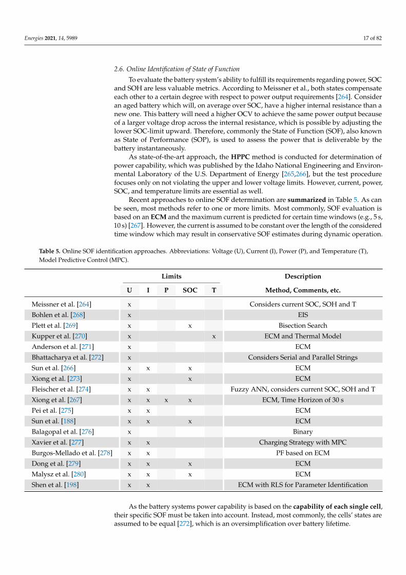
Recent approaches to online SOF determination are summarized in Table 5. As canbe seen, most methods refer to one or more limits. Most commonly, SOF evaluation isbased on an ECM and the maximum current is predicted for certain time windows (e.g., 5 s,10 s) [267]. However, the current is assumed to be constant over the length of the consideredtime window which may result in conservative SOF estimates during dynamic operation.
Table 5. Online SOF identification approaches. Abbreviations: Voltage (U), Current (I), Power (P), and Temperature (T),Model Predictive Control (MPC).
Limits Description
U I P SOC T Method, Comments, etc.
Meissner et al. [264] x Considers current SOC, SOH and T
Bohlen et al. [268] x EIS
Plett et al. [269] x x Bisection Search
Kupper et al. [270] x x ECM and Thermal Model
Anderson et al. [271] x ECM
Bhattacharya et al. [272] x Considers Serial and Parallel Strings
Sun et al. [266] x x x ECM
Xiong et al. [273] x x ECM
Fleischer et al. [274] x x Fuzzy ANN, considers current SOC, SOH and T
Xiong et al. [267] x x x x ECM, Time Horizon of 30 s
Pei et al. [275] x x ECM
Sun et al. [188] x x x ECM
Balagopal et al. [276] x Binary
Xavier et al. [277] x x Charging Strategy with MPC
Burgos-Mellado et al. [278] x x PF based on ECM
Dong et al. [279] x x x ECM
Malysz et al. [280] x x x ECM
Shen et al. [198] x x ECM with RLS for Parameter Identification
As the battery systems power capability is based on the capability of each single cell,their specific SOF must be taken into account. Instead, most commonly, the cells’ states areassumed to be equal [272], which is an oversimplification over battery lifetime.
Energies 2021, 14, 5989 18 of 82
An IBS promises the benefit of more accurate determination of the battery system’sSOF when each individual power capability is considered. Furthermore, as we will pointout in Section 4, operating strategies may take individual SOFs into account. Hence, SOFdetermination on cell level is a necessary basis of advanced operation strategies in an IBS.
3. Implementation of Sensing in Intelligent Battery Systems
The previous section has shown the extensive opportunities of advanced monitoringapproaches under the premise of sufficiently available measurement data. Thus, the dataacquisition with sensing on single cell level is considered to be a vital building block forthe realization of an IBS, but at the same time its implementation represents a significantchallenge. Hence, the implementation of sensor technology has to be considered carefully.In addition to most common sensor domains like current, voltage, and temperature, moresophisticated sensor technologies are promising to gain deeper insight into the cell’s state.However, this advantage comes at the price of higher costs and complexity. The approachesrange from the integration of sensors into the cell to the application of non-intrusivediagnostic techniques like EIS and acoustic methods.
In the following, we give an overview of sensors and sensor domains, which are con-sidered as promising for the use in IBSs and point out practical implementation, obstacles,and open scientific questions. Furthermore, requirements with regard to the application ofBEVs are discussed.
3.1. Current
Electric current is one of the most important quantities in battery applications. Whileconventional battery systems typically use one central current sensor, IBSs might use multiplesmaller current sensors that are distributed throughout the system [281,282]. This providesadditional data that can be used for advanced functions like error detection, sensor datafusion [283], or to improve parameter estimation [284]. Due to the increased number ofsensors, the selection of current sensors in an IBS requires special consideration. This sectionwill give a summary of important requirements for potential sensor candidates. A briefoverview of suitable sensor principles is provided and promising methods are described.
In advance of selecting or developing a current sensor for an IBS, functional and non-functional requirements have to be defined: The sensor has to support the full range ofthe cell’s charge and discharge current. Given the trend to cells with higher and highercapacity, this can range from tens to hundreds of amperes. Sensors in IBSs have to be able tomeasure DC but should also provide sufficient bandwidth for the frequency ranges that arerequired by certain monitoring functions. Features like EIS or Pulse Width Modulation (PWM)significantly increase the required bandwidth in comparison to conventional systems.
Additionally, there are various requirements concerning the quality of the obtained mea-surements. Measurement errors can affect functions like EIS as well as SOC and parameterestimation. This in turn leads to increased safety margins that limit overall performance. Staticoffset and gain errors are easily corrected in software, time, or temperature dependent errordrift is a more complex problem. Furthermore, nonlinearity can impair the spectra acquiredwith EIS. These errors are difficult to compensate without time-consuming calibration. Sensornoise compromises all monitoring functions. Signal processing methods, like filtering andsensor fusion [283], help to reduce the effective noise power.
Research has been done on various current sensing techniques for a wide rangeof applications [23,285–287]. Many of these techniques can be used for IBSs in EVs. Thesuitability, however, greatly depends on the actual implementation of the system. In general,current sensing techniques are categorized into resistive or electromagnetic methods.While the former use a resistive element in the current path, the latter measure current bymeasuring the electromagnetic field around a conductor.
A well-known resistive technique is to use a Current Sense Resistor (CSR), alsoknown as shunt resistor. Current sensing should not increase the parasitic resistance inthe current path; therefore, low resistance CSRs is used, and the resulting low voltage

Energies 2021, 14, 5989 19 of 82
signal must be amplified. While the resistor itself is accurate and linear, the amplificationcan impact measurement performance by introducing offset and gain errors as well asnonlinearity [286]. Either the resistor’s parasitic inductance or the following amplifier maylimit the bandwidth of this technique. High precision CSRs are made of special alloys withlow temperature coefficients [286]. Additionally, temperature compensation may be usedto achieve good accuracy over a wide range.
Alternatively, one can use existing resistive elements for current sensing such aswires or busbars. This reduces parasitic resistances but copper and aluminum, the typicalmaterials, have much higher temperature coefficients in comparison to CSRs. For shortconductor stretches, the low resistance makes the measurement of the resulting voltagedrop challenging. The high temperature coefficient makes temperature compensationcritical [286].
In IBSs with semiconductor actuators (see Section 4), switches can be used as aresistive element. For Metal-Oxide-Semiconductor Field-Effect Transistors (MOSFETs), thistechnique is known as RDS(on)-current-sensing. However, the on-resistance of MOSFETsis highly temperature dependent [287] and subject to production tolerances of die, package,and connection to the circuit board. Temperature gradients inside the MOSFET increase thecomplexity. The relatively high on-resistance, which is unavoidable regardless of currentmeasurement, makes this method a promising approach.
Another technique that relies on the on-resistance of MOSFETs, are Sense-FETs. Thisspecial type of MOSFET provides a measurement current, via an internal current mirrorthat is proportional to the primary current [287]. The current mirror ratio can be matchedto the application. The instantaneous ratio depends on the temperature distribution on thedie and the primary current. This makes precise measurement challenging [288].
While the aforementioned techniques require a galvanic connection to the primarycircuit, electromagnetic based techniques are inherently isolated [287]. This is beneficialfor high-voltage applications. A common technique is to combine a Hall-element witha magnetic core in order to measure the magnetic field around the conductor [287]. Thecore concentrates the magnetic flux at the sensing element and suppresses the influence ofexternal fields.
Electromagnetic sensors tend to behave nonlinear and show a temperature dependentoffset. To improve linearity, closed-loop sensors are applied. This sensor class uses acompensation winding to operate the sensing element at a constant flux [286]. This in turnincreases power consumption.
The problem of offset drift is addressed by using better sensing elements. Fluxgatesensors are used in high-precision current sensors due to their extremely low offset [286].Over the past few years, various types of magnetoresistive current sensors have also comeonto the market but are still not widely adopted yet.
The demand for small size and high integration in an IBS makes coreless electromag-netic sensors an appealing solution. Differential sensor arrangements are used to suppressexternal fields [285]. Due to the confined space and resulting packing density in automotivebattery packs, crosstalk between neighboring cells is to be expected nevertheless.
While a lot of research has been done regarding current sensors in general, the authorsbelieve that additional research, targeting current sensing in IBSs, could lead the way tomore cost-effective solutions. For example, approaches to use knowledge of IBS systembehavior to compensate for errors, caused by low-cost sensors, with appropriate algorithmshave not yet been explored. Currently, we believe that CSRs offers the best performancein a wide range of applications. In a system design that pursues maximum efficiency andminimum cost, this solution is still far from optimal. There is still a lot of work to be donein order to achieve an economic, energy efficient, and performant solution tailored to thedemands and challenges of IBSs.

Energies 2021, 14, 5989 20 of 82
3.2. Voltage
Cell individual voltage measurement is already implemented in conventional Li-ionbattery systems. This is crucial for monitoring the upper and lower voltage limits of eachcell to prevent failure and damage. Voltage measurements are also required by all advancedmonitoring algorithms and are therefore an essential for IBSs.
In today’s battery systems, the cell voltage is most commonly captured by integratedcircuits, where the electrical signals are converted by ADCs and further processed by theBMS controller. Precise data acquisition is an acquainted challenge. Usually, the accuracy islimited to 1 mV, or more, for cost reasons. Higher measurement accuracy requires modelsand look-up tables of corresponding quality, which is usually not the case, to be beneficial.The trend to BMSs on cell level results in short wires. This is generally advantageous withregard to signal integrity and Electromagnetic Interference (EMI) [15].
Further requirements may arise depending on the applied functionalities in an IBS. Theoptimal sample rate depends on the algorithm that the measurement data are used for. Formonitoring the safety voltage limits, a sampling time of 1 Hz or even less is sufficient. Stateand parameter estimation functions operate with sampling rates of 10 Hz–1 kHz. With regardto high frequency switching (for example in inverter concepts, Section 4.3), the switchingfrequency is in the range of many kHz, which severely affects the measurement process.
For impedance measurement, current and voltage have to be acquired synchronously.Faced with a large amount of battery cells in the system, this task is challenging. Distributedmeasurement systems are favorable, where the measurement hardware and its processingis located close to each cell. In doing so, communication effort is kept low. Further thoughtson impedance measurement are presented in the following section.
3.3. Impedance
The literature review of advanced monitoring in Section 2 shows that functions such asSOH or SOF identification use impedance measurements in addition to cell voltage, current,and temperature. They require measurements either at single frequencies or over a range offrequencies also referred to as impedance spectrum. The metrological process of measuringthe impedance spectrum of an electrochemical cell is commonly called ElectrochemicalImpedance Spectroscopy (EIS). However, in this section, the term is defined to include allmethods used with the intent of measuring impedance at arbitrary frequencies.
Literature on EIS is a broad topic, which can roughly be divided into the subdomainsof measurement, validation, and interpretation. A current review of the application ofEIS [289] covers all these subdomains and may serve as a starting point. In this contribution,we will only review publications with a focus on the online implementation of EIS thatinclude experimental results of the proposed method. These limitations are made with theintention of providing an overview of methods that are nearly applicable in IBSs.
The implementation of EIS requires to excite the cell, measure the response signal,and evaluate the acquired data. These tasks are particularly challenging for large bat-tery systems with small impedance. Measuring small impedances requires either largeexcitation currents or sensitive, low-noise front-ends and data converters to be able tomeasure the system response with sufficient accuracy for further processing. To enableonline measurements in commercial systems, the additional hardware costs should be keptto a minimum. This is especially critical when impedance measurement is aimed to bedeployed on a module or cell level. The literature discussed in the following is furthersummarized in Tables S1 and S2.
Methods that estimate ECM parameters from time domain data also fit the broad-ened concept of EIS as the impedance of arbitrary frequencies can be extracted from theECM. However, related publications were already discussed in Section 2.2 and will not berepeated here.
As the excitation source, linear [149,157,290,291] and switched modeactuators [147,151,292–295] can be found in the literature. For cell level measurement,linear excitation is a simple and common technique, whereas switched mode actuators

Energies 2021, 14, 5989 21 of 82
tend to be employed for large cells or packs to create arbitrarily shaped excitation signals.It is desirable to use either low-cost or already deployed hardware for this purpose. Thisincludes, for example, the use of active [296] and passive [143,147,297,298] cell balancers,as well as more advanced methods such as using charging circuits [299,300] or the EV’straction inverter [207]. Switched mode actuators can be further differentiated based onwhether the energy used to excite the system is dissipated as heat [301–303] or redirectedto reduce power dissipation [292,296,304]. The latter is especially relevant for large batterysystems, where high currents are necessary to obtain a sufficient voltage response. Omit-ting the actuators all together and measuring passively is also a viable option for manysystems [112,268,293,304–310]. This, however, requires the load current to exhibit dynamicproperties in order to be suitable as an excitation signal. Thus, in many cases, performingpassive measurements limits the usable frequency range [112,293]. Switching events in anReconfigurable Battery System (RBS) support the process of passive broadband impedancemeasurement in a comparatively efficient manner [293,294]. Sophisticated methods forexcitation, using slightly modified existing hardware, are presented in [290,296,304]. Thework of Gong et al. demonstrates a unique hybrid architecture, combining the benefits oflinear and switched mode excitation [290].
Another challenging aspect of impedance measurement is the design of the AnalogFront End (AFE) for data acquisition. Single-ended and differential AFEs comprisingfixed or variable gain [292] amplifiers, Lowpass Filters (LPFs) for anti-aliasing, High PassFilters (HPFs) for removing low frequency and DC components [149,207,291,301], and moreadvanced circuits are commonly found in the literature. A notable implementation wasdescribed by Din et al. [296] using a digitally controlled DC servo amplifier for removingDC offsets from the voltage signal to utilize a larger part of the ADC’s full-scale range.The utilized servo amplifier also features a fourth order active LPF for anti-aliasing. ACSR is most commonly used for current sensing [207,268,296,303,311], but Hall-effectcurrent transducers are utilized as well [112,293,294,301,302]. Low-cost implementationsuse MCU internal SAR ADCs [157,292,300,301,304] in most cases. For more performantsystems, with an accuracy of >12 bit, standalone SAR or delta-sigma ADCs are employedtypically [296,299,311–313].
Before transformation of the acquired data to the frequency domain, preprocessing isperformed. Preprocessing steps may include, for example, digital filtering [268,290,314], gainand offset compensation [290,292], segmentation [112,315], windowing [112,306,307,316], zero-padding [308], and down sampling [293,296,312]. Potential uses of digital filtering includeHPFs to remove low frequency components [290] and compensate for drift [314], BandpassFilters (BPFs) as preparation for correlation based postprocessing [268] as well as decimationfilters for down sampling [293,296].
For online impedance estimation, especially the usage of Discrete Fourier Transfor-mation (DFT) based methods is widely accepted and applied in many publications. Thereare also publications on time domain [268,291,317] and Laplace based [318,319] methods.Laplace based methods, however, tend to suffer from high computational complexity andare therefore challenging to implement on the resource constraint hardware of an onlinemeasurement system [319]. The impedance is calculated based on Power Spectral Den-sity (PSD) and Cross Power Spectral Density (CPSD) [112,207,292–294,320] or by directlyusing the DFT of current and voltage [299,302,321]. PSD based approaches tend to yieldbetter results as they are less susceptible to noise and distortion. Such frequency domainmethods have not changed significantly since their introduction in 1982, when Osaka etal. proposed the usage of the DFT for online voltammetry in analytical chemistry [322].Depending on implementation and hardware platform, these calculations may impose asignificant computational burden.
To deal with this limitation, alternative approaches have been developed. Particularlyunconventional methods are proposed by Carkhuff et al. who use a root mean squareconverter for magnitude measurement and an MCU timer peripheral as a phase detec-tor [149]. Wang et al. calculate the impedance magnitude from the peak-to-peak ratio of

Energies 2021, 14, 5989 22 of 82
the recorded current and voltage signals and the impedance argument from their relativetemporal offset [157]. These approaches, however, are best suited for sinusoidal excitationand the absence of load current or other disturbances. More robust alternative approachesare based on correlation of current and voltage in a selected frequency range [268], theGoertzel algorithm [151,308,314], or single frequency DFT methods [296,300,311].
After impedance estimation, averaging may be utilized to reduce result variationand allow for more accurate tracking of impedance changes over time [315]. Windowaveraging [301], exponential averaging [297,306,315], and more advanced methods [305]are proposed in the literature.
With cell level measurement in a multi cell system, the choice of a distributed architec-ture with central excitation seems natural [151,290,310,311]. If the current measurement isalso performed centrally, a reduction in electronics cost is achieved. This, however, requiresa method to synchronize current and voltage measurement. Synchronization methods,based on communication or radio signals, are proposed in [290,310,311]. In addition to po-tentially reducing costs, the use of a distributed system allows for decentralized impedanceestimation, which can offload calculations from the main BMS and also reduce data trafficin the communication system.
We draw a couple of conclusions from the present literature review. Regardingmethods for impedance estimation, no clear recommendations can be made since theusability of the respective methods depends heavily on factors like excitation signal andmethod, system architecture, or degree of disturbance during the measurement.
Distributed systems have shown good results for impedance measurement. Theyrequire a mechanism for synchronizing the acquisition of voltage and current. The syn-chronicity has a large impact on the precision of the impedance argument at higher fre-quencies [311]. Further research in synchronization methods for BMS might therefore beworthwhile as solutions for similar problems exist in other fields. Passive EIS was shownto be feasible, but limitations of the instantaneous load current bandwidth have to beaddressed by using hybrid approaches that combine passive and active excitation [293,294].If the computational complexity and disturbance susceptibility of Laplace-based process-ing were overcome, implementations using impulse excitation could provide a promisingalternative to Fourier-based approaches. This would enable the accurate transformationof transient processes, without the need for windowing and the consequential distortionof the results [318,319]. Averaging is shown to positively influence measurement qualityand is therefore recommended, especially for measurements with low SNR [315]. It canbe performed on frequency domain data as well as impedance data. To further reducecost and enable compact solutions, chip-level integration of dedicated battery EIS hard-ware, combining multiple components of the signal path on a single chip, needs to bepromoted [290,310].
The complexity of obtaining accurate impedance data is largely influenced by thecell under test. Measurements on small, high energy density cells with relatively highimpedance are significantly easier to perform, since the system’s response to a given ex-citation current will be higher compared to large, high power density cells. By varyingenvironmental factors, like ambient temperature, the cell’s impedance can be further influ-enced to suit the measurement system and enhance the experimental results. The reader istherefore advised to consider the magnitude of the impedance as an indicator for the intri-cacy of performing the measurement rather than the cell type or measurement conditions.
Given the multitude of factors that influence the measurement quality of EIS, it is clearthat a holistic approach that considers all steps of the measurement process must be takento bring online EIS to the module or even cell level.
In summary, the present literature review leaves the impression that the online esti-mation of battery impedance is feasible for applications, even though there is not a proven,almost standard set of approaches, yet, and it still requires significant effort. If the applica-tion of online impedance information results in clear benefits, the effort is justified, andthere is enough research to point early adopters in a promising direction.

Energies 2021, 14, 5989 23 of 82
3.4. Temperature
It is well known that the temperature is one of the most crucial parameters for safe andreliable operation of Li-ion cells. In state-of-the-art BEV, a limited number of temperaturesensors are distributed within the battery, providing information to the BMS.
Due to their low cost and robustness, thermo-resistive devices such as thermistorswith Negative Thermal Coefficient (NTC) are mostly used for temperature measurementsin Li-ion EV batteries and portable devices [323,324]. Thermo-junctive devices (thermo-couples), based on the Seebeck effect, are also broadly used in multiple studies [325,326]exhibiting good reliability and decent accuracy. Other methods such as thermal imag-ing [327,328], Johnson noise [329,330], and liquid crystals, despite their benefits, are toopricy and/or too bulky to be used in mass applications.
However, to improve the safety and the overall efficiency of the battery systems,the rising number of fails and fires reveals the necessity of cell individual temperaturemonitoring [134]. Therefore, in recent years, a significant amount of scientific work wasconducted to develop new approaches and sensors for temperature monitoring in Li-ionbattery systems.
Various studies show that, due to the large thermal mass and the anisotropic thermalconductivity of the jelly roll the difference of internal and external temperatures can besignificant, especially at high currents [325,328,331]. As a consequence, the internal celltemperature is often underestimated by external temperature measurements [332].
A rising number of scientific works focus on integration of temperature sensor in theLi-ion cells. Although cell internal sensors provide technically significant benefits for thesafe and reliable operation of Li-ion cells, their implementation proves to be challengingand costly. Several requirements have to be fulfilled for sensors to be successfully integratedwithin commercial Li-ion cells for BEVs:
• low costs;• small size, so that the volumetric energy density of the cell is not significantly reduced• long term chemical stability towards the electrolyte;• negligible impact on the cell performance;• compatible with the cell assembly process;• reliable operation at least for eight to ten years depending on the local geopolitical
regulations.
Thin film temperature sensors based on thermistor and thermocouple technologyare low cost and small-sized, however, need to be isolated from the aggressive liquidelectrolyte of the Li-ion cells. Thereby, the used materials as well as the processing methodsneed to be considered for reliable and reproducible long term operation. Several studiesuse polyimide materials as support material or protective coating due to its very goodthermal conductivity and chemical stability in polar aprotic solvents [333–335].
Mutyala et al. [334] reported a technique to fabricate a flexible thin film K-type ther-mocouple device embedded in polyimide and transferred to a thin copper foil. The sensor,which was attached to the outer face of the jelly roll of a 3 Ah NMC/graphite pouch cell,showed reliable behavior during the charging and discharging of the cell at differentC-rates (see Figure 5a).

Energies 2021, 14, 5989 24 of 82
(a) Thermocouple © Elsevier 2014 (b) NTC Thermistors © Elsevier 2019
(c) Resistance Temperature Detector (RTD) © Elsevier 2020 (d) FBG © Elsevier 2017
Figure 5. Integration of various sensors: (a) Thermocouple attached to the outer face of the cell stack of a 3 Ah pouch cell [334]. (b) NTC thermistors integrated within the cell stack ofa 5.5 Ah pouch cell (A–D) and in the mandrel core of an 18650 cylindrical cell (E–H) [331]. (c) RTDs integrated within electrode cavities [333]. (d) Integration of an Fiber Bragg GratingSensor (FBG) within the cell stack of a 15 Ah pouch cell [336]. All reprinted with the permission of Elsevier, 2021.

Energies 2021, 14, 5989 25 of 82
However, the authors do not report behavior and stability of the sensor over continu-ous cycling. Martiny et al. use a polyimide substrate to fabricate thin K-type thermocouplesensor assembly (54 µm) by sputtering Ni and Cu. Subsequently, the sensor, covered bya polyimide tape, is inserted in a 2 Ah Lithium Cobalt Oxide (LCO)/graphite cell [335].The authors report that, while no influence from the sensor on the cell response is ob-served, the behavior of the sensor after few cycles is unreliable and irreproducible, mostprobably due to electrolyte leakage. The same group reports similar behavior for 27 µmsensors using as a protective Parylene C coating, deposited via vapor deposition polymer-ization [337]. After the cell disassembly, damaged coating as well as massive corrosionof the Cu is observed. Although Parylene C exhibits high chemical stability and formsthin pinhole free coatings, its poor adhesion in liquid environments is generally an is-sue [338]. Fleming et al. [331] report a stable behavior of NTC thermistors with Parylene Cprotective coating, integrated directly into the mandrel core of 3 Ah Lithium Nickel CobaltAluminum Oxide (NCA)/graphite 18650 cell as shown in Figure 5b. After the attachmentof the thermistor to a polyimide substrate, the authors apply 1 µm Parylene C coating viavacuum deposition. According to the authors, the integrated sensors are durable and haveno adverse effect on the cell performances for the studied period of three months. Theauthors report similar behavior when the sensor is integrated between the middle layers ofthe jelly roll of a 5.5 Ah LCO/graphite pouch cell (see Figure 5b). Although the authorsdo not observe an impact of the sensor integrated in the middle of the pouch cell, it isto be expected that the sensor would impede the ionic flow at this position between theelectrodes, especially when the cells are compressed within a module.
Zhu et al. [333] suggest the integration of several thin polyimide embedded platinumRTDs in specially created cavities within the electrodes, so that the ionic flow is notdisturbed (Figure 5c). The cells show a stable behavior over 100 charge/discharge cycles;however, a slight reduction of the cell capacity is apparent due to removal of active material.
3.5. Mechanical and Volumetric Change Detection
Another important parameter that is changing during the operation of Li-ion cells,is the mechanical stress induced in the cells by the main reversible intercalation anddeintercalation of Li-ions and the side reactions. Due to lithium exchange between theelectrodes, the active material contracts and expands. This effect is called breathing andis directly related to the lithiation of the electrodes. Irreversible aging effects, such asSEI growth and electrolyte decomposition, cause permanent expansion of the cell, calledswelling. Additional information about the mechanical changes within the cell has thepotential to significantly improve the in operando determination of SOC and SOH of theindividual cells in the battery system. It can also support the early detection of safetycritical events [339–342]. The general methods that are used for monitoring mechanicaleffects in individual Li-ion cells are summarized in two recent reviews [343,344].
In real applications, the volume changes are impeded by mechanical constraints, such ascell and module housing, inducing strain within the cells [343]. Few studies suggest the com-bination of thermal and strain sensors to simultaneously monitor the temperature and themechanical changes within the cell during operation for improved and efficient assessment.
Knobloch et al. [345,346] report the design of a thin sensor platform containing plat-inum RTDs for temperature measurements and a flat spiral eddy current displacementsensor. The sensor platform is attached to the housing of prismatic 5 Ah NMC/graphitecells and the cells are assembled into modules, so that the sensor platforms are positionedin between the cells [345]. Moreover, the authors instrument a 2014 Hybrid Electric FordFocus battery pack, containing 76 compressed cells, with 19 sensor platforms [346]. Al-though the authors observe the expansion and contraction of the cells during chargingand discharging, only the deflection of the cell in the lower SOC range is measured, due tothe resolution of the eddy current sensor and the low displacement of the hard cased cellsunder compression. Nevertheless, the authors report that the cell individual RTDs detectthe temperature changes better than the few original thermistors in the battery pack.

Energies 2021, 14, 5989 26 of 82
Hu et al. [26] prepare a health monitoring sensor consisting of piezoelectric/pyroelectricpolymer array (vinylidene fluoride-trifluoroethylene) and a thin-film transistor array by an insitu poling process. Attached to a Li-ion cell, the polymer array provides a real-time responseto externally applied mechanical and thermal changes while the thin-film transistor arrayresponds to quasi-static mechanical damage with a high resolution of 50 µm. According tothe authors, the suggested monitoring sensor can be used as an early warning of mechanicaland thermal damage.
Another popular approach for measuring the mechanical changes and the temperaturein Li-ion cells is the integration of Fiber Bragg Grating Sensors (FBGs) [347]. FBGs arelight-weight, small-sized, tolerant to EMI, and electrically insulating which makes them veryattractive for application as internal sensors in Li-ion cells. FBGs are sensitive to temperaturechanges that influence the refraction index and cause thermal expansion of the optical fiber.Moreover, the Bragg wavelength is affected by strain due to physical elongation of the FBG andphoto-elastic effects. Thus, many studies utilize the sensitivity of the FBG to simultaneouslymonitor the temperature and the surface or internal strain of Li-ion cells.
Several works claim that the integration of FBGs into the mandrel core of cylindricalcells is a promising method for in situ monitoring of the internal temperature [348–350].However, it needs to be verified that the integrated sensor of the cell is not blocking themandrel. Clogging the mandrel will increase the risk of cell bursting as it provides a pathfor molten material and gases to flow to the burst vent in the case of thermal runway [351].
Other contributions show that FBGs, attached to the surface of free standing pouch orprismatic cells, provide meaningful and reliable data on the temperature and mechanicalchanges occurring as a function of the SOC during operation [352–354]. It is shown thatFBGs exhibit 28 % lower rise time compared to K-Type thermocouples, emphasizing theirreal-time monitoring capabilities [355]. Furthermore, it is suggested that FBGs are deploy-able within the jelly roll or even in the electrode coatings [336,356–359]. The mechanical andtemperature changes during operation can be precisely monitored in this position. Morecomprehensive information on the application of FBGs are found in recently publishedreviews [134,343].
Despite the promising results, several issues regarding the integration of FBGs in realapplications should be considered. Few studies report that internally integrated opticalfibers can cause significant mechanical damage to the electrodes and the separator during celloperation [353,357,358]. However, Raghavan et al. manage to successfully embed optical fibersduring the assembly of 15 Ah pouch cells with LG Chem’s stack-and-fold bi-cell structure (seeFigure 5d) and report stable cycling behavior even during stress test [336]. Moreover, theauthors emphasize the applicability of their approach to EV batteries and project the costsup to the system level [211,336]. The additional cost is significant and thus regarded as anobstacle for the successful application of FBGs as cell integrated sensors.
The application of optical sensors for the characterization of Li-ion cells gained sig-nificant popularity in the scientific literature recently. Several publications of the sameresearch group report measurements of the SOC of small laboratory cells. An optical fiberis embedded into the graphite anode to exploit the strong correlation of the graphite’sreflectance in the near-infrared band and the anode’s lithiation [212–214,360]. The authorssuggest the application of in situ fiber evanescent wave spectroscopy (FEWS) as a cost-effective, real-time, and robust method to monitor the optical changes of the graphite anodeduring operation. Their preliminary studies show that the capacity fade of the anode canbe monitored in operando [361]. However, the presence of the optical fiber within the elec-trode can impair the lithiation in the vicinity of the sensor, impeding the Li-ion diffusionsimilar to defect-induced diffusion behavior changes [362]. Moreover, further studies onlarger cells, where the SOC distribution within the jelly roll is more inhomogeneous, areessential for further consideration of FEWS for application in real battery systems.
In recent years, ultrasonic probing is gaining popularity as a non-invasive techniquefor characterization of commercial Li-ion cells. In ultrasonic measurements, an actuatoremits a wave which propagates through the medium and a sensor measures the system’s

Energies 2021, 14, 5989 27 of 82
response to the excitation [343]. The measurements can be performed in reflection, through-plane, or in-plane modes, depending on the position of emitter and receiver. The higherthe density of the sample, the higher the attenuation of the signal.
The performed studies reveal that SOC and SOH of Li-ion cells can be successfullyestimated by ultrasonic probing. According to the literature, the mechanical changes thatarise during operation, can be monitored by tracking the propagation speed as well as theamplitude of the signal. Davies et al. report that the propagation time and intensity ofthe through-thickness bulk waves can be used as predictors for SOC and SOH estimation.They use cell voltage, Time-of-Flight (TOF), and total signal amplitude metrics to train asimple machine learning model. According to the authors, an SOC prediction error of±1 %is achieved [363].
Moreover, it is suggested that ultrasonic probing can be integrated into EVs andportable devices by using basic signal processing electronics and simple piezoelectrictransducers [364]. Another use case is end-of-life assessment [365]. The majority of thestudies use high frequency transducers, such as piezoelectric transducers. They offeran opportunity for smaller packaging, since the active element thickness is inverselyproportional to ultrasonic wavelength [363]. Some authors suggest the operation at lowerfrequencies which enables the analysis of slow compressional waves [366].
Table 6 provides an overview of the research on ultrasonic probing for characteriza-tion of Li-ion batteries. The performed studies imply that ultrasonic probing of Li-ion cellsis a promising technique for state assessment of different cell compositions. However, themajorities of the studies are performed with relatively small single pouch cells, and it isshown that the acoustic behavior becomes more complex as the number of pass-throughlayers grows [364]. Further studies on larger cells are necessary in order to access theapplicability of ultrasonic sensors in EV battery systems. There is also a lack of studieson prismatic cells with wound jelly roll structure. In addition, concepts and examples forintegration of the sensors on module and system level have not been yet reported.
Table 6. Application of ultrasonic probing for characterization of Li-ion cells in the literature. All cells feature graphiteanodes. Abbreviations: pouch (po), cylindrical (cy).
Cell Type Capacity Frequency Operation Mode Application
LCO po 210 mAh 2.25 MHz temporally resolved pulse-receiveacoustic TOF measurements
stress induced failure [367]SOC/SOH
LCO po 200 mAh 2.25 MHz transmission mode SOC/SOH estimation [363]
LFP po 1.1 Ah n.a. n.a. n.a.
LCO po 1 Ah 5 MHz pulse echo mode throughtransmission mode
detection of localdegradation [368]
LCO po 1.2 Ah 200 kHz transmission mode SOC determination [366]
LCO po n.a. 2.25 MHz pulse echo mode SOC determination [364]
NCA cy n.a. n.a. through transmission mode n.a.
NMC po 3.3 Ah n.a. in-plane and through-plane modes mechanical structure duringhigh temperature abuse [369]
NMC po 3.65 Ah 100–200 kHz acousto-ultrasonic guided wavesin-plane mode
SOC determination intercalationstaging [370]
NMC po 36 Ah 200–600 kHz non-contact air-coupled SOC determination [371]
4. Reconfiguration in Intelligent Battery Systems
Advanced monitoring with the necessary implementation of sensors in an IBS solvesthe challenge of unknown single cell states in automotive battery systems. However, even ifthe cell states are known and potentially weak cells are identified, the fixed interconnection

Energies 2021, 14, 5989 28 of 82
of multiple battery cells in today’s automotive battery systems prevents flexible interven-tion. The conceptualization of a multi-cell topology is defined in the battery design processand is permanently linked during production via rigid electrical connections. However,the operation of the entire system has to be restricted in such a way that the conditions areacceptable for each cell in the battery [372,373]. A promising technology to overcome theselimitations is reconfiguration which has been widely discussed in the literature.
For this work, an IBS with reconfiguration functionality is called ReconfigurableBattery System (RBS), which is defined by the following capabilities in its minimumconfiguration (see also Figure 6):
• The smallest unit in an RBS can be a single cell or multiple cells combined. Since thesecells do not necessarily have to be cells of the same type or even battery cells, thesmallest unit is referred to as Energy Storage Unit (ESU) (Figure 6a). However, in thecase of multiple cells, the flexibility of having influence on each individual energystorage decreases [374].
• An RBS is characterized by the fact that connections between the inherent ESUs canbe changed during operation. As visualized in Figure 6b, an ESU can have threedifferent states:
– An ESU can be switched out of the power path, while the power path is eitherfurther maintained after switching of the ESU (bypass state) and/or the switchingof the ESUs disrupts the power path (idle state).
– An ESU is switched into the power path (active state).
• An important feature of RBSs is that these states are reversible and can be repeatedmultiple times during operation. Furthermore, such a system can be designed in away that it contains multiple load paths and that an ESU is assignable to one or moreof them. It is worth noting that an RBS needs to be able to change its configuration inreal-time depending on system state [372,373].
ESU “Z” ESU “B”ESU “A”
Cell Z2Cell 1 Cell 2 Cell 3 Cell 4 Cell 6
Cell Z1…
(a) Several possible ESUs as smallest unit in an RBS.
bypass idleactive
ESU ESU ESU
(b) Different reversible states of ESUs in a serial connected RBS with half bridge microtopology.
ESU “A” ESU “A” ESU “A”
ESU “A” ESU “A” ESU “A”
ESU “A” ESU “X” ESU “Y”
U
t
U
t
U
t
t
RBS Type 1
RBS Type 2
RBS Type 3
(c) Schematic representations of RBS Types 1–3.
Figure 6. (a) Visualization of possible ESUs including single cells, multiple cells, and different cell types. (b) A serialconnected RBS with half bridge microtopology and all possible switching states. (c) Schematic representation of RBSTypes 1–3 with the respective output voltage waveforms.
Energies 2021, 14, 5989 29 of 82
Reconfiguration actively controls the energy flow through the battery system. Asa consequence, new opportunities arise to influence system states in the battery systemduring operation and over lifetime. In addition, RBSs gain flexibility and scalability com-pared to conventional battery systems and increase their tolerance to failures of individualESUs [372,373,375,376]. Different general expansion types of RBSs are differentiated inFigure 6c, since not all applications require an RBS with its maximum possible configura-tion or functionality. These general types are introduced by the example of a two-switchmicrotopology in serial configuration. The multitude of possibilities of different micro- andmacrotopologies will be shown in the following sections:
RBS Type 1 uses reconfiguration to directly change the state of an individual ESU. Themain goal of this expansion level is to change or adjust the SOC [377–380], thetemperature, and the SOH of an individual ESU as well as to guarantee its operationin case of single ESU failure [379,381]. Reconfiguration is thus used to influenceinternal states so that the batteries performance matches a new one’s for as longas possible. Since it has the same electrical output characteristics as a conventionalbattery but an extended lifetime, this technology can directly replace conventionalbattery systems in BEVs.
RBS Type 2 performs reconfiguration dynamically and continuously to achieve the de-sired condition to operate the load, resulting in AC output voltage wave-forms. Thisleads to a transfer of the power electronics into the battery system and thus a fu-sion of both components. In the literature, Type 2 is referred to as an MultilevelInverter (MLI) [382]. Commonly, the system is arranged in multiple strings of ESUsto supply multi-phase AC. In an electric drive train, an IBS with MLI technology candirectly operate an electrical machine without additional components.
RBS Type 3 are battery systems in the form of Type 1 or Type 2. They are used to operatedifferent types of ESUs in one system. This type is called Hybrid Battery StorageSystem with the goal to combine ESUs e.g., with different energy storage capabilityor different power ratings [374]. With Type 3, an automobile manufacturer can, forexample, replace defective cells in a battery system of an older costumer vehicle, evenif the battery technology has changed in the meantime.
4.1. Basic Functions
The integration of switches into the battery system enables the BMS to directly controlthe operation of individual ESUs. In this way, it is possible to define which ESU activelycontributes to the operation of the load. Furthermore, the load on the ESU has a significantinfluence on internal state variables of the ESU, such as the SOC, temperature, or aging.Reconfigurable IBSs can exploit this impact to increase the performance of the batterysystem. Thereby, the basic functions are mostly implemented with a single cell ESU, sincebalancing, detection, and handling of bad blocks is mainly dedicated to single cells.
4.1.1. Bad Block Management
As shown in Section 2.1, IBSs are equipped with the potential for extended faultdiagnosis. In addition, with an RBS, a new control lever is established at the ESU levelwhile conventional battery systems have no ability of error handling, except shuttingdown the entire system. In a first step, the switches of an RBS can be used to identifyweak cells, since they are advantageously for active fault diagnosis [32,383,384]. Secondly,cells with unusual behavior can be removed from the load path at an early stage withouthaving to interrupt the operation of the load [385]. Such procedures are called Bad-Block-Management (BBM).
With a cell detected as abnormal, an RBS has the capability to reduce its effectiveoperating time by dynamic bypassing or by switching off the cell permanently. The decisivefactor is whether the state of a cell is defined as safe or unsafe for further operation [386].Already, RBS Type 1 allows for an improved localization of faults within the battery
Energies 2021, 14, 5989 30 of 82
system [32]. This is possible since RBSs can operate even if some ESUs are isolated orbypassed as long as the load demands can be fulfilled, and the battery system safetyboundaries are taken into account. However, each isolated cell further limits the electricalperformance of the battery system.
There are methods that try to tolerate ESU failures completely maintaining the elec-trical performance for a certain number of ESU failures [385]. For this purpose, redundantESUs is kept available, which are not integrated into the operation or are cyclically ex-changed with active ESUs [387,388]. This oversizing makes the system heavier, bulkier,costlier, and less efficient, since even bypassed cells generate ohmic losses while the maxi-mum possible voltage is not used. RBSs usually has a large number of redundant switchingstates. However, the load can be operated normally even in the case of an error. If noredundant hardware is available, the full control is limited only by the faulty ESU [384,389].
A further aspect of dynamic BBM comprising weak but safe cells is that the individualcell states are influenced by the BBM procedures [386]. Related to the thermal interactions,this aspect is discussed in Section 4.1.3.
For multi-phase systems of RBS Type 2, it is important to note that mostly symmetricaloutput voltage systems are needed, so that an ESU failure in one phase will affect the otherphases in order to maintain the symmetry [389]. Thus, for AC voltage systems, moresophisticated methods are found in the literature, which enable increased fault tolerancewithout over-dimensioning. These methods do not require any additional hardware, sincethey are based purely on the control of the RBSs. These are procedures of the NeutralPoint Shift (NPS) [385,390,391]. The NPS for fault tolerant operation tries to maximize theload voltage by adjusting the phase shifts of the output system bringing the load voltagesystems amplitudes as close as possible to the desired original system [381,392–394].
4.1.2. Balancing
Deviations in SOC between ESUs can be caused by internal or external influences [373].Internal imbalances are manufacturing variances, which are production-related differencesin the capacities, internal resistances [395,396], and self-discharge rates [397]. Examples forexternal influences are the discharge via non-ideal parts of electronic circuits or safety com-ponents, leading to effects similar to self-discharge [396]. Both classes of influencing factorsare subject to environmental influences such as temperature [396,397]. Since the ESUs ina conventional battery system is permanently connected to each other, the entire batterysystem can only be operated until the limits of the weakest cell are reached, even if otherESUs have not yet reached their cell-specific limits [372,376,396]. These differences canincrease over the lifetime of the ESUs [376,398,399]. To prevent this, balancing proceduresare implemented in battery systems.
Three types of balancing methods can be distinguished in conventional Li-ion bat-tery systems: shunting, shuttling, and energy conversion. Shunting is often referredto as passive balancing [395] as the energy conversion is dissipative [400,401]. For theshuttling method and energy converter method, there are different topology architec-tures [395,402–404]. A classification can be made on the basis of energy flow either fromsingle cell to pack, pack to single cell, or single cell to single cell. In general, the energeticpoor passive balancing seems to have established itself in practice at present conven-tional battery system due to best cost–benefit ratio. There have been numerous reviewsof these conventional methods concerning hardware and operating strategies in recentyears [395,402–404]. In general, these methods can also be used in IBSs with an adequateoperating strategy. At this point, we focus on a different balancing method, which shiftsenergy between the load and the ESU by using the reconfigurability of an RBS.
For RBS Type 1, where the output voltage must not change or should only change veryslowly in relation to the discharge time, a compromise must be found between balancingfunctionality and output voltage quality. This is in order to create degrees of freedom forbalancing on the one hand and on the other hand to minimize battery losses and meet thevoltage requirements of the load. Manenti et al. [379] consider this condition as fulfilled if

Energies 2021, 14, 5989 31 of 82
in large battery systems the weakest cell is taken out of the cell compound for adjustingSOC during operation. In this case, the previous redundant cell is switched back into theload path as a new one is isolated. Practical validation shows the feasibility of this method.
Bouchhima et al. [405] utilize dynamic programming to solve a finite horizon nonlin-ear optimal control problem using network modeling in order to find optimal distributionof balancing impact. The algorithm decides how much balancing is currently justified toachieve minimal power losses, if future charges are comparable to historic power distri-butions. The authors show that the model is robust against inaccurate power prediction.The approach is advanced and designed for online application, but the algorithm becomescomputationally complex when applied to larger battery systems.
In contrast to the systems described above, RBS Type 2 permanently changes itsoutput voltage. The discharge time is orders of magnitude greater than the cycle times ofthe periodic voltage changes. Thus, charge balancing methods are an integral component,since these systems use reconfiguration for the adjustment of the output voltage [406,407]with the charge withdrawal being cell-individual. It is irrelevant for the output voltagefor which ESUs are cascaded to form the output voltage as long as the sum of the voltagesproduces an acceptable output voltage level. This results in intrinsic degrees of freedomfor balancing.
Focusing on RBS Type 2, a simple balancing-algorithm is implementedin [380,387,408,409]. Thereby, the assignments of the ESUs to the voltage units are pe-riodically rotated. Therefore, the average load times are theoretically identical for allESUs over the entire operation time. The method is statically not able to compensate fordeviations of ESU or for example initial SOC deviations.
A comparable method is used by Babaei et al. [410], where a shift angle optimizationfor energy equalization is proposed. However, this method only considers the chargeinequalities that are introduced due to the multi-phase functionality. The actual load istaken into account; however, classical reasons for charge differences like self-discharge andcapacity differences are not considered.
Chang et al. [411] present a phase-shift carrier modulation for an active cell voltageequalization, where a closed-loop controller adjusts the phase shift angles according tovoltage inequalities. Nevertheless, due to the carrier-based method, only voltage and not aSOC-based balancing can be performed [411,412]. Due to aging, this can lead to short-termload balancing processes reducing the effectiveness of the procedure.
Methods using sorting algorithms in combination with an RBS are often used toachieve equally charged battery systems [413–415]. Their aim is to assign higher chargedcells to lower voltage levels, since these levels are operated longer resulting from thetypically sinusoidal-shaped waveform of the output voltages. The sorting algorithmevaluates voltages or SOC and adopts evolving differences in a closed loop overall batterycontrol strategy during operation.
Goetz et al. [416] introduce balancing strategies for topologies with parallel connect-ing capability. For this kind of topology, cells are not switched in idle, but the individual cellload is reduced through parallelization of cells. Therefore, besides minimization of losses,the controller keeps track of the maximum time each cell was in a parallel configuration.
Especially for RBS Type 2 in star-configured macrotopology, three or more phasestrings are set up. Usually, each string consists of a number of serial cascaded ESUs. Tooperate a three-phase load, all three phases are needed. Therefore, a balancing between thephases has to be considered to prevent early stopping due to under- or overcharge of onestring while the other two strings are still operable [406,407]. To ensure inter-phase balanc-ing for a converter topology, an asymmetric power distribution over the three phases of athree-phase converter must be established. Therefore, the overall performance must corre-spond to the required performance. Hardware solutions are one option, but they are bulkyand expensive. In the literature, multiple software approaches are investigated [417–419].
Balancing by reconfiguration is a convenient way for RBS to solve balancing issuesin a simple and flexible way. It is superior to conventional balancing systems because
Energies 2021, 14, 5989 32 of 82
it is software-based and no additional hardware is required. Furthermore, it is trulylossless and adjustable to different balancing needs over lifetime. However, balancing byreconfiguration is only possible in operation with load currents.
Even though balancing by reconfiguration is generally based on the same principle forall RBS types, a distinction must be made in the application between RBS Type 1, Type 2,and Type 3. For RBS Type 1, balancing is in general in direct conflict with energy efficiencyfor all balancing strategies, since the output voltage is reduced when cells are switchedout of the load path. However, in the opinion of the authors, the simple redundant cellapproach is a sufficient method for most applications and can also be used with a rule-basedon/off strategy to optimize efficiency based on different load situations.
Advanced balancing approaches do theoretically have better efficiency by findingoptimal solutions, but this does not seem to justify the computational effort in terms ofenergy and hardware costs. These algorithms constantly try to exploit off-peak periods.However, these are abundant in the operation of electric cars and therefore do not need tobe used particularly efficiently.
For RBS Type 2, balancing becomes an integral part of the system but is intrinsic andtruly lossless, as reconfiguration is part of generating AC output voltages. A reasonableapproach might consider equal load methods to reduce balancing effort by a static balancingrule, but do not consider ESU differences. Additional methods should be used to accountfor random ESU state deviations based on the actual system states. Since these effectsare small, the balancing methods should again be as simple as possible and balance thedifferent SOCs of the ESUs in a controlled manner. In RBS Type 3, the inherent balancingproperties of RBS are exploited to combine heterogeneous ESUs into a single battery system.Depending on the degree of inhomogeneity, more advanced balancing procedures may berequired to manage the balancing effort.
4.1.3. Wear Leveling
The term balancing is usually limited to SOC balancing. However, the given methodscan also be extended to other ESU states. In the literature, there is also an attempt toadjust the aging behavior of ESUs in a battery systems [376,420] and often the temperatureis included in this context due to its relation to aging and safety [421,422]. Operatingevery cell in a module/system the temperature depends in general on the cell specific heatgeneration of various cells and their position regarding the cooling system. If it is possibleto bypass cells in the system, the local heat generation of the bypassed cell is approximatelyzero, while the cell current of the remaining active cells increases automatically to meet theperformance requirement. With knowledge of the resulting thermal behavior regardingbypassing a cell or a parallel string, it is possible to implement intelligent algorithms thatperform balancing by switching not only for the thermal state. Furthermore, the focusof wear leveling is to optimize multi-dimensional inhomogeneities e.g., of SOC, current,temperature, and aging [2] comprehensively within the system.
Bouchhima et al. [423] evaluate the possible impact of an RBS on the main driver foraging of Li-ion batteries including cell temperature, OCV, Depth of Discharge (DOD), andcharge throughput. Since most of these parameters are influenceable by reconfiguration,an aging model is introduced. Based on the calendric and cyclic factors, a significantenhancement on the battery lifetime and energy throughput over lifetime with an RBS isachieved. Moreover, it is shown that cell inhomogeneity decreases with RBS operation.Kleiner et al. [424] introduced an adaptive balancing algorithm with the focus on thermalhomogeneity implemented on a reconfigurable module hardware. Thereby, the authorspointed out the resulting thermal effects of the current increase as well as the interactionsof temperature and SOC homogeneity related to RBS procedures. Atlaf et al. [421] considerthe simultaneous balancing of SOC and temperature. The close dependence of the twoquantities on the current flow is modeled, and an active balancing of SOC and temperatureis illustrated in a suitable control strategy. However, the use of the predictive control frame-work solves a rather complex control problem which is computationally expensive. This

Energies 2021, 14, 5989 33 of 82
fact is addressed in [425], where model predictive control and an orthogonal decomposi-tion into two problems are implemented. Thereby, the temperature and the SOC-balancingare solved with limited knowledge on future load information. The presented methodsare strongly based on a suitable aging model. Li et al. [420] propose a method that focuseson the change of the SOC while the cells are loaded with the same power. This is to detectdeviations in the capacity and the internal resistances. The method has been designed onan MLI and considers circulating currents.
Generally, multi-objective wear leveling approaches become maximum attractivewith RBS in combination with advanced monitoring procedures. Not only dual-objectivebalancing of SOC and temperature but further important states or influences on the wearlevel, such as SOH and fault states, can be integrated. The goal is to find the optimalload scheduling for the specific system in combination with the application. However, theinfluence of switching procedures on aging or efficiency aspects as mentioned in Section 5.4should not be neglected.
4.2. Switching Topologies
The functionality of reconfiguring ESUs is nowadays technically implemented by thedesign of a connection network between the ESU and the selective insertion of switchingelements into the network trajectories. The interconnection of the ESU and the circuitnetwork is also referred to as a module. In such systems, these modules are reconfigurablewith each other, since the switching elements are able to activate and deactivate electricalconnections [375,426,427].
In the following, only cascaded topologies are considered in which each ESU can beassigned to a defined structure of switching elements and connection paths. Therefore,known MLI classes such as Flying Capacitor (FC) [428] and Neutral Point Clamped (NPC)topologies [429,430] are not considered. The structure of the electrical paths within amodule, which connects a number of module terminals directly or via switching unitswith the terminals of the ESU, is referred to as microtopology [374]. By multiple use ofthis microtopology in an electrically cascaded manner, a larger storage system can becreated which has a higher voltage and/or current carrying capacity. The result of thecascading process is called macrotopology, where the microtopologies can be switchedin series, parallel, or both [416,431,432]. Possible topology implementations for RBSs aretherefore not necessarily of the same quality, since they can vary in the number of inherentswitching devices or in the way they are interconnected. For this reason, a large part of therecent research dealing with RBSs is focused on the development of innovative and mostappropriate structures. Topologies in general differ in the number of inherent switches,their arrangement as well as the presence of possible connections between the ESUs. Inaddition, they are distinguished depending on the number of immanent electrical ESUsand their resulting voltage value.
4.2.1. Microtopology
In Table 7, various different microtopologies are listed. They mainly differ in theirrespective functional range. Simple structures, such as the half bridge proposed byDarco et al. [413], provide the basic functions for an RBS in serial configuration. The halfbridge design is one of the most frequently used topologies for RBSs today [375,381,408,413,433–443]. The main advantage of this topology is its low complexity. For this reason,the circuit is used in applications ranging from pure RBS Type 1 to voltage adjustable batter-ies like MLIs (RBS Type 2 and 3). They are able to disconnect any ESU from the load pathwithout interrupting the supply to the load [375,434]. The switching state of each moduleis independent of the switching states of the other modules [375,413,433,434,438,444–446].Due to the great importance of the half bridge topology, investigations have been madeto further improve this circuit by minimizing the number of switches in the load path,while maintaining the same functionality. Choi et al. proposed in [447] a Prior half bridgetopology. It is characterized by having one switch in the load path for the case of an

Energies 2021, 14, 5989 34 of 82
active ESU, whereby no switch is in current path if the ESU is bypassed. However, thisdrastic reduction in switches causes dependencies that inhibit ESU-independent bypassing.The half bridge topology is suitable for most RBSs. Drive applications require sinusoidalvoltages and currents that contain positive and negative voltage segments. The half bridgemisses the function of polarity reversal at the module terminals though.
Table 7. Overview of microtopologies from the literature with the number of submodules N and the instantaneous outputlevel n. All associated macrotopologies achieve the full 2N + 1 output levels but may need a polarity reversal circuit to doso. The number of switches is counted with respect to the macrotopology, which includes the potential polarity reversalcircuit. Abbreviations: serial switches (SS), total switches (TS), polarity reversal (PR), serial bypass (SB), parallelization (PA),external (ext), internal (int), Common Emitter Bidirectional Switched Based MLI (CEBS).
Microtopology SS TS PR SB PA
Half Bridge[375,381,408,413,433–443] N + 2 2N + 4 ext yes no
Prior Half Bridge[447]
n + 2Level 0: 2
Level N: N + 1
2N + 2 ext no no
Cross-Switched[448] N + 1 2N + 2 int no no
Cascaded Cross-Switched[449]
32
N 3N int yes no
CEBS[450] 4 4N + 4 int no no
Full Bridge[380,385,407,410,418,419,435,451–456]
2N 4N int yes no
ECIN[457] ≈ N + 1 4N + 2 int yes no
Marx[458–461] ≤ N + 2 3N + 4 ext yes yes
MMSPC[416,431,435] ≤ N 8N int yes yes
M2B[455,462,463] ≤ 2N 9N int yes yes
PECIN[464] ≤ N + 1 6N + 2 int yes yes

Energies 2021, 14, 5989 35 of 82
In [437,440,465], this problem is solved on the macrotopology level by connecting anexternal polarity unit in the form of a full bridge at the terminals of the entire cascadedstring composed of the half bridge circuits.
In order to avoid this external device or a reduction of the maximum output levelof the battery system, further research was carried out to create this functionality on amicrotopology level. In [448], Kangarlu et al. present a Cross-Switched MLI having onlytwo switches per ESU. It has the capability to generate positive and negative output voltageon the phase terminals [466,467]. Resulting from the absence of individual bypass capabilityand in order to increase the number of possible voltage levels a Cascaded Cross-SwitchedMLI is introduced by Sabahi et al. [449]. Babaei et al. [450] present a comparable simplebut energetically optimized topology. With the Common Emitter Bidirectional SwitchedBased MLI, the number of switches in the load path is always four regardless of how manyof these modules are serially connected. Even for a small number of ESUs, the internalresistance is therefore similar to a conventional battery system [468]. However, the smallnumber of switching elements leads to a reduced flexibility in reconfiguration; therefore,e.g., an ESU individual bypass is not possible. Ebrahimi et al. [469] present a unipolarversion of the circuit. This variant saves components, whereas the missing bi-directionalityis created by a downstream full bridge.
One of the most frequently investigated microtopologies is the full bridge topology,also named Cascaded H-Bridge (CHB) [380,385,407,410,418,419,435,451–456]. It offers thesame functionality as the half bridge, but the polarity inversion is directly integrated intothe microtopology [470]. Therefore, it is able to switch each individual ESU positively ornegatively into the load path. This offers a larger number of voltage levels but doublesthe switches in the load path for both active and bypass cases [470]. Thus, topologies suchas the CHB and the following more sophisticated topologies are mostly addressed if MLIcapability is requested. In the case of a Type 1 RBS, the half bridge circuit as in [375] istypically preferred.
Terbrack et al. [457] have developed the so-called Enhanced Commutation IntegratedNested (ECIN) topology. It reduces the number of switches in the load path for activeESUs to one. Despite the lower internal resistance, it uses only four switching elements inits microtopology, as the CHB. In addition to the functionality of voltage reversal, there isa large number of topologies that extend the half bridge topology by the functionality ofparallel connection of ESUs [458,460,461]. An important field of application is the reductionof the internal resistance of the battery system as well as the active switches in the load pathby this technology. In particular, this is feasible if the desired output voltage of the RBS islower than its maximum generable voltage value. In this case, some ESUs are temporaryout of use [457].
A side effect of the topologies, which can connect cells not only in series but also inparallel, is that the usual two connection terminals are no longer sufficient for one module.For these microtopologies, two connection points must be provided to the previous andalso to the subsequent ESU, so that a parallel connection is feasible. In technical realization,there are topologies which require four terminals for the microtopology and topologieswhich manage with three terminals. Doing so, the third terminal must be connectedto the preceding and subsequent ESU [374,416,429,431,471]. Especially in MLIs, wherethe output voltage is periodically changed, advantages can be achieved with parallelreconfiguration [472]. Compared to the CHB topology, however, e.g., the Marx topologypresented in [458,459] does not have the capability of direct voltage inversion. The topologyis further investigated and called BM3 by Helling et al. [460] while Kim et al. [461] call itDESA. These topologies also have to use external commutation units for MLI operationguaranteeing positive and negative output voltages. The so-called MMSPC topologypresented in [416,431,435] combines the functions of polarity inversion, parallelization, andindividual control of the ESUs in one topology. Therefore, it integrates the entire range offunctionality in one circuit. The topology consists out of two full bridges, containing at leasteight switches. In the purely serial case, there is only one switch in the load path for both
Energies 2021, 14, 5989 36 of 82
active and bypass. This number can be effectively reduced by parallel connection of ESUs.Helling et al. [462] present an M2B MLI with the advanced functionality of parallelizationof cells. Thereby, parallel groups of cells can be formed even across defective ESUs byinserting a further switch in series to each ESU [462]. However, for this reason, the numberof switches in the load path increases significantly, which leads to higher conductionlosses. In general, MMSPC and M2B are sophisticated but hardware intensive topologies.Terbrack et al. [464] have implemented the Parallel Enhanced Commutation IntegratedNested (PECIN) topology design. It incorporates all the functionality of the MMSPC, butwith reduced hardware effort.
The microtopology already defines important features of the overall RBS. The topolo-gies presented attempt to minimize electrical components while maximizing functionality.Especially for EVs, the way the microtopology is derived from the overall topology isimportant to get few and equal parts for assembly. Since cost is a major driver in industrial-ization, the goal is to keep electrical equipment to a minimum. From a technical point ofview, the efficiency of the RBS benefits from the lowest internal resistance of the microtopol-ogy. For these reasons, the half bridge topology is most appropriate for RBS Type 1. Moresophisticated approaches are discussed for RBS Type 2, since polarity commutation is anintegral part of AC voltage generation. Topologies with external or intrinsic commutationare presented in the literature. The half bridge or the MARX Inverter in combinationwith an external full bridge are suitable candidates with low internal resistance. However,topologies with intrinsic commutation do not require any additional external hardwarecomponent. Since cost is a major consideration, the system designer needs to be clear aboutthe functionality required of the RBS system, as generally more functionality comes withmore hardware expense. The ECIN topology has very low internal resistance compared toits number of components. If a more sophisticated approach is appropriate, PECIN hasslightly more hardware effort, but the additional ability to reduce internal resistance byparalleling the battery cells, which increases the efficiency.
4.2.2. Macrotopology
There are different possibilities to cascade the microtopologies to a larger RBS. In mostcases, only one type of microtopology is cascaded to a specific macro-version. However,it is possible to integrate different types of microtopologies in a macrotopology as it wasexecuted, for example, by Hinago et al. [432] or by adding a downstream full bridge aspolarity unit as in [437,440,465]. The combination of different topologies is in the literaturereferred to as hybrid MLI [382,467,473]. The macrotopology has a great influence onthe function of the entire battery system and significantly determines its performanceand behavior. Therefore, the macrotopology is strongly dependent on the application.An overview of common macrotopologies for reconfigurable IBSs is given as schematicvisualization in Figure 7.
A straightforward connection of microtopologies is based on a conventional battery sys-tem cell connection either in serial, parallel, or serial and parallel configuration (Figure 7a–d).Typically, RBS Type 1 often do have these configurations [375,379,437,441,442]. For MLI appli-cations, the star configuration (Figure 7f) is utilized in most cases [470,474], since it deliversthe highest output voltage for a given number of ESUs. A delta configuration of submodules(Figure 7g) is proposed by Helling et al. [374] in order to improve the reliability of electriccars at a fault in one electrical phase. Since the delta configuration is fault-tolerant [374], afaulty string leads to the presented reduced string configuration which only uses two thirdsof the otherwise needed ESUs of the delta configuration. Especially for BEV, a commonDC-link is important to provide energy not only for the main drive, but also for electricauxiliary consumers.
The star, delta, and reduced string configurations (Figure 7f–h) do not provide a DC-link [374,416]. However, the Modular Multilevel Converter (MMC) topology (Figure 7e)provides a DC-link. Therefore, the MMC is a well-investigated inverter design. Char-acteristic for the MMC is that circulating currents are emerging, which on the one hand

Energies 2021, 14, 5989 37 of 82
are undesirable and can be reduced by control strategies or further included arm in-ductors [475]. On the other hand, the phase arms are balanced to each other automati-cally [433,434,445,446]. The MMC is mostly used with half bridge submodules, but thereare also variants that for example use full bridge and Clamped-Double microtopolo-gies [467,476]. Nonetheless, in MLI applications, the MMC provides only a quarter of theentire DC-link voltage on the AC-connections, which is a considerable disadvantage fordrive applications [431,433,434,445,472].
M1,1 M1,2 M1,n
M1,1
M2,1
Mm,1
M1,1
M2,1
Mm,1 Mm,2
M2,2
M1,2 M1,n
M2,n
Mm,n
M1,1 M1,2
M2,1 M2,2
Mm,1 Mm,2 Mm,n
M2,n
M1,n
M1,1 M1,2 M1,3
Mi,3Mi,2Mi,1
M j,1 Mj,2 Mj,3
Mm,1 Mm,2 Mm,3
M1,1 M1,2
M2,2M2,1
Mm,1 Mm,2
M1,n
M2,n
Mm,n
M1,1 M1,2
M2,2M2,1
Mm,1 Mm,2
M1,1
M2,1
Mm,1
M1,2
M2,2
Mm,2
2,3
M1,3
M
Mm,3
PN
PN
PN
PN
P
N
SL1L2L3
N
L1 L2 Ln
L1 L2
L3 L1
L2
L3
a b c d
hgfe
Figure 7. Schematic visualization of different macrotopologies for reconfigurable IBSs: (a) parallel circuit, (b) serialcircuit, (c) serial parallel configuration, (d) parallel serial configuration, (e) MMC topology, (f) star configuration, (g) deltaconfiguration, (h) reduced string configuration.
Terbrack et al. [457] introduce a new approach to achieve a DC-link with as fewcomponents as possible by integrating additional voltage taps into an MLI battery system.Therefore, two or more MLI systems arise and are integrated into one battery system. Theyindependently supply individual adjustable output voltage systems but have access toshared ESUs. An externally excited synchronous machine is operated with its three-phasestator system and a controllable DC-voltage for the rotor system. In addition, there areapproaches with an RBS to generate several different output voltages simultaneously inorder to be able to operate different loads. Helling et al. [462] integrate so-called low voltagepower supply units in the phase arms to tap additional consumers. A further method ispresented by Kuder et al. [455], where two electrical machines are operated simultaneouslywith the same MLI. However, this concept exhibits a higher control complexity, withoutproviding benefits in the hardware implementation.
In general, the most commonly used topology for conventional battery systems isthe parallel-serial configuration, which is directly transferrable to RBS Type 1. For RBSType 2, multi-phase approaches need to be considered. The star topology is the one mostconsidered due to the maximum output voltage and its simple structure. However, amajor drawback for RBS Type 2 is the missing DC-Link circuit for auxiliary devices. Thereare approaches to provide a DC-Link, but they increase the complexity of the system.Furthermore, the MMC topology that provides a DC-Link is inefficient in EV applicationsdue to a low AC output voltage.
4.3. Multilevel Inverter
As already briefly introduced, an MLI is the most common form of RBS Type 2. Thiskind of inverter is a frequently investigated topic in the past few years and a still growing
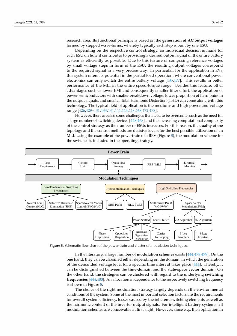
Energies 2021, 14, 5989 38 of 82
research area. Its functional principle is based on the generation of AC output voltagesformed by stepped wave-forms, whereby typically each step is built by one ESU.
Depending on the respective control strategy, an individual decision is made foreach ESU on how it contributes to providing a desired output signal of the entire batterysystem as efficiently as possible. Due to this feature of composing reference voltagesby small voltage steps in form of the ESU, the resulting output voltages correspondto the required signal in a very precise way. In particular, for the application in EVs,this system offers its potential in the partial load operation, where conventional powerelectronics can only switch the entire battery voltage [435,477]. This results in betterperformance of the MLI in the entire speed-torque range. Besides this feature, otheradvantages such as lower EMI and consequently smaller filter effort, the application ofpower semiconductors with smaller breakdown voltage, lower proportion of harmonics inthe output signals, and smaller Total Harmonic Distortion (THD) can come along with thistechnology. The typical field of application is the medium- and high power and voltagerange [426,429–431,433,434,444,445,448,468,472,478].
However, there are also some challenges that need to be overcome, such as the need fora large number of switching devices [448,468] and the increasing computational complexityof the control strategy as the number of ESUs increases. For this reason, the quality of thetopology and the control methods are decisive levers for the best possible utilization of anMLI. Using the example of the powertrain of a BEV (Figure 8), the modulation scheme forthe switches is included in the operating strategy.
Modulation Techniques
Low/Fundamental Switching
Frequencies
Nearest Level
Control (NLC)
Selective Harmonic
Elimination (SHE)
Space/Nearest Vector
Control (SVC/NVC)
2D-Algorithm
High Switching Frequencies
Multicarrier PWM
(MC-PWM)
Space Vector
Modulation (SVM)
Hybrid Modulation Techniques
3D-Algorithm
3-Leg
Inverters
4-Leg
Inverters
Phase-Shifted Level-Shifted
Phase
Disposition
Opposition
Disposition
Alternate
Opposition
Disposition
Carrier
Overlapping
Power Train
Load
Requirement
Control
Unit
Operational
StrategyRBS / MLI
Electrical
Machine
SHE-PWM NLC-PWM
Figure 8. Schematic flow chart of the power train and cluster of modulation techniques.
In the literature, a large number of modulation schemes exists [444,478,479]. On theone hand, they can be classified either depending on the domain, in which the generationof the demanded voltage level for a specific time interval takes place [444]. Thereby, itcan be distinguished between the time-domain and the state-space vector domain. Onthe other hand, the strategies can be clustered with regard to the underlying switchingfrequencies [444,480]. An allocation in dependence to the respectively switching frequencyis shown in Figure 8.
The choice of the right modulation strategy largely depends on the environmentalconditions of the system. Some of the most important selection factors are the requirementsfor overall system efficiency, losses caused by the inherent switching elements as well asthe harmonic content of the inverter output signals. For intelligent battery systems, allmodulation schemes are conceivable at first sight. However, since e.g., the application in

Energies 2021, 14, 5989 39 of 82
BEV requires a high-dynamically system with real-time characteristic, the computationaleffort of the chosen variant should be low. Due to the typical high number of includedESUs, attention should also be paid to the switching frequency of all inherent switchingdevices. With increasing switching frequency, the total switching losses usually increaseby the factor of the number of ESUs. One comparatively simple method to control theswitching signals of an MLI is the Nearest Level Control (NLC) [481]. In this time-basedswitching strategy, the output voltage level is chosen that is closest to the desired referencevector (Vref) [427]. Only one switching operation per voltage level is performed, and thusthe utilized switching frequency is in the fundamental range. Consequently, the entireswitching losses are kept low. No carrier signals are required to generate the control signalfor each individual ESU in the MLI structure. The NLC variant is flexible and stands outfor an easy digital implementation [20,482], which makes it attractive compared to otherstrategies. This fact becomes more important with increasing number of ESUs or ratherlevels. As mentioned in [481], the NLC scheme is in fact no modulation technique, sinceno averaging processes take place. In general, all switching strategies are summarizedunder the term of modulation techniques though [426,431,444]. With the NLC method,suppression of harmonics is not feasible [483] and thus the harmonic content cannot beminimized specifically. As a consequence, the performance suffers [481]. This fact getseven more obvious for the case of a lower number of inherent ESUs in the entire system,since the proportion of harmonics is comparatively higher [427].
This problem is addressed with Selective Harmonic Elimination (SHE) strategies,which, however, still use low switching frequencies [426,427,444,481]. With the elimina-tion feature, the harmonic content decreases while low switching frequencies result in lowswitching losses. Kamaldeep et al. [427] investigated the comparison of the NLC- and theSHE-method for a seven level MLI. The results show that a smaller THD value of harmonicsup to the 5th order is achieved when applying the SHE instead of the NLC. For SHE, theFourier coefficients of the expected reference signal are examined in an offline procedurebefore the actual operation. From this system of equations, the associated switching an-gles (α1, α2, α3, . . . , αn) are determined [481]. Special numerical methods or optimizationalgorithms such as Particle Swarm Optimization (PSO) or GA are utilized to calculate themost suitable angles [454,484]. With the help of lookup-tables, the pre-calculated switch-ing angles are applied in operation and interpolated with respect to the actual operatingpoint [444]. However, the complexity of these elimination procedures due to the underlyingnumerical solving processes increases with the number of MLI levels. Thus, the application ofoffline-based SHE is not the most appropriate one, especially for systems with high-dynamicdemands [481]. In addition, the required storage of the lookup-tables complicates the usagein real-time applications [444] and diminishes its implementation in low cost microprocessors.Furthermore, there is no control over the higher order harmonics that are not specifically sup-pressed with this method. As mentioned by Rodriguez et al. [481], they can become higher,since the energy of the eliminated harmonics is allocated to the other ones.
Therefore, another approach called SHE-PWM is developed that has more than onlyone switching operation on a level. Li et al. [485] introduce SHE-PWM as systematic controlstrategy for cascaded MLI. Since those methods have similar outcome as high-frequencybased strategies described in the following, the elimination of low order harmonics seemsto be very expensive, especially regarding computational as well as storage effort.
A less complicated method is the so-called Space Vector Control (SVC), which isbetter suited for dynamical applications and does not need any lookup-tables like multipleSHE or SHE-PWM techniques [481]. It can be seen as a counterpart to the time-domain-based NLC-method. Like the NLC, its principle follows a fundamental switching frequency,but depends on the closest voltage vectors in the space vector plane [486]. One drawback ofthe SVC is that it suffers from the non-existent elimination of harmonics resulting in higherTHD and performance losses as NLC does [444,481]. However, the results of Rodrigueset al. [486] show that the SVC method performs better regarding the voltage THD than alow-frequency switching Multi-Carrier (MC)-based PWM method.
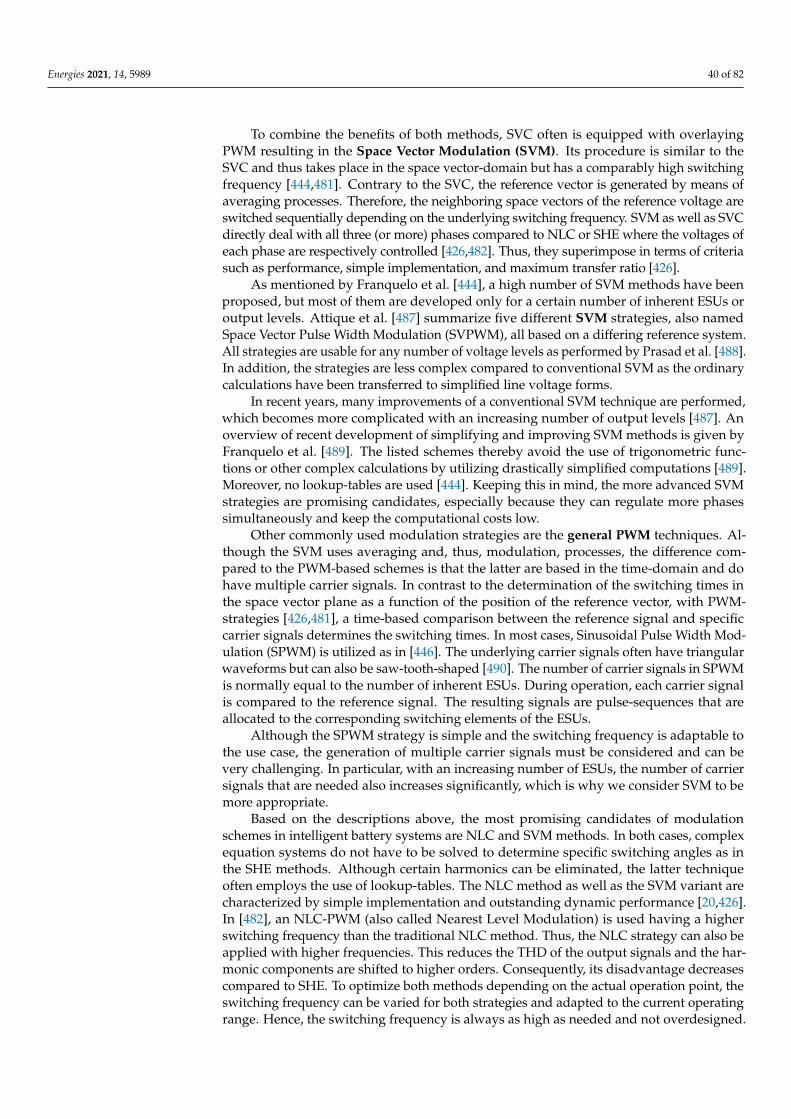
Energies 2021, 14, 5989 40 of 82
To combine the benefits of both methods, SVC often is equipped with overlayingPWM resulting in the Space Vector Modulation (SVM). Its procedure is similar to theSVC and thus takes place in the space vector-domain but has a comparably high switchingfrequency [444,481]. Contrary to the SVC, the reference vector is generated by means ofaveraging processes. Therefore, the neighboring space vectors of the reference voltage areswitched sequentially depending on the underlying switching frequency. SVM as well as SVCdirectly deal with all three (or more) phases compared to NLC or SHE where the voltages ofeach phase are respectively controlled [426,482]. Thus, they superimpose in terms of criteriasuch as performance, simple implementation, and maximum transfer ratio [426].
As mentioned by Franquelo et al. [444], a high number of SVM methods have beenproposed, but most of them are developed only for a certain number of inherent ESUs oroutput levels. Attique et al. [487] summarize five different SVM strategies, also namedSpace Vector Pulse Width Modulation (SVPWM), all based on a differing reference system.All strategies are usable for any number of voltage levels as performed by Prasad et al. [488].In addition, the strategies are less complex compared to conventional SVM as the ordinarycalculations have been transferred to simplified line voltage forms.
In recent years, many improvements of a conventional SVM technique are performed,which becomes more complicated with an increasing number of output levels [487]. Anoverview of recent development of simplifying and improving SVM methods is given byFranquelo et al. [489]. The listed schemes thereby avoid the use of trigonometric func-tions or other complex calculations by utilizing drastically simplified computations [489].Moreover, no lookup-tables are used [444]. Keeping this in mind, the more advanced SVMstrategies are promising candidates, especially because they can regulate more phasessimultaneously and keep the computational costs low.
Other commonly used modulation strategies are the general PWM techniques. Al-though the SVM uses averaging and, thus, modulation, processes, the difference com-pared to the PWM-based schemes is that the latter are based in the time-domain and dohave multiple carrier signals. In contrast to the determination of the switching times inthe space vector plane as a function of the position of the reference vector, with PWM-strategies [426,481], a time-based comparison between the reference signal and specificcarrier signals determines the switching times. In most cases, Sinusoidal Pulse Width Mod-ulation (SPWM) is utilized as in [446]. The underlying carrier signals often have triangularwaveforms but can also be saw-tooth-shaped [490]. The number of carrier signals in SPWMis normally equal to the number of inherent ESUs. During operation, each carrier signalis compared to the reference signal. The resulting signals are pulse-sequences that areallocated to the corresponding switching elements of the ESUs.
Although the SPWM strategy is simple and the switching frequency is adaptable tothe use case, the generation of multiple carrier signals must be considered and can bevery challenging. In particular, with an increasing number of ESUs, the number of carriersignals that are needed also increases significantly, which is why we consider SVM to bemore appropriate.
Based on the descriptions above, the most promising candidates of modulationschemes in intelligent battery systems are NLC and SVM methods. In both cases, complexequation systems do not have to be solved to determine specific switching angles as inthe SHE methods. Although certain harmonics can be eliminated, the latter techniqueoften employs the use of lookup-tables. The NLC method as well as the SVM variant arecharacterized by simple implementation and outstanding dynamic performance [20,426].In [482], an NLC-PWM (also called Nearest Level Modulation) is used having a higherswitching frequency than the traditional NLC method. Thus, the NLC strategy can also beapplied with higher frequencies. This reduces the THD of the output signals and the har-monic components are shifted to higher orders. Consequently, its disadvantage decreasescompared to SHE. To optimize both methods depending on the actual operation point, theswitching frequency can be varied for both strategies and adapted to the current operatingrange. Hence, the switching frequency is always as high as needed and not overdesigned.

Energies 2021, 14, 5989 41 of 82
4.4. Hybrid Battery Storage System
Battery systems containing individual ESUs that differ significantly in electrical,mechanical or thermal properties are often refereed to as Hybrid Battery Storage Sys-tem (HBSS). They pursue the goal of creating an optimal system through combination andoperation of several different ESUs that meet the application-specific requirements best.Most HBSSs that are described in the literature are composed of high energy and highpower ESUs to achieve a system with superior characteristics regarding energy, power,system efficiency, fast charging, long lifetime, low cost, low weight, and low volume [491].In addition to the system-related advantages, the combination of different cell types or cellgenerations result in further benefits for the manufacturer such as flexible dimensioningand adaption of battery storages, utilization of scale effects (realization of several sys-tems with a fixed number of different cells), or reduction of storage costs (combination ofdifferent cell types/generations or aging states).
4.4.1. Topologies
An independent control of the energy and power flow of each battery cell of a certaintype is essential for the optimal operation and safety of the HBSS. Traditionally, thisrequires additional power electronics such as one or more unidirectional or bidirectionalDC/DC converters. However, with the occurrence of reconfigurable topologies at the cell,module, and system levels, no additional hardware components are required to realize anHBSS. Despite the high potential of HBSSs, there are currently only a few publications thatdeal with this topic in detail.
First, thoughts on the hybridization of battery storage systems are already found in pub-lications on RBSs and MLIs [442,460,463,492–497]. The most comprehensive and systematiccollection of macrotopologies for HBSSs has been published by Zimmermann et al. [498]. Asone of the first, the authors combine the two research fields of RBSs and HBSSs and proposea new topology class called discrete hybrid energy storage topologies. The basis for thistopology class is formed by ESUs which consist of single, multiple serial, or parallel connectedcells. Within a ESU, only one cell type is used such as high power or high energy. Thehybridization is realized by using different cell types for ESUs. Besides the energy storageelement itself, each ESU also contains some switching elements to activate, bypass, ordisable individual units, and therefore allows the reconfiguration of the HBSS as well asan active load management. Based on Zimmermann et al. [497,498], four macrotopolo-gies of multiple ESUs are frequently used for HBSSs: parallel, serial, serial-parallel, andparallel-serial (see Figure 7a–d). The serial macrotopology is used by Horsche et al. [442] toimplement a serial HBSS with ESUs on cell level and switches in half bridge configuration.
A different concept is proposed by Tu et al. [492] for the combination of multipleEnergy Storage Systems (ESSs) on a system level called series-parallel reconfigurableHBSS. This macrotopology allows for arranging two storage modules in series, parallel,or serial-parallel configuration. However, due to the reconfiguration at system level, thistopology results in some restrictions in the operation and dimensioning of an HBSS toavoid high compensation currents.
Guo et al. [494] propose a macrotopology for an HBSS based on the common MMCtopology. Therefore, the MMC topology with half bridge microtopology and high powerstorage units is extended with a separate high energy storage as DC-Link. Thereby, thehigh energy pack contains no additional switching elements.
Another HBSS topology, also based on the MMC structure, is presented by George et al. [496].Their concept features a microtopology of the individual ESUs, where each ESU consists of a highenergy and high power cells as well as eight switching elements. Four of the switching elementsare used to select one or both ESUs (high energy or/and high power) and the remaining fourswitches form a full bridge to change the polarity of the corresponding ESU. A disadvantageof this concept is the high number of switching elements in the current-carrying path inducingadditional losses.

Energies 2021, 14, 5989 42 of 82
Ciccarelli et al. [493] provide an MMC approach extending high power storage unitswith high energy units via an additional DC-link. Furthermore, each ESU integrates a halfbridge in conjunction with a DC/DC converter. As a result, a large number of switchesand passive components are required in this configuration. Preliminary considerationson HBSSs are found in the publications of Helling et al. [460,463] which introduce themicrotopology of BM3 and M2B, as already presented in Section 4.2.1.
In addition to the topologies listed above with reference to HBSSs, many other topolo-gies form the scientific literature on RBSs and especially MLIs are interesting to be used foran HBSS. Particularly promising are topologies that enable the independent control of theenergy and power flow within the system and also can generate an AC output voltage. Thisopens up the possibility to combine the advantages of HBSSs and MLIs, whereby the sys-tem efficiency can be increased even further and additional power electronic componentscan be reduced.
4.4.2. Operation
The combination of two or more different cells in one battery system results in ahigh degree of flexibility in terms of system design and operating strategy. However, theoptimal control of the power or energy flow within the HBSS is challenging. A variety ofso-called energy management strategies are presented in the scientific literature. Generally,most strategies aim to absorb short-term power peaks with the corresponding high powerstorages and thus keep the output power of the high energy storage as constant as possible.At the same time, the energy losses are intended to be minimal and simultaneously toextent cyclic lifetime of the high energy storage. As far as the authors are aware, nooperating strategy has yet been published that explicitly deals with HBSSs in the context ofthe novel RBS Type 3 topologies. However, the basic concept of most energy managementstrategies is applicable to RBSs with some minor changes with regard to power controland current distribution within the HBSS topologies. A compilation of various energymanagement strategies for an HBSS is given by Krishna et al. [499]. Figure 9 visualizes theircategorization. The different algorithms for energy management strategies are classifiedinto four categories: rule-based, filtration-based, optimization-based, and learning-based.This classification is not uniform in the scientific literature and other authors pursuedifferent approaches to grouping and classifying the algorithms.
Rule-Based
Fuzzy Logic
Adaptive Mode Switch
Limited Tolerance Strategy
Average Current Strategy
Thermostatic Strategy
Filtration-Based
Low/High-Pass Filter
Crossover Filter
Average Power Method
Wavelet Transform
Optimization-Based
Linear/Dynamic Programming
Stochastic Programming
Convex Programming
Particle Swarm Optimization
Model Predictive Control
Artificial Neural Network
Pontryagin Minimal Principle
Equal Consumption Minimization
Simulated Annealing
Evolutionary Algorithms
Learning-Based
TD(𝜆)-Learning
Q-Learning
Deep Q-Learning
Power Train
HBSS Energy Management Strategies
Load
Requirement
Operational
Strategy
Control
UnitHBSS
Electrical
Machine
Figure 9. Categorization of different energy management strategies for an HBSS based on [499]. Online strategies aremarked with a white background, offline strategies with a gray background.

Energies 2021, 14, 5989 43 of 82
The most common are rule-based controllers due to their simplicity in implementationand validation, as well as their good real-time performance. The underlying set of rulesare often predefined based on the application and the characteristics of the storage unit.Therefore, the established rules depend either on the expert knowledge of the developer orresult from optimization algorithms used to derive the rules. Depending on the underlyingalgorithms, these can be further subdivided into deterministic and fuzzy logic rule-basedstrategies [499]. Simple deterministic approaches based on heuristics or empiric experiencecan be found in [500–502]. The underlying rules are often fixed and presented in a flowchart. Accordingly, the operation strategy can be regarded as a finite state machine.Their performance is heavily dependent on knowledge of the system and its workingcondition. The same disadvantage also applies to algorithms based on fuzzy logic. Onepossible way to improve the performance is to use adaptive control strategies that changethe underlying set of rules depending on the respective operating point. A relativelysimple adaptive strategy, proposed by Jiang et al. [500], includes the setpoint of the outputcurrent from the high energy storage depending on the SOC of the high power storage.Zhou et al. [503] introduce another adaptive fuzzy logic based strategy, which changes theoutput membership function of the fuzzy logic algorithm and the corresponding updatefrequency according to the past driving cycle pattern. Another very promising approach isto derive the underlying set of rules from the results of a global optimization-based energymanagement strategy. Promising methods among others used in the literature are dynamicprogramming [504,505], neural networks [506], and PSO [507,508]. Hu et al. [505] also taketraffic information into account.
An alternative variant of energy management strategies are filtration-based alsocalled filter-based or frequency-based approaches, which decompose the power demandof the load into different frequency components to match them to the dynamic responseof the involved ESUs. High power cells offer a much higher short-term power capabilitycompared to high energy cells. Therefore, the aim of filtration-based approaches is tostress high energy cells only with the low frequency part of the power demand, while thehigh power cells take care of the high frequency components. The cutoff frequency andother parameters in the filter design must be set accordingly. Filtration-based strategieshave the major disadvantage to introduce a large phase shift [501,509]. A relatively simplefiltration-based called average power method is provided by Wang et al. [510]. In orderto reduce the operation current/power frequency on the high energy storage, the highpower storage acts as a real-time adaptive power filter. For this purpose, the method usesinformation from both the real-time power and history power demands. Another simpleapproach to separate high and low frequency components is to apply a crossover filter [511].The wavelet transformation is also a widely spread mathematical method to analyze andseparate different frequency of the power demand in energy management strategies forHBSSs. Using the wavelet transformation, an original signal can be decomposed intocomponents at different positions and scales. Furthermore, the technique can be usedin the time as well as frequency-domain [504,512,513]. For an HBSS consisting of threedifferent energy storages, Zhang et al. [512] uses a three-level Haar wavelet to realize anenergy management strategy and to allocate power components with different frequencycontents. To take the influence of the driving cycle into account, Hu et al. propose in [513]an adaptive wavelet transform-fuzzy logic control energy management strategy basedon driving pattern recognition. Cluster analysis is utilized to classify driving cycles intodifferent patterns according to the features extracted from the historical driving datasampling window, and pattern recognition is used to identify real-time driving patterns. Asimilar two-level structure-based real-time energy management strategy is proposed byZhang et al. [504]. It is composed of a learning ANN for driving cycle identification and amultilevel Haar wavelet transform for power demand allocation. Whereby the first levelalgorithm identifies the type of driving cycles based on a series of statistical characteristicvehicle parameters, the wavelet transform algorithm subsequently uses the information toenhance the power allocation.
Energies 2021, 14, 5989 44 of 82
All the aforementioned energy management strategies (rule-based and filtration-based) are only sufficient to provide a nearly optimal solution under all circumstances. Onthe contrary, optimization-based approaches are able to deliver the optimal solution for agiven power demand profile. However, this often comes at the expense of high computa-tional effort and lack of real-time applicability. The corresponding optimization algorithmscan be classified into (a) global optimization and (b) real-time optimization [499]. Theglobal optimization includes algorithms such as linear programming, dynamic program-ming, convex optimization, and GAs, which can only be applied to real-time problems withadequate modifications or extensions (e.g., an adequate forecasting method). Therefore,global optimization algorithms often serve as a benchmark for the performance of otheralgorithms or as a starting point to design new strategies [504–508,514,515]. Optimizationalgorithms that are promising for real-time application include methods such as stochasticdynamic programming, model predictive control, neural networks, simulated annealing,and Pontryagin’s minimum principle. However, these algorithms have the disadvantagethat they, in turn, can often only achieve nearly-optimal solutions. In order to handlethe stochastic uncertainties in operation such as driver-dependent variation of power de-mand, Wegmann et al. [515] present a real-time stochastic dynamic programming approachbased on a stochastic model of the vehicle velocity and power demand. In comparisonwith the dynamic programming solution, the stochastic dynamic programming strategyshows a comparable performance with the advantage of real-time applicability. In [514],Romaus et al. applied stochastic dynamic programming as well. Since the calculationstake up a significant amount of memory, the resolution of the state variables is limited.Therefore, the algorithm results in a look-up table that also can be implemented e.g., ona microcontroller. Further approaches based on model predictive control that make useof a short-term prediction horizon are found in [502,516]. A combination of a rule-basedand an optimization-based approach is also feasible. Trovao et al. [517] present an in-tegrated rule-based meta-heuristic approach, where the strategy consists of a long-termrule-based strategy to set the long-term management. It restricts the search space forthe optimization-based strategy that optimizes the real-time power distribution withoutprior knowledge of power demand. The authors use a meta-heuristic simulated annealingapproach in [517], while, in [518], a PSO is used within the same framework. In bothapproaches, the rule-based strategy helps the optimization method to find a good solutionquickly, by narrowing the scope of the search to the regions of interest. Choi et al. presentin [519] a similar structured real-time control framework based on convex programming.
Another promising category are learning-based energy management strategies, which,however, are up to now rarely considered in the scientific literature. Yue et al. [520] pro-pose a model-free reinforcement learning-based approach. Compared to relatively simplerule-based strategies, the proposed learning-based method delivers the better results. An-other approach based on a reinforcement algorithm called Q-learning is introduced byJiayi et al. [521]. Another rule-based strategy is presented in [522], where the control rulesare abstracted from the optimization results with dynamic programming and the learning-based method shows its effectiveness. A more advanced approach present Li et al. [523],which combines reinforcement learning with deep learning. Thereby, the energy man-agement strategy not only aims to minimize the energy loss (as in [520,521]), but also toincrease the electrical and thermal safety level of the HBSS.
Due to the great dependency between the design and operation of hybrid storagesystems, there are also a large number of publications that have linked these two tasks andsolve them together within a multi-objective optimization framework. The common goalof those investigations is to find the global optimum for an HBSS in terms of dimensioningand operation strategy. In contrast, the sole consideration of the operating strategy for afixed design often only provides a suboptimal solution for the entire HBSS. Yu et al. [524]propose a multi-objective bi-level optimal design and control framework, in order to findthe optimal parameters for a fuzzy-logic-based real-time energy management algorithm.This framework is able to obtain the Pareto optimal solutions of the objective function.

Energies 2021, 14, 5989 45 of 82
It achieves both the optimal sizing parameters and the static parameters of the energymanagement system simultaneously for each Pareto optimal solution. The formulatedobjective function focuses on the reduction of the total mass of the HBSS consisting of ahigh energy and high power storage and the extension of the cyclic lifetime of the highenergy storage. In the subsequent publication [525], Yu et al. enhance the algorithm forthe energy management strategy and introduce a parametric vectorized fuzzy inferencesystem, where a large number of fuzzy logic controllers run in parallel and enable fasttraining and optimization. A different method is presented by Hung et al. [526] with theso-called integrated optimization approach, which iteratively optimizes the system dimen-sioning and an “if-then-else” rule-based energy management strategy. The approach isimplemented within a nested for-loop-structure by solving the different objective functionswith a global searching methodology.
The operation strategy has a high degree of flexibility in order to achieve an optimalenergy and power distribution within the system. However, this also means a high levelof complexity in order to achieve flexibility for all operation conditions and reconcile theinterests of various other battery monitoring functions. With this objective and the re-quirement for real-time capability, optimization-based methods such as stochastic dynamicprogramming, model predictive control as well as deterministic approaches with rulesderived from optimization results are most promising for IBSs. The performance andcomputation effort of learning-based methods according to the current state of research isdifficult to assess due to the limited literature and therefore requires closer investigationsand comparisons.
5. Implementation of Reconfigurable Battery Systems
The idea of being able to flexibly combine individual battery cells or other ESUs intoa favored system configuration shows its attractiveness in many of the applications de-scribed in the previous section. However, regardless of the type, an RBS imposes hardwareand requirements to be realized in practice. Especially, the selected switching technologyinfluences the feasibility and efficiency of the applied operation strategy. Furthermore,depending on the number of involved ESUs, suitable communication capabilities and anadequate BMS architecture can become a serious challenge to realize the desired function-ality. Within this section, questions of practical implementation of RBSs are discussed.Notably, we put emphasize on side effects e.g., thermal influences or aging of switchedLi-ion cells that arise in an RBS but is seldom discussed in literature.
5.1. Switches for Reconfiguration Functionality
In order to achieve any RBS type, switches are imperative. The correct choice ofthe switches depends on various factors, such as switching speed and conduction losses.Therefore, it is important to address the general requirements related to the switches. Oncethis is done, a suitable device among the existing technologies can be chosen.
Generally the switching topology dictates if switches with unidirectional voltageblocking capability [527], bidirectional voltage blocking capability [379], or even a combi-nation of those two [427] is needed. According to Rößler [528], the most important taskof the switch is the safe disconnect. Thereby, the operating voltage, load current, pulsecurrent capability, and the option to conduct current in both forward and reverse directionplay a crucial role. A low parasitic resistance is desirable as it reduces the conductionlosses [529,530]. Manenti et al. [379] states that the switch choice is affected by both thenumber of components necessary to control the switch and the system’s ability to remainsafe in every operating point. A general collection of requirements related to switches inreconfigurable battery systems for automotive applications is shown in Table 8.
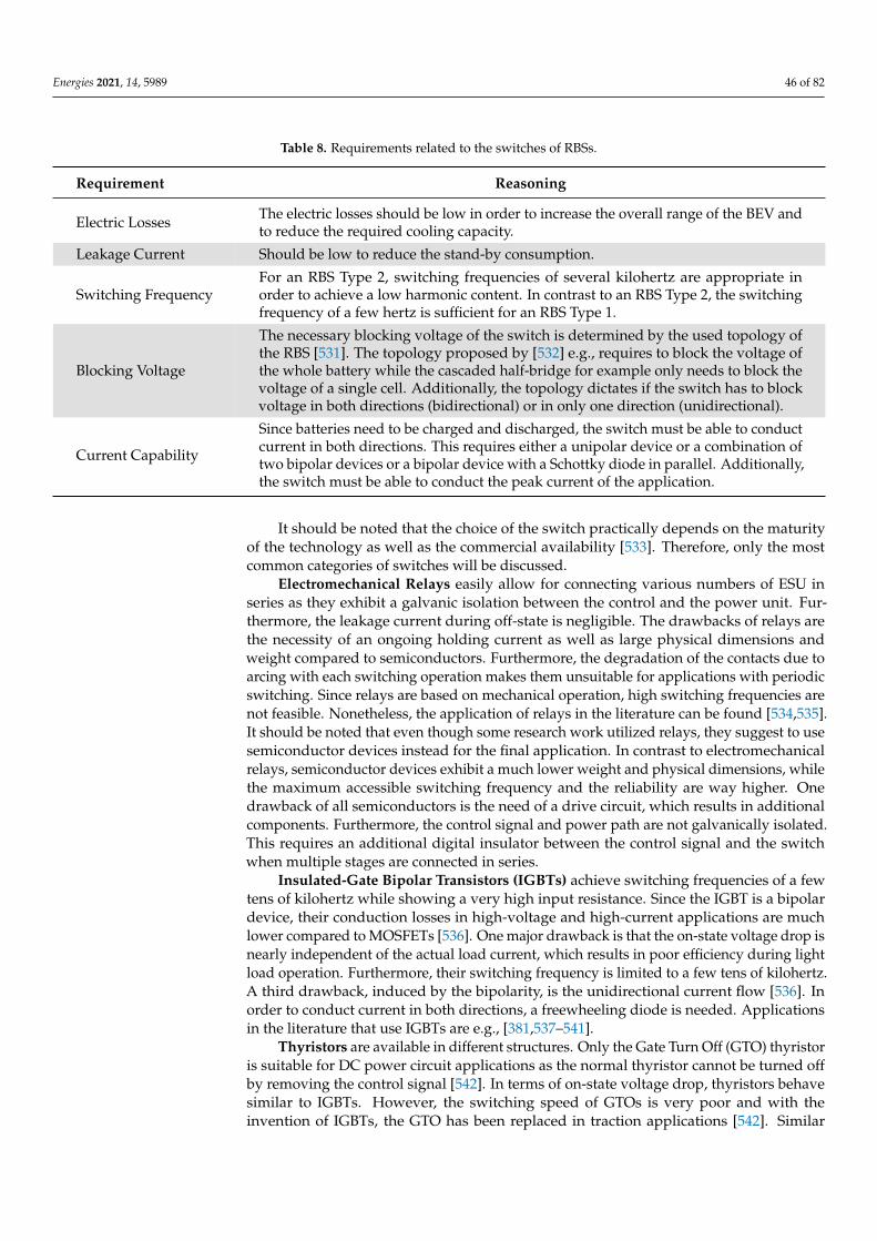
Energies 2021, 14, 5989 46 of 82
Table 8. Requirements related to the switches of RBSs.
Requirement Reasoning
Electric Losses The electric losses should be low in order to increase the overall range of the BEV andto reduce the required cooling capacity.
Leakage Current Should be low to reduce the stand-by consumption.
Switching FrequencyFor an RBS Type 2, switching frequencies of several kilohertz are appropriate inorder to achieve a low harmonic content. In contrast to an RBS Type 2, the switchingfrequency of a few hertz is sufficient for an RBS Type 1.
Blocking Voltage
The necessary blocking voltage of the switch is determined by the used topology ofthe RBS [531]. The topology proposed by [532] e.g., requires to block the voltage ofthe whole battery while the cascaded half-bridge for example only needs to block thevoltage of a single cell. Additionally, the topology dictates if the switch has to blockvoltage in both directions (bidirectional) or in only one direction (unidirectional).
Current Capability
Since batteries need to be charged and discharged, the switch must be able to conductcurrent in both directions. This requires either a unipolar device or a combination oftwo bipolar devices or a bipolar device with a Schottky diode in parallel. Additionally,the switch must be able to conduct the peak current of the application.
It should be noted that the choice of the switch practically depends on the maturityof the technology as well as the commercial availability [533]. Therefore, only the mostcommon categories of switches will be discussed.
Electromechanical Relays easily allow for connecting various numbers of ESU inseries as they exhibit a galvanic isolation between the control and the power unit. Fur-thermore, the leakage current during off-state is negligible. The drawbacks of relays arethe necessity of an ongoing holding current as well as large physical dimensions andweight compared to semiconductors. Furthermore, the degradation of the contacts due toarcing with each switching operation makes them unsuitable for applications with periodicswitching. Since relays are based on mechanical operation, high switching frequencies arenot feasible. Nonetheless, the application of relays in the literature can be found [534,535].It should be noted that even though some research work utilized relays, they suggest to usesemiconductor devices instead for the final application. In contrast to electromechanicalrelays, semiconductor devices exhibit a much lower weight and physical dimensions, whilethe maximum accessible switching frequency and the reliability are way higher. Onedrawback of all semiconductors is the need of a drive circuit, which results in additionalcomponents. Furthermore, the control signal and power path are not galvanically isolated.This requires an additional digital insulator between the control signal and the switchwhen multiple stages are connected in series.
Insulated-Gate Bipolar Transistors (IGBTs) achieve switching frequencies of a fewtens of kilohertz while showing a very high input resistance. Since the IGBT is a bipolardevice, their conduction losses in high-voltage and high-current applications are muchlower compared to MOSFETs [536]. One major drawback is that the on-state voltage drop isnearly independent of the actual load current, which results in poor efficiency during lightload operation. Furthermore, their switching frequency is limited to a few tens of kilohertz.A third drawback, induced by the bipolarity, is the unidirectional current flow [536]. Inorder to conduct current in both directions, a freewheeling diode is needed. Applicationsin the literature that use IGBTs are e.g., [381,537–541].
Thyristors are available in different structures. Only the Gate Turn Off (GTO) thyristoris suitable for DC power circuit applications as the normal thyristor cannot be turned offby removing the control signal [542]. In terms of on-state voltage drop, thyristors behavesimilar to IGBTs. However, the switching speed of GTOs is very poor and with theinvention of IGBTs, the GTO has been replaced in traction applications [542]. Similar

Energies 2021, 14, 5989 47 of 82
to the IGBT, it conducts current only in a forward direction and blocks voltage in bothdirections [536].
Metal-Oxide-Semiconductor Field-Effect Transistors (MOSFETs) achieves high switch-ing speed capability of several hundreds of kilohertz in power applications and have anextremely high input resistance. The on-state voltage drop rises linearly with the load current,thus creating a better efficiency at light load operation than IGBTs. On the contrary, theresistance rises strongly with higher blocking voltage [542] making the technology unsuitablefor applications with an operating voltage beyond a few hundred volts. MOSFETs blockvoltage in only one direction which makes them suitable for DC applications. Furthermore, itcan conduct current in both forward and reverse directions [536]. Therefore, MOSFETs arewidely used for IBS-functionalities in the literature [371,375,377,379,380,400,401,441,442,456,460,463,529–531,543–551].
Rößler [528] compares thyristors, IGBTs, MOSFETs as well as relays and concludesthat thyristors can be excluded for usage in RBSs. According to the author, IGBTs can beused at the cost of poor efficiency and higher cooling effort during light load, whereasMOSFETs is the most promising device especially for low voltage applications wheretheir on-state resistance outperforms any other semiconductor device. Additionally, thepossibility of conducting current in both directions without the need of an additionalfreewheeling diode makes a MOSFET the ideal choice.
Apart from the research work, industrial solutions related to RBSs and MLIs in vehiclesare seldom. Drivetek from Switzerland offers an MLI solution based on IGBTs [552]. Theirflying capacitor MLI can generate five output levels. Thus, the voltage step size is largeenough so that IGBTs are justified.
5.2. Architecture of the Battery Management System
The Battery Management System (BMS) is an essential component and is responsiblefor the safe operation of the battery system. This results in several tasks, from which themost important ones are listed in Table 9.
Table 9. Requirements for the BMS based on [1,553–557].
Requirement Reasoning
Cell Monitoring To keep the battery cells in a save state, parameters like the cell voltages, temperatures, andcurrents have to be monitored [558].
Battery Safety andProtection
No battery cell in the pack may exceed a safety critical limit regarding voltage and tempera-ture [558].
Estimation of SOC,SOH, and SOF
SOC, SOH, and SOF are important indicators of battery systems and serve as basis forfunctionalities like range prediction, balancing, etc. [554].
Ensure the Isolation The BMS must guarantee the isolation between the HV and the rest of the vehicle.
Balancing To increase the total usable capacity of the battery pack, charge imbalances between serialcells must be compensated [554,559].
Charge Control The batteries have limitations for the charge current. They have to be considered during thecharging process. Advanced charging strategies (e.g., pulse charging) may be applied.
Thermal Management For safety reason, but also to increase the efficiency, the battery must be operated in anoptimal temperature range. For this purpose, it can be cooled as well as heated.
Communication withthe Car
The BMS is responsible for sharing important parameters like the SOC of the battery withthe other vehicle’s components. Furthermore, power requirements of the drive train arereceived.
Open Main Switch In emergency case or when the vehicle is parked the BMS opens the main switch.
Control RBS switchesA significant number of switches are controlled to reconfigure the ESUs. Depending onthe RBS type and its functionality, the switching operation must be performed with highsynchronicity.
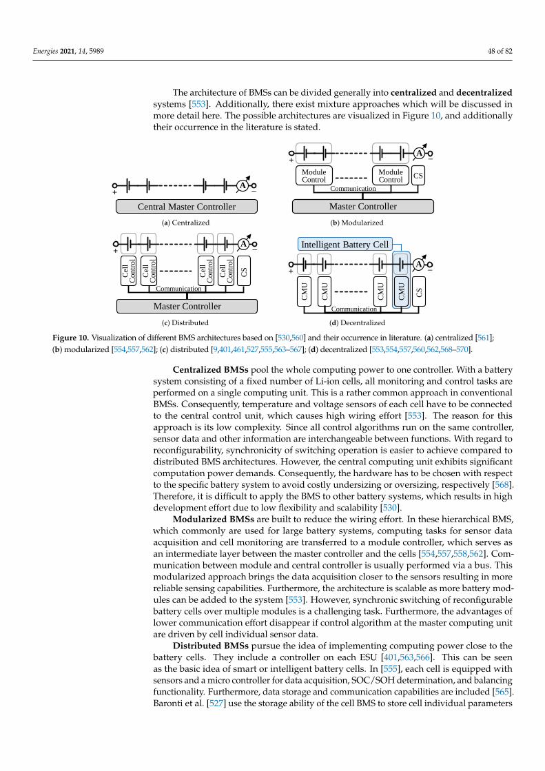
Energies 2021, 14, 5989 48 of 82
The architecture of BMSs can be divided generally into centralized and decentralizedsystems [553]. Additionally, there exist mixture approaches which will be discussed inmore detail here. The possible architectures are visualized in Figure 10, and additionallytheir occurrence in the literature is stated.
Central Master Controller
+ –A
Master Controller
Module Control
Module Control
CS
Communication
+ –A
(a) Centralized (b) Modularized
Master Controller
Cel
l C
ontr
ol
CS
Cel
l C
ontr
ol
Cel
l C
ontr
ol
Cel
l C
ontr
ol
Communication
+ –A
CM
U
CS
CM
U
CM
U
CM
U
Communication
Intelligent Battery Cell
+ –A
(c) Distributed (d) Decentralized
Figure 10. Visualization of different BMS architectures based on [530,560] and their occurrence in literature. (a) centralized [561];(b) modularized [554,557,562]; (c) distributed [9,401,461,527,555,563–567]; (d) decentralized [553,554,557,560,562,568–570].
Centralized BMSs pool the whole computing power to one controller. With a batterysystem consisting of a fixed number of Li-ion cells, all monitoring and control tasks areperformed on a single computing unit. This is a rather common approach in conventionalBMSs. Consequently, temperature and voltage sensors of each cell have to be connectedto the central control unit, which causes high wiring effort [553]. The reason for thisapproach is its low complexity. Since all control algorithms run on the same controller,sensor data and other information are interchangeable between functions. With regard toreconfigurability, synchronicity of switching operation is easier to achieve compared todistributed BMS architectures. However, the central computing unit exhibits significantcomputation power demands. Consequently, the hardware has to be chosen with respectto the specific battery system to avoid costly undersizing or oversizing, respectively [568].Therefore, it is difficult to apply the BMS to other battery systems, which results in highdevelopment effort due to low flexibility and scalability [530].
Modularized BMSs are built to reduce the wiring effort. In these hierarchical BMS,which commonly are used for large battery systems, computing tasks for sensor dataacquisition and cell monitoring are transferred to a module controller, which serves asan intermediate layer between the master controller and the cells [554,557,558,562]. Com-munication between module and central controller is usually performed via a bus. Thismodularized approach brings the data acquisition closer to the sensors resulting in morereliable sensing capabilities. Furthermore, the architecture is scalable as more battery mod-ules can be added to the system [553]. However, synchronic switching of reconfigurablebattery cells over multiple modules is a challenging task. Furthermore, the advantages oflower communication effort disappear if control algorithm at the master computing unitare driven by cell individual sensor data.
Distributed BMSs pursue the idea of implementing computing power close to thebattery cells. They include a controller on each ESU [401,563,566]. This can be seenas the basic idea of smart or intelligent battery cells. In [555], each cell is equipped withsensors and a micro controller for data acquisition, SOC/SOH determination, and balancingfunctionality. Furthermore, data storage and communication capabilities are included [565].Baronti et al. [527] use the storage ability of the cell BMS to store cell individual parameters

Energies 2021, 14, 5989 49 of 82
over lifetime. A similar approach is proposed by Lorentz et al. [564]. It enables the usageof the cells for second life application because the aging and corresponding parameterchanges can be tracked even if the battery pack is disassembled [530]. Li et al. [561]introduce a distributed battery system with active balancing, where the functionality isimplemented on cell level. However, a central BMS controller is still provided for taskthat are implemented on system level [567]. Communication between cell and centralcontroller is commonly realized by a bus [461]. Distributed BMSs feature a fast responsetime for cell functionality, which is advantageous for switching operation of RBS, whilethe data rate of the communication to the master controller is kept low. Furthermore, themeasurement accuracy is improved by shorter connection wires and increased interferenceimmunity [553]. Algorithms that are focusing on the individual cell (e.g., SOC and SOHestimation, safety monitoring, etc.) are implemented on the cell controller, which reducesthe computational power requirements of the central BMS Thereby, an energy-efficientBMS can be realized [461]. Though, the information available on system level is limitedbecause raw sensor data are not transferred to the central controller. Consequently, thesystem algorithms have to deal with reduced input data. Depending on the application, thenumber of cells in the battery pack can vary, with negligible adjustment of the architecture.
Decentralized BMSs, in contrast, consist of a multitude of identical intelligent batterycells [568]. In this case, no master controller exists as the individual intelligent cells takeover all monitoring and control task of the BMS. However, considering that the smartbattery cells exchange information with each other, this can lead to an excessive bus load.Consequently, communication has to be limited to a certain degree. With fragmentaryinformation, optimal control is hard to achieve. For decentralized BMSs, the type ofalgorithms completely differs from central architectures [530,569]. System functions likebalancing or MLI must be solved in collaboration. Many research questions regarding“concepts of self-organization and collaborative system-level” functionality [568] in batterysystems are still unanswered [553]. However, according to Steinhorst et al. [530] and Frostet al. [570], algorithms for active cell balancing are implementable in an efficient mannerwith such an architecture. Decentralized BMSs surpass central approaches regardingscalability [560,568] because additional cells can be added to the pack with ease, and allcell controller are built in the same way. However, difficulties arise about the connection toother parts of the vehicle as no central communication interface towards the vehicle exists.Decentralized architectures are regarded as robust and reliable because the control andmonitoring functions are not relying on specific components which might fail. However,this assumption holds true only in case faulty cells are safely bypassed and cannot damagethe rest of the system. Otherwise, the whole battery pack must be disconnected for safetyreasons. Therefore, the BBM has to comprise the Li-ion cell itself as well as its correspondingcomputing power.
To conclude, in today’s research regarding IBSs, the trend towards distributed anddecentralized BMS architectures is clearly visible. With sensors directly mounted to eachLi-ion cell, it is an obvious outgrowth to move computing power for cell monitoring onthis level too. Further advantages are the increased scalability and reliability comparedto centralized architectures. However, whereas simple operation strategies for e.g., ac-tive balancing can be implemented in a decentralized manner, other functionalities stillrequire control of a central master controller. This is true especially for MLI operation,where synchronization of the switching actions is important. With regard to a cost- andenergy-efficient solution, the best allocation of computing power is an optimization prob-lem that depends significantly on the specific application. This still remains an openresearch question.
5.3. Communication in Intelligent Battery Systems
Communication of the BMS and among the cells is a major and important element ofthe application of IBSs with distributed or decentralized architectures. The latter requireconsideration of communication latencies in order to enable real-time capable realization

Energies 2021, 14, 5989 50 of 82
of the features presented in Sections 2 and 3. The quality of some algorithms depend ontheir cycle time, requiring a high sensor data throughput. MLIs and HBSSs also requirelow latency for the current control algorithm to achieve a high efficiency of the engine.Unfortunately, most of the literature on the BMS communication do not compare theirapproaches neither to other solutions nor to the state of the art with regard to metrics likethe bitrate, bit error rate, costs, weight, or determinism. Usually, prior literature lack ofrequirements, communication matrices and measurements under realistic environmentand higher number of nodes. Most of the researchers demonstrate the feasibility of theirapproaches with just a few nodes, whereas BEV may consist of hundreds of nodes with dis-tributed or decentralized architectures. These deficiencies impede a qualitative comparisonof the communication systems presented in the literature. Most important requirementsregarding the communication are:
• Reliability, due to the high safety requirements.• Determinism and real-time capability, especially for safety critical data.• Synchronization, in order to enable synchronous switching in RBSs [571] and to
increase the quality of measured data [572]• Bit rate, which depends on the number of cells, the amount of data to be exchanged
per cell and the necessary data update rate of the system.• Scalability, in order to enable cheap and easy adaption for different vehicles and
vehicle variants.• Security, as the network is a common entry door for hackers.
Reliability and real-time capability are very important for the application in vehicles,since most of the BMS functions are assessed as Automotive Safety Integrity Level (ASIL) [573]C or D [574] and therefore have to meet strict safety and timing requirements. These pointsare probably much more important than scalability, as the number of cells in a car is normallyfixed. Requirements on the communication further depend on features of the IBS. If cells canbe bypassed through switches and, thus, can enter safe states, the criticality of communicationlosses to individual nodes can be reduced [568] and therefore also the significance of a reliablecommunication. Furthermore, number and type of sensors strongly influence the necessarybit rate. If the data of current sensors on cell level or the impedance results of EIS must beexchanged, the required bit rate can be significantly higher.
Wired bus topologies are the state-of-the art of BMS communication. However, com-pared to wireless solutions, complex wiring of more than a hundred nodes leads to difficultyin automated manufacturing [575] (higher production costs), limited flexibility and scala-bility [576] as well as heavier and larger battery packs [577]. The communication interfacemust be isolated due to the different voltage levels of serially connected cells [575]. De-pending on the maximum voltage difference, this has to be considered for the selection ofcomponents and isolation space [9]. The wiring is a potential error source, affecting thereliability in BEVs. Vibrations can lead to physical failure of cables and connectors [575,576].According to car manufacturers and suppliers, the key failure modes of vehicles are issueswith wiring harnesses and connectors [572].
Isolated differential daisy chain connections are usually used with cell monitoringchips such as [578–580]. If the nodes are connected into a ring topology and can forwarddata in both directions, the system’s reliability can be significantly increased through faulttolerance to cable breaks [578,579]. Daisy chain is only rarely found in the literature relatedto BMS communication. In [581], a master–slave network with serially connected Cell Man-agement Units (CMUs) is implemented with isolated Universal Asynchronous ReceiverTransmitter (UART). Ring topologies are more likely used for MLI applications [582,583].EtherCAT is often used due to its exact synchronization feature and to achieve ideal switch-ing precision of ±20 ns. Applying MCUs with integrated EtherCAT in combination withautomotive Ethernet [584] is not present in literature, but seems very promising for RBSs,as it is deterministic, requires only two cables, and reaches bit rates up to 100 Mbit/s.
Isolated bus topologies are commonly used for wired intra-battery communication. State-of-the-art BMSs usually use isolated Controller Area Networks (CANs) [554,560,568,585,586].

Energies 2021, 14, 5989 51 of 82
Brandl et al. [554] present galvanic isolation concepts for BMS communication. CAN isvery robust, widely used in the automotive industry, cheap, and real-time capable due toits multi-master prioritization and collision resolution scheme [587]. The message filterfeature is useful to address individual cells with broadcast communication and to reducecomputational load on all other nodes. However, Alonso et al. [588] criticize the poordata rate of ordinary CAN of just 1 Mbit/s. The automotive industry has come up withsolutions to that problem. CAN-FD (Flexible Data rate) supports bit rates up to 5 Mbit/s.The upcoming CAN-XL [589] technology from Bosch even features up to 10 Mbit/s. Fur-thermore, the necessary throughput can be achieved by partitioning Module ManagementUnits (MMUs)/CMUs into separate networks, as long as a distributed master slave topol-ogy is applied. Future works on optical CAN and CAN in combination with Ethernet arerecommended by Reindl et al. [553]. For the latter case, CAN-XL sounds promising, since itsupports up to 2048 B payload per frame, enabling IP-based protocols [589]. An I2C bus isshown in [561] and a UART bus is presented in [590]. Both solutions support master–slavecommunication. However, these communication systems are much less robust comparedto CAN [587]. A novel bidirectional technology based on galvanically isolated, capacitivecoupled, differential bus with Frequency Shift Keying (FSK) is presented in [9,563,564]. Theauthors analyzed the communication between up to 100 ESUs. The major advantage oftheir approach is that isolated contacts and connectors are unnecessary. In order to reducethe number of wires, Zhang et al. [565] propose a novel approach that uses the wiringbetween the pack managing unit and the CMUs for both power and time division multi-plexed data transmission. EMI issues may occur for high numbers of nodes. Unfortunately,literature lacks of measurements on how many nodes can be connected to the same bus,while keeping the communication reliable. This plays an important role for the costs andthe network architecture of IBSs.
Power Line Communication (PLC) in EVs utilizes the battery’s HV power path asthe physical medium to exchange data using coupler circuits. The major benefit comparedto standard wired solutions is the reduction of the wiring. Saleem et al. [591] presenta BMS with UART over power line with FSK, but the validation comprises only threenodes. Saidani et al. [592] developed a new PLC concept where an AC current source inparallel to the cell is used instead of an inductive or capacitive isolator. Unfortunately, thecell impedance is too small to obtain the necessary amplitude. Using Rogowski coils ascoupling elements for PLC, in order to avoid saturation effects of iron-core couplers athigh current spikes, is proposed by Opako et al. [593]. The high noise due to invertersand DC/DC converters on the medium is an important issue of PLC [563]. A simulativeexamination of the physical layer of PLC in EVs is published by Ouannes et al. [594]. Theauthors modeled a battery with 100 cells and analyzed several modulation schemes withoutconsidering noise from the power electronics. Their results show that the attenuation ofthe master signal strongly depends on the cell’s location as the signal propagates throughdifferent PLC channels. Furthermore, the busbars used in battery packs do not have adefined impedance characteristic, leading to a lack of scalability and re-usability [594,595].In [594,595], the authors show that the channel transfer function varies from cell to cell.Unfortunately, it is not investigated how the cell type, cell manufacturer, and cell agingeffects influence the transfer functions of the PLC channel. To the best of our knowledge,there are no publications on PLC for RBSs. The additional switches and the varying powerpath configuration will probably reduce the reliability. MLIs may lead to less interferences,due to the lower switching voltages compared to traditional inverters. Additionally, if thepower path is interrupted by switching, the communication will probably break down.Further research is required here.
Wireless Battery Management Systems (WBMSs) are of scientific interest for IBSs asit is naturally isolated and cheap. In addition, it reduces the overall weight of the vehicledue to less wiring [572]. However, safety, availability, reliability, and security have to befulfilled [596]. Easy access to the network from outside the car is one major disadvantageof WBMS, leading to potential data theft by sniffers, communication losses due to jamming,
Energies 2021, 14, 5989 52 of 82
or malicious firmware updates [597]. Unfortunately, most presented WBMSs are not testedunder realistic environmental conditions in BEVs. The feasibility of WBMSs in batterypacks is thus not proven. Wireless communication issues comprise inference and fading,which can lead to communication losses, so it is seldom applied [565]. For the use in EVs,a deep understanding of the radio channel inside the battery is required [577], which issimulated and investigated for various battery pack parameters by Alonso et al. [598].The authors analyze different antennas for the application in intra-battery communicationin [577,588]. Their results show that the channels strongly depend on the pack’s geometryand that the distance between the antennas has a high impact on the channels’ attenuation.The impact of these parameters increases with higher signal frequencies. Constructing areliable and stable wireless link inside an EV battery pack is very complex and inflexiblewhich contradicts the advantages of WBMS promised by various publications. However,the usage in other applications like smart grids and ESS might be more promising. TheWBMSs presented in the literature use different wireless technologies like ZigBee [599,600],Bluetooth [601], and Wi-Fi [571,602]. An approach where the CMU is integrated inside thecell is proposed by Schneider et al. [566]. Kumtachi et al. [603] suggest a multi-hop forward-ing technique based on over-hearing, useful for large scale IBS in smart grids. An Internetof Things (IoT)-based decentralized WBMS architecture is shown by Faika et al. [604]. Un-fortunately, the average data aggregation time is over 5 s for only five nodes. This isobviously too long for safe application in BMSs, where battery data update rates of 10 Hzare common [572]. Poor real-time capability is also shown by Lafrenz et al. [571] witha WiFi-based WBMS for RBSs. Their measurements show high jitter on the sensor dataresponse time. Lee et al. [575] present a promising master-slave WBMS that can manageup to 780 slave nodes with update rates of 10 Hz. It applies Amplitude Shift Keying (ASK)or FSK modulation for 1 Mbit/s. A contribution by Navitas Solutions Inc. [605] shows thatthe bitrate already increased to 2 Mbit/s for up to 640 nodes, communicating tempera-ture and voltage data. Various semiconductor manufacturers work on integrated WBMSsolutions. Linear Technology has presented the first WBMS in a BMW i3 concept car in2016 [606]. General Motors announced to use Analog Devices WBMSs for its automotiveUltium battery platform with the aim to save up to 90 % of the wiring and up to 15 % ofthe battery pack’s volume [607].
It is difficult to determine a specific technology as the best for communication in IBSs.Literature for this topic lacks comparability and realistic conditions, especially with respectto the number of nodes. Wireless communication offers promising advantages but requiresa deep understanding of the radio channel. Focusing on MLIs and their requirements onhigh data throughput, real-time capability, and time synchronous switching, EtherCAT ishighly recommendable due to the very precise synchronization, determinism, and highdata rate of the technology. Another option is the upcoming CAN-XL, as CAN is veryreliable, cheap, and common in the automotive world. CAN-XL further improves CANnetworks considering data-rate and payload length. This solution is promising for RBSswith a lower real-time demand compared to MLIs.
5.4. Further Implications of Reconfiguration
At this point, further aspects are addressed that are commonly overseen in applicationof RBSs. Operating physical in contrast to ideal switches implies additional heat in thesystem and influence on the cell chemistry, but these topics are seldom discussed. Further-more, the influence of high-frequency switching on lifetime of the cells and efficiencyof RBSs is an important topic to guarantee the reliability in an industrial application andjustify their application.
5.4.1. Thermal Influence and Interaction in Reconfigurable Battery Systems
The main influence for the thermal behavior of battery modules and systems is thelocal heat generation of cells in combination with the cooling system strategy. In IBS,additional electronic components are utilized at a cell level that generate additional heat

Energies 2021, 14, 5989 53 of 82
during use [386,608]. Identifying the heat generating components, mainly sensing (e.g.,CSRs) and switching components in the current path generate power losses [377,609]. Thefact that an intelligent battery system in any case has an increased heat generation is rarelyreported and investigated in the literature. It is stated in the context of the number ofswitches that an increasing number of switches improves the configuration flexibility butincreases the power dissipation [373]. In another work, the thermal influence is stated tobe negligible [529]. However, in a recent publication, Kleiner et al. [609] investigated theinfluence of reconfigurable hardware on prismatic cells and found a significant influence onthe cell’s core temperature. In their follow up work, the authors match the IBS hardware tothe automotive application and report a temperature increase of approximately 1 K due tothe power dissipation of the electronics [608]. Thereby, the thermal influence of electronicscan be reduced with suitable approaches, but it must not be neglected.
Regarding the thermal modeling of IBS, the consequent approach is to considerthe electronics’ influence in the model-based estimation of the core temperature. Withthe electronics influencing the cell’s thermal behavior, the influences need to either berepresented in the model or to be included in the dataset of solely data-driven approaches.
5.4.2. Influence of Switching on Cell Lifetime
During the application in RBS Type 2, such as MLIs, the cells are switched on and offup to the kHz range. The data base for answering the question on the influence of switch-ing on cell aging is limited as there is a high variety of potential current profiles (waveform,duty cycle, frequency, C-Rate, etc.) and ambient temperature profile. Even for an explicitaging pattern, it is not straight forward to define the appropriate constant current refer-ence test as, e.g., a lower duty cycle increases the test time, reduces the average current,and decreases the temperature rise caused by resistive heat. Therefore, it is not possible tokeep all parameters such as average current, maximum current, test time, and cell temper-ature constant. This makes a comparison of MLIs and reference tests challenging. Thesefundamental issues of the optimal test design are one explanation for the contradictoryconclusions in the various publications on the topic.
The influence on the lifetime of Li-ion batteries for MLI comparable applications,with rectangular waveforms up to the kHz range, is investigated in only two publicationsthat are known to us [610,611]. Uno et al. [611] tested 24 cells with 2 Ah capacity eachand a current of ±1 A for a high-frequency balancer application that is comparable toMLIs. Varying the frequency from 1 Hz to 100 kHz, the authors conclude from the results ahigher capacity fade during switching for frequencies below 10 Hz. However, applyingswitching procedures in the range of 100 Hz to 100 kHz, no significant aging in comparisonto calendar life tests is obtained. This was explained by the influence of micro cyclesat low frequencies while at higher frequencies only the double layer capacitances of theelectrodes are cycled. Chang et al. [610] investigate the MLI application explicitly for aCHB at 2 kHz and 10 kHz. The results for five 3 Ah cells show no dependence on frequencyand power factor on capacity fade, but a 2 % lower capacity compared to reference cellswith the same average C-rate. Smaller deviations could be explainable by an unintendedtest pause leading to anode overhang effects that have nearly compensated by the end ofthe test [612]. The internal resistance changed comparably for all cells. In other literaturefound for DC/DC converters and fast charging, it is also reported that pulsing in the kHzrange has a negative [613], not significant [614] or positive [615] effect on aging. KorthPereira Ferraz et al. highlight for 5 kHz a slightly stronger aging for 10 % DOD while noimpact is observed for 100 % DOD cycling [616].
As a conclusion, the impact of switching remains unclear, and it is necessary to investi-gate the influence of switching on the lifetime of the cells for different aging test conditions,high power/high energy cells, and cell chemistries in the upcoming test campaign.

Energies 2021, 14, 5989 54 of 82
5.4.3. Efficient Operation of Reconfigurable Battery Systems
In addition to the many advantages offered by switches on cell level and reconfig-urability at the system level, the influence on the efficiency of the system must not beneglected. This important point is usually not considered or discussed in current publica-tions related to switches and reconfiguration. If at all, the statement is being made that theconduction loss of the used switches needs to be negligibly small to avoid to degrade theperformance and the efficiency of the system [375]. Focusing on the influence of switches,Kim et al. [377] mention three approaches to improve the efficiency:
• reduce the internal resistance of a switch by suitable components;• use multiple switches in parallel for the same functionality;• reduce the number of single switched ESUs by including multiple cells.
The latter, however, reduces the flexibility of the system. This approach of resistanceoptimization can be transferred to the other relevant components e.g., by contactless currentsensing or high-current capable hardware [608]. Nevertheless, for a meaningful evaluationof the total energy efficiency of the whole EV system, the entire power train must beconsidered and the lifetime of a vehicle must also be taken into account. The reason is thatmany advantages and possibilities of intelligent battery systems only become apparent withincreasing runtime when cells start to age, faults, and failures occur and weak cells limitthe whole system. Especially in this period, when range and performance of conventionalbattery systems decrease, IBS in their basic functions show their strengths.
Another point of view on efficiency arises when reconfigurable battery systemsfundamentally change the architecture of the power train. With MLIs and HBSSs in variousforms, conventional power electronics can be replaced. This is of decisive importance forthe overall efficiency as switching only takes place at the cell voltage level (3–5 V) in mostRBS cases. In current power electronics architectures, switching is usually performed atthe system voltage level of 400–800 V. This opens up the opportunity of using completelydifferent semiconductor components and changing the overall efficiency. Ultimately,however, efficiency can only be assessed for a specific vehicle with real components.A general evaluation of the power loss in RBSs with different topologies and levels ofmodularization is made by Zimmerman et al. [497].
Besides the electric efficiency of the hardware, the well-designed combination ofBMS functionality is relevant due to contrary operation strategies influencing each other.For example, a balancing procedure with respect to SOC homogeneity always changesthe cells’ temperature and aging coincidently. When switching procedures are necessaryfor fault detection, EIS excitation, balancing, and MLI procedures simultaneously, a well-coordinated control and regulation software in the BMS is indispensable.
Consequently, a focus of future research must be on finding operation strategies thatcombine the discussed functionalities. This is regarded as a multi-objective optimizationproblem. Thereby, the individual requirements of the advanced sensing functionalities aswell as the approaches based on reconfiguration must be intelligently combined with eachother to form a holistic IBS.
6. Summary, Conclusions, and Outline
Intelligent Battery Systems (IBSs), as a new technological advancement, represent apromising but also a challenging approach to significantly improve the reliability, safety,and efficiency of Battery Electric Vehicles (BEVs). Within this review, the functionalitiesof IBSs and the prerequisites for their implementation in BEVs have been discussed. Con-sidering the reviewed scientific literature on the functionalities of IBSs, we conclude that,as an emerging technology, IBSs are in a rather early development stage and substantialimprovement has to be achieved until a phase of technological maturity is reached.
In this regard, IBSs are a versatile area of research due to their prosperity of availablesensor data and manifold control levers. Thereby, intelligent methods can be incorporatedin many applications such as continuous adaptive control, aging adaptation, online param-eter, and state estimation. In addition to vital operating parameters of individual cells, a

Energies 2021, 14, 5989 55 of 82
reliable detection and localization of faults is also achievable. Therefore, the goal of futureresearch related to fault diagnosis must be to bundle the detection of several different errorsin a unified fault diagnosis function. Furthermore, in contrast to the well-established Stateof Charge determination, the existing State of Health monitoring functions must alwaysadapt to the ongoing development of chemical compositions for lithium-ion batteries. Thisis a general challenge of battery systems. In the context of IBSs, it is an attractive option touse on-board Electrochemical Impedance Spectroscopy for monitoring the aging behavior.However, the hardware implementation for measuring the impedance in a BEV has notbeen solved yet. In the area of temperature estimation, a major step has already beentaken with cell-specific temperature measurement using cell-dedicated hardware. Fromthe economic point of view, algorithm- and model-based approaches for cell temperatureestimation seem to be more attractive solutions than cell integrated temperature sensorsat present. In general, the realization of IBSs with advanced sensing imposes severe re-quirements on size, cost, and energy consumption, which is only partly solved by today’scommercial sensor technology. Therefore, further research and development regardingsimple and yet reliable sensors is encouraged.
With the incorporation of cell individual actuators (switches) into an IBS, a new degreeof freedom for optimal and efficient operation is introduced. The resulting ReconfigurableBattery System is a mechatronic system, where intelligent operation strategies can be appliedbased on sensor data, advanced diagnosis, and overall energy demand. Simple topologies,such as half bridges, already enable basic functionalities such as Bad-Block-Managementand balancing. However, when it comes to advanced reconfiguration applications such asMultilevel Inverters (MLIs) or Hybrid Battery Storage Systems, more complex topologies arefavorable. The large number of emerging topologies suggests that a detailed analysis of thespecific use case is required to be able to find the optimal micro- and macrotopology. Forexample, if an IBS enables AC output voltage by MLI functionality, external power electronicscan be omitted. This in turn requires a topology that enables variable system voltage levels.However, the number of switches in the load path increases costs, losses, and the probabilityof failure. Moreover, the chosen topology directly affects the thermal interactions as wellas the efficiency of the system. Therefore, appropriate semiconductor devices are requiredto replace the system level power electronics. In addition, the high frequency applicationof switching for MLIs requires a suited Battery Management System and communicationarchitecture. In addition, finally, all algorithms and functionalities that are based on switchingprocedures must be coordinated for a functional operation strategy.
Despite the existing challenges, IBSs have the potential to significantly improve thebattery systems of Electric Vehicles and provide sophisticated solutions to the many lim-itations and issues encountered with conventional battery systems. The next importantstep, besides the continuous development of the individual functionalities of advancedmonitoring and Reconfigurable Battery Systems, is to examine the mutual effects of themany functionalities described in the literature to form a holistic concept of IntelligentBattery Systems for future generations of Electric Vehicles.
Supplementary Materials: The following are available online at https://www.mdpi.com/article/10.3390/en14185989/s1, Table S1: Overview of investigated publications regarding online EIS, part Iof II: Excitation and Signal Acquisition; Table S2: Overview of investigated publications regardingonline EIS, part II of II: Evaluation and Setup.
Author Contributions: Conceptualization, L.K., J.K. and D.S.; Methodology, L.K., J.K. and D.S.;Writing—original draft preparation, L.K., T.B., S.D., M.E., C.H. (Christian Hanzl), C.H. (ChristophHartmann), M.H. (Markus Hölzle), J.K., M.L., B.L., M.S., D.S., S.S., J.S. and C.T.; Writing—reviewand editing, L.K., T.B., S.D., M.E., C.H. (Christian Hanzl), C.H. (Christoph Hartmann), M.H. (MarkusHölzle), J.K., M.L., B.L., M.S., D.S., S.S., J.S., C.T., M.H. (Michael Hinterberger) and C.E.; Visualization,M.H. (Markus Hölzle) and J.K.; Supervision, L.K., M.H. (Michael Hinterberger), and C.E.; Projectadministration, L.K., M.H. (Michael Hinterberger), and C.E. All authors have read and agreed to thepublished version of the manuscript.

Energies 2021, 14, 5989 56 of 82
Funding: This research was funded by AUDI AG, 85057 Ingolstadt, Germany.
Acknowledgments: The authors express their gratitude to AUDI AG for their support over the pastyears and the good cooperation.
Conflicts of Interest: The authors declare no conflict of interest.
AbbreviationsThe following abbreviations are used in this manuscript:
AFE Analog Front End
ANN Artificial Neural Network
ASK Amplitude Shift Keying
BBM Bad-Block-Management
BEV Battery Electric Vehicle
BMS Battery Management System
BPF Bandpass Filter
CAN Controller Area Network
CCCT Constant Current Charging Time
CHB Cascaded H-Bridge
CMU Cell Management Unit
CPSD Cross Power Spectral Density
CVCT Constant Voltage Charging Time
CSR Current Sense Resistor
DFT Discrete Fourier Transformation
DKF Dual Kalman Filter
DOD Depth of Discharge
DVA Differential Voltage Analysis
ECM Equivalent Circuit Model
ECIN Enhanced Commutation Integrated Nested
ESC External Short Circuit
EIS Electrochemical Impedance Spectroscopy
EKF Extended Kalman Filter
EMI Electromagnetic Interference
ESU Energy Storage Unit
ESS Energy Storage System
EV Electric Vehicle
FBG Fiber Bragg Grating Sensor
FC Flying Capacitor
FSK Frequency Shift Keying
GA Genetic Algorithm
GPR Gaussian Process Regression
GTO Gate Turn Off
HBSS Hybrid Battery Storage System
HPF High Pass Filter
HPPC Hybrid Pulse Power Characterization
IBS Intelligent Battery System

Energies 2021, 14, 5989 57 of 82
ICA Incremental Capacity Analysis
ISC Internal Short Circuit
IGBT Insulated-Gate Bipolar Transistor
IoT Internet of Things
KF Kalman Filter
LAM Loss of Active Material
LCO Lithium Cobalt Oxide
Li-ion lithium-ion
LFP Lithium Iron Phosphate
LLI Loss of Lithium Inventory
LMO Lithium Manganese Oxide
LPF Lowpass Filter
MC Multi-Carrier
MCU Microcontroller Unit
MLI Multilevel Inverter
MOSFET Metal-Oxide-Semiconductor Field-Effect Transistor
MMC Modular Multilevel Converter
MMU Module Management Unit
NCA Lithium Nickel Cobalt Aluminum Oxide
NLC Nearest Level Control
NMC Lithium Nickel Manganese Cobalt Oxide
NPC Neutral Point Clamped
NPS Neutral Point Shift
NTC Negative Thermal Coefficient
OCV Open Circuit Voltage
PECIN Parallel Enhanced Commutation Integrated Nested
PF Particle Filter
PLC Power Line Communication
PSD Power Spectral Density
PSO Particle Swarm Optimization
PWM Pulse Width Modulation
RBS Reconfigurable Battery System
RLS Recursive Least Squares
RTD Resistance Temperature Detector
SEI Solid Electrolyte Interphase
SHE Selective Harmonic Elimination
SOC State of Charge
SOF State of Function
SOH State of Health
SOP State of Performance
SPM Single Particle Model
SPWM Sinusoidal Pulse Width Modulation
SVC Space Vector Control
SVM Space Vector Modulation

Energies 2021, 14, 5989 58 of 82
SVPWM Space Vector Pulse Width Modulation
SVR Support Vector Regression
TECM Thermal Equivalent Circuit Model
TOF Time-of-Flight
THD Total Harmonic Distortion
UART Universal Asynchronous Receiver Transmitter
UKF Unscented Kalman Filter
WBMS Wireless Battery Management System
WTLS Weighted Total Least Squares
References1. Lu, L.; Han, X.; Li, J.; Hua, J.; Ouyang, M. A review on the key issues for lithium-ion battery management in electric vehicles.
J. Power Sources 2013, 226, 272–288. [CrossRef]2. Liu, X.; Ai, W.; Naylor Marlow, M.; Patel, Y.; Wu, B. The effect of cell-to-cell variations and thermal gradients on the performance
and degradation of lithium-ion battery packs. Appl. Energy 2019, 248, 489–499. [CrossRef]3. Campestrini, C.; Keil, P.; Schuster, S.F.; Jossen, A. Ageing of lithium-ion battery modules with dissipative balancing compared
with single-cell ageing. J. Energy Storage 2016, 6, 142–152. [CrossRef]4. Rumpf, K.; Rheinfeld, A.; Schindler, M.; Keil, J.; Schua, T.; Jossen, A. Influence of Cell-to-Cell Variations on the Inhomogeneity of
Lithium-Ion Battery Modules. J. Electrochem. Soc. 2018, 165, A2587–A2607. [CrossRef]5. Hosseinzadeh, E.; Arias, S.; Krishna, M.; Worwood, D.; Barai, A.; Widanalage, D.; Marco, J. Quantifying cell-to-cell variations of a
parallel battery module for different pack configurations. Appl. Energy 2021, 282, 115859. [CrossRef]6. Paul, S.; Diegelmann, C.; Kabza, H.; Tillmetz, W. Analysis of ageing inhomogeneities in lithium-ion battery systems. J. Power
Sources 2013, 239, 642–650. [CrossRef]7. Saidani, F.; Hutter, F.X.; Selinger, W.; Yu, Z.; Burghartz, J.N. A lithium-ion battery demonstrator for HEV applications featuring a
smart system at cell level. In Proceedings of the 2017 IEEE International Systems Engineering Symposium (ISSE), Vienna, Austria,11–13 October 2017; pp. 1–5. [CrossRef]
8. Schneider, D.; Liebhart, B.; Endisch, C. Active state and parameter estimation as part of intelligent battery systems. J. EnergyStorage 2021, 39, 102638. [CrossRef]
9. Lorentz, V.; Wenger, M.; Giegerich, M.; Zeltner, S.; März, M.; Frey, L. Smart Battery Cell Monitoring with Contactless Data Trans-mission. In Advanced Microsystems for Automotive Applications 2012; Meyer, G., Ed.; Springer: Berlin/Heidelberg, Germany, 2012.
10. Kim, T.; Qiao, W.; Qu, L. Series-connected reconfigurable multicell battery: A novel design towards smart batteries. In Proceed-ings of the 2010 IEEE Energy Conversion Congress and Exposition, Atlanta, GA, USA, 12–16 September 2010; pp. 4257–4263.[CrossRef]
11. Canfield, D. Smart Battery with Integrated Sensing and Electronics. U.S. Patent 20170092994 A1, 30 March 2017.12. Butzmann, S. Battery Having a Plurality of Battery Cells and Method for Regulating a Battery Voltage of a Battery Using Switchon
Probabilities of the Battery Cells. U.S. Patent 9362760 B2, 7 June 2016.13. Hinterberger, M.; Hellenthal, B. Smart Battery Cell of a Battery for a Motor Vehicle. U.S. Patent 10361466B2, 23 July 2019.14. Hinterberger, M.; Hellenthal, B. Battery Cell for a Battery of a Motor Vehicle, Battery, and Motor Vehicle. CN 107210418 B, 26
September 2017.15. Wei, Z.; Zhao, J.; He, H.; Ding, G.; Cui, H.; Liu, L. Future smart battery and management: Advanced sensing from external to
embedded multi-dimensional measurement. J. Power Sources 2021, 489, 229462. [CrossRef]16. Xia, G.; Cao, L.; Bi, G. A review on battery thermal management in electric vehicle application. J. Power Sources 2017, 367, 90–105.
[CrossRef]17. Wu, C.; Zhu, C.; Ge, Y.; Zhao, Y. A Review on Fault Mechanism and Diagnosis Approach for Li-Ion Batteries. J. Nanomater. 2015,
2015, 631263. [CrossRef]18. Shen, M.; Gao, Q. A review on battery management system from the modeling efforts to its multiapplication and integration. Int.
J. Energy Res. 2019, 43, 5042–5075. [CrossRef]19. Kim, I.S. A Technique for Estimating the State of Health of Lithium Batteries Through a Dual-Sliding-Mode Observer. IEEE Trans.
Power Electron. 2010, 25, 1013–1022. [CrossRef]20. Dixon, J.; Pereda, J.; Castillo, C.; Bosch, S. Asymmetrical Multilevel Inverter for Traction Drives Using Only One DC Supply.
IEEE Trans. Veh. Technol. 2010, 59, 3736–3743. [CrossRef]21. Waag, W.; Fleischer, C.; Sauer, D.U. Critical review of the methods for monitoring of lithium-ion batteries in electric and hybrid
vehicles. J. Power Sources 2014, 258, 321–339. [CrossRef]22. Lipu, M.H.; Hannan, M.A.; Hussain, A.; Hoque, M.M.; Ker, P.J.; Saad, M.; Ayob, A. A review of state of health and remaining
useful life estimation methods for lithium-ion battery in electric vehicles: Challenges and recommendations. J. Clean. Prod. 2018,205, 115–133. [CrossRef]

Energies 2021, 14, 5989 59 of 82
23. Ripka, P. Electric current sensors: A review. Meas. Sci. Technol. 2010, 21, 112001. [CrossRef]24. Lyu, D.; Ren, B.; Li, S. Failure modes and mechanisms for rechargeable Lithium-based batteries: A state-of-the-art review.
Acta Mech. 2019, 230, 701–727. [CrossRef]25. Tran, M.K.; Fowler, M. Sensor Fault Detection and Isolation for Degrading Lithium-Ion Batteries in Electric Vehicles Using
Parameter Estimation with Recursive Least Squares. Batteries 2020, 6, 1. [CrossRef]26. Hu, X.; Jiang, Z.; Yan, L.; Yang, G.; Xie, J.; Liu, S.; Zhang, Q.; Xiang, Y.; Min, H.; Peng, X. Real-time visualized battery health
monitoring sensor with piezoelectric/pyroelectric poly (vinylidene fluoride-trifluoroethylene) and thin film transistor array byin-situ poling. J. Power Sources 2020, 467, 228367. [CrossRef]
27. Wang, H.; Simunovic, S.; Maleki, H.; Howard, J.N.; Hallmark, J.A. Internal configuration of prismatic lithium-ion cells at theonset of mechanically induced short circuit. J. Power Sources 2016, 306, 424–430. [CrossRef]
28. Diao, W.; Xing, Y.; Saxena, S.; Pecht, M. Evaluation of Present Accelerated Temperature Testing and Modeling of Batteries. Appl.Sci. 2018, 8, 1786. [CrossRef]
29. Xiong, R.; Yu, Q.; Shen, W. Review on sensors fault diagnosis and fault-tolerant techniques for lithium ion batteries in electricvehicles. In Proceedings of the 2018 13th IEEE Conference on Industrial Electronics and Applications (ICIEA), Wuhan, China, 31May–2 June 2018; pp. 406–410. [CrossRef]
30. Yao, L.; Wang, Z.; Ma, J. Fault detection of the connection of lithium-ion power batteries based on entropy for electric vehicles. J.Power Sources 2015, 293, 548–561. [CrossRef]
31. Offer, G.J.; Yufit, V.; Howey, D.A.; Wu, B.; Brandon, N.P. Module design and fault diagnosis in electric vehicle batteries. J. PowerSources 2012, 206, 383–392. [CrossRef]
32. Schmid, M.; Gebauer, E.; Hanzl, C.; Endisch, C. Active Model-Based Fault Diagnosis in Reconfigurable Battery Systems. IEEETrans. Power Electron. 2021, 36, 2584–2597. [CrossRef]
33. Lombardi, W.; Zarudniev, M.; Lesecq, S.; Bacquet, S. Sensors fault diagnosis for a BMS. In Proceedings of the 2014 EuropeanControl Conference (ECC 2014), Strasbourg, France, 24–27 June 2014; IEEE: Piscataway, NJ, USA, 2014; pp. 952–957. [CrossRef]
34. Schmid, M.; Gebauer, E.; Endisch, C. Structural Analysis in Reconfigurable Battery Systems for Active Fault Diagnosis. IEEETrans. Power Electron. 2021, 36, 8672–8684. [CrossRef]
35. Xia, B.; Mi, C. A fault-tolerant voltage measurement method for series connected battery packs. J. Power Sources 2016, 308, 83–96.[CrossRef]
36. Xia, B.; Nguyen, T.; Yang, J.; Mi, C. The improved interleaved voltage measurement method for series connected battery packs. J.Power Sources 2016, 334, 12–22. [CrossRef]
37. Kang, Y.; Duan, B.; Zhou, Z.; Shang, Y.; Zhang, C. A multi-fault diagnostic method based on an interleaved voltage measurementtopology for series connected battery packs. J. Power Sources 2019, 417, 132–144. [CrossRef]
38. Schmid, M.; Kneidinger, H.G.; Endisch, C. Data-Driven Fault Diagnosis in Battery Systems through Cross-Cell Monitoring. IEEESens. J. 2020, 21, 1829–1837. [CrossRef]
39. Schmid, M.; Liebhart, B.; Kleiner, J.; Endisch, C.; Kennel, R. Online Detection of Soft Internal Short Circuits in Lithium-IonBattery Packs by Data-Driven Cell Voltage Monitoring. In Proceedings of the 2021 IEEE International Conference on Electricaland Electromechanical Energy Conversion (ECCE Asia), Singapore, 24–27 May 2021; pp. 1711–1718. [CrossRef]
40. Dubarry, M.; Truchot, C.; Liaw, B.Y. Cell degradation in commercial LiFePO4 cells with high-power and high-energy designs. J.Power Sources 2014, 258, 408–419. [CrossRef]
41. Dubarry, M.; Liaw, B.Y. Identify capacity fading mechanism in a commercial LiFePO4 cell. J. Power Sources 2009, 194, 541–549.[CrossRef]
42. Bloom, I.; Christophersen, J.; Gering, K. Differential voltage analyses of high-power lithium-ion cells. J. Power Sources 2005,139, 304–313. [CrossRef]
43. Singh, A.; Izadian, A.; Anwar, S. Fault diagnosis of Li-Ion batteries using multiple-model adaptive estimation. In Proceedingsof the 39th annual conference of the IEEE Industrial Electronics Societ, Vienna, Austria, 10–13 November 2013; pp. 3524–3529.[CrossRef]
44. Sidhu, A.; Izadian, A.; Anwar, S. Adaptive Nonlinear Model-Based Fault Diagnosis of Li-Ion Batteries. IEEE Trans. Ind. Electron.2015, 62, 1002–1011. [CrossRef]
45. Alavi, S.M.M.; Samadi, M.F.; Saif, M. Plating Mechanism Detection in Lithium-ion batteries, by using a particle-filtering basedestimation technique. In Proceedings of the 2013 American Control Conference (ACC 2013), Washington, DC, USA, 17–19 June2013; IEEE: Piscataway, NJ, USA, 2013; pp. 4356–4361. [CrossRef]
46. Tian, J.; Wang, Y.; Chen, Z. Sensor fault diagnosis for lithium-ion battery packs based on thermal and electrical models. Int. J.Electr. Power Energy Syst. 2020, 121, 106087. [CrossRef]
47. Zheng, C.; Chen, Z.; Huang, D. Fault diagnosis of voltage sensor and current sensor for lithium-ion battery pack using hybridsystem modeling and unscented particle filter. Energy 2020, 191, 116504. [CrossRef]
48. Lin, T.; Chen, Z.; Zheng, C.; Huang, D.; Zhou, S. Fault diagnosis of lithium-ion battery pack based on hybrid system and dualextended Kalman filter algorithm. IEEE Trans. Transp. Electrif. 2020, 7, 26–36. [CrossRef]
49. Xiong, R.; Yu, Q.; Shen, W.; Lin, C.; Sun, F. A Sensor Fault Diagnosis Method for a Lithium-Ion Battery Pack in Electric Vehicles.IEEE Trans. Power Electron. 2019, 34, 9709–9718. [CrossRef]

Energies 2021, 14, 5989 60 of 82
50. Liu, Z.; He, H. Sensor fault detection and isolation for a lithium-ion battery pack in electric vehicles using adaptive extendedKalman filter. Appl. Energy 2017, 185, 2033–2044. [CrossRef]
51. Liu, Z.; Ahmed, Q.; Zhang, J.; Rizzoni, G.; He, H. Structural analysis based sensors fault detection and isolation of cylindricallithium-ion batteries in automotive applications. Control Eng. Pract. 2016, 52, 46–58. [CrossRef]
52. Liu, Z.; He, H. Model-based Sensor Fault Diagnosis of a Lithium-ion Battery in Electric Vehicles. Energies 2015, 8, 6509–6527.[CrossRef]
53. He, H.; Liu, Z.; Hua, Y. Adaptive Extended Kalman Filter Based Fault Detection and Isolation for a Lithium-Ion Battery Pack.Energy Procedia 2015, 75, 1950–1955. [CrossRef]
54. Gadsden, S.A.; Habibi, S.R. Model-based fault detection of a battery system in a hybrid electric vehicle. In Proceedings of theIEEE Vehicle Power and Propulsion Conference 2011, Chicago, IL, USA, 6–9 September 2011; pp. 1–6. [CrossRef]
55. Dey, S.; Biron, Z.A.; Tatipamula, S.; Das, N.; Mohon, S.; Ayalew, B.; Pisu, P. On-board Thermal Fault Diagnosis of Lithium-ionBatteries For Hybrid Electric Vehicle Application. IFAC-PapersOnLine 2015, 48, 389–394. [CrossRef]
56. Dey, S.; Biron, Z.A.; Tatipamula, S.; Das, N.; Mohon, S.; Ayalew, B.; Pisu, P. Model-based real-time thermal fault diagnosis ofLithium-ion batteries. Control Eng. Pract. 2016, 56, 37–48. [CrossRef]
57. Dey, S.; Perez, H.E.; Moura, S.J. Model-Based Battery Thermal Fault Diagnostics: Algorithms, Analysis, and Experiments. IEEETrans. Control Syst. Technol. 2019, 27, 576–587. [CrossRef]
58. Xu, J.; Wang, J.; Li, S.; Cao, B. A Method to Simultaneously Detect the Current Sensor Fault and Estimate the State of Energy forBatteries in Electric Vehicles. Sensors 2016, 16, 1328. [CrossRef]
59. Dey, S.; Mohon, S.; Pisu, P.; Ayalew, B. Sensor Fault Detection, Isolation, and Estimation in Lithium-Ion Batteries. IEEE Trans.Control Syst. Technol. 2016, 24, 2141–2149. [CrossRef]
60. Zhang, H.; Pei, L.; Sun, J.; Song, K.; Lu, R.; Zhao, Y.; Zhu, C.; Wang, T. Online Diagnosis for the Capacity Fade Fault of aParallel-Connected Lithium Ion Battery Group. Energies 2016, 9, 387. [CrossRef]
61. Marcicki, J.; Onori, S.; Rizzoni, G. Nonlinear Fault Detection and Isolation for a Lithium-Ion Battery Management System. InProceedings of the ASME 2010 Dynamic Systems and Control Conference, Cambridge, MA, USA, 12–15 September 2010; ASME:New York, NY, USA, 2010; pp. 607–614. [CrossRef]
62. Liu, Z.; He, H.; Ahmed, Q.; Rizzoni, G. Structural Analysis Based Fault Detection and Isolation Applied for A Lithium-Ion BatteryPack. IFAC-PapersOnLine 2015, 48, 1465–1470. [CrossRef]
63. Liu, Z.; Ahmed, Q.; Rizzoni, G.; He, H. Fault Detection and Isolation for Lithium-Ion Battery System Using Structural Analysisand Sequential Residual Generation. In Proceedings of the ASME 2014 Dynamic Systems and Control Conference, DSCC 2014,San Antonio, TX, USA, 22–24 October 2014; Volume 2. [CrossRef]
64. Shang, Y.; Lu, G.; Kang, Y.; Zhou, Z.; Duan, B.; Zhang, C. A multi-fault diagnosis method based on modified Sample Entropy forlithium-ion battery strings. J. Power Sources 2020, 446, 227275. [CrossRef]
65. Ma, M.; Wang, Y.; Duan, Q.; Wu, T.; Sun, J.; Wang, Q. Fault detection of the connection of lithium-ion power batteries in series forelectric vehicles based on statistical analysis. Energy 2018, 164, 745–756. [CrossRef]
66. Sun, Z.; Liu, P.; Wang, Z. Real-time Fault Diagnosis Method of Battery System Based on Shannon Entropy. Energy Procedia 2017,105, 2354–2359. [CrossRef]
67. Zheng, Y.; Han, X.; Lu, L.; Li, J.; Ouyang, M. Lithium ion battery pack power fade fault identification based on Shannon entropyin electric vehicles. J. Power Sources 2013, 223, 136–146. [CrossRef]
68. Yao, L.; Fang, Z.; Xiao, Y.; Hou, J.; Fu, Z. An Intelligent Fault Diagnosis Method for Lithium Battery Systems Based on GridSearch Support Vector Machine. Energy 2021, 214, 118866. [CrossRef]
69. Lai, X.; Yi, W.; Kong, X.; Han, X.; Zhou, L.; Sun, T.; Zheng, Y. Online detection of early stage internal short circuits inseries-connected lithium-ion battery packs based on state-of-charge correlation. J. Energy Storage 2020, 30, 101514. [CrossRef]
70. Gao, W.; Zheng, Y.; Ouyang, M.; Li, J.; Lai, X.; Hu, X. Micro-Short-Circuit Diagnosis for Series-Connected Lithium-Ion BatteryPacks Using Mean-Difference Model. IEEE Trans. Ind. Electron. 2019, 66, 2132–2142. [CrossRef]
71. Feng, X.; Pan, Y.; He, X.; Wang, L.; Ouyang, M. Detecting the internal short circuit in large-format lithium-ion battery usingmodel-based fault-diagnosis algorithm. J. Energy Storage 2018, 18, 26–39. [CrossRef]
72. Chen, W.; Chen, W.T.; Saif, M.; Li, M.F.; Wu, H. Simultaneous Fault Isolation and Estimation of Lithium-Ion Batteries viaSynthesized Design of Luenberger and Learning Observers. IEEE Trans. Control Syst. Technol. 2014, 22, 290–298. [CrossRef]
73. Xu, J.; Wang, H.; Shi, H.; Mei, X. Multi-scale short circuit resistance estimation method for series connected battery strings. Energy2020, 202, 117647. [CrossRef]
74. Meng, J.; Boukhnifer, M.; Delpha, C.; Diallo, D. Incipient short-circuit fault diagnosis of lithium-ion batteries. J. Energy Storage2020, 31, 101658. [CrossRef]
75. Seo, M.; Park, M.; Song, Y.; Kim, S.W. Online Detection of Soft Internal Short Circuit in Lithium-Ion Batteries at Various StandardCharging Ranges. IEEE Access 2020, 8, 70947–70959. [CrossRef]
76. Seo, M.; Goh, T.; Park, M.; Koo, G.; Kim, S. Detection of Internal Short Circuit in Lithium Ion Battery Using Model-BasedSwitching Model Method. Energies 2017, 10, 76. [CrossRef]
77. Feng, X.; Weng, C.; Ouyang, M.; Sun, J. Online internal short circuit detection for a large format lithium ion battery. Appl. Energy2016, 161, 168–180. [CrossRef]

Energies 2021, 14, 5989 61 of 82
78. Ouyang, M.; Zhang, M.; Feng, X.; Lu, L.; Li, J.; He, X.; Zheng, Y. Internal short circuit detection for battery pack using equivalentparameter and consistency method. J. Power Sources 2015, 294, 272–283. [CrossRef]
79. Kong, X.; Zheng, Y.; Ouyang, M.; Lu, L.; Li, J.; Zhang, Z. Fault diagnosis and quantitative analysis of micro-short circuits forlithium-ion batteries in battery packs. J. Power Sources 2018, 395, 358–368. [CrossRef]
80. Kim, J.; Cho, B.H. An innovative approach for characteristic analysis and state-of-health diagnosis for a Li-ion cell based on thediscrete wavelet transform. J. Power Sources 2014, 260, 115–130. [CrossRef]
81. Xia, B.; Shang, Y.; Nguyen, T.; Mi, C. A correlation based fault detection method for short circuits in battery packs. J. PowerSources 2017, 337, 1–10. [CrossRef]
82. Li, X.; Wang, Z. A novel fault diagnosis method for lithium-Ion battery packs of electric vehicles. Measurement 2018, 116, 402–411.[CrossRef]
83. Liu, P.; Sun, Z.; Wang, Z.; Zhang, J. Entropy-Based Voltage Fault Diagnosis of Battery Systems for Electric Vehicles. Energies 2018,11, 136. [CrossRef]
84. Wang, Z.; Hong, J.; Liu, P.; Zhang, L. Voltage fault diagnosis and prognosis of battery systems based on entropy and Z -score forelectric vehicles. Appl. Energy 2017, 196, 289–302. [CrossRef]
85. Zheng, Y.; Lu, Y.; Gao, W.; Han, X.; Feng, X.; Ouyang, M. Micro-Short-Circuit Cell Fault Identification Method for Lithium-ionBattery Packs Based on the Mutual Information. IEEE Trans. Ind. Electron. 2020, 68, 4373–4381. [CrossRef]
86. Hong, J.; Wang, Z.; Liu, P. Big-Data-Based Thermal Runaway Prognosis of Battery Systems for Electric Vehicles. Energies 2017,10, 919. [CrossRef]
87. Xue, Q.; Li, G.; Zhang, Y.; Shen, S.; Chen, Z.; Liu, Y. Fault diagnosis and abnormality detection of lithium-ion battery packs basedon statistical distribution. J. Power Sources 2021, 482, 228964. [CrossRef]
88. Diao, W.; Naqvi, I.H.; Pecht, M. Early detection of anomalous degradation behavior in lithium-ion batteries. J. Energy Storage2020, 32, 101710. [CrossRef]
89. Haider, S.N.; Zhao, Q.; Li, X. Data driven battery anomaly detection based on shape based clustering for the data centers class. J.Energy Storage 2020, 29, 101479. [CrossRef]
90. Da, L.; Zhang, Z.; Liu, P.; Wang, Z.; Zhang, L. Battery Fault Diagnosis for Electric Vehicles Based on Voltage Abnormality byCombining the Long Short-Term Memory Neural Network and the Equivalent Circuit Model. IEEE Trans. Power Electron. 2021,36, 1303–1315. [CrossRef]
91. Ojo, O.; Lang, H.; Kim, Y.; Hu, X.; Mu, B.; Lin, X. A Neural Network-Based Method for Thermal Fault Detection in Lithium-IonBatteries. IEEE Trans. Ind. Electron. 2020, 68, 4068–4078. [CrossRef]
92. Xiong, J.; Banvait, H.; Li, L.; Chen, Y.; Xie, J.; Liu, Y.; Wu, M.; Chen, J. Failure detection for over-discharged Li-ion batteries. InProceedings of the 2012 IEEE International Electric Vehicle Conference, Greenville, SC, USA, 4–8 March 2012; pp. 1–5. [CrossRef]
93. Gao, W.; Li, X.; Ma, M.; Fu, Y.; Jiang, J.; Mi, C. Case Study of an Electric Vehicle Battery Thermal Runaway and Online InternalShort Circuit Detection. IEEE Trans. Power Electron. 2020, 36, 2452–2455. [CrossRef]
94. Xia, B.; Chen, Z.; Mi, C.; Robert, B. External short circuit fault diagnosis for lithium-ion batteries. In Proceedings of the IEEETransportation Electrification Conference and Expo (ITEC), Dearborn, MI, USA, 15–18 June 2014; IEEE: Piscataway, NJ, USA,2014; pp. 1–7. [CrossRef]
95. Muddappa, V.K.S.; Anwar, S. Electrochemical Model Based Fault Diagnosis of Li-Ion Battery Using Fuzzy Logic. In Proceedingsof the ASME International Mechanical Engineering Congress and Exposition, Montreal, QC, Canada, 14–20 November 2014;ASME: New York, NY, USA, 2015. [CrossRef]
96. Kaypmaz, T.C.; Tuncay, R.N. An advanced cell model for diagnosing faults in operation of Li-ion Polymer batteries. InProceedings of the IEEE Vehicle Power and Propulsion Conference (VPPC), Chicago, IL, USA, 6–9 September 2011; IEEE:Piscataway, NJ, USA, 2011; pp. 1–5. [CrossRef]
97. Yang, R.; Xiong, R.; He, H.; Chen, Z. A fractional-order model-based battery external short circuit fault diagnosis approach forall-climate electric vehicles application. J. Clean. Prod. 2018, 187, 950–959. [CrossRef]
98. Zhao, Y.; Liu, P.; Wang, Z.; Zhang, L.; Hong, J. Fault and defect diagnosis of battery for electric vehicles based on big data analysismethods. Appl. Energy 2017, 207, 354–362. [CrossRef]
99. Schmid, M.; Vögele, U.; Endisch, C. A novel matrix-vector-based framework for modeling and simulation of electric vehiclebattery packs. J. Energy Storage 2020, 32, 101736. [CrossRef]
100. Xiong, R.; Sun, F.; Chen, Z.; He, H. A data-driven multi-scale extended Kalman filtering based parameter and state estimationapproach of lithium-ion polymer battery in electric vehicles. Appl. Energy 2014, 113, 463–476. [CrossRef]
101. Wang, Q.; Kang, J.; Tan, Z.; Luo, M. An online method to simultaneously identify the parameters and estimate states for lithiumion batteries. Electrochim. Acta 2018, 289, 376–388. [CrossRef]
102. Wei, Z.; Zhao, J.; Zou, C.; Lim, T.M.; Tseng, K.J. Comparative study of methods for integrated model identification and state ofcharge estimation of lithium-ion battery. J. Power Sources 2018, 402, 189–197. [CrossRef]
103. Wang, Y.; Zhao, L.; Cheng, J.; Zhou, J.; Wang, S. A State of Charge Estimation Method of Lithium-Ion Battery Based on FusedOpen Circuit Voltage Curve. Appl. Sci. 2020, 10, 1264. [CrossRef]
104. Meng, J.; Boukhnifer, M.; Diallo, D.; Wang, T. A New Cascaded Framework for Lithium-Ion Battery State and ParameterEstimation. Appl. Sci. 2020, 10, 1009. [CrossRef]

Energies 2021, 14, 5989 62 of 82
105. Dai, H.; Wei, X.; Sun, Z. Recursive Parameter Identification of Lithium-Ion Battery for EVs Based on Equivalent Circuit Model. J.Comput. Theor. Nanosci. 2013, 10, 2813–2818. [CrossRef]
106. Xia, J.; Dai, H.; Sun, Z.; Venturi, M. Parameter Identification of Battery Pack Considering Cell Inconsistency. In Proceedings ofthe SAE World Congress Experience 2017, Detroit, MI, USA, 4–6 April 2017. [CrossRef]
107. Wen, F.; Duan, B.; Zhang, C.; Zhu, R.; Shang, Y.; Zhang, J. High-Accuracy Parameter Identification Method for Equivalent-CircuitModels of Lithium-Ion Batteries Based on the Stochastic Theory Response Reconstruction. Electronics 2019, 8, 834. [CrossRef]
108. Wei, Z.; Zou, C.; Leng, F.; Soong, B.H.; Tseng, K.J. Online Model Identification and State-of-Charge Estimate for Lithium-IonBattery With a Recursive Total Least Squares-Based Observer. IEEE Trans. Ind. Electron. 2018, 65, 1336–1346. [CrossRef]
109. Chiang, Y.H.; Sean, W.Y.; Ke, J.C. Online estimation of internal resistance and open-circuit voltage of lithium-ion batteries inelectric vehicles. J. Power Sources 2011, 196, 3921–3932. [CrossRef]
110. Ali, M.U.; Zafar, A.; Nengroo, S.H.; Hussain, S.; Kim, H.J. Effect of Sensors Sensitivity on Lithium-Ion Battery Modeled Parametersand State of Charge: A Comparative Study: State of charge (SOC); sensitivity analysis; current sensor precision; voltage sensorprecision. Electronics 2019, 8, 709. [CrossRef]
111. Pang, H.; Zhang, F. Experimental Data-Driven Parameter Identification and State of Charge Estimation for a Li-Ion BatteryEquivalent Circuit Model. Energies 2018, 11, 1033. [CrossRef]
112. Liebhart, B.; Komsiyska, L.; Endisch, C. Passive impedance spectroscopy for monitoring lithium-ion battery cells during vehicleoperation. J. Power Sources 2020, 449, 227297. [CrossRef]
113. Troxler, Y.; Wu, B.; Marinescu, M.; Yufit, V.; Patel, Y.; Marquis, A.J.; Brandon, N.P.; Offer, G.J. The effect of thermal gradients onthe performance of lithium-ion batteries. J. Power Sources 2014, 247, 1018–1025. [CrossRef]
114. Arora, S.; Shen, W.; Kapoor, A. Neural network based computational model for estimation of heat generation in LiFePO4 pouchcells of different nominal capacities. Comput. Chem. Eng. 2017, 101, 81–94. [CrossRef]
115. Cui, X.; Zeng, J.; Zhang, H.; Yang, J.; Qiao, J.; Li, J.; Li, W. Optimization of the lumped parameter thermal model for hard-casedli-ion batteries. J. Energy Storage 2020, 32, 101758. [CrossRef]
116. Lundgren, H.; Svens, P.; Ekström, H.; Tengstedt, C.; Lindström, J.; Behm, M.; Lindbergh, G. Thermal Management of Large-FormatPrismatic Lithium-Ion Battery in PHEV Application. J. Electrochem. Soc. 2016, 163, A309–A317. [CrossRef]
117. Kleiner, J.; Komsiyska, L.; Elger, G.; Endisch, C. Thermal Modelling of a Prismatic Lithium-Ion Cell in a Battery Electric VehicleEnvironment: Influences of the Experimental Validation Setup. Energies 2020, 13, 62. [CrossRef]
118. Baumann, M.; Rohr, S.; Lienkamp, M. Cloud-connected battery management for decision-making on second-life of electricvehicle batteries. In Proceedings of the 2018 Thirteenth International Conference, Monte Carlo, Monaco, 10–12 April 2018; pp. 1–6.[CrossRef]
119. Jiang, J.; Ruan, H.; Sun, B.; Zhang, W.; Gao, W.; Le Wang, Y.; Zhang, L. A reduced low-temperature electro-thermal coupledmodel for lithium-ion batteries. Appl. Energy 2016, 177, 804–816. [CrossRef]
120. Richardson, R.R.; Ireland, P.T.; Howey, D.A. Battery internal temperature estimation by combined impedance and surfacetemperature measurement. J. Power Sources 2014, 265, 254–261. [CrossRef]
121. Richardson, R.R.; Zhao, S.; Howey, D.A. On-board monitoring of 2D spatially-resolved temperatures in cylindrical lithium-ionbatteries: Part I. Low-order thermal modelling. J. Power Sources 2016, 326, 377–388. [CrossRef]
122. Forgez, C.; Vinh Do, D.; Friedrich, G.; Morcrette, M.; Delacourt, C. Thermal modeling of a cylindrical LiFePO4/graphitelithium-ion battery. J. Power Sources 2010, 195, 2961–2968. [CrossRef]
123. Damay, N.; Forgez, C.; Bichat, M.P.; Friedrich, G. Thermal modeling of large prismatic LiFePO4/graphite battery. Coupledthermal and heat generation models for characterization and simulation. J. Power Sources 2015, 283, 37–45. [CrossRef]
124. Zhao, Y.; Patel, Y.; Zhang, T.; Offer, G.J. Modeling the Effects of Thermal Gradients Induced by Tab and Surface Cooling onLithium Ion Cell Performance. J. Electrochem. Soc. 2018, 165, A3169–A3178. [CrossRef]
125. Li, Y.; Chen, J.; Lan, F. Enhanced online model identification and state of charge estimation for lithium-ion battery under noisecorrupted measurements by bias compensation recursive least squares. J. Power Sources 2020, 456, 227984. [CrossRef]
126. Liu, Z.; Du, J.; Stimming, U.; Wang, Y. Adaptive observer design for the cell temperature estimation in battery packs in electricvehicles. In Proceedings of the 2014 IEEE 9th Conference on Industrial Electronics and Applications (ICIEA 2014), Hangzhou,China, 9–11 June 2014; IEEE: Piscataway, NJ, USA, 2014; pp. 348–353. [CrossRef]
127. Lin, X.; Fu, H.; Perez, H.E.; Siege, J.B.; Stefanopoulou, A.G.; Ding, Y.; Castanier, M.P. Parameterization and Observability Analysisof Scalable Battery Clusters for Onboard Thermal Management. Oil Gas Sci. Technol.–Rev. D’Ifp Energies Nouv. 2013, 68, 165–178.[CrossRef]
128. Kleiner, J.; Komsiyska, L.; Elger, G.; Endisch, C. Real-time core temperature prediction of prismatic automotive li-ion battery cellsbased on artificial neural networks. J. Energy Storage 2021, 39, 102588. [CrossRef]
129. Kleiner, J.; Komsiyska, L.; Elger, G.; Endisch, C. Advanced thermal state monitoring and temperature prediction in electricvehicles by physical-based and data-driven modeling of intelligent battery cells. Batteries 2021, 7, 31. [CrossRef]
130. Panchal, S.; Dincer, I.; Agelin-Chaab, M.; Fraser, R.; Fowler, M. Thermal modeling and validation of temperature distributions ina prismatic lithium-ion battery at different discharge rates and varying boundary conditions. Appl. Therm. Eng. 2016, 96, 190–199.[CrossRef]
131. Panchal, S.; Mathew, M.; Dincer, I.; Agelin-Chaab, M.; Fraser, R.; Fowler, M. Thermal and electrical performance assessments oflithium-ion battery modules for an electric vehicle under actual drive cycles. Electr. Power Syst. Res. 2018, 163, 18–27. [CrossRef]

Energies 2021, 14, 5989 63 of 82
132. Hussein, A.A.; Chehade, A.A. Robust Artificial Neural Network-Based Models for Accurate Surface Temperature Estimation ofBatteries. IEEE Trans. Ind. Appl. 2020, 56, 5269–5278. [CrossRef]
133. Srinivasan, R.; Carkhuff, B.G.; Butler, M.H.; Baisden, A.C. Instantaneous measurement of the internal temperature in lithium-ionrechargeable cells. Electrochim. Acta 2011, 56, 6198–6204. [CrossRef]
134. Raijmakers, L.; Danilov, D.L.; Eichel, R.A.; Notten, P. A review on various temperature-indication methods for Li-ion batteries.Appl. Energy 2019, 240, 918–945. [CrossRef]
135. Richardson, R.R.; Howey, D.A. Sensorless Battery Internal Temperature Estimation Using a Kalman Filter With ImpedanceMeasurement. IEEE Trans. Sustain. Energy 2015, 6, 1190–1199. [CrossRef]
136. Srinivasan, R. Monitoring dynamic thermal behavior of the carbon anode in a lithium-ion cell using a four-probe technique. J.Power Sources 2012, 198, 351–358. [CrossRef]
137. Srinivasan, R.; Demirev, P.A.; Carkhuff, B.G. Rapid monitoring of impedance phase shifts in lithium-ion batteries for hazardprevention. J. Power Sources 2018, 405, 30–36. [CrossRef]
138. Beelen, H.; Raijmakers, L.; Donkers, M.; Notten, P.; Bergveld, H.J. An Improved Impedance-Based Temperature EstimationMethod for Li-ion Batteries. IFAC-PapersOnLine 2015, 48, 383–388. [CrossRef]
139. Beelen, H.; Raijmakers, L.; Donkers, M.; Notten, P.; Bergveld, H.J. A comparison and accuracy analysis of impedance-basedtemperature estimation methods for Li-ion batteries. Appl. Energy 2016, 175, 128–140. [CrossRef]
140. Zhu, J.G.; Sun, Z.C.; Wei, X.Z.; Dai, H.F. A new lithium-ion battery internal temperature online estimate method based onelectrochemical impedance spectroscopy measurement. J. Power Sources 2015, 274, 990–1004. [CrossRef]
141. Zhu, J.; Sun, Z.; Wei, X.; Dai, H. Battery Internal Temperature Estimation for LiFePO4 Battery Based on Impedance Phase Shiftunder Operating Conditions. Energies 2017, 10, 60. [CrossRef]
142. Liebhart, B.; Diehl, S.; Endisch, C. Sensitivity Analysis of Battery Cell Aging Estimators based on Impedance Spectroscopyregarding Temperature Compensation. In Proceedings of the 2020 IEEE Conference on Control Technology and Applications(CCTA), Montreal, QC, Canada, 24–26 August 2020; pp. 801–806. [CrossRef]
143. Beelen, H.; Mundaragi Shivakumar, K.; Raijmakers, L.; Donkers, M.; Bergveld, H.J. Towards impedance–based temperatureestimation for Li–ion battery packs. Int. J. Energy Res. 2020, 44, 2889–2908. [CrossRef]
144. Raijmakers, L.; Danilov, D.L.; van Lammeren, J.; Lammers, M.; Notten, P. Sensorless battery temperature measurements based onelectrochemical impedance spectroscopy. J. Power Sources 2014, 247, 539–544. [CrossRef]
145. Raijmakers, L. Sensorless Temperature Measurements for Advanced Battery Management Systems. Ph.D. Thesis, Delft Universityof Technology, Delft, The Netherlands, 2018.
146. Ranieri, M.; Alberto, D.; Piret, H.; Cattin, V. Electronic module for the thermal monitoring of a Li-ion battery cell throughthe electrochemical impedance estimation. In Proceedings of the THERMINIC 2016—22nd International Workshop ThermalInvestigations of ICs and Systems, Budapest, Hungary, 21–23 September 2016; IEEE: Piscataway, NJ, USA, 2016; pp. 294–297.[CrossRef]
147. Raijmakers, L.H.J.; Danilov, D.L.; van Lammeren, J.P.M.; Lammers, T.J.G.; Bergveld, H.J.; Notten, P.H.L. Non-Zero InterceptFrequency: An Accurate Method to Determine the Integral Temperature of Li-Ion Batteries. IEEE Trans. Ind. Electron. 2016,63, 3168–3178. [CrossRef]
148. Socher, S.; Jehle, C.; Potthoff, U. Improving the Functional Safety of Automotive Batteries Using in-situ Impedance Spectroscopy.Transp. Res. Procedia 2016, 14, 3661–3666. [CrossRef]
149. Carkhuff, B.G.; Demirev, P.A.; Srinivasan, R. Impedance-Based Battery Management System for Safety Monitoring of Lithium-IonBatteries. IEEE Trans. Ind. Electron. 2018, 65, 6497–6504. [CrossRef]
150. Haussmann, P.; Melbert, J. Internal Cell Temperature Measurement and Thermal Modeling of Lithium Ion Cells for AutomotiveApplications by Means of Electrochemical Impedance Spectroscopy. SAE Int. J. Altern. Powertrains 2017, 6, 261–270. [CrossRef]
151. Morello, R.; Di Rienzo, R.; Roncella, R.; Saletti, R.; Schwarz, R.; Lorentz, V.; Hoedemaekers, E.; Rosca, B.; Baronti, F. Advancesin Li-Ion Battery Management for Electric Vehicles. In Proceedings of the IECON 2018—44th Annual Conference of the IEEEIndustrial Electronics Society, Washington, DC, USA, 21–23 October 2018; pp. 4949–4955. [CrossRef]
152. Richardson, R.R.; Zhao, S.; Howey, D.A. On-board monitoring of 2D spatially-resolved temperatures in cylindrical lithium-ionbatteries: Part II. State estimation via impedance-based temperature sensing. J. Power Sources 2016, 327, 726–735. [CrossRef]
153. Schmidt, J.P.; Arnold, S.; Loges, A.; Werner, D.; Wetzel, T.; Ivers-Tiffée, E. Measurement of the internal cell temperature viaimpedance: Evaluation and application of a new method. J. Power Sources 2013, 243, 110–117. [CrossRef]
154. Schwarz, R.; Semmler, K.; Wenger, M.; Lorentz, V.R.H.; Marz, M. Sensorless battery cell temperature estimation circuit forenhanced safety in battery systems. In Proceedings of the IECON 2015—Yokohama, Yokohama, Japan, 9–12 November 2015;Ohishi, K., Hashimoto, H., Eds.; IEEE: Piscataway, NJ, USA, 2015; pp. 001536–001541. [CrossRef]
155. Spinner, N.S.; Love, C.T.; Rose-Pehrsson, S.L.; Tuttle, S.G. Expanding the Operational Limits of the Single-Point ImpedanceDiagnostic for Internal Temperature Monitoring of Lithium-ion Batteries. Electrochim. Acta 2015, 174, 488–493. [CrossRef]
156. Wang, L.; Lu, D.; Song, M.; Zhao, X.; Li, G. Instantaneous estimation of internal temperature in lithium–ion battery by impedancemeasurement. Int. J. Energy Res. 2020, 44, 3082–3097. [CrossRef]
157. Wang, X.; Wei, X.; Dai, H.; Wu, Q. State Estimation of Lithium Ion Battery Based on Electrochemical Impedance Spectroscopywith On-Board Impedance Measurement System. In Proceedings of the 2015 IEEE Vehicle Power and Propulsion Conference(VPPC), Montreal, QC, Canada, 19–22 October 2015; IEEE: Piscataway, NJ, USA, 2015; pp. 1–5. [CrossRef]

Energies 2021, 14, 5989 64 of 82
158. Wang, X.; Wei, X.; Chen, Q.; Zhu, J.; Dai, H. Lithium-ion battery temperature online estimation based on fast impedancecalculation. J. Energy Storage 2019, 26, 100952. [CrossRef]
159. Rivera-Barrera, J.; Muñoz-Galeano, N.; Sarmiento-Maldonado, H. SoC Estimation for Lithium-ion Batteries: Review and FutureChallenges. Electronics 2017, 6, 102. [CrossRef]
160. Shrivastava, P.; Soon, T.K.; Idris, M.Y.I.B.; Mekhilef, S. Overview of model-based online state-of-charge estimation using Kalmanfilter family for lithium-ion batteries. Renew. Sustain. Energy Rev. 2019, 113, 109233. [CrossRef]
161. Plett, G.L. Efficient Battery Pack State Estimation using Bar-Delta Filtering. In Proceedings of the International Battery, Hybridand Fuel Cell Electric Vehicle Symposium, Stavanger, Norway, 13–16 May 2009; pp. 1–8.
162. Roscher, M.A.; Bohlen, O.S.; Sauer, D.U. Reliable State Estimation of Multicell Lithium-Ion Battery Systems. IEEE Trans. EnergyConvers. 2011, 26, 737–743. [CrossRef]
163. Dai, H.; Wei, X.; Sun, Z.; Wang, J.; Gu, W. Online cell SOC estimation of Li-ion battery packs using a dual time-scale Kalmanfiltering for EV applications. Appl. Energy 2012, 95, 227–237. [CrossRef]
164. Zheng, Y.; Ouyang, M.; Lu, L.; Li, J.; Han, X.; Xu, L.; Ma, H.; Dollmeyer, T.A.; Freyermuth, V. Cell state-of-charge inconsistencyestimation for LiFePO4 battery pack in hybrid electric vehicles using mean-difference model. Appl. Energy 2013, 111, 571–580.[CrossRef]
165. Sun, F.; Xiong, R.; He, H. A systematic state-of-charge estimation framework for multi-cell battery pack in electric vehicles usingbias correction technique. Appl. Energy 2016, 162, 1399–1409. [CrossRef]
166. Yang, C.; Wang, X.; Fang, Q.; Dai, H.; Cao, Y.; Wei, X. An online SOC and capacity estimation method for aged lithium-ion batterypack considering cell inconsistency. J. Energy Storage 2020, 29, 101250. [CrossRef]
167. Zhong, L.; Zhang, C.; He, Y.; Chen, Z. A method for the estimation of the battery pack state of charge based on in-pack cellsuniformity analysis. Appl. Energy 2014, 113, 558–564. [CrossRef]
168. Chun, C.Y.; Baek, J.; Seo, G.S.; Cho, B.H.; Kim, J.; Chang, I.K.; Lee, S. Current sensor-less state-of-charge estimation algorithm forlithium-ion batteries utilizing filtered terminal voltage. J. Power Sources 2015, 273, 255–263. [CrossRef]
169. Fleischer, C.; Waag, W.; Heyn, H.M.; Sauer, D.U. On-line adaptive battery impedance parameter and state estimation consideringphysical principles in reduced order equivalent circuit battery models. J. Power Sources 2014, 260, 276–291. [CrossRef]
170. Moura, S.J.; Chaturvedi, N.A.; Krstic, M. PDE estimation techniques for advanced battery management systems—Part I: SOCestimation. In Proceedings of the 2012 American Control Conference (ACC), Montreal, QC, Canada, 27–29 June 2012; pp. 559–565.[CrossRef]
171. Xu, J.; Mi, C.C.; Cao, B.; Deng, J.; Chen, Z.; Li, S. The State of Charge Estimation of Lithium-Ion Batteries Based on a Proportional-Integral Observer. IEEE Trans. Veh. Technol. 2014, 63, 1614–1621. [CrossRef]
172. Kim, I.S. The novel state of charge estimation method for lithium battery using sliding mode observer. J. Power Sources 2006,163, 584–590. [CrossRef]
173. Kim, T.; Qiao, W.; Qu, L. Online SOC and SOH estimation for multicell lithium-ion batteries based on an adaptive hybrid batterymodel and sliding-mode observer. In Proceedings of the IEEE Energy Conversion Congress and Exposition (ECCE), Denver, CO,USA, 15–19 September 2013; IEEE: Piscataway, NJ, USA, 2013; pp. 292–298. [CrossRef]
174. Hu, C.; Youn, B.D.; Chung, J. A multiscale framework with extended Kalman filter for lithium-ion battery SOC and capacityestimation. Appl. Energy 2012, 92, 694–704. [CrossRef]
175. Kim, J.; Cho, B.H. State-of-Charge Estimation and State-of-Health Prediction of a Li-Ion Degraded Battery Based on an EKFCombined With a Per-Unit System. IEEE Trans. Veh. Technol. 2011, 60, 4249–4260. [CrossRef]
176. Mastali, M.; Vazquez-Arenas, J.; Fraser, R.; Fowler, M.; Afshar, S.; Stevens, M. Battery state of the charge estimation using Kalmanfiltering. J. Power Sources 2013, 239, 294–307. [CrossRef]
177. Plett, G.L. Extended Kalman filtering for battery management systems of LiPB-based HEV battery packs: Part 3. State andparameter estimation. J. Power Sources 2004, 134, 277–292. [CrossRef]
178. Santhanagopalan, S.; White, R.E. Online estimation of the state of charge of a lithium ion cell. J. Power Sources 2006, 161, 1346–1355.[CrossRef]
179. Lai, X.; Qin, C.; Gao, W.; Zheng, Y.; Yi, W. A State of Charge Estimator Based Extended Kalman Filter Using an Electrochemistry-Based Equivalent Circuit Model for Lithium-Ion Batteries. Appl. Sci. 2018, 8, 1592. [CrossRef]
180. Li, W.; Fan, Y.; Ringbeck, F.; Jöst, D.; Han, X.; Ouyang, M.; Sauer, D.U. Electrochemical model-based state estimation forlithium-ion batteries with adaptive unscented Kalman filter. J. Power Sources 2020, 476, 228534. [CrossRef]
181. Zheng, Y.; Ouyang, M.; Han, X.; Lu, L.; Li, J. Investigating the error sources of the online state of charge estimation methods forlithium-ion batteries in electric vehicles. J. Power Sources 2018, 377, 161–188. [CrossRef]
182. Lin, C.; Yu, Q.; Xiong, R.; Le Wang, Y. A study on the impact of open circuit voltage tests on state of charge estimation forlithium-ion batteries. Appl. Energy 2017, 205, 892–902. [CrossRef]
183. Pop, V.; Bergveld, H.J.; Op het Veld, J.H.G.; Regtien, P.P.L.; Danilov, D.; Notten, P.H.L. Modeling Battery Behavior for AccurateState-of-Charge Indication. J. Electrochem. Soc. 2006, 153, A2013. [CrossRef]
184. Walder, G.; Campestrini, C.; Lienkamp, M.; Jossen, A. Adaptive State and Parameter Estimation of Lithium-Ion Batteries Basedon a Dual Linear Kalman Filter. In Proceedings of the Second International Conference on Technological Advances in Electrical,Electronics and Computer Engineering, Kuala Lumpur, Malaysia, 18–20 March 2014; pp. 16–24.

Energies 2021, 14, 5989 65 of 82
185. Zou, Y.; Hu, X.; Ma, H.; Li, S.E. Combined State of Charge and State of Health estimation over lithium-ion battery cell cyclelifespan for electric vehicles. J. Power Sources 2015, 273, 793–803. [CrossRef]
186. Zou, C.; Manzie, C.; Nešic, D.; Kallapur, A.G. Multi-time-scale observer design for state-of-charge and state-of-health of alithium-ion battery. J. Power Sources 2016, 335, 121–130. [CrossRef]
187. Rubagotti, M.; Onori, S.; Rizzoni, G. Automotive Battery Prognostics Using Dual Extended Kalman Filter. In Proceedings of theASME 2009 Dynamic Systems and Control Conference, Hollywood, CA, USA, 12–14 October 2009; ASME: New York, NY, USA,2009; Volume 2, pp. 257–263. [CrossRef]
188. Sun, F.; Xiong, R.; He, H. Estimation of state-of-charge and state-of-power capability of lithium-ion battery considering varyinghealth conditions. J. Power Sources 2014, 259, 166–176. [CrossRef]
189. Kim, J.; Cho, B.H. Pattern Recognition for Temperature-Dependent State-of-Charge/Capacity Estimation of a Li-ion Cell. IEEETrans. Energy Convers. 2013, 28, 1–11. [CrossRef]
190. Maletic, F.; Hrgetic, M.; Deur, J. Dual Nonlinear Kalman Filter-Based SoC and Remaining Capacity Estimation for an ElectricScooter Li-NMC Battery Pack. Energies 2020, 13, 540. [CrossRef]
191. Dragicevic, T.; Sucic, S.; Guerrero, J.M. Battery state-of-charge and parameter estimation algorithm based on Kalman filter. InProceedings of the Eurocon 2013, Zagreb, Croatia, 1–4 July 2013; pp. 1519–1525. [CrossRef]
192. Andre, D.; Appel, C.; Soczka-Guth, T.; Sauer, D.U. Advanced mathematical methods of SOC and SOH estimation for lithium-ionbatteries. J. Power Sources 2013, 224, 20–27. [CrossRef]
193. Guo, F.; Hu, G.; Hong, R. A parameter adaptive method with dead zone for state of charge and parameter estimation oflithium-ion batteries. J. Power Sources 2018, 402, 174–182. [CrossRef]
194. Plett, G.L. Sigma-point Kalman filtering for battery management systems of LiPB-based HEV battery packs: Part 2: Simultaneousstate and parameter estimation. J. Power Sources 2006, 161, 1369–1384. [CrossRef]
195. Zhang, F.; Rehman, M.M.U.; Wang, H.; Levron, Y.; Plett, G.; Zane, R.; Maksimovic, D. State-of-charge estimation based onmicrocontroller-implemented sigma-point Kalman filter in a modular cell balancing system for Lithium-Ion battery packs. InProceedings of the 2015 IEEE 16th Workshop on Control and Modeling for Power Electronics (COMPEL), Vancouver, BC, Canada,12–15 July 2015; IEEE: Piscataway, NJ, USA, 2015; pp. 1–7. [CrossRef]
196. Xiong, R.; Sun, F.; Gong, X.; He, H. Adaptive state of charge estimator for lithium-ion cells series battery pack in electric vehicles.J. Power Sources 2013, 242, 699–713. [CrossRef]
197. Sun, F.; Hu, X.; Zou, Y.; Li, S. Adaptive unscented Kalman filtering for state of charge estimation of a lithium-ion battery forelectric vehicles. Energy 2011, 36, 3531–3540. [CrossRef]
198. Shen, P.; Ouyang, M.; Lu, L.; Li, J.; Feng, X. The Co-estimation of State of Charge, State of Health, and State of Function forLithium-Ion Batteries in Electric Vehicles. IEEE Trans. Veh. Technol. 2018, 67, 92–103. [CrossRef]
199. Xu, W.; Xu, J.; Yan, X. Lithium-ion battery state of charge and parameter joint estimation using cubature Kalman filter and particlefilter. J. Power Electron. 2020, 20, 292–307. [CrossRef]
200. Ganeshan, A.; Shanmughasundaram, R. Estimation of SOC and SOH using Mixed Neural Network and Coulomb CountingAlgorithm. Int. J. Innov. Technol. Explor. Eng. 2019, 8, 2557–2561. [CrossRef]
201. Rahbari, O.; Omar, N.; van den Bossche, P.; van Mierlo, J. A centralized state of charge estimation technique for electric vehiclesequipped with lithium-ion batteries in smart grid environment. In Proceedings of the 2018 IEEE International Conference onIndustrial Technology (ICIT), Lyon, France, 20–22 February 2018; pp. 1721–1725. [CrossRef]
202. Yang, F.; Li, W.; Li, C.; Miao, Q. State-of-charge estimation of lithium-ion batteries based on gated recurrent neural network.Energy 2019, 175, 66–75. [CrossRef]
203. Zahid, T.; Xu, K.; Li, W.; Li, C.; Li, H. State of charge estimation for electric vehicle power battery using advanced machinelearning algorithm under diversified drive cycles. Energy 2018, 162, 871–882. [CrossRef]
204. Li, R.; Xu, S.; Li, S.; Zhou, Y.; Zhou, K.; Liu, X.; Yao, J. State of Charge Prediction Algorithm of Lithium-Ion Battery Based onPSO-SVR Cross Validation. IEEE Access 2020, 8, 10234–10242. [CrossRef]
205. Shi, Q.S.; Zhang, C.H.; Cui, N.X. Estimation of battery state-of-charge using v-support vector regression algorithm. Int. J.Automot. Technol. 2008, 9, 759–764. [CrossRef]
206. Ozcan, G.; Pajovic, M.; Sahinoglu, Z.; Wang, Y.; Orlik, P.V.; Wada, T. Online battery state-of-charge estimation based on sparsegaussian process regression. In Proceedings of the 2016 IEEE Power and Energy Society General Meeting (PESGM), Boston, MA,USA, 17–21 July 2016; pp. 1–5. [CrossRef]
207. Howey, D.A.; Mitcheson, P.D.; Yufit, V.; Offer, G.J.; Brandon, N.P. Online Measurement of Battery Impedance Using MotorController Excitation. IEEE Trans. Veh. Technol. 2014, 63, 2557–2566. [CrossRef]
208. Jansen, P.; Vergossen, D.; Renner, D.; John, W.; Götze, J. Impedance spectra classification for determining the state of charge on alithium iron phosphate cell using a support vector machine. Adv. Radio Sci. 2015, 13, 127–132. [CrossRef]
209. Mohan, S.; Kim, Y.; Siegel, J.B.; Samad, N.A.; Stefanopoulou, A.G. A Phenomenological Model of Bulk Force in a Li-Ion BatteryPack and Its Application to State of Charge Estimation. J. Electrochem. Soc. 2014, 161, A2222–A2231. [CrossRef]
210. Mohan, S.; Kim, Y.; Stefanopoulou, A.G. On Improving Battery State of Charge Estimation Using Bulk Force Measurements. InProceedings of the ASME 2015 Dynamic Systems and Control Conference, Columbus, OH, USA, 28–30 October 2015; Volume 1,Paper No. V001T13A010. [CrossRef]

Energies 2021, 14, 5989 66 of 82
211. Ganguli, A.; Saha, B.; Raghavan, A.; Kiesel, P.; Arakaki, K.; Schuh, A.; Schwartz, J.; Hegyi, A.; Sommer, L.W.; Lochbaum, A.; et al.Embedded fiber-optic sensing for accurate internal monitoring of cell state in advanced battery management systems part 2:Internal cell signals and utility for state estimation. J. Power Sources 2017, 341, 474–482. [CrossRef]
212. Ghannoum, A.; Norris, R.C.; Iyer, K.; Zdravkova, L.; Yu, A.; Nieva, P. Optical Characterization of Commercial Lithiated GraphiteBattery Electrodes and in Situ Fiber Optic Evanescent Wave Spectroscopy. ACS Appl. Mater. Interfaces 2016, 8, 18763–18769.[CrossRef]
213. Ghannoum, A.; Nieva, P.; Yu, A.; Khajepour, A. Development of Embedded Fiber-Optic Evanescent Wave Sensors for OpticalCharacterization of Graphite Anodes in Lithium-Ion Batteries. ACS Appl. Mater. Interfaces 2017, 9, 41284–41290. [CrossRef]
214. Modrzynski, C.; Roscher, V.; Rittweger, F.; Ghannoum, A.; Nieva, P.; Riemschneider, K.R. Integrated Optical Fibers forSimultaneous Monitoring of the Anode and the Cathode in Lithium Ion Batteries. In Proceedings of the IEEE SENSORS 2019,Montreal, QC, Canada, 27–30 October 2019; IEEE: Piscataway, NJ, USA, 2019; pp. 1–4. [CrossRef]
215. Birkl, C.R.; Roberts, M.R.; McTurk, E.; Bruce, P.G.; Howey, D.A. Degradation diagnostics for lithium ion cells. J. Power Sources2017, 341, 373–386. [CrossRef]
216. Lewerenz, M.; Marongiu, A.; Warnecke, A.; Sauer, D.U. Differential voltage analysis as a tool for analyzing inhomogeneousaging: A case study for LiFePO4|Graphite cylindrical cells. J. Power Sources 2017, 368, 57–67. [CrossRef]
217. Haifeng, D.; Xuezhe, W.; Zechang, S. A new SOH prediction concept for the power lithium-ion battery used on HEVs. InProceedings of the IEEE Vehicle Power and Propulsion Conference, Dearborn, MI, USA, 7–10 September 2009; IEEE: Piscataway,NJ, USA, 2009; pp. 1649–1653. [CrossRef]
218. Berecibar, M.; Gandiaga, I.; Villarreal, I.; Omar, N.; van Mierlo, J.; van den Bossche, P. Critical review of state of health estimationmethods of Li-ion batteries for real applications. Renew. Sustain. Energy Rev. 2016, 56, 572–587. [CrossRef]
219. Xiong, R.; Li, L.; Tian, J. Towards a smarter battery management system: A critical review on battery state of health monitoringmethods. J. Power Sources 2018, 405, 18–29. [CrossRef]
220. Tian, H.; Qin, P.; Li, K.; Zhao, Z. A review of the state of health for lithium-ion batteries: Research status and suggestions. J. Clean.Prod. 2020, 261, 120813. [CrossRef]
221. Li, Y.; Liu, K.; Foley, A.M.; Zülke, A.; Berecibar, M.; Nanini-Maury, E.; van Mierlo, J.; Hoster, H.E. Data-driven health estimationand lifetime prediction of lithium-ion batteries: A review. Renew. Sustain. Energy Rev. 2019, 113, 109254. [CrossRef]
222. Prasad, G.K.; Rahn, C.D. Model based identification of aging parameters in lithium ion batteries. J. Power Sources 2013, 232, 79–85.[CrossRef]
223. Guo, Z.; Qiu, X.; Hou, G.; Liaw, B.Y.; Zhang, C. State of health estimation for lithium ion batteries based on charging curves. J.Power Sources 2014, 249, 457–462. [CrossRef]
224. Liu, H.; Naqvi, I.H.; Li, F.; Liu, C.; Shafiei, N.; Li, Y.; Pecht, M. An analytical model for the CC-CV charge of Li-ion batteries withapplication to degradation analysis. J. Energy Storage 2020, 29, 101342. [CrossRef]
225. Eddahech, A.; Briat, O.; Vinassa, J.M. Determination of lithium-ion battery state-of-health based on constant-voltage chargephase. J. Power Sources 2014, 258, 218–227. [CrossRef]
226. Lee, S.; Kim, J.; Lee, J.; Cho, B.H. State-of-charge and capacity estimation of lithium-ion battery using a new open-circuit voltageversus state-of-charge. J. Power Sources 2008, 185, 1367–1373. [CrossRef]
227. Feng, X.; Li, J.; Ouyang, M.; Lu, L.; Li, J.; He, X. Using probability density function to evaluate the state of health of lithium-ionbatteries. J. Power Sources 2013, 232, 209–218. [CrossRef]
228. Li, Y.; Abdel-Monem, M.; Gopalakrishnan, R.; Berecibar, M.; Nanini-Maury, E.; Omar, N.; van den Bossche, P.; van Mierlo, J. Aquick online state of health estimation method for Li-ion battery with incremental capacity curves processed by Gaussian filter. J.Power Sources 2018, 373, 40–53. [CrossRef]
229. Theiler, M.; Endisch, C.; Lewerenz, M. Float Current Analysis for Fast Calendar Aging Assessment of 18650 Li(NiCoAl)O2/GraphiteCells. Batteries 2021, 7, 22. [CrossRef]
230. Tröltzsch, U.; Kanoun, O.; Tränkler, H.R. Characterizing aging effects of lithium ion batteries by impedance spectroscopy.Electrochim. Acta 2006, 51, 1664–1672. [CrossRef]
231. Huhman, B.M. A Single-Frequency Impedance Diagnostic for State of Health Determination in Li-ion 4P1S Battery Packs. Ph.D.Thesis, Virginia State University, Falls Church, VA, USA, 2017.
232. Lajara, R.; Perez-Solano, J.J.; Pelegri-Sebastia, J. Predicting the batteries’ state of health in wireless sensor networks applications.IEEE Trans. Ind. Electron. 2018, 65, 8936–8945. [CrossRef]
233. Gong, W.; Chen, Y.; Kou, L.; Kang, R.; Yang, Y. Life Prediction of Lithium Ion Batteries for Electric Vehicles Based on GasProduction Behavior Model. In Proceedings of the 2017 International Conference on Sensing, Diagnostics, Prognostics, andControl, Shanghai, China, 16–18 August 2017; Li, C., Ed.; IEEE: Piscataway, NJ, USA, 2017; pp. 275–280. [CrossRef]
234. Li, Y.; Wei, Z.; Xiong, B.; Vilathgamuwa, D.M. Adaptive Ensemble-Based Electrochemical-Thermal-Degradation State Estimationof Lithium-Ion Batteries. IEEE Trans. Ind. Electron. 2021, 1. [CrossRef]
235. Chiang, Y.H.; Sean, W.Y. Dynamical estimation of State-of-Health of batteries by using adaptive observer. In Proceedings of the2009 2nd International Conference on Power Electronics and Intelligent Transportation System (PEITS), Shenzhen, China, 19–20December 2009; pp. 110–115. [CrossRef]
236. Plett, G.L. Recursive approximate weighted total least squares estimation of battery cell total capacity. J. Power Sources 2011,196, 2319–2331. [CrossRef]

Energies 2021, 14, 5989 67 of 82
237. Remmlinger, J.; Buchholz, M.; Meiler, M.; Bernreuter, P.; Dietmayer, K. State-of-health monitoring of lithium-ion batteries inelectric vehicles by on-board internal resistance estimation. J. Power Sources 2011, 196, 5357–5363. [CrossRef]
238. Rahimian, S.K.; Rayman, S.; White, R.E. State of Charge and Loss of Active Material Estimation of a Lithium Ion Cell under LowEarth Orbit Condition Using Kalman Filtering Approaches. J. Electrochem. Soc. 2012, 159, A860. [CrossRef]
239. Nuhic, A.; Terzimehic, T.; Soczka-Guth, T.; Buchholz, M.; Dietmayer, K. Health diagnosis and remaining useful life prognostics oflithium-ion batteries using data-driven methods. J. Power Sources 2013, 239, 680–688. [CrossRef]
240. Remmlinger, J.; Buchholz, M.; Soczka-Guth, T.; Dietmayer, K. On-board state-of-health monitoring of lithium-ion batteries usinglinear parameter-varying models. J. Power Sources 2013, 239, 689–695. [CrossRef]
241. Schwunk, S.; Straub, S.; Armbruster, N.; Matting, S.; Vetter, M. Parallel particle filter for state of charge and health estimationwith a long term test. In Proceedings of the World Electric Vehicle Symposium and Exposition (EVS 27), Barcelona, Spain, 17–20November 2013; IEEE: Piscataway, NJ, USA, 2013; pp. 1–10. [CrossRef]
242. Weng, C.; Cui, Y.; Sun, J.; Peng, H. On-board state of health monitoring of lithium-ion batteries using incremental capacityanalysis with support vector regression. J. Power Sources 2013, 235, 36–44. [CrossRef]
243. Zheng, Y.; Lu, L.; Han, X.; Li, J.; Ouyang, M. LiFePO4 battery pack capacity estimation for electric vehicles based on charging cellvoltage curve transformation. J. Power Sources 2013, 226, 33–41. [CrossRef]
244. Han, X.; Ouyang, M.; Lu, L.; Li, J. A comparative study of commercial lithium ion battery cycle life in electric vehicle: Capacityloss estimation. J. Power Sources 2014, 268, 658–669. [CrossRef]
245. Hu, X.; Li, S.E.; Jia, Z.; Egardt, B. Enhanced sample entropy-based health management of Li-ion battery for electrified vehicles.Energy 2014, 64, 953–960. [CrossRef]
246. Berecibar, M.; Omar, N.; Garmendia, M.; Dubarry, M.; Villarreal, I.; van den Bossche, P.; van Mierlo, J. SOH Estimation andPrediction for NMC Cells Based on Degradation Mechanism Detection. In Proceedings of the 2015 IEEE Vehicle Power andPropulsion Conference (VPPC), Montreal, QC, Canada, 19–22 October 2015; pp. 1–6. [CrossRef]
247. Wu, J.; Wang, Y.; Zhang, X.; Chen, Z. A novel state of health estimation method of Li-ion battery using group method of datahandling. J. Power Sources 2016, 327, 457–464. [CrossRef]
248. Dubarry, M.; Berecibar, M.; Devie, A.; Anseán, D.; Omar, N.; Villarreal, I. State of health battery estimator enabling degradationdiagnosis: Model and algorithm description. J. Power Sources 2017, 360, 59–69. [CrossRef]
249. Sánchez, L.; Couso, I.; Otero, J.; Echevarría, Y.; Anseán, D.; Sánchez, L.; Couso, I.; Otero, J.; Echevarría, Y.; Anseán, D. AModel-Based Virtual Sensor for Condition Monitoring of Li-Ion Batteries in Cyber-Physical Vehicle Systems. J. Sens. 2017,2017, 9643279. [CrossRef]
250. Cai, Y.; Yang, L.; Deng, Z.; Zhao, X.; Deng, H. Online identification of lithium-ion battery state-of-health based on fast wavelettransform and cross D-Markov machine. Energy 2018, 147, 621–635. [CrossRef]
251. Chen, Z.; Sun, M.; Shu, X.; Shen, J.; Xiao, R. On-board state of health estimation for lithium-ion batteries based on random forest.In Proceedings of the 2018 IEEE International Conference on Industrial Technology (ICIT), Lyon, France, 20–22 February 2018;pp. 1754–1759. [CrossRef]
252. Li, S.; Pischinger, S.; He, C.; Liang, L.; Stapelbroek, M. A comparative study of model-based capacity estimation algorithmsin dual estimation frameworks for lithium-ion batteries under an accelerated aging test. Appl. Energy 2018, 212, 1522–1536.[CrossRef]
253. Santos, S.R.d.; Aranha, J.C.M.S.; Nascimento, T.C.d.; Vieira, D.; Junior, E.M.O.; Cerri, F. Study of machine learning algorithms tostate of health estimation of iron phosphate lithium-ion battery used in fully electric vehicles. In Proceedings of the 2018 SAEBrasil Congress & Exhibition, Sao Paulo, Brazil, 3–5 September 2018. [CrossRef]
254. Smiley, A.; Plett, G.L. An adaptive physics-based reduced-order model of an aged lithium-ion cell, selected using an interactingmultiple-model Kalman filter. J. Energy Storage 2018, 19, 120–134. [CrossRef]
255. Tang, X.; Zou, C.; Yao, K.; Chen, G.; Liu, B.; He, Z.; Gao, F. A fast estimation algorithm for lithium-ion battery state of health. J.Power Sources 2018, 396, 453–458. [CrossRef]
256. Wassiliadis, N.; Adermann, J.; Frericks, A.; Pak, M.; Reiter, C.; Lohmann, B.; Lienkamp, M. Revisiting the dual extended Kalmanfilter for battery state-of-charge and state-of-health estimation: A use-case life cycle analysis. J. Energy Storage 2018, 19, 73–87.[CrossRef]
257. Yu, Q.; Xiong, R.; Yang, R.; Pecht, M.G. Online capacity estimation for lithium-ion batteries through joint estimation method.Appl. Energy 2019, 255, 113817. [CrossRef]
258. Zheng, Y.; Qin, C.; Lai, X.; Han, X.; Xie, Y. A novel capacity estimation method for lithium-ion batteries using fusion estimation ofcharging curve sections and discrete Arrhenius aging model. Appl. Energy 2019, 251, 113327. [CrossRef]
259. Bi, Y.; Yin, Y.; Choe, S.Y. Online state of health and aging parameter estimation using a physics-based life model with a particlefilter. J. Power Sources 2020, 476, 228655. [CrossRef]
260. Jiang, B.; Dai, H.; Wei, X. Incremental capacity analysis based adaptive capacity estimation for lithium-ion battery consideringcharging condition. Appl. Energy 2020, 269, 115074. [CrossRef]
261. Shu, X.; Li, G.; Zhang, Y.; Shen, J.; Chen, Z.; Liu, Y. Online diagnosis of state of health for lithium-ion batteries based on short-termcharging profiles. J. Power Sources 2020, 471, 228478. [CrossRef]
262. Xu, J.; Mei, X.; Wang, X.; Fu, Y.; Zhao, Y.; Wang, J. A Relative State of Health Estimation Method Based on Wavelet Analysis forLithium-Ion Battery Cells. IEEE Trans. Ind. Electron. 2020, 1. [CrossRef]

Energies 2021, 14, 5989 68 of 82
263. Yang, J.; Du, C.; Liu, W.; Wang, T.; Yan, L.; Gao, Y.; Cheng, X.; Zuo, P.; Ma, Y.; Yin, G.; et al. State-of-health estimation for satellitebatteries based on the actual operating parameters—Health indicator extraction from the discharge curves and state estimation. J.Energy Storage 2020, 31, 101490. [CrossRef]
264. Meissner, E.; Richter, G. Battery Monitoring and Electrical Energy Management. J. Power Sources 2003, 116, 79–98. [CrossRef]265. Farmann, A.; Sauer, D.U. A comprehensive review of on-board State-of-Available-Power prediction techniques for lithium-ion
batteries in electric vehicles. J. Power Sources 2016, 329, 123–137. [CrossRef]266. Sun, F.; Xiong, R.; He, H.; Li, W.; Aussems, J.E.E. Model-based dynamic multi-parameter method for peak power estimation of
lithium–ion batteries. Appl. Energy 2012, 96, 378–386. [CrossRef]267. Xiong, R.; Sun, F.; He, H.; Nguyen, T.D. A data-driven adaptive state of charge and power capability joint estimator of lithium-ion
polymer battery used in electric vehicles. Energy 2013, 63, 295–308. [CrossRef]268. Bohlen, O.; Buller, S.; de Doncker, R.W.; Gelbke, M.; Naumann, R. Impedance based battery diagnosis for automotive applications.
In Proceedings of the 2004 IEEE 35th Annual Power Electronics Specialists Conference (IEEE Cat. No.04CH37551), Aachen,Germany, 20–25 June 2004; IEEE: Piscataway, NJ, USA, 2004; pp. 2792–2797. [CrossRef]
269. Plett, G.L. High-Performance Battery-Pack Power Estimation Using a Dynamic Cell Model. IEEE Trans. Veh. Technol. 2004,53, 1586–1593. [CrossRef]
270. Küpper, M.; Hülshorst, T.; Seibert, D. Prädiktive Algorithmen für Lithium-Ionen-Traktionsbatterien in Elektro- und Hybrid-fahrzeugen. ATZelektronik 2011, 6, 70–78. [CrossRef]
271. Anderson, R.D.; Zhao, Y.; Wang, X.; Yang, X.G.; Li, Y. Real time battery power capability estimation. In Proceedings of the 2012American Control Conference (ACC), Montreal, QC, Canada, 27–29 June 2012; pp. 592–597. [CrossRef]
272. Bhattacharya, S.; Bauer, P. Requirements for charging of an electric vehicle system based on state of power (SoP) and state ofenergy (SoE). In Proceedings of the 7th International Power Electronics and Motion Control Conference, Harbin, China, 2–5 June2012; pp. 434–438. [CrossRef]
273. Xiong, R.; He, H.; Sun, F.; Zhao, K. Online Estimation of Peak Power Capability of Li-Ion Batteries in Electric Vehicles by aHardware-in-Loop Approach. Energies 2012, 5, 1455–1469. [CrossRef]
274. Fleischer, C.; Waag, W.; Bai, Z.; Sauer, D.U. Adaptive On-line State-of-available-power Prediction of Lithium-ion Batteries. J.Power Electron. 2013, 13, 516–527. [CrossRef]
275. Pei, L.; Zhu, C.; Wang, T.; Lu, R.; Chan, C.C. Online peak power prediction based on a parameter and state estimator forlithium-ion batteries in electric vehicles. Energy 2014, 66, 766–778. [CrossRef]
276. Balagopal, B.; Chow, M.Y. The state of the art approaches to estimate the state of health (SOH) and state of function (SOF)of lithium Ion batteries. In Proceedings of the 2015 IEEE 13th International Conference on Industrial Informatics (INDIN),Cambridge, UK, 22–24 July 2015; pp. 1302–1307. [CrossRef]
277. Xavier, M.A.; Trimboli, M.S. Lithium-ion battery cell-level control using constrained model predictive control and equivalentcircuit models. J. Power Sources 2015, 285, 374–384. [CrossRef]
278. Burgos-Mellado, C.; Orchard, M.E.; Kazerani, M.; Cárdenas, R.; Sáez, D. Particle-filtering-based estimation of maximum availablepower state in Lithium-Ion batteries. Appl. Energy 2016, 161, 349–363. [CrossRef]
279. Dong, G.; Wei, J.; Chen, Z. Kalman filter for onboard state of charge estimation and peak power capability analysis of lithium-ionbatteries. J. Power Sources 2016, 328, 615–626. [CrossRef]
280. Malysz, P.; Ye, J.; Gu, R.; Yang, H.; Emadi, A. Battery State-of-Power Peak Current Calculation and Verification Using anAsymmetric Parameter Equivalent Circuit Model. IEEE Trans. Veh. Technol. 2016, 65, 4512–4522. [CrossRef]
281. Lelie, M.; Braun, T.; Knips, M.; Nordmann, H.; Ringbeck, F.; Zappen, H.; Sauer, D. Battery Management System HardwareConcepts: An Overview. Appl. Sci. 2018, 8, 534. [CrossRef]
282. Luca, R.; Whiteley, M.; Neville, T.; Tranter, T.; Weaving, J.; Marco, J.; Shearing, P.R.; Brett, D.J.L. Current Imbalance in ParallelBattery Strings Measured Using a Hall–Effect Sensor Array. Energy Technol. 2021, 9, 2001014. [CrossRef]
283. Schneider, D.; Vögele, U.; Endisch, C. Model-based sensor data fusion of quasi-redundant voltage and current measurements in alithium-ion battery module. J. Power Sources 2019, 440, 227156. [CrossRef]
284. Schneider, D.; Endisch, C. Robustness and Reliability of Model-based Sensor Data Fusion in a Lithium-Ion Battery System.In Proceedings of the 2020 IEEE Conference on Control Technology and Applications (CCTA), Montreal, QC, Canada, 24–26August 2020. [CrossRef]
285. Ripka, P. Contactless measurement of electric current using magnetic sensors. tm-Tech. Mess. 2019, 86, 586–598. [CrossRef]286. Ziegler, S.; Woodward, R.C.; Iu, H.H.-C.; Borle, L.J. Current Sensing Techniques: A Review. IEEE Sens. J. 2009, 86, 354–376.
[CrossRef]287. Patel, A.; Ferdowsi, M. Current Sensing for Automotive Electronics—A Survey. IEEE Trans. Veh. Technol. 2009, 58, 4108–4119.
[CrossRef]288. Takaya, H.; Miyagi, K.; Hamada, K. Current-sensing power MOSFETs with excellent temperature characteristics. In Proceedings
of the 2009 21st International Symposium on Power Semiconductor Devices & IC’s, Barcelona, Spain, 14–18 June 2009; pp. 73–76.[CrossRef]
289. Meddings, N.; Heinrich, M.; Overney, F.; Lee, J.S.; Ruiz, V.; Napolitano, E.; Seitz, S.; Hinds, G.; Raccichini, R.; Gaberšcek, M.; et al.Application of electrochemical impedance spectroscopy to commercial Li-ion cells: A review. J. Power Sources 2020, 480, 228742.[CrossRef]

Energies 2021, 14, 5989 69 of 82
290. Gong, Z.; Liu, Z.; Wang, Y.; Gupta, K.; da Silva, C.; Liu, T.; Zheng, Z.H.; Zhang, W.P.; van Lammeren, J.P.M.; Bergveld, H.J.;et al. IC for online EIS in automotive batteries and hybrid architecture for high-current perturbation in low-impedance cells.In Proceedings of the APEC 2018, San Antonio, TX, USA, 4–8 March 2018; IEEE: Piscataway, NJ, USA, 2018; pp. 1922–1929.[CrossRef]
291. Alavi, S.; Birkl, C.R.; Howey, D.A. Time-domain fitting of battery electrochemical impedance models. J. Power Sources 2015,288, 345–352. [CrossRef]
292. Depernet, D.; Ba, O.; Berthon, A. Online impedance spectroscopy of lead acid batteries for storage management of a standalonepower plant. J. Power Sources 2012, 219, 65–74. [CrossRef]
293. Liebhart, B.; Diehl, S.; Schneider, D.; Endisch, C.; Kennel, R. Enhancing the Cell Impedance Estimation of a Lithium-Ion BatterySystem with Embedded Power Path Switches. In Proceedings of the 2021 IEEE Applied Power Electronics Conference andExposition (APEC), Phoenix, AZ, USA, 14–17 June 2021; pp. 967–974. [CrossRef]
294. Liebhart, B.; Diehl, S.; Schmid, M.; Endisch, C.; Kennel, R. Improved Impedance Measurements for Electric Vehicles withReconfigurable Battery Systems. In Proceedings of the 2021 IEEE 12th Energy Conversion Congress & Exposition-Asia (ECCE-Asia), Singapore, 24–27 May 2021; pp. 1736–1742. [CrossRef]
295. Sihvo, J.; Messo, T.; Roinila, T.; Luhtala, R. Online Internal Impedance Measurements of Li-ion Battery Using PRBS BroadbandExcitation and Fourier Techniques: Methods and Injection Design. In Power Electronics for Sustainable Society; IEEE: Piscataway,NJ, USA, 2018; pp. 2470–2475. [CrossRef]
296. Din, E.; Schaef, C.; Moffat, K.; Stauth, J.T. A Scalable Active Battery Management System With Embedded Real-Time Electrochem-ical Impedance Spectroscopy. IEEE Trans. Power Electron. 2017, 32, 5688–5698. [CrossRef]
297. Piret, H.; Portier, B.; Bacquet, S.; Palmieri, M.; Granjon, P.; Guillet, N.; Cattin, V. Key parameters design for online batteryelectrochemical impedance tracker. In Proceedings of the European Battery, Hybrid and Fuel Cell Electric Vehicle Congress,Brussels, Belgium, 1–4 December 2015.
298. Yao, Q.; Lu, D.; Lei, G. Battery Impedance Measurement Using Fast Square Current Perturbation. In Proceedings of the 2019IEEE 4th International Future Energy Electronics Conference (IFEEC), Singapore, 25–28 November 2019; pp. 1–5. [CrossRef]
299. Koch, R.; Kuhn, R.; Zilberman, I.; Jossen, A. Electrochemical impedance spectroscopy for online battery monitoring-powerelectronics control. In Proceedings of the 2014 16th European Conference on Power Electronics and Applications, Lappeenranta,Finland, 26–28 August 2014; pp. 1–10. [CrossRef]
300. Nguyen, T.T.; Doan, V.T.; Lee, G.H.; Kim, H.W.; Choi, W.; Kim, D.W. Development of an Intelligent Charger with a BatteryDiagnosis Function Using Online Impedance Spectroscopy. J. Power Electron. 2016, 16, 1981–1989. [CrossRef]
301. Ferrero, R.; Wu, C.; Carboni, A.; Toscani, S.; de Angelis, M.; George-Williams, H.; Patelli, E.; Pegoraro, P.A. Low-Cost BatteryMonitoring by Converter-Based Electrochemical Impedance Spectroscopy. In Proceedings of the 2017 IEEE InternationalWorkshop on Applied Measurements for Power Systems (AMPS), Liverpool, UK, 20–22 September 2017; pp. 1–6. [CrossRef]
302. Moore, S.; Barendse, P. Online condition monitoring of lithium-ion batteries using impedance spectroscopy. In Proceedings ofthe ECCE 2017, Cincinnati, OH, USA, 1–5 October 2017; IEEE: Piscataway, NJ, USA, 2017; pp. 5617–5624. [CrossRef]
303. Hong, P.; Jiang, H.; Li, J.q.; Xu, L.; Ouyang, M. Modeling and Experiment Validation of the DC/DC Converter for Online ACImpedance Identification of the Lithium-Ion Battery. SAE Int. J. Altern. Powertrains 2017, 6, 233–245. [CrossRef]
304. Qahouq, J.A.A.; Xia, Z. Single-Perturbation-Cycle Online Battery Impedance Spectrum Measurement Method With Closed-LoopControl of Power Converter. IEEE Trans. Ind. Electron. 2017, 64, 7019–7029. [CrossRef]
305. Piret, H.; Sockeel, N.; Heiries, V.; Michel, P.H.; Ranieri, M.; Cattin, V.; Guillet, N.; Granjon, P. Passive and active tracking ofelectrochemical impedance of a drone battery. In Proceedings of the European Battery, Hybrid and Fuel Cell Electric VehicleCongress, Brussels, Belgium, 1–4 December 2015.
306. Sockeel, N.; Ball, J.; Shahverdi, M.; Mazzola, M. Passive Tracking of the Electrochemical Impedance of a Hybrid Electric VehicleBattery and State of Charge Estimation through an Extended and Unscented Kalman Filter. Batteries 2018, 4, 52. [CrossRef]
307. Lohmann, N.; Haussmann, P.; Wesskamp, P.; Melbert, J.; Musch, T. Employing Real Automotive Driving Data for ElectrochemicalImpedance Spectroscopy on Lithium-Ion Cells. SAE Int. J. Altern. Powertrains 2015, 4, 308–317. [CrossRef]
308. Lohmann, N.; Weßkamp, P.; Haußmann, P.; Melbert, J.; Musch, T. Electrochemical impedance spectroscopy for lithium-ioncells: Test equipment and procedures for aging and fast characterization in time and frequency domain. J. Power Sources 2015,273, 613–623. [CrossRef]
309. Mingant, R.; Bernard, J.; Sauvant-Moynot, V. Towards Onboard Li-ion Battery State-of-health Diagnosis by a Virtual Sensor.World Electr. Veh. J. 2012, 5, 405–411. [CrossRef]
310. Roscher, V.; Schneider, M.; Durdaut, P.; Sassano, N.; Pereguda, S.; Mense, E.; Riemschneider, K.R. Synchronisation using wirelesstrigger-broadcast for impedance spectroscopy of battery cells. In Proceedings of the 2015 IEEE Sensors Applications Symposium(SAS), Zadar, Croatia, 13–15 April 2015; IEEE: Piscataway, NJ, USA, 2015; pp. 1–6. [CrossRef]
311. Wei, X.; Wang, X.; Dai, H. Practical On-Board Measurement of Lithium Ion Battery Impedance Based on Distributed Voltage andCurrent Sampling. Energies 2018, 11, 64. [CrossRef]
312. Zhang, L.; Zhou, Z.; Chen, Q.; Long, R.; Quan, S. Model Predictive Control for Electrochemical Impedance SpectroscopyMeasurement of Fuel Cells Based on Neural Network Optimization. IEEE Trans. Transp. Electrif. 2019, 5, 524–534. [CrossRef]
313. Ivanisevic, N.; Rodriguez, S.; Rusu, A. Impedance Spectroscopy Based on Linear System Identification. IEEE Trans. Biomed.Circuits Syst. 2019, 13, 396–402. [CrossRef]

Energies 2021, 14, 5989 70 of 82
314. Kuipers, M.; Schröer, P.; Nemeth, T.; Zappen, H.; Blömeke, A.; Sauer, D.U. An Algorithm for an Online Electrochemical ImpedanceSpectroscopy and Battery Parameter Estimation: Development, Verification and Validation. J. Energy Storage 2020, 30, 101517.[CrossRef]
315. Piret, H.; Granjon, P.; Guillet, N.; Cattin, V. Tracking of electrochemical impedance of batteries. J. Power Sources 2016, 312, 60–69.[CrossRef]
316. Zappen, H.; Ringbeck, F.; Sauer, D. Application of Time-Resolved Multi-Sine Impedance Spectroscopy for Lithium-Ion BatteryCharacterization. Batteries 2018, 4, 64. [CrossRef]
317. Schmidt, J.P.; Ivers-Tiffée, E. Pulse-fitting–A novel method for the evaluation of pulse measurements, demonstrated for the lowfrequency behavior of lithium-ion cells. J. Power Sources 2016, 315, 316–323. [CrossRef]
318. Barsoukov, E.; Ryu, S.H.; Lee, H. A novel impedance spectrometer based on carrier function Laplace-transform of the response toarbitrary excitation. J. Electroanal. Chem. 2002, 536, 109–122. [CrossRef]
319. Klotz, D.; Schönleber, M.; Schmidt, J.P.; Ivers-Tiffée, E. New approach for the calculation of impedance spectra out of time domaindata. Electrochim. Acta 2011, 56, 8763–8769. [CrossRef]
320. Yokoshima, T.; Mukoyama, D.; Nara, H.; Maeda, S.; Nakazawa, K.; Momma, T.; Osaka, T. Impedance Measurements ofKilowatt-Class Lithium Ion Battery Modules/Cubicles in Energy Storage Systems by Square-Current Electrochemical ImpedanceSpectroscopy. Electrochim. Acta 2017, 246, 800–811. [CrossRef]
321. Carbonnier, H.; Barde, H.; Riga, L.; Carre, A. Electrochemical Impedance Spectroscopy for Online Satellite Battery MonitoringUsing Square Wave Excitation. In Proceedings of the 2019 European Space Power Conference (ESPC), Juan-les-Pins, France,30 September–4 October 2019; pp. 1–6. [CrossRef]
322. Osaka, T.; Naoi, K. Application of On-line Impedance Measurement Using Fast Fourier Transform to Electrochemical Systems.Bull. Chem. Soc. Jpn. 1982, 55, 36–40. [CrossRef]
323. Kamat, R.K.; Naik, G.M. Thermistors—In search of new applications, manufacturers cultivate advanced NTC techniques. Sens.Rev. 2002, 22, 334–340. [CrossRef]
324. Cao, J.; Emadi, A. Batteries Need Electronics. IEEE Ind. Electron. Mag. 2011, 5, 27–35. [CrossRef]325. Anthony, D.; Wong, D.; Wetz, D.; Jain, A. Non-invasive measurement of internal temperature of a cylindrical Li-ion cell during
high-rate discharge. Int. J. Heat Mass Transf. 2017, 111, 223–231. [CrossRef]326. Drake, S.J.; Martin, M.; Wetz, D.A.; Ostanek, J.K.; Miller, S.P.; Heinzel, J.M.; Jain, A. Heat generation rate measurement in a Li-ion
cell at large C-rates through temperature and heat flux measurements. J. Power Sources 2015, 285, 266–273. [CrossRef]327. Childs, P.R.N.; Greenwood, J.R.; Long, C.A. Review of temperature measurement. Rev. Sci. Instrum. 2000, 71, 2959–2978.
[CrossRef]328. Wang, S.; Li, K.; Tian, Y.; Wang, J.; Wu, Y.; Ji, S. Infrared imaging investigation of temperature fluctuation and spatial distribution
for a large laminated lithium–ion power battery. Appl. Therm. Eng. 2019, 152, 204–214. [CrossRef]329. White, D.R.; Galleano, R.; Actis, A.; Brixy, H.; de Groot, M.; Dubbeldam, J.; Reesink, A.L.; Edler, F.; Sakurai, H.; Shepard, R.L.; et
al. The status of Johnson noise thermometry. Metrologia 1996, 33, 325–335. [CrossRef]330. Liu, X.; Zheng, C.; Liu, C.; Pong, P.W.T. Experimental Investigation of a Johnson Noise Thermometry Using GMR Sensor for
Electric Vehicle Applications. IEEE Sens. J. 2018, 18, 3098–3107. [CrossRef]331. Fleming, J.; Amietszajew, T.; Charmet, J.; Roberts, A.J.; Greenwood, D.; Bhagat, R. The design and impact of in-situ and operando
thermal sensing for smart energy storage. J. Energy Storage 2019, 22, 36–43. [CrossRef]332. Zhang, G.; Cao, L.; Ge, S.; Wang, C.Y.; Shaffer, C.E.; Rahn, C.D. Reaction temperature sensing (RTS)-based control for Li-ion
battery safety. Sci. Rep. 2015, 5, 18237. [CrossRef]333. Zhu, S.; Han, J.; An, H.Y.; Pan, T.S.; Wei, Y.M.; Song, W.L.; Chen, H.S.; Fang, D. A novel embedded method for in-situ measuring
internal multi-point temperatures of lithium ion batteries. J. Power Sources 2020, 456, 227981. [CrossRef]334. Mutyala, M.S.K.; Zhao, J.; Li, J.; Pan, H.; Yuan, C.; Li, X. In-situ temperature measurement in lithium ion battery by transferable
flexible thin film thermocouples. J. Power Sources 2014, 260, 43–49. [CrossRef]335. Martiny, N.; Rheinfeld, A.; Geder, J.; Wang, Y.; Kraus, W.; Jossen, A. Development of an All Kapton-Based Thin-Film Thermocouple
Matrix for In Situ Temperature Measurement in a Lithium Ion Pouch Cell. IEEE Sens. J. 2014, 14, 3377–3384. [CrossRef]336. Raghavan, A.; Kiesel, P.; Sommer, L.W.; Schwartz, J.; Lochbaum, A.; Hegyi, A.; Schuh, A.; Arakaki, K.; Saha, B.; Ganguli, A.; et al.
Embedded fiber-optic sensing for accurate internal monitoring of cell state in advanced battery management systems part 1: Cellembedding method and performance. J. Power Sources 2017, 341, 466–473. [CrossRef]
337. Martiny, N.; Geder, J.; Wang, Y.; Kraus, W.; Jossen, A. Development of a thin-film thermocouple matrix for in-situ temperaturemeasurement in a lithium ion pouch cell. In Proceedings of the IEEE Sensors, Baltimore, MD, USA, 3–6 November 2013; IEEE:Piscataway, NJ, USA, 2013; pp. 1–4. [CrossRef]
338. Charmet, J.; Bitterli, J.; Sereda, O.; Liley, M.; Renaud, P.; Keppner, H. Optimizing Parylene C Adhesion for MEMS Processes:Potassium Hydroxide Wet Etching. J. Microelectromech. Syst. 2013, 22, 855–864. [CrossRef]
339. Oh, K.Y.; Epureanu, B.I. A novel thermal swelling model for a rechargeable lithium-ion battery cell. J. Power Sources 2016,303, 86–96. [CrossRef]
340. Oh, K.Y.; Epureanu, B.I.; Siegel, J.B.; Stefanopoulou, A.G. Phenomenological force and swelling models for rechargeablelithium-ion battery cells. J. Power Sources 2016, 310, 118–129. [CrossRef]

Energies 2021, 14, 5989 71 of 82
341. Rieger, B.; Schlueter, S.; Erhard, S.V.; Schmalz, J.; Reinhart, G.; Jossen, A. Multi-scale investigation of thickness changes in acommercial pouch type lithium-ion battery. J. Energy Storage 2016, 6, 213–221. [CrossRef]
342. Kim, Y.; Mohan, S.; Samad, N.A.; Siegel, J.B.; Stefanopoulou, A.G. Optimal power management for a series hybrid electric vehiclecognizant of battery mechanical effects. In Proceedings of the 2014 American Control Conference, Portland, OR, USA, 4–6 June2014; pp. 3832–3837. [CrossRef]
343. Popp, H.; Koller, M.; Jahn, M.; Bergmann, A. Mechanical methods for state determination of Lithium-Ion secondary batteries: Areview. J. Energy Storage 2020, 32, 101859. [CrossRef]
344. Cheng, X.; Pecht, M. In Situ stress measurement techniques on li-ion battery electrodes: A review. Energies 2017, 10, 591.[CrossRef]
345. Knobloch, A.; Kapusta, C.; Karp, J.; Plotnikov, Y.; Siegel, J.B.; Stefanopoulou, A.G. Fabrication of Multimeasurand Sensor forMonitoring of a Li-Ion Battery. J. Electron. Packag. 2018, 140, 031002. [CrossRef]
346. Knobloch, A.; Karp, J.; Plotnikov, Y.; Kapusta, C.; Siegel, J.; Samad, N.; Stefanopoulou, A. Novel thin temperature and expansionsensors for li-ion battery monitoring. In Proceedings of the 2017 IEEE SENSORS, Glasgow, UK, 29 October–1 November 2017;pp. 1–3. [CrossRef]
347. Kinet, D.; Mégret, P.; Goossen, K.W.; Qiu, L.; Heider, D.; Caucheteur, C. Fiber Bragg grating sensors toward structural healthmonitoring in composite materials: Challenges and solutions. Sensors 2014, 14, 7394–7419. [CrossRef]
348. Fleming, J.; Amietszajew, T.; McTurk, E.; Towers, D.P.; Greenwood, D.; Bhagat, R. Development and evaluation of in-situinstrumentation for cylindrical Li-ion cells using fibre optic sensors. HardwareX 2018, 3, 100–109. [CrossRef]
349. McTurk, E.; Amietszajew, T.; Fleming, J.; Bhagat, R. Thermo-electrochemical instrumentation of cylindrical Li-ion cells. J. PowerSources 2018, 379, 309–316. [CrossRef]
350. Amietszajew, T.; McTurk, E.; Fleming, J.; Bhagat, R. Understanding the limits of rapid charging using instrumented commercial18650 high-energy Li-ion cells. Electrochim. Acta 2018, 263, 346–352. [CrossRef]
351. Finegan, D.P.; Darcy, E.; Keyser, M.; Tjaden, B.; Heenan, T.M.M.; Jervis, R.; Bailey, J.J.; Vo, N.T.; Magdysyuk, O.V.; Drakopoulos,M.; et al. Identifying the Cause of Rupture of Li-Ion Batteries during Thermal Runaway. Adv. Sci. 2018, 5, 1700369. [CrossRef]
352. Nascimento, M.; Ferreira, M.; Pinto, J. Simultaneous Sensing of Temperature and Bi-Directional Strain in a Prismatic Li-IonBattery. Batteries 2018, 4, 23. [CrossRef]
353. Nascimento, M.; Novais, S.; Ding, M.S.; Ferreira, M.S.; Koch, S.; Passerini, S.; Pinto, J.L. Internal strain and temperaturediscrimination with optical fiber hybrid sensors in Li-ion batteries. J. Power Sources 2019, 410–411, 1–9. [CrossRef] [PubMed]
354. Peng, J.; Zhou, X.; Jia, S.; Jin, Y.; Xu, S.; Chen, J. High precision strain monitoring for lithium ion batteries based on fiber Bragggrating sensors. J. Power Sources 2019, 433, 226692. [CrossRef]
355. Nascimento, M.; Ferreira, M.S.; Pinto, J.L. Real time thermal monitoring of lithium batteries with fiber sensors and thermocouples:A comparative study. Measurement 2017, 111, 260–263. [CrossRef]
356. Bae, C.J.; Manandhar, A.; Kiesel, P.; Raghavan, A. Monitoring the Strain Evolution of Lithium-Ion Battery Electrodes using anOptical Fiber Bragg Grating Sensor. Energy Technol. 2016, 4, 851–855. [CrossRef]
357. Nedjalkov, A.; Meyer, J.; Gräfenstein, A.; Schramm, B.; Angelmahr, M.; Schwenzel, J.; Schade, W. Refractive Index Measurementof Lithium Ion Battery Electrolyte with Etched Surface Cladding Waveguide Bragg Gratings and Cell Electrode State Monitoringby Optical Strain Sensors. Batteries 2019, 5, 30. [CrossRef]
358. Fortier, A.; Tsao, M.; Williard, N.; Xing, Y.; Pecht, M. Preliminary Study on Integration of Fiber Optic Bragg Grating Sensors inLi-Ion Batteries and In Situ Strain and Temperature Monitoring of Battery Cells. Energies 2017, 10, 838. [CrossRef]
359. Novais, S.; Nascimento, M.; Grande, L.; Domingues, M.F.; Antunes, P.; Alberto, N.; Leitão, C.; Oliveira, R.; Koch, S.; Kim, G.T.; etal. Internal and External Temperature Monitoring of a Li-Ion Battery with Fiber Bragg Grating Sensors. Sensors 2016, 16, 1394.[CrossRef]
360. Ghannoum, A.; Iyer, K.; Nieva, P.; Khajepour, A. Fiber optic monitoring of lithium-ion batteries: A novel tool to understandthe lithiation of batteries. In Proceedings of the IEEE SENSORS 2016, Orlando, FL, USA, 30 October–3 November 2016; IEEE:Piscataway, NJ, USA, 2016; pp. 1–3. [CrossRef]
361. Ghannoum, A.; Nieva, P. Graphite lithiation and capacity fade monitoring of lithium ion batteries using optical fibers. J. EnergyStorage 2020, 28, 101233. [CrossRef]
362. Yang, L.; Chen, H.S.; Song, W.L.; Fang, D. Effect of Defects on Diffusion Behaviors of Lithium-Ion Battery Electrodes: In SituOptical Observation and Simulation. ACS Appl. Mater. Interfaces 2018, 10, 43623–43630. [CrossRef]
363. Davies, G.; Knehr, K.W.; van Tassell, B.; Hodson, T.; Biswas, S.; Hsieh, A.G.; Steingart, D.A. State of charge and state of healthestimation using electrochemical acoustic time of flight analysis. J. Electrochem. Soc. 2017, 164, A2746. [CrossRef]
364. Hsieh, A.G.; Bhadra, S.; Hertzberg, B.J.; Gjeltema, P.J.; Goy, A.; Fleischer, J.W.; Steingart, D.A. Electrochemical-acoustic time offlight: In operando correlation of physical dynamics with battery charge and health. Energy Environ. Sci. 2015, 8, 1569–1577.[CrossRef]
365. Robinson, J.B.; Maier, M.; Alster, G.; Compton, T.; Brett, D.J.L.; Shearing, P.R. Spatially resolved ultrasound diagnostics of Li-ionbattery electrodes. Phys. Chem. Chem. Phys. 2019, 21, 6354–6361. [CrossRef]
366. Gold, L.; Bach, T.; Virsik, W.; Schmitt, A.; Müller, J.; Staab, T.E.; Sextl, G. Probing lithium-ion batteries’ state-of-charge usingultrasonic transmission—Concept and laboratory testing. J. Power Sources 2017, 343, 536–544. [CrossRef]

Energies 2021, 14, 5989 72 of 82
367. Robinson, J.B.; Pham, M.; Kok, M.D.; Heenan, T.M.; Brett, D.J.; Shearing, P.R. Examining the Cycling Behaviour of Li-Ion BatteriesUsing Ultrasonic Time-of-Flight Measurements. J. Power Sources 2019, 444, 227318. [CrossRef]
368. Sood, B.; Osterman, M.; Pecht, M. Health monitoring of lithium-ion batteries. In Proceedings of the 10th Annual IEEE Symposiumon Product Compliance Engineering ISPCE, Austin, TX, USA, 7–9 October 2013; pp. 1–6. [CrossRef]
369. Zappen, H.; Fuchs, G.; Gitis, A.; Sauer, D.U. In-Operando Impedance Spectroscopy and Ultrasonic Measurements duringHigh-Temperature Abuse Experiments on Lithium-Ion Batteries. Batteries 2020, 6, 25. [CrossRef]
370. Ladpli, P.; Kopsaftopoulos, F.; Chang, F.K. Estimating state of charge and health of lithium-ion batteries with guided waves usingbuilt-in piezoelectric sensors/actuators. J. Power Sources 2018, 384, 342–354. [CrossRef]
371. Chang, J.J.; Zeng, X.F.; Wan, T.L. Real-time measurement of lithium-ion batteries’ state-of-charge based on air-coupled ultrasound.AIP Adv. 2019, 9, 085116. [CrossRef]
372. Muhammad, S.; Rafique, M.U.; Li, S.; Shao, Z.; Wang, Q.; Liu, X. Reconfigurable Battery Systems. ACM Trans. Des. Autom.Electron. Syst. 2019, 24, 1–27. [CrossRef]
373. Ci, S.; Lin, N.; Wu, D. Reconfigurable Battery Techniques and Systems: A Survey. IEEE Access 2016, 4, 1175–1189. [CrossRef]374. Helling, F.; Glück, J.; Singer, A.; Pfisterer, H.J.; Weyh, T. The AC battery—A novel approach for integrating batteries into AC
systems. Int. J. Electr. Power Energy Syst. 2019, 104, 150–158. [CrossRef]375. Kim, T.; Qiao, W.; Qu, L. A series-connected self-reconfigurable multicell battery capable of safe and effective charg-
ing/discharging and balancing operations. In Proceedings of the 2012 Twenty-Seventh Annual IEEE Applied Power ElectronicsConference and Exposition (APEC), Orlando, FL, USA, 5–9 February 2012; pp. 2259–2264. [CrossRef]
376. He, L.; Yang, Z.; Gu, Y.; Liu, C.; He, T.; Shin, K.G. SoH-Aware Reconfiguration in Battery Packs. IEEE Trans. Smart Grid 2018,9, 3727–3735. [CrossRef]
377. Kim, T.; Qiao, W.; Qu, L. Power Electronics-Enabled Self-X Multicell Batteries: A Design Toward Smart Batteries. IEEE Trans.Power Electron. 2012, 27, 4723–4733. [CrossRef]
378. Kim, T.; Qiao, W.; Qu, L. A multicell battery system design for electric and plug-in hybrid electric vehicles. In Proceedings of the2012 IEEE International Electric Vehicle Conference, Greenville, SC, USA, 4–8 March 2012; pp. 1–7. [CrossRef]
379. Manenti, A.; Abba, A.; Merati, A.; Savaresi, S.M.; Geraci, A. A New BMS Architecture Based on Cell Redundancy. IEEE Trans.Ind. Electron. 2011, 58, 4314–4322. [CrossRef]
380. Tolbert, L.A.; Peng, F.Z.; Cunnyngham, T.; Chiasson, J.N. Charge balance control schemes for cascade multilevel converter inhybrid electric vehicles. IEEE Trans. Ind. Electron. 2002, 49, 1058–1064. [CrossRef]
381. Zhu, Q.; Dai, W.; Guan, L.; Tan, X.; Li, Z.; Xie, D. A Fault-Tolerant Control Strategy of Modular Multilevel Converter withSub-Module Faults Based on Neutral Point Compound Shift. Energies 2019, 12, 876. [CrossRef]
382. Venkataramanaiah, J.; Suresh, Y.; Panda, A.K. A review on symmetric, asymmetric, hybrid and single DC sources based multilevelinverter topologies. Renew. Sustain. Energy Rev. 2017, 76, 788–812. [CrossRef]
383. Chen, Z.; Lin, F.; Wang, C.; Le Wang, Y.; Xu, M. Active Diagnosability of Discrete Event Systems and its Application to BatteryFault Diagnosis. IEEE Trans. Control Syst. Technol. 2014, 22, 1892–1898. [CrossRef]
384. Lezana, P.; Pou, J.; Meynard, T.A.; Rodriguez, J.; Ceballos, S.; Richardeau, F. Survey on Fault Operation on Multilevel Inverters.IEEE Trans. Ind. Electron. 2010, 57, 2207–2218. [CrossRef]
385. Maharjan, L.; Yamagishi, T.; Akagi, H.; Asakura, J. Fault-tolerant control for a battery energy storage system based on a cascadePWM converter. In Proceedings of the IEEE 6th International Power Electronics and Motion Control Conference, Wuhan, China,17–20 May 2009; IEEE: Piscataway, NJ, USA, 2009; pp. 945–950. [CrossRef]
386. Kleiner, J.; Lechermann, L.; Komsiyska, L.; Elger, G.; Endisch, C. Thermal Effects of Bad-Block-Management in an IntelligentAutomotive Lithium-ion Battery Module based on lumped 3D Electro-Thermal Modeling. In Proceedings of the 2021 IEEETransportation Electrification Conference & Expo (ITEC), Chicago, IL, USA, 21–25 June 2021.
387. Konstantinou, G.; Pou, J.; Ceballos, S.; Agelidis, V.G. Active Redundant Submodule Configuration in Modular MultilevelConverters. IEEE Trans. Power Deliv. 2013, 28, 2333–2341. [CrossRef]
388. Liu, G.; Xu, Z.; Xue, Y.; Tang, G. Optimized Control Strategy Based on Dynamic Redundancy for the Modular MultilevelConverter. IEEE Trans. Power Electron. 2015, 30, 339–348. [CrossRef]
389. Zhang, W.; Xu, D.; Enjeti, P.N.; Li, H.; Hawke, J.T.; Krishnamoorthy, H.S. Survey on Fault-Tolerant Techniques for PowerElectronic Converters. IEEE Trans. Power Electron. 2014, 29, 6319–6331. [CrossRef]
390. Hammond, P.W. Enhancing the reliability of modular medium-voltage drives. IEEE Trans. Ind. Electron. 2002, 49, 948–954.[CrossRef]
391. Yu, Y.; Konstantinou, G.; Townsend, C.D.; Agelidis, V.G. Comparison of zero-sequence injection methods in cascaded H-bridgemultilevel converters for large-scale photovoltaic integration. IET Renew. Power Gener. 2017, 11, 603–613. [CrossRef]
392. Lezana, P.; Ortiz, G. Extended Operation of Cascade Multicell Converters Under Fault Condition. IEEE Trans. Ind. Electron. 2009,56, 2697–2703. [CrossRef]
393. Herzog, M.; Ebentheuer, A.W.; Lahlou, T.; Herzog, H.G. Management Algorithms for Cascaded H-Bridge Multilevel Inverters. InProceedings of the 2018 53rd International Universities Power Engineering Conference (UPEC2018), Glasgow, UK, 4–7 September2018; pp. 1–6. [CrossRef]

Energies 2021, 14, 5989 73 of 82
394. Kim, S.M.; Lee, J.S.; Lee, K.B. Fault-tolerant strategy using neutral-shift method for cascaded multilevel inverters based onlevel-shifted PWM. In Proceedings of the 2015 9th International Conference on Power Electronics and ECCE Asia (ICPE-ECCEAsia), Seoul, Korea, 1–5 June 2015; IEEE: Piscataway, NJ, USA, 2015; pp. 1327–1332. [CrossRef]
395. Daowd, M.; Omar, N.; van den Bossche, P.; van Mierlo, J. Passive and active battery balancing comparison based on MATLABsimulation. In Proceedings of the IEEE Vehicle Power and Propulsion Conference (VPPC), Chicago, IL, USA, 6–9 September 2011;IEEE: Piscataway, NJ, USA, 2011; pp. 1–7. [CrossRef]
396. Aizpuru, I.; Iraola, U.; Canales, J.M.; Unamuno, E.; Gil, I. Battery pack tests to detect unbalancing effects in series connectedLi-ion cells. In Proceedings of the International Conference on Clean Electrical Power (ICCEP), Alghero, Italy, 11–13 June 2013;IEEE: Piscataway, NJ, USA, 2013; pp. 99–106. [CrossRef]
397. Santhanagopalan, S.; White, R.E. Quantifying Cell-to-Cell Variations in Lithium Ion Batteries. Int. J. Electrochem. 2012, 2012, 1–10.[CrossRef]
398. Baumhöfer, T.; Brühl, M.; Rothgang, S.; Sauer, D.U. Production caused variation in capacity aging trend and correlation to initialcell performance. J. Power Sources 2014, 247, 332–338. [CrossRef]
399. Schuster, S.F.; Brand, M.J.; Berg, P.; Gleissenberger, M.; Jossen, A. Lithium-ion cell-to-cell variation during battery electric vehicleoperation. J. Power Sources 2015, 297, 242–251. [CrossRef]
400. Gao, Z.C.; Chin, C.S.; Toh, W.D.; Chiew, J.; Jia, J. State-of-Charge Estimation and Active Cell Pack Balancing Design of LithiumBattery Power System for Smart Electric Vehicle. J. Adv. Transp. 2017, 2017, 1–14. [CrossRef]
401. Ricco, M.; Meng, J.; Gherman, T.; Grandi, G.; Teodorescu, R. Smart Battery Pack for Electric Vehicles Based on Active Balancingwith Wireless Communication Feedback. Energies 2019, 12, 3862. [CrossRef]
402. Cao, J.; Schofield, N.; Emadi, A. Battery balancing methods: A comprehensive review. In Proceedings of the IEEE Vehicle Powerand Propulsion Conference, Harbin, China, 3–5 September 2008; IEEE: Piscataway, NJ, USA, 2008; pp. 1–6. [CrossRef]
403. Qi, J.; Dah-Chuan Lu, D. Review of battery cell balancing techniques. In Proceedings of the Australasian Universities PowerEngineering Conference (AUPEC), Perth, WA, Australia, 28 September–1 October 2014; Abu-Siada, A., Ed.; IEEE: Piscataway, NJ,USA, 2014; pp. 1–6. [CrossRef]
404. Omariba, Z.B.; Zhang, L.; Sun, D. Review of Battery Cell Balancing Methodologies for Optimizing Battery Pack Performance inElectric Vehicles. IEEE Access 2019, 7, 129335–129352. [CrossRef]
405. Bouchhima, N.; Schnierle, M.; Schulte, S.; Birke, K.P. Active model-based balancing strategy for self-reconfigurable batteries. J.Power Sources 2016, 322, 129–137. [CrossRef]
406. Alaas, Z.; Wang, C.; Jiang, C.; Duan, C.; Chen, J. Improved cascaded multilevel battery inverters with phase-to-phase SOCbalancing capability. In Proceedings of the 2017 IEEE Transportation and Electrification Conference and Expo (ITEC), Chicago, IL,USA, 22–24 June 2017; IEEE: Piscataway, NJ, USA, 2017; pp. 323–327. [CrossRef]
407. Vasiladiotis, M.; Rufer, A. Balancing control actions for cascaded H-bridge converters with integrated battery energy storage. InProceedings of the 2013 15th European Conference on Power Electronics and Applications (EPE), Lille, France, 2–6 September2013; pp. 1–10. [CrossRef]
408. Yang, C.Y.; Chen, Y.M.; Juang, K.C. A sorting balance control for battery sources in a single phase multilevel inverter. In Proceed-ings of the IEEE Energy Conversion Congress and Exposition (ECCE), Cincinnati, OH, USA, 1–5 October 2017; pp. 2742–2747.[CrossRef]
409. Kim, J.H.; Kang, M.S.; Oh, S.B.; Kim, E.H. New control scheme of lithium-polymer battery units using single phase multi-levelconverter. In Proceedings of the IEEE 8th International Conference on Power Electronics and ECCE Asia (ICPE & ECCE), Jeju,Korea, 30 May–3 June 2011; IEEE: Piscataway, NJ, USA, 2011; pp. 2997–3000. [CrossRef]
410. Babaei, E.; Azimpour, Y.; Kangarlu, M.F. Charge balance control of a seven-level asymmetric cascade multilevel inverter. InProceedings of the 3rd IEEE International Symposium on Power Electronics for Distributed Generation Systems (PEDG), Aalborg,Denmark, 25–28 June 2012; IEEE: Piscataway, NJ, USA, 2012; pp. 674–681. [CrossRef]
411. Chang, F.; Zheng, Z.; Li, Y.; Peng, L. A two-level SOC balance strategy for a novel hybrid energy storage topology. In Proceedingsof the 2015 17th European Conference on Power Electronics and Applications (EPE’15 ECCE-Europe), Geneva, Switzerland,8–10 September 2015; pp. 1–10. [CrossRef]
412. Townsend, C.D.; Summers, T.J.; Betz, R.E. Phase-Shifted Carrier Modulation Techniques for Cascaded H-Bridge MultilevelConverters. IEEE Trans. Ind. Electron. 2015, 62, 6684–6696. [CrossRef]
413. D’Arco, S.; Piegari, L.; Tricoli, P. A modular converter with embedded battery cell balancing for electric vehicles. In Proceedingsof the Electrical Systems for Aircraft, Railway and Ship Propulsion (ESARS), Bologna, Italy, 16–18 October 2012; IEEE: Piscataway,NJ, USA, 2012; pp. 1–6. [CrossRef]
414. Ilves, K.; Harnefors, L.; Norrga, S.; Nee, H.P. Predictive Sorting Algorithm for Modular Multilevel Converters Minimizing theSpread in the Submodule Capacitor Voltages. IEEE Trans. Power Electron. 2015, 30, 440–449. [CrossRef]
415. Siemaszko, D. Fast Sorting Method for Balancing Capacitor Voltages in Modular Multilevel Converters. IEEE Trans. PowerElectron. 2015, 30, 463–470. [CrossRef]
416. Goetz, S.M.; Li, Z.; Liang, X.; Zhang, C.; Lukic, S.M.; Peterchev, A.V. Control of Modular Multilevel Converter With ParallelConnectivity—Application to Battery Systems. IEEE Trans. Power Electron. 2017, 32, 8381–8392. [CrossRef]

Energies 2021, 14, 5989 74 of 82
417. Kandasamy, K.; Vilathgamuwa, M.; Tseng, K.J. Inter-module state-of-charge balancing and fault-tolerant operation of cascadedH-bridge converter using multi-dimensional modulation for electric vehicle application. IET Power Electron. 2015, 8, 1912–1919.[CrossRef]
418. Maharjan, L.; Inoue, S.; Akagi, H.; Asakura, J. State-of-Charge (SOC)-Balancing Control of a Battery Energy Storage System Basedon a Cascade PWM Converter. IEEE Trans. Power Electron. 2009, 24, 1628–1636. [CrossRef]
419. Summers, T.J.; Betz, R.E.; Mirzaeva, G. Phase leg voltage balancing of a cascaded H-Bridge converter based STATCOM usingzero sequence injection. In Proceedings of the 2009 13th European Conference on Power Electronics and Applications, Barcelona,Spain, 8–10 September 2009; pp. 1–10.
420. Li, N.; Gao, F.; Hao, T.; Ma, Z.; Zhang, C. SOH Balancing Control Method for the MMC Battery Energy Storage System. IEEETrans. Ind. Electron. 2018, 65, 6581–6591. [CrossRef]
421. Altaf, F.; Johannesson, L.; Egardt, B. Simultaneous Thermal and State-of-Charge Balancing of Batteries: A Review. In Proceedingsof the 2014 IEEE Vehicle Power and Propulsion Conference (VPPC), Coimbra, Portugal, 27–30 October 2014; IEEE: Piscataway, NJ,USA, 2014; pp. 1–7. [CrossRef]
422. Docimo, D.J.; Fathy, H.K. Using a Linear Quadratic Regulator to Attenuate Cell-to-Cell Heterogeneity within a Lithium-IonBattery Pack. In Proceedings of the 2018 IEEE Conference on Control Technology and Applications (CCTA), Copenhagen,Denmark, 21–24 August 2018; pp. 1395–1402. [CrossRef]
423. Bouchhima, N.; Gossen, M.; Schulte, S.; Birke, K.P. Lifetime of self-reconfigurable batteries compared with conventional batteries.J. Energy Storage 2018, 15, 400–407. [CrossRef]
424. Kleiner, J.; Lechermann, L.; Komsiyska, L.; Elger, G.; Endisch, C. Thermal Behavior of Intelligent Automotive Lithium-IonBatteries: Operating Strategies for Adaptive Thermal Balancing by Reconfiguration. J. Energy Storage 2021, 40, 102686. [CrossRef]
425. Altai, F.; Egardt, B.; Johannesson, L. Electro-thermal Control of Modular Battery using Model Predictive Control with ControlProjections. IFAC-PapersOnLine 2015, 48, 368–375. [CrossRef]
426. Hasan, N.S.; Rosmin, N.; Osman, D.A.A.; Hatib, A. Reviews on multilevel converter and modulation techniques. Renew. Sustain.Energy Rev. 2017, 80, 163–174. [CrossRef]
427. Kamaldeep; Kumar, J. Switch reduction and performance analysis using different modulation technique in multilevel inverter. InProceedings of the First IEEE International Conference on Power Electronics, Intelligent Control and Energy Systems (IPEICES2016), Delhi, India, 4–6 July 2016; pp. 1–4. [CrossRef]
428. Hinago, Y.; Koizumi, H. A Switched-Capacitor Inverter Using Series/Parallel Conversion With Inductive Load. IEEE Trans. Ind.Electron. 2012, 59, 878–887. [CrossRef]
429. Nabae, A.; Takahashi, I.; Akagi, H. A New Neutral-Point-Clamped PWM Inverter. IEEE Trans. Ind. Appl. 1981, IA-17, 518–523.[CrossRef]
430. Rodriguez, J.; Bernet, S.; Wu, B.; Pontt, J.O.; Kouro, S. Multilevel Voltage-Source-Converter Topologies for Industrial Medium-Voltage Drives. IEEE Trans. Ind. Electron. 2007, 54, 2930–2945. [CrossRef]
431. Goetz, S.M.; Peterchev, A.V.; Weyh, T. Modular Multilevel Converter With Series and Parallel Module Connectivity: Topologyand Control. IEEE Trans. Power Electron. 2015, 30, 203–215. [CrossRef]
432. Hinago, Y.; Koizumi, H. A single phase multilevel inverter using switched series/parallel DC voltage sources. In Proceedings ofthe IEEE Energy Conversion Congress and Exposition, San Jose, CA, USA, 20–24 September 2009; IEEE: Piscataway, NJ, USA,2009; pp. 1962–1967. [CrossRef]
433. Vasiladiotis, M.; Rufer, A. Analysis and Control of Modular Multilevel Converters With Integrated Battery Energy Storage. IEEETrans. Power Electron. 2015, 30, 163–175. [CrossRef]
434. Quraan, M.; Tricoli, P.; D Arco, S.; Piegari, L. Efficiency Assessment of Modular Multilevel Converters for Battery Electric Vehicles.IEEE Trans. Power Electron. 2017, 32, 2041–2051. [CrossRef]
435. Korte, C.; Specht, E.; Hiller, M.; Goetz, S. Efficiency evaluation of MMSPC/CHB topologies for automotive applications. InProceedings of the 2017 IEEE 12th International Conference on Power Electronics and Drive Systems (PEDS), Honolulu, HI, USA,12–15 December 2017; pp. 324–330. [CrossRef]
436. Baronti, F.; Fantechi, G.; Roncella, R.; Saletti, R. Design of a module switch for battery pack reconfiguration in high-powerapplications. In Proceedings of the 2012 IEEE International Symposium on Industrial Electronics, Hangzhou, China, 28–31 May2012; pp. 1330–1335. [CrossRef]
437. Babaei, E.; Hosseini, S.H. New cascaded multilevel inverter topology with minimum number of switches. Energy Convers. Manag.2009, 50, 2761–2767. [CrossRef]
438. Lesnicar, A.; Marquardt, R. An innovative modular multilevel converter topology suitable for a wide power range. In Proceedingsof the 2003 IEEE Bologna PowerTech, Bologna, Italy, 23–26 June 2003; pp. 272–277. [CrossRef]
439. Allebrod, S.; Hamerski, R.; Marquardt, R. New transformerless, scalable Modular Multilevel Converters for HVDC-transmission.In Proceedings of the IEEE Power Electronics Specialists Conference, Rhodes, Greece, 15–19 June 2008; pp. 174–179. [CrossRef]
440. Alaas, Z.; Wang, C.; Jiang, C.; Duan, C.; Le Wang, Y. A Hierarchal Cascaded Multilevel Converter for uniform SOC batterymanagement. In Proceedings of the 2016 IEEE Transportation Electrification Conference and Expo (ITEC), Dearborn, MI, USA,27–29 June 2016; pp. 1–6. [CrossRef]

Energies 2021, 14, 5989 75 of 82
441. Liu, L.; Gotting, G.; Xie, J. Torque Ripple Reduction Using Variable DC-link Voltage Technique for Permanent Magnet SynchronousMotor in Battery Electric Vehicle. In Proceedings of the 2020 IEEE 29th International Symposium on Industrial Electronics (ISIE),Delft, The Netherlands, 17–19 June 2020; pp. 374–379. [CrossRef]
442. Horsche, M.; Sturm, M.; Jossen, A. Realising Serial Hybrid Energy Storage Systems (sHESS) by Implementing Switching Circuitson Battery Cell Level. World Electr. Veh. J. 2016, 8, 371–378. [CrossRef]
443. D’Arco, S.; Quraan, M.; Tricoli, P.; Piegari, L. Low frequency operation of Modular Multilevel Converters with embedded batterycells for traction drives. In Proceedings of the 2016 International Symposium on Power Electronics, Electrical Drives, Automationand Motion (SPEEDAM), Capri, Italy, 22–24 June 2016; pp. 1375–1382. [CrossRef]
444. Franquelo, L.; Rodriguez, J.; Leon, J.; Kouro, S.; Portillo, R.; Prats, M. The age of multilevel converters arrives. IEEE Ind. Electron.Mag. 2008, 2, 28–39. [CrossRef]
445. McGrath, B.P.; Teixeira, C.A.; Holmes, D.G. Optimized Phase Disposition (PD) Modulation of a Modular Multilevel Converter.IEEE Trans. Ind. Appl. 2017, 53, 4624–4633. [CrossRef]
446. McGrath, B.P.; Holmes, D.G. Multicarrier PWM strategies for multilevel inverters. IEEE Trans. Ind. Electron. 2002, 49, 858–867.[CrossRef]
447. Choi, W.K.; Kang, F.S. H-bridge based multilevel inverter using PWM switching function. In Proceedings of the 31st InternationalTelecommunications Energy Conference, Incheon, Korea, 18–22 October 2009; IEEE: Piscataway, NJ, USA, 2009; pp. 1–5. [CrossRef]
448. Babaei, E.; Farhadi Kangarlu, M. Cross-switched multilevel inverter: An innovative topology. IET Power Electron. 2013, 6, 642–651.[CrossRef]
449. Sabahi, M.; Babaei, E.; Farhadi Kangarlu, M. Cascaded cross-switched multilevel inverter in symmetric and asymmetricconditions. IET Power Electron. 2013, 6, 1041–1050. [CrossRef]
450. Babaei, E.; Hosseini, S.H.; Gharehpetian, G.B.; Haque, M.T.; Sabahi, M. Reduction of dc voltage sources and switches inasymmetrical multilevel converters using a novel topology. Electr. Power Syst. Res. 2007, 77, 1073–1085. [CrossRef]
451. Hammond, P.W. A new approach to enhance power quality for medium voltage AC drives. IEEE Trans. Ind. Appl. 1997,33, 202–208. [CrossRef]
452. Josefsson, O.; Thiringer, T.; Lundmark, S.; Zelaya, H. Evaluation and comparison of a two-level and a multilevel inverter for anEV using a modulized battery topology. In Proceedings of the IECON 2012, Montreal, QC, Canada, 25–28 October 2012; IEEE:Piscataway, NJ, USA, 2012; pp. 2949–2956. [CrossRef]
453. Diong, B.; Sepahvand, H.; Corzine, K.A. Harmonic Distortion Optimization of Cascaded H-Bridge Inverters Considering DeviceVoltage Drops and Noninteger DC Voltage Ratios. IEEE Trans. Ind. Electron. 2013, 60, 3106–3114. [CrossRef]
454. Routray, A.; Kumar Singh, R.; Mahanty, R. Harmonic Minimization in Three-Phase Hybrid Cascaded Multilevel Inverter UsingModified Particle Swarm Optimization. IEEE Trans. Ind. Inform. 2019, 15, 4407–4417. [CrossRef]
455. Kuder, M.; Singer, A.; Weyh, T. Multi-Engine in Modular Multilevel Converter based Split Battery Systems for Electric Vehicles.In Proceedings of the PCIM Europe 2019; International Exhibition and Conference for Power Electronics, Intelligent Motion,Renewable Energy, and Energy Management, Nuremberg, Germany, 7–9 May 2019; pp. 1–7. [CrossRef]
456. Theliander, O.; Kersten, A.; Kuder, M.; Han, W.; Arfa Grunditz, E.; Thiringer, T. Battery Modeling and Parameter Extraction forDrive Cycle Loss Evaluation of a Modular Battery System for Vehicles based on a Cascaded H-Bridge Multilevel Inverter. IEEETrans. Ind. Appl. 2020, 56, 6968–6977. [CrossRef]
457. Terbrack, C.; Stottner, J.; Endisch, C. Operation of an Externally Excited Synchronous Machine with a Hybrid Multilevel Inverter.In Proceedings of the 2020 22nd European Conference on Power Electronics and Applications (EPE’20 ECCE Europe), Lyon,France, 7–11 September 2020; pp. 1–12. [CrossRef]
458. Rodriguez, J.I.; Leeb, S.B. A Multilevel Inverter Topology for Inductively Coupled Power Transfer. IEEE Trans. Power Electron.2006, 21, 1607–1617. [CrossRef]
459. Hinago, Y.; Koizumi, H. A Single-Phase Multilevel Inverter Using Switched Series/Parallel DC Voltage Sources. IEEE Trans. Ind.Electron. 2010, 57, 2643–2650. [CrossRef]
460. Helling, F.; Gotz, S.; Weyh, T. A battery modular multilevel management system (BM3) for electric vehicles and stationary energystorage systems. In Proceedings of the 2014 16th European Conference on Power Electronics and Applications, Lappeenranta,Finland, 26–28 August 2014; pp. 1–10. [CrossRef]
461. Kim, H.; Shin, K.G. DESA: Dependable, Efficient, Scalable Architecture for Management of Large-Scale Batteries. IEEE Trans. Ind.Inform. 2012, 8, 406–417. [CrossRef]
462. Helling, F.; Kuder, M.; Singer, A.; Schmid, S.; Weyh, T. Low Voltage Power Supply in Modular Multilevel Converter based SplitBattery Systems for Electrical Vehicles. In Proceedings of the 20th European Conference on Power Electronics and Applications,Riga, Latvia, 17–21 September 2018; pp. 1–10.
463. Helling, F.; Gluck, J.; Singer, A.; Weyh, T. Modular multilevel battery (M2B) for electric vehicles. In Proceedings of the 2016 18thEuropean Conference on Power Electronics and Applications (EPE’16 ECCE Europe), Karlsruhe, Germany, 5–9 September 2016;pp. 1–9. [CrossRef]
464. Terbrack, C.; Stöttner, J.; Endisch, C. Design and Validation of the Parallel Enhanced Commutation Integrated Nested MultilevelInverter Topology. IEEE Trans. Ind. Electron. 2021, under review.

Energies 2021, 14, 5989 76 of 82
465. Su, G.J. Multilevel DC link inverter. In Proceedings of the Conference record of the 2004 IEEE Industry Applications Conference,Seattle, WA, USA, 3–7 October 2004; Institute of Electrical and Electronics Engineers: Piscataway, NJ, USA, 2004; pp. 806–812.[CrossRef]
466. Gupta, K.K.; Jain, S. Comprehensive review of a recently proposed multilevel inverter. IET Power Electron. 2014, 7, 467–479.[CrossRef]
467. Debnath, S.; Qin, J.; Bahrani, B.; Saeedifard, M.; Barbosa, P. Operation, Control, and Applications of the Modular MultilevelConverter: A Review. IEEE Trans. Power Electron. 2015, 30, 37–53. [CrossRef]
468. Babaei, E. A Cascade Multilevel Converter Topology With Reduced Number of Switches. IEEE Trans. Power Electron. 2008,23, 2657–2664. [CrossRef]
469. Ebrahimi, J.; Babaei, E.; Gharehpetian, G.B. A New Multilevel Converter Topology With Reduced Number of Power ElectronicComponents. IEEE Trans. Ind. Electron. 2012, 59, 655–667. [CrossRef]
470. Buccella, C.; de Santis, C.C.E.; Khalid, H.A. Impact of the Number of Angles and Levels on Harmonic Mitigation in MultilevelConverters. In Proceedings of the IECON 2015, Yokohama, Japan, 9–12 November 2015; Ohishi, K., Hashimoto, H., Eds.; IEEE:Piscataway, NJ, USA, 2015; pp. 002834–002839. [CrossRef]
471. Gupta, K.K.; Jain, S. Topology for multilevel inverters to attain maximum number of levels from given DC sources. IET PowerElectron. 2012, 5, 435. [CrossRef]
472. Singer, A.; Helling, F.; Weyh, T.; Jungbauer, J.; Pfisterer, H.J. Modular multilevel parallel converter based split battery system(M2B) for stationary storage applications. In Proceedings of the 2017 19th European Conference on Power Electronics andApplications (EPE’17 ECCE Europe), Warsaw, Poland, 11–14 September 2017; pp. P.1–P.10. [CrossRef]
473. Rech, C.; Pinheiro, J.R. Hybrid Multilevel Converters: Unified Analysis and Design Considerations. IEEE Trans. Ind. Electron.2007, 54, 1092–1104. [CrossRef]
474. Helling, F.; Gotz, S.; Singer, A.; Weyh, T. Fast Modular Multilevel series/Parallel Converter for direct-drive gas turbines. InProceedings of the 2015 IEEE North West Russia Section Young Researchers in Electrical and Electronic Engineering Conference(2015 ElConRusNW), St. Petersburg, Russia, 2–4 February 2015; Shaposhnikov, S.O., Ed.; IEEE: Piscataway, NJ, USA, 2015;pp. 198–202. [CrossRef]
475. Liang, H.; Guo, L.; Song, J.; Yang, Y.; Zhang, W.; Qi, H. State-of-Charge Balancing Control of a Modular Multilevel Converterwith an Integrated Battery Energy Storage. Energies 2018, 11, 873. [CrossRef]
476. Marquardt, R. Modular Multilevel Converter: An universal concept for HVDC-Networks and extended DC-Bus-applications. InProceedings of the International Power Electronics Conference (IPEC), Sapporo, Japan, 21–24 June 2010; IEEE: Piscataway, NJ,USA, 2010; pp. 502–507. [CrossRef]
477. Chang, F.; Ilina, O.; Lienkamp, M.; Voss, L. Improving the Overall Efficiency of Automotive Inverters Using a MultilevelConverter Composed of Low Voltage Si mosfets. IEEE Trans. Power Electron. 2019, 34, 3586–3602. [CrossRef]
478. Rodriguez, J.; Lai, J.S.; Peng, F.Z. Multilevel inverters: A survey of topologies, controls, and applications. IEEE Trans. Ind. Electron.2002, 49, 724–738. [CrossRef]
479. Lai, J.S.; Peng, F.Z. Multilevel converters-a new breed of power converters. Electron. Lett. 1996, 32, 509–517. [CrossRef]480. El-Hosainy, A.; Hamed, H.A.; Azazi, H.Z.; El-Kholy, E.E. A review of multilevel inverter topologies, control techniques, and
applications. In Proceedings of the 2017 Nineteenth International Middle East Power Systems Conference (MEPCON), Cairo,Egypt, 19–21 December 2017; pp. 1265–1275. [CrossRef]
481. Rodriguez, J.; Franquelo, L.G.; Kouro, S.; Leon, J.I.; Portillo, R.C.; Prats, M.; Perez, M.A. Multilevel Converters: An EnablingTechnology for High-Power Applications. Proc. IEEE 2009, 97, 1786–1817. [CrossRef]
482. Deng, Y.; Harley, R.G. Space-Vector Versus Nearest-Level Pulse Width Modulation for Multilevel Converters. IEEE Trans. PowerElectron. 2015, 30, 2962–2974. [CrossRef]
483. Swamy, D.M.; Venkatesan, M. Three Phase Multi-Level Inverter Topologies and Modulation Techniques: A Short review. InProceedings of the 2019 2nd International Conference on Intelligent Computing, Instrumentation and Control Technologies(ICICICT), Kannur, India, 5–6 July 2019; pp. 305–311. [CrossRef]
484. Dupont, F.H.; Pinheiro, J.R.; Montagner, V.F.; Pinheiro, H. GA optimization to mitigate voltage harmonics of cascade multilevelconverters. In Proceedings of the IEEE Chilecon2015, Santiago, Chile, 28–30 October 2015; Fernández-Fernández, M., Ed.; IEEE:Piscataway, NJ, USA, 2015; pp. 461–466. [CrossRef]
485. Li, L.; Czarkowski, D.; Liu, Y.; Pillay, P. Multilevel selective harmonic elimination PWM technique in series-connected voltageinverters. IEEE Trans. Ind. Appl. 2000, 36, 160–170. [CrossRef]
486. Rodriguez, J.; Moran, L.; Correa, P.; Silva, C. A vector control technique for medium-voltage multilevel inverters. IEEE Trans. Ind.Electron. 2002, 49, 882–888. [CrossRef]
487. Attique, Q.M. A Survey on Space-Vector Pulse Width Modulation for Multilevel Inverters. CPSS Trans. Power Electron. Appl.2017, 2, 226–236. [CrossRef]
488. Prasad, K.N.V.; ParimitaPradhan, P.; Misra, B.; Surekha, J. A modified space vector algorithm for 5-level cascaded multilevelinverter. In Proceedings of the 2017 Innovations in Power and Advanced Computing Technologies (i-PACT), Vellore, India, 21–22April 2017; pp. 1–6. [CrossRef]
489. Franquelo, L.G.; León, J.I.; Prats, M.M.; Portillo, R. Space Vector Modulation techniques for multilevel converters—A survey. Prz.Elektrotech. 2006, 82, 56–61.

Energies 2021, 14, 5989 77 of 82
490. Mostafa, M.; Abdou, A.F.; El-Gawad, A.F.A.; El-Kholy, E.E. Comparison of multi-carrier and SHE-PWM for a nine levels cascadedH-bridge inverter. In Proceedings of the 2017 Nineteenth International Middle East Power Systems Conference (MEPCON),Cairo, Egypt, 19–21 December 2017; pp. 1483–1491. [CrossRef]
491. Becker, J.; Nemeth, T.; Wegmann, R.; Sauer, D. Dimensioning and Optimization of Hybrid Li-Ion Battery Systems for EVs. WorldElectr. Veh. J. 2018, 9, 19. [CrossRef]
492. Tu, C.H.; Emadi, A. A novel series-parallel reconfigurable hybrid energy storage system for electrified vehicles. In Proceedingsof the 2012 IEEE Transportation Electrification Conference and Expo (ITEC), Dearborn, MI, USA, 18–20 June 2012; pp. 1–4.[CrossRef]
493. Ciccarelli, F.; Clemente, G.; Iannuzzi, D. Energy storage management control based on supercapacitors using a modular multilevelinverter topology for electrical vehicles. In Proceedings of the 2013 International Conference on Clean Electrical Power (ICCEP),Alghero, Italy, 11–13 June 2013; pp. 170–176. [CrossRef]
494. Guo, F.; Sharma, R. A modular multilevel converter with half-bridge submodules for hybrid energy storage systems integratingbattery and UltraCapacitor. In Proceedings of the 2015 IEEE Applied Power Electronics Conference and Exposition (APEC),Charlotte, NC, USA, 15–19 March 2015; pp. 3025–3030. [CrossRef]
495. Bharadwaj, C.A.; Maiti, S. Modular multilevel converter based hybrid energy storage system. In Proceedings of the IEEE PESAsia-Pacific Power and Energy Engineering Conference 2017, Bangalore, India, 8–10 November 2017; pp. 1–6. [CrossRef]
496. George, S.S.; Badawy, M.O. A Modular Multi-Level Converter for Energy Management of Hybrid Storage System in ElectricVehicles. In Proceedings of the 2018 IEEE Transportation Electrification Conference and Expo (ITEC), Long Beach, CA, USA,13–15 June 2018; pp. 336–341. [CrossRef]
497. Zimmermann, T.; Mora, M.; Steinhorst, S.; Mueller-Gritschneder, D.; Jossen, A. Analysis of Dissipative Losses in ModularReconfigurable Energy Storage Systems Using SystemC TLM and SystemC-AMS. ACM Trans. Des. Autom. Electron. Syst. 2019,24, 1–33. [CrossRef]
498. Zimmermann, T.; Keil, P.; Hofmann, M.; Horsche, M.F.; Pichlmaier, S.; Jossen, A. Review of system topologies for hybrid electricalenergy storage systems. J. Energy Storage 2016, 8, 78–90. [CrossRef]
499. Praveena Krishna, P.S.; Sabhahit, J.N.; Kedlaya, A. Energy Management Strategies for Hybrid Energy Storage System in ElectricVehicles: A Review. In Proceedings of the 2020 IEEE International Conference on Electronics, Computing and CommunicationTechnologies (CONECCT), Bangalore, India, 2–4 July 2020; pp. 1–7. [CrossRef]
500. Jiang, Z.; Gao, L.; Dougal, R.A. Adaptive Control Strategy for Active Power Sharing in Hybrid Fuel Cell/Battery Power Sources.IEEE Trans. Energy Convers. 2007, 22, 507–515. [CrossRef]
501. Song, Z.; Hofmann, H.; Li, J.; Hou, J.; Han, X.; Ouyang, M. Energy management strategies comparison for electric vehicles withhybrid energy storage system. Appl. Energy 2014, 134, 321–331. [CrossRef]
502. Santucci, A.; Sorniotti, A.; Lekakou, C. Power split strategies for hybrid energy storage systems for vehicular applications. J.Power Sources 2014, 258, 395–407. [CrossRef]
503. Zhou, W.; Li, M.; Yin, H.; Ma, C. An adaptive fuzzy logic based energy management strategy for electric vehicles. In Proceedingsof the 2014 IEEE 23rd International Symposium on Industrial Electronics (ISIE), Istanbul, Turkey, 1–4 June 2014; pp. 1778–1783.[CrossRef]
504. Zhang, Q.; Deng, W. An Adaptive Energy Management System for Electric Vehicles Based on Driving Cycle Identification andWavelet Transform. Energies 2016, 9, 341. [CrossRef]
505. Hu, J.; Jiang, X.; Jia, M.; Zheng, Y. Energy Management Strategy for the Hybrid Energy Storage System of Pure Electric VehicleConsidering Traffic Information. Appl. Sci. 2018, 8, 1266. [CrossRef]
506. Shen, J.; Khaligh, A. A Supervisory Energy Management Control Strategy in a Battery/Ultracapacitor Hybrid Energy StorageSystem. IEEE Trans. Transp. Electrif. 2015, 1, 223–231. [CrossRef]
507. Chenghui, Z.; Qingsheng, S.; Naxin, C.; Wuhua, L. Particle Swarm Optimization for energy management fuzzy controller designin dual-source electric vehicle. In Proceedings of the IEEE Power Electronics Specialists Conference 2007, Orlando, FL, USA,17–21 June 2007; pp. 1405–1410. [CrossRef]
508. Mesbahi, T.; Rizoug, N.; Bartholomeus, P.; Sadoun, R.; Khenfri, F.; Lemoigne, P. Optimal Energy Management for a Li-IonBattery/Supercapacitor Hybrid Energy Storage System Based on Particle Swarm Optimization Incorporating Nelder-MeadSimplex Approach. IEEE Trans. Intell. Veh. 2017, 2, 99–110. [CrossRef]
509. Awerbuch, J.J.; Sullivan, C.R. Filter-based power splitting in ultracapacitor-battery hybrids for vehicular applications. InProceedings of the 2010 IEEE 12th Workshop on Control and Modeling for Power Electronics (COMPEL), Boulder, CO, USA,28–30 June 2010; pp. 1–8. [CrossRef]
510. Wang, B.; Wang, C.; Ma, G.; Zhang, L. Power-split strategy based on average power method for semi-active hybrid energystorage system in small electric vehicles. Energy Procedia 2019, 158, 2994–2999. [CrossRef]
511. Xie, Q.; Lin, X.; Wang, Y.; Pedram, M.; Shin, D.; Chang, N. State of health aware charge management in hybrid electrical energystorage systems. In Proceedings of the 2012 Design, Automation & Test in Europe Conference & Exhibition (DATE), Dresden,Germany, 12–16 March 2012; pp. 1060–1065. [CrossRef]
512. Zhang, X.; Mi, C.C.; Masrur, A.; Daniszewski, D. Wavelet-transform-based power management of hybrid vehicles with multipleon-board energy sources including fuel cell, battery and ultracapacitor. J. Power Sources 2008, 185, 1533–1543. [CrossRef]

Energies 2021, 14, 5989 78 of 82
513. Hu, J.; Liu, D.; Du, C.; Yan, F.; Lv, C. Intelligent energy management strategy of hybrid energy storage system for electric vehiclebased on driving pattern recognition. Energy 2020, 198, 117298. [CrossRef]
514. Romaus, C.; Gathmann, K.; Bocker, J. Optimal energy management for a hybrid energy storage system for electric vehicles basedon Stochastic Dynamic Programming. In Proceedings of the 2010 IEEE Vehicle Power and Propulsion Conference, Lille, France,1–3 September 2010; pp. 1–6. [CrossRef]
515. Wegmann, R.; Döge, V.; Becker, J.; Sauer, D.U. Optimized operation of hybrid battery systems for electric vehicles usingdeterministic and stochastic dynamic programming. J. Energy Storage 2017, 14, 22–38. [CrossRef]
516. Zhou, F.; Xiao, F.; Chang, C.; Shao, Y.; Song, C. Adaptive Model Predictive Control-Based Energy Management for Semi-ActiveHybrid Energy Storage Systems on Electric Vehicles. Energies 2017, 10, 1063. [CrossRef]
517. Trovão, J.P.; Pereirinha, P.G.; Jorge, H.M.; Antunes, C.H. A multi-level energy management system for multi-source electricvehicles–An integrated rule-based meta-heuristic approach. Appl. Energy 2013, 105, 304–318. [CrossRef]
518. Trovao, J.P.F.; Santos, V.D.N.; Antunes, C.H.; Pereirinha, P.G.; Jorge, H.M. A Real-Time Energy Management Architecture forMultisource Electric Vehicles. IEEE Trans. Ind. Electron. 2015, 62, 3223–3233. [CrossRef]
519. Choi, M.E.; Lee, J.S.; Seo, S.W. Real-Time Optimization for Power Management Systems of a Battery/Supercapacitor HybridEnergy Storage System in Electric Vehicles. IEEE Trans. Veh. Technol. 2014, 63, 3600–3611. [CrossRef]
520. Yue, S.; Wang, Y.; Xie, Q.; Zhu, D.; Pedram, M.; Chang, N. Model-free learning-based online management of hybrid electricalenergy storage systems in electric vehicles. In Proceedings of the IECON 2014—40th Annual Conference of the IEEE IndustrialElectronics Society, Dallas, TX, USA, 29 October–1 November 2014; pp. 3142–3148. [CrossRef]
521. Cao, J.; Xiong, R. Reinforcement Learning-based Real-time Energy Management for Plug-in Hybrid Electric Vehicle with HybridEnergy Storage System. Energy Procedia 2017, 2017, 1896–1901. [CrossRef]
522. Zhang, S.; Xiong, R.; Cao, J. Battery durability and longevity based power management for plug-in hybrid electric vehicle withhybrid energy storage system. Appl. Energy 2016, 179, 316–328. [CrossRef]
523. Li, W.; Cui, H.; Nemeth, T.; Jansen, J.; Ünlübayir, C.; Wei, Z.; Zhang, L.; Wang, Z.; Ruan, J.; Dai, H.; et al. Deep reinforcementlearning-based energy management of hybrid battery systems in electric vehicles. J. Energy Storage 2021, 36, 102355. [CrossRef]
524. Yu, H.; Cao, D. Multi-objective Optimal Sizing and Real-time Control of Hybrid Energy Storage Systems for Electric Vehicles. InProceedings of the IEEE Intelligent Vehicles Symposium 2018, Changshu, China, 26–30 June 2018; pp. 191–196. [CrossRef]
525. Yu, H.; Castelli-Dezza, F.; Cheli, F.; Tang, X.; Hu, X.; Lin, X. Dimensioning and Power Management of Hybrid Energy StorageSystems for Electric Vehicles With Multiple Optimization Criteria. IEEE Trans. Power Electron. 2021, 36, 5545–5556. [CrossRef]
526. Hung, Y.H.; Wu, C.H. An integrated optimization approach for a hybrid energy system in electric vehicles. Appl. Energy 2012,98, 479–490. [CrossRef]
527. Baronti, F.; Fantechi, G.; Roncella, R.; Saletti, R. Intelligent Cell Gauge for a Hierarchical Battery Management System. InProceedings of the IEEE Transactions on Transportation Electrification, Dearborn, MI, USA, 18–20 June 2012. [CrossRef]
528. Rößler, W. When Do We Get the Electronic Battery Switch? In Advanced Microsystems for Automotive Applications 2014; Fischer-Wolfarth, J., Meyer, G., Eds.; Lecture Notes in Mobility; Springer International Publishing: Cham, Switzerland, 2014; pp. 165–177.[CrossRef]
529. Kim, T.; Qiao, W.; Qu, L. Series-connected self-reconfigurable multicell battery. In Proceedings of the 2011 Twenty-Sixth AnnualIEEE Applied Power Electronics Conference and Exposition (APEC), Fort Worth, TX, USA, 6–11 March 2011; pp. 1382–1387.[CrossRef]
530. Steinhorst, S.; Shao, Z.; Chakraborty, S.; Kauer, M.; Li, S.; Lukasiewycz, M.; Narayanaswamy, S.; Rafique, M.U.; Wang, Q.Distributed reconfigurable Battery System Management Architectures. In Proceedings of the 2016 21st Asia and South PacificDesign Automation Conference (ASP-DAC), Macao, China, 25–28 January 2016; pp. 429–434. [CrossRef]
531. Hanzl, C.; Hartmann, C.; Hölzle, M.; Liebhart, B.; Schmid, M.; Endisch, C. Current Commutation in a Switched Lithium–Ion Cellused in Cascaded Half–Bridge Multilevel Inverters. IET Power Electron. 2021, 14, 1073–1088. [CrossRef]
532. Shalchi Alishah, R.; Nazarpour, D.; Hosseini, S.H.; Sabahi, M. Novel multilevel inverter topologies for medium and high–voltageapplications with lower values of blocked voltage by switches. IET Power Electron. 2014, 7, 3062–3071. [CrossRef]
533. Ng, K.K. Complete Guide to Semiconductor Devices; John Wiley & Sons, Inc.: Hoboken, NJ, USA, 2009. [CrossRef]534. Ci, S.; Zhang, J.; Sharif, H.; Alahmad, M. (Eds.) Dynamic Reconfigurable Multi-Cell Battery: A Novel Approach to Improve
Battery Performance. In Proceedings of the Twenty-Seventh Annual IEEE Applied Power Electronics Conference and Exposition(APEC), Orlando, FL, USA, 5–9 February 2012; IEEE: Piscataway, NJ, USA, 2012; pp. 439–442 [CrossRef]
535. Ji, F.; Liao, L.; Wu, T.; Chang, C.; Wang, M. Self-reconfiguration batteries with stable voltage during the full cycle without theDC-DC converter. J. Energy Storage 2020, 28, 101213. [CrossRef]
536. Lutz, J.; Schlangenotto, H.; Scheuermann, U.; de Doncker, R. Semiconductor Power Devices; Springer International Publishing:Cham, Switzerland, 2018. [CrossRef]
537. Haghdar, K. Optimal DC Source Influence on Selective Harmonic Elimination in Multilevel Inverters Using Teaching–Learning-Based Optimization. IEEE Trans. Ind. Electron. 2020, 67, 942–949. [CrossRef]
538. Haritha, M.; Sujith, S. DC link voltage balancing of three phase neutral point clamped multilevel inverter by redundant vectoridentification. In Proceedings of the IEEE International Conference on Power, Control, Signals and Instrumentation Engineering2017, Chennai, India, 21–22 September 2017; pp. 1952–1958. [CrossRef]

Energies 2021, 14, 5989 79 of 82
539. Ma, Y.; Lin, H.; Wang, Z.; Ze, Z. Modified State-of-Charge Balancing Control of Modular Multilevel Converter with IntegratedBattery Energy Storage System. Energies 2019, 12, 96. [CrossRef]
540. Memon, M.A.; Mekhilef, S.; Mubin, M. Selective harmonic elimination in multilevel inverter using hybrid APSO algorithm. IETPower Electron. 2018, 11, 1673–1680. [CrossRef]
541. Tolbert, L.M.; Peng, F.Z.; Habetler, T.G. Multilevel inverters for electric vehicle applications. In Proceedings of the PowerElectronics in Transportation (Cat. No.98TH8349), Dearborn, MI, USA, 22–23 October 1998; pp. 79–84. [CrossRef]
542. Baliga, B.J. Fundamentals of Power Semiconductor Devices; Springer International Publishing: Cham, Switzerland, 2019. [CrossRef]543. Engelhardt, J.; Gabderakhmanova, T.; Rohde, G.; Marinelli, M. Reconfigurable Stationary Battery with Adaptive Cell Switching
for Electric Vehicle Fast-Charging. In Proceedings of the 2020 55th International Universities Power Engineering Conference(UPEC), Turin, Italy, 1–4 September 2020; pp. 1–6. [CrossRef]
544. Gao, Z.; Lu, Q. A Hybrid Cascaded Multilevel Converter Based on Three-Level Cells for Battery Energy Management Applied inElectric Vehicles. IEEE Trans. Power Electron. 2019, 34, 7326–7349. [CrossRef]
545. Lee, K.M.; Kim, D.H.; Shin, J.H.; Goh, T.D.; Park, J.H.; Ryu, Y.H. Reconfigurable battery system with active balancing circuit. InProceedings of the IECON 2019—45th Annual Conference of the IEEE Industrial Electronics Society, Lisbon, Portugal, 14–17October 2019; pp. 4583–4586. [CrossRef]
546. Patel, V.; Tinari, M.; Buccella, C.; Cecati, C. Analysis on Multilevel Inverter Powertrains for E-transportation. In Proceedings ofthe 2019 IEEE 13th International Conference on Compatibility, Power Electronics and Power Engineering (CPE-POWERENG),Sonderborg, Denmark, 23–25 April 2019; pp. 1–6. [CrossRef]
547. Sathik, M.J.; Bhatnagar, K.; Siwakoti, Y.P.; Bassi, H.M.; Rawa, M.; Sandeep, N.; Yang, Y.; Blaabjerg, F. Switched-capacitor multilevelinverter with self-voltage-balancing for high-frequency power distribution system. IET Power Electron. 2020, 13, 1807–1818.[CrossRef]
548. Schettino, G.; Viola, F.; Di Tommaso, A.O.; Livreri, P.; Miceli, R. Experimental Validation of a Novel Method for HarmonicMitigation for a Three-Phase Five-Level Cascaded H-Bridges Inverter. IEEE Trans. Ind. Appl. 2019, 55, 6089–6101. [CrossRef]
549. Sheir, A.; Youssef, M.Z. A Novel Power Balancing Technique in Neutral Point Clamping Multilevel Inverters for the ElectricVehicle Industry under Distributed Unbalance Battery Powering Scheme. In Proceedings of the 2019 IEEE Applied PowerElectronics Conference and Exposition (APEC), Anaheim, CA, USA, 17–21 March 2019; pp. 3304–3308. [CrossRef]
550. Sheir, A.; Youssef, M.Z.; Orabi, M. A Novel Bidirectional T-Type Multilevel Inverter for Electric Vehicle Applications. IEEE Trans.Power Electron. 2019, 34, 6648–6658. [CrossRef]
551. Sheir, A.; Youssef, M.Z.; Orabi, M. A Novel Auxiliary Modular Inverter with Battery Integration for Electric Vehicle Applications.In Proceedings of the 2019 IEEE Applied Power Electronics Conference and Exposition (APEC), Anaheim, CA, USA, 17–21 March2019; pp. 1730–1737. [CrossRef]
552. Drivetek AG. Electric, Drive, Technology, Products, Multilevel, Highspeed, Inverter. 2019. Available online: https://www.drivetek.ch (accessed on 8 September 2021). [CrossRef]
553. Reindl, A.; Meier, H.; Niemetz, M. Scalable, Decentralized Battery Management System Based on Self-organizing Nodes.In Proceedings of the International Conference on Architecture of Computing Systems, Aachen, Germany, 25–28 May 2020;pp. 171–184.
554. Brandl, M.; Gall, H.; Wenger, M.; Lorentz, V.; Giegerich, M.; Baronti, F.; Fantechi, G.; Fanucci, L.; Roncella, R.; Saletti, R.; et al.Batteries and battery management systems for electric vehicles. In Proceedings of the 2012 Design, Automation & Test in EuropeConference & Exhibition (DATE), Dresden, Germany, 12–16 March 2012; pp. 971–976. [CrossRef]
555. Otto, A.; Rzepka, S.; Mager, T.; Michel, B.; Lanciotti, C.; Günther, T.; Kanoun, O. Battery Management Network for Fully ElectricalVehicles Featuring Smart Systems at Cell and Pack Level. In Advanced Microsystems for Automotive Applications 2012; Meyer, G.,Ed.; Springer: Berlin/Heidelberg, Germany, 2012. [CrossRef]
556. Baronti, F.; Fantechi, G.; Leonardi, E.; Roncella, R.; Saletti, R. Hierarchical platform for monitoring, managing and chargebalancing of LiPo batteries. In Proceedings of the 2011 IEEE Vehicle Power and Propulsion Conference, Chicago, IL, USA,6–9 September 2011; pp. 1–6. [CrossRef]
557. Linlin, L.; Xu, Z.; Zhujinsheng.; Jing, X.; Shuntao, X. Research on dynamic equalization for lithium battery management system.In Proceedings of the 2017 29th Chinese Control in Addition, Decision Conference (CCDC), Chongqing, China, 28–30 May 2017;pp. 6884–6888. [CrossRef]
558. Narayanaswamy, S.; Park, S.; Steinhorst, S.; Chakraborty, S. Design automation for battery systems. In Proceedings of theInternational Conference on Computer-Aided Design—ICCAD ’18, San Diego, CA, USA, 5–8 November 2018; Bahar, I., Ed.;ACM Press: New York, NY, USA, 2018; pp. 1–7. [CrossRef]
559. Rahimi-Eichi, H.; Ojha, U.; Baronti, F.; Chow, M.Y. Battery Management System: An Overview of Its Application in the SmartGrid and Electric Vehicles. IEEE Ind. Electron. Mag. 2013, 7, 4–16. [CrossRef]
560. Steinhorst, S.; Lukasiewycz, M.; Narayanaswamy, S.; Kauer, M.; Chakraborty, S. Smart Cells for Embedded Battery Management.In Proceedings of the 2014 IEEE International Conference on Cyber-Physical Systems, Networks, and Applications, Hong Kong,China, 25–26 August 2014; pp. 59–64. [CrossRef]
561. Li, Y.; Han, Y. A Module-Integrated Distributed Battery Energy Storage and Management System. IEEE Trans. Power Electron.2016, 31, 8260–8270. [CrossRef]

Energies 2021, 14, 5989 80 of 82
562. Kim, C.H.; Kim, M.Y.; Moon, G.W. A Modularized Charge Equalizer Using a Battery Monitoring IC for Series-Connected Li-IonBattery Strings in Electric Vehicles. IEEE Trans. Power Electron. 2013, 28, 3779–3787. [CrossRef]
563. Wenger, M.M.; Filimon, R.; Lorentz, V.; Marz, M. A robust contactless capacitive communication link for high power batterysystems. In Proceedings of the 2014 IEEE 23rd International Symposium on Industrial Electronics (ISIE), Istanbul, Turkey,1–4 June 2014; pp. 1766–1772. [CrossRef]
564. Lorentz, V.; Wenger, M.M.; Grosch, J.L.; Giegerich, M.; Jank, M.; Marz, M.; Frey, L. Novel cost-efficient contactless distributedmonitoring concept for smart battery cells. In Proceedings of the 2012 IEEE International Symposium on Industrial Electronics,Hangzhou, China, 28–31 May 2012; pp. 1342–1347. [CrossRef]
565. Zhang, R.; Wu, J.; Wang, R.; Yan, R.; Zhu, Y.; He, X. A Novel Battery Management System Architecture Based on an IsolatedPower/Data Multiplexing Transmission Bus. IEEE Trans. Ind. Electron. 2019, 66, 5979–5991. [CrossRef]
566. Schneider, M.; Ilgin, S.; Jegenhorst, N.; Kube, R.; Puttjer, S.; Riemschneider, K.R.; Vollmer, J. Automotive battery monitoring bywireless cell sensors. In Proceedings of the 2012 IEEE International Instrumentation and Measurement Technology ConferenceProceedings, Graz, Austria, 13–16 May 2012; pp. 816–820. [CrossRef]
567. Li, Y.; Han, Y. Power electronics integration on battery cells. In Proceedings of the 2014 IEEE Applied Power ElectronicsConference and Exposition—APEC 2014, Fort Worth, TX, USA, 16–20 March 2014; pp. 3318–3322. [CrossRef]
568. Steinhorst, S. Design and verification methodologies for Smart Battery Cells. In Proceedings of the 2016 International Symposiumon Integrated Circuits (ISIC), Singapore, 12–14 December 2016; pp. 1–4. [CrossRef]
569. Chowdhury, S.M.; Badawy, M.O.; Sozer, Y.; Garcia, J.A.D.A. A Novel Battery Management System Using the Duality of theAdaptive Droop Control Theory. IEEE Trans. Ind. Appl. 2019, 55, 5078–5088. [CrossRef]
570. Frost, D.F.; Howey, D.A. Completely Decentralized Active Balancing Battery Management System. IEEE Trans. Power Electron.2018, 33, 729–738. [CrossRef]
571. Lafrenz, J.L.; Scheff, P.; Ricco, M.; Kerekes, T.; Olsen, R.L.; Teodorescu, R.; Liserre, M. Application Layer Design for Smart BatteryPack Control with Wi-Fir Feedback. In Proceedings of the 2018 IEEE Energy Conversion Congress and Exposition (ECCE),Portland, OR, USA, 23–27 September 2018; pp. 5586–5590. [CrossRef]
572. Vogt, T. Comparing wired vs. wireless solutions in automotive battery management systems. In Automotive TI Tech Days 2020,Online, 22–24 September 2020; Texas Instruments: Dallas, TX, USA, 2020.
573. ISO. ISO 26262-(1-12):2018 Road Vehicles—Functional Safety; International Organization for Standardization: Geneva, Switzer-land, 2018.
574. Tabatowski-Bush, B. Functional Safety for Battery Monitoring Integrated Circuits. In Proceedings of the WCX™ 17: SAE WorldCongress Experience, Detroit, MI, USA, 4–6 April 2017. [CrossRef]
575. Lee, M.; Lee, J.; Lee, I.; Lee, J.; Chon, A. Wireless battery management system. In Proceedings of the World Electric VehicleSymposium and Exposition (EVS 27), Barcelona, Spain, 17–20 November 2013; IEEE: Piscataway, NJ, USA, 2013; pp. 1–5.[CrossRef]
576. Huang, X.; Sui, X.; Stroe, D.I.; Teodorescu, R. A Review of Management Architectures and Balancing Strategies in SmartBatteries. In Proceedings of the IECON 2019—45th Annual Conference of the IEEE Industrial Electronics Society, Lisbon, Portugal,14–17 October 2019; pp. 5909–5914. [CrossRef]
577. Alonso, D.; Opalko, O.; Dostert, K. Channel Measurements and Simulations with Planar Inverted F-Antennas in an EnhancedTestbed for a Wireless Battery Management System. In Proceedings of the WSA 2015, 19th International ITG Workshop on SmartAntennas, Ilmenau, Germany, 3–5 March 2015; pp. 1–8.
578. Texas Instruments. BQ7961x-Q1 Family of 12S, 14S, 16S Precision Automotive Battery Monitor, Balancer and Integrated HardwareProtector; Texas Instruments: Dallas, TX, USA, 2020.
579. Infineon. TLE9015QU BMS Transceiver IC—UART to iso UART; Infineon: Munich, Germany, 2019.580. NXP Semiconductors. MC33771B_SDS Battery Cell Controller IC; Rev. 6.0 Product Short Data Sheet; NXP Semiconductors:
Eindhoven, The Netherlands, 2020.581. Kilic, A.; Koroglu, S.; Demirçalı, A.; Kesler, S.; Oner, Y.; Karakas, E.; Sergeant, P. Design of Master and Slave Modules on Battery
Management System for Electric Vehicles. In Proceedings of the (2017) 6th International Conference on Advanced Technology &Sciences (ICAT’Riga), Riga, Latvia, 12–15 September 2017; pp. 161–166.
582. Toh, C.L.; Norum, L.E. A high speed control network synchronization jitter evaluation for embedded monitoring and control inmodular multilevel converter. In Proceedings of the 2013 IEEE Grenoble Conference, Grenoble, France, 16–20 June 2013; pp. 1–6.[CrossRef]
583. Dan Burlacu, P.; Mathe, L.; Teodorescu, R. Synchronization of the distributed PWM carrier waves for modular multilevelconverters. In Proceedings of the 2014 International Conference on Optimization of Electrical and Electronic Equipment (OPTIM),Bran, Romania, 22–24 May 2014; pp. 553–559. [CrossRef]
584. IEEE. IEEE Standard for Ethernet Amendment 1: Physical Layer Specifications and Management Parameters for 100 Mbs Operation over aSingle Balanced Twisted Pair Cable (100BASE-T1); IEEE: Piscataway, NJ, USA, 2015.
585. Bae, J.H.; Zhiguo, B.; Koo, B.J.; Kim, H.R.; Jang, D.G. The CAN communication application on the BMS. In Proceedings of the2013 International Conference on ICT Convergence (ICTC), Jeju, Korea, 14–16 October 2013; pp. 1140–1145. [CrossRef]

Energies 2021, 14, 5989 81 of 82
586. Reindl, A.; Meier, H.; Niemetz, M. Software Framework for the Simulation of a Decentralized Battery Management SystemConsisting of Intelligent Battery Cells. In Proceedings of the 2019 IEEE Student Conference on Research and Development(SCOReD), Bandar Seri Iskandar, Malaysia, 15–17 October 2019; pp. 75–80. [CrossRef]
587. Bilbao, J.; Varela, C.; Bravo, E.; Rodríguez, M.; García, O.; González, P. Alternatives for a design of a Battery ManagementSystem for traction applications. In Proceedings of the 2013 12th WSEAS International Conference on Applications of ComputerEngineering (ACE 2013), Cambridge, MA, USA, 1–30 January 2013.
588. Alonso, D.; Opalko, O.; Sigle, M.; Dostert, K. Towards a Wireless Battery Management System: Evaluation of Antennas andRadio Channel Measurements Inside a Battery Emulator. In Proceedings of the 2014 IEEE 80th Vehicular Technology Conference(VTC2014-Fall), Vancouver, BC, Canada, 14–17 September 2014; pp. 1–5. [CrossRef]
589. Robert Bosch GmbH. CAN XL: Next, Step in CAN Evolution; Robert Bosch GmbH: Gerlingen, Germany, 2020.590. Morello, R.; Schwarz, R.; Hoedemaekers, E.R.G.; Habenschaden, F.; Di Rienzo, R.; Roncella, R.; Saletti, R.; Rosca, B.; Steffenhagen,
T.; Lorentz, V.R.H.; et al. Implementation and Test of a 48 V Smart Battery System with Integrated DC/DC Converter. InProceedings of the 2019 IEEE 28th International Symposium on Industrial Electronics (ISIE), Vancouver, BC, Canada, 12–14June 2019. [CrossRef]
591. Saleem, M.S. Development of PLC based Communication Architecture for Battery Management System. In Proceedings of the2020 IEEE 91st Vehicular Technology Conference (VTC2020-Spring), Antwerp, Belgium, 25–28 May 2020; pp. 1–5. [CrossRef]
592. Saidani, F.; Hutter, F.X.; Scurtu, R.G.; Braunwarth, W.; Burghartz, J.N. Lithium-ion battery models: A comparative study and amodel-based powerline communication. Adv. Radio Sci. 2017, 15, 83–91. [CrossRef]
593. Opalko, O.; Alonso, D.; Dostert, K. Measurements on Rogowski coils as coupling elements for power line communication intraction lithium-ion batteries. In Proceedings of the 2015 IEEE International Symposium on Power Line Communications and ItsApplications (ISPLC), Austin, TX, USA, 29 March–1 April 2015; pp. 29–34. [CrossRef]
594. Ouannes, I.; Nickel, P.; Bernius, J.; Dostert, K. Physical Layer Performance Analysis of Power Line Communication (PLC) Appliedfor Cell-Wise Monitoring of Automotive Lithium-Ion Batteries. In Proceedings of the OFDM 2014; 18th International OFDMWorkshop 2014 (InOWo’14), Essen, Germany, 27–28 August 2014; pp. 1–8.
595. Ouannes, I.; Nickel, P.; Dostert, K. Cell-wise monitoring of Lithium-ion batteries for automotive traction applications by usingpower line communication: Battery modeling and channel characterization. In Proceedings of the 18th IEEE InternationalSymposium on Power Line Communications and Its Applications, Glasgow, UK, 30 March–2 April 2014; pp. 24–29.
596. Lara, D.; Porter, D. Using Wireless Technologies to Replace Cables in Car Access and Battery Management Systems in Automotive; TexasInstruments: Dallas, TX, USA, 2020.
597. Kumbhar, S.; Faika, T.; Makwana, D.; Kim, T.; Lee, Y. Cybersecurity for Battery Management Systems in Cyber-PhysicalEnvironments. In Proceedings of the 2018 IEEE Transportation Electrification Conference and Expo (ITEC), Long Beach, CA,USA, 13–15 June 2018; pp. 934–938. [CrossRef]
598. Alonso, D.; Opalko, O.; Dostert, K. Parametrization of automotive lithium-ion batteries and its influence on the wireless in-batterychannel. In Proceedings of the 2016 10th European Conference on Antennas and Propagation (EuCAP), Davos, Switzerland,10–15 April 2016; pp. 1–5. [CrossRef]
599. Mathew, S.A.; Prakash, R.; John, P.C. A smart wireless battery monitoring system for Electric Vehicles. In Proceedings of the2012 12th International Conference on Intelligent Systems Design and Applications (ISDA), Kochi, India, 27–29 November 2012;pp. 189–193. [CrossRef]
600. Wu, Y.; Liao, X.; Chen, W.; Chen, D. A Battery Management System for electric vehicle based on Zigbee and CAN. In Proceedingsof the 2011 4th International Congress on Image and Signal Processing, Shanghai, China, 15–17 October 2011; pp. 2517–2521.[CrossRef]
601. Shell, C.; Henderson, J.; Verra, H.; Dyer, J. Implementation of a wireless battery management system (WBMS). In Proceedingsof the 2015 IEEE International Instrumentation and Measurement Technology Conference (I2MTC) Proceedings, Pisa, Italy,11–14 May 2015; pp. 1954–1959. [CrossRef]
602. Huang, X.; Acharya, A.B.; Meng, J.; Sui, X.; Stroe, D.I.; Teodorescu, R. Wireless Smart Battery Management System for ElectricVehicles. In Proceedings of the 2020 IEEE Energy Conversion Congress and Exposition (ECCE), Detroit, MI, USA, 11–15 October2020; pp. 5620–5625. [CrossRef]
603. Kumtachi, T.; Kinoshita, K.; Watanabe, T. Reliable wireless communications in battery management system of electric vehicles. InProceedings of the 2017 Tenth International Conference on Mobile Computing and Ubiquitous Network (ICMU), Toyama, Japan,3–5 October 2017; pp. 1–6. [CrossRef]
604. Faika, T.; Kim, T.; Khan, M. An Internet of Things (IoT)-Based Network for Dispersed and Decentralized Wireless BatteryManagement Systems. In Proceedings of the 2018 IEEE Transportation Electrification Conference and Expo (ITEC), Long Beach,CA, USA, 13–15 June 2018; pp. 1060–1064. [CrossRef]
605. Navitas Solutions Inc. Wireless Battery Management System: For Smart Grid and Electric Vehicle Applications; Navitas Solutions Inc.:Princeton, NJ, USA, 2016.
606. Zimmer, G. Wireless Battery Management Systems Highlight Industry’s Drive for Higher Reliability; Linear Technology: Milpitas, CA,USA, 2007.
607. Analog Devices. Analog Devices Introduces Automotive Industry’s First Wireless Battery Management System for Electric Vehicles: GeneralMotors to Use ADI’s Wireless Battery Management System Across its Ultium Battery Platform; Analog Devices: Norwood, MA, USA, 2020.

Energies 2021, 14, 5989 82 of 82
608. Kleiner, J.; Heider, A.; Komsiyska, L.; Elger, G.; Endisch, C. Experimental Study on the Thermal Interactions in Novel IntelligentLithium-Ion Modules for Electric Vehicles. In Proceedings of the 2021 IEEE ITherm The Intersociety Conference on Thermal andThermomechanical Phenomena in Electronic Systems, San Diego, CA, USA, 1–4 June 2021.
609. Kleiner, J.; Heider, A.; Hanzl, C.; Komsiyska, L.; Elger, G.; Endisch, C. Thermal Behavior of an Intelligent Li-Ion Cell under VehicleConditions. In Proceedings of the IECON 2020—46th Annual Conference of the IEEE Industrial Electronics Society, Singapore,18–21 October 2020; pp. 2081–2086. [CrossRef]
610. Chang, F.; Roemer, F.; Lienkamp, M. Influence of Current Ripples in Cascaded Multilevel Topologies on the Aging of LithiumBatteries. IEEE Trans. Power Electron. 2020, 35, 11879–11890. [CrossRef]
611. Uno, M.; Tanaka, K. Influence of High-Frequency Charge–Discharge Cycling Induced by Cell Voltage Equalizers on the LifePerformance of Lithium-Ion Cells. IEEE Trans. Veh. Technol. 2011, 60, 1505–1515. [CrossRef]
612. Lewerenz, M.; Fuchs, G.; Becker, L.; Sauer, D.U. Irreversible calendar aging and quantification of the reversible capacity losscaused by anode overhang. J. Energy Storage 2018, 18, 149–159. [CrossRef]
613. Wong, D.; Shrestha, B.; Wetz, D.A.; Heinzel, J.M. Impact of high rate discharge on the aging of lithium nickel cobalt aluminumoxide batteries. J. Power Sources 2015, 280, 363–372. [CrossRef]
614. Soares, R.; Bessman, A.; Wallmark, O.; Lindbergh, G.; Svens, P. An Experimental Setup with Alternating Current Capability forEvaluating Large Lithium-Ion Battery Cells. Batteries 2018, 4, 38. [CrossRef]
615. Prasad, R.; Namuduri, C.; Kollmeyer, P. Onboard unidirectional automotive G2V battery charger using sine charging and itseffect on li-ion batteries. In Proceedings of the 2015 IEEE Energy Conversion Congress and Exposition (ECCE), Montreal, QC,Canada, 20–24 September 2015; pp. 6299–6305. [CrossRef]
616. Korth Pereira Ferraz, P.; Kowal, J. A Comparative Study on the Influence of DC/DC-Converter Induced High Frequency CurrentRipple on Lithium-Ion Batteries. Sustainability 2019, 11, 6050. [CrossRef]