DESIGN AND MANUFACTURING OF COST EFFICIENT ...
13
253 | Page DESIGN AND MANUFACTURING OF COST EFFICIENT VORTEX TUBE USING ALTERNATE MATERIAL Anish Bhide 1 , Kunal Ghule 2 , Prashant Anerao 3 1 Department of Mechanical Engineering, Vishwakarma Institute of Information Technology, Pune,( India) 2 Department of Mechanical Engineering, Vishwakarma Institute of Information Technology, Pune,( India) 3 Assistant Professor, Department of Mechanical Engineering, Vishwakarma Institute of Information Technology, Pune, (India) ABSTRACT Vortex tube is a non-conventional type of refrigerating systems. It is a simple device to get desired lower temperatures. Vortex tube is a simple energy separating device which causes heat separation between two air streams and is compact and simple to produce and to operate. Even after extensive research the efficiency of such a system, in refrigeration is very low. The phenomenon of temperature distribution in a confined steady rotating gas flows is called Ranque-Hilsch effect. A simple counter-flow vortex tube consists of a long hollow cylinder a tangential nozzle at one end for injecting compressed air. The flow of air in the vortex tube is sinusoidal in the 2D plane and has a spring-shaped vortex track. The vortex tube is attached to the hot surface. Compressed air is passed through it tangentially and in such a process, heat is added to the air. At the same time, once the air flow comes in contact with the cone, fitted at the front end of the vortex tube, it flows back towards the backend of the setup, due to pressure difference. Hence, two different air streams are setup in the system. The temperature difference between the two streams, causes heat exchange to take place between the air streams Keywords: Compressed Air, Heat Exchange, Ranque-Hilsch Vortex Tube, Refrigerating System, Sinusoidal I. INTRODUCTION The vortex tube is a heat exchanging device which separates a high pressure flow that enters tangentially into the tube, which has low pressure in it, producing a temperature change. High pressure gas enters the tube through the nozzle, hence increasing the angular velocity and producing a swirling effect. Thus the air entering,
-
Upload
khangminh22 -
Category
Documents
-
view
3 -
download
0
Transcript of DESIGN AND MANUFACTURING OF COST EFFICIENT ...

253 | P a g e
DESIGN AND MANUFACTURING OF COST
EFFICIENT VORTEX TUBE USING ALTERNATE
MATERIAL
Anish Bhide1, Kunal Ghule
2, Prashant Anerao
3
1Department of Mechanical Engineering,
Vishwakarma Institute of Information Technology, Pune,( India)
2Department of Mechanical Engineering,
Vishwakarma Institute of Information Technology, Pune,( India)
3Assistant Professor, Department of Mechanical Engineering,
Vishwakarma Institute of Information Technology, Pune, (India)
ABSTRACT
Vortex tube is a non-conventional type of refrigerating systems. It is a simple device to get desired lower
temperatures. Vortex tube is a simple energy separating device which causes heat separation between two air
streams and is compact and simple to produce and to operate. Even after extensive research the efficiency of
such a system, in refrigeration is very low. The phenomenon of temperature distribution in a confined steady
rotating gas flows is called Ranque-Hilsch effect. A simple counter-flow vortex tube consists of a long hollow
cylinder a tangential nozzle at one end for injecting compressed air. The flow of air in the vortex tube is
sinusoidal in the 2D plane and has a spring-shaped vortex track. The vortex tube is attached to the hot surface.
Compressed air is passed through it tangentially and in such a process, heat is added to the air. At the same
time, once the air flow comes in contact with the cone, fitted at the front end of the vortex tube, it flows back
towards the backend of the setup, due to pressure difference. Hence, two different air streams are setup in the
system. The temperature difference between the two streams, causes heat exchange to take place between the air
streams
Keywords: Compressed Air, Heat Exchange, Ranque-Hilsch Vortex Tube, Refrigerating System,
Sinusoidal
I. INTRODUCTION
The vortex tube is a heat exchanging device which separates a high pressure flow that enters tangentially into
the tube, which has low pressure in it, producing a temperature change. High pressure gas enters the tube
through the nozzle, hence increasing the angular velocity and producing a swirling effect. Thus the air entering,
254 | P a g e
will follow a swirling path. There are two exits in the vortex tube. One of the exits is located near the far end
from the inlet nozzle called as hot exit, while the other is located at the other end, close to the inlet nozzle. The
inlet air, after following the swirl path collides with surface of the cone, which is located at the hot end. After
collision, we get low pressure air. This air flows through the center of the tube almost following a straight line
path. Thus, on the boundary of the tube, there is hot air flowing, which is at high pressure, while the returning
air is flowing /through the center, which is at low pressure and lower temperature (below ambient temperature
getting a cooling effect). At the cold end, before the outlet, an orifice can be fitted for producing the required
pressure drop and allowing only the cold air, to pass through it [1]. A simple Vortex Tube is shown below[2],
Fig. 1 Schematic Drawing of a Vortex Tube operational mechanism [2].
This concept of temperature separation was first observed by George J. Ranque (1931)[3] and later Rudolf
Hilsch (1947), a German physicist, came forward with the theory that it is the internal friction that lead to
separation of energy in vortex tube[4]. Kassener and Knoernschild proposed that radial redistribution of energy
is a result of conversion of initially a free vortex into a forced vortex [5]. Stephan and Lin put forth that the
energy separation in the vortex tube was mainly due the tangential velocity of the fluid [6]. Linderstorm – Lang
made the assumption that transfer of thermal energy was the reason for energy separation [7]. Mischner and
Bespalov proposed that entropy generation inside the vortex tube was the main reason behind separation of
energy [8]. While T. Amitani, T Adachi and T.A. Kato said that this was because of compressibility of the fluid,
but R.T. Balmer opposed to this by stating that temperature separation was not just confined to compressibility
of fluids[9][10].
1.2 Problem Statement
“Design and Manufacturing of Cost Efficient Vortex Tube Using Alternate Material"
1.2.1 Design
To design a Vortex tube using hand calculations and to change basic parameters to receive a variance in output
of temperatures.
1.2.2 Manufacture
To manufacture a vortex tube made out of UPVC Pipes with varying parameters to get the similar effect as that
of a standard metal vortex tube.

255 | P a g e
1.3 Working Principle
1. The Compressed air is passed at high pressure in to the Vortex chamber through small holes. These
holes are drilled tangentially to the surface with a small forward angle. This forward angle guides the
air through the walls of the tube, thus creating a vortex flow.
2. The air flows through the length of the tube. As the air flows it gains momentum and because of this
there is a rise in temperature. This rise in temperature causes the relatively cold particles present in the
air to move to centre. This happens because of the inertia effect.
3. The end of the tube is covered with a cone and kept partially open. When the air flows towards this
cone it tries to escape from the small opening but since the speed of the air is too high, only some part
of the hot air siphons off and the remaining air is forced to bounce back and flow through the centre to
the other end of the tube.
4. While the air is flowing back from the centre, again the comparatively hot molecules try to move
outwards pushing the colder ones inside. Thus this creates a cold zone at the centre of the tube. The
flows from the centre of the tube is received as the cold air at the other end of the tube.
II.DESIGN
2.1 Sample Calculations
2.1.1 Pipe 1: ID = 0.75inch, OD = 1.05inch, TInlet = 28 degrees, L/D = 38
2.1.2 Specifications of the reciprocating air – compressor.
Table 1: Compressor Specifications
Compressor Power HP 5 Working pressure bar 7
No. of cylinders 2 Compressor Speed rpm 1448
Free air displacement m3/sec 0.01008
For Adiabatic efficiency of the air-compressor:
Table 2: Data
atmospheric pressure bar 1.01325 Energy input Watts 3730
delivery pressure bar 7 Theoretical volume m3/sec 0.01008
Adiabatic Work Done = (Ɣ-1÷Ɣ)*P1V1 [[(Pa/Pi) ^ (Ɣ-1/Ɣ)]-1] = 1501.8 Joules
∴ Compressor efficiency (ηac) = adiabatic work done /energy input = 1501.8/3730 = 0.4007 = 40%
256 | P a g e
2.1.3 Coefficient of performance of vortex tube (cop)
Observations:
Table 3: COP Parameters
Parameter Symbol Unit Value Parameter Symbol Unit Value
Atmospheric
pressure Pa bar 1.01325
Cold air exit
temperature Tc °C 14
Inlet pressure of air Pi bar 7 Hot air exit
temperature Th °C 43
Inlet temperature of
air Tin °C 28
Calculations:
1. Cold drop temperature (ΔTc) = Tin-Tc = 14°
2. Hot raise temperature (ΔTh) = Th-Tin = 14°
3. Temperature drop at the two ends (ΔT) = Th–Tc = 28°
4. Cold mass fraction (μ) =Th/(Th-Tc) = .75
5. Static temperature drop due to expansion (ΔT’c) = Tin (1-(Pa/Pi) (γ-1)/γ) = 11.91°
6. Relative temperature drop (ΔTrel) = (ΔTc/ΔT’c) = 1.17°
7. Vortex tube adiabatic efficiency (ηab) = μ * ΔTrel = μ (ΔTc/ΔT’c) = 0.88
8 Coefficient of Performance (C.O.P) = ηab. ηac. [(Pa/Pi) (γ-1)/γ] = .202
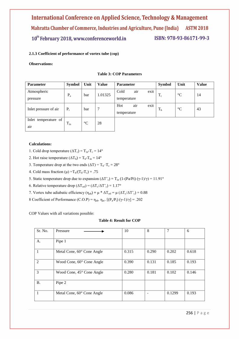
COP Values with all variations possible:
Table 4: Result for COP
Sr. No. Pressure 10 8 7 6
A. Pipe 1
1 Metal Cone, 60° Cone Angle 0.315 0.290 0.202 0.618
2 Wood Cone, 60° Cone Angle 0.390 0.131 0.185 0.193
3 Wood Cone, 45° Cone Angle 0.280 0.181 0.102 0.146
B. Pipe 2
1 Metal Cone, 60° Cone Angle 0.086 - 0.1299 0.193
257 | P a g e
2 Metal Cone, 30° Cone Angle 0.365 0.048 - 0.0821
3 Wood Cone, 60° Cone Angle 0.159 0.098 0.103 0.135
4 Wood Cone, 45° Cone Angle 0.139 0.116 0.104 0.096
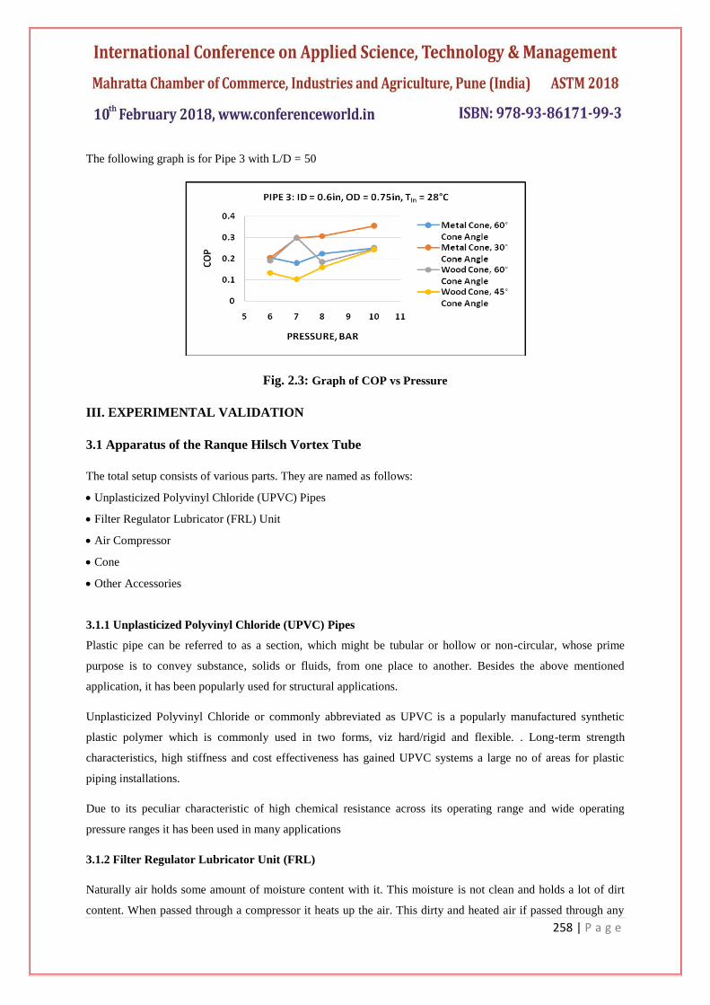
C. Pipe 3
1 Metal Cone, 60° Cone Angle 0.2486 0.224 0.177 0.204
2 Metal Cone, 30° Cone Angle 0.3533 0.3072 0.2964 0.2042
3 Wood Cone, 60° Cone Angle 0.2463 0.1813 0.2997 0.1894
4 Wood Cone, 45° Cone Angle 0.2416 0.1595 0.1010 0.1332
Graphs displaying variation in COP values at different pressures for different cone material
The following graph is for Pipe 1 with L/D = 38
Fig. 2.1: Graph of COP vs Pressure
The following graph is for Pipe 2 with L/D = 30
Fig. 2.2: Graph of COP vs Pressure
258 | P a g e
The following graph is for Pipe 3 with L/D = 50
Fig. 2.3: Graph of COP vs Pressure
III. EXPERIMENTAL VALIDATION
3.1 Apparatus of the Ranque Hilsch Vortex Tube
The total setup consists of various parts. They are named as follows:
Unplasticized Polyvinyl Chloride (UPVC) Pipes
Filter Regulator Lubricator (FRL) Unit
Air Compressor
Cone
Other Accessories
3.1.1 Unplasticized Polyvinyl Chloride (UPVC) Pipes
Plastic pipe can be referred to as a section, which might be tubular or hollow or non-circular, whose prime
purpose is to convey substance, solids or fluids, from one place to another. Besides the above mentioned
application, it has been popularly used for structural applications.
Unplasticized Polyvinyl Chloride or commonly abbreviated as UPVC is a popularly manufactured synthetic
plastic polymer which is commonly used in two forms, viz hard/rigid and flexible. . Long-term strength
characteristics, high stiffness and cost effectiveness has gained UPVC systems a large no of areas for plastic
piping installations.
Due to its peculiar characteristic of high chemical resistance across its operating range and wide operating
pressure ranges it has been used in many applications
3.1.2 Filter Regulator Lubricator Unit (FRL)
Naturally air holds some amount of moisture content with it. This moisture is not clean and holds a lot of dirt
content. When passed through a compressor it heats up the air. This dirty and heated air if passed through any
259 | P a g e
system, can reduce the functional life of the following sub-systems of the assembly. Thus it becomes critically
important to cleanse the air before it is passed into the system. An Airline filter cleans the compressed air by
straining the air and trapping the dust and dirt particles. Also it’s another function is to separate the liquids like
moisture and oil particles from the compressed air. To avoid any further damage use of filters is practiced at the
very beginning of any such systems. This proves advantageous in reducing the downtime that will be caused
because of the interaction of these particles with the pneumatic systems, thus leading to cost reduction and better
efficiency.
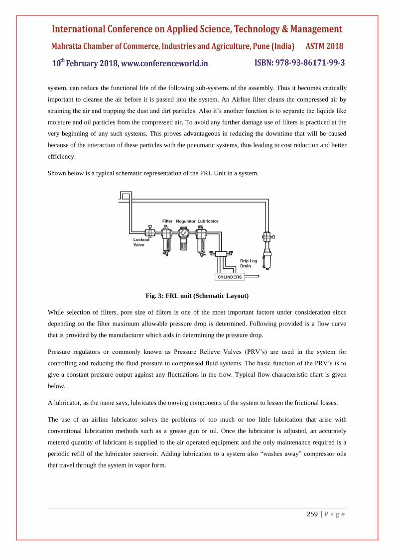
Shown below is a typical schematic representation of the FRL Unit in a system.
Fig. 3: FRL unit (Schematic Layout)
While selection of filters, pore size of filters is one of the most important factors under consideration since
depending on the filter maximum allowable pressure drop is determined. Following provided is a flow curve
that is provided by the manufacturer which aids in determining the pressure drop.
Pressure regulators or commonly known as Pressure Relieve Valves (PRV’s) are used in the system for
controlling and reducing the fluid pressure in compressed fluid systems. The basic function of the PRV’s is to
give a constant pressure output against any fluctuations in the flow. Typical flow characteristic chart is given
below.
A lubricator, as the name says, lubricates the moving components of the system to lessen the frictional losses.
The use of an airline lubricator solves the problems of too much or too little lubrication that arise with
conventional lubrication methods such as a grease gun or oil. Once the lubricator is adjusted, an accurately
metered quantity of lubricant is supplied to the air operated equipment and the only maintenance required is a
periodic refill of the lubricator reservoir. Adding lubrication to a system also “washes away” compressor oils
that travel through the system in vapor form.

260 | P a g e
The following is the actual picture of the FRL unit that we are using.
Fig. 4: FRL unit
3.1.3 Air Compressor
An air compressor is a device that converts power (using an electric motor, diesel or gasoline engine, etc.) into
potential energy stored in pressurized air (i.e., compressed air). The Air compressor which was used for the
experiment was a 5 HP, twin cylinder KND air compressor.
Fig. 5: KND make, Compressor
3.1.4 Cone
The Cone is an integral and a very crucial component of the vortex tube. This being placed at the hot end of the
vortex tube, is responsible for the opening of the space provided for escaping the air, which intern affects the
cooling achieved. The working of the cone is as follows:
the air makes it to the end of the pipe, and, because the ball valve (cone) is opened slightly, with a small
opening near the wall of the hot pipe, it siphons off hot air, but, because the pressure is too great to go out that
single opening, some of the air must rebound and travel through the center of the vortex, and exit back through
the hole in the middle of the vortex chamber.
The cone that we have used is made up of MS bar and wood.
Fig. 6: Cone
261 | P a g e
3.1.5 Other Accessories
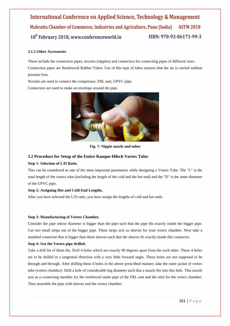
These include the connection pipes, nozzles (nipples) and connectors for connecting pipes of different sizes.
Connection pipes are Reinforced Rubber Tubes. Use of this type of tubes ensures that the air is carried without
pressure loss.
Nozzles are used to connect the compressor, FRL unit, UPVC pipe.
Connectors are used to make an envelope around the pipe.
Fig. 7: Nipple nozzle and tubes
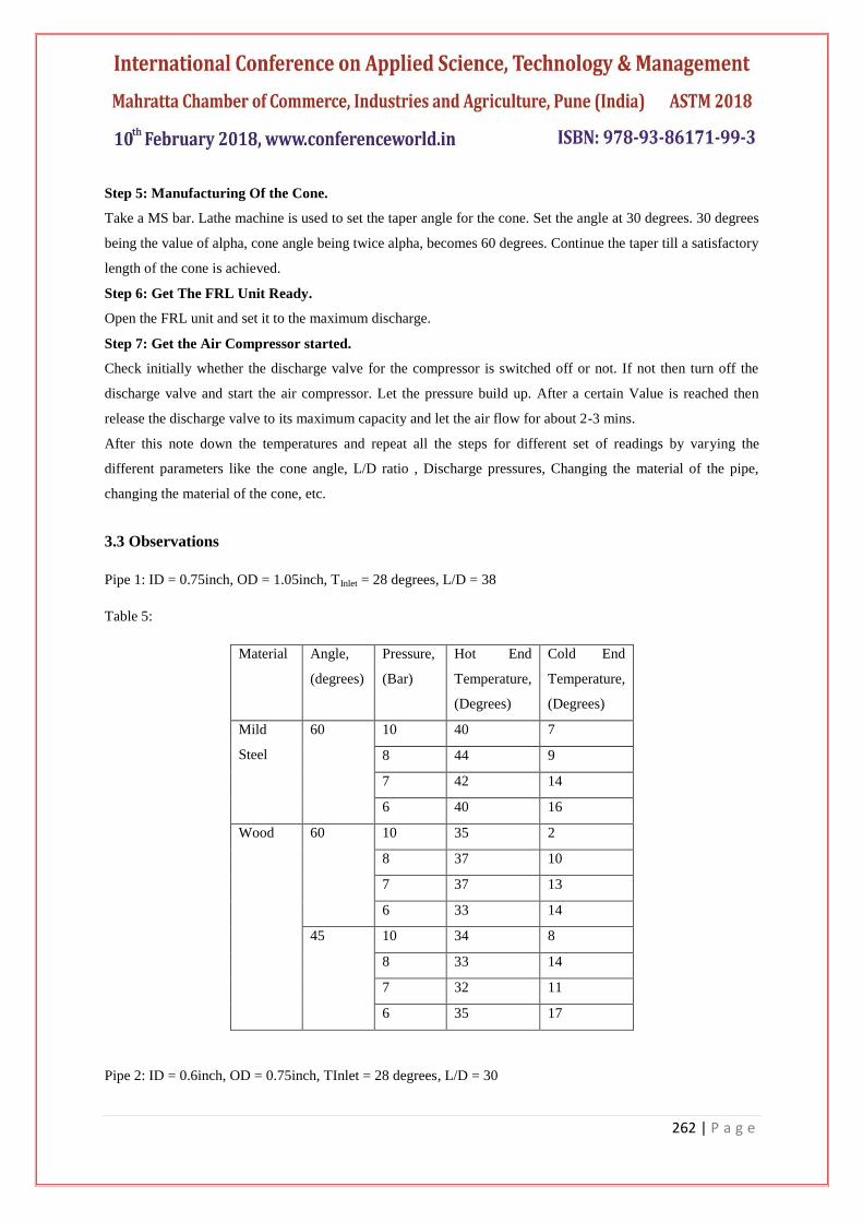
3.2 Procedure for Setup of the Entire Ranque-Hilsch Vortex Tube:
Step 1: Selection of L/D Ratio.
This can be considered as one of the most important parameters while designing a Vortex Tube. The "L" is the
total length of the vortex tube (including the length of the cold and the hot end) and the "D" is the inner diameter
of the UPVC pipe.
Step 2: Assigning Hot and Cold End Lengths.
After you have selected the L/D ratio, you have assign the lengths of cold and hot ends.
Step 3: Manufacturing of Vortex Chamber.
Consider the pipe whose diameter is bigger than the pipe such that the pipe fits exactly inside the bigger pipe.
Cut two small strips out of the bigger pipe. These strips acts as sleeves for your vortex chamber. Now take a
standard connector that is bigger than these sleeves such that the sleeves fit exactly inside this connector.
Step 4: Get the Vortex pipe drilled.
Take a drill bit of 8mm dia. Drill 4 holes which are exactly 90 degrees apart from the each other. These 4 holes
are to be drilled in a tangential direction with a very little forward angle. These holes are not supposed to be
through and through. After drilling these 4 holes in the above prescribed manner, take the outer jacket of vortex
tube (vortex chamber). Drill a hole of considerable big diameter such that a nozzle fits into this hole. This nozzle
acts as a connecting member for the reinforced outlet pipe of the FRL unit and the inlet for the vortex chamber.
Then assemble the pipe with sleeves and the vortex chamber.
262 | P a g e
Step 5: Manufacturing Of the Cone.
Take a MS bar. Lathe machine is used to set the taper angle for the cone. Set the angle at 30 degrees. 30 degrees
being the value of alpha, cone angle being twice alpha, becomes 60 degrees. Continue the taper till a satisfactory
length of the cone is achieved.
Step 6: Get The FRL Unit Ready.
Open the FRL unit and set it to the maximum discharge.
Step 7: Get the Air Compressor started.
Check initially whether the discharge valve for the compressor is switched off or not. If not then turn off the
discharge valve and start the air compressor. Let the pressure build up. After a certain Value is reached then
release the discharge valve to its maximum capacity and let the air flow for about 2-3 mins.
After this note down the temperatures and repeat all the steps for different set of readings by varying the
different parameters like the cone angle, L/D ratio , Discharge pressures, Changing the material of the pipe,
changing the material of the cone, etc.
3.3 Observations
Pipe 1: ID = 0.75inch, OD = 1.05inch, TInlet = 28 degrees, L/D = 38
Table 5:
Material Angle,
(degrees)
Pressure,
(Bar)
Hot End
Temperature,
(Degrees)
Cold End
Temperature,
(Degrees)
Mild
Steel
60 10 40 7
8 44 9
7 42 14
6 40 16
Wood 60 10 35 2
8 37 10
7 37 13
6 33 14
45 10 34 8
8 33 14
7 32 11
6 35 17
Pipe 2: ID = 0.6inch, OD = 0.75inch, TInlet = 28 degrees, L/D = 30
263 | P a g e
Table 6:
Material Angle,
(degrees)
Pressure,
(Bar)
Hot End
Temperature,
(Degrees)
Cold End
Temperature,
(Degrees)
Mild
Steel
60 10 29 21
7 28 17
6 29 15
30 10 29 4
8 29 23
7 31 21
6 33 20
Wood 60 10 27 14
8 28 19
7 29 19
6 28 17
45 11 32 16
10 32 16
8 31 18
6 31 20
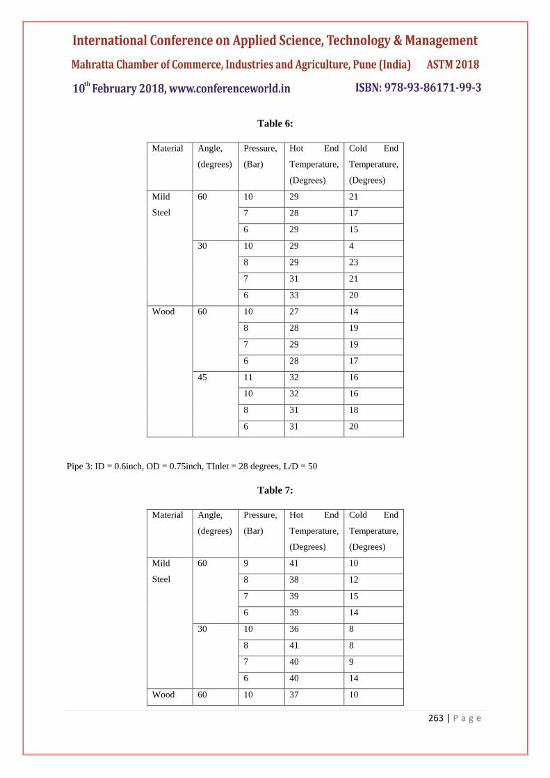
Pipe 3: ID = 0.6inch, OD = 0.75inch, TInlet = 28 degrees, L/D = 50
Table 7:
Material Angle,
(degrees)
Pressure,
(Bar)
Hot End
Temperature,
(Degrees)
Cold End
Temperature,
(Degrees)
Mild
Steel
60 9 41 10
8 38 12
7 39 15
6 39 14
30 10 36 8
8 41 8
7 40 9
6 40 14
Wood 60 10 37 10
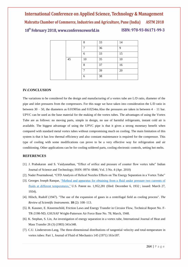
264 | P a g e
8 33 14
7 36 9
6 33 15
45 10 35 10
8 37 16
7 39 20
6 38
IV.CONCLUSION
The variations to be considered for the design and manufacturing of a vortex tube are L/D ratio, diameter of the
pipe and inlet pressures from the compressors. For this stage we have taken into consideration the L/D ratio in
between 30 – 50, the diameters as 0.01905m and 0.0254m.Also the pressures are taken in between 4 – 11 bar.
UPVC can be used as the base material for the making of the vortex tubes. The advantages of using the Vortex
Tube are as follows: no moving parts, simple in design, no use of harmful refrigerants, instant cold air is
available. The biggest advantage of using the UPVC pipe is that it gives a strong monetary benefit when
compared with standard metal vortex tubes without compromising much on cooling. The main limitation of this
system is that it has low thermal efficiency and also constant maintenance is required for the compressor. This
type of cooling with some modifications can prove to be a very effective way for refrigeration and air
conditioning. Other applications can be for cooling soldered parts, cooling electronic controls, setting hot melts.
REFERENCES
[1]. J. Prabakaran
and S. Vaidyanathan, “Effect of orifice and pressure of counter flow vortex tube” Indian
Journal of Science and Technology; ISSN: 0974- 6846; Vol. 3 No. 4 (Apr. 2010)
[2]. Nader Pourmahoud, “CFD Analysis of Helical Nozzles Effects on The Energy Separation in a Vortex Tube”
[3]. Georges Joseph Ranque, “Method and apparatus for obtaining from a fluid under pressure two currents of
fluids at different temperatures,” U.S. Patent no. 1,952,281 (filed: December 6, 1932 ; issued: March 27,
1934).
[4]. Hilsch, Rudolf (1947). "The use of the expansion of gases in a centrifugal field as cooling process". The
Review of Scientific Instruments. 18 (2): 108–113.
[5]. R. Kassner, E. Knoernschild, Friction Laws and Energy Transfer in Circuior Flow, Technical Report No. F-
TR-2198-ND, GSUSAF Wright-Patterson Air Force Base No. 78; March, 1948.
[6]. K. Stephan, S. Lin, An investigation of energy separation in a vortex tube, International Journal of Heat and
Mass Transfer 26 (3) (1983) 341e348.
[7]. C.U. Linderstrom-Lang, The three-dimensional distributions of tangential velocity and total-temperature in
vortex tubes: Part 1, Journal of Fluid of Mechanics 145 (1971) 161e187.

265 | P a g e
[8]. J. Mischner, V.I. Bespalov, Zur Entropieproduktion im RanqueeHilscheRohr, Forschung im Ingenieurwesen
67 (2002) 1e10.
[9]. T. Amitani, T. Adachi, T.A. Kato, Study on temperature separation in a large vortex tube, Transactions of
the Japan Society of Mechanical Engineers 48 (1983) 877e884.
[10]. R.T. Balmer, Pressure-driven RanqueeHilsch temperature separation in liquids, ASME Journal of Fluid
Engineering 110 (1998) 161e164.