
Photovoltaic Generation System with MPPT Control Using ANFIS

International Journal of Electronic and Electrical Engineering. ISSN 0974-2174 Volume 7, Number 1 (2014), pp. 35-48 © International Research Publication House http://www.irphouse.com
Design and Implementation of MPPT for Photo Voltaic System with Neutral Point Clamped Inverter Fed Induction
Motor Drive
S. Narasimman, J. Gowri Shankar and M. Balasubramani
PG Scholar Department of EEE, SASTRA university, narasimansankar@gmail. com AP-II, Department of EEE, SASTRA university, gowrishankar@eee. sastra. edu
AP-III, Department of EEE, SASTRA University, balasubramani@eee. sastra. edu
ABSTRACT
Solar Energy utilization has gained importance in the past few decades as it is green energy. Maximum Power Point Tracking (MPPT) is one of the efficient methods used to track the maximum Solar Energy. This paper explains the different techniques for MPPT algorithm like Petrub and observe (P&O), Fuzzy logic controller to utilize the solar power in an efficient manner. The closed loop simulation of the Solar PV array based MPPT using (P&O) and fuzzy logic controller is simulated in MATLAB/ Simulink. The simulation results show that the MPPT algorithm using the fuzzy logic controller is the efficient power tracking mechanism. The neutral point clamped multilevel inverter fed IM is also incorporated in this system.
INTRODUCTION Due to global warming the demand of petroleum and coal is insufficient for future generation. to overcome this problem and to alternate the energy crisis in the world without affecting the environment affairs we have to develop renewable energy source like solar, wind, biomass etc. From this solar energy is very much suitable for renewable source because it will not produce noise. To increase Air pollution and the only drawback is it requires more space when compared to other energy source. The efficiency of solar cell is about 35 to 45%. To increase the efficiency of the output power in solar cell, the MPPT is implemented. This project implements the FLC based MPPT control the DC-DC boost converter for photo voltaic application. The MPPT control is used to determine the climatic changing condition like temperature and irradiance. The three level NPC multilevel inverter fed IM drive is simulated in this system. The reason for selecting the NPCMLI is, it’s a single DC source dv/dt of the motor is less, less motor shaft bearing current. Size of output filter is less, voltage

36 S. Narasimman, J. Gowri Shankar and M. Balasubramani
stress on MOSFET is less and less switching losses. The fuzzy logic controller does not require accurate IM motor model [3], [8]. 2. PHOTO VOLTAIC CELL 2. 1 PV MODELING A single solar cell will get less output power, so in order to get the maximum output power rating the solar cell is connected in series and parallel network to form a solar panel. The series resistance R, value will increase the voltage and the parallel resistance Rp value wills the current array in this region [1], [2], [4], [7], [9] and [10].
Figure 2. 1Schematic diagram of photo voltaic array The characteristics equation for a photovoltaic cell is given by [1], [2], [4], [7], [9] and [10]
Rsh
RvTAkiRvqlosngI 01101*exp* −+
−⎥⎦
⎤⎢⎣
⎡−⎟
⎠⎞
⎜⎝⎛
−−+
−=
( ) 1
11
**exp*/* 2
⎥⎥⎥⎥
⎦
⎤
⎢⎢⎢⎢
⎣
⎡
⎢⎢⎢
⎣
⎡ −=
AkiTTrEgoqTiTlorlos
[ ] λ*)25( −+= TKiIscrlig The characteristics equation of the PV module is dependent on the parallel series arrangement of the cells. It is noted from experimental results that the current variation is less dependent on the shunt resistance and is more dependent on the series resistance [7]
Rsh
RoNxNoV
NoRx
NxvqlosNpNgNpL
−⎟⎠⎞
⎜⎝⎛−
−⎥⎦
⎤⎢⎣
⎡−⎟
⎠⎞
⎜⎝⎛ −+−=
1*11*exp***

Design and Implementation of MPPT for Photo Voltaic System 37
The I-V and P-V curves for a solar cell are given in the following figure. It can be seen that the cell controls as a constant current source at low values of operating voltages and a constant voltage source at low values of operating current.
2. 2 EFFECT OF VARIATION OF SOLAR IRRADIATION The P-V and I-V characteristics of a solar cell are highly dependent on the solar irradiation values. The solar irradiation as a result of the environmental changes keeps on fluctuating, but control mechanisms are available that can track this exchange and can alter the working of the solar cell to meet the required load requirements. Higher is the solar irradiation, the open circuit voltage is increased due to solar irradiation rises. This is due to the fact that, when more sunlight occurrence on to the PV cell, the electrons are provided with higher excitation energy, thereby increasing the electron mobility and thus more power is generated [7] and [10].
P-V Characteristics of Solar Cell

38
2. 3
in Mchanthis comSo tthe dep Wh 3. 1ThePV sourHer
BOOST C
In MPPT teMOSFET. Wnge the MP
duty cylcmpaered witthe variatioDuty cyle
ending uponVa=Vs/1-k
ere Va= Output
MAXIMUe MPPT ma
cell. This rce. This tere some dif
CONVERT
echniques thWhen the fiPPT gives thce and trianh the relatio
on of ouput e varies thn this equat
t Voltage, V
UM POWEaximum powmethod is
echnique is fferent algo
S. Narasim
ER
he DC-DC iuctuation ohe maximumngular wavon operator voltage wil
he DC-DC tion 2. 1
Vs=Input Vo
R POINT Twer point trused to rectracking th
orithm are
mman, J. G
converter is
of light raysm power of
ve generatoto generate
ll be vary dBoost con
oltage and K
TRACKINracking is uceive maximhe maximuutilized fo
owri Shank
s used for ths in PV celf the output
or (switchine the pulse adepending unverter oup
K= Duty Cy
NG used to incrmum availa
um peak voor increase
kar and M. B
he controllinl the outputt as a constng frequencand given toupon the Duput voltage
ycle
rease the efable power ltage from the efficie
Balasubram
ng the gate t power wiltant Duty cycy of 2000o the MOSFuty cycle, we will be
2
fficiency offrom chanthe solar cncy of the
mani
puls ll be ycle, 0Hz) FET. when vary
2. 1
f the nging cells. PV

Design and Implementation of MPPT for Photo Voltaic System 39
system such algorithm are given below. The MPPT is implemented with boost converter for tracking the voltage. [3], [4], [5] and [8]. 3. 2 DIFFERENT TYPES OF MPPT There are many methods used for maximum power point tracking a few are listed below: • Perturb and Observe method • Incremental Conductance method • Parasitic Capacitance method • Constant Voltage method • Constant Current method 3. 2. 1 Perturb and Observe method The most widely accepted MPP method is Perturb & Observe due to its ease of implementation and low cost. This may result in top level efficiency, with the criteria that a proper predictive and adaptive hill climbing strategy is acquired. Voltage and current of the solar panel should be evaluated continuously.
Figure 3. 1 flow chart of P&O algorithm
Power is computed by finding the product of current and voltage. Foremost, the difference in power of existing with the previous power should be calculated and also

40 S. Narasimman, J. Gowri Shankar and M. Balasubramani
the difference in the voltage of two successive intervals should be found. Depending on this power difference and voltage difference the four cases are to be studied as follows: First two cases occur when ∆P >0 where ∆P = Pk - Pk-1 Case 1: ∆P >0 and Vk – Vk-1 >0 (3. 1) If we infer from this that PV array’s operating voltage is perturbed in the given direction and the power obtained from the PV array is enhanced, the operating point also has shifted towards the MPP and hence the perturbation of the operating voltage should be continued in the same direction. Case 2: ∆P >0 and Vk – Vk-1 <0 (3. 2) Here, when the power increases and the voltage decreases compared to the previous voltage, then the perturbation of voltage should be reversed (i. e. ) decrease in the voltage In the cases where ∆P<0, the power drawn is decreased and the operating point is drifted away from the MPP. Case 3: ∆P<0 and Vk – Vk-1 >0 (3. 3) Decrease the voltage Case 4: ∆P<0 and Vk – Vk-1 <0 (3. 4) 3. 2 MPPT BASED FUZZY LOGIC CONTROLLER
Table. 1. Rule table of fuzzy logic
Fuzzy logic is simple and robust than conventional PI controller. It is the suitable replacement for the conventional controller. The fuzzy logic controller is consisting of fuzzification, inference & defuzzification. The voltage and change in voltage of the proposed system is taken as an input and duty cycle for the boost converter is considered as an output. Fuzzy rule base is formed as shown in table where row represents voltage and column represents change in voltage. The rule base consists of seven membership function for both input and output. Totally forty nine rules formed to get the better duty cycle with variations in the input.

Design and Implementation of MPPT for Photo Voltaic System 41
4. NEUTRAL POINT CLAMPED INVERTER
Figure 4. 1 Neutral Point Clamped Inverter The three level NPC inverter is shown in the figure 4. 1, there is a two source capacitance are used to split the DC voltage by Vdc/2 and the middle point of the two capacitor is denoted as n, the clamping diodes D1 and D2 connected to the neutral point of the switches. The switching table of the NPC is shown in the table 2, ”1”denoted as the switch is ON condition and”0”denoted as the switch is OFF condition the pair of two switches is conducted together. When the switch SA1 and SA2 is conducted the output voltage will be Vdc/2. The switches SA2 and SA3 is conducted the voltage will be zero similarly the switches SA3 and SA4 are conducted the output voltage will be –Vdc/2. Two switches are always turned ON at the same time.
Table. 2. switching state of NPC
.

42 S. Narasimman, J. Gowri Shankar and M. Balasubramani
5. SIMULATION AND RESULTS
Figure 5. 1 I-V characteristics of PV Panel
Figure 5. 2 P-V characteristics of PV Panel
Figure 5. 3 Design of PV cell with boost converter without MPPT system (Open loop Control)
Figure 5. 4 Output voltage of Boost converter without MPPT system with different irradiance condition

Design and Implementation of MPPT for Photo Voltaic System 43
Figure 5. 5 Output Current of Boost converters without MPPT system with different irradiance condition
Figure 5. 6 Model of PV cell with boost converter with P&O algorithm
Figure 5. 7 Output Voltage of Boost converter with P&O MPPT system with different irradiance condition

44 S. Narasimman, J. Gowri Shankar and M. Balasubramani
MPPT based FLC for Photo voltaic system
Figure 5. 8 open loop system of NPCMLI
Figure 5. 9 line voltage of leg A
Figure 5. 10 LC filter output voltage
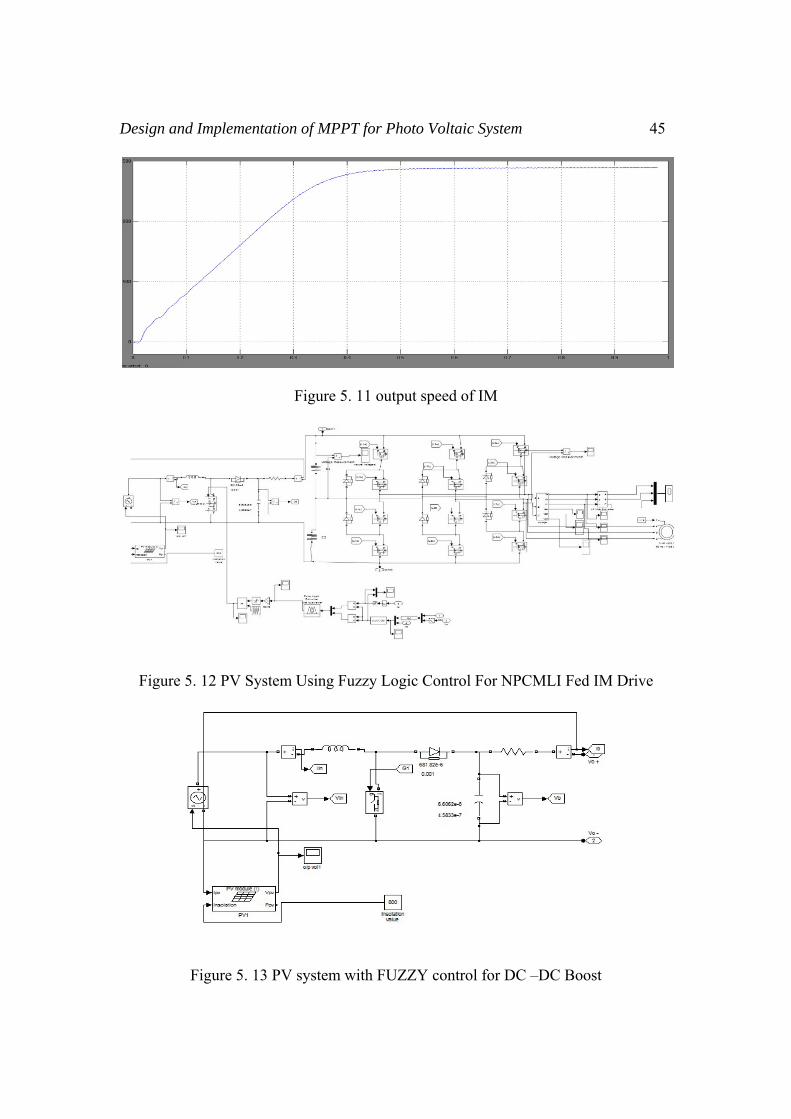
Design and Implementation of MPPT for Photo Voltaic System 45
Figure 5. 11 output speed of IM
Figure 5. 12 PV System Using Fuzzy Logic Control For NPCMLI Fed IM Drive
Figure 5. 13 PV system with FUZZY control for DC –DC Boost

46 S. Narasimman, J. Gowri Shankar and M. Balasubramani
Figure 5. 14 output voltage and current of boost converter
Figure 5. 15 line voltage of leg A using FUZZY
6. HARDWARE DESIGN The model of hardware circuit is designed by using proteus software
Figure 6. 1 hardware circuit design using proteus

Design and Implementation of MPPT for Photo Voltaic System 47
Figure 6. 2 three level output voltage
The hardware is implemented for three level inverter, Six IRF460 – MOSFET are used in this design which has high voltage and current carrying capability. Gate Driver circuits IR2112 are used for boosting the pulses which we get from a microcontroller. PIC16F877A is used for generating required pulses 7. CONCLUSION In this paper P&O based MPPT is compared with FLC based MPPT for photo voltaic system. The proposed system shows better result as compared with the other one. Boost converter for the proposed system is also implemented. NPC inverter fed induction motor performance is also verified. The overall system is simulated in Matlab/Simulink. A three level NPC using Proteus is also designed. 8. REFERENCES
[1] M. G. Villalva, J. R. Gazoli, E. Ruppert F, ”Comprehensive approach to modeling and simulation of photovoltaic arrays", IEEE Transactions on Power Electronics, 2009 vol. 25, no. 5, pp. 1198--1208, ISSN 0885-8993.
[2] M. G. Villalva, J. R. Gazoli, E. Ruppert F, ”Modeling and circuit-based simulation of photovoltaic arrays", Brazilian Journal of Power Electronics, 2009 vol. 14, no. 1, pp. 35--45, ISSN 1414-8862.
[3] Mummadi Veerachary, ”Control of TI-SEPIC Converter for Optimal Utilization of PV Power", IICPE, 2010 New Delhi.
[4] R. Sridhar, Dr. Jeevananathan, N. Thamizh Selvan, Saikat Banerjee, ”Modeling of PV Array and Performance Enhancement by MPPT Algorithm",

48 S. Narasimman, J. Gowri Shankar and M. Balasubramani
International Journal of Computer Applications (0975 – 8887) Volume 7– No. 5, September 2010.
[5] Hairul Nissah Zainudin, Saad Mekhilef, ”Comparison Study of Maximum Power Point Tracker Techniques for PV Systems”, Cairo University, Egypt, December 19-21, 2010, Paper ID 278.
[6] Katherine A. Kim and Philip T. Krein, ”Photovoltaic Converter Module Configurations for Maximum Power Point Operation”, University of Illinois Urbana-Champaign Urbana, IL 61801 USA.
[7] Huan-Liang Tsai, Ci-Siang Tu, and Yi-Jie Su, ”Development of Generalized Photovoltaic Model Using MATLAB/SIMULINK”, Proceedings of the World Congress on Engineering and Computer Science 2008 WCECS 2008, October 22 - 24, 2008, San Francisco, USA.
[8] M. Berrera, A. Dolara, R. Faranda and S. Leva, ”Experimental test of seven widely-adopted MPPT algorithms”, 2009 IEEE Bucharest Power Tech Conference, June 28th - July 2nd, Bucharest, Romania.
[9] P. S. Revankar, W. Z. Gandhare and A. G. Thosar Government College of Engineering, Aurangabad, ”Maximum Power Point Tracking for PV Systems Using MATLAB/SIMULINK”, 2010 Second International Conference on Machine Learning and Computing.
[10] Ramos Hernanz, JA., Campayo Martín, J. J. Zamora Belver, I., Larrañaga Lesaka, J., Zulueta Guerrero, E. Puelles Pérez, E., ”Modeling of Photovoltaic Module”, International Conference on Renewable Energies and Power Quality (ICREPQ’10) Granada (Spain), 23th to 25th March, 2010.
[11] Arun KumarVerma, Bhim Singh and S. C Kaushik, ”An Isolated Solar Power Generation using Boost Converter and Boost Inverter, ”in Proc. National Conference on Recent Advances in Computational Technique in Electrical Engineering, SLITE, Longowal (India), 19-20 March, 2010, paper 3011, pp. 1-8.
[12] Athimulam Kalirasu, Subharensu Sekar Dash, ”Simulation of Closed Loop Controlled Boost Converter for Solar Installation”, Serbian Journal of Electrical Engineering Vol. 7, No. 1, May 2010, 121-130.
[13] Nevzat Onat, ”Recent Developments in Maximum Power Point Tracking Technologies for Photovoltaic Systems”, Hindawi Publishing Corporation International Journal of Photoenergy Volume 2010, Article ID 245316, 11 pages.
Copyright © 2022 FDOKUMEN