Design and implementation of FPGA based low power digital ...
6
Design and Implementation of FPGA Based Low Power Digital PID Controllers Sreenivasappa.B.V. 1 Dr. Udaykumar.R.Y. 2 Research Scholar Professor & Head Department of EEE National Institute of Technology Karnataka Surathkal, Mangalore-575025, India, Tel: +91-824-2474000/23, Extn: 3045 Fax: +91-824-2474033 1 E-mail : [email protected] , [email protected] 2 E-mail : [email protected] Abstract- In this paper design and implementation of low power Proportional Integral Derivative (PID) controller using Field Programmable Gate Array (FPGA) is presented. In the present status the embedded control applications requires low power and fast acting PID controllers with a closed loop performance using less resources, resulting in cost reduction. Different types of digital PID controllers are analyzed with the frequency response using Matlab tool. The controller algorithm is synthesized, simulated and implemented using Xilinx Spartan3e XC3S100E board with XilinxISE 9.1i as a tool and synthesized and simulated using Altera Cyclone EP1C12Q240C8 with Quartus II 6.1 as a tool. The results are compared in terms of their power consumption, speed, memory usage, Look Up Tables (LUTs) and number of Multipliers, Adders/Subtractors. Index Terms- Proportional Integral Derivative (PID) controller, Field Programmable Gate Array (FPGA), Backward Difference (BD), Look Up Tables (LUTs). I. INTRODUCTION Proportional Integral Derivative (PID) controllers have been widely used over the past five decades due to their simplicity, robustness, effectiveness, and applicability for a broad class of systems. Despite the numerous control design approaches that have appeared in the literature, it is estimated that nowadays PID controllers are still employed in more than 95% of industrial processes [1]. An important feature of this controller is that it does not require a precise analytical model of the system that is being controlled. For this reason, PID controllers have been widely used in robotics, automation, process control, manufacturing, transportation, and interestingly in real time multi tasking applications [2]. Implementation of digital PID controller has gone through several stages of evolution, from the early mechanical and pneumatic designs to the microprocessor based systems but these systems have the drawback of demanding control requirements of modern power conditioning systems will overload most of the microprocessors and the computing speed limits the use of microprocessor in complex algorithms. Microprocessors, Microcontrollers and Digital Signal Processors (DSPs) can no longer keep pace with the new generation of applications that requires more flexible and higher performance without increasing cost and resources. Further more the tasks are executed sequentially which takes longer processing time to accomplish the same task in Microcontrollers and DSPs. Recently, Field Programmable Gate Arrays (FPGA) has becoming alternative solution for the realization of digital control systems. The FPGA based controllers offer advantages such as high speed computation, complex functionality, real time processing capabilities and low power consumption [3]. In this paper we consider discrete time PID controller and is implemented in a dedicated FPGA. Following the standard digital design practices, the controller functionality is described in Very High Speed Integrated Circuit Hardware Description Language (VHDL). Using synthesis tool, the design is then targeted to the FPGA board. The organization of this paper is as follows: In section II different discrete time PID controllers are reviewed. Implementation of PID controller algorithm using FPGA is explained in section III. The simulation and FPGA implementation results are discussed in section IV. II. DISCRETIZATION PID CONTROLLER The general form of PID controller given in most of the text book is the standard form. 0 1 () () () ( ) t p d i de t ut K et e d T T dt τ τ ⎛ ⎞ = + + ⎜ ⎟ ⎝ ⎠ ∫ (1) Where p K is the Proportional gain, i T is the Integral time, d T is the derivative time, () et is the error signal and () ut is the output of the controller. The ideal parallel form of the PID controller shown in Fig. 1 is represented by a mathematical equation as 0 () () () () t p i d de t ut Ket K e d K dt τ τ = + + ∫ (2) The gain parameters are related to the parameters of the standard form through p i i K K T = and d p d K KT = This parallel form is shown in Fig 1, where the parameters are treated as simple gains, is the most general and flexible form. However, it is also the form where the parameters have the least physical interpretation and is generally reserved for theoretical treatment of the PID controller. The purpose of integral action is to increase the low frequency gain and thus Fourth International Conference on Industrial and Information Systems, ICIIS 2009, 28 - 31 December 2009, Sri Lanka 978-1-4244-4837-1/09/$25.00 ©2009 IEEE 568 Authorized licensed use limited to: NATIONAL INSTITUTE OF TECHNOLOGY SURATHKAL. Downloaded on February 26,2021 at 05:44:11 UTC from IEEE Xplore. Restrictions apply.
-
Upload
khangminh22 -
Category
Documents
-
view
0 -
download
0
Transcript of Design and implementation of FPGA based low power digital ...
Design and Implementation of FPGA Based Low Power Digital PID Controllers
Sreenivasappa.B.V.1 Dr. Udaykumar.R.Y.2 Research Scholar Professor & Head
Department of EEE National Institute of Technology Karnataka Surathkal,
Mangalore-575025, India, Tel: +91-824-2474000/23, Extn: 3045 Fax: +91-824-2474033 1E-mail : [email protected] , [email protected]
2E-mail : [email protected] Abstract- In this paper design and implementation of low power Proportional Integral Derivative (PID) controller using Field Programmable Gate Array (FPGA) is presented. In the present status the embedded control applications requires low power and fast acting PID controllers with a closed loop performance using less resources, resulting in cost reduction. Different types of digital PID controllers are analyzed with the frequency response using Matlab tool. The controller algorithm is synthesized, simulated and implemented using Xilinx Spartan3e XC3S100E board with XilinxISE 9.1i as a tool and synthesized and simulated using Altera Cyclone EP1C12Q240C8 with Quartus II 6.1 as a tool. The results are compared in terms of their power consumption, speed, memory usage, Look Up Tables (LUTs) and number of Multipliers, Adders/Subtractors.
Index Terms- Proportional Integral Derivative (PID) controller, Field Programmable Gate Array (FPGA), Backward Difference (BD), Look Up Tables (LUTs).
I. INTRODUCTION
Proportional Integral Derivative (PID) controllers have been widely used over the past five decades due to their simplicity, robustness, effectiveness, and applicability for a broad class of systems. Despite the numerous control design approaches that have appeared in the literature, it is estimated that nowadays PID controllers are still employed in more than 95% of industrial processes [1]. An important feature of this controller is that it does not require a precise analytical model of the system that is being controlled. For this reason, PID controllers have been widely used in robotics, automation, process control, manufacturing, transportation, and interestingly in real time multi tasking applications [2]. Implementation of digital PID controller has gone through several stages of evolution, from the early mechanical and pneumatic designs to the microprocessor based systems but these systems have the drawback of demanding control requirements of modern power conditioning systems will overload most of the microprocessors and the computing speed limits the use of microprocessor in complex algorithms. Microprocessors, Microcontrollers and Digital Signal Processors (DSPs) can no longer keep pace with the new generation of applications that requires more flexible and higher performance without increasing cost and resources. Further more the tasks are executed sequentially which takes longer processing time to accomplish the same task in Microcontrollers and DSPs. Recently, Field Programmable
Gate Arrays (FPGA) has becoming alternative solution for the realization of digital control systems. The FPGA based controllers offer advantages such as high speed computation, complex functionality, real time processing capabilities and low power consumption [3]. In this paper we consider discrete time PID controller and is implemented in a dedicated FPGA. Following the standard digital design practices, the controller functionality is described in Very High Speed Integrated Circuit Hardware Description Language (VHDL). Using synthesis tool, the design is then targeted to the FPGA board.
The organization of this paper is as follows: In section II different discrete time PID controllers are reviewed. Implementation of PID controller algorithm using FPGA is explained in section III. The simulation and FPGA implementation results are discussed in section IV.
II. DISCRETIZATION PID CONTROLLER
The general form of PID controller given in most of the text book is the standard form.
0
1 ( )( ) ( ) ( )t
p di
de tu t K e t e d TT dt
ττ⎛ ⎞= + +⎜ ⎟
⎝ ⎠∫ (1)
Where pK is the Proportional gain, iT is the Integral time,
dT is the derivative time, ( )e t is the error signal and ( )u t is the output of the controller. The ideal parallel form of the PID controller shown in Fig. 1 is represented by a mathematical equation as
0
( )( ) ( ) ( )t
p i dde tu t K e t K e d K
dtτ τ= + +∫ (2)
The gain parameters are related to the parameters of the
standard form through pi
i
KK
T= and d p dK K T=
This parallel form is shown in Fig 1, where the parameters are treated as simple gains, is the most general and flexible form. However, it is also the form where the parameters have the least physical interpretation and is generally reserved for theoretical treatment of the PID controller. The purpose of integral action is to increase the low frequency gain and thus
Fourth International Conference on Industrial and Information Systems, ICIIS 2009, 28 - 31 December 2009, Sri Lanka
978-1-4244-4837-1/09/$25.00 ©2009 IEEE 568
Authorized licensed use limited to: NATIONAL INSTITUTE OF TECHNOLOGY SURATHKAL. Downloaded on February 26,2021 at 05:44:11 UTC from IEEE Xplore. Restrictions apply.
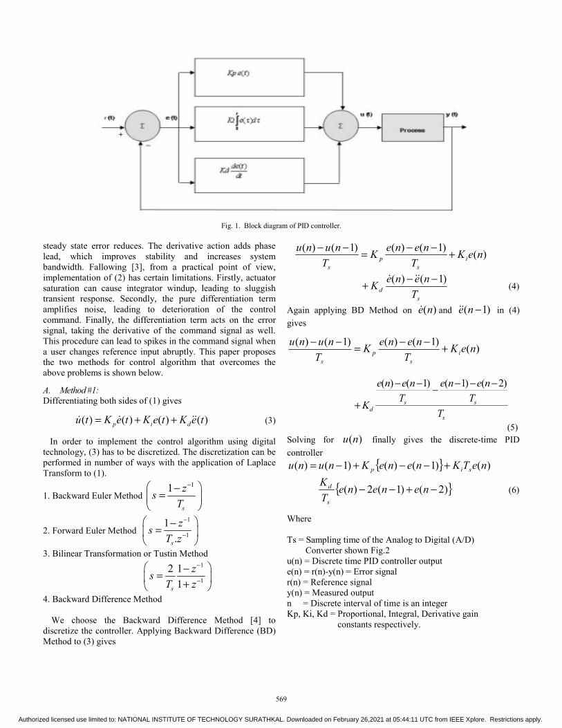
Fig. 1. Block diagram of PID controller.
steady state error reduces. The derivative action adds phase lead, which improves stability and increases system bandwidth. Fallowing [3], from a practical point of view, implementation of (2) has certain limitations. Firstly, actuator saturation can cause integrator windup, leading to sluggish transient response. Secondly, the pure differentiation term amplifies noise, leading to deterioration of the control command. Finally, the differentiation term acts on the error signal, taking the derivative of the command signal as well. This procedure can lead to spikes in the command signal when a user changes reference input abruptly. This paper proposes the two methods for control algorithm that overcomes the above problems is shown below.
A. Method #1: Differentiating both sides of (1) gives
( ) ( ) ( ) ( )p i du t K e t K e t K e t= + + (3)
In order to implement the control algorithm using digital technology, (3) has to be discretized. The discretization can be performed in number of ways with the application of Laplace Transform to (1).
1. Backward Euler Method 11
s
zsT
−⎛ ⎞−=⎜ ⎟⎝ ⎠
)()1()()1()( neKT
neneKT
nunui
sp
s
+−−=−−
s
d TneneK )1()( −−+ (4)
Again applying BD Method on )(ne and )1( −ne in (4) gives
)()1()()1()( neKT
neneKT
nunui
sp
s
+−−=−−
s
ssd T
Tnene
Tnene
K
)2()1()1()( −−−−−−
+
(5) Solving for )(nu finally gives the discrete-time PID controller
{ } )()1()()1()( neTKneneKnunu sip +−−+−=
{ })2()1(2)( −+−− neneneTK
s
d (6)
2. Forward Euler Method 1
1
1.s
zsT z
−
−
⎛ ⎞−=⎜ ⎟⎝ ⎠
3. Bilinear Transformation or Tustin Method 1
1
2 11s
zsT z
−
−
⎛ ⎞−=⎜ ⎟+⎝ ⎠
4. Backward Difference Method
We choose the Backward Difference Method [4] to discretize the controller. Applying Backward Difference (BD) Method to (3) gives
Where Ts = Sampling time of the Analog to Digital (A/D) Converter shown Fig.2 u(n) = Discrete time PID controller output e(n) = r(n)-y(n) = Error signal r(n) = Reference signal y(n) = Measured output n = Discrete interval of time is an integer Kp, Ki, Kd = Proportional, Integral, Derivative gain constants respectively.
569
Authorized licensed use limited to: NATIONAL INSTITUTE OF TECHNOLOGY SURATHKAL. Downloaded on February 26,2021 at 05:44:11 UTC from IEEE Xplore. Restrictions apply.
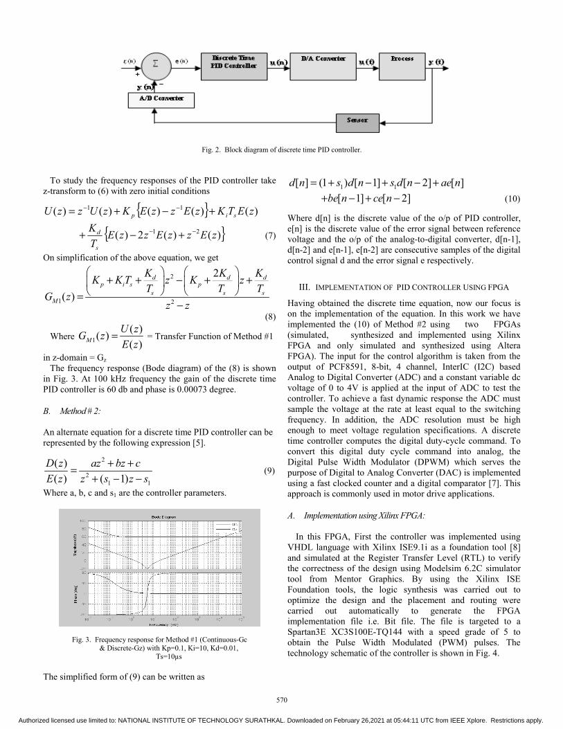
Fig. 2. Block diagram of discrete time PID controller.
To study the frequency responses of the PID controller take z-transform to (6) with zero initial conditions
{ } )()()()()( 11 zETKzEzzEKzUzzU sip +−+= −−
{ })()(2)( 21 zEzzEzzETK
s
d −− +−+ (7)
On simplification of the above equation, we get
2
1 2
2
( )
d d dp i s p
s s sM
K K KK K T z K zT T T
G zz z
⎛ ⎞ ⎛ ⎞+ + − + +⎜ ⎟ ⎜ ⎟
⎝ ⎠ ⎝ ⎠=−
(8)
Where 1( )( )( )M
U zG zE z
= = Transfer Function of Method #1
in z-domain = Gz The frequency response (Bode diagram) of the (8) is shown in Fig. 3. At 100 kHz frequency the gain of the discrete time PID controller is 60 db and phase is 0.00073 degree. B. Method # 2: An alternate equation for a discrete time PID controller can be represented by the following expression [5].
2
21 1
( )( ) ( 1)
D z az bz cE z z s z s
+ +=+ − −
(9)
Where a, b, c and s1 are the controller parameters.
Fig. 3. Frequency response for Method #1 (Continuous-Gc & Discrete-Gz) with Kp=0.1, Ki=10, Kd=0.01,
Ts=10µs The simplified form of (9) can be written as
1 1[ ] (1 ) [ 1] [ 2] [ ]d n s d n s d n ae n= + − + − +
[ 1] [ 2]be n ce n+ − + − (10)
Where d[n] is the discrete value of the o/p of PID controller, e[n] is the discrete value of the error signal between reference voltage and the o/p of the analog-to-digital converter, d[n-1], d[n-2] and e[n-1], e[n-2] are consecutive samples of the digital control signal d and the error signal e respectively.
III. IMPLEMENTATION OF PID CONTROLLER USING FPGA
Having obtained the discrete time equation, now our focus is on the implementation of the equation. In this work we have implemented the (10) of Method #2 using two FPGAs (simulated, synthesized and implemented using Xilinx FPGA and only simulated and synthesized using Altera FPGA). The input for the control algorithm is taken from the output of PCF8591, 8-bit, 4 channel, InterIC (I2C) based Analog to Digital Converter (ADC) and a constant variable dc voltage of 0 to 4V is applied at the input of ADC to test the controller. To achieve a fast dynamic response the ADC must sample the voltage at the rate at least equal to the switching frequency. In addition, the ADC resolution must be high enough to meet voltage regulation specifications. A discrete time controller computes the digital duty-cycle command. To convert this digital duty cycle command into analog, the Digital Pulse Width Modulator (DPWM) which serves the purpose of Digital to Analog Converter (DAC) is implemented using a fast clocked counter and a digital comparator [7]. This approach is commonly used in motor drive applications. A. Implementation using Xilinx FPGA:
In this FPGA, First the controller was implemented using VHDL language with Xilinx ISE9.1i as a foundation tool [8] and simulated at the Register Transfer Level (RTL) to verify the correctness of the design using Modelsim 6.2C simulator tool from Mentor Graphics. By using the Xilinx ISE Foundation tools, the logic synthesis was carried out to optimize the design and the placement and routing were carried out automatically to generate the FPGA implementation file i.e. Bit file. The file is targeted to a Spartan3E XC3S100E-TQ144 with a speed grade of 5 to obtain the Pulse Width Modulated (PWM) pulses. The technology schematic of the controller is shown in Fig. 4.
570
Authorized licensed use limited to: NATIONAL INSTITUTE OF TECHNOLOGY SURATHKAL. Downloaded on February 26,2021 at 05:44:11 UTC from IEEE Xplore. Restrictions apply.
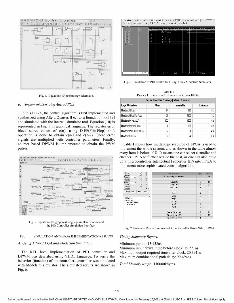
Fig. 4. Equation (10) technology schematic. B. Implementation using Altera FPGA:
In this FPGA, the control algorithm is first implemented and synthesized using Altera Quartus II 6.1 as a foundation tool [9] and simulated with the internal simulator tool. Equation (10) is represented in Fig. 5 in graphical language. The register error block stores values of e(n), using D-FF(Flip-Flop) shift operation is done to obtain e(n-1)and e(n-2). These error signals are multiplied with controller parameters. Finally, counter based DPWM is implemented to obtain the PWM pulses.
Fig. 5. Equation (10) graphical language implementation and the PID Controller simulation Interface.
IV. SIMULATION AND FPGA IMPLEMENTATION RESULTS
A. Using Xilinx FPGA and Modelsim Simulator:
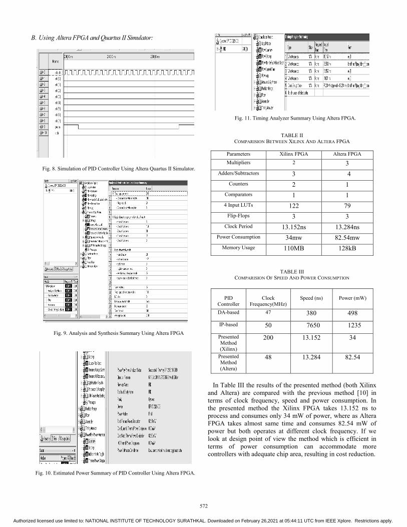
The RTL level implementation of PID controller and DPWM was described using VHDL language. To verify the behavior (function) of the controller, controller was simulated with Modelsim simulator. The simulated results are shown in Fig. 6.
Fig. 6. Simulation of PID Controller Using Xilinx Modelsim Simulator.
TABLE I DEVICE UTILIZATION SUMMARY OF XILINX FPGA
Table I shows how much logic resource of FPGA is used to implement the whole system, and as shown in the table almost every item is below 40%. It means one can select a smaller and cheaper FPGA to further reduce the cost, or one can also build up a microcontroller Intellectual Properties (IP) into FPGA to implement more sophisticated control algorithm.
Fig. 7. Estimated Power Summary of PID Controller Using Xilinx FPGA. Timing Summary Report:
Minimum period: 13.152ns Minimum input arrival time before clock: 15.271ns Maximum output required time after clock: 20.391ns Maximum combinational path delay: 22.494ns
Total Memory usage: 110000kbytes
571
Authorized licensed use limited to: NATIONAL INSTITUTE OF TECHNOLOGY SURATHKAL. Downloaded on February 26,2021 at 05:44:11 UTC from IEEE Xplore. Restrictions apply.
B. Using Altera FPGA and Quartus II Simulator:
Fig. 8. Simulation of PID Controller Using Altera Quartus II Simulator.
Fig. 9. Analysis and Synthesis Summary Using Altera FPGA
Fig. 10. Estimated Power Summary of PID Controller Using Altera FPGA.
Fig. 11. Timing Analyzer Summary Using Altera FPGA.
TABLE II COMPARISION BETWEEN XILINX AND ALTERA FPGA
Parameters Xilinx FPGA Altera FPGA Multipliers 2 3
Adders/Subtractors 3 4 Counters 2 1
Comparators 1 1 4 Input LUTs 122 79
Flip-Flops 3 3 Clock Period 13.152ns 13.284ns
Power Consumption 34mw 82.54mw Memory Usage 110MB 128kB
TABLE III COMPARISION OF SPEED AND POWER CONSUMPTION
PID Controller
Clock
Frequency(MHz)
Speed (ns)
Power (mW)
DA-based 47 380 498
IP-based 50 7650 1235
Presented Method (Xilinx)
200 13.152 34
Presented Method (Altera)
48 13.284 82.54
In Table III the results of the presented method (both Xilinx and Altera) are compared with the previous method [10] in terms of clock frequency, speed and power consumption. In the presented method the Xilinx FPGA takes 13.152 ns to process and consumes only 34 mW of power, where as Altera FPGA takes almost same time and consumes 82.54 mW of power but both operates at different clock frequency. If we look at design point of view the method which is efficient in terms of power consumption can accommodate more controllers with adequate chip area, resulting in cost reduction.
572
Authorized licensed use limited to: NATIONAL INSTITUTE OF TECHNOLOGY SURATHKAL. Downloaded on February 26,2021 at 05:44:11 UTC from IEEE Xplore. Restrictions apply.
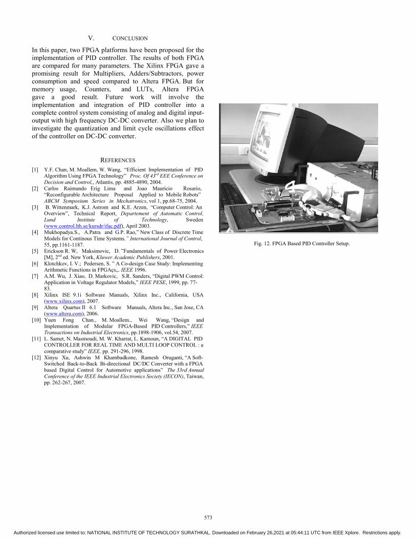
V. CONCLUSION
In this paper, two FPGA platforms have been proposed for the implementation of PID controller. The results of both FPGA are compared for many parameters. The Xilinx FPGA gave a promising result for Multipliers, Adders/Subtractors, power consumption and speed compared to Altera FPGA. But for
memory usage, Counters, and LUTs, Altera FPGA gave a good result. Future work will involve the implementation and integration of PID controller into a complete control system consisting of analog and digital input-output with high frequency DC-DC converter. Also we plan to investigate the quantization and limit cycle oscillations effect of the controller on DC-DC converter.
REFERENCES [1] Y.F. Chan, M. Moallem, W. Wang, “Efficient Implementation of PID
Algorithm Using FPGA Technology” Proc. Of 43rd EEE Conference on Decision and Control,, Atlantis, pp. 4885-4890, 2004.
[2] Carlos Raimundo Erig Lima and Joao Mauricio Rosario, “Reconfigurable Architecture Proposal Applied to Mobile Robots” ABCM Symposium Series in Mechatronics, vol 1, pp.68-75, 2004.
[3] B. Wittenmark, K.J. Astrom and K.E. Arzen, “Computer Control: An Overview”, Technical Report, Departement of Automatic Control, Lund Institute of Technology, Sweden (www.control.lth.se/kursdr/ifac.pdf), April 2003.
[4] Mukhopadya.S., A.Patra and G.P. Rao,” New Class of Discrete Time Models for Continous Time Systems,” International Journal of Control, 55, pp.1161-1187.
[5] Erickson R. W, Maksimovic, D. ”Fundamentals of Power Electronics [M], 2nd ed. New York, Kluwer Academic Publishers, 2001.
[6] Klotchkov, I. V.; Pedersen, S. ” A Co-design Case Study: Implementing Arithmetic Functions in FPGAçs„. IEEE 1996.
[7] A.M. Wu, J. Xiao, D. Markovic, S.R. Sanders, “Digital PWM Control: Application in Voltage Regulator Models,” IEEE PESE, 1999, pp. 77-83.
[8] Xilinx ISE 9.1i Software Manuals, Xilinx Inc., California, USA (www.xilinx.com), 2007.
[9] Altera Quartus II 6.1 Software Manuals, Altera Inc., San Jose, CA (www.altera.com), 2006.
[10] Yuen Fong Chan., M. Moallem., Wei Wang, “Design and Implementation of Modular FPGA-Based PID Controllers,” IEEE Transactions on Industrial Electronics, pp.1898-1906, vol.54, 2007.
[11] L. Samet, N. Masmoudi, M. W. Kharrat, L. Kamoun, “A DIGITAL PID CONTROLLER FOR REAL TIME AND MULTI LOOP CONTROL : a comparative study” IEEE, pp. 291-296, 1998.
[12] Xinyu Xu, Ashwin M Khambadkone, Ramesh Oruganti, “A Soft-Switched Back-to-Back Bi-directional DC/DC Converter with a FPGA based Digital Control for Automotive applications” The 33rd Annual Conference of the IEEE Industrial Electronics Society (IECON), Taiwan, pp. 262-267, 2007.
Fig. 12. FPGA Based PID Controller Setup.
573
Authorized licensed use limited to: NATIONAL INSTITUTE OF TECHNOLOGY SURATHKAL. Downloaded on February 26,2021 at 05:44:11 UTC from IEEE Xplore. Restrictions apply.