Design and Implementation of an Educational Testbed for Experiencing With Industrial Communication...
12
3122 IEEE TRANSACTIONS ON INDUSTRIAL ELECTRONICS, VOL. 54, NO. 6, DECEMBER 2007 Design and Implementation of an Educational Testbed for Experiencing With Industrial Communication Networks Lucia Lo Bello, Member, IEEE, Orazio Mirabella, Member, IEEE, and Antonino Raucea, Member, IEEE Abstract—This paper presents the design and implementation of an educational testbed developed for a course on industrial communication networks at the Engineering Faculty, University of Catania. The aim is to realize a platform capable of emulating various network configurations, thus enabling students to find out by themselves through practical experiments how different design choices, parameter settings, network configurations, and algorithms impact on the overall network performance. The test- bed comprises a number of basic components (hosts, routers, and access points) implemented on nodes equipped with operating systems and open source software, which together make up a modular system. Each router can be loaded with data flows and monitored over preestablished time windows so as to evaluate its performance in a wide range of operating conditions. The wireless part makes it possible to configure environments with different levels of noise and bandwidth utilization so as to emulate a broad spectrum of real operating environments. The testbed can be used via remote access through a web interface that not only allows the operating conditions to be configured but also permits real-time monitoring. Students can configure the testbed on the basis of the network they are studying and can measure its performance for evaluation purposes. Index Terms—Communication engineering education, com- puter networks, measurement, scheduling, wireless LAN. I. I NTRODUCTION O NE OF THE main difficulties encountered by students attending a course on industrial communication networks lies in the specific nature of these networks, which have to support various types of traffic flows with varying requirements in terms of bandwidth, delay, and time constraints [1], [2]. In addition, the interoperability of field bus systems with external systems and applications, which adds further complexity to the design of distributed process control systems, must be considered [3]. Another factor to be taken into account is the presence of both wired and wireless networks. As wireless networks feature quite different issues than wired ones [4]–[6] in order to understand how to properly design hybrid industrial communication networks, the adoption of new concepts and paradigms is needed. Manuscript received April 16, 2007; revised August 14, 2007. The authors are with the Department of Computer Engineering and Telecommunications, University of Catania, 95125 Catania, Italy (e-mail: [email protected]; [email protected]; [email protected]). Color versions of one or more of the figures in this paper are available online at http://ieeexplore.ieee.org. Digital Object Identifier 10.1109/TIE.2007.907025 The traditional approach for students to learn and evaluate communication networks is based on the use of analytical or simulation-based tools. However, these tools only give an abstract view of the network behavior. As a result, it is very difficult for the students to assess the impact of the hardware or software on the overall performance taking into account all the parameters and variables present in a real industrial network. In a hybrid wired/wireless system, this problem is further complicated by the presence of communication systems with very different features. On the other hand, the penetration of wireless communication in industrial applications is contin- uously increasing, and its impact on the overall communication system must be understood and carefully evaluated. For these reasons, students need hands-on approaches in addition to traditional teaching methods through lectures and simulations. An effective solution is to use a real testbed that enables stu- dents to discover by themselves through practical experiments how network performances are influenced by different design choices, parameter settings, and operating conditions. The results obtained this way provide, from the student per- spective, a higher degree of “trustworthiness” than assessments made using only analytical or simulation-based tools. Students can directly verify the validity of the design solutions being in- vestigated, i.e., identifying their advantages and disadvantages. In addition, they can define and test new strategies to improve the system performance. Some network testbeds have been recently developed and implemented, and many researchers have used them to evaluate specific applications in specific areas. Two main application ar- eas have been exploited, i.e., wireless sensor networks (WSNs) and wireless mesh networks (WMNs). In the sensor network area, several testbed solutions have been implemented. One of the most popular is MoteLab [7], which is a set of software tools for the management of a sensor network deployed in a large laboratory. It provides an Ethernet back channel with a central server for scheduling, node repro- gramming, and data logging, and allows students to access the testbed through a web interface. Twist [8] is similar to MoteLab but allows greater interaction with students and the evaluation of both hierarchical and flat WSNs. Both testbeds allow the boundary between simulated components and hardware to be shifted in such a way that an application can run on a simulated radio model or in the real hardware present in the testbed. All these testbeds use a wired Ethernet for management purposes. To avoid the cabling costs that are associated with Ethernet- based management in a large deployment, the Eidgenössis- che Technische Hochschule Zurich testbed [9] uses an out of 0278-0046/$25.00 © 2007 IEEE
-
Upload
independent -
Category
Documents
-
view
0 -
download
0
Transcript of Design and Implementation of an Educational Testbed for Experiencing With Industrial Communication...
3122 IEEE TRANSACTIONS ON INDUSTRIAL ELECTRONICS, VOL. 54, NO. 6, DECEMBER 2007
Design and Implementation of an EducationalTestbed for Experiencing With Industrial
Communication NetworksLucia Lo Bello, Member, IEEE, Orazio Mirabella, Member, IEEE, and Antonino Raucea, Member, IEEE
Abstract—This paper presents the design and implementationof an educational testbed developed for a course on industrialcommunication networks at the Engineering Faculty, Universityof Catania. The aim is to realize a platform capable of emulatingvarious network configurations, thus enabling students to findout by themselves through practical experiments how differentdesign choices, parameter settings, network configurations, andalgorithms impact on the overall network performance. The test-bed comprises a number of basic components (hosts, routers, andaccess points) implemented on nodes equipped with operatingsystems and open source software, which together make up amodular system. Each router can be loaded with data flows andmonitored over preestablished time windows so as to evaluate itsperformance in a wide range of operating conditions. The wirelesspart makes it possible to configure environments with differentlevels of noise and bandwidth utilization so as to emulate a broadspectrum of real operating environments. The testbed can be usedvia remote access through a web interface that not only allows theoperating conditions to be configured but also permits real-timemonitoring. Students can configure the testbed on the basis of thenetwork they are studying and can measure its performance forevaluation purposes.
Index Terms—Communication engineering education, com-puter networks, measurement, scheduling, wireless LAN.
I. INTRODUCTION
ONE OF THE main difficulties encountered by studentsattending a course on industrial communication networks
lies in the specific nature of these networks, which have tosupport various types of traffic flows with varying requirementsin terms of bandwidth, delay, and time constraints [1], [2]. Inaddition, the interoperability of field bus systems with externalsystems and applications, which adds further complexity tothe design of distributed process control systems, must beconsidered [3]. Another factor to be taken into account is thepresence of both wired and wireless networks. As wirelessnetworks feature quite different issues than wired ones [4]–[6]in order to understand how to properly design hybrid industrialcommunication networks, the adoption of new concepts andparadigms is needed.
Manuscript received April 16, 2007; revised August 14, 2007.The authors are with the Department of Computer Engineering and
Telecommunications, University of Catania, 95125 Catania, Italy (e-mail:[email protected]; [email protected]; [email protected]).
Color versions of one or more of the figures in this paper are available onlineat http://ieeexplore.ieee.org.
Digital Object Identifier 10.1109/TIE.2007.907025
The traditional approach for students to learn and evaluatecommunication networks is based on the use of analyticalor simulation-based tools. However, these tools only give anabstract view of the network behavior. As a result, it is verydifficult for the students to assess the impact of the hardwareor software on the overall performance taking into accountall the parameters and variables present in a real industrialnetwork. In a hybrid wired/wireless system, this problem isfurther complicated by the presence of communication systemswith very different features. On the other hand, the penetrationof wireless communication in industrial applications is contin-uously increasing, and its impact on the overall communicationsystem must be understood and carefully evaluated. For thesereasons, students need hands-on approaches in addition totraditional teaching methods through lectures and simulations.An effective solution is to use a real testbed that enables stu-dents to discover by themselves through practical experimentshow network performances are influenced by different designchoices, parameter settings, and operating conditions.
The results obtained this way provide, from the student per-spective, a higher degree of “trustworthiness” than assessmentsmade using only analytical or simulation-based tools. Studentscan directly verify the validity of the design solutions being in-vestigated, i.e., identifying their advantages and disadvantages.In addition, they can define and test new strategies to improvethe system performance.
Some network testbeds have been recently developed andimplemented, and many researchers have used them to evaluatespecific applications in specific areas. Two main application ar-eas have been exploited, i.e., wireless sensor networks (WSNs)and wireless mesh networks (WMNs).
In the sensor network area, several testbed solutions havebeen implemented. One of the most popular is MoteLab [7],which is a set of software tools for the management of a sensornetwork deployed in a large laboratory. It provides an Ethernetback channel with a central server for scheduling, node repro-gramming, and data logging, and allows students to access thetestbed through a web interface. Twist [8] is similar to MoteLabbut allows greater interaction with students and the evaluationof both hierarchical and flat WSNs. Both testbeds allow theboundary between simulated components and hardware to beshifted in such a way that an application can run on a simulatedradio model or in the real hardware present in the testbed. Allthese testbeds use a wired Ethernet for management purposes.To avoid the cabling costs that are associated with Ethernet-based management in a large deployment, the Eidgenössis-che Technische Hochschule Zurich testbed [9] uses an out of
0278-0046/$25.00 © 2007 IEEE
LO BELLO et al.: DESIGN AND IMPLEMENTATION OF AN EDUCATIONAL TESTBED 3123
band wireless network (based on Bluetooth [10]) for signaling.However, this adds problems related to several network oper-ations such as switching a single node on/off, if this has to bedone simultaneously and reliably for a large number of nodes.
In the WMN area, one of the most important aspects tobe evaluated is mobility, and various testbeds have dealt withthis problem in different ways. The Ad hoc Protocol Evalua-tion Testbed [11] was developed for the comparative study ofdifferent routing protocols. In this testbed, node deploymentis done manually in a large space. Mobility is achieved byvolunteers carrying laptops. Another large testbed is ORBIT[12], which uses an indoor grid of 400 nodes in a 20 × 20 mspace. Here, node movement is achieved through a mobilityserver that selectively turns wireless nodes “On” and “Off”in order to represent the same emulated node. A differentapproach to cope with mobility and reduce the physical spacerequired by the testbed is used in the Emulated Wireless AdHoc Network Testbed [13], which uses radio signal attenuatorsto reduce the radio range of the wireless cards. Mobility isemulated by connecting one wireless card to four externalwireless links through a 1 : 4 RF demultiplexer and switchingthe transmission between these links. This approach is furtherstressed in miniaturized network testbed (MINT) [14], whichuses two different approaches to emulate node mobility. Theyreduce the space required by the testbed by attenuating the radiosignal on the transmitter and the receiver. To this end, they usea wireless card that allows the transmission power to be setto different values, i.e., from 100 mW to 1 mW. The signalattenuation can be further improved through the use of fixedexternal attenuators. Mobility is emulated by varying the signalattenuation or mounting the nodes on small mobile robots.
Some testbeds have also been developed for experimentsin the industrial communications area. A real-time controlnetwork testbed in a Linux-based system with sporadic messagearrivals is described in [15]. This testbed allows the user toevaluate the performances obtained with event-driven messagetraffic and provides useful indications for the design and fea-sibility analysis of the network. Another testbed for remotesensor/actuator control in production automation through awireless real-time system is described in [16]. The performanceof a first prototype implementation is discussed with emphasison timing behavior and power consumption.
Most available testbeds have been implemented with specificapplications in mind or for research purposes. They are notsuitable for education due to their high cost, low flexibility, andlimited scope. A key point is to understand what a testbed forengineering education should be, i.e., what features it shouldpossess and what kind of measurements it should allow thestudents to perform. It is therefore important to define themain parameters for characterizing the testbed and the toolsthat have to be developed for the acquisition of the data tobe measured. This paper tries to answer all these questionswhile addressing the development of an educational remotelaboratory testbed for experiencing wired/wireless networkingin industrial communication.
The remote laboratories that were developed for educationpurposes act as an interface between students and real appli-ances. Their aim is allowing students to remotely access, test,
and control real appliances. Remote laboratories have been suc-cessfully used in engineering education for several purposes,e.g., teaching power electronics [17] or semiconductor devices[18], running simulation in virtual laboratories [19], generatingand simulating digital circuitries [20], and emulating applianceswith distributed control [21].
Due to the increasing performance achievable over high-speed dedicated data lines, several web-based remote labora-tories have been successfully developed even in the challengingscenario of real-time control over the Internet, including run-ning control experiments on tanks [22] and implementing real-time control of robotic systems [23], [24]. However, accordingto the author’s knowledge, no specific testbed for the study ofreal-time communication in process control systems has beendeveloped.
This paper describes an educational testbed that is developedfor a course on industrial communication networks at theEngineering Faculty, University of Catania. The testbed is thecore element of a remote educational laboratory. It extendsthe first prototype addressed in [25], which was conceived toaddress only wired networks, and the wired/wireless integratedprototype outlined in [26].
A few months have already passed from the completion ofthe wired/wireless prototype that has been deeply tested andused by many students. During this time, interactions withstudents allowed the teacher to catch their impressions on theuse of the system. Then, some first adjustments have beenintroduced in order to improve the remote interface accordingto suggestions of the students. The rationale behind the workwas to realize a platform capable of emulating various networkconfigurations, thus enabling students to discover by them-selves, i.e., by carrying out practical experiments, how differentdesign choices, parameter settings, network configurations, andalgorithms impact on the overall network performance.
In industrial communication and process control, the in-formation flows exchanged can be split into real-time flows,featuring more or less critical delivery deadlines, and nonreal-time ones, i.e., nontime-sensitive flows that can tolerate evenconsiderable delays without serious consequences. Examples ofreal-time flows are those connected with plant monitoring andcontrol, as well as alarms and related operations. Nonreal-timeflows, on the other hand, refer to plant configuration, softwaredownloading, database back-up operations, etc.
In this area, a flexible testbed that incorporates variousoperating modes to configure the traffic flows that the studentcan choose between to modify the working conditions of thenetwork, i.e., like the one addressed here, is of great use. In thetestbed, measurements are performed using software modulesembedded in the testbed, which allow the student to monitorthe network while it is operating. Following the measurements,log files for an accurate analysis of its behavior can also beacquired.
Moreover, with reference to the wireless section, it is impor-tant to decide how mobility and noise interference in wirelessnetworks have to be implemented in the testbed. Although thedecision to implement the testbed as a remote system adds somecomplexity to the design, it makes the system more suitable foreducational use. Having the testbed implemented as a remote
3124 IEEE TRANSACTIONS ON INDUSTRIAL ELECTRONICS, VOL. 54, NO. 6, DECEMBER 2007
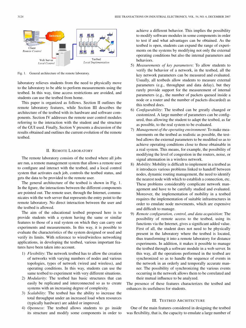
Fig. 1. General architecture of the remote laboratory.
laboratory relieves students from the need to physically moveto the laboratory to be able to perform measurements using thetestbed. In this way, time access restrictions are avoided, andstudents can use the testbed from home.
This paper is organized as follows. Section II outlines theremote laboratory features, while Section III describes thearchitecture of the testbed with its hardware and software com-ponents. Section IV addresses the remote user control modulesreferring to the interaction with the student and the structureof the GUI used. Finally, Section V presents a discussion of theresults obtained and outlines the current evolution of the remotetestbed.
II. REMOTE LABORATORY
The remote laboratory consists of the testbed where all jobsare run, a remote management system that allows a remote userto configure and interact with the testbed, and a local controlsystem that activates each job, controls the testbed status, andgets the data to be provided to the remote user.
The general architecture of the testbed is shown in Fig. 1.In the figure, the interactions between the different componentsare pointed out. The remote user, through the Internet, commu-nicates with the web server that represents the entry point to theremote laboratory. No direct interaction between the user andthe testbed is allowed.
The aim of the educational testbed proposed here is toprovide students with a system having the same or similarfeatures to those of a real system on which they can carry outexperiments and measurements. In this way, it is possible toevaluate the characteristics of the system designed or used andverify its limits. With reference to wired/wireless networkingapplications, in developing the testbed, various important fea-tures have been taken into account.
1) Flexibility: The network testbed has to allow the creationof networks with varying numbers of nodes and varioustopologies, types of network (wired and wireless), andoperating conditions. In this way, students can use thesame testbed to experiment with very different situations.
2) Modularity: The testbed has basic structures that caneasily be replicated and interconnected so as to createsystems with an increasing degree of complexity.
3) Scalability: The testbed has the ability to increase thetotal throughput under an increased load when resources(typically hardware) are added or improved.
4) Openness: The testbed allows students to go insideits structure and modify some components in order to
achieve a different behavior. This implies the possibilityto modify software modules in some components in orderto test if and what advantages can be obtained. As thetestbed is open, students can expand the range of experi-ments on the systems by modifying not only the externaloperating conditions but also the internal parameters andbehaviors.
5) Measurements of key parameters: To allow students toverify the behavior of a network, in the testbed, all thekey network parameters can be measured and evaluated.Usually, all testbeds allow students to measure externalparameters (e.g., throughput and data delay), but theyrarely provide support for the measurement of internalparameters (e.g., the number of packets queued inside anode or a router and the number of packets discarded) asthis testbed does.
6) Configurability: The testbed can be greatly changed orcustomized. A large number of parameters can be config-ured, thus allowing the student to adapt the testbed, as faras possible, to the real system to be evaluated.
7) Management of the operating environment: To make mea-surements on the testbed as realistic as possible, the test-bed allows the external parameters to be modified so as toachieve operating conditions close to those obtainable ina real system. This means, for example, the possibility ofmodifying the level of congestion in the routers, noise, orsignal attenuation in a wireless network.
8) Mobility: Mobility is difficult to implement in a testbed asit introduces various problems linked to handoff betweennodes, dynamic routing management, the need to identifythe nearest node with which to establish a connection, etc.These problems considerably complicate network man-agement and have to be carefully studied and evaluated.Moreover, the implementation of mobility in a testbedrequires the implementation of suitable infrastructures inorder to emulate node movements, which are expensiveand difficult to manage.
9) Remote configuration, control, and data acquisition: Thepossibility of remote access to the testbed, using itsfunctions via the Internet, gives a significant added value.First of all, the student does not need to be physicallypresent in the laboratory where the testbed is located,thus transforming it into a remote laboratory for distanceexperiments. In addition, it makes it possible to managethe testbed through a software module in a web server. Inthis way, all the operations performed in the testbed aresynchronized so as to handle the sequence of events inthe network in an orderly and temporally accurate man-ner. The possibility of synchronizing the various eventsoccurring in the network allows them to be correlated andtheir mutual influence to be analyzed.
The presence of these features characterizes the testbed andenhances its usefulness for students.
III. TESTBED ARCHITECTURE
One of the main features considered in designing the testbedwas flexibility, that is, the capacity to emulate a large number of
LO BELLO et al.: DESIGN AND IMPLEMENTATION OF AN EDUCATIONAL TESTBED 3125
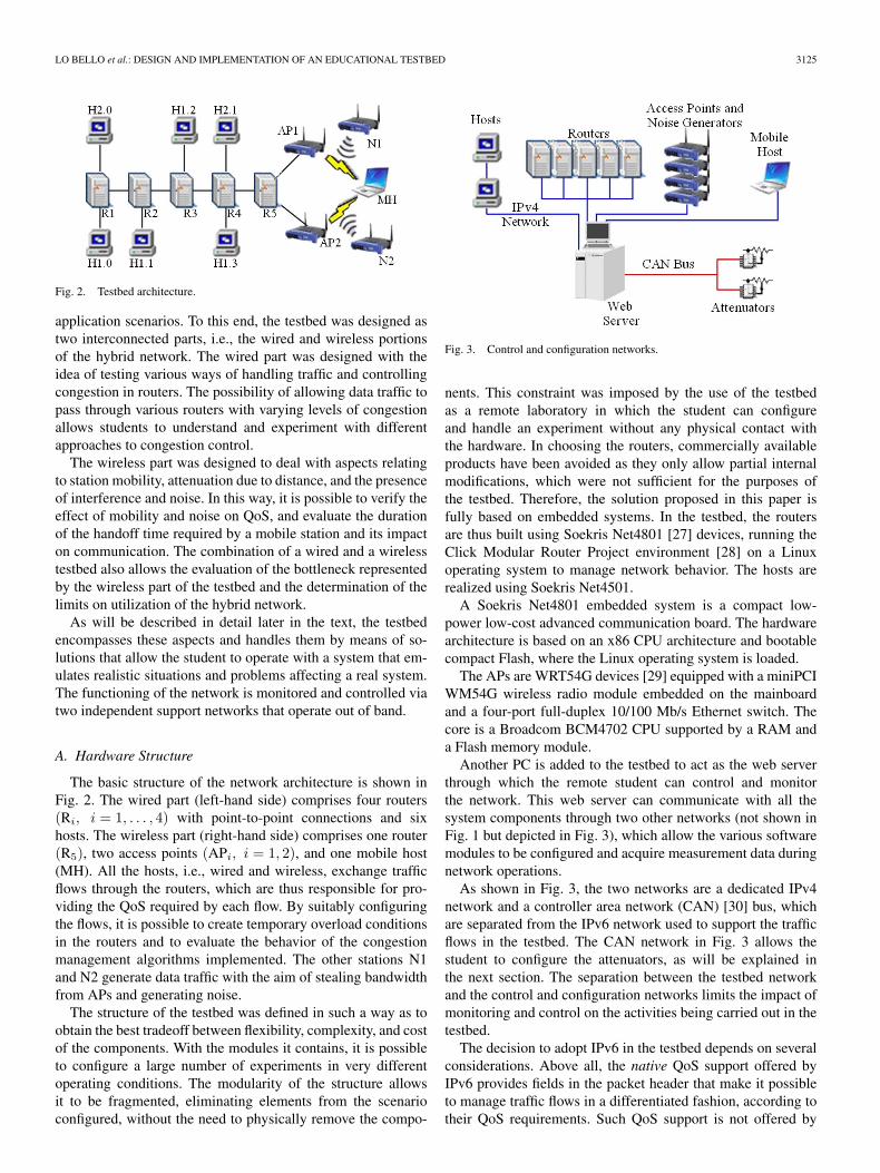
Fig. 2. Testbed architecture.
application scenarios. To this end, the testbed was designed astwo interconnected parts, i.e., the wired and wireless portionsof the hybrid network. The wired part was designed with theidea of testing various ways of handling traffic and controllingcongestion in routers. The possibility of allowing data traffic topass through various routers with varying levels of congestionallows students to understand and experiment with differentapproaches to congestion control.
The wireless part was designed to deal with aspects relatingto station mobility, attenuation due to distance, and the presenceof interference and noise. In this way, it is possible to verify theeffect of mobility and noise on QoS, and evaluate the durationof the handoff time required by a mobile station and its impacton communication. The combination of a wired and a wirelesstestbed also allows the evaluation of the bottleneck representedby the wireless part of the testbed and the determination of thelimits on utilization of the hybrid network.
As will be described in detail later in the text, the testbedencompasses these aspects and handles them by means of so-lutions that allow the student to operate with a system that em-ulates realistic situations and problems affecting a real system.The functioning of the network is monitored and controlled viatwo independent support networks that operate out of band.
A. Hardware Structure
The basic structure of the network architecture is shown inFig. 2. The wired part (left-hand side) comprises four routers(Ri, i = 1, . . . , 4) with point-to-point connections and sixhosts. The wireless part (right-hand side) comprises one router(R5), two access points (APi, i = 1, 2), and one mobile host(MH). All the hosts, i.e., wired and wireless, exchange trafficflows through the routers, which are thus responsible for pro-viding the QoS required by each flow. By suitably configuringthe flows, it is possible to create temporary overload conditionsin the routers and to evaluate the behavior of the congestionmanagement algorithms implemented. The other stations N1and N2 generate data traffic with the aim of stealing bandwidthfrom APs and generating noise.
The structure of the testbed was defined in such a way as toobtain the best tradeoff between flexibility, complexity, and costof the components. With the modules it contains, it is possibleto configure a large number of experiments in very differentoperating conditions. The modularity of the structure allowsit to be fragmented, eliminating elements from the scenarioconfigured, without the need to physically remove the compo-
Fig. 3. Control and configuration networks.
nents. This constraint was imposed by the use of the testbedas a remote laboratory in which the student can configureand handle an experiment without any physical contact withthe hardware. In choosing the routers, commercially availableproducts have been avoided as they only allow partial internalmodifications, which were not sufficient for the purposes ofthe testbed. Therefore, the solution proposed in this paper isfully based on embedded systems. In the testbed, the routersare thus built using Soekris Net4801 [27] devices, running theClick Modular Router Project environment [28] on a Linuxoperating system to manage network behavior. The hosts arerealized using Soekris Net4501.
A Soekris Net4801 embedded system is a compact low-power low-cost advanced communication board. The hardwarearchitecture is based on an x86 CPU architecture and bootablecompact Flash, where the Linux operating system is loaded.
The APs are WRT54G devices [29] equipped with a miniPCIWM54G wireless radio module embedded on the mainboardand a four-port full-duplex 10/100 Mb/s Ethernet switch. Thecore is a Broadcom BCM4702 CPU supported by a RAM anda Flash memory module.
Another PC is added to the testbed to act as the web serverthrough which the remote student can control and monitorthe network. This web server can communicate with all thesystem components through two other networks (not shown inFig. 1 but depicted in Fig. 3), which allow the various softwaremodules to be configured and acquire measurement data duringnetwork operations.
As shown in Fig. 3, the two networks are a dedicated IPv4network and a controller area network (CAN) [30] bus, whichare separated from the IPv6 network used to support the trafficflows in the testbed. The CAN network in Fig. 3 allows thestudent to configure the attenuators, as will be explained inthe next section. The separation between the testbed networkand the control and configuration networks limits the impact ofmonitoring and control on the activities being carried out in thetestbed.
The decision to adopt IPv6 in the testbed depends on severalconsiderations. Above all, the native QoS support offered byIPv6 provides fields in the packet header that make it possibleto manage traffic flows in a differentiated fashion, according totheir QoS requirements. Such QoS support is not offered by
3126 IEEE TRANSACTIONS ON INDUSTRIAL ELECTRONICS, VOL. 54, NO. 6, DECEMBER 2007
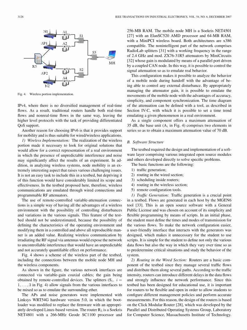
Fig. 4. Wireless portion implementation.
IPv4, where there is no diversified management of real-timeflows. As a result, traditional routers handle both real-timeflows and nonreal-time flows in the same way, leaving thehigher level protocols with the task of providing differentiatedQoS support.
Another reason for choosing IPv6 is that it provides supportfor mobility and is thus suitable for wired/wireless applications.1) Wireless Implementation: The realization of the wireless
portion made it necessary to look for original solutions thatwould allow for a correct representation of a real environmentin which the presence of unpredictable interference and noisemay significantly affect the results of an experiment. In ad-dition, in analyzing wireless systems, node mobility is an ex-tremely interesting aspect that raises various challenging issues.It is not an easy task to include this in a testbed, but depriving itof this function would have considerably limited its scope andeffectiveness. In the testbed proposed here, therefore, wirelesscommunications are emulated through wired connections andprogrammable RF attenuators.
The use of remote-controlled variable-attenuation connec-tions is a simple way of having all the advantages of a wirelessenvironment with the possibility of controlling disturbancesand variations in the various signals. This feature of the test-bed should not be underestimated, because the possibility ofdefining the characteristics of the operating environment andmodifying them in a controlled and above all reproducible man-ner is an added value. Realizing wireless communication byirradiating the RF signal via antennas would expose the networkto uncontrollable interference that would have an unpredictableand not accurately quantifiable effect on performance.
Fig. 4 shows a scheme of the wireless part of the testbed,including the connections between the mobile node MH andthe wireless components.
As shown in the figure, the various network interfaces areconnected via variable-gain coaxial cables; the gain beingobtained by remote-controlled devices. The splitters (Si, i =1, . . . , 3 in Fig. 4) allow signals from the various interfaces tobe mixed so as to emulate the surrounding ether.
The APs and noise generators were implemented withLinksys WRT54G hardware version 5.0, in which the boot-loader was modified to replace the firmware with an appropri-ately developed Linux-based version. The router R5 is a SoekrisNET4801 with a 266-MHz Geode SC1100 processor and
256-MB RAM. The mobile node MH is a Soekris NET4501[27] with an ElanSC520 AMD processor and 64-MB RAM,with a MiniPCI wireless board. Both architectures are x386compatible. The nonintelligent part of the network comprisesRadioLab splitters [31] with a working frequency in the rangeof 2.4 GHz and mod. ZX76-31R5 attenuators by MiniCircuits[32] whose gain is modulated by means of a parallel port drivenby a coupled CAN node. In this way, it is possible to control thesignal attenuation so as to emulate real behavior.
This configuration makes it possible to analyze the behaviorof a mobile node during handoff with the advantage of be-ing able to control any external disturbance. By appropriatelymanaging the attenuator gain, it is possible to emulate themovements of the mobile node with the advantages of accuracy,simplicity, and component synchronization. The time diagramof the attenuation can be defined with a tool, as described inSection IV-C, with which it is possible to set a time trendemulating a given phenomenon in a real environment.
As a single component offers a maximum attenuation of35 dB, the base unit (Ai in Fig. 4) comprises two elements inseries so as to obtain a maximum attenuation value of 70 dB.
B. Software Structure
The testbed required the design and implementation of a soft-ware layer comprising various integrated open source modulesand others developed directly to solve specific problems.
The basic functions are the following:1) traffic generation;2) routing in the wired section;3) scheduling inside routers;4) routing in the wireless section;5) remote configuration tools.1) Traffic Generation: Traffic generation is a crucial point
in a testbed. Flows are generated in each host by the MGEN6tool [33]. This is an open source software with a GeneralPublic License and was chosen on account of its simplicity andflexible programming by means of scripts. In an initial phase,the student must define the times and modes of transmission forthe various flows. To make the network configuration easier,a user-friendly interface that interacts with the generators wasdesigned, which makes it unnecessary for the student to usescripts. It is simple for the student to define not only the variousdata flows but also the way in which they vary over time so asto predetermine critical situations and study the behavior of thesystem.2) Routing in the Wired Section: Routers are a basic com-
ponent of the testbed since they manage several traffic flowsand distribute them along several paths. According to the trafficintensity, routers can introduce different delays in the data flowsand strongly influence the network performance. Since thistestbed has been designed for educational use, it is importantfor routers to be flexible and open in order to allow students toconfigure different management policies and perform accuratemeasurements. For this reason, the design of the routers is basedon the Click Modular Router [28], which was developed by theParallel and Distributed Operating Systems Group, Laboratoryfor Computer Science, Massachusetts Institute of Technology.
LO BELLO et al.: DESIGN AND IMPLEMENTATION OF AN EDUCATIONAL TESTBED 3127
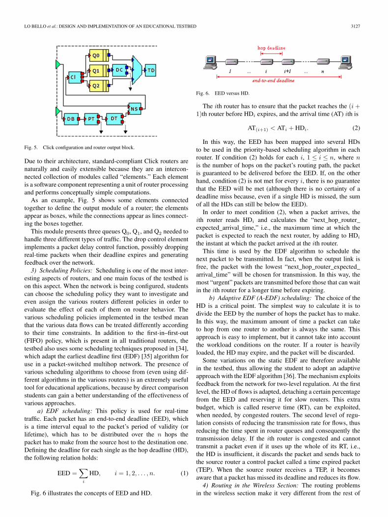
Fig. 5. Click configuration and router output block.
Due to their architecture, standard-compliant Click routers arenaturally and easily extensible because they are an intercon-nected collection of modules called “elements.” Each elementis a software component representing a unit of router processingand performs conceptually simple computations.
As an example, Fig. 5 shows some elements connectedtogether to define the output module of a router; the elementsappear as boxes, while the connections appear as lines connect-ing the boxes together.
This module presents three queues Q0, Q1, and Q2 needed tohandle three different types of traffic. The drop control elementimplements a packet delay control function, possibly droppingreal-time packets when their deadline expires and generatingfeedback over the network.3) Scheduling Policies: Scheduling is one of the most inter-
esting aspects of routers, and one main focus of the testbed ison this aspect. When the network is being configured, studentscan choose the scheduling policy they want to investigate andeven assign the various routers different policies in order toevaluate the effect of each of them on router behavior. Thevarious scheduling policies implemented in the testbed meanthat the various data flows can be treated differently accordingto their time constraints. In addition to the first-in–first-out(FIFO) policy, which is present in all traditional routers, thetestbed also uses some scheduling techniques proposed in [34],which adapt the earliest deadline first (EDF) [35] algorithm foruse in a packet-switched multihop network. The presence ofvarious scheduling algorithms to choose from (even using dif-ferent algorithms in the various routers) is an extremely usefultool for educational applications, because by direct comparisonstudents can gain a better understanding of the effectiveness ofvarious approaches.
a) EDF scheduling: This policy is used for real-timetraffic. Each packet has an end-to-end deadline (EED), whichis a time interval equal to the packet’s period of validity (orlifetime), which has to be distributed over the n hops thepacket has to make from the source host to the destination one.Defining the deadline for each single as the hop deadline (HD),the following relation holds:
EED =∑
i
HD, i = 1, 2, . . . , n. (1)
Fig. 6 illustrates the concepts of EED and HD.
Fig. 6. EED versus HD.
The ith router has to ensure that the packet reaches the (i +1)th router before HDi expires, and the arrival time (AT) ith is
AT(i+1) < ATi + HDi. (2)
In this way, the EED has been mapped into several HDsto be used in the priority-based scheduling algorithm in eachrouter. If condition (2) holds for each i, 1 ≤ i ≤ n, where nis the number of hops on the packet’s routing path, the packetis guaranteed to be delivered before the EED. If, on the otherhand, condition (2) is not met for every i, there is no guaranteethat the EED will be met (although there is no certainty of adeadline miss because, even if a single HD is missed, the sumof all the HDs can still be below the EED).
In order to meet condition (2), when a packet arrives, theith router reads HDi and calculates the “next_hop_router_expected_arrival_time,” i.e., the maximum time at which thepacket is expected to reach the next router, by adding to HDi
the instant at which the packet arrived at the ith router.This time is used by the EDF algorithm to schedule the
next packet to be transmitted. In fact, when the output link isfree, the packet with the lowest “next_hop_router_expected_arrival_time” will be chosen for transmission. In this way, themost “urgent” packets are transmitted before those that can waitin the ith router for a longer time before expiring.
b) Adaptive EDF (A-EDF) scheduling: The choice of theHD is a critical point. The simplest way to calculate it is todivide the EED by the number of hops the packet has to make.In this way, the maximum amount of time a packet can taketo hop from one router to another is always the same. Thisapproach is easy to implement, but it cannot take into accountthe workload conditions on the router. If a router is heavilyloaded, the HD may expire, and the packet will be discarded.
Some variations on the static EDF are therefore availablein the testbed, thus allowing the student to adopt an adaptiveapproach with the EDF algorithm [36]. The mechanism exploitsfeedback from the network for two-level regulation. At the firstlevel, the HD of flows is adapted, detaching a certain percentagefrom the EED and reserving it for slow routers. This extrabudget, which is called reserve time (RT), can be exploited,when needed, by congested routers. The second level of regu-lation consists of reducing the transmission rate for flows, thusreducing the time spent in router queues and consequently thetransmission delay. If the ith router is congested and cannottransmit a packet even if it uses up the whole of its RT, i.e.,the HD is insufficient, it discards the packet and sends back tothe source router a control packet called a time expired packet(TEP). When the source router receives a TEP, it becomesaware that a packet has missed its deadline and reduces its flow.4) Routing in the Wireless Section: The routing problems
in the wireless section make it very different from the rest of
3128 IEEE TRANSACTIONS ON INDUSTRIAL ELECTRONICS, VOL. 54, NO. 6, DECEMBER 2007
the network. As shown in Fig. 2, the topology of the wirelesssection in the testbed is limited to a few elements, so the choiceof the route is a simple task. In the testbed, problems mainlyrelated to handoff/handover of a moving node are focused inorder to allow students to measure the delay introduced inthis phase. For this section, a software layer has been definedand implemented, which highlights classical problems affectingwireless systems and offers various solutions that students cancompare and evaluate. In the structure of the testbed, the routerR5 represents the border between the wired and wireless parts,and the route toward the correct AP on the basis of its internalrouting table, which changes in relation to the connectionstatus of the MH. Updating the information in this table is afundamental aspect as it directly affects the performance ofthe wireless link. The currently adopted solution is based ona distributed application executed by R5 and the APs. Themost significant part resides in the APs, which send router R5
information regarding handoff/handover by an MH.Differentiation between types of traffic is extremely impor-
tant in wireless networks because solutions that are optimalfor one type of traffic may penalize other types. For example,a buffer that represents the optimal solution to avoid packetloss introduces a delay that may be a problem in real-timetransmissions where meeting deadlines is more important thanthe actual delivery of information.
The testbed offers the student a series of features that canbe activated via a web interface by means of which it ispossible to set the basic parameters and choose between thevarious approaches available. The main purpose of the toolsthat were developed is to verify the behavior of multimediaflows when they pass from the wired part to the wireless partthrough router R5 and then reach an MH. In the default version,transiting packets are not subject to any control, so part ofthe packets routed during handoff/handover will be lost. Thissimple solution can then be compared with the other approachesavailable in the testbed to evaluate the performance obtainable.The following approaches are currently available.
1) Buffer in Router R5: The AP notifies R5 of the start of ahandoff/handover by an MH, and R5 buffers the packetsfor the flows involved in a FIFO or random early detection(RED) queue with configurable parameters. When theMH rejoins, the packets are routed along the new path.This minimizes packet loss but introduces greater delay,which penalizes multimedia flows.
2) Packet Duplication: The AP notifies R5 of the start of ahandoff/handover by an MH, and R5 knows the status ofall the APs directly connected and thus chooses a new linkon which to duplicate packets in transit. When the MHrejoins, R5 updates its routing tables and resumes normalactivity. This minimizes packet loss but introduces prob-lems of overhead and duplicated packets.
3) Temporary Change in Priority: In synergy with the pres-ence of the buffer in router R5, packets belonging toflows regarding a station undergoing a change in AP arebuffered in the FIFO or RED queue. When the stationrejoins, they are sent with a higher priority than the flowsof the other mobile stations.
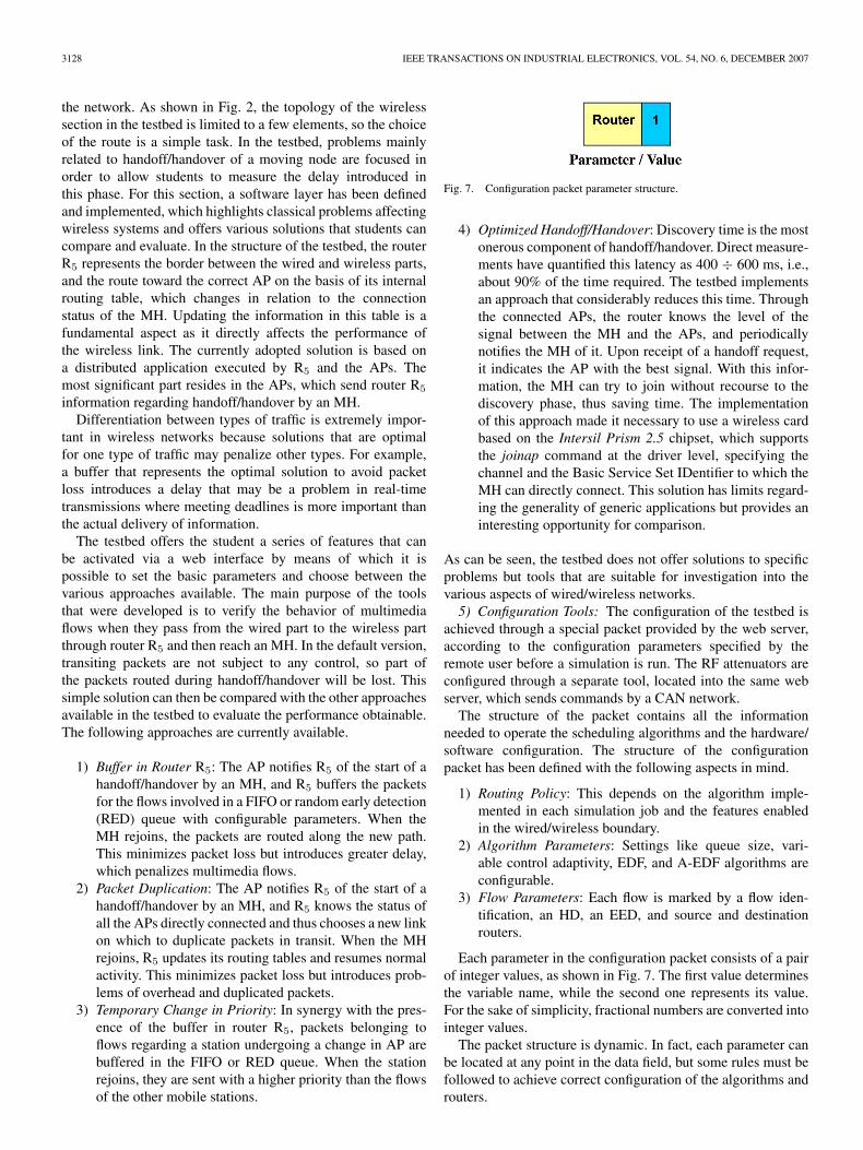
Fig. 7. Configuration packet parameter structure.
4) Optimized Handoff/Handover: Discovery time is the mostonerous component of handoff/handover. Direct measure-ments have quantified this latency as 400 ÷ 600 ms, i.e.,about 90% of the time required. The testbed implementsan approach that considerably reduces this time. Throughthe connected APs, the router knows the level of thesignal between the MH and the APs, and periodicallynotifies the MH of it. Upon receipt of a handoff request,it indicates the AP with the best signal. With this infor-mation, the MH can try to join without recourse to thediscovery phase, thus saving time. The implementationof this approach made it necessary to use a wireless cardbased on the Intersil Prism 2.5 chipset, which supportsthe joinap command at the driver level, specifying thechannel and the Basic Service Set IDentifier to which theMH can directly connect. This solution has limits regard-ing the generality of generic applications but provides aninteresting opportunity for comparison.
As can be seen, the testbed does not offer solutions to specificproblems but tools that are suitable for investigation into thevarious aspects of wired/wireless networks.5) Configuration Tools: The configuration of the testbed is
achieved through a special packet provided by the web server,according to the configuration parameters specified by theremote user before a simulation is run. The RF attenuators areconfigured through a separate tool, located into the same webserver, which sends commands by a CAN network.
The structure of the packet contains all the informationneeded to operate the scheduling algorithms and the hardware/software configuration. The structure of the configurationpacket has been defined with the following aspects in mind.
1) Routing Policy: This depends on the algorithm imple-mented in each simulation job and the features enabledin the wired/wireless boundary.
2) Algorithm Parameters: Settings like queue size, vari-able control adaptivity, EDF, and A-EDF algorithms areconfigurable.
3) Flow Parameters: Each flow is marked by a flow iden-tification, an HD, an EED, and source and destinationrouters.
Each parameter in the configuration packet consists of a pairof integer values, as shown in Fig. 7. The first value determinesthe variable name, while the second one represents its value.For the sake of simplicity, fractional numbers are converted intointeger values.
The packet structure is dynamic. In fact, each parameter canbe located at any point in the data field, but some rules must befollowed to achieve correct configuration of the algorithms androuters.
LO BELLO et al.: DESIGN AND IMPLEMENTATION OF AN EDUCATIONAL TESTBED 3129
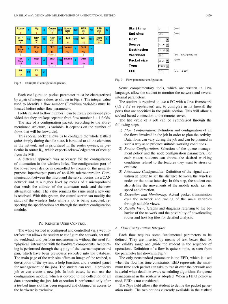
Fig. 8. Example of configuration packet.
Each configuration packet parameter must be characterizedby a pair of integer values, as shown in Fig. 8. The integer valueused to identify a flow number (FlowNum variable) must belocated before other flow parameters.
Fields related to flow number i can be freely positioned pro-vided that they are kept separate from flow number i + 1 fields.
The size of a configuration packet, according to the afore-mentioned structure, is variable. It depends on the number offlows that will be forwarded.
This special packet allows us to configure the whole testbedquite simply during the idle state. It is routed to all the elementsin the network and is prioritized in the router queues, in par-ticular in router R5, which expects acknowledgement of receiptfrom the MH.
A different approach was necessary for the configurationof attenuation in the wireless links. The configuration port ofthe lower level device is controlled by means of the general-purpose input/output ports of an 8-bit microcontroller. Com-munication between the micro and the server occurs via a CANnetwork and at a higher level by means of a microprotocolthat sends the address of the attenuator node and the newattenuation value. The value remains the same until a new oneis received. With this system, the central server can modify thestatus of the wireless links while a job is being executed, re-specting the specifications set through the student configurationmodule.
IV. REMOTE USER CONTROL
The whole testbed is configured and controlled via a web in-terface that allows the student to configure the network, set traf-fic workload, and perform measurements without the need for“physical” interaction with the hardware components. Account-ing is performed through the typing of the username/passwordpair, which have been previously recorded into the database.The main page of the web site offers an image of the testbed, adescription of the system, a help function, and a control panelfor management of the jobs. The student can recall a previousjob or can create a new job. In both cases, he can use theconfiguration module, which is devoted to the collection of alldata concerning the job. Job execution is performed only aftera testbed time slot has been required and obtained as access tothe hardware is exclusive.
Fig. 9. Flow parameter configuration.
Some complementary tools, which are written in Javalanguage, allow the student to monitor the network and severalinternal parameters.
The student is required to use a PC with a Java framework(jdk 1.4.2 or equivalent) and to configure in its firewall theports that are specified in the guide section. This will allow asocked-based connection to the remote server.
The life cycle of a job can be synthesized through thefollowing steps.
1) Flow Configuration: Definition and configuration of allthe flows involved in the job in order to plan the activity.Data flows can vary during the job and can be planned insuch a way as to produce suitable working conditions.
2) Router Configuration: Selection of the queue manage-ment policy and the node configuration parameters. Foreach router, students can choose the desired workingconditions related to the features they want to stress orevaluate.
3) Attenuator Configuration: Definition of the signal atten-uation in order to set the distance between the wirelessnodes or the noise intensity. In this step, the student canalso define the movements of the mobile node, i.e., itsspeed and direction.
4) Execution and Monitoring: Actual packet transmissionover the network and tracing of the main variablesthrough suitable views.
5) Results View: Graphs and diagrams referring to the be-havior of the network and the possibility of downloadingrouter and host log files for detailed analysis.
A. Flow Configuration Interface
Each flow requires some fundamental parameters to bedefined. They are inserted by means of text boxes that fixthe validity range and guide the student in the sequence ofoperations. Definition of a flow is quite simple, as seen fromthe parameter list shown in Fig. 9.
The only nonstandard parameter is the EED, which is usedwhen the flow has time constraints. EED represents the maxi-mum time each packet can take to transit over the network andis useful when deadline-aware scheduling algorithms for queuemanagement in the routers is adopted. When a FIFO policy isused, EED is not considered.
The Type field allows the student to define the packet gener-ation mode. The two options currently available in the testbed
3130 IEEE TRANSACTIONS ON INDUSTRIAL ELECTRONICS, VOL. 54, NO. 6, DECEMBER 2007
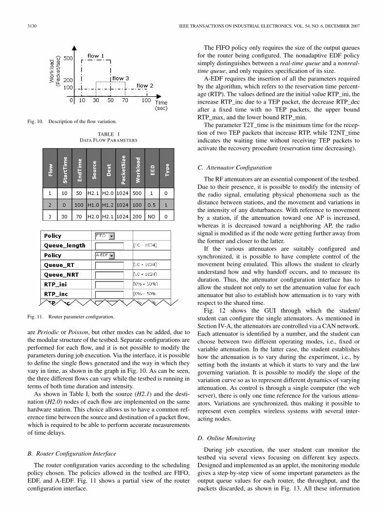
Fig. 10. Description of the flow variation.
TABLE IDATA FLOW PARAMETERS
Fig. 11. Router parameter configuration.
are Periodic or Poisson, but other modes can be added, due tothe modular structure of the testbed. Separate configurations areperformed for each flow, and it is not possible to modify theparameters during job execution. Via the interface, it is possibleto define the single flows generated and the way in which theyvary in time, as shown in the graph in Fig. 10. As can be seen,the three different flows can vary while the testbed is running interms of both time duration and intensity.
As shown in Table I, both the source (H2.1) and the desti-nation (H2.0) nodes of each flow are implemented on the samehardware station. This choice allows us to have a common ref-erence time between the source and destination of a packet flow,which is required to be able to perform accurate measurementsof time delays.
B. Router Configuration Interface
The router configuration varies according to the schedulingpolicy chosen. The policies allowed in the testbed are FIFO,EDF, and A-EDF. Fig. 11 shows a partial view of the routerconfiguration interface.
The FIFO policy only requires the size of the output queuesfor the router being configured. The nonadaptive EDF policysimply distinguishes between a real-time queue and a nonreal-time queue, and only requires specification of its size.
A-EDF requires the insertion of all the parameters requiredby the algorithm, which refers to the reservation time percent-age (RTP). The values defined are the initial value RTP_ini, theincrease RTP_inc due to a TEP packet, the decrease RTP_decafter a fixed time with no TEP packets, the upper boundRTP_max, and the lower bound RTP_min.
The parameter T2T_time is the minimum time for the recep-tion of two TEP packets that increase RTP, while T2NT_timeindicates the waiting time without receiving TEP packets toactivate the recovery procedure (reservation time decreasing).
C. Attenuator Configuration
The RF attenuators are an essential component of the testbed.Due to their presence, it is possible to modify the intensity ofthe radio signal, emulating physical phenomena such as thedistance between stations, and the movement and variations inthe intensity of any disturbances. With reference to movementby a station, if the attenuation toward one AP is increased,whereas it is decreased toward a neighboring AP, the radiosignal is modified as if the node were getting further away fromthe former and closer to the latter.
If the various attenuators are suitably configured andsynchronized, it is possible to have complete control of themovement being emulated. This allows the student to clearlyunderstand how and why handoff occurs, and to measure itsduration. Thus, the attenuator configuration interface has toallow the student not only to set the attenuation value for eachattenuator but also to establish how attenuation is to vary withrespect to the shared time.
Fig. 12 shows the GUI through which the student/student can configure the single attenuators. As mentioned inSection IV-A, the attenuators are controlled via a CAN network.Each attenuator is identified by a number, and the student canchoose between two different operating modes, i.e., fixed orvariable attenuation. In the latter case, the student establisheshow the attenuation is to vary during the experiment, i.e., bysetting both the instants at which it starts to vary and the lawgoverning variation. It is possible to modify the slope of thevariation curve so as to represent different dynamics of varyingattenuation. As control is through a single computer (the webserver), there is only one time reference for the various attenu-ators. Variations are synchronized, thus making it possible torepresent even complex wireless systems with several inter-acting nodes.
D. Online Monitoring
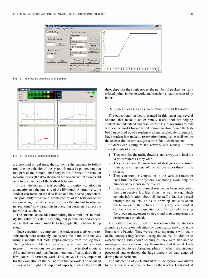
During job execution, the user student can monitor thetestbed via several views focusing on different key aspects.Designed and implemented as an applet, the monitoring modulegives a step-by-step view of some important parameters as theoutput queue values for each router, the throughput, and thepackets discarded, as shown in Fig. 13. All these information
LO BELLO et al.: DESIGN AND IMPLEMENTATION OF AN EDUCATIONAL TESTBED 3131
Fig. 12. Interface for attenuator configuration.
Fig. 13. Example of router monitoring.
are provided in real time, thus allowing the students to followrun time the behavior of the system. It must be pointed out thatthis part of the remote laboratory is not foreseen for detailedmeasurements (the data shown on the screen are not stored) butonly to give an idea of the testbed behavior.
In the wireless part, it is possible to monitor variations inattenuation and the intensity of the RF signal. Alternatively, thestudent can focus on the data flows and their basic parameters.The possibility of visual run-time control of the behavior of thesystem is significant because it allows the student to observein “real time” how variations in operating parameters affect thenetwork as a whole.
The student can decide (after halting the simulation) to mod-ify the value of certain preconfigured parameters and chooseothers that are more suitable to highlight the behavior beingsought.
Once execution is complete, the student can analyze the re-sults much more accurately than is possible in run-time analysisusing a module that plots graphs directly from the log files.The log files are obtained by collecting various parameters ofinterest in the various devices present in the testbed (routers,APs, and hosts) and transferring them, out of band, through theIPv4 control Ethernet network. This analysis is very importantfor the evaluation of the behavior of the network. The obtainedcurves in fact highlight important aspects, such as the overall
throughput for the single nodes, the number of packets lost, anycritical points in the network, and transient situations caused bybursts.
V. SOME EXPERIENCES AND CONCLUDING REMARK
The educational testbed presented in this paper has severalfeatures that make it an extremely useful tool for helpingstudents to understand and practice with issues regarding wired/wireless networks for industrial communication. Since the test-bed can be used by one student at a time, a schedule is required.Each student first makes a reservation through an e-mail sent tothe teacher that in turn assigns a time slot to each student.
Students can configure the network and manage it fromseveral points of view.
1) They can size the traffic flows in such a way as to load thevarious routers as they wish.
2) They can choose the management strategies in the singlerouters, selecting one of the various algorithms in thesystem.
3) They can monitor congestion in the various routers in“real time” while the system is operating, examining thenumber of elements in the queues.
4) Finally, once a measurement session has been completed,they can receive log files from the web server, whichcontain information about all the traffic that has passedthrough the routers, so as to draw up statistics aboutthe behavior of the network. In this way, each studentcan launch several sequential tests, for example, varyingthe queue management strategy, and then comparing theperformance obtained.
The testbed has been used for several months by studentsattending a course on industrial communication networks at theEngineering Faculty. They were able to experiment with manyof the concepts they learned during the course. In addition toexperimenting with known techniques, they were also able toinvestigate new solutions they themselves had devised. Eachexperiment led to a subsequent phase in which the studentsprocessed and evaluated the large amount of data acquiredduring the experiment.
The interaction of each student with the system was drivenby a specific task assigned to him by the teacher. Each student
3132 IEEE TRANSACTIONS ON INDUSTRIAL ELECTRONICS, VOL. 54, NO. 6, DECEMBER 2007
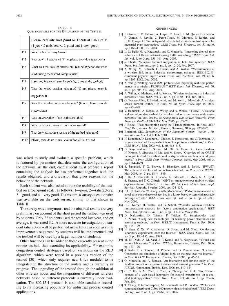
TABLE IIQUESTIONNAIRE FOR THE EVALUATION OF THE TESTBED
was asked to study and evaluate a specific problem, whichis featured by parameters that determine the configuration ofthe network. At the end, each student must prepare a reportcontaining the analysis he has performed together with theresults obtained, and a discussion that gives reasons for thebehavior of the network.
Each student was also asked to rate the usability of the test-bed on a four-point scale, as follows: 1—poor, 2—satisfactory,3—good, and 4—very good. To this aim, a survey questionnairewas available on the web server, similar to that shown inTable II.
The survey was anonymous, and the obtained results are verypreliminary on account of the short period the testbed was usedby students. Only 22 students used the testbed last year, and onaverage, it was rated 3.2. A more accurate investigation on stu-dent satisfaction will be performed in the future as soon as someimprovements suggested by students will be implemented, andthe testbed will be used by a larger number of students.
Other functions can be added to those currently present in theremote testbed, thus extending its applicability. For example,congestion control strategies based on variations on the REDalgorithm, which were tested in a previous version of thetestbed [30], which only requires new Click modules to beintegrated in the structure of the routers and is currently inprogress. The upgrading of the testbed through the addition ofother wireless nodes and the integration of different wirelessnetworks based on different protocols is currently under eval-uation. The 802.15.4 protocol is a suitable candidate accord-ing to its increasing popularity for industrial process controlapplications.
REFERENCES
[1] J. Garcia, F. R. Palomo, A. Luque, C. Aracil, J. M. Quero, D. Carrion,F. Gamiz, P. Revilla, J. Perez-Tinao, M. Moreno, P. Robles, andL. G. Franquelo, “Reconfigurable distributed network control system forindustrial plant automation,” IEEE Trans. Ind. Electron., vol. 51, no. 6,pp. 1168–1180, Dec. 2004.
[2] L. Lo Bello, G. A. Kaczynski, and O. Mirabella, “Improving the real-timebehavior of Ethernet networks using traffic smoothing,” IEEE Trans. Ind.Inf., vol. 1, no. 3, pp. 151–161, Aug. 2005.
[3] S. Eberle, “Adaptive Internet integration of field bus systems,” IEEETrans. Ind. Informat., vol. 3, no. 1, pp. 12–20, Feb. 2007.
[4] A. Willig, M. Kubisch, C. Hoene, and A. Wolisz, “Measurements ofa wireless link in an industrial environment using an IEEE 802.11-compliant physical layer,” IEEE Trans. Ind. Electron., vol. 49, no. 6,pp. 1265–1282, Dec. 2002.
[5] A. Willig, “Polling-based MAC protocols for improving real-time perfor-mance in a wireless PROFIBUS,” IEEE Trans. Ind. Electron., vol. 50,no. 4, pp. 806–817, Aug. 2003.
[6] A. Willig, K. Matheus, and A. Wolisz, “Wireless technology in industrialnetworks,” Proc. IEEE, vol. 93, no. 6, pp. 1130–1151, Jun. 2005.
[7] G. Werner-Allen, P. Swieskowski, and M. Welsh, “MoteLab: A wirelesssensor network testbed,” in Proc. 4th Int. Symp. IPSN, Apr. 15, 2005,pp. 483–488.
[8] V. Handziski, A. Köpke, A. Willig, and A. Wolisz, “TWIST: A scalableand reconfigurable testbed for wireless indoor experiments with sensornetworks,” in Proc. 2nd Int. Workshop Multi-Hop Ad Hoc Networks: FromTheory to Reality REALMAN, May 2006, pp. 63–70.
[9] J. Beutel, “Fast-prototyping using the BTnode platform,” in Proc. ACMConf. Des., Autom. Test Eur., Munich, Germany, 2006, pp. 977–982.
[10] Bluetooth SIG, Specification of the Bluetooth System—Version 1.1B,Specification Vol. 1 & 2, Feb. 2001.
[11] H. Lundgren, D. Lundberg, J. Nielsen, E. Nordstrom, and C. Tschudin, “Alarge-scale testbed for reproducible ad hoc protocol evaluations,” in Proc.IEEE WCNC, Mar. 2002, vol. 1, pp. 412–418.
[12] D. Raychaudhuri, I. Seskar, M. Ott, S. Ganu, K. Ramachandran,H. Kremo, R. Siracusa, H. Liu, and M. Singh, “Overview of the ORBITradio grid testbed for evaluation of next-generation wireless network pro-tocols,” in Proc. IEEE Conf. Wireless Commun. Netw., Mar. 2005, vol. 3,pp. 1664–1669.
[13] S. Sanghani, T. X. Brown, S. Bhandare, and S. Doshi, “EWANT:The emulated wireless ad hoc network testbed,” in Proc. IEEE WCNC,Mar. 2003, vol. 3, pp. 1844–1849.
[14] P. De, A. Raniwala, R. Krishnan, K. Tatavarthi, J. Modi, N. A. Syed,S. Sharma, and T.-C. Chiueh, “MiNT-m: An autonomous mobile wirelessexperimentation platform,” in Proc. 4th Int. Conf. Mobile Syst., Appl.Services, Uppsala, Sweden, 2006, pp. 124–137.
[15] P. C. Richardson, W. Xiang, and S. Mohammad, “Performance analysis ofa real-time control network test bed in a Linux-based system with sporadicmessage arrivals,” IEEE Trans. Ind. Inf., vol. 2, no. 4, pp. 231–241,Nov. 2006.
[16] H.-J. Korber, H. Wattar, and G. Scholl, “Modular wireless real-timesensor/actuator network for factory automation applications,” IEEETrans. Ind. Informat., vol. 3, no. 2, pp. 111–119, May 2007.
[17] D. Nafpaktitis, D. Triantis, P. Tsiakas, C. Stergiopoulos, andK. Ninos, “Using new technologies for teaching power electronics andassessing students,” in Proc. ICELIE, Hammamet, Tunisia, Dec. 2006,pp. 125–129.
[18] H. Shen, Z. Xu, V. Kristiansen, O. Strom, and M. Shur, “Conductinglaboratory experiments over the Internet,” IEEE Trans. Educ., vol. 42,no. 3, pp. 180–185, Aug. 1999.
[19] M. M. Dodo, A. M. Saad, J. P. Kenné, and V. Nerguizian, “Virtual andremote laboratories,” in Proc. ICELIE, Hammamet, Tunisia, Dec. 2006,pp. 173–176.
[20] S. Kubisch, R. Rennert, H. Pfueller, and D. Timmermann, “LoGen—Generation and simulation of digital logic on the gate-level via Internet,”in Proc. ICELIE, Hammamet, Tunisia, Dec. 2006, pp. 46–51.
[21] O. Mirabella and A. Raucea, “An interactive tool for the study of thefieldbus impact on a steam turbine-based current generator,” in Proc.ICELIE, Hammamet, Tunisia, Dec. 2006, pp. 119–124.
[22] C. C. Ko, B. M. Chen, J. Chen, Y. Zhuang, and K. C. Tan, “Devel-opment of a web-based laboratory for control experiments on a cou-pled tank apparatus,” IEEE Trans. Educ., vol. 44, no. 1, pp. 76–86,Feb. 2001.
[23] T. Chang, P. Jaroonsiriphan, M. Bernhardt, and P. Ludden, “Web-basedcommand shaping of Cobra 600 robot with a swinging load,” IEEE Trans.Ind. Inf., vol. 2, no. 1, pp. 59–69, Feb. 2006.
LO BELLO et al.: DESIGN AND IMPLEMENTATION OF AN EDUCATIONAL TESTBED 3133
[24] A. Turan, S. Bogosyan, and M. Gokasan, “Development of a client-server communication method for Matlab/Simulink based remote roboticsexperiments,” in Proc. IEEE ISIE, Montreal, QC, Canada, Jul. 9–12, 2006,pp. 3201–3206.
[25] L. Lo Bello, O. Mirabella, and A. Raucea, “ReTe: A remote testbed fordistance learning,” in Proc. 10th IEEE ETFA, Catania, Italy, Sep. 2005,vol. II, pp. 27–34.
[26] O. Mirabella, L. Lo Bello, and A. Raucea, “An integrated wired–wirelesstestbed for distance learning on networking,” in Proc. ICELIE,Hammamet, Tunisia, Dec. 2006, pp. 74–79.
[27] Soekris Engineering, Inc., Santa Cruz, CA. (2003). [Online]. Available:http://www.soekris.com
[28] E. Kohler, R. Morris, B. Chen, J. Jannotti, and M. F. Kaashoek, “The Clickmodular router,” ACM Trans. Comput. Syst., vol. 18, no. 3, pp. 263–297,Aug. 2000.
[29] Linksys Division of Cisco Systems, Inc., Irvine, CA. (2007). [Online].Available: http://www.linksys.com
[30] Robert Bosch GmbH, CAN Specification (Version 2.0).Sep. 1991. [Online]. Available: http://www.semiconductors.bosch.de/pdf/can2spec.pdf
[31] RadioLab, Russia. [Online]. Available: http://www.radiolab.com[32] Mini-Circuits. [Online]. Available: http://www.minicircuits.com[33] MGEN6 U.S. Naval Research Laboratory, Information Technology
Division (ITD), Networks and Communication Systems Branch,Multi-Generator Project. (2004). [Online]. Available: http://cs.itd.nrl.navy.mil/work/mgen/
[34] L. Lo Bello and O. Mirabella, “An approach to comply with real-timetraffic constraints over a multi-hop factory network,” in Proc. IEEE ISIE,Aquila, Italy, Jul. 2002, pp. 8–11.
[35] S. Floyd and V. Jacobson, “Random early detection gateways for con-gestion avoidance,” IEEE/ACM Trans. Netw., vol. 1, no. 4, pp. 397–413,Aug. 1993.
[36] O. Mirabella, S. Fichera, and S. Visalli, “QoS support for real-time flowsin Internet routers,” in Proc. RTLIA, Porto, Portugal, 2003.
Lucia Lo Bello (M’01) received the M.D. degree inelectronic engineering and the Ph.D. degree in com-puter engineering from the University of Catania,Catania, Italy, in 1994 and 1998, respectively.
During the academic year 2000–2001, she was aVisiting Researcher with the Department of Com-puter Engineering, Seoul National University, Seoul,Korea. She is currently an Associate Professor withtenure with the Department of Computer Engineer-ing and Telecommunications, University of Catania.She is a Reviewer for the Real-Time Systems Journal.
Since 1994, she has authored or coauthored more than 70 technical paperspublished in international conference proceedings, books, and journals in thearea of real-time systems, factory communication, and distributed systems.Her research interests include real-time systems design, wireless networks andsensor networks, factory communication, distributed process control systems,and embedded systems.
Prof. Lo Bello is a member of the IEEE Industrial Electronics Society (IES).She is a Cochair of the “Intelligent Sensors and Sensor Networks in Industrialand Factory Automation” Subcommittee of the IEEE/IES Technical Committeeon Factory Automation and a Member of Subcommittee 65C, Working Group11 of the International Electrotechnical Commission for the standardization ofreal-time Ethernet. She is also a Reviewer for several international journals,including the IEEE TRANSACTIONS ON INDUSTRIAL INFORMATICS, IEEETRANSACTIONS ON INDUSTRIAL ELECTRONICS, and IEEE TRANSACTIONS
ON COMPUTERS. She has served on a number of program committees ofdistinguished international conferences in the area of real-time systems andfactory communication, being also the General Chair and Program Chair ofsome of them.
Orazio Mirabella (M’92) received the M.D. degreein physics from the University of Catania, Catania,Italy.
He is currently a Full Professor of computer net-works with the Department of Computer Engineer-ing and Telecommunications, Engineering Faculty,University of Catania. He is the author of more than120 technical papers in international journals andconference proceedings. His research interests in-clude real-time distributed systems, communicationprotocols, field buses, ad hoc wireless networks, and
sensor networks.Prof. Mirabella has been active in the International Electrotechnical Com-
mission TC65C/WG6 since 1982, contributing to the definition of a standardfield bus.
Antonino Raucea (M’06) received the degree incomputer science engineering from the Universityof Catania, Catania, Italy, in 2004. He is currentlyworking toward the Ph.D. degree in the Departmentof Computer Engineering and Telecommunications,Engineering Faculty, University of Catania, which iscoordinated by Prof. O. Mirabella.
His research activity is focused on wireless net-works and sensor networks. His research interestsalso include software design and development forhigh-level or embedded systems application.