
Vehicular communication: protocol design, testbed implementation and performance analysis
Upload
independentCategory
view
1download
0
Research article
A testbed architecture for Auto-ID technologiesA. Soylemezoglu
Engineering Management and Systems Engineering Department, Center for Aerospace Manufacturing Technologies, IntelligentSystems Center, University of Missouri-Rolla, Rolla, Missouri, USA
M. J. Zawodniok and K. ChaElectrical and Computer Engineering Department, Center for Aerospace Manufacturing Technologies, Intelligent Systems Center,
University of Missouri-Rolla, Rolla, Missouri, USA
D. Hall, J. Birt and C. SayginEngineering Management and Systems Engineering Department, Center for Aerospace Manufacturing Technologies, Intelligent
Systems Center, University of Missouri-Rolla, Rolla, Missouri, USA, and
J. SarangapaniElectrical and Computer Engineering Department, Center for Aerospace Manufacturing Technologies, Intelligent Systems Center,
University of Missouri-Rolla, Rolla, Missouri, USA
AbstractPurpose – This paper presents an overview on the Auto-ID (Automatic Identification) technologies testbed that has been established at the Universityof Missouri-Rolla (UMR) with the objective of supporting research, development, and implementation of Auto-ID technologies in network-centricmanufacturing environments.Design/methodology/approach – UMR’s Auto-ID testbed uses a unique hardware-in-the-loop simulation methodology, which integrates decision-making model development with the design of networking topology and data routing/scheduling schemes, in order to develop, test, and implementviable Auto-ID solutions. The methodology is founded on a 3-level integrated model: controller simulation, distributed controller simulation, anddistributed controller simulation with hardware-in-the-loop.Findings – This paper discusses two case studies that highlight the effective use of RFID technology, its potential advantages, challenges, anddeficiencies stemming from particular applications. These applications include dock doors, automated guided vehicles, conveyor and automatedstorage/retrieval systems, integration of RFID middleware with programmable logic controllers, and inventory management of time-sensitive materials.Originality/value – The paper presents an innovative idea: hardware-in-the-loop simulation methodology to design automation systems.The approach has been implemented on a variety of applications, which are presented in the paper as case studies.
Keywords Manufacturing industries, Identification, Radiofrequencies, Parts
Paper type Research paper
1. Introduction
The advent of Auto-ID (Automatic Identification) technology
has enabled electronic labeling and wireless identification of
objects, which facilitates real-time product visibility and
accurate tracking at all levels of the product life cycle
(McFarlane et al., 2003). From supply chain level business
processes to shop floor level manufacturing execution, this
technology presents many opportunities for process
improvement and re-engineering (Brewer et al., 1999; Lee
et al., 2004; Michael and McCathie, 2005). On the other
hand, it also presents many challenges due to lack of
standards and roadmaps to transform Auto-ID technologies
into Auto-ID solutions (Engels et al., 2001; McFarlane, 2002;
Penttila et al., 2004). In spite of its potential advantages, the
major challenge is how to manage such voluminous data in a
timely fashion. If this can be achieved, then “information” can
replace “inventory” on the shop floor.A typical Auto-ID application requires effective integration
of two components. First, business processes (i.e. decision-
making models) must be re-engineered to encapsulate
Auto-ID data. For instance, the amount of safety stocks,The current issue and full text archive of this journal is available at
www.emeraldinsight.com/0144-5154.htm
Assembly Automation
26/2 (2006) 127–136
q Emerald Group Publishing Limited [ISSN 0144-5154]
[DOI 10.1108/01445150610658112]
This research was partially funded by the Air Force Research Lab(FA8650-04-C-704) through the Center for Aerospace ManufacturingTechnologies (CAMT) at the UMR. Any opinions, findings, andconclusions or recommendations expressed in this material are those ofthe authors and do not necessarily reflect the views of the Air ForceResearch Lab or the CAMT.
127
which are typically used in traditional inventory management
models, can be dramatically reduced if Auto-ID data can be
incorporated into the model. The second component is the
networking topologies and related scheduling/routing
protocols. In order for the decision-making component to
be realistic, the network must facilitate effective and efficient
routing of Auto-ID data packets. Academic studies usually
focus either on manufacturing-specific decision-making
(manufacturing engineering and industrial engineering)
(Zaremba and Morel, 2003; Naso and Turchiano, 2004;
Gao et al., 2005) or on networking (electrical and computer
engineering) (Jacquet et al., 2001; Agarwal et al., 2001;
Vaidya et al., 2005). Owing to the gap between these two
sub-components, namely decision-making and networking,
the solutions provided to the industry are not directly
applicable; further testing on Auto-ID technologies within the
proposed solution is usually necessary in order to fine-tune it
to the production environment.
2. UMR’s Auto-ID testbed
An Auto-ID testbed has been established at the University of
Missouri-Rolla (UMR) with the objective of providing viable
solutions to industry by developing architectures,
methodologies, and tools that include both decision-making
and networking components, and facilitate effective and
efficient collection and use of Auto-ID data for manufacturing
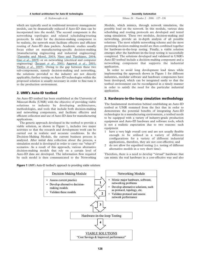
applications.The generic approach developed in the testbed to provide a
viable solution, as shown in Figure 1, includes two major
activities so that the research and development work can be
carried out in realistic and accurate conditions. In the
Decision-Making Module, the current business process is
analyzed. After initial data collection about the process, a
simulation model is developed in order to carry out “what-if”
scenarios. As a result of this approach, various alternative
decision-making models that rely on a certain level of
Auto-ID data are developed. The information flow required
by each model is then communicated to the Networking
Module, which mimics, through network simulation, thepossible load on the network. In this module, various datascheduling and routing protocols are developed and testedusing simulation. These two modules, decision-making andnetworking, provide an in-depth analysis of all possiblesolutions. The most reliable networking scheme and the mostpromising decision-making model are then combined togetherfor hardware-in-the-loop testing. Finally, a viable solutionemerges after the hardware-in-the-loop testing is successfullycompleted. The solutions developed and validated in UMR’sAuto-ID testbed include a decision-making component and anetworking component that supports the industrialapplication.In order to avoid long development lead times while
implementing the approach shown in Figure 1 for differentindustries, modular software and hardware components havebeen developed, which can be integrated easily so that thetestbed environment can be reconfigured in a timely mannerin order to satisfy the need for the particular industrialapplication.
3. Hardware-in-the-loop simulation methodology
The fundamental motivation behind establishing an Auto-IDtestbed at UMR stemmed from the fact that in order todemonstrate the potential benefits of integrating Auto-IDtechnologies in a manufacturing environment, a testbed needsto be equipped with a variety of industry-grade productionequipment and Auto-ID hardware and software tools, whichis not a realistic expectation due to two reasons: suchequipment1 have a very high overall cost and are not usually flexible
enough to be utilized in a variety of differentconfigurations for a variety of different industrialapplications, therefore, they are not cost-effective; and
2 do not allow for expedited testing (i.e. testing of differentalternative models in a very short time).
Therefore, there is a need to develop “virtual” hardware thatcan mimic the real hardware in a cost-effective way and also
Figure 1 UMR’s Auto-ID testbed’s approach to providing viable solutions
A testbed architecture for Auto-ID technologies
A. Soylemezoglu et al.
Assembly Automation
Volume 26 · Number 2 · 2006 · 127–136
128
allow for developing simulated production scenarios for
expedited testing. An additional advantage of such virtualmodels (VMs) is that they can be run on distributed
computers, similar to a realistic industrial setting, which thenallows for networking and communications related testing.
UMR’s Auto-ID testbed is equipped with VMs that have thecapability to communicate with real hardware, which leads to
the concept of hardware-in-the-loop simulation models. Suchan approach provides a dynamic, controlled testbed
environment for developing, testing, and evaluating Auto-IDsystems, and it enables development of guidelines for
technology transfer.VMs can be used to mimic actual hardware and they can
generate a large amount of data, which are essential fordeveloping realistic solutions to industrial problems. For
example, data generated by using such a combination ofactual hardware and VMs can provide a basis for low-costexperimentation on network overloading. In order to make
effective decisions with the data generated in a hardware-in-the-loop simulation environment, data must be properly
communicated among decision-makers (i.e. controllers),therefore, reliable data scheduling and routing schemes are
required for such reliable data transfer.Most real-world systems are too complex to allow realistic
models to be evaluated analytically. Traditionally, simulationis used for modeling of such systems where a simple closed
form analytical solution through the use of a mathematicalmodel is not possible due to the highly stochastic natures of
these systems (Law and Kelton, 1991). In a typical simulationstudy, a computer is used to evaluate a model numerically,
and data are gathered in order to estimate the desired truecharacteristics of the model. In addition to its typical use, at
UMR’s Auto-ID testbed, simulation is used in threeother ways:1 Virtual model development. Simulation is used to
develop virtual hardware/equipment models that cancommunicate with real hardware. When such VMs are
validated, they can be duplicated to form a morecomplicated production environment, where they can
interact with each other, as well as with other hardware,and run in real-time (i.e. unlike typical simulation models
that are run in accelerated mode) on distributedcomputing platforms to represent complex behaviors.
2 System controller (SC) development. Since, simulationpackages have capabilities to facilitate decision-making
modeling, simulation models can be used to control realhardware/equipment if they are properly designed to
communicate with the hardware (i.e. I/O capability withthe equipment’s protocol).
3 Networking simulation (NS). Auto-ID technologypotentially leads to generation of large amounts of data,
which can overload the network and cause congestion andinformation loss. Amount and type of data flow is dictated
by the design of decision-making models embedded in asystem. Therefore, networking performance, in the
presence of such voluminous data transfer, must beevaluated in order to make sure that the decision-makingmodels perform as expected. Network simulators are used
to construct virtual networks of varying sizes based on theAuto-ID devices that are being considered for deployment
with alternative topologies to find suitable solutions for aparticular Auto-ID environment. In addition, network
simulators are used in the process of evaluating different
communication protocols and in the design of newprotocols specifically for Auto-ID networks. One exampleof such a protocol design is to predict the onset ofcongestion due to Auto-ID data and to mitigatecongestion while ensuring that sufficient data will betransferred for decision making.
Simulation packages, by default, are designed to collect dataon a variety of events and entities defined by the user.Therefore, VM, SC, and NS development strategies, VMsand controllers are also used as “system monitors” since theyhave the informational equivalence of real systems, whichjustifies the approach adopted by the UMR’s Auto-IDtestbed. In addition, distributed simulation models provideadvantages in modeling the behavior of Auto-ID devicesembedded in an application that consists of geographicallydistributed environments.The hardware-in-the-loop simulation methodology,
developed at UMR’s Auto-ID testbed, is built on threeintegrated levels of development and testing activities.A typical industrial application (referred to as a “project”hereafter) goes through those three levels, as described inSections 3.1 through 3.3, before a viable solution is generated.Before starting at level 1, a conceptual system design iscarried out; the application domain analyzed, potentialAuto-ID tools determined, material and information flowrequirements investigated, and new decision-making modelsthat rely on Auto-ID data are developed. These activities arecarried out in close cooperation with the industry client. Oncean agreement is reached, the 3-level hardware-in-the-loopsimulation methodology starts.
3.1 Level 1: Controller simulation
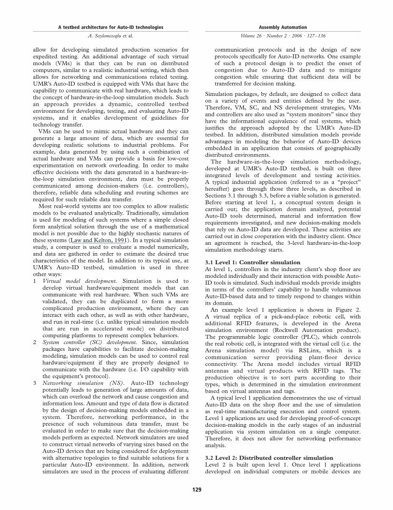
At level 1, controllers in the industry client’s shop floor aremodeled individually and their interaction with possible Auto-ID tools is simulated. Such individual models provide insightsin terms of the controllers’ capability to handle voluminousAuto-ID-based data and to timely respond to changes withinits domain.An example level 1 application is shown in Figure 2.
A virtual replica of a pick-and-place robotic cell, withadditional RFID features, is developed in the Arenasimulation environment (Rockwell Automation product).The programmable logic controller (PLC), which controlsthe real robotic cell, is integrated with the virtual cell (i.e. theArena simulation model) via RSLinx, which is acommunication server providing plant-floor deviceconnectivity. The Arena model includes virtual RFIDantennas and virtual products with RFID tags. Theproduction objective is to sort parts according to theirtypes, which is determined in the simulation environmentbased on virtual antennas and tags.A typical level 1 application demonstrates the use of virtual
Auto-ID data on the shop floor and the use of simulationas real-time manufacturing execution and control system.Level 1 applications are used for developing proof-of-conceptdecision-making models in the early stages of an industrialapplication via system simulation on a single computer.Therefore, it does not allow for networking performanceanalysis.
3.2 Level 2: Distributed controller simulation
Level 2 is built upon level 1. Once level 1 applicationsdeveloped on individual computers or mobile devices are
A testbed architecture for Auto-ID technologies
A. Soylemezoglu et al.
Assembly Automation
Volume 26 · Number 2 · 2006 · 127–136
129
verified, they are integrated with each other based on material
and information flow determined at the conceptual design
stage of a project. Such integration requires communications
network design, selecting alternative topologies, and necessary
data scheduling and routing protocols. Level 2 allows for
experimenting with distributed level 1 applications that have
virtual Auto-ID tools. At this level, alternative decision-
making models, along with their communications
requirements, can be tested and benchmarked. Therefore,
an initial assessment of the overall system, including a
network performance analysis, can be carried out.Different networking topologies that connect decision-making
models, which reside on distributed computers or mobile
devices, can be tested. Once the decision-making models are
validated in terms of system-level performancemeasures, a series
of different network topologies and communication protocols
can be evaluated to identify satisfactory solution for such
decision-making models. This is first done by prototyping the
decision-making network with existing modular hardware and
software. For example, at UMR’s Auto-ID testbed, a set of
wireless nodes are built for evaluating different wireless networks
and protocols; these plug-and-play nodes include Bluetooth,
802.11, Zigbee, and 900MHz RF radio, each with varying
capabilities and limitations in terms of data transfer rate. Such
modular devices allow for validation of small-scale
communication network and provide sufficient information on
simulating larger-scale networks. If it is not possible to develop a
satisfactory networking topology in order tomeet the networking
performance requirements, referred to as quality of service
(QoS), defined in terms of end-to-end delay, information loss,
throughput, and delay variation, alternative networking
topologies and decision-making models are sought and tested.Different data scheduling and routing schemes are required
in order to meet the user defined QoS, which affects the
decision-making models. Therefore, the feedback/revision
loop (as shown in Figure 1) between the system simulation
and NS continues until satisfactory results, both at system
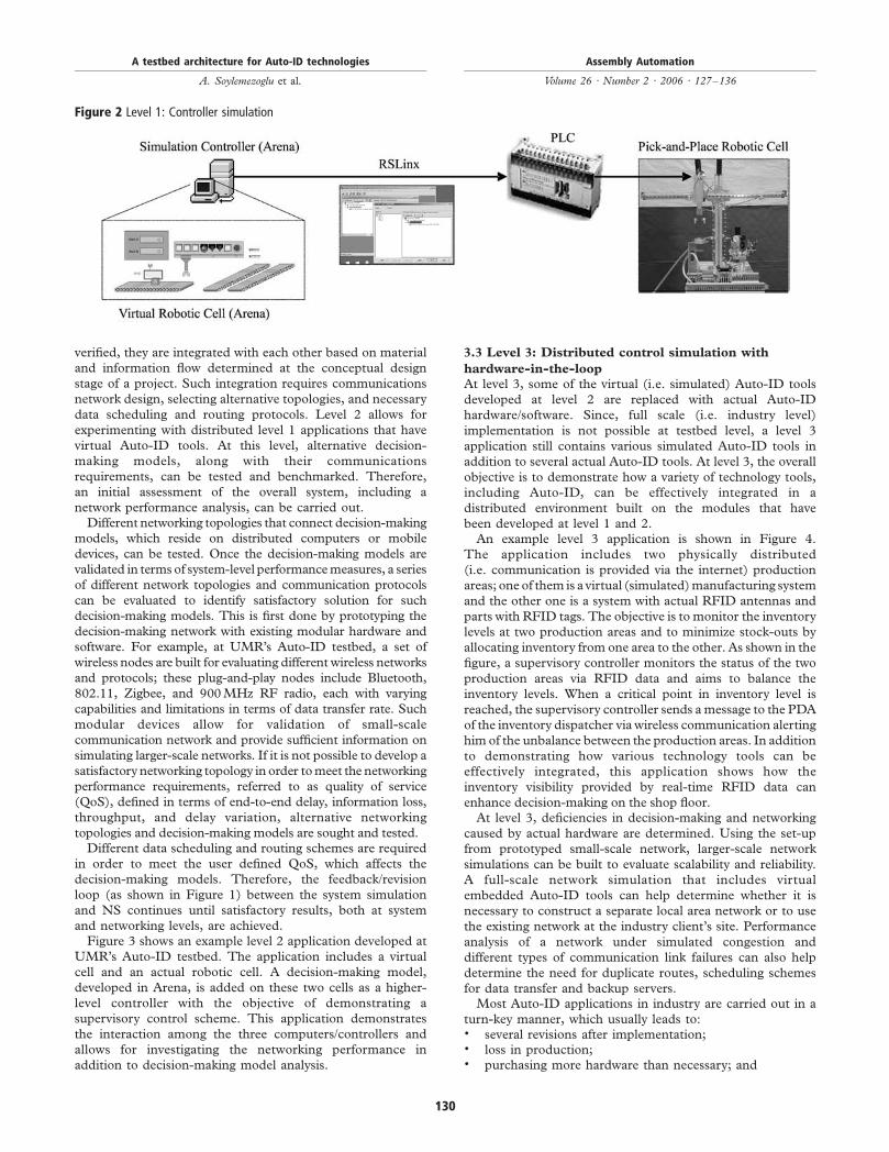
and networking levels, are achieved.Figure 3 shows an example level 2 application developed at
UMR’s Auto-ID testbed. The application includes a virtual
cell and an actual robotic cell. A decision-making model,
developed in Arena, is added on these two cells as a higher-
level controller with the objective of demonstrating a
supervisory control scheme. This application demonstrates
the interaction among the three computers/controllers and
allows for investigating the networking performance in
addition to decision-making model analysis.
3.3 Level 3: Distributed control simulation with
hardware-in-the-loop
At level 3, some of the virtual (i.e. simulated) Auto-ID tools
developed at level 2 are replaced with actual Auto-ID
hardware/software. Since, full scale (i.e. industry level)
implementation is not possible at testbed level, a level 3
application still contains various simulated Auto-ID tools in
addition to several actual Auto-ID tools. At level 3, the overall
objective is to demonstrate how a variety of technology tools,
including Auto-ID, can be effectively integrated in a
distributed environment built on the modules that have
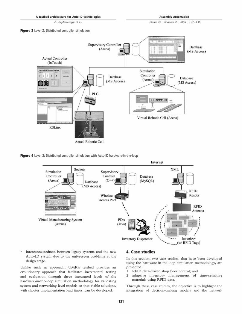
been developed at level 1 and 2.An example level 3 application is shown in Figure 4.
The application includes two physically distributed
(i.e. communication is provided via the internet) production
areas; one of them is a virtual (simulated)manufacturing system
and the other one is a system with actual RFID antennas and
parts with RFID tags. The objective is to monitor the inventory
levels at two production areas and to minimize stock-outs by
allocating inventory from one area to the other. As shown in the
figure, a supervisory controller monitors the status of the two
production areas via RFID data and aims to balance the
inventory levels. When a critical point in inventory level is
reached, the supervisory controller sends amessage to the PDA
of the inventory dispatcher via wireless communication alerting
him of the unbalance between the production areas. In addition
to demonstrating how various technology tools can be
effectively integrated, this application shows how the
inventory visibility provided by real-time RFID data can
enhance decision-making on the shop floor.At level 3, deficiencies in decision-making and networking
caused by actual hardware are determined. Using the set-up
from prototyped small-scale network, larger-scale network
simulations can be built to evaluate scalability and reliability.
A full-scale network simulation that includes virtual
embedded Auto-ID tools can help determine whether it is
necessary to construct a separate local area network or to use
the existing network at the industry client’s site. Performance
analysis of a network under simulated congestion and
different types of communication link failures can also help
determine the need for duplicate routes, scheduling schemes
for data transfer and backup servers.Most Auto-ID applications in industry are carried out in a
turn-key manner, which usually leads to:. several revisions after implementation;. loss in production;. purchasing more hardware than necessary; and
Figure 2 Level 1: Controller simulation
A testbed architecture for Auto-ID technologies
A. Soylemezoglu et al.
Assembly Automation
Volume 26 · Number 2 · 2006 · 127–136
130
. interconnectedness between legacy systems and the new
Auto-ID system due to the unforeseen problems at the
design stage.
Unlike such an approach, UMR’s testbed provides an
evolutionary approach that facilitates incremental testing
and evaluation through three integrated levels of the
hardware-in-the-loop simulation methodology for validating
system and networking-level models so that viable solutions,
with shorter implementation lead times, can be developed.
4. Case studies
In this section, two case studies, that have been developed
using the hardware-in-the-loop simulation methodology, are
presented:1 RFID data-driven shop floor control; and2 adaptive inventory management of time-sensitive
materials using RFID data.
Through these case studies, the objective is to highlight the
integration of decision-making models and the network
Figure 3 Level 2: Distributed controller simulation
Figure 4 Level 3: Distributed controller simulation with Auto-ID hardware-in-the-loop
A testbed architecture for Auto-ID technologies
A. Soylemezoglu et al.
Assembly Automation
Volume 26 · Number 2 · 2006 · 127–136
131
topology/scheduling/routing models with emphasis on the
testbed design.
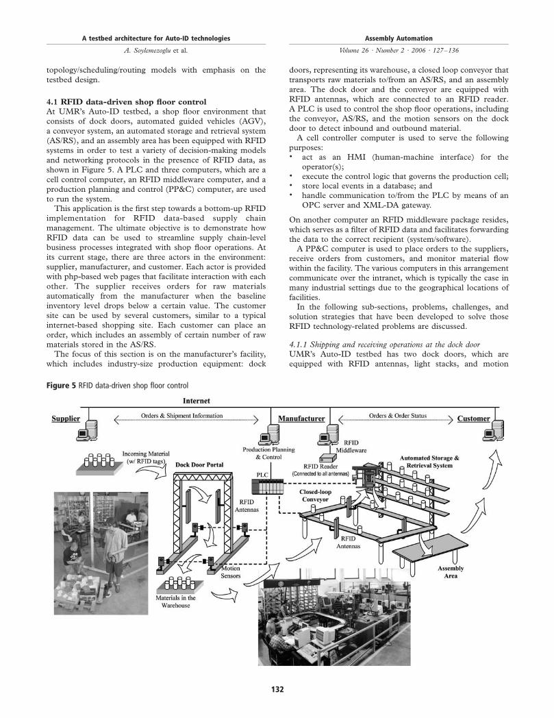
4.1 RFID data-driven shop floor control
At UMR’s Auto-ID testbed, a shop floor environment that
consists of dock doors, automated guided vehicles (AGV),
a conveyor system, an automated storage and retrieval system
(AS/RS), and an assembly area has been equipped with RFID
systems in order to test a variety of decision-making models
and networking protocols in the presence of RFID data, as
shown in Figure 5. A PLC and three computers, which are a
cell control computer, an RFID middleware computer, and a
production planning and control (PP&C) computer, are used
to run the system.This application is the first step towards a bottom-up RFID
implementation for RFID data-based supply chain
management. The ultimate objective is to demonstrate how
RFID data can be used to streamline supply chain-level
business processes integrated with shop floor operations. At
its current stage, there are three actors in the environment:
supplier, manufacturer, and customer. Each actor is provided
with php-based web pages that facilitate interaction with each
other. The supplier receives orders for raw materials
automatically from the manufacturer when the baseline
inventory level drops below a certain value. The customer
site can be used by several customers, similar to a typical
internet-based shopping site. Each customer can place an
order, which includes an assembly of certain number of raw
materials stored in the AS/RS.The focus of this section is on the manufacturer’s facility,
which includes industry-size production equipment: dock
doors, representing its warehouse, a closed loop conveyor that
transports raw materials to/from an AS/RS, and an assembly
area. The dock door and the conveyor are equipped with
RFID antennas, which are connected to an RFID reader.
A PLC is used to control the shop floor operations, including
the conveyor, AS/RS, and the motion sensors on the dock
door to detect inbound and outbound material.A cell controller computer is used to serve the following
purposes:. act as an HMI (human-machine interface) for the
operator(s);. execute the control logic that governs the production cell;. store local events in a database; and. handle communication to/from the PLC by means of an
OPC server and XML-DA gateway.
On another computer an RFID middleware package resides,
which serves as a filter of RFID data and facilitates forwarding
the data to the correct recipient (system/software).A PP&C computer is used to place orders to the suppliers,
receive orders from customers, and monitor material flow
within the facility. The various computers in this arrangement
communicate over the intranet, which is typically the case in
many industrial settings due to the geographical locations of
facilities.In the following sub-sections, problems, challenges, and
solution strategies that have been developed to solve those
RFID technology-related problems are discussed.
4.1.1 Shipping and receiving operations at the dock doorUMR’s Auto-ID testbed has two dock doors, which are
equipped with RFID antennas, light stacks, and motion
Figure 5 RFID data-driven shop floor control
A testbed architecture for Auto-ID technologies
A. Soylemezoglu et al.
Assembly Automation
Volume 26 · Number 2 · 2006 · 127–136
132
sensors. The shipping and receiving operations are carried out
by pallet jacks and AGV.Initial implementation was done using pallet jacks, which
require manual handling of tagged materials placed on pallets,to investigate read rates. The second implementation was
carried out using AGVs that also require wirelesscommunications, which adds more complexity to the overall
system. The third application involved operating two dockdoors side by side, similar to an actual warehouse setting, in
order to investigate the interference and cross-reading ofmaterial, which refers to the case where both dock doors read
each other’s material due to the range of the RFID antennas,and location and identity information cannot be matched. As
a result of the third implementation, an RFID data-basedAGV traffic management model was developed.The basic dock door operation involves the following steps.
Each material has an RFID tag and all materials are placed on
an industrial pallet. First, the motion sensors detect thedirection of the pallet (i.e. inbound or outbound materialflow). The information is sent wirelessly to an RFID server
(i.e. middleware). It turns on the red light on the light stack,in case of manual material handling, for the dispatcher to stop
or it stops the AGV, in case of automated (i.e. unmanned)material handling, at the dock door. Then, the server initiates
the RFID tag reading process and passes the readings to thePP&C computer, which compares the order list with the
pallet content to determine if right materials at the rightamount have been received.After reading the tags, there can be a mismatch between the
order list and the pallet content, which can be due to two
possibilities. First, the pallet content may be correct but thereadings, due to read-rate problems, can be wrong. Second,
the pallet may include incomplete shipment. In either case,the material flow is not disrupted at the dock door but the
inventory database is updated to reflect this anomaly. Whenthe pallet reaches its destination on the shop floor, eachmaterial on the pallet is manually placed on the conveyor,
which is equipped with RFID antennas. On their way to theAS/RS via the conveyor, the tag on each material is read and
checked against the order list in the database. Since, it is lesslikely to have a read-rate problem when you have only one tag,
the overall decision-making model that monitors material flowbetween the dock door and the conveyor facilitates “process
visibility” in spite of the read-rate problem associated withRFID technology.The dock doors use Class-0 900MHz UHF RFID readers
and tags, which are known to be prone to interferences
(Engels, 2002). High power devices, such as RFID readers,placed in close proximity cause interferences among
themselves and for other RF devices (i.e. wirelesstransmitter for motion sensor). In dense networks, detection
range and read rates of RFID readers suffer severely whileother lower power RF devices become completely unusable.
Similarly, dock doors located next to each other form a denseRFID reader network, and therefore, it is not possible toobtain reliable identification data. In addition, when a pallet,
loaded with tagged materials, is moved parallel to the dockdoors, the antennas on both dock doors read the tags. In other
words, it is not possible to detect whether the material is beingmoved through a dock door or it is being maneuvered in front
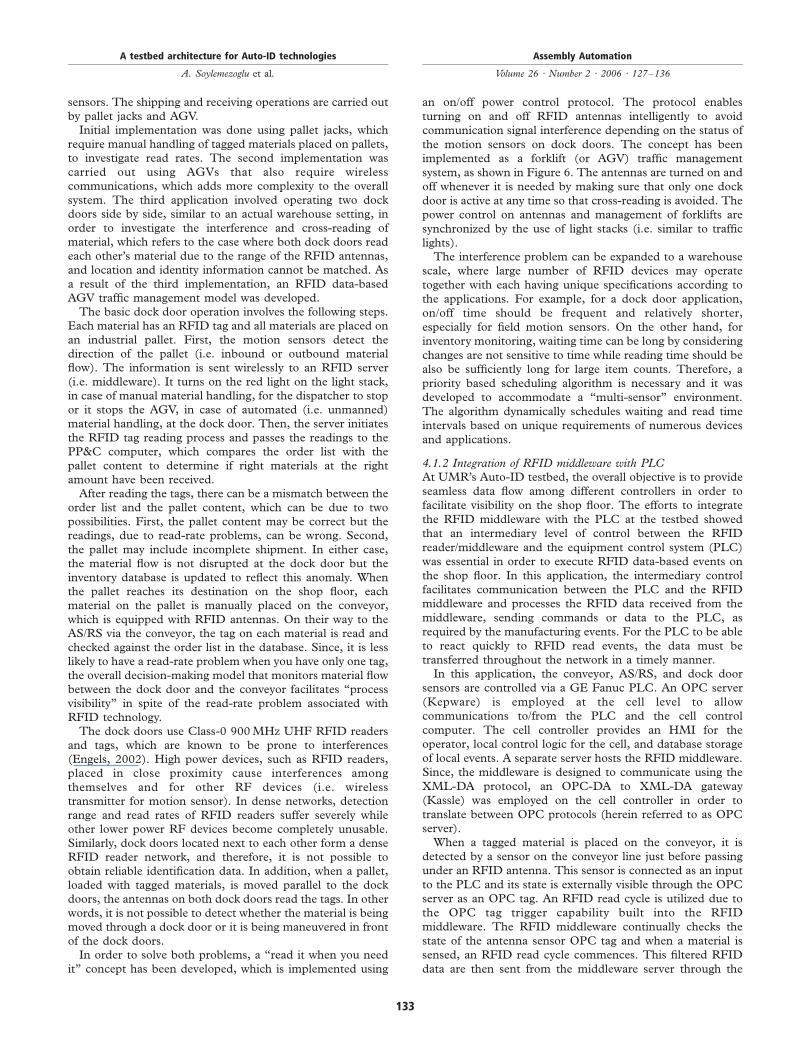
of the dock doors.In order to solve both problems, a “read it when you need
it” concept has been developed, which is implemented using
an on/off power control protocol. The protocol enables
turning on and off RFID antennas intelligently to avoid
communication signal interference depending on the status of
the motion sensors on dock doors. The concept has been
implemented as a forklift (or AGV) traffic management
system, as shown in Figure 6. The antennas are turned on and
off whenever it is needed by making sure that only one dock
door is active at any time so that cross-reading is avoided. The
power control on antennas and management of forklifts are
synchronized by the use of light stacks (i.e. similar to traffic
lights).The interference problem can be expanded to a warehouse
scale, where large number of RFID devices may operate
together with each having unique specifications according to
the applications. For example, for a dock door application,
on/off time should be frequent and relatively shorter,
especially for field motion sensors. On the other hand, for
inventory monitoring, waiting time can be long by considering
changes are not sensitive to time while reading time should be
also be sufficiently long for large item counts. Therefore, a
priority based scheduling algorithm is necessary and it was
developed to accommodate a “multi-sensor” environment.
The algorithm dynamically schedules waiting and read time
intervals based on unique requirements of numerous devices
and applications.
4.1.2 Integration of RFID middleware with PLCAt UMR’s Auto-ID testbed, the overall objective is to provide
seamless data flow among different controllers in order to
facilitate visibility on the shop floor. The efforts to integrate
the RFID middleware with the PLC at the testbed showed
that an intermediary level of control between the RFID
reader/middleware and the equipment control system (PLC)
was essential in order to execute RFID data-based events on
the shop floor. In this application, the intermediary control
facilitates communication between the PLC and the RFID
middleware and processes the RFID data received from the
middleware, sending commands or data to the PLC, as
required by the manufacturing events. For the PLC to be able
to react quickly to RFID read events, the data must be
transferred throughout the network in a timely manner.In this application, the conveyor, AS/RS, and dock door
sensors are controlled via a GE Fanuc PLC. An OPC server
(Kepware) is employed at the cell level to allow
communications to/from the PLC and the cell control
computer. The cell controller provides an HMI for the
operator, local control logic for the cell, and database storage
of local events. A separate server hosts the RFID middleware.
Since, the middleware is designed to communicate using the
XML-DA protocol, an OPC-DA to XML-DA gateway
(Kassle) was employed on the cell controller in order to
translate between OPC protocols (herein referred to as OPC
server).When a tagged material is placed on the conveyor, it is
detected by a sensor on the conveyor line just before passing
under an RFID antenna. This sensor is connected as an input
to the PLC and its state is externally visible through the OPC
server as an OPC tag. An RFID read cycle is utilized due to
the OPC tag trigger capability built into the RFID
middleware. The RFID middleware continually checks the
state of the antenna sensor OPC tag and when a material is
sensed, an RFID read cycle commences. This filtered RFID
data are then sent from the middleware server through the
A testbed architecture for Auto-ID technologies
A. Soylemezoglu et al.
Assembly Automation
Volume 26 · Number 2 · 2006 · 127–136
133
intranet to the cell control computer. This controlled read
cycle helps to reduce interference between multiple RFID
antennas in close proximity and also allows the system to
detect items on the conveyor with missing or unreadable
RFID tags, which strengthens visibility on the shop floor.Upon receiving the RFID data from the middleware server,
the cell control computer then processes the data into
information useful at the cell level. The cell control computer
is in a unique position, which allows it to communicate with
both lower level (PLC) and higher level systems (PP&C). This
capability allows the cell control computer to associate the
RFID tag read with a material type and transform this
information into actions needed to be taken by the PLC. The
necessary data are then forwarded to the PLC through theOPC
server.This arrangement of decoupling the equipment control
functions (PLC) from the higher level processes lends itself to
an evolutionary approach to the implementation of RFID
data onto the shop floor. Existing systems and controls can be
refitted to make use of RFID data without a major
interruption in production.
4.2 Adaptive inventory management
Inventory management of time-sensitive materials is very
critical due to their shelf lives. One primary concern is to
insure that the required materials are available at all times to
the operators. The lack of time-sensitive materials results in
loss of production and in turn loss of profits. On the other
hand, those materials that are not used in production within
their lives expire and become another cost factor. In addition,
disposal of time-sensitive materials, once they reach their shelf
life, to prevent their usage on a product is also major concern.The implementation, as show in Figure 7, included two
major tasks:1 A simulation-based business case that demonstrated the
overall cost savings when real-time RFID data were used
for inventory management was developed. To achieve this
goal, a trend-adjusted exponential smoothing algorithm
(i.e. forecasting model) was developed. The algorithm
looks at the difference between the current inventory
level based on real-time RFID data and the forecast
(i.e. predicted demand) in order to determine the amount
of material that needs to be ordered. The simulation
model included 20 buffers and approximately 6,000
virtual RFID-tagged time-sensitive materials. A gap
analysis, which compared the as-is practice with the
RFID data-based inventory management on the basis of
amount of expired, ordered, and re-allocated (among
buffers) materials, was carried out. The gap analysis
showed that approximately $500 K per year would be
saved by implementing the proposed model.2 A prototype network was built with one real and several
virtual RFID readers, multiple databases, RIFD
middleware/decision-maker, and a PDA unit. Several
scenarios were created to test the basic connectivity and
reliability. A larger-scale network simulation was then
constructed to model the real manufacturing
environment. The simulation model involved 100 RFID
readers connected in a star topology, and network traffic
was simulated based on real data captured at an RFID
reader. The model was then expanded to emulate multiple
routes (i.e. duplicate routes), network bandwidth test
(i.e. 10/100/1,000Mbps), and wireless network test
(i.e. 802.11 a/b/g). Average delay, packet drop, and
average throughput were used to evaluate different
topologies. An example of the network simulation results
is shown in Table I.
5. Discussion
UMR’s Auto-ID testbed is currently being used to address
various research challenges. It has been experienced that the
read rates on RFID antennas vary between 70 and 80 percent
depending on product types, number of products, and
orientation of the products with respect to each other on a
pallet. If the read-rate problem cannot be solved, then the
ultimate goal of RFID, which is “100 % visibility on the shop
floor”, cannot be realized. While the RFID vendors are
Figure 6 An RFID data-based forklift traffic management system
A testbed architecture for Auto-ID technologies
A. Soylemezoglu et al.
Assembly Automation
Volume 26 · Number 2 · 2006 · 127–136
134

working on improving the technology, the industry users
should understand the fact that for a successful RFID
implementation, their processes must be 100 percent visible.
RFID technology cannot magically bring order to a chaotic
shop floor environment; the processes must be redesigned to
make them lean and visible.To avoid the above-mentioned potential deficiency of RFID
technology, the applications at UMR’s Auto-ID testbed have
been designed to operate on various check points so as to
improve the visibility of the overall process. For instance,
when raw materials are received at the dock door, the
antennas read the RFID tags on the materials while they are
on a pallet. If the pallet content does not match the order list,
the pallet is not rejected immediately since the problem can be
caused by the read rate of the antenna, not necessarily due to
a mismatch between the order list and the pallet content.
The raw materials are then transported to the production area
and each material is loaded on a pallet on the conveyor.
Each pallet goes through two RFID antennas to verify its
identity. After each material is identified, it is stored in the AS/
RS. If a material cannot be identified after it is circulated on
the conveyor twice, then it is pushed out of the conveyor for
manual identification. If there is an unknown material, then it
is sent back to the supplier. Similarly, if there are materials
missing on the pallet, then the supplier is notified.
Another potential problem with RFID antennas is that
when they are placed in closed proximity, a tag can be read by
multiple antennas. In this case, the actual location of the tag
(i.e. the product) cannot be determined. For example, when
the dock door is placed very close to the conveyor, the
antennas on the dock door and the conveyor can read “all”
the tags in the environment; a tag on a pallet at the dock door
simultaneously appears on the conveyor. To avoid this
problem, the environment must be equipped with additional
sensors. The testbed demonstrates a lean approach: “read it
when you need it.” Unless there is an event that requires
automatic identification, then the antennas should not be
powered. Event detection can be done by integrating sensors
into the environment and interpreting the sensor data
together with RFID data. Therefore, it is important to
scrutinize RFID implementations as potential “multi-sensor”
applications, where such sensors need to be carefully
determined in order to improve the visibility of the business
process.
6. Conclusions
UMR’s Auto-ID testbed provides a flexible test environment
that can be used for evaluating Auto-ID technologies and
solutions for industry. The testing environment, as well as the
testing conditions, can be varied easily in order to match the
Figure 7 Adaptive inventory management based on RFID data
Table I Network simulation results
Performance measure Scenario 1 Scenario 2 Scenario 3 Scenario 4
Link bandwidth 10 Mbps 100 Mbps 1,000 Mbps 802.11 g (54 Mbps)
Packet drop 2,923 0 0 345
Average delay (s) 0.237 0.0157 0.0132 0.0179
Link utilization (percent) 100 44.6 4.6 99
A testbed architecture for Auto-ID technologies
A. Soylemezoglu et al.
Assembly Automation
Volume 26 · Number 2 · 2006 · 127–136
135
needs of the industry. The testbed can be used as a low-costtechnology development and assessment platform (proof-of-concept) due to the availability of reconfigurable models,which facilitate rapid model development, hardware/softwarebenchmarking, and implementation.UMR’s Auto-ID testbed provides viable solutions to industry
due to its integrated approach; decision-making models andhardware/software/networking issues are consideredsimultaneously. The testbed allows the researchers andindustry practitioners to investigate the operational limits andpossible failure behaviors of a variety of Auto-ID technologies.Especially, the effective use of simulated scenarios in thepresence of hardware leads to realistic solutions that are greatlyvalued by industry.The distributed hardware-in-the-loop simulation
environment at the UMR’s Auto-ID testbed is intended toinvestigate, with increasing level of system complexity, thepotential benefits of Auto-ID technologies using simulation.
References
Agarwal, S., Katz, R.H., Krishnamurthy, S.V. and Dao, S.K.(2001), “Distributed power control in ad-hoc wirelessnetworks”, paper presented at the 12th IEEE InternationalSymposium on Personal, Indoor and Mobile RadioCommunications,Vol. 2, pp. F59-F66.
Brewer, A., Sloan, N. and Landers, T.L. (1999), “Intelligenttracking in manufacturing”, Journal of IntelligentManufacturing, Vol. 10 Nos 3/4, pp. 245-50.
Engels, D.W. (2002), “The reader collision problem”,MIT-AUTOID-WH-002, MIT Auto-ID Center.
Engels, D.W., Foley, J., Waldrop, J., Sarma, S.E. and Brock,D. (2001), “The networked physical world: an automatedidentification architecture”, Proceedings of the Second IEEEWorkshop on Internet Applications (WIAPP 2001), pp. 76-7.
Gao, Q., Luo, X. and Yang, S. (2005), “Stigmergiccooperation mechanism for shop floor control system”,Int. J. Adv. Mfg. Tech., Vol. 25, pp. 743-53.
Jacquet, P., Muhlethaler, P., Clausen, T., Laouiti, A.,Qayyum, A. and Viennot, L. (2001), “Optimized linkstate routing protocol for ad hoc networks”, Proceedings ofthe IEEE International Multi Topic Conference, pp. 62-8.
Law, A.M. and Kelton, W.D. (1991), Simulation Modeling andAnalysis, McGraw-Hill, New York, NY.
Lee, Y.M., Cheng, F. and Leung, Y.T. (2004), “Exploring theimpact of RFID on supply chain dynamics”, Proceedings ofthe 2004 Winter Simulation Conference,Vol. 2, pp. 1145-52.
McFarlane, D. (2002), “Auto ID-based control systems: anoverview”, paper presented at IEEE InternationalConference on Systems, Man and Cybernetics,Vol. 3,pp. 6-11.
McFarlane, D., Sarma, S., Chirn, J.L., Wong, C.Y. andAshton, K. (2003), “Auto ID systems and intelligentmanufacturing control”, Engineering Applications of ArtificialIntelligence, Vol. 16, pp. 365-76.
Michael, K. and McCathie, L. (2005), “The pros and cons ofRFID in supply chain management”, paper presented at theInternational Conference on Mobile Business, pp. 623-9.
Naso, D. and Turchiano, B. (2004), “A coordination strategyfor distributed multi-agent manufacturing systems”,Int. J. Prod. Res., Vol. 42 No. 12, pp. 2497-520.
Penttila, K., Sydanheimo, L. and Kivikoski, M. (2004),“Performance development of a high-speed automaticobject identification using passive RFID technology”,paper presented at IEEE International Conference onRobotics and Automation (ICRA ’04),Vol. 5, pp. 4864-8.
Vaidya, N., Dugar, A., Gupta, S. and Bahl, P. (2005),“Distributed fair scheduling in a wireless LAN”, IEEETransactions on Mobile Computing, Vol. 4 No. 6, pp. 616-29.
Zaremba, M.B. and Morel, G. (2003), “Integration andcontrol of intelligence in distributed manufacturing”,Journal of Intelligent Manufacturing, Vol. 14 No. 1, pp. 25-42.
Corresponding author
C. Saygin can be contacted at: [email protected]
A testbed architecture for Auto-ID technologies
A. Soylemezoglu et al.
Assembly Automation
Volume 26 · Number 2 · 2006 · 127–136
136
To purchase reprints of this article please e-mail: [email protected]
Or visit our web site for further details: www.emeraldinsight.com/reprints
Copyright © 2022 FDOKUMEN