Development of polyimide membranes for the separation of water vapor from organic compounds
Upload
independentCategory
view
1download
0
Di
YCa
b
c
d
e
f
g
a
ARRA
KMPECE
1
ofrC(Xd(we
0d
Journal of Neuroscience Methods 182 (2009) 6–16
Contents lists available at ScienceDirect
Journal of Neuroscience Methods
journa l homepage: www.e lsev ier .com/ locate / jneumeth
esign and fabrication of a polyimide-based microelectrode array: Applicationn neural recording and repeatable electrolytic lesion in rat brain
ou-Yin Chena,∗, Hsin-Yi Laia, Sheng-Huang Linb, Chien-Wen Choa, Wen-Hung Chaoc,hia-Hsin Liaod,e, Siny Tsangf, Yi-Fan Cheng, Si-Yue Ling
Department of Electrical and Control Engineering, National Chiao Tung University, No. 1001, Ta-Hsueh Road, Hsinchu 300, Taiwan, ROCDepartment of Neurology, Buddhist Tzu Chi General Hospital, No. 707, Sec. 3, Zhong Yang Road, Hualien 970, Taiwan, ROCDepartment of Biomedical Engineering, Yuanpei University, No.306, Yuanpei St., Hsinchu 300, Taiwan, ROCDepartment of Research, Buddhist Tzu Chi General Hospital, No. 707, Sec. 3, Zhong Yang Road, Hualien 970, Taiwan, ROCInstitute of Medical Sciences, Tzu Chi University, No.701, Sec 3, Zhong Yang Road, Hualien 970, Taiwan, ROCCollege of Criminal Justice, Sam Houston State University, Huntsville, TX 77341-2296, USADepartment of Applied Science, National Hsinchu University of Education, No. 521, Nanda Road, Hsinchu 300, Taiwan, ROC
r t i c l e i n f o
rticle history:eceived 12 February 2009eceived in revised form 24 April 2009ccepted 14 May 2009
eywords:icroelectrode array
olyimidelectroplatinghronic recording
a b s t r a c t
The design and testing of a new microelectrode array, the NCTU (National Chiao Tung University) probe,was presented. Evaluation results showed it has good biocompatibility, high signal-to-noise ratio (SNR:the root mean square of background noise to the average peak-to-peak amplitude of spikes) during chronicneural recordings, and high reusability for electrolytic lesions. The probe was a flexible, polyimide-basedmicroelectrode array with a long shaft (14.9 mm in length) and 16 electrodes (5 �m-thick and 16 �m inradius); its performance in chronic in vivo recordings was examined in rodents. To improve the preci-sion of implantation, a metallic, impact-resistant layer was sandwiched between the polyimide layers tostrengthen the probe. The three-dimensional (3D) structure of electrodes fabricated by electroplating pro-duced rough textures that increased the effective surface area. The in vitro impedance of electrodes on the
lectrolytic lesion NCTU probe was 2.4 ± 0.52 M� at 1 kHz. In addition, post-surgical neural recordings of implanted NCTUprobes were conducted for up to 40 days in awake, normally behaving rats. The electrodes on the NCTUprobe functioned well and had a high SNR (range: 4–5) with reliable in vivo impedance (<0.7 M�). Theelectrodes were also robust enough to functionally record events, even after the anodal current (30 �A,10 s) was repeatedly applied for 60 times. With good biocompatibility, high and stable SNR for chronicrecording, and high tolerance for electrolytic lesion, the NCTU probe would serve as a useful device infuture neuroscience research.
. Introduction
Implantable microelectrode arrays have advanced the studyf brain function by simultaneously recording signals from dif-erent groups of neurons, gathering spatiotemporal informationegarding complex neural processes (Butovas and Schwarz, 2003;hen et al., 2004). Rigid silicon-based microelectrode arraysCsicsvari et al., 2003; Norlin et al., 2002; Shi et al., 2006;u et al., 2002) have been fabricated using semiconductor pro-
uction methods and advanced microelectro-mechanical systemsMEMS). These microelectrode arrays showed desirable features,ith precisely defined recording-site configurations, high-densitylectrode placement capabilities, and potential combinations with
∗ Corresponding author. Tel.: +886 3 571 2121x54427; fax: +886 3 612 5059.E-mail address: [email protected] (Y.-Y. Chen).
165-0270/$ – see front matter © 2009 Elsevier B.V. All rights reserved.oi:10.1016/j.jneumeth.2009.05.010
© 2009 Elsevier B.V. All rights reserved.
on-chip integrated circuitry (Cheung et al., 2007; Vetter et al.,2004).
Nevertheless, micromotion at tissue–electrode contact sites hasbeen a major problem in the application of silicon-based micro-electrode arrays for chronic recording. The mismatch between thestiff microelectrode array (silicon or glass substrate) and soft tis-sue aggravates micromotion, inducing inflammation at the implantsite (Biran et al., 2007; Suner et al., 2005). Reactive astrocytesbuild up, encapsulating the electrode and isolating it from the sur-rounding neural tissue, which leads to the eventual breakdownof the electrode’s recording ability (Biran et al., 2007; Polikov etal., 2005; Schwartz et al., 2006). Microelectrode arrays based on
flexible substrates may reduce micromotion and alleviate tissueencapsulation of the implant caused by inflammatory response(Cheung, 2007). Signal stability and quality were maintained forchronic recording. Polymer materials such as polyimide (Cheung etal., 2007; Ludwig et al., 2006), benzocyclobutent (Lee et al., 2004a)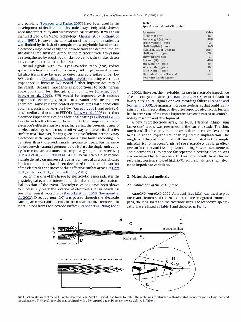
roscience Methods 182 (2009) 6–16 7
adgmewesbm
sfSitnLiTpeefeasedei(ifoe
pitsacm
Table 1Specifications of the NCTU probe.
Parameter ValueNumber of sites 16Probe length (A) (mm) 18.8Probe width (B) (mm) 2Shaft length (C) (mm) 14.9Max shaft width (D) (�m) 996Shaft width (E) (�m) 220Tip width (F) (�m) 3Distance (G) (�m) 48.4Site radius (H) (�m) 16Wire width (I) (�m) 10Wire width (J) (�m) 5
Fr
Y.-Y. Chen et al. / Journal of Neu
nd parylene (Seymour and Kipke, 2007) have been used in theevelopment of flexible microelectrode arrays. Polyimide showedood biocompatibility and high mechanical flexibility; it was easilyanufactured with MEMS technology (Cheung, 2007; Richardson
t al., 1993). However, the application of the polyimide substrateas limited by its lack of strength; most polyimide-based micro-
lectrode arrays bend easily and deviate from the desired implantite during implantation. Although the microelectrode arrays maye strengthened by adopting a thicker polyimide, the thicker deviceay cause greater harm to the tissue.Neural signals with low signal-to-noise ratio (SNR) reduce
pike detection and sorting accuracy. Although several power-ul algorithms may be used to detect and sort spikes under lowNR conditions (Nenadic and Burdick, 2005), reducing electrode’smpedance to increase SNR would further improve accuracy ofhe results. Because impedance is proportional to both thermaloise and signal loss through shunt pathways (Cheung, 2007;udwig et al., 2006), SNR would be improved with reducedmpedance. Accordingly, signal loss would also be reduced.herefore, some research coated electrode sites with conductiveolymers, such as polypyrrole (PPy) (Cui et al., 2001) and poly (3,4-thylenedioxythiophene or PEDOT) (Ludwig et al., 2006), to reducelectrode impedance. Besides additional coatings, Paik et al. (2003)ound a trade-off relationship between electrode impedance and anlectrode’s effective surface area. Increasing the geometric area ofn electrode may be the most intuitive way to increase its effectiveurface area. However, for any given length of microelectrode array,lectrodes with larger geometric areas have lower recording siteensities than those with smaller geometric areas. Furthermore,lectrodes with a small geometric area isolate the single-unit activ-ty from more distant units, thus improving single-unit selectivityLudwig et al., 2006; Paik et al., 2003). To maintain a high record-ng site density on microelectrode arrays, special and complicatedabrication methods have been developed to roughen the surfacef the electrodes and increase their effective surface areas (De Harot al., 2002; Lee et al., 2002; Paik et al., 2003).
Lesion marking of the tissue by electrolytic lesion indicates thehysiological event of interest and identifies the precise anatom-
cal location of the event. Electrolytic lesions have been shown
o successfully mark the location of electrode sites in neural tis-ue after neural recordings (Brozoski et al., 2006; Townsend etl., 2002). Direct current (DC) was passed through the electrode,ausing an irreversible electrochemical reaction that removed theetallic ions from the electrode surface (Branner et al., 2004; Lee etig. 1. Schematic view of the NCTU probe depicted in an AutoCAD layout (not drawn to secording sites. The tip of the probe was designed with a 50◦ tapered angle. Dimensions w
Electrode distance (K) (�m) 74Recording length (L) (mm) 1.1
al., 2002). However, the inevitable increase in electrode impedanceafter electrolytic lesions (De Haro et al., 2002) would result inlow quality neural signals or even recording failure (Branner andNormann, 2000). Designing a microelectrode array that could main-tain high signal recording quality after repeated electrolytic lesionshas become one of the most important issues in recent neurotech-nology research and development.
A new microelectrode array, the NCTU (National Chiao TungUniversity) probe, was presented in the current study. The thin,tough and flexible polyimide-based substrate caused less harmto tissue at the implant site, enabling precise implantation. Theroughened three-dimensional (3D) surface created with a simplemicrofabrication process furnished the electrode with a large effec-tive surface area and low impedance during in vivo measurement.The electrode’s DC tolerance for repeated electrolytic lesion wasalso increased by its thickness. Furthermore, results from chronicrecording sessions showed high SNR neural signals and small elec-trode impedance variations.
2. Materials and methods
2.1. Fabrication of the NCTU probe
AutoCAD (AutoCAD 2002, Autodesk Inc., USA) was used to plotthe main elements of the NCTU probe: the integrated connectorpads, the long shaft and the electrode sites. The respective specifi-cations were listed in Table 1 and depicted in Fig. 1.
cale). The probe was constructed with integrated connector pads, a long shaft andere defined in Table 1.
8 Y.-Y. Chen et al. / Journal of Neuroscience Methods 182 (2009) 6–16
F ale). (t tchedT or thee outli
Ntc#TitsLawK
ig. 2. An illustration of the fabrication process of the NCTU probe (not drawn to scrace layer was patterned on the second 30-�m polyimide layer, which was then ehe protective polyimide layer (3.2 �m) was spun onto the trace layer; windows flectroplating to form the 3D recording sites and connector pads. (E) The probe was
Three masks were used in the fabrication process for theCTU probe. The first mask (MASK #1) was used to construct
he site bases of the electrode/connector pads and the inter-onnecting traces of the NCTU probe. The second mask (MASK2) formed the 3D recording electrodes and connector pads.he third mask (MASK #3) was used to shape the NCTU probe,ncluding the shaft and the angle of its tip. First, a 200 nm-hick chrome layer, followed by a 700 nm-thick copper layer, were
puttered (Vvs-70L, VICTOR Taichung Machinery Works Corp.,td., Taiwan) as the sacrificial layer onto a glass wafer. Next,30 �m-thick polyimide (PI-2611, HD Microsystems, USA) layeras coated onto the sacrificial layer with a spin coater (ModelW-4A, CHEMAT Technology, Inc., Taiwan); it was then cured forA) Impact-resistance layer was formed on the first 30-�m polyimide layer. (B) Theto construct the 16 pairs of electrode/connector pads and interconnect traces. (C)16-paired sites of electrode/connector pad were opened. (D) Gold was added by
ned and detached.
30 min in an inert gas oven at 350 ◦C (QHMO-2, CSUN MFG. Ltd.,Taiwan).
The impact resistance layer of the NCTU probe was created bydepositing a 200 nm-thick chrome layer onto the cured polyimide.After the photoresistor (EPG512, Everlight Chemical IndustrialCorp., Taiwan) was spun onto the impact resistance layer, MASK #3was aligned and exposed. Chrome etchant (eSolv EG-201, DemandInternational Corp., Taiwan) was used to pattern the outline of the
NCTU probe, as shown in Fig. 2A.The trace layer was shown in Fig. 2B. A second polyimide layer(30 �m-thick) was coated on and cured as before. Next, a 100 nm-thick chrome layer and a 700 nm-thick copper layer were sputteredonto the second polyimide layer with a reactor. MASK #1 was used

roscie
tpcE(t
lpptp
ecce
wlRtf
2
Caa2o
2
iDdScAintWscCscrt
2
wtP1mfis
t
Y.-Y. Chen et al. / Journal of Neu
o pattern the metal circuits, the 16 pairs of electrode/connectorads and the interconnecting traces lithographically. Chrome andopper were then respectively etched with chrome etchant (eSolvG-201, Demand International Corp., Taiwan) and copper etchantRTE-Cu29 WBL-B, Resound Tech. Inc., Taiwan), forming the struc-ures of the metal circuits.
Next, the insulation procedure was carried out. A thin, thirdayer of polyimide (3.2 �m) was spun onto the trace layer for therotection of the metal circuits. Windows (3.2 �m) lithographicallyatterned with MASK #2 were created (O2 plasma etching) on thehird layer of polyimide, forming the 16 electrode/connector padair sites (Fig. 2C).
The 3D electrodes and connector pads were created withlectroplating. Optimal electroplating parameters and control pro-edures were used to refine the structure of the electrodes andonnector pads. Then, a 5 �m gold layer was deposited onto thelectrode sites and connector pads (Fig. 2D).
The outline of the NCTU probe was lithographically patternedith MASK #3, which was etched with O2 plasma. The sacrificial
ayer was selectively etched with copper etchant (RTE-Cu29 WBL-B,esound Tech. Inc., Taiwan) in the final stage of fabrication. Finally,he NCTU probe was removed from the glass wafer (Fig. 2E). Theabricating procedures of the NCTU probe were shown in Fig. 2.
.2. Subjects
The study, approved by the Institutional Animal Care and Useommittee at the National Chiao Tung University, was conductedccording to the standards established in the Guide for the Carend Use of Laboratory Animals. Five male Wistar rats weighing50–300 g (BioLASCO Taiwan Corp., Ltd.) were individually housedn a 12 h light/dark cycle, with access to food and water ad libitum.
.3. Surgical implantation procedures
The animals were anesthetized with pentobarbital (50 mg/kg.p.) and placed on a standard stereotaxic apparatus (Model 900,avid Kopf, USA). The implantation site and reference screws wereemarcated. Holes were then drilled through the skull of the rat.tainless steel bone screws were inserted into the skull, and theortical surface was irrigated with phosphate buffered saline (PBS).fter the dura was removed from the brain, the NCTU probe was
nserted vertically into the thalamic ventral posterior medial (VPM)ucleus (target location: P 3.6 mm and L 3.2 mm with respect tohe bregma, 5.6 mm from the surface of the brain); Paxinos and
atson’s (2007) atlas was used as a reference. The NCTU probe, fourtainless steel bone screws, and the connector were permanentlyemented to the bone with dental acrylic (Type 1 Class 1, Hygenicorp., USA). During probe implantation, the animals’ blood pres-ures were maintained at > 90 mm Hg, with 3–4.5% end tidal CO2oncentration. The animals were given a one-week post-surgeryecovery period, after which neural signals were recorded everywo days for six weeks.
.4. Neural ensemble recording and SNR analysis
During the recording sessions, the animal was free to moveithin the recording booth while neural signals were recorded con-
inuously for 5 min. A Multi-Channel Acquisition Processor (MAP,lexon Inc., USA) was used to record neural signals from the6-channel NCTU probe. The recorded electrical signals were trans-
itted from the headstage to an amplifier, through a band-passlter (spike preamp filter: 450–5 kHz; gain: 15,000–20,000), andampled at 40 kHz per channel.
Chebyshev’s theorem was used to set the threshold to determinehe presence of spikes in the sample. It was stated that the prob-
nce Methods 182 (2009) 6–16 9
ability that any random variable, X, will assume a value within kstandard deviations of the mean is at least 1–1/k2. In some research,the thresholds were set between three and five standard devia-tions (SD) to detect action potentials (Ludwig et al., 2006; Sniderand Bonds, 1998; Vetter et al., 2004). In this study, the thresholdwas set at four SD above or below the mean noise level. That is, inthe absence of spike activity, at least 93.75% of the signals wouldfall within the threshold. Spikes from each electrode were classifiedwith template sorting algorithms in a commercial software (OfflineSorter, Plexon Inc., USA); single units were identified and isolatedfrom the recorded neural signals.
The quality of neural signals recorded was analyzed offline withSNR estimation in MATLAB (MATLAB R11, Mathworks Inc., USA). Thepresent study defined SNR as the root mean square of backgroundnoise to the average peak-to-peak amplitude of spikes (Maynard etal., 2000; Ludwig et al., 2006). SNR estimation was conducted asfollows:
First, the 5-min neural signal, Xt, was divided into L segmentsof 30-s, xi, where 1 ≤ i ≤ L (in this study, L = 10). k was defined asthe number of data points in xi, with mean, xi. The threshold, Thi,was determined by the distribution probability of the 30 s/segmentneural signal xi. Thi was set to 4 SD for xi,
Xt = (x1, x2, . . . , xL)
Thi = 4 ·
√√√√ 1k − 1
k∑j=1
(xi (j) − xi)2
Next, Thi was used to detect spikes from each segment xi,{xi ∈ si , if xi ≥ ± Thi
xi ∈ ni , else⇒
{Si : spikes in xi
Ni : background noise in xi
Finally, SNR was estimated as
AVG(PP(Si)) = 1mi
mi∑p=1
PP(Spi)
rms(Ni) =
√√√√ 1oi
oi∑q=1
(Nqi)2
SNRi = AVG(PP(Si))
2 × rms(Ni)
SNR = 1L
L∑i=1
SNRi
where PP(Si) was the peak-to-peak spike amplitude in Si, mi wasthe number of spikes in Si, rms(Ni) was the root mean square of thebackground noise, Ni, and oi was the number of data points in Ni.
2.5. Measurements of in vitro and in vivo electrode impedance
The impedance of each electrode on the NCTU probe was mea-sured with an impedance spectroscopy (LCR4235, Wayne KerrElectronics Ltd., UK). Immersed in PBS solution, in vitro impedanceof the NCTU probe and a large Ag/AgCl reference electrode wasmeasured by applying a 10 Hz to 10 kHz 20 mV sinusoidal voltage.
In vivo impedance was measured in animals with implantsevery two days for six weeks after the one-week recovery period.Impedance of the 16 implanted electrodes were measured with asinusoidal voltage source (20 mV, <150 nA, at 1 kHz).
2.6. Histological procedures
After the last recording session, each rat was anesthetized withsodium pentobarbital (50 mg/kg, i.p.). A 30 �A DC was directed

10 Y.-Y. Chen et al. / Journal of Neuroscience Methods 182 (2009) 6–16
Fig. 3. An overall view of the NCTU probe assembly and SEM images of the electrodes. (A) The NCTU probe was bonded onto two different types of PCB. Type A assembly wasu nimals obe shw e, ind
t2iTwpcpeib
sed for chronic recording and Type B was used for acute recording in free-moving aeverely bent. (C) In contrast to the shaft of a commercial probe, the long NCTU prith 16 recording sites. (E) An enlarged SEM image of the electrode in the blue circl
o the outermost site of the NCTU probe for 10 s (Cheung et al.,007), marking the specific recording site in the brain with an
solated pulse stimulator (Model 2100, A-M Systems Inc., USA).he rats were then given an overdose of anesthetic and perfusedith a mixture of 150 ml ice-cold PBS solution and 500 ml 4%araformaldehyde at the flow rate of 50 ml/min. The brains were
arefully removed from the skulls and kept in a mixture of 4%araformaldehyde and 30% sucrose at 4 ◦C for two days. Afterwards,ach brain was sliced into 50-�m coronal sections with a freez-ng microtome (CM 1800, Leica, Germany). In order to identify therain tissue and confirm the recording locations, both neurons ands. (B) The NCTU probe was flexible; its original shape was restored even after it wasaft did not bend when positioned horizontally. (D) SEM image of the NCTU probe
icating a 3D structure with rough surface.
glia in the tissue sections were stained blue/violet with 0.1% cresylviolet.
2.7. Electrodes’ tolerance for electrolytic lesions and direct current
Two tests were conducted to evaluate electrodes’ DC tolerance.
The first test examined the maximum number of electrolytic lesionsthe electrode could withstand. Repeated electrolytic lesions wereinduced in the rat brain with a constant anodal current (30 �A, 10 s).After each electrolytic lesion, the probe was carefully removed andimmersed in PBS solution for in vitro impedance (at 1 kHz) measure-
Y.-Y. Chen et al. / Journal of Neuroscie
Fa2
mew
t5tfi
graph (SEM) images of the NCTU probe were displayed in Fig. 3E
F(svsf
ig. 4. The impedance spectroscopy of NCTU probe, with the impedance spectrumnd the phase spectrum ranging from 10 Hz to 10 kHz. The average impedance was.40 M� ± 0.52 M� at 1 kHz.
ent. The procedures were repeated until a drastic increase in thelectrode impedance was observed, indicating that the electrodeas no longer functional.
The second test was administered to determine the largest DC
hat the electrode could tolerate. Each 10 s anodal DC (50, 100, 200,00 �A, 1, 2, 5 and 10 mA) was conducted through the electrodehree times, after which in vitro impedance was measured as in therst test.ig. 5. Neural ensemble recordings in a free-moving rat. (A) A normally behaving rat impB) Photomicrograph of a Nissl-stained coronal section at the anteroposterior (AP) level ohown. S1, primary somatosensory cortex; Po, the posterior thalamus nuclear group; Rtentral posterolateral thalamic nucleus. (C) An enlarged photomicrograph of the blue rectite (red arrowhead) in the VPM, was observed at the depth of 5600 �m. (D) Four weeksrom the VPM of a freely moving rat.
nce Methods 182 (2009) 6–16 11
3. Results
3.1. NCTU probe assembly
Two types of NCTU probe assemblies, Type A for implantationand Type B for chronic recording, were respectively constructed(Fig. 3A). Type A: the NCTU probe was bonded onto a miniatureprinted circuit boards (PCB) that was combined with a connector(A8141-001, Omnetics Connector Corp., USA). The small and light(<3 g) assembly could be implanted into the rat brain, allowing theanimal to move freely. Type B: the NCTU probe was wire-bondedonto a standard Dual-Inline Pin (DIP) PCB, with pins soldered intotwo rows of 8 in a wide DIP format. An adapter (ADP/8o50-MICH,Plexon Inc., USA) was applied as an interface between the Plexonheadstage and the Type B assembly for acute recording.
As shown in Fig. 3B, the original shape of the probe was restoredeven after it was bent at the tip. The NCTU probe and the commercialprobe (No. a1×16-3mm50-177, NeuroNexus, USA) were juxtaposedin Fig. 3C. As shown in the enlarged image of Fig. 3C (circled in red),the NCTU probe’s longer shaft stretched as straight as the commer-cial probe with no downward slant (Fig. 3D). Young’s modulus is ameasure of the stiffness of an isotropic elastic material. The Young’smodulus of the NCTU probe was 54 GPa. Scanning electron micro-
and F. In Fig. 3E, the 16 electrode sites and interconnecting tracesbased on the long shaft of polyimide substrate were shown. Theenlarged image of Fig. 3E (circled in blue) presented the rough 3Dstructure of the electrode (Fig. 3F).
lanted with a 16-channel NCTU probe, connected to a Plexon headstage and cables.f −3.6 mm relative to the bregma. The in situ location of the NCTU probe was also, reticular thalamus nucleus; VPM, ventral posteromedial thalamus nucleus; VPL,angle in (B) indicated the implantation location in the thalamus. A reference lesionafter implantation, the 16-channel neural activities were simultaneously recorded
1 roscience Methods 182 (2009) 6–16
3
iispgi2
3e
nwriVcf(fomtpaewroi
itmtvDi1drfseaowwww
3
frt26oow
2 Y.-Y. Chen et al. / Journal of Neu
.2. In vitro impedance spectroscopy
As the quality of neural signal recording is affected by electrodempedance, electrode impedance was examined in this section. Then vitro impedance of the 16 electrodes on the NCTU probe, mea-ured by impedance spectroscopy, was illustrated in Fig. 4. Thehase of the electrodes was approximately −80◦ after 100 Hz. Aradual decline in the magnitude of impedance was found withncreased frequency. The in vitro impedance of one NCTU probe was.40 ± 0.52 M� (mean ± SD, n = 16), with a −81◦ phase at 1 kHz.
.3. Neural ensemble recording: in vivo impedance and SNRstimation
The NCTU probe was primarily designed for chronic recording. Aormally behaving rat, implanted with the Type A assembly probe,as shown in Fig. 5A. This small NCTU probe assembly allowed the
at to move freely in different situations, such as running, explor-ng, eating, grooming, sleeping, and performing learned tasks. ThePM was classified as a subcortical relay station of the lemnis-al pathway, receiving somatosensory information from whiskerollicles and gathering tactile information about the environmentSugitani et al., 1990). Accordingly, neural signals were recordedrom the VPM during unrestrained behavior. A photomicrographf the implantation section was shown in Fig. 5B. The figure wasodified by superimposing one lesion marker on one implantation
rack, which was then overlaid with a scaled image of the NCTUrobe. The lesion marker (arrowhead, with a vertical diameter ofpproximately 80 �m) was used to identify the location of the out-rmost recording site. The recording site, in relative to the VPM,as shown in the enlarged photomicrograph of the area (the blue
ectangle) (Fig. 5C). The spontaneous neural activities simultane-usly recorded from the 16 electrodes during the fourth week ofmplantation were shown in Fig. 5D.
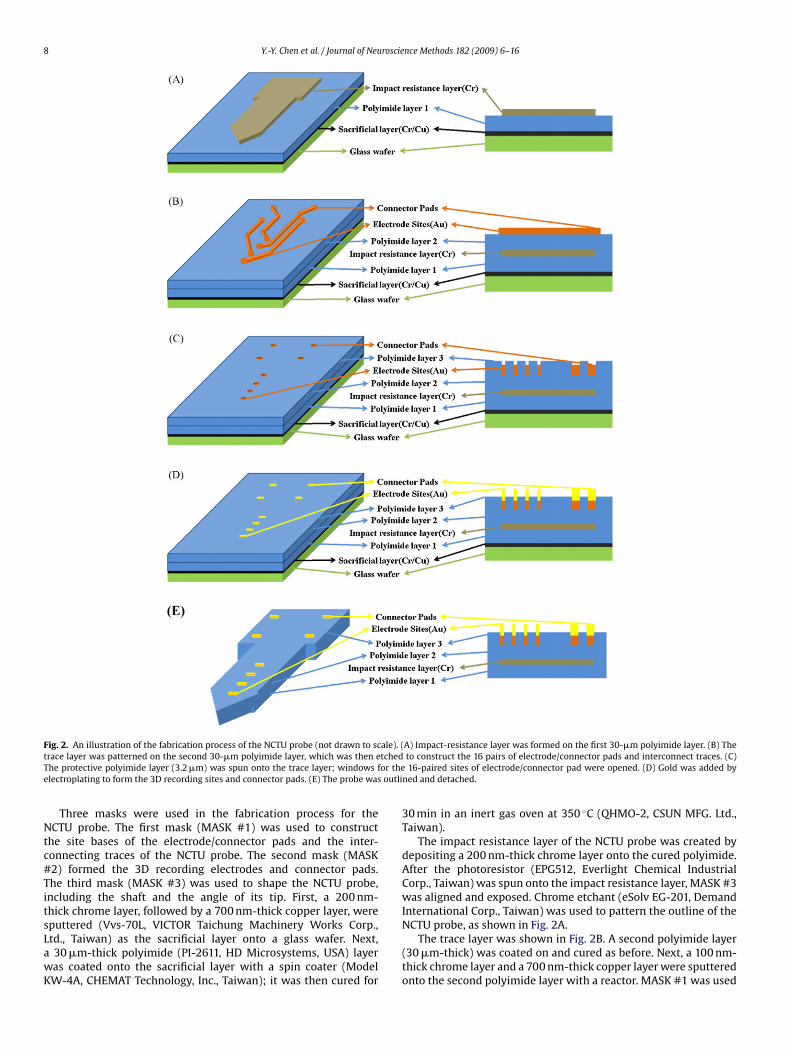
After implantation, in vivo impedance (at 1 kHz), SNR of themplanted NCTU probe and the number of units per channel overime, were measured (Fig. 6). In vivo impedance (at 1 kHz) was
easured to detect chronic tissue proliferation around the elec-rodes (Suner et al., 2005). After implantation (Day 0), the probe’s inivo impedance (at 1 kHz) was 0.61 ± 0.14 M� (mean ± SD, n = 16).uring the first two weeks of implantation, the in vivo impedance
ncreased slightly, attaining a maximum of 0.70 ± 0.09 M� on the4th day. Afterwards, the in vivo impedance curve gradually slopedownward into flatness SNR results estimated the quality of neu-al signal recordings over time. The SNR of recorded signals rangedrom 4 to 5, with no significant decrease within the entire recordingession (Fig. 6). In all the five animal subjects, the number of viablelectrodes ranged from 98% to 100% (average of 97.5%). Multi-unitnd single-unit were recorded from the 16-channel NCTU probever time. On the 0th day, 1.31 ± 0.48 units/channel (mean ± SD)ere recorded from one animal; monitoring results for 50 daysere shown in Fig. 6. Although the number of units varied, thereas no decrease over time. Results indicated that the NCTU probeas stable for at least 40 days.
.4. Surface microstructure of the NCTU probe electrode
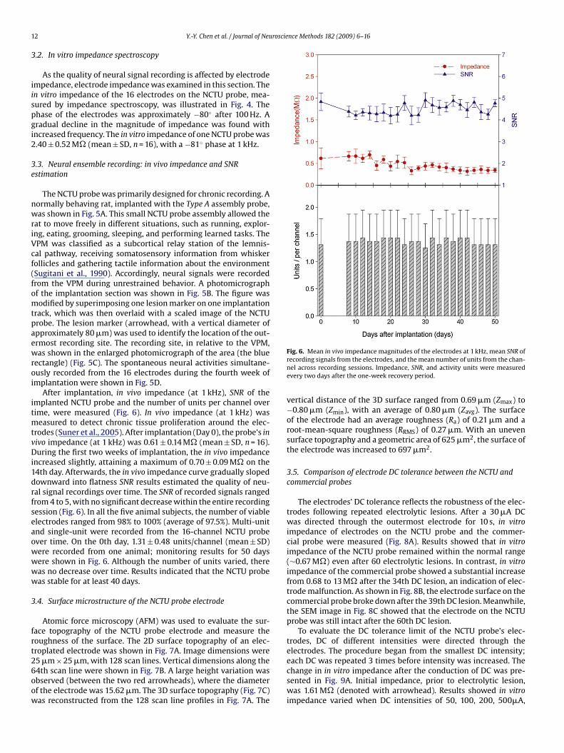
Atomic force microscopy (AFM) was used to evaluate the sur-ace topography of the NCTU probe electrode and measure theoughness of the surface. The 2D surface topography of an elec-roplated electrode was shown in Fig. 7A. Image dimensions were
5 �m × 25 �m, with 128 scan lines. Vertical dimensions along the4th scan line were shown in Fig. 7B. A large height variation wasbserved (between the two red arrowheads), where the diameterf the electrode was 15.62 �m. The 3D surface topography (Fig. 7C)as reconstructed from the 128 scan line profiles in Fig. 7A. TheFig. 6. Mean in vivo impedance magnitudes of the electrodes at 1 kHz, mean SNR ofrecording signals from the electrodes, and the mean number of units from the chan-nel across recording sessions. Impedance, SNR, and activity units were measuredevery two days after the one-week recovery period.
vertical distance of the 3D surface ranged from 0.69 �m (Zmax) to−0.80 �m (Zmin), with an average of 0.80 �m (Zavg). The surfaceof the electrode had an average roughness (Ra) of 0.21 �m and aroot-mean-square roughness (RRMS) of 0.27 �m. With an unevensurface topography and a geometric area of 625 �m2, the surface ofthe electrode was increased to 697 �m2.
3.5. Comparison of electrode DC tolerance between the NCTU andcommercial probes
The electrodes’ DC tolerance reflects the robustness of the elec-trodes following repeated electrolytic lesions. After a 30 �A DCwas directed through the outermost electrode for 10 s, in vitroimpedance of electrodes on the NCTU probe and the commer-cial probe were measured (Fig. 8A). Results showed that in vitroimpedance of the NCTU probe remained within the normal range(∼0.67 M�) even after 60 electrolytic lesions. In contrast, in vitroimpedance of the commercial probe showed a substantial increasefrom 0.68 to 13 M� after the 34th DC lesion, an indication of elec-trode malfunction. As shown in Fig. 8B, the electrode surface on thecommercial probe broke down after the 39th DC lesion. Meanwhile,the SEM image in Fig. 8C showed that the electrode on the NCTUprobe was still intact after the 60th DC lesion.
To evaluate the DC tolerance limit of the NCTU probe’s elec-trodes, DC of different intensities were directed through theelectrodes. The procedure began from the smallest DC intensity;
each DC was repeated 3 times before intensity was increased. Thechange in in vitro impedance after the conduction of DC was pre-sented in Fig. 9A. Initial impedance, prior to electrolytic lesion,was 1.61 M� (denoted with arrowhead). Results showed in vitroimpedance varied when DC intensities of 50, 100, 200, 500�A,
Y.-Y. Chen et al. / Journal of Neuroscience Methods 182 (2009) 6–16 13
F TU pr2 s indici (C) A 3fi
1iaep
a1
4
cspvssir
4
iatraaish(A
ig. 7. In situ AFM experiment performed on an electroplated electrode on the NC5 �m × 25 �m. The dark colors indicated the lowest points, while the bright color
n (A) indicated the profile and diameter (between 2 arrowheads) of the electrode.gure legend, the reader is referred to the web version of the article.)
, 2, 5 and 10 mA were induced through the electrode. However,mpedance showed a significant increase from 1.43 to 8.45 M� after10 mA anodal current was induced. After the third time, the out-rmost electrode on the NCTU probe broke and its polyimide filmeeled off from the base (Fig. 9B).
Results indicated the electrode on the NCTU probe could tolerates many as 60 electrolytic lesions, and a maximum of 5 mA DC for0 s.
. Discussion
A flexible, polyimide-based microelectrode array applicable forhronic recording was presented in this study. Metallic layers wereandwiched between polyimide layers to strengthen the NCTUrobe and increase the precision of implantation. Results from inivo impedance and SNR variation indicated the NCTU probe pre-ented stable and quality chronic recording could. In addition, theturdiness, density and thickness of each electrode were effectivelyncreased by electroplating, thus extending the lifespan for signalecordings and electrolytic lesions.
.1. The strengthened NCTU probe
Recent studies have applied silicon-based microelectrode arraysn chronic neural signal recordings (Bai et al., 2000; Csicsvari etl., 2003; Tae Hwan et al., 2000). However, micromotion at theissue–electrode contact areas induced persistent inflammatoryesponses (Cheung, 2007), directly resulting in neuronal loss. Aftercertain period, the efficiency of signal recordings may also be
ffected (Polikov et al., 2005; Szarowski et al., 2003). Prior stud-
es suggested that polyimide-based microelectrode arrays, with amall Young’s modulus (∼3 GPa) as compared to silicon (∼170 GPa),ave gained increasing popularity in research and developmentCheung et al., 2007; Lee et al., 2004b; Subbaroyan et al., 2005).s the Young’s modulus difference between the microelectrodeobe. The AFM image (A) of the electrode topography with scanning dimension ofated the highest points of the topography. (B) Section analysis along the black lineD AFM image of the electrode. (For interpretation of the references to color in this
array and brain tissue is small, inflammatory responses duringlong-term implantation was reduced, hence improving the stabilityduring chronic recordings (Cheung, 2007; Kim et al., 2004; Ludwiget al., 2006). However, a microelectrode array constructed from apolyimide-based substrate was easily bent and deviated from thedesired implant site during the implantation.
Although there were attempts to improve polyimide-basedmicroelectrode arrays by optimizing the use of several metallicmaterials, microelectrode arrays available were not sturdy enough,and their shafts were not applicable for deep brain implanta-tion. Rousche et al. (2001) constructed a microelectrode array bysandwiching a gold layer (200 nm-thick) between two layers ofpolyimide (10–20 �m-thick). However, this microelectrode arraywas too soft to be inserted directly into brain tissue; an inci-sion was required for implantation. As an alternative option, atungsten wire (∼100 �m) could be used to guide the implanta-tion. Nevertheless, the microelectrode array was only long enoughto reach the cortex. Another microelectrode array was fabricatedwith two Ti/Pt (50 nm/200 nm) electrode layers, separated with apolyimide layer (Cheung et al., 2007). Using this microelectrodearray, the hippocampus could be reached without an implantationguide. However, the microelectrode array substrate was not strongenough; deep brain implantation resulted in the bending of theshaft. The NCTU probe presented in this article reduced the micro-electrode array’s micromotion against tissue at the implantationsite, and also allowed precise insertion into the anatomical area ofinterest without bending.
An impact resistance layer was applied to the NCTU probe toincrease its strength. It was constructed by sandwiching a 200 nm-thick chrome layer between two 30 �m-thick polyimide layers. This
design increased the strength of the polyimide-based microelec-trode array while retaining the flexibility. In order to constructa microelectrode array that is long enough to penetrate into thedeep brain without bending or path deviation, materials witha certain amount of strength was required. The Young’s modu-
14 Y.-Y. Chen et al. / Journal of Neuroscience Methods 182 (2009) 6–16
F es onw he ouw ctrodee
ltphtdfNmRa
F(
ig. 8. The maximum number of repeated electrolytic lesions tolerated by electrodas measured after a number of electrolytic lesions. (B) An enlarged SEM image of tas corroded after the 39th electrolytic lesion. (C) SEM image of the outermost ele
lectrolytic lesions.
us of the NCTU probe was increased to 54 GPa, falling withinhat of silicon-based microelectrode array (∼170 GPa) and purelyolyimide-based microelectrode array (∼3 GPa). Consequently,armful effects caused by micromotion at the tissue–electrode con-act area were reduced, and the NCTU probe could be insertedirectly into deep brain. The NCTU probe showed improvement
rom brittle, silicon-based (Cheung et al., 2003; Rousche andormann, 1999; Suner et al., 2005) and some soft polyimide-basedicroelectrode arrays (Cheung et al., 2007; Rousche et al., 2001).esults from this study demonstrated significant advantages inpplying the NCTU probe to chronic implantation.
ig. 9. DC tolerance of electrodes on the NCTU probe (A) In vitro impedance of the electrodblack arrowhead) was 1.61 M�. (B) SEM image of the broken electrode; a polyimide film
the NCTU probe and the commercial probe. (A) In vitro impedance of the electrodetermost electrode on the commercial probe, as indicated in the yellow rectangle; iton the NCTU probe, as indicated in the blue rectangle; it remained intact after 60
4.2. Quality and stable chronic recording
A two-phase transition of in vivo impedance (at 1 kHz) was foundfor the electrode on the NCTU probe during the recording session(Fig. 6). For the first two weeks of implantation, in vivo impedanceincreased, which then decreased at the third week. Bio-film encap-
sulation around the implant, caused by immune responses, couldaffect in vivo impedance (Vetter et al., 2004; Ludwig et al., 2006).In our study, in vivo impedance showed a steady increase until the14th day of recording, a result from acute immune responses. Atthis stage, the microelectrode array insertion damaged the brain tis-e was measured after electrolytic lesion at various DC intensities. Initial impedancepeeled off the probe substrate after a 10 s, 10 mA electrolytic pulse.

roscie
swtnbrtSatie
mS(fosgactep
itcutulw
4
eacsaa(oeoEv0
d(api2ui2t2itD
Y.-Y. Chen et al. / Journal of Neu
ue, inducing an initial wound healing response. Microglia, whichas produced to repair the damaged area, eventually enveloped
he electrodes, and gliosis insulated the electrodes from the sig-al source (Biran et al., 2005; Polikov et al., 2005). Chronic foreignody reactions against the microelectrode array then occurred, andeactive astrocytes (glial scar and activated microglia) began to dis-ribute around the implant (Biran et al., 2005; Polikov et al., 2005;zarowski et al., 2003; Turner et al., 1999). The second phase beganfter the 14th day of recording. As acute immune response activi-ies decreased, in vivo impedance gradually decreased (Fig. 6). Suchmpedance changes were also found in studies using silicon-basedlectrodes (Ludwig et al., 2006; Vetter et al., 2004).
Suner et al. (2005) and Ludwig et al.’s (2006) SNR estimationethods were adopted in this study. Their work suggested that an
NR greater than 4 indicated a high quality signal. In Ludwig et al.’s2006) study, SNR of the silicon-based microelectrode array rangedrom 4 to 6. Across all recording sessions, SNR estimation resultsf the NCTU probe were between 4 and 5, implying the receivedignals were of good quality (Fig. 6). The small SNR variation sug-ested the NCTU probe was more stable than that used in Ludwig etl.’s (2006) study. Due to disparities among animal models, surgi-al techniques, and signal quality measurements, it was not feasibleo compare microelectrode arrays used in different studies (Vettert al., 2004). Therefore, it is reasonable to conclude that the NCTUrobe produced high quality and stable chronic recordings.
On average, 97.5% of the electrodes retained their viability dur-ng the recording sessions of the five animal subjects (15/16 forwo subjects, 16/16 for three subjects). The high retaining rate indi-ated the NCTU probe was highly reliable. The mean number ofnits showed no significant variance over time (Fig. 6). The rela-ionship between the SNR of the NCTU probe and the number ofnits from the channel was not examined in this study. However,
ess multi-unit channels were recorded if the SNR of the NCTU probeas greater than 4.7.
.3. Advantages of the electroplated electrode
Results from the AFM images and section analysis of thelectrodes on the commercial probe (thin-film deposited; datavailable upon request) and the NCTU probe (electroplated) indi-ated that electroplating produced electrodes with rougher 3Durfaces. Electroplated electrodes showed high corrosion resistancend roughened surfaces (De Haro et al., 2002). The effective surfacerea was hence increased and electrode impedance was reducedDe Haro et al., 2002; Kovacs, 1994; Paik et al., 2003). Accordingly,ur evaluations indicated that in vivo and in vitro impedance of thelectroplated electrodes on the NCTU probe was smaller than thosef the thin-film deposited electrodes on the commercial probe.valuated under the same criteria, in vitro and in vivo impedancealues for the commercial probe at 1 kHz were 2.71 ± 0.99 M� and.93 ± 0.16 M�, respectively.
Given that electroplating attained harder, denser and thickereposits that could withstand a large amount of metal dissolutionDe Haro et al., 2002), electrodes on the NCTU probe could toler-te stronger electrical conduction than those on the commercialrobe. DC is usually passed through electrodes for lesion mark-
ngs of tissue after neural signal recordings (Branner and Normann,000; Cheung et al., 2007; DiCarlo et al., 1996). A recent methodsed radiofrequency (RF) lesions to mark each of the 16 record-
ng sites of a 16-channel linear array multiprobes (Brozoski et al.,006). However, RF lesion methods were much less destructive
han DC lesion methods (Brozoski et al., 2006; Townsend et al.,002), electrode performance of the NCTU probe was thus exam-ned with DC lesions. Having a high tolerance threshold for DC,he NCTU probe electrodes were also robust for RF current. AsC was passed through the electrode, electromigration (Arnaud
nce Methods 182 (2009) 6–16 15
et al., 2000) and thermomigration (Manku and Orchard-Webb,1995) caused ion migration on the metallic thin-film. Repeatedelectrolytic lesions, therefore, reduced the thickness of the thin-film electrode, increasing electrode impedance that consequentlycaused structurally irreversible electrode malfunction (De Haro etal., 2002). The thin-film deposited electrodes on the commercialprobe were shown to be more vulnerable than the electroplatedelectrodes on the NCTU probe. The hard, dense and thick electrodeson the NCTU probe were stable during chronic recording. Moreover,the application of the NCTU probe could reduce the replacementcosts due to malfunction.
Results in this study indicated that the NCTU probe showed goodbiocompatibility, high and stable SNR for chronic recording, as wellas great DC tolerance for electrolytic lesion or electrical stimulation.Therefore, the NCTU probe could serve as a useful device for futureneuroscience research.
Acknowledgments
The authors thank Miss Pen-Li Lu (Institute of BiomedicalEngineering, National Taiwan University) for her assistance withhistological procedures. This study was supported by grants fromthe National Science Council of the Republic of China (NSC 95-2221-E-009-171-MY3) and the VGHUST Joint Research Program,Tsou’s Foundation (VGHUST96-P5-19). The authors would like tocontribute 20 free NCTU probes each year for academic researchpurposes; details are available upon request.
References
Arnaud L, Tartavel G, Berger T, Mariolle D, Gobil Y, Touet I. Microstructure and elec-tromigration in copper damascene lines. Microelectron Reliab 2000;40:77–86.
Bai Q, Wise KD, Anderson DJ. A high-yield microassembly structure for three-dimensional microelectrode arrays. IEEE Trans Biomed Eng 2000;47:281–9.
Biran R, Martin DC, Tresco PA. The brain tissue response to implanted silicon micro-electrode arrays is increased when the device is tethered to the skull. J BiomedMater Res A 2007;82A:169–78.
Biran R, Martin DC, Tresco PA. Neuronal cell loss accompanies the brain tissueresponse to chronically implanted silicon microelectrode arrays. Exp Neurol2005;195:115–26.
Branner A, Normann RA. A multielectrode array for intrafascicular recording andstimulation in sciatic nerve of cats. Brain Res Bull 2000;51:293–306.
Branner A, Stein RB, Fernandez E, Aoyagi Y, Normann RA. Long-term stimulation andrecording with a penetrating microelectrode array in cat sciatic nerve. IEEE TransBiomed Eng 2004;51:146–57.
Brozoski TJ, Caspary DM, Bauer CA. Marking multi-channel silicon-substrateelectrode recording sites using radiofrequency lesions. J Neurosci Methods2006;150:185–91.
Butovas S, Schwarz C. Spatiotemporal effects of microstimulation in rat neo-cortex: a parametric study using multielectrode recordings. J Neurophysiol2003;90:3024–39.
Chen YY, Kuo TS, Jaw FS. A laser micromachined probe for recording multiple fieldpotentials in the thalamus. J Neurosci Methods 2004;139:99–109.
Cheung KC. Implantable microscale neural interfaces. Biomed Microdevices2007;9:923–38.
Cheung KC, Djupsund K, Dan Y, Lee LP. Implantable multichannel electrode arraybased on SOI technology. IEEE J Microelectromech Syst 2003;12:179–84.
Cheung KC, Renaud P, Tanila H, Djupsund K. Flexible polyimide microelectrode arrayfor in vivo recordings and current source density analysis. Biosens Bioelectron2007;22:1783–90.
Csicsvari J, Henze DA, Jamieson B, Harris KD, Sirota A, Bartho P, et al. Massivelyparallel recording of unit and local field potentials with silicon-based electrodes.J Neurophysiol 2003;90:1314–23.
Cui X, Lee VA, Raphael Y, Wiler JA, Hetke JF, Anderson DJ, et al. Surface modificationof neural recording electrodes with conducting polymer/biomolecule blends. JBiomed Mater Res 2001;56:261–72.
De Haro C, Mas R, Abadal G, Munoz J, Perez-Murano F, Dominguez C. Electrochemicalplatinum coatings for improving performance of implantable microelectrodearrays. Biomaterials 2002;23:4515–21.
DiCarlo JJ, Lane JW, Hsiao SS, Johnson KO. Marking microelectrode penetrations withfluorescent dyes. J Neurosci Methods 1996;64:75–81.
Kim C-S, Ufer S, Seagle CM, Engle CL, Troy Nagle H, Johnson TA, et al. Use of microma-
chined probes for the recording of cardiac electrograms in isolated heart tissues.Biosens Bioelectron 2004;19:1109–16.Kovacs GTA. Introduction to the theory, design, and modeling of thin-film micro-electrodes for neural interfaces. In: Stenger DA, McKenna T, editors. EnablingTechnologies for Cultured Neural Networks. New York: Academic Press; 1994. p.121–65.

1 roscie
L
L
L
L
M
M
N
N
P
PP
R
R
R
6 Y.-Y. Chen et al. / Journal of Neu
ee IS, Whang CN, Choi K, Choo MS, Lee YH. Characterization of iridium film as astimulating neural electrode. Biomaterials 2002;23:2375–80.
ee K, He J, Clement R, Massia S, Kim B. Biocompatible benzocyclobutene(BCB)-based neural implants with micro-fluidic channel. Biosens Bioelectron2004a;20:404–7.
ee K, Singh A, He J, Massia S, Kim B, Raupp G. Polyimide based neural implants withstiffness improvement. Sens Actuatators: B Chem 2004b;102:67–72.
udwig KA, Uram JD, Yang J, Martin DC, Kipke DR. Chronic neural recordingsusing silicon microelectrode arrays electrochemically deposited with a poly(3,4-ethylenedioxythiophene) (PEDOT) film. J Neural Eng 2006;3:59–70.
anku T, Orchard-Webb JH. Reliability problems of polysilicon/Al contacts dueto grain-boundary enhanced thermomigration effects. IEEE Trans Reliab1995;44:550–5.
aynard EM, Fernandez E, Normann RA. A technique to prevent dural adhe-sions to chronically implanted microelectrode arrays. J Neurosci Methods2000;97:93–101.
enadic Z, Burdick JW. Spike detection using the continuous wavelet transform. IEEETrans Biomed Eng 2005;52:74–87.
orlin P, Kindlundh M, Mouroux A, Yoshida K, Hofmann UG. A 32-site neuralrecording probe fabricated by DRIE of SOI substrates. J Micromechan Microeng2002;12:414–9.
aik SJ, Park Y, Cho DI. Roughened polysilicon for low impedance microelectrodes inneural probes. J Micromechan Microeng 2003;13:373–9.
axinos G, Watson C. The Rat Brain in Stereotaxic Coordinates. Academic Press; 2007.olikov VS, Tresco PA, Reichert WM. Response of brain tissue to chronically
implanted neural electrodes. J Neurosci Methods 2005;148:1–18.ichardson RR, Miller JA, Reichert WM. Polyimides as biomaterials: preliminary
biocompatibility testing. Biomaterials 1993;14:627–35.
ousche PJ, Normann RA. Chronic intracortical microstimulation (ICMS) of cat sen-sory cortex using the Utah intracortical electrode array. IEEE Trans Rehab Eng1999;7:56–68.
ousche PJ, Pellinen DS, Pivin Jr DP, Williams JC, Vetter RJ, Kirke DR. Flexiblepolyimide-based intracortical electrode arrays with bioactive capability. IEEETrans Biomed Eng 2001;48:361–71.
nce Methods 182 (2009) 6–16
Schwartz AB, Cui XT, Weber DJ, Moran DW. Brain-controlled interfaces: movementrestoration with neural prosthetics. Neuron 2006;52:205–20.
Seymour JP, Kipke DR. Neural probe design for reduced tissue encapsulation in CNS.Biomaterials 2007;28:3594–607.
Shi LH, Luo F, Woodward DJ, Chang JY. Basal ganglia neural responses duringbehaviorally effective deep brain stimulation of the subthalamic nucleus in ratsperforming a treadmill locomotion test. Synapse 2006;59:445–57.
Snider RK, Bonds AB. Classification of non-stationary neural signals. J Neurosci Meth-ods 1998;84:155–66.
Subbaroyan J, Martin DC, Kipke DR. A finite-element model of the mechanicaleffects of implantable microelectrodes in the cerebral cortex. J Neural Eng2005;2:103–13.
Sugitani M, Yano J, Sugai T, Ooyama H. Somatotopic organization and columnar struc-ture of vibrissae representation in the rat ventrobasal complex. Exp Brain Res1990;81:346–52.
Suner S, Fellows MR, Vargas-Irwin C, Nakata GK, Donoghue JP. Reliability of signalsfrom a chronically implanted, silicon-based electrode array in non-human pri-mate primary motor cortex. IEEE Trans Neural Syst Rehab Eng 2005;13:524–41.
Szarowski DH, Andersen MD, Retterer S, Spence AJ, Isaacson M, Craighead HG,et al. Brain responses to micro-machined silicon devices. Brain Res Protoc2003;983:23–35.
Tae Hwan Y, Eun Jung H, Dong Yong S, Se Ik P, Seung Jae O, Sung Cherl J, et al.A micromachined silicon depth probe for multichannel neural recording. IEEETrans Biomed Eng 2000;47:1082–7.
Townsend G, Peloquin P, Kloosterman F, Hetke JF, Leung LS. Recording and markingwith silicon multichannel electrodes. Brain Res Protoc 2002;9:122–9.
Turner JN, Shain W, Szarowski DH, Andersen M, Martins S, Isaacson M, et al.Cerebral astrocyte response to micromachined silicon implants. Exp Neurol
1999;156:33–49.Vetter RJ, Williams JC, Hetke JF, Nunamaker EA, Kipke DR. Chronic neural recordingusing silicon-substrate microelectrode arrays implanted in cerebral cortex. IEEETrans Biomed Eng 2004;51:896–904.
Xu C, Lemon W, Liu C. Design and fabrication of a high-density metal microelectrodearray for neural recording. Sens Actuators A: Phys 2002;96:78–85.
Copyright © 2022 FDOKUMEN