Design and Construction of Micro Fabrication Cleanroom for Teaching Microelectronic Undergraduate
8
Faculty of Electrical Engineering Universiti Teknologi Malaysia VOL. 8, NO. 2, 2006, 46‐53 ELEKTRIKA Design and Construction of Micro Fabrication Cleanroom for Teaching Microelectronic Undergraduate Uda Hashim * , Zul Azhar Zahid Jamal , KC Phang , Mohamad Nurzaihan , Nurhamidah Abdul Halim and Haffiz Abd Razak School of Microelectronic Engineering, Northern Malaysia University College of Engineering, Kompleks Pusat Pengajian KUKUM, 02600 Jejawi, Perlis, Malaysia. * Corresponding author: [email protected] (Uda Hashim), Tel: 604-979884, Fax: 604-9798790 Abstract: This paper describes about the experience of Kolej Universiti Kejuruteraan Utara Malaysia (KUKUM) establishing the Micro Fabrication Cleanroom (MFC). This facility is mainly designed for teaching undergraduate microelectronic course leading to a Bachelor’s degree. With the construction of its “Micro Fabrication Cleanroom” (MFC), KUKUM has set the vision to reverse our reliance on imported technologies, as well as spearhead and support human resources needed by our nation, at the same time promoting indigenous talents and professionals especially in the field of microelectronic engineering. The cleanroom is approximately 115m 2 with cleanliness class from ISO Class 5 in the Yellow Room to ISO Class 8 in the Grey Area (Utility Chase). The cleanroom are equipped with distributed process gases such as purified nitrogen, oxygen and compressed dry air and 18.0MΩ ultra-pure water system supplied to the three fume hoods. Exhaust air from the fume hood are exhausted to the laboratory scrubber system for treatment. Despite being a teaching facility, the MFC cleanroom was designed and specified to ISO Class 5 cleanroom standard, and provided with features such as air shower, talk- through and pass box usually found in commercial facilities, it is our intention to expose and teach students to appreciate the stringent cleanroom protocols, in addition to the formal course works. This paper also describes the specifications, designs, development, testing, commissioning and operation of the cleanroom. Keywords: Air shower, De-ionized water, Fan filter unit, Micro fabrication cleanroom, Scrubber system. 1. INTRODUCTION The MFC in KUKUM is the first and largest purpose-built Micro Fabrication Cleanroom constructed by a university in Malaysia. The total area is 115 m 2 , in which comprises of a Yellow Room (ISO Class 5), White Room (ISO Class 6), Characterization Room (ISO Class 6), Preparation Room (ISO Class 7), Changing Room (ISO Class 7), and Grey Area (ISO Class 8). The MFC layout is as shown in Figure 1. The glass panels of the Yellow and Characterization rooms were coated with anti-static high tack vinyl film with UV protection [1]. In addition, both the rooms were also equipped with yellow luminaries. The Grey Area housed all the support utilities required for the wafer fabrication processes. Purified Gas Cylinders (compressed dry air, nitrogen, oxygen) are located along the corridor in the Grey Area. The gases are supplied to the laboratory via manual manifold system and distributed 316L stainless steel tubing routed under the raised floor space of the Yellow and White rooms. A dew point sensor was installed for the compressed dry air. An 18.0MΩ de-ionized water system was provided to service the three fume hoods with ultra- pure water. This ultra high purity water system was sourced from Millipore, the piping reticulate comprised of polypropylene pipes. The final outlet water purity at point- of-use shall contain suspended particulate not larger than 0.5μm, heavy metal ions less than 50 ppt, dissolved oxygen less than 1 ppb and bacteria present shall be less than 5cfu/mL. A custom-made scaled down laboratory chemical scrubber was installed to treat fume exhaust from all the three fume hoods [2]. The body of the scrubber unit was constructed entirely from polypropylene panels. This laboratory size scrubber has an air flow rate of 1,800 m 3 /hr and fresh water consumption of 30 l/hr. The scrubber pump unit was interlocked to a fiberglass reinforced plastic (FRP) exhaust fan rated at 1,800 m 3 /hr and 90 mm aqueous external static. The exhaust stack discharge velocity was designed to approximately 9m/s. 2. INTERNAL ARCHITECTURAL WORKS Like all other teaching laboratory in the world [3-6], besides teaching the educational aspect of the course, our intention is also to expose our students to a fully functional cleanroom environment. Students are expected to adhere to cleanroom protocols and environmental health and safety requirements expected in any commercial cleanrooms. The laboratory was built in an empty existing building with approximately 288m 2 and the height of the building is estimated to be about 8m high. 46
Transcript of Design and Construction of Micro Fabrication Cleanroom for Teaching Microelectronic Undergraduate

Faculty of Electrical Engineering Universiti Teknologi Malaysia
VOL. 8, NO. 2, 2006, 46‐53 ELEKTRIKA
Design and Construction of Micro Fabrication Cleanroom for Teaching Microelectronic
Undergraduate Uda Hashim*, Zul Azhar Zahid Jamal , KC Phang , Mohamad Nurzaihan , Nurhamidah Abdul Halim and
Haffiz Abd Razak
School of Microelectronic Engineering, Northern Malaysia University College of Engineering, Kompleks Pusat Pengajian KUKUM, 02600 Jejawi, Perlis, Malaysia.
*Corresponding author: [email protected] (Uda Hashim), Tel: 604-979884, Fax: 604-9798790
Abstract: This paper describes about the experience of Kolej Universiti Kejuruteraan Utara Malaysia (KUKUM) establishing the Micro Fabrication Cleanroom (MFC). This facility is mainly designed for teaching undergraduate microelectronic course leading to a Bachelor’s degree. With the construction of its “Micro Fabrication Cleanroom” (MFC), KUKUM has set the vision to reverse our reliance on imported technologies, as well as spearhead and support human resources needed by our nation, at the same time promoting indigenous talents and professionals especially in the field of microelectronic engineering. The cleanroom is approximately 115m2 with cleanliness class from ISO Class 5 in the Yellow Room to ISO Class 8 in the Grey Area (Utility Chase). The cleanroom are equipped with distributed process gases such as purified nitrogen, oxygen and compressed dry air and 18.0MΩ ultra-pure water system supplied to the three fume hoods. Exhaust air from the fume hood are exhausted to the laboratory scrubber system for treatment. Despite being a teaching facility, the MFC cleanroom was designed and specified to ISO Class 5 cleanroom standard, and provided with features such as air shower, talk- through and pass box usually found in commercial facilities, it is our intention to expose and teach students to appreciate the stringent cleanroom protocols, in addition to the formal course works. This paper also describes the specifications, designs, development, testing, commissioning and operation of the cleanroom.
Keywords: Air shower, De-ionized water, Fan filter unit, Micro fabrication cleanroom, Scrubber system.
1. INTRODUCTION The MFC in KUKUM is the first and largest purpose-built Micro Fabrication Cleanroom constructed by a university in Malaysia. The total area is 115 m2, in which comprises of a Yellow Room (ISO Class 5), White Room (ISO Class 6), Characterization Room (ISO Class 6), Preparation Room (ISO Class 7), Changing Room (ISO Class 7), and Grey Area (ISO Class 8). The MFC layout is as shown in Figure 1. The glass panels of the Yellow and Characterization rooms were coated with anti-static high tack vinyl film with UV protection [1]. In addition, both the rooms were also equipped with yellow luminaries. The Grey Area housed all the support utilities required for the wafer fabrication processes.
Purified Gas Cylinders (compressed dry air, nitrogen, oxygen) are located along the corridor in the Grey Area. The gases are supplied to the laboratory via manual manifold system and distributed 316L stainless steel tubing routed under the raised floor space of the Yellow and White rooms. A dew point sensor was installed for the compressed dry air. An 18.0MΩ de-ionized water system was provided to service the three fume hoods with ultra-pure water. This ultra high purity water system was sourced from Millipore, the piping reticulate comprised of polypropylene pipes. The final outlet water purity at point-
of-use shall contain suspended particulate not larger than 0.5μm, heavy metal ions less than 50 ppt, dissolved oxygen less than 1 ppb and bacteria present shall be less than 5cfu/mL. A custom-made scaled down laboratory chemical scrubber was installed to treat fume exhaust from all the three fume hoods [2].
The body of the scrubber unit was constructed entirely from polypropylene panels. This laboratory size scrubber has an air flow rate of 1,800 m3/hr and fresh water consumption of 30 l/hr. The scrubber pump unit was interlocked to a fiberglass reinforced plastic (FRP) exhaust fan rated at 1,800 m3/hr and 90 mm aqueous external static. The exhaust stack discharge velocity was designed to approximately 9m/s.
2. INTERNAL ARCHITECTURAL WORKS Like all other teaching laboratory in the world [3-6], besides teaching the educational aspect of the course, our intention is also to expose our students to a fully functional cleanroom environment. Students are expected to adhere to cleanroom protocols and environmental health and safety requirements expected in any commercial cleanrooms. The laboratory was built in an empty existing building with approximately 288m2 and the height of the building is estimated to be about 8m high.
46

UDA HASHIM, ZUL AZHAR ZAHID JAMAL, KC PHANG, MOHAMMAD NURZAIHAN, NURHAMIDAH ABDUL HALIM, HAFFIZ ABDUL RAZAK / ELEKTRIKA, 8(2), 2006, 46‐53
Figure 1. KUKUM Micro Fabrication Cleanroom
(a) (b)
Figure 2. The completed Micro Fabrication Cleanroom. (a) exit door and (b) entrance or air shower.
(a) (b)
Figure 3. Grey area with (a) electrical distribution panel and (b) scrubber.
(a) (b) Figure 4. (a) Cleanroom ceiling chamber and (b) fan filter units (FFU).
47

UDA HASHIM, ZUL AZHAR ZAHID JAMAL, KC PHANG, MOHAMMAD NURZAIHAN, NURHAMIDAH ABDUL HALIM, HAFFIZ ABDUL RAZAK / ELEKTRIKA, 8(2), 2006, 46‐53
The total area required for the cleanroom is only approximately 115m2 and not more than 5m high. With this available height, we adopted to construct a cleanroom with a negative plenum to house the fan filter units cum service area, as well as accommodating the installation of raised floor as shown in Figure 4. The cleanroom construction began with the cleaning of the existing space. Structural supports using hollow sections were erected to provide wall and ceiling stability. The inner wall between the cleanroom and Grey Area were constructed from 50 mm thick panels with static dissipative finish on steel sheet and aluminum honeycomb core [7]. The outer wall between the Grey Area and the external were polyurethane insulated core sandwiched between steel sheets with powder coat finish. The existing floor within the cleanroom footprint was applied with damp proof membrane and barrette screed coat finished with 2.0 mm thick fully flexible anti-static vinyl sheet to BS 3261. Conductive adhesive were used to stick the vinyl to the floor and thermal welding of all joints were done to form seamless flooring. A 100 mm skirting complete with cove former and capping strip were applied to all edges. Raised access floor within the White and Yellow room were 600 mm x 600 mm x 35 mm anti-static steel panels with cementations infill.
Perforated raised floor panels were strategically located for under floor return air. Return air slots were located below the raised floor adjacent to the Grey Area. There are three automatic sliding doors each leading into the Yellow Room, Characterization Room and Preparation Room. These sliding doors were operated by push buttons located beside the sliding doors both at the inside and outside of the rooms. At the Changing Room a clean garment storage cabinet with 99.99% efficiency HEPA filters rated at 0.3�m and 2 mm thick anti-static vinyl sheet as front cover. This garment storage cabinet was located just before the physical barrier cum shoe rack. On completion, the cleanroom is entirely cleaned with HEPA vacuum cleaner and subsequently wiped down using a mixture of 50% isopropyl alcohol (IPA) and 50% de-ionized (DI) water. Following the commissioning of the air conditioning system, all persons entering the cleanroom are required to be gowned in fully “bunny suits”. Entrance to the Grey Area shall only require the wearing of cleanroom smock and shoes.
3. FAN FILTER UNITS AND LIGHTINGS Two way switching are provided for lights, fan filter units, air conditioning before and after the air shower. The fan filter units (FFU) installed were AAF AstroFan, with stainless steel casing complete with AAF Astrocel II HEPA filter at 99.9995% efficiency rated for 0.12 μm. These FFU fitted nicely onto the ceiling ‘T’, the ceiling grid were 1200 mm x 600 mm, with 25 mm thick blank ceiling panels in place of the FFU. As the fan filter units were located at the ceiling chamber, the ceiling type selected was designed to withstand human loads under normal circumstances, in order to facilitate maintenance work. All blank ceiling panels and HEPA fan filter units had been sealed to the ceiling grid with gasket to prevent infiltration of contaminant into the cleanroom. The HEPA filters are also isolated from the motor section of the fan filter units to
minimize vibration. The entire ceiling was suspended from the secondary ceiling. Turnbuckles were used to level the ceiling with the help of using a laser theodolite. Cleanroom teardrop lights were fastened along the ceiling grids, the ceiling grids have screw grooves that accommodate screws, so as to prevent the ceiling grid from being punctured.
Teardrop lightings installed were complete with clear see-through U shape covers and aluminum end-covers. All pipes and electrical trunking penetrations through the walls were sealed with Sikaflex-221, a non out-gassing polyurethane based sealant. 4. EMERGENCY SHUT DOWN PUSH BUTTON The cleanroom were provided with two emergency power shut off push buttons. On activation, all power socket outlets and the air conditioning system are isolated. Each of the emergency push button was located at both the exits within the White Room, near the air shower and the rear door within the cleanroom.
5. AIR SHOWER A three doors air shower was installed at the changing room adjacent to the Grey Area and White Room. Inside the air shower one door will lead to the White Room and the other into the Grey Area as shown in Figure 5. The air shower was equipped with a high static fan, washable pre-filter and 99.99% HEPA filter rated at 0.3 μm. The nozzles air discharge velocity is at 23m/s + 20%.
6. PASS BOX AND TALK THROUGH An Airtech pass box shown in Figure 5 with an effective dimension 600mmW x 600mmD x 600mmH were installed between the Preparation Room and the Characterization Room. The pass box was equipped with micro electro-magnetic interlock switch to prevent both the doors from opening simultaneously; warning buzzers and indicator lights were incorporated on both sides of the pass box. Two cleanroom talk-through as shown in Figure 6 which consist of overlapping Mylar “S” diaphragms were installed in the Preparation Room, to facilitate clear communication and visibility to the White Room and Characterization Room.
7. AIR CONDITIONING SYSTEM AND HEAT RECOVERY FOR REHEAT The air handling units were supplied with two stage filtrations before the conditioned air was introduced into the ceiling plenum, the pre-filter were AAF AmAir 300E rated at 25-30% efficiency and secondary filter were AAF Varicel II MH with rated efficiency of 90-95%. The outside air needed to maintain the cleanroom under positive pressure with reference to the adjacent space at all times are also passed through these filters. The air handling units (AHU) was located at the back of the building, supply air is routed to the cleanroom via galvanized iron (GI) air duct to the cleanroom chamber. The supply air was then introduced to the cleanroom through the fan filter units installed at the ceiling of the cleanroom. The space below the raised floor installed in the cleanroom act as a return air chamber, air was returned to the chamber via strategically
48

UDA HASHIM, ZUL AZHAR ZAHID JAMAL, KC PHANG, MOHAMMAD NURZAIHAN, NURHAMIDAH ABDUL HALIM, HAFFIZ ABDUL RAZAK / ELEKTRIKA, 8(2), 2006, 46‐53
placed perforated raised floor panels. Air flow from the plenum will flow towards the return slots adjacent to the Grey Area / return air chamber where it returned to the AHU via GI return air ducts as shown in the Figure 6.
The cooling requirement is achieved via the four (4) mini chillers installed as shown in Figure 6. The mini chillers were piped to the AHU via insulated chilled water pipes and circulating pumps. For relative humidity control, two sets of hot water recovery tanks were installed, heat discharged from the compressors of the mini chillers were extended to the heat recovery tanks and heat exchanged in these tanks were then circulated to the heating coil installed at the air handling units discharge section. Based on a 24 hours operating throughout the year, and assumed of its effective life cycle of 10 years, the energy cost saving is estimated to be more than double the capital cost of the installed air conditioning system.
8. SCRUBBER SYSTEM Three way switching were also provided for the scrubber system, each remote switches are located within the White and Yellow Room near the fume hoods. On activation on either of these buttons, the scrubber system will start to operate, however all three buttons need to be pressed off to
stop the scrubber system. The scrubber exhaust fan was interlocked to the scrubber system pump unit, when the scrubber pump starts to operate, the fan will simultaneously start and like wise for stopping. The Laboratory Gas Scrubber was especially designed for laboratories uses where toxic, corrosive, and odorous gases are set free. The laboratory gas scrubbers are mainly used for the absorption of strong acids. The Laboratory Gas Scrubber, use water without any additional substances. In the laboratory gas scrubber, the air flows through the packed bed in horizontal direction with a single turn. The washing solution flows in vertical flow to the air from the top to the bottom through the packed bed. The droplet separator situated in front of the exhaust air outlet retained liquid drops contained in the exhaust air. The bottom section of the laboratory gas scrubber was executed as washing liquid tank. Water losses by evaporation are controlled via level measurements. (b) (a)
Figure 5. (a) Pass box and (b) talk through.
Figure 6. Air handling unit (AHU).
Fresh water valve will open automatically to compensate for water losses. The electrical conductivity of the washing solution is measured. If the adjustable set value is exceeded, a portion of the washing solution is discharged and replaced by fresh water. The discharged wastewater shall be strongly acidic and therefore has to be transferred
49
UDA HASHIM, ZUL AZHAR ZAHID JAMAL, KC PHANG, MOHAMMAD NURZAIHAN, NURHAMIDAH ABDUL HALIM, HAFFIZ ABDUL RAZAK / ELEKTRIKA, 8(2), 2006, 46‐53
to a neutralization plant. Pre-condition for the transference of the wastewater from the laboratory gas scrubber to the neutralization plant was determined from the liquid level in the scrubber is below the maximum level set point.
9. HEAT EXHAUST The total heat exhaust requirement for all process equipments are approximately 1,790m3/hr, a 720 rpm with 25 mm aqueous external static axial fan was provided for this purpose. The main ducts were routed within the negative plenum and droppers duct dropped directly to the exhaust discharge points. The main duct immediately after the axial fan was installed with a motorized shut off damper to minimize infiltration of contaminant into the clean room during shut down.
10. DE-IONIZED WATER The system installed was to provide ultra-pure water requirement to match the micro fabrication application needed at the fume hoods. This system comprised of four steps purification techniques that purify tap water to the Type I (ASTM) water standard. Step One is the Pre-filtration, which consist of a Grundfos water booster pump to boost water pressure to more than 1 bar, this water wais fed through a 5 μm 10” pre-filter to filter feed water particles not more than 5 μm size and then through an activated carbon 10” pre-filter to reduce feed water chlorine level. Step Two comprised of a Pure Water System (Type II Water System: Elix 10). Step two is to produce pure water to the analytical grade water based on the following specification; resistivity of more than 5 MΩcm and Total Organic Compound (TOC) of less than 30 ppb. Figure 7. Heat recovery vessels.
Figure 8. Laboratory gas scrubber.
50

UDA HASHIM, ZUL AZHAR ZAHID JAMAL, KC PHANG, MOHAMMAD NURZAIHAN, NURHAMIDAH ABDUL HALIM, HAFFIZ ABDUL RAZAK / ELEKTRIKA, 8(2), 2006, 46‐53
The purification sequences for step two were Pre-
treatment (Progard 1). Progard was tailored to the feed water source which contain several steps, polyphosphates to prevent scaling, activated carbon to remove chlorines and organic and depth filters to remove particulates. This is followed by reverse osmosis (RO) where RO efficiency removes up to 99% of organic, particles and micro-organism and approximately 95% of ionic contaminants. A hydraulic pressure is applied to the concentrated (feed water) solution forcing water across the semi-permeable membrane, leaving the contaminants behind. Reverse osmosis provide an effective pre-treatment before electro-deionization and final polishing. Electro-deionzation (EDI), this technology was an advance form of electro-deionization that provides an efficient method for the removal of ionic contaminants employing an electric current to regenerate the ion exchange resins without the need for additional softener.
This avoids hazardous chemical regeneration. Step Three
was the storage in a 100 litres reservoir with automatic sanitization module and air vent. This was where a storage tank is provided to store 100 litres of Elix-Type II water and to maintain the purity of the stored water. Also, this reservoir can be connected to a looping system to provide a few point-of-uses at several locations. To prevent bacterial growth inside the tank, an automatic sanitization module (ASM) with programmed radiation of ultra violet (UV) light (254nm) was installed. Finally Step Four, the Ultra pure water system (Type I water system: Milli-Q Gradient A10) was designed to produce ultra pure water based on the following specifications; resistivity more than 18 MΩcm, TOC less than 5 ppb, particulate less than 0.1μm, bacteria less than 1 cfu/mL. The purification technique inside Milli-Q Gradient A10 where Q-Gard 1, was tailored to Elix water to optimize the performance of the down stream purification media.
Figure 9. Scrubber system.
Figure 10. DI water system. Figure 11. Gas cylinder.
51
UDA HASHIM, ZUL AZHAR ZAHID JAMAL, KC PHANG, MOHAMMAD NURZAIHAN, NURHAMIDAH ABDUL HALIM, HAFFIZ ABDUL RAZAK / ELEKTRIKA, 8(2), 2006, 46‐53
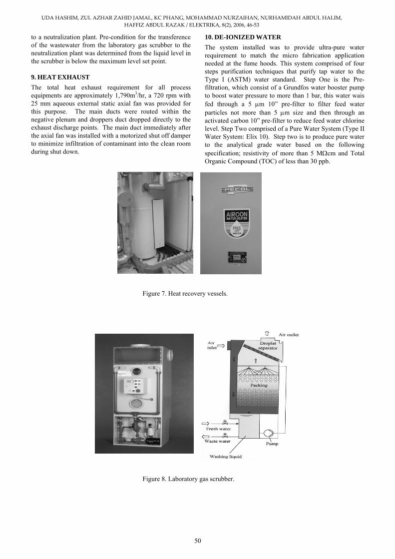
It contains mainly mixed bed ion-exchange resin. UV lamp, UV photo oxidation technology was used to reduce organics to levels below 5 ppb. UV radiation was generated by a powerful low pressure mercury vapor lamp, constructed of ultra-pure quartz to ensure optimal UV of 185 and 254 nm wavelength transmissions. An electro-polished 316L stainless steel housing provides maximum UV light reflection for optimum efficiency. Quantum IX, was tailored to remove ionic contaminants down to ultra-low trace ionic level. The Optimiser filtration is the final filter used to remove particles more than 0.1 μm.
11. UTILITY PIPING SYSTEM The Micro Fabrication Cleanroom was equipped with pure gases such as nitrogen, oxygen and compressed dry air for fabrication purposes. All pipes serving into the cleanroom were laid below the raised floor with each branch out having an isolating valve. The gases are stored in cylinders located in the Grey Area, each of the nitrogen, oxygen and compressed dry system were provided with duty and standby gas cylinders. The switch over from manual to standby cylinder is through a manual change-over manifold as shown below. The reticulate pipe used for these gasses are stainless steel tubing. The welding method was automated orbital fusion weld. The gas cylinders were securely chained to the common frame, to prevent the cylinder from falling over. The Material Safety Data Sheet were distributed and located at convenient locations. 12. FIRE ALARM SYSTEM The fire alarm systems consist of heat detectors located at ceiling levels in both the cleanroom and the chamber ceiling. Break glasses are also provided along the escape routed. The alarm zones are as shown below.
Zones Location
Zone 1 Inside cleanroom
Zone 2 Grey area and chamber
Zone 3 Fire alarm break glasses
Zone 4 Spare
In the event of fire, the fire alarm will sound, all personnel must evacuate the facility in an orderly manner.
Figure 12. Cleanroom testing in operation.
Figure 13. Airbone particle count test in
progress.
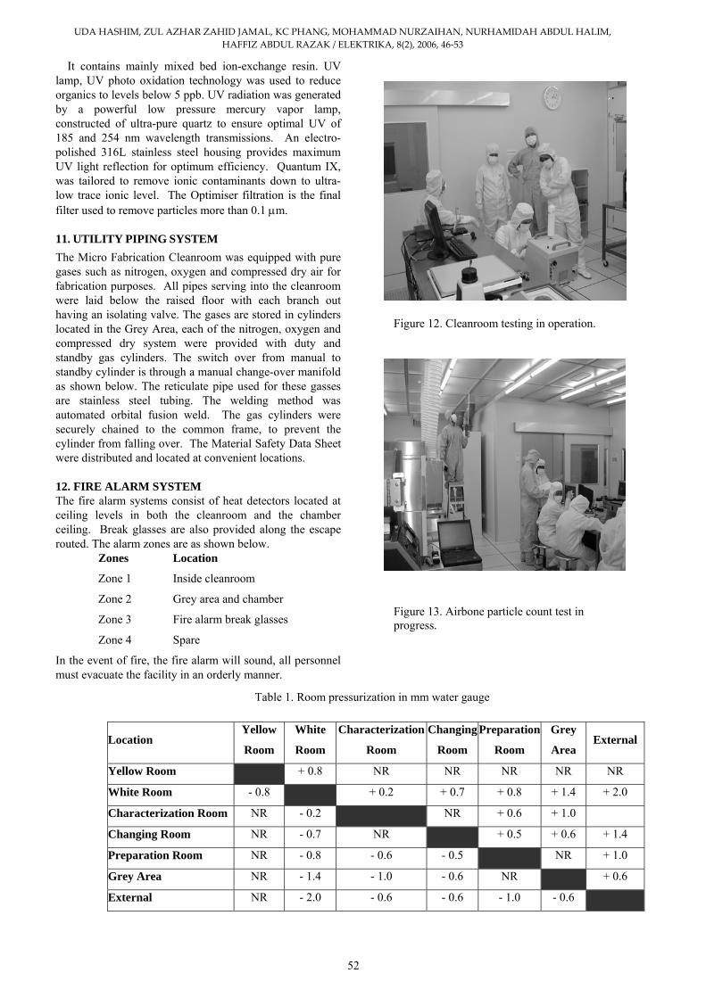
Table 1. Room pressurization in mm water gauge
Location Yellow
Room
White
Room
Characterization
Room
Changing Preparation
Room Room
Grey
Area External
Yellow Room + 0.8 NR NR NR NR NR
White Room - 0.8 + 0.2 + 0.7 + 0.8 + 1.4 + 2.0
Characterization Room NR - 0.2 NR + 0.6 + 1.0
Changing Room NR - 0.7 NR + 0.5 + 0.6 + 1.4
Preparation Room NR - 0.8 - 0.6 - 0.5 NR + 1.0
Grey Area NR - 1.4 - 1.0 - 0.6 NR + 0.6
External NR - 2.0 - 0.6 - 0.6 - 1.0 - 0.6
52

UDA HASHIM, ZUL AZHAR ZAHID JAMAL, KC PHANG, MOHAMMAD NURZAIHAN, NURHAMIDAH ABDUL HALIM, HAFFIZ ABDUL RAZAK / ELEKTRIKA, 8(2), 2006, 46‐53
13. TESTING AND COMMISSIONING Extensive testing and commissioning were conducted for the facilities. Testing was carried for all three modes as defined in ISO 14644, namely “As built”, “At Rest” and “As Operation” modes. Only the result for the “As Operation” shall be discussed here. Although cleanroom enclosure integrity test is not a mandatory testing requirement, it was useful in determining the infiltration of particles into the space. The enclosure integrity test conducted pin pointed to joint defects as shown in Figure 13. Airborne particulate test were carried out in all designated rooms, the “As Operation”, results for all areas were below the 95% Upper Confidence Limit stipulated in ISO 14644. Therefore, the cleanrooms meet the required classifications. Light level test exceeded minimum lighting requirement, the average illumination was about 750 lox for the White Room. Air velocity and airflow tests were carried out upon completion of air balancing, the relative standard deviation of air flow for all fan filter units are within stipulated 15%, the corrected air change in the Yellow Room and White Room were 190 times and 50 times respectively. A Pitot traverse of the main duct were carried out to determine the total airflow of the air handling unit, the total airflow measured was 22,514 cmh which was within the 10% acceptable tolerance range. The design airflow capacity was 20,500 cmh. The temperature and relative humidity recorded during the testing period were within the acceptable ranges, 22 + 2oC and 50 + 5% respectively. The pressurization between adjacent rooms were recorded and tabulated as in Table 1.
14. CONCLUSION The facilities designed and setup were comparable to commercially installed cleanrooms. It may be said that the provision were over-kill for a teaching laboratory, however, it is also our intention to expose undergraduate to the “real-life” cleanroom environment, the protocols and environmental, health and safety requirements and good laboratory practices within cleanrooms. It is our hope that
graduates from KUKUM will be contributing toward the organization they join, thus matching industry needs.
ACKNOWLEDGMENT A task of this magnitude would not be possible without the support, guidance, advice and valuable time and effort of many individuals. A special gratitude to all those who involved directly and indirectly on completing the overall project. This project is supported by KUKUM through its development grant.
REFERENCES [1] L. Fuller, “Undergraduate microelectronic engineering
programs and laboratory facilities”, Education News-Newsletter of IEEE Educational Board, 1999.
[2] M. A. Khaliq, “Undergraduate microelectronics education in engineering and technology programs at Minnesota State University, Mankato,” Education News-Newsletter of IEEE Educational Board, 2001.
[3] M. M. Rahman and C. Y. Yang, “Undergraduate microelectronics education,” Education News-Newsletter of IEEE Educational Board.
[4] Robert W. Hendricks, Louis J. Guido, James R. Heflin, and Subhash Sarin, “An interdisciplinary curriculum for microelectronics”, Proceedings of the 2001 American Society for Engineering Education Annual Conference & Exposition, 2003.
[5] S. Parke, S. Duttagupta, S. Burkett and N. Rafla, “A new microelectronics program at Boise State University”, Proceedings of Twelfth Biennial UGIM Symposium, pp. 40-42, 1997.
[6] L. Savage, “Universities offer hands-on training”, Solid State Technology, pp. 57-61, 1997.
[7] G. A. Runkle, S. P. Blondell and L. F. Fuller, “Care and feeding of a university cleanroom facility”, Proceeding of the 8th Industry-University Microelectronics Symposium, 1989.
53