
Design and Analysis of Microstrip Line Feed Toppled T ...
7
J Electr Eng Technol.2015; 10(2): 634-640 http://dx.doi.org/10.5370/JEET.2015.10.2.634 Copyright ⓒ The Korean Institute of Electrical Engineers This is an Open-Access article distributed under the terms of the Creative Commons Attribution Non-Commercial License (http://creativecommons.org/ licenses/by-nc/3.0/)which permits unrestricted non-commercial use, distribution, and reproduction in any medium, provided the original work is properly cited. 634 Design and Analysis of Microstrip Line Feed Toppled T Shaped Microstrip Patch Antenna using Radial Basis Function Neural Network Mohammad Aneesh † , Anil Kumar*, Ashish Singh**, Kamakshi** and J.A Ansari** Abstract – This paper deals with the design of a microstrip line feed toppled T shaped microstrip patch antenna that gives dualband characteristics at 4 GHz and 6.73 GHz respectively. The simulation of proposed antenna geometry has been performed using method of moment based IE3D simulation software. A radial basis function neural network (RBFNN) is used for the estimation of bandwidth for dualband at 4 GHz and 6.73 GHz respectively. In RBFNN model, antenna parameters such as dielectric constant, height of substrate, and width are used as input and bandwidth of first and second band is considered as output of the network. To validate the RBFNN output, an antenna has been physically fabricated on glass epoxy substrate. The fabricated antenna can be utilized in S and C bands applications. RBFNN results are found in close agreement with simulated and experimental results. Keywords: Artificial neural network, Microstrip patch antenna, Radial basis function, Bandwidth. 1. Introduction Microstrip patch antennas (MSAs) have gained attention of researchers due to the topical development in the field of wireless communication. These antennas are in mammoth demand due to their wide range of applications such as mobile, satellite, terrestrial cellular, personal com- munication systems [1-3] etc. Microstrip antennas plays vital role in efficient reception and transmitting of signals in wireless communications. These antennas become more abundant when single antenna can be used for both transmission and reception of the signals, i.e., for dualband operation has two or more than two bands of frequencies. This provoked the researchers to design microstrip patch antenna for dualband operation. Dualband MSA was first reported by Wang and Lo [4] in 1984. Subsequently, plethora of dualband microstrip antennas have been reported [5-20]. In dualband microstrip antenna design, determination of bandwidth is a fundamental point because the bandwidth is important parameter of microstrip patch antenna [21-27]. Two types of analysis are mostly reported in the literature [21-27] for calculating the bandwidth of these antennas. These analysis techniques are numerical and analytical methods. Both these methods have its own limitations. Analytical methods are applicable for few specific shapes of the patch geometry whereas a numerical method is applicable for all shapes of the patch geometry and requires much time for solving the differential equations. Another drawback is that for any minor change in geometry it requires new solution for geometry and thus it becomes time consuming method. To avoid all these difficulties, a novel method is suggested in this paper, which is the application of artificial neural network (ANN) model. ANNs are suitable models for parameter optimization of microstrip patch antenna. ANN models are computationally much more efficient than EM models (analytical and numerical methods). The ANN provides fast and accurate models for MSA modeling, simulation, and optimization. ANN is computational tools and based on learning strategies. The application of ANN on the field of microstrip patch antenna is very recent. A number of papers [28-44] are present in the literature that signifies the importance of ANN in the field of microstrip patch antenna. This work aims to design a microstrip line feed toppled T shaped MSA for dual frequency operation using radial basis function neural network. In this work RBFNN is used for the optimizing the bandwidth of proposed antenna with respect to used dielectric material. The proposed antenna is physically fabricated for the verification of RBFNN results. The beauty of the proposed work is the combination of simulated, experimental, and ANN results. This paper is organized as follows, section 1 deals with the introduction, and section 2 deals with antenna geometry. Section 3 demonstrates the neural modeling and generation of data. Finally section 4 and 5 hold the results and conclusion of entire study respectively. 2. Antenna Design and Data Generation In Fig. 1(a), the proposed antenna geometry is shown. A † Corresponding Author: Dept. of Electronics and Communication, University of Allahabad, Allahabad, India. ([email protected]) * Dept. of Electronics and Communication, Sam Higginbottom Institute of Agriculture, Technology & Sciences, Allahabad, India. ** Dept. of Electronics and Communication, University of Allahabad, Allahabad, India. Received: May 20, 2014; Accepted: October 20, 2014 ISSN(Print) 1975-0102 ISSN(Online) 2093-7423
-
Upload
khangminh22 -
Category
Documents
-
view
1 -
download
0
Transcript of Design and Analysis of Microstrip Line Feed Toppled T ...
J Electr Eng Technol.2015; 10(2): 634-640 http://dx.doi.org/10.5370/JEET.2015.10.2.634
Copyright ⓒ The Korean Institute of Electrical Engineers This is an Open-Access article distributed under the terms of the Creative Commons Attribution Non-Commercial License (http://creativecommons.org/
licenses/by-nc/3.0/)which permits unrestricted non-commercial use, distribution, and reproduction in any medium, provided the original work is properly cited.
634
Design and Analysis of Microstrip Line Feed Toppled T Shaped Microstrip Patch Antenna using Radial Basis Function
Neural Network
Mohammad Aneesh†, Anil Kumar*, Ashish Singh**, Kamakshi** and J.A Ansari**
Abstract – This paper deals with the design of a microstrip line feed toppled T shaped microstrip patch antenna that gives dualband characteristics at 4 GHz and 6.73 GHz respectively. The simulation of proposed antenna geometry has been performed using method of moment based IE3D simulation software. A radial basis function neural network (RBFNN) is used for the estimation of bandwidth for dualband at 4 GHz and 6.73 GHz respectively. In RBFNN model, antenna parameters such as dielectric constant, height of substrate, and width are used as input and bandwidth of first and second band is considered as output of the network. To validate the RBFNN output, an antenna has been physically fabricated on glass epoxy substrate. The fabricated antenna can be utilized in S and C bands applications. RBFNN results are found in close agreement with simulated and experimental results.
Keywords: Artificial neural network, Microstrip patch antenna, Radial basis function, Bandwidth.
1. Introduction Microstrip patch antennas (MSAs) have gained attention
of researchers due to the topical development in the field of wireless communication. These antennas are in mammoth demand due to their wide range of applications such as mobile, satellite, terrestrial cellular, personal com-munication systems [1-3] etc. Microstrip antennas plays vital role in efficient reception and transmitting of signals in wireless communications. These antennas become more abundant when single antenna can be used for both transmission and reception of the signals, i.e., for dualband operation has two or more than two bands of frequencies. This provoked the researchers to design microstrip patch antenna for dualband operation.
Dualband MSA was first reported by Wang and Lo [4] in 1984. Subsequently, plethora of dualband microstrip antennas have been reported [5-20]. In dualband microstrip antenna design, determination of bandwidth is a fundamental point because the bandwidth is important parameter of microstrip patch antenna [21-27]. Two types of analysis are mostly reported in the literature [21-27] for calculating the bandwidth of these antennas. These analysis techniques are numerical and analytical methods. Both these methods have its own limitations. Analytical methods are applicable for few specific shapes of the patch geometry whereas a numerical method is applicable for all shapes of the patch geometry and requires much time for
solving the differential equations. Another drawback is that for any minor change in geometry it requires new solution for geometry and thus it becomes time consuming method. To avoid all these difficulties, a novel method is suggested in this paper, which is the application of artificial neural network (ANN) model.
ANNs are suitable models for parameter optimization of microstrip patch antenna. ANN models are computationally much more efficient than EM models (analytical and numerical methods). The ANN provides fast and accurate models for MSA modeling, simulation, and optimization. ANN is computational tools and based on learning strategies. The application of ANN on the field of microstrip patch antenna is very recent. A number of papers [28-44] are present in the literature that signifies the importance of ANN in the field of microstrip patch antenna.
This work aims to design a microstrip line feed toppled T shaped MSA for dual frequency operation using radial basis function neural network. In this work RBFNN is used for the optimizing the bandwidth of proposed antenna with respect to used dielectric material. The proposed antenna is physically fabricated for the verification of RBFNN results. The beauty of the proposed work is the combination of simulated, experimental, and ANN results. This paper is organized as follows, section 1 deals with the introduction, and section 2 deals with antenna geometry. Section 3 demonstrates the neural modeling and generation of data. Finally section 4 and 5 hold the results and conclusion of entire study respectively.
2. Antenna Design and Data Generation In Fig. 1(a), the proposed antenna geometry is shown. A
† Corresponding Author: Dept. of Electronics and Communication, University of Allahabad, Allahabad, India. ([email protected])
* Dept. of Electronics and Communication, Sam Higginbottom Institute of Agriculture, Technology & Sciences, Allahabad, India.
** Dept. of Electronics and Communication, University of Allahabad, Allahabad, India.
Received: May 20, 2014; Accepted: October 20, 2014
ISSN(Print) 1975-0102ISSN(Online) 2093-7423

Mohammad Aneesh, Anil Kumar, Ashish Singh, Kamakshi and J. A Ansari
http://www.jeet.or.kr │ 635
very low loss dielectric substrate glass epoxy with 1.58 mm height, tan∂ = 0.002, and dielectric constant of εr = 4.7 is used as the substrate for proposed antenna. The patch and ground plane are printed on the top and bottom of the dielectric substrate respectively. The dimension of the ground plane is Lg×Wg. The radiating patch is designed and its dimensions are selected so as to achieve dualband characteristics. All the respective values of designing parameters mentioned in Fig. 1(a) are given in Table 1. The proposed antenna geometry is simulated using IE3D software [45]. Fig. 1(b) shows the physically fabricated microstrip antenna with ground plane on glass epoxy substrate. Microstrip line feeding is used here for the excitation of antenna geometry.
Fig. 2(a) - (b) shows the current distribution of the proposed antenna at frequencies 4 GHz and 6.73 GHz
respectively. From the Fig. 2(a), it is observed that a good amount of current with different length appears on the upper patch and ground plane of the proposed geometry. This different length of currents is responsible for generating dualband resonance frequencies. Fig. 2(b) depicted the current distribution at 6.73 GHz and found that, current flowing in two direction on the upper patch and ground plane due to which antenna characteristics improves in good radiation mode.
3. ANN Implementation The implementation of ANN on above proposed
geometry is mainly characterized in two steps; these are generation of data for training and testing, and selection of ANN topology.
3.1 Data generation
The bandwidth of microstrip patch antenna is mainly
depending on the length (L), width (W), height (h), and dielectric constant (εr) of the substrate. Here, three parameters of the antenna are considered as an input for ANN model. In ANN model simulated, theoretical, and measured data can be used for training and testing. The simulated data of the proposed antenna geometry is obtained from method of moment based IE3D simulation software and used in RBF neural network model. Here 55 samples (34 training and 21 testing samples) are generated with the variation of dielectric constant from the range of 2 ≤ εr ≤ 4.7 and antenna geometry is simulated using IE3D software. Simulated reflection coefficient (S11) of the proposed antenna geometry is recorded and their respective bandwidths for dualband are calculated. Whereas the other two parameters h and W are kept constant.
3.2 Model selection of artificial neural network
Artificial neural network uses several topologies. The
most used topology of ANN are RBF and multilayer perceptron (MLP) neural network because the process of learning in this model (topology) has two stages and both of the stages are made more efficient by using appropriate learning algorithm. So, this is the leading reason of using RBFNN instead of MLPNN in the present work. A three layered radial basis neural network is selected for the estimation of bandwidth of proposed antenna geometry. Fig. 3 shows the structure of RBFNN model which have three layers. First one is the input layer consist of three source nodes with εr, h, w as an input function. Another is the output layer which consisting of two computational units with parameters bandwidth of first and second band respectively. Middle one is the hidden layer, which consists of N = 60 numbers of computation units as the size of the training samples and each unit of hidden layer is
Table 1. Design specifications for proposed antenna geometry
Parameter Value Lg 40 mm Wg 40 mm L 40 mm W 2 mm L1 20 mm W1 2 mm L2 10 mm εr 4.7 h 1.58 mm
tan∂ 0.002
Lg
Wg
W X
Y
L
L2L2
L2
W1W1
L1 W1
(a) (b)
Fig. 1. (a) Proposed antenna design; (b) Fabricated antenna
(a) (b)
Fig. 2. Current distribution at frequency: (a) 4GHz; (b) 6.73GHz

Design and Analysis of Microstrip Line Feed Toppled T Shaped Microstrip Patch Antenna using Radial Basis Function Neural Network
636 │ J Electr Eng Technol.2015;10(2): 634-640
mathematically described by radial basis function [46].
( )( )j jx x x= −ϕ ϕ , j = 1, 2,….., N (1)
where jth input data point xj defines the center of radial basis function and x is the dimension of input vector (x = 3). Gaussian function is implemented in each hidden layer of the network as shown in Fig. 3 and defined by
( ) ( )j jx x x= −ϕ ϕ (2)
2
2
1( ) exp( )2j j
j
x x xσ
= − −ϕ , j=1, 2, ----, N (3)
where σj is measure of the width of jth Gaussian function with center xj. In this model, all the Gaussian hidden units are assigned a common width (σ). Fig. 4 shows the number of epochs to achieve minimum mean square errors (MSE) in case of RBF neural network. From the results of Fig. 4, it is observed that the level of mean square error is found
minimum with 188 numbers of epochs during the training of RBF neural network model.
4. Results and Discussion Radial basis function neural network is tested with 21
sets of training data. Figs. 5-6 show the ANN output for estimated bandwidth with respect to several dielectric constant of the material for first and second band. The values of obtained bandwidth with respect to the dielectric constant have been evaluated at me (numbers of neurons in hidden layer) = 25, where all the other parameters, such as eg (error goal) = 0.0001, sc (spread constant) = 0.01 are kept constant for both of the cases. From these Figs. it is observed that at 25 neurons are in the hidden layer, error is minimized and RBFNN outputs are found in good agreement with the target bandwidth (%).
To validate the ANN results a tested sample of data is used for fabricating the antenna design as shown in Fig. 1(b). The reflection coefficient and radiation pattern of the fabricated antenna are measured using Agilent N5230 network analyzer and in anechoic chamber respectively.
22.54
3.083.62
4.164.7
0
0.5
15
6
7
8
9
10
11
12
Input: Diectric Constantbias (b)
Targ
et: B
andw
idth
(%)
me = 25eg = 0.0001SC = 0.01
Target data ofbandwidth forfirst band
Fig. 5. Bandwidth of first band at 25 neurons
22.54
3.083.62
4.164.7
0
0.5
17
8
9
10
11
12
13
14
Input: Dielectric Constantbias (b)
Targ
et: B
andw
idth
(%)
me = 25eg = 0.0001SC = 0.01
Target data ofbandwidth forsecond band
Fig. 6. Bandwidth of second band at 25 neurons
1
2
3
4
2
1
N
h
W
O1
O2
.
.
rε
w1,1
w1,nw2,n
w2,1
bias (b)
bias (b)
Input layer
Hidden layer of size N
Output layer
Fig. 3. Radial basis function neural network model
Fig. 4. Number of epochs to achieve minimum mean
square errors
Mohammad Aneesh, Anil Kumar, Ashish Singh, Kamakshi and J. A Ansari
http://www.jeet.or.kr │ 637
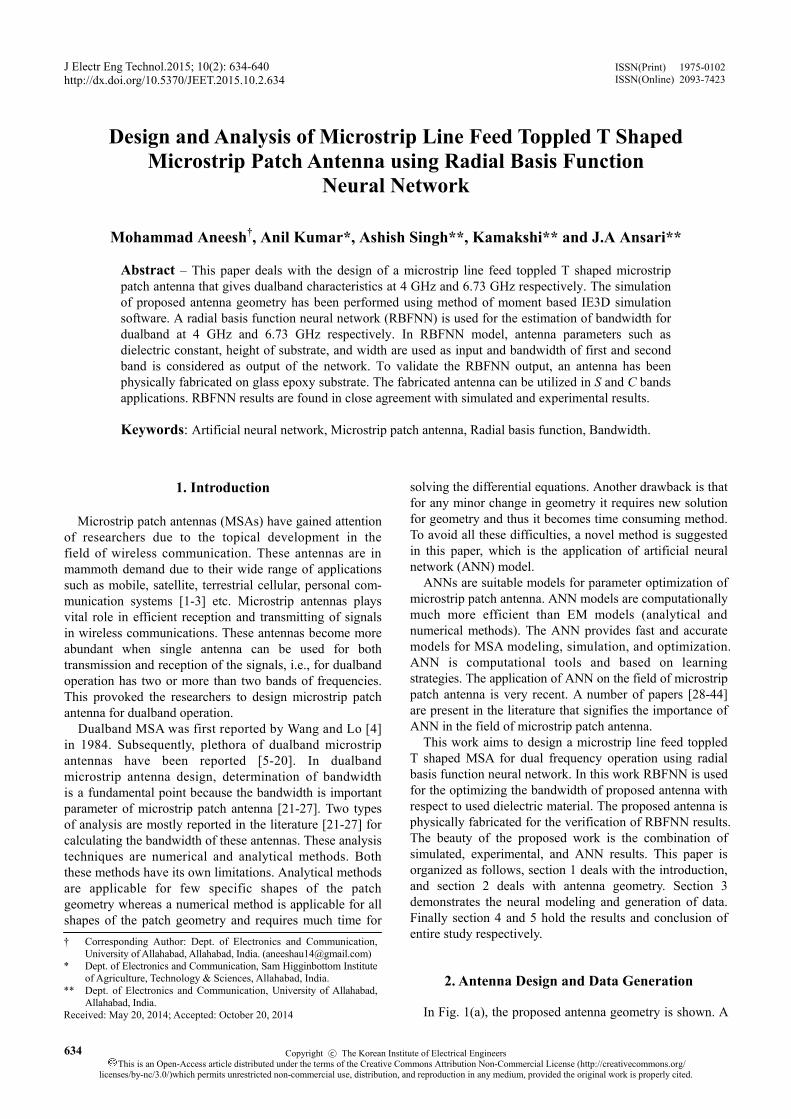
4.1 Proposed antenna results Fig. 7 shows the variation in reflection coefficients
with frequency for several heights of the used substrate glass epoxy. Fig. 7 demonstrates that the reflection coefficients for upper and lower resonance frequencies are shifted towards higher resonance side with decreasing the height from 1.58 mm to 0.25 mm. This change occurs as the substrate height is inversely proportional to the resonant frequency of patch antenna. Characteristics of proposed antenna are summarized in Table 2 with respect to the variation of different heights.
Fig. 8 shows the variation in reflection coefficient with
frequency for several dielectric materials. It is observed that the lower resonance frequency is shifted towards higher resonance side with decreasing the value of dielectric constant from glass epoxy to foam whereas higher resonance frequency is shifted towards higher resonance side. From the Fig. 8, it is clear that the obtained bandwidth is wider for Bakelite (εr = 3.3) and RT Duroid (εr = 2.32) substrate than the comparison of glass epoxy substrate. In this work, substrate used is glass epoxy and the reason behind selecting this substrate because it is easily available and less costly than the other substrates. Table 3 shows the summarized data of proposed antenna characteristics with the variation in dielectric constant (εr) of substrate. This data is used for the testing of RBF neural network model and star sign in Table 3 shows that glass epoxy (εr = 4.7) substrate is used to validate ANN results.
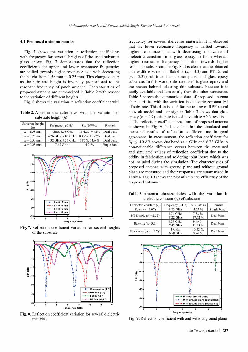
The reflection coefficient spectrum of proposed antenna is shown in Fig. 9. It is evident that the simulated and measured results of reflection coefficient are in good agreement. In measurement, the reflection coefficient for S11 ≤ -10 dB covers dualband at 4 GHz and 6.73 GHz. A non-noticeable difference occurs between the measured and simulated values of reflection coefficient due to the oddity in fabrication and soldering joint losses which was not included during the simulation. The characteristics of proposed antenna with ground plane and without ground plane are measured and their responses are summarized in Table 4. Fig. 10 shows the plot of gain and efficiency of the proposed antenna.
Table 2. Antenna characteristics with the variation of substrate height (h)
Substrate height (h) Frequency (GHz) S11 (BW%) Remark
h = 1.58 mm 4 GHz, 6.58 GHz 10.42%, 9.42% Dual bandh = 0.75 mm 4.26 GHz, 7.06 GHz 8.45%, 13.72% Dual bandh = 0.50 mm 4.32 GHz, 7.37 GHz 7.87%, 14.6 % Dual bandh = 0.25 mm 7.67 GHz 4.21% Single band
3 4 5 6 7 8 9 10-35
-30
-25
-20
-15
-10
-5
0
S11
(dB
)
Frequency (GHz)
h = 0.25 mmh = 0.50 mmh = 0.75 mmh = 1.58 mm
Fig. 7. Reflection coefficient variation for several heights
of the substrate
3 4 5 6 7 8 9 10-35
-30
-25
-20
-15
-10
-5
0
Frequency (GHz)
S11
(dB)
Glass epoxy [4.7]Bakelite [3.3]Foam [1.07]RT Duroid [2.32]
Fig. 8. Reflection coefficient variation for several dielectric
materials
Table 3. Antenna characteristics with the variation in dielectric constant (εr) of substrate
Dielectric constant (εr) Frequency (GHz) S11 (BW%) Remark Foam (εr=1.07) 8.83 GHz 4.27 % Single band
RT Duroid (εr =2.32) 4.74 GHz, 8.22 GHz
7.58 %, 17.72 % Dual band
Bakelite (εr=3.3) 4.29 GHz, 7.42 GHz
9.49 %, 11.63 % Dual band
Glass epoxy (εr =4.7)* 4 GHz, 6.58 GHz
10.42 %, 9.42 % Dual band
3 4 5 6 7 8 9-35
-30
-25
-20
-15
-10
-5
0
Frequency (GHz)
S11
(dB
)
Without ground planeWith ground plane (Simulated)With ground plane (Measured)
Fig. 9. Reflection coefficient with and without ground plane
Design and Analysis of Microstrip Line Feed Toppled T Shaped Microstrip Patch Antenna using Radial Basis Function Neural Network
638 │ J Electr Eng Technol.2015;10(2): 634-640
The radiation patterns for E-H plane with resonant frequencies 4 GHz and 6.73 GHz are represented in Fig. 11 (a)-(b) respectively. The 3dB beamwidth is 56.3˚ for E-theta, phi=0˚ and 67.4˚ for E-theta, phi=90˚ at frequency 4 GHz. The 3 dB beamwidth is 44.6˚ for E-theta, phi=0˚ and 70.1˚ for E-theta, phi=90˚ at frequency 6.73 GHz. E-plane is measured in xz-axis and H-plane is measured in xy-axis. Comparison of simulated, ANN, and measured results are summarized in Table 5.
5. Conclusion In this paper, microstrip line feed toppled T shaped MSA
is successfully analyzed using RBF neural network. The antenna operates in dual frequency bands at 4 GHz and 6.73 GHz respectively. The achievement of dualband with substrate glass epoxy is the focus of attention with etched toppled T shaped as a radiator. An RBF algorithm has been successfully developed for the estimation of bandwidth for first and second bands respectively. RBF neural network model results are found quite satisfactory with high accuracy for bandwidth estimation. The reflection coefficient and radiation pattern results obtained are in closed agreement with simulated and experimental results.
References
[1] W. W. Wu, E. F. Miller, W. L. Pritchard, and R. L. Pickholtz, “Mobile satellite communication,” Proc. IEEE, Vol. 82, pp. 1431-1448, Sept. 1997.
[2] B. R. Elbert, “The Satellite Communication Appli-cations Handbook,” Norwood, MA, Artech House, 1997.
[3] B. Miller, “Satellite free the mobile phone,” IEEE spectrum, Vol. 35, pp. 26-35, March 1998.
[4] B. Wang, and Y. Lo, “Microstrip antennas for dual frequency operation,” IEEE Tran. Antenna Propagat., Vol. 32, pp. 938-934, Sept. 1984.
[5] C. Y. Huang, C. W. Ling, and J. S. Kuo, “Dual-band microstrip antenna using capacitive loading,” IEEE Trans. Antennas Propagt., Vol. 150, pp. 401-404, 2003.
[6] M.Polivka, M.Drahovzal, and M.Mazanek, “Synthesis of dualband broadside radiated microstrip patch antenna operating with TM10 and TM21 modes,” IEEE Antenna Propagat. Soc. Int. Symp., Vol.1, pp. 245-248, June 2004.
[7] S. H. Hwang, W. Kwak, J. I. Moon, and S. O. Park,
Table 4. Antenna characteristics
Proposed antenna Frequency (GHz) S11 (BW %) Remark Without ground
plane 8.5 GHz 4.20 % Single band
With ground plane (simulated) 4 GHz, 6.73 GHz 10.42 %,
9.42 % Dual band
With ground plane (measured) 4 GHz, 6.73 GHz 10.03 %,
9.12 % Dual band
0.8
4.4
8
Gai
n (d
B)
3 4 5 6 7 810
20
30
40
50
60
70
80
90
100
Ante
nna
Effi
cien
cy (%
)
Frequency (GHz)
EfficiencyGain
Fig. 10. Plot of gain and efficiency with frequency
-10
-20
-30
-40 dB
30
210
60
240
90270
120
300
150
330
180
0
E-planeH-plane
(a)
-10
-20
-30
-40 dB
30
210
60
240
90270
120
300
150
330
180
0
E-planeH-plane
(b)
Fig. 11. Radiation pattern at (a) 4 GHz (b) 6.73 GHz
Table 5. Comparison of simulated, ANN, and measured results for bandwidth
Parameter Bandwidth of first band Bandwidth of second bandSimulated 10.42 % 9.42 %
ANN 10.4012 % 9.4145% Measured 9.23 %, 9.12 %
Mohammad Aneesh, Anil Kumar, Ashish Singh, Kamakshi and J. A Ansari
http://www.jeet.or.kr │ 639
“An internal dualband printed antenna for CDMA/ PCS handsets,” Microw. Opt. Technol. Lett., Vol. 45, pp. 537-540, June 2005.
[8] I. Surjati, E. T. Rahardjo, and D. Hartanto, “Increas-ing bandwidth dual frequency triangular microstrip antenna feed by coplanar waveguide,” IEEE Trans., Asia-Pacific Conf. Comm., Busan, pp. 1-4, Aug. 2006.
[9] K. L. Lau, K. C. Kong, and K.M. Luk, “Dual-band stacked folded patch antenna,” Electronic Lett., Vol. 43, pp. 789-790, 2007.
[10] W. S. Chen, and K. Y. Ku, “Band-rejected design of the open slot antenna for WLAN/WiMAX operation,” IEEE Trans. Antennas Propagt., Vol. 56, 1163-1169, 2008.
[11] Y. J. Sung, “Simple tunable dual-band microstrip patch antenna,” Electronics Lett., Vol. 45, pp. 666-667, 2009.
[12] M. A. Al-Joumayly, S. M. Aguilar, N. Behdad, and S. C. Hagness, “Dual-band miniaturized patch antennas for microwave breast imaging,” IEEE Antennas and Wireless Propagation Lett., Vol. 9, pp. 268-271, March 2010.
[13] Y. Li, Q. Xue, H. Z. Tan and Y. Long, “A dual fre-quency microstrip antenna using a double sided parallel strip line periodic structure,” IEEE Trans., Antenna Propag., Vol. 60, pp. 3016-3019, 2012.
[14] A. Singh, M. Aneesh, K. Kamakshi, A. Mishra, and J. A. Ansari, “Analysis of F-shape microstrip line fed dualband antenna for WLAN applications,” Wireless Netw. –DOI 10.1007/s11276-013-0599-4.
[15] K. P. Ray, and G. Kumar, “Multi-frequency and broadband hybrid coupled circular microstrip an-tennas,” Electronics Lett., Vol.33, pp.437-438, March 1997.
[16] Y. S. Shin, B. N. Kim, W. Kwak, and S. O. Park, “GSM/DCS/IMT-2000 triple-band built-in antenna for wireless terminals,” IEEE Trans. Antennas and Wireless Propag. Lett., Vol. 3, pp. 104-107, April 2004.
[17] L. Peng, C. L. Ruan, and X. H. Wu, “Design and operation of dual/triple-band asymmetric M-shaped microstrip patch antennas,” IEEE Trans. Antennas and Wireless Propag. Lett., Vol.9, pp. 1069-1072, 2010.
[18] K. F. Lee, K. M. Luk, K. M. Mak, S. L. S. Yang, “On the use of U-slots in the design of Dual-and Triple-Band Patch Antennas,” IEEE Trans. Antennas Propag. Magaz., Vol. 53, pp. 60-74, June 2011.
[19] M. Bod, H.R. Hassani, and M.M.S. Taheri, “Compact UWB printed slot antenna with extra bluetooth, GSM, and GPS bands,” IEEE Trans. Antennas Wireless Propag. Lett., Vol. 11, pp. 531-534, 2012.
[20] O. P Falade, Y. Gao, X. Chen, and C. Parini, “Stacked-patch dual-polarized antenna for triple-band handheld terminals,” IEEE Trans. Antennas Wireless Propag. Lett., Vol. 12 , pp. 202-205, 2013.
[21] I. J. Bahl, and P. Bhartia, Microstrip antennas, Artech House, Dedham, MA, 1980.
[22] K. R. Carver, and J. W. Mink, Microstrip antenna technology, IEEE Trans Antennas Propagat., Vol. 29, Issue 1, pp. 2-24, 1981.
[23] K. C. Gupta, and A. Benella (Editors), Microstrip antennas design, Artech House, Dedham, MA, 1988.
[24] J. R. James, and P. S. Hall, Handbook of microstrip antennas, IEE Electromagnetic Wave Series No. 28. Vol. 1 and 2, Peter Peregrinus Ltd., London, 1989.
[25] Y. T. Lo, S. M. Wright, and M. Davidovitz, ‘‘Micros-trip Antennas,’’ Handbook of microwave and optical components, K. Chang (Editor), Vol. 1, Wiley, New York, 1989, pp. 764-889.
[26] J. F. Zurcher, and F. E. Gardiol, Broadband patch antennas, Artech House, Norwood, MA, 1995.
[27] D. M. Pozar, and D. H. Schaubert (Editors), Micro-strip antennas: The analysis and design of microstrip antennas and arrays, IEEE Press, New York, 1995.
[28] S. Sagiroglu, K. Guney, M. Erler, “Calculation of Bandwidth for Electrically Thin and Thick Rec-tangular Microstrip Antennas with the Use of Multilayered Perceptrons,” Int J RF and Microwave CAE 9: 277-286, 1999.
[29] L. Vegni, and A. Toscano, “Analysis of microstrip antennas using neural networks,” IEEE Trans. Magn., Vol. 33, pp. 1414-1419, Mar. 1997.
[30] R. K. Mishra, and A. Patnaik, “Neural Network-Based CAD Model for the Design of Square-Patch Antennas,” IEEE transactions on antennas and propa-gation, Vol.46, No.12, December 1998, pp. 1890-1891.
[31] A. Patnaik, R. K. Mishra, G. K. Patra and S. K. Dash, “An artificial neural network model for effective dielectric constant of microstrip line,” IEEE Trans. Antennas Propagat.., Vol. 45, pp. 1697, Nov. 1997.
[32] R. K. Mishra, and A. Patnaik, “Designing Rectan-gular Patch Antenna Using the Neuro spectral Method”, IEEE transactions on antennas and pro-pagation,” Vol. 51, No. 8, pp. 1914-21, Aug. 2003.
[33] P. M. Watson, and K. C. Gupta, “Design and opti-mization of CPW circuits using EM ANN models for CPW components,” IEEE Trans. Microwave Theory Techniques, Vol. 45, No. 12, pp. 2515-2523, Dec. 1997.
[34] A. H. Zaabab, Q. J. Zhang, and M. Nakhla, “Analysis and optimization of microwave circuits & devices using neural network models," IEEE MTT-S Digest, pp. 393-396, 1994.
[35] S. Devi, D. C. Panda, and S. S. Pattnaik, “A novel method of using artificial neural networks to calculate input impedance of circular microstrip antenna,” Antennas and Propagation Society International Symposium, Vol. 3, pp. 462-465, June 16-21, 2002.
[36] D. Karaboga, K. Guney, S. Sagiroglu, and M. Erler, “Neural computation of resonant frequency of electrically thin and thick rectangular microstrip antennas,” IEEE Proceedings, Microwaves, Antennas and Propagation, Vol. 146, No. 2, pp. 155-159, Apr.
Design and Analysis of Microstrip Line Feed Toppled T Shaped Microstrip Patch Antenna using Radial Basis Function Neural Network
640 │ J Electr Eng Technol.2015;10(2): 634-640
1999. [37] K. Guney, and N. Sarikaya, “Resonant frequency
calculation for circular microstrip antennas with a dielectric cover using adaptive network-based fuzzy inference system optimized by various algorithms,” Progress In Electromagnetic Research, Vol. 72, pp. 279-306, 2007.
[38] S. S. Pattnaik, D. C. Panda, and S. Devi, “Radiation resistance of coax-fed rectangular microstrip antenna using artificial neural networks,” Microwave and Optical Technology Lett., Vol. 34, No. 1, pp. 51-53, Jul. 5, 2002.
[39] V. V Thakare, and P. K. Singhal, “Bandwidth analysis by introducing slots in microstrip antenna design using ANN,” Progress In Electromagnetics Research M, Vol. 9, pp. 107-122, 2009.
[40] M. Aneesh, J. A. Ansari, Ashish Singh, Kamakshi and S. Verma, “RBF Neural Network Modeling of Rectangular Microstrip Patch Antenna,” 2012 Third International Conference Computer Comm. Tech-nology, pp. 241-244, DOI 10.1109/ICCCT.2012.56
[41] K. Guney, and N. Sarikaya, “Adaptive neuro-fuzzy inference system for the input resistance computation of rectangular microstrip antennas with thin and thick substrates,” Journal of Electromagnetic Waves and Applications, Vol. 18, pp. 23-39, 2004.
[42] D. K. Neog, S. S. Pattnaik, D. C. Panda, S. Devi, B. Khuntia, and M. Dutta, “Design of a wideband microstrip antenna and the use of artificial neural networks in parameter calculation,” IEEE Antennas Propag. Mag., Vol. 47, No. 3, pp. 60-65, Jun. 2005.
[43] M. Aneesh, A. Singh, J. A. Ansari, Kamakshi, and S. S. Sayeed, “Investigations for performance im-provement of X-shaped RMSA using artificial neural network by predicting slot size,” Progress In Elec-tromagnetics Research C, Vol. 47, pp. 55-63, 2014.
[44] M. Aneesh, J. A. Ansari, A. Singh, Kamakshi, and S. S. Sayeed, “Analysis of microstrip line feed slot loaded patch antenna using artificial neural network,” Progress In Electromagnetics Research B, Vol. 58, pp. 35-46, 2014.
[45] IE3D simulation software, Zeeland, version 14.05, 2008.
[46] S.Haykin, Neural Networks a Comprehensive Found-ation, Englewood Cliff, New Jersey, Macmillan Publishing Company, 1994.
Mohammad Aneesh He received B.Tech degree in Electrical and Elec-tronics Engineering from Uttar Pradesh Technical University Lucknow, India in 2007 and completed his M.Tech degree in Advance Communications System form Sam Higginbottom In-stitute of
Agriculture, Technology & Sciences Allahabad India in 2009. He is presently pursuing Ph.D from Dept. of Electronics & Communication University of Allahabad, Allahabad, India.
Anil Kumar He received B.Tech degree in Electronics and Communi-cation from Gorakhpur University, India in 1999, M.Tech degree in Micro Electronics from Institute of Technology, Banaras Hindu University (BHU), Varanasi, India in 2005, and Ph.D degree from Sam Higginbottom Institute
of Agriculture, Technology & Sciences, Allahabad, India in 2013. He is presently working as Associate Professor with the Department of Electronics and Communication, Shiats, Allahabad.
Ashish Singh He received B.Tech degree from B.B.S. College of Engi-neering and Technology, U.P. Technical University, M. Tech (Electronics Engg.) & pursuing Ph.D. from Dept. of Elec-tronics & Communication, University of Allahabad.
Kamakshi She received B.Tech degree in Electronics Engineering from the Institute of Engineering and Rural Technology Allahabad, U.P., India 2007. She completed her M.Tech degree in Communication Technology from De-partment of Electronics and Commu-nication, Allahabad University in 2009
and now days she is working as a research scholar with the same Department.
J. A Ansari He received B.Sc and B.Tech degree from University of Allahabad, India, the M.Tech degree in communication systems from the In-stitute of Technology, Banaras Hindu University (BHU), Varanasi, India, in 1991, and the Ph.D degree from Mahatma Gandhi Chitrakoot Gramo-
daya Vishvavidyalaya, Chitrakoot (Satna), India, in 2000. He has published more than 110 papers in different national and international journals and conference pro-ceedings. His current area of research is microstrip antenna, millimeter wave, and fiber optics. He is presently working as professor with the Department of Electronics and Communication, University of Allahabad.