Bandwidth enhancement at microstrip patch antenna using ...
10
University of Wollongong Research Online University of Wollongong in Dubai - Papers University of Wollongong in Dubai 2018 Bandwidth enhancement at microstrip patch antenna using modified EC-SRR structures Nornikman Hassan Universiti Teknikal Malaysia Melaka Badrul Ahmad Universiti Teknikal Malaysia Melaka Mohamad Zoinol Abi Aziz Universiti Teknikal Malaysia Melaka Muhmamad Azizi Universiti Teknikal Malaysia Melaka Mohd Noor Ismail Universiti Teknikal Malaysia Melaka See next page for additional authors Research Online is the open access institutional repository for the University of Wollongong. For further information contact the UOW Library: [email protected] Publication Details Hassan, N., Ahmad, B. Hisham., Aziz, M. Zoinol Abidin Abd., Azizi, M. Syafiq Noor., Ismail, M. Khairy. & AbdulMalek, M. 2018, 'Bandwidth enhancement at microstrip patch antenna using modified EC-SRR structures', EEA - Electrotehnica, Electronica, Automatica, vol. 66, no. 1, pp. 140-146.
-
Upload
khangminh22 -
Category
Documents
-
view
0 -
download
0
Transcript of Bandwidth enhancement at microstrip patch antenna using ...

University of WollongongResearch Online
University of Wollongong in Dubai - Papers University of Wollongong in Dubai
2018
Bandwidth enhancement at microstrip patchantenna using modified EC-SRR structuresNornikman HassanUniversiti Teknikal Malaysia Melaka
Badrul AhmadUniversiti Teknikal Malaysia Melaka
Mohamad Zoinol Abi AzizUniversiti Teknikal Malaysia Melaka
Muhmamad AziziUniversiti Teknikal Malaysia Melaka
Mohd Noor IsmailUniversiti Teknikal Malaysia Melaka
See next page for additional authors
Research Online is the open access institutional repository for the University of Wollongong. For further information contact the UOW Library:[email protected]
Publication DetailsHassan, N., Ahmad, B. Hisham., Aziz, M. Zoinol Abidin Abd., Azizi, M. Syafiq Noor., Ismail, M. Khairy. & AbdulMalek, M. 2018,'Bandwidth enhancement at microstrip patch antenna using modified EC-SRR structures', EEA - Electrotehnica, Electronica,Automatica, vol. 66, no. 1, pp. 140-146.

AuthorsNornikman Hassan, Badrul Ahmad, Mohamad Zoinol Abi Aziz, Muhmamad Azizi, Mohd Noor Ismail, andMohamedFareq AbdulMalek
This journal article is available at Research Online: http://ro.uow.edu.au/dubaipapers/974

Bandwidth Enhancement at Microstrip Patch Antenna using modified EC-SRR Structures
Nornikman Hassan1, Badrul Hisham Ahmad1, Mohamad Zoinol Abidin Abd Aziz1, Muhmamad Syafiq Noor Azizi1, Mohd Khairy Ismail1, Mohamed Fareq Abdul Malek2
1Centre for Telecommunication Research and Innovation (CeTRI), Faculty of Electronics and Computer Engineering (FKEKK), Hang Tuah Jaya, Universiti Teknikal Malaysia Melaka (UTeM), 76100 Durian Tunggal, Melaka,
Malaysia 2Faculty of Engineering and Information Sciences, University of Wollongong in Dubai (UOWD), P.O. Box 20183,
Dubai, United Arab Emirates (UAE)
Abstract The research explores the effect of modified Edge Couple Split Ring Resonator (EC-SRR) on the wideband microstrip patch antenna. Firstly, there are three different size of the EC-SRR, namely larger EC-SRR, normal EC-SRR and smaller EC-SRR had been structured first before located into the patch antenna. After that, a simple microstrip patch antenna of Design A had been simulated using the CST Microwave Studio software. Then, the addition of different number of modified EC-SRR on the side and above side of the patch. Beside the basic design of Design A, three different stages of addition of SRR are considered in this research. Design B, Design C and Design D consist of SRR addition at the edges, sides and above of patch. The wideband antenna resonates between 2.08 GHz to 3.45 GHz of frequency with – 24.271 dB of return loss at resonant frequency of 3.11 GHz. At 2.4 GHz of WLAN application, the return loss is – 15.154 dB. Design D shows the increment of the bandwidth compare all designs with 1.372 GHz (from 2.077 GHz 3.449 GHz) compare with Design A with only 0.645 GHz (from 2.307 GHz to 2.952 GHz). Keywords: split ring resonator, bandwidth enhancement, microstrip patch antenna, Wireless LAN, antenna gain,
return loss
Received: March 09, 2017
To cite this article: Hassan, N., Ahmad, B. H., Abd Aziz, M. Z. A., Ismail, M. K., Abdul Malek, M. F., Bandwidth Enhancement at Microstrip Patch Antenna using modified EC-SRR Structures, in Electrotehnica, Electronica, Automatica (EEA), 2018, vol. 66, no. 1, pp. 140-146, ISSN 1582-5175.
1. Introduction
In current telecommunication situation, the antenna with wideband or multi-band effect are important for cater many users’ demands. This is because of problem of size and the cost of production by using smaller substrate. For example, the important applications are like Wireless Local Area Network (WLAN) at 2.4 GHz [1] or 5.2 GHz and Worldwide Interoperability for Microwave Access (WiMAX) at 5.8 GHz [2] of frequency.
The printed patch antenna is a most used antenna types that applies the split ring resonator structure on its design. Printed antennas have become the preferred and popular solution in recent telecommunication systems.
In the recent finding, several enhanced methods are applied to create wideband or multiband effect to the patch antenna design. The first bandwidth enhancement method is single-feed compact cross-aperture coupled for circularly polarized microstrip antenna (CPMA), stated in [3]. This method effect to miniaturized size of the antenna (50mm × 50mm × 6.8mm) while improve the bandwidth to achieve between 1.88GHz and 2.11 GHz.
Yuan in his paper [4] had been achieved a wideband of 1.1 GHz and high-gain effect at 13 GHz of resonant frequency from the metamaterial added to the microstrip patch antenna. Wong in [5] had proposed a monopolar patch antenna that using a V-shaped slot for car-to-car (C2C) and wireless local area network for increase the bandwidth performance in the range between 4.82 GHz and
6.67 GHz of resonant frequencies. In other paper, the stacked H-shaped shaped structure
is effected to improve the gain and the bandwidth of the proposed antenna performance. In Liu paper [6], it stated that the bandwidth is enhanced from 0.65 % to 10.15 % while the gain is improved to 20 dB.
Xu in his paper [7] had been combine several techniques to widening the bandwidth of the proposed omnidirectional circularly polarized patch antenna. In his work, the antenna are designs with the combination method of L-shaped slots, a ground plane loaded a metal sleeve and a set of conductive vias. The bandwidth is improved in the range between 2.29 GHz and 2.51 GHz in the azimuthal plane. The other works on enhancement bandwidth performance in these several research papers [8-12].
The metamaterial or left-handed material (LHM) construction design is a non-natural material that can be originate in the nature or it is non-existence in actual environment. The term ‘meta’ is initiated from the Greek language of “µετα” that means beyond.
In detail, this split ring resonator is a fragment of the metamaterial structure has been a widespread topic for revisions and between researchers after year of 2000. In microwave investigation, the structure of split ring resonator has been practical in many designs. Beside antenna, this structure had been found in microwave filter, oscillator, amplifier, frequency selective surface (FSS), microwave absorber, and many others design.
Split ring resonator (SRR) structure is one the best candidate that can use in this difficulty, example in these

ELECTROTEHNICĂ, ELECTRONICĂ, AUTOMATICĂ (EEA), 66 (2018), nr. 1
141
several papers [13-15]. The SRR is one of the popular metamaterial or left-handed material (LHM) beside electromagnetics band gap (EBG), photonic band gap (PBG), or artificial magnetic conductor (AMC) structure. This SRR also had probably to reduce the dimension of microstrip patch antenna. For example, in [16-18], the size reduction of the antenna after addition of SRR is 35 %, 21.9 % and 47 %, respectively.
Right now, it has many split ring resonator structures that have been use by numerous researchers such as edge couple split ring resonator (EC-SRR), broadside couple split ring resonator (BC-SRR), nonbianistropic couple split ring resonator (NC-SRR), spiral resonator and others. Edge couple split ring resonator (EC-SRR) or sometimes called as double split ring resonator (D-SRR) is a most used split ring resonator structure that has been researched and designed. This edge couple split ring resonator structure consists of two similar split rings that are coupled to create strong distributed capacitance in the region between the rings, examples in [19-20]. The small gap between rings effect to produce a high capacitance value, which could reduce the value the resonance frequency of the antenna design. Ramakrishna in his paper stated that, the big gap in each ring evades the current from flowing around in a single ring, and the circuit is completed across the small capacitive gap between the two rings [21].
Pendry [22-23] introduced to have developed microstructured artificial materials exhibiting strange magnetic properties. In the theory by Veselago, this SRR design also is used to produce the negative dielectric constant (permittivity) and negative permeability [24]. From the previous work, it also and have the capability to improve the gain performance, such as in this paper of [25-26].
Figure 1 shows the SRR structure and its equivalent circuit with basic SRR and compare with the complementary SRR structure.
a)
b)
Figure 1. SRR structure and its equivalent circuit: (a) SRR, (b) Complementary SRR [27]
This two structures effect to create a different equivalent LC circuit.
The resonant frequency of the resonator structure, f=1/(2π√(LC)), can be obtain by deploying its structure
sizes. The modification in the inductance value of the resonator is correlated to the changes in the length of the resonator. Equally, the value of capacitance can be change by increasing or decreasing the ring gap of the split ring resonator.
There are several examples shows the improvement of bandwidth by adding the split ring resonator, such as by Patel [28]. By adding a multiple corrugated split ring resonator, he had a maximum of 420 MHz compared with the normal antenna which is only 230 MHz. In his paper, he also compared with a small 10 mm and larger 16 mm gap between ring. It shows that small ring gap of SRR have a better return loss as several frequencies. Beside that, the gain also improved from 6.2 dB to 7.0 dB.
In the fractal geometry theory, the size of each iteration stage design is different using the reducing scale for the structure. The different number of iterations can be done, but considering the compactness of fractal antenna [29-30].
In this work, the effect of embedded EC-SRR on microstrip patch antenna had been investigated. Four different stages of Design A, Design B, Design C and Design D are compared.
2. Materials and Methods
This section illustrates the split ring resonator structure. It also describes the dimension and configuration structure of the proposed microstrip patch antenna with split ring resonator structure.
The works start with the development of the split ring resonator structure. This structure will be located at the several locations in the antenna. Firstly, this structure had been design stand alone. There are three different size of the EC-SRR, namely larger EC-SRR, normal EC-SRR and smaller EC-SRR.
Figure 2 shows the modified Edge Couple split ring resonator (EC-SRR) structure.
Figure 2. Modified Edge Couple split ring resonator (EC-SRR) structure (normal SRR dimension)
The dimension of the larger structure is 10.15 mm length (LSUB) x 10.15 mm width (WSUB) while the dimension of the normal EC-SRR and smaller EC-SRR is only 7.25 mm x 7.25 mm and 4.35 mm length x 4.35 mm length, respectively. The dimension of normal WSSR1 and WSSR2 is 5.45 mm and 3.65 mm, respectively. It had been different in size but remained the same design of L-shaped structure.
Table 1 shows the dimension of for larger, normal, and smaller modified Edge Couple split ring resonator (EC-SRR) structure.
ELECTROTEHNICĂ, ELECTRONICĂ, AUTOMATICĂ (EEA), 66 (2018), nr. 1
142
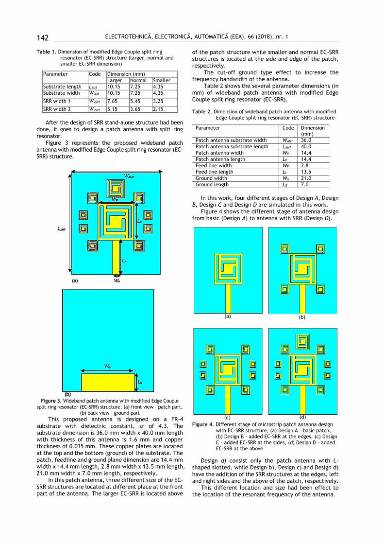
Table 1. Dimension of modified Edge Couple split ring resonator (EC-SRR) structure (larger, normal and smaller EC-SRR dimension)
Parameter Code Dimension (mm)
Larger Normal Smaller
Substrate length LSUB 10.15 7.25 4.35
Substrate width WSUB 10.15 7.25 4.35
SRR width 1 WSSR1 7.65 5.45 3.25
SRR width 2 WSSR2 5.15 3.65 2.15
After the design of SRR stand-alone structure had been
done, it goes to design a patch antenna with split ring resonator.
Figure 3 represents the proposed wideband patch antenna with modified Edge Couple split ring resonator (EC-SRR) structure.
Figure 3. Wideband patch antenna with modified Edge Couple
split ring resonator (EC-SRR) structure, (a) front view – patch part, (b) back view – ground part
This proposed antenna is designed on a FR-4 substrate with dielectric constant, εr of 4.3. The substrate dimension is 36.0 mm width x 40.0 mm length with thickness of this antenna is 1.6 mm and copper thickness of 0.035 mm. These copper plates are located at the top and the bottom (ground) of the substrate. The patch, feedline and ground plane dimension are 14.4 mm width x 14.4 mm length, 2.8 mm width x 13.5 mm length, 21.0 mm width x 7.0 mm length, respectively.
In this patch antenna, three different size of the EC-SRR structures are located at different place at the front part of the antenna. The larger EC-SRR is located above
of the patch structure while smaller and normal EC-SRR structures is located at the side and edge of the patch, respectively.
The cut-off ground type effect to increase the frequency bandwidth of the antenna.
Table 2 shows the several parameter dimensions (in mm) of wideband patch antenna with modified Edge Couple split ring resonator (EC-SRR).
Table 2. Dimension of wideband patch antenna with modified Edge Couple split ring resonator (EC-SRR) structure
Parameter Code Dimension (mm)
Patch antenna substrate width WANT 36.0
Patch antenna substrate length LANT 40.0
Patch antenna width WP 14.4
Patch antenna length LP 14.4
Feed line width WF 2.8
Feed line length LF 13.5
Ground width WG 21.0
Ground length LG 7.0
In this work, four different stages of Design A, Design
B, Design C and Design D are simulated in this work. Figure 4 shows the different stage of antenna design
from basic (Design A) to antenna with SRR (Design D).
Figure 4. Different stage of microstrip patch antenna design with EC-SRR structure, (a) Design A – basic patch, (b) Design B - added EC-SRR at the edges, (c) Design C – added EC-SRR at the sides, (d) Design D – added EC-SRR at the above
Design a) consist only the patch antenna with L-shaped slotted, while Design b), Design c) and Design d) have the addition of the SRR structures at the edges, left and right sides and the above of the patch, respectively.
This different location and size had been effect to the location of the resonant frequency of the antenna.
(a) (b)
(c) (d)

ELECTROTEHNICĂ, ELECTRONICĂ, AUTOMATICĂ (EEA), 66 (2018), nr. 1
143
The numbers od EC-SRR of each design is four, eight and nine EC-SRR structures.
3. Results & Discussion
This section describes the result performance of the propose antenna. The important parameters that are considered in this work are resonant frequency (in GHz), return loss (in dB), bandwidth (in GHz), and the gain (in dB). Beside that, radiation pattern and surface current of the proposed microstrip patch antenna also had been shown.
Figure 5 and Table 3 show return loss performance of the different stage of antenna design (Design a)-Design d)).
Figure 5. Return loss performance of the different stage of antenna design (Design a)-Design d))
Table 3. Return loss at resonant frequency and at 2.4 GHz
Design Return loss Bandwidth, frequency range
At resonant frequency, return loss
Return loss at 2.4 GHz
a) 2.56 GHz, -16.156 dB
2.4 GHz, -12.753 dB
0.514 GHz (2.464 GHz-2.978 GHz)
b) 2.996 GHz, -34.316 dB
2.4 GHz, -12.848 dB
1.067 GHz (2.214 GHz-3.281 GHz)
c) 3.164 GHz, -26.597 dB
2.4 GHz, -13.226 dB
1.289 GHz (2.198 GHz-3.487 GHz)
d) 3.112 GHz, -24.271 dB
2.4 GHz, -15.154 dB
1.394 GHz (2.097 GHz-491 GHz)
For Design a), it shows that the return loss of –16.156
dB at 2.56 dB; Design a) antenna has a narrow bandwidth of 0.514 GHz between 2.464 GHz and 2.978 GHz. Compared with the basic rectangular antenna in [x], it had been shifted from 2.4 GHz, effected by the L-slotted shaped at the patch antenna. At 2.4 GHz for Design a), the return loss is -12.753 dB
For Design b), the EC-SRR structures is located at the edge part of the patch. It creates new resonant frequency, but in the graph, we cannot have seen it has two resonant frequency. This because, this two-resonant frequency had combines to create a wider bandwidth. In this case, the bandwidth is 1.067 GHz, covers from 2.214 GHz to 3.281 GHz with resonant frequency at 2.996 GHz with
return loss of -34.316 dB. At 2.4 GHz, the return loss achieves -12.848 dB.
For the same concept with the Design b), the Design c) is the same design with addition of smaller size of EC-SRR at the left and right of the patch antenna. It effects to shift the resonant frequency from 2.996 GHz to 3.164 GHz and effect to increase the bandwidth from to 1.067 GHz to 1.289 GHz. At 3.164 GHz, the return loss is -26.597 dB while for 2.4 GHz, its only shows -13.226 dB.
For the last Design d), the addition of the larger sizes of the EC-SRR had been increase the bandwidth of this antenna to 1.394 GHz, covers from 2.097 GHz to 3.491 GHz. It this point, it shows that the resonant frequency at 3.112 GHz with return loss of –24.271 dB. At 2.4 GHz, it shows the return loss only –15.154 dB. So, after all design had been done, it shows that the improvement of bandwidth from the Design A to Design D by 0.514 GHz to 1.394 GHz, with the improvement of 0.880 GHz.
Table 4 shows the bandwidth performance of different design at resonant frequency. From the graph, it shows that the Design d) had the wider bandwidth of 1.372 GHz between 2.077 GHz and 3.449 GHz
Table 4. Bandwidth performance of different design at resonant frequency
Design Bandwidth, start and stop bandwidth
a) 0.645 GHz, (2.307 GHz-2.952 GHz)
b) 1.114 GHz, (2.209 GHz–3.323 GHz)
c) 1.294 GHz, (2.170 GHz–3.464 GHz)
d) 1.372 GHz, (2.077 GHz-3.449 GHz)
It shows that the addition of the SRR had been increase
the bandwidth of the patch antenna. It also improves the return loss at 2.4 GHz of the antenna in the small volume after the addition of the SRR. The return loss at 2.4 GHz for Design d) is -15.154 dB while for Design a) is -12.753 dB.
Figure 6 shows the return loss performance of Design d).
Figure 6. Return loss performance of Design D with resonant frequency at 3.112 GHz and at 2.4 GHz
Figure 7 represents the radiation pattern for antenna of Design D at two different frequencies of 3.112 GHz and at 2.4 GHz.

ELECTROTEHNICĂ, ELECTRONICĂ, AUTOMATICĂ (EEA), 66 (2018), nr. 1
144
Figure 7. Radiation pattern of the proposed antenna at 3.112 GHz and 2.4 GHz of frequency at different phase, (a) 3.112 GHz, 00, (b) 3.112 GHz, 900, (c) 2.4 GHz, 00, and (d) 2.4 GHz, 900
For the 3.112 GHz, the antenna effect o gives a eight-shaped and kidney shaped for 00 and 900, respectively. While the other two radiation pattern at 2.4 GHz shows the love-like shaped for both 00 and 900, respectively.
Figure 8 shows surface current distribution of the proposed antenna at 2.4 GHz of frequency at four different phases of 00, 450, 900, and 1350.
Figure 8. Surface current distribution of the proposed antenna at 2.4 GHz of frequency at different phase, (a) 00, (b) 450, (c) 900, and (d) 1350
For 2.4 GHz, the main contribution at the feedline and also at the patch antenna.
4. Conclusions
After simulation work done, it shows that the patch antenna bandwidth had been enhanced by the addition of
the modified EC-SRR. An improvement of the bandwidth is 727 MHz, increase from 0.645 GHz (Design a)) to 1.372 GHz (Design d)).
The antenna of Design a) achieved a bandwidth of 0.514 GHz in the range between 2.464 GHz and 2.978 GHz, while Design d) effect of bandwidth of 1.394 GHz between
(a)
(b)
(c)
(d)
(a)
(b)
(c)
(d)

ELECTROTEHNICĂ, ELECTRONICĂ, AUTOMATICĂ (EEA), 66 (2018), nr. 1
145
2.097 GHz and 3.491 GHz. The return loss also increases but not gives the significant effect to the antenna design.
For Design a), the antenna radiates at resonant frequency of 2.56 GHz with return loss of - 16.156 dB, while for Design d), it radiates at resonant frequency of 3.112 GHz with return loss of -24.271 dB.
5. References
[1] W. Cao, B. Zhang, A. Liu, T. Yu, D. Guo, and Y. Wei, Gain Enhancement for Broadband Periodic Endfire Antenna using Split-Ring Resonators Structures,” IEEE Transactions on Antennas and Propagation, vol. 60, no. 7, pp. 3513-3516, 2012
[2] B. D. Bala, M. K. A. Rahim, N. A. Murad, R. Dewan, “Wideband Metamaterial Antenna Employing SRR Loading for WiMAX and WLAN Operations,” 2014 IEEE Asia-Pacific Conference on Applied Electromagnetics (APACE), pp. 241-244, 2014
[3] L. Li, J. Li, B. He, S. Zhang, and A. Zhang, “3A Compact Circularly Polarized Microstrip Antenna with Bandwidth Enhancement,” Progress In Electromagnetics Research Letters, Vol. 61, pp. 85–89, 2016
[4] H.-Y. Yuan, S.-B. Qu, J.-Q. Zhang, J.-F. Wang, H.-Y. Chen, H. Zhou, Z. Xu, A.-X. Zhang, “A Metamaterial-Inspired Wideband High-Gain FABRY–Perot Resonator Microstrip Patch Antenna,” Vol. 58, Issue 7, pp. 1675–1678, 2016
[5] H. Wong, K. K. So, X. Gao, “Bandwidth Enhancement of a Monopolar Patch Antenna With V-Shaped Slot for Car-to-Car and WLAN Communications,” IEEE Transactions on Vehicular Technology, pp. 1130-1136, 2016
[6] Y. Liu, L. Shafai, C. Shafai, “Gain and Bandwidth Enhancement of Stacked H-Shaped Patch-Open Ring Antenna,” 2016 17th International Symposium on Antenna Technology and Applied Electromagnetics (ANTEM), 16252012, 2016
[7] G. Xu, Y. Sun, M. Yang, W. Liu, D. Zhou, “An Omnidirectional Circularly Polarized Patch Antenna with Bandwidth Broadening,” 2016 IEEE International Conference on Microwave and Millimeter Wave Technology (ICMMT), 16505757, 2016
[8] M. S. Rabbani, H. G. Shiraz, “Improvement of Microstrip Patch Antenna Gain and Bandwidth at 60 GHz and X Bands for Wireless Applications,” IET Microwaves, Antennas & Propagation, Vol. 10, issue 11, pp. 1167-1173, 2016
[9] N.-W. Liu, L. Zhu, W.-W. Choi, J.-D. Zhang “A Novel Differential-Fed Patch Antenna on Stepped-Impedance Resonator with Enhanced Bandwidth Under Dual-Resonance,” IEEE Transactions on Antennas and Propagation, Vol. 64, Issue 11, 4618 – 4625, 2016
[10] A. Saxena, S. Joshi, A. Gupta, S. Saxena, D. Kumar, “Gain and bandwidth enhancement of CPW-fed Patch Antenna for Wideband Applications,” IEEE International Conference on Recent Trends in Electronics, Information & Communication Technology (RTEICT), 16582981, 2016
[11] G. Varshney, P. Mittal, V. S. Pandey, R. S. Yaduvanshi, S. Pundir, “Enhanced Bandwidth High Gain Micro-Strip Patch Feed Dielectric Resonator Antenna,” 2016 International Conference on Computing, Communication and Automation (ICCCA), 16598773, 2017
[12] C. L. Palson, A. E. Sunny, D. D. Krishna, “Circularly Polarized Square Patch Antenna with Improved Axial Ratio Bandwidth,” 2016 IEEE Annual India Conference (INDICON), 2016
[13] A. Kumar, M. M. Sharma, "An extremely Wideband Printed Antenna with WLAN Stop Band using SRR," 2014 International Conference on Signal Propagation and Computer Technology (ICSPCT), pp. 228-231, 2014
[14] H. Attia, O. Siddiqui, L. Yousefi, and O. M. Ramahi, “Metamaterial for Gain Enhancement of Printed Antennas: Theory, Measurements and Optimizations,” 2011 Saudi International Electronics, Communications and Photonics Conference (SIECPC 2011), pp. 1-6, 2011
[15] X. Yang, Z. Yu, Q. Shi, R. Tao, "Design of novel ultra-wideband antenna with individual SRR," Electronics
Letters, Vol. 44, issue 19, pp. 1109-1110, 2008 [16] J. Anderson, K. Johnson, C. Satterlee, A. Lynch, B. D.
Braaten, “A Reduced Frequency Printed Quasi-Yagi Antenna Symmetrically Loaded with Meander Open Complementary Split Ring Resonator (MOCSRR) Elements,” 2011 IEEE International Symposium on Antennas and Propagation (APSURSI), pp. 270 – 273, 2011
[17] M. U. Vakani, K. H. Wandra, A. K. Sarvaiya, “Comparative Analysis of Small Size Dual Band Split Ring Resonator Based Antenna,” 2012 Nirma University International Conference on Engineering (NUiCONE), pp. 1– 4, 2012.
[18] H. A. Jang, D. O. Kim, and C. Y. Kim, “Size Reduction of Patch Antenna Array Using CSRRs Loaded Ground Plane,” Progress In Electromagnetics Research Symposium Proceedings, pp. 1487-1489, 2012
[19] R. Marques, F. Mesa, J. Martel, F. Medina, “Comparative Analysis of Edge - and Broadside - Coupled Split Ring Resonators for Metamaterial Design - Theory and Experiments,” IEEE Transactions on Antennas and Propagation, Vol. 51 (10), pp. 2572 – 2581, 2003.
[20] R. Marques, J. D. Baena, M. Beruete, F. Falcone, T. Lopetegi, M. Sorolla, F. Mart´ın and J. J. Garcia, “Ab Initio Analysis of Frequency Selective Surfaces Based on Conventional and Complementary Split Ring Resonators,” Journal of Optics A: Pure and Applied Optics, Vol. 7, pp. 38 – 43, 2005
[21] S. A. Ramakrishna, “Physics of Negative Refractive Index Materials, Reports on Progress Physics,” vol. 68, pp. 449 – 451, 2005.
[22] J. B. Pendry, A. J. Holden, D. J. Robins, and W. J. Stewart, “Magnetism from Conductors and Enhanced Nonlinear Phenomena,” IEEE Transactions on Microwave Theory and Techniques, Vol. 47 (11), pp. 2075 – 2084, 1999.
[23] Pendry, J. B., 2003. New Lenses for Imaging the Near Field, Postconference Digest Quantum Electronics and Laser Science (QELS), pp. 1 – 2.
[24] D. R. Smith, W. J. Padilla, D. C. Vier, S. C. Nemat-Nasser, S. Schultz, “Composite Medium with Simultaneously Negative Permeability and Permittivity,” Phys. Rev. Lett., vol. 84, pp. 4184–4187, 2000.
[25] W. Cao, B. Zhang, A. Liu, T. Yu, D. Guo, Y. Wei, "Gain Enhancement for Broadband Periodic Endfire Antenna by Using Split-Ring Resonator Structures," IEEE Transactions on Antennas and Propagation, Vol. 60, issue 7, pp. 3513-3516, 2012
[26] J. D. Baena, R. Marques, F. Medina, and J. Martel, “Artificial Magnetic Metamaterial Design by using Spiral Resonators,” Physics Review B, Vol. 69, pp. 1 – 5, 2004.
[27] N. Ortiz, F. Falcone, M. Sorolla, "Gain Improvement of Dual Band Antenna Based on Complementary Rectangular Split-Ring Resonator," ISRN Communications and Networking, Vol. 2012, ID 951290, pp. 1-9, 2012
[28] S. K. Patel & C. Argyropoulos, “Enhanced Bandwidth And Gain Of Compact Microstrip Antennas Loaded with Multiple Corrugated Split Ring Resonators,” Journal of Electromagnetic Waves and Applications, vol. 30, issue 7, pp. 1-17, 2016
[29] A. Ajey Shambavi and. Z. C. Alex, “Design and Analysis of Fractal Antenna for UWB Applications,” 2012 IEEE Students’ Conference on Electrical Electronics and Computer Science (SCEECS), pp. 1 – 4, 2012.
[30] [30] B. H. Lincy, A. Srinivasan, and B. Rajalakshmi, “Wide Band Fractal Microstrip Antenna For wireless Application,” Proceedings of 2013 IEEE Conference on Information and Communication Technologies (lCT 2013), pp. 735 – 738, 2013.
Acknowledgments
The authors would like to thank Centre for Telecommunication Research and Innovation (CeTRI), Faculty of Electronics and Computer Engineering (FKEKK), Universiti Teknikal Malaysia Melaka (UTeM), and Ministry of Higher Education (MOHE) and Government of Malaysia which sponsoring this work under the PJP/2017/FKEKK/HI13/S01543.

ELECTROTEHNICĂ, ELECTRONICĂ, AUTOMATICĂ (EEA), 66 (2018), nr. 1
146
The authors would also like to thank Centre for Research and Innovation Management Universiti Teknikal Malaysia Melaka (CRIM-UTeM) and Faculty of Engineering and Information Sciences, University of Wollongong in Dubai (UOWD), United Arab Emirates (UAE).
Biography
Nornikman Hassan was born in Bandar Melaka, Malaysia, on August 26, 1984. He graduated his PhD degree in Electronics Engineering from the Universiti Teknikal Malaysia Melaka (UTeM), Melaka, Malaysia in 2016. Before that, he received his Bachelor Engineering (Hons) and Master Science, both in Communication
Engineering course from Universiti Malaysia Perlis, Perlis, Malaysia. He is currently a Post-Doctoral Researcher in Research and Innovation Management (CRIM), Universiti Teknikal Malaysia Melaka (UTeM) and also at Centre for Telecommunication Research and Innovation (CeTRI), Faculty of Electronics and Computer Engineering (FKEKK), Universiti Teknikal Malaysia Melaka (UTeM). His research interests concern is antenna design, microwave absorber and metamaterial of split ring resonator. e-mail: [email protected]
Badrul Hisham AHMAD received the PhD degree in electronics engineering from the Microwave Engineering, University of Leeds, United Kingdom. He is currently a Senior Lecturer (Associate Professor) and researcher in Centre for Telecommunication Research and Innovation (CeTRI), Faculty of Electronics and Computer
Engineering (FKEKK), Universiti Teknikal Malaysia Melaka (UTeM). His research interests concern is microwave filter, antenna design, and metamaterial. e-mail: [email protected]
Mohamad Zoinol Abidin Abd Aziz received the PhD degree in Electrical Engineering (Telecommunication) from the Universiti Teknologi Malaysia (UTM), Johor, Malaysia. He is currently a Senior Lecturer (Associate Professor) and researcher in Centre for Telecommunication Research and Innovation (CeTRI), Faculty of
Electronics and Computer Engineering (FKEKK, Universiti Teknikal Malaysia Melaka (UTeM). His research interests concern is antenna design, microwave and MIMO. e-mail: [email protected]
Muhammad Syafiq Noor Azizi received the Master degree in Electronics Engineering from the Universiti Teknikal Malaysia Melaka (UTeM), Melaka, Malaysia in 2017. Before that, he receives his Bachelor Degree Electronics Engineering in Telecommunication from the
Universiti Teknikal Malaysia Melaka (UTeM), Melaka in 2014. Now, he works at Senawang, Seremban, Negeri Sembilan. His research interests concern is antenna design, biomedical. e-mail: [email protected]
Mohd Khairy Ismail received the Master degree in Electronics Engineering from the Universiti Teknikal Malaysia Melaka (UTeM), Melaka, Malaysia in 2016. Before that, he receives his Bachelor Degree Electronics Engineering in Telecommunication from the Universiti Teknikal
Malaysia Melaka (UTeM), Melaka in 2013. He is currently a Research Officer in UTeM Research and Innovation Management (CRIM), Universiti Teknikal Malaysia Melaka (UTeM). He also a researcher in Centre for Telecommunication Research and Innovation (CeTRI), Faculty of Electronics and Computer Engineering (FKEKK), Universiti Teknikal Malaysia Melaka (UTeM). His research interests concern is wireless telecommunication, Long-Term Evolution (LTE) e-mail: [email protected]
Mohamed Fareq Abdul Malek is an Associate Professor in the Faculty of Engineering and Information Sciences at UOWD. Dr Mohamed received his B.Eng. (Hons.) in Electronic and Communication Engineering from The University of Birmingham, UK.
Subsequently he obtained MSc (Eng.) in Microelectronic Systems and Telecommunications (with Distinction) and PhD in Electrical Engineering (Applied Electromagnetic) from The University of Liverpool, UK. He maintains a broad range of research interests that covers a wide range of applied engineering, including applied electromagnetic, telecommunication engineering, antenna, microwave absorbers from agricultural wastes, microwave drying, effects of RF on health, RF energy harvesting, and wireless communication. e-mail: [email protected]

Reproduced with permission of copyright owner. Further reproduction
prohibited without permission.