gas gathering lines - Maryland Department of the Environment
Upload
khangminh22Category
view
0download
0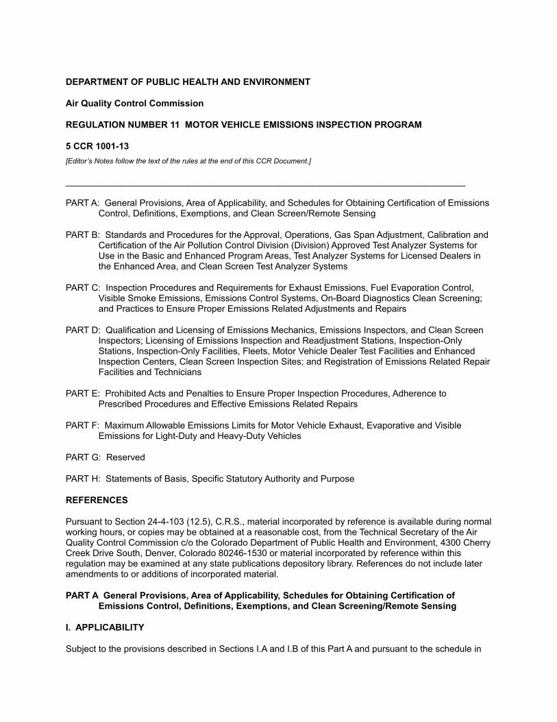
DEPARTMENT OF PUBLIC HEALTH AND ENVIRONMENT
Air Quality Control Commission
REGULATION NUMBER 11 MOTOR VEHICLE EMISSIONS INSPECTION PROGRAM
5 CCR 1001-13
[Editor’s Notes follow the text of the rules at the end of this CCR Document.]
_______________________________________________________________________________
PART A: General Provisions, Area of Applicability, and Schedules for Obtaining Certification of Emissions Control, Definitions, Exemptions, and Clean Screen/Remote Sensing
PART B: Standards and Procedures for the Approval, Operations, Gas Span Adjustment, Calibration and Certification of the Air Pollution Control Division (Division) Approved Test Analyzer Systems for Use in the Basic and Enhanced Program Areas, Test Analyzer Systems for Licensed Dealers in the Enhanced Area, and Clean Screen Test Analyzer Systems
PART C: Inspection Procedures and Requirements for Exhaust Emissions, Fuel Evaporation Control, Visible Smoke Emissions, Emissions Control Systems, On-Board Diagnostics Clean Screening; and Practices to Ensure Proper Emissions Related Adjustments and Repairs
PART D: Qualification and Licensing of Emissions Mechanics, Emissions Inspectors, and Clean Screen Inspectors; Licensing of Emissions Inspection and Readjustment Stations, Inspection-Only Stations, Inspection-Only Facilities, Fleets, Motor Vehicle Dealer Test Facilities and Enhanced Inspection Centers, Clean Screen Inspection Sites; and Registration of Emissions Related Repair Facilities and Technicians
PART E: Prohibited Acts and Penalties to Ensure Proper Inspection Procedures, Adherence to Prescribed Procedures and Effective Emissions Related Repairs
PART F: Maximum Allowable Emissions Limits for Motor Vehicle Exhaust, Evaporative and Visible Emissions for Light-Duty and Heavy-Duty Vehicles
PART G: Reserved
PART H: Statements of Basis, Specific Statutory Authority and Purpose
REFERENCES
Pursuant to Section 24-4-103 (12.5), C.R.S., material incorporated by reference is available during normal working hours, or copies may be obtained at a reasonable cost, from the Technical Secretary of the Air Quality Control Commission c/o the Colorado Department of Public Health and Environment, 4300 Cherry Creek Drive South, Denver, Colorado 80246-1530 or material incorporated by reference within this regulation may be examined at any state publications depository library. References do not include later amendments to or additions of incorporated material.
PART A General Provisions, Area of Applicability, Schedules for Obtaining Certification of Emissions Control, Definitions, Exemptions, and Clean Screening/Remote Sensing
I. APPLICABILITY
Subject to the provisions described in Sections I.A and I.B of this Part A and pursuant to the schedule in
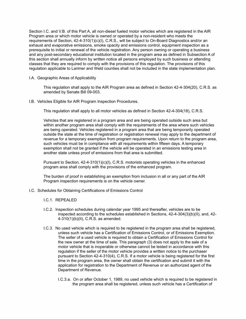
Section I.C. and V.B. of this Part A, all non-diesel fueled motor vehicles which are registered in the AIR Program area or which motor vehicle is owned or operated by a non-resident who meets the requirements of Section, 42-4-310(1)(c)(I), C.R.S., will be subject to On-Board Diagnostics and/or an exhaust and evaporative emissions, smoke opacity and emissions control, equipment inspection as a prerequisite to initial or renewal of the vehicle registration. Any person owning or operating a business and any post-secondary educational institution located in the program area as defined in Subsection A of this section shall annually inform by written notice all persons employed by such business or attending classes that they are required to comply with the provisions of this regulation. The provisions of this regulation applicable to Larimer and Weld counties shall not be included in the state implementation plan.
I.A. Geographic Areas of Applicability
This regulation shall apply to the AIR Program area as defined in Section 42-4-304(20), C.R.S. as amended by Senate Bill 09-003.
I.B. Vehicles Eligible for AIR Program Inspection Procedures.
This regulation shall apply to all motor vehicles as defined in Section 42-4-304(18), C.R.S.
Vehicles that are registered in a program area and are being operated outside such area but within another program area shall comply with the requirements of the area where such vehicles are being operated. Vehicles registered in a program area that are being temporarily operated outside the state at the time of registration or registration renewal may apply to the department of revenue for a temporary exemption from program requirements. Upon return to the program area, such vehicles must be in compliance with all requirements within fifteen days. A temporary exemption shall not be granted if the vehicle will be operated in an emissions testing area in another state unless proof of emissions from that area is submitted.
Pursuant to Section, 42-4-310(1)(c)(I), C.R.S. motorists operating vehicles in the enhanced program area shall comply with the provisions of the enhanced program.
The burden of proof in establishing an exemption from inclusion in all or any part of the AIR Program inspection requirements is on the vehicle owner.
I.C. Schedules for Obtaining Certifications of Emissions Control
I.C.1. REPEALED
I.C.2. Inspection schedules during calendar year 1995 and thereafter, vehicles are to be inspected according to the schedules established in Sections, 42-4-304(3)(b)(II), and, 42-4-310(1)(b)(II), C.R.S. as amended.
I.C.3. No used vehicle which is required to be registered in the program area shall be registered, unless such vehicle has a Certification of Emissions Control, or of Emissions Exemption. The seller of a used vehicle is required to obtain a Certification of Emissions Control for the new owner at the time of sale. This paragraph (3) does not apply to the sale of a motor vehicle that is inoperable or otherwise cannot be tested in accordance with this regulation if the seller of the motor vehicle provides a written notice to the purchaser pursuant to Section 42-4-310(4), C.R.S. If a motor vehicle is being registered for the first time in the program area, the owner shall obtain the certification and submit it with the application for registration to the Department of Revenue or an authorized agent of the Department of Revenue.
I.C.3.a. On or after October 1, 1989, no used vehicle which is required to be registered in the program area shall be registered, unless such vehicle has a Certification of
Emissions Control, or of Emissions Exemption. The seller of a used vehicle is required to obtain a Certification of Emissions Control for the new owner at the time of sale. This paragraph (3) does not apply to the sale of a motor vehicle which is inoperable or otherwise cannot be tested in accordance with this regulation or that is being sold pursuant to Part 18 (Vehicles Abandoned on Public Property) or Part 21 (Vehicles Abandoned on Private Property) of Article 4 of Title 42, C.R.S. if the seller of the motor vehicle provides a written notice to the purchaser pursuant to Section 42-4-310(4), C.R.S. If a motor vehicle is being registered for the first time in the program area, the owner shall obtain the certification and submit it with the application for registration to the Department of Revenue or an authorized agent of the Department of Revenue.
I.C.3.b. An inspection is not required prior to the sale of a motor vehicle with at least twelve months remaining before the vehicle's certification of emissions compliance expires if such certification was issued when the vehicle was new.
I.C.3.c. A motor vehicle being registered in the program area for the first time may be registered without an inspection or certification if the vehicle has not yet reached its seventh model year pursuant to Section 42-4-310(1)(a)(II)(C)C.R.S.
I.C.4. Any motor vehicle may be voluntarily inspected and a Certification of Emissions Control obtained which shall be valid as specified in Section I.C.2. of this Part A.
I.C.5. (Reserved)
I.C.5.a. As it pertains specifically to federally owned or leased vehicles; tactical military vehicles are not required to be inspected.
I.C.5.b. Federal installation managers are to declare all federal employee-owned vehicles operated on the installation and demonstrate that these vehicles have complied with periodic inspection requirements pursuant to 40 CFR Section 51.356(A)(4). Inspection results shall be reported to the Department of Revenue AIR Program section and up-dated based on inspection cycles.
I.C.6. (Reserved)
I.C.7. Fleets of twenty or more eligible vehicles shall be periodically inspected, comply with inspection provisions and obtain a Certification of Emissions Control.
I.C.7.a. Fleets may pursue licensing as a fleet inspection station under Part D of this Regulation Number 11 pursuant to Section, 42-4-309, C.R.S. and comply with the provisions of that section.
I.C.7.b. Fleets may elect to comply with periodic inspection requirements under the provisions of Section 42-4-309 (2)(a), C.R.S. to include the inspection schedules of Sections 42-4-304(3)(b)(II) and 42-4-310(1)(b)(II)(a), C.R.S.
I.C.7.c. As it pertains to the fleet vehicles provisions pursuant to Section, 42-4-309, C.R.S. and this Section I.C.7., municipal fleets of twenty vehicles or more may comply with periodic inspection requirements as specified in Section 42-4-309(2)(a), C.R.S. to include inspection schedule of Sections 42-4-304(3)(b)(II) and 42-4-310 (1)(b)(II)(a), C.R.S.
I.C.8. New motor vehicles being registered with a Manufacturer's Statement of Origin (MSO), Manufacturer's Certificate of Origin (MCO) or similar document shall be issued a

registration without a Certificate of Emissions Control.
Such new motor vehicles are to be issued a Verification of Emissions Test exemption windshield sticker at the time of sale and valid for up to seven (7) years. The selling dealer is responsible for obtaining the Verification of Emissions Test.
New vehicles under this section shall also include those new vehicles leased under an MSO or MCO or similar document and seven years without an inspection. After the seventh year or a transfer of ownership, such vehicles shall be issued a registration only with a Certificate of Emissions Control. The inspection schedule for these vehicles shall then revert to a biennial cycle.
I.C.9.a. Compliance with AIR Program inspection requirements will not be required for wholesale transactions between motor vehicle dealers licensed pursuant to Article 6 of Title 12, C.R.S.
I.C.9.b. Motor vehicle dealers shall have motor vehicles inventoried or consigned for retail sale inspected annually. A further inspection is not required at the time of sale if:
i. For a 1982 or later motor vehicle, there are at least twelve months remaining before the vehicle's certification of emission compliance expires and the dealer has had the vehicle inspected since acquiring it. Such a vehicle purchased from a licensed motor vehicle dealer may be registered in the program area without an inspection if, on the date of vehicle registration, at least twelve months remain before the expiration of such certification.
ii. For a 1981 or earlier motor vehicle, the vehicle has a valid certification of emission compliance and the dealer has had the vehicle inspected since acquiring it. Such a vehicle purchased from a licensed motor vehicle dealer may be registered in the program area without an inspection if, on the date of vehicle registration, at least nine months remain before the expiration of such certification.
I.C.10. For purposes of Sections 42-4-304(3), 42-4-309(3) and 42-4-310, C.R.S., a certificate of emissions Control shall be considered to be issued at the time of sale or transfer of a vehicle if such certificate is issued pursuant to an inspection conducted no later than the date of such sale or transfer, and no earlier than one hundred twenty calendar days prior to such sale or transfer.
I.C.11. Eligible fleets as defined in Section 42-4-309, C.R.S. that declare not to self-inspect shall be inspected according to the same schedules, subject to the same emissions related repair requirements and waiver provisions as non-fleet vehicles.
I.C.12. For the purposes of 42-4-309(6)(B) if a vehicle fails the test or is untestable due to mechanical and/or electrical/electronic problem, the motorist shall have the same recourse as that of not passing an inspection. However, Section 42-4-309(6), C.R.S. and the regulations implementing such provision, shall not be federally enforceable, and shall not be incorporated into the State Implementation Plan.
II. DEFINITIONS
1. "Accreditation" means certification that the instrument and instrument manufacturer meet the operating criteria specifications and requirements of the Colorado Department of Health, Air Quality Control Commissions as specified in Part B of this regulation.
2. "Air Intake Systems" are those systems that allow for the induction of ambient air (to include preheated air) into the engine combustion chamber for the purpose of mixing with a fuel for combustion.
3. "AIR Program Station" is an Automobile Inspection and Readjustment (AIR) Station that qualifies and is licensed to operate as an emissions inspection and readjustment station.
4. "Air System" is a system for providing supplementary air into the vehicle's exhaust system to promote further oxidation of HC and CO gases and to assist catalytic reaction.
5. "BAR 90" refer to the California Bureau of Automotive Repair specifications for Exhaust Gas Test Analyzer Systems (TAS) that became effective in 1990. "BAR 97" refers to the California Bureau of Automotive Repair specifications for Exhaust Gas Test Analyzer Systems (TAS) that became effective in 1997.
6. "Basic Engine Systems" are those parts or assemblies which provide for the efficient conversion of a compressed air/fuel charge into useful power to include but not limited to valve train mechanisms, cylinder head to block integrity, piston-ring-cylinder sealing integrity and post-combustion emissions control devise integrity.
7. "Calibration" is the process of establishing or verifying the total response curve of an exhaust gas analyzer. Calibration is a laboratory procedure using several different calibration gases having precisely known concentrations.
8. "Calibration Gases" are gases of precisely known concentration that are usually used in the laboratory as references for establishing or verifying the calibration curve of an exhaust gas analyzer.
9. "Catalytic Converter" is a post-combustion device that oxidizes HC and CO gases and/or reduces oxides of nitrogen.
10. "Certification" means assurance by the authorized source, whether it is a laboratory, the manufacturer, or the State, that a specific product or statement is in fact true and meets all required accreditation requirements.
11. "Certification of Emissions Control" shall have the same meaning as set forth in Section 42-4-304(3)(1), C.R.S.
12. "Chlorofluorocarbon" (CFC) is a class I stratospheric ozone depleting compound as listed in Appendix A, final rule vol.57.mp 147 Federal Register, 40 CFR Part 82.
13. "Clean Screen Inspection Site" is that location within the program area as defined in Section 42-4-304(20)(a), C.R.S., approved by the Division and the Department of Revenue.
14. "Clean Screen Inspector" is a person found qualified by the Division, and licensed by the Executive Director to operate Clean Screen Inspection equipment.
15. "Clean Screen Program" is that program as defined in Section 42-4-304(3.5), C.R.S.
16. "Clean Screened Vehicle" is a vehicle that is eligible for inspection, has at least two consecutive passing remote sensing emissions readings performed on different days or at different approved Clean Screen Inspection Sites prior to its registration renewal date, or for vehicles identified as low emitters on the low emitting vehicle index, one passing remote sensing reading prior to its registration date, and has otherwise complied with the provisions of Section IV of this Part A, Section XII of Part C and Section VI of Part F.
17. "Clean Screen Data Manager" is that person or entity that contracts with the state to provide clean
screen data management functions. This same person or entity may also act as general contractor in conducting and facilitating clean screen inspections.
18. "Colorado 94" refers to those test analyzer systems that are based on BAR 90 but modified as specified by the Division for use in the AIR Program for the period of time after January 1,1994. "Colorado AIR Program BAR 97 Exhaust Gas Analyzer" or Colorado 97" refers to those test analyzer systems that are based on BAR 97, but modified as specified by the Division for all fleet inspection stations and inspection-only facilities that become licenses after May 1, 2010.
19. "Colorado Automobile Dealer Transient Mode Test Analyzer System" is a dynamometer based inspection system capable of performing an inspection grade (IG 240) emissions inspection procedure under simulated driving conditions. The procedure is intended for determining the compliance status for used vehicles prior to retail sale.
20. "Colorado On-Board Diagnostic (OBD) Test Analyzer System" refers to the analytical and testing instrumentation used to verify automotive emissions and to prompt the emissions inspector through the elements of an official Colorado OBD emissions inspection.
21. "Compliance" means verification that certain submission data and hardware submitted by a manufacturer for accreditation consideration, meet all required accreditation requirements.
22. "Diagnostic Trouble Code (DTC)" is an alpha-numeric code representing a specific fault or problem identified by the OBD system on a vehicle. OBD diagnostic trouble codes are standardized across all vehicle manufacturers and are defined individually in the Society of Automotive Engineers Recommended Practice J2012.
23. "Division" is the Air Pollution Control Division of the Colorado Department of Public Health and Environment.
24. "Electrical, Electronic, or Electro-mechanical Span" is the adjustment of an exhaust gas analyzer using an electronic signal rather than a calibration or span gas as a reference source.
25. "Emissions Control Systems" are those parts, assemblies or systems originally installed by the manufacturer in or on a vehicle for the purpose of reducing emissions.
26. "Estes Park Area" means that part of the program area west of Range 71 West in Larimer County.
27. "Executive Director of the Department of Revenue" or "Executive Director" is the representative of the Department of Revenue or designee responsible for the field enforcement of the AIR Program, licensing of emissions mechanics, clean screen inspectors and inspection stations.
28. "Fuel Control Systems" are those mechanical, electro-mechanical, galvanic or electronic parts or assemblies that regulate the air/fuel ratio in an engine for the purpose of providing a combustible charge.
29. "Fuel Filler Neck Restrictor system" is the orifice and obstruction ("Flapper Door") in the gas tank filler neck that prevents the insertion of a "leaded gasoline" nozzle and deters the introduction of "leaded fuel".
30. "Gas Span" is the adjustment of an exhaust gas analyzer to correspond with known concentrations of span gases.
31. "Gas Span Check" is a procedure using known concentrations of span gases to verify the gas span adjustment of an analyzer.
32. "Gross Vehicle Weight (GVW) Rating" is the maximum recommended combined weight of the motor vehicle and its load as prescribed by the manufacturer and expressed on a permanent identification label affixed to the motor vehicle.
33. "Heavy Duty Vehicles (HDV)" are those motor vehicles for model years 1978 and earlier having a GVW rating of greater than 6000 pounds and for model years 1979 and newer, having a GVW rating of greater than 8,500 pounds.
34. "Idle Mode" means a condition where the vehicle engine is warm and running at the rate specified by the manufacturer's curb idle, where the engine is not propelling the vehicle, and where the throttle is in the closed or idle stop position.
35. "Ignition Systems" are those parts or assemblies that are designed to cause and time the ignition of a compressed air/fuel charge.
36. "Inspection Area" is the area that is occupied by the analyzer, sample hose and the vehicle being inspected.
37. "Inspection-only station" is that licensed station within the basic program area as defined in Section 42-4-304(2), C.R.S., which meets the requirements of Section 42-4-308, C.R.S., which facility the operator is licensed to operate by the Executive Director as an inspection-only station.
38. "Instrument" is the complete system that samples and reads out the concentration of pollutant HC and CO gas plus CO2 gas. The instrument includes the sample handling system, the exhaust gas analyzer and the enclosure cabinet.
39. "Light Duty Vehicles (LDV)" are those motor vehicles (to include trucks) for model years 1978 and earlier having a GVW rating of 6,000 pounds or less and for model years 1979 and newer having a GVW rating of 8,500 pounds or less.
40. "Low Emitting Vehicle Index" refers to a statistical table summarizing the probability of vehicles passing the IM 240 inspection. The statistical table will be updated annually by each July 1st. The low emitting vehicle index must meet the requirements of Part F, VI.B. based on a tabulation of the previous calendar year’s IM 240 inspection program results.
41. "Malfunction Indicator Light (MIL)" is a warning light located on the dash of vehicles equipped with On-Board Diagnostic (OBD) systems that notifies the motorist that a malfunction to the vehicle’s emissions control system has been detected.
42. "Motor Vehicle Emissions Compliance Inspectors (ECI)" are those persons employed and authorized by the Department of Revenue for licensing and enforcement of the AIR Program.
43. "North Front Range Area" is the portion of the Program Area located in Larimer and Weld Counties as set forth in Section 42-4-304(20) as amended by Senate Bill 09-003. The North Front Range area is a State-Only program and is not part of any State Implementation Plan with the US EPA.
44. "On-Board Diagnostics II (OBD or OBDII) Test" means the electronic retrieval of stored readiness status, diagnostic trouble codes, malfunction indicator light (MIL) illumination status, and other information from a vehicle’s OBD system to determine if any emission related trouble codes are present and if the MIL is commanded to be on, which would indicate the existence of an emission related malfunction with the vehicle.
45. "Original Condition" means the condition as installed by the manufacturer but not necessarily to the original level of effectiveness.
46. "Program Area" is that geographic area defined in Section 42-4-304(20), C.R.S. as amended by Senate Bill 09-003.
47. "Registration Renewal Date" is the last day of the month in which the vehicle registration expires as defined in Section 42-3-103, C.R.S.
48. "Span Gases" are gases of known concentration used as references to adjust or verify the adjustment of an exhaust gas analyzer's span settings.
49. "State Emissions Technical Center Personnel" are those persons employed by or authorized by the Department of Health for technical or administrative support of the AIR Program.
50. "Test Analyzer Systems" (TAS) in the context of this regulation is that analytical instrumentation used to measure automotive emissions and prompt the operator through other elements of an emissions inspection.
51. "True Concentration" is the concentration of the gases of interest as measured by a standardized instrument which has been calibrated with 1% precision gases traceable to the National Institute for Standards and Technology.
52. "Zero Gas" is a gas, usually air or nitrogen, which is used as a reference for establishing or verifying the zero point of an exhaust gas analyzer.
III. EXEMPTION FROM SECTION 42-4-314, C.R.S. FOR DEPARTMENT OF DEFENSE PERSONNEL PARTICIPATING IN THE PRIVATELY OWNED VEHICLE IMPORT CONTROL PROGRAM
III.A. U.S. Department of Defense (DOD) personnel participating in the DOD POV (privately owned vehicle) Import Control Program operating a 1975 or subsequent model year automobile, are exempt from the prohibition of C.R.S., 42-4-314(2), C.R.S. insofar as it pertains to filler neck restrictors, catalytic converter systems, and, if applicable, exhaust gas oxygen (O2) sensor(s), if one of the following conditions are met:
III.A.1. The automobile will be driven to the port and surrendered for exportation under said program within ten (10) working days of disconnection, deactivation, or inoperability of the restrictor, catalytic converter systems, or exhaust gas oxygen (O2) sensor(s); or
III.A.2. The reconnection, reactivation, or reoperability of the restrictor, catalytic converter systems, and, if applicable, exhaust gas oxygen (02) sensor(s), is made within ten (10) working days from the time the owner picked up the automobile at the port.
III.B. Persons disconnecting, deactivating, or rendering inoperable any filler neck restrictor, catalytic converter system, exhaust gas oxygen (O2) sensor(s) on 1975 or subsequent model year automobile of DOD personnel participating in the DOD POV Import Control Program which will be driven to the port and surrendered for exportation under said program within ten (10) working days are exempt from the prohibition of 42-4-314, C.R.S.
III.C. Unless otherwise exempt under this Section III of Part A, vehicles shall be required to be configured as a vehicle certified by the EPA for sale and use within the United States pursuant to 40 CFR, Part 86, Subpart A.
IV. CLEAN SCREEN/REMOTE EMISSIONS SENSING
IV.A. Geographic Area of Applicability
IV.A.1. (Reserved)
IV.A.2. The Division shall implement an expanded clean screen program in the enhanced program area.
IV.A.3. (Reserved)
IV.B. Vehicles Eligible to participate in the Clean Screen/Remote Emissions Sensing Program
IV.B.1. The clean screen program established in this Section IV. of Part A shall apply to eligible motor vehicles as defined in 42-4-310(5)(a), C.R.S., for which registration will expire within twelve months, a certificate of emissions control is a prerequisite to renewal and which are registered in a clean screen program county.
IV.B.2. The counties of Adams, Arapahoe, Boulder, Broomfield, Denver, Douglas, Jefferson, Larimer, and Weld are clean screen counties.
IV.C. REPEALED
IV.D. Schedule for collection of emissions inspection fees by county clerks and recorders.
The clerks and recorders for the counties of Adams, Arapahoe, Boulder, Broomfield, Denver, Douglas, Jefferson, Larimer and Weld shall collect an emissions inspection fee in the amount specified pursuant to Section 42-3-304(19)(a)(I), C.R.S. at the time of registration of a motor vehicle that the Department of Revenue has determined to have been clean screened, unless a valid certification of emissions compliance has already been issued for the vehicle being registered indicating that the vehicle passed the applicable emissions test at an enhanced inspection center, motor vehicle dealer test facility or fleet inspection station.
V. EXPANSION OF THE ENHANCED EMISSIONS PROGRAM TO THE NORTH FRONT RANGE AREA
V.A. Program Commencement
Beginning November 1, 2010, unless the Division comes back to the Commission and the Commission agrees to a later date, motor vehicles registered in the North Front Range Area, and vehicles operating in the North Front Range Area that meet the requirements of Section 42-4-310(1)(c)(I), C.R.S. shall be subject to an Enhanced emissions inspection as defined in Section 42-4-304(8.5). Notwithstanding the above, the Estes Park Area, located west of Range Seventy-one (71) West, shall be excluded from the Enhanced Emissions Program. Such inspection shall be the same as the inspection required in the Adams, Arapahoe, Boulder, Broomfield, Denver, Douglas, and Jefferson county portions of the Program Area The Vehicle Emissions Inspection program in the North Front Range area is a State-Only program and is not part of any state implementation plan with the US EPA.
V.B. Requirement to Obtain Certification of Emission Control and Emissions Inspection Schedule
V.B.1. Except as otherwise provided in Title 42, Article 4, Part 3, C.R.S. and this Regulation Number 11, a motor vehicle that is subject to the North Front Range Area Inspection and Maintenance Program pursuant to Subsection V.A. above may not be registered or sold without a valid Certification of Emissions Control. In order to obtain a Certification of Emissions Control the vehicle must either pass the applicable emissions inspection or obtain a waiver from the Department of Revenue under this Regulation Number 11.
V.B.2. Subject to the phase-in provision in Subsection V.B.3. below, emissions inspections shall be conducted and Certification of Emissions Controls shall remain valid in accordance with the schedules set forth in Section 42-4-304(3), C.R.S., Section 42-4-310(1)(b)(II),
C.R.S. and Part A, Section I.C. of this Regulation Number 11.
V.B.3. In order to better balance the number of inspections from year to year, odd number model year motor vehicles that require biennial inspections under Subsection V.B.2. above, shall be inspected commencing January 1, 2011. This phase-in shall not excuse a vehicle from an inspection in 2010 that is required due to the sale or transfer of the motor vehicle.
PART B Standards and Procedures for the Approval, Operation, Gas Span Adjustment, Calibration and Certification of the Division Approved Test Analyzer Systems for Use in the Basic and Enhanced Areas and Test Analyzer Systems for Licensed Dealers in the Enhanced Area
I. APPROVAL OF THE COLORADO 94 AND COLORADO 97 TEST ANALYZER SYSTEMS
I.A. From January 1, 1995 and thereafter no emissions inspection required by the AIR Program in the enhanced program area shall be performed unless the instrument used for measuring exhaust gases from motor vehicles is identified as a Colorado AIR Program Colorado 94 exhaust gas analyzer. For any emissions inspection station licensed after May 1, 2010, a Colorado BAR 97 exhaust gas analyzer must be used. Sources of vendors for the approved analyzers may be obtained from the Program Administrator, Mobile Sources Section, Air Pollution Control Division, Colorado Department of Public Health and Environment, 4300 Cherry Creek Drive South, Denver CO 80246-1530.
I.B. As an element of accreditation, the Division will accept a Certification statement for the exhaust gas analytical and sampling system portion of the Colorado AIR Program Colorado 94 exhaust gas analyzer or a Colorado BAR 97 exhaust gas analyzer from the California Bureau of Automotive Repair (BAR) or a recognized laboratory. The Division or its designee will determine the manufacturers’ compliance with the revisions and additions to the specifications necessary for use of the instrument within the AIR Program. Those testing procedures are to be included with the bid specifications.
I.C. The following statement is a requirement of the AIR Program for approval of an exhaust gas analyzer and is included to make manufacturers and purchasers of exhaust gas analyzers aware of the warranty requirements of Section 207(b) of the federal Clean Air Act, as amended 1981.
207(b) Warranty Requirements:
Unless an exhaust gas analyzer has been certified by the manufacturer as having met the specifications of 40 CFR Part 85, Subpart W as published in Part IX of the May 22, 1980 Federal Register, an inspection performed using that analyzer may not qualify a 1982 or later model year vehicle for warranty repair coverage according to the provisions of the Emission Control System Performance Warranty (Section 207(b) of the federal Clean Air Act).
II. APPLICATIONS FOR APPROVAL OF COLORADO 94 OR COLORADO BAR 97 TEST ANALYZER SYSTEMS EQUIPMENT MANUFACTURERS
Those manufacturers wishing to participate in the open bid process shall make application with the Air Pollution Control Division, Mobile Sources Section, of the Colorado Department of Public Health and Environment, 4300 Cherry Creek Drive South, Denver, CO 80246-1530 on forms provided thereby. All manufacturers making application shall meet the requirements as specified by the Department of Administration and the Procurement Code, Articles 101-112 of Title 24, C.R.S.
A manufacturer requesting the approval of an instrument for the measurement of exhaust gases for use in the AIR Program station shall make application therefore with the Air Pollution Control Division, 4300 Cherry Creek Drive South, Denver, CO 80246-1530 on forms provided thereby. All manufacturers making
application shall meet the technical specifications and administrative requirements specified by the Air Pollution Control Division.
III. PERFORMANCE AND DESIGN SPECIFICATIONS FOR THE COLORADO 94 AND COLORADO BAR 97 EXHAUST GAS ANALYZERS
Pursuant to Section 42-4-306(3)(a), C.R.S the specifications for the exhaust gas analyzer required for inspections conducted July 1,1987 and thereafter are attached to this regulation as Appendix A. These specifications include but are not limited to the provisions of California BAR 90, data collection, service/maintenance, requirements for replacement or loan instruments and warranty for the period of the agreement. These specifications are described in a separate document entitled "Colorado Department of Public Health and Environment Specifications for Colorado 94 Analyzer - Hardware Specifications" March 17, 1994 as adopted by the Commission. This information is available from the Air Pollution Control Division, Mobile Sources Section, 4300 Cherry Creek Drive South, Denver, CO 80246-1530. Those manufacturers making application should refer to Section II of this Part B.
The Division in its discretion may accept substitute specifications for Test Analyzer Systems provisions that such substitute specifications are equivalent to those contained in Appendix A.
IV. SPAN GASES FOR USE WITH COLORADO 94 AND COLORADO BAR 97 TEST ANALYZER SYSTEMS
IV.A. General
The instrument manufacturer and his designated marketing vendors shall, supply span gases approved by the Division to any ultimate purchaser of his unit. The instrument manufacturer shall also provide the analyzer purchaser with a comprehensive, up-to-date list (with addresses and phone numbers) of gas blenders approved by the Division. Each new or used instrument sold by the instrument manufacturer or marketing vendor shall have full span gas containers installed and operational at time of delivery.
IV.B. Span Gas Blends
The span gas concentrations supplied to the AIR Program stations shall conform to the specifications contained in Section VI. of this Part B.
Only gas blends supplied by Division approved blenders selected pursuant to Section 42-4-306(3)(a)(I)(C) shall be offered for sale in Colorado.
Pursuant to Section 42-4-306(3)(a)(I)(C), the Division shall select blenders authorized to provide span gases that comply with the standards and specifications set out in Appendix B. The requirement to use gases procured pursuant to the standards and specification in Appendix B shall not be federally enforceable, and shall not be part of the State Implementation Plan.
IV.C. Optical Correction Factor [also referred to as "C" factor, propane to hexane conversion factor" (P.E.F.)].
Each instrument shall be permanently labeled with its correction factor visible from the outside of its cabinet. The correction factor shall be carried to at least two decimal places e.g., (0.52). Factor confirmation shall be made on each assembled analyzer by measuring both N-hexane and propane on assembly line quality checks. P.E.F. limitations are described in the specifications document attached to this regulation as Appendix A.
IV.D. Running Changes and Equipment Updates
The Commission must approve any changes to design or performance characteristics of component specifications that may affect instrument performance. It will be the instrument manufacturer's responsibility to confirm that such changes have no detrimental effect on analyzer performance. All Colorado 94 exhaust gas analyzers will be updated as needed and as specified in the specifications document.
V. DOCUMENTATION, LOGISTICS, AND WARRANTY REQUIREMENTS
V.A. Instruction Manual
The instruction manual accompanying each analyzer shall contain at least the following:
V.A. 1. Complete technical description.
V.A.2. If available, functional schematics (mechanical and electrical).
V.A.3. Accessories and options (included and/or available).
V.A.4. Model number, identification markings and location.
V.A.5. Operating maintenance to include periodic recommendations, i.e., daily, weekly, monthly, and procedure for maintaining sample system integrity (leaks, hang-up, calibration, filters, etc.).
V.A.6. Required service schedule identifying the items needing maintenance and the procedures to be followed by the purchaser. The services to be performed only by the manufacturer shall be clearly identified.
V.A.7. Warranty provisions to include listing of warranty repair stations by name, address, and phone number.
V.A.8. The name, address, and phone number of the permanent Colorado representative offering training, service, warranties, etc.
V.A.9. Information and terms of manufacturers service contract clearly stating the coverage including but not limited to each party's obligation, period of coverage, cost, service response times, availability of loaner units. Manufacturer or designee performed service/maintenance provisions and costs shall be so stated for the duration of the program and annually up-dateable costs.
VI. CALIBRATION OF COLORADO 94 AND COLORADO BAR 97 TEST ANALYZER SYSTEMS
The Division shall use and require for use in the calibration and spanning of exhaust gas analyzers span gases and containers supplied by authorized blenders meeting the following parameters, blends, and specifications:
VI.A. Standardizing Instruments
The calibration gases for standardizing instruments shall conform to the provisions outlined in 40 CFR, Section 86.114 (July 1, 1992) (EPA) for automotive exhaust emissions testing. Those gases shall be of "precision" quality, certified to be within ±1% of the labeled concentration, and traceable to the National Institute for Standards and Technology (NIST).
VI.B. AIR Program Station Instruments
The span gases supplied to AIR Program stations shall conform to the following:
VI.B.1. Tri-blends of HC, CO, CO2 in a carrier gas of nitrogen (N2). The hydrocarbon (HC) gas will be propane.
VI.B.2. The concentrations) of the span gas blends (two) shall be within limits established by the Division to provide for uniform exhaust gas analyzer spanning. The Division may establish such limits to ensure gasses are measurable based upon the ranges or scales of the equipment.
VI.B.3. The accuracy of the AIR Program station span gas blend shall be certified by the blender to be ±2% of labeled concentration and traceable to the NIST.
VI.C. AIR Program stations will calibrate the exhaust gas instrument once every 72 hours as determined by the instrument or as needed in order to maintain accuracy.
VI.D. All AIR Program exhaust gas analyzers will be calibrated only with span gases bearing a Colorado approval label.
VI.E. Additional specifications related to calibration requirements are described in the specifications document attached to this document as Appendix A.
VII. APPROVAL OF THE COLORADO AUTOMOBILE DEALERS TRANSIENT MODE TEST ANALYZER SYSTEM
Any applicable emissions inspection required by the AIR Program performed by a licensed Motor Vehicle Dealers Test Facility pursuant to Section 42-4-304 (19), C.R.S., in the enhanced program area, shall be performed utilizing a Colorado Automobile Dealer Transient Mode (IG 240) test analyzer system approved by the state open bid process. Sources of vendors for the approved test system may be obtained from the Program Administrator, Mobile Sources Section, Air Pollution Control Division, Colorado Department of Public Health and Environment, 4300 Cherry Creek Drive South, Denver Colorado 80246-1530.
This Section VII, and the associated design and performance specifications set out in Appendix A, Attachment III, shall not be federally enforceable and shall not be part of the State Implementation Plan.
VIII. APPLICATIONS FOR APPROVAL OF THE COLORADO AUTOMOBILE DEALERS TRANSIENT MODE TEST ANALYZER SYSTEM
Those manufacturers wishing to participate in the open bid process shall make application with the Air Pollution Control Division, Mobile Sources Section, of the Colorado Department of Public Health and Environment, 4300 Cherry Creek Drive South, Denver Colorado 80246-1530 on forms provided thereby. All manufactures making application shall meet the requirements as specified by the Department of Administration and Procurement Code, Articles 101-112 of Title 24, C.R.S.
The design and performance specifications for the Colorado Automobile Dealers Transient Mode Test Analyzer System Technical and Hardware Specification Document of January 27. 1997 attached as Appendix A, Attachment III. Pursuant to 42-4-306(3)(a)(I)(C), the Division shall let bids for the procurement of instruments that comply with such specifications. In addition to the specifications set out in Appendix A, attachment III, qualifying bids shall:
Include a bid for the procurement of any working/support and span gases necessary for the operation of such Colorado Automobile Dealers Transient Mode Test Analyzer System, unless all such gases are already subject to a contract issued pursuant to 42-4-306(3)(a)(I)(C). Any bid for the procurement of such gases shall comply with the relevant requirements of Part B, IV of the Regulation Number 11 and relevant requirements of Standards and Specifications for Calibration and Span Gas Suppliers , attached as
Appendix B, including the "Gas Requirements for the Basic and Enhanced Inspection Test Programs, 1997" as set out in Section 5 of Appendix B.
Include a comprehensive and up-to-date list of working/support and span gas suppliers subject to a contract issued pursuant to 42-4-306(3)(a)(I)(C). A copy of such list shall be provided to each purchaser.
Provide for the Division-approved calibration gases for calibration of the Colorado Automobile Dealers Transient Mode Test Analyzer System.
A service and maintenance plan, including a description of services, service response times, periodic maintenance schedules and annual service agreement costs inclusive of all services necessary to comply with the Colorado Automobile Dealers Transient Mode Test Analyzer System Technical and Hardware Specification Document of January 27, 1997 . Service agreement costs are to be listed annually and shall be for the remaining period of the AIR Program.
IX. APPROVAL OF THE COLORADO ON-BOARD DIAGNOSTIC (OBD) TEST ANALYZER SYSTEM
Any applicable on-board diagnostic emissions inspection required by the Air Program performed shall be performed utilizing an on-board diagnostic (OBD) test analyzer system approved by the state. Sources of vendors for the approved Colorado On-Board Diagnostic Test Analyzer System may be obtained from the Program Administrator, Mobile Sources Section, Air Pollution Control Division, Colorado Department of Public Health and Environment, 4300 Cherry Creek Drive South, Denver, Colorado 80246-1530.
X. THE COLORADO ON-BOARD DIAGNOSTIC (OBD) TEST ANALYZER SYSTEM
The design and performance specifications for the Colorado On-Board Diagnostic Test Analyzer System are outlined in the Society of Automotive Engineers J1979 Standard.
In addition to the specifications set out in J1979 Standard, additions and/or modifications to the operational, data collection, data recording and quality assurance auditing functions shall be outlined in a Colorado On-Board Diagnostic (OBD) Test Analyzer System Requirements Specification, to be submitted by the Division for Air Quality Control Commission approval no later than December 31, 2013.
XI. REQUESTS FOR APPROVAL OF CLEAN SCREEN TEST ANALYZER SYSTEMS
XI.A. REPEALED
XI.B. Calibration gas blends intended for Clean Screen Test Analyzer Systems shall be verified and approved subject to the requirements of Standards and Specifications for Calibration and Span Gas Suppliers including Gas Requirements for the Basic and Enhanced Inspection Test Programs. 1997 , (Appendix B).
Concentrations of calibration gases noted above are to be determined pending system configuration, operating ranges and expected emissions readings.
State audit blends for Clean Screen Test Analyzer Systems shall be of varying concentrations of and shall conform to the above gas blending standards.
PART C Inspection Procedures and Requirements for Exhaust Emissions, Fuel Evaporation Control, Visible Smoke Emissions, Emissions Control Systems, On-Board Diagnostics (OBD); and Practices to Ensure Proper Emissions Related Adjustments and Repairs
I. PRE-INSPECTION REQUIREMENTS
I.A. A licensed emissions mechanic, licensed emissions inspector or authorized emissions inspector must perform all aspects of the inspection. It is the responsibility of emissions mechanics and emissions inspectors to notify the Department of Revenue of their current place of employment and any subsequent transfer, and place of residence. The Contractor shall be responsible for its personnel and notifying the Department of all personnel assignments and adjustments in those assignments.
The emissions mechanic not employed by an "Inspection-Only Station" shall notify the customer prior to initiating an emissions inspection if he/she is unable to perform the required adjustments and/or repairs for that particular vehicle should that vehicle fail the inspection. Otherwise the emissions mechanic shall not conduct an inspection on a motor vehicle unless that emissions mechanic so notifies the customer or is able to perform the adjustment and/or repair procedures for that particular vehicle as prescribed by the manufacturer and specified by Section IV. of this Part C.
I.B. Inspections may only be performed on the premises of the licensed address as prescribed in Part D Section I. A. 2. The entire inspection shall take place within the reach of the analyzer hose.
I.C. In consideration of maintaining inspection integrity:
I.C.1. The temperature of the inspection area when utilizing one or more test analyzer systems as specified in Part B of this regulation shall be between 41°F and 110°F (5°C and 43°C) during the inspection. Inspection area temperatures must be accurately recorded, and monitored in a well-ventilated location away from vehicle engine and exhaust heat sources and out of direct sunlight. The inspection area includes the vehicle being inspected.
I.C.2. The test analyzer system and other inspection equipment shall be kept in an area within the facility that affords adequate protection from the weather.
I.C.3. A permanent location that meets all applicable requirements of this rule to provide for the inspection of vehicles is required. Electrical supply must be public utility designated for that area and meeting the analyzer manufacturer's requirements for to the test analyzer system is to be dedicated to this purpose. Full-time connectivity to a dedicated data transmission media meeting the analyzer manufacturer’s requirements for the test analyzer system.
I.D. Upon a physical verification of the vehicle identification number (VIN) and license plate number, the emissions mechanic or emissions inspector will enter this information into the program database in order to match this information with the state registration record. In the case of a match, the emissions mechanic or emissions inspector shall proceed. If no match is found, a new inspection record will be created. All non-Colorado registered vehicles and first time registrations with the State of Colorado will require the creation of a new inspection record by the emissions mechanic or emissions inspector.
I.E. The emissions mechanic or emissions inspector shall ascertain from the inspection record data base if an initial inspection or an after-repairs inspection is to be conducted. If an after-repairs inspection is to be conducted, previous inspection data is required for comparison. Specific emissions related repair information as specified in Section VII (B) of this Part C shall be entered to the database. Inspections conducted within 60 days of the initial inspection date are to be considered an after-repairs inspection. Inspections conducted greater than 60 days from the initial inspection date are to be considered initial inspections. The emissions mechanic or emissions inspector shall accurately enter vehicle, and last inspection information as required for vehicle emissions inspection records.
I.F. The emissions mechanic or emissions inspector shall perform a cursory safety assessment of the motor vehicle prior to inspection. If in the opinion of the emissions mechanic or emissions inspector the vehicle is unsafe to inspect due to engine/drive-line metallic noises, or leaking fluids, the request for inspection may be refused.
II. EXHAUST EMISSIONS INSPECTION PROCEDURES
II.A. All heavy-duty vehicles and all 1981 and older model year vehicles to be inspected at licensed inspection-only facilities or licensed enhanced inspection centers in the enhanced program area shall be administered an EPA approved idle short test as specified in 40 CFR, Part 51, Subpart S, Appendix B.
II.A.1. The emissions mechanic or emissions inspector will use a certified TAS to select the appropriate idle short test cycle based upon the make, model year engine family and vehicle classification. These idle short tests include, but may not be limited to, a standard single speed idle test; the pre-idle 30-second pre-conditioning idle test with the high speed (2500 ± 300 RPM) pre-conditioning cycle before the idle mode; a standard two speed (3 - mode) idle test with the raised idle segment at 2500 ± 300 RPM; second chance raised idle pre-conditioning for 30 seconds just prior to the idle mode after an initial failure, and second chance restart in which the ignition is turned off for ten (10) seconds and then restarted to complete the emissions inspection procedure. All sampling modes shall (each) be thirty seconds in duration and raised engine speed modes be it for pre-conditioning or sampling, shall be 2500 RPM ± 300 RPM. As a pass/fail determination, the vehicle's emissions levels must be the same as or less than applicable limits at the designated engine speed(s) in order to pass.
II.A.2. The entire vehicle shall be in normal operating condition and at normal operating temperature, which shall be determined by carefully feeling the top radiator hose while the engine is not operating, by checking the temperature gauge, and/or operating the vehicle prior to performing the idle emissions inspection. Vehicles are not to be idled for extended periods of time but rather inspected in an expeditious manner as soon as normal operating temperature is achieved. The vehicle shall be inspected in an as-received condition.
II.A.3. The inspection shall be performed with the transmission in park or neutral and with all accessories off.
II.A.4. The analyzer probe shall be inserted at least twelve (12) inches or as recommended by the analyzer manufacturer for a quality sample whichever is greater.
II.A.5. For all vehicles equipped with a multiple exhaust system, the analyzer's dual exhaust procedure must be used.
II.A.6. If a baffle or screen prevents probe insertion to an adequate depth, a suitable probe adapter or snug fitting hose that effectively lengthens the exhaust pipe may be used.
II.A.7. The appropriate emissions limits specified in Part F of this regulation would be utilized by the certified test analyzer system. In selecting appropriate emissions limits, for motor vehicles of model years 1978 and earlier having a gross vehicle weight (GVW) rating of greater than 6000 lbs., or of model years 1979 and newer having a gross vehicle weight rating of greater than 8500 lbs., the emissions mechanic or emissions inspector shall identify that particular vehicle's GVW rating by examining the vehicle information (metal) plate or sticker. These motor vehicles will be subject to the applicable emissions limits as listed in Part F of this regulation. If the vehicle information plate or sticker is missing, illegible or the GVW rating information is not otherwise available, the emissions mechanic
or emissions inspector shall examine the engine exhaust emissions control information label which is permanently affixed to the engine and determine heavy-duty engine/vehicle federal certification status. Vehicle engines not labeled as having complied with applicable U.S. EPA heavy-duty regulations by the manufacturer are assumed to be light-duty vehicles and subject to the emissions limits listed in Part F of this regulation. Emissions limits for vehicles in which the engine has been changed shall be based upon whichever is newest, the vehicle or the replacement engine, as specified on a vehicle evaluation form (DR2365) or bar coded label generated by emissions technical center staff or designee.
II.A.8. In the event the tachometer over-ride mode must be utilized to inspect a vehicle, an accurate auxiliary tachometer must be used to verify engine speeds mandated in Part C, Section II.A.1.
II.A.9. The vehicle will be evaluated for the presence of visible smoke emissions. The evaluation is to be performed during all (engine) operating conditions of the inspection procedures prescribed in Part C, Sections II.A.1 through II.A.11.
II.A.10. A Certification of Emissions Compliance shall be issued if the vehicle passes the emissions control systems inspection (for 1975 and newer model year vehicles only), the exhaust and evaporative emissions inspection, and there is no evidence of visible smoke emissions.
II.A.11. If the vehicle fails the initial emissions inspection the owner is to have appropriate emissions related repairs or adjustments made and may return the vehicle to an AIR Program station, facility or center, as appropriate, for reinspection. Within ten (10) calendar days of the initial test, one free reinspection shall be provided to the motorist if the vehicle is returned to the same station or facility at which the initial test was performed. A motorist shall be entitled to one free after-repairs test at any contractor operated center within ten (10) calendar days of the initial test performed at a contractor operated center. If during repairs, it is determined the necessary parts are not available, the motorist may be issued a temporary Certificate of Emissions Control by Department of Revenue personnel. Proof of part(s) non-availability as described in Part C, Section III.D. of this part is required. Motorists pursuing a temporary Certificate of Emissions Control must facilitate final vehicle inspection and compliance with adopted regulation.
II.B. All model year 1982 and newer light-duty vehicles, except vehicles required to be OBD tested pursuant to Part C, Section II.C. to be inspected at licensed enhanced inspection centers within the enhanced program area shall be administered an EPA approved transient loaded mode inspection procedure as specified in 40 CFR, Part 51 Subpart S Federal Register as amended to incorporated OBD testing August 6, 1996.
II.B.1. Vehicles shall be inspected in an as-received condition.
II.B.2. The inspection shall be performed with all accessories off.
II.B.3. The appropriate emissions limits as specified in Part F of this regulation shall be selected by the TAS based upon the model year and vehicle classification.
II.B.4. Light-duty vehicles of model year 1995 and older found to be safe but unable to be dynamometer tested shall be administered an idle short test as specified in 40 CFR, Part 51, Subpart S, Appendix B. OBD equipped light-duty vehicles that are unable to be tested on the dynamometer shall be tested using the OBD test procedures in Part C, Section II.C. to include meeting passing criteria in Part F, Section VII. Eligibility for an alternative test procedure shall be determined by the Division based upon:
II.B.4.a. The vehicle wheelbase greater than 125 inches
II.B.4.b. The vehicle wheelbase less than 92 inches
II.B.4.c. The vehicle driveline, traction control system, and/or brake system, which have not been modified from the original configuration, cannot be accommodated on the dynamometer.
II.B.4.d. The vehicle is "Handicapped" plated and fitted with hand controls or similar apparatus to facilitate operation of the vehicle.
II.B.5. Heavy-duty vehicles to be inspected at licensed enhanced inspection centers within the enhanced program area shall be administered an appropriate EPA approved idle short test as specified in Section II (A) of this Part C.
II.B.6. The inspector may refuse to conduct the transient driving cycle dynamometer inspection procedure if the tires on the drive wheels are worn such that the cords are visible or sidewalls are peeling or blistered.
II.C. Effective January 1, 2015, light-duty vehicles, to include light-duty trucks in their eighth through eleventh model year, and all light-duty vehicles, to include light-duty trucks of model year 1996 and newer that are unable to be tested on an IM 240 test, are to be inspected at licensed enhanced inspection centers and shall be administered an EPA approved on-board diagnostic test as specified in 40 CFR, 85.2222.
II.C.1. Vehicles shall be inspected in an as-received condition.
II.C.2. The on-board diagnostic inspection shall be conducted with the key-on/engine running.
II.C.3. The on-board diagnostic test analyzer system shall determine what monitors are supported by the diagnostic system and the readiness status for applicable monitors.
II.C.3.a. If the readiness evaluation indicates that a vehicle has more than one unset (not ready) readiness monitor, and the malfunction indicator light (MIL) is commanded off, the vehicle shall be subjected to an IM 240 emissions inspection immediately.
II.C.3.b. If the vehicle’s on-board diagnostics are unable to communicate electronically with the Colorado OBD Test Analyzer System, the vehicle will be subjected to an IM 240 emissions inspection immediately.
II.C.3.c. The readiness requirement, outlined in this Part C, Section II.C.3.a. may be waived to accommodate for specific vehicles with known readiness design problems, in accordance with applicable technical service bulletins, EPA guidance, or division technical findings, as approved by the Division.
II.C.4. The OBD test analyzer system shall evaluate the malfunction indicator light status and record status information in the vehicle test record.
II.C.5. All diagnostic trouble codes resulting in malfunction indicator light commanded-on status shall be recorded in the vehicle test record.
II.C.6. If the vehicle meets the passing criteria for the OBD inspection as listed in Part F, Section VII. Of this regulation, the vehicle passes the on-board diagnostic inspection.
II.C.7. Vehicles in an OBD "not ready" status, or vehicles unable to communicate with the OBD
Test Analyzer System that default to an IM 240 test as described in Part C, Section II.B. shall be subject to pass/fail for the applicable IM 240 pass/fail standards in Part F, Section III. of this regulation.
II.C.8. If the malfunction indicator light is not commanded on and the vehicle passed the mil visual inspection, as outlined in this Part C, Section III.B., the vehicle shall pass the on-board diagnostic portion of the emissions inspection even if diagnostic trouble codes are present.
II.C.9. The division may require no more than five percent, at random, of all OBD tested vehicles to undergo an IM 240 test at the time of the OBD testing. The failure of the vehicle to pass IM 240 shall be reported to the motorist, but shall not be used to fail the vehicle.
III. EMISSIONS CONTROL SYSTEMS INSPECTION PROCEDURES
Motor vehicles shall be configured as required for sale or use within the United States pursuant to 40 CFR, Part 86, Subpart A; unless specific documentation in the form of a state issued vehicle evaluation form (DR2365) or an EPA (EPA form 3520) or DOT exemption is submitted. To ensure compliance with this requirement, the emissions mechanic or emissions inspector shall inspect all model year 1975 through 1995 model year vehicles and assess the integrity of the emissions control system in accordance with the procedures set forth in this Section III.
III.A. All model year 1975 through 1995 model year vehicles shall be visually inspected for the presence and operability of the air system, catalytic converter system(s) and oxygen (O2) systems. If these parts or systems are not operating as designed, inoperable or have been removed or otherwise tampered with, the vehicle will not qualify for a Certification of Emissions Control. In assessing whether the proper emissions control systems are present, the emissions mechanic or emissions inspector shall examine the emissions control information decal within the engine compartment to determine the appropriate emissions control systems for that particular vehicle. If an emissions control information decal is missing, incomplete, illegible or is not appropriate for the specific vehicle, the emissions mechanic or inspector may contact a state emissions technical center for guidance, use other reference materials or refer the vehicle to a state emissions technical center for further evaluation.
III.B. An assessment of the emissions control system malfunction/service-maintenance indicator(s) performance shall be conducted by the emissions mechanic or emissions inspector on those vehicles so equipped.
For those vehicles equipped with "check engine" dash indicator lights or similar emissions control systems malfunction or service-maintenance indicator(s), the following procedure if applicable will be performed to assess the integrity of the system:
- Ignition Off, Engine Off = indicator(s) off
- Ignition On, Engine Off = indicator(s) on or displayed
- Ignition On, Engine Running = indicator(s) off
The failure of the system to respond as described above shall be reported to the motorist, but shall not be used to fail the vehicle.
III.C. The repair/replacement of catalytic converters must incorporate the same type, style and location on the exhaust system relative to engine as originally designed by the vehicle manufacturer. If a new original equipment manufacturer (OEM) part is not used, only an EPA "accepted" after-market component appropriate to that application may be used. Verification of the correct
application and certification status must be performed at the time of reinspection. The submittal and review of repair receipts as specified in Subsection VII.B of this section is required in order to substantiate proper repairs of applicable emissions control system.
III.D. If the necessary part(s) will not be available prior to the month of expiration of the present vehicle registration, and the owner obtains a signed form or statement to that effect from a manufacturer's dealer for that make vehicle, or from an automotive parts supplier which in the normal course of business supplies part(s) for that vehicle, Department of Revenue personnel after verification may issue a temporary Certification of Emissions Control. The form or statement provided must specifically identify by part numbers and description, the necessary part(s). The owner then has until the expiration of the temporary certification to complete the necessary repairs or replacement.
IV. ON-BOARD DIAGNOSTIC II INSPECTION PROCEDURES
Light-duty vehicles to include light-duty trucks of model year 1996 through those vehicles that have reached their eleventh model year old equipped with California on-board diagnostic (OBDII) or EPA on-board diagnostic systems (EPA, OBD) shall be evaluated to determine operability and integrity of the applicable system(s). The OBD system will be connected to the TAS and interrogated. Fault codes and diagnostics shall be reported to the motorist with other emissions inspection information but with the exception of dynamometer incompatible vehicles as noted in Part C, Section II.B.4. shall not be used to fail the vehicle.
V. EVAPORATIVE FUEL CONTROL INSPECTION PROCEDURES
Model year 1975 and newer vehicles shall be inspected for the presence and integrity of the gasoline cap(s). The gasoline cap(s) of such vehicles inspected in the nine county Front Range enhanced program area as defined in Section 42-4-304(9)(a)., shall also be inspected for sealing integrity as specified in Part F, Section IV of this regulation.
Vehicles with a missing gasoline cap(s) shall not qualify for issuance of a Certificate of Emissions Control. Motorists whose vehicles have gasoline cap(s) demonstrating excessive leakage shall be notified of the deficiency, repair/replacement and a full retest shall be mandatory.
VI. FREE REINSPECTION
Vehicles which fail any or all elements of an emissions inspection are eligible for one free reinspection within ten (10) calendar days if presented to the same station or facility as initially inspected and failed. In the case of the contractor operated enhanced inspection center network, the ten (10) day free reinspection shall be honored at any enhanced inspection center.
VII. REPAIR INFORMATION
Any after-repairs reinspection of a vehicle initially failed calls for the submittal of a completed official AIR Program emissions repair form.
VIII. CERTIFICATION OF EMISSIONS CONTROL
In order to obtain a Certificate of Emissions Control, the vehicle must meet the following conditions:
VIII.A. Certification of Emissions Compliance may be issued if:
VIII.A.1. The vehicle emissions levels are the same as or less than the applicable emissions limits; or
VIII.A.2. For vehicles in model years seven through ten subject to an on-board diagnostic inspection, the OBD system meets the passing criteria established in Part F, Section VII. of this regulation, and
VIII.A.3. There are no smoke emissions visible from the vehicle engine crankcase and/or tailpipe, and
VIII.A.4. For 1975 through 1995 model years, the vehicle passes the emissions control systems inspection, and
VIII.A.5. Under enhanced inspection requirements, the vehicle owner/operator of a 1995 or newer model year vehicle shall demonstrate compliance with any federal emissions recall-pursuant to 40 CFR Part 85.1902 (d) or remedial repair plan pursuant to Section 207 (C) of the federal Clean Air Act for which owner notification occurs after 01 January 1995.
VIII.B. A Certification of Emissions Waiver may be issued if:
VIII.B.1. The vehicle passes the emissions control systems inspection (1975 and newer model year vehicles only) required by Part C, Section III. A, B and C.; and
VIII.B.2. Basic Program
For model year 1981 and earlier at least seventy-five dollars ($75) has been spent on emissions related adjustments and repairs as specified in Part C, Sections IX and X provided that proof of repair costs for that specific vehicle has been provided to Department of Revenue personnel or designee in the form of an itemized bill, invoice, work order, manifest, or statement in which emissions related parts and/or repairs, are specifically identified.
For model years 1982 and newer, at least two hundred dollars ($200) has been spent on emissions related adjustments and repairs as specified in Part C, Sections IX and X, provided that proof of repair costs for that specific vehicle has been provided to Department of Revenue personnel or their designee in the form of an itemized bill, invoice, work order, manifest, or statement in which emissions related parts and/or repairs, are specifically identified.
VIII.B.3. Enhanced Program
For model year 1968 and newer, at least four hundred and fifty dollars ($450) or as adjusted annually by the Consumers Price Index for Urban Consumers (CPIU) of the previous year as compared to 1989 has been spent on emissions related adjustments and repairs as specified in Part C, Sections IX and X, provided that proof of repair costs for that specific vehicle has been provided to Department of Revenue personnel or their designee in the form of an itemized bill, invoice, work order, manifest, or statement in which emissions related parts and/or repairs, are specifically identified. The Division shall adjust the amount that must be expended by the motorist in order to qualify for a Certificate of Emissions Waiver, which amount shall be established for each calendar year through 2004 by the Division pursuant to the criteria specified in Section 42-4-310(1)(d)(VI),C.R.S.
For model year 1967 and earlier at least seventy-five dollars ($75) has been spent on emissions related adjustments and repairs as specified in Part C, Sections IX and X provided that proof of repair costs for that specific vehicle has been provided to and verified by the emissions inspector in the form of an itemized bill, invoice, work order,
manifest, or statement in which emissions related parts and/or repairs, are specifically identified.
If no emissions reduction is achieved, the motorist is to be referred to the Department of Revenue or its designee pursuant to Sections IX. G. and X. of this Part C.
VIII.B.4. An emissions reduction as determined either by the Division-approved Colorado 94 of Colorado BAR 97 Test Analyzer System has resulted due to emissions related repairs and the applicable cost limit has been met. Proof of these emissions related repairs are required and to be retained by the AIR Program station, facility or center until purged by state program personnel. The vehicle must have passed the emissions control systems inspection and there were no smoke emissions visible from the vehicle engine crankcase or exhaust system.
VIII.B.5. Engine operational parameter verification.
VIII.B.5.a. All engine parameter adjustments for idle speed, proper air/fuel ratio and cold enrichment, as well as proper ignition dwell and timing (if applicable), have been set to or verified as being set to manufacturers specification by a licensed mechanic or registered repair facility/technician.
VIII.B.5.b. For those 1981 and newer vehicles equipped with computer based, engine management systems, also known as closed loop, feedback controls shall have the following additional sensors/systems verified to be operating within vehicle manufacturer specifications.
VIII.B.5.b.(1) As applicable to the vehicle being inspected, the oxygen sensor, throttle position sensor, coolant temperature sensor, manifold absolute pressure sensor.
VIII.B.5.b.(2) The engine management control system will be scanned for default/malfunction codes with those systems or components identified corrected.
VIII.B.5.b.(3) Primary and secondary ignition system integrity shall be verified for correct operation.
VIII.B.5.b.(4) A fuel delivery system utilizing a carburetor will be inspected for leaks, idle speed control adjustments, float operation and cold enrichment. A fuel delivery system utilizing fuel injection, be it throttle body or multiport configuration, shall be checked for injector function, cold enrichment and injector spray patterns. Fuel injectors shall also be evaluated for proper volume and injection pulse width. Fuel system pressure shall be checked for residual and running pressure.
VIII.B.5.b.(5) A cylinder leak down procedure shall be performed on all cylinders of the engine with the results reported to the motorist.
VIII.B.5.b.(6) With the exception of item (5) above, component/system deficiencies found to be out of manufacturer's operational specification(s) will be corrected. The cost of such repairs shall be creditable towards issuance of a waiver.
VIII.C. If in the opinion of a registered emissions repair facility/technician, a vehicle which is properly adjusted to all manufacturers emissions related specifications and all emissions control systems
appear to be operating as required, yet the vehicle continues to exceed one or more emissions limits and the repair expenditure limits have not been met, a waiver shall be issued upon physical verification of systems operation and vehicle performance by emissions technical center personnel.
VIII.D. For vehicles registered and operated in the enhanced area, upon verification by a Department of Revenue Motor Vehicle Emissions Compliance Inspector, a waiver not to exceed one inspection cycle may be granted to obtain necessary emissions related repairs on a vehicle in the case of economic hardship when the Certificate of Emissions Waiver requirements of this section have not been met. It must be verified that the vehicle owner in question is participating in an established and recognized public assistance program. The provisions of this Paragraph D shall only apply to a vehicle once. To obtain a hardship waiver, the registered owner of the vehicle in question shall satisfy the following requirements:
VIII.D.1. The vehicle must fail for carbon monoxide, hydrocarbons, and/or oxides of nitrogen failures.
VIII.D. 2. The hardship waiver will not be approved for vehicles that are tampered, missing equipment, fail the evaporative inspection, or fail for visible smoke.
VIII.D. 3. The vehicle owner must be participating in an established and recognized public assistance program.
VIII.D. 4. The vehicle must be the sole means of transportation for the vehicle owner, and the only vehicle registered in the owner’s name.
VIII.D. 5. Such extension may be granted only once per vehicle.
VIII.E. A Certificate of Emissions Waiver will not be issued to a vehicle that is eligible for the Emissions Control Systems Performance Warranty, 207(b) of the federal Clean Air Act. Per the provisions of the 207(b) Performance Warranty, the repair costs necessary for compliance with AIR Program emissions limits specified in Part F of this regulation will be borne by the vehicle manufacturer or his authorized dealer representative.
VIII.F. The emissions mechanic or emissions inspector shall generate the appropriate vehicle inspection report forms, electronic records, Certificate of Emissions Control, as required by the Department of Revenue or the Division and distribute to the motorist and the Departments of Health and Revenue. The emissions mechanic or emissions inspector will remove all expired Verification of Emissions Test windshield stickers. The vehicle inspection report is to be electronically identified by the issuing emissions mechanic or emissions inspector.
IX. ADJUSTMENT PROCEDURES
The emissions mechanic is to secure high altitude specifications for idle speed, idle mixture, ignition timing, dwell, and fast idle speed for the purpose of adjustment. If no high altitude specifications are available through the Department of Health or other reference sources refer to the emissions decal, other applicable specifications guide, or sea level specifications for proper specifications.
IX.A. With a dwell meter, check to determine if the ignition dwell is within the recommended tolerance of ±2° of specifications. Reset if the ignition dwell is not within tolerance.
IX.B. Connect tachometer to determine if idle speed is correct. If not, set to manufacturer's specifications with a tolerance of ±50 rpm.
IX.C. With the engine idling at the correct speed, check ignition timing to determine if it is within +4° to -2°
of the recommended setting, if no high altitude specifications are available.
IX.D. Using an infrared analyzer, propane enrichment kit, and/or tachometer, adjusts the idle air/fuel ratio using manufacturer's suggested procedures and specifications, if applicable.
IX.E. After completing the preceding steps, readjust idle speed to manufacturer's specifications, if not within tolerance.
IX.F. Using the manufacturer's suggested procedure, check the fast idle speed and adjust to manufacturer's specifications.
IX.G. If the vehicle continues to exceed applicable emissions limits, or continues to fail OBD, the vehicle must undergo specific emissions related adjustments and repairs. Adjustments and repairs must be accomplished to the point of compliance, or the applicable cost ceiling must have been met. If the applicable emissions related adjustment and repair requirements have been met but an emissions reduction has not resulted, the vehicle owner may be referred to a Department of Revenue Motor Vehicle Emissions Compliance Inspector to get a waiver. Repairs must have been reasonably calculated to achieve a reduction in emissions of those components of the inspection the vehicle failed, pursuant to manufacture's specifications as required by Sections 42-4-306(7)(a)(II)(A) and 42-9-111,C.R.S.
X. EMISSIONS RELATED REPAIRS
X.A. Emissions related repairs generally include only those adjustments to and maintenance and repair of the motor vehicle that are directly related to the reduction of exhaust emissions necessary to comply with the applicable emissions limits and procedures. The expenditure for emissions related repairs does not include the inspection fee as specified in Section 42-4-311, C.R.S. or expenses associated with the adjustments to and maintenance, replacement, and repair of air pollution control equipment on the vehicle if the need for such adjustment, maintenance, or repair pursuant to Part C, Section III is due to disconnection of, tampering with, or abuse to such air pollution control equipment. Air pollution control equipment is any part, assembly or system originally installed by the manufacturer for the sole or primary purpose of reducing emissions.
X.B. Repairs and maintenance to the following systems shall qualify as emissions related repairs insofar as the purpose is to reduce exhaust emissions:
- Air Intake Systems
- Ignition Systems
- Fuel Control Systems
- Emissions Control Systems
- Basic Engine Systems
- For microprocessor (02) based air/fuel control systems, cooling systems.
X.C. Within the basic program, emissions related adjustments and repairs must have been performed by a licensed emissions mechanic or repair facility/technician registered with the Division pursuant to Part D of this regulation in order to be creditable to the repair cost waiver limits.
In order to be creditable to the enhanced repair cost limits, adjustments and repairs must have been performed by a repair facility/technician registered with the Division pursuant to Part D of this regulation.
Only the appropriate emissions failure related parts costs should apply to applicable waiver limits for repairs not performed at a licensed emissions inspection station or registered repair facility/technician.
XI. ENGINE CHANGES
XI.A. For those vehicles in which the original engine has been replaced, the emissions limits and applicable emissions control equipment for the year and model of the vehicle body/chassis, as per registration/title or replacement engine, whichever is newest, shall apply. For those diesel powered vehicles which have been converted to operate on fuel(s) other than diesel; the emissions limits and applicable emissions control equipment for the year, make and model of the gasoline powered engine equivalent as originally manufactured, for the vehicle body/chassis, per the registration or replacement engine, whichever is newest, shall apply as determined by emissions technical center personnel or designee and specified on an official AIR Program vehicle evaluation form (DR2365).
XI.B. For 1975 and newer vehicles in which the original engine has been replaced, if either the vehicle body/chassis original engine, as per registration/title or replacement engine as manufactured had a catalytic converter system, air injection reaction system, and/or microprocessor based air/fuel control system, these emission control systems must be present, intact and operational before a Certification of Emissions Control may be issued.
XI.C. For those vehicles titled/registered as model year 1975 and newer, that were assembled by other than a licensed manufacturer such as kit-cars, registered/titled according to Section(s) 42-6-108 and/or 42-5-205, C.R.S. and assigned a state or manufacturer specific identification number, the applicable emissions control equipment and standards will be based upon a determination by technical center personnel of the vintage of the vehicle engine. The technical center personnel may issue an affidavit and the year of the engine shall be presumed to be that stated by the vehicle owner unless it is determined by state emissions technical center personnel or designee, after physical inspection of the vehicle engine, that the year of the engine is other than stated by the owner.
XII. CLEAN SCREEN INSPECTION PROGRAM PROCEDURES
XII.A. Eligibility to participate
XII.A.1. Vehicles specified in Part A, Section IV.B., are eligible for participation in the Clean Screen Program.
XII.A.2. Clean Screen inspections applicable to the program are those performed within twelve months prior to an individual vehicle's registration renewal date.
XII.A.3. Vehicles are eligible for participation in the Clean Screen Program when the two most recent consecutive emissions readings observed during the 12-months prior to its registration date comply with the standards specified in Part F, Section VI. and: the most recent passing emissions reading occurred on a different day or at a different site location from the prior reading. Additionally, vehicles that are identified as low emitters on the low emitting vehicle index are eligible for participation in the clean screen program when the most recent emissions reading observed during the 12-months prior to their registration date complies with the standard specified in Part F, Section VI.
XII.A.4. The following vehicles are ineligible for participation in the Clean Screen Program:
XII.A.4.a. New Vehicles as specified in Section 42-4-310(b)(II)(A), C.R.S.
XII.A.4.b. Vehicles involved in a change of ownership.
XII.A.4.c. Vehicles owned by the United States government or any agency thereof pursuant to Section 42-4-310(l)(b)(I), C.R.S.
XII.B. All aspects of inspection must be performed by a licensed Clean Screen Inspector.
XII.C. Clean Screen Test Analyzer Systems
XII.C.1. Vehicles participating in the Clean Screen Program shall be tested as specified in this Part C utilizing a Clean Screen Test Analyzer System recognized by the Division as having complied with the performance and design requirements specified in Part B, Section IX. of this regulation.
XII.C.2. Clean Screen Test Analyzer Systems will be periodically calibrated and maintained as required in Part B, Section IX. of this regulation.
XII.C.3. The inspection data processing system(s) used by the Data Manger and Clean Screen Inspector will be that approved by the Division, and the Department of Revenue.
XII.D. Vehicle owners participating in the Clean Screen Program are not subject to the provisions of Part C, Sections I. through XI.
XII.E. Certification of Emissions Control.
In order to obtain a Certificate of Emissions Control the following conditions must be met:
XII.E.1. The vehicle emissions levels are the same as or less than the limits specified in Part F, Section VI.
XII.E.2. The most recent two consecutive emissions readings were observed within twelve months of the registration renewal date provided that the most recent passing emissions reading must have occurred on a different day or at a different site location from the prior reading.
XII.E.3. No non-complying emissions readings are observed between or subsequent to the last pair of complying readings.
XII.E.4. For vehicles that are identified as low emitters on the low emitting index the most recent emission reading was observed within 12-months of the registration renewal date. For these vehicles, identification as a low emitter on the low emitting vehicle index shall take the place of the second remote sensing reading otherwise required under Section XII.E.2., above.
PART D Qualification and Licensing of Emissions Mechanics, Emissions Inspectors, and Clean Screen Inspectors; Licensing of Emissions Inspection and Readjustment Stations, Inspection-Only Stations, Inspection-Only Facilities, Fleets, Motor Vehicle Dealer Test Facilities, Enhanced Inspection Centers; Qualification of Clean Screen Inspection Sites; and Registration of Emissions Related Repair Facilities and Technicians
I. LICENSING OF EMISSIONS INSPECTION AND READJUSTMENT STATIONS, INSPECTION-ONLY STATIONS, INSPECTION-ONLY FACILITIES, ENHANCED INSPECTION CENTERS, FLEET INSPECTION STATIONS AND MOTOR VEHICLE DEALER TEST FACILITIES
I.A. Emissions Site Requirements for the Licensing of Emissions Inspection and Readjustment Stations,
Inspection-Only Stations, Inspection-Only Facilities, Fleet Inspection Stations and Motor Vehicle Dealer Test Facilities:
I.A.1. Applicability
All emissions inspection and readjustment stations, inspection-only stations, inspection-only facilities, fleet inspection stations, and motor vehicle dealer test facilities are required to meet all applicable standards pursuant to this Part D and the Department of Revenue's adopted regulations in order to qualify for licensing for operation in Colorado's AIR Program.
To achieve the uniformity and security needed in test site locations; in order to meet federal EPA regulations contained in Federal Register vol. 57, Number 215, of the Federal Register and meet the statutory requirements contained in Sections 42-4-301 through 42-4-316, C.R.S.; the Air Quality Control Commission adopts this standard for emissions site requirements.
I.A.2. Standards for emissions inspection sites:
I.A.2.a. All facilities shall be a permanent type of structure.
I.A.2.b. All sites must be capable of receiving mail.
I.A.2.c. All test facilities shall have a minimum of two off-street parking spaces for staging to accommodate additional vehicles.
I.A.2.d. All test site facilities shall have a customer waiting area that provides for observation of the entire emissions inspection process. Observation can be, direct observation, observation by electronic equipment, or other methods that prove to be as effective with prior approval of the Department of Revenue.
I.A.2.e. All test sites shall be capable of conducting all aspects of the inspection process within the confines of a building or structure, and maintaining ambient air temperatures between 41 degrees and 110 degrees Fahrenheit in the inspection area as defined in Section I. C. 1. of Part C of this regulation. Inspections are not required to be performed within the confines of a structure or building provided ambient temperatures are within such parameters.
I.A.2.f. All test site facilities shall have an adequate exhaust removal system which shall be designed so as to not alter the inspection results and to assure safe ambient air quality of the inspection area as established by the Occupational Safety and Health Administration pursuant to 29 CFR, Part 1910, Subpart Z.
I.A.3. Pursuant to Sections 42-4-306(4)(a) and 42-4-307 (8)(a), C.R.S. as amended, the Division shall develop or contract for the development of a training program for emissions mechanics and emissions inspectors. The training program shall be comprehensive in nature and address all aspects of vehicle inspection procedures specified for this regulation.
I.A.3.a. Participation by emissions inspectors intending to operate in the enhanced program area shall be required.
I.A.3.b. Participation by emissions mechanics intending to operate in the basic program area shall be voluntary.
I.A.3.c. Training classes shall be funded by tuition charged to the participants.
I.A.3.d. The following tuition rates and fees shall apply
I.A.3.d.(1) The training class fee shall be no greater than $150 per participant.
I.A.3.d.(2) The instructor's fee for presenting a class shall not exceed $400.
I.A.3.d.(3) The training manual for those emissions mechanics who choose not to participate in a training class shall be no greater than $25.
I.A.3.e. These same training provisions shall be applicable to the requalification provisions of Section II.B. of this Part D.
I.B. The following tools, reference manuals and diagnostic equipment shall be available for performance of inspections; and within the basic program, emissions related adjustments and repairs.
I.B.1. Division approved calibrated and spanned Test Analyzer System (TAS).
I.B.1.a. As a provision of continued license to perform AIR Program inspections, the TAS must be updated as required, pursuant to this regulation.
I.B.1.b. The station or facility owner or operator shall maintain a full service/maintenance contract with the equipment manufacturer or equipment manufacturer's designee valid for the duration of the program but renewable on an annual basis
I.B.2. Rules for the operation of AIR Program inspection stations provided by the Colorado Department of Revenue.
I.B.3. Tachometer capable of reading 4,6 and 8 cylinders, 0-6,000 RPM minimum at no greater than 10 RPM of actual speed.
I.B.4. Emissions control systems applications guide as incorporated into the TAS, and oxygen sensor/check engine light, systems maintenance guide in either printed or electronic medium.
I.B.5. Dwell meter.
I.B.6. Ignition timing light.
I.B.7. Propane enrichment kit for idle mixture adjustment and diagnostics.
I.B.8. Commercially available reference manuals giving idle speed, idle mixture, mixture control dwell or fuel injection duration, timing, dwell, fast idle speed specification, high altitude specifications and information covering the emissions control systems description, diagnostic and repair procedures for the year models of vehicles involved in the AIR Program. In either printed or electronic medium.
I.B.9. Sufficient hand tools including but not limited to suitable computer scanner diagnostic link, digital volt/ohm meter, vacuum pump and other automotive diagnostic equipment for proper performance of the inspections, adjustments and emissions related repairs as applicable to the licensed entity.
I.B.10. Division approved span gas and equipment for performing gas span checks and calibrations.
I.B.11. Suitable non-reactive tail pipe extenders or probe adapter for inspecting vehicles with screened or baffled exhaust systems, or exhaust systems with multiple tail pipes.
I.B.12. The analyzer manufacturer's maintenance and calibration manual must be retained in the inspection area.
I.B.13. (Reserved)
I.B.14. Items #5, 6, 7, 8 and 9 above are not required for licensing as an inspection-only station or inspection-only facility.
I.C. A licensed emissions mechanic or emissions inspector who has successfully completed a hands-on proficiency check administered by the Department of Revenue in accord with the Commission regulations and those of the Department of Revenue, and the criteria specified in Part D of this regulation is or will be available to make a proper inspection. Enhanced inspection centers shall be open 8:30 am - 7:30 p.m. weekdays, and Saturday 8:00 a.m. -1:00 p.m.
I.D. An emissions inspection-only station and inspection-only facility, must so indicate same by posting a sign in a readily visible location, and that no emissions related adjustments or repair services are available should the vehicle fail the inspection procedure.
I.E. A person to whom there are twenty (20) or more vehicles registered, or to whom said number of vehicles are leased for not less than six continuous months, or are consigned for sale, may be licensed as a "fleet inspection station" or as a dealer licensed under Article 6 of Title 12, C.R.S., a motor vehicle dealers test facility and conduct inspections of that fleet or those vehicles inventoried or consigned for retail sale. As a fleet inspection station or motor vehicle dealer test facility, no inspections may be conducted for the employees or general public, but only on vehicles owned, leased by the business, or consigned or held in inventory for sale. A Certificate of Emissions Control issued by a fleet emissions inspection station will be valid for 12 months, one vehicle registration cycle.
I.E.1. Under the self-inspection provisions of Section 42-4-309, C.R.S. for fleets of twenty (20) or more vehicles, the retail sale of a fleet vehicle within the enhanced program area requires full compliance with applicable inspection procedures as performed by an enhanced inspection center or an (enhanced) inspection-only facility.
I.E.2. At the time of initial licensing and annually thereafter, the vehicle fleet shall be declared by completing a listing of all eligible vehicles by make, model year, light-heavy duty classification, vehicle identification number, license plate number, and if applicable unit number and state of registration on forms provided by the Division.
I.F. All AIR Program inspection stations, facilities and centers are required to post in a conspicuous location in a clearly legible fashion a sign indicating the fees charged for inspections and in the basic program area, and maximum fees for emissions related adjustments and repairs required for the issuance of a Certificate of Emissions Control.
I.G. All AIR Program inspection stations, facilities and centers are required to be linked via dedicated service line to the program data/communications network.
I.G.1. Basic program inspection services providers and independent inspection-only facilities in the enhanced area shall be linked to the data network via dedicated voice quality telephone lines with a dial-up back-up telephone line.
I.G.2. Enhanced inspection centers shall be linked via dedicated data quality lines with dedicated voice quality lines as dial-up back-up.
I.H. All sites must provide for reasonable access in order for Departments of Revenue (or if applicable, Health) staff to conduct periodic quality control and audit functions as necessary.
I.I. Upon request for a license as an emissions inspection and readjustment station, inspection-only station, fleet inspection station, motor vehicle dealer test facility, or inspection-only facility, applicants shall complete forms approved by the Department of Revenue which shall include but not be limited to a declaration of any past violations of AIR Program statute Section 42-4-301 through 42-4-316, C.R.S. as amended or any rule or regulation pursuant to such law.
II. QUALIFICATION AND LICENSING OF EMISSIONS MECHANICS AND EMISSIONS INSPECTORS
II.A. Qualification of Emissions Mechanics and Emissions Inspectors
II.A.1. Application for qualification as an emissions mechanic and emissions inspector shall be filed with the Air Pollution Control Division. The Division shall administer issuance of letters of qualification. Applications for such letters of qualification shall be completed on forms provided by the Division. Before an applicant may be given a letter of qualification, he must comply with the requirements of this Section II. The Division will notify applicants of the evaluation requirements prior to testing.
II.A.2. An applicant must demonstrate knowledge, skill, and competence concerning the conduct of emissions inspections, and within the basic program area the adjustment and repair of vehicles to manufacturers' specifications. Such knowledge, skill and competence will be shown by passing a written and skills proficiency qualification test including, but not limited to, knowledge of the following:
II.A.2.a. Operation and purpose of emissions control systems.
II.A.2.b. Relationship of exhaust and evaporative HC and CO to timing and air/fuel ratio control.
II.A.2.c. Adjustment and repair to manufacturers' and applicable high altitude specifications.
II.A.2.d. Rules and regulations of AIR Program and proper inspection procedures.
II.A.2.e. Contemporary diagnostic and engine tune-up procedures.
II.A.2.f. The provisions of the Emissions Control Systems Performance Warranty pursuant to Section 207 (A) and (b) of the federal Clean Air Act as it applies to the AIR Program.
II.A.2.g. Visual inspection of the required emissions control equipment for 1975 and newer vehicles.
II.A.2.h. Operation of and proper use, care maintenance, calibration and gas span checking of the Division-approved inspection equipment.
II.A.2.i. Proper use of, security, and distribution of inspection forms, Certificates of Emissions Control, and supplemental inspection documents.
II.A.2.j. Emissions related adjustment and repair requirements for all vehicles failing the initial emissions inspection.
II.A.2.k. Inspecting for visible smoke emissions.
II.A.2.l. (Reserved)
II.A.2.m. Cause and effect of air pollution.
II.A.2.n. Purpose, goal and function of the AIR Program.
II.A.2.o. Exhaust and evaporative emissions inspection procedures and rationale for use.
II.A.2.p. Public relations and motorist assistance.
II.A.2.q. Safety procedures in the inspection lane or bay.
II.B. Requalification Requirements for all Emissions Mechanics and Emissions Inspectors
II.B.1. Upon the determination by the Commission of the necessity of technically updating the qualifications for emissions mechanics or emissions inspectors and, upon development or approval of retraining courses and retesting requirements for emissions mechanics to demonstrate said qualification, emissions mechanics, or holders of certificates of qualification, shall be required to requalify biennially.
II.B.2. Emissions mechanics and emissions inspectors shall be required to requalify within ninety days from the date of written notification by the Department of Revenue. Said notice shall be mailed to the address of record in the office of the Department of Revenue charged with licensing of emissions mechanics and inspectors, which notice shall inform the person of the necessity of requalification and the nature of such skills, systems, and procedures requiring the retraining for the continued performance of the emissions inspection. The notice shall give the name and location of training sources approved or accredited for purposes of retraining, the necessity of requalification by a certain date, and the nature and evidence of documentation to be filed with the Department of Revenue evidencing such requalification, and state that failure to requalify within said period of time shall result in suspension or revocation of the emissions mechanic's or emissions inspector's license or certification as described in the Department of Revenue rules and regulations.
II.B.3. The Division shall issue a letter of requalification to any person who has requalified to the satisfaction of the Division and according to the requalification regulation of the Department of Revenue.
II.C. Transmittal of Letters of Qualification and Issuance of Emissions Mechanic's and Emissions Inspector's Licenses
The Division shall provide a listing of all letters of qualification or letters of requalification for emissions mechanics or emissions inspectors to the Department of Revenue, and, upon application by any person qualified, the Department of Revenue shall issue an emissions mechanic's or emissions inspector's license or renewal license in accord with the regulations of that department.
II.D. Lapse of Certificate of Qualification for Emission Mechanic.
A person to whom the Division has issued a letter of qualification, who has not been issued an emissions mechanic's or emissions inspector's license within six (6) months from the date of issuance of the most recently issued letter of qualification shall be deemed to have forfeited said qualification and shall be required to reapply if a new letter of qualification is requested.
II.E. Program License Application Performance Review Criteria

II.E.1. Applicability
Pursuant to Sections 42-4-306(4)(c) and 42-4-308(1 )(b), C.R.S. the Commission is authorized to establish minimum performance criteria for licensed emissions inspectors, mechanics, and stations. Based on these performance criteria, Section 42-4-312, C.R.S. grants authority to the Executive Director of the Department of Revenue to suspend or revoke a license on a finding of a pattern of violations.
In order to meet federal act requirements and to provide consistent criteria for the Department of Revenue's review of performance based evaluations that may result in a denial of the license application, the Executive Director of the Department of Revenue or the designee shall apply criteria contained in this Section E.
II.E.2. Standards
The following criteria shall be used by the Department of Revenue's Executive Director or his designee in the review of any emissions license application for a mechanic, inspector, inspection and readjustment station, inspection-only station, inspection-only facility, fleet station, or motor vehicle dealer test facility.
Performance
Based on violations and penalties provided in Section 42-4-313(4)(b)(1), C.R.S. the following criteria will be used for the review of any emissions license application listed in this section:
II.E.2.a. Any substantiated violation of intentional passing of a failing vehicle.
II.E.2.b. Any substantiated violation of performance of emissions tests by an unlicensed mechanic, inspector, or station.
II.E.2.c. Any substantiated violation of performance of an emissions test on falsified emissions test equipment.
II.E.2.d. Any substantiated violation of failing of passing vehicles.
II.E.2.e. Any substantiated violation of flagrant misuse of emissions program control documents.
II.E.2.f. Any substantiated pattern of non-compliance with AIR Program regulations.
II.E.2.g. Any substantiated violation of false statements on any emissions license application in an attempt to conceal problems such as: administrative hearings held for program violations, any probation of any emissions license held previously or currently held, any suspension or revocation of any emissions license held previously or currently.
For the purposes of emissions license application review, past performance may entail complete program history review of any person, persons, or officers of a corporation, or partners of any partnership that hold or held a license with the AIR Program.
II.E.2.h. As a prerequisite to licensing of an emissions mechanic or emissions inspector, a hands-on proficiency check to address the criteria described in Section II. A. 2. of this Part D will be administered by the Department of Revenue in accord with
the regulations of the Commission. This evaluation will be conducted at the emissions mechanic's or emissions inspector's place of employment and on an exhaust gas analyzer or test analyzer system that would be used to conduct inspections.
In order to provide for continuity and consistency with training, testing and licensing activities conducted per this Part D, the development and maintenance of the hand-on proficiency check will be coordinated between the Department of Revenue and the Division.
III. REGISTRATION OF EMISSIONS RELATED REPAIR FACILITIES
III.A. Automotive Emissions Related Repair Facilities May Voluntarily Register with the Division.
III.A.1. The repair facility/technicians agree to have the effectiveness of their emissions related repairs and repair costs monitored by the Division on an on-going basis.
III.A.2. Repair facility/technicians agree to have repair effectiveness listing provided to those motorists whose vehicles fail any element of the inspection procedures specified in Part C of this regulation.
III.A.3. The facility shall complete and process AIR Program repair report forms as approved by the Division. Repair report form processing equipment may incorporate PC based bar code technology such that one-dimensional "3 of 9" and two dimensional "PDF 417" symbology can be read and written. The system must be capable of supporting form generation software provided by the state. The printer shall be an ink jet printer or equivalent capable of printing the bar code symbology stated. Refer to Section 2.14 of the TAS specifications attached as Appendix A of this regulation for microcomputers specifications. The Division shall determine performance equivalence.
III.B. As an aid to motorists seeking emissions related repair assistance, a means will be established whereby a listing of registered repair facilities whose repair effectiveness would be made available and presented to the motorist at the time of inspection failure. Repair effectiveness shall include but may not be limited to:
a. Number of vehicles repaired and retested
b. Percent passing on first retest
c. Percent requiring additional repairs and retests
d. Percent issued waivers
The listing shall document any recognized professional automotive accreditation or memberships that may include but not be limited to the National Institute for Automotive Service Excellence, or Automotive Service Association. The listing may also indicate the vehicle make(s) or vehicle classification that the repair facility specializes in.
III.C. Repair facilities may request removal from the listing or temporary placement on an inactive listing while measures are being taken to improve repair effectiveness.
III.D. It is further suggested that:
III.D.1. The repair facility/technicians will seek out appropriate training when repair effectiveness deficiencies are identified.
III.D.2. Repair facilities will hire and retain technicians certified under "Automotive Service Excellence" tests number A-1, A-6, A-8, and L-1 and that technicians will maintain these levels of certifications.
Ill.D.3. That the repair facility be adequately equipped and maintain a level of diagnostic and repair equipment necessary to perform emissions related repairs based upon the criteria set forth by the Automotive Service Association of Colorado, Incorporated.
III.D.4. The Department of Revenue performs a site evaluation of facilities that apply to assess compliance and confirm qualifications.
III.D.5. The facility has or could comply with the provisions established in Part D of this regulation and have not been subject to the penalties prescribed by Section 42-9-111, C.R.S.
III.E. The Division will monitor and periodically report to individual repair facilities their repair effectiveness and average costs as compared to other registered repair facilities.
III.F. The Division shall make repair effectiveness data available to the general public upon request as well as periodically to the Department of Revenue.
III.G. The Division may request a site evaluation of any registered repair facility by the Department of Revenue for reasons of diminished repair effectiveness or noted consumer complaints.
III.H. The Division shall identify the level(s) of repair effectiveness that would result in inadequate emission(s) reductions and negatively impact consumer protection.
IV. REQUIREMENTS FOR CLEAN SCREEN/REMOTE SENSING SITES
IV.A. Applicability
Clean Screen Inspection Sites must meet all applicable standards pursuant to this Part D and the Department of Revenue's regulations in order to qualify for operating in Colorado's Clean Screen Program.
IV.B. Standards for emissions inspection sites
All sites shall comply with all applicable state and local codes/ordinances and maintain appropriate permits for that specific municipality and location.
IV.C. All Clean Screen Sites must provide reasonable access in order for Department of Revenue (and if applicable, Division) staff to conduct periodic quality control and audit functions as necessary.
IV.D. Applicants for a license as a Clean Screen Emissions Inspector shall complete forms approved by the Department of Revenue which shall include, but not be limited to, a declaration of any past violations of AIR Program statute Sections 42-4-301 through 42-4-316, C.R.S., as amended or any rule or regulation pursuant to such law.
V. QUALIFICATION OF CLEAN SCREEN EMISSIONS INSPECTORS
V.A. Clean Screen Emissions Inspector applicants shall apply for letters of qualification on forms provided by the Division. The Division shall issue letters of qualification to applicants who comply with the requirements of this Section V. The Division will notify applicants of the evaluation requirements specified in Part D, Section V.B. prior to testing.
V.B. An applicant for a letter of qualification or requalification must demonstrate knowledge, skill, and
competence concerning the operation of Clean Screen emissions inspections. Such knowledge, skill and competence will be demonstrated on actual Clean Screen equipment and by passing a skills proficiency qualification test including, but not limited to, knowledge of the following:
V.B.1. Operation of and proper use, care, maintenance, calibration and gas span checking of the Division-approved Clean Screen Test Analyzer System.
V.B.2. Safety procedures for the Clean Screen Inspection Site.
V.B.3. Proper setup and breakdown of the Clean Screen equipment
VI. REQUALIFICATION REQUIREMENTS FOR ALL CLEAN SCREEN EMISSIONS INSPECTORS
VI.A. Upon the determination by the Division of the necessity of updating the technical qualifications for Clean Screen Emissions Inspectors, holders of certificates of qualification shall be required to requalify biannually. The Division may waive this requirement should it be unnecessary.
VI.B. Clean Screen Emissions Inspectors shall be required to requalify within ninety days from the date of electronic notification by the Department of Revenue.
VI.C. The Division shall issue a letter of requalification to any licensed Clean Screen Emissions Inspector who meets the requirements of Section Part D, Section V.B.
VII. TRANSMITTAL OF LETTERS OF QUALIFICATION AND ISSUANCE OF CLEAN SCREEN INSPECTOR LICENSES
The Division shall provide a listing of all letters of qualification or letters of requalification for Clean Screen Inspectors to the Department of Revenue, and upon application by any person qualified, the Department of Revenue may issue a Clean Screen Inspector's license or renewal license in accordance with the regulations of that department.
VIII. LAPSE OF CERTIFICATE OF QUALIFICATION FOR CLEAN SCREEN INSPECTOR
A person to whom the Division has issued a letter of qualification, who has not been issued a Clean Screen Inspector license within six (6) months from the date of issuance of the most recently issued letter of qualification shall be deemed to have forfeited said qualification and shall be required to reapply if a new letter of qualification is requested.
IX. PROGRAM LICENSE APPLICATION PERFORMANCE REVIEW CRITERIA
IX.A. Applicability
Pursuant to Sections 42-4-306(4)(c) and 42-4-308(1 )(b), C.R.S., the Commission is authorized to establish minimum performance criteria for licensed Clean Screen Inspectors and Data Management Contractor(s). Based on these performance criteria, Section 42-4-312, C.R.S., grants authority to the executive director of the Department of Revenue to suspend or revoke a license.
In order to provide consistent criteria for the Department of Revenue's review of performance based evaluations that may result in a denial of a license application, or revocation of a license, the executive director of the Department of Revenue or the designee shall apply criteria contained in Sections IV through VII of this Part D.
IX.B. Requirements
The Department of Revenue’s executive director or his designee in the review of any emissions license application shall use the following criteria for a Clean Screen Inspector, or Clean Screen Data Manager.
Performance
Based on violations and penalties provided in Section 42-4-313(4)(b)(1), C.R.S., the following criteria will be used for the review of any license application listed in the section:
IX.B.1. Any violation of intentional passing of a failing vehicle.
IX.B.2. Any violation of performance of Clean Screen inspections by an unlicensed inspector, or at an unapproved/unlicensed site.
IX.B.3. Any violation of performance of a Clean Screen inspection on a falsified Clean Screened Test Analyzer System.
IX.B.4. Any violation of flagrant misuse of Clean Screen inspection data, control documents, vehicle owner information, or vehicle registration data.
IX.B.5. Any pattern of non-compliance with AIR Program regulations, including Clean Screen provisions.
IX.B.6. Any violation of false statements on any license application.
IX.B.7. As a prerequisite to licensing of a Clean Screen Inspector, a hands-on proficiency check to address the criteria described in Section V of this Part D will be administered by the Department of Revenue in accord with the regulations of the Commission. This evaluation will be conducted at a mutually agreed upon location and on an approved Clean Screen Test Analyzer System that would be used to conduct inspections.
In order to provide for continuity and consistency with qualifying and licensing activities conducted per this Part D, the development and maintenance of the hands-on proficiency check will be coordinated between the Department of Revenue and the Division.
PART E Prohibited Acts and Penalties to Ensure Proper Inspection Procedures, Adherence to Prescribed Procedures and Effective Emissions Related Repairs
I. THIS PART E DESCRIBES THE GROUNDS UPON WHICH THE LICENSE OF AN EMISSIONS MECHANIC, EMISSIONS INSPECTOR OR ANY TYPE OF AIR PROGRAM INSPECTION BUSINESS MAY BE SUSPENDED, FOR A PERIOD OF TIME NOT LESS THAN Six MONTHS, OR REVOKED.
I.A. Pattern of Violations
The license of an emissions mechanic, emissions inspector, inspections and readjustment station, inspection-only station, inspection-only facility, fleet inspection facility, motor vehicle dealer test facility, or contractor's contract may be revoked or suspended, as appropriate pursuant to Sections 42-4-312 and, 42-4-313, C.R.S., if such mechanic, inspector or facility has engaged in a pattern of violations of the provisions of this Regulation Number 11, or other applicable statutes or regulations, including, but not limited to:
I.A.1. AIR Program inspection business, and/or emissions inspector or emissions mechanic is involved in any unauthorized entry into the analyzer or inspection system that result in a fraudulent inspection report and/or emissions certificate being issued.
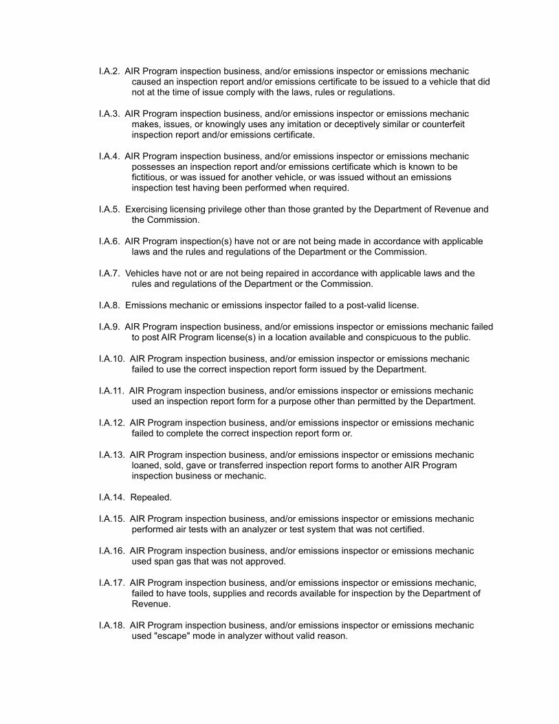
I.A.2. AIR Program inspection business, and/or emissions inspector or emissions mechanic caused an inspection report and/or emissions certificate to be issued to a vehicle that did not at the time of issue comply with the laws, rules or regulations.
I.A.3. AIR Program inspection business, and/or emissions inspector or emissions mechanic makes, issues, or knowingly uses any imitation or deceptively similar or counterfeit inspection report and/or emissions certificate.
I.A.4. AIR Program inspection business, and/or emissions inspector or emissions mechanic possesses an inspection report and/or emissions certificate which is known to be fictitious, or was issued for another vehicle, or was issued without an emissions inspection test having been performed when required.
I.A.5. Exercising licensing privilege other than those granted by the Department of Revenue and the Commission.
I.A.6. AIR Program inspection(s) have not or are not being made in accordance with applicable laws and the rules and regulations of the Department or the Commission.
I.A.7. Vehicles have not or are not being repaired in accordance with applicable laws and the rules and regulations of the Department or the Commission.
I.A.8. Emissions mechanic or emissions inspector failed to a post-valid license.
I.A.9. AIR Program inspection business, and/or emissions inspector or emissions mechanic failed to post AIR Program license(s) in a location available and conspicuous to the public.
I.A.10. AIR Program inspection business, and/or emission inspector or emissions mechanic failed to use the correct inspection report form issued by the Department.
I.A.11. AIR Program inspection business, and/or emissions inspector or emissions mechanic used an inspection report form for a purpose other than permitted by the Department.
I.A.12. AIR Program inspection business, and/or emissions inspector or emissions mechanic failed to complete the correct inspection report form or.
I.A.13. AIR Program inspection business, and/or emissions inspector or emissions mechanic loaned, sold, gave or transferred inspection report forms to another AIR Program inspection business or mechanic.
I.A.14. Repealed.
I.A.15. AIR Program inspection business, and/or emissions inspector or emissions mechanic performed air tests with an analyzer or test system that was not certified.
I.A.16. AIR Program inspection business, and/or emissions inspector or emissions mechanic used span gas that was not approved.
I.A.17. AIR Program inspection business, and/or emissions inspector or emissions mechanic, failed to have tools, supplies and records available for inspection by the Department of Revenue.
I.A.18. AIR Program inspection business, and/or emissions inspector or emissions mechanic used "escape" mode in analyzer without valid reason.
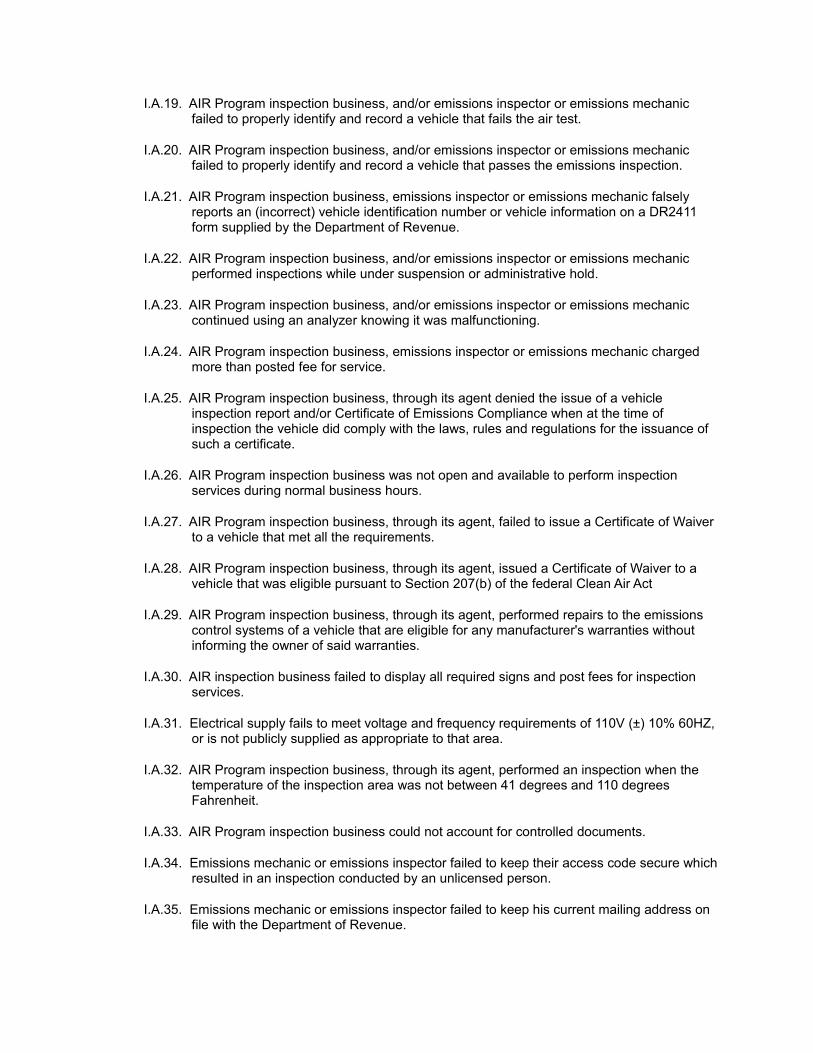
I.A.19. AIR Program inspection business, and/or emissions inspector or emissions mechanic failed to properly identify and record a vehicle that fails the air test.
I.A.20. AIR Program inspection business, and/or emissions inspector or emissions mechanic failed to properly identify and record a vehicle that passes the emissions inspection.
I.A.21. AIR Program inspection business, emissions inspector or emissions mechanic falsely reports an (incorrect) vehicle identification number or vehicle information on a DR2411 form supplied by the Department of Revenue.
I.A.22. AIR Program inspection business, and/or emissions inspector or emissions mechanic performed inspections while under suspension or administrative hold.
I.A.23. AIR Program inspection business, and/or emissions inspector or emissions mechanic continued using an analyzer knowing it was malfunctioning.
I.A.24. AIR Program inspection business, emissions inspector or emissions mechanic charged more than posted fee for service.
I.A.25. AIR Program inspection business, through its agent denied the issue of a vehicle inspection report and/or Certificate of Emissions Compliance when at the time of inspection the vehicle did comply with the laws, rules and regulations for the issuance of such a certificate.
I.A.26. AIR Program inspection business was not open and available to perform inspection services during normal business hours.
I.A.27. AIR Program inspection business, through its agent, failed to issue a Certificate of Waiver to a vehicle that met all the requirements.
I.A.28. AIR Program inspection business, through its agent, issued a Certificate of Waiver to a vehicle that was eligible pursuant to Section 207(b) of the federal Clean Air Act
I.A.29. AIR Program inspection business, through its agent, performed repairs to the emissions control systems of a vehicle that are eligible for any manufacturer's warranties without informing the owner of said warranties.
I.A.30. AIR inspection business failed to display all required signs and post fees for inspection services.
I.A.31. Electrical supply fails to meet voltage and frequency requirements of 110V (±) 10% 60HZ, or is not publicly supplied as appropriate to that area.
I.A.32. AIR Program inspection business, through its agent, performed an inspection when the temperature of the inspection area was not between 41 degrees and 110 degrees Fahrenheit.
I.A.33. AIR Program inspection business could not account for controlled documents.
I.A.34. Emissions mechanic or emissions inspector failed to keep their access code secure which resulted in an inspection conducted by an unlicensed person.
I.A.35. Emissions mechanic or emissions inspector failed to keep his current mailing address on file with the Department of Revenue.
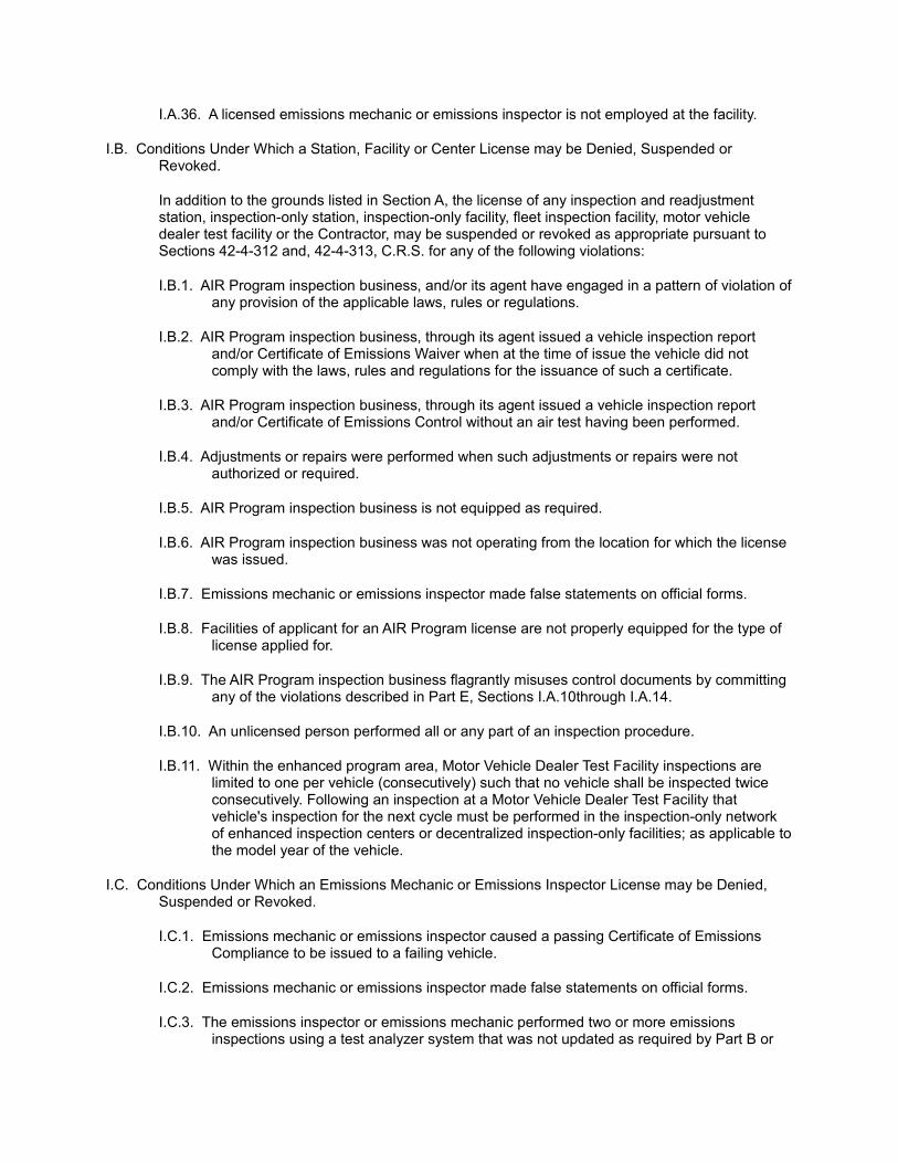
I.A.36. A licensed emissions mechanic or emissions inspector is not employed at the facility.
I.B. Conditions Under Which a Station, Facility or Center License may be Denied, Suspended or Revoked.
In addition to the grounds listed in Section A, the license of any inspection and readjustment station, inspection-only station, inspection-only facility, fleet inspection facility, motor vehicle dealer test facility or the Contractor, may be suspended or revoked as appropriate pursuant to Sections 42-4-312 and, 42-4-313, C.R.S. for any of the following violations:
I.B.1. AIR Program inspection business, and/or its agent have engaged in a pattern of violation of any provision of the applicable laws, rules or regulations.
I.B.2. AIR Program inspection business, through its agent issued a vehicle inspection report and/or Certificate of Emissions Waiver when at the time of issue the vehicle did not comply with the laws, rules and regulations for the issuance of such a certificate.
I.B.3. AIR Program inspection business, through its agent issued a vehicle inspection report and/or Certificate of Emissions Control without an air test having been performed.
I.B.4. Adjustments or repairs were performed when such adjustments or repairs were not authorized or required.
I.B.5. AIR Program inspection business is not equipped as required.
I.B.6. AIR Program inspection business was not operating from the location for which the license was issued.
I.B.7. Emissions mechanic or emissions inspector made false statements on official forms.
I.B.8. Facilities of applicant for an AIR Program license are not properly equipped for the type of license applied for.
I.B.9. The AIR Program inspection business flagrantly misuses control documents by committing any of the violations described in Part E, Sections I.A.10through I.A.14.
I.B.10. An unlicensed person performed all or any part of an inspection procedure.
I.B.11. Within the enhanced program area, Motor Vehicle Dealer Test Facility inspections are limited to one per vehicle (consecutively) such that no vehicle shall be inspected twice consecutively. Following an inspection at a Motor Vehicle Dealer Test Facility that vehicle's inspection for the next cycle must be performed in the inspection-only network of enhanced inspection centers or decentralized inspection-only facilities; as applicable to the model year of the vehicle.
I.C. Conditions Under Which an Emissions Mechanic or Emissions Inspector License may be Denied, Suspended or Revoked.
I.C.1. Emissions mechanic or emissions inspector caused a passing Certificate of Emissions Compliance to be issued to a failing vehicle.
I.C.2. Emissions mechanic or emissions inspector made false statements on official forms.
I.C.3. The emissions inspector or emissions mechanic performed two or more emissions inspections using a test analyzer system that was not updated as required by Part B or
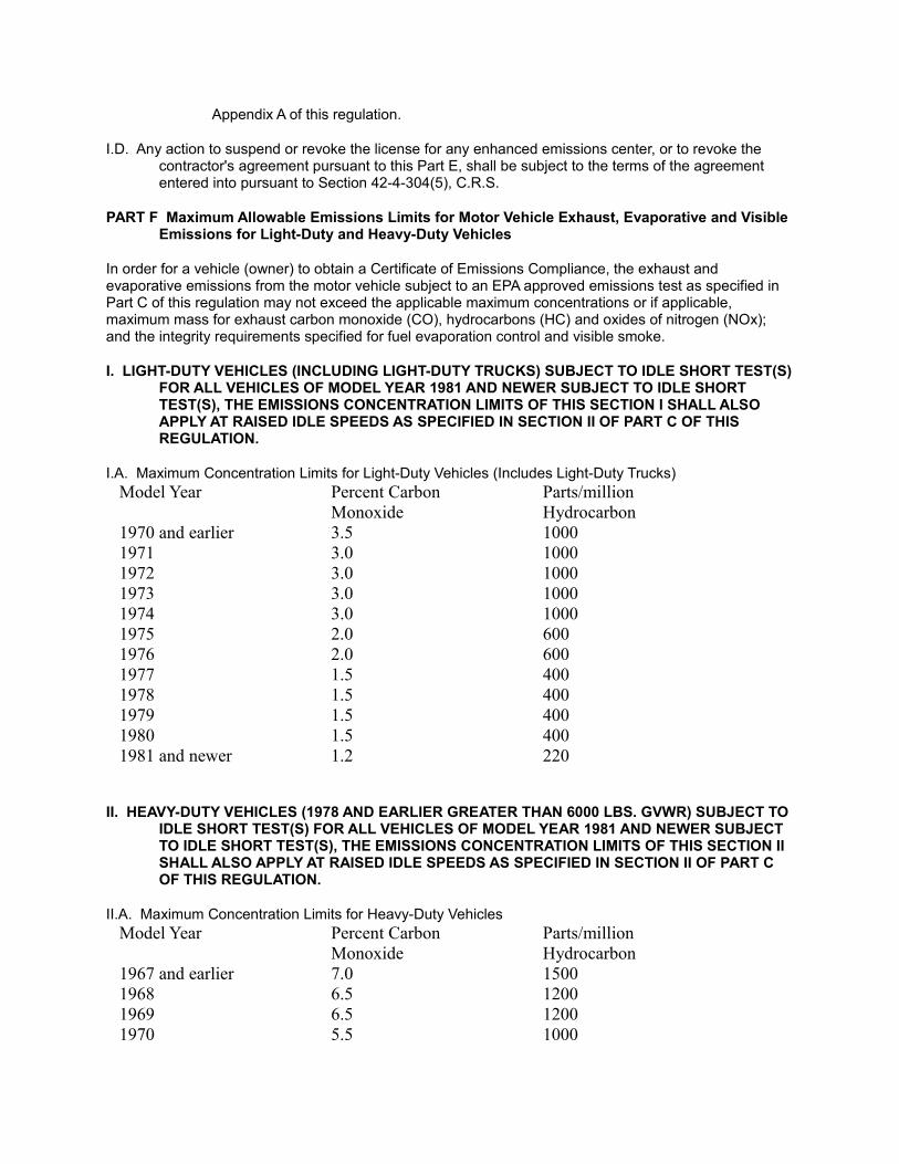
Appendix A of this regulation.
I.D. Any action to suspend or revoke the license for any enhanced emissions center, or to revoke the contractor's agreement pursuant to this Part E, shall be subject to the terms of the agreement entered into pursuant to Section 42-4-304(5), C.R.S.
PART F Maximum Allowable Emissions Limits for Motor Vehicle Exhaust, Evaporative and Visible Emissions for Light-Duty and Heavy-Duty Vehicles
In order for a vehicle (owner) to obtain a Certificate of Emissions Compliance, the exhaust and evaporative emissions from the motor vehicle subject to an EPA approved emissions test as specified in Part C of this regulation may not exceed the applicable maximum concentrations or if applicable, maximum mass for exhaust carbon monoxide (CO), hydrocarbons (HC) and oxides of nitrogen (NOx); and the integrity requirements specified for fuel evaporation control and visible smoke.
I. LIGHT-DUTY VEHICLES (INCLUDING LIGHT-DUTY TRUCKS) SUBJECT TO IDLE SHORT TEST(S) FOR ALL VEHICLES OF MODEL YEAR 1981 AND NEWER SUBJECT TO IDLE SHORT TEST(S), THE EMISSIONS CONCENTRATION LIMITS OF THIS SECTION I SHALL ALSO APPLY AT RAISED IDLE SPEEDS AS SPECIFIED IN SECTION II OF PART C OF THIS REGULATION.
I.A. Maximum Concentration Limits for Light-Duty Vehicles (Includes Light-Duty Trucks)Model Year Percent Carbon
MonoxideParts/million Hydrocarbon
1970 and earlier 3.5 10001971 3.0 10001972 3.0 10001973 3.0 10001974 3.0 10001975 2.0 6001976 2.0 6001977 1.5 4001978 1.5 4001979 1.5 4001980 1.5 4001981 and newer 1.2 220
II. HEAVY-DUTY VEHICLES (1978 AND EARLIER GREATER THAN 6000 LBS. GVWR) SUBJECT TO IDLE SHORT TEST(S) FOR ALL VEHICLES OF MODEL YEAR 1981 AND NEWER SUBJECT TO IDLE SHORT TEST(S), THE EMISSIONS CONCENTRATION LIMITS OF THIS SECTION II SHALL ALSO APPLY AT RAISED IDLE SPEEDS AS SPECIFIED IN SECTION II OF PART C OF THIS REGULATION.
II.A. Maximum Concentration Limits for Heavy-Duty VehiclesModel Year Percent Carbon
MonoxideParts/million Hydrocarbon
1967 and earlier 7.0 15001968 6.5 12001969 6.5 12001970 5.5 1000
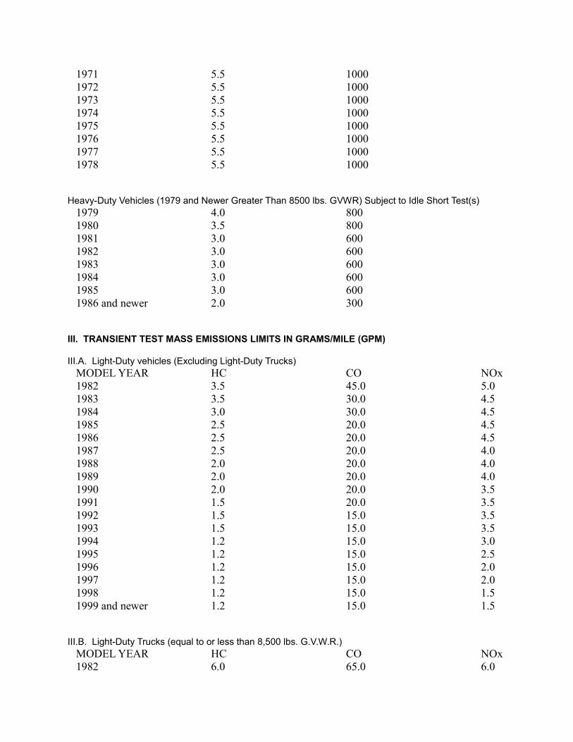
1971 5.5 10001972 5.5 10001973 5.5 10001974 5.5 10001975 5.5 10001976 5.5 10001977 5.5 10001978 5.5 1000
Heavy-Duty Vehicles (1979 and Newer Greater Than 8500 lbs. GVWR) Subject to Idle Short Test(s)1979 4.0 8001980 3.5 8001981 3.0 6001982 3.0 6001983 3.0 6001984 3.0 6001985 3.0 6001986 and newer 2.0 300
III. TRANSIENT TEST MASS EMISSIONS LIMITS IN GRAMS/MILE (GPM)
III.A. Light-Duty vehicles (Excluding Light-Duty Trucks)MODEL YEAR HC CO NOx1982 3.5 45.0 5.01983 3.5 30.0 4.51984 3.0 30.0 4.51985 2.5 20.0 4.51986 2.5 20.0 4.51987 2.5 20.0 4.01988 2.0 20.0 4.01989 2.0 20.0 4.01990 2.0 20.0 3.51991 1.5 20.0 3.51992 1.5 15.0 3.51993 1.5 15.0 3.51994 1.2 15.0 3.01995 1.2 15.0 2.51996 1.2 15.0 2.01997 1.2 15.0 2.01998 1.2 15.0 1.51999 and newer 1.2 15.0 1.5
III.B. Light-Duty Trucks (equal to or less than 8,500 lbs. G.V.W.R.)MODEL YEAR HC CO NOx1982 6.0 65.0 6.0
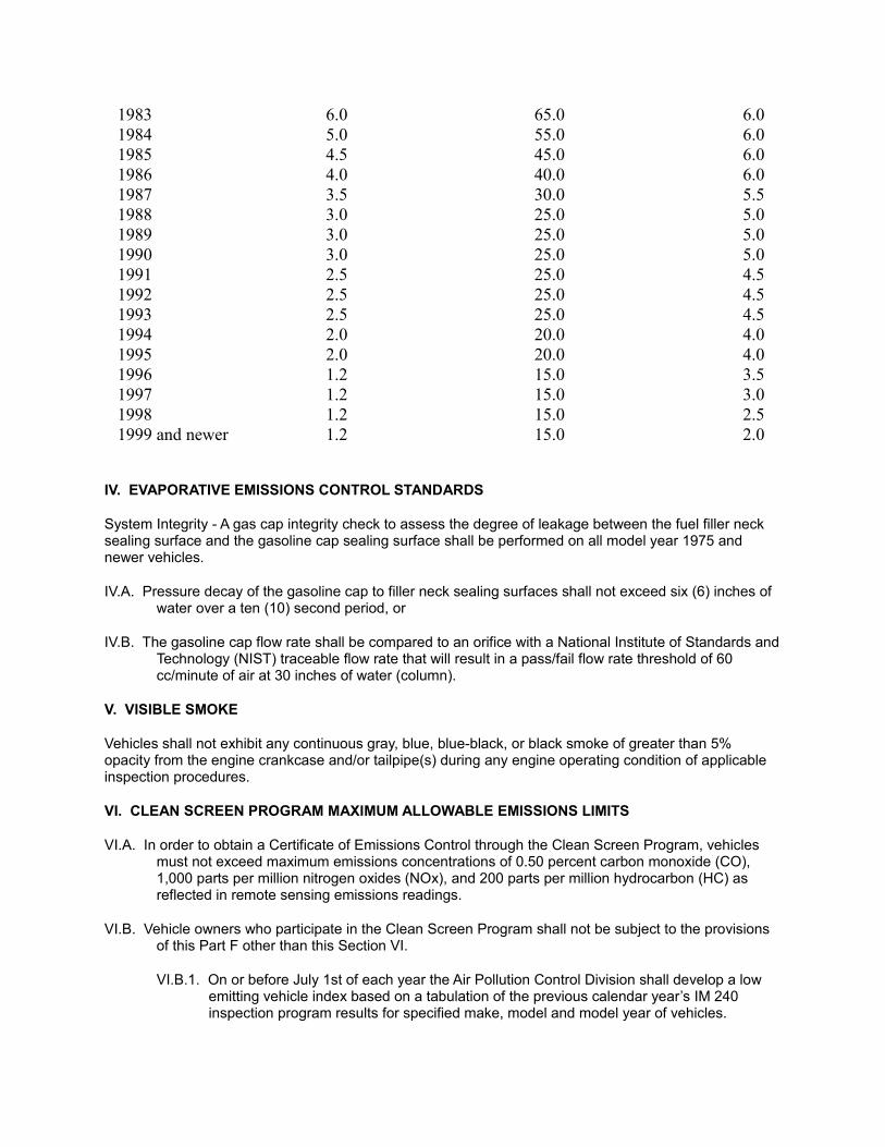
1983 6.0 65.0 6.01984 5.0 55.0 6.01985 4.5 45.0 6.01986 4.0 40.0 6.01987 3.5 30.0 5.51988 3.0 25.0 5.01989 3.0 25.0 5.01990 3.0 25.0 5.01991 2.5 25.0 4.51992 2.5 25.0 4.51993 2.5 25.0 4.51994 2.0 20.0 4.01995 2.0 20.0 4.01996 1.2 15.0 3.51997 1.2 15.0 3.01998 1.2 15.0 2.51999 and newer 1.2 15.0 2.0
IV. EVAPORATIVE EMISSIONS CONTROL STANDARDS
System Integrity - A gas cap integrity check to assess the degree of leakage between the fuel filler neck sealing surface and the gasoline cap sealing surface shall be performed on all model year 1975 and newer vehicles.
IV.A. Pressure decay of the gasoline cap to filler neck sealing surfaces shall not exceed six (6) inches of water over a ten (10) second period, or
IV.B. The gasoline cap flow rate shall be compared to an orifice with a National Institute of Standards and Technology (NIST) traceable flow rate that will result in a pass/fail flow rate threshold of 60 cc/minute of air at 30 inches of water (column).
V. VISIBLE SMOKE
Vehicles shall not exhibit any continuous gray, blue, blue-black, or black smoke of greater than 5% opacity from the engine crankcase and/or tailpipe(s) during any engine operating condition of applicable inspection procedures.
VI. CLEAN SCREEN PROGRAM MAXIMUM ALLOWABLE EMISSIONS LIMITS
VI.A. In order to obtain a Certificate of Emissions Control through the Clean Screen Program, vehicles must not exceed maximum emissions concentrations of 0.50 percent carbon monoxide (CO), 1,000 parts per million nitrogen oxides (NOx), and 200 parts per million hydrocarbon (HC) as reflected in remote sensing emissions readings.
VI.B. Vehicle owners who participate in the Clean Screen Program shall not be subject to the provisions of this Part F other than this Section VI.
VI.B.1. On or before July 1st of each year the Air Pollution Control Division shall develop a low emitting vehicle index based on a tabulation of the previous calendar year’s IM 240 inspection program results for specified make, model and model year of vehicles.
VI.B.2. A 98% passing rate for exhaust emissions shall be set as the minimum allowable passing criteria for the low emitting vehicle index.
VI.B.3. In developing the low emitting vehicle index, the Division may use passing criteria greater than 98% if necessary to ensure that the use of the low emitting vehicle index is equivalent to or better than the use of a second remote sensing measurement in terms of air quality benefits.
VII. ON-BOARD DIAGNOSTIC INSPECTION PASSING CRITERIA
In order for a vehicle (owner) to obtain a certificate of emissions compliance, the results of the OBD inspection as specified in Part C, Section II.C. of this regulation must meet the following requirements:
VII.A. The data link connector (DLC) is not missing, has not been tampered with, and is operational
VII.B. The malfunction indicator light (MIL) illuminates when the ignition key is turned to the key on, engine off (KOEO) position.
VII.C. The MIL extinguishes and remains off once the vehicle’s engine is started (KOER).
VII.D. The MIL status, as indicated by the on-board diagnostic test analyzer system is commanded off.
VII.E. Only one readiness monitor may be set to "not ready" status.
VII.F. Upon a retest, all monitors except the evaporative monitor must be set to "ready".
PART G Reserved
PART H Statements of Basis, Specific Statutory Authority and Purpose
I. AMENDMENTS TO PART A - E
ADOPTED MARCH 21, 1996
The amendments to Regulation Number 11 were adopted by the Air Quality Control Commission (Commission) of the State of Colorado. This Statement of Basis, Specific Statutory Authority and Purpose is required by Sections 24-4-103(4), C.R.S. The specific statutory authority for these changes is Sections 42-4-301 through 42-4-316, C.R.S. (1995 Supplement).
The revisions to Regulation Number 11 address the effects of recodifying Title 42 of Colorado's Revised Statutes. This regulatory action is necessary to correct statutory references within the regulation in order to be consistent with the renumbered statute. The only other change to the rule is to clarify that “licensed emissions inspectors” are eligible to perform an emissions inspection pursuant to Part C, Section I.A. The previous rule referred only to “authorized emissions inspectors” . The purpose of this change is to avoid confusion between emissions inspectors authorized to perform an inspection at an enhanced inspection center and emissions inspectors licensed to do so at an inspection-only facility, fleet inspection station, or motor vehicle dealer test facility. This rule amendment does not change the rights or obligations of any person because the term “authorized emissions inspector” has been applied to include “licensed emissions inspectors” for purposes of Part C Section I. A. The specific statutory authority for this rule amendment is set out at Section 42-4-304 (7), C.R.S.
For the reasons noted, the Commission has adopted amendments to Regulation Number 11, Parts A-E. These rule revisions are administrative in nature; do not apply to stationary sources; and will have no regulatory impact on any person, facility or activity. Furthermore, the Commission has no discretion not to adopt the changes to the numbering scheme for the statutory provisions, and these revisions will have no
significant fiscal impact. These revisions are not more stringent than the relevant federal requirements.
II. AMENDMENTS TO PARTS A, B, C, F, G, AND APPENDICES A AND B
ADOPTED JULY 17, 1997
The amendments to Regulation Number 11 were adopted by the Air Quality Control Commission (Commission) of the State of Colorado. This Statement of Basis, Specific Statutory Authority and Purpose is required by Sections 24-4-103(4), C.R.S. The specific statutory authority for these changes is Sections 42-4-301 through 42-4-316, C.R.S. (1995 Supplement).
1. Changes to Part A(l) (C) (9) and (11) address statutory amendments to Section 42-4-309 (6) enacted by the 1996 session of the General Assembly which make provision for an inspection voucher system for retail sale of used motor vehicles into the enhanced emissions inspection program area by licensed dealers. The rule revisions ensure that such dealers are not required to have the vehicle inspected prior to the sale provided they comply with the requirements of Section 42-4-309 (6). Furthermore, the revisions allow sellers to have a vehicle inspected up to one hundred twenty days prior to the sale. The specific authority for these changes is set out in Sections 42-4-309 (6) and 42-4-306 (7). This provision is necessary to implement state law, but is not required by federal law. The rule specifically provides that the provisions of 42-4-309 (6) are not federally enforceable, and are not included in the SIP. The Department of Revenue, may however, enforce such requirements, subject to the adoption of any regulations that may be necessary. Such administrative enforcement is necessary to ensure compliance with the statutory requirements. The revisions to Regulation Number 11, Part A(I)(C)(13) make it clear that a vehicle will fail the inspection for purposes of 42-4-309 (6) if the vehicle has any defect that makes it impractical or unsafe to test the vehicle.
2. The revisions to Part A(I)(B) clarify motorist compliance requirements For those persons that live in the basic program area yet commute into and have complied with enhanced program requirements. The specific statutory authority for these changes is set out in Sections 42-4-306 (7) and 42-4-310 (1) (c) (V). This provision is consistent with, and does not exceed, federal requirements.
3. The revisions to Part C (II)(G)(4) make it clear that vehicles with excessively long or short wheelbases, and specially designed vehicles equipped with hand controls or similar apparatus, are exempt from testing on the IM 240 dynamometer. The IM 240 dynamometer system is not designed to handle such vehicles, and the population of such vehicles is so small that this exemption will have no effect on emissions reductions. This provision is consistent with, and does not exceed, federal requirements. The specific statutory authority for this exemption is set out in Section 42-4-306 (6) (d).
4. The revisions to Part C (III) (D) eliminate the previous requirement to repair or replace the catalytic converter and exhaust gas oxygen sensor if the fuel inlet restrictor has become enlarged. Leaded fuels, which damaged these components, have not been available for several years and this rule is no longer necessary. This provision is consistent with, and does not exceed, federal requirements. The specific statutory authority for this exemption is set out at Section 42-4-306 (6) (a).
5. The revisions to Part C (XI) allow inspection stations to use vehicle identification numbers (VINs) issued by kit car manufacturers and by other states. The rule previously required inspection stations to use a VIN assigned by Colorado for kit cars, custom cars and home-built vehicles. Under the previous rule, such specialized vehicles were often required to comply with inspection criteria applicable to later model vehicles. As a result the inspection criteria were unreasonably stringent. This change will ensure that vehicles are inspected pursuant to the appropriate procedure, This provision is consistent with, and does not exceed, federal requirements. The specific statutory authority for this provision is set out at Section 42-4-306 (6).
6. The revisions to Parts C (IV) and F (IV) provide a pressure integrity or leak check for gas caps in order to reduce emissions of volatile organic compounds, an ozone precursor. The gas cap pressure check requirements is based on established demonstrated methodologies, and will provide an estimated 40% reduction in VOC, an ozone precursor, to escape into the atmosphere. Such evidence supports the finding that the rule will result in a demonstrable reduction in air pollution. Because the Denver area is in the inspection and maintenance program due to carbon monoxide, rather than ozone problems, federal law does not require such a pressure check. The state did not take credit for such a pressure check in the maintenance plan for ozone, and associated redesignation request, recently adopted by the AQCC. Therefore, this provision is not required by federal law, and will not be incorporated into the State implementation Plan. An evaporative emissions inspection procedure is required pursuant to Sections 42-4-310 (2) (a) and 42-4-306 (6) (a), C.R.S. for those vehicles inspected in the metro Denver enhanced program area.
7. The revisions to Part B (IV)(B&C), (VI)(C&D) and Appendix B propose standards and specifications consistent with EPA and recognized industry standards for the manufacturer and “naming” of precision calibration gases for use in test analyzer systems. Consistent protocol reduces the burden to the gas manufacturer, those regulated parties that are end users of the calibration gases, and improve overall quality control. Additionally, revisions to Appendix B address specific program administrative needs such as the bar code tracking system necessary for tracking certified test analyzer system gases which have been placed into service. The revisions to Appendix B are consistent with guidance documents issued by EPA. Federal law requires span gases to be accurate within a tolerance of 2%, but federal law does not specifically require the state to establish requirements for manufacturers. Therefore, the requirements set out in Appendix B shall not be included in the SIP, and shall not be federally enforceable. The specific statutory authority for this action is Section 42-4-306 (3)(a)(l).
8. The revisions to Appendix A, attachment III establish equipment design and performance specifications for a “Motor Vehicle Dealer Transient Mode Test Analyzer System (IG 240)” to be used at Motor Vehicle Dealer Test Facilities (MVDTFs). Equipment that meets these specifications will allow MVDTFs to conduct emissions inspections on their used vehicle inventory prior to its retail sale. This provision provides increased convenience and reduced costs for affected automobile dealers that currently utilize the contractor operated IM 240 system in the enhanced program area. Use of this system is not mandated. Federal law does not require specifications for an IG 240, and the state did not take credit for inspections conducted at the time of sale or transfer of used vehicles sold by motor vehicle dealers. Therefore, the specifications applicable to MVDTFs and the IG 240 are not included in the SIP. The specific statutory authority for this revision is Sections 42-4-304 (19) and 42-4-306 (3)(a)(l)(A-C).
9. Revisions to Part A(l)(9) delete the present exemption that vehicles sold as “tow-away” by licensed dealers are not required to comply with applicable emissions inspection requirements at the time of sale. The proposal would eliminate present confusion within the regulated community. Part A (l)(9) is now consistent with Section 42-4-309(3)(a). The Commission is not required to create a specific exemption for tow-away vehicles and therefore has the authority to remove the existing exemption. Additional statutory authority is set out at Sections 42-4-306 (1) and 42-4-309 (3)(A).
The Department of Revenue is the state agency charged with the regulation of motor vehicle dealers, and for the titling and registration of motor vehicles. The tow-away exemption has hampered the Department of Revenue's enforcement actions. Therefore, the Commission is repealing this exemption and deferring this issue to the Department of Revenue. The Department of Revenue should handle this issue through rule making or otherwise, as appropriate.
10. Revisions to Part A (V) amends the notice to interested parties that materials incorporated into the rule by reference may be examined at any state publications depository library, as required by Section42-4-103 (12.5)(d). The revision expands the text of the existing notice of availability to be consistent with prescriptive state requirements.
For the reason noted, the Commission has adopted amendments to Regulation Number 11, Parts A, B, C, F, G and Appendices A and B. Revisions implement and/or clarify statutory provisions for the vehicle emissions inspection program pursuant to Sections 42-4-301 through 42-4-316, C.R.S. Rule revisions amend existing inspection procedures consistent with State Implementation Plan commitments.
III. REVISIONS TO PART C (VIII) AND PART F (III)
ADOPTED NOVEMBER 19, 1998
Basis and Purpose
The November 19, 1998 revisions to regulations Part C (VIII) (b.4) (b.5) and (c.-g.) reinstate, with some minor clarifications, text addressing compliance waivers and related inspection provisions regarding specific circumstances involving certain participating motorists and the repair of vehicles that had failed one or more emissions inspections. This text was inadvertently omitted during the last publication of the regulation, August 1997. The omitted text was initially adopted by the Commission immediately prior to implementing the improved basic program and enhanced inspection and maintenance program January 1995, pursuant to Sections 42-4-301 through 42-4-316, C.R.S. (1998). Reinstating this text results in the regulation being consistent with state statute and the federal program. The November 19,1998 revisions to regulations Part F (III) reconcile the emissions limits used by enhanced inspection centers for motor vehicle emissions inspections with the emissions limits that were used for purposes of demonstrating attainment of the National Ambient Air Quality Standards (NAAQS) for carbon monoxide (CO) and for particulate matter less than ten microns in diameter (PM10). The rule change only applies to the enhanced emissions program and only affects the standards used for testing 1982 and newer vehicles.
The emissions limits adopted by the Commission are more stringent than the emissions limits that were being implemented prior to the hearing, but are less stringent than the emissions limits that were scheduled to take effect on January 1, 1999 under the previous version of Regulation Number 11.
The emissions limits adopted by the Commission must go into effect by the end of December 1998 in order to comply with the minimum federal requirement to show attainment of the NAAQS for CO by December 31, 2000.
The emissions limits contained in the previous rule for 1999 and beyond were more stringent than necessary to comply with federal law and were so stringent that many vehicles would not be able to comply with the standards even when repaired. Such emissions limits were based on EPA guidance issued in 1993. Experience with the program since then has demonstrated that such standards are unreasonable.
Federal Requirements
There are several federal requirements that are relevant to the emissions limits used in the AIR Program. 40 CFR Part 51 establishes specific emissions limits for the AIR Program. In addition, the AIR Program was used to demonstrate attainment of the NAAQS for CO and PM10. Therefore, the emissions limits must be included as enforceable control measures in the State Implementation Plan.
For purposes of CO, 40 CFR Section 51.351 requires the AIR Program to achieve at least as much reduction in fleet emissions, measured in grams per mile, as the model federal program. The modeling results that were used to demonstrate compliance with the requirements of 40 CFR Part 51 were also used to demonstrate attainment of the NAAQS for CO in the Denver CO SIP. The emissions limits for CO and hydrocarbons implement the assumptions that were made in the modeling to show compliance with 40 CFR 51.351 and to show attainment of the CO NAAQS. The emissions limits for hydrocarbons are a necessary component of an effective CO control program and, therefore, are being included in the State Implementation Plan.
The emissions limits for NOx for the years 1999 through 2014 established in the rule are necessary to achieve the NOx reductions that were assumed for the AIR Program in the Denver PM10 SIP. Thus, such emissions limits are necessary to implement the control measures contained in the Denver PM10 SIP as required by federal law.
For the foregoing reasons, the Commission concludes that the emissions limits in Regulation Number 11 for the years 1999 through 2014 are necessary to comply with federal law and do not otherwise exceed the minimum federal requirements. However, the rule revision also includes an emissions limit for NOx for the year 2015 and beyond that is more stringent than the minimum federal requirements. Such more stringent NOx limit is necessary beginning in the year 2015 in order for the Denver Regional Council of Governments (DRCOG) to demonstrate that the transportation network for the Denver metropolitan area will remain below the emissions budget for NOx in the State Implementation Plan. Pursuant to federal law, the Commission must adopt such a control measure before DRCOG makes its conformity determination. 40 CFR 93.122(a)(3)(l). However, federal law does not require the more stringent emissions limit for NOx to be included in the State Implementation Plan. Therefore, the emissions limit for NOx established in Part F, Sections III.A.2 and III.B.2 shall not be included in the State Implementation Plan.
Statutory Authority
The specific statutory authority for the adoption of emissions limits for carbon monoxide, hydrocarbons and oxides of nitrogen is set out at Section 42-4-306(6), C.R.S. (1998).
Effective date of rule changes
Pursuant to Section 24-4-103(5), C.R.S. (1998), the standards or cut-points established by the Commission on November 19,1998 shall take effect on December 30, 1998; provided the rule revisions are published in the Code of Colorado Regulations on December 10, 1998. Such an effective date is consistent with the relevant SIP demonstrations. For purposes of Section 42-4-306(6)(b)(ii), C.R.S. (1998), the standards established by this rule revision were established on November 19,1998 even though such standards shall not become effective until December 30,1998.
Findings pursuant to Section 25-7-110.8. C.R.S. (1998).
The revisions to Regulation Number 11 are based on reasonably available, validated, reviewed and sound scientific methodologies. The Commission has considered all scientific and other information made available by interested parties.
Evidence in the record supports the finding that the revised emissions limits will result in a demonstrable reduction in air pollution when compared to the emissions limits that were in effect prior to the rule change.
The rule adopted by the Commission is the most cost-effective alternative, and will maximize the air quality benefits of the regulation in the most cost-effective manner.
IV. REVISIONS TO PARTS A, B, C, D, AND F
ADOPTED FEBRUARY 19, 1999
Basis and Purpose
The February 19, 1999 revisions implement Sections 42-4-304 through 42-4-307 and 42-4-310, C.R.S. as amended, pursuant to S.B. 98-182. Additionally, the revisions codify the provisions of Sections 42-4-304 and 42-4-310, C.R.S. as amended, pursuant to S.B. 98-182.
Explanation of the Provisions
The revisions implement a “Clean Screen Program” as an operating element of Colorado's AIR Program as established in Sections 42-4-301 through 42-4-316, C.R.S. The Clean Screen Program is designed and intended to improve participating motorist convenience and reduce costs when complying with a periodic inspection requirement. Screening clean vehicles out of the vehicle population subject to inspection requirements reduces the burden of compliance on vehicle owners. One program premise is that these vehicles would have passed a traditional inspection and that air quality would not necessarily benefit from using traditional inspection procedures on these vehicles. Clean Screened vehicles would be exempt from complying with what would normally be mandatory inspection, for one inspection cycle.
Participation by owners of vehicles registered in the program areas specified, i.e., Larimer County and metro Greeley, Weld County as well as by owners of vehicles registered elsewhere but required to obtain a certification of emissions compliance by Section 42-4-310 (l)(c)(l), C.R.S., is voluntary. Provisions within the enabling legislation allow for participation by other program areas or for other areas of the state based upon a request by respective lead air quality planning agencies, and approval by the Commission.
As proposed for implementation in the Larimer County and Weld County program areas, Clean Screening is an appropriate application of remote emissions sensing technology. Based on the Greeley Pilot Study conducted by the Division, implementing this technology as an alternate inspection procedure brings with it an estimated maximum 4-7% loss in emissions reduction compared to traditional inspection procedures. The Environmental Protection Agency's modeling projects a 1% loss. The Commission concludes that this loss of emissions reductions will have no negative impact on compliance with the National Ambient Air Quality Standards for the areas included.
Reducing the number of vehicles seeking an inspection each cycle will reduce business for licensed inspection providers serving these program areas.
The Division is committed to continuously evaluating the performance of the program especially as it pertains to the specific emissions thresholds used in the program, impacts on air quality, and may request the Commission to consider revisions to elements of the program. Additionally, the Division has committed to evaluating the feasibility of low emission(s) profiling as a supplementary inspection criteria to a Clean Screen Program.
Statutory Authority
Sections 42-4-304 through 42-4-307, and Section 42-4-310, C.R.S., as amended, authorize adoption of a Clean Screen Program.
Federal Requirements
There are no specific federal requirements requiring a Clean Screen Program. This program is not a federal mandate. The United States Environmental Protection Agency has published general guidance that is reflected in the revised regulations. A revision of the SIP for the applicable program areas is necessary to reflect the potential emissions reduction impact associated with Clean Screen Program procedures.
Explanation of Additional Revisions to Regulation for February 19,1999.
The revisions to the regulation also implement the provisions of Sections 42-4-304 and 42-4-310, C.R.S., as amended, pursuant to SB 98-046 as it pertains to the responsibility of compliance with emissions inspection requirements for vehicles in the process of being sold. The provisions require the seller to obtain an emission inspection when the vehicle is operable and can be tested. Where the vehicle is deemed inoperable or otherwise cannot be tested, the seller must provide written notice to the purchaser prior to completion of the sale on specific forms prepared by the Department of Revenue.
Statutory Authority
The specific statutory authority for the provisions discussed above is set out at Sections 42-4-304 and 42-4-310, C.R.S. as amended. The Department of Revenue adopted and implemented regulations to address these provisions. Regulation Number 11 is now consistent with state statute.
Federal Requirements
There are no federal requirements as it pertains to these provisions.
Effective Date of Rule Changes
The effective date for the revisions to Regulation Number 11 shall be April 30, 1999.
V. AMENDMENTS TO PARTS A, C AND F (III)
ADOPTED JANUARY 10, 2000
Basis and Purpose
Regulation Number 11 requires periodic emissions tests for vehicles registered or operating within the program area, which covers most of the Front Range. The purpose of the program is to reduce the amount of carbon monoxide, oxides of nitrogen, and hydrocarbons emitted by automobiles. The purpose of the January 2000 revisions to Regulation Number 11 is to make the program more cost-effective and more convenient for motorists, and to do so in a manner that protects air quality.
This rule revision makes two changes to the motor vehicle emissions inspection program. First, it extends the clean screen program to the Denver metropolitan area. The dean screen program uses remote sensing technology to identify vehicles that do not need to be tested at an emissions inspection station. Beginning in the year 2002, the revised rule will allow a motorist that passes the requisite remote sensing test to obtain a certification of emissions compliance through the mail without taking the vehicle to an inspection station for a test.
Second, the rule-revisions amend the emissions standards for 1996 and later motor vehicles, beginning in the year 2002. The revisions make the standards consistent with the air pollution control technology on new vehicles.
Federal Requirements
The revisions to Regulation Number 11 were developed in conjunction with the redesignation of the Denver metropolitan area as an attainment area for carbon monoxide. Section 175 a of the federal Clean Air Act requires the State to demonstrate that the region will remain within the national ambient air quality standard (NAAQS) for carbon monoxide for ten years after EPA takes action on the maintenance plan. EPA may not take action on the maintenance plan until 2002. Thus, federal law requires the maintenance plan to show compliance with the NAAQS for carbon monoxide through the year 2013.
Air quality analyses performed for the maintenance plan indicate that the region will remain within the NAAQS for carbon monoxide through the year 2010, even with the clean screen program. The tools currently available for predicting air quality in the future suggest, however, that the clean screen program may be inconsistent with maintenance of the NAAQS for carbon monoxide after 2010. The rule revisions provide for the expiration of the clean screen program in the year 2010 in order to demonstrate maintenance of the NAAQS through 2013.
The rule revisions codify the emissions standards that were used to perform the computer modeling to demonstrate maintenance of the NAAQS. In performing the requisite computer modeling, the Air Pollution Control Division (APCD) used emissions standards that are more stringent than appeared in Regulation Number 11 prior to these amendments. The APCD used the more stringent standards in order to
maximize the air quality benefits of the program for purposes of the computer model. Although the revisions make more stringent the emissions standards in the rule, the changes do not necessarily make the program as a whole more stringent. This is because, as a practical matter, more stringent standards will automatically apply under pre-existing state and federal law. The federal rules require vehicle manufacturers to equip all 1996 and later light-duty vehicles with on-board diagnostic systems that will cause vehicles with emissions in excess of the revised standards to display fault codes (40 CFR Section 86.094-17). Regulation Number 11 already provides that a vehicle will fail the emissions test if the on-board diagnostic system displays such a fault code (Regulation Number 11, Part C, Section III.C.). The result is that the federal standards for the on-board diagnostic systems (which are more stringent than even the revised standards) already apply as a practical matter. The rule change is necessary to allow the APCD to take credit for more stringent standards when performing the computer modeling exercise. The revision merely make the standards consistent with improved technology that vehicle manufacturers are using to meet the on-board diagnostic requirements and to meet the Tier-1 standards mandated by federal law. The revised standards do not exceed the requirements of federal law.
The air quality impacts of the revisions to Regulation Number 11 were analyzed using the computer models approved by EPA, as is required by federal rules. Regulation Number 11, as revised, is necessary to comply with the requirements of the federal act and is not more stringent than the requirements of the federal act.
Statutory Authority
Specific statutory authority for the extension of the clean screen program to the Denver area is provided in Section 42-4-306(23), C.R.S. (1999). Specific statutory authority to establish emissions standards is provided in Section 42-4-306(6)(a), C.R.S. (1999).
Findings pursuant to Section 25-7-110.8
The primary intent of the January 2000 changes to Regulation Number 11 is to make the motor vehicle emissions inspection program more convenient and less costly, rather than achieving further reductions in emissions of air pollution. In addition, the rules establish more stringent emissions standards for automobiles in order to make the standards consistent with technology mandated by federal law.
The revisions are based on the computer model currently approved by the EPA. The computer model used to develop the revised rule overstates the carbon monoxide problem the Denver area will face in the future. The EPA is currently updating and improving the computer model but the revised computer model has not been approved by EPA and may not be used for federal regulatory purposes. In spite of the problems with the computer model used to develop this regulation, the regulation is based on the most reasonably available, validated, reviewed, and sound scientific methodologies currently available under federal law. All methodologies and information made available by interested parties have been considered.
The alternative chosen by the Commission provides the regulated community flexibility and achieves the necessary reduction in air pollution. The evidence is insufficient for the Commission to determine that the alternative chosen by the Commission is the most cost-effective alternative. The cost analysis developed by the Division indicates that it may be more cost-effective to eliminate the oxygenated fuels program instead of implementing a clean-screen program, but there is considerable uncertainty in that cost estimate. The impact of oxygenates on gasoline prices varies from year to year depending on the cost of ethanol and gasoline. Thus, reducing the oxygen content of gasoline does not ensure lower consumer gasoline prices. The Commission chose the alternative proposed by the Regional Air Quality Council (RAQC) for several reasons. First the RAQC's proposal is a balanced proposal that was developed through an inclusive stakeholder process. Second, it will establish a remote-sensing network, which is a necessary first step to establish a cost-effective high-emitter program in the future. Finally, the selection of a different option could delay the redesignation of the Denver area and would delay any cost-savings associated with such alternative.
VI. AMENDMENTS TO PARTS C AND D
ADOPTED NOVEMBER 16, 2000
Basis and Purpose
This rule revision makes two changes to the motor vehicle emissions inspection program. First, the change to Part C, Section XII.E.2 extends the time period for taking valid emissions readings for purposes of the clean screen program. This section previously required a reading within 90 days of the registration renewal date for the relevant motor vehicle. Since it often takes 90 days just to correlate the data, make the necessary communications and receive payment for the motorist, this time period was too restrictive and made the clean screen program impractical. The time period was extended by a minimum of 30 days to allow more time for emissions readings.
Second, the provision on licensing requirements for clean screen inspectors in Section IX.B.7 erroneously required such inspectors to demonstrate proficiency with the criteria in Section II.A.2 (qualifications for emissions mechanics and emissions inspectors) rather than Section V (qualifications for dean screen inspectors). The rule revision corrects this citation error.
Federal Requirements
The federal act and EPA regulations do not mention clean screen programs. See, 40 CFR Part 51, Subpart S. EPA has, however, developed a draft guidance document that authorizes the use of dean screen programs to exempt certain vehicles from the federally-required automobile inspection program. EPA document 420-P-98-008 (May 1998). The draft guidance document requires two remote-sensing readings, but does not require the readings to be any more recent than twelve months prior to the vehicle's regularly scheduled emissions test.
The clean screen program is voluntary and is designed to reduce the burden of the federally based automobile inspection program described at 40 CFR Part 51, Subpart S. Overall, the dean screen program results in an automobile inspection program that is less stringent than the program described in the federal regulations. Thus, the amendments will result in a motor vehicle inspection program that is less stringent than the program described in the federal regulations, but that requires more recent test results than is required by the draft federal guidance. Because EPA does not expressly require such a cutoff date, the revised rule will not be part of the federally enforceable SIP.
Although not expressly required by draft federal guidance, the requirement for a recent emission reading is necessary and reasonable to ensure that the emission test is representative of vehicle emissions near the time of registration. Motor vehicle emissions deteriorate over time. It follows that emission readings should be considered valid for a limited period of time. The General Assembly intended for 1982 and newer vehicles to be inspected every twenty-four months. Section 42-4-310(1)(b)(II)(C), C.R.S. A vehicle that passes a clean screen test based on a reading taken 120 days prior to the registration renewal date can go twenty-eight months without inspection (or even twenty-nine months if the motorist takes full advantage of the one month grace-period allowed by the Department of Revenue following the registration renewal date). The requirement for an emissions reading within 120 days of the registration renewal date strikes a reasonable balance between the requirement to implement a clean screen program and the legislative intent for emissions tests every two years.
The federal requirements for the licensing or certification of inspectors are set out at 40 CFR 51.367. The criteria established in Regulation Number 11, Part D, Section V are not more stringent than the federal requirements.
Statutory Authority
Specific statutory for the authority to promulgate regulations governing the operation of the clean screen
program is set out at 42-4-306(23), C.R.S.
Findings Pursuant to 25-7-110.8. C.R.S.
The primary intent of the November 2000 changes to Regulation Number 11 is not to achieve further reductions in emissions of air pollution, but rather to make more practical the administration of the clean screen program. Thus, the rule revision is administrative in nature.
The expanded time period allows additional time for taking emission measurements, analyzing the data, and communicating with motorist and the Clerk and Recorder. The revision to the time period does not change the standards or technology used in the program. The revision is consistent with all relevant, reasonably available, validated, reviewed, and sound scientific methodologies. All validated, reviewed, and sound scientific methodologies and information made available by interested parties has been considered.
The rule revision makes the dean screen program more cost-effective, provides the contractor and motorists with greater flexibility, will achieve the necessary reduction in air pollution, and will maximize the air quality benefits of the automobile inspection program in the most cost-effective manner.
VII. AMENDMENTS
ADOPTED DECEMBER 20, 2001
Basis and Purpose
The December 2001 revisions to Regulation Number 11 do three things: First, the rule revisions expand the clean screen program to include the enhanced emissions program area. However, the Commission did not, at this time, establish an implementation schedule pursuant to Section 42-3-134, C.R.S. This rule change is necessary to establish the clean screen authority pursuant to Section 42-4-307.5(1), C.R.S. The creation of the clean screen authority is necessary so that the Colorado Department of Revenue may receive and expend funds pursuant to Sections 42-4-307(10.5)(a) and Section 13 of House Bill 2001 -1402 (“HB1402” ). Thus, this portion of the rule change has no regulatory effect other than the creation of the clean screen enterprise. The Commission intends to hold a subsequent rulemaking hearing to establish an implementation schedule.
Second, the rule change excludes the El Paso county portion of the basic emissions program area from the clean screen program pursuant to Section 42-4-306(23)(a), C.R.S.
Third, the revisions conform Regulation Number 11 to the provisions of HB 1402, which repealed the Verification of Emissions Test requirements.
Federal Requirements
Although federal rules establish minimum performance requirements for the basic and enhanced emissions programs, nothing in the federal rules bear directly on the rule changes that were the subject of the December 2001 rulemaking hearing. The revised rule does not exceed the minimum requirements of federal law.
Statutory Authority
The specific statutory authority to expand the clean screen program to enhanced emissions program area is set out at 42-4-306(23)(b), C.R.S. The specific statutory authority to exclude the El Paso county portion of the basic emissions program area from the clean screen program is set out at 42-4-306(23)(a), C.R.S. The statutory authority to conform the Regulation to the applicable statutory provision is set out at 42-4-306(1), C.R.S.
Findings Pursuant to 25-7-110.8. C.R.S.
The requirement for findings set out in Section 25-7-110.8, C.R.S. does not apply to this rulemaking hearing. The creation of the clean screen authority is merely an administrative change; it is not intended to reduce air pollution. Similarly, the exclusion of El Paso County from the clean screen program is exempt from the requirements of 25-7-110.8 because it makes no change to the program applicable in that area because El Paso County was already exempt from the clean screen program. This rule change merely formalizes the area's status in the wake of HB 1402. Finally, the Commission has no discretion concerning the repeal of the provisions related to the verification of emissions tests. For these reasons, 25-7-110.8 does not apply to this matter.
VIII. AMENDMENTS TO PART A
ADOPTED JULY 18, 2002
Basis and Purpose
This rulemaking action removes the Fort Collins area component of the Automobile Inspection and Maintenance Program (“AIR Program” ) from the State Implementation Plan (SIP), but does not make any change in the state laws implementing the program. This means that the AIR Program will remain in full force and effect under state laws, but it will not be federally enforceable after January 1, 2004. The continuation of the AIR Program as a state-only program will afford the Division and the City of Fort Collins an opportunity to work together to identify feasible options to replace the AIR Program in the Fort Collins area.
The maintenance plan adopted by the Commission in conjunction with these rule changes includes a commitment to begin implementing the AIR Program in the Fort Collins area in the year 2026. Such a commitment is necessary to authorize state and local transportation planning agencies to take emissions reduction credit for such a program when such agencies make transportation conformity determinations 40 CFR 93.122(a)(iii). The Commission intends to reevaluate this commitment when it revises the maintenance plan, as it is required to do within eight years pursuant to as required by 42 USC 750 a (b), and may, in compliance with all applicable state and federal laws, revise the commitment as necessary and appropriate.
Federal Requirements
After January 1, 2004, the basic AIR Program will no longer be necessary to maintain the National Ambient Air Quality Standards for carbon monoxide in the Fort Collins area through the year 2015. Therefore, the program is no longer a federal requirement for the Fort Collins area. The Commission is removing the program from the State Implementation Plan, but is not repealing the program. The basic AIR Program will continue to apply in the Fort Collins area. Thus, the provisions of Regulation Number 11 applicable to motorists registered in the Fort Collins area are not required by federal law and are more stringent than the minimum federal requirements.
IX. AMENDMENTS TO PARTS A AND C
ADOPTED AUGUST 15, 2002
Basis and Purpose
The primary purpose of this rulemaking action is to switch Larimer and Weld counties to a pay-upon-registration system for the Clean Screen Program. The purpose of the Clean Screen Program is to make the Automobile Inspection and Readjustment Program (“the AIR program” ) more convenient, although not necessarily less expensive. The intent behind the pay-upon-registration system is to make it easier for motorists to pay for dean screen tests. Motorists were previously required to make a separate payment to
the contractor by mail before a dean screen test could be used to register a motor vehicle. With the change adopted by the Commission, motorists will be able to pay for dean screens tests at the time of registration. This change should make the Clean Screen Program, and therefore the AIR Program, more convenient for motorists. This rule change is intended merely to give motorists an option.
Clean screen motorists will have the choice of paying for the clean screen test and using it to register the vehicle, or having the vehicle tested at a conventional inspection and readjustment station and paying for such test at the testing station.
The rule amendments include a change to the timing requirements for remote sensing readings to make the Clean Screen Program more flexible. As amended, the regulation requires two valid remote sensing readings within a twelve-month period in order to clean screen a vehicle. The regulation previously required the most recent reading to be within 120 days of the registration renewal date. The 120-day requirement exceeded the minimum federal requirement. The rule has been revised rule to reflect EPA guidance and to maximize the use of the Clean Screen Program. The contract provides for adequate quality assurance by requiring the contractor to return to the same remote sensing locations on a frequent basis. Such rotation of the remote sensing units should minimize the number of vehicles that are dean screened based solely on readings taken early in the twelve-month period.
In addition, the rule changes include several minor, housekeeping changes such as:
The elimination of a requirement for the agencies to develop the equivalent of a windshield sticker for clean screened vehicles. Such a rule was inconsistent with the change in statute eliminating the windshield sticker requirements.
The elimination of a provision requiring annual inspections for government vehicles. Such a rule was inconsistent with a change in statute establishing biennial inspections for such vehicles.
The repeal of provisions establishing a method to mail payments to the contractor.
Federal Requirements
There are no federal requirements relevant to the payment mechanism for the Clean Screen Program. As indicated above, the purpose of this change is to make the program more convenient and to provide motorists with an option. Although the AIR Program may not be federally required in Larimer or Weld county after January 1, 2004 federal law requires the continued implementation of the AIR program in such areas until removed from the SIP through the SIP revision process. In the meantime, motorists must pay for emissions tests. Therefore such payment requirements do not exceed minimum federal requirements.
For clean screen programs, federal guidelines require two remote sensing readings within twelve months. The rule change makes the Colorado rule identical to the federal guideline.
For these reasons, this rule change does not exceed minimum federal requirements and is not otherwise more stringent than federal law.
Statutory Authority
The statutory authority to establish the specific dates for county clerks and recorders to begin collecting emissions inspection fees is set out at Section 42-3-134(26.5)(a), C.R.S. The Commission expressed the start date as the month in which motor vehicle registrations come due in order to effectively coordinate the Commission rules with the motorist notification process used by the County Clerks and Recorders.
In addition Section 42-4-306(1) grants the Commission the authority to promulgate such regulations as may be necessary to implement the Automobile Inspection and Readjustment Program, which authority
extends to all the relevant rule changes.
Findings Pursuant to 25-7-110.8. C.R.S.
The requirements of 25-7-110.8 do not apply to the August 15, 2002 rule revisions because such revisions were not adopted for the purpose of reducing air pollution. Section 25-7-110.8 requires the Commission to make express findings whenever it imposes new regulatory requirements to improve air quality. The changes are administrative in nature and that are designed to implement the Clean Screen Program and the pay-upon-registration program in an efficient and cost-effective manner. Therefore, the requirements of Section 25-7-110.8 do not apply here.
X. AMENDMENTS TO PARTS A AND C
ADOPTED OCTOBER 17, 2002
Basis and Purpose
This rulemaking action implements the Clean Screen Program in the enhanced emissions program area. The purpose of the Clean Screen Program is to make the Automobile Inspection and Readjustment Program (“the AIR program” ) more convenient, although not necessarily less expensive. This rule change is intended merely to give motorists the option of using the Clean Screen Program. Clean screened motorists will have the choice of paying for the clean screen test and using it to register the vehicle, or paying to have the vehicle tested at a conventional inspection and readjustment station and paying for such test at the testing station.
The rule was also changed so that the malfunction indicator light (MIL) and on-board diagnostic (“OBD II” ) fault codes will not be used as the basis for test failures. Data provided by the Division reveals that MIL and OBD II requirements are not cost effective test criteria.
Federal Requirements
There are no relevant federal requirements to the payment mechanism for the Clean Screen Program. As indicated above, the purpose of this change is to make the program more convenient and to provide motorists with an option.
Nothing in federal law requires MIL or OBD tests for pre-1996 vehicles. The rule change eliminates a pre-existing state requirement for such vehicles to pass MIL tests. The rule change also eliminates the requirement for 1996 and newer vehicles to pass MIL and OBD tests. Although federal law requires OBD tests on such newer vehicles registered in certain carbon monoxide and ozone nonattainment areas, such federal requirement no longer applies in Colorado because all carbon monoxide and ozone areas have been redesignated to attainment.
For these reasons, this rule change does not exceed minimum federal requirements and is not otherwise more stringent than federal law.
Statutory Authority
The statutory authority to establish the specific dates for County Clerks and Recorders to begin collecting emissions inspection fees is set out at Section 42-3-134(26.5)(a), C.R.S. The Commission expressed the start date as the month in which motor vehicle registrations come due in order to effectively coordinate the Commission rules with the motorist notification process used by the County Clerks and Recorders.
The authority to revise the OBD and MIL requirements is set out in Section 42-4-306((i)(a).
Findings Pursuant to 25-7-110.8. C.R.S.
The requirements of 25-7-110.8 do not apply to the October 2002 rule revisions. Section 25-7-110.8 requires the Commission to make express findings only when it imposes new or amended regulatory requirements intended to reduce air pollution. Essentially, the statute requires the Commission to determine that the costs and burdens imposed by the new or more stringent requirements are justified by the air quality benefits. The purpose of the October 2002 rule changes is to reduce the burden of Automobile Inspection and Readjustment Program. Therefore, the requirements of Section 25-7-110.8 do not apply to such revisions.
XI. AMENDMENTS TO PART C
ADOPTED NOVEMBER 21, 2002
This rule change requires the Division to make annual adjustments to the minimum expenditure required to qualify for a certification of emissions waiver, based on the consumer price index for all urban consumers for the Denver-Boulder metropolitan statistical area as authorized by Section 42-4-310(1)(d)(VI), C.R.S. The rule adopted by the Commission requires the Division to make such annual adjustments through the year 2004. The Commission intends to re-evaluate the waiver amount in 2004. At such time, the Division shall submit to the Commission an analysis of cost and emission reduction benefit, if any, associated with the adjustments to the waiver amount.
In addition, the rule was also modified so that changes adopted by the Commission at their October 17, 2002 hearing, concerning malfunction indicator light (MIL) requirements, will be delayed until April 1, 2003 to provide an opportunity to complete necessary computer software changes.
Federal Requirements
The federal requirements for an emissions waiver are set out in 40 CFR 51.360(a)(7). The federal rule requires a minimum expenditure of $450, which amount is to be adjusted annually, beginning in 1998, based on the consumer price index. However, the federal requirement applies only in certain carbon monoxide nonattainment areas. The federal requirement no longer applies to the Denver area since it has been redesignated as an attainment area for carbon monoxide, provided the waiver rate does not exceed 3% of the failed vehicles. Arguments can be made both ways on the question of whether the rule change exceeds minimum federal requirements. Arguably, it does not because the revised rule is consistent with the intent of the federal law to annually adjust the waiver amount based on the consumer price index.
Statutory Authority
The authority to revise the waiver amount is set out in Section 42-4-310(1)(d)(VI), C.R.S.
The authority to delay the effective date of the rule change concerning the MIL is set out in Section 24-4-103(5), C.R.S.
Findings Pursuant to 25-7-110.8. C.R.S
The revision of emissions repair waiver limits brings the waiver limits in line with the customer cost index. The rule revision is based on reasonably available, validated, reviewed, and sound scientific methodologies. All validated, reviewed, and sound scientific methodologies and information made available by interested parties has been considered. Evidence in the record supports the finding that the rule shall result in a demonstratable reduction in air pollution. The rule revision is the most cost-effective alternative, provides the regulated community flexibility, and achieves the necessary reduction in air pollution. The revised rule will maximize the air quality benefits of the regulation in the most cost-effective manner.
The requirements of 25-7-110.8 do not apply to the rule revision delaying repeal of the MIL test requirement. Section 25-7-110.8 requires the Commission to make express findings only when it imposes

new or amended regulatory requirements intended to reduce air pollution. Essentially, the statute requires the Commission to determine that the costs and burdens imposed by the new or more stringent requirements are justified by the air quality benefits. The rule revision concerning delay of the MIL test requirement make implementation of the Commission revisions of October 17, 2002 possible, and thus reduce the cost and burden of the Automobile Inspection and Readjustment Program. Therefore, the requirements of Section 25-7-110.8 do not apply to such revisions.
XII. AMENDMENTS
ADOPTED DECEMBER 19, 2002
Basis and Purpose
This rulemaking action removes the Greeley component of the Automobile Inspection and Maintenance Program (“AIR Program” ) from the State Implementation Plan (“SIP” ), effective January 1, 2004. The AIR Program would remain a state-only program while the lead air quality planning agency for the Greeley area evaluates options for discontinuing the program altogether or retaining it as a local program. The AIR Program for the Greeley area has been removed from the SIP because it is no longer necessary for the Greeley area to meet the ambient air quality standards.
The maintenance plan adopted by the Commission in conjunction with these rule changes includes a commitment to begin implementing the AIR Program in the Greeley area anew in the year 2026. Such a commitment is necessary to authorize state and local transportation planning agencies to take emissions reduction credit for such a program when such agencies make transportation conformity determinations, 40 CFR 93.122 (a) (iii). The Commission intends to reevaluate this commitment when it revises the maintenance plan, as it is required to do within eight years pursuant to as required by 42 USC Section 750 a (b), and may, in compliance with all applicable state and federal laws, revise the commitment as necessary and appropriate. The rule resulting from this rule change exceeds minimum federal requirements because air quality modeling shows that the AIR Program is not necessary to maintain the national ambient air quality standard for carbon monoxide in the Greeley area after 2003.
Specific Statutory Authority
The application of the Basic AIR Program to the Greeley area is prescribed in state statute, Section 42-4-304(20)(a)(V). The Commission has the statutory authority to adopt a comprehensive State Implementation Plan (SIP) and to decide which control measure should be included in such SIP, Section 25-7-105, C.R.S. The Commission is required to exclude from the SIP rules that exceed the minimum requirements of federal law, and has the authority to adopt regulations exclusively under state authority, Section 25-7-105.1(1), C.R.S. Thus, the Commission has the statutory authority to maintain the AIR Program as a state-only rule in the Greeley area, but remove the program from the SIP for such area.
Findings Pursuant to 25-7-110.8. C.R.S.
The December 2002 changes to Regulation Number 11 merely change the federal status of the regulation; this rule change does not have any effect on air quality or motor vehicle emission. Thus, the rule change is administrative in nature, and is not based on scientific evidence demonstrating that it will improve air quality.
In evaluating the available options, the Commission considered the option of repealing the AIR Program for the Greeley area. Such an option would likely comply with the minimum federal requirements in a more cost-effective manner.
Notwithstanding the cost effectiveness of the repeal of the program, the Commission has retained the AIR Program as a state-only program. This is the same approach the Commission took for the City of Ft. Collins in July 2002. The retention of the regulation as a state-only rule will provide an opportunity for the
North Front Range Transportation and Air Quality Planning Council to explore planning options for the region as a whole.
XII. AMENDMENTS
ADOPTED SEPTEMBER 18, 2003
Basis and Purpose
The purpose of this rulemaking action is to implement House Bill 2003-1016 and House Bill 2003-1357. The bills revised Sections 42-4-309 and 42-4-310, C.R.S. to allow the sale and registration of used motor vehicles without an emissions inspection if the motor vehicle is less than three years old, and to provide that motor vehicle dealers shall not be required to have vehicles inspected more than once a year.
Federal Requirements
The federal rules do not require an inspection upon vehicle sale or transfer. The relevant federal requirement is the general requirement for the state implementation plan to contain the control measures necessary to demonstrate maintenance of the national ambient air quality standards. Although the pre-existing requirement for an emissions test upon sale or transfer of a vehicle is included in the state implementation plan, Colorado did not take any emissions reduction credit for such a requirement. Thus, we may revise the state implementation plan to implement HB03-1016 and HB03-1357.
Statutory Authority
The Commission promulgates these regulatory changes pursuant to its authority to promulgate such regulations as may be necessary to implement the program set out in Section 42-4-306(1), C.R.S.
Findings Pursuant to 25-7-110.8. C.R.S.
The requirements of 25-7-110.8 do not apply to the September 2003 rule revisions because these revisions do not establish new requirements intended to reduce air pollution. Instead, the rule revisions relax pre-existing requirements as provided in HB03-1016 and HB03-1357.
XIII. AMENDMENTS
ADOPTED DECEMBER 18, 2003
The purpose of this revision is to postpone the change in emissions standards scheduled to take effect on January 1, 2004 for 1996 and newer light-duty vehicles. The standards scheduled to take effect on January 1, 2004 were overly stringent, and were likely to result in an unacceptable number of “false failures” . A false failure occurs when a vehicle fails the emissions test even though there is nothing wrong with the vehicle. The effect of the rule change is to maintain the status quo pending a SIP revision based on MOBILE6. The Commission will reconsider the standards appropriate for 1996 and newer light-duty vehicles when it revises the carbon monoxide maintenance plan for the Denver metropolitan area.
The specific authority to establish emissions standards is set out at Section 42-4-306(6)(b), C.R.S.
The requirements of Section 25-7-110.8, C.R.S. do not apply to the November 2003 rule revision because the revision does not establish new requirements intended to reduce air pollution. Instead, the rule revision relaxes the emissions standards for 1996 and newer vehicles.
XV. AMENDMENTS
ADOPTED DECEMBER 18, 2003
Basis and Purpose
The purpose of this rulemaking action is to remove the El Paso County component of the automobile inspection and maintenance program (“AIR Program” ) from the federally enforceable state implementation plan (SIP). Although the AIR Program will continue to apply in El Paso County as state law, the Commission will schedule another hearing to consider terminating the program in El Paso County once the Division has evaluated the impact such termination may have on ozone concentrations.
The AIR program is no longer necessary to comply with minimum federal requirements in El Paso County. The retention of a state-only program is arguable more stringent than the minimum federal requirements, but it is reasonable and appropriate to retain the program while the Division evaluates the impacts the program may have on ozone concentrations.
Statutory Authority
Section 25-7-105, C.R.S. grants the Commission the authority to adopt a comprehensive SIP. In addition, Section 25-7-105.1(1), C.R.S. authorizes the Commission to adopt rules exclusively under state authority that shall not be part of the SIP.
Findings Pursuant to 25-7-110.8. C.R.S.
The December 2003 changes to Regulation Number 11 merely change the federal status of the regulation. This rule change is administrative in nature and will not have any effect on air quality or motor vehicle emissions.
XVI. AMENDMENTS
ADOPTED MARCH 12, 2004
Basis and Purpose
The revisions to Regulation Number 11 reduce the maximum number of vehicles that may be exempted from conventional emissions testing at an inspection station through the use of the Clean Screen Program. The Clean Screen Program, beginning February 28, 2005, may evaluate regulation Number 11 previously provided that up to 80% of the fleet. However, it appeared at the hearing the goal of screening 80% of the vehicle fleet with the Clean Screen Program was unrealistic; a more realistic goal would be to screen 50% of the vehicle fleet. Revising the Regulation and the SIP to reflect this reality will result in an emission reduction benefit for purposes of the attainment demonstration.
The Commission also repealed provisions stating that the NOx standards and gas cap test requirements were not to be included in the State Implementation Plan. Previously, such requirements were not necessary to the SIP because the State took no credit for the measures for SIP modeling purposes. The requirements are, however, necessary for the attainment demonstration set out in the Early Action Compact Ozone Action Plan for the 8-hour Ozone Control Area. Therefore, these requirements must now be incorporated into the SIP.
The statutory authority for the rule change is set out at Section 42-4-306(23)(a), C.R.S. This rule revision is based on the recognition that practical and technical hurdles make it unlikely that the clean screen program will achieve the 80% level previously authorized by the regulation. The amendment is not intended to reduce pollution, rather the change is necessary so that the SIP will reflect the true nature of the clean screen program. Since this change is not intended to reduce air pollution, the requirements of 25-7-110.8 do not apply.
XVII. AMENDMENTS
ADOPTED FEBRUARY 18, 2005
Basis and Purpose
The purpose of this rulemaking is to specify that the AIR program will no longer apply in El Paso, Larimer, and Weld counties.
Federal Requirements
Federal law no longer requires the basic program in El Paso, Larimer, and Weld counties because the Commission has submitted carbon monoxide maintenance plans for such areas showing maintenance of the NAAQS without the AIR program.
Statutory Authority
The Commission promulgates these regulatory changes pursuant to its authority to promulgate such regulations as may be necessary to implement the program set out in Section 42-4-306(1), C.R.S. Specific statutory authority to specify that the AIR program no longer apply in El Paso, Larimer, and Weld counties is set out in Section 42-4-316(1), C.R.S.
Findings Pursuant to 25-7-110.8, C.R.S.
The requirements of 25-7-110.8 do not apply to the February 2004 rule revisions because these revisions do not establish new requirements intended to reduce air pollution. Instead, these revisions terminate the program in El Paso, Larimer, and Weld counties.
XVIII. AMENDMENTS
ADOPTED NOVEMBER 17, 2005
The purposed of this rulemaking is to implement provisions contained in HB05-1214 that eliminate the inspection requirement for vehicles that have not yet reached their fourth model year registering in the I/M Program area for the first time. Another purpose of this revision is to prevent a change in emissions standards scheduled to take effect on January 1, 2006 for 1996 and newer light-duty vehicles. The standards scheduled to take effect on January 1, 2006 were overly stringent, and were likely to result in an unacceptable number of “false failures” . A false failure occurs when a vehicle fails the emissions test even thought there is nothing wrong with the vehicle. The effect of the rule change is to maintain the status quo. The provisions amended in this rule change are not more stringent than federal requirements.
Statutory Authority
The Commission promulgates these regulatory changes pursuant to its authority to promulgate such regulations as may be necessary to implement the program set out in Section 42-4-306(1), C.R.S. and the authority to set emissions standards provided by Section 42-4-306(6)(b).
Findings Pursuant to 25-7-110.8, C.R.S.
The requirements of 25-7-110.8 do not apply to the November 2005 rule revisions because these revisions do not establish new requirements intended to reduce air pollution. Instead, these revisions implement state statute and lessen the cost and burden of the automobile inspection and readjustment program.
XIX. AMENDMENTS
ADOPTED JUNE 21, 2007
The purpose of this rulemaking is to allow the option of using a low emitting vehicle index in place of a second remote sensing clean screen measurement for clean screen program eligibility.
Federal Requirements
Federal requirements allow substitution of program elements or criteria contained in a State Implementation Plan when such new program element or criteria gives equal or greater air quality benefits than the program element or criteria replaced. Rule modifications adopted at this rule making are intended to produce similar air quality benefits as the old rule.
Statutory Authority
The Commission promulgates these regulatory changes pursuant to its authority to promulgate such regulations as may be necessary to implement the clean screen and high emitter programs set out in Sections 42-4-306(23), 42-4-307(12), and 42-4-310(5) C.R.S. Specific statutory authority for this rule change is set out in Section 42-4-306(23), C.R.S. General authority for this regulation is contained in the Colorado Air Pollution and Control Act (Colorado Act) Sections 25-7-105, and 25-7-109, C.R.S., which authorize the Commission to promulgate air emission control regulations to control air pollutants and to implement a State Implementation Plan (SIP) for maintenance of air quality.
Findings Pursuant to 25-7-110.8, C.R.S.
This rule modification is intended to make the Clean Screen Program more convenient to the public and increase the cost effectiveness of the program. It is administrative in nature, and is not intended to be more stringent than existing rule. Therefore requirements of 25-7-110.8 do not apply to the April 2007 rule revisions because these revisions do not establish new requirements intended to reduce air pollution.
Factual and Policy issues For Commission To Decide
The requested rulemaking action is designed as a step to implement HB1302 requirements to increase the use of remote sensing to clean screen vehicles in the I/M Program. The requested rulemaking is not anticipated to raise any significant factual, policy or legal issues, but rather to improve the efficiency of the I/M Program, to reduce its regulatory burden, and to help facilitate the eventual implementation of a high-emitter program as required by statute.
Scientific/Technical Rationale
The proposed rule is designed to implement the requirements in HB06-1302 for increasing the use of remote sensing in the I/M Program and for building a framework for a high-emitter program. The scientific and technical basis for the specific revisions in this rulemaking are generally accepted results found in reports developed under the direction of the Colorado Air Quality Control Commission and the Air Pollution Control Division, including reports conducted by the state contractor, Envirotest, for the State of Colorado, such as the Greeley Study Report which EPA relied upon in developing its guidance for remote sensing programs.
Rule Portions Not Specifically Required by the Federal Act
The Federal Act does not specifically require this rule, nor is it more stringent than requirements of the federal act. Rather, it provides a means to more efficiently meet current requirements of the state implementation plan as now required under the federal act. In addition, as addressed above, this rule meets requirements under state law to improve the clean screen program.
Further, these revisions will include any typographical and grammatical errors throughout the regulation.
XX. AMENDMENTS
ADOPTED OCTOBER 18, 2007
This Statement of Basis, Specific Statutory Authority and Purpose complies with the requirements of the Colorado Administrative Procedure Act Sections 24-4-103(4), C.R.S. for new and revised regulations.
Basis and Purpose
The Air Quality Control Commission has adopted these state-only provisions as a means of implementing the legislative direction set forth in HB06-1302. The specific purpose of the amendments is to establish the regulatory requirements for a mandatory remote sensing based High Emitting Vehicle Identification Program on a limited pilot scale basis as an add-on to the existing vehicle inspection and maintenance program and to continue the Clean Screen Program as contemplated by HB06-1302. These revisions reflect the Commission’s determination that the goals of HB06-1302 can be achieved in the most cost effective way by first enacting a High Emitting Vehicle Identification Pilot Project, that can be used to test the effectiveness of using remote sensing technology to identify high emitting vehicles prior to establishing a full scale High Emitting Vehicle Identification Program. In the establishing the pilot Program the Commission has concluded that while the program should be independent of the existing inspection and maintenance programs, the testing procedures and requirements should, for the most part, mirror the procedures and requirements applicable to the existing I/M programs. Additional requirements have been added, however, to make the Pilot Project more useful in studying the effectiveness of remote sensing technology in identifying high emitting vehicles without unduly burdening the motoring public, while still enacting the specific legislative directives set forth in HB06-1302.
These revisions are not specifically required by the Federal Clean Air Act and are not intended to be included in any State Implementation Plan
Specific Statutory Authority
The specific statutory authority for these revisions is set forth in Sections 42-4-307, 42-4-307.7, and 42-4-313 C.R.S, which direct the Commission to develop and implement a remote sensing based high emitting vehicle identification program, and to expand the existing Clean Screen Program.
Scientific/Technical Rationale
The proposed rule is designed to implement the requirements in HB06-1302 for increasing the use of remote sensing in the I/M Program and for building a framework for a high-emitter program. The scientific and technical basis for the specific revisions in this rulemaking are generally accepted results found in reports developed under the direction of the Colorado Air Quality Control Commission and the Air Pollution Control Division, including reports conducted by the state contractor, Envirotest, for the State of Colorado, such as the Greeley Study Report which EPA relied upon in developing its guidance for remote sensing programs. Evidence in the record supports the finding that the High Emitter Pilot Project will result in a reduction of air emissions though the identification and repair of high emitting vehicles.
XXI. AMENDMENTS
ADOPTED MARCH 20, 2008
Basis and Purpose
The purpose of this rulemaking is to implement revised, more stringent, model year emissions standards. It is expected that this revision will result in increased air quality benefits generated by the inspection and maintenance program. Another purpose of this revision is to delete obsolete language and correct minor typographic errors.
The effect of the rule change is to identify more high emitting motor vehicles. Emissions reductions
generated by the repair of these vehicles are expected to assist in reducing summertime ozone concentrations. The state this summer violated the national ambient air quality standards for ozone, making necessary these modifications. The provisions amended in this rule change are not more stringent than federal requirements.
Specific Statutory Authority
The Commission promulgates these regulatory changes pursuant to its authority to authority to set emissions standards as provided by Section 42-4-306(6)(b)(I), C.R.S. Additional authority is set forth in Section 42-4-306(1), C.R.S., which gives the Commission the authority to adopt regulations as may be necessary to implement the emissions testing program.
Scientific/Technical Rationale
The rule is based on reasonably available, validated, reviewed, and sound scientific methodologies including analysis of existing emission testing data and EPA approved mobile source emissions modeling. It will result in demonstratable reductions in ozone precursor emissions, and should help reduce the risk to human health or the environment from high ozone levels in the Denver Metro Area. Among the options considered, the regulatory option chosen will maximize the air quality benefits in the most cost-effective manner.
XXII. AMENDMENTS
ADOPTED OCTOBER 16, 2008
Basis and Purpose
The purpose of this rulemaking is to implement revised visual inspection procedures and methodology for 1996 and newer model year vehicles. It is expected that this rule revision will result in improved inspection throughput, resulting in shorter vehicle wait times and improved motorist convenience. Another purpose of this revision is to delete obsolete language and correct minor typographic errors.
The effect of the rule change is to shorten the amount of time it takes to inspect vehicles for exhaust and gas cap evaporative emissions.
Currently the state receives no sip credit from visual inspecting 1996 and newer vehicles. Therefore, this rule change will result in no sip credit loss. Vehicles that would be expected to fail the visual component of the I/M inspection will continue to be detected through interrogation of the MIL command and OBD system.
Another purpose of this rulemaking is to eliminate certain no longer relevant components of the regulation, concerning chlorofluorocarbons and motor vehicle filler-neck inspections. These inspections have become obsolete, and no longer serve a purpose. Chlorofluorocarbons have been outlawed for a number of years now. The filler-neck restriction was to prevent the use of leaded gasoline in unleaded fueled vehicles. Leaded gasoline use in on-highway motor vehicles has been banned since 1993.
Specific Statutory Authority
The Commission promulgates these regulatory changes pursuant to its authority to authority to set emissions inspection requirements and procedures as provided by Section 42-4-306(a), C.R.S. Additional authority is set forth in Section 42-4-306(1), C.R.S., which gives the Commission the authority to adopt regulations as may be necessary to implement the emissions testing program.
Scientific/Technical Rationale
The rule is based on reasonably available, validated, reviewed, and sound scientific methodologies. This rule change will bring the visual inspection component in line with current EPA guidance and requirements and the practices of other states. The regulatory change will maximize the air quality benefits from the AIR Program, while improving motorist convenience in a cost-effective manner.
XXIII. AMENDMENTS
ADOPTED DECEMBER 12, 2008
Basis and Purpose
In November 2007, USEPA designated the Denver Metro Area (DMA) and North Front Range (NFR) as out of attainment with the then current eight-hour ozone standard of 0.84 ppm. Since that time, USEPA has promulgated a new, stricter standard of 0.75 ppm.
High ozone concentrations are of concern since breathing ozone can trigger a variety of health problems including chest pain, coughing, throat irritation, and congestion. It can worsen bronchitis, emphysema, and asthma. Ground-level ozone also can reduce lung function and inflame the linings of the lungs. Emissions from motor vehicles are one of the prime contributors to ozone pollution in the DMA and NFR.
The purpose of this rulemaking is to expand the existing enhanced emissions inspection program currently applicable in the seven County Denver Metro Areas to the AIR Program area of Larimer and Weld counties. It is important to re-establish an inspection and maintenance program in this area as part of the state’s efforts to reduce ozone precursor emissions in the Denver Metro and North Front Range Area.
Specific Statutory Authority
The Commission promulgates these regulatory changes pursuant to 42-4-306(9)(A)(II), C.R.S., which allows the Commission to expand the existing enhanced emissions inspection program to the AIR Program Area portions of Larimer and Weld counties. Additional authority is set forth in Section 42-4-306(1), C.R.S., which gives the Commission the authority to adopt regulations as may be necessary to implement an emissions testing program.
Scientific/Technical Rationale
The rule is based on reasonably available, validated, reviewed, and sound scientific methodologies. Analysis of existing motor vehicle emissions inspection programs and their benefits, both in state, as well as from other states, were analyzed in developing this rule. Emissions benefits were derived using EPA approved mobile source emissions modeling.
Comprehensive analysis of this rule shows that it will result in demonstratable reductions in ozone precursor emissions, and should help reduce the risk to human health or the environment from high ozone levels in the Area. Among the options considered, the regulatory option chosen will maximize the air quality benefits in the most cost-effective manner.
XXIV. AMENDMENTS
ADOPTED MARCH 18, 2010
Basis and Purpose
The purpose of this rulemaking is to provide agreement with statute regarding program boundaries, update certain technical specifications, and provide for some limited flexibility for the startup of the enhanced vehicle inspection and maintenance program in the North Front Range area. This rule revision
will result in:
1) Boundaries for the inspection and maintenance program in Larimer and Weld Counties that are consistent with the boundaries established in SB09-003. While the Commission interprets that the boundaries that the legislature adopted in Section 42-4-304(20) as part of SB09-003 are self-implementing, this regulatory action will provide clarity for the motoring public and the county clerks in understanding which geographic areas in Larimer and Weld Counties are included and excluded from emissions testing requirements,
2) Specifications for an up-to-date test analyzer system for vehicle fleets and independent inspection shops (for 1981 and older vehicles) to provide a voluntary alternative to centralized emissions testing,
3) A set of interim phase-in emissions cut-points (pass/fail standards) that better reflect the condition of vehicles in the North Front Range vehicle fleet and the capabilities of the North Front Range automobile repair industry, and
4) Flexibility of program start date that reflect the realities of starting up a major contractor-operated public program in the North Front Range,
5) A demonstrable reduction in tailpipe and evaporative emissions of ozone precursor pollutants that will help Colorado achieve compliance with the 8 hour ozone standard in the Denver Metropolitan Area and North Front Range.
The enhanced emissions program startup in the North Front Range is a state-only emissions reduction strategy and is not included in any State Implementation Program (SIP) with the US EPA.
The Commission has extended the timeline for implementation of the program for the Estes Park area and intends for the Division to return to the Commission to discuss an analysis of the applicable science and the effects of the program on the population living in the region. The Commission also intends for the Division to provide a review of other vehicle emission testing programs that could be implemented in the area.
Specific Statutory Authority
The Commission promulgates these regulatory changes pursuant to its authority to: 1) establish regulations for program areas under 42-4-306(1); 2) review and change emissions program area boundaries under 42-4-304 (20) (d); 3) establish technical specifications for Test Analyzer Systems under 42-4-306 (3)(a); and 4) to establish interim emissions cut-points (standards) under 42-4-306 (6). Statute also provides flexibility for startup of the North Front Range enhanced I/M Program in 42-4-304 (20)(c) as amended by SB 09-003.
Scientific/Technical Rationale
The proposed rule is based on reasonably available, validated, reviewed, and sound scientific methodologies. All validated, reviewed and sound scientific methodologies and information made available by interested parties has been considered by the Commission in the adoption of this revision. Further, the Commission finds, based on the evidence in the record, that this revision will bring about reductions in risks to human health and the environment associated with ground-level ozone, as well as its precursor pollutants, and that these benefits justify the costs to government and the public. This revision maximizes air quality benefits in the most cost-effective manner of all alternatives available to the Commission. This proposed rule change will provide clarity for citizens, county clerks, and vehicle fleet operators in the North Front Range. It will also ensure that the vehicle emissions failure rate of this new program is reasonable, manageable and that those vehicles that fail emissions are repairable within the capabilities of local repair businesses. Finally, the proposed rule will allow administrative flexibility to begin
the program when the testing network is complete and the public has been properly informed of program requirements. The record demonstrates that this change will result in demonstrable reductions in tailpipe and evaporative ozone precursor emissions from vehicles in the Front Range ozone non-attainment area.
XXV. AMENDMENTS
ADOPTED AUGUST19, 2010
Basis and Purpose
The purpose of this rulemaking is to revise the provisions of Regulation Number 11 to add a Nitrogen Oxides (NOx) cut-point to the selection criteria used in the Clean Screen Program. This change will enhance the environmental effectiveness of the Automobile Inspection and Readjustment (AIR) Program as a whole by helping to ensure that vehicles with high NOx emissions are not exempted from testing through the Clean Screen Program. This change will also address one of the key recommendations by the State Auditor’s Office during the 2009 performance audit of the AIR Program.
Specific Statutory Authority
The Commission promulgates these regulatory changes pursuant to its authority to establish rules governing the Clean Screen Program including clean screen emission levels pursuant to Sections 42-4-306 (23)(a) and 42-4-306 (6)(a), C.R.S.
Scientific/Technical Rationale
The rule is based on reasonably available, validated, reviewed, and sound scientific methodologies including analysis of existing emission testing data, clean screen data and EPA approved mobile source emissions modeling. It will result in demonstrable reductions in ozone precursor emissions as well as mobile source air toxics, and should help reduce the risk to human health or the environment from vehicle emissions in the program area. Among the options considered, the regulatory option chosen will maximize the air quality benefits in the most cost-effective manner.
XXVI. AMENDMENTS
ADOPTED OCTOBER 21, 2010
Basis and Purpose
The purpose of this rulemaking is to correct 12 clerical errors for the implementation of the enhanced vehicle inspection and maintenance program in Colorado’s North Front Range.
This rule revision will result in a set of interim phase-in emissions cut-points (pass/fail standards) that better reflect the condition of vehicles in the North Front Range vehicle fleet and the capabilities of the North Front Range automobile repair industry.
The Commission’s intent to implement phase-in cutpoints is evident in the Statement of Basis and Purpose for the March 18, 2010 rulemaking hearing; however 12 of the 108 numerical values in the tables adopted at that time were incorrect. This rulemaking is intended to correct those 12 values and implement the Commission’s original intent from its March 18, 2010 public hearing.
The enhanced emissions program startup in the North Front Range is a state-only emissions reduction strategy and is not included in any State Implementation Program (SIP) with the US EPA.
Specific Statutory Authority

The Commission promulgates these regulatory changes pursuant to its authority to establish interim emissions cut-points (standards) under 42-4-306 (6) C.R.S.
Scientific/Technical Rationale
The proposed rule is based on reasonably available, validated, reviewed, and sound scientific methodologies. All validated, reviewed and sound scientific methodologies and information made available by interested parties has been considered by the Commission in the adoption of this revision. This proposed rule change will ensure that the vehicle emissions failure rate of this new program is reasonable, manageable and that those vehicles that fail emissions are repairable within the capabilities of local repair businesses.
XXVII. AMENDMENTS
ADOPTED JANUARY 20, 2011
Basis and Purpose
The purpose of this rulemaking is to correct 12 clerical errors for the implementation of the enhanced vehicle inspection and maintenance program in Colorado’s North Front Range.
This rule revision will result in a set of interim phase-in emissions cut-points (pass/fail standards) that better reflect the condition of vehicles in the North Front Range vehicle fleet and the capabilities of the North Front Range automobile repair industry.
The Commission’s intent to implement phase-in cutpoints is evident in the Statement of Basis and Purpose for the March 18, 2010 rulemaking hearing; however 12 of the 108 numerical values in the tables adopted at that time were incorrect. This rulemaking is intended to correct those 12 values and implement the Commission’s original intent from its March 18, 2010 public hearing.
The enhanced emissions program startup in the North Front Range is a state-only emissions reduction strategy and is not included in any State Implementation Program (SIP) with the US EPA.
Specific Statutory Authority
The Commission promulgates these regulatory changes pursuant to its authority to establish interim emissions cut-points (standards) under 42-4-306 (6) C.R.S.
Scientific/Technical Rationale
The proposed rule is based on reasonably available, validated, reviewed, and sound scientific methodologies. All validated, reviewed and sound scientific methodologies and information made available by interested parties has been considered by the Commission in the adoption of this revision. This proposed rule change will ensure that the vehicle emissions failure rate of this new program is reasonable, manageable and that those vehicles that fail emissions are repairable within the capabilities of local repair businesses.
XXVIII. AMENDMENTS
ADOPTED SEPTEMBER 15, 2011
Basis and Purpose
The purpose of this rulemaking is to revise the provisions of Regulation Number 11 to exclude the Estes Park area from the North Front Range Enhanced IM Program. Previous rulemaking had scheduled the
Estes Park area to be included in the program on December 31, 2011.
Specific Statutory Authority
The Commission promulgates these regulatory changes pursuant to its authority to establish rules governing program adoption and implementation pursuant to Sections 42-4-304(20)(d) and 42-4-306(1) and 42-4-306 (6)(a) and Section 42-4-306 (7)(a) and Section 42-4-306 (9)(a)(II), C.R.S.
Scientific/Technical Rationale
As compared with the Denver Metro North Front Range region, the Estes Park area is unique because most summertime vehicle emissions are from tourist vehicles, the areas older residents would experience a hardship driving to remote testing stations, the increased vehicle miles travelled to the test stations is counter-productive, and the cost of emission reductions is proportionally higher in Estes Park.
In developing this rule, the Division met with Estes Park and Larimer County officials on April 13, 2011 to discuss the upcoming rulemaking proceedings and the Division’s proposal. Those officials obtained party status and presented an alternative proposed rule to exclude Estes Park from the emissions program.
XXIX. AMENDMENTS
ADOPTED MAY 17, 2012
Basis and Purpose
The purpose of this rulemaking is to:
- Remove the regulatory prohibition that disallows government fleet-owned vehicles from being clean screened by roadside emissions monitors,
- Clarify the language for criteria to issue an economic hardship waiver for a vehicle that cannot pass emissions,
- Add clarifying language to the body of the regulation that clearly designates the North Front Range I/M Program as a state-only program and that it is not part of any State Implementation Plan with US EPA,
- Remove obsolete provisions for less-stringent phase-in emissions standards (cutpoints) for the North Front Range enhanced program startup, and remove the repealed Part G, which established regulatory authority to operate the roadside remote sensing high emitter pilot project through July 1, 2010.
- Replace language that was inadvertently deleted in Part F that provides for specific pass/fail criteria for 1981 and newer vehicles receiving a two-speed idle emissions test.
The Automobile Inspection and Readjustment (AIR) Program is designed to reduce motor vehicle emissions through the detection and repair of high emitting gasoline-powered motor vehicles. To accomplish this goal vehicles within the program area are required to undergo a periodic inspection at an emissions testing station. Vehicles that fail the inspection must undergo repairs and pass a retest in order to register their vehicle. To reduce the inconvenience for motorists, the AIR Program also uses roadside remote sensing devices to screen out clean vehicles and exempt them from their periodic test (Clean Screen Program). Clean screened vehicle owners still pay the $25 inspection fee.
Government-owned fleet vehicles (City, County, State, School district and special district vehicles) are required to undergo emissions testing just like privately-owned vehicles. Since government-owned vehicles renew their registration information every year in a completely different manner than privately owned vehicles, and government vehicles do not pay an annual registration fee, there was never a
mechanism for notification of "Passing Roadside Emissions" or payment for clean screen of government vehicles. Therefore, government vehicles were prohibited by Regulation from participation in Clean Screen.
At the request of several local governments, and in an effort to comply with directives from the Governor’s office, the Division, Department of Revenue and the emissions inspection contractor have agreed to develop procedures to provide for clean screen notification and payment mechanisms to allow government fleet vehicles to be clean screened, at the option of the government agency. The proposed rule in this request for hearing removes the regulatory prohibition against clean screening Government vehicles in Part C, Section XII.A.4.c.
The Commission is revising rules on hardship waivers in Part C, Section VIII.D. to ensure that the Commission’s rules are consistent with its statutory authority. The Commission is revising rules to clarify that the North Front Range program is a state-only program to address an objection from the US EPA in Part A, Section II.40. and Part A, Section V.A. The Commission is removing provisions already noted in the regulation as repealed or obsolete (North Front Range phase-in cutpoints in Part F, Section III.C. and Part F, Section III.D. and the High emitter pilot project), and replacing language that was inadvertently rescinded in 2006 (pass/fail criteria for 1981 and newer vehicles receiving a two-speed idle emissions test).
The Commission is revising the language for criteria to issue an economic hardship waiver for a vehicle that cannot pass emissions after receiving comment that Regulation Number 11 should, but does not, establish those criteria. The Commission adds clarifying language that clearly designates the North Front Range I/M Program as a state-only program because, under the previous version of the rules governing the North Front Range I/M program, it is not clear whether the program is in the State Implementation Plan approved by the Environmental Protection Agency. When originally adopted, the Commission intended for the program to be state-only. EPA sought clarification, so the rules now explicitly state that the program is state-only.
Finally, the Commission is removing expired cutpoints and addressing the inadvertent deletion of pass/fail criteria for older vehicles.
This rule revision will result in:
1) Improved convenience and reduced costs for state and local government fleet operators, by making emissions compliance easier and faster,
2) Legal and regulatory clarity in the rule language, while not affecting procedures and operation of the program or its customers,
3) A lean and streamlined regulation by removing repealed and obsolete provisions.
Specific Statutory Authority
The Commission has the authority to promulgate rules governing the operation of the clean screen program pursuant to Section 42-4-306(23). The Commission has the authority to promulgate rules governing the issuance of economic hardship waivers pursuant to Section 42-4-306 (7) (a) (II) (C), C.R.S. ; the labeling of the North Front Range as state-only falls under the general authority of the Commission to promulgate rules pursuant to Section 42-4-306 (1) C.R.S.; establishing cutpoints and pass-fail criteria in Section 42-4-306 (6)(a) C.R.S.; operating the remote sensing high emitter project in Section 42-4-307.7 C.R.S.
Additional findings under Sections 25-7-110.5(5) and 25-7-110.8, C.R.S
None of the revisions in this rulemaking exceed federal requirements. With the exception of the revision
addressing the two-speed idle emissions test, these rules are not federally mandated, nor are there any counterpart federal rules. The rule is based upon reasonably available, validated, reviewed, and sound scientific methodologies, and the Commission has considered all information submitted by interested parties. This revision will result in cost savings and efficiencies to state and local government vehicle fleets with minimal impact on air quality and emissions, and that the cost savings to government and the public justify the slight air quality impact. This proposed rule change will provide clarity for citizens, government vehicle fleet operators, and the automotive repair industry and achieve any necessary reduction in air pollution. These rules will maximize the air quality benefits of the regulation in the most cost-effective manner.
XXX. AMENDMENTS
ADOPTED DECEMBER 20, 2012
This revision to Regulation Number 11, Parts A, B, C, D, E, F and H – is to amend language that would extend model-year exemptions; require on-board diagnostic inspections; no longer require visual inspections of emission control systems on 1996 model-year and newer vehicles; require retesting after failing gas cap integrity test; delete obsolete language; and revise typographical, grammatical, and formatting errors.0
This Statement of Basis, Specific Statutory Authority, and Purpose complies with the requirements of the Colorado Administrative Procedures Act, Section 24-4-103, C.R.S., and the statutory authority provided in Sections 42-4-301 through 42-4-316, C.R.S.
Basis and Purpose
The Commission’s December 2012 amendments are intended to assure that emission reduction benefits are maintained while at the same time increasing the flexibility and convenience of motor vehicle emission inspections. The amendments increase new vehicle model-year exemptions from emissions testing from four to seven years. The amendments provide for OBD inspections of 1996 year-model and newer motor vehicles for the first two testing cycles (four model years) after the seven year new vehicle exemption runs out. Procedures are included to default to the use of OBD testing on vehicles that are not readily testable using IM 240; and to default to IM 240 testing on vehicles that are not readily testable with OBD. Visual inspections of emission control equipment are eliminated on 1996 year-model and newer motor vehicles. To clarify and assure compliance with the federal requirements at Title 40, Part 51, Subpart S, 51.357, the already current practice of requiring a full retest after a gas cap failure is being specified as part of the evaporative fuel control inspection procedures.
Federal Requirements
The current inspection and maintenance program, except in the North Front Range is contained in Colorado’s ozone State Implementation Plan (SIP). Any revision to the program requires that air quality credits achieved from the program are not lost.
In general, EPA rules require certain nonattainment areas implement Inspection and Maintenance programs as part of a SIP. Under the Clean Air Amendments of 1990, the Denver metropolitan area was required to implement an "Enhanced" IM Program, specifically for carbon monoxide. Since that time, the state has come into attainment with carbon monoxide, but the program remains a necessary element of Colorado’s ozone SIP. The North Front Range area of the program operates as a state-only program
Specific Statutory Authority
Sections 42-4-306 and 42-4-310, C.R.S. authorize the Air Quality Control Commission ("Commission") to promulgate rules for inspection of motor vehicle emissions. Section 42-4-306(8) authorizes the Commission to exempt motor vehicles from emission inspections. Section 42-4-306(3)(b)(V)(B)
authorizes the Commission to promulgate rules for alternative motor vehicle emission inspections, including on-board diagnostics (OBD) inspections. 42-4-306(6)(a) authorizes the Commission to promulgate rules on inspection procedures, including those related to OBD and evaporative gases.
Findings Pursuant to 25-7-110.8, C.R.S.
The revision of the rule is to lessen the regulatory burden on the motoring public through expanding the new vehicle exemption period to seven years and the introduction of OBD inspection to select vehicles, among other measures, while maintaining the current air quality benefits received from the program, in a cost effective manner, at similar or reduced costs to the current program.
The rule revision is based on reasonably available, validated, reviewed, and sound scientific methodologies. All validated, reviewed, and sound scientific methodologies and information made available by interested parties has been considered. Evidence in the record supports the finding that the rule shall result in a continued demonstrable reduction in air pollution. The rule revision is the most cost-effective alternative, provides the regulated community flexibility, and achieves the necessary reduction in air pollution. The revised rule will maximize the air quality benefits of the regulation in the most cost-effective manner.
APPENDIX A (Technical Specifications)
COLORADO DEPARTMENT OF PUBLIC HEALTH AND ENVIRONMENT
SPECIFICATIONS FOR COLORADO 94 ANALYZER
HARDWARE SPECIFICATIONS
Revised Sept 09, 1994
INTRODUCTION
The Colorado AIR Program is in the process of modifying its current automotive inspection and maintenance program to comply with the Clean Air Amendments of 1990. Colorado's current program is based upon BAR 84 inspection technology utilizing a decentralized program format encompassing nine front range counties. In order to achieve compliance with the Clean Air Amendments of 1990, Colorado will change to a program format that will have a contractor based operation conducting the IM 240 emissions test and a population of independent inspectors conducting inspections utilizing a new Colorado 94 emissions analyzer. The contractor is based in the “enhanced” program area, basically the Denver metropolitan area and will inspect 1982 and newer vehicles. Independent inspection facilities will inspect vehicles of all years within the “basic” program area as well as being able to inspect 1981 and older vehicles within the “enhanced” area.
The demands for more accurate analytical information as well as a more automated inspection process with real-time data transfer has superseded the capabilities of BAR 84 technology. Current BAR 90 analytical technology is acceptable, but other system enhancements are necessary to meet Colorado’s inspection needs. These enhancements and other technical details are described in the remainder of this document.
1.0 GENERAL
1.1 Design Goals
The specifications that have been developed are designed utilizing a personal computer system. The analyzer system must be capable of performing uniform and consistent emission tests for Colorado's Automotive Inspection and Readjustment (AIR) Program. Features of the analyzer
include: vehicle emissions measurements of hydrocarbon (HC), carbon monoxide (CO), carbon dioxide (CO2)and oxygen(O2); engine RPM measurements, exhaust dilution determinations, pressure test system for EVAP; data entry; data retrieval tables; a dedicated printer (for vehicle inspection certificates) and an additional printer for diagnostics and general purpose printouts; data recording on double sided high density 1.44 megabyte (Mb) 3.5” floppy diskette and a 120Mb (or greater) hard drive; modem for “on-line real time” data transmission; CRT information display to the inspector; bar code (2D) reader and printing capabilities; and fully menu driven, interactive simple microprocessor controlled operation.
Additional, automatic features required include: gas calibrations, zero and span checks, pressure calibrations, gas auditing procedure; leak checks, HC hang-up checks, audit menus (i.e., data read system), test sequencing, and low-flow checks. The analyzer shall be designed and constructed to provide reliable and accurate service in the automotive environment. The software used in the analyzer shall consist of a process control system as well as data look-up files. Security shall be provided to prevent unauthorized modifications to the software or test data and recording unauthorized entry (tampering) and locking out of the inspection process when detected.
The emissions analyzer software shall be designed for maximum operational simplicity.
It shall also be capable of providing emission-reading characteristics, independent of the inspection function, which can be used for vehicle diagnostic.
1.2 Useful Life
The useful life of the analyzer shall be a minimum of five years.
1.3 Nameplate Data
A nameplate including the following information shall be permanently affixed to the housing of the analyzer:
Name and Address of Manufacturer
Model Description
Serial Number
Date of Assembly
The manufacturer shall affix a stick-on type label to the analyzer that contains a toll-free telephone number for customer service. This number can also be included in a service software message.
1.4 Manuals
Each analyzer shall be delivered with the following manuals:
A. Reference Operating Instructions
B. Operation Instruction Manual
C. Maintenance Instruction Manual (limited)
D. Initial Start-up Instructions
Colorado 94 Analyzer manufacturers may consolidate manuals. The manuals shall be constructed of durable materials and shall not deteriorate as a result of normal use over a five-year period. The analyzer housing shall provide convenient storage for each manual in a manner that will:
E. Allow easy use.
F. Prevent accidental loss or destruction.
1.5 Certification Documentation
The analyzer software shall be fully documented. Two copies of the documentation listed below shall be submitted to the Colorado Department of Public Health and Environment as part of the certification application.
A. Complete program listings. Program listings may be on diskette. They are not required to be submitted with the application for certification.
B. Functional specifications.
C. Functional flowcharts of the software.
D. Example inputs and outputs from all processes.
E. Detailed interface information on system components including the identification of protocol and output specifications.
F. All DOS file layouts with file names, file types, file security, field names, field types, field sizes, and field editing criteria.
Documentation provided by the vendor to meet this requirement will be treated as proprietary information by the Colorado Department of Public Health and Environment.
Prior to certification of any Colorado 94 emissions analyzer for sale in Colorado, the manufacturer of such analyzer shall provide the Division with software source codes and all other technical information (including, but not limited to all working codes, schematics and drawings) necessary to operate, maintain, calibrate and repair such analyzer in the event that the manufacturer or its agent ceases providing adequate maintenance, calibration and repair services in Colorado. The manufacturer shall keep such information current, and will provide the Division with copies of any and all changes. So long as such maintenance, calibration and repair, services are available from the manufacturer or its agent, the Division shall protect such information as confidential commercial data if it is clearly marked as such. In the event that the manufacturer becomes insolvent or stops providing adequate maintenance, repair or calibration services in Colorado all such information shall be the property of the Division and may be released to a third party as necessary to repair, calibrate and maintain the analyzers.
1.6 Warranty Coverage/Mandatory Service Contract
A written warranty coverage agreement, signed by an authorized representative of the equipment manufacturer and the vehicle inspection station owner, which provides a complete description of coverage for all systems and components and all manufacturer provided services listed in Section 1.8, must accompany the sale or lease of each Colorado 94 emissions analyzer.
An extended service contract must be available upon the expiration of the manufacturers original warranty period. Original manufacturer’s warranty shall be a minimum of one year from the date

of purchase. The “service contract” shall be offered in one-year increments and is a mandatory condition of inspection station operation. The “service contract” agreement shall include the inspection station owner's name, inspection station address, telephone number, inspection station identification number, analyzer serial number and detailed terms of the agreement. The agreement must extend for at least one year with the expiration date entered to software file and monitored by the system clock. Approaching expiration messages must be displayed at daily system start-up beginning thirty days prior to expiration and massaging “30 days until expiration, 29 days etc.” Failure to renew the “service contract agreement” will cause the analyzer to automatically “lock-out” from any official inspection process. Renewals shall be offered at the inspection station owner’s request and governed by “good business” practices between the parties involved. Service contract agreements must be available by the manufacturer for the mandated life of the Colorado AIR Program. Cost disclosures and detailed descriptions of coverage’s must be available in printed form and distributed to all Colorado 94 users. Cost disclosure shall also be made for “consumable” inventory items 1.8B. This information would most appropriately be presented with the original manufactures warranty.
1.7 Tampering Resistance
Controlled access design shall be the responsibility of the manufacturer and is subject to approval by the Colorado Department of Public Health and Environment. Analyzer service personnel, inspectors or others shall be prohibited, to the Colorado Department of Public Health and Environment satisfaction, from creating or changing any test results, programs or data files contained in the analyzer. Manufacturers shall utilize special BIOS partitions, or other appropriate software and hardware provisions, deemed necessary to protect the I/M files and programs. The protection features shall prevent access to the secured floppy disk drive and those portions of the hard disk containing I/M programs and test data or files.
The emission analyzer and the sampling system shall be made tamper-resistant to the Colorado Department of Public Health and Environment satisfaction. At a minimum, the manufacturer shall develop tamper-resistant features to prevent unauthorized access though the cabinet. Microswitches, keyed locks, or software algorithms requiring the use of a password, which can be changed by the Colorado Department of Public Health and Environment would all be acceptable provided the physical or logical design effectively prevents unauthorized access.
Manufacturers may offer analyzers with additional floppy disk drives that can run optional software application programs.
If tampering occurs, a software lockout algorithm shall be activated which aborts any existing test sequence and prevents further inspections until an authorized AIR Program official clears the lockout.
The lockout system shall be designed so that an AIR Program official from the audit menu can activate it. Only AIR Program Auditors may remove lockouts put in place from the audit menu. Manufacturers shall develop a system by which their service technicians shall be prevented from clearing “tamper” lockouts.
Optional software packages shall not interfere with the normal operation of the I/M inspection and testing software, and shall not compromise the tamper-resistant features of the analyzer.
Manufacturer field service representatives will not have access to DOS, unless assurances acceptable to the Colorado Department of Public Health and Environment have been provided that insure, integrity of the system will not be jeopardized.
1.8 Manufacturer Provided Services
The manufacturer shall agree to provide the following services to the inspection station as part of the manufacturer’s original warranty and thereafter as a portion of the service contract agreement. The cost of a service agreement is to be listed on a year-by-year basis. Future charges cannot exceed the amount published.
A. Delivery, installation, calibration, and verification of the proper operating condition of a Colorado 94 emissions analyzer.
B. Quarterly (90 days) examination, calibration, and routine maintenance of the analyzer and sampling systems. Full systems support and repair, including loaner units. Upon initial sale or loan, provide “extra” printer medium (1 ea.) sample filter(s)(2), sample hose (1) and sample probes (1). Maintain the “extra” consumable inventory upon examination and provide a software history file for the replacement of consumables accessible to AIR Program officials. Consumables and the cost(s) thereof must be disclosed in the service agreement.
C. Instruct all certified inspectors employed by the inspection station at the time of installation in the proper use, maintenance, and operation of the analyzer. The analyzer shall contain a feature that will allow an inspector to go through the complete inspection procedure without generating an official inspection record. This function will be used for evaluating inspector performance, by AIR Program officials, or by the manufacturer for demonstration purposes. The “training mode” shall not require the use of an inspector’s access code or allow access to secured areas of hardware or software. The display shall show a message throughout the inspection that this is not an official inspection. Vehicle inspection reports shall indicate to the satisfaction of the Colorado Department of Public Health and Environment that they are for training only. No official Certificate of Compliance will be generated during the training exercise.
D. On-site service response by a qualified repair technician within two (2) business days, (48 hours) excluding Sundays and national holidays, of a request from the inspection station. The names, toll-free telephone numbers, and service facility addresses of all manufacturer representatives responsible for equipment service shall be provided to the inspection station. A service representative shall be available at all times during normal working hours. Sundays and national holidays are not included. All system repairs, component replacements, and/or analyzer adjustments, shall be accomplished on-site within 48 hours after a service request has been initiated. If the completion of this work is not possible within this time period, a Colorado 94 loaner unit shall be provided until the malfunctioning unit is properly repaired and returned to service. Service representatives shall have a software driven menu option that allows the transfer of inspection station, inspector information and other applicable data files from one analyzer to another without manual inputs and without transfer of previous test files.
E. Updates of the “Functional” software will be limited to once per year at no cost.
Updates of operational software i.e., file based information will be on an “as required” basis. All forms of software updating will utilize modem technology for the updating process. File updates are at no cost and every effort will be made to minimize them.
F. The analyzer software shall be designed so that AIR Program officials can insert a floppy disk, prepared by the manufacturer, into the Program system host, and update the existing software version, via modem. A system of manual updating by program officials utilizing the auditor’s menu shall also be available. Look-up up tables and message screens shall be designed sufficiently separate from the main operations software so that it is not possible, to interfere in any way with the operations of the analyzer.
The Colorado Department of Public Health and Environment will require the manufacturer
to render updates as necessary in the first year of the program to ensure the program meets all design criteria. Thereafter software updates will be limited to once per year at no cost. Since modem software updating will be utilized, there are no costs to the analyzer owner. A software version number, consisting of a four character alpha-numeric code made up of the last two digits of the year followed by a two character version number, shall be recorded in the analyzer and included on each vehicle test record. The analyzer manufacturer shall not modify any existing software version without obtaining written approval from the Colorado Department of Public Health and Environment.
The Colorado Department of Public Health and Environment may require the manufacturers to conduct on-site or laboratory testing of in-use analyzers in order to document continued compliance. When an analyzer is removed from the field, for repair or testing, manufacturers shall supply the inspection station from which it was removed with a temporary replacement unit meeting all program requirements. Manufacturers shall pay for all necessary shipping and transfer costs for the replacement of the analyzer selected for compliance testing. Manufacturers shall also pay for any required testing performed by their personnel or by an independent company.
The manufacturers shall provide training to AIR Program officials on all operational, maintenance, and quality control features of the analyzers, including full access to and use of inspection menus, audit menus and calibration menus, as well as optional programs offered to inspectors. Such training shall be conducted at the manufacturer's expense as a condition of certification and thereafter at reasonable intervals upon written request by the Colorado Department of Public Health and Environment
1.9 Certification Requirements
The manufacturer shall submit a formal certificate to the Colorado Department, of Public Health and Environment that states that any analyzer sold or leased by the manufacturer or its authorized representatives for use in the Colorado AIR Program will satisfy all design and performance criteria described in these specifications. The manufacturer shall also provide sufficient documentation to demonstrate conformance with these criteria including a complete description of all hardware components, the results of appropriate performance testing, and a point-by-point response to specific requirements. Previous certification by the California Bureau of Automotive Repair (BAR) is necessary for the analytical bench.
In addition, a full description of the company's service procedures and policies, as well as sample contracts, warranties, and extended service agreements, shall be provided as part of the certification application to ensure proper maintenance of all analyzers throughout their useful life. One fully functional analyzer shall be presented for evaluation and one additional fully functional analyzer for the certification process. If certified these units will remain in AIR Program possession for continued in-use evaluation for the life of the AIR Program. In the event that 1 % of overall unit sales exceed this two-unit base, in-use evaluation will require 1 % of overall unit sales for in use evaluation.
2.0 CONSTRUCTION DESIGN
2.1 Materials
All materials used in the fabrication of the analyzer and the appropriate housing assembly shall be new and of industrial quality and durability. Contact between non-ferrous and ferrous metals shall be avoided where possible. Suitable protective coatings shall be applied where galvanic action is likely. All mechanical fasteners shall have appropriate locking features. Use of self-tapping screws shall be limited. All parts subject to adjustment or removal and reinstallation shall not be permanently deformed by the adjustment or removal-reinstallation process and this process shall not cause deformations to adjoining parts. Only materials that are not susceptible to
deterioration when in contact with automobile exhaust gases shall be used.
2.2 Construction
The analyzer shall be complete and all necessary parts and equipment required for satisfactory operation shall be furnished. A suitable means of storing the probes and sample hose shall be provided. A means of storing the “spares” inventory shall be included. All parts shall be manufactured and assembled to permit the replacement and/or adjustment of components and parts without requiring the modification of any parts or the basic equipment design. Where practical, components and/or subassemblies shall be modularized. The analyzer cabinet finish shall be baked enamel or another durable finish.
2.3 Mobility
The analyzer unit shall be designed for easy and safe movement over rough surfaces and/or graded surfaces (15° incline). The center of gravity and wheel design shall be such that the analyzer can negotiate a vertical grade separation of one-half inch (1/2") without overturning when being moved in a prescribed manner. Industrial grade, swivel casters shall be used to permit 360° rotation of the unit. The caster wheels shall be equipped with oil resistant tires and foot operated brakes capable of preventing movement on a 15° incline.
2.4 Electrical Materials/Construction
Unless otherwise specified, all electrical components and wiring shall conform to standards established by the Underwriters Laboratories, Standard for Electrical and Electronic Measuring and Testing Equipment (U.L-1244).
The analyzer shall operate from an 115VAC, 60 hertz (Hz) supply. An input voltage variation of ±12 volts shall not change analyzer performance more than 1 % of full scale. The analyzer must operate on a 15 AMP breaker. The power cable shall be equipped with a standard three-prong connector at the inlet, and shall have a National Electrical Code rating of SO, SJO or better with an overall length not to exceed 25 feet. Each emissions analyzer shall incorporate safety devices to prevent conditions hazardous to personnel or detrimental to equipment. The system shall be grounded to prevent electrical shock, and adequate circuit overload protection shall be provided. The analyzer shall incorporate an internal surge protector.
2.5 Sampling System
The sampling system consists of two subsystems: (1) external sampling system; and (2) internal sampling system. The external system shall include a sample probe, sample hose twenty-five feet (25') in length, a water trap, and a filtration system. The internal subsystem shall include but not necessarily be limited to, a sample pump and bypass pump, or an equivalent system approved by the Colorado Department of Public Health and Environment.
The sample probe shall incorporate a positive means of retention to prevent it from slipping out of the tailpipe when in use. A thermally insulated, securely attached handgrip shall be provided on the probe in such a manner that easy probe insertion using one hand is ensured.
The probe shall also have a smooth surface near the probe tip before the flexible portion of the probe to be used for sealing of the span gas adaptor necessary for field or on-board leak checking (vacuum or gas) or response time checking equipment. For standardization, it is recommended that the sealing surface be one-half inch (1/2") in outside diameter and one-half to one inch (1/2” to 1” ) long. A probe tip cap shall be provided for the sample system leak check. A probe tip adapter or assembly shall be included for use with spark arrester type tail pipes.
The interconnecting hose shall be of such design and weight that the inspector can easily handle it. The hose shall be of non-kinking construction and fabricated of materials that will not be affected by or react with the exhaust gases. Molecular HC hang-up shall be minimized. The hose connection to the analyzer shall be reinforced at the point of maximum bending. The system shall be designed with a water trap in the bypass sample stream. The water trap shall be continually self-draining. The trap bowl shall be constructed of a durable transparent material. The water trap should be located as low as possible on the analyzer so that condensed water in the sample hose will drain into them. However, the trap must be placed in a position readily visible to the inspector. The sample for the analyzer shall be obtained from the top of the water trap. The sampling system shall be equipped with a suitable particulate filter upstream of the optical bench. There may be a secondary filter located in the sample hose, serviceable by the inspector. This filter must have sufficient capacity to filter the samples obtained during the routine testing of vehicles in the inspection station. Threaded connections must be used to attach the filter to the sample hose. A prompt shall be provided to the inspector indicating when the filter should be changed based on an indication of low flow (automatic lock-out) or other criteria approved by the Colorado Department of Public Health and Environment
The pumps shall contain corrosion resistant internal surfaces. The pumps shall have a minimum operational life of 2,000 hours without failure.
The sample pump system may be a single pump, multiple pumps, or a multiple stage pump or an equivalent system approved by the Colorado Department of Public Health and Environment. The sample pump shall have integral motor overload protection and be permanently lubricated. The bypass system shall be connected in the sample system so that any water condensed in the water trap is removed and dumped outside the system.
2.6 Storage Temperature
While in storage, the analyzer and all components thereof shall be undamaged from ambient air temperatures ranging from 0° F to 120° F.
2.7 Operating Temperature
The analyzer and all components shall operate within calibration limits in ambient air temperatures ranging from 41° F to 110° F.
2.8 Humidity Conditions
The analyzer shall be designed for use inside a building that is vented or open to outside ambient humidity. The analyzer, including all components of the analytical, sampling, and computer systems, shall operate within the required performance specifications at ambient conditions of up to 80% percent non-condensing relative humidity throughout the required temperature range, assuming the components are reasonably protected by the inspector from direct contact with water, or other condensing moisture. Failure of any component due to exposure to temperature and humidity extremes within this limits specified during actual use shall be corrected at the manufacturer's expense.
2.8.1 Temperature Control
Analyzer components that affect sensitivity and calibration shall have their internal temperatures controlled to maintain design temperature when exposed to prevailing ambient conditions. If internal operating temperatures are exceeded the analyzer will automatically lockout from any official inspection process.
2.9 Barometric Pressure Compensation
Barometric pressure compensation shall be provided. Compensation shall be made for elevations up to 6,000 feet (mean sea level). At any given altitude and temperature, errors due to barometric pressure changes of ±two inches (2") of mercury shall not exceed the accuracy limits specified in this specification. Manufacturers shall describe in writing how compensation will be accomplished. The method used shall be acceptable if approved by the Colorado Department of Public Health and Environment.
2.10 Operational Design
A. Analytical System
These analyzers shall utilize non-dispersive infrared systems for measuring hydrocarbons (HC), carbon monoxide (CO), and carbon dioxide (CO2). Oxygen (O2) shall also be measured and ambient air will be used for calibration purposes.
B. Readout Display/CRT Screen
The screen shall contain numerical HC (as hexane), CO, CO2 and O2 displays and a pass/fail indication at the completion of the inspection process. Pressure purge shall be a pass/fail indication, with pressure/time values recorded to file.
The numerical display shall be of a digital format. The resolution of the emissions display shall be as follows:
HC: XXXX ppm (as hexane)
CO: XX.XX%
CO2: XX.X%
O2: XX.X%
The MINIMUM display increments shall be 1 ppm HC, 0.01 % CO, 0.1% CO2, and 0.1% O2. The displays shall be capable of full-scale readings of 2000 ppm HC (as hexane), 9.99% CC, 16.0% CO2 and 25.0% O2.
CRT display is to be employed for an exhaust sample validity (sample dilution). This indication will signal excess dilution in the exhaust system based upon measurement of CO + CO2 emissions.
The analyzer shall be capable of selecting the pass/fail values (limits) based on vehicle model year, vehicle type, or other criteria. The system shall be designed in such a manner that the standards and vehicle groups may be readily revised by a modem software update.
Specific emissions limits and vehicle model year groupings are available in this Regulation Number 11, Part F: maximum allowable emissions limits for motor vehicle exhaust, evaporative and visible emissions for Light-Duty and Heavy-Duty vehicles.
2.11 Automatic Calibrations
The analyzer shall be designed to require an automatic two-point gas calibration for HC, CO, and CO2, and an automatic electrical zero and span check. (O2 shall be measured by ambient air.) The automatic gas calibration shall be conducted every 24 or 72 hours, activated by the internal clock. The option of 24 HOUR calibration will be software selectable, with the default @ 72 hours.
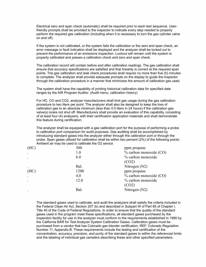
Electrical zero and span check (automatic) shall be required prior to each test sequence. User-friendly prompts shall be provided to the inspector to indicate every step needed to properly perform the required gas calibration (including when it is necessary to turn the gas cylinder valve on and off).
If the system is not calibrated, or the system fails the calibration or the zero and span check, an error message or fault indication shall be displayed and the analyzer shall be locked out to prevent the performance of an emissions inspection. Lockout will remain until the system is property calibrated and passes a calibration check and zero and span check.
The calibration record will contain before and after calibration readings. The gas calibration shall ensure that accuracy specifications are satisfied and that linearity is correct at the required span points. The gas calibration and leak check procedures shall require no more than five (5) minutes to complete. The analyzer shall provide adequate prompts on the display to guide the inspector through the calibration procedure in a manner that minimizes the amount of calibration gas used.
The system shall have the capability of printing historical calibration data for specified date ranges by the AIR Program Auditor. (Audit menu, calibration history)
For HC, CO and CO2, analyzer manufacturers shall limit gas usage during the gas calibration procedure to two liters per point. The analyzer shall also be designed to keep the loss of calibration gas to an absolute minimum (less than 0.5 liters in 24 hours) if the calibration gas valve(s) is/are not shut off. Manufacturers shall provide an evaluation of this capability, consisting of at least four (4) analyzers, with their certification application materials and shall demonstrate this feature during certification.
The analyzer shall be equipped with a gas calibration port for the purpose of performing a probe to calibration port comparison for audit purposes. Gas auditing shall be accomplished by introducing standard gases into the analyzer either through the calibration port or through the probe. Span gases utilized for calibration shall be within two percent (2%) of the following points: Ambient air may be used to calibrate the O2 sensor.
(HC) 300 ppm propane. 1.0 % carbon monoxide (CO). 6.0 % carbon monoxide
(CO2). Bal. Nitrogen (N2)(HC) 1200 ppm propane. 4.0 % carbon monoxide (CO). 12.0 % carbon monoxide
(CO2). Bal. Nitrogen (N2)
The standard gases used to calibrate, and audit the analyzers shall satisfy the criteria included in the Federal Clean Air Act, Section 207 (b) and described in Subpart W of Part 85 of Chapter I, Title 40 of the Code of Federal Regulations. In order to ensure that the quality of the standard gases used in the program meet these specifications, all standard gases purchased by the inspection facility for use in the analyzer must conform to the requirements established in 1990 by the California BAR for Test Analyzer System Calibration Gases. Calibration gases must be purchased from a vendor that has Colorado gas blender certification, REF. Colorado Regulation Number 11, Appendix B. These requirements include the testing and certification of the concentration, accuracy, precision, and purity of the standard gases to within the referenced limits and the labeling of individual gas canisters describing these and other specified parameters.
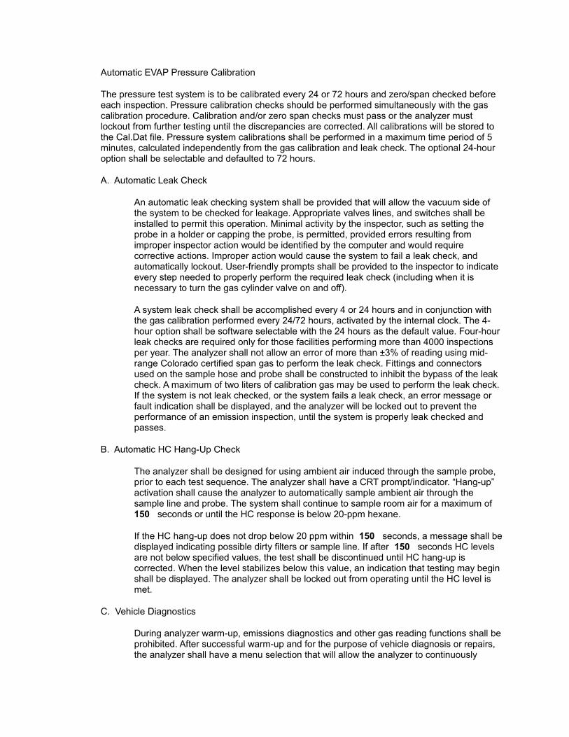
Automatic EVAP Pressure Calibration
The pressure test system is to be calibrated every 24 or 72 hours and zero/span checked before each inspection. Pressure calibration checks should be performed simultaneously with the gas calibration procedure. Calibration and/or zero span checks must pass or the analyzer must lockout from further testing until the discrepancies are corrected. All calibrations will be stored to the Cal.Dat file. Pressure system calibrations shall be performed in a maximum time period of 5 minutes, calculated independently from the gas calibration and leak check. The optional 24-hour option shall be selectable and defaulted to 72 hours.
A. Automatic Leak Check
An automatic leak checking system shall be provided that will allow the vacuum side of the system to be checked for leakage. Appropriate valves lines, and switches shall be installed to permit this operation. Minimal activity by the inspector, such as setting the probe in a holder or capping the probe, is permitted, provided errors resulting from improper inspector action would be identified by the computer and would require corrective actions. Improper action would cause the system to fail a leak check, and automatically lockout. User-friendly prompts shall be provided to the inspector to indicate every step needed to properly perform the required leak check (including when it is necessary to turn the gas cylinder valve on and off).
A system leak check shall be accomplished every 4 or 24 hours and in conjunction with the gas calibration performed every 24/72 hours, activated by the internal clock. The 4-hour option shall be software selectable with the 24 hours as the default value. Four-hour leak checks are required only for those facilities performing more than 4000 inspections per year. The analyzer shall not allow an error of more than ±3% of reading using mid-range Colorado certified span gas to perform the leak check. Fittings and connectors used on the sample hose and probe shall be constructed to inhibit the bypass of the leak check. A maximum of two liters of calibration gas may be used to perform the leak check. If the system is not leak checked, or the system fails a leak check, an error message or fault indication shall be displayed, and the analyzer will be locked out to prevent the performance of an emission inspection, until the system is properly leak checked and passes.
B. Automatic HC Hang-Up Check
The analyzer shall be designed for using ambient air induced through the sample probe, prior to each test sequence. The analyzer shall have a CRT prompt/indicator. “Hang-up” activation shall cause the analyzer to automatically sample ambient air through the sample line and probe. The system shall continue to sample room air for a maximum of 150 seconds or until the HC response is below 20-ppm hexane.
If the HC hang-up does not drop below 20 ppm within 150 seconds, a message shall be displayed indicating possible dirty filters or sample line. If after 150 seconds HC levels are not below specified values, the test shall be discontinued until HC hang-up is corrected. When the level stabilizes below this value, an indication that testing may begin shall be displayed. The analyzer shall be locked out from operating until the HC level is met.
C. Vehicle Diagnostics
During analyzer warm-up, emissions diagnostics and other gas reading functions shall be prohibited. After successful warm-up and for the purpose of vehicle diagnosis or repairs, the analyzer shall have a menu selection that will allow the analyzer to continuously

monitor the vehicle exhaust.
The automatic data collection system shall be prevented from operating anytime the analyzer is not being used in the official emissions inspection mode.
D. Dilution
The analyzer manufacturer shall document to the satisfaction of the Colorado Department of Public health and Environment that the flow rate on the analyzer shall not cause more than 10% dilution during sampling of the exhaust at normal idle (10% dilution defined as sample of 90% exhaust and 10% ambient air). Manufacturers shall utilize the procedures specified by the BAR for demonstrating this dilution criterion. The analyzer shall be equipped with a feature to identify vehicle exhaust system leaks and sample dilution. The preferred method for identifying leaks is monitoring the CO & CO2 levels in the exhaust. Other additional techniques that can demonstrate improved sensitivity to leaks may also be used.
DILUTION VALUES:
All light duty vehicles: 6%
All heavy-duty vehicles: 5%
If the CO + CO2 reading is less than the limit, the inspector shall be prompted to check the exhaust system for leaks and to make sure that the sample probe is all the way into the tailpipe. If the excessive dilution is detected after the initiation of the test sequence, the analyzer output shall display “SAMPLE DILUTION” . If dilution continues the inspector shall be required to “Abort Test” . The system shall store the “Abort Test” indication.
E. Engine Tachometer
A digital display tachometer shall be CRT displayed for the purpose of measuring engine speed. The tachometer operation shall be by two means; (1) radio frequencies “RF” type transmitter/receiver that requires no direct vehicle connection and can detect engine RPM on vehicles utilizing “DIS” systems. (2) a cable type connection capable of detecting engine RPM from all forms of current O.E.M. ignition technology. Tachometer performance shall be no less than; RPM with a 0.5 second response time and an accuracy of ±3.0% of actual RPM. During an official inspection process, the software will prompt the inspector to shut the engine off while connecting the RPM probe (only if a cable connection is being made). A software “HELP” screen will be available to assist the inspector in locating an RPM signal. This information may be supplied or reviewed by the Colorado Department of Public Health and Environment. Based on the vehicle identification information available to the inspector, the analyzer will prompt the inspector as to which vehicles require a specific type or method of connection of the tachometer pick-up. Analyzers shall be provided with all the software and hardware that is necessary to make them capable of reading engine RPM from all O.E.M. ignition technologies in use at the time of certification, Possible updates may be required to enable future ignition systems to be monitored for engine RPM.
F. Analytical Bench Accuracy
Each analyzer shall meet the following analytical accuracy requirement:Channel Range AccuracyHC ppm 0-400 ±12 ppm. 401-1000 ±30 ppm
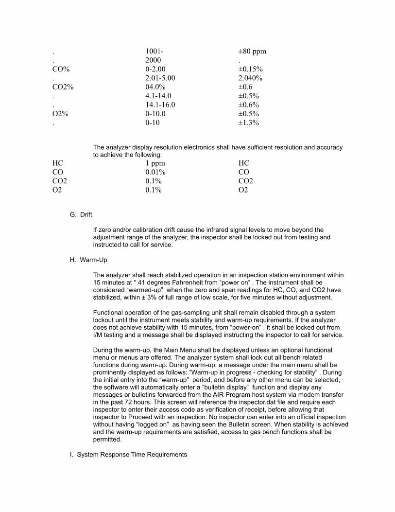
. 1001- ±80 ppm
. 2000 .CO% 0-2.00 ±0.15%. 2.01-5.00 2.040%CO2% 04.0% ±0.6. 4.1-14.0 ±0.5%. 14.1-16.0 ±0.6%O2% 0-10.0 ±0.5%. 0-10 ±1.3%
The analyzer display resolution electronics shall have sufficient resolution and accuracy to achieve the following:
HC 1 ppm HCCO 0.01% COCO2 0.1% CO2O2 0.1% O2
G. Drift
If zero and/or calibration drift cause the infrared signal levels to move beyond the adjustment range of the analyzer, the inspector shall be locked out from testing and instructed to call for service.
H. Warm-Up
The analyzer shall reach stabilized operation in an inspection station environment within 15 minutes at ° 41 degrees Fahrenheit from “power on” . The instrument shall be considered “warmed-up” when the zero and span readings for HC, CO, and CO2 have stabilized, within ± 3% of full range of low scale, for five minutes without adjustment.
Functional operation of the gas-sampling unit shall remain disabled through a system lockout until the instrument meets stability and warm-up requirements. If the analyzer does not achieve stability with 15 minutes, from “power-on” , it shall be locked out from I/M testing and a message shall be displayed instructing the inspector to call for service.
During the warm-up, the Main Menu shall be displayed unless an optional functional menu or menus are offered. The analyzer system shall lock out all bench related functions during warm-up. During warm-up, a message under the main menu shall be prominently displayed as follows: “Warm-up in progress - checking for stability” . During the initial entry into the “warm-up” period, and before any other menu can be selected, the software will automatically enter a “bulletin display” function and display any messages or bulletins forwarded from the AIR Program host system via modem transfer in the past 72 hours. This screen will reference the inspector.dat file and require each inspector to enter their access code as verification of receipt, before allowing that inspector to Proceed with an inspection. No inspector can enter into an official inspection without having “logged on” as having seen the Bulletin screen. When stability is achieved and the warm-up requirements are satisfied, access to gas bench functions shall be permitted.
I. System Response Time Requirements
The response time from the probe to the display shall not exceed eight (8) seconds to 90% of a step change in input, nor will it exceed 12 seconds to 95% of a step change in input. For the O2 sensor, the response time shall be no more than fifteen (15) seconds to 90% of full scale.
J. Optical Correction Factors
The hexane/propane equivalency factor (PEF) shall be limited to values between 0.49 and 0.52. If an optical bench is used that can demonstrate accuracy of propane/hexane identification within specification, using a range greater or lesser than indicated, it will be considered. Factor confirmation shall be made on each analyzer assembly by measuring both N-hexane and propane on assembly line quality checks. The PEF shall be permanently stored in non-volatile memory. The PEF shall be displayed on the monitor on request by inquiry through the menu system. The optical bench shall he marked with a permanent “stamped” type tag identifying its PEF.
The signal strength from the source to the detector for all channels shall be monitored such that when the signal degrades beyond the adjustment range of the analyzer, the analyzer shall be locked out from operation, i.e. fail calibration.
K. Interference Effects
The effect of extraneous gas interference on the HC, CO, and CO2 analyzers shall not exceed ±10 ppm HC, ± 0.05% CO, and ±0.20% for CO2.
The instrument design shall insure that readings do not vary as a result of electromagnetic radiation and induction devices normally found in the inspection environment (including high energy vehicle ignition systems, RF transmission radiation sources, and building electrical systems). In addition, the manufacturer shall ensure that the analyzer processor and memory components are sufficiently protected to prevent the loss of programs and test records.
2.12 Gas Calibration File
At the conclusion of each gas calibration the required data shall be placed in the CAL.DAT file.
2.13 Microcomputer Specifications
A. A standard microcomputer must be included in the analyzer and is to be used to control all analyzer functions. Each vendor is to develop DOS executable programs for each required function. These programs shall:
1. control each of the analyzer functions and time of function;
2. examine and obtain values from all of the analyzer sensors;
3. read and write information to diskette in standard DOS format; and
4. copy the analyzer, inspection station identification information from the hard disk onto each new floppy diskette when formatted.
The Colorado Department of Public Health and Environment reserves the right to add additional programs and functional performance requirements, up to the technical limits of the hardware, to improve the I/M program.
Sufficient flexibility shall be provided in the design of the microcomputer system to allow expansion of the analyzer to include, but not be limited to, the following additional capabilities:
1. connect and recover data from vehicle on-board diagnostic systems (OBD) meeting SAE specifications when they become available;
2. monitor vehicle recall data; identify, record and process data as required when an official EPA/SAE format is identified.
3. accommodate additional input channels in both analog and digital form. Two free slots, 16 bit capability.
The manufacturer may offer additional features that utilize the microcomputer as a stand-alone personal computer by providing optional software to perform various non-l/M functions. Such offerings must not interfere with the inspection requirements, or in any manner affect or allow the inspector to tamper with the inspection-related computer programming or data files.
The analyzer shall be equipped with an internal clock that operates independently from the power source and will provide accurate and automatic date and time information for the following functions:
a. each test performed;
b. automatic gas calibration and pressure test check (72 hours); (24 hour) optional
c. automatic leak check (4 or 24 hours and every 24/72 hours for automatic gas calibration), and leak check combination.
d. audit sequence:
All equipment and software submitted for Colorado certification must be the full and current configuration proposed for sale. Partial, dated, or incomplete models are not acceptable.
Acceptance of the microcomputer portion of the Colorado 94 Analyzer system will be dependent upon the satisfactory performance of the full-proposed configuration meeting all the requirements of this specification.
The proposed hardware configuration must be fully supported by all software and/or operating systems listed in the acceptance requirements or elsewhere in these specifications. Performance tests to prove compatibility will be conducted. The vendor will bear all shipping and equipment preparation charges for the certification testing.
2.14 Standard Hardware: Minimum Required Configuration
1. Operating System
DOS Version 6.2 or most current
2. Processor
The microprocessor must be fully compatible with the Intel 80486 microprocessor. Upgradable to Pentium technology.
3. RAM Memory
The system must contain at least 2 MB of user available RAM. (expandable to 16 MB)
4. Power Up Sequence
The system must include a power up sequence that provides a self-diagnostic routine to check the on-line presence of critical PC components (including, at a minimum, the processor, firmware ROM, hard disk controller, keyboard, clock, modem, printers, bar code reader I/O ports, setup RAM and memory).
5. Video
The CRT display must be at least 12” in diagonal measure and operate in a VGA mode.
The software shall automatically blank the screen or use a screen saver mode, if no keyboard entry is made for 10 minutes. The display shall return when the inspector strikes any key.
6. Floppy Disk
Each unit must come with an IBM compatible floppy disk drive that will permit full usage of 2sHD 1.44 Mb 3.5” removable media. The drive must be located in a secured area accessible only to authorized AIR Program Service representatives. That secured drive must also include an approved method to limit logical access. Colorado Department of Public Health and Environment will test the system for drive security and it should not provide access to the secured floppy except through the approved security procedure. The secured floppy drive shall be designated the “A” drive.
7. Hard Disk
Each unit must come with at least 120 megabytes of hard disk storage. The vendor may use up to 40 megabytes for their programs and data provided at least a full 80 megabytes of usable storage is available for Colorado Department o1 Public Health and Environment and user information. The hard disk is to be self-parking (where applicable), shock mounted, and able to operate reliably in the inspection environment. The hard disk must also include a Colorado Department of Public Health and Environment approved method of limiting access to data and programs. The hard disk containing programs and data files shall be designated the “C” drive.
8. I/O Ports
The unit must include sufficient I/O ports of proper configuration to allow the connection of all required options and the capability to add additional I/O boards.
9. Keyboard
The Colorado 94 Analyzer keyboard must be fully interfaced with the microcomputer and have all of the necessary normal, numeric, cursor, control, shift, alternate, and function keys needed to operate a standard IBM PC compatible microcomputer, preferably 101 keys should be provided.

10. Bar Code Scanner
The bar code scanner shall be equivalent to the PDF 1000 “HV” (High Visibility) Scanner from Symbol Technologies. Performance specifications are included in Technical Specification Appendix A. The PDF 1000 “HV” is a scanner capable of reading both 1 -D and PDF-417(2-D) bar codes.
11. Hard Disk Expansion
System must include a hard disk interface that will fully support a second internal disk drive of the same type as the original type drive or a functional equivalent approved by the Colorado Department of Public Health and Environment that does not compromise tamper-resistance.
12. Additional Storage
3.5” 1.44 Mb Floppy Disk Drive IBM Optical disk drive, floptical, CD ROM reader etc., these options would be for manufacturer offered look up tables, service information or other options requiring additional storage capability.
13. Communications
Hayes compatible modem at 14,400B, M.N.P. Level 5. Error correction: Microcom networking protocol (M.N.P.) levels 1-4 and V.42 data compression: M.N.P. level 5 and V.32BIS/V.42BIS. Protocol will be provided within the operational software package. Modem communications will be necessary during the inspection process for V.I.N. verification, multiple “I” Test Control, vehicle recall etc., from the Network System Host Computer.
2.15 Required Printers
A. Diagnostic printer:
A 24 pin impact printer shall be supplied which is dedicated to the task of printing designated information on a VEHICLE DIAGNOSTIC FORM, or other repair type information. Continuous, fanfold, preprinted (ghost printed certificates) will be used. The printer shall print information on the certificate using 12 characters per inch and 80 characters per line.
B. Certificate Printer:
The certificate printer is to be a “thermal transfer” technology printer, capable of producing PDF 417, two dimensional bar code and Code 39, one-dimensional bar code. As of date, Standard Register produces a model of printer that meets or exceeds all requirements necessary to print upon the required certificate. This model is a PT650 Thermal/Thermal Transfer Printer. Specifications of the certificate printer shall be Standard Register FT650 or equivalent. With equivalency being defined as successful completion of printing, security, storing and dispensing of the required certificate. Final acceptance of alternative printers lies with written State approval.
Standard Register PT650 technical specifications are included in the Technical Specification Appendix B.
PHYSICAL SPECIFICATIONS OF CERTIFICATE :
Physical specifications of the certificate, to include print fields, physical design, materials and sizing are to be determined by the Department of Revenue.
C. Certificate Security:
The inspection certificate printer and certificate storage area shall be located in a secured area. Access to the area securing the printer and certificates shall be available only to the licensed inspector at the station. The certificate storage area shall have a redundant security system utilizing both a hardware lock and a software lock that meets Colorado Department of Public Health and Environment approval. Certificates will be prevented from being “pulled” through the printer. A form of printer locking must be utilized. The secured area containing certificates and the certificate printer, shall be designed so that the same key can be used to open any access doors that secure any optional storage media. If any of these doors are opened, a microswitch (or equivalent) shall be used which prevents the printing of certificates and records each event with time and date to an entry.dat file.
The purpose of the software lock is to restrict access to the printer with the following exceptions: loading and aligning certificates prior to printing, clearing paper misfeed or jam problems, etc., and to provide a record of the personnel performing those functions.
The area containing the certificates shall be located so that proper routing is maintained on the certificates as they are fed through the printer.
If tampering occurs, a software lockout algorithm shall be activated which aborts any existing test sequence and prevents further emission testing until an AIR Program official clears the lockout.
There shall be easy access to the vehicle diagnostic report printer so that the inspector can easily replace paper, clear paper jams and change ribbons.
2.16 Clock/Calendar
The analyzer unit shall have a real time clock/calendar which shall make available the current date and time. Date will be in month, day, year format and time will be in 24-hour format. The AIR Program system host computer shall update both time and date during each transfer of data via the system modem.
The date/time, along with the time the test started and when it ended, is to be included on the test record. The start time is when the inspector’s access code is entered and the end time is when the analyzer data is written to the test file.
If the clock/calendar fails or becomes unstable (as referenced to the program host system during modem data transfer), the analyzer unit shall be locked out from I/M testing and a message shall be displayed indicating that service is required.
Resetting of the clock, independent of the host updating, shall require controlled access.
2.17 Lockout Notification
The analyzer shall alert the inspector of any lockout situation by prominently displaying a message on the CRT. Any lockout condition will be stored to file.
2.18 Vehicle Diagnosis
The analyzer shall be capable of menu selection that will allow the analyzer to be used as an ordinary garage type emissions analyzer for general automotive repair work and diagnostics.
2.19 Software Loading
The inspector shall not have to load the microcomputer's operating or applications software to operate the analyzer. On each POWER ON of the analyzer, the analyzer shall automatically do all microcomputer component self-diagnostics, memory checking, and loading of all necessary operating software without inspector intervention. Upon satisfactory computer component check out, the applications software is to present a menu of available analyzer operations. All offered features are to be menu-driven. For each feature, a context sensitive, on-line help facility is to be provided which can be accessed preferably with a single keystroke.
3.0 DISPLAY PROMPTS AND PROGRAMMING CRITERIA REQUIREMENTS
Operational software requirements will be available from the Division upon request.
ATTACHMENT I TO THE TECHNICAL SPECIFICATION APPENDIX A
PDF 1000 SCANNER
PERFORMANCE CHARACTERISTICS
Type: Raster scanning, retro-collective
Scan Element Low mass, single mirror, resonant
Light Source: 675 nm. Laser diodePattern Size: At 9 in. (22.8 cm) from
the nose of the scanner, the pattern is 7 in. (17.8 cm) horizontally and 2.6 in. (6.6 cm) vertically
Scan Rate: 560 scans/sec. 280 Hz + 10 Hz (horizontal)
Frame Rate: 22 frames/sec. 11 Hz + 1 Hz (vertical)
Optical Resolution Can decode a 6.6 mil X-dimension symbol (PDF417); Y-dimension must be 3X
Haz Size of PDF 417: 5.9 in. (15cm) wide x 2.3 in. (5.8 cm) high (928 code words, at security level 0-8)
PHYSICAL CHARACTERISTICS
Pitch Tolerance: + 30” (“front and back” )Skew: + 15” plane parallel to
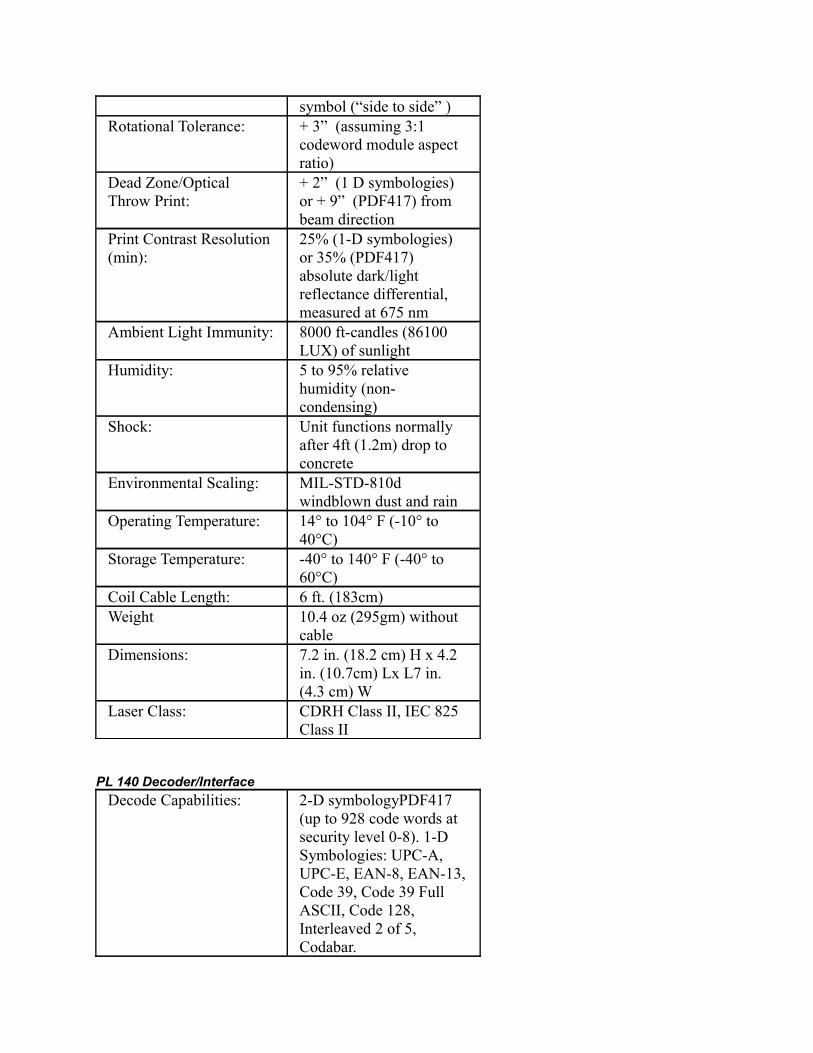
symbol (“side to side” )Rotational Tolerance: + 3” (assuming 3:1
codeword module aspect ratio)
Dead Zone/Optical Throw Print:
+ 2” (1 D symbologies) or + 9” (PDF417) from beam direction
Print Contrast Resolution (min):
25% (1-D symbologies) or 35% (PDF417) absolute dark/light reflectance differential, measured at 675 nm
Ambient Light Immunity: 8000 ft-candles (86100 LUX) of sunlight
Humidity: 5 to 95% relative humidity (non-condensing)
Shock: Unit functions normally after 4ft (1.2m) drop to concrete
Environmental Scaling: MIL-STD-810d windblown dust and rain
Operating Temperature: 14° to 104° F (-10° to 40°C)
Storage Temperature: -40° to 140° F (-40° to 60°C)
Coil Cable Length: 6 ft. (183cm)Weight 10.4 oz (295gm) without
cableDimensions: 7.2 in. (18.2 cm) H x 4.2
in. (10.7cm) Lx L7 in. (4.3 cm) W
Laser Class: CDRH Class II, IEC 825 Class II
PL 140 Decoder/Interface
Decode Capabilities: 2-D symbologyPDF417 (up to 928 code words at security level 0-8). 1-D Symbologies: UPC-A, UPC-E, EAN-8, EAN-13, Code 39, Code 39 Full ASCII, Code 128, Interleaved 2 of 5, Codabar.
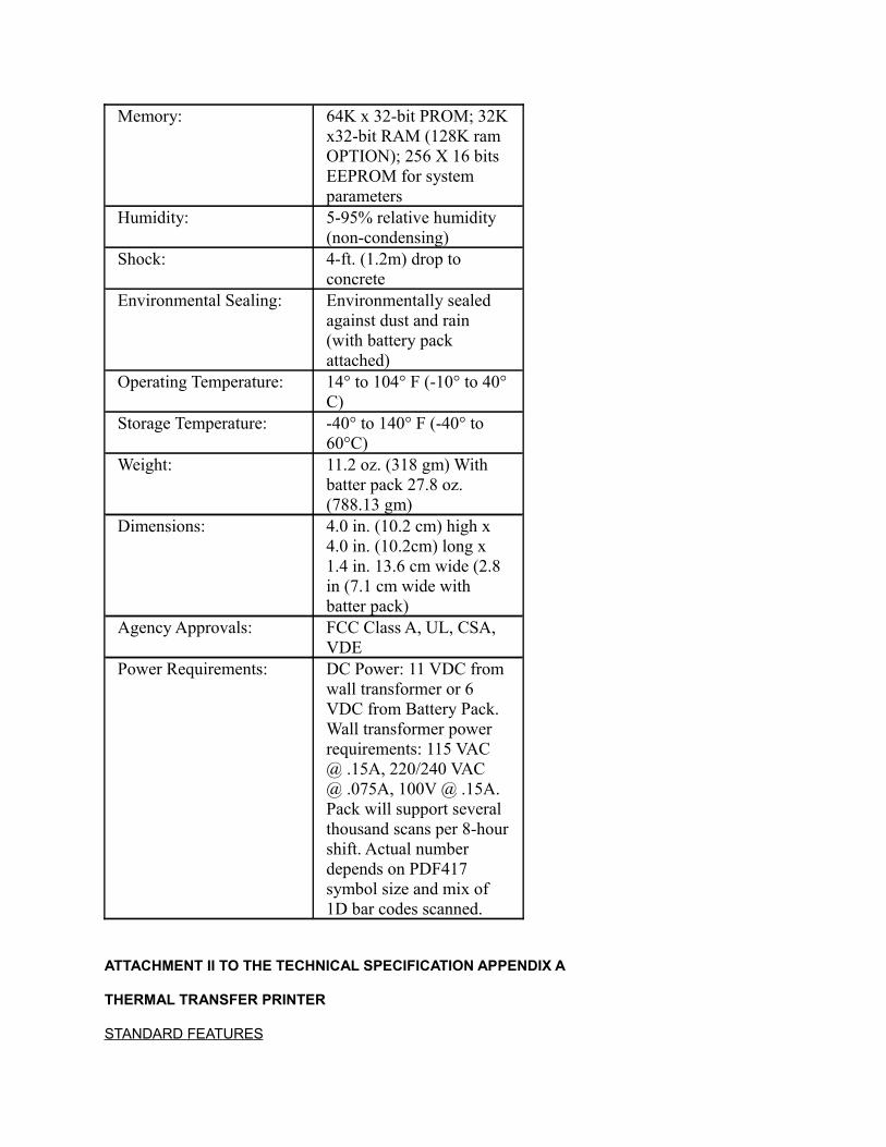
Memory: 64K x 32-bit PROM; 32K x32-bit RAM (128K ram OPTION); 256 X 16 bits EEPROM for system parameters
Humidity: 5-95% relative humidity (non-condensing)
Shock: 4-ft. (1.2m) drop to concrete
Environmental Sealing: Environmentally sealed against dust and rain (with battery pack attached)
Operating Temperature: 14° to 104° F (-10° to 40° C)
Storage Temperature: -40° to 140° F (-40° to 60°C)
Weight: 11.2 oz. (318 gm) With batter pack 27.8 oz. (788.13 gm)
Dimensions: 4.0 in. (10.2 cm) high x 4.0 in. (10.2cm) long x 1.4 in. 13.6 cm wide (2.8 in (7.1 cm wide with batter pack)
Agency Approvals: FCC Class A, UL, CSA, VDE
Power Requirements: DC Power: 11 VDC from wall transformer or 6 VDC from Battery Pack. Wall transformer power requirements: 115 VAC @ .15A, 220/240 VAC @ .075A, 100V @ .15A. Pack will support several thousand scans per 8-hour shift. Actual number depends on PDF417 symbol size and mix of 1D bar codes scanned.
ATTACHMENT II TO THE TECHNICAL SPECIFICATION APPENDIX A
THERMAL TRANSFER PRINTER
STANDARD FEATURES
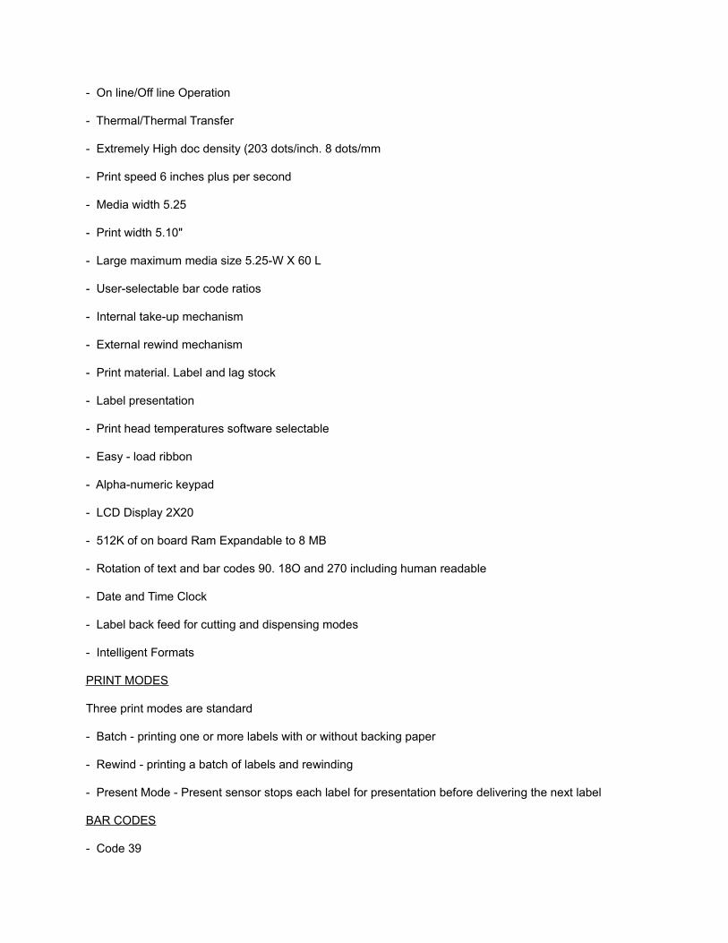
- On line/Off line Operation
- Thermal/Thermal Transfer
- Extremely High doc density (203 dots/inch. 8 dots/mm
- Print speed 6 inches plus per second
- Media width 5.25
- Print width 5.10"
- Large maximum media size 5.25-W X 60 L
- User-selectable bar code ratios
- Internal take-up mechanism
- External rewind mechanism
- Print material. Label and lag stock
- Label presentation
- Print head temperatures software selectable
- Easy - load ribbon
- Alpha-numeric keypad
- LCD Display 2X20
- 512K of on board Ram Expandable to 8 MB
- Rotation of text and bar codes 90. 18O and 270 including human readable
- Date and Time Clock
- Label back feed for cutting and dispensing modes
- Intelligent Formats
PRINT MODES
Three print modes are standard
- Batch - printing one or more labels with or without backing paper
- Rewind - printing a batch of labels and rewinding
- Present Mode - Present sensor stops each label for presentation before delivering the next label
BAR CODES
- Code 39

- Interleave 2 of 5
- Codabar
- Code 128 A. B, and C subsets
- UPC-A and E
- UPC addendum codes 2 and 5 digit
- UPC random weight
- EAN 13 and 8
- Code93
- Universal shipping contained symbology (with fixed or random weight codes) code 39 variations to produce all industry standards such as LOGMARS. HIBCC. and AIAG
- Bar code modulus (“x” dimensions): 5 mil to 10 mil in picket or ladder orientation
- Bar codes printed with or without human readable interpretation
FONT STYLES
- 12 Scalable Fonts On-Board
- Downloadable font support
- Downloadable graphics
- Inverse text support
- International language support different language character sets
- Inverse image support
MEDIA SPECIFICATIONS
- Media type: Roll-fed, die-cut continuous or fan-fold labels, tags or tickets
- Material: plain paper thermal transfer or thermal sensitive paper
- Sensing: adjustable transmissive sensor for die cut labels or tags.
- Reflective sensor for use with black marks
- Programmable top of form
- Maximum media width: 5.25
- Minimum media width: 0. 50”
- Maximum media length: 60.0”
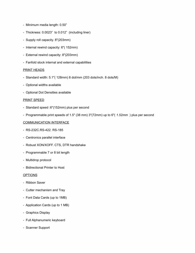
- Minimum media length: 0.50”
- Thickness: 0.0023” to 0.012” (including liner)
- Supply roll capacity. 8"(203mm)
- Internal rewind capacity: 6"( 152mm)
- External rewind capacity: 8"(203mm)
- Fanfold stock internal and external capabilities
PRINT HEADS
- Standard width: 5.1"( 128mm) 8 dot/mm (203 dots/inch. 8 dots/M)
- Optional widths available
- Optional Dot Densities available
PRINT SPEED
- Standard speed :6"(152mm) plus per second
- Programmable print speeds of 1.5" (38 mm) 3"(72mm) up to 6"( 1.52mm ) plus per second
COMMUNICATION INTERFACE
- RS-232C.RS-422. RS-185
- Centronics parallel interface
- Robust XON/XOFF. CTS, DTR handshake
- Programmable 7 or 8 bit length
- Multidrop protocol
- Bidirectional Printer to Host
OPTIONS
- Ribbon Saver
- Cutter mechanism and Tray
- Font Data Cards (up to 1MB)
- Application Cards (up to 1 MB)
- Graphics Display
- Full Alphanumeric keyboard
- Scanner Support
- User Data Support Cards (up to 1MB)
- Twinax & Coax IBM Inter faces
MECHANICAL
- Height: 10"(254mm)
- Width: 11"(279mm)
- Depth: 16"(406mm)
- Weight: 35 lbs. (16 kg)
ELECTRICAL
- Power 110/220 VAC + or - 10% 5O/60 Hz at 2 amps maximum 100 VAC on request
- Built to ULCSA and TUV-GS safety standards and VDE Class B and FCC Class A emissions standard
ENVIRONMENTAL
- Operating Temperature: 32° F to 100° F (0° to40° C)
- Storage Temperature:-40F to 140° F (-40° Cto60° C)
- Humidity. 10% to 90% non-condensing
- Ventilation: Free air movement
- Dust: non-conducting, non-corrosive
ATTACHMENT III TO TECHNICAL SPECIFICATION, APPENDIX A
COLORADO AUTOMOBILE DEALERS TRANSIENT MODE TEST ANALYZER SYSTEM
TRANSIENT MODE TEST SYSTEM TECHNICAL AND HARDWARE SPECIFICATIONS
COLORADO AUTOMOBILE DEALERS TRANSIENT MODE TEST ANALYZER SYSTEM
(IG 240)
TEST SYSTEM TECHNICAL AND HARDWARE SPECIFICATIONS
JANUARY 27, 1997
INTRODUCTION
This document contains technical specifications for a Colorado Automobile Dealers Transient Mode IG 240 Test Analyzer System. The technical specifications of the system are based upon the Environmental Protection Agency High-Tech I/M Test Procedures dated June 1996, Emission Standards, Quality Control Requirements and Equipment Specifications: IM 240 and Functional Evaporative System Tests technical guidance document EPA-AA-RSPD-IM-96-1, dated June 1996. The technical concept allows for the use of technologies of similar application but of a lower monetary cost. Utilizing lower cost technologies and identifying equipment required to directly address the requirements of the Colorado Enhanced Inspection
Program, the system can perform transient loaded mode testing in the Motor Vehicle Dealer Test Facility pursuant to Section 42-4-309 (3)(B), C.R.S.
In review of these specifications, sections may indicate that they are not applicable . Not applicable indicates that the content of that section does not apply to the Colorado system. Not applicable sections remain within this specification, as they provide insight into the systems total capability with hardware often sharing functionality with another test process. This specification is intended to act as a guide to hardware requirements, provides insight into the application of the hardware, and provides testing and quality control requirements and to provide a general overview of the operating system software requirements. Numerical references to methodology or procedures refer to sections so indicated within the code of federal regulations (40 CFR 85.2 July 1996) (EPA).
This attachment III establishes equipment specifications, test procedures and test standards. In order to qualify for the Colorado Automobile Dealers Transient Mode IG 240 Test Analyzer System must comply with the equipment specifications, must be capable of performing all applicable elements of the test procedure, and must be capable of measuring, calculating, displaying and recording each test standard.
Table of Contents
Introduction
Test Standards
(a) Transient Mode Emissions Limits
(b) Transient Test Score Calculations
(c) Evaporative System Pressure Test Standards
Transient Mode and Evaporative System Purge Test Procedures
(a) General Requirements
(b) Pre-inspection and Preparation
(c) Equipment Positioning and Settings
(d) Vehicle Conditioning
(e) Vehicle Emission Test Sequence
(f) Emission Measurements
Evaporative System Pressure Test Procedures
(a) General Requirements
(b) Pre-inspection and Preparation
(c) Canister-End Pressure Test - NOT APPLICABLE
(d) Fuel Inlet Pressure Test -- NOT APPLICABLE
(e) Fuel Cap Leak Test - Pressure Decay Method
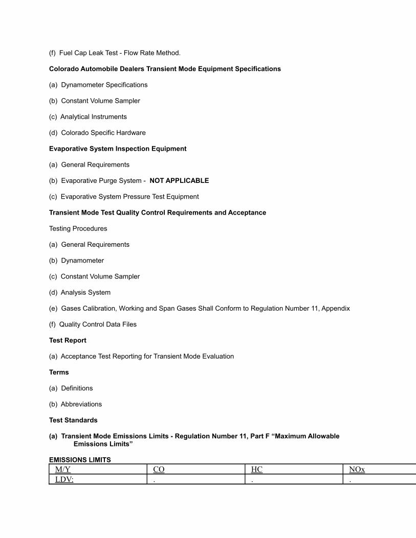
(f) Fuel Cap Leak Test - Flow Rate Method.
Colorado Automobile Dealers Transient Mode Equipment Specifications
(a) Dynamometer Specifications
(b) Constant Volume Sampler
(c) Analytical Instruments
(d) Colorado Specific Hardware
Evaporative System Inspection Equipment
(a) General Requirements
(b) Evaporative Purge System - NOT APPLICABLE
(c) Evaporative System Pressure Test Equipment
Transient Mode Test Quality Control Requirements and Acceptance
Testing Procedures
(a) General Requirements
(b) Dynamometer
(c) Constant Volume Sampler
(d) Analysis System
(e) Gases Calibration, Working and Span Gases Shall Conform to Regulation Number 11, Appendix
(f) Quality Control Data Files
Test Report
(a) Acceptance Test Reporting for Transient Mode Evaluation
Terms
(a) Definitions
(b) Abbreviations
Test Standards
(a) Transient Mode Emissions Limits - Regulation Number 11, Part F “Maximum Allowable Emissions Limits”
EMISSIONS LIMITS
M/Y CO HC NOxLDV: . . .
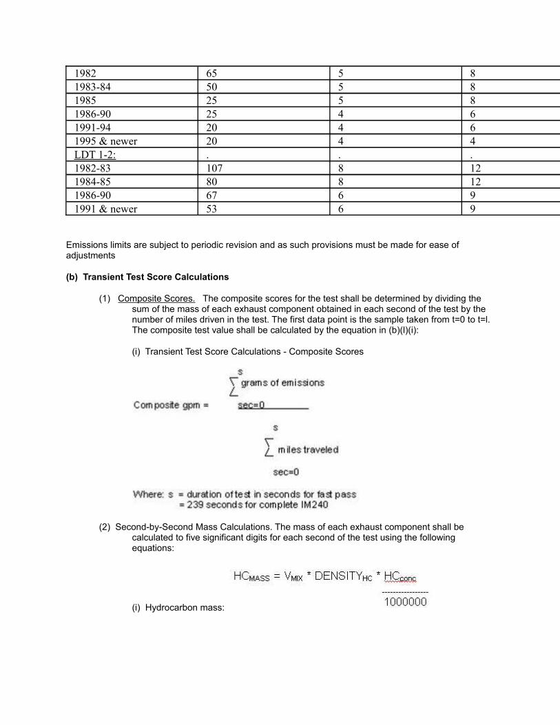
1982 65 5 81983-84 50 5 81985 25 5 81986-90 25 4 61991-94 20 4 61995 & newer 20 4 4LDT 1-2: . . .1982-83 107 8 121984-85 80 8 121986-90 67 6 91991 & newer 53 6 9
Emissions limits are subject to periodic revision and as such provisions must be made for ease of adjustments
(b) Transient Test Score Calculations
(1) Composite Scores. The composite scores for the test shall be determined by dividing the sum of the mass of each exhaust component obtained in each second of the test by the number of miles driven in the test. The first data point is the sample taken from t=0 to t=l. The composite test value shall be calculated by the equation in (b)(l)(i):
(i) Transient Test Score Calculations - Composite Scores
(2) Second-by-Second Mass Calculations. The mass of each exhaust component shall be calculated to five significant digits for each second of the test using the following equations:
(i) Hydrocarbon mass:
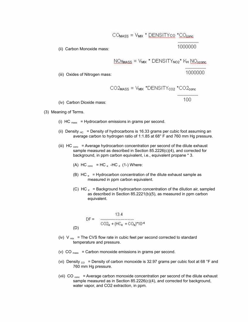
(ii) Carbon Monoxide mass:
(iii) Oxides of Nitrogen mass:
(iv) Carbon Dioxide mass:
(3) Meaning of Terms.
(i) HC mass = Hydrocarbon emissions in grams per second.
(ii) Density HC = Density of hydrocarbons is 16.33 grams per cubic foot assuming an average carbon to hydrogen ratio of 1:1.85 at 68° F and 760 mm Hg pressure.
(iii) HC conc = Average hydrocarbon concentration per second of the dilute exhaust sample measured as described in Section 85.2226(c)(4), and corrected for background, in ppm carbon equivalent, i.e., equivalent propane * 3.
(A) HC conc = HC e -HC d (1-) Where:
(B) HC e = Hydrocarbon concentration of the dilute exhaust sample as measured in ppm carbon equivalent.
(C) HC d = Background hydrocarbon concentration of the dilution air, sampled as described in Section 85.2221(b)(5), as measured in ppm carbon equivalent.
(D)
(iv) V mix = The CVS flow rate in cubic feet per second corrected to standard temperature and pressure.
(v) CO mass = Carbon monoxide emissions in grams per second.
(vi) Density CO = Density of carbon monoxide is 32.97 grams per cubic foot at 68 °F and 760 mm Hg pressure.
(vii) CO conc = Average carbon monoxide concentration per second of the dilute exhaust sample measured as in Section 85.2226(c)(4), and corrected for background, water vapor, and CO2 extraction, in ppm.
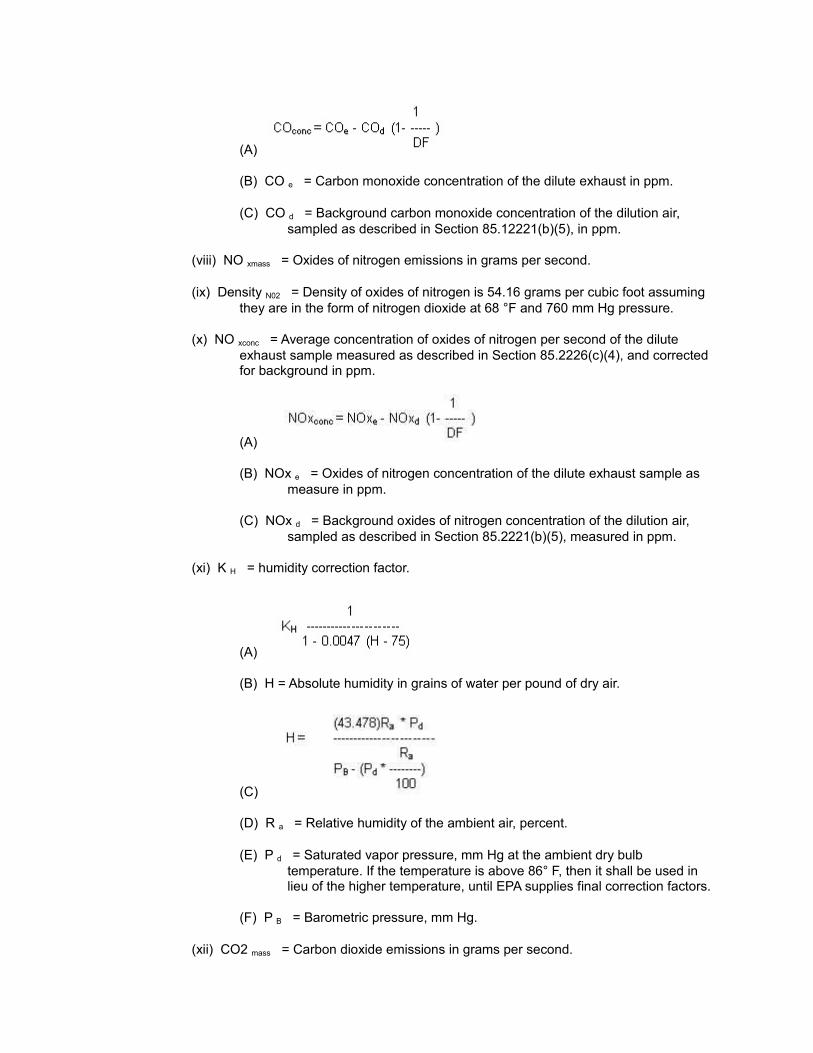
(A)
(B) CO e = Carbon monoxide concentration of the dilute exhaust in ppm.
(C) CO d = Background carbon monoxide concentration of the dilution air, sampled as described in Section 85.12221(b)(5), in ppm.
(viii) NO xmass = Oxides of nitrogen emissions in grams per second.
(ix) Density N02 = Density of oxides of nitrogen is 54.16 grams per cubic foot assuming they are in the form of nitrogen dioxide at 68 °F and 760 mm Hg pressure.
(x) NO xconc = Average concentration of oxides of nitrogen per second of the dilute exhaust sample measured as described in Section 85.2226(c)(4), and corrected for background in ppm.
(A)
(B) NOx e = Oxides of nitrogen concentration of the dilute exhaust sample as measure in ppm.
(C) NOx d = Background oxides of nitrogen concentration of the dilution air, sampled as described in Section 85.2221(b)(5), measured in ppm.
(xi) K H = humidity correction factor.
(A)
(B) H = Absolute humidity in grains of water per pound of dry air.
(C)
(D) R a = Relative humidity of the ambient air, percent.
(E) P d = Saturated vapor pressure, mm Hg at the ambient dry bulb temperature. If the temperature is above 86° F, then it shall be used in lieu of the higher temperature, until EPA supplies final correction factors.
(F) P B = Barometric pressure, mm Hg.
(xii) CO2 mass = Carbon dioxide emissions in grams per second.
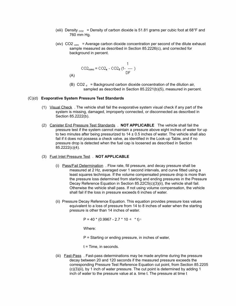
(xiii) Density CO2 = Density of carbon dioxide is 51.81 grams per cubic foot at 68°F and 760 mm Hg.
(xiv) CO2 conc = Average carbon dioxide concentration per second of the dilute exhaust sample measured as described in Section 85.2226(c), and corrected for background in percent.
(A)
(B) CO2 d = Background carbon dioxide concentration of the dilution air, sampled as described in Section 85.2221(b)(5), measured in percent.
(C)(d) Evaporative System Pressure Test Standards
(1) Visual Check . The vehicle shall fail the evaporative system visual check if any part of the system is missing, damaged, improperly connected, or disconnected as described in Section 85.2222(b).
(2) Canister End Pressure Test Standards . NOT APPLICABLE The vehicle shall fail the pressure test if the system cannot maintain a pressure above eight inches of water for up to two minutes after being pressurized to 14 ± 0.5 inches of water. The vehicle shall also fail if it does not possess a check valve, as identified in the Look-up Table, and if no pressure drop is detected when the fuel cap is loosened as described in Section 85.2222(c)(4).
(3) Fuel Inlet Pressure Test . NOT APPLICABLE
(i) Pass/Fail Determination . Flow rate, fill pressure, and decay pressure shall be measured at 2 Hz, averaged over 1 second intervals, and curve fitted using a least squares technique. If the volume compensated pressure drop is more than the pressure loss determined from starting and ending pressures in the Pressure Decay Reference Equation in Section 85.22C5(c)(3)(ii), the vehicle shall fail. Otherwise the vehicle shall pass. If not using volume compensation, the vehicle shall fail if the loss in pressure exceeds 6 inches of water.
(ii) Pressure Decay Reference Equation. This equation provides pressure loss values equivalent to a loss of pressure from 14 to 8 inches of water when the starting pressure is other than 14 inches of water.
P = 40 * (0.9967 - 2.7 * 10 -6 * t) t
Where:
P = Starting or ending pressure, in inches of water,
t = Time, in seconds.
(iii) Fast-Pass . Fast-pass determinations may be made anytime during the pressure decay between 20 and 120 seconds if the measured pressure exceeds the corresponding Pressure Test Reference Equation cut point, from Section 85.2205 (c)(3)(ii), by 1 inch of water pressure. The cut point is determined by adding 1 inch of water to the pressure value at a. time t. The pressure at time t
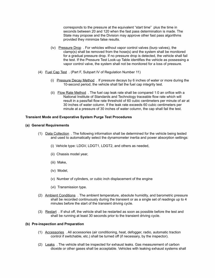
corresponds to the pressure at the equivalent “start time” plus the time in seconds between 20 and 120 when the fast pass determination is made. The State may propose and the Division may approve other fast pass algorithms provided they minimize false results.
(iv) Pressure Drop . For vehicles without vapor control valves (burp valves), the clamp(s) shall be removed from the hose(s) and the system shall be monitored for a gradual pressure drop. If no pressure drop is detected, the vehicle shall fail the test. If the Pressure Test Look-up Table identifies the vehicle as possessing a vapor control valve, the system shall not be monitored for a loss of pressure.
(4) Fuel Cap Test . (Part F, Subpart IV of Regulation Number 11)
(i) Pressure Decay Method . If pressure decays by 6 inches of water or more during the 10-second period, the vehicle shall fail the fuel cap integrity test.
(ii) Flow Rate Method . The fuel cap leak rate shall be compared 1:0 an orifice with a National Institute of Standards and Technology traceable flow rate which will result in a pass/fail flow rate threshold of 60 cubic centimeters per minute of air at 30 inches of water column. If the leak rate exceeds 60 cubic centimeters per minute at a pressure of 30 inches of water column, the cap shall fail the test.
Transient Mode and Evaporative System Purge Test Procedures
(a) General Requirements
(1) Data Collection . The following information shall be determined for the vehicle being tested and used to automatically select the dynamometer inertia and power absorption settings:
(i) Vehicle type: LDGV, LDGT1, LDGT2, and others as needed,
(ii) Chassis model year,
(iii) Make,
(iv) Model,
(v) Number of cylinders, or cubic inch displacement of the engine
(vi) Transmission type.
(2) Ambient Conditions . The ambient temperature, absolute humidity, and barometric pressure shall be recorded continuously during the transient or as a single set of readings up to 4 minutes before the start of the transient driving cycle.
(3) Restart . If shut off, the vehicle shall be restarted as soon as possible before the test and shall be running at least 30 seconds prior to the transient driving cycle.
(b) Pre-inspection and Preparation
(1) Accessories . All accessories (air conditioning, heat, defogger, radio, automatic traction control if switchable, etc.) shall be turned off (if necessary, by the inspector).
(2) Leaks . The vehicle shall be inspected for exhaust leaks. Gas measurement of carbon dioxide or other gases shall be acceptable. Vehicles with leaking exhaust systems shall
be rejected from testing.
(3) Operating Temperature . The vehicle temperature gauge, if equipped and operating, shall be checked to assess temperature. If the temperature gauge indicates that the engine is not at normal operating temperature, the vehicle shall be inspected and shall get a second-chance emission test if it fails the initial test for any criteria exhaust component. Vehicles in overheated condition shall be rejected from testing.
(4) Tire Condition . Vehicles shall be rejected from testing if the tire cords, bubbles, cuts, or other damage are visible. Vehicles shall be rejected that have space-saver spare tires on the drive axle. Vehicles may be rejected that do not have reasonably sized tires. Vehicle tires shall be visually checked for adequate pressure level. Drive wheel tires that appear low shall be inflated to approximately 30 psi, or to tire sidewall pressure, or manufacturer's recommendation.
(5) Ambient Background . Background concentrations of hydrocarbons, carbon monoxide, oxides of nitrogen, and carbon dioxide (HC, CO, NOx, and CO2, respectively) shall be sampled as specified in Section 85.2226(b)(2)(iv) to determine background concentration of constant volume sampler dilution air. The sample shall be taken for a minimum of 15 seconds within 120 seconds of the start of the transient driving cycle, using the same analyzers used to measure tailpipe emissions except as provided in Section 85.2221(f)(3). Average readings over the 15 seconds for each gas shall be recorded in the test record. Testing shall be prevented until the average ambient background levels are less than 20 ppm HC, 30 ppm CO, and 2 ppm NOx, or outside ambient air levels (not influenced by station exhaust), which ever are greater.
(6) Sample System Purge. While a system is in operation, the CVS shall continuously purge the CVS hose between tests, and the sample system shall be continuously purged when not taking measurements.
(7) Negative Values. Negative gram per second readings shall be integrated as zero and recorded as such.
(c) Equipment Positioning and Settings
(1) Purge Equipment . NOT APPLICABLE If an evaporative system purge test is to be performed:
(i) The evaporative canister shall be checked unless the canister is inaccessible. A missing or obviously damaged canister shall result in failure of the visual evaporative system check.
(ii) The evaporative system shall be visually inspected for the appearance of proper hose routing and connection of hoses, unless the canister is inaccessible. If any evaporative system hose is disconnected, then the vehicle shall fail the visual evaporative system check. All hoses disconnected for the test shall be reconnected after a purge flow test is performed.
(iii) The purge flow measurement equipment shall be connected in series between the evaporative canister and the engine, preferably on the canister end of the hose. For vehicles equipped with a service port for evaporative functional testing, the measurement equipment shall be connected to the port.
(2) Roll Rotation . The vehicle shall be maneuvered onto the dynamometer with the drive wheels positioned on the dynamometer rolls. Prior to test initiation, the rolls shall be
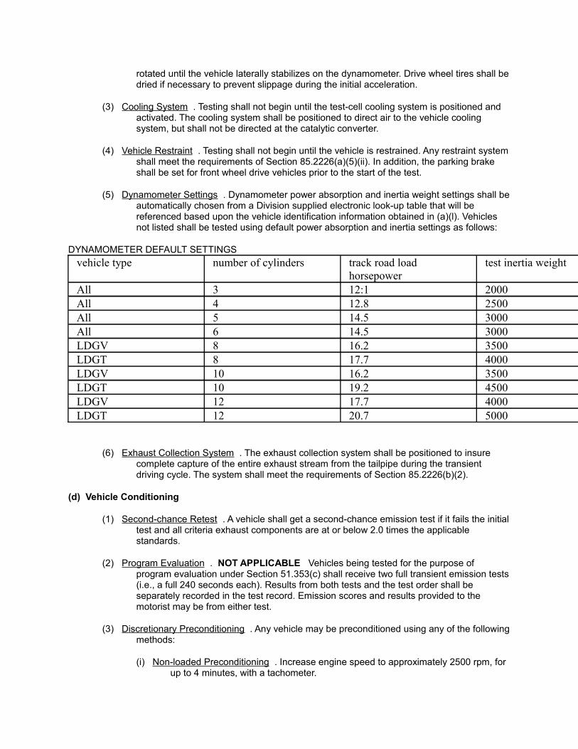
rotated until the vehicle laterally stabilizes on the dynamometer. Drive wheel tires shall be dried if necessary to prevent slippage during the initial acceleration.
(3) Cooling System . Testing shall not begin until the test-cell cooling system is positioned and activated. The cooling system shall be positioned to direct air to the vehicle cooling system, but shall not be directed at the catalytic converter.
(4) Vehicle Restraint . Testing shall not begin until the vehicle is restrained. Any restraint system shall meet the requirements of Section 85.2226(a)(5)(ii). In addition, the parking brake shall be set for front wheel drive vehicles prior to the start of the test.
(5) Dynamometer Settings . Dynamometer power absorption and inertia weight settings shall be automatically chosen from a Division supplied electronic look-up table that will be referenced based upon the vehicle identification information obtained in (a)(l). Vehicles not listed shall be tested using default power absorption and inertia settings as follows:
DYNAMOMETER DEFAULT SETTINGS
vehicle type number of cylinders track road load horsepower
test inertia weight
All 3 12:1 2000All 4 12.8 2500All 5 14.5 3000All 6 14.5 3000LDGV 8 16.2 3500LDGT 8 17.7 4000LDGV 10 16.2 3500LDGT 10 19.2 4500LDGV 12 17.7 4000LDGT 12 20.7 5000
(6) Exhaust Collection System . The exhaust collection system shall be positioned to insure complete capture of the entire exhaust stream from the tailpipe during the transient driving cycle. The system shall meet the requirements of Section 85.2226(b)(2).
(d) Vehicle Conditioning
(1) Second-chance Retest . A vehicle shall get a second-chance emission test if it fails the initial test and all criteria exhaust components are at or below 2.0 times the applicable standards.
(2) Program Evaluation . NOT APPLICABLE Vehicles being tested for the purpose of program evaluation under Section 51.353(c) shall receive two full transient emission tests (i.e., a full 240 seconds each). Results from both tests and the test order shall be separately recorded in the test record. Emission scores and results provided to the motorist may be from either test.
(3) Discretionary Preconditioning . Any vehicle may be preconditioned using any of the following methods:
(i) Non-loaded Preconditioning . Increase engine speed to approximately 2500 rpm, for up to 4 minutes, with a tachometer.
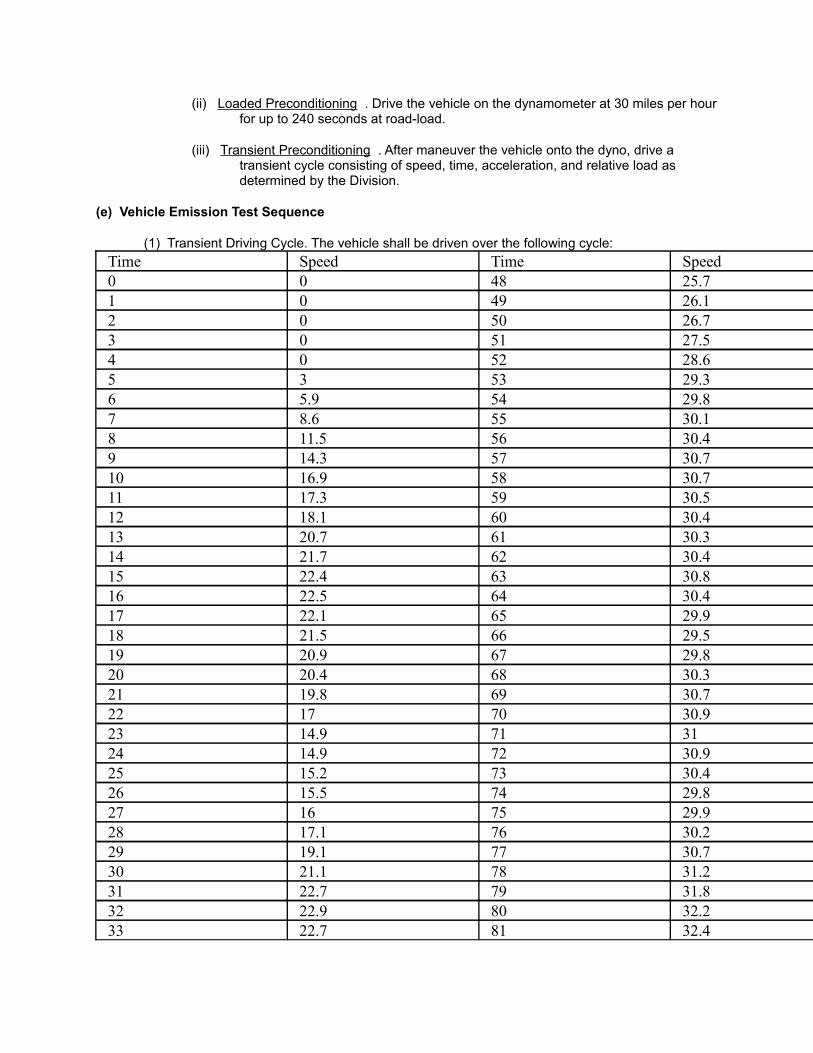
(ii) Loaded Preconditioning . Drive the vehicle on the dynamometer at 30 miles per hour for up to 240 seconds at road-load.
(iii) Transient Preconditioning . After maneuver the vehicle onto the dyno, drive a transient cycle consisting of speed, time, acceleration, and relative load as determined by the Division.
(e) Vehicle Emission Test Sequence
(1) Transient Driving Cycle. The vehicle shall be driven over the following cycle:
Time Speed Time Speed0 0 48 25.71 0 49 26.12 0 50 26.73 0 51 27.54 0 52 28.65 3 53 29.36 5.9 54 29.87 8.6 55 30.18 11.5 56 30.49 14.3 57 30.710 16.9 58 30.711 17.3 59 30.512 18.1 60 30.413 20.7 61 30.314 21.7 62 30.415 22.4 63 30.816 22.5 64 30.417 22.1 65 29.918 21.5 66 29.519 20.9 67 29.820 20.4 68 30.321 19.8 69 30.722 17 70 30.923 14.9 71 3124 14.9 72 30.925 15.2 73 30.426 15.5 74 29.827 16 75 29.928 17.1 76 30.229 19.1 77 30.730 21.1 78 31.231 22.7 79 31.832 22.9 80 32.233 22.7 81 32.4
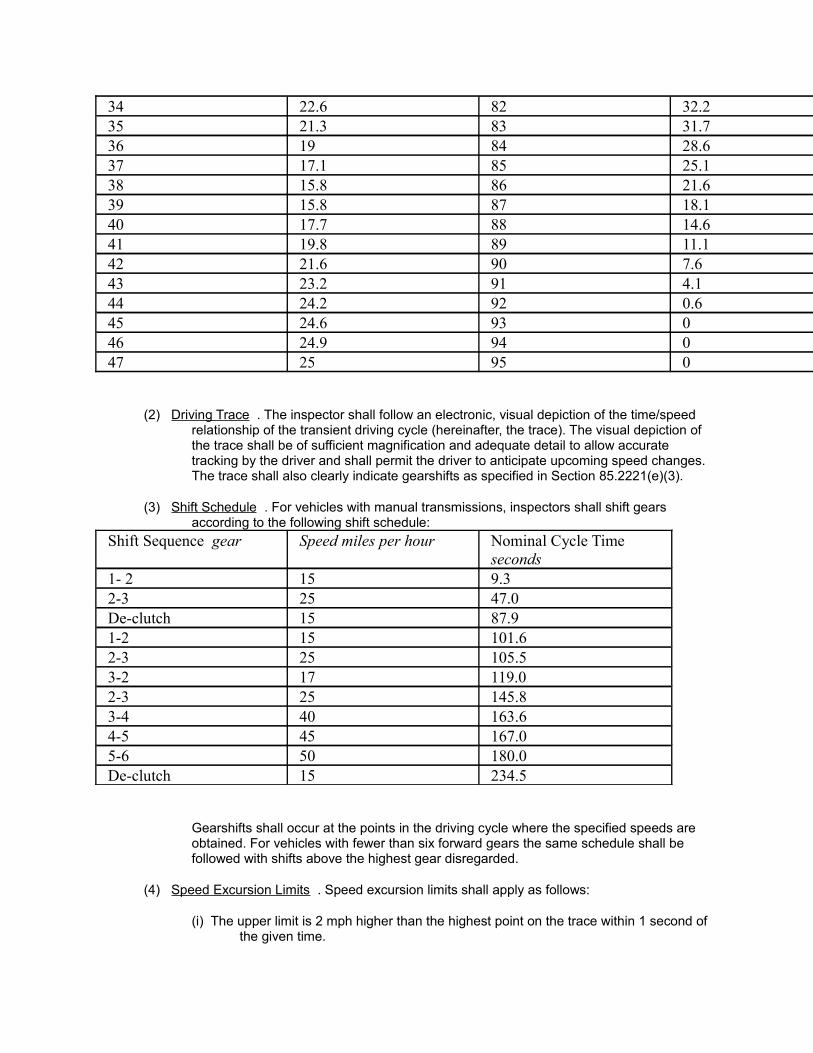
34 22.6 82 32.235 21.3 83 31.736 19 84 28.637 17.1 85 25.138 15.8 86 21.639 15.8 87 18.140 17.7 88 14.641 19.8 89 11.142 21.6 90 7.643 23.2 91 4.144 24.2 92 0.645 24.6 93 046 24.9 94 047 25 95 0
(2) Driving Trace . The inspector shall follow an electronic, visual depiction of the time/speed relationship of the transient driving cycle (hereinafter, the trace). The visual depiction of the trace shall be of sufficient magnification and adequate detail to allow accurate tracking by the driver and shall permit the driver to anticipate upcoming speed changes. The trace shall also clearly indicate gearshifts as specified in Section 85.2221(e)(3).
(3) Shift Schedule . For vehicles with manual transmissions, inspectors shall shift gears according to the following shift schedule:
Shift Sequence gear Speed miles per hour Nominal Cycle Time seconds
1- 2 15 9.32-3 25 47.0De-clutch 15 87.91-2 15 101.62-3 25 105.53-2 17 119.02-3 25 145.83-4 40 163.64-5 45 167.05-6 50 180.0De-clutch 15 234.5
Gearshifts shall occur at the points in the driving cycle where the specified speeds are obtained. For vehicles with fewer than six forward gears the same schedule shall be followed with shifts above the highest gear disregarded.
(4) Speed Excursion Limits . Speed excursion limits shall apply as follows:
(i) The upper limit is 2 mph higher than the highest point on the trace within 1 second of the given time.

(ii) The lower limit is 2 mph lower than the lowest point on the trace within 1 second of the given time.
(iii) Speed variations greater than the tolerances (such as may occur luring gear changes) are acceptable provided they occur for no more than 2 seconds on any occasion.
(iv) Speeds lower than those prescribed during accelerations are acceptable provided the vehicle is operated at maximum available power during such accelerations until the vehicle speed is within the excursion limits.
(v) Exceedances of the limits in Section 85.2221(i) through Section 85.2221(iii) shall automatically result in a void test. Tests shall be aborted if the upper excursion limits are exceeded. Tests may be aborted if the lower limits are exceeded.
(5) Speed Variation Limits .
(i) A linear regression of feedback value on reference value shall be performed on each transient driving cycle for each speed using the method of least squares, with the best fit equation having the form: y = mx + b, where:
(A) y = The feedback (actual) value of speed;
(B) m = The slope of the regression line;
(C) x = The reference value; and
(D) b = The y-intercept of the regression line.
(ii) The standard error of estimate (SE) of y on x shall be calculated for each regression line. A transient driving cycle lasting the full 240 seconds that exceeds the following criteria shall be void and the test shall be repeated:
(A) SE = 2.0 mph maximum.
(B) m = 0.96-1.01.
(C) r 2 = 0.97 minimum.
(D) b = ± 2.0 mph.
(iii) A transient driving cycle that ends before the full 240 seconds that exceeds the following criteria shall be void and the test shall be repeated:
(A) SE = (NOT APPLICABLE)
(B) m = (NOT APPLICABLE)
(C) r 2 = (NOT APPLICABLE)
(D) b = (NOT APPLICABLE)
(6) Distance Criteria . The actual distance traveled for the transient driving cycle and the equivalent vehicle speed (i.e., roll speed) shall be measured. If the absolute difference between the measured distance and the theoretical distance for the actual test exceeds
0.05 miles, the test shall be void.
(7) Vehicle Stalls . Vehicle stalls during the test shall result in a void and a new test. More than 3 stalls shall result in test failure.
(8) Dynamometer Controller Check . For each test, the measured horsepower, and inertia if electric simulation is used, shall be integrated from 55 seconds to 81 seconds (divided by 26 seconds), and compared with the theoretical road-load horsepower (for the vehicle selected) integrated over the same portion of the cycle. The same procedure shall be used to integrate the horsepower between 189 seconds to 201 seconds (divided by 12 seconds). The theoretical horsepower shall be calculated based on the observed speed during the integration interval. If the absolute difference between the theoretical horsepower and the measured horsepower exceeds 0.5 hp, the test shall be void. Alternate error checking methods may be used if shown to be equivalent and approved by the Division.
(9) Inertia Weight Selection . Operation of the inertia weight selected for the vehicle shall be verified as specified in Section 85.2226(a)(4)(iii). For systems employing electrical inertia simulation, an algorithm identifying the actual inertia force applied during the transient driving cycle shall be used to determine proper inertia simulation. For all dynamometers, if the observed inertia is more than 1 % different from the required inertia, the test shall be void.
(10) CVS Operation . The CVS operation shall be verified for each test for a CFV-type CVS by measuring either the absolute pressure difference across the venturi or measuring the blower vacuum behind the venturi for minimum levels needed to maintain choke flow for the venturi design. The operation of an SSV-type CVS shall be verified throughout the test by monitoring the difference in pressure between upstream and throat pressure. The minimum values shall be determined from system calibrations. Monitored pressure differences below the minimum values shall void the test.
(11) Fuel Economy . For each test, the health of the overall analysis system shall be evaluated by checking a test vehicle's fuel economy for reasonableness, relative to upper and lower limits, representing the range of fuel economy values normally encountered for the test inertia and horsepower selected. For each inertia selection, the upper fuel economy limit shall be determined using the lowest horsepower setting typically selected for the inertia weight, along with statistical data, test experience, and engineering judgment. A similar process for the lower fuel economy limit shall be used with the highest horsepower setting typically selected for the inertia weight. For test inertia selections where the range of horsepower settings is greater than 5 horsepower, at least two sets of upper and lower fuel economy limits shall be determined and appropriately used for the selected test inertia. Tests with fuel economy results in excess of 1.5 times the upper limit shall result in a void test.
(f) Emission Measurements
(1) Exhaust Measurement . The emission analysis system shall sample and record dilute exhaust HC, CO, CO2, and NOx during the transient driving cycle as described in Section 85.2226(c).
(2) Purge Measurement . NOT APPLICABLE The analysis system shall sample and record the purge flow in standard liters per second and total volume of flow in standard liters over the course of the actual driving cycle as described in - Section 85.2227(b).
(3) Integrity Measurement . The analysis system shall measure and record the integrity of the
fuel cap as described in Section 85.2227(c).
Evaporative System Pressure Test Procedures NOT APPLICABLE
(a) General Requirements
(1) The on-vehicle pressure tests described in Section 85.2222(c) and (d) shall be performed after any tailpipe emission test to be performed on a vehicle. Fuel cap tests described in Section 85.2222(e).and (f) may be performed before or after the tailpipe emission test.
(2) The pressure test shall be conducted in a manner that minimizes changes in temperature, since pressure measurements are affected by changes in the vapor space temperature.
(3) The Look-up Table identifies which cm-vehicle pressure test to perform on a given vehicle. Vehicles receiving the canister end pressure test specified in Section 85.2222(c) do not need to receive any other pressure tests. Vehicles receiving the feel inlet pressure test specified in Section 85.2222(d) should also be given one of the fuel cap pressure tests specified in Sections 85.2222(e) and (f).
(4) Alternative procedures may be used if they are shown to be equivalent or better to the satisfaction of the Division. Any damage done to the evaporative emission control system during this test shall be repaired.
(b) Pre-inspection and Preparation
(1) The evaporative canister(s) shall be visually checked to the degree practical. A missing or obviously damaged canister(s) shall fail the visual evaporative system check.
(2) The evaporative system hoses shall be visually inspected for the appearance of proper routing, connection, and condition, to the degree practical. If any evaporative system hose is misrouted, disconnected, or damaged, the vehicle shall fail the visual evaporative system check.
(3) If the fuel cap is missing, obviously defective or the wrong style cap for the vehicle, the vehicle shall fail the visual evaporative system check.
(c) Canister-End Pressure Test NOT APPLICABLE
(1) Equipment Set-up . Test equipment shall be connected to the fuel tank canister hose at the canister end. The fuel cap shall be checked to ensure that it is properly, but not excessively tightened, and shall be tightened if necessary.
(2) Pressure Value . The system shall be pressurized to 14 ± 0.5 inches of water without exceeding 26 inches of water system pressure.
(3) Stability . Close off the pressure source, seal the evaporative system and monitor pressure decay for up to two minutes.
(4) Depressurization . Loosen the fuel cap after a maximum of two minutes and monitor for a sudden pressure drop, indicating that the fuel tank was pressurized.
(5) Reconnection . The inspector shall carefully ensure that all items disconnected or loosened in the course of the test are properly reconnected at the conclusion of the test.
(d) Fuel Inlet Pressure Test NOT APPLICABLE
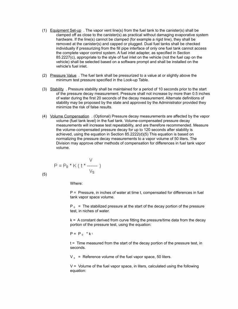
(1) Equipment Set-up . The vapor vent line(s) from the fuel tank to the canister(s) shall be clamped off as close to the canister(s) as practical without damaging evaporative system hardware. If the line(s) cannot be clamped (for example a rigid line), they shall be removed at the canister(s) and capped or plugged. Dual fuel tanks shall be checked individually if pressurizing from the fill pipe interface of only one fuel tank cannot access the complete vapor control system. A fuel inlet adapter, as specified in Section 85.2227(c), appropriate to the style of fuel inlet on the vehicle (not the fuel cap on the vehicle) shall be selected based on a software prompt and shall be installed on the vehicle's fuel inlet.
(2) Pressure Value . The fuel tank shall be pressurized to a value at or slightly above the minimum test pressure specified in the Look-up Table.
(3) Stability . Pressure stability shall be maintained for a period of 10 seconds prior to the start of the pressure decay measurement. Pressure shall not increase by more than 0.5 inches of water during the first 20 seconds of the decay measurement. Alternate definitions of stability may be proposed by the state and approved by the Administrator provided they minimize the risk of false results.
(4) Volume Compensation . (Optional) Pressure decay measurements are affected by the vapor volume (fuel tank level) in the fuel tank. Volume-compensated pressure decay measurements will increase test repeatability, and are therefore recommended. Measure the volume-compensated pressure decay for up to 120 seconds after stability is achieved, using the equation in Section 85.2222(d)(5) This equation is based on normalizing the pressure decay measurements to a vapor volume of 50 liters. The Division may approve other methods of compensation for differences in fuel tank vapor volume.
(5)
Where:
P = Pressure, in inches of water at time t, compensated for differences in fuel tank vapor space volume.
P 0 = The stabilized pressure at the start of the decay portion of the pressure test, in niches of water.
k = A constant derived from curve fitting the pressure/time data from the decay portion of the pressure test, using the equation:
P = P 0 * k t
t = Time measured from the start of the decay portion of the pressure test, in seconds.
V s = Reference volume of the fuel vapor space, 50 liters.
V = Volume of the fuel vapor space, in liters, calculated using the following equation:
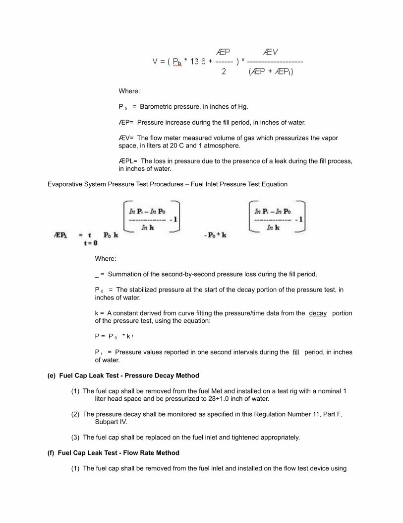
Where:
P b = Barometric pressure, in inches of Hg.
ÆP= Pressure increase during the fill period, in inches of water.
ÆV= The flow meter measured volume of gas which pressurizes the vapor space, in liters at 20 C and 1 atmosphere.
ÆPL= The loss in pressure due to the presence of a leak during the fill process, in inches of water.
Evaporative System Pressure Test Procedures – Fuel Inlet Pressure Test Equation
Where:
_ = Summation of the second-by-second pressure loss during the fill period.
P 0 = The stabilized pressure at the start of the decay portion of the pressure test, in inches of water.
k = A constant derived from curve fitting the pressure/time data from the decay portion of the pressure test, using the equation:
P = P 0 * k t
P t = Pressure values reported in one second intervals during the fill period, in inches of water.
(e) Fuel Cap Leak Test - Pressure Decay Method
(1) The fuel cap shall be removed from the fuel Met and installed on a test rig with a nominal 1 liter head space and be pressurized to 28+1.0 inch of water.
(2) The pressure decay shall be monitored as specified in this Regulation Number 11, Part F, Subpart IV.
(3) The fuel cap shall be replaced on the fuel inlet and tightened appropriately.
(f) Fuel Cap Leak Test - Flow Rate Method
(1) The fuel cap shall be removed from the fuel inlet and installed on the flow test device using
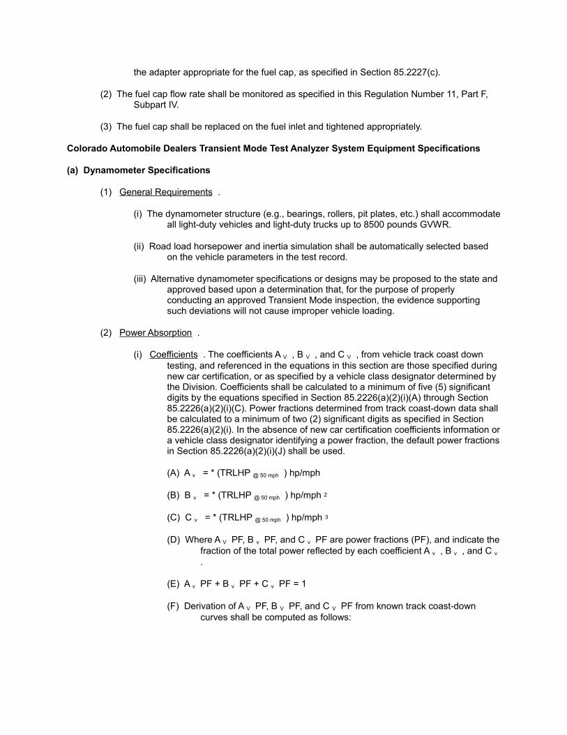
the adapter appropriate for the fuel cap, as specified in Section 85.2227(c).
(2) The fuel cap flow rate shall be monitored as specified in this Regulation Number 11, Part F, Subpart IV.
(3) The fuel cap shall be replaced on the fuel inlet and tightened appropriately.
Colorado Automobile Dealers Transient Mode Test Analyzer System Equipment Specifications
(a) Dynamometer Specifications
(1) General Requirements .
(i) The dynamometer structure (e.g., bearings, rollers, pit plates, etc.) shall accommodate all light-duty vehicles and light-duty trucks up to 8500 pounds GVWR.
(ii) Road load horsepower and inertia simulation shall be automatically selected based on the vehicle parameters in the test record.
(iii) Alternative dynamometer specifications or designs may be proposed to the state and approved based upon a determination that, for the purpose of properly conducting an approved Transient Mode inspection, the evidence supporting such deviations will not cause improper vehicle loading.
(2) Power Absorption .
(i) Coefficients . The coefficients A V , B V , and C V , from vehicle track coast down testing, and referenced in the equations in this section are those specified during new car certification, or as specified by a vehicle class designator determined by the Division. Coefficients shall be calculated to a minimum of five (5) significant digits by the equations specified in Section 85.2226(a)(2)(i)(A) through Section 85.2226(a)(2)(i)(C). Power fractions determined from track coast-down data shall be calculated to a minimum of two (2) significant digits as specified in Section 85.2226(a)(2)(i). In the absence of new car certification coefficients information or a vehicle class designator identifying a power fraction, the default power fractions in Section 85.2226(a)(2)(i)(J) shall be used.
(A) A v = * (TRLHP @ 50 mph ) hp/mph
(B) B v = * (TRLHP @ 50 mph ) hp/mph 2
(C) C v = * (TRLHP @ 50 mph ) hp/mph 3
(D) Where A V PF, B v PF, and C v PF are power fractions (PF), and indicate the fraction of the total power reflected by each coefficient A v , B v , and C v .
(E) A v PF + B v PF + C v PF = 1
(F) Derivation of A V PF, B V PF, and C V PF from known track coast-down curves shall be computed as follows:
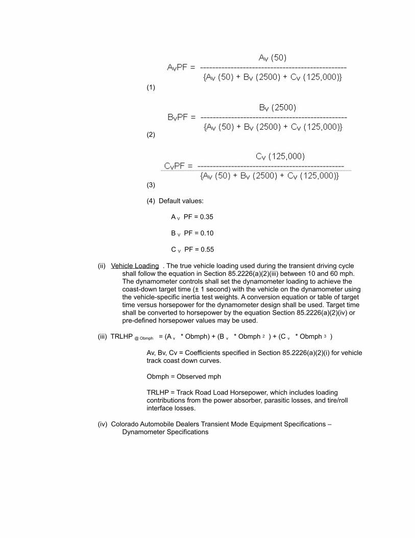
(1)
(2)
(3)
(4) Default values:
A V PF = 0.35
B V PF = 0.10
C V PF = 0.55
(ii) Vehicle Loading . The true vehicle loading used during the transient driving cycle shall follow the equation in Section 85.2226(a)(2)(iii) between 10 and 60 mph. The dynamometer controls shall set the dynamometer loading to achieve the coast-down target time (± 1 second) with the vehicle on the dynamometer using the vehicle-specific inertia test weights. A conversion equation or table of target time versus horsepower for the dynamometer design shall be used. Target time shall be converted to horsepower by the equation Section 85.2226(a)(2)(iv) or pre-defined horsepower values may be used.
(iii) TRLHP @ Obmph = (A v * Obmph) + (B v * Obmph 2 ) + (C v * Obmph 3 )
Av, Bv, Cv = Coefficients specified in Section 85.2226(a)(2)(i) for vehicle track coast down curves.
Obmph = Observed mph
TRLHP = Track Road Load Horsepower, which includes loading contributions from the power absorber, parasitic losses, and tire/roll interface losses.
(iv) Colorado Automobile Dealers Transient Mode Equipment Specifications – Dynamometer Specifications
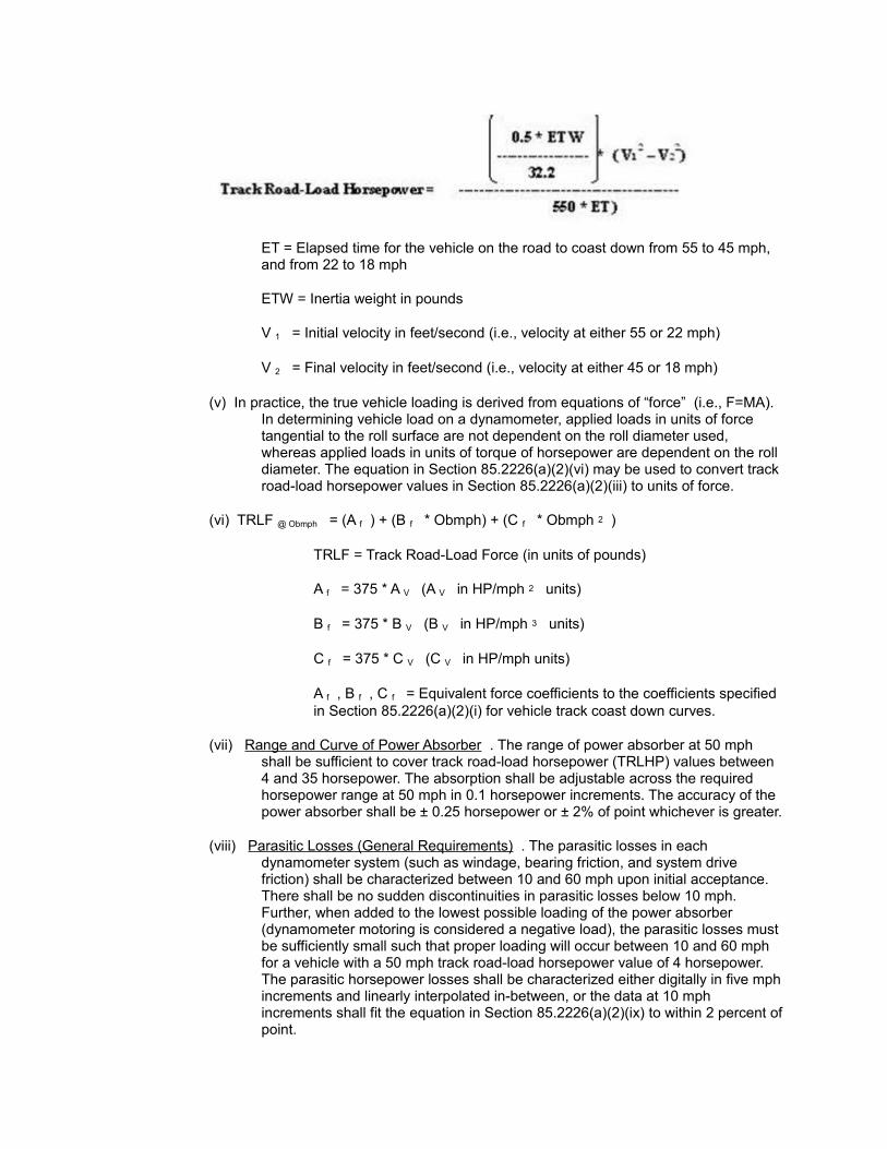
ET = Elapsed time for the vehicle on the road to coast down from 55 to 45 mph, and from 22 to 18 mph
ETW = Inertia weight in pounds
V 1 = Initial velocity in feet/second (i.e., velocity at either 55 or 22 mph)
V 2 = Final velocity in feet/second (i.e., velocity at either 45 or 18 mph)
(v) In practice, the true vehicle loading is derived from equations of “force” (i.e., F=MA). In determining vehicle load on a dynamometer, applied loads in units of force tangential to the roll surface are not dependent on the roll diameter used, whereas applied loads in units of torque of horsepower are dependent on the roll diameter. The equation in Section 85.2226(a)(2)(vi) may be used to convert track road-load horsepower values in Section 85.2226(a)(2)(iii) to units of force.
(vi) TRLF @ Obmph = (A f ) + (B f * Obmph) + (C f * Obmph 2 )
TRLF = Track Road-Load Force (in units of pounds)
A f = 375 * A V (A V in HP/mph 2 units)
B f = 375 * B V (B V in HP/mph 3 units)
C f = 375 * C V (C V in HP/mph units)
A f , B f , C f = Equivalent force coefficients to the coefficients specified in Section 85.2226(a)(2)(i) for vehicle track coast down curves.
(vii) Range and Curve of Power Absorber . The range of power absorber at 50 mph shall be sufficient to cover track road-load horsepower (TRLHP) values between 4 and 35 horsepower. The absorption shall be adjustable across the required horsepower range at 50 mph in 0.1 horsepower increments. The accuracy of the power absorber shall be ± 0.25 horsepower or ± 2% of point whichever is greater.
(viii) Parasitic Losses (General Requirements) . The parasitic losses in each dynamometer system (such as windage, bearing friction, and system drive friction) shall be characterized between 10 and 60 mph upon initial acceptance. There shall be no sudden discontinuities in parasitic losses below 10 mph. Further, when added to the lowest possible loading of the power absorber (dynamometer motoring is considered a negative load), the parasitic losses must be sufficiently small such that proper loading will occur between 10 and 60 mph for a vehicle with a 50 mph track road-load horsepower value of 4 horsepower. The parasitic horsepower losses shall be characterized either digitally in five mph increments and linearly interpolated in-between, or the data at 10 mph increments shall fit the equation in Section 85.2226(a)(2)(ix) to within 2 percent of point.

(ix) PLHP = [A p * (Obmph)] + [(B p ) * (Obmph) 2 ] + [(C p ) * (Obmph) 3 ]
PLHP = Dynamometer parasitic losses.
A p , B p , and C p are curve coefficients necessary to properly characterize the dynamometer parasitic losses for the inertia weight(s) used.
(x) Parasitic Losses (Low Speed Requirements) . The coast down time of the dynamometer between 8 and 12 mph shall be greater than or equal to the value calculated by the equation in Section 85.2226(a)(2)(xi) when the dynamometer is set for a 2000-pound vehicle with a track road-load horsepower of 4 horsepower at 50 mph.
(xi) Low Speed Loading . The following procedure is used to determine if a dynamometer system is correctly loading a vehicle with an ETW of 2000 pounds and a TRLHP of 6.0 horsepower at low speeds. Use “default” coefficients from Section 85.2226(a)(2)(i)(F)(4). Dynamometer must be warmed up prior to this procedure.
(A) Select vehicle with a driven axle weight between 1200 and 1300 pounds (sandbags or other ballast may be used to achieve this weight). Record vehicles driven axle weight to the nearest pound.
(B) Calculate the actual tire/roll interface losses (ATRL) using the following sub procedure.
(1) Determine PLHP for dynamometer system being tested.
(2) Calculate GTRL using equations from Sections 85.2226(a)(2)(xiii) and (xv) or (xvi).
(3) Calculate IHP using the following formula:
IHP = TRLHP-PLHP-GTRL
(4) Set dynamometer based on IHP calculated is step C above.
(5) Perform dynamometer coast down with vehicle selected in step 1 correctly positioned on rolls. Record coast down time from 12 mph to 8 mph.
(6) Calculate new TRLHP based on 12 mph to 8 mph coast
(7) Calculate actual tire/roll interface losses (ATRL) using the following equation.
ATRL = TRLHP-PLHP-IHP
(C) Using calculated ATRL determine new IHP using the following formula:
IHP = TRLHP-PLHP-ATRL
(D) Set dynamometer based on IHP calculated is step 3 above.
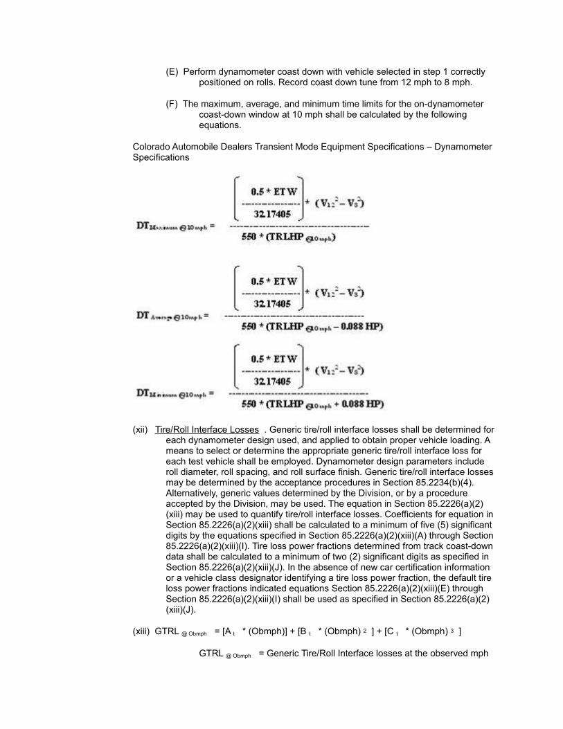
(E) Perform dynamometer coast down with vehicle selected in step 1 correctly positioned on rolls. Record coast down tune from 12 mph to 8 mph.
(F) The maximum, average, and minimum time limits for the on-dynamometer coast-down window at 10 mph shall be calculated by the following equations.
Colorado Automobile Dealers Transient Mode Equipment Specifications – Dynamometer Specifications
(xii) Tire/Roll Interface Losses . Generic tire/roll interface losses shall be determined for each dynamometer design used, and applied to obtain proper vehicle loading. A means to select or determine the appropriate generic tire/roll interface loss for each test vehicle shall be employed. Dynamometer design parameters include roll diameter, roll spacing, and roll surface finish. Generic tire/roll interface losses may be determined by the acceptance procedures in Section 85.2234(b)(4). Alternatively, generic values determined by the Division, or by a procedure accepted by the Division, may be used. The equation in Section 85.2226(a)(2)(xiii) may be used to quantify tire/roll interface losses. Coefficients for equation in Section 85.2226(a)(2)(xiii) shall be calculated to a minimum of five (5) significant digits by the equations specified in Section 85.2226(a)(2)(xiii)(A) through Section 85.2226(a)(2)(xiii)(I). Tire loss power fractions determined from track coast-down data shall be calculated to a minimum of two (2) significant digits as specified in Section 85.2226(a)(2)(xiii)(J). In the absence of new car certification information or a vehicle class designator identifying a tire loss power fraction, the default tire loss power fractions indicated equations Section 85.2226(a)(2)(xiii)(E) through Section 85.2226(a)(2)(xiii)(I) shall be used as specified in Section 85.2226(a)(2)(xiii)(J).
(xiii) GTRL @ Obmph = [A t * (Obmph)] + [B t * (Obmph) 2 ] + [C t * (Obmph) 3 ]
GTRL @ Obmph = Generic Tire/Roll Interface losses at the observed mph
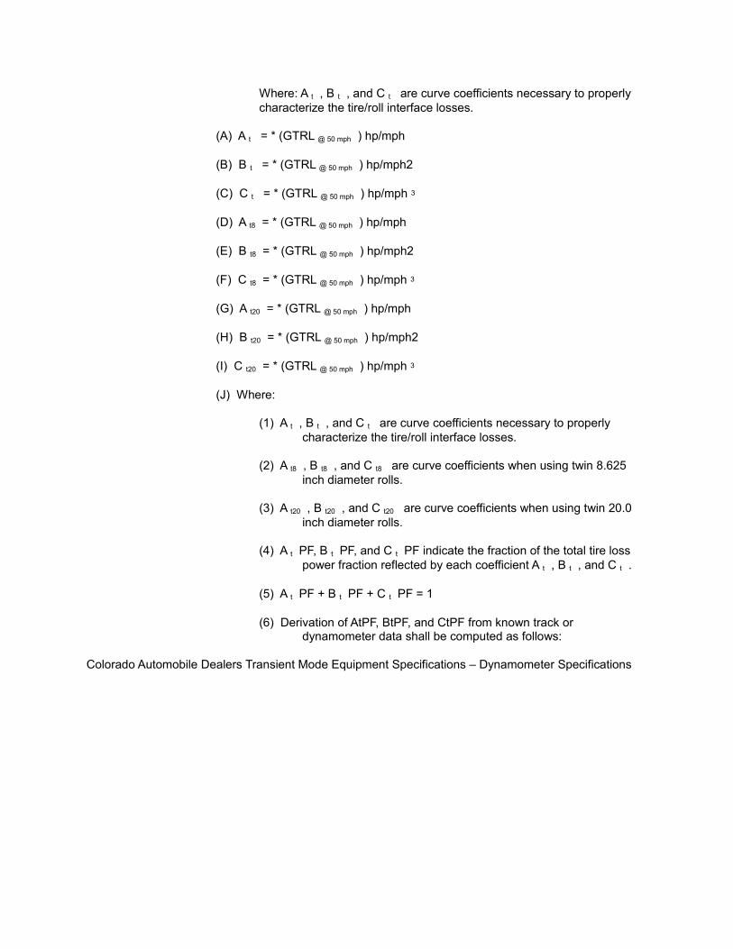
Where: A t , B t , and C t are curve coefficients necessary to properly characterize the tire/roll interface losses.
(A) A t = * (GTRL @ 50 mph ) hp/mph
(B) B t = * (GTRL @ 50 mph ) hp/mph2
(C) C t = * (GTRL @ 50 mph ) hp/mph 3
(D) A t8 = * (GTRL @ 50 mph ) hp/mph
(E) B t8 = * (GTRL @ 50 mph ) hp/mph2
(F) C t8 = * (GTRL @ 50 mph ) hp/mph 3
(G) A t20 = * (GTRL @ 50 mph ) hp/mph
(H) B t20 = * (GTRL @ 50 mph ) hp/mph2
(I) C t20 = * (GTRL @ 50 mph ) hp/mph 3
(J) Where:
(1) A t , B t , and C t are curve coefficients necessary to properly characterize the tire/roll interface losses.
(2) A t8 , B t8 , and C t8 are curve coefficients when using twin 8.625 inch diameter rolls.
(3) A t20 , B t20 , and C t20 are curve coefficients when using twin 20.0 inch diameter rolls.
(4) A t PF, B t PF, and C t PF indicate the fraction of the total tire loss power fraction reflected by each coefficient A t , B t , and C t .
(5) A t PF + B t PF + C t PF = 1
(6) Derivation of AtPF, BtPF, and CtPF from known track or dynamometer data shall be computed as follows:
Colorado Automobile Dealers Transient Mode Equipment Specifications – Dynamometer Specifications
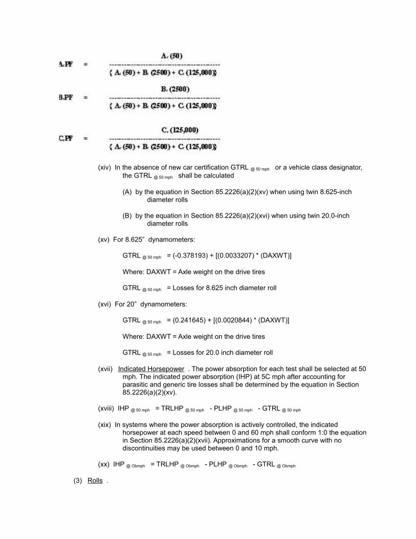
(xiv) In the absence of new car certification GTRL @ 50 mph or a vehicle class designator, the GTRL @ 50 mph shall be calculated
(A) by the equation in Section 85.2226(a)(2)(xv) when using twin 8.625-inch diameter rolls
(B) by the equation in Section 85.2226(a)(2)(xvi) when using twin 20.0-inch diameter rolls
(xv) For 8.625” dynamometers:
GTRL @ 50 mph = (-0.378193) + [(0.0033207) * (DAXWT)]
Where: DAXWT = Axle weight on the drive tires
GTRL @ 50 mph = Losses for 8.625 inch diameter roll
(xvi) For 20” dynamometers:
GTRL @ 50 mph = (0.241645) + [(0.0020844) * (DAXWT)]
Where: DAXWT = Axle weight on the drive tires
GTRL @ 50 mph = Losses for 20.0 inch diameter roll
(xvii) Indicated Horsepower . The power absorption for each test shall be selected at 50 mph. The indicated power absorption (IHP) at 5C mph after accounting for parasitic and generic tire losses shall be determined by the equation in Section 85.2226(a)(2)(xv).
(xviii) IHP @ 50 mph = TRLHP @ 50 mph - PLHP @ 50 mph - GTRL @ 50 mph
(xix) In systems where the power absorption is actively controlled, the indicated horsepower at each speed between 0 and 60 mph shall conform 1:0 the equation in Section 85.2226(a)(2)(xvii). Approximations for a smooth curve with no discontinuities may be used between 0 and 10 mph.
(xx) IHP @ Obmph = TRLHP @ Obmph - PLHP @ Obmph - GTRL @ Obmph
(3) Rolls .
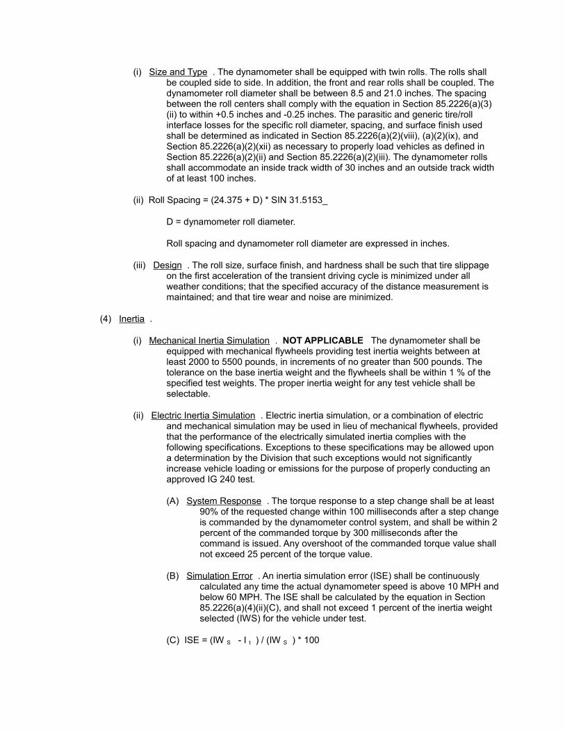
(i) Size and Type . The dynamometer shall be equipped with twin rolls. The rolls shall be coupled side to side. In addition, the front and rear rolls shall be coupled. The dynamometer roll diameter shall be between 8.5 and 21.0 inches. The spacing between the roll centers shall comply with the equation in Section 85.2226(a)(3)(ii) to within +0.5 inches and -0.25 inches. The parasitic and generic tire/roll interface losses for the specific roll diameter, spacing, and surface finish used shall be determined as indicated in Section 85.2226(a)(2)(viii), (a)(2)(ix), and Section 85.2226(a)(2)(xii) as necessary to properly load vehicles as defined in Section 85.2226(a)(2)(ii) and Section 85.2226(a)(2)(iii). The dynamometer rolls shall accommodate an inside track width of 30 inches and an outside track width of at least 100 inches.
(ii) Roll Spacing = (24.375 + D) * SIN 31.5153_
D = dynamometer roll diameter.
Roll spacing and dynamometer roll diameter are expressed in inches.
(iii) Design . The roll size, surface finish, and hardness shall be such that tire slippage on the first acceleration of the transient driving cycle is minimized under all weather conditions; that the specified accuracy of the distance measurement is maintained; and that tire wear and noise are minimized.
(4) Inertia .
(i) Mechanical Inertia Simulation . NOT APPLICABLE The dynamometer shall be equipped with mechanical flywheels providing test inertia weights between at least 2000 to 5500 pounds, in increments of no greater than 500 pounds. The tolerance on the base inertia weight and the flywheels shall be within 1 % of the specified test weights. The proper inertia weight for any test vehicle shall be selectable.
(ii) Electric Inertia Simulation . Electric inertia simulation, or a combination of electric and mechanical simulation may be used in lieu of mechanical flywheels, provided that the performance of the electrically simulated inertia complies with the following specifications. Exceptions to these specifications may be allowed upon a determination by the Division that such exceptions would not significantly increase vehicle loading or emissions for the purpose of properly conducting an approved IG 240 test.
(A) System Response . The torque response to a step change shall be at least 90% of the requested change within 100 milliseconds after a step change is commanded by the dynamometer control system, and shall be within 2 percent of the commanded torque by 300 milliseconds after the command is issued. Any overshoot of the commanded torque value shall not exceed 25 percent of the torque value.
(B) Simulation Error . An inertia simulation error (ISE) shall be continuously calculated any time the actual dynamometer speed is above 10 MPH and below 60 MPH. The ISE shall be calculated by the equation in Section 85.2226(a)(4)(ii)(C), and shall not exceed 1 percent of the inertia weight selected (IWS) for the vehicle under test.
(C) ISE = (IW S - I t ) / (IW S ) * 100
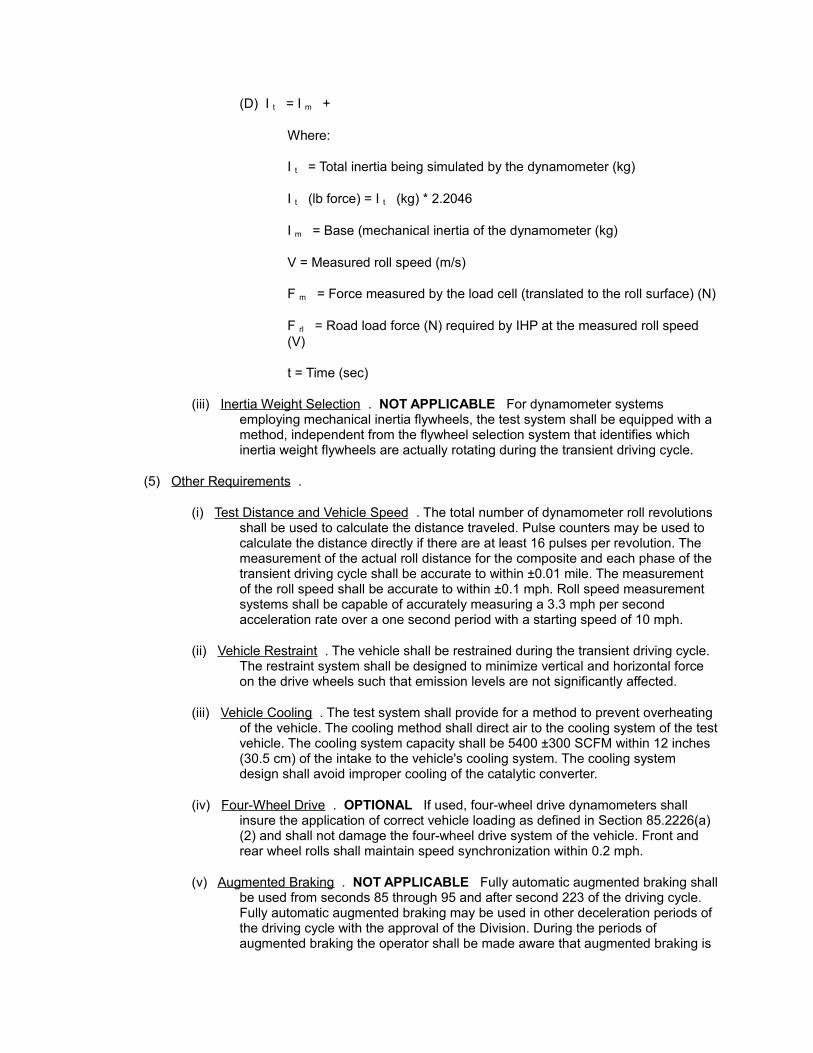
(D) I t = I m +
Where:
I t = Total inertia being simulated by the dynamometer (kg)
I t (lb force) = I t (kg) * 2.2046
I m = Base (mechanical inertia of the dynamometer (kg)
V = Measured roll speed (m/s)
F m = Force measured by the load cell (translated to the roll surface) (N)
F rl = Road load force (N) required by IHP at the measured roll speed (V)
t = Time (sec)
(iii) Inertia Weight Selection . NOT APPLICABLE For dynamometer systems employing mechanical inertia flywheels, the test system shall be equipped with a method, independent from the flywheel selection system that identifies which inertia weight flywheels are actually rotating during the transient driving cycle.
(5) Other Requirements .
(i) Test Distance and Vehicle Speed . The total number of dynamometer roll revolutions shall be used to calculate the distance traveled. Pulse counters may be used to calculate the distance directly if there are at least 16 pulses per revolution. The measurement of the actual roll distance for the composite and each phase of the transient driving cycle shall be accurate to within ±0.01 mile. The measurement of the roll speed shall be accurate to within ±0.1 mph. Roll speed measurement systems shall be capable of accurately measuring a 3.3 mph per second acceleration rate over a one second period with a starting speed of 10 mph.
(ii) Vehicle Restraint . The vehicle shall be restrained during the transient driving cycle. The restraint system shall be designed to minimize vertical and horizontal force on the drive wheels such that emission levels are not significantly affected.
(iii) Vehicle Cooling . The test system shall provide for a method to prevent overheating of the vehicle. The cooling method shall direct air to the cooling system of the test vehicle. The cooling system capacity shall be 5400 ±300 SCFM within 12 inches (30.5 cm) of the intake to the vehicle's cooling system. The cooling system design shall avoid improper cooling of the catalytic converter.
(iv) Four-Wheel Drive . OPTIONAL If used, four-wheel drive dynamometers shall insure the application of correct vehicle loading as defined in Section 85.2226(a)(2) and shall not damage the four-wheel drive system of the vehicle. Front and rear wheel rolls shall maintain speed synchronization within 0.2 mph.
(v) Augmented Braking . NOT APPLICABLE Fully automatic augmented braking shall be used from seconds 85 through 95 and after second 223 of the driving cycle. Fully automatic augmented braking may be used in other deceleration periods of the driving cycle with the approval of the Division. During the periods of augmented braking the operator shall be made aware that augmented braking is
occurring and shall be trained not to use the vehicle accelerator during these periods. It shall be automatically interlocked such that it can be actuated only while the vehicle brakes are applied. Simultaneous engine acceleration is systematically prevented through periodic quality assurance.
(b) Constant Volume Sampler
(1) General Design Requirements .
(i) Venturi Type . A constant volume sampling (CVS) system of the critical flow venturi (CFV), sub-sonic venturi (SSV), or square edged orifice (SEO) type shall be used to collect vehicle exhaust samples. The CVS system and components shall generally conform to the specifications in Section 86.109-90.
(ii) CVS Flow Size . The CVS system shall be sized in a manner that prevents condensation in the dilute sample over the range of ambient conditions to be encountered during testing. A minimum 325 SCFM CVS system and heated lines or sample conditioning system (dryer) may be used to eliminate condensation and to increase measured concentrations for better resolution. Should the heated sample lines be used, the sample line and components (e.g., filters, etc.) shall be heated to a minimum of 120° F and a maximum of 250°F, which shall be monitored during the transient driving cycle.
(iii) CVS Compressor . The CVS compressor flow capacity shall be sufficient to maintain proper flow in the main CVS venturi with an adequate margin. For CFV CVSs the margin shall be sufficient to maintain choke flow. The capacity of the blower relative to the CFV flow capacity shall not be so large as to create a limited surge margin.
(iv) Materials. All materials in contact with exhaust gas shall be unaffected by and shall not affect the sample (i.e., the materials shall not react with the sample, and neither shall they taint the sample as a result of out gassing). Acceptable materials include stainless steel, Teflon, silicon rubber, and Tedlar.
(v) Alternative Approaches . Alternative CVS specifications, materials, or designs may be allowed upon a determination by the Division, that for the purpose of properly conducting an approved short test, the evidence supporting such deviations will not significantly affect the proper measurement of emissions.
(2) Sample System .
(i) Sample Probe . The sample probe within the CVS shall be designed such that a continuous and adequate volume of sample is collected for analysis. The system shall have a method for determining if the sample collection system has deteriorated or malfunctioned such that an adequate sample is not being collected, or that the response tune has deteriorated such that the tune correlation for each emission constituent is no longer valid.
(ii) CVS Mixing Tee .
(A) Design and Effect . The mixing tee for diluting the vehicle exhaust with ambient air shall be at the vehicle tailpipe exit as in Section 86.109-90(a)(2)(iv). The dilution-mixing tee shall be capable of collecting exhaust from all light-duty vehicle and light-duty truck exhaust systems. The design used shall not cause static pressure in the tailpipe to change such that
the emission levels are significantly affected. A change of ±1.0 inch of water, or less, shall be acceptable.
(B) Locating Device . The mixing tee shall have a device for positively locating the tee relative to the tailpipe with respect to distance from the tailpipe, and with respect to positioning the exhaust stream from the tailpipe(s) in the center of the mixing tee flow area. The locating device, or the size of the entrance to the tee shall be such that if a vehicle moves laterally from one extreme position on the dynamometer to the other extreme, that mixing tee will collect all of the exhaust sample.
(iii) Dual Exhaust . For dual exhaust systems, the design used shall insure that each leg of the sample collection system maintains equal flow. Equal flow will be assumed if the design of the “Tee” intersection for the dual CVS hoses is a “Y” that minimizes the flow loss from each leg of the “Y,” if each leg of the dual exhaust collection system is approximately equal in length (± 1 foot), and if the dilution area at the end of each leg is approximately equal. In addition, the CVS flow capacity shall be such that the entrance flow velocity for each leg of the dual exhaust system is sufficient to entrain all of the vehicle's exhaust from each tailpipe.
(iv) Background Sample . The mixing tee shall be used to collect the background sample. The position of the mixing tee for taking the background sample shall be within 12 lateral and 12 longitudinal feet of the position during the transient driving cycle, and approximately 4 vertical feet from the floor.
(v) Integrated Sample . A continuous dilute sample shall be provided for integration by the analytical instruments in a manner similar to the method for collecting bag samples as described in Section 86.109.
(c) Analytical Instruments
(1) General Requirements .
(i) The emission analysis system shall automatically sample, integrate, and record the specified emission values for HC, CO, CO2, and NOx. Performance of the analytical instruments with respect to accuracy and precision, drift, interferences, noise, etc. shall be similar to instruments used for testing under Section 86 Subparts B, D, and N. Analytical instruments shall perform in this manner in the full range of operating conditions in the system environment.
(ii) Alternative analytic equipment specifications, materials, designs, or detection methods may be allowed upon a determination by the Division, that for the purpose of properly conducting an approved short test, the evidence supporting such deviations will not significantly affect the proper measurement of emissions.
(2) Detection Methods and Instrument Ranges .
(i) Total Hydrocarbon Analysis . A flame ionization detector shall determine total hydrocarbon analysis. If a 325 SCFM CVS is used, the analyzer calibration curve shall cover at least the range of 0 ppmC to 4,000 ppmC. Use of a different CVS flow capacity shall require an adjustment to these ranges. Appropriate documentation supporting any adjustment in ranges shall be available. Such documentation shall also address the ability of any altered ranges to accurately measure all cutpoints, including cutpoints for vehicles older than those specified
in Section 85.2205(a) that may be used in the specific I/M program for which the altered ranges are proposed to be used. The calibration curve must comply with the quality control specifications in Section 85.2234(d).
(ii) Carbon Monoxide Analysis . CO analysis shall be determined using a non-dispersive infrared analyzer. If a 325 SCFM CVS is used, CO analysis shall cover at least the range of 0 ppm to 20,000 ppm (2%). ppm. Use of a different CVS flow capacity shall require an adjustment to these ranges. Appropriate documentation supporting any adjustment in ranges shall be available. Such documentation shall also address the ability of any altered ranges to accurately measure all cutpoints, including cutpoints for vehicles older than those specified in Section 85.2205(a) that may be used in the specific I/M program for which the altered ranges are proposed to be used. The calibration curve must comply with the quality control specifications in Section 85.2234(d).
(iii) Carbon Dioxide Analysis . CO2 analysis shall be determined using an NDIR analyzer. If a 325 SCFM CVS is used, CO2 analysis shall cover at least the range of 0 ppm to 80,000 ppm (8%). Use of a different CVS flow capacity shall require an adjustment to these ranges. Appropriate documentation supporting any adjustment in ranges shall be available. Such documentation shall also address the ability of any altered ranges to accurately measure all cutpoints, including cutpoints for vehicles older than those specified in Section 85.2205(a) that may be used in the specific I/M program for which the altered ranges are proposed to be used. The calibration curve must comply with the quality control specifications in Section 85.2234(d).
(iv) Oxides of Nitrogen Analysis . NOx analysis shall be determined using chemiluminescence. The NOx measurement shall be the sum of nitrogen oxide and nitrogen dioxide. If a 325 SCFM CVS is used, the NOx analysis shall cover at least the range of 0 ppm to 1000 ppm. Use of a different CVS flow capacity shall require an adjustment to these ranges. Appropriate documentation supporting any adjustment in ranges : shall be available. Such documentation shall also address the ability of any altered ranges to accurately measure all cutpoints, including cutpoints for vehicles older than those specified in this Regulation Number 11, Part F, that may be used for which the altered ranges are proposed to be used. The calibration curve must comply with the quality control specifications in Section 85.2234(d).
(3) System Response Requirements . The governing requirement for system response is the ability of the integration system to measure vehicle emissions to within ±5 % of that measured from a bag sample simultaneously collected over the same integration period, on both clean and dirty vehicles. Historically, continuously integrated emission analyzers have been required to have a response time of 1.5 seconds or less to 90% of a step change, where a step change was 60% of full scale or better. System response tunes between a step change at the probe and reading 90% of the change have generally been less than 4-10 seconds. Systems proposed that exceed these historical values shall provide an engineering explanation as to why the slower system response of the integrated system will compare to the bag reading within the specified 5 %.
(4) Integration Requirements .
(i) The analyzer voltage responses, CVS pressure(s), CVS temperature(s), dynamometer speed, and dynamometer power shall be sampled as a frequency of no less than 5 Hertz, and the voltage levels shall be averaged over 1 second intervals.
(ii) The system shall properly tune correlate each analyzer signal, CVS signals and dynamometer signals to the driving trace (test time). The driving trace update rate from the computer shall be at a rate to produce a smooth transition from one data point to another.
(iii) The one-second average analyzer voltage levels shall be converted to concentrations by the analyzer calibration curves. Corrected concentrations for each gas shall be derived by subtracting the pre-test background concentrations from the measured concentrations, according to the method in Section 85.2205(b). The corrected concentrations shall be converted to grams for each second using the equations specified in Section 85.2205(b) to combine the concentrations with the CVS flow over the same interval. The grams of emissions per test phase shall be determined using the equations in Section 85.2205(b).
(iv) When multiple analyzers are used for any constituent, the integration system shall simultaneously integrate both analyzers. The integrated values for the lowest analyzer in range shall be used for each second.
(v) For all constituents, the background concentration levels from the lowest range analyzer shall be used, including the case where multiple analyzers may have been used.
(5) Analytical System Design .
(i) Materials . All materials in contact with exhaust gas prior to and throughout the measurement portion of the system shall be unaffected by and shall not affect the sample (i.e., the materials shall not react with the sample, and neither shall they taint the sample as a result of out gassing). Acceptable materials include stainless steel, Teflon, silicon rubber, and Tedlar.
(ii) Bag Ports . All analysis systems shall have provisions for reading a sample bag. A portable pump for sampling such bags is permitted.
(iii) System Filters . The sample system shall have an easily replaceable filter element to prevent particulate matter from reducing the reliability of the analytical system. The filter element shall provide for reliable sealing after filter element changes. If the sample line is heated, the filter system shall also be heated.
(iv) Availability of Intermediate Calculation Variables . Upon request prior to a test, all intermediate calculation variables shall be available to be downloaded to electronic files or hard copy. These variables shall include those that calculate the vehicle emission test results, perform emission analyzer and dynamometer function checks, and perform quality assurance and quality control measurements.
(d) Colorado Automobile Dealers Transient Mode Test Analyzer System Specific Hardware
General Design Requirements.
(i) Computer System. Minimum CPU system to include; 90MHZ Pentium processor, Memory 16MB, Secondary Cache 256 KB, Video Type SVGA, Video Card 2 MB memory, 15” Color Monitor (drivers aid), Diskette drive A 1.44 MB, Hard-disk drive C 1.6 GB, Parallel Port (1), Serial Port (1), Mouse Port (1), 104 Key Keyboard, Expansion Slots (4). Port configurations noted may not reflect the necessary number or type to support subsystem requirements or options.
(ii) Modem. Minimum requirement. Hayes compatible able to operate at 14.400B M.N.P. level 5. Error correction, Microcom networking protocol (M.N.P.) levels 1-4 with V.42 data compression. M.N.P. level 5 - V.32BIS/V.42BIS.
(iii) Printer. Vehicle Inspection Report. 24 pin impact printer operating at 12 characters per inch and 80 characters per line.
(iv) Printer. Diagnostic Report, (customer option) 24-pin impact printer operating at 12 characters per inch and 80 characters per line.
(v) Printer. Certificate/Sticker. A Standard Register PT-640, thermal transfer printer.
(vi) Barcode Scanner. Symbol Technologies PDF 1000 HV or equivalent.
(1) Fuel cap Tester. An internal or external unit capable of performing either the pressure decay method or flow rate method of fuel cap testing as defined in Evaporative System Test Procedures, Sections (e) and (f).
(2) System Security. Access to the analytical system, computer system, official state documents shall be prevented by locked enclosure and monitored by micro switches or other similar means to assure that unauthorized access is denied. Detection of unauthorized access shall result in automatic inspection system lock out.
(3) Manufacturer Options installed to operate independent of an official inspection processes may be utilized and configured into the hardware as necessary. An example would be a CD-ROM for vehicle diagnostics or software supported programs.
Evaporative System Inspection Equipment
(a) General Requirements
(1) Equipment Design . Automated and computerized test systems shall be used for the evaporative system tests. Pass/fail decisions shall be made automatically. The systems shall be tamper resistant and designed to avoid damage to the vehicle during installation, testing, and removal.
(2) Alternative Systems . Alternative purge or pressure test equipment, specifications, materials, or designs, may be proposed and approved upon a determination by the Division that, for the purpose of properly conducting an approved Transient Mode test, the evidence supporting such deviations will not appreciably or adversely affect the proper determination of system integrity, the proper measurement of purge, or the proper operation of the vehicle.
(b) Evaporative Purge System NOT APPLICABLE
(1) General Requirements . The evaporative purge analysis system shall measure the instantaneous purge flow in standard liters/minute, and shall compute the total volume of the flow in standard liters over the transient driving cycle.
(2) Specifications . The purge flow measuring system shall comply with the following requirements.
(i) Flow Capacity . A minimum of 50 liters per minute.
(ii) Pressure Drop . Maximum of 16 inches of water at 50 liters per minute for the
complete system including hoses necessary to connect the system to the vehicle.
(iii) Totaled Flow . 0 to 100 liters of volume
(iv) Response Time . 410 milliseconds maximum to 90% of a step change between approximately 2 and 10 liters per minute measured with air.
(v) Accuracy .
(A) ±2.0 liters per minute between 10 and 50 liters per minute (rate)
(B) ±0.15 liters per minute between 0 and 10 liters per minute (rate)
(C) ±4% of 50 standard liters total flow volume between 10 and 50 liters total flow volume over one minute.
(D) ±1.5% of 10 standard liters between 0 and 10 liters total volume flow over one minute.
(vi) Noise . The maximum noise shall be less than 0.001 liters per second
(vii) Calibration Gas . Air
(3) Automatic Operation . Vehicle purge flow shall be monitored with a computerized system at a minimum sample rate of 1 Hz, shall automatically capture average (if sampled faster than 1 Hz) second-by-second readings, and shall automatically derive a pass/fail decision. In determining the total volume of flow, the monitoring system shall not count signal noise as flow volume. The test sequence shall be automatically initiated when the transient driving cycle test is initiated.
(4) Adaptability . The purge flow system shall have sufficient adapters to connect in a leak-tight manner with the variety of evaporative systems and hose deterioration conditions in the vehicle fleet. The purge measurement system shall not substantially interfere with purge flow.
(c) Evaporative System Pressure Test Equipment ITEMS 1-4 NOT APPLICABLE
(1) General Requirements .
(i) Pressure Gas . Nitrogen (N2), or equivalent non-toxic, non-greenhouse, inert gas, shall be used for pressurizing the evaporative system.
(ii) Automatic Operation . The process for filling the evaporative system, monitoring compliance, recording data, and making a pass/fail decision shall be automatic. After the determination that the evaporative system has been filled to the specific pressure level, and upon initiation of the test, the pressure level in the evaporative system shall be recorded at a frequency of no less than 1 Hertz until the conclusion of the test.
(iii) Test Abort . The system shall be equipped with an abort system that positively shuts off and relieves pressure. The abort system shall be capable of being activated quickly and conveniently by the inspector should the need arise.
(2) Adapters and Clamps.
(i) Canister Hose Adapters . The system shall have sufficient adapters to connect in a leak-tight manner with the variety of evaporative systems and hose deterioration conditions in the vehicle fleet.
(ii) Fuel Inlet Adapters . Fuel inlet adapters that fit on the vehicles fuel inlet in a manner similar to the fuel cap and designed to admit a pressurized source of gas into the fuel tank shall be used for the fuel inlet pressure test specified in 85.222(d). Inlet specific adapters shall be available for at least 95 percent of the fuel inlets that are used on U.S. light duty vehicles and light duty trucks for the model years Specified in Part F of this Regulation. Varying internal volumes of the adapter assemblies shall not affect the accuracy of the test results. Adapters shall be made available within two years of the introduction of new model year vehicles.
(iii) Hose Clamp . The hose clamp used for the fuel inlet pressure test shall be designed to apply only enough pressure to close the hose without damaging it. The nose of the clamp shall be smooth-surfaced or otherwise designed to avoid abrasion of the vehicle hose.
(3) Pressure Gauge . The device for measuring pressure in the vehicle's evaporative system shall have a minimum range of 0 to 50 inches of water and an accuracy of +-0.3 inches of water (2 % of 15) or better.
(4) Flow Meter . A flow meter with a range of at least 0 to 10 liters per minute and +-5% accuracy shall be used for the measurement of flow.
(5) Fuel Cap Tester . The tester shall provide a visual or digital signal that the required air supply pressure is within the acceptable range and the flow comparison test is ready to be conducted. The tester shall incorporate an upstream maintainable filter. If the tester is battery powered, it must be equipped with an automatic shutoff and a low-battery indicator. A NIST traceable reference passing fuel cap of nominal 52-56 cubic centimeters per minute, and a NIST traceable reference failing fuel cap of nominal 64-68 cubic centimeters per minute shall be supplied with the tester for daily test verification. Leak rate measurements shall be accurate to ±3 cubic centimeters per minute.
(6) Flow Standard . The flow standard shall be a square edged circular orifice with a NIST traceable flow rate that in combination with the comparison circuitry will produce a pass/fail threshold of 60 cubic centimeters at 30 inches of water column. Transducers used in the comparison circuitry shall have accuracy traceable to NIST. The supply pressure may be obtained using room air and any convenient low-pressure source. The tester shall control the supply pressure and prevent over pressurization.
Quality Control Requirements and Acceptance Testing Procedures
(a) General Requirements
(1) Minimums . The frequency and standards for quality control specified here are minimum requirements, unless modified as specified in Section 85.2234(2). Greater frequency or tighter standards may be used as determined by the Division.
(2) Statistical Process Control . Reducing the frequency of the quality control checks, modifying the procedure or specifications, or eliminating the quality control checks altogether may be allowed if the Division determines, for the purpose of properly conducting an approved short test, that sufficient Statistical Process Control (SPC) data exist to make a determination, that the SPC data support such action, and that taking such action will not significantly reduce the quality of the emission measurements. Should emission
measurement performance or quality deteriorate as a result of allowing such actions, the approval shall be suspended, and the frequencies, procedures, specifications, or checks specified here or otherwise approved shall be reinstated, pending further determination by the Division.
(3) Modifications . The Division may modify the frequency and standards contained in this section if found to be impractical.
(b) Dynamometer
(1) Coast Down Check .
(i) The calibration of each dynamometer shall be checked on a weekly basis by a dynamometer coast-down equivalent that in Section 86.118-78 (for reference see EOD Test Procedures TP-302A and TP-202) between the speeds of 55 to 45 mph, and between 22 to 18 mph. All rotating dynamometer components shall be included in the coast-down check for the inertia weight selected.
(ii) The base dynamometer and the base plus each prime inertia weight flywheel, if any, shall be checked with at least two horsepower settings within the normal range of the inertia weight. For dynamometers that use electrical inertia simulation and have a base inertia outside of the range of 3000 pounds to 4500 pounds, the coast-down check shall be conducted with at least two horsepower settings at the base inertia, and two settings at either 2500 pounds or 4500 pounds, whichever is furthest from the base inertia weight. For both mechanical flywheel dynamometers and electrical inertia simulation dynamometers, the horsepower settings selected shall correspond to a vehicle/engine category that matches the inertia weight selected for the coast-down test. Where the base inertia, or the base inertia plus the smallest flywheel results in a coast-down inertia of less than 2250 pounds, only one horsepower setting is required for the check.
(iii) The coast-down procedure shall be of a self-motoring method. If the difference between the measured coast-down tune and the theoretical coast-down time is greater than ±1 second on the 55 to 45 mph coast-down as calculated by Section 85.2234(b)(l)(iii)(A) or (B), official testing shall automatically be prevented, and corrective action shall be taken to bring the dynamometer into calibration. Official testing shall also automatically be prevented, and corrective action shall be taken to bring the dynamometer into calibration, if the difference between the measured coast-down time and the theoretical coast-down time for 22 to 18 mph is outside of the time window calculated by Section 85.2234(b)(l)(iii)(C) or (D). For tests using inertia weights of 8500 lbs. and above, if the difference between the measured coast-down time and the theoretical coast-down time is outside of the time window calculated by Section 85.2234(b)(l)(iii)(O) or (D) for the 22 mph to the 18 mph coast-down when substituting 0.27 HP for the allowable force-error (equivalent to 5.0 pounds-force at 20 mph), official testing shall automatically be prevented, and corrective action shall be taken to bring the dynamometer into calibration.
(A) The off-dynamometer target coast-down time at 50 mph (DBT @50 mph.g ) for dynamometers with 8.265-inch rolls shall be calculated as follows.
Transient Mode Test Quality Control Requirements and Acceptance Testing Procedures
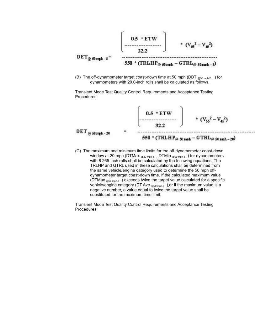
(B) The off-dynamometer target coast-down time at 50 mph (DBT @50 mph-2o ) for dynamometers with 20.0-inch rolls shall be calculated as follows.
Transient Mode Test Quality Control Requirements and Acceptance Testing Procedures
(C) The maximum and minimum time limits for the off-dynamometer coast-down window at 20 mph (DTMax @20 mph-8 , DTMin @20 mph-8 ) for dynamometers with 8.265-inch rolls shall be calculated by the following equations. The TRLHP and GTRL used in these calculations shall be determined from the same vehicle/engine category used to determine the 50 mph off-dynamometer target coast-down time. If the calculated maximum value (DTMax @20 mph-8 ) exceeds twice the target value calculated for a specific vehicle/engine category (DT Ave @20 mph-8 ),or if the maximum value is a negative number, a value equal to twice the target value shall be substituted for the maximum time limit.
Transient Mode Test Quality Control Requirements and Acceptance Testing Procedures
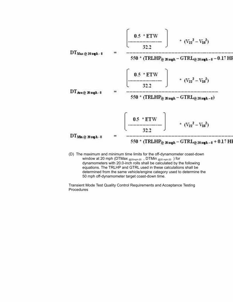
(D) The maximum and minimum time limits for the off-dynamometer coast-down window at 20 mph (DTMax @20mph-20 , DTMin @20 mph-20 ) for dynamometers with 20.0-inch rolls shall be calculated by the following equations. The TRLHP and GTRL used in these calculations shall be determined from the same vehicle/engine category used to determine the 50 mph off-dynamometer target coast-down time.
Transient Mode Test Quality Control Requirements and Acceptance Testing Procedures
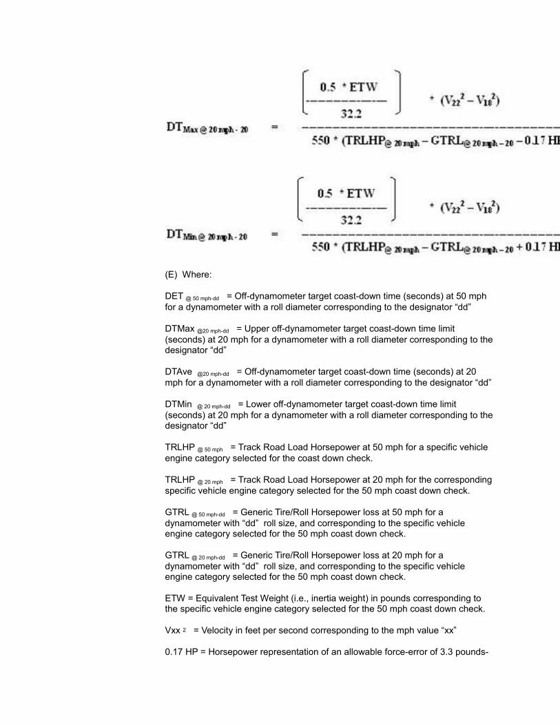
(E) Where:
DET @ 50 mph-dd = Off-dynamometer target coast-down time (seconds) at 50 mph for a dynamometer with a roll diameter corresponding to the designator “dd”
DTMax @20 mph-dd = Upper off-dynamometer target coast-down time limit (seconds) at 20 mph for a dynamometer with a roll diameter corresponding to the designator “dd”
DTAve @20 mph-dd = Off-dynamometer target coast-down time (seconds) at 20 mph for a dynamometer with a roll diameter corresponding to the designator “dd”
DTMin @ 20 mph-dd = Lower off-dynamometer target coast-down time limit (seconds) at 20 mph for a dynamometer with a roll diameter corresponding to the designator “dd”
TRLHP @ 50 mph = Track Road Load Horsepower at 50 mph for a specific vehicle engine category selected for the coast down check.
TRLHP @ 20 mph = Track Road Load Horsepower at 20 mph for the corresponding specific vehicle engine category selected for the 50 mph coast down check.
GTRL @ 50 mph-dd = Generic Tire/Roll Horsepower loss at 50 mph for a dynamometer with “dd” roll size, and corresponding to the specific vehicle engine category selected for the 50 mph coast down check.
GTRL @ 20 mph-dd = Generic Tire/Roll Horsepower loss at 20 mph for a dynamometer with “dd” roll size, and corresponding to the specific vehicle engine category selected for the 50 mph coast down check.
ETW = Equivalent Test Weight (i.e., inertia weight) in pounds corresponding to the specific vehicle engine category selected for the 50 mph coast down check.
Vxx 2 = Velocity in feet per second corresponding to the mph value “xx”
0.17 HP = Horsepower representation of an allowable force-error of 3.3 pounds-
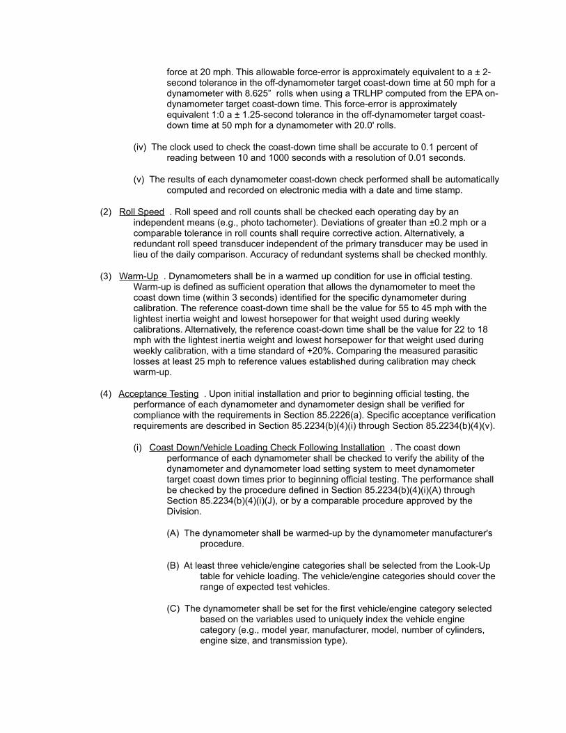
force at 20 mph. This allowable force-error is approximately equivalent to a ± 2-second tolerance in the off-dynamometer target coast-down time at 50 mph for a dynamometer with 8.625” rolls when using a TRLHP computed from the EPA on-dynamometer target coast-down time. This force-error is approximately equivalent 1:0 a ± 1.25-second tolerance in the off-dynamometer target coast-down time at 50 mph for a dynamometer with 20.0' rolls.
(iv) The clock used to check the coast-down time shall be accurate to 0.1 percent of reading between 10 and 1000 seconds with a resolution of 0.01 seconds.
(v) The results of each dynamometer coast-down check performed shall be automatically computed and recorded on electronic media with a date and time stamp.
(2) Roll Speed . Roll speed and roll counts shall be checked each operating day by an independent means (e.g., photo tachometer). Deviations of greater than ±0.2 mph or a comparable tolerance in roll counts shall require corrective action. Alternatively, a redundant roll speed transducer independent of the primary transducer may be used in lieu of the daily comparison. Accuracy of redundant systems shall be checked monthly.
(3) Warm-Up . Dynamometers shall be in a warmed up condition for use in official testing. Warm-up is defined as sufficient operation that allows the dynamometer to meet the coast down time (within 3 seconds) identified for the specific dynamometer during calibration. The reference coast-down time shall be the value for 55 to 45 mph with the lightest inertia weight and lowest horsepower for that weight used during weekly calibrations. Alternatively, the reference coast-down time shall be the value for 22 to 18 mph with the lightest inertia weight and lowest horsepower for that weight used during weekly calibration, with a time standard of +20%. Comparing the measured parasitic losses at least 25 mph to reference values established during calibration may check warm-up.
(4) Acceptance Testing . Upon initial installation and prior to beginning official testing, the performance of each dynamometer and dynamometer design shall be verified for compliance with the requirements in Section 85.2226(a). Specific acceptance verification requirements are described in Section 85.2234(b)(4)(i) through Section 85.2234(b)(4)(v).
(i) Coast Down/Vehicle Loading Check Following Installation . The coast down performance of each dynamometer shall be checked to verify the ability of the dynamometer and dynamometer load setting system to meet dynamometer target coast down times prior to beginning official testing. The performance shall be checked by the procedure defined in Section 85.2234(b)(4)(i)(A) through Section 85.2234(b)(4)(i)(J), or by a comparable procedure approved by the Division.
(A) The dynamometer shall be warmed-up by the dynamometer manufacturer's procedure.
(B) At least three vehicle/engine categories shall be selected from the Look-Up table for vehicle loading. The vehicle/engine categories should cover the range of expected test vehicles.
(C) The dynamometer shall be set for the first vehicle/engine category selected based on the variables used to uniquely index the vehicle engine category (e.g., model year, manufacturer, model, number of cylinders, engine size, and transmission type).
(D) The dynamometer shall be coasted down from 65 mph to 5 mph with the settings pre-selected in Section 85.2234(b)(4)(i)(C).
(E) The 55 mph to 45 mph, and the 22 mph to 18 mph coast down tunes shall be recorded for the data collected in Section 85.2234(b)(4)(i)(D).
(F) The dynamometer shall be coasted down from 65 mph to 5 mph after having been adjusted for each of the other two vehicle engine categories, and the 55 mph to 45 mph, and the 22 mph to 1 mph coast down times shall be recorded for each coast-down.
(G) The coast-downs specified in Section 85.2234(b)(4)(i)(C) through Section 85.2234 (b)(4)(i)(F) shall be replicated for a total of three coast-down tests for each vehicle inertia category. The replications of the coast-downs for each vehicle engine category shall be run in random sequence.
(H) The off-dynamometer target coast-down tune at 50 mph (DET @ 50 mph-dd ) for each vehicle/engine category shall be calculated as specified in Section 85.2234(b)(l)(iii)(A) or (B) for the applicable dynamometer roll size.
(I) The upper and lower off-dynamometer coast-down time limits at 20 mph (DT Max @ 20 mph-dd , DT Min @ 20 mph-dd ) for each vehicle/engine category shall be calculated as specified in Section 85.2234(b)(l)(iii)(C) or (D) for the applicable dynamometer roll size.
(J) The dynamometer vehicle loading is considered acceptable if each measured 55 mph to 45 mph coast-down tune for each vehicle/engine category tested is within ±1 second of the off-dynamometer target coast-down time determined in (b)(4)(i)(H) above, and if each measured 22 mph to 18 mph coast-down tune for each vehicle/engine category tested is within the off-dynamometer target coast-down time limits determined in (b)(4)(i)(I) above.
(ii) Vehicle Loading Check of Dynamometer Design . For each dynamometer design used, the Division shall obtain and maintain a report verifying the ability of the dynamometer design to properly load vehicles as specified in Section 85.2226(a). The dynamometer manufacturer may prepare the report. The report shall identify how each requirement in Section 85.2226(a) is performed by the specific dynamometer design used. In addition, where specific performance levels or characterizations are specified [e.g., Section 85.2226 (a)(2)(viii), Section 85.2226(2)(x), Section 85.2226(4)(ii) and Section 85.2226(a)(5)], test data with supporting analysis verifying compliance shall be included. At a minimum, the test data shall include a comparison and analysis of the expected coast-down times versus the actual vehicle on-dynamometer coast-down times for at least three vehicles spanning the range of drive axle weights and horsepower. Actual track coast-down data and curves shall be available for the makes and models of vehicles selected from which the expected coast-down times shall be derived. The analysis shall also graphically compare the track horsepower curves to curves generated from the on-dynamometer coast-down testing. Reasons for variations in time, equivalent to one horsepower, between the expected coast-down times and the actual vehicle on-dynamometer coast-down times, or variations between the curves of more than one horsepower shall be explained in the report.
(iii) Alternative Coast Down/Vehicle Loading Check . This procedure may be used in lieu of the procedures in Section 85.2234(b)(4)(i). The coast down performance of each dynamometer shall be checked with at least two categories of vehicles to verify the ability of the dynamometer and dynamometer load setting system to meet dynamometer target coast down times. The coast down performance of each dynamometer design used shall be checked with at least 6 categories of vehicles to determine the ability of the dynamometer design to properly load the vehicle over the required speed range as defined in Section 85.2226(a)(2). The performance of the design shall be checked by the procedure defined Section 85.2234(b)(4)(ii)(A) through Section 85.2234(b)(4)(ii)(L), or by a comparable procedure proposed by the Division.
(A) The dynamometer shall be warmed-up by the dynamometer manufacturer's procedure, and the tires and drive train on the test car shall be warmed-up by operating the vehicle at 50 mph for 20 minutes. The tire pressure in the test vehicles shall be at 45 psi.
(B) The dynamometer indicated power (IHP) and inertia weight for the vehicle should be selected for the test vehicle.
(C) The test vehicle shall be coasted down from 65 mph to 5 mph on the dynamometer with the settings pre-selected in Section85.2234(b)(4)(i)(B).
(D) The 55 mph to 45 mph, and the 22 mph to 18 mph coast down times shall be recorded for the data collected in Section 85.2234(b)(4)(i)(C).
(E) The test vehicle shall again be coasted down from 65 mph to 5 mph on the dynamometer with the dynamometer power absorber reset to a load of zero.
(F) A speed versus horsepower equation of the form in Section 85.2226(a)(2)(iii) shall be determined for the data collected in Section 85.2234(b)(4)(i)(E).
(G) The test vehicle shall be removed from the dynamometer, and the dynamometer shall be coasted down from 65 mph to 5 mph with the dynamometer power absorber set to a load of zero.
(H) A speed versus horsepower equation of the form in Section 85.2226(a)(2)(ix) for parasitic losses (PLHP) shall be determined for the data collected in Section 85.2234(b)(4)(i)(G).
(I) The tire/roll interface losses shall be determined by subtracting the horsepower curve determined in Section 85.2234(b)(4)(i)(H) from the horsepower curve determined in Section 85.2234(b)(4)(i)(F). The tire loss curve (GTRL) shall be in the form specified in Section 85.2226(a)(2)(xiii).
(J) Repeat the steps in Section 85.2234(b)(4)(i)(B) through Section 85.2234(b)(4)(i)(I) to obtain a total of three sets of data for each test vehicle. The dynamometer and vehicle may be warmed-up as needed to meet the requirements in Section 85.2234(b)(4)(i)(A).
(K) For each test vehicle, compute the average 55 mph to 45 mph coast down tune, the average 22 mph to 18 mph coast down time, and the average tire/roll interface loss curve as measured in Section 85.2234(b)(4)(i)(B)
through Section 85.2234(b)(4)(i)(J).
(L) The dynamometer vehicle loading is considered acceptable if, for each test vehicle, the average values determined in Section 85.2234(b)(4)(i)(K) are within ±1 second of the 55 mph to 45 mph for the target time specified in Section 85.2226(a)(2)(ii), are within ±7 percent of the 22 mph to 18 mph that is calculated from Section 85.2226(a)(2)(iii) and Section 85.2226(a)(2)(iv), and within ±15 percent of a generic tire/roll loss curve for the category of vehicle.
(iv) Load Measuring Device Check . The load measuring device on each dynamometer shall be checked by a dead-weight method (or equivalent) at least six points across the range of loads used for vehicle testing. Physical checking weights shall be traceable to NIST standards to within ±0.5 percent. Equivalent methods shall document the method used to verify equivalent accuracy. The accuracy of the interpreted value used for calculation or control shall be within ±1 percent of full scale.
(v) Vehicle Inertia Loading . The actual inertia applied to the vehicle by each inertia weight, in combination with the base inertia, shall be verified for each dynamometer to insure compliance with the requirements in Section 85.2226(a)(4)(i) or Section 85.2226(a)(4)(ii) as applicable.
(vi) Parasitic loss check between 8 and 12 mph . The coast down tune of each dynamometer between 8 and 12 mph shall be verified for compliance with the requirements of Section 85.2226(a)(2)(x).
(vii) Speed and Distance Check . The performance of the speed and distance measuring system of each dynamometer shall be verified for compliance with the requirements of Section 85.2226(a)(5)(i). The ability to resolve acceleration as specified in Section 85.2226(a)(5)(i) need only be generically verified for the design used. If more than one design is used, each design shall be verified.
(viii) Warm-up System Check . The dynamometer warm-up system shall be checked for compliance with the requirements in Section 85.2234(b)(3) by conducting a coast down check immediately following completion of the warm-up specified by the dynamometer manufacturer or the system. The design of the warm-up system should be checked across the range of temperatures experience in-use, and particularly at the lower speeds.
(5) Coast-down Times . Following acceptance, 55 to 45 mph, and 22 to 18 mph coast-down times shall be determined for quality control purposes with the vehicle off the dynamometer for each inertia weight and for at least 2 horsepower settings within the normal range of the inertia weight as required in Section 85.2234(b)(l)(ii). These quality control values shall be determined when the dynamometer has been set to meet either the coast-down target times with the vehicle on the dynamometer (i.e., 55 to 45 mph and 22 to 18 mph), or the equation coefficients. The Division, may however, select different vehicle/engine categories to check coast-down times as in Section 85.2234(b)(4)(i) for audit purposes.
(c) Constant Volume Sampler
(1) Flow Calibration . The flow of the CVS shall be calibrated at six flow rates upon initial installation, 6 months following installation, and every 12 months thereafter. The flow rates shall include the nominal rated flow-rate and a rate below the rated flow-rate for
both critical flow Venturis and subsonic Venturis, and a flow-rate above the rated flow for sub-sonic Venturis. The flow calibration points shall cover the range of variation in flow that typically occurs when testing. A complete calibration shall be performed following repairs to the CVS that could affect flow.
(2) System Check . CVS flow calibration at the nominal CVS design flow shall be checked once per operating day using a procedure that identifies deviations in flow from the true value. A procedure equivalent to that in Section 86.119(c) shall be used. Deviations greater than ±4% shall result in automatic lockout of official testing until corrected.
(3) Cleaning Flow Passages . The sample probe shall be checked at least once per month and cleaned if necessary to maintain proper sample flow. CVS venturi passages shall be checked once per year and cleaned if necessary.
(4) Probe Flow . The indicator identifying the presence of proper probe flow for the system design (e.g., proportional flow for CFV systems, minimum flow for time correlation of different analyzers) shall be checked on a daily basis. Lack of proper flow shall require corrective action.
(5) Leak Check . The vacuum portion of the sample system shall be checked for leaks on a daily basis and each time the system integrity is violated (e.g., changing a filter).
(6) Bag Sample Check . On a quarterly basis, vehicle exhaust shall be collected in sample bags with simultaneous integrated measurement of the sample. At least one bag each for Phase 1 and for Phase 2 of the transient test cycle shall be conducted. Differences between the two measurement systems greater than 10% shall result in system lockout until corrective action is taken. For the purposes of acceptance testing, the differences shall be no greater than 5 %.
(7) Response Time Check . The response time of each analyzer shall be checked upon initial installation, during each check for compliance with Section 85.2234(c)(6), after each repair or modification to the flow system that would reasonably be expected to affect the response time, and as determined by the Division. The check shall include the complete sample system from the sample probe to the analyzer. Statistical process control shall be used to monitor compliance and establish fit for use limits based on the requirements in Section 85.2226(c). At a minimum, response time measurements that deviate significantly from the average response time for all CVS systems designed to the same specification in the program shall require corrective action before testing may resume.
(8) Mixing Tee Acceptance Test .
(i) The design of the mixing tee shall be evaluated by running the transient driving cycle on at least two vehicles, representing the high and low ends of engine displacement and inertia. Changes in the static tailpipe pressure with and without CVS, measured on a second-by-second basis within 3 inches of the end of the tailpipe, shall not exceed ±1.0 inch of water.
(ii) The ability of the mixing tee design to capture all of the exhaust as a vehicle moves laterally from one extreme position on the dynamometer to the other extreme shall be evaluated with back-to-back testing of three vehicles, representing the high and low ends of engine displacement and inertia. The back-to-back testing shall be done with the mixing tee at the tailpipe and with an airtight connection to the tailpipe (i.e., the mixing tee will be effectively moved downstream, as in typical FTP testing). The difference in carbon-balance fuel economy between the mixing tee located at the vehicle and the positive connection shall be no greater

than 6%.
(iii) The design of the dual exhaust system shall be evaluated with back-to-back testing of three vehicles, representing the high and low ends of engine displacement and inertia, with an airtight connection to the tailpipe (i.e., the mixing tee will be effectively moved downstream, as in typical FTP testing, for these qualification tests). The difference in carbon-balance fuel economy between the two methods shall be no greater than 5%.
(d) Analysis System
(1) Calibration Curve Generation .
(i) Upon initial installation, calibration curves shall be generated for each analyzer. If an analyzer has more than one measurement transducer, each transducer shall be considered as a separate analyzer in the analysis system for the purposes of curve generation and analysis system checks.
(ii) The calibration curve shall consider the entire range of the analyzer as one curve.
(iii) A ten (10)-point equal distribution calibration curve is required of each analyzer. The calibration zero gas shall be used to set the analyzer to zero.
(iv) Gas dividers may be used to obtain the intermediate points for the general range classifications specified.
(v) The calibration curves generated shall be a polynomial of the best fit and no greater than 4th order, and shall fit the data within 2.0% at each calibration point as specified in Section 86.121-90, Section 86.122-78, Section 86.123-78, and Section 86.124-78.
(vi) Each curve shall be verified for each analyzer with a confirming calibration standard between 40-80% of full scale that is not used for curve generation. Each confirming standard shall be measured by the curve within 2.5%.
(2) Spanning Frequency . The zero and up-scale span points shall be checked at 2 hour intervals following the daily mid-scale curve check specified in Section 85.2234(d)(4) and adjusted if necessary. If the up-scale span point drifts by more than 2.0% from the previous check or, for the first check performed after the daily calibration check described in Section 85.2234(d)(4), from the daily check official testing shall be prevented and corrective action shall be taken to bring the system into compliance. If the zero point drifts by more than 2 ppm HC, 1 ppm NOx, 10 ppm CO, or 40 ppm CO2, official testing shall be prevented and corrective action shall be taken to bring the system into compliance. Or, the unit may be zeroed prior to each test.
(3) Limit Check . The tolerance on the adjustment of the up-scale span point shall be 0.4% of point. A software algorithm to perform the zero and span adjustment and subsequent calibration curve adjustment shall be used. Cumulative software up-scale zero and span adjustments greater than ±10% from the latest calibration curve shall cause official testing to be prevented and corrective action shall be taken to bring the system into compliance.
(4) Daily Calibration Checks . The curve for each analyzer shall be checked and adjusted to correctly read zero using a working zero gas, and an up-scale span gas within the tolerance in Section 85.2234(d)(3), and then by reading a mid-scale span gas within
2.5% of point, on each operating day prior to vehicle testing. If the analyzer does not read the mid-scale span point within 2.5% of point, the analyzer shall automatically be prevented from official testing. The up-scale span gas concentration for each analyzer shall correspond to approximately 80% of full scale, and the mid-point concentration shall correspond to approximately 15% of full scale.
(5) Weekly NOx Converter Checks . The converter efficiency of the NO2 to NO converter shall be checked on a weekly basis or as determined by the Division. The check shall be equivalent to Section 86.123-78 (for reference see EOD Form 305-01) except that the concentration of the NO gas shall be in the range of 100-300 ppm. Alternative methods may be used if approved by the Division.
(6) Weekly NO/NOx Flow Balance . The flow balance between the NO and NOx test modes shall be checked weekly or as determined by the Division. The check may be combined with the NOx converter check as illustrated in EPA NVFEL Form 305-01.
(7) Monthly Calibration Checks . The basic calibration curve shall be verified monthly by the same procedure used to generate the curve in Section 85.2234(d)(l), and to the same tolerances.
(8) FID Check .
(i) Upon initial operation, and after maintenance to the detector, each FID shall be checked, and adjusted if necessary, for proper peaking and characterization using the procedures described in SAE Paper Number 70141 or by analyzer manufacturer recommended procedures.
(ii) The response of each FID to a methane concentration of approximately 50 ppm CH4 shall be checked once per month. If the response is outside of the range of 1.00 to 1.30, corrective action shall be taken to bring the FID response within this range. The response shall be computed by the equation in Section 85.2234(d)(9)(iii).
(iii) Ratio of Methane Response =
(9) Integrator Checks . Upon initial operation, emissions from a vehicle with transient cycle test values between 60% and 400% of the 1984 LDGV standard shall be simultaneously sampled by the normal integration method and by the bag method in each system. The data from each method shall be put into a historical database for determining normal and deviant performance for each test system. Specific deviations between the integrator and bag readings exceeding ±10% shall require corrective action.
(10) Cross-Checks . NOT APPLICABLE On a quarterly basis, and whenever gas bottles are changed, each analyzer in a given facility shall analyze a sample of a test gas. The test gas shall be independent of the gas used for the daily calibration check in Section 85.2234(d)(4), in independent bottles. The same test gas, or gas mixture shall be used for all analyzers. The concentration of the gas shall be one of three values corresponding to approximately 0.5 to 3 times the cut point (in gpm) for 1984 and later model year vehicles for the constituent. One of the three values shall be at the lower end of the range, another shall be at the higher end of the range, and the other shall be near the middle of the range. The values selected shall be rotated in a random manner for each crosscheck. A gas divider may determine the value of the checking sample. The deviation in analysis from the concentration of the checking sample for each analyzer shall be recorded and compared to the historical mean and standard deviation for the analyzers at the network and at all facilities. Any reading exceeding 3 sigma shall cause the analyzer
to be placed out of service.
(11) Interference, Laboratory Testing . The design of each CO, CO2, and NOx analyzer shall be checked for water vapor interference prior to initial service. The interference limits in this paragraph shall apply to analyzers used with a CVS of 700 SCFM or greater. For analyzers used with lower flow rate CVS units, the allowable interference response shall be proportionately adjusted downward.
(i) CO Analyzer . A gas mixture of 4% CO2 in N2 bubbled through water with a saturated-mixture temperature of 40°C shall produce a response on the CO analyzer of no greater than 15 ppm at 40°C. Also, a gas mixture of 4 percent CO2 in N2 shall produce a response on the CO analyzer of no greater than 10 ppm at 40°C.
(ii) CO2 Analyzer . A calibration zero gas bubbled through water with a saturated-mixture temperature of 40°C shall produce a response on the CO2 analyzer of no greater than 60 ppm.
(iii) NOx Analyzer . A calibration zero gas bubbled through water with a saturated-mixture temperature of 40°C shall produce a response on the NOx analyzer of no greater than 1 ppm. Also, a gas mixture of 4 percent CO2 in either N2 or air shall produce a response on the NOx analyzer of no greater than 1.0 ppm at 40°C.
(12) Interference — Field Testing . Each CO, CO2, and NOx analyzers shall be checked for water vapor interference prior to initial service, and on a yearly basis thereafter. The in-field check prior to initial service and the yearly checks shall be performed on a high ambient temperature summer day (or simulated conditions). For analyzers used with lower flow rate CVS units, the allowable interference response shall be proportionately adjusted downward. The allowable interference level shall be adjusted to coincide with the saturated-mixture temperature used. For the CO analyzer, a rejection ratio of 9,000 to 1 shall be used for this calculation. A ratio of 2000 to 1 shall be used for CO2 analyzers. A ratio of 90,000 to 1 shall be used for NOx analyzers.
(e) Gases
Calibration, Working and Span Gases Shall Conform to Regulation Number 11, Appendix B
(f) Quality Control Data Files for Individual Test Systems . In general, quality files control for individual test systems shall include parameters that will allow the cause for abnormal performance of a test system to be pinpointed to individual systems or components. Test system control charts shall include at a minimum:
(i) Overall number of voided tests
(ii) Number of voided tests by type
(iii) Level of difference between theoretical and measured coast-down times
(iv) Level of difference between theoretical and measured CVS flow
(v) Level of up-scale span change from last up-scale span (not required if software corrections are tracked)
(vi) Level of mathematical or software correction to the calibration curve as a result of an up-scale span change (if used)
(vii) Level of difference between the analyzer response to the daily crosscheck, and the test gas concentration
(viii) Level of difference between the integrated measurements 2nd the bag measurements
(ix) The system response time
(x) Level of the FID CH4 response ratio
(xi) Level of the ambient background concentrations
(xii) The average, median, 10th percentile and 90th percentile of the composite emissions (HC, CO, CO2, and NOx) measured over the defined periodic basis
(xiii) Average number of passing vehicles, and average number of failing vehicles over the defined periodic basis
(xiv) Level of difference between theoretical or measured values for other parameters measured during quality assurance procedures
Test Report
(a) Acceptance Test Reporting for System Evaluation
(1) Test Types and Standards . The test report shall indicate the types of tests performed on the vehicle and the test standards for each. Test standards shall be displayed to the appropriate number of significant digits as in Section 85.2205(a). The reported standards shall be the composite test standards.
(2) Test Scores . The test report shall show the scores for each test performed. Test scores shall be displayed to the same number of significant digits as the standards.
(3) Transient Mode Test Scores . The reported score for the Transient Mode shall be in units of grams per mile and shall be selected based upon the following:
(i) If the emissions of any exhaust component of the composite Transient Test are below the applicable standard in Pan F of this regulation, then the vehicle shall pass for that constituent and the composite score shall be reported.
(ii) If the emissions of any exhaust component on the composite Transient Test exceed the applicable standard in Part F of this regulation, but are below the Phase 2 standard, then the vehicle shall pass for that component and the Phase 2 score shall be reported.
Terms
(a) Definitions
(1) Track coast-down target time: The new vehicle certification track coast-down time between 55 and 45 mph.
(2) Road load horsepower: The power required for a vehicle to maintain a given constant speed taking into account power losses due to such things as wind resistance, tire losses, bearing friction, etc.
(3) Tier 1: New gaseous and particulate tailpipe emission standards for use in certifying new light duty vehicles and light duty trucks phased in beginning with the 1994 model year.
(1) CVS hose: The hose, connecting to the tailpipe of the vehicle that carries exhaust and dilution air to the stationary portion of the CVS system.
(1) The Division: Colorado Department of Public Health and Environment, Air Pollution Control Division.
(5)(b) Abbreviations
(1) CFV: Critical flow venturi
(2) CH 4 : Methane
(3) CO2: Carbon dioxide
(4) CO: Carbon monoxide
(5) CRM: Certified reference material
(6) CVS: constant volume sampler
(7) FID: Flame ionization detector
(8) gpm: Grams per mile
(9) GVWR: Gross Vehicle Weight Rating
(10) HC: Hydrocarbons
(11) HDGT: Heavy-Duty Gasoline-powered Truck greater than 8500 pounds GVWR
(12) hp: horsepower
(13) Hz: cycles per second (Hertz)
(14) I/M: Inspection and Maintenance
(15) IW: Inertia weight
(16) LDGT1: Light-Duty Gasoline-powered Truck from 0 to 6000 pounds GVWR
(17) LDGT2: Light-Duty Gasoline-powered Truck from 6001 to 8500 pounds GVWR
(18) LDGV: Light-Duty Gasoline-powered Vehicle
(19) LVW Loaded Vehicle Weight
(20) mph: Miles per hour
(21) NDIR: non-dispersive infrared
(22) NIST: National Institute for Standards and Technology
(23) NO2: Nitrogen dioxide
(24) NO: Nitrogen oxide
(25) NOx: Oxides of nitrogen
(26) NVFEL: National Vehicle and Fuel Emissions Laboratory
(27) Obmph: Observed dynamometer speed in mph of the loading roller, if rolls are not coupled
(28) PLHP: Parasitic horsepower loss at the observed dynamometer speed in mph
(29) ppm: parts per million by volume
(30) ppmC: parts per million, carbon
(31) psi: Pounds per square inch
(32) RFP: Request for Proposal
(33) RLHP Road Load Horsepower
(34) rpm: revolutions per minute
(1) SCFM: standard cubic feet per minute
(1) SEO: square edged orifice
(37) SPC: Statistical process control
(38) SRM: Standard reference material
(39) SSV: Subsonic venturi
(40) TRLHP: Track road-load horsepower
ATTACHMENT IV TO THE TECHNICAL SPECIFICATION APPENDIX A
COLORADO DEPARTMENT OF PUBLIC HEALTH AND ENVIRONMENT
SPECIFICATIONS FOR COLORADO 97 ANALYZER
INTRODUCTION
Colorado's current enhanced I/M program contains a two-speed idle (TSI) emissions testing component, the Colorado 94 Test Analyzer System that is based upon BAR 90 technology. The TSI program utilizes a decentralized, independent inspection only format encompassing the seven Denver Metro Area (DMA) Front Range counties. The DMA program is expanding to the North Front Range counties of Weld and Larimer in 2010. This inspection only population of independent inspectors will conduct inspections utilizing a new Colorado 97 emissions analyzer.
The demands for more accurate analytical information as well as a more automated inspection process with real-time data transfer has superseded the capabilities of BAR 90 (Colorado 94) technology. System enhancements are necessary to meet Colorado’s inspection needs. These enhancements and other technical details are described in this document.
1.0 GENERAL
It is expected that the Colorado 97 software will be Colorado 94 software upgraded to BAR 97 and SAE J1978 and J1979 compliance.
1.1 Design Goals
The specifications that have been developed are designed utilizing a personal computer system. The analyzer system must be capable of performing uniform and consistent emission tests for Colorado's Automotive Inspection and Readjustment (AIR) Program. Features of the analyzer include: vehicle emissions measurements of hydrocarbon (HC), carbon monoxide (CO), carbon dioxide (CO2)and oxygen(O2); engine RPM measurements, exhaust dilution determinations, pressure test system for EVAP; OBD II monitor readiness and diagnostic trouble code retrieval; data entry; data retrieval tables; a dedicated printer (for vehicle inspection certificates; data recording on hard drive or removable media ; modem for “on-line real time” data transmission; monitor information display to the inspector; bar code reader and printing capabilities; and fully menu driven, interactive simple microprocessor controlled operation.
Additional, automatic features required include: gas calibrations, zero and span checks, pressure calibrations, gas auditing procedure; leak checks, HC hang-up checks, audit menus (i.e., data read system), test sequencing, and low-flow checks. The analyzer shall be designed and constructed to provide reliable and accurate service in the automotive environment. The software used in the analyzer shall consist of a process control system as well as data look-up files. Security shall be provided to prevent unauthorized modifications to the software or test data and recording unauthorized entry (tampering) and locking out of the inspection process when detected.
The emissions analyzer software shall be designed for maximum operational simplicity.
It shall also be capable of providing emission-reading characteristics, independent of the inspection function, which can be used for vehicle diagnostic.
1.2 Useful Life
The useful life of the analyzer shall be a minimum of five years.
1.3 Nameplate Data
A nameplate including the following information shall be permanently affixed to the housing of the analyzer:
Name and Address of Manufacturer
Model Description
Serial Number
Date of Assembly
The manufacturer shall affix a stick-on type label to the analyzer that contains a toll-free telephone number for customer service. This number can also be included in a service software message.
1.4 Manuals

Each analyzer shall be delivered with the following manuals:
A. Reference Operating Instructions
B. Operation Instruction Manual
C. Maintenance Instruction Manual (limited)
D. Initial Start-up Instructions
Colorado 97 Analyzer manufacturers may consolidate manuals. The manuals shall be constructed of durable materials and shall not deteriorate as a result of normal use over a five-year period. The analyzer housing shall provide convenient storage for each manual in a manner that will:
E. Allow easy use.
F. Prevent accidental loss or destruction.
1.5 Certification Documentation
The analyzer software shall be fully documented. Two copies of the documentation listed below shall be submitted to Colorado Department of Public Health and Environment as part of the certification application.
A. Complete program listings. Program listings may be on disk. They are not required to be submitted with the application for certification.
B. Functional specifications.
C. Functional flowcharts of the software.
D. Example inputs and outputs from all processes.
E. Detailed interface information on system components including the identification of protocol and output specifications.
F. All file layouts with file names, file types, file security, field names, field types, field sizes, and field editing criteria.
Documentation provided by the vendor to meet this requirement will be treated as proprietary information by Colorado Department of Public Health and Environment.
Prior to certification of any Colorado 97 emissions analyzer for sale in Colorado, the manufacturer of such analyzer shall provide the Division with software source codes and all other technical information (including, but not limited to all working codes, schematics and drawings) necessary to operate, maintain, calibrate and repair such analyzer in the event that the manufacturer or its agent ceases providing adequate maintenance, calibration and repair services in Colorado. The manufacturer shall keep such information current, and will provide the Division with copies of any and all changes. So long as such maintenance, calibration and repair, services are available from the manufacturer or its agent, the Division shall protect such information as confidential commercial data if it is clearly marked as such. In the event that the manufacturer becomes insolvent or stops providing adequate maintenance, repair or calibration services in Colorado all such information shall be the property of the Division and may be released to a third party as necessary to repair, calibrate and maintain the analyzers.
1.6 Warranty Coverage/Service Contract
A written warranty coverage agreement, signed by an authorized representative of the equipment manufacturer and the vehicle inspection station owner, which provides a complete description of coverage for all systems and components and all manufacturer provided services listed in Section 1.8, must accompany the sale or lease of each Colorado 97 emissions analyzer.
An extended service contract shall be available upon the expiration of the manufacturers original warranty period. Original manufacturer’s warranty shall be a minimum of one year from the date of purchase. The “service contract” shall be offered in one-year increments. The “service contract” agreement shall include the inspection station owner's name, inspection station address, telephone number, inspection station identification number, analyzer serial number and detailed terms of the agreement. The agreement must extend for at least one year and if purchased, the expiration date must be entered to software file and monitored by the system clock. Approaching expiration messages must be displayed at daily system start-up beginning thirty days prior to expiration and messaging “30 days until expiration, 29 days etc.” Renewals shall be offered at the inspection station owner’s request and governed by “good business” practices between the parties involved. Service contract agreements must be available by the manufacturer for the mandated life of Colorado AIR Program. Cost disclosures and detailed descriptions of coverage’s must be available in printed form and distributed to all Colorado 97 users. Cost disclosure shall also be made for “consumable” inventory items 1.8B. This information would most appropriately be presented with the original manufactures warranty.
1.7 Tampering Resistance
Controlled access design shall be the responsibility of the manufacturer and is subject to approval by Colorado Department of Public Health and Environment. Analyzer service personnel, inspectors or others shall be prohibited, to Colorado Department of Public Health and Environment satisfaction, from creating or changing any test results, programs or data files contained in the analyzer. Manufacturers shall utilize special BIOS partitions, or other appropriate software and hardware provisions, deemed necessary to protect the I/M files and programs. The protection features shall prevent access to the secured floppy disk drive and those portions of the hard disk containing I/M programs and test data or files.
The emission analyzer and the sampling system shall be made tamper-resistant to the Colorado Department of Public Health and Environment satisfaction. At a minimum, the manufacturer shall develop tamper-resistant features to prevent unauthorized access through the cabinet. Microswitches, keyed locks, or software algorithms requiring the use of a password which can be changed by the Colorado Department of Public Health and Environment would all be acceptable provided the physical or logical design effectively prevents unauthorized access.
Manufacturers may offer analyzers with additional disk drives that can run optional software application programs.
If tampering occurs, a software lockout algorithm shall be activated which aborts any existing test sequence and prevents further inspections until an authorized AIR Program official clears the lockout.
The lockout system shall be designed so that an AIR Program official from the audit menu can activate it. Only AIR Program Auditors may remove lockouts put in place from the audit menu. Manufacturers shall develop a system by which their service technicians shall be prevented from clearing “tamper” lockouts.
Optional software packages shall not interfere with the normal operation of the I/M inspection and testing software, and shall not compromise the tamper-resistant features of the analyzer.
Manufacturer field service representatives will not have access to DOS, unless assurances acceptable to Colorado Department of Public Health and Environment have been provided that insure, integrity of the system will not be jeopardized.
1.8 Manufacturer Provided Services
The manufacturer shall agree to provide the following services to the inspection station as part of the manufacturer’s original warranty and thereafter as a portion of the service contract agreement. The cost of a service agreement is to be listed on a year-by-year basis. Future charges cannot exceed the amount published.
A. Delivery, installation, calibration, and verification of the proper operating condition of a Colorado 97 emissions analyzer.
B. Quarterly (90 days) examination, calibration, and routine maintenance of the analyzer and sampling systems. Full systems support and repair, including loaner units. Upon initial sale or loan, provide “extra” printer medium (1 ea.) sample filter(s) (2), sample hose (1) and sample probes (1). Maintain the “extra” consumable inventory upon examination and provide a software history file for the replacement of consumables accessible to AIR Program officials. Consumables and the cost(s) thereof must be disclosed in the service agreement.
C. Instruct all certified inspectors employed by the inspection station at the time of installation in the proper use, maintenance, and operation of the analyzer. The analyzer shall contain a feature that will allow an inspector to go through the complete inspection procedure without generating an official inspection record. This function will be used for evaluating inspector performance, by AIR Program officials, or by the manufacturer for demonstration purposes. The “training mode” shall not require the use of an inspector’s access code or allow access to secured areas of hardware or software. The display shall show a message throughout the inspection that this is not an official inspection. Vehicle inspection reports shall indicate to the satisfaction of Colorado Department of Public Health and Environment that they are for training only. No official Certificate of Compliance will be generated during the training exercise.
D. On-site service response by a qualified repair technician within two (2) business days, (48 hours) excluding Sundays and national holidays, of a request from the inspection station. The names, toll-free telephone numbers, and service facility addresses of all manufacturer representatives responsible for equipment service shall be provided to the inspection station. A service representative shall be available at all times during normal working hours. Sundays and national holidays are not included. All system repairs, component replacements, and/or analyzer adjustments, shall be accomplished on-site within 48 hours after a service request has been initiated. If the completion of this work is not possible within this time period, a Colorado 97 loaner unit shall be provided until the malfunctioning unit is properly repaired and returned to service. Service representatives shall have a software driven menu option that allows the transfer of inspection station, inspector information and other applicable data files from one analyzer to another without manual inputs and without transfer of previous test files.
E. Updates of the “Functional” software will be limited to once per year at no cost.
Updates of operational software, i.e., file based information will be on an “as required” basis. All forms of software updating will utilize modem technology for the updating process. File updates are at no cost and every effort will be made to minimize them.
F. The analyzer software shall be designed so that AIR Program officials can insert a disk,
prepared by the manufacturer, into the Program system host, and update the existing software version, via modem. A system of manual updating by program officials utilizing the auditor’s menu shall also be available. Look-up up tables and message screens shall be designed sufficiently separate from the main operations software so that it is not possible, to interfere in any way with the operations of the analyzer.
Colorado Department of Public Health and Environment will require the manufacturer to render updates as necessary in the first year of the program to ensure the program meets all design criteria. Thereafter software updates will be limited to once per year at no cost. Since modem software updating will be utilized, there are no costs to the analyzer owner. A software version number, consisting of a four character alpha-numeric code made up of the last two digits of the year followed by a two character version number, shall be recorded in the analyzer and included on each vehicle test record. The analyzer manufacturer shall not modify any existing software version without obtaining written approval from Colorado Department of Public Health and Environment.
Colorado Department of Public Health and Environment may require the manufacturers to conduct on-site or laboratory testing of in-use analyzers in order to document continued compliance. When an analyzer is removed from the field, for repair or testing, manufacturers shall supply the inspection station from which it was removed with a temporary replacement unit meeting all program requirements. Manufacturers shall pay for all necessary shipping and transfer costs for the replacement of the analyzer selected for compliance testing. Manufacturers shall also pay for any required testing performed by their personnel or by an independent company.
The manufacturers shall provide training to AIR Program officials on all operational, maintenance, and quality control features of the analyzers, including full access to and use of inspection menus, audit menus and calibration menus, as well as optional programs offered to inspectors. Such training shall be conducted at the manufacturer's expense as a condition of certification and thereafter at reasonable intervals upon written request by Colorado Department of Public Health and Environment
1.9 Certification Requirements
The manufacturer shall submit a formal certificate to Colorado Department, of Public Health and Environment that states that any analyzer sold or leased by the manufacturer or its authorized representatives for use in Colorado AIR Program will satisfy all design and performance criteria described in these specifications. The manufacturer shall also provide sufficient documentation to demonstrate conformance with these criteria including a complete description of all hardware components, the results of appropriate performance testing, and a point-by-point response to specific requirements. Previous certification by the California Bureau of Automotive Repair (BAR) is necessary for the analytical bench.
In addition, a full description of the company's service procedures and policies, as well as sample contracts, warranties, and extended service agreements, shall be provided as part of the certification application to ensure proper maintenance of all analyzers throughout their useful life. One fully functional analyzer shall be presented for evaluation and one additional fully functional analyzer for the certification process. If certified these units will remain in AIR Program possession for continued in-use evaluation for the life of the AIR Program. In the event that 1 % of overall unit sales exceed this two-unit base, in-use evaluation will require 1 % of overall unit sales for in use evaluation.
2.0 HARDWARE SPECIFICATIONS
2.1 General
Colorado 97 hardware shall be compliant with the BAR 97 Section 2 specification, the August 2008 revision available at: http://www.smogcheck.ca.gov/70_siteWideInfo/Library/09_IndustryResources.html
And current SAE on-board diagnostic “J” standards including but not limited to J1978 and J1979 available from SAE.
NOTE: The Colorado 97 is not an ASM system. ASM hardware, i.e. the dynamometer and NOx sensor, are not needed. By extension, ASM software is also unnecessary.
2.2 Span Gases
The Colorado 97 shall use the same span gases utilized for calibration of the Colorado 94 TAS namely:
AIR 94 Low Range:
300 ppm propane
1.0% carbon monoxide
6.0% carbon monoxide
Balance: oxygen-free nitrogen
AIR 94 Mid Range:
1200 ppm propane
4.0% carbon monoxide
12.0% carbon monoxide
Balance: oxygen-free nitrogen
2.3 Audit Gases
Audit gases shall be those described in Colorado Air Quality Control Commission Regulation Number 11.
3.0 SOFTWARE COMPONENTS
3.1 Communication and Data Field Specification
Operational software requirements at a minimum must support the existing Colorado 94 Communication Protocol and Data Field Specification. See Appendix A.
3.2 SAE “J” Standards
The Colorado 97 shall be compliant with current SAE on-board diagnostic “J” standards including but not limited to J1978 and J1979.
3.3 OBD II
The Colorado 97 must be capable of accessing OBD II readiness monitors and diagnostic trouble
codes. The operational software requirements will be available from the Division upon request.
3.4 Forms
The Colorado 97 shall be capable of completing the current, pre-printed, continuous form-fed Vehicle Inspection Report (VIR) form. Examples of the VIR and the Vehicle Repair Form (VRF) are in Appendix B.
3.5 Upgrades
Software shall be updated/upgraded per Section 1.8 above.
Colorado 94 Communications and Data Fields Specification
Vehicle Inspection Report Form-Front
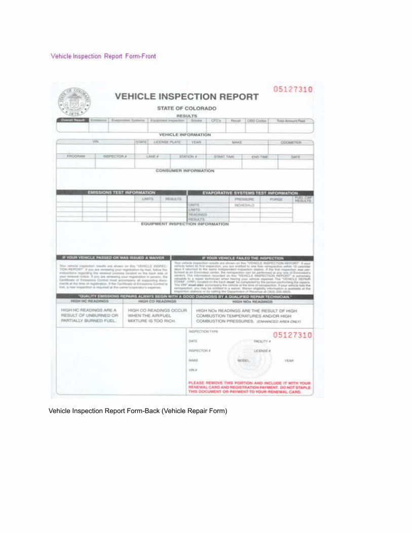
Vehicle Inspection Report Form-Back (Vehicle Repair Form)
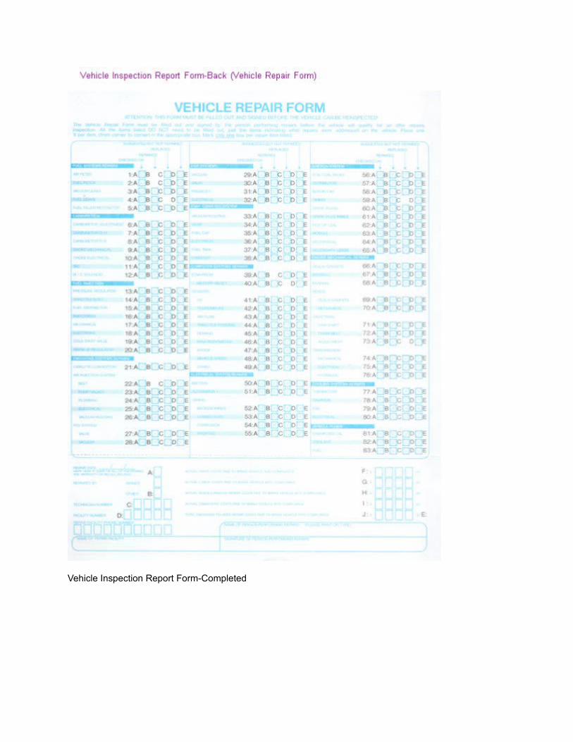
Vehicle Inspection Report Form-Completed
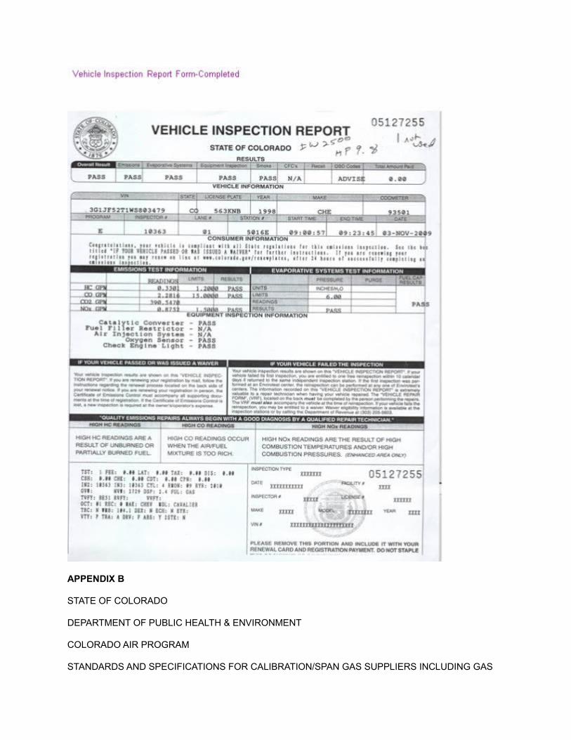
APPENDIX B
STATE OF COLORADO
DEPARTMENT OF PUBLIC HEALTH & ENVIRONMENT
COLORADO AIR PROGRAM
STANDARDS AND SPECIFICATIONS FOR CALIBRATION/SPAN GAS SUPPLIERS INCLUDING GAS
REQUIREMENTS FOR THE BASIC AND ENHANCED INSPECTION TEST PROGRAMS 1997
INTRODUCTION
This Appendix B describes the standards and specifications for the suppliers of span and calibration gases to the Colorado AIR Program, including facility requirements and documentation required of potential suppliers.
CONTENTS
SECTION 1: Definitions
BASIC AND ENHANCED IDLE AIR PROGRAM
SECTION 2: Technical requirements
SECTION 3: Calibration/span gas approval & labeling
SECTION 4: Cylinder tracking and recall
ENHANCED IM & IG 240 AIR PROGRAM
SECTION 5: Technical requirements
SECTION 6: Calibration/span gas approval & labeling
AIR PROGRAM/BASIC AND ENHANCED
SECTION 7: Blender facility requirements & documentation
ATTACHMENT I
Program Contact/Addresses/Phone Numbers
ATTACHMENT H
“Colorado Approved” Label Samples
SECTION 1 DEFINITIONS
AIR: Colorado's “Automotive Inspection & Readjustment” Program.
ANALYTICAL ACCURACY: The relative percent deviation of the stated concentration of the components of a gas blend from the “true” value as determined by comparison with Colorado AIR Program standards.
(% DEV = STATED CONC - “TRUE” CONC/“TRUE” CONC X 100)
AUDIT GAS: Reference gas standards with direct traceability to NIST and/or EPA, to be used by AIR Program QA/QC personnel.
APCD: Colorado “Air Pollution Control Division” .
AUTHORIZED GAS BLENDER: A blender of precision gas products selected to provide such products pursuant to the requirements of 42-4-306(3)(A)(l)(C).
BALANCE GAS: The balance or makeup gas for Colorado AIR Program gases shall be as follows: for basic program tri-blend span gases, nitrogen shall be the balance gas. For the enhanced IM 240 program standards and span gases, air shall be the balance gas. The balance gas for mixtures containing nitric oxide (NO) shall be nitrogen.
BAR: California “Bureau of Automotive Repair”
BLEND TOLERANCE: Deviation between the requested or nominal concentration and the measured or certified concentration of a gas mixture.
CALIBRATION STANDARD: A precision blended gas used to generate calibration curves, with an analytical accuracy of +/- 1%, traceable to NIST gas standards. (Enhanced Program)
CALIBRATION/SPAN GAS: A blend of carbon monoxide (CO), carbon dioxide (CO2), and propane, with a balance gas of nitrogen (NO2), which is used to calibrate the Colorado 94 test analyzers. (Basic program)
CALIBRATION ZERO AIR: The gas used as a diluent for gas dividers or to establish analyzer zero during calibration curve generation. Impurities shall not exceed 0.1 ppm carbon response, 0.5 ppm CO, 1 ppm CO2, 0.1 ppm NOx, and 1 ppm moisture. Blended air shall have oxygen content between 20.6% and 21%
CALIBRATION ZERO NITROGEN: The gas used as a diluent for gas dividers or to establish analyzer zero during calibration curve generation shall have a minimum purity of 99.997% with impurities not to exceed 0.1 ppm carbon response, 0.5 ppm CO, 1 ppm CO2, 0.1 ppm NOx, 1 ppm moisture and 0.5 ppm O2.
CAPSL: Colorado AIR Program Standards Lab.
CDPHE: Colorado Department of Public Health & Environment.
CERTIFIED GAS BLENDER: A blender of precision gas products, approved by the Colorado AIR Program. A certified blender has met or exceeded the requirements set forth by the CDPHE to provide a consistently high quality calibration and span gas to both the Basic and Enhanced Air Program.
CGA: Compressed Gas Association
CRM: Certified Reference Material
DOT: Department of Transportation
FID: HC analyzer using a flame ionization detector
FED FUEL: A mixture of 40% hydrogen (+/- 2%) and 60% helium
FID OXIDIZER: Zero grade air with oxygen content between 20.6% And 21 %
GOLD STANDARDS: NIST traceable air program standards named by EPA at the National Vehicle Fuels and Emission lab (NVFEL), Ann Arbor, Michigan
NIST: National Institute of Standards and Technology
STATE: The State of Colorado
SRM: Standard reference material. The highest integrity gas standard, prepared by, and only available
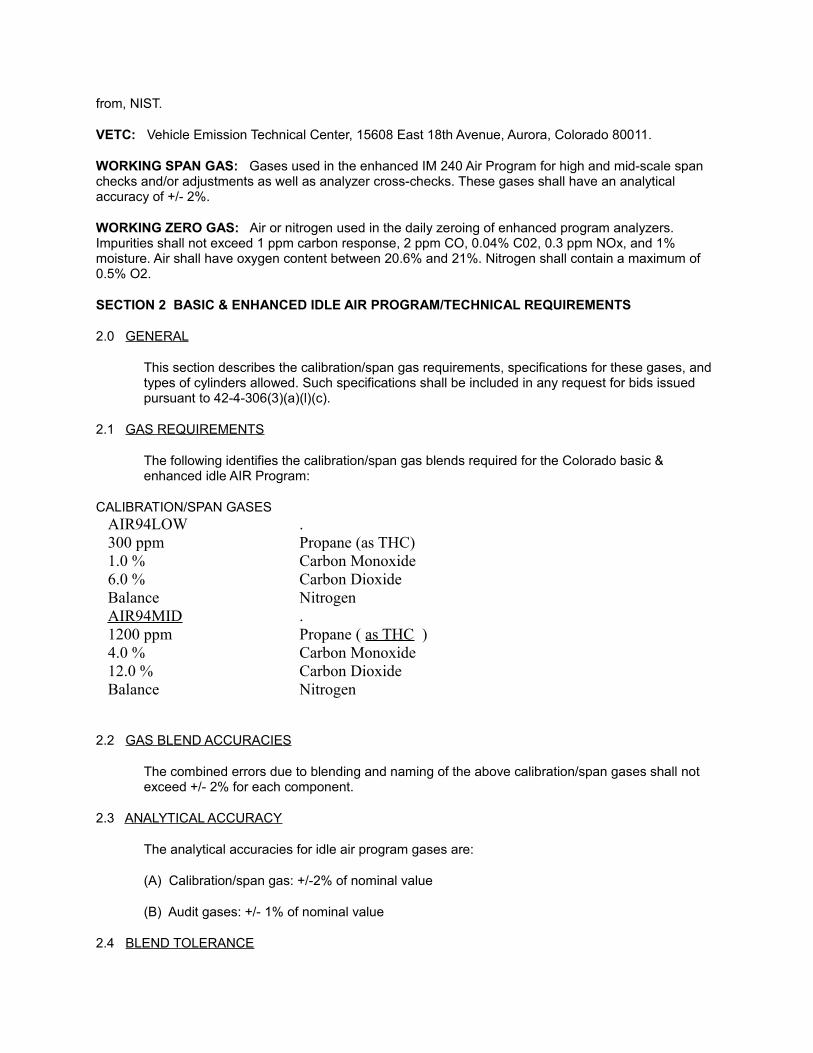
from, NIST.
VETC: Vehicle Emission Technical Center, 15608 East 18th Avenue, Aurora, Colorado 80011.
WORKING SPAN GAS: Gases used in the enhanced IM 240 Air Program for high and mid-scale span checks and/or adjustments as well as analyzer cross-checks. These gases shall have an analytical accuracy of +/- 2%.
WORKING ZERO GAS: Air or nitrogen used in the daily zeroing of enhanced program analyzers. Impurities shall not exceed 1 ppm carbon response, 2 ppm CO, 0.04% C02, 0.3 ppm NOx, and 1% moisture. Air shall have oxygen content between 20.6% and 21%. Nitrogen shall contain a maximum of 0.5% O2.
SECTION 2 BASIC & ENHANCED IDLE AIR PROGRAM/TECHNICAL REQUIREMENTS
2.0 GENERAL
This section describes the calibration/span gas requirements, specifications for these gases, and types of cylinders allowed. Such specifications shall be included in any request for bids issued pursuant to 42-4-306(3)(a)(l)(c).
2.1 GAS REQUIREMENTS
The following identifies the calibration/span gas blends required for the Colorado basic & enhanced idle AIR Program:
CALIBRATION/SPAN GASESAIR94LOW .300 ppm Propane (as THC)1.0 % Carbon Monoxide6.0 % Carbon DioxideBalance NitrogenAIR94MID .1200 ppm Propane ( as THC )4.0 % Carbon Monoxide12.0 % Carbon DioxideBalance Nitrogen
2.2 GAS BLEND ACCURACIES
The combined errors due to blending and naming of the above calibration/span gases shall not exceed +/- 2% for each component.
2.3 ANALYTICAL ACCURACY
The analytical accuracies for idle air program gases are:
(A) Calibration/span gas: +/-2% of nominal value
(B) Audit gases: +/- 1% of nominal value
2.4 BLEND TOLERANCE
Zero blend tolerance is required for basic & enhanced idle AIR Program calibration span gases.
2.5 BLENDER REFERENCE STANDARDS
Each authorized gas blender shall present documentation of its own internal standards for approval. The state provides two methods for standard documentation:
(I) Blender may prepare a reference cylinder of each gas blend intended for the AIR Program to be named vs. Colorado's gold standards. Cylinder(s) shall be sent to the state for naming and labeling. This standard will become the blender's reference standard for the analysis of production span gases.
NOTE: The associated costs of shipping reference cylinders to and from Colorado will be the responsibility of the blender. No shipping costs will be borne by the state.
(II) Blenders certified by the State of California, Bureau of Automotive Repair, may elect to submit copies of their current certification including a listing of all SRM's, CRM's, or other reference gases accepted by bar, as pertaining to the analysis of I/M span gases. BAR acceptance of these standards will be sufficient to obtain approval of same for the AIR Program.
2.6 CYLINDERS
The cylinders to be used in the Colorado 94 analyzers in the field shall be low pressure, non refillable, disposable canisters.
High pressure, refillable cylinders will be used by AIR Program audit/QC teams and, in some cases, by analyzer manufacturers. Approval of span gas in high pressure cylinders will be on an individual basis. (See Section 3)
2.7 DISPOSABLE CYLINDERS
(A) Disposable cylinders shall be in accordance with dot specification 39 for non refillable, disposable cylinders. (260 PSIG service pressure, 325 PSIG test pressure, 650 PSIG minimum burst pressure) [CFR Title 49, Part 178, Section 178.65, Oct 1, 1996]
(B) Nominal size shall not exceed 750 cubic inches +/- 5% (approximately 9 inches inside diameter by 16 inches high, providing an equivalent water capacity of 27 lbs.) As a minimum, cylinders shall contain 7.5 cubic feet of gas blend at 260 PSIG cylinder pressure.
(C) Cylinders shall be designed with an integral stand to facilitate upright storage.
(D) Cylinder outlet shall be CGA 165, 1/4” SAE flare, 45 degree male. Shutoff valves shall be of the non refillable type.
(E) Cylinders shall be equipped with a safety relief device in accordance with DOT regulations [CFR 49, 173.34,(D), Oct, 1996]. The safety relief device must comply with the requirements of the compressed gas association pamphlet S.1.1, 8th Edition, 1994.
(F) Cylinders shall have a built in safety shield to protect the shut off valve.
(G) No material shall be used in cylinder fabrication or assembly, or in cylinder charging equipment, which is incompatible with the gas blend as to cause contamination or degradation.
(H) Blenders must comply with applicable DOT specifications for the shipment of cylinders. [CFR Title 49, Volume 2, Part 173, Subpart B, Oct, 1996].
2.8 HIGH PRESSURE REFILLABLE CYLINDERS
(A) Refillable cylinders must be aluminum and made in accordance with DOT specifications 3AA or 3AL [CFR Tide 49, Volume 2, Part 178, Subpart C, Oct, 1996], whichever is applicable.
(B) All cylinders must comply with applicable DOT Regulations and requirements for safety and shipment. [CFR Title 49, Volume 2, Part 173, Subpart B, Oct, 1996]
2.9 LABELING
(A) Caution labels shall be affixed to all cylinders and shall comply with applicable DOT and OSHA regulations.
(B) “Colorado Approved” labels will be provided by the Colorado AIR Program (Section 3) and shall be affixed to the upper portion of the canisters.
2.10 EXPIRATION
Triblend span gas cylinders containing CO, CO2, and propane in nitrogen, shall have an expiration date of 36 months after date of fill.
2.11 QUALITY ASSURANCE
All gas blenders shall have in place a fully documented and implemented quality assurance program as a prerequisite to certification. This QA program shall include, but not be limited to:
(A) Regular equipment maintenance and calibration, performed in accordance with manufacturer guidelines, as a minimum.
(B) Documentation of the analysis of each batch or lot of gas produced. A copy of the certificate of analysis from each batch or lot shall accompany each approval request.
(C) Blender may choose to retain a cylinder from each batch/lot for internal documentation. However, one cylinder from each batch/lot must accompany each request for “Colorado Approved” labels. This sample cylinder will not be returned.
(D) Documentation of maintenance and calibration of equipment and instrumentation shall be made available upon request.
2.12 BREACH OF TERMS
Each contract entered into pursuant to 42-4-306(3)(a)(l)(C), shall authorize the APCD to suspend the blender's authority to supply precision gas products to inspection and readjustment stations, inspection-only facilities, fleet inspection stations, motor vehicle dealer facilities and enhanced inspection centers in the event the gas blender violates the terms of the contract and this appendix B. The APCD may terminate such a suspension once the blender corrects the problems that led to the violation. An onsite inspection of the blender's facility by an APCD representative may be required to ensure that the relevant requirements are being observed.
SECTION 3 CALIBRATION/SPAN GAS APPROVAL & LABELING
3.0 GENERAL
Information in this section describes the calibration/span gas approval process as well as the procedure for obtaining “Colorado Approved” labels.
3.1 CALIBRATION SPAN GAS APPROVAL PROCEDURE
Batches or lots of span gas will be produced referencing procedures and specifications contained herein. Authorized blender shall analyze a representative number of cylinders from each batch or lot. Authorized blender shall then request from the CDPHE a number of Colorado approved labels corresponding to the number of cylinders in that batch or lot. The request for labels must include:
(I) Analytical report to contain:
(A) Actual analysis of samples in batch
(B) Number of cylinders in batch
(C) Fill date
(D) Number of labels required
(E) Batch or lot number
(II) One representative cylinder from each batch or lot of span gas produced to be verified by analysis and retained for future reference.
NOTE: This sample cylinder will not be returned. Cylinder will be archived by the state until the expiration date expires (36 months from fill date). This sample may be analyzed as a spot check or reference gas in matters concerning potential inquiries into batch integrity.
Upon approval, blender will be sent an appropriate number of “Colorado Approved” labels to be affixed to cylinders in that batch or lot.
Samples, along with request for “Colorado Approved” labels, should be sent to: CDPHE
VEHICLE EMISSION TECHNICAL CENTER
15608 E. 18TH AVENUE
AURORA, COLORADO 80011
ATTN: SPAN GAS VERIFICATION PROGRAM
3.2 CALIBRATION/SPAN GAS APPROVAL/HIGH PRESSURE CYLINDERS
Approval of calibration/span gases in high pressure cylinders will be done on an individual basis. Each cylinder seeking approval must be submitted for verification against AIR Program standards. A certificate of analysis shall accompany each cylinder and shall contain the following information:
(A) Cylinder number
(B) Components contained
(C) Analytical results
(D) Analytical accuracy
(E) Statement of traceability
(F) Analysis date
(G) Fill date
Upon approval, blender will be notified that the cylinder is ready for pickup by the purchaser. Approved cylinder, with “Colorado Approved” label attached, may be picked up during normal business hours (8:00 am - 5:00 pm) Monday through Friday. Cylinders shall be sent to the above address. (See 3.1)
3.3 SHIPPING COSTS
Blenders shall provide for the shipping of all cylinders seeking Colorado approval for use in the AIR Program. The pick-up and delivery of individual high pressure cylinders is also the responsibility of the blender and/or the purchaser of that cylinder. These cylinders are expected to be picked-up within 30 days of notification of approval. No costs pertaining to the pick-up or delivery of span gases shall be borne by the state.
3.4 LABELING
“Colorado Approved” labels will be provided by the State of Colorado. These labels will include information necessary to track span gases throughout the system as well as identify each cylinder as Colorado approved. Information contained on the label will include:
(A) Blender name
(B) Blending facility
(C) Batch or lot number
(D) Identify “low” (yellow label) or “mid” (white label) SPAN GAS
(E) Fill date
(F) Expiration date
(G) AIR Program number
(H) Bar code containing cylinder tracking information
(For a sample of the “Colorado Approved” labels, see attachment II)
3.5 AIR PROGRAM NUMBER
“Colorado Approved” labels will contain an AIR Program number. Each certified blender will be assigned a letter code that will precede the numbering of batch cylinders. These coded numbers will be generated by the state and assigned to each cylinder as batches of span gas are produced. Cylinder numbers will be held on file for the life span of the cylinder to assist in tracking, auditing and accounting purposes.
SECTION 4 CYLINDER TRACKING & RECALL
4.0 GENERAL
This section describes the method of tracking calibration/span gas throughout the AIR Program area. This system protects the inspection stations and provides for a replacement, in an expedient manner, should a non-conforming calibration/span gas be discovered.
4.1 TRACKING CYLINDERS VIA BAR CODE
Each “Colorado Approved” label will contain a bar code to be scanned whenever a cylinder of calibration/span gas is put into service on a Colorado 94 analyzer or Motor Vehicle Dealer Transient Mode Test Analyzer System. Scanned information will be stored in a file, accessible through a host computer linking all inspection stations. AIR Program QA/QC personnel will be able to locate individual cylinders, track batches of span gas, etc., throughout the program area.
Label bar codes will be generated at the time of batch or lot approval and will contain information necessary to facilitate the tracking process. Blenders are required to continue to track internally, the whereabouts of “Colorado Approved” batches of calibration/span gas prior to retail sale. In the event of a recall of a batch of non-conforming calibration/span gas, the blender, through procedure described herein (see 4.2), will begin recall. In-use calibration/span gas affected will be identified by bar cod; information through system host and replacement procedures will begin.
4.2 RECALL PROCEDURE
In the event a non-conforming cylinder of calibration/span gas is discovered at an AIR Program inspection station, the following recall procedure will begin:
(A) Suspected non-conforming span gas confiscated by AIR Program Q/C personnel;
(B) Cylinder brought to the Colorado AIR Program Standards Lab (CAPSL) for analysis;
(C) Exposed non-conforming cylinder cross referenced by air number go blender and batch;
(D) Archived sample retrieved and analyzed vs. suspected non-conforming cylinder. Blender advised of results;
(E) Through host system, the state identifies whereabouts of any non-conforming cylinders on line. Blender provided with a listing of affected inspection stations;
(F) Blender shall immediately begin recall of all remaining unsold cylinders from batch in question and, simultaneously, begin process of supplying known conforming cylinder(s) to affected inspection stations by overnight service;
(G) A total recall and replacement of all cylinders in affected batch must be completed within 10 days. A detailed report of the recall procedure and analysis of cause of the non-conforming product entering the system will be provided to the state within 15 days.
(H) The state may elect to withhold certification of future batches until such time as blender shows problems have been corrected.
(I) The state may also suspend the contract with the blender if information obtained suggests blending procedures were violated, pending a correction of the problems that caused the violation.
SECTION 5 ENHANCED IM & IG 240 AIR PROGRAM / TECHNICAL REQUIREMENTS
5.0 GENERAL
This section addresses the calibration gases, technical requirements, cylinder specifications and documentation required for IM & IG 240 testing.
5.1 GASES
Gases used in the calibration and support of IM & IG 240 testing shall conform to the provisions outlined in CFR Title 40, Part 86, Subpart B, Section 114, as revised July 1, 1992, for exhaust emission testing. Concentrations for IM 240 gases are as follows:
5.2 CALIBRATION GASES/CURVE GENERATION
(I) High tri-blends: (+/-1% analytical accuracy)
CO: 9000 ppm
C02: 3.6%
Propane: 600 ppm
Balance: Air
(II) High NOx: (+/-1%)
NOx: 450 ppm
Balance: Nitrogen
5.2.1 MID-SCALE CALIBRATION GASES/CURVE CONFORMATION
(I) Mid tri-blend: ( +1-1% )
CO: 4500 ppm
C02:1.8 %
Propane: 300 ppm
Balance: Air
(II) Mid NOx tri-blend: (+/-1%)
NOx: 225 ppm
Balance: Nitrogen
5.2.2 CALIBRATION ZERO GASES
(I) Calibration zero AIR
HC: < 0.1 ppm
CO: < 0.5 ppm
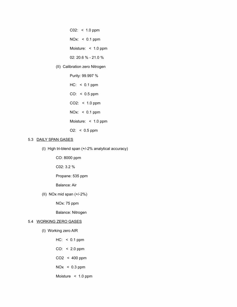
C02: < 1.0 ppm
NOx: < 0.1 ppm
Moisture: < 1.0 ppm
02: 20.6 % - 21.0 %
(II) Calibration zero Nitrogen
Purity: 99.997 %
HC: < 0.1 ppm
CO: < 0.5 ppm
CO2: < 1.0 ppm
NOx: < 0.1 ppm
Moisture: < 1.0 ppm
O2: < 0.5 ppm
5.3 DAILY SPAN GASES
(I) High tri-blend span (+/-2% analytical accuracy)
CO: 8000 ppm
C02: 3.2 %
Propane: 535 ppm
Balance: Air
(II) NOx mid span (+/-2%)
NOx: 75 ppm
Balance: Nitrogen
5.4 WORKING ZERO GASES
(I) Working zero AIR
HC: < 0.1 ppm
CO: < 2.0 ppm
CO2 < 400 ppm
NOx < 0.3 ppm
Moisture < 1.0 ppm

OY2: 20.6-21.0 %
(II) Working zero Nitrogen
Purity: 99.997%
HC: < 1.0 ppm
CO: < 2.0 ppm
C02: < 400 ppm
NOx: < 0.3 ppm
Moisture: < 1.0 ppm
02: < 0.5 ppm
5.5 SUPPORT GASES
A variety of miscellaneous support gases are required for IM & IG 240 testing. Among these are:GAS USAGEPropane: 99.5% (min) CVS system flow checksMethane: 50 ppm/AIR FID check gasFID Fuel: 40% H2/60% HE
FID burner fuel
N02: 200 ppm/N2 NOx converter efficiency test gas
AIR: 18%-21% NOx ozonator gas
5.6 IG 240 GASES
Calibration, span, working and support gases required by IG 240 systems, are among the gases listed (5.2 thru 5.5). Additional gases of specific concentrations and blend make-up may be required pending final configuration of the IG system.
5.7 CYLINDERS
Calibration and working gas tri or quad-blends used for IM & IG 240 testing, must be supplied in aluminum cylinders as well as all no or NOx blends. Other gases may be supplied in steel or aluminum cylinders as appropriate.
High pressure refillable cylinders shall be manufactured in accordance with DOT specifications 3AL or 3AA [CFR Title 49, Volume 2, Part 178, Subpart C, Oct l, 1996], whichever is applicable.
Approved valves and relief devices, appropriate for the intended use, shall be used on all high pressure cylinders. [CFR Title 49, Volume 2, Subpart B, Section 173.124, Oct 1, 1996]
All cylinders shall have appropriate labeling to comply with all DOT regulations concerning transportation and safety. [CFR 49, Volume 2, Part 173, Subpart B, Oct 1, 1996].
5.8 MISCELLANEOUS
A full line of gas products shall be made available to the enhanced AIR Program contractor(s) to insure safe handling and storage of gas cylinders, such as regulators, carts, restraints, and leak detection equipment. The contractor(s), as well as state QA/QC personnel, may also request a variety of gas blends, tri-blends, and other specialty gas products associated with automotive emission testing. Blender must demonstrate the ability to provide the above gases, equipment and associated products, in order to be designated as an approved blender to the Colorado enhanced AIR Program.
5.9 CERTIFICATES OF ANALYSIS
Each calibration gas, working span gas, and calibration zero gas shall be documented by a certificate of analysis to include; cylinder number, components, analytical results, accuracy, traceability and analysis date. A batch analysis certificate stating purity may document zero grade air and nitrogen. (Zero AIR certificate must also provide documentation of oxygen content.)
The enhanced program contractor(s) must produce documentation of cylinder contents of the above upon request of state QA/QC personnel.
5.9.1 TRACKING CYLINDERS VIA BAR CODE
Each “Colorado Approved” label will contain a bar code to be scanned whenever a cylinder of calibration/span gas is put into service on a Colorado 94 analyzer or Motor Vehicle Dealer Transient Mode Test Analyzer System scanned information will be stored in a file, accessible through a host computer linking all inspection stations. AIR Program QA/QC personnel will be able to locate individual cylinders, track batches of span gas, etc., throughout the program area.
Label bar codes will be generated at the time of batch or lot approval and will contain information necessary to facilitate the tracking process. Blenders are required to continue to track internally, the whereabouts of “Colorado Approved” batches of calibration/span gas prior to retail sale. In the event of a recall of a batch of non-conforming calibration/span gas, the blender, through procedure described herein (see 4.2), will begin recall. In-use calibration/span gas affected will be identified by bar code information through system host and replacement procedures will begin.
SECTION 6 COLORADO APPROVAL PROCESS
6.0 CALIBRATION STANDARDS AND AUDIT GASES
All calibration standards used in the Colorado Enhanced IM & IG 240 AIR Program must be submitted by the contractor to the state for approval and labeling as “Colorado Approved” . In addition, all audit gases utilized by AIR Program QA/QC teams will undergo the same verification and/or renaming process that will take place at the Colorado AIR Program standards lab (CAPSL) in Broomfield, Colorado. At CAPSL, each standard and/or audit gas will be read vs. program gold standards, named by EPA's NVFEL, in an effort to tie all primary gases to one source, regardless of manufacturer.
Each calibration standard and audit gas will receive a “Colorado Approved” label displaying the concentration of each major component as determined by analysis comparing such calibration standard or audit gas to the program gold standards. Labeled values are to be used in curve generation by the contractor and by audit teams to verify analyzer accuracy.
6.1 ZERO AIR/OXYGEN CONTENT
On a random basis, cylinders of zero air will be analyzed at CAPSL to verify oxygen content. As

previously stated, the oxygen content of artificial blended air shall be 20.6 to 21 %. This is necessary to insure that an air cylinder used as a backup to a zero air generator (zag), will provide air as close to ambient in 02 as possible, should a zag be taken offline. FID response has been shown to be greatly affected by the O2 content of oxidizer air. Random analysis will provide verification that O2 content in zero air is within specifications.
SECTION 7 BLENDER FACILITY REQUIREMENTS & DOCUMENTATION
7.0 GENERAL
(A) A gas blender who intends to supply calibration/span gas to the Colorado AIR Program basic inspection stations and/or enhanced program contractor(s), must be selected by the Colorado Department of Public Health & Environment pursuant to 42-4-306(3)(A)(l)(C).
(B) If a company has more than one facility that will be providing gases to Colorado, each must be included in the selection. The selection of one blending facility owned by a company does not imply or impart authority to other facilities within that company to supply precision gas products in Colorado.
(C) The CDPHE shall be notified of a pending sale of a blending facility at least 60 days prior to change of ownership.
(D) Contracts shall be for a one year period, but may be renewed annually.
7.1 CONTRACT PROPOSAL PACKET
The certification request packet shall contain information described in the following paragraphs. Information submitted should be as complete as possible. However, should some information be unavailable, so indicate and provide reasons, therefore, for AIR Program consideration.
7.2 CONFIDENTIAL AND COMMERCIAL INFORMATION
To the extent authorized by 24-72-101, C.R.S., the Colorado Department of Public Health & Environment shall maintain the confidentiality of any information which is included in the blender's bid and which is clearly marked as proprietary or confidential.
7.3 APPLICATION
The following items are to be included in blenders request for air program approved status:
(A) COVER SHEET - An application cover sheet must be signed by the President or Chief Financial Officer of the gas blending company.
(B) BLENDING FACILITY DESCRIPTION -Provide a complete description of the blending facility to include:
— Facility location
— Physical dimensions of lab and production areas
— Number of employees
— General description of blending facility and procedures
(C) INSTRUMENTATION - Provide description of all instrumentation utilized in the blending
and analysis of AIR Program calibration/span gases. Provide instrumentation brand, model, type (NDIR, FID, GC, etc.). As well as calibration and maintenance schedules and personnel responsible.
(D) REFERENCE STANDARDS - Indicate the cylinder numbers, SRM/CRM numbers, concentrations and expiration dates for each NIST traceable reference standard to be used in the preparation and/or naming of AIR Program gases.
(E) BUSINESS STATUS REPORT - Application for certification shall contain information to verify blending facility's status as a bona fide blender of precision gases. Include evidence that applicant is a registered corporation in Colorado and/or a registered out-of-state corporation.
(F) DISTRIBUTORS AND MARKETING - Applicant shall provide a description of expected distribution and marketing plans for providing calibration/span gas to the basic AIR program. Include a current listing of the names, addresses and phone numbers of the distributors used by the applicant. Such information shall be updated as necessary and notification of any change provided to the state in a timely manner. Lists of distributors will be made available to AIR Program inspection stations.
(G) RECALL OF NON-CONFORMING GASES/BASIC PROGRAM - Certified blenders shall be responsible for the recall and replacement of non-conforming calibration/span gases. Blenders will be required to replace suspected non-conforming cylinders by overnight service. Should such a discovery extend past a single cylinder to a batch or lot, a total recall of all cylinders will take place. (See Section 4).
Applicant shall provide procedures intended for use should such a recall be necessary.
(H) QUALITY ASSURANCE - Applicant shall include information regarding internal quality assurance program(s). Provide details of techniques, methodology and documentation utilized in QA program. Include calibration and maintenance schedules for all equipment and instrumentation used.
(I) SAFETY REGULATIONS - Certification application must include assurance the applicant is in compliance with all applicable DOT and OSHA regulations and standards.
(J) LIABILITY - Provide a copy of product liability insurance demonstrating adequate protection (minimum $300,000) exists for catastrophic failure situations (e.g., cylinder or valve rapture, noxious gas leakage, etc.). Evidence of bonding coverage shall be provided upon request.
APPENDIX B ATTACHMENT I TO THE CALIBRATION AND SPAN GAS CERTIFICATION PROCEDURES
ATTACHMENT I
PROGRAM CONTACT/ADDRESSES/PHONE NUMBERS
PROGRAM CONTACT; The main contact on matters concerning air program gases, requirements and specifications is:
COLORADO DEPARTMENT OF PUBLIC HEALTH & ENVIRONMENT
VEHICLE EMISSION TECHNICAL CENTER
15608 EAST 18TH AVENUE
AURORA, COLORADO 80011
(303) 364-4135
ATTN: SPAN GAS VERIFICATION PROGRAM
OR
COLORADO AIR PROGRAM STANDARDS LAB
11609 TELLER STREET
BROOMFIELD, COLORADO 80020
(303) 404-0268.
APPENDIX B ATTACHMENT IITO THE CALIBRATION AND SPAN GAS CERTIFICATION PROCEDURES
Appendix B – Attachment II
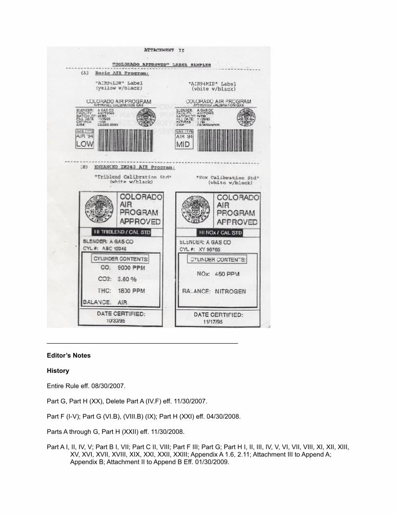
_____________________________________________________
Editor’s Notes
History
Entire Rule eff. 08/30/2007.
Part G, Part H (XX), Delete Part A (IV.F) eff. 11/30/2007.
Part F (I-V); Part G (VI.B), (VIII.B) (IX); Part H (XXI) eff. 04/30/2008.
Parts A through G, Part H (XXII) eff. 11/30/2008.
Part A I, II, IV, V; Part B I, VII; Part C II, VIII; Part F III; Part G; Part H I, II, III, IV, V, VI, VII, VIII, XI, XII, XIII, XV, XVI, XVII, XVIII, XIX, XXI, XXII, XXIII; Appendix A 1.6, 2.11; Attachment III to Append A; Appendix B; Attachment II to Append B Eff. 01/30/2009.
Entire Rule eff. 05/15/2010.
Part F (VI.A), Part H (XXV) eff. 09/30/2010.
Part F (III.C-E); Part H (XXVI) emer. rule eff. 11/01/2010; expired 02/18/2011.
Part F (III.C-D); Part H (XXVII) eff. 03/02/2011.
Part A (V.A), Part H (XXVIII) eff. 10/30/2011.
Entire rule eff. 06/30/2012.
Parts A – G, H (XXX) eff. 02/15/2013.
Copyright © 2022 FDOKUMEN