Criminal Procedure Code (1995 Revision) - Cayman Islands ...
Upload
khangminh22Category
view
0download
0
Revision of Grid Code and Distribution Code for facilitating Variable Renewable Energy Integration – Final Report
2
Imprint
Published by the
Deutsche Gesellschaft für
Internationale Zusammenarbeit (GIZ) GmbH
Registered offices
Bonn and Eschborn, Germany
MOIT/GIZ Energy Support Programme
Unit 042A, 4th Floor, Coco Building,
14 Thuy Khue, Tay Ho District
Hanoi, Viet Nam
T + 84 24 39 41 26 05
F + 84 24 39 41 26 06
www.giz.de/viet-nam
http://gizenergy.org.vn
http://smart-grid.vn/
As at
Dec 2019
Design and layout
Energy Support Programme
Text
Markus Pöller (M.P.E GmbH),
Nguyen Thanh Nam, Tran Anh Tuan (VietnamMW Co., Ltd)
GIZ is responsible for the content of this publication.
On behalf of the
German Federal Ministry for Economic Cooperation and
Development (BMZ)

3
Table of Contents Table of Contents .............................................................................................................................................. 3
Acknowledgement and Disclaimer ............................................................................................................. 5
1. Background and Introduction.................................................................................................................. 6
1.1. Background ................................................................................................................................................................. 6
1.2. Introduction ................................................................................................................................................................ 7
2. Comments on the Grid Code (Circular 25/2016 and Draft Amendments) ............................... 9
2.1. Amendment to Article 3, Circular 25 .................................................................................................................. 9
2.1.1. Paragraph 5a/Article 3 – Definition of rated power ......................................................................................... 9
2.1.2. Paragraph 10/Article 3 – Definition of frequency control services ............................................................. 10
2.2 Article 42 – Technical Requirements of wind and solar power plants ................................................. 11
2.2.1. Paragraph 1/Article 42 – Active power control ............................................................................................... 11
2.2.2. Paragraph 3/Article 42 – Frequency range of operation ............................................................................... 11
2.2.3. Paragraph 4/Article 42 – High frequency response ........................................................................................ 15
2.2.4. Paragraph 5 a) and b) /Article 42 – Reactive power capability ................................................................... 15
2.2.5. Paragraph 5 c) and d) /Article 42 – Voltage control ....................................................................................... 20
2.2.6. Paragraph 6 /Article 42 – LVRT/HVRT (paragraph 7 in proposed amendment) .................................... 25
2.2.7. Paragraph 8 /Article 42 – Harmonics ................................................................................................................. 28
2.2.8. Paragraph 9 /Article 42 – Flicker ........................................................................................................................ 28
2.2.9. Gaps ............................................................................................................................................................................ 29
3. Interconnection rules for LV connected inverters ......................................................................... 33
3.1 Background: Safety and performance ............................................................................................................... 33
3.2. Safety ............................................................................................................................................................................ 33
3.2.1. General ......................................................................................................................................................................................... 33
3.2.2. Switches ...................................................................................................................................................................................... 34
3.2.3. Earthing and short circuiting during maintenance work ....................................................................................... 34
3.2.4. Inverter protection ................................................................................................................................................................. 34
3.2.5. Unintentional islanding ........................................................................................................................................................ 35

4
3.2.6. Protection against DC current injection ......................................................................................................................... 36
3.2.7. PV-inverter systems for grid-parallel and island operation (UPS) ..................................................................... 36
3.3. Performance .............................................................................................................................................................. 36
3.3.1. General ......................................................................................................................................................................................... 36
3.3.2. Frequency ranges of operation .......................................................................................................................................... 36
3.3.3. Voltage ranges of operation ................................................................................................................................................ 36
3.3.4. Power quality ............................................................................................................................................................................ 37
3.3.5. Power factor control .............................................................................................................................................................. 37
3.3.6. Grid Disturbance/LVRT ........................................................................................................................................................ 37
4. Proposed changes to the Grid Code – Circular 25/2016 ............................................................... 38
5. Comments on the Distribution Code (Circular 39/2015) ............................................................ 49
References ......................................................................................................................................................... 63

5
Acknowledgement
and Disclaimer
This report was produced as part of activities within
the Smart Grids for Renewable Energy and Energy
Efficiency Project.
The authors would like to thank all who contributed
to the results presented in this report, in particular
the members of the Vietnamese GIZ office, ERAV,
and EVN subsidiaries for sharing their insights of the
Vietnamese power system. The views and opinions
expressed in this report are those of the authors and
do not necessarily reflect the positions of any other
parties involved in this assignment.
Markus Pöller (M.P.E GmbH)
Nguyen Thanh Nam (VietnamMW Co., Ltd)
Tran Anh Tuan (VietnamMW Co., Ltd)
6
Classically, the physical characteristics of synchronous generating systems define the dynamic performance
characteristics of power systems. However, with the increasing use of variable renewable energies, more and
more non-synchronous generating systems (converter driven system like wind turbine generators with fully
rated converter, PV-inverters or doubly fed induction machines), which are typically controlled by power
electronics converters will replace synchronous generators. With increasing penetration of non-synchronous
generating systems, their behaviour, and specifically their controls, will become defining factors for power
system dynamics.
1. Background and Introduction
1.1. Background
Whereas most of the dynamic (short-term) characteristics of synchronous generators depend on a
‘natural’ response due to physics (e.g. flux linkage, rotating masses etc.), the dynamics of non-
synchronous generating systems almost exclusively depend on the design of their controller
algorithms which are defined using computer code by the plant manufacturers. These controllers can
quickly control electrical quantities like active and reactive power, within the technical capabilities of
the generating system. The key performance characteristics, which are of interest include:
• Provision of inertia
• The provision of short-circuit current (reactive current support during grid faults)
• Provision of synchronising torque and damping torque
• Provision of fast, short-term voltage support
These services, which are naturally delivered by synchronous generators because of their physics,
require explicit specification for non-synchronous generating systems.
Whereas synchronous generating systems are very relaxed regarding technical limits in the short-term
(up to 1s), non-synchronous generating systems are very restrictive because power electronic
converters have only limited short-term thermal overload capability. Synchronous machines can easily
deliver currents up to three or even five times their rated current in the short term, whereas power
electronic converters have either small or almost no technical overload capability. A typical value may
be something in the range of 1.2 per unit depending of their technology (e.g. air-cooled or water-
cooled). Consequently, services requiring thermal overload capability (e.g. provision of short-circuit
current or synchronizing torque) can be very costly for non-synchronous generating systems.
On the other hand, non-synchronous generating systems are much more resilient against frequency
excursions than synchronous generating systems, because electrical and mechanical systems are
entirely de-coupled (or because there isn’t any mechanical system as in case of PV or fuel cells).
These aspects must be considered when specifying technical connection rules for non-synchronous
generating systems with the aim at securing system security while avoiding unnecessary cost
overheads.
Technical connection rules for generating systems require the specification of voltage and frequency
limits of future power systems and the definition of services ensuring that voltage and frequency
(including rate of change of frequency/ROCOF) will remain within these limits. Technical withstand
capabilities of generating systems must finally be aligned with the specified voltage and frequency
performance.

7
Generally, it must be considered that tighter voltage and frequency limits relax the required technical
withstand capabilities of all components of a power system (including but not limited to generators) but
increase the need for services ensuring that the system can achieve this performance (and vice
versa). For example, allowing larger voltage excursions reduces the need for reactive power control
capability (and control dynamics), or, allowing larger ROCOF reduces the required inertia.
Because reactive power services can optionally also be provided by grid-side components, the
definition of mandatory reactive power services of generators should always be based on a cost-
benefit analysis comparing generator-side and grid-side provision of these services.
Besides grid connection rules, power systems with considerable share of variable renewable
generation, such as wind or PV require adjusted operational procedures. Aspects like wind and PV
generation forecast and the integration of those tools in operational processes must be defined and
implemented. Additionally, ancillary service procurement must be reviewed because in situations with
very large share of wind and PV, primary frequency control or inertia require a certain number of must-
run-synchronous units in operation, or wind and PV must actively contribute to those services.
Optionally, battery energy storage can be used to provide frequency control services under these
conditions.
Finally, data exchange guidelines must be established, which define data to be exchanged between
grid operators and plant operators.
To verify that renewable power plants comply with the requirements defined by the grid connection
conditions, grid code compliance procedures must be defined. Grid code compliance procedures
should include:
• Grid code compliance studies (during the planning phase)
• Grid code compliance tests (during commissioning)
• Grid code compliance monitoring (during commercial operation)
Only together with sound grid code compliance procedures, system security of a system with large
share of variable renewables can be ensured.
1.2. Introduction
In Vietnam, as is the case for many other countries around the globe, it is expected that more and
more synchronous generating systems will be replaced by non-synchronous generating systems in the
near future.
To reflect the fact that this will cause substantial changes to the performance characteristics of the
future Vietnamese power system, ERAV has proposed amendments to the Vietnamese Grid Code.
These changes are considered necessary to ensure secure system operation of the future
Vietnamese power system.
GIZ has engaged M.P.E. to review the existing grid code together with the proposed amendments.
The review outlined in this document specifically comments on the following points:
• To what extent manufacturers are able to meet the proposed technical requirements for wind and
solar generators. This can include:
o The extent to which the requirements are becoming standard in equipment and international
grid codes
o What costs to comply may exist and whether these are considered reasonable

8
o If unreasonable costs do exist what changes could be made to the proposed requirement(s)
that will deliver the same intended outcome
• Extent to which the grid code and the proposed amendments ensure system security, and whether
there are any alternative options to achieve the same outcome.
• Whether the grid code including the proposed amendments creates any unnecessary barriers to
entry of any specific generation technology type and, if so, how these could be avoided or mitigated
• To what extent the requirements of the grid code and the proposed amendments are inconsistent
with other international grid codes.
• Related practical evidence / examples as to how other jurisdictions balance their grid code
frameworks in terms of cost versus capability.
• Commentary as to whether the proposed standards align with other grid code frameworks, or are
there other mean by which these outcomes could be achieved, such as markets or operations
9
2. Comments on the Grid Code (Circular 25/2016 and Draft
Amendments)
2.1. Amendment to Article 3, Circular 25
2.1.1. Paragraph 5a/Article 3 – Definition of rated power
2.1.1.1. Summary of proposed amendment
5a: Nominal power of power plant is equal to total nominal power of power plant sets. Nominal power
of set is a parameter declared by the manufacturer in the design of set. For solar power plant, nominal
power of solar power plant is equal to the set power of solar cell panels multiplying conversion ratio of
inverters declared by the manufacturer.
2.1.1.2. International practice
VDE-AR-4120 [1] and VDE-AR-4130 [2]
Nominal power Pn:
Nominal Power is the maximum active power production under nominal conditions, as declared by the
manufacturer
PAV:
Agreed power of the connection: Maximum power total power at connection point, as agreed between
the network operator and the client
The Grid Code, National Grid, U.K. [3]:
Rated MW:
The “rating-plate” MW output of a Power Generating Module, Generating Unit, Power Park Module,
HVDC Converter or DC Converter, being:
a) …..
b) the nominal rating for the MW output of a Power Park Module or Power Generating Module being
the maximum continuous electric output power which the Power Park Module or Power
Generating Module was designed to achieve under normal operating conditions; or
c) …..
2.1.1.3. Comments and Recommendations
We recommend using a declared value, which applies at the grid connection point and which represents the maximum power that a power plant is allowed to produce at the grid connection point.

10
2.1.2. Paragraph 10/Article 3 – Definition of frequency control services
2.1.2.1. Summary of proposed amendment
10. Frequency control includes: Primary frequency control, secondary frequency control and third level
frequency control, in which:
a) Secondary frequency control is the next control process of primary frequency control that is carried
out by the impact of AGC system to generation sets detailed and ones providing secondary frequency
control in electric system;
b) Third level frequency control is the adjustment by the intervention of dispatch order to make electric
system frequency operated stably in the current regulation and in assurance of economic distribution
of generation power of generation sets.”
2.1.2.2. International practice
Terms like Primary, Secondary and Tertiary control should be defined by the Operation Code at
system level and in the Connection Condition from a plant performance point of view.
Plant performance: It is important to define for each type of frequency control
• Response time
• Activation time
• Time during which the service must be sustained
• Method to activate
2.1.2.3. Comments and Recommendations
In the existing grid code (circular 25/2016) we find definitions of the terms “primary frequency
adjustment”, “secondary frequency adjustment”. Tertiary (or Third Level) is missing. Should the new
definitions of the amendment replace or complement the existing definitions?
Article 72 of the Grid Code defines Ancillary Services. The terms used there is Frequency Regulation
and Spinning Reserve. It is important that the definitions made in the Connection Conditions and
Ancillary Service Definitions are consistent.
Mandatory technical requirements for generating units should be part of the connection conditions.
E.g. “Article 6 - Technical requirements for the governor system of generation units” of the frequency
control procedure should be transferred into the connection conditions section of the grid code,
because all units must have the capability to provide this service.
Article 7 of the Ancillary Service procedure contains definitions of timings. We recommend reviewing
connection conditions, frequency control procedure and ancillary service procedure for consistency.
Also Level I, Level II and Level III frequency regulation services are not entirely clear (could also be a
problem with translation into English and an inconstancy of terminology arising from the translation).
In total, we find the following terms:
- Primary frequency control, primary frequency reserve, governor system
- Frequency regulation Level I, Level II and Level II, AGC, secondary control
- Spinning reserve,
At least the English versions of grid code, ancillary service procedure and frequency control procedure
11
must be reviewed for consistency of these definitions.
2.2. Article 42 – Technical Requirements of wind and solar power plants
2.2.1. Paragraph 1/Article 42 – Active power control
2.2.1.1 Summary of requirements
The technical requirements distinguish between a “free generation mode” and “Generation capacity
control mode”. In the “Generation capacity control mode” a wind or PV farm is essentially required to
limit its active power output considering corresponding commands from the control centre.
We further understand that an amendment is proposed containing a minimum requirement for a ramp
rate limit, which is 10% of nominal power per minute.
2.2.1.2. International practice
It’s a standard requirement of international connection conditions for wind and PV (e.g. U.K.,
Germany, South Africa, etc.) that wind and PV farms must have the technical capability to limit their
power output to a value defined remotely by the Control Centre. This is mainly used for managing grid
congestions and in cases, in which residual load lower than conventional must-run generation
requiring renewables to be limited to increase residual load.
Ramping requirements: We know about ramp-rate limits in some international codes (e.g. South
Africa) to avoid that a wind farm ramps too quickly. The definition of a minimum ramp rate is not very
common because wind and PV farms have fast ramping capabilities.
2.2.1.3. Comments and recommendations
The code should talk about “power limitation” instead of “dispatch instructions”. Essentially, the system
operator must be able to impose an upper limit to the power production of a wind or solar farm. The
wind/PV farm in turn must respect such a limit signal almost instantaneously (ramp rate of 10%/minute
seems to be very slow). We would rather define a time constant characterizing the step response of
the controller than a minimum ramping requirement.
Defining a minimum requirement for ramping up or ramping down can be misleading because a
wind/PV farm is never able to increase its production above the limits defined by the primary source of
energy (wind speed or solar irradiation). Therefore, the term “limitation” is better than the definition of
dispatch commands.
2.2.2. Paragraph 3/Article 42 – Frequency range of operation
2.2.2.1. Summary of requirements
According to Article 42 (3), wind and PV farms must be capable of maintaining generation of power for
a minimum period of time in proportion to frequency band prescribed in below:
Table 1: Minimum time to maintain power generation in proportion to frequency (Table 8 of Circular 25)
Frequency band Minimum time
From 47.5 Hz to 48.0 Hz 10 minutes

12
Over 48 Hz to under 49 Hz 30 minutes
From 49 Hz to 51 Hz Continuous generation
From 51 Hz to 51.5 Hz 30 minutes
Over 51.5 Hz to 52 Hz 01 minute
2.2.2.2. International practice
In fact, this paragraph 3 of Article 42 addresses two different aspects in one paragraph:
• Minimum time that a power plant must remain connected in the case that frequency is out of
normal operation.
• Permitted capacity reduction in the case of low frequencies
In the U.K. required frequency ranges of operation are similar to the Vietnamese requirements (see
Table 2). If frequency is below 49,5Hz, active power may be reduced in proportion to frequency, as
shown in Figure 1.
Table 2: Frequency ranges of operation according to the Grid Code/U.K. [3] (applies to all generator types)
Frequency band Minimum time
From 47.0 Hz to 47.5 Hz 15 minutes
Over 47,5 Hz to under 49 Hz 90 minutes
From 49 Hz to 51 Hz Continuous generation
From 51 Hz to 51.5 Hz 90 minutes
Over 51.5 Hz to 52 Hz 15 minutes

13
Figure 1: Minimum Active Power vs. Frequency according to the Grid Code/U.K. [3]
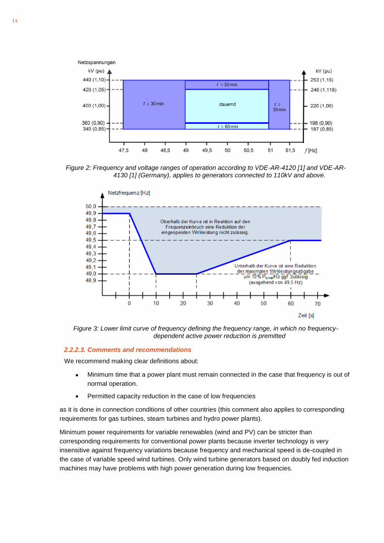
In Germany, frequency ranges of operation are defined by the diagram according to Figure 2.
No active power reduction is permitted if frequency is above 49,5Hz. In the time frame of up to 60s,
there is a lower limit curve defined, specifying the frequency range in which no active power
reduction is permitted in the short-term (see Figure 3).
Below this lower limit curve, a frequency-dependent active power reduction is permitted for gas and
steam turbines, which must not exceed the active power reduction according to the following formula
(which corresponds to a reduction of 10% of Pinst per Hz for frequencies above 49,5Hz)
49.50,1
1inst
Hz fP P
Hz
− =
14
Figure 2: Frequency and voltage ranges of operation according to VDE-AR-4120 [1] and VDE-AR-4130 [1] (Germany), applies to generators connected to 110kV and above.
Figure 3: Lower limit curve of frequency defining the frequency range, in which no frequency-dependent active power reduction is premitted
2.2.2.3. Comments and recommendations
We recommend making clear definitions about:
• Minimum time that a power plant must remain connected in the case that frequency is out of
normal operation.
• Permitted capacity reduction in the case of low frequencies
as it is done in connection conditions of other countries (this comment also applies to corresponding
requirements for gas turbines, steam turbines and hydro power plants).
Minimum power requirements for variable renewables (wind and PV) can be stricter than
corresponding requirements for conventional power plants because inverter technology is very
insensitive against frequency variations because frequency and mechanical speed is de-coupled in
the case of variable speed wind turbines. Only wind turbine generators based on doubly fed induction
machines may have problems with high power generation during low frequencies.

15
2.2.3. Paragraph 4/Article 42 – High frequency response
2.2.3.1. Summary of requirement
The required high frequency response according to Circular 25/2016 requires wind and PV generators
to reduce active power if frequency is above the normal range of operation (51Hz) according to the
following formula:
−=
50
0.5120 n
m
fxPP
- ΔP: Level of active power reduction (MW);
- Pm: Active power in proportion to the point of time prior to power reduction (MW);
- fn: Electricity system frequency prior to power reduction (Hz).
The factor of 20 is equivalent to a droop (slope) of 5% of Pm.
The amendment proposes the following modifications:
- Frequency reduction required above 50,5Hz (instead of 51Hz)
- Settable droop, between 0% and 5% of Pm.
2.2.3.2. International practice
In Germany and many other countries, a high-frequency response similar to the response defined by
circular 25 was common standard. However, high frequency response in Germany starts if frequency
is above the normal range of operation, which is 50,2Hz.
The newer codes VDE-AR-N-4120 [1] and VDE-AR-N-4130 [2] contain the following modifications:
- Frequency value, at which high frequency response is activated must be a settable parameter
(50,2Hz-50,5Hz)
- The static (droop setting) must be a settable parameter in a range between 2% and 12% of Pref
- Pref is a constant value (e.g. equal to Pinst)
2.2.3.3. Comments and recommendations
The frequency settings of the high frequency response should be in-line with Article 4 (“Frequency”,
part of the Operating Code). Here, 50,2Hz is specified to be the upper limit of the normal frequency
band of operation. Therefore, reducing the frequency value, at which high frequency response is
activated from 51Hz to 50,5Hz is reasonable. Also, a full alignment with German practice (settable
parameter, between 50,2Hz and 50,5Hz) would be appropriate in Vietnam.
A droop value of 5% generally works well. If the droop value is too low, there is a risk that high
frequency response is unstable. Therefore, defining a lower limit of the droop setting of e.g. 2% is
recommended.
2.2.4. Paragraph 5 a) and b) /Article 42 – Reactive power capability
2.2.4.1. Summary of requirements
According to the requirements of Article 42 (5a), wind and PV plants must have the capability of
injecting or absorbing reactive power, which is equivalent to a power factor of
cosphi=0,95/underexcited and cosphi=0,85/overexcited, if active power is above 20% of rated power

16
and voltage is in a range between +/-10% of nominal voltage.
According to Article 42 (5b) If active power is below 20% of installed capacity, reactive power
capability can be reduced.
The proposed amendment adds a figure to illustrate the reactive power requirement. However, the
figure is not fully in-line with the actual requirement (only cosphi=0,95/overexcited)
2.2.4.2. International practice
The ENTSOE-RFG specifies limits, in which European TSOs can define reactive power requirements.
The limit curve is depicted in Figure 4.
Figure 4: Limits for reactive power requirement definitions in ENTSO-E systems
These limit curves don’t specify reactive power requirements as such but provide a guideline to
European TSOs about the specification of reactive power capability requirements. The interpretation
of the inner and outer envelope is the following:
• A reactive power capability profile (defined by a Q-V boundary curve) must be inside the inner
envelope (dashed line).
• The profile can then be moved and placed anywhere within the boundaries specified by the
outer envelope (solid line).
Further, the ENTSO-E-RfG defines upper limits for the Q/Pmax range and the voltage range for each
of the five synchronous areas belonging to ENTSO-E (see Table 3).
17
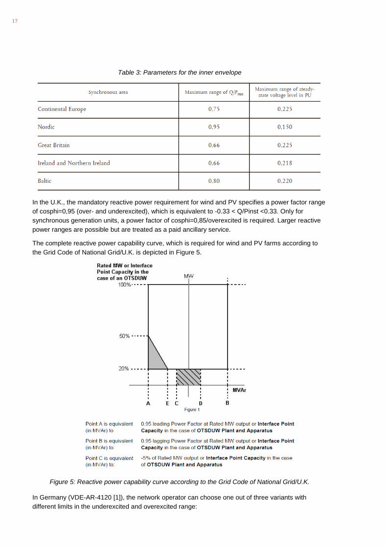
Table 3: Parameters for the inner envelope
In the U.K., the mandatory reactive power requirement for wind and PV specifies a power factor range
of cosphi=0,95 (over- and underexcited), which is equivalent to -0.33 < Q/Pinst <0.33. Only for
synchronous generation units, a power factor of cosphi=0,85/overexcited is required. Larger reactive
power ranges are possible but are treated as a paid ancillary service.
The complete reactive power capability curve, which is required for wind and PV farms according to
the Grid Code of National Grid/U.K. is depicted in Figure 5.
Figure 5: Reactive power capability curve according to the Grid Code of National Grid/U.K.
In Germany (VDE-AR-4120 [1]), the network operator can choose one out of three variants with
different limits in the underexcited and overexcited range:

18
• -0,41 < Q/Pinst < 0,33
• -0,33 < Q/Pinst < 0,41
• -0,24 < Q/Pinst < 0,48
Additionally, the German requirements specify voltage versus reactive power ranges as shown by
Figure 6 below and do not require that the complete reactive power range must be available in a
voltage range of +/-10% of nominal voltage.
Figure 6: Voltage versus reactive power ranges according to VDE-AR-4120 [1]
2.2.4.3. Comments and recommendations
The reactive power requirement according to Article 42 (5) is widely in-line with international practice.
However, a power factor range of cosphi=0,85/overexcited is large (Qmax/Pn=0.62) and can only be
realized at additional cost, by oversizing the inverters or by installing additional reactive power
equipment.
Comparing the Vietnamese requirements with the ENTSO-E guidelines leads to the following
conclusions:
- The reactive power range defined by the Vietnamese requirements defines a Q/Pmax-range of
0,95, which is beyond the maximum permitted range in most synchronous areas of ENTSOE. Only
TSOs of the Nordic area have the right to require such a large Q/Pmax range.
- The voltage range defined by the Vietnamese requirements is equal to 0.2. This is lower than in
most synchronous areas of the ENTSO-E but larger than the voltage range of the Nordic system.
Consequently, the Vietnamese requirements would not fit into the inner envelope according to Figure
4 for any of the five synchronous areas of the ENTSO-E. Therefore, the requirement can be
considered to be very strict and should be reconsidered.
A very large reactive power range can be justified in systems with particularly high reactive power
demand, e.g. resulting from demand with low power factor (e.g. because loads are not compensated)
or resulting from highly loaded transmission lines.
Weak networks (with low short circuit levels) usually require only small reactive power ranges because
in a weak network even small changes of reactive power lead to large voltage variations.
Additionally, it should be reconsidered, whether the complete reactive power range is required for the

19
complete voltage range. In situations with low voltage it is usually required that power plants deliver
overexcited reactive power and in situation with high voltage, it is required to deliver reactive power in
the underexcited range. The Q-V- curves according to the German VDE-AR-4120 [1] (see Figure 6)
reflect this.
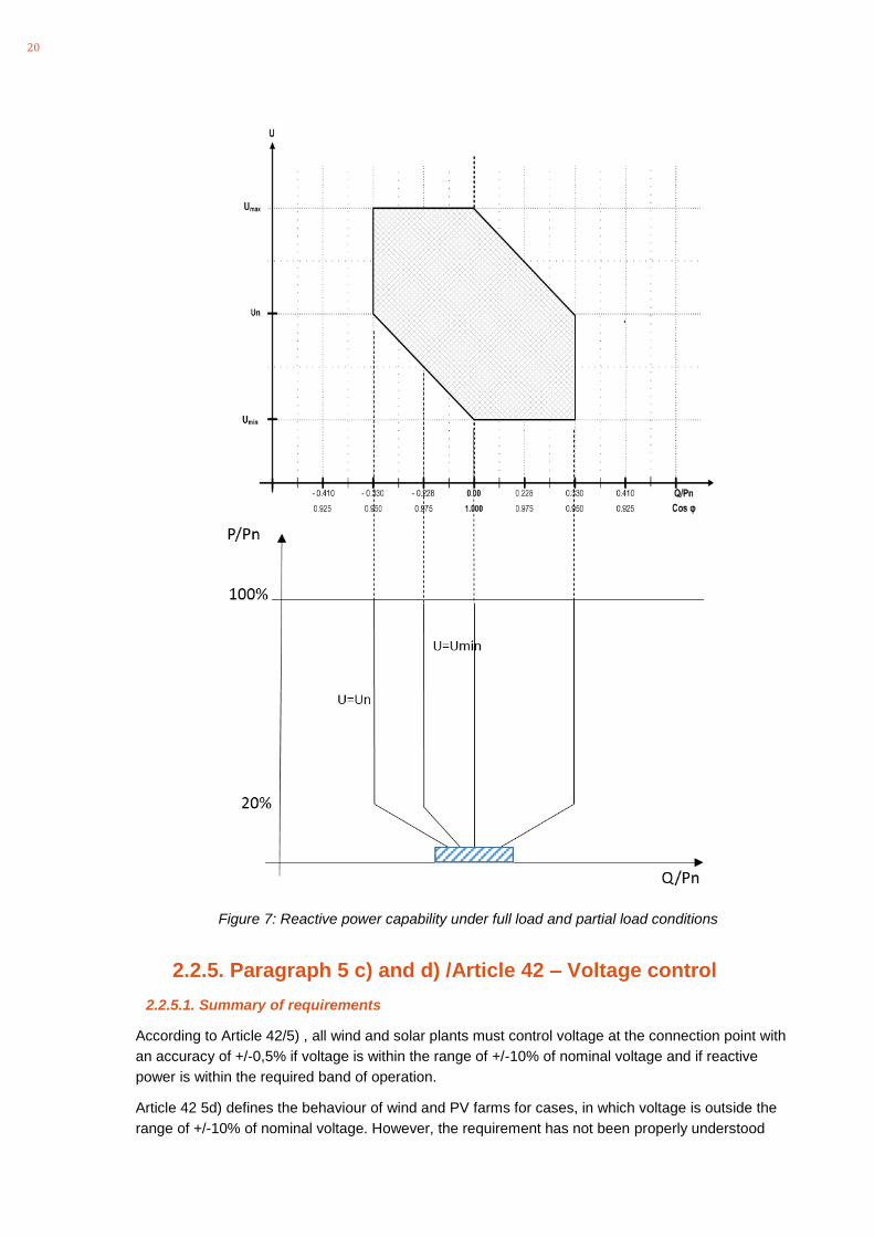
In order to clearly define reactive power requirements under full load and partial load conditions, a
representation as shown in Figure 7 could be used. Of course, the actual shapes would have to be
adapted to the Vietnamese requirements.
20
Figure 7: Reactive power capability under full load and partial load conditions
2.2.5. Paragraph 5 c) and d) /Article 42 – Voltage control
2.2.5.1. Summary of requirements
According to Article 42/5) , all wind and solar plants must control voltage at the connection point with
an accuracy of +/-0,5% if voltage is within the range of +/-10% of nominal voltage and if reactive
power is within the required band of operation.
Article 42 5d) defines the behaviour of wind and PV farms for cases, in which voltage is outside the
range of +/-10% of nominal voltage. However, the requirement has not been properly understood
21
(which might be due to the English translation). Therefore, we won’t comment on it.
2.2.5.2. International practice
In most countries, the TSO defines the required modes of reactive power/voltage control at the grid
connection point.
In contrast to conventional power plants, wind or PV farms control voltage (or reactive power)
continuously at the HV connection point. The park transformer controls voltage in the step-down
direction (regulates the MV-side voltage). Therefore, it is essential that the voltage control
characteristic at the HV connection point is properly defined.
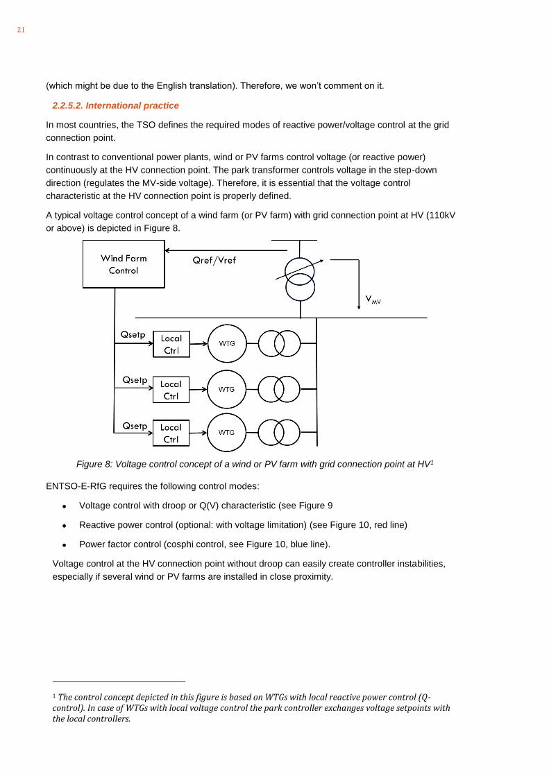
A typical voltage control concept of a wind farm (or PV farm) with grid connection point at HV (110kV
or above) is depicted in Figure 8.
Figure 8: Voltage control concept of a wind or PV farm with grid connection point at HV1
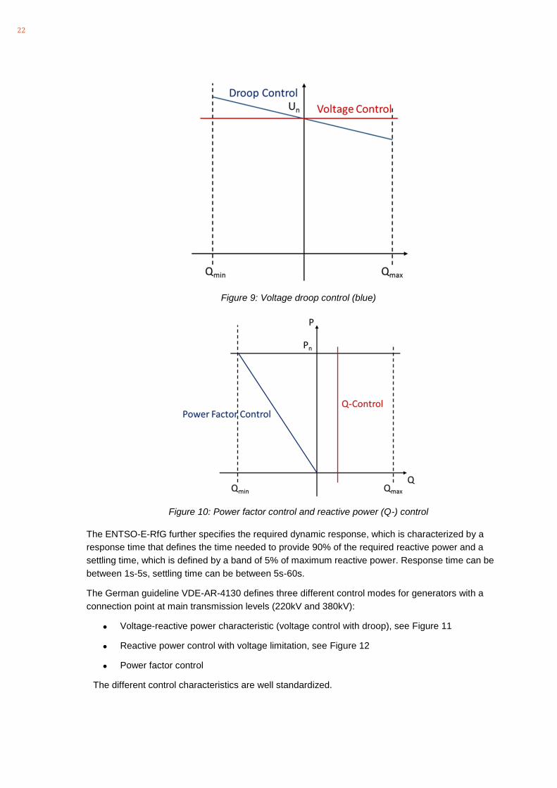
ENTSO-E-RfG requires the following control modes:
• Voltage control with droop or Q(V) characteristic (see Figure 9
• Reactive power control (optional: with voltage limitation) (see Figure 10, red line)
• Power factor control (cosphi control, see Figure 10, blue line).
Voltage control at the HV connection point without droop can easily create controller instabilities,
especially if several wind or PV farms are installed in close proximity.
1 The control concept depicted in this figure is based on WTGs with local reactive power control (Q-control). In case of WTGs with local voltage control the park controller exchanges voltage setpoints with the local controllers.
22
Figure 9: Voltage droop control (blue)
Figure 10: Power factor control and reactive power (Q-) control
The ENTSO-E-RfG further specifies the required dynamic response, which is characterized by a
response time that defines the time needed to provide 90% of the required reactive power and a
settling time, which is defined by a band of 5% of maximum reactive power. Response time can be
between 1s-5s, settling time can be between 5s-60s.
The German guideline VDE-AR-4130 defines three different control modes for generators with a
connection point at main transmission levels (220kV and 380kV):
• Voltage-reactive power characteristic (voltage control with droop), see Figure 11
• Reactive power control with voltage limitation, see Figure 12
• Power factor control
The different control characteristics are well standardized.

23
Figure 11: Voltage-reactive power control characteristic according to VDE-AR-41302
Figure 12: Reactive power with voltage limitation according to VDE-AR-41302
National Grid/U.K. requires a voltage-droop control characteristic, which is very similar to the German
2 Note: reactive power is in load orientation, negative value corresponds to overexcited reactive power, positive value corresponds to reactive power in the underexcited range.

24
control characteristic according to VDE-AR-4130 (see Figure 13)
Figure 13: Voltage control characteristic of National Grid/U.K.
With respect to dynamic performance, the German and British guidelines are very specific:
• VDE-AR-4130: response time: 1s-5s (T90%), settling time: 5s-60s (fully in-line with ENTSO-E
standard). Value is selected by TSO case by case.
• National Grid, U.K.: Response time: 1s, settling time: 2-3s (2 seconds from reaching the 90%
value).
2.2.5.3. Comments and recommendations
We recommend a clear specification of the required voltage/reactive power control modes. As
described above, wind and PV farms should be equipped with central controllers that control voltage
and reactive power at the point of connection. Park controllers should support the following control
modes:
• Voltage control with droop or Q(V) characteristic (see Figure 9
• Reactive power control (optional: with voltage limitation) (see Figure 10, red line)
• Power factor control (cosphi control, see Figure 10, blue line).
The selection of the control mode should be done by the system operator. It should be possible to
change the control mode at any time (remote access is not required because the control mode
shouldn’t be changed too often).
Setpoints should be remotely settable signals that can be controlled via the dispatch centre. Signal
lists and communication standards can either be integrated into the grid code or defined by additional
documents and communicated to wind or PV farm planners during the planning phase of a wind/PV
project.
With respect to dynamic response requirements, the connection conditions should be clear weather

25
fast voltage control (response within e.g. 1s) or slow voltage control (minute range) will be required.
This will have a considerable impact on the reactive power concept of wind/PV farms (e.g. whether
MSCDNs or switched inductors can be used to support reactive power provision).
Because the reactive power range is so large, we recommend defining rather slow response times
(e.g. 60s) so that mechanically switched components can be used for voltage control/reactive power
purpose. Optionally, the Vietnamese grid code could define a more narrow range, in which fast voltage
control is required (e.g. cosphi>0,95) and a larger range, in which voltage control can be supported by
mechanically switched components.
2.2.6. Paragraph 6 /Article 42 – LVRT/HVRT (paragraph 7 in proposed amendment)
2.2.6.1. Summary of requirements
Wind and PV farms must remain connected if voltage is above the red line and below the black line
(within the grey area) of Figure 14.
Figure 14: LVRT/HVRT curve
2.2.6.2. International practice
The ENTSO-E-RfG defines a standard curve with settable parameters as shown in Figure 15.
For Type D Power Park Modules (Wind/PV farms with connection at transmission level), the
parameters are defined as follows:
Table 4: LVRT parameters for wind/PV farms with connection point at transmission level (Type D) according to ENTSO-E-RfG
Parameter Value Parameter Value
Uret: 0s Tret 0.14s-0.15s (0.14s-0.25s if system protection and secure operation so require)
Uclear: Uret Tclear Tret
Urec1: Uclear Trec1 Tclear
Urec2: 0.85 p.u. Trec2 1.5s-3.s

26
Figure 15: LVRT-curve according to ENTSO-E-RfG
Expressing the Vietnamese requirements with the definitions and parameters of the ENTSO-E- RfG,
the following parameters would have to be used:
Table 5: Parameters of the Vietnames LVRT requirement, expressed by ENTSO-E-RfG definitions
Parameter Value Parameter Value
Uret: 0s Tret 0.15s
Uclear: 0.3 p.u. Tclear Tret
Urec1: Uclear Trec1 0.6s
Urec2: 0.9 p.u. Trec2 3s
The German LVRT requirements are fully in-line with ENTSO-E-RfG as depicted in Figure 16.
However, the German guidelines provide much more detail for the interpretation of the LVRT/HVRT
curve:
- LVRT applies to the lowest of the three line-to-line voltages
- HVRT applies to the highest of the three line-to-line or line-to-earth voltages
- Additionally, the German guidelines provide a HVRT limit curve for the maximum required voltage
step-change (see also Figure 17).
- The LVRT curve only applies in cases, in which the post-fault short-circuit ratio (Sk/Pn) is greater
than 6.
- The German guideline further specifies the required behaviour of a wind or PV farm in case of
LVRT or HVRT events (reactive current injection/dynamic voltage support, active power recovery
subsequent to a fault, reactive power behaviour during voltage recovery)
- The German guidelines also include requirements about multiple consecutive LVRT events.

27
Figure 16: LVRT/HVRT characteristic according to VDE-AR-4130 [2] (Germany)
Figure 17: Maximum required voltage step-change according to VDE-AR-4130 [2]
2.2.6.3. Comments and recommendations
The LVRT/HVRT requirements according to the Vietnamese grid code is widely in-line with
international practice. However, in order to verify whether it is appropriate or not, the following system
characteristics would have to be considered:
- The time of 150ms for U<0,3 p.u. should be greater or equal to the maximum fault clearing time.
This is the case (see Article 12: max. fault clearing time at 500kV: 80ms, max. fault clearing time at
220kV: 100ms). Based on the maximum fault clearing times at main transmission level, the time to
remain connected in case of U<0,3p.u. could even be reduced to e.g. 120ms.
- The lower limit curve between U=0,3p.u. and U=0,9p.u would have to be verified by analysing
voltage dips resulting from faults at distribution level and the corresponding fault clearing times.
- Additionally, it should be ensured that in case of faults at main transmission levels voltage recovery
is sufficiently fast to stay above the lower limit curve of the LVRT characteristic.
The HVRT requirement is in-line with some other international grid codes for wind generation (e.g.
South African grid code for RPPs). However, the current HVRT curve, as shown in Figure 14, makes
28
no further assumption with regard to the maximum possible voltage step change. Without such an
additional assumption, the maximum voltage step change is a variation from u=0.9p.u. to u=1.3p.u.,
which is equivalent to a voltage step-change of 0.4 p.u. Assuming that pre-fault voltage at the main
MV bus bar of a wind- or PV farm operates at a pre-fault voltage of 1.p.u., this would mean that the
worst post-disturbance voltage, for which a wind- or PV farm must remain connected would be equal
to 1.4 p.u. This would be extremely challenging. Therefore, we recommend introducing additional
voltage step-change limits, similar to the German practice (see Figure 17).
2.2.7. Paragraph 8 /Article 42 – Harmonics
2.2.7.1. Summary of requirements
According to the proposed amendments, the requirements for wind and PV farms at the connection point with respect to harmonics at the connection point are the following:
Total harmonic caused by wind, solar power plants at connection point is not allowed to exceed the following values:
a) Total harmonic distortion is not allowed to exceed 3% (in % of nominal voltage);
b) Total harmonic current is not allowed to exceed 5% (in % of nominal voltage).
2.2.7.2. International practice
In most countries, network operators refer to limits and procedures defined by IEC61000-3-6. The
procedure defined by IEC61000-3-6 is the following:
- Definition of compatibility levels for harmonic voltage distortion at every frequency.
- Definition of planning levels for harmonic voltage distortion at every frequency and at every bus
bar.
- Apportioning of harmonic distortion caused by load and generation at the different voltage levels.
As a result of this step, there would be a harmonic voltage limit per frequency for harmonic
distortions caused by all wind/PV farms in the system.
- Allocation of individual limits to each wind/PV farm in proportion to their installed capacity.
2.2.7.3. Comments and recommendations
The harmonic distortion requirement is not clear. E.g. it is not clear whether the limit of 3% (total
harmonic distortion) applies to harmonics caused by all wind and PV farms in the system or to each
individual wind and PV farm. Most likely it is meant that each wind or PV farm can cause a total
harmonic voltage distortion of 3% at its POC. However, if this was the case, the requirement would not
ensure that harmonic voltage distortion caused by several wind and PV farms in the system would
remain within the total voltage distortion limits (e.g. compatibility limits according to IEC61000-3-6).
Therefore, we strongly recommend adopting a procedure, which assigns individual harmonic limits by
applying a methodology, which is in-line with e.g. IEC61000-3-6. In this case, overall harmonics,
caused by load and generation could be maintained within required limits.
2.2.8. Paragraph 9 /Article 42 – Flicker
2.2.8.1. Summary of requirements
The requirements refer to Article 9 of Circular 25/2016.
Article 9 of Circular 25/2016 defines limits of long-term and short-term flicker (Plt and Pst) of Plt=0,6
29
and Pst=0,8. We understand that these requirements refer to flicker caused by all loads and
generators in the system.
2.2.8.2. International practice
The limit values for Plt and Pst of Plt=0,6 and Pst=0,8 are in-line with international standards.
However, the grid code should explicitly refer to IEC61000-3-7, which is the most widely used
standard for flicker, including measurement procedures, a flicker limit curve and a procedure to
allocate individual flicker limits to individual customers, including generators.
2.2.8.3. Comments and recommendations
Paragraph (9) of Article 42 should state how the system operator will fulfil its obligation to ensure that
flicker at all 220kV and 500kV bus bars will remain within the limits outlined in Article 9.
To do this, a procedure according to IEC61000-3-7 should be put in place, which is based on the
allocation of individual flicker limits to every load and generator in the system. Such a procedure is
described by IEC61000-3-7. The main idea of this procedure is that if every customer respects the
individual limits, which have been assigned to him, overall flicker will remain within the flicker limits
defined by Article 9 of Circular 25/2016.
2.2.9. Gaps
Article 42 of Circular 25 defines connection conditions for wind and PV plants. The requirements
defined by this article cover the most important aspects. However, there are some aspects, which are
not addressed but which are important.
2.2.9.1. ROCOF requirements
ROCOF states for “Rate of Change of Frequency”. Because increased penetration of wind and PV will
reduce the available inertia of the system, ROCOF will increase with increasing levels of wind and PV.
Therefore, it is important to defined maximum values of ROCOF, for which power plants (steam, gas,
hydro, wind and PV) are not allowed to disconnect.
For example, the German connection conditions for generators (VDE-AR-4120 [1] and VDE-AR-4130
[2]) define the following ROCOF limits:
- +/-2Hz/s for up to 0.5s
- +/-1.5 Hz/s for up to 1s
- +/-1.25Hz/s for up to 2s
Generally, we recommend requiring at least that all types of generators must remain connected if
ROCOF is below +/-1Hz/s.
2.2.9.2. Reactive current support during LVRT and HVRT events
The current requirements don’t specify the behaviour of wind and PV farms during a LVRT or HVRT
condition. In order to support the voltage during LVRT situations it should be required that every wind
or PV farm injects reactive current in proportion to the voltage dip (or voltage rise).
Such a requirement should be defined considering the following principles:
- Reactive current should be in proportion to the voltage dip (or voltage rise)
- Reactive current should be available almost instantaneously

30
- The provision of reactive current does not need to follow a precisely controlled response at the
connection point, but large tolerances are permitted. Therefore, reactive current injection can be
applied to currents and voltages at the LV terminals of a generating system
- In the case of temporary over-voltages, generating systems shall absorb reactive current for keeping
voltages low.
- The negative sequence response should be in-line with a negative sequence reactance.
When respecting the above principles, a reactive current support characteristic as depicted in Figure 18 is
resulting.
Figure 18: Reactive current support during LVRT and HVRT
The interpretation of this characteristic is the following:
- The current iq should be added to the pre-disturbance current
- The parameter K should be a settable parameter (range between 0 and 10 -> German requirement)
- The characteristic according to Figure 18 applies to positive sequence voltages and currents.
- A negative sequence current control should be implemented, which applies the same characteristic
but based on negative sequence voltages and currents.
- The total reactive current (sum of pre-disturbance reactive current and iq according to Figure 18)
can be limited to the rated current of the inverter/turbine (imax=1p.u.)
- During LVRT events, active current should be limited to a value of ipmax=1-|iq|. This ensures that an
inverter or wind turbine generator doesn’t try to inject active power above the voltage stability limit of
the grid (which can be very low under LVRT conditions).
- During HVRT events, active current should by prioritized over reactive current.
2.2.9.3. Active power recovery time
During an LVRT event, active power is reduced. Subsequent to an LVRT event, active should
recovery quickly (but not too quickly neither) with a ramp rate between 0.5 p.u./s and 1 p.u./s.
31
Slow active power recovery times of wind and PV farms would have a negative impact on frequency
stability of the system.
However, recent studies have also shown that too fast active power recovery can have negative
impact on transient stability and voltage stability. Therefore, upper and lower limits should be specified
for the active power recovery ramp rate.
2.2.9.4. Reactive power during voltage recovery
Old wind turbine generators using fixed speed induction machines (IEC-Type-1) or induction machines
with variable rotor resistance (IEC-Type-2), but also older wind turbines based on DFIG (IEC-Type-3)
using crow-bar protection show a risk of high absorbing reactive power during voltage recovery after a
grid fault. To avoid this, the connection conditions should clearly state that it is not allowed to absorb
more reactive power during voltage recovery than the pre-disturbance value.
2.2.9.5. Multiple LVRT
Multiple LVRT should always be addressed if
- Automatic re-closing is applied
- There is a risk of adverse weather conditions, which could cause several voltage dips with short
period of time (e.g. within 5 minutes).
International practice
Multiple LVRT has gained lots of attention since the South Australian blackout in September 2016,
which was initiated by six voltage dips that occurred within 120s because of very heavy weather
(storm and lightning). Because Multiple LVRT was not explicitly addressed in the AEMO market rules,
some wind turbine generators tripped on multiple LVRT leading to a loss of around 900MW of
generation in South Australia. This huge power deficit initiated a voltage instability across the
Heywood interconnector and the disconnection of the South Australian system from the national
interconnected Australian system.
Because at the time of this event, inertia in South Australia was extremely low (only very few gas
turbines were in operation), and because the power deficit was so large, frequency dropped very
quickly (with a very high ROCOF), which didn’t allow the underfrequency load shedding scheme to
operate properly and the final result was a blackout in South Australia.
In Germany, VDE-AR-4120 [1] requires ride-through capability for a total of four consecutive voltage
disturbance events with a total duration of 2s. However, VDE-AR-4120 [1] is not very specific about
the actual interpretation of this requirement and talks about the “… (calculational) ability” of riding
through four consecutive LVRT events. At the same time VDE-AR-4120 [1] states that this
requirement can be considered to be fulfilled if the chopper resistor has an energy absorption
capability of PEmax * 2s, with PEmax being the maximum power absorption capability of the chopper
resistor. This requirement is equivalent to four consecutive solid faults with a duration of 500ms each.
It therefore specifies how the chopper resistance of a wind turbine generator should be rated instead
of explicitly requiring that WTGs must remain connected in the case of up to four consecutive voltage
dips.
The Danish “Technical Regulation 3.2.5 for wind power plants with a power output above 11kW” [5],
published by the Danish TSO Energinet.dk in 2010 (revision 2 in 2015), probably contains the most
detailed requirement with respect to the ride-through capability of wind power plants for multiple LVRT
events.
First, it defines clearly that “If the voltage UPOC reverts to area A (normal operating range) after 1,5
32
seconds during a fault sequence, subsequent voltage dips will be regarded as a new fault situation…”.
It further states explicitly that disconnection is allowed in the case of two consecutive voltage dips that
occur before voltage reverts to its normal range of operation.
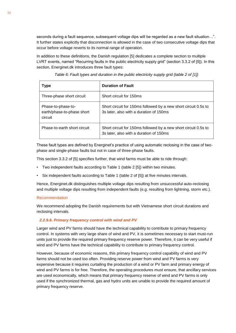
In addition to these definitions, the Danish regulation [5] dedicates a complete section to multiple
LVRT events, named “Recurring faults in the public electricity supply grid” (section 3.3.2 of [5]). In this
section, Energinet.dk introduces three fault types:
Table 6: Fault types and duration in the public electricity supply grid (table 2 of [1])
Type Duration of Fault
Three-phase short circuit Short circuit for 150ms
Phase-to-phase-to-
earth/phase-to-phase short
circuit
Short circuit for 150ms followed by a new short circuit 0.5s to
3s later, also with a duration of 150ms
Phase-to-earth short circuit Short circuit for 150ms followed by a new short circuit 0.5s to
3s later, also with a duration of 150ms
These fault types are defined by Energinet’s practice of using automatic reclosing in the case of two-
phase and single-phase faults but not in case of three-phase faults.
This section 3.3.2 of [5] specifies further, that wind farms must be able to ride through:
• Two independent faults according to Table 1 (table 2 [5]) within two minutes.
• Six independent faults according to Table 1 (table 2 of [5]) at five minutes intervals.
Hence, Energinet.dk distinguishes multiple voltage dips resulting from unsuccessful auto-reclosing
and multiple voltage dips resulting from independent faults (e.g. resulting from lightning, storm etc.).
Recommendation
We recommend adopting the Danish requirements but with Vietnamese short circuit durations and
reclosing intervals.
2.2.9.6. Primary frequency control with wind and PV
Larger wind and PV farms should have the technical capability to contribute to primary frequency
control. In systems with very large share of wind and PV, it is sometimes necessary to start must-run
units just to provide the required primary frequency reserve power. Therefore, it can be very useful if
wind and PV farms have the technical capability to contribute to primary frequency control.
However, because of economic reasons, this primary frequency control capability of wind and PV
farms should not be used too often. Providing reserve power from wind and PV farms is very
expensive because it requires curtailing the production of a wind or PV farm and primary energy of
wind and PV farms is for free. Therefore, the operating procedures must ensure, that ancillary services
are used economically, which means that primary frequency reserve of wind and PV farms is only
used if the synchronized thermal, gas and hydro units are unable to provide the required amount of
primary frequency reserve.

33
3. Interconnection rules for LV connected inverters
3.1. Background: Safety and performance
When connecting embedded generators to the grid, highest priority must be assigned to safety:
under no circumstances, consumers or utility staff shall be exposed to any additional risk that may be
caused by renewable generation.
Secondly, interconnection rules must ensure that other consumers or other embedded generators
connected to the same grid will not be exposed to disturbances caused by embedded generators (like
power quality issues, high or low voltage etc.)
Finally, in systems with a very high overall penetration of embedded generation, technical
requirements must be put in place, which ensure that the grid will be actively supported by embedded
generators. However, this is only required if the level of embedded generators is so high that during
extreme operational conditions, generators connected to transmission or subtransmission grids are
not able to provide the required ancillary services.
While ensuring that safety and security of the system is maintained, it is also important that overhead
costs resulting from technical requirements or compliance procedures remain low in comparison to
overall project costs. Otherwise, there is a high risk that the potential of small scale embedded
generation will not be unlocked.
With regard to costs, the following aspects must be considered:
- PV inverters are mass produced:
any technical requirement that requires changes to individual PV inverters require new
development, testing and adapted production.
- Deviation from international practice:
country-specific requirements of countries with relatively small PV markets require special
development and testing for only a small number of products. This introduces additional
market barriers, reduces competition, and hence will increase PV inverter costs in this market.
- Compliance Procedures:
costs of grid code compliance procedures do not scale with the size of a project. Hence,
relative costs of these procedures increase with decreasing project size. In order not to
endanger the economic viability of small rooftop PV projects, corresponding procedures must
be adjusted to project size.
These are just some of the aspects to consider. As a general rule, each individual technical
requirement of interconnection rules must be well justified in terms of system security.
In the following sections, some key elements of interconnection rules for LV-connected PV systems
will be introduced. These aspects include safety and performance aspects.
3.2. Safety
3.2.1. General
Every PV installation must comply with the local rules and regulations of LV installations. In most

34
countries, there is a general “electric code” or “wiring code”, in which all relevant installation, earthing
and protection aspects are specified.
However, in many cases, the existing standards don’t cover PV-inverter systems specifically and
require some additions in order to ensure safety of grid-parallel PV-inverter systems.
3.2.2. Switches
Installation requirements must ensure:
- Protection of the owner and operator of the PV system against short circuit and electric shock
- Protection of the public grid against malfunctioning of the PV-inverter
For this purpose, the connection point of the PV inverter system must be protected by a disconnect
breaker, which is equipped with short circuit protection, overload protection and, if required by the
DNO, residual current detection (RCD).
The second type of protection, protection against malfunctioning of the PV-inverter, can either be
realized by an integrated disconnect device, which is built into the PV-inverter, or an independent
disconnect switch may be required, which is independent from the PV inverter and integrates all
relevant protection functions into a separate device.
According to the German VDE-AR-N 4105 guideline [6], only for inverter systems with a rating >30kVA
an independent switch device is required for inverter protection. For smaller PV installations, the built-
in disconnect device is accepted.
3.2.3. Earthing and short-circuiting during maintenance work
According to the internationally accepted “five safety rules”, it is recommended but not mandatory to
short-circuit and earth LV feeders during maintenance work (likewise MV and HV grids).
In those LV networks, where it is common practice to earth and short-circuit LV feeders before starting
with any maintenance work, the risk resulting from unintentional back-energization of LV inverters is
substantially lower than in systems, in which earthing and short circuiting of LV feeders is not common
practice. For those systems, additional safety measures must be put in place:
In some countries, it is a mandatory requirement that the central disconnect switch is accessible to the
distribution utility and can be locked in the open position. This is indeed a solution to this problem but it
is of course very difficult to organize that disconnect switches of all PV inverters are opened and
locked prior to any maintenance work.
Another possibility is to require an independent inverter protection switch, which operates independent
from the inverter for all systems (not only for larger inverter systems, as it is practice in Germany).
3.2.4. Inverter protection
The inverter protection shall integrate the following type of protection functionality:
• Over-/under-voltage
• Over-/under-frequency
• Unintentional islanding
• Protection against DC current injection (in case of transformer-less inverters only)
In the case that voltage or frequency gets out of bound, embedded generators should disconnect

35
automatically. However, it has to be ensured that protection settings are specified, which are not in
conflict with corresponding performance requirements. It is generally strongly recommended to clearly
distinguish between so-called “must remain connected” requirements, which effectively represent
performance requirements and “must disconnect” requirements, which represent safety requirements.
In order to ensure that inverters don’t disconnect while they still operate within the limits specified by
“must remain connected” requirements, it has to be ensured that there are no overlaps between both
requirements. An example of “must remain connected” and “must disconnect” settings is depicted in
Figure 19.
Figure 19: "Must remain connected" and "Must trip conditions" for voltage
3.2.5. Unintentional islanding
In the case that an LV feeder is disconnected from the grid, there is a theoretical risk that embedded
PV-inverter systems continue energizing the feeder and form an “unintentional island”.
It is even extremely unlikely that such an island will sustain for more than a few seconds. A maintained
island would require a proper balance of active and reactive power, which is very unlikely because
there is neither frequency control nor voltage control on typical rooftop PV-inverters. Besides this, the
control of grid-tight inverters requires an external AC voltage source as a reference for
synchronization.
Only in the presence of small synchronous generators in the same feeder, the likelihood of such an
event is considerable.
However, protection against unintentional islanding should be a mandatory requirement in connection
conditions for SSEG.
With this regard, passive and active methods have to be distinguished:
- Passive methods: These are simple “out of bound” conditions, like over-/under-voltage or
over-/underfrequency.
- Active methods: There are several “active methods” common, like the “frequency shift
method” or “impedance measurement methods”.
The general recommendation is to require at least one active anti-islanding detection method, e.g.
36
according to IEC 62116: Test procedure of islanding prevention measures for utility-interconnected
photovoltaic inverters, or as specified in Annex D of VDE-AR-N 4105.
3.2.6. Protection against DC current injection
In the case of transformer-less inverters, there is a certain risk that an inverter feeds DC-currents back
into the grid, which could possibly influence the saturation of transformers.
In order to ensure the identification of DC current injections, it is recommend to require a specific RCD
(residual current detection) device, which is able to detect DC currents. This functionality can either be
integrated into the PV-inverter or in a separate device (see also IEC61209-2:2011).
3.2.7. PV-inverter systems for grid-parallel and island operation (UPS)
There are PV-inverter systems available, which are suitable for grid-parallel operation and island
operation and can therefore be used as UPS system as well. For these systems, special safety
measures against unintentional back-energisation have to be put in place. Because of the general
ability of these inverters to supply an electrical island, the likelihood that such an inverter back-
energizes an islanded LV feeder is substantially higher compared to inverters, which are not suitable
for island operation.
3.3. Performance
3.3.1. General
In order to ensure that PV inverter systems don’t disturb any other consumer or generator or even
endanger the stability of the power system (only in case of high penetration levels), they have to
comply with a set of performance requirements, which are presented and discussed in the following
sections:
3.3.2. Frequency ranges of operation
Frequency is a global parameter in a power system. In the relevant time frames, frequency is the
same at all nodes in a synchronized area, independent from the voltage level.
For this reason, there is a high risk of common mode failures (one cause, multiple trips) if frequency
ranges of operation are not defined appropriately.
The general rule for the specification of frequency ranges of operation is that they should be the same
for all generators at all voltage levels (transmission to LV).
In the past, many interconnection rules for LV connected generators only required operation within the
normal frequency range of operation. However, with increasing penetration of embedded generation,
system operators realized that this increasingly represents a risk to the stability of the power system.
In Germany, this issue became known as the “50,2Hz-problem” and it was necessary to upgrade all
PV inverters for operation in a wide frequency range.
3.3.3. Voltage ranges of operation
Voltage ranges of operation should be in-line with the generally applicable power quality criteria for the
voltage in LV feeders (typically +/-10%).
37
3.3.4. Power quality
Interconnection rules for LV connected PV-systems shall address the following power quality aspects:
- Harmonics
- Flicker
- Rapid voltage changes
- Voltage unbalance
With respect to power quality, the generally applicable standard (e.g. IEC61000-3-2 or IEC61000-3-12
for harmonics and IEC61000-3-3 or IEC61000-3-11 for flicker, depending on the installed capacity, or
national power quality standards) shall be addressed.
3.3.5. Power factor control
Because voltage control by adjusting reactive power is very inefficient in LV feeders (because of the
low X/R ratios of LV lines and cables) power factor or reactive power control is not recommended for
LV networks.
Instead of a power factor or reactive power control capability, a tolerance range for power factor
should be specified, which can be very narrow (e.g. cosphi>0,99).
In Germany, power factory control is a requirement according to VDE-AR-N-4105. However, because
it indeed turned out that reactive power compensation on PV inverters for reducing maximum voltages
is very inefficient, there are not many distribution network operators actually using it. Instead, MV-LV
transformers with on-load tap changers or LV-LV voltage regulators become increasingly popular for
limiting voltages on LV networks.
Therefore it is strongly recommended not to require PV inverter to operate in power factor control or to
provide an extended reactive power capability.
3.3.6. Grid Disturbance/LVRT
LVRT refers to the ability of a PV inverter to “ride through” voltage sags without disconnecting. As
described in section 2.4.4, a simple LVRT capability without any further requirement with regard to the
provision of reactive current can be supported quite easily by PV-inverters, without any substantial
cost overhead.
However, when asking for LVRT, it is very important to specify precisely the required response of PV-
inverters during a low voltage condition. Otherwise, the current response of PV-inverters during LVRT
situations becomes unpredictable, which could have a disturbing impact on protection selectivity in LV
and MV grids.
Alternatively, some sort of tolerance against voltage sags could also be formulated as a
recommendation (not as a requirement), as it is done for loads, so that frequent disconnections
because of voltage sags can be avoided.
38
4. Proposed changes to the Grid Code – Circular 25/2016
Article 3,35: Short-term flicker perceptibility (Pst) is a value measured for ten minutes by a flicker
meter according to IEC61000-4-15
Article 3,36: Long-term flicker perceptibility (Plt) is a value calculated from 12 measurement results of
short-term perceptibility for about two hours (see IEC61000-3-7 and IEC61000-4-15) using following
formula:
Article 3, 57:
Electromagnetic compatibility Level: specified electromagnetic disturbance level used as a reference
level in a specified environment for co-ordination in the setting of emission and immunity limits
(definition according to IEC61000-3-6)
Article 3, 58:
Harmonic compatibility level: Electromagnetic compatibility level applying to harmonic distortions (see
IEC61000-3-6).
Article 3.59
Flicker compatibility level: Electromagnetic compatibility level applying to flicker perturbations (see
IEC61000-3-7).
Article 3, 61:
Nominal power: The nominal power is defined as the maximum continuous electric output power
which a power plant was designed to achieve under normal operating conditions. Generators are not
allowed to generate more than nominal power on a 15-minute average.
Article 3.62:
Residual Load: Residual Load is defined by Load minus generation from variable renewable energy
sources (wind and solar PV).
Article 3, 63:
Definition of Primary, Secondary Frequency control as well as manually activated reserve must be
defined consistently amongst all relevant documents. Grid Code: The terms Frequency Regulation,
Spinning Reserve, Quick-Start Reserve are used.
Article 8,2: Please remove (what is “demand distortion”)?
Article 8.1:
Harmonic distortion
a) Permissible maximum value of total harmonic distortion (based on percentage of nominal voltage)
caused by high-level harmonic components to the voltage level 220 kV and 500 kv is not allowed
to exceed 3%.
b) In normal operation, harmonics at individual frequencies should be within the Indicative Planning
Levels for EHV and HV systems according to IEC61000-3-6.

39
Article 8.2:
To ensure that harmonics remain within these limits, the transmission system operator shall assign
individual harmonic limits for harmonic voltage emissions of loads, MV/HV networks and generators.
The allocation procedure should follow the procedures described by IEC61000-3-6.
Article 8.3:
Customers using transmission grid shall ensure that their equipment is designed to operate securely
and safely without any disturbance if harmonics remain within a THD of 3% and the indicative planning
levels for EHV and HV systems according to IEC61000-3-6.
Article 9.2:
2. The transmission network operator is responsible that flicker perceptibility on the transmission grid
remains below the value prescribed in Table 5 in normal operation mode. For this purpose, the
transmission network operator shall follow the procedures described by IEC61000-3-7.
3. Customers using the transmission grid shall ensure that their equipment operates securely and
safely if flicker is below the values prescribed in Table 5.
Chapter III
(RESIDUAL) LOAD FORECASTING FOR NATIONAL ELECTRICITY SYSTEM
Article 16.1.
1. Residual Load forecasting for the national electricity system is forecasts on demand for loads to be
supplied by the national electricity system except loads from independent power supplies and not
connected to the national grid and generation from variable renewable energies such as wind and
solar PV. Residual Load forecasting for the national electricity system is grounds for making annual
electricity transmission system development plans, plans and methods for operation of electricity
system, electricity market.
Article 16.2
2. Residual Load forecasting for the national electricity system includes annual, monthly, weekly and
daily forecasts on loads and electricity market transaction cycle.
Article 16.3.
a) The electricity system and market operator shall make forecasts on loads for the national electricity
system, electricity systems in the Northern, Central and Southern Vietnam and connection points. He
further shall execute forecasts on variable renewable energy generation plants with an installed
capacity of more (or equal to) 30MW.
Comment: The responsibility for wind and PV systems with a nominal power <30MW is unclear at this
stage. During the workshop, no agreement could be found on this aspect. It should be amended here
as soon as it is decided.
b) Electricity distribution units, electricity retailers and electricity customers shall provide load forecasts
to the electricity system and market operator including forecasts on demand for loads of the entire unit
and individual 110 kV transformers.
Article 17.3.
e) Renewable energy expansion plans.
Article 17.4
40
Results of annual residual load forecasting for national electricity system include: Maximum capacity,
electrical energy, typical daily diagrams in a 30-minute cycle for 104 weeks of national, regional
electricity systems and connection points.
Article 18.1
The monthly load forecast includes demand and electricity generated from variable renewable
energies (wind and solar PV). The result of monthly load forecasting is a forecast of the residual load
(demand minus wind and solar generation), which must be supplied by the dispatchable power plants
of the system.
Article 18.4.d)
d) Generation of renewable energy sources, like wind and PV.
Article 19.1
1. The weekly load forecast includes demand and electricity generated from variable renewable
energies (wind and solar PV). The result of weekly load forecasting is a forecast of the residual load
(demand minus wind and solar generation), which must be supplied by the dispatchable power plants
of the system.
Article 20.1
The daily load forecast includes demand and electricity generated from variable renewable energies
(wind and solar PV). The result of daily load forecasting is a forecast of the residual load (demand
minus wind and solar generation), which must be supplied by the dispatchable power plants of the
system.
c) Generation of variable renewable energy sources (wind and PV) in a 30-minute cycle of the next
transaction cycle and eight cycles thereafter.
Article 23.4.
List of power generation projects (including renewable energy power plants) connecting to the
transmission grid for next year with account taken of the year thereafter accompanied by planned
connection points, connection agreements for these power generation projects.
Article 24.2 d)
Expected capacity of wind and solar power plants connected to their distribution grids.
Article 29.4.
On the request of the transmission system operator, substations must be equipped with voltage
transformers, which are able to measure harmonic voltages up to 50th order with sufficient accuracy
Article 38.8.
Frequency gradient: If the rate of change of frequency does not exceed the limit of Hz per second,
provided that the network frequency is still within the frequency operating range indicated in Table 7
above, power plants must remain connected (no disconnection allowed).
Section 4. TECHNICAL REQUIREMENTS OF WIND AND SOLAR POWER PLANTS
Article 42. Technical requirements of wind and solar power plants
Article 42.1
Wind and solar power plants with installed capacity over 30 MW must be equipped with facilities,
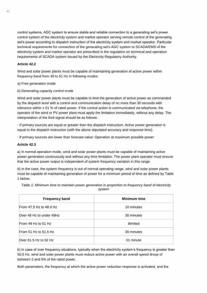
41
control systems, AGC system to ensure stable and reliable connection to a generating set’s power
control system of the electricity system and market operator serving remote control of the generating
set’s power according to dispatch instruction of the electricity system and market operator. Particular
technical requirements for connection of the generating set's AGC system to SCADA/EMS of the
electricity system and market operator are prescribed in the regulation on technical and operation
requirements of SCADA system issued by the Electricity Regulatory Authority.
Article 42.2
Wind and solar power plants must be capable of maintaining generation of active power within
frequency band from 49 to 51 Hz in following modes:
a) Free generation mode
b) Generating capacity control mode
Wind and solar power plants must be capable to limit the generation of active power as commanded
by the dispatch level with a control and communication delay of no more than 30 seconds with
tolerance within ± 01 % of rated power. If the contral action is communicated via telephone, the
operator of the wind or PV power plant must apply the limitation immediately, without any delay. The
interpretation of the limit signal should be as follows:
- If primary sources are equal or greater than the dispatch instruction; Active power generation is
equal to the dispatch instruction (with the above stipulated accuracy and response time).
- If primary sources are lower than forecast value: Operation at maximum possible power
Article 42.3
a) In normal operation mode, wind and solar power plants must be capable of maintaining active
power generation continuously and without any time limitation. The power plant operator must ensure
that the active power output is independent of system frequency variation in this range.
b) In the case, the system frequency is out of normal operating range, wind and solar power plants
must be capable of maintaining generation of power for a minimum period of time as defined by Table
1 below:
Table 1: Minimum time to maintain power generation in proportion to frequency band of electricity system
Frequency band Minimum time
From 47.5 Hz to 48.0 Hz 10 minutes
Over 48 Hz to under 49Hz 30 minutes
From 49 Hz to 51 Hz illimited
From 51 Hz to 51.5 Hz 30 minutes
Over 51.5 Hz to 52 Hz 01 minute
b) In case of over frequency situations, typically when the electricity system’s frequency is greater than
50,5 Hz, wind and solar power plants must reduce active power with an overall speed droop of
between 2 and 5% of the rated power.
Both parameters, the frequency at which the active power reduction response is activated, and the
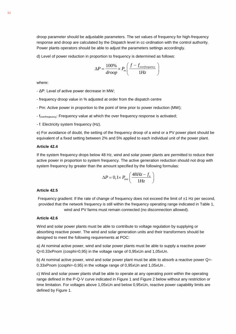
42
droop parameter should be adjustable parameters. The set values of frequency for high-frequency
response and droop are calculated by the Dispatch level in cc-ordination with the control authority.
Power plants operators should be able to adjust the parameters settings accordingly.
d) Level of power reduction in proportion to frequency is determined as follows:
100%
1
overfrequency
m
f fP P
droop Hz
− =
where:
- ΔP: Level of active power decrease in MW;
- frequency droop value in % adjusted at order from the dispatch centre
- Pm: Active power in proportion to the point of time prior to power reduction (MW);
- foverfreqeuncy: Frequency value at which the over frequency response is activated;
- f: Electricity system frequency (Hz).
e) For avoidance of doubt, the setting of the frequency droop of a wind or a PV power plant should be
equivalent of a fixed setting between 2% and 5% applied to each individual unit of the power plant.
Article 42.4
If the system frequency drops below 48 Hz, wind and solar power plants are permitted to reduce their
active power in proportion to system frequency. The active generation reduction should not drop with
system frequency by greater than the amount specified by the following formulas:
480,1
1
ninst
Hz fP P
Hz
− =
Article 42.5
Frequency gradient: If the rate of change of frequency does not exceed the limit of ±1 Hz per second,
provided that the network frequency is still within the frequency operating range indicated in Table 1,
wind and PV farms must remain connected (no disconnection allowed).
Article 42.6
Wind and solar power plants must be able to contribute to voltage regulation by supplying or
absorbing reactive power. The wind and solar generation units and their transformers should be
designed to meet the following requirements at POC:
a) At nominal active power, wind and solar power plants must be able to supply a reactive power
Q=0.33xPnom (cosphi=0,95) in the voltage range of 0,95xUn and 1,05xUn.
b) At nominal active power, wind and solar power plant must be able to absorb a reactive power Q=-
0.33xPnom (cosphi=-0,95) in the voltage range of 0,95xUn and 1,05xUn .
c) Wind and solar power plants shall be able to operate at any operating point within the operating
range defined in the P-Q-V curve indicated in Figure 1 and Figure 2 below without any restriction or
time limitation. For voltages above 1,05xUn and below 0,95xUn, reactive power capability limits are
defined by Figure 1.
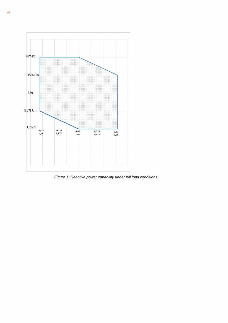
43
Figure 1: Reactive power capability under full load conditions
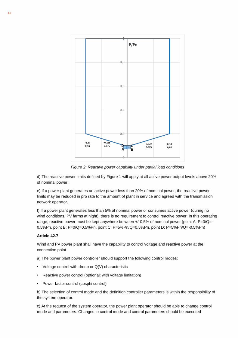
44
Figure 2: Reactive power capability under partial load conditions
d) The reactive power limits defined by Figure 1 will apply at all active power output levels above 20%
of nominal power..
e) If a power plant generates an active power less than 20% of nominal power, the reactive power
limits may be reduced in pro rata to the amount of plant in service and agreed with the transmission
network operator.
f) If a power plant generates less than 5% of nominal power or consumes active power (during no
wind conditions, PV farms at night), there is no requirement to control reactive power. In this operating
range, reactive power must be kept anywhere between +/-0,5% of nominal power (point A: P=0/Q=-
0,5%Pn, point B: P=0/Q=0,5%Pn, point C: P=5%Pn/Q=0,5%Pn, point D: P=5%Pn/Q=-0,5%Pn)
Article 42.7
Wind and PV power plant shall have the capability to control voltage and reactive power at the
connection point.
a) The power plant power controller should support the following control modes:
• Voltage control with droop or Q(V) characteristic
• Reactive power control (optional: with voltage limitation)
• Power factor control (cosphi control)
b) The selection of control mode and the definition controller parameters is within the responsibility of
the system operator.
c) At the request of the system operator, the power plant operator should be able to change control
mode and parameters. Changes to control mode and control parameters should be executed

45
immediately, without any delay.
Article 42.8
Wind and solar power plants at every time of connection to the grid shall remain connected to the
system without tripping of any generating unit and to withstand voltage dips (low voltage ride through)
and over voltage profiles (high voltage ride through) represented by the limit curves according to
Figure 2 and the parameters according to Table 2 and Table 3.
Figure 2: LVRT/HVRT requirements
Table 2 Parameters of the Vietnamese LVRT requirements
Parameter Value Parameter Value
Uret: 0p.u. Tret 0.15s
Uclear: 0.3 p.u. Tclear Tret
Urec1: Uclear Trec1 0.6s
Urec2: 0.9 p.u Trec2 3s
Table 3 Parameters of the Vietnamese HVRT requirements
Parameter Value Parameter Value
Urec3: 1.15 p.u Trec 3 3s
Urec4: 1.2 Trec4 0.5
46
a) In case of unbalanced faults, the requirement applies to the lowest of the three line to line voltages in case of LVRT and to the highest of the three line-to-line voltages in case of HVRT
b) In case consecutive voltage dips (or overvoltage) occurs, and the voltage at the POC reverts to the normal operating range area during a fault sequence, subsequent voltage drops shall be regarded as a new fault condition and power plants are not allowed to disconnect from the transmission network. Disconnection are allowed only if the voltage at POC does not evolve into the normal operating area.
c) During High Voltage events it can further be assumed that the worst-case voltage step change (difference between post-disturbance voltage and the one-minute average value of the voltage) will not exceed 0,2 p.u. (e.g. step from 1 p.u. to 1,2 p.u. or step from 0,9p.u. to 1,1p.u.). In the case of large step changes exceeding a value of 0,2 p.u., disconnection is allowed.
Article 42.9
In order to support the voltage during LVRT (or HVRT) situations every wind and solart power plant
should be able to inject (or to absorb) reactive current in proportion to the voltage dip (or voltage rise)
as depicted in Figure 3. Reactive current support during fault shall respect the following requirements:
a) Reactive current should be in proportion to the voltage dip (or voltage rise) and shall obey to the
following formula:
∆Iq=-KqLVRT (∆U+D) if U<0
∆Iq=-KqHVRT (∆U-D) if U>0
where:
- ∆Iq is the additional reactive current at the low voltage terminal of the generating unit and shall
be added to the pre-fault reactive current. Positive reactive current is voltage supporting
(inductive in generator-orientation and capacitive in load orientation) and negative reactive
current is voltage reducing.
- ∆U is the voltage deviation at the low voltage terminal of the generating unit and is defined by
the difference between the voltage during a voltage sag (or voltage rise) and the pre-fault
voltage (negative value of U is equivalent to a voltage sag). Pre-fault values of voltage and
current are defined by the one-minute average of voltage and current.
- D is the voltage deadband, which is equal to 0,1p.u. according to Figure 3
- LVRT and HVRT requirements apply to positive sequence voltage and current.
- KqLVRT and KqHVRT is the reactive current gain factors (proportionality factors) for LVRT and
HVRT events respectively.
b) The proportionality factors KqLVRT and KqHVRT are settable parameters that can be defined in a
range between 0 and 10 and shall be defined by the transmission system operator.
c) Dynamic performance: After 60ms, the additional current Iq must have been settled, meaning that
it shall remain within a tolerance band of ±20% of rated current (Ir) around the value according to
Figure 3.
d) Reactive current limitation: The total reactive current (sum of pre-disturbance reactive current and
Iq according to Figure 3 can be limited to the rated current of the inverter/turbine (imax=1p.u.)
e) During LVRT events, active current should be limited to a value of ipmax=1-|iq|. This ensures that
an inverter or wind turbine generator doesn’t try to inject active power above the voltage stability limit
of the grid (which can be very low under LVRT conditions).

47
f) During HVRT events, active current should by prioritized over reactive current.
g) A negative sequence current control should be implemented, which applies the same characteristic
as shown in Figure 3 but based on negative sequence voltages and currents. The negative sequence
reactive current gain Kq2 should be a settable parameter, independent from the gains applying to
LVRT and HVRT events.
Figure 3: Reactive current support during LVRT and HVRT
Article 42.10
The behaviour of wind and PV plant during voltage recovery is specified as follows:
a) Within 1 second following a voltage sag (LVRT-event) active power must have been recovered to
its pre-disturbance value. The ramp rate, at which active power recovers should not exceed a value of
2 p.u./s.
b) At no time between a voltage sag (LVRT event) and full voltage recovery, a wind or PV generator is
allowed to absorb more reactive power than it might have absorbed prior to the voltage sag (LVRT
event).
Article 42.11
Harmonic compatibility: Every wind and PV farm must follow the requirements of the system operator
with respect to harmonic voltage distortions. Harmonic emissions of every wind and PV farm must not
exceed the individual emission limits (as defined by Article 8) specified by the system operator.
Article 42.12
Flicker compatibility: Every wind and PV farms must follow the requirements of the system operator
with respect to Flicker. Flicker emissions of every wind and PV farm must not exceed the individual
emission limits (as defined by Article 9) specified by the system operator.
Article 42.13
Voltage unbalance: For negative sequence voltages less than 3%, no disconnection of any wind
generator or PV inverter is allowed. Disconnection because of voltage unbalance is only permitted if
U in p.u.
Iq in p.u.
0,1−0,1
0,5
0,5
−0,5
−0,5
0,2
−1,5
1
Change in Voltage, Uact-Uinit [p.u]
Change in r
eactive c
urr
ent
(Positiv
e=
over
excited)
[p.u
]
Iq=-KqHVRTU.
Iq=-KqLVRTU.
48
the maximum permitted negative sequence voltage of 3% is exceeded during more than 15 minutes.
Article 46.1.c)
c) Documents concerning technical parameters and operation management including:
- Technical parameters of equipment including parameters of transmission lines;
- Documents concerning primary energy system, excitation systems, governors, simulation
modelling, PSS, Laplace transform diagram together with other installation values (for
construction of new power plants);
- Operators of wind and PV farms should provide a simulation model of the generating unit
(wind turbine generator or PV-inverter), which has been validated by measurements (power
quality, LVRT and HVRT tests). The manufacturer of wind and PV generators shall declare
that the simulation model is valid and provide evidence of its validity (results of field tests
together with simulation results).
- Instruction manuals for setting of protective relays, automation, specialized software;
- Instruction manuals for equipment operation and other technical documents.
Article 69.3.
Maintain reliable and stable operation of the governor and excitation systems, connection of AGC and
other technical requirements related to the equipment at connection points as prescribed herein to
ensure adequate supply of power at the request of the electricity system and market operator aligned
with the PPA and connection agreement. Do not change settings of the governor, excitation system,
connection of AGC and other relevant technical requirements without consent of the electricity system
and market operator. In the case of wind or PV power plants this applies to all controller settings of
wind turbine generators, PV inverters and associated control and protection elements. Carry out
necessary trial operation and tests at the request of the electricity system and market operator.
Article 72. Types of ancillary services
Comment: it is very important that the terms for ancillary services will be consistently defined
throughout all codes and procedures. However, it is possible that the inconsistent naming of ancillary
services is just a translation problem.

49
5. Comments on the Distribution Code (Circular 39/2015)
Article 3, 32:
Electromagnetic compatibility Level: specified electromagnetic disturbance level used as a reference
level in a specified environment for co-ordination in the setting of emission and immunity limits
(definition according to IEC61000-3-6)
Article 3, 33:
Harmonic compatibility level: Electromagnetic compatibility level applying to harmonic distortions (see
IEC61000-3-6).
Article 3.34
Flicker compatibility level: Electromagnetic compatibility level applying to flicker perturbations (see
IEC61000-3-7).
Article 3, 35:
Nominal power: The nominal power is defined as the maximum continuous electric output power
which a power plant was designed to achieve under normal operating conditions. Generators are not
allowed to generate more than nominal power on a 15-minute average.
Article 5. – Voltage
Comment: 35kV + 10% is 38,5kV which is above Um according to IEC600071-1
Article 7.1:
During normal operation, total harmonic distortion must not exceed the limits defined by Table 1.
a) During normal operation, total harmonic distortion in MV and LV networks must not exceed the
compatibility levels defined by Table 1 below. In 110kV networks, maximum harmonic voltage
distortion should be below the planning level according to Table 1.
Table 1: Table 1. Harmonic voltage distortion
Voltage level Max. THD, compatibility level Max. THD, planning level
110 kV
3,0%
Medium and low voltage 8 % 6,5%
b) In normal operation, harmonics at individual frequencies in MV and LV networks should be within
the Compatibility Levels according to IEC61000-3-6. Harmonics at individual frequencies in HV
networks should respect the Indicative Planning Levels for HV networks according to IEC61000-3-
6.
Article 7.2
To ensure that harmonics remain within these limits, the distribution network operator shall assign
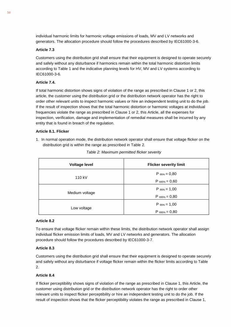
50
individual harmonic limits for harmonic voltage emissions of loads, MV and LV networks and
generators. The allocation procedure should follow the procedures described by IEC61000-3-6.
Article 7.3
Customers using the distribution grid shall ensure that their equipment is designed to operate securely
and safely without any disturbance if harmonics remain within the total harmonic distortion limits
according to Table 1 and the indicative planning levels for HV, MV and LV systems according to
IEC61000-3-6.
Article 7.4.
If total harmonic distortion shows signs of violation of the range as prescribed in Clause 1 or 2, this
article, the customer using the distribution grid or the distribution network operator has the right to
order other relevant units to inspect harmonic values or hire an independent testing unit to do the job.
If the result of inspection shows that the total harmonic distortion or harmonic voltages at individual
frequencies violate the range as prescribed in Clause 1 or 2, this Article, all the expenses for
inspection, verification, damage and implementation of remedial measures shall be incurred by any
entity that is found in breach of the regulation.
Article 8.1. Flicker
1. In normal operation mode, the distribution network operator shall ensure that voltage flicker on the
distribution grid is within the range as prescribed in Table 2.
Table 2: Maximum permitted flicker severity
Voltage level Flicker severity limit
110 kV P 95% = 0,80
P lt95% = 0,60
Medium voltage P 95% = 1,00
P lt95% = 0,80
Low voltage P 95% = 1,00
P lt95% = 0,80
Article 8.2
To ensure that voltage flicker remain within these limits, the distribution network operator shall assign
individual flicker emission limits of loads, MV and LV networks and generators. The allocation
procedure should follow the procedures described by IEC61000-3-7.
Article 8.3
Customers using the distribution grid shall ensure that their equipment is designed to operate securely
and safely without any disturbance if voltage flicker remain within the flicker limits according to Table
2.
Article 8.4
If flicker perceptibility shows signs of violation of the range as prescribed in Clause 1, this Article, the
customer using distribution grid or the distribution network operator has the right to order other
relevant units to inspect flicker perceptibility or hire an independent testing unit to do the job. If the
result of inspection shows that the flicker perceptibility violates the range as prescribed in Clause 1,

51
this Article, all the expenses for inspection, verification, damage and implementation of remedial
measures shall be incurred by any entity that is found in breach of the regulation.
Article 39.2
Frequency gradient: If the rate of change of frequency does not exceed the limit of +/-1 Hz per
second, provided that the network frequency is still within the frequency operating range indicated in
Table 5 above, power plants must remain connected (no disconnection allowed).
Article 40. Requirements for wind power plants solar power plants connected to the
distribution grid of medium voltage and above
Article 40.1.
a) Wind and PV power plants with a total installed capacity of more than 30 MW connected to the
distribution grid must comply with the technical requirements in the Regulation on transmission
power system by the Ministry of Public Merchant issued.
b) Wind and PV power plants having an installed capacity of 30 MW or less must comply with the
requirements according to Article 40.2 – Article 40.14.
Article 40.2
Wind and solar power plants must be capable of maintaining generation of active power within
frequency band from 49 to 51 Hz in following modes:
a) Free generation mode
b) Generating capacity control mode
Wind and solar power plants must be capable to limit the generation of active power as commanded
by the dispatch level with a control and communication delay of no more than 30 seconds with
tolerance within ± 01 % of rated power. If the control action is communicated via telephone, the
operator of the wind or PV power plant must apply the limitation immediately, without any delay. The
interpretation of the limit signal should be as follows:
- If primary sources are equal or greater than the dispatch instruction; Active power generation is
equal to the dispatch instruction (with the above stipulated accuracy and response time).
- If primary sources are lower than forecast value: Operation at maximum possible power generation
Article 40.3
a) In normal operation mode, wind and solar power plants must be capable of maintaining active
power generation continuously and without any time limitation. The power plant operator must ensure
that the active power output is independent of system frequency variation in this range.
b) In the case, the system frequency is out of normal operation range, wind and solar power plants
must be capable of maintaining generation of power for a minimum period of time as defined by Table
8 below:

52
Table 8: Minimum time to maintain power generation in proportion to frequency band of electricity system
Frequency band Minimum time
From 47.5 Hz to 48.0 Hz 10 minutes
Over 48 Hz to under 49Hz 30 minutes
From 49 Hz to 51 Hz illimited
From 51 Hz to 51.5 Hz 30 minutes
Over 51.5 Hz to 52 Hz 01 minute
c) In case of over-frequency situations, typically when the electricity system’s frequency is greater than
50,5 Hz, wind and solar power plants must reduce active power with an overall speed droop of
between 2% and 5% of the rated power.
Both parameters, the frequency at which the active power reduction response is activated, and the
speed droop parameter should be adjustable parameters. The set values of frequency for high-
frequency response and speed droop are calculated by the Dispatch level in co-ordination with the
control authority. Power plant operators should be able to adjust the settings accordingly.
c) Level of power reduction in proportion to frequency is determined as follows:
100%
1
overfrequency
m
f fP P
droop Hz
− =
where:
- ΔP: Level of active power decrease in MW;
- droop: frequency droop value in % adjusted at order from the dispatch centre
- Pm: Active power in proportion to the point of time prior to power reduction (MW);
- foverfrequency: Frequency value at which the over frequency response is activated.
- f: Electrical frequency (Hz).
d) For avoidance of doubt, the setting of the speed droop of a wind or a PV power plant should be
equivalent to a fixed setting between 2% and 5% applied to each individual unit of the power plant.
Article 40.4
If the system frequency drops below 48 Hz, wind and solar power plants are permitted to reduce their
active power in proportion to system frequency. The active generation reduction should not drop with
system frequency by greater than the amount specified by the following formula:
480,1
1inst
Hz fP P
Hz
− =
Article 40.5
Frequency gradient: If the rate of change of frequency does not exceed the limit of ±1 Hz per second,
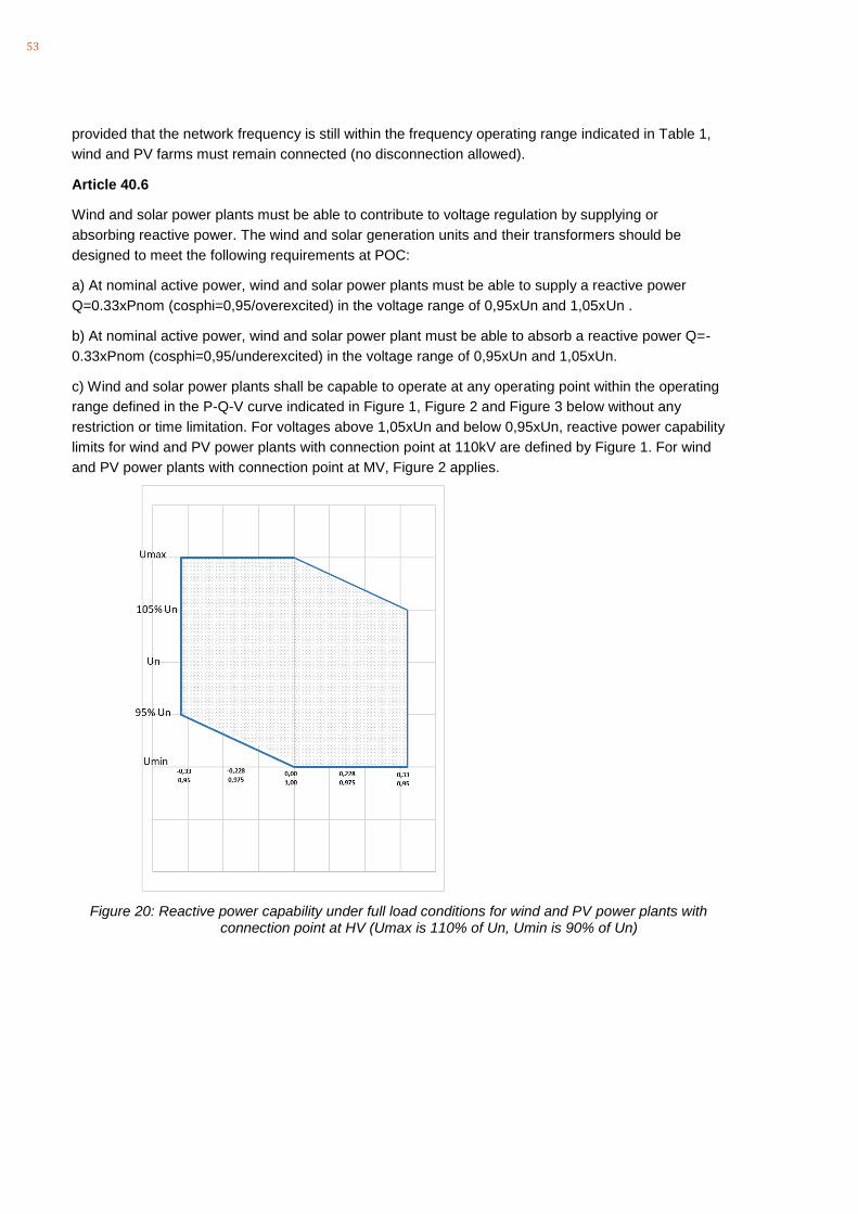
53
provided that the network frequency is still within the frequency operating range indicated in Table 1,
wind and PV farms must remain connected (no disconnection allowed).
Article 40.6
Wind and solar power plants must be able to contribute to voltage regulation by supplying or
absorbing reactive power. The wind and solar generation units and their transformers should be
designed to meet the following requirements at POC:
a) At nominal active power, wind and solar power plants must be able to supply a reactive power
Q=0.33xPnom (cosphi=0,95/overexcited) in the voltage range of 0,95xUn and 1,05xUn .
b) At nominal active power, wind and solar power plant must be able to absorb a reactive power Q=-
0.33xPnom (cosphi=0,95/underexcited) in the voltage range of 0,95xUn and 1,05xUn.
c) Wind and solar power plants shall be capable to operate at any operating point within the operating
range defined in the P-Q-V curve indicated in Figure 1, Figure 2 and Figure 3 below without any
restriction or time limitation. For voltages above 1,05xUn and below 0,95xUn, reactive power capability
limits for wind and PV power plants with connection point at 110kV are defined by Figure 1. For wind
and PV power plants with connection point at MV, Figure 2 applies.
Figure 20: Reactive power capability under full load conditions for wind and PV power plants with connection point at HV (Umax is 110% of Un, Umin is 90% of Un)
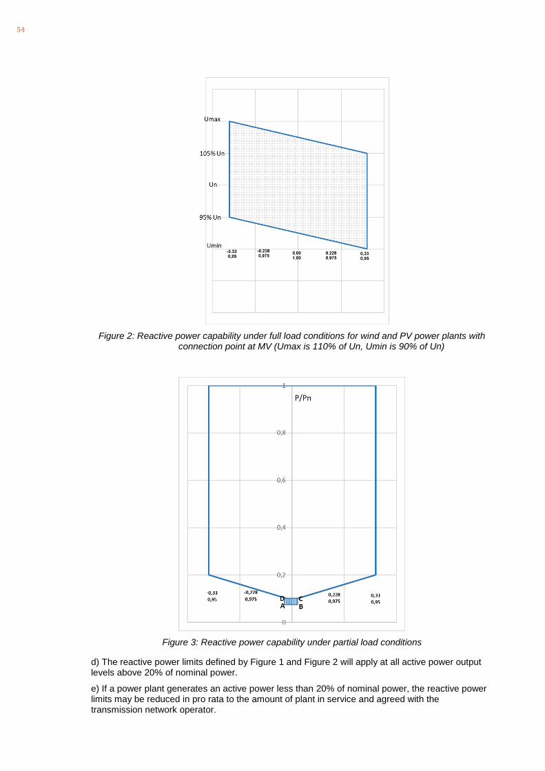
54
Figure 2: Reactive power capability under full load conditions for wind and PV power plants with connection point at MV (Umax is 110% of Un, Umin is 90% of Un)
Figure 3: Reactive power capability under partial load conditions
d) The reactive power limits defined by Figure 1 and Figure 2 will apply at all active power output levels above 20% of nominal power.
e) If a power plant generates an active power less than 20% of nominal power, the reactive power limits may be reduced in pro rata to the amount of plant in service and agreed with the transmission network operator.

55
f) If a power plant generates less than 5% of rated power or consumes active power (during no wind conditions, PV farms at night), there is no requirement to control reactive power. In this operating range, reactive power must be kept anywhere between +/-0,5% of nominal power (point A: P=0/Q=-0,5%Pn, point B: P=0/Q=0,5%Pn, point C: P=5%Pn/Q=0,5%Pn, point D: P=5%Pn/Q=-0,5%Pn).
Article 40.7
Wind and PV power plant shall have the capability to control voltage and reactive power at the POC.
a) The power plant power controller should support the following control modes:
• Voltage control with droop or Q(V) characteristic
• Reactive power control (optional: with voltage limitation).
• Power factor control (cosphi control)
• A characteristic defining a power factor or reactive power in function of the active power generated. (cosphi(P) or Q(P) control characteristic).
b) The definition of control mode and controller parameters is within the responsibility of the system operator.
c) At the request of the system operator, the power plant operator should be able to change control
mode and parameters. Changes to setpoints must be implemented immediately, without any delay.
In the case of wind and PV power plants with connection point at 110kV, changes to control mode
and other control parameters should be executed immediately, without any delay. In the case of MV-
connected wind or PV power plants, changes to control mode and other control parameters should
be executed with reasonable delays (e.g. one day).
Article 40.7
Wind and solar power plants at every time of connection to the grid shall remain connected to the
system without tripping of any generating unit and to withstand voltage dips (low voltage ride
through) and over voltage profiles (high voltage ride through) represented by the limit curves
according to Figure 2 and the parameters according to Table 2, Table 3 and Table 4. Table 2 applies
to wind and PV power plants with a connection point at 110kV. Table 3 applies to wind and PV
power plants with connection point at MV.

56
Figure 2: LVRT/HVRT requirements
Table 2: Parameters of LVRT requirements for 110kV connections or installed capacity >=30MW
Parameter Value Parameter Value
Uret: 0p.u. Tret 0.15s
Uclear: 0.3 p.u. Tclear Tret
Urec1: Uclear Trec1 0.6s
Urec2: 0.9 p.u Trec2 3s
Table 3: Parameters of LVRT requirements for MV connections <30MW
Parameter Value Parameter Value
Uret: 0.15p.u. Tret 0.15s
Uclear: 0.3 p.u. Tclear Tret
Urec1: Uclear Trec1 0.6s
Urec2: 0.9 p.u Trec2 3s

57
Table 4 Parameters of HVRT requirements
Parameter Value Parameter Value
Urec3: 1.15 p.u Trec 3 3s
Urec4: 1.2 Trec4 0.5
a) In case of unbalanced faults, the requirement applies to the lowest of the three line to line voltages in case of LVRT and to the highest of the three line-to-line voltages in case of HVRT
b) In case consecutive voltage dips (or overvoltage) occurs, and the voltage at the POC reverts to the normal operating range area during a fault sequence, subsequent voltage drops shall be regarded as a new fault condition and power plants are not allowed to disconnect from the transmission network. Disconnection are allowed only if the voltage at POC does not evolve into the normal operating area.
c) During High Voltage events it can further be assumed that the worst-case voltage step change (difference between post-disturbance voltage and the one-minute average value of the voltage) will not exceed 0,2 p.u. (e.g. step from 1 p.u. to 1,2 p.u. or step from 0,9p.u. to 1,1p.u.). In the case of large step changes exceeding a value of 0,2 p.u., disconnection is allowed.
Article 40.8
In order to support the voltage during LVRT (or HVRT) situations wind and solar power plants with a connection point at 110kV or with a connection point at MV and an installed capacity >10MW should be able to inject (or to absorb) reactive current in proportion to the voltage dip (or voltage rise) as depicted in Figure 3. Reactive current support during fault shall respect the following requirements:
a) Reactive current should be in proportion to the voltage dip (or voltage rise) and shall obey to the
following formula:
∆Iq=-KqLVRT (∆U+D) if U<0
∆Iq=-KqHVRT (∆U-D) if U>0
where:
- ∆Iq is the additional reactive current at the low voltage terminal of the generating unit and shall
be added to the pre-fault reactive current. Positive reactive current is voltage supporting
(inductive in generator-orientation and capacitive in load orientation) and negative reactive
current is voltage reducing.
- ∆U is the voltage deviation at the low voltage terminal of the generating unit and is defined by
the difference between the voltage during a voltage sag (or voltage rise) and the pre-fault
voltage (negative value of U is equivalent to a voltage sag). Pre-fault values of voltage and
current are defined by the one-minute average of voltage and current.
- D is the voltage deadband, which is equal to 0,1p.u. according to Figure 3
- LVRT and HVRT requirements apply to positive sequence voltage and current.
- KqLVRT and KqHVRT is the reactive current gain factors (proportionality factors) for LVRT and
HVRT events respectively.
b) The proportionality factors KqLVRT and KqHVRT are settable parameters that can be defined in a
range between 0 and 10 and shall be defined by the transmission system operator.
c) Dynamic performance: After 60ms, the additional current Iq must have been settled, meaning

58
that it shall remain within a tolerance band of ±20% of rated current (Ir) around the value according
to Figure 3.
d) Reactive current limitation: The total reactive current (sum of pre-disturbance reactive current and
Iq according to Figure 3 can be limited to the rated current of the inverter/turbine (imax=1p.u.)
e) During LVRT events, active current should be limited to a value of ipmax=1-|iq|. This ensures that
an inverter or wind turbine generator doesn’t try to inject active power above the voltage stability limit
of the grid (which can be very low under LVRT conditions).
f) During HVRT events, active current should by prioritized over reactive current.
g) A negative sequence current control should be implemented, which applies the same characteristic
as shown in Figure 3 but based on negative sequence voltages and currents. The negative sequence
reactive current gain Kq2 should be a settable parameter, independent from the gains applying to
LVRT and HVRT events.
Figure 3: Reactive current support during LVRT and HVRT
Article 40.9
Wind and solar power plants with an installed capacity <10MW should reduce active and reactive
currents to zero during a LVRT condition. During HVRT they must retain active power and are allowed
to adjust reactive current according to paragraph 6.
Article 40.10
The behaviour of wind and PV plant during voltage recovery is specified as follows:
a) Within 1 second following a voltage sag (LVRT-event) active power must have been recovered to
its pre-disturbance value. The ramp rate, at which active power recovers should not exceed a value of
2 p.u./s.
b) At no time between a voltage sag (LVRT event) and full voltage recovery, a wind or PV generator
should absorb more reactive power than it might have absorbed prior to the voltage sag (LVRT event).
Article 40.11

59
Harmonic compatibility: Every wind and PV farm must follow the requirements of the system operator
with respect to harmonic voltage distortions. Harmonic emissions of every wind and PV farm must not
exceed the individual emission limits (as defined by Article 8) specified by the distribution network
operator.
Article 40.12
Flicker compatibility: Every wind and PV farms must follow the requirements of the system operator
with respect to Flicker. Flicker emissions of every wind and PV farm must not exceed the individual
emission limits (as defined by Article 9) specified by the distribution network operator.
Article 40.13
Voltage unbalance: For negative sequence voltages less than 3%, no disconnection of any wind
generator or PV inverter is allowed. Disconnection because of voltage unbalance is only permitted if
the maximum permitted negative sequence voltage of 3% is exceeded for more than 15 minutes.
Article 41. Requirements for solar systems connected to the low voltage network
Article 41.1
The grid connection of LV connected photovoltaic systems should be in-line with IEC61727.
Article 41.2
In order to verify that there is no adverse impact on the utility LV-network, the network operator should
carry out a grid impact assessment considering the size of the MV/LV transformer, thermal loading of
LV cables and voltage rise on the LV feeder.
Article 41.3 Inverter types:
a) Single phase installations are permitted for PV systems with a rated a.c. capacity of up to 5kVA.
b) Up to 15kVA, PV installations can use single phase inverters with ratings up to 5kVA, which must
be connected in a balanced manner over the three phases.
c) PV installations with a rated capacity greater than 15kVA should be equipped with balanced three-
phase inverters.
Article 41.4
PV installations must respect the frequency range of operation (with and without active power
restrictions) according to Article 40.2 and Article 40.3, including the capability of the PV installation to
reduce active power in the case of over-frequencies.
Article 41.5
a) PV installations must be able to maintain continuous and unrestricted power generation without any
time limitation if voltage at the connection point is in the range between 85% and 110% of nominal
voltage. If voltage is below 85% of nominal voltage, the minimum retention times according to Table 9
apply:

60
Table 7: Recommended "remain connected times" for voltage dips
Voltage at connection point Minimum retention time
Below 50% of nominal voltage disconnection allowed
From 50% nominal voltage to less than 0.85 nominal voltage
2 seconds
From 85% nominal voltage to 110% nominal voltage
continuous operation
Above 110% nominal voltage disconnection allowed
b) During voltage dips, if voltage is below 85% of nominal voltage, the PV inverter should inject zero active and reactive power (zero power mode).
Article 41.6
Harmonic compatibility: PV installations must follow the requirements of the system operator with respect to harmonic voltage distortions.
a) Harmonic emissions of every PV installation must not exceed the individual emission limits specified by the system operator.
b) In any case, PV inverters must respect harmonic current emission limits specified by IEC 61727. According to IEC61727, the maximum harmonic current emission must be below a THD of 5%. Each harmonic component must be below the limits defined by Table 10 below.
Table 8: Current distortion limit as a function of harmonics (Source: IEC 61727:2004)
1 2
Odd harmonics Distortion limit
3rd through 9th Less than 4,0 %
11th through 15th Less than 2,0 %
17th through 21st Less than 1,5 %
23rd through 33rd Less than 0,6 %
Even harmonics Distortion limit
2nd through 8th Less than 1,0 %
10th through 32nd Less than 0,5 %
Article 41.7
Flicker compatibility: Every wind and PV farms must follow the requirements of the system operator with respect to Flicker. Flicker emissions of every wind and PV farm must not exceed the individual emission limits specified by the system operator.
Article 41.8
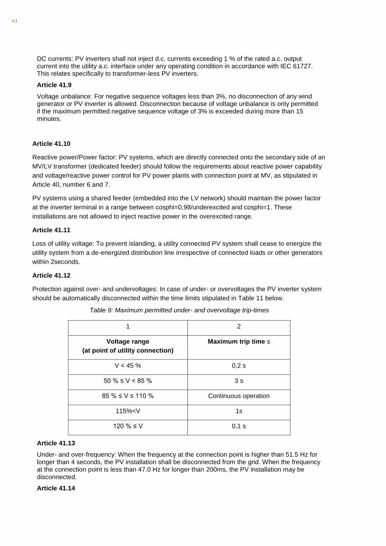
61
DC currents: PV inverters shall not inject d.c. currents exceeding 1 % of the rated a.c. output current into the utility a.c. interface under any operating condition in accordance with IEC 61727. This relates specifically to transformer-less PV inverters.
Article 41.9
Voltage unbalance: For negative sequence voltages less than 3%, no disconnection of any wind generator or PV inverter is allowed. Disconnection because of voltage unbalance is only permitted if the maximum permitted negative sequence voltage of 3% is exceeded during more than 15 minutes.
Article 41.10
Reactive power/Power factor: PV systems, which are directly connected onto the secondary side of an
MV/LV transformer (dedicated feeder) should follow the requirements about reactive power capability
and voltage/reactive power control for PV power plants with connection point at MV, as stipulated in
Article 40, number 6 and 7.
PV systems using a shared feeder (embedded into the LV network) should maintain the power factor
at the inverter terminal in a range between cosphi=0,98/underexcited and cosphi=1. These
installations are not allowed to inject reactive power in the overexcited range.
Article 41.11
Loss of utility voltage: To prevent islanding, a utility connected PV system shall cease to energize the
utility system from a de-energized distribution line irrespective of connected loads or other generators
within 2seconds.
Article 41.12
Protection against over- and undervoltages: In case of under- or overvoltages the PV inverter system
should be automatically disconnected within the time limits stipulated in Table 11 below.
Table 9: Maximum permitted under- and overvoltage trip-times
1 2
Voltage range
(at point of utility connection)
Maximum trip time s
V < 45 % 0,2 s
50 % ≤ V < 85 % 3 s
85 % ≤ V ≤ 110 % Continuous operation
115%<V 1s
120 % ≤ V 0,1 s
Article 41.13
Under- and over-frequency: When the frequency at the connection point is higher than 51.5 Hz for longer than 4 seconds, the PV installation shall be disconnected from the grid. When the frequency at the connection point is less than 47.0 Hz for longer than 200ms, the PV installation may be disconnected.
Article 41.14

62
Protection against unintentional islanding: An islanding condition shall cause the PV installation to cease to energize the utility network within 2 s, irrespective of connected loads or other small scale generators. The PV installation shall comply with the requirements of IEC 62116 (ed. 1).
Article 41.15
Protection against DC current injections: The PV installation shall cease to energize the utility network within 500 ms if a d.c. component of the current greater than 1% of rated a.c. output is injected into the utility system.
Article 41.16
Earthing: The PV installation should be earthed in accordance with IEC60364-7-712 and in accordance with the requirements of the utility to which it is connected.
Article 41.17
Short-circuit protection: The photovoltaic system shall have short-circuit protection in accordance with IEC 60364-7-712.
Article 41.18
A method of isolation and switching shall be provided in accordance with IEC 60364-7-712.
Article 41.19
23. Disconnect unit
a) The PV inverter shall be equipped with a disconnection switching unit which separates the PV inverter from the grid due to abnormal conditions. The disconnection unit may be integrated into one of the components of the PV installation (for example the PV utility-interconnected inverter) or may be an independent device installed between the inverter and the utility interface.
NOTE 1: A central disconnection switch unit is not required for a single unit less than 100kVA NOTE 2: The limit of 100kVA applies to LV networks, which are earthed prior to any maintenance work. In networks, in which this is not the case this value should be reduced.
b) The disconnection switching unit shall be able to operate under all operating conditions of the utility network.
c) A failure within the disconnection switching unit shall lead to disconnection and indication of the failure condition.
d) A single failure within the disconnection switching unit shall not lead to failure to disconnect. Failures with one common cause shall be taken into account and addressed through adequate redundancy.
e) The disconnection switching unit shall disconnect from the network by means of two series switches. Each switch shall be separately rated to the inverter’s nominal a.c. power output. At least one of the switches shall be an electromechanical switch while the second switch may be part of the existing solid state switching circuits of a utility-interconnected static power converter. The electromechanical switch shall disconnect the PV inverter generator on the neutral and the live wire(s).
NOTE 1: The switching unit need not disconnect its sensing circuits.
f) The fault current breaking capacity of the disconnecting switch shall be appropriately sized for the application.
g) A static power converter without built-in disconnection device shall make use of two series-connected electromechanical disconnection switches.
h) Any programmable parameters of the disconnection switching unit shall be protected from interference by third-parties, i.e. password protected or access physically sealed.
i) The disconnection switching unit may be incorporated in the mains connection switch, provided that none of the network disconnection requirements in this document are violated. This will allow customers to supply their own load in isolated operation where this is feasible and required.

63
References
[1] Energinet.dk, „Technical Regulation 3.2.5 for wind power plants with a power output above 11kW,“ Energinet.dk, 2015.
[2] European Union, „establishing a network code on requirements for grid connection of generators,“ 2016.
[3] National Grid, „The Grid Code,“ 2018.
[4] VDE/FNN, „VDE-AR 4120: Technical requirements for the connection and operation of customer installations to the high voltage network,“ 2018.
[5] VDE, „VDE-AR 4130: Technical requirements for the connection and operation of customer installations to the extra high voltage network,“ 2019.

64
MOIT/GIZ Energy Support Programme (ESP)
Smart Grids for Renewable Energy and Energy Efficiency (SGREEE)
—
Unit 042A, 4th Floor, Coco Building, T +84 (0)24 3941 2605 E [email protected]
14 Thuy Khue, Tay Ho District, Hanoi, Viet Nam F +84 (0)2 3941 2606 W www.giz.de
www.smart-grid.vn
http://gizenergy.org.vn
—
Copyright © 2022 FDOKUMEN