Deliverable D7.4 Report on the integration of the infrastructure ...
25
Disclaimer: This documen reflects the FLEXICIENCY consortium view and the European Commission (or its delegated Agency INEA) is not responsible for any use that may be made of the information it contains energy services demonstrations of demand response, FLEXibility and energy efficIENCY based on metering data Deliverable D7.4 Report on the integration of the infrastructure with the new Services/Aggregator platforms V1.0 This project has received funding from the European Union’s Horizon 2020 research and innovation programme under grant agreement n° 646482 Ref. Ares(2018)557688 - 30/01/2018
-
Upload
khangminh22 -
Category
Documents
-
view
2 -
download
0
Transcript of Deliverable D7.4 Report on the integration of the infrastructure ...
Disclaimer: This documen reflects the FLEXICIENCY consortium view and the European Commission (or its delegated Agency INEA) is not responsible for any use that may be made of the information it contains
energy services demonstrations of demand response,
FLEXibility and energy efficIENCY based on metering data
Deliverable D7.4
Report on the integration of the infrastructure with the new
Services/Aggregator platforms
V1.0
This project has received funding from the
European Union’s Horizon 2020 research and innovation programme
under grant agreement n° 646482
Ref. Ares(2018)557688 - 30/01/2018
D7.4 – Report on the integration of the infrastructure with the new Services/Aggregator platform
V1.0
FLEXICIENCY GA n° 646482 Page 2 of 25
D7.4 – Report on the integration of the infrastructure with the new Services/Aggregator platforms for the Spanish demo Document Information
Program Horizon 2020 – Cooperation / Energy
Project acronym FLEXICIENCY
Grant agreement number 646482
Number of the Deliverable D7.4
WP/Task related [WP7 / T7.4]
Type (distribution level) PU Public
Date of delivery [12-01-2018]
Status and Version Version 1.0
Number of pages 25 pages
Document Responsible Giulia Vaccarone – Siemens; Andrea Zocchi –
Siemens;
Author(s) Giulia Vaccarone – Siemens; Andrea Zocchi –
Siemens;
Reviewers Gazvoda, Anton Zvonko- University of Ljubljana
Friedrich Schwarzlaender-SAP
D7.4 – Report on the integration of the infrastructure with the new Services/Aggregator platform
V1.0
FLEXICIENCY GA n° 646482 Page 3 of 25
Revision History
Version Date Author/Reviewer Notes
0.1 21/11/2017 Giulia Vaccarone DRAFT
0.2 29/11/2017 Giulia Vaccarone DRAFT
0.3 30/11/2017 Andrea Zocchi DRAFT
0.4 05/12/2017 Giulia Vaccarone Draft for first revision
0.5 13/12/2017 Andrea Zocchi First release for external review
1.0 12/01/2018 Giulia Vaccarone Final release
Notations, abbreviations and acronyms
DSO Distribution System Operator
EB Energy Box
EMS Energy Management System
POD Point of Delivery
MQTT M2M IOT focused connectivity protocol
D7.4 – Report on the integration of the infrastructure with the new Services/Aggregator platform
V1.0
FLEXICIENCY GA n° 646482 Page 4 of 25
Executive summary
The deliverable provides the results obtained by the integration (prototyping and deployment) of
different equipment (energy box, V2H, etc.) and systems with the new Service/Aggregator platform
in Malaga City demo site.
This integration is carried out as part of the WP7 (Spanish demonstration).
The project has been developed in Malaga and devices have been installed in different buildings in
the ownership of the Municipality:
- Medium and small building where only monitoring services have been provided.
- Tabacalera Complex represented by a group of buildings where monitoring and load control
services have been provided.
EMS platform is used as backend infrastructure for both Service and Aggregator.
D7.4 – Report on the integration of the infrastructure with the new Services/Aggregator platform
V1.0
FLEXICIENCY GA n° 646482 Page 5 of 25
Table of contents
Revision History ............................................................................................................................... 3
Notations, abbreviations and acronyms ........................................................................................... 3
Executive summary ......................................................................................................................... 4
Table of contents ............................................................................................................................. 5
List of Figures .................................................................................................................................. 6
1. Scope of the document ............................................................................................................. 7
2. Introduction ............................................................................................................................... 8
2.1. EMS User Interface for Small Buildings ............................................................................. 8
2.1.1 Smart Info ................................................................................................................................ 9
2.2. EMS User Interface for Large Buildings .......................................................................... 10
2.2.1 Building – Module 4 ............................................................................................................. 11
2.2.2 Building – Module 5 ............................................................................................................. 12
2.2.3 Microgrid ................................................................................................................................ 13
2.2.4 Smart Home showroom (V2H Home Pilot) ....................................................................... 13
3. Devices integration ................................................................................................................. 14
3.1. Asset General details ...................................................................................................... 16
3.2. Asset feeds ..................................................................................................................... 17
3.3. Asset Communication Properties .................................................................................... 20
3.4. Asset diagnostic .............................................................................................................. 20
4. Energy box integration ............................................................................................................ 22
4.1. EMS and external algorithms platform ............................................................................. 22
5. Appendix ................................................................................................................................ 24
5.1. Devices installed by typology .......................................................................................... 24
5.2. Devices installed by Use Cases ...................................................................................... 25
D7.4 – Report on the integration of the infrastructure with the new Services/Aggregator platform
V1.0
FLEXICIENCY GA n° 646482 Page 6 of 25
List of Figures
Figure 1: Small/medium building monitoring view ............................................................................ 8
Figure 2: Malaga territory geographical view ................................................................................... 8
Figure 3: Smart Info device .............................................................................................................. 9
Figure 4: Tabacalera complex geographical view .......................................................................... 10
Figure 5: Aggregation by typology for Tabacalera complex ........................................................... 11
Figure 6: Module 4 geographical view ........................................................................................... 12
Figure 7: Module 5 geographical view ........................................................................................... 12
Figure 8: Microgrid geographical view ........................................................................................... 13
Figure 9: Home Pilot geographical view ........................................................................................ 13
Figure 10: EMS High level integration architecture ........................................................................ 14
Figure 11: Example of high level integration between Assets and Gateways ................................ 15
Figure 12: Smart Info Gateway ...................................................................................................... 15
Figure 13: Compatible devices ...................................................................................................... 16
Figure 14: Asset general details .................................................................................................... 17
Figure 15: Example of Smart Info Feeds ....................................................................................... 18
Figure 16: Example of Power Analyzer Feeds ............................................................................... 18
Figure 17: Third Floor of Module 4 ................................................................................................. 19
Figure 18: Smart Info Communication properties........................................................................... 20
Figure 19: Asset Diagnostic Status ................................................................................................ 20
Figure 20: Energy Box integration ................................................................................................. 22
Figure 21: Algorithm communication Time diagram ....................................................................... 23
Figure 22: Rule Set for Tabacalera complex .................................................................................. 23
D7.4 – Report on the integration of the infrastructure with the new Services/Aggregator platform
V1.0
FLEXICIENCY GA n° 646482 Page 7 of 25
1. Scope of the document
Deliverable D7.4 gives a detailed description of the integration and communication between the field
devices deployed in Malaga and the EMS Platform.
This integration is carried out as part of the WP7 (Spanish demonstration).
Chapter 2 describes the user interface of EMS Platform for Small buildings and Large buildings.
Chapter 3 offers a technical description of the communication protocol used to integrate the
devices with the EMS Platform.
Chapter 4 describes Energy Boxes integration and how external algorithms communicate with the
EMS Platform.
D7.4 – Report on the integration of the infrastructure with the new Services/Aggregator platform
V1.0
FLEXICIENCY GA n° 646482 Page 8 of 25
2. Introduction
2.1. EMS User Interface for Small Buildings
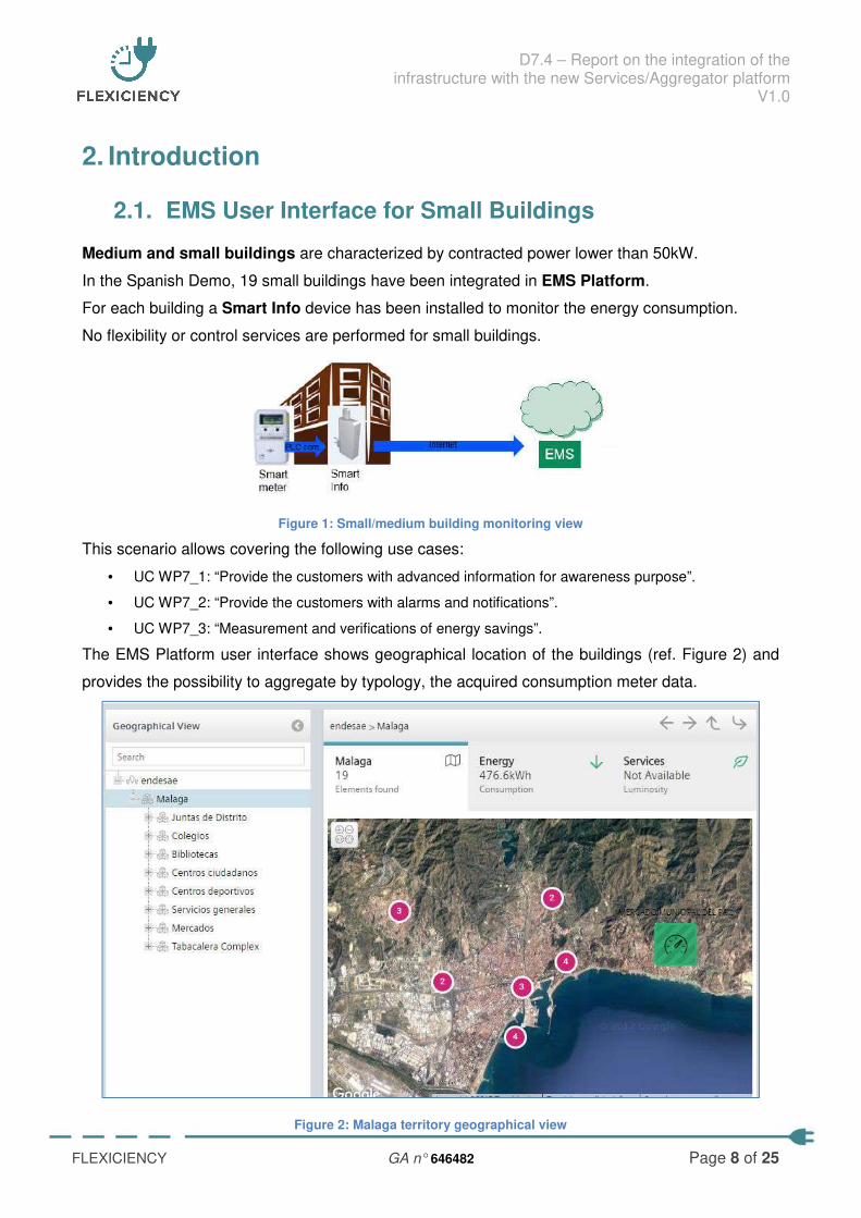
Medium and small buildings are characterized by contracted power lower than 50kW.
In the Spanish Demo, 19 small buildings have been integrated in EMS Platform.
For each building a Smart Info device has been installed to monitor the energy consumption.
No flexibility or control services are performed for small buildings.
Figure 1: Small/medium building monitoring view
This scenario allows covering the following use cases:
• UC WP7_1: “Provide the customers with advanced information for awareness purpose”.
• UC WP7_2: “Provide the customers with alarms and notifications”.
• UC WP7_3: “Measurement and verifications of energy savings”.
The EMS Platform user interface shows geographical location of the buildings (ref. Figure 2) and
provides the possibility to aggregate by typology, the acquired consumption meter data.
Figure 2: Malaga territory geographical view
D7.4 – Report on the integration of the infrastructure with the new Services/Aggregator platform
V1.0
FLEXICIENCY GA n° 646482 Page 9 of 25
2.1.1 Smart Info
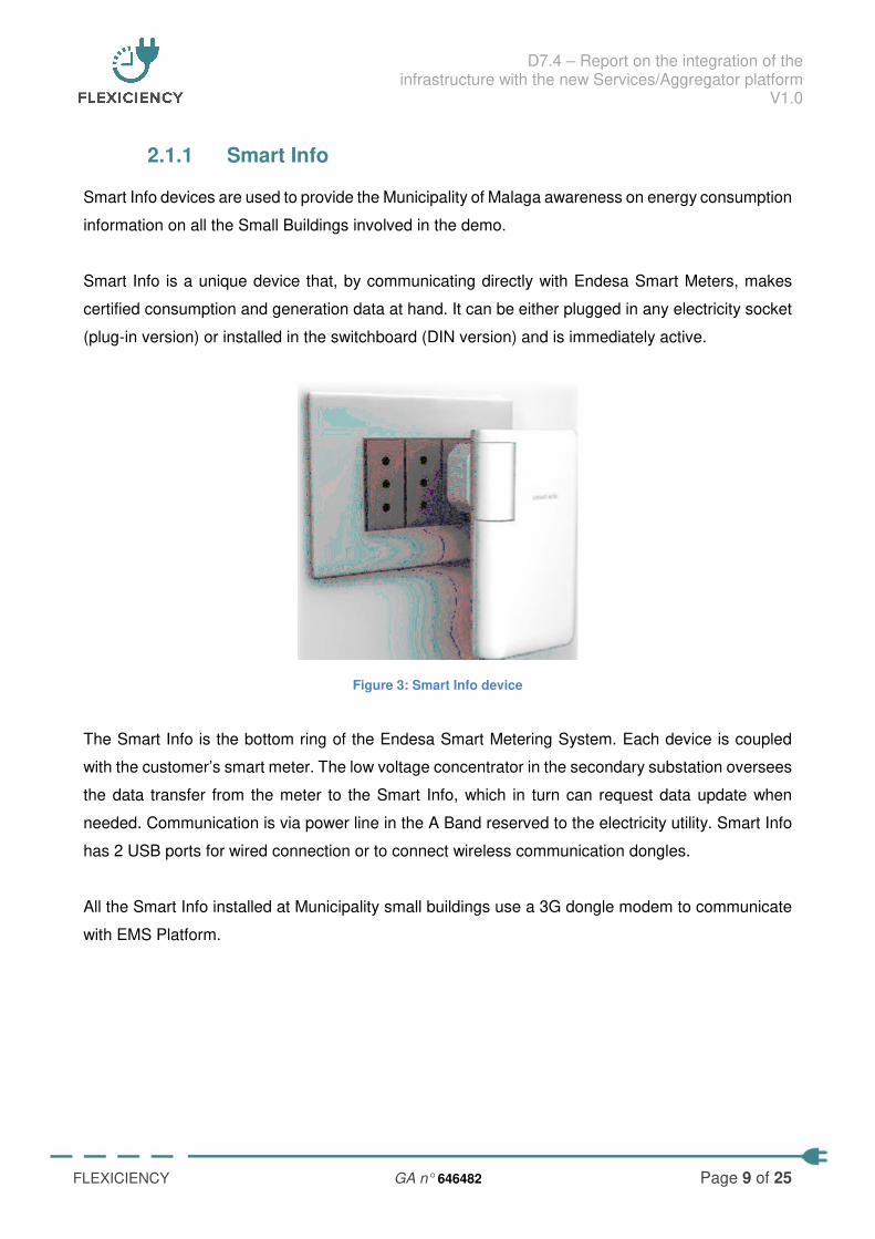
Smart Info devices are used to provide the Municipality of Malaga awareness on energy consumption
information on all the Small Buildings involved in the demo.
Smart Info is a unique device that, by communicating directly with Endesa Smart Meters, makes
certified consumption and generation data at hand. It can be either plugged in any electricity socket
(plug-in version) or installed in the switchboard (DIN version) and is immediately active.
Figure 3: Smart Info device
The Smart Info is the bottom ring of the Endesa Smart Metering System. Each device is coupled
with the customer’s smart meter. The low voltage concentrator in the secondary substation oversees
the data transfer from the meter to the Smart Info, which in turn can request data update when
needed. Communication is via power line in the A Band reserved to the electricity utility. Smart Info
has 2 USB ports for wired connection or to connect wireless communication dongles.
All the Smart Info installed at Municipality small buildings use a 3G dongle modem to communicate
with EMS Platform.
D7.4 – Report on the integration of the infrastructure with the new Services/Aggregator platform
V1.0
FLEXICIENCY GA n° 646482 Page 10 of 25
2.2. EMS User Interface for Large Buildings
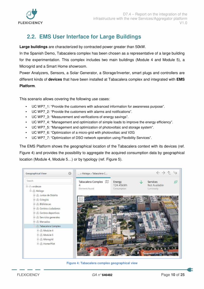
Large buildings are characterized by contracted power greater than 50kW.
In the Spanish Demo, Tabacalera complex has been chosen as a representative of a large building
for the experimentation. This complex includes two main buildings (Module 4 and Module 5), a
Microgrid and a Smart Home showroom.
Power Analyzers, Sensors, a Solar Generator, a Storage/Inverter, smart plugs and controllers are
different kinds of devices that have been installed at Tabacalera complex and integrated with EMS
Platform.
This scenario allows covering the following use cases:
• UC WP7_1: “Provide the customers with advanced information for awareness purpose”.
• UC WP7_2: “Provide the customers with alarms and notifications”.
• UC WP7_3: “Measurement and verifications of energy savings”.
• UC WP7_4: “Management and optimization of simple loads to improve the energy efficiency”.
• UC WP7_5: “Management and optimization of photovoltaic and storage system”.
• UC WP7_6: “Optimization of a micro-grid with photovoltaic and V2G
• UC WP7_7: “Optimization of DSO network operation using Flexibility Services”.
The EMS Platform shows the geographical location of the Tabacalera context with its devices (ref.
Figure 4) and provides the possibility to aggregate the acquired consumption data by geographical
location (Module 4, Module 5…) or by typology (ref. Figure 5).
Figure 4: Tabacalera complex geographical view
D7.4 – Report on the integration of the infrastructure with the new Services/Aggregator platform
V1.0
FLEXICIENCY GA n° 646482 Page 11 of 25
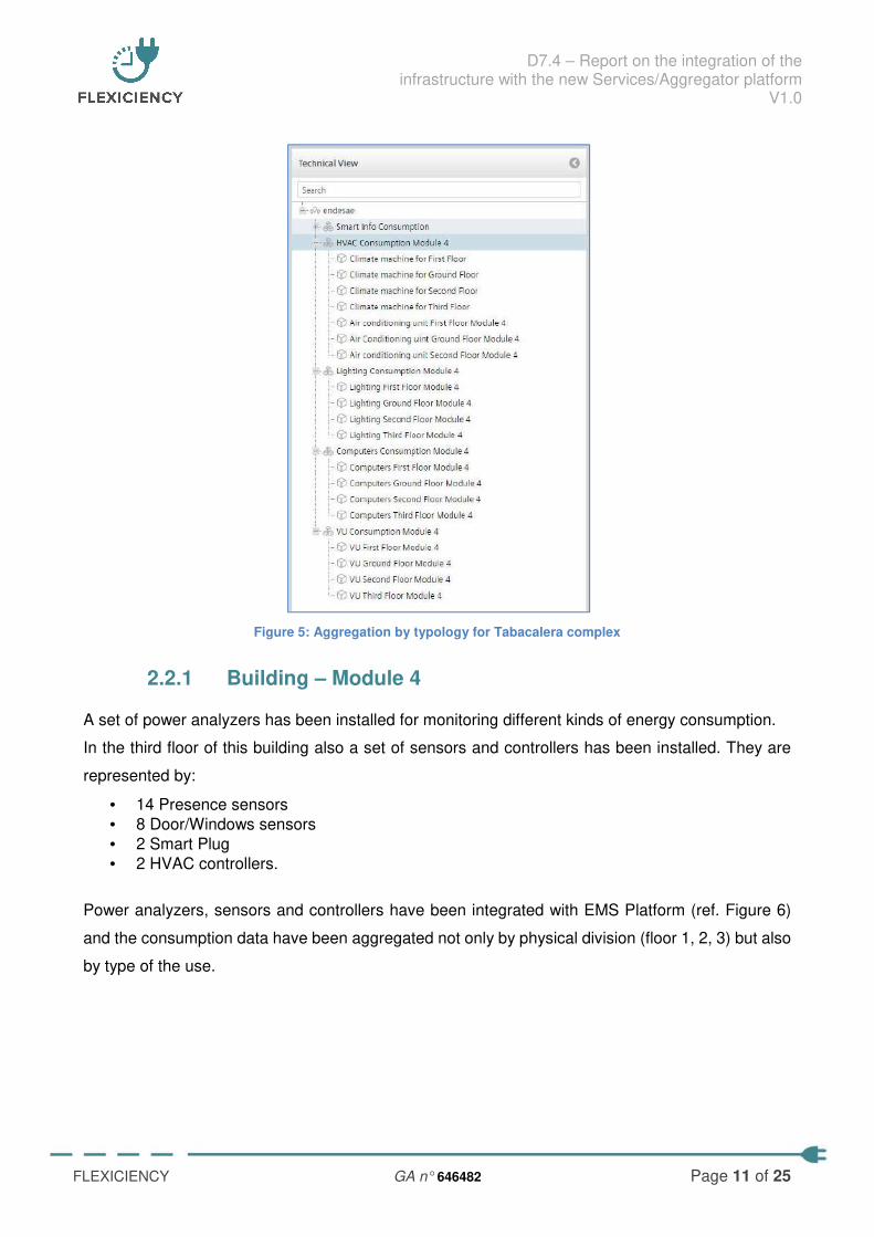
Figure 5: Aggregation by typology for Tabacalera complex
2.2.1 Building – Module 4
A set of power analyzers has been installed for monitoring different kinds of energy consumption.
In the third floor of this building also a set of sensors and controllers has been installed. They are
represented by:
• 14 Presence sensors
• 8 Door/Windows sensors
• 2 Smart Plug
• 2 HVAC controllers.
Power analyzers, sensors and controllers have been integrated with EMS Platform (ref. Figure 6)
and the consumption data have been aggregated not only by physical division (floor 1, 2, 3) but also
by type of the use.
D7.4 – Report on the integration of the infrastructure with the new Services/Aggregator platform
V1.0
FLEXICIENCY GA n° 646482 Page 12 of 25
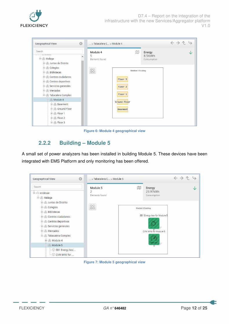
Figure 6: Module 4 geographical view
2.2.2 Building – Module 5
A small set of power analyzers has been installed in building Module 5. These devices have been
integrated with EMS Platform and only monitoring has been offered.
Figure 7: Module 5 geographical view
D7.4 – Report on the integration of the infrastructure with the new Services/Aggregator platform
V1.0
FLEXICIENCY GA n° 646482 Page 13 of 25
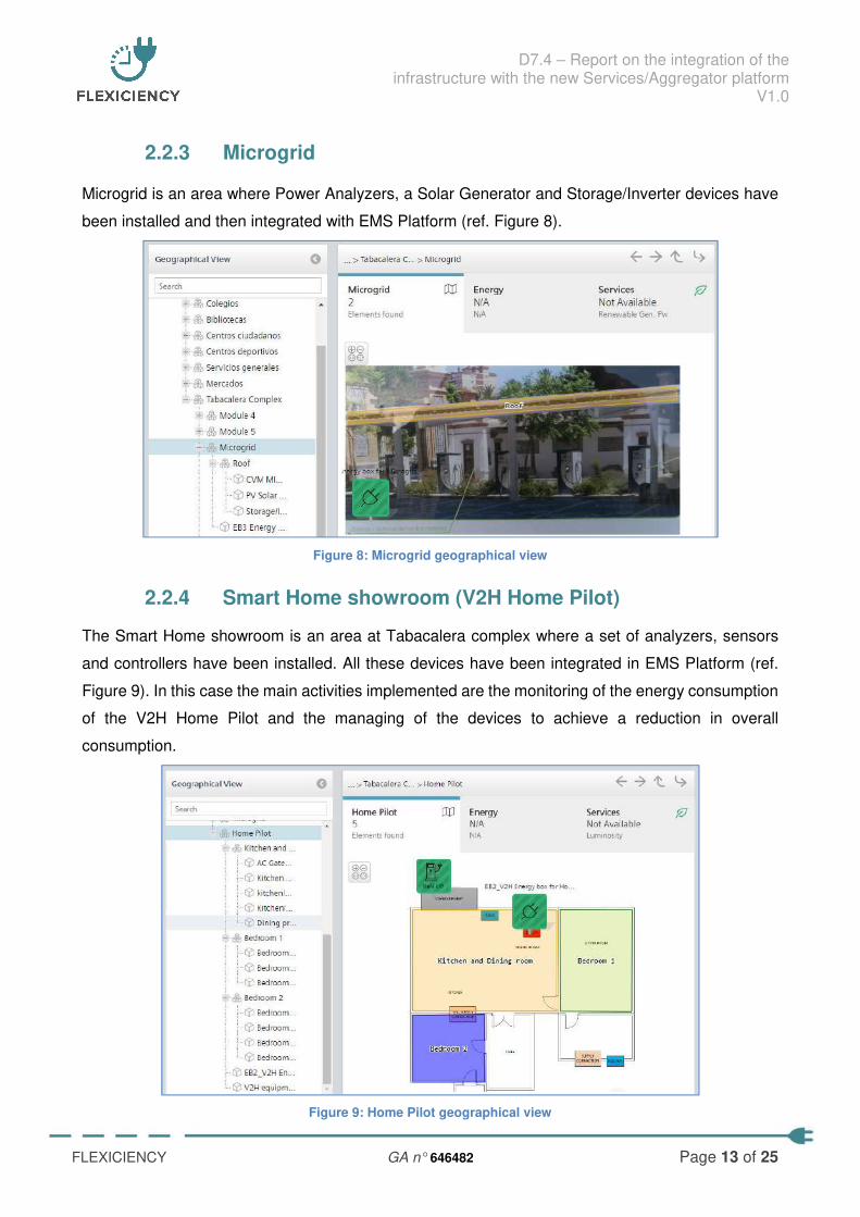
2.2.3 Microgrid
Microgrid is an area where Power Analyzers, a Solar Generator and Storage/Inverter devices have
been installed and then integrated with EMS Platform (ref. Figure 8).
Figure 8: Microgrid geographical view
2.2.4 Smart Home showroom (V2H Home Pilot)
The Smart Home showroom is an area at Tabacalera complex where a set of analyzers, sensors
and controllers have been installed. All these devices have been integrated in EMS Platform (ref.
Figure 9). In this case the main activities implemented are the monitoring of the energy consumption
of the V2H Home Pilot and the managing of the devices to achieve a reduction in overall
consumption.
Figure 9: Home Pilot geographical view
D7.4 – Report on the integration of the infrastructure with the new Services/Aggregator platform
V1.0
FLEXICIENCY GA n° 646482 Page 14 of 25
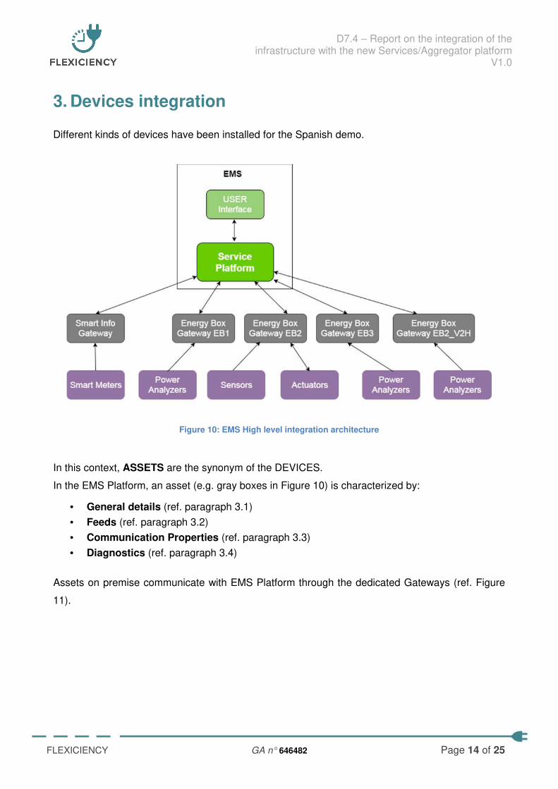
3. Devices integration
Different kinds of devices have been installed for the Spanish demo.
Figure 10: EMS High level integration architecture
In this context, ASSETS are the synonym of the DEVICES.
In the EMS Platform, an asset (e.g. gray boxes in Figure 10) is characterized by:
• General details (ref. paragraph 3.1)
• Feeds (ref. paragraph 3.2)
• Communication Properties (ref. paragraph 3.3)
• Diagnostics (ref. paragraph 3.4)
Assets on premise communicate with EMS Platform through the dedicated Gateways (ref. Figure
11).
D7.4 – Report on the integration of the infrastructure with the new Services/Aggregator platform
V1.0
FLEXICIENCY GA n° 646482 Page 15 of 25
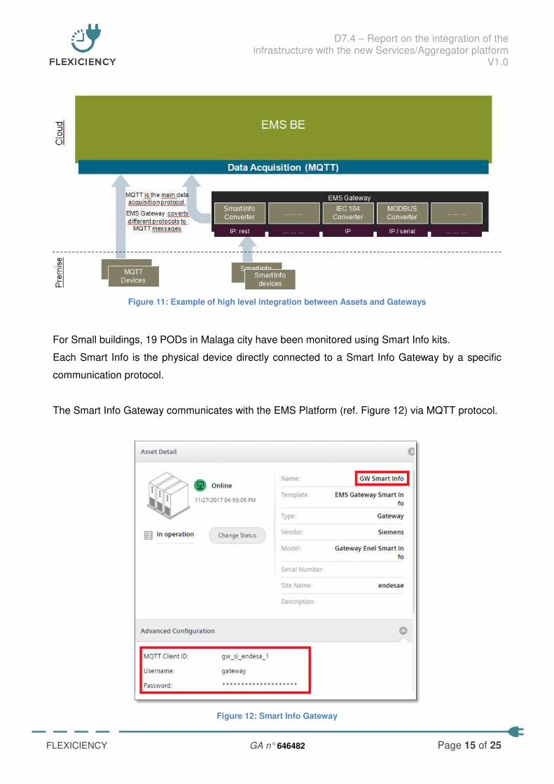
Figure 11: Example of high level integration between Assets and Gateways
For Small buildings, 19 PODs in Malaga city have been monitored using Smart Info kits.
Each Smart Info is the physical device directly connected to a Smart Info Gateway by a specific
communication protocol.
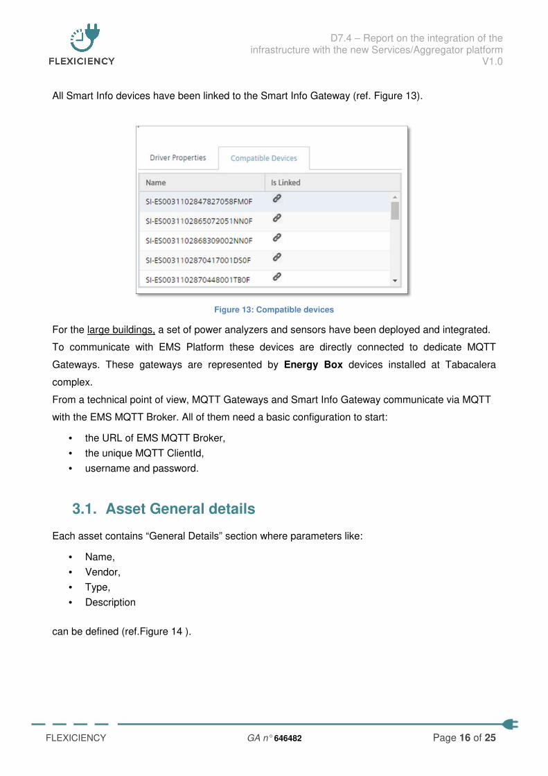
The Smart Info Gateway communicates with the EMS Platform (ref. Figure 12) via MQTT protocol.
Figure 12: Smart Info Gateway
D7.4 – Report on the integration of the infrastructure with the new Services/Aggregator platform
V1.0
FLEXICIENCY GA n° 646482 Page 16 of 25
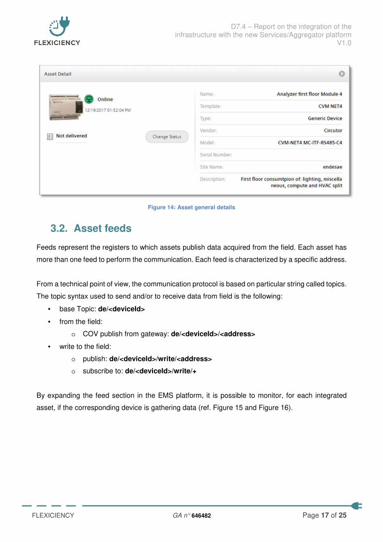
All Smart Info devices have been linked to the Smart Info Gateway (ref. Figure 13).
Figure 13: Compatible devices
For the large buildings, a set of power analyzers and sensors have been deployed and integrated.
To communicate with EMS Platform these devices are directly connected to dedicate MQTT
Gateways. These gateways are represented by Energy Box devices installed at Tabacalera
complex.
From a technical point of view, MQTT Gateways and Smart Info Gateway communicate via MQTT
with the EMS MQTT Broker. All of them need a basic configuration to start:
• the URL of EMS MQTT Broker,
• the unique MQTT ClientId,
• username and password.
3.1. Asset General details
Each asset contains “General Details” section where parameters like:
• Name,
• Vendor,
• Type,
• Description
can be defined (ref.Figure 14 ).
D7.4 – Report on the integration of the infrastructure with the new Services/Aggregator platform
V1.0
FLEXICIENCY GA n° 646482 Page 17 of 25
Figure 14: Asset general details
3.2. Asset feeds
Feeds represent the registers to which assets publish data acquired from the field. Each asset has
more than one feed to perform the communication. Each feed is characterized by a specific address.
From a technical point of view, the communication protocol is based on particular string called topics.
The topic syntax used to send and/or to receive data from field is the following:
• base Topic: de/<deviceId>
• from the field:
o COV publish from gateway: de/<deviceId>/<address>
• write to the field:
o publish: de/<deviceId>/write/<address>
o subscribe to: de/<deviceId>/write/+
By expanding the feed section in the EMS platform, it is possible to monitor, for each integrated
asset, if the corresponding device is gathering data (ref. Figure 15 and Figure 16).
D7.4 – Report on the integration of the infrastructure with the new Services/Aggregator platform
V1.0
FLEXICIENCY GA n° 646482 Page 18 of 25
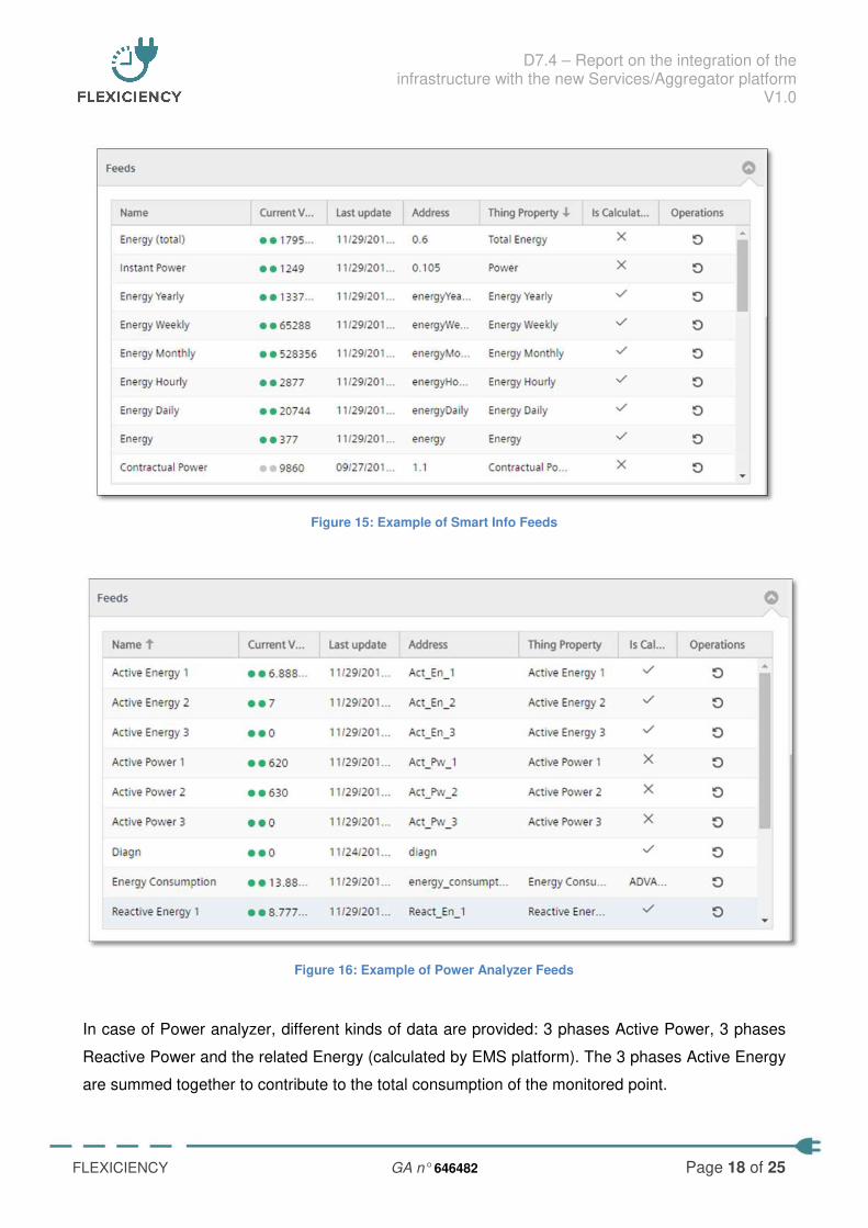
Figure 15: Example of Smart Info Feeds
Figure 16: Example of Power Analyzer Feeds
In case of Power analyzer, different kinds of data are provided: 3 phases Active Power, 3 phases
Reactive Power and the related Energy (calculated by EMS platform). The 3 phases Active Energy
are summed together to contribute to the total consumption of the monitored point.
D7.4 – Report on the integration of the infrastructure with the new Services/Aggregator platform
V1.0
FLEXICIENCY GA n° 646482 Page 19 of 25
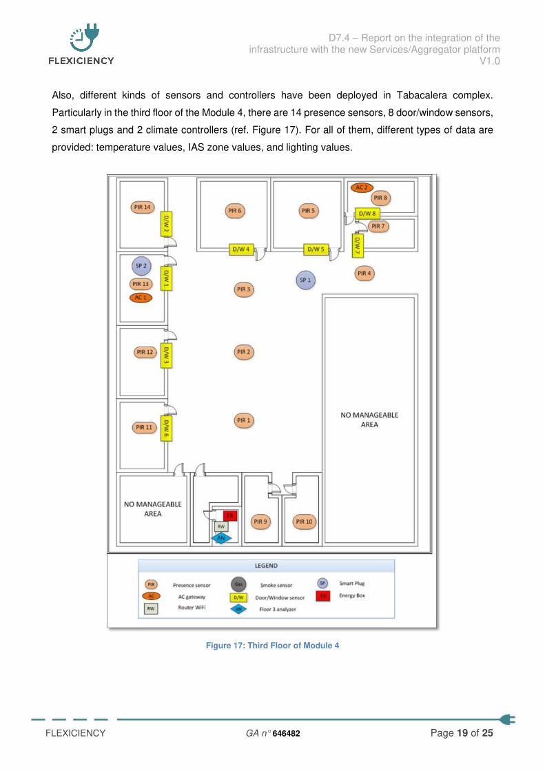
Also, different kinds of sensors and controllers have been deployed in Tabacalera complex.
Particularly in the third floor of the Module 4, there are 14 presence sensors, 8 door/window sensors,
2 smart plugs and 2 climate controllers (ref. Figure 17). For all of them, different types of data are
provided: temperature values, IAS zone values, and lighting values.
Figure 17: Third Floor of Module 4
D7.4 – Report on the integration of the infrastructure with the new Services/Aggregator platform
V1.0
FLEXICIENCY GA n° 646482 Page 20 of 25
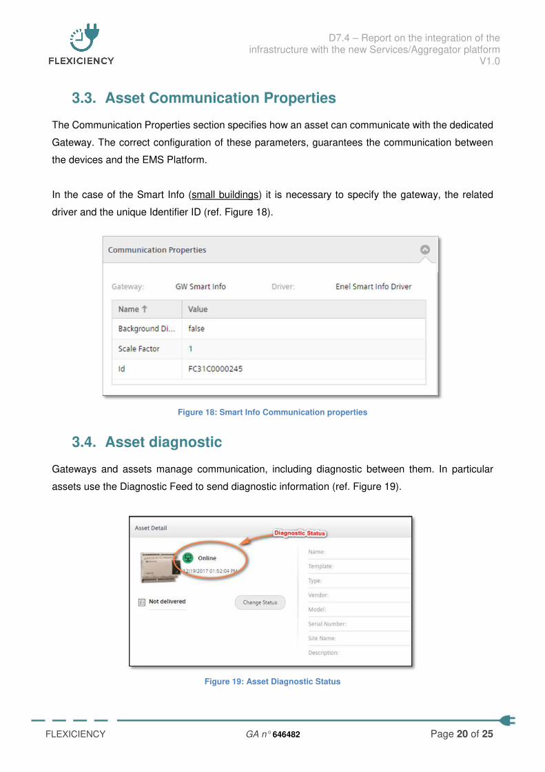
3.3. Asset Communication Properties
The Communication Properties section specifies how an asset can communicate with the dedicated
Gateway. The correct configuration of these parameters, guarantees the communication between
the devices and the EMS Platform.
In the case of the Smart Info (small buildings) it is necessary to specify the gateway, the related
driver and the unique Identifier ID (ref. Figure 18).
Figure 18: Smart Info Communication properties
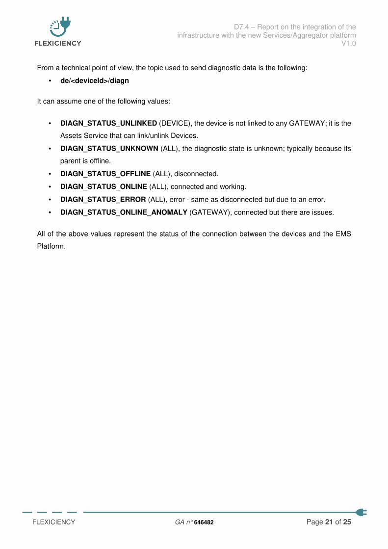
3.4. Asset diagnostic
Gateways and assets manage communication, including diagnostic between them. In particular
assets use the Diagnostic Feed to send diagnostic information (ref. Figure 19).
Figure 19: Asset Diagnostic Status
D7.4 – Report on the integration of the infrastructure with the new Services/Aggregator platform
V1.0
FLEXICIENCY GA n° 646482 Page 21 of 25
From a technical point of view, the topic used to send diagnostic data is the following:
• de/<deviceId>/diagn
It can assume one of the following values:
• DIAGN_STATUS_UNLINKED (DEVICE), the device is not linked to any GATEWAY; it is the
Assets Service that can link/unlink Devices.
• DIAGN_STATUS_UNKNOWN (ALL), the diagnostic state is unknown; typically because its
parent is offline.
• DIAGN_STATUS_OFFLINE (ALL), disconnected.
• DIAGN_STATUS_ONLINE (ALL), connected and working.
• DIAGN_STATUS_ERROR (ALL), error - same as disconnected but due to an error.
• DIAGN_STATUS_ONLINE_ANOMALY (GATEWAY), connected but there are issues.
All of the above values represent the status of the connection between the devices and the EMS
Platform.
D7.4 – Report on the integration of the infrastructure with the new Services/Aggregator platform
V1.0
FLEXICIENCY GA n° 646482 Page 22 of 25
4. Energy box integration
In Tabacalera complex, five Energy Box devices have been installed. Each of them communicates
with a set of sensors and analyzers located in different area of the buildings.
All the data acquired by the EMS Platform from sensors and analyzers is processed by Circe
algorithms platform and then sent to the related Energy Box.
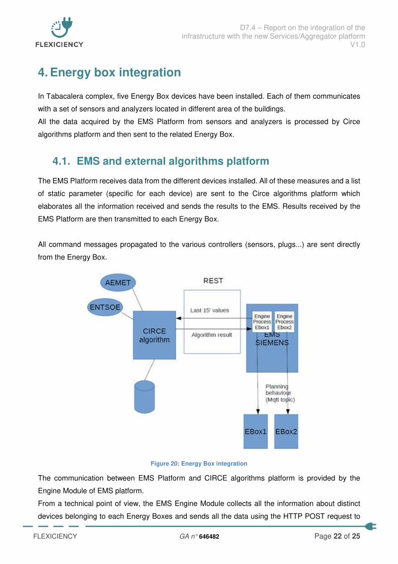
4.1. EMS and external algorithms platform
The EMS Platform receives data from the different devices installed. All of these measures and a list
of static parameter (specific for each device) are sent to the Circe algorithms platform which
elaborates all the information received and sends the results to the EMS. Results received by the
EMS Platform are then transmitted to each Energy Box.
All command messages propagated to the various controllers (sensors, plugs...) are sent directly
from the Energy Box.
Figure 20: Energy Box integration
The communication between EMS Platform and CIRCE algorithms platform is provided by the
Engine Module of EMS platform.
From a technical point of view, the EMS Engine Module collects all the information about distinct
devices belonging to each Energy Boxes and sends all the data using the HTTP POST request to
D7.4 – Report on the integration of the infrastructure with the new Services/Aggregator platform
V1.0
FLEXICIENCY GA n° 646482 Page 23 of 25
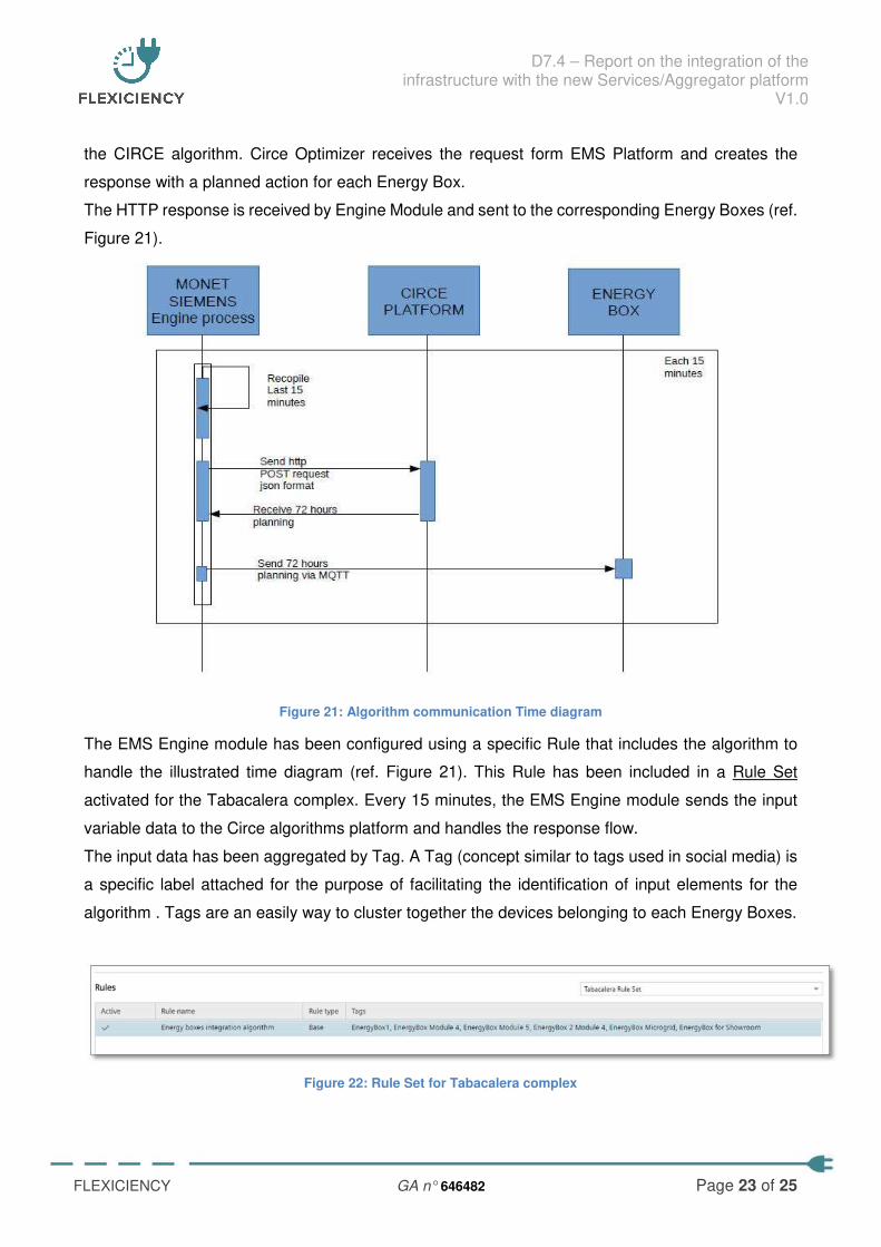
the CIRCE algorithm. Circe Optimizer receives the request form EMS Platform and creates the
response with a planned action for each Energy Box.
The HTTP response is received by Engine Module and sent to the corresponding Energy Boxes (ref.
Figure 21).
Figure 21: Algorithm communication Time diagram
The EMS Engine module has been configured using a specific Rule that includes the algorithm to
handle the illustrated time diagram (ref. Figure 21). This Rule has been included in a Rule Set
activated for the Tabacalera complex. Every 15 minutes, the EMS Engine module sends the input
variable data to the Circe algorithms platform and handles the response flow.
The input data has been aggregated by Tag. A Tag (concept similar to tags used in social media) is
a specific label attached for the purpose of facilitating the identification of input elements for the
algorithm . Tags are an easily way to cluster together the devices belonging to each Energy Boxes.
Figure 22: Rule Set for Tabacalera complex
D7.4 – Report on the integration of the infrastructure with the new Services/Aggregator platform
V1.0
FLEXICIENCY GA n° 646482 Page 24 of 25
5. Appendix
5.1. Devices installed by typology
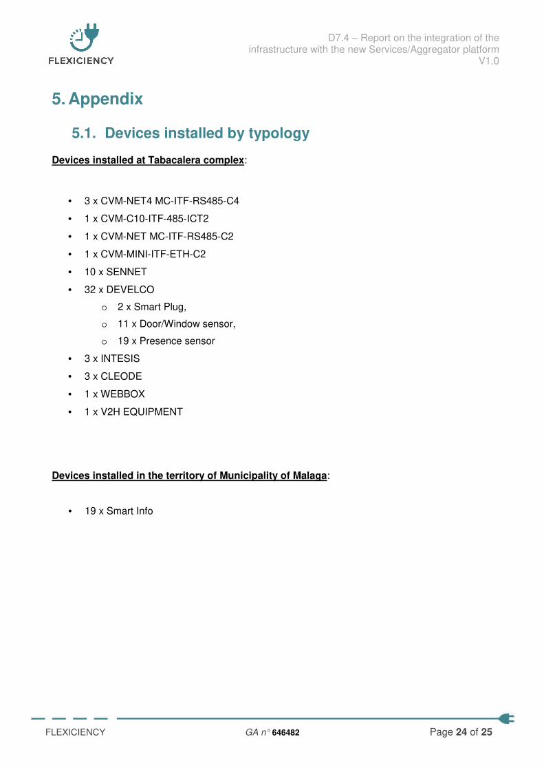
Devices installed at Tabacalera complex:
• 3 x CVM-NET4 MC-ITF-RS485-C4
• 1 x CVM-C10-ITF-485-ICT2
• 1 x CVM-NET MC-ITF-RS485-C2
• 1 x CVM-MINI-ITF-ETH-C2
• 10 x SENNET
• 32 x DEVELCO
o 2 x Smart Plug,
o 11 x Door/Window sensor,
o 19 x Presence sensor
• 3 x INTESIS
• 3 x CLEODE
• 1 x WEBBOX
• 1 x V2H EQUIPMENT
Devices installed in the territory of Municipality of Malaga:
• 19 x Smart Info
D7.4 – Report on the integration of the infrastructure with the new Services/Aggregator platform
V1.0
FLEXICIENCY GA n° 646482 Page 25 of 25
5.2. Devices installed by Use Cases
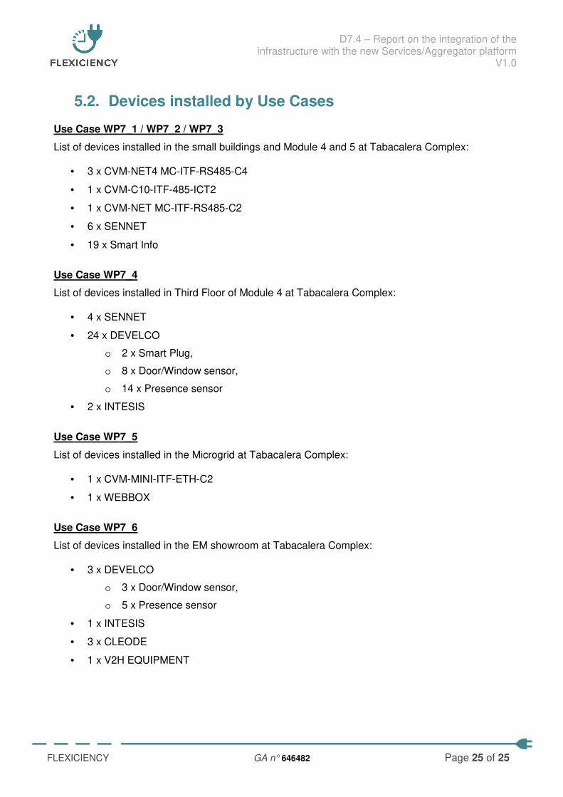
Use Case WP7_1 / WP7_2 / WP7_3
List of devices installed in the small buildings and Module 4 and 5 at Tabacalera Complex:
• 3 x CVM-NET4 MC-ITF-RS485-C4
• 1 x CVM-C10-ITF-485-ICT2
• 1 x CVM-NET MC-ITF-RS485-C2
• 6 x SENNET
• 19 x Smart Info
Use Case WP7_4
List of devices installed in Third Floor of Module 4 at Tabacalera Complex:
• 4 x SENNET
• 24 x DEVELCO
o 2 x Smart Plug,
o 8 x Door/Window sensor,
o 14 x Presence sensor
• 2 x INTESIS
Use Case WP7_5
List of devices installed in the Microgrid at Tabacalera Complex:
• 1 x CVM-MINI-ITF-ETH-C2
• 1 x WEBBOX
Use Case WP7_6
List of devices installed in the EM showroom at Tabacalera Complex:
• 3 x DEVELCO
o 3 x Door/Window sensor,
o 5 x Presence sensor
• 1 x INTESIS
• 3 x CLEODE
• 1 x V2H EQUIPMENT