DC Inverter Multi Split - Certificazione Energetica.net
68
DC Inverter Multi Split A5MSX- 2009 Models: A5MSX 20 A/AR A5MSX 25 A/AR A5MSX 30 A/AR
-
Upload
khangminh22 -
Category
Documents
-
view
8 -
download
0
Transcript of DC Inverter Multi Split - Certificazione Energetica.net
DC Inverter Multi SplitA5MSX- 2009
Models: A5MSX 20 A/AR A5MSX 25 A/AR A5MSX 30 A/AR

A5MSX-2009 Table of Contents
“McQuay” is a registered trademark of McQuay International. All rights reserved.© 2009 McQuay International. All rights reserved throughout the world.
Bulletin illustrations cover the general appearance of McQuay International products at the time of publication. We reserve the right to change design and construction specifications at any time without notice.
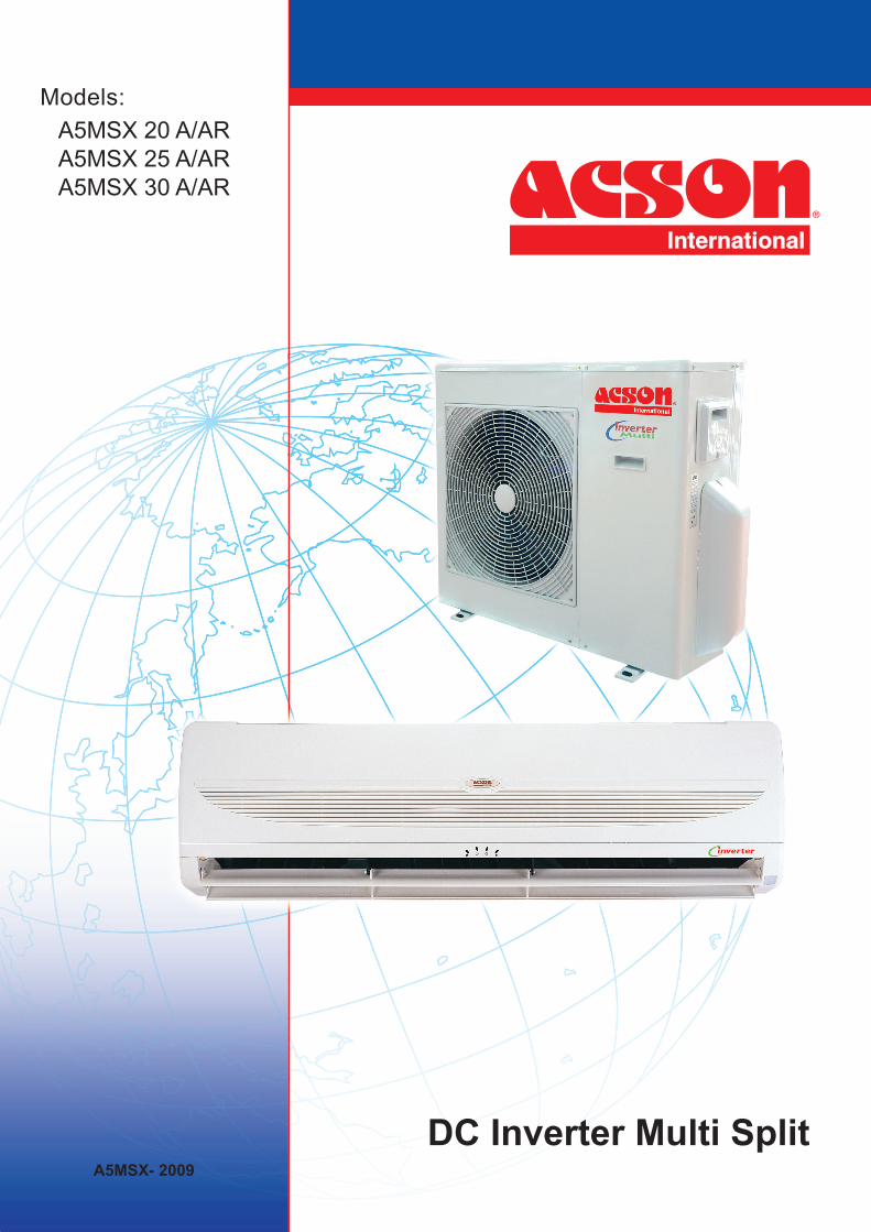
Table of ContentsNomenclature......................................................................................................................1
Indoor Unit .....................................................................................................................1
Outdoor Unit ..................................................................................................................2
Product Line-Up .............................................................................................................3
Features...............................................................................................................................5
Application Information .....................................................................................................6
Operating Range ...........................................................................................................6
Refrigerant Circuit Diagram ...........................................................................................7
Controller .................................................................................................................... 10
Installation Guideline ...................................................................................................11
Engineering & Physical Data .......................................................................................... 24
General Data .............................................................................................................. 24
Component Data......................................................................................................... 32
Performance Data ............................................................................................................ 40
Performance Table ...................................................................................................... 40
Outline and Dimension ................................................................................................... 43
Electrical Data .................................................................................................................. 47
Wiring Diagram ................................................................................................................ 51
Service and Maintenance................................................................................................ 54
Troubleshooting .............................................................................................................. 56
Exploded View and Part List .......................................................................................... 60
1
A5MSX-2009
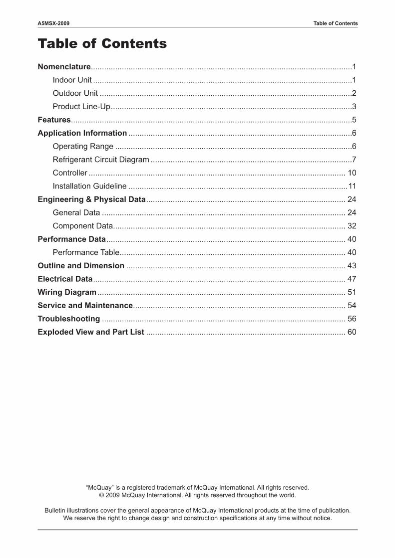
NomenclatureIndoor Unit
A 5 WM X 10 G R
BrandA : Acson
Model Name
Capacity Index
Model Type
Refrigerant5 : R410A
WM : Wall Mounted
Inverter System TypeX : X series
10 : 10,000 Btu/h15 : 15,000 Btu/h20 : 20,000 Btu/h
ChassisG : G series
“ ” : Omitted if cooling onlyR : Heatpump
Nomenclature
2
A5MSX-2009
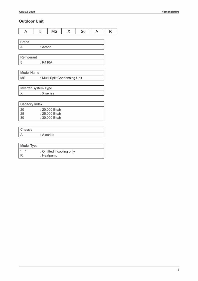
Outdoor Unit
A 5 MS X 20 A R
BrandA : Acson
Model Name
Capacity Index
Model Type
Refrigerant5 : R410A
MS : Multi Split Condensing Unit
Inverter System TypeX : X series
20 : 20,000 Btu/h25 : 25,000 Btu/h30 : 30,000 Btu/h
ChassisA : A series
“ ” : Omitted if cooling onlyR : Heatpump
Nomenclature
3
A5MSX-2009
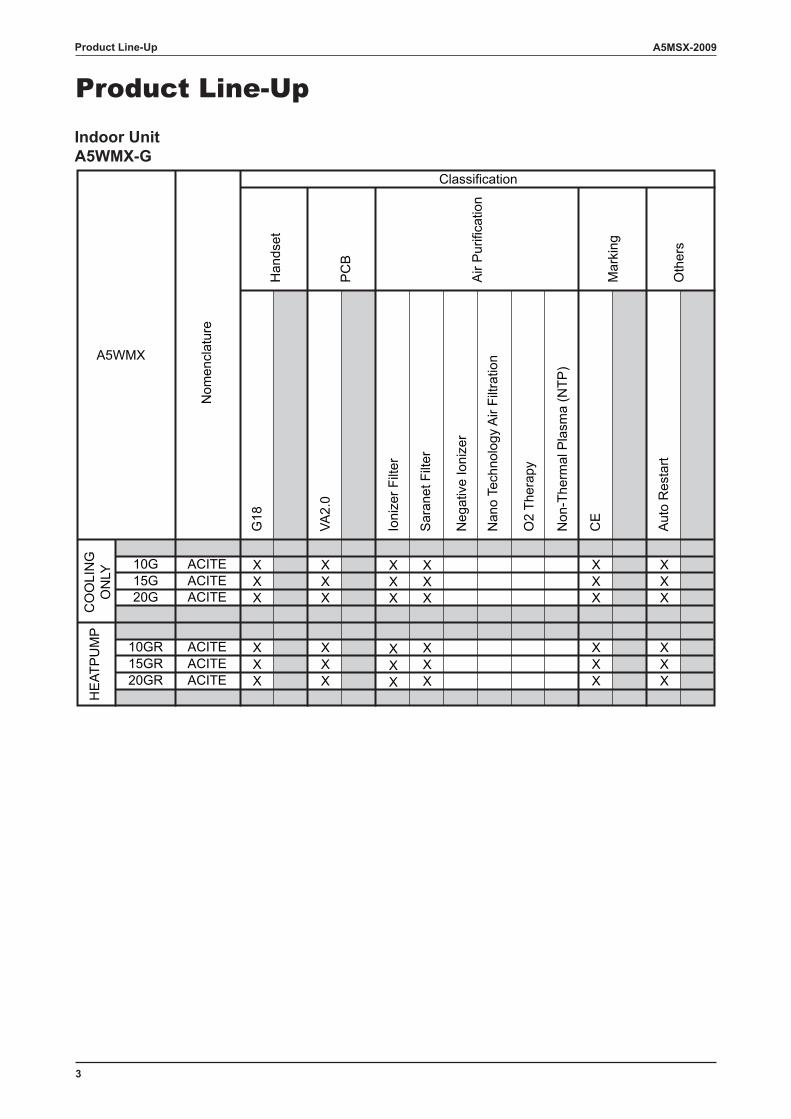
Product Line-UpIndoor UnitA5WMX-G
G18
VA2.
0
Ioni
zer F
ilter
Sar
anet
Filt
er
Neg
ativ
e Io
nize
r
Nan
o Te
chno
logy
Air
Filtr
atio
n
O2
Ther
apy
Non
-The
rmal
Pla
sma
(NTP
)
CE
Aut
o R
esta
rt
10G ACITE X X X X X X15G ACITE X X X X X X20G ACITE X X X X X X
10GR ACITE X X X X X X15GR ACITE X X X X X X20GR ACITE X X X X X X
Oth
ers
Classification
Air
Pur
ifica
tion
Mar
king
Han
dset
PC
BA5WMX
CO
OLI
NG
ON
LYH
EAT
PU
MP
Nom
encl
atur
e
Product Line-Up
4
A5MSX-2009
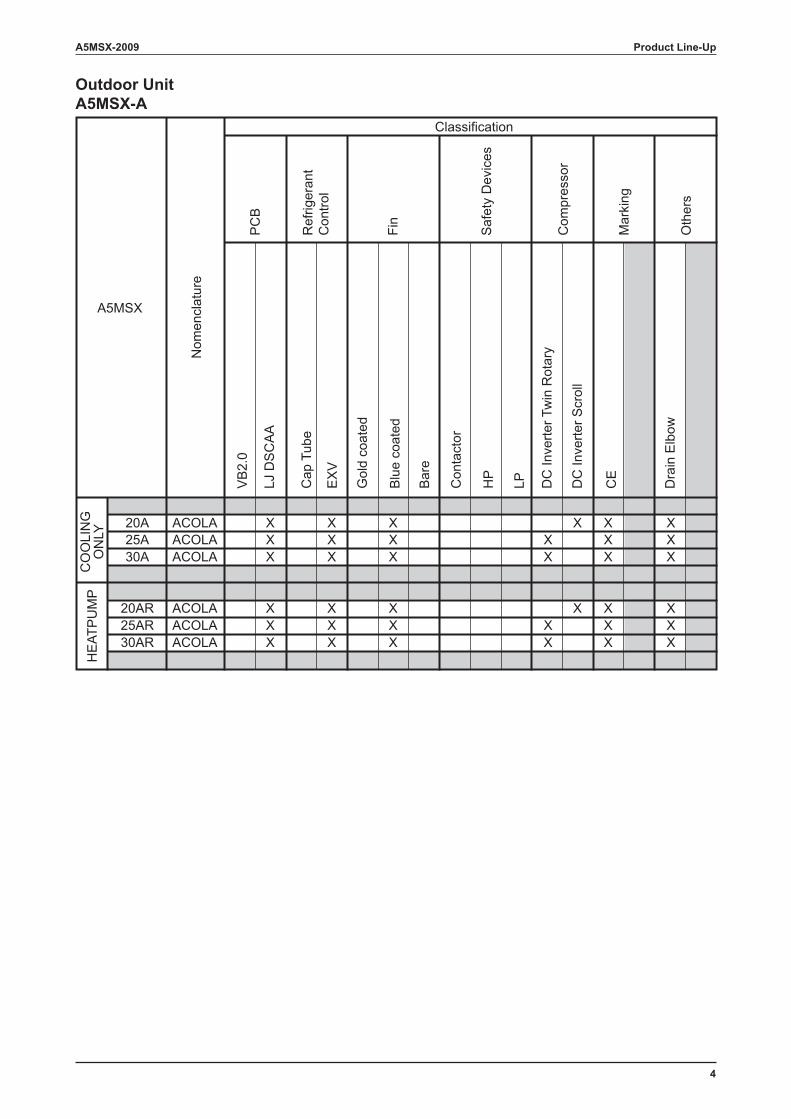
Outdoor UnitA5MSX-A
VB
2.0
LJ D
SC
AA
Cap
Tub
e
EX
V
Gol
d co
ated
Blu
e co
ated
Bar
e
Con
tact
or
HP
LP DC
Inve
rter T
win
Rot
ary
DC
Inve
rter S
crol
l
CE
Dra
in E
lbow
20A ACOLA X X X X X X25A ACOLA X X X X X X30A ACOLA X X X X X X
20AR ACOLA X X X X X X25AR ACOLA X X X X X X30AR ACOLA X X X X X X
A5MSX
Fin
Nom
encl
atur
e
Classification
Mar
king
Oth
ers
Saf
ety
Dev
ices
Com
pres
sor
PC
B
Ref
riger
ant
Con
trol
HE
ATP
UM
PC
OO
LIN
GO
NLY
Product Line-Up
5
A5MSX-2009
Self Diagnosis
The microprocessor provides the possibility to detect and diagnose any fault or malfunction that occurs in the system. The error will be reflected by the blinking of the LED lights.
Advance Technology
Incorporating fuzzy logic control enables greater flexibility in system control handling to achieve• Powerful, efficient and economical operation.• Even room temperature control.• Constant and quiet compressor operation.• Enhanced system reliability and reduced maintenance costs.
On / Off Button on Indoor Unit
On/Off button is provided on the front panel of the unit. It can be used when the remote controller is missing or if its battery has run out. (Note: This button can also be used for forced operation mode)
Wireless Remote Controller
• The compact LCD transmitter is able to operate the air conditioner unit within the distance of 8 meters.• Fan speed can be set at high / medium / low / super low or automatic.• Sleep mode auto control will gradually increase or decrease the setting temperature to provide a
comfortable surrounding for sleeping.• Air flow direction can be controlled automatically.• Room temperature is controlled by electronic thermostat.• The real time timer allows the air conditioner to be switched On and Off automatically based on user
settings.• Turbo mode function is available to enables the required set temperature to be achieved in a short time.• Personalized Setting allows user to preset and store 2 groups of personal settings (including timer setting)
in the handset.
Higher Energy Savings
The inverter compressor is programmed to run at the optimum speed. This is controlled by input frequency that varies according to the indoor load requirements.Once the indoor set temperature is achieved, the input frequency supply to the compressor will be reduced.Hence, less power is required to maintain the unit operation and this will consume less energy.
Improved Compressor Life Span
For this multi-split inverter system, once the unit is started, the compressor rotation speed is steadily ramp up or down based on load requirement throughout the operation. This control method gives the compressor motor a smooth operation. It helps to reduce the wear and tear of the compressor motor. In the long run, the life span of compressor is increased.
Overheating Protection (for heat pump unit only)
In case the internal and/or the external temperature are too high, or the filter is dirty and clogged up, the refrigerant may be overheated. The compressor will reduce its running speed in order to lower the temperature of heat exchanger. If the temperature is still very high, the compressor will stop.
Features
Features
6
A5MSX-2009
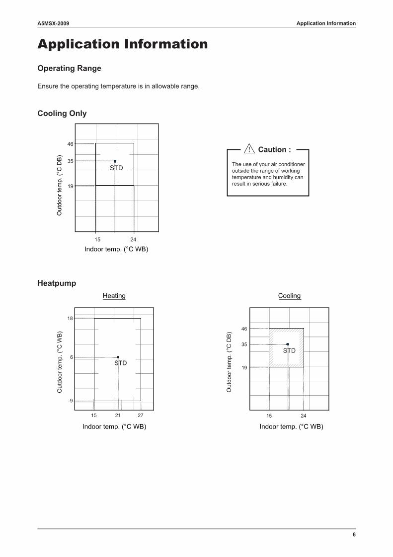
Application InformationOperating Range
Ensure the operating temperature is in allowable range.
Cooling Only
Heatpump
Out
door
tem
p. (°
C D
B)
Heating Cooling
Out
door
tem
p. (°
C W
B)
Out
door
tem
p. (°
C D
B)
15 24
19
35
46
STD
-9
15 21
6
27
18
STD
Indoor temp. (°C WB)
Indoor temp. (°C WB) Indoor temp. (°C WB)
15 24
19
35
46
STD
! Caution :
The use of your air conditioner outside the range of working temperature and humidity can result in serious failure.
Application Information
7
A5MSX-2009Application Information
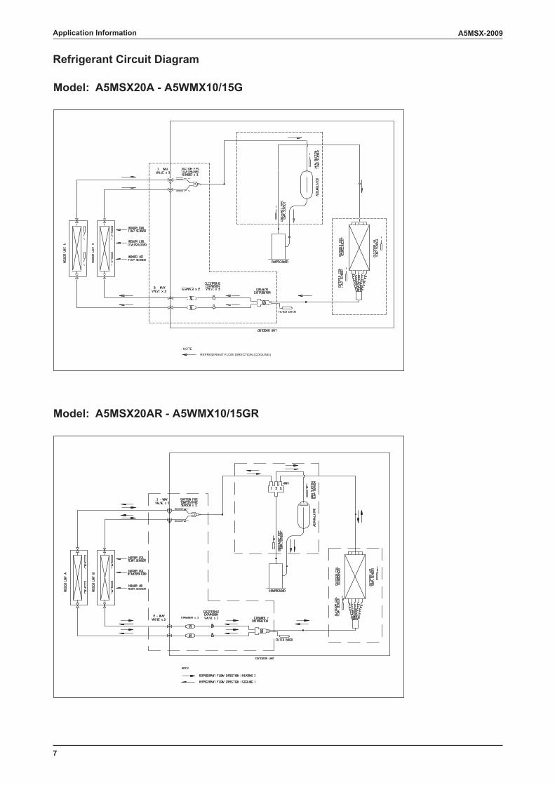
Model: A5MSX20A - A5WMX10/15G
Model: A5MSX20AR - A5WMX10/15GR
NOTE
REFRIGERANT FLOW DIRECTION (COOLING)
Refrigerant Circuit Diagram
8
A5MSX-2009 Application Information
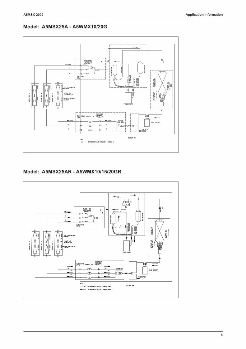
Model: A5MSX25A - A5WMX10/20G
Model: A5MSX25AR - A5WMX10/15/20GR
9
A5MSX-2009
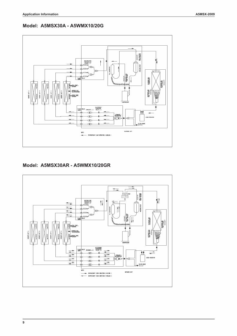
Model: A5MSX30A - A5WMX10/20G
Model: A5MSX30AR - A5WMX10/20GR
Application Information
10
A5MSX-2009
Controller
G18
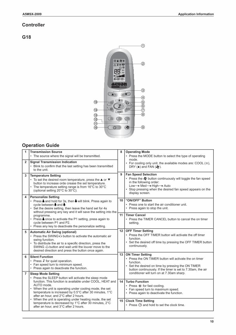
Operation Guide1 Transmission Source
The source where the signal will be transmitted.•
2 Signal Transmission IndicationBlink to confirm that the last setting has been transmitted to the unit.
•
3 Temperature SettingTo set the desired room temperature, press the or button to increase orde crease the set temperature.The temperature setting range is from 16°C to 30°C (optional setting 20°C to 30°C).
•
•
4 Personalize SettingPress and hold for 3s, then will blink. Press again to cycle between and Set the desire setting, then leave the hand set for 4s without pressing any key and it will save the setting into the programme.Press once to activate the P1 setting, press again to cycle between P1 and P2.Press any key to deactivate the personalize setting.
•
•
•
•
5 Automatic Air Swing (optional)Press the SWING button to activate the automatic air swing function.To distribute the air to a specific direction, press the SWING button and wait until the louver move to the desired direction and press the button once again.
•
•
6 Silent FunctionPress for quiet operation.Fan speed turn to minimum speed.Press again to deactivate the function.
•••
7 Sleep Mode SettingPress the SLEEP button will activate the sleep mode function. This function is available under COOL, HEAT and AUTO mode.When the unit is operating under cooling mode, the set temperature is increased by 0.5°C after 30 minutes, 1°C after an hour, and 2°C after 2 hours.When the unit is operating under heating mode, the set temperature is decreased by 1°C after 30 minutes, 2°C after an hour, and 3°C after 2 hours.
•
•
•
8 Operating ModePress the MODE button to select the type of operating mode.For cooling only unit, the available modes are: COOL ( ), DRY ( ) and FAN ( ).
•
•
9 Fan Speed SelectionPress the button continuously will toggle the fan speed in the following order:Low Med High AutoStop pressing when the desired fan speed appears on the display screen.
•
•
10 “ON/OFF” ButtonPress one to start the air conditioner unit.Press again to stop the unit.
••
11 Timer CancelPress the TIMER CANCEL button to cancel the on timer setting.
•
12 OFF Timer SettingPress the OFF TIMER button will activate the off timer function.Set the desired off time by pressing the OFF TIMER button continuously.
•
•
13 ON Timer SettingPress the ON TIMER button will activate the on timer function.Set the desired on time by pressing the ON TIMER button continuously. If the timer is set to 7.30am, the air conditioner will turn on at 7.30am sharp.
•
•
14 Turbo FunctionPress for fast cooling.Fan speed turn to maximum speed.Press again to deactivate the function.
•••
15 Clock Time SettingPress and hold to set the clock time.•
P1P2
ONTIMER
OFFTIMER
TIMERCANCEL
SLEEPMODE
Application Information
11
A5MSX-2009
Installation Guideline
Safety Precautions
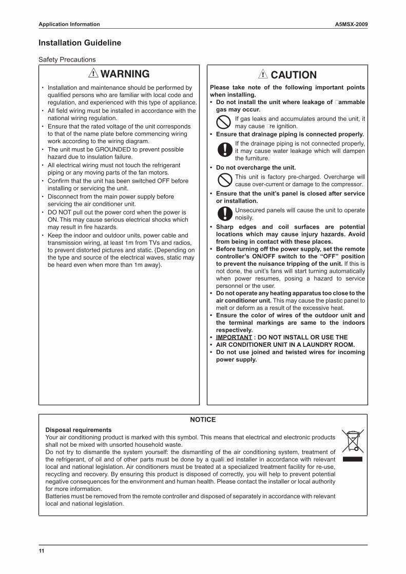
WARNING CAUTIONInstallation and maintenance should be performed by qualifi ed persons who are familiar with local code and regulation, and experienced with this type of appliance.All fi eld wiring must be installed in accordance with the national wiring regulation.Ensure that the rated voltage of the unit corresponds to that of the name plate before commencing wiring work according to the wiring diagram.The unit must be GROUNDED to prevent possible hazard due to insulation failure.All electrical wiring must not touch the refrigerant piping or any moving parts of the fan motors.Confi rm that the unit has been switched OFF before installing or servicing the unit.Disconnect from the main power supply before servicing the air conditioner unit.DO NOT pull out the power cord when the power is ON. This may cause serious electrical shocks which may result in fi re hazards.Keep the indoor and outdoor units, power cable and transmission wiring, at least 1m from TVs and radios, to prevent distorted pictures and static. {Depending on the type and source of the electrical waves, static may be heard even when more than 1m away}.
•
•
•
•
•
•
•
•
•
Please take note of the following important points when installing.
Do not install the unit where leakage of � ammable gas may occur.
If gas leaks and accumulates around the unit, it may cause � re ignition.
Ensure that drainage piping is connected properly. If the drainage piping is not connected properly, it may cause water leakage which will dampen the furniture.
Do not overcharge the unit. This unit is factory pre-charged. Overcharge will cause over-current or damage to the compressor.
Ensure that the unit’s panel is closed after service or installation.
Unsecured panels will cause the unit to operate noisily.
Sharp edges and coil surfaces are potential locations which may cause injury hazards. Avoid from being in contact with these places.Before turning off the power supply, set the remote controller’s ON/OFF switch to the “OFF” position to prevent the nuisance tripping of the unit. If this is not done, the unit’s fans will start turning automatically when power resumes, posing a hazard to service personnel or the user.Do not operate any heating apparatus too close to the air conditioner unit. This may cause the plastic panel to melt or deform as a result of the excessive heat.Ensure the color of wires of the outdoor unit and the terminal markings are same to the indoors respectively.IMPORTANT : DO NOT INSTALL OR USE THEAIR CONDITIONER UNIT IN A LAUNDRY ROOM.Do not use joined and twisted wires for incoming power supply.
•
•
•
•
•
•
•
•
•••
NOTICEDisposal requirementsYour air conditioning product is marked with this symbol. This means that electrical and electronic products shall not be mixed with unsorted household waste.Do not try to dismantle the system yourself: the dismantling of the air conditioning system, treatment of the refrigerant, of oil and of other parts must be done by a quali� ed installer in accordance with relevant local and national legislation. Air conditioners must be treated at a specialized treatment facility for re-use, recycling and recovery. By ensuring this product is disposed of correctly, you will help to prevent potential negative consequences for the environment and human health. Please contact the installer or local authority for more information.Batteries must be removed from the remote controller and disposed of separately in accordance with relevant local and national legislation.
Application Information
12
A5MSX-2009 Application Information
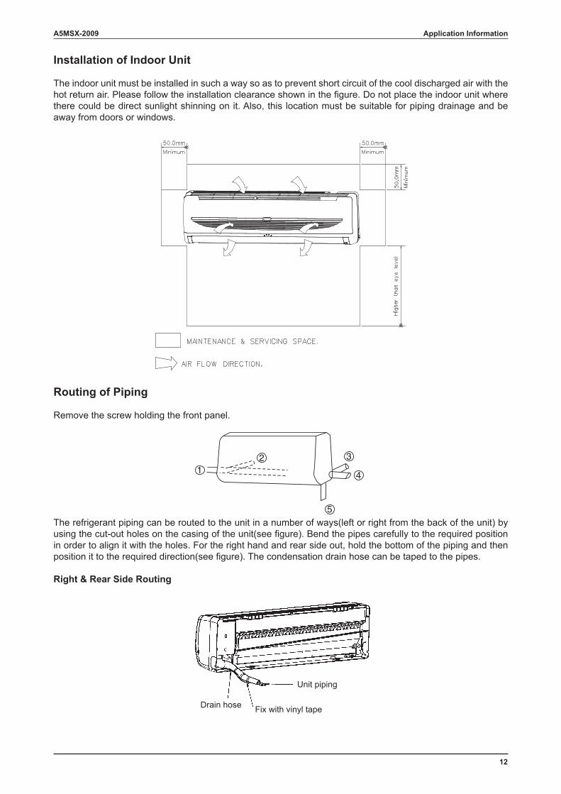
Installation of Indoor Unit
The indoor unit must be installed in such a way so as to prevent short circuit of the cool discharged air with the hot return air. Please follow the installation clearance shown in the figure. Do not place the indoor unit where there could be direct sunlight shinning on it. Also, this location must be suitable for piping drainage and be away from doors or windows.
Routing of Piping
Remove the screw holding the front panel.
The refrigerant piping can be routed to the unit in a number of ways(left or right from the back of the unit) by using the cut-out holes on the casing of the unit(see figure). Bend the pipes carefully to the required position in order to align it with the holes. For the right hand and rear side out, hold the bottom of the piping and then position it to the required direction(see figure). The condensation drain hose can be taped to the pipes.
Right & Rear Side Routing
12 3
4
5
Drain hose Fix with vinyl tape
Unit piping
13
A5MSX-2009
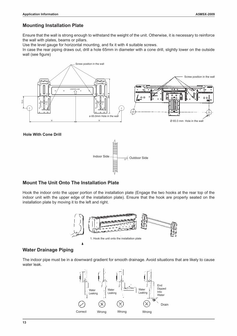
Mounting Installation Plate
Ensure that the wall is strong enough to withstand the weight of the unit. Otherwise, it is necessary to reinforce the wall with plates, beams or pillars.Use the level gauge for horizontal mounting, and fix it with 4 suitable screws.In case the rear piping draws out, drill a hole 65mm in diameter with a cone drill, slightly lower on the outside wall (see figure)
Hole With Cone Drill
Mount The Unit Onto The Installation Plate
Hook the indoor onto the upper portion of the installation plate (Engage the two hooks at the rear top of the indoor unit with the upper edge of the installation plate). Ensure that the hook are properly seated on the installation plate by moving it to the left and right.
Water Drainage Piping
The indoor pipe must be in a downward gradient for smooth drainage. Avoid situations that are likely to cause water leak.
72.0
'A' 'A'
Screw position in the wall
ø 65.0mm Hole in the wall
Screw position in the wall
Ø 65.0 mm Hole in the wall
CENTER LINE
Indoor Side Outdoor Side
Correct
EndDippedIntoWater
WaterLeaking
WaterLeaking
WaterLeaking
Wrong Wrong Wrong
Drain
1. Hook the unit onto the installation plate
Application Information
14
A5MSX-2009 Application Information
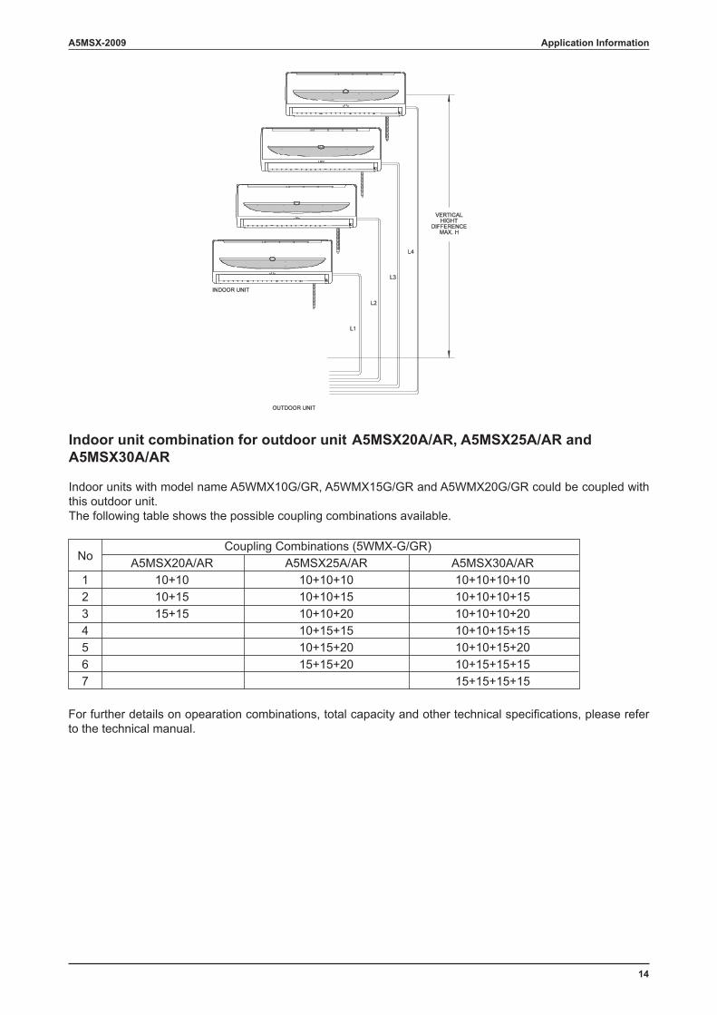
Indoor unit combination for outdoor unit A5MSX20A/AR, A5MSX25A/AR and A5MSX30A/AR
Indoor units with model name A5WMX10G/GR, A5WMX15G/GR and A5WMX20G/GR could be coupled with this outdoor unit. The following table shows the possible coupling combinations available.
For further details on opearation combinations, total capacity and other technical specifications, please refer to the technical manual.
No Coupling Combinations (5WMX-G/GR)
A5MSX20A/AR A5MSX25A/AR A5MSX30A/AR 1 10+10 10+10+10 10+10+10+10
2 10+15 10+10+15 10+10+10+15 3 15+15 10+10+20 10+10+10+20 4 10+15+15 10+10+15+15 5 10+15+20 10+10+15+20 6 15+15+20 10+15+15+15 7 15+15+15+15
15
A5MSX-2009
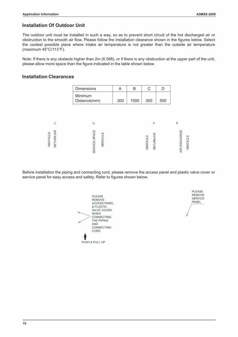
Installation Of Outdoor Unit
Installation Clearances
Dimensions A B C D
MinimumDistance(mm) 300 1000 300 500
PLEASEREMOVESERVICEPANEL
PLEASEREMOVEACCESS PANEL& PLASTICVALVE COVERWHENCONNECTINGTHE PIPINGANDCONNECTINGCORD.
PUSH & PULL UP
DC A B
ELC
ATSB
O
RIA
NRUTER
ELC
ATSB
O
ELC
ATSB
O
The outdoor unit must be installed in such a way, so as to prevent short circuit of the hot discharged air or obstruction to the smooth air flow. Please follow the installation clearance shown in the figures below. Select the coolest possible place where intake air temperature is not greater than the outside air temperature (maximum 45°C/113°F).
Note: If there is any obstacle higher than 2m (6.56ft), or if there is any obstruction at the upper part of the unit, please allow more space than the figure indicated in the table shown below.
SE
RV
ICE
SP
AC
E
AIR
DIS
CH
AR
GE
Before installation the piping and connecting cord, please remove the access panel and plastic valve cover or service panel for easy access and safety. Refer to figures shown below.
RE
TUR
N A
IR
OB
STA
CLE
Application Information
16
A5MSX-2009
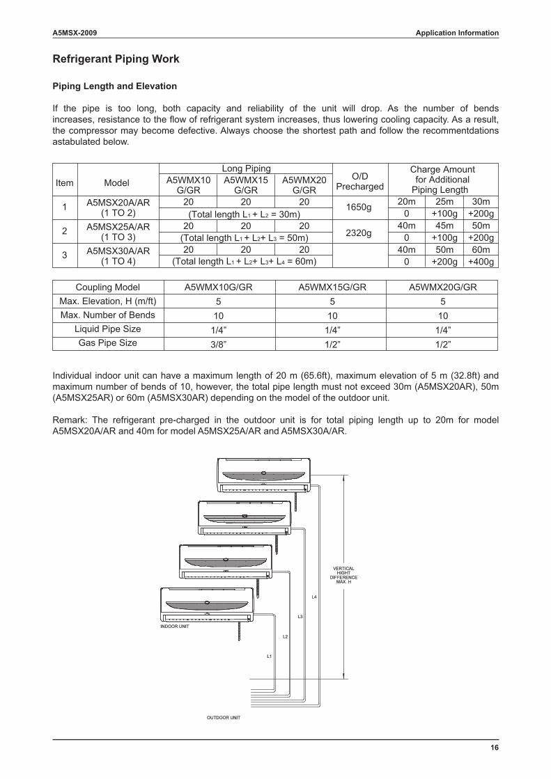
Refrigerant Piping Work
Piping Length and Elevation
If the pipe is too long, both capacity and reliability of the unit will drop. As the number of bends increases, resistance to the flow of refrigerant system increases, thus lowering cooling capacity. As a result, the compressor may become defective. Always choose the shortest path and follow the recommentdations astabulated below.
Individual indoor unit can have a maximum length of 20 m (65.6ft), maximum elevation of 5 m (32.8ft) and maximum number of bends of 10, however, the total pipe length must not exceed 30m (A5MSX20AR), 50m (A5MSX25AR) or 60m (A5MSX30AR) depending on the model of the outdoor unit.
Remark: The refrigerant pre-charged in the outdoor unit is for total piping length up to 20m for model A5MSX20A/AR and 40m for model A5MSX25A/AR and A5MSX30A/AR.
Item
1
2
3
ModelLong Piping
O/DPrecharged
Charge Amountfor Additional
Piping Length
1650g 20m0
40m0
40m0
25m+100g45m
+100g50m
+200g
30m+200g50m
+200g60m
+400g
2320g
A5MSX20A/AR(1 TO 2)
A5WMX10G/GR
A5WMX15G/GR
A5WMX20G/GR
20 20 20
20 20 20
20 20 20
A5MSX25A/AR(1 TO 3)
Coupling ModelMax. Elevation, H (m/ft)Max. Number of Bends
Liquid Pipe SizeGas Pipe Size
A5WMX10G/GR510
1/4”3/8”
A5WMX15G/GR510
1/4”1/2”
A5WMX20G/GR510
1/4”1/2”
A5MSX30A/AR(1 TO 4)
(Total length L1 + L2 = 30m)
(Total length L1 + L2+ L3 = 50m)
(Total length L1 + L2+ L3+ L4 = 60m)
Application Information
17
A5MSX-2009
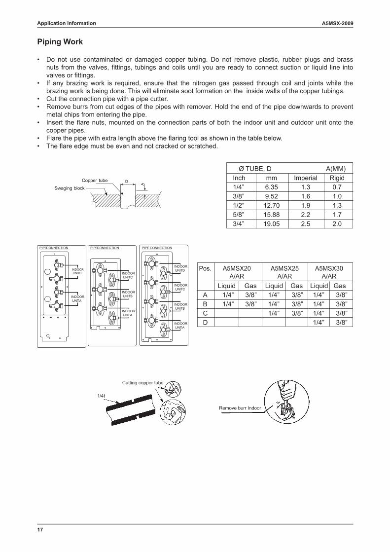
Piping Work
• Do not use contaminated or damaged copper tubing. Do not remove plastic, rubber plugs and brass nuts from the valves, fittings, tubings and coils until you are ready to connect suction or liquid line into valves or fittings.
• If any brazing work is required, ensure that the nitrogen gas passed through coil and joints while the brazing work is being done. This will eliminate soot formation on the inside walls of the copper tubings.
• Cut the connection pipe with a pipe cutter.• Remove burrs from cut edges of the pipes with remover. Hold the end of the pipe downwards to prevent
metal chips from entering the pipe.• Insert the flare nuts, mounted on the connection parts of both the indoor unit and outdoor unit onto the
copper pipes.• Flare the pipe with extra length above the flaring tool as shown in the table below.• The flare edge must be even and not cracked or scratched.
Copper tube
Swaging blockD
A
Ø TUBE, D A(MM)Inch mm Imperial Rigid1/4” 6.35 1.3 0.73/8” 9.52 1.6 1.01/2” 12.70 1.9 1.35/8” 15.88 2.2 1.73/4” 19.05 2.5 2.0
PIPE CONNECTION PIPE CONNECTION PIPE CONNECTION
INDOORUNIT A
INDOORUNIT B INDOOR
UNIT C
INDOORUNIT B
INDOORUNIT A
INDOORUNIT C
INDOORUNIT B
INDOORUNIT A
INDOORUNIT D Pos. A5MSX20 A5MSX25 A5MSX30
A/AR A/AR A/AR
A 1/4” 3/8” 1/4” 3/8” 1/4” 3/8”B 1/4” 3/8” 1/4” 3/8” 1/4” 3/8”C 1/4” 3/8” 1/4” 3/8”D 1/4” 3/8”
Liquid Gas Liquid LiquidGas Gas
Cutting copper tube
1/4t
Remove burr Indoor
Application Information
18
A5MSX-2009 Application Information
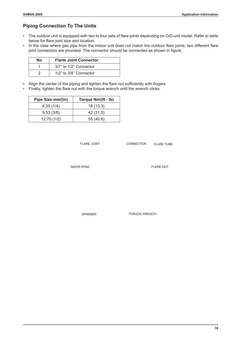
Piping Connection To The Units
• The outdoor unit is equipped with two to four sets of flare joints depending on O/D unit model. Refer to table below for flare joint size and location.
• In the case where gas pipe from the indoor unit does not match the outdoor flare joints, two different flare joint connectors are provided. The connector should be connected as shown in figure.
No Flarte Joint Connector 1 3/7” to 1/2” Connector 2 1/2” to 3/8” Connector
Pipe Size mm/(in) Torque Nm/(ft - Ib) 6.35 (1/4) 18 (13.3) 9.53 (3/8) 42 (31.0) 12.70 (1/2) 55 (40.6)
• Align the center of the piping and tighten the flare nut sufficiently with fingers.• Finally, tighten the flare nut with the torque wrench until the wrench clicks.
FLARE JOINT CONNECTOR FLARE TUBE
INDOOR PIPING FLARE NUT
SPANNER TORQUE WRENCH
19
A5MSX-2009
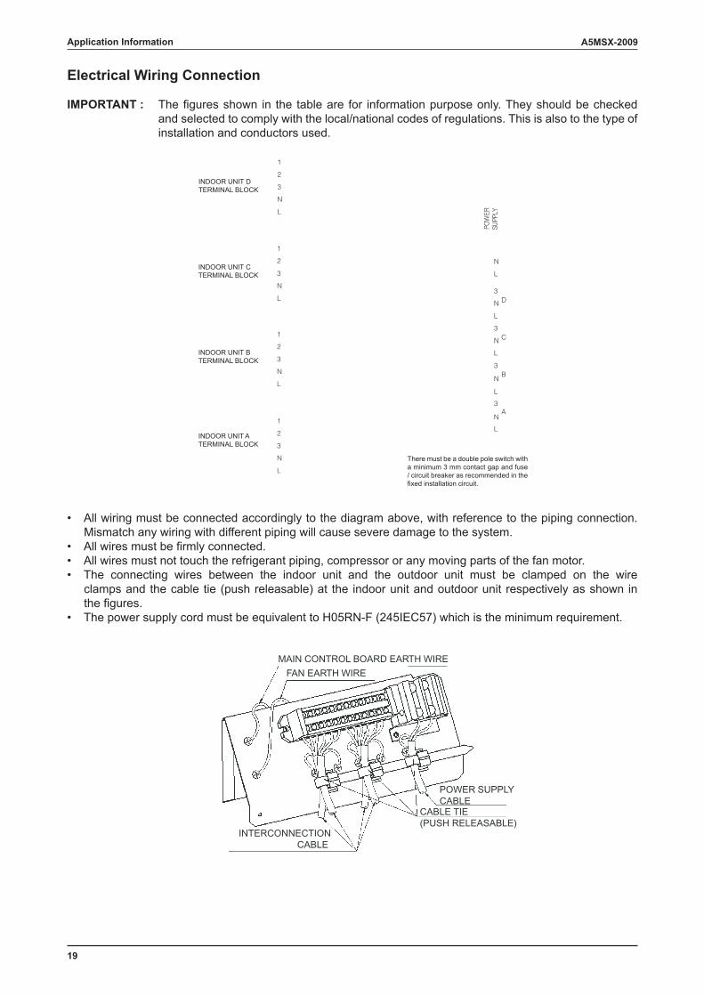
Electrical Wiring Connection
IMPORTANT : The figures shown in the table are for information purpose only. They should be checked and selected to comply with the local/national codes of regulations. This is also to the type of installation and conductors used.
INDOOR UNIT DTERMINAL BLOCK
INDOOR UNIT CTERMINAL BLOCK
INDOOR UNIT BTERMINAL BLOCK
INDOOR UNIT ATERMINAL BLOCK
1
2
3
N
L
1
2
3
N
L
1
2
3
N
L
1
2
3
N
L
N
L
3
N
L
3
N
L
3
N
L
3
N
L
D
C
B
A
REW
OPYLPP
US
There must be a double pole switch with a minimum 3 mm contact gap and fuse / circuit breaker as recommended in the fixed installation circuit.
• All wiring must be connected accordingly to the diagram above, with reference to the piping connection. Mismatch any wiring with different piping will cause severe damage to the system.
• All wires must be firmly connected. • All wires must not touch the refrigerant piping, compressor or any moving parts of the fan motor. • The connecting wires between the indoor unit and the outdoor unit must be clamped on the wire
clamps and the cable tie (push releasable) at the indoor unit and outdoor unit respectively as shown in the figures.
• The power supply cord must be equivalent to H05RN-F (245IEC57) which is the minimum requirement.
MAIN CONTROL BOARD EARTH WIREFAN EARTH WIRE
POWER SUPPLYCABLE
CABLE TIE(PUSH RELEASABLE)
INTERCONNECTIONCABLE
Application Information
20
A5MSX-2009 Application Information
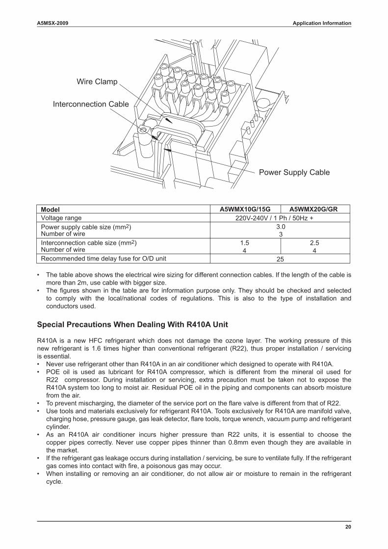
• The table above shows the electrical wire sizing for different connection cables. If the length of the cable is more than 2m, use cable with bigger size.
• The figures shown in the table are for information purpose only. They should be checked and selected to comply with the local/national codes of regulations. This is also to the type of installation and conductors used.
Special Precautions When Dealing With R410A Unit
R410A is a new HFC refrigerant which does not damage the ozone layer. The working pressure of this new refrigerant is 1.6 times higher than conventional refrigerant (R22), thus proper installation / servicing is essential.• Never use refrigerant other than R410A in an air conditioner which designed to operate with R410A.• POE oil is used as lubricant for R410A compressor, which is different from the mineral oil used for
R22 compressor. During installation or servicing, extra precaution must be taken not to expose the R410A system too long to moist air. Residual POE oil in the piping and components can absorb moisture from the air.
• To prevent mischarging, the diameter of the service port on the flare valve is different from that of R22.• Use tools and materials exclusively for refrigerant R410A. Tools exclusively for R410A are manifold valve,
charging hose, pressure gauge, gas leak detector, flare tools, torque wrench, vacuum pump and refrigerant cylinder.
• As an R410A air conditioner incurs higher pressure than R22 units, it is essential to choose the copper pipes correctly. Never use copper pipes thinner than 0.8mm even though they are available in the market.
• If the refrigerant gas leakage occurs during installation / servicing, be sure to ventilate fully. If the refrigerant gas comes into contact with fire, a poisonous gas may occur.
• When installing or removing an air conditioner, do not allow air or moisture to remain in the refrigerant cycle.
Voltage range 220V-240V / 1 Ph / 50Hz + Power supply cable size (mm2) 3.0 Number of wire 3 Interconnection cable size (mm2) Number of wire Recommended time delay fuse for O/D unit 25
Wire Clamp
Power Supply Cable
Interconnection Cable
A5WMX10G/15G A5WMX20G/GRModel
1.54
2.54
21
A5MSX-2009
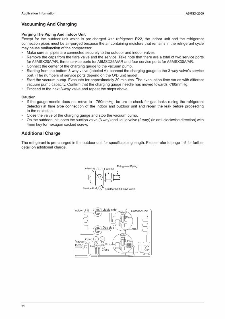
Vacuuming And Charging
Purging The Piping And Indoor UnitExcept for the outdoor unit which is pre-charged with refrigerant R22, the indoor unit and the refrigerant connection pipes must be air-purged because the air containing moisture that remains in the refrigerant cycle may cause malfunction of the compressor. • Make sure all pipes are connected securely to the outdoor and indoor valves.• Remove the caps from the flare valve and the service. Take note that there are a total of two service ports
for A5MSX20A/AR, three service ports for A5MSX25A/AR and four service ports for A5MSX30A/AR.• Connect the center of the charging gauge to the vacuum pump. • Starting from the bottom 3-way valve (labeled A), connect the charging gauge to the 3-way valve’s service
port. (The numbers of service ports depend on the O/D unit model).• Start the vacuum pump. Evacuate for approximately 30 minutes. The evacuation time varies with different
vacuum pump capacity. Confirm that the charging gauge needle has moved towards -760mmHg. • Proceed to the next 3-way valve and repeat the steps above.
Caution• If the gauge needle does not move to - 760mmHg, be ure to check for gas leaks (using the refrigerant
detector) at flare type connection of the indoor and outdoor unit and repair the leak before proceeding to the next step.
• Close the valve of the charging gauge and stop the vacuum pump.• On the outdoor unit, open the suction valve (3 way) and liquid valve (2 way) (in anti-clockwise direction) with
4mm key for hexagon sacked screw.
Additional Charge
The refrigerant is pre-charged in the outdoor unit for specific piping length. Please refer to page 1-5 for further detail on additional charge.
Service Port Outdoor Unit 3 ways valve
Flare nutRefrigerant Piping
Allen key
Suctionvalve
Discharge Valve
Indoor Unit Outdoor UnitLiquid side
Gas side
Vacuumpump
Open
Close
Close
CloseHi
Low
Application Information
22
A5MSX-2009
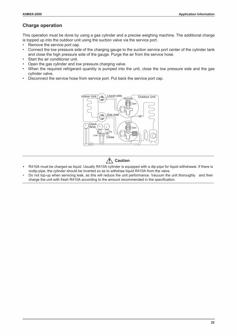
Charge operation
This operation must be done by using a gas cylinder and a precise weighing machine. The additional charge is topped up into the outdoor unit using the suction valve via the service port.• Remove the service port cap.• Connect the low pressure side of the charging gauge to the suction service port center of the cylinder tank
and close the high pressure side of the gauge. Purge the air from the service hose.• Start the air conditioner unit.• Open the gas cylinder and low pressure charging valve.• When the required refrigerant quantity is pumped into the unit, close the low pressure side and the gas
cylinder valve.• Disconnect the service hose from service port. Put back the service port cap.
Open
Open
SuctionValve
DischargeValve
Indoor Unit Outdoor UnitLiquid side
Gas side
CheckValve
Close
HiLow
Caution•• R410A must be charged as liquid. Usually R410A cylinder is equipped with a dip-pipe for liquid withdrawal. If there is
nodip-pipe, the cylinder should be inverted so as to withdraw liquid R410A from the valve.• Do not top-up when servicing leak, as this will reduce the unit performance. Vacuum the unit thoroughly and then
charge the unit with fresh R410A according to the amount recommended in the specification.
Application Information
23
A5MSX-2009
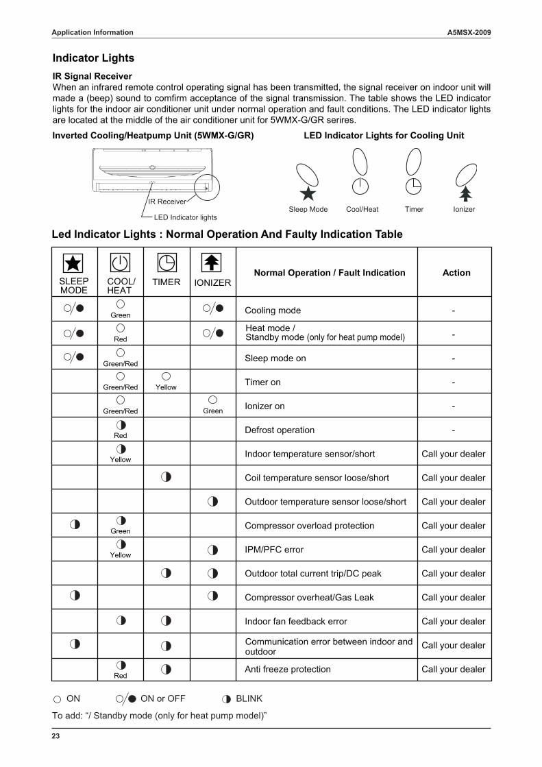
Indicator LightsIR Signal ReceiverWhen an infrared remote control operating signal has been transmitted, the signal receiver on indoor unit will made a (beep) sound to comfirm acceptance of the signal transmission. The table shows the LED indicator lights for the indoor air conditioner unit under normal operation and fault conditions. The LED indicator lights are located at the middle of the air conditioner unit for 5WMX-G/GR serires.
Led Indicator Lights : Normal Operation And Faulty Indication Table
Inverted Cooling/Heatpump Unit (5WMX-G/GR) LED Indicator Lights for Cooling Unit
IR Receiver
LED Indicator lights
Application Information
SLEEPMODE
COOL/HEAT
TIMER IONIZER Normal Operation / Fault Indication
Cooling mode
Sleep mode on
Timer on
Ionizer on
Defrost operation
Indoor temperature sensor/short
Coil temperature sensor loose/short
Outdoor temperature sensor loose/short
Compressor overload protection
IPM/PFC error
Outdoor total current trip/DC peak
Compressor overheat/Gas Leak
Indoor fan feedback error
Anti freeze protection
-
-
-
-
-
-
Call your dealer
Call your dealer
Call your dealer
Call your dealer
Call your dealer
Call your dealer
Call your dealer
Call your dealer
Call your dealer
Call your dealer
Action
Green
Red
Green/Red
Green/Red Yellow
GreenGreen/Red
Red
Yellow
Yellow
Red
Green
Communication error between indoor andoutdoor
ON ON or OFF BLINK
Heat mode /Standby mode (only for heat pump model)
To add: “/ Standby mode (only for heat pump model)”
Sleep Mode Cool/Heat Timer Ionizer
24
A5MSX-2009 Engineering & Physical Data
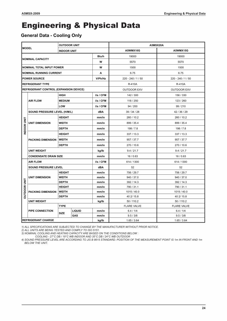
Engineering & Physical DataGeneral Data - Cooling Only
A5WMX10G A5WMX15G
Btu/h
W
W
A
V/Ph/Hz
R-410A
l/s / CFM 142 / 300 156 / 330
l/s / CFM 118 / 250 123 / 260
l/s / CFM 94 / 200 99 / 210
dBA 39 / 34 / 28 42 / 36 / 29
mm/in 260 / 10.2 260 / 10.2
mm/in 899 / 35.4 899 / 35.4
mm/in 198 / 7.8 198 / 7.8
mm/in 337 / 13.3 337 / 13.3
mm/in 957 / 37.7 957 / 37.7
mm/in 270 / 10.6 270 / 10.6
kg/lb 9.4 / 21.7 9.4 / 21.7
mm/in 16 / 0.63 16 / 0.63
l/s / CFM
dBA
mm/in
mm/in
mm/in
mm/in
mm/in
mm/in
kg/lb
LIQUID mm/in
GAS mm/in
kg/lb 1.65 / 3.64
FLARE VALVE
50 / 110.2
6.4 / 1/4
9.5 / 3/8
392 / 14.3
790 / 31.1
1015 / 40.0
40 2/ 15.8
614 / 1300
52
756 / 29.7
940 / 37.0
1.65 / 3.64
FLARE VALVE
50 / 110.2
6.4 / 1/4
9.5 / 3/8
392 / 14.3
790 / 31.1
1015 / 40.0
40 2/ 15.8
614 / 1300
52
756 / 29.7
940 / 37.0
A5MSX20A
OUTDOOR EXV
19000
5570
1500
6.75
220 - 240 / 1 / 50
R-410A
OUTDOOR EXV
19000
5570
1500
6.75
220 - 240 / 1 / 50POWER SOURCE
UNIT DIMENSION
HEIGHT
WIDTH
DEPTH
REFRIGERANT TYPE
IND
OO
R U
NIT
WIDTH
DEPTH
UNIT DIMENSION
HEIGHT
MODELOUTDOOR UNIT
LOW
INDOOR UNIT
NOMINAL CAPACITY
NOMINAL TOTAL INPUT POWER
NOMINAL RUNNING CURRENT
REFRIGERANT CONTROL (EXPANSION DEVICE)
AIR FLOW MEDIUM
REFRIGERANT CHARGE
OU
TDO
OR
UN
IT
UNIT WEIGHT
PIPE CONNECTION
TYPE
SIZE
WIDTHPACKING DIMENSION DEPTH
HEIGHT
SOUND PRESSURE LEVEL
WIDTH
DEPTH
HIGH
SOUND PRESSURE LEVEL (H/M/L)
AIR FLOW
HEIGHT
UNIT WEIGHT
PACKING DIMENSION
CONDENSATE DRAIN SIZE
1) ALL SPECIFICATIONS ARE SUBJECTED TO CHANGE BY THE MANUFACTURER WITHOUT PRIOR NOTICE. 2) ALL UNITS ARE BEING TESTED AND COMPLY TO ISO 5151. 3) NOMINAL COOLING AND HEATING CAPACITY ARE BASED ON THE CONDITIONS BELOW : COOLING - 27°C DB / 19°C WB INDOOR AND 35°C DB / 24°C WB OUTDOOR 4) SOUND PRESSURE LEVEL ARE ACCORDING TO JIS B 8615 STANDARD. POSITION OF THE MEASUREMENT POINT IS 1m IN FRONT AND 1m BELOW THE UNIT.
25
A5MSX-2009Engineering & Physical Data
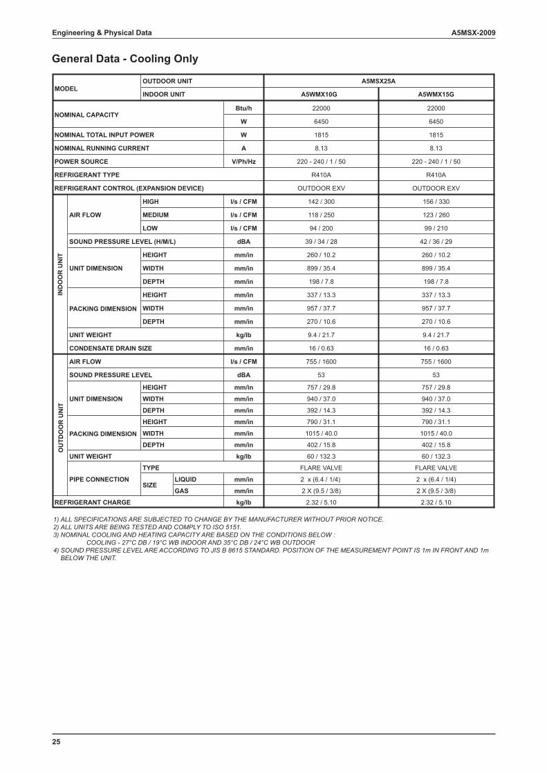
General Data - Cooling Only
1) ALL SPECIFICATIONS ARE SUBJECTED TO CHANGE BY THE MANUFACTURER WITHOUT PRIOR NOTICE. 2) ALL UNITS ARE BEING TESTED AND COMPLY TO ISO 5151. 3) NOMINAL COOLING AND HEATING CAPACITY ARE BASED ON THE CONDITIONS BELOW : COOLING - 27°C DB / 19°C WB INDOOR AND 35°C DB / 24°C WB OUTDOOR 4) SOUND PRESSURE LEVEL ARE ACCORDING TO JIS B 8615 STANDARD. POSITION OF THE MEASUREMENT POINT IS 1m IN FRONT AND 1m BELOW THE UNIT.
A5WMX10G A5WMX15G
Btu/h
W
W
A
V/Ph/Hz
l/s / CFM 142 / 300 156 / 330
l/s / CFM 118 / 250 123 / 260
l/s / CFM 94 / 200 99 / 210
dBA 39 / 34 / 28 42 / 36 / 29
mm/in 260 / 10.2 260 / 10.2
mm/in 899 / 35.4 899 / 35.4
mm/in 198 / 7.8 198 / 7.8
mm/in 337 / 13.3 337 / 13.3
mm/in 957 / 37.7 957 / 37.7
mm/in 270 / 10.6 270 / 10.6
kg/lb 9.4 / 21.7 9.4 / 21.7
mm/in 16 / 0.63 16 / 0.63
l/s / CFM
dBA
mm/in
mm/in
mm/in
mm/in
mm/in
mm/in
kg/lb
LIQUID mm/in
GAS mm/in
kg/lb 2.32 / 5.10
FLARE VALVE
60 / 132.3
2 x (6.4 / 1/4)
2 X (9.5 / 3/8)
392 / 14.3
790 / 31.1
1015 / 40.0
402 / 15.8
755 / 1600
53
757 / 29.8
940 / 37.0
2.32 / 5.10
FLARE VALVE
60 / 132.3
2 x (6.4 / 1/4)
2 X (9.5 / 3/8)
392 / 14.3
790 / 31.1
1015 / 40.0
402 / 15.8
755 / 1600
53
757 / 29.8
940 / 37.0
A5MSX25A
OUTDOOR EXV
22000
6450
1815
8.13
220 - 240 / 1 / 50
R410A
OUTDOOR EXV
22000
6450
1815
8.13
220 - 240 / 1 / 50
R410A
POWER SOURCE
UNIT DIMENSION
HEIGHT
WIDTH
DEPTH
REFRIGERANT TYPE
IND
OO
R U
NIT
WIDTH
DEPTH
UNIT DIMENSION
HEIGHT
MODELOUTDOOR UNIT
LOW
INDOOR UNIT
NOMINAL CAPACITY
NOMINAL TOTAL INPUT POWER
NOMINAL RUNNING CURRENT
REFRIGERANT CONTROL (EXPANSION DEVICE)
AIR FLOW MEDIUM
REFRIGERANT CHARGE
OU
TDO
OR
UN
IT
UNIT WEIGHT
PIPE CONNECTION
TYPE
SIZE
WIDTHPACKING DIMENSION DEPTH
HEIGHT
SOUND PRESSURE LEVEL
WIDTH
DEPTH
HIGH
SOUND PRESSURE LEVEL (H/M/L)
AIR FLOW
HEIGHT
UNIT WEIGHT
PACKING DIMENSION
CONDENSATE DRAIN SIZE
26
A5MSX-2009 Engineering & Physical Data
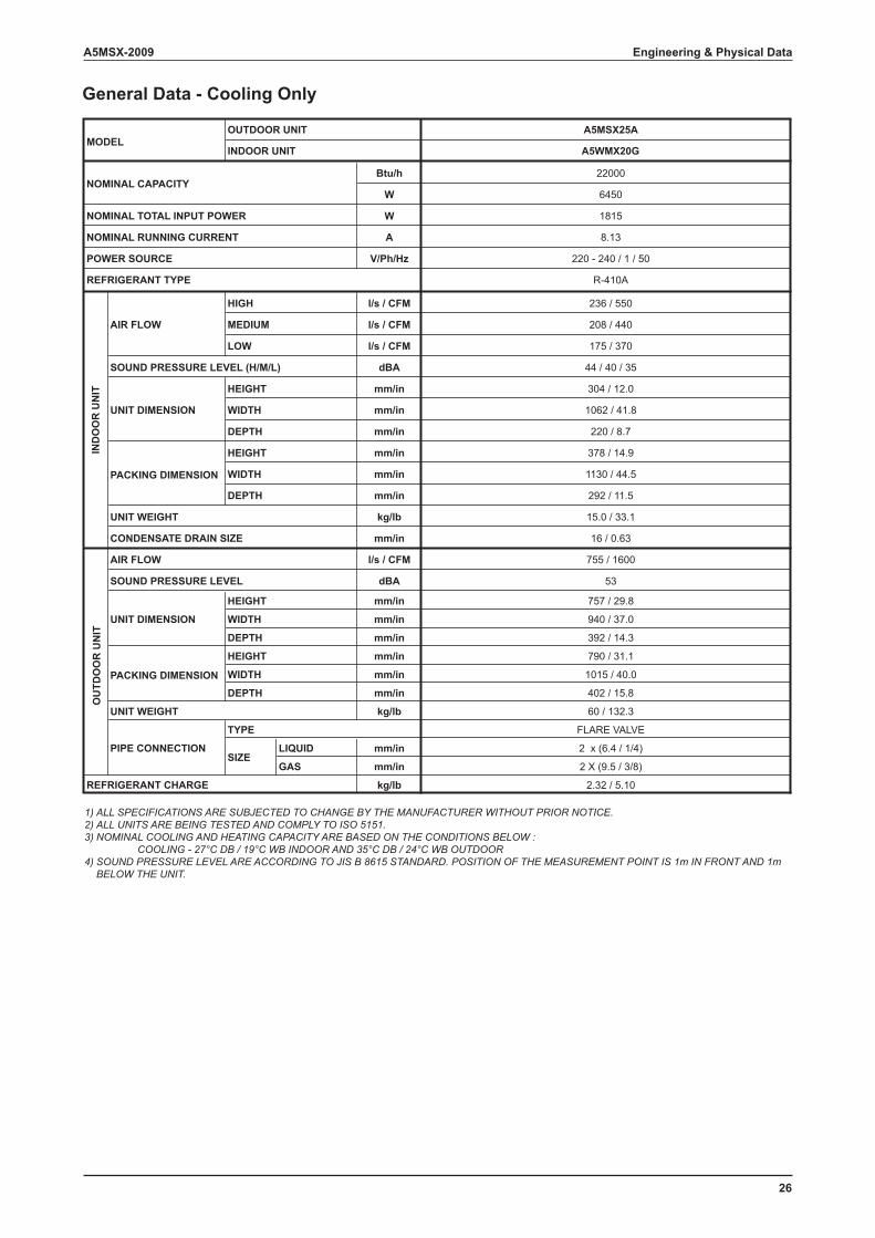
General Data - Cooling Only
1) ALL SPECIFICATIONS ARE SUBJECTED TO CHANGE BY THE MANUFACTURER WITHOUT PRIOR NOTICE. 2) ALL UNITS ARE BEING TESTED AND COMPLY TO ISO 5151. 3) NOMINAL COOLING AND HEATING CAPACITY ARE BASED ON THE CONDITIONS BELOW : COOLING - 27°C DB / 19°C WB INDOOR AND 35°C DB / 24°C WB OUTDOOR 4) SOUND PRESSURE LEVEL ARE ACCORDING TO JIS B 8615 STANDARD. POSITION OF THE MEASUREMENT POINT IS 1m IN FRONT AND 1m BELOW THE UNIT.
A5WMX20G
Btu/h
W
W
A
V/Ph/Hz
l/s / CFM 236 / 550
l/s / CFM 208 / 440
l/s / CFM 175 / 370
dBA 44 / 40 / 35
mm/in 304 / 12.0
mm/in 1062 / 41.8
mm/in 220 / 8.7
mm/in 378 / 14.9
mm/in 1130 / 44.5
mm/in 292 / 11.5
kg/lb 15.0 / 33.1
mm/in 16 / 0.63
l/s / CFM
dBA
mm/in
mm/in
mm/in
mm/in
mm/in
mm/in
kg/lb
LIQUID mm/in
GAS mm/in
kg/lb 2.32 / 5.10
FLARE VALVE
60 / 132.3
2 x (6.4 / 1/4)
2 X (9.5 / 3/8)
392 / 14.3
790 / 31.1
1015 / 40.0
402 / 15.8
755 / 1600
53
757 / 29.8
940 / 37.0
A5MSX25A
22000
6450
1815
8.13
220 - 240 / 1 / 50
R-410A
POWER SOURCE
UNIT DIMENSION
HEIGHT
WIDTH
DEPTH
REFRIGERANT TYPE
IND
OO
R U
NIT
WIDTH
DEPTH
UNIT DIMENSION
HEIGHT
MODELOUTDOOR UNIT
LOW
INDOOR UNIT
NOMINAL CAPACITY
NOMINAL TOTAL INPUT POWER
NOMINAL RUNNING CURRENT
AIR FLOW MEDIUM
REFRIGERANT CHARGE
OU
TDO
OR
UN
IT
UNIT WEIGHT
PIPE CONNECTION
TYPE
SIZE
WIDTHPACKING DIMENSION DEPTH
HEIGHT
SOUND PRESSURE LEVEL
WIDTH
DEPTH
HIGH
SOUND PRESSURE LEVEL (H/M/L)
AIR FLOW
HEIGHT
UNIT WEIGHT
PACKING DIMENSION
CONDENSATE DRAIN SIZE
27
A5MSX-2009
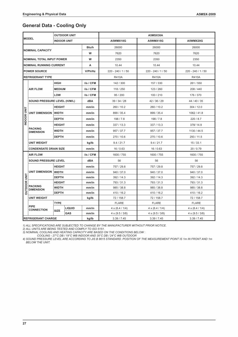
General Data - Cooling Only
1) ALL SPECIFICATIONS ARE SUBJECTED TO CHANGE BY THE MANUFACTURER WITHOUT PRIOR NOTICE. 2) ALL UNITS ARE BEING TESTED AND COMPLY TO ISO 5151. 3) NOMINAL COOLING AND HEATING CAPACITY ARE BASED ON THE CONDITIONS BELOW : COOLING - 27°C DB / 19°C WB INDOOR AND 35°C DB / 24°C WB OUTDOOR 4) SOUND PRESSURE LEVEL ARE ACCORDING TO JIS B 8615 STANDARD. POSITION OF THE MEASUREMENT POINT IS 1m IN FRONT AND 1m BELOW THE UNIT.
A5WMX10G A5WMX15G A5WMX20G
Btu/h
W
W
A
V/Ph/Hz
l/s / CFM 142 / 300 157 / 330 261 / 550
l/s / CFM 118 / 250 123 / 260 208 / 440
l/s / CFM 95 / 200 100 / 210 176 / 370
dBA 39 / 34 / 28 42 / 36 / 29 44 / 40 / 35
mm/in 260 / 10.2 260 / 10.2 304 / 12.0
mm/in 899 / 35.4 899 / 35.4 1062 / 41.8
mm/in 198 / 7.8 198 / 7.8 220 / 8.7
mm/in 337 / 13.3 337 / 13.3 378/ 14.9
mm/in 957 / 37.7 957 / 37.7 1130 / 44.5
mm/in 270 / 10.6 270 / 10.6 293 / 11.5
kg/lb 9.4 / 21.7 9.4 / 21.7 15 / 33.1
mm/in 16 / 0.63 16 / 0.63 20 / 0.79
l/s / CFM
dBA
mm/in
mm/in
mm/in
mm/in
mm/in
mm/in
kg/lb
LIQUID mm/in
GAS mm/in
kg/lb
2350
7620
26000
R410A
72 / 158.7
FLARE
4 x (6.4 / 1/4)
4 x (9.5 / 3/8)
3.39 / 7.45
793 / 31.3
392 / 14.3
985 / 38.8
410 / 16.2
1600 / 755
56
757 / 29.8
940 / 37.0
72 / 158.7
FLARE
4 x (6.4 / 1/4)
4 x (9.5 / 3/8)
3.39 / 7.45
793 / 31.3
392 / 14.3
985 / 38.8
410 / 16.2
1600 / 755
56
757 / 29.8
940 / 37.0
72 / 158.7
FLARE
4 x (6.4 / 1/4)
4 x (9.5 / 3/8)
3.39 / 7.45
793 / 31.3
392 / 14.3
985 / 38.8
410 / 16.2
1600 / 755
56
757 / 29.8
940 / 37.0
A5MSX30A
220 - 240 / 1 / 50
10.44
2350
7620
26000
R410A
220 - 240 / 1 / 50
10.44
2350
7620
26000
R410A
220 - 240 / 1 / 50
10.44
POWER SOURCE
UNIT DIMENSION
HEIGHT
WIDTH
DEPTH
REFRIGERANT TYPE
IND
OO
R U
NIT
WIDTH
DEPTH
UNIT DIMENSION
HEIGHT
MODELOUTDOOR UNIT
LOW
INDOOR UNIT
NOMINAL CAPACITY
NOMINAL TOTAL INPUT POWER
NOMINAL RUNNING CURRENT
AIR FLOW MEDIUM
REFRIGERANT CHARGE
OU
TDO
OR
UN
IT
UNIT WEIGHT
PIPECONNECTION
TYPE
SIZE
WIDTHPACKINGDIMENSION
DEPTH
HEIGHT
SOUND PRESSURE LEVEL
WIDTH
DEPTH
HIGH
SOUND PRESSURE LEVEL (H/M/L)
AIR FLOW
HEIGHT
UNIT WEIGHT
PACKINGDIMENSION
CONDENSATE DRAIN SIZE
Engineering & Physical Data
28
A5MSX-2009
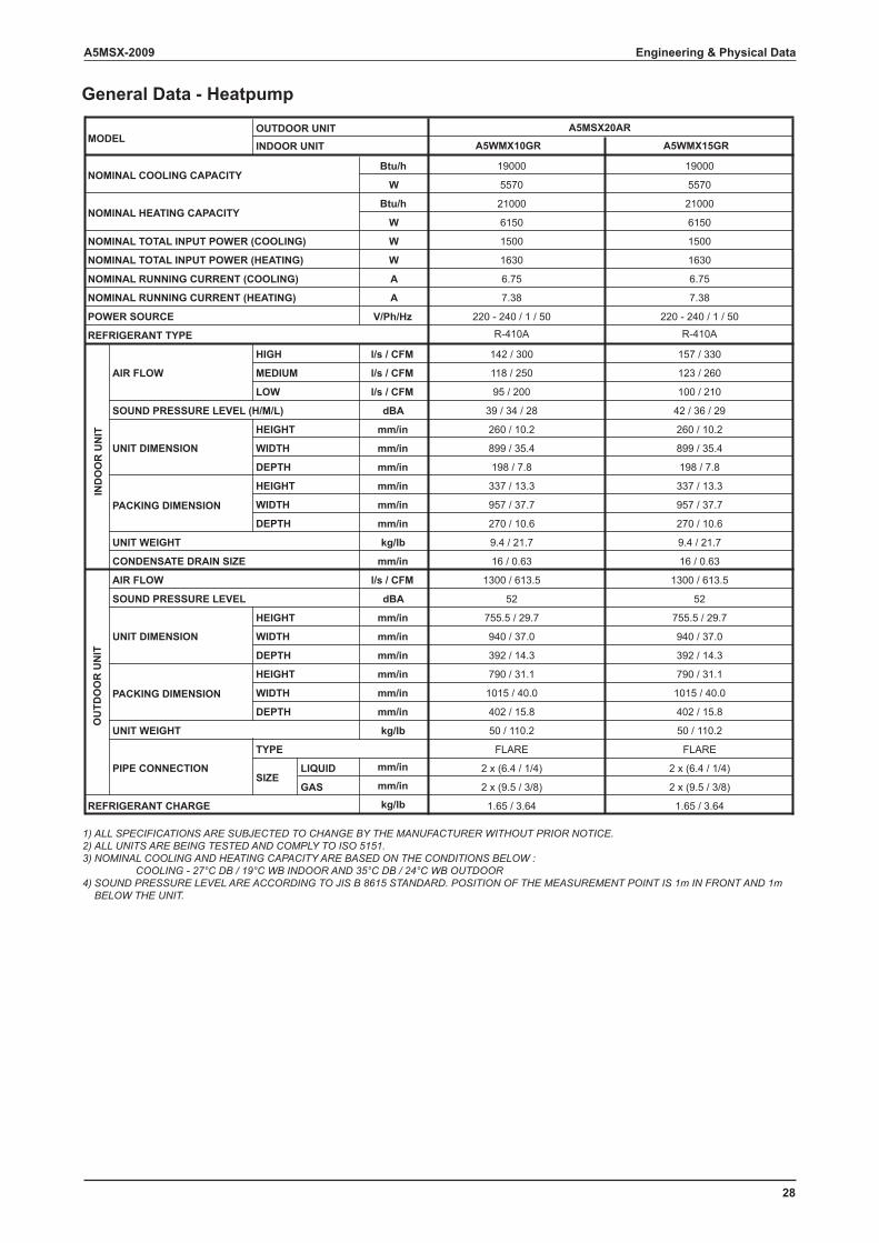
General Data - Heatpump
1) ALL SPECIFICATIONS ARE SUBJECTED TO CHANGE BY THE MANUFACTURER WITHOUT PRIOR NOTICE. 2) ALL UNITS ARE BEING TESTED AND COMPLY TO ISO 5151. 3) NOMINAL COOLING AND HEATING CAPACITY ARE BASED ON THE CONDITIONS BELOW : COOLING - 27°C DB / 19°C WB INDOOR AND 35°C DB / 24°C WB OUTDOOR 4) SOUND PRESSURE LEVEL ARE ACCORDING TO JIS B 8615 STANDARD. POSITION OF THE MEASUREMENT POINT IS 1m IN FRONT AND 1m BELOW THE UNIT.
A5WMX10GR A5WMX15GR
Btu/h
W
Btu/h
W
W
W
A
A
V/Ph/Hz
l/s / CFM 142 / 300 157 / 330
l/s / CFM 118 / 250 123 / 260
l/s / CFM 95 / 200 100 / 210
dBA 39 / 34 / 28 42 / 36 / 29
mm/in 260 / 10.2 260 / 10.2
mm/in 899 / 35.4 899 / 35.4
mm/in 198 / 7.8 198 / 7.8
mm/in 337 / 13.3 337 / 13.3
mm/in 957 / 37.7 957 / 37.7
mm/in 270 / 10.6 270 / 10.6
kg/lb 9.4 / 21.7 9.4 / 21.7
mm/in 16 / 0.63 16 / 0.63
l/s / CFM
dBA
mm/in
mm/in
mm/in
mm/in
mm/in
mm/in
kg/lb
LIQUID mm/in
GAS mm/in
kg/lbREFRIGERANT CHARGE 1.65 / 3.64
NOMINAL HEATING CAPACITY
NOMINAL TOTAL INPUT POWER (COOLING)
NOMINAL RUNNING CURRENT (COOLING) 6.75
1500
6150
21000
50 / 110.2
PIPE CONNECTION
TYPE FLARE
SIZE2 x (6.4 / 1/4)
2 x (9.5 / 3/8)
790 / 31.1
WIDTH 1015 / 40.0
DEPTH 402 / 15.8
1300 / 613.5
SOUND PRESSURE LEVEL 52
UNIT DIMENSION
HEIGHT 755.5 / 29.7
WIDTH 940 / 37.0
DEPTH 392 / 14.3
1.65 / 3.64
50 / 110.2
FLARE
2 x (6.4 / 1/4)
2 x (9.5 / 3/8)
790 / 31.1
1015 / 40.0
402 / 15.8
1300 / 613.5
52
755.5 / 29.7
940 / 37.0
392 / 14.3
UNIT WEIGHT
CONDENSATE DRAIN SIZE
OU
TDO
OR
UN
IT
AIR FLOW
PACKING DIMENSION
HEIGHT
UNIT WEIGHT
WIDTH
DEPTH
PACKING DIMENSION
HEIGHT
WIDTH
DEPTH
REFRIGERANT TYPE R-410A
IND
OO
R U
NIT
AIR FLOW
HIGH
MEDIUM
LOW
SOUND PRESSURE LEVEL (H/M/L)
UNIT DIMENSION
HEIGHT
NOMINAL RUNNING CURRENT (HEATING) 7.38
POWER SOURCE 220 - 240 / 1 / 50
NOMINAL COOLING CAPACITY19000
5570
NOMINAL TOTAL INPUT POWER (HEATING) 1630
6.75
1500
6150
21000
R-410A
7.38
220 - 240 / 1 / 50
19000
5570
1630
MODELINDOOR UNITOUTDOOR UNIT A5MSX20AR
Engineering & Physical Data
29
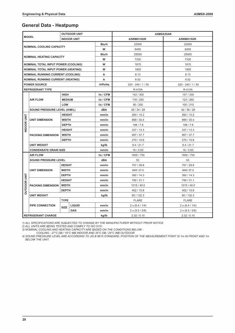
A5MSX-2009Engineering & Physical Data
General Data - Heatpump
1) ALL SPECIFICATIONS ARE SUBJECTED TO CHANGE BY THE MANUFACTURER WITHOUT PRIOR NOTICE. 2) ALL UNITS ARE BEING TESTED AND COMPLY TO ISO 5151. 3) NOMINAL COOLING AND HEATING CAPACITY ARE BASED ON THE CONDITIONS BELOW : COOLING - 27°C DB / 19°C WB INDOOR AND 35°C DB / 24°C WB OUTDOOR 4) SOUND PRESSURE LEVEL ARE ACCORDING TO JIS B 8615 STANDARD. POSITION OF THE MEASUREMENT POINT IS 1m IN FRONT AND 1m BELOW THE UNIT.
A5WMX10GR A5WMX15GR
Btu/h
W
Btu/h
W
W
W
A
A
V/Ph/Hz
l/s / CFM 142 / 300 157 / 330
l/s / CFM 118 / 250 123 / 260
l/s / CFM 95 / 200 100 / 210
dBA 39 / 34 / 28 42 / 36 / 29
mm/in 260 / 10.2 260 / 10.2
mm/in 899 / 35.4 899 / 35.4
mm/in 198 / 7.8 198 / 7.8
mm/in 337 / 13.3 337 / 13.3
mm/in 957 / 37.7 957 / 37.7
mm/in 270 / 10.6 270 / 10.6
kg/lb 9.4 / 21.7 9.4 / 21.7
mm/in 16 / 0.63 16 / 0.63
l/s / CFM
dBA
mm/in
mm/in
mm/in
mm/in
mm/in
mm/in
kg/lb
LIQUID mm/in
GAS mm/in
kg/lb
MODELINDOOR UNIT
OUTDOOR UNIT A5MSX25AR
NOMINAL COOLING CAPACITY22000
6450
NOMINAL TOTAL INPUT POWER (HEATING) 1900
NOMINAL RUNNING CURRENT (HEATING) 8.52
POWER SOURCE 220 - 240 / 1 / 50
REFRIGERANT TYPE R-410A
IND
OO
R U
NIT
AIR FLOW
HIGH
MEDIUM
LOW
SOUND PRESSURE LEVEL (H/M/L)
UNIT DIMENSION
HEIGHT
WIDTH
DEPTH
PACKING DIMENSION
HEIGHT
WIDTH
DEPTH
UNIT WEIGHT
CONDENSATE DRAIN SIZE
OU
TDO
OR
UN
IT
AIR FLOW
PACKING DIMENSION
HEIGHT
UNIT WEIGHT
1600 / 755
SOUND PRESSURE LEVEL 53
UNIT DIMENSION
HEIGHT 757 / 29.8
WIDTH 940/ 37.0
DEPTH 392 / 14.3
790 / 31.1
WIDTH 1015 / 40.0
DEPTH 402 / 15.8
PIPE CONNECTION
TYPE FLARE
SIZE2 x (6.4 / 1/4)
2 x (9.5 / 3/8)
REFRIGERANT CHARGE 2.32 / 5.10
NOMINAL HEATING CAPACITY
NOMINAL TOTAL INPUT POWER (COOLING)
NOMINAL RUNNING CURRENT (COOLING) 8.13
1815
7330
25000
22000
6450
1900
8.52
220 - 240 / 1 / 50
R-410A
8.13
1815
7330
25000
60 / 132.3
1600 / 755
53
757 / 29.8
940/ 37.0
392 / 14.3
790 / 31.1
1015 / 40.0
402 / 15.8
FLARE
2 x (6.4 / 1/4)
2 x (9.5 / 3/8)
2.32 / 5.10
60 / 132.3
30
A5MSX-2009 Engineering & Physical Data
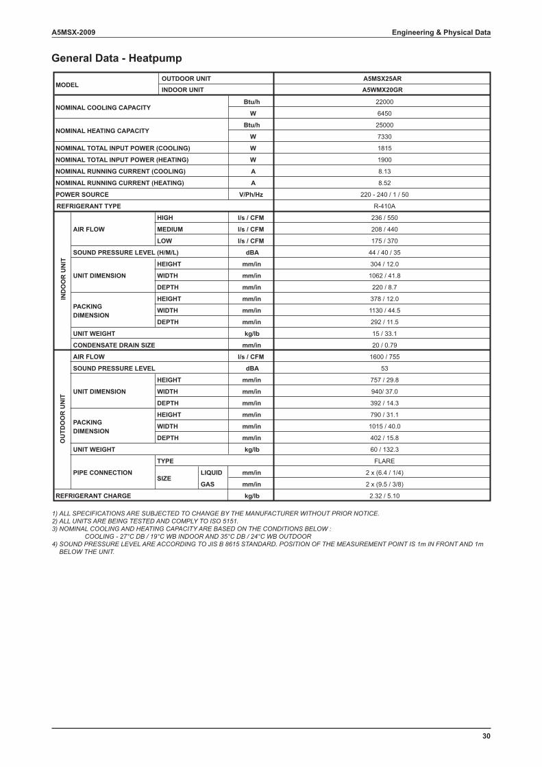
General Data - Heatpump
1) ALL SPECIFICATIONS ARE SUBJECTED TO CHANGE BY THE MANUFACTURER WITHOUT PRIOR NOTICE. 2) ALL UNITS ARE BEING TESTED AND COMPLY TO ISO 5151. 3) NOMINAL COOLING AND HEATING CAPACITY ARE BASED ON THE CONDITIONS BELOW : COOLING - 27°C DB / 19°C WB INDOOR AND 35°C DB / 24°C WB OUTDOOR 4) SOUND PRESSURE LEVEL ARE ACCORDING TO JIS B 8615 STANDARD. POSITION OF THE MEASUREMENT POINT IS 1m IN FRONT AND 1m BELOW THE UNIT.
A5WMX20GR
A5MSX25AR
Btu/h 22000
W 6450
Btu/h 25000
W 7330
W 1815
W 1900
A 8.13
A 8.52
V/Ph/Hz 220 - 240 / 1 / 50
R-410A
l/s / CFM 236 / 550
l/s / CFM 208 / 440
l/s / CFM 175 / 370
dBA 44 / 40 / 35
mm/in 304 / 12.0
mm/in 1062 / 41.8
mm/in 220 / 8.7
mm/in 378 / 12.0
mm/in 1130 / 44.5
mm/in 292 / 11.5
kg/lb 15 / 33.1
mm/in 20 / 0.79
l/s / CFM 1600 / 755
dBA 53
mm/in 757 / 29.8
mm/in 940/ 37.0
mm/in 392 / 14.3
mm/in 790 / 31.1
mm/in 1015 / 40.0
mm/in 402 / 15.8
kg/lb 60 / 132.3
FLARE
LIQUID mm/in 2 x (6.4 / 1/4)
GAS mm/in 2 x (9.5 / 3/8)
kg/lb 2.32 / 5.10REFRIGERANT CHARGE
PIPE CONNECTION
TYPE
SIZE
WIDTH
DEPTH
SOUND PRESSURE LEVEL
UNIT DIMENSION
HEIGHT
WIDTH
DEPTH
UNIT WEIGHT
CONDENSATE DRAIN SIZE
OU
TDO
OR
UN
IT
AIR FLOW
PACKING DIMENSION
HEIGHT
UNIT WEIGHT
WIDTH
DEPTH
PACKING DIMENSION
HEIGHT
WIDTH
DEPTH
REFRIGERANT TYPE
IND
OO
R U
NIT
AIR FLOW
HIGH
MEDIUM
LOW
SOUND PRESSURE LEVEL (H/M/L)
UNIT DIMENSION
HEIGHT
NOMINAL RUNNING CURRENT (HEATING)
POWER SOURCE
NOMINAL TOTAL INPUT POWER (HEATING)
NOMINAL RUNNING CURRENT (COOLING)
NOMINAL TOTAL INPUT POWER (COOLING)
MODELINDOOR UNIT
OUTDOOR UNIT
NOMINAL COOLING CAPACITY
NOMINAL HEATING CAPACITY
31
A5MSX-2009Engineering & Physical Data
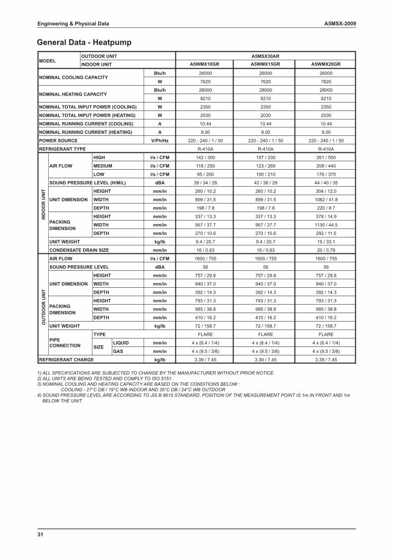
General Data - Heatpump
1) ALL SPECIFICATIONS ARE SUBJECTED TO CHANGE BY THE MANUFACTURER WITHOUT PRIOR NOTICE. 2) ALL UNITS ARE BEING TESTED AND COMPLY TO ISO 5151. 3) NOMINAL COOLING AND HEATING CAPACITY ARE BASED ON THE CONDITIONS BELOW : COOLING - 27°C DB / 19°C WB INDOOR AND 35°C DB / 24°C WB OUTDOOR 4) SOUND PRESSURE LEVEL ARE ACCORDING TO JIS B 8615 STANDARD. POSITION OF THE MEASUREMENT POINT IS 1m IN FRONT AND 1m BELOW THE UNIT.
A5WMX10GR A5WMX15GR A5WMX20GR
Btu/h
W
Btu/h
W
W
W
A
A
V/Ph/Hz
l/s / CFM 142 / 300 157 / 330 261 / 550
l/s / CFM 118 / 250 123 / 269 208 / 440
l/s / CFM 95 / 200 100 / 210 176 / 370
dBA 39 / 34 / 28 42 / 36 / 29 44 / 40 / 35
mm/in 260 / 10.2 260 / 10.2 304 / 12.0
mm/in 899 / 31.5 899 / 31.5 1062 / 41.8
mm/in 198 / 7.8 198 / 7.8 220 / 8.7
mm/in 337 / 13.3 337 / 13.3 378 / 14.9
mm/in 957 / 37.7 957 / 37.7 1130 / 44.5
mm/in 270 / 10.6 270 / 10.6 292 / 11.5
kg/lb 9.4 / 20.7 9.4 / 20.7 15 / 33.1
mm/in 16 / 0.63 16 / 0.63 20 / 0.79
l/s / CFM
dBA
mm/in
mm/in
mm/in
mm/in
mm/in
mm/in
kg/lb
LIQUID mm/in
GAS mm/in
kg/lbREFRIGERANT CHARGE
A5MSX30AR
R-410A
220 - 240 / 1 / 50
9.00
10.44
2030
2350
8210
28000
PIPECONNECTION
TYPE
SIZE
7620
1600 / 755
56
757 / 29.8
940 / 37.0
WIDTH
DEPTH
26000
R-410A
220 - 240 / 1 / 50
9.00
10.44
2030
2350
8210
28000
7620
26000
R-410A
220 - 240 / 1 / 50
9.00
10.44
2030
2350
8210
28000
7620
26000
392 / 14.3
793 / 31.3
985 / 38.8
410 / 16.2
SOUND PRESSURE LEVEL
UNIT DIMENSION
HEIGHT
WIDTH
DEPTH
UNIT WEIGHT
CONDENSATE DRAIN SIZE
OU
TDO
OR
UN
IT
AIR FLOW
PACKING DIMENSION
HEIGHT
UNIT WEIGHT
WIDTH
DEPTH
PACKING DIMENSION
HEIGHT
WIDTH
DEPTH
REFRIGERANT TYPE
IND
OO
R U
NIT
AIR FLOW
HIGH
MEDIUM
LOW
SOUND PRESSURE LEVEL (H/M/L)
UNIT DIMENSION
HEIGHT
NOMINAL RUNNING CURRENT (HEATING)
POWER SOURCE
72 / 158.7
FLARE
NOMINAL TOTAL INPUT POWER (HEATING)
NOMINAL RUNNING CURRENT (COOLING)
4 x (6.4 / 1/4)
4 x (9.5 / 3/8)
NOMINAL TOTAL INPUT POWER (COOLING)
3.39 / 7.45
1600 / 755
56
757 / 29.8
940 / 37.0
392 / 14.3
793 / 31.3
985 / 38.8
410 / 16.2
72 / 158.7
FLARE
4 x (6.4 / 1/4)
4 x (9.5 / 3/8)
3.39 / 7.45
1600 / 755
56
757 / 29.8
940 / 37.0
392 / 14.3
793 / 31.3
985 / 38.8
410 / 16.2
72 / 158.7
FLARE
4 x (6.4 / 1/4)
4 x (9.5 / 3/8)
3.39 / 7.45
MODELINDOOR UNIT
OUTDOOR UNIT
NOMINAL COOLING CAPACITY
NOMINAL HEATING CAPACITY
32
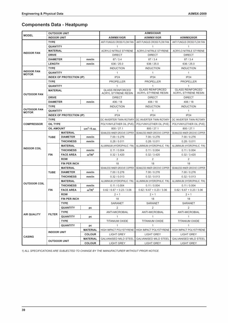
A5MSX-2009 Engineering & Physical Data
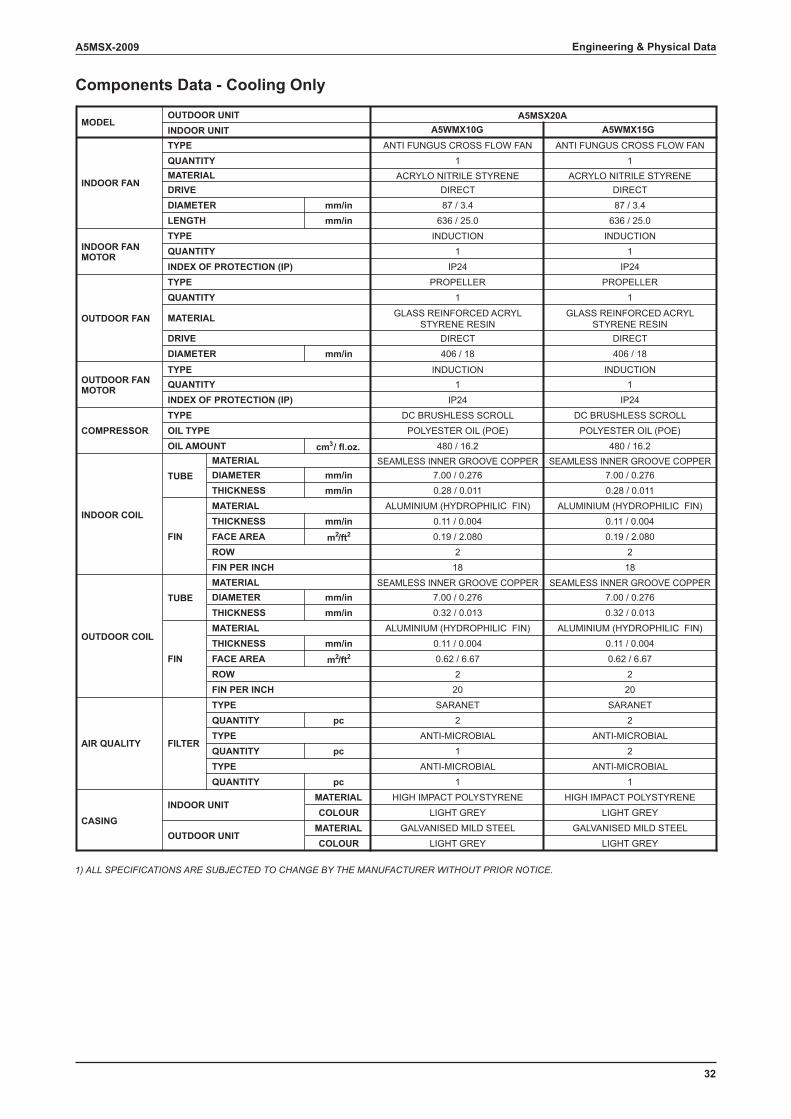
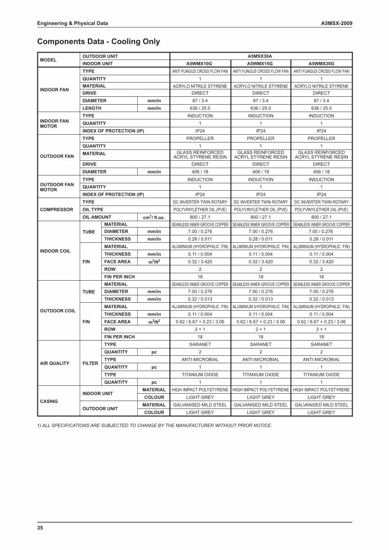
Components Data - Cooling Only
A5WMX10G A5WMX15GANTI FUNGUS CROSS FLOW FAN ANTI FUNGUS CROSS FLOW FAN
1 1ACRYLO NITRILE STYRENE ACRYLO NITRILE STYRENE
DIRECT DIRECTmm/in 87 / 3.4 87 / 3.4mm/in 636 / 25.0 636 / 25.0
INDUCTION INDUCTION1 1
IP24 IP24
mm/in
cm3 / fl.oz.SEAMLESS INNER GROOVE COPPER SEAMLESS INNER GROOVE COPPER
mm/in 7.00 / 0.276 7.00 / 0.276mm/in 0.28 / 0.011 0.28 / 0.011
ALUMINIUM (HYDROPHILIC FIN) ALUMINIUM (HYDROPHILIC FIN)mm/in 0.11 / 0.004 0.11 / 0.004
m2/ft2 0.19 / 2.080 0.19 / 2.0802 218 18
mm/inmm/in
mm/in
m2/ft2
SARANET SARANETpc 2 2
ANTI-MICROBIAL ANTI-MICROBIALpc 1 2
ANTI-MICROBIAL ANTI-MICROBIALpc 1 1
MATERIAL HIGH IMPACT POLYSTYRENE HIGH IMPACT POLYSTYRENECOLOUR LIGHT GREY LIGHT GREY
MATERIALCOLOUR LIGHT GREY
0.11 / 0.0040.62 / 6.67
220
7.00 / 0.2760.32 / 0.013
ALUMINIUM (HYDROPHILIC FIN)
GALVANISED MILD STEELLIGHT GREY
GALVANISED MILD STEEL
DC BRUSHLESS SCROLLPOLYESTER OIL (POE)
480 / 16.2
SEAMLESS INNER GROOVE COPPER
0.11 / 0.0040.62 / 6.67
220
7.00 / 0.2760.32 / 0.013
ALUMINIUM (HYDROPHILIC FIN)
SEAMLESS INNER GROOVE COPPER
TYPE
A5MSX20A
PROPELLER1
GLASS REINFORCED ACRYLSTYRENE RESIN
DIRECT406 / 18
INDUCTION1
IP24DC BRUSHLESS SCROLL
POLYESTER OIL (POE)480 / 16.2
PROPELLER1
GLASS REINFORCED ACRYLSTYRENE RESIN
DIRECT406 / 18
INDUCTION1
IP24
MATERIAL
MATERIAL
ROWFIN PER INCH
DIAMETERTHICKNESS
THICKNESSFACE AREA
CASING
AIR QUALITY FILTER
QUANTITYTYPE
INDOOR UNIT
OUTDOOR UNIT
TYPE
QUANTITY
QUANTITY
INDOOR COIL
OUTDOOR COIL
FIN
FIN
TUBE
TUBE
INDOOR UNITOUTDOOR UNIT
MODEL
TYPE
INDOOR FAN
INDOOR FAN MOTOR
QUANTITYMATERIALDRIVE
INDEX OF PROTECTION (IP)
DIAMETERLENGTH
OUTDOOR FAN MATERIAL
DRIVE
TYPE
TYPEQUANTITY
DIAMETER
COMPRESSORTYPEOIL TYPE
INDEX OF PROTECTION (IP)
OUTDOOR FAN MOTOR
OIL AMOUNT
QUANTITY
ROWFIN PER INCH
DIAMETERTHICKNESS
THICKNESSFACE AREA
MATERIAL
TYPEQUANTITY
MATERIAL
1) ALL SPECIFICATIONS ARE SUBJECTED TO CHANGE BY THE MANUFACTURER WITHOUT PRIOR NOTICE.
33
A5MSX-2009Engineering & Physical Data
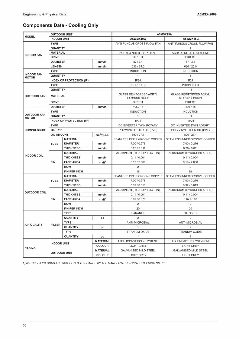
Components Data - Cooling Only
A5WMX10G A5WMX15GANTI FUNGUS CROSS FLOW FAN ANTI FUNGUS CROSS FLOW FAN
1 1ACRYLO NITRILE STYRENE ACRYLO NITRILE STYRENE
DIRECT DIRECTmm/in 87 / 3.4 87 / 3.4mm/in 636 / 25.0 636 / 25.0
INDUCTION INDUCTION1 1
IP24 IP24
mm/in
cm3 / fl.oz.SEAMLESS INNER GROOVE COPPER SEAMLESS INNER GROOVE COPPER
mm/in 7.00 / 0.276 7.00 / 0.276mm/in 0.28 / 0.011 0.28 / 0.011
ALUMINIUM (HYDROPHILIC FIN) ALUMINIUM (HYDROPHILIC FIN)mm/in 0.11 / 0.004 0.11 / 0.004
m2/ft2 0.19 / 2.080 0.19 / 2.0802 2
18 18
mm/inmm/in
mm/in
m2/ft2
SARANET SARANETpc 2 2
ANTI-MICROBIAL ANTI-MICROBIALpc 1 2
TITANIUM OXIDE TITANIUM OXIDEpc 1 1
MATERIAL HIGH IMPACT POLYSTYRENE HIGH IMPACT POLYSTYRENECOLOUR LIGHT GREY LIGHT GREY
MATERIALCOLOUR LIGHT GREY
0.11 / 0.0040.62 / 6.670
220
7.00 / 0.2760.32 / 0.013
ALUMINIUM (HYDROPHILIC FIN)
GALVANISED MILD STEELLIGHT GREY
GALVANISED MILD STEEL
DC INVERTER TWIN ROTARYPOLYVINYLETHER OIL (PVE)
800 / 27.1
SEAMLESS INNER GROOVE COPPER
0.11 / 0.0040.62 / 6.67
220
7.00 / 0.2760.32 / 0.013
ALUMINIUM (HYDROPHILIC FIN)
SEAMLESS INNER GROOVE COPPER
TYPE
A5MSX25A
PROPELLER1
GLASS REINFORCED ACRYLSTYRENE RESIN
DIRECT406 / 18
INDUCTION1
IP24DC INVERTER TWIN ROTARYPOLYVINYLETHER OIL (PVE)
800 / 27.1
PROPELLER1
GLASS REINFORCED ACRYLSTYRENE RESIN
DIRECT406 / 18
INDUCTION1
IP24
MATERIAL
MATERIAL
ROWFIN PER INCH
DIAMETERTHICKNESS
THICKNESSFACE AREA
CASING
AIR QUALITY FILTER
QUANTITYTYPE
INDOOR UNIT
OUTDOOR UNIT
TYPE
QUANTITY
QUANTITY
INDOOR COIL
OUTDOOR COIL
FIN
FIN
TUBE
TUBE
INDOOR UNITOUTDOOR UNIT
MODEL
TYPE
INDOOR FAN
INDOOR FAN MOTOR
QUANTITYMATERIALDRIVE
INDEX OF PROTECTION (IP)
DIAMETERLENGTH
OUTDOOR FAN MATERIAL
DRIVE
TYPE
TYPEQUANTITY
DIAMETER
COMPRESSORTYPEOIL TYPE
INDEX OF PROTECTION (IP)
OUTDOOR FAN MOTOR
OIL AMOUNT
QUANTITY
ROWFIN PER INCH
DIAMETERTHICKNESS
THICKNESSFACE AREA
MATERIAL
TYPEQUANTITY
MATERIAL
1) ALL SPECIFICATIONS ARE SUBJECTED TO CHANGE BY THE MANUFACTURER WITHOUT PRIOR NOTICE.

34
A5MSX-2009 Engineering & Physical Data
Components Data - Cooling Only
A5WMX20G
ANTI FUNGUS CROSS FLOW FAN1
ACRYLO NITRILE STYRENEDIRECT
mm/in 87 / 3.4mm/in 636 / 25.0
INDUCTION1
IP24
mm/in
cm3 / fl.oz.SEAMLESS INNER GROOVE COPPER
mm/in 7.00 / 0.276mm/in 0.28 / 0.011
ALUMINIUM (HYDROPHILIC FIN)mm/in 0.11 / 0.004
m2/ft2 0.27 / 2.9002
18
mm/inmm/in
mm/in
m2/ft2
SARANETpc 2
ANTI-MICROBIALpc 1
TITANIUM OXIDEpc 1
MATERIAL HIGH IMPACT POLYSTYRENECOLOUR LIGHT GREY
MATERIALCOLOUR LIGHT GREY
0.11 / 0.0040.62 / 6.670
220
7.00 / 0.2760.32 / 0.013
ALUMINIUM (HYDROPHILIC FIN)
GALVANISED MILD STEEL
DC INVERTER TWIN ROTARYPOLYVINYLETHER OIL (PVE)
800 / 27.1
SEAMLESS INNER GROOVE COPPER
TYPE
A5MSX25A
PROPELLER1
GLASS REINFORCED ACRYL STYRENE RESIN
DIRECT406 / 18
INDUCTION1
IP24
MATERIAL
MATERIAL
ROWFIN PER INCH
DIAMETERTHICKNESS
THICKNESSFACE AREA
CASING
AIR QUALITY FILTER
QUANTITYTYPE
INDOOR UNIT
OUTDOOR UNIT
TYPE
QUANTITY
QUANTITY
INDOOR COIL
OUTDOOR COIL
FIN
FIN
TUBE
TUBE
INDOOR UNITOUTDOOR UNIT
MODEL
TYPE
INDOOR FAN
INDOOR FAN MOTOR
QUANTITYMATERIALDRIVE
INDEX OF PROTECTION (IP)
DIAMETERLENGTH
OUTDOOR FAN MATERIAL
DRIVE
TYPE
TYPEQUANTITY
DIAMETER
COMPRESSORTYPEOIL TYPE
INDEX OF PROTECTION (IP)
OUTDOOR FAN MOTOR
OIL AMOUNT
QUANTITY
ROWFIN PER INCH
DIAMETERTHICKNESS
THICKNESSFACE AREA
MATERIAL
TYPEQUANTITY
MATERIAL
1) ALL SPECIFICATIONS ARE SUBJECTED TO CHANGE BY THE MANUFACTURER WITHOUT PRIOR NOTICE.
35
A5MSX-2009Engineering & Physical Data
Components Data - Cooling Only
A5WMX10G A5WMX15G A5WMX20GANTI FUNGUS CROSS FLOW FAN
1ACRYLO NITRILE STYRENE
DIRECTmm/in 87 / 3.4mm/in 636 / 25.0
INDUCTION1
IP24
ANTI FUNGUS CROSS FLOW FAN1
ACRYLO NITRILE STYRENEDIRECT87 / 3.4
636 / 25.0INDUCTION
1IP24
ANTI FUNGUS CROSS FLOW FAN1
ACRYLO NITRILE STYRENEDIRECT87 / 3.4
636 / 25.0INDUCTION
1IP24
mm/in
cm3 / fl.oz.SEAMLESS INNER GROOVE COPPER
mm/in 7.00 / 0.276mm/in 0.28 / 0.011
ALUMINIUM (HYDROPHILIC FIN)mm/in 0.11 / 0.004
m2/ft2 0.32 / 3.4202
18
SEAMLESS INNER GROOVE COPPER7.00 / 0.2760.28 / 0.011
ALUMINIUM (HYDROPHILIC FIN)0.11 / 0.0040.32 / 3.420
218
SEAMLESS INNER GROOVE COPPER7.00 / 0.2760.28 / 0.011
ALUMINIUM (HYDROPHILIC FIN)0.11 / 0.0040.32 / 3.420
218
mm/inmm/in
mm/in
m2/ft2
SARANETpc 2
ANTI-MICROBIALpc 1
TITANIUM OXIDEpc 1
MATERIAL HIGH IMPACT POLYSTYRENECOLOUR LIGHT GREY
SARANET2
ANTI-MICROBIAL1
TITANIUM OXIDE1
HIGH IMPACT POLYSTYRENELIGHT GREY
SARANET2
ANTI-MICROBIAL1
TITANIUM OXIDE1
HIGH IMPACT POLYSTYRENELIGHT GREY
MATERIALCOLOUR LIGHT GREY
0.11 / 0.0040.62 / 6.67 + 0.23 / 3.06
2 + 118
7.00 / 0.2760.32 / 0.013
ALUMINIUM (HYDROPHILIC FIN)
GALVANISED MILD STEELLIGHT GREY
GALVANISED MILD STEELLIGHT GREY
GALVANISED MILD STEEL
DC INVERTER TWIN ROTARYPOLYVINYLETHER OIL (PVE)
800 / 27.1
SEAMLESS INNER GROOVE COPPER
0.11 / 0.0040.62 / 6.67 + 0.23 / 3.06
2 + 118
7.00 / 0.2760.32 / 0.013
ALUMINIUM (HYDROPHILIC FIN)
SEAMLESS INNER GROOVE COPPER
0.11 / 0.0040.62 / 6.67 + 0.23 / 3.06
2 + 118
7.00 / 0.2760.32 / 0.013
ALUMINIUM (HYDROPHILIC FIN)
SEAMLESS INNER GROOVE COPPER
TYPE
A5MSX30A
PROPELLER1
GLASS REINFORCEDACRYL STYRENE RESIN
DIRECT406 / 18
INDUCTION1
IP24DC INVERTER TWIN ROTARYPOLYVINYLETHER OIL (PVE)
800 / 27.1
PROPELLER1
GLASS REINFORCEDACRYL STYRENE RESIN
DIRECT406 / 18
INDUCTION1
IP24DC INVERTER TWIN ROTARYPOLYVINYLETHER OIL (PVE)
800 / 27.1
PROPELLER1
GLASS REINFORCEDACRYL STYRENE RESIN
DIRECT406 / 18
INDUCTION1
IP24
MATERIAL
MATERIAL
ROWFIN PER INCH
DIAMETERTHICKNESS
THICKNESSFACE AREA
CASING
AIR QUALITY FILTER
QUANTITYTYPE
INDOOR UNIT
OUTDOOR UNIT
TYPE
QUANTITY
QUANTITY
INDOOR COIL
OUTDOOR COIL
FIN
FIN
TUBE
TUBE
INDOOR UNITOUTDOOR UNIT
MODEL
TYPE
INDOOR FAN
INDOOR FAN MOTOR
QUANTITYMATERIALDRIVE
INDEX OF PROTECTION (IP)
DIAMETERLENGTH
OUTDOOR FAN MATERIAL
DRIVE
TYPE
TYPEQUANTITY
DIAMETER
COMPRESSORTYPEOIL TYPE
INDEX OF PROTECTION (IP)
OUTDOOR FAN MOTOR
OIL AMOUNT
QUANTITY
ROWFIN PER INCH
DIAMETERTHICKNESS
THICKNESSFACE AREA
MATERIAL
TYPEQUANTITY
MATERIAL
1) ALL SPECIFICATIONS ARE SUBJECTED TO CHANGE BY THE MANUFACTURER WITHOUT PRIOR NOTICE.
36
A5MSX-2009 Engineering & Physical Data
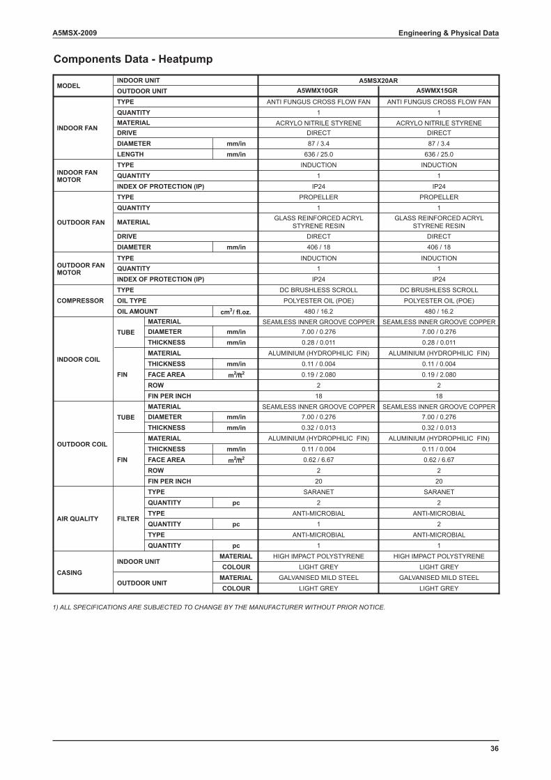
Components Data - Heatpump
A5WMX10GR A5WMX15GR
ANTI FUNGUS CROSS FLOW FAN ANTI FUNGUS CROSS FLOW FAN1 1
ACRYLO NITRILE STYRENE ACRYLO NITRILE STYRENEDIRECT DIRECT
mm/in 87 / 3.4 87 / 3.4mm/in 636 / 25.0 636 / 25.0
INDUCTION INDUCTION1 1
IP24 IP24
mm/in
cm3 / fl.oz.SEAMLESS INNER GROOVE COPPER SEAMLESS INNER GROOVE COPPER
mm/in 7.00 / 0.276 7.00 / 0.276mm/in 0.28 / 0.011 0.28 / 0.011
ALUMINIUM (HYDROPHILIC FIN) ALUMINIUM (HYDROPHILIC FIN)mm/in 0.11 / 0.004 0.11 / 0.004
m2/ft2 0.19 / 2.080 0.19 / 2.0802 218 18
mm/inmm/in
mm/in
m2/ft2
SARANET SARANETpc 2 2
ANTI-MICROBIAL ANTI-MICROBIALpc 1 2
ANTI-MICROBIAL ANTI-MICROBIALpc 1 1
MATERIAL HIGH IMPACT POLYSTYRENE HIGH IMPACT POLYSTYRENECOLOUR LIGHT GREY LIGHT GREY
MATERIALCOLOUR LIGHT GREY
0.11 / 0.0040.62 / 6.67
220
7.00 / 0.2760.32 / 0.013
ALUMINIUM (HYDROPHILIC FIN)
GALVANISED MILD STEELLIGHT GREY
GALVANISED MILD STEEL
DC BRUSHLESS SCROLLPOLYESTER OIL (POE)
480 / 16.2
SEAMLESS INNER GROOVE COPPER
0.11 / 0.0040.62 / 6.67
220
7.00 / 0.2760.32 / 0.013
ALUMINIUM (HYDROPHILIC FIN)
SEAMLESS INNER GROOVE COPPER
TYPE
A5MSX20AR
PROPELLER1
GLASS REINFORCED ACRYLSTYRENE RESIN
DIRECT406 / 18
INDUCTION1
IP24DC BRUSHLESS SCROLL
POLYESTER OIL (POE)480 / 16.2
PROPELLER1
GLASS REINFORCED ACRYLSTYRENE RESIN
DIRECT406 / 18
INDUCTION1
IP24
MATERIAL
MATERIAL
ROWFIN PER INCH
DIAMETERTHICKNESS
THICKNESSFACE AREA
CASING
AIR QUALITY FILTER
QUANTITYTYPE
INDOOR UNIT
OUTDOOR UNIT
TYPE
QUANTITY
QUANTITY
INDOOR COIL
OUTDOOR COIL
FIN
FIN
TUBE
TUBE
INDOOR UNITOUTDOOR UNIT
MODEL
TYPE
INDOOR FAN
INDOOR FAN MOTOR
QUANTITYMATERIALDRIVE
INDEX OF PROTECTION (IP)
DIAMETERLENGTH
OUTDOOR FAN MATERIAL
DRIVE
TYPE
TYPEQUANTITY
DIAMETER
COMPRESSORTYPEOIL TYPE
INDEX OF PROTECTION (IP)
OUTDOOR FAN MOTOR
OIL AMOUNT
QUANTITY
ROWFIN PER INCH
DIAMETERTHICKNESS
THICKNESSFACE AREA
MATERIAL
TYPEQUANTITY
MATERIAL
1) ALL SPECIFICATIONS ARE SUBJECTED TO CHANGE BY THE MANUFACTURER WITHOUT PRIOR NOTICE.
37
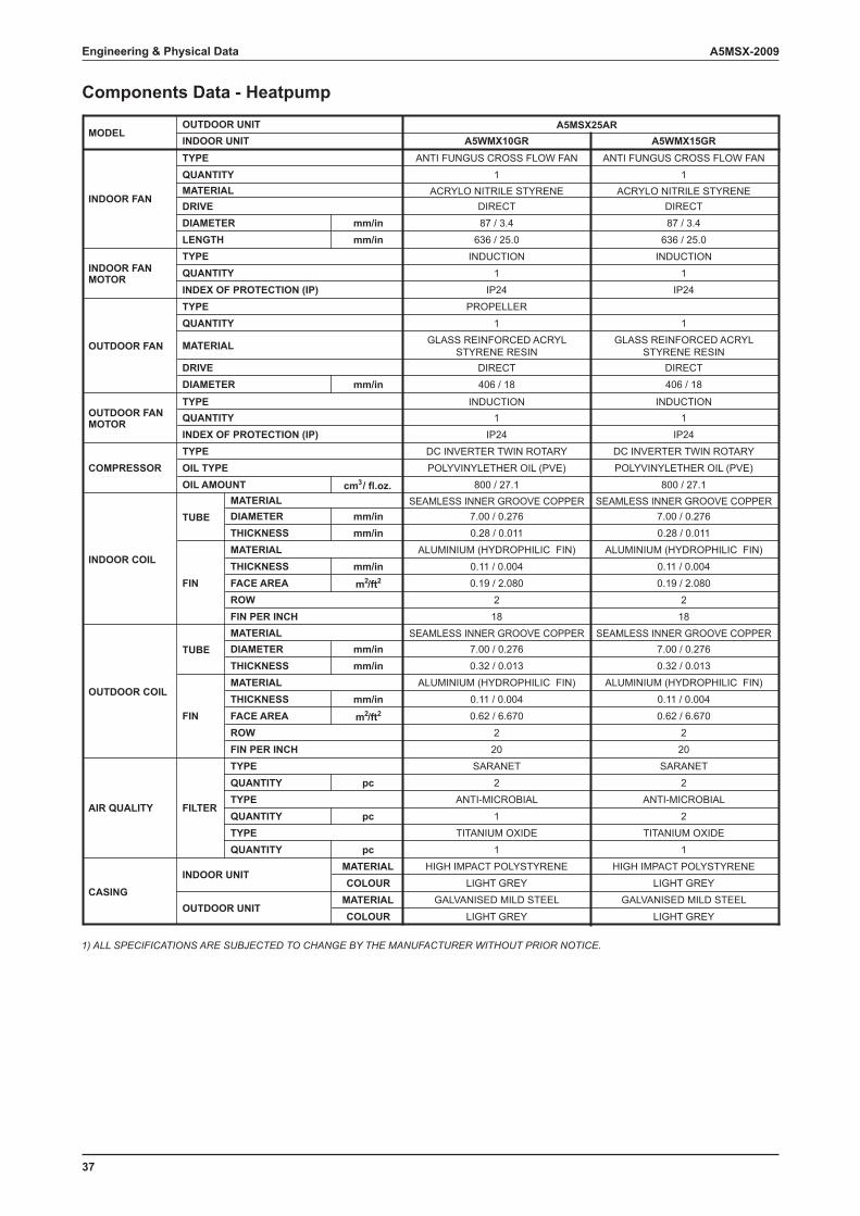
A5MSX-2009Engineering & Physical Data
Components Data - Heatpump
A5WMX10GR A5WMX15GRANTI FUNGUS CROSS FLOW FAN ANTI FUNGUS CROSS FLOW FAN
1 1ACRYLO NITRILE STYRENE ACRYLO NITRILE STYRENE
DIRECT DIRECTmm/in 87 / 3.4 87 / 3.4mm/in 636 / 25.0 636 / 25.0
INDUCTION INDUCTION1 1
IP24 IP24
mm/in
cm3 / fl.oz.SEAMLESS INNER GROOVE COPPER SEAMLESS INNER GROOVE COPPER
mm/in 7.00 / 0.276 7.00 / 0.276mm/in 0.28 / 0.011 0.28 / 0.011
ALUMINIUM (HYDROPHILIC FIN) ALUMINIUM (HYDROPHILIC FIN)mm/in 0.11 / 0.004 0.11 / 0.004
m2/ft2 0.19 / 2.080 0.19 / 2.0802 2
18 18
mm/inmm/in
mm/in
m2/ft2
SARANET SARANETpc 2 2
ANTI-MICROBIAL ANTI-MICROBIALpc 1 2
TITANIUM OXIDE TITANIUM OXIDEpc 1 1
MATERIAL HIGH IMPACT POLYSTYRENE HIGH IMPACT POLYSTYRENECOLOUR LIGHT GREY LIGHT GREY
MATERIALCOLOUR LIGHT GREY
0.11 / 0.0040.62 / 6.670
220
7.00 / 0.2760.32 / 0.013
ALUMINIUM (HYDROPHILIC FIN)
GALVANISED MILD STEELLIGHT GREY
GALVANISED MILD STEEL
DC INVERTER TWIN ROTARYPOLYVINYLETHER OIL (PVE)
800 / 27.1
SEAMLESS INNER GROOVE COPPER
0.11 / 0.0040.62 / 6.670
220
7.00 / 0.2760.32 / 0.013
ALUMINIUM (HYDROPHILIC FIN)
SEAMLESS INNER GROOVE COPPER
TYPE
A5MSX25AR
PROPELLER1
GLASS REINFORCED ACRYLSTYRENE RESIN
DIRECT406 / 18
INDUCTION1
IP24DC INVERTER TWIN ROTARYPOLYVINYLETHER OIL (PVE)
800 / 27.1
1GLASS REINFORCED ACRYL
STYRENE RESINDIRECT406 / 18
INDUCTION1
IP24
MATERIAL
MATERIAL
ROWFIN PER INCH
DIAMETERTHICKNESS
THICKNESSFACE AREA
CASING
AIR QUALITY FILTER
QUANTITYTYPE
INDOOR UNIT
OUTDOOR UNIT
TYPE
QUANTITY
QUANTITY
INDOOR COIL
OUTDOOR COIL
FIN
FIN
TUBE
TUBE
INDOOR UNITOUTDOOR UNIT
MODEL
TYPE
INDOOR FAN
INDOOR FAN MOTOR
QUANTITYMATERIALDRIVE
INDEX OF PROTECTION (IP)
DIAMETERLENGTH
OUTDOOR FAN MATERIAL
DRIVE
TYPE
TYPEQUANTITY
DIAMETER
COMPRESSORTYPEOIL TYPE
INDEX OF PROTECTION (IP)
OUTDOOR FAN MOTOR
OIL AMOUNT
QUANTITY
ROWFIN PER INCH
DIAMETERTHICKNESS
THICKNESSFACE AREA
MATERIAL
TYPEQUANTITY
MATERIAL
1) ALL SPECIFICATIONS ARE SUBJECTED TO CHANGE BY THE MANUFACTURER WITHOUT PRIOR NOTICE.
38
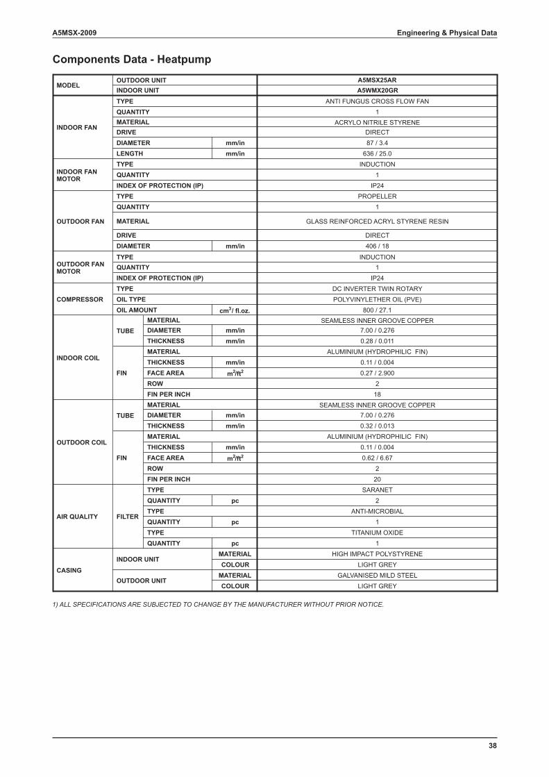
A5MSX-2009 Engineering & Physical Data
Components Data - Heatpump
A5WMX20GRANTI FUNGUS CROSS FLOW FAN
1ACRYLO NITRILE STYRENE
DIRECTmm/in 87 / 3.4mm/in 636 / 25.0
INDUCTION1
IP24
mm/in
cm3 / fl.oz.SEAMLESS INNER GROOVE COPPER
mm/in 7.00 / 0.276mm/in 0.28 / 0.011
ALUMINIUM (HYDROPHILIC FIN)mm/in 0.11 / 0.004
m2/ft2 0.27 / 2.9002
18
mm/inmm/in
mm/in
m2/ft2
SARANETpc 2
ANTI-MICROBIALpc 1
TITANIUM OXIDEpc 1
MATERIAL HIGH IMPACT POLYSTYRENECOLOUR LIGHT GREY
MATERIALCOLOUR LIGHT GREY
0.11 / 0.0040.62 / 6.67
220
7.00 / 0.2760.32 / 0.013
ALUMINIUM (HYDROPHILIC FIN)
GALVANISED MILD STEEL
DC INVERTER TWIN ROTARYPOLYVINYLETHER OIL (PVE)
800 / 27.1
SEAMLESS INNER GROOVE COPPER
TYPE
A5MSX25AR
PROPELLER1
GLASS REINFORCED ACRYL STYRENE RESIN
DIRECT406 / 18
INDUCTION1
IP24
MATERIAL
MATERIAL
ROWFIN PER INCH
DIAMETERTHICKNESS
THICKNESSFACE AREA
CASING
AIR QUALITY FILTER
QUANTITYTYPE
INDOOR UNIT
OUTDOOR UNIT
TYPE
QUANTITY
QUANTITY
INDOOR COIL
OUTDOOR COIL
FIN
FIN
TUBE
TUBE
INDOOR UNITOUTDOOR UNIT
MODEL
TYPE
INDOOR FAN
INDOOR FAN MOTOR
QUANTITYMATERIALDRIVE
INDEX OF PROTECTION (IP)
DIAMETERLENGTH
OUTDOOR FAN MATERIAL
DRIVE
TYPE
TYPEQUANTITY
DIAMETER
COMPRESSORTYPEOIL TYPE
INDEX OF PROTECTION (IP)
OUTDOOR FAN MOTOR
OIL AMOUNT
QUANTITY
ROWFIN PER INCH
DIAMETERTHICKNESS
THICKNESSFACE AREA
MATERIAL
TYPEQUANTITY
MATERIAL
1) ALL SPECIFICATIONS ARE SUBJECTED TO CHANGE BY THE MANUFACTURER WITHOUT PRIOR NOTICE.
39
A5MSX-2009Engineering & Physical Data
Components Data - Heatpump
A5WMX10GR A5WMX15GR A5WMX20GRANTI FUNGUS CROSS FLOW FAN
1ACRYLO NITRILE STYRENE
DIRECTmm/in 87 / 3.4mm/in 636 / 25.0
INDUCTION1
IP24
ANTI FUNGUS CROSS FLOW FAN1
ACRYLO NITRILE STYRENEDIRECT87 / 3.4
636 / 25.0INDUCTION
1IP24
ANTI FUNGUS CROSS FLOW FAN1
ACRYLO NITRILE STYRENEDIRECT87 / 3.4
636 / 25.0INDUCTION
1IP24
mm/in
cm3 / fl.oz.SEAMLESS INNER GROOVE COPPER
mm/in 7.00 / 0.276mm/in 0.28 / 0.011
ALUMINIUM (HYDROPHILIC FIN)mm/in 0.11 / 0.004
m2/ft2 0.32 / 3.4202
18
SEAMLESS INNER GROOVE COPPER7.00 / 0.2760.28 / 0.011
ALUMINIUM (HYDROPHILIC FIN)0.11 / 0.0040.32 / 3.420
218
SEAMLESS INNER GROOVE COPPER7.00 / 0.2760.28 / 0.011
ALUMINIUM (HYDROPHILIC FIN)0.11 / 0.0040.32 / 3.420
218
mm/inmm/in
mm/in
m2/ft2
SARANETpc 2
ANTI-MICROBIALpc 1
TITANIUM OXIDEpc 1
MATERIAL HIGH IMPACT POLYSTYRENECOLOUR LIGHT GREY
SARANET2
ANTI-MICROBIAL1
TITANIUM OXIDE1
HIGH IMPACT POLYSTYRENELIGHT GREY
SARANET2
ANTI-MICROBIAL1
TITANIUM OXIDE1
HIGH IMPACT POLYSTYRENELIGHT GREY
MATERIALCOLOUR LIGHT GREY
0.11 / 0.0040.62 / 6.67 + 0.23 / 3.06
2 + 118
7.00 / 0.2760.32 / 0.013
ALUMINIUM (HYDROPHILIC FIN)0.11 / 0.004
0.62 / 6.67 + 0.23 / 3.062 + 1
18
7.00 / 0.2760.32 / 0.013
ALUMINIUM (HYDROPHILIC FIN)0.11 / 0.004
0.62 / 6.67 + 0.23 / 3.062 + 1
18
7.00 / 0.2760.32 / 0.013
ALUMINIUM (HYDROPHILIC FIN)
GALVANISED MILD STEELLIGHT GREY
GALVANISED MILD STEELLIGHT GREY
GALVANISED MILD STEEL
DC INVERTER TWIN ROTARYPOLYVINYLETHER OIL (PVE)
800 / 27.1
SEAMLESS INNER GROOVE COPPERSEAMLESS INNER GROOVE COPPER SEAMLESS INNER GROOVE COPPER
TYPE
A5MSX30AR
PROPELLER11
GLASS REINFORCEDACRYL STYRENE RESIN
DIRECT406 / 18
INDUCTION11
IP24DC INVERTER TWIN ROTARYPOLYVINYLETHER OIL (PVE)
800 / 27.1
PROPELLER1
GLASS REINFORCEDACRYL STYRENE RESIN
DIRECT406 / 18
INDUCTION1
IP24DC INVERTER TWIN ROTARYPOLYVINYLETHER OIL (PVE)
800 / 27.1
PROPELLER
GLASS REINFORCEDACRYL STYRENE RESIN
DIRECT406 / 18
INDUCTION
IP24
MATERIAL
MATERIAL
ROWFIN PER INCH
DIAMETERTHICKNESS
THICKNESSFACE AREA
CASING
AIR QUALITY FILTER
QUANTITYTYPE
INDOOR UNIT
OUTDOOR UNIT
TYPE
QUANTITY
QUANTITY
INDOOR COIL
OUTDOOR COIL
FIN
FIN
TUBE
TUBE
INDOOR UNITOUTDOOR UNIT
MODEL
TYPE
INDOOR FAN
INDOOR FAN MOTOR
QUANTITYMATERIALDRIVE
INDEX OF PROTECTION (IP)
DIAMETERLENGTH
OUTDOOR FANMATERIAL
DRIVE
TYPE
TYPEQUANTITY
DIAMETER
COMPRESSORTYPEOIL TYPE
INDEX OF PROTECTION (IP)
OUTDOOR FAN MOTOR
OIL AMOUNT
QUANTITY
ROWFIN PER INCH
DIAMETERTHICKNESS
THICKNESSFACE AREA
MATERIAL
TYPEQUANTITY
MATERIAL
1) ALL SPECIFICATIONS ARE SUBJECTED TO CHANGE BY THE MANUFACTURER WITHOUT PRIOR NOTICE.
40
A5MSX-2009 Performance Data
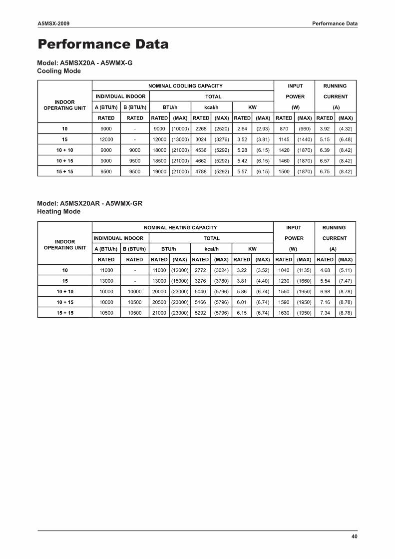
Performance DataModel: A5MSX20A - A5WMX-G Cooling Mode
Model: A5MSX20AR - A5WMX-GRHeating Mode
A (BTU/h) B (BTU/h)
RATED RATED RATED (MAX) RATED (MAX) RATED (MAX) RATED (MAX) RATED (MAX)
10 9000 - 9000 (10000) 2268 (2520) 2.64 (2.93) 870 (960) 3.92 (4.32)
15 12000 - 12000 (13000) 3024 (3276) 3.52 (3.81) 1145 (1440) 5.15 (6.48)
10 + 10 9000 9000 18000 (21000) 4536 (5292) 5.28 (6.15) 1420 (1870) 6.39 (8.42)
10 + 15 9000 9500 18500 (21000) 4662 (5292) 5.42 (6.15) 1460 (1870) 6.57 (8.42)
15 + 15 9500 9500 19000 (21000) 4788 (5292) 5.57 (6.15) 1500 (1870) 6.75 (8.42)
BTU/h kcal/h KW
INDIVIDUAL INDOOR TOTAL CURRENT
(W) (A)INDOOR
OPERATING UNIT
NOMINAL COOLING CAPACITY INPUT RUNNING
POWER
A (BTU/h) B (BTU/h)
RATED RATED RATED (MAX) RATED (MAX) RATED (MAX) RATED (MAX) RATED (MAX)
10 11000 - 11000 (12000) 2772 (3024) 3.22 (3.52) 1040 (1135) 4.68 (5.11)
15 13000 - 13000 (15000) 3276 (3780) 3.81 (4.40) 1230 (1660) 5.54 (7.47)
10 + 10 10000 10000 20000 (23000) 5040 (5796) 5.86 (6.74) 1550 (1950) 6.98 (8.78)
10 + 15 10000 10500 20500 (23000) 5166 (5796) 6.01 (6.74) 1590 (1950) 7.16 (8.78)
15 + 15 10500 10500 21000 (23000) 5292 (5796) 6.15 (6.74) 1630 (1950) 7.34 (8.78)
BTU/h kcal/h KW
INDIVIDUAL INDOOR TOTAL CURRENT
(W) (A)INDOOR
OPERATING UNIT
NOMINAL HEATING CAPACITY INPUT RUNNING
POWER
41
A5MSX-2009Performance Data
Model: A5MSX25A - A5WMX-G Cooling Mode
Model: A5MSX25AR - A5WMX-GR Heating Mode
A B CRATED RATED RATED RATED (MAX) RATED (MAX) RATED (MAX) RATED (MAX) RATED (MAX)
10 9000 - - 9000 (10000) 2268 (2520) 2.64 (2.93) 592 (724) 3.18 (3.39)
15 12000 - - 12000 (13500) 3024 (3402) 3.52 (3.96) 969 (1207) 4.44 (5.47)
20 18000 - - 18000 (19000) 4536 (4788) 5.28 (5.57) 1595 (1944) 7.22 (8.71)
10 + 10 9000 9000 - 18000 (20000) 4536 (5040) 5.28 (5.86) 1474 (1838) 6.68 (8.32)
10 + 15 8000 12000 - 20000 (21000) 5040 (5292) 5.86 (6.15) 1573 (2065) 9.26 (9.35)
10 + 20 7400 14600 - 22000 (24000) 5544 (6048) 6.45 (7.03) 1802 (2205) 8.08 (9.86)
15 + 15 11000 11000 - 22000 (24000) 5544 (6048) 6.45 (7.03) 1814 (2200) 8.13 (9.86)
15 + 20 8800 13200 - 22000 (24000) 5544 (6048) 6.45 (7.03) 1814 (2200) 8.13 (9.86)
10 + 10 + 10 7300 7300 7300 21900 (24000) 5519 (6048) 6.42 (7.03) 1814 (2200) 8.13 (9.86)
10 + 10 + 15 6600 6600 8800 22000 (24000) 5544 (6048) 6.45 (7.03) 1814 (2200) 8.13 (9.86)
10 + 10 + 20 5500 5500 11000 22000 (24000) 5544 (6048) 6.45 (7.03) 1814 (2200) 8.13 (9.86)
10 + 15 + 15 6020 7990 7990 22000 (24000) 5544 (6048) 6.45 (7.03) 1814 (2200) 8.13 (9.86)
10 + 15 + 20 5080 6750 10170 22000 (24000) 5544 (6048) 6.45 (7.03) 1814 (2200) 8.13 (9.86)
15 + 15 + 15 7350 7350 7350 22050 (24000) 5557 (6048) 6.46 (7.03) 1814 (2200) 8.13 (9.86)
RUNNING NOMINAL COOLING CAPACITYINDIVIDUAL INDOOR TOTAL POWER CURRENT
INDOOR OPERATING INPUT
(W) (A)KWUNIT (A5WMX-G)
BTU/h kcal/h
A B C
RATED RATED RATED RATED (MAX) RATED (MAX) RATED (MAX) RATED (MAX) RATED (MAX)
10 11000 - - 11000 (12000) 2772 (3024) 3.22 (3.52) 1317 (1618) 5.97 (7.25)
15 11000 - - 11000 (13000) 2772 (3276) 3.22 (3.81) 1676 (2149) 7.51 (9.53)
20 19000 - - 19000 (20000) 4788 (5040) 5.57 (5.86) 2133 (2489) 9.46 (11.04)
10 + 10 11000 11000 - 22000 (23000) 5544 (5796) 6.45 (6.74) 1953 (2248) 8.85 (10.18)
10 + 15 10000 13000 - 23000 (24000) 5796 (6048) 6.74 (7.03) 2042 (2346) 9.16 (10.40)
10 + 20 8000 16000 - 24000 (26000) 6048 (6552) 7.03 (7.62) 2033 (2527) 9.21 (11.30)
15 + 15 12000 12000 - 24000 (26000) 6048 (6552) 7.03 (7.62) 1990 (2410) 8.92 (10.70)
15 + 20 9600 14400 - 24000 (26000) 6048 (6552) 7.03 (7.62) 1990 (2410) 8.92 (10.70)
10 + 10 + 10 8300 8300 8300 24900 (26000) 6275 (6552) 7.30 (7.62) 1900 (2155) 8.52 (9.57)
10 + 10 + 15 7300 7300 10400 25000 (26000) 6300 (6552) 7.33 (7.62) 1900 (2155) 8.52 (9.57)
10 + 10 + 20 6000 6000 13000 25000 (26000) 6300 (6552) 7.33 (7.62) 1900 (2155) 8.52 (9.57)
10 + 15 + 15 7000 9000 9000 25000 (26000) 6300 (6552) 7.33 (7.62) 1900 (2155) 8.52 (9.57)
10 + 15 + 20 6700 7800 10500 25000 (26000) 6300 (6552) 7.33 (7.62) 1900 (2155) 8.52 (9.57)
15 + 15 + 15 8350 8350 8350 25050 (26000) 6312 (6552) 7.34 (7.62) 1900 (2155) 8.52 (9.57)
RUNNING NOMINAL COOLING CAPACITY
INDIVIDUAL INDOOR TOTAL POWER CURRENTINDOOR OPERATING
INPUT
(W) (A)KWUNIT (A5WMX-GR)
BTU/h kcal/h
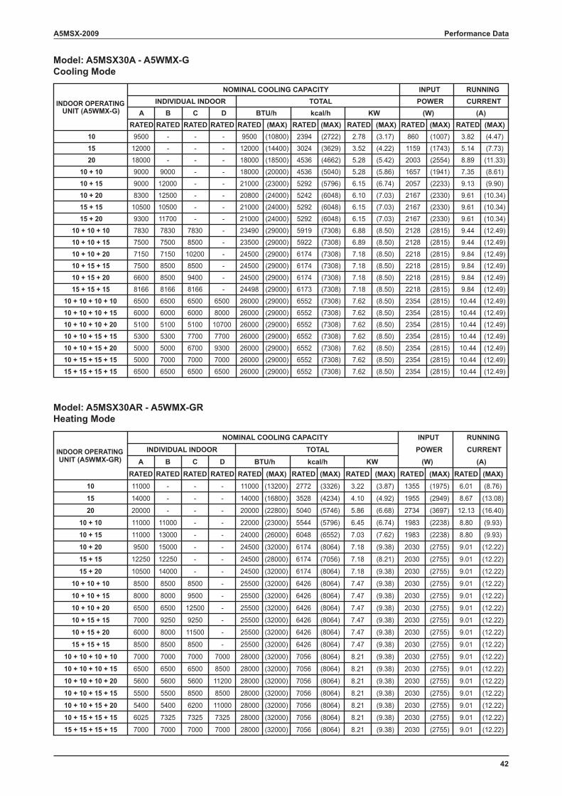
42
A5MSX-2009 Performance Data
Model: A5MSX30A - A5WMX-G Cooling Mode
Model: A5MSX30AR - A5WMX-GR Heating Mode
A B C DRATED RATED RATED RATED RATED (MAX) RATED (MAX) RATED (MAX) RATED (MAX) RATED (MAX)
10 9500 - - - 9500 (10800) 2394 (2722) 2.78 (3.17) 860 (1007) 3.82 (4.47)15 12000 - - - 12000 (14400) 3024 (3629) 3.52 (4.22) 1159 (1743) 5.14 (7.73)20 18000 - - - 18000 (18500) 4536 (4662) 5.28 (5.42) 2003 (2554) 8.89 (11.33)
10 + 10 9000 9000 - - 18000 (20000) 4536 (5040) 5.28 (5.86) 1657 (1941) 7.35 (8.61)10 + 15 9000 12000 - - 21000 (23000) 5292 (5796) 6.15 (6.74) 2057 (2233) 9.13 (9.90)10 + 20 8300 12500 - - 20800 (24000) 5242 (6048) 6.10 (7.03) 2167 (2330) 9.61 (10.34)15 + 15 10500 10500 - - 21000 (24000) 5292 (6048) 6.15 (7.03) 2167 (2330) 9.61 (10.34)15 + 20 9300 11700 - - 21000 (24000) 5292 (6048) 6.15 (7.03) 2167 (2330) 9.61 (10.34)
10 + 10 + 10 7830 7830 7830 - 23490 (29000) 5919 (7308) 6.88 (8.50) 2128 (2815) 9.44 (12.49)10 + 10 + 15 7500 7500 8500 - 23500 (29000) 5922 (7308) 6.89 (8.50) 2128 (2815) 9.44 (12.49)10 + 10 + 20 7150 7150 10200 - 24500 (29000) 6174 (7308) 7.18 (8.50) 2218 (2815) 9.84 (12.49)10 + 15 + 15 7500 8500 8500 - 24500 (29000) 6174 (7308) 7.18 (8.50) 2218 (2815) 9.84 (12.49)10 + 15 + 20 6600 8500 9400 - 24500 (29000) 6174 (7308) 7.18 (8.50) 2218 (2815) 9.84 (12.49)15 + 15 + 15 8166 8166 8166 - 24498 (29000) 6173 (7308) 7.18 (8.50) 2218 (2815) 9.84 (12.49)
10 + 10 + 10 + 10 6500 6500 6500 6500 26000 (29000) 6552 (7308) 7.62 (8.50) 2354 (2815) 10.44 (12.49)10 + 10 + 10 + 15 6000 6000 6000 8000 26000 (29000) 6552 (7308) 7.62 (8.50) 2354 (2815) 10.44 (12.49)10 + 10 + 10 + 20 5100 5100 5100 10700 26000 (29000) 6552 (7308) 7.62 (8.50) 2354 (2815) 10.44 (12.49)10 + 10 + 15 + 15 5300 5300 7700 7700 26000 (29000) 6552 (7308) 7.62 (8.50) 2354 (2815) 10.44 (12.49)10 + 10 + 15 + 20 5000 5000 6700 9300 26000 (29000) 6552 (7308) 7.62 (8.50) 2354 (2815) 10.44 (12.49)10 + 15 + 15 + 15 5000 7000 7000 7000 26000 (29000) 6552 (7308) 7.62 (8.50) 2354 (2815) 10.44 (12.49)15 + 15 + 15 + 15 6500 6500 6500 6500 26000 (29000) 6552 (7308) 7.62 (8.50) 2354 (2815) 10.44 (12.49)
(W) (A)TOTAL POWER CURRENTINDIVIDUAL INDOORINDOOR OPERATING
NOMINAL COOLING CAPACITY INPUT RUNNING
UNIT (A5WMX-G) BTU/h kcal/h KW
A B C DRATED RATED RATED RATED RATED (MAX) RATED (MAX) RATED (MAX) RATED (MAX) RATED (MAX)
10 11000 - - - 11000 (13200) 2772 (3326) 3.22 (3.87) 1355 (1975) 6.01 (8.76)
15 14000 - - - 14000 (16800) 3528 (4234) 4.10 (4.92) 1955 (2949) 8.67 (13.08)
20 20000 - - - 20000 (22800) 5040 (5746) 5.86 (6.68) 2734 (3697) 12.13 (16.40)
10 + 10 11000 11000 - - 22000 (23000) 5544 (5796) 6.45 (6.74) 1983 (2238) 8.80 (9.93)
10 + 15 11000 13000 - - 24000 (26000) 6048 (6552) 7.03 (7.62) 1983 (2238) 8.80 (9.93)
10 + 20 9500 15000 - - 24500 (32000) 6174 (8064) 7.18 (9.38) 2030 (2755) 9.01 (12.22)
15 + 15 12250 12250 - - 24500 (28000) 6174 (7056) 7.18 (8.21) 2030 (2755) 9.01 (12.22)
15 + 20 10500 14000 - - 24500 (32000) 6174 (8064) 7.18 (9.38) 2030 (2755) 9.01 (12.22)
10 + 10 + 10 8500 8500 8500 - 25500 (32000) 6426 (8064) 7.47 (9.38) 2030 (2755) 9.01 (12.22)
10 + 10 + 15 8000 8000 9500 - 25500 (32000) 6426 (8064) 7.47 (9.38) 2030 (2755) 9.01 (12.22)
10 + 10 + 20 6500 6500 12500 - 25500 (32000) 6426 (8064) 7.47 (9.38) 2030 (2755) 9.01 (12.22)
10 + 15 + 15 7000 9250 9250 - 25500 (32000) 6426 (8064) 7.47 (9.38) 2030 (2755) 9.01 (12.22)
10 + 15 + 20 6000 8000 11500 - 25500 (32000) 6426 (8064) 7.47 (9.38) 2030 (2755) 9.01 (12.22)
15 + 15 + 15 8500 8500 8500 - 25500 (32000) 6426 (8064) 7.47 (9.38) 2030 (2755) 9.01 (12.22)
10 + 10 + 10 + 10 7000 7000 7000 7000 28000 (32000) 7056 (8064) 8.21 (9.38) 2030 (2755) 9.01 (12.22)
10 + 10 + 10 + 15 6500 6500 6500 8500 28000 (32000) 7056 (8064) 8.21 (9.38) 2030 (2755) 9.01 (12.22)
10 + 10 + 10 + 20 5600 5600 5600 11200 28000 (32000) 7056 (8064) 8.21 (9.38) 2030 (2755) 9.01 (12.22)
10 + 10 + 15 + 15 5500 5500 8500 8500 28000 (32000) 7056 (8064) 8.21 (9.38) 2030 (2755) 9.01 (12.22)
10 + 10 + 15 + 20 5400 5400 6200 11000 28000 (32000) 7056 (8064) 8.21 (9.38) 2030 (2755) 9.01 (12.22)
10 + 15 + 15 + 15 6025 7325 7325 7325 28000 (32000) 7056 (8064) 8.21 (9.38) 2030 (2755) 9.01 (12.22)
15 + 15 + 15 + 15 7000 7000 7000 7000 28000 (32000) 7056 (8064) 8.21 (9.38) 2030 (2755) 9.01 (12.22)
(W) (A)TOTAL POWER CURRENTINDIVIDUAL INDOORINDOOR OPERATING
NOMINAL COOLING CAPACITY INPUT RUNNING
UNIT (A5WMX-GR) BTU/h kcal/h KW
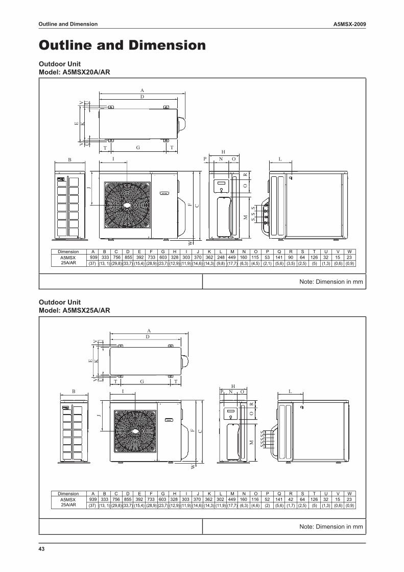
43
A5MSX-2009Outline and Dimension
Outline and DimensionOutdoor UnitModel: A5MSX20A/AR
mm ni noisnemiD :etoN
Outdoor UnitModel: A5MSX25A/AR
mm ni noisnemiD :etoN
AD
G TT
KE
I
J
B
F CW
HN OP
MR
OS
SS
L
UVUV
AD
G TT
KE
I
J
B
F CW
HN OP
MO
R
S
L
UVUV
SSSS
Dimension A B C D E F G H I J K L M N O P Q R S T U V W939 333 756 855 392 733 603 328 303 370 362 302 449 160 116 52 141 42 64 126 32 15 23A5MSX
25A/AR (37) (13, 1) (29,8) (33,7) (15,4) (28,9) (23,7) (12,9) (11,9) (14,6) (14,3) (11,9) (17,7) (6,3) (4,6) (2) (5,6) (1,7) (2,5) (5) (1,3) (0,6) (0,9)
Dimension A B C D E F G H I J K L M N O P Q R S T U V W939 333 756 855 392 733 603 328 303 370 362 248 449 160 115 53 141 90 64 126 32 15 23A5MSX
25A/AR (37) (13, 1) (29,8) (33,7) (15,4) (28,9) (23,7) (12,9) (11,9) (14,6) (14,3) (9,8) (17,7) (6,3) (4,5) (2,1) (5,6) (3,5) (2,5) (5) (1,3) (0,6) (0,9)
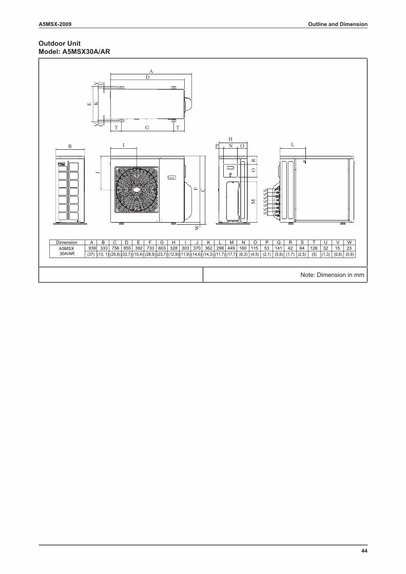
44
A5MSX-2009 Outline and Dimension
Outdoor UnitModel: A5MSX30A/AR
mm ni noisnemiD :etoN
AD
G TT
KE
I
J
B
F CW
HN OP
MR
O
S
L
UVUV
SS
SS
SS
Dimension A B C D E F G H I J K L M N O P Q R S T U V W939 333 756 855 392 733 603 328 303 370 362 298 449 160 115 53 141 42 64 126 32 15 23A5MSX
30A/AR (37) (13, 1) (29,8) (33,7) (15,4) (28,9) (23,7) (12,9) (11,9) (14,6) (14,3) (11,7) (17,7) (6,3) (4,5) (2,1) (5,6) (1,7) (2,5) (5) (1,3) (0,6) (0,9)
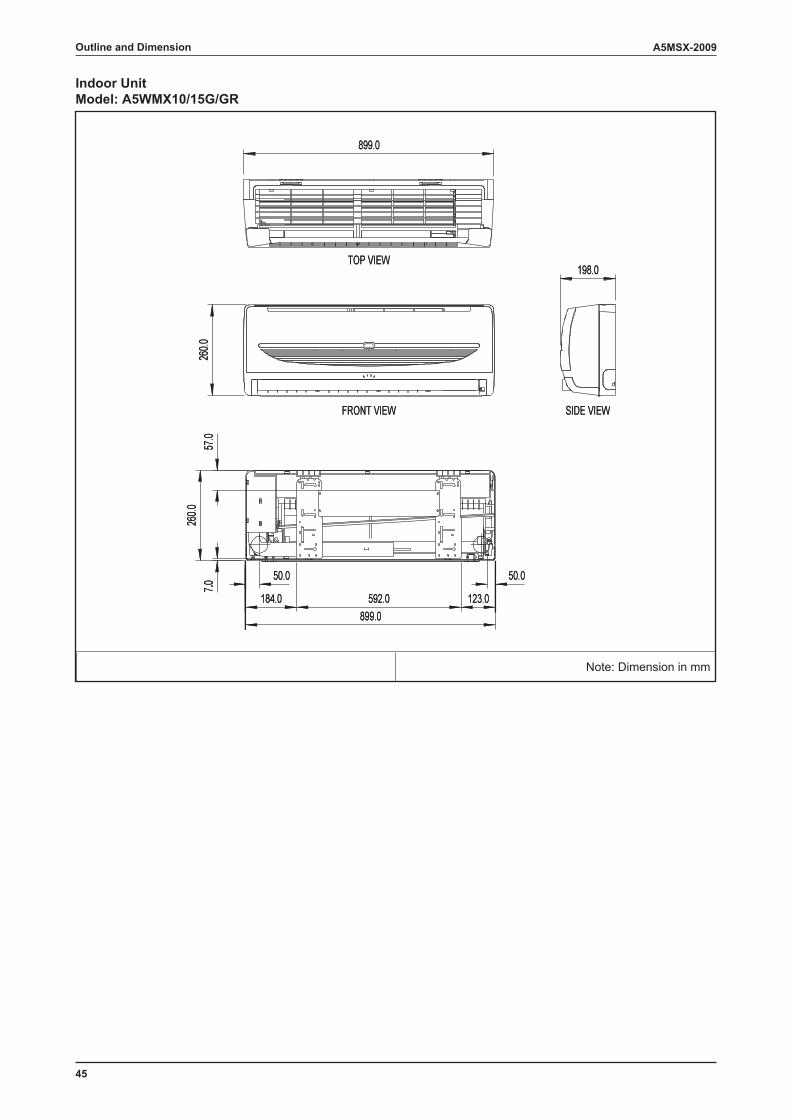
45
A5MSX-2009Outline and Dimension
Indoor UnitModel: A5WMX10/15G/GR
mm ni noisnemiD :etoN
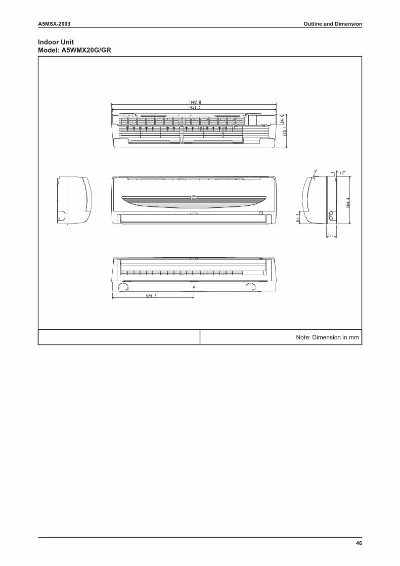
46
A5MSX-2009 Outline and Dimension
Indoor UnitModel: A5WMX20G/GR
mm ni noisnemiD :etoN
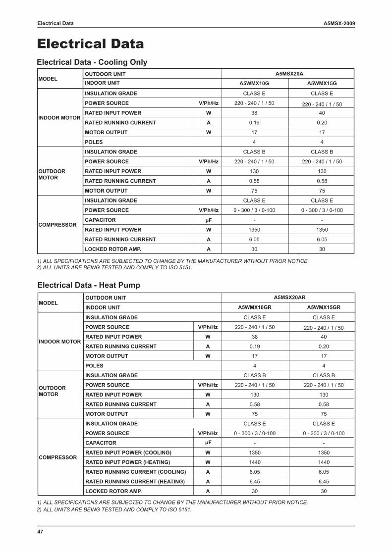
47
A5MSX-2009Electrical Data
Electrical DataElectrical Data - Cooling Only
1) ALL SPECIFICATIONS ARE SUBJECTED TO CHANGE BY THE MANUFACTURER WITHOUT PRIOR NOTICE. 2) ALL UNITS ARE BEING TESTED AND COMPLY TO ISO 5151.
Electrical Data - Heat Pump
1) ALL SPECIFICATIONS ARE SUBJECTED TO CHANGE BY THE MANUFACTURER WITHOUT PRIOR NOTICE.2) ALL UNITS ARE BEING TESTED AND COMPLY TO ISO 5151.
A5WMX10G A5WMX15G
CLASS E CLASS E
POWER SOURCE V/Ph/Hz 220 - 240 / 1 / 50 220 - 240 / 1 / 50RATED INPUT POWER W 38 40
RATED RUNNING CURRENT A 0.19 0.20
MOTOR OUTPUT W 17 17
4 4
POWER SOURCE V/Ph/Hz
RATED INPUT POWER W
RATED RUNNING CURRENT A
MOTOR OUTPUT W
POWER SOURCE V/Ph/Hz
CAPACITOR μF
RATED INPUT POWER W
RATED RUNNING CURRENT A
LOCKED ROTOR AMP. A
COMPRESSOR
OUTDOORMOTOR
INSULATION GRADE
INSULATION GRADE
MODEL
INDOOR MOTOR
INDOOR UNITOUTDOOR UNIT
INSULATION GRADE
POLES
A5MSX20A
CLASS B
220 - 240 / 1 / 50
130
0.58
75
CLASS E
0 - 300 / 3 / 0-100
-
1350
6.05
30
CLASS B
220 - 240 / 1 / 50
130
0.58
75
CLASS E
0 - 300 / 3 / 0-100
-
1350
6.05
30
A5WMX10GR A5WMX15GR
CLASS E CLASS E
POWER SOURCE V/Ph/Hz 220 - 240 / 1 / 50 220 - 240 / 1 / 50
RATED INPUT POWER W 38 40
RATED RUNNING CURRENT A 0.19 0.20
MOTOR OUTPUT W 17 17
4 4
POWER SOURCE V/Ph/Hz
RATED INPUT POWER W
RATED RUNNING CURRENT A
MOTOR OUTPUT W
POWER SOURCE V/Ph/Hz
CAPACITOR μF
RATED INPUT POWER (COOLING) W
RATED INPUT POWER (HEATING) W
RATED RUNNING CURRENT (COOLING) A
RATED RUNNING CURRENT (HEATING) A
LOCKED ROTOR AMP. A
INDOOR MOTOR
INSULATION GRADE
POLES
COMPRESSOR
INSULATION GRADE
OUTDOORMOTOR
INSULATION GRADE
MODELINDOOR UNIT
OUTDOOR UNIT
CLASS B
220 - 240 / 1 / 50
130
0.58
30
A5MSX20AR
1350
1440
6.05
6.45
75
CLASS E
0 - 300 / 3 / 0-100
-
CLASS B
220 - 240 / 1 / 50
130
0.58
30
1350
1440
6.05
6.45
75
CLASS E
0 - 300 / 3 / 0-100
-
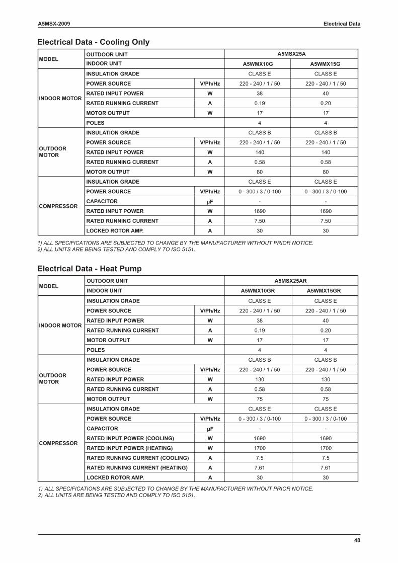
48
A5MSX-2009 Electrical Data
Electrical Data - Cooling Only
1) ALL SPECIFICATIONS ARE SUBJECTED TO CHANGE BY THE MANUFACTURER WITHOUT PRIOR NOTICE. 2) ALL UNITS ARE BEING TESTED AND COMPLY TO ISO 5151.
Electrical Data - Heat Pump
1) ALL SPECIFICATIONS ARE SUBJECTED TO CHANGE BY THE MANUFACTURER WITHOUT PRIOR NOTICE.2) ALL UNITS ARE BEING TESTED AND COMPLY TO ISO 5151.
A5WMX10G A5WMX15G
CLASS E CLASS E
POWER SOURCE V/Ph/Hz 220 - 240 / 1 / 50 220 - 240 / 1 / 50
RATED INPUT POWER W 38 40
RATED RUNNING CURRENT A 0.19 0.20
MOTOR OUTPUT W 17 17
4 4
CLASS B CLASS B
POWER SOURCE V/Ph/Hz 220 - 240 / 1 / 50 220 - 240 / 1 / 50
RATED INPUT POWER W 140 140
RATED RUNNING CURRENT A 0.58 0.58
MOTOR OUTPUT W 80 80
CLASS E CLASS E
POWER SOURCE V/Ph/Hz 0 - 300 / 3 / 0-100 0 - 300 / 3 / 0-100
CAPACITOR μF - -
RATED INPUT POWER W 1690 1690
RATED RUNNING CURRENT A 7.50 7.50
LOCKED ROTOR AMP. A 30 30
COMPRESSOR
OUTDOORMOTOR
INSULATION GRADE
INSULATION GRADE
MODEL
INDOOR MOTOR
INDOOR UNITOUTDOOR UNIT
INSULATION GRADE
POLES
A5MSX25A
A5WMX10GR A5WMX15GR
CLASS E CLASS E
POWER SOURCE V/Ph/Hz 220 - 240 / 1 / 50 220 - 240 / 1 / 50
RATED INPUT POWER W 38 40
RATED RUNNING CURRENT A 0.19 0.20
MOTOR OUTPUT W 17 17
4 4
CLASS B CLASS B
POWER SOURCE V/Ph/Hz 220 - 240 / 1 / 50 220 - 240 / 1 / 50
RATED INPUT POWER W 130 130
RATED RUNNING CURRENT A 0.58 0.58
MOTOR OUTPUT W 75 75
CLASS E CLASS E
POWER SOURCE V/Ph/Hz 0 - 300 / 3 / 0-100 0 - 300 / 3 / 0-100
CAPACITOR μF - -
RATED INPUT POWER (COOLING) W 1690 1690
RATED INPUT POWER (HEATING) W 1700 1700
RATED RUNNING CURRENT (COOLING) A 7.5 7.5
RATED RUNNING CURRENT (HEATING) A 7.61 7.61
LOCKED ROTOR AMP. A 30 30
INDOOR MOTOR
INSULATION GRADE
POLES
COMPRESSOR
INSULATION GRADE
OUTDOORMOTOR
INSULATION GRADE
MODELINDOOR UNIT
OUTDOOR UNIT A5MSX25AR
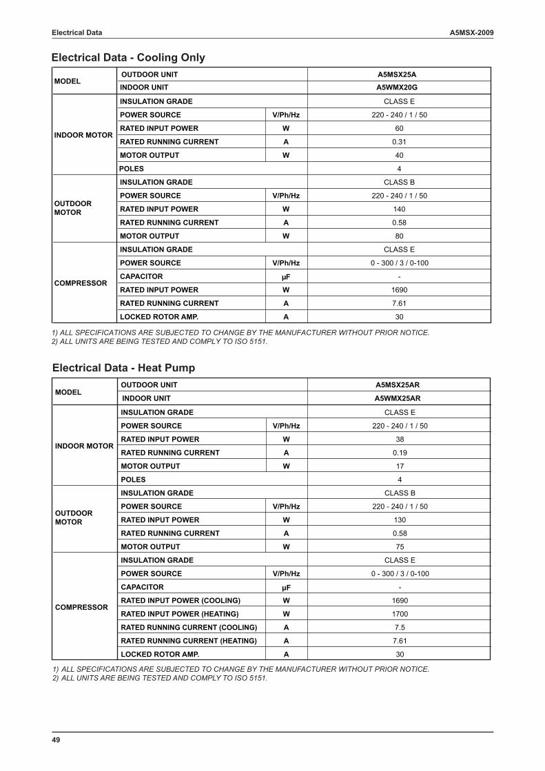
49
A5MSX-2009Electrical Data
Electrical Data - Cooling Only
1) ALL SPECIFICATIONS ARE SUBJECTED TO CHANGE BY THE MANUFACTURER WITHOUT PRIOR NOTICE. 2) ALL UNITS ARE BEING TESTED AND COMPLY TO ISO 5151.
Electrical Data - Heat Pump
1) ALL SPECIFICATIONS ARE SUBJECTED TO CHANGE BY THE MANUFACTURER WITHOUT PRIOR NOTICE.2) ALL UNITS ARE BEING TESTED AND COMPLY TO ISO 5151.
A5WMX20G
A5MSX25A
CLASS E
POWER SOURCE V/Ph/Hz 220 - 240 / 1 / 50
RATED INPUT POWER W 60
RATED RUNNING CURRENT A 0.31
MOTOR OUTPUT W 40
4
CLASS B
POWER SOURCE V/Ph/Hz 220 - 240 / 1 / 50
RATED INPUT POWER W 140
RATED RUNNING CURRENT A 0.58
MOTOR OUTPUT W 80
CLASS E
POWER SOURCE V/Ph/Hz 0 - 300 / 3 / 0-100
CAPACITOR μF -
RATED INPUT POWER W 1690
RATED RUNNING CURRENT A 7.61
LOCKED ROTOR AMP. A 30
COMPRESSOR
OUTDOORMOTOR
INSULATION GRADE
INSULATION GRADE
MODEL
INDOOR MOTOR
INDOOR UNIT
OUTDOOR UNIT
INSULATION GRADE
POLES
A5WMX25AR
A5MSX25AR
CLASS E
POWER SOURCE V/Ph/Hz 220 - 240 / 1 / 50
RATED INPUT POWER W 38
RATED RUNNING CURRENT A 0.19
MOTOR OUTPUT W 17
4
CLASS B
POWER SOURCE V/Ph/Hz 220 - 240 / 1 / 50
RATED INPUT POWER W 130
RATED RUNNING CURRENT A 0.58
MOTOR OUTPUT W 75
CLASS E
POWER SOURCE V/Ph/Hz 0 - 300 / 3 / 0-100
CAPACITOR μF -
RATED INPUT POWER (COOLING) W 1690
RATED INPUT POWER (HEATING) W 1700
RATED RUNNING CURRENT (COOLING) A 7.5
RATED RUNNING CURRENT (HEATING) A 7.61
LOCKED ROTOR AMP. A 30
INDOOR MOTOR
INSULATION GRADE
POLES
COMPRESSOR
INSULATION GRADE
OUTDOORMOTOR
INSULATION GRADE
MODELINDOOR UNIT
OUTDOOR UNIT
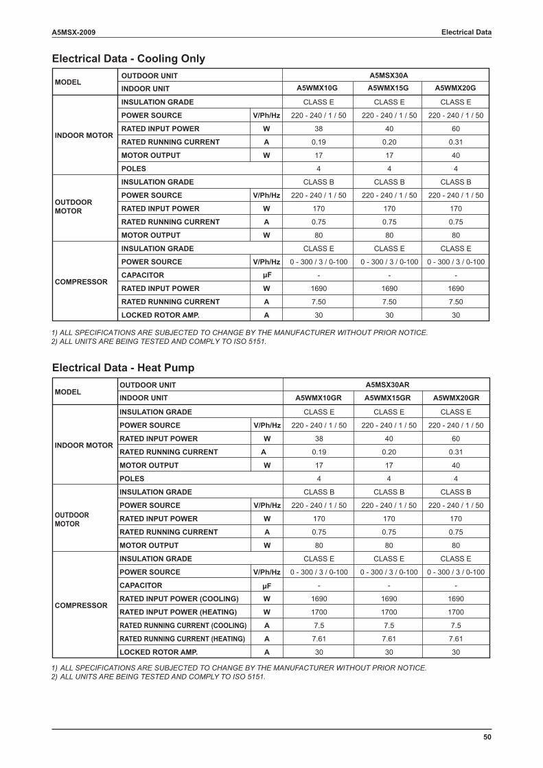
50
A5MSX-2009 Electrical Data
Electrical Data - Cooling Only
1) ALL SPECIFICATIONS ARE SUBJECTED TO CHANGE BY THE MANUFACTURER WITHOUT PRIOR NOTICE. 2) ALL UNITS ARE BEING TESTED AND COMPLY TO ISO 5151.
Electrical Data - Heat Pump
1) ALL SPECIFICATIONS ARE SUBJECTED TO CHANGE BY THE MANUFACTURER WITHOUT PRIOR NOTICE.2) ALL UNITS ARE BEING TESTED AND COMPLY TO ISO 5151.
A5WMX10G A5WMX20GA5WMX15G
CLASS E CLASS E CLASS E
POWER SOURCE V/Ph/Hz 220 - 240 / 1 / 50 220 - 240 / 1 / 50 220 - 240 / 1 / 50
RATED INPUT POWER W 38 40 60
RATED RUNNING CURRENT A 0.19 0.20 0.31
MOTOR OUTPUT W 17 17 40
4 4 4
CLASS B CLASS B CLASS B
POWER SOURCE V/Ph/Hz 220 - 240 / 1 / 50 220 - 240 / 1 / 50 220 - 240 / 1 / 50
RATED INPUT POWER W 170 170 170
RATED RUNNING CURRENT A 0.75 0.75 0.75
MOTOR OUTPUT W 80 80 80
CLASS E CLASS E CLASS E
POWER SOURCE V/Ph/Hz 0 - 300 / 3 / 0-100 0 - 300 / 3 / 0-100 0 - 300 / 3 / 0-100
CAPACITOR μF - - -
RATED INPUT POWER W 1690 1690 1690
RATED RUNNING CURRENT A 7.50 7.50 7.50
LOCKED ROTOR AMP. A 30 30 30
COMPRESSOR
OUTDOORMOTOR
INSULATION GRADE
INSULATION GRADE
MODEL
INDOOR MOTOR
INDOOR UNIT
OUTDOOR UNIT
INSULATION GRADE
POLES
A5MSX30A
A5WMX10GR A5WMX15GR A5WMX20GR
CLASS E CLASS E CLASS E
POWER SOURCE V/Ph/Hz 220 - 240 / 1 / 50 220 - 240 / 1 / 50 220 - 240 / 1 / 50
RATED INPUT POWER W 38 40 60
RATED RUNNING CURRENT A 0.19 0.20 0.31
MOTOR OUTPUT W 17 17 40
4 4 4
CLASS B CLASS B CLASS B
POWER SOURCE V/Ph/Hz 220 - 240 / 1 / 50 220 - 240 / 1 / 50 220 - 240 / 1 / 50
RATED INPUT POWER W 170 170 170
RATED RUNNING CURRENT A 0.75 0.75 0.75
MOTOR OUTPUT W 80 80 80
CLASS E CLASS E CLASS E
POWER SOURCE V/Ph/Hz 0 - 300 / 3 / 0-100 0 - 300 / 3 / 0-100 0 - 300 / 3 / 0-100
CAPACITOR μF - - -
RATED INPUT POWER (COOLING) W 1690 1690 1690
RATED INPUT POWER (HEATING) W 1700 1700 1700
RATED RUNNING CURRENT (COOLING) A 7.5 7.5 7.5
RATED RUNNING CURRENT (HEATING) A 7.61 7.61 7.61
LOCKED ROTOR AMP. A 30 30 30
INDOOR MOTOR
INSULATION GRADE
POLES
COMPRESSOR
INSULATION GRADE
OUTDOORMOTOR
INSULATION GRADE
MODELINDOOR UNIT
OUTDOOR UNIT A5MSX30AR
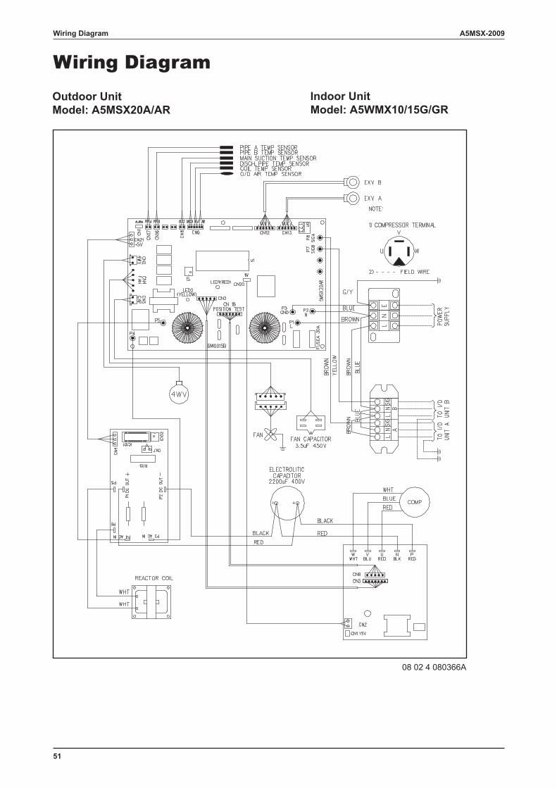
51
A5MSX-2009Wiring Diagram
Wiring DiagramIndoor UnitModel: A5WMX10/15G/GR
Outdoor UnitModel: A5MSX20A/AR
08 02 4 080366A
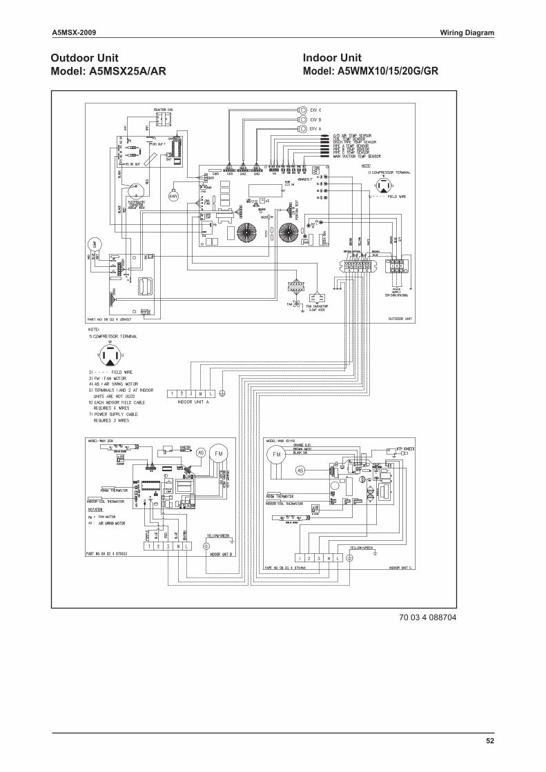
52
A5MSX-2009 Wiring Diagram
Indoor UnitModel: A5WMX10/15/20G/GR
Outdoor UnitModel: A5MSX25A/AR
70 03 4 088704
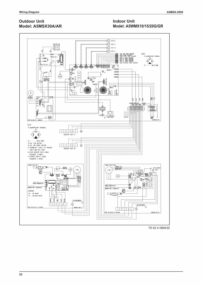
53
A5MSX-2009Wiring Diagram
Indoor UnitModel: A5WMX10/15/20G/GR
Outdoor UnitModel: A5MSX30A/AR
70 03 4 089435
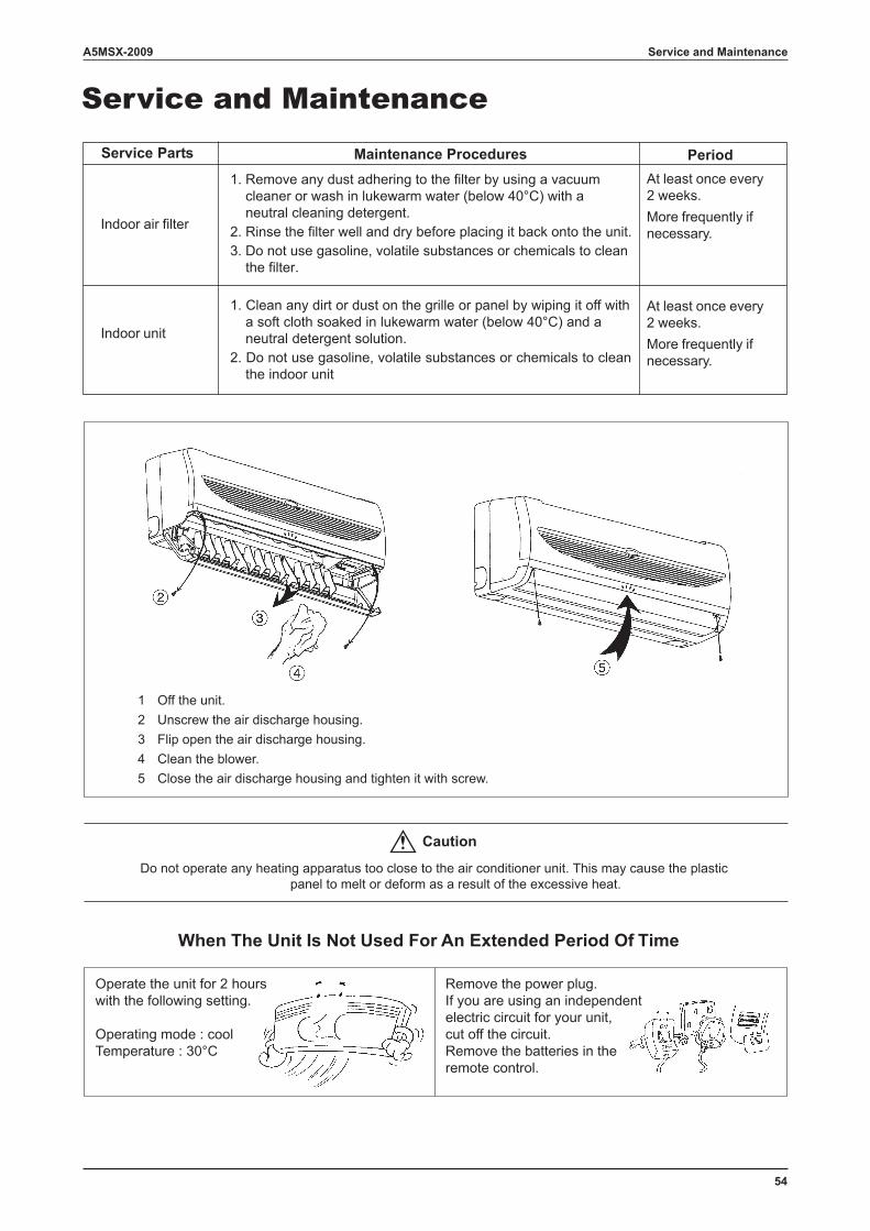
54
A5MSX-2009 Service and Maintenance
Service and MaintenanceMaintenance ProceduresService Parts Period
At least once every2 weeks.More frequently ifnecessary.
At least once every2 weeks.More frequently ifnecessary.
Indoor air filter
Indoor unit
When The Unit Is Not Used For An Extended Period Of Time
Operate the unit for 2 hourswith the following setting.
Operating mode : coolTemperature : 30°C
Remove the power plug.If you are using an independentelectric circuit for your unit,cut off the circuit.Remove the batteries in theremote control.
Do not operate any heating apparatus too close to the air conditioner unit. This may cause the plasticpanel to melt or deform as a result of the excessive heat.
1 Off the unit.2 Unscrew the air discharge housing.3 Flip open the air discharge housing.4 Clean the blower.5 Close the air discharge housing and tighten it with screw.
1. Remove any dust adhering to the filter by using a vacuum cleaner or wash in lukewarm water (below 40°C) with a neutral cleaning detergent.2. Rinse the filter well and dry before placing it back onto the unit.3. Do not use gasoline, volatile substances or chemicals to clean the filter.
1. Clean any dirt or dust on the grille or panel by wiping it off with a soft cloth soaked in lukewarm water (below 40°C) and a neutral detergent solution.2. Do not use gasoline, volatile substances or chemicals to clean the indoor unit
Caution
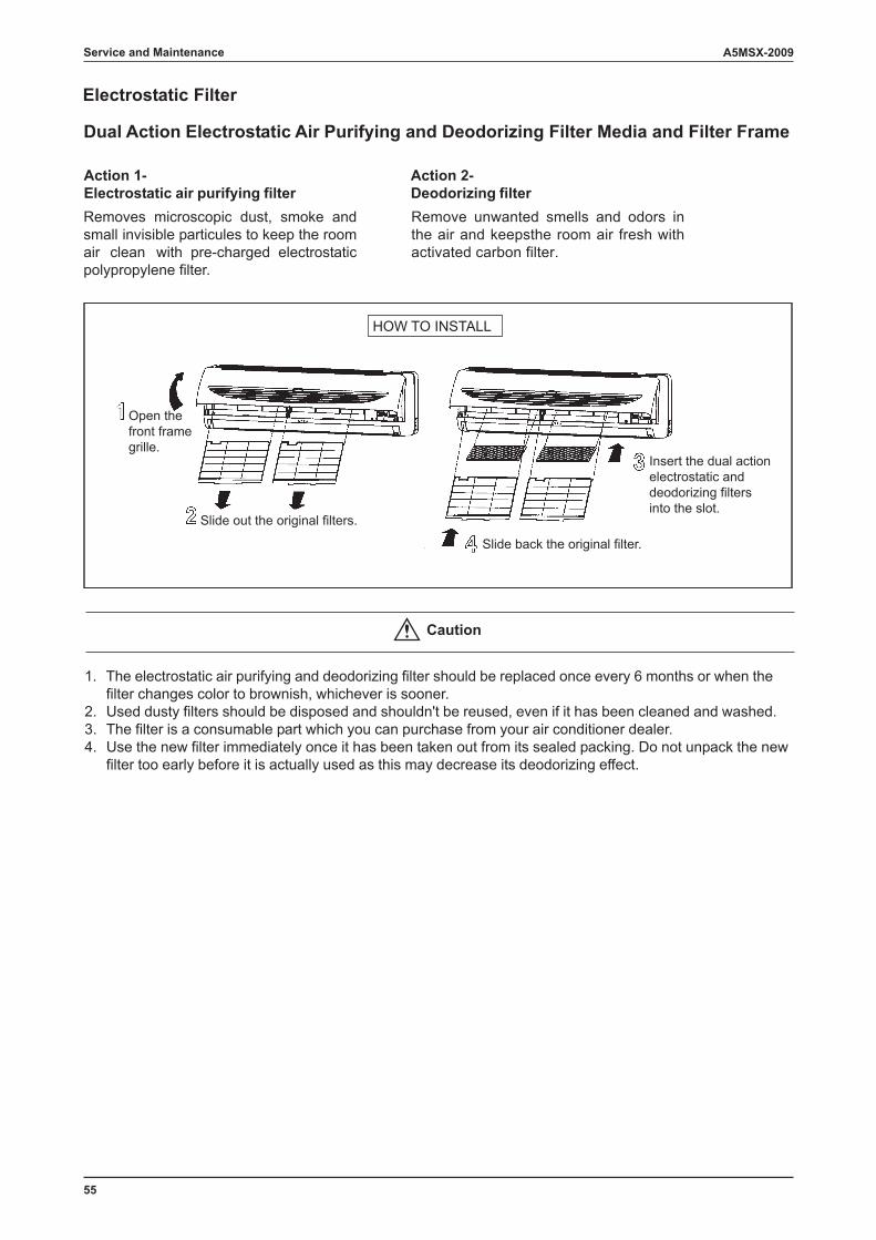
55
A5MSX-2009Service and Maintenance
Electrostatic Filter
Dual Action Electrostatic Air Purifying and Deodorizing Filter Media and Filter Frame
HOW TO INSTALL
Open thefront framegrille.
Slide out the original filters.
Slide back the original filter.
Insert the dual actionelectrostatic anddeodorizing filtersinto the slot.
Action 1-Electrostatic air purifying filter
Action 2-Deodorizing filter
Removes microscopic dust, smoke and small invisible particules to keep the room air clean with pre-charged electrostatic polypropylene filter.
Remove unwanted smells and odors in the air and keepsthe room air fresh with activated carbon filter.
1. The electrostatic air purifying and deodorizing filter should be replaced once every 6 months or when the filter changes color to brownish, whichever is sooner. 2. Used dusty filters should be disposed and shouldn't be reused, even if it has been cleaned and washed. 3. The filter is a consumable part which you can purchase from your air conditioner dealer. 4. Use the new filter immediately once it has been taken out from its sealed packing. Do not unpack the new filter too early before it is actually used as this may decrease its deodorizing effect.
Caution
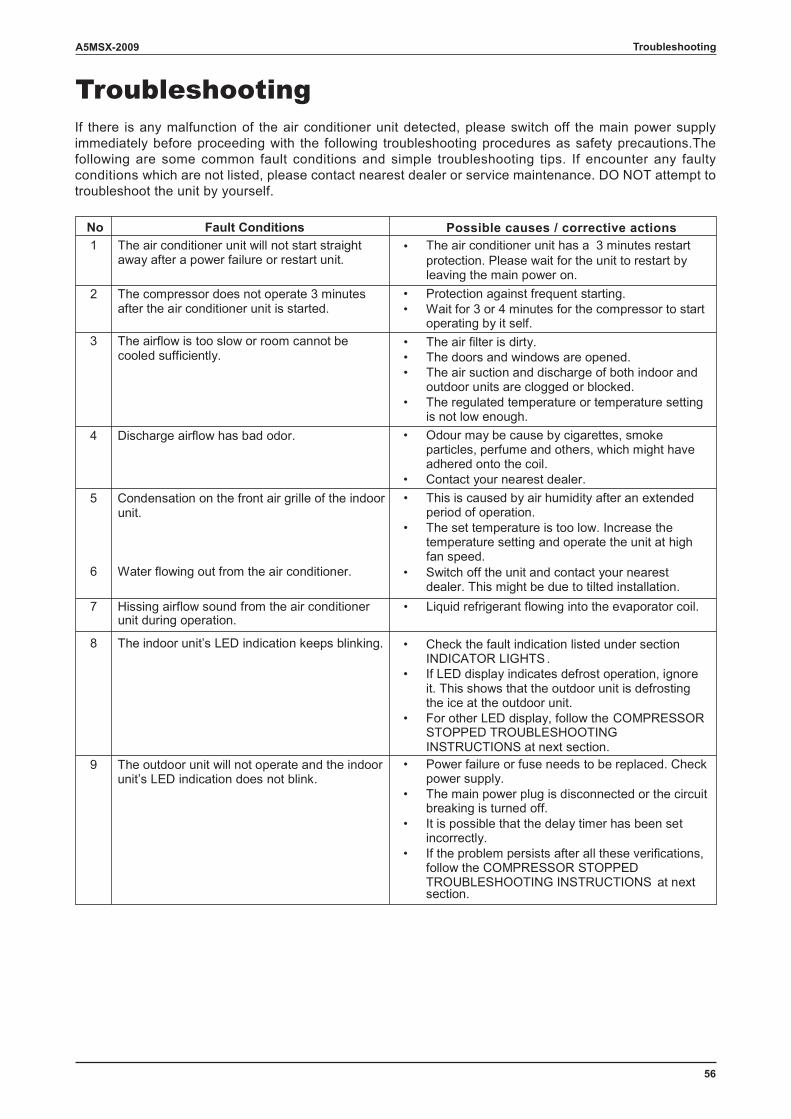
56
A5MSX-2009 Troubleshooting
Troubleshooting
Fault ConditionsNo1 The air conditioner unit will not start straight
away after a power failure or restart unit. • The air conditioner unit has a 3 minutes restart
protection. Please wait for the unit to restart by leaving the main power on.
2 The compressor does not operate 3 minutes after the air conditioner unit is started.
• Protection against frequent starting. • Wait for 3 or 4 minutes for the compressor to start
operating by it self. 3 The airflow is too slow or room cannot be
cooled sufficiently. • The air filter is dirty. • The doors and windows are opened. • The air suction and discharge of both indoor and
outdoor units are clogged or blocked. • The regulated temperature or temperature setting
is not low enough. 4 Discharge airflow has bad odor. • Odour may be cause by cigarettes, smoke
particles, perfume and others, which might have adhered onto the coil.
• Contact your nearest dealer. 5 Condensation on the front air grille of the indoor
unit. • This is caused by air humidity after an extended
period of operation. • The set temperature is too low. Increase the
temperature setting and operate the unit at high fan speed.
6 Water flowing out from the air conditioner. • Switch off the unit and contact your nearest dealer. This might be due to tilted installation.
7 Hissing airflow sound from the air conditioner unit during operation.
• Liquid refrigerant flowing into the evaporator coil.
8 The indoor unit’s LED indication keeps blinking. • Check the fault indication listed under section INDICATOR LIGHTS.
• If LED display indicates defrost operation, ignore it. This shows that the outdoor unit is defrosting the ice at the outdoor unit.
• For other LED display, follow the COMPRESSOR STOPPED TROUBLESHOOTING INSTRUCTIONS at next section.
9 The outdoor unit will not operate and the indoor unit’s LED indication does not blink.
• Power failure or fuse needs to be replaced. Check power supply.
• The main power plug is disconnected or the circuit breaking is turned off.
• It is possible that the delay timer has been set incorrectly.
• If the problem persists after all these verifications, follow the COMPRESSOR STOPPED TROUBLESHOOTING INSTRUCTIONS at next section.
If there is any malfunction of the air conditioner unit detected, please switch off the main power supply immediately before proceeding with the following troubleshooting procedures as safety precautions.The following are some common fault conditions and simple troubleshooting tips. If encounter any faulty conditions which are not listed, please contact nearest dealer or service maintenance. DO NOT attempt to troubleshoot the unit by yourself.
Possible causes / corrective actions
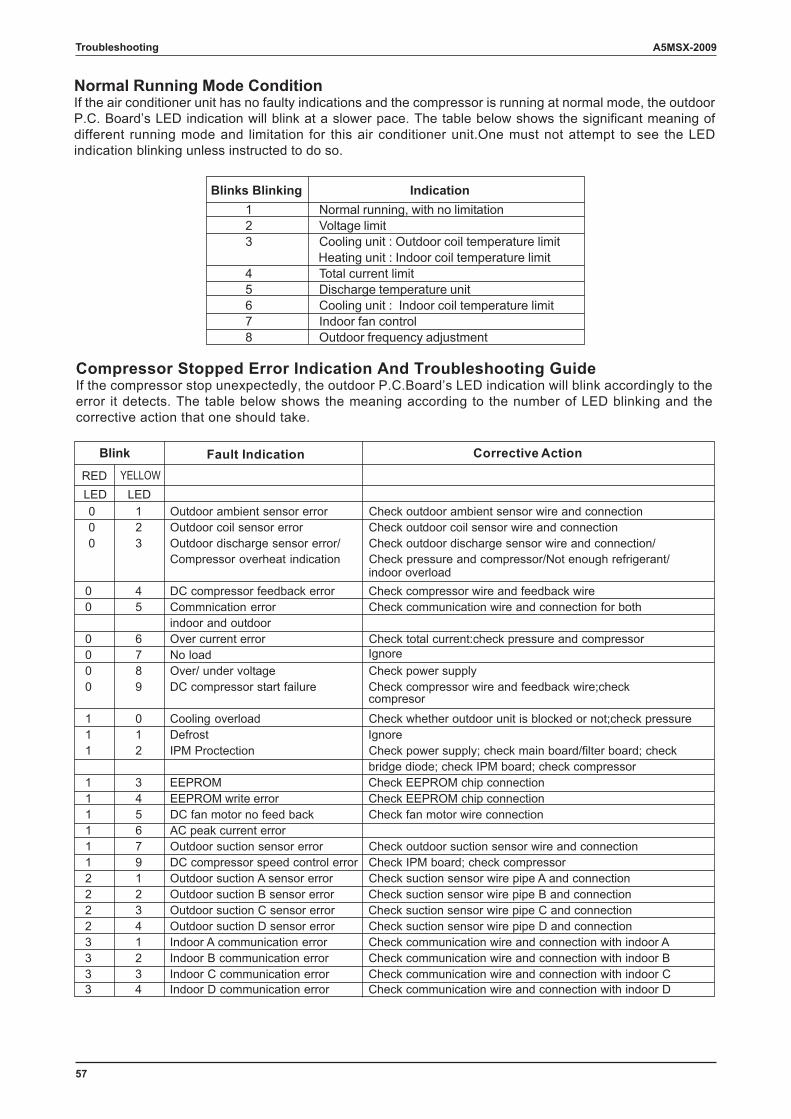
57
A5MSX-2009Troubleshooting
Blinks Blinking Indication 1 Normal running, with no limitation 2 Voltage limit 3 Cooling unit : Outdoor coil temperature limit
Heating unit : Indoor coil temperature limit 4 Total current limit 5 Discharge temperature unit 6 Cooling unit : Indoor coil temperature limit 7 Indoor fan control 8 Outdoor frequency adjustment
Blink noitcA evitcerroCnoitacidnI tluaF RED LED LED 0 1 Outdoor ambient sensor error Check outdoor ambient sensor wire and connection 0 2 Outdoor coil sensor error Check outdoor coil sensor wire and connection 0 3 Outdoor discharge sensor error/ Check outdoor discharge sensor wire and connection/
Compressor overheat indication Check pressure and compressor/Not enough refrigerant/ indoor overload
0 4 DC compressor feedback error Check compressor wire and feedback wire 0 5 Commnication error Check communication wire and connection for both
indoor and outdoor 0 6 Over current error Check total current:check pressure and compressor
erongI daol oN7 0 0 8 Over/ under voltage Check power supply 0 9 DC compressor start failure Check compressor wire and feedback wire;check
compresor
1 0 Cooling overload Check whether outdoor unit is blocked or not;check pressureerongI tsorfeD1 1
1 2 IPM Proctection Check power supply; check main board/filter board; check bridge diode; check IPM board; check compressor
1 3 EEPROM Check EEPROM chip connection 1 4 EEPROM write error Check EEPROM chip connection 1 5 DC fan motor no feed back Check fan motor wire connection 1 6 AC peak current error 1 7 Outdoor suction sensor error Check outdoor suction sensor wire and connection 1 9 DC compressor speed control error Check IPM board; check compressor 2 1 Outdoor suction A sensor error Check suction sensor wire pipe A and connection 2 2 Outdoor suction B sensor error Check suction sensor wire pipe B and connection 2 3 Outdoor suction C sensor error Check suction sensor wire pipe C and connection 2 4 Outdoor suction D sensor error Check suction sensor wire pipe D and connection 3 1 Indoor A communication error Check communication wire and connection with indoor A 3 2 Indoor B communication error Check communication wire and connection with indoor B 3 3 Indoor C communication error Check communication wire and connection with indoor C 3 4 Indoor D communication error Check communication wire and connection with indoor D
Normal Running Mode ConditionIf the air conditioner unit has no faulty indications and the compressor is running at normal mode, the outdoor P.C. Board’s LED indication will blink at a slower pace. The table below shows the significant meaning of different running mode and limitation for this air conditioner unit.One must not attempt to see the LED indication blinking unless instructed to do so.
Compressor Stopped Error Indication And Troubleshooting GuideIf the compressor stop unexpectedly, the outdoor P.C.Board’s LED indication will blink accordingly to the error it detects. The table below shows the meaning according to the number of LED blinking and the corrective action that one should take.
YELLOW
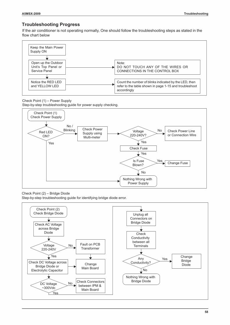
58
A5MSX-2009 Troubleshooting
Troubleshooting Progress
Check Point (1) – Power SupplyStep-by-step troubleshooting guide for power supply checking.
Check Point (2) – Bridge DiodeStep-by-step troubleshooting guide for identifying bridge diode error.
Red LEDON?
Check Point (1)Check Power Supply
Check PowerSupply usingMulti-meter
Voltage220-240V?
Check Power Lineor Connection Wire
Check Fuse
Is FuseBlown?
Nothing Wrong withPower Supply
Change Fuse
No /Blinking
Yes
No
Yes
No
Notice the RED LEDand YELLOW LED
Open up the OutdoorUnit’s Top Panel orService Panel
Keep the Main PowerSupply ON
Count the number of blinks indicated by the LED, thenrefer to the table shown in page 1-15 and troubleshootaccordingly
Note:DO NOT TOUCH ANY OF THE WIRES ORCONNECTIONS IN THE CONTROL BOX
Check Point (2)Check Bridge Diode
No
Yes
DC Voltage~300Vdc
Check DC Voltage acrossBridge Diode or
Electrolytic Capacitor
Fault on PCBTransformer
ChangeMain Board
AnyConductivity?
Unplug allConnectors onBridge Diode
CheckConductivitybetween allTerminals
Nothing Wrong withBridge Diode
ChangeBridgeDiode
No
Yes
Check AC Voltageacross Bridge
Diode
Voltage220-240V
Yes
Check Connectorsbetween IPM &
Main Board
No
Yes
Yes
If the air conditioner is not operating normally, One should follow the troubleshooting steps as stated in the flow chart below
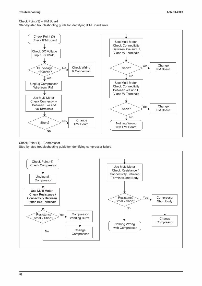
59
A5MSX-2009Troubleshooting
Check Point (4) – CompressorStep-by-step troubleshooting guide for identifying compressor failure.
Check Point (4)Check Compressor
Yes
Unplug allCompressor
No
Nothing Wrongwith Compressor
No
Yes
Use Multi MeterCheck Resistance /
Connectivity BetweenEither Two Terminals
ResistanceSmall / Short?
CompressorWinding Burnt
ChangeCompressor
Use Multi MeterCheck Resistance /
Connectivity BetweenEither Two Terminals
Use Multi MeterCheck Resistance /
Connectivity BetweenTerminals and Body
ChangeCompressor
CompressorShort Body
ResistanceSmall / Short?
Check Point (3) – IPM BoardStep-by-step troubleshooting guide for identifying IPM Board error.
Check Point (3)Check IPM Board
No
Yes
Check DC VoltageInput ~300Vdc
Unplug CompressorWire from IPM
Check Wiring& Connection
Yes
DC Voltage~300Vdc?
Short?
Use Multi MeterCheck ConnectivityBetween +ve and
-ve Terminals
No
Short?
Use Multi MeterCheck ConnectivityBetween +ve and U,V and W Terminals
Use Multi MeterCheck ConnectivityBetween -ve and U,V and W Terminals
Short?
Nothing Wrongwith IPM Board
ChangeIPM Board
ChangeIPM Board
ChangeIPM Board
Yes
No
Yes
No
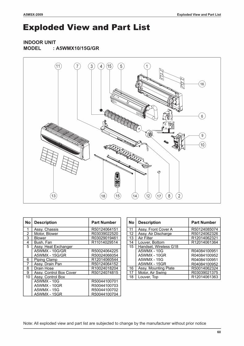
60
A5MSX-2009 Exploded View and Part List
Exploded View and Part ListINDOOR UNITMODEL : A5WMX10/15G/GR
1 Assy. Chassis R50124064151 11 Assy. Front Cover A R501240850742 Motor, Blower R03039022520 12 Assy. Air Discharge R501240623263 Blower R03029019461 13 Air Filter R120140623214 Bush, Fan R11014029514 14 Louver, Bottom R120140613645 Assy. Heat Exchanger 15 Handset, Wireless G18
A5WMX - 10G/GR R50024064225 A5WMX - 10GA5WMX - 15G/GR R50024066054 A5WMX - 10GR
6 Piping Clamp R12014060544 A5WMX - 15G7 Assy. Drain Pan R50124064152 A5WMX - 15GR8 Drain Hose R10024018204 16 Assy. Mounting Plate R500140623249 Assy. Control Box Cover R50124074815 17 Motor, Air Swing R0303902137510 Assy. Control Box 18 Louver, Top R12014061363
A5WMX - 10G R50044100701A5WMX - 10GR R50044100703A5WMX - 15G R50044100702A5WMX - 15GR R50044100704
Description Part NumberNo Description Part Number No
16
1714151813
R04084100951R04084100952R04084100951R04084100952
Note: All exploded view and part list are subjected to change by the manufacturer without prior notice
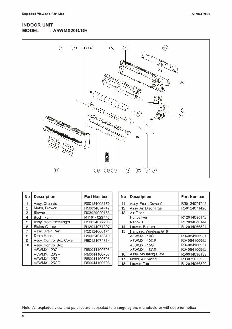
61
A5MSX-2009Exploded View and Part List
INDOOR UNITMODEL : A5WMX20G/GR
1 Assy. Chassis R50124068170 11 Assy. Front Cover A R501240747432 Motor, Blower R50034074747 12 Assy. Air Discharge R501240714263 Blower R03029029158 13 Air Filter4 Bush, Fan R11014023775 Nanosilver R120140801425 Assy. Heat Exchanger R50024072203 Nanovis R120140801446 Piping Clamp R12014071297 14 Louver, Bottom R120140668217 Assy. Drain Pan R50124068171 15 Handset, Wireless G188 Drain Hose R10024015319 A5WMX - 10G9 Assy. Control Box Cover R50124074814 A5WMX - 10GR10 Assy. Control Box A5WMX - 15G
A5WMX - 20G R50044100705 A5WMX - 15GRA5WMX - 20GR R50044100707 16 Assy. Mounting Plate R50014036133A5WMX - 25G R50044100706 17 Motor, Air Swing R03039022933A5WMX - 25GR R50044100708 18 Louver, Top R12014066820
Description Part NumberNo Description Part Number No
13 1518 14
16
17
R04084100951R04084100952R04084100951R04084100952
Note: All exploded view and part list are subjected to change by the manufacturer without prior notice
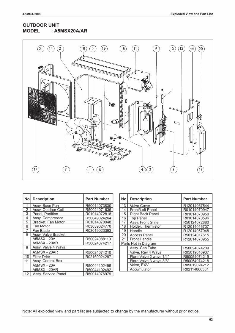
62
A5MSX-2009 Exploded View and Part List
OUTDOOR UNITMODEL : A5MSX20A/AR
1 Assy. Base Pan R500140738302 Assy. Outdoor Coil R50024071636
13 Valve Cover R12014057544
3 Panel, Partition R0101407281814 Front/Left Panel R01014070947
4 Assy. Compressor R5004902426415 Right Back Panel R01014070950
5 Bracket, Fan Motor R0101407094816 Top Panel R01014070596
6 Fan Motor R0303902477017 Assy. Front Grille R50124072880
7 Fan Blade R0301902339318 Holder, Thermistor R12014016707
8 Assy. Valve Bracket19 Handle R12014057948
A5MSX - 20A R5002408811020 Access Panel R50124017615
A5MSX - 20AR R5002407421721 Front Handle R12014070955
9 Assy. Valve 4 WaysParts Not in Diagram
Assy. Cap Tube R50024074209A5MSX - 20AR R50024074210 Valve, Rev 4 Ways R05019016937
10 Filter Drier R02169024287 Flare Valve 2 ways 1/4" R5005407421911 Assy. Control Box Flare Valve 3 ways 3/8" R50054074218
A5MSX - 20A R50044102495 Valve, EXV R05019024212A5MSX - 20AR R50044102492 Accumulator R02114066381
No No Description Part NumberPart NumberDescription
12 Assy. Service Panel R50014076979
Note: All exploded view and part list are subjected to change by the manufacturer without prior notice
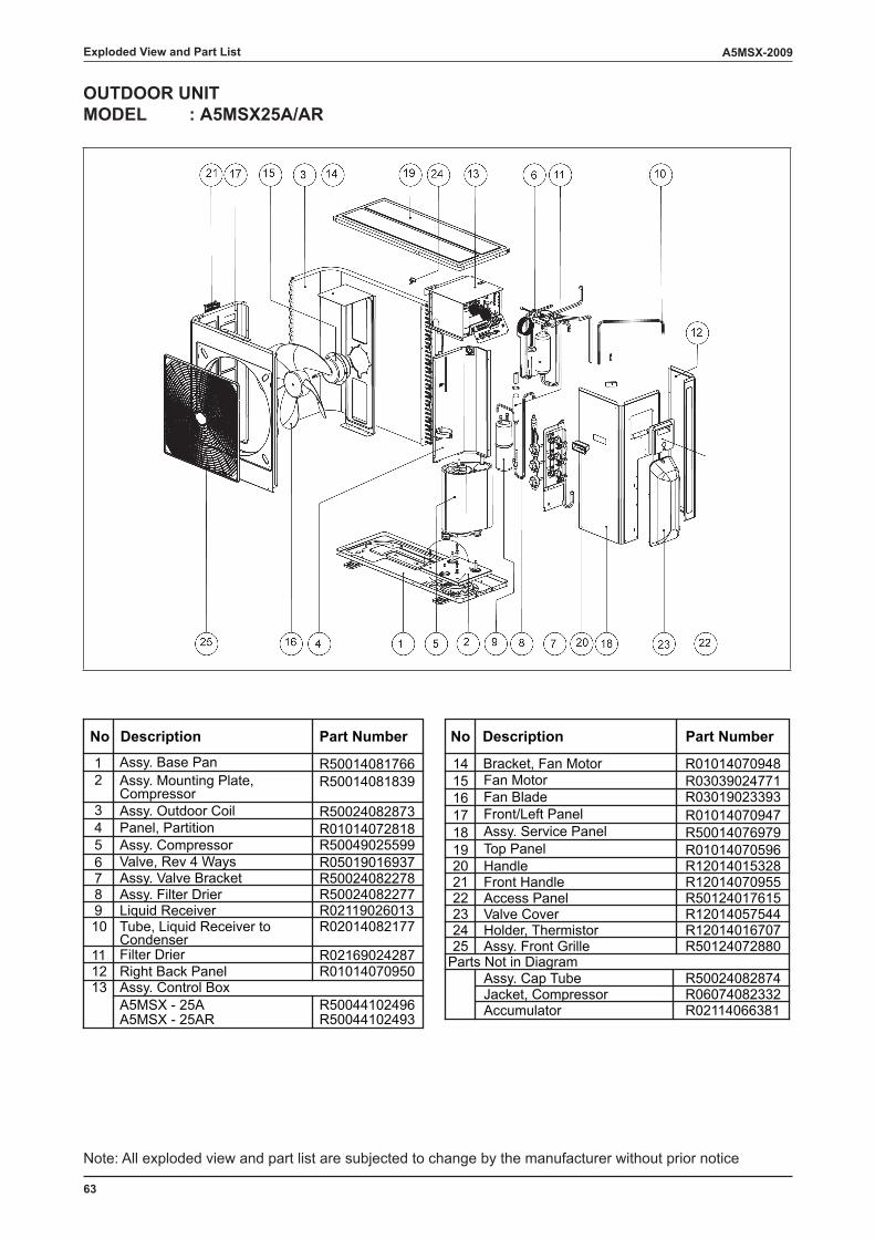
63
A5MSX-2009
OUTDOOR UNITMODEL : A5MSX25A/AR
1 Assy. Base Pan R5001408176615 Fan Motor R030390247712 Assy. Mounting Plate,
Compressor R50014081839
16 Fan Blade R030190233933 Assy. Outdoor Coil R50024082873 17 Front/Left Panel R010140709474 Panel, Partition R01014072818 18 Assy. Service Panel R500140769795 Assy. Compressor R50049025599 19 Top Panel R010140705966 Valve, Rev 4 Ways R05019016937 20 Handle R120140153287 Assy. Valve Bracket R50024082278 21 Front Handle R120140709558 Assy. Filter Drier R50024082277 22 Access Panel R501240176159 Liquid Receiver R02119026013 23 Valve Cover R1201405754410 Tube, Liquid Receiver to
CondenserR02014082177 24 Holder, Thermistor R12014016707
11 Filter Drier R02169024287 25 Assy. Front Grille R50124072880
12 Right Back Panel R01014070950Parts Not in Diagram
13 Assy. Control Box Assy. Cap Tube R50024082874
A5MSX - 25A R50044102496Jacket, Compressor R06074082332
A5MSX - 25AR R50044102493 Accumulator R02114066381
14 Bracket, Fan Motor R01014070948
No Description Part Number No Description Part Number
Exploded View and Part List
Note: All exploded view and part list are subjected to change by the manufacturer without prior notice
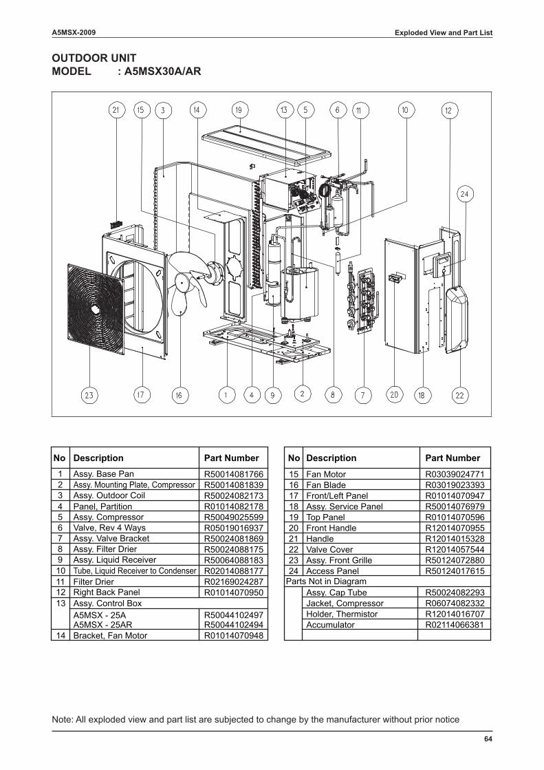
64
A5MSX-2009
OUTDOOR UNITMODEL : A5MSX30A/AR
1 Assy. Base Pan R50014081766 15 Fan Motor R030390247712 Assy. Mounting Plate, Compressor R50014081839 16 Fan Blade R030190233933 Assy. Outdoor Coil R50024082173 17 Front/Left Panel R010140709474 Panel, Partition R01014082178 18 Assy. Service Panel R500140769795 Assy. Compressor R50049025599 19 Top Panel R010140705966 Valve, Rev 4 Ways R05019016937 20 Front Handle R120140709557 Assy. Valve Bracket R50024081869 21 Handle R120140153288 Assy. Filter Drier R50024088175 22 Valve Cover R120140575449 Assy. Liquid Receiver R50064088183 23 Assy. Front Grille R5012407288010 Tube, Liquid Receiver to Condenser R02014088177 24 Access Panel R5012401761511 Filter Drier R02169024287 Parts Not in Diagram12 Right Back Panel R01014070950 Assy. Cap Tube R5002408229313 Assy. Control Box Jacket, Compressor R06074082332
A5MSX - 25A Holder, Thermistor R12014016707A5MSX - 25AR R50044102494
R50044102497Accumulator R02114066381
14 Bracket, Fan Motor R01014070948
No Description Part Number No Description Part Number
Exploded View and Part List
Note: All exploded view and part list are subjected to change by the manufacturer without prior notice

While upmost care is taken in ensuring that all details in the publication are correct at time of going to press, we are constantly striving for improvement and therefore reserve the rights to alter model specifications and equipment without prior notice. Details of specifications and equipment are also subject to change to suit local conditions and requirements and not all models are available in every market.