Date: 29-01-2010 Project Name: TT Race Data ... - UPCommons
72
Date: 29-01-2010 Project Name: TT Race Data Logger Author (s): David Auñon Plandolit Jose Mª Gallardo Robles
-
Upload
khangminh22 -
Category
Documents
-
view
1 -
download
0
Transcript of Date: 29-01-2010 Project Name: TT Race Data ... - UPCommons

Date: 29-01-2010 Project Name: TT Race Data Logger Author (s): David Auñon Plandolit
Jose Mª Gallardo Robles
2
Contact Information
Client
TriCAT Racing
Adress: P/A Stoombootkade 27-28 8701 KA Bolsward
Telf : 0515-576491 Email: [email protected]
Contractor
Walter Jansen
Email: [email protected]
Coach
Marien Van Westen
Email: [email protected]
Author(s)
David Auñon Plandolit
Email: [email protected]
Jose Maria Gallardo Robles
Email: [email protected]

3
Summary
This report is made to accomplish the demand from TriCAT Racing motor race team.
They suggest if it was possible to create a device capable to log data from a motorbike
during a race or testing seasons, mentioning some other similar systems out on the
market, but is really expensive. Taking an initial idea, we thought about one way to
design a system capable of satisfy the demand of our contractor, trying to reduce costs
on the design.
At this point we accept the project offered by TriCAT racing team. Known the several
issues that they have about the design and studying the different ways to make it, the
design is starting to be thought. The contractor needs that the system has to be
capable of store the data into a SD card, this data are: position, velocity, RPM,
cornering angle and lap time of a motorbike in a circuit race. For solve this issues we
thought about microprocessors, GPS’s, and other kind of possibilities, arriving to one
possible solution.
Now the solution of design question is solved, it is possible to design a system capable
to accomplish the demands of the contractor, with a microcontroller PIC18F4550 and a
GPS Unit, one Accelerometer, and programming a complex program on C for
microcontrollers it is possible arrive to a solution.
When we start to build the first prototype and we decide to test it a problem appears,
not enough space in ROM memory. During the implementation part, we arrived the
conclusion that we made an error choosing the microprocessor PIC18F4550, this error
is because the ROM memory. The program that we are using is too big, and the ROM
memory of the microprocessor PIC18F4550 it’s not enough to contain all the program.
As a result of the short time disposed for make the project, and the errors made at the
end, it is not possible to change the design, the prototype is build and we are trying to
make it run. If the project could be continued for another students or another
engineers, the best idea for start, is change the microcontroller for another with the
minimum resources needed by the C program.
4
Index Pag.
Contact information 2
Summary 3
1. Introduction 7
2. Goals 8
3. Analysis 9
3.1 Theory of Data Logging 9
3.2 TT Race Data Logger 9
3.3 Functionality 9
3.4 File Format 10
3.5 Interface 11
4. Study of possibilities 12
4.1 Cornering, Angle detection and study of Gravitational forces (G’s) 12
4.2 Angle detection by range Finder 17
4.3 Power Supply 19
4.4 Revolutions per minute (RPM) and Engine Control Unit (ECU) 19
4.5 Speed and Position 20
4.6 Start/End Beacon Line 20
4.7 Calculation time of 100 first meters 21
5. Hardware Requirements and solutions 22
5.1 Mother Board/Core 22
5.2 GPS Unit 22
5.3 Display 26
5.4 Accelerometer 26
5.5 Removable memory 26
5.6 USB Interface 28
5.7 Power Supply 28
6. TT Race Data Logger Prototype 29
6.1 Design 29
6.2 Interface 29
6.3 Algorithm 30
6.4 Implementation 34
6.5 C Code 35
6.5.1 Files and functions Graph 35
6.5.2 PC- Microcontroller Interface Diagram 36
6.5.3 USB “Plug&Play” 37
6.5.4 Project Files Architecture 38
6.5.5 Data Logging functions, file dependences and explanations 39
6.5.6 LCD Display 40
5
Pag.
6.6 Important C Code Spots 40
6.6.1 Boot Loader remapping vectors 41
6.6.2 File management 41
6.6.3 Speed factor conversion 42
6.6.4 Auto Shut-Down after 60 seconds of non activity 42
6.6.5 Non rebounding button system 43
6.6.6 USB tasks 43
6.6.7 SD socket and SPI connection Definitions 44
6.6.8 LCD port definitions 45
6.6.9 NMEA configuration system 45
6.6.10 TT Race Data Logger States 46
6.6.11 GPS States 46
6.7 Schematic 47
6.8 Component pin wire connection in the prototype 48
6.8.1 SD Socket and pin connections 48
6.8.2 GPS pin assignment 49
6.8.3 Display pin assignment 50
6.8.4 Accelerometer pin assignment 51
6.8.5 Mother Board SBU44UC 51
6.9 Configuration of the connections in the prototype 54
6.9.1 SD pin connections 54
6.9.2 GPS pin connections 54
6.9.3 Display pin connections 55
6.9.4 Accelerometer pin connections 55
6.10 Prototype Pictures 56
6.11 Sub-Devices Location inside the Prototype 58
6.12 Dimensions & Orientation 59
6.12.1 TT Race Data Logger location and position on the motorbike 60
6.13 Tools 61
6.14 Components 62
6.14.1 Mother board SBC44UC 62
6.14.2 GPS Unit 63
6.14.3 Accelerometer 63
6.14.4 LCD 16x2 Display 64
7. Budget 65
7.1 Budget for our Prototype and experimental equipment 65
7.2 Budget for a Prototype 65
8. Observation & Evaluation 66
6
Pag.
9. Recommendations 67
9.1 Dimensions 67
9.2 Power Supply 67
9.3 SD socket with USB chipset included 68
9.4 Microcontroller 69
9.5 Data file Processing and Google Maps 70
10. Literature 71
11. Annex 72
SBC44UC Mother Board Datasheet
Accelerometer (ADLX335) Datasheet
GPS Unit (EM-408) Datasheet
Display (GDM1602K) Datasheet
1 CD with all source code & software tools for design it
7
1. Introduction
Since many years, professional teams from the high end of the TT Motorbike Races are spending thousands of Euros trying to get efficient systems that could provide detailed information about the behavior of a motorbike and his pilot during a professional race. They want Information like angle of cornering, horizontal acceleration, brake pressure, real time video streaming and recording to monitor the movements of the pilot, etc… These systems are really expensive and they are only designed to improve the performance of the bike and the driving skill of the Pilot. They are created by teams of expert engineers with a huge presupposition. Actually, amateur races are becoming progressively more usual and more people are interested to race in a circuit. Like at professional races, to improve their skill it would be attractive to use some technology that gives to you information about the behavior of yourself and your motorbike has had during the race. We ask ourselves if it would be possible to design a cheap, easy, removable and small device that offers the maximum utilities, sensor resources and best performance that can be offered at this moment with low price. This device could not be expensive because amateur drivers compete for fun or medium level training. It means they usually don’t have any source where they can provide money for improvements in their motorbikes as the professional teams have with the sponsors and the advertisement. To complete this accomplishment is needed a previous study of the statements that we have to take care related about processional races. For example: behavior of a motorbike, structure of a motorbike, how it works, environment where it is and the forces suffered during a race. Also a study of what the technology offers at this moment and the money that’s required to get it. These studies are meant to answer this question: What can be or not be done? Have been answered this question and got a good, cheap and efficient answer, we will proceed designing an algorithm and implementing it into a Prototype. This Prototype has to be able to make data logging from a TT Race Motorbike. Getting Data from different sensors placed on the motorbike. Tricatracing is a Duch motorrace team that offers to us the possibility of design one of those systems, given to us some information about the motorbike and also the races, with a minimum budget to design a prototype capable to do this work.
8
2. Goals
The main goals are focused in the study the possible solutions and build a design for a Data Logger to accomplish:
- Easy interface Data logging for amateur drivers
- Non destructible data collector
- Low price
- Easy installation Like in professional races data logging is based in collect data from the bike and the driver for make a study of it. This device has to be able to provide data about :
- Speed, RPM
- Acceleration - Horizontal G Forces - Angle
- Position on the circuit
- Chrono Time Global/ first 100m The design is made for amateur drivers and has to be easy to install.
- Easy downloading data (USB, Removable Memory)
- Easy to install (Laptop, Mobile Phone) This device is thought for amateur customers, it has to be cheap and reliable. The idea
is to keep a design between the accuracy and the price, with enough performance and
efficiency but low cost.
Implement this design into a Prototype granting all the requirements mentioned.
9
3. Analysis
3.1 Theory of Data Logging
The term “Data Logging” means collect information about some entity or event during
time in relation with his physical properties or position. This information generates
data that has to be stored for later study. “Data Logger” is an electronic device that
records data over time or in relation to location either with a built
in instrument or sensor or via external instruments and sensors. Increasingly, but not
entirely, they are based on a digital processor (or computer), generally are small,
battery powered, portable, and equipped with a microprocessor, internal memory for
data storage, and sensors.
3.2 TT Race Data Logger
TT Race Data Logger should be an electronic device capable of collect and store data
from nearby sensors. It’s meant to work with a motorbike, logging data about the
behavior and the position during a race.
3.3 Functionality
The main idea is to generate a file with all the information about your last track, stored
in one Standard removable memory (SD /MMC) in TXT format.
At least is needed a device capable to store data during 30 minutes of tracking race.
Divide in several files.
This Txt file contains all the data showed as a clearly table with all the values in
columns with a step of 1/5 second.
First contains a table with the Global time values since the beginning of the race to the
end. At the end of the file, shown the average time calculated for the 100 meters.
The syntax of the table stored in the TXT file is shown below.
10
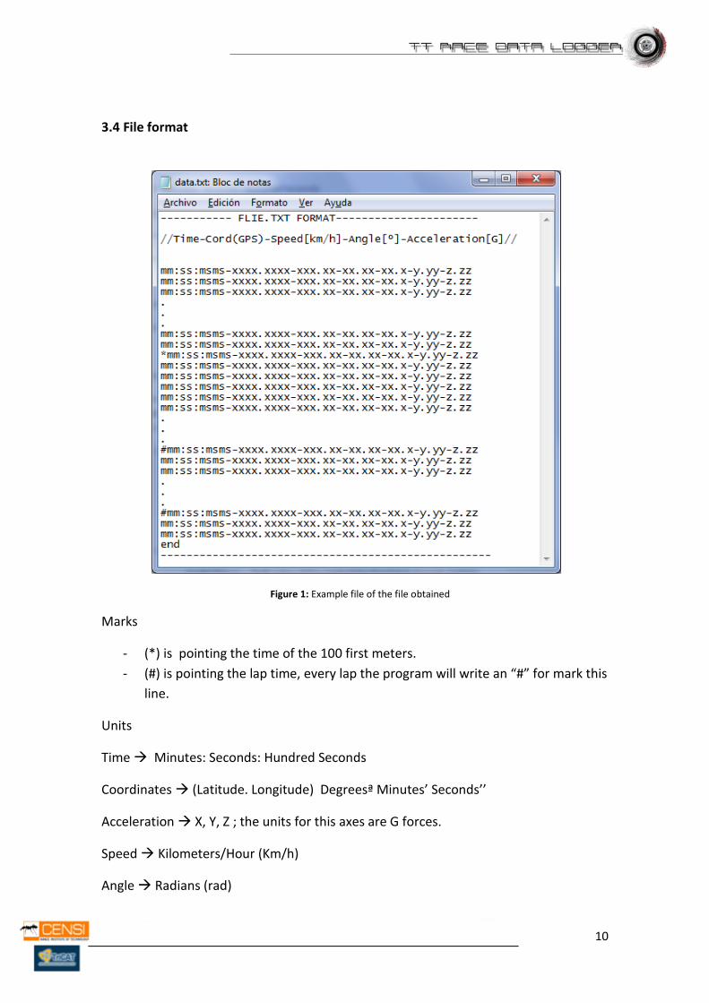
3.4 File format
Figure 1: Example file of the file obtained
Marks
- (*) is pointing the time of the 100 first meters.
- (#) is pointing the lap time, every lap the program will write an “#” for mark this
line.
Units
Time Minutes: Seconds: Hundred Seconds
Coordinates (Latitude. Longitude) Degreesª Minutes’ Seconds’’
Acceleration X, Y, Z ; the units for this axes are G forces.
Speed Kilometers/Hour (Km/h)
Angle Radians (rad)
11
3.5 Interface
This device is designed for amateur customers and it needs to have an easy and quick
installation on the motorbike with a non destructible data collector. Also it has to have
an easy extraction of the files generated.
Installation on the Motorbike (Installation needed)
Core – Somewhere, away from warm and electromagnetic sources.
RPM Sensor – Cooper solenoid coiled to ECU’s Rpm Wire or directly to
spark plug with a circuit protection.
GPS antenna – Away from the main engine solenoid and directed to
open sky.
Angle Sensor – Both sides of the motorbike fixed and strongly hold to
the chassis
Accelerometer – Placed inside of the main core or mother board.
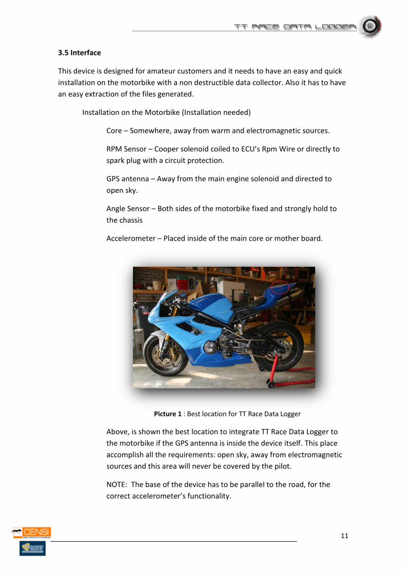
Picture 1 : Best location for TT Race Data Logger
Above, is shown the best location to integrate TT Race Data Logger to
the motorbike if the GPS antenna is inside the device itself. This place
accomplish all the requirements: open sky, away from electromagnetic
sources and this area will never be covered by the pilot.
NOTE: The base of the device has to be parallel to the road, for the
correct accelerometer’s functionality.
12
Extraction of the files:
Via Standard SD/MMC Socket (Easy to plug/unplug)
Via USB 2.0 Interface (Download the Files directly to a Computer)
Power Duration - 3 Hour
3 Optional Inputs for more sensors
Memory – 512KB/1GB
Sensors Sample Rate – 100Hz
Chrono Step : 1/5 seconds
13
4. Study of Possibilities
A previous study of the possibilities is needed to decide the best and cheap options
that the technology offers to get the desired information. It includes a study of the
sensors, the GPS unit and where they should be placed. Also a review of how a
motorbike behaves during a race (Max suffered G’s, Cornering Angle, and engine’s
ECU’s).
4.1 Cornering, Angle Detection and Study of Gravitational forces (G’s)
One important thing on the motorbike races is the manner that the pilot is turning on the corner, this action has to be perfect to do it as fast as possible. To improve this, is important to know how the pilot is taking every corner. So is needed a system capable to measure the angle of the motorbike on each corner.
To resolve this problem we have thought of an accelerometer, with it we could take the angle, doing some calculations with the values given by this device.
Here some information about the accelerations suffer by the motorbike.
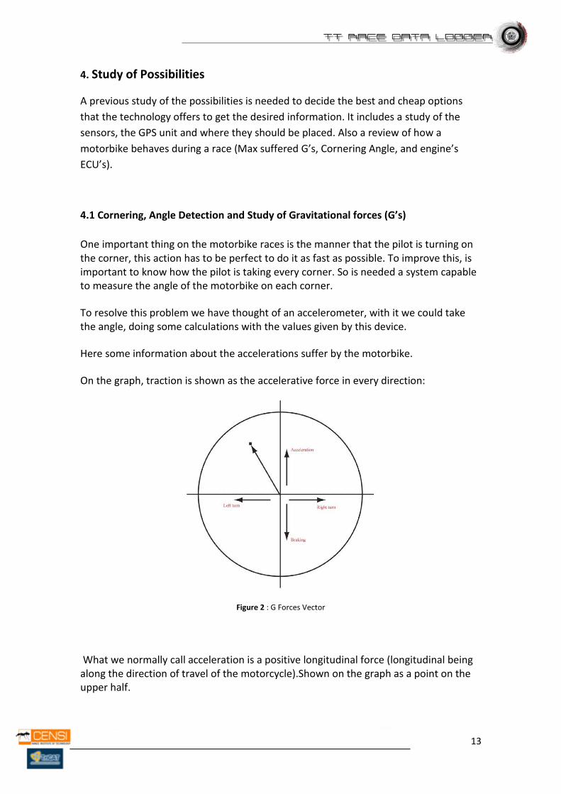
On the graph, traction is shown as the accelerative force in every direction:
Figure 2 : G Forces Vector
What we normally call acceleration is a positive longitudinal force (longitudinal being along the direction of travel of the motorcycle).Shown on the graph as a point on the upper half.
14
Braking is a negative longitudinal force, shown on the bottom half of the graph. Cornering generates lateral forces, generally felt as centrifugal force when you're in a car, for instance. On the traction circle, points on the right-hand side represent a right-hand turn, and vice versa.
We've covered both axis of the graph so far, but what about points away from an axis? Say you were accelerating out of a right-hand turn, generating forces in both the lateral and longitudinal directions. This would show as a point in the upper right-hand quadrant of the graph. Likewise, trail braking into a left-hand turn is displayed as a point in the bottom left-hand quadrant.
Also we have the vertically acceleration, it means that it’s possible to calculate the angle of the bike when it turns in a corner, with the acceleration forces separates in 3 axis. Each one contains the acceleration on their directions, as we told before the acceleration could be negative.
The tires on the motorcycle are capable of providing a certain level of grip in any one direction; let's say the maximum accelerative force is 1’5 G, a realistic number. This force can be applied all in one direction, such as braking or turning, or in a combination of directions-braking and turning. Since we're dealing with vector forces that are summed with a value as well as a direction, the graph of maximum grip values is shown as a circle: the traction circle with a radius of 1,5 G.
Taking the result force vector and making on it some trigonometric equations finally we could know the angle that the bike needs for remain in the road, without sliding.
If the motorbike starts to slide, the resultant angle will not be the exact one. The lateral acceleration will be highest because the motorbike is sliding, in result we will have a non exact angle.
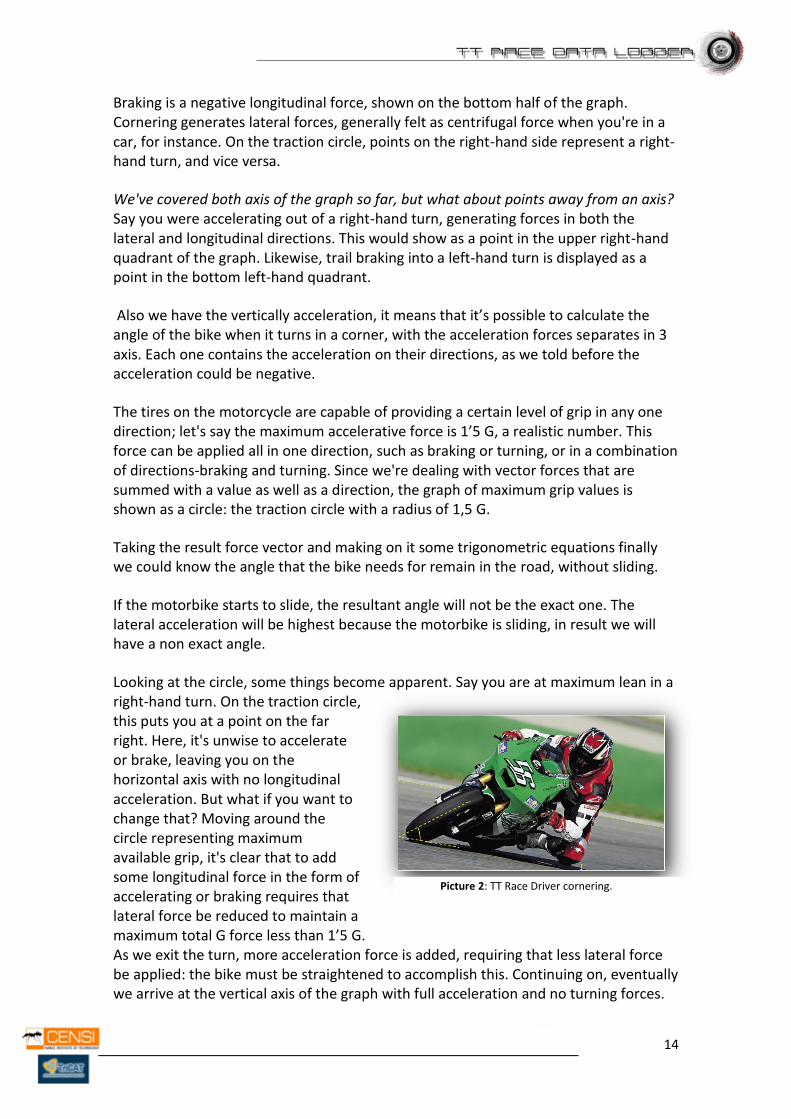
Looking at the circle, some things become apparent. Say you are at maximum lean in a right-hand turn. On the traction circle, this puts you at a point on the far right. Here, it's unwise to accelerate or brake, leaving you on the horizontal axis with no longitudinal acceleration. But what if you want to change that? Moving around the circle representing maximum available grip, it's clear that to add some longitudinal force in the form of accelerating or braking requires that lateral force be reduced to maintain a maximum total G force less than 1’5 G. As we exit the turn, more acceleration force is added, requiring that less lateral force be applied: the bike must be straightened to accomplish this. Continuing on, eventually we arrive at the vertical axis of the graph with full acceleration and no turning forces.
Picture 2: TT Race Driver cornering.
15
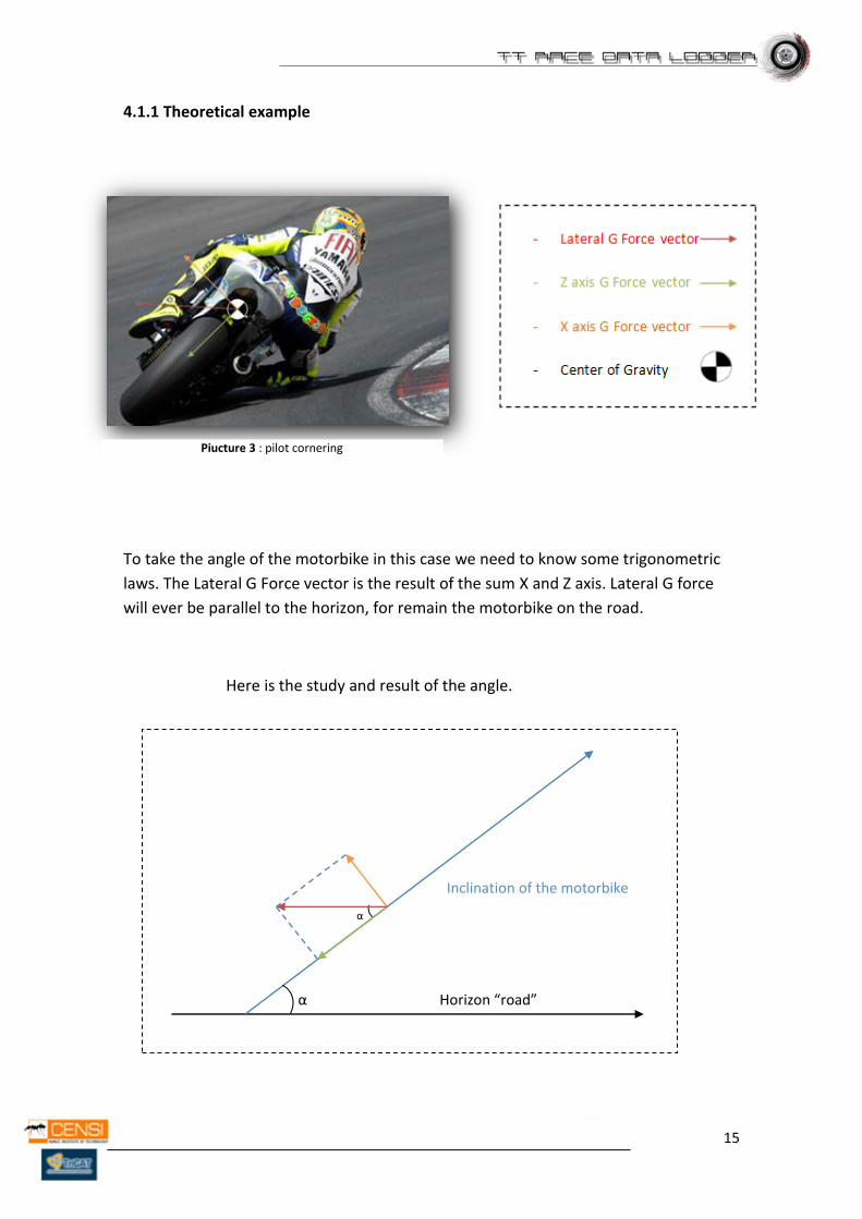
4.1.1 Theoretical example
To take the angle of the motorbike in this case we need to know some trigonometric
laws. The Lateral G Force vector is the result of the sum X and Z axis. Lateral G force
will ever be parallel to the horizon, for remain the motorbike on the road.
Here is the study and result of the angle.
Inclination of the motorbike
α
α
Horizon “road”
Piucture 3 : pilot cornering
16
Alpha “α” is the inclination angle of the motor bike, as we know our design with an
accelerometer gives to us the resultant G force on each axis, knowing the value of the
G forces X axis G Force vector and Z axis G Force vector, we could calculate the value of
the angle α.
Equation:
𝛼 = tan−1 X axis G Force vector
Z axis G Force vector
As a result of the calculations, we get the angle, also with the G forces we could
make a study of the circuit race.
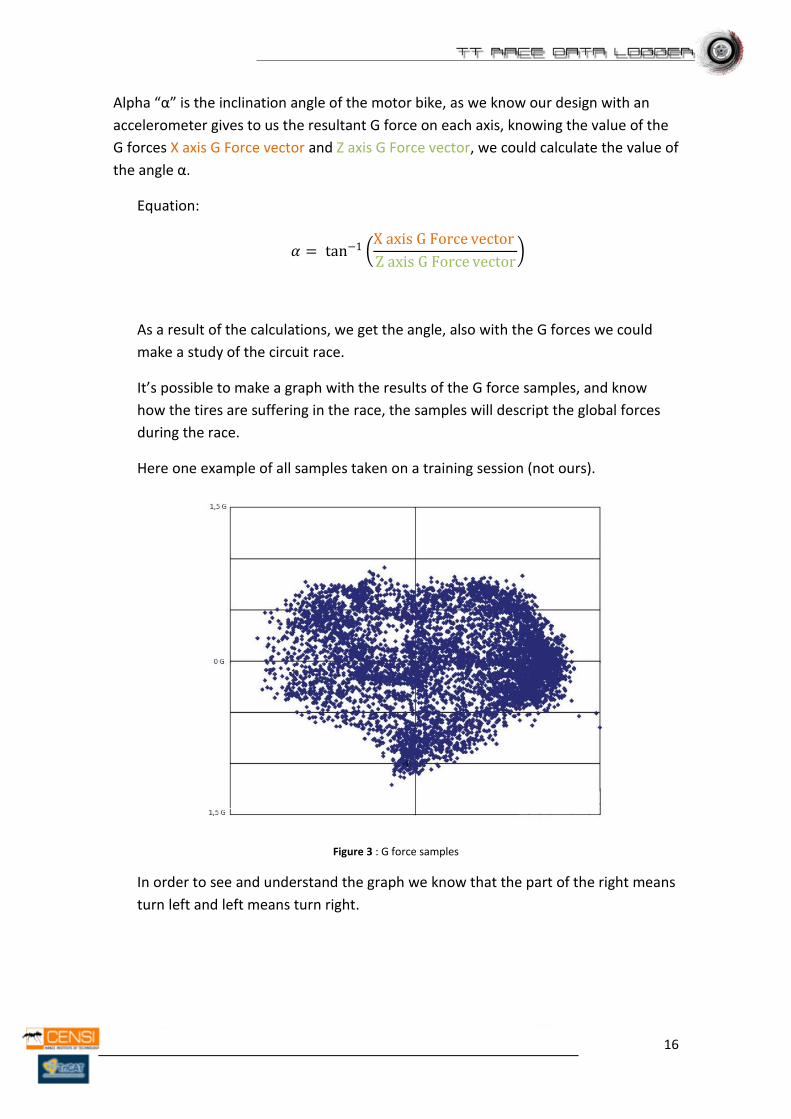
It’s possible to make a graph with the results of the G force samples, and know
how the tires are suffering in the race, the samples will descript the global forces
during the race.
Here one example of all samples taken on a training session (not ours).
Figure 3 : G force samples
In order to see and understand the graph we know that the part of the right means
turn left and left means turn right.
17
Gyroscopes tilt sensors and are tools that are capable to calculate the angle between
an already known point to another in 3 planes of the space. They are
mechanical/electrical tools it means some none desired forces applied to these sensors
are going to change the correct functionally of themselves. On the other hand, the
accelerometers gives the acceleration on 3 Axes. Knowing the forcers G’s on the
motorbike and how to calculate the angle from them an accelerometer is a good
choice.
Advantages Relative cheap for the required porpoises.
Disadvantages Relative Accuracy.
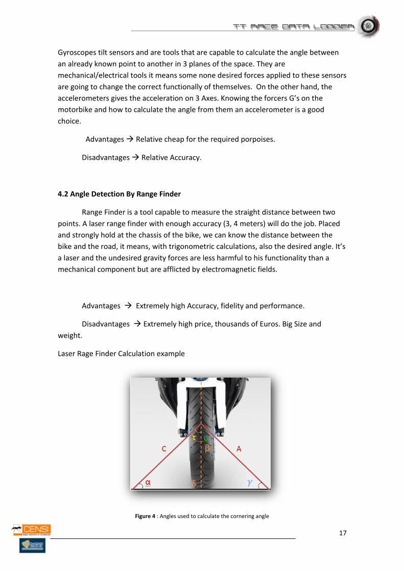
4.2 Angle Detection By Range Finder
Range Finder is a tool capable to measure the straight distance between two
points. A laser range finder with enough accuracy (3, 4 meters) will do the job. Placed
and strongly hold at the chassis of the bike, we can know the distance between the
bike and the road, it means, with trigonometric calculations, also the desired angle. It’s
a laser and the undesired gravity forces are less harmful to his functionality than a
mechanical component but are afflicted by electromagnetic fields.
Advantages Extremely high Accuracy, fidelity and performance.
Disadvantages Extremely high price, thousands of Euros. Big Size and
weight.
Laser Rage Finder Calculation example
Figure 4 : Angles used to calculate the cornering angle
18
That picture above shows the situation of the lasers on the motorbike. We need
minimum 2 lasers placed at both sides to calculate the angle. The lasers are the
segments A and C. And the desired angle is Delta. The lasers are positioned making a
90º angle between each other.
We can found Delta using trigonometric equations because the lasers provide the
value C and A all the time.
The calculations are:
With A and C:
𝐶
𝐴= tan 𝛾 → tan−1
𝐶
𝐴= 𝛾 ;
With Gamma: 𝛽 = 90° ; 𝛾 = 𝑘𝑛𝑜𝑤𝑛 ; 𝛼 = ? ;
180° = 𝛽 + 𝛾 + 𝛼 → 𝛼 = 180 − 𝛽 − 𝛾;
With Alpha: 𝜏 = 45° ; 𝛼 = 𝑘𝑛𝑜𝑤𝑛;
180° = 𝜏 + 𝛼 + 𝛿 → 𝛿 = 180 − 𝜏 − 𝛼 ;
We have got 𝛿;
It’s possible to get the desired angle only with arithmetic calculations.
19
4.3 Power Supply
It would be interesting to design an autonomous and internal power supply system to
improve performance and utility. Integrating this system, TT Race Data Logger gets
complete autonomy and has the possibility to work on his own.
A power supply is compounded by a rechargeable battery, a charging system, and
voltage regulators to deliver the desired voltage to all the sub-devices.
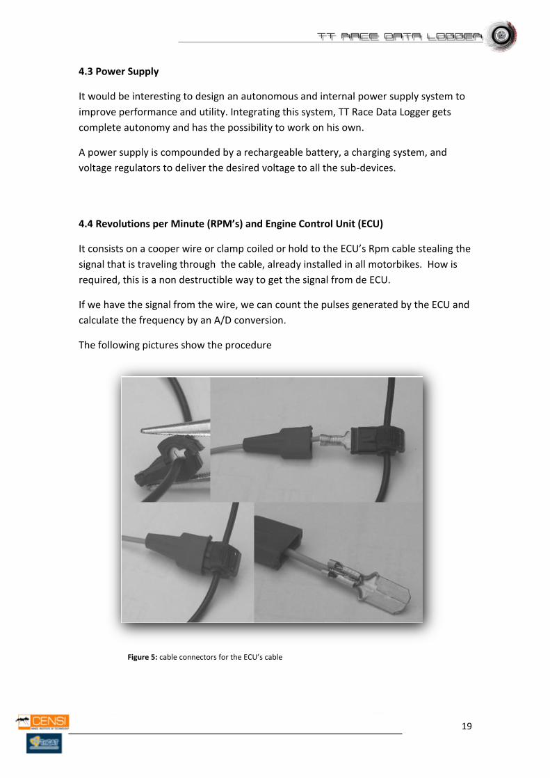
4.4 Revolutions per Minute (RPM’s) and Engine Control Unit (ECU)
It consists on a cooper wire or clamp coiled or hold to the ECU’s Rpm cable stealing the
signal that is traveling through the cable, already installed in all motorbikes. How is
required, this is a non destructible way to get the signal from de ECU.
If we have the signal from the wire, we can count the pulses generated by the ECU and
calculate the frequency by an A/D conversion.
The following pictures show the procedure
Figure 5: cable connectors for the ECU’s cable

20
Also it’s possible to do the same procedure but directly to the wire of the Spark plug
but it’s necessary some kind of circuit protection because the amperes generated by
the spark plug are really high and not accurate. If we know the amount of cylinders, we
could know the revolutions per minute.
In conclusion the best way to get the RPM’s is from the ECU.
NOTE:. It’s offered only a theoretical design and way of implementation but it won’t
be implemented in the prototype as contractor’s request because is an inaccuracy
system. It needs lot of testing and prototyping.
4.5 Speed and Position
There’s no best option than a GPS to get the Position. Is Accurate enough, cheap and
also grants the speed, date and time to our system.
It’s possible to get the speed from one of the cables from the ECU with the same
procedure as the RPM’s.
4.6 Start/End Beacon Line
Picture 4: The two Preset Points for the beacon line.
To get a preset beacon line, it is necessary to do it like is shown in the previous Picture,
its necessary two presetting points. We could make and imaginary line knowing the
difference between them.

21
4.7 Calculation time of 100 first meters
Picture 5: Vectors with a module of 100 meters
In order to know the time of the first 100 meters made by a pilot in a race, it is possible to
calculate it by different ways. We decide to do it by a vector; TT Race Data Logger has to
calculate every sample the module of the vector generated between the start position and the
current position , when the vector module size is equal to 100 meters, the device store the
time realized in those 100 meters.
The manner to do it is calculating every sample the “δ|P|” differential of the module , giving
an accuracy module vector. Then comparing the value of this vector to the cipher 100m we
obtain the time expended for it.
22
5. Hardware Requirements and Solutions
As a result of the previous investigation we decide that our TT Race Data Logger has to
include the following sub-devices to grant the desired functionality.
5.1 Mother Board / Core
Our Data Logging device needs to process the amount of data generated by the
sensors, it means we need some kind of processor to understand and store this data.
The best and cheap option is a microcontroller programmed in assembler for our
purposes. We can found the microcontroller itself but it’s necessary to design the
connections and the environment between the microcontroller and the sensors.
Another and faster way is to use a standard prototyping board that already has all of
that.
5.2 GPS Unit
To Know the position, straight acceleration, date and time is needed a GPS unit.
A Standard GPS receiver unit with antenna working with a digital protocol RX, TX, in
USART mode, with enough sample rate to get the position, the speed, the acceleration
and time from the satellites.
Try to design some system onboard to get the value of the speed and straight
acceleration it would be redundant. GPS offer to us the best way to get this
information. It’s quick and exact.
GPS Accuracy -
Initialization Start – Less than 5-30 seconds
Sample Rate- 1 Mhz
Range - 5 to 10 meters (Best on the market)
The most GPS units on the market are working with NMEA protocol and It is required a
previous study of this protocol to ensure a correct design.

23
5.2.1 The NMEA Sentence
GPS data comes in a data stream form known as NMEA sentences. NMEA is the
universal standard for information coming from GPS satellites. In particular, the NMEA-
0183 is of interest to our project. In order to use any of the data you must know what
kind of data you need. These sentences include all kinds of information about the
position, time, and direction of the receiver and this information is usually displayed
on a screen or delivered to a device or computer. Several sentences are delivered to
the receiver at once. These sentences are updated every 1 millisecond to every several
seconds depending on the receiver and the use. Each sentence contains a different
kind of data stream. Some types and examples are listed below.
Sentence Description
$GPGGA Global positioning system fixed data
$GPGLL Geographic position - latitude / longitude
$GPGSA GNSS DOP and active satellites
$GPGSV GNSS satellites in view
$GPRMC Recommended minimum specific GNSS data
$GPVTG Course over ground and ground speed Table 1: Description important kind of NMEA sentences
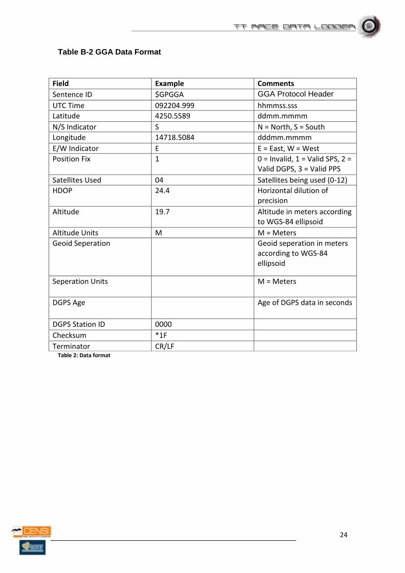
The GPGGA and GPVTG example are the most useful because our data logger cans incorporate the times, and date as well as the position, and speed. Most receivers transmit each type of sentence consecutively, each one beginning with a dollar sign and ending with a carriage return. The GPGGA example and its characteristics is listed below. Table B-2 contains the values for the following example:
GGA-Global Positioning System Fixed Data Signal not acquired: $GPGGA,235947.000,0000.0000,N,00000.0000,E,0,00,0.0,0.0,M,,,,0000*00 Example Signal acquired: $GPGGA,161229.487,3723.2475,N,12158.3416,W,1,07,1.0,9.0,M,,,,0000*18
24
Table B-2 GGA Data Format
Table 2: Data format
Field Example Comments
Sentence ID $GPGGA GGA Protocol Header
UTC Time 092204.999 hhmmss.sss
Latitude 4250.5589 ddmm.mmmm
N/S Indicator S N = North, S = South
Longitude 14718.5084 dddmm.mmmm
E/W Indicator E E = East, W = West
Position Fix 1 0 = Invalid, 1 = Valid SPS, 2 = Valid DGPS, 3 = Valid PPS
Satellites Used 04 Satellites being used (0-12)
HDOP 24.4 Horizontal dilution of precision
Altitude 19.7 Altitude in meters according to WGS-84 ellipsoid
Altitude Units M M = Meters
Geoid Seperation Geoid seperation in meters according to WGS-84 ellipsoid
Seperation Units M = Meters
DGPS Age Age of DGPS data in seconds
DGPS Station ID 0000
Checksum *1F
Terminator CR/LF
25
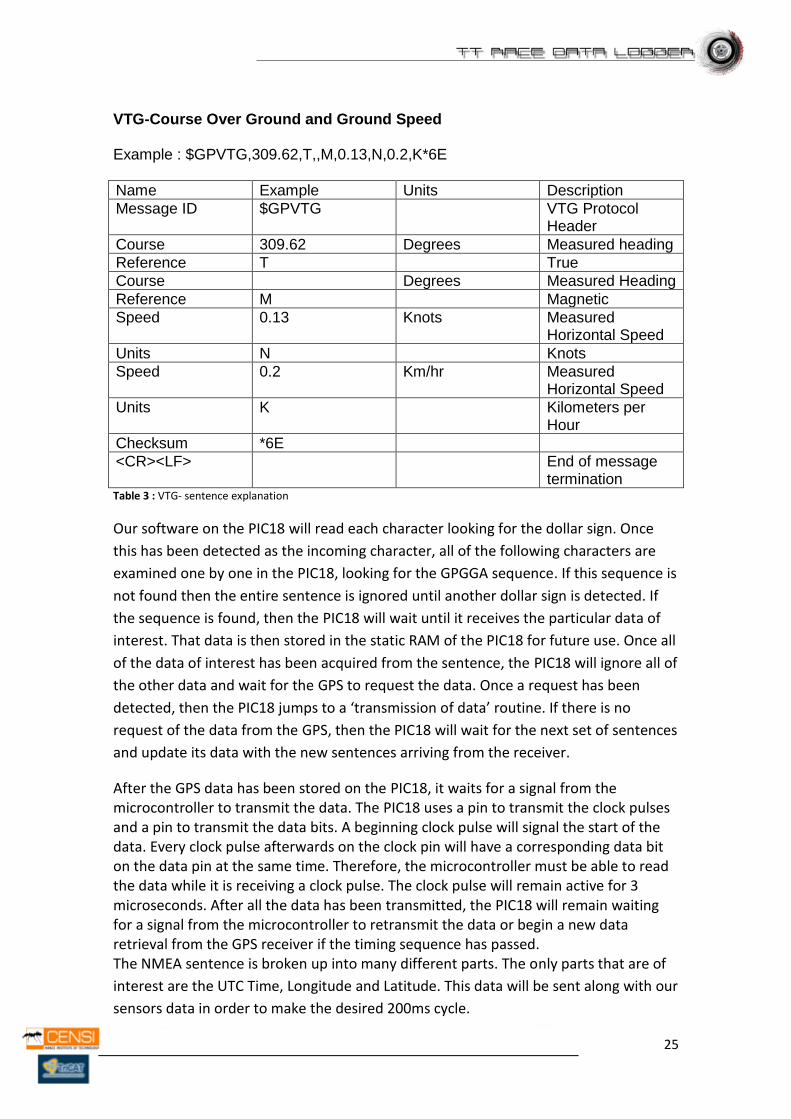
VTG-Course Over Ground and Ground Speed Example : $GPVTG,309.62,T,,M,0.13,N,0.2,K*6E
Name Example Units Description
Message ID $GPVTG VTG Protocol Header
Course 309.62 Degrees Measured heading
Reference T True
Course Degrees Measured Heading
Reference M Magnetic
Speed 0.13 Knots Measured Horizontal Speed
Units N Knots
Speed 0.2 Km/hr Measured Horizontal Speed
Units K Kilometers per Hour
Checksum *6E
<CR><LF> End of message termination
Table 3 : VTG- sentence explanation
Our software on the PIC18 will read each character looking for the dollar sign. Once
this has been detected as the incoming character, all of the following characters are
examined one by one in the PIC18, looking for the GPGGA sequence. If this sequence is
not found then the entire sentence is ignored until another dollar sign is detected. If
the sequence is found, then the PIC18 will wait until it receives the particular data of
interest. That data is then stored in the static RAM of the PIC18 for future use. Once all
of the data of interest has been acquired from the sentence, the PIC18 will ignore all of
the other data and wait for the GPS to request the data. Once a request has been
detected, then the PIC18 jumps to a ‘transmission of data’ routine. If there is no
request of the data from the GPS, then the PIC18 will wait for the next set of sentences
and update its data with the new sentences arriving from the receiver.
After the GPS data has been stored on the PIC18, it waits for a signal from the microcontroller to transmit the data. The PIC18 uses a pin to transmit the clock pulses and a pin to transmit the data bits. A beginning clock pulse will signal the start of the data. Every clock pulse afterwards on the clock pin will have a corresponding data bit on the data pin at the same time. Therefore, the microcontroller must be able to read the data while it is receiving a clock pulse. The clock pulse will remain active for 3 microseconds. After all the data has been transmitted, the PIC18 will remain waiting for a signal from the microcontroller to retransmit the data or begin a new data retrieval from the GPS receiver if the timing sequence has passed. The NMEA sentence is broken up into many different parts. The only parts that are of
interest are the UTC Time, Longitude and Latitude. This data will be sent along with our
sensors data in order to make the desired 200ms cycle.
26
5.3 Display
A standard 16x2 LCD display is added to improve the interaction between the user and
the device. Different text messages could show the different states of the TT Race Data
Logger.
5.4 Accelerometer
It’s required an electronic component to provide us the horizontal force in G’s with a
factor of 9,8 m/s2 and X,Y,Z dimensions. Capable of endure the max. G’s suffered
during a professional race.
5.5 Removable Memory
To store the files generated is needed a big memory, EPROM’s memory modules are
usually too small to store such data, an Standard Removable Memory ( Mini SD / SD )
has the perfect performance and size to this work, with a FAT 16 System , 2GB
maximum size. It will be the best choice.
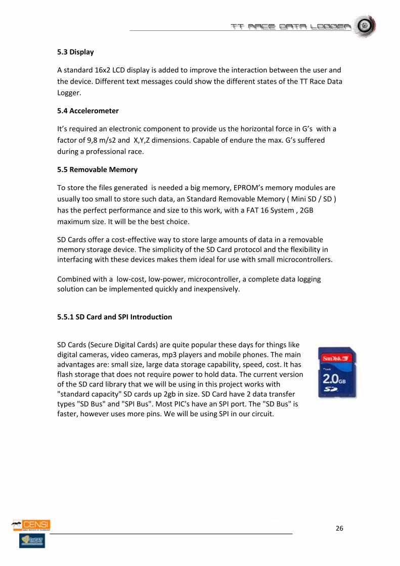
SD Cards offer a cost-effective way to store large amounts of data in a removable memory storage device. The simplicity of the SD Card protocol and the flexibility in interfacing with these devices makes them ideal for use with small microcontrollers. Combined with a low-cost, low-power, microcontroller, a complete data logging solution can be implemented quickly and inexpensively.
5.5.1 SD Card and SPI Introduction
SD Cards (Secure Digital Cards) are quite popular these days for things like digital cameras, video cameras, mp3 players and mobile phones. The main advantages are: small size, large data storage capability, speed, cost. It has flash storage that does not require power to hold data. The current version of the SD card library that we will be using in this project works with "standard capacity" SD cards up 2gb in size. SD Card have 2 data transfer types "SD Bus" and "SPI Bus". Most PIC's have an SPI port. The "SD Bus" is faster, however uses more pins. We will be using SPI in our circuit.
27
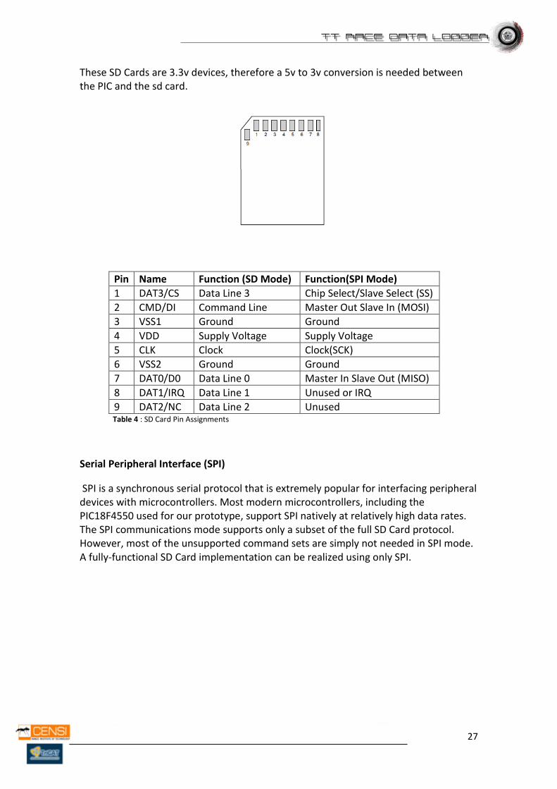
These SD Cards are 3.3v devices, therefore a 5v to 3v conversion is needed between the PIC and the sd card.
Pin Name Function (SD Mode) Function(SPI Mode)
1 DAT3/CS Data Line 3 Chip Select/Slave Select (SS)
2 CMD/DI Command Line Master Out Slave In (MOSI)
3 VSS1 Ground Ground
4 VDD Supply Voltage Supply Voltage
5 CLK Clock Clock(SCK)
6 VSS2 Ground Ground
7 DAT0/D0 Data Line 0 Master In Slave Out (MISO)
8 DAT1/IRQ Data Line 1 Unused or IRQ
9 DAT2/NC Data Line 2 Unused Table 4 : SD Card Pin Assignments
Serial Peripheral Interface (SPI)
SPI is a synchronous serial protocol that is extremely popular for interfacing peripheral devices with microcontrollers. Most modern microcontrollers, including the PIC18F4550 used for our prototype, support SPI natively at relatively high data rates. The SPI communications mode supports only a subset of the full SD Card protocol. However, most of the unsupported command sets are simply not needed in SPI mode. A fully-functional SD Card implementation can be realized using only SPI.
28
5.6 USB Interface
USB is the most common and reliable bus connection between a
device and a computer. It’s strong, quick, durable and easy to
plug/unplug.
It’s necessary an USB 1.0/2.0 interface to be able to download the data from the
removable memory to any computer recognizing our data logging as Mass Storage
Device or Car Reader.
Microchip offers a large number of free license libraries with datasheets created to be
used with their components. With them is possible to design a perfect USB interface
with all kind of devices, in our case with a Computer.
Further in this document, in “prototype algorithm code” we will explain the
functionality and how they are implemented together with the data logging code.
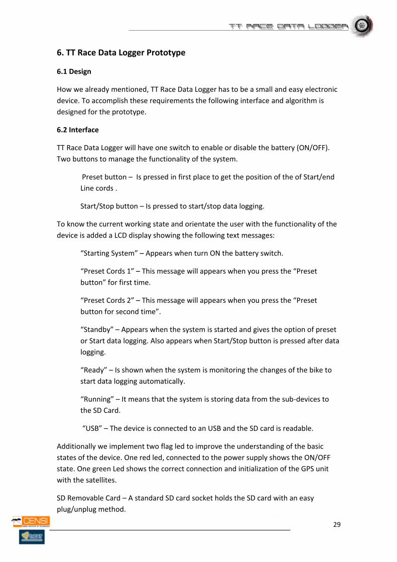
5.7 Power Supply
Li-On batteries have the best endurance and performance for small
electronic devices. They are small, safe, cheap, have long-life,
rechargeable with quick charge and long durability. It will be
interesting that TT Race Data Logger owns one of them.
If we use a Li-On battery we need some charging system to recharge it. In the market
we can found some chips specially designed for this labor. The MCP73863 is a highly
advanced linear charge management controller for use in space limited, high
performance applications. The MCP73863 integrates most of the external components
(pass transistor, reverse blocking protection, current sensing) and combines high-
accuracy constant voltage/constant current regulation, cell preconditioning, cell
temperature monitoring, advanced safety timers, automatic charge termination, and
charge status and fault indication in a small 16-pin 4mm x 4mm QFN package.
29
6. TT Race Data Logger Prototype
6.1 Design
How we already mentioned, TT Race Data Logger has to be a small and easy electronic
device. To accomplish these requirements the following interface and algorithm is
designed for the prototype.
6.2 Interface
TT Race Data Logger will have one switch to enable or disable the battery (ON/OFF).
Two buttons to manage the functionality of the system.
Preset button – Is pressed in first place to get the position of the of Start/end
Line cords .
Start/Stop button – Is pressed to start/stop data logging.
To know the current working state and orientate the user with the functionality of the
device is added a LCD display showing the following text messages:
“Starting System” – Appears when turn ON the battery switch.
“Preset Cords 1” – This message will appears when you press the “Preset
button” for first time.
“Preset Cords 2” – This message will appears when you press the “Preset
button for second time”.
“Standby” – Appears when the system is started and gives the option of preset
or Start data logging. Also appears when Start/Stop button is pressed after data
logging.
“Ready” – Is shown when the system is monitoring the changes of the bike to
start data logging automatically.
“Running” – It means that the system is storing data from the sub-devices to
the SD Card.
“USB” – The device is connected to an USB and the SD card is readable.
Additionally we implement two flag led to improve the understanding of the basic
states of the device. One red led, connected to the power supply shows the ON/OFF
state. One green Led shows the correct connection and initialization of the GPS unit
with the satellites.
SD Removable Card – A standard SD card socket holds the SD card with an easy
plug/unplug method.
30
USB – The prototype provides this interface to read the SD card from a PC. How we
said before, TT Race Data Logger will be recognized by a PC as Mass Storage Device,
working with a standard driver provided by Microsoft. It won’t be necessary any
previous configuration, just plug it.
6.3 Algorithm
The entire functionality of the TT Race Data Logger will be defined by a Synchronous
State Algorithm.
The different States and their explanations are:
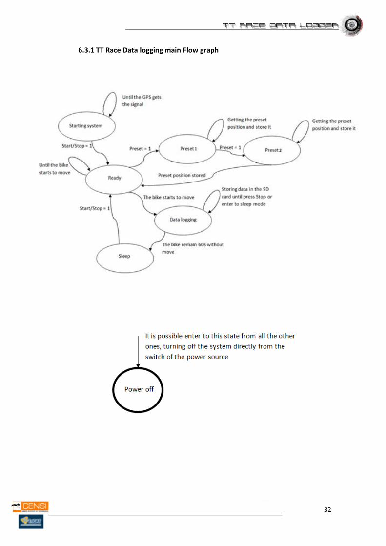
Starting System – Switch is turned ON. System is starting and configuring the
device. Led red will be lighting until power switch is turned OFF. This state will
remain until the GPS unit gets the signal from the satellites ( 1 - 30 Seconds).
Led green will be lighting to proof that this process was successful. LCD display
will show the message “Starting System” during all the Sate. Next state is state
“ready”.
Standby/Sleep State - The devices enter automatically to this state from the
Ready State, giving the option to the user to push the preset button to get the
actual position or press Start/Stop Button to start the Data Logging without any
preset. This state is a standby state; the device is only waiting the interaction of
the user. Next State is “Preset State” or “Ready State”. LCD display will show
during all this state the message “Standby”.
Preset1 State - When the “Preset Button” is pressed, the device enter to this
state, getting the coordinates of the TT Race Data Logger at this moment. There
are two Preset Points for make the imaginary beacon line. Allegedly, Start/End
line from the race circuit. If this coordinates are already stored in the device by
a previous preset, this state is optional. This state remains active during 3
seconds since the Preset Button was pressed. LCD Display will show during
these 3 seconds the message “Preset Cords 1”. Next state is “Preset2 State”.
Preset2 State – Second Preset to get the second Spot of the start line. Next
state is Ready State after press start/stop button. LCD will show “Preset Cords
2” also during 3 seconds.
Ready State – Had been pressed “Start/Stop Button” the device enter to Ready
state, in this state where the device is collecting data from the accelerometer
and the GPS, monitoring the G’s and the position. This state needs to process
the data from the accelerometer and the GPS but it’s not necessary to be
stored. It’s included to give the device the possibility to realize when the race
starts and the bike is moving. Any promptly change will start automatically the
31
next state, “data logging state”, it means store incoming data to the SD Card.
LCD display will show the message “Ready”.
Data Logging State – The device enter to this state when the bike is moving. It’s
processing the A/D channels and the GPS data, calculating the Angle, suffered
G’s, speed, position, time, lap time, date, 100 meters time. An average of these
values will be stored on the SD card with a cycle of 200ms. The algorithm for
the calculations is designed to accomplish the starting required performance.
Minimum sensor sample rate 100Hz. This state will remain until Start/Stop is
pressed or the detection of any movement during 60 seconds on the device
(changes on G’s and Position) automatically stops data logging. Next State is
“Standby/Sleep State”. LCD display will give the message “Running”.
32
6.3.1 TT Race Data logging main Flow graph
33
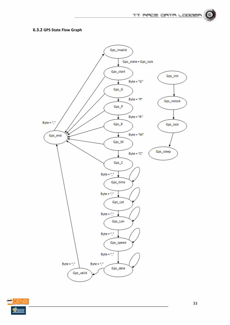
6.3.2 GPS State Flow Graph
34
6.4 Implementation
Algorithm
The implementation of the algorithm for the TT Race Data Logger is programmed with
embeds code and C language. Following the typical structure of an embed project
working with files in *.h (Libraries) and .c (Includes) extensions.
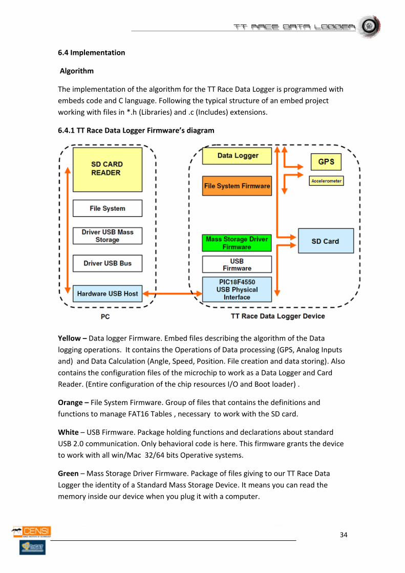
6.4.1 TT Race Data Logger Firmware’s diagram
Yellow – Data logger Firmware. Embed files describing the algorithm of the Data
logging operations. It contains the Operations of Data processing (GPS, Analog Inputs
and) and Data Calculation (Angle, Speed, Position. File creation and data storing). Also
contains the configuration files of the microchip to work as a Data Logger and Card
Reader. (Entire configuration of the chip resources I/O and Boot loader) .
Orange – File System Firmware. Group of files that contains the definitions and
functions to manage FAT16 Tables , necessary to work with the SD card.
White – USB Firmware. Package holding functions and declarations about standard
USB 2.0 communication. Only behavioral code is here. This firmware grants the device
to work with all win/Mac 32/64 bits Operative systems.
Green – Mass Storage Driver Firmware. Package of files giving to our TT Race Data
Logger the identity of a Standard Mass Storage Device. It means you can read the
memory inside our device when you plug it with a computer.
35
Blue – USB Physical Interface. Files configuring the SPI communication of the chip to
work through USB interface.
USB Interface and SD Card
The whole USB and SD Card interface is designed with the Microchip’s USB 2.0
Firmware and “Mass Storage Driver Firmware” Libraries.
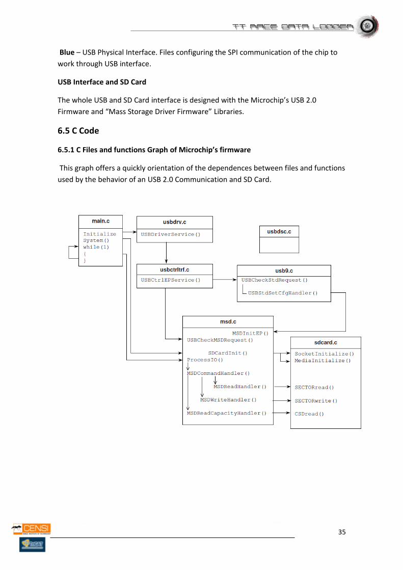
6.5 C Code
6.5.1 C Files and functions Graph of Microchip’s firmware
This graph offers a quickly orientation of the dependences between files and functions
used by the behavior of an USB 2.0 Communication and SD Card.
36
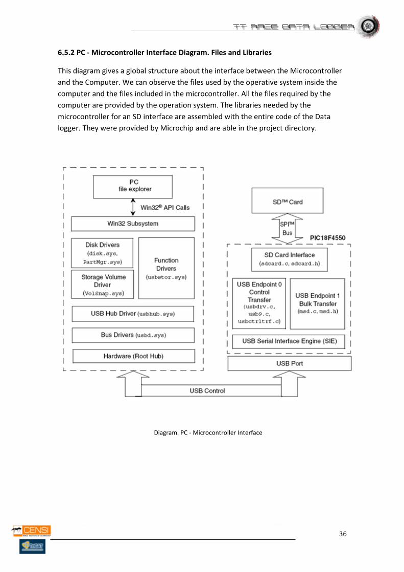
6.5.2 PC - Microcontroller Interface Diagram. Files and Libraries
This diagram gives a global structure about the interface between the Microcontroller
and the Computer. We can observe the files used by the operative system inside the
computer and the files included in the microcontroller. All the files required by the
computer are provided by the operation system. The libraries needed by the
microcontroller for an SD interface are assembled with the entire code of the Data
logger. They were provided by Microchip and are able in the project directory.
Diagram. PC - Microcontroller Interface
37
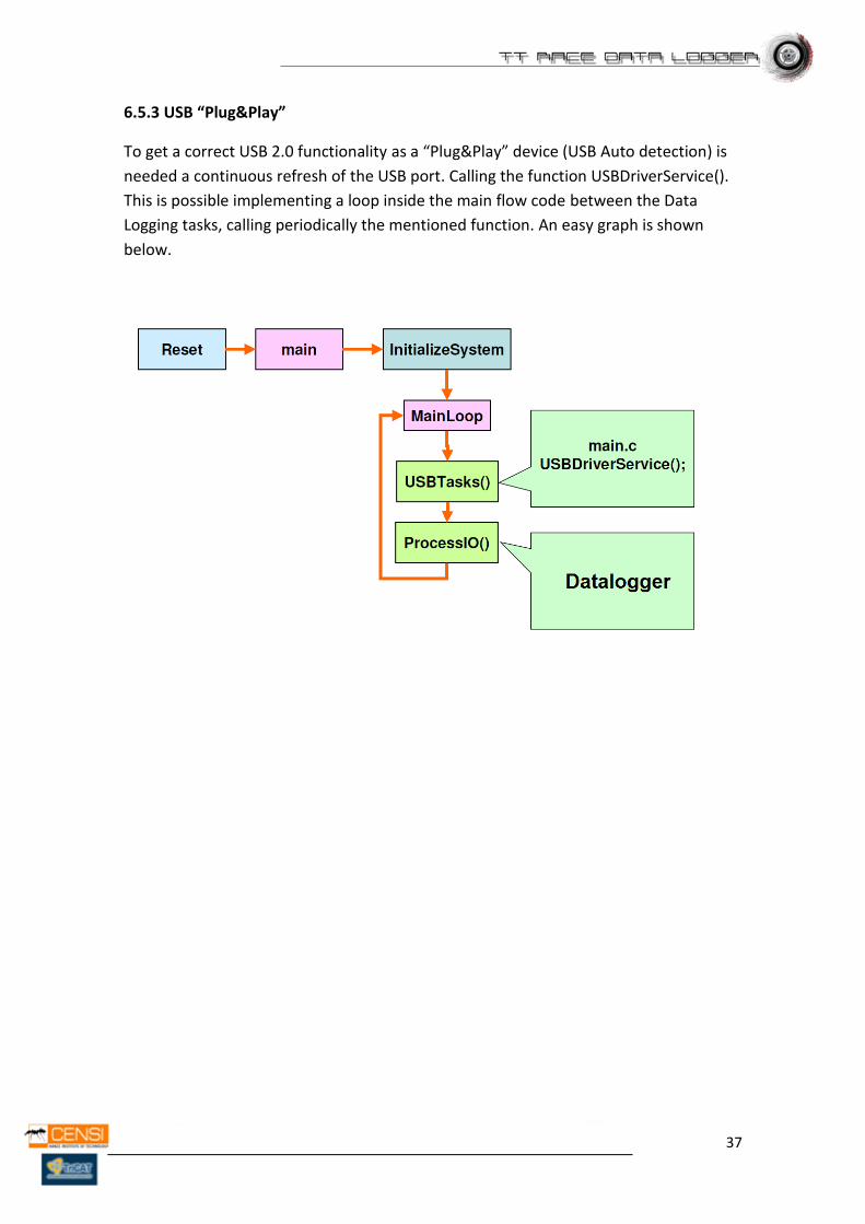
6.5.3 USB “Plug&Play”
To get a correct USB 2.0 functionality as a “Plug&Play” device (USB Auto detection) is
needed a continuous refresh of the USB port. Calling the function USBDriverService().
This is possible implementing a loop inside the main flow code between the Data
Logging tasks, calling periodically the mentioned function. An easy graph is shown
below.
38
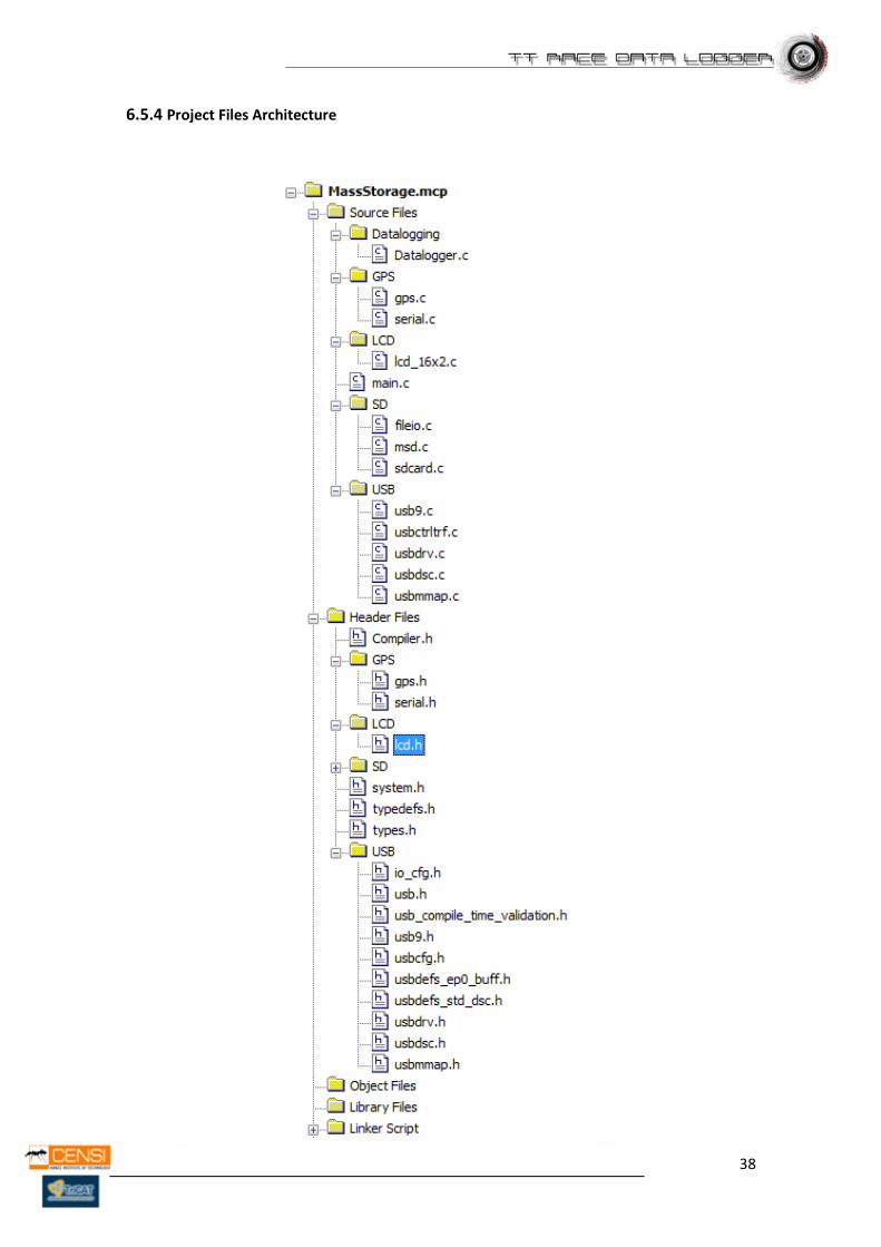
6.5.4 Project Files Architecture
39
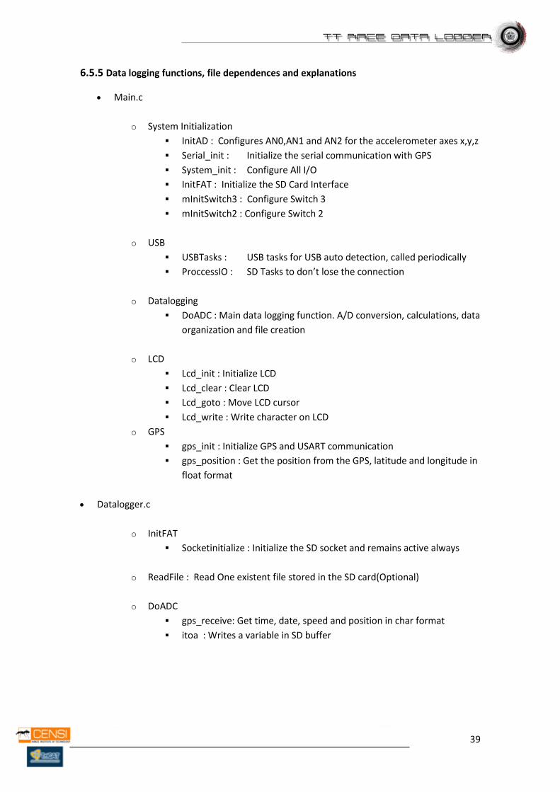
6.5.5 Data logging functions, file dependences and explanations
Main.c
o System Initialization
InitAD : Configures AN0,AN1 and AN2 for the accelerometer axes x,y,z
Serial_init : Initialize the serial communication with GPS
System_init : Configure All I/O
InitFAT : Initialize the SD Card Interface
mInitSwitch3 : Configure Switch 3
mInitSwitch2 : Configure Switch 2
o USB
USBTasks : USB tasks for USB auto detection, called periodically
ProccessIO : SD Tasks to don’t lose the connection
o Datalogging
DoADC : Main data logging function. A/D conversion, calculations, data
organization and file creation
o LCD
Lcd_init : Initialize LCD
Lcd_clear : Clear LCD
Lcd_goto : Move LCD cursor
Lcd_write : Write character on LCD
o GPS
gps_init : Initialize GPS and USART communication
gps_position : Get the position from the GPS, latitude and longitude in
float format
Datalogger.c
o InitFAT
Socketinitialize : Initialize the SD socket and remains active always
o ReadFile : Read One existent file stored in the SD card(Optional)
o DoADC
gps_receive: Get time, date, speed and position in char format
itoa : Writes a variable in SD buffer
40
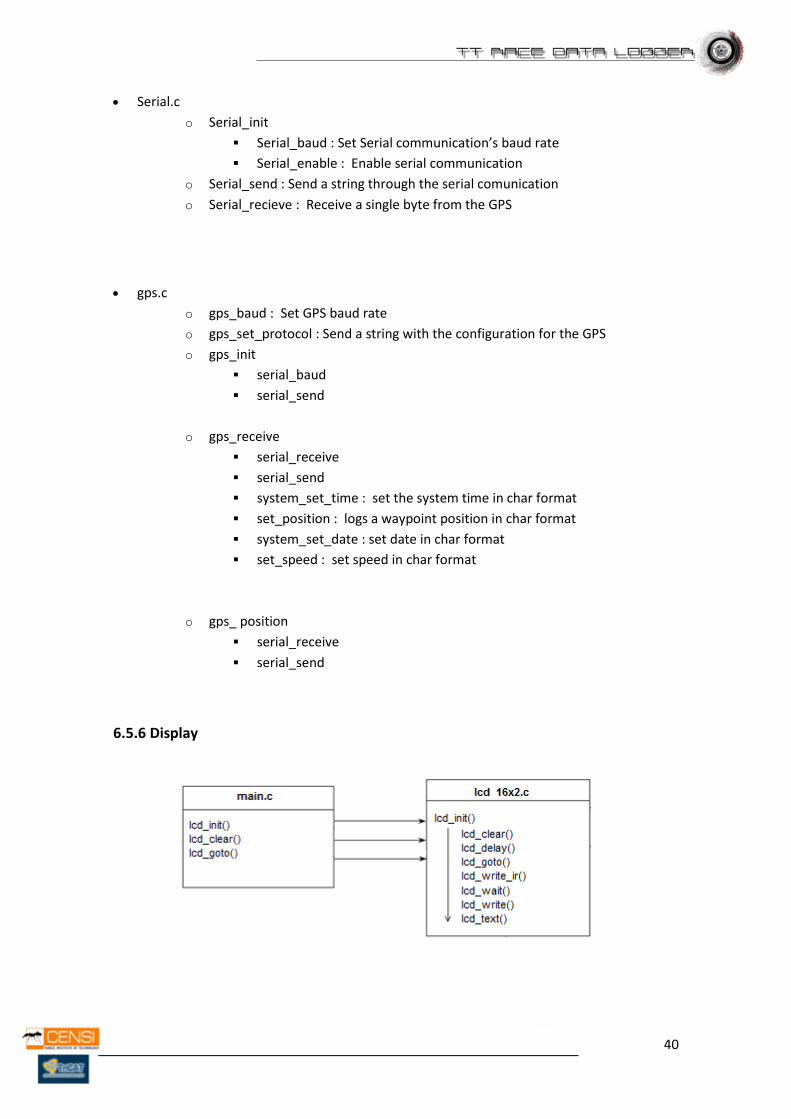
Serial.c
o Serial_init
Serial_baud : Set Serial communication’s baud rate
Serial_enable : Enable serial communication
o Serial_send : Send a string through the serial comunication
o Serial_recieve : Receive a single byte from the GPS
gps.c
o gps_baud : Set GPS baud rate
o gps_set_protocol : Send a string with the configuration for the GPS
o gps_init
serial_baud
serial_send
o gps_receive
serial_receive
serial_send
system_set_time : set the system time in char format
set_position : logs a waypoint position in char format
system_set_date : set date in char format
set_speed : set speed in char format
o gps_ position
serial_receive
serial_send
6.5.6 Display
41
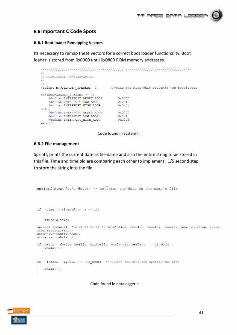
6.6 Important C Code Spots
6.6.1 Boot loader Remapping Vectors
Its necessary to remap these vectors for a correct boot loader functionality. Boot
loader is stored from 0x0000 until 0x0800 ROM memory addresses.
Code found in system.h
6.6.2 File management
Sprintf, prints the current date as file name and also the entire string to be stored in
this file. Time and time old are comparing each other to implement 1/5 second step
to store the string into the file.
Code found in datalogger.c
42
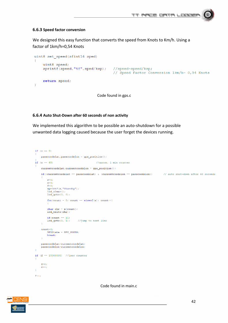
6.6.3 Speed factor conversion
We designed this easy function that converts the speed from Knots to Km/h. Using a
factor of 1km/h=0,54 Knots
Code found in gps.c
6.6.4 Auto Shut-Down after 60 seconds of non activity
We implemented this algorithm to be possible an auto-shutdown for a possible
unwanted data logging caused because the user forget the devices running.
Code found in main.c
43
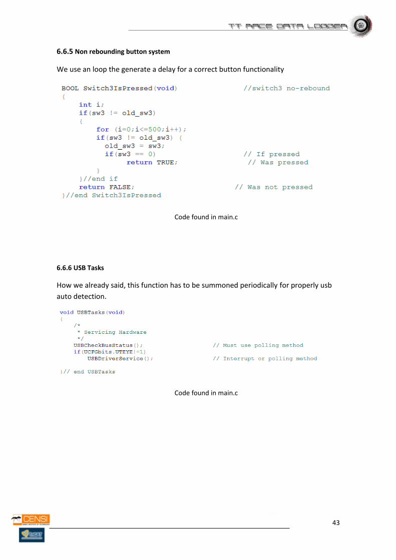
6.6.5 Non rebounding button system
We use an loop the generate a delay for a correct button functionality
Code found in main.c
6.6.6 USB Tasks
How we already said, this function has to be summoned periodically for properly usb
auto detection.
Code found in main.c
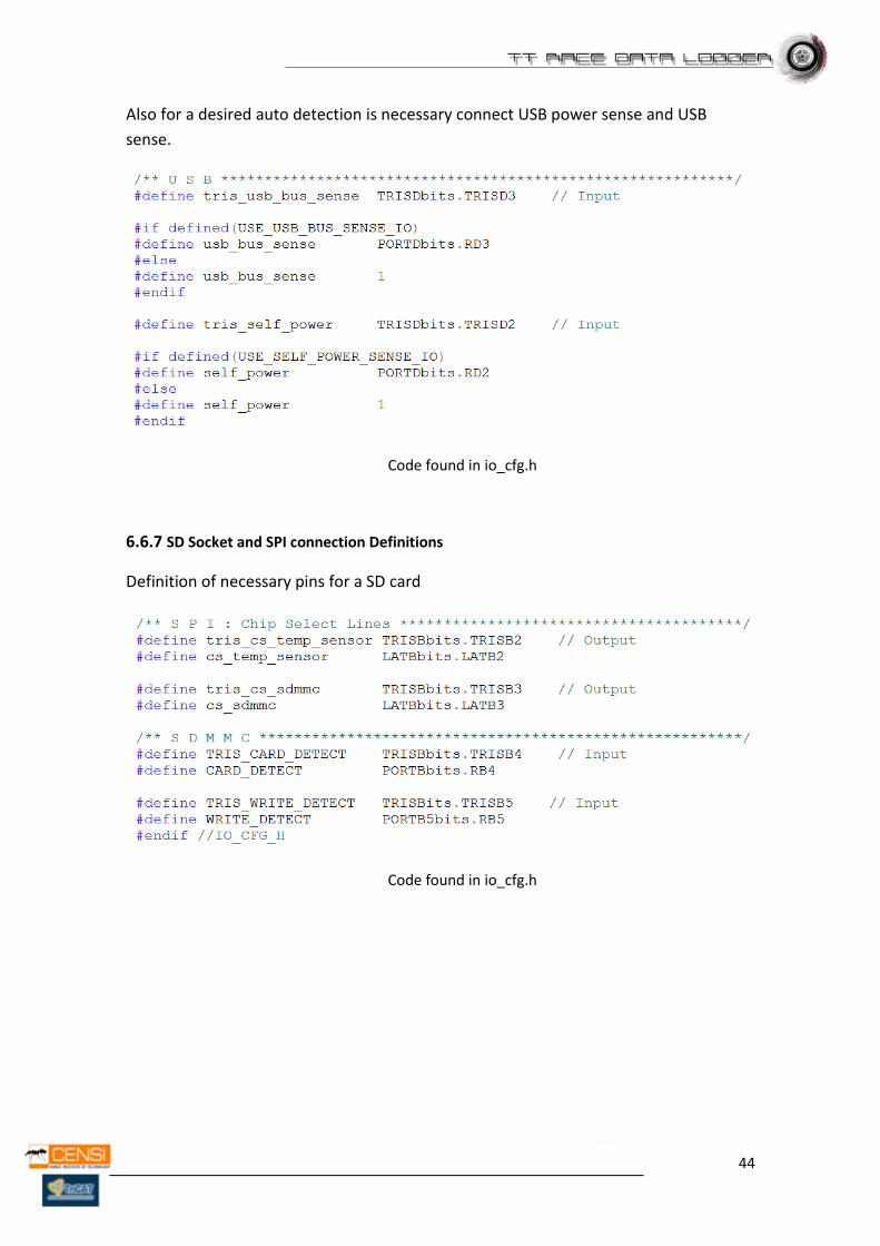
44
Also for a desired auto detection is necessary connect USB power sense and USB
sense.
Code found in io_cfg.h
6.6.7 SD Socket and SPI connection Definitions
Definition of necessary pins for a SD card
Code found in io_cfg.h
45
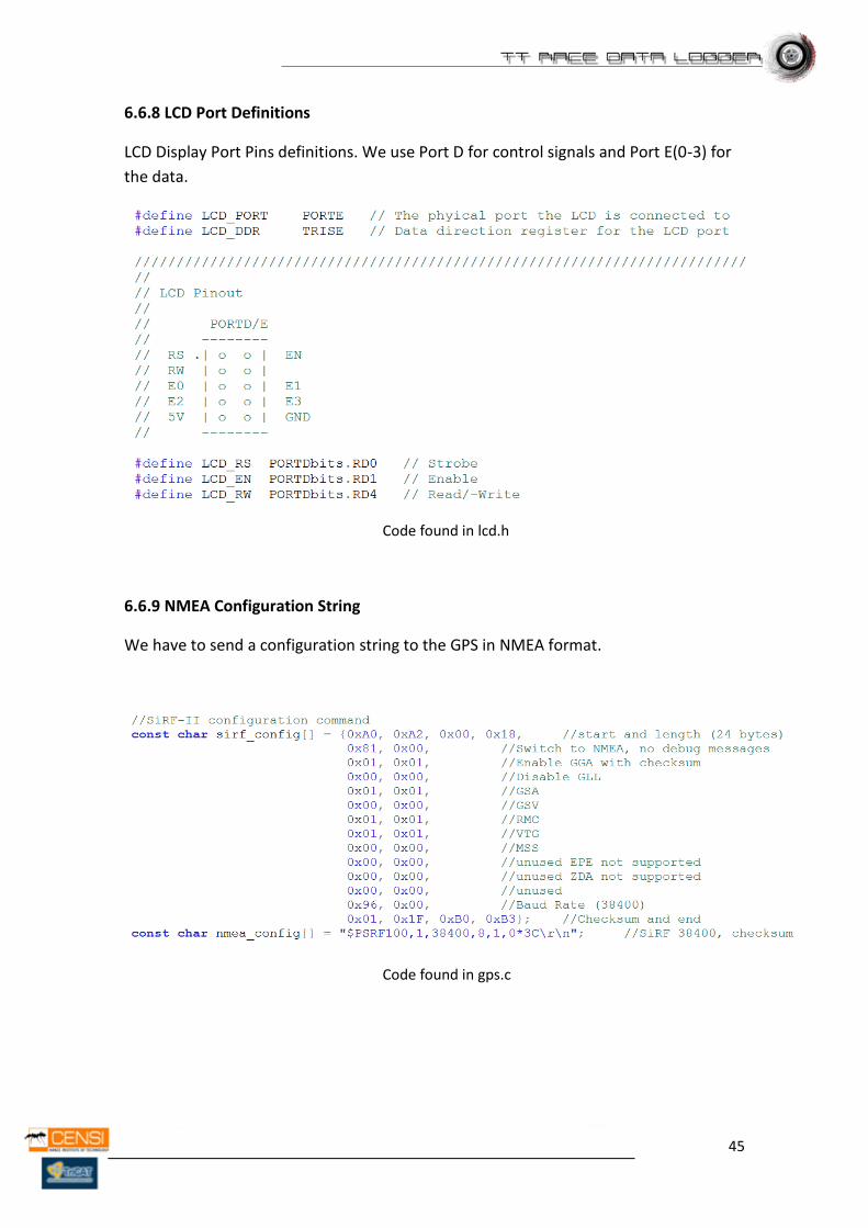
6.6.8 LCD Port Definitions
LCD Display Port Pins definitions. We use Port D for control signals and Port E(0-3) for
the data.
Code found in lcd.h
6.6.9 NMEA Configuration String
We have to send a configuration string to the GPS in NMEA format.
Code found in gps.c
46
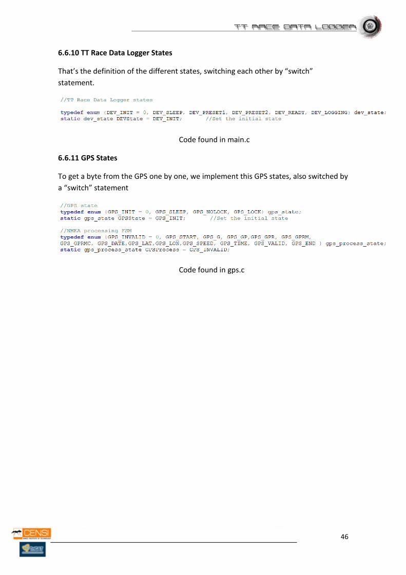
6.6.10 TT Race Data Logger States
That’s the definition of the different states, switching each other by “switch”
statement.
Code found in main.c
6.6.11 GPS States
To get a byte from the GPS one by one, we implement this GPS states, also switched by
a “switch” statement
Code found in gps.c
47
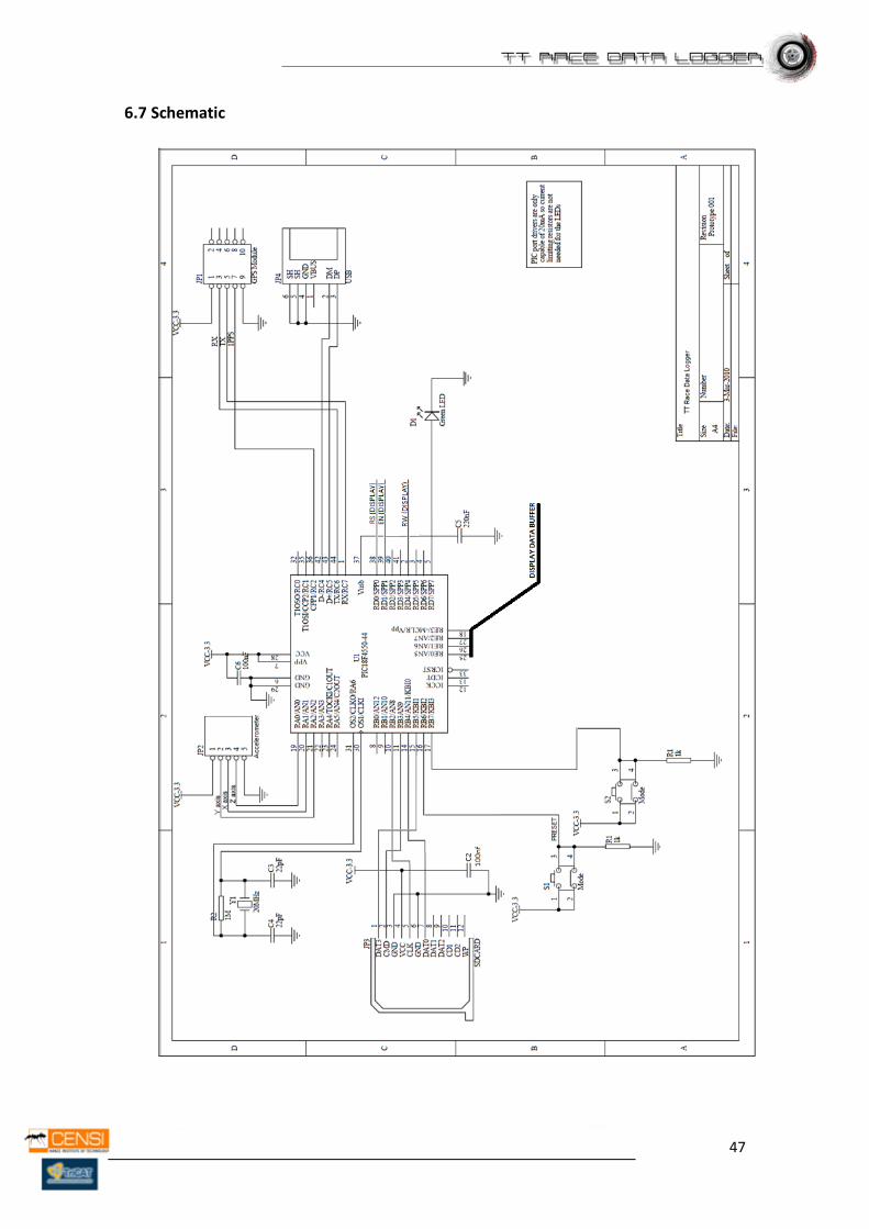
6.7 Schematic
48
6.8 Components pin wire connection in the prototype
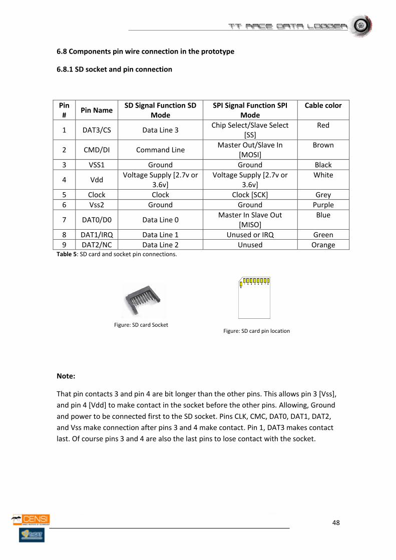
6.8.1 SD socket and pin connection
Pin #
Pin Name SD Signal Function SD
Mode SPI Signal Function SPI
Mode Cable color
1 DAT3/CS Data Line 3 Chip Select/Slave Select
[SS] Red
2 CMD/DI Command Line Master Out/Slave In
[MOSI] Brown
3 VSS1 Ground Ground Black
4 Vdd Voltage Supply [2.7v or
3.6v] Voltage Supply [2.7v or
3.6v] White
5 Clock Clock Clock [SCK] Grey
6 Vss2 Ground Ground Purple
7 DAT0/D0 Data Line 0 Master In Slave Out
[MISO] Blue
8 DAT1/IRQ Data Line 1 Unused or IRQ Green
9 DAT2/NC Data Line 2 Unused Orange Table 5: SD card and socket pin connections.
Note:
That pin contacts 3 and pin 4 are bit longer than the other pins. This allows pin 3 [Vss],
and pin 4 [Vdd] to make contact in the socket before the other pins. Allowing, Ground
and power to be connected first to the SD socket. Pins CLK, CMC, DAT0, DAT1, DAT2,
and Vss make connection after pins 3 and 4 make contact. Pin 1, DAT3 makes contact
last. Of course pins 3 and 4 are also the last pins to lose contact with the socket.
Figure: SD card pin location Figure: SD card Socket
49
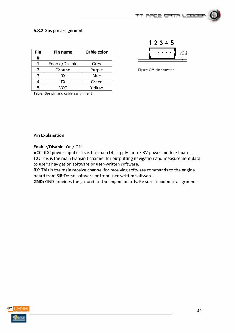
6.8.2 Gps pin assignment
Pin #
Pin name Cable color
1 Enable/Disable Grey
2 Ground Purple
3 RX Blue
4 TX Green
5 VCC Yellow Table: Gps pin and cable assignment
Pin Explanation Enable/Disable: On / Off VCC: (DC power input) This is the main DC supply for a 3.3V power module board. TX: This is the main transmit channel for outputting navigation and measurement data to user’s navigation software or user-written software. RX: This is the main receive channel for receiving software commands to the engine board from SiRfDemo software or from user-written software. GND: GND provides the ground for the engine boards. Be sure to connect all grounds.
Figure: GPS pin conector
50
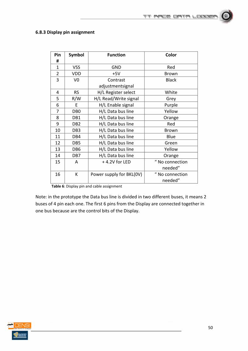
6.8.3 Display pin assignment
Pin #
Symbol Function Color
1 VSS GND Red
2 VDD +5V Brown
3 V0 Contrast adjustmentsignal
Black
4 RS H/L Register select White
5 R/W H/L Read/Write signal Grey
6 E H/L Enable signal Purple
7 DB0 H/L Data bus line Yellow
8 DB1 H/L Data bus line Orange
9 DB2 H/L Data bus line Red
10 DB3 H/L Data bus line Brown
11 DB4 H/L Data bus line Blue
12 DB5 H/L Data bus line Green
13 DB6 H/L Data bus line Yellow
14 DB7 H/L Data bus line Orange
15 A + 4.2V for LED “ No connection needed”
16 K Power supply for BKL(0V) “ No connection needed”
Table 6: Display pin and cable assignment
Note: in the prototype the Data bus line is divided in two different buses, it means 2
buses of 4 pin each one. The first 6 pins from the Display are connected together in
one bus because are the control bits of the Display.

51
6.8.4 Accelerometer pin assignment
Pin # Pin name Function Color
1 ST Self-test -No connect-
2 Z Z axis Green
3 Y Y axis Blue
4 X X axis Grey
5 GND Ground Black
6 VCC Supply Voltage (1.8 V to 3.6 V).
Red
Table 7: Accelerometer pin and cable assignment
Note: ESD CAUTION (for device manipulation)!
ESD (electrostatic discharge) sensitive device. Charged devices and
circuit boards can discharge without detection. Although this product
features patented or proprietary protection circuitry, damage may
occur on devices subjected to high energy ESD. Therefore, proper ESD
precautions should be taken to avoid performance degradation or loss
of functionality. It’s important to know this information on time to
manipulate the accelerometer.
6.8.5 Mother board pin assignment
Figure: Motherboard (SBC44UCR) pin location
52
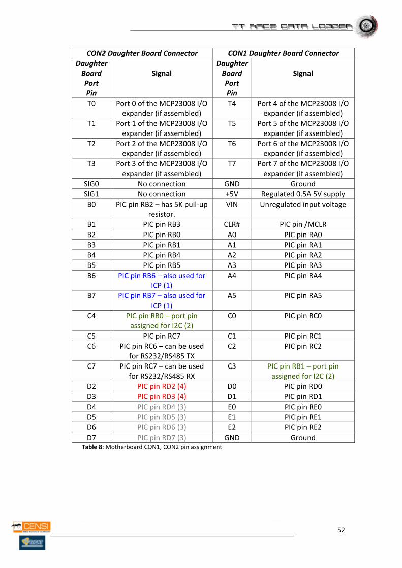
CON2 Daughter Board Connector CON1 Daughter Board Connector
Daughter Board Port Pin
Signal
Daughter Board Port Pin
Signal
T0 Port 0 of the MCP23008 I/O expander (if assembled)
T4 Port 4 of the MCP23008 I/O expander (if assembled)
T1 Port 1 of the MCP23008 I/O expander (if assembled)
T5 Port 5 of the MCP23008 I/O expander (if assembled)
T2 Port 2 of the MCP23008 I/O expander (if assembled)
T6 Port 6 of the MCP23008 I/O expander (if assembled)
T3 Port 3 of the MCP23008 I/O expander (if assembled)
T7 Port 7 of the MCP23008 I/O expander (if assembled)
SIG0 No connection GND Ground
SIG1 No connection +5V Regulated 0.5A 5V supply
B0 PIC pin RB2 – has 5K pull-up resistor.
VIN Unregulated input voltage
B1 PIC pin RB3 CLR# PIC pin /MCLR
B2 PIC pin RB0 A0 PIC pin RA0
B3 PIC pin RB1 A1 PIC pin RA1
B4 PIC pin RB4 A2 PIC pin RA2
B5 PIC pin RB5 A3 PIC pin RA3
B6 PIC pin RB6 – also used for ICP (1)
A4 PIC pin RA4
B7 PIC pin RB7 – also used for ICP (1)
A5 PIC pin RA5
C4 PIC pin RB0 – port pin assigned for I2C (2)
C0 PIC pin RC0
C5 PIC pin RC7 C1 PIC pin RC1
C6 PIC pin RC6 – can be used for RS232/RS485 TX
C2 PIC pin RC2
C7 PIC pin RC7 – can be used for RS232/RS485 RX
C3 PIC pin RB1 – port pin assigned for I2C (2)
D2 PIC pin RD2 (4) D0 PIC pin RD0
D3 PIC pin RD3 (4) D1 PIC pin RD1
D4 PIC pin RD4 (3) E0 PIC pin RE0
D5 PIC pin RD5 (3) E1 PIC pin RE1
D6 PIC pin RD6 (3) E2 PIC pin RE2
D7 PIC pin RD7 (3) GND Ground Table 8: Motherboard CON1, CON2 pin assignment
53
Note:
(1) Port Pins B6 and B7 are also used for in circuit programming, and to enter bootloader mode! If they are used, and the board should still be in circuit programmable, make sure their impedance is greater then a 1000 ohms!
(2) Port Pins C3 and C4 are connected to PIC port pins RB0 and RB1, those ports can be used for the I2C bus. When no I2C devices are used (external EEPROM or MCP23008 I/O expander for example), these ports can be used as general purpose I/O pins.
(3) If a serial FRAM chip is assembled, these pins will be used to
communicate with it. By default, there is no FRAM chip assembled, and these pins can be used for general purpose I/O pins. Pin D4 has a 5K pull-up resistor connected to it!
(4) PIC port pins RD2 and RD3 are also used for “USB Self Power Sense”
and “USB Bus Sense” inputs. If this functionality is not required, they can be used as general purpose I/O pins. They both have a 47k resistor that will pull it high or low, depending on how the board is currently powered.
54
6.9 Configuration of the connections in the prototype
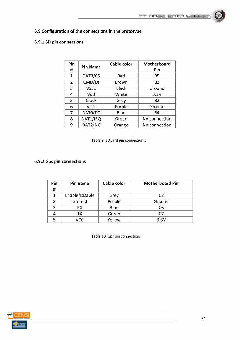
6.9.1 SD pin connections
Pin #
Pin Name Cable color Motherboard
Pin
1 DAT3/CS Red B5
2 CMD/DI Brown B3
3 VSS1 Black Ground
4 Vdd White 3.3V
5 Clock Grey B2
6 Vss2 Purple Ground
7 DAT0/D0 Blue B4
8 DAT1/IRQ Green -No connection-
9 DAT2/NC Orange -No connection-
Table 9: SD card pin connections.
6.9.2 Gps pin connections
Pin #
Pin name Cable color Motherboard Pin
1 Enable/Disable Grey C2
2 Ground Purple Ground
3 RX Blue C6
4 TX Green C7
5 VCC Yellow 3.3V
Table 10: Gps pin connections
55
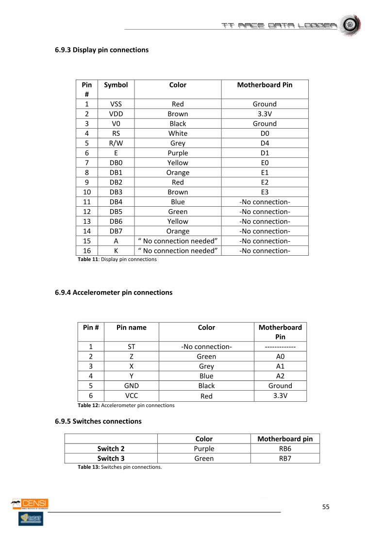
6.9.3 Display pin connections
Pin #
Symbol Color Motherboard Pin
1 VSS Red Ground
2 VDD Brown 3.3V
3 V0 Black Ground
4 RS White D0
5 R/W Grey D4
6 E Purple D1
7 DB0 Yellow E0
8 DB1 Orange E1
9 DB2 Red E2
10 DB3 Brown E3
11 DB4 Blue -No connection-
12 DB5 Green -No connection-
13 DB6 Yellow -No connection-
14 DB7 Orange -No connection-
15 A “ No connection needed” -No connection-
16 K “ No connection needed” -No connection- Table 11: Display pin connections
6.9.4 Accelerometer pin connections
Pin # Pin name Color Motherboard Pin
1 ST -No connection- -------------
2 Z Green A0
3 X Grey A1
4 Y Blue A2
5 GND Black Ground
6 VCC Red 3.3V Table 12: Accelerometer pin connections
6.9.5 Switches connections
Color Motherboard pin
Switch 2 Purple RB6
Switch 3 Green RB7 Table 13: Switches pin connections.
56
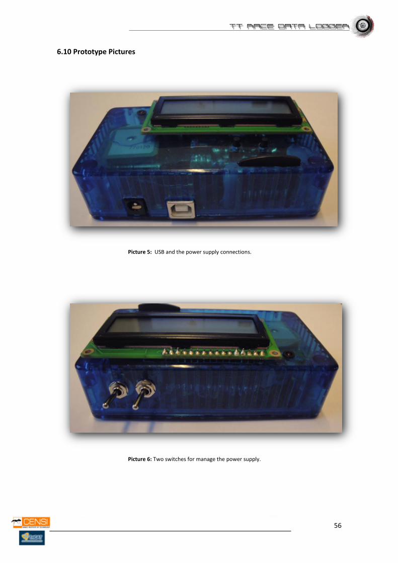
6.10 Prototype Pictures
Picture 5: USB and the power supply connections.
Picture 6: Two switches for manage the power supply.

57
Picture 7: Connections inside the device.
58
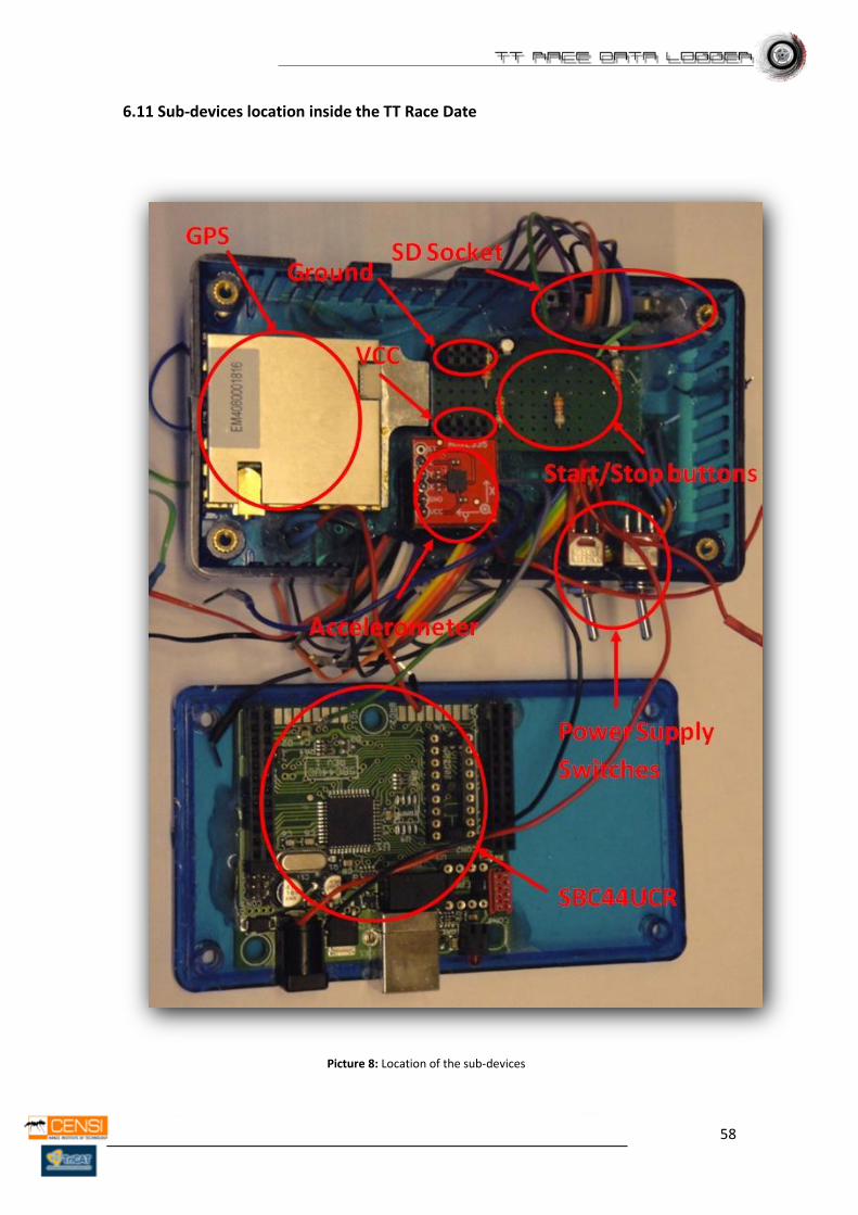
6.11 Sub-devices location inside the TT Race Date
Picture 8: Location of the sub-devices
59
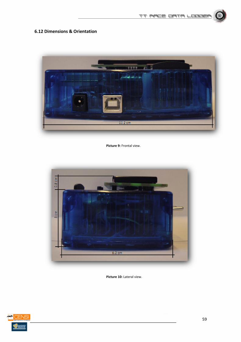
6.12 Dimensions & Orientation
Picture 9: Frontal view.
Picture 10: Lateral view.
60
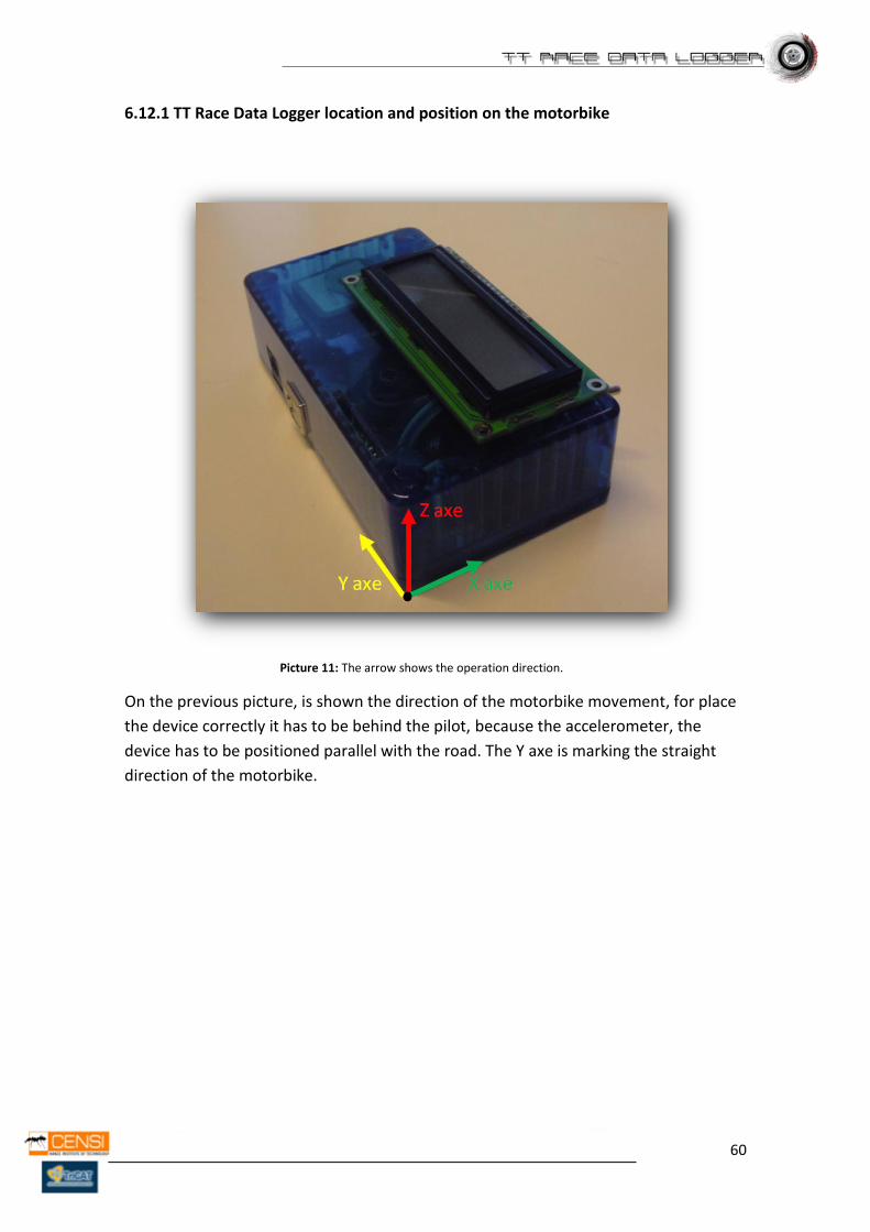
6.12.1 TT Race Data Logger location and position on the motorbike
Picture 11: The arrow shows the operation direction.
On the previous picture, is shown the direction of the motorbike movement, for place
the device correctly it has to be behind the pilot, because the accelerometer, the
device has to be positioned parallel with the road. The Y axe is marking the straight
direction of the motorbike.
61
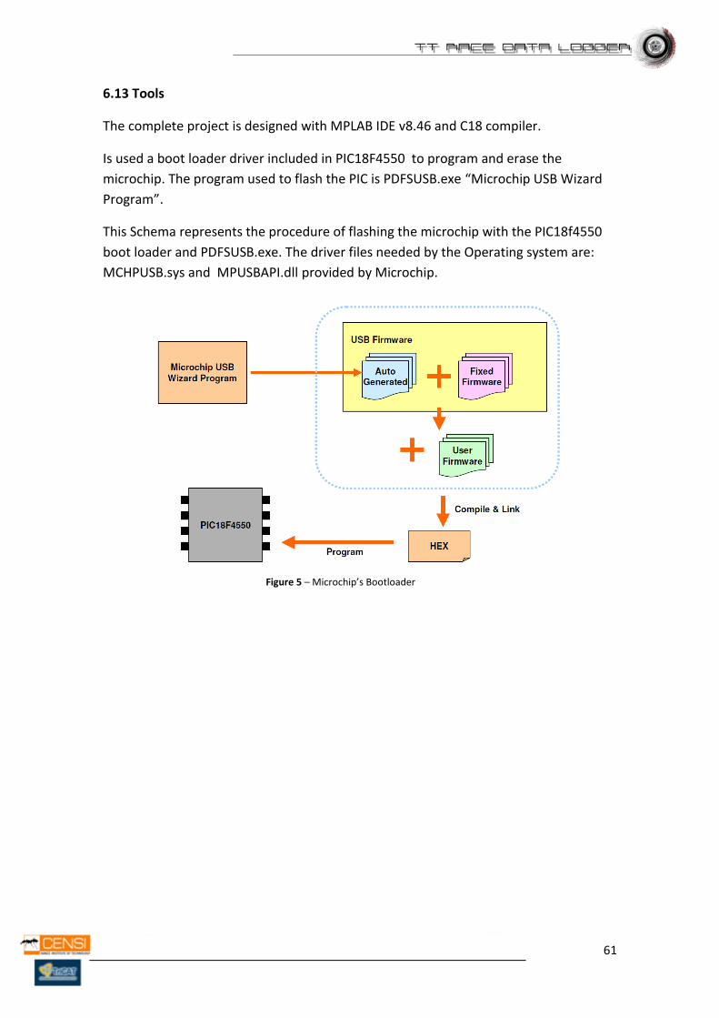
6.13 Tools
The complete project is designed with MPLAB IDE v8.46 and C18 compiler.
Is used a boot loader driver included in PIC18F4550 to program and erase the
microchip. The program used to flash the PIC is PDFSUSB.exe “Microchip USB Wizard
Program”.
This Schema represents the procedure of flashing the microchip with the PIC18f4550
boot loader and PDFSUSB.exe. The driver files needed by the Operating system are:
MCHPUSB.sys and MPUSBAPI.dll provided by Microchip.
Figure 5 – Microchip’s Bootloader
62
6.14 Components
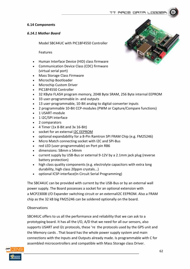
6.14.1 Mother Board
Model SBC44UC with PIC18F4550 Controller
Features
Human Interface Device (HID) class firmware Communication Device Class (CDC) firmware
(virtual serial port) Mass Storage Class Firmware Microchip Bootloader Microchip Custom Driver PIC18F4550 Controller 32 KByte FLASH program memory, 2048 Byte SRAM, 256 Byte internal EEPROM 33 user-programmable in- and outputs 13 user-programmable, 10-Bit analog to digital-converter inputs 2 programmable 10-Bit CCP-modules (PWM or Capture/Compare functions) 1 USART-module 1 I2C/SPI interface 2 comparators 4 Timer (1x 8-Bit and 3x 16-Bit) socket for an external I2C EEPROM optional expandability for a 8-Pin Ramtron SPI FRAM Chip (e.g. FM25246) Micro Match connecting socket with I2C and SPI-Bus red LED (user-programmable) on Port pin RB6 dimensions: 58mm x 54mm current supply by USB-Bus or external 9-12V by a 2.1mm jack plug (reverse
battery protection) high class quality components (e.g. electrolyte capacitors with extra long
durability, high class 20ppm crystals...) optional ICSP-interface(In Circuit Serial Programming)
The SBC44UC can be provided with current by the USB-Bus or by an external wall
power supply. The Board possesses a socket for an optional extension with
a MCP23008 I/O Expander switching circuit or an externalI2C EEPROM. Also a FRAM
chip as the 32 kB big FM25246 can be soldered optionally on the board.
Observations
SBC44UC offers to us all the performance and reliability that we can ask to a
prototyping board. It has all the I/O, A/D that we need for all our sensors, also
supports USART and I2c protocols, these ‘re the protocols used by the GPS unit and
the Memory cards . That board has the whole power supply system and main
connections with the Inputs and Outputs already made. Is programmable with C for
assembled microcontrollers and compatible with Mass Storage class Driver.
63
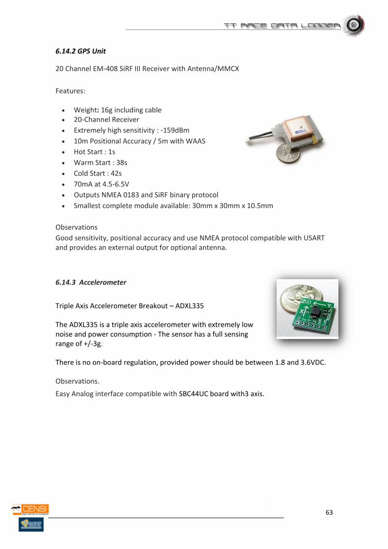
6.14.2 GPS Unit
20 Channel EM-408 SiRF III Receiver with Antenna/MMCX
Features:
Weight: 16g including cable 20-Channel Receiver
Extremely high sensitivity : -159dBm
10m Positional Accuracy / 5m with WAAS
Hot Start : 1s
Warm Start : 38s
Cold Start : 42s
70mA at 4.5-6.5V
Outputs NMEA 0183 and SiRF binary protocol
Smallest complete module available: 30mm x 30mm x 10.5mm
Observations
Good sensitivity, positional accuracy and use NMEA protocol compatible with USART and provides an external output for optional antenna.
6.14.3 Accelerometer
Triple Axis Accelerometer Breakout – ADXL335
The ADXL335 is a triple axis accelerometer with extremely low noise and power consumption - The sensor has a full sensing range of +/-3g.
There is no on-board regulation, provided power should be between 1.8 and 3.6VDC.
Observations.
Easy Analog interface compatible with SBC44UC board with3 axis.
64
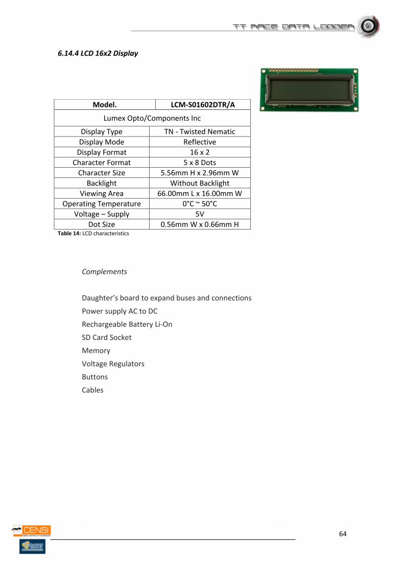
6.14.4 LCD 16x2 Display
Table 14: LCD characteristics
Complements
Daughter’s board to expand buses and connections
Power supply AC to DC
Rechargeable Battery Li-On
SD Card Socket
Memory
Voltage Regulators
Buttons
Cables
Model. LCM-S01602DTR/A
Lumex Opto/Components Inc
Display Type TN - Twisted Nematic
Display Mode Reflective
Display Format 16 x 2
Character Format 5 x 8 Dots
Character Size 5.56mm H x 2.96mm W
Backlight Without Backlight
Viewing Area 66.00mm L x 16.00mm W
Operating Temperature 0°C ~ 50°C
Voltage – Supply 5V
Dot Size 0.56mm W x 0.66mm H
65
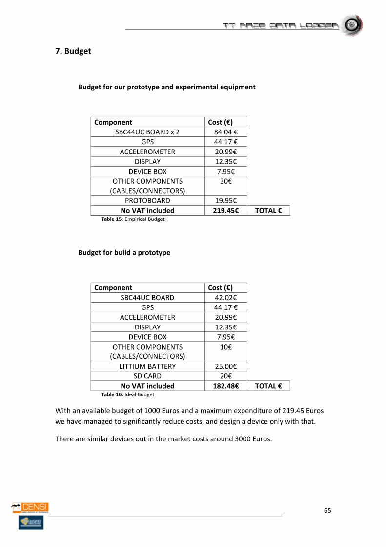
7. Budget
Budget for our prototype and experimental equipment
Component Cost (€)
SBC44UC BOARD x 2 84.04 €
GPS 44.17 €
ACCELEROMETER 20.99€
DISPLAY 12.35€
DEVICE BOX 7.95€
OTHER COMPONENTS (CABLES/CONNECTORS)
30€
PROTOBOARD 19.95€
No VAT included 219.45€ TOTAL € Table 15: Empirical Budget
Budget for build a prototype
Component Cost (€)
SBC44UC BOARD 42.02€
GPS 44.17 €
ACCELEROMETER 20.99€
DISPLAY 12.35€
DEVICE BOX 7.95€
OTHER COMPONENTS (CABLES/CONNECTORS)
10€
LITTIUM BATTERY 25.00€
SD CARD 20€
No VAT included 182.48€ TOTAL € Table 16: Ideal Budget
With an available budget of 1000 Euros and a maximum expenditure of 219.45 Euros
we have managed to significantly reduce costs, and design a device only with that.
There are similar devices out in the market costs around 3000 Euros.
66
8. Observations & Evaluation
At this point, and without possibility of having been tested successfully the full
algorithm designed for the prototype, we are satisfied with the done. We have not had
the opportunity to change the design due to the short period of time which we have
provided.
Design has been tailored to meet the demands of the contractor, we have made and
studied a design for it, in theory the design is well implemented, but due to last minute
problems on the size of the ROM of the microcontroller, it is not able to successfully
perform the tests necessary to complete the final design.
Assessing the problems we had have, we concluded that the only way to solve these
problems is to change the chosen microcontroller by one with more resources,
enough to accomplish the needs of the program we have done.
67
9. Recommendations
9.1 Dimensions
This design is intended as a prototype, after the prototype is tested and getting the
desired result, it’s possible to redesign the board, designing a new board with all the
components located in the same plane, making the design as small as the technology
permits, it means less cost and less space.
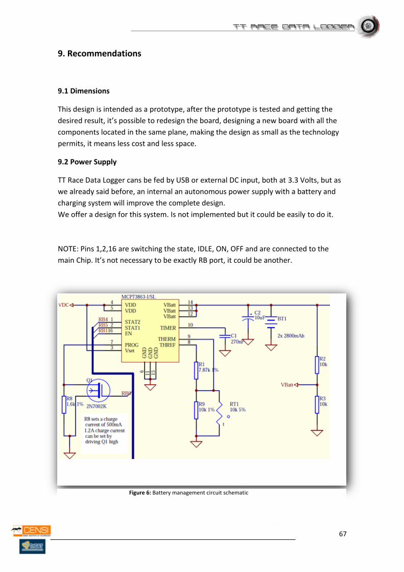
9.2 Power Supply
TT Race Data Logger cans be fed by USB or external DC input, both at 3.3 Volts, but as
we already said before, an internal an autonomous power supply with a battery and
charging system will improve the complete design.
We offer a design for this system. Is not implemented but it could be easily to do it.
NOTE: Pins 1,2,16 are switching the state, IDLE, ON, OFF and are connected to the
main Chip. It’s not necessary to be exactly RB port, it could be another.
Figure 6: Battery management circuit schematic
68
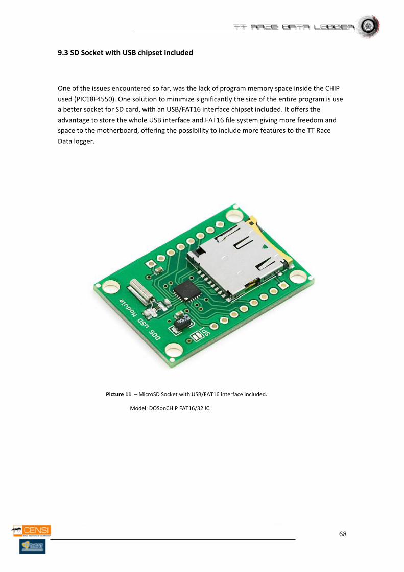
9.3 SD Socket with USB chipset included
One of the issues encountered so far, was the lack of program memory space inside the CHIP
used (PIC18F4550). One solution to minimize significantly the size of the entire program is use
a better socket for SD card, with an USB/FAT16 interface chipset included. It offers the
advantage to store the whole USB interface and FAT16 file system giving more freedom and
space to the motherboard, offering the possibility to include more features to the TT Race
Data logger.
Picture 11 – MicroSD Socket with USB/FAT16 interface included.
Model: DOSonCHIP FAT16/32 IC
69
9.4 Microprocessor
TT Race Data Logger needs a complex program to run, this means that this will use a
lot of ROM memory to store it. During the study of the possibilities we found this
problem, is caused because the main program is large to store it into the PIC18F4550,
because of this our prototype is not running as well as we want.
We couldn’t test it and know if the algorithm of the program is ok. During the part of
the design we found several problems, we asked Microchip about this problems, they
tried to solve it and found a solution, but finally, the best choice is change the
microprocessor (PIC18F4550) for another with more capacity, and more resources.
PIC18F4550 has 32Kb of ROM memory, at least is needed the double, so minimum is
needed a microcontroller with a memory ROM > 64 Kb. Is proposed one
microprocessor for continue the project. PIC18F87J50 family should be enough with
more than the double of resources. It has 3.800 Kbytes of Ram Memory.
To continue with this project will be necessary some changes in the wire connections
and the code, to try to habituate for another chipset.
70
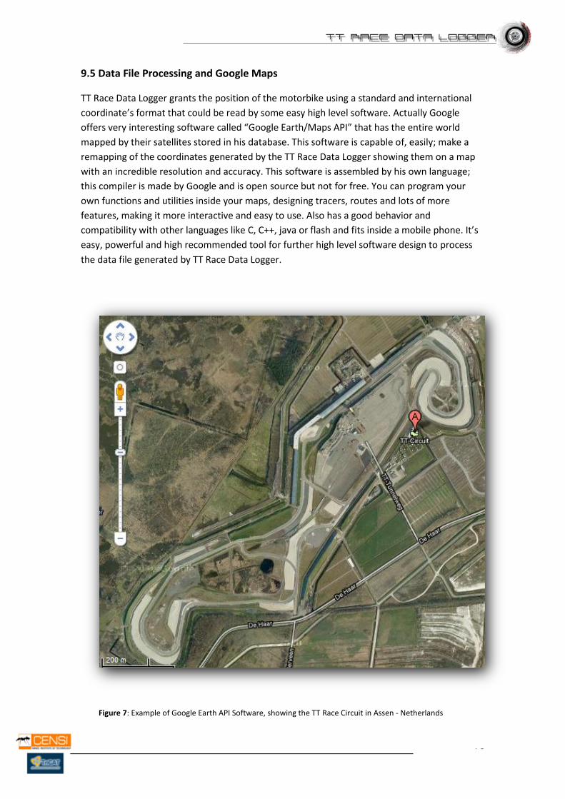
9.5 Data File Processing and Google Maps
TT Race Data Logger grants the position of the motorbike using a standard and international
coordinate’s format that could be read by some easy high level software. Actually Google
offers very interesting software called “Google Earth/Maps API” that has the entire world
mapped by their satellites stored in his database. This software is capable of, easily; make a
remapping of the coordinates generated by the TT Race Data Logger showing them on a map
with an incredible resolution and accuracy. This software is assembled by his own language;
this compiler is made by Google and is open source but not for free. You can program your
own functions and utilities inside your maps, designing tracers, routes and lots of more
features, making it more interactive and easy to use. Also has a good behavior and
compatibility with other languages like C, C++, java or flash and fits inside a mobile phone. It’s
easy, powerful and high recommended tool for further high level software design to process
the data file generated by TT Race Data Logger.
Figure 7: Example of Google Earth API Software, showing the TT Race Circuit in Assen - Netherlands
71
10. Literature
The next web links are some pages used for do our project
- http://www.aim-sportline.com
- http://www.gpsinformation.org/dale/nmea.htm
- http://en.wikipedia.org
- http://www.microchip.com/
- http://www.edaboard.com/
- http://www.xilinx.com/itp/xilinx10/isehelp/pim_c_introduction_spi_configuration.ht
m
- http://www.digitale-elektronik.de/shopsystem/
- http://www.microchip.com/stellent/idcplg?IdcService=SS_GET_PAGE&nodeId=1824&
appnote=en532040
- http://elm-chan.org/docs/mmc/mmc_e.html
- http://mbed.org/projects/cookbook/wiki/SDCard
- http://www.vti.fi/midcom-serveattachmentguid-
b469d17c67e60d4e3dbb25b0d099ad68/TN15_SPI_Interface_Specification.pdf
Books used
Title: PIC Microcontrollers
Author: Milan Verle
Number of pages: 394
Publisher: mikroElektronika; 1st edition (2008)
Language: English
72
11. Annex
This report has to be followed by a CD where the user cans find the whole C Code and
the necessary software tools for design it (MPLAB IDE, C18 Compiler and Firmware’s
Libraries). Also is included all datasheets about integrated components, no added to
this report cause their size.