
DataMan® Industrial Protocols Manual - Log into MyCognex
130
DataMan ® Industrial Protocols Manual 2020 August 13 Revision: 6.1.9.1
-
Upload
khangminh22 -
Category
Documents
-
view
2 -
download
0
Transcript of DataMan® Industrial Protocols Manual - Log into MyCognex

DataMan® IndustrialProtocols Manual
2020August13Revision:6.1.9.1

Legal NoticesThe software described in this document is furnished under license, and may be used or copied only in accordance withthe terms of such license and with the inclusion of the copyright notice shown on this page. Neither the software, thisdocument, nor any copies thereof may be provided to, or otherwise made available to, anyone other than the licensee.Title to, and ownership of, this software remains with Cognex Corporation or its licensor. Cognex Corporation assumesno responsibility for the use or reliability of its software on equipment that is not supplied by Cognex Corporation.Cognex Corporation makes no warranties, either express or implied, regarding the described software, itsmerchantability, non-infringement or its fitness for any particular purpose.
The information in this document is subject to change without notice and should not be construed as a commitment byCognex Corporation. Cognex Corporation is not responsible for any errors that may be present in either this document orthe associated software.
Companies, names, and data used in examples herein are fictitious unless otherwise noted. No part of this documentmay be reproduced or transmitted in any form or by any means, electronic or mechanical, for any purpose, nortransferred to any other media or language without the written permission of Cognex Corporation.
Copyright © 2020. Cognex Corporation. All Rights Reserved.
Portions of the hardware and software provided by Cognex may be covered by one or more U.S. and foreign patents, aswell as pending U.S. and foreign patents listed on the Cognex web site at: cognex.com/patents.
The following are registered trademarks of Cognex Corporation:
Cognex, 2DMAX, Advantage, AlignPlus, Assemblyplus, Check it with Checker, Checker, Cognex Vision for Industry,Cognex VSOC, CVL, DataMan, DisplayInspect, DVT, EasyBuilder, Hotbars, IDMax, In-Sight, Laser Killer, MVS-8000,OmniView, PatFind, PatFlex, PatInspect, PatMax, PatQuick, SensorView, SmartView, SmartAdvisor, SmartLearn,UltraLight, Vision Solutions, VisionPro, VisionView
The following are trademarks of Cognex Corporation:
The Cognex logo, 1DMax, 3D-Locate, 3DMax, BGAII, CheckPoint, Cognex VSoC, CVC-1000, FFD, iLearn, In-Sight(design insignia with cross-hairs), In-Sight 2000, InspectEdge, Inspection Designer, MVS, NotchMax, OCRMax,PatMax RedLine, ProofRead, SmartSync, ProfilePlus, SmartDisplay, SmartSystem, SMD4, VisiFlex, Xpand
Portions copyright © Microsoft Corporation. All rights reserved.
Portions copyright © MadCap Software, Inc. All rights reserved.
Other product and company trademarks identified herein are the trademarks of their respective owners.
2
Legal Notices

Table of ContentsLegal Notices 2Table of Contents 3Symbols 5About This Manual 6Industrial Network Protocols 7EtherNet/IP 7DMCC 7Reader Configuration Code 8Setup Tool 8Getting Started 9Object Model 13Rockwell ControlLogix Examples 24Rockwell CompactLogix Examples 37
PROFINET 50DMCC 50Reader Configuration Code 50Setup Tool 51Getting Started 52Object Model 55SIMATIC Examples 62TIA Portal Examples 74DataMan 370/470 v6.1.8 – PROFINET Class B 83
iQ Sensor Solution 85DMCC 86Reader Configuration Code 86Setup Tool 87Overview 87Discovering DataManReaders onGXWork2 87Monitoring the status of the DataManReader 88
CC-Link IE Field Basic 89DMCC 89Reader Configuration Code 90Setup Tool 90Modules 90
SLMP Protocol 94DMCC 94Reader Configuration Code 94SLMP Protocol Scanner 95Getting Started 95Network Configuration 97Data Block Configuration 97Interface 98Operation 103Examples 107
ModbusTCP 111DMCC 111
3
Table of Contents

Reader Configuration Code 111Setup Tool 112Modbus TCP Handler 112Getting Started 112Network Configuration 113Data Block Configuration 114Interface 115Operation 119Examples 123
Industrial Protocols for the Wireless DataMan 127Protocol Operation 127Ethernet Address 127PLC Triggering 127SoftEvents 127DMCC 127
Offline Buffering 128Status of Industrial Protocols 128
4
Table of Contents

SymbolsThe following symbols indicate safety precautions and supplemental information:
WARNING: This symbol indicates a hazard that could cause death, serious personal injury or electrical shock.
CAUTION: This symbol indicates a hazard that could result in property damage.
Note: This symbol indicates additional information about a subject.
Tip: This symbol indicates suggestions and shortcuts that might not otherwise be apparent.
5
Symbols

About This ManualThe DataMan reader connected to a network can be triggered to acquire images by several methods:
l using the DataMan Setup Tool
l trigger bits
l through a DMCC command
l manipulating objects through industrial protocols
The DataMan Industrial Protocols Manual provides information on how to integrate DataMan readers into your particularenvironment using industrial protocols.
6
About This Manual

Industrial Network ProtocolsDataMan uses industrial network protocols that are based on standard Ethernet protocols. These protocols, EtherNet/IP,PROFINET, SLMP Protocol, and Modbus/TCP, are enhanced to provide more reliability than standard Ethernet.
When you install the Setup Tool, the Installer prompts you to download the tools and sample programs associated withindustrial protocols.
EtherNet/IPDataMan supports EtherNet/IP™, an application level protocol based on the Common Industrial Protocol (CIP).EtherNet/IP provides an extensive range of messaging options and services transferring data and I/O over Ethernet. Alldevices on an EtherNet/IP network present their data to the network as a series of data values called attributes. Attributescan be grouped with other related data values into sets called Assemblies.
By default the DataMan device has the EtherNet/IP protocol disabled. The protocol can be enabled via DMCC, scanninga configuration code, or in the DataMan Setup Tool.
Note: If you have a wireless DataMan reader, see section Industrial Protocols for the Wireless DataMan onpage 127
DMCCThe following commands can be used to enable/disable EtherNet/IP on a DataMan reader. The commands can beissued via RS-232 or Telnet connection.
Note: Use a third party Telnet client such as PuTTY to communicate with your DataMan reader.
Enable:
7
Industrial Network Protocols

||>SET ETHERNET-IP.ENABLED ON||>CONFIG.SAVE||>REBOOT
Disable:
||>SET ETHERNET-IP.ENABLED OFF||>CONFIG.SAVE||>REBOOT
Reader Configuration CodeScan the following reader configuration codes to enable/disable EtherNet/IP on your corded reader.
Note: You must reboot the device for the change to take effect.
Enable: Disable:
Scan the following reader configuration codes to enable/disable EtherNet/IP on your DataMan 8000 base station.
Note: You must reboot the device for the change to take effect.
Enable: Disable:
Setup ToolIn the Setup Tool's Communications application step's Ethernet tab, check EtherNet/IP to enable this industrialprotocol.
8
Industrial Network Protocols
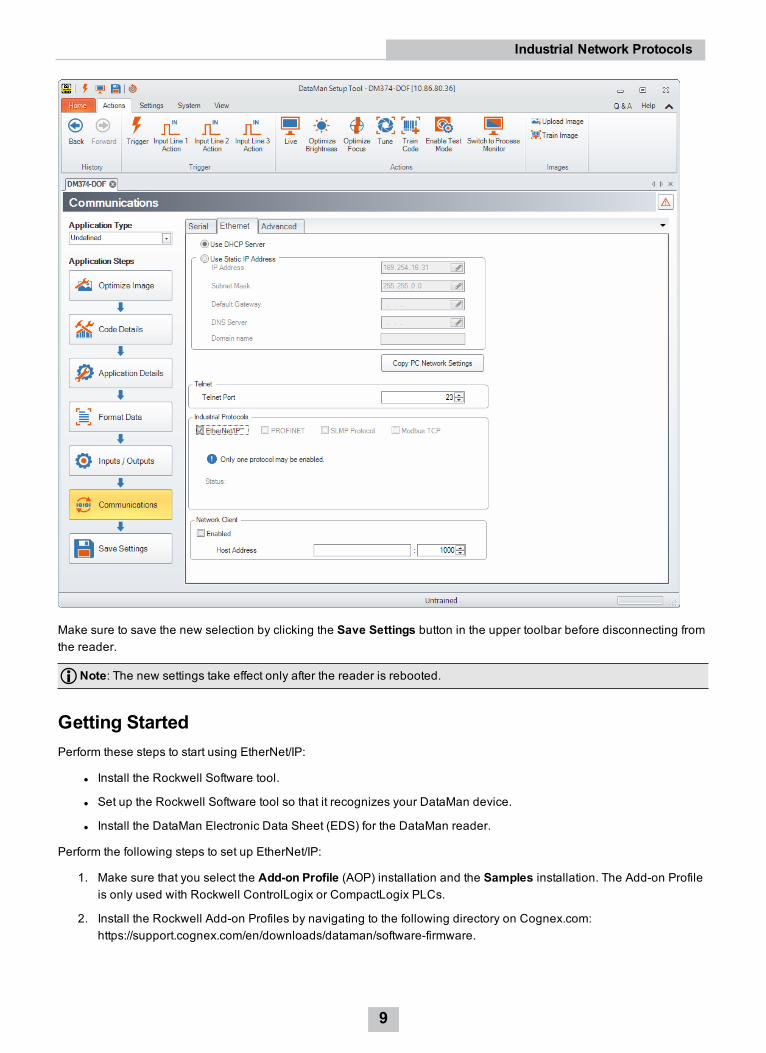
Make sure to save the new selection by clicking the Save Settings button in the upper toolbar before disconnecting fromthe reader.
Note: The new settings take effect only after the reader is rebooted.
Getting StartedPerform these steps to start using EtherNet/IP:
l Install the Rockwell Software tool.
l Set up the Rockwell Software tool so that it recognizes your DataMan device.
l Install the DataMan Electronic Data Sheet (EDS) for the DataMan reader.
Perform the following steps to set up EtherNet/IP:
1. Make sure that you select the Add-on Profile (AOP) installation and the Samples installation. The Add-on Profileis only used with Rockwell ControlLogix or CompactLogix PLCs.
2. Install the Rockwell Add-on Profiles by navigating to the following directory on Cognex.com:https://support.cognex.com/en/downloads/dataman/software-firmware.
9
Industrial Network Protocols

3. In the search box, type Add-on Profile. Click the file and download it from the following page:
4. From the Start menu, go to Programs -> Rockwell Software -> EDS Hardware Installation Tool.
10
Industrial Network Protocols
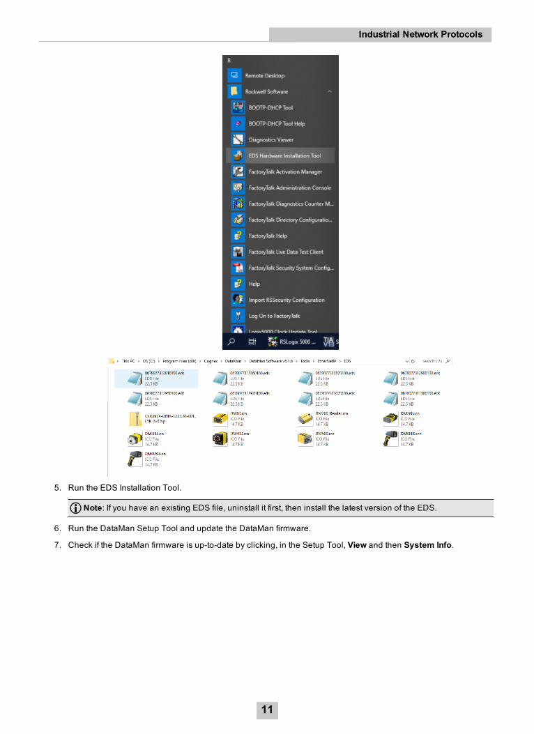
5. Run the EDS Installation Tool.
Note: If you have an existing EDS file, uninstall it first, then install the latest version of the EDS.
6. Run the DataMan Setup Tool and update the DataMan firmware.
7. Check if the DataMan firmware is up-to-date by clicking, in the Setup Tool, View and then System Info.
11
Industrial Network Protocols
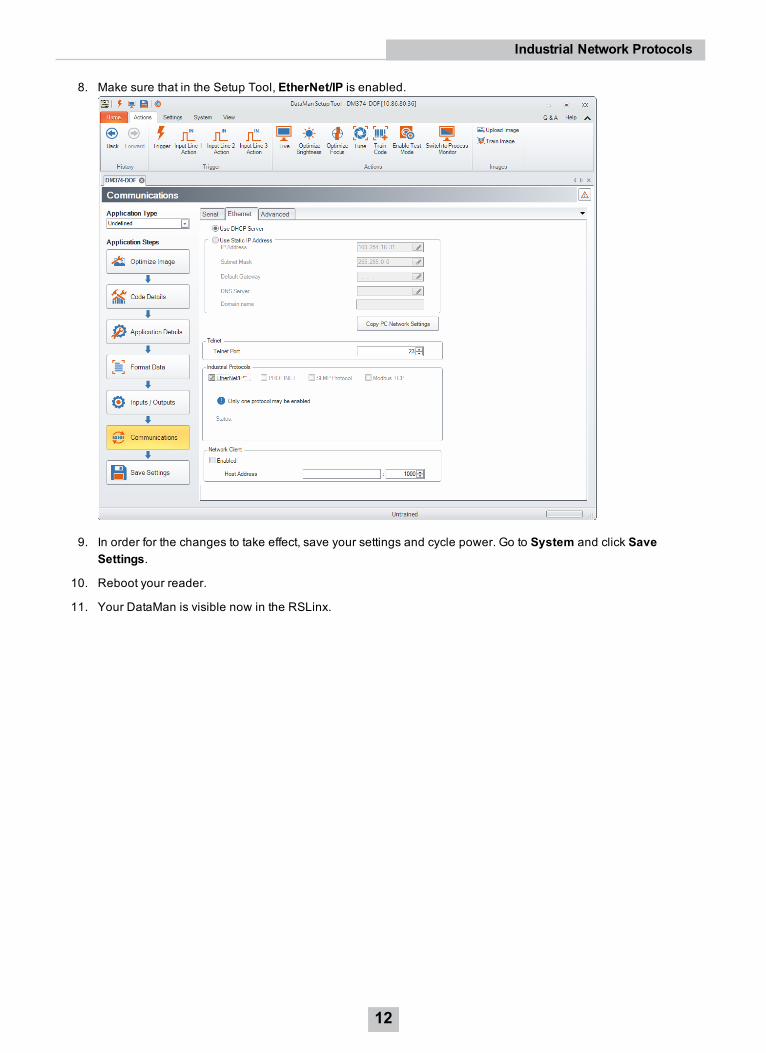
8. Make sure that in the Setup Tool, EtherNet/IP is enabled.
9. In order for the changes to take effect, save your settings and cycle power. Go to System and click SaveSettings.
10. Reboot your reader.
11. Your DataMan is visible now in the RSLinx.
12
Industrial Network Protocols

Note: If your DataMan is visible, but the icon is a question mark, repeat the EDS Installation.
12. Open one of the sample jobs and integrate your DataMan into your program using the Add-on Profile.
Object ModelThe ID Reader Object is a vendor specific object class. This means that it is not part of the CIP common (public)architecture but an extension. It is a custom object that Cognex has added to the EtherNet/IP architecture on theDataMan device. All the data and functionality of this object model are available in the DataMan reader. This includestriggering, status, events, errors, and result data.
The ID Reader Object is identified by its vendor specific class code:
DataMan ID Reader Object Class Code: 0x79Objects are made up of attributes (data) and services (functionality). These can be defined at the class level (common toall instances of the class) or the instance level (unique to an individual instance). The CIP specification defines commonattributes and services that apply to all objects (often these are optional). Vendors may also define their own attributesand services for their vendor specific classes.
13
Industrial Network Protocols

The ID Reader Object attributes and services can be individually accessed via explicit messaging. In addition, a numberof the ID Reader Object attributes are exposed in the DataMan assembly objects which allow them to be accessed as agroup via implicit messaging.
AttributesThe DataMan ID Reader Object (Class Code: 0x79) has the following attributes:
AttributeID
AccessRule
Name DataType
Description
0x9 Set AcqTriggerEnable BOOL 0 = EtherNet/IP triggering is disabled1 = EtherNet/IP triggering is enabled
0xA Set AcqTrigger BOOL Acquire an image when this attribute changes from 0 to 1.0xB Get AcqStatusRegister BYTE Bit0: Trigger Ready
Bit1: Trigger AckBit2: ReservedBit3: Missed AcquisitionBit4-7: Reserved
0xC Set UserData ARRAYof BYTE
User defined data that can be used as an input to theacquisition/decode.
0xD Set BufferResultsEnable BOOL When true, it enables buffering of the decode results. The readercan buffer up to 50 and the base station can buffer up to 500sets of read results.
0xE Get DecodeStatusRegister BYTE Bit0: DecodingBit1: Decode completed (toggle)Bit2: Results buffer overrunBit3: Results availableBit4: ReservedBit5: ReservedBit6: ReservedBit7: General fault indicator
0xF Set ResultsAck BOOL Acknowledges that the client received the decode results.
14
Industrial Network Protocols
AttributeID
AccessRule
Name DataType
Description
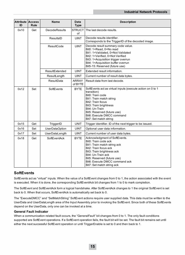
0x10 Get DecodeResults STRUCTof
The last decode results.
ResultsID UINT Decode results identifier.Corresponds to the TriggerID of the decoded image.
ResultCode UINT Decode result summary code value.Bit0: 1=Read, 0=No readBit1: 1=Validated, 0=Not ValidatedBit2: 1=Verified, 0=Not VerifiedBit3: 1=Acquisition trigger overrunBit4: 1=Acquisition buffer overrunBit5-15: Reserved (future use)
ResultExtended UINT Extended result information.ResultLength UINT Current number of result data bytes.ResultData ARRAY
of BYTEResult data from last decode.
0x12 Set SoftEvents BYTE SoftEvents act as virtual inputs (execute action on 0 to 1transition)Bit0: Train codeBit1: Train match stringBit2: Train focusBit3: Train brightnessBit4: Un-TrainBit5: Reserved (future use)Bit6: Execute DMCC commandBit7: Set match string
0x15 Get TriggerID UNIT Trigger identifier. ID of the next trigger to be issued.0x16 Set UserDataOption UINT Optional user data information.0x17 Set UserDataLength UINT Current number of user data bytes.0x18 Get SoftEventAck BYTE Acknowledgment of SoftEvents.
Bit0: Train code ackBit1: Train match string ackBit2: Train focus ackBit3: Train brightness ackBit4: Un-Train ackBit5: Reserved (future use)Bit6: Execute DMCC command ackBit7: Set match string ack
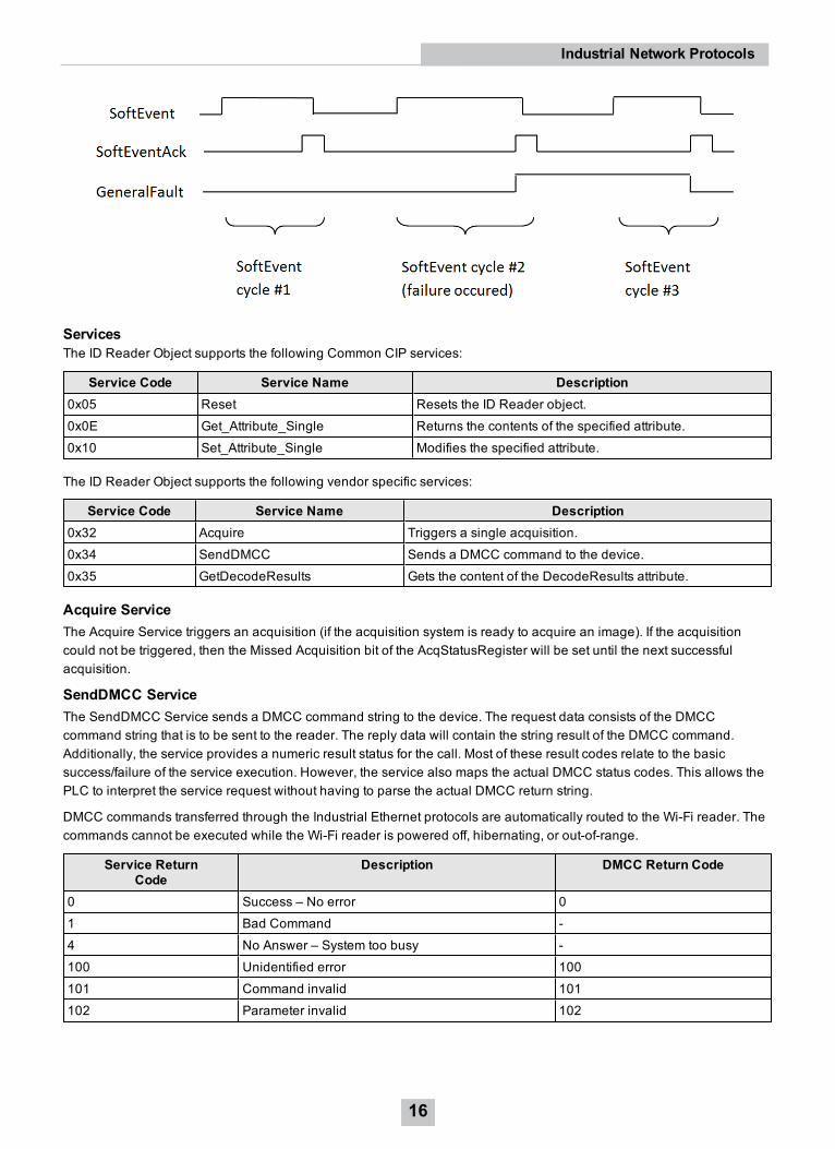
SoftEventsSoftEvents act as “virtual” inputs. When the value of a SoftEvent changes from 0 to 1, the action associated with the eventis executed. When it is done, the corresponding SoftEventAck bit changes from 1 to 0 to mark completion.
The SoftEvent and SoftEventAck form a logical handshake. After SoftEventAck changes to 1 the original SoftEvent is setback to 0. When that occurs, SoftEventAck is automatically set back to 0.
The “ExecuteDMCC” and “SetMatchString” SoftEvent actions require user supplied data. This data must be written to theUserData and UserDataLength area of the Input Assembly prior to invoking the SoftEvent. Since both of these SoftEventsdepend on the UserData, only one can be invoked at a time.
General Fault IndicatorWhen a communication related fault occurs, the “GeneralFault” bit changes from 0 to 1. The only fault conditionssupported are SoftEvent operations. If a SoftEvent operation fails, the fault bit will be set. The fault bit remains set untileither the next successful SoftEvent operation or until TriggerEnable is set to 0 and then back to 1.
15
Industrial Network Protocols
ServicesThe ID Reader Object supports the following Common CIP services:
Service Code Service Name Description0x05 Reset Resets the ID Reader object.0x0E Get_Attribute_Single Returns the contents of the specified attribute.0x10 Set_Attribute_Single Modifies the specified attribute.
The ID Reader Object supports the following vendor specific services:
Service Code Service Name Description0x32 Acquire Triggers a single acquisition.0x34 SendDMCC Sends a DMCC command to the device.0x35 GetDecodeResults Gets the content of the DecodeResults attribute.
Acquire ServiceThe Acquire Service triggers an acquisition (if the acquisition system is ready to acquire an image). If the acquisitioncould not be triggered, then the Missed Acquisition bit of the AcqStatusRegister will be set until the next successfulacquisition.
SendDMCC ServiceThe SendDMCC Service sends a DMCC command string to the device. The request data consists of the DMCCcommand string that is to be sent to the reader. The reply data will contain the string result of the DMCC command.Additionally, the service provides a numeric result status for the call. Most of these result codes relate to the basicsuccess/failure of the service execution. However, the service also maps the actual DMCC status codes. This allows thePLC to interpret the service request without having to parse the actual DMCC return string.
DMCC commands transferred through the Industrial Ethernet protocols are automatically routed to the Wi-Fi reader. Thecommands cannot be executed while the Wi-Fi reader is powered off, hibernating, or out-of-range.
Service ReturnCode
Description DMCC Return Code
0 Success – No error 01 Bad Command -4 No Answer – System too busy -100 Unidentified error 100101 Command invalid 101102 Parameter invalid 102
16
Industrial Network Protocols
Service ReturnCode
Description DMCC Return Code
103 Checksum incorrect 103104 Parameter rejected/altered due to
reader state104
Note: The DMCC command string must be in the CIP STRING2 format (16-bit integer indicating the string length incharacters followed by the actual string characters, no terminating null required).
GetDecodeResults ServiceThe GetDecodeResults service reads data from the DecodeResults attribute of the ID Reader Object. This service takesparameters indicating the “size” (number of bytes to read) and the “offset” (offset into the DecodeResults attribute tobegin reading). This gives the service the flexibility to be used with PLCs that have different restrictions on the amount ofdata allowed in an explicit message. It also allows you to access very large codes that cannot be completely transferredwith implicit messaging (assembly object).
GetDecodeResults Request Data FormatName Type Description
Size UINT The number of bytes of the DecodeResults attribute to read.Offset UINT The offset into the DecodeResults attribute. This specifies the first byte of the
DecodeResults attribute to begin reading (0 based offset).
Acquisition SequenceDataMan can be triggered to acquire images by several methods. It can be done either implicitly through the Assemblyobject, or done explicitly through the ID Reader object. When using explicit messaging, you can either:
l access the Acquire Service in a single step, or
l directly manipulate the ID Reader object attributes (AcqTrigger and AcqStatusRegister), or
l use DMCC commands.
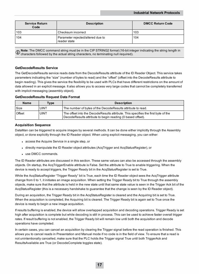
The ID Reader attributes are discussed in this section. These same values can also be accessed through the assemblyobjects. On startup, the AcqTriggerEnable attribute is False. Set the attribute to True to enable triggering. When thedevice is ready to accept triggers, the Trigger Ready bit in the AcqStatusRegister is set to True.
While the AcqStatusRegister “Trigger Ready” bit is True, each time the ID Reader object sees the AcqTrigger attributechange from 0 to 1, it initiates an image acquisition. When setting the Trigger Ready bit to True through the assemblyobjects, make sure that the attribute is held in the new state until that same state value is seen in the Trigger Ack bit of theAcqStatusRegister (this is a necessary handshake to guarantee that the change is seen by the ID Reader object).
During an acquisition, the Trigger Ready bit in the AcqStatusRegister is cleared and the Acquiring bit is set to True.When the acquisition is completed, the Acquiring bit is cleared. The Trigger Ready bit is again set to True once thedevice is ready to begin a new image acquisition.
If results buffering is enabled, the device will allow overlapped acquisition and decoding operations. Trigger Ready is sethigh after acquisition is complete but while decoding is still in process. This can be used to achieve faster overall triggerrates. If result buffering is not enabled, the Trigger Ready bit will remain low until both the acquisition and decodeoperations have completed.
In certain cases, you can cancel an acquisition by clearing the Trigger signal before the read operation is finished. Thisallows you to cancel reads in Presentation and Manual mode if no code is in the field of view. To ensure that a read isnot unintentionally cancelled, make sure that the PLC holds the Trigger signal True until both TriggerAck andResultsAvailable are True (or DecodeComplete toggles state).
17
Industrial Network Protocols
To force a reset of the trigger mechanism, set the AcqTriggerEnable attribute to False until the AcqStatusRegister is 0.Then the AcqTriggerEnable can be set to True to re-enable acquisition.
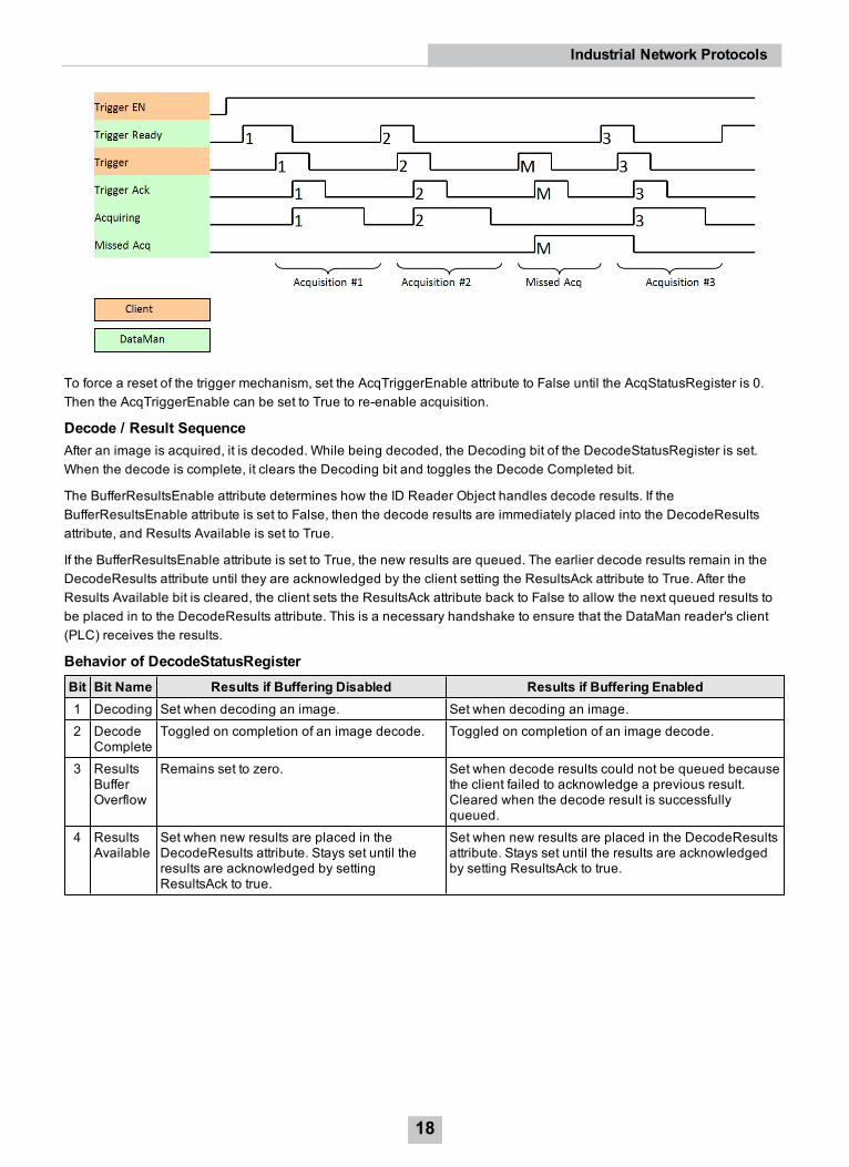
Decode / Result SequenceAfter an image is acquired, it is decoded. While being decoded, the Decoding bit of the DecodeStatusRegister is set.When the decode is complete, it clears the Decoding bit and toggles the Decode Completed bit.
The BufferResultsEnable attribute determines how the ID Reader Object handles decode results. If theBufferResultsEnable attribute is set to False, then the decode results are immediately placed into the DecodeResultsattribute, and Results Available is set to True.
If the BufferResultsEnable attribute is set to True, the new results are queued. The earlier decode results remain in theDecodeResults attribute until they are acknowledged by the client setting the ResultsAck attribute to True. After theResults Available bit is cleared, the client sets the ResultsAck attribute back to False to allow the next queued results tobe placed in to the DecodeResults attribute. This is a necessary handshake to ensure that the DataMan reader's client(PLC) receives the results.
Behavior of DecodeStatusRegisterBit Bit Name Results if Buffering Disabled Results if Buffering Enabled1 Decoding Set when decoding an image. Set when decoding an image.2 Decode
CompleteToggled on completion of an image decode. Toggled on completion of an image decode.
3 ResultsBufferOverflow
Remains set to zero. Set when decode results could not be queued becausethe client failed to acknowledge a previous result.Cleared when the decode result is successfullyqueued.
4 ResultsAvailable
Set when new results are placed in theDecodeResults attribute. Stays set until theresults are acknowledged by settingResultsAck to true.
Set when new results are placed in the DecodeResultsattribute. Stays set until the results are acknowledgedby setting ResultsAck to true.
18
Industrial Network Protocols
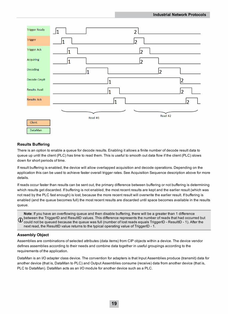
Results BufferingThere is an option to enable a queue for decode results. Enabling it allows a finite number of decode result data toqueue up until the client (PLC) has time to read them. This is useful to smooth out data flow if the client (PLC) slowsdown for short periods of time.
If result buffering is enabled, the device will allow overlapped acquisition and decode operations. Depending on theapplication this can be used to achieve faster overall trigger rates. See Acquisition Sequence description above for moredetails.
If reads occur faster than results can be sent out, the primary difference between buffering or not buffering is determiningwhich results get discarded. If buffering is not enabled, the most recent results are kept and the earlier result (which wasnot read by the PLC fast enough) is lost, because the more recent result will overwrite the earlier result. If buffering isenabled (and the queue becomes full) the most recent results are discarded until space becomes available in the resultsqueue.
Note: If you have an overflowing queue and then disable buffering, there will be a greater than 1 differencebetween the TriggerID and ResultID values. This difference represents the number of reads that had occurred butcould not be queued because the queue was full (number of lost reads equals TriggerID - ResultID - 1). After thenext read, the ResultID value returns to the typical operating value of TriggerID - 1.
Assembly ObjectAssemblies are combinations of selected attributes (data items) from CIP objects within a device. The device vendordefines assemblies according to their needs and combine data together in useful groupings according to therequirements of the application.
DataMan is an I/O adapter class device. The convention for adapters is that Input Assemblies produce (transmit) data foranother device (that is, DataMan to PLC) and Output Assemblies consume (receive) data from another device (that is,PLC to DataMan). DataMan acts as an I/O module for another device such as a PLC.
19
Industrial Network Protocols
Assembly objects use implicit messaging. They are blocks of data which are transmitted as the raw payload of implicitmessaging packets. These implicit messaging packets are produced (transmitted) repeatedly at a predefined chosenrate (for example, 100ms or 200ms).
DataMan readers have a single input assembly and single output assembly. These assemblies combine selectedattributes (data) of the DataMan ID Reader Object into groupings that minimize network bandwidth, and still allow forefficient control and processing. The data in these assemblies can also be accessed individually from the ID ReaderObject. However, using the assembly objects is much more efficient, thus they are the primary means of runtimecommunication between a DataMan reader and a PLC.
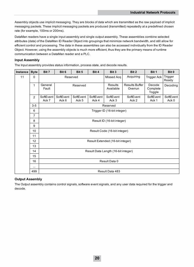
Input AssemblyThe Input assembly provides status information, process state, and decode results.
Instance Byte Bit 7 Bit 6 Bit 5 Bit 4 Bit 3 Bit 2 Bit 1 Bit 011 0 Reserved Missed Acq Acquiring Trigger Ack Trigger
Ready
1 GeneralFault
Reserved ResultsAvailable
Results BufferOverrun
DecodeCompleteToggle
Decoding
2 SoftEventAck 7
SoftEventAck 6
SoftEventAck 5
SoftEventAck 4
SoftEventAck 3
SoftEventAck 2
SoftEventAck 1
SoftEventAck 0
3-5 Reserved6 Trigger ID (16-bit integer)78 Result ID (16-bit integer)910 Result Code (16-bit integer)1112 Result Extended (16-bit integer)1314 Result Data Length (16-bit integer)1516 Result Data 0...499 Result Data 483
Output AssemblyThe Output assembly contains control signals, software event signals, and any user data required for the trigger anddecode.
20
Industrial Network Protocols

Instance Byte Bit 7 Bit 6 Bit 5 Bit 4 Bit 3 Bit 2 Bit 1 Bit 021 0 Reserved Results
AckBufferResultsEnable
Trigger TriggerEnable
1 SoftEvent7
SoftEvent6
SoftEvent5
SoftEvent4
SoftEvent3
SoftEvent2
SoftEvent1
SoftEvent0
2 Reserved34 User Data Option (16-bit integer)56 User Data Length (16-bit integer)78 User Data 0...499 User Data 491
PCCC ObjectDataMan has limited support for the Rockwell PCCC object. This allows legacy PLCs (PLC-5, SLC, and so on) tocommunicate with DataMan using their native PCCC command set and explicit messaging. The PCCC object allowsDataMan to look like a Rockwell PLC-5 logic controller.
PCCC commands are organized to work with “data tables” that exist in legacy logic controllers. Each data table is anarray of a give data type (BYTE, INT, FLOAT, and so on). The commands are oriented to read/write one or more dataitems of a given data table. Items are addressed by specifying the data table and the index of the item in the table(indexes base from 0). For instance, to read the 6th integer in PLC data table, you need to send the PCCC command toread N7:5. “N” specifies an integer table, “7” is the table number in the PLC (each table has a unique numeric identifier –assigned when the user PLC program was created), and “5” is the index into the table (note indexes begin at 0).
The PCCC object in DataMan maps the read and write requests to ID Reader assemblies, or in one special case to theDMCC service. Read commands return data from the Input assembly (instance 11). Write commands send data to theOutput assembly (instance 21). The implementation only supports an Integer data table (N7) and an ASCII data table(A9). There is one special case of String data table (ST10:0) for DMCC.
Table Data Type Table SizeN7 Integer (16-bit) 250 elementsA9 ASCII (8-bit) 500 elementsST10 String 1 element
The ResultCode value is located at word offset 5 (counting from 0) of the Input Assembly. To access this value, issue thefollowing PLC command:
21
Industrial Network Protocols

The decode ResultData begins at byte offset 16 (counting from 0) of the Input Assembly. To read the first 4 bytes of resultdata, issue the following PLC command:
The UserData begins at word offset 4 (counting from 0) of the Output Assembly. To write 4 words of UserData, issue thefollowing PLC command:
22
Industrial Network Protocols

The bit to trigger an acquisition is in byte offset 0 of the Output Assembly. To write to this byte, issue the following PLCcommand:
The PCCC Object supports a special case mapping of a string table element (ST10:0) to the DMCC service. Any stringwritten to ST10:0 is passed to the DMCC service for processing. This allows PCCC write string commands to be used toinvoke DMCC commands.
Note: The string table is only one element in size. Writing to the other elements will return an error.
23
Industrial Network Protocols

Rockwell ControlLogix ExamplesImplicit messages transmit time-critical application specific I/O data and can be point-to-point or multicast. Explicitmessages require a response from the receiving device. As a result, explicit messages are better suited for operationsthat occur less frequently. An instruction to send a DMCC command is an example of an explicit message.
Implicit MessagingEtherNet/IP implicit messaging allows a DataMan reader’s inputs and outputs to be mapped into tags in the ControlLogixPLC. Once these connections are established, the data is transferred cyclically at a user defined interval (10ms, 50ms,100ms, and so on).
The figure below represents Ethernet-based I/O through EtherNet/IP:
The Input Assembly and Output Assembly map various attributes (data) from the ID Reader object: The Input Assembly isthe collection of DataMan reader data values sent to the PLC (PLC inputs); and the Output Assembly is the collection ofdata values received by the DataMan reader from the PLC (PLC outputs).
Establishing an Implicit Messaging ConnectionTo setup an EtherNet/IP implicit messaging connection between a DataMan and a ControlLogix controller, the DataManreader must first be added to the ControlLogix I/O Configuration tree. The most efficient method is to use the Add-onProfile. This example assumes that the Add-on Profile has already been installed. If you do not have the Add-on Profile,see section Using the Generic EtherNet/IP Profile.
To establish an implicit messaging connection with a ControlLogix PLC:
1. Open RSLogix5000 and load your project (or select “File -> New…” to create a new one).From the I/O Configuration node, select the Ethernet node under the project Ethernet Module, right-click on the
24
Industrial Network Protocols

icon and select NewModule... from the menu:
2. From the Select Module dialog, choose your model of DataMan ID Reader from the list.
Note: This option is only available after you install the DataMan Add-On Profile.
Note: The rest of the steps is identical regardless of which DataMan model is selected.
25
Industrial Network Protocols

3. After selecting the device, the configuration dialog for the DataMan ID Reader system is displayed. Give themodule a name and enter the DataMan’s IP address. The default is a bidirectional (send/receive) connectionconsisting of control, status, and 32 bytes of result data with keying disabled. To change this default connection,click the Change… button. If no change is required, skip the next step.
4. Clicking the Change… button brings up the Module Definition dialog. This dialog is used to alter the connectionconfiguration. You can change:
l DataMan revision
l Electronic keying
l Connection type (bidirectional/receive-only)
l Amount of data received (from the DataMan)
l Amount of data sent (to the DataMan)
26
Industrial Network Protocols

Electronic Keying: Defines the level of module type checking that is performed by the PLC before a connectionis established.
Exact Match – All of the parameters must match or the connection will be rejected.
l Vendor
l Product Type
l Catalog Number
l Major Revision
l Minor Revision
Compatible Module – To prevent the inserted module from rejecting the connection:
l The Module Types have to match
l Catalog Number has to match
l Major Revision has to match
l The Minor Revision of the module has to be equal to or greater than the one specified in the software.
Disable Keying – The controller does not employ keying at all.
Connection: Defines the type of data flow.
Data (Bidirectional) – The connection sends data to the DataMan and receives data from the DataMan.
Input (Results only) – The connection only receives data from the DataMan. If more than one PLC needs toreceive data from the same DataMan device, choose the Input connection option.
Input Results from Sensor: Defines the amount of data received on the connection from the DataMan. Theminimum amount is the Status data only. The connection can be configured to also receive read result data. Theamount of result data received is defined in fixed increments (16 bytes, 32 bytes, 64 bytes, and so on). Select thesize to return no more than the largest code size to be read by the application. Setting the size larger wastesnetwork bandwidth and diminishes performance.
27
Industrial Network Protocols

Output Data to Sensor: Defines the amount of data transmitted on the connection (to the DataMan). Theminimum amount is the Control data only. The connection can be configured to also send user data. The amountof user data sent is defined in fixed increments (16 bytes, 32 bytes, 64 bytes, and so on). To enable User Dataoutput, right-click the DataMan module and then go to Properties -> Change -> Output Data to Sensor.
5. The final step is configuring the connection rate. The rate at which data is transmitted/received is defined as theRequested Packet Interval (RPI). The RPI defines how frequently the data is transmitted/received over theconnection. To optimize network performance, do not set this rate lower than required by a given application, orlower than half the expected maximum read rate of the user application. Setting it lower wastes bandwidth anddoes not improve processing performance.
28
Industrial Network Protocols
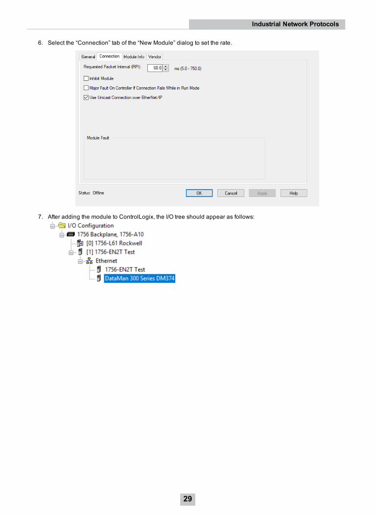
6. Select the “Connection” tab of the “New Module” dialog to set the rate.
7. After adding the module to ControlLogix, the I/O tree should appear as follows:
29
Industrial Network Protocols

8. When the DataMan module is added to the I/O tree, RSLogix 5000 creates tags that map to the DataMan readerInput and Output Data (that is, the Input and Output Assembly Objects in the DataMan Reader). These tags canbe found under the “Controller Tags” node of the project tree.
Note: The base name of these tags is the name you gave to the DataMan Module that you added to the I/OConfiguration in the previous steps.
The tags are organized in two groups: Status and Control. The Status group represents all the data beingreceived from the DataMan. The Control group represents all the data being sent to the DataMan.
These tags are the symbolic representation of the DataMan Assembly Object contents. The PLC ladder is writtento access these tag values. By monitoring or changing these tag values the PLC ladder is monitoring andchanging the DataMan Assembly Object contents.
Note: Based on the configured RPI, there is a time delay between the DataMan and the PLC tag values.Take this time delay into account when writing all PLC ladders.
Accessing Implicit Messaging Connection DataOne aspect of the Add-on Profile is that it automatically generates ControlLogix tags representing the connection data.
The generated tags are divided into two groups: Status and Control. The Status group represents all the data beingreceived from the DataMan. The Control group represents all the data being sent to the DataMan.
Status tag group is the data the ControlLogix receives from the DataMan reader:
30
Industrial Network Protocols

l TriggerReady: Indicates when the DataMan reader can accept a new trigger. This tag is True when the Controltag “TriggerEnable” has been set , and the sensor is not acquiring an image.
l TriggerAck: Indicates when the DataMan reader has been triggered (that is, the Control tag “Trigger” has beenset to True). This tag stays set until the Trigger tag is cleared.
l Acquiring: Indicates when the DataMan reader is acquiring an image either by setting the Trigger bit or by anexternal trigger.
l MissedAcq: Indicates when the DataMan reader misses an acquisition trigger. It is cleared when the nextsuccessful acquisition occurs.
l Decoding: Indicates when the DataMan reader is decoding an acquired image.
l DecodeCompleted: Tag value is toggled (1 to 0 or 0 to 1) when a decode is completed.
l ResultsBufferOverrun: Indicates when the DataMan reader discards a set of decode results because the resultsqueue is full. Cleared when the next set of results are successfully queued.
l ResultsAvailable: Indicates when a set of decode results are available (that is, the ResultID, ResultCode,ResultLength and ResultsData tags contain valid data).
l GeneralFault: Indicates when a fault has occurred (that is, SoftEvent “SetMatchString” or “ExecuteDMCC” errorhas occurred).
l TrainCodeAck: Indicates that the SoftEvent “TrainCode” is complete.
l TrainMatchStringAck: Indicates that the SoftEvent “TrainMatchString” has completed.
l TrainFocusAck: Indicates that the SoftEvent “TrainFocus” has completed.
l TrainBrightnessAck: Indicates that the SoftEvent “TrainBrightness” has completed.
l UnTrainAck: Indicates that the SoftEvent “UnTrain” has completed.
l ExecuteDmccAck: Indicates that the SoftEvent “ExecuteDMCC” has completed.
l SetMatchStringAck: Indicates that the SoftEvent “SetMatchString” has completed.
l TriggerID: Value of the next trigger to be issued. Used to match triggers issued with corresponding result datareceived later.
31
Industrial Network Protocols

l ResultID: The value of TriggerID when the trigger that generated these results was issued. Used to matchTriggerID’s with result data.
l ResultCode: Indicates success/failure of this set of results.l Bit 0 ,1=read 0=no read
l Bit 1 ,1=validated 0=not validated (or validation not in use)
l Bit 2 ,1=verified 0=not verified (or verification not in use)
l Bit 3 ,1=acquisition trigger overrun
l Bit 4 ,1=acquisition buffer overflow (not the same as result buffer overflow).
l Bits 5-15 , reserved (future use)
l ResultExtended: Unused.
l ResultLength: Number of bytes of result data contained in the ResultData tag.
l ResultData: Decode result data. Control tag group is the data sent from the ControlLogix to the DataMan reader:
l TriggerEnable: Setting this tag enables EtherNet/IP triggering. Clearing this field disables the EtherNet/IPtriggering.
l Trigger: Setting this tag triggers an acquisition if:l The TriggerEnable tag is set.
l No acquisition/decode is currently in progress.
l The device is ready to trigger.
l ResultsBufferEnable: When set, the decode results are queued. Results are made available each time the PLCacknowledges the current results. The Decode ID, Decode Result and Decode ResultsData fields are heldconstant until the ResultsAck field acknowledged and set them. The DataMan reader responds to theacknowledgment by clearing the ResultsValid bit. Once the ResultsAck field is cleared, the next set of decoderesults are posted.
l ResultsAck: The ResultsAck tag is used to acknowledge that the PLC read the latest results. When ResultsAck isset, the ResultsAvailable tag will be cleared. If results buffering is enabled, the next set of results are madeavailable when the ResultsAck tag is cleared again.
l TrainCode: Changing this tag from 0 to 1 invokes the train code operation.
l TrainMatchString: Changing this tag from 0 to 1 invokes the train match string operation.
l TrainFocus: Changing this tag from 0 to 1 invokes the train focus operation.
32
Industrial Network Protocols
l TrainBrightness: Changing this tag from 0 to 1 invokes the train brightness operation.
l Untrain: Changing this tag from 0 to 1 invokes the un-train operation.
l ExecuteDMCC: Changing this tag from 0 to 1 invokes the DMCC operation. A valid DMCC command string mustbe written to UserData prior to invoking this SoftEvent.
l SetMatchString: Changing this tag from 0 to 1 invokes the set match string operation. The match string data mustbe written to UserData prior to invoking this SoftEvent.
l UserDataOption: Unused.
l UserDataLength: Number of bytes of user data contained in the UserData tag.
l UserData: This data is sent to the DataMan reader to support acquisition and/or decode.
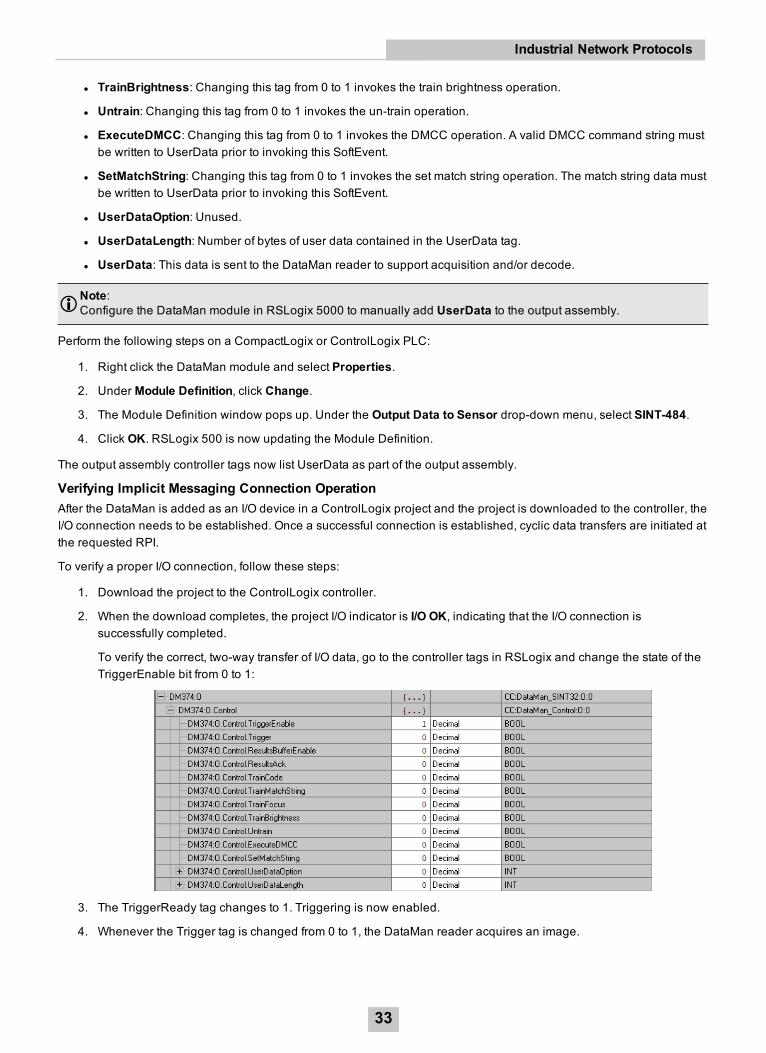
Note:Configure the DataMan module in RSLogix 5000 to manually add UserData to the output assembly.
Perform the following steps on a CompactLogix or ControlLogix PLC:
1. Right click the DataMan module and select Properties.
2. Under Module Definition, click Change.
3. The Module Definition window pops up. Under the Output Data to Sensor drop-down menu, select SINT-484.
4. Click OK. RSLogix 500 is now updating the Module Definition.
The output assembly controller tags now list UserData as part of the output assembly.
Verifying Implicit Messaging Connection OperationAfter the DataMan is added as an I/O device in a ControlLogix project and the project is downloaded to the controller, theI/O connection needs to be established. Once a successful connection is established, cyclic data transfers are initiated atthe requested RPI.
To verify a proper I/O connection, follow these steps:
1. Download the project to the ControlLogix controller.
2. When the download completes, the project I/O indicator is I/O OK, indicating that the I/O connection issuccessfully completed.
To verify the correct, two-way transfer of I/O data, go to the controller tags in RSLogix and change the state of theTriggerEnable bit from 0 to 1:
3. The TriggerReady tag changes to 1. Triggering is now enabled.
4. Whenever the Trigger tag is changed from 0 to 1, the DataMan reader acquires an image.
33
Industrial Network Protocols

Note: The current TriggerID value is 1. Make sure that the results of the next trigger to be issued come backwith a corresponding ResultID of 1.
5. After the acquisition/decode has completed, the DecodeCompleted tag will toggle, and the ResultsAvailable taggoes to 1. This example shows a successful read (ResultCode bit 0 = 1) and the read has returned 16 bytes ofdata (ResultLength=16). The data is in the ResultData tag.
Explicit MessagingUnlike implicit messaging, explicit messages are sent to a specific device that always sends a reply to that message. Asa result, explicit messages are better suited for operations that occur infrequently. Explicit messages can be used to readand write the attributes (data) of the ID Reader Object. They can also be used for acquiring images, sending DMCCcommands and retrieving result data.
Issuing DMCC CommandsOne of the more common explicit messages sent to a DataMan ID Reader is an instruction to execute a DMCCcommand. Explicit messages are sent from ControlLogix to a DataMan using MSG instructions. There are two differentpaths for invoking DMCC messages with explicit messaging: through the PCCC Object, or through the ID Reader Object“SendDMCC” service. The example shows the SendDMCC service.
The CIP STRING2 format is required for transmission across EtherNet/IP: a 16-bit length value followed by actual stringcharacters, no null terminator. Logix stores strings in a slightly different format: a 32-bit length value followed by actual
34
Industrial Network Protocols

string characters, no null terminator. Therefore, some of the sample ladder involves converting to/from the two differentstring formats.
Note: The instruction to send a DMCC is intended as a demonstration of DataMan explicit messaging behavior.This same operation could be written in a much more efficient ladder but would be less useful as a learning tool.
1. Add the following tags to the ControlLogix Controller Tags dialog:
l Send_DMCC_Command: Boolean flag used to initiate the command.
l DMCC_Command_String: String containing the DMCC command to execute.
l DMCC_Result_String: String receiving the DMCC command results.
l Message_Data: Temp buffer holding the data to send via the MSG instruction.
l Message_Result: Temp buffer holding the data received via the MSG instruction.
l Message_Pending: Boolean flag used to indicate that a message is in process.
l MSG_DMCC: Data structure required by the Logix MSG instruction.
35
Industrial Network Protocols

2. Add the following two rungs to the MainRoutine of your ControlLogix project:
3. Edit the MSG instruction. Configure it for “CIP Generic”, service 0x34 “SendDMCC”, class 0x79 “ID ReaderObject” and instance 1. Set the source to “Message_Data” and the destination to “Message_Result”.
36
Industrial Network Protocols

4. On the MSG instruction Communication tab, browse for and select the DataMan which you added to the projectI/O Configuration tree. This tells Logix where to send the explicit message.
5. Download the project to the ControlLogix and place in “Run Mode”.
To operate:
1. Place a DMCC command in the “DMCC_Command_String” tag. For example “||>GET TRIGGER.TYPE$r$l”. Notethe $r$l at the end of the string. This is how Logix represents a CRLF.
2. Toggle the “Send_DMCC_Command” tag to 1.
3. When the “Send_DMCC_Command” tag goes back to 0 execution is complete. The DMCC command results canbe found in “DMCC_Result_String”.
Rockwell CompactLogix ExamplesIn the CompactLogix project, the Ethernet logic module is embedded in the CompactLogix processor module. It isdisplayed in the I/O Configuration tree as if it were a separate module on the backplane. This module is configuredexactly like a ControlLogix Ethernet module.
The DataMan module is added in the same way for CompactLogix as for ControlLogix. Perform the following steps:
37
Industrial Network Protocols

1. Right-click the Ethernet node in the I/O Configuration tree and select NewModule....
2. From the Select Module dialog, choose your model of DataMan ID Reader from the list.
After the selection is completed, the configuration dialog for the DataMan ID Reader system is displayed. From this pointon, configuration and programming are done exactly as shown in the ControlLogix section above.
38
Industrial Network Protocols
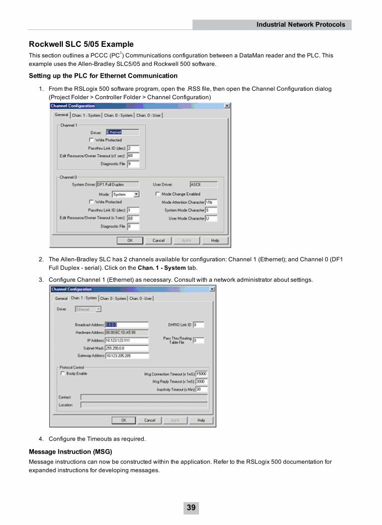
Rockwell SLC 5/05 ExampleThis section outlines a PCCC (PC3) Communications configuration between a DataMan reader and the PLC. Thisexample uses the Allen-Bradley SLC5/05 and Rockwell 500 software.
Setting up the PLC for Ethernet Communication
1. From the RSLogix 500 software program, open the .RSS file, then open the Channel Configuration dialog(Project Folder > Controller Folder > Channel Configuration)
2. The Allen-Bradley SLC has 2 channels available for configuration: Channel 1 (Ethernet); and Channel 0 (DF1Full Duplex - serial). Click on the Chan. 1 - System tab.
3. Configure Channel 1 (Ethernet) as necessary. Consult with a network administrator about settings.
4. Configure the Timeouts as required.
Message Instruction (MSG)Message instructions can now be constructed within the application. Refer to the RSLogix 500 documentation forexpanded instructions for developing messages.
39
Industrial Network Protocols

The following setup parameters can be configured within a Message (MSG) Instruction.
l Type: Peer-To-Peer. This cannot be modified.
l Read/Write: Select the function you want to perform on a DataMan reader. Read retrieves data from theDataMan;Write sends data to the DataMan.
l Target Device: Choose PLC5 to talk to a DataMan reader. This tells the SLC which communication protocol touse. The DataMan reader acts much like a ControlLogix controller (see Rockwell document 13862).
l Local/Remote: Choose Local to indicate that the DataMan reader is on the same network as the SLC; Remotetells the SLC that you will be communicating to a DataMan on another network. For remote communication, youhave to direct the message through another device acting as a gateway to that secondary network. Typically, thiscould be an Allen-Bradley ControlLogix controller. (See the Rockwell documentation on how to address deviceson other networks through a gateway.)
l Control Block: This is a temporary integer file that the MSG instruction uses to store data (that is, IP address,message type, and so on). This is typically not the user data to be sent.
l Control Block Length: This is automatically computed by the MSG instruction.
l Setup Screen: Selecting Setup Screen opens the Message Instruction Setup dialog.
The following setup parameters can be configured within an MSG Instruction Setup screen.
This Controller section:
l Communication Command: Make sure that it is the same command (READ/WRITE) as the command chosen onthe first screen (as seen in MSG Instruction screen).
40
Industrial Network Protocols

l Data Table Address: The location of the data file on the SLC where data will be written to (READ) or sent from(WRITE) (as seen in MSG Instruction screen). In this instance, 'N7:0', 'N' indicates the integer file, '7' indicates thefile number 7, and '0' indicates the offset into that file (in this case, start at the 0th element).
l Size in Elements: The number of elements (or individual data) to read. In this example, two elements are beingread.
l Channel: Depends on the configuration of the SLC. In the SLC, Channel 1 is the Ethernet port.
Target Device section:
l Message Timeout: Choose an appropriate length of time in which the DataMan reader can respond. If theDataMan does not respond within this length of time, the MSG instruction will error out. This parameter cannot bechanged from this screen. The parameters entered in the Channel 1 setup dialog determine the TimeoutMessage.
l Data Table Address: The location on the DataMan reader where data will be read from or written to. In thisinstance, 'N7:1', 'N' indicates that the data is of type integer (16-bit); '7' is ignored by the DataMan (data is alwaysbeing written to the Output Assembly, and read from the Input Assembly); and the '1' is the element offset from thestart of the target buffer. For example: If the message were a READ, 'N7:2' would instruct to read the 3rd integer(the ':2' indicates the 3rd element, due to the SLC's 0-based index) from the Input Assembly (because a READgets data from the DataMan's Input Assembly). If the message were a WRITE, 'N7:12' would indicate to write a(16-bit) integer value to the 13 integer location of the Output Assembly.
Note: The ST10:0 destination address is a special case used for sending DMCC commands to a DataMan reader.Any string sent to ST10:0 will be interpreted as a DMCC command.
l Local/Remote: Set to Local or Remote, depending on the application.
l MultiHop: This setting depends on the information previously entered. For successful In-Sightcommunication, make sure that it is YES at this time.
Sending DMCC Commands from an SLC 5/0
1. Configure the SLC5/05 as necessary.
2. Create a String Table that will hold your DMCC commands.
41
Industrial Network Protocols

3. Add the required DMCC command strings to the Data File.
4. Add a new Message (MSG) instruction to your ladder logic and configure it as shown in the following example:
5. Enter the MSG Setup Screen and configure it as follows:
42
Industrial Network Protocols

ThisController
Parameter Description
Data TableAddress
ST10:0 First element from the String Table (ST) created above.
Size inElements
1 Always set to 1. PCCC MSG only allows 1 string (therefore 1 command) to be sentat a time.
Channel 1 Set this to the Ethernet channel of your controller.
Target Device Parameter DescriptionMessage Timeout (From channel configuration dialog)Data TableAddress
ST10:0 This is the destination address. For DMCC commands, this will always beST10:0.
6. Click the MultiHop tab and configure it as required (that is, set IP address of DataMan).
7. When everything is configured, close the MSG window.
8. Save your ladder logic, download it to the controller, then go online and set the controller in RUN mode.
9. Trigger the message to send it to the DataMan reader.
Message Instruction Results
The Enable (EN) bit of the message instruction will be set to 1 when the input to the instruction is set high. The Done(DN) bit will be set to 1 when DataMan has replied that the DMCC command was received and executed with success. Ifthe Error bit (ER) is enabled (set to 1), it indicates a problem with the message instruction. If an error occurs, click theSetup Screen for the MSG instruction. The Error Code will be shown at the bottom of the window.
Using the Generic EtherNet/IP ProfileFor devices without a specific Add-on Profile Rockwell provides a Generic EtherNet/IP profile. This profile allows you tocreate implicit messaging connections but lacks the automatic tag generation feature of a specific product Add-on Profile.
Establishing a Generic Implicit Messaging ConnectionTo set up an EtherNet/IP implicit messaging connection between a DataMan and a ControlLogix controller, add theDataMan reader to the ControlLogix I/O Configuration tree. This can be accomplished with the Rockwell providedgeneric profile.
To establish a generic implicit messaging connection with a ControlLogix PLC:
43
Industrial Network Protocols

1. Open RSLogix5000 and load your project (or select “File->New…” to create a new one).
2. From the I/O Configuration node, select the Ethernet node under the project Ethernet Module, right-click the iconand select NewModule... from the menu:
3. From the Select Module Type dialog, choose the Allen-Bradley Generic Ethernet Module.
44
Industrial Network Protocols

4. After selecting it, the configuration dialog for the Generic Ethernet Module is displayed. Configure the following:
l Give the module a name.
l Enter your DataMan’s IP address.
l Set the Comm Format to “Data – INT”. This tells the module to treat the data as an array of 16-bit integers.
l Input Assembly: Set instance 11. Set the size to the amount of Input Assembly data you want the PLC toreceive. Basic “Status” data requires 8 integers. The amount beyond that will be the actual decode resultdata. In the example below the size is set to 24 (8 for status + 16 for result data). This connection willreceive the status info plus 32 bytes of result data.
l Output Assembly: Set instance 21. Set the size to 4 integers. This size is sufficient to send all required“Control” data to the DataMan.
l Configuration Assembly: Set instance 1. Set size to zero (not used).
45
Industrial Network Protocols
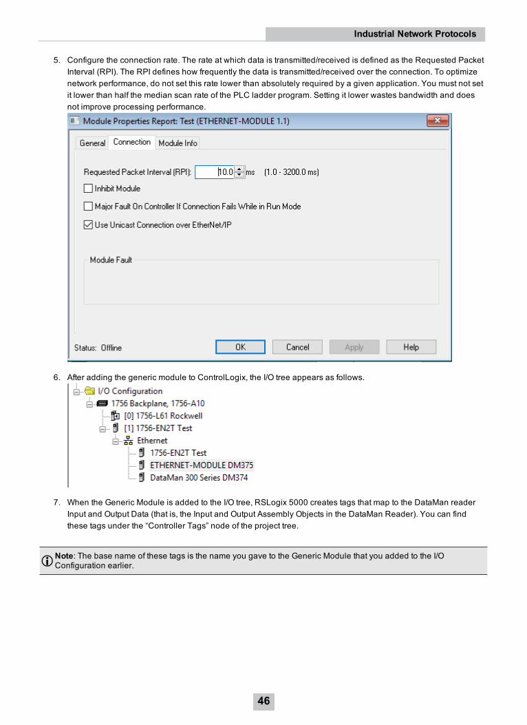
5. Configure the connection rate. The rate at which data is transmitted/received is defined as the Requested PacketInterval (RPI). The RPI defines how frequently the data is transmitted/received over the connection. To optimizenetwork performance, do not set this rate lower than absolutely required by a given application. You must not setit lower than half the median scan rate of the PLC ladder program. Setting it lower wastes bandwidth and doesnot improve processing performance.
6. After adding the generic module to ControlLogix, the I/O tree appears as follows.
7. When the Generic Module is added to the I/O tree, RSLogix 5000 creates tags that map to the DataMan readerInput and Output Data (that is, the Input and Output Assembly Objects in the DataMan Reader). You can findthese tags under the “Controller Tags” node of the project tree.
Note: The base name of these tags is the name you gave to the Generic Module that you added to the I/OConfiguration earlier.
46
Industrial Network Protocols

The tags are organized in three groups: Config “MyDM200:C”, Input “MyDM200:I”, and Output “MyDM200:O”. You canignore the Config tags (not used). The Input tags represent all the data being received (from the DataMan). The Ouputtags represent all the data being sent (to the DataMan).
These tags are the data table representation of the DataMan Assembly Object contents. The PLC ladder is written toaccess these tag values. By monitoring or changing these tag values, the PLC ladder is actually monitoring andchanging the DataMan Assembly Object contents.
Note: Based on the configured RPI, there is a time delay between the DataMan and the PLC tag values. Take thistime delay into account when writing all PLC ladders.
Accessing Generic Implicit Messaging Connection DataUnlike the DataMan Add-on Profile, the Generic Module profile does not automatically generate named tagsrepresenting the individual data items within an Assembly Object. Instead it simply generates an array of data accordingto the size of the connection you defined.
To access individual data items within an Assembly Object, manually select the correct tag offset and data subtype (ifnecessary) within the tag array that the Generic profile provided. This means that you have to manually reference thevendor documentation which defines the Assembly Objects.
Note: The start of the Input tags “MyDM200:I.Data[0]” maps directly to the start of the DataMan Input Assembly.Likewise, the start of the Output tags “MyDM200:O.Data[0]” maps directly to the start of the DataMan OutputAssembly.
ExamplesInput Assembly “TriggerReady”: Bit 0 of word 0 of the Input Assembly. From the Input tag array for the DataMan select bit0 of word 0.
47
Industrial Network Protocols

Input Assembly “ResultLength”: Word 7 of the Input Assembly. From the Input tag array for the DataMan select word 7.
48
Industrial Network Protocols

Output Assembly “Trigger”: Bit 1 of word 0 of the OutputAssembly. From the Output tag array for the DataMan select bit 1of word 0.
49
Industrial Network Protocols

PROFINETPROFINET is an application-level protocol used in industrial automation applications. This protocol uses standardEthernet hardware and software to exchange I/O data, alarms, and diagnostics.
DataMan supports PROFINET I/O. This is one of the two “views” contained in the PROFINET communication standard.PROFINET I/O performs cyclic data transfers to exchange data with Programmable Logic Controllers (PLCs) overEthernet. The second “view” in the standard, PROFINET Component Based Automation (CBA), is not supported.
By default, the DataMan has the PROFINET protocol disabled. The protocol can be enabled via DMCC, scanning aparameter code or in the DataMan Setup Tool.
Note: If you have a wireless DataMan reader, see section Industrial Protocols for the Wireless DataMan onpage 127
DMCCThe following commands can be used to enable/disable PROFINET. The commands can be issued via RS-232 or Telnetconnection.
Note: Use a third party Telnet client such as PuTTY to communicate with your DataMan reader.
Enable:
||>SET PROFINET.ENABLED ON||>CONFIG.SAVE||>REBOOT
Disable:
||>SET PROFINET.ENABLED OFF||>CONFIG.SAVE||>REBOOT
Reader Configuration CodeScanning the following reader configuration codes enables/disables PROFINET for your corded reader.
Note: You must reboot the device for the change to take effect.
Enable: Disable:
Scanning the following reader configuration codes enables/disables PROFINET for your DataMan 8000 base station.
Note: You must reboot the device for the change to take effect.
50
Industrial Network Protocols
Enable: Disable:
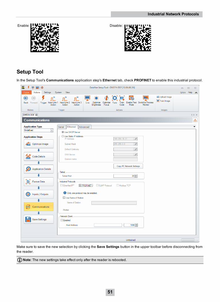
Setup ToolIn the Setup Tool's Communications application step's Ethernet tab, check PROFINET to enable this industrial protocol.
Make sure to save the new selection by clicking the Save Settings button in the upper toolbar before disconnecting fromthe reader.
Note: The new settings take effect only after the reader is rebooted.
51
Industrial Network Protocols

Getting StartedPreparing to use PROFINET involves the following main steps:
l Make sure that you have either the SIMATIC Step 7 programming software or TIA Portal installed.
l Set up the Siemens Software tool so that it recognizes your DataMan device.
l Install the Generic Station Description (GSD) file.
Note: Expanding the process image can have a performance impact on the PLC scan cycle time. If your scan timeis critical, use the minimal acceptable module sizes and manually remap them down lower in the process image.
Perform the following steps to set up PROFINET using SIMATIC or TIA Portal:
1. Verify that SIMATIC is on your machine.
2. From the Windows Start menu, go to Cognex and select the folder that contains the PROFINET tools.
3. Check if the DataMan's firmware is up-to-date by clicking, in the Setup Tool, View and then System Info.
52
Industrial Network Protocols

4. Make sure that in the Setup Tool, PROFINET is enabled.
53
Industrial Network Protocols
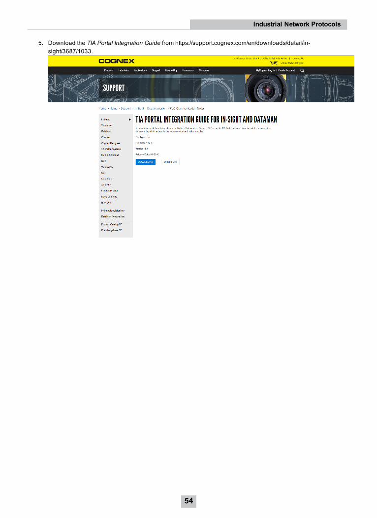
5. Download the TIA Portal Integration Guide from https://support.cognex.com/en/downloads/detail/in-sight/3687/1033.
54
Industrial Network Protocols

6. Open the PROFINET Tag Generator file that is included in the TIA Portal Integration Guide.
7. From the Windows Start menu, launch the SIMATIC Manager or TIA Portal.
Object ModelModulesThe PROFINET implementation on DataMan consists of seven I/O modules:
1. Acquisition Control Module
2. Acquisition Status Module
3. Results Control Module
4. Results Status Module
5. SoftEvent Control Module
6. User Data Module
7. Result Data Module
55
Industrial Network Protocols
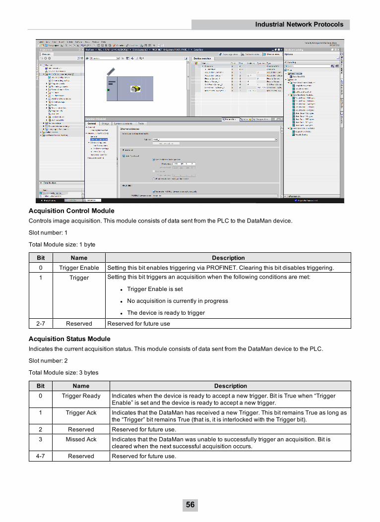
Acquisition Control ModuleControls image acquisition. This module consists of data sent from the PLC to the DataMan device.
Slot number: 1
Total Module size: 1 byte
Bit Name Description0 Trigger Enable Setting this bit enables triggering via PROFINET. Clearing this bit disables triggering.1 Trigger Setting this bit triggers an acquisition when the following conditions are met:
l Trigger Enable is set
l No acquisition is currently in progress
l The device is ready to trigger
2-7 Reserved Reserved for future use
Acquisition Status ModuleIndicates the current acquisition status. This module consists of data sent from the DataMan device to the PLC.
Slot number: 2
Total Module size: 3 bytes
Bit Name Description0 Trigger Ready Indicates when the device is ready to accept a new trigger. Bit is True when “Trigger
Enable” is set and the device is ready to accept a new trigger.1 Trigger Ack Indicates that the DataMan has received a new Trigger. This bit remains True as long as
the “Trigger” bit remains True (that is, it is interlocked with the Trigger bit).2 Reserved Reserved for future use.3 Missed Ack Indicates that the DataMan was unable to successfully trigger an acquisition. Bit is
cleared when the next successful acquisition occurs.4-7 Reserved Reserved for future use.
56
Industrial Network Protocols
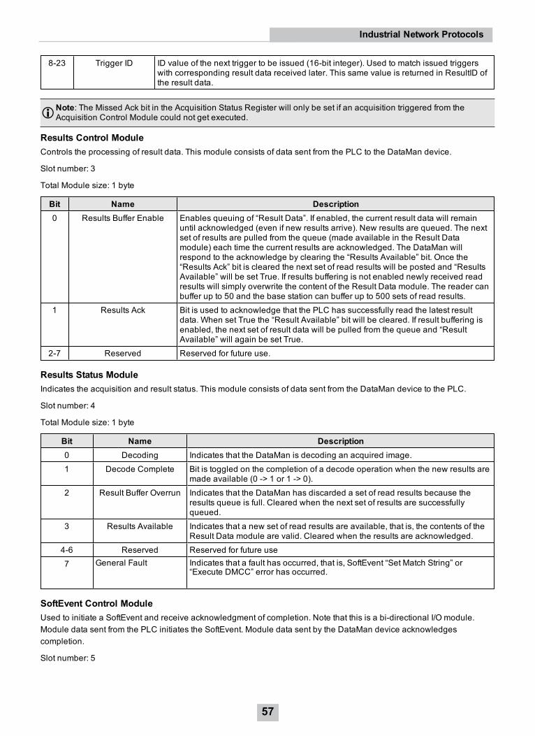
8-23 Trigger ID ID value of the next trigger to be issued (16-bit integer). Used to match issued triggerswith corresponding result data received later. This same value is returned in ResultID ofthe result data.
Note: The Missed Ack bit in the Acquisition Status Register will only be set if an acquisition triggered from theAcquisition Control Module could not get executed.
Results Control ModuleControls the processing of result data. This module consists of data sent from the PLC to the DataMan device.
Slot number: 3
Total Module size: 1 byte
Bit Name Description0 Results Buffer Enable Enables queuing of “Result Data”. If enabled, the current result data will remain
until acknowledged (even if new results arrive). New results are queued. The nextset of results are pulled from the queue (made available in the Result Datamodule) each time the current results are acknowledged. The DataMan willrespond to the acknowledge by clearing the “Results Available” bit. Once the“Results Ack” bit is cleared the next set of read results will be posted and “ResultsAvailable” will be set True. If results buffering is not enabled newly received readresults will simply overwrite the content of the Result Data module. The reader canbuffer up to 50 and the base station can buffer up to 500 sets of read results.
1 Results Ack Bit is used to acknowledge that the PLC has successfully read the latest resultdata. When set True the “Result Available” bit will be cleared. If result buffering isenabled, the next set of result data will be pulled from the queue and “ResultAvailable” will again be set True.
2-7 Reserved Reserved for future use.
Results Status ModuleIndicates the acquisition and result status. This module consists of data sent from the DataMan device to the PLC.
Slot number: 4
Total Module size: 1 byte
Bit Name Description0 Decoding Indicates that the DataMan is decoding an acquired image.1 Decode Complete Bit is toggled on the completion of a decode operation when the new results are
made available (0 -> 1 or 1 -> 0).2 Result Buffer Overrun Indicates that the DataMan has discarded a set of read results because the
results queue is full. Cleared when the next set of results are successfullyqueued.
3 Results Available Indicates that a new set of read results are available, that is, the contents of theResult Data module are valid. Cleared when the results are acknowledged.
4-6 Reserved Reserved for future use7 General Fault Indicates that a fault has occurred, that is, SoftEvent “Set Match String” or
“Execute DMCC” error has occurred.
SoftEvent Control ModuleUsed to initiate a SoftEvent and receive acknowledgment of completion. Note that this is a bi-directional I/O module.Module data sent from the PLC initiates the SoftEvent. Module data sent by the DataMan device acknowledgescompletion.
Slot number: 5
57
Industrial Network Protocols

Total Module size: 1 byte (input) and 1 byte (output)
Data written from the PLC to DataMan:
Bit Name Description0 Train Code Bit transition from 0 -> 1 causes the train code operation to be invoked.1 Train Match
StringBit transition from 0 -> 1 causes the train match string operation to be invoked.
2 Train Focus Bit transition from 0 -> 1 causes the train focus operation to be invoked.3 Train
BrightnessBit transition from 0 -> 1 causes the train brightness operation to be invoked.
4 Untrain Bit transition from 0 -> 1 causes the untrain operation to be invoked.5 Reserved Reserved for future use6 Execute
DMCCBit transition from 0 -> 1 causes the DMCC operation to be invoked. Note that a validDMCC command string must first be placed in “User Data” before invoking this event.
7 Set MatchString
Bit transition from 0 -> 1 causes the set match string operation to be invoked. Note thatmatch string data must first be placed in “User Data” before invoking this event.
Data written from the DataMan to PLC:
Bit Name Description0 Train Code Ack Indicates that the “Train Code” operation is complete1 Train Match String Ack Indicates that the “Train Match String” operation is complete2 Train Focus Ack Indicates that the “Train Focus” operation is complete3 Train Brightness Ack Indicates that the “Train Brightness” operation is complete4 Untrain Ack Indicates that the “Untrain” operation is complete5 Reserved Reserved for future use6 Execute DMCC Ack Indicates that the “Execute DMCC” operation is complete7 Set Match String Ack Indicates that the “Set Match String” operation is complete
User Data ModuleData sent from a PLC to a DataMan to support acquisition, decode and other special operations. Currently this module isonly used to support the “Execute DMCC” and “Set Match String” SoftEvents.
Note: There are 5 versions of the User Data module. Only one instance can be configured for use in a givenapplication. The “User Data Option” and “User Data Length” fields are the same for each module. The “User Data”field varies in size based on the selected module. Choose the module which is large enough to exchange theamount of data your application requires.
Slot number: 6
Total Module size:
4 + 16 (16 bytes of User Data)
4 + 32 (32 bytes of User Data)
4 + 64 (64 bytes of User Data)
4 + 128 (128 bytes of User Data)
4 + 250 (250 bytes of User Data)
Byte Name Description
58
Industrial Network Protocols

0-1 User Data Option Currently only used by “Set Match String” SoftEvent. Specifies which codetarget to assign the string (16-bit Integer).0, assign string to all targets1, assign string to 2D codes2, assign string to QR codes3, assign string to 1D / stacked / postal codes
2-3 User Data Length Number of bytes of valid data actually contained in the “User Data” field (16-bit Integer).
4... User Data Data sent from the PLC to the DataMan to support acquisition, decoding,and other special operations (array of bytes).
Result Data ModuleRead result data sent from a DataMan to a PLC.
Look into the Result Data Module for non-PROFINET related data if there is an acquisition problem on the reader. The"Result Code" part contains information about trigger overruns or buffer overflows that have occurred on the reader.
Note: There are 5 versions of the Result Data module. Only a single instance can be configured for use in a givenapplication. The “Result ID”, “Result Code”, “Result Extended” and “Result Length” fields are the same for eachmodule. The “Result Data” field varies in size based on the selected module. Choose the module which is largeenough to exchange the amount of result data your application requires.
Slot number: 7
Total Module size:
8 + 16 (16 bytes of Result Data)
8 + 32 (32 bytes of Result Data)
8 + 64 (64 bytes of Result Data)
8 + 128 (128 bytes of Result Data)
8 + 246 (246 bytes of Result Data)
Byte Name Description0-1 Result ID The value of the “Trigger ID” when the trigger that generated these results was
issued. Used to match up triggers with corresponding result data (16-bit Integer).2-3 Result Code Indicates the success or failure of the read that produced these results (16-bit
Integer).Bit 0,1=read, 0=no readBit 1,1=validated, 0=not validated (or validation not in use)Bit 2,1=verified, 0=not verified (or verification not in use)Bit 3,1=acquisition trigger overrunBit 4,1=acquisition buffer overflowBits 5-15 reserved
4-5 Result Extended Currently unused (16-bit Integer).6-7 Result Length Actual number of bytes of read data contained in the “Result Data” field (16-bit
Integer).8... Result Data Decoded read result data (array of bytes)
OperationSoftEventsSoftEvents act as “virtual” inputs. When the value of a SoftEvent changes from 0 -> 1 the action associated with the eventwill be executed. When the action completes the corresponding SoftEventAck bit will change from 0 -> 1 to signalcompletion. The acknowledge bit will change back to 0 when the corresponding SoftEvent bit is set back to 0.
59
Industrial Network Protocols

The “ExecuteDMCC” and “SetMatchString” SoftEvent actions require user supplied data. This data must be written to theUserData and UserDataLength area of the UserData Module prior to invoking the SoftEvent. Only one SoftEvent can beinvoked at a time because both of these SoftEvents depend on the UserData.
General Fault IndicatorWhen a communication related fault occurs the “GeneralFault” bit will change from 0 -> 1. Currently the only faultconditions supported are SoftEvent operations. If a SoftEvent operation fails, the fault bit will be set. The fault bit willremain set until the next SoftEvent operation or until triggering is disabled and again re-enabled.
Acquisition SequenceDataMan can be triggered to acquire images by several methods. It can be done explicitly by manipulating the Trigger bitof the Acquisition Control Module, it can be triggered by external hard wired input, and it can be triggered via DMCC.This section describes manipulating the Acquisition Control Module bits.
On startup the “Trigger Enable” bit will be False. It must be set to True to enable triggering. When the device is ready toaccept triggers, the “Trigger Ready” bit will be set to True.
While the Trigger Ready bit is True, each time the reader detects the “Trigger” bit change from 0 to 1, it initiates an imageacquisition. Make sure that the client (PLC) holds the bit in the new state until that same state value is seen back in theTrigger Ack bit. This is a necessary handshake to guarantee that the reader detects the change.
During an acquisition, the Trigger Ready bit will be cleared and the Acquiring bit will be set to True. When the acquisitionis completed, the Acquiring bit will be cleared. The Trigger Ready bit is again set to True once the device is ready tobegin a new image acquisition.
If results buffering is enabled, the device will allow overlapped acquisition and decoding operations. Trigger Ready willbe set high after acquisition is complete but while decoding is still in process. This can be used to achieve faster overalltrigger rates. If result buffering is not enabled, the Trigger Ready bit will remain low until both the acquisition and decodeoperations are complete.
To force a reset of the trigger mechanism, set the Trigger Enable bit to False, until the Trigger Ready bit is 0. Then,Trigger Enable can be set to True to re-enable acquisition.
As a special case, an acquisition can be cancelled by clearing the Trigger signal before the read operation is complete.This allows cancelling reads in Presentation and Manual mode if no code is in the field of view. To ensure that a read isnot unintentionally cancelled, it is advised that the PLC hold the Trigger signal True until both TriggerAck andResultsAvailable are True or DecodeComplete toggles state.
60
Industrial Network Protocols

Decode / Result SequenceAfter an image is acquired, it is decoded. While being decoded, the “Decoding” bit of the Result Status Module is set.When decode is complete, the Decoding bit is cleared and the “Decode Complete” bit is toggled.
The “Results Buffer Enable” bit determines how the reader handles decode results. If the Results Buffer Enable bit is setto False, then the decode results are immediately placed into the Results Module and Results Available is set to True.
If the Results Buffer Enable bit is set to True, the new results are queued. The earlier decode results remain in theResults Module until the client acknowledges them by setting the “Results Ack” bit to True. After the Results Available bitis cleared, make sure that the client sets the Results Ack bit back to False to allow the next queued results to be placed into the Results Module. This is a necessary handshake to ensure the results are received by the DataMan client (PLC).
Behavior of DecodeStatusRegisterBit Bit Name Results if Buffering Disabled Results if Buffering Enabled0 Decoding Set when decoding an image. Set when decoding an image.1 Decode Complete Toggled on completion of an image decode. Toggled on completion of an image
decode.2 Results Buffer
OverflowRemains set to zero. Set when decode results could not
be queued because the clientfailed to acknowledge a previousresult. Cleared when the decoderesult is successfully queued.
3 Results Available Set when new results are placed in the ResultsModule. Stays set until the results areacknowledged by setting Results Ack to true.
Set when new results are placed inthe Results Module. Stays set untilthe results are acknowledged bysetting Results Ack to true.
61
Industrial Network Protocols

Results BufferingThere is an option to enable a queue for decode results. If enabled, this allows a finite number of decode result data toqueue up until the client (PLC) has time to read them. This is useful to smooth out data flow if the client (PLC) slowsdown for short periods of time or if there are surges of read activity.
If result buffering is enabled, the device will allow overlapped acquisition and decode operations. Depending on theapplication this can be used to achieve faster over all trigger rates. For more information, see the Acquisition Sequencedescription.
In general, if reads are occurring faster than results can be sent out, the primary difference between buffering or notbuffering determines which results get discarded. If buffering is not enabled the most recent results are kept and theearlier result (which was not read by the PLC fast enough) is lost. The more recent result overwrites the earlier result. Ifbuffering is enabled and the queue becomes full, the most recent results are discarded until space becomes available inthe results queue.
Note: If the queue has overflowed and then buffering is disabled, there will be a greater than 1 difference betweenthe TriggerID and ResultID values. This difference represents the number of reads that occurred but could not bequeued because the queue was full (number of lost reads equals TriggerID - ResultID - 1). After the next read, theResultID value will return to the typical operating value of TriggerID - 1.
SIMATIC ExamplesThis section gives some examples of using the DataMan with a Siemens S7-300 PLC assuming that you are familiar withthe S7-300 and the SIMATIC programming software.
1. If you already have a project, click Cancel to skip past the New Project wizard. Otherwise, let the wizard guideyou through creating a new project.
62
Industrial Network Protocols

2. In the opened project, double-click the Hardware icon to open the HWConfig dialog. From the main menu, selectOptions -> Install GSD File….
3. Browse to the installation folder of the GSD file (or the folder where you saved the GSD file if you downloaded itfrom the web).
4. Select the GSD file you wish to install and follow the displayed instructions to complete the installation.
Note: If there is more than one GSD file in the list, and you are unsure which to install, choose the one withthe most recent date.
63
Industrial Network Protocols

5. Add your DataMan device to your project. This makes the DataMan available in the Hardware Catalog. Launchthe SIMATIC Hardware Config tool.
6. In the main menu, select View -> Catalog.
7. The catalog is displayed. Expand the PROFINET IO tree to the Cognex ID Readers node.
8. Press and hold the left mouse button to drag the DataMan reader and drop it on the PROFINET IO networksymbol in the left pane.
The HWConfig tool automatically maps the DataMan I/O modules into the memory space.
Note: By default, the 64 byte User Data and 64 byte Result Data Modules are inserted. There are multiplesizes available for both of these modules. To optimize performance, use the module size that most closelymatches the actual data requirements of your application. You can change the module by deleting the onein the table and inserting the appropriate sized module from the catalog.
64
Industrial Network Protocols

9. Right-click the DataMan icon and selectObject Properties….
10. Give the reader a name. This must match the name of your actual DataMan reader. The name must be uniqueand follow DNS naming conventions. For details, see the SIMATIC Software help.
11. If your DataMan reader is configured to use its own static IP, uncheck Assign IP address via IO controller. As analternative, if you wish the PLC to assign an IP address, select the Ethernet button and configure the appropriateaddress.
12. In the IO Cycle tab, select the appropriate cyclic update rate for your application.
13. By default, the SIMATIC software maps the User Data and Result Data Modules to offset 256. This is outside ofthe default process image area size of 128. That is, data in these modules are inaccessible by some SFCs suchas BLKMOV. As a solution, either remap the modules to lower offsets within the process image area or expandthe process image area to include these modules.
If you choose to expand the process image area, make the size large enough for the module size plus the default 256offset.
65
Industrial Network Protocols

Note: Expanding the process image can have a performance impact on the PLC scan cycle time. If your scan timeis critical, use the minimal acceptable module sizes and manually remap them down lower in the process image.
Symbol TableIt is recommended that you define symbols for the DataMan I/O module elements to make the code much easier to readand reduce mistakes. This sample table shows symbols defined for a typical instance of a DataMan reader. It is possiblethat DataMan I/O modules are at different addresses in your project. Make sure to adjust your symbol definitions basedon the specific offsets of the I/O modules.
66
Industrial Network Protocols
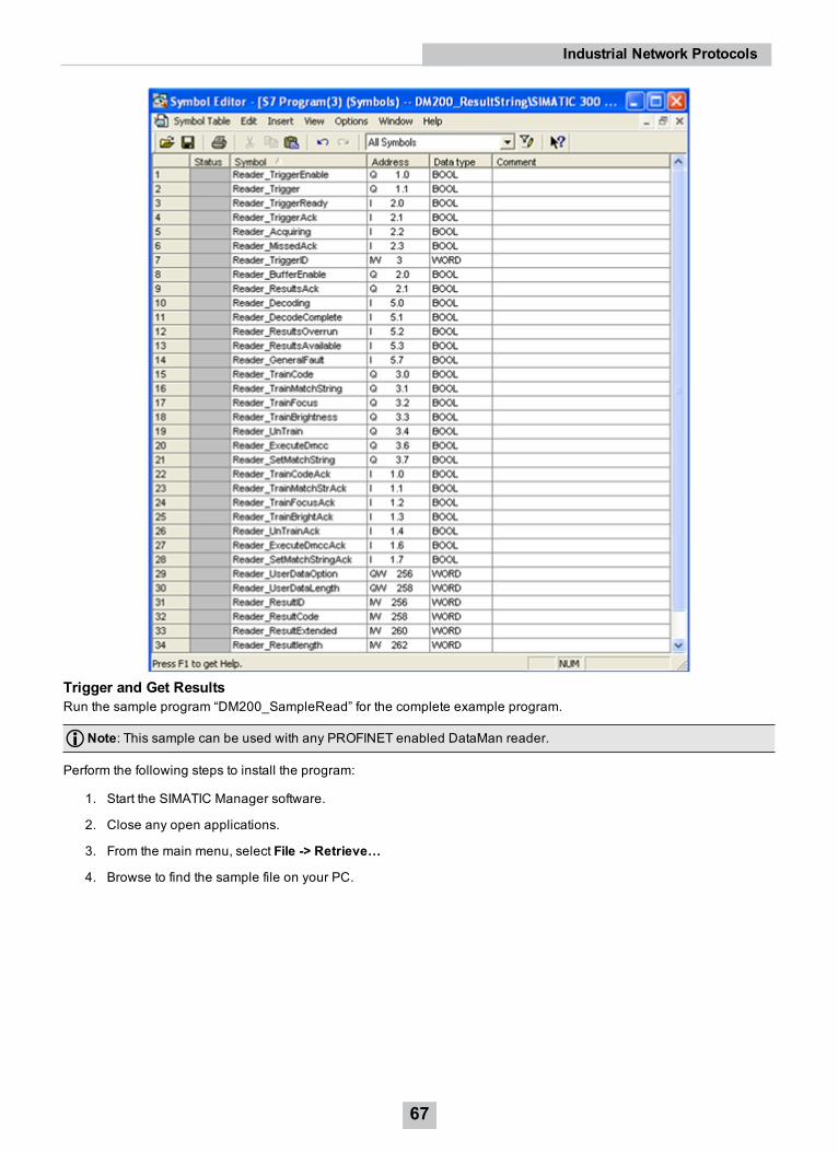
Trigger and Get ResultsRun the sample program “DM200_SampleRead” for the complete example program.
Note: This sample can be used with any PROFINET enabled DataMan reader.
Perform the following steps to install the program:
1. Start the SIMATIC Manager software.
2. Close any open applications.
3. From the main menu, select File -> Retrieve…
4. Browse to find the sample file on your PC.
67
Industrial Network Protocols

5. Save the project on your PC.
6. The Siemens software extracts the sample archive and makes it available.
Reduced to the basics, the process of reading and retrieving results consists of the following:
1. Define an area in your application to save read results. There are many options regarding how and where resultdata can be stored. In this example, a Data Block (DB) is defined containing the fields of the Result Data modulethat are relevant for our application.
2. Enable the reader.
68
Industrial Network Protocols

3. Set the trigger signal and set coil to indicate a read is pending.
4. As soon as the trigger signal is acknowledged, clear the trigger signal.
5. As soon as the results are available, save a copy of the result data and set the results acknowledge signal.
69
Industrial Network Protocols

6. When the reader sees the result acknowledge signal, clear result acknowledge, clear the read pending coil, andsignal that the read process is complete.
70
Industrial Network Protocols
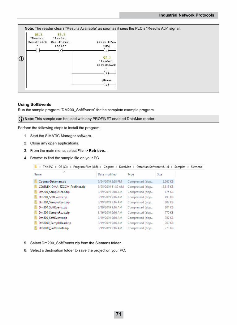
Note: The reader clears “Results Available” as soon as it sees the PLC’s “Results Ack” signal.
Using SoftEventsRun the sample program “DM200_SoftEvents” for the complete example program.
Note: This sample can be used with any PROFINET enabled DataMan reader.
Perform the following steps to install the program:
1. Start the SIMATIC Manager software.
2. Close any open applications.
3. From the main menu, select File -> Retrieve…
4. Browse to find the sample file on your PC.
5. Select Dm200_SoftEvents.zip from the Siemens folder.
6. Select a destination folder to save the project on your PC.
71
Industrial Network Protocols

7. The Siemens software extracts the sample archive and makes it available.
SoftEvents are a means of invoking an activity by manipulating a single control bit. The activity for each bit is predefined(for more details, see section SoftEvents). With the exception of “Execute DMCC” and “Set Match String” all SoftEventsmay be invoked in the same way. “Execute DMCC” and “Set Match String” require the added step of loading the UserData module with application data before invoking the event.
Reduced to the basics, the process of invoking a SoftEvent consists of the following:
72
Industrial Network Protocols

Executing DMCC CommandsRefer to sample program “DM200_SoftEvents” for the complete example program. For information on how to install it,see section Using SoftEvents.
Note: This sample can be used with any PROFINET enabled DataMan reader.
“Execute DMCC” is a SoftEvent which requires the added step of loading the User Data module with the desired DMCCcommand string before invoking the event. Note that the SoftEvent mechanism does not provide a means of returningDMCC response data other than a failure indication. This mechanism cannot be used for DMCC “||>GET…” commands.
The process of executing a DMCC command is the same for all other SoftEvents as in the example above except thestep of invoking the SoftEvent also includes copying the command string to the User Data Module. In this example thecommand string is in a Data Block. This example can be expanded to utilize a Data Block with an array of commandstrings that the copy function can reference by an index value. It allows the user to pre-define all DMCC commands thatare required by the application and invoke them by index.
73
Industrial Network Protocols

The function “Set User Data” (FC11) copies the provided string to the User Data module. Refer to the example programfor the actual STL code.
TIA Portal ExamplesThis section gives some examples of using the DataMan with a Siemens S7-1200 PLC, assuming that you are familiarwith the S7-1200 and TIA Portal.
74
Industrial Network Protocols

1. In TIA Portal, either create a new project, or open an existing one.
2. In Project View, click Options and click Manage general station description files (GSD).
3. Browse to the installation folder of the GSD file (or the location where you saved the GSD file if you downloaded itfrom the web).
4. Select the GSD file you wish to install and follow the displayed instructions to complete the installation.
Note: If there is more than one GSD file in the list and you are unsure which to install, choose the one with the mostrecent date.
75
Industrial Network Protocols
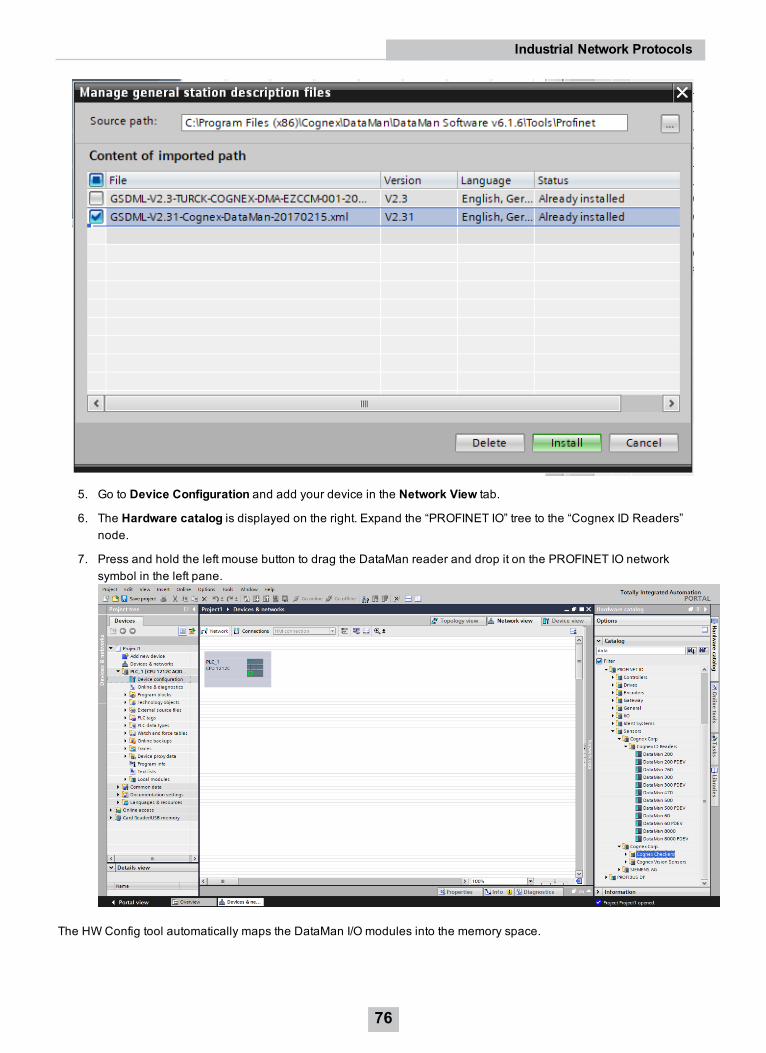
5. Go to Device Configuration and add your device in the Network View tab.
6. The Hardware catalog is displayed on the right. Expand the “PROFINET IO” tree to the “Cognex ID Readers”node.
7. Press and hold the left mouse button to drag the DataMan reader and drop it on the PROFINET IO networksymbol in the left pane.
The HWConfig tool automatically maps the DataMan I/O modules into the memory space.
76
Industrial Network Protocols

Note: By default, the 64 byte User Data and 64 byte Result Data Modules are inserted. There are multiple sizesavailable for both of these modules. To optimize performance, use the module size that most closely matches theactual data requirements of your application. You can change the module by deleting the one in the table andinserting the appropriate sized module from the catalog.
8. Right-click the DataMan icon and select Properties….
9. Give the reader a name. This must match the name of your actual DataMan reader. The name must be uniqueand follow DNS naming conventions. For details, see the TIA Portal help documentation.
10. If your DataMan reader is configured to use its own static IP, select the IP address is set directly at the deviceradio button. As an alternative, if you wish the PLC to assign an IP address, select the Ethernet button andconfigure the appropriate address.
11. Check the checkbox next to the device image and connect the selected device with the PLC by drawing a linewith your mouse.
77
Industrial Network Protocols

12. By default, the SIMATIC software maps the User Data and Result Data Modules to offset 256. This is outside ofthe default process image area size of 128. That is, data in these modules are inaccessible by some SFCs suchas BLKMOV. As a solution, either remap the modules to lower offsets within the process image area or expandthe process image area to include these modules.
If you choose to expand the process image area, make the size large enough for the module size plus the default 256offset.
78
Industrial Network Protocols

Note: Expanding the process image can have a performance impact on the PLC scan cycle time. If your scan timeis critical, use the minimal acceptable module sizes and manually remap them down lower in the process image.
Symbol TableIt is recommended that you define symbols for the DataMan I/O module elements to make the code much easier to readand reduce mistakes. This sample table shows symbols defined for a typical instance of a DataMan reader. It is possiblethat DataMan I/O modules are at different addresses in your project. Make sure to adjust your symbol definitions basedon the specific offsets of the I/O modules. For more information, see the TIA Portal Integration Guide for In-Sight andDataMan at https://support.cognex.com/en/downloads/detail/in-sight/3687/1033.
Trigger and Get ResultsOpen the sample program “Cognex-Dataman” for the complete example program.
Note: This sample can be used with any PROFINET enabled DataMan reader.
Perform the following steps to install the program:
1. Start TIA Portal.
2. Browse to find the sample file on your PC.
79
Industrial Network Protocols

3. Save the project on your PC. TIA Portal extracts the sample archive and makes it available.
Reduced to the basics, the process of reading and retrieving results consists of the following:
1. Define an area in your application to save read results. There are many options regarding how and where resultdata can be stored. In this example, a temporary tag is defined containing the fields of the Result Data modulethat are relevant for our application.
2. Enable the reader.
3. Set the trigger signal and set coil to indicate a read is pending.
4. As soon as the results are available, clear the trigger signal and save a copy of the result data and set the resultsacknowledge signal.
80
Industrial Network Protocols

5. When the reader sees the result acknowledge signal, clear result acknowledge, clear the read pending coil, andsignal that the read process is complete.
Note: The reader clears “Results Available” as soon as it sees the PLC’s “Results Ack” signal.
Using SoftEventsSoftEvents are a means of invoking an activity by manipulating a single control bit. The activity for each bit is predefined.For more details, see section SoftEvents. With the exception of “Execute DMCC” and “Set Match String” all SoftEventsmay be invoked in the same way. “Execute DMCC” and “Set Match String” require the added step of loading the UserData module with application data before invoking the event.
Reduced to the basics, the process of invoking a SoftEvent consists of the following:
81
Industrial Network Protocols

Executing DMCC CommandsRefer to sample program “Cognex-Dataman” for the complete example program. For information on how to install it, seesection Using SoftEvents.
Note: This sample can be used with any PROFINET enabled DataMan reader.
“Execute DMCC” is a SoftEvent which requires the added step of loading the User Data module with the desired DMCCcommand string before invoking the event. Note that the SoftEvent mechanism does not provide a means of returningDMCC response data (other than a failure indication). So this mechanism cannot be used for DMCC “||>GET…”commands.
The process of executing a DMCC command is the same for all other SoftEvents (see example above) except the step ofinvoking the SoftEvent also includes copying the command string to the User Data Module. In this example the commandstring is exists in a Data Block. This example can be expanded to utilize a Data Block with an array of command stringsthat the copy function can reference by an index value. This allows the user to pre-define all DMCC commands that arerequired by the application and invoke them by index.
82
Industrial Network Protocols

DataMan 370/470 v6.1.8 – PROFINET Class BUpgrading a DataMan 370/470 reader to firmware version 6.1.8 or higher installs a new PROFINET stack, addingsupport for PROFINET Class B. While this adds new functions and capabilities, it is not a drop-in replacement for aDataMan reader running the Class A stack, which all previous versions of DataMan firmware supported. You need toupdate the hardware configuration in the TIA software.
If you add DM370/DM470 readers to an existing system that has other DataMan products, both GSD files need to beinstalled. Refer to the table for which GSD file to use with a given reader.
FirmwareVersion and
DataMan Model
GSD File Description
DM370/DM470Firmware 6.1.7or later
V2.34 (GSDML-V2.34-Cognex-DataManClassB-20191018.xml)
Supports Class B, uses the Port stack. The Class-B configurations aresuffixed with CC-B, indicating that the configuration is Class B.Example: DataMan 470 CC-B.
All otherDataMan
V2.31 (GSDML-V2.31-Cognex-DataMan-20170215.xml)
Uses the Siemens PROFINET stack.
SNMP (Simple Network Management Protocol) v2 is supported only when the V2.34 GSD file is used. PROFINET usesthe topology technology to detect and identify devices on SNMP.
Supported MIBs:
l LLDP-MID
l LLDP-EXT-DOT3-MIB
l MIB-II
Writable OIDs:
l 1.3.6.1.2.1.1.4.0 (sysContact, defaults to “Someone <[email protected]>”)
l 1.3.6.1.2.1.1.5.0 (sysLocation, defaults to “somewhere”)
l 1.3.6.1.2.1.1.6.0 (sysName, defaults to “something”)
These OIDs are reset to the default settings after a factory reset. Other OIDs are also supported in the above MIBs buthave read access only.
PLC ChangesWhen upgrading the firmware on a DataMan 370/470 reader to firmware version 6.1.8 or higher, you need to remove thereader from the PLC hardware configuration, replace the General Station Description (GSD) file, then re-add the “CC-B”version of the reader to the hardware configuration.
From the point of view of the PLC, a Class A device is replaced with a Class B device, which fundamentally changes howthe PLC communicates with the reader. The PLC treats the reader as a completely different device.
Follow these steps to replace the reader in the hardware configuration of the PLC while maintaining the IO moduleaddressing scheme to ensure that the logic in the project is not affected.
Note: It is highly recommended to follow this process for each reader being upgraded, one at a time.
1. Go into the TIA Portal software and install the new GSD file from the Options drop down menu -> ManageGeneral Station Description File dialog.
83
Industrial Network Protocols
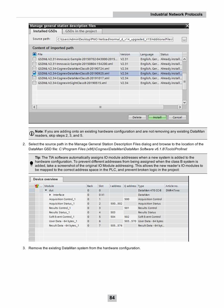
Note: If you are adding onto an existing hardware configuration and are not removing any existing DataManreaders, skip steps 2, 3, and 5.
2. Select the source path in the Manage General Station Description Files dialog and browse to the location of theDataMan GSD file: C:\Program Files (x86)\Cognex\DataMan\DataMan Software v6.1.8\Tools\Profinet
Tip: The TIA software automatically assigns IO module addresses when a new system is added to thehardware configuration. To prevent different addresses from being assigned when the class B system isadded, take a screenshot of the original IO Module addressing. This allows the new reader’s IO modules tobe mapped to the correct address space in the PLC, and prevent broken logic in the project:
3. Remove the existing DataMan system from the hardware configuration.
84
Industrial Network Protocols

4. Expand the catalog in the TIA Portal software, select the “DataMan 370 CC-B” or “DataMan 470 CC-B” versionand add it to your configuration.
5. Confirm that the IO Module addressing matches what the original vision system was mapped to. If they aredifferent, refer to the screenshot taken in step 2 to restore the IO module addresses to their previous values.
6. To change the cycle time to 8 ms, or to another value, select the reader from the Device view, and on the Generaltab, select Real Time Settings. Select the appropriate cycle time from the Update Time drop down menu:
Note: The new GSD file has a faster cycle time, defaulting to 4 ms from 8 ms. While this shortens the networkupdate interval, it also doubles the amount of PROFINET traffic from this device.
7. Compile and download the changes to the PLC.
iQ Sensor SolutioniQ Sensor Solution (iQSS) is an engineering tool offered by Mitsubishi Electric. It allows the intuitive configuration andmaintenance of sensors. If iQSS is enabled in the Setup tool, DataMan supports setting and monitoring of the followingdevice settings via iQSS:
l IP address and subnet mask
l The selected industrial protocol (SLMP, CC-Link IE Field Basic, or None).
l SLMP scanner parameters and device address mappings
Disabling iQSS blocks any attempts to remotely get or set these device settings.
85
Industrial Network Protocols

Note: If you have a wireless DataMan reader, read the section Industrial Protocols for the Wireless DataMan.
DMCCThe following commands can be used to enable or disable the iQ Sensor Solution. The commands can be issued viaRS-232 or Telnet connection.
Note: Because you have to make changes to the Telnet client provided by Windows to communicate with DataMan,it is recommended you use third party clients such as PuTTY.
Enable:
||>SET IQSS.ENABLED ON||>CONFIG.SAVE||>REBOOT
Disable:
||>SET IQSS.ENABLED OFF||>CONFIG.SAVE||>REBOOT
Choose language:
English:
||>SET IQSS.LANGUAGE 0||>CONFIG.SAVE||>REBOOT
Japanese:
||>SET IQSS.LANGUAGE 1||>CONFIG.SAVE||>REBOOT
Reader Configuration CodeScanning the following reader configuration codes will enable/disable iQ Sensor Solution for your corded reader.
Enable: Disable:
Scanning the following reader configuration codes will set the language for the iQSS on your DataMan reader.
English: Japanese:
86
Industrial Network Protocols

Setup ToolThe iQ Sensor Solution can be enabled by checking the box iQ Sensor Solution in the Communications step under theEthernet tab. Make sure to save the new selection by choosing Save Settings before disconnecting from the reader.
OverviewThis topic describes how to configure the iQ Sensor Solution for DataMan devices, and transfer data between a readerand a Mitsubishi Automation Controller using GX Works2. The examples in this topic were written assuming the followingcomponents are being used:
l DataMan Reader
l Mitsubishi iQ-R, Q, L or F-series (3E Frame) Automation Controller
Note: Note: FX Series (1E Frame) are not supported.
l Mitsubishi GX Works2 software (SWnDNC-GXW2-E) version 1.492 or later
l Cognex Language Package (English = CognexInsight_en.ipar; Japanese = CognexInsight_ja.ipar) includedwithin Setup Tool
Note: iQ Sensor Solution is only available on Setup Tool using 6.1.5 version.
Note: For more information on Mitsubishi iQ Sensor Solution, refer to Mitsubishi's iQ Sensor Solution ReferenceManual.
Mitsubishi iQ Sensor Solution is a factory protocol that enables the GX Works2 software to control readers over the SLMPScanner protocol. With the iQ Sensor Solution, GX Work2 is able to discover readers on the network, read/write thereader's SLMP Scanner parameter settings and monitor the status of a reader.
Note: For more information on GX Works2, refer to the GX Works2 Operating Manual.
Discovering DataMan Readers on GX Work2The following procedure assumes that the DataMan reader has not been previously configured for SLMP Scanner and isconnected to the same Ethernet subnet as a supported Mitsubishi Automation Controller.
1. Launch GX Works2.
2. From the Toolmenu, select Register Profile. The Register Profile window opens.
3. Create a new project in GX Works2.
4. Navigate to the Cognex DataMan Language Package (English = CognexInsight_en.ipar; Japanese =CognexInsight_ja.ipar), and click Register.
Note: By default, the Cognex Language Package is installed to: C:\Program Files (x86)\Cognex\In-Sight\In-Sight Explorer 4.9.x\Factory Protocol Description\ESPP.
5. Select Parameter --> PLC Parameter on the Project view. The L Parameter Setting window is displayed.
6. Select the Built-in Ethernet Port Settings tab.
7. Check the Set Open Setting in Ethernet Configuration window checkbox. The following message will bedisplayed.
8. Click Yes; the Open Settings button will be changed to the Ethenet Conf. button.
87
Industrial Network Protocols
9. Click the Ethernet Conf. button. The Ethernet Configuration window will be displayed.
10. Select Ethernet Configuration --> Online --> Detect Now; the following message is displayed.
11. Read the message and click Yes. The actual system configuration is reflected on the Ethernet Configurationwindow.
12. Select Close with Reflecting the Setting. The settings on the Ethernet Configuration window will be saved, andthe system configuration setting is completed.
Note: Up to 16 readers may be displayed (in ascending order of their IP addresses) on the Ethernet Configurationwindow after executing the automatic detection of connected devices. If the Detect Now button is pressed, and areader in the network is not iQSS-compatible, the reader will not appear in the Ethernet configuration window. If areader is iQSS-compatible but no profile was previously added to GX Works2, "Module With No Profile Found" willbe displayed.
Note: When a reader is detected in the actual system configuration, error information is displayed on the Outputwindow when there is an error in the system configuration after executing the automatic detection of connecteddevices. Double-click the error on the Output window and correct the error at the error jump destination.
Note: For troubleshooting, refer to Mitsubishi's iQ Sensor Solution Reference Manual.
Monitoring the status of the DataMan Reader1. Launch GX Works2 and open a project that has the specified network configured.
2. From the Diagnostics menu, select Sensor/Device Monitor. The Module Selection (Sensor/Device Monitor)window will be displayed.
3. Click OK; the Status of readers connected to the Built-in Ethernet port LCPU will be displayed on theSensor/Device Monitor window.
88
Industrial Network Protocols

4. Select the desired reader from the "list of devices" or "device map area". The status of the reader will be displayedon the Monitor Information window.
Note: Only one reader can be monitored in the Ethernet Configuration window at a time.
List of iQSS Error Codes:Error Code Description
0 SLMP connection established1 SLMP connection in progress2 SLMP connection rejected3 SLMP connection or configuration faulted4 SLMP poll rate configured too low5 SLMP connection idle6 SLMP connection timed out7 SLMP Status block error8 SLMP Control block error9 SLMP Output block error10 SLMP Input block error11 SLMP Command block error12 SLMP Command Result block error13 SLMP not started (if none or if different protocol like CC-Link is started)14 SLMP settings require a reader reboot to become effective
CC-Link IE Field BasicThe CC-Link IE Field Basic is an application-level protocol used in industrial automation applications. This protocol usesstandard Ethernet hardware and software to exchange I/O data, alarms, and diagnostics. It is Mitsubishi Electric’spublicly available, standardized communication format for communicating with iQ- Series, FX Series, iQ-R, iQ-F, Q, and LSeries PLCs through Ethernet or serial connections. DataMan supports the CC-Link IE Field Basic on Ethernet only.
By default the DataMan has the CC-Link Protocol disabled. The protocol can be enabled in the Setup Tool, via DMCC, orby scanning a parameter code.
Note: If you have a wireless DataMan reader, read the section Industrial Protocols for the Wireless DataMan.
DMCCThe following commands can be used to enable or disable the CC-Link IE Field Basic. The commands can be issued viaRS-232 or Telnet connection.
Note: Because you have to make changes to the Telnet client provided by Windows to communicate with DataMan,it is recommended you use third party clients such as PuTTY.
Enable:
||>SET CC-LINK.ENABLED ON||>CONFIG.SAVE||>REBOOT
Disable:
89
Industrial Network Protocols

||>SET CC-LINK.ENABLED OFF||>CONFIG.SAVE||>REBOOT
Reader Configuration CodeScanning the following reader configuration codes will enable/disable CC-Link Protocol for your corded reader.
Enable: Disable:
Setup ToolThe CC-Link IE Field Basic can be enabled by checking the box CC-Link in the Communications step under theEthernet tab - > Industrial Protocols. Make sure to save the new selection by choosing Save Settings beforedisconnecting from the reader.
Note: You must reboot your reader for the new settings to take effect.
Note: For more information visit Mitsubishi website.
ModulesThe CC-Link IE Field Basic implementation on DataMan consists of four I/O modules:
1. Control Block
2. Status Block
3. Output Data Block
4. Input Data Block
Signal LayoutBlock name Link Device Name Data Length Data FlowControl Block RY 64 bits (only the first 32 bits
are used)PLC to Reader
Status Block RX 64 bits (only the first 32 bitsare used)
Reader to PLC
Output Data Block RWw 32 Words (64 bytes) PLC to ReaderInput Data Block RWr 32 Words (64 bytes) Reader to PLC
Note: The number of link devices can be increased up to a factor of 4, if the reader is configured in GXWorks tooccupy more than one station. This can be useful if inspection results or DMCC commands need to be transmittedthat are longer than 62 bytes.
90
Industrial Network Protocols

Control Block (RY)The Control block contains bit type data. However, the block may be defined to exist in either bit or word memory in thePLC. This block consists of the control signals sent from the PLC to the reader. It is used by the PLC to initiate actionsand acknowledge certain data transfers.Control Block
Bit 7 Bit 6 Bit 5 Bit 4 Bit 3 Bit 2 Bit 1 Bit 0Reserved Results Ack Buffer
ResultsEnable
Trigger TriggerEnable
Bit 15 Bit 14 Bit 13 Bit 12 Bit 11 Bit 10 Bit 9 Bit 8Reserved
Bit 23 Bit 22 Bit 21 Bit 20 Bit 19 Bit 18 Bit 17 Bit 16Reserved Reserved Reserved
Bit 31 Bit 30 Bit 29 Bit 28 Bit 27 Bit 26 Bit 25 Bit 24Soft Event 7 Soft Event 6 Soft Event 5 Soft Event 4 Soft Event 3 Soft Event 2 Soft Event 1 Soft Event 0
Control Block (RY) Field DescriptionsBit Name Description0 Trigger
EnableThis field is set to enable triggering via the Trigger bit. Clear this field to disable the networktriggering mechanism.
1 Trigger Setting this bit triggers an acquisition.
Note: The Trigger Ready bit must be set high before triggering an acquisition.
2 BufferResultsEnable
When this bit is set, each read result set (ResultID, ResultCode, ResultLength and ResultDatafields) will be held in the Output Block until it is acknowledged. Once acknowledged, the nextset of read results will be made available from the buffer. If new read results arrive before theearlier set is acknowledged the new set will be queued in the reader’s buffer. The reader canbuffer up to 50 and the base station can buffer up to 500 sets of read results. See Operation fora description of the acknowledgement handshake sequence.
3 ResultsAck Set by the PLC to acknowledge that it has received the latest results (ResultID, ResultCode,ResultLength and ResultData fields). When the reader sees this bit transition from 0->1 itclears the ResultsAvailable bit. This forms a logical handshake between the PLC and reader. Ifresult buffering is enabled, the acknowledgement will cause the next set of queued results tobe moved from the buffer. See Operation for a description of the acknowledgement handshakesequence.
4-15 Reserved Future use16 Reserved Future use17 Reserved Future use
18-23 Reserved Future use24-31 SoftEvents Bits act as virtual discrete inputs. When a bit transitions from 0->1 the associated action is
executed. After executing the action the reader sets the corresponding SoftEventAck to signalthat the action is complete. This forms a logical handshake between the PLC and reader.Bit0: Train codeBit1: Train match stringBit2: Train focusBit3: Train brightnessBit4: Un-TrainBit5: Reserved (future use)Bit6: Execute DMCC commandBit7: Set match string
91
Industrial Network Protocols

Status Block (RX)The status block contains bit type data. However, the block may be defined to exist in either bit or word memory in thePLC. This block consists of the status signals sent from the reader to the PLC. It is used by the reader to signal status andhandshake certain data transfers.
Bit 7 Bit 6 Bit 5 Bit 4 Bit 3 Bit 2 Bit 1 Bit 0Reserved Missed
AcqAcquiring Trigger
AckTriggerReady
Bit 15 Bit 14 Bit 13 Bit 12 Bit 11 Bit 10 Bit 9 Bit 8GenerealFault
Reserved ResultsAvailable
Results BufferOverrun
Decode CompleteToggle
Decoding
Bit 23 Bit 22 Bit 21 Bit 20 Bit 19 Bit 18 Bit 17 Bit 16Reserved Reserved Reserved
Bit 31 Bit 30 Bit 29 Bit 28 Bit 27 Bit 26 Bit 25 Bit 24Soft EventAck 7
Soft EventAck 6
Soft EventAck 5
Soft EventAck 4
Soft EventAck3
Soft EventAck 2
Soft EventAck 1
Soft EventAck 0
Status Block (RX) Field DescriptionsBit Name Description0 Trigger Ready Indicates when the reader is ready to accept a new Trigger. The reader sets this bit when
TriggerEnable has been set and the reader is ready to accept a new trigger.1 Trigger Ack Indicates when the reader recognizes that Trigger has been set. This bit will remain set
until the Trigger bit has been cleared.2 Acquiring Set to indicate that the reader is in the process of acquiring an image.
Note: For CF26, this bit is “Reserved”.
3 Missed Acq Indicates that the reader missed a requested acquisition trigger. The bit is cleared whenthe next acquisition is issued.
4-7 Reserved Future use8 Decoding Set to indicate that the reader is in the process of decoding an image.9 Decode
CompleteToggle
Indicates new result data is available. Bit toggles state (0->1 or 1->0) each time newresult data becomes available.
10 Results BufferOverrun
Set to indicate that the reader has discarded a set of read results because the PLC hasnot acknowledged the earlier results. Cleared when the next set of result data issuccessfully queued in the buffer. This bit only has meaning if result buffering is enabled.
11 ResultsAvailable
Set to indicate that new result data is available. Bit will remain set until acknowledgedwith ResultsAck even if additional new read results become available.
12-14 Reserved Future use15 General Fault Set to indicate that an Ethernet communications fault has occurred. Currently only used
by soft event operations. Bit will remain set until the next successful soft event or untilTriggerEnable is set low and then high again.
16 Reserved Future use.17 Reserved Future use
18-23 Reserved Future use
92
Industrial Network Protocols
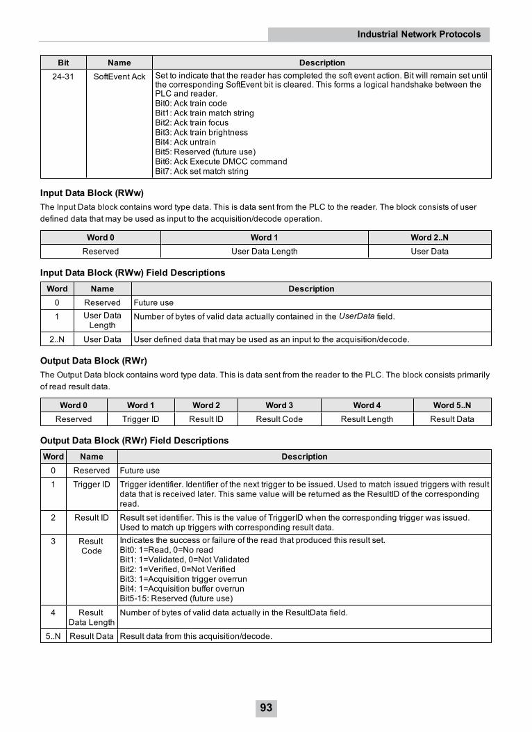
Bit Name Description24-31 SoftEvent Ack Set to indicate that the reader has completed the soft event action. Bit will remain set until
the corresponding SoftEvent bit is cleared. This forms a logical handshake between thePLC and reader.Bit0: Ack train codeBit1: Ack train match stringBit2: Ack train focusBit3: Ack train brightnessBit4: Ack untrainBit5: Reserved (future use)Bit6: Ack Execute DMCC commandBit7: Ack set match string
Input Data Block (RWw)The Input Data block contains word type data. This is data sent from the PLC to the reader. The block consists of userdefined data that may be used as input to the acquisition/decode operation.
Word 0 Word 1 Word 2..NReserved User Data Length User Data
Input Data Block (RWw) Field DescriptionsWord Name Description0 Reserved Future use1 User Data
LengthNumber of bytes of valid data actually contained in the UserData field.
2..N User Data User defined data that may be used as an input to the acquisition/decode.
Output Data Block (RWr)The Output Data block contains word type data. This is data sent from the reader to the PLC. The block consists primarilyof read result data.
Word 0 Word 1 Word 2 Word 3 Word 4 Word 5..NReserved Trigger ID Result ID Result Code Result Length Result Data
Output Data Block (RWr) Field DescriptionsWord Name Description0 Reserved Future use1 Trigger ID Trigger identifier. Identifier of the next trigger to be issued. Used to match issued triggers with result
data that is received later. This same value will be returned as the ResultID of the correspondingread.
2 Result ID Result set identifier. This is the value of TriggerID when the corresponding trigger was issued.Used to match up triggers with corresponding result data.
3 ResultCode
Indicates the success or failure of the read that produced this result set.Bit0: 1=Read, 0=No readBit1: 1=Validated, 0=Not ValidatedBit2: 1=Verified, 0=Not VerifiedBit3: 1=Acquisition trigger overrunBit4: 1=Acquisition buffer overrunBit5-15: Reserved (future use)
4 ResultData Length
Number of bytes of valid data actually in the ResultData field.
5..N Result Data Result data from this acquisition/decode.
93
Industrial Network Protocols

SLMP ProtocolThe SLMP Protocol uses standard Ethernet hardware and software to exchange I/O data, alarms, and diagnostics. It isMitsubishi Electric’s publicly available, standardized communication format for communicating with Q, iQ and L SeriesPLCs through Ethernet or serial connections. DataMan supports SLMP Protocol on Ethernet only.
By default, the DataMan has SLMP Protocol disabled. The protocol can be enabled in the Setup Tool, via DMCC, or byscanning a configuration code.
Note: If you have a wireless DataMan reader, see section Industrial Protocols for the Wireless DataMan onpage 127.
DMCCThe following commands can be used to enable/disable SLMP Protocol. The commands can be issued via RS-232 orTelnet connection.
Note: Use a third party Telnet client such as PuTTY to communicate with your DataMan reader.
Enable:
||>SET SLMP-PROTOCOL.ENABLED ON||>CONFIG.SAVE||>REBOOT
Disable:
||>SET SLMP-PROTOCOL.ENABLED OFF||>CONFIG.SAVE||>REBOOT
Reader Configuration CodeScanning the following reader configuration codes enables/disables SLMP Protocol for your corded reader.
Note: You must reboot the device for the change to take effect.
Enable: Disable:
Scanning the following reader configuration codes enables/disables SLMP protocol on your DataMan 8000 base station.
Note: You must reboot the device for the change to take effect.
Enable: Disable:
94
Industrial Network Protocols
SLMP Protocol ScannerSLMP Protocol on DataMan is implemented as a client type device also referred to as a scanner. The DataMan readerinitiates all communication in the form of read and write requests. The PLC acts as a passive server reacting to the readand write requests. Since the PLC cannot initiate communication, it relies on the reader to periodically ask (scan) thePLC for any actions or information that the PLC requires, such as triggering or retrieving read results.
Getting StartedBy default, SLMP Protocol is not enabled on the DataMan reader. The protocol must be enabled and the protocolconfiguration parameters must be set to correctly interact with a PLC. Protocol configuration is accomplished via theDataMan Setup Tool.
In the Setup Tool's Communications application step's Ethernet tab, check SLMP Protocol to enable this industrialprotocol.
95
Industrial Network Protocols

Make sure to save the new selection by clicking the Save Settings button in the upper toolbar before disconnecting fromthe reader.
Note: The new settings take effect only after the reader is rebooted.
SLMP Protocol configuration consists of two aspects: defining the network information and defining the data to beexchanged. All configuration parameters are accessed via the SLMP Protocol tab.
You must modify the IP Address to match the address of your PLC. In addition, modify Network Number, PC Numberand Destination Module if they differ from your network.
96
Industrial Network Protocols
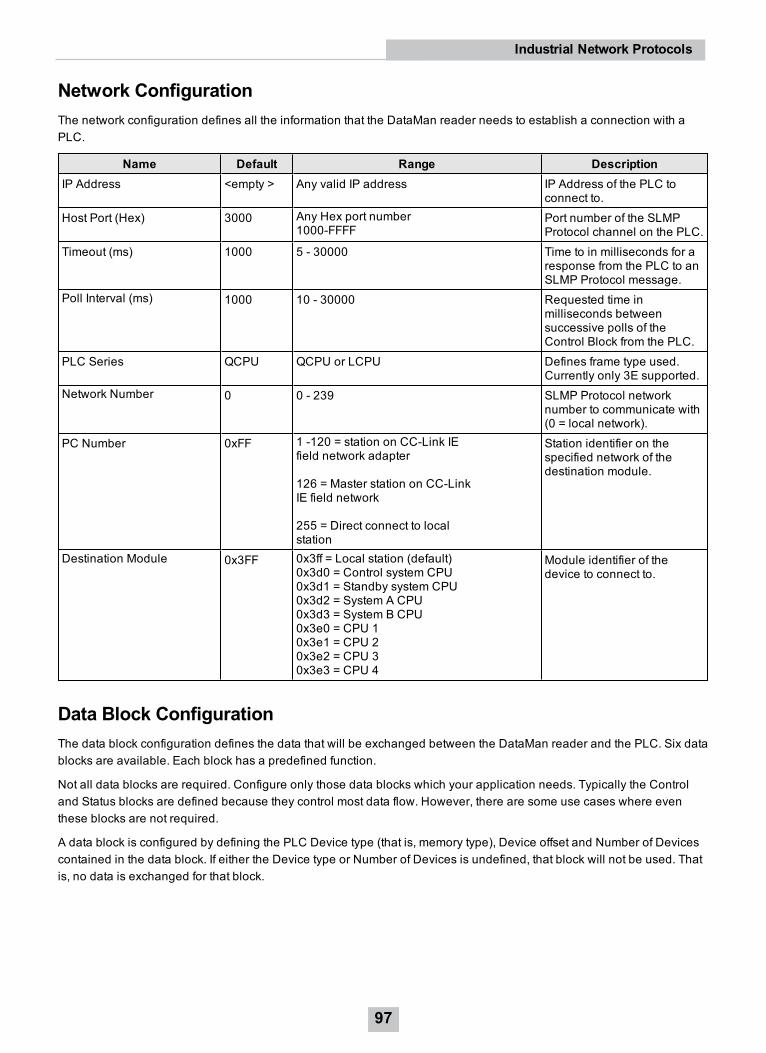
Network ConfigurationThe network configuration defines all the information that the DataMan reader needs to establish a connection with aPLC.
Name Default Range DescriptionIP Address <empty > Any valid IP address IP Address of the PLC to
connect to.Host Port (Hex) 3000 Any Hex port number
1000-FFFFPort number of the SLMPProtocol channel on the PLC.
Timeout (ms) 1000 5 - 30000 Time to in milliseconds for aresponse from the PLC to anSLMP Protocol message.
Poll Interval (ms) 1000 10 - 30000 Requested time inmilliseconds betweensuccessive polls of theControl Block from the PLC.
PLC Series QCPU QCPU or LCPU Defines frame type used.Currently only 3E supported.
Network Number 0 0 - 239 SLMP Protocol networknumber to communicate with(0 = local network).
PC Number 0xFF 1 -120 = station on CC-Link IEfield network adapter
126 = Master station on CC-LinkIE field network
255 = Direct connect to localstation
Station identifier on thespecified network of thedestination module.
Destination Module 0x3FF 0x3ff = Local station (default)0x3d0 = Control system CPU0x3d1 = Standby system CPU0x3d2 = System A CPU0x3d3 = System B CPU0x3e0 = CPU 10x3e1 = CPU 20x3e2 = CPU 30x3e3 = CPU 4
Module identifier of thedevice to connect to.
Data Block ConfigurationThe data block configuration defines the data that will be exchanged between the DataMan reader and the PLC. Six datablocks are available. Each block has a predefined function.
Not all data blocks are required. Configure only those data blocks which your application needs. Typically the Controland Status blocks are defined because they control most data flow. However, there are some use cases where eventhese blocks are not required.
A data block is configured by defining the PLC Device type (that is, memory type), Device offset and Number of Devicescontained in the data block. If either the Device type or Number of Devices is undefined, that block will not be used. Thatis, no data is exchanged for that block.
97
Industrial Network Protocols

Block Name Supported Device Types Offset Numberof
DevicesControl <none>, D, W, R, ZR, M, X, Y, L, F, B 0 -
655350, if type<none>
32, if bittype
2, ifwordtype(read-only)
Status <none>, D, W, R, ZR, M, X, Y, L, F, B 0 -65535
0, if type<none>
32, if bittype
2, ifwordtype(read-only)
PLC Input None, D, W, R, ZR 0 -65535
0 - 960
PLC Output None, D, W, R, ZR 0 -65535
0 - 960
Command None, D, W, R, ZR 0 -65535
0 - 960
CommandResult
None, D, W, R, ZR 0 -65535
0 - 960
InterfaceThis section describes the interface to the DataMan reader as seen by the PLC via SLMP Protocol. The interface modelconsists of six data blocks grouped in three logical pairs:
l Control and Status
l PLC Input and PLC Output
l Command and Command Response
Not all of the blocks are required. You may select which blocks are appropriate for your particular application. However,Control and Status will generally be included for most applications.
You can define the starting address and device type for each interface block that you choose to use in your application.Undefined blocks will not be exchanged. For any transfer (read or write) the entire block is sent, even if only one fieldwithin the block has changed value. The protocol implementation will minimize network use by grouping as many valuechanges as logically possible into a single transfer.
Control BlockThe Control block contains bit type data. However, the block may be defined to exist in either bit or word memory in thePLC. This block consists of the control signals sent from the PLC to the reader. It is used by the PLC to initiate actionsand acknowledge certain data transfers.Control Block
98
Industrial Network Protocols

Bit 7 Bit 6 Bit 5 Bit 4 Bit 3 Bit 2 Bit 1 Bit 0Reserved Results Ack Buffer
ResultsEnable
Trigger TriggerEnable
Bit 15 Bit 14 Bit 13 Bit 12 Bit 11 Bit 10 Bit 9 Bit 8Reserved
Bit 23 Bit 22 Bit 21 Bit 20 Bit 19 Bit 18 Bit 17 Bit 16Reserved Initiate
String CmdSet UserData
Bit 31 Bit 30 Bit 29 Bit 28 Bit 27 Bit 26 Bit 25 Bit 24SoftEvent 7 SoftEvent 6 SoftEvent 5 SoftEvent 4 SoftEvent 3 SoftEvent 2 SoftEvent 1 SoftEvent 0
Control Block Field DescriptionsBit Name Description0 Trigger
EnableThis field is set to enable triggering via the Trigger bit. Clear this field to disable the networktriggering mechanism.
1 Trigger Setting this bit triggers an acquisition.
Note: The Trigger Ready bit must be set high before triggering an acquisition.
2 BufferResultsEnable
When this bit is set, each read result set (ResultID, ResultCode, ResultLength andResultData fields) will be held in the Output Block until it is acknowledged. Onceacknowledged, the next set of read results will be made available from the buffer. If new readresults arrive before the earlier set is acknowledged, the new set will be queued in thereader’s buffer. The reader can buffer up to 50 and the base station can buffer up to 500 setsof read results. See Operation for a description of the acknowledgement handshakesequence.
3 ResultsAck Set by the PLC to acknowledge that it has received the latest results (ResultID, ResultCode,ResultLength and ResultData fields). When the reader sees this bit transition from 0 to 1, itclears the ResultsAvailable bit. This forms a logical handshake between the PLC and reader.If result buffering is enabled, the acknowledgement will cause the next set of queued resultsto be moved from the buffer. See section Operation for a description of the acknowledgementhandshake sequence.
4-15 Reserved Reserved for future use.16 SetUserData Set by the PLC to signal that new UserData is available. After reading the new UserData, the
reader sets Set UserDataAck to signal that the transfer is complete. This forms a logicalhandshake between the PLC and reader.
17 InitiateStringCmd
Set by the PLC to signal that a new StringCommand is available. After processing thecommand, the reader sets StringCmdAck to signal that the command result is available. Thisforms a logical handshake between the PLC and reader.
18-23 Reserved Future use24-31 SoftEvents Bits act as virtual discrete inputs. When a bit transitions from 0 to 1, the associated action is
executed. After executing the action, the reader sets the corresponding SoftEventAck tosignal that the action is complete. This forms a logical handshake between the PLC andreader.Bit0: Train codeBit1: Train match stringBit2: Train focusBit3: Train brightnessBit4: Un-TrainBit5: Reserved (future use)Bit6: Execute DMCC commandBit7: Set match string
99
Industrial Network Protocols

Status BlockThe status block contains bit type data. The block can also be defined to exist in either bit or word memory in the PLC.This block consists of the status signals sent from the reader to the PLC. The reader uses it to signal status andhandshake certain data transfers.
Bit 7 Bit 6 Bit 5 Bit 4 Bit 3 Bit 2 Bit 1 Bit 0Reserved Missed
AcqAcquiring Trigger
AckTriggerReady
Bit 15 Bit 14 Bit 13 Bit 12 Bit 11 Bit 10 Bit 9 Bit 8GeneralFault
Reserved ResultsAvailable
Results BufferOverrun
Decode CompleteToggle
Decoding
Bit 23 Bit 22 Bit 21 Bit 20 Bit 19 Bit 18 Bit 17 Bit 16Reserved String Cmd
AckSet UserData Ack
Bit 31 Bit 30 Bit 29 Bit 28 Bit 27 Bit 26 Bit 25 Bit 24SoftEventAck 7
SoftEventAck 6
SoftEventAck 5
SoftEventAck 4
SoftEventAck3
SoftEventAck 2
SoftEventAck 1
SoftEventAck 0
Status Block Field DescriptionsBit Name Description0 Trigger
ReadyIndicates when the reader is ready to accept a new Trigger. The reader sets this bit whenTriggerEnable has been set and the reader is ready to accept a new trigger.
1 TriggerAck
Indicates when the reader recognizes that Trigger has been set. This bit remains set until theTrigger bit is clear.
2 Acquiring Set to indicate that the reader is in the process of acquiring an image.
3 MissedAcq
Indicates that the reader missed a requested acquisition trigger. The bit is cleared when the nextacquisition is issued.
4-7 Reserved Future use8 Decoding Set to indicate that the reader is in the process of decoding an image.9 Decode
CompleteToggle
Indicates new result data is available. Bit toggles state (0 to 1 or 1 to 0) each time new resultdata becomes available.
10 ResultsBufferOverrun
Set to indicate that the reader has discarded a set of read results because the PLC has notacknowledged the earlier results. Cleared when the next set of result data is successfullyqueued in the buffer. This bit only has meaning if result buffering is enabled.
11 ResultsAvailable
Set to indicate that new result data is available. Bit will remain set until acknowledged withResultsAck even if additional new read results become available.
12-14 Reserved Future use15 General
FaultSet to indicate that an Ethernet communications fault has occurred. Currently only used bySoftEvent operations. Bit will remain set until the next successful SoftEvent or untilTriggerEnable is set low and then high again.
16 Set UserData Ack
Set to indicate that the reader has received new UserData. Bit will remain set until thecorresponding SetUserData bit is cleared. This forms a logical handshake between the PLC andreader.
17 StringCmd Ack
Set to indicate that the reader has completed processing the latest string command and that thecommand response is available. Bit will remain set until the corresponding InitiateStringCmd bitis cleared. This forms a logical handshake between the PLC and reader.
18-23 Reserved Future use
100
Industrial Network Protocols

Bit Name Description24-31 SoftEvent
AckSet to indicate that the reader has completed the SoftEvent action. Bit will remain set until thecorresponding SoftEvent bit is cleared. This forms a logical handshake between the PLC andreader.Bit0: Ack train codeBit1: Ack train match stringBit2: Ack train focusBit3: Ack train brightnessBit4: Ack untrainBit5: Reserved (future use)Bit6: Ack Execute DMCC commandBit7: Ack set match string
Input Data BlockThe Input Data block contains word type data. This is data sent from the PLC to the reader. The block consists of userdefined data that may be used as input to the acquisition/decode operation.
Word 0 Word 1 Word 2..NReserved User Data Length User Data
Input Data Block Field DescriptionsWord Name Description0 Reserved Future use1 User Data
LengthNumber of bytes of valid data actually contained in the UserData field.
2..N User Data User defined data that may be used as an input to the acquisition/decode.
Output Data BlockThe Output Data block contains word type data. This is data sent from the reader to the PLC. The block consists primarilyof read result data.
Word 0 Word 1 Word 2 Word 3 Word 4 Word 5..NReserved Trigger ID Result ID Result Code Result Length Result Data
Output Data Block Field DescriptionsWord Name Description0 Reserved Future use1 Trigger ID Trigger identifier. Identifier of the next trigger to be issued. Used to match issued triggers with result
data that is received later. This same value will be returned as the ResultID of the correspondingread.
2 Result ID Result set identifier. This is the value of TriggerID when the corresponding trigger was issued.Used to match up triggers with corresponding result data.
101
Industrial Network Protocols

Word Name Description3 Result
CodeIndicates the success or failure of the read that produced this result set.Bit0: 1=Read, 0=No readBit1: 1=Validated, 0=Not ValidatedBit2: 1=Verified, 0=Not VerifiedBit3: 1=Acquisition trigger overrunBit4: 1=Acquisition buffer overrunBit5-15: Reserved (future use)
4 ResultData Length
Number of bytes of valid data actually in the ResultData field.
5..N Result Data Result data from this acquisition/decode.
String Command BlockThe String Command block contains word type data. This is data sent from the PLC to the reader. The block is used totransport string based commands (DMCC) to the reader.
Note: Do not send string commands that change the reader configuration at the same time as reads are beingtriggered. Changing configuration during acquisition/decode can lead to unpredictable results.
Word 0 Word 1..NLength String Command
String Command Block Field DescriptionsWord Name Description0 Length Number of bytes of valid data in the StringCommand field.1..N String Command ASCII text string containing the command to execute. No null termination required.
String Command Result BlockThe String Command Result block contains word type data. This is data sent from the reader to the PLC. The block isused to transport the response from string based commands (DMCC) to the PLC.
Word 0 Word 1 Word 2..NResult Code Length String Command Result
String Command Result Block Field DescriptionsWord Name Description0 Result Code Code value indicating the success or failure of the command. Refer to the Command Reference,
available through the Windows Start menu or the DataMan Setup Tool Help menu.1 Length Number of bytes of valid data in the StringCommand field.
2..N StringCommandResult
ASCII text string containing the command to execute. No null termination required.
102
Industrial Network Protocols
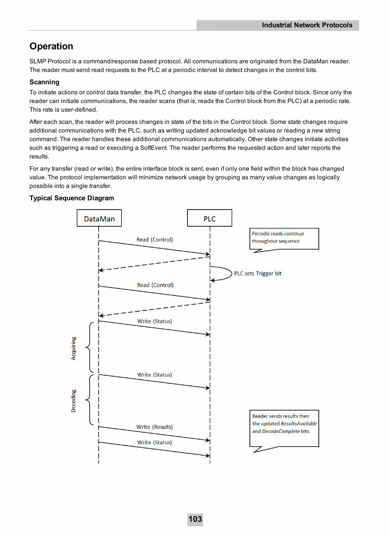
OperationSLMP Protocol is a command/response based protocol. All communications are originated from the DataMan reader.The reader must send read requests to the PLC at a periodic interval to detect changes in the control bits.
ScanningTo initiate actions or control data transfer, the PLC changes the state of certain bits of the Control block. Since only thereader can initiate communications, the reader scans (that is, reads the Control block from the PLC) at a periodic rate.This rate is user-defined.
After each scan, the reader will process changes in state of the bits in the Control block. Some state changes requireadditional communications with the PLC, such as writing updated acknowledge bit values or reading a new stringcommand. The reader handles these additional communications automatically. Other state changes initiate activitiessuch as triggering a read or executing a SoftEvent. The reader performs the requested action and later reports theresults.
For any transfer (read or write), the entire interface block is sent, even if only one field within the block has changedvalue. The protocol implementation will minimize network usage by grouping as many value changes as logicallypossible into a single transfer.
Typical Sequence Diagram
103
Industrial Network Protocols

HandshakingA number of actions are accomplished by means of a logical handshake between the reader and the PLC: triggering,transferring results, executing SoftEvents, string commands, and so on. This ensures that both sides of a transactionknow the state of the operation on the opposite side. Network transmission delays always introduce a finite time delay intransfer data and signals. Without this handshaking, one side of a transaction might not detect a signal state change onthe other side. Any operation that has both an initiating signal and corresponding acknowledge signal uses this basichandshake procedure.
The procedure involves a four-way handshake.
1. Assert signal
2. Signal acknowledge
3. De-assert signal
4. De-assert acknowledge
The requesting device asserts the signal to request an action (set bit 0 to 1). When the target device detects the signaland the requested operation is complete, it asserts the corresponding acknowledge (set bit 0 to 1). When the requestingdevice detects the acknowledge, it de-asserts the original signal (1 to 0). Finally, when the target device detects theoriginal signal de-asserted, it de-asserts its acknowledge (bit 0 to 1). To function correctly, both sides must see thecomplete assert/de-assert cycle (0 to 1 and 1 to 0). The requesting device should not initiate a subsequent request untilthe cycle completes.
Acquisition SequenceDataMan can be triggered to acquire images by several methods. It can be done via the SLMP Protocol by setting theTrigger bit or issuing a trigger String Command, by DMCC (Telnet), or hardwired trigger signal. This section describesthe Trigger bit method.
On startup the TriggerEnable will be False. It must be set to True to enable triggering via the SLMP Protocol Trigger bit.When the device is ready to accept triggers, the reader will set the TriggerReady bit to True.
While the TriggerReady bit is True, each time the reader detects the Trigger bit change from 0 to 1, it initiates a read.Make sure that the Trigger bit is held in the new state until that same state value is seen in the TriggerAck bit. This is anecessary handshake to guarantee that the reader detects the trigger.
During an acquisition, the TriggerReady bit will be cleared and the Acquiring bit will be set to True. When the acquisitionis completed, the Acquiring bit will be cleared. When the device is ready to begin another image acquisition, theTriggerReady bit will again be set to True.
If results buffering is enabled, the reader will allow overlapped acquisition and decoding operations. TriggerReady willbe set high after acquisition is complete but while decoding is still in process. This can be used to achieve faster overalltrigger rates. If result buffering is not enabled, the TriggerReady bit will remain low until both the acquisition and decodeoperations are complete.
104
Industrial Network Protocols

To force a reset of the trigger mechanism, set the TriggerEnable to False until TriggerReady is also set to False. Then,TriggerEnable can be set to True to re-enable acquisition.
As a special case, an acquisition can be cancelled by clearing the Trigger signal before the read operation is complete.This allows for canceling reads in Presentation and Manual mode if no code is in the field of view. To ensure that a readis not unintentionally cancelled, make sure that the PLC holds the Trigger signal True until both TriggerAck andResultsAvailable are True (or DecodeComplete toggles state).
Decode / Result SequenceAfter an image is acquired, it is decoded. While being decoded, the Decoding bit is set. When the decode operation iscomplete, the Decoding bit is cleared. The ResultsBufferEnable determines how the reader handles decode results.
If ResultsBufferEnable is set to False, the read results are immediately placed into the Output Data block,ResultsAvailable is set to True and DecodeComplete is toggled.
If ResultsBufferEnable is set to True, the new results are queued in a buffer and DecodeComplete is toggled. The earlierread results remain in the Output Data block until the PLC acknowledges them. After the acknowledgment handshake, ifthere are more results in the queue, the next set of results will be placed in the Output Data block and ResultsAvailable isset to True.
105
Industrial Network Protocols

Results BufferingThere is an option to enable a queue for read results. If enabled, this allows a finite number of sets of result data to bequeued up until the PLC has time to read them. This is useful to smooth out data flow if the PLC slows down for shortperiods of time.
If result buffering is enabled, the reader will allow overlapped acquisition and decode operations. Depending on theapplication this can be used to achieve faster overall trigger rates. For more information, see the Acquisition Sequencedescription.
In general, if reads are occurring faster than results can be sent out, the primary difference between buffering or notbuffering determines which results get discarded. If buffering is not enabled, the most recent results are kept and theearlier result, which the PLC did not read quickly enough, is lost. The more recent result overwrites the earlier result. Ifbuffering is enabled and the queue becomes full, the most recent results are discarded until space becomes available inthe results queue.
Note: If the queue has overflowed and then buffering is disabled, there will be a greater than 1 difference betweenthe TriggerID and ResultID values. This difference represents the number of reads that occurred but could not bequeue because the queue was full (number of lost reads equals TriggerID - ResultID - 1). After the next read, theResultID value will return to the typical operating value of TriggerID - 1.
SoftEventsSoftEvents act as “virtual” inputs. When the value of a SoftEvent bit changes from 0 to 1, the action associated with theevent is executed. When the action completes, the corresponding SoftEventAck bit will change from 0 to 1 to signalcompletion.
The SoftEvent and SoftEventAck form a logical handshake. After SoftEventAck changes to 1, the original SoftEventshould be set back to 0. When that occurs, SoftEventAck will automatically be set back to 0.
WARNING: Do not execute SoftEvents that change the reader configuration at the same time that reads are beingtriggered. Changing configuration during acquisition/decode can lead to unpredictable results.
106
Industrial Network Protocols

Note: The “ExecuteDMCC” and “SetMatchString” SoftEvent actions require user supplied data. This data must bewritten to the UserData and UserDataLength area of the Input Data block prior to invoking the SoftEvent. Since bothof these SoftEvents depend on the UserData, only one may be invoked at a time.
String CommandsThe DataMan SLMP Protocol implementation includes a String Command feature. This feature allows you to executestring-based DMCCs over the SLMP protocol connection. The DMCC is sent to the reader through the String Commandblock. The DMCC result is returned through the String Command Result block. Initiating a command and notification ofcompletion is accomplished by signaling bits in the Control and Status blocks.
To execute a DMCC, the command string is placed in the data field of the String Command block. The command stringconsists of standard ASCII text. The same command format is used for a serial (RS-232) or Telnet connection. The stringdoes not need to be terminated with a null character. Instead, the length of the string (that is, the number of ASCIIcharacters) is placed in the length field of the String Command block.
After executing the DMCC, the result string is returned in the String Command Result block. Similar to the originalcommand, the result string consists of ASCII characters in the same format that is returned through a serial or Telnetconnection. Also, there is no terminating null character. Instead the length of the result is returned in the Command StringResult length field. The Command String Result block also contains a numeric result code. This allows you to determinethe success or failure of the command without having to parse the text string. The values of the result code are defined inthe DMCC documentation.
General Fault IndicatorWhen an SLMP Protocol communication-related fault occurs, the “GeneralFault” bit will change from 0 to 1. Currently theonly fault conditions supported are SoftEvent operations. If a SoftEvent operation fails, the fault bit will be set. The fault bitwill remain set until the next successful SoftEvent operation, or, until TriggerEnable is set to 0 and then back to 1.
ExamplesIncluded with the DataMan Setup Tool installer is an example PLC program created with Mitsubishi (GX Works2)software. This program demonstrates the DataMan ID readers’ capabilities and proper operation. You can do the sameoperations by using more advanced features and efficient programming practices with Mitsubishi PLCs. Fordemonstration purposes, the sample program is used.
FunctionThe example application demonstrates the following operations:
1. Triggering a read
2. Getting read results
3. Executing string commands (DMCC)
107
Industrial Network Protocols

4. Executing SoftEvent operations
a. Train code
b. Train match string
c. Train focus
d. Train brightness
e. Un-train
f. Execute DMCC
g. Set match string
The “Main” program contains a PLC ladder rung to invoke each of these operations. The operation is invoked by togglingthe control bit on the rung from 0 to 1. This invokes the associated subroutine to perform the operation. When theoperation is complete, the subroutine sets the control bit back to 0.
Triggering a ReadThe example provides two trigger options; “Continuous Trigger” and “Single Trigger”. As the name implies, enabling the“Continuous Trigger” bit will invoke a continuous series of read operations. Once enabled, the “Continuous Trigger”control bit will remain set until you disable it. The “Single Trigger” control bit invokes a single read operation. This controlbit will automatically be cleared when the read is completed.
Primarily, the trigger subroutine manages the trigger handshake operation between the PLC and the reader. The controlTrigger bit is set, the PLC waits for the corresponding TriggerAck status bit from the reader, and the control Trigger bit isreset. Refer to a description of handshaking in section Operation.
The trigger subroutine contains a delay timer. This is not required for operation. It exists simply to add an adjustableartificial delay between reads for demonstration purposes.
Getting Read ResultsFor this example the operation of triggering a read and getting read results were intentionally separated. This is tosupport the situation where the PLC is not the source of the read trigger. For example, the reader may be configured touse a hardware trigger. In such a case, only the get results subroutine would be needed.
Like the triggering subroutine, the get results subroutine manages the results handshake operation between the PLCand the reader. However, it also copies the result data to internal storage. The routine waits for the ResultsAvailablestatus bit to become active, it copies the result data to internal storage, and then executes the ResultsAck handshake.Refer to a description of handshaking in section Operation.
The read result consists of a ResultCode, ResultLength, and ResultData. Refer to section Output Data Block FieldDescriptions for details of the ResultCode values. The ResultLength field indicates how many bytes of actual result dataexist in the ResultData field. The subroutine converts this byte length to word length before copying the results to internalstorage.
108
Industrial Network Protocols

The get results subroutine gathers read statistics: number of good reads, number of no-reads, and so on. This is notrequired for operation. It is simply for demonstration purposes.
Execute String Commands (DMCC)The string command feature provides a simple way to invoke DMCC commands from the PLC. The command format andcommand result format is exactly identical to that used for serial or Telnet DMCC operation.
This subroutine copies an example DMCC command (||>GET CAMERA.EXPOSURE) to the String Command block andthen manages the string command handshake operation between the PLC and the reader to invoke the command andretrieve the command result. Any valid DMCC command may be invoked with this mechanism. Refer to the DataManCommand Reference document available through the Windows Start menu or the DataMan Setup Tool Helpmenu.
Execute SoftEventsSoftEvents are used to invoke a predefined action. Each SoftEvent is essentially a virtual input signal. Each of theSoftEvent subroutines manages the handshake operation between the PLC and the reader to invoke the predefinedaction. The associated action is invoked when the SoftEvent bit toggles from 0 to 1. The subroutine then watches for theassociated SoftEventAck bit from the reader which signals that the action is complete. For a description of handshaking,see section Operation.
Note: The “Execute DMCC” and “Set Match String” SoftEvents make use of the Input Data block. The subroutine forthese two events copies the relevant data into the User Data fields of the Input Data block and then invokes theUser Data subroutine to transfer the data to the reader. The actual SoftEvent action is invoked only after the userdata is transferred. The user data needs to be transferred before invoking either of these events.
109
Industrial Network Protocols

Note: The “Train Match String” SoftEvent only prepares the training mechanism. The actual training occurs on thenext read operation. Therefore, a trigger must be issued following “Train Match String”.
110
Industrial Network Protocols

ModbusTCPModbus is an application layer protocol. It provides client/server communication between devices connected to differenttypes of buses or networks. Modbus is a request/response protocol, and its services are specified by using functioncodes.
Modbus TCP provides the Modbus protocol using TCP/IP. System port 502 is reserved for Modbus communication. Ituses standard Ethernet hardware and software to exchange I/O data and diagnostics. DataMan provides Modbus TCPserver functionality only.
By default, DataMan has the Modbus TCP protocol disabled. The protocol can be enabled in the Setup Tool, via DMCC,or by scanning a configuration code.
Note: If you have a wireless DataMan reader, see section Industrial Protocols for the Wireless DataMan onpage 127
DMCCThe following commands can be used to enable/disable Modbus TCP. The commands can be issued via RS-232 orTelnet connection.
Note: Use a third party Telnet client such as PuTTY to communicate with your DataMan reader.
Enable:
||>SET MODBUSTCP.ENABLED ON||>CONFIG.SAVE||>REBOOT
Disable:
||>SET MODBUSTCP.ENABLED OFF||>CONFIG.SAVE||>REBOOT
Reader Configuration CodeScanning the following reader configuration codes enables/disables Modbus TCP for your corded reader.
Note: You must reboot the device for the change to take effect.
Enable: Disable:
Scanning the following reader configuration codes enables/disables Modbus TCP for your DataMan 8000 base station.
Note: You must reboot the device for the change to take effect.
111
Industrial Network Protocols

Enable: Disable:
Setup ToolModbus TCP can be enabled by checking Enabled on the Industrial Protocols pane’s Modbus TCP tab. Make sure tosave the new selection by choosing “Save Settings” before disconnecting from the reader.
Note: You must reboot your reader for the new settings to take effect.
Modbus TCP HandlerModbus TCP on DataMan is implemented as a server type device. All communication is initiated by the PLC in the formof read and write requests. The PLC acts as a client which actively sends read and write requests.
Getting StartedBy default, Modbus TCP is not enabled on the DataMan reader. The protocol must be enabled and the protocolconfiguration parameters must be set to correctly interact with a PLC. Protocol configuration is accomplished via theDataMan Setup Tool.
In the Setup Tool's Communications application step's Ethernet tab, check Modbus TCP to enable this industrialprotocol.
112
Industrial Network Protocols

Make sure to save the new selection by clicking the Save Settings button in the upper toolbar before disconnecting fromthe reader.
Note: The new settings take effect only after the reader is rebooted.
Network ConfigurationThe network configuration defines all the information that the DataMan reader needs to establish a connection with aPLC. In most cases the default values may be used and no changes are need.
Name Default Range DescriptionHost Port 502 Fixed Port number where Modbus TCP can be accessed on this reader.
113
Industrial Network Protocols

Max Connections 3 1-6 Maximum number of simultaneous Modbus TCP connections.Idle Timeout(seconds)
120 1-3600 Timeout period after which the Modbus TCP connection will beclosed. If no traffic is received on a Modbus TCP connection forthis amount of time, the connection will automatically be closed.
String byte swap False True / False String byte swap enable. If set to True, bytes within each registerthat forms a string will be swapped.
Holding RegisterOnly Mode
False True / False Holding Register Only Mode enable. If set to True, all data blockswill be mapped to the Holding Register space.
Data Block ConfigurationThe data block configuration defines the data that will be exchanged between the DataMan reader and the PLC. Six datablocks are available. Each block has a predefined function.
DataMan only supports Modbus TCP server operation. For standard server operation, only two configuration optionsexist. By default the ‘Control’ and ‘Status’ data blocks are located in bit address space (Coil and Discrete Input). Ifneeded, one or both of these data blocks may be redefined to exist in register address space (Holding Register andInput Register). All other data block configurations are fixed.
Standard Block Configuration
Block Name Address Space Offset Schneider Form Addressing QuantityControl Coil or Holding Register 0 000000 – 000031
400000 – 40000132, if coil2, if holding register
Status Discrete Input or Input Register 0 100000 – 100031300000 – 300001
32, if discrete input2, if input register
PLC Input Holding Register 2000 402000 – 404004 1 – 2005PLC Output Input Register 2000 302000 – 304004 1 - 2005Command String Holding Register 1000 401000 – 401999 1 - 1000Command String Result Input Register 1000 301000 – 301999 1 - 1000
Note: The 6 digit 0-based Schneider representation is used here.
DataMan also supports an alternate block configuration. A number of PLCs can only access the ModbusTCP ‘HoldingRegister’ address space. The alternate 'Holding Register Only' configuration exists to accommodate these PLCs. In thisalternate configuration, all reader input and output data is mapped to the ModbusTCP ‘Holding Register’ address space.To enable this alternate mode, perform one of the following options:
l Check the “Holding Register Only” box on the ModbusTCP configuration screen.
l Use the DMCC, which switches on or off the alternate mode (Holding Register Only mode).
Enable:
||>SET MODBUSTCP-HOLDING-ONLY ON
Disable:
||>SET MODBUSTCP-HOLDING-ONLY OFF
l scan the Reader Programming Codes
l for the wireless reader
114
Industrial Network Protocols

Enable: Disable:
l for the corded reader
Enable: Disable:
Holding Register Only” Block Configuration
Block Name Address Space Offset Schneider Form Addressing QuantityControl Holding Register 0 400000 – 400001 2Status Holding Register 5000 405000 – 405001 2PLC Input Holding Register 2000 402000 – 404004 1 – 2005PLC Output Holding Register 7000 407000 – 409004 1 – 2005Command String Holding Register 1000 401000 – 401999 1 – 1000Command String Result Holding Register 6000 406000 – 406999 1 – 1000
Note: The 6 digit 0-based Schneider representation is used here.
InterfaceThis section describes the interface to the DataMan reader as seen by the PLC via Modbus TCP. The interface modelconsists of 6 data blocks grouped in 3 logical pairs:
l Control and Status
l Input Data and Output Data
l String Command and String Response
Control BlockThe Control block contains bit type data. This block consists of the control signals sent from the PLC to the reader. It isused by the PLC to initiate actions and acknowledge certain data transfers.
Bit 7 Bit 6 Bit 5 Bit 4 Bit 3 Bit 2 Bit 1 Bit 0Reserved Results Ack Buffer
ResultsEnable
Trigger TriggerEnable
115
Industrial Network Protocols

Bit 15 Bit 14 Bit 13 Bit 12 Bit 11 Bit 10 Bit 9 Bit 8Reserved
Bit 23 Bit 22 Bit 21 Bit 20 Bit 19 Bit 18 Bit 17 Bit 16Reserved Initiate
String CmdSet UserData
Bit 31 Bit 30 Bit 29 Bit 28 Bit 27 Bit 26 Bit 25 Bit 24SoftEvent 7 SoftEvent 6 SoftEvent 5 SoftEvent 4 SoftEvent 3 SoftEvent 2 SoftEvent 1 SoftEvent 0
Control Block Field DescriptionsBit Name Description
0 Trigger Enable This field is set to enable triggering via the Trigger bit. Clear this field to disable thenetwork triggering mechanism.
1 Trigger Setting this bit triggers an acquisition. Note that the Trigger Ready bit must be sethigh before triggering an acquisition.
2 Buffer ResultsEnable
When this bit is set, each read result (ResultID, ResultCode, ResultLength andResultData fields) will be held in the Output Block until it is acknowledged. Onceacknowledged, the next set of read results will be made available from the buffer. Ifnew read results arrive before the earlier set is acknowledged the new set will bequeued in the reader’s buffer. The reader can buffer up to 50 and the base stationcan buffer up to 500 sets of read results. See Operation for a description of theacknowledgement handshake sequence.
3 ResultsAck Set by the PLC to acknowledge that it has received the latest results (ResultID,ResultCode, ResultLength and ResultData fields). When the reader sees this bittransition from 0à1 it clears the ResultsAvailable bit. This forms a logical handshakebetween the PLC and reader. If result buffering is enabled, the acknowledgementwill cause the next set of queued results to be moved from the buffer. See sectionOperation for a description of the acknowledgement handshake sequence.
4-15 Reserved Future use16 SetUserData Set by the PLC to signal that new UserData is available. After reading the new
UserData the reader sets SetUserDataAck to signal that the transfer is complete.This forms a logical handshake between the PLC and reader.
17 InitiateStringCmd
Set by the PLC to signal that a new StringCommand is available. After processingthe command, the reader sets StringCmdAck to signal that the command result isavailable. This forms a logical handshake between the PLC and reader.
18-23 Reserved Future use24-31 SoftEvents Bits act as virtual discrete inputs. When a bit transitions from 0 -> 1 the associated
action is executed. After executing the action the reader sets the correspondingSoftEventAck to signal that the action is complete. This forms a logical handshakebetween the PLC and reader.Bit0: Train codeBit1: Train match stringBit2: Train focusBit3: Train brightnessBit4: Un-TrainBit5: Reserved (future use)Bit6: Execute DMCC commandBit7: Set match string
Status BlockThe status block contains bit type data. This block consists of the status signals sent from the reader to the PLC. It is usedby the reader to signal status and handshake certain data transfers.
Bit 7 Bit 6 Bit 5 Bit 4 Bit 3 Bit 2 Bit 1 Bit 0
116
Industrial Network Protocols

Reserved MissedAcq
Acquiring TriggerAck
TriggerReady
Bit 15 Bit 14 Bit 13 Bit 12 Bit 11 Bit 10 Bit 9 Bit 8GeneralFault
Reserved ResultsAvailable
ResultsBufferOverrun
DecodeCompleteToggle
Decoding
Bit 23 Bit 22 Bit 21 Bit 20 Bit 19 Bit 18 Bit 17 Bit 16Reserved String Cmd
AckSet UserData Ack
Bit 31 Bit 30 Bit 29 Bit 28 Bit 27 Bit 26 Bit 25 Bit 24SoftEventAck 7
SoftEventAck 6
SoftEventAck 5
SoftEventAck 4
SoftEventAck3
SoftEventAck 2
SoftEventAck 1
SoftEventAck 0
Status Block Field DescriptionsBit Name Description0 Trigger Ready Indicates when the reader is ready to accept a new Trigger. The reader sets this
bit when TriggerEnable has been set and the reader is ready to accept a newtrigger.
1 TriggerAck Indicates when the reader recognizes that Trigger has been set. This bit willremain set until the Trigger bit has been cleared.
2 Acquiring Set to indicate that the reader is in the process of acquiring an image.
3 Missed Acq Indicates that the reader missed a requested acquisition trigger. The bit iscleared when the next acquisition is issued.
4-7 Reserved Future use8 Decoding Set to indicate that the reader is in the process of decoding an image.9 Decode Complete
ToggleIndicates new result data is available. Bit toggles state (0 -> 1 or 1 -> 0) eachtime new result data becomes available.
10 Results BufferOverrun
Set to indicate that the reader has discarded a set of read results because thePLC has not acknowledged the earlier results. Cleared when the next set ofresult data is successfully queued in the buffer. This bit only has meaning ifresult buffering is enabled.
11 Results Available Set to indicate that new result data is available. Bit will remain set untilacknowledged with ResultsAck even if additional new read results becomeavailable.
12-14 Reserved Future use15 General Fault Set to indicate that an Ethernet communications fault has occurred. Currently
only used by SoftEvent operations. Bit will remain set until the next successfulSoftEvent or until TriggerEnable is set low and then high again.
16 Set User Data Ack Set to indicate that the reader has received new UserData. Bit will remain setuntil the corresponding SetUserData bit is cleared. This forms a logicalhandshake between the PLC and reader.
17 StringCmd Ack
Set to indicate that the reader has completed processing the latest stringcommand and that the command response is available. Bit will remain set untilthe corresponding InitiateStringCmd bit is cleared. This forms a logicalhandshake between the PLC and reader.
18-23 Reserved Future use
117
Industrial Network Protocols

24-31 SoftEventAck
Set to indicate that the reader has completed the SoftEvent action. Bit willremain set until the corresponding SoftEvent bit is cleared. This forms a logicalhandshake between the PLC and reader.Bit0: Ack train codeBit1: Ack train match stringBit2: Ack train focusBit3: Ack train brightnessBit4: Ack untrainBit5: Reserved (future use)Bit6: Ack Execute DMCC commandBit7: Ack set match string
Input Data BlockThe Input Data block is sent from the PLC to the reader. The block consists of user defined data that may be used asinput to the acquisition/decode operation.
Word 0 Word 1 Word 2..NReserved User Data Length User Data
Input Data Block Field DescriptionsWord Name Description0 Reserved Future use1 User Data Length Number of bytes of valid data actually contained in the UserData field.2..N User Data User defined data that may be used as an input to the acquisition/decode.
Output Data BlockThe Output Data block is sent from the reader to the PLC. The block consists primarily of read result data.
Word 0 Word 1 Word 2 Word 3 Word 4 Word 5...nReserved Trigger ID Result ID Result Code Result Length Result Data
Output Data Block Field DescriptionsWord Name Description
0 Reserved Future use1 Trigger ID Trigger identifier. Identifier of the next trigger to be issued. Used to match issued
triggers with result data that is received later. This same value will be returned as theResultID of the corresponding read.
2 Result ID Result identifier. This is the value of TriggerID when the corresponding trigger wasissued. Used to match up triggers with corresponding result data.
3 Result Code Indicates the success or failure of the read that produced this result set.Bit0: 1=Read, 0=No readBit1: 1=Validated, 0=Not ValidatedBit2: 1=Verified, 0=Not VerifiedBit3: 1=Acquisition trigger overrunBit4: 1=Acquisition buffer overrunBit5-15: Reserved (future use)
118
Industrial Network Protocols

4 Result DataLength
Number of bytes of valid data actually in the ResultData field.
5...n Result Data Result data from this acquisition/decode. Formatted as ASCII text with two charactersper 16-bit register. No terminating null character.
String Command BlockThe String Command block is sent from the PLC to the reader. The block is used to transport string based commands(DMCC) to the reader.
Note: Do not send string commands that change the reader configuration at the same time as reads are beingtriggered. Changing configuration during acquisition/decode can lead to unpredictable results.
Word 0 Word 1...nLength String Command
String Command Block Field DescriptionsWord Name Description0 Length Number of bytes of valid data in the StringCommand field.
1..N StringCommand
ASCII text string containing the command to execute. No null termination required.
String Command Result BlockThe String Command Result block is sent from the reader to the PLC. The block is used to transport the response fromstring based commands (DMCC) to the PLC.
Word 0 Word 1 Word 2..NResultCode
Length String Command Result
String Command Result Block Field DescriptionsWord Name Description0 Result Code Code value indicating the success or failure of the command. Refer to the
Command Reference, available through the Windows Start menu or theDataMan Setup Tool Helpmenu, for specific values.
1 Length Number of bytes of valid data in the StringCommand field.2..N String
CommandResult
ASCII text string containing the command to execute. No null terminationrequired.
OperationModbus TCP is a request/response based protocol. All communications are originated from the PLC. The reader acts asserver.
119
Industrial Network Protocols

RequestsTo initiate actions or control data transfer, the PLC changes the state of certain bits of the Control block and sendsrequests to the reader.
After each request, the reader will process changes in state of the bits in the Control block. Some state changes requireadditional communications with the PLC, such as writing updated acknowledge bit values or reading a new stringcommand. These additional communications are handled automatically by the reader. Other state changes initiateactivities such as triggering a read or executing a SoftEvent. The reader performs the requested action and later reportsthe results.
Typical Sequence Diagram
HandshakingA number of actions are accomplished by means of a logical handshake between the reader and the PLC (triggering,transferring results, executing SoftEvents, string commands, and so on). This is done to ensure that both sides of atransaction know the state of the operation on the opposite side. Network transmission delays will always introduce afinite time delay in transfer data and signals. Without this handshaking, it is possible that one side of a transaction mightnot detect a signal state change on the other side. Any operation that has both an initiating signal and correspondingacknowledge signal will use this basic handshake procedure.
The procedure involves a four-way handshake.
1. Assert signal
2. Signal acknowledge
3. De-assert signal
4. De-assert acknowledge
The requesting device asserts the signal to request an action (set bit 0 -> 1). When the target device detects the signaland the requested operation has completed, it asserts the corresponding acknowledge (set bit 0 -> 1). When therequesting device detects the acknowledge, it de-asserts the original signal (1 -> 0). Finally, when the target devicedetects the original signal de-asserted, it de-asserts its acknowledge (bit 0 -> 1). To function correctly both sides must
120
Industrial Network Protocols

see the complete assert/de-assert cycle (0 -> 1 and 1 -> 0). The requesting device should not initiate a subsequentrequest until the cycle completes.
Acquisition SequenceDataMan can be triggered to acquire images by several methods. It can be done by setting the Trigger bit or issuing atrigger String Command. It can also be done via DMCC command (Telnet) or hardwired trigger signal. The Trigger bitmethod will be discussed here.
On startup, TriggerEnable will be False. It must be set to True to enable triggering via the Trigger bit. When the device isready to accept triggers, the reader will set the TriggerReady bit to True.
While the TriggerReady bit is True, each time the reader detects the Trigger bit change from 0 -> 1, it will initiate a read.The Trigger bit should be held in the new state until that same state value is seen in the TriggerAck bit (this is anecessary handshake to guarantee that the trigger is seen by the reader).
During an acquisition, the TriggerReady bit will be cleared and the Acquiring bit will be set to True. When the acquisitionis completed, the Acquiring bit will be cleared. When the device is ready to begin another image acquisition, theTriggerReady bit will again be set to True.
If results buffering is enabled, the reader will allow overlapped acquisition and decoding operations. TriggerReady willbe set high after acquisition is complete but while decoding is still in process. This can be used to achieve faster overalltrigger rates. If result buffering is not enabled, the TriggerReady bit will remain low until both the acquisition and decodeoperations have completed.
To force a reset of the trigger mechanism set the TriggerEnable to False until TriggerReady is also set to False. Then,TriggerEnable can be set to True to re-enable acquisition.
As a special case, an acquisition can be cancelled by clearing the Trigger signal before the read operation hascompleted. This allows for the cancellation of reads in Presentation and Manual mode if no code is in the field of view. Toensure that a read is not unintentionally cancelled, it is advised that the PLC hold the Trigger signal True until bothTriggerAck and ResultsAvailable are True (or DecodeComplete toggles state).
Decode / Result SequenceAfter an image is acquired, it is decoded. While being decoded, the Decoding bit is set. When the decode operation hascompleted, the Decoding bit is cleared. The ResultsBufferEnable determines how decode results are handled by thereader.
If ResultsBufferEnable is set to False, then the read results are immediately placed into the Output Data block,ResultsAvailable is set to True and DecodeComplete is toggled.
If ResultsBufferEnable is set to True, the new results are queued in a buffer and DecodeComplete is toggled. The earlierread results remain in the Output Data block until they are acknowledged by the PLC. After the acknowledgment
121
Industrial Network Protocols
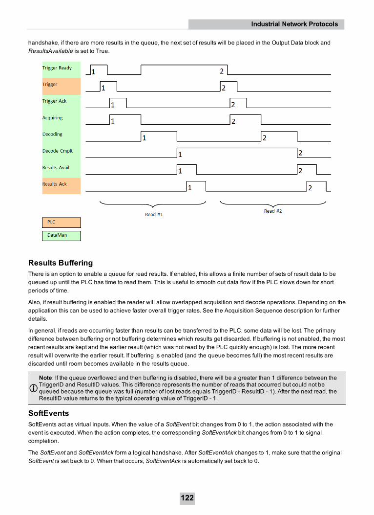
handshake, if there are more results in the queue, the next set of results will be placed in the Output Data block andResultsAvailable is set to True.
Results BufferingThere is an option to enable a queue for read results. If enabled, this allows a finite number of sets of result data to bequeued up until the PLC has time to read them. This is useful to smooth out data flow if the PLC slows down for shortperiods of time.
Also, if result buffering is enabled the reader will allow overlapped acquisition and decode operations. Depending on theapplication this can be used to achieve faster overall trigger rates. See the Acquisition Sequence description for furtherdetails.
In general, if reads are occurring faster than results can be transferred to the PLC, some data will be lost. The primarydifference between buffering or not buffering determines which results get discarded. If buffering is not enabled, the mostrecent results are kept and the earlier result (which was not read by the PLC quickly enough) is lost. The more recentresult will overwrite the earlier result. If buffering is enabled (and the queue becomes full) the most recent results arediscarded until room becomes available in the results queue.
Note: If the queue overflowed and then buffering is disabled, there will be a greater than 1 difference between theTriggerID and ResultID values. This difference represents the number of reads that occurred but could not bequeued because the queue was full (number of lost reads equals TriggerID - ResultID - 1). After the next read, theResultID value returns to the typical operating value of TriggerID - 1.
SoftEventsSoftEvents act as virtual inputs. When the value of a SoftEvent bit changes from 0 to 1, the action associated with theevent is executed. When the action completes, the corresponding SoftEventAck bit changes from 0 to 1 to signalcompletion.
The SoftEvent and SoftEventAck form a logical handshake. After SoftEventAck changes to 1, make sure that the originalSoftEvent is set back to 0. When that occurs, SoftEventAck is automatically set back to 0.
122
Industrial Network Protocols

Note: Do not execute SoftEvents that change the reader configuration at the same time that reads are beingtriggered. Changing configuration during acquisition/decode can lead to unpredictable results.
The “ExecuteDMCC” and “SetMatchString” SoftEvent actions require user supplied data. Make sure that this data iswritten to the UserData and UserDataLength area of the Input Data block prior to invoking the SoftEvent. Only oneSoftEvent can be invoked at a time, because both of these SoftEvents depend on the UserData.
String CommandsThe DataMan Modbus TCP Protocol implementation includes a String Command feature. This feature allows you toexecute string-based DMCCs. The DMCC is sent to the reader through the String Command block. The DMCC result isreturned through the String Command Result block. Initiating a command and notification of completion is accomplishedby signaling bits in the Control and Status blocks.
To execute a DMCC, the command string is placed in the data field of the String Command block. The command stringconsists of standard ASCII text. The same command format is used for a serial (RS-232) or Telnet connection. The stringdoes not need to be terminated with a null character. Instead, the length of the string, that is, the number of ASCIIcharacters, is placed in the length field of the String Command block.
After executing the DMCC, the result string is returned in the String Command Result block. Similar to the originalcommand, the result string consists of ASCII characters in the same format as returned through a serial or Telnetconnection. Also, there is no terminating null character. Instead, the length of the result is returned in the CommandString Result length field. The Command String Result block also contains a numeric result code. This allows you todetermine the success or failure of the command without having to parse the text string. The values of the result code aredefined in the DMCC documentation, available through the Windows Start menu or the Setup Tool Helpmenu.
General Fault IndicatorWhen a communication-related fault occurs, the “GeneralFault” bit changes from 0 to 1. The only fault conditionssupported are SoftEvent operations. If a SoftEvent operation fails, the fault bit will be set. The fault bit will remain set untilthe next successful SoftEvent operation, or until TriggerEnable is set to 0 and then back to 1.
ExamplesIncluded with the DataMan Setup Tool installer are two example PLC programs created with CoDeSys v2.3 software.These samples are designed and tested on a Wago 750-841 PLC. These programs demonstrate the DataMan IDreaders’ capabilities and proper operation. You can do the same operations by using more advanced features andefficient programming practices with Wago PLCs. The examples try to show different approaches in the techniques usedfor the communication to the DataMan reader and they are better for demonstration purposes.
123
Industrial Network Protocols
Note: All examples are designed to work only if the “Control” datablock is mapped to the Coil space and the“Status” datablock is mapped to the Discrete Input space.
ApplicationLayer ExampleThis sample realizes a generic data transfer between the DataMan reader and the PLC. Memory areas of the “Control”,“Status” and “Output Area” are cloned in the PLC and synchronized cyclically, or as needed. Each data area issynchronized with its own instance of “ETHERNETMODBUSMASTER_TCP”. This causes three TCP connections to beopen simultaneously. Make sure that the Modbus TCP related setting “Maximum Connections” on the DataMan reader isset to at least 3 for this example to work.
FunctionThe example application demonstrates the following operations:
1. Transfer the 32-bit “Control” register data from the PLC to the reader.
2. Transfer the 32-bit “Status” register data from the reader to the PLC.
3. Transfer “Output Data” from the reader to the PLC.
All actions are started when there is a connection to the reader.
Transferring “Control” Register DataAll data gets transferred when there is a change in the local PLC data. The local PLC data can be manipulated in thevisualization.
Note: No synchronization is implemented from the reader to the PLC, so the local PLC data can be incorrect afterbuilding up the connection or if another Modbus TCP client manipulates the Contol register simultaneously. Thereis a timeout setting that can lead to a disconnect if you do not manipulate the “Control” register during thistimeframe.
Transferring Status Register DataAll data gets transferred cyclically. The poll interval can be specified in the visualization.
Transferring Output DataAll data gets transferred cyclically. The poll interval can be specified in the visualization.
DataManControl ExampleThis sample shows in a sequential manner the steps to do to achieve one of the functions named in the followingsubsection. To outline this chronological sequence, “Sequential Function Chart” is used as programming language.
FunctionThe example application demonstrates the following operations:
1. Triggering a read
2. Getting read results
3. Executing string commands (DMCC)
124
Industrial Network Protocols
4. Executing SoftEvent operations
a. Train code
b. Train match string
c. Train focus
d. Train brightness
e. Untrain
f. Execute DMCC
g. Set match string
The “Main” program contains variables to invoke each of these operations. The operation is invoked by toggling thecontrol bool directly or from the visualization (red=0, green=1) from 0 to 1. This will invoke the associated subroutine toperform the operation. When the operation 4 is complete, the subroutine will set the control bit back to 0.
Triggering a ReadThe example provides a “Continuous Trigger”. As the name implies, enabling the “xTrigger” bit will invoke a continuousseries of read operations. Once enabled, the “xTrigger” control bit will remain set until you disable it.
Primarily, the trigger subroutine manages the trigger handshake operation between the PLC and the reader. The controlResult Ack and Trigger bits are reset, the Trigger Enable bit is set, the PLC waits for the corresponding TriggerReadystatus bit from the reader, and the control Trigger bit is set. Refer to a description of handshaking in section Operation.
Getting Read ResultsFor this example the operation of triggering a read and getting read results was intentionally separated. This is to supportthe situation where the PLC is not the source of the read trigger. For example, the reader may be configured to use ahardware trigger. In such a case, only the get results subroutine would be needed.
Like the triggering subroutine, the get results subroutine manages the results handshake operation between the PLCand the reader. The routine waits for the ResultsAvailable status bit to become active, it copies the result data to internalstorage, and then executes the ResultsAck handshake. Refer to a description of handshaking in section Operation.
The read result consists of a ResultCode, ResultLength, and ResultData. Refer to section Output Data Block FieldDescriptions for details of the ResultCode values. The ResultLength field indicates how many bytes of actual result dataexist in the ResultData field. The subroutine converts this byte length to word length before copying the results to internalstorage.
Execute String Commands (DMCC)The string command feature provides a simple way to invoke DMCCs from the PLC. The command format and commandresult format is exactly identical to that used for serial or Telnet DMCC operation.
This subroutine copies an example DMCC (||>GET DEVICE.TYPE) to the String Command block and then manages thestring command handshake operation between the PLC and the reader to invoke the command and retrieve thecommand result. Any valid DMCC command may be invoked with this mechanism. Refer to the DataMan CommandReference document available through the Windows Start menu or the Setup Tool Helpmenu.
Execute SoftEventsSoftEvents are used to invoke a predefined action. Each SoftEvent is essentially a virtual input signal. Each of theSoftEvent subroutines manages the handshake operation between the PLC and the reader to invoke the predefinedaction. The associated action is invoked when the SoftEvent bit toggles from 0 to 1. The subroutine then watches for theassociated SoftEventAck bit from the reader which signals that the action is complete. For a description of handshaking,see section Operation.
125
Industrial Network Protocols

Note: The “Execute DMCC” and “Set Match String” SoftEvents make use of the Input Data block. The subroutine forthese two events copies the relevant data into the User Data fields of the Input Data block and then invokes theUser Data subroutine to transfer the data to the reader. Only after the user data is transferred is the actual SoftEventaction invoked. It is required that the user data be transferred before invoking either of these events.
Note: The “Train Match String” SoftEvent only prepares the training mechanism. The actual training occurs on thenext read operation. Therefore, a trigger must be issued following “Train Match String”.
126
Industrial Network Protocols

Industrial Protocols for the Wireless DataManSpecial considerations must be taken into account when using any of the Industrial Ethernet protocols with DataManwireless readers. Industrial protocol connections are established not between the PLC and the wireless device, butbetween the PLC and the DataMan base station.
The DataMan wireless reader may be, at times:
l powered down
l in hibernation mode
l physically out of range
Automatic power down and hibernation are features that preserve power and extend the time period betweenrecharging.
The following sections detail the necessary configurations you have to set to communicate with the DataMan basestation (through which information is routed to the DataMan wireless reader).
Protocol OperationBecause the wireless reader can become unavailable at times, the Industrial Ethernet protocols are actually run from thebase station. The base station is directly wired to the Ethernet network and is online continuously (even when the readeris unavailable). In this way the Ethernet protocol operation is not disrupted when the reader is unavailable. This results ina few special considerations.
Ethernet AddressBecause the Ethernet protocols are run from the base station, you must use the base station Ethernet address whenconfiguring the protocol. For example, when configuring EtherNet/IP using the RSLogix5000 software package, youselect the DM8000 reader but you must enter the IP address of the base station (not the reader). The PLC using theprotocol must communicate with the base station.
PLC TriggeringBecause the wireless reader can become unavailable at times, triggering from the PLC is not supported on wirelessreaders. The PLC will receive all read results triggered from the reader. Also, SoftEvents and DMCC commands aresupported (when the reader is available).
SoftEventsSoftEvents triggered from the PLC are supported. However, these events will fail if the reader is unavailable. Such afailure will be signaled by the ‘General Fault’ bit.
Note: Some operations assigned to SoftEvents are in general not supported on any handheld DataMan readers (forexample, ‘Train Code’, ‘Train Focus’, ‘Train Brightness’). Unsupported operations will also result in the ‘GeneralFault’ signal being set.
DMCCDMCC commands issued from the PLC are supported. However, these events will fail if the reader is unavailable.Depending on which Industrial Ethernet protocol is in use, the failure will be signaled either with the ‘General Fault’
127
Industrial Protocols for the Wireless DataMan

signal or an error status return code. The new DMCC error return code ‘105’ has been established to signal that thereader is unavailable.
Note: When issuing DMCC commands from the PLC to a wireless reader, do not change the DMCC responseformat (that is, do not issue the command ‘COM.DMCC-RESPONSE’). Doing this may disable DMCC operation onthe wireless reader. This command can be used on non-Industrial Ethernet connections such as Telnet.
Offline BufferingWhen the wireless reader is physically out of range of the base station, it will automatically buffer all reads. Buffercapacity varies according to a number of factors. However, typically several hundred reads can be stored. Thesebuffered reads are also preserved if the reader enters hibernation (sleep mode). When the reader is brought back intorange of the base station the buffered reads will automatically be downloaded.
If this offline buffering situation is anticipated in the user application, then Industrial Ethernet protocol buffering shouldalso be enabled. Protocol buffering will allow a PLC to control the rate that read results are returned to the PLC. Thisprevents the PLC from becoming overwhelmed by a rapid flow of read results. Refer to the specific Industrial Protocolsection of this document for details of enabling and utilizing protocol buffering.
Note: The base station can buffer up to 500 results.
Status of Industrial ProtocolsThe Status field of the industrial protocols (in Setup Tool, under Industrial Protocols tab) displays the last loggedmessage of the status dialog. The message will remain displayed until another message is logged. If no industrialprotocol is enabled, the status field remains blank.
Status messages vary by protocol, and some protocols do not log any messages. See the table below for a summary ofmessages for protocols that display them:
Protocol/Reader Message Description
Wi-Fi readers Industrial ethernetprotocols shutdown
Displayed if no protocol is running
Proxy %s connectionopening
Opening connection to Wi-Fi reader, s == connection type ("Command","Result", or "User DMCC")
Proxy %s open Connection open, s == connection type ("Command", "Result", or "UserDMCC")
Proxy %s not open failed to open connection, s == connection type ("Command", "Result", or"User DMCC")
Proxy %s closed connection has been closed, s == connection type ("Command", "Result", or"User DMCC")
Modbus TCP Modbus TCP starting... Protocol startingModbus TCP: ServerSetup Failed
Failed to start server
Modbus TCP running Protocol runningModbus TCP: Addblock%s failed
Data block configuration error
Modbus TCP controlblock %s
Status of ModbusTCP data block, s == “info” or “error”
128
Industrial Protocols for the Wireless DataMan

Protocol/Reader Message Description
SLMP Protocol Opening SLMPscannerconnection %s:%x
starting SLMP connection, s==IP address, x==port number
SLMP scannerconnection established%s:%x
SLMP connection established, s==IP address, x==port number
SLMP scannerconnection %s:%xrejected
PLC has rejected the connection, s==IP address, x==port number
SLMP scannerconnection %s:%xfaulted
Miscellaneous connection fault has occurred, s==IP address, x==portnumber
SLMP scanner poll rateset too low
Configured SLMP poll rate is set too low
SLMP scannerconnection normal%s:%x
SLMP connection has been restored, s==IP address, x==port number
SLMP Scanner controlblock %s
Status of SLMP data block, s == “info” or “error”
SLMP Scanner failedtransfering '%s' block
Comm error, failed to transfer a data block, s==block name
129
Industrial Protocols for the Wireless DataMan

Copyright © 2020Cognex Corporation. All Rights Reserved.