Data Flow - WordPress.com
50
6 CHAPTER 1 INTRODUCTION use a microphone to change voice or music to an electric signal, we create a continuous signal. In Chapters 4 and 5, we learn how to change sound or music to a digital or an analog signal. Video Video refers to the recording or broadcasting of a picture or movie. Video can either be produced as a continuous entity (e.g., by a TV camera), or it can be a combination of images, each a discrete entity, arranged to convey the idea of motion. Again we can change video to a digital or an analog signal, as we will see in Chapters 4 and 5. Data Flow Communication between two devices can be simplex, half-duplex, or full-duplex as shown in Figure 1.2. Figure 1.2 Data flow (simplex, half-duplex, and full-duplex) Mainframe a. Simplex b. Half-duplex c. Full·duplex Direction of data Direction of data at time I Direction of data at time 2 Direction of data all the time ) Monitor Simplex In simplex mode, the communication is unidirectional, as on a one-way street. Only one of the two devices on a link can transmit; the other can only receive (see Figure 1.2a). Keyboards and traditional monitors are examples of simplex devices. The key- board can only introduce input; the monitor can only accept output. The simplex mode can use the entire capacity of the channel to send data in one direction. Half-Duplex In half-duplex mode, each station can both transmit and receive, but not at the same time. : When one device is sending, the other can only receive, and vice versa (see Figure 1.2b).
-
Upload
khangminh22 -
Category
Documents
-
view
0 -
download
0
Transcript of Data Flow - WordPress.com

6 CHAPTER 1 INTRODUCTION
use a microphone to change voice or music to an electric signal, we create a continuoussignal. In Chapters 4 and 5, we learn how to change sound or music to a digital or ananalog signal.
Video
Video refers to the recording or broadcasting of a picture or movie. Video can either beproduced as a continuous entity (e.g., by a TV camera), or it can be a combination ofimages, each a discrete entity, arranged to convey the idea of motion. Again we canchange video to a digital or an analog signal, as we will see in Chapters 4 and 5.
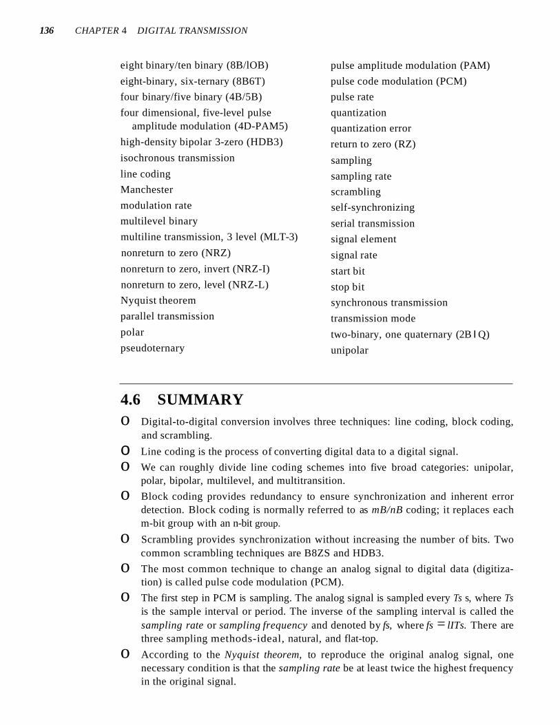
Data FlowCommunication between two devices can be simplex, half-duplex, or full-duplex asshown in Figure 1.2.
Figure 1.2 Data flow (simplex, half-duplex, andfull-duplex)
Mainframe
a. Simplex
b. Half-duplex
c. Full·duplex
Direction of data
Direction of data at time I~
Direction of data at time 2
Direction of data all the time)
Monitor
Simplex
In simplex mode, the communication is unidirectional, as on a one-way street. Only oneof the two devices on a link can transmit; the other can only receive (see Figure 1.2a).
Keyboards and traditional monitors are examples of simplex devices. The keyboard can only introduce input; the monitor can only accept output. The simplex modecan use the entire capacity of the channel to send data in one direction.
Half-Duplex
In half-duplex mode, each station can both transmit and receive, but not at the same time. :When one device is sending, the other can only receive, and vice versa (see Figure 1.2b).

SECTION 1.2 NETWORKS 7
The half-duplex mode is like a one-lane road with traffic allowed in both directions. When cars are traveling in one direction, cars going the other way must wait. In ahalf-duplex transmission, the entire capacity of a channel is taken over by whichever ofthe two devices is transmitting at the time. Walkie-talkies and CB (citizens band) radiosare both half-duplex systems.
The half-duplex mode is used in cases where there is no need for communicationin both directions at the same time; the entire capacity of the channel can be utilized foreach direction.
Full-Duplex
In full-duplex m.,lle (als@ called duplex), both stations can transmit and receive simultaneously (see Figure 1.2c).
The full-duplex mode is like a tW<D-way street with traffic flowing in both directions at the same time. In full-duplex mode, si~nals going in one direction share thecapacity of the link: with signals going in the other din~c~on. This sharing can occur intwo ways: Either the link must contain two physically separate t:nmsmissiIDn paths, onefor sending and the other for receiving; or the capacity of the ch:arillilel is dividedbetween signals traveling in both directions.
One common example of full-duplex communication is the telephone network.When two people are communicating by a telephone line, both can talk and listen at thesame time.
The full-duplex mode is used when communication in both directions is requiredall the time. The capacity of the channel, however, must be divided between the twodirections.
1.2 NETWORKSA network is a set of devices (often referred to as nodes) connected by communicationlinks. A node can be a computer, printer, or any other device capable of sending and/orreceiving data generated by other nodes on the network.
Distributed ProcessingMost networks use distributed processing, in which a task is divided among multiplecomputers. Instead of one single large machine being responsible for all aspects of aprocess, separate computers (usually a personal computer or workstation) handle asubset.
Network CriteriaA network must be able to meet a certain number of criteria. The most important ofthese are performance, reliability, and security.
Performance
Performance can be measured in many ways, including transit time and response time.Transit time is the amount of time required for a message to travel from one device to

8 CHAPTER 1 INTRODUCTION
another. Response time is the elapsed time between an inquiry and a response. The performance of a network depends on a number of factors, including the number of users,the type of transmission medium, the capabilities of the connected hardware, and theefficiency of the software.
Performance is often evaluated by two networking metrics: throughput and delay.We often need more throughput and less delay. However, these two criteria are oftencontradictory. If we try to send more data to the network, we may increase throughputbut we increase the delay because of traffic congestion in the network.
Reliability
In addition to accuracy of delivery, network reliability is measured by the frequency offailure, the time it takes a link to recover from a failure, and the network's robustness ina catastrophe.
Security
Network security issues include protecting data from unauthorized access, protectingdata from damage and development, and implementing policies and procedures forrecovery from breaches and data losses.
Physical StructuresBefore discussing networks, we need to define some network attributes.
Type of Connection
A network is two or more devices connected through links. A link is a communicationspathway that transfers data from one device to another. For visualization purposes, it issimplest to imagine any link as a line drawn between two points. For communication tooccur, two devices must be connected in some way to the same link at the same time.There are two possible types of connections: point-to-point and multipoint.
Point-to-Point A point-to-point connection provides a dedicated link between twodevices. The entire capacity of the link is reserved for transmission between those twodevices. Most point-to-point connections use an actual length of wire or cable to connect the two ends, but other options, such as microwave or satellite links, are also possible (see Figure 1.3a). When you change television channels by infrared remote control,you are establishing a point-to-point connection between the remote control and thetelevision's control system.
Multipoint A multipoint (also called multidrop) connection is one in which morethan two specific devices share a single link (see Figure 1.3b).
In a multipoint environment, the capacity of the channel is shared, either spatiallyor temporally. If several devices can use the link simultaneously, it is a spatially sharedconnection. If users must take turns, it is a timeshared connection.
Physical Topology
The term physical topology refers to the way in which a network is laid out physically.:1\vo or more devices connect to a link; two or more links form a topology. The topology
SECTION 1.2 NETWORKS 9
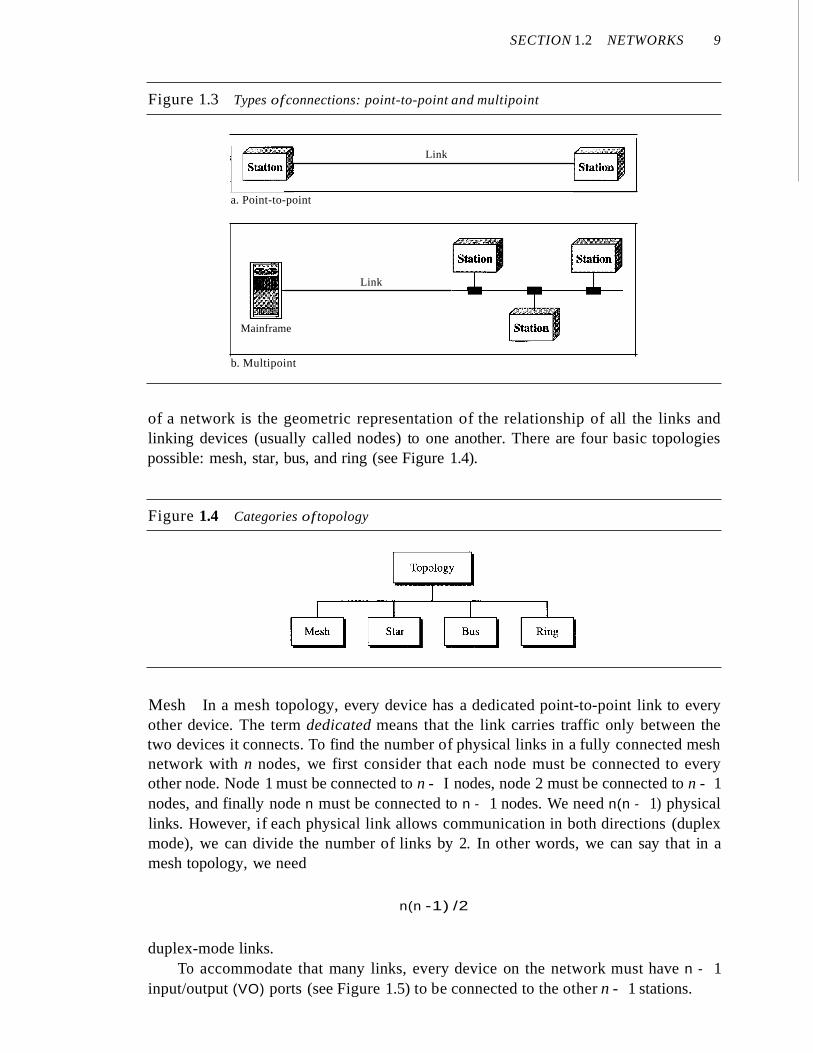
Figure 1.3 Types ofconnections: point-to-point and multipoint
Link
a. Point-to-point
Mainframe
Link
b. Multipoint
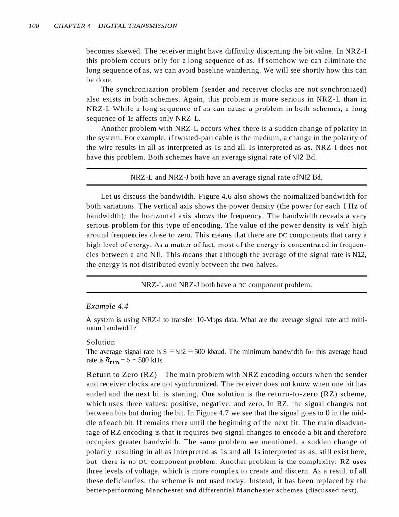
of a network is the geometric representation of the relationship of all the links andlinking devices (usually called nodes) to one another. There are four basic topologiespossible: mesh, star, bus, and ring (see Figure 1.4).
Figure 1.4 Categories of topology
Mesh In a mesh topology, every device has a dedicated point-to-point link to everyother device. The term dedicated means that the link carries traffic only between thetwo devices it connects. To find the number of physical links in a fully connected meshnetwork with n nodes, we first consider that each node must be connected to everyother node. Node 1 must be connected to n - I nodes, node 2 must be connected to n - 1nodes, and finally node n must be connected to n - 1 nodes. We need n(n - 1) physicallinks. However, if each physical link allows communication in both directions (duplexmode), we can divide the number of links by 2. In other words, we can say that in amesh topology, we need
n(n -1) /2
duplex-mode links.To accommodate that many links, every device on the network must have n - 1
input/output (VO) ports (see Figure 1.5) to be connected to the other n - 1 stations.

10 CHAPTER 1 INTRODUCTION
Figure 1.5 A fully connected mesh topology (five devices)
A mesh offers several advantages over other network topologies. First, the use ofdedicated links guarantees that each connection can carry its own data load, thus eliminating the traffic problems that can occur when links must be shared by multiple devices.Second, a mesh topology is robust. If one link becomes unusable, it does not incapacitate the entire system. Third, there is the advantage of privacy or security. When everymessage travels along a dedicated line, only the intended recipient sees it. Physicalboundaries prevent other users from gaining access to messages. Finally, point-to-pointlinks make fault identification and fault isolation easy. Traffic can be routed to avoidlinks with suspected problems. This facility enables the network manager to discover theprecise location of the fault and aids in finding its cause and solution.
The main disadvantages of a mesh are related to the amount of cabling and thenumber of I/O ports required. First, because every device must be connected to everyother device, installation and reconnection are difficult. Second, the sheer bulk of thewiring can be greater than the available space (in walls, ceilings, or floors) can accommodate. Finally, the hardware required to connect each link (I/O ports and cable) can beprohibitively expensive. For these reasons a mesh topology is usually implemented in alimited fashion, for example, as a backbone connecting the main computers of a hybridnetwork that can include several other topologies.
One practical example of a mesh topology is the connection of telephone regionaloffices in which each regional office needs to be connected to every other regional office.
Star Topology In a star topology, each device has a dedicated point-to-point linkonly to a central controller, usually called a hub. The devices are not directly linked toone another. Unlike a mesh topology, a star topology does not allow direct trafficbetween devices. The controller acts as an exchange: If one device wants to send data toanother, it sends the data to the controller, which then relays the data to the other connected device (see Figure 1.6) .
A star topology is less expensive than a mesh topology. In a star, each device needsonly one link and one I/O port to connect it to any number of others. This factor alsomakes it easy to install and reconfigure. Far less cabling needs to be housed, and additions, moves, and deletions involve only one connection: between that device and the hub.
Other advantages include robustness. If one link fails, only that link is affected. Allother links remain active. This factor also lends itself to easy fault identification and

SECTION 1.2 NETWORKS 11
Figure 1.6 A star topology connecting four stations
Hub
fault isolation. As long as the hub is working, it can be used to monitor link problemsand bypass defective links.
One big disadvantage of a star topology is the dependency of the whole topologyon one single point, the hub. If the hub goes down, the whole system is dead.
Although a star requires far less cable than a mesh, each node must be linked to acentral hub. For this reason, often more cabling is required in a star than in some othertopologies (such as ring or bus).
The star topology is used in local-area networks (LANs), as we will see in Chapter 13.High-speed LANs often use a star topology with a central hub.
Bus Topology The preceding examples all describe point-to-point connections. A bustopology, on the other hand, is multipoint. One long cable acts as a backbone to link allthe devices in a network (see Figure 1.7).
Figure 1.7 A bus topology connecting three stations
Drop line Drop line Drop line
Cable end 11I-----1..-----..-----..----11 Cable endTap Tap Tap
Nodes are connected to the bus cable by drop lines and taps. A drop line is a connection running between the device and the main cable. A tap is a connector that eithersplices into the main cable or punctures the sheathing of a cable to create a contact withthe metallic core. As a signal travels along the backbone, some of its energy is transformedinto heat. Therefore, it becomes weaker and weaker as it travels farther and farther. Forthis reason there is a limit on the number of taps a bus can support and on the distancebetween those taps.
Advantages of a bus topology include ease of installation. Backbone cable can belaid along the most efficient path, then connected to the nodes by drop lines of variouslengths. In this way, a bus uses less cabling than mesh or star topologies. In a star, forexample, four network devices in the same room require four lengths of cable reaching

12 CHAPTER 1 INTRODUCTION
all the way to the hub. In a bus, this redundancy is eliminated. Only the backbone cablestretches through the entire facility. Each drop line has to reach only as far as the nearest point on the backbone.
Disadvantages include difficult reconnection and fault isolation. A bus is usuallydesigned to be optimally efficient at installation. It can therefore be difficult to add newdevices. Signal reflection at the taps can cause degradation in quality. This degradationcan be controlled by limiting the number and spacing of devices connected to a givenlength of cable. Adding new devices may therefore require modification or replacementof the backbone.
In addition, a fault or break in the bus cable stops all transmission, even betweendevices on the same side of the problem. The damaged area reflects signals back in thedirection of origin, creating noise in both directions.
Bus topology was the one of the first topologies used in the design of early localarea networks. Ethernet LANs can use a bus topology, but they are less popular now forreasons we will discuss in Chapter 13.
Ring Topology In a ring topology, each device has a dedicated point-to-point connection with only the two devices on either side of it. A signal is passed along the ringin one direction, from device to device, until it reaches its destination. Each device inthe ring incorporates a repeater. When a device receives a signal intended for anotherdevice, its repeater regenerates the bits and passes them along (see Figure 1.8).
Figure 1.8 A ring topology connecting six stations
Repeater
RepeaterRepeater
Repeater
RepeaterRepeater
A ring is relatively easy to install and reconfigure. Each device is linked to only itsimmediate neighbors (either physically or logically). To add or delete a device requireschanging only two connections. The only constraints are media and traffic considerations (maximum ring length and number of devices). In addition, fault isolation is simplified. Generally in a ring, a signal is circulating at all times. If one device does notreceive a signal within a specified period, it can issue an alarm. The alarm alerts thenetwork operator to the problem and its location.
However, unidirectional traffic can be a disadvantage. In a simple ring, a break inthe ring (such as a disabled station) can disable the entire network. This weakness canbe solved by using a dual ring or a switch capable of closing off the break.

SECTION 1.2 NETWORKS 13
Ring topology was prevalent when IBM introduced its local-area network TokenRing. Today, the need for higher-speed LANs has made this topology less popular.
Hybrid Topology A network can be hybrid. For example, we can have a main star topology with each branch connecting several stations in a bus topology as shown in Figure 1.9.
Figure 1.9 A hybrid topology: a star backbone with three bus networks
Hub
Network Models
Computer networks are created by different entities. Standards are needed so that theseheterogeneous networks can communicate with one another. The two best-known standards are the OSI model and the Internet model. In Chapter 2 we discuss these twomodels. The OSI (Open Systems Interconnection) model defines a seven-layer network; the Internet model defines a five-layer network. This book is based on the Internetmodel with occasional references to the OSI model.
Categories of Networks
Today when we speak of networks, we are generally referring to two primary categories: local-area networks and wide-area networks. The category into which a networkfalls is determined by its size. A LAN normally covers an area less than 2 mi; a WAN canbe worldwide. Networks of a size in between are normally referred to as metropolitanarea networks and span tens of miles.
Local Area Network
A local area network (LAN) is usually privately owned and links the devices in a singleoffice, building, or campus (see Figure 1.10). Depending on the needs of an organizationand the type of technology used, a LAN can be as simple as two PCs and a printer insomeone's home office; or it can extend throughout a company and include audio andvideo peripherals. Currently, LAN size is limited to a few kilometers.

106 CHAPTER 4 DIGITAL TRANSMISSION
At 1 Mbps, the receiver receives 1,001,000 bps instead of 1,000,000 bps.
1,000,000 bits sent 1,001,000 bits received 1000 extra bps
Built-in Error Detection It is desirable to have a built-in error-detecting capabilityin the generated code to detect some of or all the errors that occurred during transmission. Some encoding schemes that we will discuss have this capability to some extent.
Immunity to Noise and Interference Another desirable code characteristic is a code I
that is immune to noise and other interferences. Some encoding schemes that we willdiscuss have this capability.
Complexity A complex scheme is more costly to implement than a simple one. Forexample, a scheme that uses four signal levels is more difficult to interpret than one thatuses only two levels.
Line Coding Schemes
We can roughly divide line coding schemes into five broad categories, as shown inFigure 4.4.
Figure 4.4 Line coding schemes
Multitransition -- MLT-3
Multilevel -- 2B/IQ, 8B/6T, and 4U-PAM5
Line coding
Unipolar
Polar
Bipolar
--NRZ
NRZ, RZ, and biphase (Manchester.and differential Manchester)
-- AMI and pseudoternary
There are several schemes in each category. We need to be familiar with allschemes discussed in this section to understand the rest of the book. This section can beused as a reference for schemes encountered later.
Unipolar Scheme
In a unipolar scheme, all the signal levels are on one side of the time axis, either aboveor below.
NRZ (Non-Return-to-Zero) Traditionally, a unipolar scheme was designed as anon-return-to-zero (NRZ) scheme in which the positive voltage defines bit I and thezero voltage defines bit O. It is called NRZ because the signal does not return to zero atthe middle of the bit. Figure 4.5 show a unipolar NRZ scheme.

SECTION 4.1 DIGITAL-TO-DIGITAL CONVERSION 107
Figure 4.5 Unipolar NRZ scheme
Amplitude
v1 f 0
f: 1 I 0
I
o 1------'1---1---1--+---.--__
I Time Nonnalized power
Compared with its polar counterpart (see the next section), this scheme is verycostly. As we will see shortly, the normalized power (power needed to send 1 bit perunit line resistance) is double that for polar NRZ. For this reason, this scheme is normally not used in data communications today.
Polar Schemes
In polar schemes, the voltages are on the both sides of the time axis. For example, thevoltage level for 0 can be positive and the voltage level for I can be negative.
Non-Return-to-Zero (NRZ) In polar NRZ encoding, we use two levels of voltageamplitude. We can have two versions of polar NRZ: NRZ-Land NRZ-I, as shown inFigure 4.6. The figure also shows the value of r, the average baud rate, and the bandwidth. In the first variation, NRZ-L (NRZ-Level), the level of the voltage determinesthe value of the bit. In the second variation, NRZ-I (NRZ-Invert), the change or lack ofchange in the level of the voltage determines the value of the bit. If there is no change,the bit is 0; if there is a change, the bit is 1.
Figure 4.6 Polar NRZ-L and NRZ-I schemes
T=:= 1 Save "'NIl
p
0: ~illdWidthoG""Iil""""'~I=-=-"""'r'-----'l..~
o I 2 fIN
Time
Time
1 : 1 0II
011II
NRZ-I f-----I----J---I---+--+--+----+----'--~
NRZ-L f--+--1---I---+--I---1------t----'--~
o No inversion: Next bit is 0 • Inversion: Next bit is 1
In NRZ-L the level of the voltage determines the value of the bit. In NRZ-Ithe inversion or the lack of inversion determines the value of the bit.
Let us compare these two schemes based on the criteria we previously defined.Although baseline wandering is a problem for both variations, it is twice as severe inNRZ-L. If there is a long sequence of Os or Is in NRZ-L, the average signal power
108 CHAPTER 4 DIGITAL TRANSMISSION
becomes skewed. The receiver might have difficulty discerning the bit value. In NRZ-Ithis problem occurs only for a long sequence of as. If somehow we can eliminate thelong sequence of as, we can avoid baseline wandering. We will see shortly how this canbe done.
The synchronization problem (sender and receiver clocks are not synchronized)also exists in both schemes. Again, this problem is more serious in NRZ-L than inNRZ-I. While a long sequence of as can cause a problem in both schemes, a longsequence of 1s affects only NRZ-L.
Another problem with NRZ-L occurs when there is a sudden change of polarity inthe system. For example, if twisted-pair cable is the medium, a change in the polarity ofthe wire results in all as interpreted as Is and all Is interpreted as as. NRZ-I does nothave this problem. Both schemes have an average signal rate of NI2 Bd.
NRZ-L and NRZ-J both have an average signal rate ofNI2 Bd.
Let us discuss the bandwidth. Figure 4.6 also shows the normalized bandwidth forboth variations. The vertical axis shows the power density (the power for each I Hz ofbandwidth); the horizontal axis shows the frequency. The bandwidth reveals a veryserious problem for this type of encoding. The value of the power density is velY higharound frequencies close to zero. This means that there are DC components that carry ahigh level of energy. As a matter of fact, most of the energy is concentrated in frequencies between a and NIl. This means that although the average of the signal rate is N12,the energy is not distributed evenly between the two halves.
NRZ-L and NRZ-J both have a DC component problem.
Example 4.4
A system is using NRZ-I to transfer 10-Mbps data. What are the average signal rate and minimum bandwidth?
SolutionThe average signal rate is S =NI2 = 500 kbaud. The minimum bandwidth for this average baudrate is Bnlin = S = 500 kHz.
Return to Zero (RZ) The main problem with NRZ encoding occurs when the senderand receiver clocks are not synchronized. The receiver does not know when one bit hasended and the next bit is starting. One solution is the return-to-zero (RZ) scheme,which uses three values: positive, negative, and zero. In RZ, the signal changes notbetween bits but during the bit. In Figure 4.7 we see that the signal goes to 0 in the middle of each bit. It remains there until the beginning of the next bit. The main disadvantage of RZ encoding is that it requires two signal changes to encode a bit and thereforeoccupies greater bandwidth. The same problem we mentioned, a sudden change ofpolarity resulting in all as interpreted as 1s and all 1s interpreted as as, still exist here,but there is no DC component problem. Another problem is the complexity: RZ usesthree levels of voltage, which is more complex to create and discern. As a result of allthese deficiencies, the scheme is not used today. Instead, it has been replaced by thebetter-performing Manchester and differential Manchester schemes (discussed next).

SECTION 4.1 DIGITAL-TO-DIGITAL CONVERSION 109
Figure 4.7 Polar RZ scheme
Amplitude
o lll
1 l1l
Time
p
o:lLo I ~
o 1 2 fiN
Biphase: Manchester and Differential Manchester The idea of RZ (transition atthe middle of the bit) and the idea of NRZ-L are combined into the Manchester scheme.In Manchester encoding, the duration of the bit is divided into two halves. The voltageremains at one level during the first half and moves to the other level in the second half.The transition at the middle of the bit provides synchronization. Differential Manchester,on the other hand, combines the ideas of RZ and NRZ-I. There is always a transition atthe middle of the bit, but the bit values are determined at the beginning of the bit. If thenext bit is 0, there is a transition; if the next bit is 1, there is none. Figure 4.8 showsboth Manchester and differential Manchester encoding.
Figure 4.8 Polar biphase: Manchester and differential Manchester schemes
( Ois L lis S )0 I 1 I 0 I 0 I 1 I 1 I
I I I I I II I I I I I..... I r+- 1,...- I _, --4I 1I I I I
ManchesterI I I I
Timel..+- I-I -+- I-
II I
I I l I I I
r¢- I,.... 1,...- I rt- II I
Differential I I I
Manchester I I I ITime1 L...¢- I I
~ 1 ~ - I1 I I I I I
o No inversion: Next bit is 1 • Inversion: Next bit is 0
p
11 Bandwidth
O.~~~o 1
)0
2 fiN
In Manchester and differential Manchester encoding, the transitionat the middle of the bit is used for synchronization.
The Manchester scheme overcomes several problems associated with NRZ-L, anddifferential Manchester overcomes several problems associated with NRZ-I. First, thereis no baseline wandering. There is no DC component because each bit has a positive and

110 CHAPTER 4 DIGITAL TRANSMISSION
negative voltage contribution. The only drawback is the signal rate. The signal rate forManchester and differential Manchester is double that for NRZ. The reason is that there isalways one transition at the middle of the bit and maybe one transition at the end of eachbit. Figure 4.8 shows both Manchester and differential Manchester encoding schemes.Note that Manchester and differential Manchester schemes are also called biphaseschemes.
The minimum bandwidth ofManchester and differential Manchester is 2 times that ofNRZ.
Bipolar Schemes
In bipolar encoding (sometimes called multilevel binary), there are three voltage levels: positive, negative, and zero. The voltage level for one data element is at zero, whilethe voltage level for the other element alternates between positive and negative.
In bipolar encoding, we use three levels: positive, zero, and negative.
AMI and Pseudoternary Figure 4.9 shows two variations of bipolar encoding: AMIand pseudoternary. A common bipolar encoding scheme is called bipolar alternatemark inversion (AMI). In the term alternate mark inversion, the word mark comesfrom telegraphy and means 1. So AMI means alternate I inversion. A neutral zero voltage represents binary O. Binary Is are represented by alternating positive and negativevoltages. A variation of AMI encoding is called pseudoternary in which the 1 bit isencoded as a zero voltage and the 0 bit is encoded as alternating positive and negativevoltages.
Figure 4.9 Bipolar schemes: AMI and pseudoternary
Amplitude
o II
I (II
o IIII
: (III
r= 1
p
Time
Time
AMI r--~-~--1--+----+---;-+
Pseudoternary I-----+--~----If----t--...,....-____r--+
The bipolar scheme was developed as an alternative to NRZ. The bipolar schemehas the same signal rate as NRZ, but there is no DC component. The NRZ scheme hasmost of its energy concentrated near zero frequency, which makes it unsuitable fortransmission over channels with poor performance around this frequency. The concentration of the energy in bipolar encoding is around frequency N12. Figure 4.9 shows thetypical energy concentration for a bipolar scheme.

SECTION 4.1 DIGITAL-TO-DIGITAL CONVERSION 111
One may ask why we do not have DC component in bipolar encoding. We cananswer this question by using the Fourier transform, but we can also think about it intuitively. If we have a long sequence of 1s, the voltage level alternates between positiveand negative; it is not constant. Therefore, there is no DC component. For a longsequence of Os, the voltage remains constant, but its amplitude is zero, which is thesame as having no DC component. In other words, a sequence that creates a constantzero voltage does not have a DC component.
AMI is commonly used for long-distance communication, but it has a synchronization problem when a long sequence of Os is present in the data. Later in the chapter, wewill see how a scrambling technique can solve this problem.
Multilevel Schemes
The desire to increase the data speed or decrease the required bandwidth has resulted inthe creation of many schemes. The goal is to increase the number of bits per baud byencoding a pattern of m data elements into a pattern of n signal elements. We only havetwo types of data elements (Os and Is), which means that a group of m data elementscan produce a combination of 2m data patterns. We can have different types of signalelements by allowing different signal levels. If we have L different levels, then we canproduce Ln combinations of signal patterns. If 2m = Ln, then each data pattern isencoded into one signal pattern. If 2m < Ln, data patterns occupy only a subset of signalpatterns. The subset can be carefully designed to prevent baseline wandering, to provide synchronization, and to detect errors that occurred during data transmission. Dataencoding is not possible if 2m > Ln because some of the data patterns cannot beencoded.
The code designers have classified these types of coding as mBnL, where m is thelength of the binary pattern, B means binary data, n is the length of the signal pattern,and L is the number of levels in the signaling. A letter is often used in place of L: B(binary) for L =2, T (ternary) for L =3, and Q (quaternary) for L =4. Note that the firsttwo letters define the data pattern, and the second two define the signal pattern.
In mBnL schemes, a pattern ofm data elements is encoded as a pattern ofn signalelements in which 2m ::::; Ln.
2BIQ The first mBnL scheme we discuss, two binary, one quaternary (2BIQ), usesdata patterns of size 2 and encodes the 2-bit patterns as one signal element belongingto a four-level signal. In this type of encoding m =2, n =1, and L =4 (quatemary). Figure 4.10 shows an example of a 2B 1Q signal.
The average signal rate of 2BlQ is S = N/4. This means that using 2BIQ, we cansend data 2 times faster than by using NRZ-L. However, 2B lQ uses four different signal levels, which means the receiver has to discern four different thresholds. Thereduced bandwidth comes with a price. There are no redundant signal patterns in thisscheme because 22 =41.
As we will see in Chapter 9, 2BIQ is used in DSL (Digital Subscriber Line) technology to provide a high-speed connection to the Internet by using subscriber telephonelines.

112 CHAPTER 4 DIGITAL TRANSMISSION
Figure 4.10 Multilevel: 2B1Q scheme
Previous level: Previous level:positive negative
Next Next Nextbits level level
00 +1 -I01 +3 -310 -I +1II -3 +3
Transition table
2 fiN
Save =N14
o 1/2
p
1 \ Bandwidth
0.5
o -
me
00 I II 0] I HI I 0]I I II II II II I
ITiI
III
I I II I I,
~1
+3
-3
+1
Assuming positive original level
8B6T A very interesting scheme is eight binary, six ternary (8B6T). This code is usedwith 100BASE-4T cable, as we will see in Chapter 13. The idea is to encode a pattern of8 bits as a pattern of 6 signal elements, where the signal has three levels (ternary). In thistype of scheme, we can have 28 =256 different data patterns and 36 =478 different signalpatterns. The mapping table is shown in Appendix D. There are 478 - 256 =222 redundantsignal elements that provide synchronization and error detection. Part of the redundancy isalso used to provide DC balance. Each signal pattern has a weight of 0 or +1 DC values. Thismeans that there is no pattern with the weight -1. To make the whole stream Dc-balanced,the sender keeps track of the weight. If two groups of weight 1 are encountered one afteranother, the first one is sent as is, while the next one is totally inverted to give a weight of -1.
Figure 4.11 shows an example of three data patterns encoded as three signal patterns. The three possible signal levels are represented as -,0, and +. The first 8-bit pattern 00010001 is encoded as the signal pattern -0-0++ with weight 0; the second 8-bitpattern 010 10011 is encoded as - + - + + 0 with weight +1. The third bit pattern shouldbe encoded as + - - + 0 + with weight +1. To create DC balance, the sender inverts theactual signal. The receiver can easily recognize that this is an inverted pattern becausethe weight is -1. The pattern is inverted before decoding.
Figure 4.11 Multilevel: 8B6T scheme
Time
01()10011OOOIO()O( O!OIOO()() II
Inverted:pattern :
o+----.--,--..,.....---l---I-+--I--I----L---r--t-----..--r-----It---r----..
+v
-v-0-0++ -+-++0 +--+0+

SECTION 4.1 DIGITAL-TO-DIGITAL CONVERSION 113
The average signal rate of the scheme is theoretically Save = ! X N X §; in practicethe minimum bandwidth is very close to 6N18. 2 8
4D-PAMS The last signaling scheme we discuss in this category is called fourdimensional five-level pulse amplitude modulation (4D-PAM5). The 4D means that datais sent over four wires at the same time. It uses five voltage levels, such as -2, -1, 0, 1, and 2.However, one level, level 0, is used only for forward error detection (discussed in Chapter 10). If we assume that the code is just one-dimensional, the four levels create somethingsimilar to 8B4Q. In other words, an 8-bit word is translated to a signal element of four different levels. The worst signal rate for this imaginary one-dimensional version is N X 4/8, or N12.
The technique is designed to send data over four channels (four wires). This meansthe signal rate can be reduced to N18, a significant achievement. All 8 bits can be fed into awire simultaneously and sent by using one signal element. The point here is that the foursignal elements comprising one signal group are sent simultaneously in a four-dimensionalsetting. Figure 4.12 shows the imaginary one-dimensional and the actual four-dimensionalimplementation. Gigabit LANs (see Chapter 13) use this technique to send 1-Gbps dataover four copper cables that can handle 125 Mbaud. This scheme has a lot of redundancyin the signal pattern because 28 data patterns are matched to 44 = 256 signal patterns. Theextra signal patterns can be used for other purposes such as error detection.
Figure 4.12 Multilevel: 4D-PAM5 scheme
00011110 1 Gbps250 Mbps
Wire 1 (125 MBd)
250 MbpsWire 2 (125 MBd)
+2+1
250 MbpsWire 3 (125 MBd)
-1-2
250 MbpsWire 4 (125 MBd)
Multiline Transmission: MLT-3
NRZ-I and differential Manchester are classified as differential encoding but use two transition rules to encode binary data (no inversion, inversion). Ifwe have a signal with more thantwo levels, we can design a differential encoding scheme with more than two transitionrules. MLT-3 is one of them. The multiline transmission, three level (MLT-3) schemeuses three levels (+v, 0, and - V) and three transition rules to move between the levels.
1. If the next bit is 0, there is no transition.
2. If the next bit is 1 and the current level is not 0, the next level is 0.
3. If the next bit is 1 and the cutTent level is 0, the next level is the opposite of the lastnonzero level.

114 CHAPTER 4 DIGITAL TRANSMISSION
The behavior of MLT-3 can best be described by the state diagram shown in Figure 4.13.The three voltage levels (-V, 0, and +V) are shown by three states (ovals). The transitionfrom one state (level) to another is shown by the connecting lines. Figure 4.13 alsoshows two examples of an MLT-3 signal.
Figure 4.13 Multitransition: MLT-3 scheme
Lastnon-zero non-zero
Next bit: 0 level: +V level: - V Next bit: 0
Next bit: 0
Next bit: 1
c. Transition states
: Time1I
011101111011111 I I I I 1
+V I II II IOV r--__---t- --t--+-------j--_ __+_~
1
OV l----+O---i--r--
+v
-v
-v
b. Worse case
a. Typical case
One might wonder why we need to use MLT-3, a scheme that maps one bit to onesignal element. The signal rate is the same as that for NRZ-I, but with greater complexity(three levels and complex transition rules). It turns out that the shape of the signal in thisscheme helps to reduce the required bandwidth. Let us look at the worst-case scenario, asequence of Is. In this case, the signal element pattern +VO - VO is repeated every 4 bits.A nonperiodic signal has changed to a periodic signal with the period equal to 4 times thebit duration. This worst-case situation can be simulated as an analog signal with a frequency one-fourth of the bit rate. In other words, the signal rate for MLT-3 is one-fourththe bit rate. This makes MLT-3 a suitable choice when we need to send 100 Mbps on acopper wire that cannot support more than 32 MHz (frequencies above this level createelectromagnetic emissions). MLT-3 and LANs are discussed in Chapter 13.
Summary ofLine Coding Schemes
We summarize in Table 4.1 the characteristics of the different schemes discussed.
Table 4.1 Summary of line coding schemes
BandwidthCategory Scheme (average) Characteristics
Unipolar NRZ B=N/2 Costly, no self-synchronization iflong Os or Is, DC
NRZ-L B=N/2 No self-synchronization if long Os or 1s, DC
Unipolar NRZ-I B=N/2 No self-synchronization for long aS, DC
Biphase B=N Self-synchronization, no DC, high bandwidth

SECTION 4.1 DIGITAL-TO-DIGITAL CONVERSION 115
Table 4.1 Summary of line coding schemes (continued)
BandwidthCategory Scheme (average) Characteristics
Bipolar AMI B=NI2 No self-synchronization for long OS, DC
2BIQ B=N/4 No self-synchronization for long same double bits
Multilevel 8B6T B =3N/4 Self-synchronization, no DC
4D-PAM5 B=N/8 Self-synchronization, no DC
Multiline MLT-3 B=N/3 No self-synchronization for long Os
Block Coding
We need redundancy to ensure synchronization and to provide some kind of inherenterror detecting. Block coding can give us this redundancy and improve the performance of line coding. In general, block coding changes a block of m bits into a blockof n bits, where n is larger than m. Block coding is referred to as an mB/nB encodingtechnique.
Block coding is normally referred to as mBlnB coding;it replaces each m~bit group with an n~bit group.
The slash in block encoding (for example, 4B/5B) distinguishes block encodingfrom multilevel encoding (for example, 8B6T), which is written without a slash. Blockcoding normally involves three steps: division, substitution, and combination. In thedivision step, a sequence of bits is divided into groups of m bits. For example, in 4B/5Bencoding, the original bit sequence is divided into 4-bit groups. The heart of block coding is the substitution step. In this step, we substitute an m-bit group for an n-bit group.For example, in 4B/5B encoding we substitute a 4-bit code for a 5-bit group. Finally,the n-bit groups are combined together to form a stream. The new stream has more bitsthan the original bits. Figure 4.14 shows the procedure.
Figure 4.14 Block coding concept
Division of a stream into m-bit groups
m bits m bits m bits
[110"'111000'''11 ••• 1010'''11
11m&-to-nB
substitution
Jl1010"'10111000'''00 1 1... 1° 11 ''.1111
n bits n bits n bits
Combining n-bit groups into a stream

116 CHAPTER 4 DIGITAL TRANSMISSION
4B/5B
The four binary/five binary (4B/5B) coding scheme was designed to be used in combination with NRZ-I. Recall that NRZ-I has a good signal rate, one-half that of thebiphase, but it has a synchronization problem. A long sequence of as can make thereceiver clock lose synchronization. One solution is to change the bit stream, prior toencoding with NRZ-I, so that it does not have a long stream of as. The 4B/5B schemeachieves this goal. The block-coded stream does not have more that three consecutiveas, as we will see later. At the receiver, the NRZ-I encoded digital signal is firstdecoded into a stream of bits and then decoded to remove the redundancy. Figure 4.15shows the idea.
Figure 4.15 Using block coding 4B/5B with NRZ-I line coding scheme
Sender Receiver
Digital signal
--::Ft:F-Link
In 4B/5B, the 5-bit output that replaces the 4-bit input has no more than one leadingzero (left bit) and no more than two trailing zeros (right bits). So when different groupsare combined to make a new sequence, there are never more than three consecutive as.(Note that NRZ-I has no problem with sequences of Is.) Table 4.2 shows the corresponding pairs used in 4B/5B encoding. Note that the first two columns pair a 4-bitgroup with a 5-bit group. A group of 4 bits can have only 16 different combinationswhile a group of 5 bits can have 32 different combinations. This means that there are 16groups that are not used for 4B/5B encoding. Some of these unused groups are used forcontrol purposes; the others are not used at all. The latter provide a kind of error detection. If a 5-bit group arrives that belongs to the unused portion of the table, the receiverknows that there is an error in the transmission.
Table 4.2 4B/5B mapping codes
Data Sequence Encoded Sequence Control Sequence Encoded Sequence
0000 11110 Q (Quiet) 00000
0001 01001 I (Idle) 11111
0010 10100 H (Halt) 00100
0011 10101 J (Start delimiter) 11000
0100 01010 K (Start delimiter) 10001
0101 01011 T (End delimiter) 01101

SECTION 4.1 DIGITAL-TO-DIGITAL CONVERSION 117
Table 4.2 4B/5B mapping codes (continued)
Data Sequence Encoded Sequence Control Sequence Encoded Sequence
0110 01110 S (Set) 11001
0111 01111 R (Reset) 00111
1000 10010
1001 10011
1010 10110
1011 10111
1100 11 010
1101 11011
1110 11100
1111 11101
Figure 4.16 shows an example of substitution in 4B/5B coding. 4B/5B encodingsolves the problem of synchronization and overcomes one of the deficiencies of NRZ-1.However, we need to remember that it increases the signal rate of NRZ-1. The redundant bits add 20 percent more baud. Still, the result is less than the biphase schemewhich has a signal rate of 2 times that of NRZ-1. However, 4B/5B block encoding doesnot solve the DC component problem of NRZ-1. If a DC component is unacceptable, weneed to use biphase or bipolar encoding.
Figure 4.16 Substitution in 48/5B block coding
4-bit blocks
I 1 1 1 1 I ••• I 000 I I I 0000 1I
1 1 1 1 1 ~l 1 1 1 1 0
ILI 1 1 1 0 1
': "0'
Ioooo~ r
5-bit blocks
Example 4.5
We need to send data at a 1-Mbps rate. What is the minimum required bandwidth, using a combination of 4B/5B and NRZ-I or Manchester coding?
SolutionFirst 4B/5B block coding increases the bit rate to 1.25 Mbps. The minimum bandwidth usingNRZ-I is NI2 or 625 kHz. The Manchester scheme needs a minimum bandwidth of 1 MHz. Thefirst choice needs a lower bandwidth, but has a DC component problem; the second choice needsa higher bandwidth, but does not have a DC component problem.

118 CHAPTER 4 DIGITAL TRANSMISSION
8RIlOR
The eight binary/ten binary (SBIlOB) encoding is similar to 4B/5B encoding exceptthat a group of 8 bits of data is now substituted by a lO-bit code. It provides greatererror detection capability than 4B/5B. The 8BIlOB block coding is actually a combination of 5B/6B and 3B/4B encoding, as shown in Figure 4.17.
Figure 4.17 8B/lOB block encoding
8B/IOB encoder
8-bit block&-+--+-IO-bit block
The most five significant bits of a 10-bit block is fed into the 5B/6B encoder; theleast 3 significant bits is fed into a 3B/4B encoder. The split is done to simplify themapping table. To prevent a long run of consecutive Os or Is, the code uses a disparitycontroller which keeps track of excess Os over Is (or Is over Os). If the bits in the current block create a disparity that contributes to the previous disparity (either direction),then each bit in the code is complemented (a 0 is changed to a 1 and a 1 is changed to a 0).The coding has 210 - 28 =768 redundant groups that can be used for disparity checkingand error detection. In general, the technique is superior to 4B/5B because of betterbuilt-in error-checking capability and better synchronization.
Scramblin~
Biphase schemes that are suitable for dedicated links between stations in a LAN are notsuitable for long-distance communication because of their wide bandwidth requirement.The combination of block coding and NRZ line coding is not suitable for long-distanceencoding either, because of the DC component. Bipolar AMI encoding, on the otherhand, has a narrow bandwidth and does not create a DC component. However, a longsequence of Os upsets the synchronization. Ifwe can find a way to avoid a long sequenceof Os in the original stream, we can use bipolar AMI for long distances. We are lookingfor a technique that does not increase the number of bits and does provide synchronization. We are looking for a solution that substitutes long zero-level pulses with a combination of other levels to provide synchronization. One solution is called scrambling. Wemodify part of the AMI rule to include scrambling, as shown in Figure 4.18. Note thatscrambling, as opposed to block coding, is done at the same time as encoding. Thesystem needs to insert the required pulses based on the defined scrambling rules. Twocommon scrambling techniques are B8ZS and HDB3.
R8ZS
Bipolar with S-zero substitution (BSZS) is commonly used in North America. Inthis technique, eight consecutive zero-level voltages are replaced by the sequence

SECTION 4.1 DIGITAL-TO-DIGITAL CONVERSION 119
Figure 4.18 AMI used with scrambling
Sender Receiver
Violated digital signal
--=ftF-
OOOVBOVB. The V in the sequence denotes violation; this is a nonzero voltage thatbreaks an AMI rule of encoding (opposite polarity from the previous). The B in thesequence denotes bipolm; which means a nonzero level voltage in accordance with theAMI rule. There are two cases, as shown in Figure 4.19.
Figure 4.19 Two cases ofB8ZS scrambling technique
I 000 000 0 ~
: i: :: ~ ~ i ,'" :t "j t I' t j 1 11 t I I B I I VI ':1I { I I 110 10 101 0 I
a. Previous level is positive. b. Previous level is negative.
Note that the scrambling in this case does not change the bit rate. Also, the technique balances the positive and negative voltage levels (two positives and two negatives), which means that the DC balance is maintained. Note that the substitution maychange the polarity of a 1 because, after the substitution, AMI needs to follow its rules.
B8ZS substitutes eight consecutive zeros with OOOVBOVB.
One more point is worth mentioning. The letter V (violation) or B (bipolar) here isrelative. The V means the same polarity as the polarity of the previous nonzero pulse; Bmeans the polarity opposite to the polarity of the previous nonzero pulse.
HDB3
High-density bipolar 3-zero (HDB3) is commonly used outside of North America. In thistechnique, which is more conservative than B8ZS, four consecutive zero-level voltages arereplaced with a sequence of OOOV or BOO\: The reason for two different substitutions is to

120 CHAPTER 4 DIGITAL TRANSMISSION
maintain the even number of nonzero pulses after each substitution. The two rules can bestated as follows:
1. If the number of nonzero pulses after the last substitution is odd, the substitutionpattern will be OOOV, which makes the total number of nonzero pulses even.
2. If the number of nonzero pulses after the last substitution is even, the substitutionpattern will be BOOV, which makes the total number of nonzero pulses even.
Figure 4.20 shows an example.
Figure 4.20 Different situations in HDB3 scrambling technique
Firstsubstitution
Second Thirdsubstitution substitution
tEven
t tEven Odd Even Even
There are several points we need to mention here. First, before the first substitution, the number of nonzero pulses is even, so the first substitution is BODY. After thissubstitution, the polarity of the 1 bit is changed because the AMI scheme, after eachsubstitution, must follow its own rule. After this bit, we need another substitution,which is OOOV because we have only one nonzero pulse (odd) after the last substitution.The third substitution is BOOV because there are no nonzero pulses after the secondsubstitution (even).
HDB3 substitutes four consecutive zeros with OOOV or BOOV dependingon the number of nonzero pulses after the last substitution.
4.2 ANALOG-TO-DIGITAL CONVERSIONThe techniques described in Section 4.1 convert digital data to digital signals. Sometimes, however, we have an analog signal such as one created by a microphone or camera. We have seen in Chapter 3 that a digital signal is superior to an analog signal. Thetendency today is to change an analog signal to digital data. In this section we describetwo techniques, pulse code modulation and delta modulation. After the digital data arecreated (digitization), we can use one of the techniques described in Section 4.1 to convert the digital data to a digital signal.

SECTION 4.3 TRANSMISSION MODES 131
Adaptive DA1
A better performance can be achieved if the value of 0 is not fixed. In adaptive deltamodulation, the value of 0 changes according to the amplitude of the analog signal.
Quantization Error
It is obvious that DM is not perfect. Quantization error is always introduced in the process. The quantization error of DM, however, is much less than that for PCM.
4.3 TRANSMISSION MODESOf primary concern when we are considering the transmission of data from one deviceto another is the wiring, and of primary concern when we are considering the wiring isthe data stream. Do we send 1 bit at a time; or do we group bits into larger groups and,if so, how? The transmission of binary data across a link can be accomplished in eitherparallel or serial mode. In parallel mode, multiple bits are sent with each clock tick.In serial mode, 1 bit is sent with each clock tick. While there is only one way to sendparallel data, there are three subclasses of serial transmission: asynchronous, synchronous, and isochronous (see Figure 4.31).
Figure 4.31 Data transmission and modes
Data transmission
Parallel Transmission
Binary data, consisting of Is and Os, may be organized into groups of n bits each.Computers produce and consume data in groups of bits much as we conceive of and usespoken language in the form of words rather than letters. By grouping, we can senddata n bits at a time instead of 1. This is called parallel transmission.
The mechanism for parallel transmission is a conceptually simple one: Use n wiresto send n bits at one time. That way each bit has its own wire, and all n bits of onegroup can be transmitted with each clock tick from one device to another. Figure 4.32shows how parallel transmission works for n = 8. Typically, the eight wires are bundledin a cable with a connector at each end.
The advantage of parallel transmission is speed. All else being equal, paralleltransmission can increase the transfer speed by a factor of n over serial transmission.

132 CHAPTER 4 DIGITAL TRANSMISSION
Figure 4.32 Parallel transmission
The 8 bits are sent together
,--" j/ ,/'-,.I v
\ I \f
< I \1
< 1I
Sender I vI Receiver
Iv
jv I \\<
I A'\ /\'::/ // "-J
We need eight lines
But there is a significant disadvantage: cost. Parallel transmission requires n communication lines (wires in the example) just to transmit the data stream. Because this isexpensive, parallel transmission is usually limited to short distances.
Serial Transmission
In serial transmission one bit follows another, so we need only one communication channel rather than n to transmit data between two communicating devices (seeFigure 4.33).
Figure 4.33 Serial transmission
We need onlyone line (wire).
o11
Sender 0oo1o
The 8 bits are sentone after another.
o1
o 00010 1-1-----------+1 g Receiver
o1o
Parallel/serialconverter
Serial/parallelconverter
The advantage of serial over parallel transmission is that with only one communication channel, serial transmission reduces the cost of transmission over parallel byroughly a factor of n.
Since communication within devices is parallel, conversion devices are required atthe interface between the sender and the line (parallel-to-serial) and between the lineand the receiver (serial-to-parallel).
Serial transmission occurs in one of three ways: asynchronous, synchronous, andisochronous.

SECTION 4.3 TRANSMISSION MODES 133
Asynchronous Transmission
Asynchronous transmission is so named because the timing of a signal is unimportant.Instead, information is received and translated by agreed upon patterns. As long as thosepatterns are followed, the receiving device can retrieve the information without regardto the rhythm in which it is sent. Patterns are based on grouping the bit stream intobytes. Each group, usually 8 bits, is sent along the link as a unit. The sending systemhandles each group independently, relaying it to the link whenever ready, without regardto a timer.
Without synchronization, the receiver cannot use timing to predict when the nextgroup will arrive. To alert the receiver to the arrival of a new group, therefore, an extrabit is added to the beginning of each byte. This bit, usually a 0, is called the start bit.To let the receiver know that the byte is finished, 1 or more additional bits are appendedto the end of the byte. These bits, usually Is, are called stop bits. By this method, eachbyte is increased in size to at least 10 bits, of which 8 bits is information and 2 bits ormore are signals to the receiver. In addition, the transmission of each byte may then befollowed by a gap of varying duration. This gap can be represented either by an idlechannel or by a stream of additional stop bits.
In asynchronous transmission, we send 1 start bit (0) at the beginning and 1 or morestop bits (Is) at the end ofeach byte. There may be a gap between each byte.
The start and stop bits and the gap alert the receiver to the beginning and end ofeach byte and allow it to synchronize with the data stream. This mechanism is calledasynchronous because, at the byte level, the sender and receiver do not have to be synchronized. But within each byte, the receiver must still be synchronized with theincoming bit stream. That is, some synchronization is required, but only for the duration of a single byte. The receiving device resynchronizes at the onset of each new byte.When the receiver detects a start bit, it sets a timer and begins counting bits as theycome in. After n bits, the receiver looks for a stop bit. As soon as it detects the stop bit,it waits until it detects the next start bit.
Asynchronous here means "asynchronous at the byte level;'but the bits are still synchronized; their durations are the same.
Figure 4.34 is a schematic illustration of asynchronous transmission. In this example, the start bits are as, the stop bits are 1s, and the gap is represented by an idle linerather than by additional stop bits.
The addition of stop and start bits and the insertion of gaps into the bit streammake asynchronous transmission slower than forms of transmission that can operatewithout the addition of control information. But it is cheap and effective, two advantages that make it an attractive choice for situations such as low-speed communication.For example, the connection of a keyboard to a computer is a natural application forasynchronous transmission. A user types only one character at a time, types extremelyslowly in data processing terms, and leaves unpredictable gaps of time between eachcharacter.

134 CHAPTER 4 DIGITAL TRANSMISSION
Figure 4.34 Asynchronous transmission
Direction of flow
"or~ n", ~rt bit
~1'_111l1011 0
Sender
01 101 I0 I @j 1111101 1 0 W000101 11 0 11 11 1
~~ r ~~Gaps between
data units
Receiver
Synchronous Transmission
In synchronous transmission, the bit stream is combined into longer "frames," whichmay contain multiple bytes. Each byte, however, is introduced onto the transmissionlink without a gap between it and the next one. It is left to the receiver to separate thebit stream into bytes for decoding purposes. In other words, data are transmitted as anunbroken string of 1s and Os, and the receiver separates that string into the bytes, orcharacters, it needs to reconstruct the information.
In synchronous transmission, we send bits one after another without start or stopbits or gaps. It is the responsibility of the receiver to group the bits.
Figure 4.35 gives a schematic illustration of synchronous transmission. We havedrawn in the divisions between bytes. In reality, those divisions do not exist; the senderputs its data onto the line as one long string. If the sender wishes to send data in separatebursts, the gaps between bursts must be filled with a special sequence of Os and Is thatmeans idle. The receiver counts the bits as they arrive and groups them in 8-bit units.
Figure 4.35 Synchronous transmission
Direction of flow
Sender 110 1 I I IFrame
111111011111110110 I··· j 111101111
Frame
1,----tReceiver11 1 1 1
Without gaps and start and stop bits, there is no built-in mechanism to help thereceiving device adjust its bit synchronization midstream. Timing becomes very important, therefore, because the accuracy of the received information is completely dependenton the ability of the receiving device to keep an accurate count of the bits as they come in.
SECTION 4.5 KEY TERMS 135
The advantage of synchronous transmission is speed. With no extra bits or gaps tointroduce at the sending end and remove at the receiving end, and, by extension, withfewer bits to move across the link, synchronous transmission is faster than asynchronous transmission. For this reason, it is more useful for high-speed applications such asthe transmission of data from one computer to another. Byte synchronization is accomplished in the data link layer.
We need to emphasize one point here. Although there is no gap between charactersin synchronous serial transmission, there may be uneven gaps between frames.
Isochronous
In real-time audio and video, in which uneven delays between frames are not acceptable, synchronous transmission fails. For example, TV images are broadcast at the rateof 30 images per second; they must be viewed at the same rate. If each image is sentby using one or more frames, there should be no delays between frames. For this typeof application, synchronization between characters is not enough; the entire stream ofbits must be synchronized. The isochronous transmission guarantees that the dataarrive at a fixed rate.
4.4 RECOMMENDED READINGFor more details about subjects discussed in this chapter, we recommend the followingbooks. The items in brackets [...] refer to the reference list at the end of the text.
BooksDigital to digital conversion is discussed in Chapter 7 of [Pea92], Chapter 3 of[CouOl], and Section 5.1 of [Sta04]. Sampling is discussed in Chapters 15, 16, 17, and18 of [Pea92], Chapter 3 of [CouO!], and Section 5.3 of [Sta04]. [Hsu03] gives a goodmathematical approach to modulation and sampling. More advanced materials can befound in [Ber96].
4.5 KEY TERMSadaptive delta modulation
alternate mark inversion (AMI)
analog-to-digital conversion
asynchronous transmission
baseline
baseline wandering
baud rate
biphase
bipolar
bipolar with 8-zero substitution (B8ZS)
bit rate
block coding
companding and expanding
data element
data rate
DC component
delta modulation (DM)
differential Manchester
digital-to-digital conversion
digitization
136 CHAPTER 4 DIGITAL TRANSMISSION
eight binary/ten binary (8B/lOB)
eight-binary, six-ternary (8B6T)
four binary/five binary (4B/5B)
four dimensional, five-level pulseamplitude modulation (4D-PAM5)
high-density bipolar 3-zero (HDB3)
isochronous transmission
line coding
Manchester
modulation rate
multilevel binary
multiline transmission, 3 level (MLT-3)
nonreturn to zero (NRZ)
nonreturn to zero, invert (NRZ-I)
nonreturn to zero, level (NRZ-L)
Nyquist theorem
parallel transmission
polar
pseudoternary
pulse amplitude modulation (PAM)
pulse code modulation (PCM)
pulse rate
quantization
quantization error
return to zero (RZ)
sampling
sampling rate
scrambling
self-synchronizing
serial transmission
signal element
signal rate
start bit
stop bit
synchronous transmission
transmission mode
two-binary, one quaternary (2B I Q)
unipolar
4.6 SUMMARYo Digital-to-digital conversion involves three techniques: line coding, block coding,
and scrambling.
o Line coding is the process of converting digital data to a digital signal.
o We can roughly divide line coding schemes into five broad categories: unipolar,polar, bipolar, multilevel, and multitransition.
o Block coding provides redundancy to ensure synchronization and inherent errordetection. Block coding is normally referred to as mB/nB coding; it replaces eachm-bit group with an n-bit group.
o Scrambling provides synchronization without increasing the number of bits. Twocommon scrambling techniques are B8ZS and HDB3.
o The most common technique to change an analog signal to digital data (digitization) is called pulse code modulation (PCM).
o The first step in PCM is sampling. The analog signal is sampled every Ts s, where Tsis the sample interval or period. The inverse of the sampling interval is called thesampling rate or sampling frequency and denoted by fs, where fs = lITs. There arethree sampling methods-ideal, natural, and flat-top.
o According to the Nyquist theorem, to reproduce the original analog signal, onenecessary condition is that the sampling rate be at least twice the highest frequencyin the original signal.
SECTION 4.7 PRACTICE SET 137
o Other sampling techniques have been developed to reduce the complexity of PCM.The simplest is delta modulation. PCM finds the value of the signal amplitude foreach sample; DM finds the change from the previous sample.
o While there is only one way to send parallel data, there are three subclasses ofserial transmission: asynchronous, synchronous, and isochronous.
o In asynchronous transmission, we send 1 start bit (0) at the beginning and 1 ormore stop bits (1 s) at the end of each byte.
o In synchronous transmission, we send bits one after another without start or stopbits or gaps. It is the responsibility of the receiver to group the bits.
o The isochronous mode provides synchronized for the entire stream of bits must. Inother words, it guarantees that the data arrive at a fixed rate.
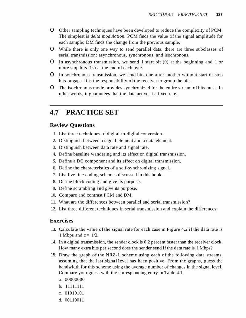
4.7 PRACTICE SET
Review Questions
1. List three techniques of digital-to-digital conversion.
2. Distinguish between a signal element and a data element.
3. Distinguish between data rate and signal rate.
4. Define baseline wandering and its effect on digital transmission.
5. Define a DC component and its effect on digital transmission.
6. Define the characteristics of a self-synchronizing signal.
7. List five line coding schemes discussed in this book.
8. Define block coding and give its purpose.
9. Define scrambling and give its purpose.
10. Compare and contrast PCM and DM.
11. What are the differences between parallel and serial transmission?
12. List three different techniques in serial transmission and explain the differences.
Exercises
13. Calculate the value of the signal rate for each case in Figure 4.2 if the data rate is1 Mbps and c = 1/2.
14. In a digital transmission, the sender clock is 0.2 percent faster than the receiver clock.How many extra bits per second does the sender send if the data rate is 1 Mbps?
15. Draw the graph of the NRZ-L scheme using each of the following data streams,assuming that the last signa11evel has been positive. From the graphs, guess thebandwidth for this scheme using the average number of changes in the signal level.Compare your guess with the corresp.onding entry in Table 4.1.
a. 00000000
b. 11111111
c. 01010101
d. 00110011

CHAPTER 6
Bandwidth Utilization:Multiplexing and Spreading
In real life, we have links with limited bandwidths. The wise use of these bandwidthshas been, and will be, one of the main challenges of electronic communications. However, the meaning of wise may depend on the application. Sometimes we need to combineseveral low-bandwidth channels to make use of one channel with a larger bandwidth.Sometimes we need to expand the bandwidth of a channel to achieve goals such asprivacy and antijamming. In this chapter, we explore these two broad categories ofbandwidth utilization: multiplexing and spreading. In multiplexing, our goal is efficiency; we combine several channels into one. In spreading, our goals are privacy andantijamming; we expand the bandwidth of a channel to insert redundancy, which isnecessary to achieve these goals.
Bandwidth utilization is the wise use of available bandwidth to achieve specific goals.
Efficiency can be achieved by multiplexing;privacy and antijamming can be achieved by spreading.
6.1 MULTIPLEXINGWhenever the bandwidth of a medium linking two devices is greater than the bandwidth needs of the devices, the link can be shared. Multiplexing is the set of techniquesthat allows the simultaneous transmission of multiple signals across a single data link.As data and telecommunications use increases, so does traffic. We can accommodatethis increase by continuing to add individual links each time a new channel is needed;or we can install higher-bandwidth links and use each to carry multiple signals. Asdescribed in Chapter 7, today's technology includes high-bandwidth media such asoptical fiber and terrestrial and satellite microwaves. Each has a bandwidth far in excessof that needed for the average transmission signal. If the bandwidth of a link is greaterthan the bandwidth needs of the devices connected to it, the bandwidth is wasted. Anefficient system maximizes the utilization of all resources; bandwidth is one of themost precious resources we have in data communications.
161

162 CHAPTER 6 BANDWIDTH UTILIZATION: MULTIPLEXING AND SPREADING
In a multiplexed system, n lines share the bandwidth of one link. Figure 6.1 showsthe basic format of a multiplexed system. The lines on the left direct their transmissionstreams to a multiplexer (MUX), which combines them into a single stream (many-toone). At the receiving end, that stream is fed into a demultiplexer (DEMUX), whichseparates the stream back into its component transmissions (one-to-many) anddirects them to their corresponding lines. In the figure, the word link refers to thephysical path. The word channel refers to the portion of a link that carries a transmission between a given pair of lines. One link can have many (n) channels.
Figure 6.1 Dividing a link into channels
n Inputlines
~ MUX: Multiplexer /DEMUX: Demultiplexer D
M E
• U , M ·· X U ·· X ·I link, 11 channels
/ ~
n Outputlines
There are three basic multiplexing techniques: frequency-division multiplexing,wavelength-division multiplexing, and time-division multiplexing. The first two aretechniques designed for analog signals, the third, for digital signals (see Figure 6.2).
Figure 6.2 Categories ofmultiplexing
Multiplexing
II I I
Frequency-division I Wavelength-division Time-divisionmultiplexing multiplexing multiplexing
Analog Analog Digital
Although some textbooks consider carrier division multiple access (COMA) as afourth multiplexing category, we discuss COMA as an access method (see Chapter 12).
Frequency-Division Multiplexing
Frequency-division multiplexing (FDM) is an analog technique that can be appliedwhen the bandwidth of a link (in hertz) is greater than the combined bandwidths ofthe signals to be transmitted. In FOM, signals generated by each sending device modulate different carrier frequencies. These modulated signals are then combined into a singlecomposite signal that can be transported by the link. Carrier frequencies are separated bysufficient bandwidth to accommodate the modulated signal. These bandwidth ranges arethe channels through which the various signals travel. Channels can be separated by

SECTION 6.1 MULTIPLEXING 163
strips of unused bandwidth-guard bands-to prevent signals from overlapping. Inaddition, carrier frequencies must not interfere with the original data frequencies.
Figure 6.3 gives a conceptual view of FDM. In this illustration, the transmission pathis divided into three parts, each representing a channel that carries one transmission.
Figure 6.3 Frequency-division multiplexing
DM Channel J E
InputU Chanllel2 M
Outputlines Jines
X UX
We consider FDM to be an analog multiplexing technique; however, this does notmean that FDM cannot be used to combine sources sending digital signals. A digitalsignal can be converted to an analog signal (with the techniques discussed in Chapter 5)before FDM is used to multiplex them.
FDM is an analog multiplexing technique that combines analog signals.
Multiplexing Process
Figure 6.4 is a conceptual illustration of the multiplexing process. Each source generates a signal of a similar frequency range. Inside the multiplexer, these similar signalsmodulates different carrier frequencies (/1,12, andh). The resulting modulated signalsare then combined into a single composite signal that is sent out over a media link thathas enough bandwidth to accommodate it.
Figure 6.4 FDM process
ModulatorU!UUUUA!!!Amvmvmnm
Carrierh
ModulatorflOflflflflflflVVlJl)l) VVV
Carrierh
Basebandanalog signals
Modulator/\/\/\/\
V \TV\)Carrier!1

164 CHAPTER 6 BANDWIDTH UTILIZATION: MULTIPLEXING AND SPREADING
Demultiplexing Process
The demultiplexer uses a series of filters to decompose the multiplexed signal into itsconstituent component signals. The individual signals are then passed to a demodulatorthat separates them from their carriers and passes them to the output lines. Figure 6.5 isa conceptual illustration of demultiplexing process.
Figure 6.5 FDM demultiplexing example
DemodulatorAAAAVVVVCarrier!l
Basebandanalog signals
DemodulatorAA!!AAAAAAAAAA!!mvmvmmn
Carrierh
~/-- ,
\ '
\ " -
•
:==D=e=m=o=d=ul=at=or==~" \ AAAAAnAA
vvvvvvvv'----~ .... ~'. /1'~~ Carrierh
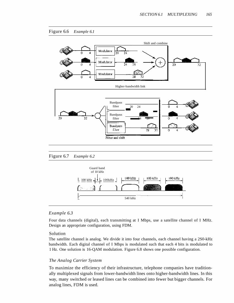
Example 6.1
Assume that a voice channel occupies a bandwidth of 4 kHz. We need to combine three voicechannels into a link with a bandwidth of 12 kHz, from 20 to 32 kHz. Show the configuration,using the frequency domain. Assume there are no guard bands.
SolutionWe shift (modulate) each of the three voice channels to a different bandwidth, as shown in Figure 6.6. We use the 20- to 24-kHz bandwidth for the first channel, the 24- to 28-kHz bandwidthfor the second channel, and the 28- to 32-kHz bandwidth for the third one. Then we combinethem as shown in Figure 6.6. At the receiver, each channel receives the entire signal, using afilter to separate out its own signal. The first channel uses a filter that passes frequenciesbetween 20 and 24 kHz and filters out (discards) any other frequencies. The second channeluses a filter that passes frequencies between 24 and 28 kHz, and the third channel uses a filterthat passes frequencies between 28 and 32 kHz. Each channel then shifts the frequency to startfrom zero.
Example 6.2
Five channels, each with a lOa-kHz bandwidth, are to be multiplexed together. What is the minimum bandwidth of the link if there is a need for a guard band of 10kHz between the channels toprevent interference?
SolutionFor five channels, we need at least four guard bands. This means that the required bandwidth is atleast 5 x 100 + 4 x 10 =540 kHz, as shown in Figure 6.7.
SECTION 6.1 MULTIPLEXING 165
Figure 6.6 Example 6.1
Shift and combine
Higher-bandwidth link
Bandpassfilter
Bandpassfilter
Figure 6.7 Example 6.2
Guard bandof 10 kHz
I. 100 kHz -Ill' 100kHz _I
I·
20 24-_.._-24 28
540 kHz
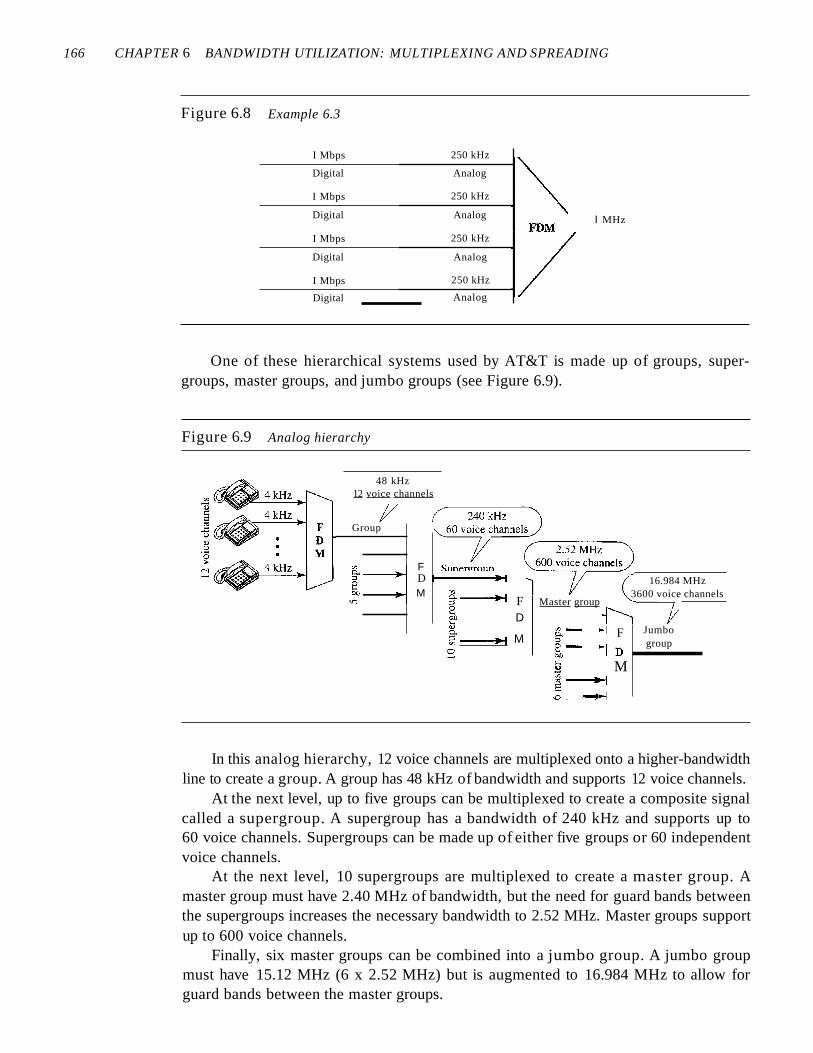
Example 6.3
Four data channels (digital), each transmitting at I Mbps, use a satellite channel of I MHz.Design an appropriate configuration, using FDM.
SolutionThe satellite channel is analog. We divide it into four channels, each channel having a 2S0-kHzbandwidth. Each digital channel of I Mbps is modulated such that each 4 bits is modulated to1 Hz. One solution is 16-QAM modulation. Figure 6.8 shows one possible configuration.
The Analog Carrier System
To maximize the efficiency of their infrastructure, telephone companies have traditionally multiplexed signals from lower-bandwidth lines onto higher-bandwidth lines. In thisway, many switched or leased lines can be combined into fewer but bigger channels. Foranalog lines, FDM is used.
166 CHAPTER 6 BANDWIDTH UTILIZATION: MULTIPLEXING AND SPREADING
Figure 6.8 Example 6.3
I Mbps 250 kHz
Digital Analog
I Mbps 250 kHz
Digital Analog I MHz
I Mbps 250 kHz
Digital Analog
I Mbps 250 kHz
Digital Analog
One of these hierarchical systems used by AT&T is made up of groups, supergroups, master groups, and jumbo groups (see Figure 6.9).
Figure 6.9 Analog hierarchy
48 kHz12 voice channels
Jumbogroup
16.984 MHz3600 voice channels
§.- ~ F~- ..-jD!:l M~-.....~E
'.Q - .....~
en
g. ----i~ F Master group
~ D
~ ----:l.~1 M:=:
FD t------i~
M
Group
In this analog hierarchy, 12 voice channels are multiplexed onto a higher-bandwidthline to create a group. A group has 48 kHz of bandwidth and supports 12 voice channels.
At the next level, up to five groups can be multiplexed to create a composite signalcalled a supergroup. A supergroup has a bandwidth of 240 kHz and supports up to60 voice channels. Supergroups can be made up of either five groups or 60 independentvoice channels.
At the next level, 10 supergroups are multiplexed to create a master group. Amaster group must have 2.40 MHz of bandwidth, but the need for guard bands betweenthe supergroups increases the necessary bandwidth to 2.52 MHz. Master groups supportup to 600 voice channels.
Finally, six master groups can be combined into a jumbo group. A jumbo groupmust have 15.12 MHz (6 x 2.52 MHz) but is augmented to 16.984 MHz to allow forguard bands between the master groups.

SECTION 6.1 MULTIPLEXING 167
Other Applications ofFDM
A very common application of FDM is AM and FM radio broadcasting. Radio uses theair as the transmission medium. A special band from 530 to 1700 kHz is assigned to AMradio. All radio stations need to share this band. As discussed in Chapter 5, each AM station needs 10kHz of bandwidth. Each station uses a different carrier frequency, whichmeans it is shifting its signal and multiplexing. The signal that goes to the air is a combination of signals. A receiver receives all these signals, but filters (by tuning) only the onewhich is desired. Without multiplexing, only one AM station could broadcast to the common link, the air. However, we need to know that there is physical multiplexer or demultiplexer here. As we will see in Chapter 12 multiplexing is done at the data link layer.
The situation is similar in FM broadcasting. However, FM has a wider band of 88to 108 MHz because each station needs a bandwidth of 200 kHz.
Another common use of FDM is in television broadcasting. Each TV channel hasits own bandwidth of 6 MHz.
The first generation of cellular telephones (still in operation) also uses FDM. Eachuser is assigned two 30-kHz channels, one for sending voice and the other for receiving.The voice signal, which has a bandwidth of 3 kHz (from 300 to 3300 Hz), is modulated byusing FM. Remember that an FM signal has a bandwidth 10 times that of the modulatingsignal, which means each channel has 30 kHz (10 x 3) of bandwidth. Therefore, each useris given, by the base station, a 60-kHz bandwidth in a range available at the time of the call.
Example 6.4
The Advanced Mobile Phone System (AMPS) uses two bands. The first band of 824 to 849 MHzis used for sending, and 869 to 894 MHz is used for receiving. Each user has a bandwidth of30 kHz in each direction. The 3-kHz voice is modulated using FM, creating 30 kHz of modulatedsignal. How many people can use their cellular phones simultaneously?
SolutionEach band is 25 MHz. If we divide 25 MHz by 30 kHz, we get 833.33. In reality, the band is dividedinto 832 channels. Of these, 42 channels are used for control, which means only 790 channels areavailable for cellular phone users. We discuss AMPS in greater detail in Chapter 16.
Implementation
FDM can be implemented very easily. In many cases, such as radio and televisionbroadcasting, there is no need for a physical multiplexer or demultiplexer. As long asthe stations agree to send their broadcasts to the air using different carrier frequencies,multiplexing is achieved. In other cases, such as the cellular telephone system, a basestation needs to assign a carrier frequency to the telephone user. There is not enoughbandwidth in a cell to permanently assign a bandwidth range to every telephone user.When a user hangs up, her or his bandwidth is assigned to another caller.
Wavelength-Division Multiplexing
Wavelength-division multiplexing (WDM) is designed to use the high-data-ratecapability of fiber-optic cable. The optical fiber data rate is higher than the data rate ofmetallic transmission cable. Using a fiber-optic cable for one single line wastes theavailable bandwidth. Multiplexing allows us to combine several lines into one.

168 CHAPTER 6 BANDWIDTH UTILIZATION: MULTIPLEXING AND SPREADING
WDM is conceptually the same as FDM, except that the multiplexing and demultiplexing involve optical signals transmitted through fiber-optic channels. The idea is thesame: We are combining different signals of different frequencies. The difference isthat the frequencies are very high.
Figure 6.10 gives a conceptual view of a WDM multiplexer and demultiplexer.Very narrow bands of light from different sources are combined to make a wider bandof light. At the receiver, the signals are separated by the demultiplexer.
Figure 6.10 Wavelength-division multiplexing
AIfl f\.
AI
AZfl flflfl fl
AzAi + Az + A3
fl flA:J A:J
WDM is an analog multiplexing technique to combine optical signals.
Although WDM technology is very complex, the basic idea is very simple. Wewant to combine multiple light sources into one single light at the multiplexer and dothe reverse at the demultiplexer. The combining and splitting of light sources are easilyhandled by a prism. Recall from basic physics that a prism bends a beam of light basedon the angle of incidence and the frequency. Using this technique, a multiplexer can bemade to combine several input beams of light, each containing a narrow band of frequencies, into one output beam of a wider band of frequencies. A demultiplexer canalso be made to reverse the process. Figure 6.11 shows the concept.
:Figure 6.11 Prisms in wavelength-division multiplexing and demultiplexing
Multiplexer
Fiber-optic cable
Demultiplexer
One application of WDM is the SONET network in which multiple opticalfiber lines are multiplexed and demultiplexed. We discuss SONET in Chapter 17.
A new method, called dense WDM (DWDM), can multiplex a very large numberof channels by spacing channels very close to one another. It achieves even greaterefficiency.

SECTION 6.1 MULTIPLEXING 169
Synchronous Time-Division Multiplexing
Time-division multiplexing (TDM) is a digital process that allows several connectionsto share the high bandwidth of a linle Instead of sharing a portion of the bandwidth as inFDM, time is shared. Each connection occupies a portion of time in the link. Figure 6.12gives a conceptual view of TDM. Note that the same link is used as in FDM; here, however, the link is shown sectioned by time rather than by frequency. In the figure, portionsof signals 1,2,3, and 4 occupy the link sequentially.
Figure 6.12 TDM
Data flow
. D 2E J--..::--{§:~
l'4321MU 3X t---~=~-~_
t--L-L-.l...--'--=.........-"'=..L...;;...J...-...l...-...l...-...J.........j
2M ~,
U 4 3 2 1 t'33 X
r=:~---l
Note that in Figure 6.12 we are concerned with only multiplexing, not switching.This means that all the data in a message from source 1 always go to one specific destination, be it 1, 2, 3, or 4. The delivery is fixed and unvarying, unlike switching.
We also need to remember that TDM is, in principle, a digital multiplexing technique.Digital data from different sources are combined into one timeshared link. However, thisdoes not mean that the sources cannot produce analog data; analog data can be sampled,changed to digital data, and then multiplexed by using TDM.
TDM is a digital multiplexing technique for combiningseveral low-rate channels into one high-rate one.
We can divide TDM into two different schemes: synchronous and statistical. We firstdiscuss synchronous TDM and then show how statistical TDM differs. In synchronousTDM, each input connection has an allotment in the output even if it is not sending data.
Time Slots and Frames
In synchronous TDM, the data flow of each input connection is divided into units, whereeach input occupies one input time slot. A unit can be 1 bit, one character, or one block ofdata. Each input unit becomes one output unit and occupies one output time slot. However, the duration of an output time slot is n times shorter than the duration of an inputtime slot. If an input time slot is T s, the output time slot is Tin s, where n is the numberof connections. In other words, a unit in the output connection has a shorter duration; ittravels faster. Figure 6.13 shows an example of synchronous TDM where n is 3.

170 CHAPTER 6 BANDWIDTH UTILIZATION: MULTIPLEXING AND SPREADING
Figure 6.13 Synchronous time-division multiplexing
Data are taken from eachline every T s.
Each frame is 3 time slots.Each time slot duration is Tf3 s.
Bl
T
Al
Cl
Jil
A2
B2
T
C2
JlfT
C3
A3
B3
If
In synchronous TDM, a round of data units from each input connection is collectedinto a frame (we will see the reason for this shortly). If we have n connections, a frameis divided into n time slots and one slot is allocated for each unit, one for each inputline. If the duration of the input unit is T, the duration of each slot is Tin and the duration of each frame is T (unless a frame carries some other information, as we will seeshortly).
The data rate of the output link must be n times the data rate of a connection toguarantee the flow of data. In Figure 6.13, the data rate of the link is 3 times the datarate of a connection; likewise, the duration of a unit on a connection is 3 times that ofthe time slot (duration of a unit on the link). In the figure we represent the data prior tomultiplexing as 3 times the size of the data after multiplexing. This is just to convey theidea that each unit is 3 times longer in duration before multiplexing than after.
In synchronous TDM, the data rate of the link is n times faster,and the unit duration is n times shorter.
Time slots are grouped into frames. A frame consists of one complete cycle oftime slots, with one slot dedicated to each sending device. In a system with n inputlines, each frame has n slots, with each slot allocated to carrying data from a specificinput line.
Example 6.5
In Figure 6.13, the data rate for each input connection is 3 kbps. If 1 bit at a time is multiplexed (aunit is 1 bit), what is the duration of (a) each input slot, (b) each output slot, and (c) each frame?
SolutionWe can answer the questions as follows:
a. The data rate of each input connection is 1 kbps. This means that the bit duration is 111000 sor 1 ms. The duration of the input time slot is 1 ms (same as bit duration).
b. The duration of each output time slot is one-third of the input time slot. This means that theduration of the output time slot is 1/3 ms.
c. Each frame carries three output time slots. So the duration of a frame is 3 x 113 ms, or 1 ms.The duration of a frame is the same as the duration of an input unit.

SECTION 6.1 MULTIPLEXING 171
Example 6.6
Figure 6.14 shows synchronous TOM with a data stream for each input and one data stream forthe output. The unit of data is 1 bit. Find (a) the input bit duration, (b) the output bit duration,(c) the output bit rate, and (d) the output frame rate.
Figure 6.14 Example 6.6
I Mbps• •• 1
1 Mbps• •• 0 0 0 0
1 Mbps• •• 1 0 0
1 Mbps• •• 0 0 0
o
o
Frames
••• ffilQI!][Q]QJQliJ1III[Q[QJQli]"
SolutionWe can answer the questions as follows:
a. The input bit duration is the inverse of the bit rate: 1/1 Mbps = 1 lls.b. The output bit duration is one-fourth of the input bit duration, or 1/411s.c. The output bit rate is the inverse of the output bit duration or 1/4 lls, or 4 Mbps. This can also
be deduced from the fact that the output rate is 4 times as fast as any input rate; so the outputrate =4 x 1 Mbps =4 Mbps.
d. The frame rate is always the same as any input rate. So the frame rate is 1,000,000 frames persecond. Because we are sending 4 bits in each frame, we can verify the result of the previousquestion by multiplying the frame rate by the number of bits per frame.
Example 6.7
Four l-kbps connections are multiplexed together. A unit is I bit. Find (a) the duration of I bitbefore multiplexing, (b) the transmission rate of the link, (c) the duration of a time slot, and(d) the duration of a frame.
SolutionWe can answer the questions as follows:
a. The duration of 1 bit before multiplexing is 1/1 kbps, or 0.001 s (l ms).b. The rate of the link is 4 times the rate of a connection, or 4 kbps.c. The duration of each time slot is one-fourth of the duration of each bit before multiplexing,
or 1/4 ms or 250 I.ls. Note that we can also calculate this from the data rate of the link, 4 kbps.The bit duration is the inverse of the data rate, or 1/4 kbps or 250 I.ls.
d. The duration of a frame is always the same as the duration of a unit before multiplexing, orI ms. We can also calculate this in another way. Each frame in this case has fouf time slots.So the duration of a frame is 4 times 250 I.ls, or I ms.
Interleaving
TDM can be visualized as two fast-rotating switches, one on the multiplexing side andthe other on the demultiplexing side. The switches are synchronized and rotate at thesame speed, but in opposite directions. On the multiplexing side, as the switch opens
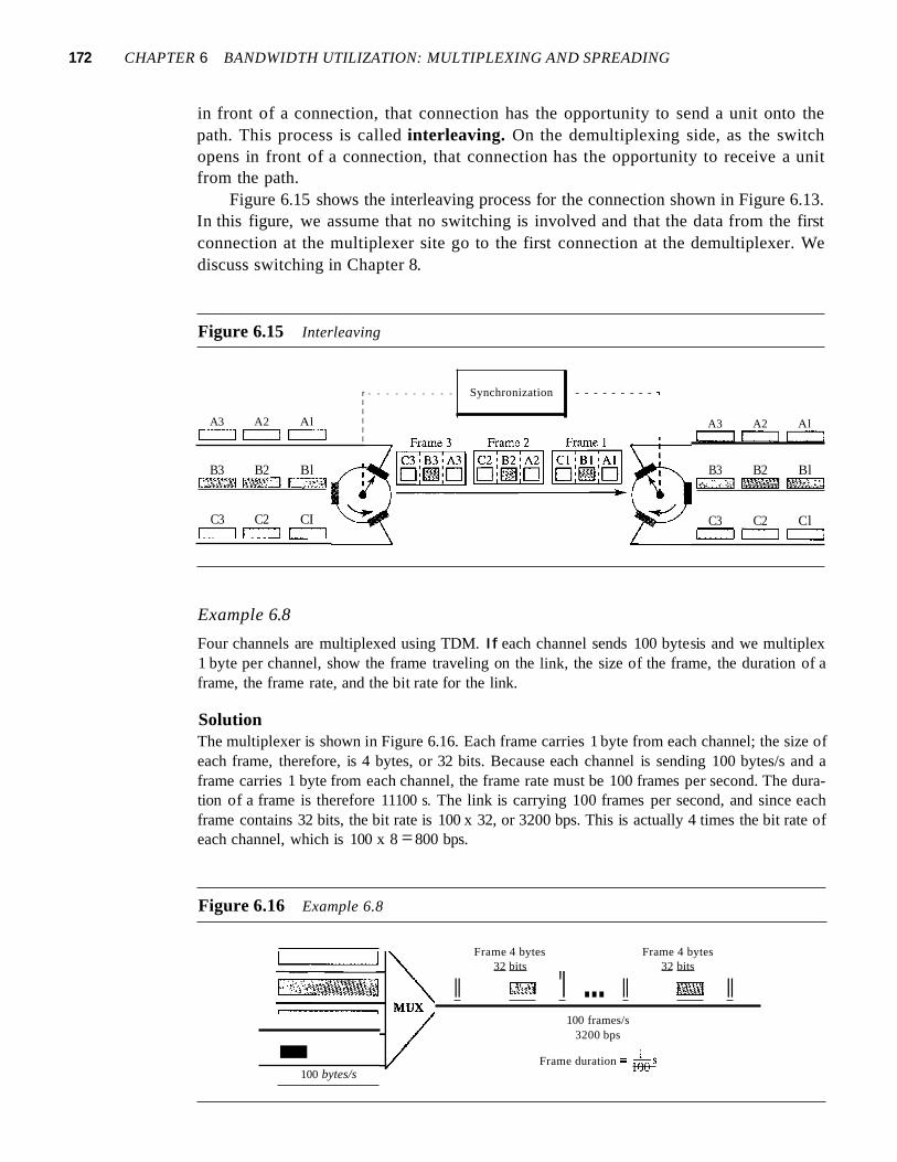
172 CHAPTER 6 BANDWIDTH UTILIZATION: MULTIPLEXING AND SPREADING
in front of a connection, that connection has the opportunity to send a unit onto thepath. This process is called interleaving. On the demultiplexing side, as the switchopens in front of a connection, that connection has the opportunity to receive a unitfrom the path.
Figure 6.15 shows the interleaving process for the connection shown in Figure 6.13.In this figure, we assume that no switching is involved and that the data from the firstconnection at the multiplexer site go to the first connection at the demultiplexer. Wediscuss switching in Chapter 8.
Figure 6.15 Interleaving
A3 A2 Alc=J [==:J c::::::J
B3 B2 Bl~~~
C3 C2 CIc=:::J [==:J c::::::J
r - - - - - - - - - - Synchronization - - - - - - - - - ,IIIII
A3 A2 Al[==:J [==:J c:::J
B3 B2 Bl~~~
C3 C2 Clc:::J r:::::J c=:::J
Example 6.8
Four channels are multiplexed using TDM. If each channel sends 100 bytesis and we multiplex1 byte per channel, show the frame traveling on the link, the size of the frame, the duration of aframe, the frame rate, and the bit rate for the link.
SolutionThe multiplexer is shown in Figure 6.16. Each frame carries 1 byte from each channel; the size ofeach frame, therefore, is 4 bytes, or 32 bits. Because each channel is sending 100 bytes/s and aframe carries 1 byte from each channel, the frame rate must be 100 frames per second. The duration of a frame is therefore 11100 s. The link is carrying 100 frames per second, and since eachframe contains 32 bits, the bit rate is 100 x 32, or 3200 bps. This is actually 4 times the bit rate ofeach channel, which is 100 x 8 =800 bps.
Figure 6.16 Example 6.8
-100 bytes/s
Frame 4 bytes Frame 4 bytes32 bits 32 bits
II 1,*"tiJ 'I ... II g~ II100 frames/s
3200 bps
Frame duration == 160s

SECTION 6.1 MULTIPLEXING 173
Example 6.9
A multiplexer combines four 100-kbps channels using a time slot of 2 bits. Show the output withfour arbitrary inputs. What is the frame rate? What is the frame duration? What is the bit rate?What is the bit duration?
SolutionFigure 6.17 shows the output for four arbitrary inputs. The link carries 50,000 frames per secondsince each frame contains 2 bits per channel. The frame duration is therefore 1/50,000 s or 20 ~s.
The frame rate is 50,000 frames per second, and each frame carries 8 bits; the bit rate is 50,000 x8 =400,000 bits or 400 kbps. The bit duration is 1/400,000 s, or 2.5 IJ.s. Note that the frame duration is 8 times the bit duration because each frame is carrying 8 bits.
Figure 6.17 Example 6.9
·.. 110010100 kbps ... 001010100 kbps
·.. 101 101100 kbps
·.. 000111100 kbps
Frame duration = lI50,000 s = 20 Ils
Frame: 8 bits Frame: 8 bits Frame: 8 bits
...~~~50,000 frames/s
400kbps
Empty Slots
Synchronous TDM is not as efficient as it could be. If a source does not have data tosend, the corresponding slot in the output frame is empty. Figure 6.18 shows a case inwhich one of the input lines has no data to send and one slot in another input line hasdiscontinuous data.
Figure 6.18 Empty slots
II II
I~ 0110 DII~ 01
The first output frame has three slots filled, the second frame has two slots filled,and the third frame has three slots filled. No frame is full. We learn in the next sectionthat statistical TDM can improve the efficiency by removing the empty slots from theframe.
Data Rate Management
One problem with TDM is how to handle a disparity in the input data rates. In all ourdiscussion so far, we assumed that the data rates of all input lines were the same. However,

174 CHAPTER 6 BANDWIDTH UTILIZATION: MULTIPLEXING AND SPREADING
if data rates are not the same, three strategies, or a combination of them, can be used.We call these three strategies multilevel multiplexing, multiple-slot allocation, andpulse stuffing.
Multilevel Multiplexing Multilevel multiplexing is a technique used when the datarate of an input line is a multiple of others. For example, in Figure 6.19, we have twoinputs of 20 kbps and three inputs of 40 kbps. The first two input lines can be multiplexed together to provide a data rate equal to the last three. A second level of multiplexing can create an output of 160 kbps.
Figure 6.19 Multilevel multiplexing
20 kbps ----;"\>------t
20 kbps ----I
40 kbps --------1
40 kbps --------1
40 kbps --------1
160 kbps
Multiple-Slot Allocation Sometimes it is more efficient to allot more than one slot ina frame to a single input line. For example, we might have an input line that has a datarate that is a multiple of another input. In Figure 6.20, the input line with a SO-kbps datarate can be given two slots in the output. We insert a serial-to-parallel converter in theline to make two inputs out of one.
Figure 6.20 Multiple-slot multiplexing
50 kbps
25 kbps -------125 kbps -------1
25 kbps -------1/
The input with a50-kHz data rate has two
slots in each frame.
Pulse Stuffing Sometimes the bit rates of sources are not multiple integers of eachother. Therefore, neither of the above two techniques can be applied. One solution is tomake the highest input data rate the dominant data rate and then add dummy bits to theinput lines with lower rates. This will increase their rates. This technique is called pulsestuffing, bit padding, or bit stuffing. The idea is shown in Figure 6.21. The input with adata rate of 46 is pulse-stuffed to increase the rate to 50 kbps. Now multiplexing cantake place.

SECTION 6.1 MULTIPLEXING 175
Figure 6.21 Pulse stuffing
50 kbps ----------1
50 kbps ----------1
46kbps ---I
150 kbps
Frame Synchronizing
The implementation of TDM is not as simple as that of FDM. Synchronization betweenthe multiplexer and demultiplexer is a major issue. If the. multiplexer and the demultiplexer are not synchronized, a bit belonging to one channel may be received by thewrong channel. For this reason, one or more synchronization bits are usually added tothe beginning of each frame. These bits, called framing bits, follow a pattern, frame toframe, that allows the demultiplexer to synchronize with the incoming stream so that itcan separate the time slots accurately. In most cases, this synchronization informationconsists of 1 bit per frame, alternating between 0 and I, as shown in Figure 6.22.
Figure 6.22 Framing bits
I 1 0 1ISynchronization
pattern
Frame 3 Frame 2 Frame 1
C3 I B3 I A3 182 I A2 CI I I Al.:11II:0 0 I I I :0:11I:0 II
Example 6.10
We have four sources, each creating 250 characters per second. If the interleaved unit is a characterand 1 synchronizing bit is added to each frame, find (a) the data rate of each source, (b) the durationof each character in each source, (c) the frame rate, (d) the duration of each frame, (e) the number ofbits in each frame, and (f) the data rate of the link.
SolutionWe can answer the questions as follows:
a. The data rate of each source is 250 x 8 = 2000 bps = 2 kbps.
b. Each source sends 250 characters per second; therefore, the duration of a character is 1/250 s,or4 ms.
c. Each frame has one character from each source, which means the link needs to send250 frames per second to keep the transmission rate of each source.
d. The duration of each frame is 11250 s, or 4 ms. Note that the duration of each frame is thesame as the duration of each character coming from each source.
e. Each frame carries 4 characters and I extra synchronizing bit. This means that each frame is
4 x 8 + 1 =33 bits.
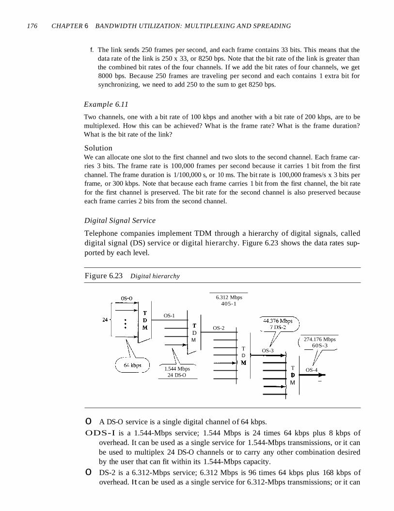
176 CHAPTER 6 BANDWIDTH UTILIZATION: MULTIPLEXING AND SPREADING
f. The link sends 250 frames per second, and each frame contains 33 bits. This means that thedata rate of the link is 250 x 33, or 8250 bps. Note that the bit rate of the link is greater thanthe combined bit rates of the four channels. If we add the bit rates of four channels, we get8000 bps. Because 250 frames are traveling per second and each contains 1 extra bit forsynchronizing, we need to add 250 to the sum to get 8250 bps.
Example 6.11
Two channels, one with a bit rate of 100 kbps and another with a bit rate of 200 kbps, are to bemultiplexed. How this can be achieved? What is the frame rate? What is the frame duration?What is the bit rate of the link?
SolutionWe can allocate one slot to the first channel and two slots to the second channel. Each frame carries 3 bits. The frame rate is 100,000 frames per second because it carries 1 bit from the firstchannel. The frame duration is 1/100,000 s, or 10 ms. The bit rate is 100,000 frames/s x 3 bits perframe, or 300 kbps. Note that because each frame carries 1 bit from the first channel, the bit ratefor the first channel is preserved. The bit rate for the second channel is also preserved becauseeach frame carries 2 bits from the second channel.
Digital Signal Service
Telephone companies implement TDM through a hierarchy of digital signals, calleddigital signal (DS) service or digital hierarchy. Figure 6.23 shows the data rates supported by each level.
Figure 6.23 Digital hierarchy
OS-4•
274.176 Mbps60S-3
OS-3
TDM
--+-\
6.312 Mbps405-1
TD :---......~
--~M
OS-2TDM
1.544 Mbps24 DS-O
OS-1
os-o
o A DS-O service is a single digital channel of 64 kbps.
ODS-I is a 1.544-Mbps service; 1.544 Mbps is 24 times 64 kbps plus 8 kbps ofoverhead. It can be used as a single service for 1.544-Mbps transmissions, or it canbe used to multiplex 24 DS-O channels or to carry any other combination desiredby the user that can fit within its 1.544-Mbps capacity.
o DS-2 is a 6.312-Mbps service; 6.312 Mbps is 96 times 64 kbps plus 168 kbps ofoverhead. It can be used as a single service for 6.312-Mbps transmissions; or it can

SECTION 6.1 MULTIPLEXING 177
be used to multiplex 4 DS-l channels, 96 DS-O channels, or a combination of theseservice types.
o DS-3 is a 44.376-Mbps service; 44.376 Mbps is 672 times 64 kbps plus 1.368 Mbpsof overhead. It can be used as a single service for 44.376-Mbps transmissions; or itcan be used to multiplex 7 DS-2 channels, 28 DS-l channels, 672 DS-O channels,or a combination of these service types.
o DS-4 is a 274. 176-Mbps service; 274.176 is 4032 times 64 kbps plus 16.128 Mbps ofoverhead. It can be used to multiplex 6 DS-3 channels, 42 DS-2 channels, 168 DS-lchannels, 4032 DS-O channels, or a combination of these service types.
T Lines
DS-O, DS-l, and so on are the names of services. To implement those services, the telephone companies use T lines (T-l to T-4). These are lines with capacities preciselymatched to the data rates of the DS-l to DS-4 services (see Table 6.1). So far only T-land T-3 lines are commercially available.
Table 6.1 DS and T line rates
Sen/ice Line Rate (Mbps) Voice Channels
DS-1 T-1 1.544 24
DS-2 T-2 6.312 96
DS-3 T-3 44.736 672
DS-4 T-4 274.176 4032
The T-l line is used to implement DS-l; T-2 is used to implement DS-2; and so on.As you can see from Table 6.1, DS-O is not actually offered as a service, but it has beendefined as a basis for reference purposes.
T Lines for Analog Transmission
T lines are digital lines designed for the transmission of digital data, audio, or video.However, they also can be used for analog transmission (regular telephone connections), provided the analog signals are first sampled, then time-division multiplexed.
The possibility of using T lines as analog carriers opened up a new generation ofservices for the telephone companies. Earlier, when an organization wanted 24 separatetelephone lines, it needed to run 24 twisted-pair cables from the company to the centralexchange. (Remember those old movies showing a busy executive with 10 telephoneslined up on his desk? Or the old office telephones with a big fat cable running fromthem? Those cables contained a bundle of separate lines.) Today, that same organizationcan combine the 24 lines into one T-l line and run only the T-l line to the exchange.Figure 6.24 shows how 24 voice channels can be multiplexed onto one T-I line. (Referto Chapter 5 for PCM encoding.)
The T-1 Frame As noted above, DS-l requires 8 kbps of overhead. To understand howthis overhead is calculated, we must examine the format of a 24-voice-channel frame.
The frame used on a T-l line is usually 193 bits divided into 24 slots of 8 bits eachplus 1 extra bit for synchronization (24 x 8 + 1 = 193); see Figure 6.25. In other words,

178 CHAPTER 6 BANDWIDTH UTILIZATION: MULTIPLEXING AND SPREADING
Figure 6.24 T-l line for multiplexing telephone lines
Sampling at 8000 sampJes/sLlsing 8 bits per sample
tI)
M
T-I line 1.544 Mbps24 x 64 kbps + 8 kbps overhead
Figure 6.25 T-l frame structure
SamplenI
1 frame= 193 bits
I Channel I·· ·1 Channel II Channel I24 2 I
1 bit 8 bits 8 bits 8 bits
Frame I Frame II Frame... ...n 2 1
T- I: 8000 frames/s = 8000 x 193 bps = 1.544 Mbps
each slot contains one signal segment from each channel; 24 segments are interleavedin one frame. If a T-l line carries 8000 frames, the data rate is 1.544 Mbps (193 x 8000 =1.544 Mbps)-the capacity of the line.
E Lines
Europeans use a version ofT lines called E lines. The two systems are conceptually identical, but their capacities differ. Table 6.2 shows the E lines and their capacities.

SECTION 6.1 MULTIPLEXING 179
Table 6.2 E line rates
Line Rate (Mbps) Voice Channels
E-1 2.048 30
E-2 8.448 120
E-3 34.368 480
E-4 139.264 1920
More Synchronous TDM Applications
Some second-generation cellular telephone companies use synchronous TDM. Forexample, the digital version of cellular telephony divides the available bandwidth into3D-kHz bands. For each band, TDM is applied so that six users can share the band. Thismeans that each 3D-kHz band is now made of six time slots, and the digitized voice signals of the users are inserted in the slots. Using TDM, the number of telephone users ineach area is now 6 times greater. We discuss second-generation cellular telephony inChapter 16.
Statistical Time-Division MultiplexingAs we saw in the previous section, in synchronous TDM, each input has a reserved slotin the output frame. This can be inefficient if some input lines have no data to send. Instatistical time-division multiplexing, slots are dynamically allocated to improve bandwidth efficiency. Only when an input line has a slot's worth of data to send is it given aslot in the output frame. In statistical multiplexing, the number of slots in each frame isless than the number of input lines. The multiplexer checks each input line in roundrobin fashion; it allocates a slot for an input line if the line has data to send; otherwise,it skips the line and checks the next line.
Figure 6.26 shows a synchronous and a statistical TDM example. In the former,some slots are empty because the corresponding line does not have data to send. Inthe latter, however, no slot is left empty as long as there are data to be sent by anyinput line.
Addressing
Figure 6.26 also shows a major difference between slots in synchronous TDM andstatistical TDM. An output slot in synchronous TDM is totally occupied by data; instatistical TDM, a slot needs to carry data as well as the address of the destination.In synchronous TDM, there is no need for addressing; synchronization and preassignedrelationships between the inputs and outputs serve as an address. We know, for example, that input 1 always goes to input 2. If the multiplexer and the demultiplexer aresynchronized, this is guaranteed. In statistical multiplexing, there is no fixed relationship between the inputs and outputs because there are no preassigned or reservedslots. We need to include the address of the receiver inside each slot to show where itis to be delivered. The addressing in its simplest form can be n bits to define N differentoutput lines with n =10g2 N. For example, for eight different output lines, we need a3-bit address.

180 CHAPTER 6 BANDWIDTH UTILIZATION: MULTIPLEXING AND SPREADING
Figure 6.26 TDM slot comparison
Line A ----[:3:0LineB
Line C --------{
Line 0 --i.iI~=~LineE
a. Synchronous TDM
Line A -----[=:ACHLineB
Line C --------i
Line 0 ---:~~LineE --I
b. Statistical TDM
Slot Size
Since a slot carries both data and an address in statistical TDM, the ratio of the data sizeto address size must be reasonable to make transmission efficient. For example, itwould be inefficient to send 1 bit per slot as data when the address is 3 bits. This wouldmean an overhead of 300 percent. In statistical TDM, a block of data is usually manybytes while the address is just a few bytes.
No Synchronization Bit
There is another difference between synchronous and statistical TDM, but this time it isat the frame level. The frames in statistical TDM need not be synchronized, so we do notneed synchronization bits.
Bandwidth
In statistical TDM, the capacity of the link is normally less than the sum of the capacities of each channel. The designers of statistical TDM define the capacity of the linkbased on the statistics of the load for each channel. If on average only x percent of theinput slots are filled, the capacity of the link reflects this. Of course, during peak times,some slots need to wait.
6.2 SPREAD SPECTRUMMultiplexing combines signals from several sources to achieve bandwidth efficiency; theavailable bandwidth of a link is divided between the sources. In spread spectrum (88), wealso combine signals from different sources to fit into a larger bandwidth, but our goals