Data communication and industrial enclosures - ZPAS
204
Data communication and industrial enclosures for your connections Data communication and industrial enclosures [ EN010 ]
-
Upload
khangminh22 -
Category
Documents
-
view
0 -
download
0
Transcript of Data communication and industrial enclosures - ZPAS
Data communication
and industrial enclosures
f o r y o u r c o n n e c t i o n s
Zakł ad Produkcji Automatyki Sieciowej S.A.
Przygórze 209 · 57-431 Wolibórz · Poland
Phone +48 748 720 100
Fax +48 748 724 074
[email protected] · www.zpas.pl
A Company of ZPAS Group
f o r y o u r c o n n e c t i o n s
Dat
a co
mm
un
icat
ion
an
d in
du
stri
al e
ncl
osu
res
[
EN
010
]Our business representatives:
Latvia
Lithuania
Luxembourg
Malta
Morocco
The Netherlands
Norway
Poland
Portugal
Russia
Slovenia
Spain
Sweden
Switzerland
Ukraine
Austria
Belarus
Belgium
Bosnia and Herzegovina
Cyprus
Denmark
France
Germany
Great Britain
Greece
Hungary
Iceland
Italy
Kazakhstan
Kyrgyzstan
Wrocław
ZąbkowiceŚląskie
Kłodzko
Wałbrzych
Jawor
Świdnica
Nowa Ruda
Kudowa Zdr.
CZEC
H R
EPU
BLIC
CZECHREPUBLIC
Dzierżoniów
Przygórze
35
384
385
381
35
5
5
3
A4
A4
8
E 67
E 67
E 40
33
2
solutions for connections
Data communication and industrial enclosures
Edition: 03.2010 [EN010]
Published by:ZPAS S.A.Przygórze 209, 57-431 Wolibórz, Poland
Design of the cover page and section pages,design consulting:Christoph Hetmaniokhetmaniok visuelle komunikation & marketingHoexter
DTP and printing:Usługi Poligraficzne Bogdan Kokot vel Kokocińskiwww.kokocinski.pl
We reserve the right to modernise and modify our products. Technical modifications shall not affect product functionality. Misprints and errors of content that may be found in this catalogue may not be used as a basis for complaints.
203
for your connections
The ZPAS Group, pursuing shared goals and business
philosophy, integrates the product offer of ZPAS S.A. and
ZPAS-NET sp. z o.o. The idea is reflected in our motto
‘‘solutions for connections’’, which refers to advantages of
our products, benefits of using them, a superb system of
communication with our customers, partnership, technical
consulting and high level of customer service, from the
moment of first contact until order fulfilment. The motto
thus reflects our attitude to clients whose requirements we
wish to satisfy, offering them top-quality services.
We have achieved a strong status in the industry over
35 years of our business activity. As a manufacturer, we
operate in accordance with our well-established reputation
as a reliable business partner providing customers with
topquality products, short lead times and very reasonable
prices.
Electronic communication products (elements of IT,
telecommunications and power systems) must
demonstrate parameters and features capable of meeting
rigorous high-tech requirements. Our primary goal is to
supply such products.
Our capital is not limited to modern machines. We also
boast of highly qualified staff. Our employees are young,
creative and innovation-minded. They also make the best
use of vast industry experience acquired over more than
30 years by specialists who have worked for our company ever
since its beginnings. Advanced technologies and wellplanned
organisation of all manufacturing processes are
supported by INFOR ERP LN, our IT system.
ZPAS Group
3
for your connections
ZPA
S S.
A.
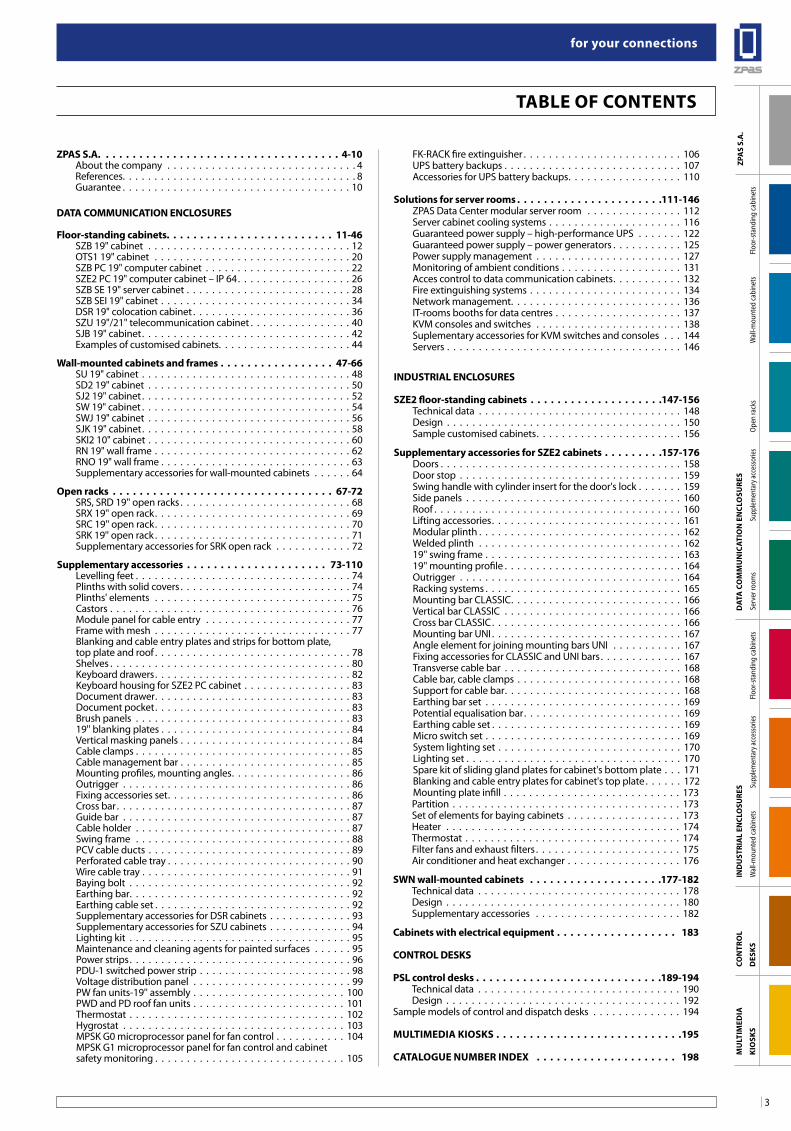
Table of ConTenTs
ZPa
s s.
a.
Floo
r-sta
ndin
g ca
bine
tsW
all-m
ount
ed ca
bine
tsOp
en ra
cks
Supp
lemen
tary
acce
ssor
iesSe
rver
room
sFl
oor-s
tand
ing
cabi
nets
Supp
lemen
tary
acce
ssor
iesW
all-m
ount
ed ca
bine
ts
Con
TRo
l
Des
Ks
Mu
lTiM
eDia
Kio
sKs
DaT
a C
oM
Mu
niC
aTio
n e
nCl
osu
Res
inD
usT
Ria
l en
Clo
suRe
s
ZPas s.a. . . . . . . . . . . . . . . . . . . . . . . . . . . . . . . . . . . . 4-10About the company . . . . . . . . . . . . . . . . . . . . . . . . . . . . . . 4References. . . . . . . . . . . . . . . . . . . . . . . . . . . . . . . . . . . . . 8Guarantee . . . . . . . . . . . . . . . . . . . . . . . . . . . . . . . . . . . . 10
DaTa CoMMuniCaTion enClosuRes
floor-standing cabinets. . . . . . . . . . . . . . . . . . . . . . . . . 11-46SZB 19" cabinet . . . . . . . . . . . . . . . . . . . . . . . . . . . . . . . . 12OTS1 19" cabinet . . . . . . . . . . . . . . . . . . . . . . . . . . . . . . . 20SZB PC 19" computer cabinet . . . . . . . . . . . . . . . . . . . . . . . 22SZE2 PC 19" computer cabinet – IP 64. . . . . . . . . . . . . . . . . . 26SZB SE 19" server cabinet . . . . . . . . . . . . . . . . . . . . . . . . . . 28SZB SEI 19" cabinet . . . . . . . . . . . . . . . . . . . . . . . . . . . . . . 34DSR 19" colocation cabinet . . . . . . . . . . . . . . . . . . . . . . . . . 36SZU 19"/21" telecommunication cabinet . . . . . . . . . . . . . . . . 40SJB 19" cabinet. . . . . . . . . . . . . . . . . . . . . . . . . . . . . . . . . 42Examples of customised cabinets. . . . . . . . . . . . . . . . . . . . . 44
Wall-mounted cabinets and frames . . . . . . . . . . . . . . . . . 47-66SU 19" cabinet . . . . . . . . . . . . . . . . . . . . . . . . . . . . . . . . . 48SD2 19" cabinet . . . . . . . . . . . . . . . . . . . . . . . . . . . . . . . . 50SJ2 19" cabinet . . . . . . . . . . . . . . . . . . . . . . . . . . . . . . . . . 52SW 19" cabinet . . . . . . . . . . . . . . . . . . . . . . . . . . . . . . . . . 54SWJ 19" cabinet . . . . . . . . . . . . . . . . . . . . . . . . . . . . . . . . 56SJK 19" cabinet. . . . . . . . . . . . . . . . . . . . . . . . . . . . . . . . . 58SKI2 10" cabinet . . . . . . . . . . . . . . . . . . . . . . . . . . . . . . . . 60RN 19" wall frame . . . . . . . . . . . . . . . . . . . . . . . . . . . . . . . 62RNO 19" wall frame . . . . . . . . . . . . . . . . . . . . . . . . . . . . . . 63Supplementary accessories for wall-mounted cabinets . . . . . . 64
open racks . . . . . . . . . . . . . . . . . . . . . . . . . . . . . . . . . 67-72SRS, SRD 19'' open racks . . . . . . . . . . . . . . . . . . . . . . . . . . . 68SRX 19'' open rack. . . . . . . . . . . . . . . . . . . . . . . . . . . . . . . 69SRC 19'' open rack. . . . . . . . . . . . . . . . . . . . . . . . . . . . . . . 70SRK 19'' open rack . . . . . . . . . . . . . . . . . . . . . . . . . . . . . . . 71Supplementary accessories for SRK open rack . . . . . . . . . . . . 72
supplementary accessories . . . . . . . . . . . . . . . . . . . . . 73-110Levelling feet . . . . . . . . . . . . . . . . . . . . . . . . . . . . . . . . . . 74Plinths with solid covers . . . . . . . . . . . . . . . . . . . . . . . . . . . 74Plinths' elements . . . . . . . . . . . . . . . . . . . . . . . . . . . . . . . 75Castors . . . . . . . . . . . . . . . . . . . . . . . . . . . . . . . . . . . . . . 76Module panel for cable entry . . . . . . . . . . . . . . . . . . . . . . . 77Frame with mesh . . . . . . . . . . . . . . . . . . . . . . . . . . . . . . . 77Blanking and cable entry plates and strips for bottom plate, top plate and roof . . . . . . . . . . . . . . . . . . . . . . . . . . . . . . . 78Shelves . . . . . . . . . . . . . . . . . . . . . . . . . . . . . . . . . . . . . . 80Keyboard drawers. . . . . . . . . . . . . . . . . . . . . . . . . . . . . . . 82Keyboard housing for SZE2 PC cabinet . . . . . . . . . . . . . . . . . 83Document drawer. . . . . . . . . . . . . . . . . . . . . . . . . . . . . . . 83Document pocket. . . . . . . . . . . . . . . . . . . . . . . . . . . . . . . 83Brush panels . . . . . . . . . . . . . . . . . . . . . . . . . . . . . . . . . . 8319'' blanking plates . . . . . . . . . . . . . . . . . . . . . . . . . . . . . . 84Vertical masking panels . . . . . . . . . . . . . . . . . . . . . . . . . . . 84Cable clamps . . . . . . . . . . . . . . . . . . . . . . . . . . . . . . . . . . 85Cable management bar . . . . . . . . . . . . . . . . . . . . . . . . . . . 85Mounting profiles, mounting angles. . . . . . . . . . . . . . . . . . . 86Outrigger . . . . . . . . . . . . . . . . . . . . . . . . . . . . . . . . . . . . 86Fixing accessories set. . . . . . . . . . . . . . . . . . . . . . . . . . . . . 86Cross bar . . . . . . . . . . . . . . . . . . . . . . . . . . . . . . . . . . . . . 87Guide bar . . . . . . . . . . . . . . . . . . . . . . . . . . . . . . . . . . . . 87Cable holder . . . . . . . . . . . . . . . . . . . . . . . . . . . . . . . . . . 87Swing frame . . . . . . . . . . . . . . . . . . . . . . . . . . . . . . . . . . 88PCV cable ducts . . . . . . . . . . . . . . . . . . . . . . . . . . . . . . . . 89Perforated cable tray . . . . . . . . . . . . . . . . . . . . . . . . . . . . . 90Wire cable tray . . . . . . . . . . . . . . . . . . . . . . . . . . . . . . . . . 91Baying bolt . . . . . . . . . . . . . . . . . . . . . . . . . . . . . . . . . . . 92Earthing bar. . . . . . . . . . . . . . . . . . . . . . . . . . . . . . . . . . . 92Earthing cable set . . . . . . . . . . . . . . . . . . . . . . . . . . . . . . . 92Supplementary accessories for DSR cabinets . . . . . . . . . . . . . 93Supplementary accessories for SZU cabinets . . . . . . . . . . . . . 94Lighting kit . . . . . . . . . . . . . . . . . . . . . . . . . . . . . . . . . . . 95Maintenance and cleaning agents for painted surfaces . . . . . . 95Power strips. . . . . . . . . . . . . . . . . . . . . . . . . . . . . . . . . . . 96PDU-1 switched power strip . . . . . . . . . . . . . . . . . . . . . . . . 98Voltage distribution panel . . . . . . . . . . . . . . . . . . . . . . . . . 99PW fan units-19'' assembly . . . . . . . . . . . . . . . . . . . . . . . . 100PWD and PD roof fan units . . . . . . . . . . . . . . . . . . . . . . . . 101Thermostat . . . . . . . . . . . . . . . . . . . . . . . . . . . . . . . . . . 102Hygrostat . . . . . . . . . . . . . . . . . . . . . . . . . . . . . . . . . . . 103MPSK G0 microprocessor panel for fan control . . . . . . . . . . . 104MPSK G1 microprocessor panel for fan control and cabinet safety monitoring . . . . . . . . . . . . . . . . . . . . . . . . . . . . . . 105
FK-RACK fire extinguisher . . . . . . . . . . . . . . . . . . . . . . . . . 106UPS battery backups . . . . . . . . . . . . . . . . . . . . . . . . . . . . 107Accessories for UPS battery backups. . . . . . . . . . . . . . . . . . 110
solutions for server rooms . . . . . . . . . . . . . . . . . . . . . .111-146 ZPAS Data Center modular server room . . . . . . . . . . . . . . . 112Server cabinet cooling systems . . . . . . . . . . . . . . . . . . . . . 116Guaranteed power supply – high-performance UPS . . . . . . . 122Guaranteed power supply – power generators . . . . . . . . . . . 125Power supply management . . . . . . . . . . . . . . . . . . . . . . . 127Monitoring of ambient conditions . . . . . . . . . . . . . . . . . . . 131Acces control to data communication cabinets. . . . . . . . . . . 132Fire extinguishing systems . . . . . . . . . . . . . . . . . . . . . . . . 134Network management. . . . . . . . . . . . . . . . . . . . . . . . . . . 136IT-rooms booths for data centres . . . . . . . . . . . . . . . . . . . . 137KVM consoles and switches . . . . . . . . . . . . . . . . . . . . . . . 138Suplementary accessories for KVM switches and consoles . . . 144Servers . . . . . . . . . . . . . . . . . . . . . . . . . . . . . . . . . . . . . 146
inDusTRial enClosuRes
sZe2 floor-standing cabinets . . . . . . . . . . . . . . . . . . . .147-156Technical data . . . . . . . . . . . . . . . . . . . . . . . . . . . . . . . . 148Design . . . . . . . . . . . . . . . . . . . . . . . . . . . . . . . . . . . . . 150Sample customised cabinets. . . . . . . . . . . . . . . . . . . . . . . 156
supplementary accessories for sZe2 cabinets . . . . . . . . .157-176Doors . . . . . . . . . . . . . . . . . . . . . . . . . . . . . . . . . . . . . . 158Door stop . . . . . . . . . . . . . . . . . . . . . . . . . . . . . . . . . . . 159Swing handle with cylinder insert for the door's lock . . . . . . . 159Side panels . . . . . . . . . . . . . . . . . . . . . . . . . . . . . . . . . . 160Roof . . . . . . . . . . . . . . . . . . . . . . . . . . . . . . . . . . . . . . . 160Lifting accessories. . . . . . . . . . . . . . . . . . . . . . . . . . . . . . 161Modular plinth . . . . . . . . . . . . . . . . . . . . . . . . . . . . . . . . 162Welded plinth . . . . . . . . . . . . . . . . . . . . . . . . . . . . . . . . 16219'' swing frame . . . . . . . . . . . . . . . . . . . . . . . . . . . . . . . 16319'' mounting profile . . . . . . . . . . . . . . . . . . . . . . . . . . . . 164Outrigger . . . . . . . . . . . . . . . . . . . . . . . . . . . . . . . . . . . 164Racking systems . . . . . . . . . . . . . . . . . . . . . . . . . . . . . . . 165Mounting bar CLASSIC. . . . . . . . . . . . . . . . . . . . . . . . . . . 166Vertical bar CLASSIC . . . . . . . . . . . . . . . . . . . . . . . . . . . . 166Cross bar CLASSIC. . . . . . . . . . . . . . . . . . . . . . . . . . . . . . 166Mounting bar UNI . . . . . . . . . . . . . . . . . . . . . . . . . . . . . . 167Angle element for joining mounting bars UNI . . . . . . . . . . . 167Fixing accessories for CLASSIC and UNI bars. . . . . . . . . . . . . 167Transverse cable bar . . . . . . . . . . . . . . . . . . . . . . . . . . . . 168Cable bar, cable clamps . . . . . . . . . . . . . . . . . . . . . . . . . . 168Support for cable bar. . . . . . . . . . . . . . . . . . . . . . . . . . . . 168Earthing bar set . . . . . . . . . . . . . . . . . . . . . . . . . . . . . . . 169Potential equalisation bar. . . . . . . . . . . . . . . . . . . . . . . . . 169Earthing cable set . . . . . . . . . . . . . . . . . . . . . . . . . . . . . . 169Micro switch set . . . . . . . . . . . . . . . . . . . . . . . . . . . . . . . 169System lighting set . . . . . . . . . . . . . . . . . . . . . . . . . . . . . 170Lighting set . . . . . . . . . . . . . . . . . . . . . . . . . . . . . . . . . . 170Spare kit of sliding gland plates for cabinet's bottom plate . . . 171Blanking and cable entry plates for cabinet's top plate . . . . . . 172Mounting plate infill . . . . . . . . . . . . . . . . . . . . . . . . . . . . 173Partition . . . . . . . . . . . . . . . . . . . . . . . . . . . . . . . . . . . . 173Set of elements for baying cabinets . . . . . . . . . . . . . . . . . . 173 Heater . . . . . . . . . . . . . . . . . . . . . . . . . . . . . . . . . . . . . 174Thermostat . . . . . . . . . . . . . . . . . . . . . . . . . . . . . . . . . . 174Filter fans and exhaust filters . . . . . . . . . . . . . . . . . . . . . . . 175Air conditioner and heat exchanger . . . . . . . . . . . . . . . . . . 176
sWn wall-mounted cabinets . . . . . . . . . . . . . . . . . . . .177-182Technical data . . . . . . . . . . . . . . . . . . . . . . . . . . . . . . . . 178Design . . . . . . . . . . . . . . . . . . . . . . . . . . . . . . . . . . . . . 180Supplementary accessories . . . . . . . . . . . . . . . . . . . . . . . 182
Cabinets with electrical equipment . . . . . . . . . . . . . . . . . . 183
ConTRol DesKs
Psl control desks . . . . . . . . . . . . . . . . . . . . . . . . . . . .189-194Technical data . . . . . . . . . . . . . . . . . . . . . . . . . . . . . . . . 190Design . . . . . . . . . . . . . . . . . . . . . . . . . . . . . . . . . . . . . 192
Sample models of control and dispatch desks . . . . . . . . . . . . . . 194
MulTiMeDia KiosKs . . . . . . . . . . . . . . . . . . . . . . . . . . . .195
CaTalogue nuMbeR inDex . . . . . . . . . . . . . . . . . . . . . 198
for your connections
4
ZPA
S S.
A.
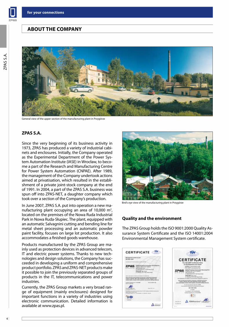
ZPas s.a.
Since the very beginning of its business activity in 1973, ZPAS has produced a variety of industrial cabi-nets and enclosures. Initially, the Company operated as the Experimental Department of the Power Sys-tem Automation Institute (IASE) in Wrocław, to beco-me a part of the Research and Manufacturing Centre for Power System Automation (CNPAE). After 1989, the management of the Company undertook actions aimed at privatisation, which resulted in the establi-shment of a private joint-stock company at the end of 1991. In 2004, a part of the ZPAS S.A. business was spun off into ZPAS-NET, a daughter company which took over a section of the Company’s production.
In June 2007, ZPAS S.A. put into operation a new ma-nufacturing plant occupying an area of 10,000 m2, located on the premises of the Nowa Ruda Industrial Park in Nowa Ruda-Słupiec. The plant, equipped with an automatic Salvagnini cutting and bending line for metal sheet processing and an automatic powder paint facility, focuses on large lot production. It also accommodates a finished goods warehouse.
Products manufactured by the ZPAS Group are ma-inly used as protection devices in advanced telecom, IT and electric power systems. Thanks to new tech-nologies and design solutions, the Company has suc-ceeded in developing a uniform and comprehensive product portfolio. ZPAS and ZPAS-NET products make it possible to join the previously separated groups of products in the IT, telecommunications and power industries.Currently, the ZPAS Group markets a very broad ran-ge of equipment (mainly enclosures) designed for important functions in a variety of industries using electronic communication. Detailed information is available at www.zpas.pl.
Quality and the environment
The ZPAS Group holds the ISO 9001:2000 Quality As-surance System Certificate and the ISO 14001:2004 Environmental Management System certificate.
abouT THe CoMPanY
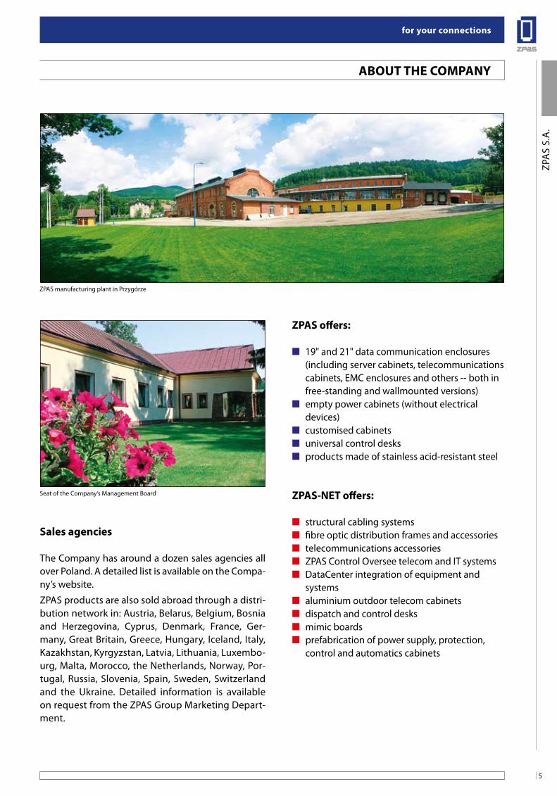
General view of the upper section of the manufacturing plant in Przygórze
Bird’s eye view of the manufacturing plant in Przygórze
5
for your connections
ZPA
S S.
A.
sales agencies
The Company has around a dozen sales agencies all over Poland. A detailed list is available on the Compa-ny’s website.
ZPAS products are also sold abroad through a distri-bution network in: Austria, Belarus, Belgium, Bosnia and Herzegovina, Cyprus, Denmark, France, Ger-many, Great Britain, Greece, Hungary, Iceland, Italy, Kazakhstan, Kyrgyzstan, Latvia, Lithuania, Luxembo-urg, Malta, Morocco, the Netherlands, Norway, Por-tugal, Russia, Slovenia, Spain, Sweden, Switzerland and the Ukraine. Detailed information is available on request from the ZPAS Group Marketing Depart-ment.
abouT THe CoMPanY
ZPas offers:
■ 19" and 21" data communication enclosures (including server cabinets, telecommunications cabinets, EMC enclosures and others -- both in free-standing and wallmounted versions)
■ empty power cabinets (without electrical devices)
■ customised cabinets■ universal control desks■ products made of stainless acid-resistant steel
ZPas-neT offers:
■ structural cabling systems■ fibre optic distribution frames and accessories■ telecommunications accessories■ ZPAS Control Oversee telecom and IT systems■ DataCenter integration of equipment and
systems■ aluminium outdoor telecom cabinets■ dispatch and control desks■ mimic boards■ prefabrication of power supply, protection,
control and automatics cabinets
ZPAS manufacturing plant in Przygórze
Seat of the Company’s Management Board
for your connections
6
ZPA
S S.
A.
abouT THe CoMPanY
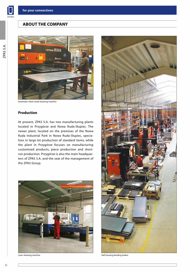
Production
At present, ZPAS S.A. has two manufacturing plants located in Przygórze and Nowa Ruda-Słupiec. The newer plant, located on the premises of the Nowa Ruda Industrial Park in Nowa Ruda-Słupiec, specia-lises in large lot production of standard items, while the plant in Przygórze focuses on manufacturing customised products, piece production and short-run production. Przygórze is also the main headquar-ters of ZPAS S.A. and the seat of the management of the ZPAS Group.
Automatic sheet metal shearing machine
Laser shearing machine Hall housing bending brakes
7
for your connections
ZPA
S S.
A.
abouT THe CoMPanY
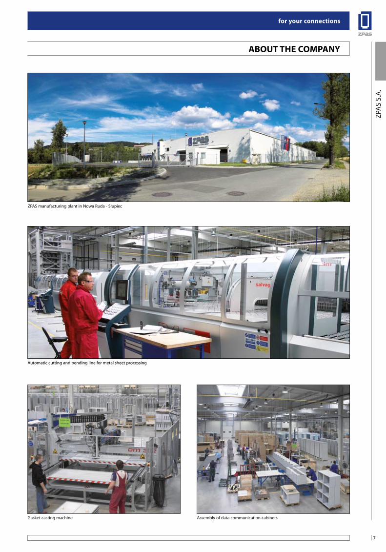
Gasket casting machine Assembly of data communication cabinets
ZPAS manufacturing plant in Nowa Ruda - Słupiec
Automatic cutting and bending line for metal sheet processing
for your connections
8
ZPA
S S.
A.
RefeRenCes
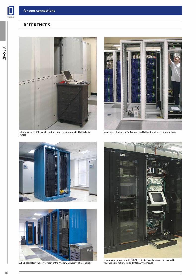
Collocation racks DSR installed in the internet server room by OVH in ParisFrance)
Installation of servers in SZB cabinets in OVH’s internet server room in Paris
Server room equipped with SZB SE cabinets. Installation was performed byMCP Ltd. from Kraków, Poland (http://www. mcp.pl)SZB SE cabinets in the server room of the Wrocław University of Technology
9
for your connections
ZPA
S S.
A.
RefeRenCes
In many places in Poland, it is possible to see enclosures
produced by ZPAS S.A. with installed equipment and
elements of structural cabling which are parts of data
communication systems. There are placed in:
- Bank Spółdzielczy,
- Bank Zachodni,
- Stock Exchange in Warsaw,
- Lukas Bank,
- NASK Warsaw and Wrocław
- Politechnika Wrocławska (Technical University in Wrocław),
- Polish Olympic Commitee in Warsaw,
- PKP (Polish Railways),
- Airport in Wrocław,
- PKO bank,
- PKN Orlen petrol stations,
- TVP (Polish TV),
- Cable TV,
- TV Polsat in Warsaw,
- TVN24 in Warsaw,
- ZUS (Polish social insurance company).
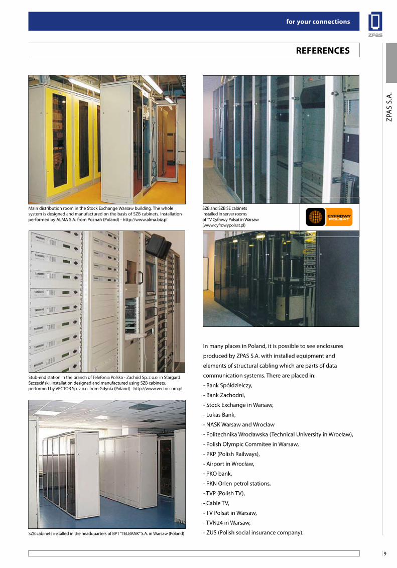
Main distribution room in the Stock Exchange Warsaw building. The whole system is designed and manufactured on the basis of SZB cabinets. Installation performed by ALMA S.A. from Poznań (Poland) - http://www.alma.biz.pl
SZB and SZB SE cabinets Installed in server rooms of TV Cyfrowy Polsat in Warsaw (www.cyfrowypolsat.pl)
Stub-end station in the branch of Telefonia Polska - Zachód Sp. z o.o. in Stargard Szczeciński. Installation designed and manufactured using SZB cabinets, performed by VECTOR Sp. z o.o. from Gdynia (Poland) - http://www.vector.com.pl
SZB cabinets installed in the headquarters of BPT “TELBANK” S.A. in Warsaw (Poland)
for your connections
10
ZPA
S S.
A.
RefeRenCes
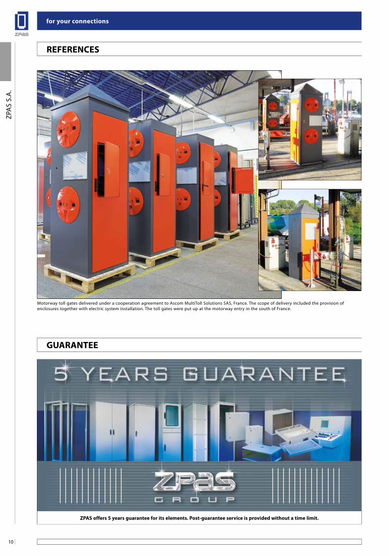
ZPas offers 5 years guarantee for its elements. Post-guarantee service is provided without a time limit.
guaRanTee
Motorway toll gates delivered under a cooperation agreement to Ascom MultiToll Solutions SAS, France. The scope of delivery included the provision of enclosures together with electric system installation. The toll gates were put up at the motorway entry in the south of France.
11
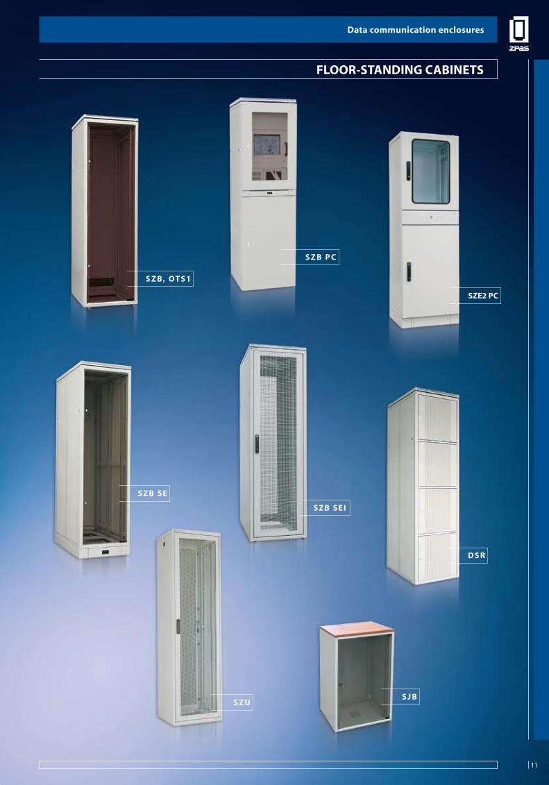
Data communication enclosures
FLO
OR-
STA
ND
ING
CA
BIN
ETS
s Z us J b
sZe2 PC
sZb se
sZb sei
D s R
s Z b, oT s 1
s Z b P C
flooR-sTanDing CabineTs
Data communication enclosures
11
Data communication enclosures
12
FLO
OR-
STA
ND
ING
CA
BIN
ETS
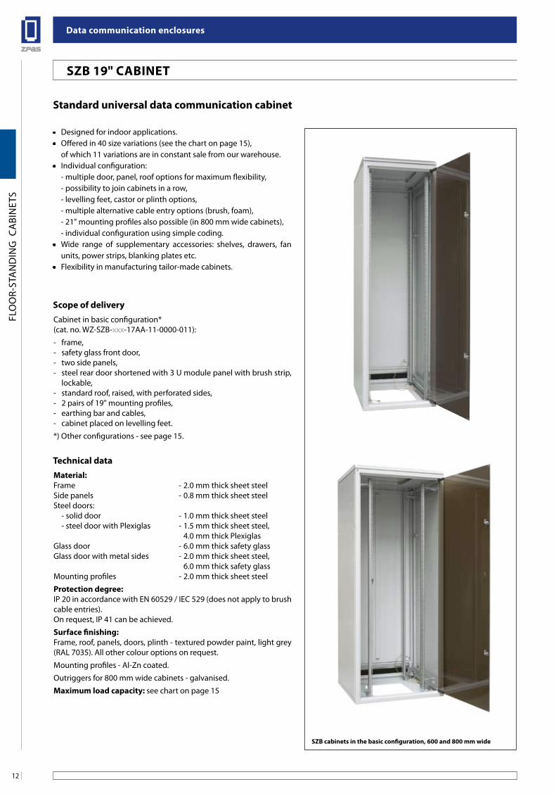
standard universal data communication cabinet
• Designed for indoor applications.• Offered in 40 size variations (see the chart on page 15), of which 11 variations are in constant sale from our warehouse.• Individual configuration: - multiple door, panel, roof options for maximum flexibility, - possibility to join cabinets in a row, - levelling feet, castor or plinth options, - multiple alternative cable entry options (brush, foam), - 21" mounting profiles also possible (in 800 mm wide cabinets), - individual configuration using simple coding.• Wide range of supplementary accessories: shelves, drawers, fan
units, power strips, blanking plates etc.• Flexibility in manufacturing tailor-made cabinets.
Technical dataMaterial:Frame - 2.0 mm thick sheet steelSide panels - 0.8 mm thick sheet steelSteel doors: - solid door - 1.0 mm thick sheet steel - steel door with Plexiglas - 1.5 mm thick sheet steel, 4.0 mm thick PlexiglasGlass door - 6.0 mm thick safety glassGlass door with metal sides - 2.0 mm thick sheet steel, 6.0 mm thick safety glassMounting profiles - 2.0 mm thick sheet steel
Protection degree:IP 20 in accordance with EN 60529 / IEC 529 (does not apply to brush cable entries).On request, IP 41 can be achieved.
surface finishing:Frame, roof, panels, doors, plinth - textured powder paint, light grey (RAL 7035). All other colour options on request.
Mounting profiles - Al-Zn coated.
Outriggers for 800 mm wide cabinets - galvanised.
Maximum load capacity: see chart on page 15
sZb cabinets in the basic configuration, 600 and 800 mm wide
scope of deliveryCabinet in basic configuration*(cat. no. WZ-SZB-xxx-17AA-11-0000-011):
- frame,- safety glass front door,- two side panels,- steel rear door shortened with 3 U module panel with brush strip,
lockable,- standard roof, raised, with perforated sides,- 2 pairs of 19" mounting profiles,- earthing bar and cables,- cabinet placed on levelling feet.
*) Other configurations - see page 15.
sZb 19" CabineT
13
Data communication enclosures
FLO
OR-
STA
ND
ING
CA
BIN
ETS
sZb 19" CabineT
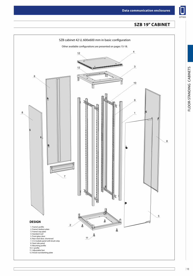
SZB cabinet 42 U, 600x600 mm in basic configuration
Other available configurations are presented on pages 15-18.
4
3
6
12
12
8
7
2
5
8
11
10
9
1
Design 1. Frame’s profile 2. Frame’s bottom plate 3. Frame’s top plate 4. Standard roof 5. Front glass door 6. Rear steel door, shortened 7. 3 U module panel with brush strip 8. Steel side panel 9. Mounting profile10. C-profile11. Adjustable feet12. Knock-out blanking plate
Data communication enclosures
14
FLO
OR-
STA
ND
ING
CA
BIN
ETS
6.7
31.75
44.4
5
12.7
n x
44.4
5
Front view Front view
B-B section D-D section
A-A section C-C section
Side view
Mounting profile
24
21
2
32.5
3049
380
W = 600 451
465W = 800
D =
600
or 8
00
DU
adju
stm
ent
DU
max
= D
– 1
00
380
380
D = 600 or 800
380
H40
H1
HU
50
10
7
12
4
10
10
5
111
2
10
6
8
3
11
11
12
B B
A
D
C
D
C
A 9
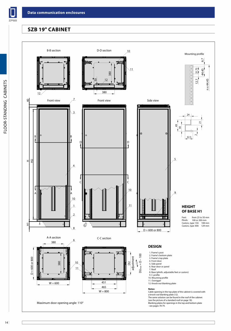
HeigHTof base H1Feet: from 25 to 50 mmPlinth: 100 or 200 mmCastors, type 150: 108 mmCastors, type 300: 129 mm
Design 1. Frame's post 2. Frame's bottom plate 3. Frame's top plate 4. Front door 5. Side panel 6. Rear door or panel 7. Roof 8. Base (plinth, adjustable feet or castors) 9. C-profile10. Mounting profile11. Outrigger12. Knock-out blanking plate
notes: Cable opening in the top plate of the cabinet is covered with a knock-out blanking plate (12). The same solution can be found in the roof of the cabinet (see the picture of a standard roof on page 18).Blanking plates for openings in the top and bottom plate - see pages 78-79.
sZb 19" CabineT
Maximum door opening angle: 110°
15
Data communication enclosures
FLO
OR-
STA
ND
ING
CA
BIN
ETS
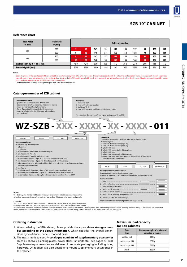
Total widthW [mm]
Total depthD [mm] Reference number
800800 5 17 145 53 149 153 157 89 101 113600 6 18 146 54 150 154 158 90 102 114
600800 9 21 147 57 151 155 159 93 105 117600 10 22 148 58 152 156 160 94 106 118
Usable height HU [U = 44.45 mm] 45 U 42 U 39 U 36 U 33 U 30 U 27 U 24 U 18 U 15 UFrame height H [mm] 2096 1963 1830 1696 1563 1430 1296 1163 896 763
Reference chart
note:
- Cabinet options in the red shaded fields are available in constant supply from ZPAS S.A.’s warehouse (this refers to cabinets with the following configuration: frame, four adjustable mounting profiles, two side panels, front glass door, lockable steel rear door shortened with 3 U module panel with brush strip, standard roof with perforation, four levelling feet, earthing bar and earthing cables for the doors and side panels - cat. no. WZ-SZB-xxx-17AA-11-0000-011).
- Lead time of other cabinets to be agreed upon with ZPAS Sales Department.
Configuration of plinth’s sides:Four digits which specify plinth side type.Four zeros (0000) should be entered for cabinet without any plinth.
Reference numberspecifies the cabinet’s overall dimensions (see reference chart). Zeros should be added beforesingle-digit or double-digit numbers.(Note: Cabinets with expanded side panels are only manufactured in the following ref. numbers 9, 21 and 147.)
Roof type: 1 - standard roof2 - roof with extra perforation3 - tight roof IP 414 - roof with opening for blanking/cable entry plate
For a detailed description of roof types, go to pages 18 and 78.
noTe: The delivery of a standard SZB cabinet (except for elements listed in cat. no.) includes thefollowing: four mounting profiles, earthing bar and earthing cables for doors and panels.
example: The cat. no. WZ-SZB-018-1AAA-14-2422-011 means SZB cabinet, usable height 42 U, width 800mm, depth 600 mm. The cabinet is equipped with front glass door, two removable side panelsand removable rear panel. The top is covered with the standard roof. Cabinet is situated on 100 mm plinth. Rear side of the plinth with brush opening for cable entry, all other sides are perforated. Doors, panels and roof are earthed. Cabinet interior is equipped with four mounting profiles installed to the frame by means of 8 outriggers.
Door or panel type: 0 - without any doors or panels1 - glass door2 - steel door3 - steel door with perforation in the bottom part4 - steel door with Plexiglas5 - steel door with Plexiglas and perforation7 - steel door, shortened + 1 pc. of 3 U module panel with brush strip9 - steel door, shortened + 2 pcs. of 3 U module panels with brush stripZ - glass door with metal sides and rod-latch lock (specially designed as front or rear door for cabinets higher than 18 U)A - steel panelC - steel side panel, shortened + 1 pc. of 3 U module panel with brush stripE - steel side panel, shortened + 2 pcs. of 3 U module panels with brush stripF - expanded steel side panel (only for cabinets with ref. numbers 9, 21 and 147)
WZ-sZb - xxx - xxxx - xx - xxxx - 011base type: 0 - without any base (cabinet set directly on bottom plate)1 - levelling feet2 - castors - type 150 (see page 76)3 - castors - type 300 (see page 76)4 - plinth 100 mm5 - plinth 100 mm with levelling option6 - plinth 200 mm7 - plinth 200 mm with levelling option8 - plinth 200 mm, widened (specially designed for SZB cabinets with expanded side panels).
FRONT REAR LEFT SIDE RIGHT SIDE
FRONT REAR LEFT SIDE RIGHT SIDE
Each side can be:1 - solid2 - with perforation3 - with double perforation*4 - with a brush opening5 - with two brush openings6 - with a brush opening and perforation*
*) Only for plinths 200 mm in height.
For a detailed descriptions of plinths, see pages 74-75.
Catalogue number of sZb cabinet
ordering instruction
1. When ordering the SZB cabinet, please provide the appropriate catalogue num-ber according to the above information, which specifies the overall dimen-sions, type of doors, panels, roof and base.
2. The next step is to specify catalogue numbers of supplementary accessories (such as: shelves, blanking plates, power strips, fan units etc. - see pages 73-108). Supplementary accessories are delivered in separate packaging including fixing hardware. On request it is also possible to mount supplementary accessories in the cabinet.
Base type
Maximum weight of equipment mounted in cabinet
levelling feet 600 kg
castors - type 150 150 kg
castors - type 300 500 kg
plinth 600 kg
Maximum load capacity for sZb cabinets
sZb 19" CabineT
Data communication enclosures
16
FLO
OR-
STA
ND
ING
CA
BIN
ETS
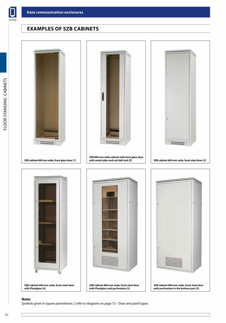
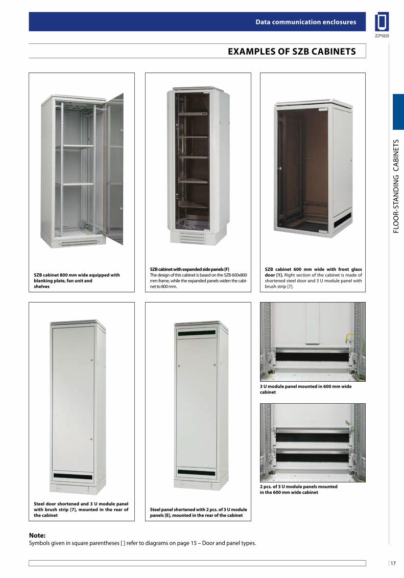
exaMPles of sZb CabineTs
sZb cabinet 600 mm wide, front glass door [1] sZb cabinet 600 mm wide, front steel door [2]sZb 600 mm wide cabinet with front glass door with metal sides and rod-lath lock [Z]
sZb cabinet 600 mm wide, front steel door with Plexiglass [4]
sZb cabinet 800 mm wide, front steel door with perforation in the bottom part [3]
sZb cabinet 800 mm wide, front steel door with Plexiglass and perforation [5]
note:Symbols given in square parentheses [ ] refer to diagrams on page 15 – Door and panel types
17
Data communication enclosures
FLO
OR-
STA
ND
ING
CA
BIN
ETS
exaMPles of sZb CabineTs
sZb cabinet 800 mm wide equipped with blanking plate, fan unit andshelves
sZb cabinet 600 mm wide with front glass door [1]. Right section of the cabinet is made of shortened steel door and 3 U module panel with brush strip [7].
sZb cabinet with expanded side panels [f]The design of this cabinet is based on the SZB 600x800 mm frame, while the expanded panels widen the cabi-net to 800 mm.
steel door shortened and 3 u module panel with brush strip [7], mounted in the rear of the cabinet
2 pcs. of 3 u module panels mounted in the 600 mm wide cabinet
steel panel shortened with 2 pcs. of 3 u module panels [e], mounted in the rear of the cabinet
note:Symbols given in square parentheses [ ] refer to diagrams on page 15 – Door and panel types.
3 u module panel mounted in 600 mm wide cabinet
Data communication enclosures
18
FLO
OR-
STA
ND
ING
CA
BIN
ETS
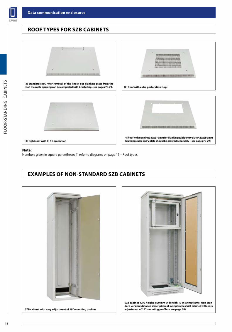
sZb cabinet 42 u height, 800 mm wide with 10 u swing frame. non-stan-dard version (detailed description of swing frames sZb cabinet with easy adjustment of 19" mounting profiles - see page 88).sZb cabinet with easy adjustment of 19" mounting profiles
[1] standard roof. after removal of the knock-out blanking plate from the roof, the cable opening can be completed with brush strip - see pages 78-79.
[4] Roof with opening 380x210 mm for blanking/cable entry plate 420x250 mm (blanking/cable entry plate should be ordered separately -- see pages 78-79)
[2] Roof with extra perforation (top)
[3] Tight roof with iP 41 protection
Roof TYPes foR sZb CabineTs
exaMPles of non-sTanDaRD sZb CabineTs
note:Numbers given in square parentheses [ ] refer to diagrams on page 15 – Roof types.
19
Data communication enclosures
FLO
OR-
STA
ND
ING
CA
BIN
ETS
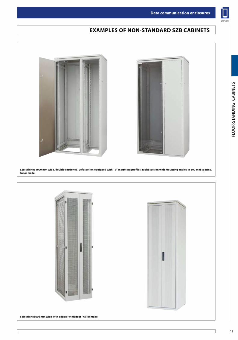
sZb cabinet 600 mm wide with double-wing door - tailor made
sZb cabinet 1000 mm wide, double-sectioned. left section equipped with 19" mounting profiles. Right section with mounting angles in 300 mm spacing. Tailor made.
exaMPles of non-sTanDaRD sZb CabineTs
Data communication enclosures
20
FLO
OR-
STA
ND
ING
CA
BIN
ETS
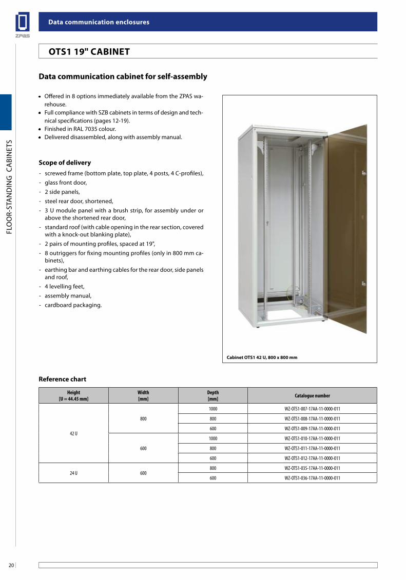
oTs1 19" CabineT
Data communication cabinet for self-assembly
• Offered in 8 options immediately available from the ZPAS wa-rehouse.
• Full compliance with SZB cabinets in terms of design and tech-nical specifications (pages 12-19).
• Finished in RAL 7035 colour.• Delivered disassembled, along with assembly manual.
scope of delivery- screwed frame (bottom plate, top plate, 4 posts, 4 C-profiles),
- glass front door,
- 2 side panels,
- steel rear door, shortened,
- 3 U module panel with a brush strip, for assembly under or above the shortened rear door,
- standard roof (with cable opening in the rear section, covered with a knock-out blanking plate),
- 2 pairs of mounting profiles, spaced at 19",
- 8 outriggers for fixing mounting profiles (only in 800 mm ca-binets),
- earthing bar and earthing cables for the rear door, side panels and roof,
- 4 levelling feet,
- assembly manual,
- cardboard packaging.
Height[U = 44.45 mm]
Width[mm]
Depth[mm] Catalogue number
42 U
800
1000 WZ-OTS1-007-17AA-11-0000-011
800 WZ-OTS1-008-17AA-11-0000-011
600 WZ-OTS1-009-17AA-11-0000-011
600
1000 WZ-OTS1-010-17AA-11-0000-011
800 WZ-OTS1-011-17AA-11-0000-011
600 WZ-OTS1-012-17AA-11-0000-011
24 U 600800 WZ-OTS1-035-17AA-11-0000-011
600 WZ-OTS1-036-17AA-11-0000-011
Reference chart
Cabinet oTs1 42 u, 800 x 800 mm
21
Data communication enclosures
FLO
OR-
STA
ND
ING
CA
BIN
ETS
oTs1 19" CabineT
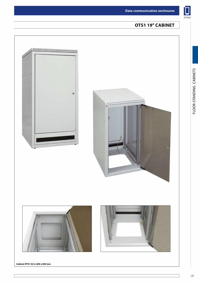
Cabinet oTs1 42 u, 600 x 600 mm
Data communication enclosures
22
FLO
OR-
STA
ND
ING
CA
BIN
ETS
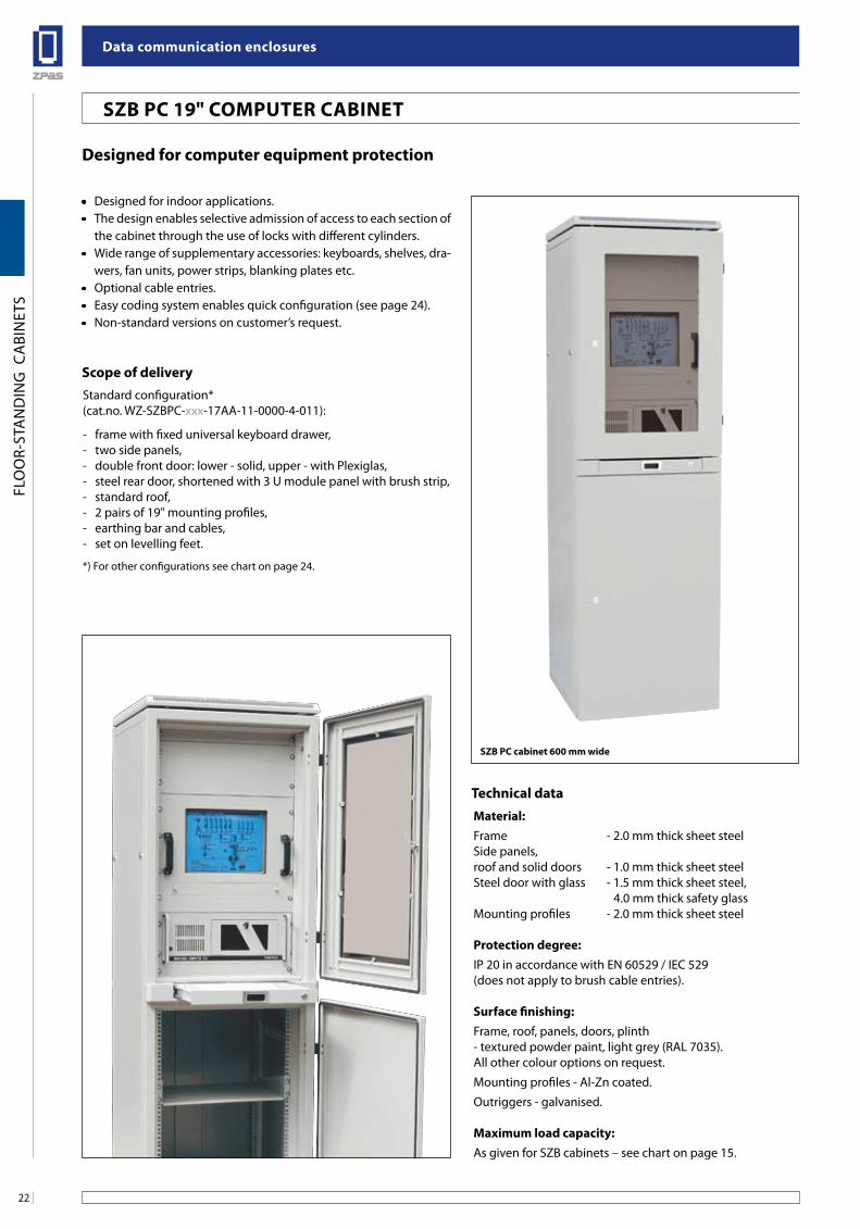
Designed for computer equipment protection
• Designed for indoor applications.• The design enables selective admission of access to each section of
the cabinet through the use of locks with different cylinders.• Wide range of supplementary accessories: keyboards, shelves, dra-
wers, fan units, power strips, blanking plates etc.• Optional cable entries.• Easy coding system enables quick configuration (see page 24).• Non-standard versions on customer’s request.
Technical dataMaterial:Frame - 2.0 mm thick sheet steelSide panels,roof and solid doors - 1.0 mm thick sheet steelSteel door with glass - 1.5 mm thick sheet steel, 4.0 mm thick safety glassMounting profiles - 2.0 mm thick sheet steel
Protection degree:IP 20 in accordance with EN 60529 / IEC 529 (does not apply to brush cable entries).
surface finishing:Frame, roof, panels, doors, plinth- textured powder paint, light grey (RAL 7035).All other colour options on request.
Mounting profiles - Al-Zn coated.
Outriggers - galvanised.
Maximum load capacity:As given for SZB cabinets – see chart on page 15.
sZb PC cabinet 600 mm wide
scope of deliveryStandard configuration*(cat.no. WZ-SZBPC-xxx-17AA-11-0000-4-011):
- frame with fixed universal keyboard drawer,- two side panels,- double front door: lower - solid, upper - with Plexiglas,- steel rear door, shortened with 3 U module panel with brush strip,- standard roof,- 2 pairs of 19" mounting profiles,- earthing bar and cables,- set on levelling feet.
*) For other configurations see chart on page 24.
sZb PC 19" CoMPuTeR CabineT
23
Data communication enclosures
FLO
OR-
STA
ND
ING
CA
BIN
ETS
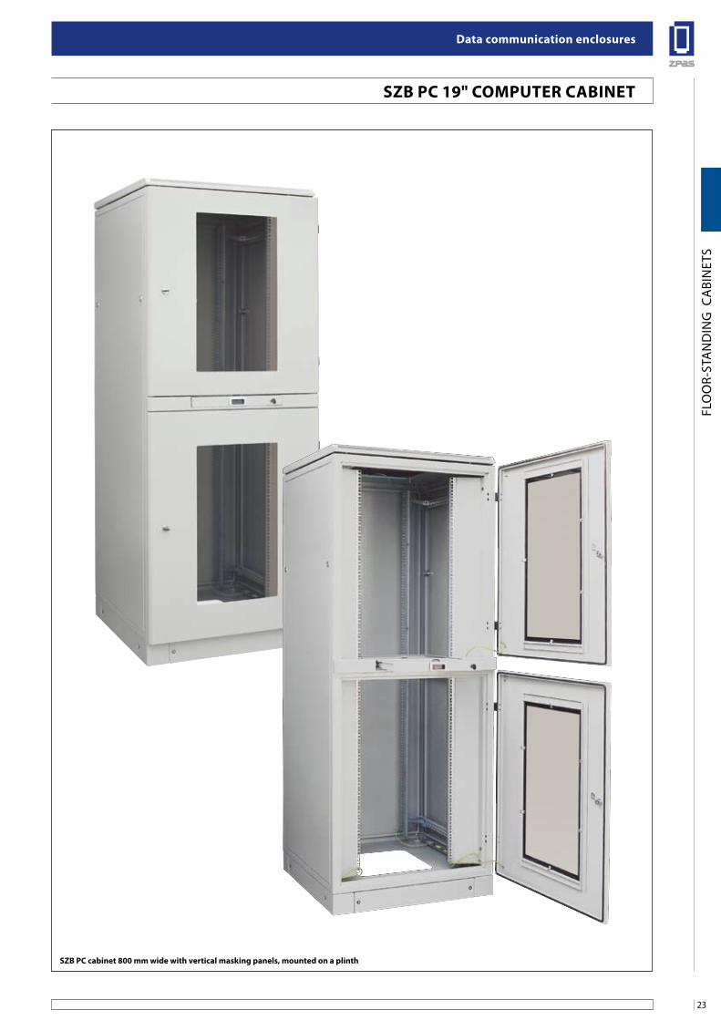
sZb PC cabinet 800 mm wide with vertical masking panels, mounted on a plinth
sZb PC 19" CoMPuTeR CabineT
Data communication enclosures
24
FLO
OR-
STA
ND
ING
CA
BIN
ETS
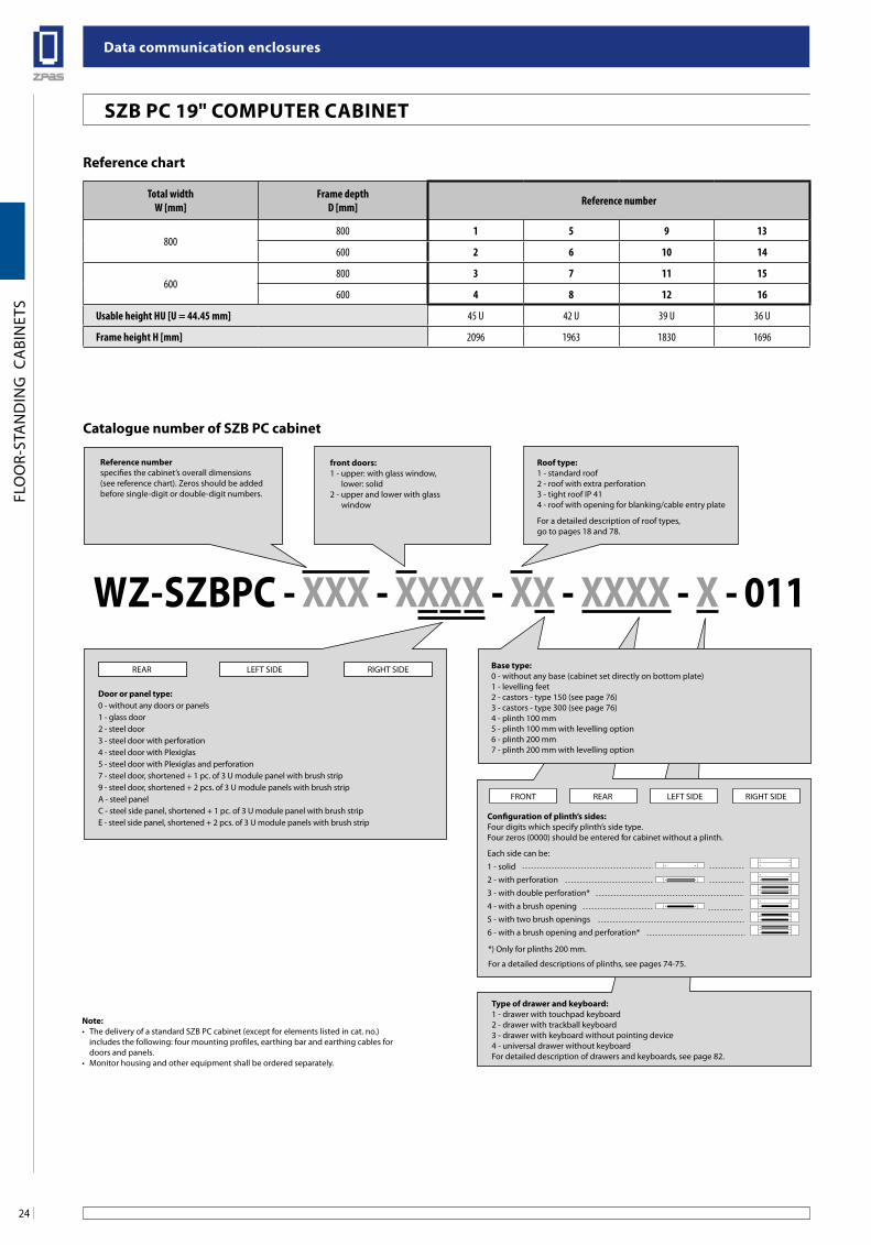
Catalogue number of sZb PC cabinet
Configuration of plinth’s sides:Four digits which specify plinth’s side type.Four zeros (0000) should be entered for cabinet without a plinth.
Type of drawer and keyboard:1 - drawer with touchpad keyboard2 - drawer with trackball keyboard3 - drawer with keyboard without pointing device4 - universal drawer without keyboardFor detailed description of drawers and keyboards, see page 82.
Reference numberspecifies the cabinet’s overall dimensions (see reference chart). Zeros should be addedbefore single-digit or double-digit numbers.
front doors: 1 - upper: with glass window, lower: solid2 - upper and lower with glass window
note: • The delivery of a standard SZB PC cabinet (except for elements listed in cat. no.) includes the following: four mounting profiles, earthing bar and earthing cables for doors and panels.• Monitor housing and other equipment shall be ordered separately.
Door or panel type: 0 - without any doors or panels1 - glass door2 - steel door3 - steel door with perforation4 - steel door with Plexiglas5 - steel door with Plexiglas and perforation7 - steel door, shortened + 1 pc. of 3 U module panel with brush strip9 - steel door, shortened + 2 pcs. of 3 U module panels with brush stripA - steel panelC - steel side panel, shortened + 1 pc. of 3 U module panel with brush stripE - steel side panel, shortened + 2 pcs. of 3 U module panels with brush strip
WZ-sZbPC - xxx - xxxx - xx - xxxx - x - 011base type:0 - without any base (cabinet set directly on bottom plate)1 - levelling feet2 - castors - type 150 (see page 76)3 - castors - type 300 (see page 76)4 - plinth 100 mm5 - plinth 100 mm with levelling option6 - plinth 200 mm7 - plinth 200 mm with levelling option
Roof type: 1 - standard roof2 - roof with extra perforation3 - tight roof IP 414 - roof with opening for blanking/cable entry plate
For a detailed description of roof types, go to pages 18 and 78.
REAR LEFT SIDE RIGHT SIDE
Each side can be:1 - solid2 - with perforation3 - with double perforation*4 - with a brush opening5 - with two brush openings6 - with a brush opening and perforation*
FRONT REAR LEFT SIDE RIGHT SIDE
*) Only for plinths 200 mm.
For a detailed descriptions of plinths, see pages 74-75.
Total widthW [mm]
Frame depthD [mm] Reference number
800800 1 5 9 13
600 2 6 10 14
600800 3 7 11 15
600 4 8 12 16
Usable height HU [U = 44.45 mm] 45 U 42 U 39 U 36 U
Frame height H [mm] 2096 1963 1830 1696
Reference chart
sZb PC 19" CoMPuTeR CabineT
25
Data communication enclosures
FLO
OR-
STA
ND
ING
CA
BIN
ETS
1. When ordering the SZB PC cabinet, please provide the appropriate catalogue number according to the above information, which specifies the overall dimensions, type of doors, panels, roof, base and the type of keyboard drawer.
2. The next step is to specify catalogue numbers of supplementary accessories (such as: shelves, blanking plates, power strips, fan units etc. - see pages 73-108). Supplementary accessories are delivered in separate packaging including fixing hardware. On requ-est it is also possible to mount supplementary accessories in the cabinet.
W = 800W = 600
889
(20
U)
HU
D = 600 or 800
Front view
Top view
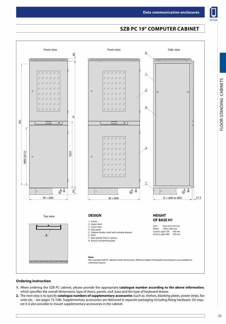
Front view Side view
H1
H10
3140
31.5
2
8
3
6
1
4
7
HeigHTof base H1Feet: from 25 to 50 mmPlinth: 100 or 200 mmCastors, type 150: 108 mmCastors, type 300: 129 mm
ordering instruction
Design1. Frame2. Upper door3. Lower door4. Side panel5. Cabinet divider (shelf with lockable drawer)6. Roof7. Base (plinth, feet or castors)8. Knock-out blanking plate
sZb PC 19" CoMPuTeR CabineT
note:Non-standard SZB PC cabinets (other dimensions, different height of keyboard mounting etc.) are available onindividual request.
Data communication enclosures
26
FLO
OR-
STA
ND
ING
CA
BIN
ETS
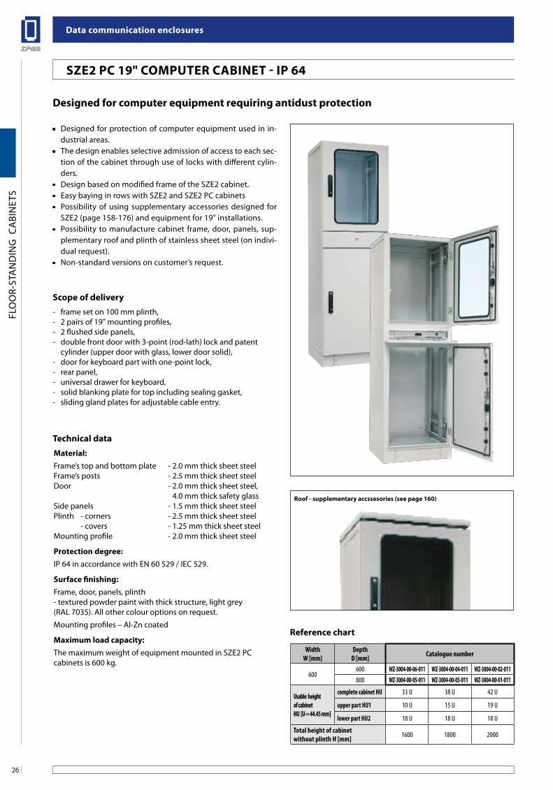
Designed for computer equipment requiring antidust protection
Technical dataMaterial:Frame’s top and bottom plate - 2.0 mm thick sheet steelFrame’s posts - 2.5 mm thick sheet steelDoor - 2.0 mm thick sheet steel, 4.0 mm thick safety glassSide panels - 1.5 mm thick sheet steelPlinth - corners - 2.5 mm thick sheet steel - covers - 1.25 mm thick sheet steelMounting profile - 2.0 mm thick sheet steel
Protection degree:IP 64 in accordance with EN 60 529 / IEC 529.
Surface finishing:Frame, door, panels, plinth- textured powder paint with thick structure, light grey (RAL 7035). All other colour options on request.
Mounting profiles – Al-Zn coated
Maximum load capacity:The maximum weight of equipment mounted in SZE2 PC cabinets is 600 kg.
Scope of delivery- frame set on 100 mm plinth,- 2 pairs of 19" mounting profiles,- 2 flushed side panels,- double front door with 3-point (rod-lath) lock and patent cylinder (upper door with glass, lower door solid),- door for keyboard part with one-point lock,- rear panel,- universal drawer for keyboard,- solid blanking plate for top including sealing gasket,- sliding gland plates for adjustable cable entry.
• Designed for protection of computer equipment used in in-dustrial areas.
• The design enables selective admission of access to each sec-tion of the cabinet through use of locks with different cylin-ders.
• Design based on modified frame of the SZE2 cabinet.• Easy baying in rows with SZE2 and SZE2 PC cabinets• Possibility of using supplementary accessories designed for
SZE2 (page 158-176) and equipment for 19" installations.• Possibility to manufacture cabinet frame, door, panels, sup-
plementary roof and plinth of stainless sheet steel (on indivi-dual request).
• Non-standard versions on customer’s request.
Roof - supplementary accssesories (see page 160)
WidthW [mm]
DepthD [mm] Catalogue number
600600 WZ-3004-00-06-011 WZ-3004-00-04-011 WZ-3004-00-02-011800 WZ-3004-00-05-011 WZ-3004-00-03-011 WZ-3004-00-01-011
Usable height of cabinetHU [U = 44.45 mm]
complete cabinet HU 33 U 38 U 42 U
upper part HU1 10 U 15 U 19 U
lower part HU2 18 U 18 U 18 U
Total height of cabinet without plinth H [mm] 1600 1800 2000
Reference chart
SZE2 PC 19" COMPUTER CABINET - IP 64
27
Data communication enclosures
FLO
OR-
STA
ND
ING
CA
BIN
ETS
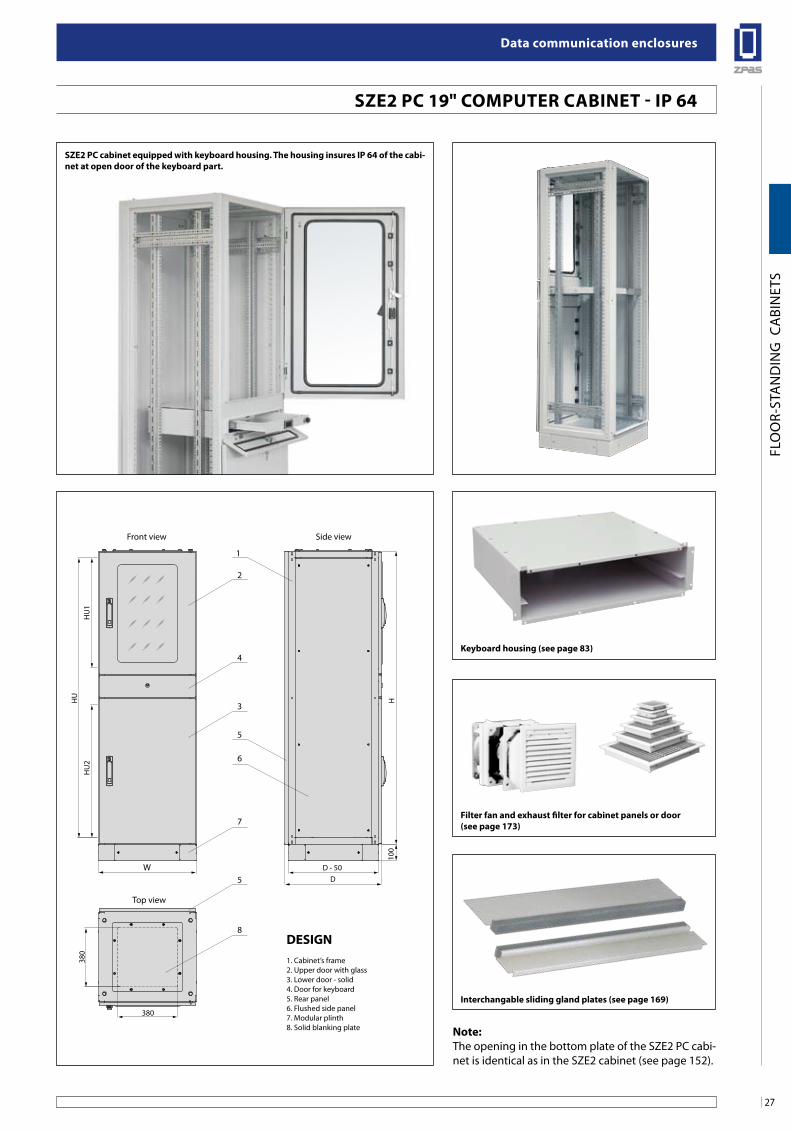
sZe2 PC 19" CoMPuTeR CabineT - iP 64
filter fan and exhaust filter for cabinet panels or door(see page 173)
Keyboard housing (see page 83)
HU
HU
1H
U2
W
1
2
4
3
5
6
7
5
8
Top view
Front view Side view
D - 50D
380
380
100
H
Design1. Cabinet’s frame2. Upper door with glass3. Lower door - solid4. Door for keyboard5. Rear panel6. Flushed side panel7. Modular plinth8. Solid blanking plate note:
The opening in the bottom plate of the SZE2 PC cabi-net is identical as in the SZE2 cabinet (see page 152).
interchangable sliding gland plates (see page 169)
sZe2 PC cabinet equipped with keyboard housing. The housing insures iP 64 of the cabi-net at open door of the keyboard part.
Data communication enclosures
28
FLO
OR-
STA
ND
ING
CA
BIN
ETS
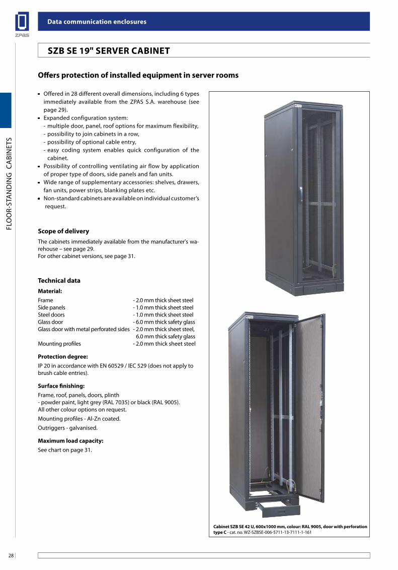
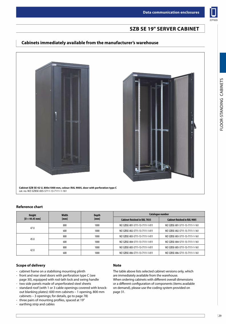
offers protection of installed equipment in server rooms
• Offered in 28 different overall dimensions, including 6 types immediately available from the ZPAS S.A. warehouse (see page 29).
• Expanded configuration system:- multiple door, panel, roof options for maximum flexibility,- possibility to join cabinets in a row,- possibility of optional cable entry,- easy coding system enables quick configuration of the
cabinet.• Possibility of controlling ventilating air flow by application
of proper type of doors, side panels and fan units.• Wide range of supplementary accessories: shelves, drawers,
fan units, power strips, blanking plates etc.• Non-standard cabinets are available on individual customer’s
request.
Technical dataMaterial:Frame - 2.0 mm thick sheet steelSide panels - 1.0 mm thick sheet steelSteel doors - 1.0 mm thick sheet steelGlass door - 6.0 mm thick safety glassGlass door with metal perforated sides - 2.0 mm thick sheet steel, 6.0 mm thick safety glassMounting profiles - 2.0 mm thick sheet steel
Protection degree:IP 20 in accordance with EN 60529 / IEC 529 (does not apply to brush cable entries).
surface finishing:Frame, roof, panels, doors, plinth- powder paint, light grey (RAL 7035) or black (RAL 9005).All other colour options on request.
Mounting profiles - Al-Zn coated.
Outriggers - galvanised.
Maximum load capacity:See chart on page 31.
Cabinet sZb se 42 u, 600x1000 mm, colour: Ral 9005, door with perforation type C - cat. no. WZ-SZBSE-006-5711-13-7111-1-161
scope of deliveryThe cabinets immediately available from the manufacturer's wa-rehouse – see page 29.For other cabinet versions, see page 31.
sZb se 19" seRVeR CabineT
29
Data communication enclosures
FLO
OR-
STA
ND
ING
CA
BIN
ETS
Cabinet sZb se 42 u, 800x1000 mm, colour: Ral 9005, door with perforation type Ccat. no. WZ-SZBSE-005-5711-13-7111-1-161
sZb se 19" seRVeR CabineT
Height[U = 44.45 mm]
Width[mm]
Depth[mm]
Catalogue number
Cabinet finished in RAL 7035 Cabinet finished in RAL 9005
47 U800 1000 WZ-SZBSE-001-5711-13-7111-1-011 WZ-SZBSE-001-5711-13-7111-1-161
600 1000 WZ-SZBSE-002-5711-13-7111-1-011 WZ-SZBSE-002-5711-13-7111-1-161
45 U800 1000 WZ-SZBSE-003-5711-13-7111-1-011 WZ-SZBSE-003-5711-13-7111-1-161
600 1000 WZ-SZBSE-004-5711-13-7111-1-011 WZ-SZBSE-004-5711-13-7111-1-161
42 U800 1000 WZ-SZBSE-005-5711-13-7111-1-011 WZ-SZBSE-005-5711-13-7111-1-161
600 1000 WZ-SZBSE-006-5711-13-7111-1-011 WZ-SZBSE-006-5711-13-7111-1-161
Reference chart
scope of delivery note- cabinet frame on a stabilising mounting plinth - front and rear steel doors with perforation type C (see
page 30), equipped with rod-lath lock and swing handle- two side panels made of unperforated steel sheets- standard roof (with 1 or 3 cable openings covered with knock-
out blanking plates): 600 mm cabinets – 1 opening, 800 mm cabinets – 3 openings; for details, go to page 78)
- three pairs of mounting profiles, spaced at 19"- earthing strip and cables
The table above lists selected cabinet versions only, whichare immediately available from the warehouse.When ordering cabinets with different overall dimensionsor a different configuration of components (items availableon demand), please use the coding system provided onpage 31.
Cabinets immediately available from the manufacturer’s warehouse
Data communication enclosures
30
FLO
OR-
STA
ND
ING
CA
BIN
ETS
sZb se 19" seRVeR CabineT
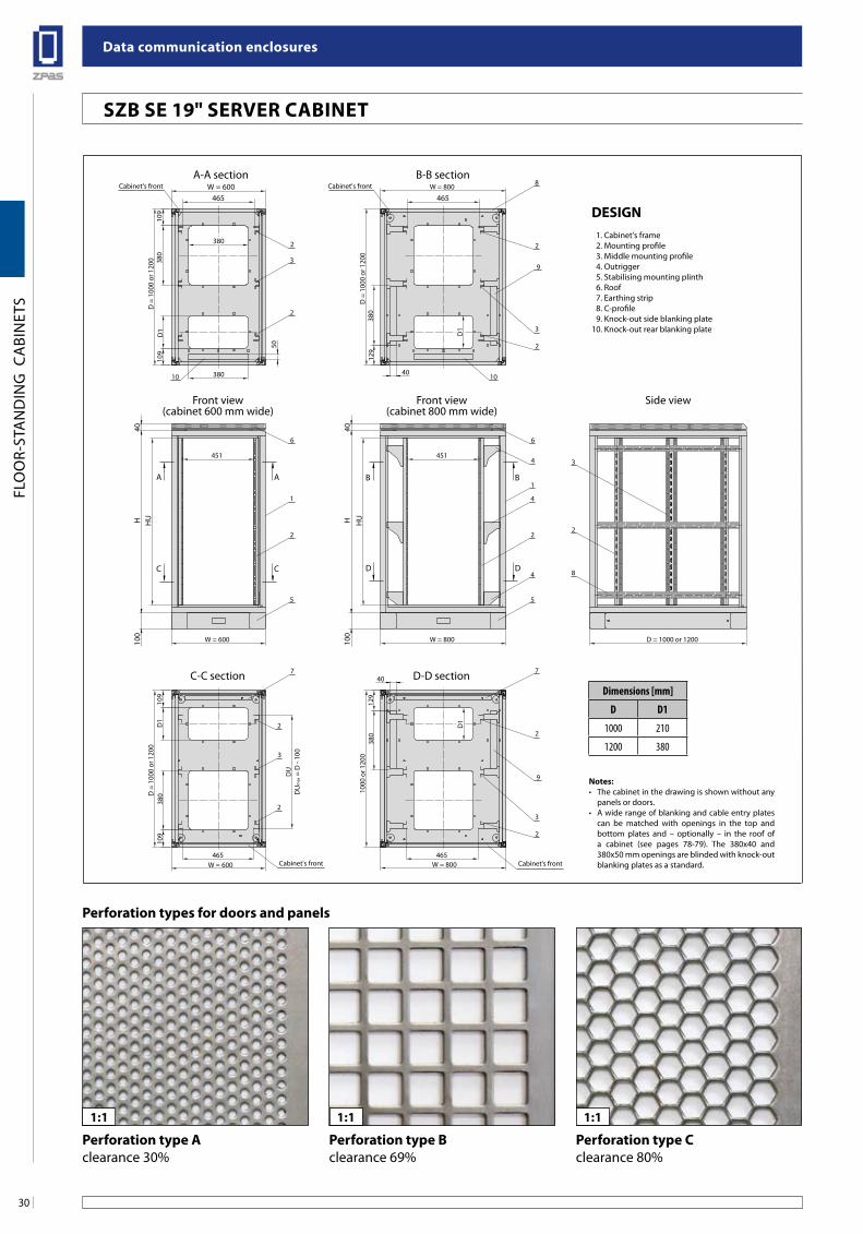
Perforation types for doors and panels
1:1 1:11:1
1000
or 1
200
W = 800 D = 1000 or 1200
HU
W = 800
451
W = 600465 465
DU
DU
max
= D
- 10
0
D =
100
0 or
120
0
H40
100
H40
100
HU
W = 600
451
109
D1
109
380
129
380
W = 800
380
2
D =
100
0 or
120
0
D =
100
0 or
120
0
109
W = 600465 465
D1
109
6
8
39
2
2
10
1
2
5
6
4
1
4
4 8
2
3
2
5
380
129
D1
50
2
3
C C
A A
D D
B B
Front view(cabinet 600 mm wide)
Front view(cabinet 800 mm wide)
Side view
C-C section D-D section
A-A section B-B section
10
7
9
2
2
3
Cabinet's front
2
7
3
2
Cabinet's front
Cabinet's front Cabinet's front
380
380 40
40
D1
notes:• Thecabinetinthedrawingisshownwithoutany
panels or doors.• Awiderangeofblankingandcableentryplates
can be matched with openings in the top and bottom plates and – optionally – in the roof of a cabinet (see pages 78-79). The 380x40 and 380x50 mm openings are blinded with knock-out blanking plates as a standard.
Design 1. Cabinet's frame 2. Mounting profile 3. Middle mounting profile 4. Outrigger 5. Stabilising mounting plinth 6. Roof 7. Earthing strip 8. C-profile 9. Knock-out side blanking plate10. Knock-out rear blanking plate
Dimensions [mm]
D D1
1000 210
1200 380
Perforation type aclearance 30%
Perforation type bclearance 69%
Perforation type Cclearance 80%
31
Data communication enclosures
FLO
OR-
STA
ND
ING
CA
BIN
ETS
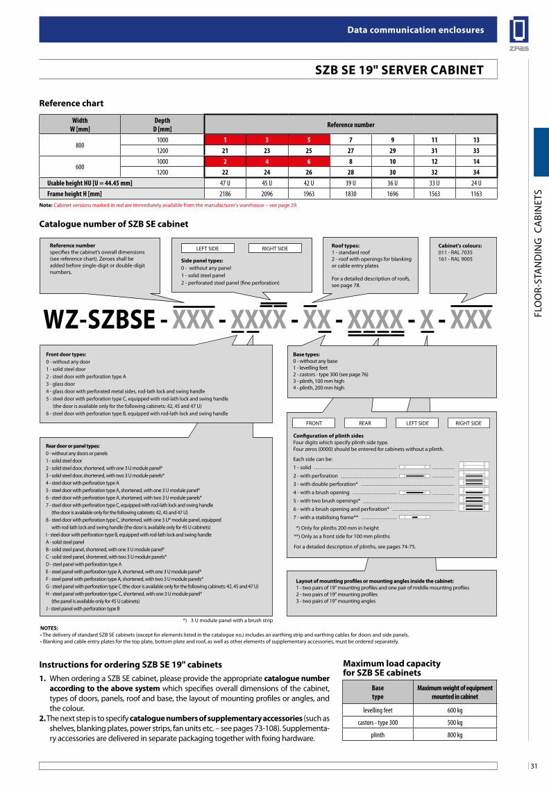
1. When ordering a SZB SE cabinet, please provide the appropriate catalogue number according to the above system which specifies overall dimensions of the cabinet, types of doors, panels, roof and base, the layout of mounting profiles or angles, and the colour.
2. The next step is to specify catalogue numbers of supplementary accessories (such as shelves, blanking plates, power strips, fan units etc. – see pages 73-108). Supplementa-ry accessories are delivered in separate packaging together with fixing hardware.
Configuration of plinth sidesFour digits which specify plinth side type.Four zeros (0000) should be entered for cabinets without a plinth.
layout of mounting profiles or mounting angles inside the cabinet:1 - two pairs of 19" mounting profiles and one pair of middle mounting profiles2 - two pairs of 19" mounting profiles3 - two pairs of 19" mounting angles
Reference numberspecifies the cabinet’s overall dimensions (see reference chart). Zeroes shall be added before single-digit or double-digit numbers.
Rear door or panel types: 0 - without any doors or panels1 - solid steel door2 - solid steel door, shortened, with one 3 U module panel*3 - solid steel door, shortened, with two 3 U module panels*4 - steel door with perforation type A5 - steel door with perforation type A, shortened, with one 3 U module panel*6 - steel door with perforation type A, shortened, with two 3 U module panels*7 - steel door with perforation type C, equipped with rod-lath lock and swing handle (the door is available only for the following cabinets: 42, 45 and 47 U)8 - steel door with perforation type C, shortened, with one 3 U* module panel, equipped with rod-lath lock and swing handle (the door is available only for 45 U cabinets)I - steel door with perforation type B, equipped with rod-lath lock and swing handleA - solid steel panelB - solid steel panel, shortened, with one 3 U module panel*C - solid steel panel, shortened, with two 3 U module panels*D - steel panel with perforation type AE - steel panel with perforation type A, shortened, with one 3 U module panel*F - steel panel with perforation type A, shortened, with two 3 U module panels*G - steel panel with perforation type C (the door is available only for the following cabinets: 42, 45 and 47 U)H - steel panel with perforation type C, shortened, with one 3 U module panel* (the panel is available only for 45 U cabinets)J - steel panel with perforation type B
WZ-sZbse - xxx - xxxx - xx - xxxx - x - xxxbase types: 0 - without any base1 - levelling feet2 - castors - type 300 (see page 76)3 - plinth, 100 mm high4 - plinth, 200 mm high
Roof types: 1 - standard roof2 - roof with openings for blanking or cable entry plates
For a detailed description of roofs, see page 78.
Cabinet's colours: 011 - RAL 7035161 - RAL 9005
Each side can be:1 - solid2 - with perforation3 - with double perforation*4 - with a brush opening5 - with two brush openings*6 - with a brush opening and perforation*7 - with a stabilising frame**
FRONT REAR LEFT SIDE RIGHT SIDE
side panel types:0 - without any panel1 - solid steel panel2 - perforated steel panel (fine perforation)
LEFT SIDE RIGHT SIDE
noTes: •The delivery of standard SZB SE cabinets (except for elements listed in the catalogue no.) includes an earthing strip and earthing cables for doors and side panels.•Blanking and cable entry plates for the top plate, bottom plate and roof, as well as other elements of supplementary accessories, must be ordered separately.
*) 3 U module panel with a brush strip
front door types: 0 - without any door1 - solid steel door2 - steel door with perforation type A3 - glass door4 - glass door with perforated metal sides, rod-lath lock and swing handle5 - steel door with perforation type C, equipped with rod-lath lock and swing handle (the door is available only for the following cabinets: 42, 45 and 47 U)6 - steel door with perforation type B, equipped with rod-lath lock and swing handle
*) Only for plinths 200 mm in height**) Only as a front side for 100 mm plinths
For a detailed description of plinths, see pages 74-75.
instructions for ordering sZb se 19" cabinets
WidthW [mm]
DepthD [mm] Reference number
8001000 1 3 5 7 9 11 131200 21 23 25 27 29 31 33
6001000 2 4 6 8 10 12 141200 22 24 26 28 30 32 34
Usable height HU [U = 44.45 mm] 47 U 45 U 42 U 39 U 36 U 33 U 24 UFrame height H [mm] 2186 2096 1963 1830 1696 1563 1163
Reference chart
sZb se 19" seRVeR CabineT
Catalogue number of sZb se cabinet
Basetype
Maximum weight of equipment mounted in cabinet
levelling feet 600 kg
castors - type 300 500 kg
plinth 800 kg
Maximum load capacity for sZb se cabinets
note: Cabinet versions marked in red are immediately available from the manufacturer's warehouse – see page 29.
Data communication enclosures
32
FLO
OR-
STA
ND
ING
CA
BIN
ETS
szafa sZb o szerokości 600 mm z drzwiamiprzednimi szklanymi [1]
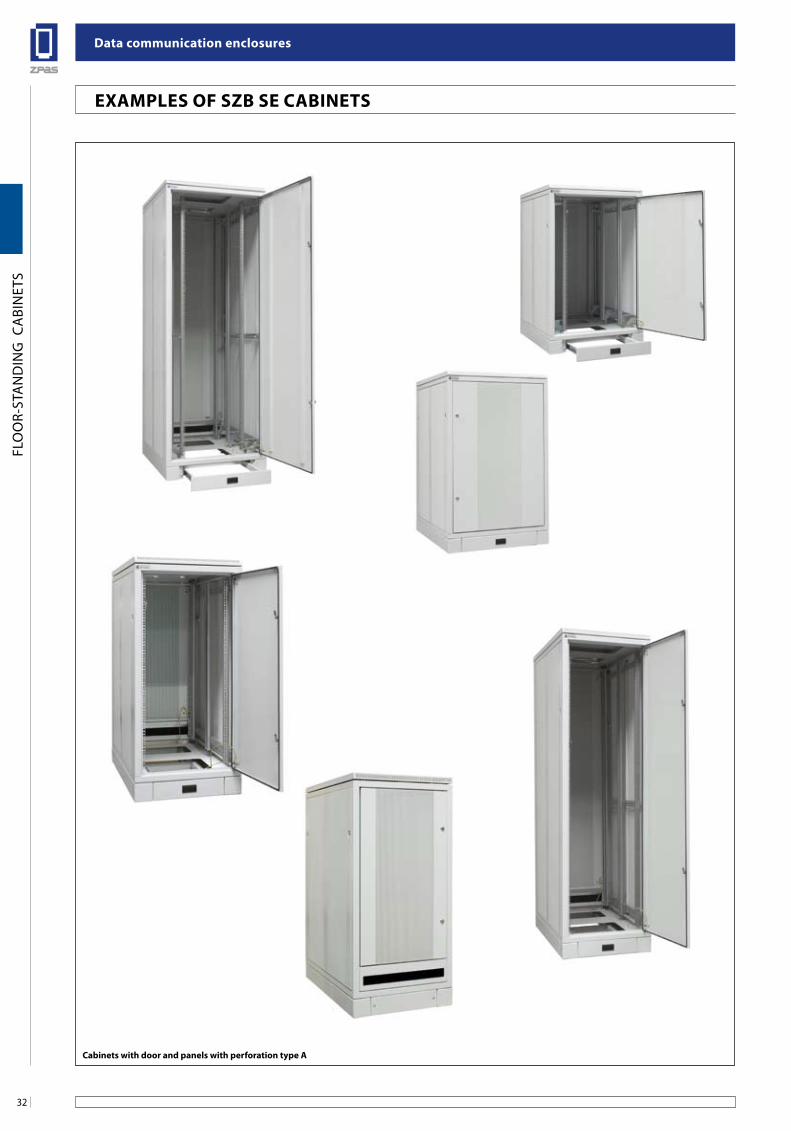
exaMPles of sZb se CabineTs
Cabinets with door and panels with perforation type a
33
Data communication enclosures
FLO
OR-
STA
ND
ING
CA
BIN
ETS
exaMPles of sZb se CabineTs
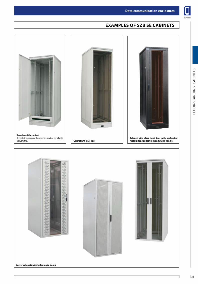
Rear view of the cabinetBeneath the rear door there is a 3 U module panel with a brush strip.
Cabinet with glass front door with perforated metal sides, rod-lath lock and swing handleCabinet with glass door
server cabinets with tailor made doors
Data communication enclosures
34
FLO
OR-
STA
ND
ING
CA
BIN
ETS
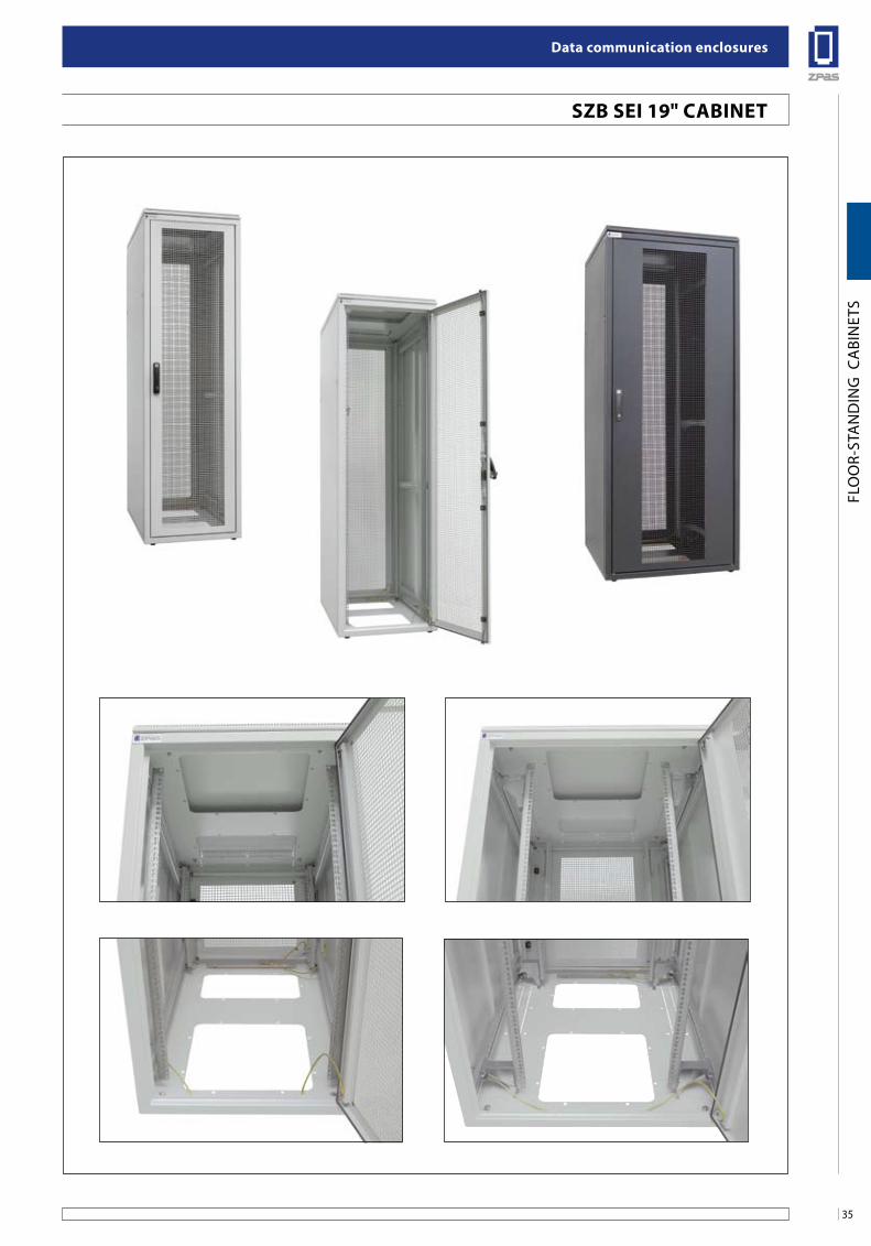
sZb sei 19" CabineT
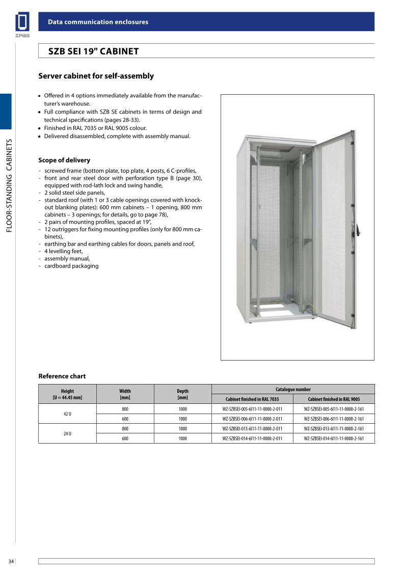
server cabinet for self-assembly
• Offered in 4 options immediately available from the manufac-turer’s warehouse.
• Full compliance with SZB SE cabinets in terms of design and technical specifications (pages 28-33).
• Finished in RAL 7035 or RAL 9005 colour.• Delivered disassembled, complete with assembly manual.
scope of delivery- screwed frame (bottom plate, top plate, 4 posts, 6 C-profiles,- front and rear steel door with perforation type B (page 30),
equipped with rod-lath lock and swing handle,- 2 solid steel side panels,- standard roof (with 1 or 3 cable openings covered with knock-
out blanking plates): 600 mm cabinets – 1 opening, 800 mm cabinets – 3 openings; for details, go to page 78),
- 2 pairs of mounting profiles, spaced at 19",- 12 outriggers for fixing mounting profiles (only for 800 mm ca-
binets),- earthing bar and earthing cables for doors, panels and roof,- 4 levelling feet,- assembly manual,- cardboard packaging
Height[U = 44.45 mm]
Width[mm]
Depth[mm]
Catalogue number
Cabinet finished in RAL 7035 Cabinet finished in RAL 9005
42 U800 1000 WZ-SZBSEI-005-6I11-11-0000-2-011 WZ-SZBSEI-005-6I11-11-0000-2-161
600 1000 WZ-SZBSEI-006-6I11-11-0000-2-011 WZ-SZBSEI-006-6I11-11-0000-2-161
24 U800 1000 WZ-SZBSEI-013-6I11-11-0000-2-011 WZ-SZBSEI-013-6I11-11-0000-2-161
600 1000 WZ-SZBSEI-014-6I11-11-0000-2-011 WZ-SZBSEI-014-6I11-11-0000-2-161
Reference chart
35
Data communication enclosures
FLO
OR-
STA
ND
ING
CA
BIN
ETS
sZb sei 19" CabineT
Data communication enclosures
36
FLO
OR-
STA
ND
ING
CA
BIN
ETS
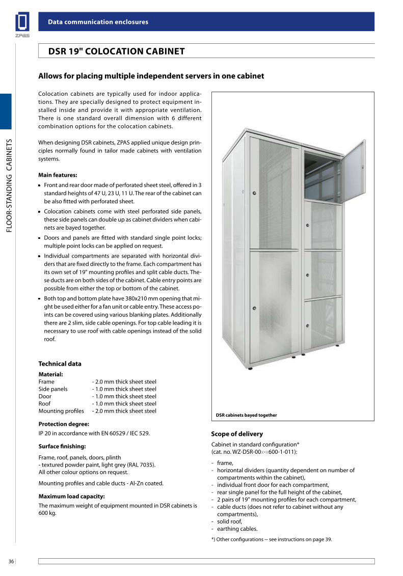
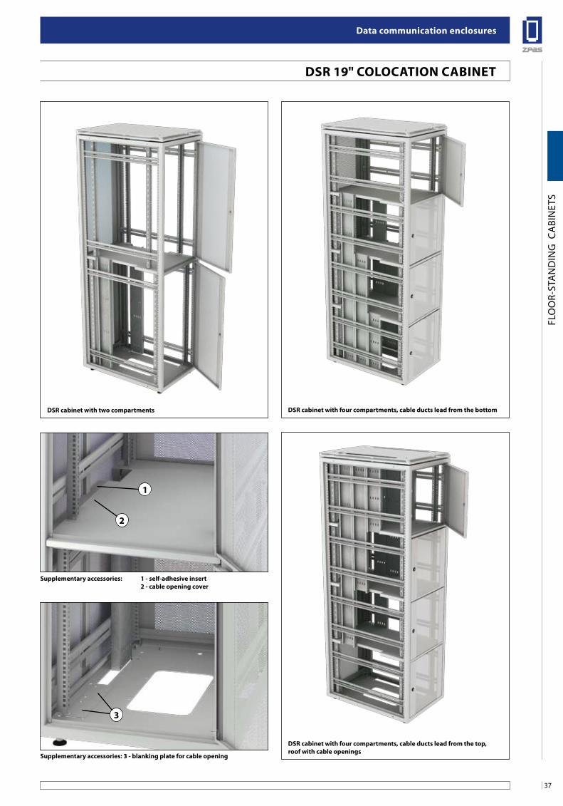
allows for placing multiple independent servers in one cabinet
Colocation cabinets are typically used for indoor applica-tions. They are specially designed to protect equipment in-stalled inside and provide it with appropriate ventilation. There is one standard overall dimension with 6 different combination options for the colocation cabinets.
When designing DSR cabinets, ZPAS applied unique design prin-ciples normally found in tailor made cabinets with ventilation systems.
Main features:
• Front and rear door made of perforated sheet steel, offered in 3 standard heights of 47 U, 23 U, 11 U. The rear of the cabinet can be also fitted with perforated sheet.
• Colocation cabinets come with steel perforated side panels, these side panels can double up as cabinet dividers when cabi-nets are bayed together.
• Doors and panels are fitted with standard single point locks; multiple point locks can be applied on request.
• Individual compartments are separated with horizontal divi-ders that are fixed directly to the frame. Each compartment has its own set of 19" mounting profiles and split cable ducts. The-se ducts are on both sides of the cabinet. Cable entry points are possible from either the top or bottom of the cabinet.
• Both top and bottom plate have 380x210 mm opening that mi-ght be used either for a fan unit or cable entry. These access po-ints can be covered using various blanking plates. Additionally there are 2 slim, side cable openings. For top cable leading it is necessary to use roof with cable openings instead of the solid roof.
Technical dataMaterial:Frame - 2.0 mm thick sheet steelSide panels - 1.0 mm thick sheet steelDoor - 1.0 mm thick sheet steelRoof - 1.0 mm thick sheet steelMounting profiles - 2.0 mm thick sheet steel
Protection degree:IP 20 in accordance with EN 60529 / IEC 529.
surface finishing:
Frame, roof, panels, doors, plinth- textured powder paint, light grey (RAL 7035).All other colour options on request.
Mounting profiles and cable ducts - Al-Zn coated.
Maximum load capacity:The maximum weight of equipment mounted in DSR cabinets is 600 kg.
DsR cabinets bayed together
scope of deliveryCabinet in standard configuration*(cat. no. WZ-DSR-00x-x600-1-011):
- frame,- horizontal dividers (quantity dependent on number of
compartments within the cabinet),- individual front door for each compartment,- rear single panel for the full height of the cabinet,- 2 pairs of 19" mounting profiles for each compartment,- cable ducts (does not refer to cabinet without any
compartments),- solid roof,- earthing cables.
*) Other configurations -- see instructions on page 39.
DsR 19" ColoCaTion CabineT
37
Data communication enclosures
FLO
OR-
STA
ND
ING
CA
BIN
ETS
DsR cabinet with two compartments DsR cabinet with four compartments, cable ducts lead from the bottom
supplementary accessories: 3 - blanking plate for cable opening
DsR cabinet with four compartments, cable ducts lead from the top,roof with cable openings
supplementary accessories: 1 - self-adhesive insert 2 - cable opening cover
2
1
3
DsR 19" ColoCaTion CabineT
Data communication enclosures
38
FLO
OR-
STA
ND
ING
CA
BIN
ETS
600
380
145580
900 900
C-C section F-F section
B-B section E-E section
A-A section D-D section
210
11 U
11 U
47 U
23 U
23 U
2185
25 -
5040
B BE E
F FC C
A AD
Front view Side view (cabinet without side panels) Side view (cabinet without side panels)
D
380
210
10
2 2
8
7
4
9
2
1
5
6
3
4
6
33
4
1313
14
12
11
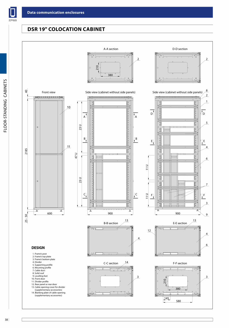
Design 1. Frame’s post 2. Frame’s top plate 3. Frame’s bottom plate 4. Divider 5. Supporting profile 6. Mounting profile 7. Cable duct 8. Solid roof 9. Levelling feet10. Front door11. Divider profile12. Rear panel or rear door13. Cable opening cover for divider (supplementary accessories)14. Blanking plate of cable opening (supplementary accessories)
DsR 19" ColoCaTion CabineT
39
Data communication enclosures
FLO
OR-
STA
ND
ING
CA
BIN
ETS
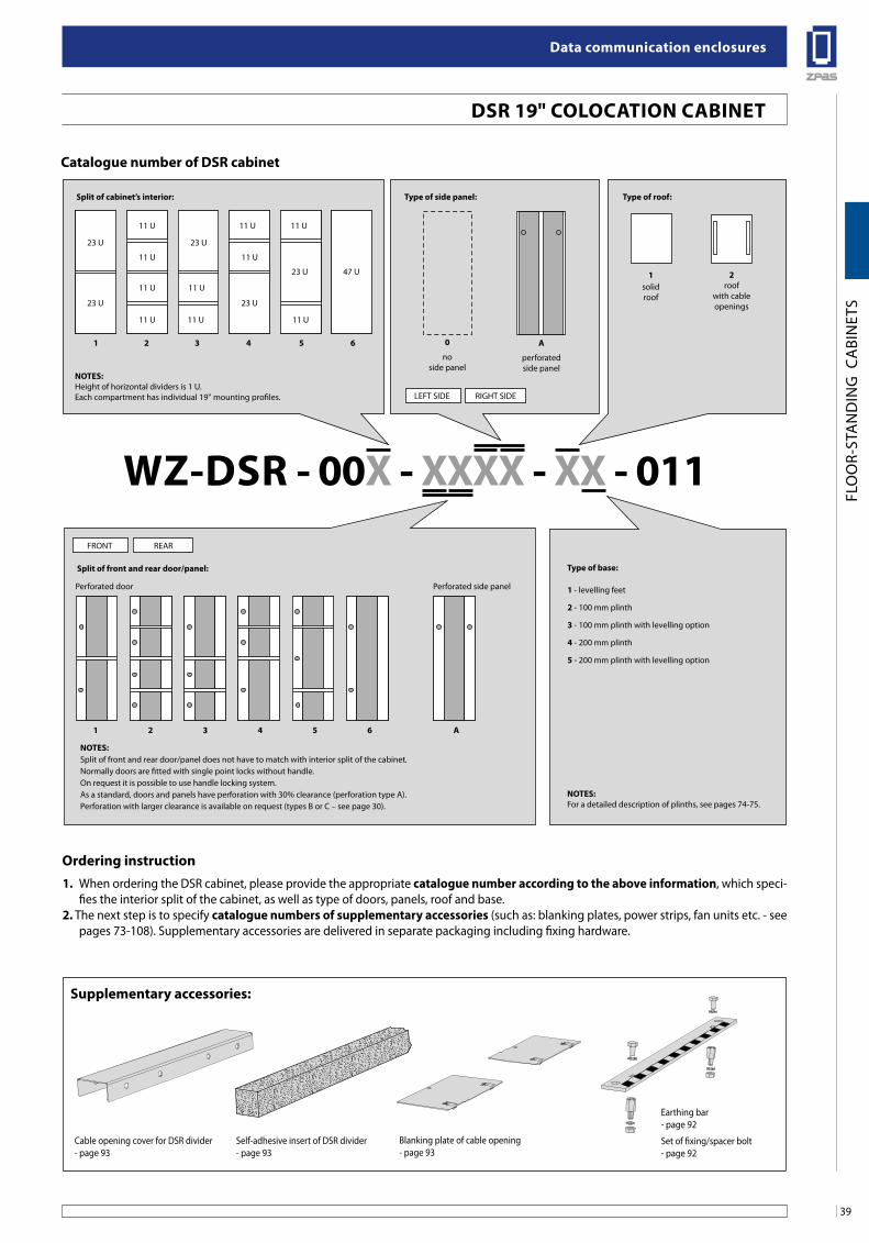
1. When ordering the DSR cabinet, please provide the appropriate catalogue number according to the above information, which speci-fies the interior split of the cabinet, as well as type of doors, panels, roof and base.
2. The next step is to specify catalogue numbers of supplementary accessories (such as: blanking plates, power strips, fan units etc. - see pages 73-108). Supplementary accessories are delivered in separate packaging including fixing hardware.
Catalogue number of DsR cabinet
noTes: Height of horizontal dividers is 1 U.Each compartment has individual 19'' mounting profiles.
split of cabinet’s interior:
split of front and rear door/panel:
Type of side panel: Type of roof:
1 2 3 4 5 6
noTes: Split of front and rear door/panel does not have to match with interior split of the cabinet.Normally doors are fitted with single point locks without handle.On request it is possible to use handle locking system.As a standard, doors and panels have perforation with 30% clearance (perforation type A). Perforation with larger clearance is available on request (types B or C – see page 30).
1 2 3 4 5 6 a
WZ-DsR - 00x - xxxx - xx - 011
0
noside panel
1 - levelling feet
2 - 100 mm plinth
3 - 100 mm plinth with levelling option
4 - 200 mm plinth
5 - 200 mm plinth with levelling option
1solidroof
2roof
with cableopenings
a
perforatedside panel
LEFT SIDE RIGHT SIDE
FRONT REAR
Perforated door Perforated side panel
23 U 23 U
23 U 23 U
23 U 47 U
11 U 11 U 11 U
11 U 11 U
11 U 11 U
11 U 11 U 11 U
Type of base:
noTes: For a detailed description of plinths, see pages 74-75.
ordering instruction
supplementary accessories:
Cable opening cover for DSR divider- page 93
Self-adhesive insert of DSR divider- page 93
Blanking plate of cable opening- page 93
Earthing bar- page 92
Set of fixing/spacer bolt- page 92
DsR 19" ColoCaTion CabineT
Data communication enclosures
40
FLO
OR-
STA
ND
ING
CA
BIN
ETS
sZu 19"/21" TeleCoMMuniCaTion CabineT
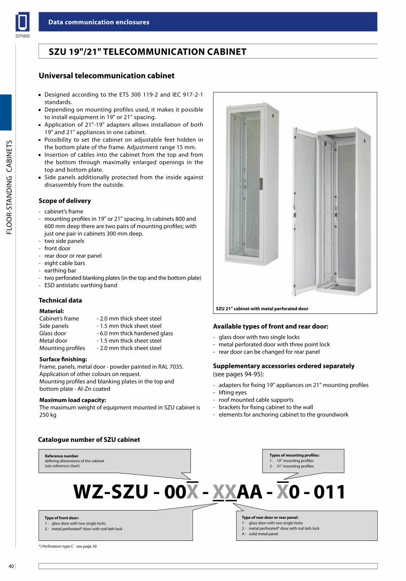
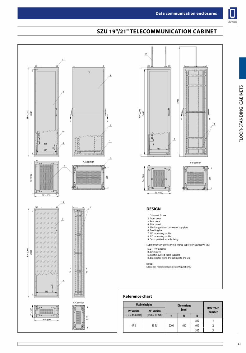
universal telecommunication cabinet
Technical dataMaterial:Cabinet’s frame - 2.0 mm thick sheet steelSide panels - 1.5 mm thick sheet steelGlass door - 6.0 mm thick hardened glassMetal door - 1.5 mm thick sheet steelMounting profiles - 2.0 mm thick sheet steel
surface finishing:Frame, panels, metal door - powder painted in RAL 7035.Application of other colours on request. Mounting profiles and blanking plates in the top andbottom plate - Al-Zn coated
Maximum load capacity:The maximum weight of equipment mounted in SZU cabinet is 250 kg
scope of delivery
available types of front and rear door:
supplementary accessories ordered separately(see pages 94-95):
- cabinet’s frame- mounting profiles in 19" or 21" spacing. In cabinets 800 and
600 mm deep there are two pairs of mounting profiles; with just one pair in cabinets 300 mm deep.
- two side panels- front door- rear door or rear panel- eight cable bars- earthing bar- two perforated blanking plates (in the top and the bottom plate) - ESD antistatic earthing band
- glass door with two single locks- metal perforated door with three point lock- rear door can be changed for rear panel
- adapters for fixing 19" appliances on 21" mounting profiles- lifting eyes- roof mounted cable supports- brackets for fixing cabinet to the wall- elements for anchoring cabinet to the groundwork
• Designed according to the ETS 300 119-2 and IEC 917-2-1 standards.
• Depending on mounting profiles used, it makes it possible to install equipment in 19" or 21" spacing.
• Application of 21"-19" adapters allows installation of both 19" and 21" appliances in one cabinet.
• Possibility to set the cabinet on adjustable feet hidden in the bottom plate of the frame. Adjustment range 15 mm.
• Insertion of cables into the cabinet from the top and from the bottom through maximally enlarged openings in the top and bottom plate.
• Side panels additionally protected from the inside against disassembly from the outside.
sZu 21" cabinet with metal perforated door
Reference numberdefining dimensions of the cabinet(see reference chart)
Type of front door: 1 - glass door with two single locks2 - metal perforated* door with rod-lath lock
WZ-sZu - 00x - xxaa - x0 - 011
Types of mounting profiles:1 - 19" mounting profiles2 - 21" mounting profiles
Type of rear door or rear panel: 1 - glass door with two single locks2 - metal perforated* door with rod-lath lockA - solid metal panel
*) Perforation type C - see page 30
Catalogue number of sZu cabinet
41
Data communication enclosures
FLO
OR-
STA
ND
ING
CA
BIN
ETS
A-A section
C-C section
B-B section
A A
C C
BB
2096
2096
2708
H =
220
0
44.4
5
465
515
W = 600
D =
300
559
25
515
25
D =
800
559
W = 600W = 600
D =
600
559
H =
220
0H
= 2
200
2096
44.4
5465
11
12
13
9
2
10
8
8
17
96
4
3
2
5
sZu 19"/21" TeleCoMMuniCaTion CabineT
Usable height Dimensions[mm] Reference
number19" version[1 U = 44.45 mm]
21" version[1 SU = 25 mm] H W D
47 U 83 SU 2200 600800 1600 2300 3
Reference chart
Design 1. Cabinet’s frame 2. Front door 3. Rear door 4. Side panel 5. Blanking plate of bottom or top plate 6. Earthing bar 7. 19" mounting profile 8. 21" mounting profile 9. Cross profile for cable fixing
Supplementary accessories ordered separately (pages 94-95):
10. 21"-19" adapter11. Lifting eye12. Roof mounted cable support13. Bracket for fixing the cabinet to the wall
note:Drawings represent sample configurations.
Data communication enclosures
42
FLO
OR-
STA
ND
ING
CA
BIN
ETS
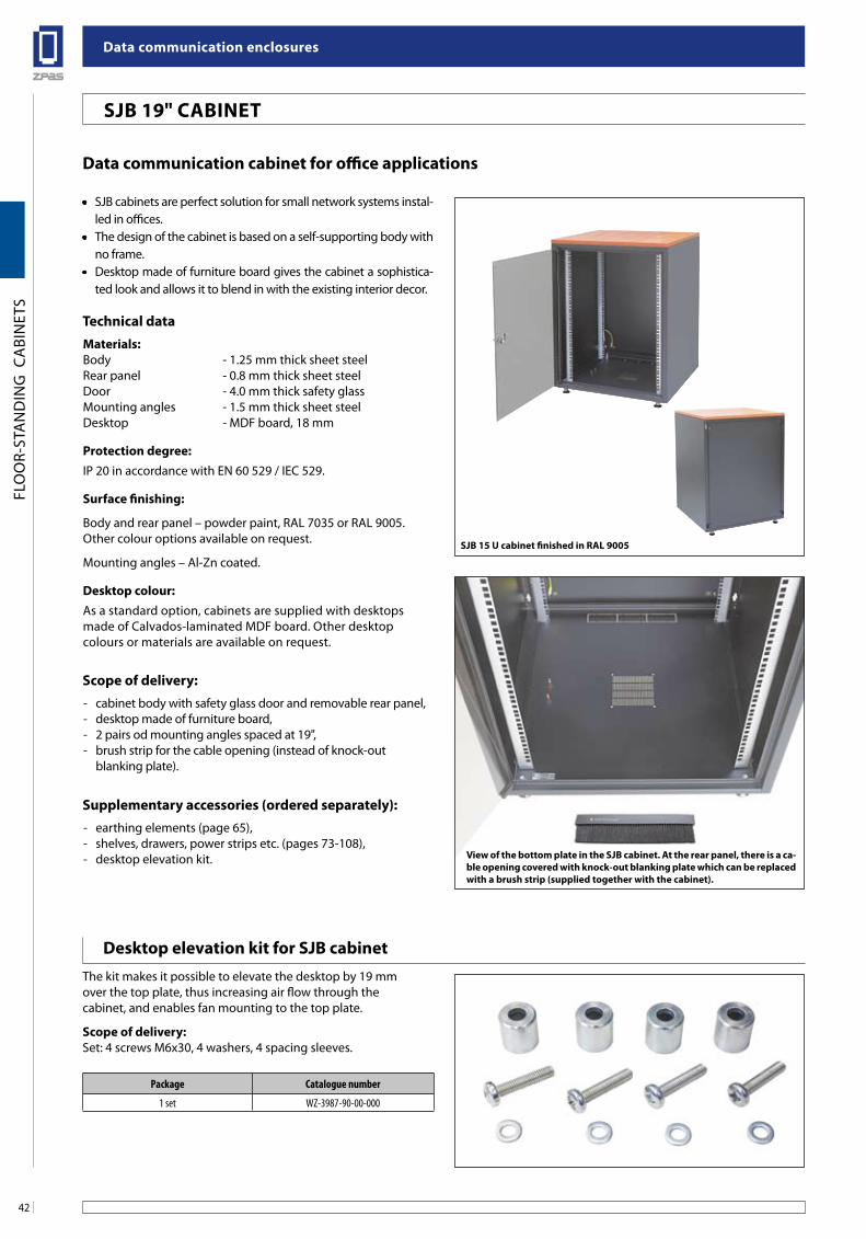
sJb 19" CabineT
sJb 15 u cabinet finished in Ral 9005
View of the bottom plate in the sJb cabinet. at the rear panel, there is a ca-ble opening covered with knock-out blanking plate which can be replaced with a brush strip (supplied together with the cabinet).
Data communication cabinet for office applications
• SJB cabinets are perfect solution for small network systems instal-led in offices.
• The design of the cabinet is based on a self-supporting body with no frame.
• Desktop made of furniture board gives the cabinet a sophistica-ted look and allows it to blend in with the existing interior decor.
Technical dataMaterials:Body - 1.25 mm thick sheet steelRear panel - 0.8 mm thick sheet steelDoor - 4.0 mm thick safety glassMounting angles - 1.5 mm thick sheet steelDesktop - MDF board, 18 mm
Protection degree:IP 20 in accordance with EN 60 529 / IEC 529.
surface finishing:
Body and rear panel – powder paint, RAL 7035 or RAL 9005.Other colour options available on request.
Mounting angles – Al-Zn coated.
Desktop colour:As a standard option, cabinets are supplied with desktopsmade of Calvados-laminated MDF board. Other desktopcolours or materials are available on request.
scope of delivery:
supplementary accessories (ordered separately):
- cabinet body with safety glass door and removable rear panel,- desktop made of furniture board,- 2 pairs od mounting angles spaced at 19",- brush strip for the cable opening (instead of knock-out
blanking plate).
- earthing elements (page 65),- shelves, drawers, power strips etc. (pages 73-108),- desktop elevation kit.
Package Catalogue number
1 set WZ-3987-90-00-000
Desktop elevation kit for sJb cabinetThe kit makes it possible to elevate the desktop by 19 mmover the top plate, thus increasing air flow through thecabinet, and enables fan mounting to the top plate.
scope of delivery: Set: 4 screws M6x30, 4 washers, 4 spacing sleeves.
43
Data communication enclosures
FLO
OR-
STA
ND
ING
CA
BIN
ETS
sJb 19" CabineT
H
W = 600
465
D = 400, 500 or 600
max 360, 460 or 560 (usable depth)
25÷5
018
HUH
B-B sectionFront view
A-A section
B
B
A A
C C
25÷5
018
19
2 1 5
5
4
7
9
3
4
6
5
7
10
B-B section(Cabinet with elevated desktop)
C-C section
1
8
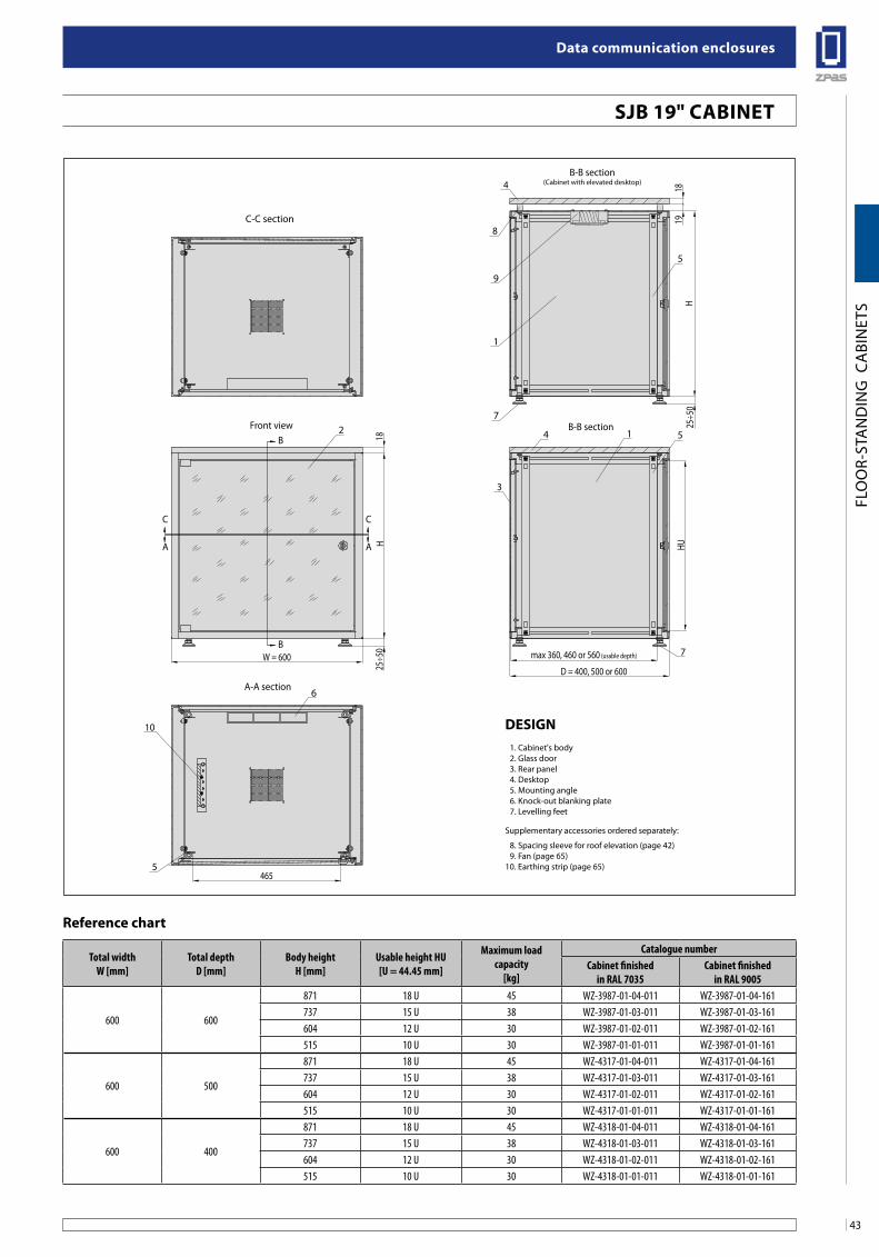
Total widthW [mm]
Total depthD [mm]
Body heightH [mm]
Usable height HU[U = 44.45 mm]
Maximum loadcapacity
[kg]
Catalogue numberCabinet finished
in RAL 7035Cabinet finished
in RAL 9005
600 600
871 18 U 45 WZ-3987-01-04-011 WZ-3987-01-04-161737 15 U 38 WZ-3987-01-03-011 WZ-3987-01-03-161604 12 U 30 WZ-3987-01-02-011 WZ-3987-01-02-161515 10 U 30 WZ-3987-01-01-011 WZ-3987-01-01-161
600 500
871 18 U 45 WZ-4317-01-04-011 WZ-4317-01-04-161737 15 U 38 WZ-4317-01-03-011 WZ-4317-01-03-161604 12 U 30 WZ-4317-01-02-011 WZ-4317-01-02-161515 10 U 30 WZ-4317-01-01-011 WZ-4317-01-01-161
600 400
871 18 U 45 WZ-4318-01-04-011 WZ-4318-01-04-161737 15 U 38 WZ-4318-01-03-011 WZ-4318-01-03-161604 12 U 30 WZ-4318-01-02-011 WZ-4318-01-02-161515 10 U 30 WZ-4318-01-01-011 WZ-4318-01-01-161
Reference chart
Design 1. Cabinet's body 2. Glass door 3. Rear panel 4. Desktop 5. Mounting angle 6. Knock-out blanking plate 7. Levelling feet
Supplementary accessories ordered separately:
8. Spacing sleeve for roof elevation (page 42) 9. Fan (page 65)10. Earthing strip (page 65)
Data communication enclosures
44
FLO
OR-
STA
ND
ING
CA
BIN
ETS
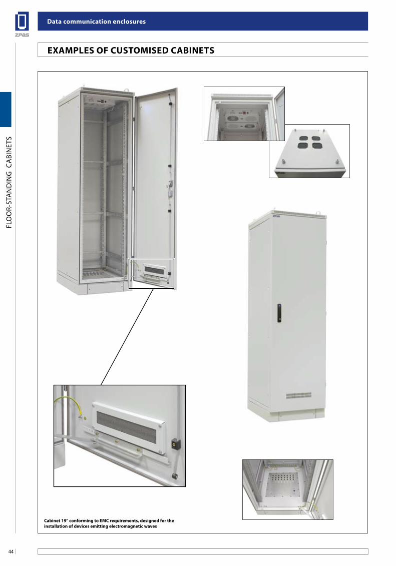
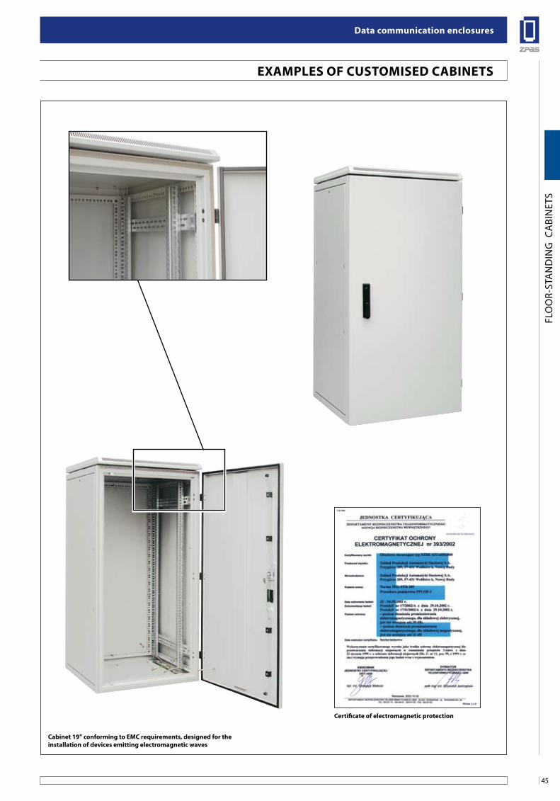
exaMPles of CusToMiseD CabineTs
Cabinet 19" conforming to eMC requirements, designed for theinstallation of devices emitting electromagnetic waves
45
Data communication enclosures
FLO
OR-
STA
ND
ING
CA
BIN
ETS
exaMPles of CusToMiseD CabineTs
Cabinet 19" conforming to eMC requirements, designed for theinstallation of devices emitting electromagnetic waves
Certificate of electromagnetic protection
Data communication enclosures
46
FLO
OR-
STA
ND
ING
CA
BIN
ETS
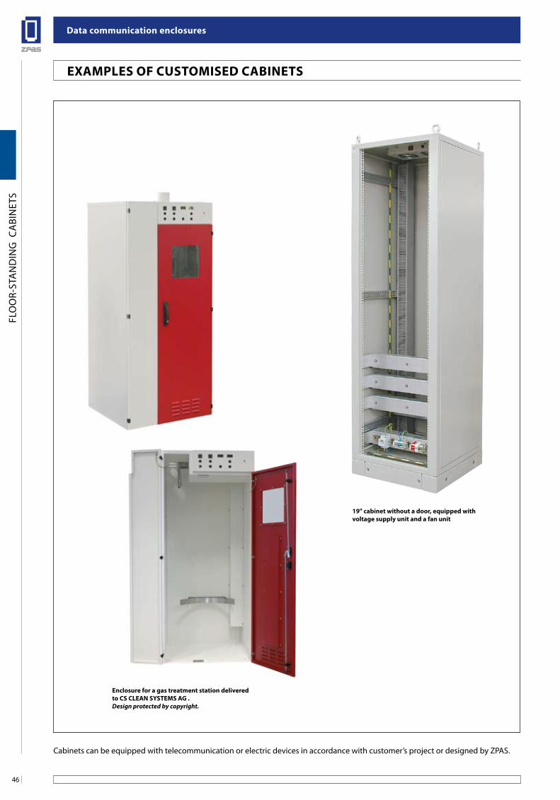
enclosure for a gas treatment station deliveredto Cs Clean sYsTeMs ag .Design protected by copyright.
19" cabinet without a door, equipped withvoltage supply unit and a fan unit
Cabinets can be equipped with telecommunication or electric devices in accordance with customer’s project or designed by ZPAS.
exaMPles of CusToMiseD CabineTs
47
Data communication enclosures
WA
LL-M
OU
NTE
D C
ABI
NET
S A
ND
FRA
MES
s u
s W
R n
s WJ
s J 2
s D 2
R n o
s J K
s K i 2
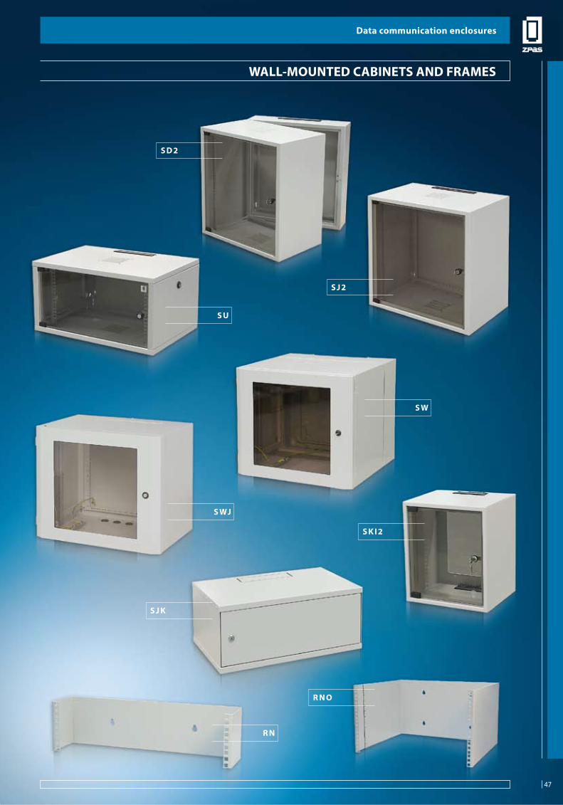
Wall-MounTeD CabineTs anD fRaMes
Data communication enclosures
47
Data communication enclosures
48
WA
LL-M
OU
NTE
D C
ABI
NET
S A
ND
FRA
MES
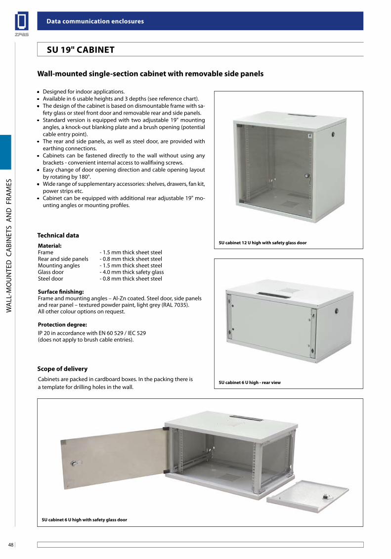
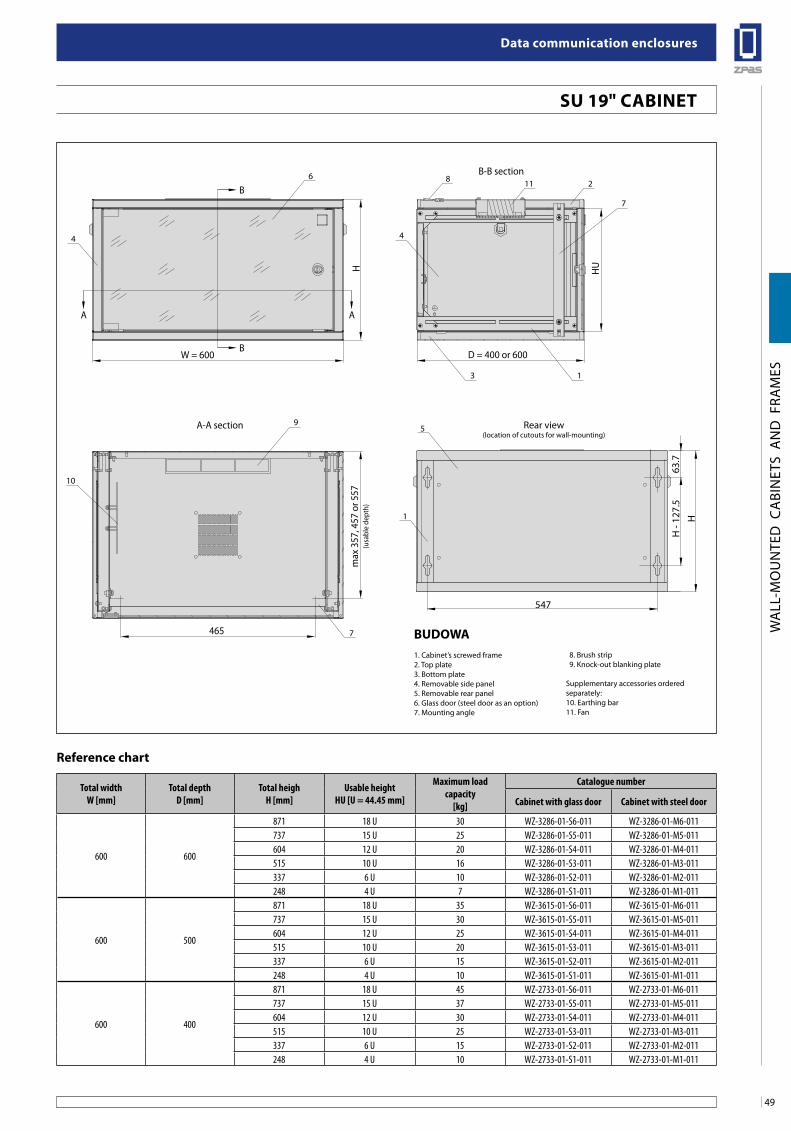
Wall-mounted single-section cabinet with removable side panels
• Designed for indoor applications.• Available in 6 usable heights and 3 depths (see reference chart).• The design of the cabinet is based on dismountable frame with sa-
fety glass or steel front door and removable rear and side panels.• Standard version is equipped with two adjustable 19" mounting
angles, a knock-out blanking plate and a brush opening (potential cable entry point).
• The rear and side panels, as well as steel door, are provided with earthing connections.
• Cabinets can be fastened directly to the wall without using any brackets - convenient internal access to wallfixing screws.
• Easy change of door opening direction and cable opening layout by rotating by 180°.
• Wide range of supplementary accessories: shelves, drawers, fan kit, power strips etc.
• Cabinet can be equipped with additional rear adjustable 19" mo-unting angles or mounting profiles.
Technical dataMaterial: Frame - 1.5 mm thick sheet steelRear and side panels - 0.8 mm thick sheet steelMounting angles - 1.5 mm thick sheet steelGlass door - 4.0 mm thick safety glassSteel door - 0.8 mm thick sheet steel
surface finishing: Frame and mounting angles – Al-Zn coated. Steel door, side panels and rear panel – textured powder paint, light grey (RAL 7035).All other colour options on request. Protection degree: IP 20 in accordance with EN 60 529 / IEC 529 (does not apply to brush cable entries).
scope of deliveryCabinets are packed in cardboard boxes. In the packing there is a template for drilling holes in the wall.
su cabinet 12 u high with safety glass door
su cabinet 6 u high with safety glass door
su cabinet 6 u high - rear view
su 19" CabineT
49
Data communication enclosures
WA
LL-M
OU
NTE
D C
ABI
NET
S A
ND
FRA
MES
Total widthW [mm]
Total depthD [mm]
Total heighH [mm]
Usable height HU [U = 44.45 mm]
Maximum load capacity
[kg]
Catalogue number
Cabinet with glass door Cabinet with steel door
600 600
871 18 U 30 WZ-3286-01-S6-011 WZ-3286-01-M6-011737 15 U 25 WZ-3286-01-S5-011 WZ-3286-01-M5-011604 12 U 20 WZ-3286-01-S4-011 WZ-3286-01-M4-011515 10 U 16 WZ-3286-01-S3-011 WZ-3286-01-M3-011337 6 U 10 WZ-3286-01-S2-011 WZ-3286-01-M2-011248 4 U 7 WZ-3286-01-S1-011 WZ-3286-01-M1-011
600 500
871 18 U 35 WZ-3615-01-S6-011 WZ-3615-01-M6-011737 15 U 30 WZ-3615-01-S5-011 WZ-3615-01-M5-011604 12 U 25 WZ-3615-01-S4-011 WZ-3615-01-M4-011515 10 U 20 WZ-3615-01-S3-011 WZ-3615-01-M3-011337 6 U 15 WZ-3615-01-S2-011 WZ-3615-01-M2-011248 4 U 10 WZ-3615-01-S1-011 WZ-3615-01-M1-011
600 400
871 18 U 45 WZ-2733-01-S6-011 WZ-2733-01-M6-011737 15 U 37 WZ-2733-01-S5-011 WZ-2733-01-M5-011604 12 U 30 WZ-2733-01-S4-011 WZ-2733-01-M4-011515 10 U 25 WZ-2733-01-S3-011 WZ-2733-01-M3-011337 6 U 15 WZ-2733-01-S2-011 WZ-2733-01-M2-011248 4 U 10 WZ-2733-01-S1-011 WZ-2733-01-M1-011
Reference chart
su 19" CabineT
B
B
AA
W = 600
465
D = 400 or 600
HUH
max
357
, 457
or 5
57(u
sabl
e de
pth)
6
9
3 1
7
10
44
2
7
8B-B section
A-A section
11
Rear view(location of cutouts for wall-mounting)
547
H
63.7
H -
127.
5
1
5
buDoWa1. Cabinet’s screwed frame2. Top plate3. Bottom plate4. Removable side panel5. Removable rear panel6. Glass door (steel door as an option)7. Mounting angle
8. Brush strip 9. Knock-out blanking plate
Supplementary accessories ordered separately:10. Earthing bar11. Fan
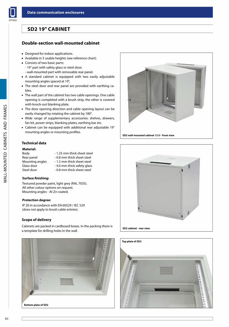
Data communication enclosures
50
WA
LL-M
OU
NTE
D C
ABI
NET
S A
ND
FRA
MES
Double-section wall-mounted cabinet
• Designed for indoor applications.• Available in 5 usable heights (see reference chart).• Consists of two basic parts: - 19" part with safety glass or steel door, - wall-mounted part with removable rear panel.• A standard cabinet is equipped with two easily adjustable
mounting angles spaced at 19",• The steel door and rear panel are provided with earthing ca-
bles.• The wall part of the cabinet has two cable openings. One cable
opening is completed with a brush strip, the other is covered with knock-out blanking plate.
• The door opening direction and cable opening layout can be easily changed by rotating the cabinet by 180°.
• Wide range of supplementary accessories: shelves, drawers, fan kit, power strips, blanking plates, earthing bar etc.
• Cabinet can be equipped with additional rear adjustable 19" mounting angles or mounting profiles.
Technical dataMaterial:Body - 1.25 mm thick sheet steelRear panel - 0.8 mm thick sheet steelMounting angles - 1.5 mm thick sheet steelGlass door - 4.0 mm thick safety glassSteel door - 0.8 mm thick sheet steel
surface finishing:Textured powder paint, light grey (RAL 7035).All other colour options on request.Mounting angles - Al-Zn coated.
Protection degree:IP 20 in accordance with EN 60529 / IEC 529 (does not apply to brush cable entries).
scope of delivery
Cabinets are packed in cardboard boxes. In the packing there is a template for drilling holes in the wall.
bottom plate of sD2
Top plate of sD2
sD2 wall-mounted cabinet 12 u - front view
sD2 cabinet - rear view
sD2 19" CabineT
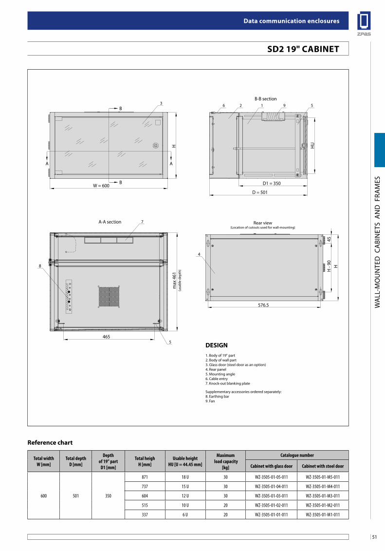
51
Data communication enclosures
WA
LL-M
OU
NTE
D C
ABI
NET
S A
ND
FRA
MES
Total widthW [mm]
Total depthD [mm]
Depthof 19" part
D1 [mm]
Total heighH [mm]
Usable height HU [U = 44.45 mm]
Maximum load capacity
[kg]
Catalogue number
Cabinet with glass door Cabinet with steel door
600 501 350
871 18 U 30 WZ-3505-01-05-011 WZ-3505-01-M5-011
737 15 U 30 WZ-3505-01-04-011 WZ-3505-01-M4-011
604 12 U 30 WZ-3505-01-03-011 WZ-3505-01-M3-011
515 10 U 20 WZ-3505-01-02-011 WZ-3505-01-M2-011
337 6 U 20 WZ-3505-01-01-011 WZ-3505-01-M1-011
Reference chart
sD2 19" CabineT
B
A A
B
H HU
3 6 2
7
1 9 5
W = 600D = 501
D1 = 350
B-B section
A-A section
max
461
(usa
ble
dept
h)
5465
45H
- 90 H
576.5
4
8
Rear view(Location of cutouts used for wall-mounting)
Design1. Body of 19" part2. Body of wall part3. Glass door (steel door as an option)4. Rear panel5. Mounting angle6. Cable entry7. Knock-out blanking plate
Supplementary accessories ordered separately:8. Earthing bar9. Fan
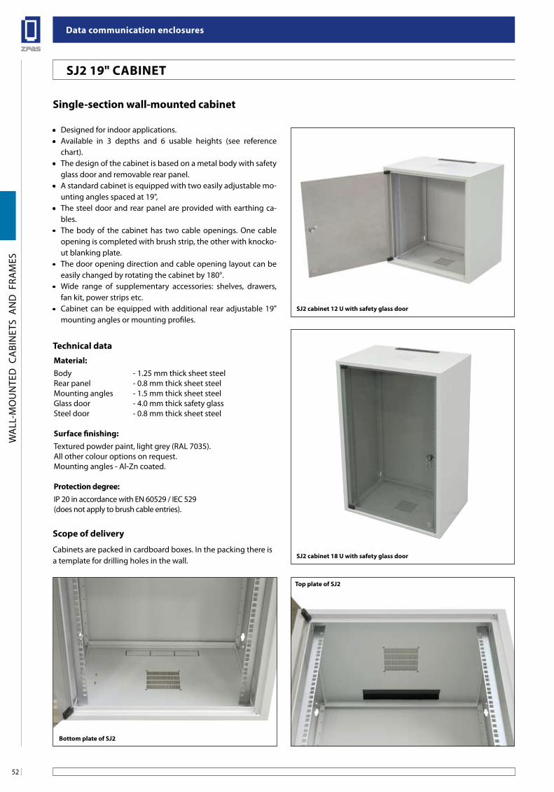
Data communication enclosures
52
WA
LL-M
OU
NTE
D C
ABI
NET
S A
ND
FRA
MES
single-section wall-mounted cabinet
• Designed for indoor applications.• Available in 3 depths and 6 usable heights (see reference
chart).• The design of the cabinet is based on a metal body with safety
glass door and removable rear panel.• A standard cabinet is equipped with two easily adjustable mo-
unting angles spaced at 19",• The steel door and rear panel are provided with earthing ca-
bles.• The body of the cabinet has two cable openings. One cable
opening is completed with brush strip, the other with knocko-ut blanking plate.
• The door opening direction and cable opening layout can be easily changed by rotating the cabinet by 180°.
• Wide range of supplementary accessories: shelves, drawers, fan kit, power strips etc.
• Cabinet can be equipped with additional rear adjustable 19" mounting angles or mounting profiles.
Technical dataMaterial:Body - 1.25 mm thick sheet steelRear panel - 0.8 mm thick sheet steelMounting angles - 1.5 mm thick sheet steelGlass door - 4.0 mm thick safety glassSteel door - 0.8 mm thick sheet steel
surface finishing:Textured powder paint, light grey (RAL 7035).All other colour options on request.Mounting angles - Al-Zn coated.
Protection degree:IP 20 in accordance with EN 60529 / IEC 529 (does not apply to brush cable entries).
scope of delivery
Cabinets are packed in cardboard boxes. In the packing there is a template for drilling holes in the wall.
bottom plate of sJ2
Top plate of sJ2
sJ2 cabinet 18 u with safety glass door
sJ2 cabinet 12 u with safety glass door
sJ2 19" CabineT
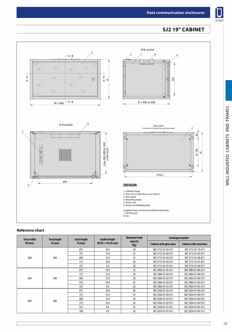
53
Data communication enclosures
WA
LL-M
OU
NTE
D C
ABI
NET
S A
ND
FRA
MES
Total widthW [mm]
Total depthD [mm]
Total heightH [mm]
Usable height HU [U = 44.45 mm]
Maximum load capacity
[kg]
Catalogue number
Cabinet with glass door Cabinet with steel door
600 600
871 18 U 30 WZ-3715-01-05-011 WZ-3715-01-10-011737 15 U 25 WZ-3715-01-04-011 WZ-3715-01-09-011604 12 U 25 WZ-3715-01-03-011 WZ-3715-01-08-011515 10 U 20 WZ-3715-01-02-011 WZ-3715-01-07-011337 6 U 20 WZ-3715-01-01-011 WZ-3715-01-06-011
600 500
871 18 U 35 WZ-3984-01-05-011 WZ-3984-01-M5-011737 15 U 30 WZ-3984-01-04-011 WZ-3984-01-M4-011604 12 U 30 WZ-3984-01-03-011 WZ-3984-01-M3-011515 10 U 25 WZ-3984-01-02-011 WZ-3984-01-M2-011337 6 U 20 WZ-3984-01-01-011 WZ-3984-01-M1-011
600 400
871 18 U 40 WZ-3504-01-05-011 WZ-3504-01-M5-011737 15 U 35 WZ-3504-01-04-011 WZ-3504-01-M4-011604 12 U 30 WZ-3504-01-03-011 WZ-3504-01-M3-011515 10 U 30 WZ-3504-01-02-011 WZ-3504-01-M2-011337 6 U 25 WZ-3504-01-01-011 WZ-3504-01-M1-011248 4 U 20 WZ-3839-01-01-011 WZ-3839-01-M1-011
Reference chart
sJ2 19" CabineT
B
A A
B
H HU
2
6
85 1 4
B-B section
A-A section
D = 400 or 600
465
W = 600
7
4
max
360
, 460
or 5
60(u
sabl
e de
pth)
Rear view(Locations of cutouts for wall-mounting) 3
45H
- 90
H
576.5
Design1. Cabinet’s body2. Glass door (steel door as an option)3. Rear panel4. Mounting angle5. Brush strip6. Knock-out blanking plate
Supplementary accessories ordered separately:7. Earthing bar8. Fan
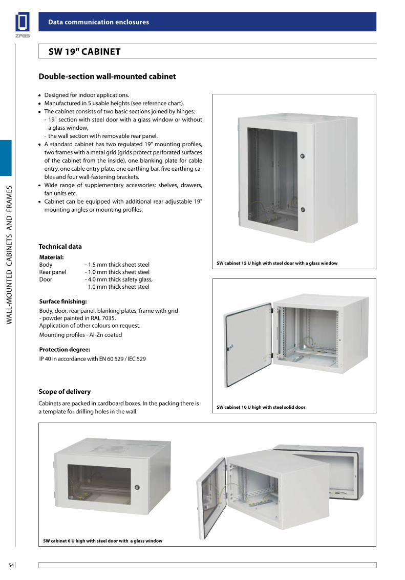
Data communication enclosures
54
WA
LL-M
OU
NTE
D C
ABI
NET
S A
ND
FRA
MES
Double-section wall-mounted cabinet
• Designed for indoor applications.• Manufactured in 5 usable heights (see reference chart).• The cabinet consists of two basic sections joined by hinges:
- 19" section with steel door with a glass window or without a glass window,
- the wall section with removable rear panel.• A standard cabinet has two regulated 19" mounting profiles,
two frames with a metal grid (grids protect perforated surfaces of the cabinet from the inside), one blanking plate for cable entry, one cable entry plate, one earthing bar, five earthing ca-bles and four wall-fastening brackets.
• Wide range of supplementary accessories: shelves, drawers, fan units etc.
• Cabinet can be equipped with additional rear adjustable 19" mounting angles or mounting profiles.
Technical dataMaterial:Body - 1.5 mm thick sheet steelRear panel - 1.0 mm thick sheet steelDoor - 4.0 mm thick safety glass, 1.0 mm thick sheet steel
surface finishing:Body, door, rear panel, blanking plates, frame with grid- powder painted in RAL 7035.Application of other colours on request.
Mounting profiles - Al-Zn coated
Protection degree: IP 40 in accordance with EN 60 529 / IEC 529
scope of delivery
Cabinets are packed in cardboard boxes. In the packing there is a template for drilling holes in the wall.
sW cabinet 6 u high with steel door with a glass window
sW cabinet 10 u high with steel solid door
sW cabinet 15 u high with steel door with a glass window
sW 19" CabineT
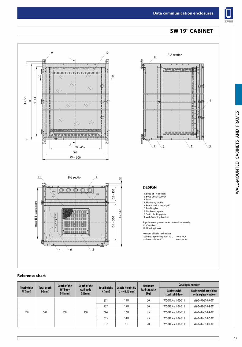
55
Data communication enclosures
WA
LL-M
OU
NTE
D C
ABI
NET
S A
ND
FRA
MES
Total widthW [mm]
Total depthD [mm]
Depth of the 19" bodyD1 [mm]
Depth of the wall bodyD2 [mm]
Total heightH [mm]
Usable height HU[U = 44.45 mm]
Maximum load capacity
[kg]
Catalogue number
Cabinet with steel solid door
Cabinet with steel door with a glass window
600 547 350 150
871 18 U 30 WZ-0405-M1-05-011 WZ-0405-S1-05-011
737 15 U 30 WZ-0405-M1-04-011 WZ-0405-S1-04-011
604 12 U 25 WZ-0405-M1-03-011 WZ-0405-S1-03-011
515 10 U 25 WZ-0405-M1-02-011 WZ-0405-S1-02-011
337 6 U 20 WZ-0405-M1-01-011 WZ-0405-S1-01-011
Reference chart
sW 19" CabineTH
- 53
H +
36
max
458
(usa
ble
dept
h)
D2 =
150
D1
= 35
0 D =
547
20
H
B
A
B
A
569
W = 600
W - 465
98
4
7
4 56
2 1 3
10
711 B-B section
A-A section
Design 1. Body of 19" section 2. Body of wall section 3. Door 4. Mounting profile 5. Frame with a metal grid 6. Earthing bar 7. Cable entry plate 8. Solid blanking plate 9. Wall-fastening bracket
Supplementary accessories ordered separately:10. Cross bar11. Filtering insert
Number of locks in the door- cabinets up to height of 12 U - one lock- cabinets above 12 U - two locks
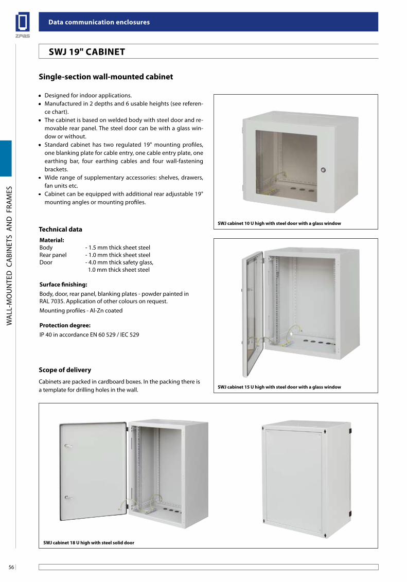
Data communication enclosures
56
WA
LL-M
OU
NTE
D C
ABI
NET
S A
ND
FRA
MES
single-section wall-mounted cabinet
• Designed for indoor applications.• Manufactured in 2 depths and 6 usable heights (see referen-
ce chart).• The cabinet is based on welded body with steel door and re-
movable rear panel. The steel door can be with a glass win-dow or without.
• Standard cabinet has two regulated 19" mounting profiles, one blanking plate for cable entry, one cable entry plate, one earthing bar, four earthing cables and four wall-fastening brackets.
• Wide range of supplementary accessories: shelves, drawers, fan units etc.
• Cabinet can be equipped with additional rear adjustable 19" mounting angles or mounting profiles.
Technical dataMaterial:Body - 1.5 mm thick sheet steelRear panel - 1.0 mm thick sheet steelDoor - 4.0 mm thick safety glass, 1.0 mm thick sheet steel
surface finishing:Body, door, rear panel, blanking plates - powder painted in RAL 7035. Application of other colours on request.
Mounting profiles - Al-Zn coated
Protection degree:IP 40 in accordance EN 60 529 / IEC 529
scope of delivery
Cabinets are packed in cardboard boxes. In the packing there is a template for drilling holes in the wall.
sWJ cabinet 18 u high with steel solid door
sWJ 19" CabineT
sWJ cabinet 15 u high with steel door with a glass window
sWJ cabinet 10 u high with steel door with a glass window
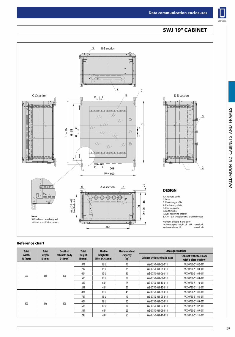
57
Data communication enclosures
WA
LL-M
OU
NTE
D C
ABI
NET
S A
ND
FRA
MES
H -
53m
ax D
1 - 4
2(u
sabl
e de
pth)
H
H +
36
3
A
B
A
B
8
7
3
4
1 2
6
5
D C
D C 569
W = 600
465
D1
D =
D1
+ 46
20
B-B section
C-C section D-D section
A-A section
Totalwidth
W (mm)
Totaldepth
D (mm)
Depth ofcabinets body
D1 (mm)
TotalheightH (mm)
Usableheight HU
[U = 44.45 mm]
Maximum loadcapacity
[kg]
Catalogue number
Cabinet with steel solid door Cabinet with steel door with a glass window
600 446 400
871 18 U 40 WZ-0750-M1-02-011 WZ-0750-S1-02-011737 15 U 35 WZ-0750-M1-04-011 WZ-0750-S1-04-011604 12 U 30 WZ-0750-M1-06-011 WZ-0750-S1-06-011515 10 U 30 WZ-0750-M1-08-011 WZ-0750-S1-08-011337 6 U 25 WZ-0750-M1-10-011 WZ-0750-S1-10-011248 4 U 20 WZ-0750-M1-12-011 WZ-0750-S1-12-011
600 346 300
871 18 U 45 WZ-0750-M1-01-011 WZ-0750-S1-01-011737 15 U 40 WZ-0750-M1-03-011 WZ-0750-S1-03-011604 12 U 35 WZ-0750-M1-05-011 WZ-0750-S1-05-011515 10 U 30 WZ-0750-M1-07-011 WZ-0750-S1-07-011337 6 U 25 WZ-0750-M1-09-011 WZ-0750-S1-09-011248 4 U 25 WZ-0750-M1-11-011 WZ-0750-S1-11-011
Reference chart
sWJ 19" CabineT
Design1. Cabinet's body2. Door3. Mounting profile4. Cable entry plate5. Blanking plate6. Earthing bar7. Wall-fastening bracket8. Cross bar (supplementary accessories)
Number of locks in the door- cabinet up to height of 12 U - one lock- cabinet above 12 U - two locks
note: SWJ cabinets are designed without a ventilation panel.
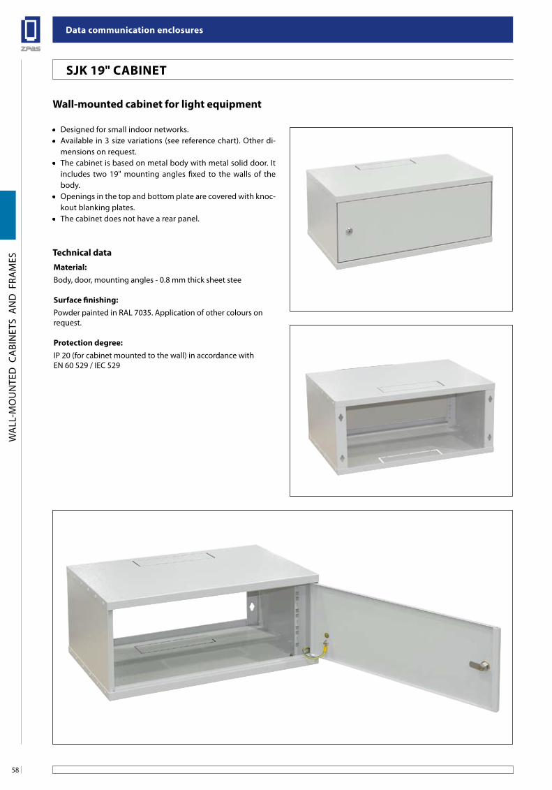
Data communication enclosures
58
WA
LL-M
OU
NTE
D C
ABI
NET
S A
ND
FRA
MES
szafka sWJ o wysokości 18 u z drzwiami bez szyby
szafka sW o wysokości 10 u z drzwiami bez szyby
szafka sW o wysokości 15 u z drzwiami z szybą szklaną
Wall-mounted cabinet for light equipment
• Designed for small indoor networks.• Available in 3 size variations (see reference chart). Other di-
mensions on request.• The cabinet is based on metal body with metal solid door. It
includes two 19" mounting angles fixed to the walls of the body.
• Openings in the top and bottom plate are covered with knoc-kout blanking plates.
• The cabinet does not have a rear panel.
Technical dataMaterial:Body, door, mounting angles - 0.8 mm thick sheet stee
surface finishing:Powder painted in RAL 7035. Application of other colours on request.
Protection degree:IP 20 (for cabinet mounted to the wall) in accordance with EN 60 529 / IEC 529
sJK 19" CabineT
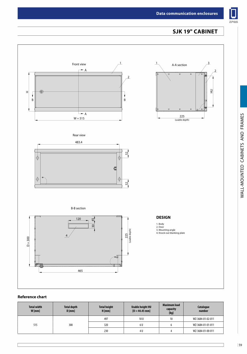
59
Data communication enclosures
WA
LL-M
OU
NTE
D C
ABI
NET
S A
ND
FRA
MES
H
D =
300
4530
120
225
(usa
ble
dept
h)
Front view
Rear view
W = 515225
(usable depth)
465
483.4
52
A
HU
52
B B
A
A-A section
B-B section
1 3
4
1
2
2
Total widthW [mm]
Total depthD [mm]
Total heightH [mm]
Usable height HU[U = 44.45 mm]
Maximum load capacity
[kg]
Cataloguenumber
515 300
497 10 U 10 WZ-3684-01-02-011
320 6 U 6 WZ-3684-01-01-011
230 4 U 4 WZ-3684-01-00-011
Reference chart
sJK 19" CabineT
Design1. Body2. Door3. Mounting angle4. Knock-out blanking plate
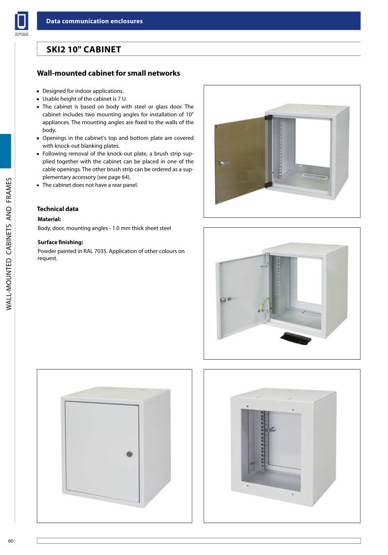
Data communication enclosures
60
WA
LL-M
OU
NTE
D C
ABI
NET
S A
ND
FRA
MES
szafka sWJ o wysokości 18 u z drzwiami bez szyby
szafka sW o wysokości 10 u z drzwiami bez szyby
szafka sW o wysokości 15 u z drzwiami z szybą szklaną
Wall-mounted cabinet for small networks
• Designed for indoor applications.• Usable height of the cabinet is 7 U.• The cabinet is based on body with steel or glass door. The
cabinet includes two mounting angles for installation of 10" appliances. The mounting angles are fixed to the walls of the body.
• Openings in the cabinet's top and bottom plate are covered with knock-out blanking plates.
• Following removal of the knock-out plate, a brush strip sup-plied together with the cabinet can be placed in one of the cable openings. The other brush strip can be ordered as a sup-plementary accessory (see page 64).
• The cabinet does not have a rear panel.
Technical dataMaterial:Body, door, mounting angles - 1.0 mm thick sheet steel
surface finishing:Powder painted in RAL 7035. Application of other colours on request.
sKi2 10" CabineT
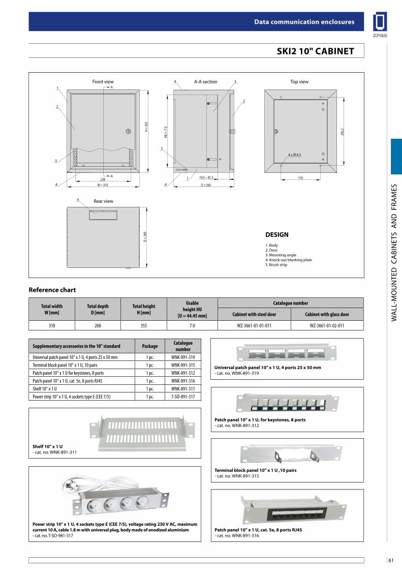
61
Data communication enclosures
WA
LL-M
OU
NTE
D C
ABI
NET
S A
ND
FRA
MES
W = 310 D = 260
D =
260
238 19.5 ÷ 81.5
A-A section Top view
Rear view
Front view
170
HU =
7 U
292.2H
= 35
5
A
A
3
44
1
4
1
4
3
22
5
4 x Ø 6.5
Total widthW [mm]
Total depthD [mm]
Total heightH [mm]
Usableheight HU
[U = 44.45 mm]
Catalogue number
Cabinet with steel door Cabinet with glass door
310 260 355 7 U WZ-3661-01-01-011 WZ-3661-01-02-011
Reference chart
sKi2 10" CabineT
Design1. Body2. Door3. Mounting angle4. Knock-out blanking plate5. Brush strip
Supplementary accessories in the 10" standard Package Catalogue number
Universal patch panel 10" x 1 U, 4 ports 25 x 50 mm 1 pc. WNK-891-319Terminal block panel 10" x 1 U, 10 pairs 1 pc. WNK-891-315Patch panel 10" x 1 U for keystones, 8 ports 1 pc. WNK-891-312Patch panel 10" x 1 U, cat. 5e, 8 ports RJ45 1 pc. WNK-891-316Shelf 10" x 1 U 1 pc. WNK-891-311Power strip 10" x 1 U, 4 sockets type E (CEE 7/5) 1 pc. T-SO-891-317
shelf 10" x 1 u- cat. no. WNK-891-311
Terminal block panel 10" x 1 u ,10 pairs- cat. no. WNK-891-315
Patch panel 10" x 1 u, cat. 5e, 8 ports RJ45- cat. no. WNK-891-316
Patch panel 10" x 1 u, for keystones, 8 ports- cat. no. WNK-891-312
universal patch panel 10" x 1 u, 4 ports 25 x 50 mm- cat. no. WNK-891-319
Power strip 10" x 1 u, 4 sockets type e (Cee 7/5), voltage rating 230 V aC, maximum current 10 a, cable 1.8 m with universal plug, body made of anodized aluminium- cat. no. T-SO-981-317
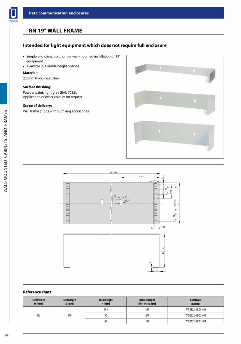
Data communication enclosures
62
WA
LL-M
OU
NTE
D C
ABI
NET
S A
ND
FRA
MES
Rn 19" Wall fRaMe
intended for light equipment which does not require full enclosure
• Simple and cheap solution for wall-mounted installation of 19" equipment.
• Available in 3 usable height options.
Material:2.0 mm thick sheet steel
surface finishing:Powder paint, light grey (RAL 7035).Application of other colours on request.
scope of delivery:Wall frame (1 pc.) without fixing accessories.
szafka sW o wysokości 15 u z drzwiami z szybą szklaną
W = 493
H
31.75
15.88
44.45
nx44
.4531
.75
7.2
21
2
9.2
Ø 13
18.5 6.5
126.57
D =
110
Total widthW [mm]
Total depthD [mm]
Total heightH [mm]
Usable height[U = 44.45 mm]
Cataloguenumber
493 110
134 3 U WZ-2522-02-03-011
90 2 U WZ-2522-02-02-011
45 1 U WZ-2522-02-01-011
Reference chart
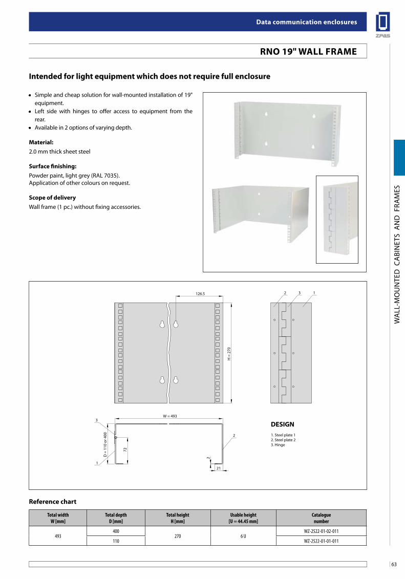
63
Data communication enclosures
WA
LL-M
OU
NTE
D C
ABI
NET
S A
ND
FRA
MES
Rno 19" Wall fRaMe
intended for light equipment which does not require full enclosure
• Simple and cheap solution for wall-mounted installation of 19" equipment.
• Left side with hinges to offer access to equipment from the rear.
• Available in 2 options of varying depth.
Material:2.0 mm thick sheet steel
surface finishing:Powder paint, light grey (RAL 7035).Application of other colours on request.
scope of deliveryWall frame (1 pc.) without fixing accessories.
szafka sW o wysokości 15 u z drzwiami z szybą szklaną
D =
110
or 4
00
W = 493
H =
270
126.5
21
2
72
2
2
3
1
3 1
Total widthW [mm]
Total depthD [mm]
Total heightH [mm]
Usable height[U = 44.45 mm]
Cataloguenumber
493400
270 6 UWZ-2522-01-02-011
110 WZ-2522-01-01-011
Reference chart
Design1. Steel plate 12. Steel plate 23. Hinge
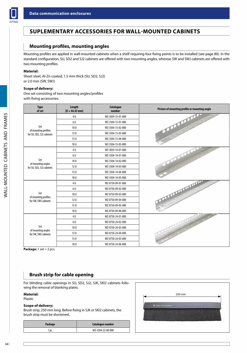
Data communication enclosures
64
WA
LL-M
OU
NTE
D C
ABI
NET
S A
ND
FRA
MES
250 mm
Mounting profiles, mounting anglesMounting profiles are applied in wall-mounted cabinets when a shelf requiring four fixing points is to be installed (see page 80). In the standard configuration, SU, SD2 and SJ2 cabinets are offered with two mounting angles, whereas SW and SWJ cabinets are offered with two mounting profiles.
Material:Sheet steel, Al-Zn coated, 1.5 mm thick (SU, SD2, SJ2)or 2.0 mm (SW, SWJ)
scope of delivery:One set consisting of two mounting angles/profileswith fixing accessories.
Type of set
Length[U = 44.45 mm]
Catalogue number Picture of mounting profile or mounting angle
Set of mounting profiles
for SU, SD2, SJ2 cabinets
4 U WZ-3839-15-01-000
6 U WZ-3504-15-01-000
10 U WZ-3504-15-02-000
12 U WZ-3504-15-03-000
15 U WZ-3504-15-04-000
18 U WZ-3504-15-05-000
Set of mounting angles
for SU, SD2, SJ2 cabinets
4 U WZ-3839-14-01-000
6 U WZ-3504-14-01-000
10 U WZ-3504-14-02-000
12 U WZ-3504-14-03-000
15 U WZ-3504-14-04-000
18 U WZ-3504-14-05-000
Set of mounting profiles for SW, SWJ cabinets
4 U WZ-0750-09-01-000
6 U WZ-0750-09-02-000
10 U WZ-0750-09-03-000
12 U WZ-0750-09-04-000
15 U WZ-0750-09-05-000
18 U WZ-0750-09-06-000
Set of mounting angles
for SW, SWJ cabinets
4 U WZ-0750-24-01-000
6 U WZ-0750-24-02-000
10 U WZ-0750-24-03-000
12 U WZ-0750-24-04-000
15 U WZ-0750-24-05-000
18 U WZ-0750-24-06-000
Package: 1 set = 2 pcs.
brush strip for cable opening
For blinding cable openings in SU, SD2, SJ2, SJK, SKI2 cabinets follo-wing the removal of blanking plates.
Material:Plastic
scope of delivery: Brush strip, 250 mm long. Before fixing in SJK or SKI2 cabinets, the brush strip must be shortened..
Package Catalogue number
1 pc. WZ-3504-22-00-000
suPleMenTaRY aCCessoRies foR Wall-MounTeD CabineTs
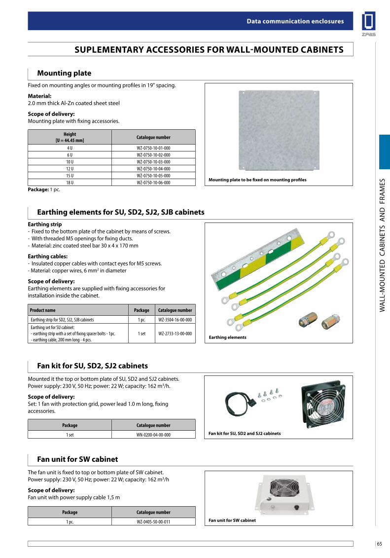
65
Data communication enclosures
WA
LL-M
OU
NTE
D C
ABI
NET
S A
ND
FRA
MES
Mounting plate to be fixed on mounting profiles
fan kit for su, sD2 and sJ2 cabinets
fan unit for sW cabinet
Mounting plateFixed on mounting angles or mounting profiles in 19" spacing.
Material:2.0 mm thick Al-Zn coated sheet steel
scope of delivery:Mounting plate with fixing accessories.
Height[U = 44.45 mm] Catalogue number
4 U WZ-0750-10-01-0006 U WZ-0750-10-02-000
10 U WZ-0750-10-03-00012 U WZ-0750-10-04-00015 U WZ-0750-10-05-00018 U WZ-0750-10-06-000
Package: 1 pc.
fan kit for su, sD2, sJ2 cabinets
fan unit for sW cabinet
Mounted it the top or bottom plate of SU, SD2 and SJ2 cabinets.Power supply: 230 V, 50 Hz; power: 22 W; capacity: 162 m3/h.
scope of delivery: Set: 1 fan with protection grid, power lead 1.0 m long, fixingaccessories.
The fan unit is fixed to top or bottom plate of SW cabinet.Power supply: 230 V, 50 Hz; power: 22 W; capacity: 162 m3/h
scope of delivery: Fan unit with power supply cable 1,5 m
Package Catalogue number
1 set WN-0200-04-00-000
Package Catalogue number
1 pc. WZ-0405-50-00-011
suPleMenTaRY aCCessoRies foR Wall-MounTeD CabineTs
earthing elements for su, sD2, sJ2, sJb cabinetsearthing strip- Fixed to the bottom plate of the cabinet by means of screws.- With threaded M5 openings for fixing ducts.- Material: zinc coated steel bar 30 x 4 x 170 mm
earthing cables:- Insulated copper cables with contact eyes for M5 screws.- Material: copper wires, 6 mm2 in diameter
scope of delivery: Earthing elements are supplied with fixing accessories forinstallation inside the cabinet.
Product name Package Catalogue number
Earthing strip for SD2, SJ2, SJB cabinets 1 pc. WZ-3504-16-00-000Earthing set for SU cabinet:- earthing strip with a set of fixing spacer bolts - 1pc.- earthing cable, 200 mm long - 4 pcs.
1 set WZ-2733-13-00-000earthing elements
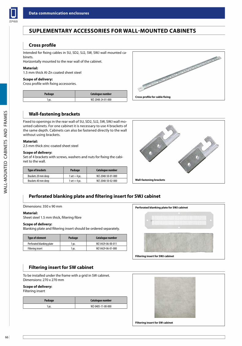
Data communication enclosures
66
WA
LL-M
OU
NTE
D C
ABI
NET
S A
ND
FRA
MES
suPleMenTaRY aCCessoRies foR Wall-MounTeD CabineTs
Wall-fastening brackets
Wall-fastening bracketsFixed to openings in the rear wall of SU, SD2, SJ2, SW, SWJ wall mo-unted cabinets. For one cabinet it is necessary to use 4 brackets of the same depth. Cabinets can also be fastened directly to the wall without using brackets.
Material:2.5 mm thick zinc-coated sheet steel
scope of delivery:Set of 4 brackets with screws, washers and nuts for fixing the cabi-net to the wall.
Type of brackets Package Catalogue number
Brackets 20 mm deep 1 set = 4 pc. WZ-2048-50-01-000Brackets 40 mm deep 1 set = 4 pc. WZ-2048-50-02-000
filtering insert for sW cabinet
Perforated blanking plate for sWJ cabinet
filtering insert for sWJ cabinet
filtering insert for sW cabinet
Perforated blanking plate and filtering insert for sWJ cabinet
To be installed under the frame with a grid in SW cabinet.Dimensions: 270 x 270 mm
scope of delivery: Filtering insert
Dimensions: 350 x 90 mm
Material:Sheet steel 1.5 mm thick, filtering fibre
scope of delivery:Blanking plate and filtering insert should be ordered separately.
Package Catalogue number
1 pc. WZ-0405-11-00-000
Type of element Package Catalogue number
Perforated blanking plate 1 pc. WZ-0429-06-00-011Filtering insert 1 pc. WZ-0429-06-01-000
Cross profileIntended for fixing cables in SU, SD2, SJ2, SW, SWJ wall mounted ca-binets. Horizontally mounted to the rear wall of the cabinet.
Material:1.5 mm thick Al-Zn coated sheet steel
scope of delivery:Cross profile with fixing accessories.
Package Catalogue number
1 pc. WZ-2048-24-01-000Cross profile for cable fixing
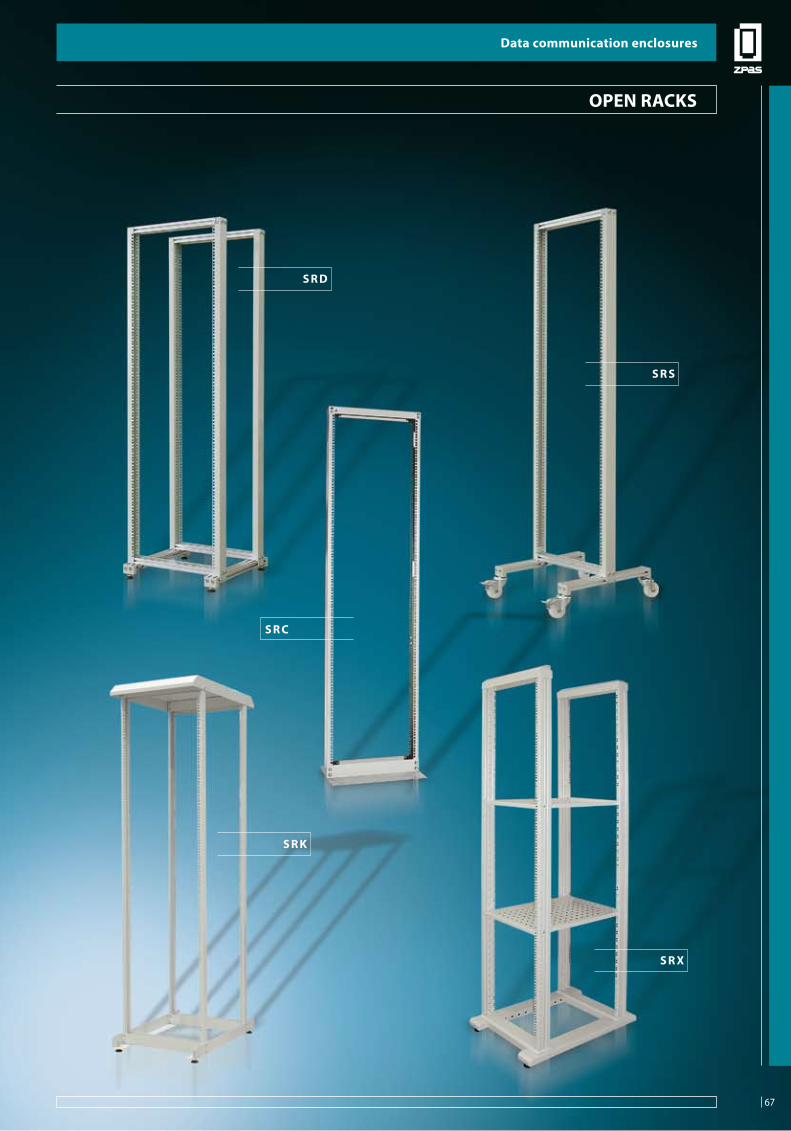
67
Data communication enclosures
OPE
N R
ACK
S
s R D
s R K
s R x
s R s
s R C
oPen RaCKs
Data communication enclosures
67
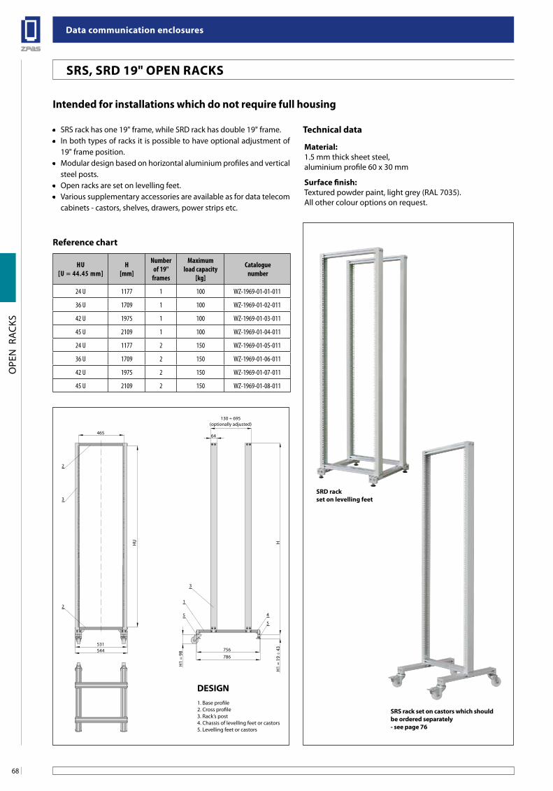
Data communication enclosures
68
OPE
N R
ACK
S
intended for installations which do not require full housing
• SRS rack has one 19" frame, while SRD rack has double 19" frame.• In both types of racks it is possible to have optional adjustment of
19" frame position.• Modular design based on horizontal aluminium profiles and vertical
steel posts.• Open racks are set on levelling feet.• Various supplementary accessories are available as for data telecom
cabinets - castors, shelves, drawers, power strips etc.
sRs rack set on castors which should be ordered separately - see page 76
HU[U = 44.45 mm]
H[mm]
Number of 19"
frames
Maximum load capacity
[kg]
Cataloguenumber
24 U 1177 1 100 WZ-1969-01-01-011
36 U 1709 1 100 WZ-1969-01-02-011
42 U 1975 1 100 WZ-1969-01-03-011
45 U 2109 1 100 WZ-1969-01-04-011
24 U 1177 2 150 WZ-1969-01-05-011
36 U 1709 2 150 WZ-1969-01-06-011
42 U 1975 2 150 WZ-1969-01-07-011
45 U 2109 2 150 WZ-1969-01-08-011
Reference chart
Technical data
Material:1.5 mm thick sheet steel,aluminium profile 60 x 30 mm
surface finish:Textured powder paint, light grey (RAL 7035).All other colour options on request.
2
3
2
3
1
5
5
4
46564
531756544786
HU
H1
= 19
÷ 4
3
H1
= 98
H
130 ÷ 695(optionally adjusted)
Design1. Base profile2. Cross profile3. Rack’s post4. Chassis of levelling feet or castors5. Levelling feet or castors
sRs, sRD 19" oPen RaCKs
sRD rackset on levelling feet
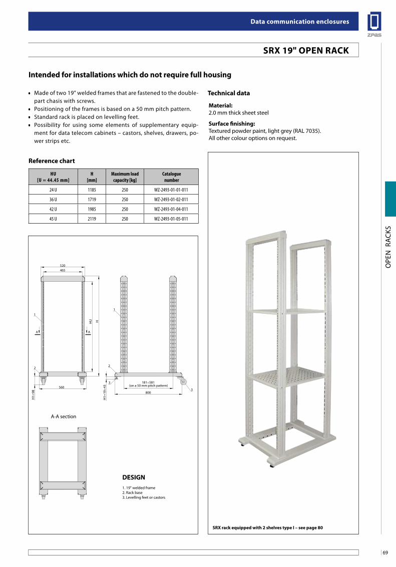
69
Data communication enclosures
OPE
N R
ACK
S560
800
HU
520465
H1=
98
1
3
H
1
3
A A
22
181÷581 (on a 50 mm pitch pattern)
A-A section
H1=
19÷4
3
intended for installations which do not require full housing
• Made of two 19" welded frames that are fastened to the double-part chasis with screws.
• Positioning of the frames is based on a 50 mm pitch pattern.• Standard rack is placed on levelling feet.• Possibility for using some elements of supplementary equip-
ment for data telecom cabinets – castors, shelves, drawers, po-wer strips etc.
HU[U = 44.45 mm]
H[mm]
Maximum load capacity [kg]
Cataloguenumber
24 U 1185 250 WZ-2493-01-01-011
36 U 1719 250 WZ-2493-01-02-011
42 U 1985 250 WZ-2493-01-04-011
45 U 2119 250 WZ-2493-01-05-011
Reference chart
Technical data
Material:2.0 mm thick sheet steel
surface finishing:Textured powder paint, light grey (RAL 7035).All other colour options on request.
Design1. 19" welded frame2. Rack base3. Levelling feet or castors
sRx rack equipped with 2 shelves type i – see page 80
sRx 19" oPen RaCK
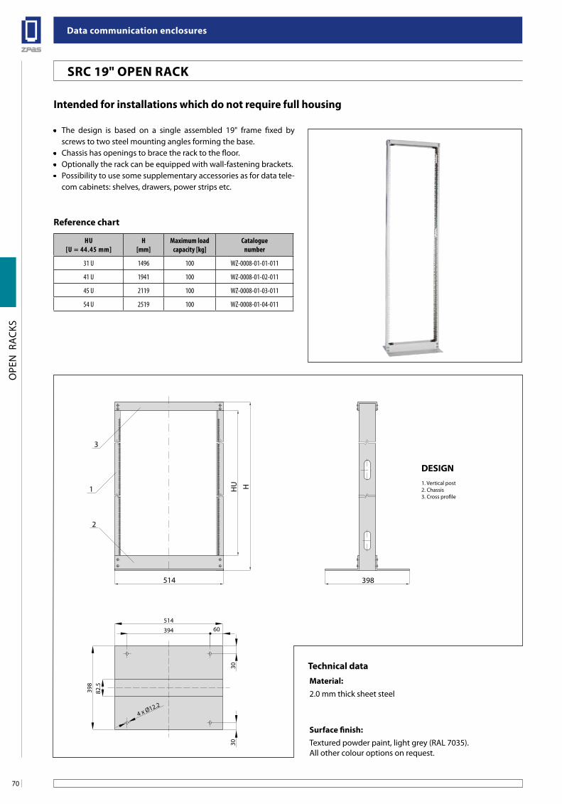
Data communication enclosures
70
OPE
N R
ACK
S
3
2
514
1 HHU
398
82.5
3030
394
4 x Ø12.2
398
51460
HU[U = 44.45 mm]
H[mm]
Maximum load capacity [kg]
Cataloguenumber
31 U 1496 100 WZ-0008-01-01-011
41 U 1941 100 WZ-0008-01-02-011
45 U 2119 100 WZ-0008-01-03-011
54 U 2519 100 WZ-0008-01-04-011
Reference chart
intended for installations which do not require full housing
• The design is based on a single assembled 19" frame fixed by screws to two steel mounting angles forming the base.
• Chassis has openings to brace the rack to the floor.• Optionally the rack can be equipped with wall-fastening brackets.• Possibility to use some supplementary accessories as for data tele-
com cabinets: shelves, drawers, power strips etc.
Design1. Vertical post2. Chassis3. Cross profile
Technical dataMaterial:2.0 mm thick sheet steel
surface finish:Textured powder paint, light grey (RAL 7035).All other colour options on request.
sRC 19" oPen RaCK
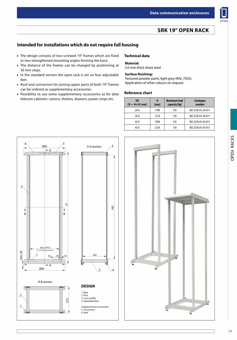
71
Data communication enclosures
OPE
N R
ACK
S
H
HU
515
5800
A
A800
max 574.5(on a 50 mm pitch pattern)
465505050
min
. 24
BB
2
6
1
3
B-B section
A-A section
43
1
3
stojak sRx wyposażony w 2 półki typu i - patrz str. 64
intended for installations which do not require full housing
• The design consists of two screwed 19" frames which are fixed to two strengthened mounting angles forming the base.
• The distance of the frames can be changed by positioning at 50 mm steps.
• In the standard version the open rack is set on four adjustable feet.
• Roof and connectors for joining upper parts of both 19" frames can be ordered as supplementary accessories.
• Possibility to use some supplementary accessories as for data telecom cabinets: castors, shelves, drawers, power strips etc. HU
[U = 44.45 mm]H
[mm]Maximum load
capacity [kg]Catalogue
number
24 U 1190 110 WZ-2378-01-24-011
36 U 1724 110 WZ-2378-01-36-011
42 U 1990 110 WZ-2378-01-42-011
45 U 2124 110 WZ-2378-01-45-011
Reference chart
Technical data
Material:2.0 mm thick sheet steel
surface finishing:Textured powder paint, light grey (RAL 7035).Application of other colours on request.
Design1. Base2. Post3. Cross profile4. Adjustable feet
Supplementary accessories:5. Connectors6. Roof
sRK 19" oPen RaCK
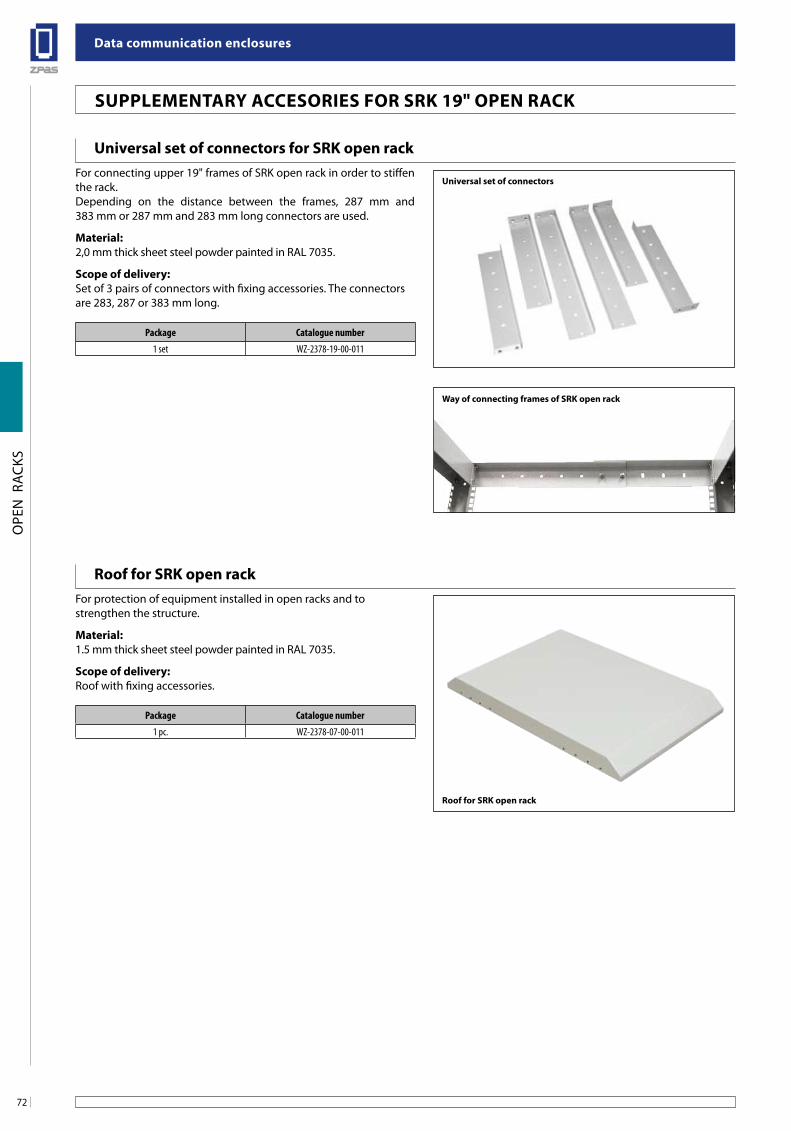
Data communication enclosures
72
OPE
N R
ACK
S
Poprzeczka pozioma do mocowania kabli
suPPleMenTaRY aCCesoRies foR sRK 19" oPen RaCK
universal set of connectors for sRK open rack
Roof for sRK open rack
For connecting upper 19" frames of SRK open rack in order to stiffen the rack.Depending on the distance between the frames, 287 mm and 383 mm or 287 mm and 283 mm long connectors are used.
Material:2,0 mm thick sheet steel powder painted in RAL 7035.
scope of delivery:Set of 3 pairs of connectors with fixing accessories. The connectors are 283, 287 or 383 mm long.
For protection of equipment installed in open racks and tostrengthen the structure.
Material:1.5 mm thick sheet steel powder painted in RAL 7035.
scope of delivery:Roof with fixing accessories.
Package Catalogue number
1 set WZ-2378-19-00-011
Package Catalogue number
1 pc. WZ-2378-07-00-011
Way of connecting frames of sRK open rack
Roof for sRK open rack
universal set of connectors
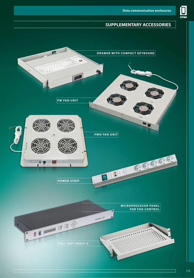
73
Data communication enclosures
SUPP
LEM
ENTA
RY A
CCES
SORI
ES
D R aW e R W i T H Co M PaC T K e Y b o a R D
P W D fa n u n i T
P W fa n u n i T
P o W e R s T R i P
M i C R o P R o C e s o R Pa n e lf o R fa n Co n T R o l
P u l l - o u T s H e l f i i
suPPleMenTaRY aCCessoRies
Data communication enclosures
73
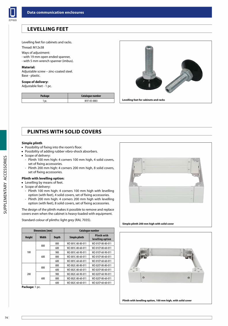
Data communication enclosures
74
SUPP
LEM
ENTA
RY A
CCES
SORI
ES
Dimensions [mm] Catalogue number
Height Width Depth Simple plinth Plinth with levelling option
100
800800 WZ-001C-80-80-011 WZ-01CP-80-80-011600 WZ-001C-80-60-011 WZ-01CP-80-60-011
600900 WZ-001C-60-90-011 WZ-01CP-60-90-011800 WZ-001C-80-60-011 WZ-01CP-80-60-011600 WZ-001C-60-60-011 WZ-01CP-60-60-011
200
800800 WZ-002C-80-80-011 WZ-02CP-80-80-011600 WZ-002C-80-60-011 WZ-02CP-80-60-011
600900 WZ-002C-60-90-011 WZ-02CP-60-90-011800 WZ-002C-80-60-011 WZ-02CP-80-60-011600 WZ-002C-60-60-011 WZ-02CP-60-60-011
Package: 1 pc.
simple plinth• Possibility of fixing into the room’s floor.• Possibility of adding rubber vibro-shock absorbers.• Scope of delivery:
- Plinth 100 mm high: 4 corners 100 mm high, 4 solid covers, set of fixing accessories.
- Plinth 200 mm high: 4 corners 200 mm high, 8 solid covers, set of fixing accessories.
Plinth with levelling option:• Levelling by means of feet.• Scope of delivery:
- Plinth 100 mm high: 4 corners 100 mm high with levelling option (with feet), 4 solid covers, set of fixing accessories.
- Plinth 200 mm high: 4 corners 200 mm high with levelling option (with feet), 8 solid covers, set of fixing accessories.
The design of the plinth makes it possible to remove and replace covers even when the cabinet is heavy-loaded with equipment.
Standard colour of plinths: light grey (RAL 7035).
Plinth with levelling option, 100 mm high, with solid cover
simple plinth 200 mm high with solid cover
levelling feet for cabinets and racks
Levelling feet for cabinets and racks.
Thread: M12x38
Ways of adjustment:- with 19 mm open ended spanner,- with 5 mm wrench spanner (imbus).
Material:Adjustable screw – zinc-coated steel.Base - plastic.
scope of delivery: Adjustable feet - 1 pc.
Package Catalogue number
1 pc. M1F-05-0003
leVelling feeT
PlinTHs WiTH soliD CoVeRs
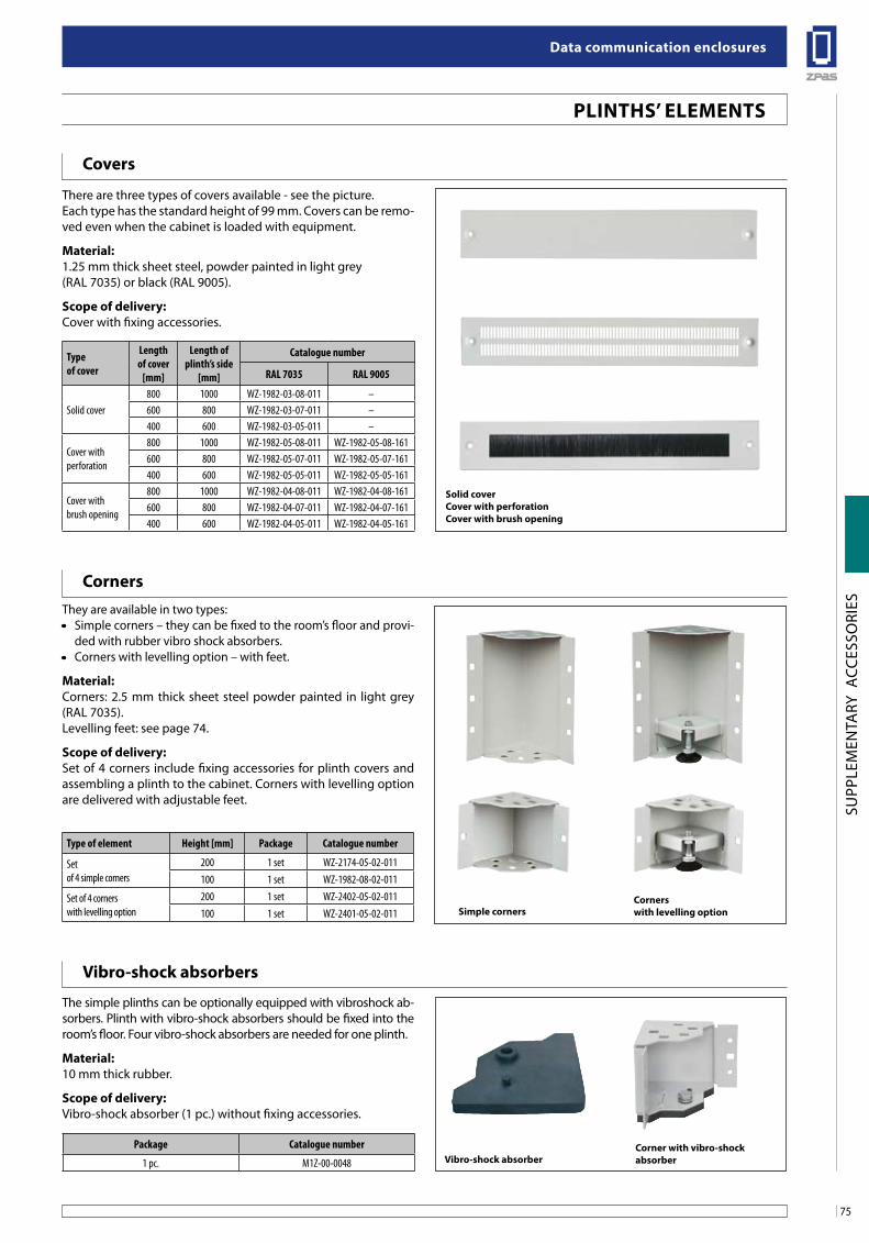
75
Data communication enclosures
SUPP
LEM
ENTA
RY A
CCES
SORI
ES
PlinTHs’ eleMenTs
solid coverCover with perforationCover with brush opening
simple corners
Covers
Corners
Corners with levelling option
Vibro-shock absorbers
Vibro-shock absorberCorner with vibro-shock absorber
There are three types of covers available - see the picture.Each type has the standard height of 99 mm. Covers can be remo-ved even when the cabinet is loaded with equipment.
Material: 1.25 mm thick sheet steel, powder painted in light grey(RAL 7035) or black (RAL 9005).
scope of delivery: Cover with fixing accessories.
Type of cover
Length of cover
[mm]
Length of plinth’s side
[mm]
Catalogue number
RAL 7035 RAL 9005
Solid cover800 1000 WZ-1982-03-08-011 –600 800 WZ-1982-03-07-011 –400 600 WZ-1982-03-05-011 –
Cover with perforation
800 1000 WZ-1982-05-08-011 WZ-1982-05-08-161600 800 WZ-1982-05-07-011 WZ-1982-05-07-161400 600 WZ-1982-05-05-011 WZ-1982-05-05-161
Cover with brush opening
800 1000 WZ-1982-04-08-011 WZ-1982-04-08-161600 800 WZ-1982-04-07-011 WZ-1982-04-07-161400 600 WZ-1982-04-05-011 WZ-1982-04-05-161
They are available in two types:• Simple corners – they can be fixed to the room’s floor and provi-
ded with rubber vibro shock absorbers.• Corners with levelling option – with feet.
Material: Corners: 2.5 mm thick sheet steel powder painted in light grey (RAL 7035).Levelling feet: see page 74.
scope of delivery:Set of 4 corners include fixing accessories for plinth covers and assembling a plinth to the cabinet. Corners with levelling option are delivered with adjustable feet.
Type of element Height [mm] Package Catalogue number
Set of 4 simple corners
200 1 set WZ-2174-05-02-011100 1 set WZ-1982-08-02-011
Set of 4 corners with levelling option
200 1 set WZ-2402-05-02-011100 1 set WZ-2401-05-02-011
The simple plinths can be optionally equipped with vibroshock ab-sorbers. Plinth with vibro-shock absorbers should be fixed into the room’s floor. Four vibro-shock absorbers are needed for one plinth.
Material:10 mm thick rubber.
scope of delivery:Vibro-shock absorber (1 pc.) without fixing accessories.
Package Catalogue number
1 pc. M1Z-00-0048
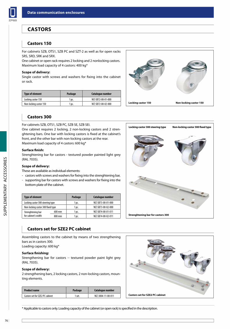
Data communication enclosures
76
SUPP
LEM
ENTA
RY A
CCES
SORI
ES
Castors 150
For cabinets SZB, OTS1, SZB PC and SZT-2 as well as for open racks SRS, SRD, SRK and SRX.One cabinet or open rack requires 2 locking and 2 nonlocking castors.Maximum load capacity of 4 castors: 400 kg*
scope of delivery:Single castor with screws and washers for fixing into the cabinet or rack.
Castors 300
For cabinets SZB, OTS1, SZB PC, SZB SE, SZB SEI.One cabinet requires 2 locking, 2 non-locking castors and 2 stren-ghtening bars. One bar with locking castors is fixed at the cabinet’s front, and the other bar with non-locking castors at the rear.Maximum load capacity of 4 castors: 600 kg*
surface finish:Strenghtening bar for castors - textured powder painted light grey (RAL 7035).
scope of delivery:These are available as individual elements:- castors with screws and washers for fixing into the strenghtening bar,- supporting bar for castors with screws and washers for fixing into the
bottom plate of the cabinet.
locking castor 150 non-locking castor 150
strenghtening bar for castors 300
non-locking castor 300 fixed type
Type of element Package Catalogue number
Locking castor 150 1 pc. WZ-SB72-00-01-000Non-locking castor 150 1 pc. WZ-SB72-00-02-000
Type of element Package Catalogue number
Locking castor 300 steering type 1 pc. WZ-SB73-00-01-000Non-locking castor 300 fixed type 1 pc. WZ-SB73-00-02-000
Strenghtening barfor cabinet’s width
600 mm 1 pc. WZ-SB74-00-01-011800 mm 1 pc. WZ-SB74-00-02-011
Castors set for sZe2 PC cabinet
Assembling castors to the cabinet by means of two strengthening bars as in castors 300.Loading capacity: 600 kg*
surface finishing:Strengthening bar for castors -- textured powder paint light grey (RAL 7035).
scope of delivery:2 strengthening bars, 2 locking castors, 2 non-locking castors, moun-ting elements.
* Applicable to castors only. Loading capacity of the cabinet (or open rack) is specified in the description.
Product name Package Catalogue number
Castors set for SZE2 PC cabinet 1 set. WZ-3004-11-00-011
locking castor 300 steering type
Castors set for sZe2 PC cabinet
CasToRs
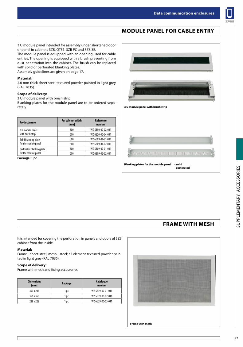
77
Data communication enclosures
SUPP
LEM
ENTA
RY A
CCES
SORI
ES
MoDule Panel foR Cable enTRY
3 U module panel intended for assembly under shortened door or panel in cabinets SZB, OTS1, SZB PC and SZB SE. The module panel is equipped with an opening used for cable entries. The opening is equipped with a brush preventing from dust penetration into the cabinet. The brush can be replaced with solid or perforated blanking plates.Assembly guidelines are given on page 17.
Material:2.0 mm thick sheet steel textured powder painted in light grey (RAL 7035).
scope of delivery:3 U module panel with brush strip.Blanking plates for the module panel are to be ordered sepa-rately.
blanking plates for the module panel - solid - perforated
Product name For cabinet width[mm]
Referencenumber
3 U module panel with brush strip
800 WZ-SB50-00-02-011600 WZ-SB50-00-04-011
Solid blanking plate for the module panel
800 WZ-SB09-01-01-011600 WZ-SB09-01-02-011
Perforated blanking platefor the module panel
800 WZ-SB09-02-01-011600 WZ-SB09-02-02-011
Package: 1 pc.
3 u module panel with brush strip
It is intended for covering the perforation in panels and doors of SZB cabinet from the inside.
Material:Frame - sheet steel, mesh - steel; all element textured powder pain-ted in light grey (RAL 7035).
scope of delivery:Frame with mesh and fixing accessories.
frame with mesh
Dimensions[mm] Package Catalogue
number
459 x 245 1 pc. WZ-SB39-00-01-011
356 x 350 1 pc. WZ-SB39-00-02-011
228 x 222 1 pc. WZ-SB39-00-03-011
fRaMe WiTH MesH
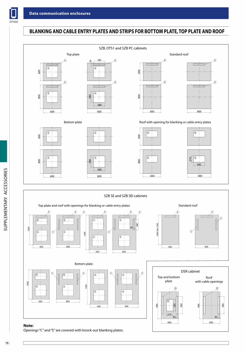
Data communication enclosures
78
SUPP
LEM
ENTA
RY A
CCES
SORI
ES
SZB, OTS1 and SZB PC cabinets
SZB SE and SZB SEI cabinets
DSR cabinet
800
800
600
380
380
600
A
E
A
A A
E
E
E
380
50
800
800
600
380
380
600
A A
A A
800
800
600
600
E
E
E
E
800
800
600
380
210
600
B B
B B
600 800
1000
B B
A A
CC
600 800
1200
A
A
A
ACC
600 800
1000
lub
1200
E
C
E
C
600 800
1000
B B
A A
CE
600
1200
A
A
A
A
EE
C
800
40
380
C
C
E
600
900
380
580
D
21040
B
600
900
580
D
40
Top and bottomplate
Standard roof
Roof with opening for blanking or cable entry plates
Bottom plate
Standard roofTop plate and roof with openings for blanking or cable entry plates
Roofwith cable openings
Top plate
Bottom plate
blanKing anD Cable enTRY PlaTes anD sTRiPs foR boTToM PlaTe, ToP PlaTe anD Roof
note:Openings ‘‘C’’ and ‘‘E’’ are covered with knock-out blanking plates.
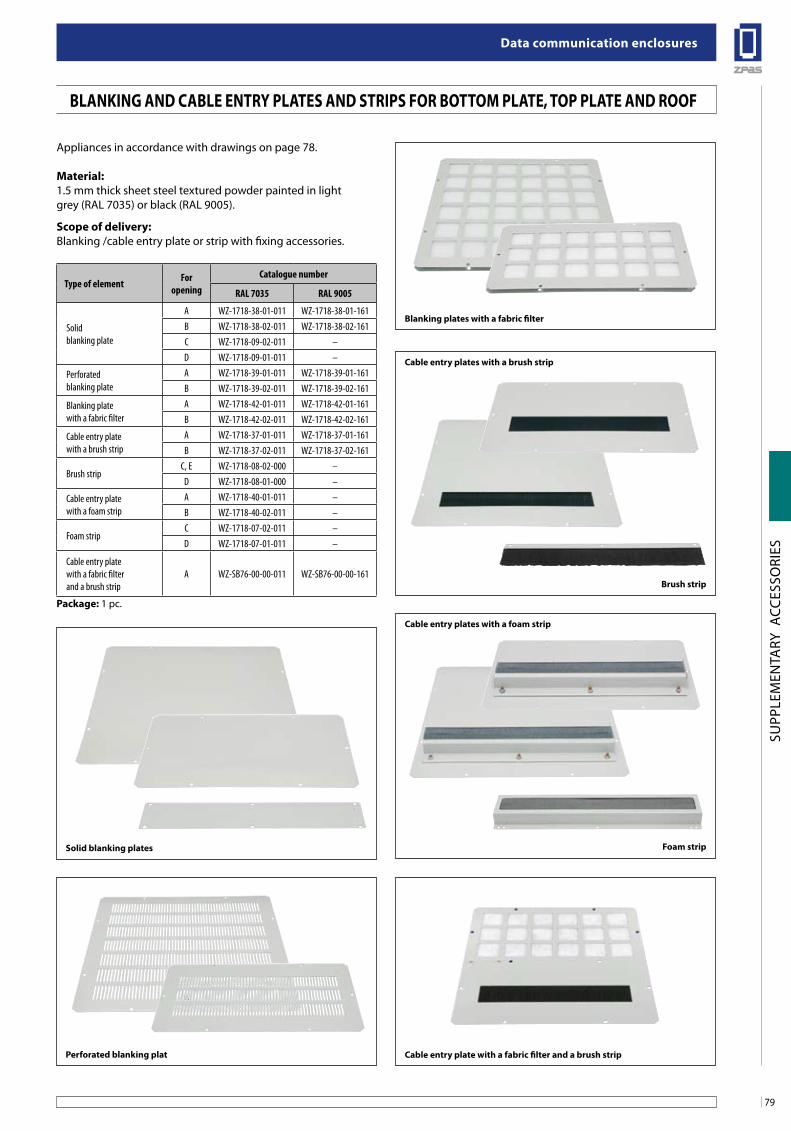
79
Data communication enclosures
SUPP
LEM
ENTA
RY A
CCES
SORI
ES
Appliances in accordance with drawings on page 78.
Material:1.5 mm thick sheet steel textured powder painted in lightgrey (RAL 7035) or black (RAL 9005).
scope of delivery:Blanking /cable entry plate or strip with fixing accessories.
Type of element For opening
Catalogue number
RAL 7035 RAL 9005
Solid blanking plate
A WZ-1718-38-01-011 WZ-1718-38-01-161B WZ-1718-38-02-011 WZ-1718-38-02-161C WZ-1718-09-02-011 –D WZ-1718-09-01-011 –
Perforated blanking plate
A WZ-1718-39-01-011 WZ-1718-39-01-161B WZ-1718-39-02-011 WZ-1718-39-02-161
Blanking plate with a fabric filter
A WZ-1718-42-01-011 WZ-1718-42-01-161B WZ-1718-42-02-011 WZ-1718-42-02-161
Cable entry plate with a brush strip
A WZ-1718-37-01-011 WZ-1718-37-01-161B WZ-1718-37-02-011 WZ-1718-37-02-161
Brush stripC, E WZ-1718-08-02-000 –
D WZ-1718-08-01-000 –
Cable entry plate with a foam strip
A WZ-1718-40-01-011 –B WZ-1718-40-02-011 –
Foam stripC WZ-1718-07-02-011 –D WZ-1718-07-01-011 –
Cable entry plate with a fabric filter and a brush strip
A WZ-SB76-00-00-011 WZ-SB76-00-00-161
Package: 1 pc.
Cable entry plate with a fabric filter and a brush stripPerforated blanking plat
blanking plates with a fabric filter
solid blanking plates foam strip
Cable entry plates with a foam strip
brush strip
Cable entry plates with a brush strip
blanKing anD Cable enTRY PlaTes anD sTRiPs foR boTToM PlaTe, ToP PlaTe anD Roof
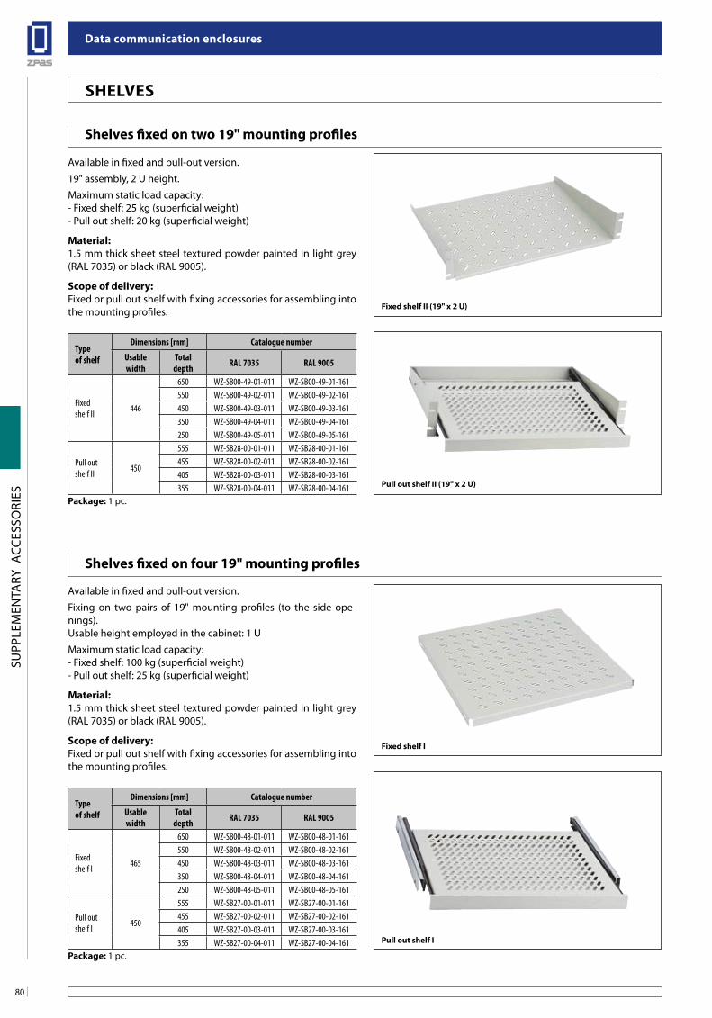
Data communication enclosures
80
SUPP
LEM
ENTA
RY A
CCES
SORI
ES
sHelVes
Pull out shelf ii (19" x 2 u)
fixed shelf i
fixed shelf ii (19" x 2 u)
Pull out shelf i
shelves fixed on two 19" mounting profiles
shelves fixed on four 19" mounting profiles
Available in fixed and pull-out version.
19" assembly, 2 U height.
Maximum static load capacity:- Fixed shelf: 25 kg (superficial weight)- Pull out shelf: 20 kg (superficial weight)
Material:1.5 mm thick sheet steel textured powder painted in light grey (RAL 7035) or black (RAL 9005).
scope of delivery:Fixed or pull out shelf with fixing accessories for assembling into the mounting profiles.
Type of shelf
Dimensions [mm] Catalogue number
Usable width
Totaldepth RAL 7035 RAL 9005
Fixed shelf II 446
650 WZ-SB00-49-01-011 WZ-SB00-49-01-161550 WZ-SB00-49-02-011 WZ-SB00-49-02-161450 WZ-SB00-49-03-011 WZ-SB00-49-03-161350 WZ-SB00-49-04-011 WZ-SB00-49-04-161250 WZ-SB00-49-05-011 WZ-SB00-49-05-161
Pull out shelf II 450
555 WZ-SB28-00-01-011 WZ-SB28-00-01-161455 WZ-SB28-00-02-011 WZ-SB28-00-02-161405 WZ-SB28-00-03-011 WZ-SB28-00-03-161355 WZ-SB28-00-04-011 WZ-SB28-00-04-161
Package: 1 pc.
Type of shelf
Dimensions [mm] Catalogue number
Usable width
Totaldepth RAL 7035 RAL 9005
Fixed shelf I 465
650 WZ-SB00-48-01-011 WZ-SB00-48-01-161550 WZ-SB00-48-02-011 WZ-SB00-48-02-161450 WZ-SB00-48-03-011 WZ-SB00-48-03-161350 WZ-SB00-48-04-011 WZ-SB00-48-04-161250 WZ-SB00-48-05-011 WZ-SB00-48-05-161
Pull out shelf I 450
555 WZ-SB27-00-01-011 WZ-SB27-00-01-161455 WZ-SB27-00-02-011 WZ-SB27-00-02-161405 WZ-SB27-00-03-011 WZ-SB27-00-03-161355 WZ-SB27-00-04-011 WZ-SB27-00-04-161
Package: 1 pc.
Available in fixed and pull-out version.
Fixing on two pairs of 19" mounting profiles (to the side ope-nings).Usable height employed in the cabinet: 1 U
Maximum static load capacity:- Fixed shelf: 100 kg (superficial weight)- Pull out shelf: 25 kg (superficial weight)
Material:1.5 mm thick sheet steel textured powder painted in light grey (RAL 7035) or black (RAL 9005).
scope of delivery: Fixed or pull out shelf with fixing accessories for assembling into the mounting profiles.
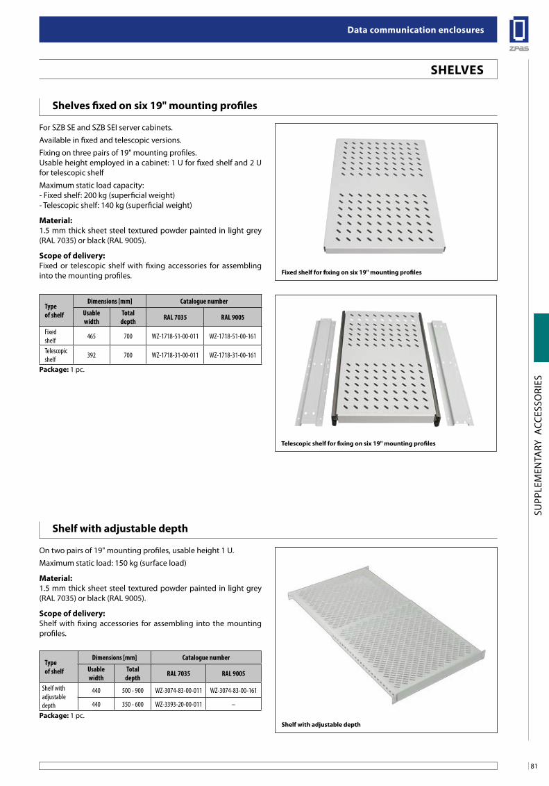
81
Data communication enclosures
SUPP
LEM
ENTA
RY A
CCES
SORI
ES
shelves fixed on six 19" mounting profiles
For SZB SE and SZB SEI server cabinets.
Available in fixed and telescopic versions.
Fixing on three pairs of 19" mounting profiles.Usable height employed in a cabinet: 1 U for fixed shelf and 2 U for telescopic shelf
Maximum static load capacity:- Fixed shelf: 200 kg (superficial weight)- Telescopic shelf: 140 kg (superficial weight)
Material:1.5 mm thick sheet steel textured powder painted in light grey (RAL 7035) or black (RAL 9005).
scope of delivery:Fixed or telescopic shelf with fixing accessories for assembling into the mounting profiles. fixed shelf for fixing on six 19" mounting profiles
Telescopic shelf for fixing on six 19" mounting profiles
shelf with adjustable depth
On two pairs of 19" mounting profiles, usable height 1 U.
Maximum static load: 150 kg (surface load)
Material:1.5 mm thick sheet steel textured powder painted in light grey (RAL 7035) or black (RAL 9005).
scope of delivery:Shelf with fixing accessories for assembling into the mounting profiles.
shelf with adjustable depth
sHelVes
Type of shelf
Dimensions [mm] Catalogue number
Usable width
Totaldepth RAL 7035 RAL 9005
Fixedshelf 465 700 WZ-1718-51-00-011 WZ-1718-51-00-161
Telescopic shelf 392 700 WZ-1718-31-00-011 WZ-1718-31-00-161
Package: 1 pc.
Type of shelf
Dimensions [mm] Catalogue number
Usable width
Totaldepth RAL 7035 RAL 9005
Shelf with adjustable depth
440 500 - 900 WZ-3074-83-00-011 WZ-3074-83-00-161
440 350 - 600 WZ-3393-20-00-011 –
Package: 1 pc.
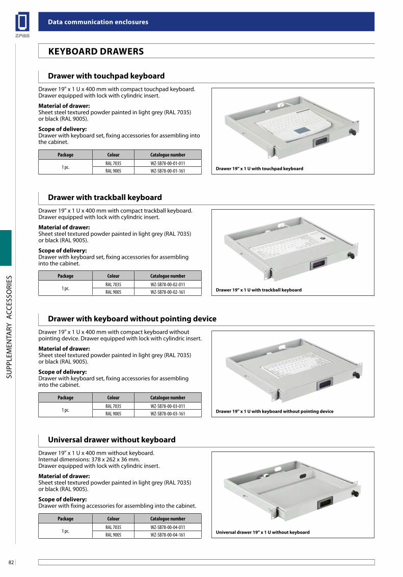
Data communication enclosures
82
SUPP
LEM
ENTA
RY A
CCES
SORI
ES
Drawer with touchpad keyboardDrawer 19" x 1 U x 400 mm with compact touchpad keyboard.Drawer equipped with lock with cylindric insert.
Material of drawer:Sheet steel textured powder painted in light grey (RAL 7035) or black (RAL 9005).
scope of delivery:Drawer with keyboard set, fixing accessories for assembling into the cabinet.
Package Colour Catalogue number
1 pc.RAL 7035 WZ-SB78-00-01-011RAL 9005 WZ-SB78-00-01-161
Package Colour Catalogue number
1 pc.RAL 7035 WZ-SB78-00-02-011RAL 9005 WZ-SB78-00-02-161
Package Colour Catalogue number
1 pc.RAL 7035 WZ-SB78-00-03-011RAL 9005 WZ-SB78-00-03-161
Package Colour Catalogue number
1 pc.RAL 7035 WZ-SB78-00-04-011RAL 9005 WZ-SB78-00-04-161
Drawer with trackball keyboardDrawer 19" x 1 U x 400 mm with compact trackball keyboard.Drawer equipped with lock with cylindric insert.
Material of drawer:Sheet steel textured powder painted in light grey (RAL 7035) or black (RAL 9005).
scope of delivery:Drawer with keyboard set, fixing accessories for assemblinginto the cabinet.
Drawer with keyboard without pointing deviceDrawer 19" x 1 U x 400 mm with compact keyboard without pointing device. Drawer equipped with lock with cylindric insert.
Material of drawer:Sheet steel textured powder painted in light grey (RAL 7035) or black (RAL 9005).
scope of delivery:Drawer with keyboard set, fixing accessories for assemblinginto the cabinet.
universal drawer without keyboardDrawer 19" x 1 U x 400 mm without keyboard.Internal dimensions: 378 x 262 x 36 mm.Drawer equipped with lock with cylindric insert.
Material of drawer:Sheet steel textured powder painted in light grey (RAL 7035) or black (RAL 9005).
scope of delivery:Drawer with fixing accessories for assembling into the cabinet.
Drawer 19" x 1 u with touchpad keyboard
Drawer 19" x 1 u with trackball keyboard
Drawer 19" x 1 u with keyboard without pointing device
universal drawer 19" x 1 u without keyboard
KeYboaRD DRaWeRs
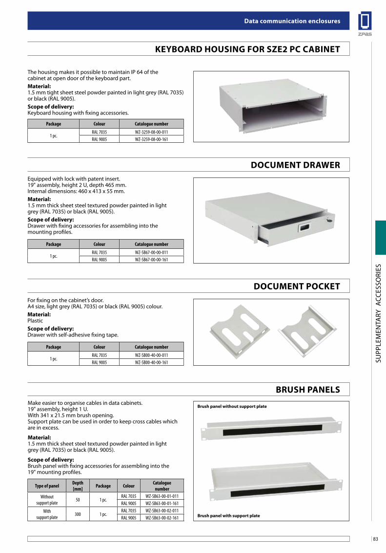
83
Data communication enclosures
SUPP
LEM
ENTA
RY A
CCES
SORI
ES
Package Colour Catalogue number
1 pc.RAL 7035 WZ-3259-08-00-011RAL 9005 WZ-3259-08-00-161
Package Colour Catalogue number
1 pc.RAL 7035 WZ-SB67-00-00-011RAL 9005 WZ-SB67-00-00-161
Package Colour Catalogue number
1 pc.RAL 7035 WZ-SB00-40-00-011RAL 9005 WZ-SB00-40-00-161
KeYboaRD Housing foR sZe2 PC CabineT
Make easier to organise cables in data cabinets.19" assembly, height 1 U.With 341 x 21.5 mm brush opening.Support plate can be used in order to keep cross cables which are in excess.
Material:1.5 mm thick sheet steel textured powder painted in lightgrey (RAL 7035) or black (RAL 9005).
scope of delivery:Brush panel with fixing accessories for assembling into the19" mounting profiles.
Type of panel Depth[mm] Package Colour Catalogue
numberWithout
support plate 50 1 pc.RAL 7035 WZ-SB63-00-01-011RAL 9005 WZ-SB63-00-01-161
With support plate 300 1 pc.
RAL 7035 WZ-SB63-00-02-011RAL 9005 WZ-SB63-00-02-161 brush panel with support plate
brush panel without support plate
Equipped with lock with patent insert.19" assembly, height 2 U, depth 465 mm.Internal dimensions: 460 x 413 x 55 mm.Material:1.5 mm thick sheet steel textured powder painted in lightgrey (RAL 7035) or black (RAL 9005).scope of delivery:Drawer with fixing accessories for assembling into themounting profiles.
The housing makes it possible to maintain IP 64 of thecabinet at open door of the keyboard part.Material:1.5 mm tight sheet steel powder painted in light grey (RAL 7035) or black (RAL 9005).scope of delivery:Keyboard housing with fixing accessories.
For fixing on the cabinet’s door.A4 size, light grey (RAL 7035) or black (RAL 9005) colour.Material:Plasticscope of delivery:Drawer with self-adhesive fixing tape.
bRusH Panels
DoCuMenT PoCKeT
DoCuMenT DRaWeR
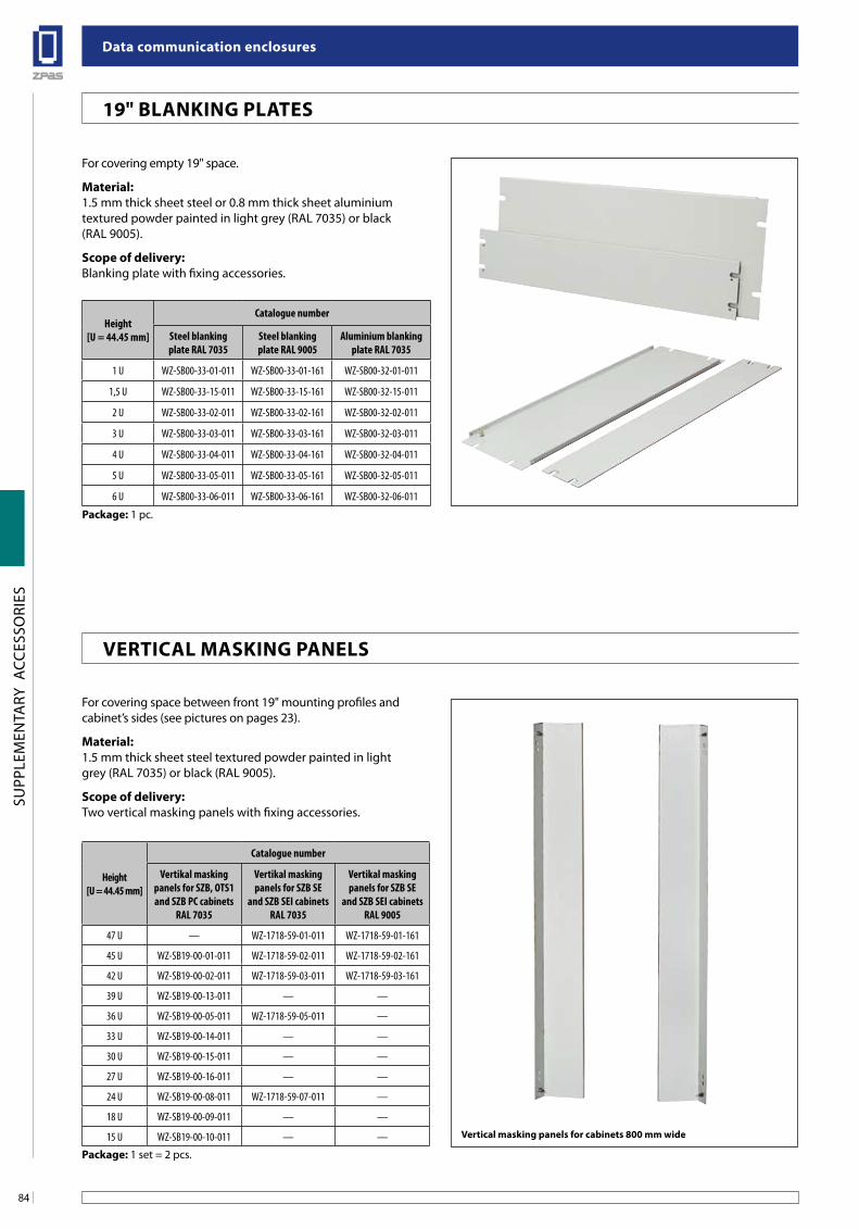
Data communication enclosures
84
SUPP
LEM
ENTA
RY A
CCES
SORI
ES
Height[U = 44.45 mm]
Catalogue number
Steel blanking plate RAL 7035
Steel blanking plate RAL 9005
Aluminium blanking plate RAL 7035
1 U WZ-SB00-33-01-011 WZ-SB00-33-01-161 WZ-SB00-32-01-011
1,5 U WZ-SB00-33-15-011 WZ-SB00-33-15-161 WZ-SB00-32-15-011
2 U WZ-SB00-33-02-011 WZ-SB00-33-02-161 WZ-SB00-32-02-011
3 U WZ-SB00-33-03-011 WZ-SB00-33-03-161 WZ-SB00-32-03-011
4 U WZ-SB00-33-04-011 WZ-SB00-33-04-161 WZ-SB00-32-04-011
5 U WZ-SB00-33-05-011 WZ-SB00-33-05-161 WZ-SB00-32-05-011
6 U WZ-SB00-33-06-011 WZ-SB00-33-06-161 WZ-SB00-32-06-011
Package: 1 pc.
For covering empty 19" space.
Material:1.5 mm thick sheet steel or 0.8 mm thick sheet aluminiumtextured powder painted in light grey (RAL 7035) or black(RAL 9005).
scope of delivery:Blanking plate with fixing accessories.
For covering space between front 19" mounting profiles and cabinet’s sides (see pictures on pages 23).
Material:1.5 mm thick sheet steel textured powder painted in lightgrey (RAL 7035) or black (RAL 9005).
scope of delivery:Two vertical masking panels with fixing accessories.
Vertical masking panels for cabinets 800 mm wide
19" blanKing PlaTes
VeRTiCal MasKing Panels
Height[U = 44.45 mm]
Catalogue number
Vertikal masking panels for SZB, OTS1 and SZB PC cabinets
RAL 7035
Vertikal masking panels for SZB SE
and SZB SEI cabinetsRAL 7035
Vertikal masking panels for SZB SE
and SZB SEI cabinetsRAL 9005
47 U — WZ-1718-59-01-011 WZ-1718-59-01-161
45 U WZ-SB19-00-01-011 WZ-1718-59-02-011 WZ-1718-59-02-161
42 U WZ-SB19-00-02-011 WZ-1718-59-03-011 WZ-1718-59-03-161
39 U WZ-SB19-00-13-011 — —
36 U WZ-SB19-00-05-011 WZ-1718-59-05-011 —
33 U WZ-SB19-00-14-011 — —
30 U WZ-SB19-00-15-011 — —
27 U WZ-SB19-00-16-011 — —
24 U WZ-SB19-00-08-011 WZ-1718-59-07-011 —
18 U WZ-SB19-00-09-011 — —
15 U WZ-SB19-00-10-011 — —
Package: 1 set = 2 pcs.
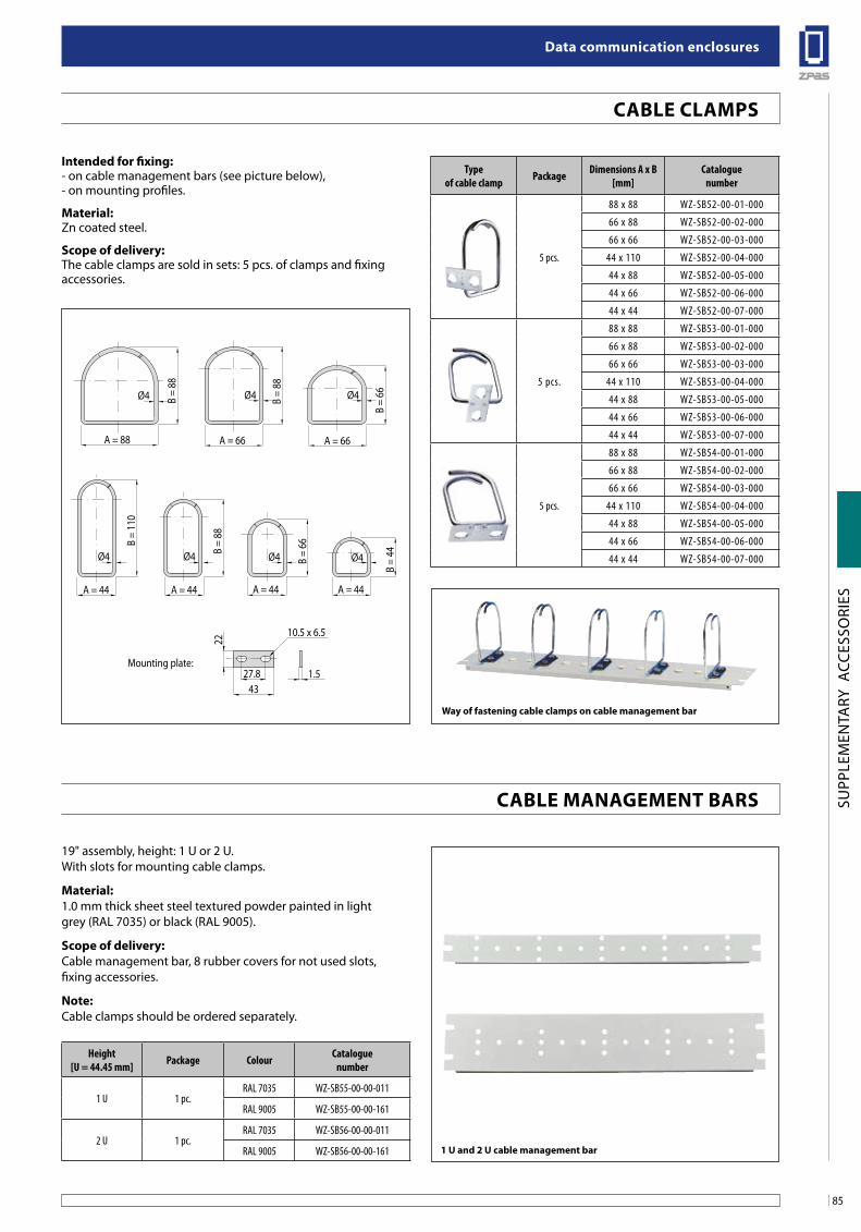
85
Data communication enclosures
SUPP
LEM
ENTA
RY A
CCES
SORI
ES
Type of cable clamp Package Dimensions A x B
[mm]Catalogue
number
5 pcs.
88 x 88 WZ-SB52-00-01-000
66 x 88 WZ-SB52-00-02-000
66 x 66 WZ-SB52-00-03-000
44 x 110 WZ-SB52-00-04-000
44 x 88 WZ-SB52-00-05-000
44 x 66 WZ-SB52-00-06-000
44 x 44 WZ-SB52-00-07-000
5 pcs.
88 x 88 WZ-SB53-00-01-000
66 x 88 WZ-SB53-00-02-000
66 x 66 WZ-SB53-00-03-000
44 x 110 WZ-SB53-00-04-000
44 x 88 WZ-SB53-00-05-000
44 x 66 WZ-SB53-00-06-000
44 x 44 WZ-SB53-00-07-000
5 pcs.
88 x 88 WZ-SB54-00-01-000
66 x 88 WZ-SB54-00-02-000
66 x 66 WZ-SB54-00-03-000
44 x 110 WZ-SB54-00-04-000
44 x 88 WZ-SB54-00-05-000
44 x 66 WZ-SB54-00-06-000
44 x 44 WZ-SB54-00-07-000
intended for fixing:- on cable management bars (see picture below),- on mounting profiles.
Material:Zn coated steel.
scope of delivery:The cable clamps are sold in sets: 5 pcs. of clamps and fixing accessories.
19" assembly, height: 1 U or 2 U.With slots for mounting cable clamps.
Material:1.0 mm thick sheet steel textured powder painted in lightgrey (RAL 7035) or black (RAL 9005).
scope of delivery:Cable management bar, 8 rubber covers for not used slots,fixing accessories.
note:Cable clamps should be ordered separately.
Ø4 Ø4 Ø4
A = 88
B =
88
B =
88
B =
110
B =
88
B =
66
B =
44B
= 66
A = 66 A = 66
Ø4 Ø4 Ø4 Ø4
A = 44 A = 44
27.8 1.543
A = 44 A = 44
10.5 x 6.5
Mounting plate:
22
Way of fastening cable clamps on cable management bar
1 u and 2 u cable management bar
Height[U = 44.45 mm] Package Colour Catalogue
number
1 U 1 pc.RAL 7035 WZ-SB55-00-00-011
RAL 9005 WZ-SB55-00-00-161
2 U 1 pc.RAL 7035 WZ-SB56-00-00-011
RAL 9005 WZ-SB56-00-00-161
Cable ClaMPs
Cable ManageMenT baRs
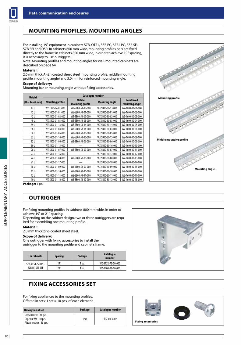
Data communication enclosures
86
SUPP
LEM
ENTA
RY A
CCES
SORI
ES
Height[U = 44.45 mm]
Catalogue number
Mounting profile Middle mounting profile Mounting angle Reinforced
mounting angle47 U WZ-1391-04-01-000 WZ-SB00-53-13-000 WZ-SB00-30-13-000 WZ-1600-30-01-00045 U WZ-SB00-01-01-000 WZ-SB00-53-01-000 WZ-SB00-30-01-000 WZ-1600-30-02-00042 U WZ-SB00-01-02-000 WZ-SB00-53-02-000 WZ-SB00-30-02-000 WZ-1600-30-03-00040 U WZ-SB00-01-03-000 WZ-SB00-53-03-000 WZ-SB00-30-03-000 WZ-1600-30-04-00039 U WZ-SB00-01-13-000 WZ-SB00-53-14-000 WZ-SB00-30-14-000 WZ-1600-30-05-00038 U WZ-SB00-01-04-000 WZ-SB00-53-04-000 WZ-SB00-30-04-000 WZ-1600-30-06-00036 U WZ-SB00-01-05-000 WZ-SB00-53-05-000 WZ-SB00-30-05-000 WZ-1600-30-07-00033 U WZ-SB00-01-14-000 WZ-SB00-53-15-000 WZ-SB00-30-15-000 WZ-1600-30-08-00032 U WZ-SB00-01-06-000 WZ-SB00-53-06-000 WZ-SB00-30-06-000 WZ-1600-30-09-00030 U WZ-SB00-01-15-000 — WZ-SB00-30-16-000 WZ-1600-30-10-00028 U WZ-SB00-01-07-000 WZ-SB00-53-07-000 WZ-SB00-30-07-000 WZ-1600-30-11-00027 U WZ-SB00-01-16-000 — WZ-SB00-30-17-000 WZ-1600-30-12-00024 U WZ-SB00-01-08-000 WZ-SB00-53-08-000 WZ-SB00-30-08-000 WZ-1600-30-13-00021 U WZ-SB00-01-17-000 — WZ-SB00-30-18-000 WZ-1600-30-14-00018 U WZ-SB00-01-09-000 WZ-SB00-53-09-000 WZ-SB00-30-09-000 WZ-1600-30-15-00015 U WZ-SB00-01-10-000 WZ-SB00-53-10-000 WZ-SB00-30-10-000 WZ-1600-30-16-00012 U WZ-SB00-01-11-000 WZ-SB00-53-11-000 WZ-SB00-30-11-000 WZ-1600-30-17-00010 U WZ-SB00-01-12-000 WZ-SB00-53-12-000 WZ-SB00-30-12-000 WZ-1600-30-18-000
Package: 1 pc.
For installing 19" equipment in cabinets SZB, OTS1, SZB PC, SZE2 PC, SZB SE, SZB SEI and DSR. In cabinets 600 mm wide, mounting profiles bars are fixed directly to the frame; in cabinets 800 mm wide, in order to achieve 19" spacing, it is necessary to use outriggers. Note: Mounting profiles and mounting angles for wall-mounted cabinets are described on page 64.Material:2.0 mm thick Al-Zn coated sheet steel (mounting profile, middle mounting profile, mounting angle) and 3.0 mm for reinforced mounting angle.scope of delivery:Mounting bar or mounting angle without fixing accessories.
For fixing mounting profiles in cabinets 800 mm wide, in order to achieve 19" or 21" spacing.Depending on the cabinet design, two or three outriggers are requ-ired for assembling one mounting profile.Material:2.0 mm thick zinc-coated sheet steel.scope of delivery:One outrigger with fixing accessories to install theoutrigger to the mounting profile and cabinet’s frame.
For cabinets Spacing Package Cataloguenumber
SZB, OTS1, SZB PC,SZB SE, SZB SEI
19" 1 pc. WZ-3752-72-00-000
21" 1 pc. WZ-1600-27-00-000
For fixing appliances to the mounting profiles.Offered in sets: 1 set = 10 pcs. of each element.
Description of set Package Catalogue number
Screw M6x16 - 10 pcs.Cage nut M6 - 10 pcs.Plastic washer - 10 pcs.
1 set T1Z-00-0002
Mounting profile
fixing accessories
Middle mounting profile
Mounting angle
MounTing PRofiles, MounTing angles
ouTRiggeR
fixing aCCessoRies seT
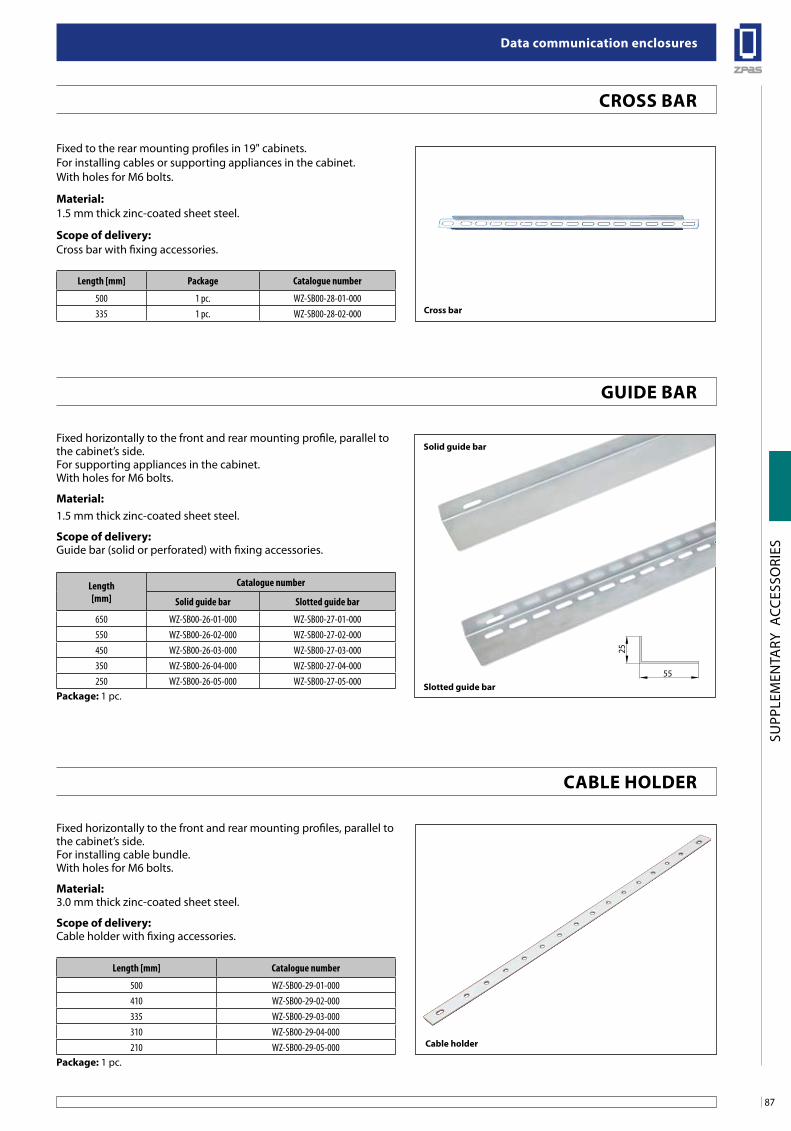
87
Data communication enclosures
SUPP
LEM
ENTA
RY A
CCES
SORI
ES
Fixed to the rear mounting profiles in 19" cabinets.For installing cables or supporting appliances in the cabinet.With holes for M6 bolts.
Material:1.5 mm thick zinc-coated sheet steel.
scope of delivery:Cross bar with fixing accessories.
Length [mm] Package Catalogue number
500 1 pc. WZ-SB00-28-01-000335 1 pc. WZ-SB00-28-02-000 Cross bar
Fixed horizontally to the front and rear mounting profile, parallel to the cabinet’s side.For supporting appliances in the cabinet.With holes for M6 bolts.
Material:1.5 mm thick zinc-coated sheet steel.
scope of delivery:Guide bar (solid or perforated) with fixing accessories.
Length[mm]
Catalogue number
Solid guide bar Slotted guide bar
650 WZ-SB00-26-01-000 WZ-SB00-27-01-000550 WZ-SB00-26-02-000 WZ-SB00-27-02-000450 WZ-SB00-26-03-000 WZ-SB00-27-03-000350 WZ-SB00-26-04-000 WZ-SB00-27-04-000250 WZ-SB00-26-05-000 WZ-SB00-27-05-000
Package: 1 pc.slotted guide bar
Fixed horizontally to the front and rear mounting profiles, parallel to the cabinet’s side.For installing cable bundle.With holes for M6 bolts.
Material:3.0 mm thick zinc-coated sheet steel.
scope of delivery:Cable holder with fixing accessories.
Length [mm] Catalogue number
500 WZ-SB00-29-01-000410 WZ-SB00-29-02-000335 WZ-SB00-29-03-000310 WZ-SB00-29-04-000210 WZ-SB00-29-05-000
Package: 1 pc.
Cable holder
solid guide bar
CRoss baR
guiDe baR
Cable HolDeR
25
55
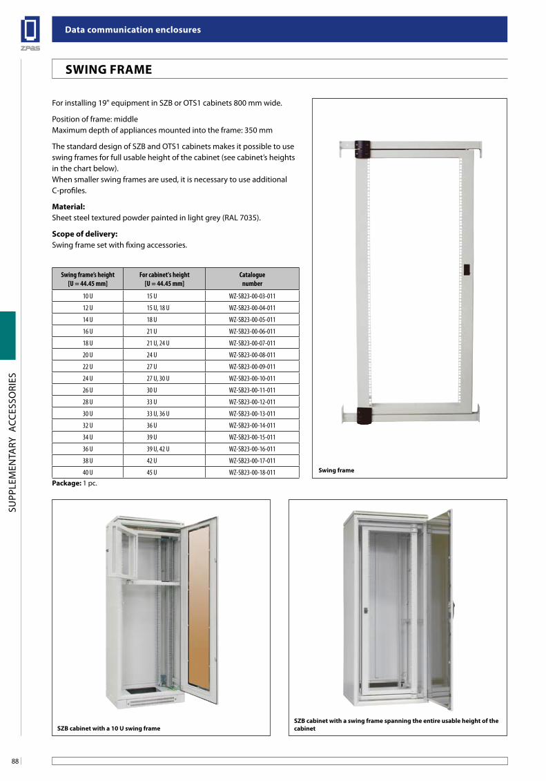
Data communication enclosures
88
SUPP
LEM
ENTA
RY A
CCES
SORI
ES
Swing frame’s height[U = 44.45 mm]
For cabinet's height[U = 44.45 mm]
Cataloguenumber
10 U 15 U WZ-SB23-00-03-011
12 U 15 U, 18 U WZ-SB23-00-04-011
14 U 18 U WZ-SB23-00-05-011
16 U 21 U WZ-SB23-00-06-011
18 U 21 U, 24 U WZ-SB23-00-07-011
20 U 24 U WZ-SB23-00-08-011
22 U 27 U WZ-SB23-00-09-011
24 U 27 U, 30 U WZ-SB23-00-10-011
26 U 30 U WZ-SB23-00-11-011
28 U 33 U WZ-SB23-00-12-011
30 U 33 U, 36 U WZ-SB23-00-13-011
32 U 36 U WZ-SB23-00-14-011
34 U 39 U WZ-SB23-00-15-011
36 U 39 U, 42 U WZ-SB23-00-16-011
38 U 42 U WZ-SB23-00-17-011
40 U 45 U WZ-SB23-00-18-011Package: 1 pc.
swing frame
For installing 19" equipment in SZB or OTS1 cabinets 800 mm wide.
Position of frame: middleMaximum depth of appliances mounted into the frame: 350 mm
The standard design of SZB and OTS1 cabinets makes it possible to use swing frames for full usable height of the cabinet (see cabinet’s heights in the chart below).When smaller swing frames are used, it is necessary to use additional C-profiles.
Material:Sheet steel textured powder painted in light grey (RAL 7035).
scope of delivery:Swing frame set with fixing accessories.
sZb cabinet with a 10 u swing framesZb cabinet with a swing frame spanning the entire usable height of thecabinet
sWing fRaMe
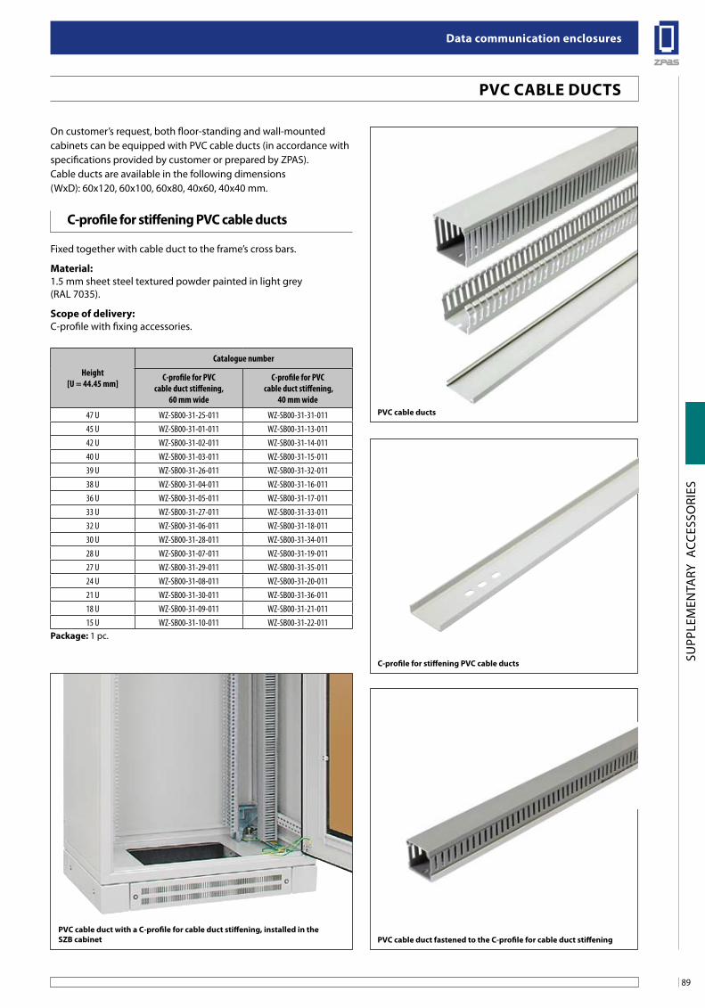
89
Data communication enclosures
SUPP
LEM
ENTA
RY A
CCES
SORI
ES
Height[U = 44.45 mm]
Catalogue number
C-profile for PVC cable duct stiffening,
60 mm wide
C-profile for PVC cable duct stiffening,
40 mm wide
47 U WZ-SB00-31-25-011 WZ-SB00-31-31-01145 U WZ-SB00-31-01-011 WZ-SB00-31-13-01142 U WZ-SB00-31-02-011 WZ-SB00-31-14-01140 U WZ-SB00-31-03-011 WZ-SB00-31-15-01139 U WZ-SB00-31-26-011 WZ-SB00-31-32-01138 U WZ-SB00-31-04-011 WZ-SB00-31-16-01136 U WZ-SB00-31-05-011 WZ-SB00-31-17-01133 U WZ-SB00-31-27-011 WZ-SB00-31-33-01132 U WZ-SB00-31-06-011 WZ-SB00-31-18-01130 U WZ-SB00-31-28-011 WZ-SB00-31-34-01128 U WZ-SB00-31-07-011 WZ-SB00-31-19-01127 U WZ-SB00-31-29-011 WZ-SB00-31-35-01124 U WZ-SB00-31-08-011 WZ-SB00-31-20-01121 U WZ-SB00-31-30-011 WZ-SB00-31-36-01118 U WZ-SB00-31-09-011 WZ-SB00-31-21-01115 U WZ-SB00-31-10-011 WZ-SB00-31-22-011
Package: 1 pc.
PVC cable ducts
C-profile for stiffening PVC cable ducts
PVC cable duct fastened to the C-profile for cable duct stiffening
On customer’s request, both floor-standing and wall-mounted cabinets can be equipped with PVC cable ducts (in accordance with specifications provided by customer or prepared by ZPAS).Cable ducts are available in the following dimensions(WxD): 60x120, 60x100, 60x80, 40x60, 40x40 mm.
Fixed together with cable duct to the frame’s cross bars.
Material:1.5 mm sheet steel textured powder painted in light grey (RAL 7035).
scope of delivery:C-profile with fixing accessories.
PVC cable duct with a C-profile for cable duct stiffening, installed in thesZb cabinet
PVC Cable DuCTs
C-profile for stiffening PVC cable ducts
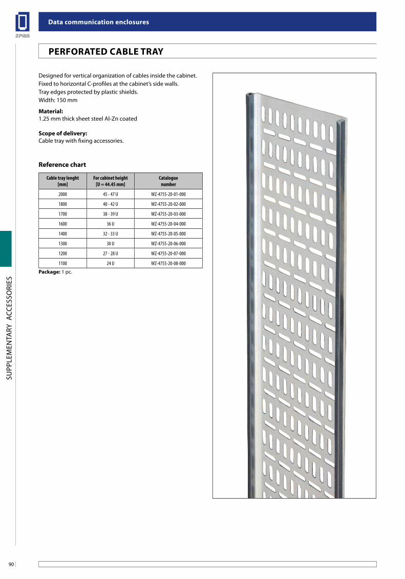
Data communication enclosures
90
SUPP
LEM
ENTA
RY A
CCES
SORI
ES
PeRfoRaTeD Cable TRaY
Designed for vertical organization of cables inside the cabinet.Fixed to horizontal C-profiles at the cabinet’s side walls.Tray edges protected by plastic shields.Width: 150 mm
Material:1.25 mm thick sheet steel Al-Zn coated
scope of delivery:Cable tray with fixing accessories.
Cable tray lenght[mm]
For cabinet height[U = 44.45 mm]
Cataloguenumber
2000 45 - 47 U WZ-4755-20-01-000
1800 40 - 42 U WZ-4755-20-02-000
1700 38 - 39 U WZ-4755-20-03-000
1600 36 U WZ-4755-20-04-000
1400 32 - 33 U WZ-4755-20-05-000
1300 30 U WZ-4755-20-06-000
1200 27 - 28 U WZ-4755-20-07-000
1100 24 U WZ-4755-20-08-000
Package: 1 pc.
Reference chart
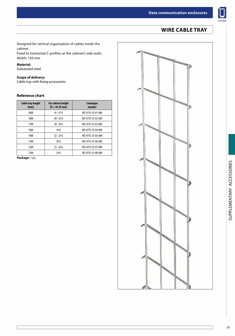
91
Data communication enclosures
SUPP
LEM
ENTA
RY A
CCES
SORI
ES
WiRe Cable TRaY
Designed for vertical organization of cables inside thecabinet.Fixed to horizontal C-profiles at the cabinet’s side walls.Width: 150 mm
Material:Galvanized steel
scope of delivery:Cable tray with fixing accessories.
Cable tray lenght[mm]
For cabinet height[U = 44.45 mm]
Cataloguenumber
2000 45 - 47 U WZ-4755-25-01-000
1800 40 - 42 U WZ-4755-25-02-000
1700 38 - 39 U WZ-4755-25-03-000
1600 36 U WZ-4755-25-04-000
1400 32 - 33 U WZ-4755-25-05-000
1300 30 U WZ-4755-25-06-000
1200 27 - 28 U WZ-4755-25-07-000
1100 24 U WZ-4755-25-08-000
Package: 1 pc.
Reference chart
szafka sW o wysokości 15 u z drzwiami z szybą szklaną
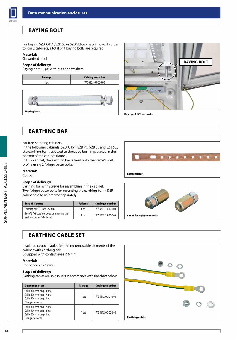
Data communication enclosures
92
SUPP
LEM
ENTA
RY A
CCES
SORI
ES
baying of sZb cabinets
Package Catalogue number
1 pc. WZ-SB25-00-00-000
For baying SZB, OTS1, SZB SE or SZB SEI cabinets in rows. In order to join 2 cabinets, a total of 4 baying bolts are required.
Material:Galvanized steel
scope of delivery:Baying bolt - 1 pc. with nuts and washers.
For free-standing cabinets.In the following cabinets: SZB, OTS1, SZB PC, SZB SE and SZB SEI, the earthing bar is screwed to threaded bushings placed in the bottom of the cabinet frame. In DSR cabinet, the earthing bar is fixed onto the frame’s post/profile using 2 fixing/spacer bolts.
Material:Copper
scope of delivery:Earthing bar with screws for assembling in the cabinet.Two fixing/spacer bolts for mounting the earthing bar in DSR cabinet are to be ordered separately.
Type of element Package Catalogue number
Earthing bar Cu 15x5x375 mm 1 pc. WZ-3393-11-00-000Set of 2 fixing/spacer bolts for mounting the earthing bar in DSR cabinet 1 set WZ-2645-15-00-000
earthing cables
Insulated copper cables for joining removable elements of the cabinet with earthing bar.Equipped with contact eyes Ø 6 mm.
Material:Copper cables 6 mm2
scope of delivery:Earthing cables are sold in sets in accordance with the chart below.
Description of set Package Catalogue number
Cable 300 mm long - 4 pcs.Cable 400 mm long - 2 pcs.Cable 600 mm long - 1 pc.Fixing accessories
1 set WZ-SB12-00-01-000
Cable 300 mm long - 2 pcs.Cable 400 mm long - 2 pcs.Cable 600 mm long - 1 pc.Fixing accessories
1 set WZ-SB12-00-02-000
baying bolt
baYing bolT
eaRTHing baR
eaRTHing Cable seT
set of fixing/spacer bolts
earthing bar
ŁĄCZniKbaYing bolT
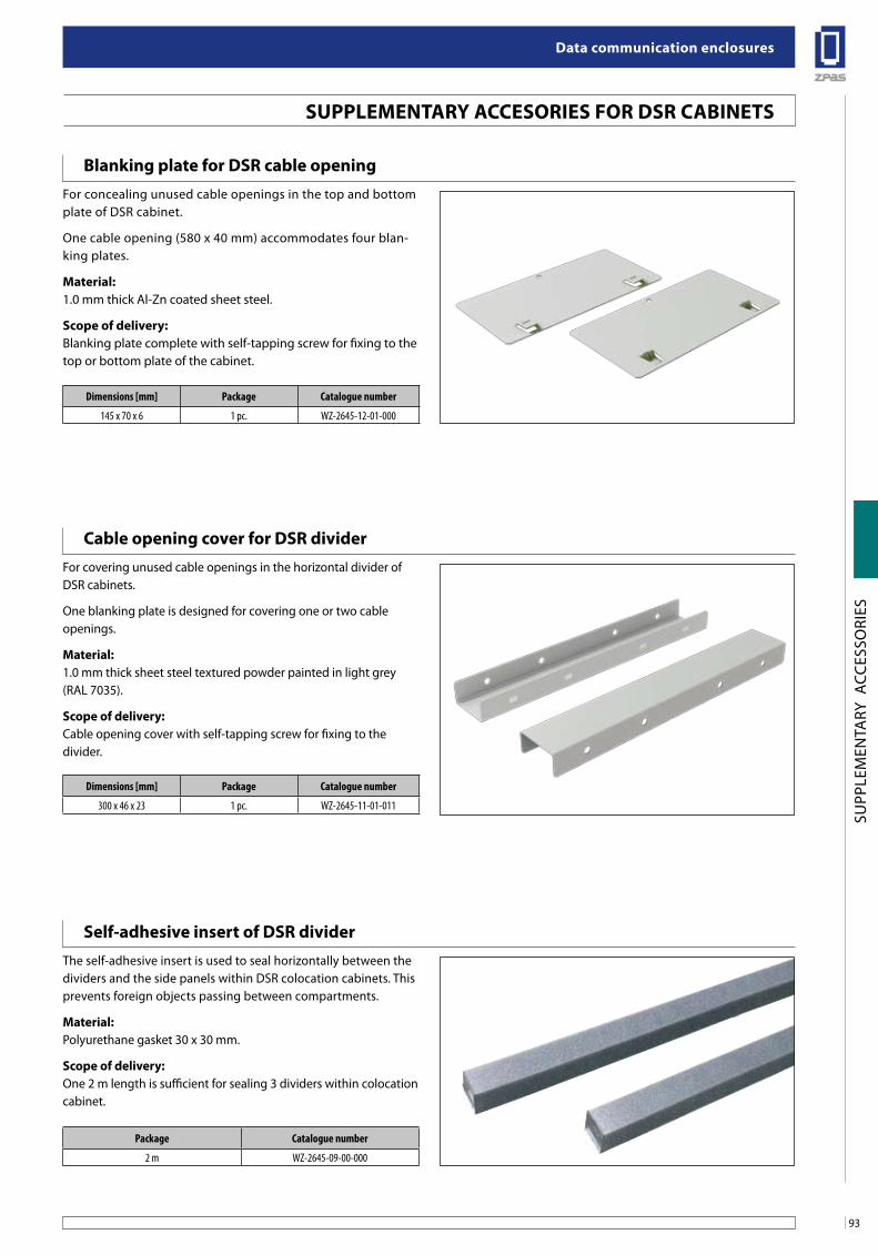
93
Data communication enclosures
SUPP
LEM
ENTA
RY A
CCES
SORI
ES
Dimensions [mm] Package Catalogue number
145 x 70 x 6 1 pc. WZ-2645-12-01-000
Package Catalogue number
2 m WZ-2645-09-00-000
Dimensions [mm] Package Catalogue number
300 x 46 x 23 1 pc. WZ-2645-11-01-011
suPPleMenTaRY aCCesoRies foR DsR CabineTs
blanking plate for DsR cable opening
Cable opening cover for DsR divider
self-adhesive insert of DsR divider
For concealing unused cable openings in the top and bottom plate of DSR cabinet.
One cable opening (580 x 40 mm) accommodates four blan-king plates.
Material:1.0 mm thick Al-Zn coated sheet steel.
scope of delivery:Blanking plate complete with self-tapping screw for fixing to the top or bottom plate of the cabinet.
For covering unused cable openings in the horizontal divider of DSR cabinets.
One blanking plate is designed for covering one or two cable openings.
Material:1.0 mm thick sheet steel textured powder painted in light grey (RAL 7035).
scope of delivery:Cable opening cover with self-tapping screw for fixing to the divider.
The self-adhesive insert is used to seal horizontally between the dividers and the side panels within DSR colocation cabinets. This prevents foreign objects passing between compartments.
Material:Polyurethane gasket 30 x 30 mm.
scope of delivery:One 2 m length is sufficient for sealing 3 dividers within colocation cabinet.
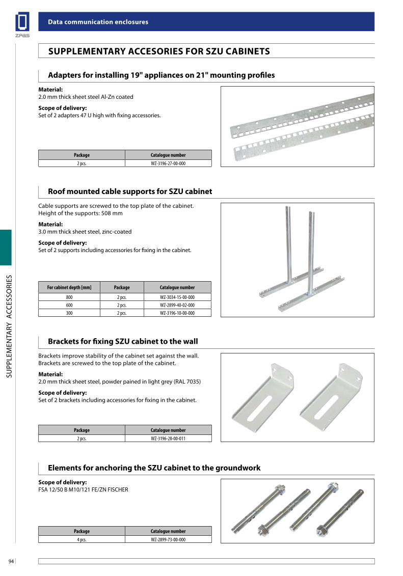
Data communication enclosures
94
SUPP
LEM
ENTA
RY A
CCES
SORI
ES
suPPleMenTaRY aCCesoRies foR sZu CabineTs
For cabinet depth [mm] Package Catalogue number
800 2 pcs. WZ-3034-15-00-000600 2 pcs. WZ-2899-40-02-000300 2 pcs. WZ-3196-10-00-000
adapters for installing 19" appliances on 21" mounting profiles
elements for anchoring the sZu cabinet to the groundwork
brackets for fixing sZu cabinet to the wall
Roof mounted cable supports for sZu cabinet
Material:2.0 mm thick sheet steel Al-Zn coated
scope of delivery:Set of 2 adapters 47 U high with fixing accessories.
scope of delivery:FSA 12/50 B M10/121 FE/ZN FISCHER
Brackets improve stability of the cabinet set against the wall.Brackets are screwed to the top plate of the cabinet.
Material:2.0 mm thick sheet steel, powder pained in light grey (RAL 7035)
scope of delivery:Set of 2 brackets including accessories for fixing in the cabinet.
Cable supports are screwed to the top plate of the cabinet.Height of the supports: 508 mm
Material:3.0 mm thick sheet steel, zinc-coated
scope of delivery:Set of 2 supports including accessories for fixing in the cabinet.
Package Catalogue number
2 pcs. WZ-3196-27-00-000
Package Catalogue number
4 pcs. WZ-2899-73-00-000
Package Catalogue number
2 pcs. WZ-3196-28-00-011
Poprzeczka pozioma do mocowania kabli
Poprzeczka pozioma do mocowania kabli
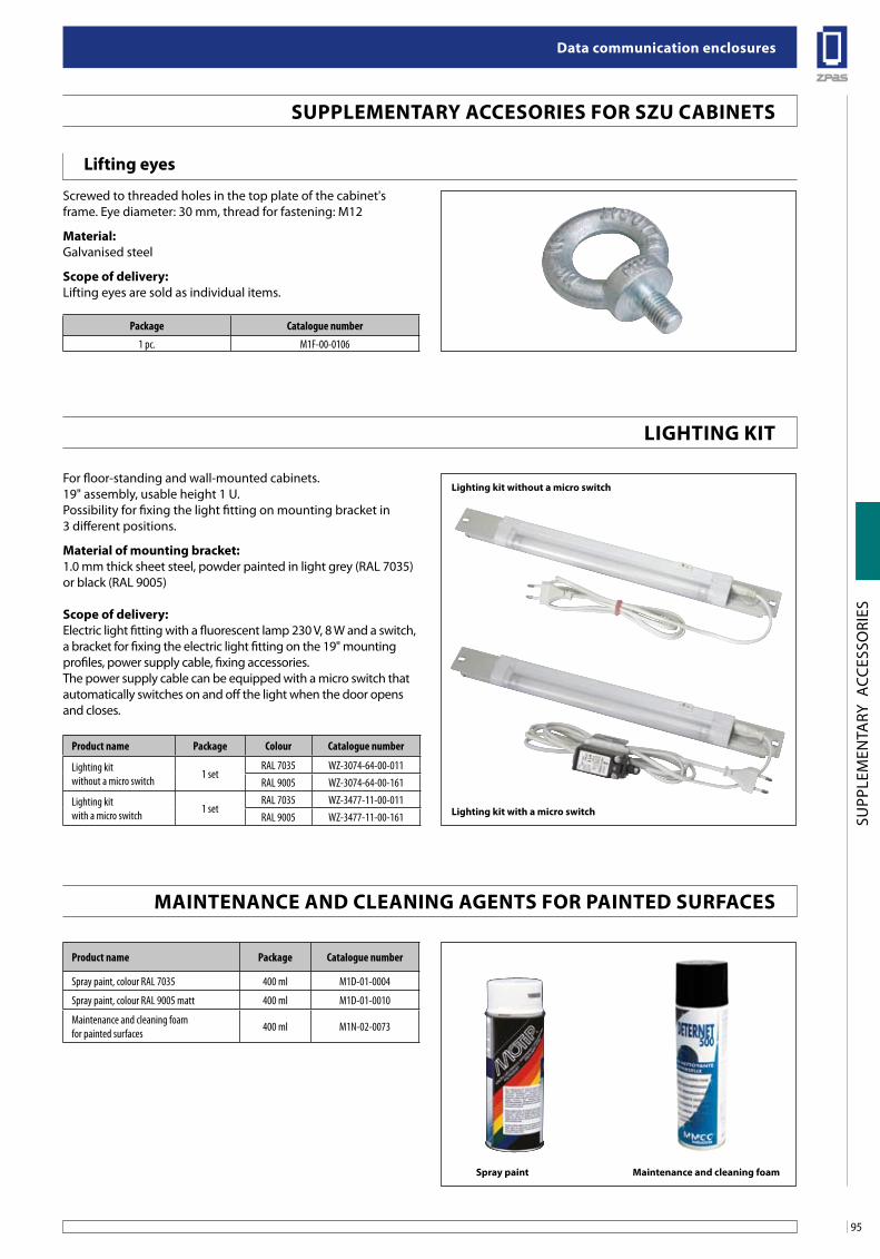
95
Data communication enclosures
SUPP
LEM
ENTA
RY A
CCES
SORI
ES
Product name Package Catalogue number
Spray paint, colour RAL 7035 400 ml M1D-01-0004
Spray paint, colour RAL 9005 matt 400 ml M1D-01-0010
Maintenance and cleaning foam for painted surfaces 400 ml M1N-02-0073
Product name Package Colour Catalogue number
Lighting kit without a micro switch 1 set
RAL 7035 WZ-3074-64-00-011RAL 9005 WZ-3074-64-00-161
Lighting kit with a micro switch 1 set
RAL 7035 WZ-3477-11-00-011RAL 9005 WZ-3477-11-00-161
spray paint Maintenance and cleaning foam
ligHTing KiT
suPPleMenTaRY aCCesoRies foR sZu CabineTs
MainTenanCe anD Cleaning agenTs foR PainTeD suRfaCes
lighting kit with a micro switch
lifting eyes
Screwed to threaded holes in the top plate of the cabinet'sframe. Eye diameter: 30 mm, thread for fastening: M12
Material:Galvanised steel
scope of delivery:Lifting eyes are sold as individual items.
For floor-standing and wall-mounted cabinets.19" assembly, usable height 1 U.Possibility for fixing the light fitting on mounting bracket in3 different positions.
Material of mounting bracket:1.0 mm thick sheet steel, powder painted in light grey (RAL 7035) or black (RAL 9005)
scope of delivery:Electric light fitting with a fluorescent lamp 230 V, 8 W and a switch, a bracket for fixing the electric light fitting on the 19" mounting profiles, power supply cable, fixing accessories.The power supply cable can be equipped with a micro switch that automatically switches on and off the light when the door opens and closes.
Package Catalogue number
1 pc. M1F-00-0106
lighting kit without a micro switch
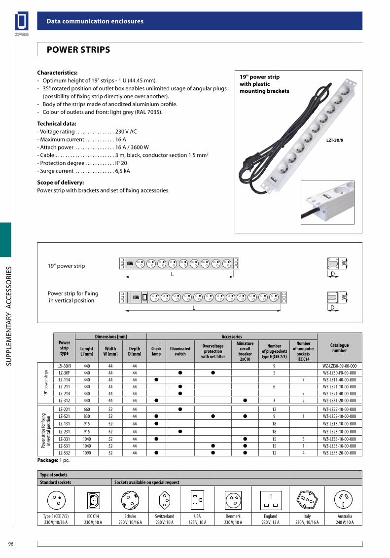
Data communication enclosures
96
SUPP
LEM
ENTA
RY A
CCES
SORI
ES
Characteristics:- Optimum height of 19" strips - 1 U (44.45 mm).- 35° rotated position of outlet box enables unlimited usage of angular plugs
(possibility of fixing strip directly one over another). - Body of the strips made of anodized aluminium profile.- Colour of outlets and front: light grey (RAL 7035).
Technical data:- Voltage rating . . . . . . . . . . . . . . . . 230 V AC- Maximum current . . . . . . . . . . . . 16 A- Attach power . . . . . . . . . . . . . . . . 16 A / 3600 W- Cable . . . . . . . . . . . . . . . . . . . . . . . . 3 m, black, conductor section 1.5 mm2
- Protection degree . . . . . . . . . . . . IP 20- Surge current . . . . . . . . . . . . . . . . 6,5 kA
Scope of delivery:Power strip with brackets and set of fixing accessories.
Type of socketsStandard sockets Sockets available on special request
Type E (CEE 7/5)230 V; 10/16 A
IEC C14230 V; 10 A
Schuko230 V; 10/16 A
Switzerland230 V; 10 A
USA125 V; 10 A
Denmark230 V; 10 A
England230 V; 13 A
Italy230 V; 10/16 A
Australia240 V; 10 A
Power strip type
Dimensions [mm] Accessories
CataloguenumberLenght
L [mm]Width
W [mm]Depth
D [mm]Check lamp
Illuminated switch
Overvoltage protection
with net filter
Miniature circult
breaker 2xC10
Number of plug-sockets type E (CEE 7/5)
Number of computer
socketsIEC C14
19" p
ower
strip
s
LZI-30/9 440 44 44 9 WZ-LZI30-09-00-000LZ-30F 440 44 44 5 WZ-LZ30-F0-00-000LZ-114 440 44 44 7 WZ-LZ11-40-00-000LZ-211 440 44 44 6 WZ-LZ21-10-00-000LZ-214 440 44 44 7 WZ-LZ21-40-00-000LZ-312 440 44 44 3 2 WZ-LZ31-20-00-000
Powe
r stri
ps fo
r fixin
g in
verti
cal p
ositi
on
LZ-221 660 52 44 12 WZ-LZ22-10-00-000LZ-521 830 52 44 9 1 WZ-LZ52-10-00-000LZ-131 915 52 44 18 WZ-LZ13-10-00-000
LZ-231 915 52 44 18 WZ-LZ23-10-00-000LZ-331 1040 52 44 15 3 WZ-LZ33-10-00-000LZ-531 1040 52 44 15 1 WZ-LZ53-10-00-000LZ-532 1090 52 44 12 4 WZ-LZ53-20-00-000
Package: 1 pc.
O
I
L D
WW
L D
19" power strip
Power strip for fixing in vertical position
POWER STRIPS
19" power strip with plastic mounting brackets
LZI-30/9
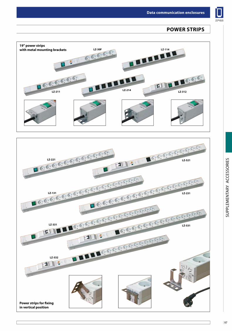
97
Data communication enclosures
SUPP
LEM
ENTA
RY A
CCES
SORI
ESlZ-521
lZ-231
lZ-531
Power strips for fixingin vertical position
PoWeR sTRiPs
lZ-221
lZ-131
lZ-331
lZ-532
19" power strips with metal mounting brackets
lZ-211
lZ-30f
lZ-214
lZ-114
lZ-312
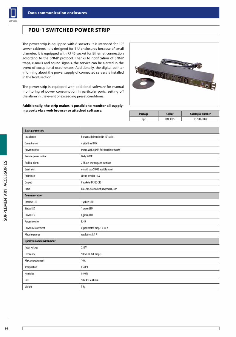
Data communication enclosures
98
SUPP
LEM
ENTA
RY A
CCES
SORI
ES
The power strip is equipped with 8 sockets. It is intended for 19" server cabinets. It is designed for 1 U enclosures because of small diameter. It is equipped with RJ 45 socket for Ethernet connection according to the SNMP protocol. Thanks to notification of SNMP traps, e-mails and sound signals, the service can be alerted in the event of exceptional occurrences. Additionally, the digital pointer informing about the power supply of connected servers is installed in the front section.
The power strip is equipped with additional software for manual monitoring of power consumption in particular ports, setting off the alarm in the event of exceeding preset conditions.
additionally, the strip makes it possible to monitor all supply-ing ports via a web browser or attached software.
Basic parameters
Installation horizontally installed in 19" racks
Current meter digital true RMS
Power monitor meter, Web, SNMP, free bundle software
Remote power control Web, SNMP
Audible alarm 2 Phase, warning and overload
Event alert e-mail, trap SNMP, audible alarm
Protection circuit breaker 16 A
Output 8 sockets IEC320 C13
Input IEC320 C20 attached power cord, 3 m
Communication
Ethernet LED 1 yellow LED
Status LED 1 green LED
Power LED 8 green LED
Power monitor RJ45
Power measurement digital meter; range: 0-20 A
Metering range resolution: 0.1 A
Operation and environment
Input voltage 230 V
Frequency 50/60 Hz (full range)
Max. output current 16 A
Temperature 0-40 ºC
Humidity 0-90%
Size 90 x 432 x 44 mm
Weight 3 kg
PDu-1 sWiTCHeD PoWeR sTRiP
Package Colour Catalogue number
1 pc. RAL 9005 T1Z-01-0004
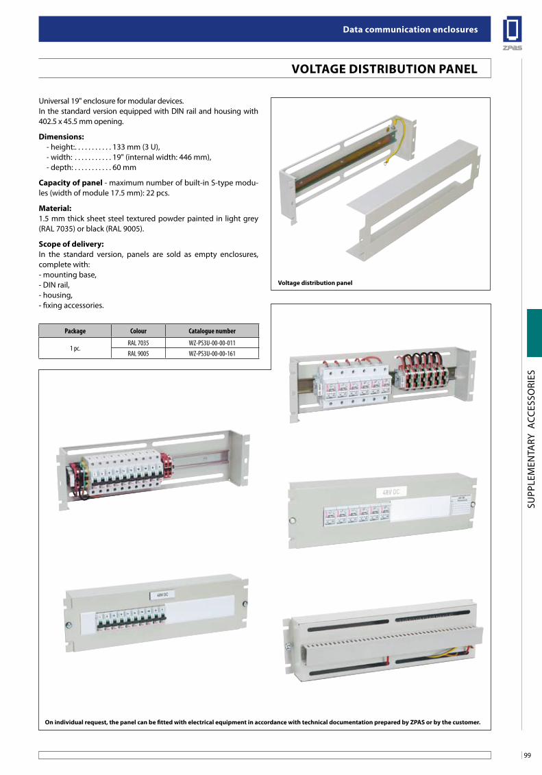
99
Data communication enclosures
SUPP
LEM
ENTA
RY A
CCES
SORI
ES
VolTage DisTRibuTion Panel
Universal 19" enclosure for modular devices.In the standard version equipped with DIN rail and housing with 402.5 x 45.5 mm opening.
Dimensions:- height:. . . . . . . . . . . 133 mm (3 U),- width: . . . . . . . . . . . 19" (internal width: 446 mm),- depth: . . . . . . . . . . . 60 mm
Capacity of panel - maximum number of built-in S-type modu-les (width of module 17.5 mm): 22 pcs.
Material:1.5 mm thick sheet steel textured powder painted in light grey (RAL 7035) or black (RAL 9005).
scope of delivery:In the standard version, panels are sold as empty enclosures, complete with:- mounting base,- DIN rail,- housing,- fixing accessories.
on individual request, the panel can be fitted with electrical equipment in accordance with technical documentation prepared by ZPas or by the customer.
Package Colour Catalogue number
1 pc.RAL 7035 WZ-PS3U-00-00-011RAL 9005 WZ-PS3U-00-00-161
Voltage distribution panel
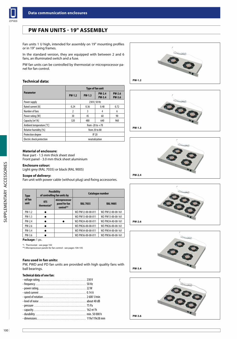
Data communication enclosures
100
SUPP
LEM
ENTA
RY A
CCES
SORI
ES
PW-3.6
PW-3.4
PW-2.6
PW-2.4
PW-1.3
PW-1.2Technical data:
ParameterType of fan unit
PW-1.2 PW-1.3 PW-2.4PW-3.4
PW-2.6PW-3.6
Power supply 230 V, 50 HzRated current [A] 0.24 0.36 0.48 0.72Number of fans 2 3 4 6Power rating [W] 30 45 60 90Capacity [m3/h] 320 480 640 960Ambient temperature [°C] from -20 to +70Relative humidity [%] from 20 to 80Protection degree IP 20Electric shock protection neutralization
Fan units 1 U high, intended for assembly on 19" mounting profiles or in 19" swing frames.
In the standard version, they are equipped with between 2 and 6 fans, an illuminated switch and a fuse.
PW fan units can be controlled by thermostat or microprocessor pa-nel for fan control.
Material of enclosure:Rear part - 1.5 mm thick sheet steelFront panel - 3.0 mm thick sheet aluminium
enclosure colour:Light grey (RAL 7035) or black (RAL 9005)
scope of delivery:Fan unit with power cable (without plug) and fixing accessories.
Type of fan unit
Possibility of controlling fan units by Catalogue number
KTSthermostat*
microprocessor panel for fan
control**RAL 7035 RAL 9005
PW-1.2 WZ-PW12-00-00-011 WZ-PW12-00-00-161PW-1.3 WZ-PW13-00-00-011 WZ-PW13-00-00-161PW-2.4 WZ-PW24-A0-00-011 WZ-PW24-A0-00-161PW-2.6 WZ-PW26-00-00-011 WZ-PW26-00-00-161PW-3.4 WZ-PW34-00-00-011 WZ-PW34-00-00-161PW-3.6 WZ-PW36-00-00-011 WZ-PW36-00-00-161
Package: 1 pc.
*) Thermostat - see page 102**) Microprocessor panels for fan control - see pages 104-105
fans used in fan units:PW, PWD and PD fan units are provided with high quality fans with ball bearings.
Technical data of one fan:- voltage rating. . . . . . . . . . . . . . . . . . . . . . . . . . . . . . . . . . . . . 230 V- frequency . . . . . . . . . . . . . . . . . . . . . . . . . . . . . . . . . . . . . . . . 50 Hz- power rating. . . . . . . . . . . . . . . . . . . . . . . . . . . . . . . . . . . . . . 22 W- rated current . . . . . . . . . . . . . . . . . . . . . . . . . . . . . . . . . . . . . 0.14 A- speed of rotation . . . . . . . . . . . . . . . . . . . . . . . . . . . . . . . . . . 2 600 1/min- level of noise . . . . . . . . . . . . . . . . . . . . . . . . . . . . . . . . . . . . . about 40 dB- pressure . . . . . . . . . . . . . . . . . . . . . . . . . . . . . . . . . . . . . . . . . 75 Pa- capacity. . . . . . . . . . . . . . . . . . . . . . . . . . . . . . . . . . . . . . . . . . 162 m3/h- durability . . . . . . . . . . . . . . . . . . . . . . . . . . . . . . . . . . . . . . . . min. 50 000 h- dimensions. . . . . . . . . . . . . . . . . . . . . . . . . . . . . . . . . . . . . . . 119x119x38 mm
PW fan uniTs - 19" asseMblY
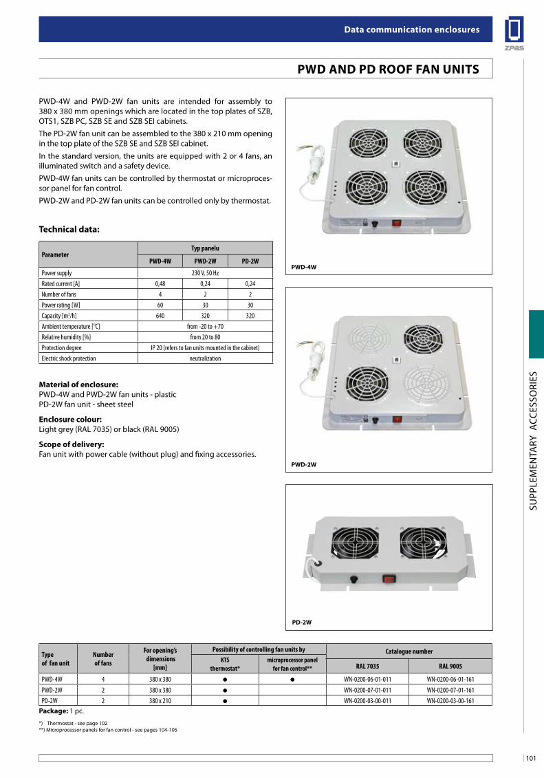
101
Data communication enclosures
SUPP
LEM
ENTA
RY A
CCES
SORI
ES
Technical data:
ParameterTyp panelu
PWD-4W PWD-2W PD-2W
Power supply 230 V, 50 HzRated current [A] 0,48 0,24 0,24Number of fans 4 2 2Power rating [W] 60 30 30Capacity [m3/h] 640 320 320Ambient temperature [°C] from -20 to +70Relative humidity [%] from 20 to 80Protection degree IP 20 (refers to fan units mounted in the cabinet)Electric shock protection neutralization
PWD-4W and PWD-2W fan units are intended for assembly to 380 x 380 mm openings which are located in the top plates of SZB, OTS1, SZB PC, SZB SE and SZB SEI cabinets.
The PD-2W fan unit can be assembled to the 380 x 210 mm opening in the top plate of the SZB SE and SZB SEI cabinet.
In the standard version, the units are equipped with 2 or 4 fans, an illuminated switch and a safety device.
PWD-4W fan units can be controlled by thermostat or microproces-sor panel for fan control.
PWD-2W and PD-2W fan units can be controlled only by thermostat.
Material of enclosure: PWD-4W and PWD-2W fan units - plasticPD-2W fan unit - sheet steel
enclosure colour:Light grey (RAL 7035) or black (RAL 9005)
scope of delivery:Fan unit with power cable (without plug) and fixing accessories.
PWD-4W
PD-2W
PWD-2W
Type of fan unit
Number of fans
For opening’s dimensions
[mm]
Possibility of controlling fan units by Catalogue numberKTS
thermostat*microprocessor panel
for fan control** RAL 7035 RAL 9005
PWD-4W 4 380 x 380 WN-0200-06-01-011 WN-0200-06-01-161
PWD-2W 2 380 x 380 WN-0200-07-01-011 WN-0200-07-01-161PD-2W 2 380 x 210 WN-0200-03-00-011 WN-0200-03-00-161
Package: 1 pc.
*) Thermostat - see page 102**) Microprocessor panels for fan control - see pages 104-105
PWD anD PD Roof fan uniTs
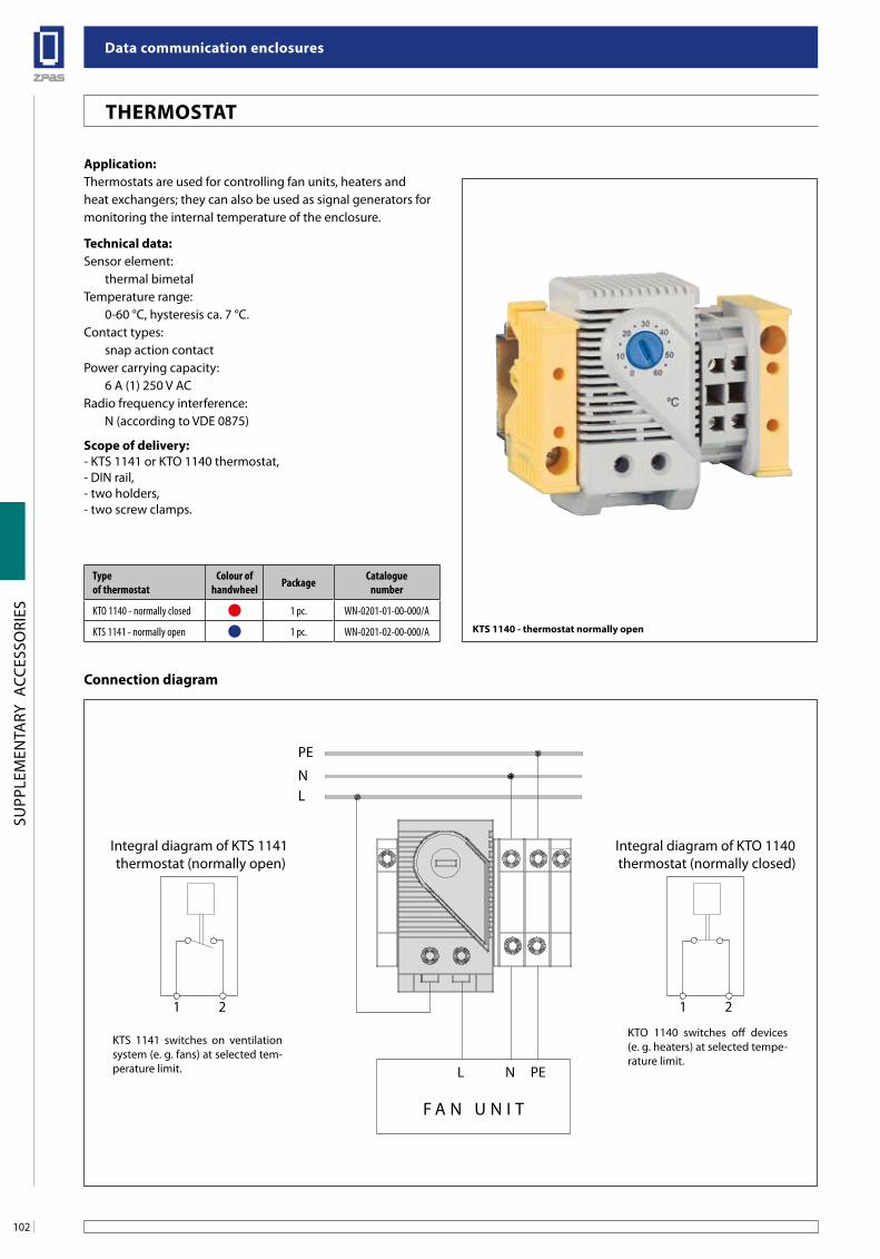
Data communication enclosures
102
SUPP
LEM
ENTA
RY A
CCES
SORI
ES
application:Thermostats are used for controlling fan units, heaters and heat exchangers; they can also be used as signal generators for monitoring the internal temperature of the enclosure.
Technical data:Sensor element:
thermal bimetalTemperature range:
0-60 °C, hysteresis ca. 7 °C.Contact types:
snap action contactPower carrying capacity:
6 A (1) 250 V ACRadio frequency interference:
N (according to VDE 0875)
scope of delivery:- KTS 1141 or KTO 1140 thermostat,- DIN rail,- two holders,- two screw clamps.
Type of thermostat
Colour of handwheel Package Catalogue
number
KTO 1140 - normally closed 1 pc. WN-0201-01-00-000/A
KTS 1141 - normally open 1 pc. WN-0201-02-00-000/A KTs 1140 - thermostat normally open
Connection diagram
PE
NL
PENL
F A N U N I T
1
Integral diagram of KTO 1140 thermostat (normally closed)
21
Integral diagram of KTS 1141 thermostat (normally open)
2
KTS 1141 switches on ventilation system (e. g. fans) at selected tem-perature limit.
KTO 1140 switches off devices (e. g. heaters) at selected tempe-rature limit.
THeRMosTaT
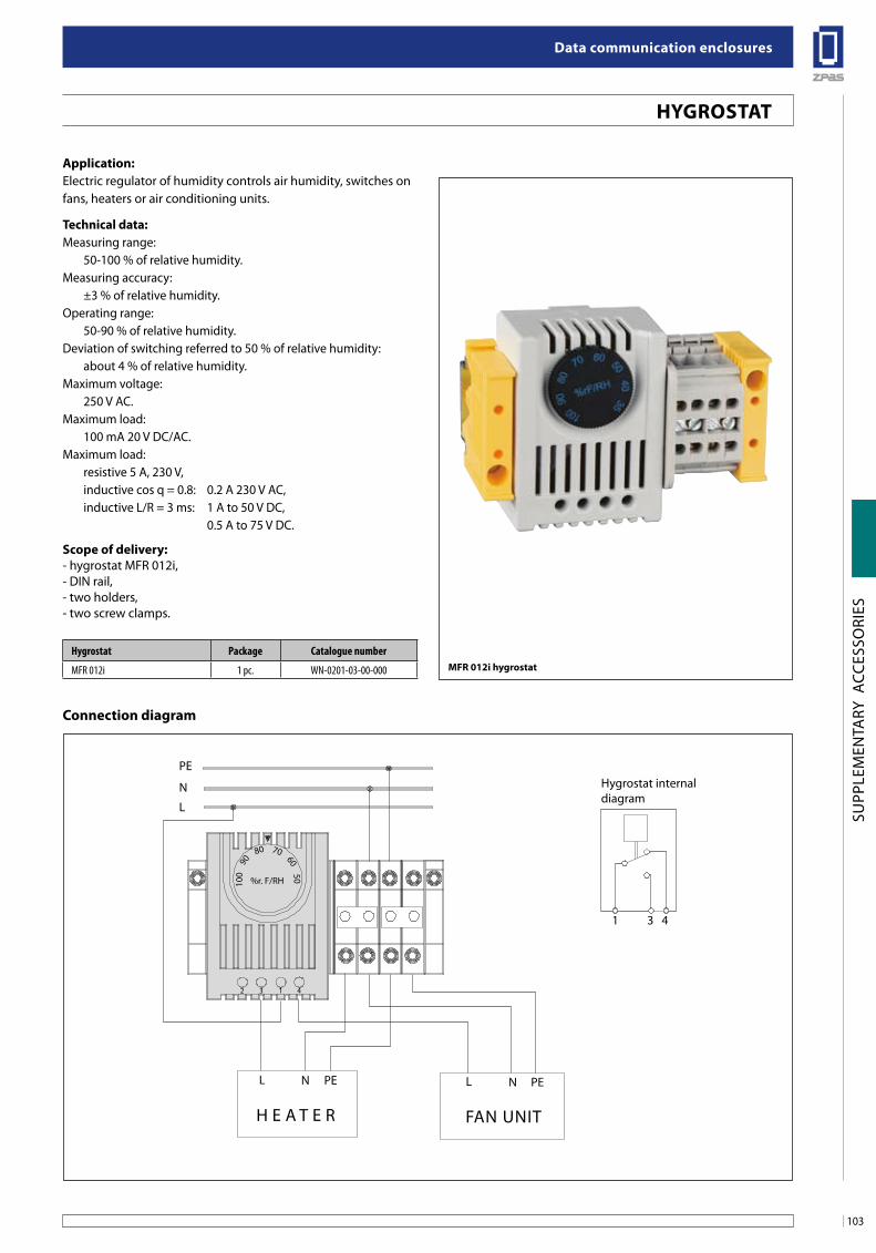
103
Data communication enclosures
SUPP
LEM
ENTA
RY A
CCES
SORI
ES
application:Electric regulator of humidity controls air humidity, switches on fans, heaters or air conditioning units.
Technical data:Measuring range:
50-100 % of relative humidity.Measuring accuracy:
±3 % of relative humidity.Operating range:
50-90 % of relative humidity.Deviation of switching referred to 50 % of relative humidity:
about 4 % of relative humidity.Maximum voltage:
250 V AC.Maximum load:
100 mA 20 V DC/AC.Maximum load:
resistive 5 A, 230 V,inductive cos q = 0.8: 0.2 A 230 V AC,inductive L/R = 3 ms: 1 A to 50 V DC, 0.5 A to 75 V DC.
scope of delivery:- hygrostat MFR 012i,- DIN rail,- two holders,- two screw clamps.
MfR 012i hygrostatHygrostat Package Catalogue number
MFR 012i 1 pc. WN-0201-03-00-000
Connection diagram
PE
N
L
PE PEN NL L
1
%r. F/RH
2 3 1 4
100
90
7080
6050
Hygrostat internal diagram
3 4
H E A T E R FAN UNIT
HYgRosTaT
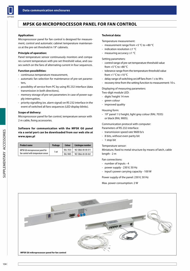
Data communication enclosures
104
SUPP
LEM
ENTA
RY A
CCES
SORI
ES
Application:Microprocessor panel for fan control is designed for measure-ment, control and automatic cabinet temperature maintenan-ce at the pre-set threshold in 19" cabinets.
Principle of operation:Panel temperature sensor continuously monitors and compa-res current temperature with pre-set threshold value, and cau-ses switch on the fans of alternating current in four sequences.
Function possibilities:- continuous temperature measurement,- automatic fan selection for maintenance of pre-set parame-
ters,- possibility of service from PC by using RS 232 interface (data
transmission in both directions),- memory storage of pre-set parameters in case of power sup-
ply interruption,- priority signalling (ex. alarm signal) on RS 232 interface in the
event of switched all fans sequences (LED display blinks).
Scope of delivery:Microprocessor panel for fan control, temperature sensor with 2 m cable, fixing accessories.
Software for communication with the MPSK G0 panel via a serial port can be downloaded from our web site at www.zpas.pl
Technical data:
Temperature measurement:- measurement range from +5 °C to +80 °C- indication resolution ±1 °C- measuring accuracy ±1 °C
Setting parameters:- control range of pre-set temperature threshold value
from +5 °C to +80 °C- tolerance range from the temperature threshold value
from +1 °C to +10 °C- delay range of switching on/off fans from 1 s to 99 s- recovery time from the setting function to measurement: 10 s.
Displaying of measuring parameters:Two-digit module LED:- digits’ height 14 mm- green colour- improved quality
Housing form:- 19" panel 1 U height, light grey colour (RAL 7035) or black (RAL 9005).
Communication protocol with computer:Parameters of RS 232 interface:- transmission speed rate 9600 b/s- 8 bits, without even parity bit- 1 stop bit
Temperature sensor:Miniature, fixed to metal structure by means of latch, cablelength - 2 m
Fan connections:- number of inputs - 4- power supply - 230 V, 50 Hz- input’s power carrying capacity - 100 W
Power supply of the panel: 230 V, 50 Hz
Max. power consumption: 2 W
Product name Package Colour Catalogue number
MPSK G0 microprocessor panel for fan control with temperature sensor
1 setRAL 7035 WZ-SB66-00-00-011
RAL 9005 WZ-SB66-00-00-061
MPSK G0 MICROPROCESSOR PANEL FOR FAN CONTROL
MPSK G0 mikroprocessor panel for fan control
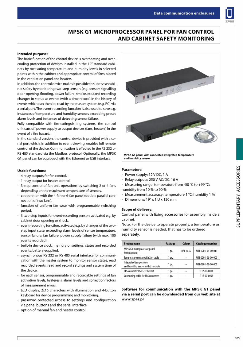
105
Data communication enclosures
SUPP
LEM
ENTA
RY A
CCES
SORI
ES
intended purpose:The basic function of the control device is overheating and over-cooling protection of devices installed in the 19" standard cabi-nets by measuring temperature and humidity levels in selected points within the cabinet and appropriate control of fans placed in the ventilation panel and heaters. In addition, the control device makes it possible to supervise cabi-net safety by monitoring two-step sensors (e.g. sensors signalling door-opening, flooding, power failure, smoke, etc.) and recording changes in status as events (with a time record) in the history of events which can then be read by the master system (e.g. PC) viaa serial port. The event-recording function is also used to save e.g. instances of temperature and humidity sensors exceeding preset alarm levels and instances of detecting sensor failure.Fully compatible with fire-extinguishing systems, the control unit cuts off power supply to output devices (fans, heaters) in the event of a fire hazard. In the standard version, the control device is provided with a se-rial port which, in addition to event viewing, enables full remote control of the device. Communication is effected in the RS 232 or RS 485 standard via the Modbus protocol. Optionally, the MPSK G1 panel can be equipped with the Ethernet or USB interface.
usable functions:- 4 relay outputs for fan control.- 1 relay output for heater control.- 3-step control of fan unit operations by switching 2 or 4 fans
depending on the maximum temperature of sensors.- cooperation with the 4-fan or 6-fan panel (double parallel con-
nection of two fans).- function of uniform fan wear with programmable switching
period.- 3 two-step inputs for event-recording sensors activated e.g. by
cabinet door opening or shock.- event-recording function, activated e.g. by changes of the two-
step input state, exceeding alarm levels of sensor temperature, sensor failure, fan failure, power supply failure (with max. 100 events recorded).
- built-in device clock, memory of settings, states and recorded events, battery-supplied.
- asynchronous RS 232 or RS 485 serial interface for communi-cation with the master system to monitor sensor states, read recorded events, read and record settings and system time of the device.
- for each sensor, programmable and recordable settings of fan activation levels, hysteresis, alarm levels and correction factors of measurement errors.
- LCD display, 2x16 characters with illumination and 4-button keyboard for device programming and monitoring.
- password-protected access to settings and configuration via panel buttons and the serial interface.
- option of manual fan and heater control.
Parameters:- Power supply: 12 V DC, 1 A- Relay outputs: 250 V AC/DC, 16 A- Measuring range: temperature from -50 °C to +99 °C;humidity from 10 % to 90 %- Measurement accuracy: temperature 1 °C; humidity 1 %- Dimensions: 19" x 1 U x 150 mm
scope of delivery:Control panel with fixing accessories for assembly inside acabinet.Note: For the device to operate properly, a temperature orhumidity sensor is needed, that has to be orderedseparately.
software for communication with the MPsK g1 panel via a serial port can be downloaded from our web site at www.zpas.pl
Product name Package Colour Catalogue number
MPSK G1 microprocessor panel for fan control
1 pc. RAL 7035 WN-0201-05-00-011
Temperature sensor with 2 m cable 1 pc. – WN-0201-06-00-000Integrated temperature and humidity sensor with 2 m cable
1 pc. – WN-0201-08-00-000
ERS converter RS232/Ethernet 1 pc. – T1Z-00-0004Connecting cable for ERS converter 1 pc. – T1Z-00-0005
MPsK g1 MiCRoPRoCessoR Panel foR fan ConTRol anD CabineT safeTY MoniToRing
MPsK g1 panel with connected integrated temperature and humidity sensor
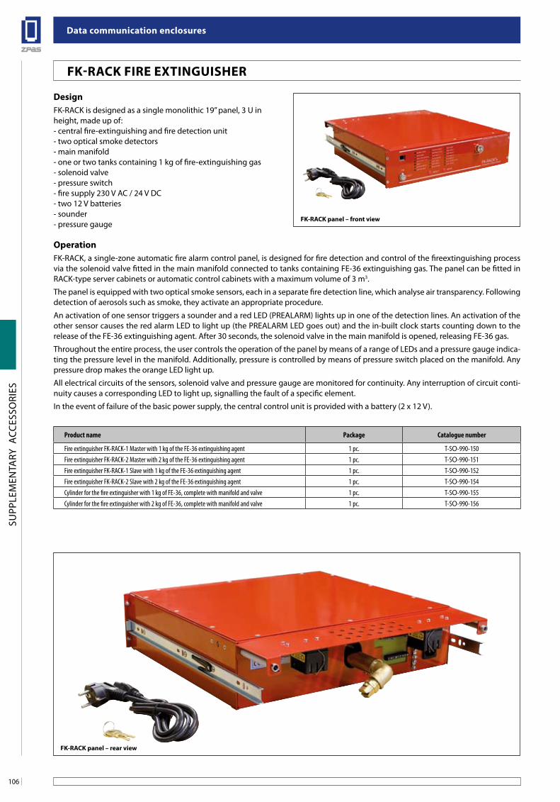
Data communication enclosures
106
SUPP
LEM
ENTA
RY A
CCES
SORI
ES
DesignFK-RACK is designed as a single monolithic 19’’ panel, 3 U inheight, made up of:- central fire-extinguishing and fire detection unit- two optical smoke detectors- main manifold- one or two tanks containing 1 kg of fire-extinguishing gas- solenoid valve- pressure switch- fire supply 230 V AC / 24 V DC- two 12 V batteries- sounder- pressure gauge
operationFK-RACK, a single-zone automatic fire alarm control panel, is designed for fire detection and control of the fireextinguishing process via the solenoid valve fitted in the main manifold connected to tanks containing FE-36 extinguishing gas. The panel can be fitted in RACK-type server cabinets or automatic control cabinets with a maximum volume of 3 m3.
The panel is equipped with two optical smoke sensors, each in a separate fire detection line, which analyse air transparency. Following detection of aerosols such as smoke, they activate an appropriate procedure.
An activation of one sensor triggers a sounder and a red LED (PREALARM) lights up in one of the detection lines. An activation of the other sensor causes the red alarm LED to light up (the PREALARM LED goes out) and the in-built clock starts counting down to the release of the FE-36 extinguishing agent. After 30 seconds, the solenoid valve in the main manifold is opened, releasing FE-36 gas.
Throughout the entire process, the user controls the operation of the panel by means of a range of LEDs and a pressure gauge indica-ting the pressure level in the manifold. Additionally, pressure is controlled by means of pressure switch placed on the manifold. Any pressure drop makes the orange LED light up.
All electrical circuits of the sensors, solenoid valve and pressure gauge are monitored for continuity. Any interruption of circuit conti-nuity causes a corresponding LED to light up, signalling the fault of a specific element.
In the event of failure of the basic power supply, the central control unit is provided with a battery (2 x 12 V).
fK-RaCK fiRe exTinguisHeR
fK-RaCK panel – front view
fK-RaCK panel – rear view
Product name Package Catalogue number
Fire extinguisher FK-RACK-1 Master with 1 kg of the FE-36 extinguishing agent 1 pc. T-SO-990-150Fire extinguisher FK-RACK-2 Master with 2 kg of the FE-36 extinguishing agent 1 pc. T-SO-990-151Fire extinguisher FK-RACK-1 Slave with 1 kg of the FE-36 extinguishing agent 1 pc. T-SO-990-152Fire extinguisher FK-RACK-2 Slave with 2 kg of the FE-36 extinguishing agent 1 pc. T-SO-990-154Cylinder for the fire extinguisher with 1 kg of FE-36, complete with manifold and valve 1 pc. T-SO-990-155Cylinder for the fire extinguisher with 2 kg of FE-36, complete with manifold and valve 1 pc. T-SO-990-156
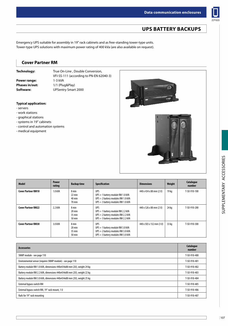
107
Data communication enclosures
SUPP
LEM
ENTA
RY A
CCES
SORI
ES
uPs baTTeRY baCKuPs
Cover Partner RM
Technology: True On-Line , Double Conversion, VFI-SS-111 (according to PN-EN 62040-3)Power range: 1-3 kVA Phases in/out: 1/1 (Plug&Play)software: UPSentry Smart 2000
Typical application: - servers- work stations- graphical stations- systems in 19" cabinets- control and automation systems- medical equipment
adapter do KVM Kat. 5
Model Powerrating Backup time Specification Dimensions Weight Catalogue
number
Cover Partner RM10 1.0 kVA 8 min22 min40 min70 min
UPSUPS + 1 battery module RM 1.0 kVAUPS + 2 battery modules RM 1.0 kVAUPS + 3 battery modules RM 1.0 kVA
440 x 434 x 88 mm (2 U) 19 kg T-SO-910-100
Cover Partner RM22 2.2 kVA 8 min20 min35 min50 min
UPSUPS + 1 battery module RM 2.2 kVAUPS + 2 battery modules RM 2.2 kVAUPS + 3 battery modules RM 2.2 kVA
440 x 526 x 88 mm (2 U) 24 kg T-SO-910-200
Cover Partner RM30 3.0 kVA 8 min20 min35 min50 min
UPSUPS + 1 battery module RM 3.0 kVAUPS + 2 battery modules RM 3.0 kVAUPS + 3 battery modules RM 3.0 kVA
440 x 503 x 132 mm (3 U) 33 kg T-SO-910-300
Accessories Cataloguenumber
SNMP module - see page 110 T-SO-910-400
Environmental sensor (requires SNMP module) - see page 110 T-SO-910-401
Battery module RM 1.0 kVA, dimensions 440x434x88 mm (2U), weight 24 kg T-SO-910-402
Battery module RM 2.2 kVA, dimensions 440x434x88 mm (2U), weight 22 kg T-SO-910-403
Battery module RM 3.0 kVA, dimensions 440x434x88 mm (2U), weight 25 kg T-SO-910-404
External bypass switch RM T-SO-910-405
External bypass switch RM, 19" rack mount, 1 U T-SO-910-406
Rails for 19" rack mounting T-SO-910-407
Emergency UPS suitable for assembly in 19" rack cabinets and as free-standing tower-type units.Tower-type UPS solutions with maximum power rating of 400 kVa (are also available on request).

Data communication enclosures
108
SUPP
LEM
ENTA
RY A
CCES
SORI
ES
uPs baTTeRY baCKuPs
Cover Partner RT
Technology: True On-Line, Double Conversion, VFI-SS-111 (according to PN-EN 62040-3)Power range: 5-11 kVA Phases in/out: 1/1software: UPSentry Smart 2000
Typical application:- servers- work stations- graphical stations- systems in 19" cabinets- control and automation systems- medical equipment
Dimensions:445 x 563 x 130 mm (3 U)(concerns all UPS and battery modules)
adapter do KVM Kat. 5
Model Power rating Backup time Specification Weight Cataloguenumber
Cover Partner RT50 5.0 kVA -12 min30 min50 min
UPSUPS + 1 battery module RT 5.0 kVA, 7 AhUPS + 2 battery modules RT 5.0 kVA, 7 AhUPS + 3 battery modules RT 5.0 kVA, 7 Ah
20.5 kg T-SO-910-500
Cover Partner RT70 7.0 kVA -8 min20 min32 min
UPSUPS + 1 battery module RT 7.0 kVA, 7 AhUPS + 2 battery modules RT 7.0 kVA, 7 AhUPS + 3 battery modules RT 7.0 kVA, 7 Ah
20.5 kg T-SO-910-700
Cover Partner RT90 9.0 kVA -8 min17 min26 min
UPSUPS + 1 battery module RT 9.0 kVA, 9 AhUPS + 2 battery modules RT 9.0 kVA, 9 AhUPS + 3 battery modules RT 9.0 kVA, 9 Ah
24.5 kg T-SO-910-900
Cover Partner RT110 11.0 kVA -5 min14 min22 min
UPSUPS + 1 battery module RT 11.0 kVA, 9 AhUPS + 2 battery modules RT 11.0 kVA, 9 AhUPS + 3 battery modules RT 11.0 kVA, 9 Ah
24.5 kg T-SO-910-910
Accessories Cataloguenumber
SNMP module - see page 110 T-SO-910-400
Environmental sensor (requires SNMP module) - see page 110 T-SO-910-401
Wireless signal panel RAM Partner RT T-SO-910-408
Battery module RT 7.0 kVA, 7 Ah, weight 69.5 kg T-SO-910-409
Battery module RT 11.0 kVA, 9 Ah, weight 69.5 kg T-SO-910-410
External wireless bypass RT (wall-mounted) T-SO-910-411
External wireless bypass RT Rack (19" rack mount) T-SO-910-412
Fire switch (REPO) T-SO-910-413
Rails for 19" rack mounting T-SO-910-407
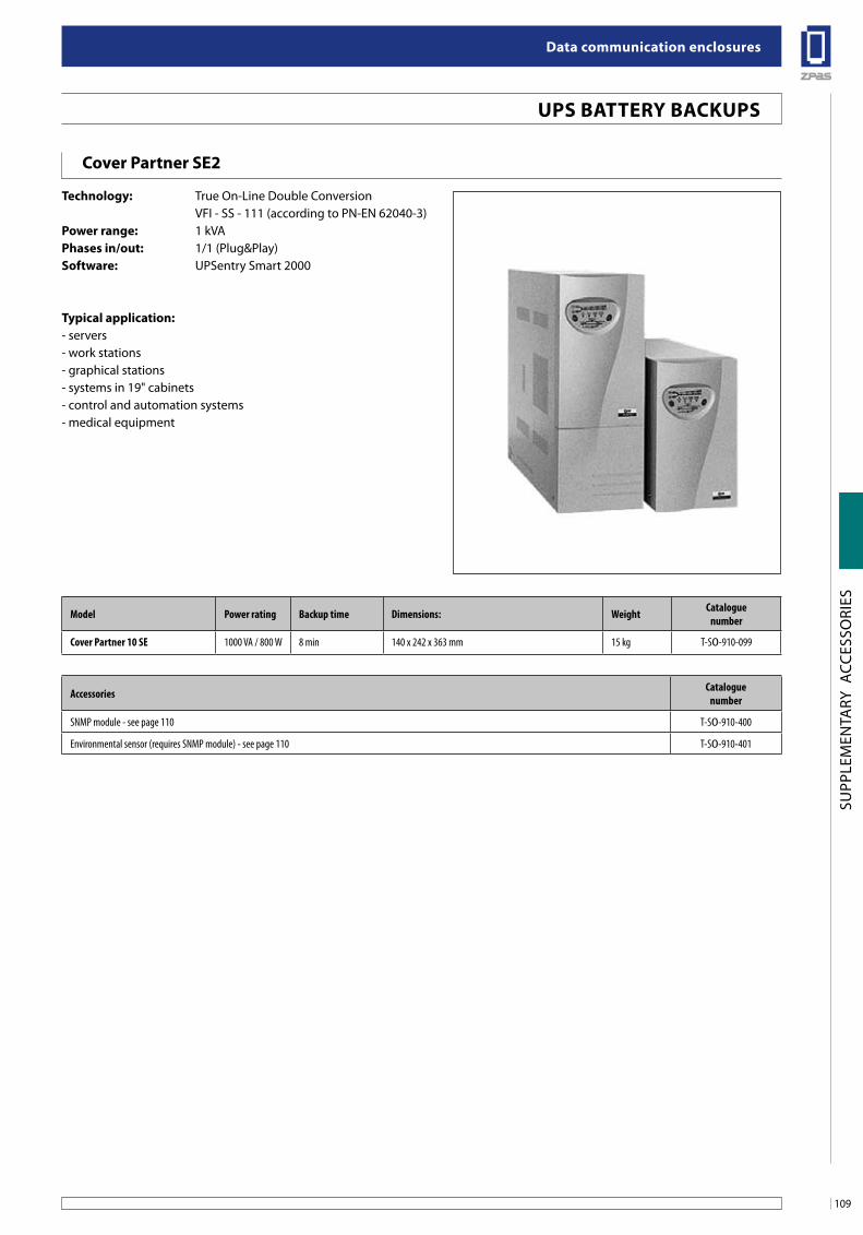
109
Data communication enclosures
SUPP
LEM
ENTA
RY A
CCES
SORI
ES
Model Power rating Backup time Dimensions: Weight Cataloguenumber
Cover Partner 10 SE 1000 VA / 800 W 8 min 140 x 242 x 363 mm 15 kg T-SO-910-099
Accessories Cataloguenumber
SNMP module - see page 110 T-SO-910-400
Environmental sensor (requires SNMP module) - see page 110 T-SO-910-401
uPs baTTeRY baCKuPs
Cover Partner se2
Technology: True On-Line Double Conversion VFI - SS - 111 (according to PN-EN 62040-3) Power range: 1 kVA Phases in/out: 1/1 (Plug&Play)software: UPSentry Smart 2000
Typical application:- servers- work stations- graphical stations- systems in 19" cabinets- control and automation systems- medical equipment
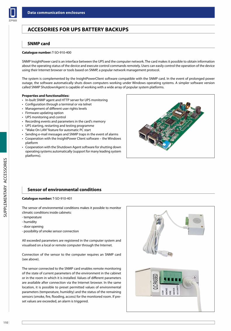
Data communication enclosures
110
SUPP
LEM
ENTA
RY A
CCES
SORI
ES
snMP card
Catalogue number: T-SO-910-400
SNMP InsightPower card is an interface between the UPS and the computer network. The card makes it possible to obtain information about the operating status of the device and execute control commands remotely. Users can easily control the operation of the device using their Internet browser or tools based on SNMP, a popular network management protocol.
The system is complemented by the InsightPowerClient software compatible with the SNMP card. In the event of prolonged power outage, the software automatically shuts down computers working under Windows operating systems. A simpler software version called SNMP ShutdownAgent is capable of working with a wide array of popular system platforms.
Properties and functionalities:• In-builtSNMPagentandHTTPserverforUPSmonitoring• Configurationthroughaterminalorviatelnet• Managementofdifferentuserrightslevels• Firmwareupdatingoption• UPSmonitoringandcontrol• Recordingeventsandparametersinthecard'smemory• UPSstarting,restartingandtestingprogramme• ’’WakeOnLAN’’featureforautomaticPCstart• Sendinge-mailmessagesandSNMPtrapsintheeventofalarms• CooperationwiththeInsightPowerClientsoftware–theWindows
platform• CooperationwiththeShutdownAgentsoftwareforshuttingdown
operating systems automatically (support for many leading system platforms).
sensor of environmental conditions
Catalogue number: T-SO-910-401
The sensor of environmental conditions makes it possible to monitor climatic conditions inside cabinets:- temperature- humidity- door opening- possibility of smoke sensor connection
All exceeded parameters are registered in the computer system and visualised on a local or remote computer through the Internet.
Connection of the sensor to the computer requires an SNMP card (see above).
The sensor connected to the SNMP card enables remote monitoring of the state of current parameters of the environment in the cabinet or in the room in which it is installed. Values of different parameters are available after connection via the Internet browser. In the same location, it is possible to preset permitted values of environmental parameters (temperature, humidity) and the status of the remaining sensors (smoke, fire, flooding, access) for the monitored room. If pre-set values are exceeded, an alarm is triggered.
aCCesoRies foR uPs baTTeRY baCKuPs
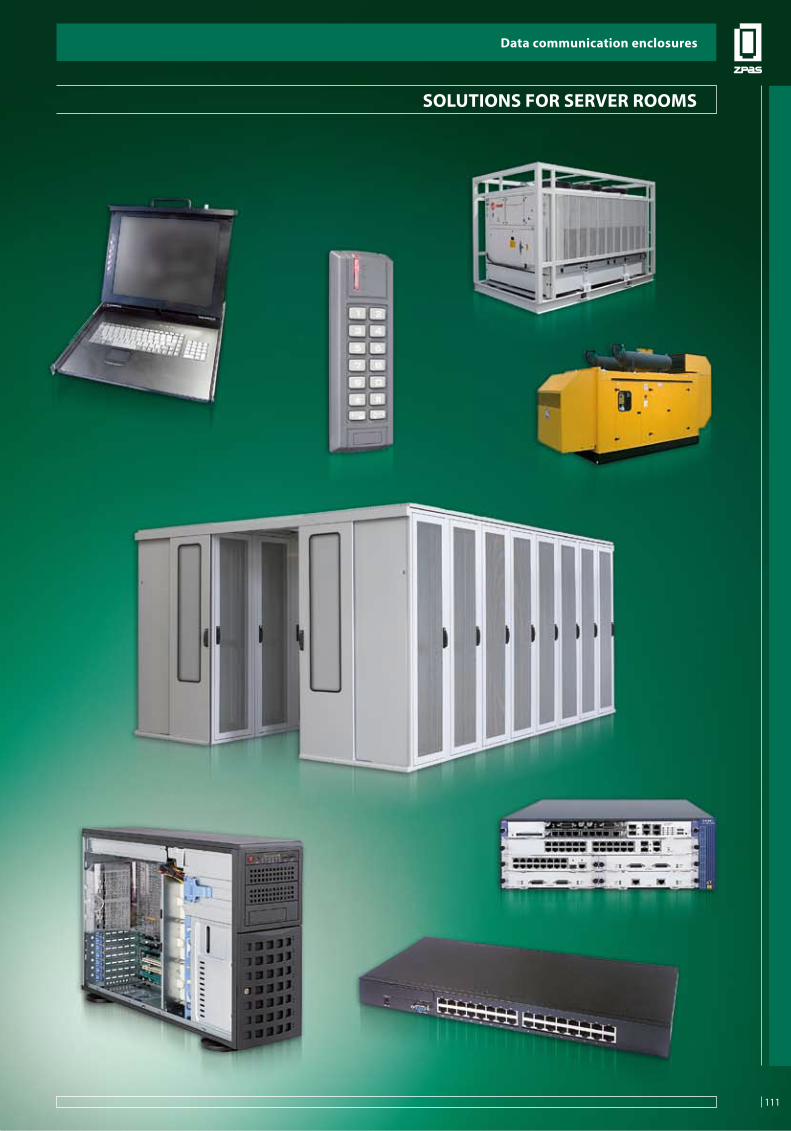
111
Data communication enclosures
SOLU
TIO
NS
FO
R S
ERVE
R RO
OM
S
soluTions foR seRVeR RooMs
Data communication enclosures
111

Data communication enclosures
112
SOLU
TIO
NS
FO
R S
ERVE
R RO
OM
S
Modular server room based on sZb se 19" cabinets
In the era of globalised business process information, appropriate protection against business and operating risks is vital if companies want to ensure their uninterrupted operation. Unlimited and complete access to information, at any time, is currently becoming one of the most valuable business resources. In many cases, data stored on company hard disks represent the most precious assets of the enterprise. Therefore, important data require a suitable level of protection and security.
ERP systems are becoming increasingly popular, and their continuous operation is of big importance to ensure proper functioning of the entire enterprise. A dedicated Data Center, i.e. a secure facility provided with independent power supply, cooling and commu-nications systems, ensures an appropriate level of company data protection. The server room is equipped with centrally coordinated systems of power supply, air conditioning, access control and security measures, which ensures a high level of working comfort and safety, as well as reliable protection against unauthorised access.
New trends in the IT industry, such as HigH DensiTY (maximum number of blade servers accommodated in a rack) and server vir-tualisation (division of one physical server into multiple isolated virtual environments), produce a markedly increased demand for power and cooling capacity in the server room.
ZPAS Data Center is a comprehensive tool designed for banks, telecommunications operators and major companies.
ZPas Data Center includes:- a system of cabinets with slide doors and a roof,- a cooling system based on ice water or a different cooling agent,- guaranteed power supply system,- power supply management system,- access control system, burglary and fire alarm system,- fire extinguishing system,- climate control system,- network management solution,- IT-room booths,- consoles and KVM switches,- servers.
ZPas DaTa CenTeR
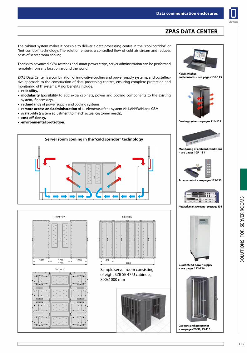
113
Data communication enclosures
SOLU
TIO
NS
FO
R S
ERVE
R RO
OM
S
The cabinet system makes it possible to deliver a data processing centre in the "cool corridor" or "hot corridor" technology. The solution ensures a controlled flow of cold air stream and reduces costs of server room cooling.
Thanks to advanced KVM switches and smart power strips, server administration can be performed remotely from any location around the world.
ZPAS Data Center is a combination of innovative cooling and power supply systems, and costeffec-tive approach to the construction of data processing centres, ensuring complete protection and monitoring of IT systems. Major benefits include:• reliability,• modularity (possibility to add extra cabinets, power and cooling components to the existing
system, if necessary),• redundancyof power supply and cooling systems,• remoteaccessandadministrationof all elements of the system via LAN/WAN and GSM,• scalability(system adjustment to match actual customer needs),• cost-efficiency,• environmentalprotection.
ZPas DaTa CenTeR
1200 100010003200 3200
Front view Side view
Top view
800
KVM switches and consoles – see pages 138-145
Cooling systems – pages 116-121
access control – see pages 132-133
network management – see page 136
guaranteed power supply – see pages 122-126
Cabinets and accessories – see pages 28-39, 73-110
Monitoring of ambient conditions – see pages 105, 131
Sample server room consisting of eight SZB SE 47 U cabinets, 800x1000 mm
server room cooling in the “cold corridor” technology
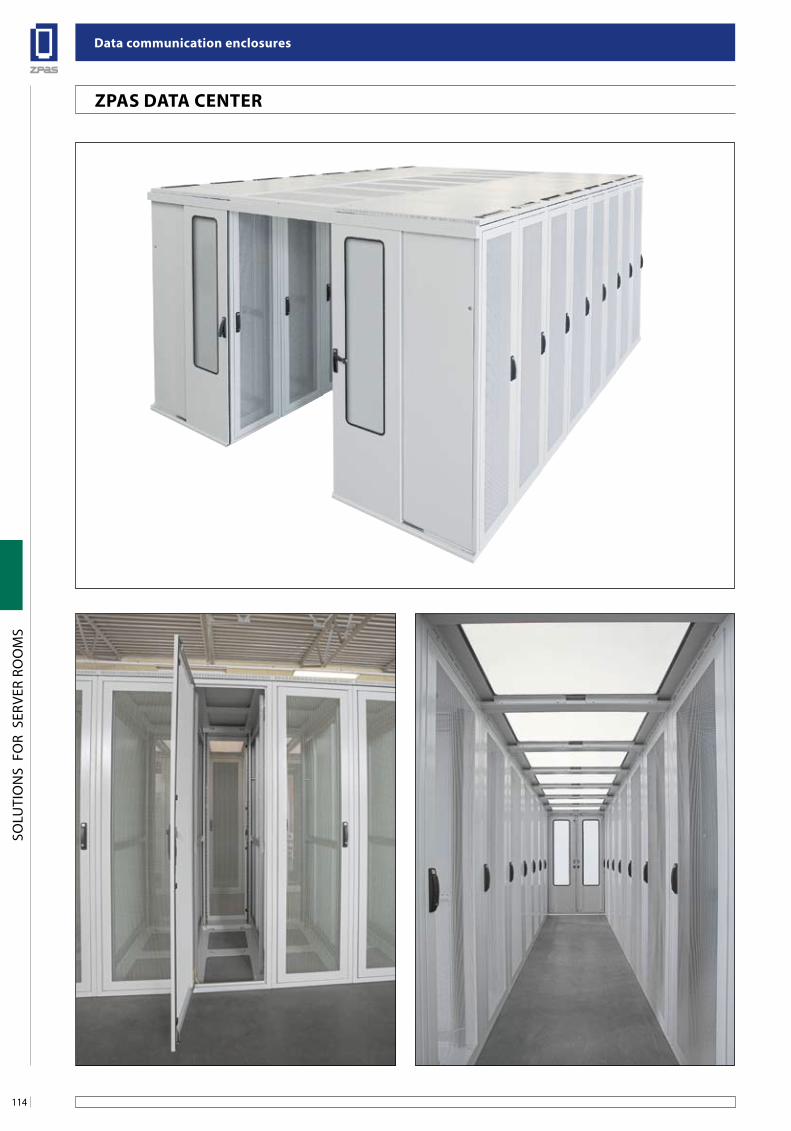
Data communication enclosures
114
SOLU
TIO
NS
FO
R S
ERVE
R RO
OM
S
ZPas DaTa CenTeR
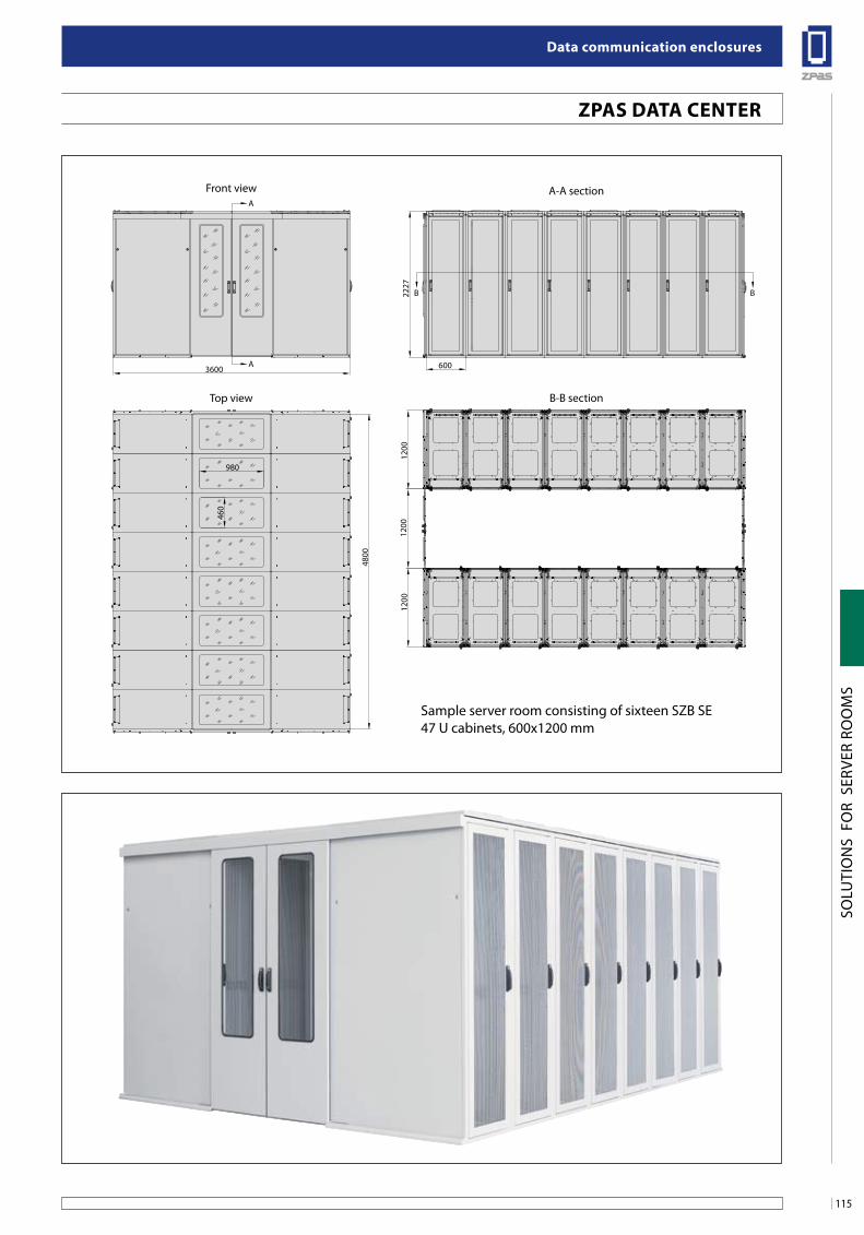
115
Data communication enclosures
SOLU
TIO
NS
FO
R S
ERVE
R RO
OM
S
ZPas DaTa CenTeR
2227
1200
460
980
1200
1200
360048
00600
A-A section
B-B section
Front view
Top view
A
A
B B
Sample server room consisting of sixteen SZB SE 47 U cabinets, 600x1200 mm
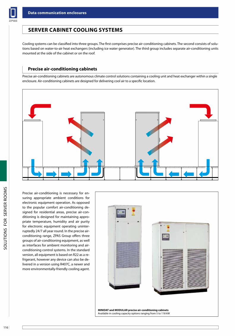
Data communication enclosures
116
SOLU
TIO
NS
FO
R S
ERVE
R RO
OM
S
seRVeR CabineT Cooling sYsTeMs
Cooling systems can be classified into three groups. The first comprises precise air-conditioning cabinets. The second consists of solu-tions based on water-to-air heat exchangers (including ice water generator). The third group includes separate air-conditioning units mounted at the side of the cabinet or on the roof.
Precise air-conditioning is necessary for en-suring appropriate ambient conditions for electronic equipment operation. As opposed to the popular comfort air-conditioning de-signed for residential areas, precise air-con-ditioning is designed for maintaining appro-priate temperature, humidity and air purity for electronic equipment operating uninter-ruptedly 24/7 all year round. In the precise air-conditioning range, ZPAS Group offers three groups of air-conditioning equipment, as well as interfaces for ambient monitoring and air-conditioning control systems. In the standard version, all equipment is based on R22 as a re-frigerant, however any device can also be de-livered in a version using R407C, a newer and more environmentally-friendly cooling agent.
Precise air-conditioning cabinetsPrecise air-conditioning cabinets are autonomous climate control solutions containing a cooling unit and heat exchanger within a single enclosure. Air-conditioning cabinets are designed for delivering cool air to a specific location.
MiniDaT and MoDulaR precise air-conditioning cabinetsAvailable in cooling capacity options ranging from 5 to 118 kW
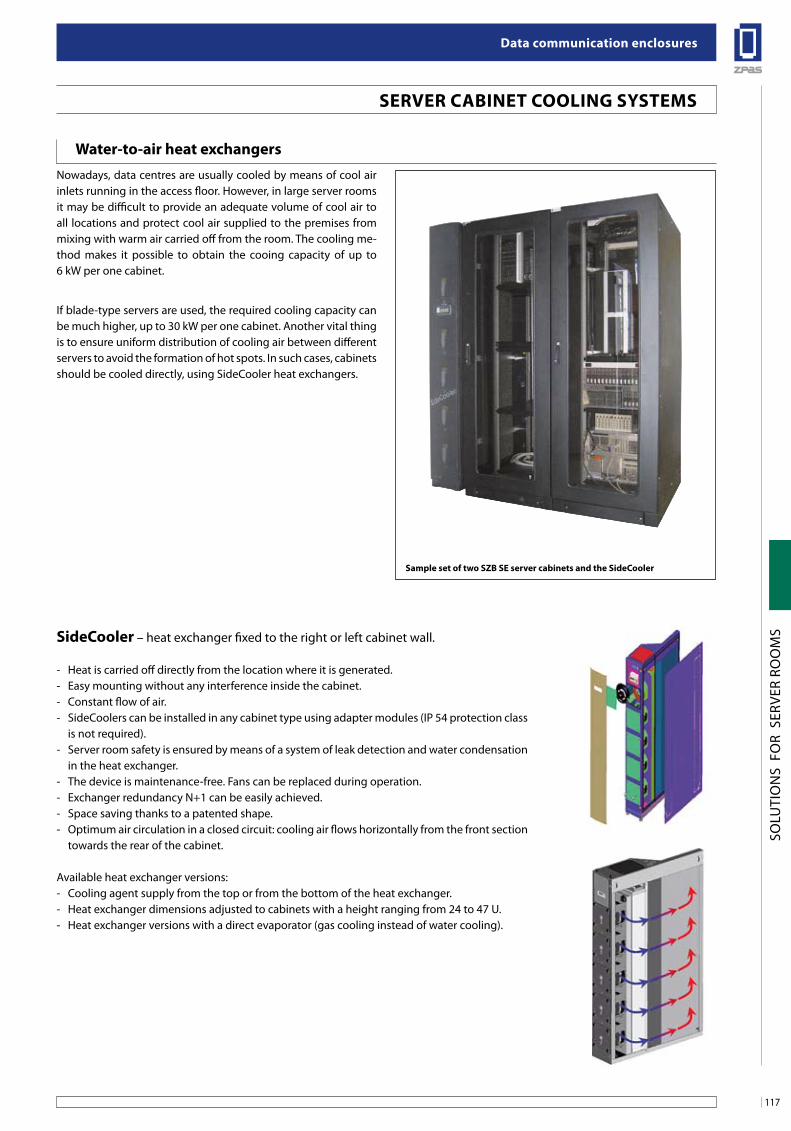
117
Data communication enclosures
SOLU
TIO
NS
FO
R S
ERVE
R RO
OM
S
seRVeR CabineT Cooling sYsTeMs
Water-to-air heat exchangers Nowadays, data centres are usually cooled by means of cool air inlets running in the access floor. However, in large server rooms it may be difficult to provide an adequate volume of cool air to all locations and protect cool air supplied to the premises from mixing with warm air carried off from the room. The cooling me-thod makes it possible to obtain the cooing capacity of up to 6 kW per one cabinet.
If blade-type servers are used, the required cooling capacity can be much higher, up to 30 kW per one cabinet. Another vital thing is to ensure uniform distribution of cooling air between different servers to avoid the formation of hot spots. In such cases, cabinets should be cooled directly, using SideCooler heat exchangers.
sideCooler – heat exchanger fixed to the right or left cabinet wall.
- Heat is carried off directly from the location where it is generated.- Easy mounting without any interference inside the cabinet.- Constant flow of air.- SideCoolers can be installed in any cabinet type using adapter modules (IP 54 protection class
is not required).- Server room safety is ensured by means of a system of leak detection and water condensation
in the heat exchanger.- The device is maintenance-free. Fans can be replaced during operation.- Exchanger redundancy N+1 can be easily achieved.- Space saving thanks to a patented shape.- Optimum air circulation in a closed circuit: cooling air flows horizontally from the front section
towards the rear of the cabinet.
Available heat exchanger versions:- Cooling agent supply from the top or from the bottom of the heat exchanger.- Heat exchanger dimensions adjusted to cabinets with a height ranging from 24 to 47 U.- Heat exchanger versions with a direct evaporator (gas cooling instead of water cooling).
sample set of two sZb se server cabinets and the sideCooler
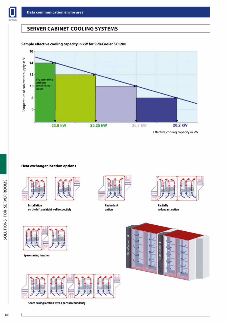
Data communication enclosures
118
SOLU
TIO
NS
FO
R S
ERVE
R RO
OM
S
sample effective cooling capacity in kW for sideCooler sC1200
Tem
pera
ture
of c
ool w
ater
sup
ply
in °C
Effective cooling capacity in kW
Heat exchanger location options
Space-saving location with a partial redundancy
Installation on the left and right wall respectiely
Redundantoption
Partially redundant option
Space-saving location
seRVeR CabineT Cooling sYsTeMs
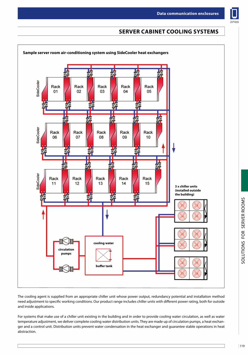
119
Data communication enclosures
SOLU
TIO
NS
FO
R S
ERVE
R RO
OM
S
seRVeR CabineT Cooling sYsTeMs
The cooling agent is supplied from an appropriate chiller unit whose power output, redundancy potential and installation method need adjustment to specific working conditions. Our product range includes chiller units with different power rating, both for outside and inside applications.
For systems that make use of a chiller unit existing in the building and in order to provide cooling water circulation, as well as water temperature adjustment, we deliver complete cooling water distribution units. They are made up of circulation pumps, a heat exchan-ger and a control unit. Distribution units prevent water condensation in the heat exchanger and guarantee stable operations in heat abstraction.
sample server room air-conditioning system using sideCooler heat exchangers
3 x chiller units (installed outside the building)
cooling water
circulation pumps
buffer tank
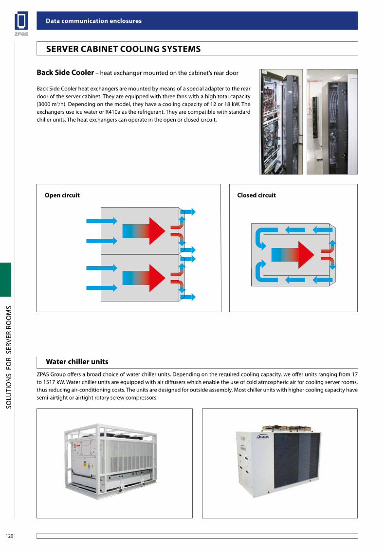
Data communication enclosures
120
SOLU
TIO
NS
FO
R S
ERVE
R RO
OM
S
seRVeR CabineT Cooling sYsTeMs
back side Cooler – heat exchanger mounted on the cabinet’s rear door
Back Side Cooler heat exchangers are mounted by means of a special adapter to the rear door of the server cabinet. They are equipped with three fans with a high total capacity (3000 m3/h). Depending on the model, they have a cooling capacity of 12 or 18 kW. The exchangers use ice water or R410a as the refrigerant. They are compatible with standard chiller units. The heat exchangers can operate in the open or closed circuit.
open circuit Closed circuit
Water chiller unitsZPAS Group offers a broad choice of water chiller units. Depending on the required cooling capacity, we offer units ranging from 17 to 1517 kW. Water chiller units are equipped with air diffusers which enable the use of cold atmospheric air for cooling server rooms, thus reducing air-conditioning costs. The units are designed for outside assembly. Most chiller units with higher cooling capacity have semi-airtight or airtight rotary screw compressors.
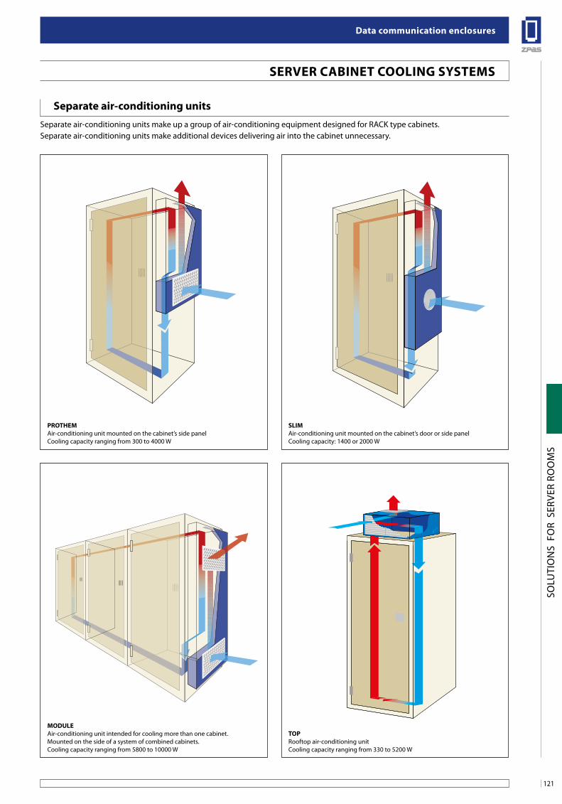
121
Data communication enclosures
SOLU
TIO
NS
FO
R S
ERVE
R RO
OM
S
seRVeR CabineT Cooling sYsTeMs
separate air-conditioning unitsSeparate air-conditioning units make up a group of air-conditioning equipment designed for RACK type cabinets.Separate air-conditioning units make additional devices delivering air into the cabinet unnecessary.
PRoTHeMAir-conditioning unit mounted on the cabinet’s side panelCooling capacity ranging from 300 to 4000 W
sliMAir-conditioning unit mounted on the cabinet’s door or side panelCooling capacity: 1400 or 2000 W
MoDuleAir-conditioning unit intended for cooling more than one cabinet.Mounted on the side of a system of combined cabinets.Cooling capacity ranging from 5800 to 10000 W
ToPRooftop air-conditioning unitCooling capacity ranging from 330 to 5200 W
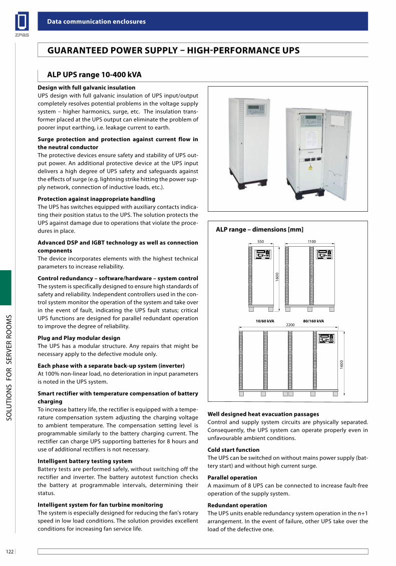
Data communication enclosures
122
SOLU
TIO
NS
FO
R S
ERVE
R RO
OM
S
guaRanTeeD PoWeR suPPlY – HigH-PeRfoRManCe uPs
alP uPs range 10-400 kVaDesign with full galvanic insulationUPS design with full galvanic insulation of UPS input/output completely resolves potential problems in the voltage supply system – higher harmonics, surge, etc. The insulation trans-former placed at the UPS output can eliminate the problem of poorer input earthing, i.e. leakage current to earth.
surge protection and protection against current flow in the neutral conductorThe protective devices ensure safety and stability of UPS out-put power. An additional protective device at the UPS input delivers a high degree of UPS safety and safeguards against the effects of surge (e.g. lightning strike hitting the power sup-ply network, connection of inductive loads, etc.).
Protection against inappropriate handlingThe UPS has switches equipped with auxiliary contacts indica-ting their position status to the UPS. The solution protects the UPS against damage due to operations that violate the proce-dures in place.
advanced DsP and igbT technology as well as connection componentsThe device incorporates elements with the highest technical parameters to increase reliability.
Control redundancy – software/hardware – system control The system is specifically designed to ensure high standards of safety and reliability. Independent controllers used in the con-trol system monitor the operation of the system and take over in the event of fault, indicating the UPS fault status; critical UPS functions are designed for parallel redundant operation to improve the degree of reliability.
Plug and Play modular designThe UPS has a modular structure. Any repairs that might be necessary apply to the defective module only.
each phase with a separate back-up system (inverter)At 100% non-linear load, no deterioration in input parameters is noted in the UPS system.
smart rectifier with temperature compensation of battery chargingTo increase battery life, the rectifier is equipped with a tempe-rature compensation system adjusting the charging voltage to ambient temperature. The compensation setting level is programmable similarly to the battery charging current. The rectifier can charge UPS supporting batteries for 8 hours and use of additional rectifiers is not necessary.
intelligent battery testing systemBattery tests are performed safely, without switching off the rectifier and inverter. The battery autotest function checks the battery at programmable intervals, determining their status.
intelligent system for fan turbine monitoringThe system is especially designed for reducing the fan's rotary speed in low load conditions. The solution provides excellent conditions for increasing fan service life.
alP range – dimensions [mm]
Well designed heat evacuation passagesControl and supply system circuits are physically separated. Consequently, the UPS system can operate properly even in unfavourable ambient conditions.
Cold start functionThe UPS can be switched on without mains power supply (bat-tery start) and without high current surge.
Parallel operationA maximum of 8 UPS can be connected to increase fault-free operation of the supply system.
Redundant operationThe UPS units enable redundancy system operation in the n+1 arrangement. In the event of failure, other UPS take over the load of the defective one.
550
1600
10/60 kVA
1100
80/160 kVA
1600
2200
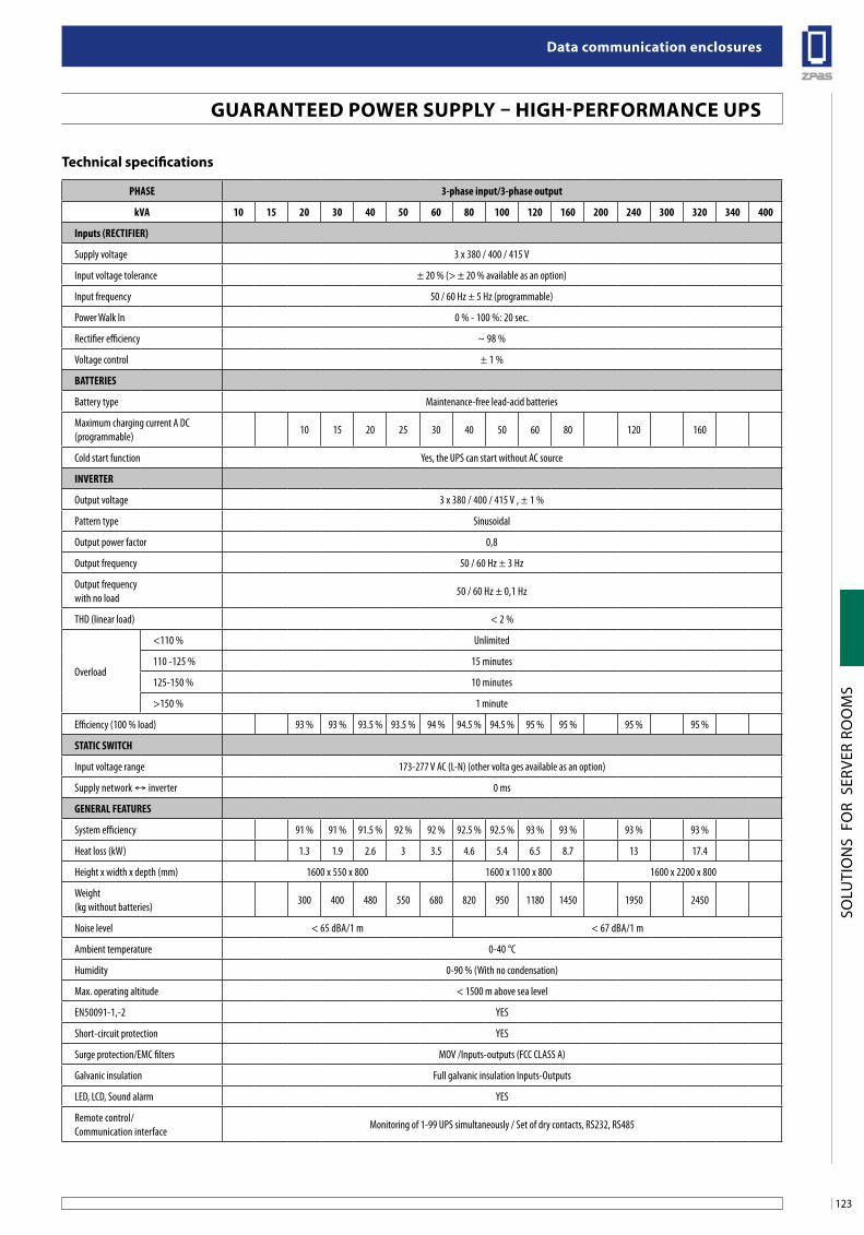
123
Data communication enclosures
SOLU
TIO
NS
FO
R S
ERVE
R RO
OM
S
guaRanTeeD PoWeR suPPlY – HigH-PeRfoRManCe uPs
PHASE 3-phase input/3-phase output
kVA 10 15 20 30 40 50 60 80 100 120 160 200 240 300 320 340 400
Inputs (RECTIFIER)
Supply voltage 3 x 380 / 400 / 415 V
Input voltage tolerance ± 20 % (> ± 20 % available as an option)
Input frequency 50 / 60 Hz ± 5 Hz (programmable)
Power Walk In 0 % - 100 %: 20 sec.
Rectifier efficiency ~ 98 %
Voltage control ± 1 %
BATTERIES
Battery type Maintenance-free lead-acid batteries
Maximum charging current A DC(programmable)
10 15 20 25 30 40 50 60 80 120 160
Cold start function Yes, the UPS can start without AC source
INVERTER
Output voltage 3 x 380 / 400 / 415 V , ± 1 %
Pattern type Sinusoidal
Output power factor 0,8
Output frequency 50 / 60 Hz ± 3 Hz
Output frequency with no load
50 / 60 Hz ± 0,1 Hz
THD (linear load) < 2 %
Overload
<110 % Unlimited
110 -125 % 15 minutes
125-150 % 10 minutes
>150 % 1 minute
Efficiency (100 % load) 93 % 93 % 93.5 % 93.5 % 94 % 94.5 % 94.5 % 95 % 95 % 95 % 95 %
STATIC SWITCH
Input voltage range 173-277 V AC (L-N) (other volta ges available as an option)
Supply network ↔ inverter 0 ms
GENERAL FEATURES
System efficiency 91 % 91 % 91.5 % 92 % 92 % 92.5 % 92.5 % 93 % 93 % 93 % 93 %
Heat loss (kW) 1.3 1.9 2.6 3 3.5 4.6 5.4 6.5 8.7 13 17.4
Height x width x depth (mm) 1600 x 550 x 800 1600 x 1100 x 800 1600 x 2200 x 800
Weight(kg without batteries)
300 400 480 550 680 820 950 1180 1450 1950 2450
Noise level < 65 dBA/1 m < 67 dBA/1 m
Ambient temperature 0-40 °C
Humidity 0-90 % (With no condensation)
Max. operating altitude < 1500 m above sea level
EN50091-1,-2 YES
Short-circuit protection YES
Surge protection/EMC filters MOV /Inputs-outputs (FCC CLASS A)
Galvanic insulation Full galvanic insulation Inputs-Outputs
LED, LCD, Sound alarm YES
Remote control/Communication interface
Monitoring of 1-99 UPS simultaneously / Set of dry contacts, RS232, RS485
Technical specifications
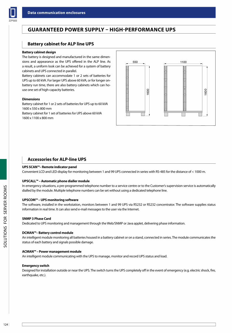
Data communication enclosures
124
SOLU
TIO
NS
FO
R S
ERVE
R RO
OM
S
guaRanTeeD PoWeR suPPlY – HigH-PeRfoRManCe uPs
battery cabinet designThe battery is designed and manufactured in the same dimen-sions and appearance as the UPS offered in the ALP line. As a result, a uniform look can be achieved for a system of battery cabinets and UPS connected in parallel.Battery cabinets can accommodate 1 or 2 sets of batteries for UPS up to 60 kVA. For larger UPS above 60 kVA, or for longer on-battery run time, there are also battery cabinets which can ho-use one set of high-capacity batteries.
DimensionsBattery cabinet for 1 or 2 sets of batteries for UPS up to 60 kVA1600 x 550 x 800 mmBattery cabinet for 1 set of batteries for UPS above 60 kVA1600 x 1100 x 800 mm
accessories for alP-line uPs
battery cabinet for alP line uPs
uPs sCan™– Remote indicator panelConvenient LCD and LED display for monitoring between 1 and 99 UPS connected in series with RS-485 for the distance of < 1000 m.
uPsCall™ – automatic phone dialler moduleIn emergency situations, a pre-programmed telephone number to a service centre or to the Customer’s supervision service is automatically dialled by the module. Multiple telephone numbers can be set without using a dedicated telephone line.
uPsCoM™ – uPs monitoring softwareThe software, installed in the workstation, monitors between 1 and 99 UPS via RS232 or RS232 concentrator. The software supplies status information in real time. It can also send e-mail messages to the user via the Internet.
snMP 3 Phase CardDedicated to UPS monitoring and management through the Web/SNMP or Java applet, delivering phase information.
DCMan™– battery control moduleAn intelligent module monitoring all batteries housed in a battery cabinet or on a stand, connected in series. The module communicates the status of each battery and signals possible damage.
aCMan™ – Power management moduleAn intelligent module communicating with the UPS to manage, monitor and record UPS status and load.
emergency switchDesigned for installation outside or near the UPS. The switch turns the UPS completely off in the event of emergency (e.g. electric shock, fire, earthquake, etc.).
550
1600
1100
1600
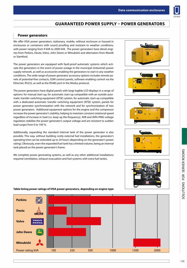
125
Data communication enclosures
SOLU
TIO
NS
FO
R S
ERVE
R RO
OM
S
guaRanTeeD PoWeR suPPlY – PoWeR geneRaToRs
We offer VISA power generators: stationary, mobile, without enclosure or housed in enclosures or containers with sound proofing and resistant to weather conditions, with power ranging from 9 kVA to 2000 kVA. The power generators have diesel engi-nes from Perkins, Deutz, Volvo, John Deere or Mitsubishi and alternators from Marelli or Stamford.
The power generators are equipped with fault-proof automatic systems which acti-vate the generators in the event of power outage in the municipal (industrial) power supply network, as well as accessories enabling the generators to start in any weather conditions. The wide range of power generator accessory options includes remote pa-nels of potential-free contacts, GSM control panels, software enabling control via the Ethernet, RS232, as well as the RS485 port in the Modus protocol.
The power generators have digital panels with large legible LCD displays in a range of options: for manual start-up, for automatic start-up compatible with an outside auto-matic transfer switching equipment (ATSE) system, for automatic start-up compatible with a dedicated automatic transfer switching equipment (ATSE) system, panels for power generator synchronization with the network and for synchronization of two power generators. Additional equipment options for the engine and the compressor increase the power generator's stability, helping to maintain constant rotational speed regardless of increase in load (i.e. keep up the frequency). AVR and AVR+PMG voltage regulators stabilize the power generator’s output voltage and are resistant to sudden load surges from 0 to 100 %.
Additionally, expanding the standard internal tank of the power generator is also possible. This way, without building costly external fuel installations, the generator’s operating time can be extended up to 24 hours (depending on the generator’s power rating). Obviously, even the expanded fuel tank has a limited volume, being an internal tank placed on the power generator’s frame.
We complete power generating systems, as well as any other additional installations required (ventilation, exhaust evacuation and fuel systems with extra fuel tanks).
Table listing power ratings of Visa power generators, depending on engine type
Perkins
Deutz
Volvo
John Deere
Mitsubishi
Power rating kVA 100 250 500 1000 1500 2000
Power generators
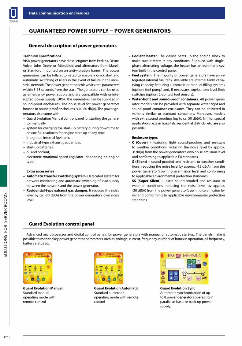
Data communication enclosures
126
SOLU
TIO
NS
FO
R S
ERVE
R RO
OM
S
guaRanTeeD PoWeR suPPlY – PoWeR geneRaToRs
general description of power generators
guard evolution control panel
Technical specificationsVISA power generators have diesel engines from Perkins, Deutz, Volvo, John Deere or Mitsubishi and alternators from Marelli or Stamford, mounted on an anti-vibration frame. The power generators can be fully automated to enable a quick start and automatic switching of users in the event of failure in the indu-strial network. The power generator achieves its rate parameters within 5-15 seconds from the start. The generators can be used as emergency power supply and are compatible with uninte-rupted power supply (UPS). The generators can be supplied in sound-proof enclosures. The noise level for power generators housed in sound-proof enclosures is 70-80 dB(A). The power ge-nerators also come with: – Guard Evolution Manual control panel for starting the genera-
tor manually,– system for charging the start-up battery during downtime to
ensure full readiness for engine start-up at any time,– integrated internal fuel tank,– Industrial-type exhaust gas damper,– start-up batteries,– oil and coolant,– electronic rotational speed regulator (depending on engine
type).
extra accessories – automatic transfer switching system. Dedicated system for
network monitoring and automatic switching of load supply between the network and the power generator.
– Residential-type exhaust gas damper. It reduces the noise level by ca. -30 dB(A) from the power generator’s own noise level.
– Coolant heater. The device heats up the engine block to make sure it starts in any conditions. Supplied with single-phase alternating voltage, the heater has an automatic sys-tem built in the control panel.
– fuel system. The majority of power generators have an in-tegrated internal fuel tank. Available are internal tanks of va-rying capacity featuring automatic or manual filling systems (option: fuel pump) and, if necessary, top/bottom level limit switches (option: 2-contact fuel sensors).
– Water-tight and sound-proof containers. All power gene-rator models can be provided with separate water-tight and sound-proof container enclosures. They can be delivered in variants similar to standard containers. Moreover, models with extra sound proofing (up to ca. 50 db(A)/1m) for special applications, e.g. in hospitals, residential districts, etc. are also possible.
enclosure types– C (Cover) – featuring light sound-proofing and resistant
to weather conditions, reducing the noise level by approx. -8 dB(A) from the power generator’s own noise emission level and conforming to applicable EU standards.
– s (silent) – sound-proofed and resistant to weather condi-tions, reducing the noise level by approx. -15 dB(A) from the power generator’s own noise emission level and conforming to applicable environmental protection standards.
– ss (super silent) – extra sound-proofed and resistant to weather conditions, reducing the noise level by approx. -20 dB(A) from the power generator’s own noise emission le-vel and conforming to applicable environmental protection standards.
Advanced microprocessor and digital control panels for power generators with manual or automatic start-up. The panels make it possible to monitor key power generator parameters such as: voltage, current, frequency, number of hours in operation, oil frequency, battery status etc.
guard evolution ManualStandard manual operating mode with remote control
guard evolution automaticStandard automatic operating mode with remote control
guard evolution syncAutomatic synchronization of up to 8 power generators operating in parallel as basic or back-up power supply.
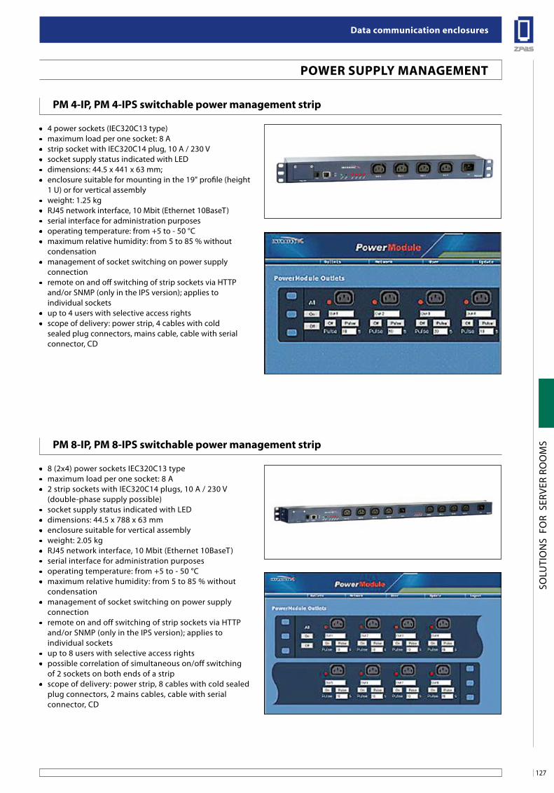
127
Data communication enclosures
SOLU
TIO
NS
FO
R S
ERVE
R RO
OM
S
POWER SUPPLY MANAGEMENT
PM 4-IP, PM 4-IPS switchable power management strip
PM 8-IP, PM 8-IPS switchable power management strip
• 4 power sockets (IEC320C13 type)• maximum load per one socket: 8 A• strip socket with IEC320C14 plug, 10 A / 230 V• socket supply status indicated with LED• dimensions: 44.5 x 441 x 63 mm;• enclosure suitable for mounting in the 19" profile (height
1 U) or for vertical assembly• weight: 1.25 kg• RJ45 network interface, 10 Mbit (Ethernet 10BaseT)• serial interface for administration purposes• operating temperature: from +5 to - 50 °C • maximum relative humidity: from 5 to 85 % without
condensation• management of socket switching on power supply
connection• remote on and off switching of strip sockets via HTTP
and/or SNMP (only in the IPS version); applies to individual sockets
• up to 4 users with selective access rights• scope of delivery: power strip, 4 cables with cold
sealed plug connectors, mains cable, cable with serial connector, CD
• 8 (2x4) power sockets IEC320C13 type• maximum load per one socket: 8 A• 2 strip sockets with IEC320C14 plugs, 10 A / 230 V
(double-phase supply possible)• socket supply status indicated with LED• dimensions: 44.5 x 788 x 63 mm• enclosure suitable for vertical assembly• weight: 2.05 kg• RJ45 network interface, 10 Mbit (Ethernet 10BaseT)• serial interface for administration purposes• operating temperature: from +5 to - 50 °C • maximum relative humidity: from 5 to 85 % without
condensation• management of socket switching on power supply
connection• remote on and off switching of strip sockets via HTTP
and/or SNMP (only in the IPS version); applies to individual sockets
• up to 8 users with selective access rights• possible correlation of simultaneous on/off switching
of 2 sockets on both ends of a strip • scope of delivery: power strip, 8 cables with cold sealed
plug connectors, 2 mains cables, cable with serial connector, CD
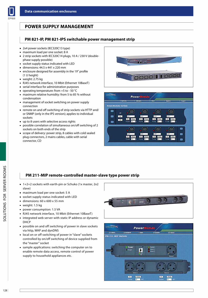
Data communication enclosures
128
SOLU
TIO
NS
FO
R S
ERVE
R RO
OM
S
PoWeR suPPlY ManageMenT
PM 821-iP, PM 821-iPs switchable power management strip
PM 211-MiP remote-controlled master-slave type power strip
• 2x4 power sockets (IEC320C13 type)• maximum load per one socket: 8 A• 2 strip sockets with IEC320C14 plugs, 10 A / 230 V (double-
phase supply possible)• socket supply status indicated with LED• dimensions: 44.5 x 441 x 220 mm• enclosure designed for assembly in the 19" profile
(1 U height)• weight: 2.75 kg• RJ45 network interface, 10 Mbit (Ethernet 10BaseT)• serial interface for administration purposes• operating temperature: from +5 to - 50 °C • maximum relative humidity: from 5 to 85 % without
condensation• management of socket switching on power supply
connection• remote on and off switching of strip sockets via HTTP and/
or SNMP (only in the IPS version); applies to individual sockets
• up to 8 users with selective access rights• possible correlation of simultaneous on/off switching of 2
sockets on both ends of the strip • scope of delivery: power strip, 8 cables with cold sealed
plug connectors, 2 mains cables, cable with serial connector, CD
• 1+2+2 sockets with earth-pin or Schuko (1x master, 2x2 slave)
• maximum load per one socket: 5 A• socket supply status indicated with LED• dimensions: 60 x 600 x 55 mm• weight: 1.5 kg• power consumption: 1.5 VA• RJ45 network interface, 10 Mbit (Ethernet 10BaseT)• integrated web server with static IP address or dynamic
DHCP• possible on and off switching of power in slave sockets
via http, WAP and dynDNS• local on or off switching of power in “slave” sockets
controlled by on/off switching of device supplied from the “master” socket
• sample applications: switching the computer on to enable remote data access, remote control of power supply to household appliances etc.
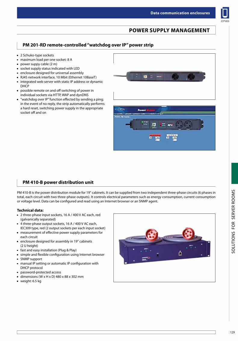
129
Data communication enclosures
SOLU
TIO
NS
FO
R S
ERVE
R RO
OM
S
PoWeR suPPlY ManageMenT
PM 201-RD remote-controlled “watchdog over iP” power strip
PM 410-b power distribution unit
• 2 Schuko-type sockets• maximum load per one socket: 8 A• power suppy cable (2 m)• socket supply status indicated with LED• enclosure designed for universal assembly• RJ45 network interface, 10 Mbit (Ethernet 10BaseT)• integrated web server with static IP address or dynamic
DHCP• possible remote on and off switching of power in
individual sockets via HTTP, WAP and dynDNS• “watchdog over IP” function effected by sending a ping;
in the event of no reply, the strip automatically performs a hard reset, switching power supply in the appropriate socket off and on
PM 410-B is the power distribution module for 19" cabinets. It can be supplied from two independent three-phase circuits (6 phases in total, each circuit with two three-phase outputs). It controls electrical parameters such as energy consumption, current consumption or voltage level. Data can be configured and read using an Internet browser or an SNMP agent.
Technical data:• 2 three-phase input sockets, 16 A / 400 V AC each, red
(galvanically separated)• 4 three-phase output sockets, 16 A / 400 V AC each,
IEC309 type, red (2 output sockets per each input socket)• measurement of effective power supply parameters for
each circuit• enclosure designed for assembly in 19" cabinets
(2 U height)• fast and easy installation (Plug & Play)• simple and flexible configuration using Internet browser• SNMP support• manual IP setting or automatic IP configuration with
DHCP protocol• password-protected access• dimensions (W x H x D) 480 x 88 x 302 mm• weight: 6.5 kg
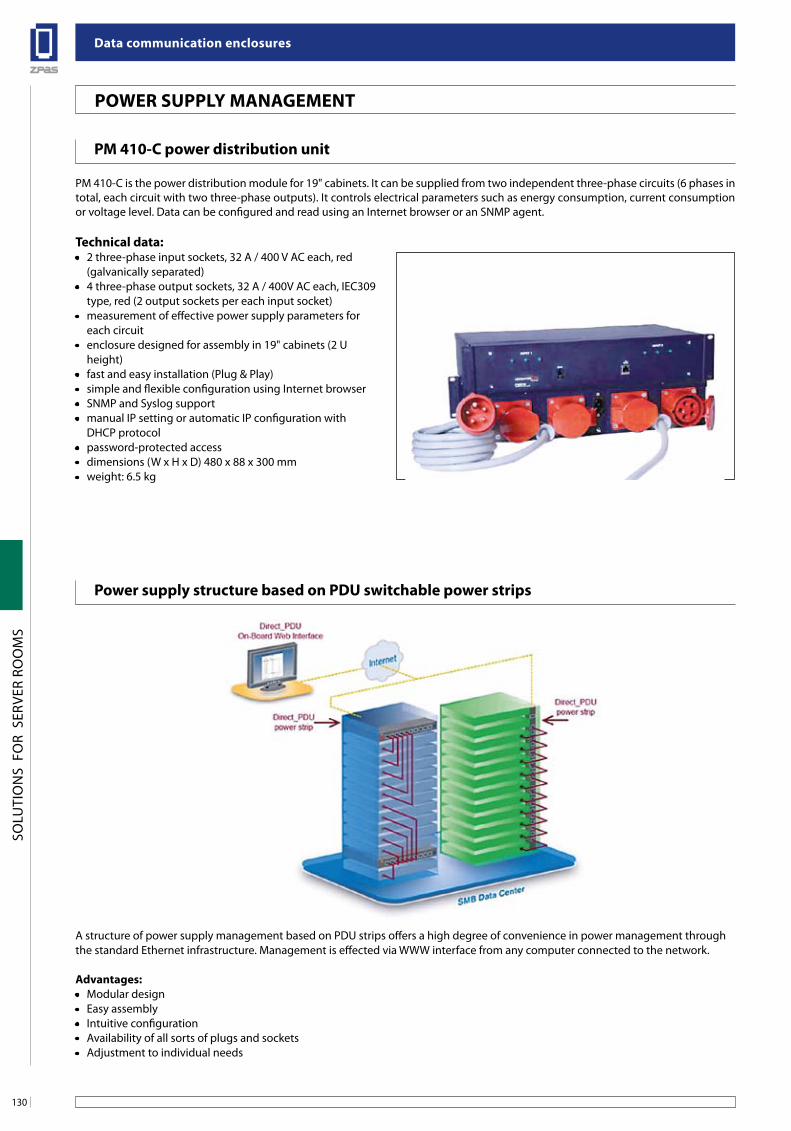
Data communication enclosures
130
SOLU
TIO
NS
FO
R S
ERVE
R RO
OM
S
PoWeR suPPlY ManageMenT
PM 410-C power distribution unit
PM 410-C is the power distribution module for 19" cabinets. It can be supplied from two independent three-phase circuits (6 phases in total, each circuit with two three-phase outputs). It controls electrical parameters such as energy consumption, current consumption or voltage level. Data can be configured and read using an Internet browser or an SNMP agent.
Technical data:• 2 three-phase input sockets, 32 A / 400 V AC each, red
(galvanically separated)• 4 three-phase output sockets, 32 A / 400V AC each, IEC309
type, red (2 output sockets per each input socket)• measurement of effective power supply parameters for
each circuit• enclosure designed for assembly in 19" cabinets (2 U
height)• fast and easy installation (Plug & Play)• simple and flexible configuration using Internet browser• SNMP and Syslog support• manual IP setting or automatic IP configuration with
DHCP protocol• password-protected access• dimensions (W x H x D) 480 x 88 x 300 mm• weight: 6.5 kg
A structure of power supply management based on PDU strips offers a high degree of convenience in power management through the standard Ethernet infrastructure. Management is effected via WWW interface from any computer connected to the network.
advantages:• Modular design• Easy assembly• Intuitive configuration• Availability of all sorts of plugs and sockets• Adjustment to individual needs
Power supply structure based on PDu switchable power strips
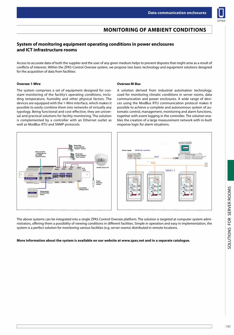
131
Data communication enclosures
SOLU
TIO
NS
FO
R S
ERVE
R RO
OM
S
system of monitoring equipment operating conditions in power enclosuresand iCT infrastructure rooms
Access to accurate data of both the supplier and the user of any given medium helps to prevent disputes that might arise as a result of conflicts of interests. Within the ZPAS Control Oversee system, we propose two basic technology and equipment solutions designed for the acquisition of data from facilities:
oversee 1-Wire
The system comprises a set of equipment designed for con-stant monitoring of the facility’s operating conditions, inclu-ding temperature, humidity and other physical factors. The devices are equipped with the 1-Wire interface, which makes it possible to easily combine them into networks of virtually any typology. Being functional and cost-effective, they are univer-sal and practical solutions for facility monitoring. The solution is complemented by a controller with an Ethernet outlet as well as ModBus RTU and SNMP protocols.
oversee M-bus
A solution derived from industrial automation technology, used for monitoring climatic conditions in server rooms, data communication and power enclosures. A wide range of devi-ces using the ModBus RTU communication protocol makes it possible to achieve a complete and autonomous system of au-tomatic control, management, monitoring and alarm functions, together with event logging in the controller. The solution ena-bles the creation of a large measurement network with in-built response logic for alarm situations.
The above systems can be integrated into a single ZPAS Control Oversee platform. The solution is targeted at computer system admi-nistrators, offering them a possibility of viewing conditions in different facilities. Simple in operation and easy in implementation, the system is a perfect solution for monitoring various facilities (e.g. server rooms) distributed in remote locations.
More information about the system is available on our website at www.zpas.net and in a separate catalogue.
MoniToRing of aMbienT ConDiTions
ethernet RJ45 – connection to the snMP Control Centre
Temperature and humidity sensor
Reed relay or microswitch – “station” section
Reed relay or microswitch – “line” section
smoke sensor 3%
Power supply
Personal computer
MiCRo xxl controller
Rs232
Cabinets 1 - 3
M-bus
R15relay
Controlled voltage 230 V
flood detector sensor
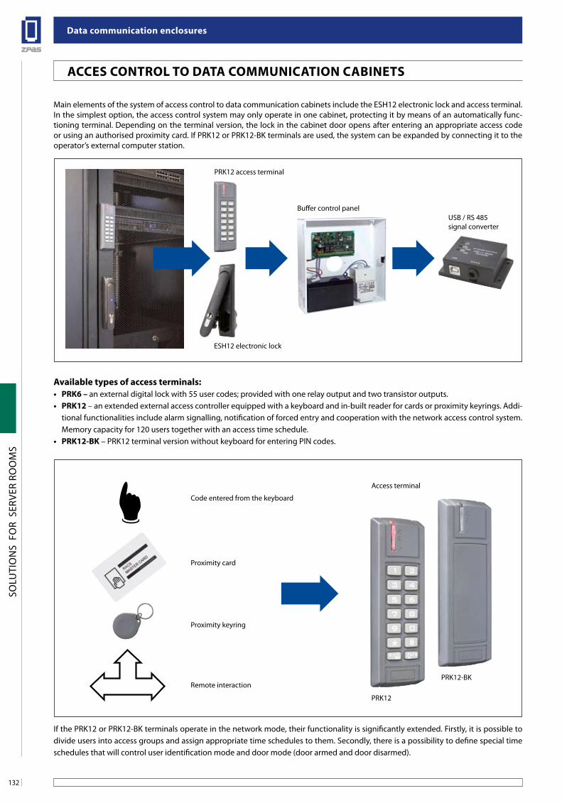
Data communication enclosures
132
SOLU
TIO
NS
FO
R S
ERVE
R RO
OM
S
aCCes ConTRol To DaTa CoMMuniCaTion CabineTs
Main elements of the system of access control to data communication cabinets include the ESH12 electronic lock and access terminal. In the simplest option, the access control system may only operate in one cabinet, protecting it by means of an automatically func-tioning terminal. Depending on the terminal version, the lock in the cabinet door opens after entering an appropriate access code or using an authorised proximity card. If PRK12 or PRK12-BK terminals are used, the system can be expanded by connecting it to the operator’s external computer station.
available types of access terminals:• PRK6 – an external digital lock with 55 user codes; provided with one relay output and two transistor outputs.• PRK12 – an extended external access controller equipped with a keyboard and in-built reader for cards or proximity keyrings. Addi-
tional functionalities include alarm signalling, notification of forced entry and cooperation with the network access control system. Memory capacity for 120 users together with an access time schedule.
• PRK12-BK – PRK12 terminal version without keyboard for entering PIN codes.
If the PRK12 or PRK12-BK terminals operate in the network mode, their functionality is significantly extended. Firstly, it is possible to divide users into access groups and assign appropriate time schedules to them. Secondly, there is a possibility to define special time schedules that will control user identification mode and door mode (door armed and door disarmed).
PRK12 access terminal
Access terminal
Code entered from the keyboard
Proximity card
Proximity keyring
Remote interaction
PRK12
PRK12-BK
Buffer control panelUSB / RS 485signal converter
ESH12 electronic lock
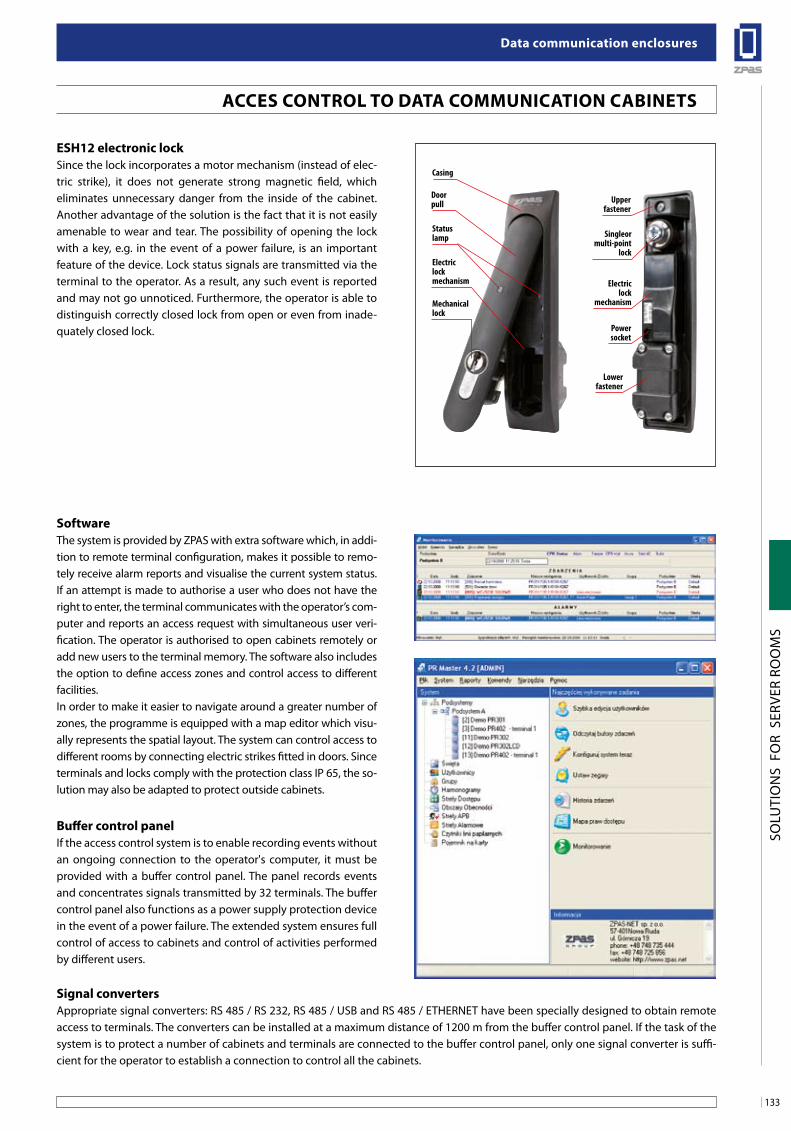
133
Data communication enclosures
SOLU
TIO
NS
FO
R S
ERVE
R RO
OM
S
esH12 electronic lockSince the lock incorporates a motor mechanism (instead of elec-tric strike), it does not generate strong magnetic field, which eliminates unnecessary danger from the inside of the cabinet. Another advantage of the solution is the fact that it is not easily amenable to wear and tear. The possibility of opening the lock with a key, e.g. in the event of a power failure, is an important feature of the device. Lock status signals are transmitted via the terminal to the operator. As a result, any such event is reported and may not go unnoticed. Furthermore, the operator is able to distinguish correctly closed lock from open or even from inade-quately closed lock.
softwareThe system is provided by ZPAS with extra software which, in addi-tion to remote terminal configuration, makes it possible to remo-tely receive alarm reports and visualise the current system status. If an attempt is made to authorise a user who does not have the right to enter, the terminal communicates with the operator’s com-puter and reports an access request with simultaneous user veri-fication. The operator is authorised to open cabinets remotely or add new users to the terminal memory. The software also includes the option to define access zones and control access to different facilities.In order to make it easier to navigate around a greater number of zones, the programme is equipped with a map editor which visu-ally represents the spatial layout. The system can control access to different rooms by connecting electric strikes fitted in doors. Since terminals and locks comply with the protection class IP 65, the so-lution may also be adapted to protect outside cabinets.
buffer control panelIf the access control system is to enable recording events without an ongoing connection to the operator's computer, it must be provided with a buffer control panel. The panel records events and concentrates signals transmitted by 32 terminals. The buffer control panel also functions as a power supply protection device in the event of a power failure. The extended system ensures full control of access to cabinets and control of activities performed by different users.
signal convertersAppropriate signal converters: RS 485 / RS 232, RS 485 / USB and RS 485 / ETHERNET have been specially designed to obtain remote access to terminals. The converters can be installed at a maximum distance of 1200 m from the buffer control panel. If the task of the system is to protect a number of cabinets and terminals are connected to the buffer control panel, only one signal converter is suffi-cient for the operator to establish a connection to control all the cabinets.
Casing
Doorpull
Statuslamp
Upperfastener
Lowerfastener
Singleormulti-point
lock
Electriclock
mechanism
Powersocket
Electriclockmechanism
Mechanicallock
aCCes ConTRol To DaTa CoMMuniCaTion CabineTs
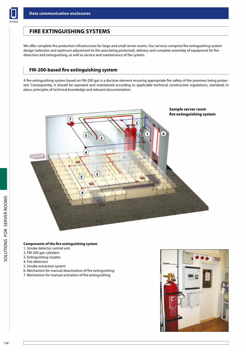
Data communication enclosures
134
SOLU
TIO
NS
FO
R S
ERVE
R RO
OM
S
fiRe exTinguisHing sYsTeMs
fM-200-based fire extinguishing system
A fire extinguishing system based on FM-200 gas is a decisive element ensuring appropriate fire safety of the premises being protec-ted. Consequently, it should be operated and maintained according to applicable technical construction regulations, standards in place, principles of technical knowledge and relevant documentation.
Components of the fire extinguishing system1. Smoke detector central unit2. FM-200 gas cylinders3. Extinguishing nozzles4. Fire detectors5. Smoke extraction system6. Mechanism for manual deactivation of fire extinguishing7. Mechanism for manual activation of fire extinguishing
We offer complete fire protection infrastructure for large and small server rooms. Our services comprise fire extinguishing system design (selection and optimum adjustment to the area being protected), delivery and complete assembly of equipment for fire detection and extinguishing, as well as service and maintenance of the system.
1
27
53
3
4
4
5
6
sample server roomfire extinguishing system
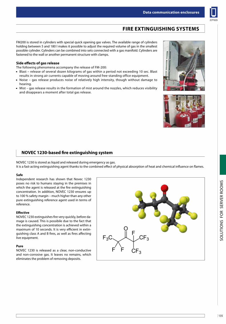
135
Data communication enclosures
SOLU
TIO
NS
FO
R S
ERVE
R RO
OM
S
FM200 is stored in cylinders with special quick opening gas valves. The available range of cylinders holding between 5 and 180 l makes it possible to adjust the required volume of gas in the smallest possible cylinder. Cylinders can be combined into sets connected with a gas manifold. Cylinders are fastened to the wall or another permanent structure with clamps.
side effects of gas releaseThe following phenomena accompany the release of FM-200:• Blast – release of several dozen kilograms of gas within a period not exceeding 10 sec. Blast
results in strong air currents capable of moving around free-standing office equipment.• Noise – gas release produces noise of relatively high intensity, though without damage to
hearing.• Mist – gas release results in the formation of mist around the nozzles, which reduces visibility
and disappears a moment after total gas release.
fiRe exTinguisHing sYsTeMs
noVeC 1230-based fire extinguishing system
NOVEC 1230 is stored as liquid and released during emergency as gas.It is a fast-acting extinguishing agent thanks to the combined effect of physical absorption of heat and chemical influence on flames.
safeIndependent research has shown that Novec 1230 poses no risk to humans staying in the premises in which the agent is released at the fire extinguishing concentration. In addition, NOVEC 1230 ensures up to 100 % safety margin – much higher than any other pure extinguishing reference agent used in terms of reference.
effectiveNOVEC 1230 extinguishes fire very quickly, before da-mage is caused. This is possibile due to the fact that the extinguishing concentration is achieved within a maximum of 10 seconds. It is very efficient in extin-guishing class A and B fires, as well as fires affecting live equipment.
PureNOVEC 1230 is released as a clear, non-conductive and non-corrosive gas. It leaves no remains, which eliminates the problem of removing deposits.
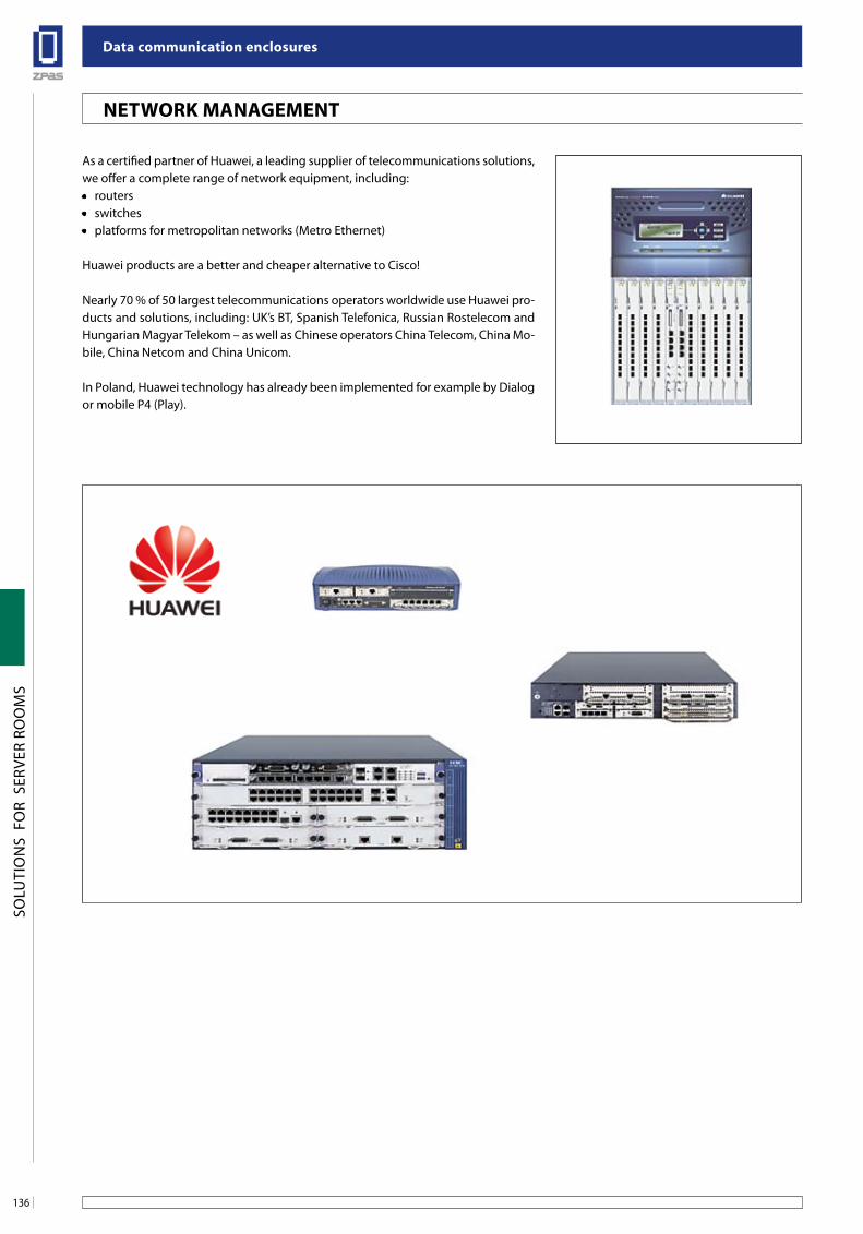
Data communication enclosures
136
SOLU
TIO
NS
FO
R S
ERVE
R RO
OM
S
neTWoRK ManageMenT
As a certified partner of Huawei, a leading supplier of telecommunications solutions, we offer a complete range of network equipment, including:• routers• switches• platforms for metropolitan networks (Metro Ethernet)
Huawei products are a better and cheaper alternative to Cisco!
Nearly 70 % of 50 largest telecommunications operators worldwide use Huawei pro-ducts and solutions, including: UK’s BT, Spanish Telefonica, Russian Rostelecom and Hungarian Magyar Telekom – as well as Chinese operators China Telecom, China Mo-bile, China Netcom and China Unicom.
In Poland, Huawei technology has already been implemented for example by Dialog or mobile P4 (Play).
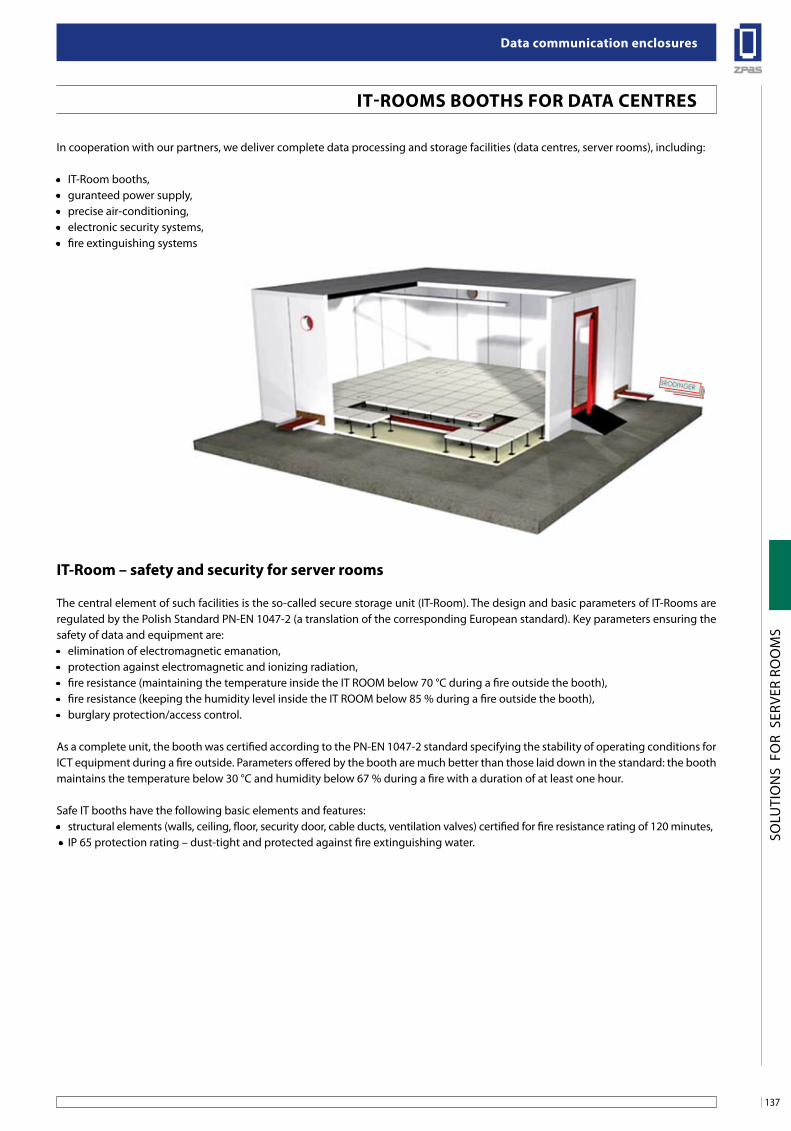
137
Data communication enclosures
SOLU
TIO
NS
FO
R S
ERVE
R RO
OM
S
iT-RooMs booTHs foR DaTa CenTRes
In cooperation with our partners, we deliver complete data processing and storage facilities (data centres, server rooms), including:
• IT-Room booths,• guranteed power supply,• precise air-conditioning,• electronic security systems,• fire extinguishing systems
iT-Room – safety and security for server rooms
The central element of such facilities is the so-called secure storage unit (IT-Room). The design and basic parameters of IT-Rooms are regulated by the Polish Standard PN-EN 1047-2 (a translation of the corresponding European standard). Key parameters ensuring the safety of data and equipment are:• elimination of electromagnetic emanation,• protection against electromagnetic and ionizing radiation,• fire resistance (maintaining the temperature inside the IT ROOM below 70 °C during a fire outside the booth),• fire resistance (keeping the humidity level inside the IT ROOM below 85 % during a fire outside the booth),• burglary protection/access control.
As a complete unit, the booth was certified according to the PN-EN 1047-2 standard specifying the stability of operating conditions for ICT equipment during a fire outside. Parameters offered by the booth are much better than those laid down in the standard: the booth maintains the temperature below 30 °C and humidity below 67 % during a fire with a duration of at least one hour.
Safe IT booths have the following basic elements and features:• structural elements (walls, ceiling, floor, security door, cable ducts, ventilation valves) certified for fire resistance rating of 120 minutes, • IP 65 protection rating – dust-tight and protected against fire extinguishing water.
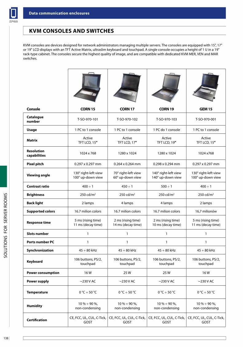
Data communication enclosures
138
SOLU
TIO
NS
FO
R S
ERVE
R RO
OM
S
KVM Consoles anD sWiTCHes
KVM consoles are devices designed for network administrators managing multiple servers. The consoles are equipped with 15", 17" or 19" LCD displays with an TFT Active Matrix, ultraslim keyboard and touchpad. A single console occupies a height of 1 U in a 19" rack-type cabinet. The consoles secure the highest quality of image, and are compatible with dedicated KVM MER, VEN and MARswitches.
Console CoRn 15 CoRn 17 CoRn 19 geM 15 geM 17 geM 19
Catalogue number T-SO-970-101 T-SO-970-102 T-SO-970-103 T-SO-970-001 T-SO-970-002 T-SO-970-003
usage 1 PC to 1 console 1 PC to 1 console 1 PC do 1 console 1 PC to 1 console 1 PC to 1 console 1 PC to 1 console
Matrix ActiveTFT LCD, 15"
ActiveTFT LCD, 17"
ActiveTFT LCD, 19"
Active TFT LCD, 15"
ActiveTFT LCD, 17"
ActiveTFT LCD, 19"
Resolution capabilities 1024 x 768 1280 x 1024 1280 x 1024 1024 x768 1280 x 1024 1280 x 1024
Pixel pitch 0.297 x 0.297 mm 0.264 x 0.264 mm 0.298 x 0.294 mm 0.297 x 0.297 mm 0.264 x 0.264 mm 0.298 x 0.294 mm
Viewing angle 130° right-left view100° up-down view
70° right-left view60° up-down view
140° right-left view140° up-down view
130° right-left view100° up-down view
70° right-left view60° up-down view
140° right-left view140° up-down view
Contrast ratio 400 ÷ 1 450 ÷ 1 500 ÷ 1 400 ÷ 1 450 ÷ 1 500 ÷ 1
brightness 250 cd/m2 250 cd/m2 250 cd/m2 250 cd/m2 250 cd/m2 250 cd/m2
back light 2 lamps 4 lamps 4 lamps 2 lamps 4 lamps 4 lamps
supported colors 16.7 milion colors 16.7 milion colors 16.7 milion colors 16,7 milionów 16.7 milion colors 16.7 milion colors
Response time 5 ms (rising time)11 ms (decay time)
2 ms (rising time)14 ms (decay time)
2 ms (rising time)10 ms (decay time)
5 ms (rising time)11 ms (decay time)
2 ms (rising time)14 ms (decay time)
2 ms (rising time)10 ms (decay time)
slots number 1 1 1 1 1 1
Ports number PC 1 1 1 1 1 1
synchronization 45 ÷ 80 kHz 45 ÷ 80 kHz 45 ÷ 80 kHz 45 ÷ 80 kHz 45 ÷ 80 kHz 45 ÷ 80 kHz
Keyboard 106 buttons, PS/2,touchpad
106 buttons, PS/2,touchpad
106 buttons, PS/2,touchpad
106 buttons, PS/2,touchpad
106 buttons, PS/2,touchpad
106 buttons, PS/2,touchpad
Power consumption 16 W 25 W 25 W 16 W 25 W 25 W
Power supply ~230 V AC ~230 V AC ~230 V AC ~230 V AC ~230 V AC ~230 V AC
Temperature 0 °C ÷ 50 °C 0 °C ÷ 50 °C 0 °C ÷ 50 °C 0 °C ÷ 50 °C 0 °C ÷ 50 °C 0 °C ÷ 50 °C
Humidity 10 % ÷ 90 %, non-condensing
10 % ÷ 90 %, non-condensing
10 % ÷ 90 %, non-condensing
10 % ÷ 90 %, non-condensing
10 % ÷ 90 %, non-condensing
10 % ÷ 90 %, non-condensing
Certification CE, FCC, UL, CUL, C-Tick, GOST
CE, FCC, UL, CUL, C-Tick, GOST
CE, FCC, UL, CUL, C-Tick, GOST
CE, FCC, UL, CUL, C-Tick, GOST
CE, FCC, UL, CUL, C-Tick, GOST
CE, FCC, UL, CUL, C-Tick, GOST
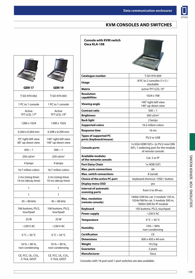
139
Data communication enclosures
SOLU
TIO
NS
FO
R S
ERVE
R RO
OM
S
KVM Consoles anD sWiTCHes
Console with KVM switchoxca Kla-108
Catalogue number T-SO-970-609
usage 8 PC to 2 consoles (1+1) /stackable
Matrix active TFT LCD, 19"
Resolutioncapabilities 1024 x 768
Viewing angle 140° right-left view140° up-down view
Contrast ratio 500 ÷ 1
brightness 260 cd/m2
back light 2 lamps
supported colors 16.2 milion colors
Response time 16 ms
Types of supported PCports (keyboard/mouse) PS/2 or USB
Console ports1x VGA HDB15(F)+ 2x PS/2 mini DIN6(F), 1 widening port for the module
of remote console
available modules of the remonte console Cat. 5 or IP
Port Daisy Chain 1x HDB15(F)
Max. ports connections 64
Max. switch connections 8 (serial)
Choice of the active PC port keyboard shortcut / OSD / button
Display menu osD yes
interval of automaticscanning ports from 5 to 99 sec.
Max. resolution(remote console)
1600x1200 for cat. 5 module 150 m,1024x768 for cat. 5 module 300 m,
1600x1200 for IP module
Keyboard 105 buttons, PS/2, touchpad
Power supply ~230 V AC
Temperature 0 °C ÷ 50 °C
Humidity 10% ÷ 90%non-condensing
Certification CE
Dimensions 600 x 450 x 44 mm
Weight 19.2 kg
guarantee 2 years
Manufacturer Oxca
Consoles with 16-port and 1-port switches are also available.
Console CoRn 15 CoRn 17 CoRn 19 geM 15 geM 17 geM 19
Catalogue number T-SO-970-101 T-SO-970-102 T-SO-970-103 T-SO-970-001 T-SO-970-002 T-SO-970-003
usage 1 PC to 1 console 1 PC to 1 console 1 PC do 1 console 1 PC to 1 console 1 PC to 1 console 1 PC to 1 console
Matrix ActiveTFT LCD, 15"
ActiveTFT LCD, 17"
ActiveTFT LCD, 19"
Active TFT LCD, 15"
ActiveTFT LCD, 17"
ActiveTFT LCD, 19"
Resolution capabilities 1024 x 768 1280 x 1024 1280 x 1024 1024 x768 1280 x 1024 1280 x 1024
Pixel pitch 0.297 x 0.297 mm 0.264 x 0.264 mm 0.298 x 0.294 mm 0.297 x 0.297 mm 0.264 x 0.264 mm 0.298 x 0.294 mm
Viewing angle 130° right-left view100° up-down view
70° right-left view60° up-down view
140° right-left view140° up-down view
130° right-left view100° up-down view
70° right-left view60° up-down view
140° right-left view140° up-down view
Contrast ratio 400 ÷ 1 450 ÷ 1 500 ÷ 1 400 ÷ 1 450 ÷ 1 500 ÷ 1
brightness 250 cd/m2 250 cd/m2 250 cd/m2 250 cd/m2 250 cd/m2 250 cd/m2
back light 2 lamps 4 lamps 4 lamps 2 lamps 4 lamps 4 lamps
supported colors 16.7 milion colors 16.7 milion colors 16.7 milion colors 16,7 milionów 16.7 milion colors 16.7 milion colors
Response time 5 ms (rising time)11 ms (decay time)
2 ms (rising time)14 ms (decay time)
2 ms (rising time)10 ms (decay time)
5 ms (rising time)11 ms (decay time)
2 ms (rising time)14 ms (decay time)
2 ms (rising time)10 ms (decay time)
slots number 1 1 1 1 1 1
Ports number PC 1 1 1 1 1 1
synchronization 45 ÷ 80 kHz 45 ÷ 80 kHz 45 ÷ 80 kHz 45 ÷ 80 kHz 45 ÷ 80 kHz 45 ÷ 80 kHz
Keyboard 106 buttons, PS/2,touchpad
106 buttons, PS/2,touchpad
106 buttons, PS/2,touchpad
106 buttons, PS/2,touchpad
106 buttons, PS/2,touchpad
106 buttons, PS/2,touchpad
Power consumption 16 W 25 W 25 W 16 W 25 W 25 W
Power supply ~230 V AC ~230 V AC ~230 V AC ~230 V AC ~230 V AC ~230 V AC
Temperature 0 °C ÷ 50 °C 0 °C ÷ 50 °C 0 °C ÷ 50 °C 0 °C ÷ 50 °C 0 °C ÷ 50 °C 0 °C ÷ 50 °C
Humidity 10 % ÷ 90 %, non-condensing
10 % ÷ 90 %, non-condensing
10 % ÷ 90 %, non-condensing
10 % ÷ 90 %, non-condensing
10 % ÷ 90 %, non-condensing
10 % ÷ 90 %, non-condensing
Certification CE, FCC, UL, CUL, C-Tick, GOST
CE, FCC, UL, CUL, C-Tick, GOST
CE, FCC, UL, CUL, C-Tick, GOST
CE, FCC, UL, CUL, C-Tick, GOST
CE, FCC, UL, CUL, C-Tick, GOST
CE, FCC, UL, CUL, C-Tick, GOST
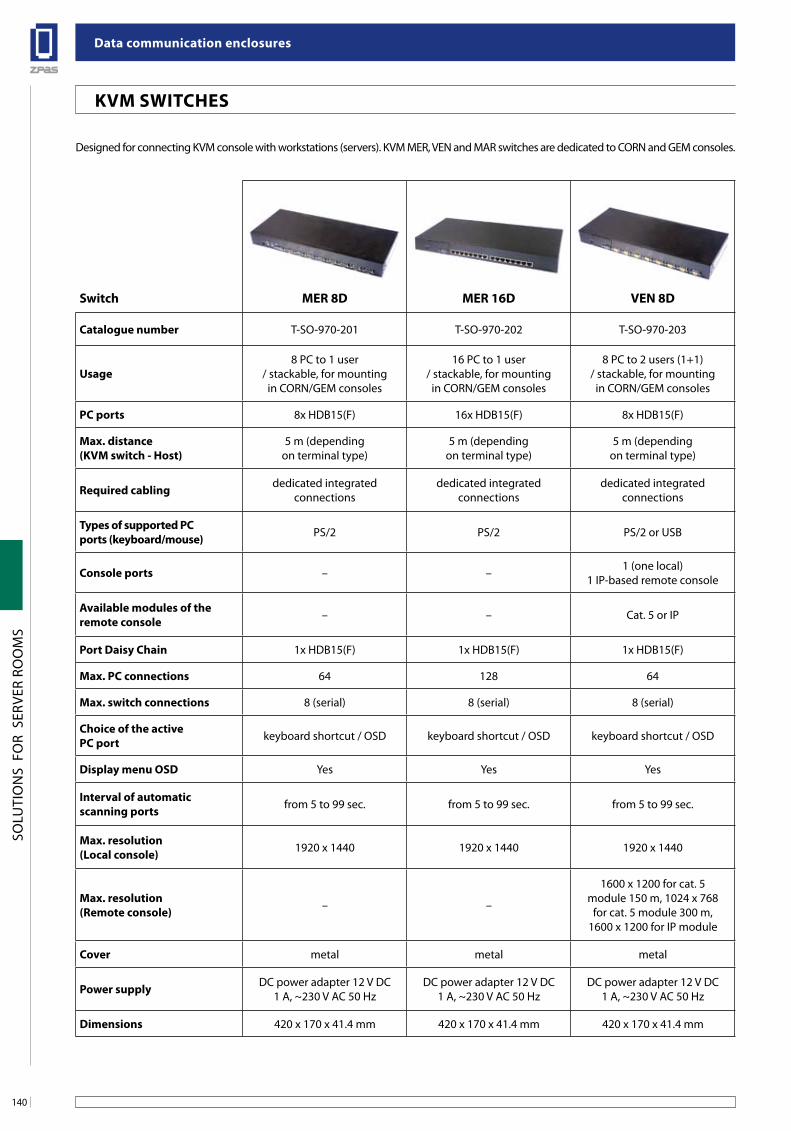
Data communication enclosures
140
SOLU
TIO
NS
FO
R S
ERVE
R RO
OM
S
KVM sWiTCHes
switch MeR 8D MeR 16D Ven 8D Ven 16D MaR 8D MaR 16D MaR 32D
Catalogue number T-SO-970-201 T-SO-970-202 T-SO-970-203 T-SO-970-204 T-SO-970-205 T-SO-970-206 T-SO-970-207
usage8 PC to 1 user
/ stackable, for mountingin CORN/GEM consoles
16 PC to 1 user/ stackable, for mounting
in CORN/GEM consoles
8 PC to 2 users (1+1)/ stackable, for mounting
in CORN/GEM consoles
16 PC to 2 users (1+1)/ stackable, for mounting
in CORN/GEM consoles
8 PC to 2 users (1+1)/ stackable, for mounting
in CORN/GEM consoles
16 PC to 2 users (1+1)/ stackable, for mounting
in CORN/GEM consoles
32 PC to 2 users (1+1)/ stackable, for mounting
in CORN/GEM consoles
PC ports 8x HDB15(F) 16x HDB15(F) 8x HDB15(F) 16x HDB15(F) 8x 8p8c(F) RJ-45 16x 8p8c(F) RJ-45 32x 8p8c(F) RJ-45
Max. distance(KVM switch - Host)
5 m (dependingon terminal type)
5 m (dependingon terminal type)
5 m (dependingon terminal type)
5 m (dependingon terminal type) 150 m with the DCC-001 150 m with the DCC-001 150 m with the DCC-001
Required cabling dedicated integratedconnections
dedicated integratedconnections
dedicated integratedconnections
dedicated integratedconnections
twisted pair cable, category5e, 6 or higher
twisted pair cable, category5e, 6 or higher
twisted pair cable, category5e, 6 or higher
Types of supported PCports (keyboard/mouse) PS/2 PS/2 PS/2 or USB PS/2 or USB PS/2 or USB PS/2 or USB PS/2 or USB
Console ports – – 1 (one local)1 IP-based remote console
1 (one local)1 IP-based remote console
1 (one local)1 IP-based remote console
1 (one local)1 IP-based remote console
1 (one local)1 IP-based remote console
available modules of theremote console – – Cat. 5 or IP Cat. 5 or IP Cat. 5 or IP Cat. 5 or IP Cat. 5 or IP
Port Daisy Chain 1x HDB15(F) 1x HDB15(F) 1x HDB15(F) 1x HDB15(F) 1x HDB15(F) 1x HDB15(F) 1x HDB15(F)
Max. PC connections 64 128 64 128 64 128 256
Max. switch connections 8 (serial) 8 (serial) 8 (serial) 8 (serial) 8 (serial) 8 (serial) 8 (serial)
Choice of the active PC port keyboard shortcut / OSD keyboard shortcut / OSD keyboard shortcut / OSD keyboard shortcut / OSD keyboard shortcut / OSD keyboard shortcut / OSD keyboard shortcut / OSD
Display menu osD Yes Yes Yes Yes Yes Yes Yes
interval of automaticscanning ports from 5 to 99 sec. from 5 to 99 sec. from 5 to 99 sec. from 5 to 99 sec. from 5 to 99 sec. from 5 to 99 sec. from 5 to 99 sec.
Max. resolution(local console) 1920 x 1440 1920 x 1440 1920 x 1440 1920 x 1440 1600 x 1200 1600 x 1200 1600 x 1200
Max. resolution(Remote console) – –
1600 x 1200 for cat. 5module 150 m, 1024 x 768
for cat. 5 module 300 m,1600 x 1200 for IP module
1600 x 1200 for cat. 5module 150 m, 1024 x 768
for cat. 5 module 300 m,1600 x 1200 for IP module
1600 x 1200 for cat. 5module 150 m, 1024 x 768
for cat. 5 module 300 m,1600 x 1200 for IP module
1600 x 1200 for cat. 5module 150 m, 1024 x 768
for cat. 5 module 300 m,1600x1200 for IP module
1600 x 1200 for cat. 5module 150 m, 1024 x 768
for cat. 5 module 300 m,1600 x 1200 for IP module
Cover metal metal metal metal metal metal metal
Power supply DC power adapter 12 V DC1 A, ~230 V AC 50 Hz
DC power adapter 12 V DC1 A, ~230 V AC 50 Hz
DC power adapter 12 V DC1 A, ~230 V AC 50 Hz
DC power adapter 12 V DC1 A, ~230 V AC 50 Hz
DC power adapter 12 V DC1 A, ~230 V AC 50 Hz
DC power adapter 12 V DC1 A, ~230 V AC 50 Hz
DC power adapter 12 V DC1 A, ~230 V AC 50 Hz
Dimensions 420 x 170 x 41.4 mm 420 x 170 x 41.4 mm 420 x 170 x 41.4 mm 420 x 170 x 41.4 mm 420 x 170 x 41.4 mm 420 x 170 x 41.4 mm 420 x 170 x 41.4 mm
Designed for connecting KVM console with workstations (servers). KVM MER, VEN and MAR switches are dedicated to CORN and GEM consoles.
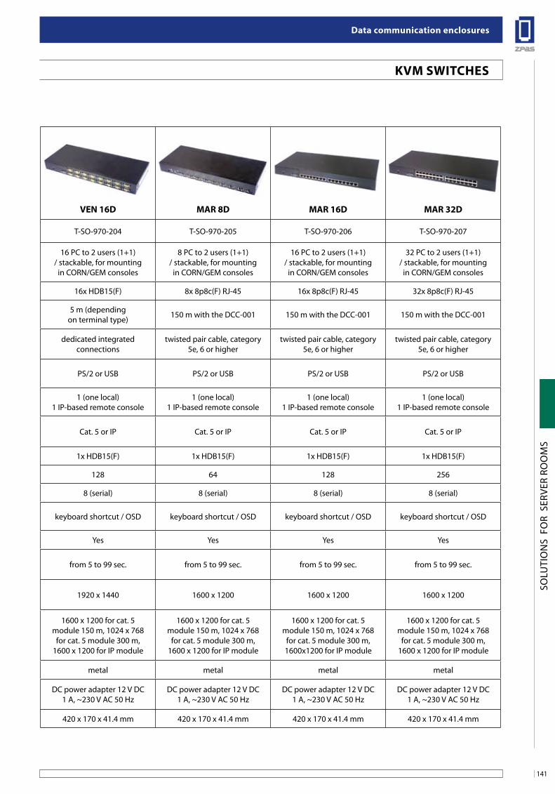
141
Data communication enclosures
SOLU
TIO
NS
FO
R S
ERVE
R RO
OM
S
KVM sWiTCHes
switch MeR 8D MeR 16D Ven 8D Ven 16D MaR 8D MaR 16D MaR 32D
Catalogue number T-SO-970-201 T-SO-970-202 T-SO-970-203 T-SO-970-204 T-SO-970-205 T-SO-970-206 T-SO-970-207
usage8 PC to 1 user
/ stackable, for mountingin CORN/GEM consoles
16 PC to 1 user/ stackable, for mounting
in CORN/GEM consoles
8 PC to 2 users (1+1)/ stackable, for mounting
in CORN/GEM consoles
16 PC to 2 users (1+1)/ stackable, for mounting
in CORN/GEM consoles
8 PC to 2 users (1+1)/ stackable, for mounting
in CORN/GEM consoles
16 PC to 2 users (1+1)/ stackable, for mounting
in CORN/GEM consoles
32 PC to 2 users (1+1)/ stackable, for mounting
in CORN/GEM consoles
PC ports 8x HDB15(F) 16x HDB15(F) 8x HDB15(F) 16x HDB15(F) 8x 8p8c(F) RJ-45 16x 8p8c(F) RJ-45 32x 8p8c(F) RJ-45
Max. distance(KVM switch - Host)
5 m (dependingon terminal type)
5 m (dependingon terminal type)
5 m (dependingon terminal type)
5 m (dependingon terminal type) 150 m with the DCC-001 150 m with the DCC-001 150 m with the DCC-001
Required cabling dedicated integratedconnections
dedicated integratedconnections
dedicated integratedconnections
dedicated integratedconnections
twisted pair cable, category5e, 6 or higher
twisted pair cable, category5e, 6 or higher
twisted pair cable, category5e, 6 or higher
Types of supported PCports (keyboard/mouse) PS/2 PS/2 PS/2 or USB PS/2 or USB PS/2 or USB PS/2 or USB PS/2 or USB
Console ports – – 1 (one local)1 IP-based remote console
1 (one local)1 IP-based remote console
1 (one local)1 IP-based remote console
1 (one local)1 IP-based remote console
1 (one local)1 IP-based remote console
available modules of theremote console – – Cat. 5 or IP Cat. 5 or IP Cat. 5 or IP Cat. 5 or IP Cat. 5 or IP
Port Daisy Chain 1x HDB15(F) 1x HDB15(F) 1x HDB15(F) 1x HDB15(F) 1x HDB15(F) 1x HDB15(F) 1x HDB15(F)
Max. PC connections 64 128 64 128 64 128 256
Max. switch connections 8 (serial) 8 (serial) 8 (serial) 8 (serial) 8 (serial) 8 (serial) 8 (serial)
Choice of the active PC port keyboard shortcut / OSD keyboard shortcut / OSD keyboard shortcut / OSD keyboard shortcut / OSD keyboard shortcut / OSD keyboard shortcut / OSD keyboard shortcut / OSD
Display menu osD Yes Yes Yes Yes Yes Yes Yes
interval of automaticscanning ports from 5 to 99 sec. from 5 to 99 sec. from 5 to 99 sec. from 5 to 99 sec. from 5 to 99 sec. from 5 to 99 sec. from 5 to 99 sec.
Max. resolution(local console) 1920 x 1440 1920 x 1440 1920 x 1440 1920 x 1440 1600 x 1200 1600 x 1200 1600 x 1200
Max. resolution(Remote console) – –
1600 x 1200 for cat. 5module 150 m, 1024 x 768
for cat. 5 module 300 m,1600 x 1200 for IP module
1600 x 1200 for cat. 5module 150 m, 1024 x 768
for cat. 5 module 300 m,1600 x 1200 for IP module
1600 x 1200 for cat. 5module 150 m, 1024 x 768
for cat. 5 module 300 m,1600 x 1200 for IP module
1600 x 1200 for cat. 5module 150 m, 1024 x 768
for cat. 5 module 300 m,1600x1200 for IP module
1600 x 1200 for cat. 5module 150 m, 1024 x 768
for cat. 5 module 300 m,1600 x 1200 for IP module
Cover metal metal metal metal metal metal metal
Power supply DC power adapter 12 V DC1 A, ~230 V AC 50 Hz
DC power adapter 12 V DC1 A, ~230 V AC 50 Hz
DC power adapter 12 V DC1 A, ~230 V AC 50 Hz
DC power adapter 12 V DC1 A, ~230 V AC 50 Hz
DC power adapter 12 V DC1 A, ~230 V AC 50 Hz
DC power adapter 12 V DC1 A, ~230 V AC 50 Hz
DC power adapter 12 V DC1 A, ~230 V AC 50 Hz
Dimensions 420 x 170 x 41.4 mm 420 x 170 x 41.4 mm 420 x 170 x 41.4 mm 420 x 170 x 41.4 mm 420 x 170 x 41.4 mm 420 x 170 x 41.4 mm 420 x 170 x 41.4 mm
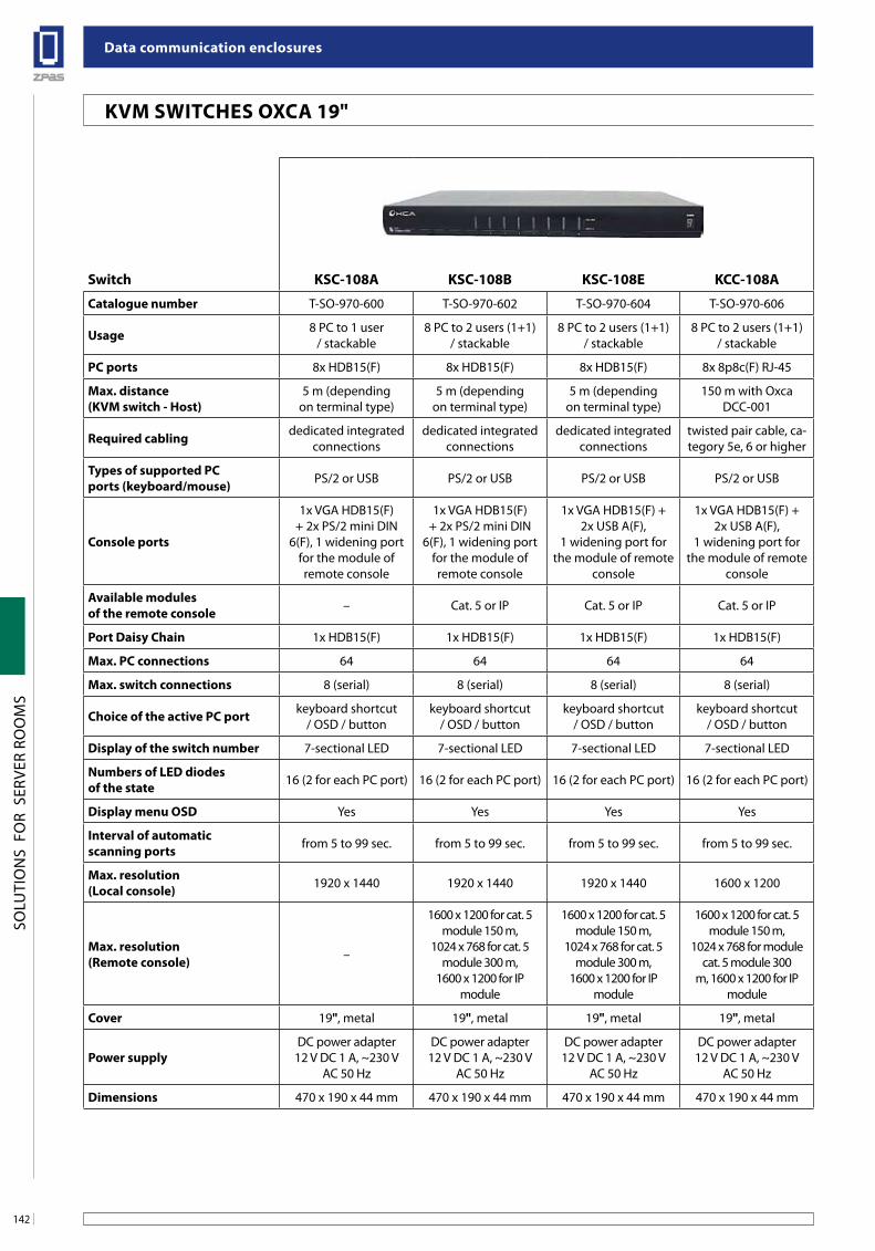
Data communication enclosures
142
SOLU
TIO
NS
FO
R S
ERVE
R RO
OM
S
KVM sWiTCHes oxCa 19"
switch KsC-108a KsC-108b KsC-108e KCC-108a
Catalogue number T-SO-970-600 T-SO-970-602 T-SO-970-604 T-SO-970-606
usage 8 PC to 1 user/ stackable
8 PC to 2 users (1+1)/ stackable
8 PC to 2 users (1+1)/ stackable
8 PC to 2 users (1+1)/ stackable
PC ports 8x HDB15(F) 8x HDB15(F) 8x HDB15(F) 8x 8p8c(F) RJ-45
Max. distance(KVM switch - Host)
5 m (dependingon terminal type)
5 m (dependingon terminal type)
5 m (dependingon terminal type)
150 m with Oxca DCC-001
Required cabling dedicated integratedconnections
dedicated integratedconnections
dedicated integratedconnections
twisted pair cable, ca-tegory 5e, 6 or higher
Types of supported PCports (keyboard/mouse) PS/2 or USB PS/2 or USB PS/2 or USB PS/2 or USB
Console ports
1x VGA HDB15(F)+ 2x PS/2 mini DIN
6(F), 1 widening portfor the module ofremote console
1x VGA HDB15(F)+ 2x PS/2 mini DIN
6(F), 1 widening portfor the module ofremote console
1x VGA HDB15(F) +2x USB A(F),
1 widening port for the module of remote
console
1x VGA HDB15(F) +2x USB A(F),
1 widening port for the module of remote
console
available modules of the remote console – Cat. 5 or IP Cat. 5 or IP Cat. 5 or IP
Port Daisy Chain 1x HDB15(F) 1x HDB15(F) 1x HDB15(F) 1x HDB15(F)
Max. PC connections 64 64 64 64
Max. switch connections 8 (serial) 8 (serial) 8 (serial) 8 (serial)
Choice of the active PC port keyboard shortcut/ OSD / button
keyboard shortcut/ OSD / button
keyboard shortcut/ OSD / button
keyboard shortcut/ OSD / button
Display of the switch number 7-sectional LED 7-sectional LED 7-sectional LED 7-sectional LED
numbers of leD diodesof the state 16 (2 for each PC port) 16 (2 for each PC port) 16 (2 for each PC port) 16 (2 for each PC port)
Display menu osD Yes Yes Yes Yes
interval of automaticscanning ports from 5 to 99 sec. from 5 to 99 sec. from 5 to 99 sec. from 5 to 99 sec.
Max. resolution(local console) 1920 x 1440 1920 x 1440 1920 x 1440 1600 x 1200
Max. resolution(Remote console) –
1600 x 1200 for cat. 5module 150 m,
1024 x 768 for cat. 5module 300 m,
1600 x 1200 for IP module
1600 x 1200 for cat. 5module 150 m,
1024 x 768 for cat. 5module 300 m,
1600 x 1200 for IP module
1600 x 1200 for cat. 5module 150 m,
1024 x 768 for modulecat. 5 module 300
m, 1600 x 1200 for IP module
Cover 19", metal 19", metal 19", metal 19", metal
Power supplyDC power adapter
12 V DC 1 A, ~230 VAC 50 Hz
DC power adapter12 V DC 1 A, ~230 V
AC 50 Hz
DC power adapter12 V DC 1 A, ~230 V
AC 50 Hz
DC power adapter12 V DC 1 A, ~230 V
AC 50 Hz
Dimensions 470 x 190 x 44 mm 470 x 190 x 44 mm 470 x 190 x 44 mm 470 x 190 x 44 mm
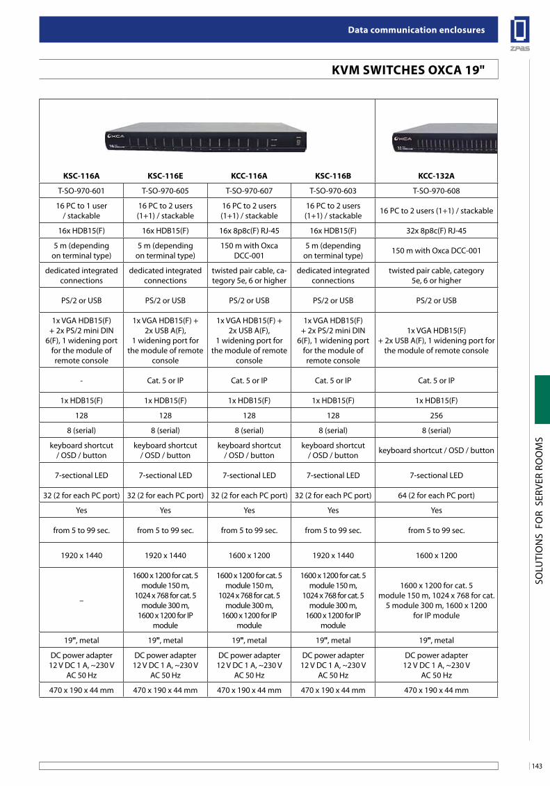
143
Data communication enclosures
SOLU
TIO
NS
FO
R S
ERVE
R RO
OM
S
KVM sWiTCHes oxCa 19"
KsC-116a KsC-116e KCC-116a KsC-116b KCC-132a
T-SO-970-601 T-SO-970-605 T-SO-970-607 T-SO-970-603 T-SO-970-608
16 PC to 1 user/ stackable
16 PC to 2 users(1+1) / stackable
16 PC to 2 users(1+1) / stackable
16 PC to 2 users(1+1) / stackable 16 PC to 2 users (1+1) / stackable
16x HDB15(F) 16x HDB15(F) 16x 8p8c(F) RJ-45 16x HDB15(F) 32x 8p8c(F) RJ-45
5 m (dependingon terminal type)
5 m (dependingon terminal type)
150 m with Oxca DCC-001
5 m (dependingon terminal type) 150 m with Oxca DCC-001
dedicated integratedconnections
dedicated integratedconnections
twisted pair cable, ca-tegory 5e, 6 or higher
dedicated integratedconnections
twisted pair cable, category5e, 6 or higher
PS/2 or USB PS/2 or USB PS/2 or USB PS/2 or USB PS/2 or USB
1x VGA HDB15(F)+ 2x PS/2 mini DIN
6(F), 1 widening portfor the module ofremote console
1x VGA HDB15(F) +2x USB A(F),
1 widening port for the module of remote
console
1x VGA HDB15(F) +2x USB A(F),
1 widening port for the module of remote
console
1x VGA HDB15(F)+ 2x PS/2 mini DIN
6(F), 1 widening portfor the module ofremote console
1x VGA HDB15(F)+ 2x USB A(F), 1 widening port for
the module of remote console
- Cat. 5 or IP Cat. 5 or IP Cat. 5 or IP Cat. 5 or IP
1x HDB15(F) 1x HDB15(F) 1x HDB15(F) 1x HDB15(F) 1x HDB15(F)
128 128 128 128 256
8 (serial) 8 (serial) 8 (serial) 8 (serial) 8 (serial)
keyboard shortcut/ OSD / button
keyboard shortcut/ OSD / button
keyboard shortcut/ OSD / button
keyboard shortcut/ OSD / button keyboard shortcut / OSD / button
7-sectional LED 7-sectional LED 7-sectional LED 7-sectional LED 7-sectional LED
32 (2 for each PC port) 32 (2 for each PC port) 32 (2 for each PC port) 32 (2 for each PC port) 64 (2 for each PC port)
Yes Yes Yes Yes Yes
from 5 to 99 sec. from 5 to 99 sec. from 5 to 99 sec. from 5 to 99 sec. from 5 to 99 sec.
1920 x 1440 1920 x 1440 1600 x 1200 1920 x 1440 1600 x 1200
–
1600 x 1200 for cat. 5module 150 m,
1024 x 768 for cat. 5module 300 m,
1600 x 1200 for IP module
1600 x 1200 for cat. 5module 150 m,
1024 x 768 for cat. 5module 300 m,
1600 x 1200 for IP module
1600 x 1200 for cat. 5module 150 m,
1024 x 768 for cat. 5module 300 m,
1600 x 1200 for IP module
1600 x 1200 for cat. 5module 150 m, 1024 x 768 for cat.
5 module 300 m, 1600 x 1200for IP module
19", metal 19", metal 19", metal 19", metal 19", metal
DC power adapter12 V DC 1 A, ~230 V
AC 50 Hz
DC power adapter12 V DC 1 A, ~230 V
AC 50 Hz
DC power adapter12 V DC 1 A, ~230 V
AC 50 Hz
DC power adapter12 V DC 1 A, ~230 V
AC 50 Hz
DC power adapter12 V DC 1 A, ~230 V
AC 50 Hz
470 x 190 x 44 mm 470 x 190 x 44 mm 470 x 190 x 44 mm 470 x 190 x 44 mm 470 x 190 x 44 mm
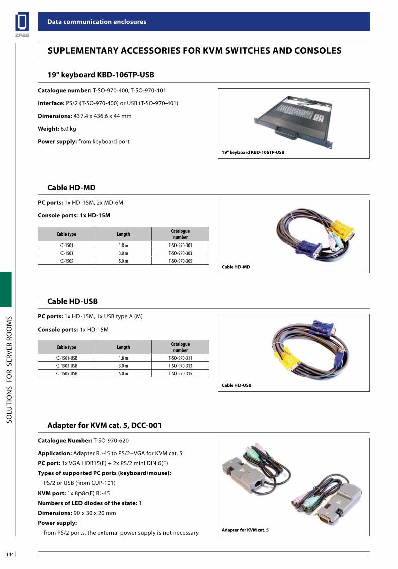
Data communication enclosures
144
SOLU
TIO
NS
FO
R S
ERVE
R RO
OM
S
suPleMenTaRY aCCessoRies foR KVM sWiTCHes anD Consoles
19" keyboard KbD-106TP-usb
Cable HD-MD
Cable HD-usb
Catalogue number: T-SO-970-400; T-SO-970-401
interface: PS/2 (T-SO-970-400) or USB (T-SO-970-401)
Dimensions: 437.4 x 436.6 x 44 mm
Weight: 6.0 kg
Power supply: from keyboard port
PC ports: 1x HD-15M, 2x MD-6M
Console ports: 1x HD-15M
PC ports: 1x HD-15M, 1x USB type A (M)
Console ports: 1x HD-15M
Cable type Length Catalogue number
KC-1501 1.8 m T-SO-970-301KC-1503 3.0 m T-SO-970-303KC-1505 5.0 m T-SO-970-305
Cable type Length Catalogue number
KC-1501-USB 1.8 m T-SO-970-311KC-1503-USB 3.0 m T-SO-970-313KC-1505-USB 5.0 m T-SO-970-315
Cable HD-MD
19" keyboard KbD-106TP-usb
Cable HD-usb
adapter for KVM cat. 5, DCC-001
Catalogue number: T-SO-970-620
application: Adapter RJ-45 to PS/2+VGA for KVM cat. 5
PC port: 1x VGA HDB15(F) + 2x PS/2 mini DIN 6(F)
Types of supported PC ports (keyboard/mouse):
PS/2 or USB (from CUP-101)
KVM port: 1x 8p8c(F) RJ-45
numbers of leD diodes of the state: 1
Dimensions: 90 x 30 x 20 mm
Power supply:
from PS/2 ports, the external power supply is not necessary adapter for KVM cat. 5
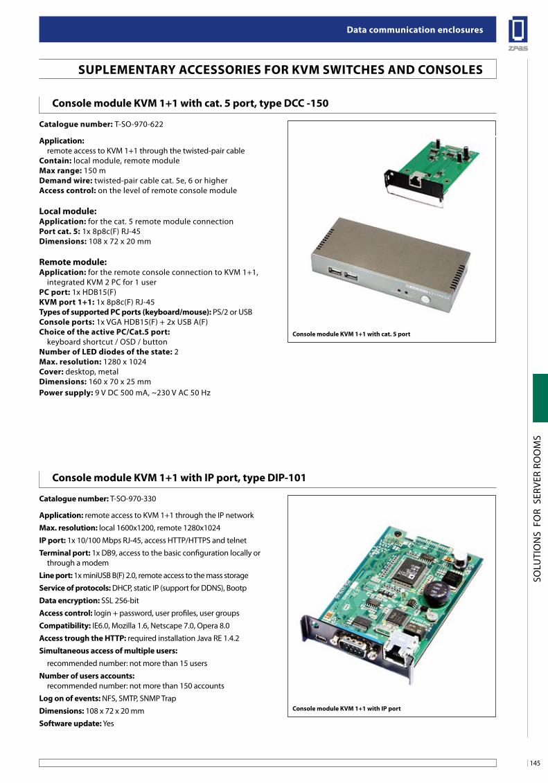
145
Data communication enclosures
SOLU
TIO
NS
FO
R S
ERVE
R RO
OM
S
suPleMenTaRY aCCessoRies foR KVM sWiTCHes anD Consoles
Console module KVM 1+1 with cat. 5 port, type DCC -150
Catalogue number: T-SO-970-622
application: remote access to KVM 1+1 through the twisted-pair cableContain: local module, remote module Max range: 150 m Demand wire: twisted-pair cable cat. 5e, 6 or higheraccess control: on the level of remote console module
local module:application: for the cat. 5 remote module connection Port cat. 5: 1x 8p8c(F) RJ-45Dimensions: 108 x 72 x 20 mm
Remote module:application: for the remote console connection to KVM 1+1, integrated KVM 2 PC for 1 userPC port: 1x HDB15(F) KVM port 1+1: 1x 8p8c(F) RJ-45 Types of supported PC ports (keyboard/mouse): PS/2 or USBConsole ports: 1x VGA HDB15(F) + 2x USB A(F)Choice of the active PC/Cat.5 port: keyboard shortcut / OSD / buttonnumber of leD diodes of the state: 2Max. resolution: 1280 x 1024Cover: desktop, metalDimensions: 160 x 70 x 25 mmPower supply: 9 V DC 500 mA, ~230 V AC 50 Hz
Console module KVM 1+1 with cat. 5 port
Console module KVM 1+1 with iP port, type DiP-101
Catalogue number: T-SO-970-330
application: remote access to KVM 1+1 through the IP network
Max. resolution: local 1600x1200, remote 1280x1024
iP port: 1x 10/100 Mbps RJ-45, access HTTP/HTTPS and telnet
Terminal port: 1x DB9, access to the basic configuration locally or through a modem
line port: 1x miniUSB B(F) 2.0, remote access to the mass storage
service of protocols: DHCP, static IP (support for DDNS), Bootp
Data encryption: SSL 256-bit
access control: login + password, user profiles, user groups
Compatibility: IE6.0, Mozilla 1.6, Netscape 7.0, Opera 8.0
access trough the HTTP: required installation Java RE 1.4.2
simultaneous access of multiple users: recommended number: not more than 15 users
number of users accounts: recommended number: not more than 150 accounts
log on of events: NFS, SMTP, SNMP Trap
Dimensions: 108 x 72 x 20 mm
software update: Yes
Console module KVM 1+1 with iP port
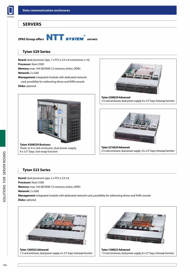
Data communication enclosures
146
SOLU
TIO
NS
FO
R S
ERVE
R RO
OM
S
seRVeRs
Tytan s29 series
Tytan s23 series
board: dual processor type, 7 x PCI-e 2.0 x 8 (connectors x 16)
Processor: Xeon 5500
Memory: max 144 GB RAM (12 memory sticks), DDR3
network: 2 x GbE
Management: integrated module with dedicated network
card, possibility for redirecting drives and KVM console
Disks: optional
board: dual processor type, 2 x PCI-e 2.0 x 8
Processor: Xeon 5500
Memory: max 144 GB RAM (12 memory sticks), DDR3
network: 2 x GbE
Management: integrated module with dedicated network card, possibility for redirecting drives and KVM console
Disks: optional
ZPas group offers servers
Tytan 1208s23 advanced1 U rack enclosure, dual power supply, 8 x 2.5" bays, hotswap function
Tytan 1204s23 advanced1 U rack enclosure, dual power supply, 4 x 3.5" bays, hotswap function
Tytan 2208s29 advanced2 U rack enclosure, dual power supply, 8 x 3.5" bays, hotswap function
Tytan 4208s29 businessTower or 4 U rack enclosure, dual power supply, 8 x 3.5" bays, hot-swap function
Tytan 2216s29 advanced2 U rack enclosure, dual power supply, 16 x 2.5" bays, hotswap function
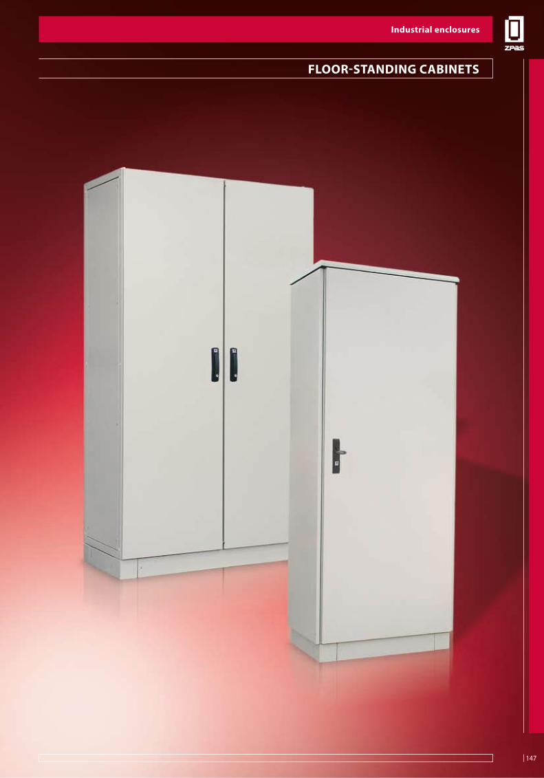
147
industrial enclosures
SZE2
FLO
OR-
STA
ND
ING
CA
BIN
ETS
flooR-sTanDing CabineTs
industrial enclosures
147
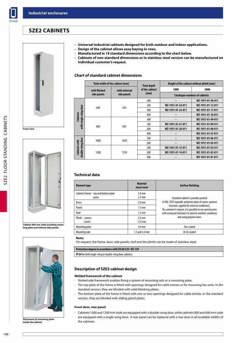
industrial enclosures
148
SZE2
FLO
OR-
STA
ND
ING
CA
BIN
ETS
front view
Cabinet 600 mm wide including moun-ting plate and without side panels
Placement of mounting plate inside the cabinet
sZe2 CabineTs
- universal industrial cabinets designed for both outdoor and indoor applications.- Design of the cabinet allows easy baying in rows.- Manufactured in 19 standard dimensions according to the chart below.- Cabinets of non-standard dimensions or in stainless steel version can be manufactured on
individual customer’s request.
Chart of standard cabinet dimensions
Technical data
Description of sZe2 cabinet design
Welded framework of the cabinet- Slotted side framework enables fixing a system of mounting rails or a mounting plate.- The top plate of the frame is fitted with openings designed for cable entries or for mounting fan units. In the
standard version, they are blinded with solid blanking plates.- The bottom plate of the frame is fitted with one or two openings designed for cable entries. In the standard
version, they are blinded with sliding gland plates.
front door, rear panel
- Cabinets 1000 and 1200 mm wide are equipped with a double-wing door, while cabinets 800 and 600 mm wide are equipped with a single-wing door. A rear panel can be replaced with a rear door in all available widths of the cabinets.
Total width of the cabinet [mm]Total depth
of the cabinet [mm]
Height of the cabinet without plinth [mm]
with flushedside panels
with externalside panels
1800 2000
Catalogue numbers of cabinets
Cabi
nets
w
ith si
ngle
-win
g do
or 600 650
400 − WZ-1951-01-50-011500 WZ-1951-01-24-011 WZ-1951-01-12-011600 WZ-1951-01-23-011 WZ-1951-01-11-011800 − WZ-1951-01-10-011
800 850
400 − WZ-1951-01-49-011500 WZ-1951-01-21-011 WZ-1951-01-09-011600 WZ-1951-01-20-011 WZ-1951-01-08-011800 − WZ-1951-01-07-011
Cabi
nets
with
do
uble
-win
g do
or 1000 1050500 − WZ-1951-01-06-011600 − WZ-1951-01-05-011
1200 1250500 WZ-1951-01-15-011 WZ-1951-01-03-011600 WZ-1951-01-14-011 WZ-1951-01-02-011800 − WZ-1951-01-01-011
Element type Materialsheet steel Surface finishing
Cabinet’s frame - top and bottom plate - posts
2.0 mm2.5 mm Standard cabinet is powder painted
in RAL 7035 (epoxide-polyester paint of coarse-grained structure, applied for internal conditions).
On customer’s request, it is possible to use special paint with increased resistance to adverse weather conditions
and using polyzinc base.
Doors 2.0 mm
Panels 1.5 mm
Roof 1.5 mm
Plinth - corners - covers
2.5 mm1.25 mm
Mounting plate 3.0 mm Zinc coated
Mounting rails 1.5 and 2.0 mm Al-Zn coated
note:On request, the frame, door, side panels, roof and the plinth can be made of stainless steel.
Protection degree in accordance with EN 60 529 / IEC 529
IP 64 for both single-wing or double-wing door cabinets.
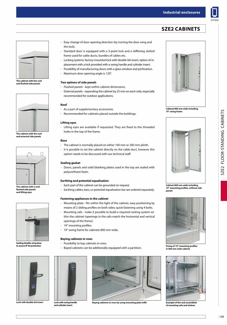
149
industrial enclosures
SZE2
FLO
OR-
STA
ND
ING
CA
BIN
ETS
- Easy change of door opening direction (by turning the door wing and the lock).- Standard door is equipped with a 3-point lock and a stiffening slotted
frame used for cable ducts, bundles of cables etc. - Locking systems: factory-mounted lock with double-bit insert, option of re-
placement with a lock provided with a swing handle and cylinder insert.- Possibility of manufacturing doors with a glass window and perforation.- Maximum door opening angle is 120°.
Two options of side panels- Flushed panels - kept within cabinet dimensions.- External panels - expanding the cabinet by 25 mm on each side; especially
recommended for outdoor applications.
Roof- As a part of supplementary accessories.- Recommended for cabinets placed outside the buildings.
lifting eyes- Lifting eyes are available if requested. They are fixed to the threaded
holes in the top of the frame.
base- The cabinet is normally placed on either 100 mm or 200 mm plinth.- It is possible to set the cabinet directly on the cable duct, however this
option needs to be discussed with our technical staff.
sealing gasket- Doors, panels and solid blanking plates used in the top are sealed with
polyurethane foam.
earthing and potential equalisation- Each part of the cabinet can be grounded on request.- Earthing cables, bars, or potential equalisation bar are ordered separately.
fastening appliances in the cabinet- Mounting plate - fits within the light of the cabinet, easy positioning by
means of 2 sliding profiles on both sides; quick fastening using 4 bolts.- Mounting rails - make it possible to build a required racking system wi-
thin the cabinet (openings in the rails match the horizontal and vertical openings of the frame).
- 19" mounting profiles.- 19" swing frame for cabinets 800 mm wide.
baying cabinets in rows- Possibility to bay cabinets in rows.- Bayed cabinets can be additionally equipped with a partition.
baying cabinets in rows by using mounting plate infill
The cabinet with the roof and flushed side panels
The cabinet with the roof and external side panels
The cabinet with a roof,flushed side panelsand lifting eyes
sealing double-wing door to assure iP 64 protection
Cabinet 800 mm wide including 19" swing frame
Cabinet 800 mm wide including19" mounting profiles, without side panels
fixing of 19" mounting profiles in 600 mm wide cabinet
example of the rack assembled of mounting rails and shelves
lock with double-bit insert lock with swing handle and cylinder insert
sZe2 CabineTs
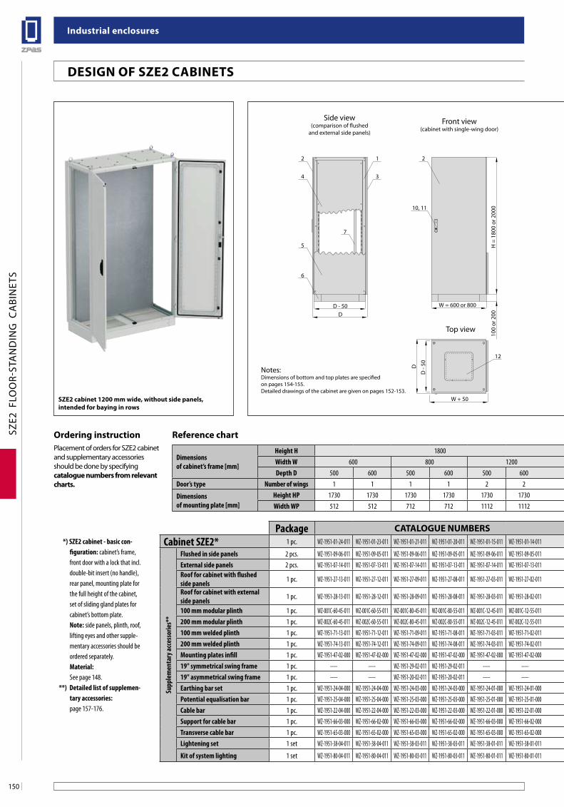
industrial enclosures
150
SZE2
FLO
OR-
STA
ND
ING
CA
BIN
ETS
W = 600 or 800D - 50D
2
4
1 2
3
5
7
6
W = 1000 or 1200D
D - 50
D - 190
W + 50 W + 50
10, 11
2
10, 11
"a"
3
9
71
8
2
1212
H =
180
0 or
200
010
0 or
200
H =
180
0 or
200
0
41.5
55
100
or 2
00
Side view(comparison of flushed
and external side panels)
Front view(cabinet with single-wing door)
Front view(cabinet with double-wing door)
Top viewTop view
Side view(with assembled roof
and lifting eyes) Mounting plate
D
D -
50 D
D -
50
WP
A-A section
Detail "a"
30
HP
35.5
A A
51.5
30
21
3
Notes:Dimensions of bottom and top plates are specified on pages 154-155.Detailed drawings of the cabinet are given on pages 152-153.
sZe2 cabinet 1200 mm wide, without side panels, intended for baying in rows
Design of sZe2 CabineTs
Dimensions of cabinet’s frame [mm]
Height H 1800 2000Width W 600 800 1200 600 800 1000 1200Depth D 500 600 500 600 500 600 400 500 600 800 400 500 600 800 500 600 500 600 800
Door’s type Number of wings 1 1 1 1 2 2 1 1 1 1 1 1 1 1 2 2 2 2 2
Dimensionsof mounting plate [mm]
Height HP 1730 1730 1730 1730 1730 1730 1930 1930 1930 1930 1930 1930 1930 1930 1930 1930 1930 1930 1930Width WP 512 512 712 712 1112 1112 512 512 512 512 712 712 712 712 912 912 1112 1112 1112
Reference chart
Package CaTalogue nuMbeRs*) SZE2 cabinet - basic con-
figuration: cabinet’s frame, front door with a lock that incl. double-bit insert (no handle), rear panel, mounting plate for the full height of the cabinet, set of sliding gland plates for cabinet’s bottom plate.Note: side panels, plinth, roof, lifting eyes and other supple-mentary accessories should be ordered separately.Material:See page 148.
**) Detailed list of supplemen-tary accessories: page 157-176.
Cabinet SZE2* 1 pc. WZ-1951-01-24-011 WZ-1951-01-23-011 WZ-1951-01-21-011 WZ-1951-01-20-011 WZ-1951-01-15-011 WZ-1951-01-14-011 WZ-1951-01-50-011 WZ-1951-01-12-011 WZ-1951-01-11-011 WZ-1951-01-10-011 WZ-1951-01-49-011 WZ-1951-01-09-011 WZ-1951-01-08-011 WZ-1951-01-07-011 WZ-1951-01-06-011 WZ-1951-01-05-011 WZ-1951-01-03-011 WZ-1951-01-02-011 WZ-1951-01-01-011
Supp
lem
enta
ry ac
cess
orie
s**
Flushed in side panels 2 pcs. WZ-1951-09-06-011 WZ-1951-09-05-011 WZ-1951-09-06-011 WZ-1951-09-05-011 WZ-1951-09-06-011 WZ-1951-09-05-011 WZ-1951-09-13-011 WZ-1951-09-03-011 WZ-1951-09-02-011 WZ-1951-09-01-011 WZ-1951-09-13-011 WZ-1951-09-03-011 WZ-1951-09-02-011 WZ-1951-09-01-011 WZ-1951-09-03-011 WZ-1951-09-02-011 WZ-1951-09-03-011 WZ-1951-09-02-011 WZ-1951-09-01-011External side panels 2 pcs. WZ-1951-07-14-011 WZ-1951-07-13-011 WZ-1951-07-14-011 WZ-1951-07-13-011 WZ-1951-07-14-011 WZ-1951-07-13-011 WZ-1951-07-29-011 WZ-1951-07-07-011 WZ-1951-07-06-011 WZ-1951-07-05-011 WZ-1951-07-29-011 WZ-1951-07-07-011 WZ-1951-07-06-011 WZ-1951-07-05-011 WZ-1951-07-07-011 WZ-1951-07-06-011 WZ-1951-07-07-011 WZ-1951-07-06-011 WZ-1951-07-05-011Roof for cabinet with flushed side panels 1 pc. WZ-1951-27-13-011 WZ-1951-27-12-011 WZ-1951-27-09-011 WZ-1951-27-08-011 WZ-1951-27-03-011 WZ-1951-27-02-011 WZ-1951-27-14-011 WZ-1951-27-13-011 WZ-1951-27-12-011 WZ-1951-27-11-011 WZ-1951-27-10-011 WZ-1951-27-09-011 WZ-1951-27-08-011 WZ-1951-27-07-011 WZ-1951-27-06-011 WZ-1951-27-05-011 WZ-1951-27-03-011 WZ-1951-27-02-011 WZ-1951-27-01-011
Roof for cabinet with external side panels 1 pc. WZ-1951-28-13-011 WZ-1951-28-12-011 WZ-1951-28-09-011 WZ-1951-28-08-011 WZ-1951-28-03-011 WZ-1951-28-02-011 WZ-1951-28-14-011 WZ-1951-28-13-011 WZ-1951-28-12-011 WZ-1951-28-11-011 WZ-1951-28-10-011 WZ-1951-28-09-011 WZ-1951-28-08-011 WZ-1951-28-07-011 WZ-1951-28-06-011 WZ-1951-28-05-011 WZ-1951-28-03-011 WZ-1951-28-02-011 WZ-1951-28-01-011
100 mm modular plinth 1 pc. WZ-001C-60-45-011 WZ-001C-60-55-011 WZ-001C-80-45-011 WZ-001C-80-55-011 WZ-001C-12-45-011 WZ-001C-12-55-011 WZ-001C-60-35-011 WZ-001C-60-45-011 WZ-001C-60-55-011 WZ-001C-60-75-011 WZ-001C-80-35-011 WZ-001C-80-45-011 WZ-001C-80-55-011 WZ-001C-80-75-011 WZ-001C-10-45-011 WZ-001C-10-55-011 WZ-001C-12-45-011 WZ-001C-12-55-011 WZ-001C-12-75-011200 mm modular plinth 1 pc. WZ-002C-60-45-011 WZ-002C-60-55-011 WZ-002C-80-45-011 WZ-002C-80-55-011 WZ-002C-12-45-011 WZ-002C-12-55-011 WZ-002C-60-35-011 WZ-002C-60-45-011 WZ-002C-60-55-011 WZ-002C-60-75-011 WZ-002C-80-35-011 WZ-002C-80-45-011 WZ-002C-80-55-011 WZ-002C-80-75-011 WZ-002C-10-45-011 WZ-002C-10-55-011 WZ-002C-12-45-011 WZ-002C-12-55-011 WZ-002C-12-75-011100 mm welded plinth 1 pc. WZ-1951-71-13-011 WZ-1951-71-12-011 WZ-1951-71-09-011 WZ-1951-71-08-011 WZ-1951-71-03-011 WZ-1951-71-02-011 WZ-1951-71-14-011 WZ-1951-71-13-011 WZ-1951-71-12-011 WZ-1951-71-11-011 WZ-1951-71-10-011 WZ-1951-71-09-011 WZ-1951-71-08-011 WZ-1951-71-07-011 WZ-1951-71-06-011 WZ-1951-71-05-011 WZ-1951-71-03-011 WZ-1951-71-02-011 WZ-1951-71-01-011200 mm welded plinth 1 pc. WZ-1951-74-13-011 WZ-1951-74-12-011 WZ-1951-74-09-011 WZ-1951-74-08-011 WZ-1951-74-03-011 WZ-1951-74-02-011 WZ-1951-74-14-011 WZ-1951-74-13-011 WZ-1951-74-12-011 WZ-1951-74-11-011 WZ-1951-74-10-011 WZ-1951-74-09-011 WZ-1951-74-08-011 WZ-1951-74-07-011 WZ-1951-74-06-011 WZ-1951-74-05-011 WZ-1951-74-03-011 WZ-1951-74-02-011 WZ-1951-74-01-011Mounting plates infill 1 pc. WZ-1951-47-02-000 WZ-1951-47-02-000 WZ-1951-47-02-000 WZ-1951-47-02-000 WZ-1951-47-02-000 WZ-1951-47-02-000 WZ-1951-47-01-000 WZ-1951-47-01-000 WZ-1951-47-01-000 WZ-1951-47-01-000 WZ-1951-47-01-000 WZ-1951-47-01-000 WZ-1951-47-01-000 WZ-1951-47-01-000 WZ-1951-47-01-000 WZ-1951-47-01-000 WZ-1951-47-01-000 WZ-1951-47-01-000 WZ-1951-47-01-00019" symmetrical swing frame 1 pc. ----- ----- WZ-1951-29-02-011 WZ-1951-29-02-011 ----- ----- ----- ----- ----- ----- WZ-1951-29-01-011 WZ-1951-29-01-011 WZ-1951-29-01-011 WZ-1951-29-01-011 ----- ----- ----- ----- -----19" asymmetrical swing frame 1 pc. ----- ----- WZ-1951-20-02-011 WZ-1951-20-02-011 ----- ----- ----- ----- ----- ----- WZ-1951-20-01-011 WZ-1951-20-01-011 WZ-1951-20-01-011 WZ-1951-20-01-011 ----- ----- ----- ----- -----Earthing bar set 1 pc. WZ-1951-24-04-000 WZ-1951-24-04-000 WZ-1951-24-03-000 WZ-1951-24-03-000 WZ-1951-24-01-000 WZ-1951-24-01-000 WZ-1951-24-04-000 WZ-1951-24-04-000 WZ-1951-24-04-000 WZ-1951-24-04-000 WZ-1951-24-03-000 WZ-1951-24-03-000 WZ-1951-24-03-000 WZ-1951-24-03-000 WZ-1951-24-02-000 WZ-1951-24-02-000 WZ-1951-24-01-000 WZ-1951-24-01-000 WZ-1951-24-01-000Potential equalisation bar 1 pc. WZ-1951-25-04-000 WZ-1951-25-04-000 WZ-1951-25-03-000 WZ-1951-25-03-000 WZ-1951-25-01-000 WZ-1951-25-01-000 WZ-1951-25-04-000 WZ-1951-25-04-000 WZ-1951-25-04-000 WZ-1951-25-04-000 WZ-1951-25-03-000 WZ-1951-25-03-000 WZ-1951-25-03-000 WZ-1951-25-03-000 WZ-1951-25-02-000 WZ-1951-25-02-000 WZ-1951-25-01-000 WZ-1951-25-01-000 WZ-1951-25-01-000Cable bar 1 pc. WZ-1951-22-04-000 WZ-1951-22-04-000 WZ-1951-22-03-000 WZ-1951-22-03-000 WZ-1951-22-01-000 WZ-1951-22-01-000 WZ-1951-22-04-000 WZ-1951-22-04-000 WZ-1951-22-04-000 WZ-1951-22-04-000 WZ-1951-22-03-000 WZ-1951-22-03-000 WZ-1951-22-03-000 WZ-1951-22-03-000 WZ-1951-22-02-000 WZ-1951-22-02-000 WZ-1951-22-01-000 WZ-1951-22-01-000 WZ-1951-22-01-000Support for cable bar 1 pc. WZ-1951-66-03-000 WZ-1951-66-02-000 WZ-1951-66-03-000 WZ-1951-66-02-000 WZ-1951-66-03-000 WZ-1951-66-02-000 WZ-1951-66-04-000 WZ-1951-66-03-000 WZ-1951-66-02-000 WZ-1951-66-01-000 WZ-1951-66-04-000 WZ-1951-66-03-000 WZ-1951-66-02-000 WZ-1951-66-01-000 WZ-1951-66-03-000 WZ-1951-66-02-000 WZ-1951-66-03-000 WZ-1951-66-02-000 WZ-1951-66-01-000Transverse cable bar 1 pc. WZ-1951-65-03-000 WZ-1951-65-02-000 WZ-1951-65-03-000 WZ-1951-65-02-000 WZ-1951-65-03-000 WZ-1951-65-02-000 WZ-1951-65-04-000 WZ-1951-65-03-000 WZ-1951-65-02-000 WZ-1951-65-01-000 WZ-1951-65-04-000 WZ-1951-65-03-000 WZ-1951-65-02-000 WZ-1951-65-01-000 WZ-1951-65-03-000 WZ-1951-65-02-000 WZ-1951-65-03-000 WZ-1951-65-02-000 WZ-1951-65-01-000Lightening set 1 set WZ-1951-38-04-011 WZ-1951-38-04-011 WZ-1951-38-03-011 WZ-1951-38-03-011 WZ-1951-38-01-011 WZ-1951-38-01-011 WZ-1951-38-04-011 WZ-1951-38-04-011 WZ-1951-38-04-011 WZ-1951-38-04-011 WZ-1951-38-03-011 WZ-1951-38-03-011 WZ-1951-38-03-011 WZ-1951-38-03-011 WZ-1951-38-02-011 WZ-1951-38-02-011 WZ-1951-38-01-011 WZ-1951-38-01-011 WZ-1951-38-01-011
Kit of system lighting 1 set WZ-1951-80-04-011 WZ-1951-80-04-011 WZ-1951-80-03-011 WZ-1951-80-03-011 WZ-1951-80-01-011 WZ-1951-80-01-011 WZ-1951-80-04-011 WZ-1951-80-04-011 WZ-1951-80-04-011 WZ-1951-80-04-011 WZ-1951-80-03-011 WZ-1951-80-03-011 WZ-1951-80-03-011 WZ-1951-80-03-011 WZ-1951-80-02-011 WZ-1951-80-02-011 WZ-1951-80-01-011 WZ-1951-80-01-011 WZ-1951-80-01-011
ordering instructionPlacement of orders for SZE2 cabinet and supplementary accessories should be done by specifying catalogue numbers from relevant charts.
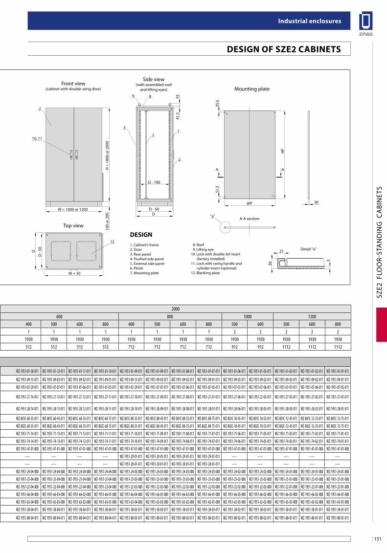
151
industrial enclosures
SZE2
FLO
OR-
STA
ND
ING
CA
BIN
ETS
W = 600 or 800D - 50D
2
4
1 2
3
5
7
6
W = 1000 or 1200D
D - 50
D - 190
W + 50 W + 50
10, 11
2
10, 11
"a"
3
9
71
8
2
1212
H =
180
0 or
200
010
0 or
200
H =
180
0 or
200
0
41.5
55
100
or 2
00
Side view(comparison of flushed
and external side panels)
Front view(cabinet with single-wing door)
Front view(cabinet with double-wing door)
Top viewTop view
Side view(with assembled roof
and lifting eyes) Mounting plate
D
D -
50 D
D -
50
WP
A-A section
Detail "a"
30
HP
35.5
A A
51.5
30
21
3
Design1. Cabinet’s frame2. Door3. Rear panel4. Flushed side panel5. External side panel6. Plinth7. Mounting plate
8. Roof 9. Lifting eye10. Lock with double-bit insert (factory installed)11. Lock with swing handle and cylinder insert (optional)12. Blanking plate
Design of sZe2 CabineTs
Dimensions of cabinet’s frame [mm]
Height H 1800 2000Width W 600 800 1200 600 800 1000 1200Depth D 500 600 500 600 500 600 400 500 600 800 400 500 600 800 500 600 500 600 800
Door’s type Number of wings 1 1 1 1 2 2 1 1 1 1 1 1 1 1 2 2 2 2 2
Dimensionsof mounting plate [mm]
Height HP 1730 1730 1730 1730 1730 1730 1930 1930 1930 1930 1930 1930 1930 1930 1930 1930 1930 1930 1930Width WP 512 512 712 712 1112 1112 512 512 512 512 712 712 712 712 912 912 1112 1112 1112
Reference chart
Package CaTalogue nuMbeRs*) SZE2 cabinet - basic con-
figuration: cabinet’s frame, front door with a lock that incl. double-bit insert (no handle), rear panel, mounting plate for the full height of the cabinet, set of sliding gland plates for cabinet’s bottom plate.Note: side panels, plinth, roof, lifting eyes and other supple-mentary accessories should be ordered separately.Material:See page 148.
**) Detailed list of supplemen-tary accessories: page 157-176.
Cabinet SZE2* 1 pc. WZ-1951-01-24-011 WZ-1951-01-23-011 WZ-1951-01-21-011 WZ-1951-01-20-011 WZ-1951-01-15-011 WZ-1951-01-14-011 WZ-1951-01-50-011 WZ-1951-01-12-011 WZ-1951-01-11-011 WZ-1951-01-10-011 WZ-1951-01-49-011 WZ-1951-01-09-011 WZ-1951-01-08-011 WZ-1951-01-07-011 WZ-1951-01-06-011 WZ-1951-01-05-011 WZ-1951-01-03-011 WZ-1951-01-02-011 WZ-1951-01-01-011
Supp
lem
enta
ry ac
cess
orie
s**
Flushed in side panels 2 pcs. WZ-1951-09-06-011 WZ-1951-09-05-011 WZ-1951-09-06-011 WZ-1951-09-05-011 WZ-1951-09-06-011 WZ-1951-09-05-011 WZ-1951-09-13-011 WZ-1951-09-03-011 WZ-1951-09-02-011 WZ-1951-09-01-011 WZ-1951-09-13-011 WZ-1951-09-03-011 WZ-1951-09-02-011 WZ-1951-09-01-011 WZ-1951-09-03-011 WZ-1951-09-02-011 WZ-1951-09-03-011 WZ-1951-09-02-011 WZ-1951-09-01-011External side panels 2 pcs. WZ-1951-07-14-011 WZ-1951-07-13-011 WZ-1951-07-14-011 WZ-1951-07-13-011 WZ-1951-07-14-011 WZ-1951-07-13-011 WZ-1951-07-29-011 WZ-1951-07-07-011 WZ-1951-07-06-011 WZ-1951-07-05-011 WZ-1951-07-29-011 WZ-1951-07-07-011 WZ-1951-07-06-011 WZ-1951-07-05-011 WZ-1951-07-07-011 WZ-1951-07-06-011 WZ-1951-07-07-011 WZ-1951-07-06-011 WZ-1951-07-05-011Roof for cabinet with flushed side panels 1 pc. WZ-1951-27-13-011 WZ-1951-27-12-011 WZ-1951-27-09-011 WZ-1951-27-08-011 WZ-1951-27-03-011 WZ-1951-27-02-011 WZ-1951-27-14-011 WZ-1951-27-13-011 WZ-1951-27-12-011 WZ-1951-27-11-011 WZ-1951-27-10-011 WZ-1951-27-09-011 WZ-1951-27-08-011 WZ-1951-27-07-011 WZ-1951-27-06-011 WZ-1951-27-05-011 WZ-1951-27-03-011 WZ-1951-27-02-011 WZ-1951-27-01-011
Roof for cabinet with external side panels 1 pc. WZ-1951-28-13-011 WZ-1951-28-12-011 WZ-1951-28-09-011 WZ-1951-28-08-011 WZ-1951-28-03-011 WZ-1951-28-02-011 WZ-1951-28-14-011 WZ-1951-28-13-011 WZ-1951-28-12-011 WZ-1951-28-11-011 WZ-1951-28-10-011 WZ-1951-28-09-011 WZ-1951-28-08-011 WZ-1951-28-07-011 WZ-1951-28-06-011 WZ-1951-28-05-011 WZ-1951-28-03-011 WZ-1951-28-02-011 WZ-1951-28-01-011
100 mm modular plinth 1 pc. WZ-001C-60-45-011 WZ-001C-60-55-011 WZ-001C-80-45-011 WZ-001C-80-55-011 WZ-001C-12-45-011 WZ-001C-12-55-011 WZ-001C-60-35-011 WZ-001C-60-45-011 WZ-001C-60-55-011 WZ-001C-60-75-011 WZ-001C-80-35-011 WZ-001C-80-45-011 WZ-001C-80-55-011 WZ-001C-80-75-011 WZ-001C-10-45-011 WZ-001C-10-55-011 WZ-001C-12-45-011 WZ-001C-12-55-011 WZ-001C-12-75-011200 mm modular plinth 1 pc. WZ-002C-60-45-011 WZ-002C-60-55-011 WZ-002C-80-45-011 WZ-002C-80-55-011 WZ-002C-12-45-011 WZ-002C-12-55-011 WZ-002C-60-35-011 WZ-002C-60-45-011 WZ-002C-60-55-011 WZ-002C-60-75-011 WZ-002C-80-35-011 WZ-002C-80-45-011 WZ-002C-80-55-011 WZ-002C-80-75-011 WZ-002C-10-45-011 WZ-002C-10-55-011 WZ-002C-12-45-011 WZ-002C-12-55-011 WZ-002C-12-75-011100 mm welded plinth 1 pc. WZ-1951-71-13-011 WZ-1951-71-12-011 WZ-1951-71-09-011 WZ-1951-71-08-011 WZ-1951-71-03-011 WZ-1951-71-02-011 WZ-1951-71-14-011 WZ-1951-71-13-011 WZ-1951-71-12-011 WZ-1951-71-11-011 WZ-1951-71-10-011 WZ-1951-71-09-011 WZ-1951-71-08-011 WZ-1951-71-07-011 WZ-1951-71-06-011 WZ-1951-71-05-011 WZ-1951-71-03-011 WZ-1951-71-02-011 WZ-1951-71-01-011200 mm welded plinth 1 pc. WZ-1951-74-13-011 WZ-1951-74-12-011 WZ-1951-74-09-011 WZ-1951-74-08-011 WZ-1951-74-03-011 WZ-1951-74-02-011 WZ-1951-74-14-011 WZ-1951-74-13-011 WZ-1951-74-12-011 WZ-1951-74-11-011 WZ-1951-74-10-011 WZ-1951-74-09-011 WZ-1951-74-08-011 WZ-1951-74-07-011 WZ-1951-74-06-011 WZ-1951-74-05-011 WZ-1951-74-03-011 WZ-1951-74-02-011 WZ-1951-74-01-011Mounting plates infill 1 pc. WZ-1951-47-02-000 WZ-1951-47-02-000 WZ-1951-47-02-000 WZ-1951-47-02-000 WZ-1951-47-02-000 WZ-1951-47-02-000 WZ-1951-47-01-000 WZ-1951-47-01-000 WZ-1951-47-01-000 WZ-1951-47-01-000 WZ-1951-47-01-000 WZ-1951-47-01-000 WZ-1951-47-01-000 WZ-1951-47-01-000 WZ-1951-47-01-000 WZ-1951-47-01-000 WZ-1951-47-01-000 WZ-1951-47-01-000 WZ-1951-47-01-00019" symmetrical swing frame 1 pc. ----- ----- WZ-1951-29-02-011 WZ-1951-29-02-011 ----- ----- ----- ----- ----- ----- WZ-1951-29-01-011 WZ-1951-29-01-011 WZ-1951-29-01-011 WZ-1951-29-01-011 ----- ----- ----- ----- -----19" asymmetrical swing frame 1 pc. ----- ----- WZ-1951-20-02-011 WZ-1951-20-02-011 ----- ----- ----- ----- ----- ----- WZ-1951-20-01-011 WZ-1951-20-01-011 WZ-1951-20-01-011 WZ-1951-20-01-011 ----- ----- ----- ----- -----Earthing bar set 1 pc. WZ-1951-24-04-000 WZ-1951-24-04-000 WZ-1951-24-03-000 WZ-1951-24-03-000 WZ-1951-24-01-000 WZ-1951-24-01-000 WZ-1951-24-04-000 WZ-1951-24-04-000 WZ-1951-24-04-000 WZ-1951-24-04-000 WZ-1951-24-03-000 WZ-1951-24-03-000 WZ-1951-24-03-000 WZ-1951-24-03-000 WZ-1951-24-02-000 WZ-1951-24-02-000 WZ-1951-24-01-000 WZ-1951-24-01-000 WZ-1951-24-01-000Potential equalisation bar 1 pc. WZ-1951-25-04-000 WZ-1951-25-04-000 WZ-1951-25-03-000 WZ-1951-25-03-000 WZ-1951-25-01-000 WZ-1951-25-01-000 WZ-1951-25-04-000 WZ-1951-25-04-000 WZ-1951-25-04-000 WZ-1951-25-04-000 WZ-1951-25-03-000 WZ-1951-25-03-000 WZ-1951-25-03-000 WZ-1951-25-03-000 WZ-1951-25-02-000 WZ-1951-25-02-000 WZ-1951-25-01-000 WZ-1951-25-01-000 WZ-1951-25-01-000Cable bar 1 pc. WZ-1951-22-04-000 WZ-1951-22-04-000 WZ-1951-22-03-000 WZ-1951-22-03-000 WZ-1951-22-01-000 WZ-1951-22-01-000 WZ-1951-22-04-000 WZ-1951-22-04-000 WZ-1951-22-04-000 WZ-1951-22-04-000 WZ-1951-22-03-000 WZ-1951-22-03-000 WZ-1951-22-03-000 WZ-1951-22-03-000 WZ-1951-22-02-000 WZ-1951-22-02-000 WZ-1951-22-01-000 WZ-1951-22-01-000 WZ-1951-22-01-000Support for cable bar 1 pc. WZ-1951-66-03-000 WZ-1951-66-02-000 WZ-1951-66-03-000 WZ-1951-66-02-000 WZ-1951-66-03-000 WZ-1951-66-02-000 WZ-1951-66-04-000 WZ-1951-66-03-000 WZ-1951-66-02-000 WZ-1951-66-01-000 WZ-1951-66-04-000 WZ-1951-66-03-000 WZ-1951-66-02-000 WZ-1951-66-01-000 WZ-1951-66-03-000 WZ-1951-66-02-000 WZ-1951-66-03-000 WZ-1951-66-02-000 WZ-1951-66-01-000Transverse cable bar 1 pc. WZ-1951-65-03-000 WZ-1951-65-02-000 WZ-1951-65-03-000 WZ-1951-65-02-000 WZ-1951-65-03-000 WZ-1951-65-02-000 WZ-1951-65-04-000 WZ-1951-65-03-000 WZ-1951-65-02-000 WZ-1951-65-01-000 WZ-1951-65-04-000 WZ-1951-65-03-000 WZ-1951-65-02-000 WZ-1951-65-01-000 WZ-1951-65-03-000 WZ-1951-65-02-000 WZ-1951-65-03-000 WZ-1951-65-02-000 WZ-1951-65-01-000Lightening set 1 set WZ-1951-38-04-011 WZ-1951-38-04-011 WZ-1951-38-03-011 WZ-1951-38-03-011 WZ-1951-38-01-011 WZ-1951-38-01-011 WZ-1951-38-04-011 WZ-1951-38-04-011 WZ-1951-38-04-011 WZ-1951-38-04-011 WZ-1951-38-03-011 WZ-1951-38-03-011 WZ-1951-38-03-011 WZ-1951-38-03-011 WZ-1951-38-02-011 WZ-1951-38-02-011 WZ-1951-38-01-011 WZ-1951-38-01-011 WZ-1951-38-01-011
Kit of system lighting 1 set WZ-1951-80-04-011 WZ-1951-80-04-011 WZ-1951-80-03-011 WZ-1951-80-03-011 WZ-1951-80-01-011 WZ-1951-80-01-011 WZ-1951-80-04-011 WZ-1951-80-04-011 WZ-1951-80-04-011 WZ-1951-80-04-011 WZ-1951-80-03-011 WZ-1951-80-03-011 WZ-1951-80-03-011 WZ-1951-80-03-011 WZ-1951-80-02-011 WZ-1951-80-02-011 WZ-1951-80-01-011 WZ-1951-80-01-011 WZ-1951-80-01-011
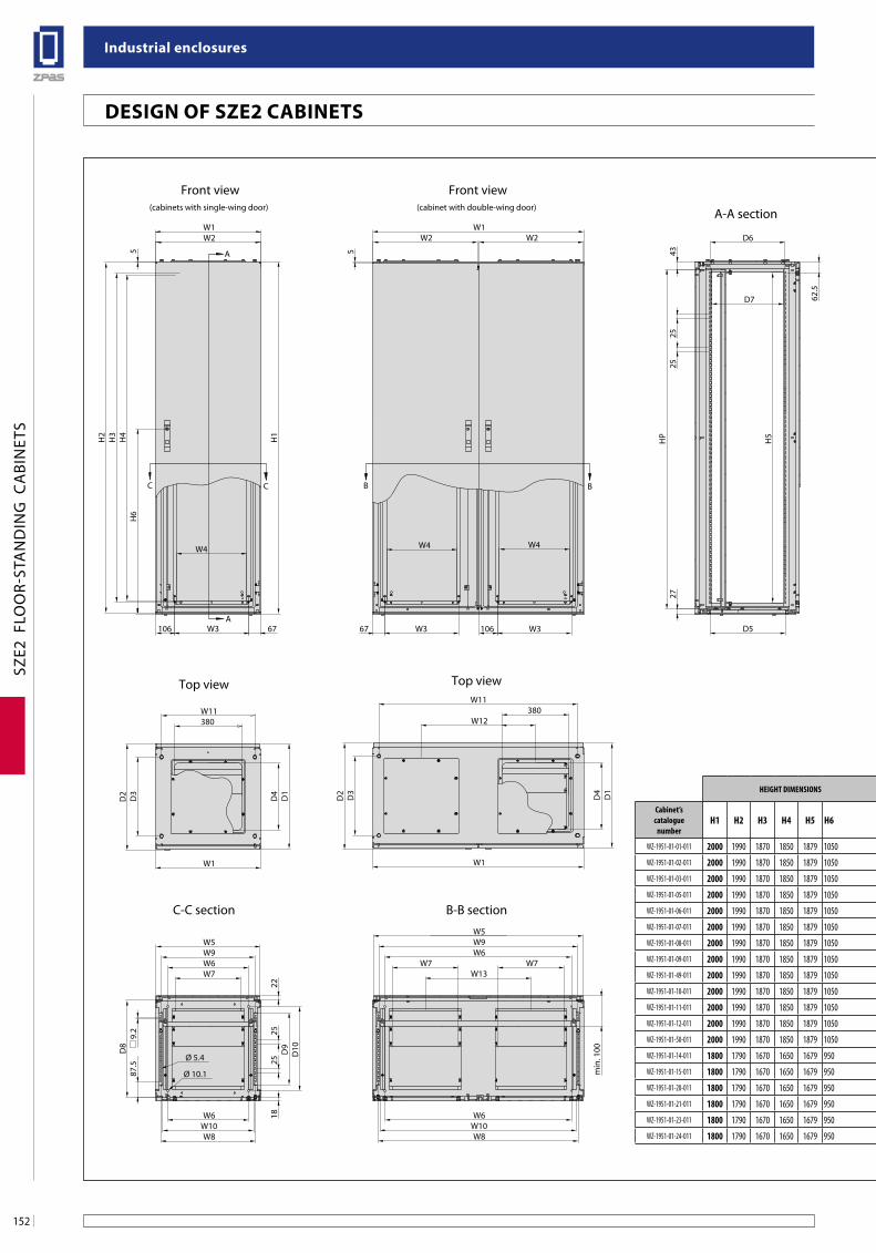
industrial enclosures
152
SZE2
FLO
OR-
STA
ND
ING
CA
BIN
ETS
C C B B
A
A
W1W2
W3106
5
H1
H2
W11
D1
W1
D3
D2
W7W6W9
Ø 5.4
9.2
Ø 10.1
W8
W6
D10D9D8
87.5
W10
22
W5
18
H3
67
W4
D6
4327
HP
25
D7 62.5
D5
H5
25
2525
H6
H4
D4
380
WP12
35,5
HP
27 27
60
60
Ø 8.5
30
W1W2 W2
W3
W367
5
W11
D3
D2 D1
W1
W13W7 W7
W6W9W5
W6W10W8
min
. 100
W4 W4
106
W12380
D4
WC2
DC1
WC1
DC2
Ø 16.2
DC1
WC3
DC3
WC1
Ø 22
80
80
Front view(cabinets with single-wing door)
Front view(cabinet with double-wing door) A-A section
Modular plinth(openings for floor fastening)
Welded plinth(openings for floor fastening)
Mounting plate
B-B sectionC-C section
Top viewTop view
HEIGHT DIMENSIONS WIDTH DIMENSIONS DEPTH DIMENSIONS MOUNTINGPLATE PLINTH
Cabinet’scatalogue
numberH1 H2 H3 H4 H5 H6 W1 W2 W3 W4 W5 W6 W7 W8 W9 W10 W11 W12 W13 D1 D2 D3 D4 D5 D6 D7 D8 D9 D10 HP WP WC1 WC2 WC3 DC1 DC2 DC3
WZ-1951-01-01-011 2000 1990 1870 1850 1879 1050 1200 593 420 400 1192 1060 376 1137,6 1130 1117 1130 650 600 800 808 650 380 630 625 610 750 610 680 1930 1112 1200 1080 900 750 630 650
WZ-1951-01-02-011 2000 1990 1870 1850 1879 1050 1200 593 420 400 1192 1060 376 1137,6 1130 1117 1130 650 600 600 608 450 380 430 425 410 550 410 480 1930 1112 1200 1080 900 550 430 450
WZ-1951-01-03-011 2000 1990 1870 1850 1879 1050 1200 593 420 400 1192 1060 376 1137,6 1130 1117 1130 550 600 500 508 350 380 330 325 310 450 310 380 1930 1112 1200 1080 900 450 330 350
WZ-1951-01-05-011 2000 1990 1870 1850 1879 1050 1000 493 320 300 992 860 326 937,6 930 917 930 — 450 600 608 450 380 430 425 410 550 410 480 1930 912 1000 880 700 550 430 450
WZ-1951-01-06-011 2000 1990 1870 1850 1879 1050 1000 493 320 300 992 860 326 937,6 930 917 930 — 450 500 508 350 380 330 325 310 450 310 380 1930 912 1000 880 700 450 330 350
WZ-1951-01-07-011 2000 1990 1870 1850 1879 1050 800 793 620 600 792 660 579 737,6 730 717 730 — — 800 808 650 380 630 625 610 750 610 680 1930 712 800 680 500 750 630 650
WZ-1951-01-08-011 2000 1990 1870 1850 1879 1050 800 793 620 600 792 660 579 737,6 730 717 730 — — 600 608 450 380 430 425 410 550 410 480 1930 712 800 680 500 550 430 450
WZ-1951-01-09-011 2000 1990 1870 1850 1879 1050 800 793 620 600 792 660 579 737,6 730 717 730 — — 500 508 350 380 330 325 310 450 310 380 1930 712 800 680 500 450 330 350
WZ-1951-01-49-011 2000 1990 1870 1850 1879 1050 800 793 620 600 792 660 579 737,6 730 717 730 — — 400 408 250 210 230 225 210 350 210 280 1930 712 800 680 500 350 230 250
WZ-1951-01-10-011 2000 1990 1870 1850 1879 1050 600 593 420 400 592 460 376 537,6 530 517 530 — — 800 808 650 380 630 625 610 750 610 680 1930 512 600 480 300 750 630 650
WZ-1951-01-11-011 2000 1990 1870 1850 1879 1050 600 593 420 400 592 460 376 537,6 530 517 530 — — 600 608 450 380 430 425 410 550 410 480 1930 512 600 480 300 550 430 450
WZ-1951-01-12-011 2000 1990 1870 1850 1879 1050 600 593 420 400 592 460 376 537,6 530 517 530 — — 500 508 350 380 330 325 310 450 310 380 1930 512 600 480 300 450 330 350
WZ-1951-01-50-011 2000 1990 1870 1850 1879 1050 600 593 420 400 592 460 376 537,6 530 517 530 — — 400 408 250 210 230 225 210 350 210 280 1930 512 600 480 300 350 230 250
WZ-1951-01-14-011 1800 1790 1670 1650 1679 950 1200 593 420 400 1192 1060 376 1137,6 1130 1117 1130 650 600 600 608 450 380 430 425 410 550 410 480 1730 1112 1200 1080 900 550 430 450
WZ-1951-01-15-011 1800 1790 1670 1650 1679 950 1200 593 420 400 1192 1060 376 1137,6 1130 1117 1130 550 600 500 508 350 380 330 325 310 450 310 380 1730 1112 1200 1080 900 450 330 350
WZ-1951-01-20-011 1800 1790 1670 1650 1679 950 800 793 620 600 792 660 576 737,6 730 717 730 — — 600 608 450 380 430 425 410 550 410 480 1730 712 800 680 500 550 430 450
WZ-1951-01-21-011 1800 1790 1670 1650 1679 950 800 793 620 600 792 660 576 737,6 730 717 730 — — 500 508 350 380 330 325 310 450 310 380 1730 712 800 680 500 450 330 350
WZ-1951-01-23-011 1800 1790 1670 1650 1679 950 600 593 420 400 592 460 376 537,6 530 517 530 — — 600 608 450 380 430 425 410 550 410 480 1730 512 600 480 300 550 430 450
WZ-1951-01-24-011 1800 1790 1670 1650 1679 950 600 593 420 400 592 460 376 537,6 530 517 530 — — 500 508 350 380 330 325 310 450 310 380 1730 512 600 480 300 450 330 350
Design of sZe2 CabineTs
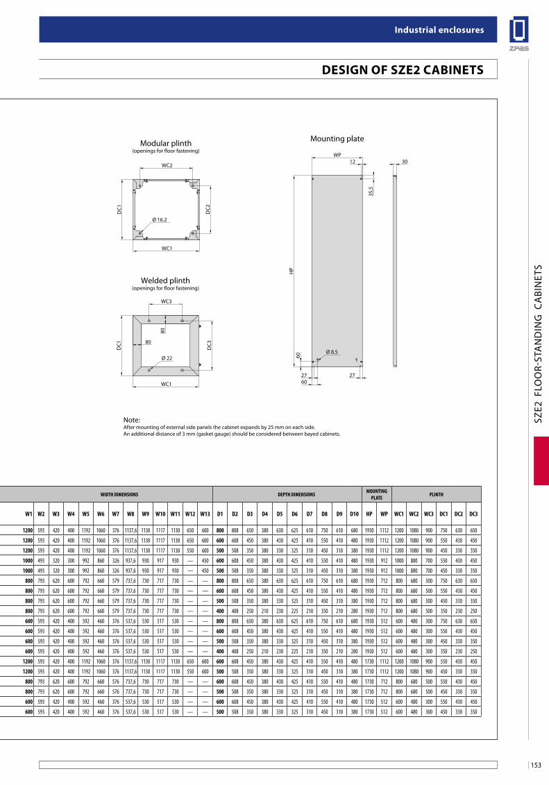
153
industrial enclosures
SZE2
FLO
OR-
STA
ND
ING
CA
BIN
ETS
C C B B
A
A
W1W2
W3106
5
H1
H2
W11
D1
W1
D3
D2
W7W6W9
Ø 5.4
9.2
Ø 10.1
W8
W6
D10D9D8
87.5
W10
22
W5
18
H3
67
W4
D6
4327
HP
25
D7 62.5
D5
H5
25
2525
H6
H4
D4
380
WP12
35,5
HP
27 27
60
60
Ø 8.5
30
W1W2 W2
W3
W367
5
W11
D3
D2 D1
W1
W13W7 W7
W6W9W5
W6W10W8
min
. 100
W4 W4
106
W12380
D4
WC2
DC1
WC1
DC2
Ø 16.2
DC1
WC3
DC3
WC1
Ø 22
80
80
Front view(cabinets with single-wing door)
Front view(cabinet with double-wing door) A-A section
Modular plinth(openings for floor fastening)
Welded plinth(openings for floor fastening)
Mounting plate
B-B sectionC-C section
Top viewTop view
HEIGHT DIMENSIONS WIDTH DIMENSIONS DEPTH DIMENSIONS MOUNTINGPLATE PLINTH
Cabinet’scatalogue
numberH1 H2 H3 H4 H5 H6 W1 W2 W3 W4 W5 W6 W7 W8 W9 W10 W11 W12 W13 D1 D2 D3 D4 D5 D6 D7 D8 D9 D10 HP WP WC1 WC2 WC3 DC1 DC2 DC3
WZ-1951-01-01-011 2000 1990 1870 1850 1879 1050 1200 593 420 400 1192 1060 376 1137,6 1130 1117 1130 650 600 800 808 650 380 630 625 610 750 610 680 1930 1112 1200 1080 900 750 630 650
WZ-1951-01-02-011 2000 1990 1870 1850 1879 1050 1200 593 420 400 1192 1060 376 1137,6 1130 1117 1130 650 600 600 608 450 380 430 425 410 550 410 480 1930 1112 1200 1080 900 550 430 450
WZ-1951-01-03-011 2000 1990 1870 1850 1879 1050 1200 593 420 400 1192 1060 376 1137,6 1130 1117 1130 550 600 500 508 350 380 330 325 310 450 310 380 1930 1112 1200 1080 900 450 330 350
WZ-1951-01-05-011 2000 1990 1870 1850 1879 1050 1000 493 320 300 992 860 326 937,6 930 917 930 — 450 600 608 450 380 430 425 410 550 410 480 1930 912 1000 880 700 550 430 450
WZ-1951-01-06-011 2000 1990 1870 1850 1879 1050 1000 493 320 300 992 860 326 937,6 930 917 930 — 450 500 508 350 380 330 325 310 450 310 380 1930 912 1000 880 700 450 330 350
WZ-1951-01-07-011 2000 1990 1870 1850 1879 1050 800 793 620 600 792 660 579 737,6 730 717 730 — — 800 808 650 380 630 625 610 750 610 680 1930 712 800 680 500 750 630 650
WZ-1951-01-08-011 2000 1990 1870 1850 1879 1050 800 793 620 600 792 660 579 737,6 730 717 730 — — 600 608 450 380 430 425 410 550 410 480 1930 712 800 680 500 550 430 450
WZ-1951-01-09-011 2000 1990 1870 1850 1879 1050 800 793 620 600 792 660 579 737,6 730 717 730 — — 500 508 350 380 330 325 310 450 310 380 1930 712 800 680 500 450 330 350
WZ-1951-01-49-011 2000 1990 1870 1850 1879 1050 800 793 620 600 792 660 579 737,6 730 717 730 — — 400 408 250 210 230 225 210 350 210 280 1930 712 800 680 500 350 230 250
WZ-1951-01-10-011 2000 1990 1870 1850 1879 1050 600 593 420 400 592 460 376 537,6 530 517 530 — — 800 808 650 380 630 625 610 750 610 680 1930 512 600 480 300 750 630 650
WZ-1951-01-11-011 2000 1990 1870 1850 1879 1050 600 593 420 400 592 460 376 537,6 530 517 530 — — 600 608 450 380 430 425 410 550 410 480 1930 512 600 480 300 550 430 450
WZ-1951-01-12-011 2000 1990 1870 1850 1879 1050 600 593 420 400 592 460 376 537,6 530 517 530 — — 500 508 350 380 330 325 310 450 310 380 1930 512 600 480 300 450 330 350
WZ-1951-01-50-011 2000 1990 1870 1850 1879 1050 600 593 420 400 592 460 376 537,6 530 517 530 — — 400 408 250 210 230 225 210 350 210 280 1930 512 600 480 300 350 230 250
WZ-1951-01-14-011 1800 1790 1670 1650 1679 950 1200 593 420 400 1192 1060 376 1137,6 1130 1117 1130 650 600 600 608 450 380 430 425 410 550 410 480 1730 1112 1200 1080 900 550 430 450
WZ-1951-01-15-011 1800 1790 1670 1650 1679 950 1200 593 420 400 1192 1060 376 1137,6 1130 1117 1130 550 600 500 508 350 380 330 325 310 450 310 380 1730 1112 1200 1080 900 450 330 350
WZ-1951-01-20-011 1800 1790 1670 1650 1679 950 800 793 620 600 792 660 576 737,6 730 717 730 — — 600 608 450 380 430 425 410 550 410 480 1730 712 800 680 500 550 430 450
WZ-1951-01-21-011 1800 1790 1670 1650 1679 950 800 793 620 600 792 660 576 737,6 730 717 730 — — 500 508 350 380 330 325 310 450 310 380 1730 712 800 680 500 450 330 350
WZ-1951-01-23-011 1800 1790 1670 1650 1679 950 600 593 420 400 592 460 376 537,6 530 517 530 — — 600 608 450 380 430 425 410 550 410 480 1730 512 600 480 300 550 430 450
WZ-1951-01-24-011 1800 1790 1670 1650 1679 950 600 593 420 400 592 460 376 537,6 530 517 530 — — 500 508 350 380 330 325 310 450 310 380 1730 512 600 480 300 450 330 350
Note:After mounting of external side panels the cabinet expands by 25 mm on each side.An additional distance of 3 mm (gasket gauge) should be considered between bayed cabinets.
Design of sZe2 CabineTs
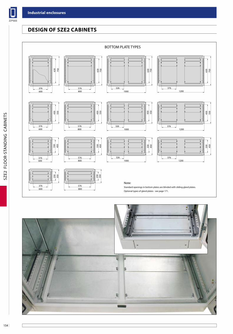
industrial enclosures
154
SZE2
FLO
OR-
STA
ND
ING
CA
BIN
ETS
BOTTOM PLATE TYPES
376600
750
630
3261000
750
630
576800
750
3761200
750
630
630
376600
550
430
576800
430
550
3261000
550
430
3761200
550
430
376600
450
330
576800
450
330
3261000
330
450
3761200
450
330
376600
350
230
576800
350
230
Note:Standard openings in bottom plates are blinded with sliding gland plates.
Optional types of gland plates - see page 171.
Design of sZe2 CabineTs
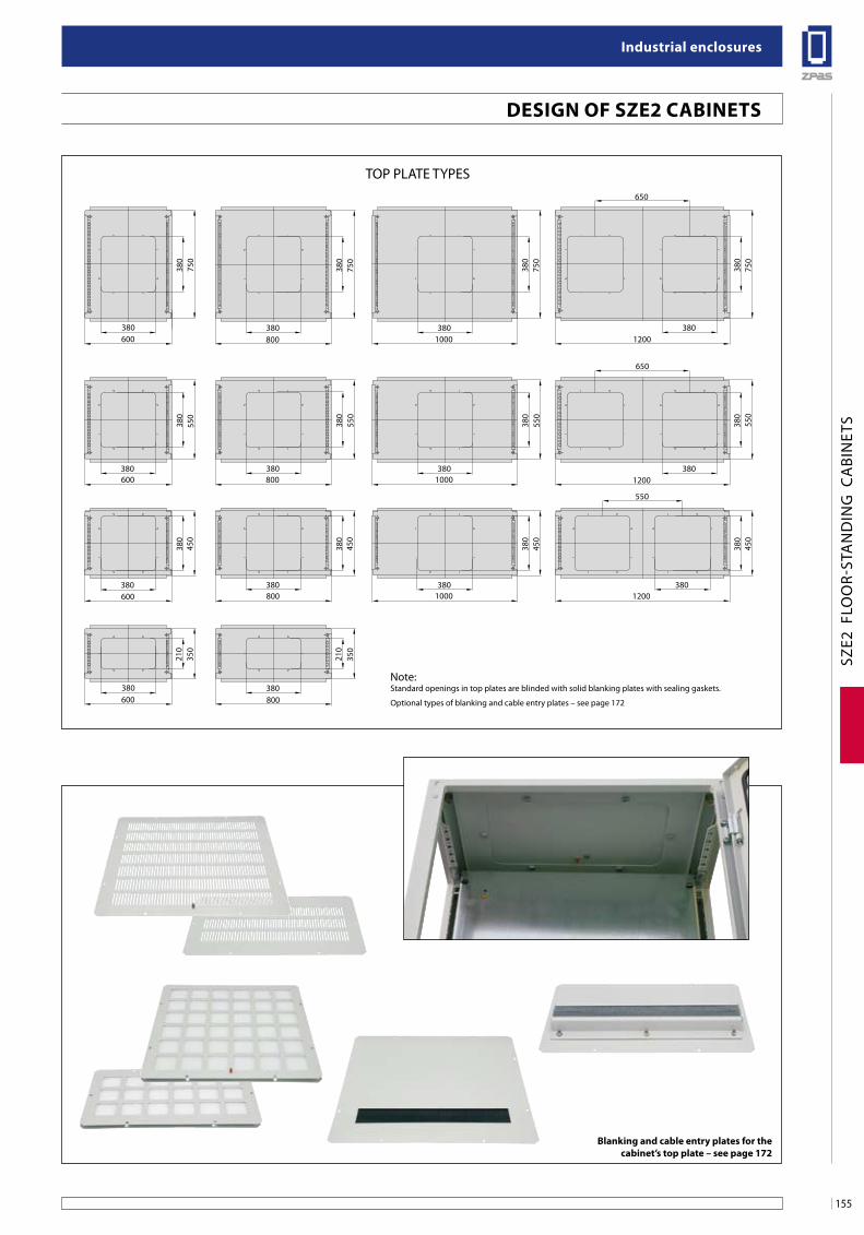
155
industrial enclosures
SZE2
FLO
OR-
STA
ND
ING
CA
BIN
ETS
TOP PLATE TYPES
750
750
380
750
750
550
550
550
550
450
450
450
450
380600
600
600
600
800
800
800
800
1000
1000
1000
1200
1200
1200
550
650
65035
0
350
380
210
380
380
380
380
380
380
380
380
380
380
380
210
380 380 380 380
380380380380
380
380 380 380
Note:Standard openings in top plates are blinded with solid blanking plates with sealing gaskets.
Optional types of blanking and cable entry plates – see page 172
blanking and cable entry plates for the cabinet’s top plate – see page 172
Design of sZe2 CabineTs
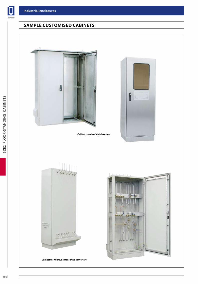
industrial enclosures
156
SZE2
FLO
OR-
STA
ND
ING
CA
BIN
ETS
Cabinets made of stainless steel
Cabinet for hydraulic measuring converters
saMPle CusToMiseD CabineTs
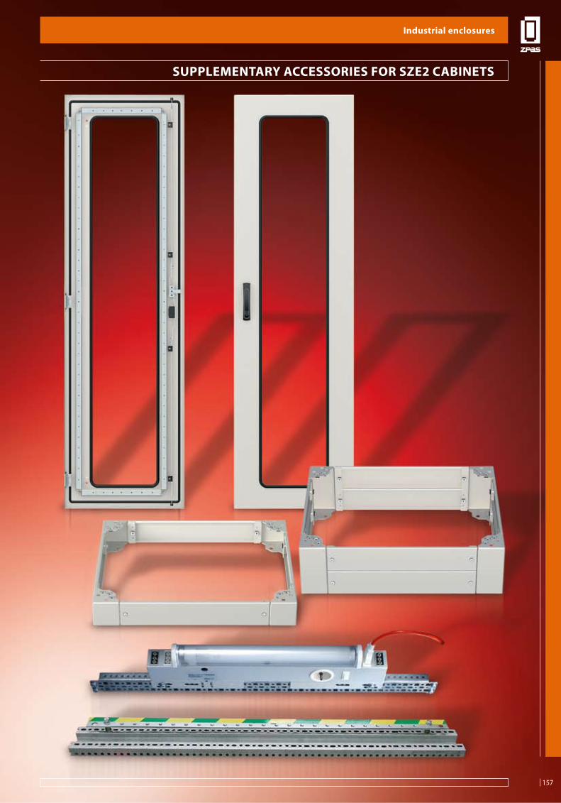
157
industrial enclosures
SUPP
LEM
ENTA
RY A
CCES
SORI
ES
suPPleMenTaRY aCCessoRies foR sZe2 CabineTs
industrial enclosures
157
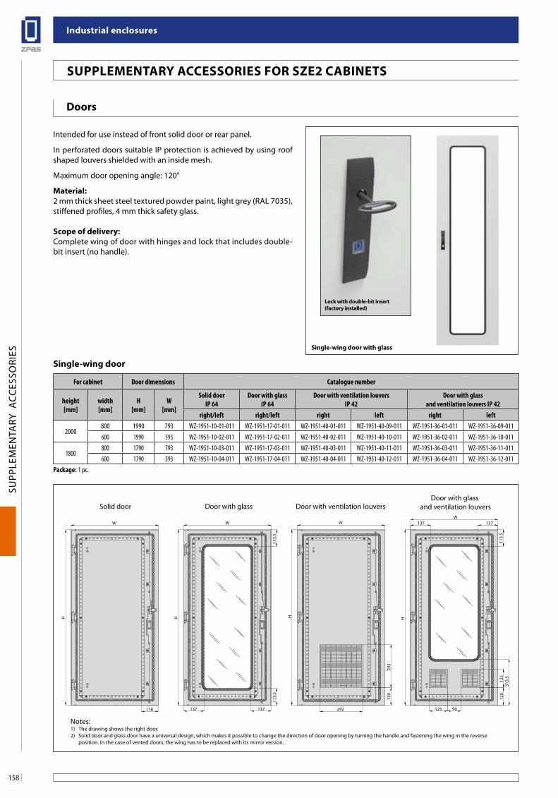
industrial enclosures
158
SUPP
LEM
ENTA
RY A
CCES
SORI
ES
137 137
113.
511
3.5
W
H
118
W
H
292
120
292
W
H H
W
113.
531
3.5
137137
120
90125
125
Solid door Door with glass Door with ventilation louversDoor with glass
and ventilation louvers
Doors
Intended for use instead of front solid door or rear panel.
In perforated doors suitable IP protection is achieved by using roof shaped louvers shielded with an inside mesh.
Maximum door opening angle: 120°
Material:2 mm thick sheet steel textured powder paint, light grey (RAL 7035), stiffened profiles, 4 mm thick safety glass.
scope of delivery: Complete wing of door with hinges and lock that includes double-bit insert (no handle).
single-wing door with glass
suPPleMenTaRY aCCessoRies foR sZe2 CabineTs
lock with double-bit insert (factory installed)
single-wing door
For cabinet Door dimensions Catalogue number
height[mm]
width[mm]
H[mm]
W[mm]
Solid door IP 64
Door with glassIP 64
Door with ventilation louversIP 42
Door with glass and ventilation louvers IP 42
right/left right/left right left right left
2000800 1990 793 WZ-1951-10-01-011 WZ-1951-17-01-011 WZ-1951-40-01-011 WZ-1951-40-09-011 WZ-1951-36-01-011 WZ-1951-36-09-011600 1990 593 WZ-1951-10-02-011 WZ-1951-17-02-011 WZ-1951-40-02-011 WZ-1951-40-10-011 WZ-1951-36-02-011 WZ-1951-36-10-011
1800800 1790 793 WZ-1951-10-03-011 WZ-1951-17-03-011 WZ-1951-40-03-011 WZ-1951-40-11-011 WZ-1951-36-03-011 WZ-1951-36-11-011600 1790 593 WZ-1951-10-04-011 WZ-1951-17-04-011 WZ-1951-40-04-011 WZ-1951-40-12-011 WZ-1951-36-04-011 WZ-1951-36-12-011
Package: 1 pc.
Notes:1) The drawing shows the right door.2) Solid door and glass door have a universal design, which makes it possible to change the direction of door opening by turning the handle and fastening the wing in the reverse
position. In the case of vented doors, the wing has to be replaced with its mirror version.
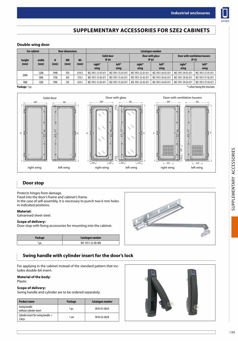
159
industrial enclosures
SUPP
LEM
ENTA
RY A
CCES
SORI
ES
WP WL
H
113,5
113,5
WP WL
HH
137137 137137
H H
120
223
223
H
223
WLWP
Solid door
right wing left wing right wing left wing right wing left wing
Door with glass Door with ventilation louvers
swing handle with cylinder insert for the door’s lock
For applying in the cabinet instead of the standard pattern that inc-ludes double-bit insert.
Material of the body:Plastic
scope of delivery:Swing handle and cylinder are to be ordered separately.
Product name Package Catalague number
Swing handlewithout cylinder insert 1 pc. M1H-01-0024
Cylinder insert for swing handle + 2 keys 1 set M1H-02-0028
Door stop
Protects hinges from damage.Fixed into the door’s frame and cabinet’s frame.In the case of self-assembly, it is necessary to punch two 6 mm holes in indicated positions.
Material:Galvanised sheet steel.
scope of delivery:Door stop with fixing accessories for mounting into the cabinet.
Package Catalogue number
1 pc. WZ-1951-32-00-000
suPPleMenTaRY aCCessoRies foR sZe2 CabineTs
Double-wing door
For cabinet Door dimensions Catalogue number
height[mm]
width[mm]
H[mm]
WR[mm]
WL[mm]
Solid doorIP 64
Door with glassIP 64
Door with ventilation louversIP 42
right*wing
left*wing
right*wing
left*wing
right*wing
left*wing
20001200 1990 593 619.5 WZ-1951-13-01-011 WZ-1951-15-01-011 WZ-1951-52-01-011 WZ-1951-54-01-011 WZ-1951-59-01-011 WZ-1951-57-01-0111000 1790 493 519.5 WZ-1951-13-02-011 WZ-1951-15-02-011 WZ-1951-52-02-011 WZ-1951-54-02-011 WZ-1951-59-02-011 WZ-1951-57-02-011
1800 1200 1990 593 619.5 WZ-1951-13-03-011 WZ-1951-15-03-011 WZ-1951-52-03-011 WZ-1951-54-03-011 WZ-1951-59-03-011 WZ-1951-57-03-011Package: 1 pc. *) when facing the structure.
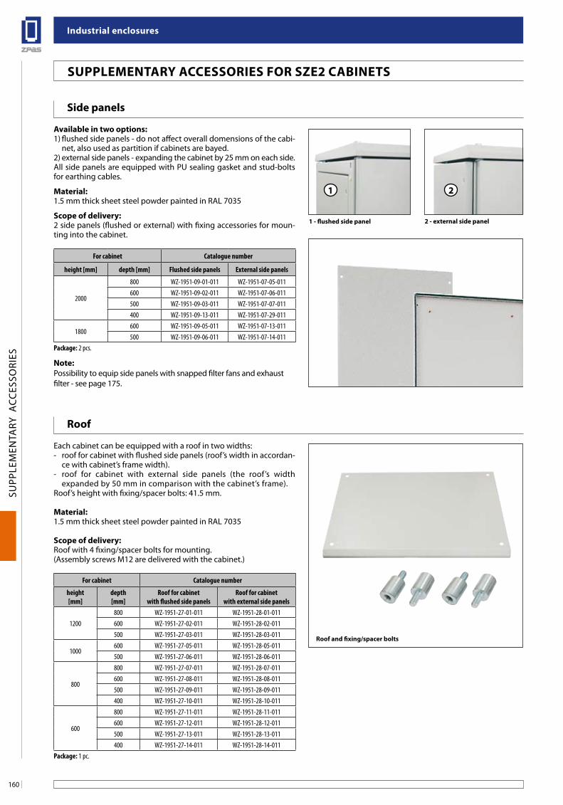
industrial enclosures
160
SUPP
LEM
ENTA
RY A
CCES
SORI
ES
Roof
Each cabinet can be equipped with a roof in two widths:- roof for cabinet with flushed side panels (roof’s width in accordan-
ce with cabinet’s frame width).- roof for cabinet with external side panels (the roof’s width
expanded by 50 mm in comparison with the cabinet’s frame).Roof’s height with fixing/spacer bolts: 41.5 mm.
Material:1.5 mm thick sheet steel powder painted in RAL 7035
scope of delivery:Roof with 4 fixing/spacer bolts for mounting.(Assembly screws M12 are delivered with the cabinet.)
For cabinet Catalogue number
height [mm]
depth [mm]
Roof for cabinetwith flushed side panels
Roof for cabinetwith external side panels
1200800 WZ-1951-27-01-011 WZ-1951-28-01-011600 WZ-1951-27-02-011 WZ-1951-28-02-011500 WZ-1951-27-03-011 WZ-1951-28-03-011
1000600 WZ-1951-27-05-011 WZ-1951-28-05-011500 WZ-1951-27-06-011 WZ-1951-28-06-011
800
800 WZ-1951-27-07-011 WZ-1951-28-07-011600 WZ-1951-27-08-011 WZ-1951-28-08-011500 WZ-1951-27-09-011 WZ-1951-28-09-011400 WZ-1951-27-10-011 WZ-1951-28-10-011
600
800 WZ-1951-27-11-011 WZ-1951-28-11-011600 WZ-1951-27-12-011 WZ-1951-28-12-011500 WZ-1951-27-13-011 WZ-1951-28-13-011400 WZ-1951-27-14-011 WZ-1951-28-14-011
Package: 1 pc.
Roof and fixing/spacer bolts
suPPleMenTaRY aCCessoRies foR sZe2 CabineTs
side panels
available in two options:1) flushed side panels - do not affect overall domensions of the cabi-
net, also used as partition if cabinets are bayed.2) external side panels - expanding the cabinet by 25 mm on each side.All side panels are equipped with PU sealing gasket and stud-bolts for earthing cables.
Material:1.5 mm thick sheet steel powder painted in RAL 7035
scope of delivery:2 side panels (flushed or external) with fixing accessories for moun-ting into the cabinet.
note:Possibility to equip side panels with snapped filter fans and exhaustfilter - see page 175.
For cabinet Catalogue number
height [mm] depth [mm] Flushed side panels External side panels
2000
800 WZ-1951-09-01-011 WZ-1951-07-05-011600 WZ-1951-09-02-011 WZ-1951-07-06-011500 WZ-1951-09-03-011 WZ-1951-07-07-011400 WZ-1951-09-13-011 WZ-1951-07-29-011
1800600 WZ-1951-09-05-011 WZ-1951-07-13-011500 WZ-1951-09-06-011 WZ-1951-07-14-011
Package: 2 pcs.
1 2
1 - flushed side panel 2 - external side panel
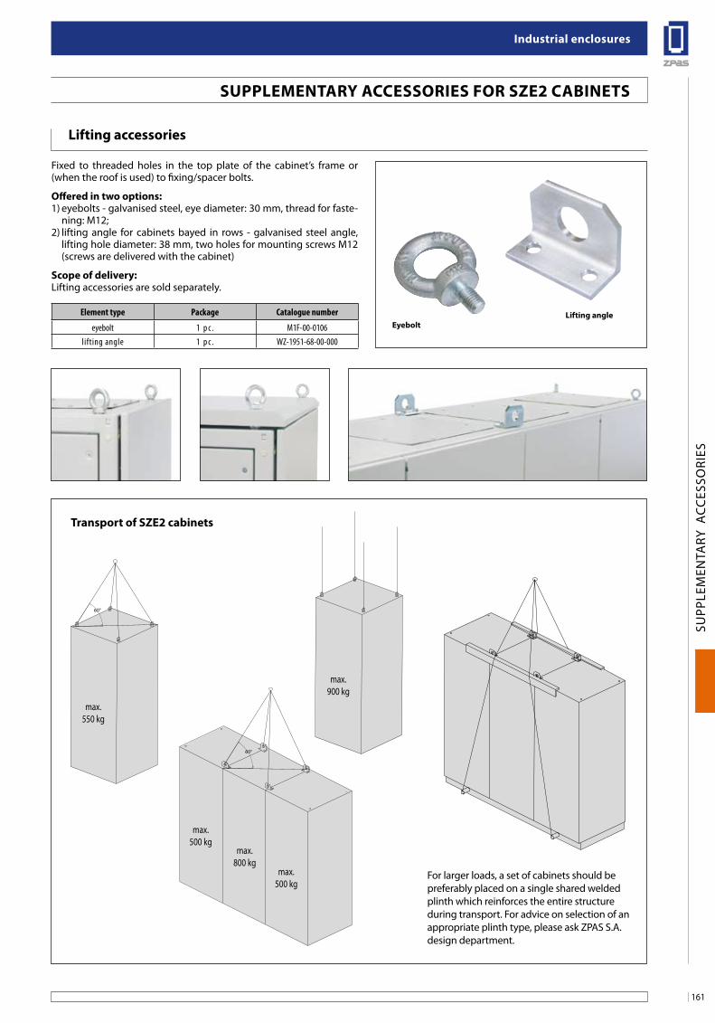
161
industrial enclosures
SUPP
LEM
ENTA
RY A
CCES
SORI
ES
lifting accessories
Fixed to threaded holes in the top plate of the cabinet’s frame or (when the roof is used) to fixing/spacer bolts.
offered in two options:1) eyebolts - galvanised steel, eye diameter: 30 mm, thread for faste-
ning: M12;2) lifting angle for cabinets bayed in rows - galvanised steel angle,
lifting hole diameter: 38 mm, two holes for mounting screws M12 (screws are delivered with the cabinet)
scope of delivery:Lifting accessories are sold separately.
Element type Package Catalogue number
eyebolt 1 p c . M1F-00-0106lifting angle 1 p c . WZ-1951-68-00-000
eyeboltlifting angle
suPPleMenTaRY aCCessoRies foR sZe2 CabineTs
60°
60°
max.550 kg
max.900 kg
max.500 kg
max.800 kg
max.500 kg
60°
60°
max.550 kg
max.900 kg
max.500 kg
max.800 kg
max.500 kg
60°
60°
max.550 kg
max.900 kg
max.500 kg
max.800 kg
max.500 kg
Transport of sZe2 cabinets
For larger loads, a set of cabinets should be preferably placed on a single shared welded plinth which reinforces the entire structure during transport. For advice on selection of an appropriate plinth type, please ask ZPAS S.A. design department.
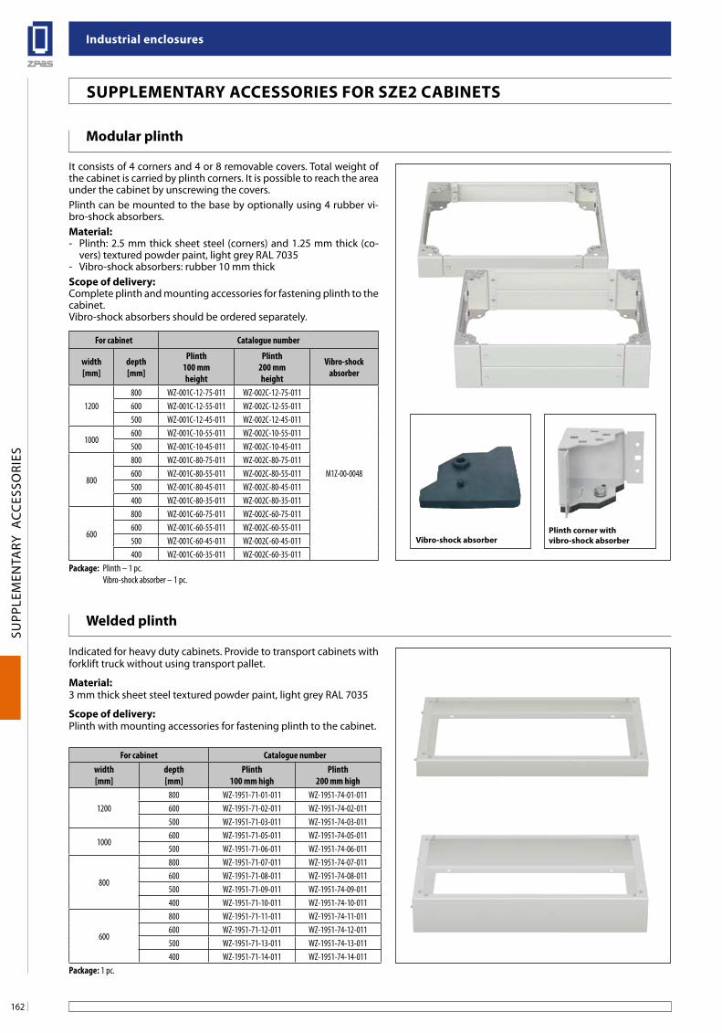
industrial enclosures
162
SUPP
LEM
ENTA
RY A
CCES
SORI
ES
suPPleMenTaRY aCCessoRies foR sZe2 CabineTs
Modular plinth
It consists of 4 corners and 4 or 8 removable covers. Total weight of the cabinet is carried by plinth corners. It is possible to reach the area under the cabinet by unscrewing the covers.Plinth can be mounted to the base by optionally using 4 rubber vi-bro-shock absorbers.Material:- Plinth: 2.5 mm thick sheet steel (corners) and 1.25 mm thick (co-
vers) textured powder paint, light grey RAL 7035- Vibro-shock absorbers: rubber 10 mm thickscope of delivery:Complete plinth and mounting accessories for fastening plinth to the cabinet.Vibro-shock absorbers should be ordered separately.
Plinth corner with vibro-shock absorberVibro-shock absorber
Welded plinth
Indicated for heavy duty cabinets. Provide to transport cabinets with forklift truck without using transport pallet.
Material:3 mm thick sheet steel textured powder paint, light grey RAL 7035
scope of delivery:Plinth with mounting accessories for fastening plinth to the cabinet.
For cabinet Catalogue number
width[mm]
depth[mm]
Plinth 100 mm height
Plinth 200 mm height
Vibro-shock absorber
1200800 WZ-001C-12-75-011 WZ-002C-12-75-011
M1Z-00-0048
600 WZ-001C-12-55-011 WZ-002C-12-55-011500 WZ-001C-12-45-011 WZ-002C-12-45-011
1000600 WZ-001C-10-55-011 WZ-002C-10-55-011500 WZ-001C-10-45-011 WZ-002C-10-45-011
800
800 WZ-001C-80-75-011 WZ-002C-80-75-011600 WZ-001C-80-55-011 WZ-002C-80-55-011500 WZ-001C-80-45-011 WZ-002C-80-45-011400 WZ-001C-80-35-011 WZ-002C-80-35-011
600
800 WZ-001C-60-75-011 WZ-002C-60-75-011600 WZ-001C-60-55-011 WZ-002C-60-55-011500 WZ-001C-60-45-011 WZ-002C-60-45-011400 WZ-001C-60-35-011 WZ-002C-60-35-011
Package: Plinth – 1 pc. Vibro-shock absorber – 1 pc.
For cabinet Catalogue numberwidth[mm]
depth[mm]
Plinth100 mm high
Plinth200 mm high
1200800 WZ-1951-71-01-011 WZ-1951-74-01-011600 WZ-1951-71-02-011 WZ-1951-74-02-011500 WZ-1951-71-03-011 WZ-1951-74-03-011
1000600 WZ-1951-71-05-011 WZ-1951-74-05-011500 WZ-1951-71-06-011 WZ-1951-74-06-011
800
800 WZ-1951-71-07-011 WZ-1951-74-07-011600 WZ-1951-71-08-011 WZ-1951-74-08-011500 WZ-1951-71-09-011 WZ-1951-74-09-011400 WZ-1951-71-10-011 WZ-1951-74-10-011
600
800 WZ-1951-71-11-011 WZ-1951-74-11-011600 WZ-1951-71-12-011 WZ-1951-74-12-011500 WZ-1951-71-13-011 WZ-1951-74-13-011400 WZ-1951-71-14-011 WZ-1951-74-14-011
Package: 1 pc.
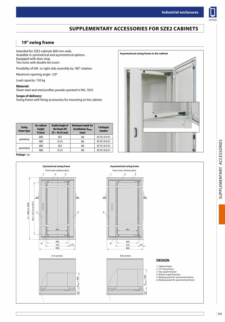
163
industrial enclosures
SUPP
LEM
ENTA
RY A
CCES
SORI
ES
19" swing frame
Intended for SZE2 cabinets 800 mm wide. Available in symmetrical and asymmetrical options. Equipped with door-stop. Two locks with double-bit insert.
Possibility of left- or right-side assembly by 180° rotation.
Maximum opening angle: 120°
Load capacity: 150 kg
Material: Sheet steel and steel profiles powder painted in RAL 7035
scope of delivery: Swing frame with fixing accessories for mounting to the cabinet.
asymmetrical swing frame in the cabinet
suPPleMenTaRY aCCessoRies foR sZe2 CabineTs
Swingframe type
For cabinet heightH [mm]
Usable height of the frame HU
[U = 44.45 mm]
Maximum depth for installations Dmax
[mm]
Cataloguenumber
symmetrical2000 40 U 360 WZ-1951-29-01-0111800 35.5 U 360 WZ-1951-29-02-011
asymmetrical2000 40 U 440 WZ-1951-20-01-0111800 35.5 U 440 WZ-1951-20-02-011
Package: 1 pc.
137525800
A-A section B-B section
Front view without door Front view without door
symmetrical swing frame asymmetrical swing frame
451
465
A
1
Dm
ax =
440
87
Dm
ax =
360
451
87
79525800
465
HU
= 3
5,5
U o
r 40
U
H =
180
0 or
200
0
2 3 1
5 65
2 3
44
A B B
Design1. Cabinet frame2. 19" swing frame3. Top supporting bar4. Bottom supporting bar5. Masking panel for symmetrical frame6. Masking panel for asymmetrical frame
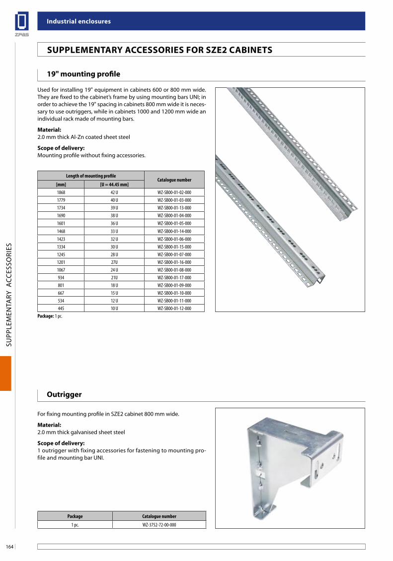
industrial enclosures
164
SUPP
LEM
ENTA
RY A
CCES
SORI
ES
suPPleMenTaRY aCCessoRies foR sZe2 CabineTs
19" mounting profile
Used for installing 19" equipment in cabinets 600 or 800 mm wide. They are fixed to the cabinet’s frame by using mounting bars UNI; in order to achieve the 19" spacing in cabinets 800 mm wide it is neces-sary to use outriggers, while in cabinets 1000 and 1200 mm wide an individual rack made of mounting bars.
Material:2.0 mm thick Al-Zn coated sheet steel
scope of delivery:Mounting profile without fixing accessories.
outrigger
For fixing mounting profile in SZE2 cabinet 800 mm wide.
Material:2.0 mm thick galvanised sheet steel
scope of delivery:1 outrigger with fixing accessories for fastening to mounting pro-file and mounting bar UNI.
Length of mounting profileCatalogue number
[mm] [U = 44.45 mm]1868 42 U WZ-SB00-01-02-0001779 40 U WZ-SB00-01-03-0001734 39 U WZ-SB00-01-13-0001690 38 U WZ-SB00-01-04-000
1601 36 U WZ-SB00-01-05-000
1468 33 U WZ-SB00-01-14-000
1423 32 U WZ-SB00-01-06-0001334 30 U WZ-SB00-01-15-0001245 28 U WZ-SB00-01-07-0001201 27U WZ-SB00-01-16-0001067 24 U WZ-SB00-01-08-000934 21U WZ-SB00-01-17-000801 18 U WZ-SB00-01-09-000667 15 U WZ-SB00-01-10-000534 12 U WZ-SB00-01-11-000445 10 U WZ-SB00-01-12-000
Package: 1 pc.
Package Catalogue number
1 pc. WZ-3752-72-00-000
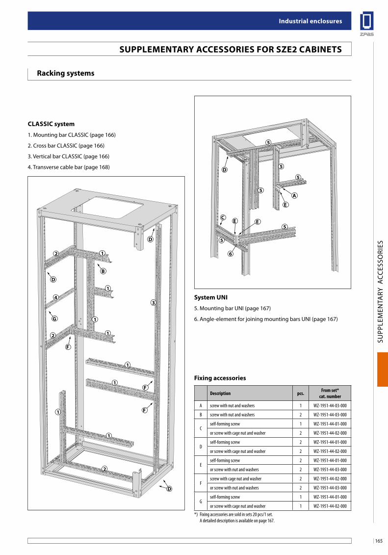
165
industrial enclosures
SUPP
LEM
ENTA
RY A
CCES
SORI
ES
5
6
5
5
5
5
5
D
a
Ce e
e
2
4
1
3
1
1
1
1
1
1
1
2
2
b
D
D
g
f
f
f
D
Description pcs. From set*cat. number
A screw with nut and washers 1 WZ-1951-44-03-000
B screw with nut and washers 2 WZ-1951-44-03-000
Cself-forming screw 1 WZ-1951-44-01-000
or screw with cage nut and washer 2 WZ-1951-44-02-000
Dself-forming screw 2 WZ-1951-44-01-000
or screw with cage nut and washer 2 WZ-1951-44-02-000
Eself-forming screw 2 WZ-1951-44-01-000
or screw with nut and washers 2 WZ-1951-44-03-000
Fscrew with cage nut and washer 2 WZ-1951-44-02-000
or screw with nut and washers 2 WZ-1951-44-03-000
Gself-forming screw 1 WZ-1951-44-01-000
or screw with cage nut and washer 1 WZ-1951-44-02-000
*) Fixing accessories are sold in sets 20 pcs/1 set. A detailed description is available on page 167.
ClassiC system
1. Mounting bar CLASSIC (page 166)
2. Cross bar CLASSIC (page 166)
3. Vertical bar CLASSIC (page 166)
4. Transverse cable bar (page 168)
system uni
5. Mounting bar UNI (page 167)
6. Angle-element for joining mounting bars UNI (page 167)
fixing accessories
suPPleMenTaRY aCCessoRies foR sZe2 CabineTs
Racking systems
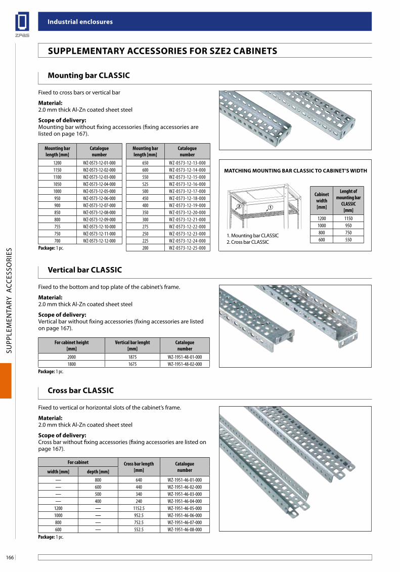
industrial enclosures
166
SUPP
LEM
ENTA
RY A
CCES
SORI
ES
1. Belka montażowa CLASSIC2. Belka poprzeczna CLASSIC
suPPleMenTaRY aCCessoRies foR sZe2 CabineTs
Mounting bar ClassiC
Fixed to cross bars or vertical bar
Material:2.0 mm thick Al-Zn coated sheet steel
scope of delivery:Mounting bar without fixing accessories (fixing accessories are listed on page 167).
Cross bar ClassiC
Fixed to vertical or horizontal slots of the cabinet’s frame.
Material:2.0 mm thick Al-Zn coated sheet steel
scope of delivery:Cross bar without fixing accessories (fixing accessories are listed on page 167).
Vertical bar ClassiC
Fixed to the bottom and top plate of the cabinet’s frame.
Material:2.0 mm thick Al-Zn coated sheet steel
scope of delivery:Vertical bar without fixing accessories (fixing accessories are listed on page 167).
MaTCHing MounTing baR ClassiC To CabineT’s WiDTH
1. Mounting bar CLASSIC2. Cross bar CLASSIC
Mounting bar length [mm]
Catalogue number
Mounting bar length [mm]
Catalogue number
1200 WZ-0573-12-01-000 650 WZ-0573-12-13-0001150 WZ-0573-12-02-000 600 WZ-0573-12-14-0001100 WZ-0573-12-03-000 550 WZ-0573-12-15-0001050 WZ-0573-12-04-000 525 WZ-0573-12-16-0001000 WZ-0573-12-05-000 500 WZ-0573-12-17-000950 WZ-0573-12-06-000 450 WZ-0573-12-18-000900 WZ-0573-12-07-000 400 WZ-0573-12-19-000850 WZ-0573-12-08-000 350 WZ-0573-12-20-000800 WZ-0573-12-09-000 300 WZ-0573-12-21-000755 WZ-0573-12-10-000 275 WZ-0573-12-22-000750 WZ-0573-12-11-000 250 WZ-0573-12-23-000700 WZ-0573-12-12-000 225 WZ-0573-12-24-000
Package: 1 pc. 200 WZ-0573-12-25-000
Cabinetwidth[mm]
Lenght of mounting bar
CLASSIC[mm]
1200 11501000 950800 750600 550
For cabinet height [mm]
Vertical bar lenght [mm]
Cataloguenumber
2000 1875 WZ-1951-48-01-0001800 1675 WZ-1951-48-02-000
Package: 1 pc.
For cabinet Cross bar length[mm]
Catalogue numberwidth [mm] depth [mm]
800 640 WZ-1951-46-01-000600 440 WZ-1951-46-02-000500 340 WZ-1951-46-03-000400 240 WZ-1951-46-04-000
1200 1152.5 WZ-1951-46-05-0001000 952.5 WZ-1951-46-06-000800 752.5 WZ-1951-46-07-000600 552.5 WZ-1951-46-08-000
Package: 1 pc.
12
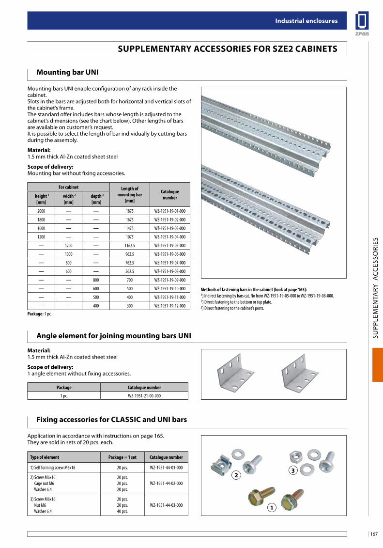
167
industrial enclosures
SUPP
LEM
ENTA
RY A
CCES
SORI
ES
2
1
3
Mounting bar uni
Mounting bars UNI enable configuration of any rack inside the cabinet.Slots in the bars are adjusted both for horizontal and vertical slots of the cabinet’s frame.The standard offer includes bars whose length is adjusted to the cabinet’s dimensions (see the chart below). Other lengths of bars are available on customer’s request.It is possible to select the length of bar individually by cutting bars during the assembly.
Material:1.5 mm thick Al-Zn coated sheet steel
scope of delivery:Mounting bar without fixing accessories.
angle element for joining mounting bars uni
Material:1.5 mm thick Al-Zn coated sheet steel
scope of delivery:1 angle element without fixing accessories.
fixing accessories for ClassiC and uni bars
Application in accordance with instructions on page 165.They are sold in sets of 20 pcs. each.
Methods of fastening bars in the cabinet (look at page 165):1) Indirect fastening by bars cat. No from WZ-1951-19-05-000 to WZ-1951-19-08-000.2) Direct fastening to the bottom or top plate.3) Direct fastening to the cabinet’s posts.
suPPleMenTaRY aCCessoRies foR sZe2 CabineTs
For cabinet Length of mounting bar
[mm]
Catalogue number height 1
[mm] width 2
[mm] depth 3
[mm]
2000 1875 WZ-1951-19-01-000
1800 1675 WZ-1951-19-02-000
1600 1475 WZ-1951-19-03-000
1200 1075 WZ-1951-19-04-000
1200 1162.5 WZ-1951-19-05-000
1000 962.5 WZ-1951-19-06-000
800 762.5 WZ-1951-19-07-000
600 562.5 WZ-1951-19-08-000
800 700 WZ-1951-19-09-000
600 500 WZ-1951-19-10-000
500 400 WZ-1951-19-11-000
400 300 WZ-1951-19-12-000
Package: 1 pc.
Package Catalogue number
1 pc. WZ-1951-21-00-000
Type of element Package = 1 set Catalogue number
1) Self forming screw M6x16 20 pcs. WZ-1951-44-01-000
2) Screw M6x16 Cage nut M6 Washer 6.4
20 pcs.20 pcs.20 pcs.
WZ-1951-44-02-000
3) Screw M6x16 Nut M6 Washer 6.4
20 pcs.20 pcs.40 pcs.
WZ-1951-44-03-000
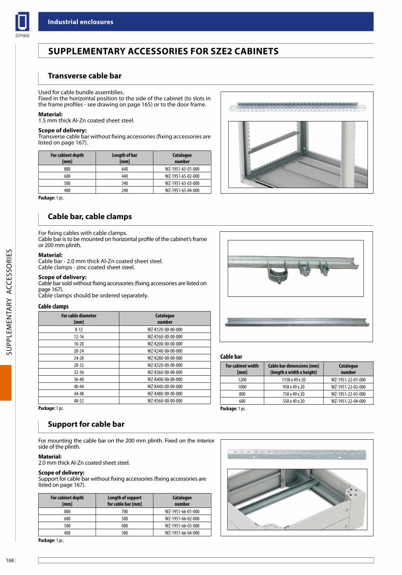
industrial enclosures
168
SUPP
LEM
ENTA
RY A
CCES
SORI
ES
suPPleMenTaRY aCCessoRies foR sZe2 CabineTs
Cable bar, cable clamps
For fixing cables with cable clamps. Cable bar is to be mounted on horizontal profile of the cabinet’s frame or 200 mm plinth.
Material: Cable bar - 2.0 mm thick Al-Zn coated sheet steel. Cable clamps - zinc coated sheet steel.
scope of delivery: Cable bar sold without fixing accessories (fixing accessories are listed on page 167). Cable clamps should be ordered separately.
Cable clampsFor cable diameter
[mm]Catalogue
number8-12 WZ-K12U-00-00-000
12-16 WZ-K16U-00-00-00016-20 WZ-K20U-00-00-00020-24 WZ-K24U-00-00-00024-28 WZ-K28U-00-00-00028-32 WZ-K32U-00-00-00032-36 WZ-K36U-00-00-00036-40 WZ-K40U-00-00-00040-44 WZ-K44U-00-00-00044-48 WZ-K48U-00-00-00048-52 WZ-K56U-00-00-000
Package: 1 pc.
Cable barFor cabinet width
[mm]Cable bar dimensions [mm]
(length x width x height)Catalogue
number1200 1158 x 49 x 20 WZ-1951-22-01-0001000 958 x 49 x 20 WZ-1951-22-02-000800 758 x 49 x 20 WZ-1951-22-03-000600 558 x 49 x 20 WZ-1951-22-04-000
Package: 1 pc.
Transverse cable bar
Used for cable bundle assemblies.Fixed in the horizontal position to the side of the cabinet (to slots in the frame profiles - see drawing on page 165) or to the door frame.
Material: 1.5 mm thick Al-Zn coated sheet steel.
scope of delivery: Transverse cable bar without fixing accessories (fixing accessories are listed on page 167).
For cabinet depth[mm]
Length of bar[mm]
Cataloguenumber
800 640 WZ-1951-65-01-000600 440 WZ-1951-65-02-000500 340 WZ-1951-65-03-000400 240 WZ-1951-65-04-000
Package: 1 pc.
support for cable bar
For mounting the cable bar on the 200 mm plinth. Fixed on the interior side of the plinth.
Material: 2.0 mm thick Al-Zn coated sheet steel.
scope of delivery:Support for cable bar without fixing accessories (fixing accessories are listed on page 167).
For cabinet depth[mm]
Length of support for cable bar [mm]
Cataloguenumber
800 700 WZ-1951-66-01-000600 500 WZ-1951-66-02-000500 400 WZ-1951-66-03-000400 300 WZ-1951-66-04-000
Package: 1 pc.
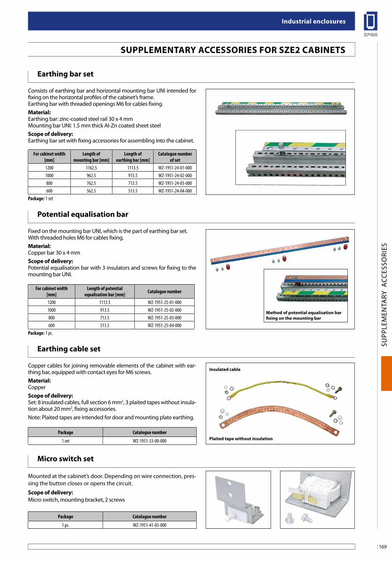
169
industrial enclosures
SUPP
LEM
ENTA
RY A
CCES
SORI
ES
earthing bar set
Consists of earthing bar and horizontal mounting bar UNI intended for fixing on the horizontal profiles of the cabinet’s frame.Earthing bar with threaded openings M6 for cables fixing.Material:Earthing bar: zinc-coated steel rail 30 x 4 mm Mounting bar UNI: 1.5 mm thick Al-Zn coated sheet steelscope of delivery:Earthing bar set with fixing accessories for assembling into the cabinet.
For cabinet width[mm]
Length of mounting bar [mm]
Length of earthing bar [mm]
Catalogue number of set
1200 1162.5 1113.5 WZ-1951-24-01-0001000 962.5 913.5 WZ-1951-24-02-000800 762.5 713.5 WZ-1951-24-03-000600 562.5 513.5 WZ-1951-24-04-000
Package: 1 set
Potential equalisation bar
Fixed on the mounting bar UNI, which is the part of earthing bar set.With threaded holes M6 for cables fixing.Material:Copper bar 30 x 4 mmscope of delivery:Potential equalisation bar with 3 insulators and screws for fixing to the mounting bar UNI.
For cabinet width [mm]
Length of potential equalisation bar [mm] Catalogue number
1200 1113.5 WZ-1951-25-01-0001000 913.5 WZ-1951-25-02-000800 713.5 WZ-1951-25-03-000600 513.5 WZ-1951-25-04-000
Package: 1 pc.
Method of potential equalisation bar fixing on the mounting bar
earthing cable set
Copper cables for joining removable elements of the cabinet with ear-thing bar, equipped with contact eyes for M6 screws.Material:Copperscope of delivery:Set: 8 insulated cables, full section 6 mm2, 3 plaited tapes without insula-tion about 20 mm2, fixing accessories.Note: Plaited tapes are intended for door and mounting plate earthing.
Micro switch set
Mounted at the cabinet’s door. Depending on wire connection, pres-sing the button closes or opens the circuit.
scope of delivery:Micro switch, mounting bracket, 2 screws
Package Catalogue number
1 set WZ-1951-33-00-000
Package Catalogue number
1 pc. WZ-1951-41-03-000
insulated cable
Plaited tape without insulation
suPPleMenTaRY aCCessoRies foR sZe2 CabineTs
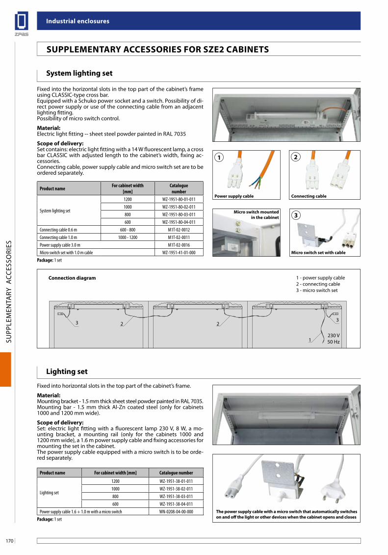
industrial enclosures
170
SUPP
LEM
ENTA
RY A
CCES
SORI
ES
suPPleMenTaRY aCCessoRies foR sZe2 CabineTs
lighting set
Fixed into horizontal slots in the top part of the cabinet’s frame.
Material:Mounting bracket - 1.5 mm thick sheet steel powder painted in RAL 7035.Mounting bar - 1.5 mm thick Al-Zn coated steel (only for cabinets 1000 and 1200 mm wide).
scope of delivery:Set: electric light fitting with a fluorescent lamp 230 V, 8 W, a mo-unting bracket, a mounting rail (only for the cabinets 1000 and 1200 mm wide), a 1.6 m power supply cable and fixing accessories for mounting the set in the cabinet. The power supply cable equipped with a micro switch is to be orde-red separately.
Product name For cabinet width [mm] Catalogue number
Lighting set
1200 WZ-1951-38-01-0111000 WZ-1951-38-02-011800 WZ-1951-38-03-011600 WZ-1951-38-04-011
Power supply cable 1.6 + 1.0 m with a micro switch WN-0208-04-00-000Package: 1 set
system lighting set
Fixed into the horizontal slots in the top part of the cabinet’s frame using CLASSIC-type cross bar. Equipped with a Schuko power socket and a switch. Possibility of di-rect power supply or use of the connecting cable from an adjacent lighting fitting. Possibility of micro switch control.
Material:Electric light fitting -- sheet steel powder painted in RAL 7035
scope of delivery:Set contains: electric light fitting with a 14 W fluorescent lamp, a cross bar CLASSIC with adjusted length to the cabinet’s width, fixing ac-cessories.Connecting cable, power supply cable and micro switch set are to be ordered separately.
Product name For cabinet width[mm]
Cataloguenumber
System lighting set
1200 WZ-1951-80-01-0111000 WZ-1951-80-02-011800 WZ-1951-80-03-011600 WZ-1951-80-04-011
Connecting cable 0.6 m 600 - 800 M1T-02-0012Connecting cable 1.0 m 1000 - 1200 M1T-02-0011Power supply cable 3.0 m M1T-02-0016Micro switch set with 1.0 m cable WZ-1951-41-01-000
Package: 1 set
1 2
3
Power supply cable Connecting cable
Micro switch set with cable
Micro switch mounted in the cabinet
The power supply cable with a micro switch that automatically switcheson and off the light or other devices when the cabinet opens and closes
233
1230 V50 Hz
2
Connection diagram 1 - power supply cable2 - connecting cable3 - micro switch set
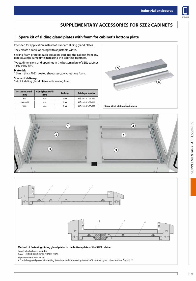
171
industrial enclosures
SUPP
LEM
ENTA
RY A
CCES
SORI
ES
1 2 3
4 5 3
2
1
3
4
5
3
spare kit of sliding gland plates with foam for cabinet's bottom plate
Intended for application instead of standard sliding gland plates.
They create a cable opening with adjustable width.
Sealing foam protects cable isolation lead into the cabinet from any defects, at the same time increasing the cabinet’s tightness.
Types, dimensions and openings in the bottom plate of SZE2 cabinet – see page 154.
Material:1.5 mm thick Al-Zn coated sheet steel, polyurethane foam.
scope of delivery:Set of 2 sliding gland plates with sealing foam.
For cabinet width[mm]
Gland plates width[mm] Package Catalogue number
800 656 1 set WZ-1951-81-01-0001200 or 600 456 1 set WZ-1951-81-02-000
1000 406 1 set WZ-1951-81-03-000 spare kit of sliding gland plates
Method of fastening sliding gland plates in the bottom plate of the sZe2 cabinetSupply of all cabinets includes:1, 2, 3 – sliding gland plates without foam.
Supplementary accessories:4, 5 – sliding gland plates with sealing foam intended for fastening instead of 2 standard gland plates without foam (1, 2).
suPPleMenTaRY aCCessoRies foR sZe2 CabineTs
5
4
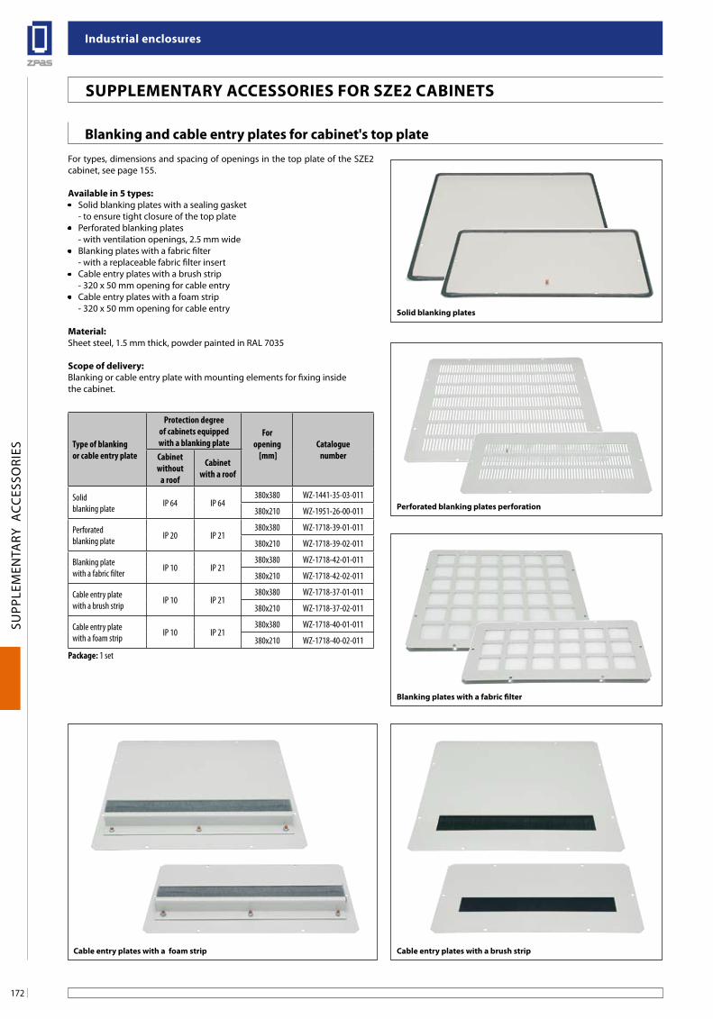
industrial enclosures
172
SUPP
LEM
ENTA
RY A
CCES
SORI
ES
blanking and cable entry plates for cabinet's top plate
For types, dimensions and spacing of openings in the top plate of the SZE2 cabinet, see page 155.
available in 5 types:• Solid blanking plates with a sealing gasket - to ensure tight closure of the top plate• Perforated blanking plates - with ventilation openings, 2.5 mm wide• Blanking plates with a fabric filter - with a replaceable fabric filter insert• Cable entry plates with a brush strip - 320 x 50 mm opening for cable entry• Cable entry plates with a foam strip - 320 x 50 mm opening for cable entry
Material:Sheet steel, 1.5 mm thick, powder painted in RAL 7035
scope of delivery:Blanking or cable entry plate with mounting elements for fixing inside the cabinet.
suPPleMenTaRY aCCessoRies foR sZe2 CabineTs
Type of blanking or cable entry plate
Protection degreeof cabinets equippedwith a blanking plate
For opening
[mm]Catalogue
numberCabinetwithout
a roof
Cabinetwith a roof
Solid blanking plate IP 64 IP 64
380x380 WZ-1441-35-03-011
380x210 WZ-1951-26-00-011
Perforated blanking plate IP 20 IP 21
380x380 WZ-1718-39-01-011
380x210 WZ-1718-39-02-011
Blanking platewith a fabric filter IP 10 IP 21
380x380 WZ-1718-42-01-011
380x210 WZ-1718-42-02-011
Cable entry platewith a brush strip IP 10 IP 21
380x380 WZ-1718-37-01-011
380x210 WZ-1718-37-02-011
Cable entry platewith a foam strip IP 10 IP 21
380x380 WZ-1718-40-01-011
380x210 WZ-1718-40-02-011
Package: 1 set
solid blanking plates
Perforated blanking plates perforation
blanking plates with a fabric filter
Cable entry plates with a brush stripCable entry plates with a foam strip
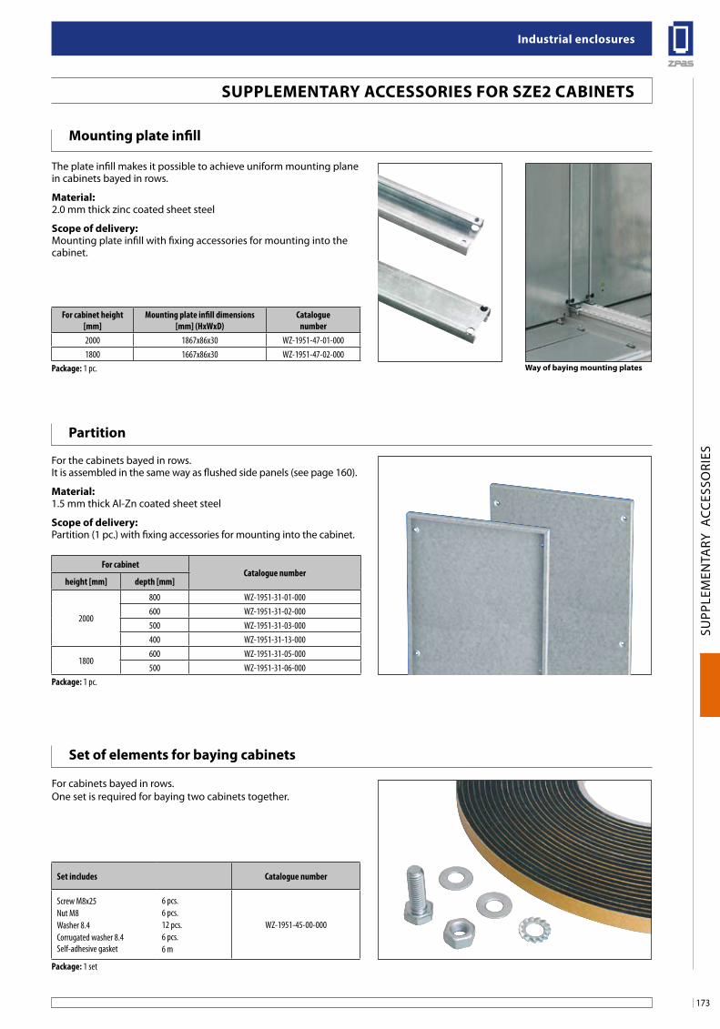
173
industrial enclosures
SUPP
LEM
ENTA
RY A
CCES
SORI
ES
suPPleMenTaRY aCCessoRies foR sZe2 CabineTs
Way of baying mounting plates
Mounting plate infill
The plate infill makes it possible to achieve uniform mounting plane in cabinets bayed in rows.
Material:2.0 mm thick zinc coated sheet steel
scope of delivery:Mounting plate infill with fixing accessories for mounting into the cabinet.
Partition
For the cabinets bayed in rows.It is assembled in the same way as flushed side panels (see page 160).
Material:1.5 mm thick Al-Zn coated sheet steel
scope of delivery:Partition (1 pc.) with fixing accessories for mounting into the cabinet.
set of elements for baying cabinets
For cabinets bayed in rows.One set is required for baying two cabinets together.
For cabinet height [mm]
Mounting plate infill dimensions [mm] (HxWxD)
Catalogue number
2000 1867x86x30 WZ-1951-47-01-0001800 1667x86x30 WZ-1951-47-02-000
Package: 1 pc.
For cabinetCatalogue number
height [mm] depth [mm]
2000
800 WZ-1951-31-01-000600 WZ-1951-31-02-000500 WZ-1951-31-03-000400 WZ-1951-31-13-000
1800600 WZ-1951-31-05-000500 WZ-1951-31-06-000
Package: 1 pc.
Set includes Catalogue number
Screw M8x25Nut M8Washer 8.4Corrugated washer 8.4Self-adhesive gasket
6 pcs.6 pcs.12 pcs.6 pcs.6 m
WZ-1951-45-00-000
Package: 1 set
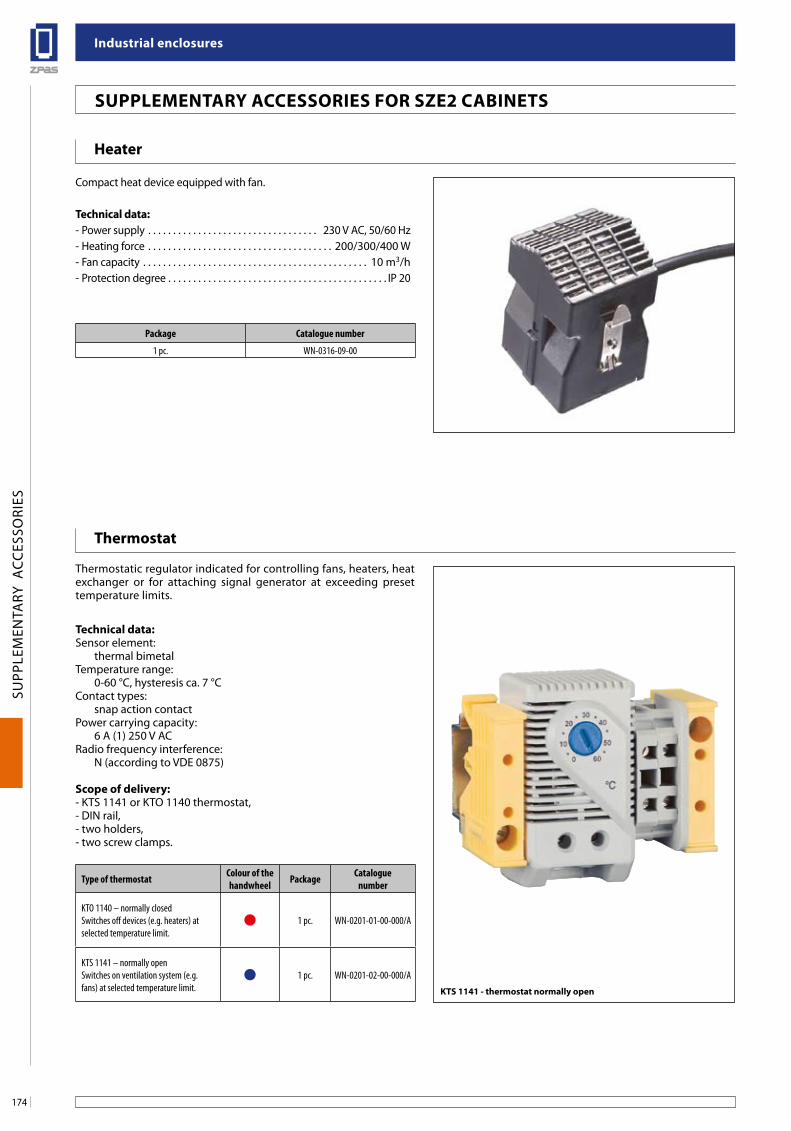
industrial enclosures
174
SUPP
LEM
ENTA
RY A
CCES
SORI
ES
Heater
Compact heat device equipped with fan.
Technical data:- Power supply . . . . . . . . . . . . . . . . . . . . . . . . . . . . . . . . . . 230 V AC, 50/60 Hz- Heating force . . . . . . . . . . . . . . . . . . . . . . . . . . . . . . . . . . . . . 200/300/400 W- Fan capacity . . . . . . . . . . . . . . . . . . . . . . . . . . . . . . . . . . . . . . . . . . . . . 10 m3/h- Protection degree . . . . . . . . . . . . . . . . . . . . . . . . . . . . . . . . . . . . . . . . . . . . IP 20
Package Catalogue number
1 pc. WN-0316-09-00
suPPleMenTaRY aCCessoRies foR sZe2 CabineTs
Type of thermostat Colour of the handwheel Package Catalogue
number
KTO 1140 – normally closed Switches off devices (e.g. heaters) at selected temperature limit.
1 pc. WN-0201-01-00-000/A
KTS 1141 – normally openSwitches on ventilation system (e.g. fans) at selected temperature limit.
1 pc. WN-0201-02-00-000/A
KTs 1141 - thermostat normally open
Thermostat
Thermostatic regulator indicated for controlling fans, heaters, heat exchanger or for attaching signal generator at exceeding preset temperature limits.
Technical data:Sensor element:
thermal bimetalTemperature range:
0-60 °C, hysteresis ca. 7 °CContact types:
snap action contactPower carrying capacity:
6 A (1) 250 V ACRadio frequency interference:
N (according to VDE 0875)
scope of delivery:- KTS 1141 or KTO 1140 thermostat,- DIN rail,- two holders,- two screw clamps.
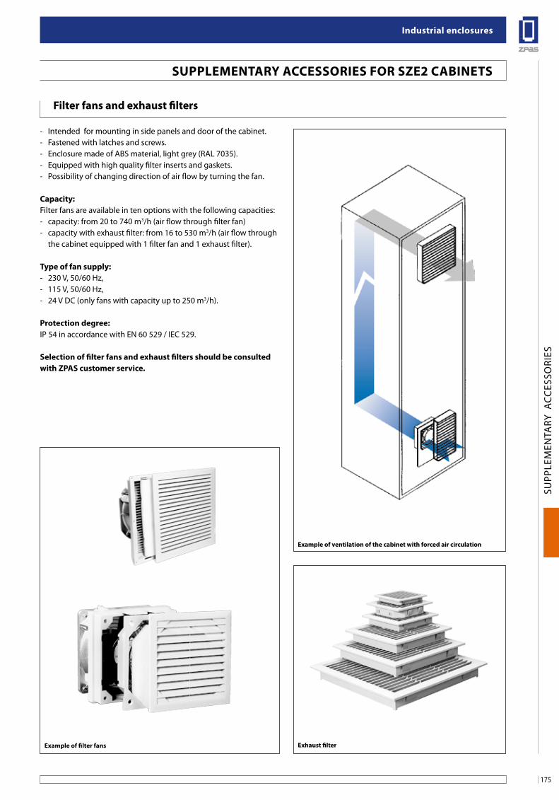
175
industrial enclosures
SUPP
LEM
ENTA
RY A
CCES
SORI
ES
suPPleMenTaRY aCCessoRies foR sZe2 CabineTs
filter fans and exhaust filters
- Intended for mounting in side panels and door of the cabinet.- Fastened with latches and screws.- Enclosure made of ABS material, light grey (RAL 7035).- Equipped with high quality filter inserts and gaskets. - Possibility of changing direction of air flow by turning the fan.
Capacity:Filter fans are available in ten options with the following capacities:- capacity: from 20 to 740 m3/h (air flow through filter fan)- capacity with exhaust filter: from 16 to 530 m3/h (air flow through
the cabinet equipped with 1 filter fan and 1 exhaust filter).
Type of fan supply:- 230 V, 50/60 Hz,- 115 V, 50/60 Hz,- 24 V DC (only fans with capacity up to 250 m3/h).
Protection degree:IP 54 in accordance with EN 60 529 / IEC 529.
selection of filter fans and exhaust filters should be consulted with ZPas customer service.
example of ventilation of the cabinet with forced air circulation
exhaust filterexample of filter fans
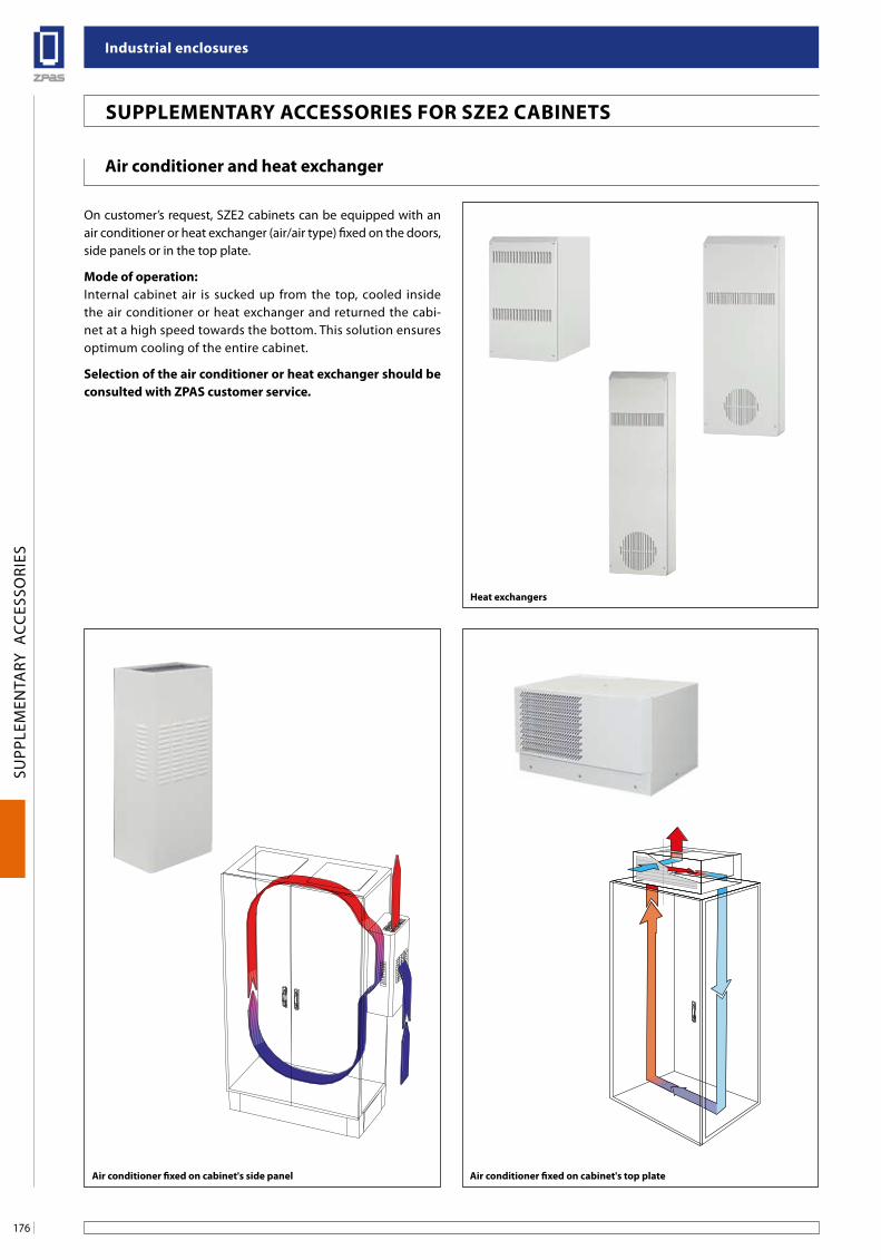
industrial enclosures
176
SUPP
LEM
ENTA
RY A
CCES
SORI
ES
suPPleMenTaRY aCCessoRies foR sZe2 CabineTs
air conditioner and heat exchanger
On customer’s request, SZE2 cabinets can be equipped with an air conditioner or heat exchanger (air/air type) fixed on the doors, side panels or in the top plate.
Mode of operation:Internal cabinet air is sucked up from the top, cooled inside the air conditioner or heat exchanger and returned the cabi-net at a high speed towards the bottom. This solution ensures optimum cooling of the entire cabinet.
selection of the air conditioner or heat exchanger should be consulted with ZPas customer service.
air conditioner fixed on cabinet's side panel air conditioner fixed on cabinet's top plate
Heat exchangers
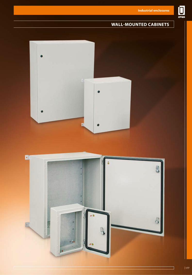
177
industrial enclosures
SWN
WA
LL-M
OU
NTE
D C
ABI
NET
S
Wall-MounTeD CabineTs
industrial enclosures
177
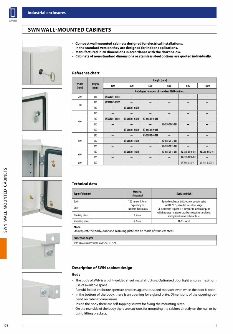
industrial enclosures
178
SWN
WA
LL-M
OU
NTE
D C
ABI
NET
S
sWn Wall-MounTeD CabineTs
- Compact wall-mounted cabinets designed for electrical installations.- in the standard version they are designed for indoor applications.- Manufactured in 20 dimensions in accordance with the chart below.- Cabinets of non-standard dimensions or stainless steel options are quoted individually.
Description of sWn cabinet design
body
- The body of SWN is a tight-welded sheet metal structure. Optimised door light ensures maximum use of available space.
- A multi-folded enclosure aperture protects against dust and moisture even when the door is open.- In the bottom of the body, there is an opening for a gland plate. Dimensions of the opening de-
pend on cabinet dimensions.- Inside the body there are self-tapping screws for fixing the mounting plate.- On the rear side of the body there are cut-outs for mounting the cabinet directly on the wall or by
using lifting brackets.
Width[mm]
Depth[mm]
Height [mm]
300 400 500 600 800 1000
Catalogue numbers of standard SWN cabinets
200 115 WZ-2285-01-01-011 — — — — —
300150 WZ-2285-01-02-011 — — — — —
210 — WZ-2285-01-03-011 — — — —
400
150 — — — — — —
210 WZ-2285-01-04-011 WZ-2285-01-05-011 WZ-2285-01-06-011 — — —
250 — — — WZ-2285-01-07-011 — —
300 — WZ-2285-01-08-011 WZ-2285-01-09-011 — — —
500
210 — — WZ-2285-01-10-011 — — —
250 — WZ-2285-01-11-011 — WZ-2285-01-12-011 — —
300 — — — WZ-2285-01-13-011 — —
600250 — WZ-2285-01-14-011 — WZ-2285-01-15-011 WZ-2285-01-16-011 WZ-2285-01-17-011
300 — — — — WZ-2285-01-18-011 —
800 300 — — — — WZ-2285-01-19-011 WZ-2285-01-20-011
Reference chart
Technical data
Type of element Materialsheet steel Surface finish
Body 1.25 mm or 1.5 mm depending on
cabinet’s dimensions
Epoxide-polyester thick-texture powder paint in RAL 7035, intended for indoor usage.
On customer’s request, it is possible to use facade paint with improved resistance to adverse weather conditions
and optional use of polyzinc base.
Door
Blanking plate 1.5 mm
Mounting plate 2.0 mm Al-Zn coated
note:On request, the body, door and blanking plate can be made of stainless steel.
Protection degree
IP 65 in accordance with EN 60 529 / IEC 529
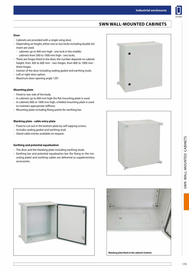
179
industrial enclosures
SWN
WA
LL-M
OU
NTE
D C
ABI
NET
S
blanking plate fixed to the cabinet’s bottom
sWn Wall-MounTeD CabineTs
Door
- Cabinets are provided with a single-wing door.- Depending on height, either one or two locks including double-bit
insert are used:- cabinets up to 400 mm high - one lock in the middle;- cabinets from 500 to 1000 mm high - two locks.
- There are hinges fixed to the door; the number depends on cabinet height: from 300 to 600 mm - two hinges, from 800 to 1000 mm - three hinges.
- Interior of the door including sealing gasket and earthing studs.- Left or right door option.- Maximum door opening angle 120°.
Mounting plate
- Fixed to rear side of the body.- In cabinets up to 600 mm high the flat mounting plate is used.- In cabinets 800 or 1000 mm high, a folded mounting plate is used to maintain appropriate stiffness.- Mounting plate including fixing points for earthing bar.
blanking plate - cable entry plate
- Fixed to cut-out in the bottom plate by self-tapping screws.- Includes sealing gasket and earthing stud.- Gland cable entries available on request.
earthing and potential equalisation
- The door and the blanking plate including earthing studs.- Earthing bar and potential equalisation bar (for fixing to the mo-
unting plate) and earthing cables are delivered as supplementary accessories.
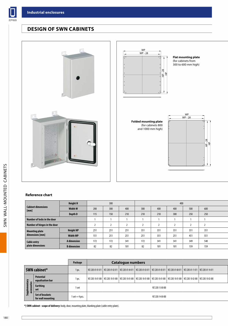
industrial enclosures
180
SWN
WA
LL-M
OU
NTE
D C
ABI
NET
S
Design of sWn CabineTs
WP
HP
- 28
WP - 28
HP
WP
HP
- 28
WP - 28
HP
flat mounting plate (for cabinets from 300 to 600 mm high)
folded mounting plate (for cabinets 800
and 1000 mm high)
Cabinet dimensions [mm]
Height H 300 400 500 600 800 1000
Width W 200 300 400 300 400 400 500 600 400 400 500 400 500 500 600 600 600 800 600 800
Depth D 115 150 210 210 210 300 250 250 210 300 210 250 250 300 250 250 300 300 250 300
Number of locks in the door 1 1 1 1 1 1 1 1 2 2 2 2 2 2 2 2 2 2 2 2
Number of hinges in the door 2 2 2 2 2 2 2 2 2 2 2 2 2 2 2 3 3 3 3 3
Mounting plate dimensions [mm]
Height HP 251 251 251 351 351 351 351 351 451 451 451 551 551 551 551 751 751 751 951 951
Width WP 151 251 251 251 351 251 451 551 351 351 451 351 451 451 551 551 551 751 551 751
Cable entry plate dimensions
A dimension 172 172 341 172 341 341 349 540 341 341 349 341 349 349 540 540 540 540 540 540
B dimension 82 82 101 82 101 101 159 159 101 101 159 101 159 159 159 159 159 159 159 159
Package Catalogue numbers
SWN cabinet* 1 pc. WZ-2285-01-01-011 WZ-2285-01-02-011 WZ-2285-01-04-011 WZ-2285-01-03-011 WZ-2285-01-05-011 WZ-2285-01-08-011 WZ-2285-01-11-011 WZ-2285-01-14-011 WZ-2285-01-06-011 WZ-2285-01-09-011 WZ-2285-01-10-011 WZ-2285-01-07-011 WZ-2285-01-12-011 WZ-2285-01-13-011 WZ-2285-01-15-011 WZ-2285-01-16-011 WZ-2285-01-18-011 WZ-2285-01-19-011 WZ-2285-01-17-011 WZ-2285-01-20-011
Supp
lem
enta
ry
acce
ssor
ies
Potentialequalisation bar 1 pc. WZ-2285-10-01-000 WZ-2285-10-01-000 WZ-2285-10-01-000 WZ-2285-10-01-000 WZ-2285-10-01-000 WZ-2285-10-01-000 WZ-2285-10-02-000 WZ-2285-10-02-000 WZ-2285-10-01-000 WZ-2285-10-01-000 WZ-2285-10-02-000 WZ-2285-10-01-000 WZ-2285-10-02-000 WZ-2285-10-02-000 WZ-2285-10-02-000 WZ-2285-10-02-000 WZ-2285-10-02-000 WZ-2285-10-02-000 WZ-2285-10-02-000 WZ-2285-10-02-000
Earthingset 1 set WZ-2285-13-00-000 WZ-2285-13-00-000
Set of brackets for wall mounting 1 set = 4 pcs. WZ-2285-14-00-000 WZ-2285-14-00-000
*) SWN cabinet - scope of delivery: body, door, mounting plate, blanking plate (cable entry plate). Detailed description of supplementary accessories: page 182.
Reference chart
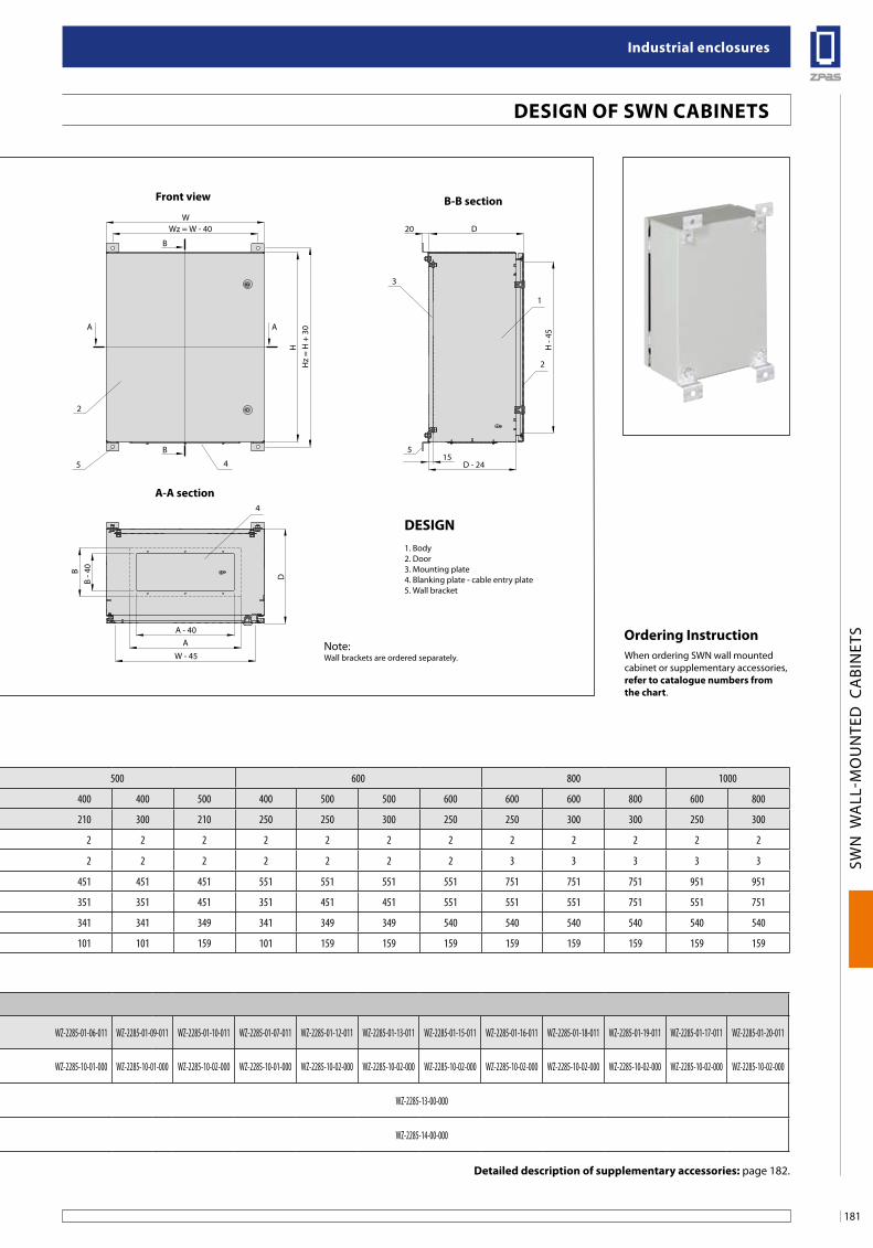
181
industrial enclosures
SWN
WA
LL-M
OU
NTE
D C
ABI
NET
S
Design of sWn CabineTs
B
A A
W
Hz
= H
+ 3
0
Wz = W - 40
H
AA - 40
W - 45
D - 2415
B - 4
0B
D20
H -
45
D
B
5
5
4
3
1
4
2
2
Design1. Body2. Door3. Mounting plate4. Blanking plate - cable entry plate5. Wall bracket
front view b-b section
a-a section
Note:Wall brackets are ordered separately.
ordering instructionWhen ordering SWN wall mounted cabinet or supplementary accessories, refer to catalogue numbers from the chart.
Cabinet dimensions [mm]
Height H 300 400 500 600 800 1000
Width W 200 300 400 300 400 400 500 600 400 400 500 400 500 500 600 600 600 800 600 800
Depth D 115 150 210 210 210 300 250 250 210 300 210 250 250 300 250 250 300 300 250 300
Number of locks in the door 1 1 1 1 1 1 1 1 2 2 2 2 2 2 2 2 2 2 2 2
Number of hinges in the door 2 2 2 2 2 2 2 2 2 2 2 2 2 2 2 3 3 3 3 3
Mounting plate dimensions [mm]
Height HP 251 251 251 351 351 351 351 351 451 451 451 551 551 551 551 751 751 751 951 951
Width WP 151 251 251 251 351 251 451 551 351 351 451 351 451 451 551 551 551 751 551 751
Cable entry plate dimensions
A dimension 172 172 341 172 341 341 349 540 341 341 349 341 349 349 540 540 540 540 540 540
B dimension 82 82 101 82 101 101 159 159 101 101 159 101 159 159 159 159 159 159 159 159
Package Catalogue numbers
SWN cabinet* 1 pc. WZ-2285-01-01-011 WZ-2285-01-02-011 WZ-2285-01-04-011 WZ-2285-01-03-011 WZ-2285-01-05-011 WZ-2285-01-08-011 WZ-2285-01-11-011 WZ-2285-01-14-011 WZ-2285-01-06-011 WZ-2285-01-09-011 WZ-2285-01-10-011 WZ-2285-01-07-011 WZ-2285-01-12-011 WZ-2285-01-13-011 WZ-2285-01-15-011 WZ-2285-01-16-011 WZ-2285-01-18-011 WZ-2285-01-19-011 WZ-2285-01-17-011 WZ-2285-01-20-011
Supp
lem
enta
ry
acce
ssor
ies
Potentialequalisation bar 1 pc. WZ-2285-10-01-000 WZ-2285-10-01-000 WZ-2285-10-01-000 WZ-2285-10-01-000 WZ-2285-10-01-000 WZ-2285-10-01-000 WZ-2285-10-02-000 WZ-2285-10-02-000 WZ-2285-10-01-000 WZ-2285-10-01-000 WZ-2285-10-02-000 WZ-2285-10-01-000 WZ-2285-10-02-000 WZ-2285-10-02-000 WZ-2285-10-02-000 WZ-2285-10-02-000 WZ-2285-10-02-000 WZ-2285-10-02-000 WZ-2285-10-02-000 WZ-2285-10-02-000
Earthingset 1 set WZ-2285-13-00-000 WZ-2285-13-00-000
Set of brackets for wall mounting 1 set = 4 pcs. WZ-2285-14-00-000 WZ-2285-14-00-000
*) SWN cabinet - scope of delivery: body, door, mounting plate, blanking plate (cable entry plate). Detailed description of supplementary accessories: page 182.
Reference chart
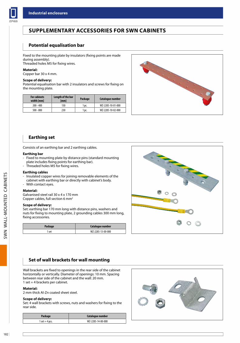
industrial enclosures
182
SWN
WA
LL-M
OU
NTE
D C
ABI
NET
S
earthing set
Consists of an earthing bar and 2 earthing cables.
earthing bar- Fixed to mounting plate by distance pins (standard mounting
plate includes fixing points for earthing bar).- Threaded holes M5 for fixing wires.
earthing cables- Insulated copper wires for joining removable elements of the
cabinet with earthing bar or directly with cabinet’s body.- With contact eyes.
Material:Galvanised steel rail 30 x 4 x 170 mmCopper cables, full section 6 mm2
scope of delivery:Set: earthing bar 170 mm long with distance pins, washers and nuts for fixing to mounting plate, 2 grounding cables 300 mm long, fixing accessories.
Potential equalisation bar
Fixed to the mounting plate by insulators (fixing points are made during assembly).Threaded holes M5 for fixing wires.
Material:Copper bar 30 x 4 mm.
scope of delivery:Potential equalisation bar with 2 insulators and screws for fixing on the mounting plate.
set of wall brackets for wall mounting
Wall brackets are fixed to openings in the rear side of the cabinet horizontally or vertically. Diameter of openings: 10 mm. Spacing between rear side of the cabinet and the wall: 20 mm.1 set = 4 brackets per cabinet.
Material:2 mm thick Al-Zn coated sheet steel.
scope of delivery:Set: 4 wall brackets with screws, nuts and washers for fixing to the rear side.
suPPleMenTaRY aCCessoRies foR sWn CabineTs
For cabinetswidth [mm]
Length of the bar [mm] Package Catalogue number
200 - 400 130 1 pc. WZ-2285-10-01-000500 - 800 230 1 pc. WZ-2285-10-02-000
Package Catalogue number
1 set WZ-2285-13-00-000
Package Catalogue number
1 set = 4 pcs. WZ-2285-14-00-000
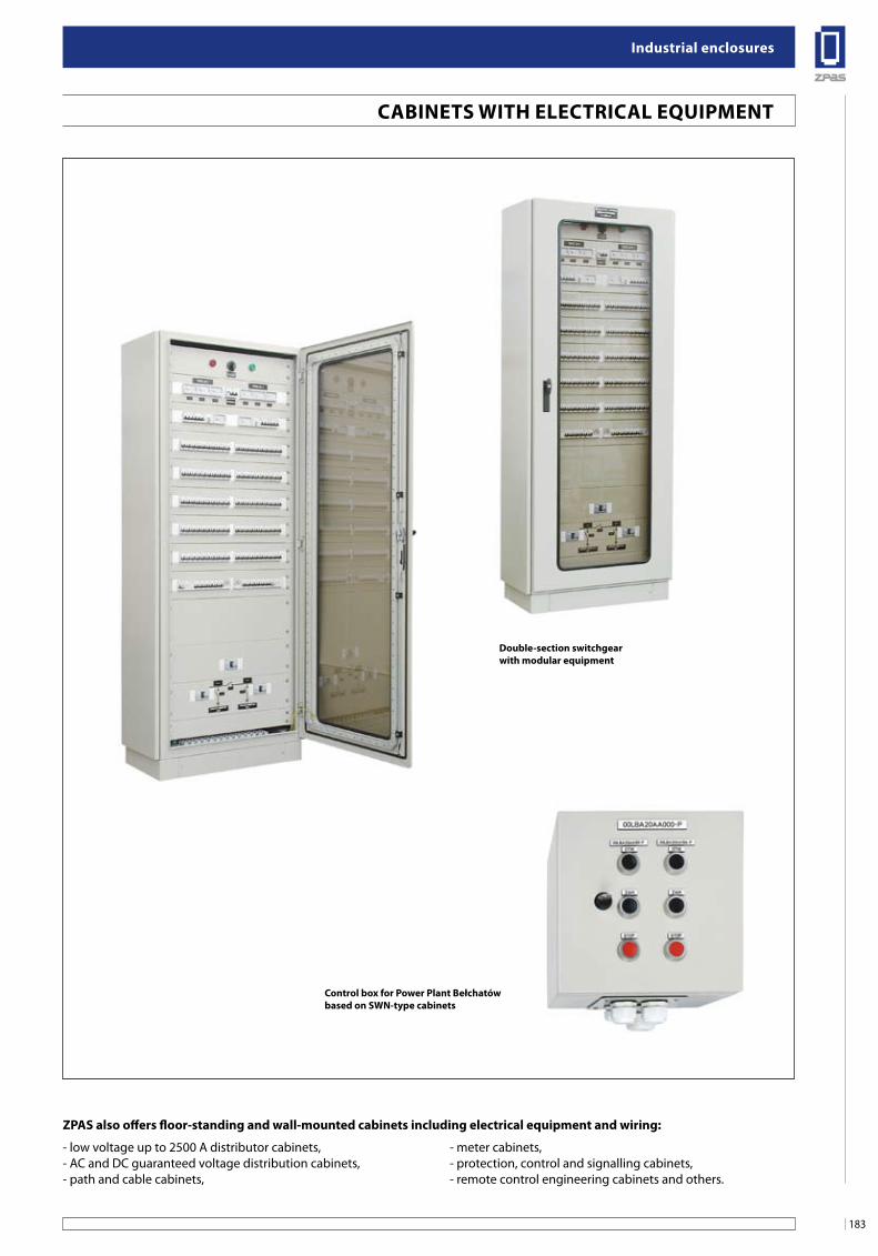
183
industrial enclosures
SWN
WA
LL-M
OU
NTE
D C
ABI
NET
S
ZPas also offers floor-standing and wall-mounted cabinets including electrical equipment and wiring:
Double-section switchgearwith modular equipment
Control box for Power Plant bełchatówbased on sWn-type cabinets
- low voltage up to 2500 A distributor cabinets,- AC and DC guaranteed voltage distribution cabinets,- path and cable cabinets,
- meter cabinets,- protection, control and signalling cabinets,- remote control engineering cabinets and others.
CabineTs WiTH eleCTRiCal eQuiPMenT
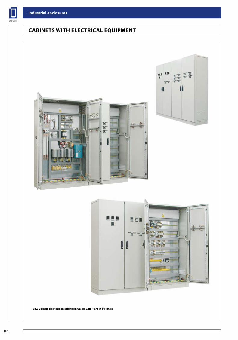
industrial enclosures
184
SWN
WA
LL-M
OU
NTE
D C
ABI
NET
S
low-voltage distribution cabinet in galess Zinc Plant in Świdnica
CabineTs WiTH eleCTRiCal eQuiPMenT
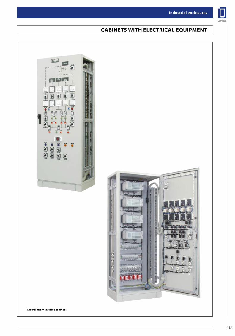
185
industrial enclosures
SWN
WA
LL-M
OU
NTE
D C
ABI
NET
S
Control and measuring cabinet
CabineTs WiTH eleCTRiCal eQuiPMenT
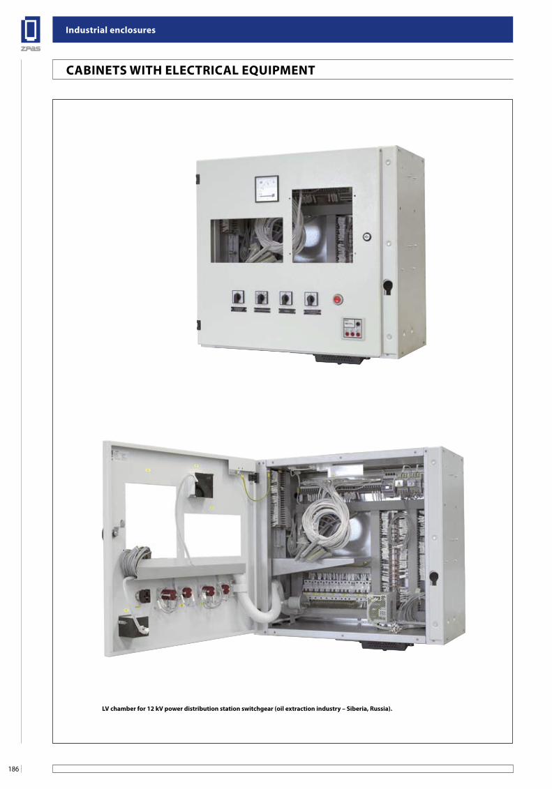
industrial enclosures
186
SWN
WA
LL-M
OU
NTE
D C
ABI
NET
S
Rozdzielnica dwupolowa niskiego napięcia dla cynkowni galess w Świdnicy
CabineTs WiTH eleCTRiCal eQuiPMenT
lV chamber for 12 kV power distribution station switchgear (oil extraction industry – siberia, Russia).
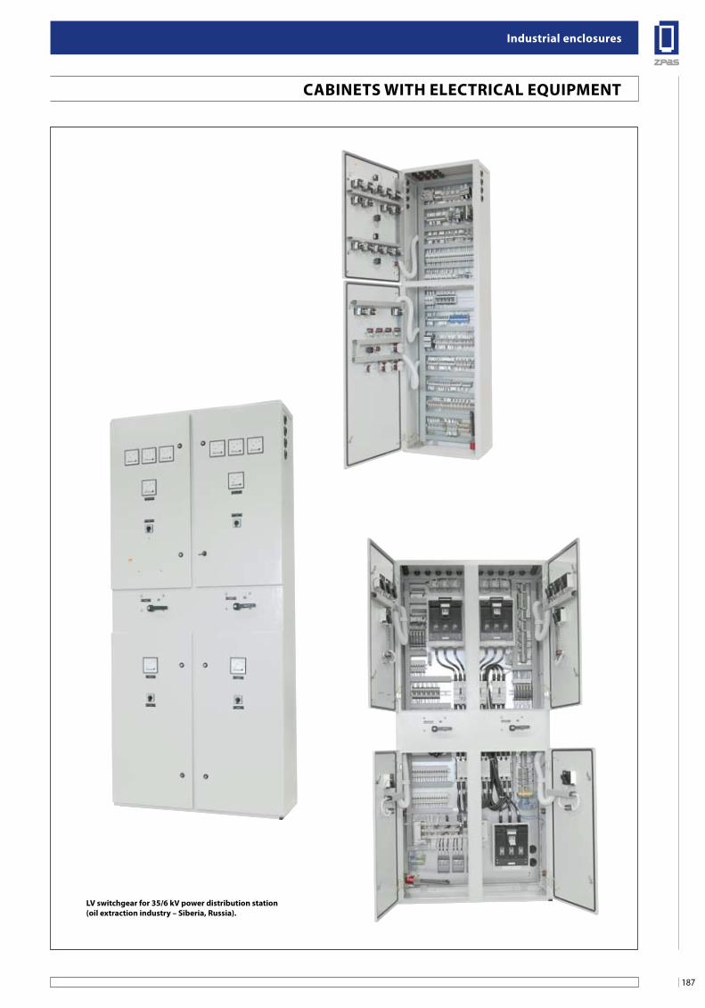
187
industrial enclosures
SWN
WA
LL-M
OU
NTE
D C
ABI
NET
S
szafa sterowniczo-pomiarowa
CabineTs WiTH eleCTRiCal eQuiPMenT
lV switchgear for 35/6 kV power distribution station (oil extraction industry – siberia, Russia).
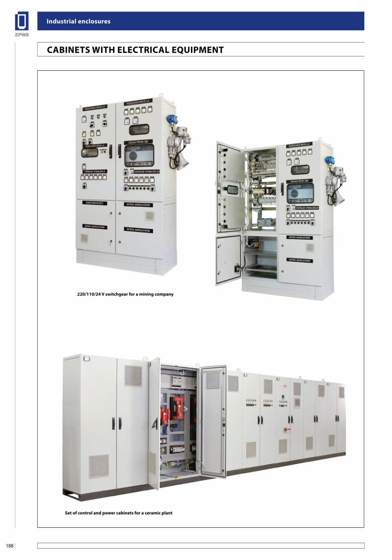
industrial enclosures
188
SWN
WA
LL-M
OU
NTE
D C
ABI
NET
S
220/110/24 V switchgear for a mining company
set of control and power cabinets for a ceramic plant
CabineTs WiTH eleCTRiCal eQuiPMenT
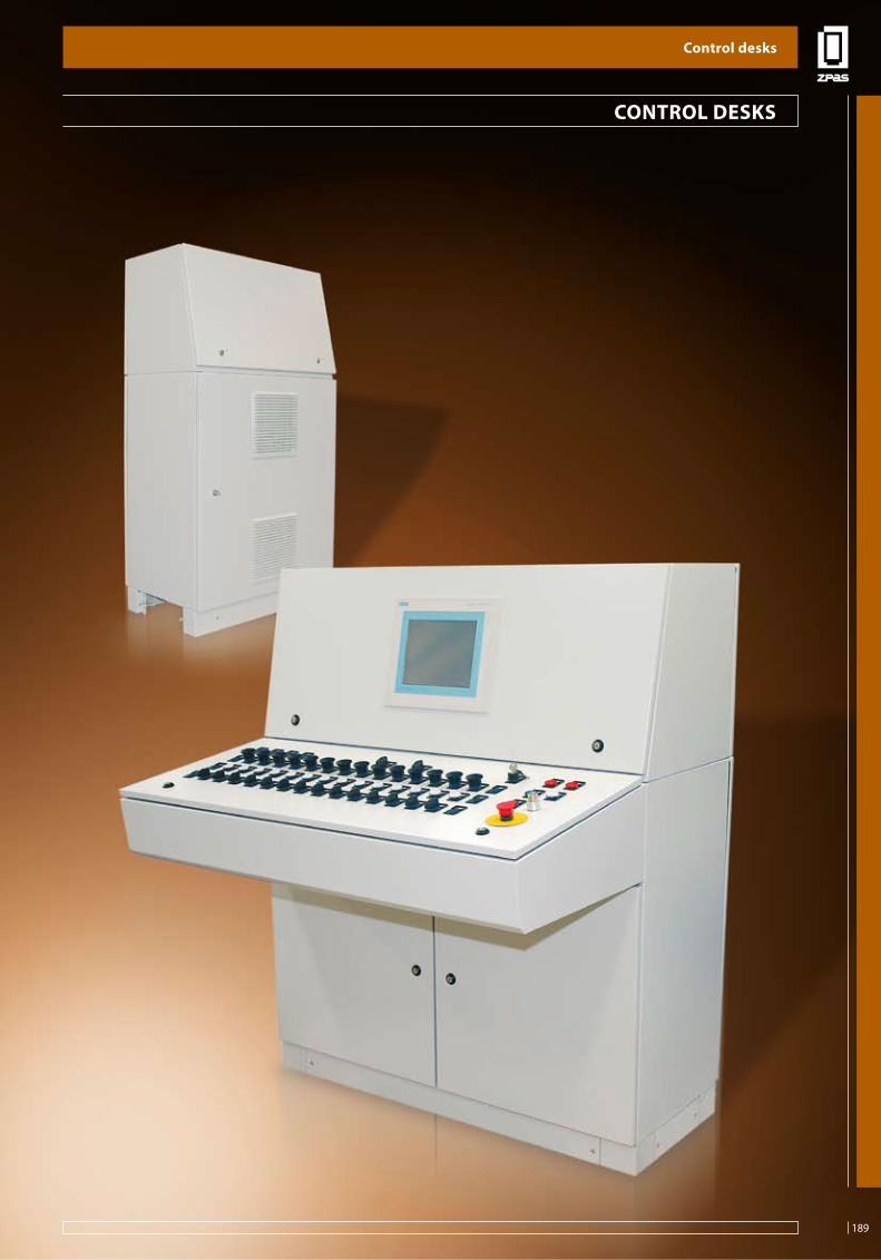
189
Control desks
PSL
CO
NTR
OL
DES
KS
ConTRol DesKs
Control desks
189
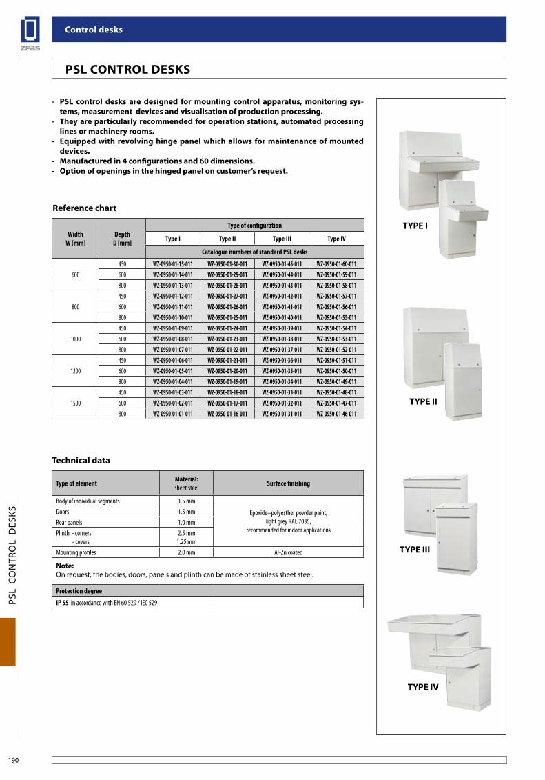
Control desks
190
PSL
CO
NTR
OL
DES
KS
TYPe i
TYPe ii
TYPe iii
TYPe iV
Psl ConTRol DesKs
- Psl control desks are designed for mounting control apparatus, monitoring sys-tems, measurement devices and visualisation of production processing.
- They are particularly recommended for operation stations, automated processing lines or machinery rooms.
- equipped with revolving hinge panel which allows for maintenance of mounted devices.
- Manufactured in 4 configurations and 60 dimensions.- option of openings in the hinged panel on customer’s request.
Reference chart
Technical data
WidthW [mm]
DepthD [mm]
Type of configuration
Type I Type II Type III Type IV
Catalogue numbers of standard PSL desks
600450 WZ-0950-01-15-011 WZ-0950-01-30-011 WZ-0950-01-45-011 WZ-0950-01-60-011600 WZ-0950-01-14-011 WZ-0950-01-29-011 WZ-0950-01-44-011 WZ-0950-01-59-011800 WZ-0950-01-13-011 WZ-0950-01-28-011 WZ-0950-01-43-011 WZ-0950-01-58-011
800450 WZ-0950-01-12-011 WZ-0950-01-27-011 WZ-0950-01-42-011 WZ-0950-01-57-011600 WZ-0950-01-11-011 WZ-0950-01-26-011 WZ-0950-01-41-011 WZ-0950-01-56-011800 WZ-0950-01-10-011 WZ-0950-01-25-011 WZ-0950-01-40-011 WZ-0950-01-55-011
1000450 WZ-0950-01-09-011 WZ-0950-01-24-011 WZ-0950-01-39-011 WZ-0950-01-54-011600 WZ-0950-01-08-011 WZ-0950-01-23-011 WZ-0950-01-38-011 WZ-0950-01-53-011800 WZ-0950-01-07-011 WZ-0950-01-22-011 WZ-0950-01-37-011 WZ-0950-01-52-011
1200450 WZ-0950-01-06-011 WZ-0950-01-21-011 WZ-0950-01-36-011 WZ-0950-01-51-011600 WZ-0950-01-05-011 WZ-0950-01-20-011 WZ-0950-01-35-011 WZ-0950-01-50-011800 WZ-0950-01-04-011 WZ-0950-01-19-011 WZ-0950-01-34-011 WZ-0950-01-49-011
1500450 WZ-0950-01-03-011 WZ-0950-01-18-011 WZ-0950-01-33-011 WZ-0950-01-48-011600 WZ-0950-01-02-011 WZ-0950-01-17-011 WZ-0950-01-32-011 WZ-0950-01-47-011800 WZ-0950-01-01-011 WZ-0950-01-16-011 WZ-0950-01-31-011 WZ-0950-01-46-011
Type of element Material:sheet steel Surface finishing
Body of individual segments 1.5 mm
Epoxide–polyesther powder paint, light grey RAL 7035,
recommended for indoor applications
Doors 1.5 mmRear panels 1.0 mmPlinth - corners - covers
2.5 mm1.25 mm
Mounting profiles 2.0 mm Al-Zn coated
note:On request, the bodies, doors, panels and plinth can be made of stainless sheet steel.
Protection degree
IP 55 in accordance with EN 60 529 / IEC 529
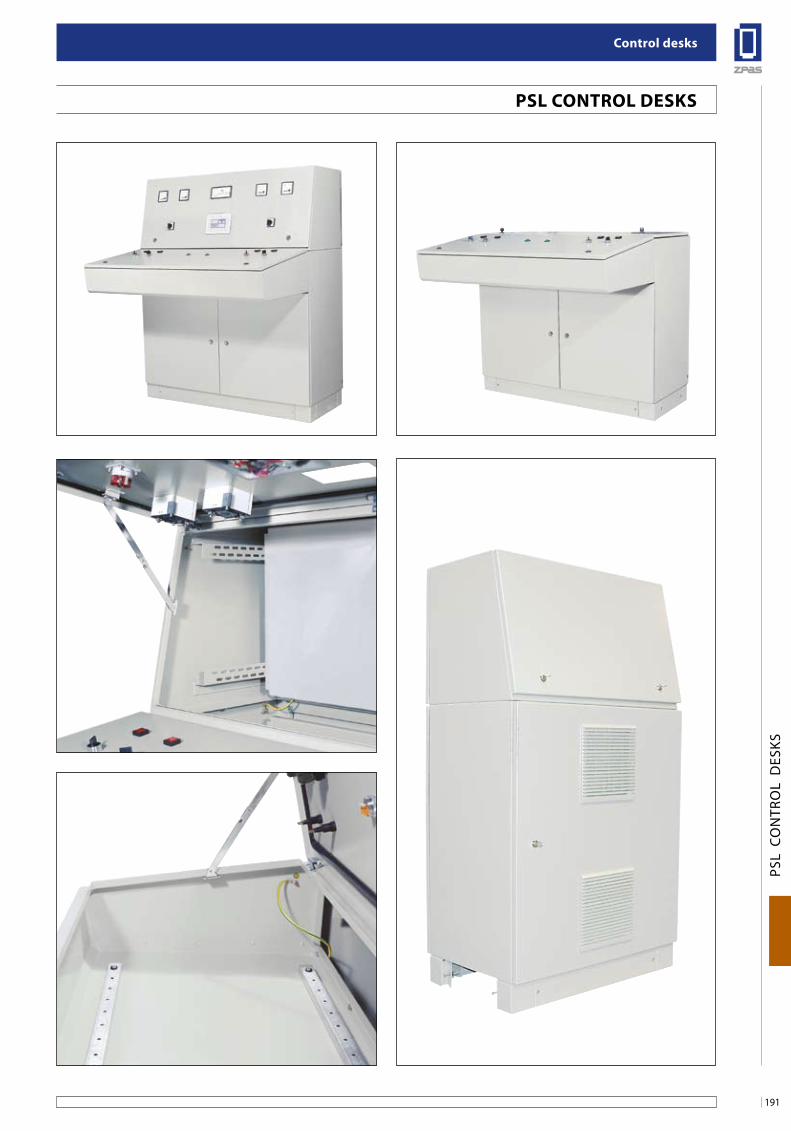
191
Control desks
PSL
CO
NTR
OL
DES
KS
Psl ConTRol DesKs
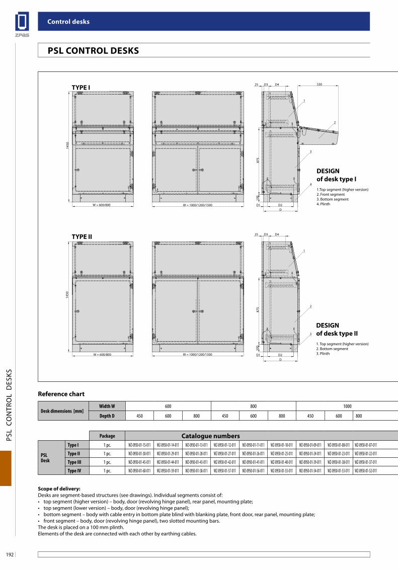
Control desks
192
PSL
CO
NTR
OL
DES
KS
Psl ConTRol DesKs
W = 1000/1200/1500
100
D
875
530D425 D3
D2D1
2
3
4
1
1450
W = 600/800
W = 1000/1200/1500
875
100
2
3
1
W = 600/800
1450
D
D425 D3
D2D1
W = 600/800
100
875
W = 1000/1200/1500
H1
2
3
1
DD2D1
875
100
W = 1000/1200/1500
530
1
2
3
W = 600/800
A A
DD2D1
B B
WP = W - 86
HP =
444 (
top
segm
ent -
hig
her v
ersio
n)HP
= 80
0 (bo
ttom
segm
ent)
15
15
20
2
W1 = W - 200W = 600/800
10 0
D
100
D5
= D
- 20
0
D5
= D
- 20
010
0D
W1 = W - 200W = 1000/1200/1500
100
Designof desk type i1.Top segment (higher version)2. Front segment3. Bottom segment4. Plinth
Desk dimensions [mm]Width W 600 800 1000 1200 1500
Depth D 450 600 800 450 600 800 450 600 800 450 600 800 450 600 800
Reference chart
Package Catalogue numbers
PSL Desk
Type I 1 pc. WZ-0950-01-15-011 WZ-0950-01-14-011 WZ-0950-01-13-011 WZ-0950-01-12-011 WZ-0950-01-11-011 WZ-0950-01-10-011 WZ-0950-01-09-011 WZ-0950-01-08-011 WZ-0950-01-07-011 WZ-0950-01-06-011 WZ-0950-01-05-011 WZ-0950-01-04-011 WZ-0950-01-03-011 WZ-0950-01-02-011 WZ-0950-01-01-011
Type II 1 pc. WZ-0950-01-30-011 WZ-0950-01-29-011 WZ-0950-01-28-011 WZ-0950-01-27-011 WZ-0950-01-26-011 WZ-0950-01-25-011 WZ-0950-01-24-011 WZ-0950-01-23-011 WZ-0950-01-22-011 WZ-0950-01-21-011 WZ-0950-01-20-011 WZ-0950-01-19-011 WZ-0950-01-18-011 WZ-0950-01-17-011 WZ-0950-01-16-011
Type III 1 pc. WZ-0950-01-45-011 WZ-0950-01-44-011 WZ-0950-01-43-011 WZ-0950-01-42-011 WZ-0950-01-41-011 WZ-0950-01-40-011 WZ-0950-01-39-011 WZ-0950-01-38-011 WZ-0950-01-37-011 WZ-0950-01-36-011 WZ-0950-01-35-011 WZ-0950-01-34-011 WZ-0950-01-33-011 WZ-0950-01-32-011 WZ-0950-01-31-011
Type IV 1 pc. WZ-0950-01-60-011 WZ-0950-01-59-011 WZ-0950-01-58-011 WZ-0950-01-57-011 WZ-0950-01-56-011 WZ-0950-01-55-011 WZ-0950-01-54-011 WZ-0950-01-53-011 WZ-0950-01-52-011 WZ-0950-01-51-011 WZ-0950-01-50-011 WZ-0950-01-49-011 WZ-0950-01-48-011 WZ-0950-01-47-011 WZ-0950-01-46-011
scope of delivery:Desks are segment-based structures (see drawings). Individual segments consist of: • topsegment(higherversion)–body,door(revolvinghingepanel),rearpanel,mountingplate;• topsegment(lowerversion)–body,door(revolvinghingepanel);• bottomsegment–bodywithcableentryinbottomplateblindwithblankingplate,frontdoor,rearpanel,mountingplate;• frontsegment–body,door(revolvinghingepanel),twoslottedmountingbars.The desk is placed on a 100 mm plinth.Elements of the desk are connected with each other by earthing cables.
Designof desk type ii1. Top segment (higher version)2. Bottom segment 3. Plinth
TYPe i
TYPe ii
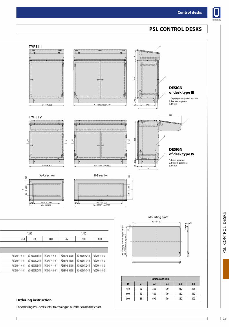
193
Control desks
PSL
CO
NTR
OL
DES
KS
Psl ConTRol DesKs
W = 1000/1200/1500
100
D
875
530D425 D3
D2D1
2
3
4
1
1450
W = 600/800
W = 1000/1200/1500
875
100
2
3
1
W = 600/800
1450
D
D425 D3
D2D1
W = 600/800
100
875
W = 1000/1200/1500
H1
2
3
1
DD2D1
875
100
W = 1000/1200/1500
530
1
2
3
W = 600/800
A A
DD2D1
B B
WP = W - 86
HP =
444 (
top
segm
ent -
hig
her v
ersio
n)HP
= 80
0 (bo
ttom
segm
ent)
15
15
20
2
W1 = W - 200W = 600/800
10 0
D
100
D5
= D
- 20
0
D5
= D
- 20
010
0D
W1 = W - 200W = 1000/1200/1500
100
Desk dimensions [mm]Width W 600 800 1000 1200 1500
Depth D 450 600 800 450 600 800 450 600 800 450 600 800 450 600 800
Reference chart
Package Catalogue numbers
PSL Desk
Type I 1 pc. WZ-0950-01-15-011 WZ-0950-01-14-011 WZ-0950-01-13-011 WZ-0950-01-12-011 WZ-0950-01-11-011 WZ-0950-01-10-011 WZ-0950-01-09-011 WZ-0950-01-08-011 WZ-0950-01-07-011 WZ-0950-01-06-011 WZ-0950-01-05-011 WZ-0950-01-04-011 WZ-0950-01-03-011 WZ-0950-01-02-011 WZ-0950-01-01-011
Type II 1 pc. WZ-0950-01-30-011 WZ-0950-01-29-011 WZ-0950-01-28-011 WZ-0950-01-27-011 WZ-0950-01-26-011 WZ-0950-01-25-011 WZ-0950-01-24-011 WZ-0950-01-23-011 WZ-0950-01-22-011 WZ-0950-01-21-011 WZ-0950-01-20-011 WZ-0950-01-19-011 WZ-0950-01-18-011 WZ-0950-01-17-011 WZ-0950-01-16-011
Type III 1 pc. WZ-0950-01-45-011 WZ-0950-01-44-011 WZ-0950-01-43-011 WZ-0950-01-42-011 WZ-0950-01-41-011 WZ-0950-01-40-011 WZ-0950-01-39-011 WZ-0950-01-38-011 WZ-0950-01-37-011 WZ-0950-01-36-011 WZ-0950-01-35-011 WZ-0950-01-34-011 WZ-0950-01-33-011 WZ-0950-01-32-011 WZ-0950-01-31-011
Type IV 1 pc. WZ-0950-01-60-011 WZ-0950-01-59-011 WZ-0950-01-58-011 WZ-0950-01-57-011 WZ-0950-01-56-011 WZ-0950-01-55-011 WZ-0950-01-54-011 WZ-0950-01-53-011 WZ-0950-01-52-011 WZ-0950-01-51-011 WZ-0950-01-50-011 WZ-0950-01-49-011 WZ-0950-01-48-011 WZ-0950-01-47-011 WZ-0950-01-46-011
ordering instruction
For ordering PSL desks refer to catalogue numbers from the chart.
Designof desk type iii1. Top segment (lower version)2. Bottom segment 3. Plinth
Designof desk type iV1. Front segment 2. Bottom segment 3. Plinth
TYPe iii
TYPe iV
A-A section B-B section
Dimensions [mm]
D D1 D2 D3 D4 H1
450 60 330 70 210 225
600 60 480 70 330 262
800 55 690 70 360 290
Mounting plate
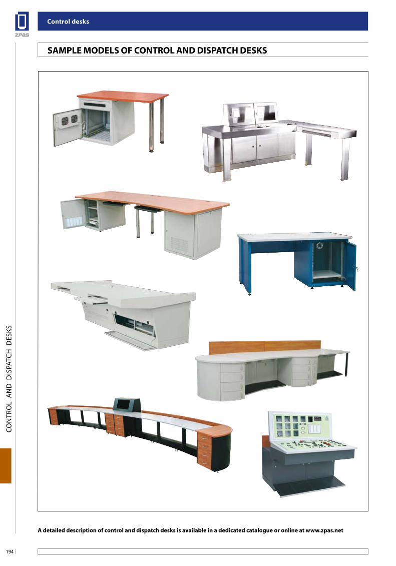
Control desks
194
PSL
CO
NTR
OL
DES
KS
a detailed description of control and dispatch desks is available in a dedicated catalogue or online at www.zpas.net
saMPle MoDels of ConTRol anD DisPaTCH DesKs
CON
TRO
L A
ND
DIS
PATC
H D
ESKS
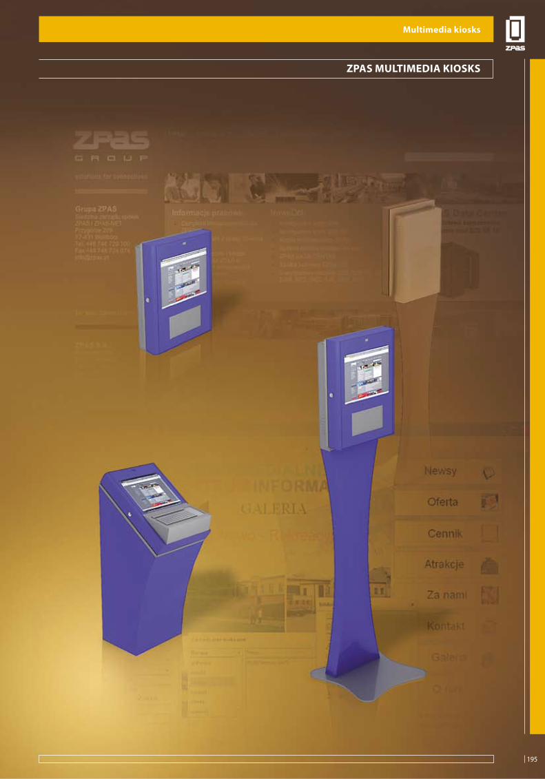
195
Multimedia kiosks
MU
LTIM
EDIA
KIO
SKS
ZPas MulTiMeDia KiosKs
Multimedia kiosks
195
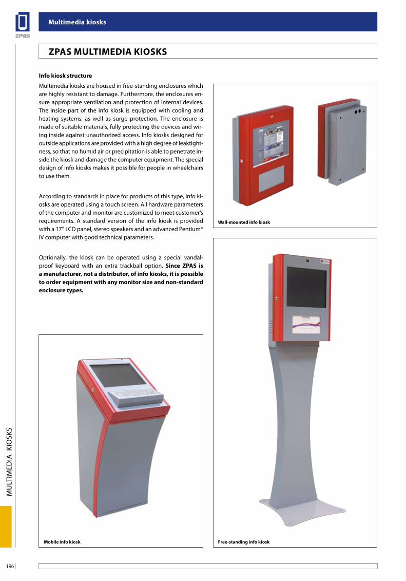
Multimedia kiosks
196
MU
LTIM
EDIA
KIO
SKS
ZPas MulTiMeDia KiosKs
info kiosk structure
Multimedia kiosks are housed in free-standing enclosures which are highly resistant to damage. Furthermore, the enclosures en-sure appropriate ventilation and protection of internal devices. The inside part of the info kiosk is equipped with cooling and heating systems, as well as surge protection. The enclosure is made of suitable materials, fully protecting the devices and wir-ing inside against unauthorized access. Info kiosks designed for outside applications are provided with a high degree of leaktight-ness, so that no humid air or precipitation is able to penetrate in-side the kiosk and damage the computer equipment. The special design of info kiosks makes it possible for people in wheelchairs to use them.
According to standards in place for products of this type, info ki-osks are operated using a touch screen. All hardware parameters of the computer and monitor are customized to meet customer’s requirements. A standard version of the info kiosk is provided with a 17'' LCD panel, stereo speakers and an advanced Pentium® IV computer with good technical parameters.
Optionally, the kiosk can be operated using a special vandal-proof keyboard with an extra trackball option. since ZPas is a manufacturer, not a distributor, of info kiosks, it is possible to order equipment with any monitor size and non-standard enclosure types.
Wall-mounted info kiosk
Mobile info kiosk free-standing info kiosk
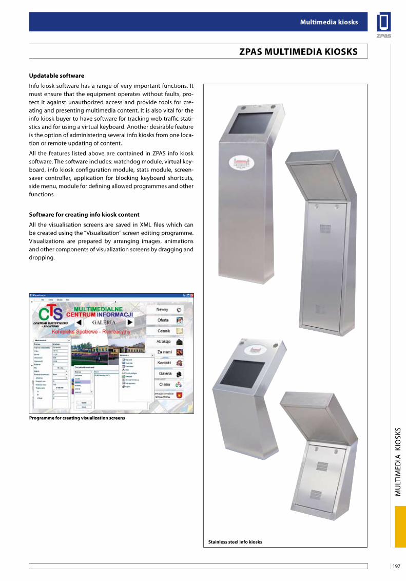
197
Multimedia kiosks
MU
LTIM
EDIA
KIO
SKS
stainless steel info kiosks
updatable software
Info kiosk software has a range of very important functions. It must ensure that the equipment operates without faults, pro-tect it against unauthorized access and provide tools for cre-ating and presenting multimedia content. It is also vital for the info kiosk buyer to have software for tracking web traffic stati-stics and for using a virtual keyboard. Another desirable feature is the option of administering several info kiosks from one loca-tion or remote updating of content.
All the features listed above are contained in ZPAS info kiosk software. The software includes: watchdog module, virtual key-board, info kiosk configuration module, stats module, screen-saver controller, application for blocking keyboard shortcuts, side menu, module for defining allowed programmes and other functions.
software for creating info kiosk content
All the visualisation screens are saved in XML files which can be created using the ‘‘Visualization’’ screen editing programme. Visualizations are prepared by arranging images, animations and other components of visualization screens by dragging and dropping.
Programme for creating visualization screens
ZPas MulTiMeDia KiosKs
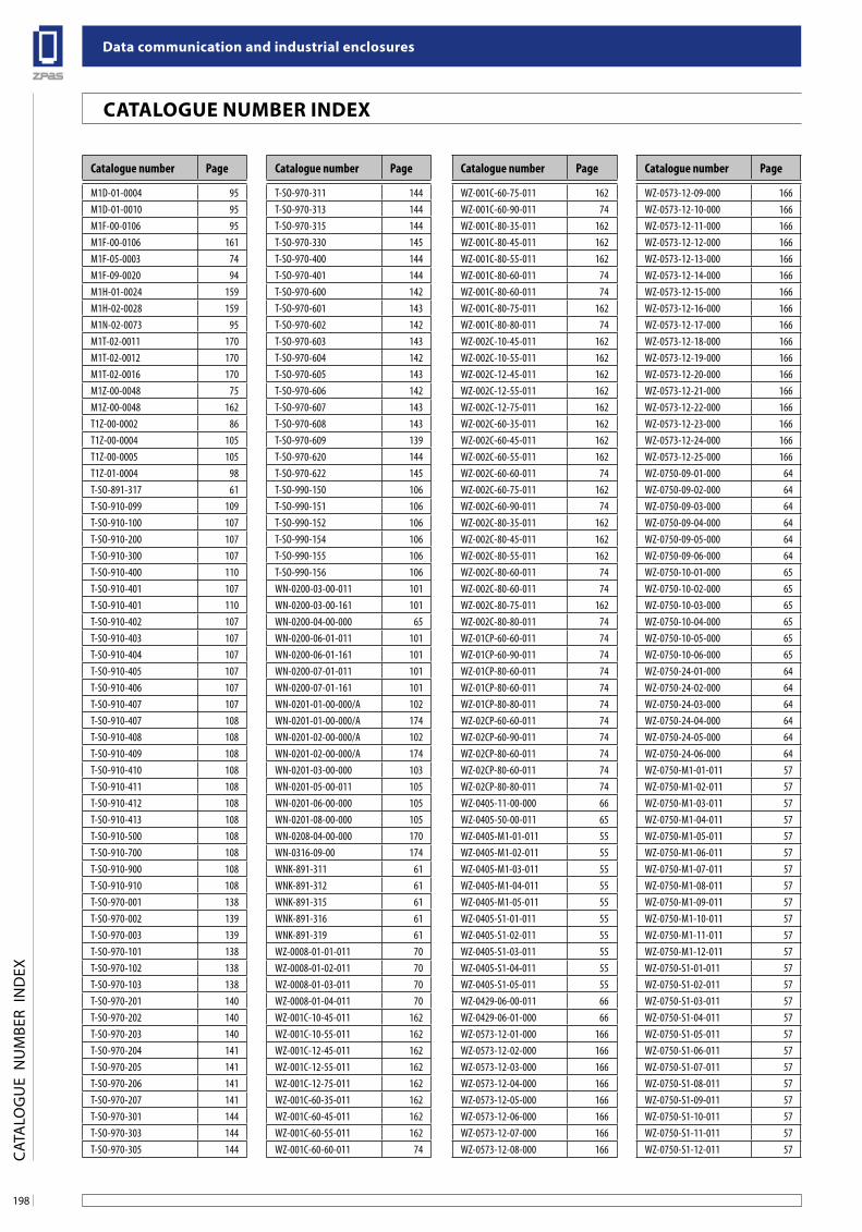
Data communication and industrial enclosures
198
CaTalogue nuMbeR inDex
CAT
ALO
GU
E N
UM
BER
IND
EX
Catalogue number Page Catalogue number PageCatalogue number Page Catalogue number Page
M1D-01-0004 95M1D-01-0010 95M1F-00-0106 95M1F-00-0106 161M1F-05-0003 74M1F-09-0020 94M1H-01-0024 159M1H-02-0028 159M1N-02-0073 95M1T-02-0011 170M1T-02-0012 170M1T-02-0016 170M1Z-00-0048 75M1Z-00-0048 162T1Z-00-0002 86T1Z-00-0004 105T1Z-00-0005 105T1Z-01-0004 98T-SO-891-317 61T-SO-910-099 109T-SO-910-100 107T-SO-910-200 107T-SO-910-300 107T-SO-910-400 110T-SO-910-401 107T-SO-910-401 110T-SO-910-402 107T-SO-910-403 107T-SO-910-404 107T-SO-910-405 107T-SO-910-406 107T-SO-910-407 107T-SO-910-407 108T-SO-910-408 108T-SO-910-409 108T-SO-910-410 108T-SO-910-411 108T-SO-910-412 108T-SO-910-413 108T-SO-910-500 108T-SO-910-700 108T-SO-910-900 108T-SO-910-910 108T-SO-970-001 138T-SO-970-002 139T-SO-970-003 139T-SO-970-101 138T-SO-970-102 138T-SO-970-103 138T-SO-970-201 140T-SO-970-202 140T-SO-970-203 140T-SO-970-204 141T-SO-970-205 141T-SO-970-206 141T-SO-970-207 141T-SO-970-301 144T-SO-970-303 144T-SO-970-305 144
T-SO-970-311 144T-SO-970-313 144T-SO-970-315 144T-SO-970-330 145T-SO-970-400 144T-SO-970-401 144T-SO-970-600 142T-SO-970-601 143T-SO-970-602 142T-SO-970-603 143T-SO-970-604 142T-SO-970-605 143T-SO-970-606 142T-SO-970-607 143T-SO-970-608 143T-SO-970-609 139T-SO-970-620 144T-SO-970-622 145T-SO-990-150 106T-SO-990-151 106T-SO-990-152 106T-SO-990-154 106T-SO-990-155 106T-SO-990-156 106WN-0200-03-00-011 101WN-0200-03-00-161 101WN-0200-04-00-000 65WN-0200-06-01-011 101WN-0200-06-01-161 101WN-0200-07-01-011 101WN-0200-07-01-161 101WN-0201-01-00-000/A 102WN-0201-01-00-000/A 174WN-0201-02-00-000/A 102WN-0201-02-00-000/A 174WN-0201-03-00-000 103WN-0201-05-00-011 105WN-0201-06-00-000 105WN-0201-08-00-000 105WN-0208-04-00-000 170WN-0316-09-00 174WNK-891-311 61WNK-891-312 61WNK-891-315 61WNK-891-316 61WNK-891-319 61WZ-0008-01-01-011 70WZ-0008-01-02-011 70WZ-0008-01-03-011 70WZ-0008-01-04-011 70WZ-001C-10-45-011 162WZ-001C-10-55-011 162WZ-001C-12-45-011 162WZ-001C-12-55-011 162WZ-001C-12-75-011 162WZ-001C-60-35-011 162WZ-001C-60-45-011 162WZ-001C-60-55-011 162WZ-001C-60-60-011 74
WZ-001C-60-75-011 162WZ-001C-60-90-011 74WZ-001C-80-35-011 162WZ-001C-80-45-011 162WZ-001C-80-55-011 162WZ-001C-80-60-011 74WZ-001C-80-60-011 74WZ-001C-80-75-011 162WZ-001C-80-80-011 74WZ-002C-10-45-011 162WZ-002C-10-55-011 162WZ-002C-12-45-011 162WZ-002C-12-55-011 162WZ-002C-12-75-011 162WZ-002C-60-35-011 162WZ-002C-60-45-011 162WZ-002C-60-55-011 162WZ-002C-60-60-011 74WZ-002C-60-75-011 162WZ-002C-60-90-011 74WZ-002C-80-35-011 162WZ-002C-80-45-011 162WZ-002C-80-55-011 162WZ-002C-80-60-011 74WZ-002C-80-60-011 74WZ-002C-80-75-011 162WZ-002C-80-80-011 74WZ-01CP-60-60-011 74WZ-01CP-60-90-011 74WZ-01CP-80-60-011 74WZ-01CP-80-60-011 74WZ-01CP-80-80-011 74WZ-02CP-60-60-011 74WZ-02CP-60-90-011 74WZ-02CP-80-60-011 74WZ-02CP-80-60-011 74WZ-02CP-80-80-011 74WZ-0405-11-00-000 66WZ-0405-50-00-011 65WZ-0405-M1-01-011 55WZ-0405-M1-02-011 55WZ-0405-M1-03-011 55WZ-0405-M1-04-011 55WZ-0405-M1-05-011 55WZ-0405-S1-01-011 55WZ-0405-S1-02-011 55WZ-0405-S1-03-011 55WZ-0405-S1-04-011 55WZ-0405-S1-05-011 55WZ-0429-06-00-011 66WZ-0429-06-01-000 66WZ-0573-12-01-000 166WZ-0573-12-02-000 166WZ-0573-12-03-000 166WZ-0573-12-04-000 166WZ-0573-12-05-000 166WZ-0573-12-06-000 166WZ-0573-12-07-000 166WZ-0573-12-08-000 166
WZ-0573-12-09-000 166WZ-0573-12-10-000 166WZ-0573-12-11-000 166WZ-0573-12-12-000 166WZ-0573-12-13-000 166WZ-0573-12-14-000 166WZ-0573-12-15-000 166WZ-0573-12-16-000 166WZ-0573-12-17-000 166WZ-0573-12-18-000 166WZ-0573-12-19-000 166WZ-0573-12-20-000 166WZ-0573-12-21-000 166WZ-0573-12-22-000 166WZ-0573-12-23-000 166WZ-0573-12-24-000 166WZ-0573-12-25-000 166WZ-0750-09-01-000 64WZ-0750-09-02-000 64WZ-0750-09-03-000 64WZ-0750-09-04-000 64WZ-0750-09-05-000 64WZ-0750-09-06-000 64WZ-0750-10-01-000 65WZ-0750-10-02-000 65WZ-0750-10-03-000 65WZ-0750-10-04-000 65WZ-0750-10-05-000 65WZ-0750-10-06-000 65WZ-0750-24-01-000 64WZ-0750-24-02-000 64WZ-0750-24-03-000 64WZ-0750-24-04-000 64WZ-0750-24-05-000 64WZ-0750-24-06-000 64WZ-0750-M1-01-011 57WZ-0750-M1-02-011 57WZ-0750-M1-03-011 57WZ-0750-M1-04-011 57WZ-0750-M1-05-011 57WZ-0750-M1-06-011 57WZ-0750-M1-07-011 57WZ-0750-M1-08-011 57WZ-0750-M1-09-011 57WZ-0750-M1-10-011 57WZ-0750-M1-11-011 57WZ-0750-M1-12-011 57WZ-0750-S1-01-011 57WZ-0750-S1-02-011 57WZ-0750-S1-03-011 57WZ-0750-S1-04-011 57WZ-0750-S1-05-011 57WZ-0750-S1-06-011 57WZ-0750-S1-07-011 57WZ-0750-S1-08-011 57WZ-0750-S1-09-011 57WZ-0750-S1-10-011 57WZ-0750-S1-11-011 57WZ-0750-S1-12-011 57
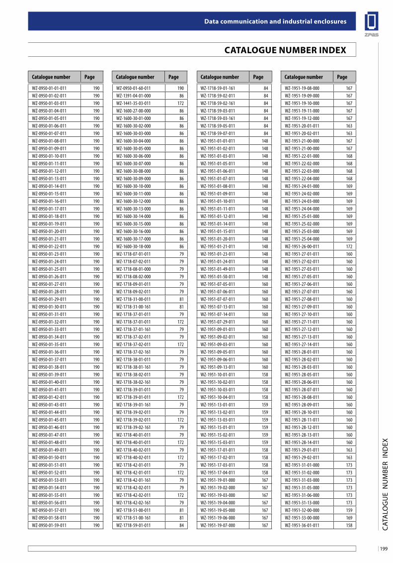
199
Data communication and industrial enclosures
CaTalogue nuMbeR inDex
CAT
ALO
GU
E N
UM
BER
IND
EX
Catalogue number Page Catalogue number PageCatalogue number Page Catalogue number Page
WZ-0950-01-01-011 190WZ-0950-01-02-011 190WZ-0950-01-03-011 190WZ-0950-01-04-011 190WZ-0950-01-05-011 190WZ-0950-01-06-011 190WZ-0950-01-07-011 190WZ-0950-01-08-011 190WZ-0950-01-09-011 190WZ-0950-01-10-011 190WZ-0950-01-11-011 190WZ-0950-01-12-011 190WZ-0950-01-13-011 190WZ-0950-01-14-011 190WZ-0950-01-15-011 190WZ-0950-01-16-011 190WZ-0950-01-17-011 190WZ-0950-01-18-011 190WZ-0950-01-19-011 190WZ-0950-01-20-011 190WZ-0950-01-21-011 190WZ-0950-01-22-011 190WZ-0950-01-23-011 190WZ-0950-01-24-011 190WZ-0950-01-25-011 190WZ-0950-01-26-011 190WZ-0950-01-27-011 190WZ-0950-01-28-011 190WZ-0950-01-29-011 190WZ-0950-01-30-011 190WZ-0950-01-31-011 190WZ-0950-01-32-011 190WZ-0950-01-33-011 190WZ-0950-01-34-011 190WZ-0950-01-35-011 190WZ-0950-01-36-011 190WZ-0950-01-37-011 190WZ-0950-01-38-011 190WZ-0950-01-39-011 190WZ-0950-01-40-011 190WZ-0950-01-41-011 190WZ-0950-01-42-011 190WZ-0950-01-43-011 190WZ-0950-01-44-011 190WZ-0950-01-45-011 190WZ-0950-01-46-011 190WZ-0950-01-47-011 190WZ-0950-01-48-011 190WZ-0950-01-49-011 190WZ-0950-01-50-011 190WZ-0950-01-51-011 190WZ-0950-01-52-011 190WZ-0950-01-53-011 190WZ-0950-01-54-011 190WZ-0950-01-55-011 190WZ-0950-01-56-011 190WZ-0950-01-57-011 190WZ-0950-01-58-011 190WZ-0950-01-59-011 190
WZ-0950-01-60-011 190WZ-1391-04-01-000 86WZ-1441-35-03-011 172WZ-1600-27-00-000 86WZ-1600-30-01-000 86WZ-1600-30-02-000 86WZ-1600-30-03-000 86WZ-1600-30-04-000 86WZ-1600-30-05-000 86WZ-1600-30-06-000 86WZ-1600-30-07-000 86WZ-1600-30-08-000 86WZ-1600-30-09-000 86WZ-1600-30-10-000 86WZ-1600-30-11-000 86WZ-1600-30-12-000 86WZ-1600-30-13-000 86WZ-1600-30-14-000 86WZ-1600-30-15-000 86WZ-1600-30-16-000 86WZ-1600-30-17-000 86WZ-1600-30-18-000 86WZ-1718-07-01-011 79WZ-1718-07-02-011 79WZ-1718-08-01-000 79WZ-1718-08-02-000 79WZ-1718-09-01-011 79WZ-1718-09-02-011 79WZ-1718-31-00-011 81WZ-1718-31-00-161 81WZ-1718-37-01-011 79WZ-1718-37-01-011 172WZ-1718-37-01-161 79WZ-1718-37-02-011 79WZ-1718-37-02-011 172WZ-1718-37-02-161 79WZ-1718-38-01-011 79WZ-1718-38-01-161 79WZ-1718-38-02-011 79WZ-1718-38-02-161 79WZ-1718-39-01-011 79WZ-1718-39-01-011 172WZ-1718-39-01-161 79WZ-1718-39-02-011 79WZ-1718-39-02-011 172WZ-1718-39-02-161 79WZ-1718-40-01-011 79WZ-1718-40-01-011 172WZ-1718-40-02-011 79WZ-1718-40-02-011 172WZ-1718-42-01-011 79WZ-1718-42-01-011 172WZ-1718-42-01-161 79WZ-1718-42-02-011 79WZ-1718-42-02-011 172WZ-1718-42-02-161 79WZ-1718-51-00-011 81WZ-1718-51-00-161 81WZ-1718-59-01-011 84
WZ-1718-59-01-161 84WZ-1718-59-02-011 84WZ-1718-59-02-161 84WZ-1718-59-03-011 84WZ-1718-59-03-161 84WZ-1718-59-05-011 84WZ-1718-59-07-011 84WZ-1951-01-01-011 148WZ-1951-01-02-011 148WZ-1951-01-03-011 148WZ-1951-01-05-011 148WZ-1951-01-06-011 148WZ-1951-01-07-011 148WZ-1951-01-08-011 148WZ-1951-01-09-011 148WZ-1951-01-10-011 148WZ-1951-01-11-011 148WZ-1951-01-12-011 148WZ-1951-01-14-011 148WZ-1951-01-15-011 148WZ-1951-01-20-011 148WZ-1951-01-21-011 148WZ-1951-01-23-011 148WZ-1951-01-24-011 148WZ-1951-01-49-011 148WZ-1951-01-50-011 148WZ-1951-07-05-011 160WZ-1951-07-06-011 160WZ-1951-07-07-011 160WZ-1951-07-13-011 160WZ-1951-07-14-011 160WZ-1951-07-29-011 160WZ-1951-09-01-011 160WZ-1951-09-02-011 160WZ-1951-09-03-011 160WZ-1951-09-05-011 160WZ-1951-09-06-011 160WZ-1951-09-13-011 160WZ-1951-10-01-011 158WZ-1951-10-02-011 158WZ-1951-10-03-011 158WZ-1951-10-04-011 158WZ-1951-13-01-011 159WZ-1951-13-02-011 159WZ-1951-13-03-011 159WZ-1951-15-01-011 159WZ-1951-15-02-011 159WZ-1951-15-03-011 159WZ-1951-17-01-011 158WZ-1951-17-02-011 158WZ-1951-17-03-011 158WZ-1951-17-04-011 158WZ-1951-19-01-000 167WZ-1951-19-02-000 167WZ-1951-19-03-000 167WZ-1951-19-04-000 167WZ-1951-19-05-000 167WZ-1951-19-06-000 167WZ-1951-19-07-000 167
WZ-1951-19-08-000 167WZ-1951-19-09-000 167WZ-1951-19-10-000 167WZ-1951-19-11-000 167WZ-1951-19-12-000 167WZ-1951-20-01-011 163WZ-1951-20-02-011 163WZ-1951-21-00-000 167WZ-1951-21-00-000 167WZ-1951-22-01-000 168WZ-1951-22-02-000 168WZ-1951-22-03-000 168WZ-1951-22-04-000 168WZ-1951-24-01-000 169WZ-1951-24-02-000 169WZ-1951-24-03-000 169WZ-1951-24-04-000 169WZ-1951-25-01-000 169WZ-1951-25-02-000 169WZ-1951-25-03-000 169WZ-1951-25-04-000 169WZ-1951-26-00-011 172WZ-1951-27-01-011 160WZ-1951-27-02-011 160WZ-1951-27-03-011 160WZ-1951-27-05-011 160WZ-1951-27-06-011 160WZ-1951-27-07-011 160WZ-1951-27-08-011 160WZ-1951-27-09-011 160WZ-1951-27-10-011 160WZ-1951-27-11-011 160WZ-1951-27-12-011 160WZ-1951-27-13-011 160WZ-1951-27-14-011 160WZ-1951-28-01-011 160WZ-1951-28-02-011 160WZ-1951-28-03-011 160WZ-1951-28-05-011 160WZ-1951-28-06-011 160WZ-1951-28-07-011 160WZ-1951-28-08-011 160WZ-1951-28-09-011 160WZ-1951-28-10-011 160WZ-1951-28-11-011 160WZ-1951-28-12-011 160WZ-1951-28-13-011 160WZ-1951-28-14-011 160WZ-1951-29-01-011 163WZ-1951-29-02-011 163WZ-1951-31-01-000 173WZ-1951-31-02-000 173WZ-1951-31-03-000 173WZ-1951-31-05-000 173WZ-1951-31-06-000 173WZ-1951-31-13-000 173WZ-1951-32-00-000 159WZ-1951-33-00-000 169WZ-1951-36-01-011 158
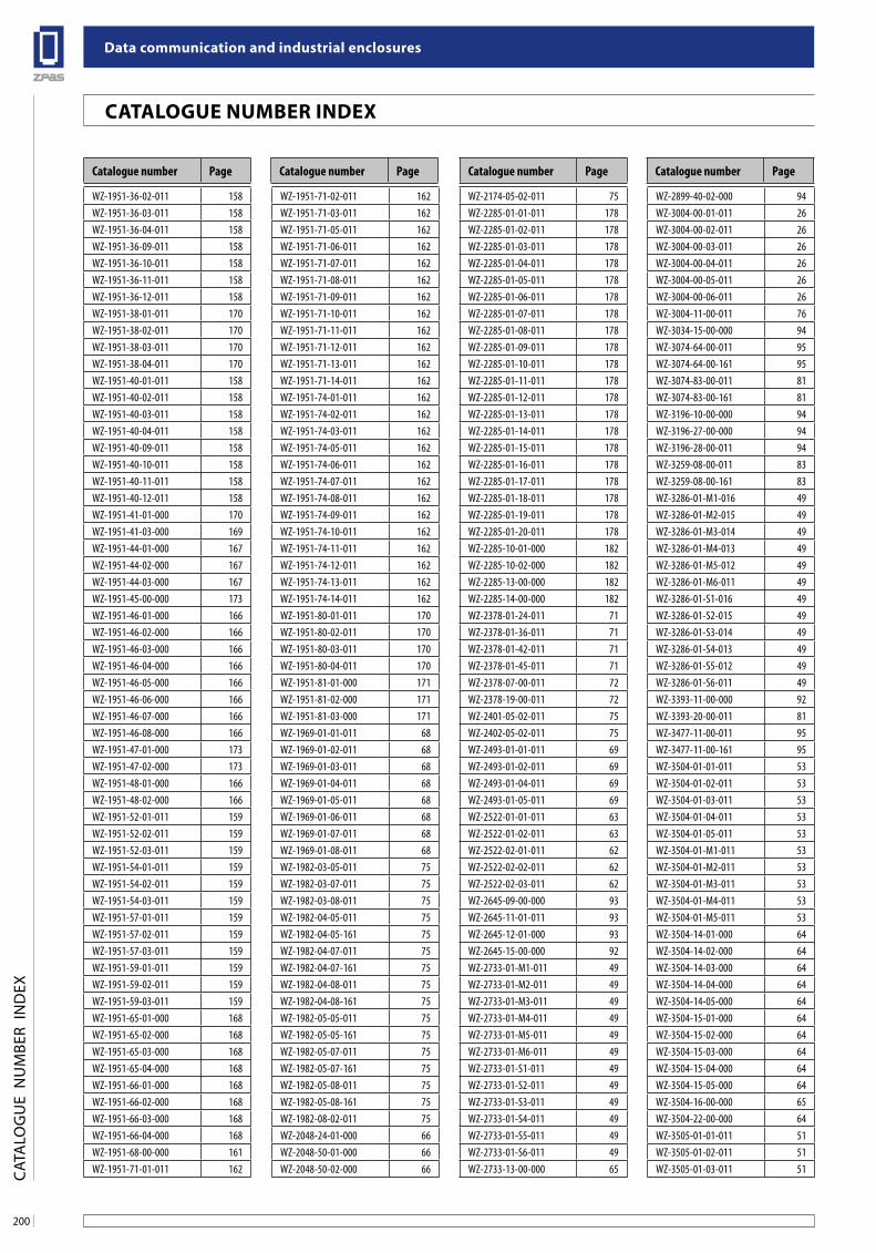
Data communication and industrial enclosures
200
CaTalogue nuMbeR inDex
CAT
ALO
GU
E N
UM
BER
IND
EX
Catalogue number Page Catalogue number PageCatalogue number Page Catalogue number Page
WZ-1951-36-02-011 158WZ-1951-36-03-011 158WZ-1951-36-04-011 158WZ-1951-36-09-011 158WZ-1951-36-10-011 158WZ-1951-36-11-011 158WZ-1951-36-12-011 158WZ-1951-38-01-011 170WZ-1951-38-02-011 170WZ-1951-38-03-011 170WZ-1951-38-04-011 170WZ-1951-40-01-011 158WZ-1951-40-02-011 158WZ-1951-40-03-011 158WZ-1951-40-04-011 158WZ-1951-40-09-011 158WZ-1951-40-10-011 158WZ-1951-40-11-011 158WZ-1951-40-12-011 158WZ-1951-41-01-000 170WZ-1951-41-03-000 169WZ-1951-44-01-000 167WZ-1951-44-02-000 167WZ-1951-44-03-000 167WZ-1951-45-00-000 173WZ-1951-46-01-000 166WZ-1951-46-02-000 166WZ-1951-46-03-000 166WZ-1951-46-04-000 166WZ-1951-46-05-000 166WZ-1951-46-06-000 166WZ-1951-46-07-000 166WZ-1951-46-08-000 166WZ-1951-47-01-000 173WZ-1951-47-02-000 173WZ-1951-48-01-000 166WZ-1951-48-02-000 166WZ-1951-52-01-011 159WZ-1951-52-02-011 159WZ-1951-52-03-011 159WZ-1951-54-01-011 159WZ-1951-54-02-011 159WZ-1951-54-03-011 159WZ-1951-57-01-011 159WZ-1951-57-02-011 159WZ-1951-57-03-011 159WZ-1951-59-01-011 159WZ-1951-59-02-011 159WZ-1951-59-03-011 159WZ-1951-65-01-000 168WZ-1951-65-02-000 168WZ-1951-65-03-000 168WZ-1951-65-04-000 168WZ-1951-66-01-000 168WZ-1951-66-02-000 168WZ-1951-66-03-000 168WZ-1951-66-04-000 168WZ-1951-68-00-000 161WZ-1951-71-01-011 162
WZ-1951-71-02-011 162WZ-1951-71-03-011 162WZ-1951-71-05-011 162WZ-1951-71-06-011 162WZ-1951-71-07-011 162WZ-1951-71-08-011 162WZ-1951-71-09-011 162WZ-1951-71-10-011 162WZ-1951-71-11-011 162WZ-1951-71-12-011 162WZ-1951-71-13-011 162WZ-1951-71-14-011 162WZ-1951-74-01-011 162WZ-1951-74-02-011 162WZ-1951-74-03-011 162WZ-1951-74-05-011 162WZ-1951-74-06-011 162WZ-1951-74-07-011 162WZ-1951-74-08-011 162WZ-1951-74-09-011 162WZ-1951-74-10-011 162WZ-1951-74-11-011 162WZ-1951-74-12-011 162WZ-1951-74-13-011 162WZ-1951-74-14-011 162WZ-1951-80-01-011 170WZ-1951-80-02-011 170WZ-1951-80-03-011 170WZ-1951-80-04-011 170WZ-1951-81-01-000 171WZ-1951-81-02-000 171WZ-1951-81-03-000 171WZ-1969-01-01-011 68WZ-1969-01-02-011 68WZ-1969-01-03-011 68WZ-1969-01-04-011 68WZ-1969-01-05-011 68WZ-1969-01-06-011 68WZ-1969-01-07-011 68WZ-1969-01-08-011 68WZ-1982-03-05-011 75WZ-1982-03-07-011 75WZ-1982-03-08-011 75WZ-1982-04-05-011 75WZ-1982-04-05-161 75WZ-1982-04-07-011 75WZ-1982-04-07-161 75WZ-1982-04-08-011 75WZ-1982-04-08-161 75WZ-1982-05-05-011 75WZ-1982-05-05-161 75WZ-1982-05-07-011 75WZ-1982-05-07-161 75WZ-1982-05-08-011 75WZ-1982-05-08-161 75WZ-1982-08-02-011 75WZ-2048-24-01-000 66WZ-2048-50-01-000 66WZ-2048-50-02-000 66
WZ-2174-05-02-011 75WZ-2285-01-01-011 178WZ-2285-01-02-011 178WZ-2285-01-03-011 178WZ-2285-01-04-011 178WZ-2285-01-05-011 178WZ-2285-01-06-011 178WZ-2285-01-07-011 178WZ-2285-01-08-011 178WZ-2285-01-09-011 178WZ-2285-01-10-011 178WZ-2285-01-11-011 178WZ-2285-01-12-011 178WZ-2285-01-13-011 178WZ-2285-01-14-011 178WZ-2285-01-15-011 178WZ-2285-01-16-011 178WZ-2285-01-17-011 178WZ-2285-01-18-011 178WZ-2285-01-19-011 178WZ-2285-01-20-011 178WZ-2285-10-01-000 182WZ-2285-10-02-000 182WZ-2285-13-00-000 182WZ-2285-14-00-000 182WZ-2378-01-24-011 71WZ-2378-01-36-011 71WZ-2378-01-42-011 71WZ-2378-01-45-011 71WZ-2378-07-00-011 72WZ-2378-19-00-011 72WZ-2401-05-02-011 75WZ-2402-05-02-011 75WZ-2493-01-01-011 69WZ-2493-01-02-011 69WZ-2493-01-04-011 69WZ-2493-01-05-011 69WZ-2522-01-01-011 63WZ-2522-01-02-011 63WZ-2522-02-01-011 62WZ-2522-02-02-011 62WZ-2522-02-03-011 62WZ-2645-09-00-000 93WZ-2645-11-01-011 93WZ-2645-12-01-000 93WZ-2645-15-00-000 92WZ-2733-01-M1-011 49WZ-2733-01-M2-011 49WZ-2733-01-M3-011 49WZ-2733-01-M4-011 49WZ-2733-01-M5-011 49WZ-2733-01-M6-011 49WZ-2733-01-S1-011 49WZ-2733-01-S2-011 49WZ-2733-01-S3-011 49WZ-2733-01-S4-011 49WZ-2733-01-S5-011 49WZ-2733-01-S6-011 49WZ-2733-13-00-000 65
WZ-2899-40-02-000 94WZ-3004-00-01-011 26WZ-3004-00-02-011 26WZ-3004-00-03-011 26WZ-3004-00-04-011 26WZ-3004-00-05-011 26WZ-3004-00-06-011 26WZ-3004-11-00-011 76WZ-3034-15-00-000 94WZ-3074-64-00-011 95WZ-3074-64-00-161 95WZ-3074-83-00-011 81WZ-3074-83-00-161 81WZ-3196-10-00-000 94WZ-3196-27-00-000 94WZ-3196-28-00-011 94WZ-3259-08-00-011 83WZ-3259-08-00-161 83WZ-3286-01-M1-016 49WZ-3286-01-M2-015 49WZ-3286-01-M3-014 49WZ-3286-01-M4-013 49WZ-3286-01-M5-012 49WZ-3286-01-M6-011 49WZ-3286-01-S1-016 49WZ-3286-01-S2-015 49WZ-3286-01-S3-014 49WZ-3286-01-S4-013 49WZ-3286-01-S5-012 49WZ-3286-01-S6-011 49WZ-3393-11-00-000 92WZ-3393-20-00-011 81WZ-3477-11-00-011 95WZ-3477-11-00-161 95WZ-3504-01-01-011 53WZ-3504-01-02-011 53WZ-3504-01-03-011 53WZ-3504-01-04-011 53WZ-3504-01-05-011 53WZ-3504-01-M1-011 53WZ-3504-01-M2-011 53WZ-3504-01-M3-011 53WZ-3504-01-M4-011 53WZ-3504-01-M5-011 53WZ-3504-14-01-000 64WZ-3504-14-02-000 64WZ-3504-14-03-000 64WZ-3504-14-04-000 64WZ-3504-14-05-000 64WZ-3504-15-01-000 64WZ-3504-15-02-000 64WZ-3504-15-03-000 64WZ-3504-15-04-000 64WZ-3504-15-05-000 64WZ-3504-16-00-000 65WZ-3504-22-00-000 64WZ-3505-01-01-011 51WZ-3505-01-02-011 51WZ-3505-01-03-011 51
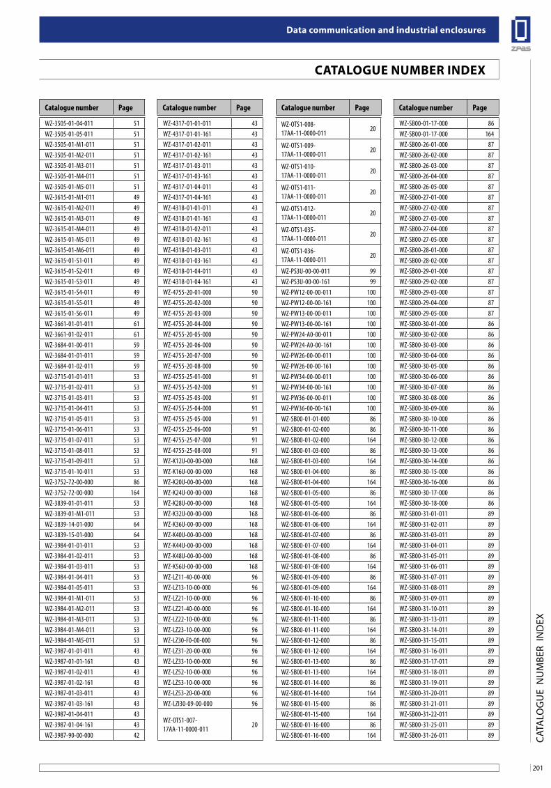
201
Data communication and industrial enclosures
CaTalogue nuMbeR inDex
CAT
ALO
GU
E N
UM
BER
IND
EX
Catalogue number Page Catalogue number PageCatalogue number Page Catalogue number Page
WZ-3505-01-04-011 51WZ-3505-01-05-011 51WZ-3505-01-M1-011 51WZ-3505-01-M2-011 51WZ-3505-01-M3-011 51WZ-3505-01-M4-011 51WZ-3505-01-M5-011 51WZ-3615-01-M1-011 49WZ-3615-01-M2-011 49WZ-3615-01-M3-011 49WZ-3615-01-M4-011 49WZ-3615-01-M5-011 49WZ-3615-01-M6-011 49WZ-3615-01-S1-011 49WZ-3615-01-S2-011 49WZ-3615-01-S3-011 49WZ-3615-01-S4-011 49WZ-3615-01-S5-011 49WZ-3615-01-S6-011 49WZ-3661-01-01-011 61WZ-3661-01-02-011 61WZ-3684-01-00-011 59WZ-3684-01-01-011 59WZ-3684-01-02-011 59WZ-3715-01-01-011 53WZ-3715-01-02-011 53WZ-3715-01-03-011 53WZ-3715-01-04-011 53WZ-3715-01-05-011 53WZ-3715-01-06-011 53WZ-3715-01-07-011 53WZ-3715-01-08-011 53WZ-3715-01-09-011 53WZ-3715-01-10-011 53WZ-3752-72-00-000 86WZ-3752-72-00-000 164WZ-3839-01-01-011 53WZ-3839-01-M1-011 53WZ-3839-14-01-000 64WZ-3839-15-01-000 64WZ-3984-01-01-011 53WZ-3984-01-02-011 53WZ-3984-01-03-011 53WZ-3984-01-04-011 53WZ-3984-01-05-011 53WZ-3984-01-M1-011 53WZ-3984-01-M2-011 53WZ-3984-01-M3-011 53WZ-3984-01-M4-011 53WZ-3984-01-M5-011 53WZ-3987-01-01-011 43WZ-3987-01-01-161 43WZ-3987-01-02-011 43WZ-3987-01-02-161 43WZ-3987-01-03-011 43WZ-3987-01-03-161 43WZ-3987-01-04-011 43WZ-3987-01-04-161 43WZ-3987-90-00-000 42
WZ-4317-01-01-011 43WZ-4317-01-01-161 43WZ-4317-01-02-011 43WZ-4317-01-02-161 43WZ-4317-01-03-011 43WZ-4317-01-03-161 43WZ-4317-01-04-011 43WZ-4317-01-04-161 43WZ-4318-01-01-011 43WZ-4318-01-01-161 43WZ-4318-01-02-011 43WZ-4318-01-02-161 43WZ-4318-01-03-011 43WZ-4318-01-03-161 43WZ-4318-01-04-011 43WZ-4318-01-04-161 43WZ-4755-20-01-000 90WZ-4755-20-02-000 90WZ-4755-20-03-000 90WZ-4755-20-04-000 90WZ-4755-20-05-000 90WZ-4755-20-06-000 90WZ-4755-20-07-000 90WZ-4755-20-08-000 90WZ-4755-25-01-000 91WZ-4755-25-02-000 91WZ-4755-25-03-000 91WZ-4755-25-04-000 91WZ-4755-25-05-000 91WZ-4755-25-06-000 91WZ-4755-25-07-000 91WZ-4755-25-08-000 91WZ-K12U-00-00-000 168WZ-K16U-00-00-000 168WZ-K20U-00-00-000 168WZ-K24U-00-00-000 168WZ-K28U-00-00-000 168WZ-K32U-00-00-000 168WZ-K36U-00-00-000 168WZ-K40U-00-00-000 168WZ-K44U-00-00-000 168WZ-K48U-00-00-000 168WZ-K56U-00-00-000 168WZ-LZ11-40-00-000 96WZ-LZ13-10-00-000 96WZ-LZ21-10-00-000 96WZ-LZ21-40-00-000 96WZ-LZ22-10-00-000 96WZ-LZ23-10-00-000 96WZ-LZ30-F0-00-000 96WZ-LZ31-20-00-000 96WZ-LZ33-10-00-000 96WZ-LZ52-10-00-000 96WZ-LZ53-10-00-000 96WZ-LZ53-20-00-000 96WZ-LZI30-09-00-000 96
WZ-OTS1-007-17AA-11-0000-011
20
WZ-OTS1-008-17AA-11-0000-011
20
WZ-OTS1-009-17AA-11-0000-011
20
WZ-OTS1-010-17AA-11-0000-011
20
WZ-OTS1-011-17AA-11-0000-011
20
WZ-OTS1-012-17AA-11-0000-011
20
WZ-OTS1-035-17AA-11-0000-011
20
WZ-OTS1-036-17AA-11-0000-011
20
WZ-PS3U-00-00-011 99WZ-PS3U-00-00-161 99WZ-PW12-00-00-011 100WZ-PW12-00-00-161 100WZ-PW13-00-00-011 100WZ-PW13-00-00-161 100WZ-PW24-A0-00-011 100WZ-PW24-A0-00-161 100WZ-PW26-00-00-011 100WZ-PW26-00-00-161 100WZ-PW34-00-00-011 100WZ-PW34-00-00-161 100WZ-PW36-00-00-011 100WZ-PW36-00-00-161 100WZ-SB00-01-01-000 86WZ-SB00-01-02-000 86WZ-SB00-01-02-000 164WZ-SB00-01-03-000 86WZ-SB00-01-03-000 164WZ-SB00-01-04-000 86WZ-SB00-01-04-000 164WZ-SB00-01-05-000 86WZ-SB00-01-05-000 164WZ-SB00-01-06-000 86WZ-SB00-01-06-000 164WZ-SB00-01-07-000 86WZ-SB00-01-07-000 164WZ-SB00-01-08-000 86WZ-SB00-01-08-000 164WZ-SB00-01-09-000 86WZ-SB00-01-09-000 164WZ-SB00-01-10-000 86WZ-SB00-01-10-000 164WZ-SB00-01-11-000 86WZ-SB00-01-11-000 164WZ-SB00-01-12-000 86WZ-SB00-01-12-000 164WZ-SB00-01-13-000 86WZ-SB00-01-13-000 164WZ-SB00-01-14-000 86WZ-SB00-01-14-000 164WZ-SB00-01-15-000 86WZ-SB00-01-15-000 164WZ-SB00-01-16-000 86WZ-SB00-01-16-000 164
WZ-SB00-01-17-000 86WZ-SB00-01-17-000 164WZ-SB00-26-01-000 87WZ-SB00-26-02-000 87WZ-SB00-26-03-000 87WZ-SB00-26-04-000 87WZ-SB00-26-05-000 87WZ-SB00-27-01-000 87WZ-SB00-27-02-000 87WZ-SB00-27-03-000 87WZ-SB00-27-04-000 87WZ-SB00-27-05-000 87WZ-SB00-28-01-000 87WZ-SB00-28-02-000 87WZ-SB00-29-01-000 87WZ-SB00-29-02-000 87WZ-SB00-29-03-000 87WZ-SB00-29-04-000 87WZ-SB00-29-05-000 87WZ-SB00-30-01-000 86WZ-SB00-30-02-000 86WZ-SB00-30-03-000 86WZ-SB00-30-04-000 86WZ-SB00-30-05-000 86WZ-SB00-30-06-000 86WZ-SB00-30-07-000 86WZ-SB00-30-08-000 86WZ-SB00-30-09-000 86WZ-SB00-30-10-000 86WZ-SB00-30-11-000 86WZ-SB00-30-12-000 86WZ-SB00-30-13-000 86WZ-SB00-30-14-000 86WZ-SB00-30-15-000 86WZ-SB00-30-16-000 86WZ-SB00-30-17-000 86WZ-SB00-30-18-000 86WZ-SB00-31-01-011 89WZ-SB00-31-02-011 89WZ-SB00-31-03-011 89WZ-SB00-31-04-011 89WZ-SB00-31-05-011 89WZ-SB00-31-06-011 89WZ-SB00-31-07-011 89WZ-SB00-31-08-011 89WZ-SB00-31-09-011 89WZ-SB00-31-10-011 89WZ-SB00-31-13-011 89WZ-SB00-31-14-011 89WZ-SB00-31-15-011 89WZ-SB00-31-16-011 89WZ-SB00-31-17-011 89WZ-SB00-31-18-011 89WZ-SB00-31-19-011 89WZ-SB00-31-20-011 89WZ-SB00-31-21-011 89WZ-SB00-31-22-011 89WZ-SB00-31-25-011 89WZ-SB00-31-26-011 89
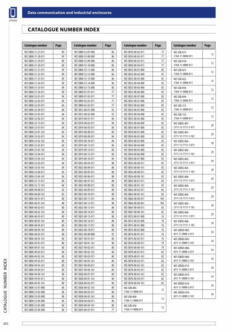
Data communication and industrial enclosures
202
CaTalogue nuMbeR inDex
CAT
ALO
GU
E N
UM
BER
IND
EX
Catalogue number Page Catalogue number PageCatalogue number Page Catalogue number Page
WZ-SB00-31-27-011 89WZ-SB00-31-28-011 89WZ-SB00-31-29-011 89WZ-SB00-31-30-011 89WZ-SB00-31-31-011 89WZ-SB00-31-32-011 89WZ-SB00-31-33-011 89WZ-SB00-31-34-011 89WZ-SB00-31-35-011 89WZ-SB00-31-36-011 89WZ-SB00-32-01-011 84WZ-SB00-32-02-011 84WZ-SB00-32-03-011 84WZ-SB00-32-04-011 84WZ-SB00-32-05-011 84WZ-SB00-32-06-011 84WZ-SB00-32-15-011 84WZ-SB00-33-01-011 84WZ-SB00-33-01-161 84WZ-SB00-33-02-011 84WZ-SB00-33-02-161 84WZ-SB00-33-03-011 84WZ-SB00-33-03-161 84WZ-SB00-33-04-011 84WZ-SB00-33-04-161 84WZ-SB00-33-05-011 84WZ-SB00-33-05-161 84WZ-SB00-33-06-011 84WZ-SB00-33-06-161 84WZ-SB00-33-15-011 84WZ-SB00-33-15-161 84WZ-SB00-40-00-011 83WZ-SB00-40-00-161 83WZ-SB00-48-01-011 80WZ-SB00-48-01-161 80WZ-SB00-48-02-011 80WZ-SB00-48-02-161 80WZ-SB00-48-03-011 80WZ-SB00-48-03-161 80WZ-SB00-48-04-011 80WZ-SB00-48-04-161 80WZ-SB00-48-05-011 80WZ-SB00-48-05-161 80WZ-SB00-49-01-011 80WZ-SB00-49-01-161 80WZ-SB00-49-02-011 80WZ-SB00-49-02-161 80WZ-SB00-49-03-011 80WZ-SB00-49-03-161 80WZ-SB00-49-04-011 80WZ-SB00-49-04-161 80WZ-SB00-49-05-011 80WZ-SB00-49-05-161 80WZ-SB00-53-01-000 86WZ-SB00-53-02-000 86WZ-SB00-53-03-000 86WZ-SB00-53-04-000 86WZ-SB00-53-05-000 86WZ-SB00-53-06-000 86
WZ-SB00-53-07-000 86WZ-SB00-53-08-000 86WZ-SB00-53-09-000 86WZ-SB00-53-10-000 86WZ-SB00-53-11-000 86WZ-SB00-53-12-000 86WZ-SB00-53-13-000 86WZ-SB00-53-14-000 86WZ-SB00-53-15-000 86WZ-SB09-01-01-011 77WZ-SB09-01-02-011 77WZ-SB09-02-01-011 77WZ-SB09-02-02-011 77WZ-SB12-00-01-000 92WZ-SB12-00-02-000 92WZ-SB19-00-01-011 84WZ-SB19-00-02-011 84WZ-SB19-00-05-011 84WZ-SB19-00-08-011 84WZ-SB19-00-09-011 84WZ-SB19-00-10-011 84WZ-SB19-00-13-011 84WZ-SB19-00-14-011 84WZ-SB19-00-15-011 84WZ-SB19-00-16-011 84WZ-SB23-00-03-011 88WZ-SB23-00-04-011 88WZ-SB23-00-05-011 88WZ-SB23-00-06-011 88WZ-SB23-00-07-011 88WZ-SB23-00-08-011 88WZ-SB23-00-09-011 88WZ-SB23-00-10-011 88WZ-SB23-00-11-011 88WZ-SB23-00-12-011 88WZ-SB23-00-13-011 88WZ-SB23-00-14-011 88WZ-SB23-00-15-011 88WZ-SB23-00-16-011 88WZ-SB23-00-17-011 88WZ-SB23-00-18-011 88WZ-SB25-00-00-000 92WZ-SB27-00-01-011 80WZ-SB27-00-01-161 80WZ-SB27-00-02-011 80WZ-SB27-00-02-161 80WZ-SB27-00-03-011 80WZ-SB27-00-03-161 80WZ-SB27-00-04-011 80WZ-SB27-00-04-161 80WZ-SB28-00-01-011 80WZ-SB28-00-01-161 80WZ-SB28-00-02-011 80WZ-SB28-00-02-161 80WZ-SB28-00-03-011 80WZ-SB28-00-03-161 80WZ-SB28-00-04-011 80WZ-SB28-00-04-161 80WZ-SB39-00-01-011 77
WZ-SB39-00-02-011 77WZ-SB39-00-03-011 77WZ-SB50-00-02-011 77WZ-SB50-00-04-011 77WZ-SB52-00-01-000 85WZ-SB52-00-02-000 85WZ-SB52-00-03-000 85WZ-SB52-00-04-000 85WZ-SB52-00-05-000 85WZ-SB52-00-06-000 85WZ-SB52-00-07-000 85WZ-SB53-00-01-000 85WZ-SB53-00-02-000 85WZ-SB53-00-03-000 85WZ-SB53-00-04-000 85WZ-SB53-00-05-000 85WZ-SB53-00-06-000 85WZ-SB53-00-07-000 85WZ-SB54-00-01-000 85WZ-SB54-00-02-000 85WZ-SB54-00-03-000 85WZ-SB54-00-04-000 85WZ-SB54-00-05-000 85WZ-SB54-00-06-000 85WZ-SB54-00-07-000 85WZ-SB55-00-00-011 85WZ-SB55-00-00-161 85WZ-SB56-00-00-011 85WZ-SB56-00-00-161 85WZ-SB63-00-01-011 83WZ-SB63-00-01-161 83WZ-SB63-00-02-011 83WZ-SB63-00-02-161 83WZ-SB66-00-00-011 104WZ-SB66-00-00-061 104WZ-SB67-00-00-011 83WZ-SB67-00-00-161 83WZ-SB72-00-01-000 76WZ-SB72-00-02-000 76WZ-SB73-00-01-000 76WZ-SB73-00-02-000 76WZ-SB74-00-01-011 76WZ-SB74-00-02-011 76WZ-SB76-00-00-011 79WZ-SB76-00-00-161 79WZ-SB78-00-01-011 82WZ-SB78-00-01-161 82WZ-SB78-00-02-011 82WZ-SB78-00-02-161 82WZ-SB78-00-03-011 82WZ-SB78-00-03-161 82WZ-SB78-00-04-011 82WZ-SB78-00-04-161 82
WZ-SZB-005-17AA-11-0000-011
12
WZ-SZB-009-17AA-11-0000-011
12
WZ-SZB-010-17AA-11-0000-011
12
WZ-SZB-017-17AA-11-0000-011
12
WZ-SZB-018-17AA-11-0000-011
12
WZ-SZB-021-17AA-11-0000-011
12
WZ-SZB-022-17AA-11-0000-011
12
WZ-SZB-093-17AA-11-0000-011
12
WZ-SZB-094-17AA-11-0000-011
12
WZ-SZB-151-17AA-11-0000-011
12
WZ-SZB-152-17AA-11-0000-011
12
WZ-SZBSE-001-5711-13-7111-1-011
29
WZ-SZBSE-001-5711-13-7111-1-161
29
WZ-SZBSE-002-5711-13-7111-1-011
29
WZ-SZBSE-002-5711-13-7111-1-161
29
WZ-SZBSE-003-5711-13-7111-1-011
29
WZ-SZBSE-003-5711-13-7111-1-161
29
WZ-SZBSE-004-5711-13-7111-1-011
29
WZ-SZBSE-004-5711-13-7111-1-161
29
WZ-SZBSE-005-5711-13-7111-1-011
29
WZ-SZBSE-005-5711-13-7111-1-161
29
WZ-SZBSE-006-5711-13-7111-1-011
29
WZ-SZBSE-006-5711-13-7111-1-161
29
WZ-SZBSEI-005-6I11-11-0000-2-011
34
WZ-SZBSEI-005-6I11-11-0000-2-161
34
WZ-SZBSEI-006-6I11-11-0000-2-011
34
WZ-SZBSEI-006-6I11-11-0000-2-161
34
WZ-SZBSEI-013-6I11-11-0000-2-011
34
WZ-SZBSEI-013-6I11-11-0000-2-161
34
WZ-SZBSEI-014-6I11-11-0000-2-011
34
WZ-SZBSEI-014-6I11-11-0000-2-161
34
2
solutions for connections
Data communication and industrial enclosures
Edition: 03.2010 [EN010]
Published by:ZPAS S.A.Przygórze 209, 57-431 Wolibórz, Poland
Design of the cover page and section pages,design consulting:Christoph Hetmaniokhetmaniok visuelle komunikation & marketingHoexter
DTP and printing:Usługi Poligraficzne Bogdan Kokot vel Kokocińskiwww.kokocinski.pl
We reserve the right to modernise and modify our products. Technical modifications shall not affect product functionality. Misprints and errors of content that may be found in this catalogue may not be used as a basis for complaints.
203
for your connections
The ZPAS Group, pursuing shared goals and business
philosophy, integrates the product offer of ZPAS S.A. and
ZPAS-NET sp. z o.o. The idea is reflected in our motto
‘‘solutions for connections’’, which refers to advantages of
our products, benefits of using them, a superb system of
communication with our customers, partnership, technical
consulting and high level of customer service, from the
moment of first contact until order fulfilment. The motto
thus reflects our attitude to clients whose requirements we
wish to satisfy, offering them top-quality services.
We have achieved a strong status in the industry over
35 years of our business activity. As a manufacturer, we
operate in accordance with our well-established reputation
as a reliable business partner providing customers with
topquality products, short lead times and very reasonable
prices.
Electronic communication products (elements of IT,
telecommunications and power systems) must
demonstrate parameters and features capable of meeting
rigorous high-tech requirements. Our primary goal is to
supply such products.
Our capital is not limited to modern machines. We also
boast of highly qualified staff. Our employees are young,
creative and innovation-minded. They also make the best
use of vast industry experience acquired over more than
30 years by specialists who have worked for our company ever
since its beginnings. Advanced technologies and wellplanned
organisation of all manufacturing processes are
supported by INFOR ERP LN, our IT system.
ZPAS Group

Data communication
and industrial enclosures
f o r y o u r c o n n e c t i o n s
Zakł ad Produkcji Automatyki Sieciowej S.A.
Przygórze 209 · 57-431 Wolibórz · Poland
Phone +48 748 720 100
Fax +48 748 724 074
[email protected] · www.zpas.pl
A Company of ZPAS Group
f o r y o u r c o n n e c t i o n s
Dat
a co
mm
un
icat
ion
an
d in
du
stri
al e
ncl
osu
res
[
EN
010
]Our business representatives:
Latvia
Lithuania
Luxembourg
Malta
Morocco
The Netherlands
Norway
Poland
Portugal
Russia
Slovenia
Spain
Sweden
Switzerland
Ukraine
Austria
Belarus
Belgium
Bosnia and Herzegovina
Cyprus
Denmark
France
Germany
Great Britain
Greece
Hungary
Iceland
Italy
Kazakhstan
Kyrgyzstan
Wrocław
ZąbkowiceŚląskie
Kłodzko
Wałbrzych
Jawor
Świdnica
Nowa Ruda
Kudowa Zdr.
CZEC
H R
EPU
BLIC
CZECHREPUBLIC
Dzierżoniów
Przygórze
35
384
385
381
35
5
5
3
A4
A4
8
E 67
E 67
E 40
33