
Mock Royal College Written Exam Pediatric Cardiology TRP ...

Z3
mr. sc. Vladimir GLAŽAR, dipl.ing.Sveučilište u RijeciTehnički fakultet Zavod za termodinamiku i energetikuVukovarska 5851 000 Rijeka e-mail: [email protected]
EKSPERIMENTALNA ANALIZA TERMODINAMIČKIH KARAKTERISTIKA CIJEVNOG LAMELNOG I LAMELNOG
IZMJENJIVAČA TOPLINE S MIKROKANALIMA
EXPERIMENTAL ANALYSIS OF THERMODYNAMICAL PROPERTIES OF FIN-AND-TUBE AND HEAT EXCHANGER WITH
MICROCHANNEL COIL
prof. dr. sc. Kristian LENIĆ, dipl. ing. Sveučilište u Rijeci, Tehnički fakultet, Rijeka
prof. dr. sc. Anica TRP, dipl. ing. Sveučilište u Rijeci, Tehnički fakultet, Rijeka
prof. dr. sc. Bernard FRANKOVIĆ, dipl. ing. Sveučilište u Rijeci, Tehnički fakultet, Rijeka

Z3
EXPERIMENTAL ANALYSIS OF THERMODYNAMICAL PROPERTIES OF FIN-AND-TUBE AND HEAT EXCHANGER
WITH MICROCHANNEL COIL
Abstract: In this study experimental analysis of two compact heat exchangers of different construction types has been done. A fin-and-tube heat exchanger and heat exchanger with microchannel coil have been installed in an open circuit wind tunnel. Air and water were used as working fluids. From measured temperatures and flows of both fluids heat transfer and effectiveness have been calculated. Comparison of acquired results has been made accompanied by the commentary of advantages and disadvantages of both types of compact heat exchangers.
Key words: compact heat exchanger, heat exchanger with microchannel coil, fin-and-tube heat exchanger, experimental analysis
EKSPERIMENTALNA ANALIZA TERMODINAMIČKIH KARAKTERISTIKA CIJEVNOG LAMELNOG I LAMELNOG
IZMJENJIVAČA TOPLINE S MIKROKANALIMA
Sažetak: U ovom je radu eksperimentalnim putem provedena termodinamička analiza dva, po konstrukciji različita tipa kompaktnih izmjenjivača topline. U zračnom tunelu otvorenog tipa su ispitani cijevni lamelni izmjenjivač topline i lamelni izmjenjivač topline s mikrokanalima. Korišteni su radni mediji zrak i voda. Mjerenjem temperatura i protoka oba radna medija dobiveni su izmijenjeni toplinski tok i iskoristivost topline za oba ispitivana izmjenjivača topline. Prikazana je usporedba rezultata te su dati zaključci o prednostima i nedostacima oba ispitivana izmjenjivača topline.
Ključne riječi: kompaktni izmjenjivač topline, lamelni izmjenjivač topline s mikrokanalima, cijevni lamelni izmjenjivač topline, eksperimentalna analiza

INTERKLIMA (2011) XXX-XXX
EXPERIMENTAL ANALYSIS OF THERMODYNAMICAL PROPERTIES OF FIN-AND-TUBE AND HEAT EXCHANGER WITH
MICROCHANNEL COIL
Vladimir Glažar, Kristian Lenić, Anica Trp, Bernard Franković Faculty of Engineering, University of Rijeka, Vukovarska 58, HR-51000 Rijeka,
Tel.: + 385 51 651 536, Fax: + 385 51 675 801, [email protected], [email protected], [email protected],
Abstract: In this study experimental analysis of two compact heat exchangers of different construction types has been done. A fin-and-tube heat exchanger and heat exchanger with microchannel coil have been installed in an open circuit wind tunnel. Air and water were used as working fluids. From measured temperatures and flows of both fluids heat transfer and effectiveness have been calculated. Comparison of acquired results has been made accompanied by the commentary of advantages and disadvantages of both types of compact heat exchangers. Key words: compact heat exchanger, heat exchanger with microchannel coil, fin-and-tube heat exchanger, experimental analysis
EKSPERIMENTALNA ANALIZA TERMODINAMIČKIH
KARAKTERISTIKA CIJEVNOG LAMELNOG I LAMELNOG IZMJENJIVAČA TOPLINE S MIKROKANALIMA
Sažetak: U ovom je radu eksperimentalnim putem provedena termodinamička analiza dva, po konstrukciji različita tipa kompaktnih izmjenjivača topline. U zračnom tunelu otvorenog tipa su ispitani cijevni lamelni izmjenjivač topline i lamelni izmjenjivač topline s mikrokanalima. Korišteni su radni mediji zrak i voda. Mjerenjem temperatura i protoka oba radna medija dobiveni su izmijenjeni toplinski tok i iskoristivost topline za oba ispitivana izmjenjivača topline. Prikazana je usporedba rezultata te su dati zaključci o prednostima i nedostacima oba ispitivana izmjenjivača topline. Ključne riječi: kompaktni izmjenjivač topline, lamelni izmjenjivač topline s mikrokanalima, cijevni lamelni izmjenjivač topline, eksperimentalna analiza

INTERKLIMA (2011) XXX-XXX
1. INTRODUCTION
Regarding construction type, heat exchangers can be divided on tubular, plate-type, regenerative and heat exchangers with extended surfaces [1]. Heat exchangers with extended surfaces comprise elements that are connected to primary surface that is in direct contact with both hot and cold fluid. These elements are referred as fins. Main use of extended surfaces is to increase the heat transfer area. Fin-and-tube heat exchangers, which are today widely used in many applications in residential, commercial and industrial HVAC systems, are representatives of heat exchangers with extended surfaces. According to surface compactness fin-and-tube heat exchangers belong to group of compact heat exchangers with high compactness ratio [2]. Further size reduction of heat exchanger passages has been implemented in the heat exchangers with flat tubes, commercially known as microchannel coil with even higher compactness. In this paper experimental analysis and comparison of such heat exchangers has been performed. The extended surfaces geometries have been studied experimentally and numerically. Still, there are only few researchers who have carried out full scale experiments studying the heat transfer effectiveness and specific heat transfer per mass and volume. Junqui et al. [3] studied experimentally several types of cross-flow heat exchangers having wavy fin and flat tube. They analysed air side thermal performance and proposed general correlations for Colburn and Fanning factors. Agarwal et al. [4] experimentally tested a few non-circular flat tube geometry shapes. They examined flat tubes with square, barrel, triangular, rectangular channels, channels with “W” and channels with “N” shaped inserts during condensation of refrigerant. Wolf et al. [5] carried out a thermodynamic analysis of the airside heat transfer performance of a wavy fin-and-tube heat exchanger for three-dimensional steady-state fluid flow and heat transfer. They found a good agreement between numerical results and experimental measurements and existing correlations. In this paper results accomplished by experimental analyses of two heat exchangers of different construction types have been compared. From measured temperatures and flows of both fluids heat transfer and effectiveness have been calculated.
2. EXPERIMENTAL PROCEDURE
2.1. Experimental Facility The schematic diagram of the open wind tunnel used in this paper is shown on Figure 1.
Figure 1. Schematic diagram of the open wind tunnel test apparatus
1 air inlet 2 air handling unit 3 orifice 4 air settling ducts 5 measuring station 6 air inlet temperature sensors 7 test heat exchanger 8 air outlet temperature sensors 9 air outlet 10 data acquisition system

INTERKLIMA (2011) XXX-XXX
Air and demineralized water were used as working fluids. The main components of the system were heat exchanger with microchannel coil, water flow loop, air supply, instrumentations and data acquisition systems. The open circuit wind tunnel system was used to intake air from laboratory or from open air over the air handling unit with capability of air preheating. Air flow could be adjusted by pressure relief damper from approximately 20 to 100% of maximum air flow. The upper part of tunnel was composed of circular ducts with diameter of φ600 mm and lower part from rectangular ducts of appropriate size 550×450 mm. Measuring station with installed test heat exchanger was insulated with 25 mm thick insulation. The inlet and outlet temperature across air side of the heat exchanger were measured by two platinum resistance thermometer meshes (Figure 2).
Figure 2. Platinum resistance thermometer meshes installed in measuring station
The inlet measuring mesh consisted of three RTD sensors while the outlet mesh
consisted of nine RTD sensors. These sensors were connected to data acquisition system in three-wire configuration. This is relatively simple wiring arrangement that provides accurate readings with reliable auto correction of any problems caused by any effect of the temperature range on the wiring itself. The RTD sensors were pre-calibrated with an accuracy of ±0.15 K. Signals from RTD-s were individually recorded and then averaged. The air flow rate was measured with pipe orifice installed in circular ducts. A fluid passing through an orifice construction experiences pressure drop which has been measured. Figure 3 shows measuring station of wind tunnel with installed data acquisition system.
Figure 3. Measuring station of wind tunnel
Air pressure drop was measured with portable measuring system Testo 350 M/XL
which has integrated differential pressure probe. Air flow rate was than calculated from pressure drop achieved on orifice. The hot/cold water loop was divided in two separate loops:
INTERKLIMA (2011) XXX-XXX
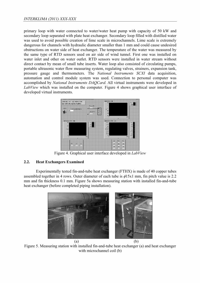
primary loop with water connected to water/water heat pump with capacity of 50 kW and secondary loop separated with plate heat exchanger. Secondary loop filled with distilled water was used to avoid possible creation of lime scale in microchannels. Lime scale is extremely dangerous for channels with hydraulic diameter smaller than 1 mm and could cause undesired obstructions on water side of heat exchanger. The temperature of the water was measured by the same type of RTD sensors used on air side of wind tunnel. First one was installed on water inlet and other on water outlet. RTD sensors were installed in water stream without direct contact by mean of small tube inserts. Water loop also consisted of circulating pumps, portable ultrasonic water flow measuring system, regulating valves, strainers, expansion tank, pressure gauge and thermometers. The National Instruments SCXI data acquisition, automation and control module system was used. Connection to personal computer was accomplished by National Instruments DAQCard. All virtual instruments were developed in LabView which was installed on the computer. Figure 4 shows graphical user interface of developed virtual instruments.
Figure 4. Graphical user interface developed in LabView
2.2. Heat Exchangers Examined
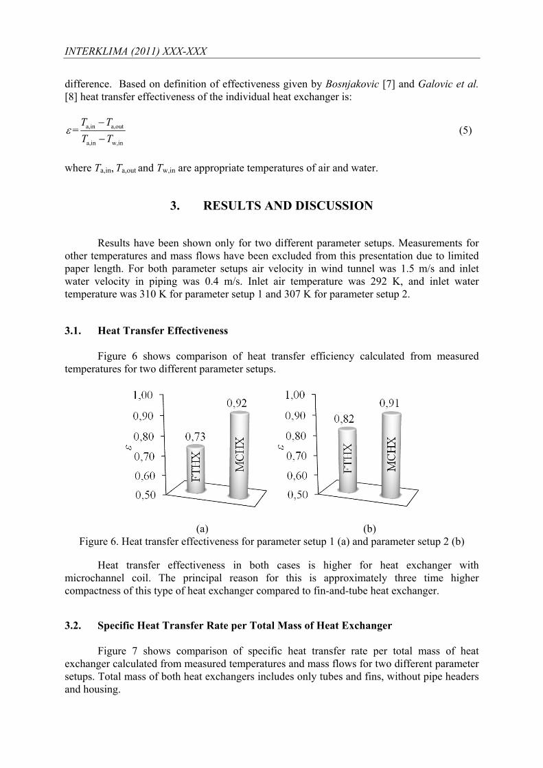
Experimentally tested fin-and-tube heat exchanger (FTHX) is made of 40 copper tubes assembled together in 4 rows. Outer diameter of each tube is φ15x1 mm, fin pitch value is 2.2 mm and fin thickness 0.1 mm. Figure 5a shows measuring station with installed fin-and-tube heat exchanger (before completed piping installation).
(a) (b)
Figure 5. Measuring station with installed fin-and-tube heat exchanger (a) and heat exchanger with microchannel coil (b)

INTERKLIMA (2011) XXX-XXX
Figure 5b shows examined heat exchanger with microchannel coil (MCHX) that consists of 68 parallel flat tubes connected with wavy fins. Both flat tubes and fins are made from aluminium. Flat tubes are made of 18 rectangular channels with hydraulic diameter of 0.99 mm each. Fin pitch value is 1.45 mm, and fin thickness 0.1 mm. Outer dimensions are same as the one of fin-and-tube heat exchanger.
2.3. Test Condition and Method The tests were performed in a range of Reynolds number from 50 to 300. Corresponding maximal air velocities were in range from 0.4 to 3 m/s. Reynolds number applied in this calculation is based on hydraulic diameter of fin entrance and maximum air velocity. The water temperature was in range from 280÷290 K with allowed tolerance of ±1 K per measurement. The choice of water flow rate was based on a principle that a temperature drop on a water side has to be higher than 3 K with constant flow for all measures [6]. 95 valid measurements of fin-and-tube heat exchanger and 35 valid experimental measurements of heat exchanger with microchannel coil have been made with different air and water temperatures and flows. Time needed to conclude one measurement was approximately 30 minutes after achievement of appropriate heat balance that is approximately one hour for each parameter set up.
2.4. Specific Heat Transfer and Heat Transfer Effectiveness Comparison between two heat exchangers has been done according to correspondent specific heat transfer and heat transfer effectiveness. Both values were calculated from temperatures and flows acquired by experimental measurement. Mean temperatures of air where calculated with following equations:
a,in1 a,in2 a,in3a,in 3
T T TT
+ +=
(1)
9
a,out,i1
a,out 9i
TT ==
∑
(2)
Heat transfer rate used for the comparison of heat exchangers can be expressed as:
w a
2Q QQ +
=
w w P,w wQ m c T= ⋅ ⋅Δ (3)
a a P,a a a a P,a aQ m c T V c Tρ= ⋅ ⋅Δ = ⋅ ⋅ ⋅Δ (4)
In previous terms wm and am are measured mass flow rates of water and air, cP,w and cP,a are specific heats at constant pressure for both fluids and ΔT is measured temperature
INTERKLIMA (2011) XXX-XXX
difference. Based on definition of effectiveness given by Bosnjakovic [7] and Galovic et al. [8] heat transfer effectiveness of the individual heat exchanger is:
a,in a,out
a,in w,in
= T TT T
ε−−
(5)
where Ta,in, Ta,out and Tw,in are appropriate temperatures of air and water.
3. RESULTS AND DISCUSSION
Results have been shown only for two different parameter setups. Measurements for
other temperatures and mass flows have been excluded from this presentation due to limited paper length. For both parameter setups air velocity in wind tunnel was 1.5 m/s and inlet water velocity in piping was 0.4 m/s. Inlet air temperature was 292 K, and inlet water temperature was 310 K for parameter setup 1 and 307 K for parameter setup 2.
3.1. Heat Transfer Effectiveness
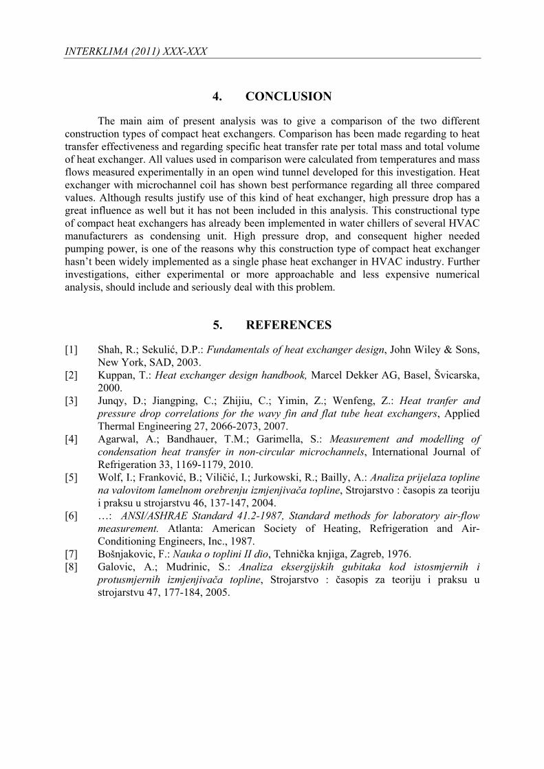
Figure 6 shows comparison of heat transfer efficiency calculated from measured temperatures for two different parameter setups.
(a) (b) Figure 6. Heat transfer effectiveness for parameter setup 1 (a) and parameter setup 2 (b)
Heat transfer effectiveness in both cases is higher for heat exchanger with microchannel coil. The principal reason for this is approximately three time higher compactness of this type of heat exchanger compared to fin-and-tube heat exchanger.
3.2. Specific Heat Transfer Rate per Total Mass of Heat Exchanger Figure 7 shows comparison of specific heat transfer rate per total mass of heat
exchanger calculated from measured temperatures and mass flows for two different parameter setups. Total mass of both heat exchangers includes only tubes and fins, without pipe headers and housing.

INTERKLIMA (2011) XXX-XXX
(a) (b) Figure 7. Specific heat transfer rate per total mass of heat exchanger for parameter setup 1 (a)
and parameter setup 2 (b)
Main reason of several times higher value of heat transfer rate per total mass of heat exchanger is production material. Fin-and-tube heat exchangers are made of copper tubes and aluminium fins. Heat exchanger with microchannel coil is made only from aluminium which has approximately three times smaller density. Higher heat transfer effectiveness also has some influence in final results. Difference would be even larger if pipe headers and header plugs were included in calculation.
3.3. Specific Heat Transfer Rate per Total Volume of Heat Exchanger Figure 8 shows comparison of specific heat transfer rate per total volume of heat
exchanger calculated from measured temperatures and mass flows for two different parameter setups. Total volume of both heat exchangers includes only tubes and fins, without pipe headers and housing.
(a) (b)
Figure 8. Specific heat transfer rate per total volume of heat exchanger for parameter setup 1 (a) and parameter setup 2 (b)
As has been seen in previous section, besides higher heat transfer rate per mass, heat exchanger with microchannel coil has also multiple times higher heat transfer rate per volume of heat exchanger due to higher compactness ratio of heat exchanger with microchannel coil.
INTERKLIMA (2011) XXX-XXX
4. CONCLUSION
The main aim of present analysis was to give a comparison of the two different construction types of compact heat exchangers. Comparison has been made regarding to heat transfer effectiveness and regarding specific heat transfer rate per total mass and total volume of heat exchanger. All values used in comparison were calculated from temperatures and mass flows measured experimentally in an open wind tunnel developed for this investigation. Heat exchanger with microchannel coil has shown best performance regarding all three compared values. Although results justify use of this kind of heat exchanger, high pressure drop has a great influence as well but it has not been included in this analysis. This constructional type of compact heat exchangers has already been implemented in water chillers of several HVAC manufacturers as condensing unit. High pressure drop, and consequent higher needed pumping power, is one of the reasons why this construction type of compact heat exchanger hasn’t been widely implemented as a single phase heat exchanger in HVAC industry. Further investigations, either experimental or more approachable and less expensive numerical analysis, should include and seriously deal with this problem.
5. REFERENCES
[1] Shah, R.; Sekulić, D.P.: Fundamentals of heat exchanger design, John Wiley & Sons, New York, SAD, 2003.
[2] Kuppan, T.: Heat exchanger design handbook, Marcel Dekker AG, Basel, Švicarska, 2000.
[3] Junqy, D.; Jiangping, C.; Zhijiu, C.; Yimin, Z.; Wenfeng, Z.: Heat tranfer and pressure drop correlations for the wavy fin and flat tube heat exchangers, Applied Thermal Engineering 27, 2066-2073, 2007.
[4] Agarwal, A.; Bandhauer, T.M.; Garimella, S.: Measurement and modelling of condensation heat transfer in non-circular microchannels, International Journal of Refrigeration 33, 1169-1179, 2010.
[5] Wolf, I.; Franković, B.; Viličić, I.; Jurkowski, R.; Bailly, A.: Analiza prijelaza topline na valovitom lamelnom orebrenju izmjenjivača topline, Strojarstvo : časopis za teoriju i praksu u strojarstvu 46, 137-147, 2004.
[6] …: ANSI/ASHRAE Standard 41.2-1987, Standard methods for laboratory air-flow measurement. Atlanta: American Society of Heating, Refrigeration and Air-Conditioning Engineers, Inc., 1987.
[7] Bošnjakovic, F.: Nauka o toplini II dio, Tehnička knjiga, Zagreb, 1976. [8] Galovic, A.; Mudrinic, S.: Analiza eksergijskih gubitaka kod istosmjernih i
protusmjernih izmjenjivača topline, Strojarstvo : časopis za teoriju i praksu u strojarstvu 47, 177-184, 2005.
Copyright © 2022 FDOKUMEN