ELFOEnergy Magnum - High temperature - Klima-Therm
36
ELFOEnergy Magnum - High temperature Nominal heating capacity (A7/W45) from 107 kW to 183 kW Nominal cooling capacity (A35/W7) from 85 kW to 149 kW ▶ R-410A MODULAR SCROLL TECHNOLOGY ▶ TWO INDEPENDENT REFRIGERATION CIRCUITS ▶ EUROVENT CLASS A IN HEATING ▶ PRODUCTION OF HOT WATER UP TO 65°C ▶ PARTIAL RECOVERY OF THE CONDENSING HEAT (OPTIONAL) ▶ ECOBREEZE FANS (OPTIONAL) For a further increase in efficiency ▶ VARYFLOW+ (OPTIONAL) Variable water flow-rate with inverter pumps Technical Bulletin Air-water heat pump at high temperature for outdoor installation WSAN-XEM HW 35.4 - 60.4 RANGE BT15D015GB-07 Clivet is taking part in the EUROVENT certification programme up to 1.500 kW. The products concerned appear in the certified products list of the EUROVENT www. eurovent-certification.com site.
-
Upload
khangminh22 -
Category
Documents
-
view
2 -
download
0
Transcript of ELFOEnergy Magnum - High temperature - Klima-Therm
ELFOEnergy Magnum - High temperature
Nominal heating capacity (A7/W45) from 107 kW to 183 kWNominal cooling capacity (A35/W7) from 85 kW to 149 kW
▶ R-410A MODULAR SCROLL TECHNOLOGY
▶ TWO INDEPENDENT REFRIGERATION CIRCUITS
▶ EUROVENT CLASS A IN HEATING
▶ PRODUCTION OF HOT WATER UP TO 65°C
▶ PARTIAL RECOVERY OF THE CONDENSING HEAT (OPTIONAL)
▶ ECOBREEZE FANS (OPTIONAL)For a further increase in e�ciency
▶ VARYFLOW+ (OPTIONAL)Variable water �ow-rate with inverter pumps
Technical Bulletin
Air-water heat pump at high temperature for outdoor installation
WSAN-XEM HW 35.4 - 60.4 RANGE
BT15D015GB-07
Clivet is taking part in the EUROVENT certi�cation programme up to 1.500 kW. The products concerned appear in the certi�ed products list of the EUROVENT www.eurovent-certi�cation.com site.

2 ELFOEnergy Magnum - High temperature BT15D015GB-07
Clivet hydronic systemDesigned to provide high energy e�ciency and sustainability of the investment, the wide range of Clivet liquid chillers and heat pumps for high e�ciency air conditioning of Residential and Commercial spaces and for Industrial applications it is available with air or water source.
SpecializationEvery intended use has speci�c requirements which determine the overall e�ciency. For this, the Clivet hydronic system always o�ers the best solution in every project.
• Modular range with over 8000 kW of overall capacity
• Capacity control with Screw and modular Scroll technology
• Multifunction versions
• Outdoor or indoor (ductable type) installation
Centrality of the Air Renewal Terminal and AHU complete systemFrom the Air Renewal depends the comfort in the spaces. Since it often represents the main building energetic load, it also determines the running costs of the entire system.
The hydronic terminal units are very di�used for their versa-tility and reliability. The Clivet range includes many versions that simplify the application in di�erents type of installation and building.
ZEPHIR3Packaged Primary Air supply system with thermodynamic energy recovery
ELFOSpaceHigh energy e�ciency hydronic terminal units
AQX
Air-conditioning unit
• Simpli�es the system, reduces the heating and cooling generators
• Puri�es the air with the standard electronic �lters
• Increases the energy e�ciency and it also allows a savings of 40% on the running costs
• From –40°C to +50°C of outdoor air temperature
• Cased and uncased terminal units, from 1 to 90 kW
• Horizontal and vertical installation
• Energy-saving DC fans
• Modular air conditioning units up to 160.000 m3/h
• EUROVENT certi�cation

BT15D015GB-07 ELFOEnergy Magnum - High temperature 3
ELFOEnergy Magnum: modular scroll technology for every application
MAGNUM HEAT PUMP HIGH TEMPERATUREWSAN-XEM HW:
• Reversible-cycle heat pump
• Production of hot water up to 65°C
• Extended operating range
MAGNUM HEAT PUMPWSAN-XEM:
• Reversible-cycle heat pump
MAGNUM COOL ONLYWSAT-XEM:
• Water chiller
• Hot water production by partial energy recovery option
MAGNUM MULTIFUNCTIONWSAN-XEM MF:
• Reversible-cycle heat pump
• Chilled and hot water produced at the same time

4 ELFOEnergy Magnum - High temperature BT15D015GB-07
Cost or reliability?
The dilemma of modern system engineering applications
Air-conditioning systems in trade centres in�uence both the starting investment and monthly management costs, for the whole of their working lives. This theme is even more relevant in residential applications with centralised systems. Furthermore, maximum working �exibility requirements should be added to that, in serving di�erent users while avoiding wasting energy and thus, money. Finally, there are several industrial applications which require hot or chilled water as service �uid, process �uid or vector �uid for operator comfort and for conserving goods and enabling cycles to function correctly. Furthermore, in all these cases, the working reliability of the system is decisive.
High e�ciency hydronic systems
The high e�ciency hydronic systems are extremely versatile, reliable and widespread
Despite their apparently low costs, split, multi-split and VRF direct expansion systems have a lot of limits in these applications. For example, they require a separate system for primary air treatment. The pipes that contain the refrigerant cross the served rooms and therefore they are subject to restrictions and use limitations. They cannot operate in the FREE-COOLING mode, the high e�ciency and convenient mode that allows energy savings.
The hydronic systems are certainly more complete and versatile. They make it possible to adopt various types of terminals in the served environment, from fan coil units exposed or integrated in the furnishings, up to radiant or induction systems. They are also irreplaceable in the service and process industrial applications. The main component performances, like air-cooled liquid chillers and hydronic heat pumps, are checked and certi�cated by appropriate certi�cation programs, as Eurovent.
Clivet technological evolution
Clivet chillers reduce consumption and are compact and reliable
With over twenty years of technological evolution, Clivet liquid chillers and heat pumps represent the state of the art in air-conditioning of residential, trade and industrial environments.
Their success is based on high energy e�ciency, compactness and management maintenance simplicity, with wide versatility in the choice of the most suitable model for the speci�c use.
BT15D015GB-07 ELFOEnergy Magnum - High temperature 5
ELFOEnergy Magnum High temperature
Provides all Clivet technological developments for their medium capacity hydronic systems
High e�ciency Scroll compressors, high performance heat exchangers, double expansion valve, fully automatic operation: these are only some of the technologies available with ELFOEnergy Magnum High temperature, in a range of models that are ideal for high capacity air conditioning systems in commercial, residential and industrial buildings.
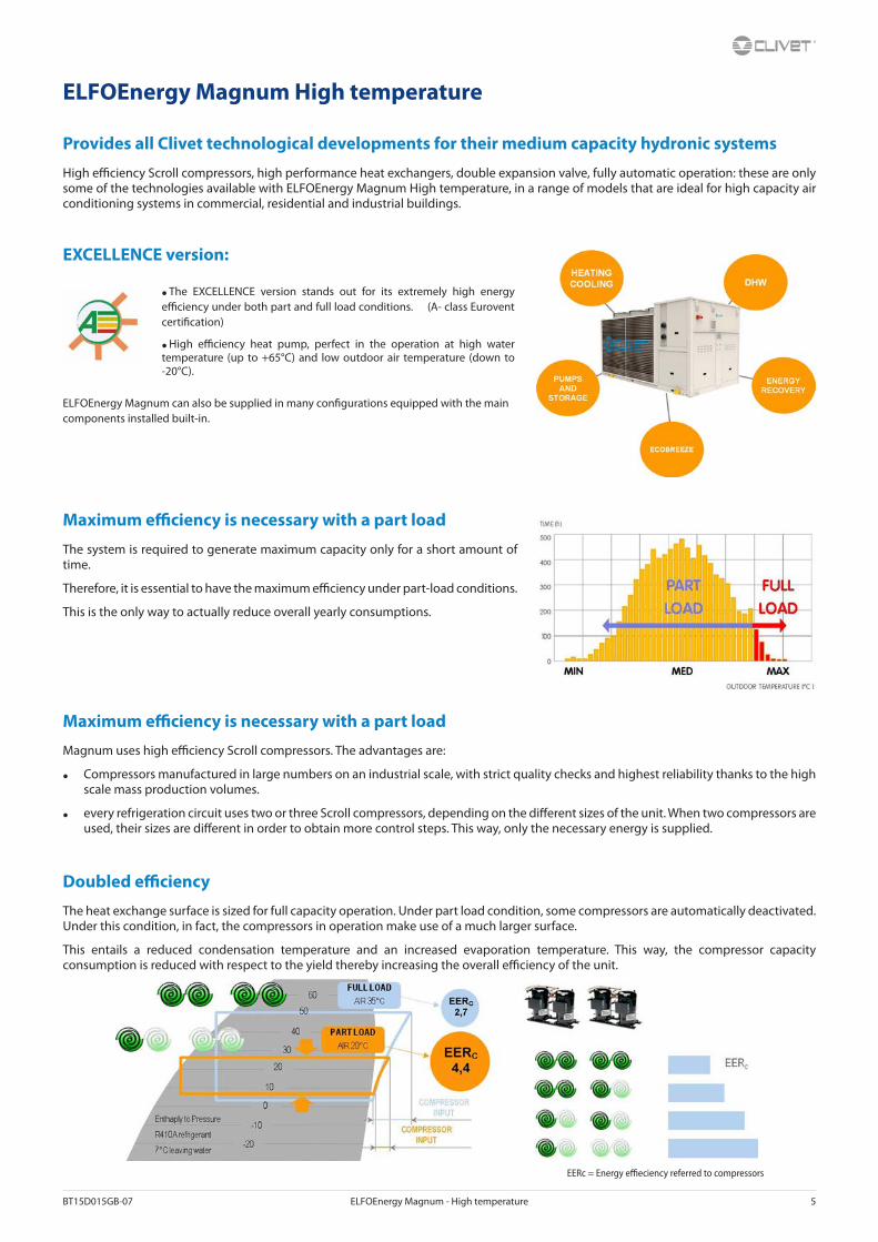
EXCELLENCE version:
• The EXCELLENCE version stands out for its extremely high energy e�ciency under both part and full load conditions. (A- class Eurovent certi�cation)
• High e�ciency heat pump, perfect in the operation at high water temperature (up to +65°C) and low outdoor air temperature (down to -20°C).
ELFOEnergy Magnum can also be supplied in many con�gurations equipped with the main components installed built-in.
Maximum e�ciency is necessary with a part load
The system is required to generate maximum capacity only for a short amount of time.
Therefore, it is essential to have the maximum e�ciency under part-load conditions.
This is the only way to actually reduce overall yearly consumptions.
Maximum e�ciency is necessary with a part load
Magnum uses high e�ciency Scroll compressors. The advantages are:
• Compressors manufactured in large numbers on an industrial scale, with strict quality checks and highest reliability thanks to the high scale mass production volumes.
• every refrigeration circuit uses two or three Scroll compressors, depending on the di�erent sizes of the unit. When two compressors are used, their sizes are di�erent in order to obtain more control steps. This way, only the necessary energy is supplied.
Doubled e�ciency
The heat exchange surface is sized for full capacity operation. Under part load condition, some compressors are automatically deactivated. Under this condition, in fact, the compressors in operation make use of a much larger surface.
This entails a reduced condensation temperature and an increased evaporation temperature. This way, the compressor capacity consumption is reduced with respect to the yield thereby increasing the overall e�ciency of the unit.
EERc = Energy e�eciency referred to compressors

6 ELFOEnergy Magnum - High temperature BT15D015GB-07
Superior �exibility and reliability
E�cient precision
Sequential activation of ELFOEnergy Magnum compressors allow:
• accurately following the load heating/cooling, supplying better comfort;
• reducing the number of compressor start-ups which is the main cause for wear and tear
• increasing the life cycle of the unit
• reducing time and costs for any repairs, thanks to the modularity of components, their reduced dimensions and the lower cost compared to semi-hermetic compressors.
Control of the refrigerant �ow
The load variability involves the continuous variation of the refrigerant volume moved by compressors.
The electronic expansion valve (EEV), standard on Clivet units, adapts rapidly and precisely to the actual load required for usage, allowing stable and reliable control in comparison with mechanical thermostatic valves (TEV). This results also in a further increase in e�ciency and longer compressor life.
The overheating control allows preventing phenomena that are hazardous to the compressors, such as overtemperature and return �uids, thereby increasing even more e�ciency and durability.
ECOBREEZE fans, electronically controlled (optional)
With ECOBREEZE, the electric motor with an external rotor is driven by the continuous magnetic switching of the stator, deriving from the integrated electronic control.
The advantages are:
• 70% increase in e�ciency thanks to the brushless technology and the special electricity supply;
• increase in the working life, thanks to the elimination of the brush wear;
• reduction in the electrical consumption by the system, thanks to a drastic reduction of the inrush current for the fans obtained using the integrated ‘Soft starter’ function.
Fans at variable speed for minimal noise emission
All units are supplied with a condensation electronic control. It automatically reduces the fan speed as the heat load drops. Since the fans are the unit’s main noise source, the bene�ts are evident especially during the night hours, when the load is reduced but sensitivity to noise is enhanced.
All this translates into a reduction of sound pressure down to 8 dB(A) compared to full load operation in 90% of operating time of the unit.
THE NUMBER OF START-UPS DECREASES THEREFORE THE LIFE CYCLE INCREASES

BT15D015GB-07 ELFOEnergy Magnum - High temperature 7
Water �ow-rate continuous modulation (optional)
The energy used for the vector pumping is fundamental on the seasonal e�ciency.
The VARYFLOW + modulating pumping unit made up of two pumps in parallel controlled by inverter, allows a precise water �ow-rate modulation reducing notably the consumptions and at the same time it guarantees its functionality also in case of temporary unavailability of one of the two pumps, guaranteeing about the 80% of the nominal �ow-rate.
The water �ow-rate is modulated by keeping the supply/return water temperature di�erential constant.
If the installation water temperature is in critical conditions, VARYFLOW+ allows to extend the ELFOEnergy Magnum operating ranges guaranteeing the operating.
In case of particular installation needs, the hydronic assemblies are also available:
• ON/OFF pump: the traditional solution with high available pressure.
• ON/OFF pump + ON/OFF pump in stand-by: the solution that favours reliability. The built-in control balances the operating hours of the two pump and in case of any failure it signals the damage and automatically activates the stand-by pump.
Built-in inertial accumulation available
In most Magnum systems it can be installed without inertial accumulation on the system. In fact, the unit quickly adapts to the load due to modular compressors, electronic thermostatic valve and low water content plate heat exchangers. However, in the event of hydraulic distribution networks with reduced dimensions, it is important to provide the system with a hydraulic �ywheel. In such cases, inertial accumulation is available built-in, equipped with insulating coating and all the necessary safety devices. This allows eliminating installation times and costs and freeing space inside the building.
Produces hot water freely
Condensation heat recovery:
• partial: it recovers about the 20% of the available heat (desuperheater)
It allows the free DHW production for:
• hot water coil supply for reheat
• domestic hot water production (with intermediate exchanger)
• other processes or operations

8 ELFOEnergy Magnum - High temperature BT15D015GB-07
Advanced control
The control system combines in a single solution the operating e�ciency and the user-friendliness.
Continuously monitoring all of the unit operating parameters, it ensures the maintenance of an optimal energy e�ciency.
The control includes many safety functions and a complete alarm management.
It also includes advanced functions, such as daily and weekly programming and automatic maximum power consumption limitation (demand limit).
It allows the management of several units in cascade up to 1 master and 6 slave (Ecoshare)
The interface terminal is equipped with a backlit graphic display and a multifunction access keyboard. The multilevel menu is protected by di�erent passwords according to the type of user.
Smart management of defrosts
The automatic defrost cycles on the remaining external exchanger surface are managed in ALTERNATED mode for each refrigeration circuit, guaranteeing the 50% of the delivered capacity. The built-in electronic control analyzes not only the external conditions but also the evaporating pressure variations in the exchanger.
Coils protected against the formation of ice
The particular technology of the heat pump developed by Clivet guarantees its continued and reliable operation.
The ICE PROTECTION SYSTEM device prevents icing on the base of the external exchanger during winter operation, thanks to a special subcooling circuit. This prevents damages caused by freezing.
Even for low water temperature
The unit is also perfectly adapted for use in process cooling where the low temperature version (Brine) together with the addition of glycol to the thermo-vector liquid produces chilled water down to –8 °C.

BT15D015GB-07 ELFOEnergy Magnum - High temperature 9
Remote system management
Magnum is standard equipped with:
• potential-free contact for remote on-o� control
• potential-free contacts for remote display of the compressor status
• setting from user interface: O� / local On / serial On
• potential-free contact to remote any possible alarm
The various communication protocols allow the unit to exchange information with the main supervision systems by means of serial connections.
Controlled power supply
Proper power supply ensures optimal unit operation and protects its many electrical components.
The phase monitor, standard supplied:
• controls the presence and the exact sequence of the phases
• checks any voltage anomalies (-10%)
• automatically restarts the unit as soon as the proper power supply is restored.
Modularity
In the event of particularly large buildings requiring high capacities, it is advisable to use several units.
The Magnum units are designed to be connected in parallel in modular logic, thereby granting the following advantages:
Increased �exibility, enhanced by the control that can adapt to the load.
Increased reliability, since the malfunction of one unit does not compromise the capacity supply of the other units.
Increased e�ciency, since energy is produced where and when required, according to the served area.
The microprocessor control combined with ECOSHARE allows controlling up to 7 units in local network (1 Master unit and 6 Slave).

10 ELFOEnergy Magnum - High temperature BT15D015GB-07
ELFOEnergy Magnum High temperatureSystem solutions:
Standard unit
• Production of chilled or hot water
Unit with Partial energy recovery option
• Production of chilled or hot water
• Free production of hot water from partial energy recovery
Unit with accessory User side DHW switching valve (supplied separately)
• Production of chilled or hot water
• Priority hot water production with User side DHW switching valve

BT15D015GB-07 ELFOEnergy Magnum - High temperature 11
Unit con�guration
(1) VoltageSupply voltage 400/3/50+N
(2) User side hydronic unitRefer to the diagrams of the hydronic assembly reported
(3) Partial recovery device(-) Not required (standard)D - Partial energy recovery
(4) Storage tank(-) Not required (standard)ACC - Storage tank
(5) Condensing coilCCS - Standard condenser coil (standard)CCCA - Copper / aluminium condenser coil with acrylic liningCCCA1 - Condenser coil with Energy Guard DCC Aluminum
(6) Soft starter(-) Not required (standard)SFSTR - Disposal for inrush current reduction
(7) Phase monitorPM - Phase monitor (standard)MF2 - Multi-function phase monitor
(8) Serial communication module(-) Not required (standard)CMSC8 - Serial communication module to BACnet supervisorCMSC9 - Serial communication module to Modbus supervisorCMSC10 - Serial communication module to LonWorks supervisor
(9) Power capacitors(-) Not required (standard)PFCP - Power factor correction capacitors (cos�>0.9)
(10) Protection grill(-) Not required (standard)PGFC - Finned coil protection grill
(11) High and low pressure gauges(-) Not required (standard)MHP - High and low pressure gauges
Functionalities Diagram hydronic assemblies
2 PIPE SYSTEM
Hot or chilled water production for installation
1.1Standard
unit(Std)
1.2Unit
with VARYFLOW+(VARYP)
1.3Unit
with one ON/OFF pump(HYG1)
1.4Unit
with two ON/OFF pumps(HYG2)
2 PIPE SYSTEM+
PARTIAL RECOVERY
Hot or chilled water production for installation
-Free production of hot water
from partial recovery
2.1Unit
with partial recovery(D)
2.2Unit
with partial recoveryand VARYFLOW+
(D+VARYP)
2.3Unit
with partial recovery and one ON/OFF pump
(D+HYG1)
2.4Unit
with partial recovery and two ON/OFF pumps
(D+HYG2)
Accessories separately supplied
• RCTX - Remote control
• BACX - BACnet serial communication module• CMMBX - Serial communication module to
supervisor (MODBUS)• CMSLWX - LonWorks serial communication
module
• PGFCX - Finned coil protection grill
• IFWX - Steel mesh strainer on the water side
• VACSUX - User side DHW switching valve
• AVIBX - Anti-vibration mount support
• MHPX - High and low pressure gauges

12 ELFOEnergy Magnum - High temperature BT15D015GB-07
General technical dataSize 35.4 40.4 45.4 50.4 55.4 60.4
Cooling (A35/W7)
Cooling capacity 1 kW 86,1 98,7 110 118 132 150
Compressor power input 1 kW 28,5 32,4 34,4 38,3 44,4 48,7
Total power input 2 kW 31,1 35,0 37,0 41,3 48,0 54,2
EER 1 2,77 2,82 2,98 2,87 2,74 2,77
Water �ow-rate 1 l/s 4,1 4,7 5,3 5,7 6,3 7,2
User side exchanger pressure drops 1 kPa 27,0 28,0 27,0 24,0 25,0 31,0
Cooling capacity (EN14511:2013) 3 kW 85,8 98,3 110 118 131 150
Total power input (EN14511:2013) 3 kW 31,5 35,4 37,5 41,7 48,4 54,8
EER (EN 14511:2013) 3 2,73 2,78 2,93 2,83 2,71 2,73
SEER 8 2,93 3,35 3,50 3,31 3,28 3,09
Heating (A7/W45)
Heating capacity 4 kW 109 122 133 143 164 184
Compressor power input 4 kW 28,7 31,6 34,7 38,0 43,9 48,1
Total power input 2 kW 31,3 34,2 37,3 41,0 47,5 53,6
COP 4 3,47 3,57 3,57 3,49 3,46 3,43
Water �ow-rate 4 l/s 5,2 5,8 6,4 6,8 7,8 8,8
User side exchanger pressure drops 4 kPa 41,0 42,0 38,0 35,0 37,0 46,0
Heating capacity (EN14511:2013) 5 kW 109 123 134 144 165 185
Total power input (EN14511:2013) 5 kW 31,8 34,9 37,9 41,6 48,2 54,5
COP (EN 14511:2013) 5 3,43 3,52 3,53 3,45 3,42 3,39
SCOP - AVERAGE Climate - W35 8 3,52 3,95 3,90 3,88 3,54 3,64
SCOP - AVERAGE Climate - W55 8 3,03 3,19 3,15 3,22 3,12 3,04
CompressorType of compressors SCROLLRefrigerant R-410ANo. of compressors No 4 4 4 4 4 4Std Capacity control steps No 4 4 6 4 4 4Oil charge (C1) l 3,5 6,5 6,5 6,5 6,5 6,5Oil charge (C2) l 3,5 6,5 6,5 6,5 6,5 6,5
Tot. refrigerant charge (C1) kg 20,0 22,0 22,0 23,0 28,0 30,0
Tot. refrigerant charge (C2) kg 20,0 22,0 23,0 23,0 28,0 30,0
Refrigeration circuits No 2 2 2 2 2 2Internal exchangerType of internal exchanger 6 PHENo. of internal exchangers No 1 1 1 1 1 1Water content l 6,8 7,7 8,9 10,1 11,4 11,4External Section FansType of fans 7 AXNumber of fans No 6 6 6 6 8 8
Standard air�ow l/s 16000 15567 15567 15567 20733 20733
Installed unit power kW 0,60 0,60 0,60 0,60 0,60 0,60ConnectionsWater �ttings 3” 3” 3” 3” 3” 3”Water circuitMax water side pressure Kpa 1000 1000 1000 1000 1000 100Safety valve calibration kPa 600 600 600 600 600 600Min. installation water contents l 350 390 360 450 530 590Power supplyStandard power supply V 400/3/50+N 400/3/50+N 400/3/50+N 400/3/50+N 400/3/50+N 400/3/50+N
The Product is compliant with the Erp (Energy Related Products) European Directive. It includes the Commission delegated Regulation (EU) No 811/2013 (rate heat output ≤70 kW at speci�ed reference conditions) and the Commission delegated Regulation (EU) No 813/2013 (rated heat output ≤400 kW at speci�ed reference conditions).‘Contains �uorinated greenhouse gases’(GWP 2087,5)1. Data referred to the following conditions: Internal exchanger water temperature = 12/7°C Entering external exchanger air temperature = 35°C2. The Total Power Input value does not take into account the part related to the pumps and required to overcome the pressure drops for the circulation of the solution inside the exchangers3. Data compliant to Standard EN 14511:2013 referred to the following conditions: - Internal exchanger water temperature = 12/7°C - Entering external exchanger air temperature = 35°C
4. Data referred to the following conditions: Internal exchanger water temperature = 40/45°C Entering external exchanger air temperature = 7°C D.B./6°C W.B5. Data compliant to Standard EN 14511:2013 referred to the following conditions: - Internal exchanger water temperature = 40/45 °C. Entering external exchanger air temperature = 7°C D.B./6°C W.B.6. PHE = Plate exchanger7. AX = Axial fan8. Data calculated according to the EN 14825:2016 Regulation

BT15D015GB-07 ELFOEnergy Magnum - High temperature 13
Electrical data
Supply voltage 400/3/50+N
Size 35.4 40.4 45.4 50.4 55.4 60.4
F.L.A. - Full load current at max admissible conditions
F.L.A. - Compressor 1 A 18,4 21,2 21,2 25,6 31,9 33,2
F.L.A. - Compressor 2 A 18,4 21,2 21,2 25,6 31,9 33,2
F.L.A. - Compressor 3 A 18,4 21,2 25,6 25,6 31,9 33,2
F.L.A. - Compressor 4 A 18,4 21,2 25,6 25,6 31,9 33,2
F.L.A. - Single External Fan A 2,60 2,60 2,60 2,60 2,60 2,60
F.L.A. - Total A 82,0 93,2 102 111 139 144
L.R.A. - Locked rotor amperes
L.R.A. - Compressor 1 A 128 118 118 140 174 174
L.R.A. - Compressor 2 A 128 118 118 140 174 174
L.R.A. - Compressor 3 A 128 118 140 140 174 174
L.R.A. - Compressor 4 A 128 118 140 140 174 174
L.R.A. - Single External Fan A 14,0 14,0 14,0 14,0 14,0 14,0
F.L.I. - Full load power input at max admissible conditions
F.L.I. - Compressor 1 kW 11,0 12,9 12,9 15,4 18,1 19,1
F.L.I. - Compressor 2 kW 11,0 12,9 12,9 15,4 18,1 19,1
F.L.I. - Compressor 3 kW 11,0 12,9 15,4 15,4 18,1 19,1
F.L.I. - Compressor 4 kW 11,0 12,9 15,4 15,4 18,1 19,1
F.L.I. - Single External Fan kW 0,60 0,60 0,60 0,60 0,60 0,60
F.L.I. - Total kW 46,1 53,7 58,7 63,7 75,1 79,1
M.I.C. Maximum inrush current
M.I.C. - Value A 191 190 216 225 280 284
M.I.C. with soft start accessory A 162 170 75,9 183 225 110
Power supply: 400/3/50 Hz. Voltage variation: max. +/-10%Voltage unbalance between phases: max 2 %for non standard voltage please contact Clivet technical o�ceThe units are compliant with the provisions of European standards CEI EN 60204 and CEI EN 60335.
Sound levels
Size
Sound power level (dB) Sound power
level
Sound pressure
levelOctave band (Hz)
63 125 250 500 1000 2000 4000 8000 dB(A) dB(A)
35.4 51 69 78 82 80 81 74 66 86 67
40.4 51 69 78 82 80 81 74 66 86 67
45.4 51 69 78 82 80 80 74 66 86 67
50.4 53 71 79 83 81 79 74 67 86 67
55.4 54 73 81 85 82 82 77 69 88 69
60.4 54 73 81 85 83 82 77 69 88 69
Sound levels refer to units with full load under nominal test conditions.The sound pressure level refers to a distance of 1 meter from the outer surface of the unit operating in open �eld.Noise levels are determined using the tensiometric method (UNI EN ISO 9614-2)Data referred to the following conditions:internal exchanger water = 12/7°Cambient temperature = 35 °C

14 ELFOEnergy Magnum - High temperature BT15D015GB-07
Operating RangeCooling
Size 35.4 Size 40.4 ÷ 60.4
Twu [°C] = Internal exchanger outlet water temperatureTae [°C] = External exchanger inlet air temperature
1. Standard unit operating range at full load2. Standard unit operating range with air �ow automatic modulation3. Operating range where the use of ethylene glycol is mandatory in relation to the temperature of the water at the outlet of the user side exchanger
Operating RangeHeating
Size 35.4 Size 40.4 ÷ 60.4
Twu [°C] = Internal exchanger outlet water temperatureTae [°C] = External exchanger inlet air temperature
1. Standard unit operating range at full load2. Standard unit operating range with air �ow automatic modulation3. Standard unit operating range at full load, not compatible with Clivet integrated pumping device (HYG1 - HYG2 - VARYP)
N.B: The domestic hot water production (that is with leaving water temperature = 65°C) is reached with a temperature di�erential of 7°C. The max water temperature allowed on return is 58°C.

BT15D015GB-07 ELFOEnergy Magnum - High temperature 15
Unit equipment with low outdoor temperatures
Minimum outdoor air tem-perature
Operating unit Unit in stand-by ***(fed unit)
Unit in storage(unit not fed)Cool* Heat**
+11°C
√ standard unit √ standard unit √ standard unit √ standard unit
+2°C
-5°C
-7°C
-10°C
Between –10°C and –15°C NOT POSSIBLE √ glycol in an appropriate percentage (1)
√ glycol in an appropriate percentage (1)
NOT POSSIBLE
Between –15°C and –20°C**** NOT POSSIBLE
√ glycol in an appropriate percentage (1)
X not compatible with Clivet integrated pumping device
√ glycol in an appropriate percentage (1)
X not compatible with Clivet integrated pumping device
NOT POSSIBLE
Data referred to the following conditions:* chilled water production: internal exchanger water = 12/7°C
** hot water production: internal exchanger water = 50/55 °C (for size 35.4, internal exchanger water = 40/45°C)
*** consider the unit powered electrically, with active control on pumping units. It is recommended to set a set-point value lower than standard (eco mode)
**** for size 35.4 minimum outdoor air temperature is between -15°C and -18°C
1. Operating range where the water pumping unit must be powered and always active, or with a periodical activation of the outdoor temperature operating pump to guarantee the correct unit operation.
At the unit start-up the water temperature or water with glycol must be inside the operating range indicated in the “Operating range” graph.To know the water freezing temperature on varying the glycol percentage refer to the speci�c ‘Correction factors for glycol use’ table.
Air conditions which are at rest are de�ned as the absence of air �owing towards the unit. Weak winds can induce air to �ow through the exchanger and air-levels which can cause a reduction in the operating range. In the presence of predominant winds it is necessary to use suitable windbreak barriers.

16 ELFOEnergy Magnum - High temperature BT15D015GB-07
Correction factors for glycol use% ethylene glycol by weight 5% 10% 15% 20% 25% 30% 35% 40%
Freezing temperature °C -2,0 -3,9 -6,5 -8,9 -11,8 -15,6 -19,0 -23,4
Safety temperature °C 3 1 -1 -4 -6 -10 -14 -19
Cooling Capacity Factor 0,995 0,990 0,985 0,981 0,977 0,974 0,971 0,968
Compressor power input Factor 0,997 0,993 0,990 0,988 0,986 0.984 0,982 0,981
Internal exchanger glycol solution �ow factor 1,003 1,010 1,020 1,033 1,050 1,072 1,095 1,124
Pressure drop Factor 1,029 1,060 1,090 1,118 1,149 1,182 1,211 1,243
The correction factors shown refer to water and glycol ethylene mixes used to prevent the formation of frost on the exchangers in the water circuit during inactivity in winter.
Fouling Correction FactorsInternal exchanger
m² °C/W F1 FK1
0,44 x 10^(-4) 1,0 1,0
0,88 x 10^(-4) 0,97 0,99
1,76 x 10^(-4) 0,94 0,98
F1 = Cooling capacity correction factorsFK1 = Compressor power input correction factor
Overload and control device calibrationsOpen Closed Value
High pressure switch kPa 4050 3300 -
Low pressure alarm (gas side) kPa 450 600 -
Antifreeze protection °C 4,0 6,0 -
High pressure safety valve (gas side) kPa - - 4500
Low pressure safety valve (gas side) kPa - - 3000
Max no. of compressor starts per hour (gas side) No - - 10
Di�erential pressure switch (water side) kPa 3 5 -
Max. pressure without hydronic assembly (water side) kPa - - 1000
Max. pressure with hydronic assembly (water side) kPa - - 600
Safety valve calibration (water side) (1) kPa - - 600
(1) Available only with hydronic assembly option
Integrated heating capacitiesAir temperature external exchanger inlet °C (B.S. / B.U) -10/-10,5 -5/-5,4 0/0,6 5/3,9 Others
Heating capacity multiplication coe�cient 0,90 0,89 0,88 0,91 1
To obtain the integrated heating capacities (the real heating capacity considering the defrost cycles too), multiply the kWt value in the heating performance tables by the following coe�cient.
BT15D015GB-07 ELFOEnergy Magnum - High temperature 17
Standard unit technical speci�cations
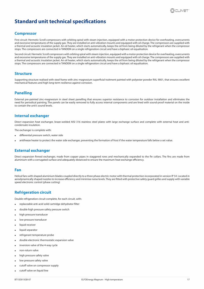
CompressorFirst circuit: Hermetic Scroll compressors with orbiting spiral with steam injection, equipped with a motor protection device for overheating, overcurrents and excessive temperatures of the supply gas. They are installed on anti-vibration mounts and equipped with oil charge. The compressors are supplied with a thermal and acoustic insulation jacket. An oil heater, which starts automatically, keeps the oil from being diluted by the refrigerant when the compressor stops. The compressors are connected in TANDEM on a single refrigeration circuit and have a biphasic oil equalisation.
Second circuit: Hermetic Scroll compressors with orbiting spiral with steam injection, equipped with a motor protection device for overheating, overcurrents and excessive temperatures of the supply gas. They are installed on anti-vibration mounts and equipped with oil charge. The compressors are supplied with a thermal and acoustic insulation jacket. An oil heater, which starts automatically, keeps the oil from being diluted by the refrigerant when the compressor stops. The compressors are connected in TANDEM on a single refrigeration circuit and have a biphasic oil equalisation.
StructureSupporting structure realised with steel frame with zinc-magnesium super�cial traitment painted with polyester powder RAL 9001, that ensures excellent mechanical features and high long-term resilience against corrosion.
PanellingExternal pre-painted zinc-magnesium in steel sheet panelling that ensures superior resistance to corrosion for outdoor installation and eliminates the need for periodical painting. The panels can be easily removed to fully access internal components and are lined with sound-proof material on the inside to contain the unit’s sound levels.
Internal exchangerDirect expansion heat exchanger, braze-welded AISI 316 stainless steel plates with large exchange surface and complete with external heat and anti-condensate insulation.
The exchanger is complete with:
• di�erential pressure switch, water side
• antifreeze heater to protect the water side exchanger, preventing the formation of frost if the water temperature falls below a set value.
External exchangerDirect expansion �nned exchanger, made from copper pipes in staggered rows and mechanically expanded to the �n collars. The �ns are made from aluminium with a corrugated surface and adequately distanced to ensure the maximum heat exchange e�ciency.
FanHelical fans with shaped aluminium blades coupled directly to a three phase electric motor with thermal protection incorporated in version IP 54. Located in aerodynamically shaped nozzles to increase e�ciency and minimise noise levels. They are �tted with protective safety guard grilles and supply with variable speed electronic control (phase cutting)
Refrigeration circuitDouble refrigeration circuit complete, for each circuit, with:
• replaceable anti-acid solid cartridge dehydrator �lter
• double high pressure safety pressure switch
• high pressure transducer
• low pressure transducer
• liquid receiver
• liquid separator
• refrigerant temperature probe
• double electronic thermostatic expansion valve
• inversion valve of the 4-way cycle
• non-return valve
• high pressure safety valve
• low pressure safety valve
• cuto� valve on compressor supply
• cuto� valve on liquid line

18 ELFOEnergy Magnum - High temperature BT15D015GB-07
Electrical panelThe capacity section includes:
• main door lock isolator switch
• isolating transformer for auxiliary circuit power supply
• on-o� “C1” and “C2” scroll compressor protection magnetothermic
• inverter scroll compressor protection fuses
• on-o� “C1” and “C2” scroll compressor control contactor
The control section includes:
• interface terminal with graphic display
• display of the set values, the error codes and the parameter index
• keys for ON/OFF control, cool and heat operating modes, alarm reset
• proportional-integral water temperature control
• daily, weekly programmer of temperature set-point and unit on/o�
• set point compensation in function of the outdoor air temperature
• set-point compensation with signal 0-10 V
• unit switching on management by local or remote (serial)
• antifreeze protection water side
• compressor overload protection and timer
• prealarm function for water antifreeze and high refrigerant gas pressure
• self-diagnosis system with immediate display of the fault code
• automatic rotation control for compressor starts
• compressor operating hour display
• input for remote ON/OFF control
• relay for remote cumulative fault signal
• inlet for demand limit (power input limitation according to a 0÷10V external signal)
• digital input for double set-point enabling
• potential-free contacts for compressor status
• phase monitor
• ECOSHARE function for the automatic management of a group of units
• 0÷10V signal output and potential-free contact for auxiliary heater
• enabling of DHW preparation in relation to remote consent
• numeration of electrical panel cables

BT15D015GB-07 ELFOEnergy Magnum - High temperature 19
Electronic control
Description of step start-up controlThe electronic control allows to manage the unit depending on the requested load.
The compressor power steps are activated to maximise e�ciency.
Main controlsLeaving water temperature control with PID algorithm: it keeps the leaving mean temperature to a set value.
• Auto-adaptive switching on di�erential: guarantees the compressors minimum operating time in systems with low water content.
• Condensation control based on pressure
• Pre-alarms at automatic reset: in case of alarm it is allowed a certain number of restarts before the de�nitive lock.
• Compressor operating hour calculation
• Compressor start calculation
• Control and continuous management of the compressor operating conditions to guarantee the unit operating also in extreme conditions
• Water temperature check (when used) to avoid the pipe freezing
• ”Anti-snow” function: in case of heavy snowfalls, it avoid the deposit of snow on fans
• Alarm log
• Autostart after voltage drop
• Local or remote control
Unit status displayBy the user interface is possible to display:
• unit operating status
• leaving/entering water temperature
• outdoor air temperature
• refrigeration circuit pressure and temperatures (circuit 1 and 2)
• signalling of alarms and anomalies in progress.
Probe, transducer and parameter displayA user interface dedicated section allows the maintenance or technical assistance personnel to control the unit operating stata.
This section is accessible only by specialized personnel.
Management of more units in cascade (ECOSHARE)It allows the management of several units hydraulically connected up to 1 master and 6 slave maximum.
Units must be of the same type: all reversible heat pumps, or all air-cooled liquid chiller.
Sizes can be di�erent.
The communication among the units is via a BUS serial cable allowing:
• supply water set-point setting of the slave units
• setting of logics that increase the system energy e�ciency
• unit operating hours balancing
• unit management in case of damage (only on slave unit)
• hydronic assembly switch-o� management of units not used
RCTX - Remote controlThe remote control allows the full control of all unit functions from remote position.
It can be easily installed on the wall and has the same aspect and functions of the user interface on the unit.

20 ELFOEnergy Magnum - High temperature BT15D015GB-07
Hydronic assembly con�guration 1.1Standard unitCon�guration without hydronic assembly, equipped with components as described on the water diagram key.
All water �ttings are Victaulic type. It is possible to control an external pump by an on/o� or 0-10V signal.
Internal exchanger pressure drop curves
To the internal exchanger pressure drops must be added the pressure drops of the steel mesh mechanical �lter that must be placed on the water input line. It is a device compulsory for the correct unit operation, and it is available as Clivet option (IFWX).
Admissible water �ow rates
Min. (Qmin) and max. (Qmax) water �ow-rates admissibles for the correct unit operation.
Grandezze 35.4 40.4 45.4 50.4 55.4 60.4
Qmin [l/s] 2,7 2,9 3,3 3,8 4,3 4,3
Qmax [l/s] 8,3 9,2 10,5 12,0 13,0 13,0
Water diagram
The pressure drops on the water side are calculated by considering an average water temperature at 7°C.
Q = Water �ow rate [l/s]DP = Pressure drops [kPa]
The water �ow rate must be calculated with the following formula
Q [l/s] = kWf / (4,186 x DT)
kWf = Cooling capacity in kWDT = Temperature di�erence between entering / leaving water
EVPT2 = Plate evaporator 2 circuits
R13 = Evaporator group heater
BT1 = Probes of entering water temperature
BT2 = Probes of leaving water temperature
SPA1 = Di�erential pressure switch water
BT15D015GB-07 ELFOEnergy Magnum - High temperature 21
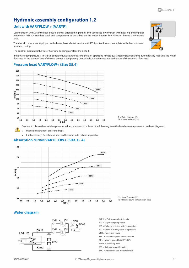
Hydronic assembly con�guration 1.2Unit with VARYFLOW + (VARYP)Con�guration with 2 centrifugal electric pumps arranged in parallel and controlled by inverter, with housing and impeller made with AISI 304 stainless steel, and components as described on the water diagram key. All water �ttings are Victaulic type.
The electric pumps are equipped with three-phase electric motor with IP55-protection and complete with thermoformed insulated casing.
The control, modulates the water �ow-rate keeping constant the delta T.
If the water temperature is in critical conditions, it allows to extend the unit operating ranges guaranteeing its operating, automatically reducing the water �ow-rate. In the event of one of the two pumps is temporarily unavailable, it guarantees about the 80% of the nominal �ow-rate.
Pressure head VARYFLOW+ (Size 35.4)
Caution: to obtain the available pressure values, you need to subtract the following from the head values represented in these diagrams:
• User side exchanger pressure drops
• IFVX accessory –Steel mesh �lter on the water side (where applicable)
Absorption curves VARYFLOW+ (Size 35.4)
Water diagram
Q = Water �ow rate [l/s]DP = Pressure head [kPa]
Q = Water �ow rate [l/s]Pe = Electric power consumption [kW]
EVPT2 = Plate evaporator 2 circuits
R13 = Evaporator group heater
BT1 = Probes of entering water temperature
BT2 = Probes of leaving water temperature
VNR = Non return valves
SPA1 = Di�erential pressure switch water
PU = Hydronic assembly VARYFLOW +
VSU = Water safety valve
R19 = Hydronic assembly heaters
SPA2 = Installation load pressure switch
22 ELFOEnergy Magnum - High temperature BT15D015GB-07
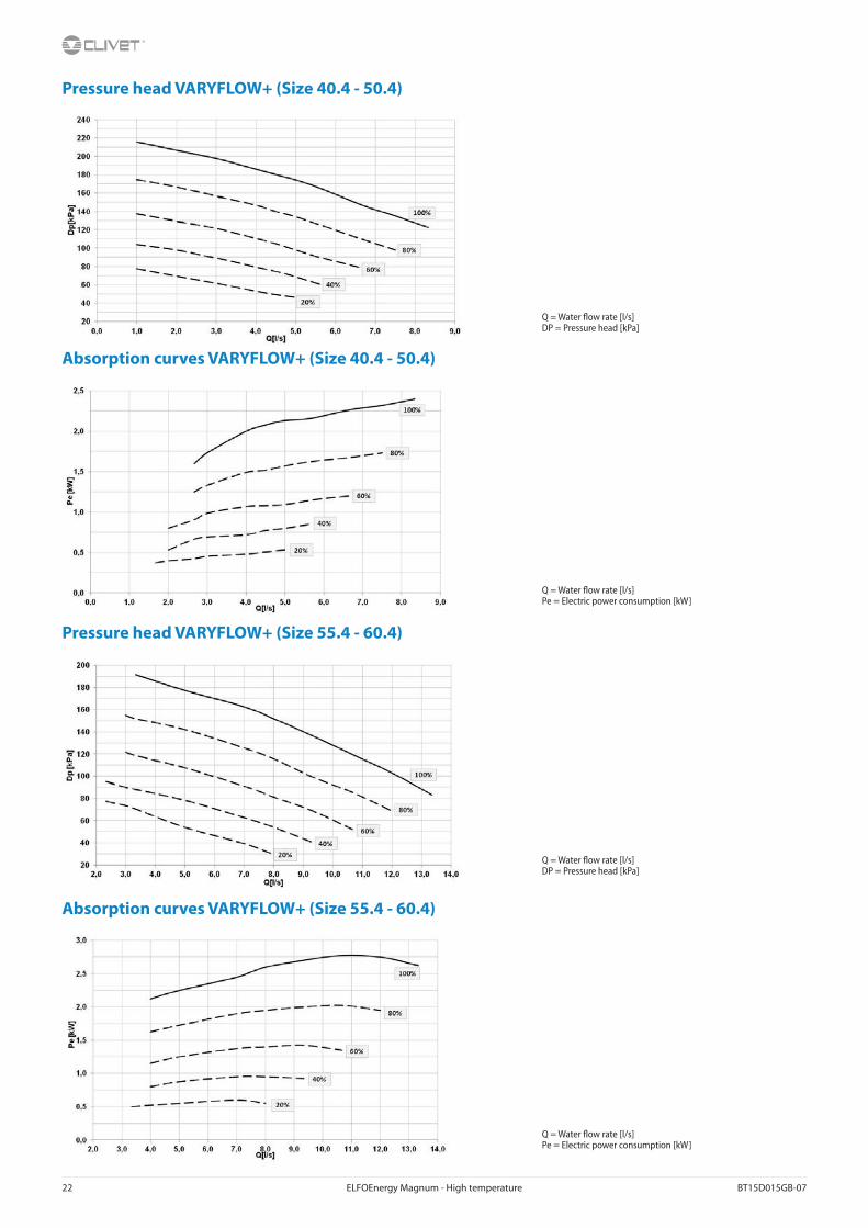
Pressure head VARYFLOW+ (Size 40.4 - 50.4)
Absorption curves VARYFLOW+ (Size 40.4 - 50.4)
Pressure head VARYFLOW+ (Size 55.4 - 60.4)
Absorption curves VARYFLOW+ (Size 55.4 - 60.4)
Q = Water �ow rate [l/s]DP = Pressure head [kPa]
Q = Water �ow rate [l/s]Pe = Electric power consumption [kW]
Q = Water �ow rate [l/s]DP = Pressure head [kPa]
Q = Water �ow rate [l/s]Pe = Electric power consumption [kW]

BT15D015GB-07 ELFOEnergy Magnum - High temperature 23
Hydronic assembly con�guration 1.3Unit with one ON/OFF pump (HYG1)Con�guration with 1 centrifugal electric pump, with housing and impeller made with AISI 304 stainless steel, and components as described on the water diagram key. All water �ttings are Victaulic type.
The electric pump is equipped with three-phase electric motor with IP55-protection and complete with thermoformed insulated casing.
ON/OFF pump pressure head (Size 35.4 - 60.4)
Caution: to obtain the available pressure values, you need to subtract the following from the head values represented in these diagrams:
• User side exchanger pressure drops
• IFVX accessory –Steel mesh �lter on the water side (where applicable)
ON/OFF pump absorption curves (Size 35.4 - 60.4)
Water diagram
Q = Water �ow rate [l/s]DP = Pressure head [kPa]
Q = Water �ow rate [l/s]Pe = Electric power consumption [kW]
EVPT2 = Plate evaporator 2 circuits
R13 = Evaporator group heater
BT1 = Probes of entering water temperature
BT2 = Probes of leaving water temperature
SPA1 = Di�erential pressure switch water
PU = Hydronic assembly 1 ON/OFF pump
VSU = Water safety valve
R19 = Hydronic assembly heaters
SPA2 = Installation load pressure switch
24 ELFOEnergy Magnum - High temperature BT15D015GB-07
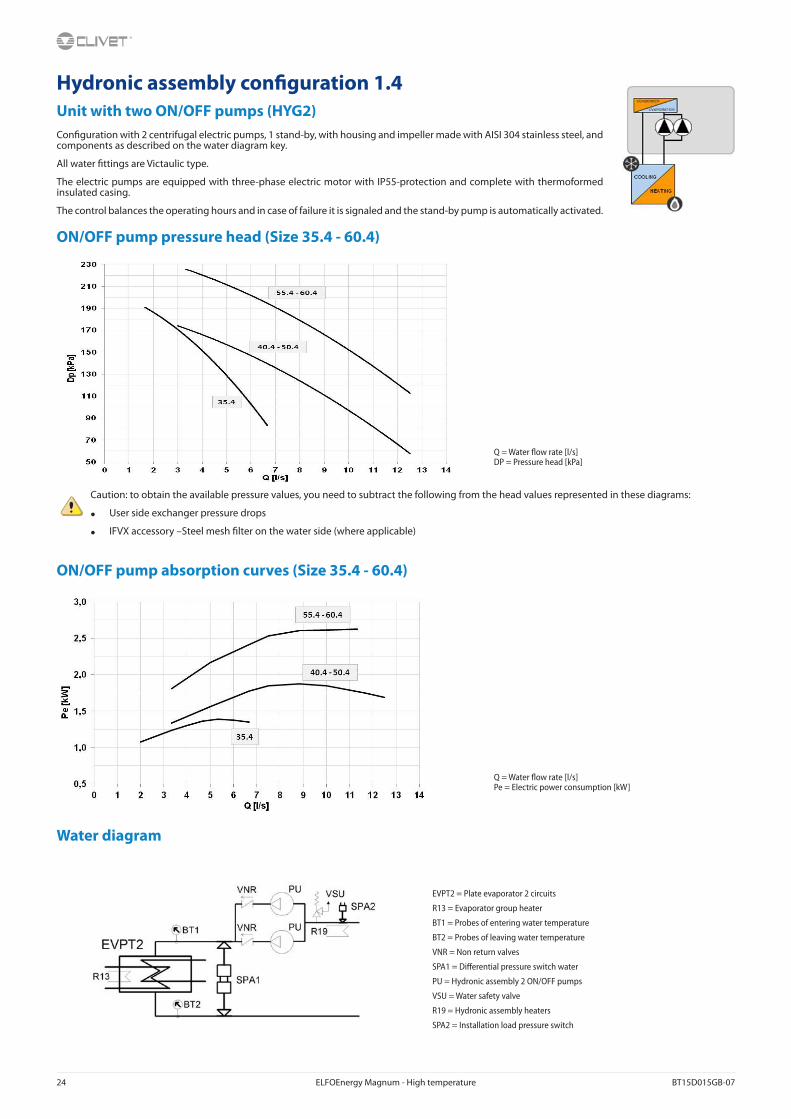
Hydronic assembly con�guration 1.4Unit with two ON/OFF pumps (HYG2)Con�guration with 2 centrifugal electric pumps, 1 stand-by, with housing and impeller made with AISI 304 stainless steel, and components as described on the water diagram key.
All water �ttings are Victaulic type.
The electric pumps are equipped with three-phase electric motor with IP55-protection and complete with thermoformed insulated casing.
The control balances the operating hours and in case of failure it is signaled and the stand-by pump is automatically activated.
ON/OFF pump pressure head (Size 35.4 - 60.4)
Caution: to obtain the available pressure values, you need to subtract the following from the head values represented in these diagrams:
• User side exchanger pressure drops
• IFVX accessory –Steel mesh �lter on the water side (where applicable)
ON/OFF pump absorption curves (Size 35.4 - 60.4)
Water diagram
Q = Water �ow rate [l/s]DP = Pressure head [kPa]
Q = Water �ow rate [l/s]Pe = Electric power consumption [kW]
EVPT2 = Plate evaporator 2 circuits
R13 = Evaporator group heater
BT1 = Probes of entering water temperature
BT2 = Probes of leaving water temperature
VNR = Non return valves
SPA1 = Di�erential pressure switch water
PU = Hydronic assembly 2 ON/OFF pumps
VSU = Water safety valve
R19 = Hydronic assembly heaters
SPA2 = Installation load pressure switch

BT15D015GB-07 ELFOEnergy Magnum - High temperature 25
Con�gurations - Partial energy recovery (D)Con�guration with one recovery side brazed stainless steel (316 AISI) plate exchanger, and components per the legend of the enclosed plumbing circuit diagram. All water �ttings are Victaulic type Ø 1 1/2”.
A con�guration which enables the production of hot water free-of-charge while operating in the cooling mode, thanks to the partial recovery of condensation heat that would otherwise be rejected to the external heat source. It is possible to recovery about 20% of the unit rejected heating capacity equal to the sum of the cooling capacity and the compressor power input.
The partial recovery device is considered to be operating when it is powered by the water �ow which is to be heated. This condition improves the unit performance, since it reduces the condensation temperature: in nominal conditions the cooling capacity increases indicatively by 3.2% and the power input of the compressors is reduced by 3.6%.
If cold water production is not requested, the unit can not produce hot water. The heating capacity request is made by the digital contact enabling, that activates the pump recovery side (outside the unit)
The partial energy recovery option (D) can be matched to the hydronic assemblies user side indicated in the previous pages according to the diagrams below.
D D+VARYP D+HYG1 D+HYG2
Partial energy recovery pressure drop curves
Partial recovery heating capacity Water diagram
The pressure drops on the water side are calculated by considering an average water temperature at 7°C.
Q = Water �ow rate [l/s]DP = Pressure drops [kPa]
kWde/kWf = Heat recovered/Cooling capacity [%]Tde = Heat recovering device outlet water temperature [°C] IN = Recovery side inlet
OUT = Recovery side outletSC = Plate heat exchangers

26 ELFOEnergy Magnum - High temperature BT15D015GB-07
Built-in con�guration options
ACC - Storage tankOption supplied built-in the unit. Steel storage tank complete with double layer covering with closed-cell insulation, stainless steel anti-freeze immersion resistance, bleed valve, draw o� cock, cast-iron shut-o� butter�y valve with quick connections and activation lever with a mechanical calibration lock at the evaporator output, quick connections with insulated casing.
For size 35.4 ÷ 60.4 the storage tank capacity is 300L.
CCCA - Copper / aluminium condenser coil with acrylic liningCoils with copper pipes and aluminium �ns with acrylic lacquering. Can be used in settings with moderately aggressive saline concentrations and other chemical agents.
Attention!
• Cooling capacity variation -2.7%
• Variation in compressor power input +4.2%
• Operating range reduction -2.1°C
CCCA1 - Condenser coil with Energy Guard DCC AluminumA treatment which o�ers an optimal thermal exchange and guarantees and protects the �nned coil exchangers from corrosion over time. Can be used in settings with very aggressive saline concentrations and other chemical agents in the air thus maintaining the performance of the coils over time.
SFSTR - Disposal for inrush current reductionElectronic device that automatically and gradually starts the compressors, thereby reducing the current peak generated in star-triangle start-ups and therefore reduces the mechanical stress on the motor and the electrodynamic stress on the power cables and on the mains.
MF2 - Multi-function phase monitorThe multifunction phase monitor controls all phases and their sequence, checks for voltage anomalies (+/–10%), and automatically restores operation of the unit as soon as the power supply returns to normal.
This control allows to:
• protect the internal components of the unit, which are powered by an abnormal voltage, may operate incorrectly or break;
• quickly identify, among the alarms of the unit’s components, the real cause of the malfunction due to the sudden change in voltage.
MHP - High and low pressure gaugesDespite the unit already enabling a series of digital displays on the operating pressure of the refrigeration circuit, this option enables analogical measuring of refrigerant pressures at compressor intake and supply thus easing the checking of these parameters for the technicians who are managing the unit. The two liquid pressure gauges and related pressure sensors are attached built-in in easily accessible positions.

BT15D015GB-07 ELFOEnergy Magnum - High temperature 27
CMSC8 - Serial communication module to BACnet supervisorThis enables the serial connection of the supervision system, using Modbus as the communication protocol. It enables access to the complete list of operational variables, commands and alarms. Using this accessory every unit can dialogue with the main supervision systems.
The device is installed and wired built-in the unit.
The con�guration and management activities for the BACnet networks are the responsibility of the client.
The total length of each serial line do not exceed 1000 meters and the line must be connected in bus typology (in/out)
CMSC9 - Serial communication module to Modbus supervisorThis enables the serial connection of the supervision system, using Modbus as the communication protocol. It enables access to the complete list of operational variables, commands and alarms. Using this accessory every unit can dialogue with the main supervision systems.
The device is installed and wired built-in the unit.
The total length of each serial line do not exceed 1000 meters and the line must be connected in bus typology (in/out)
CMSC10 - Serial communication module to LonWorks supervisorThis enables the serial connection of the supervision system which uses the LonWorks communication protocol. It enables access to a list of operating variables, commands and alarms which comply with the Echelon® standard.
The device is installed and wired built-in the unit.
The con�guration and management activities for the LonWorks networks are the responsibility of the client.
LonWorks technology uses the LonTalk® protocol for communicating between the network nodes. Contact the service supplier for further information.
PFCP - Power-factor correction capacitors (cos� >0,9)The component is necessary to lower the phase di�erence between current and voltage in the electromagnetic components of the unit (e.g. asynchronous motors). The component allows to put the cos� power factor to values on average higher than 0.9, reducing the network reactive power. This often leads to an economic bene�t which the energy provider grants to the �nal user.
PGFC - Finned coil protection grillThis accessory is used to protect the external coil from the accidental contact with external things or people. Ideal for installation in places where persons can pass from, such as car parks, terraces, etc.
28 ELFOEnergy Magnum - High temperature BT15D015GB-07
Accessories separately supplied
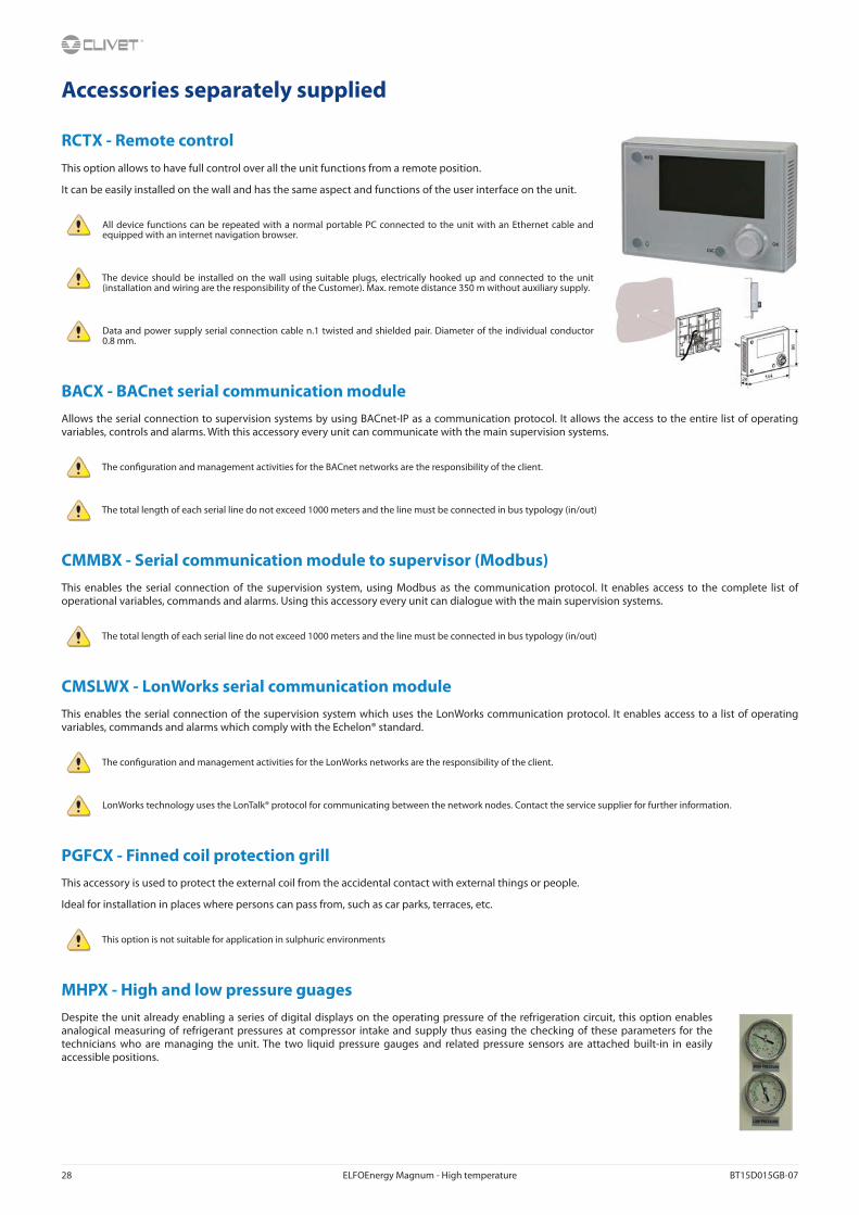
RCTX - Remote controlThis option allows to have full control over all the unit functions from a remote position.
It can be easily installed on the wall and has the same aspect and functions of the user interface on the unit.
All device functions can be repeated with a normal portable PC connected to the unit with an Ethernet cable and equipped with an internet navigation browser.
The device should be installed on the wall using suitable plugs, electrically hooked up and connected to the unit (installation and wiring are the responsibility of the Customer). Max. remote distance 350 m without auxiliary supply.
Data and power supply serial connection cable n.1 twisted and shielded pair. Diameter of the individual conductor 0.8 mm.
BACX - BACnet serial communication moduleAllows the serial connection to supervision systems by using BACnet-IP as a communication protocol. It allows the access to the entire list of operating variables, controls and alarms. With this accessory every unit can communicate with the main supervision systems.
The con�guration and management activities for the BACnet networks are the responsibility of the client.
The total length of each serial line do not exceed 1000 meters and the line must be connected in bus typology (in/out)
CMMBX - Serial communication module to supervisor (Modbus)This enables the serial connection of the supervision system, using Modbus as the communication protocol. It enables access to the complete list of operational variables, commands and alarms. Using this accessory every unit can dialogue with the main supervision systems.
The total length of each serial line do not exceed 1000 meters and the line must be connected in bus typology (in/out)
CMSLWX - LonWorks serial communication moduleThis enables the serial connection of the supervision system which uses the LonWorks communication protocol. It enables access to a list of operating variables, commands and alarms which comply with the Echelon® standard.
The con�guration and management activities for the LonWorks networks are the responsibility of the client.
LonWorks technology uses the LonTalk® protocol for communicating between the network nodes. Contact the service supplier for further information.
PGFCX - Finned coil protection grillThis accessory is used to protect the external coil from the accidental contact with external things or people.
Ideal for installation in places where persons can pass from, such as car parks, terraces, etc.
This option is not suitable for application in sulphuric environments
MHPX - High and low pressure guagesDespite the unit already enabling a series of digital displays on the operating pressure of the refrigeration circuit, this option enables analogical measuring of refrigerant pressures at compressor intake and supply thus easing the checking of these parameters for the technicians who are managing the unit. The two liquid pressure gauges and related pressure sensors are attached built-in in easily accessible positions.

BT15D015GB-07 ELFOEnergy Magnum - High temperature 29
IFWX - Steel mesh strainer on the water sideThe device prevents any impurity in the hydraulic circuit from soiling the exchanger. The stainless steel mesh mechanical �lter must be placed on the water inlet line. It needs to be easy to remove for periodical maintenance and cleaning operations.
Moreover, it consists of:
• cast-iron shut-o� butter�y valve with quick coupling and throttle drive and mechanical calibration stop
• quick couplings with an insulated casing
Steel mesh strainer pressure drops
AVIBX - Anti-vibration mount supportThe spring antivibration mounts are attached in special housing on the support frame and serve to smooth the vibrations produced by the unit thus reducing the noise transmitted to the support structure.
VACSUX - User side DHW switching valveThe DHW switching valve user side is supplied as accessory separated from the unit. The unit controller closes a digital output to control the DHW switching valve from the installation to the storage tank up to the DHW set point reaching.For sizes from 35.4 to 60.4 the DHW switching valve is 3”.The DHW switching valve has a IP 40 protection degree.
It is therefore compulsory that client provides a protection for the external liquid valve.
DHW switching valve pressure drops
Q = Water �ow rate [l/s]DP = Water side pressure drops [kPa]
Q = Water �ow rate [l/s]DP = Water side pressure drops [kPa]

30 ELFOEnergy Magnum - High temperature BT15D015GB-07
Heating Performance
Size Tae (°C)D.B/W.B.
Leaving internal exchanger water temperature (°C)
35 40 45 50 55 60 65*
kWt kWe kWt kWe kWt kWe kWt kWe kWt kWe kWt kWe kWt kWe
35.4
-15 / -15.4 65,2 20,9 66,7 23,2 67,7 25,7 68,1 28,8 - - - - - --7 / -8 78,7 21,8 80,1 24,2 80,9 26,9 81,6 30,1 82,3 33,3 86,2 37,3 - -
-5 / -5.4 82,9 22,0 84,2 24,4 85,1 27,2 85,7 30,5 86,4 33,7 90,4 37,7 - -0 / -1 92,1 22,5 93,2 25,0 94,2 27,8 94,7 31,2 95,2 34,6 99,6 38,6 102 41,87 / 6 107 23,2 108 25,7 108 28,7 109 32,2 109 35,7 115 39,9 117 43,2
15 / 12 126 23,8 126 26,4 126 29,4 125 33,0 125 36,6 132 41,0 135 44,3
40.4
-15 / -15.4 73,9 24,5 75,0 27,5 75,8 30,9 76,7 35,5 77,7 40,1 81,2 46,2 - --7 / -8 89,2 24,9 90,2 27,9 91,0 31,3 91,9 35,9 92,8 40,5 97,9 46,6 99,9 50,3
-5 / -5.4 94,1 24,9 95,3 28,0 95,8 31,4 96,5 36,0 97,3 40,6 103 46,7 105 50,40 / -1 104 25,0 106 28,1 106 31,6 107 36,2 107 40,8 113 46,9 115 50,77 / 6 121 24,9 122 28,1 122 31,6 122 36,4 123 41,1 130 47,1 132 50,9
15 / 12 141 24,4 141 27,7 140 31,5 140 36,3 141 41,2 149 47,2 152 51,0
45.4
-15 / -15.4 80,3 26,7 81,6 30,0 82,6 33,2 84,7 38,1 86,8 43,0 90,0 48,5 - --7 / -8 96,8 27,0 98,2 30,5 99,3 34,3 100 39,0 101 43,8 106 49,6 108 53,6
-5 / -5.4 102 27,0 103 30,5 105 34,4 105 39,2 106 44,1 111 50,2 113 54,20 / -1 113 27,0 115 30,6 115 34,6 116 39,6 117 44,6 123 50,9 125 55,07 / 6 131 26,8 132 30,5 133 34,7 133 39,8 134 45,0 141 51,4 144 55,6
15 / 12 153 26,5 153 30,1 153 34,4 153 39,7 153 45,0 162 51,7 165 55,9
50.4
-15 / -15.4 86,7 29,1 88,4 32,6 89,4 36,3 90,2 40,7 90,9 45,2 94,2 51,0 - --7 / -8 104 29,6 106 33,4 107 37,6 109 42,6 110 47,7 115 54,0 117 58,4
-5 / -5.4 110 29,6 111 33,4 113 37,7 114 42,9 115 48,1 121 54,5 123 58,90 / -1 121 29,5 123 33,5 124 38,0 126 43,5 127 48,9 134 55,7 137 60,27 / 6 140 29,4 142 33,3 143 38,0 144 43,7 145 49,4 154 56,5 157 61,1
15 / 12 163 29,3 164 33,1 164 37,8 164 43,7 165 49,6 175 56,9 178 61,5
55.4
-15 / -15.4 99,0 33,7 101 37,6 102 41,9 104 47,8 106 53,7 111 61,4 - --7 / -8 119 34,1 121 38,0 122 42,4 124 48,3 125 54,3 133 62,3 134 62,3
-5 / -5.4 126 34,2 128 38,2 129 42,6 130 48,6 131 54,7 140 62,6 141 62,70 / -1 140 34,6 141 38,6 142 43,1 143 49,3 144 55,4 154 63,5 156 63,67 / 6 162 34,9 164 39,1 164 43,9 165 50,4 166 56,9 176 64,9 178 64,9
15 / 12 189 34,9 190 39,4 189 44,6 190 51,5 191 58,3 204 66,7 206 66,8
60.4
-15 / -15.4 111 37,2 113 41,5 114 46,4 114 52,3 115 58,2 123 67,7 - --7 / -8 135 37,7 136 42,0 137 46,9 138 53,4 139 59,9 147 68,6 150 74,1
-5 / -5.4 142 37,9 143 42,1 144 47,1 145 53,6 146 60,1 155 68,8 158 74,40 / -1 158 38,2 159 42,5 159 47,4 160 54,0 161 60,7 170 69,3 174 75,07 / 6 184 38,8 184 43,1 184 48,1 185 54,8 185 61,6 197 70,2 200 75,9
15 / 12 216 39,6 215 43,8 213 49,0 213 55,8 213 62,6 228 71,4 232 77,2
kWt = Internal exchanger heating capacity (kW)kWe = Compressor power input (kW)Tae [°C] = Entering external exchanger air temperaturePerformances in function of the entering/leaving water temperature di�erential = 5°C* Performances in function of the entering/leaving water temperature di�erential = 7°C

BT15D015GB-07 ELFOEnergy Magnum - High temperature 31
Cooling Performance
Size To(°C)
Entering external exchanger air temperature (C°)
25 30 35 40 43 46
kWf kWe kWf kWe kWf kWe kWf kWe kWf kWe kWf kWe
35.4
5 85,6 22,9 83,3 25,5 81,1 28,4 78,8 31,6 77,1 34,1 75,3 36,77 90,3 23,3 88,1 25,9 86,1 28,5 83,3 32,5 81,4 34,9 79,6 37,3
10 98,3 23,8 95,9 26,4 93,5 29,3 90,5 32,9 88,3 35,6 86,1 38,212 104 24,0 101 26,7 98,5 29,9 95,3 33,2 92,9 36,0 90,5 38,815 110 24,8 108 27,5 105 30,8 101 34,2 98,6 37,4 95,8 40,518 118 25,3 115 28,4 112 31,4 108 35,3 106 38,1 103 40,8
40.4
5 99,7 24,8 96,7 28,3 93,2 32,1 89,6 36,6 86,5 40,5 83,4 44,5
7 105 25,0 102 28,5 98,7 32,4 94,6 37,3 91,4 41,5 88,1 45,610 113 25,4 109 28,8 106 33,0 101 38,0 98,2 41,9 95,0 45,912 118 25,6 114 29,0 110 33,4 106 38,5 103 42,3 99,7 46,015 126 25,7 122 29,5 118 33,7 114 39,0 109 43,9 104 48,918 135 25,7 131 29,4 126 34,4 121 39,6 117 44,1 112 48,5
45.4
5 111 26,3 107 30,4 104 34,6 101 39,4 97,6 43,7 94,4 48,07 117 26,3 114 30,4 110 34,4 106 39,9 103 43,9 100 47,9
10 126 26,8 123 30,6 119 34,8 115 40,3 111 44,7 108 49,012 132 27,0 129 30,7 125 35,0 121 40,5 117 45,2 113 49,815 141 27,0 138 30,9 133 35,7 129 40,8 124 45,8 120 50,718 150 27,3 146 31,1 142 35,8 137 41,5 132 46,5 127 51,4
50.4
5 118 29,6 115 33,8 112 38,5 109 44,0 105 48,8 102 53,67 125 29,7 122 34,1 118 38,3 115 44,4 111 48,9 108 53,5
10 135 30,1 132 34,3 128 39,0 123 45,2 120 49,9 116 54,712 142 30,4 138 34,4 134 39,4 129 45,7 126 50,6 122 55,515 151 31,2 147 35,2 143 39,9 138 46,4 132 52,8 127 59,118 160 31,8 156 36,2 152 41,0 147 47,0 141 52,9 136 58,8
55.4
5 131 33,8 128 38,4 125 43,3 121 49,0 118 54,1 114 59,17 138 34,3 135 38,8 132 44,4 127 50,4 124 55,8 120 61,3
10 148 34,6 145 39,3 141 44,8 136 51,3 133 56,4 129 61,612 155 34,7 152 39,6 147 45,1 142 51,9 139 56,9 135 61,815 165 35,4 161 40,4 157 46,4 152 52,7 147 58,7 142 64,818 177 35,7 172 41,4 168 47,0 162 54,5 157 60,6 152 66,6
60.4
5 150 37,9 146 42,4 141 48,0 137 54,1 134 59,0 130 64,07 159 38,6 155 43,0 150 48,7 145 54,8 141 60,5 137 66,1
10 170 39,1 165 43,8 161 49,5 156 55,7 151 61,5 147 67,312 177 39,5 172 44,4 168 50,0 162 56,3 158 62,2 153 68,115 189 40,5 184 45,2 179 50,9 173 57,9 169 63,6 164 69,218 202 41,8 197 46,5 192 52,6 186 59,0 180 66,4 173 73,8
kWf = Internal exchanger cooling capacity (kW)kWe = Compressor power input (kW)To (°C) = Leaving internal exchanger water temperature (°C)Performances in function of the entering/leaving water temperature di�erential = 5°C

32 ELFOEnergy Magnum - High temperature BT15D015GB-07
Dimensional drawings
Size 35.4 - 40.4 - 45.4 - 50.4
1) External exchanger2) Unit �xing holes Ø 253) Lifting brackets (Removable)4) Electrical panel5) Power input6) Clearance access recommended7) Water inlet user side of no pumps unit / Water inlet user side of unit with pumps (optional) Ø 3”8) Water outlet user side of no pumps unit / Water outlet user side of unit with pumps (optional) Ø 3”9) Recovery side exchanger water inlet (optional) Ø 1 1/2”10) Recovery side exchanger water outlet (optional) Ø 1 1/2”
Size 35.4 40.4 45.4 50.4
Length mm 3400 3400 3400 3400
Height mm 1800 1800 1800 1800
Depth mm 1812 1812 1812 1812
W1 Support point kg 472 521 529 531
W2 Support point kg 167 184 187 187
W3 Support point kg 500 552 561 563
W4 Support point kg 177 195 198 199
Operation weight kg 1285 1418 1441 1444
Shipping weight kg 1315 1451 1475 1479
The presence of optional accessories may result in a substantial variation of the weights shown in the table.
DAAL 535.4_50.4 _0 REV00Data/Date 31/07/2015

BT15D015GB-07 ELFOEnergy Magnum - High temperature 33
Size 55.4 - 60.4
1) External exchanger2) Unit �xing holes Ø 253) Lifting brackets (Removable)4) Electrical panel5) Power input6) Clearance access recommended7) Water inlet user side of no pumps unit / Water inlet user side of unit with pumps (optional) Ø 3”8) Water outlet user side of no pumps unit / Water outlet user side of unit with pumps (optional) Ø 3”9) Recovery side exchanger water inlet (optional) Ø 1 1/2”10) Recovery side exchanger water outlet (optional) Ø 1 1/2”
Size 55.4 60.4
Length mm 4400 4400
Height mm 1800 1800
Depth mm 1812 1812
W1 Support point kg 593 595
W2 Support point kg 228 229
W3 Support point kg 686 687
W4 Support point kg 264 264
Operation weight kg 1735 1739
Shipping weight kg 1772 1776
The presence of optional accessories may result in a substantial variation of the weights shown in the table.
DAAL 555.4_60.4 _0 REV00Data/Date 31/07/2015

Page intentionally left blank
34 ELFOEnergy Magnum - High temperature BT15D015GB-07

Page intentionally left blank
BT15D015GB-07 ELFOEnergy Magnum - High temperature 35

w w w . c l i v e t . c o mw w w.cl ivet l ive.com
A Group Company of
CLIVET SPAVia Camp Lonc 25, Z.I. Villapaiera - 32032 Feltre (BL) - Italy Tel. + 39 0439 3131 - Fax + 39 0439 313300 - [email protected]
CLIVET GROUP UK LIMITED 4 Kingdom Close, Segensworth East - Fareham, Hampshire - PO15 5TJ - United KingdomTel. + 44 (0) 1489 572238 - Fax + 44 (0) 1489 573033 - [email protected]
CLIVET GROUP UK Limited (Service Department)Units F5&F6 Railway Triangle Ind Est, Walton Road - Portsmouth, Hampshire - PO6 1TG - United KingdomTel. +44 (0) 2392 381235 - Fax. +44 (0) 2392 381243 - [email protected]
CLIVET ESPAÑA S.A.U.C/ Bac de Roda, 36 - 08019 Barcelona - EspañaTel: +34 93 8606248 - Fax +34 93 8855392 - [email protected]
Av.Manoteras Nº 38, Oficina C303 - 28050 Madrid - EspañaTel. +34 91 6658280 - Fax +34 91 6657806 - [email protected]
CLIVET GmbH (Hydronic and Applied Division)Hummelsbütteler Steindamm 84, 22851 Norderstedt - GermanyTel. + 49 (0) 40 32 59 57-0 - Fax + 49 (0) 40 32 59 57-194 - [email protected]
CLIVET GmbH (VRF, Residential and Lightcom Division)Eisenstrasse 9c, 65428 Rüsselsheim/Frankfurt - GermanyTel. + 49 (0) 6142 83594-0 - Fax + 49 (0) 6142 83594-20 - [email protected]
CLIVET RUSSIA Elektrozavodskaya st. 24, office 509 - 107023, Moscow, RussiaTel. + 74956462009 - Fax + 74956462009 - [email protected]
CLIVET MIDEAST FZCODubai Silicon Oasis (DSO), High Bay Complex, Office N. 20, PO BOX 342009, Dubai, UAE Tel. + 9714 3208499 - Fax + 9714 3208216 - [email protected]
CLIVET AIRCONDITIONING SYSTEMS PRIVATE LIMITED4BA, Gundecha Onclave, Kherani Road - Sakinaka, Andheri (East) - Mumbai 400 072 - IndiaTel. +91 22 6193 7000 - Fax +91 22 6193 7001 - [email protected]