D11.5.pdf - Optique
147
Project N o : FP7-318338 Project Acronym: Optique Project Title: Scalable End-user Access to Big Data Instrument: Integrated Project Scheme: Information & Communication Technologies Deliverable D11.5 Standards for Optique Due date of deliverable: (T0+48) Actual submission date: November 15, 2016 Start date of the project: 1st November 2012 Duration: 48 months Lead contractor for this deliverable: UOXF Dissemination level: PU – Public Final version
-
Upload
khangminh22 -
Category
Documents
-
view
2 -
download
0
Transcript of D11.5.pdf - Optique

Project No: FP7-318338
Project Acronym: Optique
Project Title: Scalable End-user Access to Big Data
Instrument: Integrated Project
Scheme: Information & Communication Technologies
Deliverable D11.5Standards for Optique
Due date of deliverable: (T0+48)
Actual submission date: November 15, 2016
Start date of the project: 1st November 2012 Duration: 48 months
Lead contractor for this deliverable: UOXF
Dissemination level: PU – Public
Final version

Executive Summary:Standards for Optique
This document summarises deliverable D11.5 of project FP7-318338 (Optique), an Integrated Project sup-ported by the 7th Framework Programme of the EC. Full information on this project, including the contentsof this deliverable, is available online at http://www.optique-project.eu/.
This deliverable presents the Optique proposal for an OWL 2 DL version of the industry standardISO 15926 to enable industrial OBDA applications. This upper ontology is directly impacting an ongoingstandardisation process within ISO. We also present ontology work on industrial standards that are currentlyin use in Siemens.
Furtner, we discuss limitations of existing standards for OBDA components and present our solutions thatwe believe should establish best practices and lead to new international standards. In particular, we developedOBDA ontology languages that are beyond the standardised OWL 2 QL and OBDA query languages that arebeyond the standard SPARQL and SQL. Then, we developed OBDA bootstrapping techniques that wouldhelp in standardising how to extract ontologies from relational databases and benchmarking that wouldhelp in standardising comparison of various bootstrapping systems. Moreover, for OBDA query formulationwe proposed ontology projection techniques that allow for graph navigation over ontologies as well as avisualisation approach that allows effective query formulation.
List of AuthorsJohan W. Klüwer (DNV)Arild Waaler (UiO)Ernesto Jimenez Ruiz (UOXF, UiO)Evgeny Kharlamov (UOXF)Andreas Nakkerud (UiO)Theofilos Mailis (UoA)Özgür L. Özçep (UzL)Diego Calvanese (FUB)Martin Giese (UiO)Ahmet Soylu (UiO)Gulnar Mehdi (SIEMENS)Sebastian Brandt (SIEMENS)
Internal reviewersRiccardo Rosati (UNIROMA1)Guohui Xiao (FUB)
2

Contents
1 Introduction 5
2 ISO 15926 Part 12: Upper ontology for industrial OBDA applications 62.1 Introduction . . . . . . . . . . . . . . . . . . . . . . . . . . . . . . . . . . . . . . . . . . . . . . 62.2 ISO 15926-12 Upper ontology . . . . . . . . . . . . . . . . . . . . . . . . . . . . . . . . . . . . 8
2.2.1 Classes . . . . . . . . . . . . . . . . . . . . . . . . . . . . . . . . . . . . . . . . . . . . . 92.2.2 Object properties . . . . . . . . . . . . . . . . . . . . . . . . . . . . . . . . . . . . . . . 102.2.3 Data properties . . . . . . . . . . . . . . . . . . . . . . . . . . . . . . . . . . . . . . . . 10
2.3 Modelling patterns for ISO 15926-12 . . . . . . . . . . . . . . . . . . . . . . . . . . . . . . . . 112.3.1 Example 1: Physical qualities . . . . . . . . . . . . . . . . . . . . . . . . . . . . . . . . 112.3.2 Example 2: Necessary and sufficient conditions . . . . . . . . . . . . . . . . . . . . . . 122.3.3 Example 3: Functions . . . . . . . . . . . . . . . . . . . . . . . . . . . . . . . . . . . . 132.3.4 Example 4: Conformance with requirements . . . . . . . . . . . . . . . . . . . . . . . . 13
2.4 Enhancing OWL 2 DL reasoning . . . . . . . . . . . . . . . . . . . . . . . . . . . . . . . . . . 142.4.1 Reasoning with OWL 2 profiles . . . . . . . . . . . . . . . . . . . . . . . . . . . . . . . 17
3 Manufacturing and Energy Standards in Siemens: IEC 62264, IEC 81346 and ISO 16952 193.1 Manufacturing Standards . . . . . . . . . . . . . . . . . . . . . . . . . . . . . . . . . . . . . . 193.2 Energy Standards . . . . . . . . . . . . . . . . . . . . . . . . . . . . . . . . . . . . . . . . . . . 203.3 Capturing Industrial Standards and Information Models using Ontologies and Constraints . . 21
4 Towards More Expressive Ontologies and Mappings for OBDA 244.1 Towards Analytics Aware Ontologies and Mappings . . . . . . . . . . . . . . . . . . . . . . . . 24
4.1.1 Analytics Aware Ontology Language . . . . . . . . . . . . . . . . . . . . . . . . . . . . 254.1.2 Mapping Language and Query Transformation . . . . . . . . . . . . . . . . . . . . . . 26
4.2 Towards OWL 2 Ontologies Beyond QL . . . . . . . . . . . . . . . . . . . . . . . . . . . . . . 27
5 Towards More Expressive Query Languages 285.1 STARQL . . . . . . . . . . . . . . . . . . . . . . . . . . . . . . . . . . . . . . . . . . . . . . . 285.2 ExaDFL . . . . . . . . . . . . . . . . . . . . . . . . . . . . . . . . . . . . . . . . . . . . . . . 29
6 Towards Standardising Ontology and Mapping Bootstrapping 346.1 Ontology Generation . . . . . . . . . . . . . . . . . . . . . . . . . . . . . . . . . . . . . . . . . 346.2 Benchmarking of Bootstrappers . . . . . . . . . . . . . . . . . . . . . . . . . . . . . . . . . . . 35
7 Towards New Standards for OBDA Query Formulation 387.1 Graph-Based Ontology Projection . . . . . . . . . . . . . . . . . . . . . . . . . . . . . . . . . . 387.2 Query Visualisation . . . . . . . . . . . . . . . . . . . . . . . . . . . . . . . . . . . . . . . . . . 397.3 User-interface Architecture . . . . . . . . . . . . . . . . . . . . . . . . . . . . . . . . . . . . . . 40
Bibliography 41
3

Optique Deliverable D11.5 Standards for Optique
Glossary 48
A ISO 15926 Part 12 ontology: DL profile 49A.1 Map of entity types from the Part 12 DL profile to Part 2 . . . . . . . . . . . . . . . . . . . . 49A.2 Ontology listing . . . . . . . . . . . . . . . . . . . . . . . . . . . . . . . . . . . . . . . . . . . . 53
B Capturing Industrial Information Models with Ontologies and Constraints 80
C Towards Analytics Aware Ontology Based Access to Static and Streaming Data 97
D Beyond OWL 2 QL in OBDA: Rewritings and Approximations 114
E OptiqueVQS: a Visual Query System over Ontologies for Industry 123
4

Chapter 1
Introduction
Deliverable D11.5 “Standards for Optique” reports on the standardisation related activities of the Optiqueteam that were envisioned in Task 11.4:
Task 11.4: Standards
This task aims at promoting active contributions to developing and advancing standards in the area ofOptique.
During the course of the project we have been monitoring existing standards and standardisation ac-tivities, and observed limitations of existing standards in addressing practical challenges of OBDA in dataintensive industrial scenarios such as the ones of Optique use-cases. As a response we develop a number ofOptique solutions that address these limitations and that make the first but important steps towards futurestandardisation. In particular, our solutions encompass the following OBDA aspects:
• Generic industrial ontologies that capture international industrial standards such as ISO and IEC andthat are used in industry (Sections 2.1 and 3);
• OBDA ontology languages that are beyond the standardised OWL 2 QL (Sections 4.1 and 4.2);
• OBDA query languages at the ontology level that are beyond the standard SPARQL (Section 5.1);
• OBDA query languages at the data level that are beyond the standard SQL, (Section 5.2);
• OBDA bootstrapping techniques that would help in standardising how to extract ontologies fromrelational databases (Section 6.1);
• Benchmarking for OBDA bootstrapping that would help in standardising comparison of various boot-strapping systems (Section 6.2);
• OBDA query formulation techniques that are tailored to industrial settings (Sections 7.1–7.3);
In the following sections we will present our novel contributions that should form the best practices andeventually ISO and W3C standards for the aforementioned OBDA aspects.
5

Chapter 2
ISO 15926 Part 12: Upper ontology forindustrial OBDA applications
2.1 Introduction
ISO 15926 is an International Standard for the representation of process industry facility life-cycle informa-tion, organised as a series of separately published parts. The most fundamental of these parts of ISO 15926is its Part 2, which specifies a generic, conceptual data model. Implemented using EXPRESS1, a standarddata modelling language for product data, Part 2 is designed to provide a basis for implementation in ashared database or data warehouse. ISO 15926 Part 2 has had official ISO International Standard statussince 2003.
A key assumption is that the data model of Part 2 will be used in conjunction with appropriate referencedata. ISO 15926 Part 4 is a so-called ISO Technical Specification (TS) that consists of “Initial referencedata”. This collection of core classes and relations used in relevant industries provides a standard vocabularywith hierarchy: including, for example, “Bolt”, “Valve”, and “Cable” as physical object types, “Monitoring”and “Testing” as activity types, and “Directive” and “Standard” as document types. The intention is thatthe classes needed in a specialised project context can be represented as subclasses (“specialisations”) of coreclasses. Reference data is as a rule designed with particular modelling patterns in mind, and a wide rangeof such patterns is described in the Part 2 documentation, with extensions in subsequent Parts.
The Optique approach is of great interest to users of industrial ontology because it can enable efficientand uniform access to data. The ontology-based approach promises to enable integration across domains,specialist applications, and projects: even as largely the same set of regulations and requirements apply, theproject portfolio of any typical enterprise will have inconsistent naming schemes and localised jargon thatstands in the way of uniform and efficient access to project data. Optique OBDA promises to make theintegrated approach, with standardised reference data and uniform patterns, work also for large and diversevolumes of project data.
With the increasing popularity of OWL, the ISO 15926 communities have gradually started a shift fromEXPRESS to OWL. A number of applications of ISO 15926 that implement various parts of ISO 15926Part 2 and Part 4 are currently in use in industry. In order to support this shift, the community hasstarted a standardisation process with the aim of agreeing on an official OWL version of ISO 15926 Part2. This OWL rendition of the generic conceptual model is called ISO 15926 Part 12, and is at the time ofwriting in the process of being proposed as an ISO Draft International Standard (DIS). Figure 2.1 showsthe (estimated) completion date of the the different ISO 15926 parts and the establishment of the differentmodelling languages and technologies relevant to ISO 15926.
Broadly speaking, contributions to Part 12 have come from two communities. One community hasconcentrated on producing an ontology which deviates as little as possible from the original Part 2; thiscommunity is now proposing a version of Part 12 which we in the following will refer to as Part 12 RDFS or
1http://www.iso.org/iso/iso_catalogue/catalogue_tc/catalogue_detail.htm?csnumber=38047
6

Optique Deliverable D11.5 Standards for Optique
Figure 2.1: Timeline: ISO 15926 and OWL
the RDFS version. The RDFS version is in particular designed to support the use of existing reference datawith minimal effort, but it makes very limited use of OWL primitives in its proposed modelling patterns.The RDFS version provides a fairly literal recasting and preservation of the patterns that were introducedwith the original EXPRESS representations.
The Optique project has made an effort to propose a version of Part 12 that supports automated reasoningand use of the Optique platform. This version is in the following referred to as Part 12 DL or the DLversion. The DL version departs from an interpretation of Part 2 ontology that was developed at DNV GLand applied in several industry development projects. This interpretation of ISO 15926 Part 2 is currentlyin use at the engineering company Aibel, where it supports a successful ontology-based system supportingrequirements management and integration of data across large capital projects. Aibel engineers, with supportfrom Optique partner DNVGL, have developed an industrial ontology of a size and scope that we may taketo be typical of what industrial users need. The ontology that is currently in production at Aibel has 10-deepsubclass hierarchies and tens of thousands of classes, partitioned into hundreds of ontology modules withstrictly enforced dependencies. This requires careful modelling, and OWL has been demonstrated to serveexcellently as a modelling language for ISO 15926 industrial reference data.
OWL reasoning gives ontology developers the ability to discover implicit facts and hidden inconsistencies.A key learning from the Aibel ontology project is that sound development of an ontology of industriallyrelevant size and complexity is completely dependent on the support of reasoning services. Assistance fromautomated reasoning is crucial for managing the complexity of domains and disciplines, and for building amodel that can serve a wide range of applications.
Optique has supported the development of ISO 15926 Part 12 in order to secure impact with the industrialusers. In short, the industry needs OWL DL reasoning to build ontologies (ISO 15926 “reference data”), andquery rewriting to apply them to project data. The Part 12 DL profile delivers a practical basis for ontology-based solutions. Thanks to the availability as an ISO standard, it is readily available for any interestedenterprise, and in particular for inter-enterprise solutions. Part 12 DL supports best-practice, reasoningsupported modelling. The resulting ontologies will in general be suitable for OBDA applications, for whichrestricted OWL profiles are required; details of this challenge are discussed in some detail below.
Part 12 DL, as proposed by the Optique project, is summarised in Section 2.2. Section 2.3 contains somekey modelling patterns of scenarios that are relevant for industrial use of the ontology. Compared to themodelling patterns that come along with the RDFS version, a common denominator of the DL version is thatsemantically significant attributes are modelled at the level of individuals through object properties and dataproperties. A case in point is given in Figure 2.3, which illustrates a representation of a measurement of the
7

Optique Deliverable D11.5 Standards for Optique
mass of a hammer in kilogram. In addition to the individual representing the hammer, the pattern introducesone individual for the mass, one for the datum, and one for the unit of measure. The three latter individualsare, respectively, members of the classes PhysicalQuantity, InformationObject, and UnitOfMeasure; in theRDFS version the corresponding classes are of type “class of class”, i.e. classes whose members are themselvesclasses. Also note that in Figure 2.3 the data value representing the mass quantity is a data property ofthe measurement datum; the RDFS version will capture this attribute through a class membership assertionabout the hammer (the hammer is a member of the 4.7 kilogram class).
Following Part 2, the RDFS version encodes semantically significant information in class names ratherthan in properties of individuals. A case in point is the modelling of a functional physical object. In theRDFS version this is modelled simply as a class that is a subclass of the physical object class. But as longas this is the only definition, there is no way that the RDFS version can be used to infer from attributevalues that a given physical object is in fact also functional. In order to support this kind of reasoning,the modelling pattern for the DL version introduces an individual representing the function and anotherindividual representing a suitable activity, as illustrated in Figure 2.4. The final example in Section 2.3illustrates how product design can be captured in the DL version, where corresponding representation in theRDFS version will use “class of class” constructs.
The relationship between the OWL 2 QL profile that the Optique platform requires and the OWL 2language needs to be made clear. While the DL version is designed for use of OWL 2 reasoning tools, it isnot obvious that this version will serve the needs of the users of the Optique platform. To this, note that someof the most important restrictions on OWL QL ontologies are also restrictions on OWL DL ontologies. WhileOWL Full allows both membership and subclass relations between classes, OWL DL allows only the subclassrelationship. The same restriction holds on properties. Since OWL QL allows just the same hierarchicalstructure as OWL DL, the core structure of any OWL DL ontology will also be OWL QL.
There are some major differences between the OWL DL and OWL QL profiles, but most of these haveno effect on modelling patterns. A consequence is that any OWL DL ontology can be approximated to anOWL QL ontology. The approximated OWL QL ontology will keep the core structure of the original OWLDL ontology. This in turn will make it easy for users to adapt to the new ontology.
The challenge facing a user of an approximated ontology is that approximated ontologies have reducedinference power. This means that the user may have to include more information in their queries, in orderto compensate for statements that were removed from the original ontology. A user of an OWL QL ontologywould have to include the same information in a query to get the same results, but would expect this fromthe beginning.
When users want to use the Optique platform, and they have an OWL DL ontology, then only a slightmodification must be made to the ontology for it to be used with Optique. This change will be of a naturewhere the users can keep their conceptual model of their domain. They can keep the way they think aboutthe core building blocks of ontologies. The only required concession will be writing slightly more complicatedqueries. The complications come from a need to capture some lost details about connections between classes,properties and data values.
OWL 2 has, however, limitations as to what reasoning support can be provided. Section 2.4 addressespotential enhancements by means of rules and SPARQL workarounds.
2.2 ISO 15926-12 Upper ontology
In this section we provide an overview of the main entities of the OWL 2 DL version of the ISO 15926 part12 upper ontology. Figure 2.2 shows the classes, object properties, and data properties included. AppendixA includes the complete mapping between Part 2 and Part 12 and a complete listing of the ontology.
Note that ISO 15926 part 12 is an upper ontology and aims at coordinating ontologies about diversedomains and with different degrees of specificity. Furthermore, it must support collaboration in developmentof ontologies. Thus ISO 15926 part 12 should contain classes and relationships to cover all relevant domains.
8

Optique Deliverable D11.5 Standards for Optique
(a) Classes (b) Object properties (c) Data properties
Figure 2.2: ISO 15926 Part 12 upper ontology: DL version
2.2.1 Classes
We review the classes of primary interest.
PhysicalObject Physical objects are typically the main citizens in an industrial ontology. Objects in thiscategory will typically have functions, be involved in activities, and possess qualities.
Function Some objects have functions that are simple, such as a nut serving to secure a bolt in its place,while others have complex and generic functions, such as a control mechanism or a robot arm. It is commonto talk about functions changing over time, which indicate that it is reasonable to represent functions asindividuals and to include Function as an upper ontology class. Function class is inspired by the BasicFormal Ontology (BFO)2 class “function”.
Activity The class Activity will group concrete activities or processes like NailDriving (i.e. the driving ofa nail into a material).
QuantityDatum This class is inspired by the class “measurement datum” of the Information ArtefactOntology (IAO)3. The change of wording from “measurement” to “quantity” is intended to support cases wheremeasurement is not involved, such as with nominal values. QuantityDatumMass, QuantityDatumPresssureand QuantityDatumTemperature are examples of possible subclasses of QuantityDatum.
ScalarQuantityDatum A scalar quantity datum has a unique unit of measure and a unique numericvalue. This class is inspired by the class “scalar measurement datum” of the Information Artefact Ontology.
Scale This class has units of measure as members, such as kilogram, pascal, bar, kelvin, celsius.
PhysicalQuantity This class and its superclass Quality are directly inspired by corresponding classesincluded in the DOLCE4 and BFO upper ontologies. Mass, Pressure and Temperature are examples ofpossible subclasses of PhysicalQuantity.
2http://ifomis.uni-saarland.de/bfo/3http://bioportal.bioontology.org/ontologies/IAO4http://www.loa.istc.cnr.it/old/DOLCE.html
9

Optique Deliverable D11.5 Standards for Optique
Role This class is motivated in the Part 2 role entity type, and in the same-named BFO class. Part 2 is notvery specific about the meaning of roles, but the examples are clear enough. There is still much disagreementin the ontology field about how roles should be understood and modelled.
2.2.2 Object properties
Object properties play a key role in the ontology since they enable the direct connection between individuals(i.e. class members).
hasFunction This object property will typically connect members of the class PhysicalObject (domain)with members of the class Function (range).
realizedIn This object property will typically connect members of the class Function with members of theclass Activity.
hasQuality This object property will enable the connection with members of the class Quality. Potentialsubproperties like hasMass can define more concrete connections among objects (i.e., with members of theclass Mass).
qualityQuantifiedAs This relation is inspired by the relation “is quality measured as” of the IAO on-tology. The term “quantified” replaces “measured” to support cases where measurement is not involved, asin e.g. estimates. This property allows the relationships of members of the class Quality with membersof QuantityDatum. Additionally one could define the subproperty qualityMeasuredAs for the cases where ameasurement is involved.
partOf This property and its inverse hasPart define a relationship part-whole and indicates that the part(possible and individual) is a part of the whole (possible and individual). A simple composition is indicated,unless a subtype is instantiated too. This property is typically transitive.
participantIn This property is a subproperty of partOf and expresses participation in an Activity. De-pending on the participant one could define additional subproperties like toolIn and agentIn.
datumUOM Relation to assign unit of measure (class UnitOfMeasure) to quantity data (class Quantity-Datum).
2.2.3 Data properties
Data properties, unlike object properties, connects individuals to data values of a certain datatype. Datatypesare special entities that refer to sets of data values. One could see datatypes as special type of classes, thedifference is that the former contain data values such as strings and numbers, rather than individuals. Forexample, the datatype integer could be seen as the class of all integer values. Alternative representations ofdatatypes using classes and individuals face the problem of incompleteness due to the inability of representingall possible allowed values for a given datatypes.
datumValue This relation is inspired by the relation “has measurement value” of the IAO ontology, al-though in our setting we do not require the value to be necessarily measured (e.g. estimated or nominalvalues).
qualityQuantityValue This is a super-property for “template” relations that combine a quality and aunit of measure into a simple data property. For instance, “mass in kilograms” can be introduced as such adata property, for expressing the mass of an entity on the kilogram scale.
10

Optique Deliverable D11.5 Standards for Optique
Figure 2.3: Hammer mass representation.
datumTimestamp Relation for recording the time a (measured) value is taken.
role start/end This relations defines the starting and ending date for which a role or qualification hasvalidity.
2.3 Modelling patterns for ISO 15926-12
In this section we show relevant examples of modelling patterns in OWL 2 DL for ISO 15926. The modellingpatterns aim at, one the one hand, providing means to represent the domain in a comprehensive manner; onthe other hand, enabling effective reasoning in practice.
For readability purposes we have removed namespaces. OWL 2 DL axioms are expressed in the Manch-ester OWL Syntax [29]. Note that the examples are simple and informal for illustration purposes. Anexamples ontology has been implemented to test the correctness of the provided examples.
2.3.1 Example 1: Physical qualities
In the following we illustrate the main points to model the hammer mass. Figure 2.3 shows the mainmodelling choices to capture physical quantities. Intuitively, a hammer has a mass and it may have differentdata associated to its mass, e.g. measured in different points of time or with different units (kilograms,stones). A Hammer and related classes could be formally represented as follows:5
Class: Hammer
SubClassOf: hasMass some Mass
Class: Mass
SubClassOf: qualityQuantifiedAs some MassQuantityDatum
Class: MassQuantityDatum
SubClassOf:
datumValue some float and datumUOM some Scale and datumTime some date
5Note that, in a real example, one would expect to inherit the restriction with the hasMass property from a Superclassinstead of being defined for Hammer, and similarly for MassQuantityDatum.
11

Optique Deliverable D11.5 Standards for Optique
2.3.2 Example 2: Necessary and sufficient conditions
In this example we show how to define hammers as small or big. Assume a big hammer is a hammer thatweights more than 1 kilogram, while small hammers must weight 1 kilogram or less. This could be formallyrepresented as follows:
Class: BigHammer
SubClassOf: hasMass some (qualityQuantifiedAs
some (datumUOM value kilogram and datumValue some float[> 1]))
Class: SmallHammer
SubClassOf: hasMass some (qualityQuantifiedAs
some (datumUOM value kilogram and datumValue some float[<= 1]))
The above two OWL 2 axioms represent necessary but not sufficient conditions for establishing classmembership of an individual. For example, the individuals hbig and hsmall with measured weights of 4.7and 0.3 kg, respectively, as declared below, will not be classified as BigHammer, respectively SmallHammer,as one would expect.
Individual: hbig
Types: Hammer
Facts: hasMass hbig_mass
Individual: hbig_mass
Types: Mass
Facts: qualityMeasuredAs hbig_mass_datum
Individual: hbig_mass_datum
Types: MassMeasurementDatum
Facts: datumUOM kilogram, datumValue 4.7f
Individual: hsmall
Types: Hammer
Facts: hasMass hsmall_mass
Individual: hsmall_mass
Types: Mass
Facts: qualityMeasuredAs hsmall_mass_datum
Individual: hsmall_mass_datum
Types: MassMeasurementDatum
Facts: datumUOM kilogram, datumValue .3f
In order to enable the desired inference, sufficient conditions are also required. This could easily beachieved by declaring BigHammer as EquivalentTo the restriction instead of SubClassOf. An alternativewould be to add a reversed SubClassOf axioms (i.e. the other side of the equivalence).
Class: hasMass some (qualityQuantifiedAs
some (datumUOM value kilogram and datumValue some float[> 1]))
SubClassOf: BigHammer
Class: hasMass some (qualityQuantifiedAs
some (datumUOM value kilogram and datumValue some float[<= 1]))
SubClassOf: SmallHammer
Apart from enabling additional inferences, sufficient conditions have typically a representation closer torules which will enhance OWL 2 DL reasoning (see Section 2.4). Necessary conditions may also be consideredas restrictions over the data (i.e. integrity constraints) which could also be represented as rules (see Section2.4).
12

Optique Deliverable D11.5 Standards for Optique
Figure 2.4: Hammer function example.
2.3.3 Example 3: Functions
Most of the physical things that we wish to describe in a store of industrial data will have a function – anintended purpose. This includes structural elements of a factory, equipment, and instruments.
A description of function could look as follows: “A Hammer’s function is realised precisely when it is usedas a tool to drive a nail”. The shape of the sentence can guide us to a modelling pattern for an ontology-basedrepresentation: “A Hammer x has a function that is realised in nail-driving activities where x has the toolrole”. Figure 2.4 shows the basic pattern. A hammer h has a function f which is realised in the nail-drivingactivity d. Ensuring that hammer functions are only realised in nail driving processes where the hammer isactive as a tool is clearly important (i.e. the link between h and d). This cannot be ensured within OWL 2but the use of rules can help in this regard (see Section 2.4).
2.3.4 Example 4: Conformance with requirements
In this example, we present the generic requirements of an Electric Motor at design level to a detailedspecification to be installed. The Component specification (Electric Motor ABCD) requires at least 850watts of output power. The ACME A model delivers 900 watts and is suitable, but ACME B delivers only800 watts, as an example of a non-conformant choice. We assume a is the individual that represents ourmotor during design, and that a1, a2, and a3 are replaceable individuals installed to fill the role of a in theassembly. a1 and a2 are concrete types of the ACME A model while a2 is of type ACME B. Figure 2.5summarises the defined classes and individuals. The component requirement and product classes would bedefined as follows:
Class: ElMotorABCD
SubClassOf: ElMotor and
power_watts only float[>= 850] and power_watts some float[>= 850]
Class: ElMotorACME_A
SubClassOf: ElMotor and power_watts value 900f
Class: ElMotorACME_B
SubClassOf: ElMotor and power_watts value 800f
Using automated reasoning we can check whether the requirements laid down in a design are satisfied bythe installed parts. In complex cases, we benefit from the reasoner’s ability to find not only obvious clashes,but also any implicit conflicts that may be very difficult to identify without the help of automated reasoning.There are different solutions to check conformance requirements:
• Checking emptiness or disjointness between the component specification class and the classes describingthe concrete specifications of a model. For example the intersection between ElMotorABCD and
13

Optique Deliverable D11.5 Standards for Optique
Figure 2.5: Requirements Electric Motor.
ElMotorACME_A is non empty since the ACME A model satisfies the requirements (delivers 900watts) while the intersection between ElMotorABCD and ElMotorACME_B is empty since ACME Amodel does not meet the requirements (delivers only 800 watts).
• Individual substitution. This can be done by selecting “concrete” individuals of a model and substitutingthem by the targeted design objects. For the example given, we substitute the replaceable parts a1,a2 and a3 for the design object a. The effect of substitution is that we combine all the requirementsof the design with all the characteristics of the product specimens. Substitution can be simulated byadding statements of the type:
Individual: a
SameAs: a1
If there is a conflict, the reasoner will discover an inconsistency. The difference with respect to theprevious solution is that the concrete individuals of a model may bring additional characteristics tomeet the design requirements.
• Checking membership. Alternatively, instead of finding conflicts between the requirements and theconcrete products, one could try to classify the concrete product individuals and model specificationsunder the component requirement specification. To this end, as in Example 2, sufficient conditions arerequired. Adding the following sufficient condition to our example would classify ElMotorACME_Aunder ElMotorABCD and thus the replaceable parts a1 and a3 will also be members of ElMotorABCD.
Class: ElMotor and power_watts some float[>= 850]
SubClassOf: ElMotorABCD
2.4 Enhancing OWL 2 DL reasoning
Reasoning with OWL 2 DL ontologies can be enhanced using (datalog) rules (e.g. SWRL6) and SPARQLworkarounds. State-of-the-art reasoners like HermiT [27] and RDFox [46] provide support for SWRL rulesin combination with OWL 2 ontologies or OWL 2 RL ontologies for the case of RDFox. -Ontop-, the queryrewriting system used in Optique, also supports the use of rules [74]. In this sections we present someexamples of potential enhancements.
Shortcuts The model of physical qualities exemplified in Section 2.3.1 is very complete and detailed since,for example, the mass can be measured at different points of time and using different unit of measure.
6https://www.w3.org/Submission/SWRL/
14

Optique Deliverable D11.5 Standards for Optique
Figure 2.6: Shortcut for the hammer mass representation.
However, it may be practical to infer a direct relationship (i.e. a shortcut) between the object and the massvalue with the corresponding unit of measure (see Figure 2.6). This can be achieved with the following rule:
hasMass(?x,?y), qualityMeasuredAs(?y,?z), datumUOM(?z,kilogram), datumValue(?z,?u) ->
hasMass_in_kilogram(?x,?u)
Note that part of the (semantic) information of the model is now represented in the novel data propertyname hasMass_in_kilogram.
Checking completeness Conformance with a design requires not violating one of the requirements (e.g.delivering less power than required) but also being complete. Identifying incomplete products (e.g. thosewithout delivered power specification) as not suitable is naturally captured by integrity constraints. Integrityconstraints, however, are not supported in OWL 2 since it requires (non-monotonic) reasoning with negation-as-failure. A product not delivering power, using the OWL 2 semantics, does not necessarily violate therequirement specification. OWL 2 reasoning assumes that, although the data is not in the knowledge base,it may exist somewhere else (e.g. the data is unknown or unspecified).
There have been several proposals to extend OWL 2 with integrity constraints [45, 71, 32]. In theseapproaches, the ontology developer explicitly designates a subset of the OWL 2 axioms as constraints.Similarly to constraints in databases, these axioms are used as checks over the given data and do notparticipate in query answering once the data has been validated. The specifics of how this is accomplishedsemantically differ amongst each of the proposals; however, all approaches largely coincide if the standardaxioms are in OWL 2 RL.
For example, Table 2.1 provides the set of OWL 2 axioms considered as constraints together with theirtranslation into rules with stratified negation suggested in [32].7 The translation assigns a unique id to eachindividual axiom marked as an integrity constraint in the ontology, and it introduces predicates not occurringin the ontology in the heads of all rules. Constraint violations are recorded using the fresh predicate Violationrelating individuals to constraint axiom ids.
In our example to identify Electric Motors with unspecified or unknown delivered power as incomplete,we could consider the following OWL 2 axiom as an integrity constraint:
Class: ElMotor
SubClassOf: power_watts some float
7This selection and translation of OWL 2 axioms is also used in Section 3.3
15

Optique Deliverable D11.5 Standards for Optique
OWL Axiom Datalog rules
A SubClassOf: R some BR_B(?x)← R(?x, ?y) ∧ B(?y) andV iolation(?x, α)← A(?x) ∧ not R_B(?x)
A SubClassOf: R value b V iolation(?x, α)← A(?x) ∧ not R(?x, b)
R Characteristics: FunctionalR_2(?x)← R(?x, ?y1) ∧ R(?x, ?y2) ∧
not owl:sameAs(?y1, ?y2)and V iolation(?x, α)← R_2(?x)
A SubClassOf: R max n B
R_(n+1)_B(?x)←∧
1≤i≤n+1
(R(?x, ?yi) ∧B(?yi))∧1≤i<j≤n+1
(not owl:sameAs(?yi, ?yj))
and V iolation(?x, α)← A(?x) ∧ R_(n+1)_B(?x)
A SubClassOf: R min n B
R_n_B(?x)←∧
1≤i≤n
(R(?x, ?yi) ∧B(?yi))∧1≤i<j≤n
(not owl:sameAs(?yi, ?yj))
and V iolation(?x, α)← A(?x) ∧ not R_n_B(?x)
Table 2.1: Constraints axioms as rules. All entities are named, n ≥ 1, and α is the unique id for the givenconstraint. Note that the axioms involving the property R apply both for the Object property and Dataproperty cases of R.
Analogously to the translation suggested in Table 2.1, the above axiom could be translated into thefollowing rule with negation:ElMotor(?x), not power_watts(?x,?y) -> Incomplete_ElMotor(?x)
The (fresh) predicate Incomplete_ElMotor could also be defined as a disjoint class with the componentrequirement specification class to enhance reasoning.
Reasoning with integrity constraints (e.g., negation-as-failure) can be currently implemented with anyRDF triple store with support for OWL 2 RL and stratified negation (e.g., RDFox [46]), as well as on top ofgeneric rule inference systems (e.g., IRIS [11]).
Ensuring correctness of functions Functions of a PhysicalObject should only be realised in activitieswhere the object is an active participant. For example, ensuring that hammer functions (see Section 2.3.3)are only realised in nail driving processes where the hammer is active as a tool can easily be defined withthe following rule:Hammer(?x), hasFunction(?x,?y), realizedIn(?y,?z) -> toolIn(?x,?z)
Detecting critical and optimal conditions Detecting if, for example, a stream has a critical or optimalpressure and/or temperature can be done similarly to detecting if a hammer is small or big (see examplesin Section 2.3.2). For example, one could define that a temperature above 850 Celsius, a pressure higherthan 15 bar, or any combination of temperature above 700 Celsius and pressure above 13 bar, as critical.The latter however requires to take into account time stamps to consider only combinations of temperaturemeasurements and pressure measurements that are close enough in time.
We advocate for not including temporal description logic within the ontology. Reasoning about timedependent concepts rapidly becomes an undecidable problem for small temporal extension of OWL 2 profileslike EL (e.g. [28].) Querying about time can be done at the application level using rules and SPARQLqueries where we can define the meaning of two time stamps being close in time using the BIND andFILTER constructs.
Validity of roles Detecting if, for example, a welder is qualified to perform a task that requires a valid rolefor a given date or interval of dates can easily be achieved using rules. One could also encode this information
16

Optique Deliverable D11.5 Standards for Optique
Figure 2.7: Starting and ending times for a role.
within the ontology but it is rather application/query dependant so we advocate the use of dedicated rulesor SPARQL queries to check for role validity. Figure 2.7 encodes the data associated to a role for a concreteagent (i.e. welder_a).
Checking if an Agent is qualified to perform an Activity happening at a given date according to thevalidity of his/her role can be encoded in the following general rule:
Activity(?x), has_date(?x,?t), Agent(?y), has_role(?y,?z), Role(?z),
role_start(?z,?t1), role_end(?z,?t2), ?t1 < ?t, ?t < ?t2 ->
qualified-to-perform-activity(?y,?x)
Note that the use of such rules is more flexible and elegant than encoding in the ontology (infinitely manypossible) classes such as Qualified_welder_at_date_X.
2.4.1 Reasoning with OWL 2 profiles
Arbitrary rules and OWL 2 ontologies may lead to undecidability. Furthermore, reasoning with data andOWL 2 DL ontologies is expensive and may lead to tractability problems as the data grows. The use ofOWL 2 profiles plays a key role in this regard.8
As mentioned in Section 2.1 there are means to translate OWL 2 DL ontologies to a specific profilesince the core components of an ontology are shared by all the profiles (e.g., class and property hierarchies,domain and ranges). Furthermore, information that cannot be captured in the profiles can still be capturedin dedicated rules, SPARQL queries or even in the mappings connecting ontology terms to relational databasedata.
The OWL 2 RL profile enables efficient reasoning with large amounts of data since OWL 2 RL ontologieshave a direct translation to datalog rules. Furthermore the use of OWL 2 RL ontologies also enables thereasoning with integrity constraints as described above. The complexity of answering conjunctive queriesin the RL profile is PTIME-complete with respect to the size/complexity of the ontology and the data.9
The complexity of answering conjunctive queries in the OWL 2 QL profile is NLOGSPACE-complete andLOGSPACE with respect to the size/complexity of the ontology and the data, respectively.10
In an OBDA scenario like in Optique, where the data lives in a relational database (e.g., it cannot bematerialised as ontology triples due to security, size, or other constraints of the operational scenario), OWL 2QL ontologies are required to allow the rewriting of ontology queries (e.g., SPARQL) to the target databasequeries (e.g., SQL).11 12 However there is an exponential blow-up in the rewriting that is unavoidable in OWL
8See OWL 2 computational properties here: https://www.w3.org/TR/owl2-profiles/#Computational_Properties9PTIME is the class of problems solvable by a deterministic algorithm using time that is at most polynomial in the size of the
input. PTIME is often referred to as tractable, whereas the problems in the classes above are often referred to as intractable.10LOGSPACE is the class of problems solvable by a deterministic algorithm using space that is at most logarithmic in the
size of the input. NLOGSPACE is the nondeterministic version of this class.11The language underlying OWL 2 QL has the first-order (FO) rewritability property [19].12Some recent works are pushing information from the ontologies to the mappings to allow ontologies beyond OWL 2 QL [14].
17

Optique Deliverable D11.5 Standards for Optique
2 QL. This blow-up is due to the combination of rich ontology hierarchies, existentials, and the complexityof mappings between the ontology and the relational database [39], which may lead to a very large numberof SQL queries.
Modelling patterns should take into account the compromise between expressive power and tractability,and find solutions that are both effective and efficient in practice. For example, large and deep ontologyhierarchies may not be suitable in an OBDA scenario as described above. Furthermore, large hierarchies inan OBDA scenario will typically imply larger set of mappings that need to be created and maintained.
State-of-the-art triple stores allow for efficient storage and retrieval of relatively large amounts of data.13
While in-memory triple stores are limited by the available RAM, RDFox, as one example, is economical withmemory and can store up to 1.5 billion triples in 50 GB of RAM. If data is very large the only solution maybe to use a traditional relational database and commit to an OBDA approach where an OWL 2 QL ontologyis required.
13https://www.w3.org/wiki/LargeTripleStores
18

Chapter 3
Manufacturing and Energy Standards inSiemens: IEC 62264, IEC 81346 and ISO16952
In this Section we summarise the participation of Optique in the design of ontology patterns for the industrialstandards relevant to Siemens. These standards include: IEC 62264 and the corresponding ISA 95, as wellas IEC 81346, ISO/TS 16952-10, and RDS-PP. We published this material in [33]. We refer the reader toAppendix B for further details.
We will first discuss industrial standards for manufacturing and energy sector that are used in Siemensand illustrate the standards on example information models that follow the standards. Then, we will discussour approach to capture these standards that we see as a step towards standardisation.
3.1 Manufacturing Standards
IEC 62264 is an international standard for enterprise-control system integration. This standard is based uponISA-95. ISA-95 is an international standard from the International Society of Automation for developingan automated interface between enterprise and control systems. This standard has been developed forglobal manufacturers. It was developed to be applied in all industries, and in all sorts of processes, like batchprocesses, continuous and repetitive processes. The objectives of ISA-95 are to provide consistent terminologythat is a foundation for supplier and manufacturer communications, provide consistent information models,and to provide consistent operations models which is a foundation for clarifying application functionalityand how information is to be used.
The ISA-95 consists of UML-like diagrammatic descriptions accompanied with tables and unstructuredtext, which are used to extend the diagrams with additional information and examples.
Figure 3.1 presents an excerpt of the ISA-95 standard modelling materials, equipment, personnel, andprocesses in a plant. For instance, one of these diagrams establishes that pieces of equipment can be composedby other pieces of equipment and are described by a number of specified ‘equipment properties’. The tablecomplementing this diagram indicates that each piece of equipment must have a numeric ID and may havea textual description; additional properties of equipment can be introduced by providing an ID, a textualdescription of the property, and a value range.
Figure 3.1 provides a simplified version of an information model based on the standard ISA-95. Themodel is organised in three layers: product, process, and execution. On the product level, we can see thespecification of two products and their relationship to production processes; for instance, Product1 consistsof PartA and PartB, which are manufactured by two consecutive processes. The process segment levelprovides more fine-grained specifications of the structure of each process; for instance, Process2 consists ofthree operations, where the second one relies on specific kinds of materials and equipment. Finally, at theexecution level, we can see how data is stored and accessed by individual processes.
19

Optique Deliverable D11.5 Standards for Optique
ISA 88/95
Manufacturing Process Model
DIN EN 62264-2:2008-07 EN 62264-2:2008
29
4.7 Process segment
4.7.1 Process segment model
A process segment is a logical grouping of personnel resources, equipment resources, and material required to carry out a production step. A process segment defines the needed classes of personnel, equipment, and material, and/or it may define specific resources, such as specific equipment needed. A process segment may define the quantity of the resource needed.
Figure 5 is a copy of Figure 17 in IEC 62264-1, with a clarification of the relationship to the personnel, equipment, and material models, and with an additional object to contain the process segment dependency.
Figure 5 – Process segment model
4.7.2 Process segment
Table 27 lists the attributes of process segment.
Corresponds to element in
Correspondsto element in
Correspondsto element in
Personnel Segment
Specification
Equipment Segment
Specification
Material Segment
Specification
Process Segment Parameter
ProcessSegment
Has propertiesof
Has propertiesof
Has properties of
Is a collection of
0..n 0..n0..n 0..n
0..n0..n0..n
May be made up of
0..n
Personnel Model
EquipmentModel
MaterialModel
0..n 0..n 0..n
1..11..11..1
Specification Property
SpecificationProperty
Material Segment Specification
Property
0..n
0..n an execution dependency on
ProcessSegment
Dependency
Corresponds to element in
Correspondsto element in
Correspondsto element in
Personnel segment
specification
Equipment segment
specification
Material segment
specification
Process segment parameter
Processsegment
Has propertiesof
Has propertiesof
Has properties of
May be made up of
Personnel Model
Personnel model
EquipmentModel
Equipmentmodel
MaterialModel
Materialmodel
1..11..11..1
Personnel segment specification
property
Equipment segment specification
property
Material segment specification
property
Processsegment
dependency
IEC 957/04
B55EB1B3E14C22109E918E8EA43EDB30F09CC7B7EF8DD9
Nor
mC
D -
Stan
d 20
09-0
3
DIN EN 62264-2:2008-07 EN 62264-2:2008
15
4.5 Personnel
4.5.1 Personnel model
The personnel model contains the information about specific personnel, classes of personnel, and qualifications of personnel. Figure 2 is a modified copy of Figure 14 in Part 1. This corresponds to a resource model for personnel, as given in ISO 15704.
Figure 2 – Personnel model
4.5.2 Personnel class
Table 3 lists the attributes of personnel class.
Table 3 – Attributes of personnel class
Attribute name
Description Example
ID A unique identification of a specific personnel class.
These are not necessarily job titles, but identify classes that are referenced in other parts of the model.
Widget assembly operator
Description Additional information and description about the personnel class.
“General information about widget assembly operators.”
Personnel class property
Personproperty
Qualificationtest
specification
Personnel class
0..n
0..n
0..n
0..n
0..n
Person
Qualification test
result
0..n
0..n1..n
< Defines a procedure for how to test
Maps to
Defined by
< Records thetesting of
Is used to test >
IEC 954/04
B55EB1B3E14C22109E918E8EA43EDB30F09CC7B7EF8DD9
Nor
mC
D -
Stan
d 20
09-0
3
DIN EN 62264-2:2008-07 EN 62264-2:2008
18
4.5.7 Qualification test result
Table 8 lists the attributes of qualification test result.
Table 8 – Attributes of qualification test result
Attribute name
Description Example
ID A unique instance identification that records the results from the execution of a test identified in a qualification test specification for a specific person. (For example, this may just be a number assigned by the testing authority.)
T5568700827
Description Additional information and description about the qualification test results.
“Results from Joe’s widget assembly qualification test for October 1999.”
Date The date and time of the qualification test. 1999-10-25 13:30
Result The result of the qualification test. For example: pass, fail Pass
Result unit of measure
The unit of measure of the associated test result, if applicable.
Pass, fail
Expiration The date of the expiration of the qualification. 2000-10-25 13:30
4.6 Equipment
4.6.1 Equipment model
The equipment model contains the information about specific equipment, the classes of equipment, equipment capability tests, and maintenance information associated with equipment. This corresponds to a resource model for equipment, as defined in ISO 15704:2000.
Figure 3 is a modified copy of Figure 15 in Part 1.
Figure 3 – Equipment model
Maintenance request
Maintenance work order
Maintenance response
May be generated for 0..n
1..1
1..1
1..1
Equipment class property
Equipmentproperty
Equipment capability test specification
Equipment class
Hasvalues for >
0..n
0..n
0..n
0..n
0..n
Equipment
Equipmentcapability test
result
0..n
0..n1..n
Has properties
of >
Maps to
Defined by <
0..n 0..n May result in >
0..1
< May be made up of ? Is against
Is madeagainst <
0..n
0..n
< Defines a procedure for how to test
< Records thetesting of
Is used to test >
>
IEC 955/04
B55EB1B3E14C22109E918E8EA43EDB30F09CC7B7EF8DD9
Nor
mC
D -
Stan
d 20
09-0
3
DIN EN 62264-2:2008-07 EN 62264-2:2008
24
Material
4.6.11 Material model
The material model defines the actual materials, material definitions, and information about classes of material definitions. Material information includes the inventory of raw, finished, and intermediate materials. The current material information is contained in the material lot and material sublot information. Material classes are defined to organize materials. This corresponds to a resource model for material, as defined in ISO 10303.
Figure 4 is a copy of Figure 16 in IEC 62264-1. An additional association is shown between a QA test specification and a material class property.
Figure 4 – Material model
4.6.12 Material class
Table 18 lists the attributes of material class.
Table 18 – Attributes of material class
Attribute name
Description Example
ID A unique identification of a specific material class, within the scope of the information exchanged (production capability, production schedule, production performance, etc.).
The ID shall be used in other parts of the model when the material class needs to be identified, such as the production capability for this material class, or a production response identifying the material class used.
Polymer sheet stock 1001A
Description Additional information about the material class. “Solid polymer resin”
May be made up of sublots >
0..n
0..n
0..n
Hasvalues for >
0..n
0..n
0..n
0..n
0..n
1..1
0..n1..n
Has properties
of >
Maps to
< Definedby
Made up ofMaterial sublot
Material definition Property
Material lotproperty
QA testspecification
Material definition Material lot
QA test result
Material class
property
Material class
0..n
Has properties
of >
0..n
Defines a grouping >
May map to
0..n
1..n
Is associated with a
< Defines a procedure for how to test
< Records thetesting of
Is used to test >
< Defines a procedure for how to test
IEC 956/04
B55EB1B3E14C22109E918E8EA43EDB30F09CC7B7EF8DD9
Nor
mC
D -
Stan
d 20
09-0
3
DIN EN 62264-2:2008-07 EN 62264-2:2008
19
4.6.2 Equipment class
Table 9 lists the attributes of equipment class.
Table 9 – Attributes of equipment class
Attribute name
Description Example
ID A unique identification of a specific equipment class, within the scope of the information exchanged (production capability, production schedule, production performance, etc.).
The ID shall be used in other parts of the model when the equipment class needs to be identified, such as the production capability for this equipment class, or a production response identifying the equipment class used.
WJ6672892
Description Additional information about the equipment class. “Jigs used to assemble widgets.”
4.6.3 Equipment class property
Table 10 lists the attributes of equipment class property.
Table 10 – Attributes of equipment class property
Attribute name
Description Examples
Run rate ID An identification of the specific property.
Template size
“Range of run rate for the widget machines.”
Description Additional information about the equipment class property.
“Range of template sizes for widget machines.”
1..100 Value The value, set of values, or range of the property.
10,20,30,40,100,200,300
Widgets/h Value unit of measure
The unit of measure of the associated property value, if applicable.
cm
B55EB1B3E14C22109E918E8EA43EDB30F09CC7B7EF8DD9
Nor
mC
D -
Stan
d 20
09-0
3
Product Segments
Process Blueprints
Execution
Product 1
Part A
Part B
Process 1 Process 2 Process 3
Process Execution
Product 2
Part A
Part B
Part C
Process Segment Operation 1
Operation 2
Operation 3
Process 1 Process 2 Process 3 Process 4
Operation 1 Operation 2
Operation 3 Process 2
Operation 1 Operation 2
Operation 3
Used in
Material
Equipment
Has part
Data flow
Product Blueprints
Process Routing
Operational Data DB
Low-level Model
Data-driven Model
High-level Model
High-level Model
Leve
l of D
etai
l
Process 2 Legend:
Figure 3.1: Fragment of ISA 95 and an example model based on it.
3.2 Energy Standards
IEC 81346, published jointly by IEC and ISO, establishes general principles for the structuring of systemsincluding structuring of the information about systems. Based on these principles, rules and guidance aregiven for the formulation of unambiguous reference designations for objects in any system. The referencedesignation identifies objects for the purpose of creation and retrieval of information about an object, andwhere realized about its corresponding component. ISO 16952 contains sector-specific stipulations for struc-turing principles and reference designation rules on technical products and technical product documentationof power plants. Finally, RDS-PP is the further development for the proven identification system for powerplants. It provides a number of innovations and extensions, coming up for today’s requirements for designa-tion of power plants components. RDS-PP was enhanced with a view on new forms of power generation, e.g. decentralized plants. This new designation system is based on international standards, especially to ISO16952-10 and IEC 81346, related to the structuring principles and the designation systematic.
IEC 81346 and ISO/TS 16952-10 provide a generic dictionary of codes for designating and classifying
20

Optique Deliverable D11.5 Standards for Optique
3
VGB PowerTech 7 l 2014 Designation of wind power plants with RDS-PP
Hierarchical designation: “From large to small“The assignment of a designation code to a motor, for example, must indicate whether this motor is part of a fan or a pump; and in the former case, if this fan is installed in the brake system of a wind turbine or in the transformer of a substation. The codes according to RDS-PP® are compiled in a hierarchical structure starting from, for example, a complete wind power plant and ending with a single circuit breaker in a control cabinet. It is important to note that each hierarchical level (group of systems, system, group of elements, element) re-presents an independent object. It receives a code of its own, which is derived from the primary designation level. For example, the entire wind turbine is an object with its own RDS-PP® designation, just like the yaw system, its drives, and their drive motors. The code allows the object itself as well as its hierarchical level to be identified. F i g u r e 2 illustrates the designation concept for a wind power plant, while Ta b l e 1 shows the designation hierarchy of RDS-PP®.The designation of systems or subsystems also follows the international standard IEC 81346-2, Table 2 and ISO/TS 16952-10. The Guideline VGB-B 101 shown in F i g u r e 3 enriches the letter codes with additional synonyms for power plant applications.The identification of basic functions and product classes follows the international standard IEC 81346-2, which was enriched by the Guideline VGB-B 102 with addition-al synonyms for power plant applications.
Each object has several aspectsF i g u r e 4 shows that an object can be considered from different aspects. One possibility is the task- or function-related approach: What does the object do, what
task does it perform? Another perspective is product-related: What components does the object consist of? A third perspective is location-related: What amount and type of
space does it need, and is there space for other objects?The designation code must clearly identify the specific aspect of the object. For this purpose, a prefix is allocated to each code in RDS-PP®, for example, an equal sign (=) for the functional aspect, a minus sign (-) for the product aspect, and plus sign (+) or plusplus (++) for the location aspect.Ta b l e 2 illustrates the classification of the various aspects of several objects.
Objects with similar characteristics are bundled in classesWithin RDS-PP®, objects with similar tasks (basic functions) are bundled into classes so that diverse technical disciplines can “speak the same language”. This approach supports the standardisation of detail engineering as well as operation and maintenance (O&M) tasks. This means that the maintenance activities for the gear boxes of all wind tur-bines will be assembled and consistently evaluated within the basic function “rota-tion conversion” irrespectively whether an automatic gearbox, a regulating transmis-sion or a reduction gear is installed.
Industrial systems, installations, equipment and industrial productsStructuring principles and reference designations
Basic
Stan
dard
s[R
DS]
IEC 81346-1Structuring principlesand reference designation basic rules
IEC 81346-2Classification of objectsand codes for classes
ISO 81346-3Application rules for areference designationsystem
Secto
r spe
cific S
tand
ard
Lette
r Cod
es a
nd A
pplic
atio
nG
uide
lines
[RDS
-PP]
ISO/TS 16952-10 being transferred to ISO/TS 81346-10Reference designation system - Part 10: Power plants
VGB B101RDS-PP Letter Codes for Power Plant SystemsVGB B102RDS-PP Letter Codes for Basic Functions and Product Classes
VGB-S-823-01 Power Plants General Mechanical
Civillectrical and I&C
Process control
VGB-S-823 – 31 Hydro Power Plants – 32 Wind Power Plants
Fig. 1. Interrelationships between designation standards and guidelines for RDS-PP®.
Conjoint designation for Wind Power Plant:#5154N00883E.DE_NW.ELI_1WN
Main system designation e.g. forWind Turbine Generator: =G001
System designation e.g. forYaw System: =G001 MDL
Subsystem designation e.g. forYaw Drive System: =G001 MDL10
Basic Function designation e.g. forYaw Drive 1: =G001 MDL10 MZ010
Product designation e.g. forYaw Motor 1: =G001 MDL10 MZ010–MA001Product designation e.g. forYaw Gear 1: =G001 MDL10 MZ010–TL001
=G002
=B001
=G003 =G001 =G004=G005
=W601
=U001 =C001
(c) Enercon
Fig. 2. Hierarchical designation with RDS-PP®.
Tab. 1. RDS-PP® designation concept: “From large to small”.
Conjoint Designation
#5154N00883E.DE_NW.ELI_1WN
Main System System Subsystem Basic Function Product Class
Wind Turbine 1 =G001
Wind Turbine 1 =G001
Yaw System MDL
Wind Turbine 1 =G001
Yaw System MDL
Drive Subsystem 10
Wind Turbine 1 =G001
Yaw System MDL
Drive Subsystem 10
Drive 1 MZ010
Wind Turbine 1 =G001
Yaw System MDL
Drive Subsystem 10
Drive 1 MZ010
Motor 1 –MA001
6
Designation of wind power plants with RDS-PP VGB PowerTech 7 l 2014
Application of RDS-PP® in asset management systemsOne of the main challenges for the opera-tion of wind power plants is to obtain con-sistent information for the entire plant and to draw trustworthy conclusions about the plant condition, asset performance and reliability, as well as component failure rates. This information serves as the back-bone of an efficient operating management in terms of budget planning, material and labour planning, history record managing, etc., in other words: a trustful basis in or-der to actively make decisions.
The basis to gain such information is a uni-fied structure and unambiguous identifica-tion of individual systems and components across countries and machinery types. For various tasks of asset management differ-ent requirements may consist regarding the level of detail of the respective infor-mation. For controlling purposes, for ex-ample, information is needed which relates to the entire wind power plant, while for planning and procurement purposes in-formation has to be provided down to the component level. F i g u r e 10 schemati-cally shows this distribution of informa-tion requirements with respect to its level of detail.
With RDS-PP® the different information hierarchies can be structured clearly and addressed uniquely as illustrated by means of the classical maintenance process (F i g -u r e 11).
This process starts with the determination of the maintenance requirements either as preventive measure( (P) , as reactive, unplanned measure( (R) or as condition-based measure (CB).
– Preventive measures are usually planned in advance and in detail with material usage and labour time in a maintenance
management system (e.g. SAP-PM). RDS-PP® serves here as structuring el-ement in order to link recurring work steps, so-called “Task Lists”, on compo-nent or system level.
– Unplanned measures mostly lead to a corresponding alarm message in the SCADA system. The RDS-PP® coding in the SCADA system is used to uniquely address the relevant system or com-ponent in order to start the respective
workflow in the maintenance manage-ment system.
– The evaluation of system conditions can take place in different ways, e.g. through regular inspections, condition monitor-ing systems or by evaluating SCADA signals. These system conditions are as-signed to the RDS-PP® designated object and enable the unambiguous allocation of the necessary maintenance measures.
The generation of work orders and the fi-nal resource planning typically takes place in the maintenance management system. The performance of these activities can be supported as well via RDS-PP®: e.g. the service team can retrieve additional detail documentation about the respective object as soon as the detail documentation identi-fier is linked to the RDS-PP® code.
In the last step, the information regarding the measures carried out are stored and as-signed to the respective object by means of RDS-PP® coding.
The entire process and the assignment of information take place always in the same manner, independent of the type of plant or contractual conditions.
In order to gain the advantages of the three different RDS-PP® aspects in one single maintenance management system (e.g. SAP-PM) this system has to provide respec-tive structural elements as shown exem-plarily in F i g u r e 12 where a wind turbine generator is structured in this manner:
Tab. 4. Basic functions and product classes of the Cooling System Drive Train MDK56.
F1 F2 P1 Denomination
=MDK56 CM001 Expansion Tank Cooling System Drive Train
=MDK56 CM001 –EQ001 Coolant Cooling System Drive Train
=MDK56 BL001 Level Coolant Cooling System Drive Train
=MDK56 GP001 Coolant Pump Cooling System Drive Train
=MDK56 GP001 –MA001 Motor Coolant Pump Cooling System Drive Train
=MDK56 … … …
F1 Denomination=MD_=MKA=MS_=MU_=MYA=B—=CK_=UMD=WBA=X—=YAA
Wind Turbine SystemPower Generator SystemTransmissionCommon Systems for Wind TurbinesRemote Monitoring SystemElectr. Auxiliary Power Supply SystemProcess MonitoringTower SystemsPersonnel Rescue SystemAncillary SystemsTelephone System
Wind Turbine System=MD_
Drive Train
Power GeneratorSystem=MK_
G
Electrical Auxiliary Power Supply System=B—
Transmission=MS_
Fig. 7. Overview of systems belonging to main system “G” (energy conversion.
F1=MDK10=MDK20=MDK30=MDK40=MDK50=MDK51=MDK52=MDK53=MDK54=MDK55=MDK56
DenominationRotor Bearing SystemSpeed Conversion SystemBrake System Drive TrainTorque Transmission High Speed ShaftAuxiliary Systems Drive TrainMain Gear Oil System
Common Oil Lubrication System Drive TrainOffline Gear Oil System
Rotor Lock Drive TrainRotor Slewing UnitCooling System Drive Train
Fig. 8. Structure of drive train system =MDK.
4
Designation of wind power plants with RDS-PP VGB PowerTech 7 l 2014
Another example is illustrated in F i g u r e 5. All tasks related to storage (energy, ma-terial, information) are grouped in a class named “storing” (C). The second letter de-fines the subcategory (electrical, informa-tion/signals, or mechanical/civil) of the respective task. The basic concept is established in the gen-eral standard IEC 81346-2 and further de-scribed in the above-mentioned guideline VGB-B 102.
Designation of wind power plants with RDS-PP®
In recent years, especially the development in the wind power industry has gained considerable momentum. This has led to a significant increase in the complexity of power plant technologies. To take this de-velopment into account, the first version of the VGB Application Explanation for Wind Power Plants from 2006 has been com-pletely revised and considerable enlarged.
Naturally, there is a special focus on the wind turbine itself. But now the entire in-frastructure, for example, the innerpark cabling and substation and communica-tion networks for power plant manage-ment, has been comprehensively covered. F i g u r e 6 offers an overview of the scope of RDS-PP® codes for wind power plants.Comprehensive designation specifications were stipulated for each main system and linked to their respective systems, subsys-tems, and basic functions. One of the main systems is called =G “en-ergy conversion” (wind turbine), which is then broken down into systems as illustrat-ed in F i g u r e 7. In addition to other systems, a wind tur-bine consists primarily of the wind turbine system (=MD). The wind turbine system is subdivided into other systems, which are listed in Table 3.One part of the wind turbine system (=MD) is the drive train system (=MDK), which contains subsystems as illustrated in F i g u r e 8.The major tasks and system boundaries to adjacent (sub) systems of all systems and subsystems are defined in the VGB Applica-tion Guideline VGB-S-823-32.
IEC 81346-2 Table 3
A
B..
U
V
W
X
Y
Z
.
Systems for common tasks
Systems of the main process(power plants)
System for storage ofmaterials or goods
Systems for administrativeor social purposes
Ancilliary systems
Communication andinformation systems
Structure and areas for systems outside of thepower plant process
BCD
E
FG
H
JKL
M
NPQRSTU
Electrical auxiliary power supply systemControl and management systemsFunctional allocation
Fuel treatment and supply of fossil and renewableenergy sources inclusive residue disposal
Handling of nuclear equipmentWater supply, disposal and treatment
Heat generation by combustion of fossil renewable energysources and heat generation from natural sources
Nuclear heat generation
Nuclear auxiliary systemsWater, steam, condensate syst
Medium supply system, energy
Systems for generation to and transmission of electrical energy
Cooling water systemsAuxiliary systems
Flue gas exhaust and treatment
- reserved for later standardization -- reserved for later standardization -
Structures and areas for systems inside the power plant process
MDMDAMDKMDLMDVMDXMDY
Wind Turbine SystemRotor SystemDrive Train SystemYaw SystemCentral Lubrication System
Central Hydraulic System
Control System
ISO/TS 16952-10 and VGB-B 101
What does this object do?It operates/switches electrical energy. How is this object constructed?
A metal frame containing electrical components.
Where is an object located?Is there any space for another
object left?
Functional aspect(Function or task)
Product aspect(Design and configuration)
Location aspect
Fig. 4. The three RDS-PP® aspects.
Tab. 3. Systems of the wind turbine system =MD.
F1 Denomination
=MDA Rotor System
=MDK Drive Train System
=MDL Yaw System
=MDV Central Lubrication System
=MDX Central Hydraulic System
=MDY Control System
Tab. 2. Prefixes for distinguishing the three aspects.
Prefix Designation task/aspect Application Example
= Function Designation Main Systems, Systems, Subsystems, Basic Functions
=G001 MDA30 GP001 WTG 1, Tip Hydraulic Oil Pump Brake System Rotor
– Product Designation Product classes –MA001 Electric Motor 1
+ Point of Installation Cabinets, vessels +G001 MDA30 GP001.MA001 WTG 1, Tip Hydraulic Oil Pump Brake System Rotor, Motor Side
++ Site of Installation Building, areas ++G001 MUD10 WTG 1, Nacelle
Fig. 3. System coding using RDS-PP®.
IEC 81346
ISO/TS 16952-10
Wind Power Plan Model
Wind Turbine Model
4
Designation of wind power plants with RDS-PP VGB PowerTech 7 l 2014
Another example is illustrated in F i g u r e 5. All tasks related to storage (energy, ma-terial, information) are grouped in a class named “storing” (C). The second letter de-fines the subcategory (electrical, informa-tion/signals, or mechanical/civil) of the respective task. The basic concept is established in the gen-eral standard IEC 81346-2 and further de-scribed in the above-mentioned guideline VGB-B 102.
Designation of wind power plants with RDS-PP®
In recent years, especially the development in the wind power industry has gained considerable momentum. This has led to a significant increase in the complexity of power plant technologies. To take this de-velopment into account, the first version of the VGB Application Explanation for Wind Power Plants from 2006 has been com-pletely revised and considerable enlarged.
Naturally, there is a special focus on the wind turbine itself. But now the entire in-frastructure, for example, the innerpark cabling and substation and communica-tion networks for power plant manage-ment, has been comprehensively covered. F i g u r e 6 offers an overview of the scope of RDS-PP® codes for wind power plants.Comprehensive designation specifications were stipulated for each main system and linked to their respective systems, subsys-tems, and basic functions. One of the main systems is called =G “en-ergy conversion” (wind turbine), which is then broken down into systems as illustrat-ed in F i g u r e 7. In addition to other systems, a wind tur-bine consists primarily of the wind turbine system (=MD). The wind turbine system is subdivided into other systems, which are listed in Table 3.One part of the wind turbine system (=MD) is the drive train system (=MDK), which contains subsystems as illustrated in F i g u r e 8.The major tasks and system boundaries to adjacent (sub) systems of all systems and subsystems are defined in the VGB Applica-tion Guideline VGB-S-823-32.
IEC 81346-2 Table 3
A
B..
U
V
W
X
Y
Z
.
Systems for common tasks
Systems of the main process(power plants)
System for storage ofmaterials or goods
Systems for administrativeor social purposes
Ancilliary systems
Communication andinformation systems
Structure and areas for systems outside of thepower plant process
BCD
E
FG
H
JKL
M
NPQRSTU
Electrical auxiliary power supply systemControl and management systemsFunctional allocation
Fuel treatment and supply of fossil and renewableenergy sources inclusive residue disposal
Handling of nuclear equipmentWater supply, disposal and treatment
Heat generation by combustion of fossil renewable energysources and heat generation from natural sources
Nuclear heat generation
Nuclear auxiliary systemsWater, steam, condensate syst
Medium supply system, energy
Systems for generation to and transmission of electrical energy
Cooling water systemsAuxiliary systems
Flue gas exhaust and treatment
- reserved for later standardization -- reserved for later standardization -
Structures and areas for systems inside the power plant process
MDMDAMDKMDLMDVMDXMDY
Wind Turbine SystemRotor SystemDrive Train SystemYaw SystemCentral Lubrication System
Central Hydraulic System
Control System
ISO/TS 16952-10 and VGB-B 101
What does this object do?It operates/switches electrical energy. How is this object constructed?
A metal frame containing electrical components.
Where is an object located?Is there any space for another
object left?
Functional aspect(Function or task)
Product aspect(Design and configuration)
Location aspect
Fig. 4. The three RDS-PP® aspects.
Tab. 3. Systems of the wind turbine system =MD.
F1 Denomination
=MDA Rotor System
=MDK Drive Train System
=MDL Yaw System
=MDV Central Lubrication System
=MDX Central Hydraulic System
=MDY Control System
Tab. 2. Prefixes for distinguishing the three aspects.
Prefix Designation task/aspect Application Example
= Function Designation Main Systems, Systems, Subsystems, Basic Functions
=G001 MDA30 GP001 WTG 1, Tip Hydraulic Oil Pump Brake System Rotor
– Product Designation Product classes –MA001 Electric Motor 1
+ Point of Installation Cabinets, vessels +G001 MDA30 GP001.MA001 WTG 1, Tip Hydraulic Oil Pump Brake System Rotor, Motor Side
++ Site of Installation Building, areas ++G001 MUD10 WTG 1, Nacelle
Fig. 3. System coding using RDS-PP®.
RDS-PP
Figure 3.2: Designation models IEC 81346, ISO/TS 16952-10, and RDS-PP and example energy informationmodel for an energy plant [56].
industrial equipment. Figure 3.2 provides an except of these standards and their dependencies. For instance,in IEC-81346 letters ‘B’ to ‘U’ are used for generically designating systems in power plants. ISO/TS 16952-10 makes this specification more precise by indicating, for example, that letter ‘M’ refers to systems forgenerating and transmitting electricity, and that we can append ‘D’ to ‘M’ to refer to a wind turbine system.RDS PP provides a more extensive vocabulary of codes for equipment, their functionality and locations, aswell as a system for combining such codes.
A typical energy plant model describes the structure of a plant by providing the functionality and locationof each equipment component using RDS PP and KKS codes. Having this information in a machine-readable format is important for planning and construction, as well as for the software-driven operation andmaintenance of the plant. Figure 3.2 shows how a specific plant is represented in a model; for instance, code=G001 MDL10 denotes that the yaw drive system number 10 of type MDL is located in the wind turbinegenerator number 001.
3.3 Capturing Industrial Standards and Information Models using On-tologies and Constraints
In this section we describe the ontologies that we have developed to capture manufacturing and energyproduction models presented above. In particular, we discuss the modelling choices underpinning the design
21

Optique Deliverable D11.5 Standards for Optique
of our ontologies and identify a fragment of OWL 2 RL that is sufficient to capture the basic aspects of theinformation models. Our analysis of the models, however, also revealed the need to incorporate databaseintegrity constraints for data validation, which are not supported in OWL 2 [45, 71]. Thus, we also discussthe kinds of constraints that are relevant to our applications.
From an ontological point of view, most building blocks of the the typical industrial information mod-els are rather standard in conceptual design and naturally correspond to OWL 2 classes (e.g., Turbine,Process, Product), object properties (e.g., hasPart, hasFunction, locatedIn) and data properties (e.g., ID,hasRotorSpeed).
The main challenge that we encountered was to capture the constraints of the models using ontologicalaxioms. We next describe how this was accomplished using a combination of OWL 2 RL axioms and integrityconstraints.
Standard OWL 2 RL Axioms
The specification of the models suggests the arrangement of classes and properties according to subsumptionhierarchies, which represent the skeleton of the model and establish the basic relationships between theircomponents. For instance, in the energy plant model a Turbine is specified as a kind of Equipment, whereashasRotorSpeed is seen as a more specific relation than hasSpeed. The models also suggest that certainproperties must be declared as transitive, such as hasPart and locatedIn. Similarly, certain properties arenaturally seen as inverse of each other (e.g., hasPart and partOf ). These requirements are easily modelledin OWL 2 using the following axioms written in functional-style syntax:
SubClassOf(Turbine Equipment) (3.1)SubDataPropertyOf(hasRotorSpeed hasSpeed) (3.2)TransitiveObjectProperty(hasPart) (3.3)InverseObjectProperties(hasPart partOf ) (3.4)
These axioms can be readily exploited by reasoners to support query answering; e.g., when asking for allequipment with a rotor, one would expect to see all turbines that contain a rotor as a part (either directlyor indirectly).
Additionally, the models describe optional relationships between entities. In the manufacturing modelcertain materials are optional to certain processes, i.e., they are compatible with the process but they are notalways required. Similarly, certain processes can optionally be followed by other processes ( e.g., conveyingmay be followed by packaging). Universal (i.e., AllValuesFrom) restrictions are well-suited for attaching anoptional property to a class. For instance, the axiom
SubClassOf(Conveying ObjectAllValuesFrom(followedBy Packaging)) (3.5)
states that only packaging processes can follow conveying processes; that is, a conveying process can beeither terminal (i.e., not followed by any other process) or it is followed by a packaging process. As a result,when introducing a new conveying process we are not forced to provide a follow-up process, but if we do soit must be an instance of Packaging.
All the aforementioned types of axioms are included in the OWL 2 RL profile. This has many prac-tical advantages for reasoning since OWL 2 RL is amenable to efficient implementation using rule-basedtechnologies.
Constraint Axioms
In addition to optional relationships, the information models presented above also describe relationshipsthat are inherently mandatory, e.g., when introducing a new turbine, the energy model requires that we alsoprovide its rotors.
22

Optique Deliverable D11.5 Standards for Optique
This behaviour is naturally captured by an integrity constraint: whenever a turbine is added and itsrotors are not provided, the application should flag an error. Integrity constraints are not supported in OWL2; for instance, the axiom
SubClassOf(Turbine ObjectSomeValuesFrom(hasPart Rotor)) (3.6)
states that every turbine must contain a rotor as a part; such rotor, however, can be possibly unknown orunspecified.
The information models also impose cardinality restrictions on relationships. For instance, each doublerotor turbine in the energy plant model is specified as having exactly two rotors. This can be modelled inOWL 2 using the axioms
SubClassOf(TwoRotorTurbine ObjectMinCardinality(2 hasPart Rotor)) (3.7)SubClassOf(TwoRotorTurbine ObjectMaxCardinality(2 hasPart Rotor)) (3.8)
Such cardinality restrictions are interpreted as integrity constraints in many applications: when introducinga specific double rotor turbine, the model requires that we also provide its two rotors. The semantics ofaxioms (3.7) and (3.8) is not well-suited for this purpose: on the one hand, (3.7) does not enforce a doublerotor turbine to explicitly contain any rotors at all; on the other hand, if more than two rotors are provided,then (3.8) non-deterministically enforces at least two of them to be equal.
There have been several proposals to extend OWL 2 with integrity constraints [45, 71]. In these ap-proaches, the ontology developer explicitly designates a subset of the OWL 2 axioms as constraints. Similarlyto constraints in databases, these axioms are used as checks over the given data and do not participate inquery answering once the data has been validated. The specifics of how this is accomplished semanticallydiffer amongst each of the proposals; however, all approaches largely coincide if the standard axioms arein OWL 2 RL. In [32] we introduced a possible selection and translation of OWL 2 axioms, considered asconstraints, to datalog rules (see Table 2.1 presented above).
23

Chapter 4
Towards More Expressive Ontologies andMappings for OBDA
In this section we sum up our work on OBDA that relies on ontology languages that go beyond the OWL 2 QLontology language that is the current standard as the right language to specify data access oriented ontologies.
In Section 4.1, we briefly present our extension of ontologies and mappings from purely data accessoriented to analytics aware that we published in [33]. We refer the reader to Appendix C for details.
In Section 4.2, we discuss OBDA that is based on OWL 2 ontologies beyond the QL profile that wepublished in [14]. We refer the reader to Appendix D for details.
4.1 Towards Analytics Aware Ontologies and Mappings
Our motivation to extend OBDA ontology languages to become analytics aware is diagnostics at Siemensturbine service centres that should detect in real-time potential faults of a turbine caused by, e.g., an unde-sirable pattern in temperature’s behaviour within various components of the turbine. Consider a (simplified)example of such a task:
In a given turbine report all temperature sensors that are reliable, i.e., with the average score ofvalidation tests at least 90%, and whose measurements within the last 10 min were similar, i.e.,Pearson correlated by at least 0.75, to measurements reported last year by a reference sensor thathad been functioning in a critical mode.
Siemens analytical tasks as the one in the example scenario typically make heavy use of aggregation andcorrelation functions as well as arithmetic operations. In our running example, the aggregation function minand the comparison operator ≥ are used to specify what makes a sensor reliable and to define a thresholdfor similarity. Performing such operations only in ontological queries, or only in data queries specified in themappings may not always be satisfactory in practice. In the case of ontological queries, all relevant valuesshould be retrieved prior to performing grouping and arithmetic operations. This can be highly inefficient,as it fails to exploit source capabilities (e.g., access to pre-computed averages), and value retrieval may beslow and/or costly, e.g., when relevant values are stored remotely. Moreover, it adds to the complexity ofapplication queries, and thus limits the benefits of the abstraction layer. In the case of source queries, aggre-gation functions and comparison operators may be used in mapping queries. This is brittle and inflexible, asvalues such as 90% and 0.75, which are used to define ‘reliable sensor’ and ‘similarity’, cannot be specifiedin the ontological query, but must be ‘hard-wired’ in the mappings, unless an appropriate extension to thequery language or the ontology are developed. In order to address these issues, OBDA should become
analytics-aware by supporting declarative representations of basic analytics operations and usingthese to efficiently answer queries over ontologies.
In practice this requires enhancing OBDA technology with ontologies and mappings, as well as with newquery preprocessing components, i.e., reasoning and query transformation.
24

Optique Deliverable D11.5 Standards for Optique
4.1.1 Analytics Aware Ontology Language
We have proposed an ontology language, DL-LiteaggA , that extends DL-LiteA [18] with concepts that are basedon aggregation of attribute values. The semantics for such concepts adapts the closed-world semantics [42].The main reason why we rely on this semantics is to avoid the problem of empty answers for aggregatequeries under the certain answers semantics [21, 38]. In DL-LiteaggA we distinguish between individuals anddata values from countable sets ∆ and D that intuitively correspond to the datatypes of RDF. We alsodistinguish between atomic roles P that denote binary relations between pairs of individuals, and attributesF that denote binary relations between individuals and data values. For simplicity of presentation we assumethat D is the set of rational numbers. Let agg be an aggregate function, e.g., min, max, count, countd, sum,or avg, and let be a comparison predicate on rational numbers, e.g., ≥,≤, <,>,=, or 6=.
DL-LiteaggA Syntax.
The grammar for concepts and roles in DL-LiteaggA is as follows:
B → A | ∃R, C → B | ∃F, E → r(agg F ), R→ P | P−,
where F , P , agg, and are as above, r is a rational number, A, B, C and E are atomic, basic, extended andaggregate concepts, respectively, and R is a basic role.
A DL-LiteaggA ontology O is a finite set of axioms. We consider two types of axioms: aggregate axiomsof the form E v B and regular axioms that take one of the following forms: (i) inclusions of the formC v B, R1 v R2, and F1 v F2, (ii) functionality axioms (funct R) and (funct F ), (iii) or denials of the formB1 u B2 v ⊥, R1 u R2 v ⊥, and F1 u F2 v ⊥. As in DL-LiteA, a DL-LiteaggA dataset D is a finite set ofassertions of the form: A(a), R(a, b), and F (a, v).
We require that if (funct R) (resp., (funct F )) is in O, then R′ v R (resp., F ′ v F ) is not in O for anyR′ (resp., F ′). This syntactic condition, as wel as the fact that we do not allow concepts of the form ∃F andaggregate concepts to appear on the right-hand side of inclusions ensure good computational properties ofDL-LiteaggA . The former is inherited from DL-LiteA, while the latter can be shown using techniques of [42].
Consider the ontology capturing the reliability of sensors as in our running example:
precisionScore v testScore, ≥0.9 (min testScore) v Reliable, (4.1)
where Reliable is a concept, precisionScore and testScore are attributes, and finally ≥0.9 (min testScore) isan aggregate concept that captures individuals with one or more testScore values whose minimum is at least0.9.
DL-LiteaggA Semantics.
We define the semantics of DL-LiteaggA in terms of first-order interpretations over the union of the countabledomains ∆ and D. We assume the unique name assumption and that constants are interpreted as themselves,i.e., aI = a for each constant a; moreover, interpretations of regular concepts, roles, and attributes are definedas usual (see [18] for details) and for aggregate concepts as follows:
(r(agg F ))I = a ∈ ∆ | agg|v ∈ D | (a, v) ∈ F I | r.
Here | · | denotes a multi-set. Similarly to [42], we say that an interpretation I is a model of O ∪ Dif two conditions hold: (i) I |= O ∪ D, i.e., I is a first-order model of O ∪ D and (ii) F I = (a, v) |F (a, v) is in the deductive closure of D with O for each attribute F . Here, by deductive closure of D withO we assume a dataset that can be obtained from D using the chasing procedure with O, as described in [18].One can show that for DL-LiteaggA satisfiability of O ∪D can be checked in time polynomial in |O ∪ D|.
As an example consider a dataset consisting of assertions: precisionScore(s1, 0.9), testScore(s2, 0.95), andtestScore(s3, 0.5). Then, for every model I of these assertions and the axioms in Eq. (4.1), it holds that(≥0.9 (min precisionScore))I = s1, (≥0.9 (min testScore))I = s1, s2, and thus s1, s2 ⊆ ReliableI .
25

Optique Deliverable D11.5 Standards for Optique
Query Answering.
Let Q be the class of conjunctive queries over concepts, roles, and attributes, i.e., each query q ∈ Q is anexpression of the form: q(~x) :- conj(~x), where q is of arity k, conj is a conjunction of atoms A(u), E(v),R(w, z), or F (w, z), and u, v, w, z are from ~x. Following the standard approach for ontologies, we adaptcertain answers semantics for query answering:
cert(q,O,D) = ~t ∈ (∆ ∪D)k | I |= conj(~t) for each model I of O ∪D.
Continuing with our example, consider the query: q(x) :- Reliable(x) that asks for reliable sensors. The setof certain answers cert(q,O,D) for this q over the example ontology and dataset is s1, s2.
We note that by relying on Theorem 1 of [42] and the fact that each aggregate concept behaves like aDL-Lite closed predicate of [42], one can show that conjunctive query answering in DL-LiteaggA is tractable,assuming that computation of aggregate functions can be done in time polynomial in the size of the data. Wealso note that our aggregate concepts can be encoded as aggregate queries over attributes as soon as the latterare interpreted under the closed-world semantics. We argue, however, that in a number of applications, suchas monitoring and diagnostics at Siemens [31], explicit aggregate concepts of DL-LiteaggA give us significantmodelling and query formulation advantages.
4.1.2 Mapping Language and Query Transformation
Recall that OBDA query transformation consists of two steps: enrichment or rewriting that turns the inputontological query into another ontological query with the help of ontology reasoning, and unfolding thatturns the enriched ontological query into a data query with the help of OBDA mappings. For our analyticsaware ontologies and conjunctive queries over them we use the rewriting procedure of [18] as the enrichmentprocedure, while the unfolding relies on mappings of two kinds:
• classical : from concepts, roles, and attributes to SQL queries over relational schemas
• aggregate: from aggregate concepts to aggregate SQL queries over relational data.
Our mapping language extends the one presented in [18] for the classical OBDA setting that allows only forthe classical mappings.
We now illustrate our mappings as well as the whole query transformation procedure using the querythat asks for reliable sensors:
Q(x) : −Reliable(x).
The rewriting of this query with the example ontology axioms from Equation (4.1) is the following query:
rewrite(Reliable(x)) = Reliable(x) ∨ (≥0.9 (min testScore))(x).
In order to unfold ‘rewrite(Reliable(x))’ we need both classical and aggregate mappings. Consider fourclassical mappings: one for the concept ‘Reliable’ and three for the attributes ‘testScore’ and ‘precisionScore’,where sqli are some SQL queries:
Reliable(x)← sql1(x), testScore(x, y)← sql3(x, y),
precisionScore(x, y)← sql2(x, y), testScore(x, y)← sql4(x, y).
We define an aggregate mapping for a concept E = r(agg F ) as E(x) ← sqlE(x), where sqlE(x) is anSQL query defined as
sqlE(x) = SELECT x FROM SQLF (x, y) GROUP BY x HAVING agg(y) r (4.2)
26

Optique Deliverable D11.5 Standards for Optique
where SQLF (x, y) = unfold(rewrite(F (x, y))), i.e., the SQL query obtained as the rewriting and unfolding ofthe attribute F . Thus, a mapping for our example aggregate concept E = (≥0.9 (min testScore)) is
sqlE(x) = SELECT x FROM SQLtestScore(x, y) GROUP BY x HAVING min(y) ≥ 0.9
where SQLtestScore(x, y) = sql2(x, y) UNION sql3(x, y) UNION sql4(x, y).Finally, we obtain
unfold(rewrite(Reliable(x))) = sql1(x) UNION sqlE(x).
Note that one can encode DL-LiteaggA aggregate concepts as standard DL-LiteA concepts using mappings.We argue, however, that such an approach has practical disadvantages compared to ours as it would requireto create a mapping for each aggregate concept that can be potentially used, thus overloading the system.
4.2 Towards OWL 2 Ontologies Beyond QL
The current language of choice for OBDA is DL-LiteR, the logic underlying OWL2QL [44], which hasbeen standardized by the W3C as the OWL 2 profile to adopt when dealing with large amounts of data.Indeed, DL-LiteR has been specifically designed to ensure FO-rewritability of query answering, so that thequery evaluation process can be carried out by a relational database engine. However, to guarantee thesecomputational properties, the logic does not allow one to express disjunctive information, and any form ofrecursion on the data (e.g., as resulting from qualified existentials on the left-hand side of concept inclusions)[20].
We discuss now the basic elements of a framework whose aim is to overcome the expressiveness limita-tions of DL-LiteR, and to extend OBDA to more expressive ontology languages, while still leveraging theunderlying relational technology for query answering. The framework exploits the idea of rewriting an OBDAspecification where the ontology is formulated in an expressive language into one where the ontology is ex-pressed in OWL2QL and the extra expressiveness of the ontology is compiled into the mapping, an essentialelement of the OBDA framework. Indeed, the mapping is a fairly expressive component of an OBDA system,since it allows one to make use of arbitrary SQL (hence FO) queries to relate the content of the data sourceto the elements of the ontology.
In general, when compiling the ontology constructs that go beyond OWL2QL into the mapping, onemight lose some of the domain semantics, so that the resulting OBDA specification Oapp is only a (sound)approximation of the original one Oorig. This means that Oapp is guaranteed to provide to queries onlyanswers that are also provided by Oorig, but in general some answers might be missing. In our work,we have identified conditions both on the ontology language, and on the form of the specific ontology, thatguarantee that the generated OBDA specification is not only a sound approximation, but also complete. Thismeans that such specification provides exactly the same answers to queries as the original one, despite beingformulated in OWL2QL. The simplification in the ontology language comes at the cost of more complicatedand larger mappings.
Hence, our work lays the ground for identifying novel ontology languages that go beyond OWL2QL, andthat can provide the basis for new standards for OBDA ontology and mapping languages. The rewritingand approximation techniques have been presented in Deliverable D4.3 (which was delivered at M36), whileresults on experimental evaluation of the developed techniques on both artificial and real-world use cases arereported in Deliverable D4.4. We also refer the reader to Appendix D for more details.
27

Chapter 5
Towards More Expressive Query Languages
During the course of the Optique project we discovered that the available standards are not sufficient toaddress various OBDA aspects in real world environments of data intensive businesses.
In particular, one vitally needs query languages on both ontology and data side that would allow toseamlessly query data of various kinds, including streaming, historical time-stamped, static, and many others.In order to meet these needs we proposed extensions to standards and see this as the first important steptowards future standardisation. More precisely, we proposed
• an extension of SPARQL to seamlessly query and analyse streaming, historical time-stamped, staticdata on the semantic level–we called this language STARQL, and
• an extension of SQL extended with UDFs and data parallelism primitives. We name the correspondingextensions ExaQL and ExaDFL.
These languages showed its usefulness in the Siemens use case and they are generic enough to coverindustrial needs in other contexts as soon as one has to deal with hybrid query answering and analyses ofstreaming, historical time-stamped, static data on a distributed environment.
5.1 STARQL
STARQL (Streaming and Temporal ontology Access with a Reasoning-based Query Language [49, 48, 50, 51,47]) was developed as part of recent efforts on temporalised [7, 13] and streamified [12, 10, 16, 17, 52, 2, 3, 35]RDF and OBDA systems.
The guiding idea behind the starql development was to provide an—equally—formally founded querylanguage with a neat semantics and an industrially useful language that is driven by industrial requirementssuch as those identified in the SIEMENS use case.
STARQL [49, 48, 50, 51, 47] offers a query framework allowing to deal with streams of timestampedRDF triples on the background of mappings and an ontology. The STARQL query language framework andthe prototype streaming engine enjoy the following features:
Expressivity STARQL allows to express typical mathematical, statistical, and event pattern featuresneeded in real-time monitoring scenarios. In fact, last year’s development of STARQL and its underly-ing backend ExaStream within the optique platform is characterized by the requirements of analytics-aware OBDA, a paradigm introduced into the community by joint efforts of optique partners [34]. For this,STARQL is allowed to refer to analytical and statistical user defined functions provided by the backendsystem. In fact, STARQL is mentioned as one of the languages aimed at combining analytics and OBDAin one of the recent tutorials on stream reasoning1 In spite of its expressivity, answering STARQL queriesis still efficient since they can be transformed into relational stream queries.
1http://streamreasoning.org/slides/2015/10/04_other-stream-reasoning-approaches.pdf
28

Optique Deliverable D11.5 Standards for Optique
Neat Semantics STARQL comes with a formal syntax and semantics. The latter one uses certain answersemantics [55] and on top of that, first-order logic semantics as in model checking, thereby combining openand closed-world reasoning. The main new feature of in STARQL, is the use of a sequencing operator ontop of a snapshot semantics for window operators [4]. With the sequencing operator integrity constraintssuch as functionality assertions
Orthogonality Both inputs and outputs of STARQL queries are timestamped RDF triples. Therefore,triples, coming from the result of one query, can be used as input when constructing another query. Thepoint of orthogonality was
Scope Locality While producing a STARQL query, one can select an ontology and streams over which thequery will be evaluated. This feature can be important in different cases, e.g., in the case of failure testing,where one is interested in querying only the streams stemming from sensors which are (or are not) suspectedto be broken.
Library Functions Often-used query patterns can be stored in the special library and re-used duringquery construction.
Same Interface for historic and stream data Roughly the same STARQL queries can be used toquery historic data (timestamped data in a DB) or to query real-time streams. And even more, one cancompare historical data with real time data.
As described in Deliverable D5.4 with a comparative overview regarding the SRBench, STARQL supportsall basic SPARQL 1.0 functionalities like union, join, optional and filter. But it has also already developedin the direction of SPARQL 1.1 with IF clauses, aggregations, arithmetic expressions and more. The maindistinguishing contribution of STARQL regarding standardization is the new idea of a flexible (ABox orRDF sub-graph) sequencing mechanism over the contents of the sliding window. This sequencing operatorallows to group timestamped triples according to criterion specified by the user. The sequencing idea isdiscussed in the RSP community as an important aspect which should find its way into the standard of RDFstream languages. And it is also recognized in the literature as the main distinguishing feature of STARQL,see, e.g., [69].
5.2 ExaDFL
ExaDFL [73, 70, 37, 36] is a dataflow description language based on SQL and extended with UDFs and dataparallelism primitives. Elevation of UDFs to first class citizens and the addition of data parallelism primitivesenable to easily express complex distributed dataflows for fast prototyping and fine-tuning. Each query hastwo semantically different parts: parallelism and ExaQL. The first part describes the computations thatare executed on each input combination and the second describes the input and output data parallelismprimitives. The following subsections present the different parts of ExaDFL, its overall grammar and finallya dataflow example is presented.
ExaDFL is the first language that considers data parallelism primitives and UDF functions on topof SQL. Its functionality extends the more limited map-reduce paradigm and allow to easily express in adeclarative way complex computations on a distributed environment.
ExaQL & UDF support The success of SQL at expressing complex data transformations derives fromthe fact that it is based on a set of powerful data processing primitives that do filtering, merging, correla-tion, and aggregation. SQL is explicit about how these primitives interact so that its meaning can be easilyunderstood independently of the runtime conditions. ExaQL is used to describe local computations com-bining UDFs and relational operators to be executed on each worker. UDFs are used to capture specialised
29

Optique Deliverable D11.5 Standards for Optique
Figure 5.1: Input and Output primitivesnon-relational processing tasks, which form a significant part of analytical workloads, e.g., information ex-traction and text mining on a corpus of publications, TF-IDF extraction, language detection. By employingan inverted syntax, ExaQL allows chaining of row and virtual table functions for even higher clarity andease of use. The following query demonstrated how a user can count the number of lines in a given file:
Select * from CountRows (select * from ’FILE(’quotes.txt’)’ );
becomes:
CountRows File quotes.txt
UDFs do not have to declare a schema for the data they produce, as the return type is dynamicallydetermined. This provides support for on-the-fly use of data without importing and easy integration ofdiverse data sources. For Optique we used UDFs to implement communication with external sources, windowpartitioning on data streams, and data mining algorithms such as the Locality-Sensitive Hashing techniquefor computing the correlation between values of multiple streams.
Data Parallelism Primitives The following subsections discuss the primitives of our language that allowthe declarative expression of data parallelism. Fig. 5.1 shows the types of combinations supported on twopartitioned tables R and S, where a query Q is executed on each partition pair indicated, as well as the typeof reduction supported on a single partitioned table.
Input Primitives:
Direct: This combines two (or more) tables that either (a) both have been partitioned in the way requiredby the combination specified, e.g., a distributed join on tables hash- partitioned on the join attribute,or (b) one has been fully replicated and the other has been partitioned in some fashion, e.g., a joinbetween a small table replicated to the locations of the partitions of the larger table.
Cartesian product: This combines two (or more) tables partitioned in ways unrelated to the combinationspecified.
Tree: This performs a multi-level tree reduction on a single table, generalising the two-level (combine andreduce) reduction of MapReduce. This is used when Q has aggregate functions that are algebraic ordistributive and has been shown to exhibit good performance in practice.
30

Optique Deliverable D11.5 Standards for Optique
Output Primitives:
Same: The default mode, the output partitions follow the number of partitions of the input.
Partition: This repartitions each of the original partitions in a different fashion and then unions the corre-sponding parts to create the final output.
Broadcast: This creates full replicas of the output file, first broadcasting each partition to all relevant workersand then performing their union at each one.
ExaDFL Grammar All of the above features of ExaDFL are made evident in its grammar, indicatedbelow:
ExaDFL := (〈query〉)+query := 〈parallelism〉 〈ExaQL〉;
parallelism := create distributed [temp]
table 〈name〉[〈output〉] as [〈input〉]output := broadcast to 〈number〉 | same | [to 〈number〉] [(hash | range)] on 〈name〉(, 〈name〉)∗input := direct | cprod | tree | external
Dataflow Example In order to demonstrate the features of Exareme we will present a detailed scenarioinspired by work in the context of the dissemination activities of Optique.
Example 5.2.1. Suppose that we have two tables, Orders and Costumers and we want to find the name ofeach customer that has placed an order. In our first example letâĂŹs assume our data is not distributed andare located in the same node, as displayed in Figure 5.2a. We need to perform a join between Costumers andOrders on the CustomerID attribute. The syntax of the corresponding query is the following:
SELECT Orders.OrderID, Customers.CustomerName
FROM Orders, Customers
WHERE Orders.CustomerID = Customers.CustomerID
In SQL we are performing a natural join between the tables on the OrderID column. The natural join willmake all possible comparisons on the specific column and will return as output two records with OrderId
10308 and 10309.
Example 5.2.2. Lets now perform the same query assuming the two tables are partitioned and distributedto multiple nodes. The tables are split to three partitions based on the value of the CustomerID column ineach table as displayed in Figure 5.2b. We can use ExaDFL to perform the join of these two tables.
CREATE DISTRIBUTED TABLE output SAME as DIRECT
SELECT OrderID, CustomerName
FROM Orders, Customers
WHERE Orders.CustomerID = Customers.CustomerID
ExaDFL is comprised of two different parts. The first part describes the parallelism and the second partdescribes the computation each worker is going to perform. In this example we assume that the DIRECT
input primitive for combining the table partitions meaning that the join is performed between partitions thatreside on the same worker. We also assume the SAME output primitive implying that the output partitionswill remain unchanged on each node.
31

Optique Deliverable D11.5 Standards for Optique
Orders
OrderID CustomerID …
10308 1 …
10309 2 …
10310 77 …
Customers
CustomerID CustomerName
1 Alfreds Futterkiste
2 Ana Trujillo
3 Antonio Moreno
Output
OrderID CustomerName
10308 Alfreds Futterkiste
10309 Ana Trujillo
Single Worker
(a) Non distributed scenario
Orders1
OrderID CustomerID
10309 2
Customers1
CustomerID CustomerName
2 Ana Trujillo
Output1
OrderID CustomerName
10309 Ana Trujillo
Orders0
OrderID CustomerID
10308 1
Customers0
CustomerID CustomerName
1Alfreds
Futterkiste
Output0
OrderID CustomerName
10308 Alfreds Futterkiste
Orders2
OrderID CustomerID
10310 77
Customers2
CustomerID CustomerName
3 Antonio Moreno
Output2
OrderID CustomerName
Worker2Worker1 Worker3
(b) Distributed scenario with direct input operator
Orders1
OrderID CustomerID
10309 2
Customers1
CustomerID CustomerName
2 Ana Trujillo
Output1
OrderID CustomerName
10309 Ana Trujillo
Orders0
OrderID CustomerID
10308 1
Customers0
CustomerID CustomerName
1Alfreds
Futterkiste
Output0
OrderID CustomerName
10308 Alfreds Futterkiste
Orders2
OrderID CustomerID
10310 77
Customers2
CustomerID CustomerName
3 Antonio Moreno
Output2
OrderID CustomerName
Worker2Worker1 Worker3
(c) Distributed scenario with cprod input operator
Output0
OrderID CustomerName
10308Alfreds
Futterkiste
10309 Ana Trujillo
Orders1
OrderID CustomerID
10309 2
Customers1
CustomerID CustomerName
2 Ana Trujillo
Orders0
OrderID CustomerID
10308 1
Customers0
CustomerID CustomerName
1Alfreds
Futterkiste
Orders2
OrderID CustomerID
10310 77
Customers2
CustomerID CustomerName
3 Antonio Moreno
Worker2Worker1 Worker3
Output1
OrderID CustomerName
10308Alfreds
Futterkiste
10309 Ana Trujillo
Output2
OrderID CustomerName
10308Alfreds
Futterkiste
10309 Ana Trujillo
(d) Distributed scenario with broadcast output operator
Figure 5.2: ExamplesExample 5.2.3. If we assume that CPROD input primitive was used, instead of the DIRECT one:
CREATE DISTRIBUTED TABLE output SAME as CPROD
SELECT OrderID, CustomerName
FROM Orders, Customers
WHERE Orders.CustomerID = Customers.CustomerID
the result of the operation will remain unchanged as displayed in Figure 5.2c. Nevertheless, the CPROD prim-itive indicates that each partition of the Orders table must be compared with each partition of the Customerstable.
Example 5.2.4. Now let us assume that BROADCAST output primitive was used, instead of the SAME, for theDirect input primitive:
CREATE DISTRIBUTED TABLE output BROADCASTto3 as CPROD
SELECT OrderID, CustomerName
FROM Orders, Customers
WHERE Orders.CustomerID = Customers.CustomerID.
32

Optique Deliverable D11.5 Standards for Optique
This time, as displayed in Figure 5.2d the result of the operation on each node is replicated to all existingnodes. Therefore the output of the operation contains the same data on all nodes.
33

Chapter 6
Towards Standardising Ontology andMapping Bootstrapping
In this chapter we summarize the efforts towards the definition of standard methods and best practices inthe development of ontologies from relational databases and the benchmarking of ontology and mappingbootstrappers.
6.1 Ontology Generation
BootOX [30]–Optique’s O&M bootstrapping component required by Task T4.1– follows the W3C directmapping guidelines1 to generate mappings from a relational database to an ontological vocabulary. BootOXrelies on the R2RML language to produce direct mappings, which are particular cases of the mappings thatcan be expressed in R2RML.2 Intuitively, an R2RML mapping allows to map any valid SQL query or view(i.e., logical table) into a target vocabulary.
The general rule provided by the W3C direct mapping to map to ontological vocabulary from a relationalschema would be (i) each (non-binary) table is mapped into an OWL class; (ii) each attribute not involvedin a foreign key into an OWL datatype property; (iii) each foreign key into an OWL object property.
The W3C direct mapping specification does not introduce specific restrictions on the used target onto-logical vocabulary, that is, it only requires to reference the ontological vocabulary via its URI. Hence, theW3C direct mapping does not provide a standard way to generate OWL axioms from relational databases.In the literature we can find some guidelines and good practises (see, e.g., [60, 67]). However, most of theexisting approaches commit to other ontology languages different from OWL, to concrete purposes or to aconcrete ontology expressiveness (i.e. OWL 2 profile). For historical reasons (i.e., OWL was not yet defined),former systems used RDFS and F-Logic axioms (e.g., [68, 8]). Other systems have also used DLR-Lite basedlanguages (e.g., [41]) and extensions based on SWRL (e.g., [26, 40]). Among the systems using OWL orOWL 2 as the ontology language, many of them typically use exact or min cardinality restrictions which falloutside the three OWL 2 profiles (e.g., [1, 72]). Furthermore, other systems, like [9], produce an ontologythat falls into OWL 2 Full due to the use of the InverseFunctional characteristic in both data and obtectproperties. MIRROR [23], -ontop- [57], and Ultrawrap [58, 59] are conformant to the OWL 2 QL, but theydo not support profiling to the other sublanguages of OWL 2.
BootOX is the only system that put special attention to the target ontology expressiveness. BootOXallows to output different ontology axioms to conform to the required OWL 2 profile. For example, if thebootstrapped ontology is to be used in a so-called Ontology Based Data Access (OBDA) scenario, as inthe Optique project, where the ontology provides a virtual access layer to the data, OWL 2 QL will bechosen as the ontology language as it is required by the query rewriting engine.3 Nevertheless, if the data is
1http://www.w3.org/TR/rdb-direct-mapping/2http://www.w3.org/TR/r2rml/3The language underlying OWL 2 QL has the first-order (FO) rewritability property [19].
34

Optique Deliverable D11.5 Standards for Optique
materialised, one could opt for other OWL 2 profiles depending on the used query answering engine.BootOX follows the strategies described in Table 6.1 to recommend the creation of vocabulary and a
set of OWL 2 axioms from the listed database features.4 One could opt for adding all the axioms associatedwith a feature or only a selection of them depending on the intended purpose. Table 6.1 aims at becominga reference in the creation of OWL 2 axioms from relational databases.
6.2 Benchmarking of Bootstrappers
The quality of automatically generated relational-to-ontology mappings is usually evaluated using self-designed and therefore potentially biased benchmarks. This situation makes it particularly difficult tocompare results across systems. Consequently, there is not enough evidence to select an adequate map-ping generation system in ontology-based data integration projects. What matters at the end of the day inpractice is whether the generated mappings are usable and useful for the task at hand. We therefore considermapping quality as mapping utility w.r.t. a query workload posed against the mapped data.5 This is ofparticular importance in large-scale industrial projects like Optique where support from (semi-)automaticsystems is vital (e.g., BootOX)
In order to help ontology-based data integration finding its way into mainstream practice, there is a needfor a generic and effective benchmark that can be used for the reliable evaluation of the quality of computedmappings w.r.t. their utility under actual query workloads. RODI [54, 53], a mapping-quality benchmarkdeveloped for Relational-to-Ontology Data Integration scenarios, was developed as an additional effort inOptique’s Task T4.1 and aims at becoming the reference benchmark for the evaluation of the utility of OBDAassets.
The RODI benchmark is composed of (i) a software framework to test systems that generate mappingsbetween relational schemata and OWL 2 ontologies (ii) a scoring function to measure the quality of system-generated mappings, (iii) different datasets and queries for benchmarking, which we call benchmark scenarios,and (iv) a mechanism to extend the benchmark with additional scenarios. Using RODI one can evaluate thequality of relational-to-ontology mappings produced by systems for ontology-based data integration from twoperspectives: how good the mappings can translate between various particularities of relational schemataand ontologies, and how good they are from the query answering perspective.
RODI is based on scenarios, with each scenario comprising several query tests. While RODI is extensibleand can run scenarios in different application domains, it ships with a set of default scenarios that are designedto test a wide range of fundamental relational-to-ontology mapping challenges in a controlled fashion. Theeffectiveness of mappings is then judged by a score that mainly represents the number of query tests thatreturn expected results on mapped data.
Currently RODI includes the following default scenarios:
• Conference domain: the conference domain is our primary testing domain since (i) it is well under-stood and comprehensible even for non-domain experts, (ii) it is complex enough for realistic testing,and (iii) it has been success- fully used as the domain of choice in other benchmarks before (e.g., [25]).In this scenario, three ontologies form the OAEI conference track [25] were selected (CMT, SIGKDD,CONFERENCE). For each ontology we synthetically derived different relational schemata focusing ondifferent mapping challenges
• Cross-matching scenarios: they require mappings of schemata to one of the other ontologies (e.g.,mapping a CMT database schema variant to the SIGKDD ontology).
• Gedodata domain: The Mondial database [43] is a manually curated database containing informationabout countries, cities, organizations, and geographic features such as waters (with subclasses lakes,
4When not stated the contrary in Table 6.1, a class CT , an object property Pf , a data property Ra and a datatype dtrepresent the ontology encoding of a table T , a foreign key fk, a data attribute a, and an SQL type t, respectively.
5Utility has also been referred to as fitness for use in similar contexts in parts of the literature, e.g., [75].
35

Optique Deliverable D11.5 Standards for Optique
Table 6.1: Encoding of relational database features as OWL 2 axioms. OWL 2 axioms are expressed in theManchester OWL Syntax [29]. * Enumeration with only one literal
# RDB feature Ontology feature OWL 2 axiom OWL 2 profileQL RL EL
(1) Non-binary Relation/ Table T
A class CT for the non-binary table Class: CT X X X
(2)Binary Relation orMany-to-Many Tablereferencing tables T1 and T2
A property P (and its in-verse Q) associated to theclasses CT1 and CT2 with lo-cal and/or global constraints
ObjectProperty: P X X XQ InverseOf: P X X -P Domain: CT1
X X XP Range: CT2
X X XCT1
SubClassOf: P some CT2X - X
CT1SubClassOf: P only CT2
- X -
(3) Data attribute in table T of(sql) type t
A property Ra associated tothe class CT and datatype dtwith local and/or global con-straints.
DataProperty: Ra X X XRa Domain: CT X X XRa Range: dt X X X
CT SubClassOf: Ra some dt X - XCT SubClassOf: Ra only dt - X -
(4)
Foreign Key in table T1,referencing T2, no intersec-tion with or strict subsetof primary key
A property Pf associated tothe classes CT1
and CT2
with local and/or global con-straints
ObjectProperty: Pf X X XPf Domain: CT1
X X XPf Range: CT2
X X XCT1
SubClassOf: Pf some CT2X - X
CT1SubClassOf: Pf only CT2
- X -
(5) Foreign Key is the pri-mary key in T1, ref. T2
Class CT1is subsumed by
class CT2
CT1SubClassOf: CT2
X X X
(6) Foreign Key in table T ref-erencing the same table
A property Pf associatedto class CT with a self-restriction. The property Pf
may also be declared withseveral characteristics
CT SubClassOf: Pf some CT X - XCT SubClassOf: Pf some Self - - XPf Characteristics: Transitive - X XPf Characteristics: Symmetric X X -Pf Characteristics: Reflexive X - X
(7)
Primary Key or Uniqueconstraint in table T1 on aforeign key fk referencingT2
Key axiom for class CT1 andproperty Pf . Pf is associatedto (local and/or global) cardi-nality constraints
CT1HasKey: Pf - X X
Pf Characteristics: Functional - X -Pf Characteristics: InverseFunctional - X -CT1 SubClassOf: Pf exactly 1 CT2 - - -CT1
SubClassOf: Pf max 1 CT2- X -
CT1 SubClassOf: Pf some CT2 X - X
(8)
Primary Key or Uniqueconstraint on a data at-tribute a of (sql) type t intable T
Key axiom for class CT
and data property Ra.Ra is associated to (localand/or global) cardinalityconstraints.
CT HasKey: Ra - X XRa Characteristics: Functional - X X
CT SubClassOf: Ra exactly 1 dt - - -CT SubClassOf: Ra max 1 dt - X -CT SubClassOf: Ra some dt X - X
(9) Composed Primary Keyin table T
Key axiom for the class CT
and the data and object prop-erties involved in primary key
CT HasKey: R1 . . . Rn P1 . . . Pn - X X
(10) Not Null Constraint on adata attribute in T , type t
Existential or cardinality re-striction over Ra in CT
CT SubClassOf: Ra min 1 dt - - -CT SubClassOf: Ra some dt X - X
(11) Not Null Constraint on aforeign key in T1, ref. T2
Existential or cardinality re-striction over Pf in CT
CT1SubClassOf: Pf min 1 CT2
- - -CT1
SubClassOf: Pf some CT2X - X
(12)
Check Constraint on dataattribute a of type t in ta-ble T listing posible valuesv1. . . vn (n ≥ 1)
Enumeration of literals: in arestriction in class CT and/oras a range of Ra. Alterna-tively, one could create sub-classes for each of the values
CT SubClassOf: Ra some v1 . . . - - X*CT SubClassOf: Ra only v1 . . . - - -CT SubClassOf: Ra value v1 - - X
Ra Range: v1 . . . - - X*CTvi SubClassOf: CT X X X
(13)Check Constraint on at-trib. a in table T restrictingnumerical range of t
Datatype restriction: in aclass restriction in CT and/oras a range of Ra
CT SubClassOf: Ra some dt[> x] - - -CT SubClassOf: Ra only dt[> x] - - -
Ra Range: dt[> x] - - -
(14)
Several data attributesa1. . . an in different tablesT1. . . Tn with the samename and type t
Group properties R1. . .Rn
under new superproperty Ra
or merge R1. . .Rn into newproperty Ra
Ri SubPropertyOf: Ra X X XRa Domain: CT1
or . . . or CTn - - -CTi
SubClassOf: Ra some dt X - XCTi
SubClassOf: Ra only dt - X -
(15)T1 and T2 not in-volved in a inheri-tance relationship
Class CT1 is disjointwith class CT2
CT1DisjointWith: CT2
X X X
rivers, and seas), mountains, and islands. It has been designed as a medium-sized case study (6,000
36

Optique Deliverable D11.5 Standards for Optique
real-world objects; 16,000 RDF IRIs, 50 properties, 90,000 RDF triples) for several scientific aspectsand data models. Based on Mondial, we have developed a number of benchmark scenarios, whichcombine the Mondial OWL ontology with a series of different relational schemata. The OWL ontologyis quite sophisticated, using many OWL constructs, and providing many po- tential challenges
• Oil & Gas domain: This scenario includes an example of an actual real-world database and ontology,in the oil and gas domain: The Norwegian Petroleum Directorate (NPD) FactPages [61]. Our testset contains a small relational database with a relatively complex structure (around 70 tables, 1,000columns and 100 foreign keys), and an ontology covering the domain of the database. The databaseis constructed from a publicly available dataset containing reference data about past and ongoingactivities in the Norwegian petroleum industry, such as oil and gas production and exploration. Thecorresponding ontology contains around 300 classes and 350 properties.
37

Chapter 7
Towards New Standards for OBDA QueryFormulation
In this chapter we discuss how our work on visual query formulation support lead to setting best practicesand made first steps towards future standardisation.
In Section 7.1 we present our ontology projection techniques that we used to support graph-based explo-ration of ontologies and submitted for publication [65]. We refer the reader to Appendix E for details.
In Sections 7.2 and 7.3 we discuss our visualisation solutions for OptiqueVQS that are tailored towardsindustrial users as well the system’s architecture. We refer the reader to Appendix E for details.
7.1 Graph-Based Ontology Projection
Although in the literature one can find different proposals for the graph-based ontology projection (e.g.in [62] only the ontology classification is projected to a graph). To the best of our knowledge there is nostandard means to translate OWL 2 axioms to a graph. Therefore, there is a need of a standard techniqueto extract a suitable graph-like structure from a set of OWL 2 axioms.
To this end, we have adapted a technique called navigation graph [6, 5].The nodes of a navigation graphare unary predicates, constants (named individuals, literal values) or datatypes, and edges are labelled withpossible relations between such elements, that is, binary predicates. The key property of a navigation graphis that every X-labelled edge (v, w) is justified by one or more axioms entailed by O1 which “semanticallyrelates” v to w via X.
Definition 7.1.1. Let O be an OWL 2 ontology A navigation graph for O is a directed labelled multigraph Ghaving as nodes unary predicates, constants or datatypes from O and s.t. each edge is labelled with a binarypredicate from O. Each edge e is justified by one or more axioms αe s.t. O |= αe and αe is of the form givennext, where b is a named individual, li is a literal value, A,Asup, Asub, B classes or unary predicates, Ro, R−oobject properties, Rd a datatype property, dt a datatype (e.g. string, integer), and x, y numerical values:
(i) Edges e of the form ARo−−→ B are justified by the following OWL 2 axioms:
• ‘A SubClassOf: Ro restriction B’, where restriction is one of the following: some (existentialrestriction), only (universal restriction), min x (minimum cardinality), max x (maximum cardi-nality) and exactly x (exact cardinality). Note that axioms of the form‘A SubClassOf: R restriction
⊔1≤i≤nBi’ and ‘A SubClassOf: R restriction
d1≤i≤nBi’ also
justify edges of the form ARo−−→ Bi .
• A combination of range and domain axioms of the form: Ro Domain: A’ and ‘Ro Range: B’.1We rely on the OWL 2 reasoner HermiT [27] to build the navigation graph (e.g., extraction of classification) in order to
consider both explicit and implicit knowledge defined in the ontology O.
38

Optique Deliverable D11.5 Standards for Optique
• ‘A SubClassOf: Ro value b’, and b being a member of the class B (e.g., ‘b Types: B’).
• ‘Ro InverseOf: R−o ’ when the navigation graph includes the edge B R−o−−→ A.
• Top-down propagation of restrictions:‘A SubClassOf: Asup’ when the navigation graph includes the edge Asup
Ro−−→ B.
• Bottom-up propagation of restrictions:‘Asub SubClassOf: A’ when the navigation graph includes the edge Asub
Ro−−→ B.
(ii) Edges e of the form ARd−−→ dt are justified by the following OWL 2 axioms:
• ‘A SubClassOf: Rd restriction dt’, where restriction is one of the following: some, only, min x,max x and exactly x. Note that dt can be a OWL 2 built-in datatype or user-defined datatype whichare typically expressed with a datatype restriction (e.g., ‘A SubClassOf: Rd restriction dt[>x,< y]’, where dt is restricted with the interval defined by x and y.)
• A combination of range and domain axioms of the form: Rd Domain: A’ and ‘Rd Range: dt’ (or‘Rd Range: dt[> x,< y]’).
• ‘A SubClassOf: Rd value l’, and l being a literal value of type dt.
• Top-down propagation of restrictions:‘A SubClassOf: Asup’ when the navigation graph includes the edge Asup
Rd−−→ dt.
• Bottom-up propagation of restrictions:‘Asub SubClassOf: A’ when the navigation graph includes the edge Asub
Rd−−→ B.
(iii) Edges e of the form ARd−−→ li are justified by the following OWL 2 axioms:
• A SubClassOf: Rd restriction l1 . . . ln, where restriction is one of the following: some, only,min x, max x and exactly x ; and l1 . . . ln is an enumeration of literal values (typically of type‘string’).
• A combination of range and domain axioms of the form: Rd Domain:A’ and ‘Rd Range: l1 . . . ln’.• ‘A SubClassOf: Rd value li’.
(iv) Edges e of the form Abroader−−−−−→ B are justified by the OWL 2 axiom: B SubClassOf: A .
In Optique, the query formulation system OptiqueVQS relies on the navigation graph presented above topopulate its frontend widgets with suggestions to guide the end user in the formulation of the query [63, 64].
7.2 Query Visualisation
A visual query system could employ a visual query language with a formal notation and syntax to visualisequeries [24, 22]. However, OptiqueVQS is built on the idea of hiding formality, and avoiding any technicaljargon related to the underlying ontology and query languages. Therefore, we developed a very simple queryvisulization approach, which is built on two key aspects:
(a) a tree-shaped query representation is meant to increase the comprehensibility compared to generic graphrepresentations with arcs and nodes directed and placed to arbitrary points,
(b) and inverted object properties ensure a direction-free (i.e., always from left to right) and intuitive queryrepresentation.
The overall design goal is to reduce the user cognitive load and to ensure a faster grasping of the visualisedquery. Three example queries are depicted in Figure 7.1, Figure 7.2, and Figure 7.3.
39

Optique Deliverable D11.5 Standards for Optique
Figure 7.1: An example query on a generic domain is visualised.
Figure 7.2: An example query for Statoil case is visualised.
Figure 7.3: An example query for Siemens case is visualised.
7.3 User-interface Architecture
OptiqueVQS is designed as a widget-based user-interface mashup (i.e., UI mashups) [63]. An UI mashupaggregates a set of applications in a common graphical space, in the form of widgets, and orchestratesthem for achieving common goals [66]. In our context, widgets are the building blocks of UI mashups andrefer to portable, self-contained, full-fledged, and mostly client side applications with less functionality andcomplexity.
Widgets are managed by a widget runtime environment, which provides basic communication and persis-tence services to the widgets, while the presence of widgets (location, size, etc.) on the interface is managedby widget containers. The orchestration of widgets relies on the requirement that each widget discloses itsfunctionality to the environment through a client side interface and notifies any other widget in the environ-ment (e.g., broadcast and subscription) and/or the widget environment upon each user action. Then, eithereach widget decides what action to execute in response, by considering the syntactic or semantic signature ofthe received event, or the environment decides on widgets to invoke. The core benefits of such an approachare as follows:
• It becomes easier to deal with complexity, since the management of functionality and data could bedelegated to different widgets.
• Each widget could employ a different representation and interaction paradigm that best suits its func-tionality.
40

Optique Deliverable D11.5 Standards for Optique
Controller
Listener
Messenger
Widgetcore
Listener
Messenger
WidgetBackend
WidgetBackend Dataprovider
Controllogic
Widgetruntimeenvironment<JavaScript>
O
O
O
O
C
C
S
Dataport
Widgete
ngine
<JavaScript>
ClientsideC
S
O
Serverside
Communicationchannel
WidgetBWidgetAWidgetcon
tainer
<HTM
L>
Figure 7.4: OptiqueVQS UI architecture based on widget-based UI mashups.
• Widgets could be used alone or together, in different combinations, for different contexts and experi-ences.
• The functionality of the overall interface could be extended by introducing new widgets.
The current architecture of OptiqueVQS UI is depicted in Figure 7.4. The architecture assumes thateach widget has client side and server side components (for complex processing), and that widgets cancommunicate with each other and with the runtime environment through a communication channel. Thecommunication channel resides at the client side and is built on post message method of HTML 5. Eachwidget also has a data port, which allows widgets to access server side data sources – through REST callsin this case. Widget runtime environment has an environment controller at the client side and a componentcontrol logic at the server side. The former is responsible for operational tasks such as collecting eventnotifications from widgets and submitting control commands to them. The latter is responsible for theorchestration logic, that is, it decides on which widgets should react to which events. Widgets follow thespecification of the W3C [15] and the architecture is adopted from the authors’ earlier work on UI mashups[66].
41

Bibliography
[1] N. Alalwan, H. Zedan, and F. Siewe. Generating OWL Ontology for Database Integration. InSEMAPRO, pages 22–31, 2009.
[2] Darko Anicic, Paul Fodor, Sebastian Rudolph, and Nenad Stojanovic. Ep-sparql: a unified language forevent processing and stream reasoning. In WWW, pages 635–644, 2011.
[3] Darko Anicic, Sebastian Rudolph, Paul Fodor, and Nenad Stojanovic. Stream reasoning and complexevent processing in etalis. Semantic Web, 3(4):397–407, 2012.
[4] Arvind Arasu, Shivnath Babu, and Jennifer Widom. The cql continuous query language: semanticfoundations and query execution. The VLDB Journal, 15:121–142, 2006. 10.1007/s00778-004-0147-z.
[5] Marcelo Arenas, Bernardo Cuenca Grau, Evgeny Kharlamov, Šarunas Marciuška, and DmitriyZheleznyakov. Faceted search over RDF-based knowledge graphs. Web Semantics: Science, Servicesand Agents on the World Wide Web, 37-38:55–74, 2016.
[6] Marcelo Arenas, Bernardo Cuenca Grau, Evgeny Kharlamov, Š Marciuška, and Dmitriy Zheleznyakov.Faceted Search over Ontology-Enhanced RDF Data. In Proceedings of the 23rd ACM InternationalConference on Conference on Information and Knowledge Management (CIKM 2014), pages 939–948.ACM, 2014.
[7] Alessandro Artale, Roman Kontchakov, Frank Wolter, and Michael Zakharyaschev. Temporal descrip-tion logic for ontology-based data access. In IJCAI, IJCAI’13, pages 711–717, 2013.
[8] Irina Astrova. Reverse Engineering of Relational Databases to Ontologies. In ESWS, pages 327–341,2004.
[9] Irina Astrova. Rules for Mapping SQL Relational Databases to OWL Ontologies. In MTSR, pages415–424, 2007.
[10] Davide Francesco Barbieri, Daniele Braga, Stefano Ceri, Emanuele Della Valle, and Michael Gross-niklaus. C-sparql: a continuous query language for rdf data streams. Int. J. Semantic Computing,4(1):3–25, 2010.
[11] Barry Bishop and Florian Ficsher. Iris - integrated rule inference system. In Workshop on AdvancingReasoning on the Web, 2008.
[12] Andre Bolles, Marco Grawunder, and Jonas Jacobi. Streaming sparql extending sparql to process datastreams. In Proceedings of the 5th European semantic web conference on The semantic web: researchand applications, pages 448–462. Springer-Verlag, 2008.
[13] Stefan Borgwardt, Marcel Lippmann, and Veronika Thost. Temporal query answering in the descriptionlogic dl-lite. In FroCoS, pages 165–180, 2013.
42

Optique Deliverable D11.5 Standards for Optique
[14] Elena Botoeva, Diego Calvanese, Valerio Santarelli, Domenico Fabio Savo, Alessandro Solimando, andGuohui Xiao. Beyond OWL 2 QL in OBDA: rewritings and approximations. In Proceedings of theThirtieth AAAI Conference on Artificial Intelligence, February 12-17, 2016, Phoenix, Arizona, USA.,pages 921–928, 2016.
[15] Marcos Cáceres. Packaged Web Apps (Widgets) - Packaging and XML Configuration (Second Edition).W3C Recommendation, W3C, November 2012.
[16] Jean-Paul Calbimonte, Oscar Corcho, and Alasdair J. G. Gray. Enabling Ontology-Based Access toStreaming Data Sources. In ISWC, ISWC’10, pages 96–111, 2010.
[17] Jean-Paul Calbimonte, Hoyoung Jeung, Oscar Corcho, and Karl Aberer. Enabling query technologiesfor the semantic sensor web. Int. J. Semant. Web Inf. Syst., 8(1):43–63, January 2012.
[18] D Calvanese, G Giacomo, and D Lembo. Ontologies and Databases: The DL-Lite Approach. In Reas.Web, 2009.
[19] Diego Calvanese, Giuseppe De Giacomo, Domenico Lembo, Maurizio Lenzerini, and Riccardo Rosati.Tractable Reasoning and Efficient Query Answering in Description Logics: The DL-Lite Family. JAR,39(3):385–429, 2007.
[20] Diego Calvanese, Giuseppe De Giacomo, Domenico Lembo, Maurizio Lenzerini, and Riccardo Rosati.Data complexity of query answering in description logics. Artificial Intelligence, 195:335–360, 2013.
[21] Diego Calvanese, Evgeny Kharlamov, Werner Nutt, and Camilo Thorne. Aggregate Queries Over On-tologies. In ONISW, pages 97–104, October 2008.
[22] Tiziana Catarci, Maria F. Costabile, Stefano Levialdi, and Carlo Batini. Visual query systems fordatabases: A survey. Journal of Visual Languages and Computing, 8(2):215–260, 1997.
[23] Luciano Frontino de Medeiros, Freddy Priyatna, and Oscar. Corcho. MIRROR: Automatic R2RMLMapping Generation from Relational Databases. In ICWE, 2015.
[24] Richard G. Epstein. The TableTalk Query Language. Journal of Visual Languages and Computing,2(2):115–141, 1991.
[25] Jérôme Euzenat, Christian Meilicke, Heiner Stuckenschmidt, Pavel Shvaiko, and Cássia Trojahn. On-tology alignment evaluation initiative: Six years of experience. J. Data Sem., 15:158–192, 2011.
[26] Matthew Fisher, Mike Dean, and Greg Joiner. Use of OWL and SWRL for Semantic Relational DatabaseTranslation. In OWLED, 2008.
[27] Birte Glimm, Ian Horrocks, Boris Motik, Giorgos Stoilos, and Zhe Wang. Hermit: An OWL 2 reasoner.Journal of Automated Reasoning, 53(3):245–269, 2014.
[28] Víctor Gutiérrez-Basulto, Jean Christoph Jung, and Roman Kontchakov. On decidability and tractabil-ity of querying in temporal EL. In Proceedings of the 29th International Workshop on Description Logics,Cape Town, South Africa, April 22-25, 2016., 2016.
[29] Matthew Horridge, Nick Drummond, John Goodwin, Alan L. Rector, Robert Stevens, and Hai Wang.The Manchester OWL Syntax. In OWLED, 2006.
[30] Ernesto Jiménez-Ruiz, Evgeny Kharlamov, Dmitriy Zheleznyakov, Ian Horrocks, Cristoph Pinkel, Mar-tin G. Skjæveland, Evgenij Thorstensen, and Jose Mora. BootOX: Practical Mapping of RDBs toOWL 2. In International Semantic Web Conference, 2015.
43

Optique Deliverable D11.5 Standards for Optique
[31] E. Kharlamov, N. Solomakhina, Ö. L. Özçep, D. Zheleznyakov, T. Hubauer, S. Lamparter, M. Roshchin,A. Soylu, and S. Watson. How Semantic Technologies Can Enhance Data Access at Siemens Energy. InISWC, 2014.
[32] Evgeny Kharlamov, Bernardo Cuenca Grau, Ernesto Jiménez-Ruiz, Steffen Lamparter, Gulnar Mehdi,Martin Ringsquandl, Yavor Nenov, Stephan Grimm, Mikhail Roshchin, and Ian Horrocks. Capturingindustrial information models with ontologies and constraints. In The Semantic Web - ISWC 2016 -15th International Semantic Web Conference, Kobe, Japan, October 17-21, 2016, Proceedings, Part II,pages 325–343, 2016.
[33] Evgeny Kharlamov, Yannis Kotidis, Theofilos Mailis, Christian Neuenstadt, Charalampos Nikolaou,Özgür L. Özçep, Christoforos Svingos, Dmitriy Zheleznyakov, Sebastian Brandt, Ian Horrocks, Yannis E.Ioannidis, Steffen Lamparter, and Ralf Möller. Towards analytics aware ontology based access to staticand streaming data. In The Semantic Web - ISWC 2016 - 15th International Semantic Web Conference,Kobe, Japan, October 17-21, 2016, Proceedings, Part II, pages 344–362, 2016.
[34] Evgeny Kharlamov, Yannis Kotidis, Theofilos Mailis, Christian Neuenstadt, Charalampos Nikolaou,Özgür L. Özçep, Christoforos Svingos, Dmitriy Zheleznyakov, Sebastian Brandt, Ian Horrocks, Yannis E.Ioannidis, Steffen Lamparter, and Ralf Möller. Towards analytics aware ontology based access to staticand streaming data. In Paul T. Groth, Elena Simperl, Alasdair J. G. Gray, Marta Sabou, MarkusKrötzsch, Freddy Lécué, Fabian Flöck, and Yolanda Gil, editors, The Semantic Web - ISWC 2016 -15th International Semantic Web Conference, Kobe, Japan, October 17-21, 2016, Proceedings, Part II,volume 9982 of Lecture Notes in Computer Science, pages 344–362, 2016.
[35] JU Kietz, T Scharrenbach, L Fischer, A Bernstein, and K Nguyen. Tef-sparql: The ddis query-languagefor time annotated event and fact triple-streams. Technical report, Technical report, University ofZurich, Department of Informatics, 2013.
[36] Herald Kllapi, Panos Sakkos, Alex Delis, Dimitrios Gunopulos, and Yannis Ioannidis. Elastic processingof analytical query workloads on iaas clouds. arXiv preprint arXiv:1501.01070, 2015.
[37] Herald Kllapi, Eva Sitaridi, Manolis M Tsangaris, and Yannis Ioannidis. Schedule optimization for dataprocessing flows on the cloud. In Proceedings of the 2011 ACM SIGMOD International Conference onManagement of data, pages 289–300. ACM, 2011.
[38] Egor V Kostylev and Juan L Reutter. Complexity of Answering Counting Aggregate Queries OverDL-Lite. J. of Web Sem., 33:94–111, 2015.
[39] Davide Lanti, Martín Rezk, Guohui Xiao, and Diego Calvanese. The NPD benchmark: Reality check forOBDA systems. In Proceedings of the 18th International Conference on Extending Database Technology,EDBT 2015, Brussels, Belgium, March 23-27, 2015., pages 617–628, 2015.
[40] Dmitry V. Levshin. Mapping Relational Databases to the Semantic Web with Original Meaning. Int.J. Software and Informatics, 4(1):23–37, 2010.
[41] Lina Lubyte and Sergio Tessaris. Automatic Extraction of Ontologies Wrapping Relational Data Sources.In DEXA, pages 128–142, 2009.
[42] Carsten Lutz, Inanç Seylan, and Frank Wolter. Mixing Open and Closed World Assumption in Ontology-Based Data Access: Non-Uniform Data Complexity. In DL, 2012.
[43] Wolfgang May. Information Extraction and Integration with Florid: The Mondial Case Study.Technical report, Universität Freiburg, Institut für Informatik, 1999.
44

Optique Deliverable D11.5 Standards for Optique
[44] Boris Motik, Achille Fokoue, Ian Horrocks, Zhe Wu, Carsten Lutz, and Bernardo Cuenca Grau. OWLWeb Ontology Language profiles. W3C Recommendation, World Wide Web Consortium, October 2009.Available at http://www.w3.org/TR/owl-profiles/.
[45] Boris Motik, Ian Horrocks, and Ulrike Sattler. Bridging the gap between OWL and relational databases.J. Web Sem., 7(2):74–89, 2009.
[46] Boris Motik, Yavor Nenov, Robert Piro, Ian Horrocks, and Dan Olteanu. Parallel Materialisation ofDatalog Programs in Centralised, Main-Memory RDF Systems. In AAAI, pages 129–137, 2014.
[47] Christian Neuenstadt, Ralf Möller, and Özgür L. Özçep. OBDA for temporal querying and streamswith STARQL. In Daniela Nicklas and Özgür L. Özçep, editors, HiDeSt ’15—Proceedings of the FirstWorkshop on High-Level Declarative Stream Processing (co-located with KI 2015), volume 1447 of CEURWorkshop Proceedings, pages 70–75. CEUR-WS.org, 2015.
[48] Ö. L. Özçep and R. Möller. Ontology based data access on temporal and streaming data. InM. Koubarakis, G. Stamou, G. Stoilos, I. Horrocks, P. Kolaitis, G. Lausen, and G. Weikum, editors,Reasoning Web. Reasoning and the Web in the Big Data Era, volume 8714. of Lecture Notes in ComputerScience, 2014.
[49] Özgür L. Özçep, Ralf Möller, Christian Neuenstadt, Dmitriy Zheleznyakov, and Evgeny Kharlamov.Deliverable D5.1 – a semantics for temporal and stream-based query answering in an OBDA context.Deliverable FP7-318338, EU, October 2013.
[50] Özgür L. Özçep, Ralf Möller, and Christian Neuenstadt. A stream-temporal query language for ontologybased data access. In KI 2014, volume 8736 of LNCS, pages 183–194. Springer International PublishingSwitzerland, 2014.
[51] Özgür L. Özçep, Ralf Möller, and Christian Neuenstadt. Stream-query compilation with ontologies. InBernhard Pfahringer and Jochen Renz, editors, Poceedings of the 28th Australasian Joint Conference onArtificial Intelligence 2015 (AI 2015), volume 9457 of LNAI. Springer International Publishing, 2015.
[52] Danh Le Phuoc, Minh Dao-Tran, Josiane Xavier Parreira, and Manfred Hauswirth. A native andadaptive approach for unified processing of linked streams and linked data. In Lora Aroyo, ChrisWelty, Harith Alani, Jamie Taylor, Abraham Bernstein, Lalana Kagal, Natasha Fridman Noy, and EvaBlomqvist, editors, ISWC, volume 7031 of Lecture Notes in Computer Science, pages 370–388. Springer,2011.
[53] Christoph Pinkel, Carsten Binnig, Ernesto Jiménez-Ruiz, Evgeny Kharlamov, Wolfgang May, AndriyNikolov, Martin G. Skjæveland, Alessandro Solimando, Mohsen Taheriyan, Christian Heupel, and IanHorrocks. RODI: Benchmarking relational-to-ontology mapping generation quality. Semantic Web J,2016 (under review). http://www.semantic-web-journal.net/system/files/swj1439.pdf.
[54] Christoph Pinkel, Carsten Binnig, Ernesto Jimenez-Ruiz, Wolfgang May, Dominique Ritze, Martin G.Skjæveland, Alessandro Solimando, and Evgeny Kharlamov. RODI: A Benchmark for Automatic Map-ping Generation in Relational-to-Ontology Data Integration. In Extended Semantic Web Conference,2015.
[55] Antonella Poggi, Domenico Lembo, Diego Calvanese, Giuseppe De Giacomo, Maurizio Lenzerini, andRiccardo Rosati. Linking Data to Ontologies. J. Data Semantics, 10:133–173, 2008.
[56] Jörg Richnow, Clemens Rossi, and Helmut Wank. Designation of wind power plants with the ReferenceDesignation System for Power Plants - RDS-PP. VGB PowerTech, 94:38–44, 2014.
[57] Mariano Rodriguez-Muro and Martin Rezk. Efficient SPARQL-to-SQL with R2RML Mappings. Toappear, J. Web Sem., 2015.
45

Optique Deliverable D11.5 Standards for Optique
[58] Juan Sequeda, Marcelo Arenas, and Daniel P. Miranker. On Directly Mapping Relational Databases toRDF and OWL. In WWW, pages 649–658, 2012.
[59] Juan Sequeda and Daniel P. Miranker. Ultrawrap: SPARQL Execution on Relational Data. J. WebSem., 22:19–39, 2013.
[60] Juan Sequeda, Syed Hamid Tirmizi, Óscar Corcho, and Daniel P. Miranker. Survey of Directly MappingSQL Databases to the Semantic Web. Knowledge Eng. Review, 26(4):445–486, 2011.
[61] M. G. Skjæveland, E. Lian, and I. Horrocks. Publishing the NPD FactPages as Semantic Web Data. InInternational Semantic Web Conference, 2013.
[62] Alessandro Solimando, Ernesto Jimenez-Ruiz, and Giovanna Guerrini. Minimizing conservativity vio-lations in ontology alignments: Algorithms and evaluation. Knowledge and Information Systems, 2016(in press).
[63] Ahmet Soylu, Martin Giese, Ernesto Jimenez-Ruiz, Guillermo Vega-Gorgojo, and Ian Horrocks. Ex-periencing OptiqueVQS: A Multi-paradigm and Ontology-based Visual Query System for End Users.Universal Access in the Information Society, 15(1):129–152, 2015.
[64] Ahmet Soylu, Martin Giese, Evgeny Kharlamov, Ernesto Jimenez-Ruiz, Dmitriy Zheleznyakov, and IanHorrocks. Ontology-based End-user Visual Query Formulation: Why, What, Who, How, and Which?Universal Access in the Information Society, (in press), 2016.
[65] Ahmet Soylu, Evgeny Kharlamov, Dimitry Zheleznyakov, Ernesto Jimenez Ruiz, Martin Giese, Mar-tin G. Skjaeveland, Dag Hovland, Rudolf Schlatte, Sebastian Brandt, Hallstein Lie, and Ian Horrocks.OptiqueVQS: a Visual Query System over Ontologies for Industry. Semantic Web Journal, Under Re-view.
[66] Ahmet Soylu, Felix Moedritscher, Fridolin Wild, Patrick De Causmaecker, and Piet Desmet. Mashupsby orchestration and widget-based personal environments: Key challenges, solution strategies, and anapplication. Program: Electronic Library and Information Systems, 46(4):383–428, 2012.
[67] Dimitrios-Emmanuel Spanos, Periklis Stavrou, and Nikolas Mitrou. Bringing Relational Databases intothe Semantic Web: A Survey. Semantic Web, 3(2):169–209, 2012.
[68] Ljiljana Stojanovic, Nenad Stojanovic, and Raphael Volz. Migrating Data-Intensive Web Sites into theSemantic Web. In SAC, pages 1100–1107, 2002.
[69] Xiang Su, Ekaterina Gilman, Peter Wetz, Jukka Riekki, Yifei Zuo, and Teemu Leppänen. Streamreasoning for the internet of things: Challenges and gap analysis. In Proceedings of the 6th InternationalConference on Web Intelligence, Mining and Semantics, WIMS ’16, pages 1:1–1:10, New York, NY,USA, 2016. ACM.
[70] Christoforos Svingos, Theofilos Mailis, Herald Kllapi, Lefteris Stamatogiannakis, Yannis Kotidis, andYannis Ioannidis. Real Time Processing of Streaming and Static Information. In 2016 IEEE Interna-tional Conference on Big Data, 2016.
[71] Jiao Tao, Evren Sirin, Jie Bao, and Deborah L. McGuinness. Integrity constraints in OWL. In AAAI,2010.
[72] Syed Hamid Tirmizi, Juan Sequeda, and Daniel P. Miranker. Translating SQL Applications to theSemantic Web. In DEXA, pages 450–464, 2008.
[73] Manolis M. Tsangaris, George Kakaletris, Herald Kllapi, Giorgos Papanikos, Fragkiskos Pentaris, PaulPolydoras, Eva Sitaridi, Vassilis Stoumpos, and Yannis E. Ioannidis. Dataflow processing and optimiza-tion on grid and cloud infrastructures. IEEEBDE, 32(1):67–74, 2009.
46

Optique Deliverable D11.5 Standards for Optique
[74] Guohui Xiao, Martin Rezk, Mariano Rodriguez-Muro, and Diego Calvanese. Rules and ontology baseddata access. In Web Reasoning and Rule Systems - 8th International Conference, RR 2014, Athens,Greece, September 15-17, 2014. Proceedings, pages 157–172, 2014.
[75] Amrapali Zaveri, Anisa Rula, Andrea Maurino, Ricardo Pietrobon, Jens Lehmann, and Sören Auer.Quality assessment for linked data: A survey. Semantic Web, 7(1):63–93, 2016.
47

Glossary
BFO Basic Formal OntologyDOLCE Descriptive Ontology for Linguistic and Cognitive EngineeringIAO Information Artefact OntologyIEC International Electrotechnical CommissionISA International Society of AutomationISO International Organization for StandardizationNPD Norwegian Petroleum DirectorateO&M Ontology and MappingOBDA Ontology-based Data AccessOWA Open-world AssumptionOWL Web Ontology LanguageSPARQL SPARQL Protocol and RDF Query LanguageSTARQL Streaming and Temporal ontology Access with a Reasoning-based Query LanguageRDF Resource Description FrameworkRODI Relational-to-Ontology Data Integration ScenariosW3C World Wide Web Consortium
48

Appendix A
ISO 15926 Part 12 ontology: DL profile
This appendix reports the current version of the document describing the DL profile ontology version of ISO15926 part 12.
A.1 Map of entity types from the Part 12 DL profile to Part 2
The following table corresponds to that included with the Community Draft (CD) version of Part 12. Wesee using OWL modelling patterns and SKOS for meta-classes allows us to considerably reduce the numberof entity types.
For some entries in the table we recommend to «implement as reference data». Individual cases may befound to be generic enough that they ought to be included in Part 12 itself; examples are «molecule» and«responsibility».
In the current preliminary proposal, 168 of the 202 Part 2 entity types are found not to be needed,marked with «–». They fall into one of seven categories:
• 77 are «class of class» entity types that can be handled using the SKOS vocabulary,
• 7 are modal notions and «not suitable» for a description logic ontology,
• 12 are determined to be out of scope, in line with the CD version,
• 11 are replaced by application of XSD data types built into OWL,
• 19 are recommended to not be part of Part 12 itself, but moved to a reference data library,
• 12 are found to be «not needed», typically entity types that are OWL native or that were only includedin Part 2 due to EXPRESS specific constraints,
• 32 are marked with «use OWL» – the entity types can be represented using OWL modelling patterns.
For 34 (= 202 - 168) entity types, we have a fairly direct match in resources proposed for the Part 12DL ontology. Note that that ontology has more than 34 resources defined. This is generally (1) to introducenew resources required to support the DL style of modelling, or (2) because Part 2 only has the «class of N»variant of an entity type explicitly defined, where the corresponding «N» type is given in the DL ontology.
ISO 15926-2 entity LIS-12-DL DL note
activity Activityactual_individual – modal, not suitable for DLarranged_individual – use OWL: hasArrangedPartarrangement_of_individual – use OWL: hasArrangedPart (twice)assembly_of_individual – use OWL: hasAssembledPart
Continued on next page
49

Optique Deliverable D11.5 Standards for Optique
Continued from previous page
ISO 15926-2 entity LIS-12-DL DL note
beginning begins, hasBeginningcause_of_event – use OWL: causesclass_of_atom – use SKOS; implement as reference dataclass_of_biological_matter – use SKOS; implement as reference dataclass_of_cause_of_beginning_of_class_of_individual – use SKOS; see beginsclass_of_cause_of_ending_of_class_of_individual – use SKOS; see endsclass_of_class_of_individual – use SKOSclass_of_composite_material – use SKOS; implement as reference dataclass_of_compound – use SKOS; see Compoundclass_of_feature – use SKOS; see Featureclass_of_functional_object – use SKOS; see examples:Functionclass_of_inanimate_physical_object – use SKOS; see InanimatePhysicalObjectclass_of_individual – use SKOSclass_of_molecule – use SKOS; implement as reference dataclass_of_organism – use SKOS; see Organismclass_of_organisation – use SKOS; see Organisationclass_of_particulate_material – use SKOS; implement as reference dataclass_of_person – use SKOS; see Personclass_of_sub_atomic_particle – use SKOS; implement as reference datacomposition_of_individual isPartOf, hasPartconnection_of_individual connectedTocontainment_of_individual contains, containedBycrystalline_structure – implement as reference datadirect_connection directlyConnectedToending ends, hasEndevent Eventfeature_whole_part featureOf, hasFeaturefunctional_physical_object – use OWL: hasFunctionindirect_connection – use OWL: directlyConnectedTo, negationmaterialized_physical_object – modal, not suitable for DLparticipation participantIn, hasParticipantperiod_in_time PeriodInTimephase Phasephysical_object PhysicalObjectpoint_in_time PointInTimepossible_individual owl:Thingrelative_location locatedRelativeTospatial_location SpatialLocationstatus – use SKOS; implement as reference datastream Stream TODO implement as reference data?temporal_bounding hasTemporalBoundtemporal_sequence occursRelativeTotemporal_whole_part hasTemporalPart restricted to Activity domain/rangewhole_life_individual – modal, not suitable for DLclass_of_class_of_definition – use SKOS (on annotation properties)class_of_class_of_description – use SKOS (on annotation properties)class_of_definition – use SKOS (on annotation properties)class_of_description – use SKOS (on annotation properties)definition skos:definitiondescription skos:scopeNoteinvolvement_by_reference – could add «refers to» annotation propertyclass_of_class_of_information_representation – use SKOS; see InformationObjectclass_of_class_of_representation – use SKOS; see InformationObjectclass_of_class_of_representation_translation – use SKOS; implement in reference dataclass_of_class_of_responsibility_for_representation – use SKOS; see InformationObjectclass_of_class_of_usage_of_representation – use SKOS; see InformationObjectclass_of_information_object – use SKOS; see InformationObjectclass_of_information_presentation – use SKOS; see InformationObjectclass_of_information_representation – use SKOS; see InformationObjectclass_of_representation_of_thing – use SKOS; see InformationObjectclass_of_representation_translation – use SKOS; see InformationObjectclass_of_responsibility_for_representation – use SKOS; see InformationObjectclass_of_usage_of_representation – use SKOS; see InformationObjectdocument_definition – reference data InformationObject subclassEXPRESS_string – use XSD data typelanguage – use RDF language tag or reference datarepresentation_form – implement in reference data (file format)representation_of_thing representedBy
Continued on next page
50

Optique Deliverable D11.5 Standards for Optique
Continued from previous page
ISO 15926-2 entity LIS-12-DL DL note
responsibility_for_representation – implement in reference data (roles)usage_of_representation – implement in reference data (roles)boundary_of_number_space – out of scope (as in CD)class_of_dimension_for_shape – out of scope (as in CD)class_of_shape – out of scope (as in CD)class_of_shape_dimension – out of scope (as in CD)coordinate_system – out of scope (as in CD)dimension_of_individual – out of scope (as in CD)dimension_of_shape – out of scope (as in CD)individual_dimension – out of scope (as in CD)property_for_shape_dimension – out of scope (as in CD)property_space_for_class_of_shape_dimension – out of scope (as in CD)shape – out of scope (as in CD)shape_dimension – out of scope (as in CD)class_of_class_of_identification – use SKOSclass_of_identification – use SKOSclass_of_left_namespace – not neededclass_of_namespace – not neededclass_of_right_namespace – not neededidentification skos:prefLabel use SKOS (as in CD)left_namespace – not needednamespace – not neededright_namespace – not neededclass_of_intended_role_and_domain – modal, not suitable for DLclass_of_possible_role_and_domain – modal, not suitable for DLintended_role_and_domain – modal, not suitable for DLpossible_role_and_domain – modal, not suitable for DLarithmetic_number – use XSD data typeclass_of_functional_mapping – use SKOS (on object/data properties)class_of_isomorphic_functional_mapping – use SKOS (on object/data properties)class_of_number – use SKOS, or OWL value rangesenumerated_number_set – use OWL nominalsfunctional_mapping – use owl:FunctionalPropertyinteger_number – use XSD data typelower_bound_of_number_range – use OWL data rangemultidimensional_number – implement in reference datamultidimensional_number_space – implement in reference datanumber_range – use OWL data rangenumber_space – use OWL data rangereal_number – use XSD data typeupper_bound_of_number_range – use OWL data rangeabstract_object – not needed/implement as reference datacardinality – use OWL cardinality constraintsclass – not neededclass_of_class_of_relationship – use SKOS (on object/data properties)class_of_class_of_relationship_with_signature – use SKOS (on object/data properties)class_of_classification – not needed, OWL has rdf:type onlyclass_of_relationship – use OWL object/data propertiesclass_of_relationship_with_related_end_1 – use OWL object/data propertiesclass_of_relationship_with_related_end_2 – use OWL object/data propertiesclass_of_relationship_with_signature – use OWL object/data propertiesclass_of_specialization – not needed, OWL has rdfs:subClassOf onlyclassification – use OWL (rdf:type)difference_of_set_of_class – use OWL union and negationenumerated_set_of_class – use OWL nominalsintersection_of_set_of_class – use OWL intersectionmultidimensional_object – use OWL list ontology – if requiredother_relationship – use OWL object/data propertiesparticipating_role_and_domain – not neededrelationship – not neededrole Role (this is left out of CD version)role_and_domain Role use OWL «class from role» patternspecialization – use rdfs:subClassOfspecialization_by_domain – use rdfs:subClassOfspecialization_by_role – use rdfs:subClassOfthing owl:Thingunion_of_set_of_class – use OWL unionclass_of_individual_used_in_connection – use OWL constraints as usual
Continued on next page
51

Optique Deliverable D11.5 Standards for Optique
Continued from previous page
ISO 15926-2 entity LIS-12-DL DL note
individual_used_in_connection – use OWL constraints as usualclass_of_abstract_object – use SKOSclass_of_activity – use SKOSclass_of_arranged_individual – use SKOSclass_of_arrangement_of_individual – use SKOSclass_of_assembly_of_individual – use SKOSclass_of_cause_of_beginning_of_class_of_individual – use SKOSclass_of_cause_of_ending_of_class_of_individual – use SKOSclass_of_class – use SKOSclass_of_class_of_composition – use SKOSclass_of_composition_of_individual – use SKOSclass_of_connection_of_individual – use SKOSclass_of_containment_of_individual – use SKOSclass_of_direct_connection – use SKOSclass_of_event – use SKOSclass_of_feature_whole_part – use SKOSclass_of_indirect_connection – use SKOSclass_of_indirect_property – use SKOSclass_of_involvement_by_reference – use SKOSclass_of_multidimensional_object – use SKOSclass_of_participation – use SKOSclass_of_period_in_time – use SKOSclass_of_point_in_time – use SKOSclass_of_property – use SKOSclass_of_property_space – use SKOSclass_of_relative_location – use SKOSclass_of_scale – use SKOSclass_of_status – use SKOSclass_of_temporal_sequence – use SKOSclass_of_temporal_whole_part – use SKOSapproval approvedBy, approvedOnclass_of_approval – use SKOSclass_of_approval_by_status – use SKOSclass_of_assertion – use OWL annotated axiomsclass_of_lifecycle_stage – use SKOSclass_of_recognition – use SKOSlifecycle_stage interests see explanatory note for why this is OKrecognition – use OWL pattern with ScalarQuantityDa-
tumboundary_of_property_space – use OWL data ranges (complex)class_of_scale_conversion – use OWL pattern with UOM reference
datacomparison_of_property – use OWL pattern/see https://www.w3.
org/TR/owl2-dr-linear/
enumerated_property_set – use OWL nominals with ScalarQuantity-Datum
indirect_property – use OWL data ranges with ScalarQuanti-tyDatum
lower_bound_of_property_range – use OWL data ranges with ScalarQuanti-tyDatum
multidimensional_property – use OWL pattern with ScalarQuantityDa-tum
multidimensional_property_space – use OWL and/or approximation withScalarQuantityDatum
multidimensional_scale – use OWL pattern with ScalarQuantityDa-tum
property PhysicalQuantity indivdual DL profile also provides the more genericQuality
property_quantification qualityQuantifiedAs use qualityMeasuredAs for measuredquantities
property_range PhysicalQuantity subclass use OWL data ranges with ScalarQuanti-tyDatum
property_space PhysicalQuantity subclassrepresentation_of_Gregorian_date_and_UTC_time – use XSD data typescale Scalesingle_property_dimension PhysicalQuantity subclassspecialization_of_individual_dimension_from_property – use OWL rdfs:subClassOf on Physi-
calQuantity
Continued on next page
52

Optique Deliverable D11.5 Standards for Optique
Continued from previous page
ISO 15926-2 entity LIS-12-DL DL note
upper_bound_of_property_range – use OWL data ranges with ScalarQuanti-tyDatum
class_of_EXPRESS_information_representation – use XSD data typesEXPRESS_binary – use XSD data typeEXPRESS_Boolean – use XSD data typeEXPRESS_integer – use XSD data typeEXPRESS_logical – use XSD data typeEXPRESS_real – use XSD data type
A.2 Ontology listing
The following is a listing of the ISO 15926 Part 12, DL profile ontology in OWL Manchester Syntax.
Prefix: : <http://standards.iso.org/iso/15926/-12/tech/ontology/DL-profile#>
Prefix: dc: <http://purl.org/dc/elements/1.1/>
Prefix: lci: <http://standards.iso.org/iso/15926/>
Prefix: owl: <http://www.w3.org/2002/07/owl#>
Prefix: pav: <http://purl.org/pav/>
Prefix: rdf: <http://www.w3.org/1999/02/22-rdf-syntax-ns#>
Prefix: rdfs: <http://www.w3.org/2000/01/rdf-schema#>
Prefix: skos: <http://www.w3.org/2004/02/skos/core#>
Prefix: xml: <http://www.w3.org/XML/1998/namespace>
Prefix: xsd: <http://www.w3.org/2001/XMLSchema#>
Ontology: <http://standards.iso.org/iso/15926/-12/tech/ontology/DL-profile>
Annotations:
rdfs:comment "This ontology contains the DL profile of ISO 15926-12, which represents ISO 15926-2 in
→OWL 2.",
rdfs:label "ISO 15926-12, DL profile",
owl:versionInfo "Date: 2016-11-12"
AnnotationProperty: lci:CD
Annotations:
rdfs:label "CD comment",
rdfs:comment "Annotation property for use in Part 12 DL profile drafts, to comment on how the
→annotated resource relates to (typically, deviates from) the RDFS profile of the CD version of
→Part 12."
AnnotationProperty: lci:definitionPart2
Annotations:
rdfs:label "definitionPart2",
rdfs:comment "Annotation property for recording definitions of entity types given in the original
→Part 2 of ISO 15926, where the Part 2 and Part 12 entities are equivalent in meaning for all
→practical purposes."
AnnotationProperty: lci:deprecatedPart2
Annotations:
rdfs:comment "Annotation property for recording annotations of related entity types given in the
→original Part 2 of ISO 15926, where Part 2 entity type is considered not suitable for a DL
→rendering.",rdfs:label "deprecated Part 2"
53

Optique Deliverable D11.5 Standards for Optique
AnnotationProperty: lci:equivalentPart2
Annotations:
rdfs:comment "Annotation property for recording annotations of entity types given in the original
→Part 2 of ISO 15926, where the Part 12 entity type is equivalent in meaning to that of Part 2.
→Metaclass (\"class of ...\") entity definitions are included.",
rdfs:label "equivalent Part 2"
AnnotationProperty: lci:remodelledPart2
Annotations:
rdfs:comment "Annotation property for recording annotations of entity types given in the original
→Part 2 of ISO 15926, where the Part 12 entity type provides the same expressive power using a
→different category, typically by recasting a Part 2 class as a constraint pattern.",
rdfs:label "remodelled Part 2"
AnnotationProperty: lci:seeAlsoPart2
Annotations:
rdfs:label "see also Part 2",
rdfs:comment "Annotation property for recording annotations of entity types given in the original
→Part 2 of ISO 15926, where the Part 12 entity type is related to the Part 2 entity type, so
→that the definition of the latter may be a useful reference."
AnnotationProperty: lci:templateReference
Annotations:
rdfs:comment "Superrelation for referring to ontology resources that act as parameter values in
→\"template\" short-cut relations that represent complex patterns. These are informal with
→regard to the OWL semantics.",
rdfs:label "template reference"
AnnotationProperty: lci:tplQuality
Annotations:
rdfs:label "Quality parameter",
rdfs:comment "Annotation for templates that have a Quality relation role. Annotations should point
→to subproperties of hasQuality; for example, \"has mass\" for a generic mass assignment, or
→\"body temperature\"."
SubPropertyOf:
lci:templateReference
Range:
<http://www.w3.org/2002/07/owl#ObjectProperty>
AnnotationProperty: lci:tplQuantification
Annotations:
rdfs:comment "Annotation for templates that have a Quantification role. Annotations should point to
→subproperties of qualityQuantifiedAs; for example, \"has mass\" for a generic mass assignment,
→or \"body temperature\".",
rdfs:label "Quantification parameter"
SubPropertyOf:
54

Optique Deliverable D11.5 Standards for Optique
lci:templateReference
Range:
<http://www.w3.org/2002/07/owl#ObjectProperty>
AnnotationProperty: lci:tplUOM
Annotations:
rdfs:label "UOM parameter",
rdfs:comment "Annotation for templates that have a Unit of Measure role. Annotations should point to
→individual members of lci:UnitOfMeasure."
SubPropertyOf:
lci:templateReference
Range:
<http://standards.iso.org/iso/15926/UnitOfMeasure>
AnnotationProperty: owl:versionInfo
AnnotationProperty: rdfs:comment
AnnotationProperty: rdfs:label
AnnotationProperty: rdfs:seeAlso
AnnotationProperty: skos:definition
Annotations:
rdfs:comment "This SKOS relation replaces the Part 2 \"definition\" attribute.",
rdfs:label "definition"
AnnotationProperty: skos:example
Annotations:
rdfs:comment "This SKOS relation replaces the Part 2 \"example\" attribute.",
rdfs:label "example"
AnnotationProperty: skos:scopeNote
Annotations:
rdfs:label "scopeNote",
rdfs:comment "This SKOS relation replaces the Part 2 \"definition\" attribute."
Datatype: rdf:PlainLiteral
Datatype: rdfs:Literal
Datatype: xsd:dateTime
55

Optique Deliverable D11.5 Standards for Optique
Datatype: xsd:decimal
Datatype: xsd:float
Datatype: xsd:integer
Datatype: xsd:string
ObjectProperty: lci:after
Annotations:
rdfs:label "after",
lci:CD "The domain and range of this relation is restricted to activities for the DL profile, where
→no such restriction is included in the CD.",
rdfs:comment "Use this relation to state that one activity after before another."
SubPropertyOf:
lci:occursRelativeTo
ObjectProperty: lci:approvedBy
Annotations:
lci:seeAlsoPart2 "ClassOfApprovalByStatus: EXAMPLE approved, approved with comments, disapproved
→with comments are examples of [class_of_approval_by_status].",
lci:remodelledPart2 "Approval: EXAMPLE The [involvement_by_reference] of a plant design with a
→construction activity, being approved by the site manager, is an example of an [approval].",
lci:remodelledPart2 "Approval: NOTE Care should be taken as to what is approved. Sometimes it will
→not be say a pump that is approved, but the participation of the pump in a particular
→[activity], or member of some [class_of_activity].",
lci:remodelledPart2 "ClassOfApproval: EXAMPLE That site managers approve design specifications for
→construction (a [class_of_involvement_by_reference]) is an example of [class_of_approval].",
lci:remodelledPart2 "Approval: An [approval] is a [relationship] that indicates that a
→[relationship] has been approved by a [possible_individual] that is an approver.",
rdfs:comment "Relation for stating that some item or activity was approved by an entity, typically a
→person or an organisation.",
lci:seeAlsoPart2 "ClassOfApprovalByStatus: A [class_of_approval_by_status] is a
→[class_of_relationship] that indicates a status of the approval that is independent of what is
→being approved by whom.",
lci:remodelledPart2 "ClassOfApproval: A [class_of_approval] is a [class_of_relationship] whose
→members are members of [approval] that indicates that members of the [class_of_individual] are
→approvers in an [approval] for the members of the [class] that are approved.",
rdfs:label "approvedBy"
SubPropertyOf:
lci:interests
ObjectProperty: lci:arrangedPartOf
Annotations:
rdfs:label "arrangedPartOf"
SubPropertyOf:
lci:partOf
InverseOf:
lci:hasArrangedPart
56

Optique Deliverable D11.5 Standards for Optique
ObjectProperty: lci:assembledPartOf
Annotations:
rdfs:label "assembledPartOf"
SubPropertyOf:
lci:arrangedPartOf
InverseOf:
lci:hasAssembledPart
ObjectProperty: lci:before
Annotations:
rdfs:label "before",
lci:CD "The domain and range of this relation is restricted to activities for the DL profile, where
→no such restriction is included in the CD.",
rdfs:comment "Use this relation to state that one activity occurs before another."
SubPropertyOf:
lci:occursRelativeTo
ObjectProperty: lci:begins
Annotations:
lci:seeAlsoPart2 "ClassOfCauseOfBeginningOfClassOfIndividual: A
→[class_of_cause_of_beginning_of_class_of_individual] is a [class_of_relationship] that
→indicates that a member of a [class_of_activity] causes the beginning of a member of a
→[class_of_individual].",lci:remodelledPart2 "Beginning: A [beginning] is a [temporal_bounding] that marks the temporal start
→of a [possible_individual].",
rdfs:label "begins",
lci:remodelledPart2 "Beginning: EXAMPLE 1 The relation that indicates that the [point_in_time] known
→as 0000hrs 1st July 1999 UTC is the beginning of the [period_in_time] known as July 1999 UTC
→can be represented by an instance of [beginning].
EXAMPLE 2 The relation that indicates that the [event] ’loading complete’ marks the start of the
→[possible_individual] ’loading plant idle’ can be represented by an instance of [beginning].",
lci:seeAlsoPart2 "ClassOfCauseOfBeginningOfClassOfIndividual: EXAMPLE A car manufacturing activity
→causes the beginning of a car."
SubPropertyOf:
lci:temporalBoundOf
InverseOf:
lci:hasBeginning
ObjectProperty: lci:causes
Annotations:
rdfs:label "causes",
lci:remodelledPart2 "CauseOfEvent: A [cause_of_event] is a [relationship] that indicates that the
→caused [event] is caused by the causer [activity].",
lci:remodelledPart2 "CauseOfEvent: EXAMPLE The relation that indicates that the tanker loading
→activity caused the [event] described as ’tank liquid level full’ can be represented by an
→instance of [cause_of_event].",
lci:CD "The CD has no domain or range restrictions, but mentions Event in the description. For the
→DL profile, we lift the restriction to allow also non-instantaneous events to stand in
57

Optique Deliverable D11.5 Standards for Optique
→\"causes\" relationships. We also make \"causes\" a subrelation of \"before\"."
SubPropertyOf:
lci:before
ObjectProperty: lci:connectedTo
Annotations:
rdfs:label "connectedTo",
lci:CD "For the DL profile, we add the restriction that only physical objects may be connected. We
→also add a symmetry constraint.",
lci:equivalentPart2 "ClassOfConnectionOfIndividual: EXAMPLE Electrical connection between wires is a
→[class_of_connection_of_individual].",lci:equivalentPart2 "ClassOfConnectionOfIndividual: A [class_of_connection_of_individual] is a
→[class_of_relationship] whose members are members of [connection_of_individual]. It indicates
→that a member of the class_of_side_1 [class_of_individual] can be connected to a member of the
→class_of_side_2 [class_of_individual].",
lci:equivalentPart2 "ClassOfConnectionOfIndividual: NOTE 1 The class_of_side_1 and class_of_side_2
→indicate the [class_of_individual] that is the side_1 and side_2 respectively in a
→[connection_of_individual] that is a member of this [class_of_connection_of_individual].
NOTE 2 Flexible, rigid, and welded cannot be represented as instances of
→[class_of_connection_of_individual], these are classes of the materials connected or used in the
→connection.",lci:equivalentPart2 "ConnectionOfIndividual: A [connection_of_individual] is a [relationship] that
→indicates that matter, energy, or both can be transferred between the members of
→[possible_individual] that are connected, either directly or indirectly.",
lci:equivalentPart2 "ConnectionOfIndividual: NOTE There is no significance to the ordering of the
→two related instances of [possible_individual]. The names side_1 and side_2 serve only to
→distinguish the attributes."
Characteristics:
Symmetric
Domain:
lci:PhysicalObject
ObjectProperty: lci:containedBy
Annotations:
lci:equivalentPart2 "ContainmentOfIndividual: NOTE Containment is distinct from composition; in
→composition the whole consists of all of its part, with containment, what is contained is not
→a part of the container.",
lci:equivalentPart2 "ClassOfContainmentOfIndividual: EXAMPLE That ’de-icing fluid’ can be contained
→by a ’1500ml screw-top plastic bottle’ is a [class_of_containment_of_individual].",
rdfs:label "containedBy",
lci:equivalentPart2 "ClassOfContainmentOfIndividual: A [class_of_containment_of_individual] is a
→[class_of_relative_location] whose members are instances of [containment_of_individual]. It
→indicates that a member of the class_of_locator [class_of_individual] can contain a member of
→the class_of_located [class_of_individual].",
lci:equivalentPart2 "ContainmentOfIndividual: EXAMPLE The contents of a vessel being inside the
→vessel can be represented by an instance of [containment_of_individual].",
lci:definitionPart2 "A [containment_of_individual] is a [relative_location] where the located
→[possible_individual] is contained by the locator [possible_individual] but is not part of
→it.",lci:equivalentPart2 "ContainmentOfIndividual: A [containment_of_individual] is a [relative_location]
→where the located [possible_individual] is contained by the locator [possible_individual] but
→is not part of it."
SubPropertyOf:
lci:locatedRelativeTo
58

Optique Deliverable D11.5 Standards for Optique
InverseOf:
lci:contains
ObjectProperty: lci:contains
Annotations:
rdfs:label "contains",
lci:equivalentPart2 "ContainmentOfIndividual: EXAMPLE The contents of a vessel being inside the
→vessel can be represented by an instance of [containment_of_individual].",
rdfs:comment "For the DL profile, we restrict this relation to physical objects. Note that this
→rules out using \"lci:contains\" for spatial locations.",
lci:equivalentPart2 "ContainmentOfIndividual: A [containment_of_individual] is a [relative_location]
→where the located [possible_individual] is contained by the locator [possible_individual] but
→is not part of it.",
lci:equivalentPart2 "ContainmentOfIndividual: NOTE Containment is distinct from composition; in
→composition the whole consists of all of its part, with containment, what is contained is not
→a part of the container."
SubPropertyOf:
lci:locatedRelativeTo
Domain:
lci:PhysicalObject
Range:
lci:PhysicalObject
InverseOf:
lci:containedBy
ObjectProperty: lci:creates
Annotations:
rdfs:comment "Use this relation to express that an activity brings a physical object into being.
→(Derived from class_of_cause_of_beginning_of_class_of_individual).",
lci:CD "This relation is not included in the CD. The CD however has \"causesBeginningOf\" with
→apparently the same meaning -- bringing about the \"beginning\" of an individual. For the DL
→profile, we keep the name \"creates\" to avoid confusion with beginning/end talk about
→temporal bounds of activities. We also restrict the range to physical objects, to distinguish
→this relation from the \"causes\" relation between activities.",
lci:definitionPart2 "A [class_of_cause_of_beginning_of_class_of_individual] is a
→[class_of_relationship] that indicates that a member of a [class_of_activity] causes the
→beginning of a member of a [class_of_individual].",
rdfs:label "creates"
Domain:
lci:Activity
Range:
lci:PhysicalObject
ObjectProperty: lci:datumUOM
Annotations:
rdfs:comment "Relation (functional) to assign unit of measure to measurement data.",
rdfs:label "datumUOM"
Characteristics:
59

Optique Deliverable D11.5 Standards for Optique
Functional
Domain:
lci:QuantityDatum
Range:
lci:UnitOfMeasure
ObjectProperty: lci:directlyConnectedTo
Annotations:
lci:seeAlsoPart2 "IndirectConnection: EXAMPLE The relation that indicates that there is a railway
→connection between the cities of London and Paris can be represented by an instance of
→[indirect_connection].",lci:seeAlsoPart2 "IndirectConnection: An [indirect_connection] is a [connection_of_individual] that
→indicates that side_1 and side_2 are connected via other individuals.",
lci:equivalentPart2 "DirectConnection: EXAMPLE The relation that indicates that the plug terminating
→a serial communications cable is connected to the socket on a piece of computer equipment can
→be represented by an instance of [direct_connection].",
rdfs:label "directlyConnectedTo",
lci:equivalentPart2 "DirectConnection: A [direct_connection] is a [connection_of_individual] that
→indicates that the side_1 and side_2 are directly connected via a common spatial boundary.",
lci:seeAlsoPart2 "ClassOfIndirectConnection: A [class_of_indirect_connection] is a
→[class_of_connection_of_individual] whose members are members of [indirect_connection].",
lci:CD "For the DL profile, we leave out the CD relation \"indirectlyConnectedTo\".",
lci:equivalentPart2 "ClassOfDirectConnection: EXAMPLE Three-pin electrical plug into three-pin
→socket is an example of [class_of_direct_connection].",
lci:equivalentPart2 "ClassOfDirectConnection: A [class_of_direct_connection] is a
→[class_of_connection_of_individual] whose members are members of [direct_connection].",
lci:seeAlsoPart2 "ClassOfIndirectConnection: EXAMPLE Drip pipe indirectly connected to drain funnel
→is an example of [class_of_indirect_connection]."
SubPropertyOf:
lci:connectedTo
ObjectProperty: lci:ends
Annotations:
lci:equivalentPart2 "Ending: An [ending] is a [temporal_bounding] that marks the end of a
→[possible_individual].",lci:seeAlsoPart2 "ClassOfCauseOfEndingOfClassOfIndividual: EXAMPLE A car crushing activity causes
→the end of the life of a car.",
rdfs:label "ends",
lci:equivalentPart2 "Ending: EXAMPLE 1 The relation that indicates that the [point_in_time] known as
→0000hrs 1st July 1999 GMT is the end of the [period_in_time] known as June 1999 GMT can be
→represented by an instance of [ending].
EXAMPLE 2 The relation that indicates that the [event] ’loading complete’ marks the end of the
→[possible_individual] ’loading plant operating period 1’ (a temporal part of the loading plant) is an
→instance of [ending].",
lci:seeAlsoPart2 "ClassOfCauseOfEndingOfClassOfIndividual: A
→[class_of_cause_of_ending_of_class_of_individual] is a [class_of_relationship] that indicates
→that a member of the [class_of_activity] causes the ending of a member of the
→[class_of_individual]."
SubPropertyOf:
lci:temporalBoundOf
InverseOf:
lci:hasEnd
60

Optique Deliverable D11.5 Standards for Optique
ObjectProperty: lci:featureOf
Annotations:
lci:equivalentPart2 "FeatureWholePart: NOTE This includes wholes that cannot be non-destructively
→disassembled and reassembled such as the cast inlet flange of a pump.",
rdfs:label "featureOf",
lci:equivalentPart2 "ClassOfFeatureWholePart: A [class_of_feature_whole_part] is a
→[class_of_arrangement_of_individual] whose members are instances of [feature_whole_part].",
lci:equivalentPart2 "FeatureWholePart: A [feature_whole_part] is an [arrangement_of_individual] that
→indicates that the part is a non-separable, contiguous part of the whole.",
lci:equivalentPart2 "ClassOfFeatureWholePart: EXAMPLE Thermowells have stems, and tables have tops
→are examples of [class_of_feature_whole_part].",
lci:equivalentPart2 "FeatureWholePart: EXAMPLE The relation that indicates that a flange face is
→part of a flange can be represented by an instance of [feature_whole_part]."
SubPropertyOf:
lci:arrangedPartOf
InverseOf:
lci:hasFeature
ObjectProperty: lci:hasArrangedPart
Annotations:
lci:remodelledPart2 "ArrangementOfIndividual: EXAMPLE 1 The relationship that indicates that a
→particular aircraft is flying as part of a formation can be represented by an instance of
→[arrangement_of_individual].EXAMPLE 2 The relationship that indicates that a particular bin in a warehouse is part of the warehouse
→layout can be represented by an instance of [arrangement_of_individual].",
rdfs:label "hasArrangedPart",
lci:remodelledPart2 "ClassOfArrangedIndividual: A [class_of_arranged_individual] is a
→[class_of_individual] whose members have a distinct form that may arise from the arrangement
→of their parts.",
lci:remodelledPart2 "ArrangementOfIndividual: NOTE 1 The term \"arranged\" implies that parts have
→particular roles with respect to the whole.
NOTE 2 The natures of the relations to other parts of the whole are not specified by the arrangement
→relation. Relationships like [connection_of_individual] and [relative_location] would indicate this.",
lci:definitionPart2 "An [arrangement_of_individual] is a [composition_of_individual] that indicates
→that the part is a part of an [arranged_individual]. The temporal extent of the part is that
→of the whole. An [arrangement_of_individual] may be an [assembly_of_individual].",
lci:remodelledPart2 "ArrangementOfIndividual: An [arrangement_of_individual] is a
→[composition_of_individual] that indicates that the part is a part of an
→[arranged_individual]. The temporal extent of the part is that of the whole. An
→[arrangement_of_individual] may be an [assembly_of_individual]. ",
lci:remodelledPart2 "ClassOfArrangementOfIndividual: EXAMPLE The fact that water is made up of H2O
→molecules is an instance of [class_of_arrangement_of_individual].",
lci:remodelledPart2 "ClassOfArrangedIndividual: NOTE 1 The ONEOF constraint on some of the subtypes
→does not prevent a particular [possible_individual] from being, say, a member of a particular
→[arranged_individual] classified by [class_of_biological_matter] and a member of a particular
→[class_of_composite_material]. It is only the classes themselves that are not members of more
→than one of the entity types.
NOTE 2 Specifications or descriptions of useful objects are often intersections of several arrangement
→classes, allowing both shape and material aspects to be constrained. In this part of ISO 15926, such
→intersections are members of [class_of_arranged_individual], [class_of_feature],
→[class_of_inanimate_physical_object], [class_of_organization], [class_of_activity],
→[class_of_organism], or [class_of_information_object].",
lci:remodelledPart2 "ArrangedIndividual: An [arranged_individual] is a [possible_individual] that
→has parts that play distinct roles with respect to the whole. The qualities of an
→[arranged_individual] are distinct from the qualities of its parts.",
61

Optique Deliverable D11.5 Standards for Optique
lci:remodelledPart2 "ClassOfArrangedIndividual: EXAMPLE Robocop is a [class_of_arranged_individual]
→that has some parts that are members of some [class_of_inanimate_physical_object] and parts
→that are members of some [class_of_organism].",
lci:remodelledPart2 "ClassOfArrangementOfIndividual: A [class_of_arrangement_of_individual] is a
→[class_of_composition_of_individual] whose members are instances of
→[arrangement_of_individual].",rdfs:comment "In line with intended use, for the DL profile this relation has a domain restricted to
→physical objects.",
lci:remodelledPart2 "ArrangedIndividual: EXAMPLE 1 The vessel with serial number V-1234 is an
→[arranged_individual].EXAMPLE 2 The company Bloggs & Co. is an [arranged_individual].
EXAMPLE 3 A laptop computer that consists of the main unit with its removable CD-ROM and floppy disk drives
→and power supply cables is an [arranged_individual]."
SubPropertyOf:
lci:hasPart
Domain:
lci:PhysicalObject
InverseOf:
lci:arrangedPartOf
ObjectProperty: lci:hasAssembledPart
Annotations:
lci:remodelledPart2 "AssemblyOfIndividual: NOTE Composition of molecules and smaller is represented
→through instances of [class_of_arrangement_of_individual].",
lci:definitionPart2 "An [assembly_of_individual] is an [arrangement_of_individual] that indicates
→that the part is connected directly or indirectly to other parts of the whole. The parts and
→wholes are super-molecular objects.",
lci:remodelledPart2 "AssemblyOfIndividual: An [assembly_of_individual] is an
→[arrangement_of_individual] that indicates that the part is connected directly or indirectly
→to other parts of the whole. The parts and wholes are super-molecular objects.",
lci:remodelledPart2 "ClassOfAssemblyOfIndividual: EXAMPLE That impellers are parts of centrifugal
→pumps is a [class_of_assembly_of_individual].",
rdfs:label "hasAssembledPart",
lci:remodelledPart2 "AssemblyOfIndividual: EXAMPLE The relation that indicates that a temporal part
→of an impeller is a part of an assembled pump can be represented by an instance of
→[assembly_of_individual].",rdfs:comment "This is the recommended (super-) relation for capturing physical breakdown of
→mechanical assemblies.",
lci:remodelledPart2 "ClassOfAssemblyOfIndividual: A [class_of_assembly_of_individual] is a
→[class_of_arrangement_of_individual] whose members are instances of [assembly_of_individual]."
SubPropertyOf:
lci:hasArrangedPart
InverseOf:
lci:assembledPartOf
ObjectProperty: lci:hasBeginning
Annotations:
lci:remodelledPart2 "Beginning: A [beginning] is a [temporal_bounding] that marks the temporal start
→of a [possible_individual].",
rdfs:label "hasBeginning",
lci:remodelledPart2 "Beginning: EXAMPLE 1 The relation that indicates that the [point_in_time] known
→as 0000hrs 1st July 1999 UTC is the beginning of the [period_in_time] known as July 1999 UTC
→can be represented by an instance of [beginning].
62

Optique Deliverable D11.5 Standards for Optique
EXAMPLE 2 The relation that indicates that the [event] ’loading complete’ marks the start of the
→[possible_individual] ’loading plant idle’ can be represented by an instance of [beginning]."
SubPropertyOf:
lci:hasTemporalBound
InverseOf:
lci:begins
ObjectProperty: lci:hasEnd
Annotations:
lci:equivalentPart2 "Ending: An [ending] is a [temporal_bounding] that marks the end of a
→[possible_individual].",rdfs:label "hasEnd",
lci:equivalentPart2 "Ending: EXAMPLE 1 The relation that indicates that the [point_in_time] known as
→0000hrs 1st July 1999 GMT is the end of the [period_in_time] known as June 1999 GMT can be
→represented by an instance of [ending].
EXAMPLE 2 The relation that indicates that the [event] ’loading complete’ marks the end of the
→[possible_individual] ’loading plant operating period 1’ (a temporal part of the loading plant) is an
→instance of [ending]."
SubPropertyOf:
lci:hasTemporalBound
InverseOf:
lci:ends
ObjectProperty: lci:hasFeature
Annotations:
rdfs:comment "Example of usage: stating that an entity has a surface suitable for connection, such
→as a flange face.",
lci:definitionPart2 "A [class_of_feature] is a [class_of_arranged_individual] whose members are
→contiguous, non-separable parts of some [possible_individual] and have an incompletely defined
→boundary.",lci:equivalentPart2 "FeatureWholePart: NOTE This includes wholes that cannot be non-destructively
→disassembled and reassembled such as the cast inlet flange of a pump.",
rdfs:label "hasFeature",
lci:equivalentPart2 "FeatureWholePart: A [feature_whole_part] is an [arrangement_of_individual] that
→indicates that the part is a non-separable, contiguous part of the whole.",
lci:equivalentPart2 "FeatureWholePart: EXAMPLE The relation that indicates that a flange face is
→part of a flange can be represented by an instance of [feature_whole_part]."
SubPropertyOf:
lci:hasArrangedPart
InverseOf:
lci:featureOf
ObjectProperty: lci:hasFunction
Annotations:
lci:remodelledPart2 "FunctionalPhysicalObject: A [functional_physical_object] is a [physical_object]
→that has functional, rather than material, continuity as its basis for identity. Adjacent
→temporal parts of a [functional_physical_object] need not have common matter or energy,
→provided the matter or energy of each temporal part fulfils the same function.",
rdfs:label "hasFunction",
63

Optique Deliverable D11.5 Standards for Optique
lci:remodelledPart2 "FunctionalPhysicalObject: EXAMPLE The heat exchanger system known as tag
→E-4507, which is part of a distillate transfer system, can be represented by an instance of
→[functional_physical_object]. Note that this is distinct from the \"shell and tube heat
→exchanger manufacture number ES/1234\" that was installed as E-4507 when the plant was first
→built and later removed when worn out, to be replaced by a new heat exchanger with different
→serial number. \"Shell and tube heat exchanger manufacture number ES/1234\" and its
→differently numbered replacement can be represented by instances of
→[materialized_physical_object]. When ES/1234 is installed as E-4507 there is a temporal part
→of ES/1234 that is also a temporal part of E-4507.",
rdfs:comment "Inspired by BFO’s \"has function\" (RO_0000085)."
Range:
lci:Function
ObjectProperty: lci:hasPart
Annotations:
lci:definitionPart2 "A [composition_of_individual] is a [relationship] that indicates that the part
→[possible_individual] is a part of the whole [possible_individual]. A simple composition is
→indicated, unless a subtype is instantiated too. [composition_of_individual] is transitive.",
lci:remodelledPart2 "CompositionOfIndividual: EXAMPLE A grain of sand being part of a pile of sand
→is an example of [composition_of_individual].",
lci:remodelledPart2 "ClassOfCompositionOfIndividual: A [class_of_composition_of_individual] is a
→[class_of_relationship] whose members are members of [composition_of_individual].",
lci:remodelledPart2 "ClassOfCompositionOfIndividual: EXAMPLE That piles of sand may have grains of
→sand as parts is an example of [class_of_composition_of_individual].",
lci:remodelledPart2 "ClassOfClassOfComposition: A [class_of_class_of_composition] is a
→[class_of_class_of_relationship] whose members are instances of
→[class_of_composition_of_individual]. It indicates that a member of a member of the
→class_of_class_of_part is a part of a member of an instance of the class_of_class_of_whole.",
rdfs:label "hasPart",
lci:remodelledPart2 "ClassOfClassOfComposition: EXAMPLE Toxicity description is a
→class_of_class_of_part of a material data sheet, where the description \"has carcinogenic
→components\" is a class_of_part on the Mogas Material Safety Data Sheet, and copy #5 of the
→Mogas Material Safety Data Sheet has \"has carcinogenic components\" as a part.",
lci:remodelledPart2 "CompositionOfIndividual: A [composition_of_individual] is a [relationship] that
→indicates that the part [possible_individual] is a part of the whole [possible_individual]. A
→simple composition is indicated, unless a subtype is instantiated too.
→[composition_of_individual] is transitive. ",
lci:remodelledPart2 "CompositionOfIndividual: NOTE Simple composition means that for example no
→arrangement of parts is necessarily implied or of concern. Where there is an arrangement of
→parts, this is indicated by an [arrangement_of_individual], which, by being a subtype, implies
→also a simple composition."
InverseOf:
lci:partOf
ObjectProperty: lci:hasParticipant
Annotations:
lci:definitionPart2 "A [participation] is a [composition_of_individual] that indicates that a
→[possible_individual] is a participant in an [activity].",
rdfs:comment "This is the recommended superrelation for roles that entities can take in activities
→-- the agent, the matter being acted upon, etc. (There may be reason to include lci:creates as
→a subrelation of this relation.)",
lci:equivalentPart2 "Participation: NOTE The [possible_individual] that is the part in the
→[participation] is may be a temporal part of a [whole_life_individual] that is classified by
→the [role_and_domain] that indicates the role it plays in the [activity].",
rdfs:comment "Note that BFO does not have ’has participant’ as a subrelation of ’has part’. This can
→be motivated in that 4D objects are not obviously able to have 3D parts.",
64

Optique Deliverable D11.5 Standards for Optique
lci:equivalentPart2 "Participation: A [participation] is a [composition_of_individual] that
→indicates that a [possible_individual] is a participant in an [activity].",
lci:equivalentPart2 "Participation: EXAMPLE The relationship between the temporal part of P1234 that
→performs the discharge of the Motor Vessel Murex on 2nd December 2002, and the activity that
→is that discharge of that vessel is a [participation].",
rdfs:label "hasParticipant"
SubPropertyOf:
lci:hasPart
Domain:
lci:Activity
InverseOf:
lci:participantIn
ObjectProperty: lci:hasQuality
Annotations:
rdfs:label "hasQuality",
lci:CD "With the CD version, qualities (in the CD, called quantities or properties) are assigned by
→way of classification. This relation to individual qualities is only implicit in Part 2."
Range:
lci:Quality
ObjectProperty: lci:hasRole
Annotations:
rdfs:label "hasRole",
rdfs:comment "Inspired by BFO’s \"has role\" (RO_0000087)"
Range:
lci:Role
InverseOf:
lci:roleOf
ObjectProperty: lci:hasTemporalBound
Annotations:
lci:remodelledPart2 "TemporalBounding: A [temporal_bounding] is a [composition_of_individual] that
→indicates that the part [event] is a temporal boundary of the whole [possible_individual].",
rdfs:label "hasTemporalBound"
SubPropertyOf:
lci:hasTemporalPart
InverseOf:
lci:temporalBoundOf
ObjectProperty: lci:hasTemporalPart
Annotations:
lci:equivalentPart2 "ClassOfTemporalWholePart: EXAMPLE The class that indicates that Crude
→Distillation Units may have a maximum naphtha mode can be represented by an instance of
→[class_of_temporal_whole_part].",
65

Optique Deliverable D11.5 Standards for Optique
lci:equivalentPart2 "TemporalWholePart: EXAMPLE 1 The relation that indicates that an operating
→period of a pump is a temporal part of the pump can be represented by an instance of
→[temporal_whole_part].EXAMPLE 2 The relationship that indicates that the time period known as March 1999 is part of the period
→known as 1st Quarter 1999 can be represented by an instance of [temporal_whole_part].",
lci:equivalentPart2 "ClassOfTemporalWholePart: A [class_of_temporal_whole_part] is a
→[class_of_composition_of_individual] whose members are members of [temporal_whole_part].",
lci:equivalentPart2 "TemporalWholePart: A [temporal_whole_part] is a [composition_of_individual]
→that indicates that one [possible_individual] is a temporal part of another
→[possible_individual]. The spatial extent of the temporal part is that of the temporal whole
→for the period of the existence of the temporal part. Relationships that apply to the whole
→[possible_individual] also apply to the temporal parts of the [possible_individual], except
→when the relationships relate to the temporal nature of the whole. So if a
→[possible_individual] is connected so are all its temporal parts, but being a
→[whole_life_individual] is not inherited by its temporal parts.",
lci:CD "The DL profile restricts temporal parts to Activity individuals.",
rdfs:label "hasTemporalPart",
lci:equivalentPart2 "TemporalWholePart: NOTE Since [temporal_whole_part] is transitive (inherited
→from its supertype) a hierarchy of temporal parts is possible, with a [whole_life_individual]
→at the top."
SubPropertyOf:
lci:hasPart
Domain:
lci:Activity
InverseOf:
lci:temporalPartOf
ObjectProperty: lci:interests
Annotations:
rdfs:label "interests",
rdfs:comment "Derived from \"LifecycleStage\" of Part 2, this is a superproperty suitable for
→various intentional relationships, such as planning, approving, or ordering. The Part 2 name
→\"lifecycle stage\" is likely to confuse, but the intended use of this type is clear enough
→from this Part 2 annotation to ClassOfLifecycleStage: \"EXAMPLE Planned, required, expected,
→and proposed can be represented by instances of [class_of_lifecycle_stage].\"",
lci:remodelledPart2 "ClassOfLifecycleStage: EXAMPLE Planned, required, expected, and proposed can be
→represented by instances of [class_of_lifecycle_stage].",
lci:remodelledPart2 "ClassOfLifecycleStage: A [class_of_lifecycle_stage] is a
→[class_of_relationship] whose members are members of [lifecycle_stage].",
lci:remodelledPart2 "LifecycleStage: EXAMPLE The relation that links a possible building to a
→temporal part of the XYZ Corp. can be represented by an instance of [lifecycle_stage]. The
→nature of that [lifecycle_stage] (e.g. ’planned’) can be expressed by classifying with the
→applicable [class_of_lifecycle_stage].",
lci:remodelledPart2 "LifecycleStage: A [lifecycle_stage] is a [relationship] that indicates the
→interest that a [possible_individual] has in some [possible_individual]. "
ObjectProperty: lci:locatedRelativeTo
Annotations:
lci:remodelledPart2 "RelativeLocation: EXAMPLE A being the located relative to B being the locator
→in a [relative_location] that is classified by the [class_of_relative_location] above,
→indicates that A is above B.",
lci:remodelledPart2 "RelativeLocation: A [relative_location] is a [relationship] that indicates that
→the position of one [possible_individual] is relative to another.",
lci:remodelledPart2 "ClassOfRelativeLocation: A [class_of_relative_location] is a
→[class_of_relationship] whose members are instances of [relative_location].",
66

Optique Deliverable D11.5 Standards for Optique
lci:remodelledPart2 "RelativeLocation: NOTE The [classification] of the [relative_location]
→indicates the nature of the [relative_location], e.g. above, below, beside.",
lci:remodelledPart2 "ClassOfRelativeLocation: EXAMPLE Beside, above, and below are examples of
→[class_of_relative_location].",rdfs:label "locatedRelativeTo",
lci:definitionPart2 "A [relative_location] is a [relationship] that indicates that the position of
→one [possible_individual] is relative to another."
ObjectProperty: lci:occursRelativeTo
Annotations:
rdfs:label "occursRelativeTo",
lci:remodelledPart2 "ClassOfTemporalSequence: EXAMPLE 1 The link that indicates that members of July
→follow members of June can be represented by an instance of [class_of_temporal_sequence].
EXAMPLE 2 The link that indicates that emptying activities for a tank precede cleaning activities can be
→represented by an instance of [class_of_temporal_sequence].",
lci:remodelledPart2 "TemporalSequence: EXAMPLE 1 The [relationship] that indicates that the
→[possible_individual] that is the construction phase of a plant precedes the
→[possible_individual] that is the commissioning phase of a plant can be represented by an
→instance of [temporal_sequence].
EXAMPLE 2 The [relationship] that indicates that the [period_in_time] known as the industrial revolution
→preceded the [period_in_time] known as the information revolution can be represented by an instance
→of [temporal_sequence].",
lci:remodelledPart2 "TemporalSequence: A [temporal_sequence] is a [relationship] that indicates that
→one [possible_individual] precedes another in a temporal sense.",
rdfs:comment "This relation is introduced for the DL profile as a top relation for various temporal
→relations between activities.",
lci:remodelledPart2 "ClassOfTemporalSequence: A [class_of_temporal_sequence] is a
→[class_of_relationship] where the sequence is of a temporal nature."
Domain:
lci:Activity
Range:
lci:Activity
ObjectProperty: lci:partOf
Annotations:
rdfs:label "partOf"
InverseOf:
lci:hasPart
ObjectProperty: lci:participantIn
Annotations:
lci:equivalentPart2 "Participation: NOTE The [possible_individual] that is the part in the
→[participation] is may be a temporal part of a [whole_life_individual] that is classified by
→the [role_and_domain] that indicates the role it plays in the [activity].",
lci:equivalentPart2 "ClassOfParticipation: A [class_of_participation] is a
→[class_of_composition_of_individual] that indicates a member of an instance of
→[participating_role_and_domain] participates in a member of an instance of
→[class_of_activity].",lci:equivalentPart2 "ClassOfParticipation: EXAMPLE \"Conductor of a musical performance\" is an
→example of [class_of_participation].",
lci:equivalentPart2 "Participation: EXAMPLE The relationship between the temporal part of P1234 that
→performs the discharge of the Motor Vessel Murex on 2nd December 2002, and the activity that
→is that discharge of that vessel is a [participation].",
67

Optique Deliverable D11.5 Standards for Optique
lci:equivalentPart2 "Participation: A [participation] is a [composition_of_individual] that
→indicates that a [possible_individual] is a participant in an [activity].",
rdfs:label "participantIn"
SubPropertyOf:
lci:partOf
InverseOf:
lci:hasParticipant
ObjectProperty: lci:qualityQuantifiedAs
Annotations:
lci:equivalentPart2 "PropertyQuantification: EXAMPLE The link that maps a particular mass to the
→number 4.2 can be represented by an instance of [property_quantification].",
lci:equivalentPart2 "PropertyQuantification: NOTE 1 The actual representation of the number is done
→by linking the [arithmetic_number] to a [class_of_EXPRESS_information_representation] via a
→[class_of_representation_of_thing].NOTE 2 The unit or scale of the quantification is given by classifying the [property_quantification] by a
→[scale].",rdfs:comment "This relation is inspired by the relation \"is quality measured as\" of the
→Information Artefact Ontology. The term \"quantified\" replaces \"measured\" to support cases
→where measurement is not involved, as in e.g. estimates.",
rdfs:label "qualityQuantifiedAs",
lci:equivalentPart2 "PropertyQuantification: A [property_quantification] is a [functional_mapping]
→whose members map a [property] to an [arithmetic_number]."
SubPropertyOf:
lci:representedBy
Domain:
lci:Quality
Range:
lci:QuantityDatum
ObjectProperty: lci:realizedIn
Annotations:
rdfs:label "realizedIn",
rdfs:comment "Inspired by BFO’s \"realized in\" (BFO_0000054)"
ObjectProperty: lci:representedBy
Annotations:
lci:seeAlsoPart2 "ClassOfClassOfInformationRepresentation: A
→[class_of_class_of_information_representation] is a [class_of_class_of_individual] that
→classifies information representation classes.",
lci:equivalentPart2 "RepresentationOfThing: A [representation_of_thing] is a [relationship] that
→indicates that a [possible_individual] is a sign for a [thing].",
rdfs:comment "Following Part 2, this is the top level relation from information objects to things.",
lci:remodelledPart2 "ClassOfInformationRepresentation: EXAMPLE The texts formed with the pattern of
→characters ’s’ concatenated with ’u’ concatenated with ’n’ are members of the ’sun’
→[class_of_information_representation].",lci:seeAlsoPart2 "ClassOfClassOfRepresentation: A [class_of_class_of_representation] is a
→[class_of_class_of_relationship] whose members are instances of
→[class_of_representation_of_thing].",lci:seeAlsoPart2 "ClassOfClassOfInformationRepresentation: EXAMPLE Integer Octal is a
→[class_of_class_of_information_representation] whose members are all the information
68

Optique Deliverable D11.5 Standards for Optique
→representation classes that correspond to Octal formatted integers.",
lci:equivalentPart2 "RepresentationOfThing: EXAMPLE The relationship between a nameplate with its
→serial number and other data, and a particular pressure vessel
→([materialized_physical_object]) is an example of [representation_of_thing] that is an
→[identification].",rdfs:label "representedBy",
lci:remodelledPart2 "ClassOfInformationPresentation: A [class_of_information_presentation] is a
→[class_of_arranged_individual] that distinguishes styles for presenting information. ",
lci:seeAlsoPart2 "ClassOfClassOfRepresentation: EXAMPLE The link that indicates that members of the
→class ’document’ can be represented by patterns of the class ’XML’ is a
→[class_of_class_of_representation].",rdfs:seeAlso "Also see \"is about\" IAO_0000136 of the Information Artifact Ontology, which is
→probably better named for a maximally general relation of \"aboutness\" (but note that \"is
→about\" goes in the opposite direction of \"representedIn\").",
lci:remodelledPart2 "ClassOfInformationRepresentation: A [class_of_information_representation] is a
→[class_of_arranged_individual] that defines a pattern that represents information.",
lci:equivalentPart2 "RepresentationOfThing: NOTE In general it will be
→[class_of_representation_of_thing] that will be of interest, rather than each
→[representation_of_thing]. However, [representation_of_thing] will be of interest when
→individual copies of documents are managed and controlled.",
lci:remodelledPart2 "ClassOfInformationPresentation: EXAMPLE The character styles bold, italic,
→Times New Roman, and 16pt can be represented as instances of
→[class_of_information_presentation]."
Range:
lci:InformationObject
ObjectProperty: lci:roleOf
Annotations:
rdfs:comment "Inspired by BFO’s \"role of\" (RO_0000081)",
rdfs:label "roleOf"
InverseOf:
lci:hasRole
ObjectProperty: lci:temporalBoundOf
Annotations:
rdfs:label "temporalBoundOf"
SubPropertyOf:
lci:temporalPartOf
InverseOf:
lci:hasTemporalBound
ObjectProperty: lci:temporalPartOf
Annotations:
rdfs:label "temporalPartOf"
SubPropertyOf:
lci:partOf
InverseOf:
lci:hasTemporalPart
69

Optique Deliverable D11.5 Standards for Optique
ObjectProperty: lci:realizedIn
Domain:
lci:Function
Range:
lci:Activity
DataProperty: lci:approvedOn
Annotations:
rdfs:comment "This is a super-property for stating the time that an entity was approved, derived
→from Part 2 \"approval\". Introduce sub-properties to match different contexts and types of
→approval. The range of sub-properties should be xsd:date or xsd:dateTime.",
lci:remodelledPart2 "Approval: EXAMPLE The [involvement_by_reference] of a plant design with a
→construction activity, being approved by the site manager, is an example of an [approval].",
lci:remodelledPart2 "Approval: NOTE Care should be taken as to what is approved. Sometimes it will
→not be say a pump that is approved, but the participation of the pump in a particular
→[activity], or member of some [class_of_activity].",
lci:remodelledPart2 "Approval: An [approval] is a [relationship] that indicates that a
→[relationship] has been approved by a [possible_individual] that is an approver.",
rdfs:label "approvedOn"
DataProperty: lci:datumValue
Annotations:
rdfs:comment "Consider whether xsd:float is the correct data type. Perhaps it’s too limiting to
→require this type.",
rdfs:comment "This relation is inspired by the relation \"has measurement value\" of the Information
→Artefact Ontology.",
rdfs:label "datumValue"
Characteristics:
Functional
Range:
xsd:float
DataProperty: lci:qualityQuantityValue
Annotations:
rdfs:label "qualityQuantityValue",
rdfs:comment "This is a super-property for \"template\" relations that combine a quality, the weak
→lci:qualityQuantifiedAs, and a unit of measure into a simple data property. For instance,
→\"mass in kilograms\" can be introduced as such a data property, for expressing the mass of an
→entity on the kilogram scale. lci:qualityQuantifiedAs is \"weak\" in the sense that it doesn’t
→distinguish between designed or estimated, and measured, values."
Class: lci:Activity
Annotations:
lci:equivalentPart2 "Activity: An [activity] is a [possible_individual] that brings about change by
→causing the [event] that marks the [beginning], or the [event] that marks the [ending] of a
→[possible_individual]. An activity consists of the temporal parts of those members of
→[possible_individual] that participate in the activity. The participating temporal parts will
→be classified by the [participating_role_and_domain] that indicates the role of the temporal
→part in the [activity].",
70

Optique Deliverable D11.5 Standards for Optique
lci:equivalentPart2 "ClassOfActivity: NOTE Behaviour is a term used to describe a
→[class_of_activity] either where there are preconditions and the [class_of_activity] is a
→response to those preconditions, e.g. reaction to touching a hot surface, or where the way an
→activity occurs is described by some property or function, e.g. fluid flow being described by
→the viscosity of the fluid.",
rdfs:label "Activity",
lci:equivalentPart2 "Activity: EXAMPLE Pumping a fluid with a mechanical pump can be represented by
→an instance of [activity].",
lci:equivalentPart2 "ClassOfActivity: A [class_of_activity] is a [class_of_arranged_individual]
→whose members are instances of [activity].",
lci:equivalentPart2 "ClassOfActivity: EXAMPLE Drilling, distilling, and approving can be represented
→by instances of [class_of_activity]."
Class: lci:Compound
Annotations:
lci:equivalentPart2 "ClassOfCompound: NOTE Compound is being used here in a more general sense than
→chemical compound.",
lci:equivalentPart2 "ClassOfCompound: A [class_of_compound] is a [class_of_arranged_individual]
→whose members consist of arrangements of molecules of the same or different types, bound
→together by intermolecular forces. This includes both mixtures and alloys.",
rdfs:label "Compound",
lci:equivalentPart2 "ClassOfCompound: EXAMPLE Water, sulphuric acid, sand, limestone, and steel can
→be represented by instances of [class_of_compound]."
SubClassOf:
lci:PhysicalObject
Class: lci:Event
Annotations:
lci:equivalentPart2 "ClassOfEvent: A [class_of_event] is a [class_of_individual] whose members are
→members of [event].",
lci:equivalentPart2 "Event: EXAMPLE The connection of power to a pump is an event that marks the
→beginning of a temporal part of that pump.",
lci:equivalentPart2 "ClassOfEvent: EXAMPLE Continuous and instantaneous are instances of
→[class_of_event]. A continuous event is one such as a stream boundary flowing through a pipe.",
lci:equivalentPart2 "Event: An [event] is a [possible_individual] with zero extent in time at any
→point in space-time - a four dimensional plane. An [event] may be at one-time only, or may
→extend in time at different places, or a combination of both. An [event] is the temporal
→boundary of one or more [possible_individual]s, although there may be no knowledge of these
→[possible_individual]s.",rdfs:label "Event"
SubClassOf:
lci:Activity
Class: lci:Feature
Annotations:
lci:equivalentPart2 "ClassOfFeature: A [class_of_feature] is a [class_of_arranged_individual] whose
→members are contiguous, non-separable parts of some [possible_individual] and have an
→incompletely defined boundary.",
rdfs:label "Feature",
lci:equivalentPart2 "ClassOfFeature: EXAMPLE The classes known as ’mountain’, ’groove’, ’rim’,
→’nozzle’, ’nose’, and ’raised face’ can all be represented as instances of [class_of_feature]."
SubClassOf:
lci:PhysicalObject
71

Optique Deliverable D11.5 Standards for Optique
Class: lci:Function
Annotations:
rdfs:label "Function",
lci:equivalentPart2 "ClassOfFunctionalObject: A [class_of_functional_object] is a
→[class_of_arranged_individual] that indicates the function or purpose of an object.",
rdfs:comment "Inspired by the BFO class \"function\" (BFO_0000034).",
lci:equivalentPart2 "ClassOfFunctionalObject: EXAMPLE Pump, valve, and car are examples of
→[class_of_functional_object]. Particular models of pump, valve, car, etc are instances of
→[class_of_inanimate_physical_object] that are specializations of these instances of
→[class_of_functional_object]."
Class: lci:InanimatePhysicalObject
Annotations:
lci:equivalentPart2 "ClassOfInanimatePhysicalObject: A [class_of_inanimate_physical_object] is a
→[class_of_arranged_individual] whose members are not living.",
rdfs:label "InanimatePhysicalObject",
lci:equivalentPart2 "ClassOfInanimatePhysicalObject: EXAMPLE The class known as ’oil’ can be
→represented by an instance of [class_of_inanimate_physical_object]."
SubClassOf:
lci:PhysicalObject
Class: lci:InformationObject
Annotations:
lci:remodelledPart2 "Class: NOTE 1 The membership of a [class] is unchanging as a result of the
→spatio-temporal paradigm upon which this schema is based. In another paradigm it might be
→stated that a car is red at one time, and green at another time, indicating that the class of
→red things and class of green things changed members. However, using a spatio-temporal
→paradigm, a temporal part, state 1, of the car is red, and another temporal part of the car,
→state 2, is green. In this way the members of the classes red and green are unchanging. The
→same principle applies to future temporal parts as to past temporal parts, it is just more
→likely that the membership of these is not known.
A class may be a member of another class or itself.
NOTE 2 The set theory that applies to classes in this model is non-wellfounded set theory [3]. This permits
→statements like \"class is a member of class\", unlike traditional set theories such as
→Zermelo-Fraenkel set theory found in standard texts [4].
There is a null [class] that has no members.
NOTE 3 The known members of a [class] are identified by [classification].
NOTE 4 Although there is only one [class] that has no members, there can be a [class] that has no members
→in the actual world, but which does have members in other possible worlds.
BIBLIOGRAPHY
[3] ACZEL, Peter. Non-Well-Founded Sets, Center for the Study of Language and Information, Stanford,
→California, 1988, ISBN 0937073229.
[4] ITO, K. (editor). Encyclopedic Dictionary of Mathematics, Mathematical Society of Japan, Edition 2,
→Cambridge, Massachusetts, MIT Press, 1993, ISBN 0262590204.",
lci:remodelledPart2 "ClassOfAbstractObject: A [class_of_abstract_object] is a [class] whose members
→classify members of [abstract_object].",
lci:remodelledPart2 "AbstractObject: An [abstract_object] is a [thing] that does not exist in
→space-time.",lci:remodelledPart2 "ClassOfInformationObject: A [class_of_information_object] is a
→[class_of_arranged_individual] whose members are members of zero or more
→[class_of_information_representation] and of zero or more
→[class_of_information_presentation].",
72

Optique Deliverable D11.5 Standards for Optique
lci:remodelledPart2 "ClassOfClass: A [class_of_class] is a [class] whose members are instances of
→[class].",lci:remodelledPart2 "ClassOfClass: NOTE When it is necessary to classify a [class_of_class], another
→[class_of_class] can be used. This is because a [class_of_class] is a [class].",
rdfs:label "InformationObject",
lci:remodelledPart2 "ClassOfRepresentationOfThing: EXAMPLE The [class_of_relationship] that
→indicates that occurrences of the pattern denoted by ’London’ represent the concept of the
→capital of the United Kingdom can be represented by an instance of
→[class_of_representation_of_thing].",lci:seeAlsoPart2 "DocumentDefinition: A [document_definition] is a
→[class_of_class_of_information_representation] that defines the content and/or structure of
→documents.",lci:remodelledPart2 "Class: EXAMPLE 1 Centrifugal pump is a [class].
EXAMPLE 2 Mechanical equipment type is a [class].
EXAMPLE 3 Temperature is a [class].
EXAMPLE 4 Commercial fusion reactor is a [class].
EXAMPLE 5 Centigrade scale is a [class].",
lci:remodelledPart2 "Class: A [class] is a [thing] that is an understanding of the nature of things
→and that divides things into those which are members of the class and those which are not
→according to one or more criteria.
The identity of a [class] is ultimately defined by its members. No two classes have the same membership.
→However, a distinction must be made between a [class] having members, and those members being known,
→so within an information system the members recorded may change over time, even though the true
→membership does not change.",
lci:seeAlsoPart2 "DocumentDefinition: EXAMPLE XYZ Corp. Material Safety Data Sheet is a
→[document_definition].",lci:remodelledPart2 "ClassOfInformationObject: NOTE Usually, it is a physical_object (like a paper
→document) that is classified as a [class_of_information_object].",
lci:remodelledPart2 "ClassOfInformationObject: EXAMPLE Newspaper is a
→[class_of_information_object].",lci:remodelledPart2 "ClassOfRepresentationOfThing: A [class_of_representation_of_thing] is a
→[class_of_relationship] that indicates that all members of the pattern
→[class_of_information_representation] represent the [thing]."
Class: lci:Organisation
Annotations:
lci:equivalentPart2 "ClassOfOrganization: EXAMPLE Company, government, and project team can be
→represented by instances of [class_of_organization]",
rdfs:label "Organisation",
lci:equivalentPart2 "ClassOfOrganization: A [class_of_organization] is a
→[class_of_arranged_individual] whose members are instances of [physical_object] that are
→composed of temporal parts of people and other assets, and are organised with a particular
→purpose."
Class: lci:Organism
Annotations:
rdfs:label "Organism",
lci:equivalentPart2 "ClassOfOrganism: A [class_of_organism] is a [class_of_arranged_individual]
→whose members are living organisms. ",
lci:equivalentPart2 "ClassOfOrganism: EXAMPLE Human being, sheep, earthworm, oak tree, and bacteria
→are instances of [class_of_organism]."
SubClassOf:
lci:PhysicalObject
Class: lci:PeriodInTime
73

Optique Deliverable D11.5 Standards for Optique
Annotations:
lci:equivalentPart2 "PeriodInTime: A [period_in_time] is a [possible_individual] that is all space
→for part of time - a temporal part of the universe.",
lci:equivalentPart2 "PeriodInTime: EXAMPLE 1 July 2000 is an instance of [period_in_time].
EXAMPLE 2 The period described by UTC 2000-11-21T06:00 to UTC 2000-11-21T11:53 is an instance of
→[period_in_time] compliant with ISO8601.",
lci:equivalentPart2 "ClassOfPeriodInTime: EXAMPLE Monday and June are examples of
→[class_of_period_in_time].",rdfs:label "PeriodInTime",
lci:equivalentPart2 "ClassOfPeriodInTime: A [class_of_period_in_time] is a [class_of_individual]
→whose members are instances of [period_in_time]."
SubClassOf:
lci:Activity
Class: lci:Person
Annotations:
rdfs:label "Person",
lci:equivalentPart2 "ClassOfPerson: EXAMPLE Engineer, plant manager, student, male, female, senior
→citizen, adult, girl, and boy can be represented by instances of [class_of_person]. Engineer,
→plant manager, and student are also instances of [class_of_functional_object].",
lci:equivalentPart2 "ClassOfPerson: A [class_of_person] is a [class_of_organism] whose members are
→people."
SubClassOf:
lci:Organism
Class: lci:Phase
Annotations:
lci:equivalentPart2 "Phase: EXAMPLE The classes known as ’liquid’ and ’solid’ can be represented by
→instances of [phase].",
lci:equivalentPart2 "Phase: NOTE [phase] excludes types of internal structure such as crystalline. ",
lci:equivalentPart2 "Phase: A [phase] is a [class_of_arranged_individual] based on the nature of the
→boundary behaviour of material resulting from its atomic and molecular bonding.",
rdfs:label "Phase"
SubClassOf:
lci:InanimatePhysicalObject
Class: lci:PhysicalObject
Annotations:
lci:deprecatedPart2 "MaterializedPhysicalObject: A [materialized_physical_object] is a
→[physical_object] that has matter and/or energy continuity as its basis for identity. Matter
→or energy continuity requires some matter or energy to be common to adjacent temporal parts of
→the [materialized_physical_object]. Replacement of some components from time to time does not
→create a new identity.",
lci:equivalentPart2 "PhysicalObject: EXAMPLE 1 A piece of metal is a [physical_object].
EXAMPLE 2 A tree is a [physical_object]
EXAMPLE 3 The thing identified by tag P101 is a [physical_object].
EXAMPLE 4 A light beam is a [physical_object].
EXAMPLE 5 A tank that is built and dismantled on site is both a [materialized_physical_object] and a
→[functional_physical_object].",lci:deprecatedPart2 "MaterializedPhysicalObject: EXAMPLE The shell and tube heat exchanger with
→manufacturer’s serial number ES/1234 can be represented by an instance of
→[materialized_physical_object].",rdfs:label "PhysicalObject",
74

Optique Deliverable D11.5 Standards for Optique
lci:equivalentPart2 "PhysicalObject: A [physical_object] is a [possible_individual] that is a
→distribution of
matter, energy, or both. "
Class: lci:PhysicalQuantity
Annotations:
lci:remodelledPart2 "Property: NOTE 1 A member of a [property] is a [possible_individual] that has
→the same degree or magnitude of the quality or characteristic represented by the [property] as
→other members.
NOTE 2 The types of characteristic or quality, such as temperature or density, are instances of
→[class_of_property].NOTE 3 Duplicate properties (e.g. that map to the same number on the same scale) should not be created
→within the same data store.",
rdfs:label "PhysicalQuantity",
lci:remodelledPart2 "PropertySpace: A [property_space] is a [class_of_property] whose members are a
→coherent continuum of [property].",
lci:remodelledPart2 "SinglePropertyDimension: EXAMPLE Temperature, pressure, viscosity, and length
→are examples of [single_property_dimension].",
lci:remodelledPart2 "ClassOfPropertySpace: A [class_of_property_space] is a [class_of_class] whose
→members are members of [property_space].",
lci:remodelledPart2 "ClassOfProperty: EXAMPLE ’Temperature’ is an example of [class_of_property].",
lci:remodelledPart2 "SinglePropertyDimension: A [single_property_dimension] is a [property_space]
→that is a single and complete continuum of properties each of which maps to a single number.",
lci:remodelledPart2 "PropertySpace: EXAMPLE 1 The set of temperature properties, known as
→temperature, is a [property_space].
EXAMPLE 2 The members of the pressure and flow rate [class_of_property] that fall on a particular pump
→curve is a [property_space].",
lci:remodelledPart2 "PropertyRange: EXAMPLE -10C to +20C is a [property_range] of temperature.",
lci:remodelledPart2 "PropertyRange: A [property_range] is a [property_space] that is a continuous
→subset of a [single_property_dimension].",
lci:remodelledPart2 "ClassOfProperty: A [class_of_property] is a [class_of_class_of_individual]
→whose members are instances of [property]. ",
lci:remodelledPart2 "ClassOfPropertySpace: EXAMPLE 1 Property curves, property areas, and property
→volumes of various dimensionality and degrees of freedom are members of
→[class_of_property_space].EXAMPLE 2 Pump performance curve is an example of [class_of_property_space].",
lci:remodelledPart2 "Property: A [property] is a [class_of_individual] that is a member of a
→continuum of a [class_of_property]. The [property] may be quantified by mapping to a number on
→a scale.",
lci:remodelledPart2 "Property: EXAMPLE A particular degree of hotness can be represented as an
→instance of [property]."
SubClassOf:
lci:Quality
Class: lci:PointInSpace
Annotations:
rdfs:label "PointInSpace"
SubClassOf:
lci:SpatialLocation
Class: lci:PointInTime
Annotations:
rdfs:label "PointInTime",
75

Optique Deliverable D11.5 Standards for Optique
lci:equivalentPart2 "PointInTime: EXAMPLE The time known as UTC 1999-05-13T16:31:23.56 is a
→[point_in_time].",lci:equivalentPart2 "ClassOfPointInTime: EXAMPLE Midnight is a [class_of_point_in_time]",
lci:equivalentPart2 "PointInTime: NOTE In using this part of ISO15926, a [point_in_time] should be
→represented by a [representation_of_Gregorian_date_and_UTC_time].",
lci:equivalentPart2 "ClassOfPointInTime: A [class_of_point_in_time] is a [class_of_event] whose
→members are members of [point_in_time]. ",
lci:equivalentPart2 "PointInTime: An [event] that is the whole space extension with zero extent in
→time."
SubClassOf:
lci:Event
Class: lci:Quality
Annotations:
rdfs:label "Quality"
Class: lci:QuantityDatum
Annotations:
rdfs:label "QuantityDatum",
rdfs:comment "This class is inspired by the class \"measurement datum\" of the Information Artefact
→Ontology. The change of wording from \"measurement\" to \"quantity\" is intended to support
→cases where measurement is not involved, such as with nominal values."
SubClassOf:
lci:InformationObject
Class: lci:RegionInSpace
Annotations:
rdfs:label "RegionInSpace"
SubClassOf:
lci:SpatialLocation
Class: lci:Role
Annotations:
lci:seeAlsoPart2 "PossibleRoleAndDomain: EXAMPLE Acting as an anchor is a possible role for pump
→1234.",lci:equivalentPart2 "Role: EXAMPLE 1 Employee is a [role] that indicates what a temporal part of a
→person has to do with an employment relation.
EXAMPLE 2 Pumper is a [role] that indicates what a temporal part of a pump has to do with a pumping
→activity.",lci:seeAlsoPart2 "ClassOfPossibleRoleAndDomain: EXAMPLE Pumps can play the [role] of anchor
→(although they are not intended to do so).",
rdfs:comment "This class is motivated in the Part 2 ’role’ entity type, and in the same-named BFO
→class. Part 2 is not very specific about the meaning of roles, but the examples are clear
→enough. There is still much disagreement in the ontology field about how roles should be
→understood and modelled.",
lci:remodelledPart2 "RoleAndDomain: A [role_and_domain] is a [class] that specifies the domain and
→role for an end of a [class_of_relationship] or [class_of_multidimensional_object].",
rdfs:label "Role",
lci:seeAlsoPart2 "IntendedRoleAndDomain: An [intended_role_and_domain] is a [relationship] that
→indicates the [role_and_domain] some temporal part of the [possible_individual] is intended to
→take with respect to some [activity].",
76

Optique Deliverable D11.5 Standards for Optique
lci:remodelledPart2 "RoleAndDomain: EXAMPLE \"Husband and man\" and \"wife and woman\" are examples
→of [role_and_domain].",
lci:remodelledPart2 "RoleAndDomain: NOTE A [role_and_domain] is analogous to specifying an EXPRESS
→attribute or its inverse.",
lci:seeAlsoPart2 "PossibleRoleAndDomain: A [possible_role_and_domain] is a [relationship] that
→indicates that a player [possible_individual] can possibly play the played [role_and_domain].",
lci:seeAlsoPart2 "IntendedRoleAndDomain: EXAMPLE Some [possible_individual] that is classified as a
→pump is intended to play the [role_and_domain] of a performer in some pumping activity.",
lci:seeAlsoPart2 "ClassOfIntendedRoleAndDomain: A [class_of_intended_role_and_domain] is a
→[class_of_relationship] that indicates that a member of the [class_of_individual] is intended
→to act as a member of the [role_and_domain].",
lci:seeAlsoPart2 "ClassOfIntendedRoleAndDomain: EXAMPLE Pumps are intended to play the
→[role_and_domain] of performer in some pumping activity.",
lci:equivalentPart2 "Role: A [role] is a [role_and_domain] that indicates what some thing has to do
→with an [activity], [relationship], or [multidimensional_object].",
lci:seeAlsoPart2 "ClassOfPossibleRoleAndDomain: A [class_of_possible_role_and_domain] is a
→[class_of_relationship] that indicates the [role_and_domain] that can be played by a member of
→the [class_of_individual], in some [activity]."
Class: lci:ScalarQuantityDatum
Annotations:
lci:seeAlsoPart2 "ClassOfIndirectProperty: A [class_of_indirect_property] is a
→[class_of_relationship] that indicates that a member of the [class_of_individual] can possess
→a member of the [class_of_property] as an [indirect_property] of this type.",
lci:seeAlsoPart2 "ComparisonOfProperty: EXAMPLE That the temperature in a room is less than that in
→a furnace can be indicated by an instance of [comparison_of_property].",
lci:remodelledPart2 "EnumeratedPropertySet: An [enumerated_property_set] is a [class_of_property]
→and an [enumerated_set_of_class] whose members are an enumerated set of properties of the same
→[single_property_dimension] or [multidimensional_property_space].",
lci:seeAlsoPart2 "IndirectProperty: An [indirect_property] is a [relationship] between a [property]
→and a [possible_individual]. The nature of the [indirect_property] is defined by its
→[classification] by a [class_of_indirect_property]. A property is indirect when it does not
→directly apply to the [possible_individual] it applies to, but is derived from some process.",
lci:remodelledPart2 "LowerBoundOfPropertyRange: EXAMPLE The instance of [property] that is
→represented by the instance of [EXPRESS_real] ’-10’ has a [lower_bound_of_property_range]
→relationship with the instance of [property_range] ’(-10 to +20 degrees Celsius)’.",
lci:seeAlsoPart2 "ComparisonOfProperty: A [comparison_of_property] is a [relationship] that
→indicates the magnitude of one [property] is greater than that of another.",
lci:remodelledPart2 "MultidimensionalProperty: A [multidimensional_property] is a [property] that is
→also a [multidimensional_object].",
lci:seeAlsoPart2 "MultidimensionalPropertySpace: EXAMPLE A pump performance curve of flowrate and
→differential head is a [multidimensional_property_space].",
lci:remodelledPart2 "UpperBoundOfPropertyRange: An [upper_bound_of_property_range] is a
→[classification] that indicates that the [property] is the upper bound of the
→[property_range].",lci:remodelledPart2 "LowerBoundOfPropertyRange: A [lower_bound_of_property_range] is a
→[classification] that indicates that a [property] is the lower bound of a [property_range].",
lci:remodelledPart2 "MultidimensionalProperty: EXAMPLE A pump flow head characteristic is a
→[multidimensional_property]. It consists of a continuum of Q, H property pairs, where Q is the
→flow rate and H is the flowing head difference. Each pair of properties Qa and Ha, where Qa is
→a particular flow rate and Ha a particular head, is a [multidimensional_property] (Qa, Ha).",
lci:remodelledPart2 "UpperBoundOfPropertyRange: EXAMPLE +20 Celsius is the upper bound of the range
→-10 to +20 Celsius.",
lci:seeAlsoPart2 "Recognition: EXAMPLE Measurement activity #358 recognized that the room was a
→member of the 20 Celsius [property].",
lci:seeAlsoPart2 "IndirectProperty: NOTE A property is indirect because it does not directly apply.
→There can only be one temperature that a thing has (at a time), so a Maximum Allowable Working
→Temperature is not its temperature, but an indirect property derived from doing some tests or
→calculations to determine its value (as opposed to it being a current measurement). This is
→what makes it indirect.",
77

Optique Deliverable D11.5 Standards for Optique
lci:remodelledPart2 "MultidimensionalScale: A [multidimensional_scale] is a [scale] that is also a
→[multidimensional_object].",rdfs:comment "A scalar quantity datum has a unique unit of measure and a unique numeric value. This
→class is inspired by the class \"scalar measurement datum\" of the Information Artefact
→Ontology.",lci:remodelledPart2 "MultidimensionalScale: EXAMPLE A [Celsius, seconds] scale is a
→[multidimensional_scale] on which temperature variation over time can be plotted.",
lci:seeAlsoPart2 "Recognition: A [recognition] is a [relationship] that indicates that a [thing] is
→recognized through an [activity].",
lci:seeAlsoPart2 "IndirectProperty: EXAMPLE A Maximum Allowable Working Pressure of 50 BarA for V101
→is specified by an [indirect_property] between the pressure of 50 BarA and V101, classified by
→the [class_of_indirect_property] Maximum Allowable Working Pressure.",
lci:seeAlsoPart2 "MultidimensionalPropertySpace: A [multidimensional_property_space] is a
→[property_space] and a [multidimensional_object] whose members are properties each of which
→maps to more than one number. Each property will consist of elements of the same property
→dimensions.",rdfs:label "ScalarQuantityDatum",
lci:seeAlsoPart2 "ClassOfRecognition: A [class_of_recognition] is a [class_of_relationship] that
→indicates that a member of a [class_of_activity] may result in the recognition of a member of
→a [class].",
lci:remodelledPart2 "EnumeratedPropertySet: EXAMPLE 115 Volt, 240 Volt is an example of an
→[enumerated_property_set].",lci:seeAlsoPart2 "ClassOfRecognition: EXAMPLE A measurement activity may result in the recognition
→of the [classification] of a [possible_individual] by a [property].",
lci:seeAlsoPart2 "ClassOfIndirectProperty: EXAMPLE Maximum Allowable Working Pressure is a
→[class_of_indirect_property] that is indicated by a pressure, and can be possessed by a
→pressure vessel."
SubClassOf:
lci:QuantityDatum,
lci:datumUOM some lci:UnitOfMeasure,
lci:datumValue some rdfs:Literal
Class: lci:Scale
Annotations:
lci:equivalentPart2 "ClassOfScale: EXAMPLE SI Unit is an example of class_of_scale.",
lci:seeAlsoPart2 "ClassOfScaleConversion: A [class_of_scale_conversion] is a
→[class_of_isomorphic_functional_mapping] that defines a conversion between two different
→scales of units used for the quantification of properties.",
lci:equivalentPart2 "ClassOfScale: A [class_of_scale] is a [class_of_class_of_relationship] whose
→members are instances of [scale].",
lci:equivalentPart2 "Scale: EXAMPLE The link that is known as the Celsius scale between the
→[class_of_number] [-273, inf] and the [class_of_property] temperature can be represented by an
→instance of [scale].",
lci:seeAlsoPart2 "ClassOfScaleConversion: EXAMPLE The Fahrenheit scale for temperature and the
→Celsius scale for temperature can each be represented by instances of [scale]. The conversion
→between these scales can be represented by an instance of [class_of_scale_conversion].",
rdfs:label "Scale",
lci:equivalentPart2 "Scale: A [scale] is a [class_of_isomorphic_functional_mapping] whose members
→are members of [property_quantification]. It indicates the [number_space] a [property_space]
→maps to for the [scale] in question."
SubClassOf:
lci:UnitOfMeasure
Class: lci:Site
Annotations:
rdfs:comment "This class is inspired by the class \"site\" of the Information Artefact Ontology.",
78

Optique Deliverable D11.5 Standards for Optique
rdfs:label "Site",
rdfs:comment "From BFO: \"b is a site means: b is a three-dimensional immaterial entity that is
→(partially or wholly) bounded by a material entity or it is a three-dimensional immaterial
→part thereof. (axiom label in BFO2 Reference: [034-002])\""
Class: lci:SpatialLocation
Annotations:
rdfs:label "SpatialLocation",
lci:equivalentPart2 "SpatialLocation: EXAMPLE Geographic datum, license block, construction area,
→country, air corridor, maritime traffic zone, hazard control zone, 4D points, lines, planes,
→solids.",lci:equivalentPart2 "SpatialLocation: A [spatial_location] is a [physical_object] that has
→continuity of relative position."
Class: lci:Stream
Annotations:
lci:equivalentPart2 "Stream: EXAMPLE Flux is a 4D-constrained case of [stream] where the path
→crosses a surface.
EXAMPLE The naphtha flowing in a pipe between a crude distillation unit and a platformer is a [stream].",
rdfs:label "Stream",
lci:equivalentPart2 "Stream: A [stream] is a [physical_object] that is material or energy moving
→along a path, where the path is the basis of identity and may be constrained. The stream
→consists of the temporal parts of those things that are in the stream whilst they are in it."
SubClassOf:
lci:InanimatePhysicalObject
Class: lci:UnitOfMeasure
Annotations:
rdfs:label "UnitOfMeasure"
DisjointClasses:
lci:Activity,lci:InformationObject,lci:Organisation,lci:PhysicalObject,
→lci:Quality,lci:Site,lci:SpatialLocation,lci:UnitOfMeasure
79

Appendix B
Capturing Industrial Information Modelswith Ontologies and Constraints
This appendix reports the paper:
− Evgeny Kharlamov, Bernardo Cuenca Grau, Ernesto JimÃľnez-Ruiz, Steffen Lamparter, Gulnar Mehdi,Martin Ringsquandl, Yavor Nenov, Stephan Grimm, Mikhail Roshchin, Ian Horrocks: Capturing In-dustrial Information Models with Ontologies and Constraints. International Semantic Web Conference(2) 2016: 325-343
80

Capturing Industrial Information Modelswith Ontologies and Constraints?
E. Kharlamov1 B. Cuenca Grau1 E. Jimenez-Ruiz1 S. Lamparter2 G. Mehdi2
M. Ringsquandl2 Y. Nenov1 S. Grimm2 M. Roshchin2 I. Horrocks1
1 University of Oxford, UK 2 Siemens AG, Corporate Technology, Germany
Abstract. This paper describes the outcomes of an ongoing collaboration betweenSiemens and the University of Oxford, with the goal of facilitating the designof ontologies and their deployment in applications. Ontologies are often used inindustry to capture the conceptual information models underpinning applications.We start by describing the role that such models play in two use cases in themanufacturing and energy production sectors. Then, we discuss the formalisation ofinformation models using ontologies, and the relevant reasoning services. Finally,we present SOMM—a tool that supports engineers with little background onsemantic technologies in the creation of ontology-based models and in populatingthem with data. SOMM implements a fragment of OWL 2 RL extended with aform of integrity constraints for data validation, and it comes with support forschema and data reasoning, as well as for model integration. Our preliminaryevaluation demonstrates the adequacy of SOMM’s functionality and performance.
1 IntroductionSoftware systems in the domain of industrial manufacturing have become increasinglyimportant in recent years. Production machines, such as assembly line robots or industrialturbines, are equipped with and controlled by complex and costly pieces of software;according to a recent survey, over 40% of the total production cost of such machines is dueto software development and the trend is for this number only to continue growing [35].Additionally, many critical tasks within business, engineering, and production departments(e.g., control of production processes, resource allocation, reporting, business decisionmaking) have also become increasingly dependent on complex software systems.
Recent global initiatives such as Industry 4.0 [9, 18, 34] aim at the development ofsmart factories based on fully computerised, software-driven, automation of productionprocesses and enterprise-wide integration of software components. In smart factories,software systems monitor and control physical processes, effectively communicateand cooperate with each other as well as with humans, and are in charge of makingdecentralised decisions. The success of such ambitious initiatives relies on the seamless(re)development and integration of software components and services. This poses majorchallenges to an industry where software systems have historically been developedindependently from each other.
There has been a great deal of research in recent years investigating key aspects ofsoftware development in industrial manufacturing domains, including life-cycle costs,? This work was partially funded by the Royal Society under a University Research Fellowship,
the EU project Optique [24] (FP7-ICT-318338), and the EPSRC projects MaSI3, DBOnto, ED3.

dependability, compatibility, integration, and performance (e.g., see [41] for a survey).This research has highlighted the need for enterprise-wide information models—machine-readable conceptualisations describing the functionality of and information flow betweendifferent assets in a plant, such as equipment and production processes. The developmentinformation models based on ISA and IEC standards1 has now become a commonpractice in modern companies [30] and Siemens is not an exception in this trend.
In practice, however, many types of models co-exist, and applications typically accessdata from different kinds of machines and processes designed according to differentmodels. These information models have been independently developed in different (oftenincompatible) formats using different types of proprietary software; furthermore, theymay not come with a well-defined semantics, and their specification can be ambiguous.As a result, model development, maintenance, and integration, as well as data exchangeand sharing pose major challenges in practice.
Adoption of semantic technologies has been a recent development in many largecompanies such as IBM [11], the steel manufacturer Arcelor Mittal [2], the oil and gascompany Statoil [21], and Siemens [1, 4, 19, 20, 22, 25, 32]. An important applicationof these technologies has been the formalisation of information models using OWL 2ontologies and the use of RDF for storing application data. OWL 2 provides a rich andflexible modelling language that seems well-suited for describing industrial informationmodels: it not only comes with an unambiguous, standardised, semantics, but also with awide range of tools that can be used to develop, validate, integrate, and reason with suchmodels. In turn, RDF data can not only be seamlessly accessed and exchanged, but alsostored directly in highly scalable RDF triple stores and effectively queried in conjunctionwith the available ontologies. Moreover, legacy and other data that must remain in itsoriginal format and cannot be transformed into RDF can be virtualised as RDF usingontologies following the Ontology-Based Data Access (OBDA) approach [21, 23, 29].
In this paper, we describe the outcomes of an ongoing collaboration between SiemensCorporate Technology in Munich and the University of Oxford, with the goal of facilitatingdeployment of ontology-based industrial information models. We start by describing thekey role that information models play in two use cases in the manufacturing and energyproduction sectors. Then, we present industrial information models that are used fordescribing manufacturing and energy plants, and discuss how they can be captured usingontologies. In our discussion, we stress the modelling choices made when formalisingthese models as ontologies and identify the key OWL constructs required in this setting.Our analysis revealed the need for integrity constraints for data validation [27, 37], whichare not available in OWL 2. Hence, we discuss in detail what kinds of constraints areneeded in industrial use cases and how to incorporate them. We then illustrate the use ofreasoning services, such as concept satisfiability, data constraint validation, and queryanswering for addressing Siemens’ application requirements.
Ontologies are currently being created and maintained in Siemens by qualified R&Dpersonnel with expertise in ontology languages and ontology engineering. In order towiden the scope of application of semantic technologies in the company it is crucialto make ontology development accessible to other teams of engineers. To this end,we have developed the Siemens-Oxford Model Manager (SOMM)—a tool that hasbeen designed to fulfil industrial requirements and which supports engineers with littlebackground on semantic technologies in the creation and use of ontologies. SOMM
1 International Society of Automation and International Electrotechnical Commission.

provides a simple interface for ontology development and enables the introduction ofinstance data via automatically generated forms that are driven by the ontology and whichhelp minimising errors in data entry. SOMM implements a fragment of the OWL 2 RLprofile [26] extended with database integrity constraints for data validation; the supportedlanguage is sufficient to capture the main features of ISA and ICE based informationmodels used by Siemens. SOMM is built on top of Web-Protege [40], which providesbuilt-in functionality for ontology versioning and collaborative development. It relies onHermiT [10] for ontology classification and LogMap [16] to support model alignment andmerging. For query answering and constraint validation, SOMM requires a connection toa triple store or a rule inference system that supports Datalog reasoning and stratifiednegation-as-failure.
We showcase the practical benefits of our tool using two ontologies in the manu-facturing and power generation domains. Both ontologies have been developed usingSOMM by Siemens engineers to capture information models currently in use. Basedon these ontologies, we conducted an empirical evaluation of SOMM’s performance insupporting constraint validation and query answering over realistic manufacturing andgas turbine data. In our experiments, we coupled SOMM with the rule inference engineIRIS [3], which is available under the LGPL license.2 Our evaluation demonstrates theadequacy of SOMM’s functionality and performance for industrial applications.
2 Industrial Information ModelsConceptual information models can be exploited in a wide range of manufacturing andenergy production applications. In this Section, we discuss two concrete use cases anddescribe the underpinning models and their limitations.
2.1 Applications in Manufacturing and Energy ProductionIn manufacturing and energy production plants it is essential that all processes andequipment run smoothly and without interruptions.
In a typical manufacturing plant, data is generated and stored whenever a pieceof equipment consumes material or completes a task. This data is then accessed byplant operators using manufacturing execution systems (MES)—software programs thatsteer the production in a manufacturing plant. MESs are responsible for keeping trackof the material inventory and tracing their consumption, thus ensuring that equipmentand materials needed for each process are available at the relevant time [30]. Similarly,turbines in energy plants are equipped with sensors that are continuously generatingdata. This data is consumed by remote monitoring systems (RMS), which analyse turbinedata to prevent faults, report anomalies and ensure that the turbines operate withoutinterruption. In both application scenarios, the use of information models is twofold.1. Models are used to provide machine-readable specifications for the data generated by
equipment and processes, and for the data flow across assets and processes in a plant.2. Models provide a schema for constructing and executing complex queries. In
particular, monitoring tasks in MESs are realised by means of queries issued toproduction machines and data hubs; similarly, anomaly detection in an RMS relieson queries spanning the structure of the turbines, the readings of their sensors, andthe configuration of turbines within a plant.
2 http://www.iris-reasoner.org/

ISA 88/95
Manufacturing Process Model
DIN EN 62264-2:2008-07 EN 62264-2:2008
29
4.7 Process segment
4.7.1 Process segment model
A process segment is a logical grouping of personnel resources, equipment resources, and material required to carry out a production step. A process segment defines the needed classes of personnel, equipment, and material, and/or it may define specific resources, such as specific equipment needed. A process segment may define the quantity of the resource needed.
Figure 5 is a copy of Figure 17 in IEC 62264-1, with a clarification of the relationship to the personnel, equipment, and material models, and with an additional object to contain the process segment dependency.
Figure 5 – Process segment model
4.7.2 Process segment
Table 27 lists the attributes of process segment.
Corresponds to element in
Correspondsto element in
Correspondsto element in
Personnel Segment
Specification
Equipment Segment
Specification
Material Segment
Specification
Process Segment Parameter
ProcessSegment
Has propertiesof
Has propertiesof
Has properties of
Is a collection of
0..n 0..n0..n 0..n
0..n0..n0..n
May be made up of
0..n
Personnel Model
EquipmentModel
MaterialModel
0..n 0..n 0..n
1..11..11..1
Specification Property
SpecificationProperty
Material Segment Specification
Property
0..n
0..n an execution dependency on
ProcessSegment
Dependency
Corresponds to element in
Correspondsto element in
Correspondsto element in
Personnel segment
specification
Equipment segment
specification
Material segment
specification
Process segment parameter
Processsegment
Has propertiesof
Has propertiesof
Has properties of
May be made up of
Personnel Model
Personnel model
EquipmentModel
Equipmentmodel
MaterialModel
Materialmodel
1..11..11..1
Personnel segment specification
property
Equipment segment specification
property
Material segment specification
property
Processsegment
dependency
IEC 957/04
B55EB1B3E14C22109E918E8EA43EDB30F09CC7B7EF8DD9
Nor
mC
D -
Stan
d 20
09-0
3
DIN EN 62264-2:2008-07 EN 62264-2:2008
15
4.5 Personnel
4.5.1 Personnel model
The personnel model contains the information about specific personnel, classes of personnel, and qualifications of personnel. Figure 2 is a modified copy of Figure 14 in Part 1. This corresponds to a resource model for personnel, as given in ISO 15704.
Figure 2 – Personnel model
4.5.2 Personnel class
Table 3 lists the attributes of personnel class.
Table 3 – Attributes of personnel class
Attribute name
Description Example
ID A unique identification of a specific personnel class.
These are not necessarily job titles, but identify classes that are referenced in other parts of the model.
Widget assembly operator
Description Additional information and description about the personnel class.
“General information about widget assembly operators.”
Personnel class property
Personproperty
Qualificationtest
specification
Personnel class
0..n
0..n
0..n
0..n
0..n
Person
Qualification test
result
0..n
0..n1..n
< Defines a procedure for how to test
Maps to
Defined by
< Records thetesting of
Is used to test >
IEC 954/04
B55EB1B3E14C22109E918E8EA43EDB30F09CC7B7EF8DD9
Nor
mC
D -
Stan
d 20
09-0
3
DIN EN 62264-2:2008-07 EN 62264-2:2008
18
4.5.7 Qualification test result
Table 8 lists the attributes of qualification test result.
Table 8 – Attributes of qualification test result
Attribute name
Description Example
ID A unique instance identification that records the results from the execution of a test identified in a qualification test specification for a specific person. (For example, this may just be a number assigned by the testing authority.)
T5568700827
Description Additional information and description about the qualification test results.
“Results from Joe’s widget assembly qualification test for October 1999.”
Date The date and time of the qualification test. 1999-10-25 13:30
Result The result of the qualification test. For example: pass, fail Pass
Result unit of measure
The unit of measure of the associated test result, if applicable.
Pass, fail
Expiration The date of the expiration of the qualification. 2000-10-25 13:30
4.6 Equipment
4.6.1 Equipment model
The equipment model contains the information about specific equipment, the classes of equipment, equipment capability tests, and maintenance information associated with equipment. This corresponds to a resource model for equipment, as defined in ISO 15704:2000.
Figure 3 is a modified copy of Figure 15 in Part 1.
Figure 3 – Equipment model
Maintenance request
Maintenance work order
Maintenance response
May be generated for 0..n
1..1
1..1
1..1
Equipment class property
Equipmentproperty
Equipment capability test specification
Equipment class
Hasvalues for >
0..n
0..n
0..n
0..n
0..n
Equipment
Equipmentcapability test
result
0..n
0..n1..n
Has properties
of >
Maps to
Defined by <
0..n 0..n May result in >
0..1
< May be made up of ? Is against
Is madeagainst <
0..n
0..n
< Defines a procedure for how to test
< Records thetesting of
Is used to test >
>
IEC 955/04
B55EB1B3E14C22109E918E8EA43EDB30F09CC7B7EF8DD9
Nor
mC
D -
Stan
d 20
09-0
3
DIN EN 62264-2:2008-07 EN 62264-2:2008
24
Material
4.6.11 Material model
The material model defines the actual materials, material definitions, and information about classes of material definitions. Material information includes the inventory of raw, finished, and intermediate materials. The current material information is contained in the material lot and material sublot information. Material classes are defined to organize materials. This corresponds to a resource model for material, as defined in ISO 10303.
Figure 4 is a copy of Figure 16 in IEC 62264-1. An additional association is shown between a QA test specification and a material class property.
Figure 4 – Material model
4.6.12 Material class
Table 18 lists the attributes of material class.
Table 18 – Attributes of material class
Attribute name
Description Example
ID A unique identification of a specific material class, within the scope of the information exchanged (production capability, production schedule, production performance, etc.).
The ID shall be used in other parts of the model when the material class needs to be identified, such as the production capability for this material class, or a production response identifying the material class used.
Polymer sheet stock 1001A
Description Additional information about the material class. “Solid polymer resin”
May be made up of sublots >
0..n
0..n
0..n
Hasvalues for >
0..n
0..n
0..n
0..n
0..n
1..1
0..n1..n
Has properties
of >
Maps to
< Definedby
Made up ofMaterial sublot
Material definition Property
Material lotproperty
QA testspecification
Material definition Material lot
QA test result
Material class
property
Material class
0..n
Has properties
of >
0..n
Defines a grouping >
May map to
0..n
1..n
Is associated with a
< Defines a procedure for how to test
< Records thetesting of
Is used to test >
< Defines a procedure for how to test
IEC 956/04
B55EB1B3E14C22109E918E8EA43EDB30F09CC7B7EF8DD9
Nor
mC
D -
Stan
d 20
09-0
3
DIN EN 62264-2:2008-07 EN 62264-2:2008
19
4.6.2 Equipment class
Table 9 lists the attributes of equipment class.
Table 9 – Attributes of equipment class
Attribute name
Description Example
ID A unique identification of a specific equipment class, within the scope of the information exchanged (production capability, production schedule, production performance, etc.).
The ID shall be used in other parts of the model when the equipment class needs to be identified, such as the production capability for this equipment class, or a production response identifying the equipment class used.
WJ6672892
Description Additional information about the equipment class. “Jigs used to assemble widgets.”
4.6.3 Equipment class property
Table 10 lists the attributes of equipment class property.
Table 10 – Attributes of equipment class property
Attribute name
Description Examples
Run rate ID An identification of the specific property.
Template size
“Range of run rate for the widget machines.”
Description Additional information about the equipment class property.
“Range of template sizes for widget machines.”
1..100 Value The value, set of values, or range of the property.
10,20,30,40,100,200,300
Widgets/h Value unit of measure
The unit of measure of the associated property value, if applicable.
cm
B55EB1B3E14C22109E918E8EA43EDB30F09CC7B7EF8DD9
Nor
mC
D -
Stan
d 20
09-0
3
DIN EN 62264-2:2008-07 EN 62264-2:2008
19
4.6.2 Equipment class
Table 9 lists the attributes of equipment class.
Table 9 – Attributes of equipment class
Attribute name
Description Example
ID A unique identification of a specific equipment class, within the scope of the information exchanged (production capability, production schedule, production performance, etc.).
The ID shall be used in other parts of the model when the equipment class needs to be identified, such as the production capability for this equipment class, or a production response identifying the equipment class used.
WJ6672892
Description Additional information about the equipment class. “Jigs used to assemble widgets.”
4.6.3 Equipment class property
Table 10 lists the attributes of equipment class property.
Table 10 – Attributes of equipment class property
Attribute name
Description Examples
Run rate ID An identification of the specific property.
Template size
“Range of run rate for the widget machines.”
Description Additional information about the equipment class property.
“Range of template sizes for widget machines.”
1..100 Value The value, set of values, or range of the property.
10,20,30,40,100,200,300
Widgets/h Value unit of measure
The unit of measure of the associated property value, if applicable.
cm
B55EB1B3E14C22109E918E8EA43EDB30F09CC7B7EF8DD9
Nor
mC
D -
Stan
d 20
09-0
3
Product Segments
Process Blueprints
Execution
Product 1
Part A
Part B
Process 1 Process 2 Process 3
Process Execution
Product 2
Part A
Part B
Part C
Process Segment Operation 1
Operation 2
Operation 3
Process 1 Process 2 Process 3 Process 4
Operation 1 Operation 2
Operation 3 Process 2
Operation 1 Operation 2
Operation 3
Used in
Material
Equipment
Has part
Data flow
Product Blueprints
Process Routing
Operational Data DB
Low-level Model
Data-driven Model
High-level Model
High-level Model
Leve
l of D
etai
l
Process 2 Legend:
Fig. 1: Fragment of ISA 88/95 and an example model based on it.
2.2 Information Models Based on Industrial StandardsWe next describe the information models in Siemens relevant to the aforementionedapplications. These models have been developed in compliance with ISA, IEC, andISO/TS international standards.
Manufacturing Models For many manufacturing applications it is a common practiceto rely on information models that are based on the international standard ISA-88/95.
The ISA-88/95 standard provides general guidelines for specifying the functionalityof and interface between manufacturing software systems. The standard consists ofUML-like diagrammatic descriptions accompanied with tables and unstructured text,which are used to extend the diagrams with additional information and examples. Figure 1presents an excerpt of the ISA-88/95 standard modelling materials, equipment, personnel,and processes in a plant. For instance, one of these diagrams establishes that piecesof equipment can be composed by other pieces of equipment and are described by anumber of specified ‘equipment properties’. The table complementing this diagramindicates that each piece of equipment must have a numeric ID and may have a textualdescription; additional properties of equipment can be introduced by providing an ID, atextual description of the property, and a value range.
Figure 1 provides a simplified version of an information model based on the standardISA-88/95. The model is organised in three layers: product, process, and execution. On

3
VGB PowerTech 7 l 2014 Designation of wind power plants with RDS-PP
Hierarchical designation: “From large to small“The assignment of a designation code to a motor, for example, must indicate whether this motor is part of a fan or a pump; and in the former case, if this fan is installed in the brake system of a wind turbine or in the transformer of a substation. The codes according to RDS-PP® are compiled in a hierarchical structure starting from, for example, a complete wind power plant and ending with a single circuit breaker in a control cabinet. It is important to note that each hierarchical level (group of systems, system, group of elements, element) re-presents an independent object. It receives a code of its own, which is derived from the primary designation level. For example, the entire wind turbine is an object with its own RDS-PP® designation, just like the yaw system, its drives, and their drive motors. The code allows the object itself as well as its hierarchical level to be identified. F i g u r e 2 illustrates the designation concept for a wind power plant, while Ta b l e 1 shows the designation hierarchy of RDS-PP®.The designation of systems or subsystems also follows the international standard IEC 81346-2, Table 2 and ISO/TS 16952-10. The Guideline VGB-B 101 shown in F i g u r e 3 enriches the letter codes with additional synonyms for power plant applications.The identification of basic functions and product classes follows the international standard IEC 81346-2, which was enriched by the Guideline VGB-B 102 with addition-al synonyms for power plant applications.
Each object has several aspectsF i g u r e 4 shows that an object can be considered from different aspects. One possibility is the task- or function-related approach: What does the object do, what
task does it perform? Another perspective is product-related: What components does the object consist of? A third perspective is location-related: What amount and type of
space does it need, and is there space for other objects?The designation code must clearly identify the specific aspect of the object. For this purpose, a prefix is allocated to each code in RDS-PP®, for example, an equal sign (=) for the functional aspect, a minus sign (-) for the product aspect, and plus sign (+) or plusplus (++) for the location aspect.Ta b l e 2 illustrates the classification of the various aspects of several objects.
Objects with similar characteristics are bundled in classesWithin RDS-PP®, objects with similar tasks (basic functions) are bundled into classes so that diverse technical disciplines can “speak the same language”. This approach supports the standardisation of detail engineering as well as operation and maintenance (O&M) tasks. This means that the maintenance activities for the gear boxes of all wind tur-bines will be assembled and consistently evaluated within the basic function “rota-tion conversion” irrespectively whether an automatic gearbox, a regulating transmis-sion or a reduction gear is installed.
Industrial systems, installations, equipment and industrial productsStructuring principles and reference designations
Basic
Stan
dard
s[R
DS]
IEC 81346-1Structuring principlesand reference designation basic rules
IEC 81346-2Classification of objectsand codes for classes
ISO 81346-3Application rules for areference designationsystem
Secto
r spe
cific S
tand
ard
Lette
r Cod
es a
nd A
pplic
atio
nG
uide
lines
[RDS
-PP]
ISO/TS 16952-10 being transferred to ISO/TS 81346-10Reference designation system - Part 10: Power plants
VGB B101RDS-PP Letter Codes for Power Plant SystemsVGB B102RDS-PP Letter Codes for Basic Functions and Product Classes
VGB-S-823-01 Power Plants General Mechanical
Civillectrical and I&C
Process control
VGB-S-823 – 31 Hydro Power Plants – 32 Wind Power Plants
Fig. 1. Interrelationships between designation standards and guidelines for RDS-PP®.
Conjoint designation for Wind Power Plant:#5154N00883E.DE_NW.ELI_1WN
Main system designation e.g. forWind Turbine Generator: =G001
System designation e.g. forYaw System: =G001 MDL
Subsystem designation e.g. forYaw Drive System: =G001 MDL10
Basic Function designation e.g. forYaw Drive 1: =G001 MDL10 MZ010
Product designation e.g. forYaw Motor 1: =G001 MDL10 MZ010–MA001Product designation e.g. forYaw Gear 1: =G001 MDL10 MZ010–TL001
=G002
=B001
=G003 =G001 =G004=G005
=W601
=U001 =C001
(c) Enercon
Fig. 2. Hierarchical designation with RDS-PP®.
Tab. 1. RDS-PP® designation concept: “From large to small”.
Conjoint Designation
#5154N00883E.DE_NW.ELI_1WN
Main System System Subsystem Basic Function Product Class
Wind Turbine 1 =G001
Wind Turbine 1 =G001
Yaw System MDL
Wind Turbine 1 =G001
Yaw System MDL
Drive Subsystem 10
Wind Turbine 1 =G001
Yaw System MDL
Drive Subsystem 10
Drive 1 MZ010
Wind Turbine 1 =G001
Yaw System MDL
Drive Subsystem 10
Drive 1 MZ010
Motor 1 –MA001
6
Designation of wind power plants with RDS-PP VGB PowerTech 7 l 2014
Application of RDS-PP® in asset management systemsOne of the main challenges for the opera-tion of wind power plants is to obtain con-sistent information for the entire plant and to draw trustworthy conclusions about the plant condition, asset performance and reliability, as well as component failure rates. This information serves as the back-bone of an efficient operating management in terms of budget planning, material and labour planning, history record managing, etc., in other words: a trustful basis in or-der to actively make decisions.
The basis to gain such information is a uni-fied structure and unambiguous identifica-tion of individual systems and components across countries and machinery types. For various tasks of asset management differ-ent requirements may consist regarding the level of detail of the respective infor-mation. For controlling purposes, for ex-ample, information is needed which relates to the entire wind power plant, while for planning and procurement purposes in-formation has to be provided down to the component level. F i g u r e 10 schemati-cally shows this distribution of informa-tion requirements with respect to its level of detail.
With RDS-PP® the different information hierarchies can be structured clearly and addressed uniquely as illustrated by means of the classical maintenance process (F i g -u r e 11).
This process starts with the determination of the maintenance requirements either as preventive measure( (P) , as reactive, unplanned measure( (R) or as condition-based measure (CB).
– Preventive measures are usually planned in advance and in detail with material usage and labour time in a maintenance
management system (e.g. SAP-PM). RDS-PP® serves here as structuring el-ement in order to link recurring work steps, so-called “Task Lists”, on compo-nent or system level.
– Unplanned measures mostly lead to a corresponding alarm message in the SCADA system. The RDS-PP® coding in the SCADA system is used to uniquely address the relevant system or com-ponent in order to start the respective
workflow in the maintenance manage-ment system.
– The evaluation of system conditions can take place in different ways, e.g. through regular inspections, condition monitor-ing systems or by evaluating SCADA signals. These system conditions are as-signed to the RDS-PP® designated object and enable the unambiguous allocation of the necessary maintenance measures.
The generation of work orders and the fi-nal resource planning typically takes place in the maintenance management system. The performance of these activities can be supported as well via RDS-PP®: e.g. the service team can retrieve additional detail documentation about the respective object as soon as the detail documentation identi-fier is linked to the RDS-PP® code.
In the last step, the information regarding the measures carried out are stored and as-signed to the respective object by means of RDS-PP® coding.
The entire process and the assignment of information take place always in the same manner, independent of the type of plant or contractual conditions.
In order to gain the advantages of the three different RDS-PP® aspects in one single maintenance management system (e.g. SAP-PM) this system has to provide respec-tive structural elements as shown exem-plarily in F i g u r e 12 where a wind turbine generator is structured in this manner:
Tab. 4. Basic functions and product classes of the Cooling System Drive Train MDK56.
F1 F2 P1 Denomination
=MDK56 CM001 Expansion Tank Cooling System Drive Train
=MDK56 CM001 –EQ001 Coolant Cooling System Drive Train
=MDK56 BL001 Level Coolant Cooling System Drive Train
=MDK56 GP001 Coolant Pump Cooling System Drive Train
=MDK56 GP001 –MA001 Motor Coolant Pump Cooling System Drive Train
=MDK56 … … …
F1 Denomination=MD_=MKA=MS_=MU_=MYA=B—=CK_=UMD=WBA=X—=YAA
Wind Turbine SystemPower Generator SystemTransmissionCommon Systems for Wind TurbinesRemote Monitoring SystemElectr. Auxiliary Power Supply SystemProcess MonitoringTower SystemsPersonnel Rescue SystemAncillary SystemsTelephone System
Wind Turbine System=MD_
Drive Train
Power GeneratorSystem=MK_
G
Electrical Auxiliary Power Supply System=B—
Transmission=MS_
Fig. 7. Overview of systems belonging to main system “G” (energy conversion.
F1=MDK10=MDK20=MDK30=MDK40=MDK50=MDK51=MDK52=MDK53=MDK54=MDK55=MDK56
DenominationRotor Bearing SystemSpeed Conversion SystemBrake System Drive TrainTorque Transmission High Speed ShaftAuxiliary Systems Drive TrainMain Gear Oil System
Common Oil Lubrication System Drive TrainOffline Gear Oil System
Rotor Lock Drive TrainRotor Slewing UnitCooling System Drive Train
Fig. 8. Structure of drive train system =MDK.
4
Designation of wind power plants with RDS-PP VGB PowerTech 7 l 2014
Another example is illustrated in F i g u r e 5. All tasks related to storage (energy, ma-terial, information) are grouped in a class named “storing” (C). The second letter de-fines the subcategory (electrical, informa-tion/signals, or mechanical/civil) of the respective task. The basic concept is established in the gen-eral standard IEC 81346-2 and further de-scribed in the above-mentioned guideline VGB-B 102.
Designation of wind power plants with RDS-PP®
In recent years, especially the development in the wind power industry has gained considerable momentum. This has led to a significant increase in the complexity of power plant technologies. To take this de-velopment into account, the first version of the VGB Application Explanation for Wind Power Plants from 2006 has been com-pletely revised and considerable enlarged.
Naturally, there is a special focus on the wind turbine itself. But now the entire in-frastructure, for example, the innerpark cabling and substation and communica-tion networks for power plant manage-ment, has been comprehensively covered. F i g u r e 6 offers an overview of the scope of RDS-PP® codes for wind power plants.Comprehensive designation specifications were stipulated for each main system and linked to their respective systems, subsys-tems, and basic functions. One of the main systems is called =G “en-ergy conversion” (wind turbine), which is then broken down into systems as illustrat-ed in F i g u r e 7. In addition to other systems, a wind tur-bine consists primarily of the wind turbine system (=MD). The wind turbine system is subdivided into other systems, which are listed in Table 3.One part of the wind turbine system (=MD) is the drive train system (=MDK), which contains subsystems as illustrated in F i g u r e 8.The major tasks and system boundaries to adjacent (sub) systems of all systems and subsystems are defined in the VGB Applica-tion Guideline VGB-S-823-32.
IEC 81346-2 Table 3
A
B..
U
V
W
X
Y
Z
.
Systems for common tasks
Systems of the main process(power plants)
System for storage ofmaterials or goods
Systems for administrativeor social purposes
Ancilliary systems
Communication andinformation systems
Structure and areas for systems outside of thepower plant process
BCD
E
FG
H
JKL
M
NPQRSTU
Electrical auxiliary power supply systemControl and management systemsFunctional allocation
Fuel treatment and supply of fossil and renewableenergy sources inclusive residue disposal
Handling of nuclear equipmentWater supply, disposal and treatment
Heat generation by combustion of fossil renewable energysources and heat generation from natural sources
Nuclear heat generation
Nuclear auxiliary systemsWater, steam, condensate syst
Medium supply system, energy
Systems for generation to and transmission of electrical energy
Cooling water systemsAuxiliary systems
Flue gas exhaust and treatment
- reserved for later standardization -- reserved for later standardization -
Structures and areas for systems inside the power plant process
MDMDAMDKMDLMDVMDXMDY
Wind Turbine SystemRotor SystemDrive Train SystemYaw SystemCentral Lubrication System
Central Hydraulic System
Control System
ISO/TS 16952-10 and VGB-B 101
What does this object do?It operates/switches electrical energy. How is this object constructed?
A metal frame containing electrical components.
Where is an object located?Is there any space for another
object left?
Functional aspect(Function or task)
Product aspect(Design and configuration)
Location aspect
Fig. 4. The three RDS-PP® aspects.
Tab. 3. Systems of the wind turbine system =MD.
F1 Denomination
=MDA Rotor System
=MDK Drive Train System
=MDL Yaw System
=MDV Central Lubrication System
=MDX Central Hydraulic System
=MDY Control System
Tab. 2. Prefixes for distinguishing the three aspects.
Prefix Designation task/aspect Application Example
= Function Designation Main Systems, Systems, Subsystems, Basic Functions
=G001 MDA30 GP001 WTG 1, Tip Hydraulic Oil Pump Brake System Rotor
– Product Designation Product classes –MA001 Electric Motor 1
+ Point of Installation Cabinets, vessels +G001 MDA30 GP001.MA001 WTG 1, Tip Hydraulic Oil Pump Brake System Rotor, Motor Side
++ Site of Installation Building, areas ++G001 MUD10 WTG 1, Nacelle
Fig. 3. System coding using RDS-PP®.
4
Designation of wind power plants with RDS-PP VGB PowerTech 7 l 2014
Another example is illustrated in F i g u r e 5. All tasks related to storage (energy, ma-terial, information) are grouped in a class named “storing” (C). The second letter de-fines the subcategory (electrical, informa-tion/signals, or mechanical/civil) of the respective task. The basic concept is established in the gen-eral standard IEC 81346-2 and further de-scribed in the above-mentioned guideline VGB-B 102.
Designation of wind power plants with RDS-PP®
In recent years, especially the development in the wind power industry has gained considerable momentum. This has led to a significant increase in the complexity of power plant technologies. To take this de-velopment into account, the first version of the VGB Application Explanation for Wind Power Plants from 2006 has been com-pletely revised and considerable enlarged.
Naturally, there is a special focus on the wind turbine itself. But now the entire in-frastructure, for example, the innerpark cabling and substation and communica-tion networks for power plant manage-ment, has been comprehensively covered. F i g u r e 6 offers an overview of the scope of RDS-PP® codes for wind power plants.Comprehensive designation specifications were stipulated for each main system and linked to their respective systems, subsys-tems, and basic functions. One of the main systems is called =G “en-ergy conversion” (wind turbine), which is then broken down into systems as illustrat-ed in F i g u r e 7. In addition to other systems, a wind tur-bine consists primarily of the wind turbine system (=MD). The wind turbine system is subdivided into other systems, which are listed in Table 3.One part of the wind turbine system (=MD) is the drive train system (=MDK), which contains subsystems as illustrated in F i g u r e 8.The major tasks and system boundaries to adjacent (sub) systems of all systems and subsystems are defined in the VGB Applica-tion Guideline VGB-S-823-32.
IEC 81346-2 Table 3
A
B..
U
V
W
X
Y
Z
.
Systems for common tasks
Systems of the main process(power plants)
System for storage ofmaterials or goods
Systems for administrativeor social purposes
Ancilliary systems
Communication andinformation systems
Structure and areas for systems outside of thepower plant process
BCD
E
FG
H
JKL
M
NPQRSTU
Electrical auxiliary power supply systemControl and management systemsFunctional allocation
Fuel treatment and supply of fossil and renewableenergy sources inclusive residue disposal
Handling of nuclear equipmentWater supply, disposal and treatment
Heat generation by combustion of fossil renewable energysources and heat generation from natural sources
Nuclear heat generation
Nuclear auxiliary systemsWater, steam, condensate syst
Medium supply system, energy
Systems for generation to and transmission of electrical energy
Cooling water systemsAuxiliary systems
Flue gas exhaust and treatment
- reserved for later standardization -- reserved for later standardization -
Structures and areas for systems inside the power plant process
MDMDAMDKMDLMDVMDXMDY
Wind Turbine SystemRotor SystemDrive Train SystemYaw SystemCentral Lubrication System
Central Hydraulic System
Control System
ISO/TS 16952-10 and VGB-B 101
What does this object do?It operates/switches electrical energy. How is this object constructed?
A metal frame containing electrical components.
Where is an object located?Is there any space for another
object left?
Functional aspect(Function or task)
Product aspect(Design and configuration)
Location aspect
Fig. 4. The three RDS-PP® aspects.
Tab. 3. Systems of the wind turbine system =MD.
F1 Denomination
=MDA Rotor System
=MDK Drive Train System
=MDL Yaw System
=MDV Central Lubrication System
=MDX Central Hydraulic System
=MDY Control System
Tab. 2. Prefixes for distinguishing the three aspects.
Prefix Designation task/aspect Application Example
= Function Designation Main Systems, Systems, Subsystems, Basic Functions
=G001 MDA30 GP001 WTG 1, Tip Hydraulic Oil Pump Brake System Rotor
– Product Designation Product classes –MA001 Electric Motor 1
+ Point of Installation Cabinets, vessels +G001 MDA30 GP001.MA001 WTG 1, Tip Hydraulic Oil Pump Brake System Rotor, Motor Side
++ Site of Installation Building, areas ++G001 MUD10 WTG 1, Nacelle
Fig. 3. System coding using RDS-PP®.
4
Designation of wind power plants with RDS-PP VGB PowerTech 7 l 2014
Another example is illustrated in F i g u r e 5. All tasks related to storage (energy, ma-terial, information) are grouped in a class named “storing” (C). The second letter de-fines the subcategory (electrical, informa-tion/signals, or mechanical/civil) of the respective task. The basic concept is established in the gen-eral standard IEC 81346-2 and further de-scribed in the above-mentioned guideline VGB-B 102.
Designation of wind power plants with RDS-PP®
In recent years, especially the development in the wind power industry has gained considerable momentum. This has led to a significant increase in the complexity of power plant technologies. To take this de-velopment into account, the first version of the VGB Application Explanation for Wind Power Plants from 2006 has been com-pletely revised and considerable enlarged.
Naturally, there is a special focus on the wind turbine itself. But now the entire in-frastructure, for example, the innerpark cabling and substation and communica-tion networks for power plant manage-ment, has been comprehensively covered. F i g u r e 6 offers an overview of the scope of RDS-PP® codes for wind power plants.Comprehensive designation specifications were stipulated for each main system and linked to their respective systems, subsys-tems, and basic functions. One of the main systems is called =G “en-ergy conversion” (wind turbine), which is then broken down into systems as illustrat-ed in F i g u r e 7. In addition to other systems, a wind tur-bine consists primarily of the wind turbine system (=MD). The wind turbine system is subdivided into other systems, which are listed in Table 3.One part of the wind turbine system (=MD) is the drive train system (=MDK), which contains subsystems as illustrated in F i g u r e 8.The major tasks and system boundaries to adjacent (sub) systems of all systems and subsystems are defined in the VGB Applica-tion Guideline VGB-S-823-32.
IEC 81346-2 Table 3
A
B..
U
V
W
X
Y
Z
.
Systems for common tasks
Systems of the main process(power plants)
System for storage ofmaterials or goods
Systems for administrativeor social purposes
Ancilliary systems
Communication andinformation systems
Structure and areas for systems outside of thepower plant process
BCD
E
FG
H
JKL
M
NPQRSTU
Electrical auxiliary power supply systemControl and management systemsFunctional allocation
Fuel treatment and supply of fossil and renewableenergy sources inclusive residue disposal
Handling of nuclear equipmentWater supply, disposal and treatment
Heat generation by combustion of fossil renewable energysources and heat generation from natural sources
Nuclear heat generation
Nuclear auxiliary systemsWater, steam, condensate syst
Medium supply system, energy
Systems for generation to and transmission of electrical energy
Cooling water systemsAuxiliary systems
Flue gas exhaust and treatment
- reserved for later standardization -- reserved for later standardization -
Structures and areas for systems inside the power plant process
MDMDAMDKMDLMDVMDXMDY
Wind Turbine SystemRotor SystemDrive Train SystemYaw SystemCentral Lubrication System
Central Hydraulic System
Control System
ISO/TS 16952-10 and VGB-B 101
What does this object do?It operates/switches electrical energy. How is this object constructed?
A metal frame containing electrical components.
Where is an object located?Is there any space for another
object left?
Functional aspect(Function or task)
Product aspect(Design and configuration)
Location aspect
Fig. 4. The three RDS-PP® aspects.
Tab. 3. Systems of the wind turbine system =MD.
F1 Denomination
=MDA Rotor System
=MDK Drive Train System
=MDL Yaw System
=MDV Central Lubrication System
=MDX Central Hydraulic System
=MDY Control System
Tab. 2. Prefixes for distinguishing the three aspects.
Prefix Designation task/aspect Application Example
= Function Designation Main Systems, Systems, Subsystems, Basic Functions
=G001 MDA30 GP001 WTG 1, Tip Hydraulic Oil Pump Brake System Rotor
– Product Designation Product classes –MA001 Electric Motor 1
+ Point of Installation Cabinets, vessels +G001 MDA30 GP001.MA001 WTG 1, Tip Hydraulic Oil Pump Brake System Rotor, Motor Side
++ Site of Installation Building, areas ++G001 MUD10 WTG 1, Nacelle
Fig. 3. System coding using RDS-PP®.
4
Designation of wind power plants with RDS-PP VGB PowerTech 7 l 2014
Another example is illustrated in F i g u r e 5. All tasks related to storage (energy, ma-terial, information) are grouped in a class named “storing” (C). The second letter de-fines the subcategory (electrical, informa-tion/signals, or mechanical/civil) of the respective task. The basic concept is established in the gen-eral standard IEC 81346-2 and further de-scribed in the above-mentioned guideline VGB-B 102.
Designation of wind power plants with RDS-PP®
In recent years, especially the development in the wind power industry has gained considerable momentum. This has led to a significant increase in the complexity of power plant technologies. To take this de-velopment into account, the first version of the VGB Application Explanation for Wind Power Plants from 2006 has been com-pletely revised and considerable enlarged.
Naturally, there is a special focus on the wind turbine itself. But now the entire in-frastructure, for example, the innerpark cabling and substation and communica-tion networks for power plant manage-ment, has been comprehensively covered. F i g u r e 6 offers an overview of the scope of RDS-PP® codes for wind power plants.Comprehensive designation specifications were stipulated for each main system and linked to their respective systems, subsys-tems, and basic functions. One of the main systems is called =G “en-ergy conversion” (wind turbine), which is then broken down into systems as illustrat-ed in F i g u r e 7. In addition to other systems, a wind tur-bine consists primarily of the wind turbine system (=MD). The wind turbine system is subdivided into other systems, which are listed in Table 3.One part of the wind turbine system (=MD) is the drive train system (=MDK), which contains subsystems as illustrated in F i g u r e 8.The major tasks and system boundaries to adjacent (sub) systems of all systems and subsystems are defined in the VGB Applica-tion Guideline VGB-S-823-32.
IEC 81346-2 Table 3
A
B..
U
V
W
X
Y
Z
.
Systems for common tasks
Systems of the main process(power plants)
System for storage ofmaterials or goods
Systems for administrativeor social purposes
Ancilliary systems
Communication andinformation systems
Structure and areas for systems outside of thepower plant process
BCD
E
FG
H
JKL
M
NPQRSTU
Electrical auxiliary power supply systemControl and management systemsFunctional allocation
Fuel treatment and supply of fossil and renewableenergy sources inclusive residue disposal
Handling of nuclear equipmentWater supply, disposal and treatment
Heat generation by combustion of fossil renewable energysources and heat generation from natural sources
Nuclear heat generation
Nuclear auxiliary systemsWater, steam, condensate syst
Medium supply system, energy
Systems for generation to and transmission of electrical energy
Cooling water systemsAuxiliary systems
Flue gas exhaust and treatment
- reserved for later standardization -- reserved for later standardization -
Structures and areas for systems inside the power plant process
MDMDAMDKMDLMDVMDXMDY
Wind Turbine SystemRotor SystemDrive Train SystemYaw SystemCentral Lubrication System
Central Hydraulic System
Control System
ISO/TS 16952-10 and VGB-B 101
What does this object do?It operates/switches electrical energy. How is this object constructed?
A metal frame containing electrical components.
Where is an object located?Is there any space for another
object left?
Functional aspect(Function or task)
Product aspect(Design and configuration)
Location aspect
Fig. 4. The three RDS-PP® aspects.
Tab. 3. Systems of the wind turbine system =MD.
F1 Denomination
=MDA Rotor System
=MDK Drive Train System
=MDL Yaw System
=MDV Central Lubrication System
=MDX Central Hydraulic System
=MDY Control System
Tab. 2. Prefixes for distinguishing the three aspects.
Prefix Designation task/aspect Application Example
= Function Designation Main Systems, Systems, Subsystems, Basic Functions
=G001 MDA30 GP001 WTG 1, Tip Hydraulic Oil Pump Brake System Rotor
– Product Designation Product classes –MA001 Electric Motor 1
+ Point of Installation Cabinets, vessels +G001 MDA30 GP001.MA001 WTG 1, Tip Hydraulic Oil Pump Brake System Rotor, Motor Side
++ Site of Installation Building, areas ++G001 MUD10 WTG 1, Nacelle
Fig. 3. System coding using RDS-PP®.
IEC 81346
ISO/TS 16952-10
Wind Power Plan Model
Wind Turbine Model
4
Designation of wind power plants with RDS-PP VGB PowerTech 7 l 2014
Another example is illustrated in F i g u r e 5. All tasks related to storage (energy, ma-terial, information) are grouped in a class named “storing” (C). The second letter de-fines the subcategory (electrical, informa-tion/signals, or mechanical/civil) of the respective task. The basic concept is established in the gen-eral standard IEC 81346-2 and further de-scribed in the above-mentioned guideline VGB-B 102.
Designation of wind power plants with RDS-PP®
In recent years, especially the development in the wind power industry has gained considerable momentum. This has led to a significant increase in the complexity of power plant technologies. To take this de-velopment into account, the first version of the VGB Application Explanation for Wind Power Plants from 2006 has been com-pletely revised and considerable enlarged.
Naturally, there is a special focus on the wind turbine itself. But now the entire in-frastructure, for example, the innerpark cabling and substation and communica-tion networks for power plant manage-ment, has been comprehensively covered. F i g u r e 6 offers an overview of the scope of RDS-PP® codes for wind power plants.Comprehensive designation specifications were stipulated for each main system and linked to their respective systems, subsys-tems, and basic functions. One of the main systems is called =G “en-ergy conversion” (wind turbine), which is then broken down into systems as illustrat-ed in F i g u r e 7. In addition to other systems, a wind tur-bine consists primarily of the wind turbine system (=MD). The wind turbine system is subdivided into other systems, which are listed in Table 3.One part of the wind turbine system (=MD) is the drive train system (=MDK), which contains subsystems as illustrated in F i g u r e 8.The major tasks and system boundaries to adjacent (sub) systems of all systems and subsystems are defined in the VGB Applica-tion Guideline VGB-S-823-32.
IEC 81346-2 Table 3
A
B..
U
V
W
X
Y
Z
.
Systems for common tasks
Systems of the main process(power plants)
System for storage ofmaterials or goods
Systems for administrativeor social purposes
Ancilliary systems
Communication andinformation systems
Structure and areas for systems outside of thepower plant process
BCD
E
FG
H
JKL
M
NPQRSTU
Electrical auxiliary power supply systemControl and management systemsFunctional allocation
Fuel treatment and supply of fossil and renewableenergy sources inclusive residue disposal
Handling of nuclear equipmentWater supply, disposal and treatment
Heat generation by combustion of fossil renewable energysources and heat generation from natural sources
Nuclear heat generation
Nuclear auxiliary systemsWater, steam, condensate syst
Medium supply system, energy
Systems for generation to and transmission of electrical energy
Cooling water systemsAuxiliary systems
Flue gas exhaust and treatment
- reserved for later standardization -- reserved for later standardization -
Structures and areas for systems inside the power plant process
MDMDAMDKMDLMDVMDXMDY
Wind Turbine SystemRotor SystemDrive Train SystemYaw SystemCentral Lubrication System
Central Hydraulic System
Control System
ISO/TS 16952-10 and VGB-B 101
What does this object do?It operates/switches electrical energy. How is this object constructed?
A metal frame containing electrical components.
Where is an object located?Is there any space for another
object left?
Functional aspect(Function or task)
Product aspect(Design and configuration)
Location aspect
Fig. 4. The three RDS-PP® aspects.
Tab. 3. Systems of the wind turbine system =MD.
F1 Denomination
=MDA Rotor System
=MDK Drive Train System
=MDL Yaw System
=MDV Central Lubrication System
=MDX Central Hydraulic System
=MDY Control System
Tab. 2. Prefixes for distinguishing the three aspects.
Prefix Designation task/aspect Application Example
= Function Designation Main Systems, Systems, Subsystems, Basic Functions
=G001 MDA30 GP001 WTG 1, Tip Hydraulic Oil Pump Brake System Rotor
– Product Designation Product classes –MA001 Electric Motor 1
+ Point of Installation Cabinets, vessels +G001 MDA30 GP001.MA001 WTG 1, Tip Hydraulic Oil Pump Brake System Rotor, Motor Side
++ Site of Installation Building, areas ++G001 MUD10 WTG 1, Nacelle
Fig. 3. System coding using RDS-PP®.
RDS-PP
Fig. 2: Designation models IEC 81346, ISO/TS 16952-10, and RDS-PP and exampleenergy information model for an energy plant [31].
the product level, we can see the specification of two products and their relationshipto production processes; for instance, Product1 consists of PartA and PartB, whichare manufactured by two consecutive processes. The process segment level providesmore fine-grained specifications of the structure of each process; for instance, Process2consists of three operations, where the second one relies on specific kinds of materialsand equipment. Finally, at the execution level, we can see how data is stored and accessedby individual processes.
Energy Plant Models Information models for energy plants are often based on the Ref-erence Designation System for Power Plants (RDS-PP) and Kraftwerk-Kennzeichensysten(KKS) standards, which are in turn extensions for the energy sector of the IEC 81346 andISO/TS 16952-10 international standards.
IEC 81346 and ISO/TS 16952-10 provide a generic dictionary of codes for designatingand classifying industrial equipment. Figure 2 provides an except of these standards andtheir dependencies. For instance, in IEC-81346 letters ‘B’ to ‘U’ are used for genericallydesignating systems in power plants. ISO/TS 16952-10 makes this specification moreprecise by indicating, for example, that letter ‘M’ refers to systems for generating andtransmitting electricity, and that we can append ‘D’ to ‘M’ to refer to a wind turbinesystem. RDS PP and KKS provide a more extensive vocabulary of codes for equipment,their functionality and locations, as well as a system for combining such codes.
A typical energy plant model describes the structure of a plant by providing thefunctionality and location of each equipment component using RDS PP and KKS codes.Having this information in a machine-readable format is important for planning and

construction, as well as for the software-driven operation and maintenance of the plant.Figure 2 shows how a specific plant is represented in a model; for instance, code =G001MDL10 denotes that the yaw drive system number 10 of type MDL is located in the windturbine generator number 001.
2.3 Technical Challenges
The development and use of information models in practice poses major challenges.1. Model development is costly, as it requires specialised training and proprietary
tools; as a result, model development often cannot keep up with the arrival of newequipment and introduction of new processes.
2. Models are difficult to integrate and share since they are often independentlydeveloped using different types of proprietary software and they are based onincompatible data formats.
3. Monitoring queries are difficult to compose and execute on top of informationmodels: they must comply with the requirements of the models (e.g., refer to specificcodes in the energy use case), and their execution requires access to heterogeneousdata from different machines and processes.
In order to overcome these challenges Siemens has recently applied semantic tech-nologies in a number of applications [13, 15, 19, 22, 32]. In particular, OWL 2 has beenused for describing information models. The choice of OWL 2 is not surprising since itprovides a rich and flexible modelling language that is well suited for addressing theaforementioned challenges: it comes with an unambiguous, standardised semantics, and awide range of tools and infrastructure. Moreover, RDF provides a unified data exchangeformat, which can be used to seamlessly access and exchange data, and hence facilitatemonitoring tasks based on complex queries.
3 From Information Models to Ontologies and Constraints
In this section we describe the ontologies that we have developed to capture manufacturingand energy production models presented in Section 2. The goal of our ontologies is toeventually replace their underpinning models in applications. Thus, their design has beendriven towards fulfilling the same purposes as the models they originate from; that is,to act as schema-level templates for data generation and exchange, and to enable theformulation and execution of monitoring queries.
The representation of industrial information models and standards using ontologieshas been widely acknowledged as a non-trivial task [5, 12, 14, 36]. In Section 3.1 wediscuss the modelling choices underpinning the design of our ontologies and identify afragment of OWL 2 RL that is sufficient to capture the basic aspects of the informationmodels. Our analysis of the models, however, also revealed the need to incorporatedatabase integrity constraints for data validation, which are not supported in OWL 2 [27,37]. Thus, we also discuss the kinds of constraints that are relevant to our applications.
Finally, in Section 3.2 we discuss how the OWL 2 RL axioms and integrity constraintscan be captured by means of rules with stratified negation for the purpose of data validationand query answering. We assume basic familiarity with Datalog—the rule languageunderpinning OWL 2 RL and SWRL—as well as with stratified negation-as-failure (see[6] for an excellent survey on Logic Programming).

3.1 Modelling
From an ontological point of view, most building blocks of the the typical industrialinformation models are rather standard in conceptual design and naturally correspondto OWL 2 classes (e.g., Turbine, Process, Product), object properties (e.g., hasPart,hasFunction, locatedIn) and data properties (e.g., ID, hasRotorSpeed).
The main challenge that we encountered was to capture the constraints of themodels using ontological axioms. We next describe how this was accomplished using acombination of OWL 2 RL axioms and integrity constraints.
Standard OWL 2 RL Axioms The specification of the models suggests the arrangementof classes and properties according to subsumption hierarchies, which represent theskeleton of the model and establish the basic relationships between their components. Forinstance, in the energy plant model a Turbine is specified as a kind of Equipment, whereashasRotorSpeed is seen as a more specific relation than hasSpeed. The models also suggestthat certain properties must be declared as transitive, such as hasPart and locatedIn.Similarly, certain properties are naturally seen as inverse of each other (e.g., hasPart andpartOf ). These requirements are easily modelled in OWL 2 using the following axiomswritten in functional-style syntax:
SubClassOf(Turbine Equipment) (1)SubDataPropertyOf(hasRotorSpeed hasSpeed) (2)TransitiveObjectProperty(hasPart) (3)InverseObjectProperties(hasPart partOf ) (4)
These axioms can be readily exploited by reasoners to support query answering; e.g.,when asking for all equipment with a rotor, one would expect to see all turbines thatcontain a rotor as a part (either directly or indirectly).
Additionally, the models describe optional relationships between entities. In themanufacturing model certain materials are optional to certain processes, i.e., they arecompatible with the process but they are not always required. Similarly, certain processescan optionally be followed by other processes ( e.g., conveying may be followed bypackaging). Universal (i.e., AllValuesFrom) restrictions are well-suited for attaching anoptional property to a class. For instance, the axiom
SubClassOf(Conveying ObjectAllValuesFrom(followedBy Packaging)) (5)
states that only packaging processes can follow conveying processes; that is, a conveyingprocess can be either terminal (i.e., not followed by any other process) or it is followed bya packaging process. As a result, when introducing a new conveying process we are notforced to provide a follow-up process, but if we do so it must be an instance of Packaging.
All the aforementioned types of axioms are included in the OWL 2 RL profile. Thishas many practical advantages for reasoning since OWL 2 RL is amenable to efficientimplementation using rule-based technologies.
Constraint Axioms In addition to optional relationships, the information models fromSection 2 also describe relationships that are inherently mandatory, e.g., when introducinga new turbine, the energy model requires that we also provide its rotors.

This behaviour is naturally captured by an integrity constraint: whenever a turbineis added and its rotors are not provided, the application should flag an error. Integrityconstraints are not supported in OWL 2; for instance, the axiom
SubClassOf(Turbine ObjectSomeValuesFrom(hasPart Rotor)) (6)
states that every turbine must contain a rotor as a part; such rotor, however, can bepossibly unknown or unspecified.
The information models also impose cardinality restrictions on relationships. Forinstance, each double rotor turbine in the energy plant model is specified as havingexactly two rotors. This can be modelled in OWL 2 using the axioms
SubClassOf(TwoRotorTurbine ObjectMinCardinality(2 hasPart Rotor)) (7)SubClassOf(TwoRotorTurbine ObjectMaxCardinality(2 hasPart Rotor)) (8)
Such cardinality restrictions are interpreted as integrity constraints in many applications:when introducing a specific double rotor turbine, the model requires that we also provideits two rotors. The semantics of axioms (7) and (8) is not well-suited for this purpose: onthe one hand, (7) does not enforce a double rotor turbine to explicitly contain any rotors atall; on the other hand, if more than two rotors are provided, then (8) non-deterministicallyenforces at least two of them to be equal.
There have been several proposals to extend OWL 2 with integrity constraints [27,37]. In these approaches, the ontology developer explicitly designates a subset of theOWL 2 axioms as constraints. Similarly to constraints in databases, these axioms areused as checks over the given data and do not participate in query answering once thedata has been validated. The specifics of how this is accomplished semantically differamongst each of the proposals; however, all approaches largely coincide if the standardaxioms are in OWL 2 RL.
3.2 Data Validation and Query Answering
Our approach to data validation and query answering follows the standard approaches inthe literature [27, 37]: given a query Q, dataset D, and OWL 2 ontology O consisting ofa set S of standard OWL 2 RL axioms and a set C of axioms marked as constraints, weproceed according to Steps 1–4 given next.1. Translate the standard axioms S into a Datalog program ΠS using the well-known
correspondence between OWL 2 RL and Datalog.2. Translate the integrity constraints C into a Datalog program ΠC with stratified
negation-as-failure containing a distinguished binary predicate Violation for record-ing the individuals and axioms involved in a constraint violation.
3. Retrieve and flag all integrity constraint violations. This can be done by computingthe extension of the Violation predicate.
4. If no constraints are violated, answer the user’s query Q using the query answeringfacilities provided by the reasoner.Steps 3 and 4 can be implemented on top of RDF triple stores with support for OWL 2
RL and stratified negation (e.g., [28]), as well as on top of generic rule inference systems(e.g., [3]). In the remainder of this Section we illustrate Steps 1 and 2, where standardaxioms and constraints are translated into rules.

OWL 2 Axiom Datalog RulesSubClassOf(A B) B(?x)← A(?x)
SubPropertyOf(P1 P2) P2(?x, ?y)← P1(?x, ?y)
TransitiveObjectProperty(P ) P (?x, ?z)← P (?x, ?y) ∧ P (?y, ?z)
InverseObjectProperties(P1, P2)P2(?y, ?x)← P1(?x, ?y) andP1(?y, ?x)← P2(?x, ?y)
SubClassOf(A AllValuesFrom(P B)) B(?y)← P (?x, ?y) ∧A(?x)
Table 1: OWL 2 RL axioms as rules. All entities mentioned in the axioms are named. Byabuse of notation, we use SubPropertyOf and AllValuesFrom to refer to both their Objectand Data versions in functional syntax.
SubClassOf(Turbine SomeValuesFrom(R B))SubClassOf(A HasValue(R b))SubClassOf(A MaxCardinality(n R B))SubClassOf(A MinCardinality(n R B))FunctionalProperty(R)
Standard Axioms Table 1 provides the standard OWL 2 RL axioms needed to capturethe information models of Section 2 and their translation into negation-free rules. Inparticular, the axioms (1)–(5) are equivalent to the following rules:
Equipment(?x)← Turbine(?x) (9)hasSpeed(?x, ?y)← hasRotorSpeed(?x, ?y) (10)hasPart(?x, ?z)← hasPart(?x, ?y) ∧ hasPart(?y, ?z) (11)Packaging(?y)← Conveying(?x) ∧ followedBy(?x, ?y) (12)
Constraint Axioms Table ?? provides the constraint axioms required to capture themodels of Section 2 together with their translation into rules with negation. Our translationassigns a unique id to each individual axiom marked as an integrity constraint in theontology, and it introduces predicates not occurring in the ontology in the heads of allrules. Constraint violations are recorded using the fresh predicate Violation relatingindividuals to constraint axiom ids.
The constraint (6) from Section 3.1 is captured by the following rules:
hasPart Rotor(?x)← hasPart(?x, ?y) ∧ Rotor(?y) (13)V iolation(?x, α)← Turbine(?x) ∧ not hasPart Rotor(?x) (14)
Rule (13) identifies all individuals with a rotor as a part, and stores them as instances ofthe auxiliary predicate hasPart Rotor . In turn, Rule (14) identifies all turbines that arenot known to be instances of hasPart Rotor (i.e., those with no known rotor as a part)and links them to the constraint α they violate.
Integrity constraints based on cardinalities require the use of the OWL 2 equalitypredicate owl:sameAs. For instance, the constraint axiom (7) from Section 3.1, to which

we assign the id β1, is translated into the following rules:
hasPart 2 Rotor(?x)←∧
1≤i≤2
(hasPart(?x, ?yi) ∧Rotor(?yi))∧
∧ (not owl:sameAs(?y1, ?y2))V iolation(?x, β1)←TwoRotorTurbine(?x) ∧ not hasPart 2 Rotor(?x)
The first rule infers an instance of the auxiliary predicate hasPart 2 Rotor if it isconnected to two instances of Rotor that are not known to be equal; in turn, the secondrule infers that all instances of TwoRotorTurbine that are not known to be instances ofthe auxiliary predicate violate the constraint (7). Similarly, axiom (8), to which we assignthe id β2, is translated as follows:
hasPart 3 Rotor(?x)←∧
1≤i≤3
(hasPart(?x, ?yi) ∧Rotor(?yi))∧
∧∧
1≤i<j≤3
(not owl:sameAs(?yi, ?yj))
V iolation(?x, β2)←TwoRotorTurbine(?x) ∧ hasPart 3 Rotor(?x)
Analogously to the previous case, the first rule infers that an individual is an instance ofhasPart 3 Rotor if it is connected to three instances of Rotor that are not known to beequal; in turn, the second rule infers that every such individual that is also an instance ofTwoRotorTurbine violates the constraint axiom (8).
To conclude this section, we note that our translation in Table ?? yields a stratifiedprogram for any set C of constraints. We can always define a stratification where thelowest stratum consists of the predicates in C and owl:sameAs, the intermediate stratumcontains all predicates of the form R B, R n B, and R n, and the uppermost stratumcontains the special V iolation predicate.
4 SOMM: an Industrial Ontology Management SystemWe have developed the Siemens-Oxford Ontology Management (SOMM) tool3 to supportengineers in building ontologies and inserting data based on their information models.The interface of SOMM is restricted to support only the kinds of standard OWL 2 RLaxioms and constraints discussed in Section 3.
SOMM is built on top of the Web-Protege platform [40] by extending its front-endwith new visual components and its back-end to access a Datalog-based triple store or ageneric rule inference system for query answering and constraint validation, the OWL 2reasoner HermiT [33] for ontology classification, and LogMap [16] to support ontologyalignment and merging. Our choice of WebProtege was based on Siemens’ requirementsfor the platform underpinning SOMM, namely that it (i) can be used as a Web application;(ii) is under active development; (iii) is open-source and modular; (iv) includes built-infunctionality for ontology versioning and collaborative development; (v) provides aform-based and end-user oriented interface; and (vi) enables the automatic generationof forms to insert instance data. Although we considered other alternatives such asProtege-desktop [39], NeON toolkit [8], OBO-Edit [7], and TopBraid Composer [38], wefound that only WebProtege satisfied all the aforementioned requirements.
3 http://www.cs.ox.ac.uk/isg/tools/SOMM/

Fig. 3: SOMM editor to attach properties to classes.
Fig. 4: Data insertion in SOMM.
In the remainder of this section, we describe the main features of SOMM.
Insertion of axioms and constraints. We have implemented a form-based interface forediting standard axioms and constraints. Figure 3 shows a screenshot of the SOMM classeditor representing the following axioms about SteamTurbine (abbreviated below asST ), where all but the last axiom represent constraints.
SubClassOf(ST ObjectSomeValuesFrom(hasState State))
SubClassOf(ST DataSomeValuesFrom(hasId xsd:string))
SubClassOf(ST ObjectMinCardinality(1 hasConfig STConfig))
SubClassOf(ST ObjectMaxCardinality(3 hasConfig STConfig))
SubClassOf(ST ObjectAllValuesFrom(hasProductLine ProductLine))
The interface shows that the class SteamTurbine has three mandatory properties(hasState , hasID and hasConfig) marked as ‘Required’ and interpreted as constraints,and an optional property (hasProductLine) interpreted as a standard axiom. Object anddata properties are indicated by blue and green rectangles, respectively. For each propertywe can specify their filler using a WebProtege autocompletion field. Finally, the fields‘Min’ and ‘Max’ are used to represent cardinality constraints on mandatory properties.
Automatically generated data forms. SOMM exploits the capabilities of the ‘knowl-edge acquisition forms’ in Web-Protege to guide engineers during data entry. The mainuse of data forms that we envision is ontology validation during the time of ontologydevelopment. The forms are automatically generated for each class based on its relevantmandatory and optional properties. For this, SOMM considers (i) the explicitly providedproperties; (ii) the inherited properties; and (iii) the properties explicitly attached to its

(a) Classes (b) Individuals
(c) Classes (d) Individuals
Fig. 5: Above: tree-like navigation of the ontology classes and individuals in SOMM.Below: reasoning services for ontology classes and individuals in SOMM.
descendant classes. The latter were deemed useful by Siemens engineers, e.g., althoughTurbine does not have directly attached properties, the SOMM interface would suggestsadding data for the properties attached to its subclass SteamTurbine . Figure 4 shows anexample of the property fields for an instance of the class SteamTurbine , where requiredfields (i.e., those for which a value must be provided) are marked with (*).
Extended hierarchies. In addition to subsumption hierarchies, SOMM allows alsofor hierarchies based on arbitrary properties. These can be seen as a generalisation ofpartonomy hierarchies, and assume that the dependencies between classes or individualsbased on the relevant property are ‘tree-shaped’. Figures 5a and 5b show the hierarchyfor the follows property, which determines which kinds of processes can follow otherprocesses; for instance, Conveying follows Loading and is followed by Testing .
Alignment. SOMM integrates the system LogMap [16] to support model alignment andmerging. Users can select and merge two Web-Protege projects, or import and merge anontology into the active Web-Protege project. Although LogMap supports interactivealignment [17], it is currently used in SOMM in an automatic mode; we are planning toextend SOMM’s interface to support user interaction in the alignment process.
Reasoning. SOMM relies on HermiT [10] to support standard reasoning services suchas class satisfiability and ontology classification. Data validation and query answeringsupport is currently provided on top of the IRIS reasoner [3], as described in Section 3.2.Figures 5c and 5d illustrates the supported reasoning services. The left-hand-side of thefigure shows that the class GasTurbineModes is satisfiable and Process is an inferredsuperclass. On the right-hand-side we can see that steam turbine 987 violates one of

the integrity constraints; indeed, as shown in Figure 4, steam turbine 987 is missingdata for the property hasState , which is mandatory for all steam turbines (see Figure 3).
5 EvaluationWe have evaluated the practical feasibility of the data validation and query answeringservices provided by SOMM. For this, we have conducted two sets of experiments forthe manufacturing and energy turbine scenarios, respectively. In the first experiment,we simulated the operation of a manufacturing plant using a synthetic generator thatproduces realistic product manufacturing data of varying size; in the second experiment,we used real anonymised turbine data.4 All our experiments were conducted on a laptopwith an Intel Core i7-4600U CPU at 2.10 GHz and 16 GB of RAM running Ubuntu 14.04(64 bits). We allocated 15 GB to Java 8 and set up IRIS with its default configuration.
Manufacturing Experiments. In our experiments for the manufacturing use case weused the ontology, data and queries given next.
– The ontology capturing the manufacturing model illustrated in Figure 1 from Section2.1. The ontology contains 79 standard axioms and 20 constraints.
– A data generator used by Siemens engineers to simulate manufacturing of productsof two types based on the aforementioned model. We used two configurations of thegenerator: configuration (C1) simulates a situation where products were manufac-tured in violation of the model specifications (e.g., they used too much material ofsome kind); in (C2), each product is manufactured according to specifications.
– A sample of three monitoring queries commonly used in practice. The first query asksfor all products that use material from a given lot; the second asks for all material lotsused in a given product; finally, the third one asks for the total quantity of material inlots of a specific kind.
We generated data for 6 different sizes, ranging from 50 triples to 1 million triples.For each size, we generated one dataset for each configuration of the generator. We setup configuration C1 so that 35% of the manufactured products violate specification.Our experiments follow Steps 1–4 in Section 3.2. We checked validity of each datasetagainst the ontology using Steps 1–3; then, for each dataset created using C2 we alsoanswered all test queries (Step 4). We repeated the experiment 5 times for each datasetand configuration (i.e., 10 times for each dataset size).
Our results are summarised in Figure 6. Times for each data size are wall clocktime averages (in ms). Constraint validation time (grey bar) correspond to Step 3 inSection 3.2. Query answering times (blue bar) measure the time for answering the usecase queries (Step 4); here, only datasets satisfying the constraints (i.e., generated usingC2) are considered. The figure also provides the average number of constraint violationsin data generated according to C1, and the number of triples after constraint validation.
Our results demonstrate the feasibility of our ontology-based approach to modelvalidation and query answering in realistic manufacturing scenarios. In particular,constraint validation and query answering were feasible within 87s on stock hardwareover datasets containing over 1 million triples.
Gas Turbine Experiment. In this experiment we used the following data:4 We are in the process of sorting out the licenses for the ontologies and data used in our
experiments; they cannot be made publicly available at this point.

25
0
75
50
500
250
45,000
1 2 3 4 5 6
≈
5,000
2,500
≈30,000
60,000
101
102
103
104
105
106
Num
ber o
f Trip
les
/ Vio
latio
ns
# of Triples in Simulated Datasets# of Triples after Constraint Validation# of Constraint Violations DetectedConstraint Validation TimeQuery Answering Time
750
≈
Tim
e (m
s)
Fig. 6: Experimental results.
– The ontology capturing the energy plant model illustrated in Figure 2 from Section 2.The ontology contains 121 standard axioms and 25 constraints.
– An anonymised dataset describing the structure of 800 real gas turbines, their sensorreadings (temperature, pressure, rotor speed and position), and associated processes(e.g., expansion, compression, start up, shut down). The dataset was converted froma relational DB into RDF, and contains 25, 090 triples involving 4, 076 individuals.
– Three commonly used test queries. The first query asks for the core parts, equipmentand current state of all turbines of a given type; the second asks for all componentsinvolved in a compression process; the last query asks for the temperature readingsof turbines of a given type.
We followed the same steps as in the previous experiments, with very positive results.Constraint checking was completed in 2s and generated 27, 007 additional triples; wefound 1, 582 constraint violations, which is especially interesting given that the data isreal. Query answering over the valid subset took 1s on average.
6 Lessons Learned and Future WorkWe have studied the use of ontologies to capture industrial information models inmanufacturing and energy production applications.
Our study of the requirements of information models revealed that many key aspectsof information models naturally correspond to integrity constraints and hence cannotbe captured by standard OWL 2 ontologies. This demonstrates intrinsic limitationsof OWL 2 for industrial modelling and gives a clear evidence of why constraints areessential for such modelling.
We also learned that even a rather simple form-based interface such as the one ofSOMM is sufficient to capture most of the manufacturing and energy information modelsbased on ISA and ICE standards. This was an important insight for us since at thebeginning of this research project it was unclear whether designing such a simple tool towrite ontologies of practical interest to our use cases would be feasible.
Finally, we have received a very positive feedback from Siemens engineers aboutthe usability of SOMM at informal workshops organised as part of the project. This
was encouraging since the development of a tool that is accessible to users withoutbackground in semantic technologies was one of the main motivations of our work.
In the future, we plan to conduct a formal user study where—with the help ofSOMM—Siemens engineers will design elaborate information models and performvarious tasks on these models, including validation and merging. We also plan to conductmore extensive scalability experiments. SOMM is a research prototype and, dependingon the outcome these studies, we would like to deploy it in production departments.
7 References[1] L. Abele, C. Legat, S. Grimm, and A. W. Muller. Ontology-Based Validation of Plant
Models. In: INDIN (2013).[2] J. Arancon, L. Polo, D. Berrueta, F. Lesaffre, N. Abajo, and A. M. Campos. Ontology-
Based Knowledge Management In The Steel Industry. In: The Semantic Web: Real-WorldApplications from Industry. 2007.
[3] B. Bishop and F. Ficsher. IRIS - Integrated Rule Inference System. In: Workshop onAdvancing Reasoning on the Web. 2008.
[4] D. Calvanese et al. Optique: OBDA Solution for Big Data. In: ESWC (Satellite Events),Revised Selected Papers. 2013.
[5] Classification and Product Description. http://www.eclass.eu/.[6] E. Dantsin, T. Eiter, G. Gottlob, and A. Voronkov. Complexity and expressive power of
logic programming. In: ACM Computing Surveys 33.3 (2001).[7] J. Day-Richter, M. A. Harris, M. Haendel, and S. Lewis. OBO-Edit - an ontology editor for
biologists. In: Bioinformatics 23.16 (2007).[8] M. Erdmann and W. Waterfeld. Overview of the NeOn Toolkit. In: Ontology Engineering in
a Networked World. 2012.[9] Forschungsunion. Fokus: Das Zukunftsprojekt Industrie 4.0, Handlungsempfehlungen zur
Umsetzung. In: Bericht der Promotorengruppe KOMMUNIKATION (2012).[10] B. Glimm, I. Horrocks, B. Motik, G. Stoilos, and Z. Wang. HermiT: An OWL 2 Reasoner.
In: J. Autom. Reasoning 53.3 (2014).[11] A. Gliozzo, O. Biran, S. Patwardhan, and K. McKeown. Semantic Technologies in IBM
Watson. In: Teaching NLP and CL Workshop (TNLP) at ACL (2013).[12] I. Grangel-Gonzalez, L. Halilaj, G. Coskun, S. Auer, D. Collarana, and M. Hoffmeister.
Towards a Semantic Administrative Shell for Industry 4.0 Components. In: ICSC. 2016.[13] S. Grimm, M. Watzke, T. Hubauer, and F. Cescolini. Embedded EL + Reasoning on
Programmable Logic Controllers. In: ISWC (2012).[14] M. Hepp and J. de Bruijn. GenTax: A Generic Methodology for Deriving OWL and RDF-S
Ontologies from Hierarchical Classifications, Thesauri, and Inconsistent Taxonomies. In:ESWC. 2007.
[15] T. Hubauer, S. Lamparter, and M. Pirker. Automata-Based Abduction for Tractable Diagno-sis. In: DL (2010).
[16] E. Jimenez-Ruiz and B. Cuenca Grau. LogMap: Logic-Based and Scalable OntologyMatching. In: ISWC. 2011.
[17] E. Jimenez-Ruiz, B. Cuenca Grau, Y. Zhou, and I. Horrocks. Large-scale InteractiveOntology Matching: Algorithms and Implementation. In: ECAI. 2012.
[18] H. Kagermann and W.-D. Lukas. Industrie 4.0: Mit dem Internet der Dinge auf dem Wegzur 4. industriellen Revolution. In: VDI Nachrichten (2011).
[19] E. Kharlamov et al. Enabling Semantic Access to Static and Streaming Distributed Datawith Optique: Demo. In: ACM DEBS. 2016.
[20] E. Kharlamov et al. How Semantic Technologies Can Enhance Data Access at SiemensEnergy. In: ISWC (2014).
[21] E. Kharlamov et al. Ontology Based Access to Exploration Data at Statoil. In: ISWC (2015).[22] E. Kharlamov et al. Ontology-Based Integration of Streaming and Static Relational Data
with Optique. In: ACM SIGMOD (2016).

[23] E. Kharlamov et al. Optique: Ontology-Based Data Access Platform. In: ISWC (P&D).2015.
[24] E. Kharlamov et al. Optique: Towards OBDA Systems for Industry. In: ESWC (SatelliteEvents), Revised Selected Papers. 2013.
[25] E. Kharlamov et al. Semantic Access to Siemens Streaming Data: the Optique Way. In:ISWC (P&D). 2015.
[26] B. Motik, B. Cuenca Grau, I. Horrocks, Z. Wu, A. Fokoue, and C. Lutz. OWL 2 WebOntology Language Profiles (Second Edition). W3C Recommendation. 2012.
[27] B. Motik, I. Horrocks, and U. Sattler. Bridging the gap between OWL and relationaldatabases. In: J. Web Sem. 7.2 (2009).
[28] Y. Nenov, R. Piro, B. Motik, I. Horrocks, Z. Wu, and J. Banerjee. RDFox: A Highly-ScalableRDF Store. In: ISWC. 2015.
[29] A. Poggi, D. Lembo, D. Calvanese, G. De Giacomo, M. Lenzerini, and R. Rosati. LinkingData to Ontologies. In: J. Data Semantics 10 (2008).
[30] R. G. Qiu and M. Zhou. Mighty MESs; state-of-the-art and future manufacturing executionsystems. In: IEEE Robot. Automat. Magazine 11.1 (2004).
[31] J. Richnow, C. Rossi, and H. Wank. Designation of wind power plants with the ReferenceDesignation System for Power Plants - RDS-PP. In: VGB PowerTech 94 (7 2014).
[32] M. Ringsquandl, S. Lamparter, S. Brandt, T. Hubauer, and R. Lepratti. Semantic-GuidedFeature Selection for Industrial Automation Systems. In: ISWC (2015).
[33] R. Shearer, B. Motik, and I. Horrocks. HermiT: a Highly-Efficient OWL Reasoner. In:OWLED (2008).
[34] Siemens. Modeling New Perspectives: Digitalization - The Key to Increased Productivity,Efficiency and Flexibility (White Paper). In: DER SPIEGEL (6 2015).
[35] R. Stetter. Software Im Maschinenbau-Laestiges Anhangsel Oder Chance Zur Markt-fuehrerschaft? In: VDMA, ITQ (2011). (http://www.software-kompetenz.de/en/).
[36] A. Stolz, B. Rodriguez-Castro, A. Radinger, and M. Hepp. PCS2OWL: A Generic Approachfor Deriving Web Ontologies from Product Classification Systems. In: ESWC. 2014.
[37] J. Tao, E. Sirin, J. Bao, and D. L. McGuinness. Integrity Constraints in OWL. In: AAAI.2010.
[38] Top Quadrant. TopBraid Composer. http://www.topquadrant.com/.[39] T. Tudorache, N. F. Noy, S. W. Tu, and M. A. Musen. Supporting Collaborative Ontology
Development in Protege. In: ISWC. 2008.[40] T. Tudorache, C. Nyulas, N. F. Noy, and M. A. Musen. WebProtege: a Collaborative
Ontology Editor and Knowledge Acquisition Tool for the Web. In: Semantic Web 4.1 (2013).[41] V. Vyatkin. Software Engineering in Industrial Automation: State-of-the-Art Review. In:
IEEE Transactions on Industrial Informatics 9.3 (2013).

Appendix C
Towards Analytics Aware Ontology BasedAccess to Static and Streaming Data
This appendix reports the paper:
− Evgeny Kharlamov, Yannis Kotidis, Theofilos Mailis, Christian Neuenstadt, Charalampos Nikolaou,ÃŰzgÃijr L. ÃŰzÃğep, Christoforos Svingos, Dmitriy Zheleznyakov, Sebastian Brandt, Ian Horrocks,Yannis E. Ioannidis, Steffen Lamparter, Ralf MÃűller: Towards Analytics Aware Ontology BasedAccess to Static and Streaming Data. International Semantic Web Conference (2) 2016: 344-362
97

Towards Analytics Aware Ontology Based Accessto Static and Streaming Data?
E. Kharlamov1 Y. Kotidis2 T. Mailis3 C. Neuenstadt4 C. Nikolaou1 Ö. Özçep4 C. Svingos3
D. Zheleznyakov1 S. Brandt5 I. Horrocks1 Y. Ioannidis3 S. Lamparter5 R. Möller4
1University of Oxford 2Athens University of Economics and Business 3University of Athens4University of Lübeck 5Siemens Corporate Technology
Abstract. Real-time analytics that requires integration and aggregation of hetero-geneous and distributed streaming and static data is a typical task in many industrialscenarios such as diagnostics of turbines in Siemens. OBDA approach has a greatpotential to facilitate such tasks; however, it has a number of limitations in dealingwith analytics that restrict its use in important industrial applications. Based on ourexperience with Siemens, we argue that in order to overcome those limitationsOBDA should be extended and become analytics, source, and cost aware. In thiswork we propose such an extension. In particular, we propose an ontology, mapping,and query language for OBDA, where aggregate and other analytical functions arefirst class citizens. Moreover, we develop query optimisation techniques that allowto efficiently process analytical tasks over static and streaming data. We implementour approach in a system and evaluate our system with Siemens turbine data.
1 Introduction
Ontology Based Data Access (OBDA) [9] is an approach to access information stored inmultiple datasources via an abstraction layer that mediates between the datasources anddata consumers. This layer uses an ontology to provide a uniform conceptual schema thatdescribes the problem domain of the underlying data independently of how and wherethe data is stored, and declarative mappings to specify how the ontology is related to thedata by relating elements of the ontology to queries over datasources. The ontology andmappings are used to transform queries over ontologies, i.e., ontological queries, into dataqueries over datasources. As well as abstracting away from details of data storage andaccess, the ontology and mappings provide a declarative, modular and query-independentspecification of both the conceptual model and its relationship to the data sources; thissimplifies development and maintenance and allows for easy integration with existingdata management infrastructure.
A number of systems that at least partially implement OBDA have been recently de-veloped; they include D2RQ [7], Mastro [10], morph-RDB [38], Ontop [39], OntoQF [33],Ultrawrap [41], Virtuoso1, and others [8, 17]. Some of them were successfully used invarious applications including cultural heritage [13], governmental organisations [15],and industry [20, 21]. Despite their success, OBDA systems, however, are not tailored
? This work was partially funded by the EU project Optique (FP7-ICT-318338) and the EPSRCprojects MaSI3, DBOnto, and ED3.
1 http://virtuoso.openlinksw.com/

towards analytical tasks that are naturally based on data aggregation and correlation.Moreover, they offer a limited or no support for queries that combine streaming and staticdata. A typical scenario that requires both analytics and access to static and streamingdata is diagnostics and monitoring of turbines in Siemens.
Siemens has several service centres dedicated to diagnostics of thousands of power-generation appliances located across the globe [21]. One typical task of such a centre isto detect in real-time potential faults of a turbine caused by, e.g., an undesirable pattern intemperature’s behaviour within various components of the turbine. Consider a (simplified)example of such a task:
In a given turbine report all temperature sensors that are reliable, i.e., withthe average score of validation tests at least 90%, and whose measurementswithin the last 10 min were similar, i.e., Pearson correlated by at least 0.75, tomeasurements reported last year by a reference sensor that had been functioningin a critical mode.
This task requires to extract, aggregate, and correlate static data about the turbine’sstructure, streaming data produced by up to 2,000 sensors installed in different partsof the turbine, and historical operational data of the reference sensor stored in multipledatasources. Accomplishing such a task currently requires to pose a collection of hundredsof queries, the majority of which are semantically the same (they ask about temperature),but syntactically differ (they are over different schemata). Formulating and executing somany queries and then assembling the computed answers take up to 80% of the overalldiagnostic time that Siemens engineers typically have to spend [21]. The use of ODBA,however, would allow to save a lot of this time since ontologies can help to ‘hide’ thetechnical details of how the data is produced, represented, and stored in data sources, andto show only what this data is about. Thus, one would be able to formulate this diagnostictask using only one ontological query instead of a collection of hundreds data queriesthat today have to be written or configured by IT specialists. Clearly, this collection ofqueries does not disappear: the OBDA query tranformation will automatically computethem from the the high-level ontological query using the ontology and mappings.
Siemens analytical tasks as the one in the example scenario typically make heavy useof aggregation and correlation functions as well as arithmetic operations. In our runningexample, the aggregation function min and the comparison operator ≥ are used to specifywhat makes a sensor reliable and to define a threshold for similarity. Performing suchoperations only in ontological queries, or only in data queries specified in the mappings isnot satisfactory. In the case of ontological queries, all relevant values should be retrievedprior to performing grouping and arithmetic operations. This can be highly inefficient,as it fails to exploit source capabilities (e.g., access to pre-computed averages), andvalue retrieval may be slow and/or costly, e.g., when relevant values are stored remotely.Moreover, it adds to the complexity of application queries, and thus limits the benefits ofthe abstraction layer. In the case of source queries, aggregation functions and comparisonoperators may be used in mapping queries. This is brittle and inflexible, as values suchas 90% and 0.75, which are used to define ‘reliable sensor’ and ‘similarity’, cannot bespecified in the ontological query, but must be ‘hard-wired’ in the mappings, unless anappropriate extension to the query language or the ontology are developed. In order toaddress these issues, OBDA should become
2

analytics-aware by supporting declarative representations of basic analyticsoperations and using these to efficiently answer higher level queries.
In practice this requires enhancing OBDA technology with ontologies, mappings, andquery languages capable of capturing operations used in analytics, but also extensivemodification of OBDA query preprocessing components, i.e., reasoning and querytransformation, to support these enhanced languages.
Moreover, analytical tasks as in the example scenario should typically be executedcontinuously in data intensive and highly distributed environments of streaming andstatic data. Efficiency of such execution requires non-trivial query optimisation. However,optimisations in existing OBDA systems are usually limited to minimisation of thetextual size of the generated queries, e.g. [40], with little support for distributed queryprocessing, and no support for optimisation for continuous queries over sequences ofnumerical data and, in particular, computation of data correlation and aggregation acrossstatic and streaming data. In order to address these issues, OBDA should become
source and cost aware by supporting both static and streaming data sources andoffering a robust query planning component and indexing that can estimate thecost of different plans, and use such estimates to produce low-cost plans.
Note that the existence of materialised and pre-computed subqueries relevant to analyticswithin sources and archived historical data that should be correlated with current streamingdata implies that there is a range of query plans which can differ dramatically with respectto data transfer and query execution time.
In this paper we make the first step to extend OBDA systems towards becominganalytics, source, and cost aware and thus meeting Siemens requirements for turbinediagnostics tasks. In particular, our contributions are the following:
– We proposed analytics-aware OBDA components, i.e., (i) ontology languageDL-LiteaggA that extends DL-LiteA with aggregate functions as first class citizens,(ii) query language STARQL over ontologies that combine streaming and staticdata, and (iii) a mapping language relating DL-LiteaggA vocabulary and STARQLconstructs with relational queries over static and streaming data.
– We developed efficient query transformation techniques that allow to turn STARQLqueries over DL-LiteaggA ontologies, into data queries using our mappings.
– We developed source and cost aware (i) optimisation techniques for processingcomplex analytics on both static and streaming data, including adaptive indexingschemes and pre-computation of frequent aggregates on user queries, and (ii) elasticinfrastructure that automatically distributes analytical computations and data over acomputational cloud for fastet query execution.
– We implemented (i) a highly optimised engine EXASTREAM capable of handlingcomplex streaming and static queries in real time, (ii) a dedicated STARQL2SQL
translator that transforms STARQL queries into queries over static and streamingdata, (iii) an integrated OBDA system that relies on our and third party components.
– We conducted a performance evaluation of our OBDA system with large scaleSiemens simulated data using analytical tasks.Due to space limitations we could not include all the relevant material in this paper
and refer the reader to its online extended version for further details [26].
3

2 Analytics Aware OBDA for Static and Streaming DataIn this section we first introduce our analytics-aware ontology language DL-LiteaggA(Sec. 2.1) for capturing static aspects of the domain of interest. In DL-LiteaggA ontologies,aggregate functions are treated as first class citizens. Then, in Sec 2.2 we will introducea query language STARQL that allows to combine static conjunctive queries overDL-LiteaggA with continuous diagnostic queries that involve simple combinations of timeaware data attributes, time windows, and functions, e.g., correlations over streams ofattribute values. Using STARQL queries one can retrieve entities, e.g., sensors, that passtwo ‘filters’: static and continuous. In our running example a static ‘filter’ checks whethera sensor is reliable, while a continuous ‘filter’ checks whether the measurements of thesensor are Pearson correlated with the measurements of reference sensor. In Sec. 2.3 wewill explain how to translate STARQL queries into data queries by mapping DL-LiteaggAconcepts, properties, and attributes occurring in queries to database schemata and bymapping functions and constructs of STARQL continuous ‘filters’ into correspondingfunctions and constructs over databases. Finally, in Sec. 2.4 we discuss how to optimiseresulting data queries.
2.1 Ontology LanguageOur ontology language, DL-LiteaggA , is an extension of DL-LiteA [9] with concepts thatare based on aggregation of attribute values. The semantics for such concepts adaptsthe closed-world semantics [32]. The main reason why we rely on this semantics is toavoid the problem of empty answers for aggregate queries under the certain answerssemantics [11, 30]. In DL-LiteaggA we distinguish between individuals and data valuesfrom countable sets ∆ and D that intuitively correspond to the datatypes of RDF. Wealso distinguish between atomic roles P that denote binary relations between pairs ofindividuals, and attributes F that denote binary relations between individuals and datavalues. For simplicity of presentation we assume that D is the set of rational numbers.Let agg be an aggregate function, e.g., min, max, count, countd, sum, or avg, and let be a comparison predicate on rational numbers, e.g., ≥,≤, <,>,=, or 6=.
DL-LiteaggA Syntax. The grammar for concepts and roles in DL-LiteaggA is as follows:
B → A | ∃R, C → B | ∃F, E → r(agg F ), R→ P | P−,
where F , P , agg, and are as above, r is a rational number, A, B, C and E are atomic,basic, extended and aggregate concepts, respectively, and R is a basic role.
A DL-LiteaggA ontology O is a finite set of axioms. We consider two types of axioms:aggregate axioms of the form E v B and regular axioms that take one of the followingforms: (i) inclusions of the form C v B, R1 v R2, and F1 v F2, (ii) functionalityaxioms (functR) and (funct F ), (iii) or denials of the formB1uB2 v ⊥,R1uR2 v ⊥,and F1 u F2 v ⊥. As in DL-LiteA, a DL-LiteaggA dataset D is a finite set of assertions ofthe form: A(a), R(a, b), and F (a, v).
We require that if (funct R) (resp., (funct F )) is in O, then R′ v R (resp., F ′ v F )is not in O for any R′ (resp., F ′). This syntactic condition, as wel as the fact that we donot allow concepts of the form ∃F and aggregate concepts to appear on the right-handside of inclusions ensure good computational properties of DL-LiteaggA . The former isinherited from DL-LiteA, while the latter can be shown using techniques of [32].
4

Consider the ontology capturing the reliability of sensors as in our running example:
precisionScore v testScore, ≥0.9 (min testScore) v Reliable, (1)
where Reliable is a concept, precisionScore and testScore are attributes, and finally≥0.9 (min testScore) is an aggregate concept that captures individuals with one or moretestScore values whose minimum is at least 0.9.
DL-LiteaggA Semantics. We define the semantics of DL-LiteaggA in terms of first-orderinterpretations over the union of the countable domains ∆ and D. We assume the uniquename assumption and that constants are interpreted as themselves, i.e., aI = a for eachconstant a; moreover, interpretations of regular concepts, roles, and attributes are definedas usual (see [9] for details) and for aggregate concepts as follows:
(r(agg F ))I = a ∈ ∆ | agg|v ∈ D | (a, v) ∈ F I | r.
Here | · | denotes a multi-set. Similarly to [32], we say that an interpretation I is amodel of O ∪ D if two conditions hold: (i) I |= O ∪ D, i.e., I is a first-order modelof O ∪ D and (ii) F I = (a, v) | F (a, v) is in the deductive closure of D with O foreach attribute F . Here, by deductive closure of D with O we assume a dataset that can beobtained from D using the chasing procedure with O, as described in [9]. One can showthat for DL-LiteaggA satisfiability of O ∪D can be checked in time polynomial in |O ∪D|.
As an example consider a dataset consisting of assertions: precisionScore(s1, 0.9),testScore(s2, 0.95), and testScore(s3, 0.5). Then, for every model I of these assertionsand the axioms in Eq. (1), it holds that (≥0.9 (min precisionScore))I = s1, (≥0.9
(min testScore))I = s1, s2, and thus s1, s2 ⊆ ReliableI .
Query Answering. Let Q be the class of conjunctive queries over concepts, roles, andattributes, i.e., each query q ∈ Q is an expression of the form: q(~x) :- conj(~x), whereq is of arity k, conj is a conjunction of atoms A(u), E(v), R(w, z), or F (w, z), and u,v, w, z are from ~x. Following the standard approach for ontologies, we adapt certainanswers semantics for query answering:
cert(q,O,D) = ~t ∈ (∆ ∪D)k | I |= conj(~t) for each model I of O ∪D.
Continuing with our example, consider the query: q(x) :- Reliable(x) that asks forreliable sensors. The set of certain answers cert(q,O,D) for this q over the exampleontology and dataset is s1, s2.
We note that by relying on Theorem 1 of [32] and the fact that each aggregateconcept behaves like a DL-Lite closed predicate of [32], one can show that conjunctivequery answering in DL-LiteaggA is tractable, assuming that computation of aggregatefunctions can be done in time polynomial in the size of the data (see more details in [26]).We also note that our aggregate concepts can be encoded as aggregate queries overattributes as soon as the latter are interpreted under the closed-world semantics. Weargue, however, that in a number of applications, such as monitoring and diagnostics atSiemens [21], explicit aggregate concepts of DL-LiteaggA give us significant modellingand query formulation advantages (see more details in [26]).
5

1 PREFIX ex : <http ://www.siemens.com/onto/gasturbine/>2
3 CREATE PULSE examplePulse WITH START = NOW , FREQUENCY = 1min4
5 CREATE STREAM StreamOfSensorsInCriticalMode AS6 CONSTRUCT GRAPH NOW ?sensor a :InCriticalMode 7
8 FROM STATIC ONTOLOGY ex:sensorOntology , DATA ex:sensorStaticData9 WHERE ?sensor a ex:Reliable
10
11 FROM STREAM sensorMeasurements [NOW - 1min , NOW]-> 1sec12 referenceSensorMeasurements 1year <-[NOW - 1min , NOW]-> 1sec ,13 USING PULSE examplePulse14 SEQUENCE BY StandardSequencing AS MergedSequenceOfMeasurementes15 HAVING EXISTS i IN MergedSequenceOfMeasurementes16 (GRAPH i ?sensor ex:hasValue ?y. ex:refSensor ex:hasValue ?z )17 HAVING PearsonCorrelation (?y, ?z) > 0.75
Fig. 1: Running example query expressed in STARQL
2.2 Query Language
STARQL is a query language over ontologies that allows to query both streamingand static data and supports not only standard aggregates such as count, avg, etc butalso more advanced aggregation functions from our backend system such as Pearsoncorrelation. In this section we illustrate on our running example the main languageconstructs and semantics of STARQL (see [26, 35] for more details on syntax andsemantics of STARQL).
Each STARQL query takes as input a static DL-LiteaggA ontology and dataset as wellas a set of live and historic streams. The output of the query is a stream of timestampeddata assertions about objects that occur in the static input data and satisfy two kindsof filters: (i) a conjunctive query over the input static ontology and data and (ii) adiagnostic query over the input streaming data—which can be live and archived (i.e.,static)— that may involve typical mathematical, statistical, and event pattern featuresneeded in real-time diagnostic scenarios. The syntax of STARQL is inspired by the W3Cstandardised SPARQL query language; it also allows for nesting of queries. Moreover,STARQL has a formal semantics that combines open and closed-world reasoning andextends snapshot semantics for window operators [3] with sequencing semantics that canhandle integrity constraints such as functionality assertions.
In Fig. 1 we present a STARQL query that captures the diagnostic task from ourrunning example and uses concepts, roles, and attributes from our Siemens ontology [19,21–25, 28] and Eq. (1). The query has three parts: declaration of the output stream(Lines 5 and 6), sub-query over the static data (Lines 8 and 9) that in the running examplecorresponds to ‘return all temperature sensors that are reliable, i.e., with the averagescore of validation tests at least 90%’ and sub-query over the streaming data (Lines 11–17) that in the running example corresponds to ‘whose measurements within the last 10min Pearson correlate by at least 0.75 to measurements reported by a reference sensorlast year’. Moreover, in Line 1 there is declarations of the namespace that is used in thesub-queries, i.e., the URI of the Siemens ontology, and in Line 3 there is a declaration ofthe pulse of the streaming sub-query.
Regarding the semantics of STARQL, it combines open and closed-world reasoningand extends snapshot semantics for window operators [3] with sequencing semanticsthat can handle integrity constraints such as functionality assertions. In particular, the
6

window operator in combination with the sequencing operator provides a sequence ofdatasets on which temporal (state-based) reasoning can be applied. Every temporaldataset frequently produced by the window operator is converted to a sequence of (pure)datasets. The sequence strategy determines how the timestamped assertions are sequencedinto datasets. In the case of the presented example in Fig. 1, the chosen sequencingmethod is standard sequencing assertions with the same timestamp are grouped into thesame dataset. So, at every time point, one has a sequence of datasets on which temporal(state-based) reasoning can be applied. This is realised in STARQL by a sorted first-orderlogic template in which state stamped graph patterns are embedded. For evaluation of thetime sequence, the graph patterns of the static WHERE clause are mixed into each state tojoin static and streamed data. Note that STARQL uses semantics with a real temporaldimension, where time is treated in a non-reified manner as an additional ontologicaldimension and not as ordinary attribute as, e.g., in SPARQLStream [8].
2.3 Mapping Language and Query Transformation
In this section we present how ontological STARQL queries, Qstarql, are transformedinto semantically equivalent continuous queries, Qsql , in the language SQL. The latterlanguage is an expressive extension of SQL with the appropriate operators for registeringcontinuous queries against streams and updatable relations. The language’s operators forhandling temporal and streaming information are presented in Sec. 3.
As schematically illustrated in Eq. (2) below, during the transformation process thestatic conjunctive QStatCQ and streaming QStream parts of Qstarql, are first independentlyrewritten using the ‘rewrite’ procedure that relies on the input ontology O into the unionof static conjunctive queries Q′StatUCQ and a new streaming query Q′Stream, and thenunfolded using the ‘unfold’ procedure that relies on the input mappings M into anaggregate SQL query Q′′AggSQL and a streaming SQL query Q′′Stream that together givean SQL query Qsql , i.e., Qsql = unfold(rewrite(Qstarql)):
Qstarql ≈ QStatCQ ∧QStreamrewrite−−−−→O
Q′StatUCQ ∧Q′Streamunfold−−−→M
Q′′AggSQL ∧Q′′Stream ≈ Qsql . (2)
In this process we use the rewriting procedure of [9], while the unfolding relies onmappings of three kinds: (i) classical: from concepts, roles, and attributes to SQLqueries over relational schemas of static, streaming, or historical data, (ii) aggregate:from aggregate concepts to aggregate SQL queries over static data, and (iii) streaming:from the constructs of the streaming queries of STARQL into SQL queries overstreaming and historical data. Our mapping language extends the one presented in [9] forthe classical OBDA setting that allows only for the classical mappings.
We now illustrate our mappings as well as the whole query transformation procedure.
Transformation of Static Queries. We first show the transformation of the examplestatic query that asks for reliable sensors. The rewriting of this query with the exampleontology axioms from Equation (1) is the following query:
rewrite(Reliable(x)) = Reliable(x) ∨ (≥0.9 (min testScore))(x).
7

In order to unfold ‘rewrite(Reliable(x))’ we need both classical and aggregatemappings. Consider four classical mappings: one for the concept ‘Reliable’ and three forthe attributes ‘testScore’ and ‘precisionScore’, where sqli are some SQL queries:
Reliable(x)← sql1(x), testScore(x, y)← sql3(x, y),
precisionScore(x, y)← sql2(x, y), testScore(x, y)← sql4(x, y).
We define an aggregate mapping for a concept E = r(agg F ) as E(x)← sqlE(x),where sqlE(x) is an SQL query defined as
sqlE(x) = SELECT x FROM SQLF (x, y) GROUP BY x HAVING agg(y) r (3)
where SQLF (x, y) = unfold(rewrite(F (x, y))), i.e., the SQL query obtained as therewriting and unfolding of the attribute F . Thus, a mapping for our example aggregateconcept E = (≥0.9 (min testScore)) is
sqlE(x) = SELECT x FROM SQLtestScore(x, y) GROUP BY x HAVING min(y) ≥ 0.9
where SQLtestScore(x, y) = sql2(x, y) UNION sql3(x, y) UNION sql4(x, y).Finally, we obtain
unfold(rewrite(Reliable(x))) = sql1(x) UNION sqlE(x).
Note that one can encode DL-LiteaggA aggregate concepts as standard DL-LiteAconcepts using mappings. We argue, however, that such an approach has practicaldisadvantages compared to ours as it would require to create a mapping for eachaggregate concept that can be potentially used, thus overloading the system (see moredetails in [26]).
Transformation of Streaming Queries. The streaming part of a STARQL query mayinvolve static concepts and roles such as Rotor and testRotor that are mapped into staticdata, and dynamic ones such as hasValue that are mapped into streaming data. Mappingsfor the static ontological vocabulary are classical and discussed above. Mappings forthe dynamic vocabulary are composed from the mappings for attributes and the mappingschemata for STARQL query clauses and constructs. The mapping schemata rely on userdefined functions of SQL and involve windows and sequencing parameters specified in agiven STARQL query which make them dependent on time-based relations and temporalstates. Note that the latter kind of mappings is not supported by traditional OBDA systems.
For instance, a mapping schema for the ‘GRAPH i’ STARQL construct (see Line 16,Fig. 1) can be defined based on the following classical mapping that relates a dynamicattribute ex :hasVal to the table Msmt about measurements that among others hasattributes sid and sval for storing sensor IDs and measurement values:
ex :hasVal(Msmt .sid ,Msmt .sval)← SELECTMsmt .sid ,Msmt .sval FROM Msmt .
The actual mapping schema for ‘GRAPH i’ extends this mapping as following:
GRAPH i ?sensor ex :hasVal ?y ← SELECT sid as ?sensor , sval as ?y
FROM Slice(Msmt , i, r, sl , st),
8

Windows
1 427ºC 2 440.5ºC
Wid Window_Start Window_EndMWS_Avg2016-02-08, 15:00:00 2016-02-08, 15:01:002016-02-08, 15:02:00 2016-02-08, 15:03:00
Measurements
426ºC 428ºC 433ºC 448ºC
Time Measurment2016-02-08, 15:00:002016-02-08, 15:01:002016-02-08, 15:02:002016-02-08, 15:03:00
Fig. 2: Schema for storing archived streams and MWSs
where the left part of the schema contains an indexed graph triple pattern and the rightpart extends the mapping for ex :hasVal by applying a function Slice that describes therelevant finite slice of the stream Msmt from which the triples in the ith RDF graph inthe sequence are produced and uses the parameters such as the window range r, the slidesl, the sequencing strategy st and the index i. (See [34] for further details.)
2.4 Query Optimisation
Since a STARQL query consists of analytical static and streaming parts, the result of itstransformation by the rewrite and unfold procedures is an analytical data query that alsoconsists of two parts and accesses information from both live streams and static datasources. A special form of static data are archived-streams that, though static in nature,accommodate temporal information that represents the evolution of a stream in time.Therefore, our analytical operations can be classified as: (i) live-stream operations thatrefer to analytical tasks involving exclusively live streams; (ii) static-data operations thatrefer to analytical tasks involving exclusively static information; (iii) hybrid operationsthat refer to analytical tasks involving live-streams and static data that usually originatefrom archived stream measurements. For static-data operations we rely on standarddatabase optimisation techniques for aggregate functions. For live-stream and hybridoperations we developed a number of optimisation techniques and execution strategies.
A straightforward evaluation strategy on complex continuous queries containingstatic-data operations is for the query planner to compute the static analytical tasks aheadof the live-stream operations. The result on the static-data analysis will subsequently beused as a filter on the remaining streaming part of the query.
We will now discuss, using an example, the Materialised Window Signatures tech-nique for hybrid operations. Consider the relational schema depicted in Fig. 2 which isadopted for storing archived streams and performing hybrid operations on them. Therelational table Measurements represents the archived part of the stream and storesthe temporal identifier (Time) of each measurement and the actual values (attributeMeasurement). The relational table Windows identifies the windows that have appearedup till now based on the existing window-mechanism. It contains a unique identifierfor each window (Wid) and the attributes that determine its starting and ending points(Window_Start, Window_End). The necessary indices that will facilitate the complexanalytic computations are materialised. The depicted schema is flexible to query changessince it separates the windowing mechanism —which is query dependent— from theactual measurements.
In order to accelerate analytical tasks that include hybrid operations over archivedstreams, we facilitate precompution of frequently requested aggregates on each archivedwindow. We name these precomputed summarisations as Materialised Window Signatures(MWSs). These MWSs are calculated when past windows are stored in the backendand are later utilised while performing complex calculations between these windowsand a live stream. The summarisation values are determined by the analytics underconsideration. E.g., for the computation of the Pearson correlation, we precompute the
9

average value and standard deviation on each archived window measurements; for thecosine similarity, we precompute the Euclidean norm of each archived window; forfinding the absolute difference between the average values of the current and the archivedwindows, we precompute the average value, etc.
The selected MWSs are stored in the Windows relation with the use of additionalcolumns. In Fig. 2 we see the MWS summary for the avg aggregate function beingincluded in the relation as an attribute termed MWS_Avg. The application can easilymodify the schema of this relation in order to add or drop MWSs, depending on theanalytical workload.
When performing hybrid operations between the current and archived windows,some analytic operations can be directly computed based on their MWS values with noneed to access the actual archived measurements. This provides significant benefits as itremoves the need to perform a costly join operation between the live stream and the,potentially very large, Measurements relation. On the opposite, for calculations suchas the Pearson correlation coefficient and the cosine similarity measures, we need toperform calculations that require the archived measurements as well, e.g., for computingcross-correlations or inner-products. Nevertheless, the MWS approach allows us to avoidrecomputing some of the information on each archived window such as its avg valueand deviation for the Pearson correlation coefficient, and the Euclidean norm of eacharchived window for the cosine similarity measure. Moreover, in case when there isa selective additional filter on the query (such as the avg value exceeds a threshold),by creating an index on the MWS attributes, we can often exclude large portions of thearchived measurements from consideration, by taking advantage of the underlying index.
3 Implementation
In this section we discuss our system that implements the OBDA extensions proposed inSec. 2. In Fig. 3 (Left), we present a general architecture of our system. On the applicationlevel one can formulate STARQL queries over analytics-aware ontologies and passthem to the query compilation module that performs query rewriting, unfolding, andoptimisation. Query compilation components can access relevant information in theontology for query rewriting, mappings for query unfolding, and source specifications foroptimisation of data queries. Compiled data queries are sent to a query execution layerthat performs distributed query evaluation over streaming and static data, post-processesquery answers, and sends them back to applications. In the following we will discuss twomain components of the system, namely, our dedicated STARQL2SQL translator thatturns STARQL queries to SQL queries, and our native data-stream management systemEXASTREAM that is in charge of data query optimisation and distributed query evaluation.
STARQL to SQL Translator. Our translator consists of several modules for trans-formation of various query components and we now give some highlights on how itworks. The translator starts by turning the window operator of the input STARQL queryand this results in a slidingWindowView on the backend system that consists of columnsfor defining windowID (as in Fig. 2) and dataGraphID based on the incoming data tuples.Our underlying data-stream management system EXASTREAM already provides userdefined functions (UDFs) that automatically create the desired streaming views, e.g., thetimeSlidingWindow function as discussed below in the EXASTREAM part of the section.
10

Application
Transformer for Answers Query Rewriting
Component
Query Unfolding Component
Access and Cost Optimiser
Backend Optimisation and Execution Layer
Analytics-awareOntology
Mappings (classical, aggregate, streaming
Source Specs (cost, access restrictions,
constraints
application-level answers application-level queries
data answers
query answers
optimised queries
optimised queries
queryanswers
Que
ry C
ompi
latio
n
rewritten queries
unfolded queries
optimised middleware plan
Gateway
Execution Engine
Resource ManagerParser
Registry Scheduler
Master
Worker Worker Worker
ComputeCloud
streaming datastatic data
StorageCloud
Fig. 3: (Left) General architecture. (Right) Distributed stream engine of EXASTREAM
The second important transformation step that we implemented is the transformationof the STARQL HAVING clause. In particular, we normalise the HAVING clause into a rela-tional algebra normal form (RANF) and apply the described slicing technique illustrated inSec. 2.3, where we unfold each state of the temporal sequence into slices of the slidingWin-dowView. For the rewriting and unfolding of each slice, we make use of available tools us-ing the OBDA paradigm in the static case, i.e., the Ontop framework [39]. After unfolding,we join all states together based on their temporal relations given in the HAVING sequence.
EXASTREAM Data-Stream Management System. Data queries produced by theSTARQL2SQL translation, are handled by EXASTREAM which is embedded inEXAREME, a system for elastic large-scale dataflow processing in the cloud [29, 42].
EXASTREAM is built as a streaming extension of the SQLite database engine, takingadvantage of existing Database Management technologies and optimisations. It providesthe declarative language SQL for querying data streams and relations. SQL extendsSQL with UDFs that incorporate the algorithmic logic for transforming SQLite into aData Stream Management Systems (DSMS). E.g., the timeSlidingWindow operator groupstuples from the same time window and associates them with a unique window id. Incontrast to other DSMSs, the user does not need to consider low-level details of queryexecution. Instead, the system’s query planner is responsible for choosing an optimalplan depending on the query, the available stream/static data sources, and the executionenvironment.
EXASTREAM system exploits parallelism in order to accelerate the process ofanalytical tasks over thousands of stream and static sources. It manages an elastic cloudinfrastructure and dynamically distributes queries and data (including both streams andstatic tables) to multiple worker nodes that process them in parallel. The architecture ofEXASTREAM’s distributed stream engine is presented in Fig. 3 (Right). One can see thatqueries are registered through the Asynchronous Gateway Server. Each registered querypasses through the EXASTREAM parser and then is fed to the Scheduler module. TheScheduler places the stream and relational operators on worker nodes based on the node’sload. These operators are executed by a Stream Engine instance running on each node.
11

4 EvaluationThe aim of our evaluation is to study how the MWS technique and query distribution tomultiple workers accelerate the overall execution time of analytic queries that correlate alive stream with multiple archived stream records.
Evaluation Setting. We deployed our system to the Okeanos Cloud Infrastructure2. andused up to 16 virtual machines (VMs) each having a 2.66 GHz processor with 4GB ofmain memory. We used streaming and static data that contains measurements produced by100, 000 thermocouple sensors installed in 950 Siemens power generating turbines. Forour experiments, we used three test queries calculating the similarity between the currentlive stream window and 100,000 archived ones. In each of the test queries we fixed thewindow size to 1 hour which corresponds to 60 tuples of measurements per window.The first query is based on the one from our running example (see Fig. 1) which wemodified so that it can correlate a live stream with a varying number of archived streams.Recall that this query evaluates window measurements similarity based on the Pearsoncorrelation. The other two queries are variations of the first one where, instead of thePearson correlation, they compute similarity based on either the average or the minimumvalues within a window. We defined such similarities between vectors (of measurements)~w and ~v as follows: |avg(~w)− avg(~v)| < 10C and |min(~w)−min(~v)| < 10C. Thearchived streams windows are stored in the Measurements relation, against which thecurrent stream is compared.
MWS Optimisation. This set of experiments is devised to show how the MWS opti-misation affects the query’s response time. We executed each of the three test querieson a single VM-worker with and without the MWS optimisation. In Fig. 4 (Left) wepresent the results of our experiments. The reported time is the average of 15 consecutivelive-stream execution cycles. The horizontal axis displays the three test queries withand without the MWS optimisation, while the vertical axis measures the time it takesto process 1 live-stream window against all the archived ones. This time is divided to thetime it takes to join the live stream and the Measurements relation and the time it takesto perform the actual computations. Observe that the MWS optimisation reduces the timefor the Pearson query by 8.18%. This is attributed to the fact that some computations (suchas the avg and standard deviation values) are already available in the Winodws relationand are, thus, omitted. Nevertheless, the join operation between the live stream and thevery large Measurements relation that takes 69.58% of the overall query execution timecan not be avoided. For the other two queries, we not only reduce the CPU overhead ofthe query, but the optimiser further prunes this join from the query plan as it is no longernecessary. Thus, for these queries, the benefits of the MWS technique are substantial.
Intra-query Parallelism. Since the MWS optimisation substantially accelerates queryexecution for the two test queries that rely on average and minimum similarities, query dis-tribution would not offer extra benefit, and thus these queries were not used in the secondexperiment. For complex analytics such as the Pearson correlation that necessitates accessto the archived windows, the EXASTREAM backend permits us to accelerate queriesby distributing the load among multiple worker nodes. In the second experiment we use
2 https://okeanos.grnet.gr/home/
12

0
20
40
60
80
100
120
140
160
Tim
e (s
ec)
Pearson Corr.
Pearson Corr. +MSW
Avg. Avg. +MSW
Min. Min. +MSW
Type of similarity (+ MSW)
0
20
40
60
80
100
120
140
160
Tim
e (s
ec)
Number of VM-workers
5 10 15 20
Aggregate
Join
PearsonCorrelation
Fig. 4: (Left) Effect of MWS optimisation (Right) Effect of intra-query parallelism
the same setting as before for the Pearson computation without the MWS technique,but we vary this time the number of available workers from 1 to 16. In Fig. 4 (Right),one can observe a significant decrease in the overall query execution time as the numberof VM-workers increases. EXASTREAM distributes the Measurements relation betweendifferent worker nodes. Each node computes the Pearson coefficient between its subsetof archived measurements and the live stream. As the number of archived windows ismuch greater than the number of available workers, intra-query parallelism results issignificant decrease to the time required to perform the join operation.
To conclude this section, we note that MWSs gave us significant improvements ofquery execution time for all test queries and parallelism would be essential in the caseswhere MWSs do not help in avoiding the high cost of query joins since it allows torun the join computation in parallel. Due to space limitations, we do not include anexperiment examining the query execution times w.r.t. the number of archived windows.Nevertheless, based on our observations, scaling up the number of archived windows bya factor of n has about the same effect as scaling down the number of workers by 1/n.
5 Related WorkOBDA System. Our proposed approach extends existing OBDA systems since they eitherassume that data is in (static) relational DBs, e.g [15, 39], or streaming, e.g., [8, 17],but not of both kinds. Moreover, we are different from existing solutions for unifiedprocessing of streaming and static semantic data e.g. [36], since they assume that data isnatively in RDF while we assume that the data is relational and mapped to RDF.
Ontology language. The semantic similarities of DL-LiteaggA to other works have beencovered in Sec. 2. Syntactically, the aggregate concepts of DL-LiteaggA have counterpartconcepts, named local range restrictions (denoted by ∀F.T ) in DL-LiteA [4]. However, forpurposes of rewritability, these concepts are not allowed on the left-hand side of inclusionaxioms as we have done for DL-LiteaggA , but only in a very restrictive semantic/syntacticway. The semantics of DL-LiteaggA for aggregate concepts is very similar to the epistemicsemantics proposed in [11] for evaluating conjunctive queries involving aggregatefunctions. A different semantics based on minimality has been considered in [30].Concepts based on aggregates functions were considered in [5] for languages ALC andEL with concrete domains, but they did not study the problem of query answering.
Query language. While already several approaches for RDF stream reasoning enginesdo exist, e.g., CSPARQL [6], RSP-QL [1] or CQELS [37], only one of them supports an
13

ontology based data access approach, namely SPARQLstream [8]. In comparison to thisapproach, which also uses a native inclusion of aggregation functions, STARQL offersmore advanced user defined functions from the backend system like Pearson correlation.
Data Stream Management System. One of the leading edges in database managementsystems is to extend the relational model to support for continuous queries based ondeclarative languages analogous to SQL. Following this approach, systems such asTelegraphCQ [14], STREAM [2], and Aurora [16] take advantage of existing DatabaseManagement technologies, optimisations, and implementations developed over 30 yearsof research. In the era of big data and cloud computing, a different class of DSMS hasemerged. Systems such as Storm and Flink offer an API that allows the user to submitdataflows of user defined operators. EXASTREAM unifies these two different approachesby allowing to describe in a declarative way complex dataflows of (possibly user-defined)operators. Moreover, the Materialised Window Signature summarisation, implemented inEXASTREAM, is inspired from data warehousing techniques for maintaining selectedaggregates on stored datasets [18, 31]. We adjusted these technique for complex analyticsthat blend streaming with static data.
6 Conclusion, Lessons Learned, and Future Work
We see our work as a first step towards the development of a solid theory and newfull-fledged systems in the space of analytics-aware ontology-based access to data that isstored in different formats such as static relational, streaming, etc. To this end we proposedontology, query, and mapping languages that are capable of supporting analytical taskscommon for Siemens turbine diagnostics. Moreover, we developed a number of backendoptimisation techniques that allow such tasks to be accomplished in reasonable time aswe have demonstrated on large scale Siemens data.
The lessons we have learned so far are the encouraging evaluation results over theSiemens turbine data (presented in Section 4). Since our work is a part of an ongoingproject that involves Siemens, we plan to continue implementation and then deploymentof our solution in Siemens. This will give us an opportunity to do further performanceevaluation as well as to conduct user studies.
Finally, there is a number of important further research directions that we plan toexplore. On the side of analytics-aware ontologies, we plan to explore bag instead ofset semantics for ontologies since bag semantics is natural and important in analyticaltasks; we also plan to investivate how to support evolution of such ontologies [12, 27]since OBDA systems are dynamic by its nature. On the side of analytics-aware queries,an important further direction is to align them with the terminology of the W3C RDFData Cube Vocabulary and to provide additional optimisations after the alignment. As forquery optimisation techniques, exploring approximation algorithms for fast computationof complex analytics between live and archived streams is particularly important. Thatis because these algorithms usually provide quality guarantees about the results andin the average case require much less computation. Thus, we intend to examine theireffectiveness in combination with the MWS approach.
14

7 References[1] D. D. Aglio, E. D. Valle, J.-P. Calbimonte, and O. Corcho. RSP-QL Semantics: A Unifying
Query Model to Explain Heterogeneity of RDF Stream Processing Systems. IJSWIS 10(4)(2015).
[2] A. Arasu, B. Babcock, S. Babu, M. Datar, K. Ito, I. Nishizawa, J. Rosenstein, and J. Widom.STREAM: The Stanford Stream Data Manager. SIGMOD. 2003.
[3] A. Arasu, S. Babu, and J. Widom. The CQL Continuous Query Language: SemanticFoundations and Query execution. VLDBJ 15.2 (2006).
[4] A. Artale, V. Ryzhikov, and R. Kontchakov. DL-Lite with Attributes and Datatypes. ECAI.2012.
[5] F. Baader and U. Sattler. Description Logics with Aggregates and Concrete Domains. IS28.8 (2003).
[6] D. F. Barbieri, D. Braga, S. Ceri, E. D. Valle, and M. Grossniklaus. C-SPARQL: A Continu-ous Query Language for RDF Data Streams. Int. J. Sem. Computing 4.1 (2010).
[7] C. Bizer and A. Seaborne. D2RQ-Treating Non-RDF Databases as Virtual RDF Graphs.ISWC. 2004.
[8] J. Calbimonte, Ó. Corcho, and A. J. G. Gray. Enabling Ontology-Based Access to StreamingData Sources. ISWC. 2010.
[9] D. Calvanese, G. Giacomo, and D. Lembo. Ontologies and Databases: The DL-LiteApproach. Reas. Web. 2009.
[10] D. Calvanese, G. De Giacomo, D. Lembo, M. Lenzerini, A. Poggi, M. Rodriguez-Muro,R. Rosati, M. Ruzzi, and D. F. Savo. The MASTRO System for Ontology-Based DataAccess. Semantic Web 2.1 (2011).
[11] D. Calvanese, E. Kharlamov, W. Nutt, and C. Thorne. Aggregate Queries Over Ontologies.ONISW. Oct. 2008.
[12] D. Calvanese, E. Kharlamov, W. Nutt, and D. Zheleznyakov. Evolution of DL-Lite Knowl-edge Bases. ISWC. 2010.
[13] D. Calvanese, P. Liuzzo, A. Mosca, J. Remesal, M. Rezk, and G. Rull. Ontology-based DataIntegration in EPNet: Production and Distribution of Food During the Roman Empire. Eng.Appl. of AI 51 (2016).
[14] S. Chandrasekaran, O. Cooper, A. Deshpande, M. J. Franklin, J. M. Hellerstein, W. Hong,S. Krishnamurthy, S. R. Madden, F. Reiss, and M. A. Shah. TelegraphCQ: ContinuousDataflow Processing. SIGMOD. 2003.
[15] C. Civili, M. Console, G. De Giacomo, D. Lembo, M. Lenzerini, L. Lepore, R. Mancini,A. Poggi, R. Rosati, M. Ruzzi, V. Santarelli, and D. F. Savo. MASTRO STUDIO: ManagingOntology-Based Data Access Applications. PVLDB 6.12 (2013).
[16] D. Abadi, D. Carney, et al. Aurora: A Data Stream Management System. SIGMOD. 2003.[17] L. Fischer, T. Scharrenbach, and A. Bernstein. Scalable Linked Data Stream Processing via
Network-Aware Workload Scheduling. SSWKBS@ISWC. 2013.[18] J. Gray, S. Chaudhuri, A. Bosworth, A. Layman, D. Reichart, M. Venkatrao, F. Pellow,
and H. Pirahesh. Data Cube: A Relational Aggregation Operator Generalizing Group-by,Cross-tab, and Sub-totals. Data mining and knowl. discovery 1.1 (1997).
[19] E. Kharlamov, S. Brandt, E. Jimenez-Ruiz, Y. Kotidis, S. Lamparter, T. Mailis, C. Neuenstadt,Ö. Özçep, C. Pinkel, C. Svingos, D. Zheleznyakov, I. Horrocks, Y. Ioannidis, and R. Möller.Ontology-Based Integration of Streaming and Static Relational Data with Optique. SIGMOD(2016).
[20] E. Kharlamov, D. Hovland, E. Jiménez-Ruiz, D. L. C. Pinkel, M. Rezk, M. G. Skjæveland,E. Thorstensen, G. Xiao, D. Zheleznyakov, E. Bjørge, and I. Horrocks. Enabling OntologyBased Access at an Oil and Gas Company Statoil. ISWC. 2015.
[21] E. Kharlamov, N. Solomakhina, Ö. L. Özçep, D. Zheleznyakov, T. Hubauer, S. Lamparter,M. Roshchin, A. Soylu, and S. Watson. How Semantic Technologies Can Enhance DataAccess at Siemens Energy. ISWC. 2014.
15

[22] E. Kharlamov, S. Brandt, M. Giese, E. Jiménez-Ruiz, Y. Kotidis, S. Lamparter, T. Mailis,C. Neuenstadt, Ö. L. Özçep, C. Pinkel, A. Soylu, C. Svingos, D. Zheleznyakov, I. Horrocks,Y. E. Ioannidis, R. Möller, and A. Waaler. Enabling semantic access to static and streamingdistributed data with optique: demo. DEBS. 2016.
[23] E. Kharlamov, S. Brandt, M. Giese, E. Jiménez-Ruiz, S. Lamparter, C. Neuenstadt, Ö. L.Özçep, C. Pinkel, A. Soylu, D. Zheleznyakov, M. Roshchin, S. Watson, and I. Horrocks.Semantic Access to Siemens Streaming Data: the Optique Way. ISWC (P&D). 2015.
[24] E. Kharlamov, E. Jiménez-Ruiz, C. Pinkel, M. Rezk, M. G. Skjæveland, A. Soylu, G. Xiao,D. Zheleznyakov, M. Giese, I. Horrocks, and A. Waaler. Optique: Ontology-Based DataAccess Platform. ISWC (P&D). 2015.
[25] E. Kharlamov, E. Jiménez-Ruiz, D. Zheleznyakov, D. Bilidas, M. Giese, P. Haase, I.Horrocks, H. Kllapi, M. Koubarakis, Ö. L. Özçep, M. Rodriguez-Muro, R. Rosati, M.Schmidt, R. Schlatte, A. Soylu, and A. Waaler. Optique: Towards OBDA Systems forIndustry. ESWC (Selected Papers). 2013.
[26] E. Kharlamov, Y. Kotidis, T. Mailis, C. Neuenstadt, C. Nicolaou, Ö. Özçep, C. Svingos,D. Zheleznyakov, S. Brandt, I. Horrocks, Y. Ioannidis, S. Lamparter, and R. Möller. TowardsAnalytics Aware Ontology Based Access to Static and Streaming Data (Extended Version).CoRR (2016).
[27] E. Kharlamov, D. Zheleznyakov, and D. Calvanese. Capturing model-based ontologyevolution at the instance level: The case of DL-Lite. J. Comput. Syst. Sci. 79.6 (2013).
[28] E. Kharlamov et al. Optique 1.0: Semantic Access to Big Data: The Case of NorwegianPetroleum Directorate FactPages. ISWC (P&D). 2013.
[29] H. Kllapi, P. Sakkos, A. Delis, D. Gunopulos, and Y. Ioannidis. Elastic Processing ofAnalytical Query Workloads on IaaS Clouds. arXiv. 2015.
[30] E. V. Kostylev and J. L. Reutter. Complexity of Answering Counting Aggregate QueriesOver DL-Lite. J. of Web Sem. 33 (2015).
[31] Y. Kotidis and N. Roussopoulos. DynaMat: A Dynamic View Management System for DataWarehouses. SIGMOD. 1999.
[32] C. Lutz, I. Seylan, and F. Wolter. Mixing Open and Closed World Assumption in Ontology-Based Data Access: Non-Uniform Data Complexity. DL. 2012.
[33] K. Munir, M. Odeh, and R. McClatchey. Ontology-Driven Relational Query FormulationUsing the Semantic and Assertional Capabilities of OWL-DL. KBS 35 (2012).
[34] C. Neuenstadt, R. Möller, and Ö. L. Özçep. OBDA for Temporal Querying and Streamswith STARQL. HiDeSt. 2015.
[35] Ö. Özçep, R. Möller, and C. Neuenstadt. A Stream-Temporal Query Language for OntologyBased Data Access. KI. 2014.
[36] D. L. Phuoc, M. Dao-Tran, J. X. Parreira, and M. Hauswirth. A Native and AdaptiveApproach for Unified Processing of Linked Streams and Linked Data. ISWC. 2011.
[37] D. Le-Phuoc, M. Dao-Tran, M.-D. Pham, P. Boncz, T. Eiter, and M. Fink. Linked StreamData Processing Engines: Facts and Figures. ISWC. 2012.
[38] F. Priyatna, O. Corcho, and J. Sequeda. Formalisation and Experiences of R2RML-BasedSPARQL to SQL Query Translation Using Morph. WWW. 2014.
[39] M. Rodriguez-Muro, R. Kontchakov, and M. Zakharyaschev. Ontology-Based Data Access:Ontop of Databases. ISWC. 2013.
[40] M. Rodrıguez-Muro and D. Calvanese. High Performance Query Answering Over DL-LiteOntologies. KR. 2012.
[41] J. Sequeda and D. P. Miranker. Ultrawrap: SPARQL Execution on Relational Data. JWS 22(2013).
[42] M. M. Tsangaris, G. Kakaletris, H. Kllapi, G. Papanikos, F. Pentaris, P. Polydoras, E. Sitaridi,V. Stoumpos, and Y. E. Ioannidis. Dataflow Processing and Optimization on Grid and CloudInfrastructures. IEEE Data Eng. Bull. 32.1 (2009).
16

Appendix D
Beyond OWL 2 QL in OBDA: Rewritingsand Approximations
This appendix reports the paper:
− Elena Botoeva, Diego Calvanese, Valerio Santarelli, Domenico Fabio Savo, Alessandro Solimando,Guohui Xiao: Beyond OWL 2 QL in OBDA: Rewritings and Approximations. AAAI 2016: 921-928
114

Beyond OWL 2 QL in OBDA: Rewritings and Approximations
Elena Botoeva1, Diego Calvanese1, Valerio Santarelli2, Domenico F. Savo2,Alessandro Solimando3, and Guohui Xiao1
1 KRDB Research Centre for Knowledge and Data, Free University of Bozen-Bolzano, Italy, [email protected] Dip. di Ing. Informatica Automatica e Gestionale, Sapienza Universita di Roma, Italy, [email protected]
3 DIBRIS, University of Genova, Italy, [email protected]
Abstract
Ontology-based data access (OBDA) is a novel paradigm fa-cilitating access to relational data, realized by linking datasources to an ontology by means of declarative mappings.DL-LiteR, which is the logic underpinning the W3C ontol-ogy language OWL 2 QL and the current language of choicefor OBDA, has been designed with the goal of delegatingquery answering to the underlying database engine, and thusis restricted in expressive power. E.g., it does not allow oneto express disjunctive information, and any form of recur-sion on the data. The aim of this paper is to overcome theselimitations of DL-LiteR, and extend OBDA to more expres-sive ontology languages, while still leveraging the underlyingrelational technology for query answering. We achieve thisby relying on two well-known mechanisms, namely conser-vative rewriting and approximation, but significantly extendtheir practical impact by bringing into the picture the map-ping, an essential component of OBDA. Specifically, we de-velop techniques to rewrite OBDA specifications with an ex-pressive ontology to “equivalent” ones with a DL-LiteR on-tology, if possible, and to approximate them otherwise. Wedo so by exploiting the high expressive power of the mappinglayer to capture part of the domain semantics of rich ontologylanguages. We have implemented our techniques in the pro-totype system ONTOPROX, making use of the state-of-the-art OBDA system ONTOP and the query answering systemCLIPPER, and we have shown their feasibility and effective-ness with experiments on synthetic and real-world data.
1 IntroductionOntology-Based Data Access (OBDA) is a popular para-digm that enables end users to access data sources throughan ontology, abstracting away low-level details of the datasources themselves. The ontology provides a high-level de-scription of the domain of interest, and is semantically lin-ked to the data sources by means of a set of mapping asser-tions (Calvanese et al. 2009; Giese et al. 2015). Typically,the data sources are represented as relational data, the ontol-ogy is constituted by a set of logical axioms over conceptsand roles, and each mapping assertion relates an SQL queryover the database to a concept or role of the ontology.
As an example, consider a bank domain, where we canspecify that a checking account in the name of a person is a
Copyright © 2016, Association for the Advancement of ArtificialIntelligence (www.aaai.org). All rights reserved.
simple account by means of the axiom (expressed in descrip-tion logic notation) CAcc u ∃inNameOf.Person v SAcc.We assume that the information about the accounts and theirowners is stored in a databaseD, and that the ontology termsCAcc, inNameOf, and Person are connected to D respec-tively via the mapping assertions sql1(x) CAcc(x),sql2(x, y) inNameOf(x, y) and sql3(x) Person(x),where each sql i is a (possibly very complex) SQL queryoverD. Suppose now that the user intends to extract all sim-ple accounts fromD. Formulating such a query directly overD would require to know precisely how D is structured, andthus could be complicated. Instead, exploiting OBDA, theuser can simply query the ontology with q(x) = SAcc(x),and rely on the OBDA system to get the answers.
Making OBDA work efficiently over large amounts ofdata, requires that query answering over the ontology isfirst-order (FO)-rewritable1 (Calvanese et al. 2007; Artaleet al. 2009), which in turn limits the expressiveness of theontology language, and the degree of detail with whichthe domain of interest can be captured. The current lan-guage of choice for OBDA is DL-LiteR, the logic under-lying OWL 2 QL (Motik et al. 2009), which has been specif-ically designed to ensure FO-rewritability of query answer-ing. Hence, it does not allow one to express disjunctive infor-mation, or any form of recursion on the data (e.g., as result-ing from qualified existentials on the left-hand side of con-cept inclusions), since using such constructs in general cau-ses the loss of FO-rewritability (Calvanese et al. 2013). Forthis reason, in many situations the expressive power of DL-LiteR is too restricted to capture real-world scenarios; e.g.,the axiom in our example is not expressible in DL-LiteR.
The aim of this work is to overcome these limitations ofDL-LiteR by allowing the use of additional constructs inthe ontology. To be able to exploit the added value com-ing from OBDA in real-world settings, an important re-quirement is the efficiency of query answering, achievedthrough a rewriting-based approach. This is only possiblefor ontology languages that are FO-rewritable. Two gen-eral mechanisms that have been proposed to cope withcomputational complexity coming from high expressive-ness of ontology languages, and that allow one to regainFO-rewritability, are conservative rewriting (Lutz, Piro, and
1Recall that FO queries constitute the core of SQL.

Wolter 2011) and approximation (Ren, Pan, and Zhao 2010;Console et al. 2014). Given an ontology in a powerful lan-guage, in the former approach it is rewritten, when possible,into an equivalent one in a restricted language, while in thelatter it is approximated, thus losing part of its semantics.
In this work, we significantly extend the practical impactof both approaches by bringing into the picture the mapping,an essential component of OBDA that has been ignored sofar. Indeed, it is a fairly expressive component of an OBDAsystem, since it allows one to make use of arbitrary SQL(hence FO) queries to relate the content of the data sourceto the elements of the ontology. Hence, a natural question ishow one can use the mapping component to capture as muchas possible additional domain semantics, resulting in betterapproximations or more cases where conservative rewritingsare possible, while maintaining a DL-LiteR ontology.
We illustrate how this can be done on our running examp-le, where the non-DL-LiteR axiom can be encoded by add-ing the assertion sql1(x) ./ sql2(x, y) ./ sql3(y) SAcc(x) to the mapping. This assertion connects D directlyto the ontology term SAcc by making use of a join of theSQL queries in the original mapping. We observe that theresulting mapping, together with the ontology in which thenon-DL-LiteR axiom has been removed, constitutes a con-servative rewriting of the original OBDA specification.
In this paper, we elaborate on this idea, by introducing anovel framework for rewriting and approximation of OBDAspecifications. Specifically, we provide a notion of rewritingbased on query inseparability of OBDA specifications (Bi-envenu and Rosati 2015). To deal with those cases whereit is not possible to rewrite the OBDA specification into aquery inseparable one whose ontology is in DL-LiteR, wegive a notion of approximation that is sound for query an-swering. We develop techniques for rewriting and approxi-mation of OBDA specifications based on compiling the extraexpressiveness into the mappings. We target rather expres-sive ontology languages, and for Horn-ALCHIQ, a Hornfragment of OWL 2, we study decidability of existence ofOBDA rewritings, and techniques to compute them whenthey exist, and to approximate them, otherwise.
We have implemented our techniques in a prototype sys-tem called ONTOPROX, which exploits functionalities pro-vided by the ONTOP (Rodriguez-Muro, Kontchakov, and Za-kharyaschev 2013) and CLIPPER systems (Eiter et al. 2012)to rewrite or approximate an OBDA specification expressedin Horn-SHIQ to one that can be directly processed by anyOBDA system. We have evaluated ONTOPROX over syntheticand real OBDA instances against (i) the default ONTOP be-havior, (ii) local semantic approximation (LSA), (iii) globalsemantic approximation (GSA), and (iv) CLIPPER over ma-terialized ABoxes. We observe that using ONTOPROX, for afew queries we have been able to obtain more answers (infact, complete answers, as confirmed by CLIPPER). However,for many queries ONTOPROX showed no difference with re-spect to the default ONTOP behavior. One reason for thisis that in the considered real-world scenario, the mappingdesigners put significant effort to manually create complexmappings that overcome the limitations of DL-LiteR. Es-sentially they followed the principle of the technique pre-
sented here, and therefore produced an OBDA specificationthat was already “complete” by design.
The observations above immediately suggest a signifi-cant practical value of our approach, which can be used tofacilitate the design of new OBDA specifications for exist-ing expressive ontologies: instead of a manual compilation,which is cumbersome, error-prone, and difficult to maintain,mapping designers can write straightforward mappings, andthe resulting specification can then be automatically trans-formed into a DL-LiteR specification with rich mappings.
The paper is structured as follows. In Section 2, weprovide some preliminary notions, and in Section 3, wepresent our framework of OBDA rewriting and approxima-tion. In Section 4, we illustrate a technique for comput-ing the OBDA-rewriting of a given Horn-ALCHIQ spec-ification. In Section 5, we address the problem of OBDA-rewritability, and show how to obtain an approximationwhen a rewriting does not exist. In Section 6, we discussour prototype ONTOPROX and experiments. Finally, in Sec-tion 7, we conclude the paper. Omitted proofs can be foundin the extended version of this paper (Botoeva et al. 2015).
2 PreliminariesWe give some basic notions about ontologies and OBDA.
2.1 OntologiesWe introduce some preliminary notions on ontologies. Weassume to have the following pairwise disjoint countably in-finite alphabets: NC of concept names, NR of role names,and NI of constants (also called individuals).
We consider ontologies expressed in Description Log-ics (DLs). Here we present the logics Horn-ALCHIQ, theHorn fragment of SHIQ without role transitivity, and DL-LiteR, for which we develop some of the technical results inthe paper. However, the general approximation framework isapplicable to any fragment of OWL 2.
A Horn-ALCHIQ TBox in normal form is a finite set ofaxioms: concept inclusions (CIs)
diAi v C, role inclusions
(RIs) R1 v R2 and role disjointness axioms R1 u R2 v ⊥,where A, Ai denote concept names, R, R1, R2 denote rolenames P or their inverses P−, and C denotes a concept ofthe form ⊥, A, ∃R.A, ∀R.A, or ≤1R.A (Kazakov 2009).For an inverse role R = P−, we use R− to denote P . ⊥denotes the empty concept/role. A DL-LiteR TBox is a finiteset of axioms of the formB1 v B2,B1uB2 v ⊥,R1 v R2,andR1uR2 v ⊥, whereBi denotes a concept of the formAor ∃R.>. In what follows, for simplicity we write ∃R insteadof ∃R.>, and we use N to denote either a concept or a rolename. We also assume that all TBoxes are in normal form.
An ABox is a finite set of membership assertions of theform A(c) or P (c, c′), where c, c′ ∈ NI. For a DL L, anL-ontology is a pair O = 〈T ,A〉, where T is an L-TBoxand A is an ABox. A signature Σ is a finite set of conceptand role names. An ontologyO is said to be defined over (orsimply, over) Σ if all the concept and role names occurringin it belong to Σ (and likewise for TBoxes, ABoxes, conceptinclusions, etc.). When T is over Σ, we denote by sig(T )the subset of Σ actually occurring in T . Moreover we denotewith Ind(A), the set of individuals appearing in A.

The semantics, models, and the notions of satisfaction andconsistency of ontologies are defined in the standard way.We only point out that we adopt the Unique Name Assump-tion (UNA), and for simplicity we also assume to have stan-dard names, i.e., for every interpretation I and every con-stant c ∈ NI interpreted by I, we have that cI = c.
2.2 OBDA and MappingsLet S be a relational schema over a countably infinite setNS of database predicates. For simplicity, we assume to dealwith plain relational schemas without constraints, and withdatabase instances that directly store abstract objects (as op-posed to values). In other words, a database instance D ofS is a set of ground atoms over the predicates in NS and theconstants in NI.2 Queries over S are expressed in SQL. Weuse ϕ(~x) to denote that query ϕ has ~x = x1, . . . , xn as free(i.e., answer) variables, where n is the arity of ϕ. Given adatabase instance D of S and a query ϕ over S, ans(ϕ,D)denotes the set of tuples of constants in NI computed by eval-uating ϕ over D.
In OBDA, one provides access to an (external) databasethrough an ontology TBox, which is connected to thedatabase by means of a mapping. Given a source schema Sand a TBox T , a (GAV) mapping assertion between S and Thas the form ϕ(x) A(x) or ϕ′(x, x′) P (x, x′), whereA and P are respectively concept and role names, and ϕ(x),ϕ′(x, x′) are arbitrary (SQL) queries expressed over S. In-tuitively, given a database instance D for S and a mappingassertionm = ϕ(x) A(x), the instances of the conceptAgenerated by m from D is the set ans(ϕ,D); similarly for amapping assertion ϕ(x, x′) P (x, x′).
An OBDA specification is a triple P = 〈T ,M,S〉, whereT is a DL TBox, S is a relational schema, and M is a fi-nite set of mapping assertions. Without loss of generality,we assume that all concept and role names appearing inMare contained in sig(T ). An OBDA instance is a pair 〈P,D〉,where P is an OBDA specification, and D is a database in-stance for S . The semantics of the OBDA instance 〈P,D〉is specified in terms of interpretations of the concepts androles in T , given the database instance D. We define it byrelying on the following (virtual3) ABoxAM,D = N(~o) | ~o ∈ ans(ϕ,D) and ϕ(~x) N(~x) inMgenerated byM fromD, where N is a concept or role namein T . Then, a model of 〈P,D〉 is simply a model of the on-tology 〈T ,AM,D〉.
Following Di Pinto et al. (2013), we split each mappingassertion m = ϕ(~x) N(~x) in M into two parts by in-troducing an intermediate view name Vm for the SQL queryϕ(~x). We obtain a low-level mapping assertion of the formϕ(~x) Vm(~x), and a high-level mapping assertion of theform Vm(~x) N(~x). In our technical development, wedeal only with the high-level mappings. Hence, we abstractaway the low-level mapping part, and in the following wedirectly consider the intermediate views as our data sources.
2All our results easily extend to the case where objects are con-structed from retrieved database values (Calvanese et al. 2009).
3We call such an ABox ‘virtual’, because we are not interestedin actually materializing its facts.
2.3 Query AnsweringWe consider conjunctive queries, which are the basic andmost important querying mechanism in relational databasesystems and ontologies. A conjunctive query (CQ) q(~x)over a signature Σ is a formula ∃~y. ϕ(~x, ~y), where ϕ is aconjunction of atoms N(~z), such that N is a concept or rolename in Σ, and ~z are variables from ~x and ~y. The set ofcertain answers to a CQ q(~x) over an ontology 〈T ,A〉, de-noted cert(q, 〈T ,A〉), is the set of tuples ~c of elements fromInd(A) of the same length as ~x, such that q(~c) (consideredas a FO sentence) holds in every model of 〈T ,A〉. We men-tion two more query classes. An atomic query (AQ) is a CQconsisting of exactly one atom whose variables are all free.A CQ with inequalities (CQ6=) is a CQ that may contain in-equality atoms between the variables of the predicate atoms.
Given a CQ q, an OBDA specification P = 〈T ,M,S〉and a database D, the answer to q over the OBDAinstance 〈P,D〉, denoted cert(q,P,D), is defined ascert(q, 〈T ,AM,D〉). Observe that, when D is inconsis-tent with P (i.e., 〈P,D〉 does not have a model), thencert(q,P,D) is the set of all possible tuples of constantsin AM,D (of the same arity as q).
3 An OBDA Rewriting FrameworkWe extend the notion of query inseparability of ontologies(Botoeva et al. 2014) to OBDA specifications. We adopt theproposal by Bienvenu and Rosati (2015), but we do not en-force preservation of inconsistency.
Definition 1. Let Σ be a signature. Two OBDA specifica-tions P1 = 〈T1,M1,S〉 and P2 = 〈T2,M2,S〉 are Σ-CQinseparable if cert(q,P1,D) = cert(q,P2,D), for everyCQ q over Σ and every database instance D of S .
In OBDA, one must deal with the trade-off between thecomputational complexity of query answering and the ex-pressiveness of the ontology language. Suppose that for anOBDA specification P = 〈T ,M,S〉, T is expressed in anontology language L that does not allow for efficient queryanswering. A possible solution is to exploit the expressivepower of the mapping layer to compute a new OBDA spec-ification P ′ = 〈T ′,M′,S〉 in which T ′ is expressed in alanguage Lt more suitable for query answering than L. Theaim is to encode inM′ not onlyM but also part of the se-mantics of T , so that P ′ is query-inseparable from P . Thisleads to the notion of rewriting of OBDA specifications.
Definition 2. Let Lt be an ontology language. The OBDAspecification P ′ = 〈T ′,M′,S〉 is a CQ-rewriting in Lt ofthe OBDA specification P = 〈T ,M,S〉 if (i) sig(T ) ⊆sig(T ′), (ii) T ′ is an Lt-TBox, and (iii) P and P ′ are Σ-CQinseparable, for Σ = sig(T ). If such P ′ exists, we say thatP is CQ-rewritable into Lt.
We observe that the new OBDA specification can be de-fined over a signature that is an extension of that of the origi-nal TBox. This is specified by condition (i). In condition (ii),we impose that the new ontology is specified in the targetlanguage Lt. Finally, condition (iii) imposes that the OBDAspecifications cannot be distinguished by CQs over the orig-inal TBox. Note that the definition allows for changing the

ontology and the mappings, but not the source schema, ac-counting for the fact that the data sources might not be underthe control of the designer of the OBDA specification.
As expected, it is not always possible to obtain a CQ-rewriting of P in an ontology language Lt that allows forefficient query answering. Indeed, the combined expressive-ness of Lt with the new mappings might not be sufficientto simulate query answering over P without loss. In thesecases, we can resort to approximating query answers overP in a sound way, which means that the answers to queriesposed over the new specification are contained in those pro-duced by querying P . Hence, we say that the OBDA speci-fication P ′ = 〈T ′,M′,S〉 is a sound CQ-approximation inLt of the OBDA specification P = 〈T ,M,S〉 if P ′ satisfies(i), (ii), and cert(q,P ′,D) ⊆ cert(q,P,D), for each CQ qover sig(T ) and for each instance D of S.
Next, we study CQ-rewritability of OBDA specificationsinto DL-LiteR, developing suitable techniques.
4 Rewriting OBDA SpecificationsIn this section, we develop our OBDA rewriting technique,which relies on Datalog rewritings of the TBox (and map-pings). Recall that a Datalog program (with inequalities) isa finite set of definite Horn clauses without functions sym-bols, i.e., rules of the form head ← ϕ, where ϕ is a finitenon-empty list of predicate atoms and guarded inequalitiescalled the body of the rule, and head is an atom, called thehead of the rule, all of whose variables occur in the body.The predicates that occur in rule heads are called intensional(IDB), the other predicates are called extensional (EDB).
4.1 ET-mappingsNow, we extend the notion of T-mappings introduced byRodriguez-Muro, Kontchakov, and Zakharyaschev (2013),and define the notion of an ET-mapping that results fromcompiling into the mapping the expressiveness of ontologylanguages that are Datalog rewritable, as introduced below.
We first introduce notation we need. Let Π be a Datalogprogram and N an IDB predicate. For a database D overthe EDB predicates of Π, let N i
Π(D) denote the set of factsabout N that can be deduced fromD by at most i ≥ 1 appli-cations of the rules in Π, and let N∞Π (D) =
⋃i≥1N
iΠ(D).
It is known that the predicate N∞Π (·) defined by N in Πcan be characterized by a possibly infinite union of CQ6=s(Cosmadakis et al. 1988), i.e., there exist CQ 6=s ϕN
0 , ϕN1 , . . .
such that for every D, we have N∞Π (D) =⋃
i≥0N(~a) |~a ∈ ans(ϕN
i ,D). The ϕNi ’s are called the expansions of N
and can be described in terms of expansion trees; cf. (Boto-eva et al. 2015, Appendix A). We denote by ΦΠ(N) the setof expansion trees for N in Π, and abusing notation also the(possibly infinite) union of CQ6=s corresponding to it. Notethat ΦΠ(N) might be infinite due to the presence of IDBpredicates that are recursive, i.e., either directly or indirectlyrefer to themselves.
We call a TBox T Datalog rewritable if it admits a trans-lation ΠT to Datalog that preserves consistency and answersto AQs (see, e.g., the translations by Hustadt, Motik, andSattler (2005), Eiter et al. (2012), and Trivela et al. (2015)
for Horn-SHIQ, and by Cuenca Grau et al. (2013) forSHI). We assume that ΠT makes use of a special nullarypredicate ⊥ that encodes inconsistency, i.e., for an ABoxA,〈T ,A〉 is consistent iff ⊥∞ΠT (A) is empty.4 We also assumethat ΠT includes the following auxiliary rules, which ensurethat ΠT derives all possible facts constructed over sig(T )and Ind(A) whenever 〈T ,A〉 is inconsistent:
>∆(x)← A(x); >∆(x)← P (x, y); >∆(y)← P (x, y);A(x)← ⊥,>∆(x); P (x, y)← ⊥,>∆(x),>∆(y);
where A and P respectively range over concept and rolenames in sig(T ), and >∆ is a fresh unary predicate denot-ing the set of all the individuals appearing in A.
In the following, we denote with ΠM the (high-level)mapping M viewed as Datalog, and with ΠT ,M the Dat-alog program ΠT ∪ ΠM associated to a Datalog rewritableTBox T and a mappingM. From the properties of the trans-lation ΠT (and the simple structure of ΠM), we obtain thatΠT ,M satisfies the following:Lemma 3. Let 〈T ,M,S〉 be an OBDA specification whereT is Datalog rewritable. Then, for every database instanceD of S, concept or role name N of T , and ~a in Ind(AM,D),we have that 〈T ,AM,D〉 |= N(~a) iff N(~a) ∈ N∞ΠT ,M(D).
For a predicate N , we say that an expansion ϕN ∈ΦΠT ,M(N) is DB-defined if ϕN is defined over databasepredicates. Now we are ready to define ET-mappings.Definition 4. Let 〈T ,M,S〉 be an OBDA specificationwhere T is Datalog rewritable. The ET-mapping forM andT , denoted etmT (M), is defined as the set of assertions ofthe form ϕN (~x) N(~x) such that N is a concept or rolename in T , and ϕN ∈ ΦΠT ,M(N) is DB-defined.
It is easy to show that, for M′ = etmT (M) and eachdatabase instance D, the virtual ABox AM′,D (which canbe defined for ET-mappings as for ordinary mappings) con-tains all facts entailed by 〈T ,AM,D〉. In this sense, the ET-mapping etmT (M) plays for a Datalog rewritable TBox Tthe same role as T-mappings play for (the simpler) DL-LiteRTBoxes. Note that, in general, an ET-mapping is not a map-ping, as it may contain infinitely many assertions. However,AM′,D is still finite, given that it is constructed over the fi-nite number of constants appearing in D.
4.2 Rewriting Horn-ALCHIQ OBDASpecifications to DL-LiteR
Let 〈T ,M,S〉 be an OBDA specification, where T is aHorn-ALCHIQ TBox over a signature Σ. Figure 1 de-scribes the algorithm RewObda(T ,M), which constructsa DL-LiteR TBox Tr and an ET-mapping Mc such that〈Tr,Mc,S〉 is Σ-CQ inseparable from 〈T ,M,S〉.
In Step 2, the algorithm applies to T1 the normalizationprocedure norm∃, which gets rid of concepts of the form∃R.(
dA′j) in the right-hand side of CIs. This is achieved by
the following well-known substitution (Artale et al. 2009):every CI
dmi=1Ai v ∃R.(
dnj=1A
′j) in T1 is replaced withdm
i=1Ai v ∃Pnew , Pnew v R, and> v ∀Pnew .A′j , for 1 ≤4Here we simply consider A as a database.

Input: Horn-ALCHIQ TBox T and mappingM.Output: DL-LiteR TBox Tr and ET-mappingMc.Step 1: T1 is obtained from T by adding all CIs of the
formdAi v ∃R.(
dA′j) entailed by T , for con-
cept names Ai, A′j ∈ sig(T ).
Step 2: T2 = norm∃(T1).Step 3: T3 = normu(T2).Step 4:Mc is etmT3(M), and Tr is the DL-LiteR TBox
consisting of all DL-LiteR axioms over sig(T3)entailed by T3 (including the trivial onesN v N ).
Figure 1: OBDA specification rewriting algorithm RewObda.
j ≤ n, where Pnew is a fresh role name. Notice that the lattertwo forms of inclusions introduced by norm∃ are actually inDL-LiteR, as > v ∀Pnew .A′j is equivalent to ∃P−new v A′j .In Step 3, the algorithm applies to T2 a further normalizationprocedure, normu, which introduces a fresh concept nameAA1u···uAn
for each concept conjunction A1 u · · · uAn ap-pearing in T2, and adds A1 u · · · u An ≡ AA1u···uAn
5 tothe TBox. Note that norm∃(T1) and normu(T2) are model-conservative extensions of T1 and T2, respectively (Lutz,Walther, and Wolter 2007), as one can easily show. We de-note by rew(T ) the resulting TBox Tr, which in general isexponential in the size of T , and by comp(T ,M) the result-ing ET-mappingMc, which in general is infinite.Example 5. Assume that the domain knowledge is rep-resented by the axiom about bank accounts from Sec-tion 1. The normalization of this axiom is the TBox T b =Person v ∀inNameOf−.A1,CAccuA1 v SAcc. Assumethat the database schema Sb consists of the two relationsENT(ID,TYPE,EMPID), PROD(NUM,TYPE,CUSTID), whosedata are mapped to the ontology terms by means of the fol-lowing mappingM:
mP: SELECT ID AS X FROM ENT WHERE ENT.TYPE=’P’ Person(X)mN: SELECT NUM AS X,CUSTID AS Y FROM PROD inNameOf(X,Y)mC: SELECT NUM AS X FROM PROD P WHERE P.TYPE=’B’ CAcc(X)
We will work with the corresponding high-level mappingMb consisting of the assertions:
hP : x | VPerson(x) Person(x)hN : x, y | VinNameOf(x, y) inNameOf(x, y)hC : x | VCAcc(x) CAcc(x)
Now, consider the OBDA specification Pb = 〈T b,Mb,Sb〉.The RewObda algorithm invoked on (T b,Mb) produces:• The intermediate TBoxes T b
1 and T b2 coinciding with T b,
and T b3 extending T b with ACAccuA1 ≡ CAcc uA1.
• The ET-mappingMbc = etmT b
3(Mb), which extendsMb
with the assertions x | VinNameOf(x, y), VPerson(y) A1(x),x | VCAcc(x), VinNameOf(x, y), VPerson(y) SAcc(x), andx | VCAcc(x), VinNameOf(x, y), VPerson(y) ACAccuA1(x).
The algorithm returns the DL-LiteR TBox T br =
ACAccuA1 v CAcc, ACAccuA1 v A1, ACAccuA1 v SAccand the mappingMb
c. It is possible to show that PbDL-LiteR =
〈T br ,Mb
c,Sb〉 is a CQ-rewriting of Pb into DL-LiteR.5We use ‘≡’ to abbreviate inclusion in both directions.
The TBox T3 obtained as an intermediate result in Step 3of RewObda(T ,M), is a model-conservative extension ofT that is tailored towards capturing in DL-LiteR the an-swers to tree-shaped CQs. This is obtained by introducingin Step 2 sufficiently new role names, and in Step 3 newconcept names, so as to capture entailed axioms that gener-ate the tree-shaped parts of models. On the other hand, theET-mapping Mc = comp(T ,M) is such that it generatesfrom a database instance a virtual ABoxAv that is completewith respect to all ABox facts that might be involved in thegeneration of the tree-shaped parts of models of Tr and Av .This allows us to prove the main result of this section.
Theorem 6. Let 〈T ,M,S〉 be an OBDA specification suchthat T is a Horn-ALCHIQ TBox, and let 〈Tr,Mc〉 =RewObda(T ,M). Then 〈T ,M,S〉 and 〈Tr,Mc,S〉 are Σ-CQ inseparable, for Σ = sig(T ).
Clearly, 〈Tr,Mc,S〉 is a candidate for being a CQ-rewri-ting of 〈T ,M,S〉 into DL-LiteR. However, sinceMc mightbe an infinite set, 〈Tr,Mc,S〉 might not be an OBDA spec-ification and hence might not be effectively usable for queryanswering. Next we address this issue, and show that insome cases we obtain proper CQ-rewritings, while in oth-ers we have to resort to approximations.
5 Approximating OBDA SpecificationsTo obtain from an ET-mapping a proper mapping, we exploitthe notion of predicate boundedness in Datalog, and use abound on the depth of Datalog expansion trees.
An IDB predicate N is said to be bounded in a Datalogprogram Π, if there exists a constant k depending only on Πsuch that, for every databaseD, we have Nk
Π(D) = N∞Π (D)(Cosmadakis et al. 1988). If N is bounded in Π, then thereexists an equivalent Datalog program Π′ such that ΦΠ′(N)is finite, and thus represents a finite union of CQ 6=s. It iswell known that predicate boundedness for Datalog is unde-cidable in general (Gaifman et al. 1987). We say that Ω is aboundedness oracle if for a Datalog program Π and a pred-icate N it returns one of the three answers: N is boundedin Π, N is not bounded in Π, or unknown. When N isbounded, Ω returns also a finite union of CQ 6=s, denotedΩΠ(N), defining N . Given a constant k, Φk
Π(N) denotesthe set of trees (and the corresponding union of CQ 6=s) inΦΠ(N) of depth at most k, hence Φk
Π(N) is always finite.We introduce a cutting operator cutΩk , which is parametric
with respect to the cutting depth k > 0 and the boundednessoracle Ω, which, when applied to a predicate N and a Data-log program Π, returns a finite union of CQ6=s as follows:
cutΩk(N,Π
)=
ΩΠ(N), if N is bounded in Π w.r.t. Ω
ΦkΠ(N), otherwise.
We apply cutting also to ET-mappings: given an ET-mappingetmT (M), the mapping cutΩk (etmT (M)) is the (finite) setof mapping assertions ϕN (~x) N(~x) s.t.N is a concept orrole name in T , and ϕN ∈ cutΩk (N,ΠT ,M) is DB-defined.
The following theorem provides a sufficient condition forCQ-rewritability into DL-LiteR in terms of the well-knownnotion of first-order (FO)-rewritability, which we recall here:

a query q is FO-rewritable with respect to a TBox T , if thereexists a FO query q′ such that cert(q, 〈T ,A〉) = ans(q′,A),for every ABox A over sig(T ) (viewed as a database). Ituses the fact that if an AQ is FO-rewritable with respect to aHorn-ALCHIQ TBox T , then it is actually rewritable intoa union of CQ 6=s, and the fact that if T is FO-rewritablefor AQs (i.e., every AQ is FO-rewritable with respect to T ),then each concept and role name is bounded in ΠT (Lutzand Wolter 2011; Bienvenu, Lutz, and Wolter 2013).Theorem 7. Let 〈T ,M,S〉 be an OBDA specification suchthat T is a Horn-ALCHIQ TBox. Further, let Tr = rew(T )and M′ = cutΩk (comp(T ,M)), for a boundedness oracleΩ and some k > 0. If T is FO-rewritable for AQs, then〈T ,M,S〉 is CQ-rewritable into DL-LiteR, and 〈Tr,M′,S〉is its CQ-rewriting. Otherwise, 〈Tr,M′,S〉 is a sound CQ-approximation of 〈T ,M,S〉 in DL-LiteR.
The above result provides us with decidable conditionsfor rewritability of OBDA specifications in several signifi-cant cases. It is shown by Bienvenu, Lutz, and Wolter (2013)and Lutz and Wolter (2011) that FO-rewritability of AQsrelative to Horn-SHI-TBoxes, Horn-ALCF-TBoxes, andHorn-ALCIF-TBoxes of depth two is decidable. In fact,these FO-rewritability algorithms provide us with a bound-edness oracle Ω: for each concept and role name N in T ,they return a FO-rewriting of the AQ N(~x) that combinedwith the mappingM results in ΩΠT ,M(N).
Unfortunately, a complete characterization of CQ-rewritability into DL-LiteR is not possible if arbitrary FO-queries are allowed in the (low-level) mapping.Theorem 8. The problem of checking whether an OBDAspecification with an EL ontology and FO source queries inthe mapping is CQ-rewritable into DL-LiteR is undecidable.
However, if we admit only unions of CQs in the (low-level) mapping, we can fully characterize CQ-rewritability.Theorem 9. The problem of checking whether an OBDAspecification with a Horn-ALCHI ontology of depth oneand unions of CQs as source queries in the mapping is CQ-rewritable into DL-LiteR is decidable.
6 Implementation and ExperimentsTo demonstrate the feasibility of our OBDA specifica-tion rewriting technique, we have implemented a proto-type system called ONTOPROX6 and evaluated it over syn-thetic and real OBDA instances. Our system relies on theOBDA reasoner ONTOP7 and the complete Horn-SHIQCQ-answering system CLIPPER8, used as Java libraries.ONTOPROX also relies on a standard Prolog engine (SWI-PROLOG9) and on an OWL 2 reasoner (HERMIT10).
Essentially, ONTOPROX implements the rewrit-ing and compiling procedure described in Figure 1,but instead of computing the (possibly infinite) ET-mapping comp(T ,M), it computes its finite part
6https://github.com/ontop/ontoprox/
7http://ontop.inf.unibz.it/
8http://www.kr.tuwien.ac.at/research/systems/clipper/
9http://www.swi-prolog.org/
10http://hermit-reasoner.com/
cutk(comp(T ,M)). So, it gets as input an OWL 2 OBDAspecification 〈TOWL2,M,S〉 and a positive integer k, andproduces a DL-LiteR OBDA specification that can be usedwith any OBDA system. Below we describe some of theimplementation details:(1) TOWL2 is first approximated to the Horn-SHIQ TBoxT by dropping the axioms outside this fragment.
(2) T is translated into a (possibly recursive) Datalog pro-gram Π and saturated with all CIs of the form
dAi v
∃R.(dA′j), using functionalities provided by CLIPPER.
(3) The expansions cutk(ΦΠ(X)) are computed by an aux-iliary Prolog program using Prolog meta-programming.
(4) To produce actual mappings that can be used by anOBDA reasoner, the views in the high-level mappingcutk(comp(T ,M)) are replaced with their originalSQL definitions using functionalities of ONTOP.
(5) The DL-LiteR closure is computed by relying on theOWL 2 reasoner for Horn-SHIQ TBox classification.
For the experiments, we have considered two scenarios:UOBM. The university ontology benchmark (UOBM) (Maet al. 2006) comes with a SHOIN ontology (with 69 con-cepts, 35 roles, 9 attributes, and 204 TBox axioms), andan ABox generator. We have designed a database schemafor the generated ABox, converted the ABox to a 10MBdatabase instance for the schema, and manually created themapping, consisting of 96 assertions11.
Among others, we have considered the following queries:Qu
1 : SELECT DISTINCT ?X WHERE ?X a ub:Person .
Qu2 : SELECT DISTINCT ?X WHERE
?X a ub:Employee . Qu
3 : SELECT DISTINCT ?X ?Y WHERE ?X rdf:type ub:ResearchGroup .?X ub:subOrganizationOf ?Y .
Qu4 : SELECT DISTINCT ?X ?Y ?Z WHERE
?X rdf:type ub:Chair .?X ub:worksFor ?Y .?Y rdf:type ub:Department .?Y ub:subOrganizationOf ?Z .
Telecom benchmark. The telecommunications ontologymodels a portion of the network of a leading telecommuni-cations company, namely the portion connecting subscribersto the operating centers of their service providers. The cur-rent specification consists of an OWL 2 ontology with 152concepts, 53 roles, 73 attributes, 458 TBox axioms, and ofa mapping with 264 mapping assertions. The database in-stance contains 32GB of real-world data.
In the following, we only provide a description of some ofthe queries because the telecommunications ontology itselfis bound by a confidentiality agreement.• Query Qt
1 asks, for each cable in the telecommunicationsnetwork, the single segments of which the cable is com-posed, and the network line (between two devices) that the11https://github.com/ontop/ontop-examples/tree/master/
aaai-2016-ontoprox/uobm

Table 1: Query evaluation with respect to 5 setups (number of answers / running time in seconds)ONTOP LSA GSA ONTOPROX CLIPPER
UOBM Qu1 14,129 / 0.08 14,197 / 0.11 14,197 / 0.43 14,197 / 0.42 14,197 / 21.4
Qu2 1,105 / 0.09 2,170 / 0.15 2,170 / 0.42 2,170 / 0.44 2,170 / 21.3
Qu3 235 / 0.20 235 / 0.24 235 / 0.88 247 / 0.83 247 / 19.6
Qu4 19 / 0.13 19 / 0.15 19 / 0.43 38 / 0.52 38 / 21.4
Telecom Qt1 0 / 2.91 0 / 0.72 0 / 1.91 82,455 / 5.21 N/A
Qt2 0 / 0.72 0 / 0.21 0 / 0.67 16,487 / 198 N/A
Qt3 5,201,363 / 128 5,201,363 / 105 5,201,363 / 538 5,260,346 / 437 N/A
Table 2: ONTOPROX pre-computation time and output sizeUOBM Telecom
Time (s) 8.47 8.72Number of mapping assertions 441 907Number of TBox axioms 294 620Number of new concepts 26 60Number of new roles 30 7
cable covers. For each cable, it also returns its bandwidthand its status (functioning, non-functioning, etc.).
• Query Qt2 asks for each path in the network that runs on
fiber-optic cable, to return the specific device from whichthe path originates, and also requires to provide the num-ber of different channels available in the path.
• Query Qt3 asks, for each cable in the telecommunications
network, the port to which the cable is attached, the sloton the device in which the port is installed, and, for eachsuch slot, its status and its type. For each cable, it alsoreturns its status.For each OBDA instance 〈〈T ,M,S〉,D〉, we have eval-
uated the number of query answers and the query answeringtime with respect to five different setups:(1) The default behavior of ONTOP v1.15, which sim-
ply ignores all non-DL-LiteR axioms in T , i.e., using〈T 1,M,S〉where T 1 are all the DL-LiteR axioms in T .
(2) The local semantic approximation (LSA) of T in DL-LiteR, i.e., using 〈T 2,M,S〉 where T 2 is obtained asthe union, for each axiom α ∈ T , of the set of DL-LiteRaxioms Γ(α) entailed by α (Console et al. 2014).
(3) The global semantic approximation (GSA) of T in DL-LiteR, i.e., using 〈T 3,M,S〉 where T 3 is the DL-LiteRclosure of T (Pan and Thomas 2007).
(4) Result of ONTOPROX, 〈rew(T ), cut5(comp(T ,M)),S〉.(5) CLIPPER over the materialization of the virtual ABox.In Table 1, we present details of the evaluation for someof the queries for which we obtained significant results.In Table 2, we provide statistics about the ONTOPROX pre-computations. The performed evaluation led to the followingfindings:• In the considered set of queries LSA and GSA produce
the same answers.
• Compared to the default ONTOP behavior, LSA/GSA pro-duces more answers for 2 queries out of 4 for UOBM.
• ONTOPROX produces more answers than LSA/GSA for 2queries out of 4 for UOBM, and for all Telecom queries.In particular, note that for Qt
1 and Qt2, ONTOP, LSA, and
GSA returned no answers at all.
• For UOBM, ONTOPROX answers are complete, as con-firmed by the comparison with the results provided byCLIPPER. We cannot determine completeness for the Tele-com queries, because the Telecom database was too largeand its materialization in an ABox was not feasible.
• Query answering of ONTOPROX is ~3–5 times slower thanONTOP, when the result sets are of comparable size (notethat for Qt
2 the result set is significantly larger).
• The size of the new DL-LiteR OBDA specifications iscomparable with that of the original specifications.
7 Conclusions
We proposed a novel framework for rewriting and approx-imation of OBDA specifications in an expressive ontologylanguage to specifications in a weaker language, in whichthe core idea is to exploit the mapping layer to encode partof the semantics of the original OBDA specification, and wedeveloped techniques for DL-LiteR as the target language.
We plan to continue our work along the following direc-tions: (i) extend our technique to Horn-SHIQ, and, moregenerally, to Datalog rewritable TBoxes (Cuenca Grau etal. 2013); (ii) deepen our understanding of the computa-tional complexity of deciding CQ-rewritability of OBDAspecifications into DL-LiteR; (iii) extend our technique toSPARQL queries under different OWL entailment regimes(Kontchakov et al. 2014); (iv) carry out more extensiveexperiments, considering queries that contain existentiallyquantified variables. This will allow us to verify the effec-tiveness of RewObda, which was designed specifically todeal with existentially implied objects.
Acknowledgement. This paper is supported by the EU un-der the large-scale integrating project (IP) Optique (Scal-able End-user Access to Big Data), grant agreement n. FP7-318338. We would like to thank Martin Rezk for insightfuldiscussions, and Benjamin Cogrel and Elem Guzel for helpwith the experimentation.

ReferencesArtale, A.; Calvanese, D.; Kontchakov, R.; and Za-kharyaschev, M. 2009. The DL-Lite family and relations.J. of Artificial Intelligence Research 36:1–69.Bienvenu, M., and Rosati, R. 2015. Query-based compari-son of OBDA specifications. In Proc. of the 28th Int. Work-shop on Description Logic (DL), volume 1350 of CEURElectronic Workshop Proceedings.Bienvenu, M.; Lutz, C.; and Wolter, F. 2013. First-orderrewritability of atomic queries in Horn description logics.In Proc. of the 23rd Int. Joint Conf. on Artificial Intelligence(IJCAI), 754–760.Botoeva, E.; Kontchakov, R.; Ryzhikov, V.; Wolter, F.; andZakharyaschev, M. 2014. Query inseparability for descrip-tion logic knowledge bases. In Proc. of the 14th Int. Conf. onthe Principles of Knowledge Representation and Reasoning(KR), 238–247. AAAI Press.Botoeva, E.; Calvanese, D.; Santarelli, V.; Savo, D. F.; Soli-mando, A.; and Xiao, G. 2015. Beyond OWL 2 QL inOBDA: Rewritings and approximations (Extended version).CoRR Technical Report abs/1511.08412, arXiv.org e-Printarchive. Available at http://arxiv.org/abs/1511.08412.Calvanese, D.; De Giacomo, G.; Lembo, D.; Lenzerini, M.;and Rosati, R. 2007. Tractable reasoning and efficient queryanswering in description logics: The DL-Lite family. J. ofAutomated Reasoning 39(3):385–429.Calvanese, D.; De Giacomo, G.; Lembo, D.; Lenzerini, M.;Poggi, A.; Rodriguez-Muro, M.; and Rosati, R. 2009. On-tologies and databases: The DL-Lite approach. In 5th Rea-soning Web Int. Summer School Tutorial Lectures (RW), vol-ume 5689 of LNCS. Springer. 255–356.Calvanese, D.; De Giacomo, G.; Lembo, D.; Lenzerini, M.;and Rosati, R. 2013. Data complexity of query answeringin description logics. Artificial Intelligence 195:335–360.Console, M.; Mora, J.; Rosati, R.; Santarelli, V.; and Savo,D. F. 2014. Effective computation of maximal sound ap-proximations of description logic ontologies. In Proc. ofthe 13th Int. Semantic Web Conf. (ISWC), volume 8797 ofLNCS, 164–179. Springer.Cosmadakis, S. S.; Gaifman, H.; Kanellakis, P. C.; andVardi, M. Y. 1988. Decidable optimization problems fordatabase logic programs. In Proc. of the 20th ACM SIGACTSymp. on Theory of Computing (STOC), 477–490.Cuenca Grau, B.; Motik, B.; Stoilos, G.; and Horrocks, I.2013. Computing datalog rewritings beyond Horn ontolo-gies. In Proc. of the 23rd Int. Joint Conf. on Artificial Intel-ligence (IJCAI), 832–838.Di Pinto, F.; Lembo, D.; Lenzerini, M.; Mancini, R.; Poggi,A.; Rosati, R.; Ruzzi, M.; and Savo, D. F. 2013. Optimiz-ing query rewriting in ontology-based data access. In Proc.of the 16th Int. Conf. on Extending Database Technology(EDBT), 561–572. ACM Press.Eiter, T.; Ortiz, M.; Simkus, M.; Tran, T.-K.; and Xiao, G.2012. Query rewriting for Horn-SHIQ plus rules. In Proc. of
the 26th AAAI Conf. on Artificial Intelligence (AAAI), 726–733. AAAI Press.Gaifman, H.; Mairson, H. G.; Sagiv, Y.; and Vardi, M. Y.1987. Undecidable optimization problems for database logicprograms. In Proc. of the 2nd IEEE Symp. on Logic in Com-puter Science (LICS), 106–115.Giese, M.; Soylu, A.; Vega-Gorgojo, G.; Waaler, A.; Haase,P.; Jimenez-Ruiz, E.; Lanti, D.; Rezk, M.; Xiao, G.; Ozcep,O. L.; and Rosati, R. 2015. Optique: Zooming in on BigData. IEEE Computer 48(3):60–67.Hustadt, U.; Motik, B.; and Sattler, U. 2005. Data com-plexity of reasoning in very expressive description logics.In Proc. of the 19th Int. Joint Conf. on Artificial Intelligence(IJCAI), 466–471.Kazakov, Y. 2009. Consequence-driven reasoning for Horn-SHIQ ontologies. In Proc. of the 21st Int. Joint Conf. onArtificial Intelligence (IJCAI), 2040–2045.Kontchakov, R.; Rezk, M.; Rodriguez-Muro, M.; Xiao, G.;and Zakharyaschev, M. 2014. Answering SPARQL queriesover databases under OWL 2 QL entailment regime. In Proc.of International Semantic Web Conference (ISWC 2014),Lecture Notes in Computer Science. Springer.Lutz, C., and Wolter, F. 2011. Non-uniform data complexityof query answering in description logics. In Proc. of the24th Int. Workshop on Description Logic (DL), volume 745of CEUR Electronic Workshop Proceedings.Lutz, C.; Piro, R.; and Wolter, F. 2011. Description logicTBoxes: Model-theoretic characterizations and rewritability.In Proc. of the 22nd Int. Joint Conf. on Artificial Intelligence(IJCAI), 983–988.Lutz, C.; Walther, D.; and Wolter, F. 2007. Conservativeextensions in expressive description logics. In Proc. of the20th Int. Joint Conf. on Artificial Intelligence (IJCAI), 453–458.Ma, L.; Yang, Y.; Qiu, Z.; Xie, G.; Pan, Y.; and Liu, S. 2006.Towards a complete OWL ontology benchmark. In Proc.of the 3rd European Semantic Web Conf. (ESWC), volume4011 of LNCS, 125–139. Springer.Motik, B.; Fokoue, A.; Horrocks, I.; Wu, Z.; Lutz, C.;and Cuenca Grau, B. 2009. OWL Web Ontology Lan-guage profiles. W3C Recommendation, World Wide WebConsortium. Available at http://www.w3.org/TR/owl-profiles/.Pan, J. Z., and Thomas, E. 2007. Approximating OWL-DL ontologies. In Proc. of the 21st AAAI Conf. on ArtificialIntelligence (AAAI), 1434–1439.Ren, Y.; Pan, J. Z.; and Zhao, Y. 2010. Soundness preserv-ing approximation for TBox reasoning. In Proc. of the 24thAAAI Conf. on Artificial Intelligence (AAAI).Rodriguez-Muro, M.; Kontchakov, R.; and Zakharyaschev,M. 2013. Ontology-based data access: Ontop of databases.In Proc. of the 12th Int. Semantic Web Conf. (ISWC), volume8218 of LNCS, 558–573. Springer.Trivela, D.; Stoilos, G.; Chortaras, A.; and Stamou, G. 2015.Optimising resolution-based rewriting algorithms for OWLontologies. J. of Web Semantics 30–49.

Appendix E
OptiqueVQS: a Visual Query System overOntologies for Industry
This appendix reports the paper:
− Ahmet Soylu, Evgeny Kharlamov, Dimitry Zheleznyakov, Ernesto Jimenez Ruiz, Martin Giese, MartinG. Skjaeveland, Dag Hovland, Rudolf Schlatte, Sebastian Brandt, Hallstein Lie, and Ian Horrocks.OptiqueVQS: a Visual Query System over Ontologies for Industry. Semantic Web Journal. UnderReview.
123

OptiqueVQS: a Visual Query System over Ontologies for IndustryI
Ahmet Soylua, Evgeny Kharlamovb, Dmitriy Zheleznyakovb, Ernesto Jimenez-Ruizb, Martin Giesec,Martin G. Skjævelandc, Dag Hovlandc, Rudolf Schlattec, Sebastian Brandtd, Hallstein Liee, Ian Horrocksb
aNTNU – Norwegian University of Science and Technology, Faculty of Computer Science and Media Technology, Teknologivegen 22, 2815 Gjøvik, NorwaybUniversity of Oxford, Department of Computer Science, Information Systems Group, Wolfson Building, Parks Road, Oxford OX1 3QD, UK
cUniversity of Oslo, Faculty of Mathematics and Natural Sciences, Department of Informatics, Gaustadalleen 23 B, 0373 Oslo, NorwaydSiemens AG, Corporate Technology Research and Technology Center, Otto-Hahn-Ring 6 81739 Muenchen, Germany
eStatoil ASA, N-4035 Stavanger, Norway
Abstract
An important application of semantic technologies in industry has been the formalisation of information models using OWL 2ontologies and the use of RDF for storing and exchanging application data. Moreover, legacy data can be virtualised as RDFusing ontologies following the Ontology-Based Data Access (OBDA). In all these applications, it is important to provide domainexperts with query formulation tools for expressing their information needs over ontologies. In this work, we present such atool, OptiqueVQS, that has been designed based on our experience with OBDA applications in Statoil and Siemens and on thebest HCI practices for interdisciplinary engineering environments. OptiqueVQS implements a number of unique techniques thatdistinguish it from analogous query formulation systems. In particular, it exploits ontology projection techniques to enable graph-based navigation over an ontology during query construction time. Secondly, while OptiqueVQS is primarily ontology driven, itexploits sampled data to enhance selection of data values for some data attributes. Finally, OptiqueVQS is built on well groundedrequirements, design rationale, and quality attributes. We have evaluated OptiqueVQS with both domain experts and casual usersand qualitatively compared our system against prominent visual systems for ontology-driven query formulation and exploration ofsemantic data. OptiqueVQS is available online and can be downloaded together with an example OBDA scenario.
Keywords: Visual query formulation, OWL 2 ontologies, RDF data, SPARQL queries, data retrieval, usability
1. Introduction
Adoption of semantic technologies has been a recent devel-opment in many large companies such as IBM [1], the steelmanufacturer Arcelor Mittal [2], the oil and gas company Sta-toil [3], and Siemens [4, 5, 6]. An important application ofthese technologies has been the formalisation of informationmodels using OWL 2 ontologies and the use of RDF for stor-ing application data. OWL 2 provides a rich and flexible mod-elling language that well-suited for describing industrial infor-mation models [7, 8, 9]: it not only comes with an unam-biguous, standardised, semantics, but also with a wide rangeof tools that can be used to develop, validate, integrate, andreason with such models. In turn, RDF data can not only beseamlessly accessed and exchanged, but also stored directly in
IThis work was funded by the EU FP7 Grant “Optique” (agreement318338), and by the EPSRC projects MaSI3, DBOnto, and ED3.
Email addresses: [email protected] (Ahmet Soylu),[email protected] (Evgeny Kharlamov),[email protected] (Dmitriy Zheleznyakov),[email protected] (Ernesto Jimenez-Ruiz),[email protected] (Martin Giese), [email protected] (Martin G. Skjæveland), [email protected] (Dag Hovland),[email protected] (Rudolf Schlatte),[email protected] (Sebastian Brandt),[email protected] (Hallstein Lie), [email protected](Ian Horrocks)
highly scalable RDF triple stores and effectively queried in con-junction with the available ontologies. Moreover, legacy andother data that must remain in its original format and cannotbe transformed into RDF can be virtualised as RDF using on-tologies following the Ontology-Based Data Access (OBDA)approach [10, 4, 11, 12, 13, 14].
In all these applications, it is important to provide domainexperts—who has extensive domain knowledge but not neces-sarily skills and knowledge in semantic technologies and for-mal query languages such as SPARQL—with query formula-tion tools for expressing their information needs over ontolo-gies. The problem of query formulation for end users has beenacknowledged by many [15, 16, 17, 3, 18, 19] and numeroussystems have been developed so far. These systems can be cat-egorised as follows:
1. Textual query editors (e.g., Virtuoso1) employ the full ex-pressivity of SPARQL, but demand technical skills andknowledge (i.e., on syntax and schema). Context-awareeditors, such as SparQLed [20], offer auto-completion andrecommendations based on the schema and dataset.
2. Keyword search (e.g., [21]) interprets a query as a bag ofwords. They are simple to use, but are inherently limited
1Virtuoso SPARQL Query Editor http://dbpedia.org/sparql
Preprint submitted to Elsevier November 6, 2016

in expressiveness. There exists approaches, such as KE-SOSD [22] and SWSE [23], aiming at increasing the ac-curacy and completeness of keyword search.
3. Natural language interfaces (e.g., [24, 25]) interpret aquery as whole and take linguistic considerations into ac-count, but suffer from ambiguities and linguistic variabil-ity. There are approaches to overcome this problem, suchas user dialogues for feedback and clarification [26].
4. Visual query languages (VQL), such as RDF-GL [27] andQueryVOWL [28], are based on a well-defined formal se-mantics with a visual notation and syntax. They are com-parable to formal textual languages as they demand hightechnical skills and knowledge.
5. Visual query systems (VQS) (cf. [15]), such as Rhizomer[29] and Konduit VQB [30], are based on a system of inter-actions, rather than a visual formalism, therefore demandno technical background. They often compromise expres-sivity to reach a fine expressiveness and usability balance.
To the best of our knowledge none of such systems has beendeveloped upon industrial requirements or evaluated with in-dustrial users. In this work we present a visual query formula-tion system, OptiqueVQS [31, 32], that has been designed upon(i) requirements from Statoil and Siemens that we consolidatedduring a joint OBDA project, called Optique2 [33, 34], withthese companies and (ii) best HCI practices for interdisciplinaryengineering environments.
OptiqueVQS implements a number of unique techniques thatdistinguish it from analogous query formulation systems. Inparticular:
• it exploits ontology projection techniques to enable graph-based navigation over an ontology during query construc-tion time;
• while OptiqueVQS is primarily ontology driven, it ex-ploits sampled data to enhance selection of data values forsome data attributes;
• it is built on well grounded requirements, design rationale,and quality attributes;
• and it has been evaluated with different types of end usersin different contexts.
We evaluated OptiqueVQS with different user groups andcontexts: a study involving casual users [32]; a comparativestudy with PepeSearch [35]; and three studies, which are re-ported in this article, with Statoil and Siemens domain experts.Our studies provided encouraging results; in particular, stud-ies with Statoil and Siemens users revealed that domain expertscould use OptiqueVQS to formulate queries meeting their dailydata needs in a few minutes with high effectiveness.
Finally, we qualitatively compared OptiqueVQS againstprominent existing visual systems for ontology-driven query
2Optique project: http://optique-project.eu
formulation and exploration of semantic data that are the mostrelevant to our system. For the comparison we consideredgFacet [36], OZONE [37], SparqlFilterFlow [38], KonduitVQB [30], and Rhizomer [29], PepeSearch [39], Super StreamCollider framework [40], and TELIOS Spatial [41]. The com-parison revealed that OptiqueVQS possesses an important setof quality attributes relevant in an industrial context, while oth-ers meet only a few of them. OptiqueVQS is available onlineand it can be downloaded together with an example OBDA sce-nario, including a data set, an ontology, mappings etc., form theproject’s website (see Section 5 for details).
The rest of article is organised as follows: in Section 2 wepresent preliminary notations and concepts used through the ar-ticle. In Section 3 we present Statoil and Siemens use-cases.In Section 4 we discuss a set of requirements and quality at-tributes, while in Section 5, we present OptiqueVQS. In Sec-tions 6 and 7, we evaluate OptiqueVQS first against the require-ments and then with a set of usability studies respectively.
This submission extends the previously published materialon OptiqueVQS in several important directions. In particular,we present:
• a set of concrete requirements collected through a system-atic requirement collection process;
• OptiqueVQS extensions for spatial and temporal queryformulation support;
• three extensive user studies with domain experts atSiemens and Statoil;
• a qualitative comparison with eight other query formula-tion systems;
• and an improved OptiqueVQS’ backend and a more de-tailed description of it, including its expressive power.
2. Preliminaries
In the following we give a brief tour through some notionsfrom Description Logics (DL), RDF, OWL, SPARQL queriesand their semantics. The goal of this section is to semi-formallyintroduce some relevant Semantic Web notions that we follow,and to make the reader ready to examples, and explanationsthat appear in the article and to use the DL syntax. Since in thisarticle we study how to support construction of queries over on-tologies and data in industrial settings, and focus mostly on userdriven requirements rather than complexity and other formalaccounts, we make the formal descriptions below light weight,and refer the reader to relevant material for more details.
We use standard notions from first-order logic. We assumepairwise disjoint countably infinite sets of constants, unarypredicates, also called (atomic) classes and binary predicates,also called properties. Constants, in turn, are constituted of dis-joint sets of objects or individuals and literal values. We treat> and ⊥ as special unary predicates, which are used to repre-sent a tautology and falsehood, respectively. A fact is a groundatom and a knowledge base is finite set of facts.
2

An ontology is a finite set of first-order sentences. The WebOntology Language OWL 2 [42] is a recursive set of ontolo-gies, closed under renaming of constants and the subset rela-tion. Each OWL 2 ontology can be represented using a spe-cialised DL syntax [43, 44] where variables are omitted andwhich provides operators for constructing complex conceptsand properties from simpler ones, as well as a set of axioms.The semantics of an OWL 2 ontology is defined in a standardway using first-order interpretations [45]. Note that, for conve-nience and readability, in the examples we use the ManchesterOWL syntax [46], which is a user-friendly compact syntax forOWL 2 ontologies
For example, consider the following statement about the ap-plication domain:
“every wellbore has (at least one) core”.
It can be written as an OWL 2 axiom of the form:
Wellbore SubClassOf: hasCore some Core
SPARQL [47] is the standard query language to access RDFdata enhanced with OWL 2 ontologies. SPARQL queries Q(~x)are defined in terms of graph patterns, i.e., sets of triples of theform 〈n1, e, n2〉 that are referred to as basic graph patterns andwhere nis denote nodes in a graph and e denotes an edge, andthey can either be concrete nodes (i.e., constants or unary pred-icates) and edges (i.e., binary predicates), or variables; some ofthese variables form the vector ~x ofQ’s output variables. In thiswork we focus on construction of SPARQL queries where ba-sic graph patterns do not have variables on the second position,nor on the third position, when e is rdf : type. That is, we donot allow predicates as variables, and thus our queries can natu-rally be represented as conjunctions of unary and binary atoms.SPARQL 1.1 also allows for the union of graph patterns, aggre-gate functions, and other operators. In our work we focus onconstruction of conjunctive queries with aggregation and dis-tinct operators. The semantics of query answering is definedin the standard way in terms of homomorphism [48]: a vectorof constants ~t is the answer for a conjunctive query Q(~x) overa dataset D, if there is a homomorphism from the query to Dsuch that the vector of output variables is matched to ~t. Thissemantics can be naturally extended from datasets to first-orderlogic (FOL) interpretations of datasets and ontologies [43].
3. Industrial Use Cases
In the context of the Optique project, we have used use casesfrom Statoil and Siemens including sample queries and datasets to feed the development of OptiqueVQS and later to eval-uate it. We believe that they are representative for many of thedata access challenges faced by today’s data-intensive indus-tries.
Statoil and Siemens have their data stored in relationaldatabases rather than triple stores, as majority of world’s en-terprises do. In the Optique project, the use case data sets havebeen represented as a knowledge bases using an ontology-based
data access (OBDA) technology to enable in-place querying oflegacy relational data sources [33]. OBDA technologies are im-portant in the context of visual query formulation as well, asthey extend the reach of ontology-based visual query formula-tion from triple stores to relational databases; hence, raising itas a viable and realistic solution for all. The OBDA approachwe employed is built on two mechanisms [12, 49]:
(a) mappings are used to virtualise the relational data indatabases into graph data expressed over a language de-fined in an ontology;
(b) and query rewriting is used expand and translate the posedqueries (e.g., in SPARQL) into the language of the under-lying relational database system (e.g., to SQL).
The complete details of underlying OBDA framework is outof scope of this work; therefore, we refer interested readers tothe Optique project [34, 33, 4, 3, 50].
In the following subsections, we describe the characteristicsof each use case. Descriptions were provided by the organiza-tions themselves and confirmed through interviews and on-sitevisits. We highlight and mark some parts of the descriptionsto support requirements derived in Section 4 (i.e.,En). We areoften not able to disclose the exact numbers in the descriptionsdue to the privacy policies of Statoil and Siemens.
3.1. Statoil Use Case
The overall goal of the Statoil use case in the Optique projectis to enable geoscientists at Statoil to find answers to theirown information needs (E1) —questions that generally concernlocating new petroleum deposits. Domain experts with tech-nical data science skills and knowledge are rare. Databaseschemas in use are often designed from an abstract generic in-formation model and presents itself quite obscurely to its end-users. Building interesting SQL queries require therefore inmany cases a very large number of table joins (i.e., 20 to 30tables) (E2), thus making the task of handcrafting SQL queriestowards this database very complex and time-consuming.
To access the data sets, Statoil personnel use special pur-pose software tools that contain predefined and mostly genericqueries. The data sets are never directly accessed by domain ex-perts through hand-crafted queries. Hence, in order to answerspecific and detailed information needs a Statoil domain expertmust gather data from the answer sets of multiple such prede-fined queries and process the answers by manipulating, joiningand filtering the data in other software tools, like spreadsheetapplications. This is a manual task that is prone to error, ineffi-cient and is difficult to automate and reproduce. Moreover, thedatabase extraction tool is complex and contains a large num-ber of predefined queries (E3), so finding the correct queries canbe an elaborate process, and due to the complexity of the tooland the underlying database schema new queries are in practicenever added to the tool. Domain experts spend considerabletime on data extraction activities daily (E4); and therefore, inthis situation, the value creation potential is severely limited.
3

3.2. Siemens Use Case
Siemens runs several service centres for power plants, eachresponsible for remote monitoring and diagnostics of manythousands of gas/steam turbines and associated componentssuch as generators and compressors. Diagnosis engineersworking at the service centres (E5) are informed about any po-tential problem detected on site. Unlike Statoil, a good num-ber of diagnosis engineers at Siemens have technical skills andknowledge. They access a variety of raw and processed datawith pre-defined queries in order to isolate the problem and toplan appropriate maintenance activities. For diagnosis situa-tions not initially anticipated, new queries are required, and anIT expert familiar with both the power plant system and the datasources in question has to be involved to formulate various typeof queries (E6). Thus, unforeseen situations may lead to signifi-cant delays of up to several hours or even days.
The required data is spread over hundreds of tables with verycomplex structure for event data (E7) (e.g., up to 2.000 sensorsin a part of appliance and static data sources). With few built-in features for manipulating time intervals, traditional data basesystems often offer insufficient support for querying time se-ries data, and it is highly non-trivial to combine querying tech-niques with the statistics-based methods for trend analysis thatare typically in use in such cases. Domain experts’ daily rou-tine are very data intensive (E8), and with the ability to formulatecomplex queries on their own with respect to an expressive andhigh-level domain vocabulary, IT experts will not be requiredanymore for adding new queries, and manual pre-processingsteps can be avoided.
4. Requirements
Domain experts have an in-depth knowledge and understand-ing of the semantics of their expertise domain. However, theymight or might not have technical skills and knowledge suchas on programming, databases, query languages. In the lattercase, they often have low tolerance, intension, or time to useand learn formal textual query languages. Therefore, our pri-mary goal is to provide a visual query specification mechanismfor users who otherwise cannot or do not desire to use formaltextual query languages to retrieve data. We also expect thatdomain experts with technical skills and knowledge could oftenbenefit from the availability of such visual mechanism, particu-larly if they are given the opportunity to switch between textualand visual query formulation within a task.
Visual query formulation (cf. [15, 18, 19]), as an end-user de-velopment paradigm (cf. [51]), is promising to remediate end-user data access problem. It is built on the direct manipulationidea [52], in which end users recognise and interact with thevisual representations of domain elements, rather than recall-ing domain and syntax elements and programmatically com-bining them. Visual approaches for query specification couldbe considered in two categories [53]. First category refers tovisual query systems (VQSs); a VQS is a system of interactionsbuilt on an informal set of user actions that effectively cap-ture a set of syntactic rules specifying a query language (e.g,
[30, 36]). Second category refers to visual query languages(VQLs); a VQL is a combination of formal visual notation andsyntax representing the semantics and syntax of a query lan-guage (e.g., [54, 28]). A VQL is as difficult as a formal textualquery language for a domain expert as it demands considerabletechnical skills and knowledge to interpret the visual semanticsand syntax and understand the relevant technical jargon.
A VQS has to support certain data access efforts: explo-ration, i.e., understanding the reality of interest, which relatesto the activities for understanding and finding schema conceptsand relationships relevant to information need at hand; and con-struction, which concerns the compilation of relevant conceptsand constraints into formal information needs (i.e., queries)[15]. On these grounds, the choice of visual representationand interaction paradigms, along with underlying metaphors,analogies etc., is of primary importance. Catarci et al. [15] clas-sify VQSs with respect to used visual representation paradigms,such as forms, diagrams, and icons, and interaction paradigms,such as navigation and browsing. The choice of appropriaterepresentation and interaction paradigm depends on query, task,and user types, such as the variance of query tasks, the structuralcomplexity of queries, and users’ familiarity with the subjectdomain [15].
One should also realise the distinction between browsing andquerying. In the former users, to a large extent, operate at datalevel to filter down an information space, e.g., faceted searchinterfaces (e.g., [55]). In the latter, which we predominantlyuse in OptiqueVQS, users have direct interaction with the vo-cabulary of the domain (concepts and relations) (e.g., [54]), butnot directly with concrete data as e.g., in OLAP cube interfaces.This is necessary because:
(a) the queries we need to pose are more complex than whatcan be achieved by more data oriented interfaces;
(b) and both the evaluation of those queries and the cachingof all possible precomputed results would use too muchresources.
Query formulation is a complex task for domain experts andother non-skilled users; therefore, an end-user visual query for-mulation tool is often limited in expressiveness to ensure a goodusability. End users make a very little use of advanced function-alities and likely to drop their own requirements for the sakeof having simpler ways for basic tasks [56]. A VQS at rightlevel of expressiveness does not necessarily mean that it willbe adopted by end users and organisations, unless it reaches toa certain level of quality in terms of user experience, systemdesign, and run-time performance.
Overall, we highlight three main challenges:
(C1) Identifying common query types (i.e., typicality), whichare reasonably complex (i.e., perceived complexity) andwould meet the majority of end-user tasks in order to set anappropriate balance between usability and expressiveness.
(C2) Identify query, task and user types at hand in order to selectrepresentation and interaction paradigms that fit best.
4

(C3) Identify a set of quality attributes (cf. [57]), i.e., non-functional requirements, ensuring that a VQS can functionand evolve as needed.
Accordingly, in the following, we list an elaborate on a set ofrequirements in terms of expressivity and quality attributes.
4.1. ExpressivenessIn order to address C1, we first studied the typicality by con-
structing a query catalogue from the 97 representative samplequeries provided by Statoil in natural language. Informationneeds in the query catalogue are considered as patterns of in-formation needs, and each such request represents one topicthat geologists are typically interested in. We verified with do-main experts that the catalogue provides a good coverage forthe information needs of Statoil geologists.
Two SPARQL experts reformulated these information needsin SPARQL given a domain ontology. Then we made a syn-tactical analysis of the query catalogue (see Figure 1) with re-spect to notable query types described in Table 1 and with re-spect to SPARQL specification [47]. These query types includeconjunctive queries (QT1), disjunctive queries (QT2), querieswith cycle (QT3), queries with aggregation (QT4), queries withnegation (QT5), and ground queries (QT6). The identificationof queries of QT1, QT2, QT4 and QT5 are straight forward asthey are built on clear SPARQL operators; however identifica-tion of QT3 queries are more involved as it relates to the topol-ogy of a given query. Therefore, we transformed each queryinto an undirected-labelled graph and executed a cycle detec-tion algorithm to identify QT3 queries.
The analysis suggest that majority of end-user queries areground queries, i.e., 64 % (see Figure 1 (a)). At this pointwe considered potential perceived complexity by the end users.Queries that involve cycles are more difficult to formulate asthey involve visiting the same node twice. Queries that involvedisjunction and negation, particularly at object property level,are also comparatively difficult as they would require a deeperunderstanding of these notions. Therefore, we are led to thefirst requirement that:
(R1) Support the formulation of tree-shaped conjunctivequeries.
In order to address C2, we have conducted a thorough con-ceptual literature survey [19]. Particularly the longstanding lit-erature on visual query formulation over relational databasesreveals a substantial amount of findings [15]. We employed aframework suggested by Catarci et al. [15] and considered di-mensions presented in Table 2 to identify suggested paradigmsfor each dimension in the order of priority. All queries in thequery catalogue are unique and cover a wide range of typicalinformation needs. The query catalogue shows that (Figure 1(b)) 73 % of queries involve more than 3 concepts referring toa high structural complexity. These evaluations led us to thesecond requirement:
(R2) Provide a multi-paradigm user-interface where a diagram-based paradigm has central role and is supported by forms-based and iconic representation paradigms.
This requirement is inline with one global finding that vi-sual query tools that combine multiple representation and inter-action paradigms are better to address varying user, task, andquery types [15, 58].
In Siemens case, a query catalogue does not exist due to ahigher privacy policy. However, it is verified by the domain ex-perts of Siemens that their information needs follow the charac-teristics of Statoil’s query catalogue. One should note that theSiemens case focuses on streaming sensor data (i.e., temporal),which leads to somewhat more domain-specific requirementson the user interface – basically possibility to involve streamproperties and to select relevant stream templates and parame-ters. This is also partly valid for Statoil as they often deal withgeographical data (i.e., spatial) and domain experts would ben-efit a lot from a map component for constraining and selectingdata values. Therefore, a third requirement also needs to bemet:
(R3) Provide domain-specific components for dealing with tem-poral and spatial data sources.
4.2. Quality attributes
Quality attributes are non-functional requirements that ef-fect run-time behaviour, design, and user experience. Froman end-user development perspective, we derive a set of qual-ity attributes for VQSs, which effectively increases the benefitsgained and decrease the cost of adoption for end users (cf. [59]).We followed the approach employed by Khalili and Auer [57]and extracted a set of quality attributes. For this purpose, weused the conceptual survey we conducted earlier [19, 18] aswell as input we received from the use case partners. In thefollowing, we describe the attributes, which are relevant in ourcontext.
(A1) Usability refers the capacity of a system to meet its identi-fied aims and is measured in terms of its effectiveness (i.e.,accuracy and completeness), efficiency (i.e., time/effort re-quired), learnability (i.e., time and effort required to learnthe tool), and user satisfaction.
(A2) Modularity refers to the degree which a system’s compo-nents are independent and interlocking. A highly modu-lar system ensures flexibility and extensibility, so that newcomponents could easily be introduced to adapt to chang-ing requirements and to extend and enrich the functionalityprovided.
(A3) Scalability refers to ability of a VQS to visualise and dealwith large ontologies in our context. A scalable VQS in-creases comprehensibility by avoiding the cluttering andscattering of presentation and cognitive overload, whichin turn makes formulation and exploration easier againstlarge ontologies.
(A4) Adaptivity refers to ability of a system to alter its be-haviour, presentation, and content with respect to context.A VQS could reduce the effort required for query formu-lation by adaptively offering concepts and properties, for
5

Table 1: Description of query types.
# Query type Description SPARQL syntaxQT1 Conjunctive queries Query atoms in a given query are con-
nected only with AND connective.SPARQL queries with basic graph pattern(BGP) and group graph patterns (GGP).
QT2 Disjunctive queries Some query atoms in a given query areconnected with OR connective.
SPARQL queries with multiple optional graphpatterns (MOGP), i.e. OPTIONAL, and alter-native graph patterns (AGP), i.e., UNION.
QT3 Queries with cycle Query graph includes at least one pathwhere a node is visited twice.
SPARQL queries having at least one pathwhich start and end with the same node, whenthe query graph is viewed as undirected la-belled graph and type assertions are omitted.
QT4 Queries with aggregation The values of multiple output elementsare grouped together to form a singlevalue.
SPARQL queries including aggregate func-tions such as MIN, MAX, AVG, SUM.
QT5 Queries with negation Queries that involve checking whethercertain triples don’t exist in the datagraph.
SPARQL queries that involve negation by fail-ure through NOT EXISTS, MINUS, NOT IN,and !BOUND operators.
QT6 Ground queries Queries that are conjunctive and three-shaped and do not include negation andaggregation.
SPARQL queries that are conjunctive and donot include cycle, aggregation, and negation.
(b)numberofconceptsperquery(%)(a)querytypes(%)
(1-3concepts)27%
(4-6concepts)32%
(7-9concepts)32%
(9-13concepts)9%
Disjunctivequeries17%
Ground64%
Cycle13%Aggregation
3%
Negation3%
Conjunctivequeries83%
Figure 1: An analysis of the Statoil query catalogue.
Table 2: Framework for selecting the representation paradigms.
Dimension Level Support Suggested paradigmsFrequency of interaction Frequent Uses cases (E4, E8) 1. form-based and 2. diagram-basedVariance of query tasks Extemporary Use cases (E3, E6) and query catalogue
(Statoil)1. icon-based and 2. diagram-based
Structural complexity Sophisticated Use cases (E2, E7) and query catalogue(Statoil)
1. diagram-based
Domain familiarity Familiar Use cases (E1, E5) 1. diagram-based
instance with respect to previously executed queries (i.e.,query log).
(A5) Adaptability, in contrary to adaptivity, is a manual pro-cess, where users customise a system to their own needs
6

and contexts. An adaptable VQS could provide flexibil-ity against changing requirements, e.g., one can add a newdomain-specific representation component.
(A6) Extensibility refers to the ability and the degree of ef-fort required to extend a system. An extensible VQS pro-vides flexibility against changing requirements by provid-ing room, from both architectural and design perspectives,for sustainable evolution.
(A7) Interoperability refers to the ability of system to com-municate and exchange data with other applications. In-teroperability contributes to the functionality of a VQS byallowing it to utilise or feed other applications in an organ-isational workflow or digital ecosystem.
(A8) Portability refers to the ability of a VQS to query otherdomains, rather than only a specific domain, without highinstallation and configuration costs. Domain-specific com-ponents (e.g., presentation modules) could be offered ifavailable; however, the lack of domain-specific compo-nents should not be blocking.
(A9) Reusability refers to ability of a VQS to utilise queriesas consumable resources in our context. Reusability coulddecrease the learning effort by utilising previous queriesfor didactic purposes and allow users to formulate morecomplex queries by modifying the existing ones.
4.3. Discussion
A VQS should not be considered in isolation from the con-text, which could be characterised by a variety of dimensionssuch as user, task, data, and organisation [60, 61]. In this re-spect, quality attributes presented previously are related andsupport usability directly/indirectly. They mainly ensure sus-tainability against potential variances in context, in other words,to support the evolution of a VQS against ever-changing contextdimensions without losing the expressiveness-usability balance.For example, the heterogeneity of data necessitates domain-specific presentation and interaction components for improveduser experiences. In this respect, modularity and extensibilityplays an underpinning role by facilitating the development andintegration of such components. Another example would be theorganisational context: a VQS is often a part of larger tool port-folio for data extraction, analysis, and decision-making, and inthis context interoperability is valuable to ensure a seamless or-chestration.
One of the main problems that typical VQS systems face isthe scalability against large ontologies (cf. [58]). A VQS hasto provide its users with the fragments of ontology (e.g., con-cepts and properties) continuously, so that users can select rel-evant ontology elements and iteratively construct their queries.However, even with considerably small ontologies, the numberof concepts and properties to choose from increases drasticallydue to the propagation of property restrictions [62]. In turn, thehigh number of ontology elements overloads the user interfaceand hinders usability (i.e., scattering and cluttering). The afore-mentioned problem can be approached with gradual access to
ontology and adaptivity (cf. [63]) (i.e., selecting and displayingthe most relevant fragments of the ontology at each step).
The structural complexity of query tasks deserves a spe-cial attention for choosing the right representation and inter-action paradigms. Our use cases come with non-simple querytasks, which are structurally complex. Respectively, naviga-tional interaction style becomes essential, i.e., query by nav-igation (QbN) [64, 65]. Recent faceted search approaches,which are originally used to browse instances of a single con-cept, even come with possibility to navigate and combine anumber of concepts and create complex structures to retrievedata (e.g., [29, 66]). We consider graph-based representationand navigation as an appropriate choice in this respect. Thisis because graphs are effective mechanisms to navigate, con-struct, communicate complex topological structures for endusers (cf. [15, 58]). Secondly, it is well-known that the majorityof end-user queries are conjunctive, and thus, in the semanticweb setting, they could naturally be seen as graphs since we aredealing with unary and binary predicates only.
5. OptiqueVQS
OptiqueVQS is composed of an interface and a navigationgraph extracted from the underlying ontologies. The interfacecomponents are populated and driven according to the informa-tion in the navigation graph. In the following subsections wepresent each part.
OptiqueVQS is available online3 together with the wholeOptique platform, a comprehensive tutorial, and an exampleOBDA scenario including artefacts such as ontology, data set,and mappings for online testing and download4.
5.1. OptiqueVQS frontendThe OptiqueVQS interface is designed as a widget-based
user-interface mashup (i.e., UI mashup), which aggregates aset of applications in a common graphical space, in the formof widgets, and orchestrates them for achieving common goals(cf. [67]). Apart from flexibility and extensibility, such a mod-ular approach provides us with the ability to combine multiplerepresentation and interaction paradigms, and distribute func-tionality to appropriate widgets.
Initially, three widgets appear in OptiqueVQS, as depicted inFigure 2 (recall R2 at Section 4):
(W1) The first widget is a menu-based QbN widget accompa-nied with icons and allows the user to navigate conceptsby picking relationships between them (see the bottom-leftpart of Figure 2).
(W2) The second widget is form-based, and presents the at-tributes of a selected concept for selection and projectionoperations (see the bottom-right part of Figure 2).
3Quick access to OptiqueVQS online demo (username and pass-word: “demo”): http://optique-northwind.fluidops.net/resource/VisualQueryFormulation
4The whole Optique platfrom with an example OBDA scenariofor online testing and download: http://optique-project.eu/northwind-tutorial/
7

Figure 2: OptiqueVQS interface – an example query in visual mode.
(W3) The third widget is diagram-based, and presents the con-structed query and affordances for manipulation (see thetop part of Figure 2) .
On the one hand, W1 and W2 provide view; i.e., they focusthe user to the current phase of the task at hand by providingmeans for gradual and on demand exploration and construction.On the other hand, W3 provides an overview, i.e., an outlook ofthe query formulated so far, and lets the user to refocus. Thesethree widgets are orchestrated by the system, through harvest-ing event notifications generated by each widget as the user in-teracts.
A typical interaction between the user and the interface hap-pens as follows:
1. the user first selects a kernel concept, i.e., the starting con-cept, from W1, which initially lists all domain conceptswith their descriptions;
2. the selected concept appears on the graph (i.e., W3) asa variable node and becomes the pivot/active/focus node(i.e., the node coloured in orange or highlighted);
3. W2 displays the attributes of selected variable node in theform of text fields, range sliders, etc., so that the user canselect them for output or constrain them;
4. the attributes selected for output (i.e., using the “eye” but-ton) appear on the corresponding variable node in blackwith a letter “o”, while constrained attributes appear inblue with letter “c”;
5. the user can further refine the type of variable node fromW2, by selecting appropriate subclasses, which are treatedas a special attribute (named “Type”) and presented as amulti-selection combo-box form element;
6. once there is a pivot node, each item in W1 represents acombination of a possible relationship – range concept pairpertaining to the pivot (i.e., indeed a path of length one);
7. a selection of path/item in W1 triggers a join between thepivot and the new variable node (of type range concept)over the specified relationship, and the new variable nodebecomes the focus (i.e., pivoting).
The user has to follow the same steps to involve new conceptsin the query and can always jump to a specific part of the queryby clicking on the corresponding variable node in W3. The arcsthat connect variable nodes do not have any direction, but it isimplicitly left to right. This is because for each active node onlyoutgoing relationships and inverses of incoming relationshipsare presented for selection in W1. An example query is depictedin Figure 2 for the Statoil use case. The query asks for the all the
8
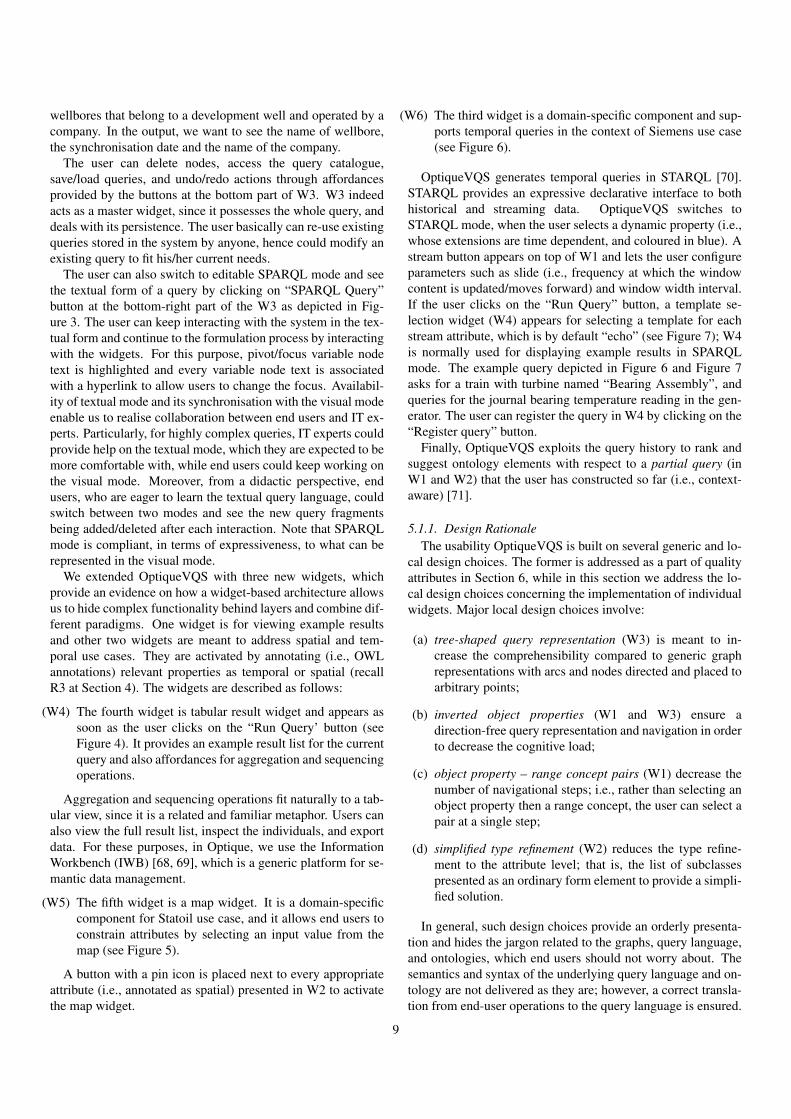
wellbores that belong to a development well and operated by acompany. In the output, we want to see the name of wellbore,the synchronisation date and the name of the company.
The user can delete nodes, access the query catalogue,save/load queries, and undo/redo actions through affordancesprovided by the buttons at the bottom part of W3. W3 indeedacts as a master widget, since it possesses the whole query, anddeals with its persistence. The user basically can re-use existingqueries stored in the system by anyone, hence could modify anexisting query to fit his/her current needs.
The user can also switch to editable SPARQL mode and seethe textual form of a query by clicking on “SPARQL Query”button at the bottom-right part of the W3 as depicted in Fig-ure 3. The user can keep interacting with the system in the tex-tual form and continue to the formulation process by interactingwith the widgets. For this purpose, pivot/focus variable nodetext is highlighted and every variable node text is associatedwith a hyperlink to allow users to change the focus. Availabil-ity of textual mode and its synchronisation with the visual modeenable us to realise collaboration between end users and IT ex-perts. Particularly, for highly complex queries, IT experts couldprovide help on the textual mode, which they are expected to bemore comfortable with, while end users could keep working onthe visual mode. Moreover, from a didactic perspective, endusers, who are eager to learn the textual query language, couldswitch between two modes and see the new query fragmentsbeing added/deleted after each interaction. Note that SPARQLmode is compliant, in terms of expressiveness, to what can berepresented in the visual mode.
We extended OptiqueVQS with three new widgets, whichprovide an evidence on how a widget-based architecture allowsus to hide complex functionality behind layers and combine dif-ferent paradigms. One widget is for viewing example resultsand other two widgets are meant to address spatial and tem-poral use cases. They are activated by annotating (i.e., OWLannotations) relevant properties as temporal or spatial (recallR3 at Section 4). The widgets are described as follows:
(W4) The fourth widget is tabular result widget and appears assoon as the user clicks on the “Run Query’ button (seeFigure 4). It provides an example result list for the currentquery and also affordances for aggregation and sequencingoperations.
Aggregation and sequencing operations fit naturally to a tab-ular view, since it is a related and familiar metaphor. Users canalso view the full result list, inspect the individuals, and exportdata. For these purposes, in Optique, we use the InformationWorkbench (IWB) [68, 69], which is a generic platform for se-mantic data management.
(W5) The fifth widget is a map widget. It is a domain-specificcomponent for Statoil use case, and it allows end users toconstrain attributes by selecting an input value from themap (see Figure 5).
A button with a pin icon is placed next to every appropriateattribute (i.e., annotated as spatial) presented in W2 to activatethe map widget.
(W6) The third widget is a domain-specific component and sup-ports temporal queries in the context of Siemens use case(see Figure 6).
OptiqueVQS generates temporal queries in STARQL [70].STARQL provides an expressive declarative interface to bothhistorical and streaming data. OptiqueVQS switches toSTARQL mode, when the user selects a dynamic property (i.e.,whose extensions are time dependent, and coloured in blue). Astream button appears on top of W1 and lets the user configureparameters such as slide (i.e., frequency at which the windowcontent is updated/moves forward) and window width interval.If the user clicks on the “Run Query” button, a template se-lection widget (W4) appears for selecting a template for eachstream attribute, which is by default “echo” (see Figure 7); W4is normally used for displaying example results in SPARQLmode. The example query depicted in Figure 6 and Figure 7asks for a train with turbine named “Bearing Assembly”, andqueries for the journal bearing temperature reading in the gen-erator. The user can register the query in W4 by clicking on the“Register query” button.
Finally, OptiqueVQS exploits the query history to rank andsuggest ontology elements with respect to a partial query (inW1 and W2) that the user has constructed so far (i.e., context-aware) [71].
5.1.1. Design RationaleThe usability OptiqueVQS is built on several generic and lo-
cal design choices. The former is addressed as a part of qualityattributes in Section 6, while in this section we address the lo-cal design choices concerning the implementation of individualwidgets. Major local design choices involve:
(a) tree-shaped query representation (W3) is meant to in-crease the comprehensibility compared to generic graphrepresentations with arcs and nodes directed and placed toarbitrary points;
(b) inverted object properties (W1 and W3) ensure adirection-free query representation and navigation in orderto decrease the cognitive load;
(c) object property – range concept pairs (W1) decrease thenumber of navigational steps; i.e., rather than selecting anobject property then a range concept, the user can select apair at a single step;
(d) simplified type refinement (W2) reduces the type refine-ment to the attribute level; that is, the list of subclassespresented as an ordinary form element to provide a simpli-fied solution.
In general, such design choices provide an orderly presenta-tion and hides the jargon related to the graphs, query language,and ontologies, which end users should not worry about. Thesemantics and syntax of the underlying query language and on-tology are not delivered as they are; however, a correct transla-tion from end-user operations to the query language is ensured.
9

Figure 3: OptiqueVQS interface – an example query in textual mode.
The goal is to hide complexity and technical jargon effectivelyso as to reduce the knowledge and skills required.
For example, in a variant of OptiqueVQS, a graph represen-tation is employed along with ingoing/outgoing arc distinction.In a user study with casual users, the participants complainedabout disorder in the presentation and their confusion due in-going/outgoing relation distinction [35]. However, in anotherstudy with original OptiqueVQS with casual users, the partici-pants praised the order and simplicity of tree-shaped presenta-tion [32].
5.2. OptiqueVQS backend
In this section, we present the backend infrastructure Op-tiqueVQS relies on. In Figure 8, one can see the main com-ponents in OptiqueVQS backend.
The frontend communicates with the backend via a RESTAPI that returns a JSON object according to the performed re-quest. The backend is in charge of accessing (i) the ontol-ogy, which drives the information displayed in the frontend, and(ii) the query log, which plays an important role in ranking [71]as well as it serves as an example for the formulation of similarfuture queries.
The ontology can optionally be enriched with additionalaxioms to capture values that are frequently used and rarely
changed (refer to “Data sampler” component in the architec-ture); this includes the list of values and numerical ranges in anOWL data property range (i.e., for max/min sliders and drop-down boxes in W2).
The main component of the backend is the “graph projector”(described in the next section), which will create a navigationgraph according to the ontology axioms. The “graph projector”in conjunction with the “VQS feeder” will drive the populationof the frontend widgets.
5.2.1. Ontology-driven Navigation GraphFrom our work on the use cases, we discovered that end users
ask mostly schema-level queries, e.g., “give me all wellboresthat are located in a certain area”. Thus, we are targeting atquery formulation that is done in terms of classes and proper-ties. OWL 2 axioms, on the other hand, can be exploited tohelp a user in navigating between classes and properties. Forexample, if a user during query formulation has the conceptWellbore active, then a query formulation system could sug-gest them to connect Wellbore with Core via hasCore due tothe axiom ‘Wellbore SubClassOf: hasCore some Core’.Moreover, most of users’ queries have a graph-like structure,where nodes are labelled with concepts and edges with proper-ties. However, OWL 2 axioms are not well-suited for a graph-based navigation. Indeed, note that OWL 2 axioms do not have
10

Figure 4: OptiqueVQS interface – the tabular result widget with aggregation and sequencing support.
a natural correspondence to a graph, e.g., an OWL 2 axiom ofthe form ‘C1 and C2 SubClassOf: D1 or D2’ can be hardlyseen as a graph. Even in the case when an axiom can naturallybe seen as a graph, to the best of our knowledge there is nostandard means to translate it to a graph. Therefore, we needa technique to extract a suitable graph-like structure from a setof OWL 2 axioms. To this end, we have adapted a techniquecalled navigation graph [66, 17].
The nodes of a navigation graph are unary predicates, con-stants (named individuals, literal values) or datatypes, andedges are labelled with possible relations between such ele-ments, that is, binary predicates. The key property of a navi-gation graph is that every X-labelled edge (v, w) is justified byone or more axioms entailed byO which “semantically relates”v to w via X .
Definition 5.1. Let O be an OWL 2 ontology A navigationgraph forO is a directed labelled multigraphG having as nodesunary predicates, constants or datatypes from O and s.t. eachedge is labelled with a binary predicate fromO. Each edge e isjustified by one or more axioms αe s.t.O |= αe and αe is of theform given next, where b is a named individual, li is a literalvalue, A,Asup, Asub, B classes or unary predicates, Ro, R
−o
object properties, Rd a datatype property, dt a datatype (e.g.string, integer), and x, y numerical values:
(i) Edges e of the formARo−−→ B are justified by the following
OWL 2 axioms:
• ‘A SubClassOf: Ro restriction B’, where restric-tion is one of the following: some (existential restric-tion), only (universal restriction), min x (minimumcardinality), max x (maximum cardinality) and ex-actly x (exact cardinality). Note that axioms of theform ‘A SubClassOf: R restriction
⊔1≤i≤nBi’
and ‘A SubClassOf: R restrictiond
1≤i≤nBi’
also justify edges of the form ARo−−→ Bi .
• A combination of range and domain axioms of theform: Ro Domain: A’ and ‘Ro Range: B’.
• ‘A SubClassOf: Ro value b’, and b being a memberof the class B (e.g., ‘b Types: B’).
• ‘Ro InverseOf: R−o ’ when the navigation graph in-
cludes the edge BR−
o−−→ A.
• Top-down propagation of restrictions:‘A SubClassOf: Asup’ when the navigation graph
includes the edge AsupRo−−→ B.
• Bottom-up propagation of restrictions:‘Asub SubClassOf: A’ when the navigation graphincludes the edge Asub
Ro−−→ B.
11

Figure 5: OptiqueVQS interface – the map widget.
(ii) Edges e of the formARd−−→ dt are justified by the following
OWL 2 axioms:
• ‘A SubClassOf: Rd restriction dt’, where re-striction is one of the following: some, only, min x,max x and exactly x. Note that dt can be a OWL 2built-in datatype or user-defined datatype which aretypically expressed with a datatype restriction (e.g.,‘A SubClassOf: Rd restriction dt[> x,< y]’,where dt is restricted with the interval defined by xand y.)
• A combination of range and domain axioms of theform: Rd Domain: A’ and ‘Rd Range: dt’ (or‘Rd Range: dt[> x,< y]’).
• ‘A SubClassOf: Rd value l’, and l being a literalvalue of type dt.
• Top-down propagation of restrictions:‘A SubClassOf: Asup’ when the navigation graph
includes the edge AsupRd−−→ dt.
• Bottom-up propagation of restrictions:‘Asub SubClassOf: A’ when the navigation graphincludes the edge Asub
Rd−−→ B.
(iii) Edges e of the formARd−−→ li are justified by the following
OWL 2 axioms:
• A SubClassOf: Rd restriction l1 . . . ln, whererestriction is one of the following: some, only, min x,max x and exactly x; and l1 . . . ln is an enumerationof literal values (typically of type ‘string’).
• A combination of range and domain axioms of theform: Rd Domain: A’ and ‘Rd Range: l1 . . . ln’.
• ‘A SubClassOf: Rd value li’.
(iv) Edges e of the formAbroader−−−−−→ B are justified by the OWL
2 axiom: B SubClassOf: A .
The edges in the navigation graph are used to populate thefrontend widgets with suggestions to guide the end user in theformulation of the query. Edges of type (i) are used to populateW1, while edges of types (ii) and (iii) populate the attributes inW2, for the focus concept A in W3. Edges of type (iii) and (ii)also guide the automatic customization of W2 with specific in-put fields for a given datatype, pre-populated dropdown lists forenumeration of values (e.g., company names) and range slidersfor datatype restrictions (e.g., min/max possible depth of well-bores). Edges of type (iv) populate the list of subclasses forthe focus concept A, which are treated as the special attribute
12

Figure 6: OptiqueVQS interface – the stream parameter selection widget.
“Type” in W2. OptiqueVQS relies on the OWL 2 reasoner Her-miT [72] to build the navigation graph (e.g., extraction of clas-sification) in order to consider both explicit and implicit knowl-edge defined in the ontology O.
The number of suggestions presented in W1 and W2 maygrow quickly due to ontology size, number of relationships be-tween concepts, inverse properties, and the propagative effectof inheritance of restrictions etc. As the lists grow, the timerequired for a user to find elements of interest increases; there-fore, adaptive query formulation, that is ranking ontology ele-ments with respect to previously executed queries (i.e. a querylog), is a critical aspect in OptiqueVQS. OptiqueVQS imple-ments a light version of the ranking method described by Soyluet al. [71].
5.2.2. Query Conformation to Navigation GraphTo realise the idea of ontology and data guided navigation,
we require that interfaces conform to the navigation graph inthe sense that the presence of every element on the interface issupported by a graph edge. In this way, we ensure that inter-faces mimic the structure of (and implicit information in) theontology and data and that the interface does not contain irrele-vant (combinations of) elements.
Our goal is to help a user to construct such queries that wouldbe “justified” by the navigation graph. We assume that all the
definitions in this section are parametrised with a fixed ontologyO.
Definition 5.2. Let Q be a conjunctive query. The graph of Qis the smallest multi-labelled directed graph GQ with a nodefor each term in Q and a directed edge (x, y) for each atomR(x, y) occurring in Q, where R is different from ≈. We saythat Q is tree-shaped if GQ is a tree. Moreover, a variable nodex is labelled with a unary predicate A if the atom A(x) occursin Q, and an edge (t1, t2) is labelled with a binary predicate Rif the atom R(t1, t2) occurs in Q.
Finally, we are ready to define the notion of conformation.
Definition 5.3. Let Q be a conjunctive query and G a navi-gation graph. We say that Q conforms to G if for each edge(t1, t2) in the graph GQ of Q the following holds:
• If t1 and t2 are variables, then for each label B of t2 thereis a label A of t1 and a label R of (t1, t2) such that A R−→B is an edge in G.
• If t1 is a variable and t2 is a constant, then there is a labelA of t1 and a label R of (t1, t2) such that A R−→ t1 is anedge in G.
Now we describe the class of queries that can be generatedusing OptiqueVQS and show that they conform to the naviga-
13

Figure 7: OptiqueVQS interface – template selection for a stream query.
OptiqueVQS frontend
OptiqueVQS backendBackend
REST APIVQS feeder
RankingGraph projectionReasoner(Hermit)
OWL 2Ontology
Querylog
Sampler
requests
sampling data
JSON objects
save/load
Data poolbackground knowledge
Figure 8: OptiqueVQS backend.
tion graph underlying the system. First, observe that the Op-
tiqueVQS queries follow the following grammar:
query ::= A(x)(∧ constr(x))∗(∧ expr(x))∗
expr(x) ::= sug(x, y)(∧ constr(x))∗(∧ expr(y))∗
constr(x) ::= ∃yR(x, y) | R(x, y) | R(x, c)
sug(x, y) ::= Q(x, y) ∧A(y)
where A is an atomic class, R is an atomic data property, Qis an object property, and c is a data value. The expression ofthe form A(∧ B)∗ designates that B-expressions can appear inthe formula 0, 1, and so on, times. An OptiqueVQS query isconstructed using suggestions sug and constraints constr, thatare combined in expressions expr. Such queries are clearlyconjunctive and tree-shaped (recall R1 at Section 4). All thevariables that occur in classes and object properties are outputvariables and some variables occurring in data properties canalso be output variables.
When users interacts with OptiqueVQS,
• They start with a “starting” class, as described above.Clearly, this initial query conforms to any navigationgraph, including the one, underlying the system.
• Then, the system suggest the list of sug(y, z) via W1 andof constr(x) via W2 such that choosing any of them
14

would leave the updated query conforming to the under-lying navigation graph. In other words, all these choicesare justified by the graph.
6. Quality Features
OptiqueVQS has the following interrelated features that aremapped to the quality attributes (i.e., An) proposed at Sec-tion 4.2:
(F1) View and overview provide a continuous outlook of thequery formulated so far while supplying the user with aset of possible actions. The goal is to ensure maximumend-user awareness and control (cf. [73]) (A1).
Realisation: W3 provides a global overview of the userquery, while W1 and W2 focus the user to the pivot forpossible join, select, and projection operations.
(F2) Exploration and construction allow the user to navigatethe conceptual space for exploration and construction pur-poses. Exploration could be also at instance level, in termsof cues (i.e., sample results) and instance level browsing(cf. [15, 74]) (A1).
Realisation: W1 and W2 suggest domain elements andallow ontology navigation. Each action adds reversiblequery fragments into the query. The user can also use thetabular result widget, i.e., W4, for example results.
(F3) Collaborative query formulation is meant to enable collab-oration between users actively or passively. Such collab-oration could be between an end user and an IT expert orbetween an end users (cf. [75]) (A1). Users can formulatemore complex queries and improve their effectiveness andefficiency.
Realisation: OptiqueVQS synchronises visual and textualmodes (i.e., active collaboration between IT experts andend users), allows users to share queries (i.e., passive col-laboration), and harnesses the query log to offer sugges-tions (i.e., passive).
(F4) Query-reuse enables the user to reuse existing queries asthey are or to modify them to construct more complexqueries and/or to improve the effectiveness and efficiency(A1 and A9). Query reuse could indeed be considered apassive form of collaboration (cf. [75]) (F3).
Realisation: OptiqueVQS allows users to store, load, andmodify queries. Queries are stored in a query cataloguewith descriptive texts to facilitate their search and retrieval.
(F5) Spiral/layered design refers to distributing system func-tionality into layers (cf. [52]), so as to enable an orderlyaccess to system, prevent complex functionalities to hinderthe usability for less competent users (A1), view ontologyat different levels of detail (A3), tailor available function-ality with respect to user needs (A4 and A5), and to addnew functionalities without overloading the interface (A6).
Realisation: OptiqueVQS delegates functionality and on-tology visualisation tasks to the different widgets. For in-stance, W4 offers aggregation and sequencing operations,while W2 presents data attributes and offers selection andprojection functions.
(F6) Gradual access is to cope with large ontologies with manyconcepts and properties. The amount of information thatcan be communicated on a finite display is limited. There-fore, gradual and on-demand access to the relevant partsof an ontology is necessary (cf. [58]) (A1 and A3).
Realisation: W1 and W2 provide ontology elements adap-tively and gradually on user demand, hence avoids clutter-ing and scattering the interface.
(F7) Iterative formulation allows the user to follow a formulate-inspect-reformulate cycle (A1), since a query is often notformulated in one iteration (cf. [76, 75]).
Realisation: OptiqueVQS provides affordances to inspect,manipulate and extend a formulated query. For instance,users can freely change the pivot, delete nodes, and addnew nodes from any point of the query.
(F8) Ranked suggestions improve the user efficiency by rankingontology elements with respect to context, e.g., previousquery log, and filtering down the amount of knowledge tobe presented (cf. [71]) (A1, A3, and A4). Ranking is aform of passive collaboration as it utilises queries formu-lated by others to provide gradual access (F3 and F6).
Realisation: OptiqueVQS offers a ranking method, whichexploits the query history of users to rank and suggest on-tology elements (in W1 and W2) with respect to a partialquery that a user has constructed so far.
(F9) Domain specific representations support varied data typesand domains. This ensures contextual delivery of dataleading to immediate grasping (cf. [77]) (A1). The avail-ability of domain specific representations provides usersand system with the opportunity to select representationparadigms that fit best to the data and task (A4 and A5).
Realisation: OptiqueVQS allows introducing newdomain-specific widgets for visualisation and interaction,for instance, the map widget (W5) for geospatial interac-tion and visualisation.
(F10) Multi-paradigm and multi-perspective presentation ismeant to combine multiple representation and interactionparadigms, such as form and diagrams, and query formula-tion approaches, such as visual query formulation and tex-tual query editing, to meet diverse contexts. (cf. [15, 58])(A1). Moreover, the system and users can adapt presen-tation (A4 and A5) and users can select among variousparadigms depending on their role (F3), task (F2), and dataat hand (F9).
Realisation: OptiqueVQS puts multiple representationand interaction paradigms (i.e., list/menus (W1), diagrams(W3), forms (W2), tables (W4)) as well as query formula-tion approaches (i.e., textual and visual) together.
15

(F11) Modular architecture allows new components to be eas-ily introduced and combined in order to adapt to chang-ing requirements and to support diverse user experi-ences (A1, A2 and A6). This could include alterna-tive/complementary components for query formulation,exploration, visualisation, etc. with respect to context (A3,A4, A5, F9, and F10).
Realisation: OptiqueVQS is based on a UI mashup ap-proach and is built on a widget-based architecture, wherewidgets are independent components acting as the build-ing blocks. They communicate through broadcasting eventnotifications.
(F12) Data exporting enables the user to feed analytics tools withthe data extracted for sense-making processes, as they arenot expected to have skills to transform data from one for-mat to another. Therefore, means to export data in differ-ent format are required to ensure that the system fits intothe organisational context (A7) and a broader user experi-ence (A1).
Realisation: OptiqueVQS allows users to export data invarious formats. For instance, in the context of Statoil usecase, users can export query results in the format of theirdata analytics tools.
(F13) Domain-agnostic backend ensures domain independence.This allows VQS to operate over different ontologies anddatasets without any extensive manual customisation andcode change [24, 25] (A8).
Realisation: OptiqueVQS relies on a domain-agnosticbackend. It projects the underlying ontology into a graphfor exploration and query construction. Yet, it also allowsdomain-specific components to be introduced.
7. User Evaluation
The purpose of a VQSs is to enable users to formulate querieseffectively and efficiently. The effectiveness (cf. [56, 78]) ismeasured in terms of accuracy and completeness that users canachieve. The cost associated with the level of effectivenessachieved is called efficiency (cf. [56, 78]), and is mostly mea-sured in terms of the time spent to complete a query. Note that,typically in information retrieval (IR), effectiveness is mea-sured in terms of precision, recall, and f-measure (harmonicmean of precision and recall) over the result set; however, aVQS is a data retrieval (DR) paradigm, for which a single miss-ing or irrelevant object implies a total failure [18]. In otherwords, data retrieval systems have no tolerance for missing orirrelevant results, while IR systems are variably insensitive toinaccuracies and errors, since they often interpret the originaluser query and the matching is assumed to indicate the like-lihood of the relevance, rather than being exact (cf. [79, 80]).Therefore, for a VQS, effectiveness is rather measured in termsof a binary measure of success (i.e., correct/incorrect query)(cf. [24]).
In the course of Optique project, we conducted a total of fourindustrial workshops with our use case partners (two at each use
case). In the first set of workshops, we conducted unstructuredinterviews with domain experts and observed them in their dailyroutines. Shortly after the first set of workshops, we demon-strated a paper mock-up and had further discussions. A runningprototype was developed iteratively with representative domainexperts in the loop. At the second round of workshops, do-main experts experimented with the prototype in a formal thinkaloud session and we measured the effectiveness and efficiencyof OptiqueVQS.
In parallel, we conducted two usability studies with casualusers to have rapid feedback, which are published elsewhere, ina non-industrial context as the availability of domain experts isoften limited:
(Exp1) An experiment involving casual users without any techni-cal skills and knowledge. It was conducted on a genericdomain. The results suggested that casual users withoutany technical background can effectively and efficientlyuse OptiqueVQS to formulate complex queries [32].
(Exp2) A comparative experiment comparing a variant of Op-tiqueVQS and a form-based query interface called Pepe-Search [39]. The results suggested that OptiqueVQS is thepreferred tool for formulating complex query tasks, wherePepeSearch is the preferred tool for less experienced usersfor completing simple tasks [35].
In this article, we report the design and the results of the ex-periments that we conducted with our industrial partners:
(Exp3) Statoil experiment employed on a bootstrapped (i.e., auto-matically generated [81, 3]) oil and gas ontology5 with 253concepts, 208 relationships (including inverse properties),and 233 attributes [82].
(Exp4) Siemens experiment without temporal queries employed amanually constructed diagnostic ontology with five con-cepts, five relationships (excluding inverse properties), andnine attributes [4].
(Exp5) Siemens experiment with temporal queries employed amanually constructed turbine ontology with 40 conceptsand 65 properties [83].
The ontologies, data, and information needs used in the ex-periments are provided by the industrial partners themselvesand therefore are not artificial and reflect the reality and realinterests.
7.1. Experiment designThe experiments were designed as a think-aloud study. Each
participant performed the experiment in a single session, whilebeing watched by an observer. Participants were instructed tothink aloud, including any difficulties they encounter (e.g., frus-tration and confusion), while performing the given tasks. A fiveminutes introduction of the topic and tool had been delivered to
5http://sws.ifi.uio.no/project/npd-v2/
16

Table 3: Profile information of the participants.
# Age Occupation Exp. Education Tech. skills Similar tools Sem. WebP1 39 Geologist Exp3 Master 3 3 1P2 40 Biostrat Exp3 Master 2 1 1P3 49 IT advisor Exp3 Master 5 4 1P4 33 Software engineer Exp4 Bachelor 5 2 1P5 27 Diagnostic Engineer Exp4 Bachelor 5 5 1P6 60 Mechanical Engineer Exp4 Master 3 1 1P7 45 Mechanical Engineer Exp4 Bachelor 1 2 1P8 37 R&D engineer Exp5 PhD 4 1 1P9 54 Diagnostics Engineer Exp5 Bachelor 5 3 1
P10 39 Engineer Exp5 PhD 5 2 1
the participants along with an example before they were askedto fill in a profile survey. The survey asked users about theirage, occupation and level of education, and asked them to ratetheir technical skills, such as on programming and query lan-guages, and their familiarity with similar tools on a Likert scale(i.e., 1 for “not familiar at all,” 5 for “very familiar”). Partici-pants were then asked to formulate a set of information needsinto queries with OptiqueVQS (i.e., tasks).
A number of empty queries, each corresponding to a taskin the experiment, was generated in OptiqueVQS for each user.Users received their tasks one by one on paper, and for each taskloaded the corresponding empty query. Formulating and exe-cuting a query, i.e., clicking “run query” button, and inspectingthe result set equals to one attempt. Participants had a maxi-mum of three attempts per task and this was enforced by thesystem (“run query” button was blocked after three attempts).A task was ended, when the participant acknowledged the com-pletion or exhausted his/her three attempts. Every attempt foreach task was recorded by the OptiqueVQS as a draft query,along with the time it had taken for each attempt.
Three participants from Statoil and seven participants fromSiemens took part in the experiments. The profiles of partici-pants are summarised in Table 3, which shows that participantsvary in technical skills and experience with similar tools andhave no familiarity with the semantic web technologies.
There were nine tasks for the Statoil experiment (Exp3), fivetasks for the Siemens experiment (Exp4), and five tasks for thesecond Siemens experiment with temporal queries (Exp5). Thetasks were all conjunctive and shown in Table 4. The key ele-ments are highlighted in the context of this article for clarity.
7.2. Results
The results of all the three experiments are summarised inFigure 9.
Regarding the Statoil experiment (Exp3), a total of 27 taskswas completed by the participants, with 84 percent correct com-pletion rate and 69 percent first-attempt correct completion rate(i.e., percentage of correctly formulated queries in the first at-tempt). The first participant had only one incorrect, and thesecond participant had no incorrect task. T3 was about fieldsoperated by Statoil, and the third participant formulated a Field
- FieldOperator pair instead of a Field - Company pair. Thisconfusion between FieldOperator and Company led him to in-correctly solve the T5 as well. T7 not only takes the longesttime but also the highest average attempts. According to par-ticipant feedback and our observations, this is particularly dueto conceptual mismatch between the participants'understandingof domain and the ontology (the ontology was automaticallybootstrapped with little manual fine tuning), which forced par-ticipants to iterate several times.
In the Siemens experiment without temporal queries (Exp4),a total of 18 tasks was completed by the participants. Thethird participant exceeded the allocated time for the session andcould not attempt the last two tasks, therefore these are omittedfrom the results. Correct completion rate was 88 percent andfirst-attempt correct completion rate was 72 percent. The thirdand fourth participants had one incorrect task. The Siemens di-agnostic ontology used in the experiment was smaller in sizeand was manually created (i.e., of higher quality). Participantshad only a minor issue with the date format, therefore Task11, where a date constraint appeared for the first time, took thelongest time.
In the Siemens experiment with temporal queries (Exp5), atotal of 15 tasks were completed by the participants with 100percent correct completion rate and 66 percent first-attempt cor-rect completion rate. They had minor issues with the fact thatusers need click on the “Run Query” button in order to select atemplate from the tabular view. A straight forward solution forstream based queries would be to change the name of button to“Select a Template” to prevent confusion, as the “Run Query”button is originally meant for non-stream query tasks.
In general, participants raised two major issues. First, theyasked for a longer training session; indeed, the training ses-sions were intentionally kept short in order to test learnabilityof the OptiqueVQS. The high completion rates, even with com-plex queries, suggest that the tool has high learnability. Sec-ondly, participants pointed that the ontology did not always re-flect their understanding of the domain, which was mostly aissue for the Statoil experiment. We acknowledge the situationand believe that the usability of an ontology is as crucial as theusability of a query formulation tool. Ontology usability is anoverlooked issue in the research community, which demands
17

Table 4: Information needs used in the experiments – marked queries (*) are temporal.
# Exp. Information need
T1 Exp3 List all fields.
T2 Exp3 What is the water depth of the “Snorre A” platform (facility)?
T3 Exp3 List all fields operated by “Statoil Petroleum AS” company.
T4 Exp3 List all exploration wellbores with the field they belong to and the geochronological era(s) with which they arerecorded.
T5 Exp3 List the fields that are currently operated by the company that operates the “Alta” field.
T6 Exp3 List the companies that are licensees in production licenses that own fields with a re-coverable oil equivalentover more than “300” in the field reserve.
T7 Exp3 List all production licenses that have a field with a wellbore completed between “1970” and “1980” and recov-erable oil equivalent greater than “100” in the company reserve.
T8 Exp3 List the blocks that contain wellbores that are drilled by a company that is a field operator.
T9 Exp3 List all producing fields operated by “Statoil Petroleum AS” company that has a wellbore containing “gas” anda wellbore containing “oil”.
T10 Exp4 Find all assemblies that exist in system.
T11 Exp4 Show all messages that tribune “NA0101/01” generated from “01.12.2009” to “02.12.2009”.
T12 Exp4 Show all turbines that sent a message containing the text “Trip” between “01.12.2009” and “02.12.2009”.
T13 Exp4 Show all event categories known to the system.
T14 Exp4 Show all turbines that sent a message category “Shutdown” between “01.12.2009” and “02.12.2009”.
T15 Exp5 Display all trains that have a turbine and a generator.
T16 Exp5 Display all turbines together with the temperature sensors in their burner tips. Be sure to include the turbinename and the burner tags.
T17* Exp5 For the turbine named “Bearing Assembly”, query for temperature readings of the journal bearing in the com-pressor. Display the reading as a simple echo.
T18* Exp5 For a train with turbine named “Bearing Assembly”, query for the journal bearing temperature reading in thegenerator. Display readings as a simple echo.
T19* Exp5 For the turbine named “Burner Assembly”, query for all burner tip temperatures. Display the readings if theyincrease monotonically.
more attention.
Overall, the results indicate high effectiveness and efficiencyrates. This suggests that OptiqueVQS is a viable tool to visu-ally construct considerably complex queries for querying struc-tured data sources. All participants praised the capability ofOptiqueVQS for formulating complex information needs intoqueries. A common statement was that such a solution willnot only improve their current practices, but also augment theirvalue creation potential due to the flexibility of formulating ar-bitrary queries. Three complex queries formulated by Statoiland Siemens domain experts and casual users are given in Fig-ure 10. First query was provided by a Statoil domain expertfor the query catalogue and he estimated that he would need afull day to extract this information with existing tools. On theother hand, the same Statoil user was able to formulate a queryof a similar complexity with OptiqueVQS within less than 10minutes. The second query (Exp3) only took 63 on average to
complete by Siemens’ domain experts. The third query tookonly 91 seconds to complete on average for a casual user [32].
8. Related Work
Visual approaches for querying structured semantic datasources are primarily categorised into VQLs and VQSs as ex-plained in Section 1. Such approaches could be further classi-fied with respect to main interaction paradigm.
Browsing and schema navigation are two prominent interac-tion paradigms. The former refers to interacting at an instancelevel, that is, the user browses the data set by adding and re-moving constraints and following the links between instances.Faceted search is a very good example of this paradigm,e.g., [55, 29, 66]. The latter is used by OptiqueVQS and refersto interacting at a conceptual level, that is using an external vo-cabulary, for example provided by an ontology, to express the
18

0
0.5
1
1.5
2
2.5
3
0102030405060708090
100
T1 T2 T3 T4 T5 T6 T7 T8 T9
Attempt(Av
g.)
Completion
(%)
Task(Statoil /Exp1)
Completion (%) Attempt(Avg.)
0
0.5
1
1.5
2
2.5
3
0102030405060708090
100
T10 T11 T12 T13 T14
Attempts(Avg.)
Completion
(%)
Task(Siemens/Exp2)
Completion (%) Attempt(Avg.)
0
100
200
300
400
500
600
T1 T2 T3 T4 T5 T6 T7 T8 T9
Time(s)
Task(Statoil /Exp1)
Max. Min. Avg.
0
100
200
300
400
500
600
T10 T11 T12 T13 T14
Time(s)
Task(Siemens/Exp2)
Max. Min. Avg.
0
0.5
1
1.5
2
2.5
3
0
20
40
60
80
100
T15 T16 T17 T18 T19
Attempts(Avg.)
Completion
(%)
Tasks(Siemens/Exp3)
Completion (%) Attempt(Avg.)
0
50
100
150
200
250
300
T15 T16 T17 T18 T19
Time(s)
Tasks(Siemens/Exp3)
Max. Min. Avg.
Figure 9: Experiment results for the three usability studies.
information need at the schema level, e.g., [30, 38]. Browsingis a good approach when the data set and result set are not verylarge and users need to pay attention to each individual itemin the result set. On the other hand, schema navigation worksbetter when both data and results sets are large and users areinterested in the result set itself and its correctness and com-pleteness; this actually describes the situation in our industrialuse cases.
Another categorisation arises from the source of vocabulary,which might be extracted from the data set or be provided byan external ontology. The former refers to extracting conceptsand relationships by analysing the data set, i.e., extracting apseudo ontology, e.g., [29, 39]. It is adequate for cases where
an ontology is not available, prevents the user from buildingunsatisfiable queries (i.e., no empty result sets), and allows us-ing statistics about data for optimisation. The latter approachuses an ontology to feed the query formulation process, e.g.,[37]. An ontology could be much more expressive than whatone can extract from data, and vocabulary extraction processcould be quite expensive for large and dynamic data sets. Forexample, data sets in our use cases change very rapidly in vastamounts and this makes real time processing very hard. Offlineprocessing is not an option as this would lead to missing and/orincorrect results; users need to access real time data. Finally,it is not always desirable to formulate queries with guaranteedresults. For example, in the Siemens use case, most of the user
19

Figure 10: Three complex queries formulated by Statoil and Siemens domain experts and casual users.
queries specify an error situation in their hardware for whichthere is often no matching data at the time of query formula-tion (i.e., only to get notified when the data changes and thequery becomes satisfied). OptiqueVQS uses a hybrid approach,where an ontology is the main source of vocabulary and dataset is used for a limited extent (recall Section 5.2).
Regarding the visual approaches in general, notable exam-ples of VQLs are LUPOSDATE [16], RDF-GL [27], Nite-light [84], GQL [54], and QueryVOWL [28]. LUPOSDATE,RDF-GL and Nitelight follow RDF syntax at a very low levelthrough node-link diagrams representing the subject-predicate-object notation, while GQL and QueryVOWL represent queriesat comparatively higher level, such as with UML-based dia-grams. Each of these languages are managed by a VQS pro-viding means for construction and manipulation of queries in avisual form. Albeit VQL-based approaches with higher level ofabstraction are closer to end users, they still need to posses ahigher level of knowledge and skills to understand the seman-tics of visual notation and syntax and to use it. Note that al-though OptiqueVQS uses a three-shaped query representation,it is informal, simplified, and free of any syntax and jargon re-lated to ontologies and query languages.
A VQS have a better potential to offer a good balance be-tween expressiveness and usability. The prominent exam-ples of VQSs are gFacet [36], OZONE [37], SparqlFilter-Flow [38], Konduit VQB [30], and Rhizomer [29], PepeSearch[39]. gFacet, OZONE, and SparqlFilterFlow employ a diagram-
based approach and diagrams representing the queries are ratherinformal. Konduit VQB and Rhizomer employ a form-basedparadigm. Diagram-based approaches are good in providinga global overview; however, they remain insufficient alone forview (i.e., zooming into a specific concept for filtering and pro-jection). This is because the visual space as a whole is mostlyoccupied for query overview. Form-based approaches providea good view; however, they provide a poor overview, since thevisual space as a whole is mostly occupied with the propertiesof the focus concept. Approaches combining multiple represen-tation and interaction paradigms are known to be better as theycould combine view and overview. gFacet and Rhizomer areoriginally meant for data browsing, that is they operate on datalevel rather than schema level and every user interaction gener-ates and sends SPARQL queries in the background. Yet they arehighly data-intensive, which is often impractical for large datasets. Finally, PepeSearch uses conventional forms and mixesschema-based search and browsing; search is limited with akernel concept and concepts directly related to it, and relevantterms are extracted from the data. Apart from limited expressiv-ity, PepeSearch suffers from poor domain knowledge extractedfrom data (i.e., compared to a rich ontology), although the inter-face is naturally tailored by the data. Secondly it does not offermeans to cope with large and frequently changing datasets (i.e.,one needs to re-extract schema information if data changes).
As far as temporal queries are concerned, notable exam-ples of temporal query languages in the Semantic Web are C-
20

Table 5: Comparison of related tools with respect to our industrial requirements (B = Browsing, S = Schema navigation, H = Hybrid, O = Ontology, D = Data; X=yes, Θ = partially, - = no).
Criteria/Tool gFacet
OZO
NE
SparqlFilterFlow
Konduit V
QB
Rhizom
er
PepeSearch
Super Stream
TELIOS
Spatial
OptiqueV
QS
Interaction type B S S S B H S S SVocabulary D O D D D D D O HDownloadable X - - - X X - - XThree-shaped X X X X X Θ X X XMulti-paradigm Θ Θ Θ - X - - X XTemporal - - - - - - X - Θ
Spatial - - - - - - - X Θ
Modularity - X - - - - X - XScalability Θ Θ Θ Θ Θ Θ Θ Θ XAdaptivity - - - - - Θ - - XAdaptability - X - - - - X - XExtensibility - X - - - - X - XInteroperability - - - - - - - Θ Θ
Portability X X X X X X X X XReusability - X X Θ - - X X X
SPARQL [85], SPARQLstream [86], and CQELS [87]. Theseapproaches extend SPARQL with a window operator whosecontent is a multi-set of variable bindings for the open variablesin the query. However, in this paper we are rather interested invisual solutions sitting on top of any of these languages. Al-though several visual tools exist for SPARQL (cf. [19]), thework is very limited for stream languages. An example isSPARQL/CQELS visual editor designed for Super Stream Col-lider framework [40]. However, the tool follows the jargon ofthe underlying language closely and is not appropriate for endusers as it will demand considerable knowledge and skills.
Concerning spatial querying, notable formal textualquery languages are stSPARQL [88] and geoSPARQL[89].stSPARQL is an extension of SPARQL 1.1 for querying linkedgeospatial data that changes over time, while geoSPARQL isa recent standard of the Open Geospatial Consortium (OGC)for static geospatial data. Although there are numerous toolsfor visualizing and interacting with spatial data such as Sextant[90], visual query tools are limited. A visual query tool is beingdeveloped in TELIOS project [41], which is an adaptationfrom an earlier facet-based search tool by introducing a sup-plementary map component for constraining certain locationdependent attributes.
In Figure 5, a comparison of the prominent tools are given.The summary suggests that none of the tools alone can addressour industrial requirements. The majority of tools presented areeither formal or have a strong focus on browsing, which leadsthem to be highly explorative and instance oriented. Browsingbeing very adequate for open Web, in our context interactingwith the ontology, instead of directly with the data, is more
suitable for domain experts and computationally feasible dueto the large data size and the nature of the tasks. OptiqueVQSis, however, a visual query system working primarily at a con-ceptual level and it is not our concern to reflect the underlyingformality (i.e., query language and ontology) per se. We arealso not interested in providing full expressivity, as we aim toreach a usability-expressiveness balance. The design of Op-tiqueVQS is based on clear requirements, solid design choiceswith a rationale, and quality attributes. Finally, there is a lackof rigorous theoretical underpinning in the context of RDF andOWL 2. Existing approaches mostly either focus on RDF, thusessentially disregarding the role of OWL 2 ontologies, or do notreveal how underlying semantics are projected to drive explo-ration and query formulation.
9. Conclusion and Future Work
In this article, we have proposed an interactive end-user vi-sual query formulation tool OptiqueVQS that is based on apragmatically motivated requirements and relies on a theoret-ical framework of navigation graphs. OptiqueVQS is targetedfor addressing complex and specific information needs withoutdemanding any specialised IT background and aims at provid-ing a good balance between usability and expressivity. We eval-uated our solution with different users groups, including twoindustrial use cases, with limited IT knowledge and skills withencouraging results.
The future work involves exploring possibilities for realisingmore complex query types hidden at different layers. However,
21

the aim is not to reach full expressivity, but to implement sim-pler forms of complex query operations. For example, disjunc-tion and negation at data property level is expected to be easiercompared to disjunctions at object property level. Finally, fur-ther user studies are planned to validate the core design choicesbehind OptiqueVQS.
References
[1] A. Gliozzo, O. Biran, S. Patwardhan, K. McKeown, Semantic Technolo-gies in IBM Watson, in: Proceedings of the 4th Workshop on TeachingNatural Language Processing, Association for Computational Linguistics,2013, pp. 85–92.
[2] J. Arancon, L. Polo, D. Berrueta, F. Lesaffre, N. Abajo, A. M. Cam-pos, Ontology-Based Knowledge Management In The Steel Industry, in:J. Cardoso, M. Hepp, M. D. Lytras (Eds.), The Semantic Web: Real-World Applications from Industry, Springer, 2007, pp. 243–272.
[3] E. Kharlamov, D. Hovland, E. Jimenez-Ruiz, D. Lanti, H. Lie, C. Pinkel,M. Rezk, M. G. Skjæveland, E. Thorstensen, G. Xiao, D. Zheleznyakov,I. Horrocks, Ontology Based Access to Exploration Data at Statoil, in:Proceedings of the 14th International Semantic Web Conference (ISWC2015), Vol. 9367 of LNCS, Springer, 2015, pp. 93–112.
[4] E. Kharlamov, N. Solomakhina, O. L. Ozcep, D. Zheleznyakov,T. Hubauer, S. Lamparter, M. Roshchin, A. Soylu, S. Watson, How Se-mantic Technologies Can Enhance Data Access at Siemens Energy, in:Proceedings of the 13th International Semantic Web Conference (ISWC2014), Vol. 8796 of LNCS, Springer, 2014, pp. 601–619.
[5] L. Abele, C. Legat, S. Grimm, A. W. Muller, Ontology-Based Validationof Plant Models, in: Proceedings of the 11th IEEE International Confer-ence on Industrial Informatics (INDIN 2013), IEEE, 2013, pp. 236–241.
[6] M. Ringsquandl, S. Lamparter, S. Brandt, T. Hubauer, R. Lepratti,Semantic-Guided Feature Selection for Industrial Automation Systems,in: Proceedings of the 14th International Semantic Web Conference(ISWC 2015), Vol. 9367 of LNCS, Springer, 2015, pp. 225–240.
[7] E. Kharlamov, B. Cuenca Grau, E. Jimenez-Ruiz, S. Lamparter,G. Mehdi, M. Ringsquandl, Y. Nenov, S. Grimm, M. Roshchin, I. Hor-rocks, Capturing Industrial Information Models with Ontologies and Con-straints: The Siemens Use Case, in: Proceedings of the 15th InternationalSemantic Web Conference (ISWC 2016), Springer, 2016.
[8] I. Grangel-Gonzalez, L. Halilaj, G. Coskun, S. Auer, D. Collarana,M. Hoffmeister, Towards a Semantic Administrative Shell for Industry4.0 Components, in: Proceedings of the IEEE 10th International Confer-ence on Semantic Computing (ICSC 2016), IEEE, 2016, pp. 230–237.
[9] L. Abele, S. Grimm, S. Zillner, M. Kleinsteuber, An Ontology-Based Ap-proach for Decentralized Monitoring and Diagnostics, in: Proceedings ofthe 12th IEEE International Conference on Industrial Informatics (INDIN2014), IEEE, 2014, pp. 706–712.
[10] E. Kharlamov, S. Brandt, E. Jimenez-Ruiz, Y. Kotidis, S. Lam-parter, T. Mailis, C. Neuenstadt, O. Ozcep, C. Pinkel, C. Svingos,D. Zheleznyakov, I. Horrocks, Y. Ioannidis, R. Moller, Ontology-BasedIntegration of Streaming and Static Relational Data with Optique, in: Pro-ceedings of the 2016 International Conference on Management of Data(SIGMOD 2016), ACM, 2016, pp. 2109–2112.
[11] C. Civili, M. Console, G. De Giacomo, D. Lembo, M. Lenzerini, L. Lep-ore, R. Mancini, A. Poggi, R. Rosati, M. Ruzzi, V. Santarelli, D. F. Savo,MASTRO STUDIO: managing ontology-based data access applications,PVLDB 6 (12) (2013) 1314–1317.
[12] D.-E. Spanos, P. Stavrou, N. Mitrou, Bringing Relational Databases intothe Semantic Web: A Survey, Semantic Web 3 (2) (2012) 169–209.
[13] M. R. Kogalovsky, Ontology-Based Data Access Systems, Programmingand Computer Software 38 (4) (2012) 167–182.
[14] A. Poggi, D. Lembo, D. Calvanese, G. De Giacomo, M. Lenzerini,R. Rosati, Linking data to ontologies, Journal on Data Semantics X 10(2008) 133–173.
[15] T. Catarci, M. F. Costabile, S. Levialdi, C. Batini, Visual Query Systemsfor Databases: A Survey, Journal of Visual Languages and Computing8 (2) (1997) 215–260.
[16] J. Groppe, S. Groppe, A. Schleifer, Visual Query System for Analyz-ing Social Semantic Web, in: Proceedings of the 20th international con-
ference companion on World wide web (WWW 2011), ACM, 2011, pp.217–220.
[17] M. Arenas, B. Cuenca Grau, E. Kharlamov, S. Marciuska,D. Zheleznyakov, Faceted search over RDF-based knowledge graphs,Web Semantics: Science, Services and Agents on the World Wide Web37-38 (2016) 55–74.
[18] A. Soylu, M. Giese, Qualifying Ontology-based Visual Query Formula-tion, in: Proceedings of the 11th International Conference Flexible QueryAnswering Systems (FQAS 2015), Vol. 400 of Advances in IntelligentSystems and Computing, Springer, 2015, pp. 243–255.
[19] A. Soylu, M. Giese, E. Kharlamov, E. Jimenez-Ruiz, D. Zheleznyakov,I. Horrocks, Ontology-based End-user Visual Query Formulation: Why,What, Who, How, and Which?, Universal Access in the Information So-ciety (in press).
[20] S. Campinas, T. E. Perry, D. Ceccarelli, R. Delbru, G. Tummarello, In-troducing RDF Graph Summary with Application to Assisted SPARQLFormulation, in: Proceedings of the 23rd International Workshop onDatabase and Expert Systems Applications (DEXA 2012), IEEE Com-puter Society, 2012, pp. 261–266.
[21] C. Bobed, G. Esteban, E. Mena, Enabling Keyword Search on LinkedData Repositories: An Ontology-based Approach, International Journalof Knowledge-based and Intelligent Engineering Systems 17 (1) (2013)67–77.
[22] J. I. Lopez-Veyna, V. J. Sosa-Sosa, I. Lopez-Arevalo, KESOSD: KeywordSearch over Structured Data, in: Proceedings of the Third InternationalWorkshop on Keyword Search on Structured Data (KEYS 2012), ACM,2012, pp. 23–31.
[23] A. Hogan, A. Harth, J. Umbrich, S. Kinsella, A. Polleres, S. Decker,Searching and browsing linked data with swse: The semantic web searchengine, Web Semantics: Science, Services and Agents on the World WideWeb 9 (4) (2011) 365–401.
[24] E. Kaufmann, A. Bernstein, Evaluating the Usability of Natural LanguageQuery Languages and Interfaces to Semantic Web Knowledge Bases,Web Semantics: Science, Services and Agents on the World Wide Web8 (4) (2010) 377–393.
[25] V. Lopez, C. Unger, P. Cimiano, E. Motta, Evaluating Question Answer-ing over Linked Data, Web Semantics: Science, Services and Agents onthe World Wide Web 21 (2013) 3–13.
[26] D. Damljanovic, M. Agatonovic, H. Cunningham, K. Bontcheva, Improv-ing Habitability of Natural Language Interfaces for Querying Ontologieswith Feedback and Clarification Dialogues, Web Semantics: Science, Ser-vices and Agents on the World Wide Web 19 (2013) 1–21.
[27] F. Hogenboom, V. Milea, F. Fransincar, U. Kaymak, RDF-GL: ASPARQL-Based Graphical Query Language for RDF, in: Emergent WebIntelligence: Advanced Information Retrieval, Advanced Information andKnowledge Processing, Springer, 2010, pp. 87–116.
[28] F. Haag, S. Lohmann, S. Siek, T. Ertl, QueryVOWL: A Visual QueryNotation for Linked Data, in: Proceedings of the Satellite Events of the12th European Conference on the Semantic Web (ESWC 2015), Vol. 9341of LNCS, Springer, 2015, pp. 387–402.
[29] J. M. Brunetti, R. Garcıa, S. Auer, From Overview to Facets and Pivotingfor Interactive Exploration of Semantic Web Data, International Journalon Semantic Web and Information Systems 9 (1) (2013) 1–20.
[30] O. Ambrus, K. Moller, S. Handschuh, Konduit VQB: A Visual QueryBuilder for SPARQL on the Social Semantic Desktop, in: Proceed-ings of the Workshop on Visual Interfaces to the Social and SemanticWeb (VISSW 2010), Vol. 565 of CEUR Workshop Proceedings, CEUR-WS.org, 2010.
[31] A. Soylu, M. Skjæveland, M. Giese, I. Horrocks, E. Jimenez-Ruiz,E. Kharlamov, D. Zheleznyakov, A Preliminary Approach on Ontology-based Visual Query Formulation for Big Data, in: Proceedings of the7th International Conference on Metadata and Semantic Research (MTSR2013), Vol. 390 of CCIS, Springer, 2013, pp. 201–212.
[32] A. Soylu, M. Giese, E. Jimenez-Ruiz, G. Vega-Gorgojo, I. Horrocks, Ex-periencing OptiqueVQS: A Multi-paradigm and Ontology-based VisualQuery System for End Users, Universal Access in the Information Soci-ety 15 (1) (2015) 129–152.
[33] M. Giese, A. Soylu, G. Vega-Gorgojo, A. Waaler, P. Haase, E. Jimenez-Ruiz, D. Lanti, M. Rezk, G. Xiao, O. Ozcep, R. Rosati, Optique: Zoomingin on Big Data, IEEE Computer Magazine 48 (3) (2015) 60–67.
[34] M. Giese, D. Calvanese, P. Haase, I. Horrocks, Y. Ioannidis, H. Kllapi,
22

M. Koubarakis, M. Lenzerini, R. Moller, M. Rodriguez-Muro, O. Ozcep,R. Rosati, R. Schlatte, M. Schmidt, A. Soylu, A. Waaler, Scalable End-User Access to Big Data, in: R. Akerkar (Ed.), Big Data Computing, CRCPress, 2013, pp. 205–244.
[35] G. Vega-Gorgojo, L. Slaughter, M. Giese, S. Heggestøyl, A. Soylu,A. Waaler, Visual Query Interfaces for Semantic Datasets: An Evalua-tion Study, Web Semantics: Science, Services and Agents on the WorldWide Web 39 (2016) 81–96.
[36] P. Heim, J. Ziegler, Faceted Visual Exploration of Semantic Data, in: Pro-ceedings of the First IFIP WG 13.7 International Workshop on HumanAspects of Visualization (HCIV 2009), Vol. 6431 of LNCS, Springer,2011, pp. 58–75.
[37] B. Suh, B. B. Bederson, OZONE: A Zoomable Interface for NavigatingOntology Information, in: Proceedings of the Working Conference onAdvanced Visual Interfaces (AVI 2002), ACM, 2002, pp. 139–143.
[38] F. Haag, S. Lohmann, S. Bold, T. Ertl, Visual SPARQL Querying Basedon Extended Filter/Flow Graphs, in: Proceedings of the 2014 Interna-tional Working Conference on Advanced Visual Interfaces (AVI 2014),ACM, 2014, pp. 305–312.
[39] G. Vega-Gorgojo, M. Giese, S. Heggestøyl, A. Soylu, A. Waaler, Pepe-Search: Semantic Data for the Masses, PLoS ONE 11 (3).
[40] H. N. M. Quoc, M. Serrano, D. L. Phuoc, M. Hauswirth, Super StreamCollider: Linked Stream Mashups for Everyone, in: Proceedings of theSemantic Web Challenge 2012 at 11th International Semantic Web Con-ference (ISWC 2012), 2012.
[41] U. Di Giammatteo, M. Sagona, S. Perelli, The TELEIOS soft-ware architecture, http://www.earthobservatory.eu/deliverables/FP7-257662-TELEIOS-D1.2.2.pdf.
[42] B. Cuenca Grau, I. Horrocks, B. Motik, B. Parsia, P. F. Patel-Schneider,U. Sattler, OWL 2: The Next Step for OWL, Web Semantics: Science,Services and Agents on the World Wide Web 6 (4) (2008) 309–322.
[43] F. Baader, D. Calvanese, D. L. McGuinness, D. Nardi, P. F. Patel-Schneider (Eds.), The Description Logic Handbook: Theory, Implemen-tation, and Applications, Cambridge University Press, 2003.
[44] I. Horrocks, O. Kutz, U. Sattler, The Even More Irresistible SROIQ, in:Proceedings of the 10th International Conference on Principles of Knowl-edge Representation and Reasoning (KR 2006), AAAI Press, 2006, pp.57–67.
[45] OWL 2 Web Ontology Language: Direct Semantics,http://www.w3.org/TR/owl2-direct-semantics/, W3C Recommenda-tion (2012).
[46] M. Horridge, N. Drummond, J. Goodwin, A. L. Rector, R. Stevens,H. Wang, The Manchester OWL Syntax, in: OWLED, 2006.
[47] S. Harris, A. Seaborne, SPARQL 1.1 Query Language,http://www.w3.org/TR/sparql11-query/ (March 2013).
[48] S. Abiteboul, R. Hull, V. Vianu, Foundations of Databases, Addison Wes-ley, 1995.
[49] D. Calvanese, B. Cogrel, S. Komla-Ebri, R. Kontchakov, D. Lanti,M. Rezk, M. Rodriguez-Muro, G. Xiao, Ontop: Answering SPARQLQueries over Relational Databases, Semantic Web (in press).
[50] E. Kharlamov, Y. Kotidis, T. Mailis, C. Neuenstadt, C. Nikolaou, O. Oz-cep, S. Christoforos, D. Zheleznyakov, S. Brandt, I. Horrocks, S. Lam-parter, Y. Ioannidis, R. Moller, Towards Analytics Aware Ontology BasedAccess to Static and Streaming Data, in: Proceedings of the 15th Interna-tional Semantic Web Conference (ISWC 2016), Springer, 2016.
[51] H. Lieberman, F. Paterno, M. Klann, V. Wulf, End-User Development:An Emerging Paradigm, in: H. Lieberman, F. Paterno, V. Wulf (Eds.),End-User Development, Vol. 9 of Human-Computer Interaction Series,Springer, 2006, pp. 1–8.
[52] B. Shneiderman, Direct Manipulation: A Step Beyond ProgrammingLanguages, IEEE Computer Magazine 16 (8) (1983) 57–69.
[53] R. G. Epstein, The TableTalk Query Language, Journal of Visual Lan-guages and Computing 2 (1991) 115–141.
[54] G. Barzdins, E. Liepins, M. Veilande, M. Zviedris, Ontology EnabledGraphical Database Query Tool for End-Users, in: Proceedings of the 8thInternational Baltic Conference on Databases and Information Systems(DB&IS 2008), IOS Press, 2009, pp. 105–116.
[55] D. Tunkelang, G. Marchionini, Faceted Search, Synthesis Lectures on In-formation Concepts, Retrieval, and Services, Morgan and Claypool Pub-lishers, 2009.
[56] T. Catarci, What Happened When Database Researchers Met Usability,
Information Systems 25 (3) (2000) 177–212.[57] A. Khalili, S. Auer, User Interfaces for Semantic Authoring of Textual
Content: A Systematic Literature Review, Web Semantics: Science, Ser-vices and Agents on the World Wide Web 22 (2013) 1–18.
[58] A. Katifori, C. Halatsis, G. Lepouras, C. Vassilakis, E. Giannopoulou,Ontology Visualization Methods - A Survey, ACM Computing Surveys39 (4) (2007) 10:1–10:43.
[59] A. Sutcliffe, Evaluating the Costs and Benefits of End-user Development,ACM SIGSOFT Software Engineering Notes 30 (4) (2005) 1–4.
[60] A. K. Dey, Understanding and Using Context, Personal and UbiquitousComputing 5 (1) (2001) 4–7.
[61] A. Soylu, P. De Causmaecker, P. Desmet, Context and Adaptivity in Per-vasive Computing Environments: Links with Software Engineering andOntological Engineering, Journal of Software 4 (9) (2009) 992–1013.
[62] B. Cuenca Grau, M. Giese, I. Horrocks, T. Hubauer, E. Jimenez-Ruiz,E. Kharlamov, M. Schmidt, A. Soylu, D. Zheleznyakov, Towards QueryFormulation and Query-Driven Ontology Extensions in OBDA Systems,in: Proceedings of the 10th International Workshop on OWL: Experiencesand Directions (OWLED 2013), CEUR Workshop Proceedings, CEUR-WS.org, 2013.
[63] P. Brusilovsky, A. Kobsa, W. Nejdl (Eds.), The Adaptive Web: Methodsand Strategies of Web Personalization, LNCS, Springer, 2007.
[64] A. H. M. ter Hofstede, H. A. Proper, T. P. van der Weide, Query Formu-lation as an Information Retrieval Problem, The Computer Journal 39 (4)(1996) 255–274.
[65] A. Soylu, F. Modritscher, P. De Causmaecker, Ubiquitous web navigationthrough harvesting embedded semantic data: A mobile scenario, Inte-grated Computer-Aided Engineering 19 (1) (2012) 93–109.
[66] M. Arenas, B. Cuenca Grau, E. Kharlamov, S. Marciuska,D. Zheleznyakov, Faceted Search over Ontology-Enhanced RDFData, in: Proceedings of the 23rd ACM International Conference onConference on Information and Knowledge Management (CIKM 2014),ACM, 2014, pp. 939–948.
[67] A. Soylu, F. Moedritscher, F. Wild, P. De Causmaecker, P. Desmet,Mashups by Orchestration and Widget-based Personal Environments:Key Challenges, Solution Strategies, and an Application, Program: Elec-tronic Library and Information Systems 46 (4) (2012) 383–428.
[68] P. Haase, M. Schmidt, A. Schwarte, The Information Workbench as aSelf-Service Platform for Linked Data Applications, in: Proceedings ofthe Second International Conference on Consuming Linked Data (COLD2011), Vol. 782 of CEUR Workshop Proceedings, CEUR-WS.org, 2011,pp. 119–124.
[69] E. Kharlamov, E. Jimenez-Ruiz, D. Zheleznyakov, D. Bilidas, M. Giese,P. Haase, I. Horrocks, H. Kllapi, M. Koubarakis, O. L. Ozcep,M. Rodriguez-Muro, R. Rosati, M. Schmidt, R. Schlatte, A. Soylu,A. Waaler, Optique: Towards OBDA Systems for Industry, in: Proceed-ings of the 10th International Conference on the Semantic Web (ESWC2013), Vol. 7955 of LNCS, Springer, 2013, pp. 125–140.
[70] O. L. Ozcep, R. Moller, C. Neuenstadt, A Stream-Temporal Query Lan-guage for Ontology Based Data Access, in: Proceedings of the 37th An-nual German Conference on Artificial Intelligence (KI 2014), Vol. 8736of LNCS, Springer, 2014, pp. 183–194.
[71] A. Soylu, M. Giese, E. Jimenez-Ruiz, E. Kharlamov, D. Zheleznyakov,I. Horrocks, Towards Exploiting Query History for Adaptive Ontology-based Visual Query Formulation, in: Proceedings of the 8th Metadataand Semantics Research Conference (MTSR 2014), Vol. 478 of CCIS,Springer, 2014, pp. 107–119.
[72] B. Glimm, I. Horrocks, B. Motik, G. Stoilos, Z. Wang, Hermit: An OWL2 reasoner, Journal of Automated Reasoning 53 (3) (2014) 245–269.
[73] A. Soylu, P. De Causmaecker, D. Preuveneers, Y. Berbers, P. Desmet,Formal Modelling, Knowledge Representation and Reasoning for Designand Development of User-centric Pervasive Software: A Meta-review,International Journal of Metadata, Semantics and Ontologies 6 (2) (2011)96–125.
[74] M. C. Schraefel, M. Wilson, A. Russell, D. A. Smith, mSpace: Improv-ing Information Access to Multimedia Domains with Multimodal Ex-ploratory Search, Communications of the ACM 49 (4) (2006) 47–49.
[75] G. Marchionini, R. White, Find What You Need, Understand What YouFind, International Journal of Human-Computer Interaction 23 (3) (2007)205–237.
[76] V. Uren, Y. Lei, V. Lopez, H. Liu, E. Motta, M. Giordanino, The Usabil-
23

ity of Semantic Search Tools: A Review, The Knowledge EngineeringReview 22 (4) (2007) 361–377.
[77] T. Tran, D. M. Herzig, G. Ladwig, SemSearchPro - Using SemanticsThroughout the Search Process, Web Semantics: Science, Services andAgents on the World Wide Web 9 (4) (2011) 349–364.
[78] N. Bevan, M. MacLeod, Usability Measurement in Context, Behaviour &Information Technology 13 (1-2) (1994) 132–145.
[79] C. J. van Rijsbergen, Information Retrieval, 2nd Edition, Butterworth-Heinemann, 1979.
[80] R. Baeza-Yates, B. Ribeiro-Neto, Modern Information Retrieval, AddisonWesley, 1999.
[81] M. G. Skjæveland, M. Giese, D. Hovland, E. H. Lian, A. Waaler, En-gineering Ontology-Based Access to Real-World Data Sources, Web Se-mantics: Science, Services and Agents on the World Wide Web 33 (2015)112–140.
[82] A. Soylu, E. Kharlamov, D. Zheleznyakov, E. Jimenez-Ruiz, M. Giese,I. Horrocks, Ontology-based Visual Query Formulation: An Industry Ex-perience, in: Proceedings of the 11th International Symposium on VisualComputing (ISVC 2015), Vol. 9474 of LNCS, Springer, 2015, pp. 842–854.
[83] A. Soylu, M. Giese, R. Schlatte, E. Jimenez-Ruiz, O. Ozcep, S. Brandt,Domain Experts Surfing on Stream Sensor Data over Ontologies, in: Pro-ceedings of the 1st International Workshop on Semantic Web Technolo-gies for Mobile and Pervasive Environments, 2016.
[84] P. R. Smart, A. Russell, D. Braines, Y. Kalfoglou, J. Bao, N. Shadbolt, AVisual Approach to Semantic Query Design Using a Web-Based Graphi-cal Query Designer, in: Proceedings of the 16th International Conferenceon Knowledge Engineering and Knowledge Management (EKAW 2008),Vol. 5268 of LNCS, Springer, 2008, pp. 275–291.
[85] D. F. Barbieri, D. Braga, S. Ceri, E. Della Valle, M. Grossniklaus, C-SPARQL: SPARQL for Continuous Querying, in: Proceedings of the 18thInternational World Wide Web Conference (WWW 2009), ACM, 2009,pp. 1061–1062.
[86] J.-P. Calbimonte, O. Corcho, A. J. G. Gray, Enabling Ontology-based Ac-cess to Streaming Data Sources, in: Proceedings of the 9th InternationalSemantic Web Conference (ISWC 2009), Vol. 6496 of LNCS, Springer,2010, pp. 96–111.
[87] D. Le-Phuoc, M. Dao-Tran, J. X. Parreira, M. Hauswirth, A Native andAdaptive Approach for Unified Processing of Linked Streams and LinkedData, in: Proceedings of the 10th international conference on The seman-tic web (ISWC 2011), Vol. 7031 of LNCS, Springer, 2011, pp. 370–388.
[88] K. Bereta, P. Smeros, M. Koubarakis, Representation and Querying ofValid Time of Triples in Linked Geospatial Data, in: Proceedings of the10th International Conference on the Semantic Web: Semantics and BigData (ESWC 2013), Vol. 7882 of LNCS, Springer, 2013, pp. 259–274.
[89] OGC, Geosparql - a geographic query language for rdf data, http://www.opengeospatial.org/standards/geosparql.
[90] C. Nikolaou, K. Dogani, K. Bereta, G. Garbis, M. Karpathiotakis,K. Kyzirakos, M. Koubarakis, Sextant: Visualizing Time-EvolvingLinked Geospatial Data, Web Semantics: Science, Services and Agentson the World Wide Web 35 (1) (2015) 35–52.
24