cx-1200 technical reference manual - CONTREX Inc
501
0001-0136 Rev C CX-1200 TECHNICAL REFERENCE MANUAL
-
Upload
khangminh22 -
Category
Documents
-
view
0 -
download
0
Transcript of cx-1200 technical reference manual - CONTREX Inc

i
0001-0136 Rev C
CX-1200
TECHNICAL
REFERENCE
MANUAL

ii
Copyright © 2006 Contrex
Technical AssistanceIf you have comments or questions concerning the operation of the CX–1200, a member of our TechnicalSupport Staff will be happy to assist you. Ask for Technical Support:763.424.7800 or 800.342.4411
Contrex ®
8900 Zachary Lane NorthMaple Grove, Minnesota 55369 USA
Phone:763.424.7800Fax:763.424.8734

iii
Improper installation cancause severe injury, death ordamage to your system.
Integrate this motion controlunit into your system withcaution.
Comply with the NationalElectrical Code and allapplicable local and nationalc o d e s .
DANGER

iv

iv

v
Table of Contents
Introduction ........................................................................................................... 1-1
Introducing the CX-1200 ..................................................................................................................... 1-3
Examples of CX-1200 Applications ..................................................................................................... 1-4
Installation/Wiring Guide .................................................................................. 2-1
Configuration ....................................................................................................................................... 2-3
Mounting .............................................................................................................................................. 2-7
Wiring .................................................................................................................................................. 2-9
Inputs ....................................................................................................................................... 2-10Outputs ..................................................................................................................................... 2-22Serial Communications ............................................................................................................ 2-25
Analog I/O Card (Optional) ............................................................................................................... 2-28
Mounting .................................................................................................................................. 2-30Wiring ....................................................................................................................................... 2-36
DeviceNet Card (Optional) ............................................................................................................... 2-42
Logic Control ..................................................................................................................................... 2-44
Operator Interface ............................................................................................... 3-1
Keypad Operation ............................................................................................................................... 3-3
Screen Operation ................................................................................................................................. 3-5
Drive Setup/Calibration...................................................................................... 4-1
Calibration ............................................................................................................................................ 4-3
Creep Calibration ..................................................................................................................... 4-10Analog Calibration ................................................................................................................... 4-11
System Setup/Control Parameters .................................................................. 5-1
Introduction to Control Parameters ..................................................................................................... 5-3
Setup .................................................................................................................................................... 5-5
Status Screen Setup P1/1 ........................................................................................................ 5-6Load & Save Parms P1/1 ....................................................................................................... 5-7Remote Scroll Setup P1/1 ........................................................................................................ 5-8Keypad Lockout Setup P1/2 ................................................................................................... 5-9Keypad Lockout Setup P2/2 ................................................................................................. 5-10Serial Com SetuP P1/1 .......................................................................................................... 5-11DeviceNet Setup P1/2 ........................................................................................................... 5-12DeviceNet Setup P2/2 ........................................................................................................... 5-13Video Setup P1/1 ................................................................................................................... 5-14

vi
Alarm Indicator Mask P1/1 ................................................................................................... 5-15Scaling ................................................................................................................................................ 5-17
Standard Signals ...................................................................................................................... 5-19Lead / Lead Frequency P1/1 ................................................................................................. 5-20Follower / Follower Frequency P1/2 ..................................................................................... 5-21Follower / Control Output P2/2 ............................................................................................. 5-22Offsets & Phase P1/2 ........................................................................................................... 5-23Offsets & Phase P2/2 ........................................................................................................... 5-24Job Sizes P1/1 ........................................................................................................................ 5-25Aux Analog Signals .................................................................................................................. 5-27Aux Analog Input 1 / Analog Input 1 P1/1 ............................................................................ 5-29Aux Analog Input 2 / Analog Input 2 P1/1 ............................................................................ 5-30Aux Analog Output / Analog Output P1/1 ............................................................................ 5-31
Setpoints and Ramps ......................................................................................................................... 5-33
Run Modes P1/1 .................................................................................................................... 5-34Master/Master Setpoint P1/1 ................................................................................................ 5-35Follower ................................................................................................................................... 5-36Follower/Follower Setpoint P1/1 ........................................................................................... 5-37Run Ramps .............................................................................................................................. 5-38Run Ramps P 1/1 .................................................................................................................... 5-39Stop Ramps P1/1 ................................................................................................................... 5-40Jog Sp & Ramps P1/1 ........................................................................................................... 5-42Direct SP & Ramps P1/1 ...................................................................................................... 5-43
Tuning ................................................................................................................................................ 5-45
Velocity Loop P1/2 ................................................................................................................ 5-47Velocity Loop P2/2 ................................................................................................................ 5-48Position Loop P1/2 ................................................................................................................ 5-49Position Loop P2/2 ................................................................................................................ 5-50Feedforward P1/1 .................................................................................................................. 5-51Large Error .............................................................................................................................. 5-52Large Error P1/1 ................................................................................................................... 5-53Related Items P1/1 ................................................................................................................ 5-54
Alarms and Limits ............................................................................................................................. 5-56
Alarms ..................................................................................................................................... 5-57Alarms Standard P1/3 ........................................................................................................... 5-60Alarms Custom P2/3 ............................................................................................................. 5-61Alarms Custom P3/3 ............................................................................................................. 5-62Limits P1/2 ............................................................................................................................ 5-64Limits P2/2 ............................................................................................................................ 5-65
Block Setup ........................................................................................................................................ 5-67
Edit Block Parms ..................................................................................................................... 5-70Edit Block 0 through 7 ............................................................................................................. 5-74
Programmable Logic Controller (PLC) ............................................................................................. 5-79
PLC Monitor ............................................................................................................................ 5-98PLC Monitor P1/4 ................................................................................................................. 5-99PLC Monitor P2/4 ............................................................................................................... 5-100PLC Monitor P3/4 ............................................................................................................... 5-101PLC Monitor P4/4 ............................................................................................................... 5-102PLC Timers ............................................................................................................................ 5-104PLC Timers P1/1 ................................................................................................................. 5-105PLC Counters ........................................................................................................................ 5-107

vii
PLC Event Cntrs P1/1 ........................................................................................................ 5-108PLC Data Copy P1/1 .......................................................................................................... 5-109Digital I/O .............................................................................................................................. 5-111Digital I/O P1/1 ................................................................................................................... 5-112PLC Programming ................................................................................................................. 5-113
System Monitoring/Monitor Parameters ....................................................... 6-1
Introduction to Monitor Parameters .................................................................................................... 6-3
System Monitor ................................................................................................................................... 6-5
Run Monitor / System P1/3 ..................................................................................................... 6-6Run Monitor / Lead P2/3 ......................................................................................................... 6-7Run Monitor / Follower P3/3 ................................................................................................... 6-8Position P1/2 ............................................................................................................................ 6-9Position Counts P2/2 ............................................................................................................... 6-10Job Sizes P1/2 ........................................................................................................................ 6-11Job Sizes P2/2 ........................................................................................................................ 6-13STD Signal Monitor / Lead P1/3 ........................................................................................... 6-14STD Signal Monitor / Follower P2/3 ..................................................................................... 6-15STD Signal Monitor / Control Outputs P3/3 ......................................................................... 6-16Alarms & Limits / Active Alarms P1/2 ................................................................................. 6-17Alarms and Limits P2/2 .......................................................................................................... 6-19DIG I/O Monitor P1/1 ........................................................................................................... 6-20Analog In Monitor P1/2 ......................................................................................................... 6-21Analog Out Monitor P2/2 ...................................................................................................... 6-22Control Overrides / State P1/4 .............................................................................................. 6-23Control Overrides P2/4 .......................................................................................................... 6-24Control Overrides P3/4 .......................................................................................................... 6-25Control Overrides P4/4 .......................................................................................................... 6-26
Serial Communications ....................................................................................... 7-1
Introduction to Serial Communications ................................................................................................ 7-3
CX-1200 Serial Communications ASCII Data-Link Protocol ................................................... 7-4CX-1200 Serial Communications ASCII2 Data-Link Protocol ............................................... 7-17CX-1200 Serial Communications Binary Data-Link Protocol ................................................. 7-35
Troubleshooting/Diagnostics............................................................................. 8-1
Device Tests ........................................................................................................................................ 8-3
Hardware Tests / Memory P1/3 ............................................................................................. 8-4Hardware Tests / Keypad P2/3 ............................................................................................... 8-5Hardware Tests / Video P3/3 .................................................................................................. 8-6Std Signal Tests .......................................................................................................................... 8-8Std Signal Tests / Frequency Inputs P1/2 ................................................................................ 8-9Std Signal Tests / Control Output P2/2 .................................................................................. 8-10Digital I/O Test P1/1 ................................................................................................................ 8-11Analog Input Tests ................................................................................................................... 8-14Analog Input Tests P1/3 ........................................................................................................ 8-21Analog Output Tests P2/3 ..................................................................................................... 8-22

viii
Analog Input Tests / Calibration P3/3 ................................................................................... 8-23Serial Communications Test P1/2 .......................................................................................... 8-24Serial Comm Test / Message Display P2/2 ........................................................................... 8-25Device Status P1/2 ................................................................................................................ 8-26Device Status P2/2 ................................................................................................................ 8-27Device Model & Revision P1/1 ............................................................................................. 8-28
Troubleshooting .................................................................................................................................. 8-30
Parameter Load at Power-Up .......................................................................................................... 8-31
EEPROM chip Replacement ............................................................................................................ 8-33
Appendices............................................................................................................. A-1
Appendix A: CX-1200 Specifications .................................................................................................A-3
Appendix B: Formulas ........................................................................................................................ B-1
Appendix C: Parameter Summary Numeric Quick Reference .......................................................... C-1
Appendix D: Control Parameter Reference ......................................................................................D-1
Appendix E: Monitor Parameter Reference ...................................................................................... E-1
Appendix F: Control Parameter Screen Locator ............................................................................... F-1
Appendix G: Monitor Parameter Screen Locator .............................................................................. G-1
Appendix H: Error Code Definitions ..................................................................................................H-1
Appendix I: Serial Communications Error Code Definitions ............................................................... I-1
Appendix J: PLC Default Program Logic ........................................................................................... J-1
Appendix K: PLC Program Commands .............................................................................................K-1
Appendix L: PLC Program Operands ................................................................................................ L-1
Appendix M: Wiring Diagram Examples ........................................................................................... M-1
Appendix N: Fax Cover Sheet ...........................................................................................................N-1
Appendix O: Revision Log .................................................................................................................O-1
Warranty/Service.................................................................................. Warranty-1
Service Policy .........................................................................................................................Warranty-3
Warranty .................................................................................................................................Warranty-4

1 - 1
Introduction
Introducing the CX-1200Examples of CX-1200 Applications

1 - 2

1 - 3
INTRODUCING THE CX-1200
The CX-1200 is a Synchronizing Controller. It controls the Follower machine in a Lead-Follow machinecoordination process. It will command the Follower to match both speed and phase as it tracks the leadmachine, to achieve automatic synchronization between the machines.
Typical applications include packaging, filling, transfer conveyors, wicket ovens, flighted conveyors withcleats or pockets, and overhead chains with hooks or grippers. The Lead and Follow machines may be ofsimilar construction, or may be completely different designs, with different motor drives, gear ratios, orprocess functions.
The CX-1200 uses four 4 basic signals. An encoder device on each machine gives high resolution speedinformation, and also provides a tracking signal to assist the position control. Two marker pulses (photoeyes, or prox switches) give precise positional information. These synchronization pulses, also called job-size markers, permit automatic alignment of the correct machine phase or position lock. The followermachine can start/stop with the lead machine, or it can be started at random into a “running lead” and stillachieve synchronization.
The CX-1200 is a Universal Controller that can operate through a DC, DC Regen, AC Inverter, AC VectorDrive, or Servo controller. It can be used to retrofit old drives, or work with the latest digital drive productsof any brand.
The built-in operator’s interface, with keypad, multi-line display, and help screens make set-up andoperation simple. A PLC function can help customize the application or coordinate with other machinecontrol devices. Automatic Learn Mode, Trending Mode, or Fixed Ratio Modes allow it to adapt to anymachine configuration. Multiple configurations or Set points can be pre-programmed, and changed on-the-fly. Advance/Retard functions permit operator supervision when desired. Serial link, or optional remoteanalog signal, or optional DeviceNet card further enhance integration with host control schemes.

1 - 4
Buckey Conveyor Synchronizing
Labeler Synchronizing
Seal & Cut Synchronizing
The CX-1200 accommodates a wide range of configurations. The universal motor speed control provides digital controlto virtually any drive. It accepts quadrature encoders, plus analog inputs.
EXAMPLES OF CX-1200 APPLICATIONS

1 - 5
Wicket Oven Synchronizing
Examples of CX-1200 Applications (continued)

2-1
Installation / Wiring Guide
ConfigurationMountingWiring
Inputs
Outputs
Serial Communications
Analog IO (Optional)Mounting
Wiring
DeviceNet (Optional)Logic Control

2-2

2-3
CONFIGURATION
This section will show you how to re-configure the CX-1200 for electrical compatibility. Complete thisprocedure prior to installation. This procedure does not require power to complete.
The area that is involved in re-configuring the CX-1200 is the AC Power Input Voltage switch. This switch islocated in an external location on the CX-1200. You will not be required to access the interior of theCX-1200.
Figure 1 (page 5) illustrates the location of this switch.

2-4
WARNING
You will damage the CX-1200 if youapply 230 VAC to the AC Power inputwhile the AC Power Input Voltage switchis in the 115 V position.
CONTREX
menupage
page
statuspar
parcodeset
help7
8
94
5
61
2
3clear
Ñ0
.enter

2-5
The AC Power Input Voltage switch is located on the rear of the CX-1200. The default configuration for theAC Power Input Voltage switch is 115 VAC.
To re-configure for 230 VAC Input, move the switch from the 115V position (up) to the 230V position (down).
Figure 1 AC Power Input Voltage Switch
115V
115V
230V
115V(default)
DI_8
DIGITAL INPUTS
GND/PE
J4
INPUT FREQUENCY
50/60 HZ
POWER
INPUT
AC
INPUT CURRENT
115/230 VACINPUT VOLTAGE
0.1 AMP
L1
L2/NEUT
+5VDC
DEVICENET
CARD
J7
DI_15
COM
DI_14
MOD
COM
STAT
STAT
NET
V-
DI_12
DI_13
DI_11
COM
DI_10
DI_9
TO DRIVE
USE COPPER WIRE ONLY.SELECT WIRE SIZE ACCORDING TOAMPACITY FOR 60�/75�C WIRE ONLY.TIGHTEN TERMINALS TO 5 LB-INS.
CO_COM
OUTPUT CONTROL CO_SIG
J2
J3
DO_7
COM
DO_6
OUTPUTS
DIGITAL
DO_2
DO_4
DO_5
DO_3
DO_1
V_DO
DO_0
+
COMM.
SERIAL
RS485
COM
TD/RD
TD/RD
+
-
J1
COM
CAN_L
CAN_H
DRAIN
V+
JB
COM
DI_7
DI_6
DI_5
DI_4
DI_3
ANALOG-I/O
CARD
AO_V
COM
AO_I
COM
DI_2
DI_1
J6
DI_0
RI_2
RI_1
REG IN
FREQUENCY INPUTS
AI_2+
COM
AI_2-
AI_2R
AI_1-
AI_1+
AI_1R
FI_2B-
FI_2A
FI_2B
-
COM
FI_2A
FI_1B-
150mA,MAX
+12VDC
JA
FI_1A
FI_1B
-
FI_1A
+12VDC
J5

2-6
3.6"(9.1 cm)
7.2"(18.3 cm)
7.7"(19.6 cm)
*6.3"(16.3 cm)
4.0"(10.2 cm)
XXXXXXXX
XX
DOOR PANEL(3.65" .03"
9.27± .07cm
CUTOUT (
CUTOUT7.25" ± .03"
18.41 ± .07 cm ( )
CONTREX
menu
status
code
help
78
9
45 6
1 2 3
- 0. enter
XXXX
XXXXXXXX
XX
* From the rear of the door panel to the back of the connectors
clear
Figure 2 CX-1200 Cutout Dimensions and Mounting Guide

2-7
MOUNTING
This section contains instructions for mounting the CX-1200 in the door panel of an industrial electricalenclosure. The CX-1200 is packaged in a compact 1/2 DIN vertical instrument enclosure that mounts easilyin the door of your industrial electrical enclosure. The CX-1200 meets the NEMA 4 and the IP65 standards.To ensure compliance with these standards, enclose the CX-1200 in a Nema 4 or IP65 industrial electricalenclosure.
To mount the CX-1200:
1) The industrial electrical enclosure that will house the CX-1200 must conform to the followingenvironmental conditions:
Temperature: 0 - 55 degrees C (Internal enclosure temperature)
Humidity: 0 - 95% RH non-condensing
Environment: Pollution degree 2 macro - environment
Altitude: To 3300 feet (1000 meters)
2) The dimensions for the door panel cutout are 3.65"+ .03" x 7.25 +.03" (9.27 x 18.41cm). Seefigure 2. Allow two inches of clearance on both sides of the cutout and four inches of clearanceon the top and bottom of the cutout for mounting clamp attachments, wire routing and heatconvection.
3) Insert the CX-1200 through the door panel cutout until the gasket and bezel are flush with thedoor panel (see figure 2).
4) Slide the two mounting clamp bars into the slots that are located on either side of the CX-1200.See figure 2. Tighten the mounting screws until the CX-1200 is mounted securely in theelectrical enclosure. Do not overtighten.

2-8
CO_Sig
CO_Com
1
2
J3
TD/RD +
TD/RD -
Com
1
2
3
J1
+V_DO
DO_0
DO_1
DO_2
DO_3
DO_4
DO_5
DO_6
DO_7
Com
1
2
3
4
5
6
7
8
9
10
J2
L1
L2/NEUT
GND/PE
1
2
3
J4
* +12VDC
FI_1A
FI_1A
FI_1B
FI_1B
Com
FI_2A
FI_2A
FI_2B
FI_2B
Com
RI_1
RI_2
1
2
3
4
5
6
7
8
9
10
11
12
13
J5
DI_0
DI_1
Com
DI_2
DI_3
DI_4
DI_5
Com
DI_6
DI_7
1
2
3
4
5
6
7
8
9
10
J6
DI_8
DI_9
Com
DI_10
DI_11
DI_12
DI_13
Com
DI_14
DI_15
1
2
3
4
5
6
7
8
9
10
J7
-
-
-
-
+12V PWR
A
A
B
B
Common
A
A
B
B
Common
+12V PWR
-
-
-
-
LeadQuadratureSensor
FeedbackQuadratureSensor
F-Stop
R-Stop
H-Stop
Run
Jog Fwd
Jog Rvs
Keypad Lockout
Spare
Block Select A
Batch Reset
Re-Learn
Open Loop
Position Reset
Sync Disable
Phase Advance
Phase Retard
RS
485
Ser
ial C
omm
Dig
ital O
utpu
tsA
C P
OW
ER
INP
UT
Frequency Inputs
Reg In
Digital Inputs
Con
trol
Out
put
To
Driv
e
R
R
R
R
R
R
R
R
Zero Speed
Hi/Low Speed Alarm
Sync Alarm
Lead Sync Absent
Foll Sync Absent
Batch Done
Fwd/Rvs
Drive Enable
230 VACL1
L2
GND/PE
115 VACL1
NEUT
GND/PE
FUSES1 A
250 V
RS485SerialCommunicationsInterface
EXTERNAL
DC
POWER
SUPPLY
(50V MAX)
+
-
Motor Drive
TD/RD +
TD/RD -
Com
Signal Input
Drive Common
CX-1200
* Power for frequency input sensors may be supplied by J5, pin 1.
Total current should not exceed 150 mA .
Foll Sync
Lead Sync
Figure 3 CX-1200 General Wiring

2-9
WIRING
This section contains the input, output and serial communications wiring information for the CX-1200. Pleaseread this section prior to wiring the CX-1200 to ensure that you make the appropriate wiring decisions.
NOTE: The installation of this motor control must conform to area and local electrical codes. See TheNational Electrical Code (NEC,) Article 430 published by the National Fire Protection Association,or The Canadian Electrical Code (CEC). Use local codes as applicable
Use a minimum wire gauge of 18 AWG.
Use shielded cable to minimize equipment malfunctions from electrical noise and terminate the shieldsat the receiving end only.
Keep the AC power wiring (J4) physically separated from all other wiring on the CX-1200. Failure todo so could result in additional electrical noise and cause the CX-1200 to malfunction.
Inductive coils on relay, contactors, solenoids that are on the same AC power line or housed in thesame enclosure should be suppressed with an RC network across the coil.
A hand operated supply disconnect device must be installed in the final application. The primarydisconnect device must meet EN requirements.
Install an AC line filter or isolation transformer to reduce excessive EMI noise, such as line notches orspikes, on the AC power line.
DANGER
Hazardous voltages.Can cause severe injury, deathor damage the equipment.The CX-1200 should only be installed by aqualified electrician.

2-10
INPUTS
NOTE: The installation of this motor control must conform to area and local electrical codes. Refer to page9 before you begin wiring.
AC Power Input(J4 pins 1, 2,3)The CX-1200 operates on either a 115 VAC - 10% +15%, 0.250 Amp., 50/60 Hz or a 230 VAC -10% +15%,0.125 Amp, 50/60 Hz. Use the separate 3 pin connector(J4) for the power connection.
* Fuse L1 for 115 VAC applications. Fuse L1and L2 for 230 VAC applications. Use 1 Amp250 V normal blow fuses.
Figure 4 AC Power Input
L1
Neutral (115 VAC)or L2 (230 VAC)
GND/PE
1
2
3
J4
*
*
WARNING
You will damage the CX-1200 if you apply230 VAC to the AC Power inputwhen the AC Power Input Voltage switchis in the 115 V position.

2-11
Lead Frequency(J5 pins 1, 2, 4, 5, 6)
The wiring for the Lead Frequency is determined by the sensor. Figures 5 through 8 illustrate the wiring for the varioussensors. For signal level and performance specifications, refer to Appendices: Appendix A .
*Total currant draw from the +12V_Aux (J5-Pin 1) should notexceed 150 Milliamps.
Figure 5 Lead FrequencyQuadrature Differential Sensor (Bidirectional)
Figure 6 Lead FrequencyQuadrature Single-Ended Sensor (Bidirectional)
+12V Pwr
A
A
B
B
Common
1
2
3
4
5
6
J5
*+12V_Aux
A
A
B
B
Com
Total currant draw from the +12V_Aux (J5-Pin 1) should notexceed 150 Milliamps.
+12V Pwr
A
B
Common
1
2
3
4
5
6
J5
*+12V_Aux
A
A
B
B
Com

2-12
*Total currant draw from the +12V_Aux (J5-Pin 1) should notexceed 150 Milliamps.
Figure 8 Lead FrequencySingle Channel Single-Ended Sensor (Unidirectional)
Figure 7 Lead FrequencySingle Channel Differential Sensor (Unidirectional)
* Total currant draw from the +12V_Aux (J5-Pin 1)should not exceed 150 Milliamps.
+12V Pwr
A
A
Common
1
2
3
4
5
6
J5
*+12V_Aux
FI_1A
FI_1A
FI_1B
FI_1B
COM
+12V Pwr
A
Common
1
2
3
4
5
6
J5
*+12V_Aux
FI_1A
FI_1A
FI_1B
FI_1B
COM
Lead Frequency continued...

2-13
*Total currant draw from the +12V_Aux (J5-Pin 1) should notexceed 150 Milliamps.
Figure 10 Feedback FrequencyQuadrature Single-Ended Sensor (Bidirectional)
Feedback Frequency(J5 pins 1, 7, 8, 9, 10, 11)
The wiring for Feedback Frequency is determined by the sensor. Figures 9 through 12 illustrate the wiring for thevarious sensors. For signal level and performance specifications refer to Appendices: Appendix A.
Figure 9 Feedback FrequencyQuadrature Differential Sensor (Bidirectional)
*Total currant draw from the +12V_Aux (J5-Pin 1) should notexceed 150 Milliamps.
+12V Pwr
A
A
B
B
Common
1
7
8
9
10
11
J5
*+12V_Aux
A
A
B
B
Com
+12V Pwr
A
B
Common
1
7
8
9
10
11
J5
*+12V_Aux
A
A
B
B
Com

2-14
*Total currant draw from the +12V_Aux (J5-Pin 1) should notexceed 150 Milliamps.
Figure 12 Feedback FrequencySingle Channel Single-Ended Sensor (Unidirectional)
Figure 11 Feedback FrequencySingle Channel Differential Sensor (Unidirectional)
* Total currant draw from the +12V_Aux (J5-Pin 1)should not exceed 150 Milliamps.
+12V Pwr
A
A
Common
1
7
8
9
10
11
J5
*+12V_Aux
FI_2A
FI_2A
FI_2B
FI_2B
COM
+12V Pwr
A
Common
1
7
8
9
10
11
J5
*+12V_Aux
FI_2A
FI_2A
FI_2B
FI_2B
COM
Feedback Frequency continued...

2-15
Lead Sync(J5 pins 11, 13)Registration Input 0
The Lead Sync is a pulse input used to indicate the positionof the lead product or machine part. This input is usuallygenerated by a proximity switch or optical sensor switch.
Follower Sync(J5 pins 11, 12)Registration Input 1
The Follower Sync is a pulse input used to indicate theposition of the follower device for synchronization purposes.This input is usually generated by a proximity switch oroptical sensor switch.
Figure 13 Lead Sync
Sig
Common
12
11
J5
RI_1
COM
Figure 14 Follower Sync
Sig
Common
13
11
J5
RI_2
COM

2-16
F-Stop(J6 pins 1, 3)Digital Input 0
F-Stop is a momentary input. When it is opened, theCX-1200 commands a zero speed immediately andignores the specified deceleration rate. However,F-Stop does not hold zero speed or position (drivedisabled). As a momentary input, F-Stop is internallylatched and does not need to be maintained open by anoperator device.
R-Stop(J6 pins 2, 3)Digital Input 1
R-Stop is a momentary input. When it is opened, theCX-1200 ramps to a zero speed command at thespecified deceleration rate. However, R-Stop does nothold zero speed after the deceleration ramp has beencompleted (drive disabled). As a momentary input, R-Stop is internally latched and does not need to bemaintained open by an operator device.
H-Stop(J6 pins 4, 3)Digital Input 2
H-Stop is a momentary input. When it is opened, theCX-1200 ramps to a zero speed command at thespecified deceleration rate. In addition, H-Stop holdszero speed after the deceleration ramp has beencompleted (drive enabled). As a momentary input,H-Stop is internally latched and does not need to bemaintained open by an operator device.
Figure 15 F-Stop
F-STOP
1
3
J6
DI_0
Com
Figure 16 R-Stop
R-STOP
2
3
J6
DI_1
Com
H-STOP
3
4
J6
Com
DI_2
Figure 17 H-Stop

2-17
Run(J6 pins 5, 3)Digital Input 3
When the Run input (J6, pin 5) is momentarily shorted tocommon, the CX-1200 enters the Run state. As a momentaryinput, Run is internally latched and does not need to bemaintained closed by an operator device.
NOTE: Close the R-Stop, H-Stop, and F-Stop inputsprior to entering the Run state. If you are onlyusing one of the Stop inputs, wire short theother Stop inputs to the common or the CX-1200 will not enter run.
Jog Forward(J6 pins 6, 8)Digital Input 4
Jog Forward is a maintained input. When it is closed,it sends a forward speed command signal to the driveat the selected Jog Setpoint. As a maintained input,Jog Forward is only active when the operator device isclosed.
NOTE: Close the R-Stop, H-Stop and F-Stop inputsprior to entering the Jog state. If you are onlyusing one of the Stop inputs, wire short theother Stop inputs to the common or theCX-1200 will not enter Jog.
Jog Reverse(J6 pins 7, 8)Digital Input 5
Jog Reverse is a maintained input. When it is closed,it sends a reverse speed command signal to the driveat the selected Jog Setpoint. As a maintained input,Jog Reverse is only active when the operator device isclosed.
NOTE: Close the R-Stop, H-Stop and F-Stop inputsprior to entering the Jog state. If you are onlyusing one of the Stop inputs, wire short theother Stop inputs to the common or theCX-1200 will not enter Jog.
Figure 18 Run
RUN
3
5
J6
Com
DI_3
Figure 19 Jog Forward
JOG FORWARD
6
8
J6
DI_4
Com
Figure 20 Jog Reverse
JOG REVERSE
7
8
J6
DI_5
Com

2-18
Figure 21 Keypad Lockout
ENABLE8
9
J6
Com
DI_6 LOCKOUT
Figure 22 Spare
Spare8
10
J6
Com
DI_7
Figure 23 Block Select A
Block Select A
1
3
J7
DI-8
Com
Keypad Lockout(J6 pins 9, 8)Digital Input 6
When the Keypad Lockout input is closed, the ControlParameters that you have selected to "lock out" areinaccessible from the front keypad. All of the MonitorParameters remain enabled.
Spare(J6 pins 10, 8)Digital Input 7
The Spare input is not defined at this time.
Block Select A(J7 pins 1, 3)Digital Input 8
Use Block Select A to select one of the two ParameterBlocks.

2-19
Figure 24 Batch Reset
Batch Reset
2
3
J7
DI_9
Com
Figure 26 Open Loop
Open Loop
3
5
J7
Com
DI_11
Figure 25 Re-Learn
Re-Learn
3
4
J7
Com
DI-10
Batch Reset(J7 pins 2,3)Digital Input 9
Batch Reset is a momentary input. When it is closed, the CX-1200 resets the internal batch counter to zero.
Open Loop(J7 pins 6, 3)Digital Input 11
Open Loop is a maintained input. When it is closed (OpenLoop), it the Control Output is adjusted in response to thesetpoint changes only and feedback and error are ignored.When it is open (Closed Loop), the control algorithm adjuststhe Control Output to reduce the error to zero.
Re-Learn(J7 pins 4, 3)Digital Input 10
Re-Learn is a maintained input. When it is closed, . As amaintained input, Re-Learn is only active when the operatordevice is closed.

2-20
Figure 28 Sync Disable
Sync Disable
8
7
J7
Com
DI_13
Figure 27 Position Reset
Position Reset
6
8
J7
DI_12
Com
Figure 29 Phase Advance
Phase Advance
8
9
J7
Com
DI-14
Position Reset(J7 pins 6, 8)Digital Input 12
Position Reset is a momentary input. When it is closed, theCX-1200 resets the Lead and Follower position information tozero.
Sync Disable(J7 pins 7, 8)Digital Input 13
Sync Disable is a maintained input. When it is closed, itdisables sync corrections.
Phase Advance(J7 pins 9, 8)Digital Input 14
Phase Advance is a maintained input. When it is closed itincrements the CP selected by "Remote Scroll" (CP-400) at therate set by "Rmt Scroll Rate" (CP-401). As a maintained input,Phase Advance is only active when the operator device isclosed.

2-21
Figure 2-30 Phase Retard
Phase Retard
10
8
J7
DI-15
Com
Phase Retard(J7 pins 10, 8)Digital Input 15
Phase Retard is a maintained input. When it is closed itincrements the CP selected by "Remote Scroll" (CP-400) at therate set by "Rmt Scroll Rate" (CP-401). As a maintained input,Phase Retard is only active when the operator device is closed.
2-22
Figure 31 Control Output
* Do not connect the Drive Isolated Common to other Logic Commons.
1
2
J3
Control Out
Isolated Com*
MOTOR DRIVE
SIGNAL INPUT
DRIVE COMMON
CO_Sig
CO_Com
Control Output(J3 pins 1, 2)
Control Output is an isolated analog output signal thatis sent to the motor drive to control the speed of themotor. Wire the Control Output into the speed signalinput of the drive. If the motor drive has apotentiometer speed control, remove the potentiometerconnections and wire the Control Output to thepotentiometer wiper point. The CX-1200's IsolatedCommon should always be connected to the drivecommon.
OUTPUTS
NOTE: The installation of this motor control must conform to area and local electrical codes. Refer to page9 before you begin wiring.
NOTE: All Digital Outputs are activated via the PLC and so are subject to the active PLC program.
Zero Speed(J2 pin 2)Digital Output 0
The Zero Speed output is activated (driven low) when the feedback is less than or equal to zero speed, as determinedby the value that you enter in the Zero Speed Alarm Control Parameter (CP-332). See Figure 32.
Hi/Low Speed Alarm(J2 pin 3)Digital Output 1
The HI SPEED ALARM output is activated (driven low) if the system's speed is greater than the speed alarm value thatyou enter in the CMPR1 Val Control Parameter (CP-388), The LO SPEED ALARM output is activated (driven low) if thesystem's speed is lower than the value that you enter in the CMPR2 Val Control Parameter (CP-389). See Figure 32.
Sync Alarm(J2 pin 4)Digital Output 2
The Sync Alarm output is activated (driven low) the Lead and Follower sync pulses are not syncronized. See Figure 32.

2-23
Lead Sync Absent(J2 pin 5)Digital Output 3
The Lead Sync Absent output is activated (driven low) when the Lead Sync Pulse is absent. See Figure 32.
Foll Sync AbsentJ2 pin 6)Digital Output 4
The Foll Sync Absent output is activated (driven low) when the Follower Sync Pulse is absent. See Figure 32.
Batch Done(J2 pin 7)Digital Output 5
The Batch Done output is activated (driven low) when the CX-1200's internal batch counter reaches the batch count thatyou enter in the Cntr1Trig (CP-420). See Figure 32.
Fwd/Rvs(J2 pin 8)Digital Output 6
The Fwd/Rvs is activated (driven low) when the CX-1200 commands a forward direction to the motor drive. The Fwd/Rvs output is deactivated (driven high) when the CX-1200 commands a reverse direction to the motor drive. See Figure32.
Drive Enable(J2 pin 9)Digital Output 7
The Drive Enable output is activated (driven low) when the CX-1200 signals a run command to the motor drive. TheDrive Enable output is driven high (relay deactivated) after Power Up and at the completion of F-Stop. See Figure 32.
NOTE: The Digital Outputs are open-collector relay drivers. For specification details, see Appendices: Appendix A .Use an external DC power supply to power the relays. Free-wheeling diodes are incorporated internally in theCX-1200 and do not need to be added externally.

2-24
1
2
3
4
5
6
7
8
9
10
J2
EXTERNALDCPOWERSUPPLY
(50V Max)
R1
R2
R3
+V_DO
Zero Speed
Hi/Low Speed Alarm
Sync Alarm
Lead Sync Absent
Foll Sync Absent
Batch Done
Fwd/Rvs
Drive Enable
Com
+
R4
R5
R6
R7
R8
-
Figure 32 CX-1102 Digital Outputs

2-25
SERIAL COMMUNICATIONS
NOTE: The installation of this motor control must conform to area and local electrical codes. Refer to page9 before you begin wiring.
The Serial Communications interface on the CX-1200 complies with EIA Standard RS-485-A for balancedline transmissions. This interface allows the host computer to perform remote computer parameter entry,status or performance monitoring, and remote control of the CX-1200. See Serial Communications forinformation on using Serial Communications.
Figures 33 and 34 illustrate a multidrop installation of the Serial Communications link and SerialCommunications connections.
Figure 33 CX-1200 Multidrop Installation
RS232 to RS485Converter
CONTREX
menu page
pagestatus
par
par
codeset
help
7 8 9
4 5 6
1 2 3 clear
Ñ 0. enter
CONTREX
menu page
pagestatus
par
par
codeset
help
7 8 9
4 5 6
1 2 3 clear
Ñ 0. enter
CONTREX
menu page
pagestatus
par
par
codeset
help
7 8 9
4 5 6
1 2 3 clear
Ñ 0. enter
CONTREX
menu page
pagestatus
par
par
codeset
help
7 8 9
4 5 6
1 2 3 clear
Ñ 0. enter
CONTREX
menu page
pagestatus
par
par
codeset
help
7 8 9
4 5 6
1 2 3 clear
Ñ 0. enter
CONTREX
menu page
pagestatus
par
par
codeset
help
7 8 9
4 5 6
1 2 3 clear
Ñ 0. enter

2-26
Figure 34 CX-1200 Serial Communications Connections
1. Shield only at one end of the cable.
2. If you need to terminate the communication line, thenterminate it at the unit which is the furthest away fromthe converter. A 100 ohm, 1/2 Watt resistor will usuallyterminate successfully. Refer to EIA Standard RS-485A, for more information.
RS232 to RS485Converter
2
1
CX-1200 #1
- TXD/RXD
COM
J1
+ TXD/RXD
CX-1200 #2
1
2
3
- TXD/RXD
COM
J1
+ TXD/RXD
TXD/ TXD/
1
3
2
COM RXD RXD- +

2-27
—NOTES—

2-28
ANALOG I/O CARD (OPTIONAL)
This section contains the mounting and wiring information for the Analog I/O Card. Please read this sectionprior to mounting or wiring the Analog I/O Card to ensure that you make the appropriate decisions.
The Analog I/O Card is an auxiliary analog card with two analog inputs and one analog output. Both theinputs and output are factory calibrated for + 12V or 0 to 20 mA signals. Some of the Monitor Parameterscan be used in connection with the analog output for either auxilary control or monitoring. Analog processsignals can be used in connection with the analog inputs to replace the following:
Lead Sensor Offset SourceFollower Sensor Offset SourcePhase Source

2-29
—NOTES—

2-30
MOUNTING
This section contains the mounting information for the CX-1200 Analog I/O card. Please read this section asyou mount the Analog I/O card to ensure that the Analog I/O card is mounted correctly. If the Analog I/Ocard does not function properly after installation, then verify that the mounting procedure has beencompleted accurately. For the specifications on the Analog I/O card, refer to Appendices: Appendix A.
The CX-1200 will support one Analog I/O card in either of the two available slots, however, the upper slot ispreferred.
W a r n i n g
The Analog I/O Card should only beinstal led by a qual i f ied technic ian.
Take the proper ant is tat icp r e c a u t i o n s .

2-31
1) If the CX-1200 unit has power connected to it, remove the power. If the CX-1200 has beenmounted in your system, disable it from the system.
2) Remove the connectors on the rear of the CX-1200. Pay careful attention to the location ofeach connector so that you can replace them in their proper locations. It is possible to replacea connector incorrectly.
3) Remove the earth ground screw and ground connections.
4) Remove the four machine screws that hold the back plate in place, and set them aside.Carefully remove the back plate.
5) Remove the upper option card slot cover plate by removing the twomachine screws.
6) Remove the CPU Board carefully - pull the CPU board straight out so that you do not bendthe card guides or the CPU board, nor damage the internal backplane card-edge connector.See figure 2-35.
NOTE: Take the appropriate antistatic precautions when you handle the CPU board and theAnalog I/O card.
7) Remove the Analog I/O card from it's antistatic bag, holding it by the edges.
8) Remove the 11-pin terminal strip plug from the 11-pin right angle terminal strip on the AnalogI/O card. Make sure that the screws that hold the round standoffs and the 40-pin connector inplace are secure. Tighten these screws, as needed.
9) Mount the Analog I/O card to the CPU Board by carefully inserting the three long pins of theOptional Analog connector to the three corresponding holes on the non-component side of theCPU board, and insert the 40-pin connector on the Analog I/O card into the 40-pin connectoron the CPU board.
10) Verify that the standoffs are flush with the CPU board. Make sure that the 40-pin contacts areproperly aligned.
11) Holding firmly to the edges of both boards to preserve the alignment, carefully flip the boardsso that the component side of the CPU board faces up.
12) Insert the four screws and the attached lock washers into the round standoff holes and alternatebetween the screws as you tighten both screws into place snugly. Verify the alignment of theboards.
13) Reinsert the CPU Board into the CX-1200 unit by aligning the CPU board with the top andbottom card edge connectors and gently push the board straight back until the CPU board cardedge connector tab seats fully into the internal backplane card-edge connector.
(continued)

2-32
Figure 2-35 Removing the CPU Board
Power Board CPU Board

2-33
14) Replace the back plate, making sure that it seats properly and the connectors are all properlyaligned in their slots.
15) Screw the back plate into place with the four machine screws.
16) Screw the ground screw back into place snugly. Replace the connectors. Replace the powerconnector.
NOTE: Be sure to follow the calibration procedure before engaging the CX-1200. Refer toDrive Setup / Calibration: Calibration.

2-34
Figure 2-36 Mounting the Analog I/O Card on the CPU Board

2-35
—NOTES—

2-36
WIRING
This section contains the input and output wiring information for the CX-1200 Analog I/O Card. Please readthis section prior to wiring the Analog I/O Card to ensure that you make the appropriate wiring decisions.
The CX-1200 will support one Analog I/O Card in either of the two available slots. The factory calibratedAnalog I/O Card has two inputs and one output available. Both the inputs and output are calibrated for + 12Vor 0 to 20 mA signals. The Analog I/O Card is fully isolated from the CPU core. For the specifications forthe Analog I/O Card, refer to Appendices Appendix A.
W a r n i n g
The Analog I/O Card should only beinstal led by a qual i f ied technic ian.
Take the proper ant is tat icp r e c a u t i o n s .

2-37
J1
1
2
3
TD / RD +
TD/ RD Ð
COM
RS
485
SE
RIA
L C
OM
M
1
2
J3
CO
NT
RO
LO
UT
PU
TT
O D
RIV
E
CO_SIG
CO_COM
1
2
3
4
5
6
7
8
9
10
J2+V_DO
DO_0
DO_1
DO_2
DO_3
DO_4
DO_5
DO_6
DO_7
COM
DIG
ITA
L O
UT
PU
TS
1
2
3
1
2
3
J4
AC
PO
WE
RIN
PU
T
L1
L2/NEUT
GND/PE
CX-1200
JA1
2
3
4
5
6
7
8
9
10
11
+12V_AUX
AI_1+
AI_1R
AI_1-
AI_2+
AI_2R
AI_2-
COM
AO_I
AO_V
COM
ANALOG INPUT 1
ANALOG INPUT 2
ANALOG OUTPUT
ANALOG OPTION I/O
J51
2
3
4
5
6
7
8
9
10
11
12
13
FR
EQ
UE
NC
Y IN
PU
TS
J6
JB5
4
3
2
1
V+
CAN_H
DRAIN
CAN_L
VÑ
NETSTATMOD
STAT
COM
+5VDC
DeviceNetConnector
InputPower
DEVICENET
2
1
DIG
ITA
L INP
UT
S
1
2
3
4
5
6
7
8
9
10
DI_0
DI_1
COM
DI_2
DI_3
DI_4
DI_5
COM
DI_6
DI_7
DI_8
DI_9
COM
DI_10
DI_11
DI_12
DI_13
COM
DI_14
DI_15
J7
RE
G IN
1
2
3
4
5
6
7
8
9
10
+ 12V_AUX
FI_1A
FI_1A
FI_1B
FI_1B
COM
FI_2A
FI_2A
FI_2B
FI_2B
COM
RI_1
RI_2
Figure 2-37 CX–1200 Analog I/O Card

2-38
INPUTS
NOTE: Refer to pages 2-9 and 2-36 before you begin wiring.
Figure 2-39 Analog Input 2: Voltage Input
Figure 2-38 Analog Input 1: Voltage Input
5
6
7
8
JA
±12V Input
-
Common
++
-
2
3
4
8
JA
±12V Input
-
Common
++
-
Analog Input 1:Voltage Input Wiring(JA, Pins 2, 4, 8)
The Analog Input 1 can be used with either ±12 VDC or0-20 mA inputs. Figure 2-38 displays the ±12 VDCoption.
For the differential inputs:Connect JA pin 2 to the positive differential signal
source.Connect JA pin 4 to the negative differential signal
source.Connect JA pin 8 to the common of the differential
signal source.
For the non-differential inputs:Connect JA pin 2 to the signal voltage source.Connect JA pin 4 and JA pin 8 to the common of the
signal source.
Analog Input 2:Voltage Input Wiring(JA, Pins 5, 7, 8)
The Analog Input 2 can be used with either ±12 VDC or0-20 mA inputs. Figure 2-39 displays the ±12 VDCoption.
For the differential inputs:Connect JA pin 5 to the positive differential signal
source.Connect JA pin 7 to the negative differential signal
source.Connect JA pin 8 to the common of the differential
signal source.
For the non-differential inputs:Connect JA pin 5 to the signal voltage source.Connect JA pin 7 and JA pin 8 to the common of the
signal source

2-39
Figure 2-40 Analog Input 1: Current Input
2
3
4
JA
0-20 mA Input
Common
243 Ohm
Analog Input 1:Current Input Wiring(JA, Pins 2,3,4)
The Analog Input 1 can be used witheither ±12 VDC or 0-20 mA inputs.Figure 2-40 displays the 0-20 mAoption.
Analog Input 2:Current Input Wiring(JA, Pins 5,6,7)
The Analog Input 2 can be used witheither ±12 VDC or 0-20 mA inputs.Figure 2-41 displays the 0-20 mAoption.
Figure 2-41 Analog Input 2: Current Input
5
6
7
JA
0-20 mA Input
Common
243 Ohm

2-40
Figure 2-42 Analog Input 1: Potentiometer Input
1
2
3
4
JA
+5V _Aux*
Common+
-
Figure 2-43 Analog Input 2: Potentiometer Input
1
2
3
4
JA
+5V _Aux*
Common+
-
Analog Input 1:Potentiometer Input Wiring(JA, Pins 1, 2, 4, 8)
The Analog Input 1 can be used with a potentiometer(e.g., dancer pot). Figure 2-42 displays this option.
* The total current from JA pin 1 and J5 pin 1(+12V_Aux) must not exceed 150 mA.
Analog Input 2:Potentiometer Input Wiring(JA, Pins 1, 5, 7, 8)
The Analog Input 1 can be used with a potentiometer(e.g., dancer pot). Figure 2-43 displays this option.
* The total current from JA pin 1 and J5 pin 1(+12V_Aux) must not exceed 150 mA
2-41
OUTPUTS
NOTE: Refer to pages 2-9 and 2-36 before you begin wiring.
Figure 2-44 Analog Output: Voltage Output
9
10
11
JA
± 12V Out
Common
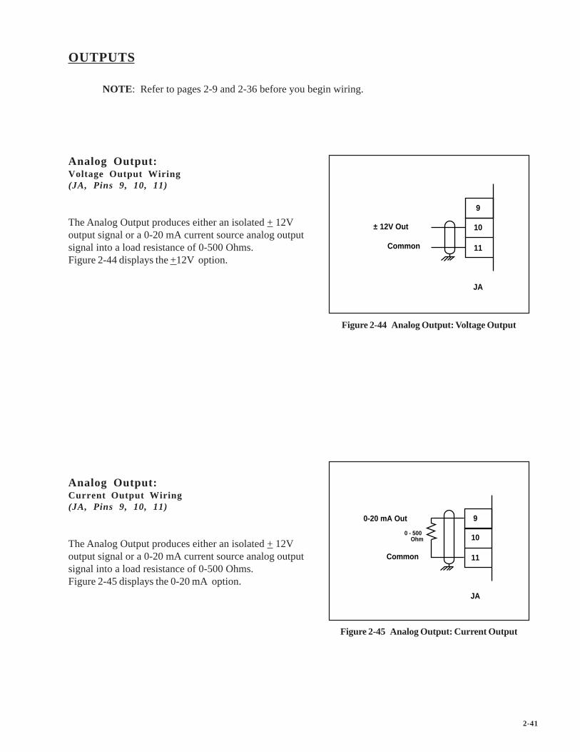
Analog Output:Voltage Output Wiring(JA, Pins 9, 10, 11)
The Analog Output produces either an isolated + 12Voutput signal or a 0-20 mA current source analog outputsignal into a load resistance of 0-500 Ohms.Figure 2-44 displays the +12V option.
Analog Output:Current Output Wiring(JA, Pins 9, 10, 11)
The Analog Output produces either an isolated + 12Voutput signal or a 0-20 mA current source analog outputsignal into a load resistance of 0-500 Ohms.Figure 2-45 displays the 0-20 mA option.
Figure 2-45 Analog Output: Current Output
9
10
11
JA
0-20 mA Out
Common
0 - 500 Ohm

2-42
DEVICENET CARD (OPTIONAL)
For the installation, wiring and operation of the optional DeviceNet card, refer to the CX-Series DeviceNetCard Technical Manual, # 0001-0132.

2-43
—NOTES—

2-44
LOGIC CONTROL
This section addresses the six digital inputs that control the CX-1200's operating state.The six digital inputs ( listed in by priority) are:
F-StopR-StopH-StopRunJog ForwardJog Reverse
When the CX-1200 is powered up, it defaults to R-Stop. If either Run or Jog have been hardwired, the CX-1200 will operate in either Run or Jog instead of R-Stop. Run is hardwired by shorting Run, R-Stop and F-Stop to common. Jog Forward or Jog Reverse are hardwired by shorting Jog, R-Stop, and F-Stop tocommon.
Run is terminated by activating F-Stop, R-Stop, or H-Stop. The operating state changes to the input thatterminated Run, provided that another input is not subsequently activated. Jog Forward or Jog Reverse areterminated by deactivating the Jog Forward or Jog Reverse inputs. Jog Forward or Jog Reverse can also beterminated by activating F-Stop, R-Stop, or H-Stop. The operating state automatically changes to R-Stopafter the Jog ramp is completed. You can not enter Run from Jog with the Jog inputs active. However, youcan enter Run during a deceleration from Jog after the Jog input is deactivated. You can not enter JogForward or Jog Reverse from Run. If two or more inputs become active at the same time, the input with thehighest priority will dictate the operating state.
The sections that follow demonstrate how to use the digital inputs.
Caut ion
Do not use the AC line power to start or stop thes y s t e m .
Use the Digital Inputs to start or stop the system.

2-45
Logic Inputs
F-Stop (Fast Stop) has priority over the other operating states. F-Stop forces the CO signal to “0” volts andmonitors the feedback. When the feedback is less than the Zero Speed (CP-332), the Drive En (PLC bit 41)resets to “0”. This PLC bit is routed by the PLC program to an output that disables the drive. If the feedbackdoes not reach Zero Speed within 1/2 second, the Drive En (PLC bit 41) automatically resets to “0”. Theintegral, trim and feedforward are also set to “0” and the loop is set to Open Loop (OL).
To activate F-Stop:• Activate High (Open), Level Sensitive, Latched• Wire to F-Stop interconnect• Use momentary contact - does not need to be maintained to remain active
F-Stop
Common
Open Momentarily
F-Stop
1
3
J6
Figure 2-46 F-Stop Input

2-46
R-Stop (Ramp Stop) has the second highest operating priority. Use R-Stop to stop the drive with adeceleration ramp. The velocity command is ramped down to “0”. If the loop is “Closed”, the ramp isexecuted with velocity loop control (with feedforward, using Kff ). If the loop is “Open”, the ramp isexecuted with feedforward only (using Kff ). The deceleration rate for the ramp is determined by Dcl TmRStp (CP-310) and Ref StopRmp (CP-210) or by the Dcl Rt RStp (CP-311). Once the ramp reaches “0”, thefeedback is monitored. When the feedback is less than the Zero Speed (CP-332), the Drive En (PLC bit 41)resets to “0”. The PLC program routes the PLC bit to an output that is disables the drive. If the feedbackdoes not reach the Zero Speed (CP-332) within 1/2 second, then the Drive EN PLC bit automatically resetsto “0”. The integral, trim and feedforward set to “0” and the loop sets to “Open Loop” (OL).
To activate R-Stop:• Activate High (Open), Level Sensitive, Latched• Use momentary contact - does not need to be maintained to remain active
R-Stop
1 F-Stop
R-Stop
Common
Open Momentarily
F-Stop
2
3
J6
Figure 2-47 R-Stop Input

2-47
H-Stop (Stop and Hold) has the third highest operating priority. Use H-Stop to stop the drive with adeceleration ramp. The velocity command is ramped down to “0”. If the loop is “Closed”, the ramp isexecuted with velocity loop control (with feedforward, using Kff ). If the loop is “Open”, the ramp will beexecuted with feedforward only (using Kff). The deceleration rate for the ramp is determined by Dcl TmHStp (CP-312) and Ref StopRmp (CP-210) or by the Dcl Rt RStp (CP-311). H-Stop differs from R-Stop inits operation after the deceleration ramp. The operation of the “Hold” function is dictated by HstpLoopMode (CP-230). In quadrature feedback, when the velocity command reaches “0” and the feedback isless than the Zero Speed (CP-332), then H-Stop will; hold the CO Signal to “0” volts (Open Loop), hold thefeedback velocity to Zero Speed (Closed Velocity Loop) or hold the feedback position to the position wherethe drive stopped (Closed Zero Error or Position Loop).
To activate H–Stop:• Activate High (Open), Level Sensitive, Latched• Use momentary contact - does not need to be maintained to remain active
H-Stop
3
J6
Open Momentarily
F-Stop1
2
4
R-Stop
F-Stop
R-Stop
H-Stop
Common
Figure 2-48 H-Stop Input

2-48
Run has the fourth highest operating priority. Run is the primary operating state. RUN Mode (CP-202)determines the mode of operation for Run, using either the master mode, the follower mode, the direct mode.The corresponding setpoint for the selected mode determines the operating speed. RUN Mode (CP-202)determines the control loop that is used during Run. At times, the selected RUN Mode is overridden. Thedirect mode will only operate in an open loop. The master mode will “Run” in velocity loop. Therefore, thefollower mode is the only mode that can “Run” with the “velocity loop” or the “Position loop”.
With the exception of the direct mode, the acceleration and deceleration ramps for the modes of operation aredetermined by Acl Tm RUN, (CP-301), Dcl Tm RUN (CP-303) and Ref Ramps (CP-300). The direct moderamps are determined by Acl Tm Drct (CP-231), Dcl Tm Drct (CP-232) and Ref Ramps (CP-300).
To activate Run:• Activate Low (closed to common), Level Sensitive, Latched• Use momentary contact - does not need to be maintained to remain active
Run
Common
F-Stop
R-Stop
H-Stop
Common
Run
Close Momentarily
5
8
1
2
4
3
J6
H-Stop
F-Stop
R-Stop
Figure 2-49 Run Input

2-49
Jog Forward has the fifth highest operating priority. Use Jog Forward to “Jog” the drive Forward at the rateindicated in Jog SP (CP-240). The acceleration and deceleration ramps are dictated by Acl Tm Jog (CP-241),Dcl Tm Jog (CP-243) and Jog SP (CP-240). After the Jog Forward input is deactivated and the rampedreference has reached “0”, the CX-1200 automatically reverts to the R-Stop operating state.
To activate Jog Forward:• Activate Low (closed to common), Level Sensitive, Not-Latched• Use momentary contact - needs to be maintained to remain active
Jog Forward
Common
F-Stop
R-Stop
H-Stop
Run
Common
Jog Fwd
Run
Close Maintained
6
8
1
2
4
5
3
J6
H-Stop
R-Stop
F-Stop
Figure 2-50 Jog Forward Input

2-50
Jog Reverse has sixth (the least) operating priority. Use Jog Reverse to “Jog” the drive Forward at the rateindicated in Jog SP (CP-240). The acceleration and deceleration ramps are dictated by Acl Tm Jog (CP-241),Dcl Tm Jog (CP-243) and Jog SP (CP-240). After the Jog Reverse input is deactivated and the rampedreference has reached “0”, the CX-1200 automatically reverts to the R-Stop operating state.
To activate Jog Reverse:• Activate Low (closed to common), Level Sensitive, Not-Latched• Use momentary contact - needs to be maintained to remain active
Jog Forward
Jog Reverse
Common
F-Stop
R-Stop
H-Stop
Run
Common
Jog Fwd
Close Maintained
6
7
8
1
2
4
5
3
J6
H-Stop
Run
R-Stop
Jog Rvs
F-Stop
Figure 2-51 Jog Reverse Input

2-51
—NOTES—

3 - 1
Operator Interface
Keypad OperationScreen Operation

3 - 2
7
4
1
-
8 9
5 6
2 3
0 .CLEAR
ENTER
MENU
STATUS
CODE
HELP
CONTREX
SETUPSCALINGSETPOINTS & RAMPSTUNINGALARMS & LIMITSBLOCKSPLCSYSTEM MONITORDEVICE TEST
CX - 1200MAIN MENU
MenuAlmMenuKey
LCDScreenDisplay
NumericKeys
ParameterUp/DownKeys (Par Up)(Par Dwn)
Code Key
StatusScreenKey Help
Screen KeyPage
Up/DownKeys Increment
Scroll Up/Down Keys
Enter Key
ClearKey
Figure 3-1 The CX–1200 Front Panel

3 - 3
KEYPAD OPERATION
The CX–1200 operates on a system of screens that are controlled by the front keypad. Figure 3-1 shows the locationof the keys and LCD screen display on the front panel. You will find detailed descriptions of the interactions of thekeys and screens throughout the “Operations” section. The following is a brief summary of how the front panelfunctions.
LCD Screen Display The screens are displayed on the LCD Display.
Menu Key The Menu key accesses the main menu from a sub-menu or status screen, and a sub-menu from a parameter screen.
Status Screen Key The Status key will immediately pop-up the status screen from any other screen. Toreturn to the previous screen, press the Status key again.
Page Up/Down Keys Some screens have multiple pages. The Page Up/Down keys allow you to scrollthrough, one page at a time.
Numeric Keys Use the Numeric keys to enter the Parameter Code of either a Control Parameter (CP) ora Monitor Parameter (MP) or to enter a Parameter Value for a Control Parameter. Usethe Enter key to activate the entry. Use the Clear key to delete the entry and clear theParameter Value to zero.
Parameter Up/Down Keys Each time you press the Parameter (Par) up key, the cursor and highlight bar will moveup by one line. Each time you press the Parameter (Par) down key, the cursor will movedown by one line. It will also automatically scroll through the lines if you hold the keydown.
Code Select Key Use the Code Select key in the Status screen and in the parameter screens to display aParameter Code line. When the Parameter Code line appears, you can use it to access aparameter and its value. Enter a Parameter Code, then press the Enter key and theparameter and its value will be displayed. You can change a Control Parameter value byentering a new value or by scrolling with the Increment Up/Down keys. Use the Clearkey to delete the entry and clear the parameter value to zero.
Help Screen Key The Help key accesses the Help screen and gives you a brief description of the parameteror subject that is highlighted (active). The Help screen also functions as an optionsscreen, where you can select Control Parameter data. You can access help from anyscreen. Press the Help key again to return to the previous screen.
Increment Scroll Up/Down Use these keys in the parameter screens to change the active value. Each time you pressthe Increment Scroll Up key, the active value will increase by one increment. Each timeyou press the Increment Scroll Down key, the active value will decrease by one decre-ment. It will also automatically scroll through the increments or decrements if you holdthe key down.
Clear Key Use the Clear key to delete a value or change which you have entered. However, theClear key will not delete the entry or change once the Enter key has been used.
Enter Key Use the Enter key to accept a value or change which you have entered.

3 - 4
Stat
usHe
lpM
ain M
enu
Setp
oints
& Ra
mps
Edit B
lock P
arm
s
Edit B
lock 0
Edit B
lock 1
Edit B
lock 2
Edit B
lock 3
Edit B
lock 4
Edit B
lock 5
Edit B
lock 6
Edit B
lock 7
Tunin
g
Mas
ter
Stop
Ram
p
Run
Ram
ps
Scali
ng
Posit
ion L
oop
Feed
forw
ard
Veloc
ity L
oop
Larg
e Er
ror
Alar
ms &
Lim
its
Lead
Follo
wer
Setu
pBl
ocks
Alar
ms
Limits
Syste
m M
onito
r
Run
Mon
itor
Std
Sign
al M
onito
r
Alar
ms &
Lim
its
DIG
I/O M
onito
r
Aux A
nalog
Mon
itor
Cont
rol O
verri
des
PLC
Even
ts Cn
trs
PLC
Data
Cop
y
PLC
Digit
al I/O
PLC
Mon
itor
PLC
Tim
ers
PLC
Prog
ram
ming
Stat
us S
cree
n Se
tup
Load
& S
ave
Parm
s
Keyp
ad L
ock S
etup
Seria
l Com
m S
etup
Devic
eNet
Set
up
Vide
o Se
tup
Alm
Indic
ator
Mas
k
Syste
m S
etup
DIG
I/O T
est
Aux A
nalog
Tes
ts
Seria
l Com
m T
est
Devic
e Te
st
Devic
e St
atus
Devic
e M
odel
and
Rev.
Hard
ware
Tes
ts
Std
Sign
al Te
sts
Dire
ct SP
& R
amps
Jog
SP &
Ram
ps
Follo
wer S
P
Rem
ote
Scro
ll
Bloc
k Sele
ction
Offse
ts &
Phas
e
Job
Size
s
Relat
ed It
ems
Posit
ion
Job
Size
s
Aux A
nalog
In 1
Aux A
nalog
In 2
Aux A
nalog
Out
Run
Mod
es
Fig
3-2
Ove
rvie
w o
f the
CX
–120
0 Sc
reen
Mat
rix

3 - 5
SCREEN OPERATION
The CX–1200 screen matrix has three main screens. These screens are:
Status ScreenMain MenuHelp Screen
There are nine sub-menus that are accessed through the Main Menu screen. These sub-menus are:
SetupScalingSetpoints and RampsTuningAlarms and LimitsBlocksPLCSystem MonitorDevice Test
All of the parameter screens are accessed through these nine sub-menu screens. You can use the parameter screensto access the parameters. Parameters fall into two classifications; Control Parameters and Monitor Parameters.The Control Parameters allow you to enter data that is unique to you system. The Monitor Parameters allow you tomonitor your system and diagnose problems.
This Screen Operation section is a basic overview of the three main screens; the Status screen, the Help screen andMain Menu screen. There is also a sample of a sub menu screen. For specific details on the parameter screens,refer to System Setup-Control Parameters and System Monitoring-Monitor Parameters. For the instructions tocustomize the Status screen, refer to System Setup-Control Parameters :Setup/Status Screen Setup.
Refer to Figure 3-2 for an overview of the CX–1200 screen matrix.

3 - 6
P1/1
C X - 1 2 0 0STATUS
Scaled Fb
RPM
Setpoint XStateFI1 RPMLd PosnFI2 RPMFb Posn
0F-STOP
0.00.00.00.0
The largenumberdisplay.
This bardisplays thename of the
screen.
The E.U. of thevalue in the
large numberdisplay.
To display thecode select line,
press the Codekey. To display aparameter and its
value, enter aparameter codeand press the
Enter key. You canselect and change
any controlparameter from
here.
The value ofthis parameteris displayed in
the largenumberdisplay.
This bardisplays error
and statusmessages.
The statuslines displaythe current
value or statusof the
parameter .Also indicatesthe number of
charactersallowed. Youcan change a
ControlParameter
when the line isactive.
This bardisplays the
current page &total pages.
"Alm" will blinkin this bar ifthere is an
active alarmstatus.
Press the Parkeys to scrollthe cursor upor down andmake the line
active.
Press the Helpkey to go to theactive line's help
screen.
Status Screen
Press the Status key to access the Status screen. The Status screen has a large number display for a quick, visualreference to a frequently used parameter, as well as its value and E.U. (Scaled Feedback is the default parameter).Below the large number display, the Status screen lists six frequently used parameters. In addition to the frequentlyused parameters, the line at the bottom of the display, called the code select line, allows you to access and displayany parameter and change any Control Parameter's value. The Status screen can be customized to reflect theparameters that you access most frequently. To customize the Status screen refer to System Setup- ControlParameters: Device Configure/Status Screen Setup.

3 - 7
Menu
C X - 1 2 0 0M A I N M E N U
SETUPSCALINGSETPOINTS & RAMPSTUNINGALARMS & LIMITSBLOCKSPLCSYSTEM MONITORDEVICE TEST
This bardisplays thename of the
screen.
Press theEnter key to go
to thehighlightedsub-menu.
Press the Helpkey to go to
the helpscreen.
This bardisplays error
and statusmessages.
"Alm" will blinkin this bar ifthere is an
active alarmstatus.
Main Menu Screen
Press the Menu key to access the Main Menu screen. The Main Menu screen displays the nine sub-menus that accessall of the parameter screens.
Press the Parkeys to scrollthe highlight
bar up or downthe list andmake a sub
menu screenactive.
If this bardisplays "Menu",then you are in a
menu screen.

3 - 8
Menu
SETPOINTS & RAMPS
RUN MODESMASTERFOLLOWERRUN RAMPSSTOP RAMPSJOG SP & RAMPSDIRECT SP & RAMPS
Menu
SCALING
LEADFOLLOWEROFFSETS & PHASEJOB SIZESAUX ANALOG INPUT 1AUX ANALOG INPUT 2AUX ANALOG OUTPUT
Press the Helpkey to go to
the helpscreen.
Press theMenu key to
go to the mainmenu screen
Press the Parkeys to scroll
up or down thesub-menu list.
This bardisplays error
and statusmessages.
Press theEnter key to go
to thehighlightedparameter
screen.
"Alm" will blinkin this bar ifthere is an
active alarmstatus.
Sub-Menu Screen / Samples
Parameter screens are accessed through the sub-menu screens.
This barindicates thatyou are in a
“Menu” screen.
This bar displaysthe name of the
sub-menuscreen.

3 - 9
Menu
HELPMaster SP
P a r a m e t e r : 2 1 0M a s t e r S P i s t h e s e t p o i n t s p e e d i n F bE U / T m . T h i s i s t h e s p e e d y o u w i s h t oa c h i e v e i n M a s t e rS e t p o i n t M o d e w h e nt h e c o n t r o l i s i nR U N s t a t e .
P 1
Press the Helpkey to exit thehelp screen.
The help textprovides a briefdescription of
the subjectand any
additionaloptions.
The first lineindicates thesubject of thehelp screen orthe parameter
number.
This bardisplays error
and statusmessages.
This bardisplays the
current page &total pages.
This linedisplays theparameternumber,
This bardisplays thename of the
screen.
"Alm" will blinkin this bar ifthere is an
active alarmstatus.
Help Screens
Press the Help key, to access the Help screens for an active (highlighted) Control Parameter line, an active MonitorParameter line or an active menu line. You can access “Help” from any screen. To exit the Help screen and returnto the previous screen, press the Help key again. In addition to the help information, the Help screens also functionas an options screen. For more information on the help options, refer to “Help Screen / Sample Options” on thenext page.

3 - 10
P 2
HELPMaster SP
Parameter: 210Select a value belowpress ENTER to change
Current ValBackup ValDefault Val
MIN ValMAX Val
00.00.0
-99999999999999
For the currentvalue, press theEnter key.
Use the Par keyto scroll to andselect backupvalue and pressthe Enter key.
Use the Par keysto scroll to andselect default valueand press theEnter key.
Help Screens / Sample Options
The Help screens also function as “options” screens where you can select a Control Parameter value. The last pageof many Help screens (usually page 2) have parameter options that have three value lines; current value, backupvalue and default value. There are also Help screens that contain a list of options that you can scroll through andselect. An asterisk next to an option indicates that it is the default value. See the samples below. To exit the Helpscreen and return to the previous screen, press the Help key again.
Use the Par key to scrollto and select (highlight)a value and press theEnter key.
P 2
HELPSync Mode
P a r a m e t e r : 2 0 3U s e ' p a r ^ o r V ' a n d ' e n t e r ' t o s e l e c t a n e w S y n c M o d e :
3 = L e a r n2 = T r e n d1 = F i x e d 0 = O f f *
The astericindicates thedefault value ofthe parameter.

4 - 1
Drive Setup/Calibration
Calibration

4 - 2

4 - 3
CALIBRATION
This procedure is a series of steps designed to verify the motor/drive/encoder wiring and polarity setup some of the basicparameters necessary for proper operation of the CX-1200.
Before you begin this procedure, the motor and drive must be wired and configured in accordance with the manufacturer’sinstructions. Refer to your drive manual to assist you in making the following drive adjustments:
• Set the maximum speed adjustment on the drive to deliver 10% more speed than the expected maximumspeed required for your application.
• Set the acceleration and deceleration times to their fastest settings.• Set the IR compensation to its minimum setting.• Set the Integral compensation to its minimum setting.
The CX-1200 must be configured and installed in accordance with the installation procedures indicated in the Installationsection of the CX-1200 Technical Reference Manual and the CX-1200, including its PLC, will be programmed as factorydefault.
NOTE: Sync Mode {CP-203} MUST have OFF selected. If the CX-1200 is not at factory default, then reference theOperator Interface Primer, Locating a parameter through the code select key procedure, (page 6) andcheck Sync Mode {CP-203}.
Setup consists of the following:
• Freq 2 and CO Setup• Motor/Encoder Signal Polarity Setup• Master Mode and Feedforward Scaling• Lead Scaling• Follower Mode Scaling
DANGER
Motion will occur in the calibration procedure.It is possible that sudden/violent motion couldresult and cause damage or personal injury.Make sure that the motor is secured in place.Take all possible precautions to ensure yoursafety.

4 - 4
DANGER
Hazardous voltages.
Can cause severeinjury, death ordamagethe equipment.
Make adjustmentswith caution.

4 - 5
Step 1 - Freq In 2 & CO Setup - Parameter Entry
The CX-1200 will display System Setup Freq In\Page 1.
Configure the CP’s on this screen as required.
State {MP-50}Cnt Mode FI2 {CP-265}PPR FI2 {CP-266}CO Mode {CP-270}CO Max Volts {CP-271}
NOTE: The Help key accesses the Help screen and gives you a brief description of the parameter or subjectthat is highlighted (active) on the screen. Press the Help key again to return to the previous screen.
Press the "Page Down" key to proceed to the next page.
Step 2 - Motor/Encoder Signal Polarity Setup - Parameter Entry
The CX-1200 will display System Setup Signal Polarity\Page 2.
Configure the CP’s on this screen as required.
State {MP-50}RUN Mode {CP-202}Direct SPx {CP-201}CO Polarity {CP-272}CO Offset {CP-273}CO Volts {MP-37}FI2 Hz {MP-03}
NOTE: The Help key accesses the Help screen and gives you a brief description of the parameter or subjectthat is highlighted (active) on the screen. Press the Help key again to return to the previous screen.

4 - 6
WARNINGPrepare the machine for motion.
Alert everyone present.
This test checks the Control Output polarity and the Encoder polarity, so a positive Control Output command causespositive Encoder feedback.
Forward:1. Enter RUN Mode {CP 202} = Direct.2. Enter Direct SPx {CP-201} = +2.0 volts.3. Place the control into "Run".
Verify forward motor direction:
4. If motor is running in the forward direction , skip to step 6.5. Rewire the motor leads for forward direction.
Verify forward sensor polarity:
6. If FI2 Hz {MP-03} is a positive number, skip to step 8.7. Rewire the feedback sensor polarity.8. Place the control into "F-Stop".
Reverse:Enter a direct mode setpoint for the reverse direction:
9. If CO Mode {CP-270} = Unipolar, skip to step 16.10. Enter Direct SPx {CP-201} = -2.0 volts.11. Place the control into "Run".
Verify reverse motor direction:
12. If motor is running in the reverse direction , skip to step 14.13. Rewire the motor leads for reverse direction, verify the motor drive is bipolar or unipolar reverseable and then recheck forward direction by returning to step 1.
Verify reverse sensor polarity:
14. If FI2 Hz {MP-03} is a negitive number, skip to step 16.15. Rewire the feedback sensor polarity, and then verify the sensor polarity in the forward direction by returning to step 1.16. Place the control into "F-Stop".17. Enter Direct SPx {CP-201} = 0 volts
Press the "Page Down" key to proceed to the next page.

4 - 7
Step 3 - Master Mode and Feedforward Scaling - Parameter Entry
The CX-1200 will display System Setup Master Mode\Page 3.
Configure the CP’s on this screen as required.
State {MP-50}RUN Mode {CP-202}Master SPx {CP-201}Pulses FI2 {CP-267}EU FI2 {CP-268}Kff Auto En {CP-364}Kff {MP-48}FI2 Hz {MP-03}FI2 RPM {MP-04}Fb EU/Tm {MP-06}
NOTE: The Help key accesses the Help screen and gives you a brief description of the parameter or subjectthat is highlighted (active) on the screen. Press the Help key again to return to the previous screen.
WARNINGPrepare the machine for motion.
Alert everyone present.
In this section, the master mode is scaled for engineering units. The feedforward is also scaled using the autofeedforward feature. Master mode scaling should be completed even if your end application is not master mode.
The CX 1200 must convert the feedback frequency into engineering units (RPM, Feet/min, etc.). To do this, itmust “know” the ratio between encoder lines and these units. This ratio is entered in two parts, the first part isFI2 Pulses and the second part is EU FI2 (Engineering Units for Frequency Input Number Two). For example,if feedback is coming from a one foot circumference metering wheel driving a 1000 line encoder and engineer-ing units will be inches, then EU FI2 {CP-268} = 12.0 and FI2 Pulses {CP-267} = 1000.
1. Enter RUN Mode {CP-202} = Master.2. Enter your FI2 Pulses {CP-267}.3. Enter your EU FI2 {CP-268}.
Enter the desired master mode setpoint in engineering units:
4. Enter Master SPx {CP-201} = Desired speed.
Verify master mode scaling:
5. Place the CX-1200 control into “Run”.6. If the Fb EU/Tm {MP-06} is not what you expect to see with the Master SP, then recalculate your scaling terms and return to step 2.
Scale the feedforward:
7. Enter Kff Auto En {CP-364} = ON.8. Wait several seconds.9. Enter Kff Auto En {CP-364} = OFF.10. Place the control into “F-Stop”.
Press the "Page Down" key to proceed to the next step.

4 - 8
Step 4 - Lead Scaling - Parameter Entry
The CX-1200 will display System Setup Lead\Page 4.
Configure the CP’s on this screen as required.
State {MP-50}Cnt Mode FI1 {CP-260}PPR FI1 {CP-261}Pulses FI1 {CP-262}EU FI1 {CP-263}FI1 Hz {MP-01}FI1 RPM {MP-02}Ld EU/Tm {MP-05}
NOTE: The Help key accesses the Help screen and gives you a brief description of the parameter or subjectthat is highlighted (active) on the screen. Press the Help key again to return to the previous screen.
When it is in follower mode, the CX-1200 must convert the lead frequency into engineering units (RPM, Feet/min, etc.). To do this, it must “know” the ratio between encoder lines and these units. This ratio is entered in twoparts, the first part is FI1 Pulses and the second part is EU FI1 (Engineering Units for Frequency Input NumberOne). For example, if the lead is coming from 60 tooth Quad Ring Kit on a motor armature driving a conveyorwith a 2 foot diameter roll through a 30:1 reduction and engineering units are feet, then FI1 Pulses {CP 262} =1800 (60*30) and EU FI1 {CP 263} = 6.283 (2*3.14...).
1. Enter your FI1 Pulses {CP 262}.2. Enter your EU FI1 {CP 263}.
Verify the Lead Scaling:
3. Place the Lead control into “Run”.4. If the Ld EU/Tm {MP-05} does not agree with the lead engineering units expected, then recalculate your scaling terms and return to step 1.5. Place the Lead control into “Stop”.
Press the "Page Down" key to proceed to the next page.

4 - 9
Step 5 - Follower Mode Scaling
The CX-1200 will display System Setup Follower Mode\Page 5.
State {MP-50}RUN Mode {CP-202}Follower SPx {CP-201}ScFbDisp EQU {CP-250}Lg Number Units {CP-449}Scaled Fb {MP-40}Ld EU/Tm {MP-05}Fb EU/Tm {MP-06}
NOTE: The Help key accesses the Help screen and gives you a brief description of the parameter or subjectthat is highlighted (active) on the screen. Press the Help key again to return to the previous screen.
WARNINGPrepare the machine for motion.
Alert everyone present.
In this section, the follower mode is scaled for engineering units. Master mode and lead scaling should becompleted before proceeding with the follower mode scaling procedure.
1. Enter RUN Mode {CP 202} = Follower.
Set the Scaled Feedback display for the disired units:
2. Enter ScFbDisp EQU {CP 250} = Ratio.3. Enter Lg Number Units {CP 449}.
In follower setpoint mode, the setpoint expresses the ratio between the follower and lead engineering units. Forexample if the lead is in centimeters, the follower is in milliliters and the setpoint is 1.25, then the follower willproduce 1.25 ml per cm. Enter the follower setpoint as the ratio of follower to lead engineering units:
4. Enter your Follower SPx {CP-201}.
Verify the Follower Mode Scaling:
5. Place the CX-1200 control into “Run” and also place the lead control into "Run"..6. If the Scaled FB {MP-40} is not what you expect to see with the Follower SP, then recalculate your scaling terms and return to step 2.7. Place the CX-1200 control into “F-Stop” and the lead control into "Stop".
Procedure complete.

4 - 10
CREEP CALIBRATION
The Creep Calibration allows you to eliminate motion that may occur with an open loop stop (zero volt)Control Output. Make sure the unit is in F-Stop to start out.
1. Go to the Setpoints & Ramps/Direct SP & Ramps/P1/1 screen and select Direct Modeby entering a 1 into the RUN Mode (CP-202) parameter. You can use the Help screen forCP-202 to select Direct Mode.
2. Make sure the Direct SP (CP-230) = 0.0 (include the decimal point).
3. Put the unit into RUN by activating the RUN input. The F-Stop, R-Stop, and H-Stop inputsmust be closed in order to enter the RUN State. You should have the Drive Enable outputconnected to the drive enable input of your drive (or to a control relay that is connected to theDrive Enable input). If not, enable the drive by some external means.
4. If motion occurs, attempt to eliminate it (stop the motion) with the balance pot (also calledzero-speed pot) or digital adjustment in your drive. If there is no pot (or digital adjustment) inthe drive, or if the motion can not be stopped, attempt to use the CO Offset (CP-273)parameter to "offset" the creep for the drive. Be sure to record this parameter and/or makesure it gets into the backup parameter list at some point.

4 - 11
ANALOG CALIBRATION
The Analog Calibration allows you to calibrate the auxiliary Analog I/O, AI1, AI2, AO. The board iscalibrated at the factory and the accuracy should be adequate for most applications. However, you may needto re-calibrate if your application demands more accuracy in a specific range or if you need to calibratedirectly to EU with a known signal level on the inputs. The Analog Calibration screen is accessed throughMain Menu/Device Tests/Aux Analog Tests/pg 3.
Analog Output (voltage):
1. Connect a voltmeter between pins 10 and 11 with the positive lead on pin 10 (pin 11 iscommon).
2. Set AO Mode (CP-291) to “Volts” (1).
3. Set Analog Cal Sel (CP-461) to AO (3) to Select AO for calibration.
4. Set Analog Cal Ref (CP-462) to “A” (1) to select point A.
NOTE: The old calibration data will be overwritten.
5. Set Analog Cal EN (CP-460) to “On” (1) to start calibration.
6. Adjust AO Bit Set (CP-464) until the meter reads the voltage that you want set for point A.This is generally your smallest (or negative) voltage point. A -12 volts requires about -29500bits, -10 volts about -24500 bits, 0 volts about 0 bits. For -12 volts, start with about -29400and use the incremental scroll key .
7. Enter the exact voltage measured by the meter into AnalogRef Val (CP-463).
8. Set Analog Cal Ref (CP-462) to “B” (2) to select point B.
9. Adjust AO Bit Set (CP-464) until the meter reads the voltage that you want use for point B.This is usually your largest (or positive) voltage point. A +12 volts requires about 30100 bits,10 volts about 25100 bits, 0 volts about 0 bits. For 12 volts, start with about 30000 and usethe incremental scroll key.
10. Enter the exact voltage measured by the meter into AnalogRef Val (CP-463).
11. Set Analog Cal EN (CP-460) to “Off” (0) to disable further calibration.
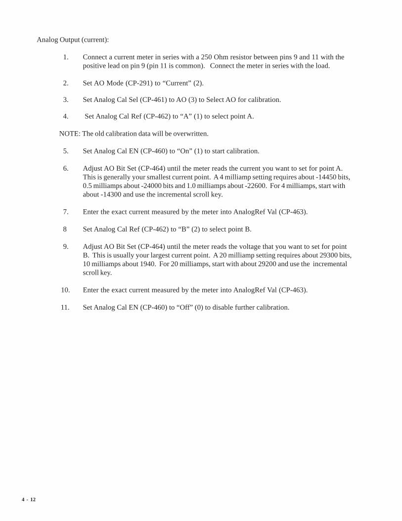
4 - 12
Analog Output (current):
1. Connect a current meter in series with a 250 Ohm resistor between pins 9 and 11 with thepositive lead on pin 9 (pin 11 is common). Connect the meter in series with the load.
2. Set AO Mode (CP-291) to “Current” (2).
3. Set Analog Cal Sel (CP-461) to AO (3) to Select AO for calibration.
4. Set Analog Cal Ref (CP-462) to “A” (1) to select point A.
NOTE: The old calibration data will be overwritten.
5. Set Analog Cal EN (CP-460) to “On” (1) to start calibration.
6. Adjust AO Bit Set (CP-464) until the meter reads the current you want to set for point A.This is generally your smallest current point. A 4 milliamp setting requires about -14450 bits,0.5 milliamps about -24000 bits and 1.0 milliamps about -22600. For 4 milliamps, start withabout -14300 and use the incremental scroll key.
7. Enter the exact current measured by the meter into AnalogRef Val (CP-463).
8 Set Analog Cal Ref (CP-462) to “B” (2) to select point B.
9. Adjust AO Bit Set (CP-464) until the meter reads the voltage that you want to set for pointB. This is usually your largest current point. A 20 milliamp setting requires about 29300 bits,10 milliamps about 1940. For 20 milliamps, start with about 29200 and use the incrementalscroll key.
10. Enter the exact current measured by the meter into AnalogRef Val (CP-463).
11. Set Analog Cal EN (CP-460) to “Off” (0) to disable further calibration.

4 - 13
Analog Input 1 (voltage):
1. Connect the Analog Output voltage pins to the Analog Input 1 voltage pins - pin 10 to pin 2,pin 11 to pin 4. Connect a voltmeter between pins 2 and 4 with the positive lead on pin 2 (pin4 is at common).
2. Set AO Mode (CP-291) to “Volts” (1).
3. Set AI1 Mode (CP-280) to “Volts” (1).
4. Set Analog Cal Sel (CP-461) to “AI1” (1) to Select AI1 for calibration.
5. Set Analog Cal Ref (CP-462) to “A” (1) to select point A.
NOTE: The old calibration data will be overwritten.
6. Set Analog Cal EN (CP-460) to “On” (1) to start calibration.
7. Adjust AO Bit Set (CP-464) until the meter reads the voltage that you want set for point A.This is generally your smallest (or negative) voltage point. A -12 volts requires about -29500bits, -10 volts about -24500 bits, 0 volts about 0 bits. For -12 volts, start with about -29400and use the incremental scroll key.
8. Enter the exact voltage measured by the meter into AnalogRef Val (CP-463).
9. Set Analog Cal Ref (CP-462) to “B” (2) to select point B.
10. Adjust AO Bit Set (CP-464) until the meter reads the voltage that you want use for point B.This is generally your largest (or positive) voltage point. A +12 volts requires about 30100bits, 10 volts about 25100 bits, 0 volts about 0 bits. For 12 volts, start with about 30000 anduse the incremental scroll key.
11. Enter the exact voltage measured by the meter into AnalogRef Val (CP-463).
12. Set Analog Cal EN (CP-460) to “Off” (0) to disable further calibration.

4 - 14
Analog Input 1 (current):
1. Connect a current meter between pin 9 and pin 2 with the positive lead on pin 9. Connect pin3 to pin 4 and pin 4 to pin 11.
2. Set AO Mode (CP-291) to “Current” (2).
3. Set AI1 Mode (CP-280) to “Current” (2).
4. Set Analog Cal Sel (CP-461) to “AI1” (1) to Select AI1 for calibration.
5. Set Analog Cal Ref (CP-462) to “A” (1) to select point A.
NOTE: The old calibration data will be overwritten.
6. Set Analog Cal EN (CP-460) to “On” (1) to start calibration.
7. Adjust AO Bit Set (CP-464) until the meter reads the current you want to set for point A.This is generally your smallest current point. A 4 milliamp setting requires about -14450 bits,0.5 milliamps about -24000 bits and 1.0 milliamps about -22600. For 4 milliamps, start withabout -14300 and use the incremental scroll key.
8. Enter the exact current measured by the meter into AnalogRef Val (CP-463).
9. Set Analog Cal Ref (CP-462) to “B” (2) to select point B.
10. Adjust AO Bit Set (CP-464) until the meter reads the voltage that you want to set for pointB. This is generally your largest current point. A 20 milliamp setting requires about 29300bits, 10 milliamps about 1940. For 20 milliamps, start with about 29200 and use theincremental scroll key.
11. Enter the exact current measured by the meter into AnalogRef Val (CP-463).
12. Set Analog Cal EN (CP-460) to “Off” (0) to disable further calibration.

4 - 15
Analog Input 2 (voltage):
1. Connect the Analog Output voltage pins to the Analog Input 2 voltage pins - pin 10 to pin 5,pin 11 to pin 7 Connect a voltmeter between pins 5 and 7 with the positive lead on pin 5 (pin7 is at common).
2. Set AO Mode (CP-291) to “Volts” (1).
3. Set AI2 Mode (CP-285) to “Volts” (1).
4. Set Analog Cal Sel (CP-461) to “AI2” (2) to Select AI2 for calibration.
5. Set Analog Cal Ref (CP-462) to “A” (1) to select point A.
NOTE: The old calibration data will be overwritten.
6. Set Analog Cal EN (CP-460) to “On” (1) to start calibration.
7. Adjust AO Bit Set (CP-464) until the meter reads the voltage that you want set for point A.This is generally your smallest (or negative) voltage point. A -12 volts requires about -29500bits, -10 volts about -24500 bits, 0 volts about 0 bits. For -12 volts, start with about -29400and use the incremental scroll key.
8. Enter the exact voltage measured by the meter into AnalogRef Val (CP-463).
9. Set Analog Cal Ref (CP-462) to “B” (2) to select point B.
10. Adjust AO Bit Set (CP-464) until the meter reads the voltage that you want use for point B.This is generally your largest (or positive) voltage point. A +12 volts requires about 30100bits, 10 volts about 25100 bits, 0 volts about 0 bits. For 12 volts, start with about 30000 anduse the incremental scroll key.
11. Enter the exact voltage measured by the meter into AnalogRef Val (CP-463).
12. Set Analog Cal EN (CP-460) to “Off” (0) to disable further calibration.

4 - 16
Analog Input 2 (current):
1. Connect a current meter between pin 9 and pin 5 with the positive lead on pin 9. Connect pin6 to pin 7 and pin 7 to pin 11.
2. Set AO Mode (CP-291) to “Current” (2).
3. Set AI2 Mode (CP-285) to “Current” (2).
4. Set Analog Cal Sel (CP-461) to “AI2” (2) to Select AI2 for calibration.
5. Set Analog Cal Ref (CP-462) to “A” (1) to select point A.
NOTE: The old calibration data will be overwritten.
6. Set Analog Cal EN (CP-460) to “On” (1) to start calibration.
7. Adjust AO Bit Set (CP-464) until the meter reads the current you want to set for point A.This is generally your smallest current point. A 4 milliamp setting requires about -14450 bits,0.5 milliamps about -24000 bits and 1.0 milliamps about -22600. For 4 milliamps, start withabout -14300 and use the incremental scroll key.
8. Enter the exact current measured by the meter into AnalogRef Val (CP-463).
9. Set Analog Cal Ref (CP-462) to “B” (2) to select point B.
10. Adjust AO Bit Set (CP-464) until the meter reads the voltage that you want to set for pointB. This is generally your largest current point. A 20 milliamp setting requires about 29300bits, 10 milliamps about 1940. For 20 milliamps, start with about 29200 and use theincremental scroll key.
11. Enter the exact current measured by the meter into AnalogRef Val (CP-463).
12. Set Analog Cal EN (CP-460) to “Off” (0) to disable further calibration.

4 - 17
Calibrating and Scaling AI1 Together
In some applications you may know the voltage (or current) to EU representation, but you have no idea thevoltage produced by the sensor at either end point. You can ‘calibrate’ the signal directly in terms of EU bysetting the calibration references the same as the scaling references, i.e. set AI1 RA (CP-281) equal toAnlgCal Ref A (MP-168) for this signal and set AI1 RB (CP-283) equal to Cal Ref B (MP-169) for thissignal. These two points should be discretely different from each other and should be reasonable estimatesfor the actual voltage or current range. You would then set the EU@ AI1 RA (CP-282) and EU@ AI1 RB(CP-284) to the sensor’s operating points used during the calibration process for points A and B respectively.
1. Connect the sensor to the AI1 voltage (or current) pins. Connect pins 3 and 4 together ifusing current mode.
2. Set AI1 Mode (CP-280) to “Volts” (1) or “Current” (2).
3. Set Analog Cal Sel (CP-461) to “AI1” (1) to Select AI1 for calibration.
4. Set Analog Cal Ref (CP-462) to “A” (1) to select point A.
NOTE: The old calibration data will be overwritten.
5. Set Analog Cal EN (CP-460) to “On” (1) to start calibration.
6. Run the sensor at the operating point for calibration point A. This is generally your smallest(or negative) voltage point (or smallest current point). Record the value of this operatingpoint as sensor operating point A in EU.
7. Enter an estimate of the voltage (or current) that the sensor is producing at this operatingpoint into AnalogRef Val (CP-463). Record this value as point A reference voltage (orcurrent) along side the sensor operating point A.
8. Set Analog Cal Ref (CP-462) to “B” (2) to select point B.
9. Run the sensor at the operating point for calibration point B. This is generally your largest (orpositive) voltage point (or largest current point). Record the value of this operating point aspoint B EU.
10. Enter an estimate of the voltage (or current) that the sensor is producing at this operatingpoint into AnalogRef Val (CP-463). Record this value as point B reference voltage (orcurrent) along side the sensor operating point B.
11. Set Analog Cal EN (CP-460) to “Off” (0) to disable further calibration.
12. Go to SCALING/SIGNAL SCALING/P1. Enter voltage (or current) that you recorded asthe point A reference voltage (or current) into AI1 RA (CP-281). Enter the sensor operatingpoint A (EU) that the sensor was producing during the point A calibration into EU@AI1 RA(CP-282). This could actually be a time-less unit, but is considered as EU scaling because itassumes speed representation for the velocity loop. Enter voltage (or current) that yourecorded as the point B reference voltage (or current) into AI1 RB (CP-283). Enter thesensor operating point B (EU) that the sensor was producing during the point B calibrationinto EU@AI1 RB (CP-284).
Repeat this procedure for AI2 if necessary. Calibrate AI2 and use the corresponding AI2 parameters.

4 - 18
—NOTES—

5 - 1
Position Loop
Feedforward
Large Error
Related Items
Alarms and LimitsAlarms
Limits
BlocksEdit Block Parms
Edit Block 0
Edit Block 1
Edit Block 2
Edit Block 3
Edit Block 4
Edit Block 5
Edit Block 6
Edit Block 7
PLCPLC Monitor
PLC Timers
PLC Event Cntrs
PLC Postion Cntrs
PLC Data Copy
Digital I/O
PLC programming
System Setup/Control Parameters
Introduction to ControlParametersSetup
System Setup
Status Screen Setup
Load and Save Parms
Remote Scroll Setup
Keypad Lock Setup
Serial Comm Setup
DeviceNet Setup
Video Setup
Alm Indicator Mask
ScalingLead
Follower
Offsets & Phase
Job Sizes
Aux Analog Input 1
Aux Analog Input 2
Aux Analog Output
Setpoints and RampsRun Modes
Master
Follower
Run Ramps
Stop Ramps
Jog SP and Ramps
Direct SP and Ramps
TuningVelocity Loop

5 - 2

5 - 3
INTRODUCTION TOCONTROL PARAMETERS
Parameters are divided into two classifications; Control Parameters (CP) and Monitor Parameters (MP).This section is about Control Parameters. Monitor Parameters are explained in System Monitoring:Monitor Parameters.
The parameters appear on the screens by a Parameter Name. The Help screens list the parameters by boththeir Parameter Name and by a numbered code, which is called the Parameter Code. The operational data isthe Parameter Value.
Parameters =Monitor Parameter Scaled Fb MP-40 0.0 (default)
Control Parameter Master SP CP-210 0.0 (default)
Parameter Name Parameter Code Parameter Value
Note: All Control Parameters are designated by a small indicator “dot” to the left of the Parameter Name,as it appears on a screen (unlike Monitor Parameters, which do not have a small indicator “dot” to the left ofthe Parameter Name).
The CX-1200 is pre-loaded at the factory with a complete set of default Control Parameter values. Themajority of these default settings are suitable for most applications and do not require modification.
Control Parameters allow you to enter data that is unique to your system (e.g., encoder resolution, Lead toFollower ratios, maximum RPM, setpoints, acceleration/deceleration ramp rates) by accessing a parameterscreen and entering a parameter value. Once the Control Parameters are entered and the setup for the CX-1200 is complete, the Control Parameters can be “locked out” so that they become inaccessible from theKeypad. This feature prevents an inadvertent accidental entry. For details, refer to the Keypad Lockoutscreen in System Setup/Control Parameters: Setup/Keypad Lockout Setup. A synopsis of the information isalso available by referencing Keypad Lockout (MP-103) in Appendices: Appendix C.
The following sections demonstrate how to use the Control Parameter screens. These sections include:
Setup Alarms and LimitsScaling BlocksSetpoints and Ramps PLCTuning

5 - 4
—NOTES—

5 - 5
SETUP
The Setup screens allow you to perform a varitey of load, save and setup functions, The “Load” parametersallow you to load Control Parameter values and the PLC program from either the backup or from the factorydefault. The “Save” parameters allow you to save the Control Parameter values and the PLC program to abackup copy. You can customize the Status screen for your specific requirements. The SerialCommunications Setup screen includes parameters that configure the serial communications port. WhenKeypad Lock Input is active, Control Parameter values can not be changed. The Keypad Lockout Setupscreens allow you to specify which Control Parameters will be exempt from the lockout when the KeypadLockout Input is active.The Video Setup screen includes the parameters that control the screen operation.Display Setup contrast and adjust the pixel intensity of the screen display. The Alarm Indicator Mask screenincludes the parameters that determine which alarms and which numerical comparator outcomes will cause the‘alm’ to flash in the lower-left corner of the screen. The DeviceNet setup includes Control Parameters forDeviceNet network communications.
Caution: To avoid damage to your system, the CX-1200 must be calibrated and the motor drive set upbefore you operate your system. Refer to Drive Setup / Calibration: Calibration.
The Setup screens are:
• Status Screen Setup• Load and Save Parms• Remote Scroll Setup• Keypad Lock Setup• Serial Comm Setup• DeviceNet Setup• Video Setup• Alm Indicator Mask

5 - 6
STATUS SCREEN SETUP P1/1
You can customize the six status lines, as well as the large number display and the E.U. line on the Statusscreen. To customize the large number display, enter this code of the parameter that you want displayed inLg Number Parm (CP-440). Use Large Number Units (CP-449) to select and customize the E.U. line thatappears immediately below the large number display. For each of the status lines (CP-441 throughCP-446), enter the code of the parameter that you want to appear on the corresponding line. You can enter a“0” in status lines 2 - 6 if you want them to remain blank. You can also access and change Control Parameters441 through 446 while you are in the Status screen by using the Code key. For details on the Code key, referto the Status screen in Operator Interface: Screen Operation.
Lg Number ParmUse Large Number Parameter (CP-440) to select the parameter that displays in the Large Number Display in the Statusscreen (refer to the status screen in Operator Interface: Screen Operation. You can also use the Code key to accessand change CP-440 in the Status Screen.
Lg Number UnitsUse Large Number Units (CP-449) to select the E.U. text that displays immediately below the Large NumberDisplay in the Status screen (refer to the status screen in Operator Interface: Screen Operation). Enter the numericcode that identifies the E.U. for the Control Parameter displayed in the Large Number Parameter (CP-440). Referto CP-449 in Appendices: Appendix C for the numeric code list. The Help screen for CP-449 also contains a partiallist of numeric code options. In addition, you can also scroll through the numeric code options by accessing CP-449with the Code key while you are in the in the Status screen.
Status Line 1Use Status Line 1 (CP-441) to select the parameter that displays on the first line, under the Large Number Display, of theStatus screen (refer to the status screen in Operator Interface: Screen Operation). You can also use the Code key toaccess and change CP-441 in the Status screen.
Status Line 2Use Status Line 2 (CP-442) to select the parameter that displays on the second line (under the Large Number Display)of the Status screen (refer to the status screen in Operator Interface: Screen Operation). If you want this line toremain blank, enter a “0” in CP-442. You can also use the Code key to access and change CP-442 in the Status screen.
Status Line 3Use Status Line 3 (CP-443) to select the parameter that displays on the third line (under the Large Number Display) ofthe Status screen (refer to the status screen in Operator Interface: Screen Operation). If you want this line to remainblank, enter a “0” in CP-443. You can also use the Code key to access and change CP-443 in the Status screen.
Status Line 4Use Status Line 4 (CP-444) to select the parameter that displays on the fourth line (under the Large Number Display) ofthe Status screen (refer to the status screen in Operator Interface: Screen Operation). If you want this line to remainblank, enter a “0” in CP-444. You can also use the “Code key to access and change CP-444 in the Status screen.
Status Line 5Use Status Line 5 (CP-445) to select the parameter that displays on the fifth line (under the Large Number Display) ofthe Status screen (refer to the status screen in Operator Interface: Screen Operation). If you want this line to remainblank, enter a “0” in CP-445. You can also use the “Code key to access and change CP-445 in the Status screen.
Status Line 6Use Status Line 6 (CP-446) to select the parameter that displays sixth line (under the Large Number Display) of theStatus screen (refer to the status screen in Operator Interface: Screen Operation). If you want this line to remainblank, enter a “0” in CP-446. You can also use the “Code key to access and change CP-446 in the Status screen.

5 - 7
LOAD & SAVE PARMS P1/1
The Load and Store Parameters screen includes four parameters. The “Load” parameters allow you toload Control Parameter values and the PLC program from either the backup or from the factory default.The “Save” parameters allow you to save the Control Parameter values and the PLC program to a backupcopy. The Control Parameters are located in two sections: the Main List CPs and the Block CPs. TheMain List CPs are (CP-201 through CP-494). The Block CP’s are (CP-500 through CP-667). You canload and save each section separately, or you can load and save both sections together .
Load ParmsUse Load Parameters (CP-496) to retrieve (load) parameter values from either the factory or the default backup list.You can specify which parameter values to load form the back up, per the list below. It is easier to select the LoadParameters values through the Help screen, however, you can enter the corresponding number directly into the LoadParameters (CP-496). A message will flash in the error and message status bar at the bottom of the screen to indicatethe completion of the operation . The Load Parameters operation will not function while the CX-1200 is in “RUN”.
6 = Load Dflts BlockCP Load Factory Defaults into CP-500 through CP-6675 = Load Dflts Main CP Load Factory Defaults into CP-201 through CP-4944 = Load Dflts All Cp Load Factory Defaults into CP-201 through CP-6673 = Load Backup BlockCP Load Backup into CP-500 through CP-6672 = Load Backup Main CP Load Backup into CP-201 through CP-4941 = Load Backup All Cps Load Backup into CP-201 through CP-6670 = No Change
Load PLC PrgmUse Load PLC Program (CP-497) to retrieve (load) either the backup for the PLC program which you have savedor the factory default PLC program. Enter “1” to load the backup PLC program or enter “2 ” to load the factorydefault PLC program. You can also select the one of the two values through the “Help” screen. The loadedprogram is compiled and a message will flash in the error and message status bar at the bottom of the screen toindicate the completion of the operation. The Load PLC Program operation will not function while the CX-1200 is in“RUN”.
2 = Load Dflt PLC Prg Load Factory Default PLC program1 = Load Backup PLC Prg Load Backup PLC program0 = No Change
Save ParmsUse Save Parameters (CP-498) to save the current parameter values to the backup. You can specify which param-eter values to save as backup, per the list below Either enter the corresponding number directly into the SaveParameters (see list below) or select the Save Parameters values through the “Help” screen. A message (Saved2BkUp) will flash in the error and message status bar at the bottom of the screen to indicate the completion of theoperation.
3 = Save Block CP’s Save CP-500 through CP-667 to Backup2 = Save Main CP’s Save CP-201 through CP-494 to Backup1 = Save All CP’s Save CP-201 through CP-667 to Backup0 = No Change
Save PLC PrgmEnter a “1” in Save PLC Program (CP-499) to save the current PLC program to the backup. A message (Saved2BkUp) will flash in the error and message status bar at the bottom of the screen to indicate the completion of theoperation.
1 = Save PLC Program to Backup0 = No Change

5 - 8
REMOTE SCROLL SETUP P1/1
Rmt ScrollIn Remote Scroll (CP-400), enter the number of the Control Parameter that you want the Remote Scroll Up PLC bit(168) or the Remote Scroll Dn PLC bit (169) to increment or decrement by 1 least significant digit, at the Rmt ScrollRate (CP-401). To disable the function, set Rmt Scroll (CP-400) to “0” .
Rmt Scroll RateRemote Scroll Rate (CP-401) is the number of times per second, that the Control Parameter that you entered in RmtScroll (CP-400) is either incremented or decremented by 1 least significant digit , when the Remote Scroll Up PLCbit (168) or the Remote Scroll Dn PLC bit (169) is active.
5 - 9
KEYPAD LOCKOUT SETUP P1/2
When Keypad Lock Input is active, Control Parameter values can not be changed. The Keypad Lockout Setup screensallow you to specify which Control Parameters, or blocks of Control Parameters, will be exempt from the lockout whenthe Keypad Lockout Input is active. Use KyPdLk Mask (CP-480) in conjunction with the Unlock Control Parameters481 - 488 to specify which Control Parameters are exempt from the lockout.
KyPdLk MaskWhen the keypad lockout input is active (low), and Key Pad Lock Mask (CP-480) is set to either "0",“1”, “2”, “3”, or“4”, then certain groupings (see list below) of Control Parameters can be exempted (masked out) from the lockout. Inaddition, the individual Control Parameters that are specified in CPs 481 through 488 are also exempt. When Key PadLock Mask (CP-480) is set to “4”, then entire blocks of Control Parameters can be exempted in Unlock Block (CP-489).If Key Pad Lock Mask (CP-480) is set to “0”, then all of the Control Parameters are locked out and non are exempt,including CPs 418-489.
4 = UnLckBlk = Block Values of the Block Selected by Unlock Block (CP-489) and the Unlocked CP’s.3 = Blk Vals = All BlockValues (CP-540-667) and the Unlocked CP’s are allowed to change.2 = Setpnts = Setpoints (CP-210, 220, 230, 235, 240) and the Unlocked CP’s are allowed to change.1 = UnlckCP = CP’s selected by the Unlock CP A - F are allowed to changed.0 = Total Lockout (default).
Unlock CP AUnlock Control Parameter A (CP-481) determines which Control Parameter can change, even when the keypad-lockoutis active. For the Unlock Control Parameter A (CP-481) to function, KyPdLk Mask (CP-480) must be set to a value otherthan “0” (All Lock). Enter “0” in Unlock Control Parameter A (CP-481) to disable it from selecting any ControlParameter.
Unlock CP B (CP-482)Unlock CP C (CP-483)Unlock CP D (CP-484)Unlock CP E (CP-485)Unlock CP F (CP-486)Unlock CP G (CP-487)Unlock CP H (CP-488)
Control Parameters 481 - 488 are identical to each other. Refer to the description for Unlock CP A (CP-481).
KeyPad LockoutKeypad Lockout (MP-103) displays the Keypad Lockout status. “On” indicates that the Keypad Lockout is active.When Keypad Lockout is active, Control Parameter values can not be changed. With the exception of the ControlParameters that are exempted by CP’s 480-489, the “OFF” indicates that the Keypad Lockout is not active. Whenthe Keypad Lockout is not active, any Control Parameter can be changed.

5 - 10
KEYPAD LOCKOUT SETUP P2/2
KyPdLk MaskWhen the keypad Lockout input is active (low), and Key Pad Lock Mask (CP-480) is set to either "0", “1”, “2”, “3”, or“4”, then certain groupings (see list below) of Control Parameters can be exempted (masked out) from the lockout. Inaddition, the individual Control Parameters that are specified in CPs 481 through 488 are also exempt. When Key PadLock Mask (CP-480) is set to “4”, then entire blocks of Control Parameters can be exempted in Unlock Block (CP-489).If Key Pad Lock Mask (CP-380) is set to “0”, then all of the Control Parameters are locked out and non are exempt,including CPs 381-389.
4 = UnLckBlk = Block Values of the Block Selected by Unlock Block (CP-489) and the Unlocked CP’s.3 = Blk Vals = All BlockValues (CP-540-667) and the Unlocked CP’s are allowed to change.2 = Setpnts = Setpoints (CP-210, 220, 230, 240) and the Unlocked CP’s are allowed to change.1 = UnlckCP = CP’s selected by the Unlock CP A - F are allowed to changed.0 = Total Lockout.
UnlockBlockUse Unlock Block (CP-489) to choose which block of Control Parameters are exempt from the lockout, even whenKeypad-lockout is active. Unlock Block (CP-489) is used in conjunction with KyPdLk Mask (CP-480), which mustbe set to “4”. Control Parameters 481 - 488 are also exempt when KyPdLk Mask (CP-480) is set to “4” . If KeyPad Lock Mask (CP-480) is set to “0”, all of the Control Parameters are locked out and none are exempt, includingCPs 481-489.
KeyPad LockoutKeypad Lockout (MP-103) displays the Keypad Lockout status. The Keypad Lockout is active when “On” isdisplayed. When Keypad Lockout is active, Control Parameter values can not be changed. With the exception ofthe Control Parameters that are exempted by CP’s 480-489. The Keypad Lockout is not active when “OFF” isdisplayed. When the Keypad Lockout is not active, any Control Parameter can be changed.

5 - 11
SERIAL COM SETUP P1/1
The Serial Communications Setup screen includes parameters that configure the serial communications port.Each CX-1200 that is connected on the same communications link, must have a unique Device Address(CP-470). The baud rate, frame format and record format must be consistent with other devices arecommunicating with the CX-1200.
Device AddressDevice Address (CP-470) assigns the serial communications address for the CX-1200. This number should be differentfrom any other units that are on the serial link.
Baud RateThe Baud Rate (CP-471) determines the serial communications data transfer rate (see list below) in Bits/Sec. With a 10bit frame length, the number of Frame/Sec would be 1/10 the Baud Rate.
1 = 300 bps = 300 Baud2 = 600 bps = 600 Baud3 = 1200 bps = 1200 Baud4 = 2400 bps = 2400 Baud5 = 4800 bps = 4800 Baud6 = 9600 bps = 9600 Baud (default)7 = 19200 bps = 19.2k baud
Frame FormatFrame Format (CP-472) determines the parity, the number of data bits and the number of stop bits for the serialcommunications.
1 = N,8,1 = No Parity, 8 data bits, 1 stop bit (10 bit frame - ASCII or Binary)2 = E,7,1 = Even Parity, 7 data bits, 1 stop bit (10 bit frame-ASCII only)
Record FormatRecord Format (CP-469) determines which type of data format (see list below) will be used for the serial communication.
3 = ASCII2 2 = ASCII 1 = BINARY
CRC EnableIf CRC Enable (CP-468) is set to “ON” (1), you must append a CRC value to all serial communications messages that arereceived by the CX-1200 (See Serial Communications: Using Serial Communications). The CX-1200 checks the CRCvalue against the the message contents (excluding the “STX”), then calculates a CRC value and appends it to all serialcommunications responses. If CRC Enable (CP-468) is set to “OFF” (0), the CX-1200 will ignore any CRC value that isappended to a message and will not append a CRC value to any serial communications responses.
1 = On (Enabled) 0 = Off (Disabled)

5 - 12
DEVICENET SETUP P1/2
The DeviceNet Setup screens include parameters to configure the DeviceNet option card for networkcommunications. Page 1 of the DeviceNet Setup screens includes the Serial Number attribute of the IdentityObject and the MAC ID and Baud Rate attributes from the DeviceNet Object. Page 2 is used to enter theeight Parameter Codes for the Assembly Queue. Refer to "DeviceNet Card Technical Manual" for moredetailed information on DeviceNet operations.
DN MAC IDDN MAC ID is the DeviceNet Media Access Control Identifier. The MAC ID is used to assign a unique identifier oraddress to each node on the network. Assign a different MAC ID to each CX-1200 device on the network from 0 to 63.
DN Baud RateThe DN Baud Rate is the network data or transfer rate. Enter the number from the listing below that corresponds to thedesired baud rate:
1 = 125k bps2 = 250k bps3 = 500k bps
Serial NumberSerial Number is the serial number from the DeviceNet card in this CX-1200 controller. If the card was factory installed,the Serial Number should already be entered. If the card is being field installed, enter the Serial Number from the labelon the card or recorded in the DeviceNet Card Technical Manual.

5 - 13
DEVICENET SETUP P2/2
The following parameters are used to identify the eight parameters for the I/O Assembly Queue.
DN Write Parm 1Enter the number of a Control Parameter to be written to with the DeviceNet poll command in the I/O Assembly Queue.
DN Write Parm 2Enter the number of a Control Parameter to be written to with the DeviceNet poll command in the I/O AssemblyQueue.
DN Write Parm 3Enter the number of a Control Parameter to be written to with the DeviceNet poll command in the I/O AssemblyQueue.
DN Write Parm 4Enter the number of a Control Parameter to be written to with the DeviceNet poll command in the I/O AssemblyQueue.
DN Read Parm 1Enter the number of a Control Parameter or Monitor Parameter to be read with the DeviceNet poll command in theI/O Assembly Queue.
DN Read Parm 2Enter the number of a Control Parameter or Monitor Parameter to be read with the DeviceNet poll command in theI/O Assembly Queue.
DN Read Parm 3Enter the number of a Control Parameter or Monitor Parameter to be read with the DeviceNet poll command in theI/O Assembly Queue.
DN Read Parm 4Enter the number of a Control Parameter or Monitor Parameter to be read with the DeviceNet poll Command in theI/O Assembly Queue.

5 - 14
VIDEO SETUP P1/1
The Video Setup screen includes the parameters that control the screen operation. Video Mode (CP-474)allows you to change the format. Contrast Value (CP-475) allows you to adjust the intensity of the pixels. Ifthe screen appears too light, increase the value in Contrast Value. If the screen appears too dark, decrease thevalue. This may vary from screen to screen.
Video ModeVideo Mode (CP-474) determines how the LCD Screen Display will be displayed, per the list below:
3 = Standard w/Border2 = Reverse Video1 = Standard Video (default)
Contrast ValueContrast Value (CP-475) determines the contrast for the LCD Screen Display. The higher values darken the pixels andlower values lighten the pixels.
5 - 15
ALARM INDICATOR MASK P1/1
The Alarm Indicator Mask screen includes the parameters that determine which alarms and which numericalcomparator outcomes will cause the ‘alm’ to flash in the lower-left corner of the screen. The two parametersare bit mapped for each condition. Place a ‘1’ in the bit position corresponding to the alarms or comparesthat you want to activate the ‘alm’ indicator. In this case, a ‘0’ in the bit masks (or disables) the conditionfrom activating the ‘alm’ indicator. Refer to Appendices: Appendix C for the Std Alm Msk (CP-375) andCustAlm Msk (CP-376) bit map list.
Std Alm MskThe Standard Alarm Mask (CP-375) allows you to mask out specific alarms so that they will not cause the ‘alm’indicator to flash (in the lower left-hand corner of the CX-1200 screen) by entering a “0” in the corresponding bitposition. You can also activate any of these alarm conditions by entering a “1” in the corresponding bit position.Refer to Appendices: Appendix C for the Alarm Mask (CP-375) bit map list.
CustAlm MskCustom Alarm Mask (CP-376) allows you to mask out the compare results so that they will not cause the ‘alm’ indicatorto flash (in the lower left-hand corner of the CX-1200 screen) by entering a “0” in the corresponding bit position. Youcan also activate any of these compare conditions by entering a “1” in the corresponding bit position. Refer toAppendices: Appendix C for the Compare Mask (CP-376) bit map list.

5 - 16
—NOTES—

5 - 17
SCALING
This section discusses the setup procedures for scaling. The CX-1200 allows you to use Engineering Units(e.g., feet, inches, revolutions) relative to a specific time (e.g., seconds, minutes) to control and monitor yoursystem. The scaling screens will walk you through the scaling of:
• the frequency inputs from the lead and feedback sensors• the control output signal to the drive• the lead and follower sync offsets & non-sync phase• the lead and follower sync job sizes• the Auxiliary Analog inputs (2) and output (1) signals• the Scaled Fb (MP-40); which is the default parameter that appears in the large number display on the
status screen
Caution: To avoid damage to your system, the CX-1200 must be calibrated and the motor drive set up before youoperate your system. Refer to Drive Setup / Calibration: Calibration.
The CX-1200 scaling screens are:
• Lead• Follower• Offsets & Phase• Job Sizes• Aux Analog Input 1• Aux Analog Input 2• Aux Analog Output

5 - 18
—NOTES—

5 - 19
STANDARD SIGNALS
The Standard Signals screens consist of the Lead Frequency Input screen (page 1), the Feedback FrequencyInput screen (page 1), and the Control Output screen (page 2).
Lead Frequency Input
The Lead Frequency Input signal is a frequency from the quadrature sensor for the lead motor. PPR FI1(CP-261) scale the Lead Feedback signal from frequency (pulses per second, Hz) to FI1 RPM (MP-02).
Feedback Frequency Input
The Feedback Input signal is a frequency from the quadrature sensor for the follower motor. PPR FI2 (CP-266) scale the Follower Feedback signal from frequency (pulses per second, Hz) to FI2 RPM (MP-04).
Control Output
The Control Output Signal (CO_Sig) is the low voltage output signal that is the control (or command) signalinput to your drive. CO_Sig typically represents a speed command since the majority of drives operate in thevelocity mode.
The CO Offset (CP-273) is calibrated at the factory and generally will not need to be re-calibrated in mostapplications. The CO Offset is added to the control output signal in order to zero (or balance) any offsetvoltage that may be present in the output circuitry. It can be used to counteract a creep problem with thedrive, if a drive balance pot (or digital adjustment) is not available. When operating the CO_Sig in bipolar,unipolar or bipolar absolute mode, the CO Offset should be set to zero the CO_Sig output voltage. Refer toDrive Setup/Calibration: Creep Calibration for more details.

5 - 20
LEAD / LEAD FREQUENCY P1/1
Cnt Mode FI1Count Mode FI1 (CP-260) identifies the type of encoder that is connected to Frequency Input 1. The “Quad x4”setting is for a quadrature encoder that gives 4 counts per pulse and also gives direction information. The Incrementalselection is for a single channel encoder, which gives 1 count per pulse but does not give direction information.
2 = Incremental1 = Quad x4 (default)
PPR FI1Pulses Per Revolution Frequency In 1 (CP-261) is the number of pulses in one revolution of the encoder device that isconnected to Frequency Input 1. The value may be called Counts, Lines, or Pulses by various encoder manufacturers.Do NOT multiply by four for quadrature encoders.
FI1 PulsesFI1 Pulses (CP-262) is used to scale the Frequency Input 1 in EU’s and EU/Tm. Enter the number of pulses thatcorresponds to the number of EU’s that are entered in EU FI1 (CP-263).
EU FI1EU FI1 (CP-263) is used to scale the Frequency Input 1 in EU’s and EU/Tm. Enter the number of EU's that correspondsto the number of pulses that are entered in FI1 Pulses (CP-262).
LdSyncPolarityLead Sync Polarity (CP-264) is a selection that determines the polarity trigger direction of the Lead Sync pulses. TheLead Sync input can be programmed to trigger on signals going from a low to high voltage level (positive going) orfrom a high to low voltage level (negative going).
2 = Falling edge triggered (negative going)1 = Rising edge triggered (positive going) (default)
Time BaseTime Base (CP-209) is the denominator, which represents the time (Tm) in the EU/Tm equation. The equation scalesthe Frequency Inputs (FI1 and FI2) to EU/Tm.
3 = per Hour2 = per Minute (default)1 = per Second
FI1 HzFrequency Input 1 Hertz (MP-01) displays the current frequency of the Frequency Input 1, in Hertz.
FI1 RPMFrequency Input 1 RPM (MP-02) displays the current speed of the Frequency Input 1 encoder in RPM, based on PPRFI1 (CP-261).
Ld EU/TmFrequency Input 1 Engineering Units per Time (MP-05) displays the current speed of the Frequency Input 1 in theEngineering Units per Time (EU/Tm) relative to the Pulses FI1 (CP-262), EU FI1 (CP-263) and Time Base (CP-209). Theplacement of the decimal point is the same as the placement of the decimal point in EU FI1 (CP-263).
Ld PosnLead Position (MP-10) displays the present value of the Lead Position in Engineering Units, as specified by PulsesFI1 (CP-262) and EU FI1 (CP-263). The placement of the decimal point is the same as the placement of the decimal pointin EU FI1 (CP-263).

5 - 21
FOLLOWER / FOLLOWER FREQUENCY P1/2
Cnt Mode FI2Count Mode FI2 (CP-265) identifies the type of encoder that is connected to Frequency Input 2. The “Quad x4” settingis a for quadrature encoder that gives 4 counts per pulse and also gives direction information. The Incrementalselection is for a single channel encoder which gives 1 count per pulse but does not give direction information.
2 = Incremental1 = Quad x4 (default)
PPR FI2Pulses Per Revolution FI2 (CP-266) is the number of pulses that are produced during one revolution of the encoder (ormotor or any other rotating part of your machine) that is connected to Frequency Input 2. This value is only used tocalculate RPM information for FI2 RPM (MP-04).
FI2 PulsesFrequency Input 2 Pulses (CP-267) is used to scale the Frequency Input 2 in EU’s and EU/Tm. Enter the number ofpulses that corresponds to the number of EU’s that are entered in EU FI2 (CP-268).
EU FI2EU Frequency Input 2 (CP-268) is used to scale the Frequency Input 2 in EU’s and EU/Tm. Enter the number of EU'sthat corresponds to the number of pulses that are entered in FI2 Pulses (CP-267).
FbSyncPolarityFeedback Sync Polarity (CP-269) is a selection that determines the polarity trigger direction of the Feedback Syncpulses. The Feedback Sync input can be programmed to trigger on signals going from a low to high voltage level(positive going) or from a high to low voltage level (negative going).
2 = Falling edge triggered (negative going)1 = Rising edge triggered (positive going) (default)
Time BaseTime Base (CP-209) is the denominator, which represents the time (Tm) in the EU/Tm equation. The equation scales theFrequency Inputs (FI1 and FI2) to EU/Tm.
3 = per Hour2 = per Minute (default)1 = per Second
FI2 HzFrequency Input 2 Hz (MP-03) displays the current frequency of the Frequency Input 2, in Hertz.
FI2 RPMFrequency Input 2 RPM (MP-04) displays the current speed of the Frequency Input 2 encoder in RPM, based on PPRFI2 (CP-266).
Fb EU/TmFrequency Input 2 Engineering Units per Time (MP-06) displays the current speed of the Frequency Input 2 in theEngineering Units per Time (EU/Tm) relative to the Pulses FI2 (CP-267), EU FI2 (CP-268) and Time Base (CP-209). Theplacement of the decimal point is the same as the placement of the decimal point in EU FI2 (CP-268).
Fb PosnFeedback Position (MP-20) displays the present value of the Feedback Position in Engineering Units, as specified byPulses FI2 (CP-267) and EU FI2 (CP-268). The placement of the decimal point is the same as the placement of thedecimal point in EU FI2 (CP-268).

5 - 22
FOLLOWER / CONTROL OUTPUT P2/2
CO ModeControl Output Mode (CP-270) affects the range of Control Output (CO_Sig) analog signal sent out to thedrive.
3 = Unipolar Reversible2 = Bipolar (default)1 = Unipolar
CO Max VoltsControl Output Maximum Volts (CP-271) sets the upper limit on the voltage sent to the drive. Bipolar operationassumes plus or minus this value. It should be set equal, or lower, than the input specifications of the drive.
CO PlrtyControl Output Polarity (CP-272) determines whether a positive, or negative, signal voltage will operate the drive in theforward direction, under the most basic normal operation.
2 = Negated (neg=fwd)1 = Normal (pos=fwd) (default)
CO OffsetControl Output Offset (CP-273) adjusts for small variations in the specifications of certain IC devices on this particularcontroller board. Usually a very small number, it serves to true up the 0 volts end point of the output voltage scale. Itis preset at the factory, and should not need field adjustments.
CO VoltsControl Output Volts (MP-37) displays the present value, in volts, of the Control Output (CO_Sig) signal to the drive.It is the combination of FeedFwd (MP-35) plus Trim Out (MP-36).
CO BitsControl Output Bits (MP-38) displays the present value, in DAC bits, of the Control Output (CO_Sig) signal to thedrive. CO Bits is the CO Volts (MP-37) expressed in DAC bits.
CO Max BitsControl Output Maximum Bits (MP-39) reflects the maximum allowed output in units of DAC bits. The value of CO MaxVolts (CP-271) determines this parameter, based on the conversion of 32767 bits = 15 VDC.

5 - 23
OFFSETS & PHASE P1/2
LdOfstSourceLead Offset Source (CP-207) identifies the source of the Lead Sensor Offset, which may be used to set a distance offsetto the lead position. Lead Offset Sources are:
3 = Analog Input 22 = Analog Input 11 = LdSnsrOfst (CP-341) (default)
FbOfstSourceFollower Offset Source (CP-208) identifies the source of the Follower Sensor Offset, which may be used to set adistance offset to the follower position. Follower Offset Sources are:
3 = Analog Input 22 = Analog Input 11 = FbSnsrOfst (CP-351) (default)
PhaseSourcePhase Source (CP-356) identifies the source of the Non-Sync Phase, which may be used to set a distance offset to thenon-sync follower position. Phase Sources are:
3 = Analog Input 22 = Analog Input 11 = NonSyncPhase (CP-357) (default)
LdNetOfstLead Net Offset (MP-15) displays the resultant Net-Offset applied to the lead position after considering the LdSnsrDist(CP-340) and the LdSnsrOfst (CP-341) values. LdNetOfst (MP-15) is the final resultant offset inside a lead job size.
FbNetOfstFollower Net Offset (MP-25) displays the resultant Net-Offset applied to the follower position after considering theFbSnsrDist (CP-350) and the FbSnsrOfst (CP-351) values. FbNetOfst (MP-25) is the final resultant offset inside afollower job size.
SyncFlgDifSync Flag Difference (MP-29) displays the difference, in Follower EU’s, between the position of the Lead and Followersync pulses.

5 - 24
OFFSETS & PHASE P2/2
Ld PosnLead Position (MP-10) displays the present value of the Lead Position in Engineering Units, as specified by Pulses FI1(CP-262) and EU FI1 (CP-263). The placement of the decimal point is the same as the placement of the decimal point inEU FI1 (CP-263).
LdSnsrDistLead Sensor Distance (CP-340) may be used to inform the CX-1200 of the distance from the critical contact point to theLead Sync sensor. Applied to the lead position only during sync pulse acceptance into the control algorithm.
LdSnsrOfstLead Sensor Offset (CP-341) may be used to set a distance offset to the lead position. This offset becomes effectiveimmediately upon entry. Values entered will rollover at a job size, or be resolved to be within a job size.
LdNetOfstLead Net Offset (MP-15) displays the resultant Net-Offset applied to the lead position after considering the LdSnsrDist(CP-340) and the LdSnsrOfst (CP-341) values. LdNetOfst (MP-15) is the final resultant offset inside a lead job size.
Fb Posn Feedback Position (MP-20) displays the present value of the Feedback Position in Engineering Units, as specified byPulses FI2 (CP-267) and EU FI2 (CP-268). The placement of the decimal point is the same as the placement of thedecimal point in EU FI2 (CP-268).
FbSnsrDistFollower Sensor Distance (CP-350) may be used to inform the CX-1200 of the distance from the critical contact point tothe Follower Sync sensor. Applied to the follower position only during sync pulse acceptance into the controlalgorithm.
FbSnsrOfstFollower Sensor Offset (CP-351) may be used to set a distance offset to the follower position. This offset becomeseffective immediately upon entry. Values entered will rollover at a job size, or be resolved to be within a job size.
FbNetOfstFollower Net Offset (MP-25) displays the resultant Net-Offset applied to the follower position after considering theFbSnsrDist (CP-350) and the FbSnsrOfst (CP-351) values. FbNetOfst (MP-25) is the final resultant offset inside afollower job size.
NonSyncPhaseNon-Sync Phase (CP-357) may be used to set a distance offset to the non-sync follower position. This phase offsetbecomes effective immediately upon entry.
SyncFlgDifSync Flag Difference (MP-29) displays the difference, in Follower EU’s, between the position of the Lead and Followersync pulses.

5 - 25
JOB SIZES P1/1
Sync ModeSync Mode (CP-203) selects the algorithm to be used when RUN Mode (CP-202) is set for Follower or Inverse Follower.0 = Non-Sync Mode the position follower only, sync pulses are ignored by the control algorithm. 1 = Fixed Mode thefollower setpoint is the ratio/scale factor. 2 = Trend Mode the follower setpoint is altered by the control algorithm toallow for continuously changing job sizes. 3 = Learn Mode learns the job spaces and the scale factor, also modifies thefollower setpoint.
3 = Learn2 = Trend1 = Fixed (default)0 = Off
LdSyncDvdLead Sync Divide (CP-205) can be used to reduce the sync rate of the CX-1200 for those processes that may need themaximum sync rate of 20 pulses per second. The lead sync pulses are divided by the LdSyncDvd (CP-205) value beforebeing submitted to the synchronization routine.
FbSyncDvdFeedback Sync Divide (CP-206) can be used to reduce the sync rate of the CX-1200 for those processes that may needthe maximum sync rate of 20 pulses per second. The follower sync pulses are divided by the FbSyncDvd (CP-206)value before being submitted to the synchronization routine.
LdSyncBandLead Sync Band (CP-335) sets a “dead-band” around the sync-mark position to allow for irregular sync marks. If theactual sync pulse occurs inside this “dead-band”, the CX-1200 will presume an “in-sync” status, and therefore make nosync-correction. A sync correction will be made if the sync pulse occurs outside this band. The band is defined as ±the value entered.
FbSyncBandFeedback Sync Band (CP-336) sets a “dead-band” around the sync-mark position to allow for irregular sync marks. Ifthe actual sync pulse occurs inside this “dead-band”, the CX-1200 will presume an “in-sync” status, and thereforemake no sync-correction. A sync correction will be made if the sync pulse occurs outside this band. The band isdefined as ± the value entered.
LdJbSzActLead Job Size Active (MP-14) displays a running average value of the last 16 qualifying lead job sizes determined by theLead Frequency and Lead Sync inputs. Displayed in EU’s. This is the job size currently being used by the controlalgorithm.
FbJbSzActFollower Job Size Active (MP-24) displays a running average value of the last 16 qualifying follower job sizes deter-mined by the Follower Frequency and Follower Sync inputs. Displayed in EU’s. This is the job size currently beingused by the control algorithm.
ScaleFactorScale Factor (MP-41) displays the calculated ratio between the LdJbSzAve (MP-13) and the FbJbSzAve (MP-23). Thismay be different than the scale factor actually being used by the control algorithm.

5 - 26
—NOTES—

5 - 27
AUX ANALOG SIGNALS
The Aux Analog Signals screens consist of the Input 1 screen, the Input 2 screen and the Output screen.
Input 1
The Auxiliary Analog Input 1 signal (AI1) can be used as a sensor offset to the Lead signal in Lead plusOffset applications, sensor offset to the Follower signal in Follower plus Offset applications or as the Phasesignal in the Non-Sync Feedback + Phase. This is selectable through LdOfstSource (CP-207), FbOfstSource(CP-208) and Phase Source (CP-356).
Go to the Scaling/Aux Analog Input 1 screen. AI1 RA (CP-281), EU@AI1 RA (CP-282), AI1 RB (CP-283)and EU@AI1 RB (CP-284) scale the Auxiliary Analog Input 1 signal from volts or milliamps to EU.
To scale the Auxiliary Analog Input 1 signal in terms of EU, you must first determine the Engineering Unitsthat are relevant to your application and determine how this signal is used. If used as an offset in offsetapplications, this signal is typically scaled to the same EU representation as the chosen Feedback. Forexample, your EU ‘speed’ representation for this signal may be in RPM, feet/minute, inches/second, or pagesper second.
Once you determine the EU representation for this signal, you need to scale the input voltage (or current) bymeans of a linear two point method. Typically, the two points (A and B) are chosen as the endpoints of therange of operation - the minimum and maximum voltage (or current) and the minimum and maximum EU.The two points also determine the ‘polarity’ of the signal by defining either a positive or negative slope.Enter a reference voltage (or current) for point A into AI1 RA (CP-281). Enter the EU that corresponds tothis voltage (or current) into EU@AI1 RA (CP-282). Enter a different reference voltage (or current) forpoint B into AI1 RB (CP-283) and the corresponding EU into EU@AI1 RB (CP-284).
For example, a pot might be used to add the sensor offset to a lead frequency. Your Lead is scaled for Feet/min. The supply voltage on the pot is +10 volts. You want the midpoint (5 volts) to represent “0” EU (Feet/min). A voltage measurement of 10 volts needs to increase the speed by 100 Feet/min and a voltagemeasurement of “0” volts needs to decrease the speed by 100 Feet/min. Enter “0” into AI1 RA (CP-281)and -100 into EU@AI1 RA (CP-282). Enter 10 into AI1 RB (CP-283) and 100 into EU@AI1 RB (CP-284).AI1 Mode (CP-280) should be set to volts (1).
The scaled range of the Analog Input 1 signal (e.g., 0 to 10 volts) should be similar to that at which the inputwas calibrated. Go to the Device Tests/Aux Analog Tests/P3 screen and select the signal with Analog CalSel (CP-461). Do not enable calibration. The two points for calibration should be displayed at the bottom ofthis screen in AnlgCal Ref A (MP-168) and AnlgCal Ref B (MP-169). Verify that the calibration range is thesame range as the operating range. If not, recalibrate the input signal. Refer to Drive Setup-Calibration:Calibration for additional details.
There may be instances where you do know the voltage (or current) to EU representation, but you have noidea the voltage produced by the sensor at either end point. You can ‘calibrate’ the signal directly in terms ofEU by setting the calibration references the same as the scaling references, i.e. set AI1 RA (CP-281) equalto AnlgCal Ref A (MP-168) for this signal and set AI1 RB (CP-283) equal to AnlgCal Ref B (MP-169) forthis signal. These two points should be discretely different from each other and should be reasonableestimates for the actual voltage or current range. Now you can perform the calibration procedure with thesensor connected to this input. Enter you estimates for AI1 RA and AI1 RB into AnalogRef Val (CP-463)for the two points of operation/calibration. Enter the EU corresponding to these two points into EU@AI1 RAand EU@AI1 RB after the calibration is completed. Refer Drive Setup/Calibration: Calibration foradditional details. For the formulas for the Auxiliary Analog Input 1 calculations, refer to Appendices:Appendix B.

5 - 28
Input 2
The Auxiliary Analog Input 2 signal (AI2) can be used as a offset to the Lead signal in Lead plus Offsetapplications, offset to the Follower signal in Follower plus Offset applications or as the Phase signal in theNon-Sync Feedback + Phase. This is selectable through LdOfstSource (CP-207), FbOfstSource (CP-208)and Phase Source (CP-356).
Go to the Scaling/Aux Analog Input 2 screen. AI2 RA (CP-286), EU@AI2 RA (CP-287), AI2 RB (CP-288)and EU@AI2 RB (CP-289) scale the Auxiliary Analog Input 2 signal from volts or milliamps to EU
To scale the Auxiliary Analog Input 2 signal in terms of EU, you must first determine the Engineering Unitsthat are relevant to your application and determine how this signal is used. If used as an offset in offsetapplications, this signal is typically scaled to the same EU representation as the chosen Feedback. Forexample, your EU ‘speed’ representation for this signal may be in RPM, feet/minute, inches/second, or pagesper second.
Once you determine the EU representation for this signal, you need to scale the input voltage (or current) bymeans of a linear two point method. Typically, the two points (A and B)are chosen as the endpoints of therange of operation - the minimum and maximum voltage (or current) and the minimum and maximum EU.The two points also determine the ‘polarity’ of the signal by defining either a positive or negative slope. Entera reference voltage (or current) for point A into AI2 RA (CP-286). Enter the EU that corresponds to thisvoltage (or current) into EU@AI2 RA (CP-287). Enter a different reference voltage (or current) for point Binto AI2 RB (CP-288) and the corresponding EU into EU@AI2 RB (CP-289).
For example, a pot might be used to add an offset to a lead frequency. Your Lead is scaled for Feet/min.The supply voltage on the pot is +10 volts. You want the midpoint (5 volts) to represent “0” EU (Feet/min).A voltage measurement of 10 volts needs to increase the speed by 100 Feet/min and a voltage measurementof “0” volts needs to decrease the speed by 100 Feet/min. Enter “0” into AI2 RA (CP-286) and -100 intoEU@AI2 RA (CP-287). Enter 10 into AI2 RB (CP-288) and 100 into EU@AI2 RB (CP-289). AI2 Mode(CP-285) should be set to volts (1).
The scaled range of the Auxiliary Analog Input 2 signal (e.g., 0 to 10 volts) should be similar to that at whichthe input was calibrated. Go to the Device Tests/Aux Analog Tests/P3 screen and select the signal withAnalog Cal Sel (CP-461). Do not enable calibration. The two points for calibration should be displayed at thebottom of this screen in AnlgCal Ref A (MP-168) and AnlgCal Ref B (MP-169). Verify that the calibrationrange is in the same range as the operating range. If not, recalibrate the input signal. Refer to Drive Setup/Calibration: Calibration for additional details.
There may be instances where you do know the voltage (or current) to EU representation, but you have noidea the voltage produced by the sensor at either end point. You can ‘calibrate’ the signal directly in terms ofEU by setting the calibration references the same as the scaling references, i.e. set AI2 RA (CP-286) equalto AnlgCal Ref A (MP-168) for this signal and set AI2 RB (CP-288) equal to AnlgCal Ref B (MP-169) forthis signal. These two points should be discretely different from each other and should be reasonableestimates for the actual voltage or current range. Now you can perform the calibration procedure with thesensor connected to this input. Enter you estimates for AI2 RA and AI2 RB into AnalogRef Val (CP-463) forthe two points of operation/calibration. Enter the EU corresponding to these two points into EU@AI2 RAand EU@AI2 RB after the calibration is completed. Refer to Drive Setup/Calibration: Calibration foradditional details. For the formulas for the Auxiliary Analog Input 2 calculations, refer to Appendices:Appendix B.

5 - 29
AUX ANALOG INPUT 1 / ANALOG INPUT 1 P1/1
AI1 ModeAnalog Input 1 Mode (CP-280) identifies the mode of operation and the calibration that are used for the AuxiliaryBoard Analog Input 1 signal.
2 = Current1 = Voltage (default)
AI1 RAAnalog Input 1 Reference A (CP-281) is used to scale the Auxiliary Board Analog Input 1 in EU. Enter the value forreference point A that corresponds to the EU that are entered in EU@AI1 RA (CP-282).
EU@AI1 RAEU @ Analog Input 1 Reference A (CP-282) is used to scale the Auxiliary Board Analog Input 1 in EU. Enter the numberof EU for point A that corresponds to the reference value that is entered in AI1 RA (CP-281).
AI1 RBAnalog Input 1 Reference B (CP-283) is used to scale the Auxiliary Board Analog Input 1 in EU. Enter the value forreference point B that corresponds to the EU that are entered in EU@AI1 RB (CP-284).
EU@AI1 RBEU@Analog Input 1 Reference B (CP-284) is used to scale the Auxiliary Board Analg Input 1 in EU. Enter the numberof EU’s for point A that corresponds to the reference value that is entered in AI1 RB (CP-283).
AI1 BitsAnalog Input 1 Bits (MP-160) displays the present value in ADC bits of Auxiliary Board Analog Input 1 signal.
AI1 SignalAnalog Input 1 Signal (MP-161) displays the present value of the Auxiliary Board Analog Input 1 signal in either voltsor milliamps relative to which setting (volts or current) has been entered in AI1 Mode (CP-280).
AI1 EUAnalog Input 1 EU (MP-162) displays the present value of the Auxiliary Board Analog Input 1 signal in EngineeringUnits (EU) as relative to the AI1 RA (CP-281), EU@AI1 RA (CP-282), AI1 RB (CP-283) and EU@AI1 RB (CP-284). Theplacement of the decimal point is the same as the placement of the decimal point in EU@AI1 RA (CP-282).

5 - 30
AUX ANALOG INPUT 2 / ANALOG INPUT 2 P1/1
AI2 ModeAnalog Input 2 Mode (CP-285) identifies the mode of operation and the calibration that are used for the Auxiliary BoardAnalog Input 2 signal.
2=Current1=Voltage (default)
AI2 RAAnalog Input 2 Reference A (CP-286) is used to scale the Auxiliary Board Analog Input 2 in EU. Enter the Analog Input2 signal value for reference point A that corresponds to the EU that are entered in EU@AI2 RA (CP-287).
EU@AI2 RA EU @ Analog Input 2 Reference A (CP-287) is used to scale the Auxiliary Board Analog Input 2 in EU. Enter the numberof EU/T’s for point A that corresponds to the reference value that is entered in AI2 RA (CP-286).
AI2 RBAnalog Input 2 Reference B (CP-288) is used to scale the Auxiliary Board Analog Input 2 in EU/Tm. Enter the AnalogInput 2 signal value for reference point B that corresponds to the EU's that are entered in EU@AI2 RB (CP-289).
EU@AI2 RBEU at Analog Input 2 Reference B (CP-289) is used to scale the Auxiliary Board Analog Input 2 in EU. Enter the numberof EU for point B that corresponds to the reference value that is entered in AI2 RB (CP-288).
AI2 BitsAnalog Input 2 Bits (MP-163) displays the present value in ADC bits of Auxiliary Board Analog Input 2 signal.
AI2 SignalAnalog Input 2 Signal (MP-164) displays the present value of the Auxiliary Board Analog Input 2 signal in either voltsor milliamps, relative to which setting (volts or current) has been entered in AI2 Mode (CP-285).
AI2 EUAnalog Input 2 EU (MP-165) displays the present value of the Auxiliary Board Analog Input 2 signal in EngineeringUnits (EU) relative to the AI2 RA (CP-286), EU@AI2 RA (CP-287), AI2 RB (CP-288) and EU@AI2 RB (CP-289). Theplacement of the decimal point is the same as the placement of the decimal point in EU@AI2 RA (CP-286).

5 - 31
AUX ANALOG OUTPUT / ANALOG OUTPUT P1/1
AO ModeAnalog Output Mode (CP-291) identifies the mode of operation and calibration that are used for the Auxiliary BoardAnalog Output signal.
2 = Current1 = Voltage (default)
AO RAAnalog Output Reference A (CP-292) scales the Auxiliary Board Analog Output from the units of the selected param-eter to the units of the output, generally measured in volts or milliamps.
Val@AO RAValue @ Analog Output Reference A (CP-293) scales the Auxiliary Board Analog Output from the units of the selectedparameter to the units of the output; generally measured in volts or milliamps. Enter the parameter value that corre-sponds to AO RA (CP-292).
AO RBAnalog Output Reference B (CP-294) scales the Auxiliary Board Analog Output from the units of the selected param-eter to the units of the output; generally measured in volts or milliamps. Enter the parameter value that correspondsto VAL@AO RB (CP-295).
Val@AO RBValue at Analog Output Reference B (CP-295) scales the Auxiliary Board Analog Output from the units of the selectedparameter to the units of the output, (generally measured in volts or milliampere). Enter the parameter value thatcorresp
AO ParameterAnalog Output Parameter (CP-290) identifies the Monitor or Control Parameter that is used for the Auxiliary AnalogOutput. When the Analog Output Parameter (CP-290) is set to “0”, the value of AO DIRECT (CP-365) is used as theoutput.
NOTE: The following Monitor and Control Parameters are not available for the Analog Output Parameter (CP-290):
MP-17 ....... AnlgCal Ref A
MP-18 ....... AnlgCal Ref B
MP-22 .......... CO Max Bits
MP-23 ..... CO DAC Range
MP-24 ................. AO Bits
MP-25 ............. AO Signal
MP-26 .................... DI 7..0
MP-27 .................. DI 15..8
MP-29 ... KeyPad Lockout
MP-38 .............. Ld EU/Tm
MP-45 ............. Cntrl Loop
CP-290 ....... AO Parameter
AO DirectAnalog Out Direct (CP-465) is the value output (in volts or milliamps) at the Auxiliary Analog Board's analog outputwhen the AO Parameter (CP-290) is set to a “0”.
AO BitsAnalog Output Bits (MP-166) displays the present value, in DAC Bits, of the Auxiliary Analog Output.
AO SignalAnalog Output Signal (MP-167) displays the present value, in either volts or milliamps of the Auxiliary Analog Output,relative to AO Mode (CP-291).

5 - 32
—NOTES—

5 - 33
SETPOINTS AND RAMPS
This section discusses the setup procedures for setpoints and ramps. The setpoint determines the speed atwhich you want your drive to operate when the CX-1200 is in the “Run” mode. The setpoint can be a speed(ft/min), a ratio (Follower to Lead) or a setting that is relative to other factors, such as a dancer position.The CX-1200 can be run in:
• Inverse Follower Mode• Follower Mode• Master Mode• Direct Mode
Use the “Run Modes” screen to select the mode of operation (e.g., Inv Follower, Follower, Master, Direct) aswell as to select the Sync mode (e.g., Off, Fixed, Trend or Learn). Once you have selected the mode ofoperation, then use the corresponding screen (e.g., Master, Follower, Direct) to specify how that mode willoperate.
Caution: To avoid damage to your system, the CX-1200 must be calibrated and the motor drive set up beforeyou operate your system. Refer to Drive Setup / Calibration: Calibration.
The CX-1200 setpoint and ramps setup screens are:
• Run Modes• Master• Follower• Run Ramps• Stop Ramp• Jog SP & Ramps• Direct SP & Ramps

5 - 34
RUN MODES P1/1
There are four modes of operation; the Inverse Follower Mode, the Follower Mode, the Master Mode, and the DirectMode. Use Run Mode (CP-202) to enter the mode of operation that you want to use when your system is in “Run”. Thesetpoints that correspond to these four modes of operation are; the Master Setpoint (CP-210), the Follower Setpoint(CP-220), and the Direct Setpoint (CP-230). Only one of these setpoints is active at any one time. The active setpoint isdetermined by the mode of operation that you select in Run Mode (CP-202). The active Setpoint will also appear as theSetpoint X (CP-201).
The Master Mode is generally used to control the speed of a single drive, but it can also be used to control the Master(Lead) speed of an entire process line.
The Follower Mode is generally used to control the ratio of one drive to another.
The Direct Mode is used for direct control of the value of CO Volts (MP-37) and consequently the voltage at CO Sig (J3,pin 1). The Direct Mode is generally used as a diagnostic tool. However, the Direct Mode can also be used to set thedrive's operating speed directly by simulating a pot.
The result of either the Master Mode or the Follower Mode calculation is displayed in Scaled Ref (MP-30). The ScaledRef (MP-30) is the reference speed in Engineering Units per time (EU/Tm). The Direct Mode caluclation is not displayedin Scaled Ref (MP-30) because the Direct Mode forces the CO Sig to match the Direct Setpoint (CP-230).
Run ModeRun Mode (CP-202) sets the mode of operation and the subsequent Setpoint, that are used when your system is in“Run”. The Setpoint and mode of operation combined, determine the Reference Speed and, if applicable, the Refer-ence Position. The modes of operation are:
4 = Inv Foll Mode3 = Follower Mode2 = Master Mode (default)1 = Direct Mode
Sync ModeSync Mode (CP-203) selects the algorithm to be used when RUN Mode (CP-202) is set for Follower or Inverse Follower.0 = Non-Sync Mode the position follower only, sync pulses are ignored by the control algorithm. 1 = Fixed Mode thefollower setpoint is the ratio/scale factor. 2 = Trend Mode the follower setpoint is altered by the control algorithm toallow for continuously changing job sizes. 3 = Learn Mode learns the job spaces and the scale factor, also modifies thefollower setpoint.
3 = Learn2 = Trend1 = Fixed0 = Off (default)

5 - 35
MASTER/MASTER SETPOINT P1/1
The Master SP (CP-210) is the desired master speed (e.g., feet/minute) at which you want you system tooperate. The ScaledRef (MP-30) is equal to the Master SP (CP-210) when the CX-1200 is in “Run”. Theoperating speed is determined directly by the Parameter Value that is in the Master SP (CP-210). TheMaster SP (CP-210) is represented in EU/Tm.
The equation that governs this mode of operating is:
Scaled Ref {MP-30} = Master SP {CP-210}
Use the Max SP Mstr (CP-211) and Min SP Mstr (CP-212) to determine the maximum and minimum valuethat can be entered into Master SP (CP-210). The Max SP Mstr (CP-211) and the Min SP Mstr (CP-212)define the range for positive and negative values ( i.e. they are magnitude limits).
Run ModeRun Mode (CP-202) sets the mode of operation and the subsequent Setpoint, that are used when your system is in“Run”. The Setpoint and mode of operation combined, determine the Reference Speed and, if applicable, theReference Position. The modes of operation are:
4 = Inv Foll Mode3 = Follower Mode2 = Master Mode (default)1 = Direct Mode
Master SPMaster Setpoint (CP-210) is the speed at which you want your system to operate (while in Run) when the Run Mode(CP-202) is set to "2” (Master Mode).
Min SP MstrMinimum Setpoint Master (CP-212) is a lower limit to the Master SP (CP-210). It will prevent lower entries in Master SP(CP-210).
Max SP MstrMaximum Setpoint Master (CP-211) is an upper limit to the Master SP (CP-210). It will prevent higher entries in MasterSP (CP-210).

5 - 36
FOLLOWER
Use the Follower mode to follow an external signal at a ratio that you will most likely define. The FollowerSP (CP-220) sets the ratio at which the follower will operate with respect to the Lead. The Ratio is thedesired Feedback EU/Tm per Lead EU/Tm in velocity mode of operation.
Ratio = Follower speed (feet/min. of the follower) Lead speed (feet/min. of the lead)
The Ratio is set by the Follower SP (CP-220), the Ratio can be considered to be equal to the Follower SP.
ScaledRef = FI1RPM * Follower SP * EU FI2 * PPR FI2 Time Base * Pulses FI2
When the RUN Mode (CP-202) is set to “4” (Inverse Follower), the Ratio can be considered to be equal to1/Follower SP.
The Max SP Fol (CP-221) and Min SP Fol (CP-222) determine the maximum and minimum value that can beentered into Follower SP (CP-220). They define the range for both positive and negative values; they aremagnitude limits.

5 - 37
FOLLOWER/FOLLOWER SETPOINT P1/1
Run ModeRun Mode (CP-202) sets the mode of operation and the subsequent Setpoint, that are used when your system is in“Run”. The Setpoint and mode of operation combined, determine the Reference Speed and, if applicable, theReference Position. The modes of operation are:
4 = Inv Foll Mode3 = Follower Mode2 = Master Mode (default)1 = Direct Mode
Sync ModeSync Mode (CP-203) selects the algorithm to be used when RUN Mode (CP-202) is set for Follower or Inverse Follower.0 = Non-Sync Mode the position follower only, sync pulses are ignored by the control algorithm. 1 = Fixed Mode thefollower setpoint is the ratio/scale factor. 2 = Trend Mode the follower setpoint is altered by the control algorithm toallow for continuously changing job sizes. 3 = Learn Mode learns the job spaces and the scale factor, also modifies thefollower setpoint.
3 = Learn2 = Trend1 = Fixed0 = Off (default)
Follower SPFollower Setpoint (CP-220) is the speed at which you want your system to operate (while in Run) when the Run Mode(CP-202) is set to "3” (Follower Mode).
Min SP FolMinimum Setpoint Follower (CP-222) is a lower limit to the Master SP (CP-210). It will prevent lower entries in MasterSP (CP-210).
Max SP FolMaximum Setpoint Master (CP-221) is an upper limit to the Follower SP (CP-220). It will prevent higher entries inFollower SP (CP-220).

5 - 38
RUN RAMPS
Since the ramp generator controls the rate of change of the velocity command, the velocity command isreferred to as the ramped reference speed. The ramped reference speed is displayed in RampedRef (MP-31). When the ScaledRef (MP-30) speed changes, the rate of change in the RampedRef (MP-31) speed islimited by the acceleration and deceleration rates that you specify. You can specify the rates for “Run”, “R-Stop”, “H-Stop”, "Direct" and “Jog” independently.
Ramps may be used in each of the following situations:
1. The application requires slow starting and stopping to prevent product damage.
2. Minimize stress on your system during starting and stopping.
3. Minimize the overshoot of the response to step changes in the ScaledRef (MP-30).
4. Filter out high frequency components of the ScaledRef (MP-30) signal.
5. Keep the drive out of current limit (saturation) and thus maintain the linear properties of thedrive. The control loop will perform better and operate more predictably.
Your drive's capacity should not be exceeded under normal operating loads. If you use acceleration rates inexcess of your drive’s potential, then overshoot can occur. However, if the Lead in follower applicationsprovides adequate ramps, you can set the Acl Tm RUN (CP-301) or Dcl Tm RUN (CP-303) to “0.5”or useRamp Thd (CP-305). The Ramp Thd (CP-305) allows the ramp for large changes in the ScaledRef (MP-30)and bypasses the ramp for small or gradual changes. The ramp generator can be stopped in progress orbypassed through the PLC or by Cntrl Latch (CP-477).
Set the acceleration rate for the ramps by defining a reference speed for the ramps in Ref Ramps (CP-300).The acceleration rate can also be entered directly in Acl Rt RUN (CP-302), although you must also enter avalid reference speed in Ref Ramps (CP-300). This reference speed is generally the operating line speed.When you enter an acceleration time in Acl Tm RUN (CP-301), the CX-1200 automatically calculates theacceleration rate. Inversely, if you enter the acceleration rate in Acl Rt RUN (CP-302), the CX-1200automatically calculates the acceleration time. The deceleration time and deceleration rate operate in thesame way. When you enter a new reference speed, the CX-1200 automatically calculates the accelerationand deceleration times and preserves the given rates. The acceleration rate is defined by:
acceleration rate = reference speed (EU/Tm) acceleration time (Seconds)
Likewise, the deceleration rate is defined by:
deceleration rate = reference speed (EU/Tm) deceleration time (Seconds)

5 - 39
RUN RAMPS P 1/1
The Run Ramps parameters determine the acceleration and deceleration rates that are used during RUN.The Ref Ramps (CP-300) is the reference speed in EU/Tm used to define the RUN ramps. Acl Tm RUN(CP-301) is the time it would take to accelerate from “0” to the Ref Ramps (CP-300) speed. The Acl RtRUN (CP-302) is the acceleration rate in EU/Tm/Sec. Dcl Tm RUN (CP-303) is the time it would take todecelerate from the reference speed to “0” speed. The Dcl Rt RUN (CP-304) is the deceleration rate in EU/Tm/Sec. Note that there are separate parameters that define the deceleration rates that are used for “H-Stop” and "R-Stop.
Ref RampsThe acceleration rate for the application selected are determined by the Acl Tm RUN (CP-301) and the Ref Ramps (CP-300). The deceleration rate (from a faster speed to a slower speed) for the application selected, are determined by theDcl Tm RUN (CP-303) and the Ref Ramps (CP-300).
Acl Tm RUNAcceleration Time RUN (CP-301) is the time that it takes to accelerate from 0 to the Ref Ramps (CP-300). Time isconsistant with Ref Ramps (CP-300) and Acl Rt RUN (CP-302).
Acl Rt RUNAcceleration Rate RUN (CP-302) is the acceleration rate that the speed changes from 0 to the Ref Ramps (CP-300).Rate is consistant with Ref Ramps (CP-300) and Acl Tm RUN (CP-301).
Dcl Tm RUNDeceleration Time RUN (CP-303) is the time that it takes to decelerate from Ref Ramps (CP-300) speed to 0. Time isconsistant with Ref Ramps (CP-300) and Dcl Rt RUN (CP-304).
Dcl Rt RUNDeceleration Rate RUN (CP-304) is the deceleration rate that the speed changes from Ref Ramps (CP-300) speed to 0,while operating in App Select (CP-202) 1, 2, 4 or 5. Rate is consistant with Ref Ramps (CP-300) and Dcl Tm RUN (CP-303).
Ramp ThdWhen the difference between the ScaledRef (MP-30) and the RampedRef (MP-31) is greater than Ramp Thd (CP-305),the ramp will work normally. When the difference between the ScaledRef (MP-30) and the RampedRef (MP-31) is lessthan or equal to Ramp Thd (CP-305), the ramp will be bypassed. This avoids ramp delays for small speed changes butstill allows a ramp for large speed or for large Master SP (CP-210) changes.

5 - 40
STOP RAMPS P1/1
There are separate parameters that define the deceleration rate that is used for “R-Stop” and “H-Stop”.However, Ref Ramps (CP-300) functions as the reference speed for both. Dcl Tm Rstp (CP-310) is thetime it would take to decelerate from the Reference Ramps speed to “0” for an “R-Stop”. Dcl Rt RStp (CP-311) is the deceleration rate for “R-Stop”. Dcl Tm HStp (CP-312) is the time it would take to deceleratefrom the Ref StopRmp speed to 0 for an “H-Stop”. Dcl Rt HStp (CP-313) is the deceleration rate for “H-Stop”.
Ref RampsThe acceleration rate for the application selected are determined by the Acl Tm RUN (CP-301) and the Ref Ramps (CP-300). The deceleration rate (from a faster speed to a slower speed) for the application selected, are determined by theDcl Tm RUN (CP-303) and the Ref Ramps (CP-300).
Dcl Tm RStpDeceleration Time R-Stop (CP-310) is the time, in seconds, that it takes to decelerate from the Ref Ramps (CP-300)speed to 0, during R-Stop.
Dcl Rt RStpDeceleration Rate R-Stop (CP-311) is the deceleration rate that is used for R-Stop.
Dcl Tm HStpDeceleration Time H-Stop (CP-312) is the time, in seconds, that it takes to decelerate from the Ref Ramps (CP-300)speed to 0, during H-Stop.
Dcl Rt HStpDeceleration Rate H-Stop (CP-313) is the deceleration rate that is used for H-Stop.

5 - 41
—NOTES—

5 - 42
JOG SP & RAMPS P1/1
The Jog screen includes the parameters that are related to “Jog” operation. The Jog Setpoint as well as theaccel and decel rates can be set in this screen. The loop type selection for the “Jog” mode of operation is alsoavailable on this screen. You can “Jog” in open loop mode, which uses Kff to generate the Control Output(CO_Sig) based on the desired Jog Setpoint. You can also “Jog” in closed velocity loop which uses Kff andthe PID loop to generate the Control Output (CO_Sig) based on the desired Jog Setpoint. The closed loopoperation requires Feedback, but should result in more accurate operating speed and better speed regulation.
There are also parameters to define the ramps used for “Jog”. The Jog SP (CP-240) in EU/Tm functions asthe reference speed. The Acl Tm Jog (CP-241) is the that time it will take to accelerate from “0” speed tothe Jog SP. The Acl Rt Jog (CP-242) is the acceleration rate for “Jog”. Dcl Tm Jog (CP-243) is the time itshould take to decelerate from the Jog SP to “0” speed. The Dcl Rt Jog (CP-244) is the deceleration rateused when the Jog SP is changed to a lower value as well as when both the Jog Forward and the JogReverse Inputs are deactivated and the speed is decreased to “0” speed before the state is changed to “R-Stop”.
Jog SPJog Setpoint (CP-240) is the speed, in EU/Tm, at which Jog ramps when it is activated. The Jog ramp rates arereferenced to this speed.
Acl Tm JogAcceleration Time Jog (CP-241) is the time, in seconds, to accelerate from 0 to the Jog SP (CP-240).
Acl Rt JogAcceleration Rate Jog (CP-242) is the rate, in EU/Tm per second, that it takes to accelerate when Jog is activated.
Dcl Tm JogDeceleration Time Jog (CP-243) is the time, in seconds, that it takes to decelerate from Jog SP (CP-240) to 0, when theJog Input is deactivated or when switching between “Jog Fwd” and “Jog Rvs”.
Dcl Rt JogDeceleration Rate Jog (CP-244) is the rate, in EU/Tm per second, that is used when the Jog input is deactivated orwhen switching between “Jog Fwd” and “Jog Rvs”.
Jog Loop ModeJog Loop Mode (CP-245) identifies the type of control loop (see list below) that is used during Jog.
1 = Velocity Loop (default)0 = Open Loop
5 - 43
DIRECT SP & RAMPS P1/1
Direct Setpoint Mode puts a voltage on the Control Output (CO_Sig). The Direct SP (CP-230) sets thisvoltage directly. Run Mode (CP-202) must be set to “1” (Direct) and the CX-1200 must be in “Run”.
Restrictions to the polarity of the output signal can be done with the CO mode (CP-270) on page 2 of theScaling / Follower screen.
Direct Setpoint Mode is used to directly control the voltage on the Control Output (CO_Sig), which connectsto the drive. It is typically used as a diagnostic tool, but could be as a pot replacement for indirectly settingthe operating speed of the drive. When using Direct Setpoint Mode, the Control Output (CO_Sig) voltagewill be fixed at the value you enter into the Direct SP (CP-230). It is an open loop operation and there is noattempt at controlling the Feedback speed. There is only one format available to Direct mode operation.There are separate ramp parameters associated with Direct Mode.
The defining equation for Direct Setpoint Mode:
CO Volts (MP-37) volts = Direct SP (CP-230) volts
Run ModeRun Mode (CP-202) sets the mode of operation and the subsequent Setpoint, that are used when your system is in“Run”. The Setpoint and mode of operation combined, determine the Reference Speed and, if applicable, theReference Position. The modes of operation are:
4 = Inv Foll Mode3 = Follower Mode2 = Master Mode (default)1 = Direct Mode
Direct SPDirect Setpoint (CP-230) is active only in Direct Mode (CP202=0). It sends a voltage value directly to the ControlOutput (CO_Sig) terminal. Run/Stop commands are recognized, but no other control function is active. All encodersignals are ignored.
Acl Tm DrctAcceleration Time Direct (CP-231) is the time, in seconds, that it takes to accelerate from 0 to the CO Max Volts (CP-271)voltage, while operating in the Direct Mode.
Dcl Tm DrctDeceleration Time Direct (CP-232) is the time, in seconds, that it takes to decelerate from the CO Max Volts (CP-271)voltage to 0 volts, while operating in the Direct Mode.
CO VoltsControl Output Volts (MP-37) displays the present value, in volts, of the Control Output (CO_Sig) signal to the drive.It is the combination of FeedFwd (MP-35) plus Trim Out (MP-36).

5 - 44
—NOTES—

5 - 45
TUNING
Tuning includes setting the PID, Feedforward and Large Error Recovery tuning parameters.
Caution: To avoid damage to your system, the CX-1200 must be calibrated and the motor drive set up beforeyou operate your system. Refer to Drive Setup / Calibration: Calibration.
The CX-1200 Tuning parameters are found in the following screens:
• Velocity Loop• Position Loop• Feedforward• Large Error• Related Items

5 - 46
—NOTES—

5 - 47
VELOCITY LOOP P1/2
The Velocity Loop screen includes parameters for the loop-type selection, the PID parameters for theVelocity Loop (Kp, Ki, Kd), and four tuning monitor parameters
Cntrl LoopControl Loop (MP-49) displays the present operating mode of the CX-1200. Only one type of loop can be active at atime. These modes are automatically selected depending on the present system State (MP-50).
3 = Psn Hld (H-Stop Position Loop)2 = Position Loop1 = Velocity Loop0 = Open Loop
Kp VLKp Velocity Loop (CP-320) is the proportional gain constant for the PID velocity loop. An increase in Kp VL (CP-320)creates a quicker response and a smaller error. However, a value that is too large will cause instability. If the integralterm is used, (i.e., Ki VL not equal to zero) then a nonzero Kp VL can actually improve the loop response and decreasethe overshoot to some extent.
Ki VLKi Velocity Loop (CP-321) is the integral constant for the PID loop. Integral action provides for zero steady state error.Increase Ki VL (CP-321) for a faster convergence to zero error. However, a value that is too large will cause instability.
Kd VLKd Velocity Loop (CP-322) is the derivative constant for the PID loop. Derivative action attempts to damp outovershoot. Its effect is highly dependent on Kp VL and Ki VL, but, generally, too large a value causes instability.
FeedFwdFeedforward (MP-35) displays the estimated voltage command to the drive required achieve the commanded RampedRef(MP-31). It is usually the major portion of the CO Volts (MP-37) signal.
IntgrlIntegral (MP-34) displays the value of the integral term (i.e., integrated error times the Ki constant) of the PID compen-sator. Intgrl (MP-34) is displayed in Volts. Intgrl (MP-34) is a conditioned error signal that serves to adjust the CO Volts(MP-37) to help achieve the desired speed. It is part of the PID error correction algorithm.
Trim OutTrim Out (MP-36) displays the value of the output of the PID compensator. Trim Out is displayed in Volts. Trim Out isthe sum of the conditioned error signals that, combined with the FeedFwd (MP-35), become the CO Volts (MP-37). TrimOut is the combination of all three terms of the PID error correction algorithm.
CO VoltsControl Output Volts (MP-37) displays the present value, in volts, of the Control Output (CO_Sig) signal to the drive.It is the combination of FeedFwd (MP-35) plus Trim Out (MP-36).
VelErrorVelocity Error (MP-32) displays the difference between the RampedRef (MP-31) and Fb EU/Tm (MP-6).Displayed in EU/Tm.

5 - 48
VELOCITY LOOP P2/2
The Velocity Loop screen includes parameters for the loop-type selection, the PID parameters for theVelocity Loop (Kp, Ki, Kd), and four tuning monitor parameters
Trim AuthorityThe trim contribution to the DAC output is limited to positive and negative Trim Authority (CP-333).
Integral LimitThe integral contribution to the trim term is limited to the positive and negative Integral Limit (CP-334). Integral Limit(CP-334) can decrease the effects of integral windup or it can limit the maximum effect of the integral term.
DerivThd VLDerivative Threshold Velocity Loop (CP-323) is the minimum speed error that is required before the derivative term inthe PID velocity algorithm gains influence. Increase the DerivThd VL (CP-323) to prevent the derivative term fromacting on signal noise.

5 - 49
POSITION LOOP P1/2
The Position Loop screen includes parameters for the loop-type selection, the PID parameters for thePosition Loop (Kp, Ki, Kd), and four tuning monitor parameters
Cntrl LoopControl Loop (MP-49) displays the present operating mode of the CX-1200. Only one type of loop can be active at atime. These modes are automatically selected depending on the present system State (MP-50).
3 = Psn Hld (H-Stop Position Loop)2 = Position Loop1 = Velocity Loop0 = Open Loop
Kp PLKp PL (CP-325) is the proportional gain constant for the PID position loop. Increasing Kp PL (CP-325) will have aquicker the response and a smaller position error. However, a value that is too large could result in overshoot andinstability. You can eliminate most or all of the error in the position loop with the proportional term (Kp PL). Use anintegral only if Kp PL (CP-325) alone can not eliminate the error to your specification.
Ki PLKi PL (CP-326) is the integral constant for the PID position loop. Integral action provides for zero steady state error.Increase Ki PL (CP-326) for a faster convergence to zero error. However, a value that is too large will cause instability.Use Ki PL (CP-326) first to eliminate the error to your specification. If this produces unacceptable results, thendecrease Kp PL (CP-325) and introduce the integral by gradually increasing Ki PL (CP-326).
Kd PLKd PL (CP-327) is the derivative constant for the PID position loop. Derivative action damps out overshoots, however,its effect is limited and is highly dependent on Kp PL (CP- 325), Ki PL (CP- 326) and the given process dynamics. Avalue that is too large can cause instability.
FeedFwdFeedforward (MP-35) displays the estimated voltage command to the drive required achieve the commanded RampedRef(MP-31). It is usually the major portion of the CO Volts (MP-37) signal.
IntgrlIntegral (MP-34) displays the value of the integral term (i.e., integrated error times the Ki constant) of the PID compen-sator. Intgrl (MP-34) is displayed in Volts. Intgrl (MP-34) is a conditioned error signal that serves to adjust the CO Volts(MP-37) to help achieve the desired speed. It is part of the PID error correction algorithm.
Trim OutTrim Out (MP-36) displays the value of the output of the PID compensator. Trim Out is displayed in Volts. Trim Out isthe sum of the conditioned error signals that, combined with the FeedFwd (MP-35), become the CO Volts (MP-37). TrimOut is the combination of all three terms of the PID error correction algorithm.
CO VoltsControl Output Volts (MP-37) displays the present value, in volts, of the Control Output (CO_Sig) signal to the drive.It is the combination of FeedFwd (MP-35) plus Trim Out (MP-36).
PosnErrPosition Error (MP-33) displays the value, in engineering units, of the accumulated position error between the lead(FI1) and the feedback (FI2) input signals. The placement of the decimal point is the same as the placement of thedecimal point in EU FI2 (CP-268).

5 - 50
POSITION LOOP P2/2
The Position Loop screen includes parameters for the loop-type selection, the PID parameters for thePosition Loop (Kp, Ki, Kd), and four tuning monitor parameters
Trim AuthorityThe trim contribution to the DAC output is limited to positive and negative Trim Authority (CP-333).
Integral LimitThe integral contribution to the trim term is limited to the positive and negative Integral Limit (CP-334). Integral Limit(CP-334) can decrease the effects of integral windup or it can limit the maximum effect of the integral term.
DerivThd PLDerivative Threshold PL (CP-328) is the minimum speed error that is required before the derivative term in the PIDalgorithm gains influence. Increase the DerivThd PL (CP-328) to prevent the derivative term from acting on signalnoise.

5 - 51
FEEDFORWARD P1/1
Kff Auto EnKff Automatic Enable (CP-364) enables the CX-1200 automatic adjustment of Kff (MP-48) at the specified KffAdjUpdt(CP-363) interval in RUN with the loop closed.
1 = ON = Enabled
KffAdjUpdtKff Adjust Update (CP-363) sets the sampling period for the Kff calculation when it is enabled. KffAdjUpdt (CP-363)is the time interval between each new Kff calculation and the automatic store to the Kff parameters depending onwhether Kff Auto En (CP-364) is enabled.
6 = 10 Min Update5 = 1 Min Update4 = 10 Sec Update3 = 1 Sec Update (default)2 = 500 mSec Update1 = 250 mSec Update
Max FbMaximum Feedback (CP-329) and CO Max Volts (CP-271) are used to calculate a rough approximation for Kff (MP-48).When a new Max FB (CP-329) value is entered, then Kff reflects a new value also.
KffKff (MP-48) is the feedforward gain for the follower. It translates a follower EU/Time into an approximate voltageoutput, which is then error-trimmed +/- to effect the desired speed. A reasonable accurate feedforward can minimize theneed for error trim action, thus improving the response of the control loop. It is automatically adjusted for any changeentered into CO Max Volts (CP-271), or Max Fb (CP-329). It is also adjusted automatically during feedforward Kff AutoEn (CP-364) mode.
FeedFwdFeedforward (MP-35) displays the estimated voltage command to the drive required achieve the commanded RampedRef(MP-31). It is usually the major portion of the CO Volts (MP-37) signal.
IntgrlIntegral (MP-34) displays the value of the integral term (i.e., integrated error times the Ki constant) of the PID compen-sator. Intgrl (MP-34) is displayed in Volts. Intgrl (MP-34) is a conditioned error signal that serves to adjust the CO Volts(MP-37) to help achieve the desired speed. It is part of the PID error correction algorithm.
Trim OutTrim Out (MP-36) displays the value of the output of the PID compensator. Trim Out is displayed in Volts. Trim Out isthe sum of the conditioned error signals that, combined with the FeedFwd (MP-35), become the CO Volts (MP-37). TrimOut is the combination of all three terms of the PID error correction algorithm.
CO VoltsControl Output Volts (MP-37) displays the present value, in volts, of the Control Output (CO_Sig) signal to the drive.It is the combination of FeedFwd (MP-35) plus Trim Out (MP-36).

5 - 52
LARGE ERROR
The Large Position Error Recovery Algorithm (LPERA) is included in the CX-1200 to provide a way togracefully recover from sudden occurrences of "large position error" while the controller is running theposition loop. Under normal operation, without this special algorithm, the CX-1200 would recover the theposition error via PID compensation. This would result in a very aggressive recovery, since the PID has nolimits other than the control output voltage, and is most likely tuned fairly tight in order to hold position.

5 - 53
LARGE ERROR P1/1
StateState (MP-50) displays the present system operating state of the CX-1200 (see list below). Only one operating statemay be active at a time. To access either the “Run” or the “Jog” operating state, the F-Stop, R-Stop and H-Stop inputsmust be closed.
9 = Not Defined8 = Diagnostics7 = Not Defined6 = Not Defined5 = Jog4 = Not Defined3 = Run2 = H-Stop1 = R-Stop0 = F-Stop
Cntrl LoopControl Loop (MP-49) displays the present operating mode of the CX-1200. Only one type of loop can be active at atime. These modes are automatically selected depending on the present system State (MP-50).
3 = Psn Hld (H-Stop Position Loop)2 = Position Loop1 = Velocity Loop0 = Open Loop
OverSpdAllowOver Speed Allowance (CP-369) sets a limit for the maximum speed ratio allowed while the CX-1200 is recoveringposition error using the ‘Large Position Error Correction’ algorithm. This limits how much faster than the lead, thefollower is allowed to go. Example: a value of 50% would allow the follower to go 1.5 times the lead speed in order torecover the position error.
LgErrGainLarge Error Gain (CP-368) sets the rate of position error recovery while the CX-1200 is utilizing the ‘Large Position ErrorCorrection’ algorithm. Larger gain will result in faster recovery.
LgErrThldLarge Error Threshold (CP-367) sets a threshold for the magnitude of Posn Err (MP-33) allowed before the CX-1200 willutilize its special ‘Large Position Error Correction’ algorithm. The CX-1200 will enter the LPECA when the magnitude ofthe position error is greater than the value entered for LgErrThld (CP-367). The CX-1200 will return to its normal positionloop when the magnitude of the position error is less than or equal to 1/4 the value entered for LgErrThld (CP-367).
Ld PosnLead Position (MP-10) displays the present value of the Lead Position in Engineering Units, as specified by Pulses FI1(CP-262) and EU FI1 (CP-263). The placement of the decimal point is the same as the placement of the decimal point inEU FI1 (CP-263).
Fb PosnFeedback Position (MP-20) displays the present value of the Feedback Position in Engineering Units, as specified byPulses FI2 (CP-267) and EU FI2 (CP-268). The placement of the decimal point is the same as the placement of the decimalpoint in EU FI2 (CP-268).
PosnErrPosition Error (MP-33) displays the value, in engineering units, of the accumulated position error between the lead (FI1)and the feedback (FI2) input signals. The placement of the decimal point is the same as the placement of the decimalpoint in EU FI2 (CP-268).

5 - 54
RELATED ITEMS P1/1
Loop UpdateLoop Update (CP-360) is the time interval between the Control Output (CO_Sig) calculations. This interval sets thesampling rate of the PID control loop.
3 = 100 mSec Update2 = 10 mSec Update1 = 1 mSec Update (default)
Sync LogicSync Logic (CP-204) allows selection of the direction taken when making a sync-correction. Closest makes the correc-tion in the direction of the closest lead sync mark. Forward always makes the correction in the forward direction towardthe lead sync mark. And Back always makes the correction back to the lagging lead sync mark.
3 = Backward2 = Forward1 = Closest (default)
InPosnBandIn Position Band (CP-337) sets a limit on the magnitude of the PosnErr (MP-33) allowed before the CX-1200 will use theSync Logic (CP-204) setting to resolve the position error. If the magnitude of the Position Error is greater than the InPosition Band value the CX-1200 will follow the Sync Logic setting to resolve the position error.
LdSyncBandLead Sync Band (CP-335) sets a “dead-band” around the sync-mark position to allow for irregular sync marks. If theactual sync pulse occurs inside this “dead-band”, the CX-1200 will presume an “in-sync” status, and therefore makeno sync-correction. A sync correction will be made if the sync pulse occurs outside this band. The band is defined as± the value entered.
FbSyncBandFeedback Sync Band (CP-336) sets a “dead-band” around the sync-mark position to allow for irregular sync marks. Ifthe actual sync pulse occurs inside this “dead-band”, the CX-1200 will presume an “in-sync” status, and thereforemake no sync-correction. A sync correction will be made if the sync pulse occurs outside this band. The band isdefined as ± the value entered.
Sig Fltr SelSignal Filter Select (CP-361) selects the signal to route through a low pass filter. The effect is visible on the speedvalue. Only one filter routine is available, and should be used on the most erratic input signal. While the dampedsignal will permit smoother control action, note that it will introduce a small delay in response to the original signalvariations.
4 = Analog In 23 = Frequency In 22 = Analog In 11 = Frequency In 10 = Not Used (default)
SigFltrTmConstSignal Filter Time Constant (CP-362) sets the time constant in milliseconds for the signal filter.

5 - 55
—NOTES—

5 - 56
ALARMS AND LIMITS
Alarms and Limits includes setting alarms and various operating limits.
Caution: To avoid damage to your system, the CX-1200 must be calibrated and the motor drive set up beforeyou operate your system. Refer to Setup / Calibration: Calibration.
The CX-1200 Alarms and Limits parameters are found in the following screens:
• Alarms• Limits

5 - 57
ALARMS
There are several monitored alarms built-in to the CX-1200. These alarms are included in the PLC Bit-Map and can be used together or separately to activate an output or any other function that is available tothe PLC. To customize the alarms for your system, modify the PLC program to include the alarm bit. Inthe PLC, Fb@0Spd (Bit 54) and RR@0Spd (Bit 53) are defaulted to DO-O, which functions as a indicatorfor a “stop” condition. The PLC program defaults the HiSpdAlm (Bit 29) and LoSpdAlm (Bit 28) to DigitalOutput 1 (DO-1) to serve as an Over/Under-Speed indicator. The remaining alarms are not included in thedefault PLC program.
The PLC Bits that are influenced by the alarm Control Parameters are:
PLCBit Name Description53 RR@0Spd Ramped Reference < Zero Speed (CP-332) EU/Tm54 Fb@0 Spd Fb EU/Tm <= Zero Speed (CP-332) EU/Tm
55 MxFbSpd Fb EU/Tm >= Max Fb Alm (CP-371) EU/Tm56 MaxAclDcl FB Accel/Decel > Max Acl/Dcl (CP-372) EU/Sec2
57 DrvNoResp Drive/Motor NOT responding for No Resp Time (CP-373)
Since the CX-1200 uses the Fb@0Spd (PLC Bit 54) for internal control, it is critical that you enter a validvalue for Zero Speed (CP-332). “F-Stop”, “H-Stop” and “R-Stop” use the Fb@0Spd (PLC Bit 54) todetermine when to force the DrvEnable (PLC Bit 51) to “0” (Off). If the feedback does not reach zerospeed as indicated by Fb@0Spd (PLC Bit 54) within 1/2 second, then the DrvEnable (PLC Bit 51) is resetto “0” (Off).
The CX-1200 has an internal 1/2 second timer that functions with “R-Stop” “H-Stop” and “F-Stop”.During “R-Stop” or “H-Stop” the timer engages only when the “R-Stop” or “H-Stop” ramp is completed.However, during “F-Stop” the timer engages immediately. If the feedback slows to zero speed before 1/2second expires, the DrvEnable (PLC Bit 51) will immediately reset to “0” for “R-Stop” and “F-Stop”. For“H-Stop”, the DrvEnable bit will remain enabled if the feedback is from a quadrature encoder and if it issupposed to stop with the loop closed.
Use Max Fb Alm (CP-371) to determine the state of the MxFbSpd (PLC Bit 55). The CX-1200 setsMxFbSpd (PLC Bit 55) to “1” when Fb EU/Tm (MP-06) is greater than Max Fb Alm (CP-371).Otherwise the CX-1200 resets MxFbSpd (PLC Bit 55) to “0”.
The change in the feedback speed is constantly being compared to Max Acl/Dcl (CP-372). If themagnitude of the change in feedback speed is greater than Max Acl/Dcl, then set the MxAclDcl(PLC Bit 55) to “1”. Otherwise the CX-1200 resets the bit to “0”.
If the CX-1200 is in “Run” and the CO Volts (MP-37) is greater than 1/8 the CO Max Volts (CP-271), theRampedRef (MP-31) is greater than the Zero Speed (CP-332) and the feedback speed is less than ZeroSpeed (CP-332) in excess of the time specified in NO Resp Time (CP-373), then the CX-1200 setsDrvNoResp (bit 57) to “1”. Otherwise, the CX-1200 resets DrvNoResp (bit 57) to “0”.
Any number of problems is can be indicated when the CX-1200 sets DrvNoResp (bit 57) to “1”. Forexample, it can indicate that neither the drive nor the motor is responding to a nonzero voltage input whenthe CX-1200 has a nonzero speed reference while in “Run”. If this occurs when the motor is turning, it

5 - 58
may indicate a loss of feedback. The encoder or encoder wiring could be at fault. If this occurs andFb EU/Tm (MP-06) displays a nonzero value, then check the feedback scaling and the value for Zero Speed(CP-332). If the motor is not moving, the drive may not be enabled. Check the enable logic and wiring. Ifthe motor is not moving, it could also indicate that the CO_Sig signal is not getting to the drive. Check theCO_Sig wiring. In addition, there could be physical restrictions to motion or there could be a malfunction inthe motor or the drive.
To further customize the alarms there are Control Parameters that you can use to make comparisons, whichare reflected in the PLC. The four Control Parameters that compare the value of a user-selected MonitorParameter to a user-entered Control Parameter value are:
Cmpr1 Val (CP-388)Cmpr2 Val (CP-389)Cmpr3 Val (CP-390)Cmpr4 Val (CP-391)
There are also four Control Parameters that establish the type of comparison between the Monitor Parameterand corresponding Control Parameter. These four Control Parameters are:
Cmpr1 Parm (CP-380)Cmpr2 Parm (CP-381)Cmpr3 Parm (CP-382)Cmpr4 Parm (CP-383)
In addition, there are four Control Parameters that establish the constant value (or threshold) that acts as thetrigger point of comparison between the Monitor Parameter and corresponding comparison type. These fourControl Parameters are:
Cmpr1 Type (CP-384)Cmpr2 Type (CP-385)Cmpr3 Type (CP-386)Cmpr4 Type (CP-387
Enter the parameter number of the Monitor Parameter that you need for comparison, into one of the four“Cmprl Parm” Control Parameters listed above. Enter the comparison type into the corresponding “Cmpr1Type ” parameter.
For a “less than” comparison, use the ‘>=’ compare type and use the compliment of the Cmpr Out PLC Bit inyour PLC program.For a “less than” or “equal to” comparison, use the ‘>’ compare type with the NOT of the Cmpr PLC Bit inyour PLC program.NOTE: The compare type also determines if the comparison is performed with the signed value or with themagnitudes of the values (absolute values).
Enter the constant value (or threshold) that you want as the trigger point of the comparison into thecorresponding “Cmpr1 Val” parameter.
There are four PLC bits that establish the “truth” of the comparison between the three correspondingparameters: Cmpr Parm, Cmpr1 Type and Cmpr Val. These four Control Parameters are:
Cmpr1 Out (Bit 60)Cmpr2 Out (Bit 61)Cmpr3 Out (Bit 62)Cmpr4 Out (Bit 63)
The result of each comparison is reflected in the corresponding PLC Bit; “1” displayed in the correspondingbit indicates that the result of the corresponding comparison is “true”. Otherwise, the bit is cleared (“0”).

5 - 59

5 - 60
ALARMS STANDARD P1/3
Zero SpeedWhen the magnitude of the Fb EU/Tm (MP-06) is less than or equal to Zero Speed (CP-332), the Fb @0Spd bit (54) in the PLC is set to “1”. This value, as well as the PLC Fb @ 0Spd bit condition, is used inother transparent internal calculations that are based on feedback information.
Max Fb AlmMaximum Feedback Alarm (CP-371) signals an over-speed condition. When the magnitude of the Fb EU/Tm (MP-39) is greater than or equal to Max Fb Alm (CP-371), then the MaxFb Spd bit (55) in the PLC isset to “1”. You can output this alarm for indication or action, or you can use the alarm logically in the PLC.
Min Fb AlmMinimum Feedback Alarm (CP-370) signals an under-speed condition. When the magnitude of the Fb EU/Tm (MP-06) is less than or equal to MinFb Alm (CP-370), then the LoSpdAlm bit (28) in the PLC is set to“1”. You can output this alarm for indication or action, or you can use the alarm logically in the PLC.
Max Acl/DclWhen either the feedback acceleration or the deceleration is greater than or equal to Maximum Accel/Decel(CP-372), then the MaxAclDcl bit (56) in the PLC is set to “1” . You can output this alarm for indication oraction, or you can use the alarm logically in the PLC.
NO Resp TimeWhen the CO_Sig output signal is greater than 1/16 CO Max Volts (CP-271) and the Fb EU/Tm (MP-06) isless than Zero Speed (CP-332) for longer than the No Response Time (CP-373), then the DrvNoRsp bit (57)is set to “1”. If this scenario occurs, it is generally an indication that the feedback has been lost. It can alsoindicate that the drive is not enabled (or faulted out), that the CO_Sig output signal is not getting to the driveor that there may be a physical obstruction preventing motion.
Posn AlarmPosition Alarm (CP-374) sets a threshold for the magnitude of position error above which the Position AlarmPLC bit is set = 1. In other words...if the magnitude of PosErr (CP-33) is greater than or equal to the valueset for Posn Alarm (CP-374), then the Position Alarm PLC bit (65) will be set.

5 - 61
ALARMS CUSTOM P2/3
Cmpr1 ParmEnter a Monitor Parameter code in Compare 1 Parameter (CP-380) that will act on the value in Cmpr1 Val (CP-392), byusing the comparison type that you entered in Cmp1 Type (CP-386). If the comparison that is established by thesethree parameters is “true”, then the PLC sets the Cmpr1 Out bit (60) in the PLC to “1”, which can be used to triggera user defined indicator.
NOTE: See Appendices: Appendix C for the Monitor Parameters that are not available for the Compare 1Parameter (CP-380).
Cmpr1 TypeUse Cmpr1 Type (CP-384) to establish the type of comparison (see list below) that will compare the Monitor Parameterthat you entered in Cmpr1 Parm (CP-380) to the value that you entered in Cmpr1 Val (CP-388). If you require acomparison that is not listed, then set the Cmpr1 Out bit in the PLC to “Ld Not”. This programs the comparison typeto become a “Not” statement For example, to program “Magnitude Less Than” (<) use “NOT” Magnitude greater thanor equal to (>=).
6 = ‘mag =’ if Magnitude of parm selected by Cmpr1 Parm = Cmpr1 Val, Cmpr1 Out = 1 5 = ‘mag >=’ if Magnitude of parm selected by Cmpr1 Parm >= Cmpr1 Val, Cmpr1 Out = 1 4 = ‘mag >’ if Magnitude of parm selected by Cmpr1 Parm > Cmpr1 Val, Cmpr1 Out = 1 3 = ‘=’ if value of parm selected by Cmpr1 Parm = Cmpr1 Val, Cmpr1 Out = 1 2 = ‘>=’ if value of parm selected by Cmpr1 Parm >= Cmpr1 Val, Cmpr1 Out = 1 1 = ‘>’ if value of parm selected by Cmpr1 Parm > Cmpr1 Val, Cmpr1 Out = 1
Cmpr1 ValEnter a value in Cmpr1 Val (CP-388) that will be compared to the Monitor Parameter in Cmpr1 Parm (CP-380), using thecomparison type that you entered in Cmpr1 Type (CP-384). If the comparison that is established by these threeparameters is “true”, then the PLC sets the Cmpr1 Out bit (60) in the PLC to “1” .
Cmpr2 ParmEnter a Monitor Parameter code in Compare 2 Parameter (CP-381) that will act on the value in Cmpr2 Val (CP-393), byusing the comparison type that you entered in Cmp2 Type (CP-387). If the comparison that is established by thesethree parameters is “true”, then the PLC sets the Cmpr2 Out bit (61) in the PLC to “1”, which can be used to trigger auser defined indicator.
NOTE: See Appendices: Appendix C for the Monitor Parameters that are not available for the Compare 2Parameter (CP-381).
Cmpr2 TypeUse Cmpr2 Type (CP-385) to establish the type of comparison (see list below) that will compare the Monitor Parameterthat you entered in Cmpr2 Parm, (CP-381) to the value that you entered in Cmpr2 Val (CP-389). If you require acomparison that is not listed, then set the Cmpr2 Out bit in the PLC to “Ld Not”. This programs the comparison typeto become a “Not” statement For example, to program “Magnitude Less Than ” (<) use “NOT ” Magnitude greaterthan or equal to (>=).
6 = ‘mag =’ if Magnitude of parm selected by Cmpr2 Parm) = Cmpr2 Val, Cmpr2 Out = 1 5 = ‘mag >=’ if Magnitude of parm selected by Cmpr2 Parm) >= Cmpr2 Val, Cmpr2 Out = 1 4 = ‘mag >’ if Magnitude of parm selected by Cmpr2 Parm) > Cmpr2 Val, Cmpr2 Out = 1 3 = ‘=’ if value of parm selected by Cmpr2 Parm) = Cmpr2 Val, Cmpr2 Out = 1 2 = ‘>=’ if value of parm selected by Cmpr2 Parm) >= Cmpr2 Val, Cmpr2 Out = 1 1 = ‘>’ if value of parm selected by Cmpr2 Parm) > Cmpr2 Val, Cmpr2 Out = 1
Cmpr2 ValEnter a value in Cmpr2 Val (CP-389) that will compared to the Monitor Parameter in Cmpr2 Parm (CP-381), using thecomparison type that you entered in Cmpr2 Type (CP-385). If the comparison that is established by these threeparameters is “true”, then the PLC sets the Cmpr2 Out bit (61) in the PLC screen to “1”.

5 - 62
ALARMS CUSTOM P3/3
Cmpr3 ParmEnter a Monitor Parameter in Compare 3 Parameter (CP-382) that will act on the value in Cmpr3 Val (CP-394), by using thecomparison type that you entered in Cmp3 Type (CP-388). If the comparison that is established by these threeparameters is “true”, then the PLC sets the Cmpr3 Out bit (62) in the PLC to “1” , which can be used to trigger a userdefined indicator.
NOTE: See Appendices: Appendix C for the Monitor Parameters that are not available for the Compare 3Parameter (CP-382).
Cmpr3 TypeUse Cmpr3 Type (CP-386) to establish the type of comparison (see list below) that will compare the Monitor Parameterthat you entered in Cmpr3 Parm (CP-382) to the value that you entered in Cmpr3 Val (CP-390). If you require acomparison that is not listed, then set the Cmpr3 Out bit in the PLC to “Ld Not”. This programs the comparison typeto become a “Not” statement For example, to program “Magnitude Less Than” (<) use “NOT” Magnitude greater thanor equal to(>=).
6 = ‘mag =’ if Magnitude of parm selected by Cmpr3 Parm) = Cmpr3 Val, Cmpr3 Out = 1 5 = ‘mag >=’ if Magnitude of parm selected by Cmpr3 Parm) >= Cmpr3 Val, Cmpr3 Out = 1 4 = ‘mag >’ if Magnitude of parm selected by Cmpr3 Parm) > Cmpr3 Val, Cmpr3 Out = 1 3 = ‘=’ if value of parm selected by Cmpr3 Parm) = Cmpr3 Val, Cmpr3 Out = 1 2 = ‘>=’ if value of parm selected by Cmpr3 Parm) >= Cmpr3 Val, Cmpr3 Out = 1 1 = ‘>’ if value of parm selected by Cmpr3 Parm) > Cmpr3 Val, Cmpr3 Out = 1
Cmpr3 ValEnter a value in Cmpr3 Val (CP-390) that will be compared to the Monitor Parameter in Cmpr3 Parm (CP-382), using thecomparison type that you entered in Cmpr3 Type (CP-386). If the comparison that is established by these threeparameters is “true”, then the PLC sets the Cmpr3 Out bit (62) in the PLC to “1”.
Cmpr4 ParmEnter a Monitor Parameter in Compare 4 Parameter (CP-383) that will act on the value in Cmpr4 Val (CP-395), by using thecomparison type that you entered in Cmpr4 Type (CP-389). If the comparison that is established by these threeparameters is “true”, then the PLC sets the Cmpr4 Out bit (63) in the PLC Programming screen to “1”, which can be usedto trigger a user defined indicator.
NOTE: See Appendices: Appendix C for the Monitor Parameters that are not available for the Compare 4Parameter (CP-383).
Cmpr4 TypeUse Cmpr4 Type (CP-387) to establish the type of comparison (see list below) that will compare the Monitor Parameterthat you entered in Cmpr4 Parm (CP-383) to the value that you entered in Cmpr4 Val (CP-391). If you require a compari-son that is not listed, then set the Cmpr4 Out bit in the PLC to “Ld Not”. This programs the comparison type to becomea “Not” statement For example, to program “Magnitude Less Then ” (<) use “NOT ” Magnitude greater than or equalto (>=).
6 = ‘mag =’ if Magnitude of parm selected by Cmpr4 Parm) = Cmpr4 Val, Cmpr4 Out = 1 5 = ‘mag >=’ if Magnitude of parm selected by Cmpr4 Parm) >= Cmpr4 Val, Cmpr4 Out = 1 4 = ‘mag >’ if Magnitude of parm selected by Cmpr4 Parm) > Cmpr4 Val, Cmpr4 Out = 1 3 = ‘=’ if value of parm selected by Cmpr4 Parm) = Cmpr4 Val, Cmpr4 Out = 1 2 = ‘>=’ if value of parm selected by Cmpr4 Parm) >= Cmpr4 Val, Cmpr4 Out = 1 1 = ‘>’ if value of parm selected by Cmpr4 Parm) > Cmpr4 Val, Cmpr4 Out = 1
Cmpr4 ValEnter a value in Cmpr4 Val (CP-391) that will be compared to the Monitor Parameter in Cmpr4 Parm (CP-383), using theboundary type that you entered in Cmpr4 Type (CP-387). If the comparison that is established by these threeparameters is “true”, then the PLC sets the Cmpr4 Out bit (63) in the PLC to “1” .

5 - 63
—NOTES—

5 - 64
LIMITS P1/2
The Limits screen includes the parameters that limit certain operating conditions. Some appear on otherscreens that are more relevant to their function.
Max Spd LmtThe Maximum Speed Limit (CP-330) is the maximum positive and negative limit applied to the ScaledRef (MP-30) whileoperating in “Run” mode.
Min Spd LmtThe Minimum Speed Limit (CP-331) is the minimum positive and negative limit applied to the ScaledRef (MP-30) whileoperating in “Run” mode. The ramp accelerates to the Min Spd Lmt (CP-331) if the reference speed is less than theMin Spd Lmt (CP-331).
Zero SpeedWhen the magnitude of the Fb EU/Tm (MP-06) is less than or equal to Zero Speed (CP-332), the Fb @ 0Spd bit (54) inthe PLC is set to “1”. This value, as well as the PLC Fb @ 0Spd bit condition, is used in other transparent internalcalculations that are based on feedback information.
Trim AuthorityThe trim contribution to the DAC output is limited to positive and negative Trim Authority (CP-333).
Integral LimitThe integral contribution to the trim term is limited to the positive and negative Integral Limit (CP-334). Integral Limit(CP-334) can decrease the effects of integral windup or it can limit the maximum effect of the integral term.

5 - 65
LIMITS P2/2
The Limits screen includes the parameters that limit certain operating conditions. Some appear on otherscreens that are more relevant to their function.
TrendJSChg%Trend Job Size Change % (CP-347) sets a limit for the maximum allowable change to the Lead and Follower Job SizeAverage values (MP-14, MP-24) that will be accepted by the CX-1200 control algorithm. This limit is applied to each jobsize average independently before they are used by the CX-1200 control loop.
NonSyncErrRecEnNonSync Error Recovery Enable(CP-348) may be used to enable or disable position error recovery upon transition intoRUN state when Sync Mode (CP-203) is set for non-Sync. If disabled the CX-1200 will perform a position reset,resolving the position error to zero, upon entry into RUN state when in non-Sync follower mode.
1 = Enabled (position error will be recovered)0 = OFF = Disabled (default)
Ld PosnLead Position (MP-10) displays the present value of the Lead Position in Engineering Units, as specified by Pulses FI1(CP-262) and EU FI1 (CP-263). The placement of the decimal point is the same as the placement of the decimal point inEU FI1 (CP-263).
Fb PosnFeedback Position (MP-20) displays the present value of the Feedback Position in Engineering Units, as specified byPulses FI2 (CP-267) and EU FI2 (CP-268). The placement of the decimal point is the same as the placement of thedecimal point in EU FI2 (CP-268).
PosnErrPosition Error (MP-33) displays the value, in engineering units, of the accumulated position error between the lead(FI1) and the feedback (FI2) input signals. The placement of the decimal point is the same as the placement of thedecimal point in EU FI2 (CP-268).

5 - 66
—NOTES—

5 - 67
BLOCK SETUP
The blocks are used as a quick access to a group of Control Parameters whose values will need to be changedover the course of your system's operation. For example, the Blocks could be used to switch between speedsetpoints and ratio setpoints. You can assign up to sixteen Control Parameters to the blocks. There are eightblocks that allow you to assign eight values to each of the sixteen Control Parameters. The blocks can be setup so that the active block (the block currently in use) can be selected through a switch.
Caution: To avoid damage to your system, the CX-1200 must be calibrated and the motor drive set up before youoperate your system. Refer to Drive Setup / Calibration: Calibration.
The Block Setup screens are:
• Edit Block Parms• Edit Blk 0• Edit Blk 1• Edit Blk 2• Edit Blk 3• Edit Blk 4• Edit Blk 5• Edit Blk 6• Edit Blk 7

5 - 68
—NOTES—

5 - 69
Block Setup
Use the blocks to assign eight different values to a single Control Parameter. Up to sixteen ControlParameters can each be assigned to each of the eight different blocks.
Up to sixteen Control Parameters are assigned to the blocks in Edit Block Parms.
Each one of the Control Parameters that was assigned in Edit Blocks Parms (above) can be assigned eight different parameter values in the Edit Block (0-7) screens.
The block (Edit Block 0-7) that is active determines which of the eight values is used.
BLOCK SETUP
Menu
Edit Block ParmsEdit Block 0Edit Block 1Edit Block 2Edit Block 3Edit Block 4Edit Block 5Edit Block 6Edit Block 7
.
You can use either the PLC or the Keypad to change the active block.
To use the PLC to change the active block:There are 3 PLC bits that are associated with the block selection: Block Select A, Block Select B and BlockSelect C. Make bits active by setting the bit equal to “1”. Select the active block in a binary (octal). Thefollowing table represents the PLC Bit logic:
BlkSel C BlkSel B BlkSel A Active Block
0 0 0 00 0 1 10 1 0 20 1 1 31 0 0 41 0 1 51 1 0 61 1 1 7
To use the Keypad to change the active block:Transfer control to the keypad by entering “2” (kypd) in Blk Sel Source (CP-478). To make a block active,enter the block's number in Keypad Blk Sel (CP-479). The active block is displayed in Active Block(MP-51).
DANGERWhen you change the active block, the new valuesare loaded and can operate the system immediately.This can cause abrupt operation.
For more information on selecting and monitoring the active block, refer to System Monitoring (MP) / SystemMonitor / Control Overrides.
123456789123456789123456789123456789123456789123456789123456789123456789123456789123456789123456789123456789123456789
123456789123456789123456789123456789123456789123456789123456789123456789123456789123456789123456789123456789123456789

5 - 70
EDIT BLOCK PARMS
Block Parm 1 - Block Parm 16The Edit Block Parms screens (pages 1-4) contain sixteen lines (Block Parm 1- 16) that allow you to assign sixteenControl Parameters to Block Parms 1 through Block Parms 16 (CP-500 to CP-515). In turn, these Control Param-eter assignments are reflected in corresponding lines in the Edit Blocks (0-7) screens (where the Control Param-eter values are selected). When you enter a Parameter Code for a specific Control Parameter in a Block Parameterline (Block Parm 1-16) , the parameter's name will appear immediately below that Block Parameter line. Enter a“0” in the Block Parameter line(s) that you do not want to assigned Control Parameter. The line immediatelybelow will display “Not Used”. Master SP (CP-210) is the default Control Parameter that is assigned to Block Parm1. You can not assign Monitor Parameters to Edit Block Params.
The graphic matrix below displays the interaction between the Edit Block Parms screens and the Edit Block 0-7screens:
The assignment is reflected on the corresponding value line in all eight of the Edit Block screens —>
Parameter Values will be entered in the Edit Block (0-7)screens
EDIT BLOCK 0<Active Block>
5*0*0*0*
P1/4
®NOT USED
Blk0 Val 1
Blk0 Val 2
Blk0 Val 3
Blk0 Val 4®NOT USED
®NOT USED
®Master SP
EDIT BLOCK 1
10*0*0*0*
P1/4
®NOT USED
Blk1 Val 1
Blk1 Val 2
Blk1 Val 3
Blk1 Val 4®NOT USED
®NOT USED
->Master SP
EDIT BLOCK 2
15*0*0*0*
P1/4
®NOT USED
Blk2 Val 1
Blk2 Val 2
Blk2 Val 3
Blk2 Val 4®NOT USED
®NOT USED
->Master SP
EDIT BLOCK 3
20*0*0*0*
P1/4
®NOT USED
Blk3 Val 1
Blk3 Val 2
Blk3 Val 3
Blk3 Val 4®NOT USED
®NOT USED
->Master SP
EDIT BLOCK 4
25*0*0*0*
P1/4
®NOT USED
Blk4 Val 1
Blk4 Val 2
Blk4 Val 3
Blk4 Val 4®NOT USED
®NOT USED
->Master SP
EDIT BLOCK 5
300*0*0*
P1/4
®NOT USED
Blk5 Val 1
Blk5 Val 2
Blk5 Val 3
Blk5 Val 4®NOT USED
®NOT USED
->Master SP
EDIT BLOCK 6
350*0*0*
P1/4
®NOT USED
Blk6 Val 1
Blk6 Val 2
Blk6 Val 3
Blk6 Val 4®NOT USED
®NOT USED
->Master SP
EDIT BLOCK 7
400*0*0*
P1/4
->NOT USED
Blk7 Val 1
Blk7 Val 2
Blk7 Val 3
Blk7 Val 4->NOT USED
->NOT USED
->Master SP
<—
<—
<—
<—
<—
<—
<—
NOTE: In this example, the blocks are used to assign eight different values to the Master Setpoint. Master SP (CP-210) is assigned to the blocks in the Edit Block Parms screen. Then the eight values for Master Setpoint are assigned in the Edit Block Screens. The block (0-7) that is active determineswhich of the eight Master Setpoint values is used.
EDIT BLOCK PARMS
210*0*0*0*
P1/4
->Master SP
->NOT USED
Block Parm 1
Block Parm 2
Block Parm 3
Block Parm 4->NOT USED
->NOT USED
The assigned Control Parameter's name appears on the line below —>
Assign (up to 16) Control Parametersin the Edit Block Parms screens
<—
<—
<—

5 - 71
The Edit Block Parms screens are accessed through—> Main Menu / Block Setup <—
EDIT BLOCK PARMS
210*0*0*0*
P1/4
->Master SP
->NOT USED
Block Parm 1
Block Parm 2
Block Parm 3
Block Parm 4->NOT USED
->NOT USED(CP503)Enter a Parameter Code.Press the Enter key.
Use the Par keys to select aline (make it active).
(CP-501)Enter a Parameter Code.Press the Enter key.
(CP-502)Enter a Parameter Code.Press the Enter key.
Displays the name of theControl Parameter that youassigned to the line above.This assignment will alsobe reflected in the EditBlock screens (0-7).
(CP-500)Enter a Parameter Code.Press the Enter key.(Master SP, CP-210 is thedefault entry)

5 - 72
EDIT BLOCK PARMS
0*0*0*0*
P2/4
->NOT USED
Block Parm 5
Block Parm 6
Block Parm 7
Block Parm 8->NOT USED
->NOT USED
->NOT USED
EDIT BLOCK PARMS
0*0*0*0*
P4/4
->NOT USED
Block Parm 13
Block Parm 14
Block Parm 15
Block Parm 16->NOT USED
->NOT USED
->NOT USED
EDIT BLOCK PARMS
0*0*0*0*
P3/4
->NOT USED
Block Parm 9
Block Parm 10
Block Parm 11
Block Parm 12->NOT USED
->NOT USED
->NOT USED
Use the Par keys to select aline (make it active).
Displays the name of theControl Parameter that youassigned to the line above.This assignment will alsobe reflected in the EditBlock screens (0-7).
(CP-512)Enter a parameter code.Press the Enter key.
Use the Page keys to scroll through pages 2 through 4 of the Edit Block Parms screens. Thesescreens are similar to each other and to the page one screen that is displayed on the previous page.Enter Control Parameter codes in these screens, as noted below.
If you enter a Control Parameter code that is already in use, then the “Not Allowed“ messages willflash briefly in the error message bar. If you enter a code that does not exist, the “Not Used”designation (or Parameter Name if the line is in use) beneath the Block Parm line will change to“Not Defined”. However, if you enter a code that does not exist and the code number is higher than“350“, then the error message “Max Error” will flash briefly in the error message bar.
If you accidently enter too many digits for a code (e.g., 1022), the error message “Field Full” willflash briefly.

5 - 73
P1/4
BLOCK PARMS EDITOR
210*0*0*0*
Block Parm 1->Line Spd SP
Block Parm 2->NOT USED
Block Parm 3->NOT USED
Block Parm 4->NOT USED
Save Changes? Press... ENTER to Save CLEAR to Discard
Press the Enter key tosave your changes orpress the Clear key todiscard your changes.
Edit Block Parms / Save
Press the Menu key from any of the Edit Block Parms screens to exit. If you have made changes in anyof the screens, a dialog box will pop up and give you the opportunity to either save or to discard yourchanges.
If you have entered Control Parameters that can not be used in the blocks, then the code for eachControl Parameter that can not be used are highlighted, one by one, and the error message “InvalidParm” will flash five times in the error bar. Change all Control Parameter codes that are highlightedand exit Edit Block Parms again. You can not save changes unless all fo the“Invalid Parm” codeshave been changed. Control Parameters that can be used are in the range of CP-202 through CP-206and CP-209 through CP-249.
If you have entered a combination of 16 Control Parameters that create more internal variables thanthe CX-1200 can execute, then the error message“Parm Mem Lmt” will flash twice in the error bar. Anynew Control Parameter codes that you entered will default back to “zero”. Although this scenario israre, it can occur. Either use different Control Parameters or use fewer Control Parameters.

5 - 74
EDIT BLOCK 0 THROUGH 7
Blk0 Val 1 - Blk7 Val 16Use the Block Values (CP-540 to CP-667) to assign Parameter Values to the Control Parameters that were designatedby name in the Edit Block Parms screens (CP-500 to CP-515). Edit Blocks 0-7 allow you to assign up to eightdifferent values to a single Control Parameter by entering a different Parameter Value in each of the Edit Blockscreens (0-7). The graphic matrix below displays the interaction between the Edit Block Parms screens and the EditBlock 0-7 screens.
The block of Control Parameters and corresponding values that is in current use, is called the “active” block. Theactive block is selected in either the Keypad Block Select (CP-479) or in the PLC (in combination with the Digitalinputs). The active block is monitored by Active Block (MP-51). For more information on selecting and monitoringthe active block, refer to System Monitoring (MP) / System Monitor / Control Overrides.
The default setting in the Val 1 line for Blocks 0-7 (Page 1), is Master Setpoint. This line can be reassigned in theEdit Block Parms screens.
The assignment is reflected on the corresponding value line in all eight of the Edit Block screens —>
Enter Parameter Values in the Edit Block (0-7)screens.
EDIT BLOCK 0<Active Block>
5*0*0*0*
P1/4
®NOT USED
Blk0 Val 1
Blk0 Val 2
Blk0 Val 3
Blk0 Val 4®NOT USED
®NOT USED
->Line Spd SP
EDIT BLOCK 1
10*0*0*0*
P1/4
®NOT USED
Blk1 Val 1
Blk1 Val 2
Blk1 Val 3
Blk1 Val 4®NOT USED
®NOT USED
->Line Spd SP
EDIT BLOCK 2
15*0*0*0*
P1/4
®NOT USED
Blk2 Val 1
Blk2 Val 2
Blk2 Val 3
Blk2 Val 4®NOT USED
®NOT USED
->Line Spd SP
EDIT BLOCK 3
20*0*0*0*
P1/4
®NOT USED
Blk3 Val 1
Blk3 Val 2
Blk3 Val 3
Blk3 Val 4®NOT USED
®NOT USED
->Line Spd SP
EDIT BLOCK 4
25*0*0*0*
P1/4
®NOT USED
Blk4 Val 1
Blk4 Val 2
Blk4 Val 3
Blk4 Val 4®NOT USED
®NOT USED
->Line Spd SP
EDIT BLOCK 5
300*0*0*
P1/4
®NOT USED
Blk5 Val 1
Blk5 Val 2
Blk5 Val 3
Blk5 Val 4®NOT USED
®NOT USED
->Line Spd SP
EDIT BLOCK 6
350*0*0*
P1/4
®NOT USED
Blk6 Val 1
Blk6 Val 2
Blk6 Val 3
Blk6 Val 4®NOT USED
®NOT USED
->Line Spd SP
EDIT BLOCK 7
400*0*0*
P1/4
->NOT USED
Blk7 Val 1
Blk7 Val 2
Blk7 Val 3
Blk7 Val 4->NOT USED
->NOT USED
->Line Spd SP
<—
<—
<—
<—
<—
<—
<—
NOTE: In this example, the blocks are used to assign eight different values to the Line Speed Setpoint. Line Spd SP (CP-210) is assigned to the blocks in the Edit Block Parms screen. Then the eight values for Line Speed Setpoint are assigned in the Edit Block Screens. The block (0-7) that is active determineswhich of the eight Line Speed Setpoint values is used.
EDIT BLOCK PARMS
210*0*0*0*
P1/4
->Line Spd SP
->NOT USED
Block Parm 1
Block Parm 2
Block Parm 3
Block Parm 4->NOT USED
->NOT USED
The assigned Control Parameter's name appears on the line below —>
Control Parameters (up to 16) have beenassigned in the Edit Block Parms sceens.
<—
<—
<—

5 - 75
The Edit Block 0-7 screens are accessed through—> Main Menu / Block Setup <—
EDIT BLOCK 0<Active Block>
0*0*0*0*
P1/4
->NOT USED
Blk0 Val 1
Blk0 Val 2
Blk0 Val 3
Blk0 Val 4->NOT USED
->NOT USED
->Line Spd SP
Displays the name of theControl Parameter that hasbeen assigned to the priorline. This ControlParameter is assigned in theEdit Block Parms screens.
Use the Par keys to select aline (make it active).
(CP-541)Enter a parameter value.Press the Enter key.
(CP-540)Enter a parameter value.Press the Enter key.
(CP-542)Enter a parameter value.Press the Enter key.
(CP-543)Enter a parameter value.Press the Enter key.

5 - 76
EDIT BLOCK 0<Active Block>
0*0*0*0*
P2/4
->NOT USED
Blk0 Val 5
Blk0 Val 6
Blk0 Val 7
Blk0 Val 8->NOT USED
->NOT USED
->NOT USED
EDIT BLOCK 0<Active Block>
0*0*0*0*
P4/4
->NOT USED
Blk0 Val13
Blk0 Val14
Blk0 Val15
Blk0 Val16->NOT USED
->NOT USED
->NOT USED
EDIT BLOCK 0<Active Block>
0*0*0*0*
P3/4
->NOT USED
Blk0 Val 9
Blk0 Val10
Blk0 Val11
Blk0 Val12->NOT USED
->NOT USED
->NOT USED
(CP-552)Enter a parameter value.Press the Enter key.
Displays the name of theControl Parameter that hasbeen assigned to the priorline. This ControlParameter is assigned in theEdit Block Parms screens.
Use the Par keys to select aline (make it active).
Use the Page keys to go scroll through pages 2 through 4 of the Block 0 Data Edit screens. Thesetup for these screens is identical to the page one screen that is displayed on the previous page.Enter the relevant information in these screens.

5 - 77
EDIT BLOCK 7
0*0*0*0*
P1/4
->NOT USED
Blk7 Val 1
Blk7 Val 2
Blk7 Val 3
Blk7 Val 4->NOT USED
->NOT USED
->Line Spd SP
EDIT BLOCK 6
0*0*0*0*
P1/4
->NOT USED
Blk6 Val 1
Blk6 Val 2
Blk6 Val 3
Blk6 Val 4->NOT USED
->NOT USED
->Line Spd SP
EDIT BLOCK 1
0*0*0*0*
P1/4
->NOT USED
Blk1 Val 1
Blk1 Val 2
Blk1 Val 3
Blk1 Val 4->NOT USED
->NOT USED
->Line Spd SP
EDIT BLOCK 5
0*0*0*0*
P1/4
->NOT USED
Blk5 Val 1
Blk5 Val 2
Blk5 Val 3
Blk5 Val 4->NOT USED
->NOT USED
->Line Spd SP
EDIT BLOCK 2
0*0*0*0*
P1/4
->NOT USED
Blk2 Val 1
Blk2 Val 2
Blk2 Val 3
Blk2 Val 4->NOT USED
->NOT USED
->Line Spd SPEDIT BLOCK 3
0*0*0*0*
P1/4
->NOT USED
Blk3 Val 1
Blk3 Val 2
Blk3 Val 3
Blk3 Val 4->NOT USED
->NOT USED
->Line Spd SP
EDIT BLOCK 4
0*0*0*0*
P1/4
->NOT USED
Blk4 Val 1
Blk4 Val 2
Blk4 Val 3
Blk4 Val 4->NOT USED
->NOT USED
->Line Spd SP
Use the Par keys to go scroll through the Block Setup menu and access the additional Edit Blockscreens (1-7). The set up for these screens is identical to the Block 0 Edit Block screens that aredisplayed on the previous pages. Enter the relevant Control Parameter values in these screens.

5 - 78
P1/4
EDIT BLOCK 0 <Active Block>
0*0*0*0*
Blk0 Val 1->Line Spd SP
Blk0 Val 2->NOT USED
Blk0 Val 3->NOT USED
Blk0 Val 4->NOT USED
Save Changes? Press... ENTER to Save CLEAR to Discard
Press the Enter key tosave your changes orpress the Clear key todiscard your changes.
Edit Block / Save
Press the Menu key from any of the Edit Block screens to exit. If you have made changes in any ofthe screens (pages 1-4), a dialog box will popup and give you the opportunity to either save or todiscard your changes.
NOTE: Once you have exited the Edit Block screen, if you change the value of a Control Parameterin any other screen (that is not a block screen) and that change can create problems with thatControl Parameter when the block is put into use, then the error message “Invalid Blk” will flashbriefly in the error message bar. Generally this scenario would only happen if a math error or anundefined operation were created in the block which houses the Control Parameter that changed.For example, If you change the value of a scaling parameter which is also used in a block and theaffect that the change has on the block would create an overflow (e.g., a setpoint is too large inrelationship to CP-208) then the block would become unusable or an “invalid block.”

5 - 79
PROGRAMMABLE LOGIC CONTROLLER(PLC)
This section discusses the setup procedures for the PLC (Programmable Logic Controller). The CX-1200provides a basic PLC to compliment the motion control operation with I/O flexibility. The PLC allows you toredirect or redefine the eight digital outputs and eight (of the 16) digital inputs. You can also use the PLC toinitiate a number of internal functions, or to test the state of status indicators. The PLC includes four timers,four event counters, four latches, and four numerical comparators. The alarms are generated by the PLC.The CX-1200 provides an editor for changing the PLC program without the need of a portable computer orproprietary pendant. The program is presented as a text-based list of commands (instructions) and operands(I/O, contacts, coils).
Caution: To avoid damage to your system, the CX-1200 must be calibrated and the motor drive set up before youoperate your system. Refer to Drive Setup / Calibration: Calibration.
The PLC screens are:
• PLC Monitor• PLC Timers• PLC Event Counters• PLC Position Counters• PLC Data Copy• PLC Digital I/O• PLC Programming

5 - 80
—NOTES—

5 - 81
PLC
The PLC adds functionality to the CX-1200. There are default settings for the PLC, which are generallysufficient for most applications, and whose operations are transparent to the user. There are also PLC screenswhich allow the user additional access to the PLC in order to expand on the CX-1200's functionality. ThePLC has a “scan time” of 2 milliseconds. The scan is divided into two parts:
• The state of the status indicators is determined (this includes the alarms and the results of the Customalarms) and the PLC-dedicated digital inputs are captured.
• The PLC program is executed and the digital outputs are updated with the results.
Since there is only one copy of the PLC bit map in memory when the PLC program executes, it uses the mostcurrent state of the PLC bits. Therefore, if a rung changes the state of a PLC bit value, the new value is thenused in subsequent rungs. Though this rule is not violated in the case of the latches, the state of the latches isnot determined until after the PLC program has completed. This means that the set and reset PLC bits canchange, but only their state at the end of the PLC program will determine the state of the Latch throughout theentire next scan. Likewise, the event counters are not incremented/decremented until after the PLC porgram iscompleted, and their associated outputs will not change state during the execution of the program.
The PLC program performs the logic on the PLC bits as dictated by the user-entered program. The state ofthese PLC bits is determined before hand via internal calculations. These bits are PLC bit 2 through PLC bit99. These bits are consider status information that are set or reset based on their function, current data andthe state (or change thereof) of other PLC bits. These bits should never be operands of an OUT command,and therefore the state of these ‘status’ bits should remain constant throughout the execution of the PLCprogram.
The scan is summarized as follows:
1. The digital output (from last scan) are output to the actual outputs, the digital inputs are captured as agroup and saved for later use.
2. Status bits are setup - state, block select, RUN mode, loop type, event counter maintenance, alarms,compares, set/reset latches.
The Timers are maintained (status bits set/reset if necessary). This ends the first 1 millisecond part ofthe scan.
3. The digital inputs (stamped at top of 2 millisecond boundary) are copied to PLC bits (while OR’ing inthe DI Set (CP-403), and performing One-shot operation on the DI 1 Shot bits, (CP-402), set PLC BitSet (CP-407) bit, reset PLC Bit Clear (CP-408) bit.
4. Execute the PLC program. This performs only the logic as given by the program. No functions calledout by setting a bit to “1” in the execution of the program will get executed at this time. Counters arenot incremented at this time, and therefore, the counter outputs remain unchanged during the execution.The state of the latches are not determined at this time.
5. The digital out PLC bits are saved, but not sent to the actual outputs at this time. The saved digitaloutput data is output at the top of the next 2 millisecond boundary. This maintains a fixed timeinterval between the reading of the digital inputs and the writing of the digital outputs.

5 - 82
6. Misc. functions: Block Select A,B,C decoded to select current block, PLC bits FrzIngrl, OpenLoop,FrzRamp, Negate SR are OR’ed in with the Cntrl Latch (CP-340). The result will be used in the nextScaled and Ramped Reference determination, or Control Loop calculation.
The Data Trace enable is maintained.
The Timers are maintained (status bits set/reset if necessary). This ends the 2nd 1 millisecond part ofthe scan.
The PLC mimics the operation of Relay Logic. In this context, the relay “Coils” can be either energized (ON)or inactive (OFF). Likewise, the relay contacts, whether “open” or “closed”, assume only one of the twostates at any given time. Therefore, relays are binary devices. The state of a coil or contact can berepresented as a “1” (ON”) or a “0” (OFF). This is the basis for the PLC; it treats everything as binaryentities with each assigned a particular function and it realizes only one state at any given time. The virtual“contacts” and “coils” that are available to the PLC program are defined in the PLC bit map. The PLC bitmap assigns the function of the contacts and coils to a bit (single binary digit) memory location. The PLCprogram has access to the PLC bit map to logically combine the “contacts” (status) bits to activate(or deactivate), a “coil” bit. For example; the Block Selection default program routes the Digital InputsDI_8, DI_9 and DI_10 to the Blk Sel A, B, C PLC Bits (coils) respectively. Note that the Digital Inputs areactive low - so a closed contact to common (which would be “0” voltage on the input) would produce a “1 ”(true = active) in the corresponding Bit in the PLC bit map. Refer to the PLC Program Operands inAppendices: Appendix L.
The status bits can be based on a binary condition (e.g., the DrvEnable /PLC bit 51) or they can be based onthe result of a comparison between two nonbinary numbers (e.g., the MaxFI1Hz /PLC Bit 49). TheMaxFI1Hz bit (49) is set (active = normally-open contact closed) when the value of the Feedback signal isgreater than the value that you entered into Max Fb Alm (CP-371). Most of the numerical comparisons thatare associated with the PLC status bits involve one (or more) Control Parameters. Some of the ControlParameters are used to setup the PLC operation. In addition, there are Monitor Parameters to monitor thestate of the PLC bits.
The PLC uses a stack-based environment for moving bit data and computing boolean expressions. Your PLCprogram must conform to this format. Each rung of your ladder-logic program would be programmed as agroup of commands (along with their operands) starting with a “LOAD” (or “LD NOT”) command andending with an “OUT” command. The stack allows you to enter a complicated logical combination (rung)without having to separate it into smaller groups (rungs) with temporary coils.
These are the commands:
LOADLD NOT (Load Not)ANDAND NOTOROR NOTXOR (Exclusive OR)XOR NOTNOTOUT<END>

5 - 83
There are three parts to the stack: the Result Register (R); a bit mapped location named “S0” (bit location“0”); and a bit mapped location named “S1” (bit location “1”). When the stack is lifted with the “LOAD”and “LOAD NOT” commands, the contents of “S0” is copied to “S1” (the contents of “S1” is overwritten)and the contents of the Result Register (R), is copied to “S0” and the contents of the operand (or thecomplement of) is copied to the Result Register, “R”. When the Stack is dropped as in the “AND 0”, the“OR 0”, the “AND NOT 0” and the “OR NOT 0” commands, then the contents of “S0” (or its complement)is “AND’ed” or “OR’ed” with the Result Register (R) and the result is left in (R). The contents of “S1” iscopied to “S0” (the contents of “S0” is overwritten), and the contents of “S1” remains the same. Thefollowing example shows the stack before and after the “LOAD” and “AND 0” commands.
Location 08 (DI_8): 1
Before “LOAD 8 DI_8”: After “LOAD 8 DI_8”:
S1: 0 S1: 1S0: 1 S0: 0R: 0 R: 1
Before “AND 0 S0”: After “AND 0 S0”:
S1: 1 S1: 1S0: 0 S0: 1R: 1 R: 0
For commands other than “LOAD” and “LD NOT” with an operand other than “0” (S0), there is no stackmovement. For example; the “AND 9 DI_9” results in an “AND”s of the contents of Bit Location 09(DI_9) with the Result Register (R) and the result of the operation stays in the Result Register (R). There isno stack movement and “S0” and “S1” remain the same. The “LOAD” and “LD NOT ”commands alwayslift the stack. The stack drops only when the operand is “0” (S0) for the “AND”, “OR”, “XOR”, “ANDNOT”, “OR NOT ” and “XOR NOT ” commands.
THE COMMANDS
1. LOADThis starts a new Rung (group of commands). The stack is lifted and the contents of the operand bit is loadedinto the Result Register (R).
2. LD NOTSame as “LOAD” but the Result Register is complemented after the load. This is used for starting the rungwith a normally-closed contact.
3. ANDThe contents (the bit value) of the operand bit is AND’ed with the Result Register (R). The operand isunaffected. The result is retained in the Result Register. If the operand is “0” (i.e., the “S0” register), thenthe stack is dropped.
4. AND NOTThe complement of the operand bit is AND’ed with the Result Register (R). The operand is unaffected. Theresult is retained in the Result Register. If the operand is “0” (i.e., the "S0" register), then the stack isdropped. This is typically used to “AND” in a normally-closed contact.

5 - 84
5. ORThe contents (the bit value) of the operand bit is OR’ed with the Result Register (R). The operand isunaffected. The result is retained in the Result Register. If the operand is “0” (i.e., the "S0" register), then thestack is dropped.
6. OR NOTThe complement of the operand bit is OR’ed with the Result Register. The operand is unaffected. The result isretained in the Result Register. If the operand is “0” (i.e., the "S0" register), then the stack is dropped. This istypically used to “OR” in a normally-closed contact.
7. XORThe contents (the bit value) of the operand bit is Exclusively OR’ed with the Result Register. The operand isunaffected. The result is retained in the Result Register. If the operand is “0” (i.e., the "S0" register), then thestack is dropped.
8. XOR NOTThe complement of the operand bit is Exclusively OR’ed with the Result Register. The operand is unaffected.The result is retained in the Result Register. If the operand is “0” (i.e., the "S0" register), then the stack isdropped. This is typically used to XOR in a normally-closed contact.
9. NOTThe contents of the Result Register is complemented. The operand is ignored but must be included in theprogram - use one of the temporary coil locations or the NOP Opnd (171). This is typically used tocomplement the result before an “OUT” command. This could be the case if the rung is controlling an active-high output.
10. NOPThis is a No Operation Command. The command is ignored by the compiler. This can be used to temporarilyremove a command.
11. OUTThis copies the contents of the Result Register (R), into the operand location. This terminates the rung.
12. <End>This ends the PLC program. It signals the compiler that there are no more valid commands to follow. Everyprogram must be terminated with an “<END>”. The operand is ignored but it must be included in the program.Use the NOP Opnd (171).
The OPERANDS
The operands are divided into two main areas: the status bits (contacts); and the function bits (coils). Thestatus bits range from bit 2 through bit 95. Do not use these bits as operands for the “OUT” command, as theresults could be unpredictable. The function bits range from bit 100 to bit 219. These are used in conjunctionwith the “OUT” command to activate the indicated function. Activation of the indicated function occurs whenthe “OUT” command moves a “1” into the bit location (the Result Register contains a “1” just prior the “OUT”command). All of the bits that are not defined, are “Reserved” for future expansion. Refer to Appendices:Appendix L for a complete list of the PLC Program Operands.

5 - 85
Descriptions of the groups of operands and discussion of the associated Control Parameters follow:
Bit 0 is the top of the stack, S0 (first entry point). Bit 1 is the bottom of the stack, S1, (lowest level). Bit 2 is fixed at the value of 0. Bit 3 is fixed at the value of 1. Bit 4 is set to a 1 for the first PLC scan after power-up.
Bits 8 through 15 reflect the values captured on the Digital Inputs 8 through 15, respectively. DI Set (CP-403)can be used to set one or all of these bits even when the corresponding input is not active. This is typically usedto test your program without having to actuate the input. DI 1 shot (CP-402) can be used to set one or more ofthe Inputs (DI_8 through DI_15) to automatically generate a one shot in the PLC bit location (bit 8-15) from anopen to closed transition on the input.
Bits 16 through 19 are the output of the latches. This would be the equivalent of the normally-open contact of alatching relay.
Bits 24 through 27 are the outputs of the timers. The running time for each timer is compared against the TimerDelay and Timer On-time CP’s (CP-410, CP-417) to determine if these output bits should be active (1).
Bits 28 and 29 are alarm conditions.
Bits 30 and 31 are basic status indicator bits.
Bits 32 through 36 are the outputs of the event counters. When the count for each counter reaches the TriggerCount (CP-420, CP-422, CP-424, CP-426, CP-428), the corresponding counter output will be active (1).
Bit 37 indicates that the AC voltage for the control is below specification.
Bits 40 through 42 reflect the value of RUN Mode (CP-202).
Bits 43 through 46 reflect the value of Sync Mode (CP-204).
Bit 49 is a basic status indicator bit.
Bits 50 through 57 are basic status indicator bits. Bit 50 (COSign) indicates the sign of the Control Output(CO_Sig). If CO Polarity is set to NEG (2), Bit 50 operates opposite of the actual voltage convention - if thevoltage is negative, this is consider normal for CO Polarity set to NEG and the Bit 50 will be “0”.
Bits 58 and 59 are alarm conditions.
Bits 60 through 63 indicate if the corresponding compare result is true (1) or not (“0”).
Bits 65 is the Out of Position status.
Bits 66 through 69 reflect the sync pulse status.
Bit 70 has the value of one (1) for ½ second and zero (0) for ½ second continuously. This represents a onesecond square wave (1 Hz).
Bits 72 through 77 and 79 indicate the system operating state of the controller. Only one of these bits can beactive at a time. These bits are monitor (status) bits only. Do Not use these bits as operands for the “OUT”command. You can not request a state change with these bits.
Bits 80 through 87 indicate the active block. Only one of these bits can be active at a time. These bits are formonitoring status only. Do not use these bits as operands for the “OUT” command. You can not request a newblock with these bits. You can do this only through the Blk Sel A,B,C bits.
Bit 89 indicates a reverse direction command to the drive from the control. This bit may be used to assist indirection changes when using unipolar reversible drive.

5 - 86
Bits 100 through 107 are used to activate the Digital Outputs 0-7 respectively. The outputs are active low.Therefore, when the “OUT” command moves a 1 into one of these bits, the corresponding output willbecome active and pull the connected device to common, sinking current as dictated.
Bits 108 through 115 are used for temporary storage. They can be used to store the intermediate results ofrelatively complicated rungs. They could be referred to as virtual “Control Relays” and they can be used inthe logic of several rungs
Bits 116 through 123 are used to set and reset the latches.
Bits 124 through 127 are used to enable the timers.
Bit 128 is used to reset Timer 4 since it retains its state when the Tmr4 En bit (PLC bit 127) is “0”.
Bits 130 through 133 are used to increment the corresponding counters. Bit 134 is used to decrement theCounter 4 count. The count is incremented on the transition from a “0” to a 1 in the increment or decrementbit.
Bits 135 through 137 are used to reset the corresponding counters. These are level activated; as long as thereset bit remains active (1), the count will remain at “0”
Bit 138 is used to preset the Counter 4 count to the Cntr4 Preset value (CP-429). This is also a levelactivated function - as long as the reset bit is active, the count will remain at the preset value for Counter 4even if transitions occur on the increment (or decrement) bits.
Bits 140 through 142 are used to select the active block. This is accomplished in a binary (octal) fashion.
The following table represents the logic:
PLC Bit 142 PLC Bit 141 PLC Bit 140 BlkSel C BlkSel B BlkSel A Active Block
0 0 0 00 0 1 10 1 0 20 1 1 31 0 0 41 0 1 51 1 0 61 1 1 7
Bit 148 is used to reset the integral term of the PID.
Bit 149 is used to control some control loop and ramp operations.
Bit 151 is used to may be used to disable Large Error Recovery.
Bits 152 through 154 are used to reset the position counters and the error. The error is the critical value thatdrives the zero-error and the position control loops. The counters are preset with the FI1PsnPrst andFI2PsnPrst values when the corresponding bits are active (level).
Bits 157 through 158 are used to control some control loop and ramp operations.
Bit 159 is used to negate the Scaled Reference signal. The Negate SR bit is used to reverse the direction ofthe commanded speed, the Scaled Reference.
Bits 160 and 161 may be used to initiate a “Data Copy” operation where a value is transferred from oneparameter to another. See the definitions of CP’s 396 thru 399.

5 - 87
Bit 164 is used to negate the Control Ouput (CO_Sig) signal. The Negate CO bit is ignored when operatingin Unipolar mode. You can not reverse the polarity of the output in this case.
Bit 167 may be used to start the “Data Trace” data collection. Refer to the section in Serial CommunicationsBinary protocol for further information regarding the “Data Trace.”
Bits 168 and 169 are used as the “Remote” scroll up and scroll down controls. The parameter that will beincremented or decremented is selected by Remote Scroll (CP-400). The Rmt Scroll Rate (CP-401)determines the rate at which the select parameter is incremented or decremented when the corresponding bitis active.
Bits 172 and 173 may be used to disable the Lead or Follower Sync.
Bit 174 may be used to initiate a Re-Learn process in one of the sync follower modes. For any other mode ofoperation, the Re-Learn bit will cause the position information to be reset to zero and the job spaceinformation to be reset to the maximum job space until the CX-1200 Re-Learns the job space information.
Bit 180 may be used to request a change in system state (MP-50 State) to F-Stop state. This is separatefrom but may be used in addition to the dedicated F-Stop input.
Bit 187 may be used to put the CX-1200 control loop into open loop.
Bit 200 is used to indicate when the CX-1200 is in “open loop” control. When in “open loop” the bit will beset to one (1).
Bits 201 through 203 indicate the operating control loop of the CX-1200. Only one of these bits can be activeat a time. These bits are monitor (status) bits only. Do Not use these bits as operands for the “OUT”command. You can not request a state change with these bits.
PROGRAMMING EXAMPLES

5 - 88
The Basic Rung - Moving Bit Data
Since the PLC is based on bit data, a bit value is moved from one location to another. The most basic rung(a normally open contact energizing a coil) is implemented in the PLC program by moving bit data.
LOAD 55 MaxFbSpdOUT 101 DO_1
MaxFbSpd
55
DO_1
101
The value of MaxFbSpd bit (contact) is loaded into the Result Register (R) with the “LOAD 55 MaxFbSpd”command and copied to the Digital Output DO_1 bit location (coil) with the “OUT” command. When theMaxFbSpd bit is set (1), the DO_1 bit will get set also. As a result, the actual DO_1 pin will be active -pulled low to sink current and possibly energize an external-relay coil. All rungs (groups of commands) muststart with a “LOAD” or “LD NOT” command and end with an “OUT” command. “LD NOT” starts therung with a normally-closed contact.
Since the “OUT” command does not change the value of the Result Register (R), you can move the result ofa rung to more than one Bit location without starting a new rung.
LOAD 15 DI_15OUT 152 RstFI1PsnOUT 153 RstFI2PsnOUT 154 RstPsnErr
DI_15
15
RstFI1Psn
152
RstFI2Psn
153
RstPsnErr
154

5 - 89
Series and Parallel Contacts - Operating on Bit Data
Often it is necessary to combine the state of more than one PLC bit (contact) to determine if another bit (coil)should be energized. The series connection of two contacts represents the “ANDing” of the states; bothcontacts need to be closed in order for energy to flow. The “AND” command is used to “AND” two PLC bits(contacts) together. The following example shows how to program a simple series connected rung.
LOAD 55 MaxFbSpdAND 24 Tmr1 OutOUT 101 DO_1
MaxFbSpd
55
DO_1
101
Tmr1 Out
24
Similarly, the “OR” command is used to “OR” two PLC bits (contacts) together. This implements the ladderlogic of parallel connected contacts as the following example illustrates.
LOAD 55 MxFbSpdOR 57 DrvNoRspOUT 101 DO_1
MxFbSpd
55
DO_1
101DrvNoRsp
57
This can be expanded to include more bits.
LOAD 55 MaxFbSpdOR 56 MaxAclDclOR 57 DrvNoRspOUT 101 DO_1
MaxFbSpd
55
DO_1
101MaxAclDcl
56
DrvNoRsp
57

5 - 90
You can combine “AND’s” and “OR’s” to implement both the series and parallel connections.
LOAD 55 MaxFbSpdOR 57 DrvNoRspAND 24 Tmr1 OutOUT 101 DO_1
MaxFbSpd
55
DO_1
101
DrvNoRsp
57
Tmr1 Out
24
LOAD 55 MaxFbSpdAND 24 Tmr1 OutOR 57 DrvNoRspOUT 101 DO_1
MaxFbSpd
55
DO_1
101
DrvNoRsp
57
Tmr1 Out
24
The order of the program commands effect the outcome. The result of each command is placed in the ResultRegister (R), which is then used in the next operation.
The exclusive “OR” command (“XOR”, “XOR NOT”) can be used to act on one of two true conditions, butnot if both are true at the same time. The truth table for the “XOR” and “XOR NOT” is given by (1 = true):
0 0 0 10 1 1 01 0 1 01 1 0 1
R Operand XOR XOR NOT
The following example implements an exclusive “OR” between Cntr1 Out and Cntr2 Out using ladder logic.The program commands use standard “AND” and “OR” logic.

5 - 91
Cntr1 Out
32
DO_1
101
Cntr2 Out
33
Cntr2 Out
33
Cntr1 Out
32
32 Cntr1 Out 33 Cntr2 Out 33 Cntr2 Out 32 Cntr1 Out 0 S0101 DO_1
LOAD AND NOTLOAD AND NOTOROUT
This programming can be greatly simplified with the “XOR” command as follows.
Cntr1 Out
32
DO_1
101
Cntr2 Out
33
Cntr2 Out
33
Cntr1 Out
32
32 Cntr1 Out 33 Cntr2 Out 101 DO_1
LOAD XOR OUT
The “AND/OR” programming of the exclusive “OR” function above illustrates more complicated logic thanwe have seen thus far. It involves not only the use of normally-closed contacts, but the use of a second“LOAD” command to start the second branch, or sub-rung. If you understand the stack movement, theprogramming should seem quite obvious. Consider the following example:
DI_8
8
DO_1
101
DI_ 9
9
DI_10
10
DI_11
11
8 DI_8 9 DI_9 10 DI_10 11 DI_11 0 S0101 DO_1
LOAD ORLOAD ORANDOUT

5 - 92
Assume the values of the Digital Input Bits DI_8, 9, 10, 11 are 1,0,0,0 respectively. The “S1” and “S0” Bitsare “0” to start. The Result Register is also “0” to start.The stack movement proceeds as follows:
Before “LOAD 8 DI_8”:S1: 0S0: 0R: 0
After “LOAD 8 DI_8” (stack is lifted)S1: 0S0: 0R: 1
After “OR 9 DI_9”:S1: 0S0: 0R: 1
After “LOAD 10 DI_10” (stack is lifted):S1: 0S0: 1R: 0
After “OR 11 DI_11”:S1: 0S0: 1R: 0
After “AND 0 S0” (stack falls):S1: 0S0: 0R: 0
After “OUT 101 D0_1”:S1: 0S0: 0R: 0

5 - 93
Another example:
DI_8
8
DO_1
101
DI_10
10
DI_9
9
DI_11
11
8 DI_8 9 DI_9 10 DI_10 11 DI_11 12 DI_12 0 S0 0 S0101 DO_1
LOAD ANDLOADLOAD ORANDOROUT
DI_12
12
Assume DI_8,9,10,11,12 have values of 1,1,0,1,1
Before “LOAD 8 DI_8”:S1: 0S0: 0R: 0
After “LOAD 8 DI_8” (stack is lifted)S1: 0S0: 0R: 1
After “AND 9 DI_9”:S1: 0S0: 0R: 1
After “LOAD 10 DI_10” (stack is lifted):S1: 0S0: 1R: 0
After “LOAD 11 DI_11” (stack is lifted):S1: 1S0: 0R: 1
After “OR 12 DI_12”:S1: 1S0: 0R: 1

5 - 94
After “AND 0 S0” (stack falls):S1: 1 (S1 remains the same after the shift down)S0: 1R: 0
After “OR 0 S0” (stack falls):S1: 1S0: 1R: 1
After “OUT 101 D0_1”:S1: 1S0: 1R: 1
The ladder diagram can be constructed differently to simplify the programming.
DI_8
8
DI_1
101
DI_11
11
DI_9
9
DI_10
10
8 DI_8 9 DI_9 11 DI_11 12 DI_12 10 DI_10 0 S0101 DO_1
LOAD ANDLOAD ORANDOROUT DI_12
12
In fact, most rungs can be simplified to require only one additional “LOAD” (other than the opening“LOAD”) and one operation with the “S0” register (i.e., the “S1” register would not be needed).
The Latches
There are four latches that are available with the PLC. Each has two inputs and one output. The outputreflects the state of the latch, either “1” (ON) or “0” (Off). When the set input is “1” (true), the state of thelatch (the output) will be “1” (On). When the reset input is “1” (true), then the state of the Latch will be “O”(Off). The set and reset inputs need only be true for one scan. The latch will retain its state (while the poweris “On”) until the opposite input becomes true. If both inputs are “1” (true) at the same time, the state of thelatch will be “0” (Off).
The set inputs (act as coils) are labelled:
Lch1 Set (PLC Bit 116)Lch2 Set (PLC Bit 117)Lch3 Set (PLC Bit 118)Lch4 Set (PLC Bit 119)

5 - 95
The reset inputs (act as coils) are labelled:
Lch1 Rst (PLC Bit 120)Lch2 Rst (PLC Bit 121)Lch3 Rst (PLC Bit 122)Lch4 Rst (PLC Bit 123)
The outputs (used as contacts or status) are labelled:
Lch1 Out (PLC Bit 16)Lch2 Out (PLC Bit 17)Lch3 Out (PLC Bit 18)Lch4 Out (PLC Bit 19)
A latch can be used to reverse the direction of motion with two sensors, one for forward, one for reverse. Thesensors will only be active temporarily, so the latch retains the state until the opposite sensor is reached. Theforward sensor is connected to DI_10, the reverse input to DI_11.
LOAD 10 DI_10 OUT 120 Lch1 Rst
DI_10
10
Lch1 Rst
120
LOAD 11 D_11OUT 116 Lch1 Set
DI_11
11
Lch1 Set
116
LOAD 16 Lch1 OutOUT 159 Negate LS
Lch1 Out
16
Negate LS
159
(forward)
(reverse)
The Latch set and reset rungs should be placed next to each other. The output of the Latch is set at theconclusion of the scan.
You can create your own custom latch using standard PLC logic.
DI_8
8
Tmp1
108Tmp1
108
DI_9
9 8 DI_8108 Tmp1 9 DI_9108 Tmp1
LOADORAND NOT OUT

5 - 96
Here DI_8 serves as the set input and DI_9 serves as the reset input. Tmp1 retains the state of the latch. Ifthe Latch Output is used as a digital output, you can use the digital output PLC bit directly (DO_0 throughDO_7, Bits 100-107) as the latch state. The state of this latch is determined in the sequence of the PLCprogram .
D_8
8
DO_1
101DO_1
101
8 DI_8101 DO_1 9 DI_9101 DO_1
LOADORAND NOT OUT
DI_9
9

5 - 97
–—NOTES—

5 - 98
PLC MONITOR
Use the PLC Monitor screens to monitor the state of all the PLC operands. Pages 2, 3 and 4 of the screensdisplay the PLC bits in sequential order. Press the “help” key on each line to view the names for each bit.The Help screen will highlight the bits that are active.
Page 1 of the PLC Monitor screens displays the parameters that select the PLC bits and monitor the PLC.Use the Control Parameters Bit ; PLC Monitor 1 (CP-405) and PLC Monitor 2 (CP-406) to select a bit. Thename and value of the bit that you choose is displayed in the corresponding Monitor Parameters ; PLC Mon 1Val (MP-108) and PLC Mon 2 Val (MP-109). The default names for these Monitor Parameters (PLC Mon1 Val and PLC Mon 2 Val) are replaced by the name and value of the PLC Bits selected in PLC Monitor 1(CP-405) and PLC Monitor 2 (CP-406). You can also use the Code key when you are in any parameterscreen to display the PLC Bit names and values of PLC Mon 1 Val (MP-108) or PLC Mon 2 Val (MP-109).You can also customize the Status screen to display them.
DI Set (CP-403) simulates an active low condition on one of the digital inputs, DI_8 through DI_15, withouthaving to physically short the input connector to common. Enter a number with a “1” in the bit locationcorresponding to the digital input you want to force active. The action will be reflected in PLC 15-8 (MP-110), which displays the bit values for the digital inputs DI_8 through DI_15.
PLC Bit Set (CP-407) and PLC Bit Clear (CP-408) allow you to force a PLC Bit “On” (1) or “Off” (0). Youcan set (or clear) one of the status bits (contacts), PLC Bits 8-95, but you can not control a PLC Bit (coil)that is controlled by the PLC program (with the “OUT” command). Enter the number of the PLC Bit that youwant to set (1) into PLC Bit Set (CP-407) and the number that you want to clear (0) into PLC Bit Clear (CP-408). When you are done testing, enter a “0” into PLC Bit Set (CP-407) and PLC Bit Clear (CP-408) .They will automatically default back to PLC Bits 3 (One) and 2 (Zero ), respectively.

5 - 99
PLC MONITOR P1/4
PLC Monitor 1PLC Monitor 1 (CP-405) determines which PLC bit will be monitored in PLC Mon 1 Val (MP-108). The PLC Mon 1 Val(MP-108) displays the name of the bit rather than “PLC Mon 1 Val”. To select a PLC bit to monitor, enter the numberof the bit or by use the ‘Scroll’ keys (^ or v) to scroll through the list. This bit can be monitored in any screen whenthe code select line set to PLC Mon 1 Val (MP-108). For the bit list, refer to Appendices: Appendix L.
PLC Mon 1 ValPLC Monitor 1 Value (MP-108) displays both the description and the value of the PLC bit that was selected in PLCMonitor 1 (CP-405). Please note that a description of the PLC bit appears on the display line instead of theparameter name (PLC Mon 1 Val).
PLC Monitor 2PLC Monitor 2 (CP-406) functions identically to PLC Monitor 1 (CP-405). See above.
PLC Mon 2 Val PLC Monitor 2 Value (MP-109) functions identically to PLC Monitor 1 Value (MP-108). See above.
DI SetDigital Input Set (CP-403) simulates an “ACTIVE” condition on any or all of the PLC dedicated Digital Inputs (DI 15..8).Digital Input Set (CP-403) is logically OR’ed with the actual DI 15..8 (MP-101) bits to form the PLC 15-8 (MP-110) bits.The PLC 15-8 (MP-110) bits are used by the PLC logic. The value of DI Set (CP-403) will not effect the actual DI 15..8(MP-101) value, rather, DI 15..8 (MP-101) reflects the present status of the actual inputs. Enter a “1” in a bit locationto simulate an active condition on the corresponding input. DI 15 to DI 8 get mapped into Bit 7 to Bit 0. Page two ofthe “Help” screen displays inputs 15..8. Refer to Appendices: Appendic C.
PLC 15-8PLC 15-8 (MP-110) displays the status of PLC bits 15-8. A “1” in any bit indicates that the input is “active”. The digitalinputs are active low. Page one of the “Help” screen displays the bit map for PLC 15-8. Also refer to Appendices:Appendic C.
PLC Bit SetPLC Bit Set (CP-407) forces a PLC bit to be set at “1”. Enter the number of the bit that you want to set at “1”. PLC BitSet (CP-407) tests your PLC program rather than commanding a direct operation. The bit is set prior to the PLC programexecution but after all the inputs, comparisons, timers and counters have had their status bits set up. However, thePLC could clear this bit and unpredictable results can occur. Do not attempt to set a PLC bit that is controlled by anOUT instruction in the PLC program. If you need to force an output, use DIG I/O TEST in the diagnostics screen. Forthe bit list, refer to Appendices: Appendix L.
PLC Bit ClearPLC Bit Clear (CP-408) forces a PLC bit to be reset to “0”. Enter the number of the bit that you want to clear. PLC BitClear (CP-408) tests your PLC rather than to commanding a direct operation. The bit is cleared prior to the PLC programexecution but after all the inputs, comparisons, timers and counters have set up their status bits. However, the PLCcould set this bit and unpredictable results can occur. Do not attempt to clear set a PLC bit that is controlled by an OUTinstruction in the PLC program. If you need to force an output, use DIG I/O TEST in the diagnostics screen. For thebit list, refer to Appendices: Appendix L.

5 - 100
PLC MONITOR P2/4
PLC 23-16PLC 23-16 (MP-111) displays the status of the internal PLC status bits 23-16. A “1” in any bit indicates that the bit is“active”. Page one of the “Help” screen displays the bit map for PLC 23-16. Also refer to Appendices: Appendic C.
PLC 31-24PLC 31-24 (MP-112) displays the status of the internal PLC status bits 31-24. A “1” in any bit indicates that the bit is“active”. Page one of the “Help” screen displays the bit map for PLC 31-24. Also refer to Appendices: Appendic C.
PLC 39-32 PLC 39-32 (MP-113) displays the status of the internal PLC status bits 39-32. A “1” in any bit indicates that the bit is“active”. Page one of the “Help” screen displays the bit map for PLC 39-32. Also refer to Appendices: Appendic C.
PLC 47-40PLC 47-40 (MP-114) displays the status of the internal PLC status bits 47-40. A “1” in any bit indicates that the bit is“active”. Page one of the “Help” screen displays the bit map for PLC 47-40. Also refer to Appendices: Appendic C.
PLC 55-48PLC 55-48 (MP-115) displays the status of the internal PLC status bits 55-48. A “1” in any bit indicates that the bit is“active”. Page one of the “Help” screen displays the bit map for PLC 55-48. Also refer to Appendices: Appendic C.
PLC 63-56PLC 63-56 (MP-116) displays the status of the internal PLC status bits 63-56. A “1” in any bit indicates that the bit is“active”. Page one of the “Help” screen displays the bit map for PLC 63-56. Also refer to Appendices: Appendic C.
PLC 71-64PLC 71-64 (MP-117) displays the status of the internal PLC status bits 71-64. A “1” in any bit indicates that the bit is“active”. Page one of the “Help” screen displays the bit map for PLC 71-64. Also refer to Appendices: Appendic C.
PLC 79-72PLC 79-72 (MP-118) displays the status of the internal PLC status bits 79-72. A “1” in any bit indicates that the bit is“active”. These bits are only used to monitor the operating state of the CX-1102. Page one of the “Help” screendisplays the bit map for PLC 79-72. Also refer to Appendices: Appendic C
PLC 87-80PLC 87-80 (MP-119) displays the status of the internal PLC status bits 87-80. A “1” in any bit indicates that the bit is“active”. These bits are only used to monitor the parameter block that is active. Page one of the “Help” screen displaysthe bit map for PLC 87-80. Also refer to Appendices: Appendic C.
PLC 95-88PLC 95-88 (MP-120) displays the status of the internal PLC status bits 95-88. A “1” in any bit indicates that the bit is“active”. Page one of the “Help” screen displays the bit map for PLC 95-88. Also refer to Appendices: Appendic C.

5 - 101
PLC MONITOR P3/4
PLC 107-100PLC 107-100 (MP-121) displays the status of PLC bits 107-100. A “1” in any bit indicates that the output is “active”.The digital outputs are active low (current sinking). Page one of the “Help” screen displays the bit map for PLC 107-100. Also refer to Appendices: Appendic C.
PLC 115-108PLC 115-108 (MP-122) displays the status of the internal PLC control bits 115-108. A “1” in any bit indicates that the bitis “active”. These internal bits (control relays) can be used as global “control relays”. For example, they can be usedto create one-shots or latches. They can also be used to simplify programming. Page one of the “Help” screen displaysthe bit map for PLC 115-108. Also refer to Appendices: Appendic C.
PLC 123-116PLC 123-116 (MP-123) displays the status of the internal PLC control bits 123-116. A “1” in any bit indicates that thebit is “active”. Page one of the “Help” screen displays the bit map for PLC 123-116. Also refer to Appendices:Appendic C.
PLC 131-124PLC 131-124 (MP-124) displays the status of the internal PLC control bits 131-124. A “1” in any bit indicates that thebit is “active”. Page one of the “Help” screen displays the bit map for PLC 131-124. Also refer to Appendices:Appendic C.
PLC 139-132PLC 139-132 (MP-125) displays the status of the internal PLC control bits 139-132. A “1” in any bit indicates that thebit is “active”. Page one of the “Help” screen displays the bit map for PLC 139-132. Also refer to Appendices:Appendic C.
PLC 147-140PLC 147-140 (MP-126) displays the status of the internal PLC control bits 147-140. A “1” in any bit indicates that thebit is “active”. Blk Sel A, B, C select the block that is active, if Blk Sel Source (CP-478) has been set to “1” (DgIn). Pageone of the “Help” screen displays the bit map for PLC 147-140. Also refer to Appendices: Appendic C.
PLC 155-148PLC 155-148 (MP-127) displays the status of the internal PLC control bits 155-148. A “1” in any bit indicates that thebit is “active”. Page one of the “Help” screen displays the bit map for PLC 155-148. Also refer to Appendices:Appendic C.
PLC 163-156PLC 163-156 (MP-128) displays the status of the internal PLC control bits 163-156. A “1” in any bit indicates that thebit is “active”. Page one of the “Help” screen displays the bit map for PLC 163-156. Also refer to Appendices:Appendic C.
PLC 171-164PLC 171-164 (MP-129) displays the status of the internal PLC control bits 171-164. A “1” in any bit indicates that thebit is “active”. Page one of the “Help” screen displays the bit map for PLC 171-164. Also refer to Appendices:Appendic C.
PLC 179-172PLC 179-172 (MP-130) displays the status of the internal PLC status bits 179-172. None of these bits are presentlyactive. They are reserved for future use. Page one of the “Help” screen displays the bit map for PLC 179-172. Alsorefer to Appendices: Appendic C.

5 - 102
PLC MONITOR P4/4
PLC 187-180PLC 187-180 (MP-131) displays the status of the internal PLC control bits 187-180. A “1” in any bit indicates that theoutput is “active”. Page one of the “Help” screen displays the bit map for PLC 187-180. Also refer to Appendices:Appendic C.
PLC 195-188PLC 195-188 (MP-132) displays the status of the internal PLC control bits 195-188. A “1” in any bit indicates that the bitis “active”. Page one of the “Help” screen displays the bit map for PLC 195-188. Also refer to Appendices: AppendicC.
PLC 203-196PLC 203-196 (MP-133) displays the status of the internal PLC control bits 203-196. A “1” in any bit indicates that the bitis “active”. Page one of the “Help” screen displays the bit map for PLC 203-196. Also refer to Appendices: AppendicC.
PLC 211-204PLC 211-204 (MP-134) displays the status of the internal PLC control bits 211-204. A “1” in any bit indicates that the bitis “active”. Page one of the “Help” screen displays the bit map for PLC 211-204. Also refer to Appendices: AppendicC.
PLC 219-212PLC 219-212 (MP-135) displays the status of the internal PLC control bits 219-212. A “1” in any bit indicates that the bitis “active”. Page one of the “Help” screen displays the bit map for PLC 219-212. Also refer to Appendices: AppendicC.

5 - 103
—NOTES—

5 - 104
PLC TIMERS
The are four timers that work in conjunction with the PLC. Each timer can be set up to generate a pulse. Thetimers operate with 1 millisecond resolution. However, when the timer times out and the timer output becomesactive, the PLC program may not react for another millisecond because of the two millisecond scan time.Therefore, enter the time values at “1” or “2” milliseconds shorter than you actually need to compensate. Thetimer outputs reflect the operation of an On-delay timer. If you need an Off-delay operation, use the “NOT”(complement) of the output. Timer 4, retains the accumulated time even when the Enable is deactivated.
The operation of each timer is dictated by their respective delay and on-time parameters. The following showsa typical time-trace of the Tmr1 Out when Tmr1 En changes from “0 ”to “1”. Tmr1 Delay (CP-410) equals“0.100” Seconds and Tmr1 on Tm (CP-411) equals “-1”.
1
0Tmr1 EN
1
0Tmr1 OUT
0.100 Sec
The following shows a time-trace of the Tmr1 Out when Tmr1 En changes from “0” to “1”. Tmr1 Delay (CP-410) equals “0.100” Seconds and Tmr1 on Tm (CP-411) equals “0.050” Seconds.
1
0Tmr1 EN
1
0Tmr1 OUT
0.100 Sec
0.050 Sec

5 - 105
PLC TIMERS P1/1
Tmr1 DelayTimer 1 Delay (CP-410) is the time, in seconds, from which Timer 1 becomes enabled (Tmr1 En bit going from “0” to “1”)until Tmr1 Out bit (24) in the PLC is going active (1). When the Tmr1 En bit (124) returns to “0”, the Tmr1 Out bit (24)is reset to “0” and the delay-time is reset to “0”.
Tmr1 on TmTimer 1 on Time (CP-411) is the time, in seconds, from which Timer 1 is going active (= 1) until Tmr1 Out is goinginactive (back to “0”). When the Tmr1 En bit (124) returns to “0”, the Tmr1 Out bit (24) is reset = “0” and the on-time is reset to “0”. If you want Timer 1on-time to be infinite (“On” until Tmr1 is disabled with Tmr1 En = “0”),then enter a value of "-1" into Tmr1 on Tm (CP-411).
Tmr2 DelayTimer 2 Delay (CP-412) is the time in seconds from which Timer 2 becoming enabled (Tmr2 En bit going from “0” to “1”)until Tmr2 Out bit (25) in the PLC going active (1). When the Tmr2 En bit (125) returns to “0”, the Tmr2 Out bit (25) isreset to “0” and the delay-time is reset to “0”.
Tmr2 on TmTimer 2 on Time (CP-413) is the time, in seconds, from which Timer 2 is going active (= 1) until Tmr2 Out is goinginactive (back to “0”). When the Tmr2 En bit (125) returns to “0”, the Tmr2 Out bit (25) is reset = “0” and the on-time is reset to “0”. If you want Tmr2 on-time to be infinite (“On” until Tmr2 is disabled with Tmr2 En = “0”), thenenter a value of "-1" into Tmr2 on Tm (CP-413).
Tmr3 DelayTimer 3 Delay (CP-414) is the time, in seconds, from which Timer 3 becomes enabled (Tmr3 En bit going from “0” to “1”)until Tmr3 Out bit (26) in the PLC is going active (1). When the Tmr3 En bit (126) returns to “0”, the Tmr3 Out bit (26)is reset to “0” and the delay-time is reset to “0”.
Tmr3 on TmTimer 3 on Time (CP-415) is the time, in seconds, from which Timer 3 is going active (= 1) until Tmr3 Out is goinginactive (back to “0”). When the Tmr3 En bit (126) returns to “0”, the Tmr3 Out bit (26) is reset = “0” and the on-time is reset to “0”. If you want Timer 3 on-time to be infinite (“On” until Tmr3 is disabled with Tmr3 En = “0”),then enter a value of "-1" into Timer 3 on Time (CP-415).
Tmr4 DelayTimer 4 Delay (CP-416) is the time, in seconds, from Timer 4 becoming enabled (Tmr4 En bit going from “0” to “1”)toTmr4 Out bit (27) in the PLC going active (1). If Tmr4 becomes disabled, the delay-time is retained so the timing cancontinue when Tmr4 is re-enabled. The Tmr4Rst bit (128) in the PLC must be used to reset the delay time to “0”.
Tmr4 on TmTimer 4 on Tm (CP-417) is the time, in seconds, from Tmr4 Out going active (= 1) until Tmr4 Out going inactive (backto “0”). When Tmr4 becomes disabled, the on-time is retained so the timing can continue when Tmr4 is re-enabled.The Tmr4 Rst bit (128) in the PLC must be used to reset the on-time to “0”. If you want Tmr4 on-time to be infinite (“On”until Tmr4 is reset with Tmr4 Rst = 1) then enter a value of “-1” in Tmr4 on Tm (CP-417).
Tmr4 TimeTimer 4 Time (MP-107) displays the elapsed time, in seconds, for Timer 4 during the delay part of it's operation.

5 - 106
—NOTES—

5 - 107
PLC COUNTERS
There are four event counters that are associated with the PLC. One of these counters functions as an up/down counter. The other three counters operate as up-counters. The maximum count rate is approximately100 counts per second (100 Hz). The up-counters all have upper trigger values associated with them. Whenthe count reaches this trigger value, the counter output will be set automatically to “1”. The count willcontinue past the trigger level when more transitions occur on the Increment PLC Bit. However, as long as thecount is equal to or greater than the (up-counter) trigger level, the counter output PLC Bit will be “1”. Eachup-counter has a reset PLC bit associated with it to reset the count to “0”. The up/down counter has a presetvalue that is loaded into the counter when the counter reset PLC Bit is set to a “1”. Special ControlParameters hold the current count of the counters. As a result, the values are retained during a power-down.In addition, you can enter a new value into the count or increment/decrement the value with the scroll keys.The up/down counter has a down count trigger value and an associated output to indicate when the count isless than or equal to this trigger level.
The position counters that are associated with Lead Encoder and Follower Encoder inputs are available formonitoring as well as for use in the numerical comparators. These counters are also used to determine theposition error, which in turn drives the position loops. These counters count pulses for non-quadrature (x1)encoders or count edges for quadrature (x4) encoders. When the position-counter count reaches (orexceeds) the rollover value, the counter is reset to “0” (plus any count over the rollover value).

5 - 108
PLC EVENT CNTRS P1/1
Cntr1 CntCounter 1 Count (CP-421) is the current count for “Counter 1”. The CX-1102 automatically increments it one count forevery “0” to “1” transition of the Cntr1 Inc bit (130). Counter 1 Count is the default batch counter. Either use the“Scroll” keys or enter a new number to change this value. When the PLC program sets Cntr1 Rst bit (135) to “1”, thenthe Counter 1 Count (CP-421) resets to “0” .
Cntr1 TrigWhen Counter 1 Count (CP-421) is greater than or equal to Counter 1 Trigger (CP-420), then the Cntr1 Out bit (32) inthe PLC is set to “1”. If the count is less than, Cntr1 Out bit (32) will equal “0”.
Cntr2 CntCounter 2 Count (CP-423) is the current count for “Counter 2”. The CX-1102 automatically increments it one count forevery “0” to “1” transition of the Cntr1 Inc bit (131). Counter 2 Count is the default batch counter. Either use the“Scroll” keys or enter a new number to change this value. When the PLC program sets Cntr1 Rst bit (136) to “1”, thenthe Counter 2 Count (CP-423) resets to “0” .
Cntr2 TrigWhen Counter 2 Count (CP-423) is greater than or equal to Counter 2 Trigger (CP-422), then the Cntr2 Out bit (33) inthe PLC is set to “1”. If the count is less than, Cntr2 Out bit (33) will equal “0”.
Cntr3 CntCounter 3 Count (CP-425) is the current count for “Counter 3”. The CX-1102 automatically increments it one count forevery “0” to “1” transition of the Cntr3 Inc bit (132). Counter 3 Count is the default batch counter. Either use the“Scroll” keys or enter a new number to change this value. When the PLC program sets Cntr3 Rst bit (137) to “1”, thenthe Counter 3 Count (CP-425) resets to “0” .
Cntr3 TrigWhen Counter 3 Count (CP-425) is greater than or equal to Counter 3 Trigger (CP-424), then the Cntr3 Out bit (34) inthe PLC is set to “1”. If the count is less than, Cntr3Out bit (34) will equal “0”.
Cntr4 CntCounter 4 Count (CP-427) is the current count for “Counter 4”. The CX-1102 automatically increments it one count forevery “0” to “1” transition of the Cntr4 Inc bit (133). Counter 4 Count is the default batch counter. Either use the“Scroll” keys or enter a new number to change this value. When the PLC program sets Cntr4 Rst bit (138) to “1”, thenthe Counter 4 Count (CP-427) resets to “0” .
Cntr4 PresetWhen the Counter 4 Rst bit in the PLC Programming screen is set to “ 1”, then Counter 4 Cnt (CP-427) is set to and heldat the Counter 4 Preset (CP-429) value. If you need a transition preset, then create a one-shot or, when possible, usethe DI 1 Shot (CP-402) mask.
Cntr4 TrigUpWhen Counter 4 Count (CP-427) is greater than or equal to Counter 4 Trigger Up (CP-426), then the Cntr4 UpOut bit(35) in the PLC is set to “1”. If the count is less than, Cntr4UpO bit (35) will equal “0”.
Cntr4 TrigDnWhen Counter 4 Count (CP-427) is less than or equal to Counter 4 Trigger Down (CP-428), then the Cntr4DnO bit (36)in the PLC is set to “1”. If the count is greater than, Cntr4DnO bit (36) will equal “0”.

5 - 109
PLC DATA COPY P1/1
The PLC Data Copy function is used to copy CP or MP data (values) to a different CP (copy from source todestination). When a 0 to 1 transition occurs in the DataCopy 1 PLC bit (160), the value of the CP or MPselected by Copy Source 1 (CP-396) is copied to the CP selected by Copy Dest 1 (CP-397). When a 0 to 1transition occurs in the DataCopy 2 PLC bit (161), the value of the CP or MP selected by Copy Source 2(CP-398) is copied to the CP selected by Copy Dest 2 (CP-399). The values of the Copy Source CP or MP isunaffected by the data copy function.
Copy Source 1Copy Source 1 (CP-396) identifies the CP or MP whose value is copied to Copy Dest 1 when a 0 to 1 transition occursin the DataCopy 1 PLC bit.
Copy Dest 1Copy Dest 1 (CP-397) identifies the CP that takes on the value of the CP or MP identified by Copy Source 1 whena 0 to 1 transition occurs in the DataCopy 1 PLC bit.
Copy Source 2Copy Source 2 (CP-398) identifies the CP or MP whose value is copied to Copy Dest 2 when a 0 to 1 transitionoccurs in the DataCopy 2 PLC bit.
Copy Dest 2Copy Dest 2 (CP-399) identifies the CP that takes on the value of the CP or MP identified by Copy Source 2 whena 0 to 1 transition occurs in the DataCopy 2 PLC bit.

5 - 110
—NOTES—

5 - 111
DIGITAL I/O
The PLC / Digital I/O, (page 1) screen displays parameters that are associated with the digital inputs for thePLC (DI-8 through DI-15). The DI-14 and DI-15 are routed to the Scroll Up bit (168) and Scroll Dn bit(169) respectively by the default PLC program. This allows these digital inputs to control the remote scroll-up and remote scroll-down function. The remote-scroll function can be assigned to almost any of the ControlParameters. Use Remote Scroll (CP-400) to select the Control Parameter that you want to assign to theremote scroll function. The rate of change when the PLC Bit is “1” (On or Digital Input active with defaultPLC program) is determined by Rmt Scroll Rate (CP-401). This is the number of increments/decrements tothe least significant digit every second that the PLC bit (input) is active. Use Table 5-1 for the time-betweenincrements or decrements of the various remote scroll rates.
DI 1 Shot (CP-402) determines which digital inputs will cause the corresponding PLC bit (8-15) to be “1”(On) for one PLC scan (one-shot) when an open-to-closed (active) transition occurs on the input. This is thedefault one-shot for the PLC.
Remote Scroll RateIncrement Interval
(Time)Number of 10 - mSec
1
Samples per Interval
10
5
4
3
2
15
14
12
11
50
30
25
20
100
1000 mSec = 1 Sec
500 mSec
100 mSec
200 mSec
250 mSec
333 mSec --> 330 mSec
67 mSec --> 60 mSec
50 mSec
40 mSec
33 mSec --> 30 mSec
20 mSec
10 mSec
71 mSec --> 70 mSec
83 mSec --> 80 mSec
91 mSec --> 90 mSec
100
10
20
25
33
50
6
7
8
9
2
3
4
5
1
Table 5-1 Remote Scroll Rates

5 - 112
DIGITAL I/O P1/1
DI 1 ShotUse the Digital Input 1 Shot (CP-402) to create a one scan pulse (one-shot) as the result of a high-to-low (open-to-closed) transition on any or all of the PLC dedicated inputs. To generate a 1-scan pulse for an inactive high to anactive low transition, enter a “1” in the bit location of corresponding digital input. In the example below, the “1”has been entered in digital input 14.
DI 7..0Digital Input 7..0 (MP-100) displays the value of the “J6” digital inputs. A ‘1’ in the bit location indicates a “lowvoltage” condition on the corresponding input (which is consistent with a contact closure to common). Refer toAppendices: Appendix C for the DI 7..0 (MP-100) bit map list.
DI 15..8Digital Input 15..8 (MP-101) displays the value of the “J7” digital inputs. A ‘1’ in the bit location indicates a “lowvoltage” condition on the corresponding input (which is consistent with a contact closure to common). These eightinputs can be set up in the PLC Programming screen to generate a One-Shot Pulse on a high-to-low transition.Refer to Appendices: Appendix C for the DI 15..8 (MP-101) bit map list.
DO 7..0Digital Output 7..0 (MP-102) displays the value of the “J2” digital outputs. A ‘1’ in the bit location indicates an active“low voltage” condition on the corresponding open collector output (which would sink DC current). Refer toAppendices: Appendix C for the DO 7..0 (MP-102) bit map list.

5 - 113
PLC PROGRAMMING
Editor and the Compiler:The PLC program consists of a text-based list of commands (instructions) and operands that work on bit datato produce the same result as a ladder-logic language. Each rung of a ladder logic program is implemented asa group of commands/operands starting with the “LOAD” (or LD NOT) command and ending with the “OUT”command. A special series of screens that function as an editor allow you to change the PLC program. Youcan add commands, delete commands or change a command or operand. This is done with the keypad andscreens; programming computer is not required.
Go to PLC / PLC Programming. This will bring up the current PLC program. There are five pages with atotal of 64 lines. Each line consists of one command and one operand. The simplest rung would require twolines: one for the opening “LOAD” and one for the closing “OUT”. Scroll through the lines with the Par Upor Par Down keys. The second line of the PLC Programming title block will display what line is active(highlight) and if the command or operand on that line is active. Use the Page Up and Page Down keys scrollquickly through the entire program. Any changes made to the PLC program will be compiled immediately.The changes go into effect as soon as the PLC Program has been exited and saved.
Changing Commands:Scroll the Par Up or Par Down keys to the command that you want to change (highlight). Use the Page Upand Page Down keys scroll quickly through the entire program. The second line of the PLC Programming titleblock will display what line is active (highlight) and the command on the line that is active. When ancommand is active (highlight), it can be changed by using the “increment scroll up/down” keys to scrollthrough the list of available commands. Stop scrolling when the correct command appears. Use the Clear keyto delete a the active line. The operand may need to be changed to be consistent with the new command. Usethe Par Down key to scroll to the operand (highlight).
Changing Operands:Scroll the Par Up or Par Down keys to the to the operand that you want to change. Use the Page Up and PageDown keys scroll quickly through the entire program. The second line of the PLC Programming title blockwill display what line is active (highlight) and the operand on the line that is active. When a operands isactive, it can be changed either by entering the PLC Bit number or by scrolling through the list of operandswith the “increment scroll s or t” keys. The name of the operand appears on the line to the right of thePLC Bit number. Stop scrolling when the correct operand appears. Press the Enter key to enter operand. Usethe Clear key to delete a the active line.
Inserting a New Line:To insert a new line at the active line (highlight), scroll to the command and press the Enter key. The new lineis now active and the prior active line, as well as the rest of the lines, move down one line. The new lineappears as a “NOP” (no operation) command and a “No Opnd” (No operand).
To Insert a new line below the active line (highlight), scroll to the operand and press the Enter key. A new lineis inserted on the next line and becomes the active line. The entire program, moves down one line. The newline appears as a “NOP” (no operation) command and a “No Opnd” (No operand).
Delete a Line:To delete a line, scroll to either the command or operand of the line and press the Clear key. A dialog boxappears and asks if you want to delete the line. Press the Enter key to delete the line or the Clear key to cancelthe request to delete.

5 - 114
Status and Help screens:Press the Help key to go to the help screen for a description of the PLC Programming. Press the Status key toaccess the status screen. Press the Status key again to return to the PLC Programming screen. The Code isstill functional in the status screen. However, if you access the status screen from the PLC programmingscreen, then you can not access the menu screens from the status screen. You must exit the PLCProgramming screen in order to access the menu screens.
Closing and Saving the PLC Programming screen:To return to the menu screen, press the Menu key. If you made any changes, a dialog box will appear toconfirm the changes. To keep the changes, press the Enter key. Pressing the Enter key to accept the changesdoes not alter the PLC backup or the PLC default program. To discard the current changes, press the Clearkey.
DANGERWhen you exit the PLC Programming screenand press the Enter key, the changes will take effectimmediately.The new program could cause a digital output tochange state, and cause an actuator to engage ordisengage.
Creating a Customized Backup Program:To save the changes that you have made to the PLC Program as a customized backup PLC program, go to theSetup/Load & Save Parms screen (page 1) and enter “1” in Save PLC Prgm (CP-499).
Loading the Backup Program or the Default Program:The last page (page 5) of the PLC programming help screens (accessed from any line) allows you to choosebetween loading the backup PLC program (that you have customized) or loading the default PLC program thatwas shipped from the factory. “Load Default Program” is the default. You can also access the PLC backupor the PLC default programs from the Setup/Load & Save Parms screen (page 1). For the list of the factorydefault PLC Program Logic, see Appendices: Appendix J.
NOTE: The backup PLC Program is identical to the default PLC Program until you customize the PLC andthen save the backup in the Setup/Load & Save Parms screen. In addition, if you perform a “Clear9” power-up, your customized backup PLC Program will revert back to the default PLC Program.

5 - 115
PLC PROGRAMMINGLine: 1 <Command>
DI_8Blk Sel ADI_9Cntr 1 RstDI_10Re-LearnDI_11OpnLpRqstDI_12RstFI1PsnRsrFI2Psn
LOADOUTLOADOUTLOADOUTLOADOUTLOADOUTOUT
81409
135101741118712152153
The PLC Programing screens are accessed through—> Main Menu / PLC <—
Choose aCommand:“OR”,“AND NOT”,“AND”,“LD NOT”,“LOAD”,“NOP”,“<END>”,“OUT”,“NOT”,“XOR NOT”,“XOR”,“OR NOT”.
Use the Par keys toscroll the highlight barand make either a“Command” or a“Operand” active.
The name of the Operand.
Use the Enter key to inserta new line, either in place ofor below the active line.
The second line in the titleblock line indicates whenthe cursor is highlighting a“Command” or a"Operand”. It also displaysthe line number.
Choose an Operandbetween 0–171.

5 - 116
PLC PROGRAMMINGLine: 12 <Command>
LOAD OUTOUTLOADOUTLOADOUTLOADOUTLOADAND
131721731416915168691305354
DI_13LdSyncOffFbSyncOffDI_14Scroll DnDI_15Scroll UpFbSyncRcvCntr 1 IncRR@0SpdFb@oSpd
PLC PROGRAMMINGLine: 23 <Command>
OUTOUTLOADOROUTLOADOUTLOADOUTLOADOUTLOAD
100292810165102661036710432
DO_0HiSpdAlmLoSpdAlmDO_1OutOfPosnDO_2LdSyncMisDO_3FbSyncMisDO_4Cntr 1 Out
PLC PROGRAMMINGLine: 34 <Command>
OUTLOADOUTLOADOUT<END>NOPNOP NOPNOPNOP
DO_5Rvs CmdDO_6DrvEnableDO_7NOP OpndNOP OpndNOP OpndNOP OpndNOP OpndNOP Opnd
1058910651107171171171171171171
PLC PROGRAMMINGLine: 45 <Command>
NOP NOPNOPNOPNOPNOPNOPNOPNOPNOPNOP
NOP OpndNOP OpndNOP OpndNOP OpndNOP OpndNOP OpndNOP OpndNOP OpndNOP OpndNOP OpndNOP Opnd
171171171171171171171171171171171
PLC PROGRAMMINGLine: 56 <Command>
NOPNOPNOPNOPNOPNOPNOPNOPNOP
NOP OpndNOP OpndNOP OpndNOP OpndNOP OpndNOP OpndNOP OpndNOP OpndNOP Opnd
171171171171171171171171171
PLC PROGRAMMINGLine: 64 <Command>
NOPNOPNOPNOPNOPNOPNOPNOPNOP
NOP OpndNOP OpndNOP OpndNOP OpndNOP OpndNOP OpndNOP OpndNOP OpndNOP Opnd
171171171171171171171171171
Use the Page keys to go scroll through the 64 command lines, a page at atime. The screens below display the default sttings for lines 12 through 64.

5 - 117
PLC Programming / Help Screen Option and Save Screen
The last page of the Help screens (page 5) allows you to choose betweencreating a backup of the changes that you have entered or loading the defaultbit program that was shipped from the factory. “Load Default Program” is thedefault choice.
P5/5
HELP
Help For PLC Editor:Make Selection belowpress enter to load.
Load Default ProgramLoad Backup Program
To change to “Load BackupProgram”, use the “par” key toscroll the highlight bar.
PLC PROGRAMMINGLine: 1 <Command>
DI_8Blk Sel ADI_9Cntr 1 RstDI_10Re-LearnDI_11OpnLpRqstDI_12RstFI1PsnRstFI2Psn
LOADOUTLOADOUTLOADOUTLOADOUTLOADOUTLOAD
81409
135101741118712152153
Save Changes? Press... ENTER to Save CLEAR to Discard
Press the Enter key to saveyour changes or press theClear key to discard yourchanges.
Press the Menu key from any of thePLC Proramming screens to exit. Ifyou have made changes in any of thescreens, a dialog box will popup andgive you the opportunity to save or todiscard your changes.

5 - 118
—NOTES—

6 - 1
System Monitoring/Monitor ParametersIntroduction to Monitor ParametersSystem Monitor
Run Monitor
Position
Job Sizes
STD Signals Monitor
Alarms and Limits
DIG I/O Monitor
Aux Analog Monitor
Control Overrides

6 - 2

6 - 3
INTRODUCTION TOMONITOR PARAMETERS
Parameters are divided into two classifications; Control Parameters (CP) and Monitor Parameters (MP). Thissection is about Monitor Parameters. Control Parameters are explained in System Setup/Control Parameters.
The parameters appear on the screens by a Parameter Name. The Help screens list the parameters by boththeir name and by a numbered code, which is called the Parameter Code. The operational data is theParameter Value.
Parameters =Monitor Parameter Scaled Fb MP-40 0.0 (default)
Control Parameter Master SP CP-210 0.0 (default)
Parameter Name Parameter Code Parameter Value
Note: Monitor Parameters are status indicators only - you can not directly affect or change a Monitor Parameter.When Monitor Parameters are displayed on the screens, they do not have a small indicator “dot” to the leftof the Parameter Name (unlike Control Parameters, which do have a small indicator “dot” to the left of theParameter Name).
Monitor Parameter (MP) screens allow you to monitor the performance of the CX-1200 and your system.These screens also help you troubleshoot for problems as well as confirm the wiring and tuning. MonitorParameter screens can be accessed at any time during the CX-1200's operation, including during Run, Jogand F-Stop. The Monitor Parameter screens are accessed through the System Monitor screen.

6 - 4
—NOTES—

6 - 5
SYSTEM MONITOR
Use the system monitor screens to access the Monitor Parameter screens that monitor the operation of theCX-1200. In addition to their monitoring capability, the Control Override screens provide limited control of theRun/Stop/Jog logic and the block selection.
The CX-1200 system monitor screens are:
• Run Monitor• Position• Job Sizes• STD Signals Monitor• Alarms and Limits Monitor• DIG I/O Monitor• Aux Analog Monitor• Control Overrides

6 - 6
RUN MONITOR / SYSTEM P1/3
The Run Monitor screen (page 1) contains monitor system data parameters. Setpoint X (CP-201) is alsoincluded on this screen to allow convenient assess to your active setpoint.
StateState (MP-50) displays the present system operating state of the CX-1200 (see list below). Only one operating statemay be active at a time. To access either the “Run” or the “Jog” operating state, the F-Stop, R-Stop and H-Stop inputsmust be closed.
9 = Not Defined 8 = Diagnostics 7 = Not Defined6 = Not Defined 5 = Jog 4 = Not Defined3 = Run 2 = H-Stop 1 = R-Stop0 = F-Stop
Setpoint XSetpoint X (CP-201) displays the name and value of the setpoint that corresponds with the mode of operation selectedin RUN Mode (CP-202). The setpoint could be the Master SP (CP-210), the Follower SP (CP-220) or the Direct SP (CP-230). Setpoint X acts as a quick access to the setpoint value. In addition to changing a setpoint value in the setpointscreens, you can also change the value of the active setpoint by entering a new value in Setpoint X (CP-201).
Scaled FbScaled Feedback (MP-40) displays the scaled feedback , which is scaled per ScFbDispEq (CP-250). The placement ofthe decimal point is the same as the placement of the decimal point in Master SP (CP-210) in "Master" and Follower SP(CP-220) in "Ratio or Inverse Ratio".
ActScaleFactorActive Scale Factor (MP-42) displays the scale factor currently being utilized by the position control algorithm. TheActScaleFactor (MP-42) may not be the same as ScaleFactor (MP-41).
Ld EU/TmFrequency Input 1 Engineering Units per Time (MP-05) displays the current speed of the Frequency Input 1 in theEngineering Units per Time (EU/Tm) relative to the Pulses FI1 (CP-262), EU FI1 (CP-263) and Time Base (CP-209). Theplacement of the decimal point is the same as the placement of the decimal point in EU FI1 (CP-263).
Fb EU/TmFrequency Input 2 Engineering Units per Time (MP-06) displays the current speed of the Frequency Input 2 in theEngineering Units per Time (EU/Tm) relative to the Pulses FI2 (CP-267), EU FI2 (CP-268) and Time Base (CP-209). Theplacement of the decimal point is the same as the placement of the decimal point in EU FI2 (CP-268).
Ld PosnLead Position (MP-10) displays the present value of the Lead Position in Engineering Units, as specified by PulsesFI1 (CP-262) and EU FI1 (CP-263). The placement of the decimal point is the same as the placement of the decimal pointin EU FI1 (CP-263).
Fb PosnFeedback Position (MP-20) displays the present value of the Feedback Position in Engineering Units, as specified byPulses FI2 (CP-267) and EU FI2 (CP-268). The placement of the decimal point is the same as the placement of thedecimal point in EU FI2 (CP-268).
PosnErrPosition Error (MP-33) displays the value, in engineering units, of the accumulated position error between the lead(FI1) and the feedback (FI2) input signals. The placement of the decimal point is the same as the placement of thedecimal point in EU FI2 (CP-268).

6 - 7
RUN MONITOR / LEAD P2/3
The Run Monitor / Lead screen (page 2) monitor the parameters that are related to the Lead.
Cntrl LoopControl Loop (MP-49) displays the present operating mode of the CX-1200. Only one type of loop can be active at atime. These modes are automatically selected depending on the present system State (MP-50).
3 = Psn Hld (H-Stop Position Loop)2 = Position Loop1 = Velocity Loop0 = Open Loop
StateState (MP-50) displays the present system operating state of the CX-1200 (see list below). Only one operating statemay be active at a time. To access either the “Run” or the “Jog” operating state, the F-Stop, R-Stop and H-Stop inputsmust be closed.
9 = Not Defined 8 = Diagnostics 7 = Not Defined6 = Not Defined 5 = Jog 4 = Not Defined3 = Run 2 = H-Stop 1 = R-Stop0 = F-Stop
FI1 HzFrequency Input 1 Hertz (MP-01) displays the current frequency of the Frequency Input 1, in Hertz.
FI1 RPMFrequency Input 1 RPM (MP-02) displays the current speed of the Frequency Input 1 encoder in RPM, based on PPRFI1 (CP-261).
Fb EU/TmFrequency Input 1 Engineering Units per Time (MP-05) displays the current speed of the Frequency Input 1 in theEngineering Units per Time (EU/Tm) relative to the Pulses FI1 (CP-262), EU FI1 (CP-263) and Time Base (CP-209). Theplacement of the decimal point is the same as the placement of the decimal point in EU FI1 (CP-263).
LdJbSzAveLead Job Size Average (MP-13) displays a running average value of the last 16 lead job sizes determined by the LeadFrequency and Lead Sync inputs. Displayed in EU’s.
Ld PosnLead Position (MP-10) displays the present value of the Lead Position in Engineering Units, as specified by PulsesFI1 (CP-262) and EU FI1 (CP-263). The placement of the decimal point is the same as the placement of the decimal pointin EU FI1 (CP-263).
PosnErrPosition Error (MP-33) displays the value, in engineering units, of the accumulated position error between the lead(FI1) and the feedback (FI2) input signals. The placement of the decimal point is the same as the placement of thedecimal point in EU FI2 (CP-268).
6 - 8
RUN MONITOR / FOLLOWER P3/3
The Run Monitor / Follower screen (page 3) monitor that are related to the Follower.
Cntrl LoopControl Loop (MP-49) displays the present operating mode of the CX-1200. Only one type of loop can be active at atime. These modes are automatically selected depending on the present system State (MP-50).
3 = Psn Hld (H-Stop Position Loop)2 = Position Loop1 = Velocity Loop0 = Open Loop
StateState (MP-50) displays the present system operating state of the CX-1200 (see list below). Only one operating statemay be active at a time. To access either the “Run” or the “Jog” operating state, the F-Stop, R-Stop and H-Stop inputsmust be closed.
9 = Not Defined 8 = Diagnostics 7 = Not Defined6 = Not Defined 5 = Jog 4 = Not Defined3 = Run 2 = H-Stop 1 = R-Stop0 = F-Stop
ScaledRefScaled Reference (MP-30) displays the reference speed, in Engineering Units per Time. This is the calculated setpointbefore the accel/decel ramps are applied. The placement of the decimal point is the same as the placement of thedecimal point in Master SP (CP-210).
RampedRefRamped Reference (MP-31) displays the speed command, in Engineering Units per Time. This is the output of the rampcalculations. When the ramp has been completed, the RampedRef (MP-31) should equal the ScaledRef (MP-30).
Fb EU/TmFrequency Input 2 Engineering Units per Time (MP-06) displays the current speed of the Frequency Input 2 in theEngineering Units per Time (EU/Tm) relative to the Pulses FI2 (CP-267), EU FI2 (CP-268) and Time Base (CP-209). Theplacement of the decimal point is the same as the placement of the decimal point in EU FI2 (CP-268).
VelErrorVelocity Error (MP-32) displays the difference between the RampedRef (MP-31) and Fb EU/Tm (MP-6). Displayed inEU/Tm.
Fb PosnFeedback Position (MP-20) displays the present value of the Feedback Position in Engineering Units, as specified byPulses FI2 (CP-267) and EU FI2 (CP-268). The placement of the decimal point is the same as the placement of thedecimal point in EU FI2 (CP-268).
PosnErrPosition Error (MP-33) displays the value, in engineering units, of the accumulated position error between the lead(FI1) and the feedback (FI2) input signals. The placement of the decimal point is the same as the placement of thedecimal point in EU FI2 (CP-268).
Trim OutTrim Out (MP-36) displays the value of the output of the PID compensator. Trim Out is displayed in Volts. Trim Out isthe sum of the conditioned error signals that, combined with the FeedFwd (MP-35), become the CO Volts (MP-37). TrimOut is the combination of all three terms of the PID error correction algorithm.
CO VoltsControl Output Volts (MP-37) displays the present value, in volts, of the Control Output (CO_Sig) signal to the drive.It is the combination of FeedFwd (MP-35) plus Trim Out (MP-36).

6 - 9
POSITION P1/2
The Position screen (page 1) allows you to select and monitor the position for the CX-1200. The first line onthe screen displays the current operating state.
StateState (MP-50) displays the present system operating state of the CX-1200 (see list below). Only one operating statemay be active at a time. To access either the “Run” or the “Jog” operating state, the F-Stop, R-Stop and H-Stop inputsmust be closed.
9 = Not Defined 8 = Diagnostics 7 = Not Defined6 = Not Defined 5 = Jog 4 = Not Defined3 = Run 2 = H-Stop 1 = R-Stop0 = F-Stop
Run ModeRun Mode (CP-202) sets the mode of operation and the subsequent Setpoint, that are used when your system is in“Run”. The Setpoint and mode of operation combined, determine the Reference Speed and, if applicable, the Refer-ence Position. The modes of operation are:
4 = Inv Foll Mode3 = Follower Mode2 = Master Mode (default)1 = Direct Mode
ScaleFactorScale Factor (MP-41) displays the calculated ratio between the LdJbSzAve (MP-13) and the FbJbSzAve (MP-23). Thismay be different than the scale factor actually being used by the control algorithm.
ActScaleFactorActive Scale Factor (MP-42) displays the scale factor currently being utilized by the position control algorithm. TheActScaleFactor (MP-42) may not be the same as ScaleFactor (MP-41).
Ld PosnLead Position (MP-10) displays the present value of the Lead Position in Engineering Units, as specified by Pulses FI1(CP-262) and EU FI1 (CP-263). The placement of the decimal point is the same as the placement of the decimal point inEU FI1 (CP-263).
Fb PosnFeedback Position (MP-20) displays the present value of the Feedback Position in Engineering Units, as specified byPulses FI2 (CP-267) and EU FI2 (CP-268). The placement of the decimal point is the same as the placement of thedecimal point in EU FI2 (CP-268).
PosnErrPosition Error (MP-33) displays the value, in engineering units, of the accumulated position error between the lead(FI1) and the feedback (FI2) input signals. The placement of the decimal point is the same as the placement of thedecimal point in EU FI2 (CP-268).
LdNetOfstLead Net Offset (MP-15) displays the resultant Net-Offset applied to the lead position after considering the LdSnsrDist(CP-340) and the LdSnsrOfst (CP-341) values. LdNetOfst (MP-15) is the final resultant offset inside a lead job size.
FbNetOfstFollower Net Offset (MP-25) displays the resultant Net-Offset applied to the follower position after considering theFbSnsrDist (CP-350) and the FbSnsrOfst (CP-351) values. FbNetOfst (MP-25) is the final resultant offset inside afollower job size.
SyncFlgDifSync Flag Difference (MP-29) displays the difference, in EU’s, between the position of the Lead and Follower syncpulses.

6 - 10
POSITION COUNTS P2/2
The Position Counts screen (page 2) allows you to select and monitor the position for the CX-1200. The firstline on the screen displays the current operating state.
StateState (MP-50) displays the present system operating state of the CX-1200 (see list below). Only one operating statemay be active at a time. To access either the “Run” or the “Jog” operating state, the F-Stop, R-Stop and H-Stop inputsmust be closed.
9 = Not Defined 8 = Diagnostics 7 = Not Defined6 = Not Defined 5 = Jog 4 = Not Defined3 = Run 2 = H-Stop 1 = R-Stop0 = F-Stop
Run ModeRun Mode (CP-202) sets the mode of operation and the subsequent Setpoint, that are used when your system is in“Run”. The Setpoint and mode of operation combined, determine the Reference Speed and, if applicable, the Refer-ence Position. The modes of operation are:
4 = Inv Foll Mode3 = Follower Mode2 = Master Mode (default)1 = Direct Mode
ScaleFactorScale Factor (MP-41) displays the calculated ratio between the LdJbSzAve (MP-13) and the FbJbSzAve (MP-23). Thismay be different than the scale factor actually being used by the control algorithm.
ActScaleFactorActive Scale Factor (MP-42) displays the scale factor currently being utilized by the position control algorithm. TheActScaleFactor (MP-42) may not be the same as ScaleFactor (MP-41).
LdPsnCntLead Position Count (MP-180) displays Ld Posn (MP-10) in lines.
FbPsnCntFollower Position Count (MP-190) displays Fb Posn (MP-20) in lines.
PsnErrCntPosition Error Count (MP-178) displays PosnErr (MP-33) in lines.
SyncFgDifCSync Flag Difference Count (MP-179) displays SyncFlgDif (MP-29) in lines.

6 - 11
JOB SIZES P1/2
The Job Sizes screen (page 1) allows you to select and monitor the job sizes for the CX-1200. The first lineon the screen displays the current operating state.
StateState (MP-50) displays the present system operating state of the CX-1200 (see list below). Only one operating statemay be active at a time. To access either the “Run” or the “Jog” operating state, the F-Stop, R-Stop and H-Stop inputsmust be closed.
9 = Not Defined 8 = Diagnostics 7 = Not Defined6 = Not Defined 5 = Jog 4 = Not Defined3 = Run 2 = H-Stop 1 = R-Stop0 = F-Stop
Cntrl LoopControl Loop (MP-49) displays the present operating mode of the CX-1200. Only one type of loop can be active at atime. These modes are automatically selected depending on the present system State (MP-50).
3 = Psn Hld (H-Stop Position Loop)2 = Position Loop1 = Velocity Loop0 = Open Loop
Run ModeRun Mode (CP-202) sets the mode of operation and the subsequent Setpoint, that are used when your system is in“Run”. The Setpoint and mode of operation combined, determine the Reference Speed and, if applicable, the Refer-ence Position. The modes of operation are:
4 = Inv Foll Mode3 = Follower Mode2 = Master Mode (default)1 = Direct Mode
Sync ModeSync Mode (CP-203) selects the algorithm to be used when RUN Mode (CP-202) is set for Follower or Inverse Follower.0 = Non-Sync Mode the position follower only, sync pulses are ignored by the control algorithm. 1 = Fixed Mode thefollower setpoint is the ratio/scale factor. 2 = Trend Mode the follower setpoint is altered by the control algorithm toallow for continuously changing job sizes. 3 = Learn Mode learns the job spaces and the scale factor, also modifies thefollower setpoint.
3 = Learn2 = Trend1 = Fixed0 = Off (default)
LdJobSizeLead Job Size (MP-11) displays the present value determined by the Lead Frequency and Lead Sync inputs. Displayedin EU’s. It is the size of the very last job size that was encountered.
FbJobSizeFollower Job Size (MP-21) displays the present value determined by the Follower Frequency and Follower Sync inputs.Displayed in EU’s. It is the size of the very last job size that was encountered.
LdJbSzAvgLead Job Size Average (MP-13) displays a running average value of the last 16 lead job sizes determined by the LeadFrequency and Lead Sync inputs. Displayed in EU’s.
LdJbSzVarLead Job Size Variance (MP-12) displays the maximum variance of the last 16 lead job sizes. Displayed in EU’s.

6 - 12
FbJbSzAveFollower Job Size Average (MP-23) displays a running average value of the last 16 follower job sizes determined by theFollower Frequency and Follower Sync inputs. Displayed in EU’s.
FbJbSzVarFollower Job Size Variance (MP-22) displays the maximum variance of the last 16 follower job sizes. Displayed in EU’s.

6 - 13
JOB SIZES P2/2
The Job Sizes screen (page 2) allows you to select and monitor the job sizes for the CX-1200. The first lineon the screen displays the current operating state.
StateState (MP-50) displays the present system operating state of the CX-1200 (see list below). Only one operating statemay be active at a time. To access either the “Run” or the “Jog” operating state, the F-Stop, R-Stop and H-Stop inputsmust be closed.
9 = Not Defined 8 = Diagnostics 7 = Not Defined6 = Not Defined 5 = Jog 4 = Not Defined3 = Run 2 = H-Stop 1 = R-Stop0 = F-Stop
Cntrl LoopControl Loop (MP-49) displays the present operating mode of the CX-1200. Only one type of loop can be active at atime. These modes are automatically selected depending on the present system State (MP-50).
3 = Psn Hld (H-Stop Position Loop)2 = Position Loop1 = Velocity Loop0 = Open Loop
Run ModeRun Mode (CP-202) sets the mode of operation and the subsequent Setpoint, that are used when your system is in“Run”. The Setpoint and mode of operation combined, determine the Reference Speed and, if applicable, the Refer-ence Position. The modes of operation are:
4 = Inv Foll Mode3 = Follower Mode2 = Master Mode (default)1 = Direct Mode
Sync ModeSync Mode (CP-203) selects the algorithm to be used when RUN Mode (CP-202) is set for Follower or Inverse Follower.0 = Non-Sync Mode the position follower only, sync pulses are ignored by the control algorithm. 1 = Fixed Mode thefollower setpoint is the ratio/scale factor. 2 = Trend Mode the follower setpoint is altered by the control algorithm toallow for continuously changing job sizes. 3 = Learn Mode learns the job spaces and the scale factor, also modifies thefollower setpoint.
3 = Learn2 = Trend1 = Fixed0 = Off (default)
LdJSCntLead Job Size Count (MP-182) displays LdJobSize (MP-11) in lines.
FbJSCntFollower Job Size Count (MP-192) displays the FbJobSize (MP-21) in lines.
LdJSAvgCtLead Job Size Average Count (MP-183) displays LdJbSzAvg (MP-14) in lines.
LdJSVarCtLead Job Size Variance Count (MP-184) displays LdJbSzVar (MP-12) in lines.
FbJSAveCtFollower Job Size Average Count (MP-193) displays FbJbSzAvg (MP-24) in lines.
FbJSVarCtFollower Job Size Variance Count (MP-194) displays FbJbSzVar (MP-22) in lines.

6 - 14
STD SIGNAL MONITOR / LEAD P1/3
The STD Signal Monitor / Lead screen (page 1) displays parameters that are related to the Frequency Input 1signal.
Cntrl LoopControl Loop (MP-49) displays the present operating mode of the CX-1200. Only one type of loop can be active at atime. These modes are automatically selected depending on the present system State (MP-50).
3 = Psn Hld (H-Stop Position Loop)2 = Position Loop1 = Velocity Loop0 = Open Loop
StateState (MP-50) displays the present system operating state of the CX-1200 (see list below). Only one operating statemay be active at a time. To access either the “Run” or the “Jog” operating state, the F-Stop, R-Stop and H-Stop inputsmust be closed.
9 = Not Defined 8 = Diagnostics 7 = Not Defined6 = Not Defined 5 = Jog 4 = Not Defined3 = Run 2 = H-Stop 1 = R-Stop0 = F-Stop
FI1 HzFrequency Input 1 Hertz (MP-01) displays the current frequency of the Frequency Input 1, in Hertz.
FI1 RPMFrequency Input 1 RPM (MP-02) displays the current speed of the Frequency Input 1 encoder in RPM, based on PPRFI1 (CP-261).
Ld EU/TmFrequency Input 1 Engineering Units per Time (MP-05) displays the current speed of the Frequency Input 1 in theEngineering Units per Time (EU/Tm) relative to the Pulses FI1 (CP-262), EU FI1 (CP-263) and Time Base (CP-209). Theplacement of the decimal point is the same as the placement of the decimal point in EU FI1 (CP-263).
Ld PosnLead Position (MP-10) displays the present value of the Lead Position in Engineering Units, as specified by Pulses FI1(CP-262) and EU FI1 (CP-263). The placement of the decimal point is the same as the placement of the decimal point inEU FI1 (CP-263).
PosnErrPosition Error (MP-33) displays the value, in engineering units, of the accumulated position error between the lead(FI1) and the feedback (FI2) input signals. The placement of the decimal point is the same as the placement of thedecimal point in EU FI2 (CP-268).
6 - 15
STD SIGNAL MONITOR / FOLLOWER P2/3
The STD Signal Monitor / Follower screen (page 2) displays the parameters that are related to theFrequency Input 1 signal.
Cntrl LoopControl Loop (MP-49) displays the present operating mode of the CX-1200. Only one type of loop can be active at atime. These modes are automatically selected depending on the present system State (MP-50).
3 = Psn Hld (H-Stop Position Loop)2 = Position Loop1 = Velocity Loop0 = Open Loop
StateState (MP-50) displays the present system operating state of the CX-1200 (see list below). Only one operating statemay be active at a time. To access either the “Run” or the “Jog” operating state, the F-Stop, R-Stop and H-Stop inputsmust be closed.
9 = Not Defined 8 = Diagnostics 7 = Not Defined6 = Not Defined 5 = Jog 4 = Not Defined3 = Run 2 = H-Stop 1 = R-Stop0 = F-Stop
RampedRefRamped Reference (MP-31) displays the speed command, in Engineering Units per Time. This is the output of the rampcalculations. When the ramp has been completed, the RampedRef (MP-31) should equal the ScaledRef (MP-30).
FI2 HzFrequency Input 2 Hz (MP-03) displays the current frequency of the Frequency Input 2, in Hertz.
FI2 RPMFrequency Input 2 RPM (MP-04) displays the current speed of the Frequency Input 2 encoder in RPM, based on PPRFI2 (CP-266).
Fb EU/TmFrequency Input 2 Engineering Units per Time (MP-06) displays the current speed of the Frequency Input 2 in theEngineering Units per Time (EU/Tm) relative to the Pulses FI2 (CP-267), EU FI2 (CP-268) and Time Base (CP-209). Theplacement of the decimal point is the same as the placement of the decimal point in EU FI2 (CP-268).
VelErrorVelocity Error (MP-32) displays the difference between the RampedRef (MP-31) and Fb EU/Tm (MP-6). Displayed inEU/Tm.
Fb PosnFeedback Position (MP-20) displays the present value of the Feedback Position in Engineering Units, as specified byPulses FI2 (CP-267) and EU FI2 (CP-268). The placement of the decimal point is the same as the placement of thedecimal point in EU FI2 (CP-268).
PosnErrPosition Error (MP-33) displays the value, in engineering units, of the accumulated position error between the lead(FI1) and the feedback (FI2) input signals. The placement of the decimal point is the same as the placement of thedecimal point in EU FI2 (CP-268).

6 - 16
STD SIGNAL MONITOR / CONTROL OUTPUTS P3/3
The STD Signal Monitor / Control Outputs screen (page 3) displays CO_Sig signal data. The CO_Sig is theCX-1200 output signal that is the input to the drive as a velocity (or torque) command.
RampedRefRamped Reference (MP-31) displays the speed command, in Engineering Units per Time. This is the output of theramp calculations. When the ramp has been completed, the RampedRef (MP-31) should equal the ScaledRef (MP-30).
FeedFwdFeedforward (MP-35) displays the estimated voltage command to the drive required achieve the commanded RampedRef(MP-31). It is usually the major portion of the CO Volts (MP-37) signal.
IntgrlIntegral (MP-34) displays the value of the integral term (i.e., integrated error times the Ki constant) of the PIDcompensator. Intgrl (MP-34) is displayed in Volts. Intgrl (MP-34) is a conditioned error signal that serves to adjust theCO Volts (MP-37) to help achieve the desired speed. It is part of the PID error correction algorithm.
Trim OutTrim Out (MP-36) displays the value of the output of the PID compensator. Trim Out is displayed in Volts. Trim Outis the sum of the conditioned error signals that, combined with the FeedFwd (MP-35), become the CO Volts (MP-37).Trim Out is the combination of all three terms of the PID error correction algorithm.
CO VoltsControl Output Volts (MP-37) displays the present value, in volts, of the Control Output (CO_Sig) signal to the drive.It is the combination of FeedFwd (MP-35) plus Trim Out (MP-36).
CO BitsControl Output Bits (MP-38) displays the present value, in DAC bits, of the Control Output (CO_Sig) signal to thedrive. CO Bits is the CO Volts (MP-37) expressed in DAC bits.
CO Max BitsControl Output Maximum Bits (MP-39) reflects the maximum allowed output in units of DAC bits. The value of COMax Volts (CP-271) determines this parameter, based on the conversion of 32767 bits = 15 VDC.

6 - 17
ALARMS & LIMITS / ACTIVE ALARMS P1/2
The Alarms & Limits / Active Alarms screen (page 1) displays the status of the alarms and limits. Thisscreen displays a list of the Limits, General Alarms and Custom Alms. The active Limits, Alarms andCustom Alms are highlighted (See next page).

6 - 18
Cmpr1Cmpr2Cmpr3Cmpr4
HiSpdLoSpdFI1 HzFI2 Hz
P1/2
ALARMS & LIMITSACTIVE ALARMS
MaxLmtMinLmtMaxFbMaxCOAclDclNo Rsp0 SpdLSyncFSync
The Alarms & Limits screen is accessed through—> Main Menu / System Monitor
The highlight bar indicatesthe active alarm.
The highlight bar indicatesthe active alarm.

6 - 19
ALARMS AND LIMITS P2/2
The Alarms & Limitsscreen (page 2) displays the bit-mapped Monitor Parameters that monitor the status ofthe Limits, Alarms and Custom Alms. Use either the Appendices: Appendix C or the “Help” screen topreview the bit map lists.
Active BlkActive Block (MP-51) displays the active block (0-7). The block can be selected and made active by the Block selectbits (Blk Sel A,B.C), in the PLC Programming screen if Blk Sel Source (CP-478) is set to “1” (DigIn & PLC). Or the blockcan be selected and made active by the keypad if Blk Sel Source (CP-478) is set to “2” (Keypad Blk Sel).
InvalidBlksInvalid Blocks (MP-52) displays the status of the blocks in the Block Setup screens. A “1” indicates that there is anerror with the corresponding block. Generally, this indicates that an overflow condition can occur if the correspondingblock is activated. In addition, since other parameters are used in conjunction with the Block Parameters that youselected, an error can result from a parameter that is not selected in Block Parameters. If a bad block is activated, theCX-1200 will execute an F-Stop until either the block error is corrected or a another block is activated.
Misc StatusMiscellaneous Status (MP-53) displays various status conditions. A “1” in the Drive Enable bit indicates a driveenabled output. A “1” in any other bit location indicates an active condition. Refer to Appendices: Appendix C forthe Misc Status (MP-53) bit map list.
Std AlarmsStd Alarms (MP-54) displays various alarm conditions . A “1” in any bit location indicates an active condition. Referto Appendices: Appendix C for the Std Alarms (MP-54) bit map list.
Custom AlmsCustom Alarms (MP-55) displays the outputs of the PLC numerical comparators. A “1” in bit locations 0-3 indicatesthat the result of the compare (Cmprx Parm value vs. Cmprx Val) is true for the given Cmprx Type. A “1” in bit locations4-7 indicates that the result of the compare (Cmprx Parm value vs. Cmprx Val) is false for the given Cmprx Type (theNOT is true). Refer to CP-380 through CP-395. Refer to Appendices: Appendix C for the Custom Alms (MP-55) bit maplist.
Misc AlarmsMisc Alarms (MP-56) displays various alarm conditions . A “1” in any bit location indicates an active condition.Refer to Appendices: Appendix C for the Misc Alarms (MP-56) bit map list.

6 - 20
DIG I/O MONITOR P1/1
The DIG I/O Monitor screen displays the status (state) of all the digital inputs and outputs.
DI 7..0Digital Input 7..0 (MP-100) displays the value of the “J6” digital inputs. A ‘1’ in the bit location indicates a “lowvoltage” condition on the corresponding input (which is consistent with a contact closure to common). Refer toAppendices: Appendix C for the DI 7..0 (MP-100) bit map list. The Help screen for DI 7..0 (MP-100) also containsa bit map list.
DI 15..8Digital Input 15..8 (MP-101) displays the value of the “J7” digital inputs. A ‘1’ in the bit location indicates a “lowvoltage” condition on the corresponding input (which is consistent with a contact closure to common). These eightinputs can be set up in the PLC Programming screen to generate a One-Shot -Pulse on a high-to-low transition.Refer to Appendices: Appendix C for the DI 15..8 (MP-101) bit map list. The Help screen for DI 15..8 (MP-101) alsocontains a bit map list.
DO 7..0Digital Output 7..0 (MP-102) displays the value of the “J2” digital outputs. A ‘1’ in the bit location indicates an active“low voltage” condition on the corresponding open collector output (which would sink DC current). Refer toAppendices: Appendix C for the DO 7..0 (MP-102) bit map list. The Help screen for DO 7..0 (MP-102) also contains a bitmap list.

6 - 21
ANALOG IN MONITOR P1/2
The Analog In Monitor screen (page 1) monitors the input signals and displays the parameters for the analoginputs (AI1 and AI2).
AI1 BitsAnalog Input 1 Bits (MP-160) displays the present value in ADC bits of Auxiliary Board Analog Input 1 signal.
AI1 SignalAnalog Input 1 Signal (MP-161) displays the present value of the Auxiliary Board Analog Input 1 signal in either voltsor milliamps relative to which setting (volts or current) has been entered in AI1 Mode (CP-280).
AI1 EUAnalog Input 1 EU (MP-162) displays the present value of the Auxiliary Board Analog Input 1 signal in EngineeringUnits (EU) as relative to the AI1 RA (CP-281), EU@AI1 RA (CP-282), AI1 RB (CP-283), EU@AI1 RB (CP-284) and TimeBase (CP-209). The placement of the decimal point is the same as the placement of the decimal point in EU@AI1 RA(CP-282).
AI1 ModeAnalog Input 1 Mode (CP-280) identifies the mode of operation and the calibration that are used for the Auxiliary BoardAnalog Input 1 signal.
2 = Current1 = Voltage (default)
AI2 BitsAnalog Input 2 Bits (MP-163) displays the present value in ADC bits of Auxiliary Board Analog Input 2 signal.
AI2 SignalAnalog Input 2 Signal (MP-164) displays the present value of the Auxiliary Board Analog Input 2 signal in either voltsor milliamps, relative to which setting (volts or current) has been entered in AI2 Mode (CP-285).
AI2 EUAnalog Input 2 EU (MP-165) displays the present value of the Auxiliary Board Analog Input 2 signal in EngineeringUnits (EU) relative to the AI2 RA (CP-286), EU@AI2 RA (CP-287), AI2 RB (CP-288), EU@AI2 RB (CP-289) and TimeBase (CP-209). The placement of the decimal point is the same as the placement of the decimal point in EU@AI2 RA(CP-286).
AI2 ModeAnalog Input 2 Mode (CP-285) identifies the mode of operation and the calibration that are used for the Auxiliary BoardAnalog Input 2 signal.
2=Current1=Voltage (default)

6 - 22
ANALOG OUT MONITOR P2/2
The Analog Out Monitor screen (page 2) monitors the output signal and displays the parameters for theanalog output (AO).
AO BitsAnalog Output Bits (MP-166) displays the present value, in DAC Bits, of the Auxiliary Analog Output.
AO SignalAnalog Output Signal (MP-167) displays the present value, in either volts or milliamps of the Auxiliary Analog Output,relative to AO Mode (CP-291).
AO ModeAnalog Output Mode (CP-291) identifies the mode of operation and calibration that are used for the Auxiliary BoardAnalog Output signal.
2 = Current1 = Voltage (default)

6 - 23
CONTROL OVERRIDES / STATE P1/4
The Control Overrides / State screen (page 1) allows you to select and monitor the operating state for theCX-1200. The first line on the screen displays the current operating state.
StateState (MP-50) displays the present system operating state of the CX-1200 (see list below). Only one operating statemay be active at a time. To access either the “Run” or the “Jog” operating state, the F-Stop, R-Stop and H-Stop inputsmust be closed.
9 = Not Defined 8 = Diagnostics 7 = Not Defined6 = Not Defined 5 = Jog 4 = Not Defined3 = Run 2 = H-Stop 1 = R-Stop0 = F-Stop
Run ModeRun Mode (CP-202) sets the mode of operation and the subsequent Setpoint, that are used when your system is in“Run”. The Setpoint and mode of operation combined, determine the Reference Speed and, if applicable, theReference Position. The modes of operation are:
4 = Inv Foll Mode3 = Follower Mode2 = Master Mode (default)1 = Direct Mode
Blk Sel SourceBlock Select Source (CP-478) determines whether the active block will be selected by the digital inputs and PLC, byKeypad Blk Sel (CP-479) or by Cntr4 Cnt.
3 = Cntr4 Cnt2 = KyPd = Keypad Blk Sel1 = DgIn = Digital Inputs/PLC (default)
Keypad Blk SelThe Keypad Block Select (CP-479) determines which block will be active when Blk Sel Source (CP-478) is set to “2”(KyPd).
Active BlkActive Block (MP-51) displays the active block (0-7). The block can be selected and made active by the Block selectbits (Blk Sel A,B.C), in the PLC Programming screen if Blk Sel Source (CP-478) is set to “1” (DigIn & PLC). Or the blockcan be selected and made active by the keypad if Blk Sel Source (CP-478) is set to “2” (Keypad Blk Sel).
Cntrl LoopControl Loop (MP-49) displays the present operating mode of the CX-1200. Only one type of loop can be active at atime. These modes are automatically selected depending on the present system State (MP-50).
3 = Psn Hld (H-Stop Position Loop)2 = Position Loop1 = Velocity Loop0 = Open Loop

6 - 24
CONTROL OVERRIDES P2/4
Use the Control Overrides screen (page 2) to reset the position. Scroll to the item that you want to reset andpress the Enter key to activate that item.
Reset Lead PositionReset Foll PositionReset Ld & Fol Posn
Reset Position ErrorReset Posn's &Err
Re-Learn

6 - 25
CONTROL OVERRIDES P3/4
Use the Control Overrides screen (page 3) to effect the following control functions:
Negate Scaled Ref (change direction),Stop RampStop IntegralOpen Loop
Lead Sync DisableFoll Sync Disable
Sync Disable
Scroll the cursor to the item that you want to activate and press Enter. The highlighter will appear and willremain on the function(s) that are active. If you want to deactivate a function, scroll the cursor to thefunction that you want to deactivate and press Enter. The highlighter will disappear and that function is nolonger active.
The Cntrl Latch bits are OR'ed with the corresponding PLC Bits. Use either the PLC or the keypad toactivate these functions.

6 - 26
CONTROL OVERRIDES P4/4
You can also use this screen to select the source from which active block will be selected, as well as to monitorthe active block. Use Blk Sel Source (CP-478) to determine the source (Digital Inputs & PLC, Keypad BlkSel, or Cntr 4 Cnt) from which the active block is will be selected. Enter “Keypad Blk Sel” (2) in Blk SelSource (CP-478) to control the selection of the blocks from Keypad Blk Sel (CP-479), using the keyboard.Enter “DI & PLC” (1) in Blk Sel Source (CP-478) to control the selection of the blocks from the inputs.
StateState (MP-50) displays the present system operating state of the CX-1200 (see list below). Only one operating statemay be active at a time. To access either the “Run” or the “Jog” operating state, the F-Stop, R-Stop and H-Stop inputsmust be closed.
9 = Not Defined 8 = Diagnostics 7 = Not Defined6 = Not Defined 5 = Jog 4 = Not Defined3 = Run 2 = H-Stop 1 = R-Stop0 = F-Stop
Blk Sel SourceBlock Select Source (CP-478) determines whether the active block will be selected by the digital inputs and PLC, byKeypad Blk Sel (CP-479) or by Cntr4 Cnt.
3 = Cntr4 Cnt2 = KyPd = Keypad Blk Sel1 = DgIn = Digital Inputs/PLC (default)
Keypad Blk SelThe Keypad Block Select (CP-479) determines which block will be active when Blk Sel Source (CP-478) is set to “2”(KyPd).
Active BlkActive Block (MP-51) displays the active block (0-7). The block can be selected and made active by the Block selectbits (Blk Sel A,B.C), in the PLC Programming screen if Blk Sel Source (CP-478) is set to “1” (DigIn & PLC). Or the blockcan be selected and made active by the keypad if Blk Sel Source (CP-478) is set to “2” (Keypad Blk Sel).
Setpoint XSetpoint X (CP-201) displays the name and value of the setpoint that corresponds with the mode of operation selectedin RUN Mode (CP-202). The setpoint could be the Master SP (CP-210), the Follower SP (CP-220) or the Direct SP (CP-230). Setpoint X acts as a quick access to the setpoint value. In addition to changing a setpoint value in the setpointscreens, you can also change the value of the active setpoint by entering a new value in Setpoint X (CP-201).
Run ModeRun Mode (CP-202) sets the mode of operation and the subsequent Setpoint, that are used when your system is in“Run”. The Setpoint and mode of operation combined, determine the Reference Speed and, if applicable, theReference Position. The modes of operation are:
4 = Inv Foll Mode3 = Follower Mode2 = Master Mode (default)1 = Direct Mode

6 - 27
Sync ModeSync Mode (CP-203) selects the algorithm to be used when RUN Mode (CP-202) is set for Follower or Inverse Follower.0 = Non-Sync Mode the position follower only, sync pulses are ignored by the control algorithm. 1 = Fixed Mode thefollower setpoint is the ratio/scale factor. 2 = Trend Mode the follower setpoint is altered by the control algorithm toallow for continuously changing job sizes. 3 = Learn Mode learns the job spaces and the scale factor, also modifies thefollower setpoint.
3 = Learn2 = Trend1 = Fixed (default)0 = Off
Cntrl LoopControl Loop (MP-49) displays the present operating mode of the CX-1200. Only one type of loop can be active at atime. These modes are automatically selected depending on the present system State (MP-50).
3 = Psn Hld (H-Stop Position Loop)2 = Position Loop1 = Velocity Loop0 = Open Loop

6 - 28
—NOTES—

7 - 1
Serial Communications
Introduction to Serial CommunicationsCX-1200 Serial Communications ASCII Data-Link Protocol
CX-1200 Serial Communications ASCII2 Data-Link Protocol
CX-1200 Serial Communications Binary Data-Link Protocol

7 - 2

7 - 3
INTRODUCTION TOSERIAL COMMUNICATIONS
The CX-1200 can interface with a host computer through a RS-485 Serial Communications Interface (referto Figure 2-30, CX-1200 Multidrop Installation, page 2-24). This interface allows the host computer toperform remote control of the CX-1200, Control Parameter entry, and status or performance monitoring.
This following sections describe the three available interfaces for Serial Communications:
CX-1200 Serial Communications ASCII Data-Link Protocol(Message Transmission / Response Structures)
CX-1200 Serial Communications ASCII2 Data-Link Protocol(Message Transmission / Response Structures)
CX-1200 Serial Communications Binary Data-Link Protocol(Message Transmission / Response Structures)
NOTE: Before you can apply Serial Communications, the CX-1200 must be interfaced with a host computerthrough a RS-485 Serial Communications Interface.
The CX-1200 comes factory pre-loaded with default Control Parameters for Serial Communications. TheseControl Parameters set up the CX-1200 to accommodate the RS-485 Serial Communications Interface.Generally, the default settings are suitable for most applications and do not require modification, however,these default parameters can be modified for your specific application.
All of the other Control Parameters can be modified as well, when communications have been establishedthrough the host computer using the Serial Communications Interface. To configure for SerialCommunications, refer to System Setup - Control Parameters: Device Configure, Serial Communicationssection.

7 - 4
CX-1200 Serial Communications ASCII Data-Link Protocol(Message Transmission / Response Structures)
STX 1 Byte ^B Char(2)Address 2 ASCII CharsFunction 2 ASCII CharsMessage Error 2 ASCII CharsData Field Number of characters defined by FunctionETX 1 Byte ^C Char(3)CRC 4 ASCII HEX Chars (0000 - FFFF)
Number of constant characters per Transmission = 10 characters (Minimum # of characters)CX-1200 Serial Communications Buffer Size = 255 characters (Maximum # of characters)(leaves a maximum of 245 characters for the data field)
Note: In this document pertaining to ASCII protocols, any reference to ASCII HEX or “0-F” refers to ASCIIrepresentation of a HEX number using ASCII characters “0-9” & “A-F”.
Functions that are included in the ASCII Protocol:
01) Data Read Single Parameter02) Data Write Single Parameter03) Data Read Parm Block (14 parameter limit)04) Data Write Parm Block (14 parameter limit)05) Control Command Send08) Data Read Custom Engineering Units09) Data Write Custom Engineering Units10) Data Read Constant Table (4 parameter limit)
Example:Request Value for CP-210
Table 7-1 Data Read Single Parameter, Host Transmission
STX ADDR FUNC DATA EXT CRC
^B 0 1 0 1 2 1 0 ^C F 4 4 6

7 - 5
Definition of Message Elements
“STX” Signals the start of transmission. (Host/CX-1200) A single byte ASCII Char(02) “^B”.
”Address” Address of the CX-1200 that will recognize and interpret the message. Atwo character ASCII number in the range of “01” - “99”. (“@0” = GlobalTransmission)
“Function” The CX-1200 function requested which defines the data structure to follow.It is a two character ASCII number in the range of “01”-”10" (acceptedfunctions are defined above).
“Message Error” (Msg Error) General transmission response from the CX-1200. This is a two characterASCII HEX number, in the range of “00” - “FF”, which may indicate aserial communications error has occurred upon receipt of a message trans-mission.
“Data Field” A field of variable length which contains the data for the function requested.The Data Field is defined for individual functions through out the followingsection.
“ETX” Signals the end of the message. (Host/CX-1200) A single byte ASCII Char(03) “^C”.
“CRC” (Cyclic Redundancy Check) If CRC Enable is “ON”, a CRC value is calcu-lated and sent with each transmission. The CRC includes all message dataexcept the STX byte. The data stream is checked against the CRC at thereceiving end. The CRC is a four character ASCII HEX number in the rangeof “0000” - “FFFF”.
“Format Character” (Fmt) An ASCII character, in the range of “0-2”; where “0” indicates the value is“OK” as is, “1” indicates the value is negative and “2” indicates the value isin binary format.
“Resolution Character” (Res) An ASCII character, in the range of “0-9”, that indicates the number of digitsto the right of the decimal point for the value.

7 - 6
FUNCTION (01) DATA READ SINGLE PARAMETER
Table 7-2 Host Transmission
Character # 1 2 3 4 5 6 7 8 9 10 11 12 13
DESC
ASCII
STX Address Function Parameter Number ETX CRC (0000 - FFFF)
^B 0-9 1-9 0 1 0-9 0-9 0-9 ^C 0-F 0-F 0-F 0-F
Data Field - Parameter Number - 3 characters.
Message Length = 13 characters.
Table 7-3 CX-1200 Response
Character # 1 2 3 4 5 6-19 20 21 22 23 24
DESC
ASCII
STX Address Msg Error Data Field ETX CRC (0000 - FFFF)
^B 0-9 1-9 0-F 0-F <below> ^C 0-F 0-F 0-F 0-F
Data Field per Table 7-3 (14 characters)
Character # 6 7 8 9 10 11 12 13 14 15 16 17 18 19
DESC
ASCII
Error Code Res Fmt Parameter Value (0000000000-9999999999)
0-3 0-9 0-9 0-2 0-9 0-9 0-9 0-9 0-9 0-9 0-9 0-9 0-9 0-9
Parameter Error Code - 2 characters.Resolution - 1 character (Number of digits to the right of the decimal point).Format - 1 character (0 = OK as is, 1 = Negative value, 2 = Binary value).Parameter Value - 10 character (Positive numeric value of the parameter).
Message Length = 24 characters.

7 - 7
FUNCTION (02) DATA WRITE SINGLE PARAMETER
Table 7-4 Host Transmission
Character # 1 2 3 4 5 6-20 21 22 23 24 25
DESC
ASCII
STX Address Function Data Field ETX CRC (0000 - FFFF)
^B 0-9 0-9 0 2 <below> ^C 0-F 0-F 0-F 0-F
Data Field per Table 7-4 (15 characters)
Character # 6 7 8 9 10 11 12 13 14 15 16 17 18 19 20
DESC
ASCII 0-9 0-9 0-9 0-9 0-9 0-9 0-9 0-9 0-9 0-9 0-9 0-9 0-9 0-9 0-9
Parm Number Res Fmt Parameter Value (0000000000-9999999999)
Parameter Number - 3 characters.Resolution - 1 character.Format - 1 character.Parameter Value - 10 characters.
Message Length = 25 characters.
Table 7-5 CX-1200 Response
Character # 1 2 3 4 5 6 7 8 9 10 11 12
DESC
ASCII
STX Address Msg Error Error Code
^B 0-9 1-9 0-F 0-F 0-3 0-9 ^C 0-F 0-F 0-F 0-F
ETX CRC (0000 - FFFF)
Data Field - Parameter Error Code - 2 characters.
Message Length = 12 characters

7 - 8
FUNCTION (03) DATA READ PARAMETER BLOCK
Table 7-6 Host Transmission
Character # 1 2 3 4 5 6-8 9 10 11 12 13
DESC
ASCII
STX Address Function Data Field ETX CRC (0000 - FFFF)
^B 0-9 1-9 0 3 <below> ^C 0-F 0-F 0-F 0-F
Data Field per Table 7-6Number of Parameters x 3 characters/parameter (14 parameters max. = 42 characters)
Character #
DESC
ASCII
6 7 8
0-9 0-9 0-9
Parameter Number 100's Parameter Number 10's Parameter Number 1's
Parameter Number - 3 characters.
Message Length = 13 to 52 characters.
Data Field Example:Data Read Block of 3 Parameters (MP-40, CP-201, CP-440)
Character #
DESC
ASCII 0 4 0 2 0 1 4 4 0
Parameter 40 Parameter 101 Parameter 440
6 7 8 9 10 11 12 13 14

7 - 9
Table 7-7 CX-1200 Response
Character # 1 2 3 4 5 6-22 23 24 25 26 27
DESC
ASCII
STX Address Msg Error Data Field ETX CRC (0000 - FFFF)
^B 0-9 1-9 0-F 0-F <below> ^C 0-F 0-F 0-F 0-F
Data Field per Table 7-7Number of Parameters x 17 characters/parameter (14 parameters max. = 238 characters)
Character #
DESC
ASCII
6 7 8 9 10 11 12 13 14 15 16 17 18 19 20 21 22
Parm Number Error Code Res Fmt Parameter Value (0000000000-9999999999
0-9 0-9 0-9 0-3 0-9 0-9 0-2 0-9 0-9 0-9 0-9 0-9 0-9 0-9 0-9 0-9 0-9
Parameter Number - 3 characters.Parameter Error Code - 2 characters.Resolution - 1 character.Format - 1 character.Parameter Value - 10 characters.
Message Length = 27 to 248 characters.

7 - 10
FUNCTION (04) DATA WRITE PARAMETER BLOCK
Table 7-8 Host Transmission
Character # 1 2 3 4 5 6-20 21 22 23 24 25
DESC
ASCII
STX Address Function Data Field ETX CRC (0000 - FFFF)
^B 0-9 0-9 0 4 <below> ^C 0-F 0-F 0-F 0-F
Data Field per Table 7-8Number of Parameters x 15 characters/parameter (14 parameters max. = 210 characters)
Character # 6 7 8 9 10 11 12 13 14 15 16 17 18 19 20
DESC
ASCII 0-9 0-9 0-9 0-9 0-2 0-9 0-9 0-9 0-9 0-9 0-9 0-9 0-9 0-9 0-9
Parm Number Res Fmt Parameter Value (0000000000-9999999999)
Parameter Number - 3 characters.Resolution - 1 characters.Format - 1 characters.Parameter Value - 10 characters.
Message Length = 25 to 220 characters.
Table 7-9 CX-1200 Response
Character # 1 2 3 4 5 6-10 11 12 13 14 15
DESC
ASCII
STX Address Msg Error Data Field ETX CRC (0000 - FFFF)
^B 0-9 1-9 0-F 0-F <below> ^C 0-F 0-F 0-F 0-F
Data Field per Table 7-9Number of Parameters x 5 characters/parameter (14 parameters max. = 70 characters)
Character #
DESC
ASCII
6 7 8 9 10
Parameter Number Parameter Error Code
0-9 0-9 0-9 0-3 0-9
Parameter Number - 3 characters.Parameter Error Code - 2 characters.
Message Length = 15 to 80 characters.

7 - 11
FUNCTION (05) CONTROL COMMAND SEND
Table 7-10 Host Transmission
Character # 1 2 3 4 5 6 7 8 9 10 11 12
DESC
ASCII
STX Address Function Command
^B 0-9 0-9 0 5 0-2 0-9 ^C 0-F 0-F 0-F 0-F
ETX CRC (0000 - FFFF)
Data Field - Control Command - 2 charactersValid Control Commands:
01 = F-Stop.02 = R-Stop.03 = H-Stop.04 = Run.05 = Jog Forward.06 = Jog Reverse.07 = Jog Stop.09 = Reset Integral.10 = Preset FB Position.11 = Preset LD Position.12 = Reset Position Error.13 = Preset FB & LD Position.14 = Preset FB, LD, & Reset Position Error.17 = Negate Scaled Reference.21 = Bypass Ramp.22 = Stop Ramp.23 = Open Loop.24 = Stop Integral.
Message Length = 12 characters.
Table 7-11 CX-1200 Response
Character # 1 2 3 4 5 6 7 8 9 10 11 12
DESC
ASCII
STX Address Msg Error Cmd Error
^B 0-9 1-9 0-F 0-F 0-3 0-9 ^C 0-F 0-F 0-F 0-F
ETX CRC (0000 - FFFF)
Data Field - Command Error Code - 2 characters.
Message Length = 12 characters.

7 - 12
FUNCTION (08) DATA READ CUSTOM ENGINEERING UNITS
Table 7-12 Host Transmission
Character # 1 2 3 4 5 6 7 8 9 10
DESC
ASCII
STX Address Function ETX CRC (0000-FFFF)
^B 0-9 1-9 0 8 ^C 0-F 0-F 0-F 0-F
Data Field - 0 characters.
Message Length = 10 characters.
Table 7-13 CX-1200 Response
Character # 1 2 3 4 5 6-20 21 22 23 24 25
DESC
ASCII
STX Address Msg Error Data Field ETX CRC (0000 - FFFF)
^B 0-9 1-9 0-F 0-F <below> ^C 0-F 0-F 0-F 0-F
Data Field per Table 7-13Engineering Units Text - (1 to 15 characters)
Character # 6 7 8 9 10 11 12 13 14 15 16 17 18 19 20
DESC
ASCII !- ~ !- ~ !- ~ !- ~ !- ~ !- ~ !- ~ !- ~ !- ~ !- ~ !- ~ !- ~ !- ~ !- ~ !- ~
Engineering Units Text
Message Length = 11 to 25 characters.
Note: The Engineering Units Text string may be any string of printable ASCII characters of up to 15characters long.

7 - 13
FUNCTION (09) DATA WRITE CUSTOM ENGINEERING UNITS
Table 7-14 Host Transmission
Character # 1 2 3 4 5 6-20 21 22 23 24 25
DESC
ASCII
STX Address Function Data Field ETX CRC (0000 - FFFF)
^B 0-9 0-9 0 9 <below> ^C 0-F 0-F 0-F 0-F
Data Field per Table 7-14Engineering Units Text - (1 to 15 characters)
Character # 6 7 8 9 10 11 12 13 14 15 16 17 18 19 20
DESC
ASCII !- ~ !- ~ !- ~ !- ~ !- ~ !- ~ !- ~ !- ~ !- ~ !- ~ !- ~ !- ~ !- ~ !- ~ !- ~
Engineering Units Text
Message Length = 11 to 25 characters.
Note: The Engineering Units Text String may be any string of printable ASCII characters of up to 15characters long.
Table 7-15 CX-1200 Response
Character # 1 2 3 4 5 6 7 8 9 10 11 12
DESC
ASCII
STX Address Msg Error Error Code
^B 0-9 1-9 0-F 0-F 0-3 0-9 ^C 0-F 0-F 0-F 0-F
ETX CRC (0000 - FFFF)
Data Field - EU Text Error Code - 2 characters.
Message Length = 12 characters.

7 - 14
FUNCTION (10) DATA READ PARAMETER CONSTANT TABLE
Table 7-16 Host Transmission
Character # 1 2 3 4 5 6-8 9 10 11 12 13
DESC
ASCII
STX Address Function Data Field ETX CRC (0000 - FFFF)
^B 0-9 1-9 1 0 <below> ^C 0-F 0-F 0-F 0-F
Data Field per Table 7-16Number of Parameters x 3 characters/parameter (4 parameters max. = 12 characters)
Character #
DESC
ASCII
6 7 8
0-9 0-9 0-9
Parameter Number 100's Parameter Number 10's Parameter Number 1's
Parameter Number - 3 characters.
Message Length = 13 to 22 characters.
Table 7-17 CX-1200 Response
Character # 1 2 3 4 5 6-241 242 243 244 245 246
DESC
ASCII
STX Address Msg Error Data Field ETX CRC (0000 - FFFF)
^B 0-9 1-9 0-F 0-F <below> ^C 0-F 0-F 0-F 0-F
Data Field - Number of Parameters x 59 characters/parameter (4 parameters max. = 236 characters).Parameter Number - 3 characters (000 - 999).Parameter Error Code - 2 characters (00 - 32).Title Text String - 15 characters (String of 15 printable ASCII characters).Minimum Value Format* - 1 character (0 - 2).Minimum Value* - 10 characters (0000000000 - 9999999999).Maximum Value Format* - 1 character (0 - 2).Maximum Value* - 10 characters (0000000000 - 9999999999).Default Value Format* - 1 character (0 - 2).Default Value* - 10 characters (0000000000 - 9999999999).Minimum Resolution* - 1 character (0 - 9) Resolution for Minimum Value.Maximum Resolution* - 1 character (0 - 9) Maximum Resolution for any value.Default Resolution* - 1 character (0 - 9) Resolution for Default Value.Parameter Control byte - 2 characters (ASCII HEX Number, 00 - FF).Field Length - 1 character (0 - 9) Length of parameter field.
* These fields will be filled with zeros for all Monitor Parameter requests.
Message Length = 69 to 246 characters

7 - 15
Message Error Bits Definitions:Bit 7 = (1) CRC FailureBit 6 = (1) Buffer OverflowBit 5 = (1) ETX Not Received/Data Field ErrorBit 4 = (1) Invalid Function/Data ErrorBit 3 = (1) Over-Run ErrorBit 2 = (1) Noise ErrorBit 1 = (1) Framing ErrorBit 0 = (1) Parity Error
Example:“86” = the number 10000110 (binary) would indicate a CRC failure with Noise errors and Framingerrors occurred when the transmission message was received.
Other Errors Returned From The Control Through Serial Communications:00 = OK01 = General Data Error02 = Res Byte Error03 = Invalid Parameter04 = String too Long05 = Out of Range06 = Not Allowed07 = Lockout During Run08 = Not Ready09 = Block Parameter Error10 = Block Value Error11 = Block Parameter Memory Limit12 = MIN Error13 = MAX Error14 = Invalid Command (PLC/Control Command Send)15 = Invalid Operand (PLC)16 = <END> Statement Missing (PLC)17 = PLC Program Memory Limit18 = Defaults Loaded19 = Backup Loaded20 = Backup Saved21 = Checksum Error22 = Faults Cleared23 = Test Passed24 = Test Failed25 = No Compare Parameter26 = Divide by Zero27 = Long Word Overflow28 = Parameter Transfer Limit Overflow29 = Memory Read request too long30 = Data Field Length Error31 = Message Function Request/Parameter NOT Processed32 = Invalid Function Request

7 - 16
Parameter Control Byte Definitions:Bit 7 = (1) Negative Numbers are Possible (0) Positive Numbers OnlyBit 6 = (1) Leading Zero’s OK (0) No Leading Zero’sBit 5 = (1) Restricted (0) Not RestrictedBit 4 = (1) Parameter Defined (0) Parameter is NOT DefinedBit 3 = Not Used (Reserved) always 0Bit 2 = (1) Floating Point Number (0) Fixed Decimal Point NumberBit 1 = (1) Binary Number (0) Decimal NumberBit 0 = (1) Integer (0) Non-Integer
Example of CRC-16 Calculation (in C):
#define CRC16 0x8005 /* CRC-16 Generating Poly */
/* function returns the accumulated CRC value calculated for the Buffer *//* this value can be transmitted or compared to a CRC value received *//* “*data” is a pointer to the Buffer of data bytes to calculate the CRC for *//* “len” is the number of data bytes to use for the calculation */
unsigned int do_crc(unsigned char *data, int len){
int i, j; /* byte & bit counters */unsigned int accum = 0xFFFF; /* CRC value accumulator */unsigned int dat; /* holds data byte */
for(i = 0; i < len; ++i){ /* for each byte of data */dat = *data++; /* get data byte & goto next */accum ^= (dat << 8); /* put data into high byte */j = 0; /* clear bit counter */while(j++ < 8){ /* for each bit */
if(accum & 0x8000) /* if MSB set */accum ^= CRC16; /* Modulus-2 math w/CRC 16 */
accum <<= 1; /* shift left 1 bit */} /* end for each bit */
} /* end for each byte */
return(accum); /* return the CRC value */} /* End do_crc function */
Note: This “CRC” must be converted to 4 ASCII characters before transmission. (Chars 0 to 9 and A to Fshould be used). For all “ASCII HEX” values the A through F characters must be in Upper Casewhen Transmitted in order to keep the conversions consistent.

7 - 17
CX-1200 Serial Communications ASCII2 Data-Link Protocol(Message Transmission / Response Structures)
STX 1 Byte ^B Char(2)Address 1 or 2 ASCII characters, normally followed by a commaData Field Flexible field of ASCII characters defined later in this documentETX 1 Byte ^C Char(3)
Note: The “ETX” character may be followed by “CRC” characters if “CRC Enable” is “ON”. Any refer-ence to ASCII HEX or “0-F” refers to ASCII representation of a HEX number using ASCII charac-ters “0-9” & “A-F”.
Functions that are included in the ASCII2 Protocol:
1) Control Acknowledgment2) Data Read Single Parameter3) Data Write Single Parameter4) Control Command Send5) Data Read Custom Engineering Units6) Data Write Custom Engineering units7) Data Read Parameter Title8) Data Read Maximum Parameter Value9) Data Read Minimum Parameter Value10) Data Read Default Parameter Value11) Data Read Backup Parameter Value12) Data Read Value of the Maximum Parameter Field length13) Data Read Parameter Control Byte

7 - 18
Definition of Message Elements
“STX” Signals the start of a transmission. (Host/CX-1200) A single byte ASCII Char (02) “^B”.
“Address” Address of the CX-1200 to recognize and interpret the message. One or two ASCIIcharacters, followed by a comma, in the range of “0-99”. (“0” indicates a Global Trans-mission to be received by all controls on the serial link).
“Message Error” (Msg Error) General transmission response from the CX-1200. This is a two characterASCII HEX number, in the range of “00” - “FF”, which may indicate a serial communi-cations error has occurred upon receipt of a message transmission.
“Data Field” A field of variable length which contains the data for the function requested. The DataField is defined for individual functions through out the following section.
“?” Field terminator requesting response from the CX-1200.
“,” Address and Data Field separator.
“=” Assignment operator indicating assignment of data to follow, or indicator of a parametervalue to follow.
“.” Indicates a Constant Table Read of type to follow.
“!” Indicates a Control Command Send.
“ETX” Signals the end of the message. (Host/CX-1200) A single byte ASCII Char (03) “^C”.
“CRC” (Cyclic Redundancy Check) If CRC Enable is “ON”, a CRC value is calculated and sentwith each transmission. The CRC includes all message data except the STX byte. Thedata stream is checked against the CRC at the receiving end. The CRC is a four characterASCII HEX number in the range of “0000” - “FFFF”.
Note: To conserve space, the CRC field has been omitted on all of the following message definition tables.If the CRC Enable is “ON”, then a CRC value must be appended to each message transmissionimmediately following the ETX character.

7 - 19
FUNCTION (01) CONTROL ACKNOWLEDGMENT
Table 7-18 Host Transmission
Character #
DESC
ASCII
1 2 3 4
STX Address Inquiry ETX
^B 1-99 ? ^C
Address FieldThis field may consist of one or two ASCII characters, depending on the address of the control. Forexample, if the address is less than 10, then only one ASCII character is required in this field. If theaddress is greater than 9, then two ASCII characters are required in this field to represent the ad-dress. Leading spaces in this field will be ignored.
Table 7-19 CX-1200 Response
\
Character #
DESC
ASCII
1 2 3 4 5
STX Msg Error Separator ACK ETX
^B 0-FF , ^F ^C
Msg Error FieldThis field may consist of one or two ASCII HEX characters that indicate any serial communicationserrors that may have occurred when the message transmission was received.
ACKThis field acknowledges that the control exists (represented by ASCII character #6). If there is not acontrol at the address indicated, there will not be a response.

7 - 20
FUNCTION (02) DATA READ SINGLE PARAMETER
Table 20 Host Transmission
Character #
DESC
ASCII
STX Address Separator Parm # Inquiry ETX
1 2 3 4 5 6
^B 1-99 , 0-999 ? ^C
Parm # FieldThis field may consist of one or more ASCII characters representing the parameter number re-quested. If the parameter number is less than 10, then a single ASCII character may be used torepresent the parameter number. If the parameter number is in the range of 10 to 99, then twocharacters are required to represent the parameter number. If the parameter number is 100 or greater,then three characters are required to represent the parameter number. Any leading spaces will beignored.
Table 21 CX-1200 Response
Character #
DESC
ASCII
STX Msg Error Separator Parm # Equals Value ETX
1 2 3 4 5 6 7
^B 0-FF , 0-999 = <below> ^C
Value FieldThis field will consist of an ASCII string representing the value for the parameter requested. If thereis an error retrieving the parameter value, this field will contain the error code number preceded byan “E” (e.g., “E3”).
Examples with No Error:decimal integer value of 1 “1”decimal integer value of 1000 “1000”decimal integer value of -20 “-20”decimal value of 1234.56 “1234.56”decimal value of -15.00 “-15.00”Binary value of 89
D“01011001”

7 - 21
FUNCTION (03) DATA WRITE SINGLE PARAMETER
Table 22 Host Transmission
Character #
DESC
ASCII
STX Address Separator Parm # Assign Value Inquiry ETX
1 2 3 4 5 6 7 8
^B 0-99 , 0-999 = <below> ? ^C
Value FieldThis field will consist of an ASCII string representing the value to be assigned to the parameter.Leading spaces in this field will be ignored.
Examples:decimal integer value of 1 “1”decimal integer value of 1 “ 1”decimal integer value of 1000 “1000”decimal integer value of -20 “-20”decimal value of 1234.56 “1234.56”decimal value of -15.00 “-15.00”Binary value of 89
D“01011001”
Inquiry Field (Inq)The inclusion of the inquiry designator is optional. If no response is required this character may beomitted from the message. If this character field is not included in the message, the operation will beperformed, however the control will not respond.
Table 23 CX-1200 Response
Character #
DESC
ASCII
STX Msg Error Separator Parm # Equals Value ETX
1 2 3 4 5 6 7
^B 0-FF , 0-999 = <below ^C
Value FieldThis field will consist of an ASCII string representing the value assigned to the parameter. If an erroroccurred in the assignment operation, this field will contain the error code number preceded by an“E” (e.g., “E3”).
Value Field Examples with No Error:decimal integer value of 1 “1”decimal integer value of 1000 “1000”decimal integer value of -20 “-20”decimal value of 1234.56 “1234.56”decimal value of -15.00 “-15.00”Binary value of 89
D“01011001”

7 - 22
FUNCTION (04) CONTROL COMMAND SEND
Table 24 Host Transmission
Character #
DESC
ASCII
STX Address Separator Command Inquiry ETX
1 2 3 4 5 6
^B 0-99 , ASCII2 Command String ? ^C
List of Valid ASCII2 Command Strings:FST! = F-StopULD! = UnloadHST! = H-StopRUN! = RunLDD! = LoadPUD! = Set Unwind Diameter to Preset valuePWD! = Set Wind Diameter to Preset valuePUC! = Set Unwind Roll Content to Preset valuePWC! = Set Wind Roll Content to Preset valuePAU! = Set Unwind Diameter and Roll Content to Preset valuesPAW! = Set Wind Diameter and Roll Content to Preset valuesRAP! = Set Both Wind and Unwind Diameter and Roll Content to Preset valuesNSR! = Negate the Line Speed Scaled ReferenceOLW! = Open Loop WindFWI! = Freeze the Wind IntegralSTR! = Stop the Line Speed RampOLU! = Open Loop UnwindFUI! = Freeze the Unwind Integral
Command FieldInsert any of the valid ASCII2 command strings defined above.
Inquiry Field (Inquiry)The inclusion of the inquiry designator is optional. If no response is required this character may beomitted from the message. If this character field is not included in the message, the commandedoperation will be performed, however the control will not respond.
Table 25 CX-1200 Response
Character #
DESC
ASCII
1 2 3 4 5
STX Msg Error Separator Command ETX
^B 0-FF , <below> ^C
Command FieldIf the requested command is acted upon, this field will contain the command string that was sent. Ifan error occurred, this field will contain an “E” followed immediately by an ASCII representation ofthe error code number which occurred. (e.g., “E31”)

7 - 23
FUNCTION (05) DATA READ CUSTOM ENGINEERING UNITS
Table 26 Host Transmission
Character #
DESC
ASCII
STX Msg Error Separator EU Request Inquiry ETX
1 2 3 4 5 6 7
^B 1-99 , E U ? ^C
Table 27 CX-1200 Response
Character #
DESC
ASCII
STX Msg Error Separator EU Indicator Equals EU Text ETX
1 2 3 4 5 6 7 8
^B 0-FF , E U = <below> ^C
Engineering Unit Text FieldThis field will contain the custom engineering units text string from the control’s memory. (Up to 15printable ASCII characters long)

7 - 24
FUNCTION (06) DATA WRITE CUSTOM ENGINEERING UNITS
Table 28 Host Transmission
Character #
DESC
ASCII ^B 0-99 , E U = <below> ? ^C
1 2 3 4 5 6 7 8 9
STX Address Separator EU Indicator Assign EU Text Inquiry ETX
EU Text FieldThis field should contain a string of up to 15 printable ASCII characters that are to be assigned to thecustom engineering units text for the control at the indicated address.
Inquiry Field (Inquiry)The inclusion of the inquiry designator is optional. If no response is required this character may beomitted from the message. If this character field is not included in the message, the commandedoperation will be performed, however the control will not respond.
Table 29 CX-1200 Response
Character #
DESC
ASCII
STX Msg Error Separator EU Indicator Equals EU Text ETX
1 2 3 4 5 6 7 8
^B 0-FF , E U = <below> ^C
Engineering Unit Text Field If the assignment is successful, this field will contain the custom engineering units text stringassigned. (Up to 15 printable ASCII characters long) If an error occurred in the assignment opera-tion, this field will contain the error code number preceded by an “E” (e.g., “E4”).

7 - 25
Data Read Constant Table
7) Data Read Parameter Title8) Data Read Maximum Parameter Value9) Data Read Minimum Parameter Value10) Data Read Default Parameter Value11) Data Read Backup Parameter Value12) Data Read Value of the Maximum Parameter Field length13) Data Read Parameter Control Byte
Note: For all constant table reads, the host transmission message structure is the same differing only by theread command following the period.
Table 30 Host Transmission
Character # 1 2 3 4 5 6 7 8 9 10
DESC
ASCII
STX Address Separator Parm Number CTR Type Inquiry ETX
^B 1-99 , 0-9 0-9 0-9 . <below> ? ^C
Constant Table Read Type Strings:TTL = Parameter Title TextMAX = Maximum Parameter ValueMIN = Minimum Parameter ValueDEF = Default Parameter ValueBKU = Backup Parameter ValueFLD = Parameter Field lengthCTB = Parameter Control Byte
CTR FieldThis field should always be a period designating a Constant Table Read of type to follow for theindicated parameter.
Type FieldInsert the desired constant table read type string into this field. The control will respond with theappropriate data for the type of read requested. This is a three character field.

7 - 26
FUNCTION (07) DATA READ PARAMETER TITLE
Table 31 CX-1200 Response
Character #
DESC
ASCII
STX Msg Error Separator Parm # Equals Parm Title Text ETX
1 2 3 4 5 6 7
^B 0-FF , 1-999 = <below> ^C
Parm Title Text FieldThis field will contain an ASCII string of 15 characters for the title of the parameter requested. Ifthere is an error in the request, this field will contain the error code number preceded by an “E” (e.g.,“E3”).

7 - 27
FUNCTION (08) DATA READ MAXIMUM PARAMETER VALUE
Table 32 CX-1200 Response
Character #
DESC
ASCII
STX Msg Error Separator Parm # Equals Max Parm Value ETX
1 2 3 4 5 6 7
^B 0-FF , 1-999 = <below> ^C
Max Parm Value FieldThis field will contain an ASCII string Representation of the numeric maximum value for the param-eter requested. If there is an error in the request, this field will contain the error code number pre-ceded by an “E” (e.g., “E3”).

7 - 28
FUNCTION (09) DATA READ MINIMUM PARAMETER VALUE
Table 33 CX-1200 Response
Character #
DESC
ASCII
STX Msg Error Separator Parm # Equals Min Parm Value ETX
1 2 3 4 5 6 7
^B 0-FF , 1-999 = <below> ^C
Min Parm Value FieldThis field will contain an ASCII string Representation of the numeric minimum value for the param-eter requested. If there is an error in the request, this field will contain the error code number pre-ceded by an “E” (e.g., “E3”).

7 - 29
FUNCTION (10) DATA READ DEFAULT PARAMETER VALUE
Table 34 CX-1200 Response
Character #
DESC
ASCII
STX Msg Error Separator Parm # Equals Default Parm Value ETX
1 2 3 4 5 6 7
^B 0-FF , 1-999 = <below> ^C
Default Parm Value FieldThis field will contain an ASCII string Representation of the numeric default value for the parameterrequested. If there is an error in the request, this field will contain the error code number precededby an “E” (e.g., “E3”).

7 - 30
FUNCTION (11) DATA READ BACKUP PARAMETER VALUE
Table 35 CX-1200 Response
Character #
DESC
ASCII
STX Msg Error Separator Parm # Equals Backup Parm Value ETX
1 2 3 4 5 6 7
^B 0-FF , 1-999 = <below> ^C
Backup Parm Value FieldThis field will contain an ASCII string Representation of the numeric backup value for the parameterrequested. If there is an error in the request, this field will contain the error code number precededby an “E” (e.g., “E3”).

7 - 31
FUNCTION (12) DATA READ VALUE OF THE MAXIMUM PARAMETER FIELD LENGTH
Table 36 CX-1200 Response
Character #
DESC
ASCII
STX Msg Error Separator Parm # Equals Parm Field Length ETX
1 2 3 4 5 6 7
^B 0-FF , 1-999 = 0-9 ^C
Parm Field Length FieldThis field will contain an ASCII character, of the range 0 to 9, for the field length of the parameterrequested. If there is an error in the request, this field will contain the error code number precededby an “E” (e.g., “E3”).

7 - 32
FUNCTION (13) DATA READ PARAMETER CONTROL BYTE
Table 37 CX-1200 Response
Character #
DESC
ASCII
STX Msg Error Separator Parm # Equals Parm Control Byte ETX
1 2 3 4 5 6-13 14
^B 0-FF , 1-999 = 0-1 ^C
Parameter Control Byte FieldThis field will contain an ASCII string of 8 characters, of the range 0 to 1, representing, in binaryformat, the parameter control byte for the parameter requested. If there is an error in the request, thisfield will contain the error code number preceded by an “E” (e.g., “E3”).
Parameter Control Byte field per Table 37
Character #
DESC
ASCII
Bit 7 Bit 6 Bit 5 Bit 4 Bit 3 Bit 2 Bit 1 Bit 0
6 7 8 9 10 11 12 13
0-1 0-1 0-1 0-1 0-1 0-1 0-1 0-1
Parameter Control Byte Definitions:Bit 7 = (1) Negative Numbers are Possible (0) Positive Numbers OnlyBit 6 = (1) Leading Zero’s OK (0) No Leading Zero’sBit 5 = (1) Restricted (0) Not RestrictedBit 4 = (1) Parameter Define (0) Parameter is NOT DefinedBit 3 = Not Used (Reserved) always 0Bit 2 = (1) Floating Decimal Point Number (0) Fixed Decimal Point NumberBit 1 = (1) Binary Number (0) Decimal NumberBit 0 = (1) Integer (0) Non-Integer
Message Error Response FieldConsists of 2 Bytes (ASCII “HEX”)“ASCII HEX” means the numeric value in the field is NOT represented as a decimal (Base 10) Number. TheNumber is represented by the characters: 0 through 9 and A through F for the HEX equivalent of the binarynumber.
Message Error Bit Definitions:Bit 7 = (1) CRC FailureBit 6 = (1) Buffer OverflowBit 5 = (1) ETX Not Received/Data Field ErrorBit 4 = (1) Invalid Function/Data ErrorBit 3 = (1) Over-Run ErrorBit 2 = (1) Noise ErrorBit 1 = (1) Framing ErrorBit 0 = (1) Parity Error
Example:“86” = the number 10000110 (binary) would indicate a CRC failure with Noise errors and Framingerrors occurred when the transmission message was received.

7 - 33
Other Errors Returned From The Control Through Serial Communications:00 = OK01 = General Data Error02 = Res Byte Error03 = Invalid Parameter04 = String too Long05 = Out of Range06 = Not Allowed07 = Lockout During Run08 = Not Ready09 = Block Parameter Error10 = Block Value Error11 = Block Parameter Memory Limit12 = MIN Error13 = MAX Error14 = Invalid Command (PLC/Control Command Send)15 = Invalid Operand (PLC)16 = <END> Statement Missing (PLC)17 = PLC Program Memory Limit18 = Defaults Loaded19 = Backup Loaded20 = Backup Saved21 = Checksum Error22 = Faults Cleared23 = Test Passed24 = Test Failed25 = No Compare Parameter26 = Divide by Zero27 = Long Word Overflow28 = Parameter Transfer Limit Overflow29 = Memory Read request too long30 = Data Field Length Error31 = Message Function Request/Parameter NOT Processed32 = Invalid Function Request
Note: In the ASCII2 protocol the error codes listed above are preceded by an “E” (e.g., “E32” indicates anInvalid Function Request)

7 - 34
Example of CRC-16 Calculation (in C):
#define CRC16 0x8005 /* CRC-16 Generating Poly */
/* function returns the accumulated CRC value calculated for the Buffer *//* this value can be transmitted or compared to a CRC value received *//* “*data” is a pointer to the Buffer of data bytes to calculate the CRC for *//* “len” is the number of data bytes to use for the calculation */
unsigned int do_crc(unsigned char *data, int len){
int i, j; /* byte & bit counters */unsigned int accum = 0xFFFF; /* CRC value accumulator */unsigned int dat; /* holds data byte */
for(i = 0; i < len; ++i){ /* for each byte of data */dat = *data++; /* get data byte & goto next */accum ^= (dat << 8); /* put data into high byte */j = 0; /* clear bit counter */while(j++ < 8){ /* for each bit */
if(accum & 0x8000) /* if MSB set */accum ^= CRC16; /* Modulus-2 math w/CRC 16 */
accum <<= 1; /* shift left 1 bit */} /* end for each bit */
} /* end for each byte */
return(accum); /* return the CRC value */} /* End do_crc function */
Note: This “CRC” must be converted to 4 ASCII characters before transmission. (Chars 0 to 9 and A to Fshould be used). For all “ASCII HEX” values the A through F characters must be in Upper Casewhen Transmitted in order to keep the conversions consistent.

7 - 35
CX-1200 Serial Communications Binary Data-Link Protocol(Message Transmission / Response Structures)
STX BYTELength BYTEAddress BYTEFunction BYTEMessage Error BYTEData Field Defined later for each function typeETX BYTECRC WORD (2 BYTES)
Valid Binary Protocol Functions:
1) Data Read Single Parameter2) Data Write Single Parameter3) Data Read Parameter Block (Limit 16)4) Data Write Parameter Block (Limit 16)5) Control Commands6) PLC Program Download from Control7) PLC Program Upload to Control8) Custom Engineering Units Download9) Custom Engineering Units Upload10) Data Read Constant Table (Limit 6)11) Parameter Data Trace Enable/Disable (enables/disables the CX-1200's ability to collect data
traces)12) Data Read Parameter Trace (read consecutive trace data from the CX-1200)13) Data Read Trace Status Byte
Example:Request for CP-210
Table 38 Data Read Single Parameter, Host Transmission
STX LEN ADDR FUNC DATA ETX CRC
02 09 01 01 00D2 03 0C56

7 - 36
Definition of Message Elements
“STX” Signals the start of a transmission (Host/CX-1200)
“Length” Length of complete message in bytes including STX, ETX, & CRC
“Address” Address of the CX-1200
“Function” Defines the data structure that is expected to follow and what action the CX-1200 will take.
“Message Error” This is a general transmission error response from the CX-1200.
“Data Field” A field of variable length which contains the data for the function requested.The Data Field is defined for individual functions through out the followingsection.
“ETX” Signals the end of a data transmission (Host/CX-1200)
“CRC” (Cyclic Redundancy Check) The CRC is calculated and sent with eachtransmission. It includes all message data except the STX byte. The datastream is checked against the CRC at the receiving end.
“Resolution Character” (Res) An ASCII character, in the range of “0-9”, that indicates the number of digitsto the right of the decimal point for the value.

7 - 37
FUNCTION (01) DATA READ SINGLE PARAMETER
Table 39 Host Transmission
Byte #
DESC
Decimal 2 9 1-99 1 1-999 3 0-65535
1 2 3 4 5 6 7 8 9
STX Length Address Function Parm Number ETX CRC
Hex 02 09 01-63 01 0001-03E7 03 0000-FFFF
Message Length = 9 bytes
Table 40 CX-1200 Response
Byte #
DESC
Decimal
Hex
1 2 3 4 5 6 7 8 9 10 11 12 13 14
STX LengthAddress Msg Error Control Res Parameter Value ETX CRCError Code Byte
2 14 1-99 0-255 0-32 0-244 0-9 -2147483648 3 0-655352147483647
02 0E 01-63 00-FF 00-20 00-F4 00-09 80000000-7FFFFFFF 03 0000-FFFF
Data Field -(7 Bytes)
Parameter Error Code - 1 byteParameter Control byte - 1 byteResolution - 1 byteParameter Value - LONG (4 bytes)
Message Length = 14 bytes

7 - 38
FUNCTION (02) DATA WRITE SINGLE PARAMETER
Table 41 Host Transmission
Byte #
DESC
Decimal
Hex
1 2 3 4 5 6 7 8 9 10 11 12 13 14
STX LengthAddress Func Parm Number Res Parameter Value ETX CRC
2 14 0-99 2 101-999 0-9 -2147483648 3 0-655352147483647
02 0E 00-63 02 0065-03E7 00-09 80000000-7FFFFFFF 03 0000-FFFF
Data Field -(7 Bytes)
Parameter Number - WORD (2 bytes)Resolution - 1 byteParameter Value - LONG (4 bytes)
Message Length = 14 bytes
Table 42 CX-1200 Response
Byte #
DESC
Decimal
1 2 3 4 5 6 7 8
STX Length Address Msg Error Error Code ETX CRC
Hex
2 8 1-99 0-255 0-32 3 0-65535
02 08 01-63 00-FF 00-20 03 0000-FFFF
Message Length = 8 bytes

7 - 39
FUNCTION (03) DATA READ PARAMETER BLOCK
Table 43 Host Transmission
Byte #
DESC
Decimal 2 9-39 1-99 3 1-999 3 0-65535
1 2 3 4 5 6 7 8 9
STX Length Address Function Parm Number ETX CRC
Hex 02 09-27 01-63 03 0001-03E7 03 0000-FFFF
Data Field per Table 43Number of parameters x 2 bytes/parameter (16 parameters max. = 32 bytes)
Parameter Number - WORD (2 bytes) for each parameter request
Message Length = 9 to 39 bytes
Table 44 CX-1200 Response
Byte #
DESC
Decimal
1 2 3 4 5-13 14 15 16
STX Length Address Msg Error Data Field ETX CRC
Hex
2 16-151 1-99 0-255 <below> 3 0-65535
02 10-97 01-63 00-FF <below> 03 0000-FFFF
Data Field per Table 44Number of parameters x 9 bytes/parameter (16 parameters max. = 144 bytes)
Byte #
DESC
Decimal
5 6 7 8 9 10 11 12 13
Error Parmameter Number Control Res Parameter ValueCode Byte
Hex
0-32 1-999 0-244 0-9 -2147483648-2147483647
00-20 0000-03E7 00-F4 00-09 80000000-7FFFFFFF
Parameter Error Code - 1 byteParameter Number - WORD (2 bytes)Parameter Control byte - 1 byteResolution - 1 byteParameter Value - LONG (4 bytes)
Message Length = 16 to 151 bytes

7 - 40
FUNCTION (04) DATA WRITE PARAMETER BLOCK
Table 45 Host Transmission
Byte #
DESC
Decimal
1 2 3 4 5-11 12 13 14
STX Length Address Function Data Field ETX CRC
Hex
2 14-199 0-99 4 <below> 3 0-65535
02 0E-77 00-63 04 <below> 03 0000-FFFF
Data Field per Table 45 Number of parameters x 7 bytes/parameter (16 parameters max. = 112 bytes)
Byte #
DESC
Decimal
5 6 7 8 9 10 11
Hex
Parameter Number Resolution Parameter Value
101-999 0-9 -2147483648 to 2147483647
0065-03E7 00-09 80000000-7FFFFFFF
Parameter Number - WORD (2 bytes)Resolution - 1 byteParameter Value - LONG (4 bytes)
Message Length = 14 to 119 bytes

7 - 41
Table 46 CX-1200 Response
Byte #
DESC
Decimal
1 2 3 4 5-7 8 9 10
STX Length Address Msg Error Data Field ETX CRC
Hex
2 10-55 1-99 0-255 <below> 3 0-65535
02 0A-37 01-63 00-FF <below> 03 0000-FFFF
Data Field per Table 46Number of Parameters x 3 bytes/parameter (16 parameters max. = 48 bytes)
Byte #
DESC
Decimal
5 6 7
Error Code Parameter Number
Hex
0-32 1-999
00-20 001-03E7
Parameter Error Code - BYTEParameter Number - WORD (2 Bytes)
Message Length = 10 to 55 bytes

7 - 42
FUNCTION (05) DATA WRITE CONTROL COMMAND
Table 47 Host Transmission
Byte #
DESC
Decimal
1 2 3 4 5 6 7 8
STX Length Address Function Command ETX CRC
Hex
2 8 0-99 5 1-24 3 0-65535
02 08 00-63 05 01-18 03 0000-FFFF
Valid Control Commands:01 (01) = F-Stop02 (02) = R-Stop03 (03) = H-Stop04 (04) = Run05 (05) = Jog Forward06 (06) = Jog Reverse07 (07) = Jog Stop09 (09) = Reset Integral10 (0A) = Preset Feedback Position11 (0B) = Preset Lead Position12 (0C) = Reset Position Error13 (0D) = Preset Feedback & Lead Position14 (0E) = Preset Feedback & Lead Position and Reset Position Error17 (11) = Negate Scaled Reference21 (15) = Bypass Ramp22 (16) = Stop Ramp23 (17) = Open Loop24 (18) = Stop Integral
Message Length = 8 bytes
Table 48 CX-1200 Response
Byte #
DESC
Decimal
1 2 3 4 5 6 7 8
STX Length Address Msg Error Error Code ETX CRC
Hex
2 8 1-99 0-255 0-32 3 0-65535
02 08 01-63 00-FF 00-20 03 0000-FFFF
Message Length = 8 bytes

7 - 43
FUNCTION (06) DATA READ PLC PROGRAM
Table 49 Host Transmission
Byte #
DESC
Decimal
1 2 3 4 5 6 7 8
STX Length Address Function PLC Type ETX CRC
Hex
2 8 1-99 6 0-1 3 0-65535
02 08 01-63 06 00-01 03 0000-FFFF
PLC Program Type:00 = Default Program01 = Current User Program
Message Length = 8 bytes
Table 50 CX-1200 Response
Byte #
DESC
Decimal
1 2 3 4 5-132 133 134 135
STX Length Address Msg Error PLC Program ETX CRC
Hex
2 9-135 1-99 0-255 0-255 3 0-65535
02 09-87 01-63 00-FF 00-FF 03 0000-FFFF
PLC Program Field - (2 to 128 Bytes)This field will contain the PLC Program Requested, which may be any where from 2 to 128 bytes of data.The format for this data will be in pairs of Commands & Operands:
PLC Command - 1 bytePLC Operand - 1 byte
Refer to Appendices: Appendix K for the PLC Program Commands and Appendices: Appendix L for the PLCProgram Operands.
Message Length = 9 to 135 bytes

7 - 44
FUNCTION (07) DATA WRITE PLC PROGRAM
Table 51 Host Transmission
Byte #
DESC
Decimal
1 2 3 4 5-132 133 134 135
STX Length Address Function PLC Program ETX CRC
Hex
2 9-135 0-99 7 0-255 3 0-65535
02 09-87 00-63 07 00-FF 03 0000-FFFF
PLC Program Field - (2 to 128 Bytes)This field should contain a PLC Program, which may be any where from 2 to 128 bytes of data. The formatfor this data should be in pairs of Commands & Operands:
PLC Command - 1 bytePLC Operand - 1 byte
Refer to Appendices: Appendix K for the PLC Program Commands and Appendices: Appendix L for the PLCProgram Operands.
Message Length = 9 to 135 bytes
Table 52 CX-1200 Response
Byte #
DESC
Decimal
1 2 3 4 5 6 7 8
STX Length Address Msg Error Error Code ETX CRC
Hex
2 8 1-99 0-255 0-32 3 0-65535
02 08 01-63 00-FF 00-20 03 0000-FFFF
Message Length = 8 bytes

7 - 45
FUNCTION (08) DATA READ CUSTOM ENGINEERING UNITS
Table 53 Host Transmission
Byte #
DESC
Decimal
1 2 3 4 5 6 7
Hex
STX Length Address Function ETX CRC
2 7 1-99 8 3 0-65535
02 07 01-63 08 03 0000-FFFF
Message Length = 7 bytes
Table 54 CX-1200 Response
Byte #
DESC
Decimal
1 2 3 4 5-19 20 21 22
STX Length Address Msg Error EU Text ETX CRC
Hex
2 8-22 1-99 0-255 <below> 3 0-65535
02 08-16 01-63 00-FF <below> 03 0000-FFFF
EU Text Field - Engineering Units Text String (0 to 15 Printable ASCII characters)
Message Length = 7 to 22 bytes

7 - 46
FUNCTION (09) DATA WRITE CUSTOM ENGINEERING UNITS
Table 55 Host Transmission
Byte #
DESC
Decimal
1 2 3 4 5-19 20 21 22
STX Length Address Function EU Text ETX CRC
Hex
2 8-22 0-99 9 <below> 3 0-65535
02 08-16 00-63 09 <below> 03 0000-FFFF
EU Text Field - Engineering Units Text String (1 to 15 Printable ASCII characters)
Message Length = 8 to 22 bytes
Table 56 CX-1200 Response
Byte #
DESC
Decimal
1 2 3 4 5 6 7 8
STX Length Address Msg Error Error Code ETX CRC
Hex
2 8 1-99 0-255 0-32 3 0-65535
02 08 01-63 00-FF 00-20 03 0000-FFFF
Message Length = 8 bytes

7 - 47
FUNCTION (10) DATA READ CONSTANT TABLE
Table 57 Host Transmission
Byte #
DESC
Decimal
1 2 3 4 5-6 7 8 9
STX Length Address Function Parameter # ETX CRC
Hex
2 9-19 1-99 10 1-999 3 0-65535
02 09-13 01-63 0A 0001-03E7 03 0000-FFFF
Parameter Number Field - Number of parameters x 2 bytes/parameter (6 parameters max. = 12 bytes)
Message Length = 9 to 19 bytes
Table 58 CX-1200 Response
Byte #
DESC
Decimal
1 2 3 4 5-220 221 222 223
STX Length Address Msg Error Data Field ETX CRC
Hex
2 43-223 1-99 0-255 <below> 3 0-65535
02 2B-DF 01-63 00-FF <below> 03 0000-FFFF
Data Field - Number of parameters x 36 bytes/parameter (6 parameters max. = 216 bytes)
Parameter Number -WORD (2 bytes) (0000 - 03E7)Parameter Error Code -1 byte (00 - 20)Parameter Title -16 bytes (String of 16 Printable ASCII characters)Minimum Value* -LONG (4 bytes) (80000000 - 7FFFFFFF)Maximum Value* -LONG (4 bytes) (80000000 - 7FFFFFFF)Default Value* -LONG (4 bytes) (80000000 - 7FFFFFFF)Resolution for Minimum* -1 byte (00 - 09)Maximum Resolution* -1 byte (00 - 09)Resolution for Default* -1 byte (00 - 09)Parameter Control byte -1 byte (00 - F4)Field Length -1 byte (00 - 09)
* These fields will be filled with zeros for all Monitor Parameter requests.
Message Length = 43 to 223 bytes

7 - 48
FUNCTION (11) PARAMETER TRACE ENABLE/DISABLE
This function is used to setup and control the CX-1200 internal data collection feature: "Data Trace".
CX-1200 internal data collection featureThe CX-1200 control has the capability to record 1 millisecond samples of up to 4 monitor parameters. Thetotal size is 8192 samples (data points). The number of "Traces" (monitor parameters sampled) may be 1(single trace), 2 (dual trace), or 4 (quad trace). The number of samples collected per trace are listed below:
Number of Samples per Trace# of Trace Parameters Description Samples per Trace Parameter Total Sample Time
1 Single Trace 8192 8.192 Sec 2 Dual Trace 4096 4.096 Sec 4 Quad Trace 2048 2.048 Sec
Configuration:For a single trace, set the value for Trace Parameter 1 to the desired monitor parameter number, andset the rest of the Trace Parameters to zero (0).
For a dual trace, set the values for Trace Parameter 1 and 2 to the desired monitor parameter num-bers, and set the rest of the Trace Parameters to zero (0).
For a quad trace, set all of the values for Trace Parameters 1 thru 4 to the desired monitor parameternumbers.
Trigger:The trace sampling begins when a "trigger" is encountered, after the "data trace" has been enabled.The trigger is signaled through the PLC program by the "start trace" bit (167) transition from 0 to 1.
The CX-1200 control has the capability to collect "pre-trigger" data samples. These are samplescollected prior to a "trigger". The "pre-trigger time" is variable from 0 seconds to 2.000 seconds, andis setup by the pre-trigger time (Pre-Trig) value and resolution in a "Set Trace Configuration" mes-sage (defined later in this section).
Actions taken by the CX-1200 control in response to this function (11) are controlled by a "message controlbyte" defined below.
Control Byte Definitions:Bit 7 = Not Used (always 0)Bit 6 = Not Used (always 0)Bit 5 = Not Used (always 0)Bit 4 = Not Used (always 0)Bit 3 = Not Used (always 0)Bit 2 = (1) Set Trace configuration (Pre-Trigger setting, and all Trace Parameter numbers)Bit 1 = (1) Read Data Trace configuration (Pre-Trigger setting, and all Trace Parameter numbers)Bit 0 = (1) Enable the Data Trace collection and wait for a trigger point (0) Disable the Trace collection "stop"

7 - 49
Message Control byte definition description:Value CX-1200 Control actions CX-1200 Response00 Disable Trace, stop collecting data Error code01 Enable Trace, wait for trigger Error code02 Read Trace Configuration, ignore bit 0 Status Byte, Trace Configuration03 Read Trace Configuration, ignore bit 0 Status Byte, Trace Configuration04 Set Trace Config, Disable Trace, stop Configuration Error Codes05 Set Trace Config, Reset Trace, wait for trigger Configuration Error Codes06 Set & Read Trace Config & Disable Trace, stop Error Codes & Trace Configuration07 Set & Read Trace Config & Reset, wait for trigger Error Codes & Trace Configuration
Trace Status Byte Definitions:Bit 7 = Not Used (always 0)Bit 6 = Not Used (always 0)Bit 5 = Not Used (always 0)Bit 4 = Not Used (always 0)Bit 3 = (1) Trace complete (0) Trace not completeBit 2 = (1) Trace active, trigger encountered, collecting data (0) No Trigger encounteredBit 1 = (1) Trigger enabled, collecting data, waiting for trigger (0) Trigger disabledBit 0 = (1) Trace enabled (0) Trace disabled
Trace Status Byte values:00 = Trace disabled01 = Trace enabled03 = Trace enabled, collecting pre-trigger data, waiting for trigger05 = Trace enabled, trigger encountered, collecting data08 = Trace complete, data collected

7 - 50
Byte #
DESC
Decimal
6
Trace Parm 1
Hex
0 - 90
0000 - 005A
7 9 10 11 12 14 15 16
0 - 90 0 - 90 0.000 - 2.000 0 - 3
0000 - 07D0 00 - 03
Trace Parm 2 Trace Parm 3 Trace Parm 4 Pre-Trigger Resolution
8 13
0 - 90
0000 - 005A0000 - 005A0000 - 005A
Byte #
DESC
Decimal
5
Parm 1
Hex
0-90
0000-
7 10 11 13 15 18 19 20
0-90 0-90 0.000-2.000 0-3
0000-07D0 00-03
Parm 2 Parm 3 Parm 4Pre-Trigger Res
8 16
0-90
0000-0000-0000-
0-32 0-32
00-20
ErrorError
005A 005A005A 005A
Trace TraceTraceTraceError Error Error
0-320-320-32
00-2000-2000-2000-20
6 9 171412
Table 60 CX-1200 Response
Data Field per Table 60
Message length = 23 bytes
Set Trace Configuration, Read Trace Configuration, and enable or disable the internal trace data captureMessage Control byte value: 6 or 7
Table 59 Host Transmission
Byte #
DESC
Decimal
1
STX
Hex
2
02
2 3 4 5 6 - 16 17 18 19
Length Address Function Control Data Field EXT CRC
19 1-99 11 6 or 7 <below> 3 0 - 65535
13 01 - 63 0B 06 or 07 <below> 03 0000 - FFFF
Data Field per Table 59
Message length = 19 bytesResult: Trace parameters 1 to 4 and the pre-trigger time value are all set, and the Trace Data collection isenabled or disabled. The values for the Trace Parameters are returned along with the Pre-Trigger setting.
Byte #
DESC
Decimal
1 2 3 4 5 - 20 21 22 23
STX Length Address Msg Error Data Field ETX CRC
Hex
2 23 1 - 99 0 - 255 <below> 3 0 - 65535
02 17 01-63 00 - FF <below> 03 0000 - FFFF

7 - 51
Response Data Field Definitions:
Byte # Type Description5 byte Error code result from Setting Trace Parameter 16-7 UINT Trace Parameter 1 value8 byte Error code result from Setting Trace Parameter 29-10 UINT Trace Parameter 2 value11 byte Error code result from Setting Trace Parameter 312-13 UINT Trace Parameter 3 value14 byte Error code result from Setting Trace Parameter 415-16 UINT Trace Parameter 4 value17 byte Error code result from Setting Pre-Trigger Time18-19 UINT Pre-Trigger Time value setting (seconds)20 byte Pre-Trigger Time value resolution byte

7 - 52
Set Trace Configuration and enable or disable the internal trace data capture.Message Control byte value: 4 or 5
Table 61 Host Transmission
Byte #
DESC
Decimal
1
STX
Hex
2
02
2 3 4 5 6 - 16 17 18 19
Length Address Function Control Data Field EXT CRC
19 1 - 99 11 4 or 5 <below> 3 0 - 65535
13 01 - 63 0B 04 or 05 <below> 03 0000 - FFFF
Data Field per Table 61
Byte #
DESC
Decimal
6
Trace Parm 1
Hex
0 - 90
0000 - 005A
7 9 10 11 12 14 15 16
0 - 90 0 - 90 0.000 - 2.000 0 - 3
0000 - 07D0 00 - 03
Trace Parm 2 Trace Parm 3 Trace Parm 4 Pre-Trigger Resolution
8 13
0 - 90
0000 - 005A0000 - 005A0000 - 005A
Message length = 19
Result: Trace parameters 1 to 4 and the pre-trigger time value are all set, and the Trace Data collection isenabled or disabled.
Table 62 CX-1200 Response
Byte #
DESC
Decimal
1 2 3 4 5 - 9 10 11 12
STX Length Address Msg Error Data Field ETX CRC
Hex
2 12 1 - 99 0 - 255 <below> 3 0 - 65535
02 0C 01-63 00 - FF <below> 03 0000 - FFFF
Data Field per Table 62
Byte #
DESC
Decimal
6
TrcParm 4 Error
Hex
0 - 32
00 - 20
7 9
0 - 32 0 - 32 0 - 32
00 - 20
TrcParm 1 Error TrcParm 2 Error TrcParm 3 Error Pre-Trigger Error
8
0 - 32
00 - 2000 - 2000 - 20
5
Message length = 12 bytes

7 - 53
Read Trace ConfigurationMessage Control byte value: 2 or 3
Table 63 Host Transmission
Byte #
DESC
Decimal
1
STX
Hex
2
02
2 3 4 5 6 7 8
Length Address Function Control EXT CRC
8 1 - 99 11 2 or 3 3 0 - 65535
08 01 - 63 0B 02 or 03 03 0000 - FFFF
Message length = 8 bytes
Result: The Data Trace is neither enabled nor disabled. The Trace configuration is simply returned in theresponse along with the Trace Status byte.
Table 64 CX-1200 Response
Byte #
DESC
Decimal
1 2 3 4 5 - 16 17 18 19
STX Length Address Msg Error Data Field ETX CRC
Hex
2 19 1 - 99 0 - 255 <below> 3 0 - 65535
02 13 01-63 00 - FF <below> 03 0000 - FFFF
Data Field per Table 64
Byte #
DESC
Decimal
6
Trace Parm 1
Hex
0 - 90
0000 - 005A
7 9 10 11 12 14 15 16
0 - 90 0 - 90 0 - 2.000 0 - 3
0000 - 07D0 00 - 03
Trace Parm 2 Trace Parm 3 Trace Parm 4 Pre-Trigger Res
8 13
0 - 90
0000 - 005A0000 - 005A0000 - 005A
Status
0-8
00-08
Message length = 19 bytes

7 - 54
Table 65 Host Transmission
Byte #
DESC
Decimal
1 2 3 4 5 6 7 8
STX Length Address Function Data ETX CRC
Hex
2 8 1-99 11 0-1 3 0-65535
02 08 01-63 0B 00-01 03 0000-FFFF
Data Field:00 = Disable Data Trace Collection01 = Enable Data Trace Collection and reset data pointers to the beginning, start collecting new dataand wait for a trigger point.
Message Length = 8 bytes
Table 66 CX-1200 Response
Byte #
DESC
Decimal
1 2 3 4 5 6 7 8
STX Length Address Msg Error Error Code ETX CRC
Hex
2 8 1-99 0-255 0-32 3 0-65535
02 08 01-63 00-FF 00-20 03 0000-FFFF
An Error Code of “00” indicates that the action was taken and was completed. Refer to page 7-53 for othererror code responses.
Message Length = 8 bytes

7 - 55
FUNCTION (12) DATA READ PARAMETER TRACE
Use this function to read consecutive trace data from the control, re-read the last data set, or reset and re-readthe trace data from the beginning again.
Table 67 Host Transmission
Control Byte (5) definition:00 = Reset and re-read from beginning01 = Continue reading from end of the last data point that was read02 = Re-read the prior data segment
Message Length = 8 bytes
Table 68 CX-1200 Response
Byte #
DESC
Decimal
1 2 3 4 5-245 246 247 248
STX Length Address Msg Error Data Field ETX CRC
Hex
2 12-248 1-99 0-255 <below> 3 0-65535
02 0C 01-63 00-FF <below> 03 0000-FFFF
Data Field per Table 68Length = 1 + [ 4 x Number of data points ]
Byte #
DESC
Decimal
5 6 7 8 9
Status/Error Code Trace Data
Hex
0-32 -2147483648-2147483647
00-20 80000000-7FFFFFFF
Trace Read Status/Error Code - 1 byte/responseTrace Data - LONG (4 bytes/data point*)
*Maximum of 60 Data Points/Transmission ( 1 + [ 4 x 60] = 241 bytes )
Message Length = 12 to 248 bytes
Byte #
DESC
Decimal
1 2 3 4 5 6 7 8
STX Length Address Function Control ETX CRC
Hex
2 8 1-99 12 0-2 3 0-65535
02 08 01-63 0C 00-02 03 0000-FFFF

7 - 56
FUNCTION (13) READ PARAMETER TRACE DATA/RE-READ PREVIOUS
Use this function to read the trace status byte.Status Byte Definitions:
Bit 7 = Not Defined (always 0)Bit 6 = Not Defined (always 0)Bit 5 = Not Defined (always 0)Bit 4 = Not Defined (always 0)Bit 3 = (1) Trace Complete (0) Not CompleteBit 2 = (1) Trace Active (trigger encountered, collecting data) (0) Not ActiveBit 1 = (1) Trace Enabled (waiting for trigger to occur) (0) DisabledBit 0 = (1) Trace Enabled (0) Disabled
Table 69 Host Transmission
Byte #
DESC
Decimal
1 2 3 4 5 6 7
Hex
STX Length Address Function ETX CRC
2 8 1-99 13 3 0-65535
02 08 01-63 0D 03 0000-FFFF
Message Length = 7 bytes
Table 70 CX-1200 Response
Byte #
DESC
Decimal
1 2 3 4 5 6 7 8
STX Length Address Msg Error Status ETX CRC
Hex
2 8 1-99 0-255 0-8 3 0-65535
02 08 01-63 00-FF 00-08 03 0000-FFFF
Status Bytes values:
Bits: 76543210 Decimal: Description00000000 = 0 Trace Disabled, no data collected.00000001 = 1 Trace Enabled.00000011 = 3 Trace Enabled, waiting for trigger.00000101 = 5 Trigger Encountered, collecting data.00001000 = 8 Trigger Complete, collecting data.
Message Length = 8 bytes

7 - 57
Message Error Response FieldThis field consists of one byte. Each bit in the byte may be set to 1 indicating a specific error hasoccurred.
Message Error Bits Definitions:Bit 7 = (1) CRC FailureBit 6 = (1) Buffer OverflowBit 5 = (1) ETX Not Received/Data Field ErrorBit 4 = (1) Invalid Function/Data ErrorBit 3 = (1) Over-Run ErrorBit 2 = (1) Noise ErrorBit 1 = (1) Framing ErrorBit 0 = (1) Parity Error
Example:“86” = the number 10000110 (binary) would indicate a CRC failure with Noise errors and Framingerrors occurred when the transmission message was received.
Other Errors Returned From Control Through The Serial Communications0 (00) = OK1 (01) = General Data Error2 (02) = Res Byte Error3 (03) = Invalid Parameter4 (04) = String too Long5 (05) = Out of Range6 (06) = Not Allowed7 (07) = Lockout During Run8 (08) = Not Ready9 (09) = Block Parameter Error10 (0A) = Block Value Error11 (0B) = Block Parameter Memory Limit12 (0C) = MIN Error13 (0D) = MAX Error14 (0E) = Invalid Command (PLC/Control Command Send)15 (0F) = Invalid Operand (PLC)16 (10) = <END> Statement Missing (PLC)17 (11) = PLC Program Memory Limit18 (12) = Defaults Loaded19 (13) = Backup Loaded20 (14) = Backup Saved21 (15) = Checksum Error22 (16) = Faults Cleared23 (17) = Test Passed24 (18) = Test Failed25 (19) = No Compare Parameter26 (1A) = Divide by Zero27 (1B) = Long Word Overflow28 (1C) = Parameter Transfer Limit Overflow29 (1D) = Memory Read request too long30 (1E) = Data Field Length Error31 (1F) = Message Function Request/Parameter NOT Processed32 (20) = Invalid Function Request

7 - 58
Control Byte Definitions:Bit 7 = (1) Negative Numbers Allowed (0) Positive Numbers onlyBit 6 = (1) Leading Zero's (0) No Leading Zero'sBit 5 = (1) Restricted Parameter (0) Unrestricted ParameterBit 4 = (1) Parameter Defined (0) Undefined ParameterBit 3 = Not Used (always 0)Bit 2 = (1) Floating Decimal Point (0) Fixed Decimal PointBit 1 = (1) Binary Number (0) Decimal NumberBit 0 = (1) Integer (0) Non-Integer
Note: Applies to Parameters & Parameter Values
Example of CRC-16 Calculation (in C):
#define CRC16 0x8005 /* CRC-16 Generating Poly */
/* function returns the accumulated CRC value calculated for the Buffer *//* this value can be transmitted or compared to a CRC value received *//* “*data” is a pointer to the Buffer of data bytes to calculate the CRC for *//* “len” is the number of data bytes to use for the calculation */
unsigned int do_crc(unsigned char *data, int len){
int i, j; /* byte & bit counters */unsigned int accum = 0xFFFF; /* CRC value accumulator */unsigned int dat; /* holds data byte */
for(i = 0; i < len; ++i){ /* for each byte of data */dat = *data++; /* get data byte & goto next */accum ^= (dat << 8); /* put data into high byte */j = 0; /* clear bit counter */while(j++ < 8){ /* for each bit */
if(accum & 0x8000) /* if MSB set */accum ^= CRC16; /* Modulus-2 math w/CRC 16 */
accum <<= 1; /* shift left 1 bit */} /* end for each bit */
} /* end for each byte */
return(accum); /* return the CRC value */} /* End do_crc function */

8 - 1
Troubleshooting/Diagnostics
Device TestsHardware Tests
STD Signals Tests
DIG I/O Tests
Aux Analog Tests
Serial Comm Tests
Device Status
Device Model & Rev.
TroubleshootingParameter Load at Power-UpEPROM

8 - 2

8 - 3
DEVICE TESTS
The Device Tests screens allow you to test the memory, keypad and display of the CX-1200. You can alsotest the analog and digital I/O as well as the serial communications and calibrate the Analog Inputs.Processor fault conditions and counters can be monitored. The software revision level, the model and therelease date is also available. If any test fails, contact Contrex Technical Support at (763) 424-7800 or(800) 342-4411.
The CX-1200 Device Tests screens are:
• Hardware Tests• STD Signal Tests• DIG I/O Tests• Aux Analog Tests• Serial Comm Test• Device Status• Device Model & Rev

8 - 4
HARDWARE TESTS / MEMORY P1/3
Use the Hardware Tests / Memory (page 1) to test the CX-1200's memory. Enter the number in MemoryTest (CP-490) that corresponds to the section of memory that you want to test (see list below), then press theEnter key. To test all three sections, enter a “4”, then press the Enter key.
4 = Test ALL MEMORY3 = Test NVRAM2 = Test SRAM1 = Test ROM0 = Test Done
You can also refer to page 1 of the Memory Test's (CP-490) Help screen for the test list and thecorresponding numeric codes. You can enter a test from the Help screen by scrolling the highlight bar to thetest and pressing the Enter key.
When the test(s) are complete, the ROM Test (MP-94), SRAM Test (MP-95) and NVRAM Test ( MP-96)will update and indicate whether the test passed or failed. A message will flash in the message bar, as well.At the completion of the test, the value of Memory Test (CP-490) will automatically return to “0” (test done).
If any test fails, contact Contrex Technical Support at (763) 424-7800 or (800) 342-4411.
Memory TestTo test the physical memory, either enter the number associated with the test (see list below) in Memory Test (CP-490)or go to the Help screen for Memory Test (CP-490) and choose the test. The test result will flash in the error andmessage status bar at the bottom of the screen and is also summarized in the Diagnostics/Device Tests Memoryscreen. The test results are also available through Monitor Parameters MP-94, MP-95, MP-96.
4 = Test ALL MEMORY3 = Test NVRAM2 = Test SRAM1 = Test ROM0 = Test Done
ROM TestROM Test (MP-94) displays the result of the most recent ROM Test. ROM Test runs a checksum test on the CX-1200program memory.
1 = Memory Test Fail0 = Memory Test Pass
SRAM TestSRAM Test (MP-95) displays the result of the most recent SRAM Test. SRAM Test runs a read/write test on thescratch-pad memory.
1 = Memory Test Fail0 = Memory Test Pass
NVRAM TestNon Volatile RAM Test (MP-96) displays the result of the most recent Non Volatile RAM Test. The test runs both aread/write and a checksum test on the nonvolatile memory. The parameter values, the PLC program and the backupsare all stored in this memory.
1 = Memory Test Fail0 = Memory Test Pass

8 - 5
HARDWARE TESTS / KEYPAD P2/3
Use the Hardware Tests / Keypad (page 2) to test the keypad. Press the Enter key to start the test. The“START” text on the first line of screen will change to “EXIT” and you can begin testing the keys (with theexception of the Enter key). Press each key individually. Each of the keys should register a number in theKeypad Buffer line that corresponds with the numbers listed in Figure 8-1. A key has failed the test if itsnumber does not correspond with the numbers that are listed in Figure 8-1. Press the Enter key to exit thetest.
KeyPad LockoutKeypad Lockout (MP-103) displays the Keypad Lockout status. The Keypad Lockout is active when“On” is displayed. When Keypad Lockout is active, Control Parameter values can not be changed, withthe exception of the Control Parameters that are exempted by CP’s 480-489. The Keypad Lockout is notactive when “OFF” is displayed. When the Keypad Lockout is not active, any Control Parameter can bechanged.
Figure 8-1 The Hardware Tests Corresponding Keypad Numbers
7
4
1
-
8 9
5 6
2 3
0 .CLEAR
ENTER
MENU
STATUS
CODE
HELP
=13
=14
=19
=20
=7 =8 =9 =21
=4 =5 =6 =22
=1 =2 =3
=11 =10
=13
=12 =24
=23
=18=16
=17=15

8 - 6
HARDWARE TESTS / VIDEO P3/3
Use the Hardware Tests / Video (page 3) to test the screen display. Either enter a “1 ”in Video Test (CP-492) and press the Enter key to start the test. You can also use the increment scroll-up key, to start the test.The Display Diagnostic instructional screen will appear. Use the Page Up or Page Down keys to stepthrough each test.
Each screen uses a different display combination to test the display hardware. The Contrast Test willautomatically scroll through a range of contrast. Refrain from pressing a key during this test and allow theContrast Test to complete its cycle. To exit the tests, and return to the Hardware Tests Display screen(page 3), press the Menu key.
Video TestTo start the Video Test, enter “1” in Video Test (CP-492). Then use the Page Up/Down keys to page through tests.Press the Menu key to exit the tests and return to the previous screen.
Video ModeVideo Mode (CP-474) determines how the LCD Screen Display will be displayed, per the list below:
3 = Standard Video w/Border2 = Reverse Video1 = Standard Video (default)
Contrast ValueContrast Value (CP-475) determines the contrast for the LCD Screen Display. The higher values darken the pixels andlower values lighten the pixels.

8 - 7
—NOTES—
8 - 8
STD SIGNAL TESTS
The STD Signal Tests screens allow you to test the control output and the frequency inputs. The STDSignals Tests / Frequency Inputs screen (page 1) displays the Monitor Parameters that are associated withFI1 Frequency Input and the FI2 Frequency Input. Input a known frequency and monitor the results here.
Use the STD Signals Tests / Control Output screen (page 2) to test the Control Output (CO_Sig). TheControl Output (CO_Sig) is the CX-1200 output signal that is input to the drive. Temporarily disconnect thesignal from the drive and use a scope or voltmeter to verify the Control Output (CO_Sig) operation.
NOTE: The CX-1200 must be in “F-Stop" when you begin the diagnostics. To start the diagnostics, enter a“1” for Unwind, "2" for Wind or "3" for Both into Diagnostics En (CP-450) and press the Enter key.
Select the type of output test in Diag DAC Test (CP-453). The output test types are:
2 = Immediate Output (an immediate step to a constant voltage)1 = Continuous Ramp (a continuous ramp to plus and minus voltage - if bipolar mode)0 = Disabled (default)
In continuous ramp (1), you can set the ramp time.
Diag DAC Volts (CP-454) determines the voltage that is output for the “Immediate Output” test (2). This isalso the peak voltage that the “Continuous Ramp” test (1) will reach. Diag DAC Bits (CP-455) alsodetermines the voltage, but in terms of the DAC bit value. Diag DAC Test (CP-453) is limited to + CO MaxVolts (CP-271).
Diag Rmp Tm (CP-456) determines the slope of the ramp for the continuous ramp. This is the time inseconds that it takes to increase the voltage from 0 volts to the Diag DAC Volts (CP-454). In order to getevery possible bit combination, the continuous ramp must ramp at a time of 32.767 seconds or more and theDiag DAC Volts (CP-454) must be equal to the CO Max Volts (CP-271). In this scenario, CO Max Volts(CP-271) must be 15 volts. The ramp should appear without discontinuity, even at low voltage.
The purpose of the CO Offset (CP-273) is to cancel any electrical offsets that may be present on theControl Output (CO_Sig) when the CX-1200 is calling for “0” volts on the output. Set Diagnostics En (CP-450) to “1” for (ON) and Diag DAC Test (CP-453) to “2” (Immediate Output), then set the Diag DAC Volts(CP-454) to “0” and measure the voltage on pin J3-1 relative to J3-2. Enter the negative of the voltagereading in CO Offset (CP-273) and then verify that the voltage on the Control Output (CO_Sig) reads at orclose to “0” volts.

8 - 9
STD SIGNAL TESTS / FREQUENCY INPUTS P1/2
The STD Signals Tests / Frequency Inputs screen (page 1) displays the Monitor Parameters that areassociated with FI1 Frequency Input and the FI2 Frequency Input. Input a known frequency and monitorthe results here.
FI1 HzFrequency Input 1 Hertz (MP-01) displays the current frequency of the Frequency Input 1, in Hertz.
FI1 RPMFrequency Input 1 RPM (MP-02) displays the current speed of the Frequency Input 1 encoder in RPM, based on PPRFI1 (CP-261).
FI1 EU/TmFrequency Input 1 Engineering Units per Time (MP-05) displays the current speed of the Frequency Input 1 in theEngineering Units per Time (EU/Tm) relative to the Pulses FI1 (CP-262), EU FI1 (CP-263) and Time Base (CP-209). Theplacement of the decimal point is the same as the placement of the decimal point in EU FI1 (CP-263).
FI2 HzFrequency Input 2 Hz (MP-03) displays the current frequency of the Frequency Input 2, in Hertz.
FI2 RPMFrequency Input 2 RPM (MP-04) displays the current speed of the Frequency Input 2 encoder in RPM, based on PPRFI2 (CP-266).
FI2 EU/TmFrequency Input 2 Engineering Units per Time (MP-06) displays the current speed of the Frequency Input 2 in theEngineering Units per Time (EU/Tm) relative to the Pulses FI2 (CP-267), EU FI2 (CP-268) and Time Base (CP-209). Theplacement of the decimal point is the same as the placement of the decimal point in EU FI2 (CP-268).

8 - 10
STD SIGNAL TESTS / CONTROL OUTPUT P2/2
The STD Signals Tests / Control Output screen (page 2) displays the Control and Monitor Parameters thatare associated with the CO_SigU. Use this screen to perform a variety of tests that verify the operation ofthe CO_SigU.
Diagnostics EnWhen Diagnostics Enable (CP-450) is set to “1” (On or enabled), the digital inputs will not recognize their normalfunction and the digital outputs can be controlled by Diag DO (CP-452). In addition, the CO_Sig Control Output can betested. When you enter diagnostics, Diag DO (CP-452) is forced equal to the current DO 7..0 (MP-102) so that thereis no unexpected change in the outputs. Change the outputs through Diag DO (CP-452) while performing the diagnos-tics.
Warning: The actuator may energize if you change Diag DO (CP-452). Stand clear of the system.
1 = On0 = Off (default)
Diag DAC TestDiagnostic DAC Test (CP-453) selects and enables the type of output control that is used for the diagnostic ControlOutput DAC test.
2 = Immediate Output1 = Continuous Ramp0 = Disabled (default)
Diag DAC VoltsDiagnostic DAC Volts (CP-454) is the maximum voltage output (either positive or negative) at the Control Output DACduring a non zero diagnostic DAC test . The voltage corresponds to Diag DAC Bits (CP-455).
Diag DAC BitsDiagnostic DAC Bits (CP-455) is the maximum value in bits written (either positive or negative) to the Control OutputDAC during a non zero diagnostic DAC test (CP-453) and when Diag En (CP-450) is set to “1” (On or enabled). Thevalue corresponds to Diag DAC Volts (CP-454).
Diag Rmp TmDiagnostic Ramp Time (CP-456) is the time, in seconds, from 0 volts to either positive or negative Diag DAC Volts (CP-454) during a diagnostic DAC test with a ramp.
CO Max VoltsControl Output Maximum Volts (CP-271) sets the upper limit on the voltage sent to the drive. Bipolar operation assumesplus or minus this value. It should be set equal, or lower, than the input specifications of the drive.
CO OffsetControl Output Offset (CP-273) adjusts for small variations in the specifications of certain IC devices on this particularcontroller board. Usually a very small number, it serves to true up the 0 volts end point of the output voltage scale. It ispreset at the factory, and should not need field adjustments.
CO VoltsControl Output Volts (MP-37) displays the present value, in volts, of the Control Output (CO_Sig) signal to the drive.It is the combination of FeedFwd (MP-35) plus Trim Out (MP-36).
StateState (MP-50) displays the present system operating state of the CX-1200 (see list below). Only one operating statemay be active at a time. To access either the “Run” or the “Jog” operating state, the F-Stop, R-Stop and H-Stop inputsmust be closed.
9 = Not Defined 8 = Diagnostics 7 = Not Defined6 = Not Defined 5 = Jog 4 = Not Defined3 = Run 2 = H-Stop 1 = R-Stop0 = F-Stop

8 - 11
DIGITAL I/O TEST P1/1
Use the Digital I/O Test to activate the digital outputs and monitor the digital inputs without the inputs being inactual operation. To enter the diagnostics state, enter a “1” in Diagnostics En (CP-450) or use the incrementscroll-up key. Danger: The CX-1200 must be in “F-Stop" when you begin the diagnostics. The DiagDO (CP-452) will automatically set to the current state of the Digital Outputs. This will prevent anyunexpected change on the outputs. Determine the binary value for Diag DO (CP-452) that places a “1” inthe bits corresponding to the digital outputs that you want active and a “0” in the bits corresponding to theoutputs that you want inactive. Danger: Changing the digital outputs may cause movement in yoursystem. Enter this value into Diag DO (CP-452). Verify that the outputs are active (low). The DigitalInputs can be monitored in DI 7..0 (MP-102) and DI 15..8 (MP-101). Short the corresponding pin commonof the inputs to make the output active. Monitor these MP’s to verify that the active pins are recognized (a“1” appears in the corresponding bit).
Diagnostics EnWhen Diagnostics Enable (CP-450) is set to “1” (On or enabled), the digital inputs will not recognize their normalfunction and the digital outputs can be controlled by Diag DO (CP-452). In addition, the CO_Sig Control Output canbe tested. When you enter diagnostics, Diag DO (CP-452) is forced equal to the current DO 7..0 (MP-102) so that thereis no unexpected change in the outputs. Change the outputs through Diag DO (CP-452) while performing thediagnostics.
Warning: The actuator may energize if you change Diag DO (CP-452). Stand clear of the system.
1 = On0 = Off (default)
Diag DODiagnostic Digital Out (CP-452) controls the digital outputs when Diagnostics En (CP-450) is set to “1, 2 or 3” (On orenabled) during diagnostics. It is an 8 Bit Binary number with 1 bit per output. If the bit is a “1”, then thecorresponding output is pulled “low”. When you enter diagnostics, Diag DO (CP-452) is forced equal to the currentDO 7..0 (MP-102) so that there is no unexpected change in the outputs. Change the outputs through Diag DO (CP-452)while performing the diagnostics.
Warning: The actuator may energize if you change Diag DO (CP-452). Stand clear of the system.
Diag DO ShiftWhen in Diagnostics State, Diagnostics Digital Out Shift (CP-451) may be used to activate the digital outputs one ata time.
Warning: The actuator may energize if you change Diag DO (CP-452). Stand clear of the system.
8 = Drive Enable Activated7 = Fwd/Rvs Alm Activated6 = Batch Done Activated5 = Foll Sync Absent Activated4 = Lead Sync Absent Activated3 = Sync Alarm Activated2 = Hi/Low Spd Alm Activated1 = Zero Speed Activated0 = Off (default)
DI 7..0Digital Input 7..0 (MP-100) displays the value of the “J6” digital inputs. A ‘1’ in the bit location indicates a “lowvoltage” condition on the corresponding input (which is consistent with a contact closure to common). Refer toAppendices: Appendix C for the DI 7..0 (MP-100) bit map list.
DI 15..8Digital Input 15..8 (MP-101) displays the value of the “J7” digital inputs. A ‘1’ in the bit location indicates a “lowvoltage” condition on the corresponding input (which is consistent with a contact closure to common). These eightinputs can be set up in the PLC Programming screen to generate a One-Shot -Pulse on a high-to-low transition. Referto Appendices: Appendix C for the DI 15..8 (MP-101) bit map list.

8 - 12
DANGER
The CX-1200 should not be in “Run” or “Jog” when youbegin the diagnostics.
Changing the digital outputs may cause movement inyour system.
DIGITAL I/O TEST P1/1 continued
DO 7..0Digital Output 7..0 (MP-102) displays the value of the “J2” digital outputs. A ‘1’ in the bit location indicates an active“low voltage” condition on the corresponding open collector output (which would sink DC current). Refer toAppendices: Appendix C for the DO 7..0 (MP-102) bit map list.
StateState (MP-50) displays the present system operating state of the CX-1200 (see list below). Only one operating statemay be active at a time. To access either the “Run” or the “Jog” operating state, the F-Stop, R-Stop and H-Stop inputsmust be closed.
9 = Not Defined 8 = Diagnostics 7 = Not Defined6 = Not Defined 5 = Jog 4 = Not Defined3 = Run 2 = H-Stop 1 = R-Stop0 = F-Stop

8 - 13
—NOTES—

8 - 14
ANALOG INPUT TESTS
The Auxiliary Analog tests screens display the input screen (page 1), the output screen (page 2) and thecalibration screen (page 3). The Analog Input screen displays the Monitor Parameters that monitor theresults of inputing a voltage or current. The Analog Output screen displays the Monitor Parameters thatmonitor the Auxiliary Analog Output. Use the Aux Analog Calibration screen (page 3) to calibrate theAuxiliary Analog I/O; AI1, AI2 and AO. The boards is calibrated at the factory and are adequate for mostapplications. However, you may need to re-calibrate if your application demands more accuracy in a specificrange or if you need to calibrate directly to EU/Tm with a known signal level on the inputs. The followingsections will explain the calibration for Analog Output (voltage), Analog Output (current), Analog Input 1(voltage), Analog Input 1 (current), Analog Input 2 (voltage), Analog Input 2 (current), and calibration togetherwith scaling.
Analog Output (voltage):
1. Connect a voltmeter between pins 10 and 11 with the positive lead on pin 10 (pin 11 iscommon).
2. Set AO Mode (CP-291) to “Volts” (1).
3. Set Analog Cal Sel (CP-461) to AO (3) to Select AO for calibration.
4. Set Analog Cal Ref (CP-462) to “A” (1) to select point A.
NOTE: The old calibration data will be overwritten.
5. Set Analog Cal EN (CP-460) to “On” (1) to start calibration.
6. Adjust AO Bit Set (CP-464) until the meter reads the voltage that you want set for point A.This is generally your smallest (or negative) voltage point. A -12 volts requires about -29500bits, -10 volts about -24500 bits, 0 volts about 0 bits. For -12 volts, start with about -29400and use the incremental scroll key .
7. Enter the exact voltage measured by the meter into AnalogRef Val (CP-463).
8. Set Analog Cal Ref (CP-462) to “B” (2) to select point B.
9. Adjust AO Bit Set (CP-464) until the meter reads the voltage that you want use for point B.This is usually your largest (or positive) voltage point. A +12 volts requires about 30100 bits,10 volts about 25100 bits, 0 volts about 0 bits. For 12 volts, start with about 30000 and usethe incremental scroll key.
10. Enter the exact voltage measured by the meter into AnalogRef Val (CP-463).
11. Set Analog Cal EN (CP-460) to “Off” (0) to disable further calibration.

8 - 15
Analog Output (current):
1. Connect a current meter in series with a 250 Ohm resistor between pins 9 and 11 with thepositive lead on pin 9 (pin 11 is common). Connect the meter in series with the load.
2. Set AO Mode (CP-291) to “Current” (2).
3. Set Analog Cal Sel (CP-461) to AO (3) to Select AO for calibration.
4. Set Analog Cal Ref (CP-462) to “A” (1) to select point A.
NOTE: The old calibration data will be overwritten.
5. Set Analog Cal EN (CP-460) to “On” (1) to start calibration.
6. Adjust AO Bit Set (CP-464) until the meter reads the current you want to set for point A.This is generally your smallest current point. A 4 milliamp setting requires about -14450 bits,0.5 milliamps about -24000 bits and 1.0 milliamps about -22600. For 4 milliamps, start withabout -14300 and use the incremental scroll key.
7. Enter the exact current measured by the meter into AnalogRef Val (CP-463).
8 Set Analog Cal Ref (CP-462) to “B” (2) to select point B.
9. Adjust AO Bit Set (CP-464) until the meter reads the voltage that you want to set for pointB. This is usually your largest current point. A 20 milliamp setting requires about 29300 bits,10 milliamps about 1940. For 20 milliamps, start with about 29200 and use the incrementalscroll key.
10. Enter the exact current measured by the meter into AnalogRef Val (CP-463).
11. Set Analog Cal EN (CP-460) to “Off” (0) to disable further calibration.

8 - 16
Analog Input 1 (voltage):
1. Connect the Analog Output voltage pins to the Analog Input 1 voltage pins - pin 10 to pin 2,pin 11 to pin 4. Connect a voltmeter between pins 2 and 4 with the positive lead on pin 2 (pin4 is at common).
2. Set AO Mode (CP-291) to “Volts” (1).
3. Set AI1 Mode (CP-280) to “Volts” (1).
4. Set Analog Cal Sel (CP-461) to “AI1” (1) to Select AI1 for calibration.
5. Set Analog Cal Ref (CP-462) to “A” (1) to select point A.
NOTE: The old calibration data will be overwritten.
6. Set Analog Cal EN (CP-460) to “On” (1) to start calibration.
7. Adjust AO Bit Set (CP-464) until the meter reads the voltage that you want set for point A.This is generally your smallest (or negative) voltage point. A -12 volts requires about -29500bits, -10 volts about -24500 bits, 0 volts about 0 bits. For -12 volts, start with about -29400and use the incremental scroll key.
8. Enter the exact voltage measured by the meter into AnalogRef Val (CP-463).
9. Set Analog Cal Ref (CP-462) to “B” (2) to select point B.
10. Adjust AO Bit Set (CP-464) until the meter reads the voltage that you want use for point B.This is generally your largest (or positive) voltage point. A +12 volts requires about 30100bits, 10 volts about 25100 bits, 0 volts about 0 bits. For 12 volts, start with about 30000 anduse the incremental scroll key.
11. Enter the exact voltage measured by the meter into AnalogRef Val (CP-463).
12. Set Analog Cal EN (CP-460) to “Off” (0) to disable further calibration.

8 - 17
Analog Input 1 (current):
1. Connect a current meter between pin 9 and pin 2 with the positive lead on pin 9. Connect pin3 to pin 4 and pin 4 to pin 11.
2. Set AO Mode (CP-291) to “Current” (2).
3. Set AI1 Mode (CP-280) to “Current” (2).
4. Set Analog Cal Sel (CP-461) to “AI1” (1) to Select AI1 for calibration.
5. Set Analog Cal Ref (CP-462) to “A” (1) to select point A.
NOTE: The old calibration data will be overwritten.
6. Set Analog Cal EN (CP-460) to “On” (1) to start calibration.
7. Adjust AO Bit Set (CP-464) until the meter reads the current you want to set for point A.This is generally your smallest current point. A 4 milliamp setting requires about -14450 bits,0.5 milliamps about -24000 bits and 1.0 milliamps about -22600. For 4 milliamps, start withabout -14300 and use the incremental scroll key.
8. Enter the exact current measured by the meter into AnalogRef Val (CP-463).
9. Set Analog Cal Ref (CP-462) to “B” (2) to select point B.
10. Adjust AO Bit Set (CP-464) until the meter reads the voltage that you want to set for pointB. This is generally your largest current point. A 20 milliamp setting requires about 29300bits, 10 milliamps about 1940. For 20 milliamps, start with about 29200 and use theincremental scroll key.
11. Enter the exact current measured by the meter into AnalogRef Val (CP-463).
12. Set Analog Cal EN (CP-460) to “Off” (0) to disable further calibration.

8 - 18
Analog Input 2 (voltage):
1. Connect the Analog Output voltage pins to the Analog Input 2 voltage pins - pin 10 to pin 5,pin 11 to pin 7 Connect a voltmeter between pins 5 and 7 with the positive lead on pin 5 (pin7 is at common).
2. Set AO Mode (CP-291) to “Volts” (1).
3. Set AI2 Mode (CP-285) to “Volts” (1).
4. Set Analog Cal Sel (CP-461) to “AI2” (2) to Select AI2 for calibration.
5. Set Analog Cal Ref (CP-462) to “A” (1) to select point A.
NOTE: The old calibration data will be overwritten.
6. Set Analog Cal EN (CP-460) to “On” (1) to start calibration.
7. Adjust AO Bit Set (CP-464) until the meter reads the voltage that you want set for point A.This is generally your smallest (or negative) voltage point. A -12 volts requires about -29500bits, -10 volts about -24500 bits, 0 volts about 0 bits. For -12 volts, start with about -29400and use the incremental scroll key.
8. Enter the exact voltage measured by the meter into AnalogRef Val (CP-463).
9. Set Analog Cal Ref (CP-462) to “B” (2) to select point B.
10. Adjust AO Bit Set (CP-464) until the meter reads the voltage that you want use for point B.This is generally your largest (or positive) voltage point. A +12 volts requires about 30100bits, 10 volts about 25100 bits, 0 volts about 0 bits. For 12 volts, start with about 30000 anduse the incremental scroll key.
11. Enter the exact voltage measured by the meter into AnalogRef Val (CP-463).
12. Set Analog Cal EN (CP-460) to “Off” (0) to disable further calibration.

8 - 19
Analog Input 2 (current):
1. Connect a current meter between pin 9 and pin 5 with the positive lead on pin 9. Connect pin6 to pin 7 and pin 7 to pin 11.
2. Set AO Mode (CP-291) to “Current” (2).
3. Set AI2 Mode (CP-285) to “Current” (2).
4. Set Analog Cal Sel (CP-461) to “AI2” (2) to Select AI2 for calibration.
5. Set Analog Cal Ref (CP-462) to “A” (1) to select point A.
NOTE: The old calibration data will be overwritten.
6. Set Analog Cal EN (CP-460) to “On” (1) to start calibration.
7. Adjust AO Bit Set (CP-464) until the meter reads the current you want to set for point A.This is generally your smallest current point. A 4 milliamp setting requires about -14450 bits,0.5 milliamps about -24000 bits and 1.0 milliamps about -22600. For 4 milliamps, start withabout -14300 and use the incremental scroll key.
8. Enter the exact current measured by the meter into AnalogRef Val (CP-463).
9. Set Analog Cal Ref (CP-462) to “B” (2) to select point B.
10. Adjust AO Bit Set (CP-464) until the meter reads the voltage that you want to set for pointB. This is generally your largest current point. A 20 milliamp setting requires about 29300bits, 10 milliamps about 1940. For 20 milliamps, start with about 29200 and use theincremental scroll key.
11. Enter the exact current measured by the meter into AnalogRef Val (CP-463).
12. Set Analog Cal EN (CP-460) to “Off” (0) to disable further calibration.

8 - 20
Calibrating and Scaling AI1 Together
In some applications you may not know the voltage (or current) to EU/Tm representation, e.g. you may knowthat your flow meter operates from 0 to 10 gallons per minute, but you have no idea the voltage produced bythe meter at either end point. You can ‘calibrate’ the signal directly in terms of EU/Tm by setting thecalibration references the same as the scaling references, i.e. set AI1 RA (CP-281) equal to AnlgCal Ref A(MP-168) for this signal and set AI1 RB (CP-283) equal to Cal Ref B (MP-169) for this signal. These twopoints should be discretely different from each other and should be reasonable estimates for the actual voltageor current range. You would then set the EU@ AI1 RA (CP-282) and EU@ AI1 RB (CP-284) to thesensor’s operating points used during the calibration process for points A and B respectively.
1. Connect the sensor to the AI1 voltage (or current) pins. Connect pins 3 and 4 together ifusing current mode.
2. Set AI1 Mode (CP-280) to “Volts” (1) or “Current” (2).
3. Set Analog Cal Sel (CP-461) to “AI1” (1) to Select AI1 for calibration.
4. Set Analog Cal Ref (CP-462) to “A” (1) to select point A.
NOTE: The old calibration data will be overwritten.
5. Set Analog Cal EN (CP-460) to “On” (1) to start calibration.
6. Run the sensor at the operating point for calibration point A. This is generally your smallest(or negative) voltage point (or smallest current point). Record the value of this operatingpoint as sensor operating point A in EU/Tm.
7. Enter an estimate of the voltage (or current) that the sensor is producing at this operatingpoint into AnalogRef Val (CP-463). Record this value as point A reference voltage (orcurrent) along side the sensor operating point A.
8. Set Analog Cal Ref (CP-462) to “B” (2) to select point B.
9. Run the sensor at the operating point for calibration point B. This is generally your largest (orpositive) voltage point (or largest current point). Record the value of this operating point aspoint B EU/Tm.
10. Enter an estimate of the voltage (or current) that the sensor is producing at this operatingpoint into AnalogRef Val (CP-463). Record this value as point B reference voltage (orcurrent) along side the sensor operating point B.
11. Set Analog Cal EN (CP-460) to “Off” (0) to disable further calibration.
12. Go to SCALING/SIGNAL SCALING/P1. Enter voltage (or current) that you recorded asthe point A reference voltage (or current) into AI1 RA (CP-281). Enter the sensor operatingpoint A (EU/Tm) that the sensor was producing during the point A calibration into EU@AI1RA (CP-282). This could actually be a time-less unit, but is considered as EU/Tm scalingbecause it assumes speed representation for the velocity loop. Enter voltage (or current) thatyou recorded as the point B reference voltage (or current) into AI1 RB (CP-283). Enter thesensor operating point B (EU/Tm) that the sensor was producing during the point Bcalibration into EU@AI1 RB (CP-284).
Repeat this procedure for AI2 if necessary. Calibrate AI2 and use the corresponding AI2 parameters.

8 - 21
ANALOG INPUT TESTS P1/3
The Analog Input screen displays the Monitor Parameters that monitor the results of inputting a voltage.
AI1 BitsAnalog Input 1 Bits (MP-160) displays the present value in ADC bits of Auxiliary Board Analog Input 1 signal.
AI1 SignalAnalog Input 1 Signal (MP-161) displays the present value of the Auxiliary Board Analog Input 1 signal in either voltsor milliamps relative to which setting (volts or current) has been entered in AI1 Mode (CP-280).
AI1 ModeAnalog Input 1 Mode (CP-280) identifies the mode of operation and the calibration that are used for the Auxiliary BoardAnalog Input 1 signal.
2 = Current1 = Voltage (default)
AI2 BitsAnalog Input 2 Bits (MP-163) displays the present value in ADC bits of Auxiliary Board Analog Input 2 signal.
AI2 SignalAnalog Input 2 Signal (MP-164) displays the present value of the Auxiliary Board Analog Input 2 signal in either voltsor milliamps, relative to which setting (volts or current) has been entered in AI2 Mode (CP-285).
AI2 ModeAnalog Input 2 Mode (CP-285) identifies the mode of operation and the calibration that are used for the Auxiliary BoardAnalog Input 2 signal.
2=Current1=Voltage (default)

8 - 22
ANALOG OUTPUT TESTS P2/3
The Analog Output screen displays the Monitor Parameters that monitor the Auxiliary Analog Output. Set theAO Parameter (CP-290) to “0 ” and depending on the AO Mode (CP-291), either enter a voltage or acurrent in AO Direct (CP-465). Measure the voltage or the current on the output to confirm the setting. Besure to return the AO Parameter to its previous value when the test is completed and set AO Direct back to“0”.
AO ParameterAnalog Output Parameter (CP-290) identifies the Monitor or Control Parameter that is used for the Auxiliary AnalogOutput. When the Analog Output Parameter (CP-290) is set to “0”, the value of AO DIRECT (CP-365) is used as theoutput.
AO DirectAnalog Out Direct (CP-465) is the value output (in volts or milliamps) at the Auxiliary Analog Board's analog outputwhen the AO Parameter (CP-290) is set to a “0”.
AO BitsAnalog Output Bits (MP-166) displays the present value, in DAC Bits, of the Auxiliary Analog Output.
AO SignalAnalog Output Signal (MP-167) displays the present value, in either volts or milliamps of the Auxiliary Analog Output,relative to AO Mode (CP-291).
AO ModeAnalog Output Mode (CP-291) identifies the mode of operation and calibration that are used for the Auxiliary BoardAnalog Output signal.
2 = Current1 = Voltage (default)
8 - 23
ANALOG INPUT TESTS / CALIBRATION P3/3
AI1 ModeAnalog Input 1 Mode (CP-280) identifies the mode of operation and the calibration that are used for the AuxiliaryBoard Analog Input 1 signal.
2 = Current1 = Voltage (default)
AI2 ModeAnalog Input 2 Mode (CP-285) identifies the mode of operation and the calibration that are used for the AuxiliaryBoard Analog Input 2 signal.
2=Current1=Voltage (default)
AO ModeAnalog Output Mode (CP-291) identifies the mode of operation and calibration that are used for the Auxiliary BoardAnalog Output signal.
2 = Current1 = Voltage (default)
Analog Cal EnAnalog Calibration Enable (CP-456) enables the calibration process for the auxiliary analog board. When Analog CalEn (CP-460) is set to “1” (On), the signal that is selected in Analog Cal Sel (CP-461) will be calibrated.
1 = Enabled0 = Disabled (default)
Analog Cal SelAnalog Calibration Select (CP-461) selects the signal (AI1, AI2) on the auxiliary analog board for calibration.
2 = Analog In 2 (Linespeed Pot)1 = Analog In 1 (default) (Dancer)
Analog Cal RefAnalog Calibration Reference (CP-462) determines which of the two calibration reference points (see list below) are tobe calibrated.
2 = point B1 = point A (default)
Analog Ref ValAnalog Reference Value (CP-463) is the value of measured data for the signal at the specified reference point (AnalogCal Ref, CP-462). Use a voltmeter for voltage mode operation to measure the voltage on the analog signal selected forcalibration at the specified reference point. Enter the measured value in the Analog Ref Val (CP-463).
AO Bit SetAnalog Out Bit Set (CP-464) sets the output value in bits that are used to calibrate the Auxiliary Analog Board'sanalog output. Change (tune) this value until the actual output matches the value that you entered for Analog Ref Val(CP-463), for the selected point.
AnlgCal Ref AAnalog Calibration Reference A (MP-168) displays the Analog Ref Val (CP-463) for the signal (AI1, AI2), which wasselected in Analog Cal Sel (CP-461) and which was stored during the calibration of point A.
AnlgCal Ref B Analog Calibration Reference B (MP-169) displays the AnalogRef Val (CP-463) for the signal (AI1, AI2), which wasselected in Analog Cal Sel (CP-461) and which was stored during the calibration of point B.

8 - 24
SERIAL COMMUNICATIONS TEST P1/2
Use the Serial Communications Test screen to set up the Baud Rate, Frame Format and Record Format thatwill be used by the host computer. You can send a byte out and receive a byte on the RS-485 port. Theseare decimal numbers. If you want to send ASCII, you must use the decimal equivalent. Likewise, if anASCII character is received, it will be displayed as the decimal equivalent (e.g., ‘A’ = 65). Use the SerComErrs (MP-91) “help” screen to decipher any errors.
Device AddressDevice Address (CP-470) assigns a serial communications address to the CX-1200. This number should be differentfrom any other units that are on the serial link.
Baud RateThe Baud Rate (CP-471) determines the serial communications data transfer rate (see list below) in bits/sec. With a 10bit frame length, the number of frame/sec would be 1/10 the Baud Rate.
1 = 300 bps = 300 Baud 2 = 600 bps = 600 Baud 3 = 1200 bps = 1200 Baud4 = 2400 bps = 2400 Baud 5 = 4800 bps = 4800 Baud 6 = 9600 bps = 9600 Baud (default)7 = 19200 bps = 19.2 Kbaud
Frame FormatFrame Format (CP-472) determines the parity, the number of data bits, and the number of stop bits for the serialcommunications.
1 = N,8,1 = No Parity, 8 data bits, 1 stop bit (10 bit frame-ASCII or Binary)2 = E,7,1 = Even Parity, 7 data bits, 1 stop bit (10 bit frame-ASCII only)
Record FormatRecord Format (CP-469) determines which type of data format (see list below) will be used for the serial communication.
3 = ASCII2 2 = ASCII 1 = BINARY
CRC EnableIf CRC Enable (CP-468) is set to “ON” (1), you must append a CRC value to all serial communications messages that arereceived by the CX-1200 (See Serial Communications: Using Serial Communications). The CX-1200 checks the CRCvalue against the the message contents (excluding the “STX”), then calculates a CRC value and appends it to all serialcommunications responses. If CRC Enable (CP-468) is set to “OFF” (0), the CX-1200 will ignore any CRC value thatis appended to a message and will not append a CRC value to any serial communications responses.
1 = On (Enabled) 0 = Off (Disabled)
SerCom Char OutWhen a new value is entered in SerCom Char Out (CP-473), it is transmitted out the RS-485 serial port at the Baud Rate(CP-471) and the Frame Format (CP-472). SerCom Char Out (CP-473) is a decimal number.
SerCom Char InSerial Communications Character In (MP-90) displays the value of the last byte that was received by the SerialCommunications port. SerCom Char In (MP-90) is displayed in a decimal format. SerCom Char In (MP-90) is usedprimarily for troubleshooting.
SerCom ErrsSerial Communications Errors (MP-91) displays all serial communications errors that occurred during the most recenttransmission.

8 - 25
SERIAL COMM TEST / MESSAGE DISPLAY P2/2
Receive Buffer:00 00 00 00 00 0000 00 00 00 00 0000 00 00 00 00 00
Transmit Buffer:00 00 00 00 00 0000 00 00 00 00 0000 00 00 00 00 00
SerCom ErrsSerial Communications Errors (MP-91) displays all serial communications errors that occurred during the most recenttransmission.

8 - 26
DEVICE STATUS P1/2
The Device Status screen displays the microprocessor related faults. Norm Pwr Ups (MP-154) indicateshow many times power has been applied to the CX-1200 since the last “Clear-7” power-up. The Low PwrCntr (MP-155) shows the number of times the CX-1200 experienced low power before shutting down. Ifthis number is greater than Norm Pwr Ups (MP-154), it can indicate that the line-power input has dippedbelow about 100 volts AC. However, this could also indicate that a “Clear-7” power-up was executed andthe Low Pwr had not been reset. Therefore, it is important to reset the Low Pwr Cntr (MP-155) after a“Clear-7” power-up, to keep the numbers accurate. Use Clr Fault Cntrs (CP-491) to reset the Low PwrCntr (MP-155).
Last ResetLast Reset (MP-150) displays a “1” in a bit to indicate the reason for the last reset. Refer to Appendices: Appendix Cfor the Last Reset (MP-150) bit map list. The Help screen for Last Reset (MP-150) also contains a bit map list.
Misc IntrptMiscellaneous Interrupts (MP-151) displays a “1” in a bit to indicate which of the various system interrupts may havecaused the last reset. Refer to Appendices: Appendix C for the Misc Intrpt (MP-151) bit map list. The Help screen forMisc Intrpt (MP-151) also contains a bit map list.
Device AlmsDevice Alarms (MP-152) displays the status of microprocessor or other hardware related alarms. Notification of a badblock selection is also included. Refer to Appendices: Appendix C for the Device Alarms (MP-152) bit map list. TheHelp screen for Device Alarms (MP-152) also contains a bit map list.
Norm Pwr UpsNormal Power Ups (MP-154) displays the number of normal power-ups since the most recent “Clear-7” power-up . Thisvalue is reset only by a “Clear-7” power-up. Norm Pwr Ups (MP-154) is used primarily for troubleshooting.
Low Pwr CntrLow Power Counter (MP-155) displays the number of low power detections, including normal “Power Downs”. Youcan reset this numeric value, but only in Clr Fault Cntrs (CP-491). Low Pwr Cntr (MP-155) is used primarily fortroubleshooting.
Mem Err CntrMemory Error Counter (MP-156) displays the number of memory test failures that occurred during “Power Up”. Youcan reset this numeric value, but only in Clr Fault Cntrs (CP-491). Mem Err Cntr (MP-156) is used primarily fortroubleshooting.
WatchDogCntrWatch Dog Counter (MP-157) displays the number of watch dog resets that were caused by Watchdog time-out.WatchDogCntr (MP-157) is used primarily for in troubleshooting. You can reset this numeric value, but only in ‘ClrFault Cntrs’ (CP-491).
Clr Fault CntrsTo reset all the system-fault counters except Norm Pwr Ups (MP-154), enter a “1” in Clear Fault Counters (CP-491). The

8 - 27
DEVICE STATUS P2/2
Last ResetLast Reset (MP-150) displays a “1” in a bit to indicate the reason for the last reset. Refer to Appendices: Appendix Cfor the Last Reset (MP-150) bit map list. The Help screen for Last Reset (MP-150) also contains a bit map list.
Misc IntrptMiscellaneous Interrupts (MP-151) displays a “1” in a bit to indicate which of the various system interrupts may havecaused the last reset. Refer to Appendices: Appendix C for the Misc Intrpt (MP-151) bit map list. The Help screen forMisc Intrpt (MP-151) also contains a bit map list.
MiscIntrptCntrMiscellaneous Interrupt Counter (MP-158) displays the number of miscellaneous interrupts that occurred as the resultof bus errors, address errors, divide-by-0 errors, unexecuted instruction errors, general exceptions, and unexecutedand spurious interrupts. You can reset this numeric value, but only in Clr Fault Cntrs (CP-491). MiscIntrptCntr (MP-158) is used primarily for troubleshooting.
PC at IntrptProgram Counter at Interrupt (MP-153) shows were the last interrupt of the microprocessor program counter oc-curred . If the CX-1200 repeatedly displays the “REST FAULT” error box, then record the “PC @Intrpt” value as wellas the line just above it (which indicates the cause of the reset), before you press the clear key to continue. Theprogram counter at interrupt is stored in the PC at Intrpt (MP-153) Monitor Parameter for review. A value of “2560”is normal.
Clr Fault CntrsTo reset all the system-fault counters except Norm Pwr Ups (MP-154), enter a “1” in Clear Fault Counters (CP-491).The error and message status bar at the bottom of the screen will flash “Flts Cleared” and the value will return to “0”.

8 - 28
DEVICE MODEL & REVISION P1/1
The Device Model and Revision screen displays the model of the CX-1200, the software number, the revisionlevel of the software and the date that this software was released. The Contrex copyright is also displayedon this screen. If you call technical support for assistance, you may be asked for this information.
Model #Model # (MP-97) displays the model number for this CX-1200. This model number is unique to the CX-1200 series ofcontrollers.
REVISIONREVISION (MP-99) is the revision level of the software for this individual CX-1200.
RELEASERELEASE (MP-98) is the date that the software for this individual CX-1200 was released. The numeric, six digit formatis: year, month, day.

8 - 29
—NOTES—

8 - 30
TROUBLESHOOTING
If you need to verify the integrity of the CX-1200 independently, refer to the Troubleshooting/Diagnostics:Device Tests section. If the information in this section does not solve your problem, consult technicalsupport:
Contrex Technical Support (763) 424-8700 or (800) 342-4411

8 - 31
PARAMETER LOAD AT POWER-UP
This section contains instructions to restore either the default Control Parameter values or the back-upControl Parameter values. The procedures are:
Clear-7Clear-8Clear-9
CLEAR-7Use the Clear-7 procedure to restore the Control Parameter's factory default settings, with the exception ofthese three Control Parameters: Contrast Value (CP-475), CO Offset (CP-273) and Serial Number (CP-495).The back-up settings for the Control Parameters are not altered.
NOTE: Clear-7 also restores the PLC to the factory default. The back-up for the PLC is not altered.The fault counters are not reset.
Norm Pwr Ups (MP-154) is reset to “1” (normal power-up) or “0” (if CPU reset occurs duringpower-up).
Job Sizes and Position Data are reset to “0”.
The Code Select line and the Large Number units in the “Status” screen are cleared.
To do the Clear-7 Procedure:
Press the Clear key and the “7” key, then continue to press the keys while you apply power to theCX-1200.
CLEAR-8Use the Clear-8 procedure to restore the Control Parameters to the back-up settings, with the exception ofthese two Control Parameters: CO Offset (CP-273) and Serial Number (CP-495). This procedure uses theback-up settings which you have entered; the back-up settings are not reset to the factory default.
NOTE: Clear-8 also restores the PLC to the back-up settings which you have entered; the PLC back-upsettings are not reset to the factory default.
The fault counters are not reset.Job Sizes and Position Data are reset to “0”.
To do the Clear-8 Procedure:
Press the Clear key and the “8” key, then continue to press the keys while you apply power to theCX-1200.

8 - 32
CLEAR-9Use the Clear-9 procedure to restore the Control Parameter's factory default settings. The back-up settingsfor the Control Parameters are also restored to the factory default.
NOTE: Clear-9 restores the PLC to the factory default. The back-up for the PLC is also restored to thefactory default.
The fault counters are reset to “0”.
Norm Pwr Ups (MP-154) is reset to “1” (normal power-up) or “0” (if CPU reset occurs duringpower-up).
Job Sizes and Position Data are reset to “0”.
The Code Select line and the Large Number units in the “Status” screen are cleared.
To do the Clear-9 Procedure:
Press the Clear key and the “9” key, then continue to press the keys while you apply power to theCX-1200.
Figure 8-6 Parameter Load at Power-up Corresponding Keypad Numbers
7
4
1
-
8 9
5 6
2 3
0 .CLEAR
ENTER
MENU
STATUS
CODE
HELP
Numeric "8" key
"Clear" key
Numeric "7" key
Numeric "9" key

8 - 33
EEPROM CHIP REPLACEMENT
The EEPROM (Electrical Erasable Programmable Read Only Memory) chip, which is also referred to as the“Flash Memory”, is the software for the CX-1200.
To replace the EEPROM chip:
• Make a record of your current Control Parameter values; the replacement chip contains defaultvalues that will replace your current values when you perform the "Clear 9" step.
• Turn off the power to the CX-1200 and remove the back panel.
• Pull out the CPU board and locate the 44 pin PSOP Surface Mount Socket that houses theEEPROM chip.
• Ground yourself - Static electricity can damage the EEPROM chip.
• The PSOP Socket has a positive locking lid design. The lock is attached to the left lid and slidesback and forth in a direction parallel to the hinge pins.
• To open them, first slide the lock sideways (approximately 1mm) to the unlocked position.
• Both lids are now free to be opened by rotating them on their respective hinges.
• Place the SOP component into the socket.

8 - 34
• The lids must be closed simultaneously to assure proper seating of the SOP component. If this isnot observed, the component will shift off center in the socket resulting in an unsatisfatoryelectrical connection. Now, while maintaining a downward pressure on the lock, slide itsideways to its locked position.
• Replace the CPU board and the back panel.
• Press the “Clear” key and the “9” key, then continue to press the keys while you apply power tothe CX-1200.
• The “Clear 9” procedure restores the factory default settings and automatically performs thePower Up diagnostic routines.
• Reenter the values for your Control Parameters.

8 - 35
—NOTES—

A - 1
Appendices
Appendix A - CX-1200 SpecificationsAppendix B - FormulasAppendix C - Parameter Summary - Numeric Quick ReferenceAppendix D - Control Parameter ReferenceAppendix E - Monitor Parameter ReferenceAppendix F - Control Parameter Screen LocatorAppendix G - Monitor Parameter Screen LocatorAppendix H - Error Code DefinitionsAppendix I - Serial Communications Error Code DefinitionsAppendix J - PLC Default Program LogicAppendix K - PLC Program CommandsAppendix L - PLC Program OperandsAppendix M - Wiring Diagram ExamplesAppendix N - Fax Cover SheetAppendix O - Revision Log

A - 2

A - 3
APPENDIX A: CX-1200 SPECIFICATIONS
Electrical
AC Power Input: 115 VAC +15% -10%48 to 62 Hertz0.250 Amps Maximum30 Watts Maximum
or (switch selectable)
230 VAC +15% -10%48 to 62 Hertz0.125 Amps Maximum30 Watts Maximum
Frequency Inputs(2): Differential Mode (26LS32):5 to 15 VDC Operating Voltage200 mV Differential Input Voltage100 mV Hysteresis Typical2.0 kOhm, 1/8 W to 5 V Internal Pullup0 to 180 kHertz Operating FrequencyQuadratureOptically Isolated (Dig_Com)
Single-Ended Mode:Current Sinking5 to 15 VDC Operating Voltage2.5 V Switching Threshold100 mV Hysteresis Typical2.0 kOhm, 1/8 W to 5 V Internal Pullup0 to 180 kHertz Operating FrequencyQuadratureOptically Isolated (Dig_Com)
Synchronizing Inputs(2): Current Sinking5 to 15 VDC Operating Voltage3.15 V Rising Edge Threshold Maximum0.90 V Falling Edge Threshold Minimum2.0 kOhm, 1/8 W to 5 V Internal PullupOptically Isolated (Dig_Com)
Digital Inputs(16): Single-Ended (74HC14)Current Sinking5 to 24 VDC Operating Voltage3.15 V Rising Edge Threshold Maximum0.90 V Falling Edge Threshold Minimum1.0 V Hysteresis Typical10.0 kOhm, 1/8 W to 5 V Internal Pullup1 mSec Response Time (DI0 - DI7)2 mSec Response Time (DI8 - DI15)Optically Isolated (Dig_Com)
(Continued)

A - 4
(Continued)
Appendix A: CX-1200 Specifications (continued)
Digital Outputs(8): NPN Darlington (ULN2003)Current Sinking50 VDC Maximum Operating Voltage1.0 V Saturation at 200 mA Typical0.6 V Saturation at 1 mA Typical200 mA Continuous/Channel500 mA Peak/Channel (50% Duty Cycle)750 mA Continuous Total All ChannelsInternal Freewheeling Diodes2 mSec Update RateOptically Isolated (Dig_Com)
Control Output to Drive: ±5 V to ±15 V Bipolar AnalogZero/Span Software Calibration16 Bits Bipolar Resolution (15+Sign)18 mA Maximum Drive CurrentOptically Isolated (CO_Com)
Aux. Power Output: +12 VDC ±5%150 mA MaximumOptically Isolated (Dig_Com)
Serial Communications: RS485 Compatible5 VDC Differential Operation300 to 19200 Baud RateSelectable Character FormatHalf DuplexOptically Isolated (Dig_Com)
Optional Analog I/O: 2 Input Channels/1 Output Channel0 to 20 mA or ±12 VDC80 kOhm Input Resistance Voltage Mode243 Ohm Input Resistance Current Mode500 Ohm Max Resistance Current Output15 mA Max Current Voltage Output16 Bits Resolution - Analog Output14 Bits Resolution - Analog Input±0.1% Drift Error Typical (50° C Range)Zero Monotonic ErrorSoftware CalibrationNOVRAM Calibration StorageOptically Isolated (Dig_Com)
Physical
Construction: NEMA4, 4X, 12, 13 IP65 Compatible Frontpanel14 Line by 21 Character LCD DisplaySealed Membrane KeypadPolycarbonate ABS Front BezelPaint over Zync Plate CRS Enclosure

A - 5
(Continued)
Appendix A: CX-1200 Specifications (continued)
Overall Dimensions: 19.6 cm (7.7 in) Bezel Height10.2 cm (4.0 in) Bezel Width17.8 cm (7.0 in) Total Depth
Panel Dimensions: 18.41 cm (7.25 in) Panel Height Cutout 9.27 cm (3.65 in) Panel Width Cutout16.30 cm (6.30 in) Panel Inside Depth
Weight: 2.3 kilograms (5.1 Pounds)
Environmental
Operating Temperature: 0° to 55° C (32° to 131° F) Int. Enclosure0° to 40° C (32° to 104° F) Ext. Enclosure
Storage Temperature: -25° to 70° C (-13° to 158° F)
Environment: The CX-1200 shall be installed in a pollution degree 2macro-environment.
Relative Humidity: 0 to 95% Non-condensing
Altitude: To 3,300 Feet (1000 Meters)
Performance
Setpoint Resolution: 6 Digits in Engineering Units
Speed Regulation: 0.01% Error in Lead Modes (>10Hz)0.00% Error in Follower Modes (>10Hz)
Accel/Decel Ramps: Settable in Time or Rate0.1 to 3600.0 Seconds0.001 to 999,999 EUs/T/SecondSeparate for Run, Direct, Jog, H-Stop and R-Stop
Sync Rate: 20 Pulses per Second
Limits: Maximum SpeedMinimum SpeedTrim AuthorityIntegral Limit
Alarms: Zero SpeedMaximum FeedbackMaximum Accel/DecelNo ResponseProgrammable Custom Alms (6)

A - 6
Appendix A: CX-1200 Specifications (continued)
PLC: 64 Program Instructions Total9 Instruction Types8 Digital Inputs (DI8-DI15)8 Digital Outputs (DO0-DO7)4 Timers4 Counters4 Latches
Setpoint Scaling Modes: DirectMasterInverse MasterFollowerInverse Follower
Digital Inputs: F-StopR-StopH-StopRunJog ForwardJog ReverseKeypad LockoutSpareBlock Select ABatch ResetRe-LearnOpen LoopPosition ResetSync DisablePhase AdvancePhase Retard
Digital Outputs: Zero SpeedHi/Low Speed AlarmSync AlarmLead Sync AbsentFoll Sync AbsentBatch DoneFwd/RvsDrive Enable
Control Loop Formats: VelocityPositionOpen Loop
Closed Loop Algorithm: PID + FFAdaptive or Self-Adjust Feedforward
Control Loop Response: 2mSec Speed Loop and PLC Functions
Block Parameters: 8 Switch Selectable Parameter BlocksPermissible Setpoint Mode Switching16 Parameters per BlockFull Control Parameter Selection
(Continued)

A - 7
Appendix A: CX-1200 Specifications (continued)
Device Configuration: Parameter Load and StorePLC Program Load and StoreStatus Screen ConfigurationSerial Communications FormatSelectable Keypad LockoutNormal/Reverse VideoVideo Contrast AdjustAnnunciator EnableStandard Alarm Mask
Diagnostics: Memory TestKeypad TestVideo TestI/O Signal TestsSerial Communications TestAnnunciator Test
Help Screens: Help Screen for all ParametersDisplays Minimum, Maximum and DefaultSummary of Parameter OperationRetrieve Default or Backup ValuesDecode/Select of Bit Mapped Parameters

A - 8
—NOTES—

B - 1
APPENDIX B: FORMULAS
(Continued)
The equations used to scale the Frequency Input 1 signal are given by:
MP-05 = MP-01 * CP-263 * X Seconds s CP-262 CP-209
written with parameter text:
Ld EU/Tm = FI1 Hz * EU FI1 1 * X Seconds Pulses FI1 Time Base
where X = 1 for CP-209 = 0, NoneX = 1 for CP-209 = 1, SecondX = 60 for CP-209 = 2, MinuteX = 3600 for CP-209 = 3, Hour
FI1 EU/Tm (MP-05) given in EU/Tm is multiplied by the ratio (given by CP-220) to obtain the desired speed in followerapplications.
MP-02 = MP-01 * 1 Rev * 60 Seconds CP-261 Minute
written with parameter text:
FI1 RPM = FI1 Hz * 1 * 60 Seconds PPR FI1 Minute
MP-10 = Lead Counts * CP-260 * CP-263 Count CP-262
written with parameter text:
Ld Posn = Lead Cnts * X Pulses (CP-260) * EU FI1 Count Pulses FI1
where X = 1 for CP-260 = 1, Quad (quadrature mode)X = 4 for CP-260 = 2, Incr (incremental mode)
Keep in mind that the scaling is included in the ratio calculation for more accurate results. This further justifies usingintegers when possible for the scaling numbers.

B - 2
Appendix B: Formulas (continued)
The equations used to scale the Frequency Input 2 signal are given by:
MP-06 = MP-03 * CP-268 * X Seconds s CP-267 CP-209
written with parameter text:
Fb EU/Tm = FI2 Hz * EU FI2 1 * X Seconds Pulses FI2 Time Base
where X = 1 for CP-209 = 0, NoneX = 1 for CP-209 = 1, SecondX = 60 for CP-209 = 2, MinuteX = 3600 for CP-209 = 3, Hour
FI2 EU/Tm (MP-06) given in EU/Tm is multiplied by the ratio (given by CP-220) to obtain the desired speed in followerapplications.
MP-04 = MP-03 * 1 Rev * 60 Seconds CP-266 Minute
written with parameter text:
FI2 RPM = FI2 Hz * 1 * 60 Seconds PPR FI2 Minute
MP-20 = Follower Counts * X Pulses (CP-265) * CP-268 Count CP-267
written with parameter text:
Fb Posn = FI2 Cnts * X Pulses (CP-265) * EU FI2 Count Pulses FI2
where X = 1 for CP-265 = 1, Quad (quadrature mode)X = 4 for CP-265 = 2, Incr (incremental mode)
Keep in mind that the scaling is included in the ratio calculation for more accurate results. This further justifies usingintegers when possible for the scaling numbers.
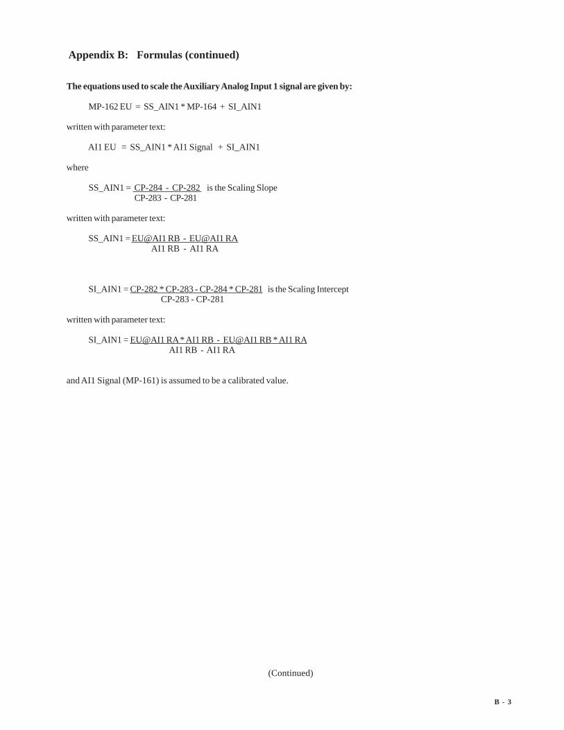
B - 3
Appendix B: Formulas (continued)
(Continued)
The equations used to scale the Auxiliary Analog Input 1 signal are given by:
MP-162 EU = SS_AIN1 * MP-164 + SI_AIN1
written with parameter text:
AI1 EU = SS_AIN1 * AI1 Signal + SI_AIN1
where
SS_AIN1 = CP-284 - CP-282 is the Scaling Slope CP-283 - CP-281
written with parameter text:
SS_AIN1 = EU@AI1 RB - EU@AI1 RA AI1 RB - AI1 RA
SI_AIN1 = CP-282 * CP-283 - CP-284 * CP-281 is the Scaling Intercept CP-283 - CP-281
written with parameter text:
SI_AIN1 = EU@AI1 RA * AI1 RB - EU@AI1 RB * AI1 RA AI1 RB - AI1 RA
and AI1 Signal (MP-161) is assumed to be a calibrated value.

B - 4
Appendix B: Formulas (continued)
The equations used to scale the Auxiliary Analog Input 1 signal are given by:
MP-162 EU = SS_AIN2 * MP-161 + SI_AIN2
written with parameter text:
AI2 EU = SS_AIN2 * AI2 Signal + SI_AIN2
where
SS_AIN2 = CP-289 - CP-287 is the Scaling Slope CP-288 - CP-286
written with parameter text:
SS_AIN2 = EU@AI2 RB - EU@AI2 RA AI2 RB - AI2 RA
SI_AIN2 = CP-282 * CP-283 - CP-284 * CP-281 is the Scaling Intercept CP-283 - CP-281
written with parameter text:
SI_AIN2 = EU@AI2 RA * AI2 RB - EU@AI2 RB * AI2 RA AI2 RB - AI2 RA
and AI2 Signal (MP-164) is assumed to be a calibrated value.

B - 5
The equations used to scale the Auxiliary Analog output signal are given by:
MP-167 volts (or mA) = SS_AO * MP/CP (selected by CP-290) + SI_AO
written with parameter text:
AO Signal = SS_AO * MP/CP (selected by CP-290) + SI_AO
where
SS_AO = CP-294 - CP-292 volts (or mA) is the Scaling Slope CP-295 - CP-293 in selected MP/CP units
written with parameter text:
SS_AO = AO RB - AO RA A Val@AO RB - Val@AO RA
SI_AO = CP-292 * CP-295 - CP-294 * CP-293 is the Scaling Intercept CP-295 - CP-293
written with parameter text:
SI_AO = AO RA * Val@AO RB - AO RB * Val@AO RA Val@AO RB - Val@AO RA
The AO is assumed calibrated so that the actual voltage (or current) is reflected by AO Signal (MP-167).
Appendix B: Formulas (continued)

B - 6
—NOTES—

C - 1
(Continued)
Appendix C: Parameter Summary Numeric Quick Reference (continued)APPENDIX C: PARAMETER SUMMARY NUMERIC
QUICK REFERENCE
MP-01 FI1 Hz
Frequency Input 1 Hertz (MP-01) displays the current frequency of the Frequency Input 1, in Hertz.
Minimum Value: -180000 Maximum Value: 180000Units: Hertz
MP-02 FI1 RPM
Frequency Input 1 RPM (MP-02) displays the current speed of the Frequency Input 1 encoder in RPM, based on PPRFI1 (CP-261).
Minimum Value: -99999.9 Maximum Value: 99999.9Units: RPM
MP-03 FI2 Hz
Frequency Input 2 Hz (MP-03) displays the current frequency of the Frequency Input 2, in Hertz.
Minimum Value: -180000 Maximum Value: 180000Units: Hertz
MP-04 FI2 RPM
Frequency Input 2 RPM (MP-04) displays the current speed of the Frequency Input 2 encoder in RPM, based on PPRFI2 (CP-266).
Minimum Value: -99999.9 Maximum Value: 99999.9Units: RPM
MP-05 Ld EU/Tm
Frequency Input 1 Engineering Units per Time (MP-05) displays the current speed of the Frequency Input 1 in theEngineering Units per Time (EU/Tm) relative to the Pulses FI1 (CP-262), EU FI1 (CP-263) and Time Base (CP-209). Theplacement of the decimal point is the same as the placement of the decimal point in EU FI1 (CP-263).
Minimum Value: -9999999 Maximum Value: 9999999Units: EU/Tm
MP-06 Fb EU/Tm
Frequency Input 2 Engineering Units per Time (MP-06) displays the current speed of the Frequency Input 2 in theEngineering Units per Time (EU/Tm) relative to the Pulses FI2 (CP-267), EU FI2 (CP-268) and Time Base (CP-209). Theplacement of the decimal point is the same as the placement of the decimal point in EU FI2 (CP-268).
Minimum Value: -9999999 Maximum Value: 9999999Units: Counts

C - 2
(Continued)
Appendix C: Parameter Summary Numeric Quick Reference (continued)
MP-10 Ld Posn
Lead Position (MP-10) displays the present value of the Lead Position in Engineering Units, as specified by Pulses FI1(CP-262) and EU FI1 (CP-263). The placement of the decimal point is the same as the placement of the decimal point inEU FI1 (CP-263).
Minimum Value: 0 Maximum Value: 999999999Units: EU
MP-11 LdJobSize
Lead Job Size (MP-11) displays the present value determined by the Lead Frequency and Lead Sync inputs. Displayed inEU’s. It is the size of the very last job size that was encountered.
Minimum Value: 0 Maximum Value: 9999999Units: EU
MP-12 LdJbSzVar
Lead Job Size Variance (MP-12) displays the maximum variance of the last 16 lead job sizes. Displayed in EU’s.
Minimum Value: -999999 Maximum Value: 999999Units: EU
MP-13 LdJbSzAvg
Lead Job Size Average (MP-13) displays a running average value of the last 16 lead job sizes determined by the LeadFrequency and Lead Sync inputs. Displayed in EU’s.
Minimum Value: 0 Maximum Value: 9999999Units: EU
MP-14 LdJbSzAct
Lead Job Size Active (MP-14) displays a running average value of the last 16 qualifying lead job sizes determined by theLead Frequency and Lead Sync inputs. Displayed in EU’s. This is the job size currently being used by the controlalgorithm.
Minimum Value: 0 Maximum Value: 9999999Units: EU
MP-15 LdNetOfst
Lead Net Offset (MP-15) displays the resultant Net-Offset applied to the lead position after considering the LdSnsrDist(CP-340) and the LdSnsrOfst (CP-341) values. LdNetOfst (MP-15) is the final resultant offset inside a lead job size.
Minimum Value: -999999 Maximum Value: 999999Units: EU
C - 3
(Continued)
Appendix C: Parameter Summary Numeric Quick Reference (continued)
MP-20 Fb Posn
Feedback Position (MP-20) displays the present value of the Feedback Position in Engineering Units, as specified byPulses FI2 (CP-267) and EU FI2 (CP-268). The placement of the decimal point is the same as the placement of the decimalpoint in EU FI2 (CP-268).
Minimum Value: 0 Maximum Value: 999999999Units: EU
MP-21 FbJobSize
Follower Job Size (MP-21) displays the present value determined by the Follower Frequency and Follower Sync inputs.Displayed in EU’s. It is the size of the very last job size that was encountered.
Minimum Value: 0 Maximum Value: 9999999Units: EU
MP-22 FbJbSzVar
Follower Job Size Variance (MP-22) displays the maximum variance of the last 16 follower job sizes. Displayed in EU’s.
Minimum Value: -999999 Maximum Value: 999999Units: EU
MP-23 FbJbSzAve
Follower Job Size Average (MP-23) displays a running average value of the last 16 follower job sizes determined by theFollower Frequency and Follower Sync inputs. Displayed in EU’s.
Minimum Value: 0 Maximum Value: 9999999Units: EU
MP-24 FbJbSzAct
Follower Job Size Active (MP-24) displays a running average value of the last 16 qualifying follower job sizes determinedby the Follower Frequency and Follower Sync inputs. Displayed in EU’s. This is the job size currently being used by thecontrol algorithm.
Minimum Value: 0 Maximum Value: 9999999Units: EU
MP-25 FbNetOfst
Follower Net Offset (MP-25) displays the resultant Net-Offset applied to the follower position after considering theFbSnsrDist (CP-350) and the FbSnsrOfst (CP-351) values. FbNetOfst (MP-25) is the final resultant offset inside afollower job size.
Minimum Value: -9999999 Maximum Value: 9999999Units: EU

C - 4
(Continued)
Appendix C: Parameter Summary Numeric Quick Reference (continued)
MP-29 SyncFlgDif
Sync Flag Difference (MP-29) displays the difference, in Follower EU’s, between the position of the Lead and Followersync pulses.
Minimum Value: -9999999 Maximum Value: 9999999Units: EU
MP-30 ScaledRef
Scaled Reference (MP-30) displays the reference speed, in Engineering Units per Time. This is the calculated setpointbefore the accel/decel ramps are applied. The placement of the decimal point is the same as the placement of the decimalpoint in Master SP (CP-210).
Minimum Value: -99999.9 Maximum Value: 99999.9Units: EU/Tm
MP-31 RampedRef
Ramped Reference (MP-31) displays the speed command, in Engineering Units per Time. This is the output of the rampcalculations. When the ramp has been completed, the RampedRef (MP-31) should equal the ScaledRef (MP-30).
Minimum Value: -99999.9 Maximum Value: 99999.9Units: EU/Tm
MP-32 VelError
Velocity Error (MP-32) displays the difference between the RampedRef (MP-31) and Fb EU/Tm (MP-6).Displayed in EU/Tm.
Minimum Value: -99999.9 Maximum Value: 99999.9Units: EU/Tm
MP-33 PosnErr
Position Error (MP-33) displays the value, in engineering units, of the accumulated position error between the lead (FI1)and the feedback (FI2) input signals. The placement of the decimal point is the same as the placement of the decimalpoint in EU FI2 (CP-268).
Minimum Value: 0 Maximum Value: 999999999Units: EU
MP-34 Intgrl
Integral (MP-34) displays the value of the integral term (i.e., integrated error times the Ki constant) of the PIDcompensator. Intgrl (MP-34) is displayed in Volts. Intgrl (MP-34) is a conditioned error signal that serves to adjust theCO Volts (MP-37) to help achieve the desired speed. It is part of the PID error correction algorithm.
Minimum Value: -15.00 Maximum Value: 15.00Units: Volts

C - 5
(Continued)
Appendix C: Parameter Summary Numeric Quick Reference (continued)
MP-35 FeedFwd
Feedforward (MP-35) displays the estimated voltage command to the drive required achieve the commanded RampedRef(MP-31). It is usually the major portion of the CO Volts (MP-37) signal.
Minimum Value: -15.00 Maximum Value: 15.00Units: Volts
MP-36 Trim Out
Trim Out (MP-36) displays the value of the output of the PID compensator. Trim Out is displayed in Volts. Trim Out isthe sum of the conditioned error signals that, combined with the FeedFwd (MP-35), become the CO Volts (MP-37). TrimOut is the combination of all three terms of the PID error correction algorithm.
Minimum Value: -15.00 Maximum Value: 15.00Units: Volts
MP-37 CO Volts
Control Output Volts (MP-37) displays the present value, in volts, of the Control Output (CO_Sig) signal to the drive. Itis the combination of FeedFwd (MP-35) plus Trim Out (MP-36).
Minimum Value: -15.00 Maximum Value: 15.00Units: Volts
MP-38 CO Bits
Control Output Bits (MP-38) displays the present value, in DAC bits, of the Control Output (CO_Sig) signal to thedrive. CO Bits is the CO Volts (MP-37) expressed in DAC bits.
Minimum Value: -32768 Maximum Value: 32767Units: Bits
MP-39 CO Max Bits
Control Output Maximum Bits (MP-39) reflects the maximum allowed output in units of DAC bits. The value of CO MaxVolts (CP-271) determines this parameter, based on the conversion of 32767 bits = 15 VDC.
Minimum Value: 0 Maximum Value: 32767Units: Bits
MP-40 Scaled Fb
Scaled Feedback (MP-40) displays the scaled feedback , which is scaled per ScFbDispEq (CP-250). The placement ofthe decimal point is the same as the placement of the decimal point in Mater SP (CP-210) in "Master" and Follower SP(CP-220) in "Ratio or Inverse Ratio".
Minimum Value: -9999999 Maximum Value: 9999999Units: EU

C - 6
(Continued)
Appendix C: Parameter Summary Numeric Quick Reference (continued)
MP-41 ScaleFactor
Scale Factor (MP-41) displays the calculated ratio between the LdJbSzAve (MP-13) and the FbJbSzAve (MP-23). Thismay be different than the scale factor actually being used by the control algorithm.
Minimum Value: 0 Maximum Value: 999999Units: Ratio
MP-42 ActScaleFactor
Active Scale Factor (MP-42) displays the scale factor currently being utilized by the position control algorithm. TheActScaleFactor (MP-42) may not be the same as ScaleFactor (MP-41).
Minimum Value: 0 Maximum Value: 999999Units: Ratio
MP-48 Kff
Kff (MP-48) is the feedforward gain for the follower. It translates a follower EU/Time into an approximate voltageoutput, which is then error-trimmed +/- to effect the desired speed. A reasonable accurate feedforward can minimize theneed for error trim action, thus improving the response of the control loop. It is automatically adjusted for any changeentered into CO Max Volts (CP-271), or Max Fb (CP-329). It is also adjusted automatically during feedforward Kff AutoEn (CP-364) mode.
Minimum Value: 0.00 Maximum Value: 99999.99Units: V/kiloRPM
MP-49 Cntrl Loop
Control Loop (MP-49) displays the present operating mode of the CX-1200. Only one type of loop can be active at atime. These modes are automatically selected depending on the present system State (MP-50).
3 = Psn Hld (H-Stop Position Loop)2 = Position Loop1 = Velocity Loop0 = Open Loop
Minimum Value: 0 Maximum Value: 3Units: Coded

C - 7
(Continued)
Appendix C: Parameter Summary Numeric Quick Reference (continued)
MP-50 State
State (MP-50) displays the present system operating state of the CX-1200 (see list below). Only one operating statemay be active at a time. To access either the “Run” or the “Jog” operating state, the F-Stop, R-Stop and H-Stop inputsmust be closed.
9 = Not Defined8 = Diagnostics7 = Not Defined6 = Not Defined5 = Jog4 = Not Defined3 = Run2 = H-Stop1 = R-Stop0 = F-Stop
Minimum Value: 0 Maximum Value: 9Units: Coded
MP-51 Active Blk
Active Block (MP-51) displays the active block (0-7). The block can be selected and made active by the Block select bits(Blk Sel A,B.C), in the PLC Programming screen if Blk Sel Source (CP-478) is set to “1” (DigIn & PLC). Or the block canbe selected and made active by the keypad if Blk Sel Source (CP-478) is set to “2” (Keypad Blk Sel).
Minimum Value: 0 Maximum Value: 7Units: Coded
MP-52 InvalidBlks
Invalid Blocks (MP-52) displays the status of the blocks in the Block Setup screens. A “1” indicates that there is anerror with the corresponding block (see graphic below). Generally, this indicates that an overflow condition can occur ifthe corresponding block is activated. In addition, since other parameters are used in conjunction with the BlockParameters that you selected, an error can result from a parameter that is not selected in Block Parameters. If a bad blockis activated, the CX-1200 will execute an F-Stop until either the block error is corrected or a another block is activated.
Block 0Block 1
Block 2Block 3
Block 4Block 5
Block 6Block 7
Minimum Value: 00000000 Maximum Value: 11111111Units: Coded

C - 8
(Continued)
Appendix C: Parameter Summary Numeric Quick Reference (continued)
MP-53 Misc Status
Miscellaneous Status (MP-53) displays various status conditions (see graphic below). A “1” in the Drive Enable bitindicates a drive enabled output. A “1” in any other bit location indicates an active condition.
Lead Sync InFoll Sync In
Missing Lead SyncMissing Foll Sync
CO SignDrive Enable
RR@0SpeedFb@0Speed
Minimum Value: 00000000 Maximum Value: 11111111Units: Coded
MP-54 Std Alms
Std Alarms (MP-54) displays various alarm conditions (see graphic below). A “1” in any bit location indicates an activecondition.
Drv No RespFdbk @Max Fb (RPM)
CO_Sig@MaxCOMax Acl/Dcl
Low SpeedHigh Speed
Min Spd LimitMax Speed Limit
Minimum Value: 00000000 Maximum Value: 11111111Units: Coded

C - 9
(Continued)
Appendix C: Parameter Summary Numeric Quick Reference (continued)
MP-55 Custom Alms
Custom Alarms (MP-55) displays the outputs of the PLC numerical comparators. A “1” in bit locations 0-3 indicatesthat the result of the compare (Cmprx Parm value vs. Cmprx Val) is true for the given Cmprx Type. A “1” in bit locations4-7 indicates that the result of the compare (Cmprx Parm value vs. Cmprx Val) is false for the given Cmprx Type (theNOT is true). Refer to CP-380 through CP-395.
Cmpr1 Out - TrueCmpr2 Out - True
Cmpr3 Out - TrueCmpr4 Out - True
Cmpr1 Out - FalseCmpr2 Out - False
Cmpr3 Out - FalseCmpr4 Out - False
Minimum Value: 00000000 Maximum Value: 11111111Units: Coded
MP-56 Misc AlarmsMisc Alarms (MP-56) displays various alarm conditions (see graphic below). A “1” in any bit location indicates anactive condition.
Low PowerNot in Use
Max FI1 HzMax FI2 Hz
Not in UseNot in Use
Not in UseNot in Use
Minimum Value: 00000000 Maximum Value: 11111111Units: Coded
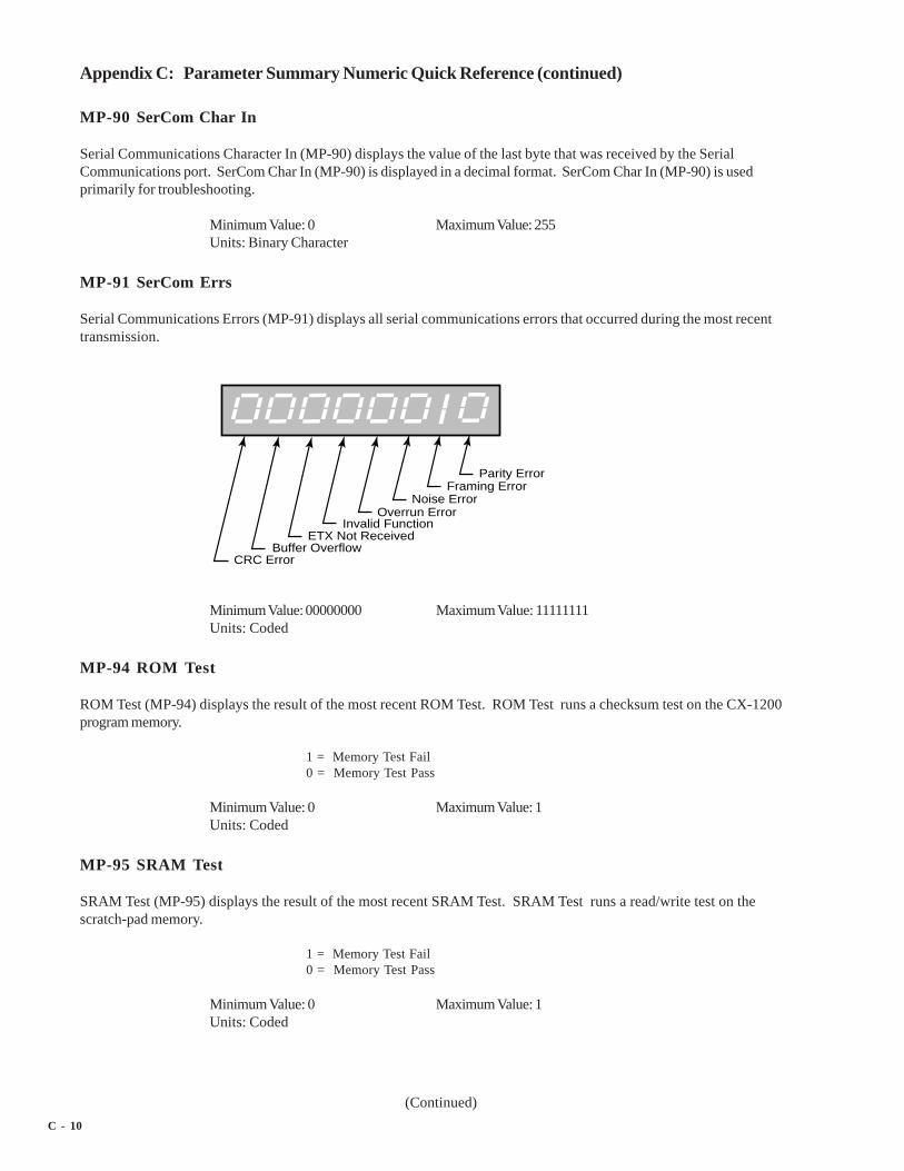
C - 10
(Continued)
Appendix C: Parameter Summary Numeric Quick Reference (continued)
MP-90 SerCom Char In
Serial Communications Character In (MP-90) displays the value of the last byte that was received by the SerialCommunications port. SerCom Char In (MP-90) is displayed in a decimal format. SerCom Char In (MP-90) is usedprimarily for troubleshooting.
Minimum Value: 0 Maximum Value: 255Units: Binary Character
MP-91 SerCom Errs
Serial Communications Errors (MP-91) displays all serial communications errors that occurred during the most recenttransmission.
Parity ErrorFraming Error
Noise ErrorOverrun Error
Invalid FunctionETX Not Received
Buffer OverflowCRC Error
Minimum Value: 00000000 Maximum Value: 11111111Units: Coded
MP-94 ROM Test
ROM Test (MP-94) displays the result of the most recent ROM Test. ROM Test runs a checksum test on the CX-1200program memory.
1 = Memory Test Fail0 = Memory Test Pass
Minimum Value: 0 Maximum Value: 1Units: Coded
MP-95 SRAM Test
SRAM Test (MP-95) displays the result of the most recent SRAM Test. SRAM Test runs a read/write test on thescratch-pad memory.
1 = Memory Test Fail0 = Memory Test Pass
Minimum Value: 0 Maximum Value: 1Units: Coded

C - 11
(Continued)
Appendix C: Parameter Summary Numeric Quick Reference (continued)
MP-96 NV RAM Test
Non Volatile RAM Test (MP-96) displays the result of the most recent Non Volatile RAM Test. The test runs both aread/write and a checksum test on the nonvolatile memory. The parameter values, the PLC program and the backups areall stored in this memory.
1 = Memory Test Fail0 = Memory Test Pass
Minimum Value: 0 Maximum Value: 1Units: Coded
MP-97 Model #
Model # (MP-97) displays the model number for this CX-1200. This model number is unique to the CX-1200 series ofcontrollers.
Minimum Value: 1000 Maximum Value: 60000Units: Model Number
MP-98 RELEASE
RELEASE (MP-98) is the date that the software for this individual CX-1200 was released. The numeric, six digit formatis: year, month, day.
Minimum Value: 010106 Maximum Value: 999999Units: Date
MP-99 REVISION
REVISION (MP-99) is the revision level of the software for this individual CX-1200.
Minimum Value: 0.50 Maximum Value: 99.99Units: Rev Level

C - 12
(Continued)
Appendix C: Parameter Summary Numeric Quick Reference (continued)
MP-100 DI 7..0
Digital Input 7..0 (MP-100) displays the value of the “J6” digital inputs. A ‘1’ in the bit location (see graphic below)indicates a “low voltage” condition on the corresponding input (which is consistent with a contact closure to common).
F-StopR-Stop
H-StopRun
Jog FwdJog Rvs
Keypad LockoutSpare
Minimum Value: 00000000 Maximum Value: 11111111Units: Coded
MP-101 DI 15..8
Digital Input 15..8 (MP-101) displays the value of the “J7” digital inputs. A ‘1’ in the bit location (see graphic below)indicates a “low voltage” condition on the corresponding input (which is consistent with a contact closure to common).These eight Inputs can be set up in the PLC Programming screen to generate a One-Shot-Pulse on a high-to-lowtransition.
Batch ResetPosition Reset
Re-LearnPhase Advance
Phase RetardBlock Select A
Sync DisableOpen Loop
Minimum Value: 00000000 Maximum Value: 11111111Units: Coded

C - 13
(Continued)
Appendix C: Parameter Summary Numeric Quick Reference (continued)
MP-102 DO 7..0
Digital Output 7..0 (MP-102) displays the value of the “J2” digital outputs. A ‘1’ in the bit location (see graphic below)indicates an active “low voltage” condition on the corresponding open collector output (which would sink DCcurrent).
Drive EnableBatch Done
Sync AlarmFwd/Rvs
Lead Sync AbsentFoll Sync Absent
Hi/Low Seed AlarmZero Speed
Minimum Value: 00000000 Maximum Value: 11111111Units: Coded
MP-103 KeyPad Lockout
Keypad Lockout (MP-103) displays the Keypad Lockout status. The Keypad Lockout is active when “On” isdisplayed. When Keypad Lockout is active, Control Parameter values can not be changed, with the exception of theControl Parameters that are exempted by CP’s 480-489. The Keypad Lockout is not active when “OFF” is displayed.When the Keypad Lockout is not active, any Control Parameter can be changed.
Minimum Value: 0 Maximum Value: 1Units: Coded
MP-107 TMR4 TIME
Timer 4 Time (MP-107) displays the elapsed time, in seconds, for Timer 4 during the delay part of its operation.
Minimum Value: 0 Maximum Value: 86400Units: Seconds

C - 14
(Continued)
Appendix C: Parameter Summary Numeric Quick Reference (continued)
MP-108 PLC Mon 1 Val
PLC Monitor 1 Value (MP-108) displays both the description and the value of the PLC bit that was selected in PLCMonitor 1 (CP-405). Please note that a description of the PLC bit appears on the display line instead of the parametername (PLC Mon 1 Val).
Minimum Value: 0 Maximum Value: 1Units: Coded
MP-109 PLC Mon 2 Val
PLC Monitor 2 Value (MP-109) displays both the description and the value of the PLC bit that was selected in PLCMonitor 2 (CP-406). Please note that a description of the PLC bit appears on the display line instead of the parametername (PLC Mon 2 Val).
Minimum Value: 0 Maximum Value: 1Units: Coded
MP-110 PLC 15-8
PLC 15-8 (MP-110) displays the status of PLC bits 15-8 (See graphic and list below). A “1” in any bit indicates that theinput is “active”. The digital inputs are active low.
Digital Input 8Digital Input 9
Digital Input 10Digital Input 11
Digital Input 12Digital Input 13
Digital Input 14Digital Input 15
Description Default FunctionDigital Input 8 Batch ResetDigital Input 9 Position ResetDigital Input 10 Re-LearnDigital Input 11 Phase AdvanceDigital Input 12 Phase RetardDigital Input 13 Block Select ADigital Input 14 Sync DisableDigital Input 15 Open Loop
Minimum Value: 00000000 Maximum Value: 11111111Units: Coded

C - 15
(Continued)
Appendix C: Parameter Summary Numeric Quick Reference (continued)
MP-111 PLC 23-16
PLC 23-16 (MP-111) displays the status of the internal PLC status bits 23-16 (See graphic below). A “1” in any bitindicates that the bit is “active”.
Latch 1 OutputLatch 2 Output
Latch 3 OutputLatch 4 Output
Not In UseNot In Use
Not In UseNot In Use
Minimum Value: 00000000 Maximum Value: 11111111Units: Coded
MP-112 PLC 31-24
PLC 31-24 (MP-112) displays the status of the internal PLC status bits 31-24 (See graphic below). A “1” in any bitindicates that the bit is “active”
Timer 1 OutputTimer 2 Output
Timer 3 OutputTimer 4 Output
Low Speed AlarmHigh Speed Alarm
Min Speed Limit ActiveMax Speed Limit Active
Minimum Value: 00000000 Maximum Value: 11111111Units: Coded

C - 16
(Continued)
Appendix C: Parameter Summary Numeric Quick Reference (continued)
MP-113 PLC 39-32
PLC 39-32 (MP-113) displays the status of the internal PLC status bits 39-32 (See graphic below). A “1” in any bitindicates that the bit is “active”
Cntr 1 OutCntr 2 Out
Cntr 3 OutCntr 4 Up Out
Cntr 4 Dn OutLow Power
Not In UseNot In Use
Bit Name DescriptionCntr1 Out Counter 1 OutputCntr2 Out Counter 2 OutputCntr3 Out Counter 3 OutputCntr4UpO Counter 4 Up counter OutputCntr4DnO Counter 4 Down counter OutputLow Power Low Power IndicationNot In UseNot In Use
Minimum Value: 00000000 Maximum Value: 11111111Units: Coded
MP-114 PLC 47-40
PLC 47-40 (MP-114) displays the status of the internal PLC status bits 47-40 (See graphic below). A “1” in any bitindicates that the bit is “active”
Direct ModeMaster Mode
Follower ModeInvs Follower Mode
Non-SyncFixed Ratio Sync
Trend Ratio SyncLearn Ratio Sync
Minimum Value: 00000000 Maximum Value: 11111111Units: Coded

C - 17
(Continued)
Appendix C: Parameter Summary Numeric Quick Reference (continued)
MP-115 PLC 55-48
PLC 55-48 (MP-115) displays the status of the internal PLC status bits 55-48 (See graphic below). A “1” in any bitindicates that the bit is “active”.
Not In UseMaxFI1Hz
CO SignDrive Enable
Ramp ActiveRR@0Spd
Fb@0SpdMaxFbSpd
Bit Name DescriptionNot In UseMaxFI1HzCO Sign Control Output sign is negative (-)DrvEn Drive EnableRmpActive Ramp ActiveRR@0Spd RampedRef (MP-31) less than Zero Speed (CP-332)Fb@0Spd Feedback is less than Zero Speed (CP-332)MaxFbSpd Feedback at Max Fb (CP-329)
Minimum Value: 00000000 Maximum Value: 11111111Units: Coded

C - 18
(Continued)
Appendix C: Parameter Summary Numeric Quick Reference (continued)
MP-116 PLC 63-56
PLC 63-56 (MP-116) displays the status of the internal PLC status bits 63-56 (See graphic below). A “1” in any bitindicates that the bit is “active”.
MaxAclDclDrvNoResp
MaxFI2HzCO@MxVlts
Cmpr1 OutCmpr2 Out
Cmpr3 OutCmpr4 Out
Bit Name DescriptionMaxAclDcl Feedback at Maximum Accel/DecelDrvNoRsp Drive/Motor NOT Responding (CP-373)MaxFI2Hz Feedback is >= Maximum Frequency = 180 KHzCO@MaxVlts CO Volts (MP-37) at CO Max Volts (CP-271)Cmpr1 Out Comparator 1 OutputCmpr2 Out Comparator 2 OutputCmpr3 Out Comparator 3 OutputCmpr4 Out Comparator 4 Output
Minimum Value: 00000000 Maximum Value: 11111111Units: Coded

C - 19
(Continued)
Appendix C: Parameter Summary Numeric Quick Reference (continued)
MP-117 PLC 71-64
PLC 71-64 (MP-117) displays the status of the internal PLC status bits 71-64.
Not In UseOutOfPosn
LdSyncMisFollSyncMis
LdSyncRcvFollSyncRcv
OneSecSqWNot In Use
Bit Name DescriptionNot In UseOutOfPosn Out of PositionLdSyncMis Lead Sync pulse is MissingFollSyncMis Follower Sync pulse is MissingLdSyncRcv Lead Sync pulse ReceivedFollSyncRcv Follower Sync pulse ReceivedOneSecSqW One Second Square Wave OutputNot In Use
Minimum Value: 00000000 Maximum Value: 11111111Units: Coded
MP-118 PLC 79-72
PLC 79-72 (MP-118) displays the status of the internal PLC status bits 79-72 (See graphic below). A “1” in any bitindicates that the bit is “active”. These bits are only used to monitor the operating state of the CX-1200.
F-StopR-Stop
H-StopRun
Jog FwdJog Rvs
Not In UseDiagState
Minimum Value: 00000000 Maximum Value: 11111111Units: Coded

C - 20
(Continued)
Appendix C: Parameter Summary Numeric Quick Reference (continued)
MP-119 PLC 87-80
PLC 87-80 (MP-119) displays the status of the internal PLC status bits 87-80 (See graphic below). A “1” in any bitindicates that the bit is “active”. These bits are only used to monitor the parameter block that is active.
Block 0 SelectedBlock 1 Selected
Block 2 SelectedBlock 3 Selected
Block 4 SelectedBlock 5 Selected
Block 6 SelectedBlock 7 Selected
Minimum Value: 00000000 Maximum Value: 11111111Units: Coded
MP-120 PLC 95-88
PLC 95-88 (MP-120) displays the status of the internal PLC status bits 95-88. None of these bits are presently active.They are reserved for future use.
Not In UseRvs Cmd
Not In UseNot In Use
Not In UseNot In Use
Not In UseNot In Use
Bit Name DescriptionNot In UseRvs Cmd Reverse direction command indicatedNot In UseNot In UseNot In UseNot In UseNot In UseNot In Use
Minimum Value: 00000000 Maximum Value: 11111111Units: Coded

C - 21
(Continued)
Appendix C: Parameter Summary Numeric Quick Reference (continued)
MP-121 PLC 107-100
PLC 107-100 (MP-121) displays the status of PLC bits 107-100 (See graphic and list below). A “1” in any bit indicatesthat the output is “active”. The digital outputs are active low (current sinking).
Digital Output 0Digital Output 1
Digital Output 2Digital Output 3
Digital Output 4Digital Output 5
Digital Output 6Digital Output 7
Bit Name DescriptionDigital Output 0 Drive EnableDigital Output 1 Batch DoneDigital Output 2 Sync AlarmDigital Output 3 Fwd/RvsDigital Output 4 Lead Sync AbsentDigital Output 5 Foll Sync AbsentDigital Output 6 Hi/Low Speed AlarmDigital Output 7 Zero Speed
Minimum Value: 00000000 Maximum Value: 11111111Units: Coded
MP-122 PLC 115-108
PLC 115-108 (MP-122) displays the status of the internal PLC control bits 115-108 (See graphic below). A “1” in any bitindicates that the bit is “active”. These internal bits (control relays) can be used as global “control relays”. Forexample, they can be used to create one-shots or latches. They can also be used to simplify programming.
Temporary Bit 1Temporary Bit 2
Temporary Bit 3Temporary Bit 4
Temporary Bit 5Temporary Bit 6
Temporary Bit 7Temporary Bit 8
Minimum Value: 00000000 Maximum Value: 11111111Units: Coded

C - 22
(Continued)
Appendix C: Parameter Summary Numeric Quick Reference (continued)
MP-123 PLC 123-116
PLC 123-116 (MP-123) displays the status of the internal PLC control bits 123-116 (See graphic below). A “1” in any bitindicates that the bit is “active”.
Latch 1 SetLatch 2 Set
Latch 3 SetLatch 4 Set
Latch 1 Set ResetLatch 2 Set Reset
Latch 3 Set ResetLatch 4 Set Reset
Minimum Value: 00000000 Maximum Value: 11111111Units: Coded
MP-124 PLC 131-124
PLC 131-124 (MP-124) displays the status of the internal PLC control bits 131-124 (See graphic below). A “1” in any bitindicates that the bit is “active”.
Timer 1 EnableTimer 2 Enable
Timer 3 EnableTimer 4 Enable
Timer 4 ResetNot In Use
Counter 1 IncrementCounter 2 Increment
Minimum Value: 00000000 Maximum Value: 11111111Units: Coded

C - 23
(Continued)
Appendix C: Parameter Summary Numeric Quick Reference (continued)
MP-125 PLC 139-132
PLC 139-132 (MP-125) displays the status of the internal PLC control bits 139-132 (See graphic below). A “1” in any bitindicates that the bit is “active”.
Counter 3 IncrementCounter 4 Increment
Counter 4 DecrementCounter 1 Reset
Counter 2 ResetCounter 3 Reset
Counter 4 ResetNot In Use
Minimum Value: 00000000 Maximum Value: 11111111Units: Coded

C - 24
(Continued)
Appendix C: Parameter Summary Numeric Quick Reference (continued)
MP-126 PLC 147-140
PLC 147-140 (MP-126) displays the status of the internal PLC control bits 147-140 (See graphic below). A “1” in any bitindicates that the bit is “active”. Blk Sel A, B, C select the block that is active, if Blk Sel Source (CP-378) has been setto “1” (DgIn). The chart below indicates which block has been selected, based on the Block Select A, B or C inputs.
Block Select ABlock Select B
Block Select CNot In Use
Not In UseNot In Use
Not In UseNot In Use
Blk SelC B A Block Selected0 0 0 00 0 1 10 1 0 20 1 1 31 0 0 41 0 1 51 1 0 61 1 1 7
Bit Name DescriptionBlk Sel A Block Select ABlk Sel B Block Select BBlk Sel C Block Select CNot In UseNot In UseNot In UseNot In UseNot In Use
Minimum Value: 00000000 Maximum Value: 11111111Units: Coded

C - 25
(Continued)
Appendix C: Parameter Summary Numeric Quick Reference (continued)
MP-127 PLC 155-148
PLC 155-148 (MP-127) displays the status of the internal PLC control bits 155-148 (See graphic below). A “1” in any bitindicates that the bit is “active”.
Rst IngrlFrzIngrl
Not In UseLgErr Off
RstFI1PosnRstFI2Posn
RstPsnErrNot In Use
Bit Name DescriptionRst Ingrl Reset Integral to zeroFrzIntgrl Freeze Integral (Freeze at current value)Not In UseLgErr Off Large Error Recovery DisabledRstFI1Posn Reset FI1 Position to zeroRstFI2Posn Reset FI2 Position to zeroRstPsnErr Reset Position Error to zeroNot In Use
Minimum Value: 00000000 Maximum Value: 11111111Units: Coded

C - 26
(Continued)
Appendix C: Parameter Summary Numeric Quick Reference (continued)
MP-128 PLC 163-156
PLC 163-156 (MP-128) displays the status of the internal PLC control bits 163-156 (See graphic below). A “1” in any bitindicates that the bit is “active”.
Not In UseByPassRmp
FrzRampNegate SR
Data Copy 1Data Copy 2
Not In UseNot In Use
Bit Name DescriptionNot In UseByPassRmp Bypass RampFrzRamp Freeze RampNegate SR Negate Scaled Reference, change sign of ScaledRef (MP-30)Data Copy 1Data Copy 2Not In UseNot In Use
Minimum Value: 00000000 Maximum Value: 11111111Units: Coded

C - 27
(Continued)
Appendix C: Parameter Summary Numeric Quick Reference (continued)
MP-129 PLC 171-164
PLC 171-164 (MP-129) displays the status of the internal PLC control bits 171-164. (See graphic below). A “1” in anybit indicates that the bit is “active”.
Not In UseNot In Use
Not In UseStart Data Trace
Scroll UpScroll Down
Not In UseNOP Operand
Bit Name DescriptionNot In UseNot In UseNot In UseStrtTrace Start Data TraceScroll Up Remote Scroll Up (CP-400, 401)Scroll Down Remote Scroll Down (CP-400, 401)Not In UseNOP Opnd No Operation Operand
Minimum Value: 00000000 Maximum Value: 11111111Units: Coded
MP-130 PLC 179-172
PLC 179-172 (MP-130) displays the status of the internal PLC control bits 179-172. (See graphic below). A “1” in anybit indicates that the bit is “active”.
LdSyncOffFollSyncOff
Re-LearnNot In Use
Not In UseNot In Use
Not In UseNot In Use
Minimum Value: 00000000 Maximum Value: 11111111Units: Coded
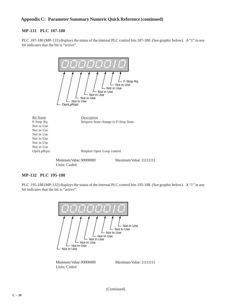
C - 28
(Continued)
Appendix C: Parameter Summary Numeric Quick Reference (continued)
MP-131 PLC 187-180
PLC 187-180 (MP-131) displays the status of the internal PLC control bits 187-180. (See graphic below). A “1” in anybit indicates that the bit is “active”.
F-Stop RqNot in Use
Not in UseNot in Use
Not in UseNot in Use
Not in UseOpnLpRqst
Bit Name DescriptionF-Stop Rq Request State change to F-Stop StateNot in UseNot in UseNot in UseNot in UseNot in UseNot in UseOpnLpRqst Request Open Loop control
Minimum Value: 00000000 Maximum Value: 11111111Units: Coded
MP-132 PLC 195-188
PLC 195-188 (MP-132) displays the status of the internal PLC control bits 195-188. (See graphic below). A “1” in anybit indicates that the bit is “active”.
Not In UseNot In Use
Not In UseNot In Use
Not In UseNot In Use
Not In UseNot In Use
Minimum Value: 00000000 Maximum Value: 11111111Units: Coded
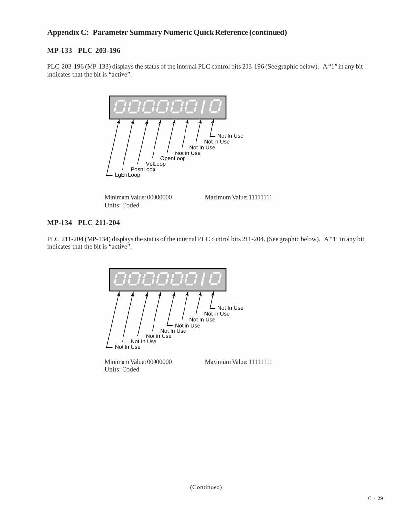
C - 29
(Continued)
Appendix C: Parameter Summary Numeric Quick Reference (continued)
MP-133 PLC 203-196
PLC 203-196 (MP-133) displays the status of the internal PLC control bits 203-196 (See graphic below). A “1” in any bitindicates that the bit is “active”.
Not In UseNot In Use
Not In UseNot In Use
OpenLoopVelLoop
PosnLoopLgErrLoop
Minimum Value: 00000000 Maximum Value: 11111111Units: Coded
MP-134 PLC 211-204
PLC 211-204 (MP-134) displays the status of the internal PLC control bits 211-204. (See graphic below). A “1” in any bitindicates that the bit is “active”.
Not In UseNot In Use
Not In UseNot in Use
Not In UseNot In Use
Not In UseNot In Use
Minimum Value: 00000000 Maximum Value: 11111111Units: Coded

C - 30
(Continued)
Appendix C: Parameter Summary Numeric Quick Reference (continued)
MP-135 PLC 219-212
PLC 219-212 (MP-135) displays the status of the internal PLC control bits 219-212. (See graphic below). A “1” in any bitindicates that the bit is “active”.
Not In UseNot In Use
Not In UseNot In Use
Not In UseNot In Use
Not In UseNot In Use
Minimum Value: 00000000 Maximum Value: 00001111Units: Coded
MP-150 Last Reset
Last Reset (MP-150) displays a “1” in a bit to indicate the reason for the last reset.
Test SubmoduleRST Instruction
Loss of ClockNot In Use
Halt MonitorWatch Dog
Normal Power-UpExt Rst - Normal Power-Up
Minimum Value: 00000000 Maximum Value: 11110111Units: Coded

C - 31
(Continued)
Appendix C: Parameter Summary Numeric Quick Reference (continued)
MP-151 Misc Intrpt
Miscellaneous Interrupts (MP-151) displays a “1” in a bit to indicate which of the various system interrupts may havecaused the last reset.
Bus ErrorAddress Error
Illegal InstructionDiv by 0
Unimplemented InterruptGeneral Exception
Not In UseNot In Use
Minimum Value: 00000000 Maximum Value: 00111111Units: Coded
MP-152 Device Alms
Device Alarms (MP-152) displays the status of microprocessor or other hardware related alarms. Notification of a badblock selection is also included .
TPU FREQ1 Not RespondingTPU FREQ2 Not Responding
Low Power Alarm (per PLC and MP-54)Bad Block Selected
Not In UseNot In Use
Not In UseNot In Use
Minimum Value: 00000000 Maximum Value: 00001111Units: Coded
MP-153 PC at Intrpt
Program Counter at Interrupt (MP-153) shows where the last interrupt of the microprocessor occurred . If the CX-1200repeatedly displays the “RESET FAULT” error box, then record the “PC @Intrpt” value as well as the line just above it(which indicates the cause of the reset), before you press the clear key to continue. The program counter at interupt isstored in the Program Counter at Interrupt (MP-153) Monitor Parameter for review. A value of “2560” is normal.
Minimum Value: 2560 Maximum Value: 524288Units: Address

C - 32
(Continued)
Appendix C: Parameter Summary Numeric Quick Reference (continued)
MP-154 Norm Pwr Ups
Normal Power Ups (MP-154) displays the number of normal power-ups since the most recent “Clear-7” power-up . Thisvalue is reset only by a “Clear-7” power-up. Norm Pwr Ups (MP-154) is used primarily for troubleshooting.
Minimum Value: 1 Maximum Value: 65535Units: Counts
MP-155 Low Pwr Cntr
Low Power Counter (MP-155) displays the number of low power detections, including normal “Power Downs”. You canreset this numeric value, but only in Clr Fault Cntrs (CP-491). Low Pwr Cntr (MP-155) is used primarily fortroubleshooting.
Minimum Value: 0 Maximum Value: 65535Units: Counts
MP-156 Mem Err CntrMemory Error Counter (MP-156) displays the number of memory test failures that occurred during “Power Up”. You canreset this numeric value, but only in Clr Fault Cntrs (CP-491). Mem Err Cntr (MP-156) is used primarily fortroubleshooting.
Minimum Value: 0 Maximum Value: 65535Units: Counts
MP-157 WatchDogCntr
Watch Dog Counter (MP-157) displays the number of watch dog resets that were caused by watchdog time-out.WatchDogCntr (MP-157) is used primarily for troubleshooting. You can reset this numeric value, but only in Clr FaultCntrs (CP-491).
Minimum Value: 0 Maximum Value: 65535Units: Counts
MP-158 MiscIntrptCntr
Miscellaneous Interrupt Counter (MP-158) displays the number of miscellaneous interrupts that occurred as the result ofbus errors, address errors, divide-by-0 errors, unexecuted instruction errors, general exceptions, and unexecuted andspurious interrupts. You can reset this numeric value, but only in Clr Fault Cntrs (CP-491). MiscIntrptCntr (MP-158) isused primarily for troubleshooting.
Minimum Value: 0 Maximum Value: 65535Units: Counts

C - 33
(Continued)
Appendix C: Parameter Summary Numeric Quick Reference (continued)
MP-160 AI1 Bits
Analog Input 1 Bits (MP-160) displays the present value in ADC bits of Auxiliary Board Analog Input 1 signal.
Minimum Value: -8192 Maximum Value: 8192Units: Bits
MP-161 AI1 Signal
Analog Input 1 Signal (MP-161) displays the present value of the Auxiliary Board Analog Input 1 signal in either voltsor milliamps relative to which setting (volts or current) has been entered in AI1 Mode (CP-280).
Minimum Value: -12.00 Maximum Value: 20Units: Volt or Milliamps
MP-162 AI1 EU
Analog Input 1 EU (MP-162) displays the present value of the Auxiliary Board Analog Input 1 signal in EngineeringUnits (EU) as relative to the AI1 RA (CP-281), EU@AI1 RA (CP-282), AI1 RB (CP-283) and EU@AI1 RB (CP-284). Theplacement of the decimal point is the same as the placement of the decimal point in EU@AI1 RA (CP-282).
Minimum Value: -999999 Maximum Value: 999999Units: EU
MP-163 AI2 Bits
Analog Input 2 Bits (MP-163) displays the present value in ADC bits of Auxiliary Board Analog Input 2 signal.
Minimum Value: -8192 Maximum Value: 8191Units: Bits
MP-164 AI2 Signal
Analog Input 2 Signal (MP-164) displays the present value of the Auxiliary Board Analog Input 2 signal in either voltsor milliamps, relative to which setting (volts or current) has been entered in AI2 Mode (CP-285).
Minimum Value: -12.00 Maximum Value: 20Units: Volt or Milliamps
MP-165 AI2 EU
Analog Input 2 EU (MP-165) displays the present value of the Auxiliary Board Analog Input 2 signal in EngineeringUnits (EU) relative to the AI2 RA (CP-286), EU@AI2 RA (CP-287), AI2 RB (CP-288) and EU@AI2 RB (CP-289). Theplacement of the decimal point is the same as the placement of the decimal point in EU@AI2 RA (CP-286).
Minimum Value: -999999 Maximum Value: 999999Units: EU

C - 34
(Continued)
Appendix C: Parameter Summary Numeric Quick Reference (continued)
MP-166 AO Bits
Analog Output Bits (MP-166) displays the present value, in DAC Bits, of the Auxiliary Analog Output.
Minimum Value: -32768 Maximum Value: 32767Units: Bits
MP-167 AO Signal
Analog Output Signal (MP-167) displays the present value, in either volts or milliamps of the Auxiliary Analog Output,relative to AO Mode (CP-291).
Minimum Value: -12.00 Maximum Value: 20Units: Volt or Milliamps
MP-168 AnlgCal Ref A
Analog Calibration Reference A (MP-168) displays the Analog Ref Val (CP-463) for the signal (AI1, AI2), which wasselected in Analog Cal Sel (CP-461) and which was stored during the calibration of point A.
Minimum Value: -13.00 Maximum Value: 25Units: Volt or Milliamps
MP-169 AnlgCal Ref B
Analog Calibration Reference B (MP-169) displays the AnalogRef Val (CP-463) for the signal (AI1, AI2), which wasselected in Analog Cal Sel (CP-461) and which was stored during the calibration of point B.
Minimum Value: -13.00 Maximum Value: 25Units: Volt or Milliamps
MP-178 PosnErrCnt
Position Error Count (MP-178) displays PosnErr (MP-33) in lines.
Minimum Value: -500000000 Maximum Value: 500000000Units: Lines
MP-179 SyncFlgDifCnt
Sync Flag Difference Count (MP-179) displays SyncFlgDif (MP-29) in lines.
Minimum Value: -500000000 Maximum Value: 500000000Units: Lines
MP-180 LdPsnCnt
Lead Position Count (MP-180) displays Ld Posn (MP-10) in lines.
Minimum Value: -500000000 Maximum Value: 500000000Units: Lines

C - 35
(Continued)
Appendix C: Parameter Summary Numeric Quick Reference (continued)
MP-182 LdJSCnt
Lead Job Size Count (MP-182) displays LdJobSize (MP-11) in lines.
Minimum Value: -500000000 Maximum Value: 500000000Units: Lines
MP-183 LdJSAvgCnt
Lead Job Size Average Count (MP-183) displays LdJbSzAvg (MP-14) in lines.
Minimum Value: -500000000 Maximum Value: 500000000Units: Lines
MP-184 LdJSVarCnt
Lead Job Size Variance Count (MP-184) displays LdJbSzVar (MP-12) in lines.
Minimum Value: -500000000 Maximum Value: 500000000Units: Lines
MP-190 FbPsnCnt
Follower Position Count (MP-190) displays Fb Posn (MP-20) in lines.
Minimum Value: -500000000 Maximum Value: 500000000Units: Lines
MP-192 FbJSCnt
Follower Job Size Count (MP-192) displays the FbJobSize (MP-21) in lines.
Minimum Value: -500000000 Maximum Value: 500000000Units: Lines
MP-193 FbJSAvgCnt
Follower Job Size Average Count (MP-193) displays FbJbSzAvg (MP-24) in lines.
Minimum Value: -500000000 Maximum Value: 500000000Units: Lines
MP-194 FbJSVarCnt
Follower Job Size Variance Count (MP-194) displays FbJbSzVar (MP-22) in lines.
Minimum Value: -500000000 Maximum Value: 500000000Units: Lines

C - 36
(Continued)
Appendix C: Parameter Summary Numeric Quick Reference (continued)
CP-201 Setpoint X
Setpoint X (CP-201) displays the name and value of the setpoint that corresponds with the mode of operation selected inRUN Mode (CP-202). The setpoint could be the Master SP (CP-210), the Follower SP (CP-220) or the Direct SP (CP-230).Setpoint X acts as a quick access to the setpoint value. In addition to changing a setpoint value in the setpointscreens, you can also change the value of the active setpoint by entering a new value in Setpoint X (CP-201).
Minimum Value: -9999999 Maximum Value: 9999999Default Value: 0.0 Units: EU/Tm
CP-202 Run Mode
Run Mode (CP-202) sets the mode of operation and the subsequent Setpoint, that are used when your system is in“Run”. The Setpoint and mode of operation combined, determine the Reference Speed and, if applicable, the ReferencePosition. The modes of operation are:
4 = Inv Foll Mode3 = Follower Mode2 = Master Mode (default)1 = Direct Mode
Minimum Value: 1 Maximum Value: 4Default Value: 2 Units: Coded
CP-203 Sync Mode
Sync Mode (CP-203) selects the algorithm to be used when RUN Mode (CP-202) is set for Follower or Inverse Follower.0 = Non-Sync Mode the position follower only, sync pulses are ignored by the control algorithm. 1 = Fixed Mode thefollower setpoint is the ratio/scale factor. 2 = Trend Mode the follower setpoint is altered by the control algorithm toallow for continuously changing job sizes. 3 = Learn Mode learns the job spaces and the scale factor, also modifies thefollower setpoint.
3 = Learn2 = Trend1 = Fixed (default)0 = Off
Minimum Value: 0 Maximum Value: 3Default Value: 0 Units: Coded
CP-204 Sync Logic
Sync Logic (CP-204) allows selection of the direction taken when making a sync-correction. Closest makes the correctionin the direction of the closest lead sync mark. Forward always makes the correction in the forward direction toward thelead sync mark. And Back always makes the correction back to the lagging lead sync mark.
3 = Backward2 = Forward1 = Closest (default)
Minimum Value: 1 Maximum Value: 3Default Value: 1 Units: Coded

C - 37
(Continued)
Appendix C: Parameter Summary Numeric Quick Reference (continued)
CP-205 LdSyncDvd
Lead Sync Divide (CP-205) can be used to reduce the sync rate of the CX-1200 for those processes that may need themaximum sync rate of 20 pulses per second. The lead sync pulses are divided by the LdSyncDvd (CP-205) value beforebeing submitted to the synchronization routine.
Minimum Value: 1 Maximum Value: 255Default Value: 1 Units: Coded
CP-206 FbSyncDvd
Feedback Sync Divide (CP-206) can be used to reduce the sync rate of the CX-1200 for those processes that may needthe maximum sync rate of 20 pulses per second. The follower sync pulses are divided by the FbSyncDvd (CP-206) valuebefore being submitted to the synchronization routine.
Minimum Value: 1 Maximum Value: 255Default Value: 1 Units: Coded
CP-207 LdOfstSource
Lead Offset Source (CP-207) identifies the source of the Lead Sensor Offset, which may be used to set a distance offsetto the lead position. Lead Offset Sources are:
3 = Analog Input 22 = Analog Input 11 = Lead Sensor Offset (CP-341) (default)
Minimum Value: 1 Maximum Value: 3Default Value: 1 Units: Coded
CP-208 FbOfstSource
Follower Offset Source (CP-208) identifies the source of the Follower Sensor Offset, which may be used to set adistance offset to the follower position. Follower Offset Sources are:
3 = Analog Input 22 = Analog Input 11 = Follower Sensor Offset (CP-351) (default)
Minimum Value: 1 Maximum Value: 3Default Value: 1 Units: Coded
CP-209 Time Base
Time Base (CP-209) is the denominator, which represents the time (Tm) in the EU/Tm equation. The equation scales theFrequency Inputs (FI1 and FI2) to EU/Tm.
3 = per Hour2 = per Minute (default)1 = per Second

C - 38
(Continued)
Appendix C: Parameter Summary Numeric Quick Reference (continued)
Minimum Value: 1 Maximum Value: 3Default Value: 2 Units: Coded
CP-210 Master SP
Master Setpoint (CP-210) is the speed at which you want your system to operate (while in Run) when the Run Mode(CP-202) is set to "2” (Master Mode).
Minimum Value: -9999999 Maximum Value: 9999999Default Value: 0.0 Units: EU/Tm
CP-211 Max SP Mstr
Maximum Setpoint Master (CP-211) is an upper limit to the Master SP (CP-210). It will prevent higher entries in MasterSP (CP-210).
Minimum Value: 0 Maximum Value: 9999999Default Value: 9999999 Units: EU/Tm
CP-212 Min SP Mstr
Minimum Setpoint Master (CP-212) is a lower limit to the Master SP (CP-210). It will prevent lower entries in Master SP(CP-210).
Minimum Value: 0 Maximum Value: 9999999Default Value: 0 Units: EU/Tm
CP-220 Follower SP
Follower Setpoint (CP-220) is the speed at which you want your system to operate (while in Run) when the Run Mode(CP-202) is set to "3” (Follower Mode).
Minimum Value: 1.000 Maximum Value: 999999Default Value: 0 Units: Ratio
CP-221 Max SP Fol
Maximum Setpoint Master (CP-221) is an upper limit to the Follower SP (CP-220). It will prevent higher entries inFollower SP (CP-220).
Minimum Value: 0 Maximum Value: 999999Default Value: 999999 Units: Ratio
CP-212 Min SP Fol
Minimum Setpoint Follower (CP-222) is a lower limit to the Master SP (CP-210). It will prevent lower entries in Master SP(CP-210).

C - 39
(Continued)
Appendix C: Parameter Summary Numeric Quick Reference (continued)
Minimum Value: 0 Maximum Value: 999999Default Value: 0 Units: Ratio
CP-230 Direct SP
Direct Setpoint (CP-230) is active only in Direct Mode (CP202=0). It sends a voltage value directly to the ControlOutput (CO_Sig) terminal. Run/Stop commands are recognized, but no other control function is active. All encodersignals are ignored.
Minimum Value: -15.0 Maximum Value: 15Default Value: 0.0 Units: Volts
CP-231 Acl Tm Drct
Acceleration Time Direct (CP-231) is the time, in seconds, that it takes to accelerate from 0 to the CO Max Volts (CP-271)voltage, while operating in the Direct Mode.
Minimum Value: 0 Maximum Value: 3600Default Value: 3.000 Units: Seconds
CP-232 Dcl Tm Drct
Deceleration Time Direct (CP-232) is the time, in seconds, that it takes to decelerate from the CO Max Volts (CP-271)voltage to 0 volts, while operating in the Direct Mode.
Minimum Value: 0 Maximum Value: 3600Default Value: 3.000 Units: Seconds
CP-240 Jog SP
Jog Setpoint (CP-240) is the speed, in EU/Tm, at which Jog ramps when it is activated. The Jog ramp rates arereferenced to this speed.
Minimum Value: 0 Maximum Value: 999999Default Value: 200 Units: EU/Tm
CP-241 Acl Tm Jog
Acceleration Time Jog (CP-241) is the time, in seconds, to accelerate from 0 to the Jog SP (CP-240).
Minimum Value: 0.0 Maximum Value: 3600Default Value: 1.000 Units: Seconds
CP-242 Acl Rt Jog
Acceleration Rate Jog (CP-242) is the rate, in EU/Tm per second, that it takes to accelerate when Jog is activated.

C - 40
(Continued)
Appendix C: Parameter Summary Numeric Quick Reference (continued)
Minimum Value: 0 Maximum Value: 9999999Default Value: 200.0 Units: EU/Tm/S
CP-243 Dcl Tm Jog
Deceleration Time Jog (CP-243) is the time, in seconds, that it takes to decelerate from Jog SP (CP-240) to 0, when the JogInput is deactivated or when switching between “Jog Fwd” and “Jog Rvs”.
Minimum Value: 0.0 Maximum Value: 3600Default Value: 0.500 Units: Seconds
CP-244 Dcl Rt Jog
Deceleration Rate Jog (CP-244) is the rate, in EU/Tm per second, that is used when the Jog input is deactivated or whenswitching between “Jog Fwd” and “Jog Rvs”.
Minimum Value: 0 Maximum Value: 9999999Default Value: 400.0 Units: EU/Tm/S
CP-245 Jog Loop Mode
Jog Loop Mode (CP-245) identifies the type of control loop (see list below) that is used during Jog.
1 = Velocity Loop (default)0 = Open Loop
Minimum Value: 0 Maximum Value: 1Default Value: 1 Units: Coded
CP-250 ScFbDispEq
Scaled Feedback Display Equation (CP-250) selects the equation used to display Scaled Fb (MP-40).
3 = Inverse Ratio (of the FI1 to FI2 input frequency)2 = Ratio (of the FI2 to FI1 input frequency)1 = Master (derived directly from FI2) (default)
Minimum Value: 1 Maximum Value: 3Default Value: 1 Units: Coded
CP-260 Cnt Mode FI1
Count Mode FI1 (CP-260) identifies the type of encoder that is connected to Frequency Input 1. The “Quad x4” settingis for a quadrature encoder that gives 4 counts per pulse and also gives direction information. The Incremental selectionis for a single channel encoder, which gives 1 count per pulse but does not give direction information.
2 = Incremental1 = Quad x4 (default)

C - 41
(Continued)
Appendix C: Parameter Summary Numeric Quick Reference (continued)
Minimum Value: 1 Maximum Value: 2Default Value: 1 Units: Coded
CP-261 PPR FI1
Pulses Per Revolution Frequency In 1 (CP-261) is the number of pulses in one revolution of the encoder device that isconnected to Frequency Input 1. The value may be called Counts, Lines, or Pulses by various encoder manufacturers.Do NOT multiply by four for quadrature encoders.
Minimum Value: 1 Maximum Value: 60000Default Value: 60 Units: Pulses/Rev
CP-262 FI1 Pulses
FI1 Pulses (CP-262) is used to scale the Frequency Input 1 in EU’s and EU/Tm. Enter the number of pulses thatcorresponds to the number of EU’s that are entered in EU FI1 (CP-263).
Minimum Value: 1 Maximum Value: 999999Default Value: 60 Units: Pulses
CP-263 EU FI1
EU FI1 (CP-263) is used to scale the Frequency Input 1 in EU’s and EU/Tm. Enter the number of EU's that correspondsto the number of pulses that are entered in FI1 Pulses (CP-262).
Minimum Value: 0.0001 Maximum Value: 999999Default Value: 1.0 Units: EU
CP-264 LdSyncPolarity
Lead Sync Polarity (CP-264) is a selection that determines the polarity trigger direction of the Lead Sync pulses. TheLead Sync input can be programmed to trigger on signals going from a low to high voltage level (positive going) orfrom a high to low voltage level (negative going).
2 = Falling edge triggered (negative going)1 = Rising edge triggered (positive going) (default)
Minimum Value: 1 Maximum Value: 2Default Value: 1 Units: Coded
CP-265 Cnt Mode FI2
Count Mode FI2 (CP-265) identifies the type of encoder that is connected to Frequency Input 2. The “Quad x4”setting is a for quadrature encoder that gives 4 counts per pulse and also gives direction information. The Incrementalselection is for a single channel encoder which gives 1 count per pulse but does not give direction information.
2 = Incremental1 = Quad x4 (default)

C - 42
(Continued)
Appendix C: Parameter Summary Numeric Quick Reference (continued)
Minimum Value: 1 Maximum Value: 2Default Value: 1 Units: Coded
CP-266 PPR FI2
Pulses Per Revolution FI2 (CP-266) is the number of pulses that are produced during one revolution of the encoder (ormotor or any other rotating part of your machine) that is connected to Frequency Input 2. This value is only used tocalculate RPM information for FI2 RPM (MP-04).
Minimum Value: 1 Maximum Value: 60000Default Value: 60 Units: Pulses/Rev
CP-267 FI2 Pulses
Frequency Input 2 Pulses (CP-267) is used to scale the Frequency Input 2 in EU’s and EU/Tm. Enter the number ofpulses that corresponds to the number of EU’s that are entered in EU FI2 (CP-268).
Minimum Value: 1 Maximum Value: 999999Default Value: 60 Units: Pulses
CP-268 EU FI2
EU Frequency Input 2 (CP-268) is used to scale the Frequency Input 2 in EU’s and EU/Tm. Enter the number of EU'sthat corresponds to the number of pulses that are entered in FI2 Pulses (CP-267).
Minimum Value: 0.0001 Maximum Value: 999999Default Value: 1.0 Units: EU
CP-269 FbSyncPolarity
Feedback Sync Polarity (CP-269) is a selection that determines the polarity trigger direction of the Feedback Syncpulses. The Feedback Sync input can be programmed to trigger on signals going from a low to high voltage level(positive going) or from a high to low voltage level (negative going).
2 = Falling edge triggered (negative going)1 = Rising edge triggered (positive going) (default)
Minimum Value: 1 Maximum Value: 2Default Value: 1 Units: Coded
CP-270 CO Mode
Control Output Mode (CP-270) affects the range of Control Output (CO_Sig) analog signal sent out to the drive.
3 = Unipolar Reversible2 = Bipolar (default)1 = Unipolar

C - 43
(Continued)
Appendix C: Parameter Summary Numeric Quick Reference (continued)
Minimum Value: 1 Maximum Value: 3Default Value: 2 Units: Coded
CP-271 CO Max Volts
Control Output Maximum Volts (CP-271) sets the upper limit on the voltage sent to the drive. Bipolar operation assumesplus or minus this value. It should be set equal, or lower, than the input specifications of the drive.
Minimum Value: 0.1 Maximum Value: 15Default Value: 10.0 Units: Volts
CP-272 CO Plrty
Control Output Polarity (CP-272) determines whether a positive, or negative, signal voltage will operate the drive in theforward direction, under the most basic normal operation.
2 = Negated (neg=fwd)1 = Normal (pos=fwd) (default)
Minimum Value: 1 Maximum Value: 2Default Value: 1 Units: Coded
CP-273 CO Offset
Control Output Offset (CP-273) adjusts for small variations in the specifications of certain IC devices on this particularcontroller board. Usually a very small number, it serves to true up the 0 volts end point of the output voltage scale. It ispreset at the factory, and should not need field adjustments.
Minimum Value: -1.00 Maximum Value: 1Default Value: 0.00 Units: Volts
CP-280 AI1 Mode
Analog Input 1 Mode (CP-280) identifies the mode of operation and the calibration that are used for the Auxiliary BoardAnalog Input 1 signal.
2 = Current1 = Voltage (default)
Minimum Value: 1 Maximum Value: 2Default Value: 1 Units: Coded
CP-281 AI1 RA
Analog Input 1 Reference A (CP-281) is used to scale the Auxiliary Board Analog Input 1 in EU. Enter the value forreference point A that corresponds to the EU that are entered in EU@AI1 RA (CP-282).
Minimum Value: -15.0 Maximum Value: 25Default Value: 0.0 Units: Volts or milliamps
CP-282 EU@AI1 RA
EU @ Analog Input 1 Reference A (CP-282) is used to scale the Auxiliary Board Analog Input 1 in EU. Enter the number

C - 44
(Continued)
Appendix C: Parameter Summary Numeric Quick Reference (continued)
of EU for point A that corresponds to the reference value that is entered in AI1 RA (CP-281).
Minimum Value: -9999999 Maximum Value: 9999999Default Value: 0.0 Units: EU
CP-283 AI1 RB
Analog Input 1 Reference B (CP-283) is used to scale the Auxiliary Board Analog Input 1 in EU. Enter the value forreference point B that corresponds to the EU's that are entered in EU@AI1 RB (CP-284).
Minimum Value: -15.0 Maximum Value: 25Default Value: 10.0 Units: Volts or milliampere
CP-284 EU@AI1 RB
EU@Analog Input 1 Reference B (CP-284) is used to scale the Auxiliary Board Analg Input 1 in EU. Enter the number ofEU’s for point A that corresponds to the reference value that is entered in AI1 RB (CP-283).
Minimum Value: -9999999 Maximum Value: 9999999Default Value: 100.0 Units: EU
CP-285 AI2 Mode
Analog Input 2 Mode (CP-285) identifies the mode of operation and the calibration that are used for the Auxiliary BoardAnalog Input 2 signal.
2=Current1=Voltage (default)
Minimum Value: 1 Maximum Value: 2Default Value: 1 Units: Coded
CP-286 AI2 RA
Analog Input 2 Reference A (CP-286) is used to scale the Auxiliary Board Analog Input 2 in EU. Enter the Analog Input2 signal value for reference point A that corresponds to the EU that are entered in EU@AI2 RA (CP-287).
Minimum Value: -15.0 Maximum Value: 25Default Value: 0.0 Units: Volts or milliamperes
CP-287 EU@AI2 RA
EU @ Analog Input 2 Reference A (CP-287) is used to scale the Auxiliary Board Analog Input 2 in EU. Enter the numberof EU’s for point A that corresponds to the reference value that is entered in AI2 RA (CP-286).
Minimum Value: -9999999 Maximum Value: 9999999Default Value: 0.0 Units: EU
CP-288 AI2 RB
C - 45
(Continued)
Appendix C: Parameter Summary Numeric Quick Reference (continued)
Analog Input 2 Reference B (CP-288) is used to scale the Auxiliary Board Analog Input 2 in EU. Enter the Analog Input2 signal value for reference point B that corresponds to the EU’s that are entered in EU@AI2 RB (CP-289).
Minimum Value: -15.0 Maximum Value: 25Default Value: 10.0 Units: Volts or milliamps
CP-289 EU@AI2 RB
EU at Analog Input 2 Reference B (CP-289) is used to scale the Auxiliary Board Analog Input 2 in EU. Enter the numberof EU for point B that corresponds to the reference value that is entered in AI2 RB (CP-288).
Minimum Value: -9999999 Maximum Value: 9999999Default Value: 100.0 Units: EU
CP-290 AO Parameter
Analog Output Parameter (CP-290) identifies the Monitor or Control Parameter that is used for the Auxiliary AnalogOutput. When the Analog Output Parameter (CP-290) is set to “0”, the value of AO DIRECT (CP-365) is used as theoutput.
Minimum Value: 0 Maximum Value: 429Default Value: 31 Units: Parameter Code
NOTE: The following Monitor and Control Parameters are not available for the Analog Output Parameter (CP-290):
MP-17 ....... AnlgCal Ref A
MP-18 ....... AnlgCal Ref B
MP-22 .......... CO Max Bits
MP-23 ..... CO DAC Range
MP-24 ................. AO Bits
MP-25 ............. AO Signal
MP-26 .................... DI 7..0
MP-27 .................. DI 15..8
MP-29 ... KeyPad Lockout
MP-38 .............. Ld EU/Tm
MP-45 ............. Cntrl Loop
CP-290 ....... AO Parameter
CP-291 AO Mode
Analog Output Mode (CP-291) identifies the mode of operation and calibration that are used for the Auxiliary BoardAnalog Output signal.

C - 46
(Continued)
Appendix C: Parameter Summary Numeric Quick Reference (continued)
2 = Current1 = Voltage (default)
Minimum Value: 1 Maximum Value: 2Default Value: 1 Units: Coded
CP-292 AO RA
Analog Output Reference A (CP-292) scales the Auxiliary Board Analog Output from the units of the selected parameterto the units of the output, generally measured in volts or milliamps.
Minimum Value: -15.0 Maximum Value: 20Default Value: -10.0 Units: Volts or Milliamps
CP-293 Val@AO RA
Value @ Analog Output Reference A (CP-293) scales the Auxiliary Board Analog Output from the units of the selectedparameter to the units of the output; generally measured in volts or milliamps. Enter the parameter value thatcorresponds to AO RA (CP-292).
Minimum Value: -9999999 Maximum Value: 9999999Default Value: -2000 Units: Parameter Value
CP-294 AO RB
Analog Output Reference B (CP-294) scales the Auxiliary Board Analog Output from the units of the selected parameterto the units of the output; generally measured in volts or milliamps. Enter the parameter value that corresponds toVAL@AO RB (CP-295).
Minimum Value: -15.0 Maximum Value: 20Default Value: 10.0 Units: Volts or Milliamps
CP-295 Val@AO RB
Value at Analog Output Reference B (CP-295) scales the Auxiliary Board Analog Output from the units of the selectedparameter to the units of the output, (generally measured in volts or milliampere). Enter the parameter value thatcorresponds to AO RB (CP-294).
Minimum Value: -9999999 Maximum Value: 9999999Default Value: 2000 Units: Parameter Value
CP-300 Ref Ramps
The acceleration rate for the application selected are determined by the Acl Tm RUN (CP-301) and the Ref Ramps (CP-300). The deceleration rate (from a faster speed to a slower speed) for the application selected, are determined by the DclTm RUN (CP-303) and the Ref Ramps (CP-300).
Minimum Value: 0.001 Maximum Value: 9999999Default Value: 100 Units: EU/Tm

C - 47
(Continued)
Appendix C: Parameter Summary Numeric Quick Reference (continued)
CP-301 Acl Tm RUN
Acceleration Time RUN (CP-301) is the time that it takes to accelerate from 0 to the Ref Ramps (CP-300). Time isconsistant with Ref Ramps (CP-300) and Acl Rt RUN (CP-302).
Minimum Value: 0.5 Maximum Value: 3600Default Value: 10.00 Units: Seconds
CP-302 Acl Rt RUN
Acceleration Rate RUN (CP-302) is the acceleration rate that the speed changes from 0 to the Ref Ramps (CP-300). Rateis consistant with Ref Ramps (CP-300) and Acl Tm RUN (CP-301).
Minimum Value: 0 Maximum Value: 9999999Default Value: 10.00 Units: Web EU/Tm/Sec
CP-303 Dcl Tm RUN
Deceleration Time RUN (CP-303) is the time that it takes to decelerate from Ref Ramps (CP-300) speed to 0. Time isconsistant with Ref Ramps (CP-300) and Dcl Rt RUN (CP-304).
Minimum Value: 0.5 Maximum Value: 3600Default Value: 10.00 Units: Seconds
CP-304 Dcl Rt RUN
Deceleration Rate RUN (CP-304) is the deceleration rate that the speed changes from Ref Ramps (CP-300) speed to 0,while operating in App Select (CP-202) 1, 2, 4 or 5. Rate is consistant with Ref Ramps (CP-300) and Dcl Tm RUN (CP-303).
Minimum Value: 0 Maximum Value: 9999999Default Value: 10.00 Units: Web EU/Tm/Sec
CP-305 Ramp Thd
When the difference between the ScaledRef (MP-30) and the RampedRef (MP-31) is greater than Ramp Thd (CP-305), the ramp will work normally. When the difference between the ScaledRef (MP-30) and the RampedRef (MP-31) isless than or equal to Ramp Thd (CP-305), the ramp will be bypassed. This avoids ramp delays for small speed changesbut still allows a ramp for large speed or for large Master SP (CP-210) changes.
Minimum Value: 0 Maximum Value: 999999Default Value: 1.0 Units: EU/Tm
CP-310 Dcl Tm RStp
Deceleration Time R-Stop (CP-310) is the time, in seconds, that it takes to decelerate from the Ref Ramps (CP-300) speedto 0, during R-Stop.
Minimum Value: 0.5 Maximum Value: 3600Default Value: 10.00 Units: Seconds

C - 48
(Continued)
Appendix C: Parameter Summary Numeric Quick Reference (continued)
CP-311 Dcl Rt RStp
Deceleration Rate R-Stop (CP-311) is the deceleration rate that is used for R-Stop.
Minimum Value: 0 Maximum Value: 9999999Default Value: 10.00 Units: Web EU/Tm/Sec
CP-312 Dcl Tm HStp
Deceleration Time H-Stop (CP-312) is the time, in seconds, that it takes to decelerate from the Ref Ramps (CP-300) speedto 0, during H-Stop.
Minimum Value: 0.5 Maximum Value: 3600Default Value: 10.00 Units: Seconds
CP-313 Dcl Rt HStp
Deceleration Rate H-Stop (CP-313) is the deceleration rate that is used for H-Stop.
Minimum Value: 0 Maximum Value: 9999999Default Value: 10.00 Units: Web EU/Tm/Sec
CP-320 Kp VL
Kp Velocity Loop (CP-320) is the proportional gain constant for the PID velocity loop. An increase in Kp VL (CP-320)creates a quicker response and a smaller error. However, a value that is too large will cause instability. If the integralterm is used, (i.e., Ki VL not equal to zero) then a nonzero Kp VL can actually improve the loop response and decreasethe overshoot to some extent.
Minimum Value: 0 Maximum Value: 200Default Value: 100 Units: Constant
CP-321 Ki VL
Ki Velocity Loop (CP-321) is the integral constant for the PID loop. Integral action provides for zero steady state error.Increase Ki VL (CP-321) for a faster convergence to zero error. However, a value that is too large will cause instability.
Minimum Value: 0 Maximum Value: 200Default Value: 60 Units: Constant
CP-322 Kd VL
Kd Velocity Loop (CP-322) is the derivative constant for the PID loop. Derivative action attempts to damp outovershoot. Its effect is highly dependent on Kp VL and Ki VL, but, generally, too large a value causes instability.
Minimum Value: 0 Maximum Value: 200Default Value: 120 Units: Constant
CP-323 DerivThd VL

C - 49
(Continued)
Appendix C: Parameter Summary Numeric Quick Reference (continued)
Derivative Threshold Velocity Loop (CP-323) is the minimum speed error that is required before the derivative term in thePID velocity algorithm gains influence. Increase the DerivThd VL (CP-323) to prevent the derivative term from acting onsignal noise.
Minimum Value: 0 Maximum Value: 99999Default Value: 5 Units: EU/Tm
CP-325 Kp PL
Kp PL (CP-325) is the proportional gain constant for the PID position loop. Increasing Kp PL (CP-325) will have aquicker the response and a smaller position error. However, a value that is too large could result in overshoot andinstability. You can eliminate most or all of the error in the position loop with the proportional term (Kp PL). Use anintegral only if Kp PL (CP-325) alone can not eliminate the error to your specification.
Minimum Value: 0 Maximum Value: 200Default Value: 130 Units: Constant
CP-326 Ki PL
Ki PL (CP-326) is the integral constant for the PID position loop. Integral action provides for zero steady state error.Increase Ki PL (CP-326) for a faster convergence to zero error. However, a value that is too large will cause instability.Use Ki PL (CP-326) first to eliminate the error to your specification. If this produces unacceptable results, then decreaseKp PL (CP-325) and introduce the integral by gradually increasing Ki PL (CP-326).
Minimum Value: 0 Maximum Value: 200Default Value: 120 Units: Constant
CP-327 Kd PL
Kd PL (CP-327) is the derivative constant for the PID position loop. Derivative action damps out overshoots, however,its effect is limited and is highly dependent on Kp PL (CP- 325), Ki PL (CP- 326) and the given process dynamics. Avalue that is too large can cause instability.
Minimum Value: 0 Maximum Value: 200Default Value: 60 Units: Constant
CP-328 DerivThd PL
Derivative Threshold PL (CP-328) is the minimum speed error that is required before the derivative term in the PIDalgorithm gains influence. Increase the DerivThd PL (CP-328) to prevent the derivative term from acting on signal noise.
Minimum Value: 0 Maximum Value: 99999Default Value: 0.5 Units: EU
CP-329 Max Fb
Maximum Feedback (CP-329) and CO Max Volts (CP-271) are used to calculate a rough approximation for Kff (MP-48).When a new Max FB (CP-329) value is entered, then Kff reflects a new value also .
Minimum Value: 0.1 Maximum Value: 130000Default Value: 2000 Units: EU/Tm
CP-330 Max Spd Lmt

C - 50
(Continued)
Appendix C: Parameter Summary Numeric Quick Reference (continued)
The Maximum Speed Limit (CP-330) is the maximum positive and negative limit applied to the ScaledRef (MP-30) whileoperating in “Run” mode.
Minimum Value: 0 Maximum Value: 9999999Default Value: 5000 Units: EU/Tm
CP-331 Min Spd Lmt
The Minimum Speed Limit (CP-331) is the minimum positive and negative limit applied to the ScaledRef (MP-30) whileoperating in “Run” mode. The ramp accelerates to the Min Spd Lmt (CP-331) if the reference speed is less than theMin Spd Lmt (CP-331).
Minimum Value: 0 Maximum Value: 9999999Default Value: 0 Units: EU/Tm
CP-332 Zero Speed
When the magnitude of the Fb EU/Tm (MP-06) is less than or equal to Zero Speed (CP-332), the Fb @ 0Spd bit (54) inthe PLC is set to “1”. This value, as well as the PLC Fb @ 0Spd bit condition, is used in other transparent internalcalculations that are based on feedback information.
Minimum Value: 0 Maximum Value: 100000Default Value: 5.00 Units: EU/Tm
CP-333 Trim Authority
The trim contribution to the DAC output is limited to positive and negative Trim Authority (CP-333).
Minimum Value: 1 Maximum Value: 100Default Value: 100.0 Units: Percent
CP-334 Integral Limit
The integral contribution to the trim term is limited to the positive and negative Integral Limit (CP-334). Integral Limit(CP-334) can decrease the effects of integral windup or it can limit the maximum effect of the integral term.
Minimum Value: 1 Maximum Value: 100Default Value: 100.0 Units: Percent
CP-335 LdSyncBand
Lead Sync Band (CP-335) sets a “dead-band” around the sync-mark position to allow for irregular sync marks. If theactual sync pulse occurs inside this “dead-band”, the CX-1200 will presume an “in-sync” status, and therefore make nosync-correction. A sync correction will be made if the sync pulse occurs outside this band. The band is defined as ±the value entered.
Minimum Value: 0 Maximum Value: 9999999Default Value: 0.0 Units: EU
CP-336 FbSyncBand

C - 51
(Continued)
Appendix C: Parameter Summary Numeric Quick Reference (continued)
Feedback Sync Band (CP-336) sets a “dead-band” around the sync-mark position to allow for irregular sync marks. Ifthe actual sync pulse occurs inside this “dead-band”, the CX-1200 will presume an “in-sync” status, and therefore makeno sync-correction. A sync correction will be made if the sync pulse occurs outside this band. The band is defined as± the value entered.
Minimum Value: 0 Maximum Value: 9999999Default Value: 0.0 Units: EU
CP-337 InPosnBand
In Position Band (CP-337) sets a limit on the magnitude of the PosnErr (MP-33) allowed before the CX-1200 will use theSync Logic (CP-204) setting to resolve the position error. If the magnitude of the Position Error is greater than the InPosition Band value the CX-1200 will follow the Sync Logic setting to resolve the position error.
Minimum Value: 0.01 Maximum Value: 9999999Default Value: 1 Units: EU
CP-340 LdSnsrDist
Lead Sensor Distance (CP-340) may be used to inform the CX-1200 of the distance from the critical contact point to theLead Sync sensor. Applied to the lead position only during sync pulse acceptance into the control algorithm.
Minimum Value: -999999 Maximum Value: 9999999Default Value: 0 Units: EU
CP-341 LdSnsrOfst
Lead Sensor Offset (CP-341) may be used to set a distance offset to the lead position. This offset becomes effectiveimmediately upon entry. Values entered will rollover at a job size, or be resolved to be within a job size.
Minimum Value: -999999 Maximum Value: 9999999Default Value: 0.00 Units: EU
CP-347 TrendJSChg%
Trend Job Size Change % (CP-347) sets a limit for the maximum allowable change to the Lead and Follower Job SizeAverage values (MP-14, MP-24) that will be accepted by the CX-1200 control algorithm. This limit is applied to each jobsize average independently before they are used by the CX-1200 control loop.
Minimum Value: 0 Maximum Value: 100Default Value: 10 Units: Percent
CP-348 NonSyncErrRecEn
NonSync Error Recovery Enable(CP-348) may be used to enable or disable position error recovery upon transition intoRUN state when Sync Mode (CP-203) is set for non-Sync. If disabled the CX-1200 will perform a position reset,

C - 52
(Continued)
Appendix C: Parameter Summary Numeric Quick Reference (continued)
resolving the position error to zero, upon entry into RUN state when in non-Sync follower mode.
1 = Enabled (position error will be recovered)0 = OFF = Disabled (default)
Minimum Value: 0 Maximum Value: 1Default Value: 0 Units: Coded
CP-350 FbSnsrDist
Follower Sensor Distance (CP-350) may be used to inform the CX-1200 of the distance from the critical contact point tothe Follower Sync sensor. Applied to the follower position only during sync pulse acceptance into the controlalgorithm.
Minimum Value: -999999 Maximum Value: 9999999Default Value: 0 Units: EU
CP-351 FbSnsrOfst
Follower Sensor Offset (CP-351) may be used to set a distance offset to the follower position. This offset becomeseffective immediately upon entry. Values entered will rollover at a job size, or be resolved to be within a job size.
Minimum Value: -999999 Maximum Value: 9999999Default Value: 0.00 Units: EU
CP-356 PhaseSource
Phase Source (CP-356) identifies the source of the Non-Sync Phase, which may be used to set a distance offset to thenon-sync follower position. Phase Sources are:
3 = Analog Input 22 = Analog Input 11 = NonSyncPhase (CP-357) (default)
Minimum Value: 1 Maximum Value: 3Default Value: 1 Units: Coded
CP-357 NonSyncPhase
Non-Sync Phase (CP-357) may be used to set a distance offset to the non-sync follower position. This phase offsetbecomes effective immediately upon entry.
Minimum Value: -999999 Maximum Value: 9999999Default Value: 0.00 Units: EU

C - 53
(Continued)
Appendix C: Parameter Summary Numeric Quick Reference (continued)
CP-360 Loop Update
Loop Update (CP-360) is the time interval between the Control Output (CO_Sig) calculations. This interval sets thesampling rate of the PID control loop.
3 = 100 mSec Update2 = 10 mSec Update1 = 1 mSec Update (default)
Minimum Value: 1 Maximum Value: 3Default Value: 1 Units: Coded
CP-361 Sig Fltr Sel
Signal Filter Select (CP-361) selects the signal to route through a low pass filter. The effect is visible on the speed value.Only one filter routine is available, and should be used on the most erratic input signal. While the damped signal willpermit smoother control action, note that it will introduce a small delay in response to the original signal variations.
4 = Analog In 23 = Frequency In 22 = Analog In 11 = Frequency In 10 = Not Used (default)
Minimum Value: 0 Maximum Value: 4Default Value: 0 Units: Coded
CP-362 SigFltrTmConst
Signal Filter Time Constant (CP-362) sets the time constant in milliseconds for the signal filter.
Minimum Value: 2 Maximum Value: 500Default Value: 10 Units: Milliseconds
CP-363 KffAdjUpdt
Kff Adjust Update (CP-363) sets the sampling period for the Kff calculation when it is enabled. KffAdjUpdt (CP-363) isthe time interval between each new Kff calculation and the automatic store to the Kff parameters depending on whetherKff Auto En (CP-364) is enabled.
6 = 10 Min Update5 = 1 Min Update4 = 10 Sec Update3 = 1 Sec Update (default)2 = 500 mSec Update1 = 250 mSec Update
Minimum Value: 1 Maximum Value: 6Default Value: 3 Units: Coded

C - 54
(Continued)
Appendix C: Parameter Summary Numeric Quick Reference (continued)
CP-364 Kff Auto En
Kff Automatic Enable (CP-364) enables the CX-1200 automatic adjustment of Kff (MP-48) at the specified KffAdjUpdt(CP-363) interval in RUN with the loop closed.
1 = ON = Enabled0 = OFF = Disabled (default)
Minimum Value: 0 Maximum Value: 1Default Value: 0 Units: Coded
CP-367 LgErrThld
Large Error Threshold (CP-367) sets a threshold for the magnitude of Posn Err (MP-33) allowed before the CX-1200 willutilize its special ‘Large Position Error Correction’ algorithm. The CX-1200 will enter the LPECA when the magnitude ofthe position error is greater than the value entered for LgErrThld (CP-367). The CX-1200 will return to its normal positionloop when the magnitude of the position error is less than or equal to 1/4 the value entered for LgErrThld (CP-367).
Minimum Value: 0 Maximum Value: 999999Default Value: 999999 Units: EU
CP-368 LgErrGain
Large Error Gain (CP-368) sets the rate of position error recovery while the CX-1200 is utilizing the ‘Large Position ErrorCorrection’ algorithm. Larger gain will result in faster recovery.
Minimum Value: 1 Maximum Value:100Default Value: 20 Units: %/Sec
CP-369 OverSpdAllow
Over Speed Allowance (CP-369) sets a limit for the maximum speed ratio allowed while the CX-1200 is recoveringposition error using the ‘Large Position Error Correction’ algorithm. This limits how much faster than the lead, thefollower is allowed to go. Example: a value of 50% would allow the follower to go 1.5 times the lead speed in order torecover the position error.
Minimum Value: 1 Maximum Value: 100Default Value: 50 Units: %
CP-370 Min Fb Alm
Minimum Feedback Alarm (CP-370) signals an under-speed condition. When the magnitude of the Fb EU/Tm (MP-06) isless than or equal to MinFb Alm (CP-370), then the LoSpdAlm bit (28) in the PLC is set to “1”. You can output this alarmfor indication or action, or you can use the alarm logically in the PLC.
Minimum Value: 0 Maximum Value: 9999999Default Value: 0 Units: EU/Tm

C - 55
(Continued)
Appendix C: Parameter Summary Numeric Quick Reference (continued)
CP-371 Max Fb Alm
Maximum Feedback Alarm (CP-371) signals an over-speed condition. When the magnitude of the Fb EU/Tm (MP-39) isgreater than or equal to Max Fb Alm (CP-371), then the MaxFb Spd bit (55) in the PLC is set to “1”. You can output thisalarm for indication or action, or you can use the alarm logically in the PLC.
Minimum Value: 0 Maximum Value: 9999999Default Value: 2000 Units: EU/Tm
CP-372 Max Acl/Dcl
When either the feedback acceleration or the deceleration is greater than or equal to Maximum Accel/Decel (CP-372),then the MaxAclDcl bit (56) in the PLC is set to “1” . You can output this alarm for indication or action, or you can usethe alarm logically in the PLC.
Minimum Value: 0 Maximum Value: 9999999Default Value: 2000 Units: EU/Sec2
CP-373 NO Resp Time
When the CO_Sig output signal is greater than 1/16 CO Max Volts (CP-271) and the Fb EU/Tm (MP-06) is less than ZeroSpeed (CP-332) for longer than the No Response Time (CP-373), then the DrvNoRsp bit (57) is set to “1”. If thisscenario occurs, it is generally an indication that the feedback has been lost. It can also indicate that the drive is notenabled (or faulted out), that the CO_Sig output signal is not getting to the drive or that there may be a physicalobstruction preventing motion.
Minimum Value: 0.010 Maximum Value: 600Default Value: 1.000 Units: Seconds
CP-374 Posn Alarm
Position Alarm (CP-374) sets a threshold for the magnitude of position error above which the Position Alarm PLC bit isset = 1. In other words...if the magnitude of PosErr (CP-33) is greater than or equal to the value set for Posn Alarm (CP-374), then the Position Alarm PLC bit (65) will be set.
Minimum Value: 0.001 Maximum Value: 9999999Default Value: 999999 Units: EU/Tm

C - 56
(Continued)
Appendix C: Parameter Summary Numeric Quick Reference (continued)
CP-375 Std Alm Msk
The Standard Alarm Mask (CP-375) allows you to mask out specific alarms so that they will not cause the ‘Alm’ indicatorto flash (in the lower left-hand corner of the CX-1200 screen) by entering a “0” in the corresponding bit position (seefigure below). You can also activate any of these alarm conditions by entering a “1” in the corresponding bit position.
Drive No RespFb@MaxHz
CO_Sig@MaxNot In Use
Not In UseNot In Use
Not In UseMaxSpdLmt
Minimum Value: 00000000 Maximum Value: 11111111Default Value: 00000000 Units: Coded
CP-376 CustAlm Msk
Custom Alarm Mask (CP-376) allows you to mask out the compare results so that they will not cause the ‘Alm’ indicatorto flash (in the lower left-hand corner of the CX-1200 screen) by entering a “0” in the corresponding bit position (seefigure below). You can also activate any of these compare conditions by entering a “1” in the corresponding bitposition.
Cmpr1 OutCmpr2 Out
Cmpr3 OutCmpr4 Out
Cmpr1 Out (Not)Cmpr2 Out (Not)
Cmpr3 Out (Not)Cmpr4 Out (Not)
Minimum Value: 00000000 Maximum Value: 11111111Default Value: 00000000 Units: Coded

C - 57
(Continued)
Appendix C: Parameter Summary Numeric Quick Reference (continued)
CP-380 Cmpr1 Parm
Enter a Monitor Parameter code in Compare 1 Parameter (CP-380) that will act on the value in Cmpr1 Val (CP-388), byusing the comparison type that you entered in Cmp1 Type (CP-384). If the comparison that is established by these threeparameters is “true”, then the PLC sets the Cmpr1 Out bit (60) in the PLC to “1”, which can be used to trigger a userdefined indicator.
Minimum Value: 1 Maximum Value: 199Default Value: 32 (VelError) Units: Parameter Code
NOTE: The following Monitor Parameters are not available for the Cmpr1 Parm (CP-380), Cmpr2 Parm (CP-381), Cmpr3Parm (CP-382) or Cmpr4 Parm (CP-383):
MP-12 LdJobSpcVar MP-13 LdJbSzAvg MP-22 FbJobSpcVarMP-23 FbJbSzAvg MP-41 ScaleFactor MP-42 ActScaleFactorMP-49 Cntrl Loop MP-52 InvalidBlks MP-53 Misc StatusMP-54 Std Alarms MP-55 Custom Alms MP-56 Misc AlarmsMP-90 SerCom Char In MP-91 SerCom Errs MP-94 ROM TestMP-95 SRAM Test MP-96 NV RAM Test MP-97 MODEL #MP-98 RELEASE MP-99 REVISION MP-100 DI 7..0MP-101 DI 15..8 MP-102 DO 7..0 MP-103 KeyPad LockoutMP-108 PLC Mon 1 Val MP-109 PLC Mon 2 Val MP-110 PLC 15-8MP-111 PLC 23-16 MP-112 PLC 31-24 MP-113 PLC 39-32MP-114 PLC 47-40 MP-115 PLC 55-48 MP-116 PLC 63-56MP-117 PLC 71-64 MP-118 PLC 79-72 MP-119 PLC 87-80MP-120 PLC 95-88 MP-121 PLC 107-100 MP-122 PLC 115-108MP-123 PLC 123-116 MP-124 PLC 131-124 MP-125 PLC 139-132MP-126 PLC 147-140 MP-127 PLC 155-148 MP-128 PLC 163-156MP-129 PLC 171-164 MP-130 PLC 179-172 MP-131 PLC 187-180MP-132 PLC 195-188 MP-133 PLC 203-196 MP-134 PLC 211-204MP-135 PLC 219-212 MP-150 Last Reset MP-151 Misc IntrptMP-152 Device Alms MP-153 PC at Intrpt MP-156 Mem Err CntrMP-157 WatchDogCntr MP-158 MiscIntrptCntr MP-168 AnlgCal Ref AMP-169 AnlgCal Ref B MP-184 LdJSVarCnt MP-194 FbJSVarCnt
CP-381 Cmpr2 Parm
Enter a Monitor Parameter code in Compare 2 Parameter (CP-381) that will act on the value in Cmpr2 Val (CP-389), byusing the comparison type that you entered in Cmp2 Type (CP-385). If the comparison that is established by these threeparameters is “true”, then the PLC sets the Cmpr2 Out bit (61) in the PLC to “1”, which can be used to trigger a userdefined indicator.
Minimum Value: 1 Maximum Value: 199Default Value: 33 (PosnErr) Units: Parameter Code
NOTE: Refer to the "NOTE" in CP-380.
CP-382 Cmpr3 Parm
Enter a Monitor Parameter in Compare 3 Parameter (CP-382) that will act on the value in Cmpr3 Val (CP-390), by using thecomparison type that you entered in Cmp3 Type (CP-386). If the comparison that is established by these threeparameters is “true”, then the PLC sets the Cmpr3 Out bit (62) in the PLC to “1” , which can be used to trigger a userdefined indicator.
Minimum Value: 1 Maximum Value: 199Default Value: 37 (CO Volts) Units: Parameter Code
NOTE: Refer to the "NOTE" in CP-380.

C - 58
(Continued)
Appendix C: Parameter Summary Numeric Quick Reference (continued)
CP-383 Cmpr4 Parm
Enter a Monitor Parameter in Compare 4 Parameter (CP-382) that will act on the value in Cmpr4 Val (CP-391), by using thecomparison type that you entered in Cmpr4 Type (CP-387). If the comparison that is established by these threeparameters is “true”, then the PLC sets the Cmpr4 Out bit (63) in the PLC Programming screen to “1”, which can be usedto trigger a user defined indicator.
Minimum Value: 1 Maximum Value: 199Default Value: 36 (Trim Out) Units: Parameter Code
NOTE: Refer to the "NOTE" in CP-380.
CP-384 Cmpr1 Type
Use Cmpr1 Type (CP-384) to establish the type of comparison (see list below) that will compare the Monitor Parameterthat you entered in Cmpr1 Parm (CP-380) to the value that you entered in Cmpr1 Val (CP-388). If you require acomparison that is not listed, then set the Cmpr1 Out bit in the PLC to “Ld Not”. This programs the comparison type tobecome a “Not” statement For example, to program “Magnitude Less Than” (<) use “NOT” Magnitude greater than orequal to (>=).
6 = ‘mag =’ if Magnitude of parm selected by Cmpr1 Parm = Cmpr1 Val, Cmpr1 Out = 1 5 = ‘mag >=’ if Magnitude of parm selected by Cmpr1 Parm >= Cmpr1 Val, Cmpr1 Out = 1 4 = ‘mag >’ if Magnitude of parm selected by Cmpr1 Parm > Cmpr1 Val, Cmpr1 Out = 1 3 = ‘=’ if value of parm selected by Cmpr1 Parm = Cmpr1 Val, Cmpr1 Out = 1 2 = ‘>=’ if value of parm selected by Cmpr1 Parm >= Cmpr1 Val, Cmpr1 Out = 1 1 = ‘>’ if value of parm selected by Cmpr1 Parm > Cmpr1 Val, Cmpr1 Out = 1
Minimum Value: 1 Maximum Value: 6Default Value: 4 Units: Coded
CP-385 Cmpr2 Type
Use Cmpr2 Type (CP-385) to establish the type of comparison (see list below) that will compare the Monitor Parameterthat you entered in Cmpr2 Parm, (CP-381) to the value that you entered in Cmpr2 Val (CP-389). If you require acomparison that is not listed, then set the Cmpr2 Out bit in the PLC to “Ld Not”. This programs the comparison type tobecome a “Not” statement For example, to program “Magnitude Less Than ” (<) use “NOT ” Magnitude greater than orequal to (>=).
6 = ‘mag =’ if Magnitude of parm selected by Cmpr2 Parm) = Cmpr2 Val, Cmpr2 Out = 1 5 = ‘mag >=’ if Magnitude of parm selected by Cmpr2 Parm) >= Cmpr2 Val, Cmpr2 Out = 1 4 = ‘mag >’ if Magnitude of parm selected by Cmpr2 Parm) > Cmpr2 Val, Cmpr2 Out = 1 3 = ‘=’ if value of parm selected by Cmpr2 Parm) = Cmpr2 Val, Cmpr2 Out = 1 2 = ‘>=’ if value of parm selected by Cmpr2 Parm) >= Cmpr2 Val, Cmpr2 Out = 1 1 = ‘>’ if value of parm selected by Cmpr2 Parm) > Cmpr2 Val, Cmpr2 Out = 1
Minimum Value: 1 Maximum Value: 6Default Value: 4 Units: Coded

C - 59
(Continued)
Appendix C: Parameter Summary Numeric Quick Reference (continued)
CP-386 Cmpr3 Type
Use Cmpr3 Type (CP-386) to establish the type of comparison (see list below) that will compare the Monitor Parameterthat you entered in Cmpr3 Parm (CP-382) to the value that you entered in Cmpr3 Val (CP-390). If you require acomparison that is not listed, then set the Cmpr3 Out bit in the PLC to “Ld Not”. This programs the comparison type tobecome a “Not” statement For example, to program “Magnitude Less Than” (<) use “NOT” Magnitude greater than orequal to(>=).
6 = ‘mag =’ if Magnitude of parm selected by Cmpr3 Parm) = Cmpr3 Val, Cmpr3 Out = 1 5 = ‘mag >=’ if Magnitude of parm selected by Cmpr3 Parm) >= Cmpr3 Val, Cmpr3 Out = 1 4 = ‘mag >’ if Magnitude of parm selected by Cmpr3 Parm) > Cmpr3 Val, Cmpr3 Out = 1 3 = ‘=’ if value of parm selected by Cmpr3 Parm) = Cmpr3 Val, Cmpr3 Out = 1 2 = ‘>=’ if value of parm selected by Cmpr3 Parm) >= Cmpr3 Val, Cmpr3 Out = 1 1 = ‘>’ if value of parm selected by Cmpr3 Parm) > Cmpr3 Val, Cmpr3 Out = 1
Minimum Value: 1 Maximum Value: 6Default Value: 4 Units: Coded
CP-387 Cmpr4 Type
Use Cmpr4 Type (CP-387) to establish the type of comparison (see list below) that will compare the Monitor Parameterthat you entered in Cmpr4 Parm (CP-383) to the value that you entered in Cmpr4 Val (CP-391). If you require acomparison that is not listed, then set the Cmpr4 Out bit in the PLC to “Ld Not”. This programs the comparison type tobecome a “Not” statement For example, to program “Magnitude Less Then ” (<) use “NOT ” Magnitude greater thanor equal to (>=).
6 = ‘mag =’ if Magnitude of parm selected by Cmpr4 Parm) = Cmpr4 Val, Cmpr4 Out = 1 5 = ‘mag >=’ if Magnitude of parm selected by Cmpr4 Parm) >= Cmpr4 Val, Cmpr4 Out = 1 4 = ‘mag >’ if Magnitude of parm selected by Cmpr4 Parm) > Cmpr4 Val, Cmpr4 Out = 1 3 = ‘=’ if value of parm selected by Cmpr4 Parm) = Cmpr4 Val, Cmpr4 Out = 1 2 = ‘>=’ if value of parm selected by Cmpr4 Parm) >= Cmpr4 Val, Cmpr4 Out = 1 1 = ‘>’ if value of parm selected by Cmpr4 Parm) > Cmpr4 Val, Cmpr4 Out = 1
Minimum Value: 1 Maximum Value: 6Default Value: 5 Units: Coded
CP-388 Cmpr1 Val
Enter a value in Cmpr1 Val (CP-388) that will be compared to the Monitor Parameter in Cmpr1 Parm (CP-380), using thecomparison type that you entered in Cmpr1 Type (CP-384). If the comparison that is established by these threeparameters is “true”, then the PLC sets the Cmpr1 Out bit (60) in the PLC to “1” .
Minimum Value: -9999999 Maximum Value: 9999999Default Value: 2000 Units: same as the selected MP
CP-389 Cmpr2 Val
Enter a value in Cmpr2 Val (CP-389) that will compared to the Monitor Parameter in Cmpr2 Parm (CP-381), using thecomparison type that you entered in Cmpr2 Type (CP-385). If the comparison that is established by these threeparameters is “true”, then the PLC sets the Cmpr2 Out bit (61) in the PLC screen to “1”.
Minimum Value: -9999999 Maximum Value: 9999999Default Value: 200 Units: same as the selected MP

C - 60
(Continued)
Appendix C: Parameter Summary Numeric Quick Reference (continued)
CP-390 Cmpr3 Val
Enter a value in Cmpr3 Val (CP-390) that will be compared to the Monitor Parameter in Cmpr3 Parm (CP-382), using thecomparison type that you entered in Cmpr3 Type (CP-386). If the comparison that is established by these threeparameters is “true”, then the PLC sets the Cmpr3 Out bit (62) in the PLC to “1”.
Minimum Value: -9999999 Maximum Value: 9999999Default Value: 200 Units: same as the selected MP
CP-391 Cmpr4 Val
Enter a value in Cmpr4 Val (CP-391) that will be compared to the Monitor Parameter in Cmpr4 Parm (CP-383), using theboundary type that you entered in Cmpr4 Type (CP-387). If the comparison that is established by these threeparameters is “true”, then the PLC sets the Cmpr4 Out bit (63) in the PLC to “1” .
Minimum Value: -9999999 Maximum Value: 9999999Default Value: 72 Units: same as the selected Monitor Parameter
CP-396 Copy Source 1
Copy Source 1 (CP-396) identifies the CP or MP whose value is copied to Copy Dest 1 (CP-397) when a 0 to 1 transitionoccurs in the Data Copy 1 PLC bit (160).
Minimum Value: 1 Maximum Value: 667Default Value: 230 Units: CP or MP
CP-397 Copy Dest 1
Copy Dest 1 (CP-397) identifies the CP that takes on the value of the CP or MP identified by Copy Source 1 (CP-396)when a 0 to 1 transition occurs in the Data Copy 1 PLC bit (160).
Minimum Value: 201 Maximum Value: 667Default Value: 230 Units: CP or MP
CP-398 Copy Source 2
Copy Source 2 (CP-398) identifies the CP or MP whose value is copied to Copy Dest 2 (CP-399) when a 0 to 1 transitionoccurs in the Data Copy 2 PLC bit (161).
Minimum Value: 1 Maximum Value: 667Default Value: 235 Units: CP or MP
CP-399 Copy Dest 2
Copy Dest 2 (CP-399) identifies the CP that takes on the value of the CP or MP identified by Copy Source 2 (CP- 398)when a 0 to 1 transition occurs in the Data Copy 2 PLC bit (161).
Minimum Value: 201 Maximum Value: 667Default Value: 235 Units: CP or MP

C - 61
(Continued)
Appendix C: Parameter Summary Numeric Quick Reference (continued)
CP-400 Rmt Scroll
In Remote Scroll (CP-400), enter the number of the Control Parameter that you want the Remote Scroll Up PLC bit (168) orthe Remote Scroll Dn PLC bit (169) to increment or decrement by 1 least significant digit, at the Rmt Scroll Rate (CP-401).To disable the function, set Rmt Scroll (CP-400) to “0” .
Minimum Value: 0 Maximum Value: 449Default Value: 351 Units: Parameter CP
CP-401 Rmt Scroll RateRemote Scroll Rate (CP-401) is the number of times per second, that the Control Parameter that you entered in Rmt Scroll(CP-400) is either incremented or decremented by 1 least significant digit , when the Remote Scroll Up PLC bit (168) orthe Remote Scroll Dn PLC bit (169) is active.
Minimum Value: 1 Maximum Value: 100Default Value: 10 Units: Increments/Decrements
CP-402 DI 1 Shot
Use the Digital Input 1 Shot (CP-402) to create a one scan pulse (one-shot) as the result of a high-to-low (open-to-closed) transition on any or all of the PLC dedicated inputs. To generate a 1-scan pulse for an inactive high to an activelow transition, enter a “1” in the bit location of corresponding digital input. In the example below, the “1” has beenentered in Digital Input 9.
Digital Input 8Digital Input 9
Digital Input 10Digital Input 11
Digital Input 12Digital Input 13
Digital Input 14Digital Input 15
Minimum Value: 00000000 Maximum Value: 11111111Default Value: 00000000 Units: Coded

C - 62
(Continued)
Appendix C: Parameter Summary Numeric Quick Reference (continued)
CP-403 DI Set
Digital Input Set (CP-403) simulates an “ACTIVE” condition on any or all of the PLC dedicated Digital Inputs (DI 15-8).DI Set (CP-403) is logically OR’ed with the actual DI 15..8 (MP-101) bits to form the PLC 15-8 (MP-110) bits. The PLC 15-8 (MP-110) bits are used by the PLC logic. The value of DI Set (CP-403) will not effect the actual DI 15..8 (MP-101) value,rather, DI 15..8 (MP-101) reflects the present status of the actual inputs. Enter a “1” in a bit location to simulate anactive condition on the corresponding input. DI 15 to DI 8 get mapped into Bit 7 to Bit 0. Refer to the graphic below.
DI-8/Batch RST Cntr1DI-9/Position Reset
DI-10/Re-LearnDI-11/Phase Advance
DI-12/Phase RetardDI-13/Block Select A
DI-14/Sync DisableDI-15/Open Loop
Minimum Value: 00000000 Maximum Value: 11111111Default Value: 00000000 Units: Coded
CP-405 PLC Monitor 1
PLC Monitor 1 (CP-405) determines which PLC bit will be monitored in PLC Mon 1 Val (MP-108). The PLC Mon 1 Val(MP-108) displays the name of the bit rather than “PLC Mon 1 Val”. To select a PLC bit to monitor, enter the number ofthe bit or by use the Scroll keys (^ or v) to scroll through the list. This bit can be monitored in any screen when the codeselect line set to PLC Mon 1 Val (MP-108).
Minimum Value: 0 Maximum Value: 223Default Value: 12 Units: PLC Bits

C - 63
(Continued)
Appendix C: Parameter Summary Numeric Quick Reference (continued)
CP-406 PLC Monitor 2
PLC Monitor 2 (CP-406) determines which PLC bit will be monitored in PLC Mon 2 Val (MP-109). The PLC Mon 2 Val(MP-109) displays the name of the bit rather than “PLC Mon 2 Val”. To select a PLC bit to monitor, enter the number ofthe bit or by use the Scroll keys (^ or v) to scroll through the list. This bit can be monitored in any screen when thecode select line set to PLC Mon 2 Val (MP-109).
Minimum Value: 0 Maximum Value: 223Default Value: 13 Units: PLC Bits
CP-407 PLC Bit Set
PLC Bit Set (CP-407) forces a PLC bit to be set to “1”. Enter the number of the bit that you want to set to “1”. PLC BitSet (CP-407) tests your PLC program rather than commanding a direct operation. The bit is set prior to the PLC programexecution but after all the inputs, comparisons, timers and counters have had their status bits set up. However, the PLCcould clear this bit and unpredictable results can occur. Do not attempt to set a PLC bit that is controlled by an OUTinstruction in the PLC program. If you need to force an output, use Diag DO in the diagnostics screen.
Minimum Value: 0 Maximum Value: 223Default Value: 3 Units: PLC Bits
CP-408 PLC Bit Clear
PLC Bit Clear (CP-408) forces a PLC bit to be reset to “0”. Enter the number of the bit that you want to clear. PLC BitClear (CP-408) tests your PLC program rather than commanding a direct operation. The bit is cleared prior to the PLCprogram execution but after all the inputs, comparisons, timers and counters have set up their status bits. However, thePLC could set this bit and unpredictable results can occur. Do not attempt to clear a PLC bit that is controlled by anOUT instruction in the PLC program. If you need to force an output, use Diag DO in the DIG I/O Test diagnosticsscreen.
Minimum Value: 0 Maximum Value: 223Default Value: 2 Units: PLC Bits
CP-410 Tmr1 Delay
Timer 1 Delay (CP-410) is the time, in seconds, from which Timer 1 becomes enabled (Tmr1 En bit going from 0 to 1) untilthe Tmr1 Out bit (24) in the PLC is activated = 1. When the Tmr1 En bit (124) returns to “0”, the Tmr1 Out bit (24) isreset to “0” and the delay-time is reset to “0”.
Minimum Value: 0 Maximum Value: 86400Default Value: 1.000 Units: Seconds
CP-411 Tmr1 on Tm
Timer 1 on Time (CP-411) is the time, in seconds, from which Tmr 1 Out is activated (= 1) until Tmr1 Out is deactivated(back to 0). When the Tmr1 En bit (124) returns to “0”, the Tmr1 Out bit (24) is reset = 0 and the on- time is reset to “0”.If you want Timer 1 on-time to be infinite (“On” until Tmr1 is disabled with Tmr1 En = 0), then enter a value of -1 intoTmr1 on Tm (CP-411).
Minimum Value: -1 Maximum Value: 86400Default Value: -1 Units: Seconds

C - 64
(Continued)
Appendix C: Parameter Summary Numeric Quick Reference (continued)
CP-412 Tmr2 Delay
Timer 2 Delay (CP-412) is the time in seconds from which Timer 2 becomes enabled (Tmr2 En bit going from 0 to 1) untilthe Tmr2 Out bit (25) in the PLC activated = 1. When the Tmr2 En bit (125) returns to “0”, the Tmr2 Out bit (25) is resetto “0” and the delay-time is reset to “0”.
Minimum Value: 0 Maximum Value: 86400Default Value: 1.000 Units: Seconds
CP-413 Tmr2 on Tm
Timer 2 on Time (CP-413) is the time, in seconds, from which Tmr 2 Out is activated (= 1) until Tmr2 Out is de-activated(back to 0). When the Tmr2 En bit (125) returns to “0”, the Tmr2 Out bit (25) is reset = 0 and the on- time is reset to “0”.If you want Tmr2 on-time to be infinite (“On” until Tmr2 is disabled with Tmr2 En = 0), then enter a value of -1 into Tmr2on Tm (CP-413).
Minimum Value: -1 Maximum Value: 86400Default Value: -1 Units: Seconds
CP-414 Tmr3 Delay
Timer 3 Delay (CP-414) is the time, in seconds, from which Timer 3 becomes enabled (Tmr3 En bit going from 0 to 1) untilthe Tmr3 Out bit (26) in the PLC is activated = 1. When the Tmr3 En bit (126) returns to “0”, the Tmr3 Out bit (26) isreset to “0” and the delay-time is reset to “0”.
Minimum Value: 0 Maximum Value: 86400Default Value: 1.000 Units: Seconds
CP-415 Tmr3 on Tm
Timer 3 on Time (CP-415) is the time, in seconds, from which Tmr3 Out is activated (= 1) until Tmr3 Out is deactivated(back to 0). When the Tmr3 En bit (126) returns to “0”, the Tmr3 Out bit (24) is reset = 0 and the on- time is reset to “0”.If you want Timer 3 on-time to be infinite (“On” until Tmr3 is disabled with Tmr3 En = 0), then enter a value of -1 intoTmr3 on Tm (CP-415).
Minimum Value: -1 Maximum Value: 86400Default Value: -1 Units: Seconds
CP-416 Tmr4 Delay
Timer 4 Delay (CP-416) is the time, in seconds, from Timer 4 becoming enabled (Tmr4 En bit going from “0” to “1”)toTmr4 Out bit (27) in the PLC going active = 1. If Tmr4 becomes disabled, the delay-time is retained so the timing cancontinue when Tmr4 is re-enabled. The Tmr4Rst bit (128) in the PLC must be used to reset the delay time to “0”.
Minimum Value: 0 Maximum Value: 86400Default Value: 1.000 Units: Seconds

C - 65
(Continued)
Appendix C: Parameter Summary Numeric Quick Reference (continued)
CP-417 Tmr4 on Tm
Timer 4 on Tm (CP-417) is the time, in seconds, from Tmr4 Out going active (= 1) until Tmr4 Out going inactive (back to“0”). When Tmr4 becomes disabled, the on-time is retained so the timing can continue when Tmr4 is re-enabled. TheTmr4 Rst bit (128) in the PLC must be used to reset the on-time to “0”. If you want Tmr4 on-time to be infinite (“On”until Tmr4 is reset with Tmr4 Rst = 1), then enter a value of “-1” in Tmr4 on Tm (CP-417).
Minimum Value: -1 Maximum Value: 86400Default Value: -1 Units: Seconds
CP-420 Cntr1 Trig
When the Cntr1 Cnt (CP-421) is greater than or equal to Counter 1 Trigger (CP-420), then the Cntr1 Out bit (32) in thePLC is set to “1”. If the count is less than Counter 1 Trigger, then Cntr1 Out bit (32) will be “0”.
Minimum Value: 0 Maximum Value: 10000000Default Value: 10 Units: Counts
CP-421 Cntr1 Cnt
Counter 1 Count (CP-421) is the current count for “Counter 1”. The CX-1200 automatically increments it one count forevery “0” to “1” transition of the Cntr1 Inc bit (130). Counter 1 Count is the default batch counter. Either use the Scrollkeys or enter a new number to change this value. When the PLC program sets Cntr1 Rst bit (135) to “1”, then theCntr1 Cnt (CP-421) resets to “0” .
Minimum Value: 0 Maximum Value: 10000000Default Value: 0 Units: Counts
CP-422 Cntr2 Trig
When the Cntr2 Cnt (CP-423) is greater than or equal to Counter 2 Trigger (CP-422), then the Cntr2 Out bit (33) in thePLC is set to “1”. If the count is less than, the Counter 2 Trigger, the Cntr2 Out bit (33) will be “0”.
Minimum Value: 0 Maximum Value: 10000000Default Value: 10 Units: Counts
CP-423 Cntr2 Cnt
Counter 2 Count (CP-423) is the current count for “Counter 2”. The CX-1200 automatically increments it one count forevery “0” to “1” transition of the Cntr2 Inc bit (131). Either use the Scroll keys or enter a new number to change thisvalue. When the PLC program sets Cntr2 Rst bit (136) to “1”, then the Cntr2 Cnt (CP-423) resets to “0” .
Minimum Value: 0 Maximum Value: 10000000Default Value: 0 Units: Counts
CP-424 Cntr3 Trig
When the Cntr3 Cnt (CP-425) is greater than or equal to Counter 3 Trigger (CP-424), then the Cntr3 Out bit (34) in thePLC is set to “1”. If the count is less than, the Counter 3 Trigger, the Cntr3 Out bit (34) will be “0”.
Minimum Value: 0 Maximum Value: 10000000Default Value: 10 Units: Counts

C - 66
(Continued)
Appendix C: Parameter Summary Numeric Quick Reference (continued)
CP-425 Cntr3 Cnt
Counter 3 Count (CP-425) is the current count for “Counter 3”. The CX-1200 automatically increments it one count forevery “0” to “1” transition of the Cntr3 Inc bit (132). Either use the Scroll keys or enter a new number to change thisvalue. When the PLC program sets Cntr3 Rst bit (137) to “1”, then the Cntr3 Cnt (CP-425) resets to “0” .
Minimum Value: 0 Maximum Value: 10000000Default Value: 0 Units: Counts
CP-426 Cntr4TrigUp
When Cntr4 Cnt (CP-427) is greater than or equal to Counter 4 Trigger Up (CP-426), then the Cntr4 UpOut bit (35) in thePLC is set to “1”. If the count is less than, the Counter 4 Trigger Up, the Cntr4UpO bit (35) will be “0”.
Minimum Value: 0 Maximum Value: 10000000Default Value: 10 Units: Counts
CP-427 Cntr4Cnt
Counter 4 Count (CP-427) is the current count for “Counter 4”. The CX-1200 automatically increments it one count forevery “0” to “1” transition of the Cntr4 Inc bit (133). The CX-1200automatically decrements it one count for every “0”to “1” transition of the Cntr Dec bit (134). Either use the Scroll keys or enter a new number to change this value. Whenthe PLC program sets Cntr4 Rst bit (138) to “1”, then the Cntr4 Cnt (CP-427) resets to the value of Cntr4Preset (CP-429).
Minimum Value: 0 Maximum Value: 10000000Default Value: 0 Units: Counts
CP-428 Cntr4TrigDn
When Cntr4 Cnt (CP-427) is less than or equal to Counter 4 Trigger Down (CP-428), then the Cntr4DnO bit (36) in thePLC is set to “1”. If the count is less than, the Counter 4 Trigger Down, the Cntr4 DnO bit (36) will be “0”.
Minimum Value: 0 Maximum Value: 10000000Default Value: 0 Units: Counts
CP-429 Cntr4Preset
When the Cntr4 Rst bit in the PLC Programming screen is set to “ 1”, then Cntr4 Cnt (CP-327) is set to and held at theCounter 4 Preset (CP-429) value. If you need a transition preset , then create a one-shot or, when possible, use the DI 1Shot (CP-402) mask.
Minimum Value: 0 Maximum Value: 10000000Default Value: 0 Units: Counts
CP-430 DN Write Parm 1
Enter the number of a Control Parameter to be written to with the DeviceNet poll command in the I/O Assembly Queue.
Minimum Value: 0 Maximum Value: 667Default Value: 0 Units: CP

C - 67
(Continued)
Appendix C: Parameter Summary Numeric Quick Reference (continued)
CP-431 DN Write Parm 2
Enter the number of a Control Parameter to be written to with the DeviceNet poll command in the I/O Assembly Queue.
Minimum Value: 0 Maximum Value: 667Default Value: 0 Units: CP
CP-432 DN Write Parm 3
Enter the number of a Control Parameter to be written to with the DeviceNet poll command in the I/O Assembly Queue.
Minimum Value: 0 Maximum Value: 667Default Value: 0 Units: CP
CP-433 DN Write Parm 4
Enter the number of a Control Parameter to be written to with the DeviceNet poll command in the I/O Assembly Queue.
Minimum Value: 0 Maximum Value: 667Default Value: 0 Units: CP
CP-434 DN Read Parm 1
Enter the number of a Control Parameter or Monitor Parameter to be read with the DeviceNet poll command in the I/OAssembly Queue.
Minimum Value: 0 Maximum Value: 667Default Value: 0 Units: CP or MP
CP-435 DN Read Parm 2
Enter the number of a Control Parameter or Monitor Parameter to be read with the DeviceNet poll command in the I/OAssembly Queue.
Minimum Value: 0 Maximum Value: 667Default Value: 0 Units: CP or MP
CP-436 DN Read Parm 3
Enter the number of a Control Parameter or Monitor Parameter to be read with the DeviceNet poll command in the I/OAssembly Queue.
Minimum Value: 0 Maximum Value: 667Default Value: 0 Units: CP or MP
CP-437 DN Read Parm 4
Enter the number of a Control Parameter or Monitor Parameter to be read with the DeviceNet poll Command in the I/OAssembly Queue.
Minimum Value: 0 Maximum Value: 667Default Value: 0 Units: CP or MP

C - 68
(Continued)
Appendix C: Parameter Summary Numeric Quick Reference (continued)
CP-438 DN MAC ID
DN MAC ID is the DeviceNet Media Access Control Identifier. The MAC ID is used to assign a uniqe identifier oraddress to each node on the network. Assign a different MAC ID to each CX-1200 device on the network from 0 to 63.
Minimum Value: 0 Maximum Value: 63Default Value: 63 Units: ID
CP-439 DN Baud Rate
The DN Baud Rate is the network data or transfer rate. Enter the number from the listing below that corresponds to thedesired baud rate:
1 = 125k bps2 = 250k bps3 = 500k bps
Minimum Value: 1 Maximum Value: 3Default Value: 1 Units: Coded
CP-440 Lg Number Parm
Use Large Number Parameter (CP-440) to select the parameter that displays in the large number display in the Statusscreen (refer to the status screen in Operation: Screen Operation). You can also use the Code key to access andchange CP-440 in the Status screen.
Minimum Value: 1 Maximum Value: 479 (restricted)Default Value: 40 Units: Parameter Code
CP-441 Status Line 1
Use Status Line 1 (CP-441) to select the parameter that displays on the first line (under the Large Number Display) of theStatus screen (refer to the status screen in Operation: Screen Operation). You can also use the Code key to accessand change CP-441 in the Status screen.
Minimum Value: 1 Maximum Value: 667Default Value: 201 Units: Parameter Code
CP-442 Status Line 2
Use Status Line 2 (CP-442) to select the parameter that displays on the second line (under the Large Number Display) ofthe Status screen (refer to the status screen in Operation: Screen Operation). If you want this line to remain blank,enter a “0” in CP-442. You can also use the Code key to access and change CP-442 in the Status screen.
Minimum Value: 0 Maximum Value: 667Default Value: 50 Units: Parameter Code
CP-443 Status Line 3
Use Status Line 3 (CP-443) to select the parameter that displays on the third line (under the Large Number Display) ofthe Status screen (refer to the status screen in Operation: Screen Operation). If you want this line to remain blank,enter a “0” in CP-443. You can also use the Code key to access and change CP-443 in the Status screen.
Minimum Value: 0 Maximum Value: 667Default Value: 7 Units: Parameter Code

C - 69
(Continued)
Appendix C: Parameter Summary Numeric Quick Reference (continued)
CP-444 Status Line 4
Use Status Line 4 (CP-444) to select the parameter that displays on the fourth line (under the Large Number Display) ofthe Status screen (refer to the status screen in Operation: Screen Operation). If you want this line to remain blank,enter a “0” in CP-444. You can also use the Code key to access and change CP-444 in the Status screen.
Minimum Value: 0 Maximum Value: 667Default Value: 17 Units: Parameter Code
CP-445 Status Line 5
Use Status Line 5 (CP-445) to select the parameter that displays on the fifth line (under the Large Number Display) of theStatus screen (refer to the status screen in Operation: Screen Operation). If you want this line to remain blank, enter a“0” in CP-445. You can also use the Code key to access and change CP-445 in the Status screen.
Minimum Value: 0 Maximum Value: 667Default Value: 83 Units: Parameter Code
CP-446 Status Line 6
Use Status Line 6 (CP-446) to select the parameter that displays sixth line (under the Large Number Display) of theStatus screen (refer to the status screen in Operation: Screen Operation). If you want this line to remain blank, enter a“0” in CP-446. You can also use the Code key to access and change CP-446 in the Status screen.
Minimum Value: 0 Maximum Value: 667Default Value: 84 Units: Parameter Code

C - 70
(Continued)
Appendix C: Parameter Summary Numeric Quick Reference (continued)
CP-449 Lg Number Units
Use Large Number Units (CP-449) to select the EU text that displays immediately below the Large Number Display onthe Status screen (refer to the status screen in Operation: Screen Operation). Enter a numeric code that identifies theEU for the Control Parameter displayed in the Large Number Parameter (CP-440). Refer to the numeric code list below.The Help screen for CP-449 also contains a partial list of numeric code options. In addition, you can also scroll throughthe numeric code options by accessing CP-449 with the Code key while you are in the in the Status screen.
0 = <BLANK> 1 = RPM (default) 2 = Hertz3 = KHz 4 = EU/sec 5 = EU/min6 = EU/hr 7 = Units/sec 8 = Units/min9 = Units/hr 10 = Inches/sec 11 = Inches/min12 = Feet/sec 13 = Feet/min 14 = Feet/hr15 = Yards/min 16 = Yards/hr 17 = CM/sec18 = CM/min 19 = Meters/min 20 = Meters/hr21 = Gal/sec 22 = Gal/min 23 = Gal/hr24 = Liters/sec 25 = Liters/min 26 = Liters/hr27 = Sec/unit 28 = Sec/inch 29 = Sec/foot30 = Sec/CM 31 = Sec/gal 32 = Sec/liter33 = Min/unit 34 = Min/inch 35 = Min/foot36 = Min/yard 37 = Min/CM 38 = Min/meter39 = Min/gal 40 = Min/liter 41 = Hr/unit42 = Hr/foot 43 = Hr/yard 44 = Hr/meter45 = Hr/gal 46 = Hr/liter 47 = Feet/foot48 = Ratio 49 = Percent (%) 50 = Seconds51 = Minutes 52 = Hours 53 = EU54 = EU/Tm 55 = EU/Tm/sec 56 = Units57 = Inches 58 = Feet 59 = Yards60 = Centimeters 61 = Meters 62 = Gallons63 = Liters 64 = lb 65 = Counts66 = Pulses 67 = Lines 68 = Revs69 = Degrees 70 = Pulses/Rev 71 = Pulses/EU72 = Volts 73 = Milliamps 74 = Bits75 = Bits/sec 76 = Volts/kiloEU 77 = oz78 = psi 79 = newton 80 = Custom (user defined through the serial com)
Minimum Value: 0 Maximum Value: 80Default Value:1 RPM (default) Units: Coded
CP-450 Diagnostics En
When Diagnostics Enable (CP-450) is set to “1” (On or enabled), the digital inputs will not recognize their normalfunction and the digital outputs can be controlled by Diag DO (CP-452). In addition, the CO_Sig Control Output can betested. When you enter diagnostics, Diag DO (CP-452) is forced equal to the current DO 7..0 (MP-102) so that there isno unexpected change in the outputs. Change the outputs through Diag DO (CP-452) while performing the diagnostics.
Warning: The actuator may energize if you change Diag DO (CP-452). Stand clear of the system.
1 = On0 = Off (default)
Minimum Value: 0 Maximum Value: 1Default Value: 0 Units: Coded

C - 71
(Continued)
Appendix C: Parameter Summary Numeric Quick Reference (continued)
CP-451 Diag DO Shift
When in Diagnostics State, Diagnostics Digital Out Shift (CP-451) may be used to activate the digital outputs one at atime.
Warning: The actuator may energize if you change Diag DO (CP-452). Stand clear of the system.
8 = Zero Speed Activated7 = Hi/Low Spd Alm Activated6 = Foll Sync Absent Activated5 = Lead Sync Absent Activated4 = Fwd/Rvs Activated3 = Sync Alarm Activated2 = Batch Done Activated1 = Drive Enable Activated0 = Off (default)
Minimum Value: 0 Maximum Value: 8Default Value: 0 Units: Coded
CP-452 Diag DO
Diagnostic Digital Out (CP-452) controls the digital outputs when Diagnostics En (CP-450) is set to “1” (On or enabled)during diagnostics. It is an 8 Bit Binary number with 1 bit per output. If the bit is a “1”, then the correspondingoutput is pulled “low”. When you enter diagnostics, Diag DO (CP-452) is forced equal to the current DO 7..0 (MP-102)so that there is no unexpected change in the outputs. Change the outputs through Diag DO (CP-452) while performingthe diagnostics.
Warning: The actuator may energize if you change Diag DO (CP-452). Stand clear of the system.
DO-0/Drive EnableDO-1/Batch Done
DO-2/Sync AlarmDO-3/Fwd/Rvs
DO-4/Lead Sync AbsentDO-5/Foll Sync Absent
DO-6/Hi/Low Speed AlarmD-7/Zero Speed
Minimum Value: 00000000 Maximum Value: 11111111Default Value: 00000000 Units: Coded

C - 72
(Continued)
Appendix C: Parameter Summary Numeric Quick Reference (continued)
CP-453 Diag DAC Test
Diagnostic DAC Test (CP-453) selects and enables the type of output control that is used for the diagnostic ControlOutput DAC test.
2 = Immediate Output1 = Continuous Ramp0 = Disabled (default)
Minimum Value: 0 Maximum Value: 2Default Value: 0 Units: Coded
CP-454 Diag DAC Volts
Diagnostic DAC Volts (CP-454) is the maximum voltage output (either positive or negative) at the Control Output DACduring a non zero diagnostic DAC test . The voltage corresponds to Diag DAC Bits (CP-455).
Minimum Value: -15 Maximum Value: 15Default Value: 0 Units: Volts
CP-455 Diag DAC Bits
Diagnostic DAC Bits (CP-455) is the maximum value in bits written (either positive or negative) to the Control OutputDAC during a non zero diagnostic DAC test (CP-453) and when Diag En (CP-450) is set to “1” (On or enabled). Thevalue corresponds to Diag DAC Volts (CP-454).
Minimum Value: -32768 Maximum Value: 32767Default Value: 0 Units: Bits
CP-456 Diag Rmp Tm
Diagnostic Ramp Time (CP-456) is the time, in seconds, from 0 volts to either positive or negative Diag DAC Volts (CP-454) during a diagnostic DAC test with a ramp.
Minimum Value: 0 Maximum Value: 600Default Value: 10.000 Units: Seconds
CP-460 Analog Cal En
Analog Calibration Enable (CP-456) enables the calibration process for the auxiliary analog board. When Analog Cal En(CP-460) is set to “1” (On), the signal that is selected in Analog Cal Sel (CP-461) will be calibrated.
1 = Enabled0 = Disabled (default)
Minimum Value: 0 Maximum Value: 1Default Value: 0 Units: Coded

C - 73
(Continued)
Appendix C: Parameter Summary Numeric Quick Reference (continued)
CP-461 Analog Cal Sel
Analog Calibration Select (CP-461) selects the signal (AI1, AI2) on the auxiliary analog board for calibration.
2 = Analog In 21 = Analog In 1 (default)
Minimum Value: 1 Maximum Value: 2Default Value: 1 Units: Coded
CP-462 Analog Cal Ref
Analog Calibration Reference (CP-462) determines which of the two calibration reference points (see list below) are to becalibrated.
2 = point B1 = point A (default)
Minimum Value: 1 Maximum Value: 2Default Value: 1 Units: Coded
CP-463 Analog Ref Val
Analog Reference Value (CP-463) is the value of measured data for the signal at the specified reference point (AnalogCal Ref, CP-462). Use a voltmeter for voltage mode operation to measure the voltage on the analog signal selected forcalibration at the specified reference point. Enter the measured value in the Analog Ref Val (CP-463).
Minimum Value: -6.0 Maximum Value: 6Default Value: 0 Units: Volts
CP-464 AO Bit Set
Analog Out Bit Set (CP-464) sets the output value in bits that are used to calibrate the Auxiliary Analog Board's analogoutput. Change (tune) this value until the actual output matches the value that you entered for Analog Ref Val (CP-463),for the selected point.
Minimum Value: -32768 Maximum Value: 32767Default Value: 0 Units: Bits
CP-465 AO Direct
Analog Out Direct (CP-465) is the value output (in volts or milliamps) at the Auxiliary Analog Board's analog outputwhen the AO Parameter (CP-290) is set to a “0”.
Minimum Value: -15.0 Maximum Value: 20Default Value: 0.0 Units: Volts or Milliamps

C - 74
(Continued)
Appendix C: Parameter Summary Numeric Quick Reference (continued)
CP-468 CRC Enable
If CRC Enable (CP-468) is set to “ON” (1), you must append a CRC value to all serial communications messages that arereceived by the CX-1200 (See Serial Communications: Using Serial Communications). The CX-1200 checks the CRCvalue against the the message contents (excluding the “STX”), then calculates a CRC value and appends it to all serialcommunications responses. If CRC Enable (CP-468) is set to “OFF” (0), the CX-1200 will ignore any CRC value that isappended to a message and will not append a CRC value to any serial communications responses.
1 = On (Enabled)0 = Off (Disabled)
Minimum Value: 0 Maximum Value: 1Default Value: 1 Units: None
CP-469 Record Format
Record Format (CP-469) determines which type of data format (see list below) will be used for the serial communication.
3 = ASCII22 = ASCII1 = BINARY
Minimum Value: 1 Maximum Value: 3Default Value: 1 Units: Coded
CP-470 Device Address
Device Address (CP-470) assigns a serial communications address to the CX-1200. This number should be differentfrom any other units that are on the serial communications link.
Minimum Value: 1 Maximum Value: 99Default Value: 1 Units: Address
CP-471 Baud Rate
The Baud Rate (CP-471) determines the serial communications data transfer rate (see list below) in Bits/sec. With a 10bit frame length, the number of frame/sec would be 1/10 the Baud Rate.
1 = 300 bps = 300 Baud2 = 600 bps = 600 Baud3 = 1200 bps = 1200 Baud4 = 2400 bps = 2400 Baud5 = 4800 bps = 4800 Baud6 = 9600 bps = 9600 Baud (default)7 = 19200 bps = 19.2k Baud
Minimum Value: 1 Maximum Value: 7Default Value: 6 Units: Coded

C - 75
(Continued)
Appendix C: Parameter Summary Numeric Quick Reference (continued)
CP-472 Frame Format
Frame Format (CP-472) determines the parity, the number of data bits, and the number of stop bits for the serialcommunications.
1 = N,8,1 = No Parity, 8 data bits, 1 stop bit (10 bit frame - ASCII or Binary) (default)2 = E,7,1 = Even Parity, 7 data bits, 1 stop bit (10 bit frame-ASCII only)
Minimum Value: 1 Maximum Value: 2Default Value: 1 Units: Coded
CP-473 SerCom Char Out
When a new value is entered in SerCom Char Out (CP-473), it is transmitted out the RS-485 serial port at the Baud Rate(CP-471) and the Frame Format (CP-472). SerCom Char Out (CP-473) is a decimal number.
Minimum Value: 0 Maximum Value: 255Default Value: 0 Units: Decimal Character
CP-474 Video Mode
Video Mode (CP-474) determines how the LCD Screen Display will be displayed, per the list below:
3 = Standard Video w/Border2 = Reverse Video1 = Standard Video(default)
Minimum Value: 1 Maximum Value: 3Default Value: 1 Units: Coded
CP-475 Contrast Value
Contrast Value (CP-475) determines the contrast for the LCD Screen Display. The higher values darken the pixels andlower values lighten the pixels.
Minimum Value: 8 Maximum Value: 32Default Value: 18 Units: Contrast Integer

C - 76
(Continued)
Appendix C: Parameter Summary Numeric Quick Reference (continued)
CP-477 Cntrl Latch
Control Latch (CP-477) allows you to set or "latch in" certain operating conditions that are specific to the CX-1200.Enter "1" in the bit that corresponds to the control condition(s) that you want active (see graphic below). Thecondition(s) will remain active till the bit is reset to 0. These requests are logically OR’d with the PLC bits that set thesame condition. In the sample below, "Open Loop" is active:
Open LoopStop Integral
Not In UseNot In Use
Not In UseNot In Use
Stop RampNegate Scaled Reference
Minimum Value: 0 Maximum Value: 255Default Value: 0 Units: Coded
CP-478 Blk Sel Source
Block Select Source (CP-478) determines whether the active block will be selected by the digital inputs and PLC, byKeypad Blk Sel (CP-479) or by Cntr4 Cnt.
3 = Cntr4 Cnt2 = KyPd = Keypad Blk Sel1 = DgIn = Digital Inputs/PLC (default)
Minimum Value: 1 Maximum Value: 2Default Value: 1 Units: Coded
CP-479 Keypad Blk Sel
The Keypad Block Select (CP-479) determines which block will be active when Blk Sel Source (CP-478) is set to “2”(KyPd).
Minimum Value: 0 Maximum Value: 7Default Value: 0 Units: Parameter Code

C - 77
(Continued)
Appendix C: Parameter Summary Numeric Quick Reference (continued)
CP-480 KyPdLk Mask
Key Pad Lock Mask (CP-480) sets the level of keypad lockout when the Keypad Lockout input is active (low). Eachlevel allows certain Control Parameters to be changed (or masked out from the lockout) even though keypad lockout isactive. A value of “1” or higher allows the Control Parameters that are selected by Unlock CP A-H (CP-481 to CP-488) tobe changed, with the keypad lockout active. When set to “3” (Blk Vals), the block values can be changed as well as theMain List Block Parameter Values and the unlocked Control Parameters. When set to “4” (UnLckBlk), the block valuesof the block selected by Unlock Block (CP-489) can be changed as well as the main list block parameter values and theunlocked Control Parameters, when the selected block is active.
4 = UnLckBlk = Block Values of the Block Selected by Unlock Block (CP-489) and the Unlocked CP’s.3 = Blk Vals = All BlockValues (CP-540-567) and the Unlocked CP’s are allowed to change.2 = Setpnts = Setpoints (CP-210, 220, 230, 240) and the Unlocked CP’s are allowed to change.1 = UnlckCP = CP’s selected by the Unlock CP A - F are allowed to changed.0 = Total Lockout (default).
Minimum Value: 0 Maximum Value: 4Default Value: 0 Units: Coded
CP-481 Unlock CP A
Unlock Control Parameter A (CP-481) determines which Control Parameter can change, even when the keypad lockout isactive. For the Unlock CP A (CP-481) to function, KyPdLk Mask (CP-480) must be set to something other than “0” (AllLock). Enter “0” in Unlock CP A (CP-481) to disable it from selecting any Control Parameter.
Minimum Value: 0 Maximum Value: 667Default Value: 0 Units: Parameter Code
CP-482 Unlock CP B
Unlock Control Parameter B (CP-482) determines which Control Parameter can change, even when the keypad lockout isactive. For the Unlock CP B (CP-482) to function, KyPdLk Mask (CP-480) must be set to something other than “0” (AllLock). Enter “0” in Unlock CP B (CP-482) to disable it from selecting any Control Parameter.
Minimum Value: 0 Maximum Value: 667Default Value: 0 Units: Parameter Code
CP-483 Unlock CP C
Unlock Control Parameter C (CP-483) determines which Control Parameter can change, even when the keypad lockout isactive. For the Unlock CP C (CP-483) to function, KyPdLk Mask (CP-480) must be set to something other than “0” (AllLock). Enter “0” in Unlock CP C (CP-483) to disable it from selecting any Control Parameter.
Minimum Value: 0 Maximum Value: 667Default Value: 0 Units: Parameter Code
CP-484 Unlock CP D
Unlock Control Parameter D (CP-484) determines which Control Parameter can change, even when the keypad lockout isactive. For the Unlock CP D (CP-484) to function, KyPdLk Mask (CP-480) must be set to something other than “0” (AllLock). Enter “0” in Unlock CP D (CP-484) to disable it from selecting any Control Parameter.
Minimum Value: 0 Maximum Value: 667Default Value: 0 Units: Parameter Code

C - 78
(Continued)
Appendix C: Parameter Summary Numeric Quick Reference (continued)
CP-485 Unlock CP E
Unlock Control Parameter E (CP-485) determines which Control Parameter can change, even when the keypad lockout isactive. For the Unlock CP E (CP-485) to function, KyPdLk Mask (CP-480) must be set to something other than “0” (AllLock). Enter “0” in Unlock CP E (CP-485) to disable it from selecting any Control Parameter.
Minimum Value: 0 Maximum Value: 667Default Value: 0 Units: Parameter Code
CP-486 Unlock CP F
Unlock Control Parameter F (CP-486) determines which Control Parameter can change, even when the keypad lockout isactive. For the Unlock CP F (CP-486) to function, KyPdLk Mask (CP-480) must be set to something other than “0” (AllLock). Enter “0” in Unlock CP F (CP-486) to disable it from selecting any Control Parameter.
Minimum Value: 0 Maximum Value: 667Default Value: 0 Units: Parameter Code
CP-487 Unlock CP G
Unlock Control Parameter G (CP-487) determines which Control Parameter can change, even when the keypad lockout isactive. For the Unlock CP G (CP-487) to function, KyPdLk Mask (CP-480) must be set to something other than “0” (AllLock). Enter “0” in Unlock CP G (CP-487) to disable it from selecting any Control Parameter.
Minimum Value: 0 Maximum Value: 667Default Value: 0 Units: Parameter Code
CP-488 Unlock CP H
Unlock Control Parameter H (CP-488) determines which Control Parameter can change, even when the keypad lockout isactive. For the Unlock CP H (CP-488) to function, KyPdLk Mask (CP-480) must be set to something other than “0” (AllLock). Enter “0” in Unlock CP H (CP-488) to disable it from selecting any Control Parameter.
Minimum Value: 0 Maximum Value: 667Default Value: 0 Units: Parameter Code
CP-489 Unlock Block
Unlock Block (CP-489) determines which block of Control Parameters can change values, even though keypad lockout isactive. The main list block parameter values are also allowed to be changed when the selected Unlock Block is activeand KyPdLk Mask (CP-480) is set to ‘UnlckBlk’ (4). For the Unlock Block (CP-489) to function, KyPdLk Mask (CP-480)must be set to “4”
Minimum Value: 0 Maximum Value: 7Default Value: 7 Units: Block Number

C - 79
(Continued)
Appendix C: Parameter Summary Numeric Quick Reference (continued)
CP-490 Memory Test
To test the physical memory, either enter the number associated with the test (see list below) in Memory Test (CP-490) orgo to the Help screen for Memory Test (CP-490) and choose the test. The test result will flash in the error and messagestatus bar at the bottom of the screen and is also summarized in the Diagnostics/Device Tests Memory screen. The testresults are also available through Monitor Parameters MP-94, MP-95, MP-96.
4 = Test ALL MEMORY3 = Test NVRAM2 = Test SRAM1 = Test ROM0 = Test Done *
Minimum Value: 0 Maximum Value: 4Default Value: 0 Units: Coded
CP-491 Clr Fault Cntrs
To reset all the system-fault counters except Norm- Pwr-Ups (MP-84), enter a “1” in Clear Fault Counters (CP-491). Theerror and message status bar at the bottom of the screen will flash “Flts Cleared” and the value will return to “0”.
Minimum Value: 0 Maximum Value: 1Default Value: 0 Units: Coded
CP-492 Video Test
To start the Video Test, enter “1” in Video Test (CP-492). Then use the page up/down keys to page through tests. Pressthe Menu key to exit the tests and return to the previous screen.
Minimum Value: 0 Maximum Value: 1Default Value: 0 Units: Coded
CP-495 Serial Number
Serial Number (CP-495) is the serial number from the DeviceNet card in this CX-1200 controller. If the card was factoryinstalled, the Serial Number should already be entered. If the card is being field installed, enter the Serial Number fromthe label on the card or recorded in the DeviceNet Card Technical Manual.
CP-496 Load Parms
Use Load Parameters (CP-496) to retrieve (load) parameter values from either the factory or the default backup list. Youcan specify which parameter values to load form the back up, per the list below. It is easier to select the Load Parametersvalues through the “Help” screen, however, you can enter the corresponding number directly into the Load Parm (CP-496). A message will flash in the error and message status bar at the bottom of the screen to indicate the completion ofthe operation . The Load Parameters operation will not function while the CX-1200 is in “RUN”.
6 = Load Dflts BlockCP Load Factory Defaults into CP-400 through CP-6675 = Load Dflts Main CP Load Factory Defaults into CP-201 through CP-4944 = Load Dflts All Cp Load Factory Defaults into CP-201 through CP-6673 = Load Backup BlockCP Load Backup into CP-500 through CP-6672 = Load Backup Main CP Load Backup into CP-201 through CP-4941 = Load Backup All Cps Load Backup into CP-201 through CP-6670 = No Change
Minimum Value: 0 Maximum Value: 6Default Value: 0 Units: Coded

C - 80
(Continued)
Appendix C: Parameter Summary Numeric Quick Reference (continued)
CP-497 Load PLC Prgm
Use Load PLC Program (CP-497) to retrieve (load) either the backup for the PLC program which you have saved or thefactory default PLC program. Enter “1” to load the backup PLC program or enter “2 ” to load the factory default PLCprogram. You can also select the one of the two values through the Help screen. The loaded program is compiled and amessage will flash in the error and message status bar at the bottom of the screen to indicate the completion of theoperation. The Load PLC Program operation will not function while the CX-1200 is in “RUN”.
2 = Load Dflt PLC Prg Load Factory Default PLC program1 = Load Backup PLC Prg Load Backup PLC program0 = No Change
Minimum Value: 0 Maximum Value: 2Default Value: 0 Units: Coded
CP-498 Save Parms
Use Save Parameters (CP-498) to save the current parameter values to the backup. You can specify which parametervalues to save as back up, per the list below Either enter the corresponding number directly into the Save Parameters(see list below) or select the Save Parameters values through the Help screen. A message (Saved2 BkUp) will flash inthe error and message status bar at the bottom of the screen to indicate the completion of the operation.
3 = Save Block CP’s Save CP-500 through CP-667 to Backup2 = Save Main CP’s Save CP-201 through CP-494 to Backup1 = Save All CP’s Save CP-201 through CP-667 to Backup0 = No Change
Minimum Value: 0 Maximum Value: 3Default Value: 0 Units: Coded
CP-499 Save PLC Prgm
Enter a “1” in Save PLC Program (CP-499) to save the current PLC program to the backup. A message (Saved2 BkUp)will flash in the error and message status bar at the bottom of the screen to indicate the completion of the operation.
1 = Save PLC Program to Backup0 = No Change
Minimum Value: 0 Maximum Value: 1Default Value: 0 Units: Coded
CP-500 to CP-515 Block Parm 1 - Block Parm 16
Use the Block Parameters 1-16 (CP-500 to CP-515 ) to select the Control Parameters that will be controlled by the BLK0Val1 - BLK7 Val 16 values (CP-540 to CP-667 ). When you enter a new parameter number in a block parameter, the textthat appears immediately below the block parameter will change accordingly. Enter a “0” to clear the block parametersthat are not in use. There are eight blocks; each contains up to sixteen Control Parameters.
Minimum Value: 0 Maximum Value: 349Default Value: 110 Units: Parameter Code

C - 81
(Continued)
Appendix C: Parameter Summary Numeric Quick Reference (continued)
CP-540 to CP-667 Blk0 Val 1 - Blk7 Val 16
Use the Block Values (CP-540 to CP-667 ) to define or change the values of the Control Parameters that you assigned tothe Block Parameters (CP-500 to CP-515 ). This allows you to assign up to eight different values to a single parameter,which you can select. The active Block Value is selected by the PLC and monitored by Active Block (CP-51).
Minimum Value: -99999999 Maximum Value: 99999999Default Value: 0 Units: Parameter Value

D - 1
APPENDIX D: CONTROL PARAMETER REFERENCE
(Continued)
USER
CODE DESCRIPTION MIN MAX DEFAULT RECORD UNITS
CP-201 Setpoint X -9999999 9999999 0.0 EU/Tm
CP-202 RUN Mode 1 4 2 Coded
CP-203 Sync Mode 0 3 0 Coded
CP-204 Sync Logic 1 3 1 Coded
CP-205 LdSnycDvd 1 255 1 Coded
CP-206 FbSyncDvd 1 255 1 Coded
CP-207 LdOfstSelect 1 3 1 Coded
CP-208 FbOfstSelect 1 3 1 Coded
CP-209 Time Base 1 3 2 Coded
CP-210 Master SP -9999999 9999999 0.0 EU/Tm
CP-211 Max SP Mstr 0 9999999 9999999 EU/Tm
CP-212 Min SP Mstr 0 9999999 0 EU/Tm
CP-220 Follower SP 0 999999 1.000 Ratio
CP-221 Max SP Fol 0 999999 999999 Ratio
CP-222 Min SP Fol 0 999999 0 Ratio
CP-230 Direct SP -15 15 0.0 Volts
CP-231 Acl Tm Drct 0 3600 3.000 Seconds
CP-232 Dcl Tm Drct 0 3600 3.000 Seconds
CP-240 Jog SP 0 999999 200 EU/Tm
CP-241 Acl Tm Jog 0.0 3600 1.000 Seconds
CP-242 Acl Rt Jog 0 9999999 200.0 EU/Tm/S
CP-243 Dcl Tm Jog 0.0 3600 0.500 Seconds
CP-244 Dcl Rt Jog 0 9999999 400.0 EU/Tm/S
CP-245 Jog Loop Mode 0 1 1 Coded
CP-250 ScFbDisp Equ 1 3 1 Coded
CP-260 Cnt Mode FI1 1 2 2 Coded
CP-261 PPR FI1 1 60000 60 Pls/Rev
CP-262 Pulses FI1 1 999999 60 Pulses
CP-263 EU FI1 0.0001 999999 1.0 EU
CP-264 LdSyncPolarity 1 2 1 Coded

D - 2
USER
CODE DESCRIPTION MIN MAX DEFAULT RECORD UNITS
CP-265 Cnt Mode FI2 1 2 2 Coded
CP-266 PPR FI2 1 60000 60 Pls/Rev
CP-267 Pulses FI2 1 999999 60 Pulses
CP-268 EU FI2 0.0001 999999 1.0 EU
CP-269 FbSyncPolarity 1 2 1 Coded
CP-270 CO Mode 1 3 2 Coded
CP-271 CO Max Volts 0.1 15 10.0 Volts
CP-272 CO Polarity 1 2 1 Coded
CP-273 CO Offset -1.00 1 0.00 Volts
CP-280 AI1 Mode 1 2 1 Coded
CP-281 AI1 RA -12.75 25 0.0 V or ma
CP-282 EU@AI1 RA -9999999 9999999 0.0 EU
CP-283 AI1 RB -12.75 25 0.0 V or ma
CP-284 EU@AI1 RB -9999999 9999999 100.0 EU
CP-285 AI2 Mode 1 2 1 Coded
CP-286 AI2 RA -12.75 25 0.0 V or ma
CP-287 EU@AI2 RA -9999999 9999999 0.0 EU
CP-288 AI2 RB -12.75 25 0.0 V or ma
CP-289 EU@AI2 RB -9999999 9999999 100.0 EU
CP-290 AO Parameter 0 429 31 MP/CP
CP-291 AO Mode 1 2 1 Coded
CP-292 AO RA -15.0 20 -10.0 V or ma
CP-293 Val@AO RA -9999999 9999999 -2000 Parm Val
CP-294 AO RB -15.00 20 10.0 V or ma
CP-295 Val@AO RB -9999999 9999999 2000 Parm Val
CP-300 Ref Ramps 0.001 9999999 1000 EU/Tm
CP-301 Acl Tm RUN 0 3600 1.000 Seconds
CP-302 Acl Rt RUN 0 9999999 1000 EU/Tm/S
CP-303 Dcl Tm RUN 0 3600 1.000 Seconds
CP-304 Dcl Rt RUN 0 9999999 1000 EU/Tm/S
(Continued)
Appendix D: Control Parameter Reference (continued)

D - 3
(Continued)
USER
CODE DESCRIPTION MIN MAX DEFAULT RECORD UNITS
CP-305 Ramp Thd 0 999999 1.0 EU/Tm
CP-310 Dcl Tm RStp 0 3600 1.000 Seconds
CP-311 Dcl Rt RStp 0 9999999 1000 EU/Tm/S
CP-312 Dcl Tm HStp 0 3600 1.000 Seconds
CP-313 Dcl Rt HStp 0 9999999 1000 EU/Tm/S
CP-320 Kp VL 0 200 100 Constant
CP-321 Ki VL 0 200 60 Constant
CP-322 Kd VL 0 200 120 Constant
CP-323 Deriv Thd VL 0 99999 5 EU/Tm
CP-325 Kp PL 0 200 130 Constant
CP-326 Ki PL 0 200 120 Constant
CP-327 Kd PL 0 200 60 Constant
CP-328 Deriv Thd PL 0 99999 0.5 EU
CP-329 Max FB 0.1 130000 2000 EU/Tm
CP-330 Max Spd Lmt 0 9999999 5000 EU/Tm
CP-331 Min Spd Lmt 0 9999999 0 EU/Tm
CP-332 Zero Speed 0 100000 5.0 EU/Tm
CP-333 Trim Authority 0 100 100.0 %
CP-334 Integral Limit 0 100 100.0 %
CP-335 LdSyncBand 0 9999999 0 EU
CP-336 FbSyncBand 0 9999999 0 EU
CP-337 InPosnBand 0.01 999999 1 EU
CP-340 LdSnsrDist -999999 9999999 0 EU
CP-341 LdSnsrOfst -999999 9999999 0.00 EU
CP-347 TrendJSChg% 0 100 10 %
CP-348 NonSyncErrRecEn 0 1 0 Coded
CP-350 FbSnsrDist -999999 9999999 0 EU
CP-351 FbSnsrOfst -999999 9999999 0.00 EU
CP-356 PhaseSource 1 3 1 Coded
CP-357 NonSyncPhase -999999 9999999 0.00 EU
Appendix D: Control Parameter Reference (continued)

D - 4
USER
CODE DESCRIPTION MIN MAX DEFAULT RECORD UNITS
CP-360 Loop Update 1 3 1 Coded
CP-361 Sig Fltr 0 4 0 Coded
CP-362 SigFltrTmConst 2 500 10 mSec
CP-363 KffAdjUpdt 1 6 3 Coded
CP-364 Kff Auto En 0 1 0 Coded
CP-367 LgErrThld 0 999999 999999 EU
CP-368 LgErrGain 1 100 20 %/Sec
CP-369 OvrSpdAllow 1 100 50 %
CP-370 Min Fb Alm 0 9999999 0 EU/Tm
CP-371 Max Fb Alm 0 9999999 2000 EU/Tm
CP-372 Max Acl/Dcl 0 9999999 2000 EU/Sec2
CP-373 NO Resp Time 0.010 600 1.000 Seconds
CP-374 Posn Alarm 0.001 9999999 999999 EU/Tm
CP-375 Std Alm Msk 00000000 11111111 00000000 Coded
CP-376 CustAlm Msk 00000000 11111111 00000000 Coded
CP-380 Cmpr1 Parm 1 199 32 MP
CP-381 Cmpr2 Parm 1 199 33 MP
CP-382 Cmpr3 Parm 1 199 37 MP
CP-383 Cmpr4 Parm 1 199 36 MP
CP-384 Cmpr1 Type 1 6 4 Coded
CP-385 Cmpr2 Type 1 6 4 Coded
CP-386 Cmpr3 Type 1 6 5 Coded
CP-387 Cmpr4 Type 1 6 5 Coded
CP-388 Cmpr1 Val -9999999 9999999 2000 Parm Val
CP-389 Cmpr2 Val -9999999 9999999 1000 Parm Val
CP-390 Cmpr3 Val -9999999 9999999 15 Parm Val
CP-391 Cmpr4 Val -9999999 9999999 7.5 Parm Val
CP-396 Copy Source 1 1 667 230 CP or MP
CP-397 Copy Dest 1 201 667 230 CP or MP
CP-398 Copy Source 2 1 667 230 CP or MP
(Continued)
Appendix D: Control Parameter Reference (continued)
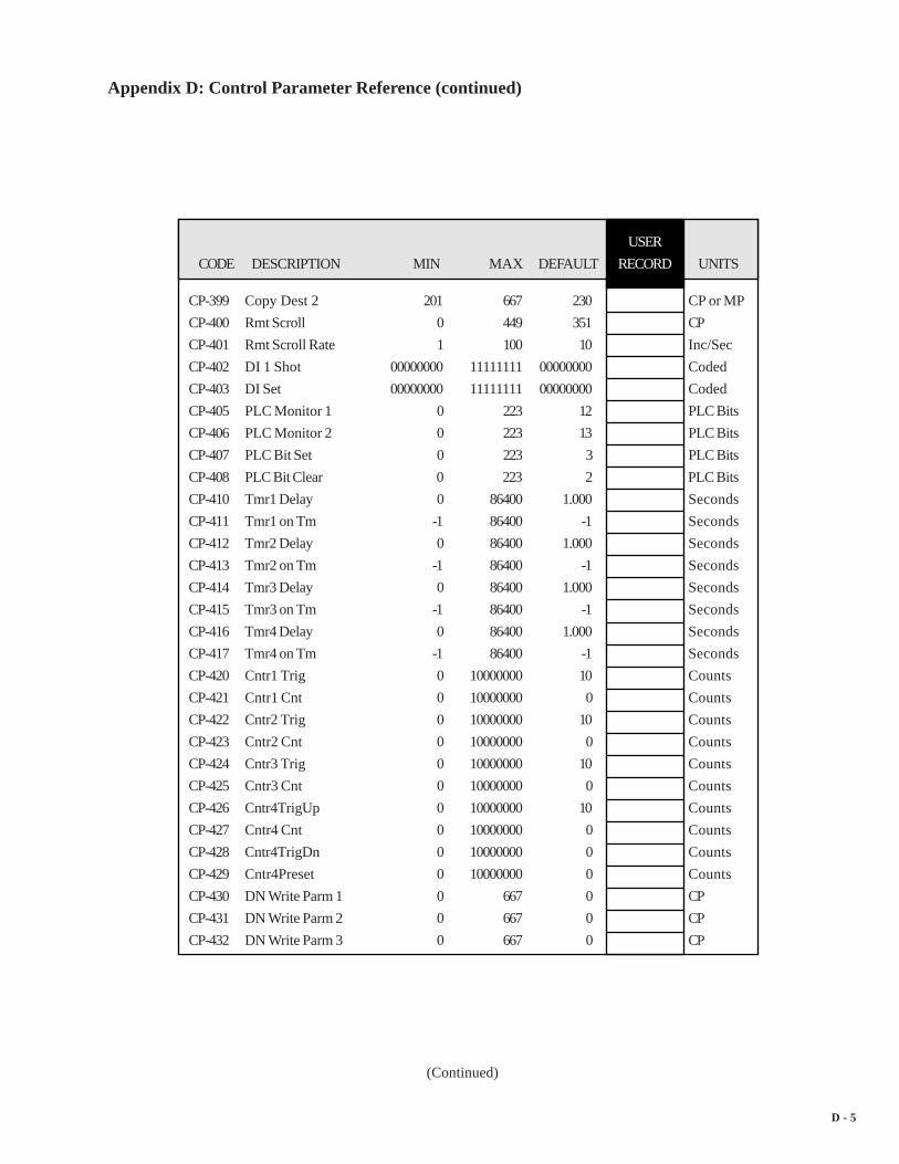
D - 5
USER
CODE DESCRIPTION MIN MAX DEFAULT RECORD UNITS
CP-399 Copy Dest 2 201 667 230 CP or MP
CP-400 Rmt Scroll 0 449 351 CP
CP-401 Rmt Scroll Rate 1 100 10 Inc/Sec
CP-402 DI 1 Shot 00000000 11111111 00000000 Coded
CP-403 DI Set 00000000 11111111 00000000 Coded
CP-405 PLC Monitor 1 0 223 12 PLC Bits
CP-406 PLC Monitor 2 0 223 13 PLC Bits
CP-407 PLC Bit Set 0 223 3 PLC Bits
CP-408 PLC Bit Clear 0 223 2 PLC Bits
CP-410 Tmr1 Delay 0 86400 1.000 Seconds
CP-411 Tmr1 on Tm -1 86400 -1 Seconds
CP-412 Tmr2 Delay 0 86400 1.000 Seconds
CP-413 Tmr2 on Tm -1 86400 -1 Seconds
CP-414 Tmr3 Delay 0 86400 1.000 Seconds
CP-415 Tmr3 on Tm -1 86400 -1 Seconds
CP-416 Tmr4 Delay 0 86400 1.000 Seconds
CP-417 Tmr4 on Tm -1 86400 -1 Seconds
CP-420 Cntr1 Trig 0 10000000 10 Counts
CP-421 Cntr1 Cnt 0 10000000 0 Counts
CP-422 Cntr2 Trig 0 10000000 10 Counts
CP-423 Cntr2 Cnt 0 10000000 0 Counts
CP-424 Cntr3 Trig 0 10000000 10 Counts
CP-425 Cntr3 Cnt 0 10000000 0 Counts
CP-426 Cntr4TrigUp 0 10000000 10 Counts
CP-427 Cntr4 Cnt 0 10000000 0 Counts
CP-428 Cntr4TrigDn 0 10000000 0 Counts
CP-429 Cntr4Preset 0 10000000 0 Counts
CP-430 DN Write Parm 1 0 667 0 CP
CP-431 DN Write Parm 2 0 667 0 CP
CP-432 DN Write Parm 3 0 667 0 CP
(Continued)
Appendix D: Control Parameter Reference (continued)

D - 6
USER
CODE DESCRIPTION MIN MAX DEFAULT RECORD UNITS
CP-433 DN Write Parm 4 0 667 0 CP
CP-434 DN Read Parm 1 0 667 0 CP or MP
CP-435 DN Read Parm 2 0 667 0 CP or MP
CP-436 DN Read Parm 3 0 667 0 CP or MP
CP-437 DN Read Parm 4 0 667 0 CP or MP
CP-438 DN MAC ID 0 63 63 ID
CP-439 DN Baud Rate 1 3 1 Coded
CP-440 Lg Number Parm 1 479 40 CP or MP
CP-441 Status Line 1 1 667 201 CP or MP
CP-442 Status Line 2 0 667 50 CP or MP
CP-443 Status Line 3 0 667 2 CP or MP
CP-444 Status Line 4 0 667 10 CP or MP
CP-445 Status Line 5 0 667 4 CP or MP
CP-446 Status Line 6 0 667 20 CP or MP
CP-449 Lg Number Units 0 80 1 Coded
CP-450 Diagnostics En 0 1 0 Coded
CP-451 Diag DO Shift 0 8 0 Coded
CP-452 Diag DO 00000000 11111111 00000000 Coded
CP-453 Diag DAC Test 0 3 0 Coded
CP-454 Diag DAC Volts -15.0 15.0 0.0 Volts
CP-455 Diag DAC Bits -32768 32767 0 Bits
CP-456 Diag Rmp Tm 0 600 10.000 Seconds
CP-460 Analog Cal En 0 1 0 Coded
CP-461 Analog Cal Sel 1 2 1 Coded
CP-462 Analog Cal Ref 1 2 1 Coded
CP-463 AnalogRef Val -13.00 25 0 V or ma
CP-464 AO Bit Set -32768 32767 0 Bits
CP-465 AO Direct -15.0 20 0.0 V or ma
CP-468 CRC Enable 0 1 1 Coded
CP-469 Record Format 1 3 1 Coded
(Continued)
Appendix D: Control Parameter Reference (continued)

D - 7
USER
CODE DESCRIPTION MIN MAX DEFAULT RECORD UNITS
CP-470 Device Address 1 99 1 Address
CP-471 Baud Rate 1 7 6 Coded
CP-472 Frame Format 1 2 1 Coded
CP-473 SerCom Char Out 0 255 0 Decimal
CP-474 Video Mode 1 3 1 Coded
CP-475 Contrast Value 8 32 18 Contrast
CP-477 Cntrl Latch 0 255 0 Coded
CP-478 Blk Sel Source 1 3 1 Coded
CP-479 Keypad Blk Sel 0 7 0 Coded
CP-480 KyPdLk Mask 0 4 0 Coded
CP-481 Unlock CP A 0 667 0 CP
CP-482 Unlock CP B 0 667 0 CP
CP-483 Unlock CP C 0 667 0 CP
CP-484 Unlock CP D 0 667 0 CP
CP-485 Unlock CP E 0 667 0 CP
CP-486 Unlock CP F 0 667 0 CP
CP-487 Unlock CP G 0 667 0 CP
CP-488 Unlock CP H 0 667 0 CP
CP-489 Unlock Block 0 7 7 Block #
CP-490 Memory Test 0 4 0 Coded
CP-491 Clr Fault Cntrs 0 1 0 Coded
CP-492 Video Test 0 1 0 Coded
CP-495 Serial Number 0 999999 0 Serial #
CP-496 Load Parms 0 6 0 Coded
CP-497 Load PLC Prgm 0 2 0 Coded
CP-498 Save Parms 0 3 0 Coded
CP-499 Save PLC Prgm 0 1 0 Coded
CP-500 Block Parm 1 0 349 210 CP
CP-501 Block Parm 2 0 349 0 CP
CP-502 Block Parm 3 0 349 0 CP
(Continued)
Appendix D: Control Parameter Reference (continued)

D - 8
CP-503 Block Parm 4 0 349 0 CP
CP-504 Block Parm 5 0 349 0 CP
CP-505 Block Parm 6 0 349 0 CP
CP-506 Block Parm 7 0 349 0 CP
CP-507 Block Parm 8 0 349 0 CP
CP-508 Block Parm 9 0 349 0 CP
CP-509 Block Parm 10 0 349 0 CP
CP-510 Block Parm 11 0 349 0 CP
CP-511 Block Parm 12 0 349 0 CP
CP-512 Block Parm 13 0 349 0 CP
CP-513 Block Parm 14 0 349 0 CP
CP-514 Block Parm 15 0 349 0 CP
CP-515 Block Parm 16 0 349 0 CP
CP-540 Blk0 Val 1 -99999999 99999999 0 Parm Val
CP-541 Blk0 Val 2 -99999999 99999999 0 Parm Val
CP-542 Blk0 Val 3 -99999999 99999999 0 Parm Val
CP-543 Blk0 Val 4 -99999999 99999999 0 Parm Val
CP-544 Blk0 Val 5 -99999999 99999999 0 Parm Val
CP-545 Blk0 Val 6 -99999999 99999999 0 Parm Val
CP-546 Blk0 Val 7 -99999999 99999999 0 Parm Val
CP-547 Blk0 Val 8 -99999999 99999999 0 Parm Val
CP-548 Blk0 Val 9 -99999999 99999999 0 Parm Val
CP-549 Blk0 Val10 -99999999 99999999 0 Parm Val
CP-550 Blk0 Val11 -99999999 99999999 0 Parm Val
CP-551 Blk0 Val12 -99999999 99999999 0 Parm Val
CP-552 Blk0 Val13 -99999999 99999999 0 Parm Val
CP-553 Blk0 Val14 -99999999 99999999 0 Parm Val
CP-554 Blk0 Val15 -99999999 99999999 0 Parm Val
CP-555 Blk0 Val16 -99999999 99999999 0 Parm Val
CP-556 Blk1 Val 1 -99999999 99999999 0 Parm Val
Appendix D: Control Parameter Reference (continued)
(Continued)
USER
CODE DESCRIPTION MIN MAX DEFAULT RECORD UNITS

D - 9
USER
CODE DESCRIPTION MIN MAX DEFAULT RECORD UNITS
CP-557 Blk1 Val 2 -99999999 99999999 0 Parm Val
CP-558 Blk1 Val 3 -99999999 99999999 0 Parm Val
CP-559 Blk1 Val 4 -99999999 99999999 0 Parm Val
CP-560 Blk1 Val 5 -99999999 99999999 0 Parm Val
CP-561 Blk1 Val 6 -99999999 99999999 0 Parm Val
CP-562 Blk1 Val 7 -99999999 99999999 0 Parm Val
CP-563 Blk1 Val 8 -99999999 99999999 0 Parm Val
CP-564 Blk1 Val 9 -99999999 99999999 0 Parm Val
CP-565 Blk1 Val10 -99999999 99999999 0 Parm Val
CP-566 Blk1 Val11 -99999999 99999999 0 Parm Val
CP-567 Blk1 Val12 -99999999 99999999 0 Parm Val
CP-568 Blk1 Val13 -99999999 99999999 0 Parm Val
CP-569 Blk1 Val14 -99999999 99999999 0 Parm Val
CP-570 Blk1 Val15 -99999999 99999999 0 Parm Val
CP-571 Blk1 Val16 -99999999 99999999 0 Parm Val
CP-572 Blk2 Val 1 -99999999 99999999 0 Parm Val
CP-573 Blk2 Val 2 -99999999 99999999 0 Parm Val
CP-574 Blk2 Val 3 -99999999 99999999 0 Parm Val
CP-575 Blk2 Val 4 -99999999 99999999 0 Parm Val
CP-576 Blk2 Val 5 -99999999 99999999 0 Parm Val
CP-577 Blk2 Val 6 -99999999 99999999 0 Parm Val
CP-578 Blk2 Val 7 -99999999 99999999 0 Parm Val
CP-579 Blk2 Val 8 -99999999 99999999 0 Parm Val
CP-580 Blk2 Val 9 -99999999 99999999 0 Parm Val
CP-581 Blk2 Val10 -99999999 99999999 0 Parm Val
CP-582 Blk2 Val11 -99999999 99999999 0 Parm Val
CP-583 Blk2 Val12 -99999999 99999999 0 Parm Val
CP-584 Blk2 Val13 -99999999 99999999 0 Parm Val
CP-585 Blk2 Val14 -99999999 99999999 0 Parm Val
CP-586 Blk2 Val15 -99999999 99999999 0 Parm Val
Appendix D: Control Parameter Reference (continued)
(Continued)

D - 10
USER
CODE DESCRIPTION MIN MAX DEFAULT RECORD UNITS
CP-587 Blk2 Val16 -99999999 99999999 0 Parm Val
CP-588 Blk3 Val 1 -99999999 99999999 0 Parm Val
CP-589 Blk3 Val 2 -99999999 99999999 0 Parm Val
CP-590 Blk3 Val 3 -99999999 99999999 0 Parm Val
CP-591 Blk3 Val 4 -99999999 99999999 0 Parm Val
CP-592 Blk3 Val 5 -99999999 99999999 0 Parm Val
CP-593 Blk3 Val 6 -99999999 99999999 0 Parm Val
CP-594 Blk3 Val 7 -99999999 99999999 0 Parm Val
CP-595 Blk3 Val 8 -99999999 99999999 0 Parm Val
CP-596 Blk3 Val 9 -99999999 99999999 0 Parm Val
CP-597 Blk3 Val10 -99999999 99999999 0 Parm Val
CP-598 Blk3 Val11 -99999999 99999999 0 Parm Val
CP-599 Blk3 Val12 -99999999 99999999 0 Parm Val
CP-600 Blk3 Val13 -99999999 99999999 0 Parm Val
CP-601 Blk3 Val14 -99999999 99999999 0 Parm Val
CP-602 Blk3 Val15 -99999999 99999999 0 Parm Val
CP-603 Blk3 Val16 -99999999 99999999 0 Parm Val
CP-604 Blk4 Val 1 -99999999 99999999 0 Parm Val
CP-605 Blk4 Val 2 -99999999 99999999 0 Parm Val
CP-606 Blk4 Val 3 -99999999 99999999 0 Parm Val
CP-607 Blk4 Val 4 -99999999 99999999 0 Parm Val
CP-608 Blk4 Val 5 -99999999 99999999 0 Parm Val
CP-609 Blk4 Val 6 -99999999 99999999 0 Parm Val
CP-610 Blk4 Val 7 -99999999 99999999 0 Parm Val
CP-611 Blk4 Val 8 -99999999 99999999 0 Parm Val
CP-612 Blk4 Val 9 -99999999 99999999 0 Parm Val
CP-613 Blk4 Val10 -99999999 99999999 0 Parm Val
CP-614 Blk4 Val11 -99999999 99999999 0 Parm Vall
CP-615 Blk4 Val12 -99999999 99999999 0 Parm Val
CP-616 Blk4 Val13 -99999999 99999999 0 Parm Val
Appendix D: Control Parameter Reference (continued)
(Continued)

D - 11
USER
CODE DESCRIPTION MIN MAX DEFAULT RECORD UNITS
CP-617 Blk4 Val14 -99999999 99999999 0 Parm Val
CP-618 Blk4 Val15 -99999999 99999999 0 Parm Val
CP-619 Blk4 Val16 -99999999 99999999 0 Parm Val
CP-620 Blk5 Val 1 -99999999 99999999 0 Parm Val
CP-621 Blk5 Val 2 -99999999 99999999 0 Parm Val
CP-622 Blk5 Val 3 -99999999 99999999 0 Parm Val
CP-623 Blk5 Val 4 -99999999 99999999 0 Parm Val
CP-624 Blk5 Val 5 -99999999 99999999 0 Parm Val
CP-625 Blk5 Val 6 -99999999 99999999 0 Parm Val
CP-626 Blk5 Val 7 -99999999 99999999 0 Parm Val
CP-627 Blk5 Val 8 -99999999 99999999 0 Parm Val
CP-628 Blk5 Val 9 -99999999 99999999 0 Parm Val
CP-629 Blk5 Val10 -99999999 99999999 0 Parm Val
CP-630 Blk5 Val11 -99999999 99999999 0 Parm Val
CP-631 Blk5 Val12 -99999999 99999999 0 Parm Val
CP-632 Blk5 Val13 -99999999 99999999 0 Parm Val
CP-633 Blk5 Val14 -99999999 99999999 0 Parm Val
CP-634 Blk5 Val15 -99999999 99999999 0 Parm Val
CP-635 Blk5 Val16 -99999999 99999999 0 Parm Val
CP-636 Blk6 Val 1 -99999999 99999999 0 Parm Val
CP-637 Blk6 Val 2 -99999999 99999999 0 Parm Val
CP-638 Blk6 Val 3 -99999999 99999999 0 Parm Val
CP-639 Blk6 Val 4 -99999999 99999999 0 Parm Val
CP-640 Blk6 Val 5 -99999999 99999999 0 Parm Val
CP-641 Blk6 Val 6 -99999999 99999999 0 Parm Val
CP-642 Blk6 Val 7 -99999999 99999999 0 Parm Val
CP-643 Blk6 Val 8 -99999999 99999999 0 Parm Val
CP-644 Blk6 Val 9 -99999999 99999999 0 Parm Val
CP-645 Blk6 Val10 -99999999 99999999 0 Parm Val
CP-646 Blk6 Val11 -99999999 99999999 0 Parm Val
Appendix D: Control Parameter Reference (continued)
(Continued)

D - 12
USER
CODE DESCRIPTION MIN MAX DEFAULT RECORD UNITS
CP-647 Blk6 Val12 -99999999 99999999 0 Parm Val
CP-648 Blk6 Val13 -99999999 99999999 0 Parm Val
CP-649 Blk6 Val14 -99999999 99999999 0 Parm Val
CP-650 Blk6 Val15 -99999999 99999999 0 Parm Val
CP-651 Blk6 Val16 -99999999 99999999 0 Parm Val
CP-652 Blk7 Val 1 -99999999 99999999 0 Parm Val
CP-653 Blk7 Val 2 -99999999 99999999 0 Parm Val
CP-654 Blk7 Val 3 -99999999 99999999 0 Parm Val
CP-655 Blk7 Val 4 -99999999 99999999 0 Parm Val
CP-656 Blk7 Val 5 -99999999 99999999 0 Parm Val
CP-657 Blk7 Val 6 -99999999 99999999 0 Parm Val
CP-658 Blk7 Val 7 -99999999 99999999 0 Parm Val
CP-659 Blk7 Val 8 -99999999 99999999 0 Parm Val
CP-660 Blk7 Val 9 -99999999 99999999 0 Parm Val
CP-661 Blk7 Val10 -99999999 99999999 0 Parm Val
CP-662 Blk7 Val11 -99999999 99999999 0 Parm Val
CP-663 Blk7 Val12 -99999999 99999999 0 Parm Val
CP-664 Blk7 Val13 -99999999 99999999 0 Parm Val
CP-665 Blk7 Val14 -99999999 99999999 0 Parm Val
CP-666 Blk7 Val15 -99999999 99999999 0 Parm Val
CP-667 Blk7 Val16 -99999999 99999999 0 Parm Val
Appendix D: Control Parameter Reference (continued)
(Continued)

D - 13
—NOTES—

E - 1
CODE DESCRIPTION MIN MAX UNITS
MP-01 FI1 Hz -180000 180000 Hertz
MP-02 FI1 RPM -99999.9 99999.9 RPM
MP-03 FI2 Hz -180000 180000 Hertz
MP-04 FI2 RPM -99999.9 99999.9 RPM
MP-05 Ld EU/Tm -9999999 9999999 EU/Tm
MP-06 Fb EU/Tm -9999999 9999999 EU/Tm
MP-10 Ld Posn 0 999999999 EU
MP-11 LdJobSize 0 9999999 EU
MP-12 LdJbSzVar -999999 999999 EU
MP-13 LdJbSzAvg 0 9999999 EU
MP-14 LdJbSzAct 0 99999999 EU
MP-15 LdNetOfst -9999999 9999999 EU
MP-20 Fb Posn 0 999999999 EU
MP-21 FbJobSize 0 9999999 EU
MP-22 FbJbSzVar -999999 999999 EU
MP-23 FbJbSzAvg 0 9999999 EU
MP-24 FbJbSzAct 0 99999999 EU
MP-25 FbNetOfst -9999999 9999999 EU
MP-29 SyncFlgDif -9999999 9999999 EU
MP-30 ScaledRef -99999.9 99999.9 EU/Tm
MP-31 RampedRef -99999.9 99999.9 EU/Tm
MP-32 VelError -99999.9 99999.9 EU/Tm
MP-33 PosnErr 0 999999999 EU
MP-34 Intgrl -15.00 15.00 Volts
MP-35 FeedFwd -15.00 15.00 Volts
MP-36 Trim Out -15.00 15.00 Volts
MP-37 CO Volts -15.00 15.00 Volts
MP-38 CO Bits -32767 32767 Bits
MP-39 CO Max Bits 0 32767 Bits
MP-40 Scaled Fb -9999999 9999999 EU
APPENDIX E: MONITOR PARAMETER REFERENCE
(Continued)

E - 2
MP-41 ScaleFactor 0 999999 Ratio
MP-42 ActScaleFactor 0 999999 Ratio
MP-48 Kff 0.00 99999.99 V/kiloRPM
MP-49 Cntrl Loop 0 3 Coded
MP-50 State 0 9 Coded
MP-51 Active Blk 0 7 Coded
MP-52 InvalidBlks 00000000 11111111 Coded
MP-53 Misc Status 00000000 11111111 Coded
MP-54 Std Alms 00000000 11111111 Coded
MP-55 Custom Alms 00000000 11111111 Coded
MP-56 Misc Alarms 00000000 11111111 Coded
MP-90 SerCom Char In 0 255 Binary
MP-91 SerCom Errs 00000000 11111111 Coded
MP-94 ROM Test 0 1 Coded
MP-95 SRAM Test 0 1 Coded
MP-96 NV RAM Test 0 1 Coded
MP-97 Model # 1000 60000 Model #
MP-98 RELEASE 090102 123105 Date
MP-99 REVISION 0.50 99.99 Rev Level
MP-100 DI 7..0 00000000 11111111 Coded
MP-101 DI 15..8 00000000 11111111 Coded
MP-102 DO 7..0 00000000 11111111 Coded
MP-103 KeyPad Lockout 0 1 Coded
MP-107 Tmr4 Time 0 86400 Seconds
MP-108 PLC Mon 1 Val 0 1 Coded
MP-109 PLC Mon 2 Val 0 1 Coded
MP-110 PLC 15-8 00000000 11111111 Coded
MP-111 PLC 23-16 00000000 11111111 Coded
MP-112 PLC 31-24 00000000 11111111 Coded
MP-113 PLC 39-32 00000000 11111111 Coded
CODE DESCRIPTION MIN MAX UNITS
Appendix E: Monitor Parameter Reference (continued)
(Continued)

E - 3
Appendix E: Monitor Parameter Reference (continued)
MP-114 PLC 47-40 00000000 11111111 Coded
MP-115 PLC 55-48 00000000 11111111 Coded
MP-116 PLC 63-56 00000000 11111111 Coded
MP-117 PLC 71-64 00000000 11111111 Coded
MP-118 PLC 79-72 00000000 11111111 Coded
MP-119 PLC 87-80 00000000 11111111 Coded
MP-120 PLC 95-88 00000000 11111111 Coded
MP-121 PLC 107-100 00000000 11111111 Coded
MP-122 PLC 115-108 00000000 11111111 Coded
MP-123 PLC 123-116 00000000 11111111 Coded
MP-124 PLC 131-124 00000000 11111111 Coded
MP-125 PLC 139-132 00000000 11111111 Coded
MP-126 PLC 147-140 00000000 11111111 Coded
MP-127 PLC 155-148 00000000 11111111 Coded
MP-128 PLC 163-156 00000000 11111111 Coded
MP-129 PLC 171-164 00000000 11111111 Coded
MP-130 PLC 179-172 00000000 11111111 Coded
MP-131 PLC 187-180 00000000 11111111 Coded
MP-132 PLC 195-188 00000000 11111111 Coded
MP-133 PLC 203-196 00000000 11111111 Coded
MP-134 PLC 211-204 00000000 11111111 Coded
MP-135 PLC 219-212 00000000 00001111 Coded
MP-150 Last Reset 00000000 11110111 Coded
MP-151 Misc Intrpt 00000000 00111111 Coded
MP-152 Device Alms 00000000 00001111 Coded
MP-153 PC at Intrpt 2560 524288 Address
MP-154 Norm Pwr Ups 1 65535 Counts
MP-155 Low Pwr Cntr 0 65535 Counts
MP-156 Mem Err Cntr 0 65535 Counts
MP-157 WatchDogCntr 0 65535 Counts
CODE DESCRIPTION MIN MAX UNITS

E - 4
CODE DESCRIPTION MIN MAX UNITS
MP-158 MiscIntrptCntr 0 65535 Counts
MP-160 AI1 Bits -8192 8191 Bits
MP-161 AI1 Signal -12.00 20 V or ma
MP-162 AI1 EU -999999 999999 EU
MP-163 AI2 Bits -8192 8191 Bits
MP-164 AI2 Signal -12.00 20 V or ma
MP-165 AI2 EU -999999 999999 EU
MP-166 AO Bits -32767 32767 Bits
MP-167 AO Signal -12.00 20 V or ma
MP-168 AnlgCal Ref A -13.00 25 V or ma
MP-169 AnlgCal Ref B -13.00 25 V or ma
MP-178 PosnErrCnt -500000000 500000000 Lines
MP-179 SyncFlgDifCnt -500000000 500000000 Lines
MP-180 LdPsnCnt -500000000 500000000 Lines
MP-182 LdJSCnt -500000000 500000000 Lines
MP-183 LdJSAvgCnt -500000000 500000000 Lines
MP-184 LdJSVarCnt -500000000 500000000 Lines
MP-190 FbPsnCnt -500000000 500000000 Lines
MP-192 FbJSCnt -500000000 500000000 Lines
MP-193 FbJSAvgCnt -500000000 500000000 Lines
MP-194 FbJSVarCnt -500000000 500000000 Lines

E - 5
—NOTES—

F- 1
(Continued)
APPENDIX F: CONTROL PARAMETERSCREEN LOCATOR
CP-201 Setpoint X ................ Status\pg 1................................. Setup\System Setup\pg 2................................. Setup\System Setup\pg 3................................. Setup\System Setup\pg 5................................. System Monitor\Run Monitor\pg 1................................. System Monitor\Control Overrides\pg 4
CP-202 RUN Mode ............. Setup\System Setup\pg 2................................. Setup\System Setup\pg 3................................. Setup\System Setup\pg 5................................. Setpoints & Ramps\Run Modes\pg1................................. Setpoints & Ramps\Run Modes\pg1................................. Setpoints & Ramps\Follower\pg1................................. Setpoints & Ramps\Direct SP & Ramps\pg 1................................. System Monitor\Position\pg 1................................. System Monitor\Position\pg 2................................. System Monitor\Job Sizes\pg 1................................. System Monitor\Job Sizes\pg 2................................. System Monitor\Control Overrides\pg 1................................. System Monitor\Control Overrides\pg 4
CP-203 Sync Mode .............. Scaling\Job Sizes\pg 1................................. Setpoints & Ramps\Master\pg1................................. Setpoints & Ramps\Follower\pg1................................. System Monitor\Job Sizes\pg 1................................. System Monitor\Job Sizes\pg 2................................. System Monitor\Control Overrides\pg 4
CP-204 Sync Logic ............... Tuning\Related Items\pg 1CP-205 LdSyncDvd ............. Scaling\Job Sizes\pg 1CP-206 FbSyncDvd .............. Scaling\Job Sizes\pg 1CP-207 LdOfstSelect ........... Scaling\Offsets & Phase\pg 1CP-208 FbOfstSelect ........... Scaling\Offsets & Phase\pg 1
CP# CP Name Screen

F - 2
CP# CP Name Screen
(Continued)
Appendix F: Control Parameter Screen Locator (continued)
CP-209 Time Base ............... Scaling\Lead\pg 1................................. Scaling\Follower\pg 1
CP-210 Master SP ............... Setpoints & Ramps\Master\pg1CP-211 Max SP Mstr ........... Setpoints & Ramps\Master\pg1CP-212 Min SP Mstr ............ Setpoints & Ramps\Master\pg1CP-220 Follower SP ............. Setpoints & Ramps\Follower\pg1CP-221 Max SP Fol .............. Setpoints & Ramps\Follower\pg1CP-222 Min SP Fol ............... Setpoints & Ramps\Follower\pg1CP-230 Direct SP ................. Setpoints & Ramps\Direct SP & Ramps\pg 1CP-231 Acl Tm Drct ............ Setpoints & Ramps\Direct SP & Ramps\pg 1CP-232 Dcl Tm Drct ............ Setpoints & Ramps\Direct SP & Ramps\pg 1CP-240 Jog SP ..................... Setpoints & Ramps\Jog SP & Ramps\pg 1CP-241 Acl Tm Jog .............. Setpoints & Ramps\Jog SP & Ramps\pg 1CP-242 Acl Rt Jog ............... Setpoints & Ramps\Jog SP & Ramps\pg 1CP-243 Dcl Tm Jog .............. Setpoints & Ramps\Jog SP & Ramps\pg 1CP-244 Dcl Rt Jog ............... Setpoints & Ramps\Jog SP & Ramps\pg 1CP-245 Jog Loop Mode ....... Setpoints & Ramps\Jog SP & Ramps\pg 1CP-250 ScFbDisp Equ .......... Setup\System Setup\pg 5CP-260 Cnt Mode FI1 .......... Setup\System Setup\pg 4
................................. Scaling\Lead\pg 1CP-261 PPR FI1 .................. Setup\System Setup\pg 4
................................. Scaling\Lead\pg 1CP-262 Pulses FI1 ................ Setup\System Setup\pg 4
................................. Scaling\Lead\pg 1CP-263 EU FI1 ..................... Setup\System Setup\pg 4
................................. Scaling\Lead\pg 1CP-264 LdSyncPolarity ........ Scaling\Lead\pg 1CP-265 Cnt Mode FI2 .......... Setup\System Setup\pg 1
................................. Scaling\Follower\pg 1CP-266 PPR FI2 .................. Setup\System Setup\pg 1
................................. Scaling\Follower\pg 1CP-267 Pulses FI2 ................ Setup\System Setup\pg 3

F- 3
Appendix F: Control Parameter Screen Locator (continued)
CP# CP Name Screen
(Continued)
................................. Scaling\Follower\pg 1CP-268 EU FI2 ..................... Setup\System Setup\pg 3
................................. Scaling\Follower\pg 1CP-269 FbSyncPolarity ........ Scaling\Follower\pg 1CP-270 CO Mode ................ Setup\System Setup\pg 1
................................. Scaling\Follower\pg 2CP-271 CO Max Volts ......... Setup\System Setup\pg 1
................................. Scaling\Follower\pg 2
................................. Device Tests\Std Signals Tests\pg 2CP-272 CO Polarity ............. Setup\System Setup\pg 2
................................. Scaling\Follower\pg 2CP-273 CO Offset ............... Setup\System Setup\pg 2
................................. Scaling\Follower\pg 2
................................. Device Tests\Std Signals Tests\pg 2CP-280 AI1 Mode ................ Scaling\Aux Analog Input 1\pg 1
................................. System Monitor\Aux Analog Monitor\pg 1
................................. Device Tests\Aux Analog Tests\pg 1
................................. Device Tests\Aux Analog Tests\pg 3CP-281 AI1 RA ................... Scaling\Aux Analog Input 1\pg 1CP-282 EU @ AI1 RA ........ Scaling\Aux Analog Input 1\pg 1CP-283 AI1 RB .................... Scaling\Aux Analog Input 1\pg 1CP-284 EU @ AI1 RB ........ Scaling\Aux Analog Input 1\pg 1CP-285 AI2 Mode ................ Scaling\Aux Analog Input 2\pg 1
................................. System Monitor\Aux Analog Monitor\pg 1
................................. Device Tests\Aux Analog Tests\pg 1
................................. Device Tests\Aux Analog Tests\pg 3CP-286 AI2 RA ................... Scaling\Aux Analog Input 2\pg 1CP-287 EU @ AI2 RA ........ Scaling\Aux Analog Input 2\pg 1CP-288 AI2 RB .................... Scaling\Aux Analog Input 2\pg 1CP-289 EU @ AI2 RB ........ Scaling\Aux Analog Input 2\pg 1CP-290 AO Parameter ......... Scaling\Aux Analog Output\pg 1
................................. Device Tests\Aux Analog Tests\pg 2

F - 4
Appendix F: Control Parameter Screen Locator (continued)
(Continued)
CP-291 AO Mode ................ Scaling\Aux Analog Output\pg 1................................. System Monitor\Aux Analog Monitor\pg 1................................. Device Tests\Aux Analog Tests\pg 2................................. Device Tests\Aux Analog Tests\pg 3
CP-292 AO RA .................... Scaling\Aux Analog Output\pg 1CP-293 Val @ AO RA ......... Scaling\Aux Analog Output\pg 1CP-294 AO RB .................... Scaling\Aux Analog Output\pg 1CP-295 Val @ AO RB ......... Scaling\Aux Analog Output\pg 1CP-300 Ref Ramps .............. Setpoints & Ramps\Run Ramps\pg 1
................................. Setpoints & Ramps\Stop Ramps\pg 1CP-301 Acl Tm RUN .......... Setpoints & Ramps\Run Ramps\pg 1CP-302 Acl Rt RUN ............ Setpoints & Ramps\Run Ramps\pg 1CP-303 Dcl Tm RUN .......... Setpoints & Ramps\Run Ramps\pg 1CP-304 Dcl Rt RUN ............ Setpoints & Ramps\Run Ramps\pg 1CP-305 Ramp Thd ................ Setpoints & Ramps\Run Ramps\pg 1CP-310 Dcl Tm RStp ........... Setpoints & Ramps\Stop Ramps\pg 1CP-311 Dcl Rt RStp ............. Setpoints & Ramps\Stop Ramps\pg 1CP-312 Dcl Tm HStp ........... Setpoints & Ramps\Stop Ramps\pg 1CP-313 Dcl Rt HStp ............. Setpoints & Ramps\Stop Ramps\pg 1CP-320 Kp VL ..................... Tuning\Velocity Loop\pg 1CP-321 Ki VL ...................... Tuning\Velocity Loop\pg 1CP-322 Kd VL ..................... Tuning\Velocity Loop\pg 1CP-323 DerivThd VL ........... Tuning\Velocity Loop\pg 2CP-325 Kp PL ...................... Tuning\Position Loop\pg 1CP-326 Ki PL ....................... Tuning\Position Loop\pg 1CP-327 Kd PL ...................... Tuning\Position Loop\pg 1CP-328 DerivThd PL ........... Tuning\Position Loop\pg 2CP-329 Max Fb .................... Tuning\Feedforward\pg 1CP-330 Max Spd Lmt .......... Alarms & Limits\Limits\pg 1CP-331 Min Spd Lmt ............ Alarms & Limits\Limits\pg 1CP-332 Zero Speed .............. Alarms & Limits\Alarms\pg 1
................................. Alarms & Limits\Limits\pg 1
CP# CP Name Screen

F- 5
Appendix F: Control Parameter Screen Locator (continued)
(Continued)
CP# CP Name Screen
CP-333 Trim Authority ......... Tuning\Velocity Loop\pg 2................................. Tuning\Position Loop\pg 2................................. Alarms & Limits\Limits\pg 1
CP-334 Integral Limit ........... Tuning\Velocity Loop\pg 2................................. Tuning\Position Loop\pg 2................................. Alarms & Limits\Limits\pg 1
CP-335 LdSyncBand ............ Scaling\Job Sizes\pg 1................................. Tuning\Related Items\pg 1
CP-336 FbSyncBand ............ Scaling\Job Sizes\pg 1................................. Tuning\Related Items\pg 1
CP-337 InPosnBand ............. Tuning\Related Items\pg 1CP-340 LdSnsrDist ............... Scaling\Offsets & Phase\pg 2CP-341 LdSnsrOfst .............. Scaling\Offsets & Phase\pg 2CP-347 TrendJSChg% ......... Alarms & Limits\Limits\pg 2CP-348 NonSyncErrRecEn . Alarms & Limits\Limits\pg 2CP-350 FbSnsrDist ............... Scaling\Offsets & Phase\pg 2CP-351 FbSnsrOfst .............. Scaling\Offsets & Phase\pg 2CP-356 Phase Source .......... Scaling\Offsets & Phase\pg 1CP-357 NonSyncPhase ........ Scaling\Offsets & Phase\pg 2CP-360 Loop Update ............ Tuning\Related Items\pg 1CP-361 Sig Fltr Sel ............... Tuning\Related Items\pg 1CP-362 SigFltrTmConst ....... Tuning\Related Items\pg 1CP-363 KffAdjUpdt ............. Tuning\Feedforward\pg 1CP-364 Kff Auto En ............. Setup\System Setup\pg 3
................................. Tuning\Feedforward\pg 1CP-367 LgErrThld ................ Tuning\Large Error\pg 1CP-368 LgErrGain ................ Tuning\Large Error\pg 1CP-369 OverSpdAllow ......... Tuning\Large Error\pg 1CP-370 Min Fb Alm ............. Alarms & Limits\Alarms\pg 1CP-371 Max Fb Alm ............ Alarms & Limits\Alarms\pg 1CP-372 Max Acl/Dcl ............ Alarms & Limits\Alarms\pg 1CP-373 NO Resp Time ........ Alarms & Limits\Alarms\pg 1

F - 6
CP# CP Name Screen
Appendix F: Control Parameter Screen Locator (continued)
(Continued)
CP-374 Posn Alarm .............. Alarms & Limits\Alarms\pg 1CP-375 Std Alm Msk ............ Setup\Alm Indicator Mask\pg 1CP-376 CustAlm Msk .......... Setup\Alm Indicator Mask\pg 1CP-380 Cmpr1 Parm ............ Alarms & Limits\Alarms\pg 2CP-381 Cmpr2 Parm ............ Alarms & Limits\Alarms\pg 2CP-382 Cmpr3 Parm ............ Alarms & Limits\Alarms\pg 3CP-383 Cmpr4 Parm ............ Alarms & Limits\Alarms\pg 3CP-386 Cmpr1 Type ............. Alarms & Limits\Alarms\pg 2CP-387 Cmpr2 Type ............. Alarms & Limits\Alarms\pg 2CP-388 Cmpr3 Type ............. Alarms & Limits\Alarms\pg 3CP-389 Cmpr4 Type ............. Alarms & Limits\Alarms\pg 3CP-392 Cmpr1 Val ............... Alarms & Limits\Alarms\pg 2CP-393 Cmpr2 Val ............... Alarms & Limits\Alarms\pg 2CP-394 Cmpr3 Val ............... Alarms & Limits\Alarms\pg 3CP-395 Cmpr4 Val ............... Alarms & Limits\Alarms\pg 3CP-396 Copy Source 1 ......... PLC\PLC Data Copy\pg 1CP-397 Copy Dest 1 ............ PLC\PLC Data Copy\pg 1CP-398 Copy Source 2 ......... PLC\PLC Data Copy\pg 1CP-399 Copy Dest 2 ............ PLC\PLC Data Copy\pg 1CP-400 Rmt Scroll ................ Setup\Remote Scroll Setup\pg 1CP-401 Rmt Scroll Rate ....... Setup\Remote Scroll Setup\pg 1CP-402 DI 1 Shot ................. PLC\Digital I/O\pg 1CP-403 DI Set ...................... PLC\PLC Monitor\pg 1CP-405 PLC Monitor 1 ........ PLC\PLC Monitor\pg 1CP-406 PLC Monitor 2 ........ PLC\PLC Monitor\pg 1CP-407 PLC Bit Set ............. PLC\PLC Monitor\pg 1CP-408 PLC Bit Clear ......... PLC\PLC Monitor\pg 1CP-410 Tmr1 Delay ............. PLC\PLC Timers\pg 1CP-411 Tmr1 on Tm ............ PLC\PLC Timers\pg 1CP-412 Tmr2 Delay ............. PLC\PLC Timers\pg 1CP-413 Tmr2 on Tm ............ PLC\PLC Timers\pg 1CP-414 Tmr3 Delay ............. PLC\PLC Timers\pg 1

F- 7
CP# CP Name Screen
Appendix F: Control Parameter Screen Locator (continued)
(Continued)
CP-415 Tmr3 on Tm ............ PLC\PLC Timers\pg 1CP-416 Tmr4 Delay ............. PLC\PLC Timers\pg 1CP-417 Tmr4 on Tm ............ PLC\PLC Timers\pg 1CP-420 Cntr1 Trig ................ PLC\PLC Event Cntrs\pg 1CP-421 Cntr1 Cnt ................. PLC\PLC Event Cntrs\pg 1CP-422 Cntr2 Trig ................ PLC\PLC Event Cntrs\pg 1CP-423 Cntr2 Cnt ................. PLC\PLC Event Cntrs\pg 1CP-424 Cntr3 Trig ................ PLC\PLC Event Cntrs\pg 1CP-425 Cntr3 Cnt ................. PLC\PLC Event Cntrs\pg 1CP-426 Cntr4TrigUp ............ PLC\PLC Event Cntrs\pg 1CP-427 Cntr4 Cnt ................. PLC\PLC Event Cntrs\pg 1CP-428 Cntr4TrigDn ............ PLC\PLC Event Cntrs\pg 1CP-429 Cntr4Preset ............. PLC\PLC Event Cntrs\pg 1CP-430 DN Write Parm 1 .... Setup\DeviceNet Setup\pg 2CP-431 DN Write Parm 2 .... Setup\DeviceNet Setup\pg 2CP-432 DN Write Parm 3 .... Setup\DeviceNet Setup\pg 2CP-433 DN Write Parm 4 .... Setup\DeviceNet Setup\pg 2CP-434 DN Read Parm 1 .... Setup\DeviceNet Setup\pg 2CP-435 DN Read Parm 2 .... Setup\DeviceNet Setup\pg 2CP-436 DN Read Parm 3 .... Setup\DeviceNet Setup\pg 2CP-437 DN Read Parm 4 .... Setup\DeviceNet Setup\pg 2CP-438 DN MAC ID ........... Setup\DeviceNet Setup\pg 1CP-439 DN Baud Rate ........ Setup\DeviceNet Setup\pg 1CP-440 Lg Number Parm .... Setup\Status Screen Setup\pg 1CP-441 Status Line 1 ........... Setup\Status Screen Setup\pg 1CP-442 Status Line 2 ........... Setup\Status Screen Setup\pg 1CP-443 Status Line 3 ........... Setup\Status Screen Setup\pg 1CP-444 Status Line 4 ........... Setup\Status Screen Setup\pg 1CP-445 Status Line 5 ........... Setup\Status Screen Setup\pg 1CP-446 Status Line 6 ........... Setup\Status Screen Setup\pg 1CP-449 Lg Number Units .... Setup\System Setup\pg 5
................................. Setup\Status Screen Setup\pg 1

F - 8
CP# CP Name Screen
Appendix F: Control Parameter Screen Locator (continued)
(Continued)
CP-450 Diagnostics En ........ Device Tests\Std Signals Tests\pg 2................................. Device Tests\Digital I/O Test\pg 1
CP-451 Diag DO Shift ......... Device Tests\Digital I/O Test\pg 1CP-452 Diag DO .................. Device Tests\Digital I/O Test\pg 1CP-453 Diag DAC Test ....... Device Tests\Std Signals Tests\pg 2CP-454 Diag DAC Volts ...... Device Tests\Std Signals Tests\pg 2CP-455 Diag DAC Bits ....... Device Tests\Std Signals Tests\pg 2CP-456 Diag Rmp Tm .......... Device Tests\Std Signals Tests\pg 2CP-460 Analog Cal En ......... Device Tests\Aux Analog Tests\pg 3CP-461 Analog Cal Sel ........ Device Tests\Aux Analog Tests\pg 3CP-462 Analog Cal Ref ....... Device Tests\Aux Analog Tests\pg 3CP-463 AnalogRef Val ......... Device Tests\Aux Analog Tests\pg 3CP-464 AO Bit Set ............... Device Tests\Aux Analog Tests\pg 3CP-465 AO Direct ............... Scaling\Aux Analog Output\pg 1
................................. Device Tests\Aux Analog Tests\pg 2CP-468 CRC Enable ............ Setup\Serial Comm Setup\pg 1
................................. Device Tests\Serial Comm Test\pg 1CP-469 Record Format ........ Setup\Serial Comm Setup\pg 1
................................. Device Tests\Serial Comm Test\pg 1CP-470 Device Address ....... Setup\Serial Comm Setup\pg 1
................................. Device Tests\Serial Comm Test\pg 1CP-471 Baud Rate ............... Setup\Serial Comm Setup\pg 1
................................. Device Tests\Serial Comm Test\pg 1CP-472 Frame Format ......... Setup\Serial Comm Setup\pg 1
................................. Device Tests\Serial Comm Test\pg 1CP-473 SerCom Char Out ... Device Tests\Serial Comm Test\pg 1CP-474 Video Mode ............. Setup\Video Setup\pg 1
................................. Device Tests\Hardware Tests\pg 3CP-475 Contrast Value ......... Setup\Video Setup\pg 1
................................. Device Tests\Hardware Tests\pg 3CP-477 Cntrl Latch .............. Available through the "CODE" keyCP-478 Blk Sel Source ......... Blocks\Block Selection\pg 1

F- 9
CP# CP Name Screen
Appendix F: Control Parameter Screen Locator (continued)
(Continued)
................................. System Monitor\Control Overrides\pg 4CP-479 Keypad Blk Sel ....... Blocks\Block Selection\pg 1
................................. System Monitor\Control Overrides\pg 4CP-480 KyPdLk Mask ......... Setup\Keypad Lock Setup\pg 1
................................. Setup\Keypad Lock Setup\pg 2CP-481 Unlock CP A ........... Setup\Keypad Lock Setup\pg 1CP-482 Unlock CP B ........... Setup\Keypad Lock Setup\pg 1CP-483 Unlock CP C ........... Setup\Keypad Lock Setup\pg 1CP-484 Unlock CP D ........... Setup\Keypad Lock Setup\pg 1CP-485 Unlock CP E ............ Setup\Keypad Lock Setup\pg 1CP-486 Unlock CP F ............ Setup\Keypad Lock Setup\pg 1CP-487 Unlock CP G ........... Setup\Keypad Lock Setup\pg 1CP-488 Unlock CP H ........... Setup\Keypad Lock Setup\pg 1CP-489 Unlock Block .......... Setup\Keypad Lock Setup\pg 2CP-490 Memory Test ........... Device Tests\Hardware Tests\pg 1CP-491 Clr Fault Cntrs ......... Device Tests\Device Status\pg 1
................................. Device Tests\Device Status\pg 2CP-492 Video Test ............... Device Tests\Hardware Tests\pg 3CP-495 Serial Number ......... Setup\DeviceNet Setup\pg 1CP-496 Load Parms ............. Setup\Load & Save Parms\pg 1CP-497 Load PLC Prgm...... Setup\Load & Save Parms\pg 1CP-498 Save Parms ............. Setup\Load & Save Parms\pg 1CP-499 Save PLC Prgm ...... Setup\Load & Save Parms\pg 1CP-500 Block Parm 1 ......... Block Setup\Edit Block Parms\pg 1CP-501 Block Parm 2 ......... Block Setup\Edit Block Parms\pg 1CP-502 Block Parm 3 ......... Block Setup\Edit Block Parms\pg 1CP-503 Block Parm 4 ......... Block Setup\Edit Block Parms\pg 1CP-504 Block Parm 5 ......... Block Setup\Edit Block Parms\pg 2CP-505 Block Parm 6 ......... Block Setup\Edit Block Parms\pg 2CP-506 Block Parm 7 ......... Block Setup\Edit Block Parms\pg 2CP-507 Block Parm 8 ......... Block Setup\Edit Block Parms\pg 2CP-508 Block Parm 9 ......... Block Setup\Edit Block Parms\pg 3

F - 10
CP# CP Name Screen
Appendix F: Control Parameter Screen Locator (continued)
(Continued)
CP-509 Block Parm 10 ........ Block Setup\Edit Block Parms\pg 3CP-510 Block Parm 11 ......... Block Setup\Edit Block Parms\pg 3CP-511 Block Parm 12 ........ Block Setup\Edit Block Parms\pg 3CP-512 Block Parm 13 ........ Block Setup\Edit Block Parms\pg 4CP-513 Block Parm 14 ........ Block Setup\Edit Block Parms\pg 4CP-514 Block Parm 15 ........ Block Setup\Edit Block Parms\pg 4CP-515 Block Parm 16 ........ Block Setup\Edit Block Parms\pg 4CP-540 Blk0 Val 1 ................ Block Setup\Edit Block 0\pg 1CP-541 Blk0 Val 2 ................ Block Setup\Edit Block 0\pg 1CP-542 Blk0 Val 3 ................ Block Setup\Edit Block 0\pg 1CP-543 Blk0 Val 4 ................ Block Setup\Edit Block 0\pg 1CP-544 Blk0 Val 5 ................ Block Setup\Edit Block 0\pg 2CP-545 Blk0 Val 6 ................ Block Setup\Edit Block 0\pg 2CP-546 Blk0 Val 7 ................ Block Setup\Edit Block 0\pg 2CP-547 Blk0 Val 8 ................ Block Setup\Edit Block 0\pg 2CP-548 Blk0 Val 9 ................ Block Setup\Edit Block 0\pg 3CP-549 Blk0 Val10 ............... Block Setup\Edit Block 0\pg 3CP-550 Blk0 Val11 ............... Block Setup\Edit Block 0\pg 3CP-551 Blk0 Val12 ............... Block Setup\Edit Block 0\pg 3CP-552 Blk0 Val13 ............... Block Setup\Edit Block 0\pg 4CP-553 Blk0 Val14 ............... Block Setup\Edit Block 0\pg 4CP-554 Blk0 Val15 ............... Block Setup\Edit Block 0\pg 4CP-555 Blk0 Val16 ............... Block Setup\Edit Block 0\pg 4CP-556 Blk1 Val 1 ................ Block Setup\Edit Block 1\pg 1CP-557 Blk1 Val 2 ................ Block Setup\Edit Block 1\pg 1CP-558 Blk1 Val 3 ................ Block Setup\Edit Block 1\pg 1CP-559 Blk1 Val 4 ................ Block Setup\Edit Block 1\pg 1CP-560 Blk1 Val 5 ................ Block Setup\Edit Block 1\pg 2CP-561 Blk1 Val 6 ................ Block Setup\Edit Block 1\pg 2CP-562 Blk1 Val 7 ................ Block Setup\Edit Block 1\pg 2CP-563 Blk1 Val 8 ................ Block Setup\Edit Block 1\pg 2CP-564 Blk1 Val 9 ................ Block Setup\Edit Block 1\pg 3

F- 11
CP# CP Name Screen
Appendix F: Control Parameter Screen Locator (continued)
(Continued)
CP-565 Blk1 Val10 ............... Block Setup\Edit Block 1\pg 3CP-566 Blk1 Val11 ............... Block Setup\Edit Block 1\pg 3CP-567 Blk1 Val12 ............... Block Setup\Edit Block 1\pg 3CP-568 Blk1 Val13 ............... Block Setup\Edit Block 1\pg 4CP-569 Blk1 Val14 ............... Block Setup\Edit Block 1\pg 4CP-570 Blk1 Val15 ............... Block Setup\Edit Block 1\pg 4CP-571 Blk1 Val16 ............... Block Setup\Edit Block 1\pg 4CP-572 Blk2 Val 1 ................ Block Setup\Edit Block 2\pg 1CP-573 Blk2 Val 2 ................ Block Setup\Edit Block 2\pg 1CP-574 Blk2 Val 3 ................ Block Setup\Edit Block 2\pg 1CP-575 Blk2 Val 4 ................ Block Setup\Edit Block 2\pg 1CP-576 Blk2 Val 5 ................ Block Setup\Edit Block 2\pg 2CP-577 Blk2 Val 6 ................ Block Setup\Edit Block 2\pg 2CP-578 Blk2 Val 7 ................ Block Setup\Edit Block 2\pg 2CP-579 Blk2 Val 8 ................ Block Setup\Edit Block 2\pg 2CP-580 Blk2 Val 9 ................ Block Setup\Edit Block 2\pg 3CP-581 Blk2 Val10 ............... Block Setup\Edit Block 2\pg 3CP-582 Blk2 Val11 ............... Block Setup\Edit Block 2\pg 3CP-583 Blk2 Val12 ............... Block Setup\Edit Block 2\pg 3CP-584 Blk2 Val13 ............... Block Setup\Edit Block 2\pg 4CP-585 Blk2 Val14 ............... Block Setup\Edit Block 2\pg 4CP-586 Blk2 Val15 ............... Block Setup\Edit Block 2\pg 4CP-587 Blk2 Val16 ............... Block Setup\Edit Block 2\pg 4CP-588 Blk3 Val 1 ................ Block Setup\Edit Block 3\pg 1CP-589 Blk3 Val 2 ................ Block Setup\Edit Block 3\pg 1CP-590 Blk3 Val 3 ................ Block Setup\Edit Block 3\pg 1CP-591 Blk3 Val 4 ................ Block Setup\Edit Block 3\pg 1CP-592 Blk3 Val 5 ................ Block Setup\Edit Block 3\pg 2CP-593 Blk3 Val 6 ................ Block Setup\Edit Block 3\pg 2CP-594 Blk3 Val 7 ................ Block Setup\Edit Block 3\pg 2CP-595 Blk3 Val 8 ................ Block Setup\Edit Block 3\pg 2CP-596 Blk3 Val 9 ................ Block Setup\Edit Block 3\pg 3

F - 12
CP# CP Name Screen
Appendix F: Control Parameter Screen Locator (continued)
(Continued)
CP-597 Blk3 Val10 ............... Block Setup\Edit Block 3\pg 3CP-598 Blk3 Val11 ............... Block Setup\Edit Block 3\pg 3CP-599 Blk3 Val12 ............... Block Setup\Edit Block 3\pg 3CP-600 Blk3 Val13 ............... Block Setup\Edit Block 3\pg 4CP-601 Blk3 Val14 ............... Block Setup\Edit Block 3\pg 4CP-602 Blk3 Val15 ............... Block Setup\Edit Block 3\pg 4CP-603 Blk3 Val16 ............... Block Setup\Edit Block 3\pg 4CP-604 Blk4 Val 1 ................ Block Setup\Edit Block 4\pg 1CP-605 Blk4 Val 2 ................ Block Setup\Edit Block 4\pg 1CP-606 Blk4 Val 3 ................ Block Setup\Edit Block 4\pg 1CP-607 Blk4 Val 4 ................ Block Setup\Edit Block 4\pg 1CP-608 Blk4 Val 5 ................ Block Setup\Edit Block 4\pg 2CP-609 Blk4 Val 6 ................ Block Setup\Edit Block 4\pg 2CP-610 Blk4 Val 7 ................ Block Setup\Edit Block 4\pg 2CP-611 Blk4 Val 8 ................ Block Setup\Edit Block 4\pg 2CP-612 Blk4 Val 9 ................ Block Setup\Edit Block 4\pg 3CP-613 Blk4 Val10 ............... Block Setup\Edit Block 4\pg 3CP-614 Blk4 Val11 ............... Block Setup\Edit Block 4\pg 3CP-615 Blk4 Val12 ............... Block Setup\Edit Block 4\pg 3CP-616 Blk4 Val13 ............... Block Setup\Edit Block 4\pg 4CP-617 Blk4 Val14 ............... Block Setup\Edit Block 4\pg 4CP-618 Blk4 Val15 ............... Block Setup\Edit Block 4\pg 4CP-619 Blk4 Val16 ............... Block Setup\Edit Block 4\pg 4CP-620 Blk5 Val 1 ................ Block Setup\Edit Block 5\pg 1CP-621 Blk5 Val 2 ................ Block Setup\Edit Block 5\pg 1CP-622 Blk5 Val 3 ................ Block Setup\Edit Block 5\pg 1CP-623 Blk5 Val 4 ................ Block Setup\Edit Block 5\pg 1CP-624 Blk5 Val 5 ................ Block Setup\Edit Block 5\pg 2CP-625 Blk5 Val 6 ................ Block Setup\Edit Block 5\pg 2CP-626 Blk5 Val 7 ................ Block Setup\Edit Block 5\pg 2CP-627 Blk5 Val 8 ................ Block Setup\Edit Block 5\pg 2CP-628 Blk5 Val 9 ................ Block Setup\Edit Block 5\pg 3

F- 13
CP# CP Name Screen
Appendix F: Control Parameter Screen Locator (continued)
(Continued)
CP-629 Blk5 Val10 ............... Block Setup\Edit Block 5\pg 3CP-630 Blk5 Val11 ............... Block Setup\Edit Block 5\pg 3CP-631 Blk5 Val12 ............... Block Setup\Edit Block 5\pg 3CP-632 Blk5 Val13 ............... Block Setup\Edit Block 5\pg 4CP-633 Blk5 Val14 ............... Block Setup\Edit Block 5\pg 4CP-634 Blk5 Val15 ............... Block Setup\Edit Block 5\pg 4CP-635 Blk5 Val16 ............... Block Setup\Edit Block 5\pg 4CP-636 Blk6 Val 1 ................ Block Setup\Edit Block 6\pg 1CP-637 Blk6 Val 2 ................ Block Setup\Edit Block 6\pg 1CP-638 Blk6 Val 3 ................ Block Setup\Edit Block 6\pg 1CP-639 Blk6 Val 4 ................ Block Setup\Edit Block 6\pg 1CP-640 Blk6 Val 5 ................ Block Setup\Edit Block 6\pg 2CP-641 Blk6 Val 6 ................ Block Setup\Edit Block 6\pg 2CP-642 Blk6 Val 7 ................ Block Setup\Edit Block 6\pg 2CP-643 Blk6 Val 8 ................ Block Setup\Edit Block 6\pg 2CP-644 Blk6 Val 9 ................ Block Setup\Edit Block 6\pg 3CP-645 Blk6 Val10 ............... Block Setup\Edit Block 6\pg 3CP-646 Blk6 Val11 ............... Block Setup\Edit Block 6\pg 3CP-647 Blk6 Val12 ............... Block Setup\Edit Block 6\pg 3CP-648 Blk6 Val13 ............... Block Setup\Edit Block 6\pg 4CP-649 Blk6 Val14 ............... Block Setup\Edit Block 6\pg 4CP-650 Blk6 Val15 ............... Block Setup\Edit Block 6\pg 4CP-651 Blk6 Val16 ............... Block Setup\Edit Block 6\pg 4CP-652 Blk7 Val 1 ................ Block Setup\Edit Block 7\pg 1CP-653 Blk7 Val 2 ................ Block Setup\Edit Block 7\pg 1CP-654 Blk7 Val 3 ................ Block Setup\Edit Block 7\pg 1CP-655 Blk7 Val 4 ................ Block Setup\Edit Block 7\pg 1CP-656 Blk7 Val 5 ................ Block Setup\Edit Block 7\pg 2CP-657 Blk7 Val 6 ................ Block Setup\Edit Block 7\pg 2CP-658 Blk7 Val 7 ................ Block Setup\Edit Block 7\pg 2CP-659 Blk7 Val 8 ................ Block Setup\Edit Block 7\pg 2CP-660 Blk7 Val 9 ................ Block Setup\Edit Block 7\pg 3
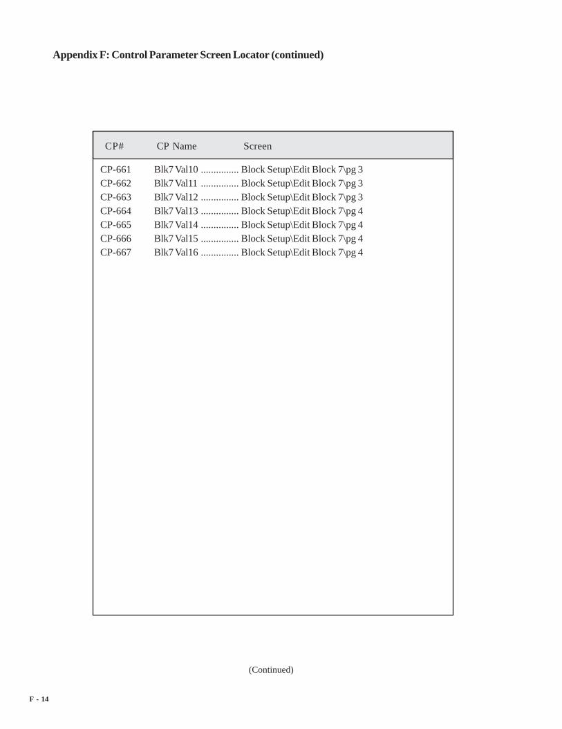
F - 14
CP# CP Name Screen
Appendix F: Control Parameter Screen Locator (continued)
(Continued)
CP-661 Blk7 Val10 ............... Block Setup\Edit Block 7\pg 3CP-662 Blk7 Val11 ............... Block Setup\Edit Block 7\pg 3CP-663 Blk7 Val12 ............... Block Setup\Edit Block 7\pg 3CP-664 Blk7 Val13 ............... Block Setup\Edit Block 7\pg 4CP-665 Blk7 Val14 ............... Block Setup\Edit Block 7\pg 4CP-666 Blk7 Val15 ............... Block Setup\Edit Block 7\pg 4CP-667 Blk7 Val16 ............... Block Setup\Edit Block 7\pg 4

G- 1
MP-01 FI1 Hz ..................... Setup\System Setup\pg 4................................. Scaling\Lead\pg 1................................. System Monitor\Run Monitor\pg 2................................. System Monitor\Std Signals Monitor\pg 1................................. Device Tests\Std Signals Tests\pg 1
MP-02 FI1 RPM ................. Status\pg 1................................. Setup\System Setup\pg 4................................. Scaling\Lead\pg 1................................. System Monitor\Run Monitor\pg 2................................. System Monitor\Std Signals Monitor\pg 1................................. Device Tests\Std Signals Tests\pg 1
MP-03 FI2 Hz ..................... Setup\System Setup\pg 2................................. Setup\System Setup\pg 3................................. Scaling\Follower\pg 1................................. System Monitor\Std Signals Monitor\pg 2................................. Device Tests\Std Signals Tests\pg 1
MP-04 FI2 RPM ................. Status\pg 1................................. Setup\System Setup\pg 3................................. Scaling\Follower\pg 1................................. System Monitor\Std Signals Monitor\pg 2................................. Device Tests\Std Signals Tests\pg 1
MP-05 LdEU/Tm ................ Setup\System Setup\pg 4................................. Setup\System Setup\pg 5................................. Scaling\Lead\pg 1................................. System Monitor\Run Monitor\pg 1................................. System Monitor\Run Monitor\pg 2................................. System Monitor\Std Signals Monitor\pg 1................................. Device Tests\Std Signals Tests\pg 1
MP-06 FbEU/Tm ................ Setup\System Setup\pg 3................................. Setup\System Setup\pg 5................................. Scaling\Follower\pg 1................................. System Monitor\Run Monitor\pg 1
APPENDIX G: MONITOR PARAMETERSCREEN LOCATOR
(Continued)
MP# MP Name Screen

G - 2
MP# MP Name Screen
................................. System Monitor\Run Monitor\pg 3
................................. System Monitor\Std Signals Monitor\pg 2
................................. Device Tests\Std Signals Tests\pg 1MP-10 Ld Posn ................... Status\pg 1
................................. Scaling\Lead\pg 1
................................. Scaling\Offsets & Phase\pg2
................................. Tuning\Large Error\pg 1
................................. Alarms & Limits\Limits\pg 2
................................. System Monitor\Run Monitor\pg 1
................................. System Monitor\Run Monitor\pg 2
................................. System Monitor\Position\pg 1
................................. System Monitor\Std Signals Monitor\pg 1MP-11 LdJobSize ................ System Monitor\Job Sizes\pg 1MP-12 LdJbSzVar ............... System Monitor\Job Sizes\pg 1MP-13 LdJbSzAvg .............. System Monitor\Run Monitor\pg 2
................................. System Monitor\Job Sizes\pg 1MP-14 LdJbSzAct ............... Scaling\Job Sizes\pg1MP-15 LdNetOfst ............... Scaling\Offsets & Phase\pg1
................................. Scaling\Offsets & Phase\pg2
................................. System Monitor\Position\pg 1MP-20 Fb Posn ................... Status\pg 1
................................. Scaling\Follower\pg 1
................................. Scaling\Offsets & Phase\pg2
................................. Tuning\Large Error\pg 1
................................. Alarms & Limits\Limits\pg 2
................................. System Monitor\Run Monitor\pg 1
................................. System Monitor\Run Monitor\pg 3
................................. System Monitor\Position\pg 1
................................. System Monitor\Std Signals Monitor\pg 2MP-21 FbJobSize ................ System Monitor\Job Sizes\pg 1MP-22 FbJbSzVar ............... System Monitor\Job Sizes\pg 1MP-23 FbJbSzAvg ............... System Monitor\Job Sizes\pg 1
Appendix G: Monitor Parameter Screen Locator (continued)
(Continued)

G- 3
MP# MP Name Screen
MP-24 FbJbSzAct ............... Scaling\Job Sizes\pg1MP-25 FbNetOfst ............... Scaling\Offsets & Phase\pg1
................................. Scaling\Offsets & Phase\pg2
................................. System Monitor\Position\pg 1MP-29 SyncFlgDif ............... Scaling\Offsets & Phase\pg1
................................. Scaling\Offsets & Phase\pg2
................................. System Monitor\Position\pg 3MP-30 ScaledRef ................ System Monitor\Run Monitor\pg 3MP-31 RampedRef ............. System Monitor\Run Monitor\pg 3
................................. System Monitor\Std Signals Monitor\pg 2
................................. System Monitor\Std Signals Monitor\pg 3MP-32 VelError ................... Tuning\Velocity Loop\pg 1
................................. System Monitor\Run Monitor\pg 3
................................. System Monitor\Std Signals Monitor\pg 2MP-33 PosnErr ................... Tuning\Position Loop\pg 1
................................. Tuning\Large Error\pg 1
................................. Alarms & Limits\Limits\pg 2
................................. System Monitor\Run Monitor\pg 1
................................. System Monitor\Run Monitor\pg 2
................................. System Monitor\Run Monitor\pg 3
................................. System Monitor\Position\pg 1
................................. System Monitor\Std Signals Monitor\pg 1
................................. System Monitor\Std Signals Monitor\pg 2MP-34 Intgrl ........................ Tuning\Velocity Loop\pg 1
................................. Tuning\Position Loop\pg 1
................................. Tuning\Feedforward\pg 1
................................. System Monitor\Std Signals Monitor\pg 3MP-35 FeedFwd.................. Tuning\Velocity Loop\pg 1
................................. Tuning\Position Loop\pg 1
................................. Tuning\Feedforward\pg 1
................................. System Monitor\Std Signals Monitor\pg 3MP-36 Trim Out .................. Tuning\Velocity Loop\pg 1
Appendix G: Monitor Parameter Screen Locator (continued)
(Continued)

G - 4
Appendix G: Monitor Parameter Screen Locator (continued)
(Continued)
MP# MP Name Screen
................................. Tuning\Position Loop\pg 1
................................. Tuning\Feedforward\pg 1
................................. System Monitor\Run Monitor\pg 3
................................. System Monitor\Std Signals Monitor\pg 3MP-37 CO Volts .................. Setup\System Setup\pg 2
................................. Scaling\Follower\pg 2
................................. Setpoints & Ramps\Direct SP & Ramps\pg 1
................................. Tuning\Velocity Loop\pg 1
................................. Tuning\Position Loop\pg 1
................................. Tuning\Feedforward\pg 1
................................. System Monitor\Run Monitor\pg 3
................................. System Monitor\Std Signals Monitor\pg 3
................................. Device Tests\Std Signals Tests\pg 2MP-38 CO Bits ................... Scaling\Follower\pg 2
................................. System Monitor\Std Signals Monitor\pg 3MP-39 CO Max Bits ........... Scaling\Follower\pg 2
................................. System Monitor\Std Signals Monitor\pg 3MP-40 Scaleed Fb ............... Status\pg 1
................................. Setup\System Setup\pg 5
................................. System Monitor\Run Monitor\pg 1MP-41 ScaleFactor ............. Scaling\Job Sizes\pg1
................................. System Monitor\Position\pg 1
................................. System Monitor\Position\pg 2MP-42 ActScaleFactor ....... System Monitor\Run Monitor\pg 1
................................. System Monitor\Position\pg 1
................................. System Monitor\Position\pg 2MP-48 Kff ........................... Setup\System Setup\pg 3
................................. Tuning\Feedforward\pg 1MP-49 Cntrl Loop ............... Tuning\Velocity Loop\pg 1
................................. Tuning\Position Loop\pg 1
................................. Tuning\Large Error\pg 1
................................. System Monitor\Run Monitor\pg 2

G- 5
Appendix G: Monitor Parameter Screen Locator (continued)
(Continued)
MP# MP Name Screen
................................. System Monitor\Run Monitor\pg 3
................................. System Monitor\Job Sizes\pg 1
................................. System Monitor\Job Sizes\pg 2
................................. System Monitor\Std Signals Monitor\pg 1
................................. System Monitor\Std Signals Monitor\pg 2
................................. System Monitor\Control Overrides\pg 1
................................. System Monitor\Control Overrides\pg 4MP-50 State ........................ Status\pg 1
................................. Setup\System Setup\pg 1
................................. Setup\System Setup\pg 2
................................. Setup\System Setup\pg 3
................................. Setup\System Setup\pg 4
................................. Setup\System Setup\pg 5
................................. Tuning\Large Error\pg 1
................................. System Monitor\Run Monitor\pg 1
................................. System Monitor\Run Monitor\pg 2
................................. System Monitor\Run Monitor\pg 3
................................. System Monitor\Position\pg 1
................................. System Monitor\Position\pg 2
................................. System Monitor\Job Sizes\pg 1
................................. System Monitor\Job Sizes\pg 2
................................. System Monitor\Std Signals Monitor\pg 1
................................. System Monitor\Std Signals Monitor\pg 2
................................. System Monitor\Control Overrides\pg 1
................................. System Monitor\Control Overrides\pg 4
................................. Device Tests\Std Signals Tests\pg 2
................................. Device Tests\Digital I/O Test\pg 1MP-51 Active Blk ............... Blocks\Block Selection\pg 1
................................. System Monitor\Limits & Alarms\pg 2
................................. System Monitor\Control Overrides\pg 1
................................. System Monitor\Control Overrides\pg 4MP-52 InvalidBlks ............... Blocks\Block Selection\pg 1
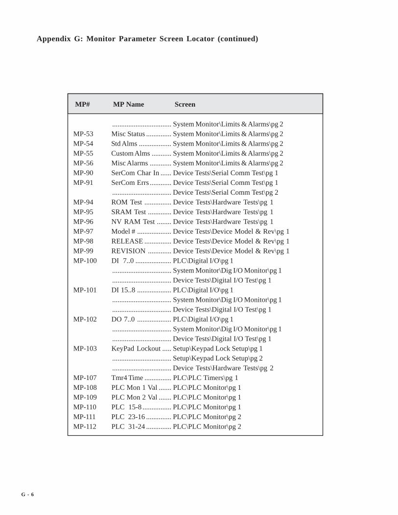
G - 6
MP# MP Name Screen
Appendix G: Monitor Parameter Screen Locator (continued)
................................. System Monitor\Limits & Alarms\pg 2MP-53 Misc Status .............. System Monitor\Limits & Alarms\pg 2MP-54 Std Alms .................. System Monitor\Limits & Alarms\pg 2MP-55 Custom Alms ........... System Monitor\Limits & Alarms\pg 2MP-56 Misc Alarms ............ System Monitor\Limits & Alarms\pg 2MP-90 SerCom Char In ...... Device Tests\Serial Comm Test\pg 1MP-91 SerCom Errs ............ Device Tests\Serial Comm Test\pg 1
................................. Device Tests\Serial Comm Test\pg 2MP-94 ROM Test ............... Device Tests\Hardware Tests\pg 1MP-95 SRAM Test ............. Device Tests\Hardware Tests\pg 1MP-96 NV RAM Test ........ Device Tests\Hardware Tests\pg 1MP-97 Model # ................... Device Tests\Device Model & Rev\pg 1MP-98 RELEASE ............... Device Tests\Device Model & Rev\pg 1MP-99 REVISION ............. Device Tests\Device Model & Rev\pg 1MP-100 DI 7..0 .................... PLC\Digital I/O\pg 1
................................. System Monitor\Dig I/O Monitor\pg 1
................................. Device Tests\Digital I/O Test\pg 1MP-101 DI 15..8 ................... PLC\Digital I/O\pg 1
................................. System Monitor\Dig I/O Monitor\pg 1
................................. Device Tests\Digital I/O Test\pg 1MP-102 DO 7..0 ................... PLC\Digital I/O\pg 1
................................. System Monitor\Dig I/O Monitor\pg 1
................................. Device Tests\Digital I/O Test\pg 1MP-103 KeyPad Lockout ..... Setup\Keypad Lock Setup\pg 1
................................. Setup\Keypad Lock Setup\pg 2
................................. Device Tests\Hardware Tests\pg 2MP-107 Tmr4 Time ............... PLC\PLC Timers\pg 1MP-108 PLC Mon 1 Val ....... PLC\PLC Monitor\pg 1MP-109 PLC Mon 2 Val ....... PLC\PLC Monitor\pg 1MP-110 PLC 15-8 ................ PLC\PLC Monitor\pg 1MP-111 PLC 23-16 .............. PLC\PLC Monitor\pg 2MP-112 PLC 31-24 .............. PLC\PLC Monitor\pg 2

G- 7
MP# MP Name Screen
MP-113 PLC 39-32 .............. PLC\PLC Monitor\pg 2MP-114 PLC 47-40 .............. PLC\PLC Monitor\pg 2MP-115 PLC 55-48 .............. PLC\PLC Monitor\pg 2MP-116 PLC 63-56 .............. PLC\PLC Monitor\pg 2MP-117 PLC 71-64 .............. PLC\PLC Monitor\pg 2MP-118 PLC 79-72 .............. PLC\PLC Monitor\pg 2MP-119 PLC 87-80 .............. PLC\PLC Monitor\pg 2MP-120 PLC 95-88 .............. PLC\PLC Monitor\pg 2MP-121 PLC 107-100 ........... PLC\PLC Monitor\pg 3MP-122 PLC 115-108 ........... PLC\PLC Monitor\pg 3MP-123 PLC 123-116 ........... PLC\PLC Monitor\pg 3MP-124 PLC 131-124 ........... PLC\PLC Monitor\pg 3MP-125 PLC 139-132 ........... PLC\PLC Monitor\pg 3MP-126 PLC 147-140 ........... PLC\PLC Monitor\pg 3MP-127 PLC 155-148 ........... PLC\PLC Monitor\pg 3MP-128 PLC 163-156 ........... PLC\PLC Monitor\pg 3MP-129 PLC 171-164 ........... PLC\PLC Monitor\pg 3MP-130 PLC 179-172 ........... PLC\PLC Monitor\pg 3MP-131 PLC 187-180 ........... PLC\PLC Monitor\pg 4MP-132 PLC 195-188 ........... PLC\PLC Monitor\pg 4MP-133 PLC 203-196 ........... PLC\PLC Monitor\pg 4MP-134 PLC 211-204 ........... PLC\PLC Monitor\pg 4MP-135 PLC 219-212 ........... PLC\PLC Monitor\pg 4MP-150 Last Reset ............... Device Tests\Device Status\pg 1
................................. Device Tests\Device Status\pg 2MP-151 Misc Intrpt ............... Device Tests\Device Status\pg 1
................................. Device Tests\Device Status\pg 2MP-152 Device Alms ............ Device Tests\Device Status\pg 1MP-153 PC at Intrpt ............. Device Tests\Device Status\pg 2MP-154 Norm Pwr Ups ....... Device Tests\Device Status\pg 1MP-155 Low Pwr Cntr ......... Device Tests\Device Status\pg 1MP-156 Mem Err Cntr ......... Device Tests\Device Status\pg 1

G - 8
MP# MP Name Screen
MP-157 WatchDogCntr ........ Device Tests\Device Status\pg 1MP-158 MiscIntrptCntr ......... Device Tests\Device Status\pg 2MP-160 AI1 Bits ................... Scaling\Aux Analog Input1\pg1
................................. System Monitor\Aux Analog Monitor\pg 1
................................. Device Tests\Aux Analog Tests\pg 1MP-161 AI1 Signal ................ Scaling\Aux Analog Input1\pg1
................................. System Monitor\Aux Analog Monitor\pg 1
................................. Device Tests\Aux Analog Tests\pg 1MP-162 AI1 EU .................... Scaling\Aux Analog Input1\pg1
................................. System Monitor\Aux Analog Monitor\pg 1MP-163 AI2 Bits ................... Scaling\Aux Analog Input2\pg1
................................. System Monitor\Aux Analog Monitor\pg 1
................................. Device Tests\Aux Analog Tests\pg 1MP-164 AI2 Signal ................ Scaling\Aux Analog Input2\pg1
................................. System Monitor\Aux Analog Monitor\pg 1
................................. Device Tests\Aux Analog Tests\pg 1MP-165 AI2 EU .................... Scaling\Aux Analog Input2\pg1
................................. System Monitor\Aux Analog Monitor\pg 1MP-166 AO Bits ................... Scaling\Aux Analog Output\pg1
................................. System Monitor\Aux Analog Monitor\pg 2
................................. Device Tests\Aux Analog Tests\pg 2MP-167 AO Signal ................ Scaling\Aux Analog Output\pg1
................................. System Monitor\Aux Analog Monitor\pg 2
................................. Device Tests\Aux Analog Tests\pg 2MP-168 AnlgCal Ref A ........ Device Tests\Aux Analog Tests\pg 3MP-169 AnlgCal Ref B ........ Device Tests\Aux Analog Tests\pg 3MP-178 PosnErrCnt .............. System Monitor\Position\pg 2MP-179 SyncFlgDifCnt ......... System Monitor\Position\pg 2MP-180 LdPsnCnt ................ System Monitor\Position\pg 2MP-182 LdJSCnt ................... System Monitor\Job Sizes\pg 2MP-183 LdJSAvgCnt ............ System Monitor\Job Sizes\pg 2MP-184 LdJSVarCnt ............. System Monitor\Job Sizes\pg 2

G- 9
MP# MP Name Screen
MP-190 FbPsnCnt ................. System Monitor\Position\pg 2MP-192 FbJSCnt ................... System Monitor\Job Sizes\pg 2MP-193 FbJSAvgCnt ............ System Monitor\Job Sizes\pg 2MP-194 FbJSVarCnt ............. System Monitor\Job Sizes\pg 2

H - 1
Error Definition
(Continued)
Acl Tm High Acceleration time is too high.Acl too Hi Acceleration rate is too high.Adrs Error Address Error, there is an internal address conflict with the CPU.Bad Blk Calc During calculations for one of the parameter blocks, an error was
encountered causing the block to be marked as bad. The blockparameter value(s) in error should be corrected.
Bad Blk Sel An attempt was made to switch to a bad parameter block.Binary Only The number is Binary, only “1’s” and “0’s” may be entered.BkUp Loaded Prompt which displays on completion of loading a code parameter
backup into main CP list.Blk Parm Err An error was encountered in the block parameters.Blk Val Err An error was encountered in the block values of a block.Buss Error There is an internal buss conflict with the CPU.ChkSm Error Checksum Error, the checksum calculated for memory data is not
correct.Dcl Tm High Deceleration time is too high.Default Set Prompt after resetting a parameter back to its default value.Defaults Set Prompt after resetting all parameters back to their default values.Divide By 0 Math error has occurred internal resulting in divide by zero.DP Present Decimal point already present in the number you are entering.Dspl Error Display Error, an error has occurred when attempting to display a
parameter (e.g., the parameter does not exist).Field Full The maximum number of characters (digits, decimal point, negative
sign) allowed for parameter entry has been reached while entering anumber via the keypad. You tried to enter more numbers/charactersthan will fit into the space allotted for the parameter value entry.
Flts Cleared Prompt to indicate that the faults have been cleared, as a result ofentering a 1 into Clr Fault Cntrs (CP-491)
Gen Intrpt Some error occurred during the controls program execution to causea General Interrupt.
APPENDIX H: ERROR CODE DEFINITIONS

H - 2
Error Definition
Appendix H: Error Code Definitions (continued)
(Continued)
Halt Monitor Reset caused by microprocessor or double bus fault.Illegal Inst Illegal Instruction.Invalid Cmd An invalid command was encountered during compilation of the
PLC program.Invalid Opnd An invalid operand was encountered during compilation of the PLC
program.Invalid Parm The parameter requested is not defined and therefore is invalid.KyPd Lockout The keypad is locked out, disallowing entry for this parameter
through the keypad.LgWd Ovfl There was a Long Word Overflow as a result of some internal
calculation.LossOf Clock There is no clock signal. Last reset caused by the detection of no
clock signal.Low Power The device’s AC input voltage level is low (below the required
specification).Max Error The parameter value just entered is above the maximum allowed for
the parameter.Max Res Met The maximum number of digits to the right of the decimal point for
the parameter being entered has already been met (an attempt wasmade to exceed this limit).
Max SP Error The value just entered for the setpoint exceeds the value set in itscorresponding Max SP (211,221).
Memory Fail Indicates that a memory test has failed.Memory Pass Indicates that the memory test has passed.Memory Error An internal memory error was encountered.Min Error The parameter value last entered exceeded the minimum value
allowed for the parameter.Min SP Error The value just entered for the setpoint exceeds the value set in its
corresponding Min SP (212,222).

H - 3
Appendix H: Error Code Definitions (continued)
(Continued)
Error Definition
Minus First When entering the value for this parameter the minus sign (-) mustbe entered first.
No <END> During compilation of the PLC program, no END command wasfound.
No Cmpr Parm Invalid comparison parameter entered.Not Allowed The last action attempted is not allowed.Not Processd The request for a parameter value change was not processed due to a
“combo” check error that occurred as a result of some calculationfor a related parameter value or a parameter in a block ofparameters. May be the result of a block parameter transfer to thecontrol via serial communications.
Not Ready The control was “not ready” to process the last request.NVRAM Failed The memory test for the nonvolatile RAM has failed.NVRAM Passed The memory test for the nonvolatile RAM has passed.Only 1 Page Occurs when the page up or page down key is pressed and there is
only one page to display.Parm Mem Lmt Indicates that the internal memory limit for parameters in block
parameters has been exceeded, and therefore the number ofparameters defined in block parameters must be reduced.
PLC BkUp set Prompt to indicate that the PLC program has been changed to be thesame as the backup PLC program that was saved to backup.
PLC Dflt set Prompt to indicate that the PLC program has been changed to be thesame as the default PLC program.
PLC Mem Lmt During compilation of the PLC program, the internal memory limitset for the PLC program has been exceeded. The PLC programshould be reduced.
Power Loss Indicates that a momentary loss of AC power was detected.Ratio too Hi The ratio is too high.

H - 4
Appendix H: Error Code Definitions (continued)
Error Definition
Res Error The resolution for the last parameter value exceeded the limits forthat parameter (result of a parameter value change using serialcommunications).
ROM Failed Indicates that the memory test for the internal ROM part has failed.ROM Passed Indicates that the memory test for the internal ROM part has passed.RUN Lockout Indicates that the parameter entry is locked out during run. An
attempt was made to enter a parameter value into a parameter that islocked out during run while the control is in run.
Saved 2 BkUp Prompt to indicate that the data has been saved to backup storage forlater use.
SP too High The setpoint is too high.SP too Low The setpoint is too low.Speed too Hi The speed is too high.SRAM Failed Indicates that the memory test for the internal RAM part has failed.SRAM Passed Indicates that the memory test for the internal RAM part has passed.Test Module Reset caused by microprocessor's test sub-module.UImpd Intrpt An error has occurred while the CPU was processing to cause an
unimplemented interrupt.Watch Dog The internal CPU watch dog timer has timed out. CPU is out of
time and is not able to function correctly.

H - 5
–NOTES—

I-1
APPENDIX I: SERIAL COMMUNICATIONS ERRORCODE DEFINITIONS
# Name Definition
0 OK Request processed1 General Data Error A non-specified error occurred as a result of the last
serial communications transmission. Check thecontents of the last message transmission againstthe protocol definition.
2 Res Error The resolution for the Control Parameter valueexceeds the minimum or maximum that is allowed.
3 Invalid Parm The requested parameter does not exist.4 String too long The custom engineering units string that was sent
exceeds the 15 character limit and was truncated to15 characters.
5 Out of Range The parameter requested is above or below theavailable number of parameters, or the addressrequested for a memory read is not within thememory address range.
6 Not Allowed The request is not allowed.7 Lockout During RUN An attempt was made to change a parameter value
for a parameter that is locked out during run, whilethe control is in run (state).
8 Not Ready The CX-1200 was “not ready” to receive the lastrequest.
9 Block Parm Error An error was encountered while processing a blockparameter request.
10 Block Value Error An error was encountered while processing a blockvalue request.
11 Parm Memory Limit The internal memory limit for block parameters wasexceeded during processing of a block parameterchange.
12 MIN Error There was an attempt to exceed the minimum valueallowed for a parameter value.
(Continued)

I-2
# Name Definition
Appendix I: Serial CommunicationsError Code Definitions (continued)
13 Max Error There was an attempt to exceed the maximum valueallowed for a parameter value.
14 Invalid Command PLC An invalid command was encountered duringcompilation of the PLC program.
15 Invalid Operand PLC An invalid operand was encountered duringcompilation of the PLC program.
16 No <END> PLC No END command was found during compilation ofthe PLC program.
17 PLC Memory Limit The internal memory limit for the PLC program wasreached while compiling the PLC program. The PLCprogram should be reduced in size.
18 Defaults Loaded The default parameter values have been loaded into theControl Parameters.
19 Backup Loaded The backup parameter values have been loaded intothe Control Parameters.
20 Backup Saved The Control Parameter values have been saved tobackup storage.
21 Checksum Error A checksum calculation error has occurred as a resultof the last request.
22 Faults Cleared The fault counters have been cleared.23 Passed The requested memory test passed.24 Failed The requested memory test failed.25 No Compare Parm No compare parameter.26 Divide by Zero The last request caused a “divide by zero” in an
internal calculation.27 Long Word Overflow The last request caused a “long word overflow” in an
internal calculation.28 Parm Transfer Limit Error An attempt was made to exceed the maximum number
of parameters allowed for a request.
(Continued)

I-3
Appendix I: Serial Communications Error Code Definitions (continued)
# Name Definition
29 Memory Read too Long An attempt was made to read too many bytes ofmemory at one time.
30 Data Length Error The “data field” length did not match the lengthexpected for the specific serial communicationsfunction request.
31 Not Processed Msg The last serial communications function request wasnot processed due to a combinational check error. Oneor more of the parameters in the block of parameterssent caused an error.
32 Invalid Serial Comm The serial communications function that wasrequested, is not defined in the list of allowedfunctions. Check the protocol definition.

I-4
–NOTES—

J - 1
PLC Command Equivalent Logic Ladder
APPENDIX J: PLC DEFAULT PROGRAMLOGIC
LOAD 8 DI_8OUT 140 Blk Sel A
DI- 8
8
BlkSel A
140
LOAD 9 DI_9OUT 135 Cntr 1 Rst
DI- 9
9
Cntr 1 Rst
135
LOAD 10 DI_10OUT 174 Re-Learn
DI-10
10
Re-Learn
174
LOAD 12 DI_12OUT 152 RstFI1PsnOUT 153 RstFI2Psn
DI-11
11
OpnLpRqst
187
LOAD 14 DI_14OUT 169 Scroll Dn
DI-12
12
RstFI1Psn
152
LOAD 13 DI_13OUT 172 LdSyncOffOUT 173 FbSyncOff
DI-14
14
Scroll Dn
169
LOAD 15 DI_15OUT 168 Scroll Up
DI-13
13
LdSyncOff
172
DI-15
15
Scroll Up
168
LOAD 11 DI_11OUT 187 OpnLpRqst
FbSyncOff
173
RstFI2Psn
153
LOAD 69 FbSyncRcvOUT 130 Cntr 1 Inc
FbSyncRcv
69
Cntr 1 Inc
130
(Continued)

J - 2
Appendix J: Default PLC Program Logic (continued)
PLC Command Equivalent Logic Ladder
LOAD 89 Rvs CmdOUT 106 DO_6
LOAD 66 LdSyncMisOUT 103 DO_3
Rvs Cmd
89
DO_6
106
LOAD 67 FbSyncMisOUT 104 DO_4
LdSyncMis
66
DO_3
103
LOAD 29 HiSpdAlmOR 28 LoSpdAlmOUT 101 DO_1
FbSyncMis
67
DO_4
104
HiSpdAlm
29
DO_1
101
LOAD 51 DrvEnableOUT 107 DO_7
LOAD 32 Cntr 1 OutOUT 105 DO_5
DrvEnable
51
DO_7
107
LOAD 65 OutOfPosnOUT 102 DO_2
Cntr 1 Out
32
DO_5
105
OutOfPosn
61
DO_2
102
LoSpdAlm
28
LOAD 53 RR@0SpdAND 54 FB@0SpdOUT 100 DO_0
RR@0Spd
53
DO_0
100
Fb@0Spd
54

K - 1
Command Description Decimal: Hexidecimal:
END Command 224 E0
LOAD Command 225 E1
AND Command 226 E2
OR Command 228 E4
Exclusive OR Command (XOR) 229 E5
NOT Command 232 E8
LOAD NOT Command 233 E9
AND NOT Command 234 EA
OR NOT Command 236 EC
Exclusive OR NOT Command 237 ED
OUT Command 240 F0
NOP Command 255 FF
APPENDIX K: PLC PROGRAM COMMANDS

K - 2
—NOTES—

L - 1L - 1L - 1L - 1L - 1
Op Name Related CP
0 S01 S12 ZERO = 0, off state3 ONE = 1, on state4 Pwr-Up 1 (on) for 1st PLC Scan5 Reserved6 Reserved7 Reserved8 DI_8, Digital Input 89 DI_9, Digital Input 910 DI_10, Digital Input 1011 DI_11, Digital Input 1112 DI_12, Digital Input 1213 DI_13, Digital Input 1314 DI_14, Digital Input 1415 DI_15, Digital Input 1516 Lch1 Out, Latch 1 Output17 Lch2 Out, Latch 2 Output18 Lch3 Out, Latch 3 Output19 Lch4 Out, Latch 4 Output20 Reserved21 Reserved22 Reserved23 Reserved24 Tmr1 Out, Timer 1 Output ......................................................... CP-410,CP-41125 Tmr2 Out, Timer 2 Output ......................................................... CP-412,CP-41326 Tmr3 Out, Timer 3 Output ......................................................... CP-414,CP-41527 Tmr4 Out, Timer 4 Output ......................................................... CP-416,CP-41728 LoSpdAlm, Low Speed Alarm29 HiSpdAlm, High Speed Alarm
APPENDIX L: PLC PROGRAM OPERANDSAPPENDIX L: PLC PROGRAM OPERANDSAPPENDIX L: PLC PROGRAM OPERANDSAPPENDIX L: PLC PROGRAM OPERANDSAPPENDIX L: PLC PROGRAM OPERANDS
(Continued)

L - 2L - 2L - 2L - 2L - 2
Op Name Related CP
30 MinSpdLmt, Scaled Ref Speed < Minimum Speed Limit ......... CP-33131 MaxSpdLmt, Scaled Ref Speed > Maximum Speed Limit ....... CP-33032 Cntr1 Out, Counter 1 Output ..................................................... CP-420,CP-42133 Cntr2 Out, Counter 2 Output .................................................... CP-422,CP-42334 Cntr3 Out, Counter 3 Output .................................................... CP-424,CP-42535 Cntr4UpO, Counter 4 Up Counter Output ............................... CP-426,CP-42736 Cntr4DnO, Counter 4 Down Counter Output .......................... CP-428,CP-42737 Low Power, Low Power Indication38 Reserved39 Reserved40 Direct, Direct Mode41 Master, Master Mode42 Follower, Follower Mode43 InvFollower, Inverse Follower Mode44 Non-Sync45 FixedSync, Fixed Ratio Sync46 TrendSync, Trend Ratio Sync47 LearnSync, Learn Ratio Sync48 Reserved49 MaxFI1Hz, Maximum FI1 Frequency [Hz}50 COSign, Control Output Sign (1 = Negative)51 DrvEnable, Drive Enable52 RmpActive, Ramp Active53 RR@0Spd, Ramped Reference at ‘0’ Speed ........................... CP-37054 Fb@0Spd, Feedback at ‘0’ Speed ............................................. CP-37055 MxFbSpd, Maximum Feedback Speed ..................................... CP-32956 MaxAclDcl, Maximum Accel/Decel ......................................... CP-37257 DrvNoRsp, Drive/Motor NOT Responding .............................. CP-37258 MaxFI2Hz, Feedback is >= Maximum Freq (Hz) .................... MP-0359 CO@MxVlts, Control Output at Maximum Volts ..................... CP-271
Appendix L: PLC Program Operands (continued)
(Continued)
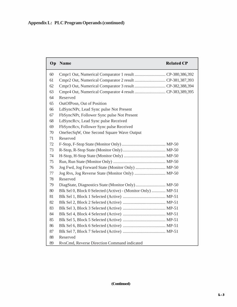
L - 3L - 3L - 3L - 3L - 3
Appendix L: PLC Program Operands (continued)
(Continued)
Op Name Related CP
60 Cmpr1 Out, Numerical Comparator 1 result ............................. CP-380,386,39261 Cmpr2 Out, Numerical Comparator 2 result ............................. CP-381,387,39362 Cmpr3 Out, Numerical Comparator 3 result ............................. CP-382,388,39463 Cmpr4 Out, Numerical Comparator 4 result ............................. CP-383,389,39564 Reserved65 OutOfPosn, Out of Position66 LdSyncNPr, Lead Sync pulse Not Present67 FbSyncNPr, Follower Sync pulse Not Present68 LdSyncRcv, Lead Sync pulse Received69 FbSyncRcv, Follower Sync pulse Received70 OneSecSqW, One Second Square Wave Output71 Reserved72 F-Stop, F-Stop State (Monitor Only) ......................................... MP-5073 R-Stop, R-Stop State (Monitor Only) ........................................ MP-5074 H-Stop, H-Stop State (Monitor Only) ....................................... MP-5075 Run, Run State (Monitor Only) ................................................. MP-5076 Jog Fwd, Jog Forward State (Monitor Only) ............................ MP-5077 Jog Rvs, Jog Reverse State (Monitor Only) ............................. MP-5078 Reserved79 DiagState, Diagnostics State (Monitor Only) ............................ MP-5080 Blk Sel 0, Block 0 Selected (Active) - (Monitor Only) ............. MP-5181 Blk Sel 1, Block 1 Selected (Active) ........................................ MP-5182 Blk Sel 2, Block 2 Selected (Active) ........................................ MP-5183 Blk Sel 3, Block 3 Selected (Active) ........................................ MP-5184 Blk Sel 4, Block 4 Selected (Active) ........................................ MP-5185 Blk Sel 5, Block 5 Selected (Active) ........................................ MP-5186 Blk Sel 6, Block 6 Selected (Active) ........................................ MP-5187 Blk Sel 7, Block 7 Selected (Active) ........................................ MP-5188 Reserved89 RvsCmd, Reverse Direction Command indicated

L - 4L - 4L - 4L - 4L - 4
Appendix L: PLC Program Operands (continued)
(Continued)
Op Name Related CP
90 Reserved91 Reserved92 Reserved93 Reserved94 Reserved95 Reserved96 Reserved (Not accessible)97 Reserved (Not accessible)98 Reserved (Not accessible)99 Reserved (Not accessible)100 DO_0, Digital Output 0101 DO_1, Digital Output 1102 DO_2, Digital Output 2103 DO_3, Digital Output 3104 DO_4, Digital Output 4105 DO_5, Digital Output 5106 DO_6, Digital Output 6107 DO_7, Digital Output 7108 Tmp1, Temporary Control Relay 1, CR1109 Tmp2, Temporary Control Relay 2, CR2110 Tmp3, Temporary Control Relay 3, CR3111 Tmp4, Temporary Control Relay 4, CR4112 Tmp5, Temporary Control Relay 5, CR5113 Tmp6, Temporary Control Relay 6, CR6114 Tmp7, Temporary Control Relay 7, CR7115 Tmp8, Temporary Control Relay 8, CR8116 Lch1 Set, Latch 1 Set117 Lch2 Set, Latch 2 Set118 Lch3 Set, Latch 3 Set119 Lch4 Set, Latch 4 Set

L - 5L - 5L - 5L - 5L - 5
Appendix L: PLC Program Operands (continued)
(Continued)
Op Name Related CP
120 Lch1 Rst, Latch 1 Reset121 Lch2 Rst, Latch 2 Reset122 Lch3 Rst, Latch 3 Reset123 Lch4 Rst, Latch 4 Reset124 Tmr1 En, Timer 1 Enable .......................................................... CP-410,CP-411125 Tmr2 En, Timer 2 Enable .......................................................... CP-412,CP-413126 Tmr3 En, Timer 3 Enable .......................................................... CP-414,CP-415127 Tmr4 En, Timer 4 Enable .......................................................... CP-416,CP-417128 Tmr4 Rst, Timer 4 Reset ........................................................... CP-416,CP-417129 Reserved130 Cntr1 Inc, Counter 1 Increment ................................................ CP-420,CP-421131 Cntr2 Inc, Counter 2 Increment ................................................ CP-422,CP-423132 Cntr3 Inc, Counter 3 Increment ................................................ CP-424,CP-425133 Cntr4 Inc, Counter 4 Increment ................................................ CP-426,CP-427134 Cntr4 Dec, Counter 4 Decrement ............................................. CP-428,CP-427135 Cntr1 Rst, Counter 1 Reset ....................................................... CP-421136 Cntr2 Rst, Counter 2 Reset ....................................................... CP-423137 Cntr3 Rst, Counter 3 Reset ....................................................... CP-425138 Cntr4 Rst, Counter 4 Reset ....................................................... CP-429,CP-427139 Reserved140 Blk Sel A, Block Select A ........................................................ CP-478,MP-51141 Blk Sel B, Block Select B ........................................................ CP-478,MP-51142 Blk Sel C, Block Select C ........................................................ CP-478,MP-51143 Reserved144 Reserved145 Reserved146 Reserved147 Reserved148 Rst Ingrl, Reset Integral to zero ................................................ MP-34149 FrzIngrl, Freeze Integral (Freeze at current value) ................... MP-34

L - 6L - 6L - 6L - 6L - 6
Appendix L: PLC Program Operands (continued)
Op Name Related CP
150 Reserved151 LgErr Off, Disable Large Error Recovery152 RstFI1Psn, Reset FI1 Position to zero153 RstFI2Psn, Reset FI2 Position to zero154 RstPsnErr, Reset Position Error to zero155 Reserved156 Reserved157 ByPassRmp, Bypass Ramp calculation158 FrzRamp, Freeze Ramp159 Negate SR, Negate Scaled Reference160 Data Copy 1161 Data Copy 2162 Reserved163 Reserved164 NegateCO, Negate Control Output165 Reserved166 Reserved167 StrtTrace, Start Data Trace168 Scroll Up, Remote Scroll Up ..................................................... CP-400,CP-401169 Scroll Dn, Remote Scroll Down ................................................ CP-400,CP-401170 Reserved171 NOP Opnd, No Operation Operand172 LdSyncOff, Disable Lead Sync173 FbSyncOff, Disable Follower Sync174 Re-Learn175 Reserved176 Reserved177 Reserved178 Reserved179 Reserved

L - 7L - 7L - 7L - 7L - 7
Op Name Related CP
180 FStpRq, Request State change to F-Stop State181 Reserved182 Reserved183 Reserved184 Reserved185 Reserved186 Reserved187 OpnLpRq, Request Open Loop control188 Reserved189 Reserved190 Reserved191 Reserved192 Reserved193 Reserved194 Reserved195 Reserved196 Reserved197 Reserved198 Reserved199 Reserved200 OpenLoop201 VelLoop, Velocity Loop202 PosnLoop, Position Loop203 LgErrLoop, Large Error Loop204 Reserved205 Reserved206 Reserved207 Reserved208 Reserved209 Reserved
Appendix L: PLC Program Operands (continued)

L - 8L - 8L - 8L - 8L - 8
Op Name Related CP
Appendix L: PLC Program Operands (continued)
210 Reserved211 Reserved212 Reserved213 Reserved214 Reserved215 Reserved216 Reserved217 Reserved218 Reserved219 Reserved

M- 1
—>NEED wiring example!!!<—
* +12VDC
FI_1A
FI_1A
FI_1B
FI_1B
Com
FI_2A
FI_2A
FI_2B
FI_2B
Com
RI_1
RI_2
1
2
3
4
5
6
7
8
9
10
11
12
13
J5
DI_0
DI_1
Com
DI_2
DI_3
DI_4
DI_5
Com
DI_6
DI_7
1
2
3
4
5
6
7
8
9
10
J6
DI_8
DI_9
Com
DI_10
DI_11
DI_12
DI_13
Com
DI_14
DI_15
1
2
3
4
5
6
7
8
9
10
J7
-
-
-
-
F-Stop
R-Stop
H-Stop
Run
Jog Fwd
Frequency InputsR
eg InD
igital Inputs
CO_Sig
CO_Com
1
2
J3
TD/RD +
TD/RD -
Com
1
2
3
J1
+V_DO
DO_0
DO_1
DO_2
DO_3
DO_4
DO_5
DO_6
DO_7
Com
1
2
3
4
5
6
7
8
9
10
J2
L1
L2/NEUT
GND/PE
1
2
3
J4
RS
485
Ser
ial C
omm
Dig
ital O
utpu
tsA
C P
OW
ER
INP
UT
Con
trol
Out
put
To D
rive
CX-1200
Figure M-1 Start/Stop Wiring Connections without Relays
APPENDIX M: WIRING DIAGRAM EXAMPLESD
AN
GE
RT
HIS
DIA
GR
AM
IS F
OR
CO
NC
EP
TU
AL
PU
RP
OS
ES
ON
LY
!U
SE
SA
FE
TY
EQ
UIP
ME
NT
.M
AK
E W
IRIN
G C
ON
NE
CT
ION
S C
AR
EF
UL
LY
.IN
CO
RR
EC
T U
SE
OF
EQ
UIP
ME
NT
OR
CO
NN
EC
TIO
NS
CA
N C
AU
SE
INJU
RY
OR
DE
AT
H.

M - 2
R-Stop Start
K-RK-R
NeutLine
F-Stop
K-FS
K-J
Run
Jog
K-R
K-J
K-FS
F-Stop
R-Stop
K-FS
K-J
K-J
K-J
* +12VDC
FI_1A
FI_1A
FI_1B
FI_1B
Com
FI_2A
FI_2A
FI_2B
FI_2B
Com
RI_1
RI_2
1
2
3
4
5
6
7
8
9
10
11
12
13
J5
DI_0
DI_1
Com
DI_2
DI_3
DI_4
DI_5
Com
DI_6
DI_7
1
2
3
4
5
6
7
8
9
10
J6
DI_8
DI_9
Com
DI_10
DI_11
DI_12
DI_13
Com
DI_14
DI_15
1
2
3
4
5
6
7
8
9
10
J7
-
-
-
-
Frequency Inputs
Reg In
Digital Inputs
CO_Sig
CO_Com
1
2
J3
TD/RD +
TD/RD -
Com
1
2
3
J1
+V_DO
DO_0
DO_1
DO_2
DO_3
DO_4
DO_5
DO_6
DO_7
Com
1
2
3
4
5
6
7
8
9
10
J2
L1
L2/NEUT
GND/PE
1
2
3
J4
RS
485
Ser
ial C
omm
Dig
ital O
utpu
tsA
C P
OW
ER
INP
UT
Con
trol
Out
put
To
Driv
e
CX-1200
K-RH-Stop
Run
Jog Fwd
Figure M-2 Start/Stop Wiring Connections with Relays
DA
NG
ER
TH
IS D
IAG
RA
M IS
FO
R C
ON
CE
PT
UA
L P
UR
PO
SE
S O
NL
Y !
US
E S
AF
ET
Y E
QU
IPM
EN
T.
MA
KE
WIR
ING
CO
NN
EC
TIO
NS
CA
RE
FU
LL
Y.
INC
OR
RE
CT
US
E O
F E
QU
IPM
EN
T O
R C
ON
NE
CT
ION
S C
AN
CA
US
E IN
JUR
Y O
R D
EA
TH
.

M- 3
Figure M-3 Start/Stop Wiring Connections with Armature Contactor
Neut
Line
K-R
M1
ArmatureContactor
- +
12 VoltPowerSupply
K-R
V+
SPDMotorDrive
K-R
A1
A2
M1 M1
F-Stop
R-Stop
H-Stop
Run
Jog Fwd
* +12VDC
FI_1A
FI_1A
FI_1B
FI_1B
Com
FI_2A
FI_2A
FI_2B
FI_2B
Com
RI_1
RI_2
1
2
3
4
5
6
7
8
9
10
11
12
13
J5
DI_0
DI_1
Com
DI_2
DI_3
DI_4
DI_5
Com
DI_6
DI_7
1
2
3
4
5
6
7
8
9
10
J6
DI_8
DI_9
Com
DI_10
DI_11
DI_12
DI_13
Com
DI_14
DI_15
1
2
3
4
5
6
7
8
9
10
J7
-
-
-
-
Fre
qu
en
cy Inp
uts
Re
g In
Dig
ital In
pu
ts
CO_Sig
CO_Com
1
2
J3
TD/RD +
TD/RD -
Com
1
2
3
J1
+V_DO
DO_0
DO_1
DO_2
DO_3
DO_4
DO_5
DO_6
DO_7
Com
1
2
3
4
5
6
7
8
9
10
J2
L1
L2/NEUT
GND/PE
1
2
3
J4
RS
48
5S
eria
l Co
mm
Dig
ital O
utp
uts
AC
PO
WE
RIN
PU
TC
on
tro
lO
utp
ut
To
Drive
CX-1200
DA
NG
ER
TH
IS D
IAG
RA
M IS
FO
R C
ON
CE
PT
UA
L P
UR
PO
SE
S O
NL
Y !
US
E S
AF
ET
Y E
QU
IPM
EN
T.
MA
KE
WIR
ING
CO
NN
EC
TIO
NS
CA
RE
FU
LL
Y.
INC
OR
RE
CT
US
E O
F E
QU
IPM
EN
T O
R C
ON
NE
CT
ION
S C
AN
CA
US
E IN
JUR
Y O
R D
EA
TH
.

M - 4
—NOTES—

N- 1
APPENDIX N: FAX COVER SHEET
Date: ______________________
Atten: Contrex Technical Support
From:Name _____________________________ Company Name _____________________________________
Telephone # ________________________ Ext # _______________________ Fax # _________________
We have ______ CX-1200(s) that are used for: ________________________________________________
_____________________________________________________________________________________
_____________________________________________________________________________________
_____________________________________________________________________________________
_____________________________________________________________________________________
_____________________________________________________________________________________
Serial Communication Hookup: _____Yes _____No
Brief Description of the Problem: ___________________________________________________________
_____________________________________________________________________________________
_____________________________________________________________________________________
_____________________________________________________________________________________
_____________________________________________________________________________________
_____________________________________________________________________________________
_____________________________________________________________________________________
Contrex Fax # = (763) 424-8734
We are transmitting _____ pages, including:This Cover Sheet,A copy of Appendix D w/ the User Record completed,

N - 2
—NOTES—

O-1
APPENDIX O: REVISION LOG
ManualRevision
ECONumber
RevisionDate
Corresponding *Software Rev.
Pages Changed
A - 08/061000-8101Rev. 1.0
New Manual Release
* Software revisions may not mandate manual changes. If your software revision is more recent than what is reflected here, use the the most current revision of the manual.
B - 10/06 Added Unidirectional hookup to manual.
C - 09/07 Manual cleanup.1000-8101Rev. 1.2

O-2
—NOTES—

Service - 1
Warranty/Service
Service PolicyWarranty

Warranty - 2

Service - 3
SERVICE POLICY
Spare PartsContrex, Inc., will usually have an adequateinventory of spare parts and circuit boards for allstandard products. However, purchasers areencouraged to maintain a nominal supply of spareparts to insure immediate on-site accessibility.
Instruction ManualsInstructions for installation, maintenance andtroubleshooting are included in manuals that areprovided with the equipment. Repairs may beperformed in the field by competent customerpersonnel; but in order to not invalidate the warrantythey must be made in strict accordance withpublished instructions, and ONLY AFTER obtainingapproval of the Technical Service Department (suchrepairs are usually limited to the replacement ofcircuit boards and major subassemblies, not therepair of these items).
OEM ServiceIn many instances Contrex, Inc., products are sold tothe original equipment manufactures or integratorsfor inclusion in larger systems. In such cases theobligations of Contrex, Inc., extend only to thatoriginal purchaser. It is the latter's responsibility tohandle any service required by his customer, the enduser. Such problems can usually be solved by fieldreplacement of complete units. OEM's areencouraged to buy and maintain a supply of“loaners” for this purpose. Contrex, Inc., willprovide factory overhaul service at nominal chargesto support that OEM. Users of Contrex, Inc.,products that were acquired as components of largersystems may buy service or spare parts directly fromContrex, Inc., at standard prices, but they mustappeal through the OEM for warranty service.
If Contrex, Inc., encounters trouble in the fieldwhich appears to be the result of fault or inadequacyof the system, Contrex, Inc., reserves the right torecover service charges from the party thatauthorized the service activity.
Contrex, Inc., recognizes that with each sale of itsproduct there are certain product obligations. Thisdocument defines the limits of such obligations andprovides guidelines for the performance of relatedservices.
Applicability This Service Policy shall apply to all product salesof Contrex, Inc. However, it may be modified bymutual consent. Thus, whenever an acceptedproposal contains wording inconsistent with thispolicy, the proposal will prevail with respect tospecific sale or series of sales involved.Applicability of this policy is also somewhat limitedin cases where products are sold to an OEM forresale to user. See paragraph below entitled OEMService.
Service PersonnelContrex, Inc., has a staff whose primaryresponsibility is service - both factory service andfield (on-site) service. Personnel of this departmentare usually available for service on a 24 hour notice.To facilitate quicker handling of service requests,either written or by phone, such requests should bedirected to the Contrex, Inc., Technical ServicesDepartment.
Service ChargesContrex, Inc., reserves the right to charge for allservices performed at the customers request with theexception of factory service performed underwarranty. All on-site service is charged at flat-rateper diem rates plus expenses. Any Contrex, Inc.,product developing defects as defined in the warrantyduring its effective period will be repaired orreplaced without charge, providing it is shipped,prepaid, to Contrex, Inc., 8900 Zachary Lane North,Maple Grove, Minnesota 55369.

Warranty - 4
Contrex, Inc., guarantees this device against defectsin workmanship and materials for a period of one (1)year from the date of purchase. Any parts orcomponents that fail during the warranty period willbe replaced or repaired without charge. Thisguarantee is void if the device has been damaged byimproper installation or operation, tampering,careless handling or accident.
When a device fails to function in accordance withstandards set forth in the instruction manual, thepurchaser should contact an authorized representativeof Contrex, Inc., 8900 Zachary Lane North, MapleGrove, Minnesota 55369. Whether repairs will takeplace in the field or at the factory will be solely theprerogative of Contrex, Inc.
If inspection reveals defects that are caused by faultymaterials or workmanship, Contrex, Inc., reserves theright to either replace the device or rebuild the deviceusing new or refurbished warranted parts andcomponents. In either instance, the device that isreturned to the purchaser meets full factory standardsfor new device performance. If there is less than 90days remaining on the warranty period at the time ofthe repair, the warranty will extend to 90 days afterthe repair.
WARRANTY
Parts and services outside the scope of this warrantywill be available at Contrex, Inc., current marketprice.
Contrex's liability for a device or it's use, whetherin warranty or not, shall not in any instance exceedthe cost of correcting the defects of the device.Contrex, Inc., assumes no responsibility for damageto property or injuries to persons from improper useof this device.
No express warranties and no implied warrantieswhether of merchantability or otherwise (except asto title), other than those set forth above , which areexpressly made in lieu of all other warranties, shallapply to any devise sold by Contrex, Inc.
Contrex, Inc., reserves the right to change orimprove its devices without imposing any obligationupon Contrex, Inc., to make changes orimprovements in previously manufactured devices.
This warranty statement is a summary of Contrex,Inc's policy. Further limits of liability are containedin the Contrex, Inc's purchase orderacknowledgments and invoices.