Curtain Wall Issues, Problems, and Solutions
27
Page 1 of 27 CURTAIN WALL ISSUES, PROBLEMS, AND SOLUTIONS by Karim P. Allana, PE, RRC, RWC Don Carter, Senior Consultant Allana Buick & Bers, Inc. RCI, INC., 2012 Symposium on Building Envelope Technology Phoenix, Arizona October 22-23, 2012 Copyright 2012 Allana Buick & Bers, Inc.
-
Upload
khangminh22 -
Category
Documents
-
view
8 -
download
0
Transcript of Curtain Wall Issues, Problems, and Solutions
Page 1 of 27
CURTAIN WALL ISSUES, PROBLEMS, AND SOLUTIONS
by
Karim P. Allana, PE, RRC, RWCDon Carter, Senior Consultant
Allana Buick & Bers, Inc.
RCI, INC., 2012 Symposium on Building Envelope TechnologyPhoenix, Arizona
October 22-23, 2012
Copyright 2012 Allana Buick & Bers, Inc.
Page 2 of 27
1. INTRODUCTION
Curtain wall design and installation can be taken for granted, even by architects, engineers, and experienced contractors. However, all curtain wall systems and materials present unique challenges in appearance, design, installation, maintenance, and repair. These issues and potential problems will be addressed in this paper, with real life, practical examples backed by engineering expertise. The paper is based on the author’s case studies of the failures of curtain walls, windows, sealants, and flashings, providing useful information on design failures and testing. Included are definitions of curtain wall types, various systems and components, and differences between stick and unitized curtain walls. Included is an overview of curtain wall types, definitions of various systems and components, and differences between curtain walls, window walls, and store fronts. Testing, design standards, and the use of mock ups are woven throughout the presentation.Curtain walls consist of many materials found in high rise steel or concrete buildings, and even two story wood framed buildings. Typical curtain wall materials include:
Aluminum Extrusions are the load bearing element of most modern curtain wall systems, and are available in different alloys as the design loads and safety factors require.
Glass, Vision and Spandrel. Aluminum Panels, in sheet, plate or aluminum composites. Stone, typically granite due to its superior resistance to wind load compared to marble or
other products. Glass Fiber Reinforced Concrete (GFRC) panels. Louvers. Operable Windows.
Each type of curtain wall system or material presents its own unique appearance, design, installation, maintenance, and repair challenges, each to be addressed by the author. The primary focus will be glass curtain walls; however, window walls, windows, and storefront systems are also covered. As architectural appeal and applications have increased, the complexities of dealing with energy usage dynamics, rain and wind, and durability have become ever more difficult for the designer. The author reviews the implication of different styles, materials, manufacturers, and installation methods.
Copyright 2012 Allana Buick & Bers, Inc.
Page 3 of 27
2. DEFINITION AND DESCRIPTION OF CURTAIN WALL SYSTEMS
A curtain wall is the exterior façade of a building that 1) spans two or more floors in height; 2) is non-structural, i.e., does not support any loads except for its own gravity load, while transferring wind and other loads to the building structure, via connections to each floor, columns, or the roof. Thus “curtain” implies that the wall is hung from the building’s structural frame, generally the edge of the slab.Curtain walls, as well as other exterior glazing systems must be properly designed to address:
Structural integrity Movement (thermal, seismic, and differential) Weather tightness Condensation Thermal insulation (curtain walls only) Fire safing (curtain walls only)
And, other project or site specific considerations such as the following need to be addressed:
Sound transmission Hurricane borne debris resistance Bomb blast resistance
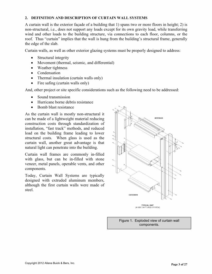
As the curtain wall is mostly non-structural it can be made of a lightweight material reducing construction costs through standardization of installation, “fast track” methods, and reduced load on the building frame leading to lower structural costs. When glass is used as the curtain wall, another great advantage is that natural light can penetrate into the building. Curtain wall frames are commonly in-filled with glass, but can be in-filled with stone veneer, metal panels, operable vents, and other components. Today, Curtain Wall Systems are typically designed with extruded aluminum members, although the first curtain walls were made of steel.
Figure 1. Exploded view of curtain wall components.
Copyright 2012 Allana Buick & Bers, Inc.
Page 4 of 27
3. THE BASIC GLAZING SYSTEMS
A. Curtain Wall Prefab or assembled units attached to the structure as described prior. Recent improvements in design do not require “dropping” the building from a swing stage to install sealants. Older designs required this expensive last step to weatherproofing the joinery between pre-assembled units.
B. Window Wall Horizontal bands (Ribbons) of fixed/operable windows, today mostly factory assembled and glazed; connected between floors or other structural elements such as pre-cast concrete.
C. Windows Individual units fixed or operable, set in a wall. These are sometimes referred to as “punched windows,” connected to stud framing, CMU, or pre-cast concrete.
D. Storefront Typically stick built floor to ceiling, includes entrance doors and vestibules. Field installed from the floor, frames first, then glass placed in the frame. Note that store fronts may contain operable windows, but should not be used at elevations too high above the first floor due to their relatively weak structural capacity. Note that a “monumental” lobby or entrance with clear vertical spans over 12 feet will require a stronger, i.e., deeper structural member, in order to resist wind loads.
Copyright 2012 Allana Buick & Bers, Inc.
Page 5 of 27
4. BRIEF HISTORY OF CURTAIN WALLS
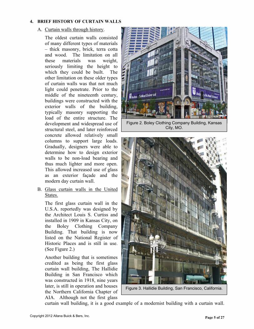
A. Curtain walls through history. The oldest curtain walls consisted of many different types of materials – thick masonry, brick, terra cotta and wood. The limitation on all these materials was weight, seriously limiting the height to which they could be built. The other limitation on these older types of curtain walls was that not much light could penetrate. Prior to the middle of the nineteenth century, buildings were constructed with the exterior walls of the building, typically masonry supporting the load of the entire structure. The development and widespread use of structural steel, and later reinforced concrete allowed relatively small columns to support large loads. Gradually, designers were able to determine how to design exterior walls to be non-load bearing and thus much lighter and more open. This allowed increased use of glass as an exterior façade and the modern day curtain wall.
B. Glass curtain walls in the United States.The first glass curtain wall in the U.S.A. reportedly was designed by the Architect Louis S. Curtiss and installed in 1909 in Kansas City, on the Boley Clothing Company Building. That building is now listed on the National Register of Historic Places and is still in use. (See Figure 2.) Another building that is sometimes credited as being the first glass curtain wall building, The Hallidie Building in San Francisco which was constructed in 1918, nine years later, is still in operation and houses the Northern California Chapter of AIA. Although not the first glass curtain wall building, it is a good example of a modernist building with a curtain wall.
Figure 2, Hallidie Building, San Francisco, first glass curtain wall.
Figure 2. Boley Clothing Company Building, Kansas City, MO.
Figure 3. Hallidie Building, San Francisco, California.
Copyright 2012 Allana Buick & Bers, Inc.
Page 6 of 27
(See Figure 3.) Note the steel mullions (vertical members) and other support members. Glass was typically held in place with clips and weather proofed with glazing compound. The first curtain wall installed in New York City, in the Lever House building (Skidmore, Owings and Merrill, 1952), was a major innovation in the extensive use of steel mullions. (See Figure 4.) In the 1960s there was the first widespread use of aluminum extrusions for the load bearing mullions. Aluminum offers the unique advantage of being able to be easily extruded into nearly any shape required for design and aesthetic purposes. Custom shapes can be designed and manufactured with relative ease, although each new design brings new complexities in installation, testing, and maintenance, discussed later in this article.
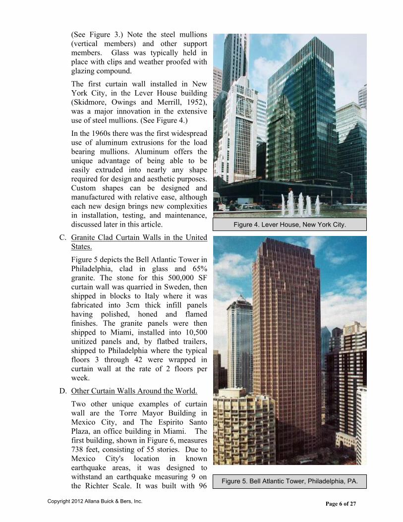
C. Granite Clad Curtain Walls in the United States. Figure 5 depicts the Bell Atlantic Tower in Philadelphia, clad in glass and 65% granite. The stone for this 500,000 SF curtain wall was quarried in Sweden, then shipped in blocks to Italy where it was fabricated into 3cm thick infill panels having polished, honed and flamed finishes. The granite panels were then shipped to Miami, installed into 10,500 unitized panels and, by flatbed trailers, shipped to Philadelphia where the typical floors 3 through 42 were wrapped in curtain wall at the rate of 2 floors per week.
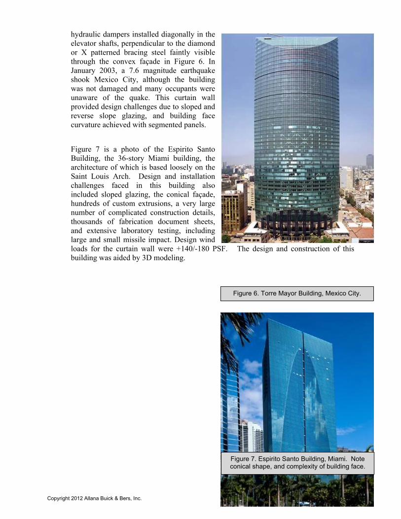
D. Other Curtain Walls Around the World. Two other unique examples of curtain wall are the Torre Mayor Building in Mexico City, and The Espirito Santo Plaza, an office building in Miami. The first building, shown in Figure 6, measures 738 feet, consisting of 55 stories. Due to Mexico City's location in known earthquake areas, it was designed to withstand an earthquake measuring 9 on the Richter Scale. It was built with 96
Figure 6, Torre Mayor Building, Mexico City.
Figure 4. Lever House, New York City.
Figure 5. Bell Atlantic Tower, Philadelphia, PA.
Copyright 2012 Allana Buick & Bers, Inc.
Page 7 of 27
hydraulic dampers installed diagonally in the elevator shafts, perpendicular to the diamond or X patterned bracing steel faintly visible through the convex façade in Figure 6. In January 2003, a 7.6 magnitude earthquake shook Mexico City, although the building was not damaged and many occupants were unaware of the quake. This curtain wall provided design challenges due to sloped and reverse slope glazing, and building face curvature achieved with segmented panels.
Figure 7 is a photo of the Espirito Santo Building, the 36-story Miami building, the architecture of which is based loosely on the Saint Louis Arch. Design and installation challenges faced in this building also included sloped glazing, the conical façade, hundreds of custom extrusions, a very large number of complicated construction details, thousands of fabrication document sheets, and extensive laboratory testing, including large and small missile impact. Design wind loads for the curtain wall were +140/-180 PSF. The design and construction of this building was aided by 3D modeling.
Figure 6. Torre Mayor Building, Mexico City.
Figure 7. Espirito Santo Building, Miami. Note conical shape, and complexity of building face.
Copyright 2012 Allana Buick & Bers, Inc.
Page 8 of 27
5. TYPES OF CURTAIN WALL SYSTEMS
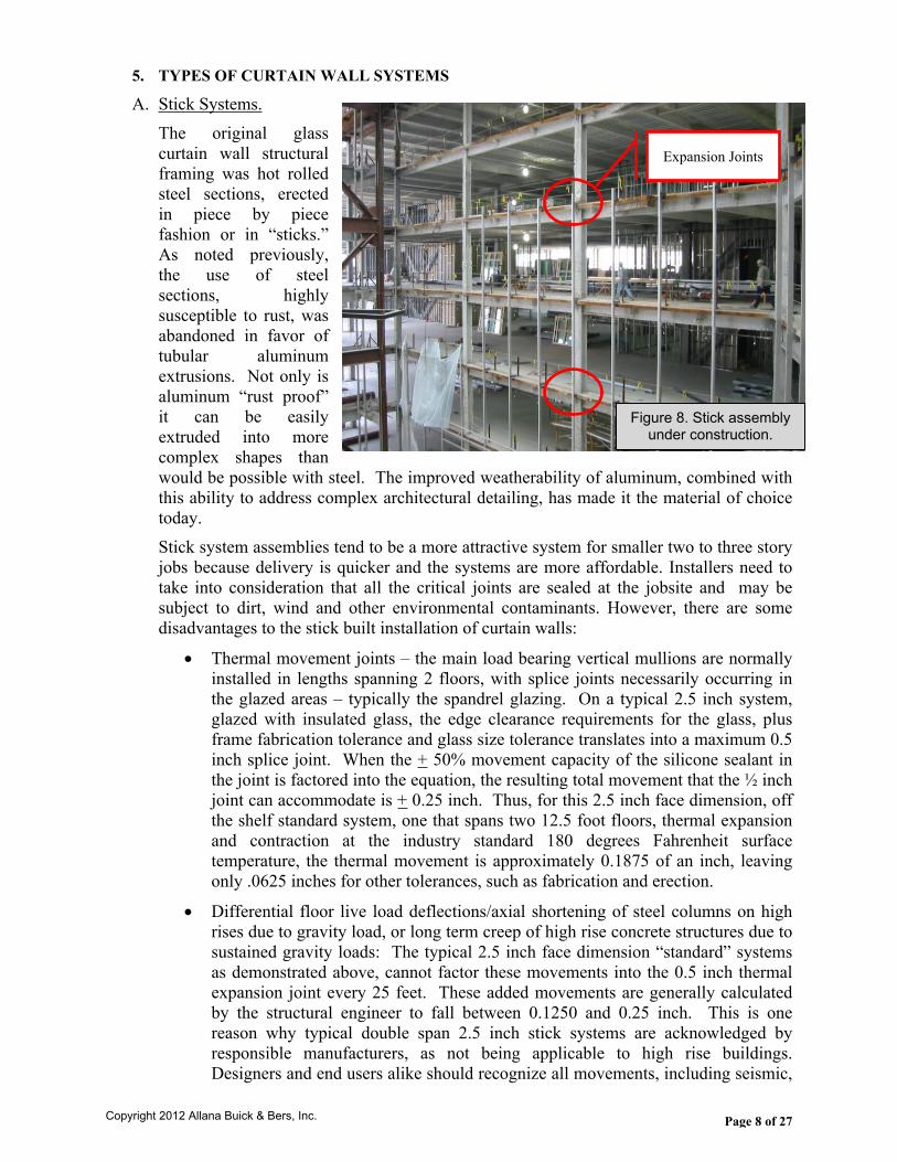
A. Stick Systems. The original glass curtain wall structural framing was hot rolled steel sections, erected in piece by piece fashion or in “sticks.” As noted previously, the use of steel sections, highly susceptible to rust, was abandoned in favor of tubular aluminum extrusions. Not only is aluminum “rust proof” it can be easily extruded into more complex shapes than would be possible with steel. The improved weatherability of aluminum, combined with this ability to address complex architectural detailing, has made it the material of choice today. Stick system assemblies tend to be a more attractive system for smaller two to three story jobs because delivery is quicker and the systems are more affordable. Installers need to take into consideration that all the critical joints are sealed at the jobsite and may be subject to dirt, wind and other environmental contaminants. However, there are some disadvantages to the stick built installation of curtain walls:
Thermal movement joints – the main load bearing vertical mullions are normally installed in lengths spanning 2 floors, with splice joints necessarily occurring in the glazed areas – typically the spandrel glazing. On a typical 2.5 inch system, glazed with insulated glass, the edge clearance requirements for the glass, plus frame fabrication tolerance and glass size tolerance translates into a maximum 0.5 inch splice joint. When the + 50% movement capacity of the silicone sealant in the joint is factored into the equation, the resulting total movement that the ½ inch joint can accommodate is + 0.25 inch. Thus, for this 2.5 inch face dimension, off the shelf standard system, one that spans two 12.5 foot floors, thermal expansion and contraction at the industry standard 180 degrees Fahrenheit surface temperature, the thermal movement is approximately 0.1875 of an inch, leaving only .0625 inches for other tolerances, such as fabrication and erection.
Differential floor live load deflections/axial shortening of steel columns on high rises due to gravity load, or long term creep of high rise concrete structures due to sustained gravity loads: The typical 2.5 inch face dimension “standard” systems as demonstrated above, cannot factor these movements into the 0.5 inch thermal expansion joint every 25 feet. These added movements are generally calculated by the structural engineer to fall between 0.1250 and 0.25 inch. This is one reason why typical double span 2.5 inch stick systems are acknowledged by responsible manufacturers, as not being applicable to high rise buildings. Designers and end users alike should recognize all movements, including seismic,
Figure 8. Stick assembly under construction.
Expansion Joints
Copyright 2012 Allana Buick & Bers, Inc.
Page 9 of 27
which could prove detrimental to the wall’s long term performance. (Note: If the designer allows for double horizontal, caulked “stack” joints every 25 feet, then this type of system could be engineered to handle many types of movements, not including seismic movements.)
Lateral seismic displacement vs. glass breakage: The stick system, having tubular vertical mullions can only accommodate lateral displacement of the glass openings within the glass rabbet or pocket. The glass must float within the pockets when the original square or rectangular shaped opening becomes trapezoidal in the displaced position, without making contact with the mullions. Also note that should any floor be cantilevered, there is then introduced a vertical component of seismic displacement which must be considered. In the 2006 IBC there is a requirement that no glass fall out of a building during a seismic event. Unless the designer:
o Minimizes the height of the tallest lite of glass, or;o Increases the mullion face dimensions, or;o Specifies all glass to be heat strengthened or annealed laminated glass
having one face adhered to the frame (one face of each laminated lite in a double laminated IGU) with a silicone sealant;
The standard stick system cannot meet this code requirement in Zone 4 when the seismic drift is H/50 (H=Height) or 2%; and the non-laminated glass height is > 5.5 feet. Note that at H/50 a 12.5 foot floor spacing will yield a 3 inch lateral displacement at each succeeding floor.
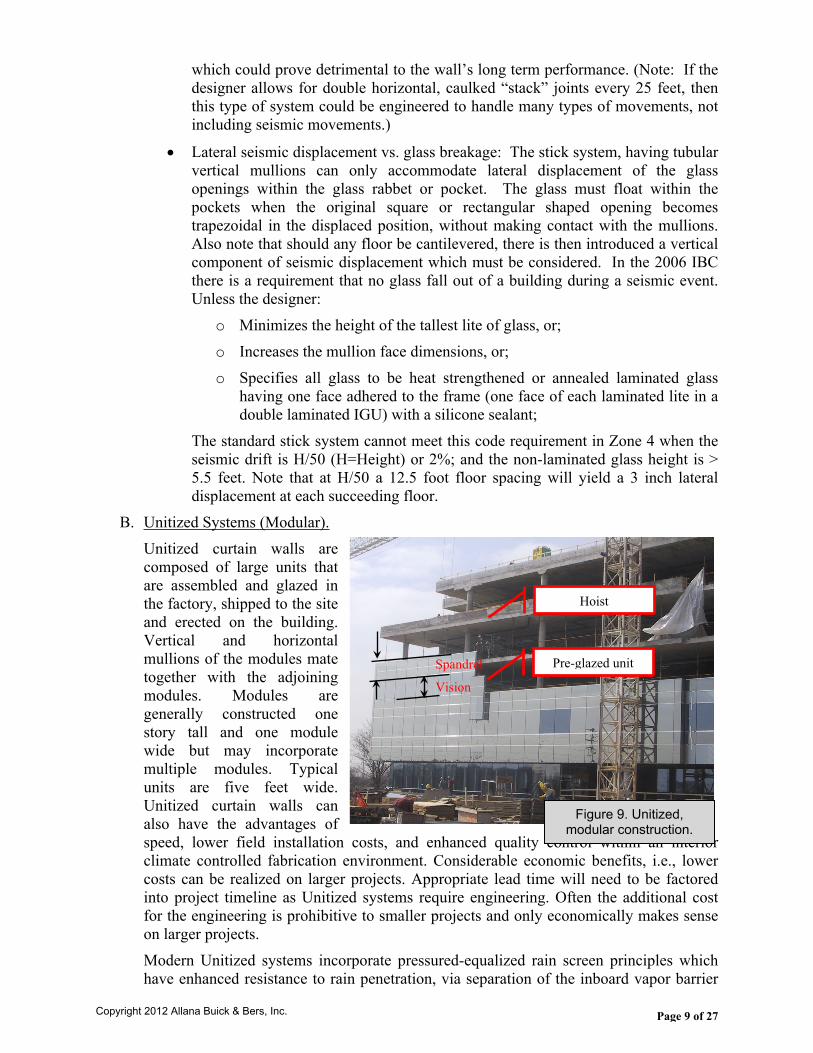
B. Unitized Systems (Modular). Unitized curtain walls are composed of large units that are assembled and glazed in the factory, shipped to the site and erected on the building. Vertical and horizontal mullions of the modules mate together with the adjoining modules. Modules are generally constructed one story tall and one module wide but may incorporate multiple modules. Typical units are five feet wide. Unitized curtain walls can also have the advantages of speed, lower field installation costs, and enhanced quality control within an interior climate controlled fabrication environment. Considerable economic benefits, i.e., lower costs can be realized on larger projects. Appropriate lead time will need to be factored into project timeline as Unitized systems require engineering. Often the additional cost for the engineering is prohibitive to smaller projects and only economically makes sense on larger projects.Modern Unitized systems incorporate pressured-equalized rain screen principles which have enhanced resistance to rain penetration, via separation of the inboard vapor barrier
Figure 9. Unitized, modular construction.
Spandrel
Vision
Pre-glazed unit
Hoist
Copyright 2012 Allana Buick & Bers, Inc.
Page 10 of 27
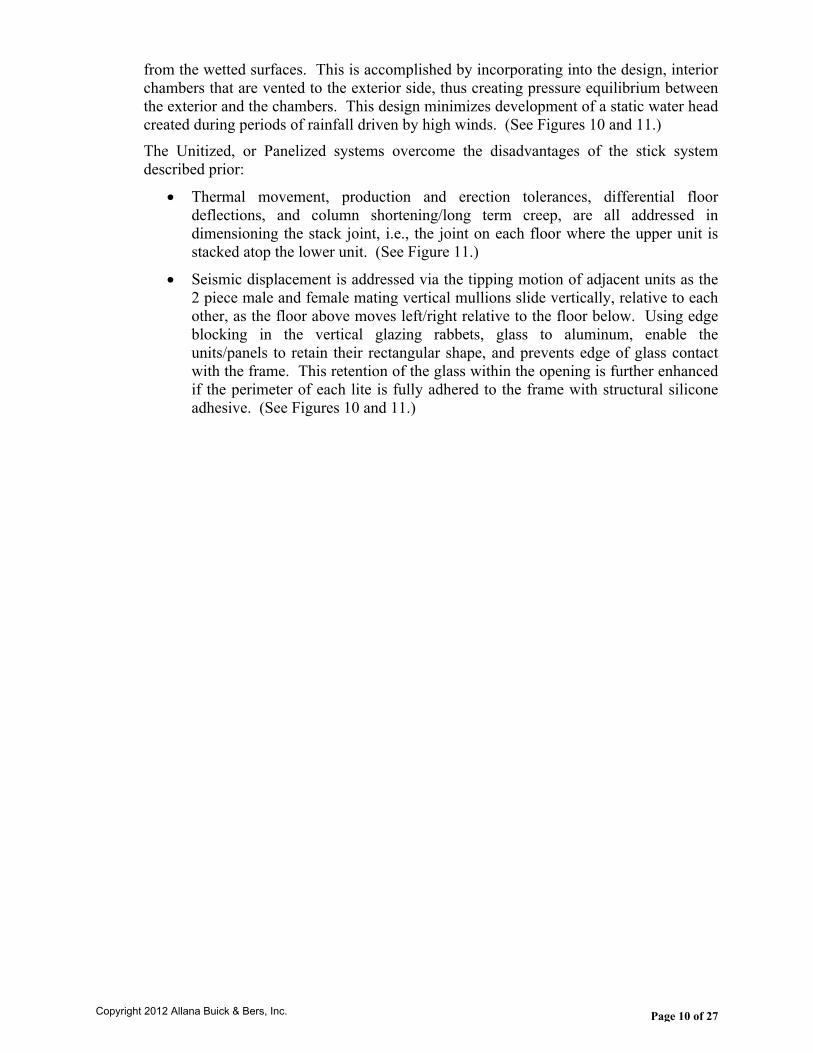
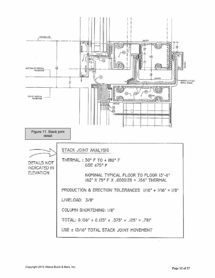
from the wetted surfaces. This is accomplished by incorporating into the design, interior chambers that are vented to the exterior side, thus creating pressure equilibrium between the exterior and the chambers. This design minimizes development of a static water head created during periods of rainfall driven by high winds. (See Figures 10 and 11.)The Unitized, or Panelized systems overcome the disadvantages of the stick system described prior:
Thermal movement, production and erection tolerances, differential floor deflections, and column shortening/long term creep, are all addressed in dimensioning the stack joint, i.e., the joint on each floor where the upper unit is stacked atop the lower unit. (See Figure 11.)
Seismic displacement is addressed via the tipping motion of adjacent units as the 2 piece male and female mating vertical mullions slide vertically, relative to each other, as the floor above moves left/right relative to the floor below. Using edge blocking in the vertical glazing rabbets, glass to aluminum, enable the units/panels to retain their rectangular shape, and prevents edge of glass contact with the frame. This retention of the glass within the opening is further enhanced if the perimeter of each lite is fully adhered to the frame with structural silicone adhesive. (See Figures 10 and 11.)
Copyright 2012 Allana Buick & Bers, Inc.
Page 11 of 27
Figure 10. Mullion detail
Copyright 2012 Allana Buick & Bers, Inc.
Page 12 of 27
Figure 11. Stack joint detail
Copyright 2012 Allana Buick & Bers, Inc.

Page 13 of 27
6. MOUNTING AND INSTALLATION
A. Stick Assembly Curtain Walls. Vertical mullions spanning 2 floors are typically anchored with steel or aluminum clip angles mounted on the face of the slab by welding to a hot rolled screed angle or by expansion bolts/epoxy bolts into reinforced concrete. The dead load / wind load anchor has horizontal slots for adjusting the mullion cantilever in and out while the wind load only anchor has vertical slots to bolt the mullion with slip pads to allow for thermal movement. Embedded “Halfen” channels or tubes cast into the slab can replace welding or field hammer drilling of the slab.
B. Unitized Curtain Walls.Typical connections are to the top of a slab cast with a recessed pocket and Halfen embedded inserts. An extruded aluminum or formed steel angle plate, is then bolted to the insert and cantilevered off the slab, toed up, to engage with a mating anchor bolted to each side of the units. The mating frame hook anchors contain jack bolts used to raise the units to the correct elevation. The bottom of each unit nests within the head of the lower unit and a lock-bolt is used so the units do not “walk” post-installation. In all applications, stick or unitized, curtain walls must be cantilevered outboard of the slab to allow room for AISC or ACI tolerances for steel and concrete erection, plus differences in as built floor registration, one above the next. To accommodate this build up of clearances, it is not uncommon to design clearances from the back of mullion to face of slab of 2.5 inch, +/-1.5 inch. (See Figure 12.)
(Note: This project did not require a pocket on top of slab due to computer flooring, and the slab insert was custom made.)
C. Window Wall.
Figure 12. Anchor detail
Lock Bolt
Copyright 2012 Allana Buick & Bers, Inc.

Page 14 of 27
This horizontal ribbon of fixed or operable windows is always connected between slabs or other construction such as stud framing, CMU, pre-cast or GFRC. The wind load transfer occurs at each end of the vertical mullions and jambs with the dead load transferred at the sill. Industry best practice dictates the use of continuous sill flashing or extruded sill starters/sill cans, the latter of which not only provides access to seal the fastener penetrations, but also mechanically locks the frame sills to resist wind loads. Depending on the height of the window wall, an extruded head receptor/head can be required as a means of anchorage, also allowing vertical/lateral movements. In all cases the window wall head condition and jamb condition require proper integration with surrounding waterproofing. Figure 13 depicts a typical window wall sill.
D. Windows. Similar to window walls, this system is always connected, all four sides, to the surrounding construction, and best practice requires sill flashing or sill receptors and head flashings, integrated with adjacent waterproofing. Both “equal leg” and “unequal leg” windows can be installed with clips all around – allowing minimal vertical thermal expansion, while unequal leg or flanged frames can be connected through the flange to the structure. It is important too, that they be properly detailed to transition or integrate with the adjacent waterproofing.
E. Storefront. As the name implies, this system is best employed as display windows and entrances at sidewalk elevations, recessed from the exterior face of any upper floors, for protection from rain cascading down the walls above. Storefront systems are generally rated as the lowest performing systems, with reference to air and water penetration in particular, and
Figure 13. Window wall sill detail
Copyright 2012 Allana Buick & Bers, Inc.
Page 15 of 27
secondarily regarding structural capacity. Similar to window wall, storefronts are connected at head and sill, and often connected on all four sides to the adjacent construction. They must have flashings designed into the storefront, including pan flashings under entry door thresholds, when storefronts are installed at or near the exterior face of the building. The better performing storefront systems incorporate extruded sill starters or cans under the fixed glass areas. As with window walls, and windows, head flashings are required, and must also be integrated with the adjacent waterproofing.
Copyright 2012 Allana Buick & Bers, Inc.
Page 16 of 27
7. ENERGY PERFORMANCE.
As the model building codes become increasingly restrictive in energy consumption, the design community must avail themselves of existing and emerging technologies in both glazing systems and glass. As recently as 2010, the American Society of Heating, Refrigerating and Air Conditioning Engineers (ASHRAE) considered revising their standard 90.1, which establishes minimum requirements for energy efficient designs for buildings other than low-rise, to lower the allowed percentage of vision glazing in exterior walls from 40% to 30% of the floor area. Much to the benefit of raw glass producers, glass fabricators, window and curtain wall manufacturers, and glazing contractors this reduction in allowed vision glazing has not yet been adopted.The aforementioned beneficiaries of ASHRAE’s non-action, had been, for quite some time, aggressively investing in new technologies to reduce energy consumption in new construction.In glazing for example:
Triple Pane Insulating Glass
Low E (low emissivity) Coatings on 1 or More Surfaces of an IGU
Argon and Krypton Gas Filled IGUs
Warm Edge Spacers in IGUs
Electronically Tintable GlassFor generation of electricity:
Photovoltaic Glass Units (PVGU)For the aluminum framing:
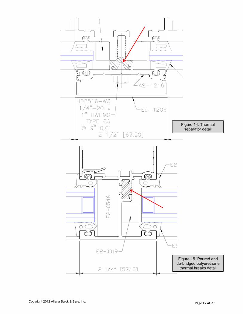
Thermal Separators Such as PVC or Elastomeric Gaskets (See Figure 14.)
Poured and De-bridged Polyurethane Thermal Breaks (See Figure 15.)
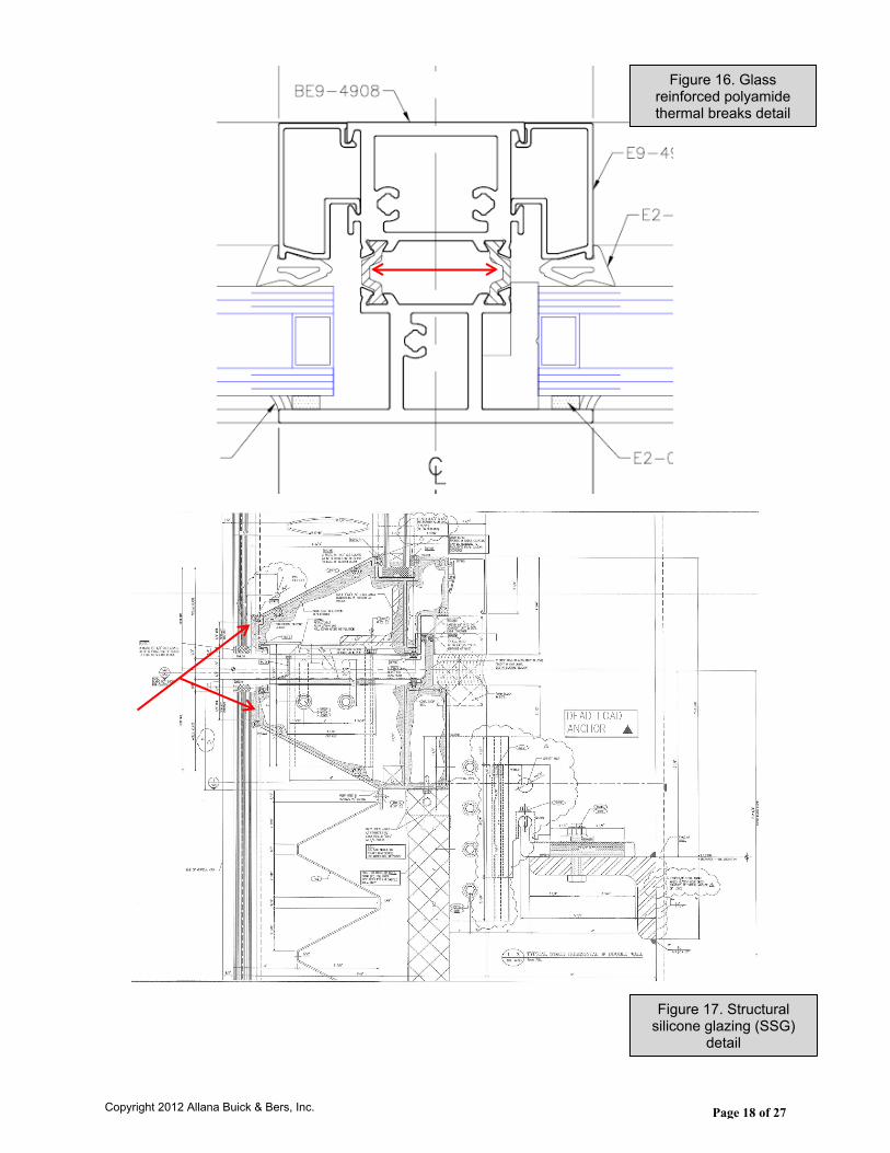
Glass Reinforced Polyamide Thermal Breaks (See Figure 16.)
Structural Silicone Glazing (SSG) 2-side or 4-side (See Figure 17.)For the exterior wall design:
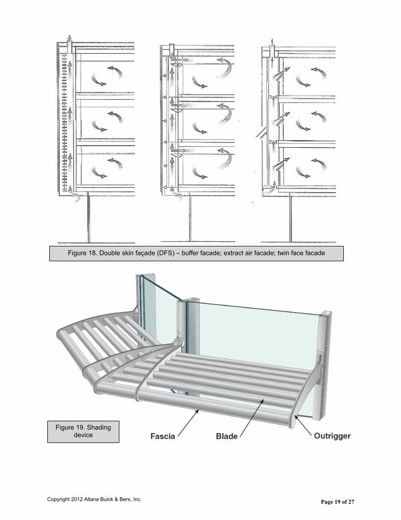
Double Skin Façade (DFS) (See Figure 18.)
Shading Devices (See Figure 19.)Critical to the energy performance of the curtain wall are these 3 attributes:
Continuity of the Air Barrier.
Center Glass “U” Value / Whole Window “U” Value.
Solar Heat Gain Coefficient (SHGC).
Copyright 2012 Allana Buick & Bers, Inc.
Page 17 of 27
Figure 14. Thermal separator detail
Figure 15. Poured and de-bridged polyurethane
thermal breaks detail
Copyright 2012 Allana Buick & Bers, Inc.
Page 18 of 27
Figure 16. Glass reinforced polyamide thermal breaks detail
Figure 17. Structural silicone glazing (SSG)
detail
Copyright 2012 Allana Buick & Bers, Inc.
Page 19 of 27
Figure 18. Double skin façade (DFS) – buffer facade; extract air facade; twin face facade
Figure 19. Shading device
Copyright 2012 Allana Buick & Bers, Inc.

Page 20 of 27
A. Continuity of the Air Barrier.The air barrier within the curtain wall system, from the exterior face of glass across glazing gaskets / sealants to the frame, and from the frame, across fluid applied sealant joints, to the Weather Resistive Barrier (WRB) in the adjacent construction must be uninterrupted. Often, the choice of sealant(s) plus the joint design at the perimeter of all glazing systems is not given the proper consideration. The architect, in the sealants specification, will sometimes specify a 1 or 2 part polyurethane sealant for this joint, not realizing:
Polyurethane will not adhere to silicone sealants which are the most common frame joint sealants in the glazing industry, and
Polyurethane degrades quickly when exposed to UV rays. The forces this joint must withstand in compression, extension and shear are also frequently overlooked in the architect’s perimeter caulk joint designs.In the case of an open back horizontal head members and tubular vertical members running through the head members, these hollows don’t work with the pre-engineered assemblies. The integration of engineered transition assemblies is best used with factory assembled aluminum/vinyl windows having mitered corners. It is more difficult to implement with hollow aluminum extrusions and/or open back extrusions without the contractor installing sealed enclosures in the ends of the tubes.The sealants need to be compatible with the WRB. In many cases the WRB adjacent to the fenestration is best installed with an aluminum foil faced peal and stick membrane, that way there are no worries about compatibility issues between the perimeter sealant and the foiled-faced WRB.
B. Center Glass “U” Value / Whole Window “U” Value.The past 20 years have marked an exponential improvement in glass technology. Metrics such as “U” value, whole window “U” value and others are now common terms in specifying glazing. The rate of heat loss through glass is termed center of glass “U” value or factor, and the lower the “U” factor, the greater the glass’ resistance to heat flow. There are now available double pane IGUs with low E coatings on both lites and argon gas filled with center of glass “U” values as low as 0.20 or R-5. For whole window “U” value, including glass and frame, the National Fenestration Rating Council (NFRC) has developed a procedure, NFRC 100, for determining the fenestration product “U” value. This whole window “U” value is commonly higher than the center of glass “U” value. A high performance double glazed window can have “U” values of 0.30 or lower. As the description of “U” value implies, low “U” values are most important in heating dominated climates, although they are also beneficial in cooling dominated climates.
C. Solar Heat Gain Coefficient (SHGC).Solar Heat Gain Coefficient (SHGC) is the fraction of incident solar radiation passing through a window, both directly transmitted and absorbed then released inward. SHGC is expressed as a number between 0 and 1. The lower the SHGC of a window assembly, the less solar heat it transmits. The nationally recognized SHGC rating method is the NFRC 200 procedure for determining fenestration product solar heat gain coefficient and visible transmittance at normal incidence. Whole window SHGC is lower than glass only SHGC, and is generally below 0.7. While solar heat gain can provide free heat in winter, it can also lead to overheating in summer. To best balance solar heat gain with an appropriate
Copyright 2012 Allana Buick & Bers, Inc.
Page 21 of 27
SHGC, the designer must consider climate, orientation, shading conditions and other factors.
8. CURTAIN WALL TEST PROCEDURES.
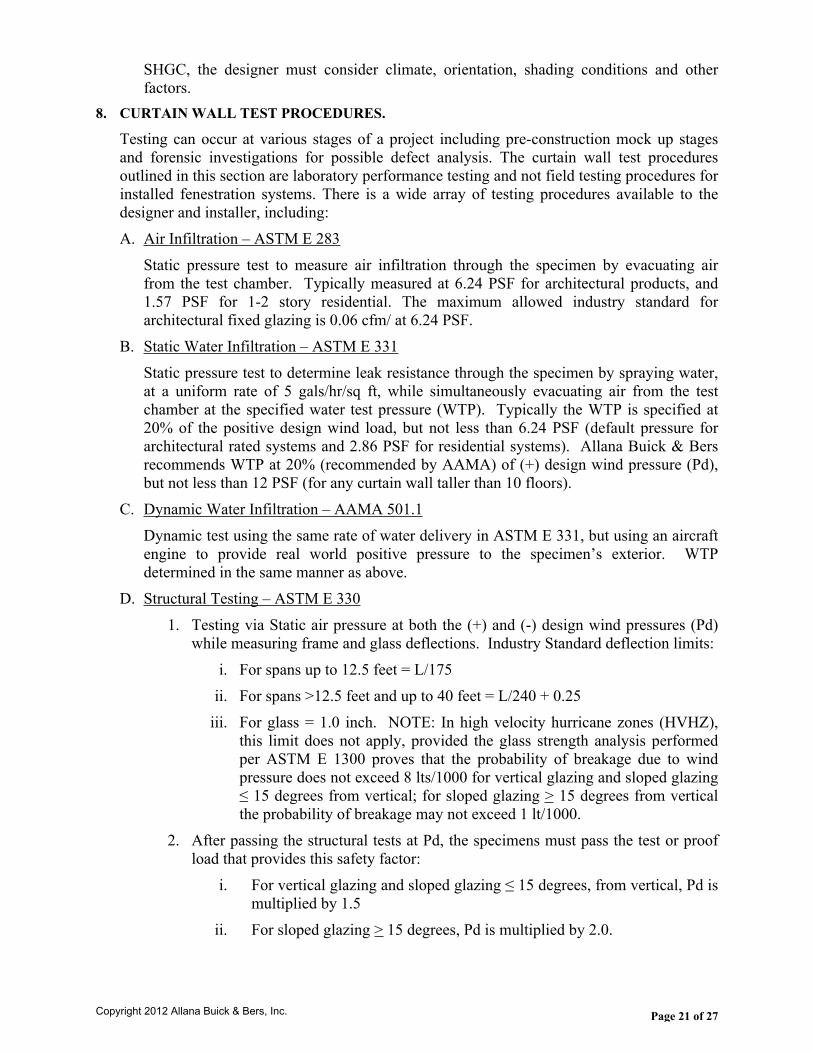
Testing can occur at various stages of a project including pre-construction mock up stages and forensic investigations for possible defect analysis. The curtain wall test procedures outlined in this section are laboratory performance testing and not field testing procedures for installed fenestration systems. There is a wide array of testing procedures available to the designer and installer, including:A. Air Infiltration – ASTM E 283
Static pressure test to measure air infiltration through the specimen by evacuating air from the test chamber. Typically measured at 6.24 PSF for architectural products, and 1.57 PSF for 1-2 story residential. The maximum allowed industry standard for architectural fixed glazing is 0.06 cfm/ at 6.24 PSF.
B. Static Water Infiltration – ASTM E 331Static pressure test to determine leak resistance through the specimen by spraying water, at a uniform rate of 5 gals/hr/sq ft, while simultaneously evacuating air from the test chamber at the specified water test pressure (WTP). Typically the WTP is specified at 20% of the positive design wind load, but not less than 6.24 PSF (default pressure for architectural rated systems and 2.86 PSF for residential systems). Allana Buick & Bers recommends WTP at 20% (recommended by AAMA) of (+) design wind pressure (Pd), but not less than 12 PSF (for any curtain wall taller than 10 floors).
C. Dynamic Water Infiltration – AAMA 501.1Dynamic test using the same rate of water delivery in ASTM E 331, but using an aircraft engine to provide real world positive pressure to the specimen’s exterior. WTP determined in the same manner as above.
D. Structural Testing – ASTM E 3301. Testing via Static air pressure at both the (+) and (-) design wind pressures (Pd)
while measuring frame and glass deflections. Industry Standard deflection limits: i. For spans up to 12.5 feet = L/175
ii. For spans >12.5 feet and up to 40 feet = L/240 + 0.25iii. For glass = 1.0 inch. NOTE: In high velocity hurricane zones (HVHZ),
this limit does not apply, provided the glass strength analysis performed per ASTM E 1300 proves that the probability of breakage due to wind pressure does not exceed 8 lts/1000 for vertical glazing and sloped glazing ≤ 15 degrees from vertical; for sloped glazing > 15 degrees from vertical the probability of breakage may not exceed 1 lt/1000.
2. After passing the structural tests at Pd, the specimens must pass the test or proof load that provides this safety factor:
i. For vertical glazing and sloped glazing ≤ 15 degrees, from vertical, Pd is multiplied by 1.5
ii. For sloped glazing > 15 degrees, Pd is multiplied by 2.0.
Copyright 2012 Allana Buick & Bers, Inc.
Page 22 of 27
iii. Deflections are not recorded and the specimens pass when there is no glass breakage, and the permanent set (deformation) is ≤ 0.2% of span for architectural products and ≤ 0.4% for residential products.
iv. Sloped glazing in areas subject to snow accumulation must have the wind pressure Pd increased by a factor representing expected snow load.
v. Seismic or Wind Induced Interstory Drift – AAMA 501.4 – Static test method focuses primarily on changes in serviceability of the specimen after horizontal racking at the design displacement (Dp) after which the specimen is subjected to repeat air and water tests. Then, after the “proof” test at 1.5 Pd, 501.4 is repeated at 1.5 Dp. Pass/fail criteria is dependent upon the building’s use/occupancy.
E. Other Tests Include:1. AAMA 501.5 – Thermal Cycling2. AAMA 501.6 – Seismic Drift Causing Glass Fallout3. AAMA 501.7 – Vertical Seismic Displacement4. Large and Small Missile Impact and Cycling (ASTM E 1886 and E 1996)5. Blast Resistance6. Window Washing Tie – Back Load Test
Copyright 2012 Allana Buick & Bers, Inc.
Page 23 of 27
9. FORENSIC CASE STUDIES.
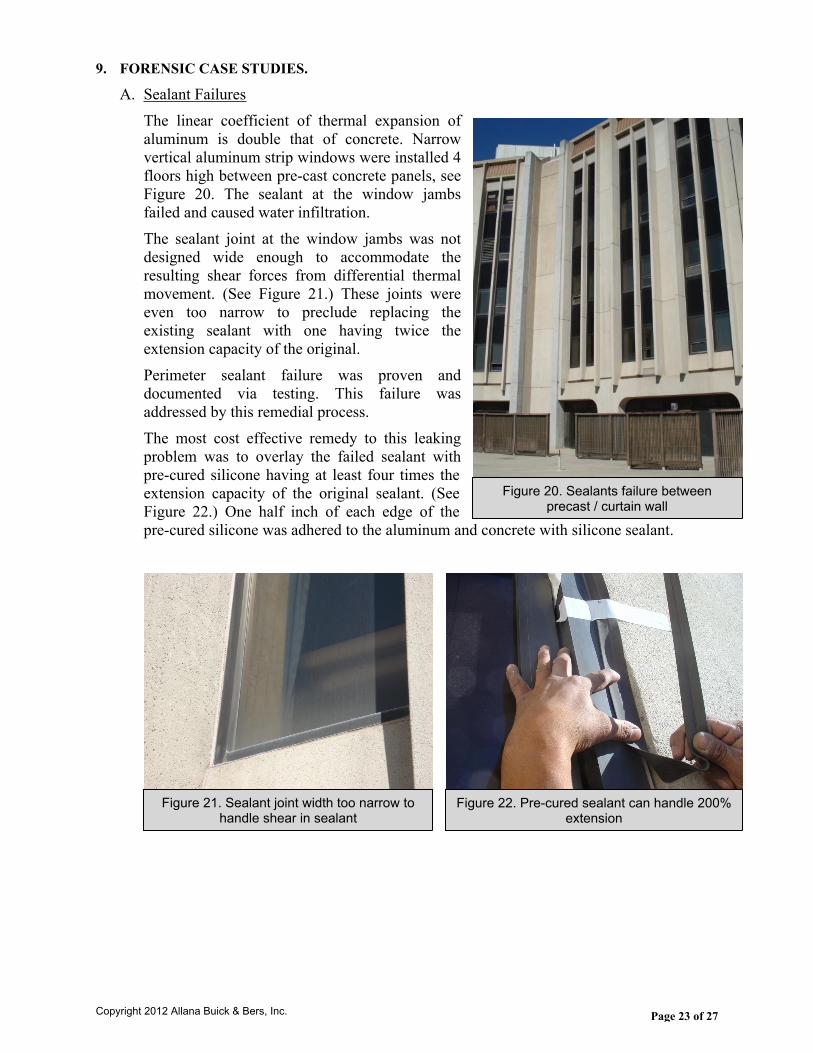
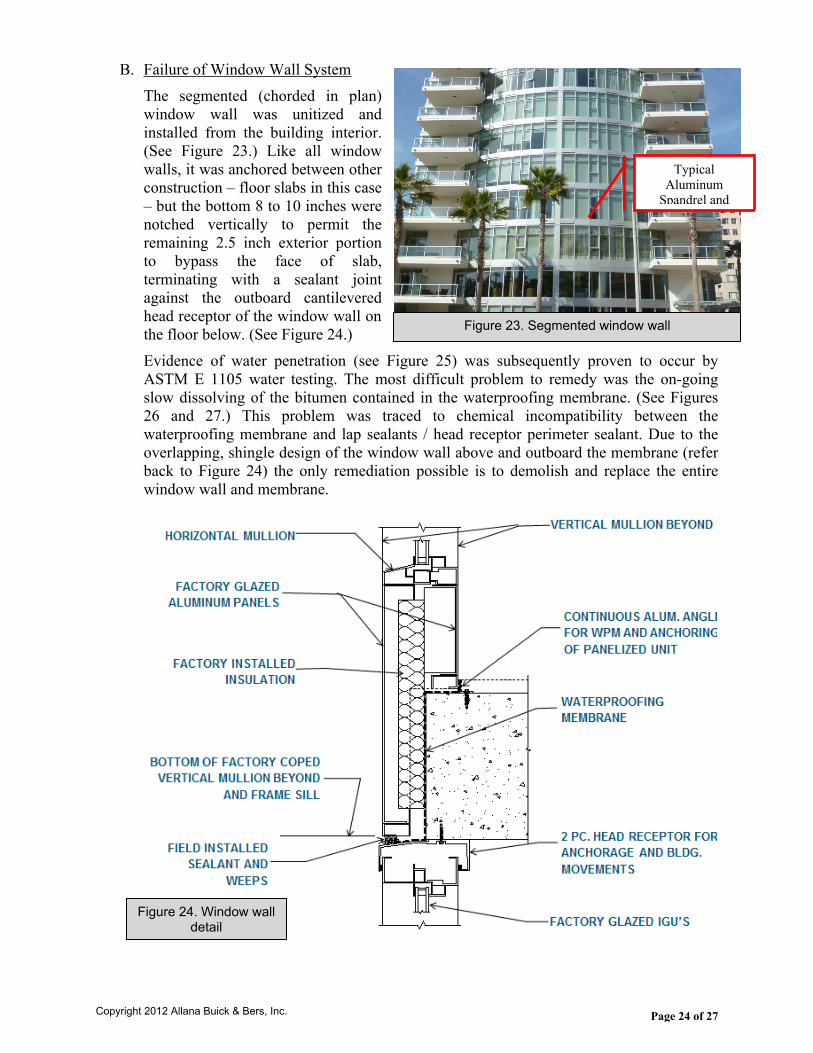
A. Sealant FailuresThe linear coefficient of thermal expansion of aluminum is double that of concrete. Narrow vertical aluminum strip windows were installed 4 floors high between pre-cast concrete panels, see Figure 20. The sealant at the window jambs failed and caused water infiltration.The sealant joint at the window jambs was not designed wide enough to accommodate the resulting shear forces from differential thermal movement. (See Figure 21.) These joints were even too narrow to preclude replacing the existing sealant with one having twice the extension capacity of the original.Perimeter sealant failure was proven and documented via testing. This failure was addressed by this remedial process. The most cost effective remedy to this leaking problem was to overlay the failed sealant with pre-cured silicone having at least four times the extension capacity of the original sealant. (See Figure 22.) One half inch of each edge of the pre-cured silicone was adhered to the aluminum and concrete with silicone sealant.
Figure 20. Sealants failure between precast / curtain wall
Figure 21. Sealant joint width too narrow to handle shear in sealant
Figure 22. Pre-cured sealant can handle 200% extension
Copyright 2012 Allana Buick & Bers, Inc.
Page 24 of 27
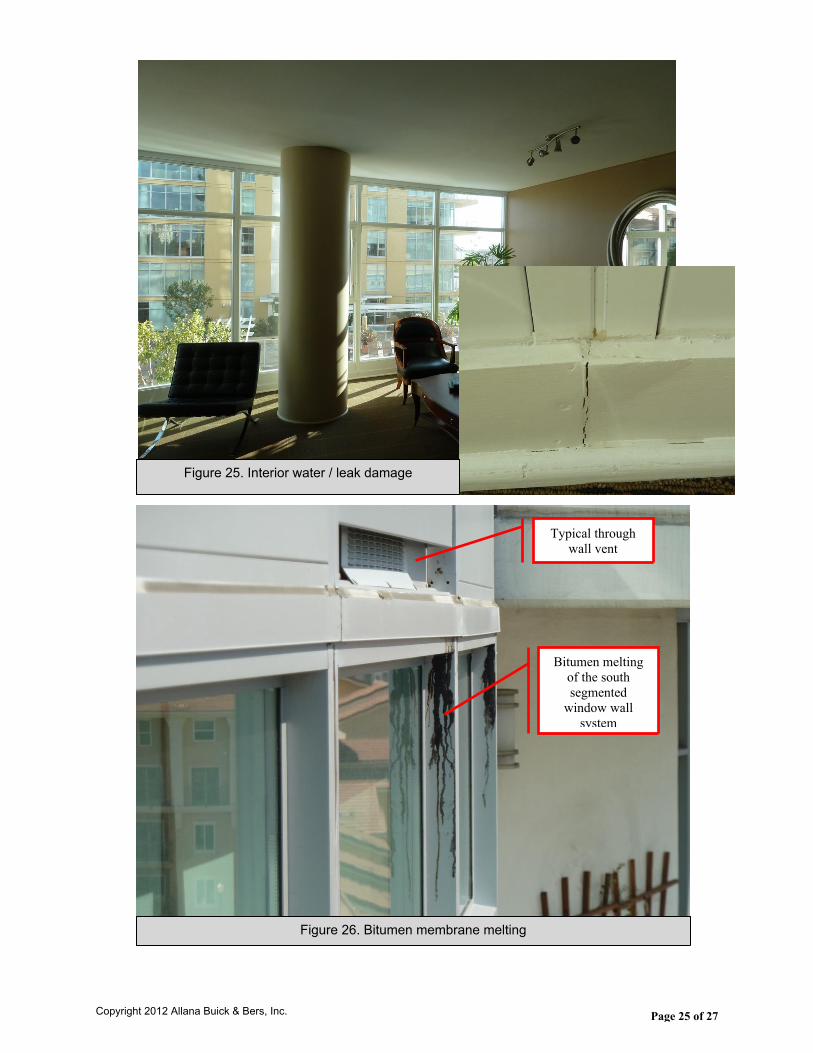
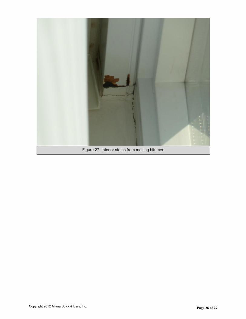
B. Failure of Window Wall SystemThe segmented (chorded in plan) window wall was unitized and installed from the building interior. (See Figure 23.) Like all window walls, it was anchored between other construction – floor slabs in this case – but the bottom 8 to 10 inches were notched vertically to permit the remaining 2.5 inch exterior portion to bypass the face of slab, terminating with a sealant joint against the outboard cantilevered head receptor of the window wall on the floor below. (See Figure 24.)Evidence of water penetration (see Figure 25) was subsequently proven to occur by ASTM E 1105 water testing. The most difficult problem to remedy was the on-going slow dissolving of the bitumen contained in the waterproofing membrane. (See Figures 26 and 27.) This problem was traced to chemical incompatibility between the waterproofing membrane and lap sealants / head receptor perimeter sealant. Due to the overlapping, shingle design of the window wall above and outboard the membrane (refer back to Figure 24) the only remediation possible is to demolish and replace the entire window wall and membrane.
Figure 23. Segmented window wall
Typical Aluminum
Spandrel and Vents
Figure 24. Window wall detail
Copyright 2012 Allana Buick & Bers, Inc.
Page 25 of 27
Figure 25. Interior water / leak damage
Figure 26. Bitumen membrane melting
Typical through wall vent
Bitumen melting of the south segmented
window wall system
Copyright 2012 Allana Buick & Bers, Inc.
Page 26 of 27
Figure 27. Interior stains from melting bitumen
Copyright 2012 Allana Buick & Bers, Inc.
Page 27 of 27
10. CONCLUSION
The modern curtain wall, having reached a high level of sophistication within the past 5 decades, continues to evolve in response to architectural design coupled with energy conservation and energy production.The recent exponential improvements in glass technology combined with more energy efficient framing systems bode well for the owners and designers who strive to improve the built environment through reductions in carbon emissions; maximizing day-lighting without increasing energy consumption; reducing glare; and increasing thermal comfort. However, as curtain wall construction has evolved, new considerations and issues have arisen as evidenced by the case studies. As we continue this evolution to meet new, more demanding performance requirements, it can be anticipated that more considerations and challenges will arise.
Photo Sources:
All photos and details used were sourced by Allana Buick & Bers or public domain sources unless listed below:
Figure 2 – Source WikiPedia - Public domain Figure 3 – Source: WorldArchitectureMap.org and WikiPedia Figure 4 – Source WikiPedia Figure 5 – Source Building Design and Construction Magazine 1992 Figure 6 – Source: Teratec, Inc. Figure 7 – Source: Viracon, Inc,
Copyright 2012 Allana Buick & Bers, Inc.