![Characterization and aging response of the d[sub 31] piezoelectric coefficient of lead zirconate titanate thin films](https://static.fdokumen.com/doc/165x107/6324ff704643260de90d8576/characterization-and-aging-response-of-the-dsub-31-piezoelectric-coefficient-of.jpg)
Current-Voltage Characteristics of Lead Zirconate Titanate/Nickel Bilayered Hollow Cylindrical...
6
Chin. Phys. B Vol. 19, No. 2 (2010) 027201 Current voltage characteristics of lead zirconate titanate/nickel bilayered hollow cylindrical magnetoelectric composites * Pan De-An( ) a) † , Zhang Shen-Gen( ) a) , Tian Jian-Jun( ) a) , Sun Jun-Sai( ) b) , Alex A. Volinsky c) , and Qiao Li-Jie( ) a) a) School of Materials Science and Engineering, University of Science and Technology Beijing, Beijing 100083, China b) Faculty of Materials and Metallurgical Engineering, Kunming University of Science and Technology, Kunming 650093, China c) Department of Mechanical Engineering, University of South Florida, Tampa FL 33620, USA (Received 27 March 2009; revised manuscript received 20 May 2009) Current–voltage measurements obtained from lead zirconate titanate/nickel bilayered hollow cylindrical magne- toelectric composite showed that a sinusoidal current applied to the copper coil wrapped around the hollow cylinder circumference induces voltage across the lead zirconate titanate layer thickness. The current–voltage coefficient and the maximum induced voltage in lead zirconate titanate at 1 kHz and resonance (60.1 kHz) frequencies increased linearly with the number of the coil turns and the applied current. The resonance frequency corresponds to the electromechanical resonance frequency. The current–voltage coefficient can be significantly improved by optimizing the magnetoelectric structure geometry and/or increasing the number of coil turns. Hollow cylindrical lead zirconate titanate/nickel struc- tures can be potentially used as current sensors. Keywords: current–voltage coefficient, bilayered cylindrical composites, electromechanical reso- nance, current sensor PACC: 7220M, 8160H, 7430G 1. Introduction Recently, bulk magnetoelectric (ME) materials have drawn increased attention due to their ME effect, which provides significant advantages for applications in devices operating at low frequencies such as a pico- Tesla sensitivity magnetometer, [1,2] and at microwave frequencies such as an electrostatically tunable band- pass filter, [3] a band-stop filter, [4] a resonator, [5] and a phase shifter, [6] etc. Most of these devices are based on layered ME composites that exhibit stronger ME effect in comparison with the particulate ME materials. [7] In previous studies plate and cylindrical lay- ered ME composites made by electro-deposition were considered. [8-11] Electrodeposited plate layered ME composites have comparable ME performance to the Tb 1-x Dy x Fe 2-y (Terfenol-D)/[lead zirconate titanate (PZT)] prepared by the gluing method. [8,9] Trilay- ered Ni/PZT/Ni composites also have some novel ME properties, [10] while PZT/Ni bilayered cylindrical composites exhibit high gain ME effect at resonant frequency under high magnetic field induced by the volume magnetostriction. [11] Cylindrical layered ME composites have a significant potential for applications in high magnetic field detection. However, the ME ef- fects are only suitable for detecting magnetic fields of constant direction, but not rotating or vortex mag- netic fields, excited by metal wires carrying current. Moreover, previous studies focused on the relation- ship between the magnetic fields (bias magnetic field H DC and AC field δH) and the ME coefficient. This paper focuses on an electric polarization in the inner PZT layer induced by the current applied to the cop- per coil wrapped around the ME composite, which is denoted as the current–voltage characteristics. * Project supported by the National Natural Science Foundation of China (Grant Nos. 50572006, 50802008 and 50874010), the Natural Science Foundation of Beijing, China (Grant No. 2073026), the Program for New Century Excellent Talents in University (Grant No. 20060420152), and Scholars and Innovative Research Team in University (Grant No. 0509). Alex A. Volinsky would like to acknowledge support from NSF (Grant No. CMMI-0600266). † Corresponding author. E-mail: [email protected] c 2010 Chinese Physical Society and IOP Publishing Ltd http://www.iop.org/journals/cpb http://cpb.iphy.ac.cn 027201-1
Transcript of Current-Voltage Characteristics of Lead Zirconate Titanate/Nickel Bilayered Hollow Cylindrical...

Chin. Phys. B Vol. 19, No. 2 (2010) 027201
Current voltage characteristics of lead zirconatetitanate/nickel bilayered hollow cylindrical
magnetoelectric composites∗
Pan De-An( )a)†, Zhang Shen-Gen( )a), Tian Jian-Jun( )a),
Sun Jun-Sai( )b), Alex A. Volinskyc), and Qiao Li-Jie( )a)
a)School of Materials Science and Engineering,
University of Science and Technology Beijing, Beijing 100083, Chinab)Faculty of Materials and Metallurgical Engineering, Kunming University
of Science and Technology, Kunming 650093, Chinac)Department of Mechanical Engineering, University of South Florida, Tampa FL 33620, USA
(Received 27 March 2009; revised manuscript received 20 May 2009)
Current–voltage measurements obtained from lead zirconate titanate/nickel bilayered hollow cylindrical magne-
toelectric composite showed that a sinusoidal current applied to the copper coil wrapped around the hollow cylinder
circumference induces voltage across the lead zirconate titanate layer thickness. The current–voltage coefficient and the
maximum induced voltage in lead zirconate titanate at 1 kHz and resonance (60.1 kHz) frequencies increased linearly
with the number of the coil turns and the applied current. The resonance frequency corresponds to the electromechanical
resonance frequency. The current–voltage coefficient can be significantly improved by optimizing the magnetoelectric
structure geometry and/or increasing the number of coil turns. Hollow cylindrical lead zirconate titanate/nickel struc-
tures can be potentially used as current sensors.
Keywords: current–voltage coefficient, bilayered cylindrical composites, electromechanical reso-
nance, current sensor
PACC: 7220M, 8160H, 7430G
1. Introduction
Recently, bulk magnetoelectric (ME) materials
have drawn increased attention due to their ME effect,
which provides significant advantages for applications
in devices operating at low frequencies such as a pico-
Tesla sensitivity magnetometer,[1,2] and at microwave
frequencies such as an electrostatically tunable band-
pass filter,[3] a band-stop filter,[4] a resonator,[5] and a
phase shifter,[6] etc. Most of these devices are based on
layered ME composites that exhibit stronger ME effect
in comparison with the particulate ME materials.[7]
In previous studies plate and cylindrical lay-
ered ME composites made by electro-deposition were
considered.[8−11] Electrodeposited plate layered ME
composites have comparable ME performance to the
Tb1−xDyxFe2−y(Terfenol-D)/[lead zirconate titanate
(PZT)] prepared by the gluing method.[8,9] Trilay-
ered Ni/PZT/Ni composites also have some novel
ME properties,[10] while PZT/Ni bilayered cylindrical
composites exhibit high gain ME effect at resonant
frequency under high magnetic field induced by the
volume magnetostriction.[11] Cylindrical layered ME
composites have a significant potential for applications
in high magnetic field detection. However, the ME ef-
fects are only suitable for detecting magnetic fields of
constant direction, but not rotating or vortex mag-
netic fields, excited by metal wires carrying current.
Moreover, previous studies focused on the relation-
ship between the magnetic fields (bias magnetic field
HDC and AC field δH) and the ME coefficient. This
paper focuses on an electric polarization in the inner
PZT layer induced by the current applied to the cop-
per coil wrapped around the ME composite, which is
denoted as the current–voltage characteristics.
∗Project supported by the National Natural Science Foundation of China (Grant Nos. 50572006, 50802008 and 50874010), the
Natural Science Foundation of Beijing, China (Grant No. 2073026), the Program for New Century Excellent Talents in University
(Grant No. 20060420152), and Scholars and Innovative Research Team in University (Grant No. 0509). Alex A. Volinsky would
like to acknowledge support from NSF (Grant No. CMMI-0600266).†Corresponding author. E-mail: [email protected]
c© 2010 Chinese Physical Society and IOP Publishing Ltd
http://www.iop.org/journals/cpb http://cpb.iphy.ac.cn
027201-1
Chin. Phys. B Vol. 19, No. 2 (2010) 027201
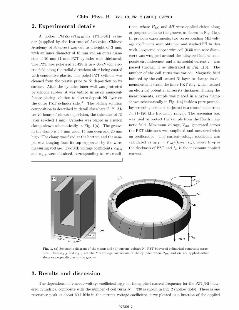
2. Experimental details
A hollow Pb(Zr0.52Ti0.48)O3 (PZT-5H) cylin-
der (supplied by the Institute of Acoustics, Chinese
Academy of Sciences) was cut to a height of 3 mm,
with an inner diameter of 18 mm and an outer diam-
eter of 20 mm (1 mm PZT cylinder wall thickness).
The PZT was polarized at 425 K in a 50-kV/cm elec-
tric field along the radial directions after being coated
with conductive plastic. The poled PZT cylinder was
cleaned from the plastic prior to Ni deposition on its
surface. After the cylinder inner wall was protected
by silicone rubber, it was bathed in nickel aminosul-
fonate plating solution to electro-deposit Ni layer on
the outer PZT cylinder side.[11] The plating solution
composition is described in detail elsewhere.[8−12] Af-
ter 20 hours of electro-deposition, the thickness of Ni
layer reached 1 mm. Cylinder was placed in a nylon
clamp shown schematically in Fig. 1(a). The groove
in the clamp is 3.5 mm wide, 15 mm deep and 20 mm
high. The clamp was fixed at the bottom and the sam-
ple was hanging from its top supported by the wires
measuring voltage. Two ME voltage coefficients, αE,A
and αE,V were obtained, corresponding to two condi-
tions, where HDC and δH were applied either along
or perpendicular to the groove, as shown in Fig. 1(a).
In previous experiments, two corresponding ME volt-
age coefficients were obtained and studied.[10] In this
work, lacquered copper wire coil (0.55 mm wire diam-
eter) was wrapped around the bilayered hollow com-
posite circumference, and a sinusoidal current Iin was
passed through it as illustrated in Fig. 1(b). The
number of the coil turns was varied. Magnetic field
induced by the coil caused Ni layer to change its di-
mensions and strain the inner PZT ring, which caused
an electrical potential across its thickness. During the
measurements, sample was placed in a nylon clamp
shown schematically in Fig. 1(a) inside a pure permal-
loy screening box and subjected to a sinusoidal current
Iin (1–120 kHz frequency range). The screening box
was used to protect the sample from the Earth mag-
netic field. Maximum voltage, Vout, generated across
the PZT thickness was amplified and measured with
an oscilloscope. The current–voltage coefficient was
calculated as αE,C = Vout/(tPZT · Iin), where tPZT is
the thickness of PZT and Iin is the maximum applied
current.
Fig. 1. (a) Schematic diagram of the clamp and (b) current–voltage Ni–PZT bilayered cylindrical composite struc-
ture. Here, αE,A and αE,V are the ME voltage coefficients of the cylinder when HDC and δH are applied either
along or perpendicular to the groove.
3. Results and discussion
The dependence of current–voltage coefficient αE,C on the applied current frequency for the PZT/Ni bilay-
ered cylindrical composite with the number of coil turns N = 330 is shown in Fig. 2 (hollow dots). There is one
resonance peak at about 60.1 kHz in the current–voltage coefficient curve plotted as a function of the applied
027201-2

Chin. Phys. B Vol. 19, No. 2 (2010) 027201
current frequency in the 1–120 kHz range. The ME voltage coefficients due to axially and vertically applied
magnetic fields, αE,A and αE,V, of the same cylinder were studied previously.[11] The dependence of the vertical
ME voltage coefficient αE,V on the applied AC magnetic field is also shown in Fig. 2 (solid dots). The positions
of the resonance peaks coincide for αE,C and αE,V.
Fig. 2. The dependence of current–voltage coefficient
αE,C (hollow dots) and the magnetoelectric coefficient
αE,V (solid dots) on the applied current or magnetic
field frequency with the number of coil turns N = 330
for the PZT/Ni bilayered cylindrical composite (1 Oe =
1 Gb/cm).
In a previous report, the layered cylinder was sim-
plified as a self-bound plate layered composite using
the method of differential coefficients along the direc-
tion of the toroidal cylinder, as shown in Fig. 3.[13]
According to this analysis, the vertical coupling mode
of the cylindrical bilayered ME composite can be sim-
plified as a plate mode of the bilayered ME compos-
ite with h × Leff× t dimensions. The effective mag-
netic fields are along the directions of the thickness (t)
and the effective length (Leff) of the plate, simultane-
ously, and their values are 2/π times of the applied
and measured magnetic fields (Fig. 4(a)). Similarly,
the cylindrical bilayered ME composite circumferen-
tial coupling mode can be simplified as an h×Leff× t
plate bilayered ME composite (Fig. 4(b)). Since HDC
and δH, as well as δHeff (effective sinusoidal magnetic
field) and Heff (effective bias magnetic field), are par-
allel to the differential coefficient face, i.e. along the
dL direction (Fig. 5), the effective values of the mag-
netic fields are the same as the measured and the ap-
plied magnetic fields. In the current–voltage compos-
ite, the applied sinusoidal current Iin would generate
a sinusoidal magnetic field along the circumference of
the cylinder. That is to say, the current–voltage com-
posite is equal to a circumferential coupling mode of
a cylindrical layered ME composite.
Based on this analysis, both the current–voltage
and the vertical cylindrical layered composites can be
simplified as the bilayered plate ME composite of the
same shape and size. The agreement between the de-
pendences of the αE,V and αE,C curves on the ap-
plied AC signal and the simplified results indicate that
the current–voltage characteristics are based on the
ME effect and the resonance peak is associated with
the electromechanical resonance (EMR) of the hollow
cylindrical bilayered composite structure.
Fig. 3. (a) Schematic diagram of the differential coefficient method in vertical coupling mode of cylindrical
layered composite; (b) schematic diagram of the corresponding simple model for the differential coefficient.
The current–voltage coefficient αE,C and the maximum generated voltage Vmax across the PZT both depend
on the maximum current Iin at 1 kHz and the resonant frequency of the PZT/Ni cylindrical composite as shown
027201-3

Chin. Phys. B Vol. 19, No. 2 (2010) 027201
in Figs. 6(a) and 6(b). At 1 kHz Iin was varied from 0 to 120 mA, and the current–voltage coefficient was
almost constant, about 20 V/(cm·A). However, the measured maximum voltage Vmax increased linearly with the
rise in the applied current (R = 0.99994). The 120-mA current could induce a voltage of about 250 mV across
the PZT. Because of the measuring range limit of the oscilloscope, the applied current Iin was only varied from
0 mA to 40 mA at the resonance frequency, as shown in Fig. 3(b). Variations of the current–voltage coefficient
and the induced maximum voltage as a function of the applied current at the resonance frequency are similar
to those obtained at 1 kHz. For the 40-mA applied current, the induced voltage across the PZT reached 3 V,
and the current voltage coefficient remained almost constant at 820 V/(cm·A). The current–voltage coefficient
and the induced voltage for the same applied current at the resonance frequency are about 40 times larger than
those at 1 kHz. This voltage enhancement effect at the resonant frequency in comparison with the non-resonant
frequency is similar to the ME effect enhancement of the ME composites, which is associated with the EMR.[14]
Fig. 4. (a) Bilayered plate composite simple bound state applied for the cylindrical layered composite in the
vertical coupling mode and (b) in the circumferential coupling mode (current–voltage composite).
Fig. 5. (a) Schematic diagram of the differential coefficient method in circumferential coupling mode of cylindri-
cal layered composite; (b) schematic diagram of the corresponding simple model for the differential coefficient.
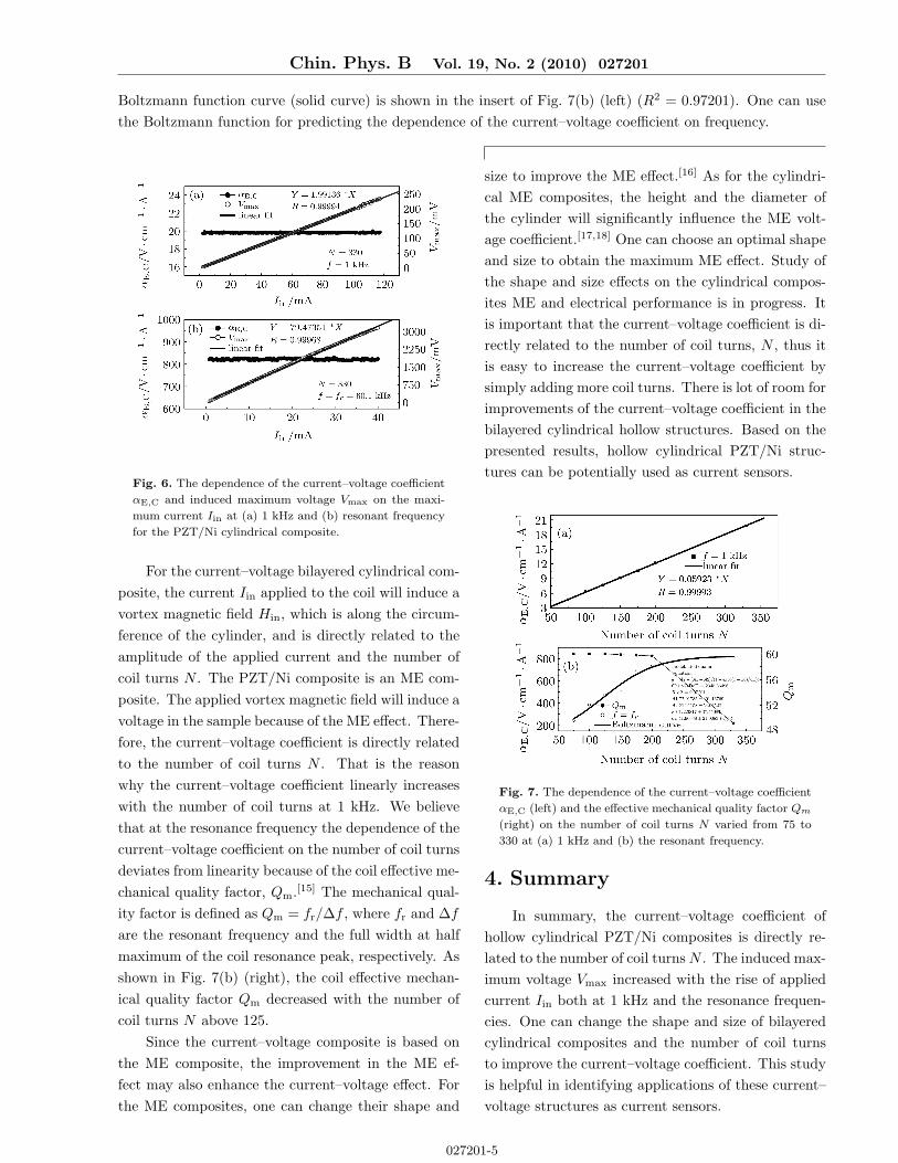
Figure 7 shows the current–voltage coefficient αE,C as a function of the number of coil turns N varied from
75 to 330 at 1 kHz and the resonance frequency, respectively. The current–voltage coefficient increased linearly
with the number of coil turns at 1 kHz applied current frequency (R = 0.9993), as shown in Fig. 7(a), due to
the higher applied magnetic field, which increases with the number of coil turns.
At the resonant frequency, the current–voltage coefficient also increased with the number of coil turns, but
did not exhibit linearity. The Boltzmann function was used and provided a better fit. The equation of the fitted
027201-4
Chin. Phys. B Vol. 19, No. 2 (2010) 027201
Boltzmann function curve (solid curve) is shown in the insert of Fig. 7(b) (left) (R2 = 0.97201). One can use
the Boltzmann function for predicting the dependence of the current–voltage coefficient on frequency.
Fig. 6. The dependence of the current–voltage coefficient
αE,C and induced maximum voltage Vmax on the maxi-
mum current Iin at (a) 1 kHz and (b) resonant frequency
for the PZT/Ni cylindrical composite.
For the current–voltage bilayered cylindrical com-
posite, the current Iin applied to the coil will induce a
vortex magnetic field Hin, which is along the circum-
ference of the cylinder, and is directly related to the
amplitude of the applied current and the number of
coil turns N . The PZT/Ni composite is an ME com-
posite. The applied vortex magnetic field will induce a
voltage in the sample because of the ME effect. There-
fore, the current–voltage coefficient is directly related
to the number of coil turns N . That is the reason
why the current–voltage coefficient linearly increases
with the number of coil turns at 1 kHz. We believe
that at the resonance frequency the dependence of the
current–voltage coefficient on the number of coil turns
deviates from linearity because of the coil effective me-
chanical quality factor, Qm.[15] The mechanical qual-
ity factor is defined as Qm = fr/∆f , where fr and ∆f
are the resonant frequency and the full width at half
maximum of the coil resonance peak, respectively. As
shown in Fig. 7(b) (right), the coil effective mechan-
ical quality factor Qm decreased with the number of
coil turns N above 125.
Since the current–voltage composite is based on
the ME composite, the improvement in the ME ef-
fect may also enhance the current–voltage effect. For
the ME composites, one can change their shape and
size to improve the ME effect.[16] As for the cylindri-
cal ME composites, the height and the diameter of
the cylinder will significantly influence the ME volt-
age coefficient.[17,18] One can choose an optimal shape
and size to obtain the maximum ME effect. Study of
the shape and size effects on the cylindrical compos-
ites ME and electrical performance is in progress. It
is important that the current–voltage coefficient is di-
rectly related to the number of coil turns, N , thus it
is easy to increase the current–voltage coefficient by
simply adding more coil turns. There is lot of room for
improvements of the current–voltage coefficient in the
bilayered cylindrical hollow structures. Based on the
presented results, hollow cylindrical PZT/Ni struc-
tures can be potentially used as current sensors.
Fig. 7. The dependence of the current–voltage coefficient
αE,C (left) and the effective mechanical quality factor Qm
(right) on the number of coil turns N varied from 75 to
330 at (a) 1 kHz and (b) the resonant frequency.
4. Summary
In summary, the current–voltage coefficient of
hollow cylindrical PZT/Ni composites is directly re-
lated to the number of coil turnsN . The induced max-
imum voltage Vmax increased with the rise of applied
current Iin both at 1 kHz and the resonance frequen-
cies. One can change the shape and size of bilayered
cylindrical composites and the number of coil turns
to improve the current–voltage coefficient. This study
is helpful in identifying applications of these current–
voltage structures as current sensors.
027201-5

Chin. Phys. B Vol. 19, No. 2 (2010) 027201
References
[1] Cai N, Zhai J Y, Shi Z, Lin Y H and Nan C W 2004 Chin.
Phys. 13 1348
[2] Zhai J, Dong S, Xing Z, Li J and Vieland D 2007 Appl.
Phys. Lett. 91 123513
[3] Srinvasan G, Tatarenko A S and Bichurin M I 2005 Elec-
tron. Lett. 41 10
[4] Pettiford C, Dasgupta S, Lou J, Yoon S D and Sun N X
2007 IEEE Trans. Mag. 43 3343
[5] Zhou J P, Shi Z, Liu G, He H C and Nan C W 2006 Acta
Phys. Sin. 55 3771 (in Chinese)
[6] Fetisov Y K and Srinivasan G 2006 Appl. Phys. Lett. 88
143503
[7] Zhang Y, Deng C Y, Ma J, Lin Y H and Nan C W 2008
Chin. Phys. B 17 3910
[8] Pan D A, Bai Y, Chu W Y and Qiao L J 2007 Smart.
Mater. Struct. 16 2501
[9] Pan D A, Bai Y, Chu W Y and Qiao L J 2008 J. Phys.:
Condens. Matt. 20 025203
[10] Pan D A, Bai Y, Chu W Y and Qiao L J 2008 J. Phys.
D: Appl. Phys. 41 02200
[11] Pan D A, Bai Y, Volinsky A A, Chu W Y and Qiao L J
2008 Appl. Phys. Lett. 92 052904
[12] Pan D A, Zhang S G, Volinsky A A and Qiao L J 2008 J.
Phys. D: Appl. Phys. 41 195004
[13] Pan D A, Zhang S G, Volinsky A A and Qiao L J 2008 J.
Phys. D: Appl. Phys. 41 205008
[14] ANSI/IEEE Standard on Piezoelectricity 1987
ANSI/IEEE Standard 176 227
[15] Wan J G, Li Z Y, Wang Y, Zeng M, Wang G H and Liu
J M 2005 Appl. Phys. Lett. 86 202504
[16] Pan D A, Zhang S G, Volinsky A A and Qiao L J 2008 J.
Phys. D: Appl. Phys. 41 172003
[17] Graef M D and Beleggia M 2006 J. Magn. Magn. Mater.
305 403
[18] Primdahl F, Brauer P, Merayo J M G and Nielsen O V
2002 Meas. Sci. Technol. 13 1248
027201-6