Cropico DO4A User Manual 154-518 Rev7.indd - Seaward
24
Bracken Hill, South West Industrial Estate, Peterlee, Co. Durham SR8 2SW. England. Tel: +44 (0)191-586 3511 Fax: +44 (0)191-586 0227 www.cropico.co.uk [email protected] Digital Ohmmeter Type DO4A Operating Instructions
-
Upload
khangminh22 -
Category
Documents
-
view
1 -
download
0
Transcript of Cropico DO4A User Manual 154-518 Rev7.indd - Seaward
Bracken Hill, South West Industrial Estate,Peterlee, Co. Durham SR8 2SW. England.Tel: +44 (0)191-586 3511 Fax: +44 (0)191-586 [email protected]
610000 Rev 7
Digital OhmmeterType DO4A Operating Instructions

Digital Ohmmeter Type DO4A Operating Instructions
Limited Warranty & Limitation of LiabilityCROPICO guarantees this product for a period of 1 year. The period of warranty will be effective at the day of delivery.
(c) Copyright 2013All rights reserved. Nothing from this edition may be multiplied, or made public in any form or manner, either electronically, mechanically, by photocopying, recording, or in any manner, without prior written consent from CROPICO. This also applies to accompanying drawings and diagrams.
Due to a policy of continuous development CROPICO reserves the right to alter the equipment specifi cation and description outlined in this publication without prior notice and no part of this publication shall bedeemed to be part of any contract for the equipment unless specifi cally referred to as an inclusion within such contract.
Digital Ohmmeter Type DO4A Operating Instructions
Disposal of Old Product
This product has been designed and manufactured with high quality materials and components that can be recycled and reused.
When the crossed out wheelie bin symbol is attached to a product it means the product is covered by the European Directive 2012/19/EU.
Please familiarise yourself with the appropriate local separate collection system for electrical and electronic products.
Please dispose of this product according to local regulations. Do not dispose of this product along with normal waste material. The correct disposal of this product will help prevent potential negative consequences for the environment and human health.
User Note:These Operating Instructions are intended for the use of Competent Personnel.
Digital Ohmmeter Type DO4A Operating Instructions
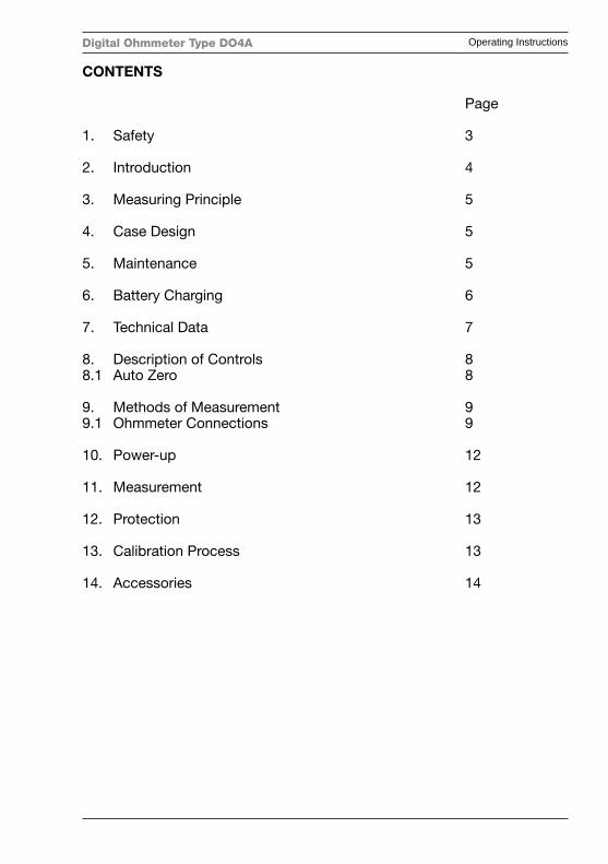
CONTENTS
Page
1. Safety 3
2. Introduction 4
3. Measuring Principle 5
4. Case Design 5
5. Maintenance 5
6. Battery Charging 6
7. Technical Data 7
8. Description of Controls 88.1 Auto Zero 8
9. Methods of Measurement 99.1 Ohmmeter Connections 9
10. Power-up 12
11. Measurement 12
12. Protection 13
13. Calibration Process 13
14. Accessories 14
Digital Ohmmeter Type DO4A Operating Instructions
3
IMPORTANT NOTE
====================
Instruments are delivered ready for immediate use; no extras are required.
Supplied Accessories: One set of test leads One mains cord One copy of Operating Instructions (English)
When unpacked, inspect for physical damage and report any defectsimmediately in writing, retaining packaging materials for inspection. Beforeplacing into service, ensure mains voltage is correct, instruments are normallysupplied for 240V 50Hz. Other voltages may also be selected according tothe chart in section 5, (Maintenance). Be sure to also change the fuse to thecorrect type.
1. Safety
Digital Ohmmeter type D04A is designated Safety Class I as defi ned in theEN61010.
This apparatus has been designed and tested in accordance with EN61010,Safety Requirements for Electronic Measuring Apparatus, and has beensupplied in a safe condition. The present instruction manual contains someinformation and warnings that have to be followed by the user to ensure safeoperation and to retain the apparatus in safe condition.
If this apparatus is to be connected to a fi xed installation, before any otherconnection is made, the protective earth terminal shall be connected to aprotective conductor.
Before switching on the apparatus, make sure that it is set to the voltage of thepower supply. The mains plug shall only be inserted in a socket outletprovided with protective earth contact. The protective action must not benegated by the use of an extension lead without a protective conductor.
Digital Ohmmeter Type DO4A Operating Instructions
4
WARNING!
Any interruption of the protective conductor inside or outside the apparatus, or disconnection of the protective earth terminal is likely to make the apparatus dangerous. Intentional interruption is prohibited.
When the apparatus is connected to its mains supply, terminals may be live, and the opening of covers or removal of parts (except those to which access can be gained by hand) is likely to expose live parts.
The apparatus shall be disconnected from all voltage sources before it is opened for any adjustment, replacement maintenance or repair.
Any adjustment, maintenance and repair of the opened apparatus under voltage shall be avoided as far as possible, and, if inevitable, shall be carried out only by a skilled person who is aware of the hazard involved.
Make sure that only fuses with the required rate current and of the specifi ed type are used for replacement. The use of makeshift fuses, and the short-circuiting of fuse holders are prohibited.
Whenever it is likely that the protection has been impaired, the apparatus shall be made inoperative and be secured against any unintended operation and returned to our factory or Agent for rectifi cation.
2. Introduction
The DO4A is an accurate bench/portable digital ohmmeter for the measurement of resistance in the range 10µΩ to 4000Ω. It offers you the four terminal resistance measurement method to eliminate the effect of lead resistance. The measured values are displayed on a 4 digit LCD display; an overfl ow of the selected range is also indicated.
Display range 4000
Simple push button selection of the range required ensures the DO4A may be easily used by unskilled personnel, error and status warnings are illuminated when appropriate. The utmost care has been used to ensure that the ohmmeter will withstand an accidental mains voltage applied to the measuring terminals, but it is not recommended that voltage should be applied.
Digital Ohmmeter Type DO4A Operating Instructions
5
3. Measuring Principle
The measurement is true 4 terminal, using the Kelvin principle. A stable current is produced across the resistance to be measured via the C terminals, and the voltage drop across the Rx is measured at the P terminals. This potential drop is then compared against the voltage drop across internal standards, the ratio of these is then converted to the resistance value of Rx and displayed in ohms on the digital display. High accuracy and long term stability is achieved by using our own manufactured internal resistance standards.
4. Case Design
The case is ruggedly constructed and is a painted aluminium shell with a strong internal sub-frame. The front panel is a reverse printed polycarbonate overlay with clear and unambiguous text. The case is painted anthracite grey, and the tilt handle means that the instrument can be positioned for easy viewing.
5. Maintenance
Normally no maintenance is required other than cleaning with a moist cloth. Avoid aggressive detergents or solvents.
CAUTION: Before any maintenance, repair or exchange of parts or fuses, the instrument must be disconnected from the mains supply and all power sources. In the event of a fault occurring, the instrument should be returned to our factory or Agent. A mains fuse is fi tted to the mains inlet socket on the rear panel, and should be replaced if necessary.
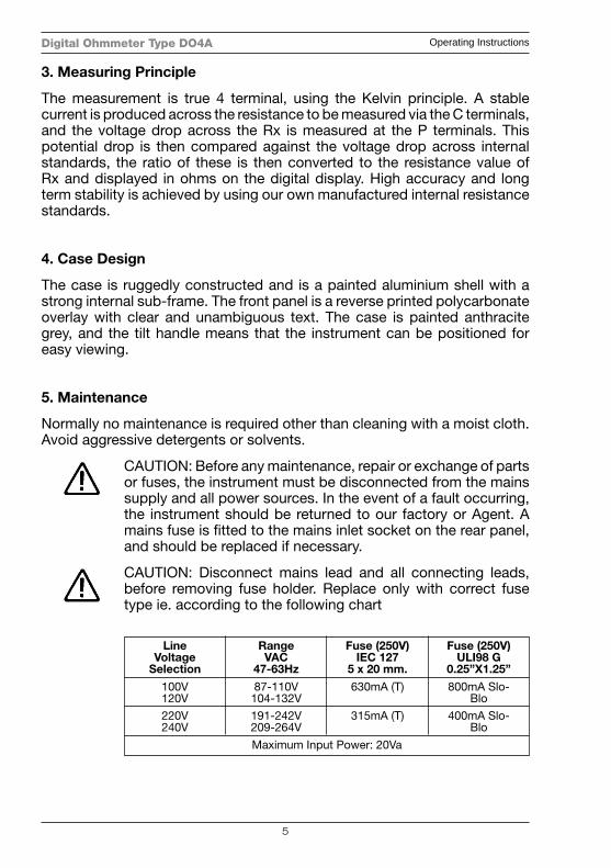
CAUTION: Disconnect mains lead and all connecting leads, before removing fuse holder. Replace only with correct fuse type ie. according to the following chart
LineVoltage
Selection
RangeVAC
47-63Hz
Fuse (250V)IEC 127
5 x 20 mm.
Fuse (250V)ULI98 G
0.25”X1.25”
100V120V
220V240V
87-110V104-132V
191-242V209-264V
Maximum Input Power: 20Va
630mA (T)
315mA (T)
800mA Slo-Blo
400mA Slo-Blo
Digital Ohmmeter Type DO4A Operating Instructions
6
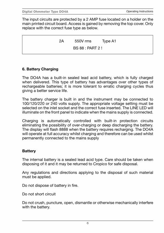
The input circuits are protected by a 2 AMP fuse located on a holder on the main printed circuit board. Access is gained by removing the top cover. Only replace with the correct fuse type as below.
6. Battery Charging
The DO4A has a built-in sealed lead acid battery, which is fully charged when delivered. This type of battery has advantages over other types of rechargeable batteries; it is more tolerant to erratic charging cycles thus giving a better service life.
The battery charger is built in and the instrument may be connected to 100/120/220 or 240 volts supply. The appropriate voltage setting must be selected on the inlet socket and the correct fuse inserted. The LINE LED will illuminate on the front panel to indicate when the mains supply is connected.
Charging is automatically controlled with built-in protection circuits eliminating the possibility of over-charging or deep discharging the battery. The display will fl ash 8888 when the battery requires recharging. The DO4A will operate at full accuracy whilst charging and therefore can be used whilst permanently connected to the mains supply
Battery
The internal battery is a sealed lead acid type. Care should be taken when disposing of it and it may be returned to Cropico for safe disposal.
Any regulations and directions applying to the disposal of such material must be applied.
Do not dispose of battery in fi re.
Do not short circuit
Do not crush, puncture, open, dismantle or otherwise mechanically interfere with the battery.
2A 550V rms Type A1
BS 88 : PART 2 !
Digital Ohmmeter Type DO4A Operating Instructions
7
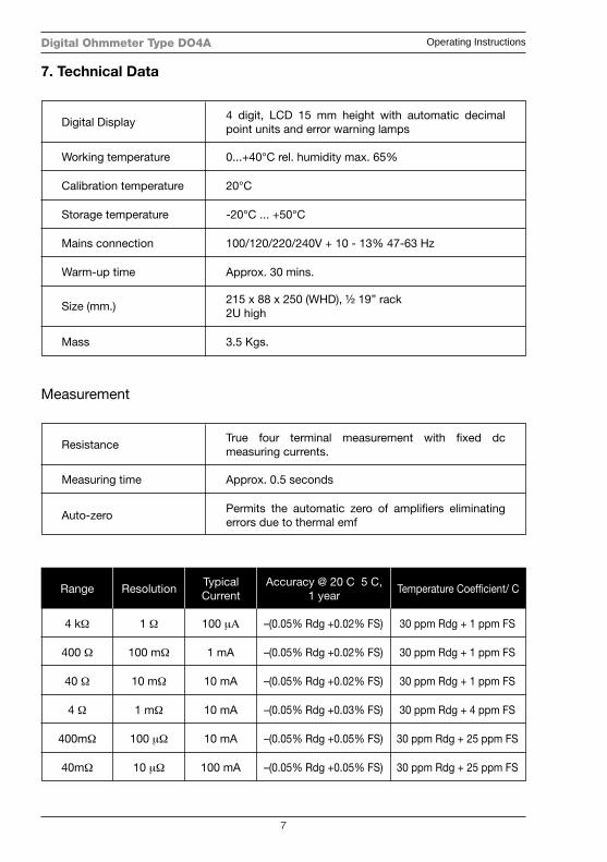
7. Technical Data
4 digit, LCD 15 mm height with automatic decimal point units and error warning lamps
0...+40°C rel. humidity max. 65%
20°C
-20°C ... +50°C
100/120/220/240V + 10 - 13% 47-63 Hz
Approx. 30 mins.
215 x 88 x 250 (WHD), ½ 19” rack2U high
3.5 Kgs.
Digital Display
Working temperature
Calibration temperature
Storage temperature
Mains connection
Warm-up time
Size (mm.)
Mass
Measurement
True four terminal measurement with fi xed dc measuring currents.
Approx. 0.5 seconds
Permits the automatic zero of amplifi ers eliminating errors due to thermal emf
Resistance
Measuring time
Auto-zero
Range
4 kΩ
400 Ω
40 Ω
4 Ω
400mΩ
40mΩ
ResolutionTypicalCurrent
Accuracy @ 20 C 5 C,1 year
Temperature Coeffi cient/ C
1 Ω
100 mΩ
10 mΩ
1 mΩ
100 μΩ
10 μΩ
100 μΑ –(0.05% Rdg +0.02% FS) 30 ppm Rdg + 1 ppm FS
1 mA –(0.05% Rdg +0.02% FS) 30 ppm Rdg + 1 ppm FS
10 mA –(0.05% Rdg +0.02% FS) 30 ppm Rdg + 1 ppm FS
10 mA –(0.05% Rdg +0.03% FS) 30 ppm Rdg + 4 ppm FS
10 mA –(0.05% Rdg +0.05% FS) 30 ppm Rdg + 25 ppm FS
100 mA –(0.05% Rdg +0.05% FS) 30 ppm Rdg + 25 ppm FS
Digital Ohmmeter Type DO4A Operating Instructions
8
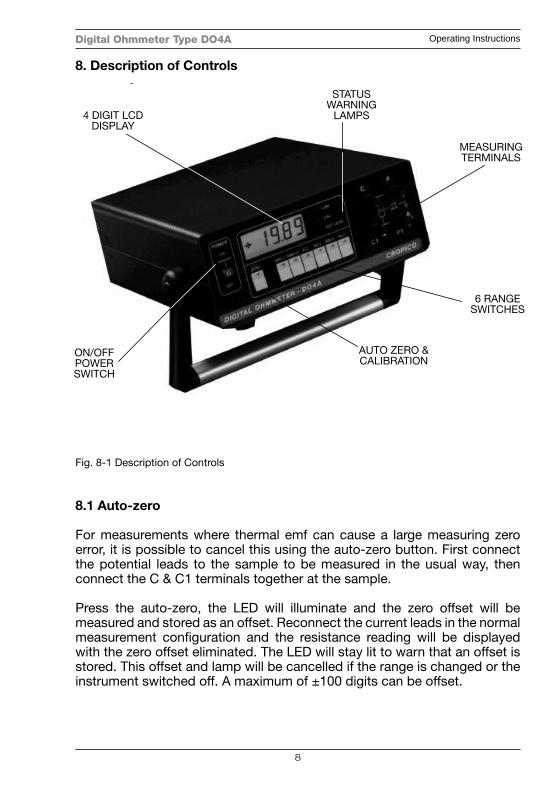
Fig. 8-1 Description of Controls
8.1 Auto-zero
For measurements where thermal emf can cause a large measuring zero error, it is possible to cancel this using the auto-zero button. First connect the potential leads to the sample to be measured in the usual way, then connect the C & C1 terminals together at the sample.
Press the auto-zero, the LED will illuminate and the zero offset will be measured and stored as an offset. Reconnect the current leads in the normal measurement confi guration and the resistance reading will be displayed with the zero offset eliminated. The LED will stay lit to warn that an offset is stored. This offset and lamp will be cancelled if the range is changed or the instrument switched off. A maximum of ±100 digits can be offset.
8. Description of Controls
4 DIGIT LCD DISPLAY
ON/OFF POWER SWITCH
STATUS WARNING
LAMPS
AUTO ZERO & CALIBRATION
p
4 DIGIT LCD DISPLAY
ON/OFF POWER SWITCH
STATUS WARNING
LAMPS
MEASURING TERMINALS
6 RANGE SWITCHES
AUTO ZERO & CALIBRATION
ON/OFFPOWERSWITCH
6 RANGESWITCHES
AUTO ZERO &CALIBRATION
MEASURINGTERMINALS
STATUSWARNING
LAMPS4 DIGIT LCDDISPLAY
Digital Ohmmeter Type DO4A Operating Instructions
9
Range Selection:
The 6 ranges may be selected manually by simply pressing the desired range button. The selected range will be indicated by an LED; over-range will be indicated by the display reading - - - -.
Error & Status Lamps
These LEDs will light to indicate the instrument status.
LINE : Mains supply is connected to the instrument.
CAL : Calibration mode has been initialised by the rear key switch and the instrument is in calibration mode.
O/C LEAD : One of the measuring leads is open circuit, to high resistance, or not connected to test sample correctly. The internal protection fuse is open circuit.
9. Methods of Measurement
9.1 Ohmmeter Connections
The Digital Ohmmeter type DO4A employs a four-wire method of measurement, ie. it is necessary to make four connections to the resistor under test. The instrument is supplied with four leads; two for the potential connections which are made across the test resistor at the points between which the resistance is to be determined, and two for the current connections which connects the test resistor to the supply circuit.
a) Connect the black leads to the C1 and P1 terminals, and the red leads to terminals C and P. It is immaterial which leads of the pair goes to the P or C terminals.
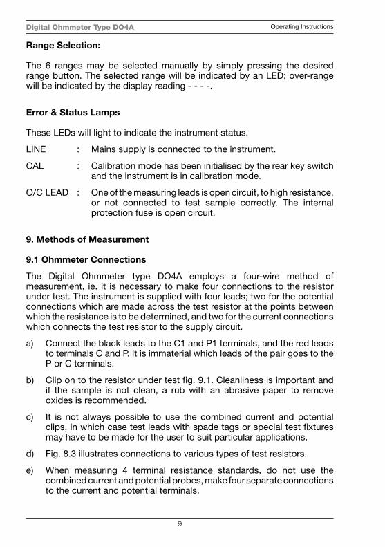
b) Clip on to the resistor under test fi g. 9.1. Cleanliness is important and if the sample is not clean, a rub with an abrasive paper to remove oxides is recommended.
c) It is not always possible to use the combined current and potential clips, in which case test leads with spade tags or special test fi xtures may have to be made for the user to suit particular applications.
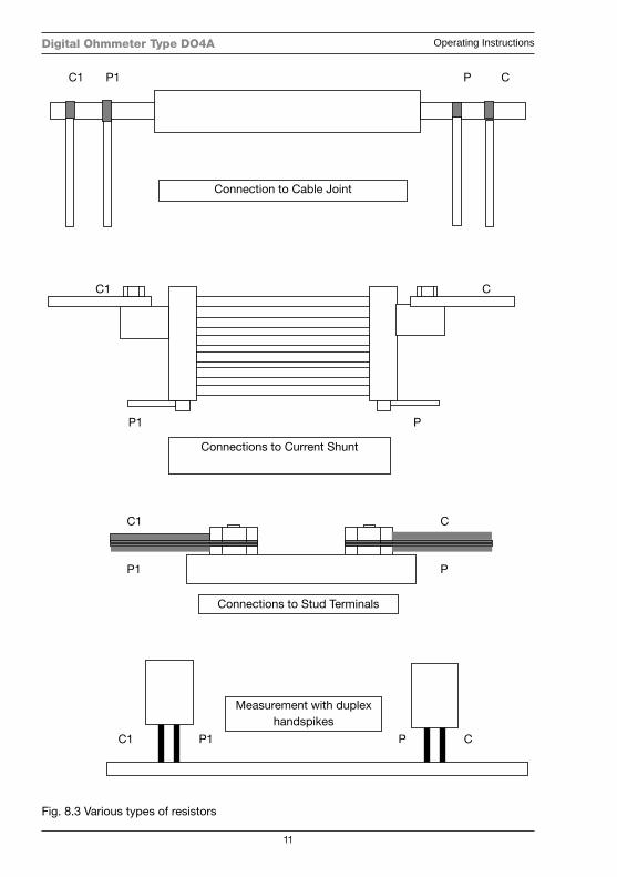
d) Fig. 8.3 illustrates connections to various types of test resistors.
e) When measuring 4 terminal resistance standards, do not use the combined current and potential probes, make four separate connections to the current and potential terminals.
Digital Ohmmeter Type DO4A Operating Instructions
10
Fig. 8.2 Combined current and potential probes
Digital Ohmmeter Type DO4A Operating Instructions
11
C1 C
P1 P Connections to Current Shunt
Connection to Cable Joint
C1 P1 P C
Measurement with duplex handspikes
C1 C
P1 P
Connections to Stud Terminals
Fig. 8.3 Various types of resistors
Measurement with duplexhandspikes
Connections to Stud Terminals
Connections to Current Shunt
Connection to Cable Joint
C1 P1 P C
C1 P1 P C
C1
P1
C
P
C1 C
P1 P

Digital Ohmmeter Type DO4A Operating Instructions
12
10. Power Up
When the DO4A is fi rst switched on, a lamp test is automatically performed, all display segments are illuminated followed by each LED lighting in sequence. The microprocessor checks for correct internal operation and indicates “P” if all tests pass O.K. At the same time the software version will be displayed and held for approximately 2 seconds. The display will typically read “P 1.1”. Should the internal checks indicate an error, then the display will read “HELP”. To rectify this, see section 13.
The DO4A will perform an automatic zero sequence and fi nally sets to the following default start up mode ready for use. The measuring range 4KΩ selected, auto-zero lamp out.
11. Measurement
Connect the resistance to be measured (Rx) to the measuring terminals in accordance with the diagram on the instrument panel. Select the range required. The green LED lamp will light to indicate which buttons are active.
CAUTION: Do not auto-zero when Rx is connected for measurement. This will store a large offset made up of resistance and thermal emf and displayed values will be invalid.
If, during measurement, any of the error messages should be displayed, then obviously the appropriate action should be taken. Whilst the input is protected against accidental application of mains voltage, single or 3-phase, care should be taken to avoid measuring on live circuits.
Over-range
The display will indicate - - - -.
Open Circuit Lead
O/C Lead will be displayed if the instrument detects that the lead resistance is too high. The C terminals are checked for compliance voltage. Measurement should not be made if this warning message is displayed. This warning will also be displayed if the internal protection fuse is open circuit.
Digital Ohmmeter Type DO4A Operating Instructions
13
Connections
When making good quality measurements, it is important to ensure that all measuring leads are in good condition, and less than 0.2 ohms resistance.
It should also be noted that some spade tags and crocodile clips can produce high thermal emfs when warmed, particularly nickel-plated brass types. This can cause problems when, for example, connecting too hot motor windings. The solution is to use plain copper or brass connections keeping them clean and oxide free.
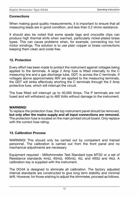
12. Protection
Every effort has been made to protect the instrument against voltages being applied to the terminals. A large 2 Amp fuse is fi tted internally to the C measuring line and a gas discharge tube, GDT, is across the C terminals. If voltages above approximately 90V are applied to the measuring terminals, the GDT will strike effectively shorting the C terminals through the 2 Amp protective fuse, which will interrupt the circuit.
The fuse fi tted will interrupt up to 40,000 Amps. The P terminals are not fused and will withstand up to 460 Volts without damage to the instrument.
WARNING!To replace the protection fuse, the top instrument panel should be removed, but only after the mains supply and all input connections are removed. The protection fuse is located on the main printed circuit board. Only replace with the correct fuse rating.
13. Calibration Process
WARNING! This should only be carried out by competent and trained personnel. The calibration is carried out from the front panel and no mechanical adjustments are necessary.
Equipment required - Milliohmmeter Test Standard type MTS2 or a set of Resistance standards 4mΩ, 40mΩ, 400mΩ, 4Ω, and 400Ω and 4kΩ. A calibration key is supplied with the instrument.
The DO4A is designed to eliminate all calibration. The factory adjusted internal standards are constructed to give long term stability and minimal drift. However, for those wishing to adjust the ohmmeter, proceed as follows.
Digital Ohmmeter Type DO4A Operating Instructions
14
The ohmmeter should be placed in a temperature controlled environment for at least 2 hours before calibration.
Select the 4mΩ range and connect a 4 milliohm Standard. This Standard should be within 0.01% or better of the nominal value. Press the CAL button and the DO4A will automatically measure the standard and store any calibration offsets.
With the Standard still connected, remove the C lead from the resistance and connect it to the C1 terminal. This effectively gives a zero value; press CAL again and the zero error is stored. Select the next range and appropriate full scale Standard and repeat the above procedure. All ranges should be calibrated in this way, ie. for both full scale and zero, the key being turned back to the run position and removed on completion.
NOTE: Should the calibration constants be corrupted, then the display will indicate HELP. To re-initialise the calibration memory, turn the calibration key to the CAL position, remove the top cover and press the red reset button on the main PCB. The instrument should be switched on, but the mains power supply MUST BE DISCONNECTED before removing the top cover.
After resetting the instrument, the full calibration procedure must be fully implemented to return the instrument to its full accuracy.
Repeated corruption of the memory and display of the HELP error essage indicates a malfunction of the instrument, which should be returned to our Service facility for rectifi cation.
A comprehensive repair and calibration service is available at our factory. When returning instruments, please ensure adequate packing to avoid damage in transit.
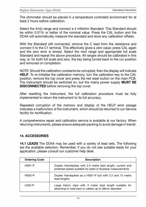
14. ACCESSORIES
14.1 LEADS The DO4A may be used with a variety of lead sets. The following are the available selection. Remember, if you do not see suitable leads for your application, please consult our customer help desk.
Description
Duplex Handspikes with 2.5 metre lead length, current and potential spikes suitable for plate or Bussbar measurements
Duplex Handspikes as a HS01-P but with 2.5 and 15 metre lead lengths
Large Kelvin clips with 3 metre lead length suitable for attaching to rods bars or cables up to 38mm diameter
Ordering Code
HS01-P
HS02-P
LS03-P
Digital Ohmmeter Type DO4A Operating Instructions
15
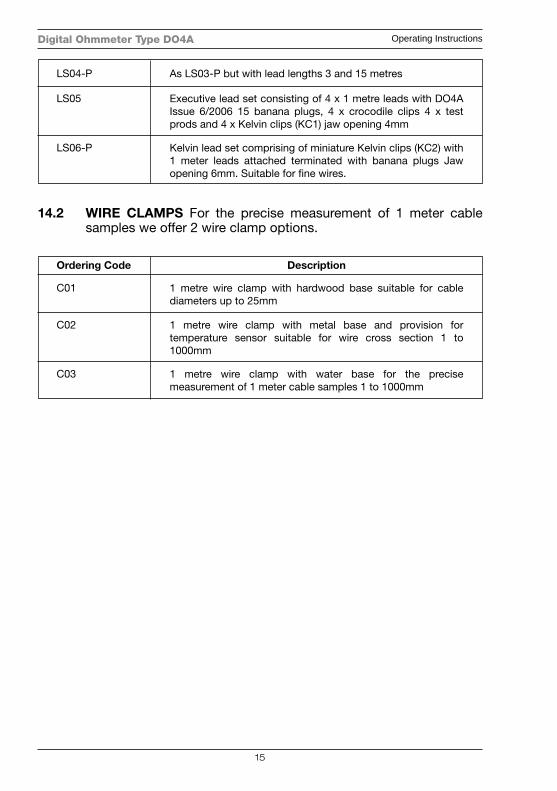
14.2 WIRE CLAMPS For the precise measurement of 1 meter cable samples we offer 2 wire clamp options.
Description
1 metre wire clamp with hardwood base suitable for cable diameters up to 25mm
1 metre wire clamp with metal base and provision for temperature sensor suitable for wire cross section 1 to 1000mm
1 metre wire clamp with water base for the precise measurement of 1 meter cable samples 1 to 1000mm
Ordering Code
C01
C02
C03
As LS03-P but with lead lengths 3 and 15 metres
Executive lead set consisting of 4 x 1 metre leads with DO4A Issue 6/2006 15 banana plugs, 4 x crocodile clips 4 x test prods and 4 x Kelvin clips (KC1) jaw opening 4mm
Kelvin lead set comprising of miniature Kelvin clips (KC2) with 1 meter leads attached terminated with banana plugs Jaw opening 6mm. Suitable for fi ne wires.
LS04-P
LS05
LS06-P
Digital Ohmmeter Type DO4A Operating Instructions
16
CE Declaration of Conformity
Manufactured by:
Seaward Electronic Ltd, Bracken Hill, South West Industrial EstatePeterlee, County Durham, SR8 2SW, England
Statement of ConformityAs the manufacturer of the apparatus listed, declare under our sole responsibility that the product:
Cropico DO4A Ohmmeter
To which the declaration relates are in conformity with the relevant clauses of the following standard(s):
BS EN61010-1:2010Safety requirements for electrical equipment for measurement, control, and laboratory use - Part 1: General requirements.
BS EN61010-2-030:2010Safety requirements for electrical equipment for measurement, control, and laboratory use - Part 2-030: Particular requirements for testing andmeasuring circuits.
BS EN61326-1:2013Electrical equipment for measurement, control and laboratory use - EMC requirements - Part 1: General requirements.
Performance: The instrument operates within specifi cation when used under the conditions in the above EMC and Safety Standards.
The product identifi ed above conforms to the requirements of Council Directive 2004/108/EC and 2006/95/EC.
This Conformity is indicated by the symbol , i.e. “Conformité Européenne”
Seaward Electronic Ltd. is registered under BS EN ISO9001:2000Certifi cate No.: Q05356.

Digital Ohmmeter Type DO4A Operating Instructions
17
For Technical Support Contact:
Tel: +44 (0) 191 587 8718
For Service and Calibration Contact:
Service DepartmentSeaward GroupUnit 11Bracken HillSouth West Industrial EstatePeterleeCo DurhamSR8 2LSEngland
Tel: +44 (0) 191 587 8739Fax: +44 (0) 191 587 8737E-mail: [email protected]
CROPICO is a division of
Digital Ohmmeter Type DO4A Operating Instructions
18
Additional Products From Cropico
DIGITAL OHMMETERS
RESISTANCE BRIDGES
RESISTANCE DECADE BOXES
RESISTANCE STANDARDS
DIGITAL THERMOMETERS
THERMOCOUPLE SIMULATORS
INSULATION TEST SETS
PT100 SIMULATORS
UNIVERSAL CALIBRATORS
HIPOT TESTERS
ELECTRICAL SAFETY TESTERS
Phone, fax or e-mail for further information on the above or for a copy of our general catalogue: - Phone: - +44 (0) 191 5863511
Fax: - +44 (0) 191 5860227E-mail:- [email protected]: - www.cropico.com
Digital Ohmmeter Type DO4A Operating Instructions
19


Bracken Hill, South West Industrial Estate,Peterlee, Co. Durham SR8 2SW. England.Tel: +44 (0)191-586 3511 Fax: +44 (0)191-586 [email protected]
610000 Rev 7
Digital OhmmeterType DO4A Operating Instructions