Artkl 1.indd
18
1 Journal of Mechanical Engineering ISSN 1823-5514 © 2015 Faculty of Mechanical Engineering, Universiti Teknologi MARA (UiTM), Malaysia. Vol. 12, No. 1, 1-17, 2015 Investigation on Heat Transfer Characteristics of Ceramic Coated Piston Crown for a CNGDI Engines Helmisyah Ahmad Jalaludin Faculty of Mechanical Engineering, Universiti Teknologi MARA Malaysia Bukit Besi Campus 23200 Bukit Besi, Terengganu, Malaysia Email: [email protected] ABSTRACT High temperature and pressure produced in an engine of compressed natural gas with direct injection system (CNGDI) may lead to high thermal stresses. With less proper heat transfer, the piston crown material fails to withstand high temperature and operate effectively. By insulating the surface namely; thermal barrier coating (TBC) such as ceramic based yttria partially stabilised zirconia (YPSZ), heat transfer to the piston might be reduced and lead to improvement of piston durability. Hence, in this research, YPSZ coating was utilised to differentiate between the uncoated and conventional tin−coated piston crowns in terms of the ability to reduce thermal stresses on the piston. Several samples of AC8A aluminium alloy piston crowns were coated with bonding element of NiCrAl and ZrO2−7.5Y2O3 namely the YPSZ as the top coat by using plasma spraying technique. The coating surfaces were assessed on their microstructure, surface roughness, hardness, and burner rig test. The rig test showed that a better performance of the YPSZ/NiCrAl coating could withstand the tests. The burner rig test exhibited a higher temperature difference of the YPSZ/NiCrAl coated piston crown than the other piston crowns. The heat flux for the YPSZ/ NiCrAl−coated piston crown was about 98% reduction compared to the uncoated piston crown. Keywords: Burner rig test, compressed natural gas direct injection, piston crown, plasma spraying, thermal barrier coating Artkl 1.indd 1 Artkl 1.indd 1 03/08/2015 10:27:22 03/08/2015 10:27:22
-
Upload
khangminh22 -
Category
Documents
-
view
0 -
download
0
Transcript of Artkl 1.indd

1
Journal of Mechanical Engineering
ISSN 1823-5514© 2015 Faculty of Mechanical Engineering, Universiti Teknologi MARA (UiTM), Malaysia.
Vol. 12, No. 1, 1-17, 2015
Investigation on Heat Transfer Characteristics of Ceramic Coated Piston Crown for a CNGDI Engines
Helmisyah Ahmad JalaludinFaculty of Mechanical Engineering,
Universiti Teknologi MARA MalaysiaBukit Besi Campus
23200 Bukit Besi, Terengganu, MalaysiaEmail: [email protected]
ABSTRACT
High temperature and pressure produced in an engine of compressed natural gas with direct injection system (CNGDI) may lead to high thermal stresses. With less proper heat transfer, the piston crown material fails to withstand high temperature and operate effectively. By insulating the surface namely; thermal barrier coating (TBC) such as ceramic based yttria partially stabilised zirconia (YPSZ), heat transfer to the piston might be reduced and lead to improvement of piston durability. Hence, in this research, YPSZ coating was utilised to differentiate between the uncoated and conventional tin−coated piston crowns in terms of the ability to reduce thermal stresses on the piston. Several samples of AC8A aluminium alloy piston crowns were coated with bonding element of NiCrAl and ZrO2−7.5Y2O3 namely the YPSZ as the top coat by using plasma spraying technique. The coating surfaces were assessed on their microstructure, surface roughness, hardness, and burner rig test. The rig test showed that a better performance of the YPSZ/NiCrAl coating could withstand the tests. The burner rig test exhibited a higher temperature difference of the YPSZ/NiCrAl coated piston crown than the other piston crowns. The heat fl ux for the YPSZ/NiCrAl−coated piston crown was about 98% reduction compared to the uncoated piston crown.
Keywords: Burner rig test, compressed natural gas direct injection, piston crown, plasma spraying, thermal barrier coating
Artkl 1.indd 1Artkl 1.indd 1 03/08/2015 10:27:2203/08/2015 10:27:22

2
Journal of Mechanical Engineering
Introduction
Alternative gaseous fuels like natural gas have higher octane levels than gasoline which allows the engine to operate at higher compression’s levels resulted in higher thermal effi ciency [1]. However, these fuels have very low lubrication, causing increased wear of fuel components such as fuel injectors and valves [2]-[4]. Due to the exposure of high temperature and pressure in high compression engine, it may affect the durability of parts, mainly the piston crown [5, 6]. A research on damage mechanisms of piston showed that different origins might occurred which mainly involved wear, temperature, and fatigue [7]-[9]. Since internal combustion engine with high effi ciency has a tendency to operate at higher temperatures, the heat resisting properties of piston have become an important issue and the demand for a better piston for internal combustion (IC) engine increases particularly in diesel engine pistons for higher heat resistance.
The use of all of available surface modifi cation technologies will be the most crucial method to expand the use of piston especially the aluminium alloy piston for automotive vehicles which need tin (Sn) or iron plating to prevent micro−welding with piston rings and to get enough wear durability as well as to improve the lubrication performance which could absorb more oil to lower the friction level between the piston and cylinder liner [10]. However, since the tin coating is mostly useful for corrosion resistance, its characteristic against high temperature should be reconsidered. Therefore, the application of thermal barrier coating (TBC) which was widely investigated during 1980’s is better in order to protect the piston crown from the combustion and capable in reducing an in−cylinder heat loss, thus can increase the thermal effi ciency, thermal fatigue protection of underlying metal surfaces, and reduced emission [11]-[13]. Initially, TBC was used to simulate an adiabatic diesel engine and gas turbine by reducing the heat transfer to the engine parts mainly to the piston. Most researchers have analysed the effect of using TBC coating on piston crown of diesel engine experimentally and/or computationally and found that surface temperature of the coated piston was showed lower thermal conductivity [14]-[17]. The majority of researchers have chosen the ceramic based yttria partially stabilised zirconia (YPSZ) as the topcoat TBC which can withstand a temperature higher than 1000oC [11-14, 17].
With low thermal conductivity, high melting point and good resistance against oxidative and a corrosive environment are the required advantages of ceramic coatings applied in energy applications [18, 19]. In a condition without a surface insulation, heat from the combustion was transferred through the piston before going through to the lubricant oil, cylinder liner, and water jacket, due to a temperature gradient. The heat transfer by conduction, per unit area per unit time, q, in a steady state is given by Fourier’s law as shown in Equation (1):
Artkl 1.indd 2Artkl 1.indd 2 03/08/2015 10:27:2903/08/2015 10:27:29

3
Investigation on Heat Transfer Characteristics
Q = − k∇T (1)
where k is the thermal conductivity and ∇T is the temperature gradient. For a steady one-dimensional temperature variation is shown in Equation (2):
qx = Q/A= − kdT/dx (2)
Nuraini et al. [20] used a thermal boundary condition for fi nite element model by assuming that the thermal resistance, R of material layer as reversed proportional to the thermal conductivity. This can be shown in Equation (3),
R = dx/k (3)
However, when piston crown surface is insulated by the ceramic coating, the k value of ceramic is lower which makes the conductance became lower leading to a rejection of heat without going through the piston.
The TBC is applied to the top land of piston to refl ect heat into combustion chamber which would increase the exhaust gas velocity, improving scavenging potential, and extending piston life by decreasing the rate of heat transfer [11]-[19]. One of TBC’s ceramic ZrO2 and ZrO2−based thick and thin fi lms are of widespread interest because of their superior properties such as corrosion, erosion, and oxidation resistance, high hardness, chemical and thermal stability at cryogenic and high temperatures [12],[16],[21]-[22]. Yonushonis [23], the researcher has discovered the delaminating mechanisms in TBC for diesel engine applications through rig tests, structural analysis modelling, non-destructive evaluation, and engine evaluation of various TBCs which resulting in improved TBCs that resist severe cyclic fatigue tests in high output diesel engines and indicated that surface connected porosity and coating surface roughness may infl uence engine fuel economy. Meanwhile, a research done by Chan and Khor [12] on three cylinders SI Daihatsu engine with yttria stabilised zirconia (YSZ) coated piston crown has compared the engine performance. The result exhibited 6% of improvement in fuel economy at low engine power. However, the unburned hydrocarbon concentrations were increased at low engine speed which caused by the porous quenching effect of the rough TBC piston crowns. Several studies about zirconia−based 8Y2O3−ZrO2 and 22MgO−ZrO2 thick TBCs for diesel engine applications show improvement on hot corrosion resistance and mechanical properties of porous TBC coatings. The results on the porosity of the outer layer of the sealed coating decreased in all cases, which led to increased micro hardness values [14]. While a research reported that the Y2O3−ZrO2 based TBC exhibited the highest thermal fatigue resistance which performed by air-plasma spraying compared to the fl ame sprayed one compared to MgZrO based TBC [22].
In this research, AC8A type CamPro pistons with uncoated, tin−coated and the YPSZ/NiCrAl−coated piston crown as well as the YPSZ/NiCrAl coated CNGDI piston crown were used for mechanical test. The experimental works are
Artkl 1.indd 3Artkl 1.indd 3 03/08/2015 10:27:2903/08/2015 10:27:29

4
Journal of Mechanical Engineering
to assess the durability of piston against extreme temperature. Samples of YPSZ/NiCrAl−coated piston crown were prepared using air plasma spraying (APS) to assess its durability by mechanical tests such as microstructure, hardness, surface roughness and burner rig tests.
Sample preparation and deposition worksSeveral of uncoated and tin coated JIS AC8A type aluminium alloy CamPro pistons about 2.5 mm thick with the diameter of 75 mm were prepared and the piston crown areas were cut from the fi rst ring groove. A prototype of CNGDI piston approximately 11.7 mm thick and 75 mm in diameter was used and the crown of CNGDI piston was cut using metal horizontal band saw machine. The surfaces of piston crown samples were grit−blasted to clean and increase the surface roughness, and then, followed by ultrasonic cleaning using ethanol to discard any unnecessary foreign substances.
The samples were coated using air−plasma spraying process at Advanced Materials Research Centre (AMREC) in the Standards and Industrial Research Institute of Malaysia (SIRIM) Berhad, Kedah. The bond coat and topcoat with powder size as in Table 1 were sprayed with spray parameters as shown in Table 2. Two types of piston samples with two different coating conditions were sprayed based on research by Hejwowski and Weronski [13] which are:
1. CamPro and CNGDI piston crown surface coated with thicknesses between 100 to 150 μm of bond coat NiCrAl.
2. CamPro and CNGDI piston crown surface coated with thicknesses between 100 to 150 μm of bond coat NiCrAl and 300 to 350 μm of YPSZ topcoat.
Argon was applied as the primary gas as well as the carrier for both NiCrAl and YPSZ particles into the plasma fl ame. The surface of piston crown was clamped on a jig and was sprayed continuously by automated plasma gun in a distance of 100 mm.
Characterisation and mechanical testSeveral tests were carried out to determine the performance of the TBC application on the CNGDI piston crowns which are the microstructure of coatings, surface
Table 1: Particle sizes of NiCrAl and YPSZ
Bond coat – NiCrAl Top coat – YPSZ (67% Ni, 22% Cr, 10% Al, (91% Zr,7.5% Y, 1% Y) 1.5% HfO2)
Particle 56 μm – 106 μm 20 μm – 100 μm size
Artkl 1.indd 4Artkl 1.indd 4 03/08/2015 10:27:2903/08/2015 10:27:29

5
Investigation on Heat Transfer Characteristics
roughness, and hardness as well as the burner rig test. The samples of plasma sprayed YPSZ (7.5Y2O3−ZrO2)/NiCrAl−coated piston crowns were observed for the surface structure by using a scanning electron microscope (SEM). The YPSZ/NiCrAl−coated samples were cut into small pieces for necessary quantities using a diamond blade at 300 rpm to prevent coating spalling or cracking with the loads of 300 g which provided on handle and connected to the diamond blade for 30 minutes. After that, the samples were washed with acetone to remove water of coolant on samples and were dried with specimen dryer and later with oven venticell at 80oC for 30 minutes before the cross−section of samples were polished with 600 and 1200 type sandpapers. Then, the pieces of polished sample were hardened and mounted in the mixture of epoxy resin and epoxide hardener for metallographic examination. The microstructure images were taken for surfaces of bond coat NiCrAl and topcoat YPSZ, and its cross-sectional view using Vickers Micro-hardness Tester. Analyses of the images were carried out for thickness measurement and fracture analysis.
Perthometer M1 was used to measure surface roughness of the NiCrAl bond coating and the YPSZ topcoat in random area of the surface. Then the averages of the roughness were calculated. The hardness of mounted YPSZ/NiCrAl coated piston crown samples were measured using a Vickers Hardness Tester Model HVS−10 at the polished cross-section surface since it was diffi cult to observe the diamond shape on a white surface of YPSZ/NiCrAl itself. The hardness tests were carried out at loads of 300 g (2.912 N) for 15 seconds randomly on the cross-sectional side for the uncoated piston crown, NiCrAl coated, and YPSZ/NiCrAl coated piston crown.
Table 2: Plasma spray settings for depositing YPSZ and bonding material on al alloy substrate
Conditions Bond coat − Top coat − NiCrAl YPSZ
Current (A) 700 700Voltage (V) 45 45Primary gas pressure: Argon (psi) 50 40Secondary gas pressure: Helium (psi) 50 120Carrier gas pressure: Argon (psi) 30 30Powder feed rate (g/min) 20 35Gun manipulation speed (mm/s) 200 200Stand of distance (mm) 100 100Number of gun pass 2 2Preheat (time) 1 1
Artkl 1.indd 5Artkl 1.indd 5 03/08/2015 10:27:2903/08/2015 10:27:29

6
Journal of Mechanical Engineering
The samples of piston crown were tested on burner test rig to obtain the function of the coating, and the temperature difference between the top surface of the coating and the backside of the piston could be achieved. The top surface of the uncoated piston crown, tin coated, and YPSZ/NiCrAl coated one were fl ame−torched at temperature of 300oC to about 900oC for about 10s in every 100oC increment before the samples melt. However, to control the temperature for desire temperature level, the distance of piston crown sample, lp was moved accordingly until the desire temperature was reached. The length of the fl ame torch from the end of nozzle, lf was approximately 400 mm while the setting distance of the piston crown sample, lp during the direct−burning was in between of 250 mm to 600 mm from the end of nozzle.
Referring to Figure 1, the experimental apparatus was set up where the fl ame source was clamped in front of piston crown sample to have direct heat to the surface of piston crown as the fl ame power was fi xed during the test to get better temperature control. The piston crown sample was clamped in a distance where it just has minimal contact with the fl ame. To record the surface temperature of the piston crown, the K−type (chromel−alumel) probe of digital thermocouples with a temperature range of from −200oC to +1370oC were installed on the surface of piston crown and the backside of piston crown. The combination of acetylene and oxygen was used as heat source for local heating the piston sample which the nozzle of the fl ame was clamped in front of a steel cylinder to cover the long fl ame from wind infl uence, so that the fl ame could be in stable position and could directly heat the surface of piston crown. The amount of acetylene and oxygen were standardised after a long blue fl ame was achieved, so that it could contribute to a high temperature up to 1000oC. Finally, the temperature of top surface and back surface of piston crowns were recorded and the heat fl uxes of each sample were calculated.
Figure 1: Experimental apparatus of burner rig test in horizontal view
Artkl 1.indd 6Artkl 1.indd 6 03/08/2015 10:27:2903/08/2015 10:27:29
7
Investigation on Heat Transfer Characteristics
Results and Discussion
In this research, the target of coating thickness for both top coat of YPSZ and bond coating of NiCrAl were at range of from 300 to 350 μm and from 100 to 150 μm respectively. The obtained results from the plasma sprayed samples showed that the general thickness result for both top coat of YPSZ and bond coating of NiCrAl were at range of from 300 to 340 μm and 100 to 130 μm respectively. The thicknesses were diffi cult to control because too many parameters such as the feed rate or the gas fl ow rate, the distance between plasma torch and the piston crown surface, and others must be changed in order to get the thickness in range of tolerance.
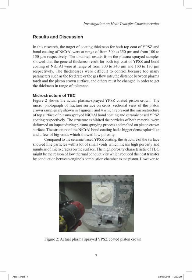
Microstructure of TBCFigure 2 shows the actual plasma-sprayed YPSZ coated piston crown. The micro−photograph of fracture surface on cross−sectional view of the piston crown samples are shown in Figures 3 and 4 which represent the microstructure of top surface of plasma sprayed NiCrAl bond coating and ceramic based YPSZ coating respectively. The structure exhibited the particles of both material were deformed on impact during plasma spraying process and melted on piston crown surface. The structure of the NiCrAl bond coating had a bigger dense splat−like and a few of big voids which showed low porosity.
Compared to the ceramic based YPSZ coating, the structure of the surface showed fi ne particles with a lot of small voids which means high porosity and numbers of micro cracks on the surface. The high porosity characteristic of TBC might be the reason of low thermal conductivity which reduced the heat transfer by conduction between engine’s combustion chamber to the piston. However, to
Figure 2: Actual plasma sprayed YPSZ coated piston crown
Artkl 1.indd 7Artkl 1.indd 7 03/08/2015 10:27:2903/08/2015 10:27:29

8
Journal of Mechanical Engineering
Figure 3: Microstructure of top surface of plasma sprayed NiCrAl
Figure 4: Microstructure of top surface of plasma sprayed YPSZ
Artkl 1.indd 8Artkl 1.indd 8 03/08/2015 10:27:2903/08/2015 10:27:29

9
Investigation on Heat Transfer Characteristics
alleviate stresses arising from thermal expansion mismatch between the YPSZ coating and the underlying metal, microstructure features such as cracks and porosity might contribute to strain tolerance [24].
Figure 5 shows a cross−sectional microphotograph of plasma−sprayed YPSZ−NiCrAl−aluminium alloy. The structure of the top layer of YPSZ ceramic layer exhibited a high porosity and a numbers of small voids and cracks with micro size. High porosity characteristic of YPSZ contributed to brittleness of the structure. This might explain the low thermal conductivity that leads to heat transfer reduction. However, the cracks might be a problem on the lifetime of coating since the materials are low frictional characteristic or low elastic modulus. Meanwhile, the second layer of NiCrAl bond coating showed a splat−like dense structure. Particles of NiCrAl bond coating were deformed on impact during plasma spraying process, and the substrate thereby remains non−melted and the NiCrAl bond coating was observed to form a mechanically bonded or interlock adhesion to the aluminium alloy substrate [25].
Surface roughnessFigure 6 shows the surface roughness of grit−blasted aluminium alloy piston crown, the unpolished bonding material NiCrAl coated piston crown as well as the YPSZ coated piston crown at ten points along the diameter of the piston crown sample. The bonding material NiCrAl coated piston crown exhibited the
Figure 5: Cross−sectional microphotograph of plasma−sprayed YPSZ−NiCrAl−aluminium alloy
Artkl 1.indd 9Artkl 1.indd 9 03/08/2015 10:27:3003/08/2015 10:27:30

10
Journal of Mechanical Engineering
highest value of surface roughness which was in average approximately of 13.0 μm. Compared to the ceramic based YPSZ coated piston crown was the second highest after NiCrAl coated piston crown. The average value of roughness obtained for the sample of YPSZ was 9.2 μm. Meanwhile, the grit−blasted uncoated piston crown exhibited 6.2 μm of average roughness value.
From the results, the NiCrAl bond coating demonstrated its capability in forming a mechanical bond in order to give interlock adhesion between the aluminium alloy substrate and the YPSZ coating. The roughness of the YPSZ coated piston crown was lower than that of the NiCrAl coated piston crown since the particles size range of YPSZ material was lower than the particle size range of NiCrAl material. The sizes were 20−100 μm and 56−106 μm respectively. High porosity characteristic of YPSZ contributed to brittleness of the structure. However, since the YPSZ coating was originally has a role as top coat, the condition of uneven rough surface might contribute to the generation of hotspot. Cooling mechanism might reduce due to the hotspots on sharp edges or uneven geometry of the piston crown [26].
Figure 6: Surface roughness on piston crown for types of material
The thermo−physical properties of ceramic coating and its surface roughness as well as the porous characteristic, whether the porosity or the pore size, had a direct infl uence on unburned or partially burned hydrocarbon through the surface quenching effect at their region in the pores [27, 28]. This means surface roughness has some effects whether in combustion or heat transfer.
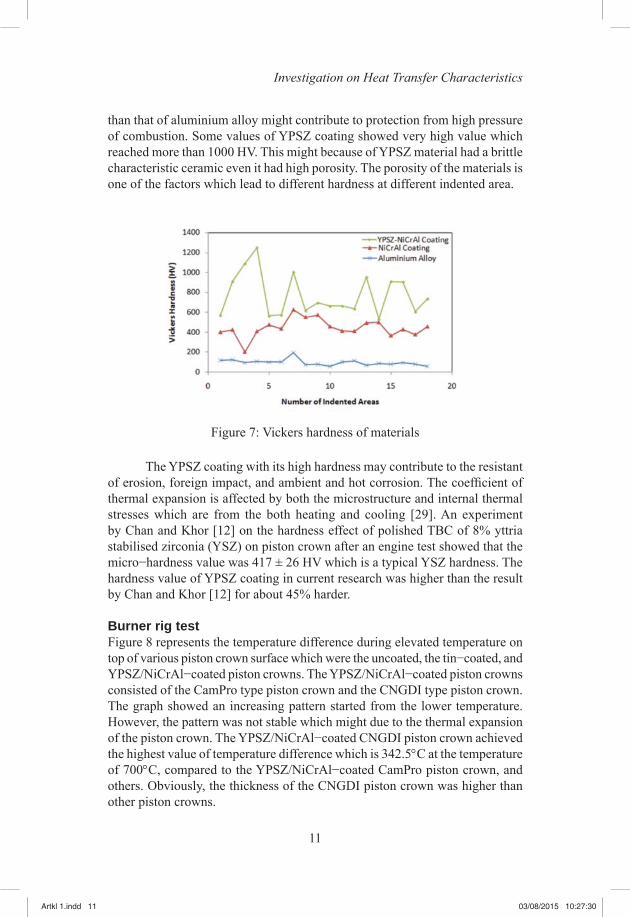
Hardness testFigure 7 shows that the average hardness of the YPSZ/NiCrAl coating was the highest compared to the NiCrAl coating and the uncoated piston crown which were 762.3 HV, 447.5 HV and 98 HV, respectively. Higher hardness of the YPSZ
Artkl 1.indd 10Artkl 1.indd 10 03/08/2015 10:27:3003/08/2015 10:27:30
11
Investigation on Heat Transfer Characteristics
than that of aluminium alloy might contribute to protection from high pressure of combustion. Some values of YPSZ coating showed very high value which reached more than 1000 HV. This might because of YPSZ material had a brittle characteristic ceramic even it had high porosity. The porosity of the materials is one of the factors which lead to different hardness at different indented area.
Figure 7: Vickers hardness of materials
The YPSZ coating with its high hardness may contribute to the resistant of erosion, foreign impact, and ambient and hot corrosion. The coeffi cient of thermal expansion is affected by both the microstructure and internal thermal stresses which are from the both heating and cooling [29]. An experiment by Chan and Khor [12] on the hardness effect of polished TBC of 8% yttria stabilised zirconia (YSZ) on piston crown after an engine test showed that the micro−hardness value was 417 ± 26 HV which is a typical YSZ hardness. The hardness value of YPSZ coating in current research was higher than the result by Chan and Khor [12] for about 45% harder.
Burner rig testFigure 8 represents the temperature difference during elevated temperature on top of various piston crown surface which were the uncoated, the tin−coated, and YPSZ/NiCrAl−coated piston crowns. The YPSZ/NiCrAl−coated piston crowns consisted of the CamPro type piston crown and the CNGDI type piston crown. The graph showed an increasing pattern started from the lower temperature. However, the pattern was not stable which might due to the thermal expansion of the piston crown. The YPSZ/NiCrAl−coated CNGDI piston crown achieved the highest value of temperature difference which is 342.5°C at the temperature of 700°C, compared to the YPSZ/NiCrAl−coated CamPro piston crown, and others. Obviously, the thickness of the CNGDI piston crown was higher than other piston crowns.
Artkl 1.indd 11Artkl 1.indd 11 03/08/2015 10:27:3003/08/2015 10:27:30

12
Journal of Mechanical Engineering
The graph pattern of the YPSZ/NiCrAl−coated CNGDI piston crown showed the gradual increment along with increasing temperature of piston crown top surface which might prove that the heat was distributed uniformly on the coating surface and through the piston crown. Considering the types of coating, both of the YPSZ/NiCrAl−coated pistons recorded the highest temperature difference compared to others. The function of low thermal conductivity of TBC was clearly proved since the heat from top surface of piston crown having resistance to transfer through piston crown material and the presence of different coating materials results on temperature difference.
Figure 8: Temperature difference of piston crowns during elevated temperature
The uncoated aluminium alloy piston crown had a trend of the lowest temperature difference value which was 219.4°C at 700°C, and this showed that the increment of temperature difference compared to the YPSZ/NiCrAl−coated CamPro piston crown was about 51%. Since there was no coating on top of the piston crown surface, the heat was allowed to transfer through the aluminium alloy made piston crown. The uncoated piston crown started to melt during at 700°C as the melting point of the material was at approximately 660°C. A problem was occurred during the burner rig test which was the diffi culties in measuring temperature since it was troublesome to stabilise the surface temperature [30].
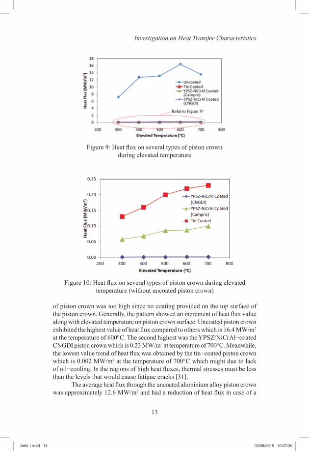
Figure 9 shows the heat fl uxes calculated on piston crown for the uncoated, tin−coated, YPSZ/NiCrAl−coated CamPro piston crown, as well as the YPSZ/NiCrAl−coated CNGDI piston crown at elevated temperature on top of piston crown surface. However, it shows the data at the lower part of the graph in Figure 10 since the gap between uncoated piston crown and the other types
Artkl 1.indd 12Artkl 1.indd 12 03/08/2015 10:27:3003/08/2015 10:27:30
13
Investigation on Heat Transfer Characteristics
of piston crown was too high since no coating provided on the top surface of the piston crown. Generally, the pattern showed an increment of heat fl ux value along with elevated temperature on piston crown surface. Uncoated piston crown exhibited the highest value of heat fl ux compared to others which is 16.4 MW/m2 at the temperature of 600°C. The second highest was the YPSZ/NiCrAl−coated CNGDI piston crown which is 0.23 MW/m2 at temperature of 700°C. Meanwhile, the lowest value trend of heat fl ux was obtained by the tin−coated piston crown which is 0.002 MW/m2 at the temperature of 700°C which might due to lack of oil−cooling. In the regions of high heat fl uxes, thermal stresses must be less than the levels that would cause fatigue cracks [31].
The average heat fl ux through the uncoated aluminium alloy piston crown was approximately 12.6 MW/m2 and had a reduction of heat fl ux in case of a
Figure 10: Heat fl ux on several types of piston crown during elevated temperature (without uncoated piston crown)
Figure 9: Heat fl ux on several types of piston crown during elevated temperature
Artkl 1.indd 13Artkl 1.indd 13 03/08/2015 10:27:3003/08/2015 10:27:30

similar thickness of the YPSZ coated CamPro piston crown which is about 98%. This is a good sign in order to reduce heat localisation on surface of piston crown and give protection to the piston crown from experiencing thermal stress from combustion would then lead to crack initiation. In comparison, in diesel engine with direct system, the combustion contributed to localisation of heat fl ux regions on piston which correlated with coating damage was observed during diesel engine evaluation of TBCs [23]. Silva [8] reported that the bowl rim was the area with higher temperature. The thermal deformations under the temperature at the bowl rim were constrained by surrounding material which causing large compressive stresses and leading to the excess of material yield strength. For this research, further work will be carried out in a real engine operation.
Conclusions
The study shows that by applying a protective low-heat conductive layer such as the Thermal Barrier Coating on engine piston might be one of some solutions in reducing thermal stress during combustion process especially in high temperature surrounding which is over 1000°C. Present study can be concluded as follows:
1. YPSZ has a higher hardness than NiCrAl and aluminium alloy which is 762.3 HV, while NiCrAl has the highest roughness which is 13.0 μm. However, it may have the tendency to crack some conditions.
2. The maximum heat fl ux of YPSZ/NiCrAl coated piston crown was much lower than the uncoated piston crowns which is decreased about 98% due to the existence of lower conductivity of the ceramic coating. This may lead to reduce the thermal stress occurred in piston structure.
Nomenclature
CNGDI compressed natural gas direct injectionTBC thermal barrier coatingYPSZ yttria partially stabilised zirconiaNiCrAl bentoniteYSZ yttria stabilised zirconia APS air plasma sprayingAMREC Advanced Materials Research CentreSIRIM Standards and Industrial Research Institute of Malaysia
Artkl 1.indd 14Artkl 1.indd 14 03/08/2015 10:27:3003/08/2015 10:27:30
15
Investigation on Heat Transfer Characteristics
Acknowledgements
The authors would like to acknowledge the support for this work from Universiti Teknologi Mara (UiTM) through Research Intensive Faculty Grant (09/2012 600-RMI/DANA 5/3/RIF (388/2012)), National University of Malaysia through Research University Grant (UKM-GUP-BTT-07-25-024), and the Ministry of Higher Education (MOHE).
References
[1] J. Kusaka, T. Okamoto, Y. Daisho, R. Kihara and T. Saito. (2000). “Combustion and exhaust gas emission characteristics of a diesel engine dual-fuelled with natural gas,” JSAE Review 21, 489-496.
[2] C.R. Ferguson and A.T. Kirkpatrick. (2001). Internal Combustion Engines, Applied Thermosciences, 2nd ed. (John Wiley & Sons. Inc, 2001).
[3] E. Adril, S. Abdullah, A.K. Ariffi n, A. Muchtar and K. Omar. (2009). “Comparative study of characteristic of lubricant oils in gasoline and compressed natural gas engines,” European Journal of Scientifi c Research 30 (2), 282-293.
[4] S. Abdullah, E. Adril, A. Muchtar and A.K. Ariffi n. (2010). “Friction reduction in compressed natural gas direct injection engine using piston rings with diffusion chromium coating,” Journal of Applied Sciences 10 (6), 462-470.
[5] S. Abdullah, W.H. Kurniawan and A. Shamsudeen. (2008). “Numerical analysis of the combustion process in a compressed natural gas direct injection engine,” Journal of Applied Fluid Mechanics 1 (2), 65-86.
[6] W.H. Kurniawan, S. Abdullah and A. Shamsudeen. (2007). “Turbulence and heat transfer analysis of intake and compression stroke in automotive 4-stroke direct injection engine,” Algerian Journal of Applied Fluid Mechanics 1, 37-50.
[7] Q. Liu, Y. Song, G. Xu and Z. Zhao. (1998). “On the laser quenching of the groove of the piston head in large diesel engines,” Journal of Materials Engineering and Performance 7, 402-406.
[8] F.S. Silva. (2006). “Fatigue on engine pistons – a compendium of case studies,” Engineering Failure Analysis 13, 480-492.
[9] Y. Wang, Y. Liu and H. Shi. (2010). “Simulation and analysis of thermo-mechanical coupling load and mechanical dynamic load for a piston,” International Conference on Computer Modelling and Simulation, 2.
[10] K. Funatani. (2000). “Recent trends in surface modifi cation of light metals,” ASM Heat Treating Society Conference Proceedings 20 (1 & 2), 138-144.
Artkl 1.indd 15Artkl 1.indd 15 03/08/2015 10:27:3003/08/2015 10:27:30
16
Journal of Mechanical Engineering
[11] Z. Mutasim and W. Brentnall. (1997). “Thermal barrier coatings for industrial gas turbine applications: an industrial note,” Journal of Thermal Spray Technology 6 (1), 105-108.
[12] S.H. Chan and K.A. Khor. (2000). “The effect of thermal barrier coated piston crown on engines characteristics,” Journal of Material Engineering and Performance 9 (1), pp. 103-109.
[13] T. Hejwowski and A. Weronski. (2002). “The effect of thermal barrier coating on diesel engine performance,” Surface Engineering, Surface Instrumentation & Vacuum Technology 65, 427-432.
[14] S. Ahmaniemi, J. Tuominen, P. Vuosristo and T. Mantyla. (2002). “Sealing procedures of thick thermal barrier coatings,” Journal of Thermal Spray Technology 11 (3), 320-332.
[15] O. Sarikaya, Y. Islamoglu and E. Celik. (2005). “Finite element modeling of the effect of the ceramic coatings on heat transfer characteristics in thermal barrier applications,” Material and Design 26, 357-362.
[16] E. Buyukkaya. (2008). “Thermal analysis of functionally graded coating alsi alloy and steel pistons,” Surface & Coatings Technology 202, 3856-3865.
[17] A. Tricoire, B. Kjellman, J. Wigren, M. Vanvolsem and L. Aixala. (2009). “Insulated piston heads for diesel engines,” Journal of Thermal Spray Technology 18 (2), 217-222.
[18] A. Uzun, I. Cevik and M. Akcil. (1999). “Effects of thermal barrier coating on a turbocharged diesel engine performance,” Surface and Coatings Technology 116-119, 505-507.
[19] D. Stover and C. Funke. (1999). “Directions of the development of thermal barrier coatings in energy applications,” Journal of Materials processing Technology 92-93, 195-202.
[20] A.A., Nuraini, A.K., Ariffi n, M.N.M., Nor and N. Jamaluddin. (2005). “Finite element analysis of free piston engine structure,” Proceedings of the International Conference on Recent Advances in Mechanical & Materials Engineering.
[21] E. Buyukkaya and M. Cerit. (2007). “Thermal analysis of a ceramic coating diesel engine piston using 3-d fi nite element method,” Surface and Coatings Technology 202, 398-402.
[22] T. Hejwowski. (2010). “Comparative study of thermal barrier coatings for internal combustion engine,” 85, 610-616.
[23] T.M. Yonushonis. (1997). “Overview of thermal barrier coatings in diesel engines,” Journal of Thermal Spray Technology 6 (1), 50-56.
[24] P. Nitin, M. Gell and E.H. Jordan. (2002). “Thermal barrier coatings for gas-turbine engine applications,” Science’s Compass 296, 280-284.
[25] A. Skopp, N. Kelling, M. Woydt and L.-M. Berger. (2007). “Thermally sprayed titanium suboxide coatings for piston ring/cylinder liners under mixed lubrication and dry-running conditions,” Wear 262, 1061-1070.
Artkl 1.indd 16Artkl 1.indd 16 03/08/2015 10:27:3003/08/2015 10:27:30
17
Investigation on Heat Transfer Characteristics
[26] Fluent. (2005). “IC Engine Piston Cooling,” Fluent Application Brief EX240
[27] R.M. Frank and J.B. Heywood. (1991). “ The effect of piston temperature on hydrocarbon emissions from a spark-ignited direct-injection engine,” SAE Paper No. 910558.
[28] J.T. Wentworth. (1992). “More on origins of exhaust hydrocarbon – effects of zero oil consumption, deposition location, and surface roughness,” SAE Paper No. 920939.
[29] Y.D. Huang, N. Hort and K.U. Kainer. (2004). “Thermal behavior of short fi ber reinforced alsi12cumgni piston alloys,” Composites – Part A: Applied Science and Manufacturing 35, 249-263.
[30] R.A. Miller. (1997). “Thermal barrier coatings for aircraft engines: history and directions,” Journal of Thermal Spray Technology 6 (1), 35-42.
[31] J.B. Heywood. (1988). “Internal Combustion Engine Fundamentals,” (International Edition, McGraw-Hill International Editions, 1988).
Artkl 1.indd 17Artkl 1.indd 17 03/08/2015 10:27:3003/08/2015 10:27:30

Artkl 1.indd 18Artkl 1.indd 18 03/08/2015 10:27:3003/08/2015 10:27:30