Coupled analysis of a backfill hydration test
27
* Corresponding to E. E. Alonso, E.T.S. de Ingenieros de Caminos, Canales y Puertos, Technical University of Catalunya, 08034 Barcelona, Spain CCC 0363—9061/98/010001—27$17.50 Received 30 March 1995 ( 1998 by John Wiley & Sons, Ltd. Revised 4 April 1997 INTERNATIONAL JOURNAL FOR NUMERICAL AND ANALYTICAL METHODS IN GEOMECHANICS, VOL. 22, 1— 27 (1998) COUPLED ANALYSIS OF A BACKFILL HYDRATION TEST E. E. ALONSO1*, A. LLORET1, C. H. DELAHAYE1, J. VAUNAT1, A. GENS1 AND G. VOLCKAERT2 1 E.T.S. de Ingenieros de Caminos, Canales y Puertos, Technical University of Catalunya, 08034 Barcelona, Spain 2 SCK-CEN, Boeretang 200, B-2400 Mol. Belgium SUMMARY BACCHUS2 in situ isothermal wetting experiment has been analysed by means of a coupled flow- deformation approach. Backfill material, a mixture of Boom clay powder and high density pellets, has been extensively tested in the laboratory in order to determine its hydraulic and mechanical properties. Para- meters of constitutive equations were derived from this experimental data base. Two mechanical constitutive models have been used in the simulation of the ‘in situ’ experiment: a state surface approach and an elastoplastic model. Calculations have shown several features of the hydration process which help to understand the behaviour of expansive clay barriers. Predictions using both models have been compared with each other and with actual measurement records. This has allowed a discussion of the comparative mertis of both approaches and the identification of some critical parameters of backfill behaviour. Overall agreement between calculations and field measurements is encouraging and shows the potential of the methods developed to model the behaviour of engineered clay barriers in the context of nuclear waste disposal. ( 1998 by John Wiley & Sons, Ltd. Int. J. Numer. Anal. Meth. Geomech., Vol. 22, 1—27 (1998) (No. of Figures: 20 No. of Tables: 2 No. of Refs: 19) Key words: expansive clay; hydromechanics; unsaturated soils; nuclear waste; in situ test 1. INTRODUCTION Compacted clays are adopted as appropriate engineered barriers in design concepts which consider the placement of the nuclear waste canisters in deep geological formation other than salt (clay, marl, granite). Very active clays (bentonites) or compacted mixtures of clay powder and high-density clay pellets have been suggested as suitable materials. Once installed in contact with the (usually saturated) natural host rock these barriers experience: (a) a transient wetting phase governed by the rate of absorption of natural water and (b) a transient temperature regime controlled by the decaying heat power input induced by the canister. The process is complex since parts of the barrier in the proximity of the hot canisters will be initially dried, whereas the outer boundary of the compacted barrier will surely hydrate and expand. The host rock close to the clay buffer will also experience a transient drying—wetting phase as the natural clay first loses water towards the unsaturated compacted fill and later resaturates. Stresses will be controlled by the relatively low initial stress state of the compacted buffer, the development of shrinkage and swelling strains and the stiffness of the backfill and surrounding host rock. Temperature changes
-
Upload
independent -
Category
Documents
-
view
1 -
download
0
Transcript of Coupled analysis of a backfill hydration test

*Corresponding to E. E. Alonso, E.T.S. de Ingenieros de Caminos, Canales y Puertos, Technical University of Catalunya,08034 Barcelona, Spain
CCC 0363—9061/98/010001—27$17.50 Received 30 March 1995( 1998 by John Wiley & Sons, Ltd. Revised 4 April 1997
INTERNATIONAL JOURNAL FOR NUMERICAL AND ANALYTICAL METHODS IN GEOMECHANICS, VOL. 22, 1—27 (1998)
COUPLED ANALYSIS OF A BACKFILL HYDRATION TEST
E. E. ALONSO1*, A. LLORET1, C. H. DELAHAYE1, J. VAUNAT1, A. GENS1 AND G. VOLCKAERT2
1 E.T.S. de Ingenieros de Caminos, Canales y Puertos, Technical University of Catalunya, 08034 Barcelona, Spain2 SCK-CEN, Boeretang 200, B-2400 Mol. Belgium
SUMMARY
BACCHUS2 in situ isothermal wetting experiment has been analysed by means of a coupled flow-deformation approach. Backfill material, a mixture of Boom clay powder and high density pellets, has beenextensively tested in the laboratory in order to determine its hydraulic and mechanical properties. Para-meters of constitutive equations were derived from this experimental data base. Two mechanical constitutivemodels have been used in the simulation of the ‘in situ’ experiment: a state surface approach and anelastoplastic model. Calculations have shown several features of the hydration process which help tounderstand the behaviour of expansive clay barriers. Predictions using both models have been comparedwith each other and with actual measurement records. This has allowed a discussion of the comparativemertis of both approaches and the identification of some critical parameters of backfill behaviour. Overallagreement between calculations and field measurements is encouraging and shows the potential of themethods developed to model the behaviour of engineered clay barriers in the context of nuclear wastedisposal. ( 1998 by John Wiley & Sons, Ltd.
Int. J. Numer. Anal. Meth. Geomech., Vol. 22, 1—27 (1998)(No. of Figures: 20 No. of Tables: 2 No. of Refs: 19)
Key words: expansive clay; hydromechanics; unsaturated soils; nuclear waste; in situ test
1. INTRODUCTION
Compacted clays are adopted as appropriate engineered barriers in design concepts whichconsider the placement of the nuclear waste canisters in deep geological formation other than salt(clay, marl, granite). Very active clays (bentonites) or compacted mixtures of clay powder andhigh-density clay pellets have been suggested as suitable materials. Once installed in contact withthe (usually saturated) natural host rock these barriers experience: (a) a transient wetting phasegoverned by the rate of absorption of natural water and (b) a transient temperature regimecontrolled by the decaying heat power input induced by the canister. The process is complex sinceparts of the barrier in the proximity of the hot canisters will be initially dried, whereas the outerboundary of the compacted barrier will surely hydrate and expand. The host rock close to theclay buffer will also experience a transient drying—wetting phase as the natural clay first loseswater towards the unsaturated compacted fill and later resaturates. Stresses will be controlled bythe relatively low initial stress state of the compacted buffer, the development of shrinkage andswelling strains and the stiffness of the backfill and surrounding host rock. Temperature changes

are also coupled with hydrothermal phenomena in several ways (water vapour transfer is stronglydependent on temperature and it also influences permeability, water retention and mechanicalproperties). In summary, a number of inter-related processes affect the clay buffer and host rock.The time length of this phase and its potential effects in modifying or conditioning some of the keyproperties of the barrier (such as its tightness) are difficult to predict. For this reason a number oflarge-scale ‘in situ’ hydration experiments such as BACCHUS2, performed in the HADESunderground research laboratory located in Mol, Belgium, and excavated in the Miocene plasticBoom clay at 220 m depth, have been carried out. These tests provide useful data for thevalidation of models but, for practical reasons, only a limited period of the hydration process ismonitored. From a basic, fundamental type of view this initial phase is characterized by theunsaturated nature of the compacted clay barrier.
In this paper the coupled hydro-mechanical behaviour of a clay barrier will be analysed inconnection with the BACCHUS2 experiment. In contrast with the previous discussion, no heatsource was used in BACCHUS2 and therefore the analysis reported here is isothermal.
Two alternative mechanical analyses of the in situ test will be presented in the paper. The firstanalysis is based on the concept of state surface as a convenient way to describe clay volumetricdeformations in terms of changes of mean stress and suction. This approach has severallimitations (irreversible and path-dependent effects cannot be modelled and neither the effect ofsuction changes in deviatoric strains, nor the influence of deviatoric stresses on volumetricchanges induced by suction changes are considered). However, it has proved useful to modelcoupled flow and deformation phenomena in swelling and collapsing soils. A computer code(NOSAT) has been developed by the authors within the state surface framework and has beenused in the past in the analysis of earthdams swelling foundations and multilayer barriers.1~3 Inthe second analysis reported, an elastoplastic constitutive law has been adopted to describe themechanical behaviour of the backfill material. The same set of laboratory tests has been used toderive model parameters in both cases. The comparison between the predictions of both modelsand measured results has an added interest which is rarely found in comparison of predictionswith performance.
2. THEORETICAL BASIS
The isothermal flow-deformation problem in an unsaturated soil requires the solution of thefollowing governing equations:
water mass balance
L (o8nS
3)
Lt#div (o
8v8)"0 (1)
air mass balance
LLt
[o!
n (1!S3#H S
3)]#div [o
!(v
!#H v
8)]"0 (2)
equilibrium equations
LLx
j
(pij!d
ijp!)#
Lp!
Lxi
#bi"0 (3)
2 E. E. ALONSO E¹ A¸.
( 1998 by John Wiley & Sons, Ltd.Int. J. Numer. Anal. Meth. Geomech., Vol. 22, 1—27 (1998)

where o8, o
!are mass densities of water and air; v
8and v
!water and air (Darcy) velocities;
n porosity; S3degree of saturation; H Henry’s constant; (p
ij!d
ijp!) net stresses (i.e. the excess of
total stress, pij, over air pressure, p
!).
Note that when suction is zero, air and water pressures become equal and equation (3) becomesthe equilibrium equation in terms of effective stresses. This situation applies, initially, to thesaturated natural clay.
Flow of water and air is assumed to be governed by generalized Darcy’s laws. Permeabilitiesare assumed to vary with suction and void ratio according to
K8(e, S
3)"Ko
8/ (1#A sB ) (4)
K!
(e, S3)"C
c!
k!
[e (1!S3)]D (5)
where Ko8
is the water permeability for saturated conditions, s is the matric suction (s"p!!p
8);
c!specific weight of air; k
!air viscosity; e void ratio and A, B, C, D parameters.
It is also required to specify the water retention characteristics of the soil. The followingvariation of degree of saturation with suction has been adopted in the analysis:4
S3"0·995!E (1!exp (!s F)) (6)
where E, F are constants.In order to describe the mechanical behaviour of unsaturated soils, the authors have developed
two alternative formulations. The first and simpler one focuses on an adequate representation ofthe volumetric3 behaviour of the soil against suction changes. A state surface approximationrelates changes in void ratio with net stress and suction and may be used to formulate a generalcoupled flow-deformation approach.5 A more consistent and general elastoplastic model de-scribes important features of unsaturated soil behaviour such as irreversibility of strains, jointswelling-collapse phenomena and changes in soil strength with suction.6,7
The two approaches will be outlined below.
2.1 State surface approach
A convenient way to formulate the stress—strain relationship under the state surface frameworkis to consider the volumetric strains induced by suction changes as initial thermal-like strains:
dp*ij"D
ijkl(de
kl!de
odkl) (7)
where p*ij"p
ij!d
ijp!
are the net stresses and deo
are the suction-induced volumetric strains.They are given by an empirical expression relating void ratio and changes in net mean stress andsuction. Based on the analysis of several suction controlled experimental programs, the followingequation has been proposed:8
e"d#a log (p!p!)#b log (s#p
!5)#c log (p!p
!) log (s#p
!5) (8)
where a, b, c, d are constants, p the mean total stress and p!5
the atmospheric pressure. For smallchanges of stress and suction linearized expressions may also be suitable:
e"d@#a@ (p!p!)#b@ (s#p
!5)#c@ (p!p
!) (s#p
!5) (9)
COUPLED ANALYSIS OF A BACKFILL HYDRATION TEST 3
( 1998 by John Wiley & Sons, Ltd. Int. J. Numer. Anal. Meth. Geomech., Vol. 22, 1—27 (1998)

In the analysis presented here, coefficients of the matrix D correspond to an isotropic non-linearelastic model defined by a compressibility modulus, K
t, and a shear modulus, G
t. K
tis obtained
directly from (7) or (8) by differentiation:
1
Kt
"
1
1#eo
de
d (p!p!)
(10)
Gtis obtained from K
t, through a constant Poisson’s ratio. This implies that the shear modulus
varies also with the current net mean confining stress in a way similar to Kt.
2.2 Elastoplastic model
Under triaxial stress states (p, q, s) where p is the net mean stress [p"(p1#2 p
3)/3!p
!], q is the
deviatoric stress (q"p1!p
3) and s the matric suction the model postulates a yield function
given by the following family of ellipses:
q2!M2 (p#ps) (p
o!p)"0 (11)
In this equation psis related to the increase in apparent cohesion with suction and is given by
ps"k
ss (12)
and pois the current yield stress for isotropic stress conditions and is related to the applied suction
through
Apo
p#B"Ap*o
p#B(j (o)~i) @ (j (s)~i)
(13)
where p*o, the yield net stress for saturated conditions, is the hardening parameter and j(s) is the
slope of the virgin compression line for isotropic conditions. j(s) is related to suction through
j (s)"j(o) [(1!r) exp (!bs)#r] (14)
In the preceding equation, M, ks, j (o), i, p#, r and b are model parameters. M is the slope of the
critical state line, j (o) is the slope of the virgin compression line for saturated conditions, i is theslope of the (elastic) isotropic unloading—reloading paths and pc is a reference stress. r defines thecompression index at high suctions and b provides the rate of change of j(s) with s.
It is assumed in the model that hardening is controlled by the plastic volumetric strains (de1v)
throughdp*
op*o
"
lj (o)!i
de1v
(15)
where v"1#e is the specific volume.A non-associated flow rule relating shear (de1
q) and volumetric deformations (dep
v) was adopted:
de1q
de1v
"
2qaM2 (2p#p
s!p
o)
(16)
where a is a constant related to M, i and j (o). Volumetric and deviatoric elastic strains induces bystress (p, q) and suction (s) changes inside the yield locus are given by
de%v"
iv
dp
p(17)
4 E. E. ALONSO E¹ A¸.
( 1998 by John Wiley & Sons, Ltd.Int. J. Numer. Anal. Meth. Geomech., Vol. 22, 1—27 (1998)

de%q"
G
3dq (18)
de%s"i
s
ds
s#p!5
(19)
where is
is the compressibility modulus against suction changes and G the constant shearstiffness.
This model reproduces expansive and collapse deformations but has some limitations forhighly expansive materials. A double structure model, which is a modification of the previouslyoutlined framework, is able to reproduce better specific features of behaviour of those materials.9In this paper, however, the basic form of the elastoplastic model will be used in the simulation ofthe ‘in situ’ BACCHUS2 test.
3. DESCRIPTION OF THE BACCHUS2 TEST
The experimental set-up is shown in Figure 1. A bottom steep plate (diameter: 475 mm; thickness50 mm) welded to an instrumented central ram (/"80 mm) was lowered into the bottomof a large diameter shaft (/"490—540 mm) drilled from the floor of the HADES undergroundresearch tunnel located at 220 m depth in overconsolidated Boom clay. The shaft reaches adepth of 14 m below the tunnel and the experiment was installed between 11 and 14 m depth.Once the steel and ram were in place, a 50/50 mixture of Boom clay powder and high-densitypellets industrially compacted by means of rotating tangential wheels to a dry unit weight of(c
$"21 kN/m3) was hand compacted to an average dry density varying between 14 and
16 kN/m3.Figure 1 shows schematically some of the instruments installed to monitor the progressive
hydration of the backfill. Total pressure cell (PT in Figure 1) and piezometers (PW in Figure 1)were installed in flexible steel stands welded to the bottom plate. Piezometers were also installedon the surface of the central ram. This ram was prepared to act as a filter/drain for incomingwater and, alternatively as a water injector. In fact, during the first phase of the test (October1993—November 1994) the fill was hydrated from the natural clay. A second phase started inNovember 1994, in which water was injected through the central ram. This paper refers only tothe first natural hydration phase.
The progress of hydration was monitored by carrying out thermal probe tests. The distributionof temperatures induces by a heat pulse was measured by means of a network of thermocouplesensors installed across the fill. The heat pulse induced by a central probe lasted 5 d and wascarried out at constant electric power (120 W at the beginning of the test when the fill was dry and140 W at the end of the experiment when the backfill was saturated). When the fill was dry themaximum temperature rise varied from 45°C close to the heater to 30—32°C at the interface withthe natural clay. This temperature range changed to 35—30°C when the fill was saturated. Thesetransient temperature changes are believed to induce very small thermo-hydro-mechanicalchanges in the fill. In fact, after the cooling phase readings of the instrumentation (pore water andtotal pressure transducers) remained within the current trend of changes. More details may befound in.10 Back calculated thermal conductivity values at several radial positions have beenconverted into moisture contents and degrees of saturation by means of a correlation obtained inthe laboratory.
COUPLED ANALYSIS OF A BACKFILL HYDRATION TEST 5
( 1998 by John Wiley & Sons, Ltd. Int. J. Numer. Anal. Meth. Geomech., Vol. 22, 1—27 (1998)

Figure 1. BACCHUS2 experiment (Reference 10)
The host clay is also instrumented in the vicinity of the hydration test. Temperature, total andpore water pressures and humidity measurements (by means of a neutron probe) can beperformed at different radial distances.11
6 E. E. ALONSO E¹ A¸.
( 1998 by John Wiley & Sons, Ltd.Int. J. Numer. Anal. Meth. Geomech., Vol. 22, 1—27 (1998)

Figure 3. Simulation of initial conditions. (a) initial state. (b) borehole drilling. (c) backfill compaction. (d) final state
Figure 2. Geometry of the analysis
4. BOUNDARY AND INITIAL CONDITIONS
Axisymmetric and plain strain conditions in a central horizontal plane have been assumed in theanalysis. The geometry is indicated in Figure 2: a central rigid cylinder (/"80 mm) is in contactwith the backfill. The interface between natural clay and compacted soil is a 0·5 m diametercylinder. Boundary conditions, as specified below, have been imposed, in the natural clay, in anouter cylinder, 7·0 m in a diameter.
Initial conditions for the hydration test have been established by means of a simulation of theactual operations: excavation of the shaft and compaction of the backfill mixture.
The sequence of calculations performed to determine initial stress conditions is indicatedschematically in Figure 3. The initial state of stress in the host natural clay was derived from
COUPLED ANALYSIS OF A BACKFILL HYDRATION TEST 7
( 1998 by John Wiley & Sons, Ltd. Int. J. Numer. Anal. Meth. Geomech., Vol. 22, 1—27 (1998)

‘in situ’ measurements. Based on those results, an almost isotropic stress state (total horizontalstress, p
o)"2·02 MPa; total vertical stress, p
o7"1·9 MPa was assumed). The large excavation
(/"500 mm) (Figure 3(b)) modifies the initial state of stress in the natural Boom clay and allowsthe installation of the test set up. Then, the effect of compaction of the backfill is simulated bymeans of a small horizontal stress (p
o"0·05 MPa) (Figures 3(c) and 3(d)). The initial suction of
the fill was taken as 60 MPa according to the initial degree of saturation and the measured waterretention curve.12
A zero displacement and impervious boundary (for both water and air) was imposed at theradius r"3·50 m. Computed results showed that during the whole transient phase of theexperiment significant changes of mechanical and hydraulic variable took place within a radiusnot exceeding 1 m. The selected outer boundary remains in a zone essentially unchanged by thepresence of the experiment. Mixed boundary conditions were prescribed on the surface of the steelcylinder: if the fill tends to move inwards zero displacement is imposed. However, if the backfillmoves outwards a zero stress condition is assumed. A drain-type condition was adopted in thisprobe/backfill content: the boundary is impervious unless the water pressure becomes positive inthe vicinity of the contact. In this case, a zero pressure boundary is imposed.
5. SOIL PARAMETERS
5.1. Hydraulic properties
Water retention and hydraulic properties are common to the two analyses performed. Thevariation of hydraulic conductivity with suction was modelled by equation (4) and requires thedetermination of parameters Ko
8, A and B. In order to do so, a hydration experiment carried out
by SCK-CEN (Boom clay powder (c$"17 kN/m3; initial water content by weight, 2·6 percent)
has been modelled by means of computer code NOSAT. In this experiment, a 70 mm long columnof compacted soil was subjected, on one end, to a hydraulic pressure of 10 kPa. The other end wasmaintained at atmospheric pressure. A detailed account of the measurement techniques andresults is given in.12 Water content was periodically monitored at close intervals by means of anX-ray tomographic technique. Measured results are given in Figure 4. Water intake by thesample was also measured and modelled (Figure 5). The best agreement was found for the set ofparameters given in Table I (backfill). Based on laboratory permeability tests, a different per-meability for saturated conditions was adopted for the natural clay. However, variation withsuction was kept identical in both materials.
Variation of air conductivity with suction was based on measurements of relative gas conduct-ivity carried out by SCK-CEN within MEGAS project.13 The air conductivity was measured bya pulse test technique. Parameters C and D of equation (5) are also given in Table I. Finally,retention curves were based on laboratory determinations of the variation of degree of saturationwith suction for a sample of Boom clay powder compacted at a dry unit weight, c
$"17 kN/m3.
Measured points and the adopted analytical relationship are shown in Figure 6. ParametersE and F of equation (6) are given in Table I.
5.2. Mechanical parameters
State surface approach. Wetting tests carried out in conventional and suction controlledoedometer devices on compacted samples of Boom clay powder and pellets provided the data for
8 E. E. ALONSO E¹ A¸.
( 1998 by John Wiley & Sons, Ltd.Int. J. Numer. Anal. Meth. Geomech., Vol. 22, 1—27 (1998)

Figure 4. Comparison between measured and estimated evolution of water content along the specimen in the hydrationexperiment
parameter determination. Tests performed in conventional oedometers involved a single stepwetting of samples from its initial as-compacted state. In suction-controlled oedometers a largereduction in suction was first applied from the high initial value to a suction close to 0·5 MPa.Further wetting was then controlled in steps by reducing nitrogen pressure. Vertical loads in therange 0—1000 kPa were applied in combination with the mentioned suction changes. A leastsquares techniques was used to minimize the differences between calculations, as given byequation (8), and measured strains. The optimum state surface is plotted in Figure 7 and theparameters are given in Table II. The adopted surface predicts a swelling strain of 15·7 percentwhen the fill is wetted under a vertical stress of 10 kPa. The vertical stress which prevents anyswelling when the soil is saturated is 440 kPa12. A ring of natural clay close to the interface withthe unsaturated compacted fill is first partially dried as water is sucked into the fill. Eventually, itsaturates again as saturation of the fill progresses. This transient shrinkage-wetting episodeexperienced by the natural clay was also modelled with a state surface. Drying tests performedin samples compacted to c
$"17 kN/m3 and in situ measured values of shear modulus
COUPLED ANALYSIS OF A BACKFILL HYDRATION TEST 9
( 1998 by John Wiley & Sons, Ltd. Int. J. Numer. Anal. Meth. Geomech., Vol. 22, 1—27 (1998)

Figure 5. Comparison between measured and estimated evolution of water uptake in hydration experiment
Table I. Hydraulic parameters
Backfill Natural clay
Hydraulic conductivityKo
8(m/s) 5]10~12 1.3]10~12
A 1·35]10~10 1·35]10~10B 1·692 1·692
Air conductivityC (m2) 1·53]10~16 1·31]10~19D 2·47 2·47
Water retentionE 0·918 0·918F (k Pa) 8·61]10~5 8·61]10~5
(G"150 MPa) have been used to approximate a simplified state surface given by equation (9).In situ G values and state of stress were derived from self-boring pressuremeter tests (Cambridgeapparatus) performed in 1988.14,15 Parameters are given in Table II.
Elastoplastic approach. Model parameters have been determined on the basis of laboratorytests and also on additional information concerning the ‘in situ’ testing and stress monitoring.A detailed presentation of the methodology for parameter determination is beyond the scope ofthis paper.12 The procedure followed to obtain some relevant parameters of elastoplastic modelwill, however, be outlined. The set of parameters which control the change in virgin soil stiffnesswith suction (j (o); r; b) may be obtained if compression tests under different suctions are
10 E. E. ALONSO E¹ A¸.
( 1998 by John Wiley & Sons, Ltd.Int. J. Numer. Anal. Meth. Geomech., Vol. 22, 1—27 (1998)

Figure 6. Water retention relationship. Comparison between analytical expression and laboratory data
Figure 7. State surface for void ratio
COUPLED ANALYSIS OF A BACKFILL HYDRATION TEST 11
( 1998 by John Wiley & Sons, Ltd. Int. J. Numer. Anal. Meth. Geomech., Vol. 22, 1—27 (1998)

Table II. Mechanical parameters
Backfill Natural clay
State surface for void ratio (s, p in Pa)d 3·71 0·66a !0·53 !0·008b !0·35 !0·00275c 0·062l 0·3 0·3
Elastoplastic modeli 9·5]10~3 2·65]10~2j(0) 9·3]10~2 2·6]10~1is
1]10~2 3.22]10~3pc (kPa) 60 60r 0·564 0·564b (kPa) 5.44]10~2 5.44]10~2l 0·3 0·333M 1 1ks
7·32]10~3 7.32]10~3
performed. Two of such tests are shown in Figure 8. They provide the values: j (s"0)"0·093;j (s"450 kPa)"0·0525. A third test for s"10 kPa, j (s"10 kPa)"0·076 is used to find r andb by solving a non-linear equation system (recall equation (14)).
A yield stress p*0"120 kPa could be approximated from saturated compression tests for a dry
unit weight c$"16 kN/m3 (see also Figure 8). Yield stresses are always difficult to pinpoint
accurately and a comparison with measured stresses suggested that a higher value (p*0"150 kPa)
improved the agreement. An explanation for this apparent backfill preconsolidation stress is thecompaction process followed during test installation. See also the final discussion of Section 6.2.
Basic stiffness parameters for the natural clay were based on existing information on Boomclay.14,15 However, due to a lack of suction controlled tests on the natural clay, the variation ofstiffness and strength with suction was maintained equal for the fill and the host clay. The set ofmodel parameters used in calculations is given in Table II.
6. ANALYSIS, COMPARISON WITH FIELD MEASUREMENTS
6.1. Flow regime
The state surface approach and elastoplastic approach lead essentially to the same hydraulicresults. This is illustrated in Figure 9 which shows the evolution of negative pore water pressuresfor three points inside the backfill. The small differences between program NOSAT (state surfaceapproach) and B1R (elastoplastic approach) may be explained by the different type of integrationrule used in the two programs. The mechanical constitutive model does not affect the flow patternin this case. The evolution of measured values of degree of saturation, at three different radialdistances (South direction) determined by means of the heat pulse technique is compared inFigure 10 with calculated values using the elastoplastic analysis (the state surface approach leadsto similar values). It was realized that, probably due to heterogeneities in the host clay and/or thebackfill, the fill hydration proceeded more slowly in the North direction. Obviously, the analysis
12 E. E. ALONSO E¹ A¸.
( 1998 by John Wiley & Sons, Ltd.Int. J. Numer. Anal. Meth. Geomech., Vol. 22, 1—27 (1998)

Figure 8. Compression curves for s"0 and s"450 kPa. Compacted Boom clay powder at c$"17 kN/m3
Figure 9. Time history of water pressure at three selected points using state surface and elastoplastic approach
COUPLED ANALYSIS OF A BACKFILL HYDRATION TEST 13
( 1998 by John Wiley & Sons, Ltd. Int. J. Numer. Anal. Meth. Geomech., Vol. 22, 1—27 (1998)
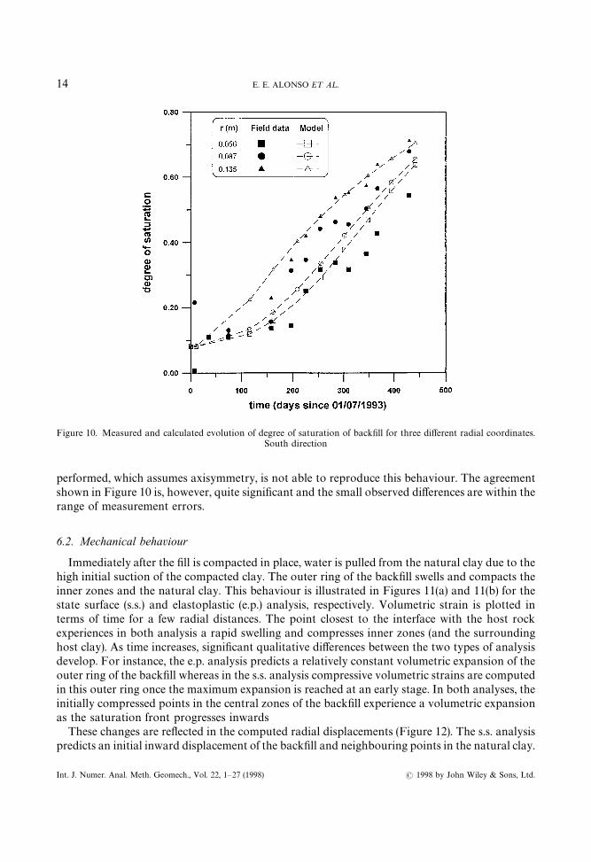
Figure 10. Measured and calculated evolution of degree of saturation of backfill for three different radial coordinates.South direction
performed, which assumes axisymmetry, is not able to reproduce this behaviour. The agreementshown in Figure 10 is, however, quite significant and the small observed differences are within therange of measurement errors.
6.2. Mechanical behaviour
Immediately after the fill is compacted in place, water is pulled from the natural clay due to thehigh initial suction of the compacted clay. The outer ring of the backfill swells and compacts theinner zones and the natural clay. This behaviour is illustrated in Figures 11(a) and 11(b) for thestate surface (s.s.) and elastoplastic (e.p.) analysis, respectively. Volumetric strain is plotted interms of time for a few radial distances. The point closest to the interface with the host rockexperiences in both analysis a rapid swelling and compresses inner zones (and the surroundinghost clay). As time increases, significant qualitative differences between the two types of analysisdevelop. For instance, the e.p. analysis predicts a relatively constant volumetric expansion of theouter ring of the backfill whereas in the s.s. analysis compressive volumetric strains are computedin this outer ring once the maximum expansion is reached at an early stage. In both analyses, theinitially compressed points in the central zones of the backfill experience a volumetric expansionas the saturation front progresses inwards
These changes are reflected in the computed radial displacements (Figure 12). The s.s. analysispredicts an initial inward displacement of the backfill and neighbouring points in the natural clay.
14 E. E. ALONSO E¹ A¸.
( 1998 by John Wiley & Sons, Ltd.Int. J. Numer. Anal. Meth. Geomech., Vol. 22, 1—27 (1998)

Figure 11. Evolution of volumetric strain in the backfill for different radial coordinates. (a) State surface approach.(b) Elastoplastic approach
This is probably due to a decrease in fill stiffness induced by the rapid changes in suction. It takessome time before the fill expansion is able to offset the initial inward displacement. The e.p.analysis shows more marked outward displacement of the outer backfill ring as time increases.Eventually, all the backfill exhibits an outward displacement. No separation between the centralsteel shaft and the backfill is computed in both analyses. It is clear from these comments that thestiffness changes of the backfill and the relative stiffness of natural clay and backfill dictatesthe distribution and direction of displacements, which seems to be a very sensitive variable.Differences between s.s. and e.p. analysis are also explained if one considers the stiffness changes
COUPLED ANALYSIS OF A BACKFILL HYDRATION TEST 15
( 1998 by John Wiley & Sons, Ltd. Int. J. Numer. Anal. Meth. Geomech., Vol. 22, 1—27 (1998)

Figure 12. Evolution of radial displacements. (a) s.s. approach. (b) e.p. approach
in both models. Within the s.s. approach any change in average net stress or suction results ina parallel change of soil stiffness. Under the e.p. framework the (elastic) stiffness parametersremain constant irrespective of loading and suction changes, provided the stress path lies withinthe current yield surface. This important qualitative difference provides an explanation for somediscrepancies between calculations carried out with both models.
Radial stresses (Figure 13) are, however, relatively homogeneous within the fill and experiencea continuous increase in time. Larger values are computed under the e.p. approach. Similarresults are obtained for the mean net stress.
16 E. E. ALONSO E¹ A¸.
( 1998 by John Wiley & Sons, Ltd.Int. J. Numer. Anal. Meth. Geomech., Vol. 22, 1—27 (1998)

Figure 13. Evolution of radial stresses in the backfill for different radial coordinates. (a) s.s. approach. (b) e.p. approach
Stress paths in both (p,s) and (p,q) planes provide an accurate image of the processesexperienced by points of the backfill and host clay as the hydration process develops. Considerfirst in Figure 14 the stress paths of the backfill in the (p, s) plane. The plotted paths are typicalswelling pressure type of paths: as suction decreases, confining pressures increase. All the pointswithin the fill experience a qualitatively similar behaviour. Consider, however, in Figure 15 the(p, s) stress paths for two points of the natural clay close to the backfill interface. The initialfill-induced dessication implies a reduction in net mean stress. In the long term, the clay regainssaturation (suction decreases again) as the mean stress increases.
COUPLED ANALYSIS OF A BACKFILL HYDRATION TEST 17
( 1998 by John Wiley & Sons, Ltd. Int. J. Numer. Anal. Meth. Geomech., Vol. 22, 1—27 (1998)

Figure 14. Stress paths in (p, s) plane for points of the backfill. (a) s.s. approach. (b) e.p. approach
Stress paths in (p, q) plane demonstrate that the process is relatively complex (Figure 16). Inboth approaches a steady increase in net mean stress is found although shear stress reversals arealso computed. Points near the centre of the backfill maintain states close to hydrostaticconditions whereas the maximum deviatoric stresses are found at the backfill boundaries.
18 E. E. ALONSO E¹ A¸.
( 1998 by John Wiley & Sons, Ltd.Int. J. Numer. Anal. Meth. Geomech., Vol. 22, 1—27 (1998)

Figure 15. Stress paths in (p, s) plane for points in the natural clay close to the interface. (a) s.s. approach. (b) e.p. approach
Measured radial stresses at two positions within the backfill (r"0·22 m and r"0·11 m) arecompared with computations in Figures 17 and 18 respectively. Field data exhibits a markedscatter when stresses along North and South directions are compared. The state surface approachpredicts a rapid early development of stresses and a continuous decrease in the rate of stress
COUPLED ANALYSIS OF A BACKFILL HYDRATION TEST 19
( 1998 by John Wiley & Sons, Ltd. Int. J. Numer. Anal. Meth. Geomech., Vol. 22, 1—27 (1998)

Figure 16. Stress paths in (p, q) plane for points within the backfill. (a) s.s. approach. (b) e.p. approach
development. In this way, it overestimates all the measurements at the beginning of the hydrationperiod and tends to underestimate the lowest values of measured stresses (North direction) atlarger times. This behaviour is linked with the continuous decrease of soil stiffness as suctionreduces implied by the state surface approach. Note that in this approach, the modulus of
20 E. E. ALONSO E¹ A¸.
( 1998 by John Wiley & Sons, Ltd.Int. J. Numer. Anal. Meth. Geomech., Vol. 22, 1—27 (1998)

Figure 17. Total radial stresses measured in two sensors located at r"0·22 m and model results
Figure 18. Total radial stresses measured in two sensors located at r"0·11 m and model results
COUPLED ANALYSIS OF A BACKFILL HYDRATION TEST 21
( 1998 by John Wiley & Sons, Ltd. Int. J. Numer. Anal. Meth. Geomech., Vol. 22, 1—27 (1998)

Figure 19. Suction-net mean stress paths for the elastoplastic approach. (a) Suction plotted in log scale. (b) Suctionplotted in natural scale
volumetric compressibility is directly obtained through differentiation of the state surface for voidratio (equation (10)).
The elastoplastic results are qualitatively different. Computed stresses increase of a constantrate during a first stage (the first 350 d), and begin to decay later. Radial stresses based on this
22 E. E. ALONSO E¹ A¸.
( 1998 by John Wiley & Sons, Ltd.Int. J. Numer. Anal. Meth. Geomech., Vol. 22, 1—27 (1998)
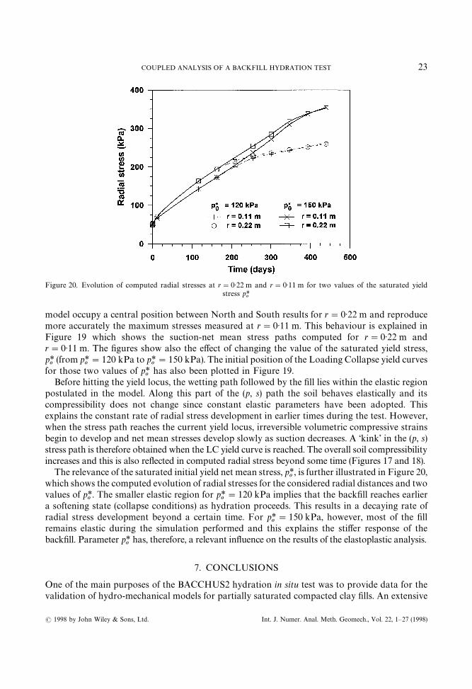
Figure 20. Evolution of computed radial stresses at r"0·22 m and r"0·11 m for two values of the saturated yieldstress p*
o
model occupy a central position between North and South results for r"0·22 m and reproducemore accurately the maximum stresses measured at r"0·11 m. This behaviour is explained inFigure 19 which shows the suction-net mean stress paths computed for r"0·22 m andr"0·11 m. The figures show also the effect of changing the value of the saturated yield stress,p*o
(from p*o"120 kPa to p*
o"150 kPa). The initial position of the Loading Collapse yield curves
for those two values of p*o
has also been plotted in Figure 19.Before hitting the yield locus, the wetting path followed by the fill lies within the elastic region
postulated in the model. Along this part of the (p, s) path the soil behaves elastically and itscompressibility does not change since constant elastic parameters have been adopted. Thisexplains the constant rate of radial stress development in earlier times during the test. However,when the stress path reaches the current yield locus, irreversible volumetric compressive strainsbegin to develop and net mean stresses develop slowly as suction decreases. A ‘kink’ in the (p, s)stress path is therefore obtained when the LC yield curve is reached. The overall soil compressibilityincreases and this is also reflected in computed radial stress beyond some time (Figures 17 and 18).
The relevance of the saturated initial yield net mean stress, p*o, is further illustrated in Figure 20,
which shows the computed evolution of radial stresses for the considered radial distances and twovalues of p*
o. The smaller elastic region for p*
o"120 kPa implies that the backfill reaches earlier
a softening state (collapse conditions) as hydration proceeds. This results in a decaying rate ofradial stress development beyond a certain time. For p*
o"150 kPa, however, most of the fill
remains elastic during the simulation performed and this explains the stiffer response of thebackfill. Parameter p*
ohas, therefore, a relevant influence on the results of the elastoplastic analysis.
7. CONCLUSIONS
One of the main purposes of the BACCHUS2 hydration in situ test was to provide data for thevalidation of hydro-mechanical models for partially saturated compacted clay fills. An extensive
COUPLED ANALYSIS OF A BACKFILL HYDRATION TEST 23
( 1998 by John Wiley & Sons, Ltd. Int. J. Numer. Anal. Meth. Geomech., Vol. 22, 1—27 (1998)

program of laboratory tests of compacted Boom clay powder and compacted mixtures of powderand pellets has provided data on permeability, water retention characteristics and volumetricdeformation of the fill under varying suction (or saturation) conditions. Instrumentation of thenatural Boom clay deposits near the test emplacement has also provided data to specify initialand boundary conditions of the experiment. Enough information has therefore been obtained toallow a simulation of test performance. Two alternative mechanical models of soil behaviour(state surface description for volumetric deformations and an elastoplastic model) have beencompared in the analysis performed.
The existing experimental data base of fill behaviour has allowed the identification of para-meters of both approaches. The methodology for parameter identification represents a major partof the modelling effort and has only been outlined in this paper. More details may be found inReference 12. It can be said that the state surface approach requires less parameters than theelastoplastic counterpart and they are also more readily found.
The analysis of the computed results reveals that the apparently simple phenomenon of fillhydration is in fact a complex coupled processes for the backfill and the immediate natural clay.The plotted stress paths indicate that the fill experiences deviatoric stress reversals whereas in thenatural clay a drying-wetting cycle takes place. Comparison between measured and computedevolution of backfill saturation shows a good agreement for the two models used. In addition, thespecific description of mechanical behaviour has a very limited effect on saturation changes.
Measured radial stresses within the backfill are markedly non-symmetrical, and this probablyindicates non-homogeneous characteristics in the fill, the natural clay or both, which were notintended or, indeed, foreseen during test installation.
Symmetrical conditions were assumed in the analysis but, nevertheless, the comparison betweenmeasured and computed radial stresses has provided an interesting insight into the relative merits ofthe two approaches adopted. Radial stresses derived from the elastoplastic approach develop in timeat a rate consistent with measurements. Computed absolute values are close to the average measuredvalues. The elastoplastic approach shows an encouraging potential to model mechanical phenomenawithin barriers experiencing a progressive hydration. Computed results are, however, criticallydependent on some key parameters of the model. The significance of the hardening parameter(saturated yield stress), a parameter which is difficult to estimate in practice, has been presented.
Computed stresses based on the state surface approach present more discrepancies withmeasured values and, more specifically, with the time development of stresses. The modeloverestimates stresses in the short term and overestimates them in the long term. This representsa qualitative disagreement with observed behaviour which has been explained by the apparentlyunrealistic continuous and rapid softening of the soil as hydration proceeds.
A better understanding of phenomena taking place in swelling clay barriers experiencingnatural hydration from the host rock has been gained. Also, present modelling capabilities atsample scale (constitutive behaviour) and real scale (field equations) have been verified within theframework of a comprehensive laboratory and ‘in situ’ testing program. Overall, results aresatisfactory and it is believed that the analysis presented in the paper is a positive step towards thedevelopment of more accurate models for the prediction of engineered clay barriers performance.
ACKNOWLEDGEMENTS
The work described has been supported by the Spanish national agency for nuclear wastedisposal (ENRESA) and by the EU through Projects FI2W-CT-91-0033 and FI2W-CT-91-0102.
24 E. E. ALONSO E¹ A¸.
( 1998 by John Wiley & Sons, Ltd.Int. J. Numer. Anal. Meth. Geomech., Vol. 22, 1—27 (1998)

BACCHUS2 test was performed by the Belgian nuclear energy center, SCK-CEN, underthe direction of G. Volckaert. J. Vaunat is the recipient of a fellowship of the Human Capitaland Mobility Programme of the EU. Basic research has been supported by the Spanishscientific and technical research agency (CICYT) through research grants PS92-0702 andPB93-0964.
APPENDIX: NOTATION
F : Force; ¸ : Length; M :Mass; ¹ : Time
a, b, c, d constant parameters in equation relating void ratio with net stress and suctionchanges (state surface approach)
a@, b@, c@, d@ constant parameters in equation relating void ratio with net stress and suctionchanges (simplified expression; state surface approach)
A, B constant parameters in equation relating unsaturated water permeability with suctionbi
body forces in equilibrium equation, F/¸3
D, C constant parameters in equation relating unsaturated air permeability with suctionand void ratio, [C : (L2)]
e, e0
void ratio; initial void ratioE, F constant parameters in equation relation degree of saturation with suction
[F : (FL~2)~1]G elastic shear modulus (elastoplastic model), F/L2
Gt
non-linear elastic shear modulus (state surface approach), F/L2
H Henry’s constant ("0·018)K
tnonlinear elastic modulus of soil compressibility (state surface approach), F/L2
K8
permeability to water (unsaturated conditions) I/TK0
8permeability to water (saturated conditions), L/T
ks
Parameter describing the increase in cohesion with suction (elastoplastic model)M slope of critical state failure envelopen porosityp net mean stres (triaxial stress states) ("p
1#2p
3/3!p
!) F/L2
p!
air pressure, F/L2p!5
atmospheric pressure, F/L2
pc reference stress (elastoplastic model), F/L2
po
current yield net mean stress (for suction s) F/L2
p*o
current effective mean yield stress (saturated state), F/L2
ps
apparent cohesion in terms of net mean stresses (elastoplastic model), F/L~2
p8
water pressure, F/L2
q deviatoric stress (triaxial stress states) ("p1!p
3) F/L2
r parameter defining maximum soil stiffness (elastoplastic model)Sr
degree of saturations matric suction ("p
!"p
8), F/L2
v!
velocity of air (Darcy), I/Tv8
velocity of water (Darcy), I/!v specific volume ("1#e)a parameter of the nonassociated flow rule (elastoplastic model)
COUPLED ANALYSIS OF A BACKFILL HYDRATION TEST 25
( 1998 by John Wiley & Sons, Ltd. Int. J. Numer. Anal. Meth. Geomech., Vol. 22, 1—27 (1998)

b parameter controlling the rate of increase of soil stiffness with suction (elastoplasticmodel), L2 F~1
c!
specific weight of air, F/L3
ekl
strain tensoreo
volumetric straine1v, e%
vplastic volumetric strains; elastic volumetric strains
e1q, e%
qplastic deviatoric strains; elastic deviatoric strains
e%s
elastic strains induced by suction changes (elastoplastic model)i elastic stiffness parameter for changes in p (elastoplastic model)is
elastic stiffness parameter for changes in suction (elastoplastic model)j(s) stiffness coefficient for changes in p for virgin states (elastoplastic model)j(o) stiffness coefficient for changes in p*
ofor virgin states (elastoplastic model)
k dynamic viscosity of air, F T L2
l Poisson’s ratioo!
mass density of air, M/L3
o8
mass density of water, M/L3
p1, p
2, p
3total principal stresses, F/L2
pij
total stress tensor F/L2
p*ij
net stress tensor (pij"p
ij!p
!dij) F/L2
REFERENCES
1. A. Gens, E. E. Alonso, A. Lloret and F. Batlle, ‘Analysis of construction and consolidation of earthdams’, Proc. 16thCongress on ¸arge Dams, Vol. (28), San Francisco, 1988, pp. 1371—1386.
2. E. E. Alonso, A. Gens and A. Lloret, ‘Double structure model for the prediction of long-term movements in expansivematerials’, in Beer, Booker and Carter (eds.) Comp. Methods Adv. Geomechanics, Balkema, 1991, pp. 541—548.
3. A. Lloret and E. E. Alonso, ‘Unsaturated flow analysis for the design of a multilayer barrier’, Proc. 13th ICSMFE,New Delhi, 1994, pp. 1629—1632.
4. A. Lloret and E. E. Alonso, ‘State surfaces for partially saturated soils’, Proc. 11th ICSMFE, Vol. 2, San Francisco,557—562.
5. E. E. Alonso, F. Batlle, A. Gens and A. Lloret, ‘Consolidation analysis of partially saturated soils: applica-tion to earthdam construction’, Proc. 6th Int. Conf. on Numerical Meth. in Geomech. Vol. 2 Innsbruck, 1988,pp. 1303—1308.
6. A. Gens, E. E. Alonso and A. Josa, ‘Elastoplastic modelling of partially saturated soil’, in: S. Pietruszcak and G.N.Pande, (eds.), Numerical Models in Geomechanics III, Elsevier ASP, London, 1989, pp. 163—170.
7. E. E. Alonso, A. Gens and A. Josa, ‘A constitutive model for partially saturated soils’, Geotechnique, 40(3), 405—430(1990).
8. A. Lloret and E. E. Alonso, ‘State surfaces for partially saturated soils’, Proc. 11th. ICSMFE, Vol. 2: San Francisco,1985, pp. 557—562.
9 A. Gens and E. E. Alonso, ‘A framework for the behaviour of unsaturated expansive soils’, Canad. Geotech. J., 29,1013—1032 (1992).
10. F. Bernier and B. Neerdael, ‘Overview of in situ thermomechanical experiments in clay: concept, results andinterpretation’, Engng Geol., 41, 51—64 (1996).
11. G. Volckaert, F. Bernier and M. Dardaine, ‘Demonstration of the in situ application of an industrial clay-basedbackfill material (BACCHUS2)’, SCK-CEN Report R-3011, 1993.
12. G. Volckaert, F. Bernier, E. Alonso, A. Gens, J. Samper, M. Villar, P. L. Martin-Martin, J. Cuevas, R. Campos, H.Thomas, C. Imbert and V. Zingarelli, ‘Thermal-hydraulic-mechanical and geochemical behaviour of the clay barrierin radioactive waste repositories (model development and validation)’, Final Report to Contracts F12¼ /C¹90/0033and F12¼/C¹91/D0102, European Commission, EUR 16744EN, 1996.
13. G. Volckaert, P. De Canniere, P. Hooker, V. Fioravante, P. Grindrod and M. Impey, MEGAS: modelling andexperiments on GAS migration in repository host rocks’, in: B. Haijtink and T. McMenamin, (eds.) Proc. ProgressMeeting: Project on Effects of Gas in ºnderground Storage Facilities for Radioactive ¼aste (Pegasus project); ReportEºR14816: 142—156, 1993.
26 E. E. ALONSO E¹ A¸.
( 1998 by John Wiley & Sons, Ltd.Int. J. Numer. Anal. Meth. Geomech., Vol. 22, 1—27 (1998)

14. G. Baldi, T. Hueckel, A. Peano and R. Pellegrini, ‘Developments in modelling the thermo-hydro-geochemicalbehavior of Boom clay and clay based buffer materials’, CEC Report EºR 13365/1 and 2 EN, 1991.
15. A. Bone, H. Beckers, R. Beaufays, M. Buyens, J. Coursier, D. de Bruyn, A. Fonteyne, J. Genicot, D. Lamy, P.Meynendonckx, M. Monsecour, B. Neerdael, L. Noynaert, M. Voet and G. Volckaert, ‘(The HADES demonstrationand pilot project on radioactive waste disposal in a clay formation’, Final Report to Contract FI1¼/0004B, EºR13581 EN, 1992.
16. E. L. Matyas and H. S. Radhakrishna, Volume change characteristics of partially saturated soils, Geotechnique, 18(4),432—448 (1968).
17. UPC Geomechanics group, ‘Modelling and validation of the thermal-hydraulic-mechanical and geochemical behav-iour of the clay barrier’, Final Report Contract F12¼-C¹91-0102, 1995.
18. D. Hilled, Fundamentals of Soil Physics, Academic Press, New York, 1980, 415p.19. V. Yoshimi and J. O. Osterberg, ‘Compression of partially saturated cohesive soils’, Inl. Soil Mech. Found. Engng Div.,
ASCE 89 (SM4), 1—24, (1963)
.
COUPLED ANALYSIS OF A BACKFILL HYDRATION TEST 27
( 1998 by John Wiley & Sons, Ltd. Int. J. Numer. Anal. Meth. Geomech., Vol. 22, 1—27 (1998)