Council Business Paper 25 July 2016
514
BUSINESS PAPER ORDINARY MEETING OF COUNCIL To be held at 6.00pm on Monday 25 July 2016 Council Chambers, Level 10, Council Administration Building, 41 Burelli Street, Wollongong Order of Business Members 1 Acknowledgement of Traditional Owners 2 Civic Prayer 3 Apologies 4 Disclosures of Pecuniary Interest 5 Petitions and Presentations 6 Confirmation of Minutes – Ordinary Council Meeting 27 June 2016 7 Public Access Forum 8 Call of the Agenda 9 Lord Mayoral Minute 10 Urgent Items 11 Agenda Items Lord Mayor – Councillor Gordon Bradbery OAM (Chair) Deputy Lord Mayor – Councillor John Dorahy Councillor Michelle Blicavs Councillor David Brown Councillor Leigh Colacino Councillor Chris Connor Councillor Bede Crasnich Councillor Vicki Curran Councillor Janice Kershaw Councillor Ann Martin Councillor Jill Merrin Councillor Greg Petty Councillor George Takacs QUORUM – 7 MEMBERS TO BE PRESENT
-
Upload
khangminh22 -
Category
Documents
-
view
0 -
download
0
Transcript of Council Business Paper 25 July 2016

BUSINESS PAPER ORDINARY MEETING OF COUNCIL
To be held at 6.00pm on
Monday 25 July 2016
Council Chambers, Level 10, Council Administration Building, 41 Burelli Street, Wollongong
Order of Business Members 1 Acknowledgement of Traditional
Owners 2 Civic Prayer 3 Apologies 4 Disclosures of Pecuniary Interest 5 Petitions and Presentations 6 Confirmation of Minutes – Ordinary
Council Meeting 27 June 2016 7 Public Access Forum 8 Call of the Agenda 9 Lord Mayoral Minute 10 Urgent Items 11 Agenda Items
Lord Mayor – Councillor Gordon Bradbery OAM (Chair)
Deputy Lord Mayor – Councillor John Dorahy Councillor Michelle Blicavs Councillor David Brown Councillor Leigh Colacino Councillor Chris Connor Councillor Bede Crasnich Councillor Vicki Curran Councillor Janice Kershaw Councillor Ann Martin Councillor Jill Merrin Councillor Greg Petty Councillor George Takacs
QUORUM – 7 MEMBERS TO BE PRESENT

Ordinary Meeting of Council 25 July 2016
INDEX
PAGE NO.
ITEM 1 St Joseph's Catholic Convent and Church, 48-50 Park Road Bulli ....................... 1
ITEM 2 Update on Proposed Additional Off Leash Dog Areas - Parks ............................... 8
ITEM 3 Draft Planning Proposal - Boundary Adjustment 63 Buttenshaw Drive, Coledale and 65 Buttenshaw Drive, Austinmer ................. 15
ITEM 4 Draft Voluntary Planning Agreement Negotiation Process between the Association of Mining Related Councils and the NSW Minerals Council ................................................................................... 20
ITEM 5 Draft Community Safety Plan 2016-2020 and draft Snapshot 2012-2016 .................................................................................. 25
ITEM 6 Debt Recovery and Hardship Assistance Council Policy ..................................... 28
ITEM 7 Policy Review: Subdivision .................................................................................. 32
ITEM 8 Dedication of Two Lanes in Coledale as Public Road .......................................... 34
ITEM 9 Proposed Acquisition of Part of Lot 48 DP 9943 No 41 Murray Road, East Corrimal for Road Widening ......................................................................... 36
ITEM 10 Proposed Creation of Reciprocal Easement for Access over Lots 40 and 42 DP 5330 Nos 24 and 26 Bridge Street, Coniston ........................ 39
ITEM 11 City of Wollongong Traffic Committee - Minutes of Meeting held 29 June 2016 ....................................................................................................... 41
ITEM 12 Bi-Monthly Tabling of Reports of Disclosures of Interests and Other Matters ....................................................................................................... 44

Ordinary Meeting of Council 25 July 2016 1
REF: CM142/16 File: ESP-100.06.017
ITEM 1 ST JOSEPH'S CATHOLIC CONVENT AND CHURCH, 48-50 PARK ROAD BULLI
On 6 April 2016, Council staff, under delegation, made an Interim Heritage Order under the NSW Heritage Act 1977, on the former St Joseph’s Roman Catholic Convent Building in Park Road Bulli. The purpose of the Order was to provide interim protection to the Convent building, to allow Council to give formal consideration to the potential heritage listing of the site. This action was triggered by an approval to demolish the Convent building issued by a Private Certifier.
The purpose of this report is to allow Council to consider the heritage significance of the former Convent Building, and the adjacent Church, and to make an informed decision on whether to proceed with the preparation of a draft Planning Proposal for the heritage listing of the two buildings.
RECOMMENDATION
1 A draft Planning Proposal be prepared to add:
a St Joseph’s Roman Catholic Church, and
b Former St Joseph’s Roman Catholic Convent,
to the heritage list contained within Schedule 5 of the Wollongong Local Environmental Plan 2009 as items of local significance, and to update the Wollongong Local Environmental Plan Heritage Map accordingly.
2 The draft planning proposal be placed on public exhibition for a minimum period of 28 days.
3 A further report on the outcomes of the exhibition be presented to Council at the conclusion of the notification period.
4 The Interim Heritage Order relating to the former Convent building be kept in place until the post exhibition report is considered.
ATTACHMENTS
1 Draft Assessment of Heritage Significance – St Joseph’s Roman Catholic Convent 2 Draft Assessment of Heritage Significance – St Joseph’s Roman Catholic Church 3 Location and Proposed Curtilage Map 4 Interim Heritage Order – St Joseph’s Roman Catholic Convent 5 Letter from the Most Rev Peter W Ingham Bishop of Wollongong, on behalf of the
Trustees of the Roman Catholic Church for the Diocese of Wollongong 6 Summary of Submissions received to date

Ordinary Meeting of Council 25 July 2016 2
REPORT AUTHORISATIONS
Report of: Renee Campbell, Manager Environmental Strategy and Planning Authorised by: Andrew Carfield, Director Planning and Environment – Future City
and Neighbourhood
COMPLIANCE WITH OFFICE OF LOCAL GOVERNMENT GUIDELINES ON COUNCIL DECISION MAKING DURING MERGER PROPOSAL PERIODS
The recommendation in this report satisfies the requirements of the OLG Guidelines - Council Decision Making During Merger Proposal Periods.
BACKGROUND
On 19 November 2015 Council received a nomination from a member of the St Joseph’s Parish of the Roman Catholic Church, for the heritage listing of the former St Joseph’s Convent Building, located at 48-50 Park Road Bulli. This building was constructed in 1903, to accommodate the Sisters of St Joseph, the order of Nuns founded by Saint Mary McKillop, who were appointed to the Parish. This nomination was added to a group of nominated items currently under assessment as part of a broader review of Council’s heritage schedule.
The heritage nomination was supported by additional information, including:
a advice from Sidney Rofe, an Architect engaged by the Bulli Parish to advise on the former Convent building. This advice included the following conclusion:
The building is significant to the history of both the parish and the school and its association with St Mary of the Cross. There is an opportunity to both retain and restore this building somewhat to its original condition, and to repurpose it for use by both the school and the parish. The old Convent could become a signature building for the school not unlike other educational institutions that use their historic buildings to promote their enduring values. There is good cause for this building to be recognised as a local heritage item.
b Structural Engineer’s Assessment of the Convent building, prepared by Peter Lockhart for the Parish. This advice draws the following conclusion:
The building is generally in very good and serviceable condition with minor cracking that is well within the acceptable standards for current construction standards.
The building has exhibited a much lesser level of movement than that which would be expected in a new building of similar size.
In December 2015 Council’s Consultant Heritage Advisor undertook and provided to Council, a draft Heritage Assessment for the former Convent Building, as well as for the adjacent St Joseph’s Roman Catholic Church building. Both heritage assessments were undertaken using the criteria specified by the NSW Heritage Branch. The heritage assessments recommended that both the Church, and the Convent building should be

Ordinary Meeting of Council 25 July 2016 3
listed as local heritage items. A copy of the heritage assessments are provided as Attachments 1 and 2 to this report.
The summary statement of heritage significance for the 1903 former Convent building in the attached report is provided as follows:
St Joseph’s Convent in Bulli is of significance for Wollongong for its historic, associative, and aesthetic values, and as a locally representative example of a Federation period purpose-built Convent building in this area. The St Joseph’s Convent is readily identifiable as part of the historic building stock in the area, and makes a contribution to the streetscape. The built fabric retains its ability to interpret historical themes, while the integrity of that presents as high when viewed from publicly accessible areas. The Convent belongs to the Roman Catholic Church in Bulli and is a related item, in heritage terms, to the adjoining St Joseph’s Church building.
The statement of heritage significance for the St Joseph’s Roman Catholic Church, which was built in 1900, states:
St Joseph’s Roman Catholic Church, Bulli is of significance for Wollongong for its historic, associative, aesthetic and spiritual values, for its potential to contribute further to an understanding of ecclesiastical design in the Federation period, and as a locally representative example of a Federation Church with some rare elements. The Church building is readily identifiable as part of the historic building stock in the area, an important element in the streetscape, and a local landmark. Its fabric demonstrates development of the area in the period of rapid growth in Bulli gained due to prosperous expansion of local industry and emergence of new technologies, and it provides evidence of the prosperous growing of the local population in the period before WWI. The built fabric retains its ability to interpret historical themes, while the integrity of that presents as high when viewed from publicly accessible areas.
A location and proposed curtilage map is provided as Attachment 3 to this report.
On 5 April 2016 Wollongong City Council received information from a member of the parish, that works were scheduled to commence shortly toward the demolition of the building. A review of Council’s records revealed a recent Private Certifier Approval issued on 22 March 2016. This approval included the demolition of the Convent building, and the construction of a single-storey administration building in its place. This application was approved by the Private Certifier under the State Environmental Planning Policy (Infrastructure) 2007. This planning instrument allows for the demolition and construction of private education facilities without a development application.
This information raised concern for Council staff in that Council held information indicating that a building of heritage significance, subject to a community nomination, and currently under investigation for heritage listing was under immediate threat of demolition. Council staff were presented with two available options:
1 To knowingly allow the demolition of the building which had been assessed as having heritage significance, or;
2 To make an Interim Heritage Order under the NSW Heritage Act 1977.

Ordinary Meeting of Council 25 July 2016 4
Council has delegation to make an Interim Heritage Order where a building (or other item) is reasonably expected to be of heritage significance, and where this building is under immediate threat of harm.
Having considered the above options, Council staff contacted the Catholic Education Office and the Bishops Office, by phone and indicated an intention to put in place an Interim Heritage Order, under the NSW Heritage Act 1977. Staff from the Catholic Education Office and the Bishop’s Office indicated a willingness to cooperate with Council’s process, and indicated a desire to meet with relevant Council staff to discuss the matter.
On 6 April 2016 the Interim Heritage Order was notified in the NSW Government Gazette No. 25. A copy of the gazettal notice is provided as Attachment 4 to this report.
On 4 May 2016 Council Staff met with representatives of the Bishop’s Office, and the Catholic Education Office to discuss the Interim Heritage Order and its implications. At this meeting, the Catholic Education Office provided some background on site considerations and site constraints relevant to the growth of St Joseph’s Catholic School, and indicated that the Convent site was seen as an important location for the growth of the School. The Catholic Education Office also provided information about a Federal Government grant of $1.675 million, which is tied in part to the demolition of the Convent and replacement with a new administration building. It was however, indicated that the development plans were already being reviewed due to cost considerations and that the approved plans are likely to be amended before construction commences.
Council staff noted their intention to prepare a Council report considering the potential Heritage listing of the former Convent building, as well as the Church building. Council staff indicated that as the land owner, the Catholic Church would be formally invited to comment on the potential heritage listing of the site, prior to the preparation of a Council report. The details of this formal consultation are provided under the consultation and communication section of this report.
PROPOSAL
This report proposes to prepare and exhibit a draft planning proposal, to progress a local heritage listing for both the former St Joseph’s Convent building, and St Joseph’s Roman Catholic Church, both of which are located at 48-50 Park Road, Bulli.
This proposal is recommended on the basis of a heritage assessment undertaken by Council’s Heritage Advisor. The assessment was triggered by a nomination of the property by a member of the Parish, who has an intimate knowledge of the building and its history. The nominator has provided independent Architects advice which supports the heritage listing of the building and indicates the feasibility of adaptive re-use of the Convent building. The nominator has also provided Engineer’s advice that the building is in good structural condition.
The owners of the property, the Trustees of the Roman Catholic Church, have objected to the heritage listing of the Convent building, but not to the listing of the Church building. The objection is made on the basis that they disagree with the assessment of

Ordinary Meeting of Council 25 July 2016 5
a number of the heritage significance criteria. This submission is discussed further in the consultation and communication section of this report and a copy of their letter is provided as Attachment 5 to this report.
Whilst the objections to the listing identified in the owner’s submission are noted, these objections do not appear to demonstrate that the building does not have heritage value worthy of recognition on the Heritage Schedule. The reasons for this conclusion are outlined in the Heritage Officer’s response column of the summary of submissions document, provided as Attachment 6 to this report.
It is worth noting that a local Heritage listing does not automatically preclude the demolition of the building. The listing would however mean that development impacting on the heritage item could not be undertaken without development consent, and that any development application would require assessment under Clause 5.10 (Heritage Conservation) of the Wollongong Local Environmental Plan 2009 and Chapter E11: Heritage Conservation of the Wollongong Development Control Plan 2009. This assessment process would encourage the adaptive re-use of the building to accommodate uses suitable for the school and/or the parish.
Council has three available options in progressing this matter. These are:
Option 1 Adopt the recommendations of this report;
Option 2 Prepare and exhibit a draft planning proposal for the heritage listing of St Joseph’s Roman Catholic Church only; and
Option 3 Not progress a heritage listing for either building.
If Council chose to adopt Option 2 or 3, the Interim Heritage Order will need to be lifted from the site. This is because the Order can only remain in place whilst Council is making consideration of the potential heritage listing of the building. The implication would therefore be that the existing approval for demolition of the building under the Private Certifier Approval would be able to be enacted, and it is likely the building will be demolished.
This report recommends that Council proceed to prepare and exhibit a draft planning proposal, to heritage list the Convent and Church buildings on the Heritage Schedule of the Wollongong Local Environmental Plan. This option will allow the community to comment on the proposal for heritage listing and at the conclusion of the notification period, Council will have the opportunity to further consider the matter through the post exhibition report.
CONSULTATION AND COMMUNICATION
On 11 May 2016 the Wollongong Heritage Advisory Committee considered a report on St Joseph’s Convent – Park Road Bulli. The report provided copies of the draft Heritage Assessment. The committee resolved that:

Ordinary Meeting of Council 25 July 2016 6
The Wollongong Heritage Advisory Committee recommends that Council prepare and exhibit a draft Planning Proposal to add St Joseph’s Convent Building on Park Road, Bulli to the Heritage Schedule.
On 26 May 2016 Council wrote to the Trustees of the Roman Catholic Church, the legal property owners of 48-50 Park Road Bulli, notifying them of Council’s intention to consider a proposed heritage listing of the Convent and Church buildings. A copy of this notification letter was sent to the Bishop’s Office, as well as to the Catholic Education Office for information. A letter of reply was received from the Bishop on behalf of the Trustees of the Roman Catholic Church (the property owner) on 21 June 2016. A copy of this letter is provided as Attachment 5 to this report. The Summary of Submissions provided at Attachment 6 provides responses to the issues raised in this letter.
An additional reply from the Director of Schools, Catholic Education Office, was received on 28 June 2016. This letter generally restated the objections raised in the Bishop’s letter and offered support to the objections raised by the Trustees of the Roman Catholic Church. Additional information about the site master planning process and the Federal Government grant are also provided. Details of this submission and responses to the issues raised are provided in Attachment 6.
In addition to the above, Council has also received a number of letters in support of the heritage listing of the Convent since the Interim Heritage Order was made. This correspondence has included a letter from the nominator, thanking Council for putting in place the Interim Heritage Order, as well as a letter from the Engineer engaged by the Parish, in support of the heritage listing of the building. Council has also received 9 separate form letters, signed by a total of 21 individuals supporting the conservation of the Convent building.
A summary of all of the above submissions, received in relation to the proposed heritage listing, and the Interim Heritage Order to date, is provided as Attachment 6 to this report. This document includes comments in relation to the objections raised in the submissions.
PLANNING AND POLICY IMPACT
This report contributes to the delivery of Wollongong 2022 objective “Community awareness and appreciation of heritage is increased” under the Community Goal “We Value and Protect our Environment”. It specifically delivers on core business activities as detailed in the Land Use Planning Service Plan 2016-17 under the delivery stream of Heritage.
FINANCIAL IMPLICATIONS
The recommendations of this report are not anticipated to present any financial implications for Council.

Ordinary Meeting of Council 25 July 2016 7
It is possible however that the progression of a draft heritage listing on the Convent building may have a financial impact on the Catholic Education Office, as this could impact on their ability to retain grant funding allocated to a capital project on the site.
CONCLUSION
The recommendations of this report will ensure that the heritage significance of St Joseph’s Roman Catholic Church, and the adjacent former Convent building located at 48-50 Park Road Bulli can be properly considered. The drafting and exhibition of a planning proposal will allow for broad community consultation and debate on the heritage significance of the Convent, and Church buildings. A further report on the outcomes of the exhibition process will be provided at the conclusion of the notification period.

Ordinary Meeting of Council 25 July 2016 8
REF: CM144/16 File: Z16/130473
ITEM 2 UPDATE ON PROPOSED ADDITIONAL OFF LEASH DOG AREAS - PARKS
This report is provided in response to a previous Council report on the Dogs on Beaches and Parks Policy which was reviewed and adopted on 24 November 2014.
In endorsing the Policy, Council also resolved to:
Establish an internal working party to assess on a ‘needs basis’ approach any additional suitable parks that may be established as off leash areas and the recommendations of this group be presented to Council for consideration.
The report provides Council with a summary of research and investigations of the internal working party, to date, noting any new off leash parks be considered by Council when the Dogs on Beaches and Parks Policy is reviewed in November 2017.
RECOMMENDATION
The report be noted and the proposed new dog park/off leash areas be considered in the review of the Dogs on Beaches and Parks Policy in November 2017.
ATTACHMENTS
1 Evaluation of seven potential sites 2 Location plans of potential new dog park/off leash areas
REPORT AUTHORISATIONS
Report of: Peter Coyte, Manager Property and Recreation Authorised by: Greg Doyle, Director Corporate and Community Services – Creative,
Engaged and Innovative City
COMPLIANCE WITH OFFICE OF LOCAL GOVERNMENT GUIDELINES ON COUNCIL DECISION MAKING DURING MERGER PROPOSAL PERIODS
The recommendation in this report satisfies the requirements of the OLG Guidelines - Council Decision Making During Merger Proposal Periods.
BACKGROUND
At the Council meeting on 24 November 2014, it was resolved that Council establish an internal working party to assess on a ‘needs basis’ approach any additional suitable parks that may be established as off leash areas and the recommendations of this group be presented to Council for consideration.

Ordinary Meeting of Council 25 July 2016 9
Current Dog Off Leash Dog Areas in Wollongong
There are currently 15 dog off leash areas within the Wollongong LGA. 10 are off leash beach areas and five are off leash park areas. These off leash park areas do not contain dog friendly infrastructure such as fencing and/or agility equipment. The five existing off leash dog areas are located at:
Proud Park, Helensburgh; Figtree Oval, Figtree; Riley Park, Unanderra; King George V Park, Port Kembla; and Eleebana Reserve, Koonawarra.
Current Provision of Off Leash Dog Areas
The five areas identified above are generally unfenced and cater for a variety of park users and recreational activities, including dog owners.
Dog owners are permitted to let their dogs run off-leash in these areas, however, dog owners share the park with other park users. Dog owners are required to ensure they comply with all relevant Local and State Government requirements and ensure their dog/s do not encroach on other park activities or users.
Internal Working Party
Since February 2015, Council officers from Property and Recreation, Strategic Planning and Regulation and Enforcement Divisions have met on a regular basis to assess additional off leash dog areas within the Wollongong LGA and explore the provision of a dog park being established.
The internal working party have referenced and further refined a selection criteria for evaluating the viability of sites, these were established utilising best practice principles.
What is a Dog Park?
Dog parks are fenced areas that may contain a number of activity areas including open ball play areas and natural rummaging environments such as rock scramble areas or grassed areas. The size of the dog park will reflect the open space hierarchy and the catchment served. A district level facility will, typically, be 600-800m2. The park may include educational or agility equipment for developing social and physical skills and confidence in dogs.
Dog parks should incorporate supporting amenities for dog owners and other visitors to ensure it is an appealing social environment and a well-used community hub. These amenities include natural shade or shade structures, water, seating, attractive and robust ground cover.

Ordinary Meeting of Council 25 July 2016 10
Larger dog parks that attract people for longer stays should include access to toilets, car parking and the provision of picnic facilities located outside the dog park.
Council currently licenses a portion of JJ Kelly Park for dog activities but the city does not specifically have a dedicated dog park.
Site Evaluation Criteria
An evaluation criteria was developed to assess the suitability of proposed dog parks and off leash dog parks in selected parks and reserves.
Primary evaluation criteria
1 The space available on the site to accommodate a dog park/off leash area without it unreasonably impacting the space available for existing park activities
The capacity of the site to accommodate a dog park/off leash area, the number of activities that may be impacted, the existing park function, the ability to provide buffers between activities if they exist and space allocated for existing activities were reviewed to allow for growth in demand.
2 The level of environmental sensitivity associated with the open space
The impact the dog park/off leash area may have on sensitive environments, areas where endangered species may exist, wetlands or previous use that may require management arrangements, such as wildlife habitat or a former landfill site.
3 Site access
Consideration was given to access from the catchment area, including barriers to access eg major roads, creeks/waterways. The location of the site including the nature of surrounding land uses, the openness of the site and the nature of other activities that will attract additional park users and optimise casual surveillance were also considered.
Secondary evaluation criteria
4 The integration of the proposed dog park/off leash area site with other park activities
The location of the dog park/off leash area within the site should provide users connectivity to other park activity spaces such as sporting and passive recreation areas.
5 The proposed dog park/off leash area site has good natural features including natural shade, attractiveness of the landscape
The dog park/off leash area should be located in a natural setting/environment and include landscaped and natural shade areas. Green sites with pleasant surroundings will attract users.

Ordinary Meeting of Council 25 July 2016 11
6 The proposed dog park/off leash area site has existing and accessible infrastructure and amenities
The location of the dog park/off leash area should give dog owners easy access to park infrastructure and amenities to support the nature and length of visit. Infrastructure will reflect the hierarchy of facility.
7 The park has good linkages via the shared path network
This will optimise the number of residents who can access the park or reserve via safe off-road pathways that provide direct routes to the dog park/off leash site.
A park or reserve within a walkable distance will encourage walking to access the facility, which is in line with Council’s Community Goal “We are a healthy community in a liveable city”.
8 The number of people living near the park and who would potentially be able to walk to the site
Locating the dog park/off leash area at a park or reserve in close proximity to a catchment population will increase the use of the facility. It will also reduce dependence on motorised transport to access the site.
9 The number of dog registrations within the postcode of the site
The location of the dog park/off leash area should be correlated to the number of dog owning households within its catchment.
Consideration was also given to the following factors to help determine the preferred site.
10 The readiness of the site to accommodate a dog park/ off leash area in the near future
The ability to proceed immediately with the establishment of a dog park/off leash area is a key requirement. Some factors to consider in the development of a dog park/off leash area include:
There are significant establishment works required as in the case of a newly established reserve, or reinstatement or remedial works as in the case of a former landfill site; or
A master plan needs to be prepared to optimise the use of the site; or
Another party owns the land and time is required to negotiate access and conditions of access to the land.
11 Whether the site is already a popular informal dog off leash/on leash area
This indicates the site has, historically, been well used for dog off-leash activities and has a level of acceptance by the broader community for dog activities.
12 The population forecast for the relevant suburb (based on 2026 data)
If all else is equal, the anticipated population growth in the area may determine the priority of one site over another.

Ordinary Meeting of Council 25 July 2016 12
Evaluation of possible sites for a dog park/off leash area
Attachment 1 identifies and evaluates seven potential sites as a dog park or future off leash areas.
All open spaces were examined to identify sites that potentially had an area available to accommodate a dog park/off leash area.
The potential sites assessed against the evaluation criteria were:
Bott Drive, Bellambi – Off Leash Dog Area Greenhouse Park, Wollongong – Off Leash Dog Area
JJ Kelly Park, Wollongong (Illawarra Dog Training Club licensed area) – Timed Off Leash Dog Area and Dog Park
JJ Kelly Park, Wollongong (South western corner, south of Coniston Lions Club Soccer licensed area) – Off Leash Dog Area
MacCabe Park, entrance on Keira Street, Wollongong – Dog Park
Road Reserve located between Tate Street and Springhill Road, Wollongong – Dog Park
Reed Park, Dapto – Off Leash Dog Area
Priority sites for future consideration to be included in the policy review
The following sites were favourably assessed for their suitability to accommodate an off leash or a dog park in line with the primary and secondary evaluation criteria.
Off Leash Dog Areas
Reed Park, Dapto (99 pts) Bott Drive, Bellambi (68 pts) Northern end of JJ Kelly Park – Illawarra Dog Training Club site – Timed Access
(62 pts)
Dog Parks
MacCabe Park, entrance on Keira Street, Wollongong (93 pts)
PROPOSAL
The information contained in this report be noted and that the proposed four new sites be considered in the review of the Dogs on Beaches and Parks Policy in November 2017.
CONSULTATION AND COMMUNICATION
When the Dogs on Beaches and Parks Policy is reviewed in 2017, a Community Engagement Strategy should be deployed to ensure that the community has an opportunity to provide feedback on the proposed new dog park and off leash dog areas that are proposed to be included in the policy.

Ordinary Meeting of Council 25 July 2016 13
In preparing this report, reference was also made to the following documents:
Hume City Council Feasibility Study – Dog Parks in Hume City, June 2012; and Unleashed Guide to Successful Dog Parks – Dog and Cat Management Board,
Government of South Australia.
Internal consultation was also undertaken with Council officers from the following Divisions:
Property and Recreation; Regulation and Enforcement; Environmental Strategy and Planning; and City Works and Services.
PLANNING AND POLICY IMPACT
This report contributes to the delivery of Wollongong 2022 goal “We are a healthy community in a liveable city”. It specifically delivers on the following:
Community Strategic Plan Delivery Program 2012-2017 Annual Plan 2016-17
Strategy 5 Year Action Annual Deliverables
5.5.2 A variety of quality public spaces and opportunities for sport, leisure, recreation, learningand cultural activities in the community
5.5.2.4 Provide statutory services to appropriately manage and maintain our public spaces
Implement regulatory and educational programs to facilitate compliance with the Companion Animals Act and Council’s Dogs on Beaches and Parks Policy
Council’s Strategic Framework for Open Space, Recreation and Community Facilities, Planning People Places (2006), supports the establishment of fenced dog parks in the LGA as a high priority noting ‘3.2.3 Identify and improve off leash areas in line with Council’s recent review of areas and consider: Fencing some areas to increase safety for dogs and people nearby, designing off leash areas to include unique and appealing settings and facilities, managing dog waste (eg signs, dog bins).’
Ecological Sustainability
Off leash dog areas may assist in helping to reduce the occurrence of dog owners and their dogs accessing sensitive environments and natural habitats through directing dog owners to designated spaces for dog recreational pursuits.

Ordinary Meeting of Council 25 July 2016 14
FINANCIAL IMPLICATIONS
The development of the three new off leash dog areas within the Wollongong LGA would require an indicative capital investment from Council as follows:
Off Leash Dog Park Items Number Unit Cost Total Cost
Park seating 4 $2,500 $10,000
Waste Bin 2 $300 $600
Waste bag dispensers 2 $100 $200
Bubbler/dog water bowl 2 $4,500 $9,000
Rules and etiquette signage 2 $500 $1,000
Total Cost $20,800
The development of a dog park at a section of MacCabe Park would require an indicative capital investment from Council as follows:
Dog Park Items Number Unit Cost Total Cost
Perimeter fencing and gates (1.2 metres high)
100 metres $150 per linear metre
$15,000
Park seating 2 $2,500 $5,000
Waste Bin 1 $300 $300
Waste bag dispensers 2 $100 $200
Bubbler/dog water bowl 1 $4,500 $4,500
Rules and etiquette signage 2 $500 $1,000
Total Cost $26,000
Additionally, ongoing operational costs associated with waste bin servicing, water usage and asset depreciation should be considered.
CONCLUSION
Council officers have reviewed and evaluated a number of locations across the Wollongong LGA as potential off leash sites and dog parks. It is proposed that the three off leash sites and one formal dog park are considered in the formal review of the Dogs on Beaches and Parks Policy when reviewed in November 2017.

Ordinary Meeting of Council 25 July 2016 15
REF: CM143/16 File: PP-2016/2
ITEM 3 DRAFT PLANNING PROPOSAL - BOUNDARY ADJUSTMENT 63 BUTTENSHAW DRIVE, COLEDALE AND 65 BUTTENSHAW DRIVE, AUSTINMER
This report considers a submission requesting the preparation of a draft Planning Proposal to facilitate a boundary adjustment between 63 Buttenshaw Drive, Coledale (Lot 30 DP 7498) and 65 Buttenshaw Drive, Austinmer (Lot 31 DP 270554). The proposal seeks to facilitate the transfer of 720m2 from 65 Buttenshaw Drive to 63 Buttenshaw Drive, to create a more regular shaped lot and to rectify boundary encroachments.
The request proposes that part of 65 Buttenshaw Drive be rezoned from E3 Environmental Management to E4 Environmental Living and the minimum lot size be reduced to 999m2, to enable the subdivision (boundary adjustment) to occur. It is proposed to reduce the minimum lot size for the remainder of 65 Buttenshaw Drive to 2,999m2 to facilitate the boundary adjustment without allowing for an additional dwelling entitlement. No additional lots or dwelling entitlements are proposed to be created.
The nature of the draft Planning Proposal request is minor and is considered to be a housekeeping amendment. It is recommended that a draft Planning Proposal be prepared and exhibited.
RECOMMENDATION
1 A draft Planning Proposal be prepared for 65 Buttenshaw Drive (Lot 31 DP 270554), Austinmer and submitted to NSW Planning and Environment for a Gateway determination, proposing to:
Rezone part of the site from E3 Environmental Management to E4 Environmental Living, with a Floor Space Ratio of 0.3:1 and a minimum lot size of 999m2.
Reduce the minimum lot size of the remainder of the site from 39.99ha to 2,999m2 to facilitate the proposed boundary adjustment.
2 Should the Gateway determination result in progression of the Planning Proposal, consultation be undertaken with NSW Rural Fire Service.
3 The draft Planning Proposal be exhibited for 28 days, should the Gateway determination result in progression of the Planning Proposal.
4 The NSW Department of Planning and Environment be requested to issue authority to the General Manager to exercise plan making delegations in accordance with Council’s resolution of 26 November 2012.

Ordinary Meeting of Council 25 July 2016 16
ATTACHMENTS
1 Location Map 2 Current Zoning Map 3 Proposed Zoning, Minimum Lot Size and Floor Space Ratio Maps
REPORT AUTHORISATIONS
Report of: Renee Campbell, Manager Environmental Strategy and Planning Authorised by: Andrew Carfield, Director Planning and Environment – Future, City
and Neighbourhoods
COMPLIANCE WITH OFFICE OF LOCAL GOVERNMENT GUIDELINES ON COUNCIL DECISION MAKING DURING MERGER PROPOSAL PERIODS
The recommendation in this report satisfies the requirements of the OLG Guidelines - Council Decision Making During Merger Proposal Periods.
BACKGROUND
A draft Planning Proposal request has been submitted by TCG Planning on behalf of the owners of 63 Buttenshaw Drive, Coledale (Lot 30 DP 7498) and 65 Buttenshaw Drive, Austinmer (Lot 31 DP 270554) (Attachment 1).
63 Buttenshaw Drive, Coledale (Lot 30 DP 7498) has an area of 411m2, and is the southernmost lot created in the subdivision of Portion 33 in 1914. The lot has no identified easements or restrictions of title. The lot is irregular in shape and follows the suburb boundary between Coledale and Austinmer on its northern edge. The lot is zoned E4 Environmental Living with a minimum lot size of 999m2 and floor space ratio of 0.3:1.
63 Buttenshaw Drive, Coledale has a dwelling house (BA-1959/2525) and a number of outbuildings. The dwelling and a more recent added rear shed partially encroach onto the adjacent Lot 31 DP270554. (Table 1 lists the applications lodged for 63 Buttenshaw Drive, Coledale). To rectify the building encroachments and facilitate a future boundary adjustment, TCG Planning has submitted a draft Planning Proposal request on behalf of the two property owners. This is the result of legal consultation with Planning Law Solutions who advised an amendment to the Wollongong LEP 2009 would be required to allow for a future boundary adjustment.

Ordinary Meeting of Council 25 July 2016 17
Applications Lodged for 63 Buttenshaw Drive, Coledale
Date Number Description Status
05/11/1959 BA-1959/2525 Dwelling Approved
11/04/1988 DA-1988/182 Extensions to Dwelling Approved
09/05/1988 BA-1988/420 Additions Approved
18/08/1992 BA-1992/1636 Proposed New Garage and Carport Approved
23/12/1998 CC-1998/847 Timber Decking Approved
23/12/1998 DA-1998/5768 Timber Decking Approved
07/11/2001 BC-2001/1097 Dwelling Lapsed Approval
Table 1: Application Data for 63 Buttenshaw Drive, Coledale
The adjoining 65 Buttenshaw Drive, Austinmer (Lot 31 DP 270554) is located on the southern side of the boundary between Austinmer and Coledale and has an area of 4324m2 and is resultant from the subdivision of Lot 1 DP 578840. The lot was formerly part of the Middle Heights Estate Community Title subdivision, formed under SC-2007/43. The community title was affected by a positive covenant. The lot has since been relinquished from the community title under SC-2013/80 and is now under Torrens title. The lot is benefitted by a 12m wide easement for landscaping at the rear eastern edge of the lot, created by DP 1144887. The lot is zoned E3 Environmental Management with a minimum lot size of 39.99ha and no floor space ratio (Attachment 2).
The intent of the draft Planning Proposal request is to rezone a portion of 65 Buttenshaw Drive, Austinmer to allow for a future subdivision (boundary adjustment), subject to DA approval, between Nos. 63 and 65 Buttenshaw Drive. A minor watercourse exists on 65 Buttenshaw Drive, which forms a logical future boundary between the 2 lots.
It is proposed that 720m2 of 65 Buttenshaw Drive will be transferred to 63 Buttenshaw Drive through a future subdivision (boundary adjustment) application, reducing the size of 65 Buttenshaw Drive to 3604m2 and increasing the size of 63 Buttenshaw Drive to 1131m2. This will address the existing building encroachment and access issues. Consequential amendments to reduce the Minimum Lot Size and introduce a Floor Space Ratio are also proposed.
There are no additional works proposed as part of this Planning Proposal. The rezoning and proposed subdivision will not result in an extra dwelling entitlement to either lot.

Ordinary Meeting of Council 25 July 2016 18
PROPOSAL
The submitted Planning Proposal for 65 Buttenshaw Drive, Austinmer (Lot 31 DP 270554) seeks the following amendments to Wollongong LEP 2009:
Rezone part of the site (720m2) from E3 Environmental Management to E4 Environmental Living, with a Minimum Lot Size of 999m2 and a Floor Space Ratio of 0.3:1; and
Reduce the Minimum Lot Size for the remainder of the site from 39.99ha to 2,999m2, to facilitate a future boundary adjustment (Attachment 3).
CONSULTATION AND COMMUNICATION
On 11 January 2016 the owners and their consultant met with Council officers, prior to lodgement of the draft Planning Proposal request.
Council’s internal pre-assessment of the application has raised no objection to the rezoning in terms of environmental, geotechnical or stormwater issues.
Should the draft Planning Proposal proceed, public consultation will be undertaken in accordance with the requirements of a Gateway determination.
The draft Planning Proposal site is mapped as being located within bushfire affected land. Although the Planning Proposal will not result in intensification of use of the site, it is recommended that consultation occur with the NSW Rural Fire Service, should the Planning Proposal proceed to Gateway.
PLANNING AND POLICY IMPACT
The Illawarra Shoalhaven Regional Plan identifies the sites as being within a biodiversity corridor within the Illawarra Escarpment. The Plan aims to maintain and improve corridors to protect and enhance the ecology of the region and the movement of plants and animals.
Wollongong LEP 2009 identifies the site as being located within the Illawarra Escarpment area. Council prepared the Illawarra Escarpment Land Use Review Strategy in 2007 to guide the long term planning and management of escarpment lands. The Strategy recommends that development be carefully located to limit the views of urban areas on escarpment benches from Lawrence Hargrave Drive and beaches. The intent of the Planning Proposal is to facilitate a boundary adjustment and not to intensify uses upon the land.
The Illawarra Escarpment Strategic Management Plan 2015 recommends that environmental improvements be undertaken as part of any rezoning proposal in the Illawarra Escarpment. This recommendation is not considered applicable to the draft Planning Proposal due to the minor nature of the proposal (boundary adjustment with no increased development potential).

Ordinary Meeting of Council 25 July 2016 19
This report contributes to the delivery of Wollongong 2022 goal “The natural environment is protected and enhanced”, under the Community Goal “We value and protect our environment.
Community Strategic Plan Delivery Program 2012-2017 Annual Plan 2016-17
Strategy 5 Year Action Annual Deliverables
1.6.1 Our urban environment minimises impacts on habitat and biodiversity and areas of high conservation values are protected.
1.6.1.1 Review planning controls for environmentally sensitive locations.
Continue to access Planning Proposals against environmental strategies, including the Illawarra Biodiversity Strategy and the Illawarra Escarpment Strategic Management Plan.
CONCLUSION
The draft Planning Proposal request seeks to facilitate a subdivision (boundary adjustment) between 63 Buttenshaw Drive, Coledale (Lot 30 DP 7498) and 65 Buttenshaw Drive, Austinmer (Lot 31 DP 270554), to resolve building encroachment and access issues. The rezoning and future subdivision will not result in an extra dwelling entitlement to either lot, or result in an intensification of land use. The nature of the draft Planning Proposal request is minor and is considered to be a housekeeping amendment.
It is recommended that a draft Planning Proposal be prepared and submitted to NSW Planning and Environment for a Gateway Determination.

Ordinary Meeting of Council 25 July 2016 20
REF: CM148/16 File: CP-911.01.001
ITEM 4 DRAFT VOLUNTARY PLANNING AGREEMENT NEGOTIATION PROCESS BETWEEN THE ASSOCIATION OF MINING RELATED COUNCILS AND THE NSW MINERALS COUNCIL
The purpose of this report is to seek Council’s endorsement of the proposed Memorandum of Understanding (MOU) between the Association of Mining Related Councils and the NSW Minerals Council to enable further discussions on a potential framework for the negotiation of Voluntary Planning Agreements (VPAs) for mining projects by mining companies and local councils. The MOU does not bind any party to agree to a particular framework but rather seeks to enable the parties to work collaboratively together over the next nine (9) months in the development of a framework for the negotiation of VPAs.
The report also seeks Council’s endorsement of the draft VPA Negotiation Process timeline flowchart, prepared by the NSW Minerals Council and now supported by the Association of Mining Related Councils.
RECOMMENDATION
1 Council support the Association of Mining Related Councils in entering into a Memorandum of Understanding with the NSW Minerals Council to enable further negotiations to potentially develop a framework for the negotiation of Voluntary Planning Agreements by mining proponents and local councils.
2 Council support in principle the proposed Draft VPA Negotiation Process timeline flowchart.
3 The Association of Mining Related Councils be advised of Council’s resolution.
ATTACHMENTS
1 Resolution of Association of Mining Related Councils meeting held on 13 May 2016 2 Proposed Memorandum of Understanding - Negotiating Voluntary Planning
Agreements for NSW Mining Development 3 Draft VPA Negotiation Process Timeline Flowchart
REPORT AUTHORISATIONS
Authorised by: Andrew Carfield, Director Planning and Environment – Future, City and Neighbourhoods
COMPLIANCE WITH OFFICE OF LOCAL GOVERNMENT GUIDELINES ON COUNCIL DECISION MAKING DURING MERGER PROPOSAL PERIODS
The recommendation in this report satisfies the requirements of the OLG Guidelines - Council Decision Making During Merger Proposal Periods.

Ordinary Meeting of Council 25 July 2016 21
BACKGROUND
In November 2015, the Association of Mining Related Councils (Association) resolved to hold discussions with the NSW Minerals Council with respect to Voluntary Planning Agreements (VPAs) for mining related projects. The purpose of this dialogue was to try to get some consistency in the way Voluntary Planning Agreements (involving contributions offered towards necessary infrastructure and services) are being negotiated between mining companies and local councils.
The Association approached the discussion with the NSW Minerals Council by the establishment of a small advisory panel comprising of two Councillors and two General Managers from member councils. This panel has now been increased to three Councillors and two General Managers. All meetings with the NSW Minerals Council are chaired by an independent Association member council delegate. The Association also appointed a consultant (ie with considerable experience in the negotiation of VPAs on behalf of councils) to attend the meetings also.
As part of these discussions, the NSW Minerals Council (in consultation with the Association of Mining Related Councils) developed a draft Memorandum of Understanding (MOU) and a proposed timeline flowchart for the completion of future Voluntary Planning Agreements between mining companies and local councils (refer Attachments 2 and 3). The Association of Mining Related Councils has refined the draft MOU and the draft timeline flowchart for the completion of future Voluntary Planning Agreements between mining companies and local councils. Accordingly, the Association considers that these documents are now developed to a point that they are worthy for consideration by each member Council.
The Association of Mining Related Councils passed a resolution at their most recent meeting held on 13 May 2016 –
“Moved Councillor John Martin, Singleton Council Seconded Councillor Chris Connor, Wollongong City Council
29/2016 The member councils be asked to advise the Association by no later than 22nd July 2016 of their acceptance or, rejection of these documents.”
These documents being the draft Memorandum of Understanding with the NSW Minerals Council and Timeline for Completion of Voluntary Planning Agreements (Attachments 2 and 3).
Purpose of the Draft Memorandum of Understanding
The purpose of the draft MOU is to seek agreement between the Association of Mining Related Councils and NSW Minerals Council that they will work collaboratively together to develop a mutually acceptable framework for negotiation of Voluntary Planning Agreements for mining projects in NSW. In the past, the negotiation of Voluntary Planning Agreements between mining companies and councils has been undertaken without clear guidelines, which in turn has caused some uncertainty with ad hoc and inconsistent outcomes in terms of what contributions have been offered to individual councils.

Ordinary Meeting of Council 25 July 2016 22
The draft MOU is recommended to be supported on the basis that it will enable both the Association and NSW Minerals Council to work collaboratively together over the next nine (9) months to establish an agreed framework for the negotiation of VPAs for mining projects. If an agreed framework for negotiation of VPAs can be achieved, then this will lead to more consistency in setting the VPA contribution terms.
The MOU does not bind any party to agree to a particular framework but rather seeks to enable further discussions to take place between the Association and the NSW Minerals Council to potentially develop a framework for negotiating VPAs between mining proponents and local councils.
If the majority of member councils to the Association support the proposed MOU, the chairperson of the Association will then formally sign the MOU agreement.
Draft VPA Negotiation Process Timeline Flowchart
The draft VPA negotiation process timeline (Attachment 3) provides a timeline for the negotiation of Voluntary Planning Agreements between a mining company and a local council. The negotiation process requires that the proponent (ie mining company) provides the local council with a comprehensive briefing of the project upfront as part of the Preliminary Environmental Assessment stage. The briefing shall include discussion on general VPA aspects. The draft VPA negotiation process timeline indicates that the formal VPA negotiation process only commences when a mining proponent provides the council with an initiation letter which requests a ‘Heads of Consideration’ meeting to be held by day 25 (ie as determined from the date of receipt of the initiation letter by council).
The “Heads of Consideration’ meeting involves a discussion between the council and mining proponent on any gaps in information (from the original project briefing meeting) that need to be addressed by the mining proponent so that the council can fully understand the mining proposal and its potential impacts upon infrastructure and services. As part of the ‘Heads of Consideration’ meeting, councils are required to advise of existing infrastructure capacity and information it has available for the mining proponent to consider in its preparation of a draft Environmental Impact Statement / Environmental Assessment.
The draft VPA negotiation process timeline shows that the mining proponent commences Phase 2 of the negotiation process by providing the formal VPA offer to council, once the Environmental Impact Statement / Environmental Assessment public exhibition period closes and the response to submissions document has been tabled to council. By day 10, the parties agree on which council meeting the final VPA offer will be considered at.
However, the draft VPA negotiation process timeline also provides for suitable ‘stop the clock’ periods firstly between the proponent’s first initiation letter to council and day 50 in the process to ensure that the draft Environmental Impact Statement / Environmental Assessment is prepared before the day 25 ‘Heads of Consideration’ meeting is held between the proponent and council. The second ‘stop the clock’ period occurs between day 1 and day 80 after the end of the Environmental Impact Statement / Environmental

Ordinary Meeting of Council 25 July 2016 23
Assessment exhibition period. Therefore, in the event that the mining proponent does not meet their timelines, council is able to ‘stop the clock’ until such time as the required information is provided to council.
The final VPA offer by a mining proponent must be made at least 15 business days prior to the agreed council meeting date, in order to enable council, in most cases, sufficient time to assess the offer.
Following the council meeting, council is obliged under the draft timeline flowchart to advise the mining proponent of its decision within 14 days.
The draft timeline document indicates that in cases where no agreement has been reached, a referral to the Independent Pricing and Regulatory Tribunal (IPART) will occur. IPART will consider the proponent’s final offer and the council’s response to the offer. IPART will then provide advice as to whether the agreement is fair and reasonable (in which case Council bears the IPART costs) or the offer requires amendment (in which case the mining proponent bears the IPART costs).
The draft VPA negotiation process timeline also includes a note (in yellow) which highlights the fact that Council’s acceptance of a final VPA offer has no bearing on whether or not it ultimately supports the mining project. This is an entirely separate matter for the Council to decide but ensures that if the NSW Department of Planning & Environment and/or Planning Assessment Commission ultimately decide to approve a mining project notwithstanding the council’s possible opposition, the VPA still provides for contributions towards necessary infrastructure and services provided for by the council.
The draft VPA negotiation process timeline has been discussed with the NSW Department of Planning & Environment and has the potential for much broader application to other state significant development projects, not just mining projects.
Should the MOU be agreed upon, the Association will then continue to work with the NSW Minerals Council to further refine the draft VPA negotiation process timeline.
PLANNING AND POLICY IMPACT
This report contributes to the delivery of Wollongong 2022 goal “We value and protect our environment”. It specifically delivers on the following:
Community Strategic Plan Delivery Program 2012-2017 Annual Plan 2016-17
Strategy 5 Year Action Annual Deliverables
1.6.3 Development is functional, attractive and sympathetic with the environment and avoids unnecessary use of energy, water or other resources
1.6.3.1 Provide high quality development assessment and certification based on QBL principles (note: QBL or the Quadruple Bottom Line takes consideration of environmental, economic, social and governance factors)
Engage with other tiers of government and the development/building industry to achieve improved development outcomes

Ordinary Meeting of Council 25 July 2016 24
CONCLUSION
As a member of the Association of Mining Related Councils, it is recommended that Council support the proposed Memorandum of Understanding between the Association and NSW Minerals Council to enable both parties to work collaboratively together over the next nine (9) months with the aim of developing an appropriate framework for negotiating VPAs. A possible standard framework for negotiating VPAs with mining proponents is considered a positive step forward given the previous ad hoc and disparate nature of VPAs negotiated by NSW councils in the past.
It is also recommended that Council support in-principle the draft VPA negotiation process timeline since this document sets in train steps in which mining proponents are obliged to formally provide VPA offers to local councils earlier in the assessment process rather than as last minute negotiations. The draft VPA negotiation flowchart has broader application potential and if ultimately supported by the NSW Department of Planning & Environment, could be used for other state significant development projects, not just mining related projects.

Ordinary Meeting of Council 25 July 2016 25
REF: CM154/16 File: Z16/151883
ITEM 5 DRAFT COMMUNITY SAFETY PLAN 2016-2020 AND DRAFT SNAPSHOT 2012-2016
Council, at its meeting on 30 May 2016, resolved to place the draft Community Safety Plan 2016-2020 and draft Community Safety Plan Snapshot 2012-2016 on public exhibition for a period of 28 days. This process is now complete with no comments or feedback received regarding these documents during the exhibition period. These documents are now presented to Council for adoption.
RECOMMENDATION
1 The draft Community Safety Plan 2016-2020 and draft Community Safety Plan Snapshot 2012-2016 be adopted.
2 The Community Safety Plan 2016-2020 be submitted to the NSW Department of Justice for endorsement.
ATTACHMENTS
1 Draft Community Safety Plan 2016-2020 2 Draft Community Safety Plan Snapshot 2012-2016
REPORT AUTHORISATIONS
Report of: Kerry Hunt, Manager Community Cultural and Economic Development
Authorised by: Brian Jenkins, Director Corporate and Community Services – Creative, Engaged and Innovative City (Acting)
COMPLIANCE WITH OFFICE OF LOCAL GOVERNMENT GUIDELINES ON COUNCIL DECISION MAKING DURING MERGER PROPOSAL PERIODS
The recommendation in this report satisfies the requirements of the OLG Guidelines - Council Decision Making During Merger Proposal Periods.
BACKGROUND
Wollongong City Council has developed and implemented Community Safety Plans incorporating crime prevention strategies since 1999. The draft Community Safety Plan 2016-2020 continues Council’s commitment to community safety, partnership development and strategies to build the capacity of local communities to prevent crime and improve safety.

Ordinary Meeting of Council 25 July 2016 26
The Wollongong Community Safety Plan 2016-2020 comprises:
Current crime trends relating to Wollongong LGA; A retrospective on the actions and initiatives undertaken over the last four years
and the results of those actions to improve community safety and reduce crime and a detailed action plan targeting specific crimes and perceptions of safety.
The draft Community Safety Plan 2016-2020 [Safety Plan] and draft Community Safety Plan Snapshot 2012-2016 [Snapshot] were placed on public exhibition from 3 June until 1 July 2016.
No comments or feedback to the draft Safety Plan or draft Snapshot were received from the general public or agency partners while on public exhibition.
Adoption by Council of the draft Safety Plan and draft Snapshot will provide Council with the opportunity to seek endorsement by the NSW Department of Justice. This endorsement will enable Council to seek funding each year from this Department over the life of the Plan.
PROPOSAL
Wollongong City Council adopts the draft Safety Plan and draft Snapshot as Wollongong Council’s Community Safety Plan 2016-2020 and Community Safety Plan Snapshot 2012-2016.
CONSULTATION AND COMMUNICATION
The draft Safety Plan and draft Snapshot were available online on Council’s ‘home page’. The community was asked for comment and feedback over the exhibition period from 3 June –1 July 2016.
A media release was sent on 7 June 2016, alerting the community the draft Safety Plan and draft Snapshot were now on exhibition and feedback and comments were welcome.
Hard copies of the draft Safety Plan and draft Snapshot were made available at each of Council’s libraries along with copies of the media release requesting comment and feedback. Hard copies were also made available to the customer service officers in the foyer of Council.
Also, hard copies of the draft Safety Plan and draft Snapshot were posted, along with a letter requesting feedback and comment, to the Commanders of NSW Police Lake Illawarra Local Area Command and Wollongong Local Area Command. Both Commanders indicated their support having contributed to the development of the document but did not submit a written response.

Ordinary Meeting of Council 25 July 2016 27
PLANNING AND POLICY IMPACT
This report contributes to the delivery of Wollongong 2022 Goal 5 – “We are a healthy community in a liveable city”. It specifically delivers on the following:
Community Strategic Plan Delivery Program 2012-2017 Annual Plan 2015-16
Strategy 5 Year Action Annual Deliverables
5.3.2 Public facilities in key locations are clean and accessible
5.3.2.1 Manage and maintain public facilities Coordinate the Graffiti Prevention and Removal Program
5.4.1 Partnerships continue to strengthen and achieve a safe and accessible community
5.4.1.1 Facilitate a range of partnerships and networks to develop community safety initiatives
Implement key strategies from the Community Safety Plan
5.4.2 Local crime continues to be prevented and levels of crime reduced
5.4.2.1 Council to liaise with Local Area Commands on key initiatives and crime reduction strategies
5.4.2.2 Deliver projects and programs to reduce crime in the Wollongong Local Government Area
Monitor and maintain Alcohol Free Zones
Complete and finalise Safety Audits and relevant reports
5.4.3 Safety is considered in the planning and design of any development
5.4.3.1 Safety is considered in the planning and design of any development
Consider crime prevention through environmental design in the assessment of new developments Provide advice on access related matters
FINANCIAL IMPLICATIONS
The majority of the strategies and actions contained within this draft Safety Plan fall within existing Council budgets. External funding will be sought from the NSW Department of Justice for projects that support other strategies within the draft Safety Plan. Existing funds will be utilised to conduct a comparative Perceptions of Safety Survey LGA wide of Wollongong residents and workers.
CONCLUSION
The draft Wollongong Community Safety Plan 2016-2020 provides a whole of Council framework for Council's continuing role in crime prevention and community safety. The draft Plan will support Wollongong 2022: Community Strategic Plan Goal 5 - “We are a healthy community in a liveable city”.

Ordinary Meeting of Council 25 July 2016 28
REF: CM145/16 File: FI-914.05.001
ITEM 6 DEBT RECOVERY AND HARDSHIP ASSISTANCE COUNCIL POLICY
At the Council meeting of 22 June 2015, it was resolved that the Debt Recovery and Hardship Assistance Policy be returned to Council after 12 months to review its operation.
RECOMMENDATION
Council receive the report.
ATTACHMENT
Debt Recovery and Hardship Assistance Council Policy
REPORT AUTHORISATIONS
Report of: Brian Jenkins, Manager Finance Authorised by: Greg Doyle, Director Corporate and Community Services – Creative,
Engaged and Innovative City
COMPLIANCE WITH OFFICE OF LOCAL GOVERNMENT GUIDELINES ON COUNCIL DECISION MAKING DURING MERGER PROPOSAL PERIODS
The recommendation of this report complies with the requirements of the OLG Guidelines – Council Decision Making During Merger Proposal Periods.
BACKGROUND
Council adopted the Debt Recovery and Hardship Assistance Policy on 22 June 2015. The proposed approach was to have a single Debt Recovery and Hardship Assistance Policy that provided a consistent and transparent approach when dealing with ratepayers and sundry debtors and to provide guidance for management procedures. The Debt Recovery and Hardship Assistance Policy incorporates a more consistent approach in both Rates and Sundry Debtors recovery, arrangements, hardship guidelines and debt write off.
During the 12 month transition period of this Policy there has been a measurable improvement in Council’s arrears percentage from 5.48% to 4.65% which is below the industry benchmark (refer graph below) and Council’s best performance in some time. This improvement is credited to changes in timing, methodology and early inclusion of Council’s solicitor that included a review of the wording contained within the Final demand letter.

Ordinary Meeting of Council 25 July 2016 29
Council had 337 ratepayers enter into an arrangement to clear the arrears within 12 months and 67 hardship arrangements allowing greater than 12 months but less than 24 months for payments. There are currently 68 Statement of Claims issued, five accounts in Judgment and 99 accounts in enforcement action being Writs, Examination Summons and Garnishees. There is currently 53 accounts are being investigated further in the Sale of Land process.
Within the transition period of the Policy Local Government Authorities were deemed to be Corporate Entities within the court process. The impact of this was that court filing fees associated with commencing a Statement of Claim doubled. The Debt Recovery and Hardship Committee agreed to increase the threshold amount for when litigation was to be commenced; the reasoning behind this was to reduce the financial burden on ratepayers/debtors and allow every opportunity to resolve the outstanding debt prior to

Ordinary Meeting of Council 25 July 2016 30
commencing action. While it would be expected that this change would ordinarily create an increase in outstanding amounts due to delayed action, it is evident that this has not been the case or was offset by the improvements.
The Policy took into consideration that some eligible pensioner ratepayers may have financial difficulties in meeting their commitments and there were a number of amendments that affected the pensioner population as detailed below:
The removal of the ability for pensioners to pay by 31 May interest free.
In the 2014-2015 financial year, Council waived $3,277 per quarter in interest that had accrued on 1,916 pensioner rate accounts. While this process has been notified a transition process was agreed that allowed a 12 month delay in its application. With transition this has resulted in a reduction in the interest write off to $2,444 per quarter covering off on 1,666 pensioner rate accounts. Further notification will be made during the current period to advise of the continued introduction of this Policy.
Agreement that Council would retain pensioner options of regular payment plans, hardship arrangements for a longer period, and the option to defer rates.
Council sent 262 letters to those pensioners that owed greater than $2,000 advising that the Policy had changed and that they have several options available to assist them with resolving the outstanding debt. In response to this mail out, Council received $120,000 in payments accounting for 46 rate accounts bringing them up to 30 June 2015, with some retaining a balance for the 2015-2016 rates.
Council had 111 pensioner ratepayers enter into an arrangement to clear the arrears within 24 months and 17 pensioners entering into hardship allowing greater than 24 months but less than 36 months for payments. There are currently 65 pensioner ratepayers totaling $616,000 in arrears that have formalised a written Deferment Arrangement with some of those making minimal payments.

Ordinary Meeting of Council 25 July 2016 31
PLANNING AND POLICY IMPACT
This report contributes to the delivery of Wollongong 2022 goal “We are a connected and engaged community”.
It specifically delivers on core business activities as detailed in the Financial Services Plan 2016-17.
CONCLUSION
Council has been working to improve its rates recovery over a period of time. It is considered that the adopted Debt Recovery and Hardship Policy has provided clear framework for a fair and equitable approach to debt recovery whilst maintaining consideration for the ratepayers who have difficulty in paying their rates when they fall due. The flexibility allowed by changes to timing, methodology and early inclusion of Council’s solicitor resulted in Council achieving rates arrears below the industry benchmark.

Ordinary Meeting of Council 25 July 2016 32
REF: CM146/16 File: CP-914.05.001
ITEM 7 POLICY REVIEW: SUBDIVISION
On 19 October 2015 the draft Subdivision Policy was considered by Council. The Policy provides specifications for the design and construction of subdivisions in the Wollongong Local Government Area. The proposed changes will ensure:
a The Policy is up-to-date by amending all superseded Australian Standards and design Guidelines to reflect current standards; and
b References to current Council adopted policies and best practice.
The draft Subdivision Policy (attached) is now recommended for adoption. The draft Policy has been exhibited as per Council’s recommendation and no comments were received.
RECOMMENDATION
The Subdivision Policy be adopted.
ATTACHMENT
Draft Subdivision Policy
REPORT AUTHORISATIONS
Report of: Mark Riordan, Manager Development Assessment and Certification Authorised by: Andrew Carfield, Director Planning and Environment – Future, City
and Neighbourhoods
COMPLIANCE WITH OFFICE OF LOCAL GOVERNMENT GUIDELINES ON COUNCIL DECISION MAKING DURING MERGER PROPOSAL PERIODS
The recommendation in this report satisfies the requirements of the OLG Guidelines - Council Decision Making During Merger Proposal Periods.
BACKGROUND
Council’s Subdivision Policy (previously ‘Code’) was adopted on 24 February 2003. The Policy provided specifications for the design and construction of Civil Infrastructure associated with new subdivisions. The Subdivision Policy structure is based on the AUSPEC Guidelines which provides the template for the creation of design and construction standards associated with various civil construction projects such as geometric road design, storm water drainage, earthworks, and pavement design.
During the review process it was identified that that several standards listed in the current Policy had been repealed or had been updated. While there are many minor changes and updates, the broader amendments include:
- Updating of references to older AUSTROADS design guides to reflect current AUSTROADS standards;

Ordinary Meeting of Council 25 July 2016 33
- Updating references to superseded documents to reflect current policies; - Updating various superseded Australian Standards; and - References to design life requirements for new assets such as bridges, drainage
structures, roads and street furniture.
The amended Policy incorporates the updated standards in the various chapters, as well as minor process changes to reflect the requirements of current adopted Council Policies.
PROPOSAL
The draft Subdivision Policy (attached) is now recommended for adoption. The draft Policy has been exhibited as per Council’s recommendation and no comments were received.
CONSULTATION AND COMMUNICATION
The draft Subdivision Policy was placed on public exhibition between 14 March 2016 and 22 April 2016, and included a notice in the Advertiser along with a page on Council’s website. A copy of the draft Policy was made available at Council’s Customer Service area, as well as all of Council’s libraries.
No submissions were received.
PLANNING AND POLICY IMPACT
This report contributes to the delivery of Wollongong 2022 goal under the Community Goal 5“We are a healthy community in a liveable city”.
It supports achievement of Objective 5.3: “The public domain is maintained to a high standard”.
It specifically addresses the Annual Plan 2016-17 Key Deliverables 1.6.3 Development is functional, attractive and sympathetic with the environment, and avoids unnecessary use of energy, water or other resources which forms part of the Five Year Action 1.6.3.2 Maximise sustainability principles in the design and construction of Wollongong’s built form contained within the Revised Delivery Program 2012-17.
It specifically delivers on core business activities as detailed in the Development Assessment Service Plan 2016-17.
CONCLUSION
After public exhibition of the draft Subdivision Policy, no submissions were received by Council. The proposed amendments to the Subdivision Policy ensure that it is up to date and reflects the latest changes in construction standards and Council’s own policies and practices. It is now recommended that the draft Subdivision Policy be adopted.

Ordinary Meeting of Council 25 July 2016 34
REF: CM149/16 File: Z16/132294
ITEM 8 DEDICATION OF TWO LANES IN COLEDALE AS PUBLIC ROAD
Two lanes on the eastern side of Lawrence Hargrave Drive, off Northcote Street, Cater Street and Rawson Street, Coledale, established in January 1836 are in uncertain status. In order to clarify their status, it is proposed to dedicate the lanes as public road.
RECOMMENDATION
In accordance with S.16 of the Roads Act 1993, Council approve the dedication as public road of two lanes in Coledale on the eastern side of Lawrence Hargrave Drive, off Northcote Street, Cater Street and Rawson Street, by placement of a notice in the NSW Government Gazette.
ATTACHMENT
Plan showing the two lanes in Coledale proposed to be dedicated as public road
REPORT AUTHORISATIONS
Report of: Peter Coyte, Manager Property and Recreation Authorised by: Greg Doyle, Director Corporate and Community Services – Creative,
Engaged and Innovative City
COMPLIANCE WITH OFFICE OF LOCAL GOVERNMENT GUIDELINES ON COUNCIL DECISION MAKING DURING MERGER PROPOSAL PERIODS
The recommendation in this report satisfies the requirements of the OLG Guidelines - Council Decision Making During Merger Proposal Periods.
BACKGROUND
The Coledale Township was created by a subdivision by the North Bulli Coal and Iron Mining Company Ltd of land originally conveyed to it on 20 January 1876. A search report obtained from Galloway and Company in 1991 advised that there is no evidence of a subdivision plan and “the plans which show the sections of the town appear to be compilations built up from the metes and bounds descriptions in the conveyances of the individual lots by the subdivider”.
The subdivision created a number of rear lanes to service the various lots created. Council, by Government Gazette dated 19 February 1971 and 19 November 1993, dedicated a number of these service lanes as public road, but the subject two lanes were overlooked and the ownership remains vested in the North Bulli Coal and Iron Mining Company Ltd.

Ordinary Meeting of Council 25 July 2016 35
The lanes may be deemed public road by virtue of the following criteria:
There was an intention by the subdivider that they be public road; There is use and acceptance of the lanes by the public; and Council has expended funds on their construction and maintenance.
An advertisement was placed in the Wollongong Advertiser on 27 April 2016 advising of Council’s intention to dedicate the lanes as public road and calling for public submissions. No objections were received.
PROPOSAL
In order to clarify the status of the lanes and formalise their use by the public, it is proposed that a notice be placed in the NSW Government Gazette, in accordance with S.16 of the Roads Act 1993, to dedicate the lanes as public road.
CONSULTATION AND COMMUNICATION
The relevant sections within Council were informed and no objections were received. A notice of the proposed dedication was placed in the Wollongong Advertiser on 27 April 2016 allowing 28 days for receipt of comments and no objections were received.
PLANNING AND POLICY IMPACT
This report contributes to the delivery of Wollongong 2022 goal under the objective Carry out commercial business management of Council’s Operational lands (Community Goal - We are a health community in a liveable city).
It specifically delivers on core business activities as detailed in the Property Services Service Plan 2016-17.
FINANCIAL IMPLICATIONS
Council’s only financial obligation will be the maintenance of the lanes for which it already takes responsibility.
CONCLUSION
As Council has already accepted dedication for the other lanes in Coledale, the same action should be taken for the subject lanes. As Council already takes responsibility for their maintenance, it should formalise its ownership of them.

Ordinary Meeting of Council 25 July 2016 36
REF: CM150/16 File: PR-005.01.133
ITEM 9 PROPOSED ACQUISITION OF PART OF LOT 48 DP 9943 NO 41 MURRAY ROAD, EAST CORRIMAL FOR ROAD WIDENING
Council reconstructed Murray Road, East Corrimal in the 1960s and 1970s which resulted in the footpath area on the southern side of the road being reduced to about one metre wide. Council then resolved to widen the footpath by acquiring portions of privately owned land for road widening purposes.
Agreement has now been reached with the landowner of No 41 Murray Road to acquire the strip of their land fronting Murray Road, being Lot 104 DP 240922. This report seeks approval to the acquisition.
RECOMMENDATION
1 Council acquire Lot 104 DP 240922 for road widening, being the portion of Lot 48 DP 9943 No 41 Murray Road, East Corrimal shown on Attachment 1, on the following conditions:
a Compensation be paid in the amount of $25,000 (GST exc);
b Council be responsible for all costs in the matter including valuation, transfer, legal and water meter relocation costs, if required.
2 Upon acquisition, the land be dedicated as public road under the provisions of Section 10 of the Roads Act 1993.
3 Authority be granted to affix the Common Seal of Council to the transfer documents and any other documentation required to give effect to this resolution.
ATTACHMENTS
1 Plan of portion of Lot 48 DP 9943 No 41 Murray Road, East Corrimal 2 Plan of portions of road widening in Murray Road still to be acquired
REPORT AUTHORISATIONS
Report of: Peter Coyte, Manager Property and Recreation Authorised by: Greg Doyle, Director Corporate and Community Services – Creative,
Engaged and Innovative City
COMPLIANCE WITH OFFICE OF LOCAL GOVERNMENT GUIDELINES ON COUNCIL DECISION MAKING DURING MERGER PROPOSAL PERIODS
The recommendation in this report satisfies the requirements of the OLG Guidelines - Council Decision Making During Merger Proposal Periods.

Ordinary Meeting of Council 25 July 2016 37
BACKGROUND
Following reconstruction of Murray Road, East Corrimal between Pioneer Road and Cawley Street in the 1960s and 70s, a narrow footpath reserve was created on the southern side of the road. Council subsequently resolved to widen the footpath to approximately 2.5m which necessitated the acquisition of portions of privately owned land as road widening.
In 1971, DP 240922 was prepared and registered at the NSW Land Titles Office defining all the land to be acquired. One of the properties affected by the road widening is Lot 48 DP 9943 No 41 Murray Road.
The portion of land to be acquired from this property is Lot 104 DP 240922 which has an area of 25.3m2, as shown on Attachment 1. With five lots remaining, the purchase of this lot will leave four lots still to be acquired, as shown on Attachment 2. Council has already acquired 24 lots along Murray Road relating to the road widening scheme.
In order to plan for footpath improvement works in the future, Council approached the owner of No 41 Murray Road seeking interest in the sale of the affected portion of their land. The owner of the property responded expressing interest in the proposal.
A valuation was undertaken by Walsh and Monaghan Valuers and based on this report, agreement has been reached with the landowner for compensation to be paid for the land in the amount of $25,000 (GST exc).
Council will be responsible for all costs in the matter including valuation, transfer, legal and water meter relocation costs, if required.
Funds are available for this matter from the adopted capital budget.
Upon completion of the transfer of the land, it will be dedicated as public road in accordance with Section 10 of the Roads Act 1993, along with other recent acquisitions at Nos 25, 27, 35, 43 and 45 Murray Road.
PROPOSAL
Council acquire for road widening Lot 104 DP 240922, being part of Lot 48 DP 9943 No 41 Murray Road, East Corrimal, as shown on Attachment 1.
Upon the land being transferred, it will be dedicated as public road in accordance with Section 10 of the Roads Act 1993.
CONSULTATION AND COMMUNICATION
Owner of Lot 48 DP 9943 No 41 Murray Road, East Corrimal.
Infrastructure Strategy Manager – in favour of the acquisition.
Walsh and Monaghan Valuers.

Ordinary Meeting of Council 25 July 2016 38
PLANNING AND POLICY IMPACT
This acquisition is in accordance with Council’s policy “Land and Easement Acquisition and Disposal”.
This report contributes to the delivery of Wollongong 2022 goal “We are a healthy community in a liveable city”.
It specifically delivers on core business activities as detailed in the Property Services Service Plan 2016-17.
FINANCIAL IMPLICATIONS
The amount of $25,000 (GST exc) for the subject land is considered to be fair and reasonable and Council’s Infrastructure Strategy Manager has advised that funds for the acquisition and associated works are available from the adopted capital budget.
CONCLUSION
As the subject land is part of an adopted road widening scheme, it is recommended Council approve the acquisition as outlined in this report.

Ordinary Meeting of Council 25 July 2016 39
REF: CM151/16 File: PR-005.01.048
ITEM 10 PROPOSED CREATION OF RECIPROCAL EASEMENT FOR ACCESS OVER LOTS 40 AND 42 DP 5330 NOS 24 AND 26 BRIDGE STREET, CONISTON
At its meeting on 27 April 2015, Council resolved to call for proposals from interested parties for the purchase, lease or license for the continued use of the Bridge Street Theatre site. Part 4 of the resolution in that report stated that “Any proposal establish or maintain rights of way over both properties to preserve access to the Coniston Community Centre”.
Council’s Legal Services Section has advised that this part of the resolution is not sufficient to permit the creation of the Easement for Access.
Therefore, this report seeks approval to the creation of the reciprocal Easement for Access.
RECOMMENDATION
1 Council authorise the grant of an Easement for Access Variable Width over Lots 40 and 42 DP 5330 Nos 24 and 26 Bridge Street, Coniston, as shown on the attachment to this report.
2 Authority be granted to affix the Common Seal of Council to the easement creation documents and any other documents required to give effect to this resolution.
ATTACHMENT
Map of proposed Easement for Access
REPORT AUTHORISATIONS
Report of: Peter Coyte, Manager Property and Recreation Authorised by: Greg Doyle, Director Corporate and Community Services – Creative,
Engaged and Innovative City
COMPLIANCE WITH OFFICE OF LOCAL GOVERNMENT GUIDELINES ON COUNCIL DECISION MAKING DURING MERGER PROPOSAL PERIODS
The recommendation in this report satisfies the requirements of the OLG Guidelines - Council Decision Making During Merger Proposal Periods.
BACKGROUND
At its meeting on 27 April 2015, Council resolved to call for proposals from interested parties for the purchase, lease or license for the continued use of the Bridge Street Theatre site. Part 4 of the resolution in that report stated that “Any proposal establish or maintain rights of way over both properties to preserve access to the Coniston Community Centre”.

Ordinary Meeting of Council 25 July 2016 40
Council’s Legal Services Section have advised that this part of the resolution is not sufficient to permit the creation of the Easement for Access and another resolution is required.
As both lots are classified as Operational land, no public consultation on the proposal is required. The only costs incurred by Council in this matter will be survey and plan lodgement costs.
PROPOSAL
It is proposed that Council grant a reciprocal Easement for Access Variable Width over Lots 40 and 42 DP 5330 Nos 24 and 26 Bridge Street, Coniston, as shown on the attachment to this report.
Survey and plan lodgement costs are available in the current budget.
CONSULTATION AND COMMUNICATION
Community and Cultural Services – are in agreement with the proposal and provided information on the proposed easement area.
KFW Infrastructure Professionals – surveyor.
PLANNING AND POLICY IMPACT
This report contributes to the delivery of Wollongong 2022 goal “We are a healthy community in a liveable city”.
It specifically delivers on core business activities as detailed in the Property Services Service Plan 2016-17.
FINANCIAL IMPLICATIONS
The only costs that will be incurred in this matter are survey and plan lodgement costs which are available in the current budget.
CONCLUSION
As Council previously resolved that access rights be preserved to the Coniston Community Hall, it is recommended that the reciprocal Easement for Access be approved as set out in this report.

Ordinary Meeting of Council 25 July 2016 41
REF: CM152/16 File: iw-911.01.150
ITEM 11 CITY OF WOLLONGONG TRAFFIC COMMITTEE - MINUTES OF MEETING HELD 29 JUNE 2016
A meeting of the City of Wollongong Traffic Committee was held on 29 June 2016.
Items 1 to 5 and 9 to 11 of the meeting held on 29 June 2016 have been approved by Council through delegated authority.
Items 6 to 8 must be determined by Council. This report recommends approval of these items for the temporary regulation of traffic on public roads for works or events by independent parties.
RECOMMENDATION
In accordance with the powers delegated to Council, the minutes and recommendations of the City of Wollongong Traffic Committee Meeting held on 29 June 2016 in relation to Regulation of Traffic be adopted.
ATTACHMENTS
1 Standard Conditions for Road Closures 2 Coastal Classic Trail Run - Saturday 3 September 2016 3 Bravo Challenge 2 Day Event - Saturday 3 and Sunday 4 September 2016 4 Staff Street, Wollongong - Installation of Tower Crane Wednesday 27 July 2016
REPORT AUTHORISATIONS
Report of: Mike Dowd, Manager Infrastructure Strategy and Planning Authorised by: Mike Hyde, Director Infrastructure and Works – Connectivity, Assets
and Liveable City
COMPLIANCE WITH OFFICE OF LOCAL GOVERNMENT GUIDELINES ON COUNCIL DECISION MAKING DURING MERGER PROPOSAL PERIODS
The recommendation in this report satisfies the requirements of the OLG Guidelines – Council Decision Making During Merger Proposal Periods.
BACKGROUND
6 OTFORD Station Road – Coastal Classic Trail Run – Saturday 3 September 2016
Background The Coast Classic Trail Run has been held for the past six years to raise funds for
the improvement of the Coast Track in the Royal National Park. The event commences from Otford Primary School, Station Road, and proceeding along Beaumont Road, Fanshawe Road and Lady Wakehurst Drive. It is proposed to close Station Road from 6am to 10.30am on Saturday 3 September 2016.

Ordinary Meeting of Council 25 July 2016 42
PROPOSAL SUPPORTED UNANIMOUSLY The submitted Traffic Management Plans (Attachment 2) be approved subject to
Council’s Standard Conditions for Road Closures (Attachment 1).
7 WOLLONGONG Bravo Challenge – 2 Day Event - Saturday 3 and Sunday 4 September 2016
Background The organisers of the Bravo Challenge have proposed a 2 day event for 2016.
Day 1 will be held on Mount Keira Road between Gipps Road and Queen Elizabeth Drive, utilising the Summit Park as well. Queen Elizabeth Drive will remain open and the event involves a road closure of Mount Keira Road from 6am to 4pm. The arrangements are similar to 2015 where the organisers agreed that should emergency access be required or Mount Keira Road be necessary as a detour for light traffic from Mount Ousley and Picton Roads, that the event would be suspended.
Day 2 will be held in Lang Park, Stuart Park and the reserve off Endeavour Drive where traffic controls are required on Cliff Road and Marine Drive to permit participants to cross safely. The traffic controls are required from 9am to 4pm.
PROPOSAL SUPPORTED UNANIMOUSLY The proposed road closure and regulation of traffic be approved subject to the submitted traffic management plans (Attachment 3) and Council’s Standard Conditions for Road Closures (Attachment 1).
8 WOLLONGONG – Late Item Staff Street – Installation of Tower Crane – Wednesday 27 July 2016
Background Subsequent to the Meeting, a developer has requested the road closure of the eastern section of Staff Street, Wollongong between Allan and Crown Streets from 6am to 6pm on Wednesday 27 July, with alternate days being 28 and 29 July.
The road network will not be significantly affected as the inbound 24 bus route uses the western section of Staff Street and vehicles entering from Crown Street to the affected section of Staff Street are limited to a left turn only, as there is a right turn ban for eastbound traffic on Crown Street.
The contractor for traffic controls will permit residents access as required during the closure. The plans have been circulated to the NSW Police and NSW Roads and Maritime Services representatives and the proposed closure is supported unanimously.
PROPOSAL SUPPORTED UNANIMOUSLY The proposed road closure and regulation of traffic for one of the 3 days 27 to 29 July 2016 weather permitting, be approved subject to the submitted traffic management plan (Attachment 4), the provision of a ‘Road Closed Ahead’ sign for westbound traffic on Crown Street and Council’s Standard Conditions for Road Closures (Attachment 1).

Ordinary Meeting of Council 25 July 2016 43
PLANNING AND POLICY IMPACT
This report contributes to the delivery of Wollongong 2022 goal under the objective Community Goal 6 – We have sustainable, affordable and accessible transport.
It specifically delivers on core business activities as detailed in the Transport Services Plan 2016 -17.

Ordinary Meeting of Council 25 July 2016 44
REF: CM153/16 File: GI-80.12.018
ITEM 12 BI-MONTHLY TABLING OF REPORTS OF DISCLOSURES OF INTERESTS AND OTHER MATTERS
The Local Government Act 1993 requires the General Manager to table all Returns of Disclosures of Interest lodged by persons nominated as designated persons. Returns are submitted to Council on a bi-monthly basis.
RECOMMENDATION
Council note the tabling of the Returns of Disclosures of Interest as required by Section 450A of the Local Government Act 1993.
ATTACHMENT
Returns of Disclosures of Interests and Other Matters (to be tabled)
REPORT AUTHORISATIONS
Report of: Jeff Reilly, Manager Governance and Information (Acting) Authorised by: Greg Doyle, Director Corporate and Community Services – Creative,
Engaged and Innovative City
COMPLIANCE WITH OFFICE OF LOCAL GOVERNMENT GUIDELINES ON COUNCIL DECISION MAKING DURING MERGER PROPOSAL PERIODS
The recommendation in this report satisfies the requirements of the OLG Guidelines - Council Decision Making During Merger Proposal Periods.
PLANNING AND POLICY IMPACT
This report contributes to the delivery of Wollongong 2022 goal “We are a connected and engaged community”.
It specifically delivers on core business activities as detailed in the Governance and Administration Service Plan 2016-17.

MINUTES ORDINARY MEETING OF COUNCIL
at 6.00 pm
Monday 27 June 2016
Present Lord Mayor – Councillor Bradbery OAM (in the Chair), Councillors Kershaw, Brown, Takacs, Martin, Merrin, Blicavs, Dorahy (from 6.19 pm), Colacino, Crasnich and Petty
In Attendance General Manager – D Farmer, Director Corporate and Community Services –Creative, Engaged and Innovative City – G Doyle, Director Infrastructure and Works – Connectivity, Assets and Liveable City – M Hyde, Director Planning and Environment – Future, City and Neighbourhoods – A Carfield, Manager Governance and Information – K Cowgill, Manager Finance – B Jenkins, Manager Property and Recreation – P Coyte, Manager Environmental Strategy and Planning – R Campbell, Manager Project Delivery – G Whittaker, Manager Infrastructure Strategy and Planning – M Dowd, Manager Development Assessment and Certification –M Riordan, Manager City Works and Services – M Roebuck and Manager Community Cultural and Economic Development – K Hunt
Apologies Min No.
67 COUNCIL’S RESOLUTION – RESOLVED UNANIMOUSLY on the motion of Councillor Brown seconded Councillor Blicavs that the apologies tendered on behalf of Councillors Connor and Curran be accepted.

Ordinary Meeting of Council 27 June 2016
INDEX
PAGE NO.
Disclosures of Interest ........................................................................................ 1
Confirmation of Minutes of Ordinary Meeting of Council held on Monday, 30 May 2016 ........................................................................................ 1
Public Access Forum – Wollongong Local Government Area – Refugee Welcome Zone ..................................................................................... 1
Public Access Forum – Water Quality Testing – Bellambi Creek ....................... 2
Public Access Forum – Draft Annual Plan 2016-17 ............................................ 2
Public Access Forum – Mt Keira Vision and Stakeholder Engagement Report ................................................................................................................. 3
Public Access Forum – Budget Management – Blue Mile and Flooding to Southern Wollongong ...................................................................... 3
Public Access Forum – Outstanding Conditions on Russell Vale Emplacment Area ............................................................................................... 4
Call of the Agenda .............................................................................................. 5
ITEM A Lord Mayoral Minute - Illegal Building Works ..................................................... 5
ITEM B Notice of Motion - Councillor Takacs - Wollongong Local Government Area - Refugee Welcome Zone .......................................................................... 6
ITEM C Notice of Motion - Councillor Merrin - Water Quality Testing - Bellambi Creek ................................................................................................... 7
ITEM 1 Draft Annual Plan and Attachments 2016-17 - Feedback Following Exhibition and Preliminary End of Term Report 2012-2016 ............................... 8
ITEM 2 Preliminary End of Term Report 2012-2016 (considered with Item 1) ................ 8
ITEM 3 Mount Keira Vision and Stakeholder Engagement Report ................................. 9
ITEM 4 Draft Planning Proposal: 220 Waples Road (Lot 14 DP 261286), Farmborough Heights ......................................................................................... 9

Ordinary Meeting of Council 27 June 2016
PAGE NO. ITEM 5 Draft Planning Proposal: Lot 101 DP 825516 Farmborough Road,
Farmborough Heights ....................................................................................... 10
ITEM 6 Acquisition of Land at 234 Paynes Road, Dombarton for Road Purposes .......................................................................................................... 11
ITEM 7 Draft Public Art Strategy and Guidelines 2016-2021 ....................................... 12
ITEM 8 Draft Crown Street Mall Activity Policy ............................................................. 12
ITEM 9 Disability Inclusion Action Plan 2016 - 2020 ..................................................... 12
ITEM 10 Proposed Reclassification and Sale of Lot 2 DP231004 Rear of 46 Montague Street, North Wollongong ........................................................... 13
ITEM 11 Tender T15/41 Bulli Surf Life Saving Clubhouse Refurbishment - Outcome of Tender Negotiations ...................................................................... 13
ITEM 12 Tender T16/21 – Construction of a New Amenities Block and Electrical Upgrade at Stuart Park ..................................................................... 14
ITEM 13 Tender T16/18 - Refurbishment Works to the Gentleman's Rock Pool at North Wollongong ......................................................................................... 14
ITEM 14 Tender T16/22 – Design, Construction, Supply, Delivery and Installation of a Demountable Transportable Building Purpose Built for use as a Camp Kitchen at Windang Beach Tourist Park ............................. 15
ITEM 15 Tender T16/13 Central Depot Amenities and Multi Purpose Room Building Refurbishment .................................................................................... 15
ITEM 16 Tender T16/20 – Market Street Car Park - Refurbishment and Safety Upgrade ............................................................................................................ 16
ITEM 17 Variation of Grant Agreement - Volunteering Illawarra ..................................... 17
ITEM 18 Financial Assistance Policy - 2016-2017 Recipients Report ............................. 17
ITEM 19 Assistance to Residents affected by recent Storm Event - June 2016 ............. 17
ITEM 20 CCTV Policy and Code of Practice Council Policy - Use of Cameras by Regulation and Enforcement Officers .......................................................... 18

Ordinary Meeting of Council 27 June 2016
PAGE NO.
ITEM 21 May 2016 Financials ......................................................................................... 18
ITEM 22 Statement of Investments - May 2016 .............................................................. 18
ITEM 23 City of Wollongong Traffic Committee - Minutes of Meeting held 25 May 2016 ..................................................................................................... 18
ITEM 24 Biodiversity Legislation Submission.................................................................. 19
ITEM 15 Tender T16/13 Central Depot Amenities and Multi Purpose Room Building Refurbishment .................................................................................... 20

Ordinary Meeting of Council 27 June 2016 1
Minute No.
DISCLOSURES OF INTERESTS
Councillor Martin declared a non-significant, non-pecuniary interest in Items 4 and 5 insofar as they refer to Planning Proposals that may proceed to her employer, the Department of Planning and Environment. Councillor Martin advised that whilst she is employed by the Department, her work does not include anything related to the Wollongong Local Government area. Councillor Dorahy was not present for the call of disclosures of interests, however, during the debate on Item C, Councillor Dorahy disclosed a pecuniary interest due to being a small shareholder in Wollongong Coal. At that point, Councillor Dorahy departed the meeting and was not present for further debate and voting on Item C.
CONFIRMATION OF MINUTES OF ORDINARY MEETING OF COUNCIL HELD ON MONDAY, 30 MAY 2016
68 COUNCIL’S RESOLUTION - RESOLVED UNANIMOUSLY on the motion of Councillor Brown seconded Councillor Colacino that the Minutes of the Ordinary Meeting of Council held on Monday, 30 May 2016 (a copy having been circulated to Councillors) be taken as read and confirmed.
PUBLIC ACCESS FORUM – WOLLONGONG LOCAL GOVERNMENT AREA – REFUGEE WELCOME ZONE
On behalf of the Illawarra Refugee Action Collective (RAC), Ms M Perrott advised that Wollongong had a distinct multicultural population dating back to the post World War II period. She said that RAC was well aware of the great initiatives Council has taken to promote multiculturalism as well as the support for new arrivals to this City. She also noted the many cultural programs supported by Council, along with the traineeships for refugees at the Botanic Garden and Green Connect, as well as the Wollongong Youth Centre programs for young refugees.
Ms Perrott urged Council to publicise its humanitarian stand by placing a banner reaffirming Wollongong’s commitment to being a Refugee Welcome Zone, as proposed in the motion by Councillor Takacs.

Ordinary Meeting of Council 27 June 2016 2
Minute No.
PUBLIC ACCESS FORUM – WATER QUALITY TESTING – BELLAMBI CREEK
Ms K Osborn for Illawarra Residents for Responsible Mining, stated that Bellambi Creek and Hicks Street Creek both flow through Russell Vale Colliery, owned by Wollongong Coal Limited. Residents regularly observe these Creeks being discoloured, sometimes even black, when they emerge from the Colliery. Flood mitigation works, including a realignment of Bellambi Creek aimed at protecting coal fines from washing into the Creeks, were a condition of Russell Vale Colliery’s Preliminary Works Major Project. The flood mitigation works were due to be completed in October 2012, but have not been carried out.
Illawarra Residents for Responsible Mining ask that Council write to the Minister for Planning requesting that the overdue flood mitigation works and Bellambi Creek realignment be carried out without further delay. Ms Osborn also requested Council write to the Minister for the EPA seeking an update on the Russell Vale Colliery’s Environmental Protection Licence to prevent pollution of Bellambi and Hicks Street Creeks, real-time monitoring of the quality of creek water exiting the Colliery site, enforcement of the updated Environmental Protection Licence and prosecution for breaches.
PUBLIC ACCESS FORUM – DRAFT ANNUAL PLAN 2016-17
Ms T Brown, Chair of Destination Wollongong, provided an update on the five year funding agreement recently negotiated with Council and the progress toward expanding the local visitor economy, which brought over $1 billion dollars to the region last year. She thanked Council for the ongoing commitment to ensuring that Wollongong continues to be recognised as one of Australia’s premier regional destinations. The Illawarra welcomed five million visitors in 2015, an increase of 17.5 percent on 2011, when the last agreement was activated, with $1 billion spent locally.
The City’s Major Events Program has also proven to be highly successful and 2016 brings the inaugural cruise ship visit to Port Kembla. Royal Caribbean will make their maiden voyage into Wollongong on 30 October, opening up opportunities for all businesses to benefit. She also noted that the 2016-17 budget includes provision for a number of key local projects as well as capital projects which would enhance the amenity of many local tourism assets. This additional spend on local assets and infrastructure ensures residents and visitors experience the best Wollongong has to offer, and come back for me. Ms Brown welcomed the additional $360,000 over the next three years to support the delivery of the Wollongong Major Events

Ordinary Meeting of Council 27 June 2016 3
Minute No.
Strategy. This program has been an enormous success and she believed that it is a key area of investment as business events are the highest yielding sector of the visitor economy. In conclusion, Ms Brown stated that the future was bright and thanks to Council’s commitment to investment in this region, together with Destination Wollongong, Wollongong will become one of Australia’s premier regional destinations.
ATTENDANCE OF COUNCILLOR
During the address by Mr G Burgess, the time being 6.19 pm, Councillor Dorahy attended the meeting.
PUBLIC ACCESS FORUM – ITEM 3 – MT KEIRA VISION AND
STAKEHOLDER ENGAGEMENT REPORT
Mr G Burgess on behalf of the National Parks Association - Illawarra Branch, congratulated Council and TRC Tourism on the work in relation to the Mt Keira Summit Park Vision. His Association was pleased to have had input into the process and, on the whole, supported the vision.
Mr Burgess offered comments in relation to governance of the site. He suggested alternate governance options and referred to the Mt Wellington Park Management Trust in Hobart which appears to be an effective model. He also suggested a more basic concept such as establishing ‘The Friends of Mt Keira Summit Park’ and referred to the well-managed facility of Minnamurra Rainforest. In terms of mountain biking, NPA was of the opinion that this does not have a place at Mt Keira and expressed concern about the feasibility of high speed cycling down from the escarpment edge. In conclusion, Mr Burgess encouraged Council to facilitate meetings with private landholders in investigating suitable biking routes. He also stated that the NPA looks forward to being involved in the development of the Concept Master Plan and Plan of Management.
PUBLIC ACCESS FORUM – BUDGET MANAGEMENT – BLUE MILE AND FLOODING TO SOUTHERN WOLLONGONG
Mr I Young advised that he had written to Councillors previously in relation to the projected cost of implementing the Blue Mile Master Plan which he considered would blow out to over $100M. This figure was based on his estimate of work completed, current work listed in the draft budget, and items which are not yet in the forward budget, based on industry benchmark costing. Mr Young outlined the reasons for this view and he urged Councillors to take the same level of scrutiny of all aspects of the Blue Mile

Ordinary Meeting of Council 27 June 2016 4
Minute No.
Master Plan as they did with the Mall and Pavilion upgrades. He said that waiting until 2018 to review the Plan was too long and he felt that the review needed to be undertaken now, the budget reset, and Councillors needed to be represented on any engagement committee.
On the issue of flooding, Mr Young said that on 5 June 2016, premises in Swan Street at the southern end of Kembla Street, were inundated with water. One resident had reported that the insurance company had refused to cover the damage, declaring it a flood reportedly based on comments from Council. He said that the flooding was foreseeable and preventable and that Council had failed to enact measures required to prevent residences from being inundated with water. The insurance companies appear to be using advice from Council in denying claims and he said that these matters need to be further investigated and reported to Council. Mr Young asked that urgent action be taken to redirect funds in the budget to have the fill in JJ Kelly Park removed, along with the removal of vegetation downstream.
PUBLIC ACCESS FORUM – OUTSTANDING CONDITIONS ON RUSSELL VALE EMPLACEMENT AREA
Mr G Workman said that the Russell Vale Emplacement Area slag heap was approved in April 1990 and contained 54 conditions, with no environmental monitoring. The approval of the emplacement of 2.2M tonnes of coal waste in a residential and environmentally sensitive area may have been an acceptable method of treating coal waste in 1990, but Mr Workman said that it is certainly not acceptable today; yet the slag heap is still current and operating. To date, the majority of the 54 conditions are non-compliant, unknown or awaiting additional information from Council and although the matter was brought to the attention of Council some two years ago, Mr Workman felt that Council had completely lost control of the process. He went on to outline numerous non-compliance issues including a 176,000 tonne stockpile illegally stored on the site. In conclusion, Mr Workman requested that Council immediately issue an Order to have the illegal stockpile removed; the Department of Planning and Environment be petitioned to include the 200,000 tonne stockpile under their Order; Council petition the Environment Protection Authority to develop and enforce an EPL strictly for the Russell Vale Emplacement Area; Council immediately pursue options for closing down the slag heap for the protection and amenity of the surrounding neighbourhood and lastly, Mr Workman asked that Council keep residents informed of all developments in the matter and that this protracted situation be made transparent.

Ordinary Meeting of Council 27 June 2016 5
Minute No.
69 COUNCIL’S RESOLUTION – RESOLVED UNANIMOUSLY on the motion
of Councillor Brown seconded Councillor Colacino that all speakers be thanked for their presentation and invited to table their notes.
CALL OF THE AGENDA
70 COUNCIL’S RESOLUTION - RESOLVED UNANIMOUSLY on the motion of Councillor Brown seconded Councillor Blicavs that the staff recommendations for Items 4, 6, 8 to 11, 14, and 16 to 23 inclusive, be adopted as a block.
ITEM A – LORD MAYORAL MINUTE - ILLEGAL BUILDING WORKS
71 COUNCIL’S RESOLUTION - RESOLVED UNANIMOUSLY on the motion of Councillor Bradbery that -
1 Council write to the Minister for Planning, The Hon Rob Stokes MP, and the Building Professionals Board, seeking support and assistance in -
a Changing the legislation to deter illegal developments that are built without appropriate approvals;
b Increasing sanctions for illegal works and commencement of building works, modifications or variations without appropriate consent; and,
c Implementing the recommendation from the draft IPART report – Regulation Review - Local Government Compliance and Enforcement (October 2013) relating to the creation of a single State regulator – ‘The Building Authority’, containing at a minimum, the roles of the Building Professionals Board and the building trades regulation aspects of NSW Fair Trading.
2 This Lord Mayoral Minute be tabled as a Notice of Motion at the 2016 Local Government NSW Annual Conference.

Ordinary Meeting of Council 27 June 2016 6
Minute No.
ITEM B – NOTICE OF MOTION - COUNCILLOR TAKACS - WOLLONGONG LOCAL GOVERNMENT AREA - REFUGEE WELCOME ZONE
MOVED by Councillor Takacs seconded Councillor Brown that Council -
1 Reaffirms its 2005 commitment that the Wollongong Local Government Area is a Refugee Welcome Zone.
2 Take action to show its public support for refugees and asylum seekers by having a banner or sign installed in a prominent location with the message “The City of Wollongong Welcomes Refugees”.
3 a Organise the placement of the banner as soon as possible, given that Refugee Week will have just ended, and,
b Use the occasion to publicly welcome refugees to our City.
72 COUNCIL’S RESOLUTION - An AMENDMENT was MOVED by
Councillor Bradbery seconded Councillor Colacino that Council -
1 Reaffirms its 2005 commitment that the Wollongong Local Government Area is a Refugee Welcome Zone.
2 Take action to show its public support for refugees and asylum seekers by having a banner on Council’s website with the message “The City of Wollongong Welcomes Refugees”.
3 The wording on the website be reviewed by Council in 18 months.
Variation The variation moved by Councillor Colacino (the addition of Part 3) was accepted by the mover.
Councillor Bradbery’s AMENDMENT on being PUT to the VOTE was CARRIED.
In favour Councillors Kershaw, Blicavs, Dorahy, Colacino, Crasnich, Petty and Bradbery
Against Councillors Brown, Martin, Takacs and Merrin
Councillor Bradbery’s AMENDMENT then BECAME the MOTION.
The MOTION on being PUT to the VOTE was CARRIED UNANIMOUSLY.

Ordinary Meeting of Council 27 June 2016 7
Minute No.
DISCLOSURE OF INTEREST
Councillor Dorahy disclosed a pecuniary interest in Item C due to being a small shareholder in Wollongong Coal. At this stage, the time being 7.35 pm, Councillor Dorahy departed the meeting and was not present for further debate and voting on Item C.
ITEM C – NOTICE OF MOTION - COUNCILLOR MERRIN - WATER QUALITY TESTING - BELLAMBI CREEK
73 COUNCIL’S RESOLUTION - RESOLVED UNANIMOUSLY on the motion of Councillor Merrin seconded Councillor Takacs that Council write to the Minister for the Environment, The Hon Mark Speakman MP, the Minister for Lands and Water, The Hon Niall Blair MLC, the Minister for Planning, The Hon Rob Stokes MP, and the Environment Protection Authority requesting that –
1 Appropriate water quality testing and monitoring of Bellambi Creek and Hicks Street Creek, below Russell Vale Colliery, be carried out; and,
2 The Colliery be required to take necessary action to ensure that Bellambi Creek and Hicks Street Creek are not polluted by runoff from the mine.
3 Councillors receive a briefing on Council’s responsibilities.
Variation The following variations were -
• Accepted by the mover: Councillor Takacs (the removal of the words ‘continuous real time’ from Part 1); and,
• Accepted by the mover and seconder: Councillor Petty (the addition of Part 3).
A PROCEDURAL MOTION was MOVED by Councillor Brown seconded Councillor Kershaw that Items 1 and 2 be considered concurrently. The PROCEDURAL MOTION on being PUT to the VOTE was CARRIED.
DEPARTURE OF COUNCILLORS
During debate and prior to voting on Items 1 and 2 Councillor Colacino departed and returned to the meeting, the time being from 7.53 pm to 7.55 pm.
Councillor Blicavs departed the meeting at 8.07 pm and was not present for the vote taken for Items 1 and 2.

Ordinary Meeting of Council 27 June 2016 8
Minute No.
ITEM 1 - DRAFT ANNUAL PLAN AND ATTACHMENTS 2016-17 - FEEDBACK FOLLOWING EXHIBITION AND ITEM 2 - PRELIMINARY END OF TERM REPORT 2012-2016
74 COUNCIL’S RESOLUTION - RESOLVED on the motion of Councillor Brown seconded Councillor Crasnich that -
1 Council incorporate the changes recommended in the report for the following documents and these documents be adopted:
a draft Annual Plan 2016-17;
b draft Budget 2016-17; and,
c draft Revenue Policy, Fees and Charges 2016-17.
2 Council make its rates and charges for the period 1 July 2016 to 30 June 2017 as detailed in the draft Revenue Policy 2016-17 and as amended in the report, including the Special Rate Variation comprising of 6.24% increase in General Revenue as determined by Independent Pricing and Regulatory Tribunal (IPART).
3 The General Manager be authorised to make any minor changes as requested by resolution of the Council.
4 The Preliminary End of Term Report 2012-2016 be adopted.
In favour Councillors Kershaw, Brown, Martin, Takacs, Merrin, Dorahy, Colacino, Crasnich and Bradbery
Against Councillor Petty ITEM 2 - PRELIMINARY END OF TERM REPORT 2012-2016
Item 2 was considered concurrently with Item 1 (refer Minute Number 74).
ATTENDANCE OF COUNCILLOR
During the debate and prior to voting on Item 3, Councillor Blicavs returned to the meeting, the time being 8.08 pm.

Ordinary Meeting of Council 27 June 2016 9
Minute No.
ITEM 3 - MOUNT KEIRA VISION AND STAKEHOLDER ENGAGEMENT REPORT
75 COUNCIL’S RESOLUTION - RESOLVED UNANIMOUSLY on the motion of Councillor Brown seconded Councillor Colacino that -
1 Council adopt the Mt Keira Summit Park Vision (Attachment 1 of the report).
2 The adopted Mt Keira Summit Park Vision be used as the basis for the development of a Plan of Management and Landscape Masterplan for the site.
3 All stakeholders and community members who have contributed to the process of formulating the Vision be formally acknowledged and invited to stay involved with the development of a Plan of Management and Landscape Masterplan for Mt Keira Summit Park.
ITEM 4 - DRAFT PLANNING PROPOSAL: 220 WAPLES ROAD (LOT 14
DP 261286), FARMBOROUGH HEIGHTS
The following staff recommendation was adopted as part of the Block Adoption of Items (refer Minute Number 70).
COUNCIL’S RESOLUTION –
1 The draft Planning Proposal for 220 Waples Road, Farmborough Heights be progressed by -
a finalising the Planning Proposal that seeks to amend the Land Zoning Map by rezoning the southern two-thirds of the site (2.2 hectares) from E3 Environmental Management to E4 Environmental Living with a Minimum Lot Size of part 1,000m2 and 3,000m2 and Floor Space Ratio of 0.3:1, and by rezoning the northern third of the site (1.0 hectares) to E2 Environmental Conservation with a Minimum Lot Size of 39.99ha;
b the final Planning Proposal being referred to the NSW Department of Planning and Environment for the making of arrangements for drafting to give effect to the final proposal; and
c noting that the General Manager will thereafter proceed to exercise his delegation issued by the NSW Department of Planning and Environment under Section 69 in relation to the final proposal.

Ordinary Meeting of Council 27 June 2016 10
Minute No.
2 Council support the establishment of a Conservation Property Vegetation Plan between the landowner and the NSW Government Local Land Services for the area to be rezoned E2 Environmental Conservation to re-vegetate and protect in perpetuity the riparian corridor in the north of the site (to be managed and funded through the creation of a Community Title subdivision).
3 The Conservation Property Vegetation Plan be established prior to development consent.
DEPARTURE OF COUNCILLOR
During the debate and prior to voting on Item 5, Councillor Merrin departed the meeting, the time being 8.29 pm. Councillor Merrin was not present for the vote taken for Item 5.
ITEM 5 - DRAFT PLANNING PROPOSAL: LOT 101 DP 825516
FARMBOROUGH ROAD, FARMBOROUGH HEIGHTS
76 COUNCIL’S RESOLUTION - RESOLVED UNANIMOUSLY on the motion of Councillor Brown seconded Councillor Takacs that –
1 A draft Planning Proposal be submitted to the NSW Department of Planning and Environment for Lot 101 DP 825516 Farmborough Road Farmborough Heights seeking a Gateway determination to:
a rezone 5.3 hectares of the site from RU2 Rural Landscape to E4 Environmental Living with a Minimum Lot Size of 2,000m² and Floor Space Ratio of 0.3:1;
b rezone 5.4 hectares of the site from RU2 Rural Landscape to E4 Environmental Living with a Minimum Lot Size of 5,000m² and Floor Space Ratio of 0.3:1;
c rezone the remainder of the site, including the northern riparian corridor (7.8 hectares) from RU2 Rural Landscape to E2 Environmental Conservation with a Minimum Lot Size of 39.99ha; and
d update the Natural Resource Sensitivity Biodiversity Map.
2 The draft Planning Proposal also rezone Lot 1 DP 720058 and Lot 1 DP 821495 (the paper road) located to the north of Lot 101 DP 825516 from RU2 Rural Landscape to E3 Environmental Management, consistent with the adjoining Lot 106 DP 825517.

Ordinary Meeting of Council 27 June 2016 11
Minute No.
3 Council support the proposed dedication (with funding) of the area proposed to be rezoned E2 Environmental Conservation (7.8 hectares) to re-vegetate and protect in perpetuity the identified environmental values of the site.
4 Following the Gateway determination, the draft Planning Proposal be exhibited for 28 days.
5 The Department of Planning and Environment be requested to issue authority to the General Manager to exercise plan making delegations in accordance with Council’s resolution of 26 November 2012.
6 A report be prepared which explores possible planning policies that reduce the creation of isolated lots of environmentally significant land separated from larger areas of similar land.
ITEM 6 - ACQUISITION OF LAND AT 234 PAYNES ROAD,
DOMBARTON FOR ROAD PURPOSES
The following staff recommendation was adopted as part of the Block Adoption of Items (refer Minute Number 70).
COUNCIL’S RESOLUTION –
1 Council acquire Lot 228 DP1194212 (parent Lot is Lot 229 DP630024) for public road under the Land Acquisition Act 1991 and pay compensation to the owners at a rate of $6.50 per sq m which is $9,700 (GST exclusive).
2 Council be responsible for all costs in this matter.
3 Upon acquisition, the land be dedicated as public road under the provisions of Section 10 of the Roads Act 1993.
4 Authority be granted to affix the Common Seal of Council to any documentation required to give effect to this resolution.
5 The General Manager be authorised to sign any required documentation.

Ordinary Meeting of Council 27 June 2016 12
Minute No.
ATTENDANCE AND DEPARTURE OF COUNCILLORS
During the debate and prior to voting on Item 7 – • Councillor Merrin returned to the meeting, the time being 8.34 pm; and, • Councillor Brown departed and returned to the meeting, the time being
from 8.35 pm to 8.36 pm. ITEM 7 - DRAFT PUBLIC ART STRATEGY AND GUIDELINES 2016-2021
77 COUNCIL’S RESOLUTION - RESOLVED UNANIMOUSLY on the motion of Councillor Colacino seconded Councillor Martin that -
1 Council adopt the draft Public Art Strategy and Guidelines 2016-2021.
2 Council adopt the updated Public Art Policy.
ITEM 8 - DRAFT CROWN STREET MALL ACTIVITY POLICY
The following staff recommendation was adopted as part of the Block Adoption of Items (refer Minute Number 70).
COUNCIL’S RESOLUTION – The draft Crown Street Mall Activity Policy be adopted.
ITEM 9 - DISABILITY INCLUSION ACTION PLAN 2016 - 2020
The following staff recommendation was adopted as part of the Block Adoption of Items (refer Minute Number 70).
COUNCIL’S RESOLUTION –
1 The draft Disability Inclusion Action Plan 2016 - 2020 for implementation from 1 July 2016 be endorsed.
2 Council note the draft Disability Inclusion Action Plan 2016 - 2020 - Implementation Plan.

Ordinary Meeting of Council 27 June 2016 13
Minute No.
ITEM 10 - PROPOSED RECLASSIFICATION AND SALE OF LOT 2 DP231004 REAR OF 46 MONTAGUE STREET, NORTH WOLLONGONG
The following staff recommendation was adopted as part of the Block Adoption of Items (refer Minute Number 70).
COUNCIL’S RESOLUTION –
1 Lot 2 DP231004 which is Council Community land be reclassified to Operational land and sold to the adjoining owner of Unit 11, 46 Montague Street, North Wollongong.
2 The owner of Unit 11, 46 Montague Street, North Wollongong pay Council an amount of $36,000 (GST exclusive) in compensation for the purchase of Lot 2 DP231004 as per the valuation advice obtained by Council.
3 The owner of Unit 11, 46 Montague Street, North Wollongong be responsible for all costs associated with the reclassification and sale.
4 The General Manager be authorised to sign all related documents and authority be granted for the use of the Common Seal of Council on any documentation required to give effect to this resolution.
ITEM 11 - TENDER T15/41 BULLI SURF LIFE SAVING CLUBHOUSE
REFURBISHMENT - OUTCOME OF TENDER NEGOTIATIONS
The following staff recommendation was adopted as part of the Block Adoption of Items (refer Minute Number 70).
COUNCIL’S RESOLUTION –
1 In accordance with the Local Government (General) Regulation 2005, Clause 178 (1) (a), Council accept the revised submission of Project Coordination (Australia) Pty Ltd for the refurbishment of the Bulli Surf Life Saving Clubhouse, in the sum of $1,638,120.00, excluding GST.
2 Council delegate to the General Manager the authority to finalise and execute the contract and any other documentation required to give effect to this resolution.
3 Council grant authority for the use of the Common Seal of Council on the contract and any other documentation, should it be required, to give effect to this resolution.

Ordinary Meeting of Council 27 June 2016 14
Minute No.
ITEM 12 - TENDER T16/21 – CONSTRUCTION OF A NEW AMENITIES BLOCK AND ELECTRICAL UPGRADE AT STUART PARK
78 COUNCIL’S RESOLUTION – RESOLVED UNANIMOUSLY on the motion of Councillor Blicavs seconded Councillor Brown that -
1 In accordance with clause 178(1)(a) of the Local Government (General) Regulation 2005, Council accept the tender of Project Coordination (Australia) Pty Ltd for the construction of a new amenities block and associated electrical upgrade at Stuart Park, North Wollongong, for the sum of $842,010.00, excluding GST.
2 Council delegate to the General Manager the authority to finalise and execute the contract and any other documentation required to give effect to this resolution.
3 Council grant authority for the use of the Common Seal of Council on the contract and any other documentation, should it be required, to give effect to this resolution.
ITEM 13 - TENDER T16/18 - REFURBISHMENT WORKS TO THE
GENTLEMAN'S ROCK POOL AT NORTH WOLLONGONG
79 COUNCIL’S RESOLUTION - RESOLVED UNANIMOUSLY on the motion of Councillor Blicavs seconded Councillor Crasnich that -
1 In accordance with clause 178(1)(a) of the Local Government (General) Regulation 2005, Council accept the tender of Cadifern Pty Ltd for refurbishment works to Gentleman’s Rock Pool at North Wollongong, in the sum of $208,300.00, excluding GST.
2 Council delegate to the General Manager the authority to finalise and execute the contract and any other documentation required to give effect to this resolution.
3 Council grant authority for the use of the Common Seal of Council on the contract and any other documentation, should it be required, to give effect to this resolution.

Ordinary Meeting of Council 27 June 2016 15
Minute No.
ITEM 14 - TENDER T16/22 – DESIGN, CONSTRUCTION, SUPPLY, DELIVERY AND INSTALLATION OF A DEMOUNTABLE TRANSPORTABLE BUILDING PURPOSE BUILT FOR USE AS A CAMP KITCHEN AT WINDANG BEACH TOURIST PARK
The following staff recommendation was adopted as part of the Block Adoption of Items (refer Minute Number 70).
COUNCIL’S RESOLUTION –
1 In accordance with clause 178(1)(a) of the Local Government (General) Regulation 2005, Council accept the tender of Uniplan Group Pty Ltd for the design, construction, supply, delivery and installation of a demountable transportable building purpose built for the use of a Camp Kitchen for the sum of $154,620.00 excluding GST.
2 Council delegate to the General Manager the authority to finalise and execute the contract and any other documentation required to give effect to this resolution.
3 Council grant authority for the use of the Common Seal of Council on the contract and any other documentation, should it be required, to give effect to this resolution.
ITEM 15 - TENDER T16/13 CENTRAL DEPOT AMENITIES AND MULTI
PURPOSE ROOM BUILDING REFURBISHMENT
MOVED by Councillor Brown seconded Councillor Martin that -
1 a In accordance with clause 178(1)(b) of the Local Government (General) Regulation 2005, Council decline to accept any of the tenders received for Central Depot Amenities and Multi-Purpose Room Building Refurbishment and resolve to enter into negotiations with one or all of the tenderers or any other party with a view to entering into a contract in relation to the subject matter of the tender.
b In accordance with clause 178(4) of the Local Government (General) Regulation 2005, the reason for Council hereby resolving to enter into negotiations with one or all of the tenderers or any other party and not inviting fresh tenders is that it is anticipated that a satisfactory outcome can be achieved with one of those parties who demonstrate a capacity and ability to undertake the works.

Ordinary Meeting of Council 27 June 2016 16
Minute No.
2 Council delegate to the General Manager the authority to undertake and finalise the negotiations, firstly with the tenderers, and, in the event of failure of negotiations with those tenderers, any other party, with a view to entering into a contract in relation to the subject matter of the tender.
3 Council grant authority for the use of the Common seal of Council on the contract and any other documentation, should it be required, to give effect to this resolution.
A PROCEDURAL MOTION was MOVED by Councillor Brown seconded Councillor Dorahy that Item 15 lay on the table.
ITEM 16 - TENDER T16/20 – MARKET STREET CAR PARK -
REFURBISHMENT AND SAFETY UPGRADE
The following staff recommendation was adopted as part of the Block Adoption of Items (refer Minute Number 70).
COUNCIL’S RESOLUTION –
1 In accordance with clause 178(1)(a) of the Local Government (General) Regulation 2005, Council accept the tender of Zauner Constructions Pty Ltd for the Market Street Car Park Refurbishment and safety upgrade, in the sum of $1,699,009.00 excluding GST.
2 Council delegate to the General Manager the authority to finalise and execute the contract and any other documentation required to give effect to this resolution.
3 Council grant authority for the use of the Common Seal of Council on the contract and any other documentation, should it be required, to give effect to this resolution.

Ordinary Meeting of Council 27 June 2016 17
Minute No.
ITEM 17 - VARIATION OF GRANT AGREEMENT - VOLUNTEERING ILLAWARRA
The following staff recommendation was adopted as part of the Block Adoption of Items (refer Minute Number 70).
COUNCIL’S RESOLUTION –
1 Council endorse acceptance of Department of Social Services’ offer of a Variation of Grant Agreement, to extend the existing funding contract for Council’s Volunteering Illawarra service until 31 December 2016.
2 Council endorse in principle acceptance of the anticipated further extension to the funding contract, for the period 1 January 2017 to 30 June 2017.
3 Council delegate signature of the variation documents to the General Manager.
ITEM 18 - FINANCIAL ASSISTANCE POLICY - 2016-2017 RECIPIENTS
REPORT
The following staff recommendation was adopted as part of the Block Adoption of Items (refer Minute Number 70).
COUNCIL’S RESOLUTION – Council note the report.
ITEM 19 - ASSISTANCE TO RESIDENTS AFFECTED BY RECENT
STORM EVENT - JUNE 2016
The following staff recommendation was adopted as part of the Block Adoption of Items (refer Minute Number 70).
COUNCIL’S RESOLUTION – The report be noted.

Ordinary Meeting of Council 27 June 2016 18
Minute No.
ITEM 20 - CCTV POLICY AND CODE OF PRACTICE COUNCIL POLICY - USE OF CAMERAS BY REGULATION AND ENFORCEMENT OFFICERS
The following staff recommendation was adopted as part of the Block Adoption of Items (refer Minute Number 70).
COUNCIL’S RESOLUTION – The minor amendments to Council’s CCTV Policy and Code of Practice, as indicated in the attachment to the report, be adopted.
ITEM 21 - MAY 2016 FINANCIALS
The following staff recommendation was adopted as part of the Block Adoption of Items (refer Minute Number 70).
COUNCIL’S RESOLUTION –
1 The report be received and noted.
2 Proposed changes in the Capital Works Program be approved.
ITEM 22 - STATEMENT OF INVESTMENTS - MAY 2016
The following staff recommendation was adopted as part of the Block Adoption of Items (refer Minute Number 70).
COUNCIL’S RESOLUTION – Council receive the Statement of Investments for May 2016.
ITEM 23 - CITY OF WOLLONGONG TRAFFIC COMMITTEE - MINUTES
OF MEETING HELD 25 MAY 2016
The following staff recommendation was adopted as part of the Block Adoption of Items (refer Minute Number 70).
COUNCIL’S RESOLUTION – In accordance with the powers delegated to Council, the minutes and recommendations of the City of Wollongong Traffic Committee Meeting held on 25 May 2016 in relation to Regulation of Traffic be adopted.

Ordinary Meeting of Council 27 June 2016 19
Minute No.
ITEM 24 - BIODIVERSITY LEGISLATION SUBMISSION
80 COUNCIL’S RESOLUTION – RESOLVED UNANIMOUSLY on the motion of Councillor Brown seconded Councillor Merrin that the draft submission on the NSW Biodiversity Reforms Package be endorsed for finalisation by the General Manager and provided to the State Government (Attachment 1 of the report), subject to the amendment to Page 4 of the submission - Sensitive Values Threshold Map – For the Wollongong LGA include - the fourth point be amended to read ‘If not as part of the forthcoming Coastal SEPP mapping of coastal wetlands and environmental features and buffers, then the foreshore and a buffer to Lake Illawarra and all riparian corridors within the catchment of Lake Illawarra’.
A PROCEDURAL MOTION was MOVED by Councillor Brown seconded
Councillor Blicavs that Item 15 be taken off the table.
ITEM 15 - TENDER T16/13 CENTRAL DEPOT AMENITIES AND MULTI PURPOSE ROOM BUILDING REFURBISHMENT
Prior to Item 15 being laid on the table, the following recommendation had been moved by Councillor Brown seconded Councillor Martin that - 1 a In accordance with clause 178(1)(b) of the Local Government
(General) Regulation 2005, Council decline to accept any of the tenders received for Central Depot Amenities and Multi-Purpose Room Building Refurbishment and resolve to enter into negotiations with one or all of the tenderers or any other party with a view to entering into a contract in relation to the subject matter of the tender.
b In accordance with clause 178(4) of the Local Government (General) Regulation 2005, the reason for Council hereby resolving to enter into negotiations with one or all of the tenderers or any other party and not inviting fresh tenders is that it is anticipated that a satisfactory outcome can be achieved with one of those parties who demonstrate a capacity and ability to undertake the works.
2 Council delegate to the General Manager the authority to undertake and finalise the negotiations, firstly with the tenderers, and, in the event of failure of negotiations with those tenderers, any other party, with a view to entering into a contract in relation to the subject matter of the tender.
3 Council grant authority for the use of the Common seal of Council on the contract and any other documentation, should it be required, to give effect to this resolution.

Ordinary Meeting of Council 27 June 2016 20
Minute No.
CLOSED SESSION
A PROCEDURAL MOTION was MOVED by Councillor Dorahy seconded Councillor Colacino that Council move into Closed Session in order to allow open debate and questions in relation to Item 15. The PROCEDURAL MOTION on being PUT to the VOTE was CARRIED.
In accordance with Section10A (4) of the Local Government Act, the Lord
Mayor invited members of the gallery to make representations to the Council meeting as to whether this part of the meeting should be closed. No submissions were received.
81 COUNCIL’S RESOLUTION – RESOLVED UNANIMOUSLY on the motion
of Councillor Crasnich seconded Councillor Brown that Council move into Closed Session.
Members of the public gallery subsequently departed the Chamber.
At this stage, the time being 8.58 pm, Council moved into Closed Session.
Whilst in Closed Session, a PROCEDURAL MOTION was MOVED by Councillor Brown seconded Councillor Crasnich that the meeting move out of Closed Session and into Open Council. The PROCEDURAL MOTION on being PUT to the VOTE was CARRIED.
At this stage, the time being 9.36 pm the meeting moved into Open Council and the public were invited back into the Chambers.
ITEM 15 - TENDER T16/13 CENTRAL DEPOT AMENITIES AND MULTI PURPOSE ROOM BUILDING REFURBISHMENT
A PROCEDURAL MOTION was MOVED by Councillor Petty seconded Councillor Crasnich that the matter lay on the table. The PROCEDURAL MOTION on being PUT to the VOTE was LOST.
82 COUNCIL’S RESOLUTION - RESOLVED on the motion of Councillor Brown seconded Councillor Martin that -
1 a In accordance with clause 178(1)(b) of the Local Government (General) Regulation 2005, Council decline to accept any of the tenders received for Central Depot Amenities and Multi-Purpose

Ordinary Meeting of Council 27 June 2016 21
Minute No.
Room Building Refurbishment and resolve to enter into negotiations with one or all of the tenderers or any other party with a view to entering into a contract in relation to the subject matter of the tender.
b In accordance with clause 178(4) of the Local Government (General) Regulation 2005, the reason for Council hereby resolving to enter into negotiations with one or all of the tenderers or any other party and not inviting fresh tenders is that it is anticipated that a satisfactory outcome can be achieved with one of those parties who demonstrate a capacity and ability to undertake the works.
2 Council delegate to the General Manager the authority to undertake and finalise the negotiations, firstly with the tenderers, and, in the event of failure of negotiations with those tenderers, any other party, with a view to entering into a contract in relation to the subject matter of the tender.
3 Council grant authority for the use of the Common Seal of Council on the contract and any other documentation, should it be required, to give effect to this resolution.
In favour Councillors Kershaw, Brown, Martin, Takacs, Merrin, Blicavs, Dorahy, Colacino, Crasnich and Bradbery
Against Councillor Petty THE MEETING CONCLUDED AT 9.38 PM
Confirmed as a correct record of proceedings at the Ordinary Meeting of the Council of the City of Wollongong held on 25 July 2016.
Chairperson

Zoran Popovic Page 1
05 December 2015 Assessment of Heritage Significance St Joseph’s Roman Catholic Convent in Bulli Introduction This report presents a detailed assessment of potential new heritage item, St Joseph’s Roman Catholic Convent in Bulli. The report was prepared by Zoran Popovic, Council’s Heritage Advisor. In preparation of this report, the author utilised information supplied by Wollongong City Council Library - Local History section, results of the independent historical research, and sources available online. Part of historical information was contributed by Terry Kass, independent historian – researcher who conducted a desktop survey of available documents specifically for the purposes of this report. The assessed item is St Joseph’s Roman Catholic Convent in Bulli, with address 48-50 Park Road, Bulli. The subject property currently has cadastral identifier Lot 1 of the DP 86818. The site is currently not listed as an item of environmental heritage in the Wollongong City Council’s Local Environmental Plan (WLEP) 2009. It is not located within any conservation area. The history of the site is presented in combination with history of the adjoining Church, as their history is connected. The two items are assessed separately as they form two distinct architectural entities, and as it is possible to use them in separation, albeit historical connections are obvious. The results of the assessment indicate that St Joseph’s Roman Catholic Convent, Bulli meets criteria for heritage listing as prescribed by the NSW Heritage Council. In this situation, it is recommended that this place should be listed as an item of environmental heritage in the heritage schedule of the Wollongong LEP. The assessment follows the Guidelines for Assessing Heritage Significance, as endorsed by the NSW Heritage Council. The assessment process consists of applying a given set of examination Criteria, with additional sub-criteria for inclusion and exclusion. In accordance with these Guidelines:
- An item is not to be excluded from the Register on the ground that items with similar characteristics have already been listed on the Register.
- While all criteria should be referred to during the assessment, only particularly complex items or places will be significant under all criteria. In many cases, items of environmental heritage will be significant under only one or two criteria.
- The inclusion and exclusion guidelines are a checklist only – they do not cancel each other out. The exclusion guidelines should not be applied in isolation from the inclusion guidelines, but should be used to help in reviewing and qualifying the conclusions reached.
- An item is significant in terms of the particular criterion if the kind of attributes listed in the inclusion guidelines help to describe it. Similarly, the item is not significant in terms of the particular criterion if the kind of attributes listed in the exclusion guidelines help describe it.
In the assessment (presented on following pages) the applicable sub-criteria for inclusion and exclusion are bolded and discussed.

Assessment of heritage significance, St Joseph’s Roman Catholic Convent Bulli 2015
Zoran Popovic Page 2
Historical Summary The following historical summary was summarised from the available sources: The creation of the Convent was associated with the Roman Catholic Church. Research of the available sources indicates that the first Roman Catholic Church at Bulli was sited “on the Woonona side of Mailbag Hollow” – near main road (now Princes Highway). The first Parish priest, Dean Michael Flanagan, arrived in 1885. After the opening of railway line in 1887, the township continued to grow and the Catholic community needed a new church, completed in 1900.
Figure 1 – St Joseph’s Church, Bulli, in 1955 (Source: IM 30/11/2000, p.19). Independent historical research by historian Terry Kass found that originally St Joseph’s Roman Catholic Church at Bulli had opened (on another site) on 11 September 1881. On 21 October 1897, a new site for the church was purchased on Park Road, Bulli. The foundation stone of a new church was laid on 1 January 1900. Builders Shaw and Son constructed the new church, which was blessed and opened on 26 August 1900, by Right Reverend Monsignor O’Brien. The church measured 70 feet by 27 feet with walls 16 feet high rising to 30 feet in the centre. In later years, a convent and school were constructed nearby.1 Book by D’Arcy Leslie, “The First 100 Years – St Joseph’s Church, Bulli”, provides additional information on the Church history, including (p.19):
1 Source References: Old System Deed No. 854 Bk 608; Freemans’ Journal, 1 Sept 1900, p. 12; William A Bayley, Black Diamonds, pp. 35, 58, 72.

Assessment of heritage significance, St Joseph’s Roman Catholic Convent Bulli 2015
Zoran Popovic Page 3
Figure 2 – Quote from D’Arcy Leslie, “The First 100 Years – St Joseph’s Church, Bulli”, p.19. The Illawarra Mercury (IM) of 28/8/1900 reported that the church “Gothic in style, roofed with Welsh slates and surmounted by 5 marble Ionian crosses, the work of F W Rose of Wollongong, was complete and had been blessed.” The first baptism in the new church took place already on 1/9/1900, when one-month old William Ray, son of Stephen and Alice Kirkton was baptised in the presence of Godparents Archibald and Frances Eagles. The first wedding however took place only after 14 months, on 16/10/1901, when Father Dunne “officiated the wedding of Alfred Burrows and Margaret Walsh. The witnesses were John James Henningson and Alice Larkin.” (D’Arcy Leslie, “The First 100 Years – St Joseph’s Church, Bulli”, pp. 17-21). The Illawarra Mercury (IM) of 12/12/1903 reported that “the new convent near the R. C. Church in Park Road, Bulli, is decidedly a ornamental addition to this pretty little street. The building, of brick, stands back from the road, and is surrounded on three sides a spacious verandah. The rooms, all of them lofty without being ungraceful, include an auditorium, refectory, several dormitories, reception room, recreation room, kitchen, laundry, and bath room. The last three have water laid on, and are master pieces of useful comfort. The building reflects the greatest credit upon the contractor, Mr T Ryan of Wollongong.” D’Arcy Leslie’s work (pp.35-36) also testifies that:
The noise of the hammers and saws had hardly died away after the completion of Corrimal's Church before Rev. Fr. Dunne had begun planning the erection of a Convent on land near the Bulli Church and Presbytery. By September 1903 The South Coast Times (incorporating The Wollongong Argus) was able to report in its issue of the 12th September that the brick work was now complete for the new Convent in Park Road. As this stage had been reached it was no surprise to read in the issue of the 19th September that an auction sale of the old convent had been arranged for that day on the site at 4.00 p.m. The result of this auction is not known. The Catholic Press of Saturday 23rd of January, devotes a considerable amount of space to reporting the opening ceremony of Sunday 17th January 1904, when Cardinal Moran, accompanied by Rev. Fathers Cregan, Phelan and Hayden, visited the Parish for this purpose. There was a good gathering of people. The Irish National Foresters of the Parish were in their green regalia and the girls of the Convent school formed a pretty picture, attired in gowns of light blue. Father Dunne reported on Parish affairs giving details of special collections, entertainments and art unions that had raised a total amount of 3,013 Pounds ($6,026) in the period from 1896 to the present (17/1/1904). He also listed some of the achievements of the people of

Assessment of heritage significance, St Joseph’s Roman Catholic Convent Bulli 2015
Zoran Popovic Page 4
the Parish, a Church and Convent in Helensburgh, Churches in Corrimal and Bulli and now this beautiful and spacious convent, which had cost a total including extras, fencing etc., of 769 Pounds ($1,538). He acknowledged the generosity of the architect, Mr. Elphinstone who had only charged half the amount due for his services and had been untiring in his efforts. He thanked the contractor Mr. Ryan, for the faithful way in which he had erected the building. Before introducing Cardinal Moran, Father Dunne praised the Wollongong Choir for their beautiful singing and thanked them for their attendance.
Figure 3 – St Joseph’s Roman Catholic Convent in Bulli in 2015.

Assessment of heritage significance, St Joseph’s Roman Catholic Convent Bulli 2015
Zoran Popovic Page 5
Assessment of Significance The detailed assessment of heritage value of St Joseph’s Roman Catholic Convent in Bulli was conducted against the NSW OEH criteria, as follows: St Joseph’s Roman Catholic Convent, Bulli
Assessment against NSW Heritage Council criteria
(A) An item is important in the course, or pattern, of NSW’s cultural or natural history (State significance); OR An item is important in the course, or pattern, of the local area’s cultural or natural history (local significance).
Inclusion: • shows evidence of a significant human activity • is associated with a significant activity or historical phase • maintains or shows the continuity of a historical process or activity
St Joseph’s Convent in Bulli is associated with the history of the early development of the area and continuing spiritual associations of the site with local Roman Catholic community. St Joseph’s Roman Catholic Convent meets inclusion guidelines under this criterion.
Exclusion: • has incidental or unsubstantiated connections with historically important activities or processes • provides evidence of activities or processes that are of dubious historical importance • has been so altered that it can no longer provide evidence of a particular association
(B) An item has strong or special association with the life or works of a person, or group of persons, of importance in NSW’s cultural or natural history (State significance); OR An item has strong or special association with the life or works of a person, or group of persons, of importance in the cultural or natural history of the local area (local significance)
Inclusion: • shows evidence of a significant human occupation • is associated with a significant event, person, or group of persons
St Joseph’s Convent, Bulli has important associations with a number of significant prominent members of this major local community and had an important role in history of the community. St Joseph’s Convent in meets inclusion guidelines under this criterion.
Exclusion: • has incidental or unsubstantiated connections with historically important people or events • provides evidence of people or events that are of dubious historical importance • has been so altered that it can no longer provide evidence of a particular association

Assessment of heritage significance, St Joseph’s Roman Catholic Convent Bulli 2015
Zoran Popovic Page 6
St Joseph’s Roman Catholic Convent, Bulli
Assessment against NSW Heritage Council criteria
(C) An item is important in demonstrating aesthetic characteristics and/or a high degree of creative or technical achievement in NSW (State significance); OR An item is important in demonstrating aesthetic characteristics and/or a high degree of creative or technical achievement in the local area (local significance)
Inclusion: • shows or is associated with, creative or technical innovation or achievement • is the inspiration for a creative or technical innovation or achievement • is aesthetically distinctive • has landmark qualities • exemplifies a particular taste, style or technology
St Joseph’s Convent retains evidence of its original design, indicative of the tastes of the Federation period. St Joseph’s Convent meets inclusion guidelines under this criterion.
Exclusion: • is not a major work by an important designer or artist • has lost its design or technical integrity • its positive visual or sensory appeal or landmark and scenic qualities have been more than temporarily degraded • has only a loose association with a creative or technical achievement
(D) An item has strong or special association with a particular community or cultural group in NSW for social, cultural or spiritual reasons (State significance); OR An item has strong or special association with a particular community or cultural group in the area for social, cultural or spiritual reasons (local significance).
Inclusion: • is important for its associations with an identifiable group • is important to a community’s sense of place
St Joseph’s Convent is associated with the local Roman Catholic community, indicating that it has spiritual associations discussed under this criterion. St Joseph’s Convent meets inclusion guidelines under this criterion.
Exclusion: • is only important to the community for amenity reasons • is retained only in preference to a proposed alternative

Assessment of heritage significance, St Joseph’s Roman Catholic Convent Bulli 2015
Zoran Popovic Page 7
St Joseph’s Roman Catholic Convent, Bulli
Assessment against NSW Heritage Council criteria
(E) An item has potential to yield information that will contribute to an understanding of NSW’s cultural or natural history (State significance); OR An item has potential to yield information that will contribute to an understanding of the area’s cultural or natural history (local significance).
Inclusion: • has the potential to yield new or further substantial scientific and/or archaeological information • is an important benchmark or reference site or type • provides evidence of past human cultures that is unavailable elsewhere
St Joseph’s Convent is a good example of its type and date of creation; however, its qualities cannot be described as “important benchmark or reference site or type”. It is thus deemed that this criterion is not applicable. Exclusion:
• the knowledge gained would be irrelevant to research on science, human history or culture • has little archaeological or research potential • only contains information that is readily available from other resources or archaeological sites
(F) An item possesses uncommon, rare or endangered aspects of NSW’s cultural or natural history (State significance); OR An item possesses uncommon, rare or endangered aspects of the area’s cultural or natural history (local significance).
Inclusion: • provides evidence of a defunct custom, way of life or process • demonstrates a process, custom or other human activity that is in danger of being lost • shows unusually accurate evidence of a significant human activity • is the only example of its type • demonstrates designs or techniques of exceptional interest • shows rare evidence of a significant human activity important to a community
St Joseph’s Convent in Bulli provides evidence of a significant human activity; however, its qualities and features cannot be described as “of exceptional interest”. It is thus deemed that this criterion is not applicable.
Exclusion: • is not rare • is numerous but under threat

Assessment of heritage significance, St Joseph’s Roman Catholic Convent Bulli 2015
Zoran Popovic Page 8
St Joseph’s Roman Catholic Convent, Bulli
Assessment against NSW Heritage Council criteria
(G) An item is important in demonstrating the principal characteristics of a class of NSW’s cultural or natural places; or cultural or natural environments (State significance); OR An item is important in demonstrating the principal characteristics of a class of the area’s cultural or natural places; or cultural or natural environments (local significance).
Inclusion: • is a fine example of its type • has the principal characteristics of an important class or group of items • has attributes typical of a particular way of life, philosophy, custom, significant process, design, technique or activity • is a significant variation to a class of items • is part of a group which collectively illustrates a representative type • is outstanding because of its setting, condition or size • is outstanding because of its integrity or the esteem in which it is held
St Joseph’s Convent retains its original design and a number of features, both in interior and exterior, which clearly demonstrate the principal characteristics of the Federation period architecture in the Illawarra region. St Joseph’s Convent meets inclusion guidelines under this criterion.
Exclusion: • is a poor example of its type • does not include or has lost the range of characteristics of a type • does not represent well the characteristics that make up a significant variation of a type
Statement of Significance St Joseph’s Convent in Bulli is of significance for Wollongong for its historic, associative, and aesthetic values, and as a locally representative example of a Federation period purpose-built convent building in this area. The St Joseph’s Convent is readily identifiable as part of the historic building stock in the area, and makes a contribution to the streetscape. The built fabric retains its ability to interpret historical themes, while the integrity of that presents as high when viewed from publicly accessible areas. The Convent belongs to the Roman Catholic Church in Bulli is a related item, in heritage terms, to the adjoining St Joseph’s Church building.
Summary Conclusion: Based on the above analysis, St Joseph’s Roman Catholic Convent in Bulli meets inclusion guidelines of the seven criteria, and should be listed as a heritage item in the Wollongong City Council Local Environmental Plan. This report was prepared by Zoran Popovic, Wollongong City Council’s Heritage Advisor.

Zoran Popovic Page 1
05 December 2015 Assessment of Heritage Significance St Joseph’s Roman Catholic Church, Bulli Introduction This report presents a detailed assessment of potential new heritage item, St Joseph’s Roman Catholic Church in Bulli. The report was prepared by Zoran Popovic, Council’s Heritage Advisor. In preparation of this report, the author utilised information supplied by Wollongong City Council Library - Local History section, results of the independent historical research, and sources available online. Part of historical information was contributed by Terry Kass, independent historian – researcher who conducted a desktop survey of available documents specifically for the purposes of this report. The assessed item is St Joseph’s Roman Catholic Convent in Bulli, with address 48-50 Park Road, Bulli. The subject property currently has cadastral identifier Lot 1 of the DP 86818. The site is currently not listed as an item of environmental heritage in the Wollongong City Council’s Local Environmental Plan (WLEP) 2009. It is not located within any conservation area. The history of the site is presented in combination with history of the adjoining Convent, as their history is connected. The two items are assessed separately as they form two distinct architectural entities, and as it is possible to use them in separation, albeit historical connections are obvious. The results of the assessment indicate that St Joseph’s Roman Catholic Church, Bulli meets criteria for heritage listing as prescribed by the NSW Heritage Council. In this situation, it is recommended that this place should be listed as an item of environmental heritage in the heritage schedule of the Wollongong LEP. The assessment follows the Guidelines for Assessing Heritage Significance, as endorsed by the NSW Heritage Council. The assessment process consists of applying a given set of examination Criteria, with additional sub-criteria for inclusion and exclusion. In accordance with these Guidelines:
- An item is not to be excluded from the Register on the ground that items with similar characteristics have already been listed on the Register.
- While all criteria should be referred to during the assessment, only particularly complex items or places will be significant under all criteria. In many cases, items of environmental heritage will be significant under only one or two criteria.
- The inclusion and exclusion guidelines are a checklist only – they do not cancel each other out. The exclusion guidelines should not be applied in isolation from the inclusion guidelines, but should be used to help in reviewing and qualifying the conclusions reached.
- An item is significant in terms of the particular criterion if the kind of attributes listed in the inclusion guidelines help to describe it. Similarly, the item is not significant in terms of the particular criterion if the kind of attributes listed in the exclusion guidelines help describe it.

Assessment of heritage significance, St Joseph’s Roman Catholic Church Bulli 2015
Zoran Popovic Page 2
In the assessment (presented on following pages) the applicable sub-criteria for inclusion and exclusion are bolded and discussed. Historical Summary The following historical summary was summarised from the available sources: Research of the available literature indicates that the first Roman Catholic Church in Bulli was sited “on the Woonona side of Mailbag Hollow” – near main road (now Princes Highway). The first Parish priest arrived in 1885, Dean Michael Flanagan. After the opening of railway line in 1887, the township continued to grow and the Catholic community needed a new church, completed in 1900.
Figure 1 – St Joseph’s Church, Bulli, in 1955 (Source: IM 30/11/2000, p.19). Independent historical research by historian Terry Kass found that originally St Joseph’s Roman Catholic Church in Bulli had opened (on another site) on 11 September 1881. On 21 October 1897, a new site for the church was purchased on Park Road, Bulli. The foundation stone of a new church was laid on 1 January 1900. Builders Shaw and Son constructed the new church, which was blessed and opened on 26 August 1900, by Right Reverend Monsignor O’Brien. The church measured 70 feet by 27 feet with walls 16 feet high rising to 30 feet in the centre. In later years, a convent and school were constructed nearby.1 Book by D’Arcy Leslie, “The First 100 Years – St Joseph’s Church, Bulli”, provides additional information on the Church history, including (p.19):
1 Source References: Old System Deed No. 854 Bk 608; Freemans’ Journal, 1 Sept 1900, p. 12; William A Bayley, Black Diamonds, pp. 35, 58, 72.

Assessment of heritage significance, St Joseph’s Roman Catholic Church Bulli 2015
Zoran Popovic Page 3
Figure 2 – Quote from D’Arcy Leslie, “The First 100 Years – St Joseph’s Church, Bulli”, p.19. The Illawarra Mercury (IM) of 28/8/1900 reported that the church “Gothic in style, roofed with Welsh slates and surmounted by 5 marble Ionian crosses, the work of F W Rose of Wollongong, was complete and had been blessed.” The first baptism in the new church took place already on 1/9/1900, when one-month old William Ray, son of Stephen and Alice Kirkton was baptised in the presence of Godparents Archibald and Frances Eagles. The first wedding however took place only after 14 months, on 16/10/1901, when Father Dunne “officiated the wedding of Alfred Burrows and Margaret Walsh. The witnesses were John James Henningson and Alice Larkin.” (D’Arcy Leslie, “The First 100 Years – St Joseph’s Church, Bulli”, pp. 17-21). D’Arcy Leslie’s work (p.22) also testifies that “Sixty-one years have taken their toll on the Presbytery built in 1891, and serious defects began to present themselves with the result that it became necessary to replace it”.
Figure 3 – Quote from D’Arcy Leslie, “The First 100 Years – St Joseph’s Church, Bulli”, p.22.

Assessment of heritage significance, St Joseph’s Roman Catholic Church Bulli 2015
Zoran Popovic Page 4
Figure 4 – Quote from D’Arcy Leslie, “The First 100 Years – St Joseph’s Church, Bulli”, p.23.
Figure 5 –St Joseph’s Church, Bulli in 2015

Assessment of heritage significance, St Joseph’s Roman Catholic Church Bulli 2015
Zoran Popovic Page 5
Assessment of Significance The detailed assessment of heritage value of St Joseph’s Roman Catholic Church in Bulli was conducted against the NSW OEH criteria, as follows: St Joseph’s Roman Catholic Church, Bulli
Assessment against NSW Heritage Council criteria
(A) An item is important in the course, or pattern, of NSW’s cultural or natural history (State significance); OR An item is important in the course, or pattern, of the local area’s cultural or natural history (local significance).
Inclusion: • shows evidence of a significant human activity • is associated with a significant activity or historical phase • maintains or shows the continuity of a historical process or activity
St Joseph’s Roman Catholic Church in Bulli demonstrates history of the early development of the area and continuity of public worship on this site since the date of construction of the church. St Joseph’s Roman Catholic Church, Bulli meets inclusion guidelines under this criterion.
Exclusion: • has incidental or unsubstantiated connections with historically important activities or processes • provides evidence of activities or processes that are of dubious historical importance • has been so altered that it can no longer provide evidence of a particular association
(B) An item has strong or special association with the life or works of a person, or group of persons, of importance in NSW’s cultural or natural history (State significance); OR An item has strong or special association with the life or works of a person, or group of persons, of importance in the cultural or natural history of the local area (local significance)
Inclusion: • shows evidence of a significant human occupation • is associated with a significant event, person, or group of persons
St Joseph’s Roman Catholic Church in Bulli has important associations with a number of significant early residents of the area. It is a sacred place of worship for a major local community and had an important role in history of the area. St Joseph’s Roman Catholic Church, Bulli meets inclusion guidelines under this criterion.
Exclusion: • has incidental or unsubstantiated connections with historically important people or events • provides evidence of people or events that are of dubious historical importance • has been so altered that it can no longer provide evidence of a particular association

Assessment of heritage significance, St Joseph’s Roman Catholic Church Bulli 2015
Zoran Popovic Page 6
St Joseph’s Roman Catholic Church, Bulli
Assessment against NSW Heritage Council criteria
(C) An item is important in demonstrating aesthetic characteristics and/or a high degree of creative or technical achievement in NSW (State significance); OR An item is important in demonstrating aesthetic characteristics and/or a high degree of creative or technical achievement in the local area (local significance)
Inclusion: • shows or is associated with, creative or technical innovation or achievement • is the inspiration for a creative or technical innovation or achievement • is aesthetically distinctive • has landmark qualities • exemplifies a particular taste, style or technology
St Joseph’s Roman Catholic Church, Bulli offers evidence of its original design, indicative of the tastes of the ecclesiastical design in the Federation period, enriched with surviving interior details and features of this period. The site is a local landmark, and comprises works of a number of local tradesmen and craftsmen from the turn of the 20th century. St Joseph’s Roman Catholic Church, Bulli meets inclusion guidelines under this criterion.
Exclusion: • is not a major work by an important designer or artist • has lost its design or technical integrity • its positive visual or sensory appeal or landmark and scenic qualities have been more than temporarily degraded • has only a loose association with a creative or technical achievement
(D) An item has strong or special association with a particular community or cultural group in NSW for social, cultural or spiritual reasons (State significance); OR An item has strong or special association with a particular community or cultural group in the area for social, cultural or spiritual reasons (local significance).
Inclusion: • is important for its associations with an identifiable group • is important to a community’s sense of place
St Joseph’s Roman Catholic Church, Bulli is a sacred place for the local Roman Catholic community, indicating that it has spiritual associations discussed under this criterion. St Joseph’s Roman Catholic Church, Bulli meets inclusion guidelines under this criterion.
Exclusion: • is only important to the community for amenity reasons • is retained only in preference to a proposed alternative

Assessment of heritage significance, St Joseph’s Roman Catholic Church Bulli 2015
Zoran Popovic Page 7
St Joseph’s Roman Catholic Church, Bulli
Assessment against NSW Heritage Council criteria
(E) An item has potential to yield information that will contribute to an understanding of NSW’s cultural or natural history (State significance); OR An item has potential to yield information that will contribute to an understanding of the area’s cultural or natural history (local significance).
Inclusion: • has the potential to yield new or further substantial scientific and/or archaeological information • is an important benchmark or reference site or type • provides evidence of past human cultures that is unavailable elsewhere
St Joseph’s Roman Catholic Church, Bulli is a good example of Federation period church in this local area and the Illawarra. St Joseph’s Roman Catholic Church, Bulli meets inclusion guidelines under this criterion. Exclusion:
• the knowledge gained would be irrelevant to research on science, human history or culture • has little archaeological or research potential • only contains information that is readily available from other resources or archaeological sites
(F) An item possesses uncommon, rare or endangered aspects of NSW’s cultural or natural history (State significance); OR An item possesses uncommon, rare or endangered aspects of the area’s cultural or natural history (local significance).
Inclusion: • provides evidence of a defunct custom, way of life or process • demonstrates a process, custom or other human activity that is in danger of being lost • shows unusually accurate evidence of a significant human activity • is the only example of its type • demonstrates designs or techniques of exceptional interest • shows rare evidence of a significant human activity important to a community
A number of architectural details of this church, including but not limited to interior features, are rare surviving elements in this local area. St Joseph’s Roman Catholic Church, Bulli meets inclusion guidelines under this criterion.
Exclusion: • is not rare • is numerous but under threat

Assessment of heritage significance, St Joseph’s Roman Catholic Church Bulli 2015
Zoran Popovic Page 8
St Joseph’s Roman Catholic Church, Bulli
Assessment against NSW Heritage Council criteria
(G) An item is important in demonstrating the principal characteristics of a class of NSW’s cultural or natural places; or cultural or natural environments (State significance); OR An item is important in demonstrating the principal characteristics of a class of the area’s cultural or natural places; or cultural or natural environments (local significance).
Inclusion: • is a fine example of its type • has the principal characteristics of an important class or group of items • has attributes typical of a particular way of life, philosophy, custom, significant process, design, technique or activity • is a significant variation to a class of items • is part of a group which collectively illustrates a representative type • is outstanding because of its setting, condition or size • is outstanding because of its integrity or the esteem in which it is held
St Joseph’s Roman Catholic Church, Bulli retains its original design and a number of features, both in interior and exterior, which clearly demonstrate the principal characteristics of the Federation period church in the Illawarra region. St Joseph’s Roman Catholic Church, Bulli meets inclusion guidelines under this criterion. Exclusion:
• is a poor example of its type • does not include or has lost the range of characteristics of a type • does not represent well the characteristics that make up a significant variation of a type
Statement of Significance St Joseph’s Roman Catholic Church, Bulli is of significance for Wollongong for its historic, associative, aesthetic and spiritual values, for its potential to contribute further to an understanding of ecclesiastical design in the Federation period, and as a locally representative example of a Federation church with some rare elements. The church building is readily identifiable as part of the historic building stock in the area, an important element in the streetscape, and a local landmark. Its fabric demonstrates development of the area in the period of rapid growth in Bulli gained due to prosperous expansion of local industry and emergence of new technologies, and it provides evidence of the prosperous growing of the local population in the period before WWI. The built fabric retains its ability to interpret historical themes, while the integrity of that presents as high when viewed from publicly accessible areas.
Summary Conclusion: Based on the above analysis, St Joseph’s Roman Catholic Church, Bulli meets inclusion guidelines of the seven criteria, and should be listed as a heritage item in the Wollongong City Council Local Environmental Plan. This report was prepared by Zoran Popovic, Wollongong City Council’s Heritage Advisor.

Park Road
Hutton Avenue
Row
an S
tree
t
Fo
wle
r S
tree
t
Colemans Lane
6192
6177
6176
6181
6180
μ0 50
Meters
Date: 08.07.2016
Drawn By: H.Jones
Date of Aerial Photography: 2014
St Joseph’s Catholic Church and Convent -Location and Curtilage Map48-50 Park Road Bulli
MAP: 48-50 Park Rd Bulli 08-07-16.sde
Subject_Site
St Joseph's Church
St Joseph's Convent
LEP2009 Heritage Items


Summary of Submissions
Proposed Heritage Listing of St Joseph’s Roman Catholic Church and Convent
No. Identifier Issues Raised Heritage Officer Response 1. Bishop of Wollongong
On Behalf of the Trustees of the Roman Catholic Church (Property Owner)
Notes convent building has not been used as a convent since 1985. Objects to assessment of heritage significance as follows: Criteria (A) Although the report states "continuing spiritual associations of the site with local Roman Catholic community" this is incorrect as the building has been rented to the public since 1985. I also note that the building's alteration by removal of the cross and other religious symbols means that it no longer provides evidence of the Catholic association. (I do note that person or persons unknown have, since the issuance of the Interim Heritage Order, re-installed a cross and made other minor alterations to the property.) Criteria (D) The building has not been a visible sign of connection with the local community since the Sisters of St Joseph vacated the convent in September 1985-31 years ago. Any connection to the local community has been lost since then. Its importance to the parish has been through the
Council was already aware of this fact, as was the author of the heritage assessment. Criteria (A) relates to an item’s importance in the course or pattern of history. The building’s historic use as a convent remains relevant under this criterion, and the building remains connected to the Catholic Church and School, by virtue of its location and ownership. The assessment does not refer to continuing connections with the Sisters of St Joseph. Many heritage items have had a change of use. This does not mean that their historic use is no longer significant. The building would remain readily identifiable to a significant portion of the local Community as the former Convent. Its co-location with the Church and School remains relevant in reinforcing and interpreting its historic use and to the significance of the building under this

provision of a source of ongoing income through the building being rented to the public. Criteria G The Diocese has been advised that the consultant who prepared the report had not seen inside the former convent before the report was finalised. However, the report dated 5 December 2015 states that: "its original design and a number of features, both in Interior and exterior, which clearly demonstrate the principal characteristics ..." The inside has been considerably altered to become a tenanted residential property available to the public and does not, I believe, meet this criterion. Overall, the legal owners of the site, The Trustees of the Roman Catholic Church for the Diocese of Wollongong (Trustees), would refute that the former convent meets the criteria for heritage listing in five of the seven criteria. The Trustees met on 8 June 2016 and unanimously endorsed the rejection of the heritage listing of the former convent and support the content of this letter. The Trustees fully appreciate that the Council
criterion. Further, the building remains historically associated with the Sisters of St Joseph by virtue of over 80 years of occupation by the Nuns of this order. The draft statement of significance for criteria G in the draft assessment states that “St Joseph’s Convent retains its original design and a number of features, both in interior and exterior, which clearly demonstrate the principle characteristics of the Federation period architecture in the Illawarra region…”. Whilst no internal inspection has been undertaken to date, the author of the draft assessment was provided with sufficient evidence to draw the conclusions outlined in the report. An internal inspection would be welcomed in finalising the assessment and will be arranged (with the owners consent) before finalisation of the post-exhibition report to Council. It is noted that an item can be listed on the basis of 1-2 significance criteria. The Convent has been found to meet 5 of the criteria in the draft assessment, noting that the owner’s response has objected to 3 of these 5 criteria (with these being discussed above). The continued presence of the Catholic

needs to weigh up the benefits of demolition compared to retaining the former convent building. To this end it is important to note that the Trustees seek to expand the provision of Catholic education on the site to meet the demands of the children in Bulli and surrounding areas. We believe that, as a person who herself strove to commence and continue Catholic education particularly for poor and underprivileged students in the late 1890s, Saint Mary of the Cross MacKillop would have been one who would have rather seen the children's education catered for than retaining a disused building which she may or may not have visited (and it is unclear from the records that she did physically visit there.)
Church, and School on the site would be encouraged under any heritage listing. A heritage listing would require that future development give consideration to the impacts on the heritage significance. The adaptive re-use of the former convent building, and even additions and alterations to the building, to accommodate School or parish uses would be encouraged and supported by the Heritage Chapter of the Development Control Plan. The draft assessment of heritage significance does not consider whether St Mary McKillop visited the site and this has no relevance to the conclusions drawn in the assessment.
2. Director of Schools Catholic Education Office
The Trustees of the Roman Catholic Church, Catholic Education Diocese of Wollongong (CEDoW), the St Joseph’s Catholic Primary School Leadership, and the Parish and School Community (specifically Reverend Peter Tien – former Parish Priest of St Joseph’s Bulli), have been discussing the future of the St Joseph’s Parish Primary School since mid-2014, with the specific need for additional space for educational facilities. This has been an urgent requirement for
Noted.

St Joseph’s Bulli, as what was initially thought to be only the minor growth of the school in one class group, has become consistent and sustained growth across all class groups. This growth has been driven by the number of land releases and in-fill developments in the Northern Illawarra area. Our demographic data indicates for example that we will draw significant enrolment from the Edgewood, Bulli Brickworks and Sandon Point/McCauley estates. Currently, the school has approximately 60 students in each year group from Kindergarten through to Year three, and 46 students in Year 4. By 2019, the school will be a full two-stream school, with an approximate stable population of 420 students. At the time of these discussions between the stakeholders, a Memorandum of Understanding (MoU) was signed between St Joseph’s Catholic Parish and CEDoW, for the building formally used as a convent to be demolished to provide space for new construction to cater for the growth of St Joseph’s Parish Primary School. Presently, the school has five temporary demountable classroom buildings, and one demountable toilet block. The current school administration space is undersized for the school, and its location presents issues with child protection given that visitors must enter the site via play areas and the school Hall. There are substantial risks of unauthorised access to the
Noted It is noted that the architect’s report submitted by the nominator indicated that the former convent appears to have the potential to be readily converted to accommodate school uses, such as administration space. In fact, the adaptive re-use of the former convent building, and even additions and alterations to the

school, which need to be managed on a day-to-day basis. Further to this, with the current delay of the capital works project (later detailed), all students from 2017 will not have access to a library. The decision has been made that, due to the loss of amenities and a lack of space in the play areas, additional demountable buildings are not acceptable on the site and so the library is to be used as permanent classroom space. With the strong and sustained growth in student numbers, along with the inadequate demountable style student classrooms, temporary toilet facilities, and poorly functioning administration spaces, CEDoW has developed a Master Plan for the site. The project was formulated and submitted as an application for Commonwealth Funding as a capital works project. This project was submitted to the Government in March 2015 and, after a very competitive assessment process, was approved in November 2015 to the value of $1,675,000. CEDoW must self-fund 30% of this project however, the final project cost is likely to be much higher. This funding is for the construction of new classrooms, administration and toilet facilities. When the aforementioned MoU was signed, a
building, to accommodate School or parish uses would be encouraged and supported by the Heritage Chapter of the Development Control Plan. Noted Noted The suggestion of a heritage listing was only

review was completed of the Council Zoning for the site. This review found no notifications or advice from Council regarding possibilities that the building to be deemed to have heritage significance, and no mention of heritage items on the Lot in the supplied 149 Certificate Documentation. Therefore, the Trustees of the Roman Catholic Church for the Diocese of Wollongong were well within its rights to make the decisions regarding development of the site. It was while moving forward with the project as a Complying Development and undertaking the works, that Wollongong City Council placed an Interim Heritage Order on the building preventing further works. Clearly the building has sat un-recognised as a heritage item for many years by Council despite the number of heritage buildings in the area. This focus on the building as a potential heritage item is now preventing development for the provision of adequate facilities and education to the Bulli community - a cornerstone for Saint Mary MacKillop and the Sisters of St Joseph. For the Sisters of St Joseph, who established the convent and resided there, the building was a residence and a sanctuary away from view. Convents are not meeting places, nor places of worship for Catholics or in fact the wider community. To this end - echoing the submission to Council from the Bishop of Wollongong, (dated 21 June 2016) many of the identified criterion
triggered in November 2015 by a nomination from a member of the Parish who felt the building had heritage value. This consideration was then in draft form, and was to be progressed as part of a broader review of Council’s Heritage Schedule. It became necessary for Council to advance the considerations relating to the site when the plans for demolition came to light. Noted. See response to the Bishop’s letter (above) in relation to individual criteria. The convent forms an integral part of the history of the site, in that the Sister’s of St Joseph, who served the Parish for over 80 years, did so, whilst living in the convent. The building also presents a range of architectural features contemporary with the adjacent Church, and

upon which Wollongong City Council’s report identifies the building as having heritage significance, are strongly rejected. CEDoW does not refute that the St Joseph’s Bulli Church building is a centre of worship and has a strong connection to the community and the spiritual growth in the area. However, the separate building formally used as a convent does not meet these criteria in our view. As touched upon in the Bishop’s letter to Council, basic research reveals that in 1902 (several years before the convent building was constructed), Saint Mary MacKillop suffered a debilitating stroke and was paralysed on her right side. She relied on a wheel chair to move around until her death in 1909. Therefore, it is highly unlikely that Saint Mary MacKillop visited the convent in an era when transport was rudimentary at best, and well before buildings and transport were accessible. As mentioned in the Bishop’s letter, and confirmed in our meeting of 4 May via Joel Thompson, neither Council officers nor Zoran Popovic (author of the Council commissioned Statement of Heritage Significance), have been inside the subject building, and it would appear that the assessment has been based on desk top review only. Therefore, criterion (G) in the report can be regarded as an assumed statement made without proper investigation and should be
remains located on the Catholic Church property which also includes the School. Noted. The draft assessment of heritage significance does not consider whether St Mary McKillop visited the site and this has no relevance to the conclusions drawn in the assessment. See response to this matter provided in relation to the Bishops letter (above). Whilst no internal inspection has been undertaken to date, the author of the draft assessment was provided with sufficient evidence to draw the conclusions outlined in the report. An internal inspection would be welcomed in finalising the assessment and will be arranged (with the owners consent)

excluded from the consideration of the report. CEDoW believes that the cultural significance of the building has been overstated in the Council’s assessment of heritage significance, as has the architectural merit of the building. We strongly insist that Council consider the limitations of a heritage listing and how this will restrict the site for future generations of the community who wish to receive an education in facilities that are able to deliver a modern pedagogy, and on a site that allows appropriate space for safe play and physical activity for the growing student population.
before finalisation of the post-exhibition report to Council. The view of the CeDoW in relation to the significance of the site is noted. The impact of a heritage listing on potential future development and growth options is a matter for the development assessment process and can be considered with the significance of the site in mind, should a listing of the building proceed.
3. St Joseph’s Parishioner and Nominator
Notes support for Council’s action in placing an Interim Heritage Order on the convent and support for the conclusions of the draft Heritage Assessment. Notes that having discussed the building with the Parish’s Architect and Engineer that they feel the building can be easily given new life for both school and Parish needs. Notes the proximity of the church and convent and contribution of these to views and vistas across the adjacent park. Claims that the sisters of St Joseph are pleased at the prospect of the building being kept and enhanced.
Noted.

4. 9 Form letters signed by 21 individuals (presumed to be Northern Suburbs residents with links to the Parish or School)
Congratulates Council on putting in place an Interim Heritage Order on the building. Notes concern that the demolition of the building would have taken from the community a physical connection with the Josephite Sisters and direct connection with Australia’s first Saint. Provides comment on the significance of the 1903 building, it’s contribution to the streetscape and township, and laments the potential loss to the Catholic, and wider community of Bulli if the building were demolished.
Noted.
5. St Joseph’s Parishioner, Engineer, and School Parent
Congratulates Council on putting in place an Interim Heritage Order on the building. Notes concern that the demolition of the building would have taken from the community a direct connection with Australia’s first Saint. Notes that all his children have attended St Joseph’s and that the historical connection of the Convent and School to St Mary McKillop and the Sisters of St Joseph was always emphasised with pride during their education. Notes belief that Mary McKillop visited and stayed at the Convent on at least one occasion. Notes that the building has undergone little change with the major variation being the addition of a shower /toilet at the rear.
Noted.

Notes pleasure in inspecting the building in professional capacity as an Engineer, and the very good structural condition of the building. Notes the significance of the setting of the building, adjacent to the 1900 Church, and its location within a row of buildings of a similar age east of the Railway. Notes that the convent, with these other building’s form an impressive streetscape and historical precinct. Notes feeling that the township of Bulli, which prides itself on its heritage, would be much poorer if this fine building was lost. Offers support for the permanent conservation of the building.

Evaluation of 7 potential dog park sites1 3
Criteria Off- Leash Dog AreaBott Drive, Bellambi
Off-Leash DogArea GreenhousePark, Wollongong
Off-Leash Dog AreaNthrn end JJ KellyPark -Portion of
Illawarra DogTraining Club site
Off-Leash Dog AreaSouth/Western cnr JJ
Kelly Park - Adj toConiston Lions Soccer
site
Dog ParkMacCabe Park
entrance via KeiraStreet,
Wollongong
Dog ParkRoad Reservebetween Tate
Street & Springhill Rd,Wollongong
Off-Leash DogArea
Reed Park, Dapto& Horsley
The space available on the site to accommodate a dog park without it unreasonably impacting on the space available for existingpark activities and to enable a buffer between adjoining activities/properties 8 3 3 3 8 10 10No environmental sensitivity associated with the site such as the close proximity of wildlife areas, landfill 7 0 6 8 10 10 10The site does not have perceptual or physical barriers that limit access e.g highway 8 5 8 8 8 6 10SUB TOTAL 23 8 17 19 26 26 30
The site is not isolated from other parkland activities 8 5 8 8 10 5 8The site has good natural features including natural shade, attractiveness of the landscape 5 3 9 6 9 10 7The site has existing and accessible infrastructure such as - car parking, toilets, picnic areas/shelters 5 0 3 5 9 2 9Good linkages to the site via the shared path network 8 10 3 3 10 3 7SUB TOTAL 18 13 15 14 38 15 31
The number of people living near the park and who would potentially be able to walk to the site 8 4 4 4 8 4 9The number of dogs residing within postcode (total dog registration within LGA 54,012) 5272 6300 6300 6300 6300 6300 11138The number of dogs residing within postcode / total dog resgistrations 2 3 3 3 3 3 5SUB TOTAL 10 7 7 7 11 7 14
The readiness of the site to accommodate a dog park in the near future 8 6 8 8 8 5 9Whether the site is already a popular dog off-leash/on-leash area (formal or informal). This indicates the site is already well used andwell like for dog off-leash activities 8 0 10 3 5 0 10Population forecast for the relevant suburb (based on 2026 data) 1 5 5 5 5 5 5SUB TOTAL 17 11 23 16 18 10 24
TOTAL 68 39 62 56 93 58 99
NOTES:Bott DriveGood location, access to cycleways, carparking, closest exeloo is Bellambi Rockpool. No shadeGreenhouse ParkNo parking, no power, lacks open space, conflict with community garden, current habitat for endangered species, potential contaminated landfill due to being old tip siteNorthern end JJ Kelly Park - Illawarra Dog Training Club siteOff street parking only, great amenity as currently licensed to Illawarra Dog Training Club, would require a timed access arrangement as public may conflict with Dog Club activitiesSouth/Western cnr JJ Kelly Park - Coniston Lions SoccerGood carparking, may conflict with sporting activities, no direct pedestrian access, will require some fencing and comprimise other sporting activitiesRoad Reserve between Tate Street & Springhill Rd, WollongongOff Street parking only, no formal pedestrain access, will require fencing,very busy traffic area, lacks open space, lots of trees, however great amenitity, great potential, currently under utilisedReed ParkGood location, carparking, good pedestrain access, will satisfy high demand in Dapto for off leash dog area, large population of registed dogs in Wollongong LGA
Other considerations
Council Ward
Primary Site Evaluation Criteria
Secondary Criteria - Site considerations
Secondary Criteria - Demographic considerations
2


47
56
59
54
64
67
63
62
65
58
57
49
61
53
52
65A
52A
64
53
BU
TTE
NS
HA
W D
RIV
E
NORTHERN CLOSE (R
.O.W
.)
Austinmer
Coledale
0 40
Meters
Map Identification number: 63-65 Buttenshaw Drv 2014Air PP.mxd
Scale 1:1000 @ A3
N
Projection: GDA 1994MGA Zone 56
WOLLONGONG LOCALENVIRONMENTALPLAN 2009
Cadastre 17.16.2016 c Wollongong City Council
Cadastre
Draft Planning Proposal Locational Map
65 Buttenshaw Drive, Austinmer(Lot 31 DP 270554)
Legend
Proposed Rezoning

E3
E4
E1
E3
E2 59
47
54
56
64
63
62
65
67
57
58
61
53
49
65A
64
53
BU
TTE
NS
HA
W D
RIV
E
NORTHERN CLOSE (R
.O.W
.)
Austinmer
Coledale
15
0 40
Meters
Map Identification number: 63-65 Buttenshaw Drv LEP2009.mxd
Scale 1:1000 @ A3
N
Projection: GDA 1994MGA Zone 56
WOLLONGONG LOCALENVIRONMENTALPLAN 2009
Cadastre 16.06.2016 c Wollongong City Council
Cadastre
Draft Planning Proposal Current Land Zoning Map
65 Buttenshaw Drive, Austinmer(Lot 31 DP 270554)
Legend
Proposed Rezoning
Subject_Site's
National Parks & Nature Reserves
Environmental Conservation
Environmental Management
Environmental Living
General Residential
Private Recreation
Primary Production
Rural Landscape
Primary Production Small Lots

E3
E4
E1
E3
E2 59
47
54
56
64
63
62
65
67
57
58
61
53
49
65A
64
53
BU
TTE
NS
HA
W D
RIV
E
NORTHERN CLOSE (R
.O.W
.)
Austinmer
Coledale
15
0 40
Meters
Map Identification number: 63-65 Buttenshaw Drv PP LEP2009.mxd
Scale 1:1000 @ A3
N
Projection: GDA 1994MGA Zone 56
WOLLONGONG LOCALENVIRONMENTALPLAN 2009
Cadastre 16.06.2016 c Wollongong City Council
Cadastre
Draft Planning Proposal Proposed Land Zoning Map
65 Buttenshaw Drive, Austinmer(Lot 31 DP 270554)
Legend
Proposed Rezoning
National Parks & Nature Reserves
Environmental Conservation
Environmental Management
Environmental Living
General Residential
Private Recreation
Primary Production
Rural Landscape
Primary Production Small Lots
From E3 Environmental Management to E4 Environmental Living

59
47
54
56
64
63
62
65
67
57
58
61
53
49
65A
64
53
BU
TTE
NS
HA
W D
RIV
E
NORTHERN CLOSE (R
.O.W
.)
Austinmer
Coledale
39.99ha
999sqm
15
0 40
Meters
Scale 1:1000 @ A3
N
Projection: GDA 1994MGA Zone 56
WOLLONGONG LOCALENVIRONMENTALPLAN 2009
Cadastre 16.06.2016 c Wollongong City Council
Cadastre
Draft Planning ProposalProposed Minimum Lot Size Map65 Buttenshaw Drive, Austinmer
(Lot 31 DP 270554)
Legend
Proposed 999sqm Minimum Lot Size
Proposed 2999sqm Minimum Lot Size
999
39.99ha
999sqm
Map Identification number: 63-65 Buttenshaw Drv PP MLZ.mxd
2999sqm

59
47
54
56
64
63
62
65
67
57
58
61
53
49
65A
64
53
BU
TTE
NS
HA
W D
RIV
E
NORTHERN CLOSE (R
.O.W
.)
Austinmer
Coledale
15
0 40
Meters
Scale 1:1000 @ A3
N
Projection: GDA 1994MGA Zone 56
WOLLONGONG LOCALENVIRONMENTALPLAN 2009
Cadastre 16.06.2016 c Wollongong City Council
Cadastre
Draft Planning ProposalProposed Floor Space Ratio Map65 Buttenshaw Drive, Austinmer
(Lot 31 DP 270554)
Legend
Proposed 0.3:1 FSR
0.3
0.5
0.75
1.2
1.5
2.0
2.5
3
0.3:1
Map Identification number: 63-65 Buttenshaw Drv PP FSR.mxd

1
Resolution Passed at Association of Mining Related CouncilsMeeting Held 13th May 2016 Memorandum of Understanding withNSW Minerals Council and Timeline for Completion of VoluntaryPlanning Agreements.
Moved Councillor John Martin, Singleton Council Seconded Councillor Chris Connor, Wollongong City Council
29/2016 The member councils be asked to advise the Association by no later than 22nd July 2016 of their acceptance or, rejection of these documents.
Carried
Background
In November 2015, The Association resolved to enter discussions with the NSW Minerals Council to see if there were opportunities to develop a closer working relationship on behalf of members of both organisations particularly in relation to Voluntary Planning Agreements (VPAS) and related contribution methodology. VPAS for some member councils in past years had become expensive and time consuming matters.
The Association approached the discussions by the appointment in November 2015 of a small advisory Panel with two Councillors and two General Managers as members. This Panel has now been increased to three Councillors and two General Managers. All meetings with the NSW Minerals Council are chaired by an independent Association member council delegate. The Association in November 2015 also appointed a consultant to assist the Panel in its negotiations. He is Mr Warwick Giblin, Managing Director, OZ Environmental Pty Ltd who has considerable experience in assisting Councils with their VPA negotiations with mining companies. The consultancy is being paid for from the Association’s cash reserves built up over past years and set aside for projects such as the VPA negotiations.
Between November 2015 and May 2016, the Panel has been able to debate and negotiate a draft Memorandum of Understanding with the NSW Minerals Council to a point where the Association has resolved it is ready for signing by both organisations.

2
Another outcome has been the Panel’s successful negotiations with the NSW Minerals Council of a Time Line document which sets out an acceptable framework and methodology for the negotiation of a VPA. The Association has also resolved to accept this document as a fair and reasonable solution to past problems with negotiations on this important local issue.
The negotiation process with the NSW Minerals Council is ongoing for the time being, with the need for an acceptable model for contributions to local social and physical infrastructure particularly roads. This matter will take some time. In the meantime, The Association wishes to gain member Council’s support to sign the Memorandum of Understanding and approval of the time line. The Association by resolving to accept both documents believes the agreements contained therein are in the best interests of member councils and the adopted processes will assist with future VPA negotiations.
As per a resolution at the recent meeting of the Association (13th May 2016) it is the intention of the Association to authorise the Chairperson to sign the Memorandum of understanding if there is positive agreement in returned responses (in writing) by a majority of member councils (50% plus one).
The Association trusts your Council will be supportive of the actions taken so far to assist member councils with this important matter.

Version 5
Memorandum of Understanding Negotiating Voluntary Planning Agreements for NSW Mining Development
Preamble
This memorandum of understanding documents an agreement of the parties to work collaboratively to develop a mutually acceptable framework for the negotiation of voluntary planning agreements (VPA) for Mining Development in New South Wales.
In the past, negotiation of VPAs by mining proponents and local governments has been characterised by a lack of a robust, transparent process which in turn has sometimes generated uncertainty, delay, distrust and ad hoc and variable outcomes. The parties to this agreement share a belief that the process by which VPAs are negotiated can be improved to the mutual benefit of all parties involved. It is therefore the intention of the parties to work together collaboratively and in good faith to see if a better process can be agreed upon.
Nothing in this MoU obliges either Party to enter a final agreement regarding a framework for VPA negotiations nor about any of the component parts (e.g economic impacts calculator and road contribution calculator) of the framework.
Date X April 2016 (to be inserted upon execution)
NSWMC NSW Minerals Council on behalf of its members.
AMRC Association of Mining Related Councils on behalf of its member Councils.
Parties Together the NSWMC and AMRC.
Additional parties [Insert any other non AMRC councils that agree to this memorandum of understanding]
Voluntary Planning AgreementNegotiationFramework
The Parties agree to: (a) work collaboratively and constructively to establish an agreed
framework for the negotiation of VPAs for Mining Development1 inNSW;
(b) seek to develop a framework which is mutually beneficial to, and better addresses the interests of the Parties’ members;
(c) approach and undertake negotiations in good faith; (d) establish respective VPA working groups that:
(i) shall meet on a regular basis; (ii) will be adequately resourced; and (iii) authorise the respective secretariats to take steps to progress
the negotiations out of session.
1 For the purposes of this agreement, ‘Mining Development’ means a mining related project which is of a scale or nature that will have an impact on infrastructure demands within the relevant Local Government Area (LGA) and: (a) for which development consent is being sought for State Significant Development under Part 4 of the Environmental
Planning and Assessment Act 1979 (NSW) (EP&A Act); or (b) an application has been made for the modification of a development consent in respect of a State Significant
Development; or (c) an application has been made for the modification of a transitional Part 3A project pursuant to section 75W of the EP&A
Act.

Methodology to calculate demands on local infrastructure
The Parties agree to work cooperatively together over the next 9 months to develop a tool that can be used by the Parties to assess the potential impact of a Mining Development on local government infrastructure and to calculate an appropriate contribution to be offered by the proponent to offset the potential impacts.
Methodology for calculating road upgrade and maintenancecontributions
The Parties agree to work cooperatively together over the next 9 months to develop a tool that can be used by the Parties to: (a) assess the likely impact of a Mining Development on council roads
within a local government area and to identify which roads will require upgrading and maintenance;
(b) determine the standard to which a road should be upgraded and maintained;
(c) develop a formula that can be used to calculate the cost of any necessary road upgrades and maintenance, using agreed industry guidelines; and
(d) use the above information to apportion the cost of the necessary road upgrades and maintenance to a particular Mining Development.
EXECUTED as an agreement
Executed by New South Wales Minerals Council on / /20 by:
Full name of Full name of
Executed by Association of Mining Related Councils on / /20 by:
Full name of Full name of

•
•

Wollongong City Council • Community Safety Plan 2016-2020 • Version 1 • July 20161
COMMUNITY SAFETY PLAN2016 - 2020
Prepared by Community Cultural and Economic DevelopmentWollongong City Council

Wollongong City Council • Community Safety Plan 2016-2020 • Version 1 • July 20162
Acknowledgement of Country
Wollongong City Council would like to show their respect and acknowledge the
Traditional Custodians of the Land, Elders past and present, and to extend that
respect to other Aboriginal and Torres Strait Islander people.
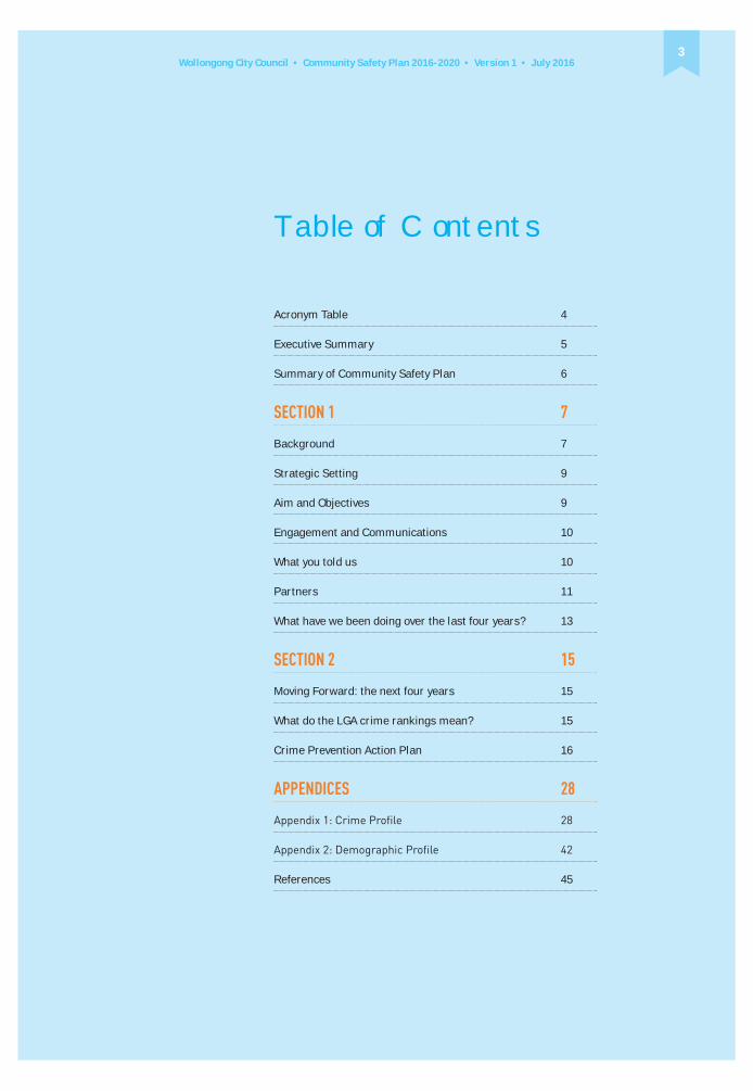
Wollongong City Council • Community Safety Plan 2016-2020 • Version 1 • July 20163
Table of Contents
Acronym Table 4
Executive Summary 5
Summary of Community Safety Plan 6
SECTION 1 7
Background 7
Strategic Setting 9
Aim and Objectives 9
Engagement and Communications 10
What you told us 10
Partners 11
What have we been doing over the last four years? 13
SECTION 2 15
Moving Forward: the next four years 15
What do the LGA crime rankings mean? 15
Crime Prevention Action Plan 16
APPENDICES 28
References 45

Wollongong City Council • Community Safety Plan 2016-2020 • Version 1 • July 20164
ABS Australian Bureau of Statistics
ADF
AFZ Alcohol Free Zone
ASB Anti-Social Behaviour
BOCSAR Bureau Of Crime Statistics And Research
CBD
CCTV Closed Circuit Television
CDAT
CPTED
DA
GLBTI Gay, Lesbian, Bi-Sexual, Transexual, Intersex
ICADV
LAC Local Area Command
LGA Local Government Area
LGCSCPN Local Government Community Safety Crime Prevention Network
NAIDOC
PAL Police Assistance Line
RMS Roads and Maritime Services
SEIFA Socio-Economic Indexes For Areas
Acronym Table

Wollongong City Council • Community Safety Plan 2016-2020 • Version 1 • July 20165
Executive SummaryThe Wollongong Community Safety Plan 2016-2020 is a key instrument to support the vision of the city outlined in Wollongong 2022. It contributes to creating and sustaining a healthy community in a liveable city, with the objective: “Community Safety is Improved” (Wollongong 2022: Community Strategic Plan).
The Community Safety Plan is developed using data from government sources as well as local crime intelligence and information from residents, in an effort to target the crimes and behaviours that have the biggest impact on the local community. Consultations have occurred with internal and external stakeholders and partners as well as the community at large.
Perceptions of safety is included in the data as fear of crime and perception of safety impacts how well Wollongong residents engage and feel connected to one another.
HOW TO READ THIS PLAN
SECTION 1 Contextualises the Plan, providing information on how Wollongong City Council approaches crime prevention and improves community safety. It describes our current and continuing partners and how we have engaged them, as well as the community, in
reviews the actions taken over the last four years and the results of those actions and strategies to improve safety and reduce targeted crimes.
SECTION 2
will be targeted over the coming four
Prevention Action Plan sits within this section and shows the strategies that will be implemented to address each crime as well as the rationale in
on which to focus.
Perceived and actual community safety is included within the Crime Prevention Action Plan because how safe the
on people’s quality of life and wellbeing.
included in this section showing who lives in our area, where the crime hotspots are located and provides a snapshot of what crimes are impacting the community the most.

Wollongong City Council • Community Safety Plan 2016-2020 • Version 1 • July 20166
Summary of Community Safety Plan The actions in the Community Safety Plan 2016-2020 aim to reduce crime and improve community safety. It takes a whole of Council approach and includes support from partners and the community.
The priority crimes that are the focus of the Community Safety Plan
issues and concerns highlighted by the community as well as crime trends in the Wollongong Local Government Area reported by the NSW Bureau of Crime Statistics and Research.
The priority crime terms are in keeping with those reported by the NSW Bureau of Crime Statistics and Research.
Priority Crime Project Lead agency and partners
Expected outcome
1. Malicious damage Reduce damage to property including
opportunities for it to occur and making it less rewarding for offenders.
Wollongong City Council, NSW Police, NSW
Corrective Services of NSW, the business sector and residents.
Improved perception of safety and pride in place due to a reduction in
2. Assault domestic violence
Reporting of domestic violence assault increases due to campaigns that raise awareness and promote support services in Wollongong.
Illawarra Committee
Business Community.
Reporting of domestic violence will increase.
Figures for attendance at the annual White Ribbon Walk will continue to rise.
3. Assault non-domestic violence (alcohol related)
Opportunities for alcohol related assault are reduced as a result of community education and community partnership strategies.
NSW Police, Wollongong City Council, Wollongong Liquor Accord, Wollongong Transport Committee, Community
Wollongong continues to show a decreasing trend regarding incidents of alcohol related assaults
hotspots.
Travelling home from a late night out in Wollongong is safer.
4. Anti-social behaviour (ASB) including harassment, threatening and offensive behaviour
Anti-social behaviour including harassment and threatening behaviour is reduced.
Wollongong City Council, residents, community groups and the business sector.
People feel safer across the LGA.
Incidents of reported and actual ASB are reduced.
5. Perceived and actual community safety
Feelings of safety by residents across the LGA are improved.
Wollongong City Council. Residents feel safer.

Wollongong City Council • Community Safety Plan 2016-2020 • Version 1 • July 20167
BackgroundWHAT IS COMMUNITY SAFETY?Being and feeling safe is the focus of community safety. Being and feeling safe enables community participation, inclusiveness and feelings of belonging that makes using public space, public services and facilities an everyday occurrence. It means we can move through our region, our city and our neighbourhoods by any means: driving, walking, cycling and using public transport. Council has a central leadership role to play in bringing together, identifying and driving the
improve and enhance community safety.
WHAT IS CRIME PREVENTION?Crime prevention from Council’s perspective is about creating an urban landscape that makes it harder to commit crime, activates public space and raises awareness in the community about crime prevention strategies. Community safety and crime prevention go hand in hand to improve safety, reduce crime and reduce the fear of crime that affects quality of life.
HOW DO WE ADDRESS CRIME, FEAR OF CRIME AND COMMUNITY SAFETY?Council uses primary and secondary crime prevention methodologies to address crime, fear of crime and
Situational Prevention: This approach reduces the opportunities to commit crime and increases the risks of being caught to the offender. Situational crime prevention enhances the physical environment so people feel safer in public and private space and
Examples of this approach include:
• Trimming trees and vegetation for clearer sightlines and to reduce the likelihood of hiding
looks and feels inviting
• Providing additional lighting in appropriate locations
• Planting ‘green screens’ to prevent
• Incorporating public art into public places making a place look and feel more attractive
• Organising activities to encourage greater legitimate use of a place
Social Prevention: This approach focuses on the quality of life of residents. Social strategies aim to foster inclusiveness for all the community, giving people from all walks of life and across the region a sense of belonging. People who feel they are valued, with a strong sense of belonging to a community or place are less likely to commit crimes against their neighbours or neighbourhood. Social strategies try to reduce unemployment, improve health, education and affordable housing that provide positive experiences and connect community members.
Activating Space: This approach turns underused public space or space used for criminal or anti-social behaviour into places used by the wider community for legitimate purposes. Events like markets, regular outdoor activities like exercise groups and public art are examples of activating space. When public space is used by people for legitimate purposes, it is less likely criminal or anti-social behaviour will occur there.
Community Development and Early Intervention: These approaches work with ‘at risk’ communities, target high risk neighbourhoods and engage communities to support themselves in developing crime prevention and safety solutions. They are usually longer term strategies using partners like government and non-government agencies and organisations to work with communities to improve their physical and social environments.
SECTION 1

Wollongong City Council • Community Safety Plan 2016-2020 • Version 1 • July 20168
Approaches to Crime PreventionPrimary Crime Prevention
Situational Preventionprevention in mind.
• Crime Prevention through Environmental
that considers lighting, improved sightlines, trimmed trees, green screening and place based public art to minimise opportunities for crime to occur.
Social Prevention• Alleviating poverty
• Improving health and education
• Reducing unemployment
• School based programs
• Organising community safety groups
Activating SpaceEvents, community participation and public art activities are examples that
combine aspects of situational and social crime prevention principles.
Secondary Crime Prevention
Tertiary Crime Prevention
Criminal Justice System
Offender Program
Working with
victims of crime
Community Development
Early Intervention
potential offenders
• Targeting high risk neighbourhoods
• Programs for youth at risk
• Longer term startegy to foster community shared ownership of crime and solutions
• Process of community engagement
Diagram 1: Approaches to Crime Prevention

Wollongong City Council • Community Safety Plan 2016-2020 • Version 1 • July 20169
Strategic SettingRELATIONSHIP TO COUNCIL’S STRATEGIC PLANNINGWollongong City Council has had a Crime
Policy was reviewed and the amended
City Council Community Safety Plan
Community Strategic Plan.
Strategic Plan outlines the Wollongong community’s priorities and aspirations and how these will be achieved. It enables Council to collectively
respond to emerging challenges and opportunities and provides direction for the provision of key projects and services which enable Council to meet the needs of our community.
OUR COMMUNITY VISIONFrom the mountains to the sea, we value and protect our natural environment and we will be leaders in building an educated, creative and connected community.
OUR COMMUNITY GOALS1. We value and protect our environment
economy
3. Wollongong is a creative, vibrant city
4. We are a connected and engaged community
5. We are a healthy community in a liveable city
6. We have sustainable, affordable and accessible transport
WOLLONGONG 2022Goal 5 - We are a healthy community in a liveable cityObjective 5.4 Community Safety is improved
5.4.1 Partnerships continue to strengthen and achieve a safe and accessible community
5.4.3 Safety is considered in the planning and design of any development
Aim and ObjectivesAIM
is a strategic plan of actions that enable Wollongong City Council, together with community stakeholders, other levels of government and the business sector, to strengthen communities and achieve inclusive places and spaces, where crime is prevented and people feel and are safer.
OBJECTIVES• Improve actual and perceived
community safety
• Embed community safety strategies across the whole of Council
• Reduce crimes that have the highest impact in our area

Wollongong City Council • Community Safety Plan 2016-2020 • Version 1 • July 201610
What you told usNSW POLICEWollongong LGA has two Police Commands within its borders: Lake Illawarra and Wollongong Local Area Commands. They both have suburbs
crime and crime targeting within the NSW Police Lake Illawarra Local
suburbs, both of whom have a low SEIFA
This LAC is rated within the top 10 of the
violence takes up most of their time with almost half of their assault call
domestic violence assault (NSW Police, Lake Illawarra Local Area Command Community Safety Precinct meeting,
NSW Police Wollongong LAC also highlighted domestic violence as a crime
This LAC is tasking suburbs which are known crime hotspots as well as the City Centre for alcohol related crime (NSW Police, Wollongong Local Area Command Community Safety Precinct
Established Alcohol Free Zones
Wollongong LGA were renewed for
Commands requested the renewal of these AFZ’s in an effort to reduce public drinking and associated anti-social behaviour. The AFZ’s are located
PERCEPTIONS OF SAFETY SURVEY 90% of residents who participated in
feel completely or mostly safe in their own neighbourhood. More than 70% feel
they feel, generally. In the City Centre, people raised safety concerns about anti-social behaviour - 36%, drug related issues - 33%, alcohol related issues -
COMMUNITY ENGAGEMENT
response. As an art form, not just ‘tags’, people of all ages thought it enhanced public space and made it look good. Tagging however, “could make a place look dirty, was a form of littering and sends the wrong message that damaging property was OK” (young woman’s
residents felt tagging increased their fear of crime thereby reducing their quality of life. They felt unable to safely walk around their neighbourhood, especially when tags were evident on private property like fences.
Some people are fearful of intoxicated strangers in public and residential estates. Consultations with older people revealed intoxicated and drug affected strangers in public prevented them from walking in their neighbourhoods and shopping centres. They also said they feared alcohol affected people could become violent. They told us they have witnessed shouting and abusive behaviour in public places by people they believed were alcohol or drug affected.
Breaking the Ice’ forum, held in
concerns from the general community about the impact and resources available for families affected by ‘ice’ addiction.
Unlit and isolated places with derelict buildings generated fear of crime and made people feel unsafe. Anti-social behaviour was an issue that concerned people who participated in the consultations. Types of anti-social behaviour include threatening and intimidating behaviour, often by people
Engagement and CommunicationsThe Plan draws together crime intelligence from NSW Police Lake Illawarra and Wollongong Local Area Commands, Australian Bureau of
of Crime Statistics and Research
We have asked the community their safety priorities, what crimes most affect them and how they perceive their own safety. We have spoken with particular
communities like young people of the Gay, Lesbian, Bisexual and Transgender community, older carers of people who live with a disability and members of the multicultural community.
We’ve spoken with Council’s Aboriginal and Community Safety Reference Groups. We’ve gone to Council’s Neighbourhood Forums to speak with the community where they live.
We ran a survey across the whole LGA
people how safe they feel, in the day time, at night, where they live and where they work. We asked them if there are
and what issues concern them the most.
The Plan was placed on public exhibition for four weeks for further comment.
all these sources to develop an action plan focusing on community safety and

Wollongong City Council • Community Safety Plan 2016-2020 • Version 1 • July 201611
Partners
INTERNAL PARTNERS
Council Division Community Safety Activities
Regulation and Enforcement Animal control, illegal dumping, noise control, parking.
Assess development applications city wide using controls
Community, Cultural and Economic Developmentcommunity safety, Aboriginal, multicultural, cultural, aged
Public art and creative spaces strategies.
Business development such as the building façade revitalisation program in the City Centre and the development of the Evening Economy Strategy.
Alcohol Free Zones.
Property and Recreation Life guards and water safety education.
Environmental Strategy and Planning
City Works and Services
Infrastructure Strategy and Planning Road safety.
who others thought were alcohol or drug affected. Anti-social behaviour of this kind impacted on people’s amenity.
People are still concerned with crimes like domestic and other violence and the impacts on the community of
drug and alcohol abuse, in spite of the general downward trend of crime across NSW. Residents who hear shouts and screams from neighbours were severely affected by this and highlighted domestic violence as a crime they
were most concerned about. More than one resident revealed they lived near families they thought were living with domestic violence.

Wollongong City Council • Community Safety Plan 2016-2020 • Version 1 • July 201612
EXTERNAL PARTNERSExternal organisations play a key role in supporting Council initiatives. Similarly, Council supports strategies and initiatives that are originated by other agencies and the business sector.
Partner Activities
NSW Police, Lake Illawarra and Wollongong Local Area Commands
Community Safety Precinct meetings.
Community Safety Audits.
Representation on Council’s Community Safety Reference Committee.
Illawarra Committee against Domestic Violence (ICADV) White Ribbon and Reclaim the Night campaigns.
raising.
Community Drug Action Team (CDAT) Community, government and non-government interagency meetings implementing projects such as Creating Synergy Conference and ‘Breaking the ICE’ Forum.
Local Government Community Safety and Crime Prevention Network (LGCSCPN)
Information sharing across NSW Councils.
Education and conferences.
Wollongong Liquor Accorddrinking behaviour that improves community safety and amenity.

Wollongong City Council • Community Safety Plan 2016-2020 • Version 1 • July 201613
What have we been doing over the last four years?Council’s Community Safety Reference Group meets quarterly and brings together partners from NSW Police, Government and non-Government agencies and community members to identify and drive the development
enhance community safety in the Wollongong Local Government Area.
Council has been implementing the
which, after extensive consultation at the
• Assault- non-domestic (alcohol
and anti-social behaviour.
• Steal from motor vehicle.
• Increase real and perceived community safety.
ASSAULT- NON-DOMESTIC (ALCOHOL RELATED)In order to reduce the incidents of alcohol related assault, Council committed to a number of initiatives that encouraged responsible drinking behaviour, improved the community’s understanding regarding alcohol related laws and strengthened partnerships with relevant Government and non-Government agencies including the business sector.
These strategies and projects included:
• In the Midnight Hour- a research project in partnership with Wollongong TAFE uncovering the reality of a Saturday night in the City Centre and the issues faced by people enjoying a night out, highlighting the lack of late night transport options as the biggest factor in people’s safety.
• Hassle Free Night- a project attempting to address late night transport issues by disseminating information about transport options.
• City Centre Evening Economy Action Plan- a range of strategies to encourage responsible drinking behaviour through the establishment of small bars and licensed eateries. The Strategy supports a mix of public and private events and attractions in key areas of the City by simplifying the event application process for 10 events per area per annum. Activating key areas within the City, especially outside normal business hours, generates places that are people-friendly and non-threatening, reducing the opportunity for criminal activity.
Prohibited Places - supporting Police and the community to reduce alcohol fueled incidents in public places across Wollongong. There are seven
that have Alcohol Prohibited Place status.
• Partnerships with the NSW and Local Liquor Accords- to continue working collaboratively in reducing incidents fueled by alcohol and continue to improve Wollongong’s reputation as a destination for a safe night out.
Results from these combined strategies as well as support from Wollongong and Lake Illawarra Licensing Police shows a decrease of 10.6%* in alcohol related
* NSW Bureau of Crime Statistics and Research, July 2007-June 2014.
ASSAULT- DOMESTIC VIOLENCE Council supports NSW Police and non-Government agencies working in the area of reducing family and domestic violence by partnering with the Illawarra
Reclaim the Night and White Ribbon Campaigns.
Results from these National campaigns as well as the work done by NSW Police and the NSW Court Assistance Scheme show domestic violence is stable # in the
is considered stable #
however there are spikes recorded during that time.
# NSW Bureau of Crime Statistics and Research, July 2010-June 2015.
MALICIOUS DAMAGE TO PROPERTY FROM GRAFFITI AND ANTI-SOCIAL BEHAVIOUR
property from anti-social behaviour is
across Wollongong.
Strategies to reduce property damage
Council assets
encouraging residents to report
• City Centre Special Rate Levy for community safety initiatives including
Centre
• Community development programs supporting artists and the community to deliver art on bus shelters and Roads and Maritime Services signal boxes as well as public art on buildings and promenades, thereby
hotspot areas throughout Wollongong

Wollongong City Council • Community Safety Plan 2016-2020 • Version 1 • July 201614
Corrective Services and community organisations like Rotary and
from non Council assets, and work with offenders as well as people with a disability who receive training and are supported to become job ready.
• Assessing new developments using Crime Prevention through
buildings, riskier to offenders and less rewarding to commit this crime.
Results
* NSW Bureau of Crime Statistics and Research, July 2010- Dec 2014.
STEAL FROM MOTOR VEHICLESteal from motor vehicle is a common crime on the coast during summer and at any time in commuter car parks. Beachgoers hide keys on cars and commuters leave valuables in plain sight resulting in theft of personal items as well as car stereos and other devices.
Private residence car ports and driveways are other hot spots targeted by opportunistic offenders looking for unlocked cars and easy access to valuables. Wollongong City Council’s
regular Community Safety Precinct meetings with NSW Police Lake Illawarra and Wollongong Local Area Commands that provide information on the most prevalent crimes committed in the area.
Police Wollongong Local Area Command
screws for car license plates in one of Council’s car parks to reduce the incidence of stolen plates that are often used on vehicles involved in crimes.
Results indicate this crime is stable over
^ NSW Bureau of Crime Statistics and Research, Jan 2011- Dec 2015.
INCREASED REAL AND PERCEIVED COMMUNITY SAFETYHow safe we feel is often directly related to the look of public space: where we live, work and recreate. Community Safety initiatives that improve public space and the built environment include:
• Community Safety Audits- these are conducted with and without NSW Police in response to issues and concerns raised by community, NSW Police or other stakeholders. Community Safety Audits provide on-site observations and recommendations that make facilities and public spaces feel and look safer and reduce opportunities for crime and anti-social behaviour to occur.
assessments against Crime Prevention through Environmental
developments across Wollongong. The assessments comment on lighting, sightlines, boundary reinforcement and access points as well as the use of appropriate landscape designs for green screening and other initiatives that minimise opportunities for crime.
that activate spaces that may otherwise be isolated or underused. Place-based projects involve community and residents in improving the design and look of public places through the use of public art and engagement strategies.
community development programs
Project coordinating the enthusiasm and strength of the local residents, businesses and other levels of government in creating community driven action plans to improve safety and reduce crime.
Results tabled in the Perceptions of
feel completely or mostly safe walking around their local area and workers/students felt 73.6% completely or mostly safe walking around their local area
students who live within the City Centre
generally.

Wollongong City Council • Community Safety Plan 2016-2020 • Version 1 • July 201615
SECTION 2
Moving forward: the next four yearsconsultations with NSW Police, Lake Illawarra and Wollongong Local Area Commands, the business sector and
crimes as well as improving how safe the community feels. It also includes information from the Australian Bureau
While the crimes targeted in this
not shown an upward trend over the last
the local community. Many crimes are under reported to NSW Police, making the statistics generated from crime
of incidents and the real impact to the community.
shows that:
“When it comes to household crime, malicious property damage continues to be the most common, with over half a million homes - about 6% - experiencing it”. Half the people who experienced property damage didn’t report the incident to police, most commonly thinking it was too trivial to report.
there was nothing the Police could do.
Regarding assault, the ABS Crime
“Being threatened with assault - in a face-to-face situation - is still the most common type of personal crime, with nearly half a million Australians experiencing this sort of threat,” said William Milne from the ABS. “For men, the threat was most likely to come from a stranger, while for women it was more likely to come from someone they knew. Almost two-thirds of people who were threatened with assault didn’t report the incident to police, often because they thought the incident was too trivial or unimportant. People also felt that alcohol or other drugs contributed to the incident in around half of all cases”.
Similarly regarding threatening
experienced face-to-face threatened assault reported their most recent incident to police.
Many of the crimes targeted within the Community Safety Plan over the next four years are interrelated. Alcohol related assault can often go hand-in-hand with anti-social behaviours. Anti-social behaviours also include malicious
Priority crimes:
• Assault- domestic violence and non-domestic violence related (alcohol related)
• Anti-social behaviour including harassment and threatening behaviour
Priority for community safety:
• Increase actual and perceived community safety
suburbs that are crime hotspots. Living and working in and around these hotspots generates fear for one’s safety and reduces the community’s amenity within these areas.
projects that reduce crime in these hotspots will improve the community’s feelings of safety, reduce their fear of crime and positively impact on their quality of life. Reducing crime in these locales will also reduce the number of victims of crime in these suburb hotspots, regardless of whether or not they report the crime.
What do the LGA crime rankings mean? The NSW Bureau of Crime Statistics
have populations greater than 3000.
139 such Local Government Areas.
Rankings are statistical equations that factor in the number of incidents
of reported crime against a rate per 100,000 population.
If an LGA is ranked #1 out of 139
crime it indicates the highest incidents of that crime against the population rate within that LGA. Being #1 in this instance is to be avoided. Being closer
to the bottom, or ranked last for a particular crime, is a better ranking indicating a community with fewer reported incidents of that crime per population.

Wollongong City Council • Community Safety Plan 2016-2020 • Version 1 • July 201616
Crime Prevention Action Plan 2016-2020
Project: it less rewarding for offenders.
Rationale: years. Wollongong LGA is ranked 60 out of 139 Local Government Areas in NSW*.
state average**.
Objective:
Lead Agency/partners:Wollongong business community.
Expected outcome:
* NSW Bureau of Crime Statistics and Research (BOCSAR) 2015
** Crime profile Appendix 1

Wollongong City Council • Com
munity Safety P
lan 2016-2020 • Version 1 • July 201617
Action Performance measures Time frames Funding Partners Milestones
1.1 Assess building development applications against CPTED controls to
opportunities
completed
Ongoing Existing operational budget
Assessment and • All major building
development applications are referred by
1.2 Conduct rapid
on Council assetsa week in the City Centre and Special Rates Levy boundary
on Council assets is
it being reported
Ongoing
Ongoing
Special Rates Levy
Existing operational budget
• City Works and Services
• The City Centre is free of
Safety Survey indicates an improvement in how safe the community feels
1.3 Support the
from non-Council assets
• Record the numbers
provided to asset owners to
to partner agencies are removed by those agencies for this purpose
Ongoing
Ongoing
Existing operational budget
• Community Partners
• Community and Government agencies
• Asset owners contribute to
their own assets
• External agencies continue to partner with Council in removing
assets
1.4 Conduct place-based
hot spot areas
• Participate in and promote
reduction and prevention projects are conducted as appropriate
Conducted annually
Ongoing
Existing operational budget
External funding, when secured
• Place-based community organisations
• Community participates in
own neighbourhoods
Table continues overleaf.

Wollongong City Council • Com
munity Safety P
lan 2016-2020 • Version 1 • July 201618Action Performance measures Time frames Funding Partners Milestones
1.5 Participate in arts-based
partnership projects
• A minimum of 10 bus shelters are painted with
• A minimum of 10 Roads and Maritime Services
Ongoing Existing operational budget
RMS funding
• Cultural Services
• Place-based organisations and communities
• Roads and Maritime Services
• RMS and Council readily support art on bus shelters and RMS signal boxes
• Perception of safety survey indicates people feel safer
1.6 Promote Council’s
and other malicious damage
• Increase in the numbers of
4 years
Ongoing Existing operational budget
• Wollongong City Council Customer Service
• There has been an increase in reporting
1.7 Retailers selling spray cans are audited for legislative compliance
• Number of retailers’ audits completed
NSW Police operational budget
• NSW Police • Retailers comply with legislation regarding sales of spray cans
1.8 Conduct community safety audits
• All customer service requests for community safety audits are investigated
Ongoing Existing operational budget
• NSW Police
• Place-based organisations and communities
based organisations and communities request community safety audits

Wollongong City Council • Community Safety Plan 2016-2020 • Version 1 • July 201619
Project: Reporting of assault domestic violence increases due to campaigns that raise awareness and promote support services in Wollongong.
Rationale:
Wollongong ranks 74 out of 139 LGAs with a steady increase in the number of reported incidents from
crime with NSW Police Lake Illawarra LAC ranking 6th in NSW**.
average***.
Objective: Increase reporting of domestic violence assault in the Wollongong LGA. Provide support for local networks and services in raising awareness about domestic and family violence in Wollongong.
Lead Agency/partners:
Expected outcome: Reporting of domestic violence will increase. Figures for attendance at the annual White Ribbon Walk will continue to rise.
* NSW Bureau of Crime Statistics and Research, 2014
** Lake Illawarra and Wollongong Local Area Command Community Safety Precinct meetings, 2015/2016
*** Crime Profile Appendix 1

Wollongong City Council • Com
munity Safety P
lan 2016-2020 • Version 1 • July 201620Action Performance measures Time frames Funding Partners Milestones
2.1 Work in partnership with lead agencies that provide support for victims of family and domestic violence to share information and raise awareness about the issue
• Regular attendance at meetings held by the Illawarra Committee
Ongoing Existing operational budget
• The production and distribution of an
showcasing all services available for families in the region
and training are scheduled annually
2.2 Support White Ribbon and Reclaim the Night campaigns
• Illawarra White Ribbon Walk held each year
• Reclaim the Night held each year
Annually Existing operational budget
• White Ribbon Illawarra Committee
• Reclaim the Night Committee
• Both campaigns are included in Council’s Annual Plan

Wollongong City Council • Community Safety Plan 2016-2020 • Version 1 • July 201621
(alcohol related)
Project: Opportunities for alcohol related assault are reduced as a result of community education and partnership strategies with Wollongong Liquor Accord members, improving transport options for late night revellers.
Rationale: Wollongong is ranked 60 out of 139 LGAs for recorded incidents of non-domestic violence assault. This ranking shows Wollongong has the highest incidents per capita of all LGA’s in the Illawarra*.
36.1% of all non-domestic violence assaults and are linked to alcohol* According to the ABS** 67.4% of men and 54.7% of women believed alcohol or other substances contributed to their assaults and 90.7% of people believed their assaults that occurred in a licensed venue had alcohol as a contributing factor. Wollongong is a regional hub for night entertainment whose reputation is improving regarding safer night time revelling due in part to the implementation of the Wollongong Evening Economy Action Plan. The strategy encourages activation of public space and the growth of small late night venues that support responsible drinking culture.
Objective: Reduce incidents of alcohol related non-domestic violence assaults.
Lead Agency/partners:
Expected outcome: Wollongong continues to show a decreasing trend regarding incidents of alcohol related assaults in
Travelling home from a late night out in Wollongong is safer.
* NSW Bureau of Crime Statistics and Research, 2014
** Australian Bureau of Statistics Crime Victimisation Survey 2013-2014

Wollongong City Council • Com
munity Safety P
lan 2016-2020 • Version 1 • July 201622Action Performance measures Time frames Funding Partners Milestones
3.1 Comment against CPTED Principles regarding Development Applications for liquor licences
• 100% of all new liquor licence applications are referred to community safety for comment
Ongoing Existing operational budget
Assessment and Compliance
• The process for referring new liquor licences against community safety is a standard operating process
3.2 Respond to requests from NSW Police and the community for alcohol free public places
and Alcohol Prohibited Places are reviewed every four years
• All customer service requests relating to alcohol free public places are investigated
Existing operational budget
• Public Relations and Communications
• Infrastructure Systems and Support
• NSW Police
• All AFZ and Alcohol Prohibited Places are mapped and available on Council’s website for the community’s information
• AFZ’s and Alcohol Prohibited Places are re-established where and when appropriate
3.3 Conduct safety audits focusing on consumption of alcohol in public spaces
• All customer service requests for safety audits are investigated
As requested Existing operational budget
• NSW Police
• Community
• Community groups
• People acknowledge Council has a role to play in restricting the consumption of alcohol in public spaces
3.4 Undertake partnerships with CDAT and youth based services to support and promote community development and education programs that target unlawful consumption of alcohol
• Talking Tactics Together is conducted in public schools
• Community resources are produced
• Community forums are conducted
Ongoing External funding
programs if successful
• Wollongong Liquor Accord
• NSW Police
• Community acknowledges its responsibility in reducing drinking habits of young people
Table continues overleaf.

Wollongong City Council • Com
munity Safety P
lan 2016-2020 • Version 1 • July 201623
Action Performance measures Time frames Funding Partners Milestones
3.5 Promote and attend Wollongong Liquor Accord meetings
• Number of meetings attended
Ongoing Existing operational budget
• Wollongong Liquor Accord
• NSW Police
• The partnership between Council, NSW Police and Wollongong Liquor Accord is strengthened
3.6 Conduct a comparative study of incidents of assault and anti-social behaviours experienced by revellers late at night during peak times (12-5am) in the CBD
the level of violence and anti-social behaviour experienced by revellers in Wollongong during peak times
Subject to external funding
• Community Partnerships and Safety Team
• TAFE Wollongong
• Wollongong Liquor Accord
• Provide information to Council’s partners to reduce alcohol related

Wollongong City Council • Community Safety Plan 2016-2020 • Version 1 • July 201624
including harassment, threatening and
Project: Anti-social behaviours including harassment and threatening behaviour is reduced through the activation of Wollongong Crown St Mall and other public spaces that are otherwise underused or isolated from regular activity.
Rationale:
thought anti-social behaviour throughout the LGA was an issue Council needed to reduce. Reported alcohol related offensive behaviour is considered trending downwards by 17.3%* over the
thought the incident too trivial to report and 9% thought there was nothing police could do. Suburbs with high numbers of incidents for anti-social behaviour showed much higher numbers of incidents than the state average**.
Objective: Reduce the incidents of ASB in the city centre as well as other public places throughout Wollongong LGA.
Lead Agency/partners: Wollongong City Council, NSW Police and City Centre Management.
Expected outcome: People feel safer in the Crown St Mall and other public places. Incidents of reported and actual ASB are reduced.
* NSW Bureau of Crime Statistics and Research, 2014
** Crime Profile Appendix 1

Wollongong City Council • Com
munity Safety P
lan 2016-2020 • Version 1 • July 201625
Action Performance measures Time frames Funding Partners Milestones
4.1 Work in partnership to develop localised place-based activation strategies to improve safety and amenity in hot spot areas
• Numbers of partnership projects and activation strategies.
• ASB is reduced.
Ongoing Existing operational budget
• Place-based organisations
• Place-based Chambers of Commerce
• Community
• Public places in hotspot locations are activated and used by residents.
4.2 Assess building development applications using CPTED Principles that encourage valid social activity
Ongoing Existing operational budget
Assessment and Compliance
• NSW Police
• All new building development applications are referred to Community
assessments.
4.3 Conduct safety audits at facilities and public spaces in hot spot locations
• All customer service requests for community safety audits to reduce ASB are investigated.
Ongoing Existing operational budget
• Branch Libraries and Community Facilities
• Sporting clubs and facilities
• Community
• NSW Police
• Community and partners acknowledge Council’s role in reducing ASB.

Wollongong City Council • Community Safety Plan 2016-2020 • Version 1 • July 201626
5. Priority for community safety: perceived and actual community safety
Project: Feelings of safety by residents across the LGA are improved.
Rationale: mixed feelings regarding how safe they feel. The Survey highlighted areas they felt less safe within the City Centre as well as what contributed to these feelings and what Council needed to focus on, moving forward.
Objective: To improve the actual and perceived feelings of safety for residents.
Lead Agency/partners: Wollongong City Council.
Expected outcome: Residents feel safer.

Wollongong City Council • Com
munity Safety P
lan 2016-2020 • Version 1 • July 201627
Action Performance measures Time frames Funding Partners Milestones
5.1 Conduct a comparative LGA wide Perceptions of Safety Survey with Wollongong residents
• Comparative Perceptions
are published.
people feel safer where they live, recreate and shop.
Additional funding
• Public Relations and Communications
• External consultant
• Comparative Perceptions of Safety Survey is completed.
of the Perception of Safety Survey provides a benchmark about how the community feels in the public arena.
5.2 Develop and implement projects that reduce residents’ concerns highlighted in the comparative Perceptions of Safety Survey
• Projects that activate public space are developed and implemented.
Subject to funding
• Community Partnerships and Safety Team
• Communities actively participate in the development and implementation of activation projects.
Note: All previous actions in the priority crime action tables contribute to and support improving the community’s actual and perceived feelings of safety.

Wollongong City Council • Community Safety Plan 2016-2020 • Version 1 • July 201628
APPENDICES
Appendix 1:
Information and tables below were created from data retrieved from the Bureau of Crime Statistics and Research using their online crime data tools and
extracted and presented covering four prevalent offences in the LGA:
• Harassment Threatening Behaviour and Private Nuisance
The methodology used to review each offence involved:
1. A general assessment of the offence, ranking it against other NSW LGAs and incident trends over a 36 month
along with looking at the effect of alcohol on this offence;
the offence has most commonly occurred;
3. Assessing when offences have been occurring i.e. weekends or weekdays; and
4. Numbers of Adult / Child Offenders; and numbers of Male and Female

Wollongong City Council • Community Safety Plan 2016-2020 • Version 1 • July 201629
General LGA Hot Spots Priority Incident times Offenders & Victims
ranked 60th out of all NSW LGAs for this crime - an improvement from the previous year
worse compared to
• The number of Assault
incidents in the LGA declined 9.9% per year
• Alcohol related Assault
spot areas primarily situated in and around town centres namely Berkeley, Corrimal,
Thirroul, Unanderra, Warrawong, Wollongong and Woonona with Bellambi being the exception.
hot spot areas, except Wollongong, were stable over the 3 year period. Wollongong recorded a 9.9% downward trend per year.
during weekday nights
year across the LGA.
the weekend whereas
during the weekday over the 3 year period.
during weekend nights
year across the LGA.
• Adult male offending
whereas adult female offending was steady.
• Adult offenders were
• Male juvenile offenders
• Male victim trends decreased 10.5% per year over the LGA whereas adult female victim trends were steady.
of adult victims were male compared to 749
victims were male
1. Assault Non-Domestic Violence
General • From 139 Local Government Areas
(that have populations greater than
improvement from the previous year where the LGA was ranked 54th, but
http://bocd.lawlink.nsw.gov.au/bocd/
• According to NSW Crime Statistics, the number of assault non-domestic violence incidents in the LGA declined
state, with the number of incidents declining 5.6% per year.
• Alcohol related assault non-domestic violence across the LGA decreased
LGA Hot Spot• Higher assault non-domestic violence
occurred in certain areas known as hotspots (see Map 1.0: LGA’s Assault
and around town centres for Berkeley,
Thirroul, Unanderra, Warrawong, Wollongong and Woonona, with Bellambi being the exception.
• Assaults rates per 100,000 population in all hot spot areas (except
3 year period. Wollongong recorded a 9.9% downward trend per year.
• Graph 1: Top Ten Assault Non-
Rates per 100,000 population from Oct Wollongong,
Warrawong and Bellambi as having the highest assault rates.

Wollongong City Council • Community Safety Plan 2016-2020 • Version 1 • July 201630
Map 1: LGA’s Assault Non-Domestic Violence Hotspot Areas.

Wollongong City Council • Community Safety Plan 2016-2020 • Version 1 • July 201631
Priority Incident Times • Assaults non-domestic violence
incidents during weekday nights from
assaults during weekday days over the same time period were stable.
• 35% of non-domestic violence assaults occurred in the weekday days as oppose to 65% occurring during weekday nights.
• Total number of non-domestic violence assaults analysed showed
occurred over the weekday times.
• Assault non-domestic violence incidents during weekend nights
LGA. However during weekend days the incident numbers were stable.
assaults occurred in the weekend day as oppose to 71% occurring during weekend nights.
Offenders• The trend of adult males offending
adult female offender trends were steady.
• The number of adult male committing this assault offence over
female assault offenders of
• The numbers of child / juvenile male and female offenders consisted of 99
female offenders.
Victims• Adult male victims decreased 10.5%
whereas adult female victim trends were steady.
• The number of adult male victims
period – over double the number of adult female assault victims of 749
• The numbers of child / juvenile male
female victims.
Graph 1: Top Ten Assault Non-Domestic Violence Hotspot Suburb Rates per 100,000 population from Oct 2014 to Sept 2015.

Wollongong City Council • Community Safety Plan 2016-2020 • Version 1 • July 201632
General LGA Hot Spots Priority Incident times Offenders & Victims
ranked 74th out of all NSW LGAs, compared to previous years of
• The number of Assault
incidents in the LGA was steady from Oct
• Alcohol related Assault
incidents decreased 9.4% per year from Oct
occurred in a number of hot spot areas with incident counts being stable. However downward trends were recorded in Berkeley
and Bellambi (down
highest in Warrawong, Bellambi and Unanderra from Oct 14
during weekdays and weekends (day and
steady.
over the weekend
occurred over the weekday times over the 3 year period.
• Adult and juvenile offender trends over the 3 year period for both males and females was steady.
• Adult offenders were
• Male juvenile offenders
• Adult male victim trends were steady per year whereas adult female victim trends were down 5.9% per year.
of adult victims were male compared to 1567
2. Assault Domestic Violence Related
General • From 139 Local Government Areas
(that have populations greater than
compared to the previous two years
(LGA ranking tool http://bocd.lawlink.
13/14 and 730 in 14/15. Over this same period, the number of incidents across the state was stable.
Assault incidents across the LGA
year.
LGA Hot Spots
across the LGA that have high number
and include:
Map 2:
Port Kembla, Farmborough Hts., Unanderra, Warrawong and Windang
Map 3:Fairy Meadow, Keiraville, North Wollongong, Tarrawanna and Wollongong
Map 4:Bulli, Corrimal, East Corrimal and Woonona
• Trends for domestic related assaults have been steady for most of these suburbs over the 3 year period to Sept
that recorded decreases and include
Warrawong, Bellambi and Unanderra recorded the highest rates over the Oct 2014 to Sept 2015 period.

Wollongong City Council • Community Safety Plan 2016-2020 • Version 1 • July 201633
Map 2: LGA Southern Suburb Hotspots for Assault Domestic Violence Related Crime.

Wollongong City Council • Community Safety Plan 2016-2020 • Version 1 • July 201634
Map 3: LGA Central Suburb Hotspots for Assault Domestic Violence Related Crime.

Wollongong City Council • Community Safety Plan 2016-2020 • Version 1 • July 201635
Map 4: LGA Northern Suburb Hotspots for Assault Domestic Violence Related Crime.

Wollongong City Council • Community Safety Plan 2016-2020 • Version 1 • July 201636
Graph 2: Top Ten Assault Domestic Violence Hotspot Suburbs Rates (Per 100,000 Population) from Oct 2014 to Sept 2015.
Priority Incident Times
during weekday nights and days and weekend nights and days all recorded
occurred in the weekend days as oppose to 60% occurring during weekend nights.
occurred over weekends whereas 1311
Offenders• The 3 year trend for adult and juvenile
offenders for both male and female was steady.
• The number of adult males
offence over the 3 year period totalled
• The number of child / juvenile male and female offenders compared to
offenders.
Victims• The 3 year trend of adult male victims
was steady whereas adult female victim trends were down 5.9% per year.
• The number of adult male victims
female assault victims numbered
• The child / juvenile male victim 3 year trend was steady with female child
• The numbers of child male victims

Wollongong City Council • Community Safety Plan 2016-2020 • Version 1 • July 201637
General LGA Hot Spots Priority Incident times Offenders & Victims
ranked 60th out of all NSW LGAs, compared to previous years of
• The number of incidents in the LGA
• Wollongong was ranked 9th in the state for
incidents in most hot spot areas was steady.
• However downward trends were recorded in Wollongong (down
Port Kembla (down
to Property rates were the highest in Warrawong, Bellambi and Wollongong from
• Incidents during weekdays and weekends (day and
recorded downward trends.
Property data showed
occurred over the weekend whereas
occurred over the weekday times over the 3 year period.
• Adult and juvenile offender trends over the 3 year period for both males and females was steady.
• Adult offenders
• Male juvenile offenders
Note: There are no crime statistics available on Victims for this offence.
General• From 139 Local Government Areas
for this crime - worse than the previous
(LGA ranking tool http://bocd.lawlink.
• The number of malicious damage to property incidents in the Wollongong
NSW state incident counts declined 9.6% per year over the same period.
9th out of the 139 Local Government
incidents (NSW Bureau of Crime
over the last four years.
and 4.outdoor/public places (14.9 per
LGA Hot Spots• Map 5 shows suburbs across the LGA
that have high malicious damage to property incidents known as hot spots. Areas which experienced high
Bulli, Corrimal, Thirroul, Woonona, Balgownie, Fairy Meadow, Figtree, Keiraville, Mangerton, Tarrawanna, Towradgi, Wollongong, Berkeley,
Port Kembla, Unanderra, Warrawong and Windang.
• Trends for malicious damage to property have been steady for many of these hot spot suburbs over the
there were decreases in several suburbs including Wollongong down
• Suburbs that recorded the highest incidents over this period included
• Graph 3.0 shows the top three suburbs with the highest rates per 100,000
Wollongong.

Wollongong City Council • Community Safety Plan 2016-2020 • Version 1 • July 201638
Map 5: Incidents of Malicious Damage to Property Hotspots Oct 2012 – Sept 2015.

Wollongong City Council • Community Safety Plan 2016-2020 • Version 1 • July 201639
Graph 3: Top Ten Malicious Damage to Property Hot Spot Suburb Rates Per 100,000 population over the Oct 2014 to Sept 2015 period.
Priority Incident times
times all recorded downward trends
nights down 10.5%, weekday days
• 57.7% of damage to property incidents occurred in the weekend days as
weekend nights. Conversely, 31.4% of occurred during the weekday days and
• Total number of incidents showed
weekday times.
Offenders• The 3 year trends for adults and
juvenile for both males and females damaging property were all steady.
• The number of adult males damaging property over the 3 year period
• The number of child / juvenile

Wollongong City Council • Community Safety Plan 2016-2020 • Version 1 • July 201640
General Priority Incident times Offenders and Victims
out of all NSW LGAs, better than
• The number of anti-social incidents for the LGA from Oct
being steady.
• Alcohol related harassment incidents fell 11.1% per year from
LGA.
suburbs with the highest anti-social rates per 100,000 population were Wollongong followed by Unanderra.
• Harassment incidents during weekend nights and days and weekday days were steady. Weekday night trends declined
occurred over the weekend
over the weekday times over the 3 year period.
• Adult and juvenile offender trends over the 3 year period for both males and females was steady.
• Male victim trends were steady per year whereas adult female victim
victims were male compared to
female.
Note: There are no hot spot crime statistics for this offence.
General• From 139 Local Government Areas,
this offence – two places better than
ranking tool - http://bocd.lawlink.nsw.
• According to NSW Crime Statistics the trend for anti-social incidents for the LGA was recorded as being steady
the trend for the NSW state of also being steady.
• The number of alcohol related harassment incidents fell 11.1% per
the LGA. The NSW trend was steady over the same period.
• The top ten suburbs that recorded the highest number of incidents over the 3 year period included Wollongong
for all suburbs was steady. However the rates per 100,000 population shown in Graph 4.0 reveal Warrawong having the highest rate followed by Wollongong and Unanderra.
4. Anti-social behaviour including harassment and threatening behaviour

Wollongong City Council • Community Safety Plan 2016-2020 • Version 1 • July 201641
Graph 4: Top ten suburbs showing incidents of harassment rates per 100,000 population.
Priority Incident Times• Harassment incident trends over the
3 year period during weekend nights and days and weekday days were steady. Weekday night trends declined
occurred in the weekend days as oppose to 57.3% occurring during weekend nights. Conversely, 70.1% of incidents occurred during the weekday
nights.
• Total number of incidents showed
weekday times.
Offenders• The 3 year incident trends for adults
and juvenile for both males and females committing anti-social behaviour was steady.
• The number of adult males charged for harassment over the 3 year period
female offenders numbered 110
• The number of child / juvenile offenders over the same 3 year period
Victims• The 3 year trend for adult female
victims was steady whereas adult
year.
• The number of adult male harassment victims over the 3 year period totalled
harassment victims tallied 1430
• The numbers of child male

Wollongong City Council • Community Safety Plan 2016-2020 • Version 1 • July 201642
Appendix 2:
service .id.
Who We Are?
Number of People
Age Distribution
• 16.3% were aged over 65 years; compared with the following respective
were in the age groups:
Diversity: Cultural Identity, Place of Birth, Language Spoken at Home
16.7% spoke a language other than English at home with the most common languages other than English spoken at home being:
Table continues overleaf.

Wollongong City Council • Community Safety Plan 2016-2020 • Version 1 • July 201643
Who We Are?
Income Distribution Household income is an important indicator of socio-economic status. The amount of income a family generates is linked to a number of factors: the number of workers in the household; the percentage of people unemployed or
members.
The median household income was $1,101 per week which was $136 less than the NSW median, with 7% of Wollongong total households classed as low
Median household incomes ranged from a low of $669 in the suburb of
and Kembla Heights.
Housing
• 34.3% of the population fully owned their dwelling.
• 30.1% were purchasing i.e. have a mortgage.
• 9.7% were experiencing mortgage stress.
• 31.5% were experiencing rental stress.
Family Structure and Household
• 11.7% one parent families.
• lone person u 3934
• couples without children u
u
Table continues overleaf.

Wollongong City Council • Community Safety Plan 2016-2020 • Version 1 • July 201644
Who We Are?
Employment and Workforceto 5.9% in New South Wales. Wollongong’s workforce is comprised of:
• 56% full time workers
• 35.1% part time workers
• 15.3% technicians and trades workers
classed as unemployed.
consequently have to commute from another LGA to Wollongong.
People with a Disability and Carers
Access to Information Technologyinternet connection compared to 73.3% in NSW. Broadband connection varied
Kembla and Kembla Heights.
Educational Attainment and
in a tertiary or technical institution.
Homelessness
Source: ABS, Census of Population and Housing: Estimating Homelessness 2011, cat no. 2049
Universitywith 13,414 comprising of international students enrolled in Australia and
Source: UOW 2015 Annual Report Main Report, UOW CRICOS: 00102E. Published April 2016
Tourism
Source: Four year averages to 2013. Sources: ABS Population Estimates - Local Government Areas - Cat. No. 3235.0. ABS Count of Australian Businesses - Cat. No. 8165.0. International Visitor Survey and National Visitor Survey, Tourism Research Australia.

Wollongong City Council • Community Safety Plan 2016-2020 • Version 1 • July 201645
References
http://www.abs.gov.au/AUSSTATS/[email protected]
http://www.bocsar.nsw.gov.au/Pages/bocsar_crime_stats/bocsar_crime_stats.aspx
http://www.crimeprevention.nsw.gov.au/Pages/cpd/protectcommunity/
Wollongong City Council
Force Police Headquarters, Parramatta NSW
strategy, Wollongong City Council
Wollongong City Council Customer Service: Customer Service Centre: Hearing Impaired: 13 3677 Email: [email protected]:

COMMUNITY SAFETY PLAN
Snapshot 2012 - 2016
Prepared by Community Cultural and Economic DevelopmentWollongong City Council

2
PUBLIC SPACESafety is considered in planning and design of all developments.
94 Community safety audits 803
Development Applications assessed using Crime Prevention through Environmental Design criteria
335Liquor licence applications and enquiries
7 Alcohol Free Zones
18 Parks and public places are now Alcohol Prohibited Places
WOLLONGONG CITY COUNCIL • DRAFT • COMMUNITY SAFETY PLAN • SNAPSHOT • 2012-2016
LOCAL CRIME Continues to be prevented and crime is reduced.
square metres of
Day with Dapto
12,146 Pioneer Hall in MacCabe Park, Thirroul public toilet and Bellambi Surf Club
58 Bus shelter murals
City Centre Special
in the City Centre 40Signal boxes with new murals
25 NEW MURALS
This snapshot provides data demonstrating the impact of strategies in the community safety plan 2012-16.
CRIME TRENDSNSW Bureau of Crime Statistics and Research (BOCSAR) tells us crime is heading down.
Malicious damage to property
ASSAULT - domestic violence related
ASSAULT - non domestic violence (alcohol related)
Harassment, threatening behaviour, public nuisance
DOWN EVEN EVEN DOWN

3
IMPROVEMENTS Everyone in Council works to improve community safety.
We use public art, activate empty shops and buildings and hold community events like Viva la Gong and support live music venues to create people-friendly spaces.
Our Evening Economy Action Plan is key to a safe and inclusive Wollongong night life with CCTV coverage, better late night transport and a responsible drinking culture encouraged at all late night venues.
the community with responses to animal control, illegal dumping of rubbish and noise complaints.
Lifeguards hold water and surf safe sessions with overseas tertiary students and community members unfamiliar with our coast.
façades in the City Centre make for a lively and attractive city centre.
We encourage major events, such as festivals, markets, that improve how people feel in the City.
If you love events like Warrawong’s South American Laneway Festival, NAIDOC week, Seniors Week, Youth
Twilight Markets, Australia Day, fEVEr and Living Books, then you’re celebrating our diversity.
We also facilitate community development projects in places like Berkeley, Warrawong and Bellambi supporting community’s strengths.
WOLLONGONG CITY COUNCIL • DRAFT • COMMUNITY SAFETY PLAN • SNAPSHOT • 2012-2016

What next !We’ll be working with the NSW Police commands in Lake Illawarra and Wollongong, using data and information from community groups, crime statistics from BOCSAR and the Australian Bureau of Statistics Crime Victimisation Survey 2013/14 to develop a new Plan. We’ll focus on:
• Assault- Domestic and non-domestic (alcohol related)
• Anti-social behaviour including harassment and threatening behaviour• Perceived and actual community safety
WC
C©
1422
53
4
PEOPLE FEAR
FEEDBACKWe asked and you told us - from the Perceptions of Safety Survey 2015.
90%
FEEL COMPLETELY
70% FEEL SATISFIED
SATISFIED WITH HOW SAFE THEY FEEL
36%
ABOUT ANTI-SOCIAL
33% 24.5%
ABOUT ALCOHOL
23.2%
ABOUT VIOLENT
PEOPLE OF ALL AGES THOUGHT PEOPLE THOUGHT TAGGING – “made a place look dirty, was a form of littering and sent a message that damaging property was ok”
Wollongong City Council Customer Service: (02) 4227 7111 Customer Service Centre: 41 Burelli Street, Wollongong. Monday to Friday 8.30am - 5pm Hearing Impaired: 13 3677 (Australian Communication Exchange) Email: [email protected]: Wollongong City Council. Locked Bag 8821, Wollongong DC NSW 2500
WOLLONGONG CITY COUNCIL • DRAFT • COMMUNITY SAFETY PLAN • SNAPSHOT • 2012-2016
INTOXICATED
IN PUBLIC AND
ESTATES
UNLIT AND ISOLATED PLACES
BUILDINGS
TAGGING DOMESTIC AND
ALCOHOL ABUSE - although these crimes are going down

DEBT RECOVERY AND HARDSHIP ASSISTANCE
COUNCIL POLICY
Adopted by Council: 22 June 2015 P a g e | 1 Trim No: Z14/184793
ADOPTED BY COUNCIL: 22 JUNE 2015
BACKGROUNDCouncil relies on Rates and Charges and fees to fund services and facilities for our community. This policy sets out the approach that Council will take to recover unpaid monies and ensure the reasonable collection of debts.
OBJECTIVE The main objectives of this policy are to –
1 Recover monies owing in a timely and effective manner to finance Council’s operations and ensure effective cash flow management.
2 Provide for a process that is ethical, transparent, compliant with legal obligations, open and accountable.
3 To improve control over debts owed to Council, including overdue rates, fees, charges and interest and to establish a debt recovery approach for the efficient collection of receivables and management of outstanding debts, including alternative payment arrangements and deferrals.
4 To recognise and assist genuine cases of financial hardship and respond with respect and compassion.
5 To establish guidelines for assessment of hardship applications by applying the principles of fairness, integrity, appropriate confidentiality and compliance to the relevant statutory requirements.
6 The key principles that will apply are:
a Council aims to collect all monies owed.
b Council will individually assess cases of financial hardship based on evidence.
c Council will not reduce rates or annual charges but will consider alternative available approaches.
d Council will consider arrangements for periodical payment outside the statutory due dates in cases of hardship, extenuating circumstances or other payment schemes implemented by Council.
POLICY STATEMENT Council recognises that it is in the community’s interest to maximise the collection of monies owed. In maximising its collection of monies, Council will recognise that the collection of these monies needs to be balanced in regards to consideration of those that may be in genuine hardship.

DEBT RECOVERY AND RATE HARDSHIP ASSISTANCE COUNCIL POLICY
Adopted by Council: 22 June 2015 P a g e | 2 Trim No: Z14/184793
PROCEDURE STATEMENT
1 Recovery of Overdue Rates and Annual Charges
• Rates and Charges include all amounts charged in accordance with Section 546 of the Local Government Act, 1993 (Act).
• Rate notices must be issued prior to 31 July each year.
• Instalment notices must be issued to ratepayers paying by instalment one month prior to the instalment due dates, being 31 August, 30 November, 28 February and 31 May.
• Council rates and annual charges are due to be paid in full before 31 August, by quarterly instalments due 31 August, 30 November, 28 February and 31 May each year, or on specific dates determined through an agreement approved by delegated Council officers.
• Interest will be charged daily in accordance with Council’s Revenue Policy after the due date.
• Where payment is overdue and an appropriate payment arrangement has not been agreed, the following recovery actions will be followed:
Reminder Notice.
Letter of Demand from Council’s Solicitor.
Where available and appropriate, additional channels of communication can be used to inform ratepayers of outstanding debts. This may include options such as SMS reminders and telephone calls.
• If those processes are not successful, legal recovery action will commence. Legal recovery process may include the following:
Statement of Claim
Field Calls/Skip Tracing
Judgement
Garnishee
Examination Notices/Summons
Writ of property
Bankruptcy
Sale of Land
• Council retains the discretion to apply the provision of Local Government Act 1993 relating to sale of land for unpaid rates, charges and interest as stated in Sections 713-726. Section 713 provides that Council, where rates and charges have been unpaid for more than five years, may sell the land to recover those outstanding amounts (excluding vacant land which can be sold with only one year’s rates and charges).
• In the case of corporate ratepayers, Council may commence legal recovery proceedings in the Federal Court of Australia.
• Where an account has incurred legal action and all debts subject to that claim have been paid in full, Council will forward notification to Credit Reporting agencies in Australia accordingly.
• Legal Costs and expenses incurred in debt recovery actions will be charged against the property (including costs of tracing a person in accordance with section 605 of the Act).
2 Recovery of Outstanding Sundry Debts (other than Rates and Charges)
• Council will issue Invoices as required or Invoice Statements monthly.
• Where payment is overdue and an appropriate payment arrangement has not been agreed, the following recovery actions will be followed:
Monthly Statements.
Letter of Demand from Council’s Solicitor.

DEBT RECOVERY AND RATE HARDSHIP ASSISTANCE COUNCIL POLICY
Adopted by Council: 22 June 2015 P a g e | 3 Trim No: Z14/184793
Where available and appropriate, additional channels of communication can be used to inform ratepayers of outstanding debts. This may include options such as SMS reminders and telephone calls.
Where available suspension of credit and/or services.
• If those processes are not successful, legal recovery action will commence. Legal recovery process may include the following:
Tribunal orders for property leases (eg Tourist Parks)
Statement of Claim
Field Calls/Skip Tracing
Judgement
Garnishee
Examination Notices/Summons
Writ on property
• Legal Costs and expenses incurred in debt recovery actions will be charged against the Sundry Debtor.
• A Late Payment Fee may be charged where a Letter of Demand from Council’s Solicitor is issued where set in Council’s Fees and Charges.
3 Hardship Assistance
• Council recognises that ratepayers and debtors may experience financial hardship in some circumstances in paying rates, annual charges and fees. A ratepayer may be eligible for consideration for hardship assistance in the payment of overdue rates, annual charges, interest and fees where:
The person is unable to pay due rates, charges, fees or accrued interest when due and payable for reasons beyond the persons control; or
Payment when due would cause the person hardship.
• The Local Government Act permits Council to exercise the following assistance to ratepayers and debtors:
Periodical payment arrangements for overdue rates and charges under Section 564.
Writing off or reducing interest accrued on rates and/or charges under Section 564 and 567.
Waiving, reducing or deferring the payment of the increase in the amount of rate payable because of hardship resulting from a general revaluation of land in the Local Government Area under Section 601.
Waiving or reducing rates, charges and interest of eligible pensioners under Section 575 and 582.
• Applications under Section 601 LGA, 1993 because of hardship resulting from a general revaluation of land must be made during the first year a new land value is used for rating purposes. Where an application is made in the first year, an application can also be made in subsequent years of the valuation base date. While Council has the discretion to waive, reduce or defer, Council will only offer a revised payment schedule and interest free periods up to three years to ease the financial stress on the ratepayer.
• While Council has the discretion to waive or reduce rates, charges and interest of eligible pensioners, Council will only offer a revised payment schedule and defer any legal action to ease the financial stress on the pensioner ratepayer.
• To be eligible for consideration of hardship, a ratepayer must complete the Application for Hardship Form and return it to Council with reasonable proof of financial hardship including details of assets, income, liabilities, expenses and such other information required for the Hardship Committee to make an informed decision.
• Each individual case will be considered on its merits. The criteria for assessment will include but not be limited to the following:
The amount of any rate increase when compared to the average rate increase for the rate category.

DEBT RECOVERY AND RATE HARDSHIP ASSISTANCE COUNCIL POLICY
Adopted by Council: 22 June 2015 P a g e | 4 Trim No: Z14/184793
The amount of rates levied compared to the average rate of the rate category.
Income from all sources.
Assets owned.
Living expenses.
Reason for financial hardship.
Length of occupancy.
• The assistance provided will be determined under the legal requirements of the Local Government Act, 1993. A Debt Recovery/Hardship Committee will review the application and recommend to the General Manager any offer of assistance having regard to the circumstances of the applicant.
• The General Manager can approve or not approve the Committee’s recommendation.
• The ratepayer will be informed of a decision in writing and if not satisfied with the outcome can request Council to reconsider its decision within 30 days.
• After Council reconsiders the application and makes a decision, the ratepayer has no further right to appeal.
• Council can make a determination to grant a moratorium up to 90 days where a group/area of ratepayers affected by a natural disaster or significant event. Applications for approval for this moratorium must be in writing.
4 Periodical Payment Arrangements
• Council may enter into a Payment Arrangement with any ratepayer in accordance with Section 564 of the Act.
• Council may grant requests for extensions of time to pay an overdue rate instalment in full provided the extension will not be greater than 30 days after the due date of the rate instalment. Only one extension can be granted to a ratepayer during an annual rating period.
• Council can accept over the phone payment arrangements for weekly, fortnightly or monthly payments. However, to formalise the arrangement, Council must send to the ratepayer Council’s Payment Agreement form setting out the terms and conditions of the agreement made over the phone. The ratepayer must sign the agreement and return it to Council within 14 days of the posting date of the agreement; otherwise the agreement is taken to be not valid.
• Once legal proceedings have commenced against a debtor, only delegated Council officers can determine any payment agreement which must be formalised in writing, subject to the debtor entering into a direct debit arrangement with Council and the debtor agreeing to pay Council’s up-to-date legal costs relating to the proceedings. If a debtor objects to the direct debit arrangement, the debtor must provide reasons for their objection in writing and propose an alternative payment method. Council will consider the alternative payment method and will advise the debtor whether it is accepted or rejected.
• Delegated person(s) may approve in writing a periodical payment arrangement for those that are within a 12 month timeframe, any periodical payment arrangements greater than 12 months need to be approved by the Debt Recovery/Hardship Committee.
• Council may collect the following information during the arrangement process, this information will be used for debt recovery process:
Contact Numbers (Mobile, Work, Home)
Employment details
Email address
5 Default of Payment Arrangement
• Where a debtor is in default of a payment arrangement (that is, the debtor fails to meet the payments within the timetable agreed), a default letter will be sent to the ratepayer. The default letter will allow the debtor seven days to pay or re-negotiate the payment arrangement.
• Where the debtor fails to comply with the terms of the default letter, Council will commence or reinstate legal proceedings to recover the debt.

DEBT RECOVERY AND RATE HARDSHIP ASSISTANCE COUNCIL POLICY
Adopted by Council: 22 June 2015 P a g e | 5 Trim No: Z14/184793
• Council will not enter into any further payment arrangements where a ratepayer is in default of a payment arrangement more than twice within a 12 month period.
• A debtor aggrieved by the above clause may appeal in writing to the Debt Recovery/Hardship Committee. The Committee must consider the appeal within 30 days of it being received by Council and notify the debtor of its decision.
6 Writing Off Outstanding Debt, Accrued Interest and Costs
• The General Manager is authorised to write off amounts due to Council up to $3,000 with amounts above $3,000 subject to reporting to Council.
• Council applies interest rates to the maximum allowable under Section 566 of the Local Government Act. However, Council may write off the accrued interest and costs on rates and charges payable by a person(s) under Section 567 of the Local Government Act and the Local Government (General) Regulation 2005
The person(s) was unable to pay when the amount became due for reasons beyond the person(s) control; or
The person(s) is unable to pay accrued interest for reasons beyond the person(s) control; or
Payment of accrued interest would cause the person(s) hardship.
7 Recovery Proceedings against Eligible Pensioners
• Council recognises the large number of pensioner ratepayers in the community and recognises the difficulties some eligible pensioner ratepayers have meeting their rates payments.
• Council has the discretion to accrue rates, charges and applicable interest against a pensioner’s property. Written agreement is required from the pensioner ratepayer. Where the eligible pensioner is willing to enter into agreement, Council will:
Provide a copy of the Pensioner Agreement Application to Defer Rates, Charges and Interest. The ratepayer must complete the application form in order to prevent legal actions.
Provide annual rates, instalment and reminder notices showing all outstanding rates, charges and interest.
Not commence recovery processes until there is a change in ownership of the property, one or more ratepayers leave the property (expect where the pensioner/s is in a care facility on a temporary basis being less than 12 months), or one or more become ineligible for a pensioner concession. Should any of these events occur, rates, charges and interest will become due and payable.
Where a pensioner does not enter into such agreement, Council will advise the pensioner of their right to negotiate a periodical payment arrangement. Where there is no periodical payment arrangement or agreement of deferral recovery action Council may commence legal action.
Due to the constraints set out in accordance in Section 712 of Local Government Act, Council will commence a legal recovery process before a debt is 20 years old to secure the debt on the property beyond that point. The costs associated with the legal process will be recovered against the property.
8 Debt Recovery/Hardship Committee
• The Committee will consist of a minimum of four Council officers and be represented from the following divisions:
Finance
Governance and Information
Community Cultural and/or Library and Community Services
• The Committee will:
determine the dollar amount in which Council will commence legal proceedings for recovery of debt
consider applications for waiving of interest and costs
consider hardship applications and make recommendations to the General Manager

DEBT RECOVERY AND RATE HARDSHIP ASSISTANCE COUNCIL POLICY
Adopted by Council: 22 June 2015 P a g e | 6 Trim No: Z14/184793
consider appeals from ratepayers who have defaulted on payment arrangements
be consulted on changes to debt recovery processes and procedures
STATEMENT OF PROCEDURES Reference Materials
• Local Government Act 1993
• Council Rating and Revenue Manual (2007) Office of Local Government
• Management Policy – Debtor Processing
• Management Policy – Credit Facility
• Management Policy – Rates Processing

DEBT RECOVERY AND RATE HARDSHIP ASSISTANCE COUNCIL POLICY
Adopted by Council: 22 June 2015 P a g e | 7 Trim No: Z14/184793
SUMMARY SHEET
Responsible Division Finance
Date adopted by Council 22 June 2015
Date of previous adoptions
Date of next review June 2016
Prepared by Rates Management Manager
Authorised by Manager Finance

SUBDIVISION
COUNCIL POLICY
Adopted by Council: [Date] P a g e | 1 Trim No: Z15/205922
ADOPTED BY COUNCIL: ******
C O N T E N T S
D1 GEOMETRIC ROAD DESIGN (URBAN AND RURAL) ......................................................................................... 2
D2 PAVEMENT DESIGN .......................................................................................................................................... 16
D3 STRUCTURES BRIDGE DESIGN ....................................................................................................................... 25
D4 SUBSURFACE DRAINAGE DESIGN .................................................................................................................. 32
D5 STORMWATER DRAINAGE DESIGN ................................................................................................................ 39
D6 SITE REGRADING .............................................................................................................................................. 41
D7 SOIL AND WATER MANAGEMENT ................................................................................................................... 46
D9 CYCLEWAY AND PATHWAY DESIGN............................................................................................................... 48
D13 LANDSCAPING ................................................................................................................................................... 54
C101 GENERAL ........................................................................................................................................................... 58
C201 CONTROL OF TRAFFIC ..................................................................................................................................... 64
C212 CLEARING AND GRUBBING .............................................................................................................................. 77
C213 EARTHWORKS ................................................................................................................................................... 82
C220 STORMWATER DRAINAGE GENERAL .............................................................................................................. 95
C221 PIPE DRAINAGE ............................................................................................................................................... 101
C222 PRECAST BOX CULVERTS ............................................................................................................................. 109
C223 117DRAINAGE STRUCTURES ........................................................................................................................ 117
C224 122OPEN DRAINS INCLUDING KERB & GUTTER (CHANNEL) ......................................................................... 122
C230 SUBSURFACE DRAINAGE GENERAL ............................................................................................................ 131
C231 SUBSOIL AND FOUNDATION DRAINS ........................................................................................................... 138
C233 DRAINAGE MATS ............................................................................................................................................. 144
C242 FLEXIBLE PAVEMENTS ................................................................................................................................... 150
C244 SPRAYED BITUMINOUS SURFACING ............................................................................................................ 164
C245 ASPHALTIC CONCRETE .................................................................................................................................. 178
C247 MASS CONCRETE SUBBASE ......................................................................................................................... 194
C248 PLAIN OR REINFORCED CONCRETE BASE .................................................................................................. 214
C254 SEGMENTAL PAVING ...................................................................................................................................... 245
C261 PAVEMENT MARKINGS ................................................................................................................................... 254
C263 GUIDE POSTS .................................................................................................................................................. 264
C271 MINOR CONCRETE WORKS ........................................................................................................................... 270
CQC QUALITY CONTROL REQUIREMENTS ........................................................................................................... 293
REFERENCE DOCUMENTS ................................................................................................................................................ 312

SUBDIVISION COUNCIL POLICY
Adopted by Council: [Date] P a g e | 2 Trim No: Z15/205922
DEVELOPMENT DESIGN SPECIFICATION
D1
GEOMETRIC ROAD DESIGN
(Urban and Rural)

SUBDIVISION COUNCIL POLICY
Adopted by Council: [Date] P a g e | 3 Trim No: Z15/205922
AMENDMENT RECORD FOR THIS SPECIFICATION PART
This Specification is Council’s edition of the AUS-SPEC generic specification part and includes Council’s primary amendments.
Details are provided below outlining the clauses amended from the Council edition of this AUS-SPEC Specification Part. The clause numbering and context of each clause are preserved. New clauses are added towards the rear of the specification part as special requirements clauses. Project specific additional script is shown in the specification as italic font.
The amendment code indicated below is ‘A’ for additional script ‘M’ for modification to script and ‘O’ for omission of script. An additional code ‘P’ is included when the amendment is project specific.
Amendment Sequence No.
Key Topic addressed in amendment
Clause No.
Amendment Code
Author Initials
Amendment Date
1 Para (d) deletion of standards
1.03 O MB 21/01/08
1
Item 9 - Footpath width included 1.17 M MB 21/01/08

SUBDIVISION COUNCIL POLICY
Adopted by Council: [Date] P a g e | 4 Trim No: Z15/205922
GEOMETRIC ROAD DESIGN – URBAN AND RURAL - INDEX
D1.01 SCOPE ........................................................................................................................................ 5
D1.02 AIMS ............................................................................................................................................ 5
D1.03 CONSULTATION ........................................................................................................................ 5
D1.04 PLANNING CONCEPTS ............................................................................................................. 5
URBAN DESIGN CRITERIA ........................................................................................................................... 6
D1.05 ROAD HIERARCHY .................................................................................................................... 6
D1.06 ROAD NETWORK ....................................................................................................................... 6
D1.07 DESIGN SPEED .......................................................................................................................... 6
D1.08 LONGITUDINAL GRADIENT ....................................................................................................... 7
D1.09 HORIZONTAL CURVES AND TURNING MOVEMENTS ............................................................ 7
D1.10 VERTICAL CURVES ................................................................................................................... 7
D1.11 CARRIAGEWAY WIDTH ............................................................................................................. 8
D1.12 CROSSFALLS ............................................................................................................................. 8
D1.13 FOOTWAY AREAS ..................................................................................................................... 9
D1.14 INTERSECTIONS ....................................................................................................................... 9
D1.15 ROUNDABOUTS ....................................................................................................................... 10
D1.16 TRAFFIC CALMING .................................................................................................................. 11
D1.17 PARKING .................................................................................................................................. 12
D1.18 BUS ROUTES ........................................................................................................................... 12
RURAL DESIGN CRITERIA .......................................................................................................................... 12
D1.19 GENERAL ................................................................................................................................. 12
D1.20 SIGHT DISTANCES .................................................................................................................. 12
D1.21 HORIZONTAL AND VERTICAL ALIGNMENT ........................................................................... 12
D1.22 INTERSECTIONS ..................................................................................................................... 13
D1.23 CARRIAGEWAYS ..................................................................................................................... 13
D1.24 SCOUR PROTECTION ............................................................................................................. 15

SUBDIVISION COUNCIL POLICY
Adopted by Council: [Date] P a g e | 5 Trim No: Z15/205922
DEVELOPMENT DESIGN SPECIFICATION D1 - DESIGN (URBAN AND RURAL)
GENERAL
D1.01 SCOPE
1 This section sets out design specifications to be used in the subdivision of land.
2 All relevant design principles must be integrated in the development of the road network. A careful balance is required between maximising amenity, safety considerations and those related to legibility and convenience.
D1.02 AIMS
1 The provision of a road system within a subdivision is to be designed so as to achieve the following aims:
• Provide convenient and safe access to all allotments for pedestrians, vehicles and cyclists.
• Provide safe, logical and hierarchical transport linkages with existing street system.
• Provide appropriate access for buses, emergency and service vehicles.
• Provide for a quality product that minimises maintenance costs.
• Provide a convenient way for public utilities.
• Provide an opportunity for street landscaping.
• Provide convenient parking for visitors.
• Have appropriate regard for the climate, geology and topography of the area.
• To ensure the design of any proposed residential subdivision takes into account inherent site constraints and natural landform features.
• To ensure that the design of any proposed residential subdivision takes into account any significant trees or other vegetation upon the subject site, including any endangered ecological community or threatened species.
• To ensure residential lots are well designed to take into account aspect, orientation, slope issues and optimal solar access.
• To provide residential lots which maximises solar access and energy efficiency opportunities for future dwellings and private open space areas.
D1.03 CONSULTATION
1 Designers are encouraged to consult with the Council and other relevant authorities prior to or during the preparation of design. Designers shall in addition to requirements of this Specification ascertain specific requirements of these authorities as they relate to the designs in hand.
2 Where there is inconsistency between the RTA Road Design Guide and AUSTROADS, the RTA Road Design Guide shall have primacy. The Designer should consult with Council for determination.
D1.04 PLANNING CONCEPTS
1 In new areas (as distinct from established areas with a pre-existing road pattern) each class of route should reflect its role in the road hierarchy by its visual appearance and related physical design standards. Routes should differ in alignment and design standard according to the volume of traffic they are intended to carry, the desirable traffic speed, and other factors.
Road Hierarchy

SUBDIVISION COUNCIL POLICY
Adopted by Council: [Date] P a g e | 6 Trim No: Z15/205922
2 The road pattern and width must be in conformity with that shown on any relevant area Development Control Plan. In areas not covered by these plans, the pattern and width(s) will be determined by Council on their merits.
3 The road network for residential developments shall have clear legibility.
4 The road network should reinforce legibility by providing sufficient differentiation between the road functions.
5 Wherever possible distinct landmark features such as watercourses, mature vegetation or ridge lines should be emphasised within the structural layout so as to enhance the legibility.
Legibility
6 Whilst legibility can be enhanced by introduced physical features such as pavement and lighting details, the road network should by its inherent design and functional distinction provide the necessary legibility.
7 The maximum number of turning movements at intersections or junctions that a visitor should be required to undertake to reach a particular address within the development should be minimised.
URBAN DESIGN CRITERIA
D1.05 ROAD HIERARCHY
1 A hierarchical road network is essential to maximise road safety, residential amenity and legibility. Each class of road in the network serves a distinct set of functions and is designed accordingly. The design shall convey to motorists the predominant function of the road. For a typical hierarchy refer to Council’s DCP’s.
D1.06 ROAD NETWORK
1 The design features of each type of road convey to the motorist its primary functions and encourage appropriate driver behaviour.
2 Traffic volumes and speeds on any road shall be compatible with the residential functions of that road.
3 The maximum length of lower order roads shall ensure their status as a residential place is retained, where the traffic, in terms of speed and volume will enable the integration of pedestrian, cycle and vehicular movements. This length will also ensure that residential convenience is not unduly impaired as a result of speed restraints.
4 The length of higher order roads within a development shall be minimised.
5 The time required for motorists to travel on all streets within the development shall be minimised.
6 Where lower order roads form part of a pedestrian or cycle network, access links should provide suitable connectivity with adjoining roads or open space systems so as to ensure such pedestrian and cycle network are functionally efficient.
7 The road network should ensure that no road links with another road which is more than two levels higher or lower in the hierarchy.
Road Links
D1.07 DESIGN SPEED
1 Design speed is generally used as the basic parameter in the specification of design standards, determining the minimum design value for other elements. Vehicular speeds are

SUBDIVISION COUNCIL POLICY
Adopted by Council: [Date] P a g e | 7 Trim No: Z15/205922
also limited by road intersections as well as changes in horizontal and vertical alignment.
2 Adoption of a low design speed discourages speeding, however, where vertical or horizontal curves of low design speed are located in otherwise high speed sections, the result is a potentially dangerous section of road. It should be recognised that in low standard roads, operating speeds will tend to be in excess of arbitrary speed standards. Attention shall be given to ensuring that potentially hazardous features are visible to the driver and adopting traffic engineering measures which will help a driver avoid errors of judgement.
Low Speeds
3 Design speeds shall be in accordance with Council’s DCP. Where a development is not covered by the provisions of a DCP, the design speed shall be set by Council.
D1.08 LONGITUDINAL GRADIENT
1 Other than at sags and crests, the minimum permissible gradient is 0.5%. Variable crossfall may be necessary to produce the required grade in the gutter. Maximum recommended grades are shown in Table D1.1.
Table D1.1
Road Carriageway Type Maximum
Desirable Grade Absolute Maximum Grade
Residential 15% Greater than 15% up to and equal to 20% for distances not exceeding 100 m and do not
require movements of Heavy Vehicle
Industrial / Commercial 12% Greater than 12 % up to and equal to 15% for distances not exceeding 100 m
2 Design of the road alignment and the grades used are interrelated. A steep grade on a side street is undesirable if vehicles on the side road have to stand waiting for traffic in the priority road.
3 The maximum grade in any direction within a cul-de-sac turning circle or T-Head shall not exceed 8%.
D1.09 HORIZONTAL CURVES AND TURNING MOVEMENTS
1. The Horizontal Alignment of a road is normally a series of tangents and curves which may be connected by transition curves. For design speeds up to 60 km/h the use of transition curves is not considered necessary. In practice, curve radii on urban roads range from right angled bends to large radius curves.
2. The radius of horizontal curves in urban areas shall meet the following objectives:
a. turning movements of a large rigid vehicle to enter and leave each street travelling in a forward direction.
b. sight distance criteria in accordance with AUSTROADS requirements taking account of building setbacks and landscape features.
c. desired speed environment to cater for pedestrian, cyclists be the largest attainable.
Transition Curves
D1.10 VERTICAL CURVES
1 Vertical curves will be simple parabolas and shall be used on all changes of grade exceeding 1 %. The desirable minimum design speed is 40 km/h. The length of the crest vertical curve for stopping sight distance shall conform with AUSTROADS requirements.
2 For adequate riding comfort, lengths of sag vertical curves shall conform with the RTA Road Riding

SUBDIVISION COUNCIL POLICY
Adopted by Council: [Date] P a g e | 8 Trim No: Z15/205922
Design Guide. As residential roads are usually lit at night, the criterion for designing sag vertical curves is a vertical acceleration of 0.05 g for desirable riding comfort, and 0.10 g for minimum riding comfort. The minimum length for vertical curves are shown in Table D1.2.
Comfort
Table D1.2
Local access (m)
Collector (m)
Distributor (m)
Minimum vertical curve 25 35 50
Absolute minimum vertical curve (to be applied at road junctions only)
8 12 20
3 Sight distance requirements at all intersections shall be provided in accordance with AUSTROADS ‘Intersections at Grade’.
Side Road
4 Drainage poses a practical limit to the length of sag curve. A minimum grade of 0.5 per cent should be maintained in the kerb and gutter.
Sag Curves
5 The three dimensional coordination of the horizontal and vertical alignment of a road should be aimed at improved traffic safety and aesthetics. Economic considerations often require a compromise with aesthetic considerations. The following principles should be applied:
• The design speed of the road in both horizontal and vertical planes should be of the same order.
• Combined horizontal and vertical stopping sight distance and minimum sight distance should be considered three dimensionally.
• Sharp horizontal curves should not be introduced at or near the crest of a vertical curve. A horizontal curve should leave the vertical curve and be longer than the vertical curve.
• A short vertical curve on a long horizontal curve or a short tangent in the gradeline between sag curves may adversely affect the road's symmetry and appearance.
D1.11 CARRIAGEWAY WIDTH
1 The cross section of the road reserve must cater for all functions that the road is expected to fulfil, including the safe and efficient movement of all users, provision for parked vehicles, acting as a buffer from traffic nuisance for residents, the provision of public utilities and streetscaping. Carriageway width, footway width and road reserve width shall comply with the relevant Council DCP.
2 Where a development is not covered by the provisions of a DCP, carriageway width footway width and road reserve width shall be determined by Council.
Functions
D1.12 CROSSFALLS
1 Desirably, roads should be crowned in the centre. Typical pavement crossfalls on straight roads are:
Pavement Type Crossfall
Bituminous seal coat 3 % AC pavement 3 % Cement concrete pavement 2 %
(Source: NAASRA (Now AUSTROADS), Guide policy for geometric design of major urban roads)
2. There are many factors affecting levels in urban areas which force departures from these crossfalls. Differences in level between road alignments can be taken up by offsetting crown
Offset Crown Changes

SUBDIVISION COUNCIL POLICY
Adopted by Council: [Date] P a g e | 9 Trim No: Z15/205922
lines or adopting one way cross falls. Sustained crossfalls should not exceed 4 per cent, although up to 6 per cent may be used where unavoidable.
3 The rate of change of crossfall should not exceed:
a. 6 per cent per 30 m for through traffic;
b. 8 per cent per 30 m for free flowing turning movements; or
c. 12 per cent per 30 m for turning movements for which all vehicles are required to stop.
Rate of Rotation
4 The crossfall on a through road shall take precedence over the grade in side streets. Standard practice is to maintain the crossfall on the priority road and adjust the side road levels to suit. The crossfall in side streets should be warped quickly either to a crown or a uniform crossfall depending on the configuration of the side street.
Priority Road
D1.13 FOOTWAY AREAS
1. A suitable design for the footpath will depend on utility services, the width of pathways, access to adjoining properties, likely pedestrian usage and preservation of trees. Crossfalls in footpath areas shall generally be 4%. Where this is not practical footpath crossfalls shall not be less than 2% nor exceed 6%. The footpath shall be graded to fall toward the kerb other than at locations specifically designed to cater for overland flow of stormwater.
Utility Services
D1.14 INTERSECTIONS
1. The design of intersections or junctions shall allow all movements to occur safely without undue delay. Projected traffic volumes should be used in designing all intersections or junctions on local distributor roads.
Traffic Volumes
2. Intersection design for the junction of subdivision roads with existing main rural, main urban and state highways should generally be designed in accordance with the publication AUSTROADS Guide to Road Design Part 4, Intersections and Crossings”
Main Roads
3. Intersections with main roads, tourist roads or state highways are to be designed and constructed in accordance with the requirements of the Roads and Traffic Authority and Council.
Tourist Roads State Highways
4. Where major intersections are required to serve a development complete reconstruction of the existing road pavements will be necessary where the speed environment and irregularity of the existing road pavement may endanger the safety of traffic in the locality.
5. Intersections should be generally located in such a way that:
a. The streets intersect preferably at right-angles and not less than 70°.
b. The landform allows clear sight distance on each of the approach legs of the intersection.
c. The minor street intersects the convex side of the major street.
d. The vertical grade lines at the intersection do not impose undue driving difficulties.
e. The vertical grade lines at the intersection will allow for any direct surface drainage.
f. Two side streets intersecting a major street in a staggered pattern should have a minimum centre-line spacing of 40 m.
Criteria
6. Stopping and sight distances are to be provided for horizontal and vertical curves at all intersections in accordance with AUSTROADS requirements.
7. In cul-de-sac streets adequate provision should be made at the end of the road for vehicle types which frequently use the streets to turn around. The likelihood of parked vehicles obstructing turns must be catered for.
8. The drainage function of the carriageway and/or road reserve must be satisfied by the road reserve cross-section profile.

SUBDIVISION COUNCIL POLICY
Adopted by Council: [Date] P a g e | 10 Trim No: Z15/205922
9. Footpath (footway/nature strip/verge) area width shall be in accordance with Council’s DCP or a minimum of 3.5 metres wide unless otherwise approved by Council.
Verge Widths
10. All vehicle turning movements are accommodated utilising AUSTROADS Design Vehicles and Turning Templates.
a. For turning movements involving local distributor roads, the "design semi-trailer" with turning path radius 15.0 m.
b. For turning movements involving local streets or collector streets, but not distributor roads, the "design bus/truck" with turning path radius 12.5 m.
c. For turning movements on access streets but not involving distributor roads, collector streets or local streets, the garbage collection vehicle used by the local authority.
d. For turning movements at the head of cul-de-sac streets sufficient area is provided for the "design bus/truck" to make a three-point turn.. Where driveway enhances are to be used for turning movements, the required area is constructed and design to withstand the relevant loads.
AUSTROADS Australian Standard
Design Length
(m) B85
Vehicle 4.91
B99 Vehicle
5.2
Small Rigid Vehicle
6.4
Service Vehicle
Medium Rigid
Vehicle
8.8
Single Unit truck/bus
Heavy Rigid
Vehicle
12.5
Single Articulated
Articulated Vehicle
19
Turning Movements
D1.15 ROUNDABOUTS
1 Roundabouts are to be approved by the Council.
2 Roundabouts shall be designed in accordance with the requirements of the publication AUSTROADS Guide to Road Design Part 4B : Roundabouts and current RMS Guidelines. Roundabout design should generally comply with the following:
a. entry width to provide adequate capacity.
b. adequate circulation width, compatible with the entry widths and design vehicles e.g. buses, trucks, cars.
c. central islands of diameter sufficient only to give drivers guidance on the manoeuvres expected.
d. deflection of the traffic to the left on entry to promote gyratory movement.
e. adequate deflection of crossing movements to ensure low traffic speeds.
f. a simple, clear and conspicuous layout.
g. design to ensure that the speed of all vehicles approaching the intersection will be less than 50 km/h.
Approach Speed

SUBDIVISION COUNCIL POLICY
Adopted by Council: [Date] P a g e | 11 Trim No: Z15/205922
D1.16 TRAFFIC CALMING
1. Calming devices such as thresholds, slowpoints, speed humps, chicanes and splitter islands should be designed in accordance with the requirements of the publication AUSTROADS Guide to Traffic Management part 8: Local Area Traffic Management and are to be approved by Council. Designs should generally comply with the Council LATM plans and the following:
(a) Streetscape
i. reduce the linearity of the street by segmentation
ii. avoid continuous long straight lines (e.g. kerb lines)
iii. enhance existing landscape character
iv. maximise continuity between existing and new landscape areas.
(b) Location of Devices/Changes
i. devices other than at intersections should be located to be generally consistent with streetscape requirements
ii. existing street lighting, drainage pits, driveways, and services may decide the exact location of devices
iii. slowing devices are located at spacings of 100-150m.
(c) Design Vehicles
i. emergency vehicles must be able to reach all residences and properties.
ii. where bus routes are involved, buses should be able to pass without mounting kerbs.
iii. in newly developing areas where street systems are being developed in line with LATM principles, building construction traffic must be catered for.
Design Vehicles
(d) Control of Vehicle Speeds
i. maximum vehicle speeds can only be reduced by deviation of the travelled path. Pavement narrowings have only minor effects on average speeds, and usually little or no effect on maximum speeds
Vehicle Speeds
ii. speed reduction can be achieved using devices which shift vehicle paths laterally (slow points, roundabouts, corners) or vertically (humps, platform intersections, platform pedestrian/school/bicycle crossings)
iii. speed reduction can be helped by creating a visual environment conducive to lower speeds. This can be achieved by 'segmenting' streets into relatively short lengths (less than 300m), using appropriate devices, streetscapes, or street alignment to create short sight lines
(e) Visibility Requirements (sight distance)
i. adequate critical sight distances should be provided such that evasive action may be taken by either party in a potential conflict situation. Sight distances should relate to likely operating speeds
Visibility
ii. sight distance to be considered include those of and for pedestrians and cyclists, as well as for drivers
iii. night time visibility of street features must be adequate. Speed control devices particularly should be located near existing street lighting if practicable, and all street features/furniture should be delineated for night time operation.
(f) Critical Dimensions
Many devices will be designed for their normal use by motor cars, but with provision (such as mountable kerbs) for larger vehicles. Some typical dimensions include:
i. pavement narrowings
- single lane 3.50 m between kerbs 3.75 m between obstructions

SUBDIVISION COUNCIL POLICY
Adopted by Council: [Date] P a g e | 12 Trim No: Z15/205922
- two lane 5.50 m minimum between kerbs
ii. bicycle lanes (including adjacent to pavement narrowings)
- 1.35m minimum
Bicycle
Lanes
iii. plateau or platform areas
- 75 mm to 150 mm height maximum, with 1 in 15 ramp slope
iv. width of clear sight path through slowing devices
- 1.0 m maximum
(i.e. the width of the portion of carriageway which does not have its line of sight through the device blocked by streetscape materials, usually vegetation)
v. dimensions of mountable areas required for the passage of large vehicles to be determined by appropriate turning templates.
D1.17 PARKING
1. The parking requirements are outlined in Council’s DCP.
D1.18 BUS ROUTES
1. Bus routes will normally be identified by Council. It is important that the road hierarchy adequately caters for buses. The main criteria in determining the location of bus routes is that no more than 5% of residents should have to walk in excess of 400 metres to catch a bus. Normally roads above the local street in the hierarchy are designed as bus routes.
Buses
RURAL DESIGN CRITERIA
D1.19 GENERAL
1. In addition to the foregoing sections this section specifically applies to all those sites identified as being suited to rural subdivisions inclusive of rural home-sites and hobby farms types of developments.
2. Design speed is to be generally used as the basic parameter of design standards and the determination of the minimum design value for other elements in rural subdivisions is to be based on the concept of a "speed environment" as outlined in AUSTROADS Guide to Road Design Part 3: Geometric Design
Design Speed
3. Reserved.
4. Where the table drain is likely to scour, a RTA Type SH dish drain, or similar structure is to be constructed along the invert. For grades of less than 0.5%, the inverts of the drain are to be lined to prevent siltation.
Table Drain
D1.20 SIGHT DISTANCES
1. Sight distances shall be in accordance with AUSTROADS requirements Sight Distance
2. Deleted
D1.21 HORIZONTAL AND VERTICAL ALIGNMENT
1. Horizontal and vertical curves are to be designed generally to the requirements of AUSTROADS Guide to Road Design Part 3: Geometric Design These requirements are essential to satisfy the safety and performance of proper road design. Roads having both

SUBDIVISION COUNCIL POLICY
Adopted by Council: [Date] P a g e | 13 Trim No: Z15/205922
horizontal and vertical curvature should be designed to conform with the terrain to achieve desirable aesthetic quality and being in harmony with the landform.
D1.22 INTERSECTIONS
1. Intersections shall be designed in accordance with the publication AUSTROADS Guide to Road Design Part 4, Intersections and Crossings. The type of intersection required will depend on existing and planned connecting roads.
2. Adequate sight distance in accordance with AUSTROADS requirements shall be provided at intersections and junctions.
3. An absolute minimum spacing of 40 m shall be adopted for staggered junctions. The intersection angle between two roads shall not be less than 70 degrees.
Staggered Junctions
D1.23 CARRIAGEWAYS
1. Carriageway width shall be in accordance with Council’s DCP. Where a development is not covered by the provisions of a DCP, carriageway width shall be determined by Council.

SUBDIVISION COUNCIL POLICY
Adopted by Council: [Date] P a g e | 14 Trim No: Z15/205922

SUBDIVISION COUNCIL POLICY
Adopted by Council: [Date] P a g e | 15 Trim No: Z15/205922
D1.24 SCOUR PROTECTION
1. Scour protection of roadside drainage and table drains is required. The level of protection will depend on the nature of the soils, road gradients and volume of stormwater runoff.
2. Protection works may involve concrete lined channels, turfing, rock pitching, grass seeding, individually or any combination of these. Geotechnical investigations should be carried out to determine the level and extent of any protection works prior to proceeding to final design stage.

SUBDIVISION COUNCIL POLICY
Adopted by Council: [Date] P a g e | 16 Trim No: Z15/205922
DEVELOPMENT DESIGN SPECIFICATION
D2
PAVEMENT DESIGN

SUBDIVISION COUNCIL POLICY
Adopted by Council: [Date] P a g e | Page 17 of 324 Trim No: Z15/205922
AMENDMENT RECORD FOR THIS SPECIFICATION PART
This Specification is Council’s edition of the AUS-SPEC generic specification part and includes Council’s primary amendments.
Details are provided below outlining the clauses amended from the Council edition of this AUS-SPEC Specification Part. The clause numbering and context of each clause are preserved. New clauses are added towards the rear of the specification part as special requirements clauses. Project specific additional script is shown in the specification as italic font.
The amendment code indicated below is ‘A’ for additional script ‘M’ for modification to script and ‘O’ for omission of script. An additional code ‘P’ is included when the amendment is project specific.
Amendment Sequence No.
Key Topic addressed in amendment
Clause No.
Amendment Code
Author Initials
Amendment Date
1 Pavement thicknesses and construction staging
2.16 M MB 21/01/08
1
Deletion of sprayed bituminous seal 2.08 O MB 21/01/08

SUBDIVISION COUNCIL POLICY
Adopted by Council: [Date] P a g e | Page 18 of 324 Trim No: Z15/205922
PAVEMENT DESIGN - INDEX
D2.01 SCOPE ...................................................................................................................................... 19
D2.02 OBJECTIVES ............................................................................................................................ 19
PAVEMENT DESIGN CRITERIA .................................................................................................................. 19
D2.03 DESIGN VARIABLES ................................................................................................................ 19
D2.04 DESIGN TRAFFIC ..................................................................................................................... 19
D2.05 SUBGRADE EVALUATION ....................................................................................................... 20
D2.06 ENVIRONMENT ........................................................................................................................ 21
D2.07 PAVEMENT AND SURFACING MATERIALS ........................................................................... 21
D2.08 CONSTRUCTION AND MAINTENANCE CONSIDERATIONS ................................................. 22
PAVEMENT THICKNESS DESIGN ............................................................................................................... 22
D2.09 PAVEMENT STRUCTURE - GENERAL .................................................................................... 22
D2.10 UNBOUND GRANULAR FLEXIBLE PAVEMENTS (BITUMINOUS SURFACED) .................... 23
D2.11 FLEXIBLE PAVEMENTS CONTAINING BOUND LAYERS (BITUMINOUS SURFACED) ........ 23
D2.12 RIGID PAVEMENTS ................................................................................................................. 23
D2.13 CONCRETE SEGMENTAL BLOCK PAVEMENTS .................................................................... 23
SURFACING DESIGN ................................................................................................................................... 23
D2.14 CHOICE OF SURFACE TYPE .................................................................................................. 23
DOCUMENTATION ....................................................................................................................................... 24
D2.15 DESIGN CRITERIA AND CALCULATIONS .............................................................................. 24

SUBDIVISION COUNCIL POLICY
Adopted by Council: [Date] P a g e | Page 19 of 324 Trim No: Z15/205922
PAVEMENT DESIGN
GENERAL
D2.01 SCOPE
1. The work to be executed under this Specification consists of the design of the road pavement to meet the required design life, based on the subgrade strength, traffic loading and environmental factors, and including the selection of appropriate materials for select subgrade, sub-base, base and wearing surface.
Design Criteria
2. The Specification contains procedures for the design of the following forms of surfaced road pavement construction:
(a) flexible pavements consisting of unbound granular materials;
(b) flexible pavements that contain one or more bound layers, including pavements containing asphalt layers other than thin asphalt wearing surfaces;
(c) rigid pavements (ie. cement concrete pavements);
(d) concrete segmental block pavements.
Surfaced Pavement Types
D2.02 OBJECTIVES
1. The objective in the design of the road pavement is to select appropriate pavement and surfacing materials, types, layer thicknesses and configurations to ensure that the pavement performs adequately and requires minimal maintenance under the anticipated traffic loading for the design life adopted.
Pavement Performance
PAVEMENT DESIGN CRITERIA
D2.03 DESIGN VARIABLES
1. Regardless of the type of road pavement proposed, the design of the pavement shall involve consideration of the following five input variables:
(a) Design Traffic
(b) Subgrade Evaluation
(c) Environment
(d) Pavement and Surfacing Materials
(e) Construction and Maintenance Considerations
Design Variables
D2.04 DESIGN TRAFFIC
1. The design traffic shall be calculated based on the following minimum design lives of pavement:-
(a) Flexible, Unbound Granular - 50 years
(b) Flexible, Containing one or more bound layers - 50 years
(c) Rigid (Concrete) - 50 years
(d) Segmental Block - 50 years
Minimum Pavement Design Life
2. Design traffic shall be calculated in equivalent standard axles (ESAs) for the applicable design life of the pavement, taking into account present and predicted commercial traffic volumes, axle loadings and configurations, commercial traffic growth and street capacity.
3. For new subdivisions, the design traffic shall take account of both the construction traffic associated with the subdivision development and the in-service traffic. For interlocking
Design Traffic

SUBDIVISION COUNCIL POLICY
Adopted by Council: [Date] P a g e | Page 20 of 324 Trim No: Z15/205922
concrete segmental pavements, the simplification of replacing ESA's with the number of commercial vehicles exceeding 3 tonne gross contained in CACA - Interlocking Concrete Road Pavements is acceptable up to a design traffic of 106. Beyond this ESAs should be calculated.
4. The pavement design shall include all traffic data and/or assumptions made in the calculation of the design traffic.
Traffic Data
6. In the absence of other traffic data, the following traffic values (in ESAs) may be taken as a guide to the design traffic, but shall be subject to variation depending on the circumstances for the particular development.
Street Type: Design ESA's - 50 year design life Urban Residential - Cul-de-sac 2 x 10⁴ - Minor 6 x 10⁴ - Local Access 3 x 10⁵ - Collector 1 x 10⁶ - Distributor 2 x 10⁶ Rural Residential - Cul-de-sac 2 x 10⁴ - Other 3 x 10⁵ - Private Road 3 x 10⁴ Commercial and Industrial 5 x 10⁶
Design ESAs
D2.05 SUBGRADE EVALUATION
1. Except where a mechanistic design approach is employed using AUSTROADS Pavement Technology, the measure of subgrade support shall be the California Bearing Ratio (CBR). Where a mechanistic design approach using linear elastic theory is employed for flexible pavements, the measure of subgrade support shall be in terms of the elastic parameters (modulus, Poisson's ratio).
California Bearing Ratio
2. The following factors must be considered in determining the design strength/stiffness of the subgrade:
(a) Sequence of earthworks construction
(b) The compaction moisture content and field density specified for construction
(c) Moisture changes during service life
(d) Subgrade variability
(e) The presence or otherwise of weak layers below the design subgrade level.
Design Considerations
3. The subgrade Design CBR adopted for the pavement design must consider the effect of moisture changes in the pavement and subgrade during the service life, and hence consideration must be given to the provision of subsurface drainage in the estimation of equilibrium in-situ CBRs, and hence in the design of the pavement structure. If subsurface drainage is not provided, then the Design CBR adopted must allow for a greater variability in subgrade moisture content during the service life of the pavement, and hence a Design Moisture Content above the Optimum Moisture Content.
Design CBR
4. The calculation of the Design CBR shall be based on a minimum of three 4 day soaked CBR laboratory samples for each subgrade area, compacted to the relative density specified for construction, and corrected to allow for the effects of subsurface drainage (or lack of), climatic zone, and soil type if appropriate (as per the guidelines in APRG No 21) to give an estimated equilibrium in-situ CBR. The Design CBR for each subgrade area is computed by using the appropriate formulae as follows:
Calculation of Design CBR

SUBDIVISION COUNCIL POLICY
Adopted by Council: [Date] P a g e | Page 21 of 324 Trim No: Z15/205922
Design CBR = Least of estimated equilibrium CBRs, for less than five results Design CBR = 10th percentile of all estimated equilibrium CBRS, for five or more
results = C - 1.3S Where C is the mean of all estimated equilibrium CBRs, and S is the standard deviation of all values.
5. The pavement design shall include a summary of all laboratory and field test results and assumptions and/or calculations made in the assessment of Design CBR.
Summary of Results
D2.06 ENVIRONMENT
1. The environmental factors which significantly affect pavement performance are moisture and temperature. Both of these factors must be considered at the design stage of the pavement. Reference should be made to AUSTROADS Pavement Technology, APRG NO 21,
Reference
2. The following factors relating to moisture environment must be considered in determining the design subgrade strength/stiffness and in the choice of pavement and surfacing materials:
(a) Rainfall/evaporation pattern
(b) Permeability of wearing surface
(c) Depth of water table
(d) Relative permeability of pavement layers
(e) Whether shoulders are sealed or not
(f) Pavement type (boxed or full width)
3. The effect of changes in moisture content on the strength/stiffness of the subgrade shall be taken into account by evaluating the design subgrade strength parameters (ie. CBR or modulus) at the highest moisture content likely to occur during the design life, ie the Design Moisture Content. The provision of subsurface drainage may, under certain circumstances, allow a lower Design Moisture Content, and hence generally higher Design CBR.
Evaluate Design CBR
4. The pavement design shall include all considerations for environmental factors, and any assumptions made that would reduce or increase design subgrade strength, or affect the choice of pavement and surfacing materials.
D2.07 PAVEMENT AND SURFACING MATERIALS
1. Pavement materials can be classified into essentially four categories according to their fundamental behaviour under the effects of applied loadings:
(a) Unbound granular materials, including modified granular materials
(b) Bound (cemented) granular materials
(c) Asphaltic Concrete
(d) Cement Concrete
Pavement Classification
2. Surfacing materials can also be classified into essentially three categories or types:-
(a) Asphaltic concrete (residential, rural, industrial and commercial),
(b) Cement Concrete (in public roads only where approved by Council in the Development Consent),
(c) Concrete Segmental Pavers (in public roads only where approved by Council in the Development Consent)
3. Unbound granular materials, including modified granular materials, shall satisfy the
Surfacing Classification

SUBDIVISION COUNCIL POLICY
Adopted by Council: [Date] P a g e | Page 22 of 324 Trim No: Z15/205922
requirements of the Construction Specification for FLEXIBLE PAVEMENTS.
4. Bound (cemented) granular materials shall satisfy the requirements of the Construction Specification for FLEXIBLE PAVEMENTS.
5. Asphaltic concrete shall satisfy the requirements of the Construction Specification for ASPHALTIC CONCRETE.
6. Cement concrete shall satisfy the requirements of the Construction Specifications for MASS CONCRETE SUBBASE, PLAIN OR REINFORCED CONCRETE BASE, or FIBRE REINFORCED CONCRETE, as appropriate.
7. Sprayed bituminous seals shall satisfy the requirements of the Construction Specification for SPRAYED BITUMINOUS SURFACING.
8. Concrete segmental pavers shall satisfy the requirements of the Construction Specification for SEGMENTAL PAVING.
D2.08 CONSTRUCTION AND MAINTENANCE CONSIDERATIONS
1. The type of pavement, choice of base and subbase materials, and the type of surfacing adopted should involve consideration of various construction and maintenance factors as follows:
(a) Extent and type of drainage
(b) Use of boxed or full width construction
(c) Available equipment of the Contractor
(d) Use of stabilisation
(e) Aesthetic, environmental and safety requirements
(f) Social considerations
(g) Construction under traffic
(h) Use of staged construction
(i) Ongoing and long-term maintenance costs
These factors are further discussed in AUSTROADS Pavement Design.
PAVEMENT THICKNESS DESIGN
D2.09 PAVEMENT STRUCTURE - GENERAL
1. Notwithstanding subgrade testing and subsequent pavement thickness design, the thickness of subbase and base layers shall not be less than the following:-
(a) Flexible pavement: Subbase 100mm, Base 100mm,
(b) Rigid pavement: Subbase 100mm, Base 150mm
Minimum Pavement Thickness
2. The subbase layer shall extend a minimum of 150mm behind the rear face of any kerbing and/or guttering.
Subbase Extent
3. The base and surfacing shall extend to the face of any kerbing and/or guttering. Where the top surface of the subbase layer is below the level of the underside of the kerbing and/or guttering, the base layer shall also extend a minimum of 150mm behind the rear face of the kerbing and/or guttering.
Base Extent
4. For unkerbed roads, the subbase and base layers shall extend at least to the outer edge of the nominated width of shoulder.

SUBDIVISION COUNCIL POLICY
Adopted by Council: [Date] P a g e | Page 23 of 324 Trim No: Z15/205922
D2.10 UNBOUND GRANULAR FLEXIBLE PAVEMENTS (BITUMINOUS SURFACED)
1. Unbound granular flexible pavements with thin bituminous surfacings, including those with cement or lime modified granular materials, with design traffic up to 106 ESAs shall be designed in accordance with APRG NO 21, using Figure 13.8.2 (A) (95% confidence limit curves).
2. For design traffic above 106 ESAs, the design shall be in accordance with AUSTROADS Pavement Technology.
D2.11 FLEXIBLE PAVEMENTS CONTAINING BOUND LAYERS (BITUMINOUS SURFACED)
1. Flexible pavements containing one or more bound layers, including cement stabilised layers or asphaltic concrete layers other than thin asphalt surfacings, shall be designed in accordance with AUSTROADS Pavement Design.
2. As an alternative to AUSTROADS Pavement Design for design traffic up to 106 ESAs, bound layers may be assumed to be equivalent to unbound layers of the same thickness, and the pavement designed in accordance with APRG NO 21, using Figure 13.8.2 (A) (95% confidence limit curves).
D2.12 RIGID PAVEMENTS
1. Rigid (concrete) pavements, with design traffic up to 106 ESAs shall be designed in accordance AUSTROADSTechnology .
Rigid (Concrete)
2. Rigid (concrete) pavements for design traffic above 106 ESAs, the design shall be in accordance with AUSTROADS Pavement Technology .
3. Single lane concrete bus bays adjacent to a flexible pavement shall be designed in accordance with AUSTROADS Pavement Technology.
D2.13 CONCRETE SEGMENTAL BLOCK PAVEMENTS
1. Concrete segmental block pavements with design traffic up to 106 estimated commercial vehicles exceeding 3T gross shall be designed in accordance with AUSTROADS Pavement Technology
Concrete Segmental Block
2. For design traffic above 106 estimated commercial vehicles exceeding 3T gross the design shall be in accordance with AUSTROADS PavementTechnology , with the calculation of design traffic in terms of ESAs.
SURFACING DESIGN
D2.14 CHOICE OF SURFACE TYPE
1. Except where the pavement is designed for concrete or segmental block surfacing, the wearing surface shall be a bituminous wearing surface as follows:-
Bitumen Wearing Surface
(a) Urban Residential Streets :
One layer of 40mm ARRB gap graded AC 14
(b) Rural and Rural Residential Roads :
One layer of 40mm ARRB gap graded AC14

SUBDIVISION COUNCIL POLICY
Adopted by Council: [Date] P a g e | Page 24 of 324 Trim No: Z15/205922
(c) Commercial and Industrial streets:
One layer of 50 mm ARRB gap graded AC 14
(d) Sub-arterial, Arterial roads and Roundabouts:
One layer of 50 mm ARRB gap graded AC 14
2. Concrete segmental pavers shall be 80mm thick, shape Type A, and designed to be paved in a herringbone pattern.
Size and Shape
3. The edges of all paving shall be designed to be constrained by kerbing and/or guttering Edge Constraint
DOCUMENTATION
D2.15 DESIGN CRITERIA AND CALCULATIONS
1. All considerations, assumptions, subgrade test results, and calculations shall be submitted with the pavement design.
Submission Details
2. The Drawings shall clearly indicate the structure, material types and layer thicknesses of the proposed pavement and surfacing.
Drawings

SUBDIVISION COUNCIL POLICY
Adopted by Council: [Date] P a g e | 25 Trim No: Z15/205922
DEVELOPMENT DESIGN SPECIFICATION
D3
STRUCTURES
BRIDGE DESIGN

SUBDIVISION COUNCIL POLICY
Adopted by Council: [Date] P a g e | 26 Trim No: Z15/205922
AMENDMENT RECORD FOR THIS SPECIFICATION PART
This Specification is Council’s edition of the AUS-SPEC generic specification part and includes Council’s primary amendments.
Details are provided below outlining the clauses amended from the Council edition of this AUS-SPEC Specification Part. The clause numbering and context of each clause are preserved. New clauses are added towards the rear of the specification part as special requirements clauses. Project specific additional script is shown in the specification as italic font.
The amendment code indicated below is ‘A’ for additional script ‘M’ for modification to script and ‘O’ for omission of script. An additional code ‘P’ is included when the amendment is project specific.
Amendment Sequence No.
Key Topic addressed in amendment
Clause No.
Amendment Code
Author Initials
Amendment Date

SUBDIVISION COUNCIL POLICY
Adopted by Council: [Date] P a g e | 27 Trim No: Z15/205922
STRUCTURES BRIDGE DESIGN – INDEX
D3.01 SCOPE ...................................................................................................................................... 28
D3.02 OBJECTIVE .............................................................................................................................. 28
D3.03 BASIS OF DESIGN ................................................................................................................... 28
D3.04 ROAD TRAFFIC BRIDGES ....................................................................................................... 28
D3.05 PEDESTRIAN BRIDGES ........................................................................................................... 29
D3.06 STRUCTURES OTHER THAN BRIDGES, ASSOCIATED WITH ROADS ................................ 29
D3.07 SMALL EARTH DAMS/DETENTION BASINS ........................................................................... 29
D3.08 STRUCTURES USED FOR PUBLIC SAFETY .......................................................................... 30
D3.09 TEMPORARY WORKS ............................................................................................................. 30
D3.10 NOISE BARRIERS AND FENCING ........................................................................................... 30
D3.11 DESIGN LIFE ............................................................................................................................ 31

SUBDIVISION COUNCIL POLICY
Adopted by Council: [Date] P a g e | 28 Trim No: Z15/205922
DEVELOPMENT DESIGN SPECIFICATION D3 STRUCTURES/BRIDGE DESIGN
GENERAL
D3.01 SCOPE
1. This section sets out design considerations to be adopted in the design of structural engineering elements for land subdivisions. Such activities will include:
• Road traffic bridges • Pedestrian bridges • Structures other than bridges, but associated with roads (eg retaining walls) • Small earth dams, detention basins • Structures used for public safety (traffic barriers, pedestrian barriers, street lighting) • Major sign support structures • Temporary works • Noise barriers and fencing adjacent to public land.
Such structures may be of concrete, timber or steel constructions, but with emphasis placed on low maintenance and longevity.
D3.02 OBJECTIVE
1. The aim of design shall be the achievement of acceptable probabilities that the structure being designed will not become unfit for use during its design life, having regard to economic, physical, aesthetic and other relevant constraints.
Design Life
D3.03 BASIS OF DESIGN
1. The design shall be based on scientific theories, experimental data and experience, interpreted statistically as far as possible. The safety and service performance of a structure depends also on the quality control exercised in fabrication, supervision on site, the control of unavoidable imperfections and the qualifications, experience and skill of all personnel involved. Adequate attention shall therefore be given to these factors. In addition, adequate management control and supervision by experienced engineers shall be required at all stages of design and construction to prevent the occurrence of gross errors.
Safety Quality Qualifications
2. Specifications shall be notated on the design plans with sufficient detail to ensure that the above described strategies are able to be effectively implemented at the construction stage.
D3.04 ROAD TRAFFIC BRIDGES
1. Structural design of bridges is a specialised field, generally falling outside the scope of most civil engineering consultancies
NPER3
2. Council will not accept bridge designs from persons who are not qualified as Chartered Professional Engineer and registered on NPER.
3. The Australian Standard AS 5100 Bridge design is the appropriate general reference for bridge proposals.
4. Council normally requires bridges to have low maintenance finishes; therefore timber and steel are not usually acceptable construction materials, unless suitable precautions are adopted. Heavy debris and bed loads may be characteristic of some streams so that large spans with slender piers are encouraged. If overtopping is permitted, handrails and guardrails shall be designed to withstand the hydraulic and impact forces. Flood depth indicators shall be provided in such cases.
Debris
Overtopping
5. The design life for bridges shall be 100 years. The ultimate limit state shall withstand, without collapse, a flood of up to and including a 1:2000 year ARI Maintenance is a key issue affecting
Design Life Maintenance

SUBDIVISION COUNCIL POLICY
Adopted by Council: [Date] P a g e | 29 Trim No: Z15/205922
the design life of the structure. The design plans shall specify the design life of the structure together with the relevant maintenance programs to be adopted upon which the design life is based. Parameters used in the design shall also be shown on the design plans.
6. Unless otherwise indicated in the Notification of Determination of Development Application, small bridges within allotments shall be designed with appropriate afflux to convey the 5 year ARI flood event and be able to withstand the inundation loadings for up to the 100 year ARI flood event.
Small Bridges
Design Storm Event
7. Where structures are designed to be inundated, the effect of the backwater gradient on upstream property shall be investigated and clearly shown on the design plans.
8. Bridges located in roadways which are to be dedicated as public roads shall be designed to convey the flood event identified in the Notification of Determination of Development Application. Where no inundation is permitted, appropriate afflux shall be adopted together with a 500mm freeboard to the underside of the bridge deck.
Freeboard
9. Designers shall consult with service authorities regarding current of likely provision for public utilities in bridges. Written advice from the service authorities shall be submitted with the Construction Certificate application.
Public Utilities
D3.05 PEDESTRIAN BRIDGES
1. Provision for pedestrians on bridges is required in rural residential and urban areas. The minimum provision is a 1.5m footpath with kerb at the road traffic edge and handrail for pedestrians and 2.5m width for shared pedestrian and cycleway. Pedestrian paths & cycleways shall be designed in accordance with Austroads – ‘Guide to Traffic Engineering Practice Part 13 & 14, and the RMS NSW Bicycle Guidelines.
Pedestrians
2. Council may require the provision of separate pedestrian carriageways in other situations should the anticipated traffic warrant it. Urban bridge approaches shall be lit. Designers should consult with the service authorities regarding the current and future utility services which the bridge may be required to carry. These shall be concealed. Disabled access shall be considered and provided for in the design.
3. Council will not accept bridge designs from persons who are not qualified as a Chartered Professional Engineer and registered on NPER.
Carriage of Utilities
D3.06 STRUCTURES OTHER THAN BRIDGES, ASSOCIATED WITH ROADS
1. Public utility structures, retaining walls, and the like shall be designed by a Chartered Professional Engineer, competent in the design of such structures. The designer shall refer to any other Australian standards to execute the design. Retaining Walls, reinforced soil structures & Reinforced rock structures are to be designed in accordance with AS 4678 Earth Retaining Structures, Austroads and other relevant Australian Standards.
2. Retaining walls and reinforced soil walls have a design life of 100 years.
D3.07 SMALL EARTH DAMS/DETENTION BASINS
1. Small earth dams may be designed following the guidelines in "Design and Construction of Small Earth Dams" by K D Nelson together with relevant geotechnical recommendations. The structural design of weir outlets to resist failure shall be considered in design.
2. Childproof fencing shall be nominated where unacceptable risk exists due to the location of the dam/basin in relation to the urban nature of the area. This requirement shall be determined by Council.
Fencing
3. The consultant shall carry out the design with recognition of the potential risk on existing and planned infrastructure downstream, assuming the probability of dam/basin failure.

SUBDIVISION COUNCIL POLICY
Adopted by Council: [Date] P a g e | 30 Trim No: Z15/205922
4. The consultant shall be a Chartered Professional Engineer having accreditation in the design of such structures.
Qualification
5. The consultant shall be required to certify the design and ultimately certify the work-as-executed plans for compliance with the design. All relevant details shall be shown on the design plans.
D3.08 STRUCTURES USED FOR PUBLIC SAFETY
1. Since the requirement of traffic barriers and pedestrian safety rails on bridges are different, the design engineer shall consider whether separate traffic and pedestrian barriers can be detailed to satisfy the major functional requirements.
Barriers
2. The AS 5100 Bridge Design is the recommended reference in this regard.
3. It is essential that all barriers have been fully tested and accredited for the intended use under quality assurance provisions.
4. Urban and rural residential bridge crossings shall be provided with adequate street lighting that conforms with the relevant Australian Standards. Such requirements will be noted accordingly on the design plans.
Lighting
D3.09 TEMPORARY WORKS
1. Structures which are proposed for the temporary support of roads, services and the like shall be designed by a qualified Chartered Professional Engineer experienced and accredited in the design of such structures. A construction programme, indicating the sequence of events leading to the implementation and removal of the temporary structures shall be specified on the design plans.
Programme of Temporary Provisions
D3.10 NOISE BARRIERS AND FENCING
1. The footings and structural members for noise barriers and fencing adjacent to public land shall be designed to withstand all forces generated by Wind Classification N3.
2. The design of noise barriers and fencing adjacent to public land shall be certified by a Chartered Professional Engineer. The design and certification must be submitted with the Construction Certificate application.

SUBDIVISION COUNCIL POLICY
Adopted by Council: [Date] P a g e | 31 Trim No: Z15/205922
D3.11 DESIGN LIFE

SUBDIVISION COUNCIL POLICY
Adopted by Council: [Date] P a g e | 32 Trim No: Z15/205922
DEVELOPMENT DESIGN SPECIFICATION
D4
SUBSURFACE
DRAINAGE DESIGN

SUBDIVISION COUNCIL POLICY
Adopted by Council: [Date] P a g e | 33 Trim No: Z15/205922
AMENDMENT RECORD FOR THIS SPECIFICATION PART
This Specification is Council’s edition of the AUS-SPEC generic specification part and includes Council’s primary amendments.
Details are provided below outlining the clauses amended from the Council edition of this AUS-SPEC Specification Part. The clause numbering and context of each clause are preserved. New clauses are added towards the rear of the specification part as special requirements clauses. Project specific additional script is shown in the specification as italic font.
The amendment code indicated below is ‘A’ for additional script ‘M’ for modification to script and ‘O’ for omission of script. An additional code ‘P’ is included when the amendment is project specific.
Amendment Sequence No.
Key Topic addressed in amendment
Clause No.
Amendment Code
Author Initials
Amendment Date

SUBDIVISION COUNCIL POLICY
Adopted by Council: [Date] P a g e | 34 Trim No: Z15/205922
SUBSURFACE DRAINAGE DESIGN – INDEX
D4.01 SCOPE ...................................................................................................................................... 35
D4.02 OBJECTIVES ............................................................................................................................ 35
D4.03 TERMINOLOGY ........................................................................................................................ 35
SUBSOIL AND SUB-PAVEMENT DRAINS .................................................................................................. 35
D4.04 APPLICATION ........................................................................................................................... 35
D4.05 LAYOUT, ALIGNMENT AND GRADE ....................................................................................... 36
FOUNDATION DRAINS ................................................................................................................................ 36
D4.06 APPLICATION ........................................................................................................................... 36
D4.07 LAYOUT, ALIGNMENT AND GRADE ....................................................................................... 37
DRAINAGE MATS (BLANKETS) .................................................................................................................. 37
D4.08 APPLICATION ........................................................................................................................... 37
MATERIALS .................................................................................................................................................. 38 3
D4.09 SUBSOIL AND SUB-PAVEMENT DRAIN PIPE ........................................................................ 38
D4.10 INTRA PAVEMENT DRAIN PIPE .............................................................................................. 38
D4.11 FILTER MATERIAL ................................................................................................................... 38
D4.12 GEOTEXTILE ............................................................................................................................ 38

SUBDIVISION COUNCIL POLICY
Adopted by Council: [Date] P a g e | 35 Trim No: Z15/205922
DEVELOPMENT DESIGN SPECIFICATION D4 SUBSURFACE DRAINAGE DESIGN
GENERAL
D4.01 SCOPE
1. The work to be executed under this Specification consists of the design of the subsurface drainage system for the road pavement and/or subgrade.
2. This specification contains procedures for the design of subsurface drainage, including:
(a) Subsoil and Foundation Drains
(b) Sub-Pavement Drains
(c) Drainage Mats, including Type A and Type B Mats
D4.02 OBJECTIVES
1. The objective in the design of the subsurface drainage system is to control moisture content fluctuations in the pavement and/or subgrade to within the limits assumed in the pavement design.
Control Moisture Content
D4.03 TERMINOLOGY
1. Subsoil drains are intended for the drainage of ground water or seepage from the subgrade and/or the subbase in cuttings.
Subsoil Drains
2. Foundation drains are designed to drain excessive ground water areas within the foundation of an embankment or the base of cutting, or to intercept water from entering these areas.
Foundation Drains
3. Sub-pavement drains are intended for the drainage of the base and subbase pavement layers in flexible pavements. They may also function to drain seepage or groundwater from the subgrade.
Sub-pavement Drains
4. Type A drainage mats are intended to ensure continuity of a sheet flow of water under fills, to collect seepage from a wet seepage area, or for protection of vegetation or habitat downstream of the road reserve where a fill would otherwise cut the flow of water.
Type A Drainage Mats
5. Type B drainage mats are constructed to intercept water which would otherwise enter pavements by capillary action or by other means on fills and to intercept and control seepage water and springs in the floors of cuttings.
Type B Drainage Mats
SUBSOIL AND SUB-PAVEMENT DRAINS
D4.04 APPLICATION
1. Subsoil or sub-pavement drains shall be provided on both sides of the formation in the following locations, unless otherwise justified by a geotechnical report:
Geotechnical Survey
(a) Formations where the depth to finished subgrade level is equal to or greater than 400mm below the natural surface level.
Locations
(b) Locations of known and/or potential hillside seepage, high water table or isolated springs.
(c) Irrigated, flood-prone or other poorly drained areas.
(d) Highly moisture susceptible subgrades, ie. commonly displaying high plasticity or low soaked CBRs.
(e) Use of moisture susceptible pavement materials.

SUBDIVISION COUNCIL POLICY
Adopted by Council: [Date] P a g e | 36 Trim No: Z15/205922
(f) Existing pavements with similar subgrade conditions displaying distress due to excess subsurface moisture.
(g) At cut to fill transitions.
Where only one side of the formation is in cut, and the other side in fill, it may be sufficient to provide subsoil or sub-pavement drains only along the edge of the formation in cut.
2. The need for subsoil and sub-pavement drains may otherwise become apparent during the construction process, due to changes in site moisture conditions or to areas of poorer subgrade being uncovered that were not identified in the geotechnical investigation. The Design Drawings shall be suitably annotated to the effect that subsoil or sub-pavement drains in addition to those shown on the Drawings shall be installed where and as directed by Council.
During Construction
D4.05 LAYOUT, ALIGNMENT AND GRADE
1. Typical cross sections of subsoil and sub-pavement drains are shown below in Figure D4.1. As indicated, subsoil drain trenches are excavated to below subgrade level, while sub-pavement drains extend into or adjacent to the pavement layers to facilitate drainage of the pavement layers in addition to the subgrade.
Typical Cross Sections
Figure D4.1 - Typical Subsoil Drain
2. In kerbed roads, the acceptable location for the trench is directly behind the rear of kerb as indicated in Figure D4.1. Pavement layers must extend to at least the line of the rear of the trench.
Kerbed Roads
3. In unkerbed roads, subsoil and sub-pavement drains shall be located within the shoulder, preferably at the edge of the pavement layers.
Unkerbed Roads
4. The minimum longitudinal design grade shall be 0.5%. Grade
5. Trench widths shall be a minimum of 300mm, with a minimum depth below finished subgrade level of 300mm in rock, 600mm in Other Than Rock and in all cases shall be below the invert level of any service crossings.
Trench Dimensions
6. Outlets shall be spaced at maximum intervals of 80 metres. Where possible, subsoil and sub-pavement drainage pipes shall discharge into stormwater pits or other stormwater drainage structures.
Outlets
FOUNDATION DRAINS
D4.06 APPLICATION
1. The need to provide foundation drains may be apparent from the results of the geotechnical survey along the proposed road formation alignment, and in this case the location shall be
Geotechnical Survey During

SUBDIVISION COUNCIL POLICY
Adopted by Council: [Date] P a g e | 37 Trim No: Z15/205922
shown on the plans. However, more commonly, the need to provide foundation drains is determined during construction, and hence in this situation requirements and locations cannot be ascertained at the design stage.
Construction
2. The Design Drawings shall be suitably annotated to the effect that foundation drains in addition to those shown on the Drawings shall be installed where and as directed by Council.
D4.07 LAYOUT, ALIGNMENT AND GRADE
1. Typical cross-sections of foundation drains are shown below in Figure D4.3. Typical Cross Section
Figure D4.3 - Foundation Drains
2. The minimum acceptable design grade shall be 0.5%. Grade
3. Foundation drains shall be a minimum trench width of 300mm, with a variable trench depth to suit the application and ground conditions on site.
Trench Dimensions
4. Outlets shall be spaced at maximum intervals of 80 metres. Outlets
DRAINAGE MATS (BLANKETS)
D4.08 APPLICATION
1. Type A drainage mats are required where there is a need to ensure continuity of a sheet flow of water under fills, to collect surface seepage from a wet seepage area, or for protection of vegetation or habitat downstream of the road reserve where a fill would otherwise cut the flow of water. Type A drainage mats are constructed after the site has been cleared and grubbed and before commencement of embankment construction.
Type A Mats
2. Type B drainage mats are required where there is a need to intercept water which would otherwise enter pavements by capillary action or by other means on fills and to intercept and control seepage water and springs in the floors of cuttings. Type B drainage mats shall be constructed after completion of the subgrade construction and before construction of the pavement.
Type B Mats
3. The need to design for the provision of drainage mats should be apparent from the result of the geotechnical survey along the proposed road formation alignment.
Geotechnical Survey

SUBDIVISION COUNCIL POLICY
Adopted by Council: [Date] P a g e | 38 Trim No: Z15/205922
MATERIALS
D4.09 SUBSOIL AND SUB-PAVEMENT DRAIN PIPE
1. Pipes designated for subsoil, foundation and sub-pavement drains shall be minimum 100mm dia. slotted pipe.
2. Corrugated plastic pipe shall be Class 1000 conforming with the requirements of AS2439.1. Joints, couplings, elbows, tees and caps shall also comply with AS2439.1..
3. Slotted rigid UPVC pipe shall be of a type and class approved by Council.
4. All pipe shall be slotted, and fitted with seamless tubular filter fabric complying with MR Form 1160. Outlets through fill batters shall be unslotted pipe.
D4.10 INTRA PAVEMENT DRAIN PIPE
1. Pipes for use in Type B Drainage Mats shall be designated 100mm diameter slotted fibre reinforced cement pipe, (designated type 100 DMR pipe) meeting the requirements of RTA Specification 3555. These pipes shall be designated for:
• intra pavement drains where crushed rock subbase layer thicknesses are greater than 200mm,
• for edge drains where any part of the shoulder consists of material other than concrete, and
• for use in Type B Drainage Mats.
D4.11 FILTER MATERIAL
1. Reserved
2. Material requirements and gradings for the filter material are included in the Construction Specification, SUBSURFACE DRAINAGE GENERAL.
3. The type of filter material specified to backfill the sub-surface drainage trenches (subsoil, foundation and sub-pavement drains) may depend on the permeability of the pavement layers and/or subgrade and the expected flow rate. Guidance to the selection of appropriate filter material is contained in ARRB Special Report 35.
D4.12 GEOTEXTILE
1. Where necessary to provide separation (ie. prevent infiltration of fines) between the filter material in the trench and the subgrade or pavement material, geotextile shall be specified to encapsulate the filter material. The geotextile shall comply with the requirements included in the Construction Specification, SUBSURFACE DRAINAGE GENERAL.
2. Geotextile shall also be specified for both Type A and Type B Drainage Mats.

SUBDIVISION COUNCIL POLICY
Adopted by Council: [Date] P a g e | 39 Trim No: Z15/205922
DEVELOPMENT DESIGN SPECIFICATION
D5
STORMWATER DRAINAGE DESIGN Refer to the following documents (or any subsequent amendments): • Wollongong Development Control Plan 2009 – Chapter E13 – Floodplain Management • Wollongong Development Control Plan 2009 - Chapter E14 – Stormwater Management • NSW Government – Floodplain Development Manual , April 2005

SUBDIVISION COUNCIL POLICY
Adopted by Council: [Date] P a g e | 40 Trim No: Z15/205922
AMENDMENT RECORD FOR THIS SPECIFICATION PART
This Specification is Council’s edition of the AUS-SPEC generic specification part and includes Council’s primary amendments.
Details are provided below outlining the clauses amended from the Council edition of this AUS-SPEC Specification Part. The clause numbering and context of each clause are preserved. New clauses are added towards the rear of the specification part as special requirements clauses. Project specific additional script is shown in the specification as italic font.
The amendment code indicated below is ‘A’ for additional script ‘M’ for modification to script and ‘O’ for omission of script. An additional code ‘P’ is included when the amendment is project specific.
Amendment Sequence No.
Key Topic addressed in amendment
Clause No.
Amendment Code
Author Initials
Amendment Date
1 Revision of OSD Policy
M MB 21/01/08
1
Inclusion of DCP 54 A MB 21/01/08

SUBDIVISION COUNCIL POLICY
Adopted by Council: [Date] P a g e | 41 Trim No: Z15/205922
DEVELOPMENT DESIGN SPECIFICATION
D6
SITE REGRADING

SUBDIVISION COUNCIL POLICY
Adopted by Council: [Date] P a g e | 42 Trim No: Z15/205922
AMENDMENT RECORD FOR THIS SPECIFICATION PART
This Specification is Council’s edition of the AUS-SPEC generic specification part and includes Council’s primary amendments.
Details are provided below outlining the clauses amended from the Council edition of this AUS-SPEC Specification Part. The clause numbering and context of each clause are preserved. New clauses are added towards the rear of the specification part as special requirements clauses. Project specific additional script is shown in the specification as italic font.
The amendment code indicated below is ‘A’ for additional script ‘M’ for modification to script and ‘O’ for omission of script. An additional code ‘P’ is included when the amendment is project specific.
Amendment Sequence No.
Key Topic addressed in amendment
Clause No.
Amendment Code
Author Initials
Amendment Date

SUBDIVISION COUNCIL POLICY
Adopted by Council: [Date] P a g e | 43 Trim No: Z15/205922
SITE REGRADING – INDEX
D6.01 SCOPE ...................................................................................................................................... 44
D6.02 OBJECTIVES ............................................................................................................................ 44
D6.03 SITE REGRADING CONCEPT .................................................................................................. 44
D6.04 SPECIAL TREATMENT OF PARTICULAR AREAS .................................................................. 44
D6.05 TEMPORARY DIVERSION DRAINS ......................................................................................... 45

SUBDIVISION COUNCIL POLICY
Adopted by Council: [Date] P a g e | 44 Trim No: Z15/205922
DEVELOPMENT DESIGN SPECIFICATION D6 - SITE REGRADING
GENERAL
D6.01 SCOPE
1. This design specification sets out requirements for the site regrading involved in land development and subdivision. Conceptual requirements are presented as necessary considerations when preparing designs for site regrading.
2. The scope of this specification assumes that the Designer is familiar with requirements cited in the various construction specifications, specifically those related to earthworks, clearing and grubbing, erosion and sedimentation. Additionally the Designer needs to make reference to the associated design specifications related to drainage design, geometric road design and stormwater management and erosion design.
Familiarity with other Specifications Required
D6.02 OBJECTIVES
1. This specification aims to assist the Designer in achieving:
• enhancement of the environmental character of the site whilst maintaining the natural features of the site
Environmentally Sound
• a minimal impact on adjoining properties and developments. Impact on Adjoining Properties
D6.03 SITE REGRADING CONCEPT
1. Subject to geotechnical, environmental and other constraints (such as but not limited to watercourses, remnant vegetation, heritage items, retention of flood storage) the Designer shall review the natural surface contours and where necessary shall design finished surface levels that ensure the land is suitably contoured to provide lots or building envelopes which are above the flood planning level in accordance with Council's DCPs.
2. Site regrading shall not create localised or trapped low points and shall ensure that surface water flows naturally to roads or drainage reserves without concentration of flow which may cause hazardous situations or scour.
Drainage
3. The Designer shall consider the implications of site regrading in relation to the existing natural environment. Generally site regrading shall not be permitted in heavily treed areas or in floodplains.
Natural Environment
4. Care shall be taken to provide overland flow routes from low points and over major drainage lines, to direct runoff for floods up to a 100 year average recurrence interval (ARI).
Overland Flow
5. The design of site regrading areas in conjunction with the design of roadworks shall be considered with the objective of balancing cut to fill and achieving both an economical development and minimising haulage of imported fill or spoil to and from the development site.
Minimal Road Haulage
D6.04 SPECIAL TREATMENT OF PARTICULAR AREAS
1. The extent of the 100 year ARI flood inundation line shall be clearly shown on the design plans.
Flooding
2. Proposals to alter surface levels in an area affected by flooding or subject to inundation shall be supported by a detailed flood study which shall be lodged with the Development Application.
Inundation Areas

SUBDIVISION COUNCIL POLICY
Adopted by Council: [Date] P a g e | 45 Trim No: Z15/205922
3. Site constraints may be required to be identified as a burden on developed property. It is recommended that the designer take this into account when preparing the design. The property may ultimately be affected by a "restriction as to user", which may be controlled by a legal 88B Instrument placed on title to the land and/or by a Section 149 message advising prospective purchasers of any restrictions affecting the land.
Restrictions on Land Use
4. The finished surface of filled areas shall be designed to levels allowing an adequate cover depth over pipelines and permitting surface stormwater flow to be guided to inlet pits.
Piped Gullies or Depressions
5. The location of natural and artificial features shall be clearly defined on the site regrading plans and defined by distance to corner boundaries, monuments, etc for purposes of relocation at the geotechnical testing stage for work as executed plans. A geotechnical report specifying the site preparation and compaction requirements shall be part of the site regrading plan. Any proposal for fill shall be supported by a geotechnical report justifying the type of material and physical and chemical characteristics including an assessment of the environmental impact.
6. The finished level of any building area shall be designed to ensure a desirable surface grading is 1%, with a absolute minimum of grade 0.5% in the direction of the drainage system designed to cater for its catchment.
Flat Ground
7. For building areas on slopes greater than 15% refer to Council’s DCP. For developments not covered by the provisions of a DCP, Council should be consulted.
Steep Slopes
D6.05 TEMPORARY DIVERSION DRAINS
1. Temporary drains shall be installed to divert surface flows away from the site regrading area. The location and silt/erosion control treatment shall be clearly identified on the engineering plans.
The objective will be to ensure minimal soil disturbances and material loss off the site.
Erosion

SUBDIVISION COUNCIL POLICY
Adopted by Council: [Date] P a g e | 46 Trim No: Z15/205922
DEVELOPMENT DESIGN SPECIFICATION
D7
SOIL AND WATER MANAGEMENT
Refer to the following document (or any subsequent amendment): • Managing Urban Stormwater - Soils & Construction – Volume 1 - 4th Edition
March 2004

SUBDIVISION COUNCIL POLICY
Adopted by Council: [Date] P a g e | 47 Trim No: Z15/205922
AMENDMENT RECORD FOR THIS SPECIFICATION PART
This Specification is Council’s edition of the AUS-SPEC generic specification part and includes Council’s primary amendments.
Details are provided below outlining the clauses amended from the Council edition of this AUS-SPEC Specification Part. The clause numbering and context of each clause are preserved. New clauses are added towards the rear of the specification part as special requirements clauses. Project specific additional script is shown in the specification as italic font.
The amendment code indicated below is ‘A’ for additional script ‘M’ for modification to script and ‘O’ for omission of script. An additional code ‘P’ is included when the amendment is project specific.
Amendment Sequence No.
Key Topic addressed in amendment
Clause No.
Amendment Code
Author Initials
Amendment Date
1 Standard modified to reflect 4th Edition
M MB 21/01/08

SUBDIVISION COUNCIL POLICY
Adopted by Council: [Date] P a g e | 48 Trim No: Z15/205922
DEVELOPMENT DESIGN SPECIFICATION
D9
CYCLEWAY AND PATHWAY
DESIGN

SUBDIVISION COUNCIL POLICY
Adopted by Council: [Date] P a g e | 49 Trim No: Z15/205922
AMENDMENT RECORD FOR THIS SPECIFICATION PART
This Specification is Council’s edition of the AUS-SPEC generic specification part and includes Council’s primary amendments.
Details are provided below outlining the clauses amended from the Council edition of this AUS-SPEC Specification Part. The clause numbering and context of each clause are preserved. New clauses are added towards the rear of the specification part as special requirements clauses. Project specific additional script is shown in the specification as italic font.
The amendment code indicated below is ‘A’ for additional script ‘M’ for modification to script and ‘O’ for omission of script. An additional code ‘P’ is included when the amendment is project specific.
Amendment Sequence No.
Key Topic addressed in amendment
Clause No.
Amendment Code
Author Initials
Amendment Date

SUBDIVISION COUNCIL POLICY
Adopted by Council: [Date] P a g e | 50 Trim No: Z15/205922
CYCLE AND PATHWAY DESIGN - INDEX
D9.01 SCOPE ...................................................................................................................................... 51
D9.02 OBJECTIVES ............................................................................................................................ 51
D9.03 CONSULTATION ...................................................................................................................... 51
D9.04 PLANNING CONCEPTS ........................................................................................................... 51
D9.05 CYCLEWAY AND PATHWAY TYPES ....................................................................................... 51
D9.06 PROVISIONS FOR CYCLEWAYS AND PATHWAYS AT STRUCTURES ................................ 52
D9.07 SIGNAGE AND PAVEMENT MARKING.................................................................................... 52
D9.08 END OF JOURNEY FACILITIES ............................................................................................... 52
D9.09 MINIMUM DESIGN STANDARDS ............................................................................................. 53

SUBDIVISION COUNCIL POLICY
Adopted by Council: [Date] P a g e | 51 Trim No: Z15/205922
DEVELOPMENT DESIGN SPECIFICATION D9 CYCLEWAY AND PATHWAY DESIGN
GENERAL
D9.01 SCOPE
1. This specification sets out requirements to be used in the design of various types of cycleways and pathways and shared use pathways.
2. All relevant design principles contained in the Austroads Guide referenced below must be integrated in the design of cycleways and associated infrastructure. This specification serves as a companion document to the Austroads Guide extended to incorporate basic requirements for pathways.
AUSTROADS
D9.02 OBJECTIVES
1. This specification aims to set standards and document requirements related to the provision of cycleways and pathways which encourage pedestrian activities and cycling for transportation and recreational purposes. Cycleways and pathways are to be safe and convenient and shall maintain a satisfactory level of service for all pathway users.
Safety Level of Service
D9.03 CONSULTATION
1. The Designer is encouraged to consult with Council, the Developer's Landscape Architects/Designers and relevant authorities prior to and during the preparation of cycleway and pathway and shared use pathway design.
Landscape Designers Public Authorities
D9.04 PLANNING CONCEPTS
1. Council will provide specific requirements for cycleways and pathways in Council's Subdivision Policy and DCP’s as well as in a regional or local strategic bicycle plan. The Designer will need to enquire about such documents and comply with requirements defined.
Subdivision Policy and Bicycle Plan
2. The Designer should be familiar with cycleway geometric design requirements in terms of:
- width
- grade
- stopping sight distance
- change in grade
- horizontal curvature
- crossfall and drainage
- superelevation
- sight distance on horizontal curves
These requirements are discussed in the AUSTROADS Guide.
Geometric Design
AUSTROADS Guide
D9.05 CYCLEWAY AND PATHWAY TYPES
1. Cycleways can be provided on road and off road. The Austroads Guide provides detailed descriptions, warrants, widths, pavement marking etc for the majority of these cycleways.
On Road Off Road
2. Common alternative cycleway types include:

SUBDIVISION COUNCIL POLICY
Adopted by Council: [Date] P a g e | 52 Trim No: Z15/205922
On Road Shared Parking/Bicycle Lanes Wide Kerbside Lanes Shared Traffic Lanes Exclusive Bicycle Lane Sealed Shoulder Off Road Shared Bicycle/Pedestrian Pathway Segregated Pathway Exclusive Cycleway
The AUSTROADS Guide provides advice on the suitability of pavement conditions; drainage pit grates etc for on road cycleways.
AUSTROADS Guide
3. Common pathway types include: Exclusive Pedestrian Pathways Shared Bicycle/Pedestrian Pathways
By definition pedestrian pathways are "off road" in that pedestrian facilities routinely designed adjacent to roadways are termed footpaths and are designed to meet criteria outlined in Council's Subdivision Policy and typically related to road cross section detailing.
Footpaths
4. Pathways by comparison diverge from the road alignment either within the road reserve or across land reserves. Pathways can be provided in conjunction with overland floodways or retention basins.
Land Reserves
D9.06 PROVISIONS FOR CYCLEWAYS AND PATHWAYS AT STRUCTURES
1. Designers shall consider the best way to cater for the uninterrupted movement of cyclists and pedestrians at proposed and existing structures wherever possible. Structures include bridges and underpasses over rivers, roads or railways. The Austroads Guide provides information on:
- acceptable widths and clearances
- types of cycleways and pathways
- handrails
- bicycle bridges
- approach ramps
etc
Bridges Underpasses
D9.07 SIGNAGE AND PAVEMENT MARKING
1. The Designer shall provide adequate signposting design for cycleways and pathways.
2. Signs and pavement marking will provide for the safe and convenient use of the facility. The signs and pavement marking will comply with AS 1742.
Signs Pavement Marking
D9.08 END OF JOURNEY FACILITIES
1. Consideration must be given to the design of adequate facilities at common destinations of bicyclists and pedestrians so as to encourage cycleway and pathway usage.
2. Such facilities could include: Facilities

SUBDIVISION COUNCIL POLICY
Adopted by Council: [Date] P a g e | 53 Trim No: Z15/205922
- seats
- standby areas
- secure bicycle parking
- picnic facilities
3. Bicycle parking installation design should meet appropriate criteria discussed in the Austroads Guide and be fabricated to meet AS 2890-3.
Parking
D9.09 MINIMUM DESIGN STANDARDS
1. Notwithstanding the guidelines provided in this specification and referenced documents the following minimum standards have been determined as shown in Table D9.1. Where a disabled access path is being provided, the cross fall should comply with AS 1428 Design for Access and Mobility.
Table D9.1
Cycleway Pathway Shared Use Pathway Remarks
Path Width 2.0 1.2m 2.5m
Formation Width 3.0m 2.0m 3.5m* Width to be 4.0m through a Major Recreational Park
Crossfall min. max.
2.5 % 5 %
2.5 % 5 %
2.5 % 5 %
Clearance Horiz. 2.5m 1.2m 2.5m
Thickness 100 mm
reinforced
100 mm
reinforced
100 mm
reinforced
SL72 mesh at vehicle crossing points or designated vehicle access
Joint Spacing 6.0m 3.6 m 6.0 m 'Conolly Key Joint' or equivalent
Concrete Grade 25 MPa 25 MPa 25 MPa

SUBDIVISION COUNCIL POLICY
Adopted by Council: [Date] P a g e | 54 Trim No: Z15/205922
DEVELOPMENT DESIGN SPECIFICATION
D13
LANDSCAPING

SUBDIVISION COUNCIL POLICY
Adopted by Council: [Date] P a g e | 55 Trim No: Z15/205922
AMENDMENT RECORD FOR THIS SPECIFICATION PART
This Specification is Council’s edition of the AUS-SPEC generic specification part and includes Council’s primary amendments.
Details are provided below outlining the clauses amended from the Council edition of this AUS-SPEC Specification Part. The clause numbering and context of each clause are preserved. New clauses are added towards the rear of the specification part as special requirements clauses. Project specific additional script is shown in the specification as italic font.
The amendment code indicated below is ‘A’ for additional script ‘M’ for modification to script and ‘O’ for omission of script. An additional code ‘P’ is included when the amendment is project specific.
Amendment Sequence No.
Key Topic addressed in amendment
Clause No.
Amendment Code
Author Initials
Amendment Date
1 Landscape standard updated
M MB 21/01/08

SUBDIVISION COUNCIL POLICY
Adopted by Council: [Date] P a g e | 56 Trim No: Z15/205922
LANDSCAPING – INDEX
13.01 CONSULTATION ...................................................................................................................... 57
13.02 PLANNING CONCEPTS ........................................................................................................... 57
13.03 STREET TREES ....................................................................................................................... 57
13.04 PLAYGROUNDS ....................................................................................................................... 57

SUBDIVISION COUNCIL POLICY
Adopted by Council: [Date] P a g e | 57 Trim No: Z15/205922
13.01 CONSULTATION
The Developer is encouraged to consult with Council prior to the preparation of landscape design plans.
13.02 PLANNING CONCEPTS
Council provides specific requirements for Landscaping in Council’s Development Control Plan B2 and E6. The Developer will need to comply with the requirements defined in these documents
13.03 STREET TREES
The developer must address the street frontage by installing street tree planting and protective bollards. The street trees shall be 100 litre pot 2.5 m minimum height, 1.2m wide and 40mm minimum calliper. Trees are to be installed in accordance with Wollongong Development Control Plan 2009 – Chapter E6: Landscaping.
Location of street tree plantings to be sited to ensure no conflict occurs with street light poles.
Bollards to consist of minimum two (2 No.) 1800mm x 90 x 90mm ACQ treated/ hardwood posts with weathered top, decorative rebate and set min one third into firm ground (or approved similar) . Brick edging to consist of 110mm wide paver on 150mm thick reinforced concrete footing (or approved similar.
Tree pits must be provided with a root barrier to protect the kerb and footpath. The nature, extent and depth of the root barrier shall be determined on site by a qualified arborist in consideration of the on-site conditions and tree species. Tree pits must be adequately mulched, plants installed and bollards/edging installed to the satisfaction of WCC Manager of Works. These requirements shall be reflected on the Subdivision Certificate plans and any supporting documentation
13.04 PLAYGROUNDS
Developers are to consult with the Council prior to and during the design and specification of playgrounds and associated equipment. The design of these spaces must consider the relevant Australia Standards for playgrounds.

SUBDIVISION COUNCIL POLICY
Adopted by Council: [Date] P a g e | 58 Trim No: Z15/205922
DEVELOPMENT CONSTRUCTION SPECIFICATION
C101
GENERAL

SUBDIVISION COUNCIL POLICY
Adopted by Council: [Date] P a g e | 59 Trim No: Z15/205922
AMENDMENT RECORD FOR THIS SPECIFICATION PART
This Specification is Council’s edition of the AUS-SPEC generic specification part and includes Council’s primary amendments.
Details are provided below outlining the clauses amended from the Council edition of this AUS-SPEC Specification Part. The clause numbering and context of each clause are preserved. New clauses are added towards the rear of the specification part as special requirements clauses. Project specific additional script is shown in the specification as italic font.
The amendment code indicated below is ‘A’ for additional script ‘M’ for modification to script and ‘O’ for omission of script. An additional code ‘P’ is included when the amendment is project specific.
Amendment Sequence No.
Key Topic addressed in amendment
Clause No.
Amendment Code
Author Initials
Amendment Date

SUBDIVISION COUNCIL POLICY
Adopted by Council: [Date] P a g e | 60 Trim No: Z15/205922
GENERAL - INDEX
C101.01 CONFLICT BETWEEN APPROVED DRAWINGS AND SPECIFICATIONS .............................. 61
C101.04 DRAWINGS ............................................................................................................................... 61
C101.05 STANDARDS AND TEST METHODS ....................................................................................... 61
C101.06 TESTING AND SURVEY ........................................................................................................... 61
C101.07 WORKING AREAS .................................................................................................................... 61
C101.08 SMOOTH JUNCTIONS ............................................................................................................. 62
C101.10 SITE MEETINGS ....................................................................................................................... 62
C101.11 WORK-AS-EXECUTED DRAWINGS ........................................................................................ 62
ENVIRONMENTAL REQUIREMENTS .......................................................................................................... 62
C101.14 PROTECTION OF THE ENVIRONMENT .................................................................................. 62
C101.16 BLASTING ................................................................................................................................. 63
C101.17 LIMITS ON NOISE .................................................................................................................... 63
C101.18 LIMITS ON GROUND VIBRATION ............................................................................................ 63

SUBDIVISION COUNCIL POLICY
Adopted by Council: [Date] P a g e | 61 Trim No: Z15/205922
SPECIFICATION C101: DEVELOPMENT CONSTRUCTION - GENERAL
GENERAL REQUIREMENTS
C101.01 CONFLICT BETWEEN APPROVED DRAWINGS AND SPECIFICATIONS
1. Where conflict or inconsistency arises between the Approved Plans, Standard Drawings and/or the Specification, the Contractor shall notify the Principal Certifying Authority and consult the Principal Certifier for a determination.
C101.04 DRAWINGS
1. A set of approved plans as issued with the Construction Certificate shall be kept on site at all times during the work.
2. A copy of the Notification Determination of Development Application (Development Consent) shall be kept on site at all times during the work.
3. A current set of WCC standard drawings shall be kept on site at all times. Unless otherwise approved by the Principal Certifying Authority the following Department of Housing Standard Drawings shall apply to the works:
a. RM 01 - Standard Kerb and Gutter
b. RM 07 - Standard Grated Gully Pit to Concrete Accessway
c. RM 10 - Standard Grated Kerb Inlet Pit
d. RM 11 - Standard Surcharge Pit
e. RM 15 - Standard Concrete Headwall (300 to 900 dia)
f. RM 16 - Standard Concrete Headwall (1050 to 1350 dia)
g. RM 17 - Standard Concrete Headwall (1500 to 1800 dia)
C101.05 STANDARDS AND TEST METHODS
1. Unless otherwise specified, materials and workmanship shall be in accordance with the relevant standard of the Standards Association of Australia.
Australian Standards
2. The AS standards applicable to the Works shall be the edition current as at 14 days prior to the commencement of work.
3. Overseas standards and other standard documents named in the Specification shall be applicable in the same manner as Australian Standards to relevant materials and workmanship.
Overseas Standards
4. Copies of any standards quoted or referred to in the Specification shall be kept on the site if so specified.
Copies to be kept on Site
5. Where no suitable AS test methods are available, those of the relevant RMS testing shall be used.
Other Test Methods
C101.06 TESTING AND SURVEY
1. The minimum frequency of testing and survey shall be in accordance with either the Specification for QUALITY CONTROL REQUIREMENTS.
Minimum Frequency
C101.07 WORKING AREAS
1. If existing fencing is cut or altered by the Contractor, the Contractor shall provide and maintain temporary fencing to the satisfaction of the Principal Certifying Authority during the Contract to
Temporary Fencing

SUBDIVISION COUNCIL POLICY
Adopted by Council: [Date] P a g e | 62 Trim No: Z15/205922
prevent unauthorised entry into the property, and shall reinstate the fencing and remove temporary fencing on completion of the work.
C101.08 SMOOTH JUNCTIONS
1. Construction shall make smooth junctions with the existing work.
C101.10 SITE MEETINGS
1. Regular site meetings will be held for the purpose of discussion of the progress and co-ordination of the work and any matters of doubt regarding the intent or interpretation of the Drawings or the Specification. The Contractor shall arrange for relevant sub-contractors or their responsible representatives to be present at these meetings. The meetings will be held at a time agreed by the Principal Certifying Authority and the Contractor.
Representation
2. The Contractor shall give the Principal Certifying Authority 48 hours’ notice of the date, time and location of the meetings.
Advice to Council
3. The Developer or the Developer's Representative shall chair site meetings, keep minutes of the proceedings and shall provide copies of the minutes for the Contractor, all present at the meeting and others concerned with the matters discussed.
4. No action shall be taken as a result of a meeting until the minutes have been accepted in writing as a true record of the meeting by the Principal Certifying Authority.
Responsibility for Minutes
C101.11 WORK-AS-EXECUTED DRAWINGS
1. Certified Work-as-Executed Drawings for the work shall be submitted to the Principal Certifying Authority prior to release of the Subdivision Certificate. The Work-as-Executed Drawings shall comply with the Notification of Determination of Development Application (Development Consent).
Submission
2. Work-as-Executed Drawings shall show in red ink all changes to the Approved Drawings and actual values of all levels shown on the Drawings. The Drawings shall be signed by a Registered Surveyor and certified by the Designer that the work as completed, including variations and meet the design intent.
Certification
ENVIRONMENTAL REQUIREMENTS
C101.14 PROTECTION OF THE ENVIRONMENT
1. All work shall be carried out in such a manner as to avoid nuisance and/or damage to the environment. The Contractor shall comply with the requirements of the conditions of the Notification of Determination of Development Application (Development Consent), the Approved Soil & Water Management Plan, Protection Of The Environment Operations (POEO) Act and all other relevant Acts.
Conformance to Acts
2. The Contractor shall plan and carry out the Works to avoid erosion, contamination and sedimentation of the site and its surroundings.
Erosion Control
3. Herbicides and other toxic chemicals shall not be used on the site without the prior written approval of the Principal Certifying Authority.
Herbicides and Toxic Chemicals
4. No noise or smoke or other nuisance, which in the opinion of the Principal Certifying Authority is unnecessary or excessive shall be permitted by the Contractor in the performance of the Works. Should work outside customary working hours be approved, the Contractor shall not use, during such period, any plant, machinery or equipment which in the opinion of the Principal Certifying Authority is causing or is likely to cause a nuisance to the public. No noisy works
Noise, Smoke or Other Nuisances

SUBDIVISION COUNCIL POLICY
Adopted by Council: [Date] P a g e | 63 Trim No: Z15/205922
and/or works likely to disturb nearby residents shall be undertaken during the hours precluding such activity as specified by Council in accordance with the requirements for development consent and building approval made under the Local Government Act and the POEO Act.
5. The Contractor shall ensure that dust from the site is minimised by a method approved by the Principal Certifying Authority.
Dust Control
C101.16 BLASTING
1. Blasting will not be permitted.
C101.17 LIMITS ON NOISE
1. The Contractor shall only use plant that have effective residential class silencers fitted to all engine exhaust, have engine covers fitted, are maintained in good order, and in addition meet the following requirements.
Plant with Silencers
(a) On purchase have met the NAASRA Specification for Noise levels of plant and equipment, or
(b) Have a Maximum Noise level (LAMAX) less than 80 dB(A) when measured at a distance of 7 metres.
2. Operational hours of plant or other noise generating equipment shall be restricted to between the prescribed working hours nominated in the development consent. Work outside of the hours specified shall not be undertaken without the prior approval of the Principal Certifying Authority.
Working Hours
3. Notwithstanding noise emission limits on plant, noise emanating from the construction site when measured at any noise sensitive location (such as a residential premise), as determined by the Environment Protection Authority shall not exceed an L10 sound pressure level (noise level exceeded for 10% of the sample time) the greater of:
Maximum Noise Levels
(a) Short term (period of up to 1 month) 65dBA or 20dBA above ambient
(b) Medium term (period of 1 month up to 6 months) 55dBA or 10dBA above ambient
(c) Long term (any period of more than 6 months) 50dBA or 5dBA above ambient
4. The monitoring positions and time period for monitoring purposes shall be set by the EPA with the time period generally based on a series of 10 to 15 minute measurements which shall be averaged over the entire daily working period for the activity concerned.
Monitoring
C101.18 LIMITS ON GROUND VIBRATION
1. It is the intent of this Specification that ground vibration levels, transmitted from operating items of plant in the vicinity of residential premises shall not exceed levels that are close to the lower level of human perception inside the premise nor will cause structural damage to the building.
Levels
2. Vibration (RMS Z-Axis) generated by construction works shall not exceed
Curve 4 - for the period of 1 month or less
Curve 2 - for the period of more than 1 month
as defined in British Standard BS6472 "Evaluation of Human Exposure to Vibration in Buildings (1 HZ to 80 HZ)" when measured inside nearby residential premises.
Limits
3. Ground vibrations generated by construction works shall not exceed a peak particle velocity (VR max) limit of 5 mm/sec when measured within one metre of any residential premise.
Peak Particle Velocity

SUBDIVISION COUNCIL POLICY
Adopted by Council: [Date] P a g e | 64 Trim No: Z15/205922
DEVELOPMENT
CONSTRUCTION SPECIFICATION
C201
CONTROL OF TRAFFIC

SUBDIVISION COUNCIL POLICY
Adopted by Council: [Date] P a g e | 65 Trim No: Z15/205922
AMENDMENT RECORD FOR THIS SPECIFICATION PART
This Specification is Council’s edition of the AUS-SPEC generic specification part and includes Council’s primary amendments.
Details are provided below outlining the clauses amended from the Council edition of this AUS-SPEC Specification Part. The clause numbering and context of each clause are preserved. New clauses are added towards the rear of the specification part as special requirements clauses. Project specific additional script is shown in the specification as italic font.
The amendment code indicated below is ‘A’ for additional script ‘M’ for modification to script and ‘O’ for omission of script. An additional code ‘P’ is included when the amendment is project specific.
Amendment Sequence No.
Key Topic addressed in amendment
Clause No.
Amendment Code
Author Initials
Amendment Date

SUBDIVISION COUNCIL POLICY
Adopted by Council: [Date] P a g e | 66 Trim No: Z15/205922
CONTROL OF TRAFFIC - INDEX C201.01 SCOPE .............................................................................................................................. 67
C201.02 REFERENCE DOCUMENTS ............................................................................................ 67
C201.03 TRAFFIC CONTROL PLAN ............................................................................................... 67
C201.04 SIDE ROADS AND PROPERTY ACCESSES ................................................................... 68
C201.05 TRAFFIC CONTROLLERS ................................................................................................ 68
C201.06 APPROVED CLOTHING FOR WORK PERSONNEL ........................................................ 68
C201.07 TEMPORARY SPEED ZONING ........................................................................................ 68
C201.08 PLANT AND EQUIPMENT ................................................................................................ 68
TEMPORARY ROADWAYS AND DETOURS ....................................................................................... 69
C201.09 APPROVAL ....................................................................................................................... 69
C201.10 DESIGN STANDARDS ...................................................................................................... 69
C201.11 DESIGN DRAWINGS ........................................................................................................ 69
C201.12 DRAINAGE ........................................................................................................................ 69
C201.13 CONSTRUCTION OF EARTHWORKS AND PAVEMENT ................................................ 70
C201.14 SURFACING ..................................................................................................................... 70
C201.15 GUARDFENCE ................................................................................................................. 70
C201.16 OPENING TO TRAFFIC .................................................................................................... 70
C201.17 MAINTENANCE ................................................................................................................ 70
C201.18 REMOVAL ......................................................................................................................... 71
ARRANGEMENTS FOR TRAFFIC ....................................................................................................... 71
C201.19 CONSTRUCTION UNDER TRAFFIC ................................................................................ 71
C201.20 OPENING COMPLETED WORK ....................................................................................... 71
TRAFFIC CONTROL DEVICES ............................................................................................................ 71
C201.21 ARRANGEMENT OF TRAFFIC CONTROL DEVICES ...................................................... 71
C201.22 MAINTENANCE OF TRAFFIC CONTROL DEVICES ........................................................ 71
C201.24 REGULATORY TRAFFIC CONTROL SIGNS AND DEVICES .......................................... 72
C201.25 SIGNS ............................................................................................................................... 72
C201.26 SUPPLEMENTARY SIGNS ............................................................................................... 72
C201.27 FLASHING ARROW SIGNS .............................................................................................. 72
C201.28 BARRIER BOARDS .......................................................................................................... 72
C201.29 HIGH VISIBILITY MESH FENCING ................................................................................... 73
C201.30 TEMPORARY POST-MOUNTED DELINEATORS ............................................................ 73
C201.31 CONES AND BOLLARDS ................................................................................................. 73
C201.32 TRAFFIC WARNING LAMPS ............................................................................................ 73
C201.33 TEMPORARY PAVEMENT MARKINGS ........................................................................... 73
C201.34 TEMPORARY LINEMARKING .......................................................................................... 73
C201.35 RAISED PAVEMENT MARKERS ...................................................................................... 74
ANNEXURE C201A SUPPLEMENTARY TEMPORARY WARNING SIGNS TO AS 1742.3 ................ 75
ANNEXURE C201A SUPPLEMENTARY TEMPORARY WARNING SIGNS TO AS 1742.3 ................ 76

SUBDIVISION COUNCIL POLICY
Adopted by Council: [Date] P a g e | 67 Trim No: Z15/205922
SPECIFICATION C201: CONTROL OF TRAFFIC
GENERAL
C201.01 SCOPE
1. The work to be executed under this Specification consists of all work necessary to provide for the safe movement of traffic and the protection of persons and property through and/or around the work site. This traffic control specification may be superseded by a Traffic Control Code of Practice issued by WorkCover.
2. The extent of work includes the design, construction, maintenance and removal of temporary roadways and detours, the provision of traffic controllers, signposting, road markings, raised pavement markers, lights, barriers and any other items required.
Works Included
3. Control of traffic shall be in accordance with AS 1742.3, SAA HB81, this Specification, and the Drawings.
Standards
4. Wherever the word 'should' occurs in AS 1742.3 the word 'shall' applies and the required action is the Contractor's responsibility.
Contractor's Responsibility
C201.02 REFERENCE DOCUMENTS
1. Documents referenced in this specification are listed in full below whilst being cited in the text in the abbreviated form or code indicated.
Documents Standards Test Methods
(a) Australian Standards
AS 1165 - Traffic Hazard Warning Lamps AS 1742.3 - Traffic Control Devices for Works on Roads AS 1743 - Road Signs Specifications AS 1744 - Standard Alphabets for Road Signs AS 1906 - Retroreflective Materials & Devices for Road Traffic Control
Purposes SAA HB81 - Field Guide for Traffic Control at Works on Roads
(b) AUSTROADS Publications
AUSTROADS - Guide to Traffic Engineering Practice - Intersections at Grade AUSTROADS - Guide to the Geometric Design of Rural Roads
C201.03 TRAFFIC CONTROL PLAN
1. The Contractor shall construct the work with the least possible obstruction to traffic. Minimise Obstruction
2. The Contractor shall obtain all necessary approvals from Councils and other Authorities for temporary traffic arrangements except where specified otherwise.
Contractor's Responsibility
3. The Traffic Control Plan shall include:-
(a) design drawings for any temporary roadways and detours in accordance with Clause C201.11 showing pavement, wearing surface and drainage details,
(b) details of arrangements for construction under traffic in accordance with SAA HB81, and
(c) a signpost layout plan showing:
Control Plan Contents
(i) location, size and legend of all temporary signs
(ii) temporary regulatory signs and temporary speed zones, and
(iii) all traffic control devices such as temporary traffic signals, linemarking, pavement reflectors, guideposts, guardfence and barrier boards.

SUBDIVISION COUNCIL POLICY
Adopted by Council: [Date] P a g e | 68 Trim No: Z15/205922
5. Where the Traffic Control Plan involves a temporary road closure, involves the use of Regulatory Traffic Control Signs or Devices and/or where in the opinion of the Council the disruption to local traffic is significant, the Contractor shall obtain the prior approval of the Local Traffic Committee. In such cases the period of notice shall be six weeks in accordance with Clause C201.24.
Notice
6. Where the Traffic Control Plan is for works on State or Regional roads the Contractor shall obtain the prior approval of the Local Traffic Committee. In such cases the period of notice shall be six weeks in accordance with Clause C201.24.
7. The Traffic Control Plan shall be in accordance with the requirements of this specification and the Drawings.
8. Special consideration to the safety of pedestrians and workers shall be given in the preparation of the Traffic Control Plan. Particular care shall be taken when requiring reversal of traffic flows or the separation of unidirectional flow by medians or other physical separation.
Safety
C201.04 SIDE ROADS AND PROPERTY ACCESSES
1. At all times, the Contractor shall provide safe and convenient passage for vehicles, pedestrians and stock to and from side roads and property accesses connecting to the roadway. Work which affects the use of side roads and existing accesses shall not be undertaken without providing adequate alternative provisions to the prior satisfaction of the Superintendent.
Access
C201.05 TRAFFIC CONTROLLERS
1. The Contractor shall advise the Principal Certifying Authority of the names of proposed traffic controllers with a signed declaration that they are appropriately trained in the duties of traffic controllers in accordance with AS 1742.3 and SAA HB81.
Trained Traffic Controllers
C201.06 APPROVED CLOTHING FOR WORK PERSONNEL
1. All personnel working in close proximity to traffic shall wear high visibility clothing to the requirements of AS 1742.3.
Safety Clothing
C201.07 TEMPORARY SPEED ZONING
1. Where a temporary speed limit has been approved by the Local Traffic Committee or Road Authority, the Contractor shall arrange for the supply of appropriate temporary speed zoning signs, including posts and fittings, for erection. Where and when directed by the Principal Certifying Authority, the Contractor shall erect these signs, cover the signs when the speed zone is not in use and remove the signs when the speed zone is no longer required as part of the provision for traffic. A diary recording operation times of the speed zone shall be kept by the Contractor.
Speed Zone Signs
C201.08 PLANT AND EQUIPMENT
1. During the day plant and equipment working in a position adjacent to traffic and having a projection beyond the normal width of the item, for example, a grader blade, shall have a fluorescent red flag attached to the outer end of the projection. During poor light conditions or at night, an additional traffic controller with an illuminated red wand shall direct traffic around such plant and equipment.
Plant Delineation
2. At night, where traffic is permitted to use the whole or portion of the existing road, all plant items and similar obstructions shall be removed from the normal path of vehicles to provide a lateral clearance of at least 6 m where practicable, with a minimum clearance of 1.2 m.
Night Time Clearance

SUBDIVISION COUNCIL POLICY
Adopted by Council: [Date] P a g e | 69 Trim No: Z15/205922
3. Plant and equipment, within 6 m of the normal path of vehicles, shall be lit by not less than two yellow steady lamps suspended vertically from the point of the obstruction nearest to a traffic lane and one yellow steady lamp at each end of the obstruction on the side furthest away from the traffic lane.
Warning Lamps
TEMPORARY ROADWAYS AND DETOURS
C201.09 APPROVAL
1. The Contractor shall submit for the Principal Certifying Authority's approval the design of all proposed temporary roadways and detours.
Temporary Roads
C201.10 DESIGN STANDARDS
1. The standard of alignment and grading adopted shall be in accordance with specific provisions of this Specification and shall otherwise be in accordance with the AUSTROADS publication `Guide to the Geometric Design of Rural Roads'.
Alignment & Grading
2. Intersections shall be designed in accordance with the AUSTROADS publication `Guide to Traffic Engineering Practice - Intersections at Grade'.
Intersections
3. Design drawings, geometric standards, design speed, wearing surface type and pavement design of the proposed temporary roadways and detours shall be submitted by the Contractor with the Traffic Control Plan.
Standards & Pavement
C201.11 DESIGN DRAWINGS
1. Design drawings submitted for approval shall show:
(a) Alignment and grading at a horizontal scale of 1:2000 for rural roads and 1:500 for urban roads. Where the temporary road rejoins the existing road, levels showing the full cross section shall be extended along the existing road for a minimum length of 200 m.
(b) A sight distance diagram if opposing traffic is to use a single carriageway
(c) Intersections, and any other locations where traffic may be required to make turning, merging or diverging movements, at a scale of 1:500.
(d) Pavement marking details.
(e) Sufficient cross-sections to indicate the feasibility of making connections between various parts of the work.
(f) Sufficient dimensions, especially lane widths, to make clear the geometry and clearances of the proposed Works.
(g) A north point or some other location method to orientate the plan.
Contents
C201.12 DRAINAGE
1. Drainage structures and drains shall be constructed in accordance with the following Specifications:
C220 - Stormwater Drainage - General C221 - Pipe Drainage C223 - Drainage Structures C224 - Open Drains, including Kerb and Gutter
Standard
2. Drainage proposed in accordance with Clause C201.03 shall be able to cope with upstream rainfall run-off resulting from all rainfall intensities up to that expected for a once in five year frequency, without overflow over the road.
Design Frequency

SUBDIVISION COUNCIL POLICY
Adopted by Council: [Date] P a g e | 70 Trim No: Z15/205922
3. Pavements shall be designed and constructed to not pond water on the wearing surface or shoulders. Temporary formations to be constructed shall not dam water.
Pavement Drainage
C201.13 CONSTRUCTION OF EARTHWORKS AND PAVEMENT
1. Temporary roadways shall be constructed in accordance with the following Specifications:
C212 - Clearing And Grubbing C213 - Earthworks C242 - Flexible Pavements
Temporary Roadways
C201.14 SURFACING
1. The wearing surface width shall extend across the full width of the traffic lanes plus the width for each shoulder, or as shown on the Drawings.
Wearing Surface
2. The wearing surface shall be carried onto any existing connecting roadway so as to finish square to the existing roadway centreline.
Tie into existing work
3. Surfacing shall be constructed in accordance with:
C244 - Sprayed Bituminous Surfacing and/or C245 - Asphaltic Concrete
Standards
C201.15 GUARDFENCE
1. Corrugated steel guardfence shall be erected on all temporary embankments where the vertical height between the edge of the shoulder and the intersection of the embankment slope and natural surface exceeds 2m and as otherwise shown on the drawings.
Warrant
2. Guardfence shall be erected in accordance with:
C264 - Guardfence
Erection
C201.16 OPENING TO TRAFFIC
1. Temporary roadways and detours (including portable or temporary traffic signals sites) shall not be open to traffic until they have been inspected, approved and authorised in writing by the Principal Certifying Authority.
Approval to use
2. All signposting, pavement marking, guardfence and portable or temporary traffic signals shall be completed before the opening of temporary roadways to traffic.
Signposting
3. Unless otherwise approved by the Principal Certifying Authority, the opening of temporary roadways shall be arranged so that sections of existing roadway being replaced are not disturbed for a minimum of forty-eight hours in the event of temporary roadway failure and there is a warrant to redirect traffic back onto the existing roadway. The determination to redirect traffic shall be by the Principal Certifying Authority.
Existing Roadway Retained
4. The costs associated with the redirection of traffic back onto the existing roadway shall be borne by the Contractor.
Contractor's Cost
5. Unless otherwise approved by the Principal Certifying Authority, traffic shall be switched to a temporary roadway or detour only where the Contractor's usual workforce will be on site for a minimum of two days thereafter.
Traffic Switch
C201.17 MAINTENANCE
1. The Contractor shall be responsible for the maintenance of temporary roadways and detours Contractor's Responsibility

SUBDIVISION COUNCIL POLICY
Adopted by Council: [Date] P a g e | 71 Trim No: Z15/205922
and shall ensure the road surface is kept safe for traffic. Any potholes or other failures shall be repaired without delay.
C201.18 REMOVAL
1. Upon completion of the Work the temporary roadways and/or detour arrangements shall be removed and the area restored to a condition equivalent to that which existed prior to the commencement of the work or restored to a design that was directed at the time of the Road Opening (RO) approval.
Restoration
ARRANGEMENTS FOR TRAFFIC
C201.19 CONSTRUCTION UNDER TRAFFIC
1. Where a temporary roadway or a detour is not provided or available then, subject to the approval of the Principal Certifying Authority, construction under traffic may be permitted provided a minimum of 3.5 m lane width is available for through traffic on a two lane roadway and where 3.5 m lanes are available in both directions for through traffic when working on multilane roads.
Lane Width
2. The carriageway/s shall be restored to a safe and trafficable state for through traffic prior to cessation of work each day in accordance with the approved Traffic Control Plan.
Carriageway Restoration
3. Full details of temporary signposting, traffic control devices and traffic control methods, in accordance with the appropriate arrangement diagrams in SAA HB81, are to be submitted for the Principal Certifying Authority's approval at least ten working days before undertaking any work which would involve construction under traffic.
Signs and Markings
C201.20 OPENING COMPLETED WORK
1. 1. The contractor shall give the Principal Certifying Authority notice that the completed work is intended to be open to traffic. An inspection is to be arranged and all work is to be to the satisfaction of the PCA prior to the road being opened to traffic.
Written Notice
2. The Contractor shall be responsible for the removal of all temporary traffic control devices no longer required for the safety of traffic, when the Works or part thereof are opened to traffic.
Contractor's Responsibility
TRAFFIC CONTROL DEVICES
C201.21 ARRANGEMENT OF TRAFFIC CONTROL DEVICES
1. The arrangement and placement of traffic control devices shall be carried out in accordance with the approved Traffic Control Plan, AS 1742.3 and SAA HB81. The arrangement diagrams illustrate the more common examples of the arrangement of traffic control devices and set out the minimum requirements.
Arrangement Diagrams
2. All temporary traffic control devices when no longer required shall be covered and/or removed without delay in order to maintain unambiguous safe guidance to traffic.
Unnecessary Signs
C201.22 MAINTENANCE OF TRAFFIC CONTROL DEVICES
1. All traffic control devices shall be maintained by the Contractor in accordance with AS 1742.3 so that they are in good order and in the correct positions day and night. They shall be neat and clean, and signs shall be clear and legible at all times.
Contractor's Responsibility
2. The Contractor may need to be contacted outside normal working hours to arrange for Out of Hours

SUBDIVISION COUNCIL POLICY
Adopted by Council: [Date] P a g e | 72 Trim No: Z15/205922
adjustments or maintenance of traffic control devices. The Contractor shall notify the Principal Certifying Authority and the local Police, in writing, the names, addresses, and means of communicating with personnel nominated for this purpose.
Contact
C201.24 REGULATORY TRAFFIC CONTROL SIGNS AND DEVICES
1. A Regulatory Traffic Control Sign or Device shall be in accordance with AS 1742.3, and shall require approval by the Local Traffic Committee before its erection. This approval should be obtained through the Principal Certifying Authority, refer to Clause C201.07.
Prior Approval
C201.25 SIGNS
1. Signs shall be designed and manufactured in accordance with AS 1743. Details of each letter shall be as shown in AS 1744.
Specifications
2. The reflective material used on signs shall be Class 2 material complying with AS 1906.1 except where otherwise specified.
Reflective Material
C201.26 SUPPLEMENTARY SIGNS
1. Signs supplementary to AS 1742.3 are shown in Annexure C201A. These signs may be used in lieu of or in addition to those shown in AS 1742.3.
(a) Heavy Machinery Crossing
This temporary sign, shown as Sign SW5-22, shall be used in lieu of W5-22, trucks entering.
(b) Cycle Hazard Grooved Road
This temporary sign, shown as Sign ST1-10, shall be used in addition to T1-10 of AS 1742.3 where the road is grooved and is a hazard to cyclists.
(c) Tar Spraying Possible Short Delay
This temporary sign, shown as Sign ST3-1, shall be used in addition to T3-1 for bituminous surfacing works.
(d) Changed Traffic Conditions Ahead
This temporary sign, shown as Sign ST1-6, shall be used in addition to T1-1,T1-6, T2-6 and T2-21 on long term works, sidetracks and detours.
C201.27 FLASHING ARROW SIGNS
1. Flashing arrow signs shall comply with AS 1742.3.
C201.28 BARRIER BOARDS
1. Barrier boards shall comply with AS 1742.3. Standard
2. Trestles supporting the barrier boards may be manufactured of timber, metal or other suitable material and shall be yellow. The trestles shall provide firm supports for the barrier board and be kept in place by sandbags or other devices. The bases of the trestles shall not protrude beyond the ends of the boards.
Trestle Support

SUBDIVISION COUNCIL POLICY
Adopted by Council: [Date] P a g e | 73 Trim No: Z15/205922
C201.29 HIGH VISIBILITY MESH FENCING
1. High visibility mesh fencing shall be constructed where shown on the Drawings, Traffic Control Plan or as directed by the Principal Certifying Authority.
2. High visibility mesh fencing shall be constructed in accordance with AS 1742.3, containment fences.
3. The mesh fencing shall be paraweb or equivalent as approved by the Principal Certifying Authority.
C201.30 TEMPORARY POST-MOUNTED DELINEATORS
1. In addition to the requirements of AS 1742.3, temporary post mounted delineators shall be provided in conjunction with high visibility mesh fencing which is erected parallel to and in close proximity to traffic.
C201.31 CONES AND BOLLARDS
1. Traffic cones and bollards shall comply with AS 1742.3 and be placed in accordance with the arrangement diagrams in SAA HB81.
Standard and Placement
2. Unless cones are firmly fixed in position they shall be used only while work is in progress, or in locations where there is an employee in attendance who shall reinstate any of the cones which have been dislodged by traffic. Otherwise they shall be removed and bollards or barriers substituted.
Conditions of Use
3. Cones and bollards used under night conditions shall be reflectorised in accordance with AS 1742.3.
Reflectorised for Night Work
C201.32 TRAFFIC WARNING LAMPS
1. Traffic warning lamps shall comply with AS 1165 and shall be installed in accordance with AS 1742.3. The Contractor shall ensure that warning lamps are in good working order, correctly aligned and positioned with respect to the direction of traffic flow each night, before the site is left unattended.
Standards and Positioning
C201.33 TEMPORARY PAVEMENT MARKINGS
1. All pavement markings shall be reflectorised and consist of painted lines, roadmarking tape and/or raised pavement markers in accordance with the relevant Australian Standards or as otherwise approved by the Principal Certifying Authority and shall be provided in accordance with AS 1742.3.
Reflectorised Markings
2. Where the adjoining roadway is edgelined, temporary roadways shall be similarly edgelined. Adjoining Work
C201.34 TEMPORARY LINEMARKING
1. Where temporary linemarking is required on the final wearing surface, only pavement marking tape shall be used.
On Final Surface
2. Where the pavement linemarking has become ineffective in the opinion of the Principal Certifying Authority, remarking shall be undertaken within forty-eight hours of direction by the Principal Certifying Authority. The cost of remarking the pavement lines shall be borne by the Contractor.
Contractor's Cost
3. Where a single carriageway is opened adjacent to or used in lieu of an existing dual Pavement

SUBDIVISION COUNCIL POLICY
Adopted by Council: [Date] P a g e | 74 Trim No: Z15/205922
carriageway length, pavement arrows indicating the direction of flow of traffic shall be placed at not more than 500 m or at a spacing nominated by the Principal Certifying Authority. The arrows shall be removed if the section is then reincorporated as dual carriageway.
Arrows
4. Immediately before or after placement of new markings all superseded pavement markings shall be obliterated or removed to the satisfaction of the Principal Certifying Authority.
Old Markings Removed
5. On a final surface, obliteration by painting shall not be permitted.
C201.35 RAISED PAVEMENT MARKERS
1. Where raised pavement markers have become ineffective in the opinion of the Principal Certifying Authority, they shall be replaced within twenty four hours of direction by the Principal Certifying Authority.
Ineffective Markers
2. The cost of replacing ineffective pavement markers shall be borne by the Contractor. Contractor's Cost
3. All superseded raised pavement markers shall be immediately removed from the pavement by the Contractor.
Removal of Superseded Markers

SUBDIVISION COUNCIL POLICY
Adopted by Council: [Date] P a g e | 75 Trim No: Z15/205922
ANNEXURE C201A SUPPLEMENTARY TEMPORARY WARNING SIGNS TO AS 1742.3
Black letters and border on yellow reflectorised ground Dimensions are in mm
(i) SW5-22
(ii) ST1-10

SUBDIVISION COUNCIL POLICY
Adopted by Council: [Date] P a g e | 76 Trim No: Z15/205922
ANNEXURE C201A SUPPLEMENTARY TEMPORARY WARNING SIGNS TO AS 1742.3
Black letters and border on yellow reflectorised ground Dimensions are in mm
(iii) ST3-1
(iv) ST1-6

SUBDIVISION COUNCIL POLICY
Adopted by Council: [Date] P a g e | 77 Trim No: Z15/205922
DEVELOPMENT CONSTRUCTION SPECIFICATION
C212
CLEARING AND GRUBBING

SUBDIVISION COUNCIL POLICY
Adopted by Council: [Date] P a g e | 78 Trim No: Z15/205922
AMENDMENT RECORD FOR THIS SPECIFICATION PART
This Specification is Council’s edition of the AUS-SPEC generic specification part and includes Council’s primary amendments.
Details are provided below outlining the clauses amended from the Council edition of this AUS-SPEC Specification Part. The clause numbering and context of each clause are preserved. New clauses are added towards the rear of the specification part as special requirements clauses. Project specific additional script is shown in the specification as italic font.
The amendment code indicated below is ‘A’ for additional script ‘M’ for modification to script and ‘O’ for omission of script. An additional code ‘P’ is included when the amendment is project specific.
Amendment Sequence No.
Key Topic addressed in amendment
Clause No.
Amendment Code
Author Initials
Amendment Date

SUBDIVISION COUNCIL POLICY
Adopted by Council: [Date] P a g e | 79 Trim No: Z15/205922
CLEARING AND GRUBBING – INDEX
C212.01 SCOPE ...................................................................................................................................... 80
C212.02 LIMITS OF CLEARING .............................................................................................................. 80
C212.03 CLEARING OPERATIONS ........................................................................................................ 80
C212.04 GRUBBING ............................................................................................................................... 81
C212.06 DISPOSAL OF MATERIALS ..................................................................................................... 81

SUBDIVISION COUNCIL POLICY
Adopted by Council: [Date] P a g e | 80 Trim No: Z15/205922
SPECIFICATION C212 CLEARING AND GRUBBING
C212.01 SCOPE
1. The work to be executed under this Specification consists of the clearing and grubbing of all vegetation, structures (such as fences and livestock yards), all rubbish and other materials which are unsuitable for use in the Works. The work also includes the mulching or disposal of all materials that have been cleared and grubbed.
Extent of Work
2. Prior to, or in conjunction with, clearing and grubbing operations, the Contractor shall install the soil and water management measures in accordance with the Soil and Water Management Plan.
Erosion Control
C212.02 LIMITS OF CLEARING
1. The area to be cleared shall be limited to the area required for:
a. erosion and sedimentation measures,
b. site regrading works,
c. road formation construction and
d. associated drainage works.
Limits of Clearing
2. A clearance of 2m beyond tops of cuts and toes of embankments will be permitted.
3. The limits of clearing shall be clearly marked by the Contractor.
C212.03 CLEARING OPERATIONS
1. Other than the trees marked for preservation, the area within the limits of clearing shall be cleared of all vegetation, all unnecessary structures (such as fences and livestock yards), all rubbish and other materials which are unsuitable for use in the Works
Extent
2. The Contractor shall give the Principal Certifying Authority not less than five days’ notice of the intention to clear any area of the work. Prior to commencing clearing and grubbing work, the Contractor shall arrange for an inspection of the site by the Principal Certifying Authority. The contractor shall mark any trees that are to be preserved in accordance with the approved plans. Trees are to be identified at the site pre commencement meeting. The Contractor shall not damage nor destroy trees that are to be preserved.
Notice
Trees to be preserved
3. The Contractor shall execute clearing and grubbing operations to ensure that there is no damage to trees marked for preservation nor any trees outside the limits of clearing.
Trees outside Limits of Work
4. Every precaution shall be taken to prevent timber or debris from falling on private property and the Contractor shall remove and dispose of any timber so fallen.
Debris in Private Property
5. Damage of any kind, including damage to trees, fencing, occurring during clearing operations shall be made good by the Contractor.
6. Tree removal costs in public areas are to be borne by developer. The removal of trees, including stumps, is to be carried out by suitably qualified tree contractor. This contractor must be appropriately insured to indemnify Council against any loss or damage incurred during the above works. They must also have appropriate WH&S policies and procedures (including traffic control) to ensure that works are carried out in a safe manner and in accordance in Council’s own WH&S policies.
The developer must apply for (and be issued) permission under section 138 of the roads act to work within the road reserve. Tree removal must be carried out to the satisfaction of WCC Manager of Works
Damage to Property

SUBDIVISION COUNCIL POLICY
Adopted by Council: [Date] P a g e | 81 Trim No: Z15/205922
7. Any branch pruning which has been given approval must be carried out by a qualified arborist in accordance with Australian Standard AS4373-2007 Pruning of Amenity Trees
C212.04 GRUBBING
1. All tree stumps within the work area shall be removed by grubbing. Extent
2. Grubbing operations shall be carried out to a depth of not less than 0.5 m below the natural surface or 1.5m below the finished surface level, whichever is the lower.
Depth
3. Holes remaining after tree stumps have been grubbed shall be backfilled promptly with suitable material. The backfill material shall be compacted to not less than the relative density of the material existing in the adjacent ground. Holes greater then 400mm measured to finished surface level shall be backfilled under Level 1 Supervision in accordance with Specification C213 : Earthworks.
Backfill Holes
C212.06 DISPOSAL OF MATERIALS
1. All materials cleared and grubbed shall be removed from the site and legally disposed of. Removal from Site
2. Unless approved by the Principal Certifying Authority disposal of timber and other combustible materials by burning shall not be permitted.
Burning not Permitted
3. The Contractor shall produce a wood-chip mulch derived from crowns of trees and branches of shrubs cleared under this Specification.
Wood-chip Mulch
4. The wood-chip mulch shall be produced from branches having a maximum diameter of 100 millimetres and the chipped material produced shall not have two orthogonal dimensions exceeding 75mm and 50mm. Woodchip kept on site for reuse shall be stored in small stockpiles and turned regularly to prevent the build-up of heat
Dimensions

SUBDIVISION COUNCIL POLICY
Adopted by Council: [Date] P a g e | 82 Trim No: Z15/205922
DEVELOPMENT CONSTRUCTION SPECIFICATION
C213
EARTHWORKS

SUBDIVISION COUNCIL POLICY
Adopted by Council: [Date] P a g e | 83 Trim No: Z15/205922
AMENDMENT RECORD FOR THIS SPECIFICATION PART This Specification is Council’s edition of the AUS-SPEC generic specification part and includes Council’s primary amendments.
Details are provided below outlining the clauses amended from the Council edition of this AUS-SPEC Specification Part. The clause numbering and context of each clause are preserved. New clauses are added towards the rear of the specification part as special requirements clauses. Project specific additional script is shown in the specification as italic font.
The amendment code indicated below is ‘A’ for additional script ‘M’ for modification to script and ‘O’ for omission of script. An additional code ‘P’ is included when the amendment is project specific.
Amendment Sequence No.
Key Topic addressed in amendment
Clause No.
Amendment Code
Author Initials
Amendment Date

SUBDIVISION COUNCIL POLICY
Adopted by Council: [Date] P a g e | 84 Trim No: Z15/205922
EARTHWORKS – INDEX
C213.01 SCOPE ...................................................................................................................................... 85
C213.04 PROTECTION OF EARTHWORKS ........................................................................................... 85
REMOVAL OF TOPSOIL .............................................................................................................................. 85
C213.07 SCOPE ...................................................................................................................................... 85
C213.09 TOPSOIL STOCKPILES ............................................................................................................ 86
CUTTINGS .................................................................................................................................................. 86
C213.10 SCOPE ...................................................................................................................................... 86
C213.11 EXCAVATION ........................................................................................................................... 86
C213.12 BATTER TOLERANCES ........................................................................................................... 86
C213.13 BENCHING IN CUTTINGS ........................................................................................................ 87
C213.14 TREATMENT OF FLOORS OF CUTTINGS .............................................................................. 87
C213.15 TRANSITION FROM CUT TO FILL ........................................................................................... 87
UNSUITABLE MATERIAL ............................................................................................................................ 87
C213.21 GENERAL ................................................................................................................................. 87
EMBANKMENT CONSTRUCTION ............................................................................................................... 88
C213.22 SCOPE ...................................................................................................................................... 88
C213.24 FOUNDATIONS FOR EMBANKMENTS .................................................................................... 88
C213.25 HILLSIDE EMBANKMENTS ...................................................................................................... 89
C213.26 PLACING FILL FOR EMBANKMENT CONSTRUCTION ........................................................... 89
C213.27 EMBANKMENT BATTERS ........................................................................................................ 89
C213.28 ROCK FACING OF EMBANKMENTS ....................................................................................... 90
C213.29 TRIMMING TOPS OF EMBANKMENTS ................................................................................... 90
C213.30 SELECTED MATERIAL ZONE (Includes Subgrade) ................................................................. 90
C213.31 FILL ADJACENT TO STRUCTURES ........................................................................................ 90
C213.32 TREATMENT AT WEEPHOLES ................................................................................................ 91
C213.33 SELECTED BACKFILL .............................................................................................................. 91
COMPACTION AND QUALITY CONTROL .................................................................................................. 92
C213.36 COMPACTION AND MOISTURE REQUIREMENTS ................................................................ 92
C213.37 TEST LOCATIONS .................................................................................................................... 93
C213.39 WIDENING OF FORMATION .................................................................................................... 93
C213.40 STANDARD OF FILL FOR LOTS .............................................................................................. 93
LIMITS AND TOLERANCES ......................................................................................................................... 93
C213.45 SUMMARY OF TOLERANCES ................................................................................................. 93

SUBDIVISION COUNCIL POLICY
Adopted by Council: [Date] P a g e | 85 Trim No: Z15/205922
SPECIFICATION C213 : EARTHWORKS
GENERAL
C213.01 SCOPE
1. The work to be executed under this Specification consists of:-
(a) removal of topsoil,
(b) all activities and quality requirements associated with site regrading, the excavation of cuttings, the haulage of material and the construction of embankments to the extent defined in the Drawings and Specification,
(c) removal and replacement of any unsuitable material,
(d) any spoil or borrow activities associated with earthworks, and
(e) any additional processing of selected material for the selected material zone.
Scope
C213.04 PROTECTION OF EARTHWORKS
1. It is the Contractor's responsibility for the care of all Works. Contractor's Responsibility
2. The Contractor shall install soil and water management control measures in accordance with the SOIL AND WATER MANAGEMENT Plan, prior to commencing vegetation clearing and/or earthworks, and shall maintain these control measures for the duration of the work on site.
Soil and Water Management
3. Adequate drainage of all working areas shall be maintained throughout the period of construction.
Drainage of Working Areas
4. The Contractor shall program and protect the works to minimise ingress of excess water into earthworks material. Particular attention shall be paid to ripped material remaining in cuttings and material placed on embankments.
Wet Weather Precautions
REMOVAL OF TOPSOIL
C213.07 SCOPE
1. Topsoil is surface soil which is reasonably free from subsoil, refuse, clay lumps and stones. Definition
2. Removal of topsoil from any section of the Works shall only commence after soil and water management controls have been implemented. Topsoil throughout the length of the work shall be removed and stockpiled separately clear of the work with care taken to avoid contamination by other materials.
Prerequisites
3. The work shall include the following:-
(a) Cuttings
Removal of the topsoil to the depth indicated on the approved engineering plans or as directed by the Geotechnical Engineer.
Extent of Work
(b) Embankments
Removal of topsoil from the base of embankments to the depth indicated on the approved engineering plans, or as directed by the Geotechnical Engineer.
(c) Other Locations
Removal of topsoil as directed by the Geotechnical Engineer.

SUBDIVISION COUNCIL POLICY
Adopted by Council: [Date] P a g e | 86 Trim No: Z15/205922
C213.09 TOPSOIL STOCKPILES
1. Unless otherwise agreed to in writing by Council, the maximum height of stockpiles shall not exceed 2.5 m and the maximum batter slope shall not exceed 2:1.
Height and Batter
2. Topsoil stockpiles shall not contain any timber or other rubbish and shall be trimmed to a regular shape.
Stockpiles Trimmed
3. To minimise erosion, stockpile batters shall be stabilised by means acceptable to the Principal Certifying Authority.
Erosion Control
4. Where seeding of stockpiles to encourage vegetation cover is specified, such work shall be carried out in accordance with the Specification for LANDSCAPING.
Seeding Stockpile
CUTTINGS
C213.10 SCOPE
1. Construction of cuttings shall include all operations associated with the excavation of material within the limits of the batters including benching, treatment of cutting floors and transition from cut to fill.
Extent of Work
C213.11 EXCAVATION
1. Materials encountered in cuttings shall be loosened and broken down as required so that they are acceptable for incorporation in the Works.
2. Cuttings shall have batter slopes as shown on the approved plans. Batter Slopes
3. The tops of all cuttings shall be neatly "rounded".
4. Batters shall be trimmed to present a regular and even surface and shall be free from abrupt surface variations. Batters may require progressive flattening at the ends of cuttings due to the presence of less stable material.
Batters to be Even
5. Cut faces shall be cleaned of loose or unstable material progressively as the excavation proceeds.
Unstable Material
6. Where material of variable quality or moisture content is encountered, the Contractor shall adjust his excavation methods to ensure blending of the materials, to obtain material meeting the quality and compaction requirements of this Specification.
Blending Material
C213.12 BATTER TOLERANCES
1. The tolerances for the excavation of batters, measured at right angles to the design grade line, shall be ± 150 mm.
Batter Tolerances
2. Reserved.
3. If restoration works are required for batters steeper than 1:1, the batter shall be restored to the average batter slope using randomly mortared stone. The stone shall be similar to the sound rock in the cutting and the mortar shall be coloured to match the colour of the rock.
Restoration of Batter Slope

SUBDIVISION COUNCIL POLICY
Adopted by Council: [Date] P a g e | 87 Trim No: Z15/205922
C213.13 BENCHING IN CUTTINGS
1. Cut batters shall be benched as shown on the Approved Drawings to provide drainage and erosion control. Notwithstanding the tolerances permitted under Clause C213.12, bench widths shall not be less than those shown on the Approved Drawings.
Bench
Construction
2. Benches shall be maintained and cleaned of loose stones and boulders regularly throughout the construction and maintenance period.
Bench Maintenance
C213.14 TREATMENT OF FLOORS OF CUTTINGS
1. The floors of cuttings shall be excavated to the design floor level which shall be at the underside of the selected material zone or at the underside of the pavement subbase. The floors shall then be trimmed to a level of not more than 10 mm above nor 30 mm below the designed floor level.
Excavation Level
2. Where the floor of the cutting is in rock, the Contractor shall rip or loosen all material in the floor to a minimum depth of 200 mm below the design floor level for the width of the selected material zone or subbase layer. The maximum dimension of any particles in the ripped or loosened zone shall not exceed 150mm.
Floor Material Ripped
3. Prior to ripping or loosening the cutting floor the Contractor shall determine the CBR of the material in the floor by AS 1289.F1.1. Sufficient tests shall be taken to represent all the various materials which may exist in the cutting floor.
CBR Testing
4. Ripped or loosened material shall be made available for inspection by the Geotechnical Engineer and the Principal Certifying Authority before recompaction commences. It shall be recompacted in accordance with Clause C213.36.
Inspection by Super-intendent
5. After recompaction, the floors of cuttings shall be re-trimmed so that the constructed levels do not vary by more than 10 mm above nor 30 mm below the design floor levels.
Level Tolerances
C213.15 TRANSITION FROM CUT TO FILL
1. The transition from cut to fill shall be in accordance with the instructions issued by the Geotechnical Engineer controlling the earthworks.
UNSUITABLE MATERIAL
C213.21 GENERAL
1. Unsuitable material is that occurring below the designed floor level of cuttings and below the nominated depth for stripping topsoil beneath embankments, which the Geotechnical Engineer and/or the Principal Certifying Authority deems to be unsuitable for embankment or pavement support in its present condition. Unsuitable material also includes material which the Geotechnical Engineer and/or the Principal Certifying Authority deems to be unsuitable for embankment construction.
Definition
2. Such material shall be excavated to the extent directed by the Geotechnical Engineer and/or the Principal Certifying Authority and removed from the works.
Extent of Excavation
3. After removal of the unsuitable material, the floor of the excavation shall be re-presented to the Geotechnical Engineer and/or the Principal Certifying Authority for inspection, prior to backfilling with replacement material, to determine whether a sufficient depth of unsuitable material has been removed. Prior to placing replacement material the excavated surface shall be compacted in accordance with Clause C213.36.
Floor Inspection

SUBDIVISION COUNCIL POLICY
Adopted by Council: [Date] P a g e | 88 Trim No: Z15/205922
4. The unsuitable material which has been removed shall be replaced with suitable material placed in accordance with Clause C213.26 and compacted in accordance with Clause C213.36.
Replacement Material
EMBANKMENT CONSTRUCTION
C213.22 SCOPE
1. Embankment construction includes all operations associated with the preparation of the foundation areas on which fill material is to be placed, the placing and compacting of approved material within areas from which unsuitable material has been removed in accordance with Clause C213.21, the placing and compacting of fill material and of materials of specified quality in nominated zones throughout the Works and all other activities required to produce embankments as specified to the alignment, grading and dimensions shown on the Drawings. It also includes any pre-treatment such as breaking down or blending material or drying out material containing excess moisture.
Extent of Work
C213.24 FOUNDATIONS FOR EMBANKMENTS
1. Following removal of topsoil in accordance with Clause C213.07, the embankment foundation area shall be made available for inspection by the Geotechnical Engineer.
Inspection
2. Where the Geotechnical Engineer considers that any underlying material is unsuitable, they may direct that it be removed and replaced in accordance with Clause C213.21.
Unsuitable Material
a) Foundations for Shallow Embankments
1. Shallow embankments are those embankments of a depth less than 1.0 metre from the top of pavement to natural surface.
Shallow Embankments
2. Material in the foundations for shallow embankments which does not meet the requirements specified in Annexure C213A, shall be deemed unsuitable in accordance with Clause C213.21 and shall be replaced by material of the specified quality.
Unsuitable Material
3. Foundations for shallow embankments shall be prepared for embankment construction after removing topsoil and unsuitable material, by loosening the material exposed to a depth of 200mm, adjusting the moisture content of the loosened material and compacting as specified in Clause C213.36. The Contractor shall use equipment and techniques to minimise surface heaving or other foundation damage.
Preparation of Foundations
b) Other Embankments
1. For all other embankments the foundation shall be prepared by grading and levelling the general area, adjusting the moisture content where necessary and compacting the top 200mm as specified in Clause C213.36.
Preparation
2. Where a bridging layer has been specified as a foundation treatment it shall be supplied and placed as part of General Earthworks. The bridging layer shall consist of free-draining granular material with or without geofabric interlayer as specified on the Drawings or as approved by the Geotechnical Engineer. The granular material shall be end-dumped and spread in a single layer and in sufficient depth to allow the passage of earthmoving equipment with minimal surface heaving. The compaction requirements of Clause C213.36 shall not apply to the bridging layer.
Bridging Layer
3. A bridging layer may also be employed, subject to the approval of the Geotechnical Engineer, where ground water or seepage is encountered in the foundation area or where the Contractor demonstrates that it is impracticable to achieve the degree of compaction specified for the foundation in Clause C213.36. A bridging layer shall not be acceptable if its proximity to the pavement is likely to affect the pavement design.
Seepage from Foundations

SUBDIVISION COUNCIL POLICY
Adopted by Council: [Date] P a g e | 89 Trim No: Z15/205922
C213.25 HILLSIDE EMBANKMENTS
1. Where embankments are to be constructed on or against any natural slopes or the batters of existing embankments, the existing slope or batter, if it is steeper than 4 horizontal to 1 vertical in any direction shall be cut in the form of horizontal terraces over the whole area to be covered by new filling. The existing slope or batter shall be stepped in successive terraces of 1 metre high or less, each at least 1 metre in width, the terraces to be cut progressively as the embankment is placed. Wherever possible terraces shall coincide with natural discontinuities. Subsoil drainage may be required in some instances. Material thus excavated shall be compacted as part of the new embankment material.
Horizontal Terraces
C213.26 PLACING FILL FOR EMBANKMENT CONSTRUCTION
1. All work shall be under Level 1 Geotechnical Control in accordance with AS 3798.
2. In the absence of a specific geotechnical engineer's specification, embankments shall be constructed in accordance with the following paragraphs:
a. The fill shall be approved by the Principal Certifying Authority.
b. The methods of excavation, transport, depositing and spreading of the fill material shall be selected so as to ensure that the placed material is uniformly mixed.
Uniformity of Material
c. The embankment shall be constructed so as to derive its stability from the adequate compaction of the fine material embedding the large rock pieces rather than mechanical interlock of the rock pieces. The fine material shall be compacted to meet the requirements of Clause C213.36.
Embankment Stability
d. Fill material for embankment construction shall be free of tree stumps, roots and other organic matter and shall be placed in layers parallel to the grade line and compacted in accordance with Clause C213.36. The layers shall be of uniform compacted thickness not exceeding 200 mm.
Layer Thickness
e. The maximum dimension, measured in any direction, of rock pieces in the fill material for embankment construction shall not exceed 150 mm. Any larger rock pieces shall be reduced in size for incorporation in the embankment layers.
Maximum Size Rock Pieces
f. Rock material shall be broken down and evenly distributed through the fill material, and sufficient fine material shall be placed around the larger material as it is deposited to fill the voids and produce a dense, compact embankment. Where the Geotechnical Engineer considers insufficient fine material is present to fill the voids, additional fine material shall be obtained from other places in the work or by a change in the method of winning fill material.
Grading of Fill Material
g. Areas with insufficient fine material to fill the voids shall be reworked with additional fine material being blended in to achieve a dense, compact layer.
Reworking
h. In placing embankment layers, the Contractor shall use equipment and techniques to avoid surface heaving or other damage to the foundations and underlying embankment layers.
Equipment Selection for Placement
i. After compaction, embankment material in the zone(s) below the selected material zone (or subbase layer, where no selected material zone) shall have a CBR value not less than that quoted in Annexure C213A for the depth(s) specified in Annexure C213A.
CBR Value
j. For the purpose of this Clause, the CBR value of the material shall be determined by Test Method AS 1289.F1.1.
Test Methods
C213.27 EMBANKMENT BATTERS
1. When completed, the average planes of the batters of embankments shall conform to those shown on the Drawings or as approved by the Principal Certifying Authority. No point on the completed batter shall vary from the specified slope line by more than ± 300mm when measured at right angles to the grade line. However, in no case shall the edge of the formation at the underside of the pavement be nearer to the roadway than shown on the Drawings.
Slope Tolerances

SUBDIVISION COUNCIL POLICY
Adopted by Council: [Date] P a g e | 90 Trim No: Z15/205922
2. Undulations in the general plane of the batter shall not be permitted. Slope Undulations
C213.28 ROCK FACING OF EMBANKMENTS
1. Where shown on the Drawings, embankment batters (including embankments at bridge abutments) shall be provided with a facing of clean, hard, durable rock.
Extent
2. The rock facing shall be built up in layers ahead of each layer of filling. Rock may be placed by hand or plant but shall be placed in such a manner that its least dimension is vertical and that mechanical interlock between the larger stones occurs. Any rock deposited in the rock facing which has an excess of fine material surrounding it shall be removed together with the excess fine material and replaced.
Mechanical Interlock
3. The Contractor shall adjust his working methods and programme the work so as to obtain hard and durable rock of the specified dimensions as it is required. The space between larger batter rocks shall be filled with progressively smaller rocks to form a 'graded filter' which prevents the leaching out of fines from the fill material but which does not overfill the voids between larger rocks, or cause the larger rocks to lose contact with one another. Fine material shall not cover the outside of the rocks on the face of the batter.
Graded Filter
4. The Contractor shall exercise extreme caution whilst placing the rock facing. Where embankment material is placed above other roads in use the outer rock layer shall be placed in such a manner as to prevent spillage down the batter. The Contractor shall ensure that, under no circumstances, could any rock be dislodged and roll onto any adjacent roadway or track in use.
Caution in Placement
C213.29 TRIMMING TOPS OF EMBANKMENTS
1. The tops of embankments at these levels shall be compacted to meet the requirements of Clause C213.36 and trimmed so that they do not vary more than 10 mm above nor 30 mm below the levels as calculated above.
Tolerances
C213.30 SELECTED MATERIAL ZONE (Includes Subgrade)
1. A selected material zone may be indicated on the Approved Drawings as a zone below the subbase layer and in accordance with the following quality requirements:
(a) it shall be free from stone larger than 100 mm maximum dimension;
(b) the fraction passing 19.0mm AS sieve shall have a CBR value of not less than 3.
Dimension and Quality
2. The selected material zone shall be placed and compacted in layers with the compacted thickness of each layer not exceeding 150mm. Compaction shall be 100% standard compactive effort.
Layer Thickness
3. After placement, the selected material shall be homogeneous and free from patches containing segregated stone or excess fines.
Homogeneous Layers
4. The top of the selected material zone shall be compacted and trimmed parallel with the designed grade line at a level equal to the finished surface level minus the thickness of pavement layers adopted. The top of the selected material zone shall not vary by more than 10 mm above nor 30 mm below the design level.
Tolerances
C213.31 FILL ADJACENT TO STRUCTURES
1. For the purpose of this Clause, structures shall include bridges, precast and cast-in-place box culverts and retaining walls. Fill adjacent to other culverts and drainage structures shall be provided in accordance with the particular Specifications for STORMWATER DRAINAGE as appropriate.
Structure Types

SUBDIVISION COUNCIL POLICY
Adopted by Council: [Date] P a g e | 91 Trim No: Z15/205922
2. No filling shall be placed against structures, retaining walls, headwalls or wingwalls within 21 days after placing of the concrete, unless the walls are effectively supported by struts or the Contractor can demonstrate that 85 per cent of the design strength of the concrete has been achieved.
Time of Placement
C213.32 TREATMENT AT WEEPHOLES
1. Drainage adjacent to weepholes shall be provided by either a layer of hard broken stone or river gravel consisting of clean, hard, durable particles graded from 50mm to 10mm such that:
(a) The maximum particle dimension shall not exceed 50mm,
(b) No more than 5 per cent by mass shall pass the 9.5mm A.S. sieve.
Grading
2. The broken stone or river gravel shall be continuous in the line of the weepholes, extend at least 300mm horizontally into the fill and extend to a point 300mm below finished surface level.
Extent
3. Alternatively the Contractor may provide a synthetic membrane of equivalent drainage characteristics. It shall be stored and installed in accordance with Manufacturer's instructions. The use of a synthetic membrane shall be subject to approval by Council.
Synthetic Membrane
C213.33 SELECTED BACKFILL
1. Selected backfill shall be placed adjacent to structures in accordance with Table C213.2. The selected backfill shall consist of a granular material having a maximum dimension not exceeding 50mm and a Plasticity Index, determined by AS 1289.3.3.1, neither less than 2 nor more than 12.
Quality
Structure Type Selected Backfill
Width Height
Bridge abutments 2m H
Cast-in-place Box Culverts H/3 H + 300mm
Corrugated Steel Pipes and Arches 0.5m H + 500mm
Retaining walls H/3 H
(Where H = height of structure)
Table C213.2 - Selected Backfill, Width and Height
2. The selected backfill shall be placed in layers, with a maximum compacted thickness of 150mm. Layers shall be placed simultaneously on both sides of box culverts to avoid differential loading. Compaction shall start at the wall and proceed away from it.
Placement in Layers
3. The backfill material shall be compacted to 100% standard compactive effort within 150mm of the subgrade level and 95% standard compactive effort below this zone.
Compaction
4. The existing embankment slope behind the structure shall be cut in the form of successive horizontal terraces, each terrace being at least 1 metre in width, and the selected backfill shall be placed in accordance with Clause C213.26.
Horizontal Terraces
5. No selected backfilling shall be placed against structures, retaining walls, headwalls or wingwalls within 21 days after placing of the concrete, unless the walls are effectively supported by struts to the satisfaction of the Principal Certifying Authority, or when the Contractor can demonstrate that 85 per cent of the design strength of the concrete has been achieved.
Time of Placement
6. Where a bridge deck is being concreted adjacent to an abutment, no filling shall be placed against the abutment within twenty-one days after placing concrete in the bridge deck.
Adjacent to Concrete Deck
7. In the case of spill-through abutments, rocks shall not be dumped against the columns or Spill through

SUBDIVISION COUNCIL POLICY
Adopted by Council: [Date] P a g e | 92 Trim No: Z15/205922
retaining walls but shall be built up evenly by individual placement around or against such structures.
Abutments
8. In the case of framed structures, embankments at both ends of the structure shall be brought up simultaneously, the difference between the levels of the embankments at the respective abutments, shall not exceed 500mm.
Framed Structures
COMPACTION AND QUALITY CONTROL
C213.36 COMPACTION AND MOISTURE REQUIREMENTS
1. All layers shall be uniformly compacted to not less than the relative compaction specified before the next layer is commenced. Each layer of material shall be trimmed prior to and during compaction to avoid bridging over low areas. An evenly trimmed surface shall be presented at the top of each layer.
Trimming and Compaction
2. The following areas shall be compacted to not less than 95% standard compaction in accordance with AS 1289.5.7.1:
a. Each layer of material replacing unsuitable material as detailed in Clause C213.21. b. Each layer of material placed in embankments, up to the subgrade level. c. The whole area on the floors of cuttings. d. Fill placed adjacent to structures up to 1.0 metre from the top of pavement. e. Material in unsealed verges and within medians up to the level at which topsoil is placed.
95% (standard) Compaction Requirements
3. The following areas shall be compacted to not less than 100% standard compaction in accordance with AS 1289.5.7.1:
a. Foundations for shallow embankments. b. Foundations other than shallow embankments. c. Each layer of the embankment within 150 mm from the subgrade level. d. Each layer of the selected material zone as specified in Clause C213.30. e. The fill material placed adjacent to structures as specified in Clauses C213.31 and
C213.33 in each layer within 1.0 metre from the top of the pavement.
100% (standard) Compaction Requirements
4. Prior to the commencement of placing embankment material, the Contractor shall engage a qualified Geotechnical Engineer to determine the optimum moisture content (OMC) for the materials to be used.
5. At the time of compaction the moisture content of the material shall be adjusted so as to permit the specified compaction to be attained at a moisture content which is within the range of the optimum moisture content (OMC) as determined by AS 1289.5.1.1 or AS 1289.5.7.1. Material which becomes wetted up after placement shall not be compacted until it has dried out so that the moisture content is within this range. If there is insufficient moisture in the material for it to be compacted as specified, water shall be added. The added water shall be applied uniformly and thoroughly mixed with the material until a homogeneous mixture is obtained.
Moisture Content
6. Compaction shall be undertaken to obtain the specified relative compaction for the full depth of each layer in embankments and for the full width of the formation over the entire length of the work. Compaction shall be completed promptly to minimise the possibility of rain damage.
Prompt Compaction
7. Any material placed by the Contractor that has attained the specified relative compaction but subsequently becomes wetted up so that the moisture content is greater than the apparent optimum, determined by AS 1289.5.7.1, shall be dried out and uniformly recompacted to the required relative compaction in accordance with this Clause before the next layer of material is placed. Alternatively, the Contractor may remove the layer of wetted material to a stockpile site for drying and later re-use.
Moisture Content above Optimum
8. Prior to placing pavement material, the Proof Roll test shall be passed. Proof Rolling

SUBDIVISION COUNCIL POLICY
Adopted by Council: [Date] P a g e | 93 Trim No: Z15/205922
C213.37 TEST LOCATIONS
1. The specified compaction and moisture tests shall be performed in accordance with Annexure CQC - B1.
Testing
2. If testing confirms that the material does not conform to the Specification, the Contractor shall carry out remedial work as necessary to achieve conformance to the requirements of Clause C213.36.
Non Compliance with Specification
C213.39 WIDENING OF FORMATION
1. Road shoulders and formation shall be widened to accommodate footpaths, guardfence, streetlight plinths, emergency telephone bays and vehicle standing areas as shown on the Approved Drawings.
Provision for Services
C213.40 STANDARD OF FILL FOR LOTS
1. Lot filling material shall conform to the following:
a. is to be clean material free from large rock, organic matter, builders refuse and other debris , and
b. Maximum particle size shall be 100 mm.
Placing of filling shall not commence until the proposed fill material and the prepared area has been inspected and approved by a qualified geotechnical engineer.
2. All work shall be under Level 1 Geotechnical Control in accordance with AS 3798. Fill is to be placed in layers not exceeding 150mm compacted thickness. All fill is to be compacted to 95% standard maximum dry density. Maximum particle size shall be 2/3 of the layer thickness.
Fill Quality
3. All areas where filling has been placed are to be top dressed with a layer of clean arable topsoil, fertilised and sown with suitable grasses. The topsoil layer shall be between 75 mm (min) and 300 mm (max).
4. Allotment earthworks to be completed in accordance with and comply with AS 3798-2007
5. All road verges, between the back of kerb and property boundary, are to have 150mm of topsoil, spray grassed and turf strip located at the back of kerb
Top Dressing
LIMITS AND TOLERANCES
C213.45 SUMMARY OF TOLERANCES
1. The tolerances applicable to the various clauses in this Specification are summarized in the Table below:

SUBDIVISION COUNCIL POLICY
Adopted by Council: [Date] P a g e | 94 Trim No: Z15/205922
Item Activity Limits/Tolerances Spec
Clause 1. Batter Slopes
a) Excavation ± 150mm
C213.12
b) Embankment ± 150mm C213.27 2. Floors
a) Floor of Cutting Parallel to the designed grade line and ± 50mm of the designed floor level
C213.14
3. Tops of Embankments
Trimming tops of Embankments
Parallel to the designed grade line, +10mm or -30mm of the levels specified
C213.29
4. Selected Material
(includes subgrade) Parallel to the designed grade line, +10mm or -30mm of the levels specified
C213.30
NOTE: Plus (+) is towards the roadway/surface and minus (-) is away from the roadway/surface. Tolerances are measured at right angles to design surfaces.

SUBDIVISION COUNCIL POLICY
Adopted by Council: [Date] P a g e | 95 Trim No: Z15/205922
DEVELOPMENT CONSTRUCTION SPECIFICATION
C220
STORMWATER DRAINAGE
GENERAL

SUBDIVISION COUNCIL POLICY
Adopted by Council: [Date] P a g e | 96 Trim No: Z15/205922
AMENDMENT RECORD FOR THIS SPECIFICATION PART
This Specification is Council’s edition of the AUS-SPEC generic specification part and includes Council’s primary amendments.
Details are provided below outlining the clauses amended from the Council edition of this AUS-SPEC Specification Part. The clause numbering and context of each clause are preserved. New clauses are added towards the rear of the specification part as special requirements clauses. Project specific additional script is shown in the specification as italic font.
The amendment code indicated below is ‘A’ for additional script ‘M’ for modification to script and ‘O’ for omission of script. An additional code ‘P’ is included when the amendment is project specific.
Amendment Sequence No.
Key Topic addressed in amendment
Clause No.
Amendment Code
Author Initials
Amendment Date

SUBDIVISION COUNCIL POLICY
Adopted by Council: [Date] P a g e | 97 Trim No: Z15/205922
STORMWATER DRAINAGE – INDEX
C220.01 INTRODUCTION ....................................................................................................................... 98
C220.02 SCOPE ...................................................................................................................................... 98
C220.03 EXTENT OF WORK .................................................................................................................. 98
CONSTRUCTION .......................................................................................................................................... 98
C220.05 TEMPORARY DRAINAGE DURING CONSTRUCTION ............................................................ 98
C220.07 EXCAVATION ........................................................................................................................... 98
C220.08 BACKFILLING & INSPECTION ................................................................................................. 99
C220.09 COMPACTION .......................................................................................................................... 99
C220.10 CONCRETE WORK ................................................................................................................ 100
C220.11 SPRAYED CONCRETE .......................................................................................................... 100
LIMITS AND TOLERANCES ....................................................................................................................... 100
C220.14 SUMMARY OF LIMITS AND TOLERANCES .......................................................................... 100

SUBDIVISION COUNCIL POLICY
Adopted by Council: [Date] P a g e | 98 Trim No: Z15/205922
SPECIFICATION C220 : STORMWATER DRAINAGE – GENERAL
GENERAL
C220.01 INTRODUCTION
1. This is the general Specification common and applicable to all types of drainage lines, open drains, kerb and gutter, and drainage structures and shall be read in conjunction with drainage Specifications:
C221 - Pipe Drainage C222 - Precast Box Culverts C223 - Drainage Structures C224 - Open Drains, including Kerb and Gutter D05 - Council’s Drainage Design Code
Purpose
C220.02 SCOPE
1. The work to be executed under this Specification consists of:
(a) preparation for stormwater drainage construction,
(b) temporary drainage during construction,
(c) siting of pipes, pipe arches and box culverts.
(d) all activities and quality requirements associated with excavation and backfilling,
(e) all concrete work associated with stormwater drainage.
C220.03 EXTENT OF WORK
1. Details of the work are shown on the Drawings.
CONSTRUCTION
C220.05 TEMPORARY DRAINAGE DURING CONSTRUCTION
1. All drainage works carried out by the Contractor shall comply with the SOIL & WATER MANAGEMENT PLAN.
Control
2. The Contractor shall make adequate provision for runoff at drainage works under construction to avoid damage or nuisance due to scour, sedimentation, soil erosion, flooding, diversion of flow, damming, undermining, seepage, slumping or other adverse effects to the Works or surrounding areas and structures as a result of the Contractor's activities.
Contractor's Responsibility
3. The Contractor shall not implement any proposals to dam up or divert existing watercourses (either temporarily or permanently) without the prior approval of the Principal Certifying Authority.
Limitations
4. The Contractor's material and equipment shall be located clear of watercourses or secured so that they will not cause danger or damage in the event of large runoff.
Location of Equipment
C220.07 EXCAVATION
1. Before undertaking stormwater drainage excavation, topsoil shall be removed in accordance with the Specification for EARTHWORKS.
Topsoil
2. The Contractor shall provide any shoring, sheet piling or other stabilisation of the sides necessary to comply with statutory requirements.
Safety

SUBDIVISION COUNCIL POLICY
Adopted by Council: [Date] P a g e | 99 Trim No: Z15/205922
3. Where public utilities exist in the vicinity of stormwater drainage works the Contractor shall obtain the approval of the relevant authority to the method of excavation before commencing excavation.
Approval by Public Utility Authorities
4. Trench or foundation excavation for stormwater drainage works shall be undertaken to the planned level for the bottom of the specified bedding or foundation level. All loose material shall be removed by the Contractor.
Excavation Level
5. Any material at the bottom of the trench or at foundation level which the Geotechnical Engineer and/or Principal Certifying Authority deems to be unsuitable shall be removed and replaced with backfill material. The bottom of the excavated trench or foundation, after any unsuitable material has been removed and replaced, shall be parallel with the specified level and slope of the culvert.
Unsuitable Material
C220.08 BACKFILLING & INSPECTION
1. Backfilling shall be carried out in accordance with the requirements of the relevant culverts or drainage structures Specifications and to the compaction requirements specified below.
2. The Contractor shall arrange for the Principal Certifying Authority to inspect the pipe laying operation at the following stages:
a. upon placing and compaction of the bedding material,
b. upon laying the pipe and backfilling to haunch zone.
C220.09 COMPACTION
1. Foundations, bedding and backfilling shall be compacted to the following requirements when tested in accordance with AS 1289.5.4.1 for standard compactive effort.
Relative
Compaction
Foundations or trench base to a depth of 150mm below foundation levels 95%
Material replacing unsuitable material 95%
Bedding material 95%
Selected backfill and ordinary backfill material
a. below 1.0m of finished surface 95% b. within 1.0m of finished surface 100%
Backfill material within the selected material zone 100%
Standard
2. All material shall be compacted in layers not exceeding 150mm compacted thickness. Each layer shall be compacted to the relative compaction specified before the next layer is commenced.
Layers
3. At the time of compaction, the moisture content of the material shall be adjusted so as to permit the specified compaction to be attained at a moisture content which, unless otherwise approved by the Geotechnical Engineer, is neither less than 60 per cent nor more than 95 per cent of the apparent optimum moisture content, as determined by AS 1289.5.7.1 (standard compaction).
Moisture Content
4. When compacting adjacent to culverts or drainage structures, the Contractor shall adopt compaction methods which will not cause damage or misalignment to any culvert or drainage structure
Precautions

SUBDIVISION COUNCIL POLICY
Adopted by Council: [Date] P a g e | 100 Trim No: Z15/205922
C220.10 CONCRETE WORK
1. For all concrete work, the Contractor shall comply with the Specification for MINOR CONCRETE WORKS in relation to the supply and placement of normal class concrete and steel reinforcement, formwork, tolerances, construction joints, curing and protection.
Specification
C220.11 SPRAYED CONCRETE
1. If sprayed concrete has been specified, shown on the Drawings or directed by the Superintendent, it shall comply with requirements in the Specification for MINOR CONCRETE WORKS.
Standard
LIMITS AND TOLERANCES
C220.14 SUMMARY OF LIMITS AND TOLERANCES
1. The limits and tolerances applicable to the various clauses in this Specification are summarised in Table C220.1 below:
Item Activity Limits/Tolerances Spec
Clause 1. Relative Compaction (Standard /
Density Index)
(a) Foundations or trench base to a
depth of 150mm below foundation levels
95% Standard C220.09
(b) Material replacing unsuitable
material 95% Standard C220.09
(c) Bedding zone material Density Index >70 C220.09 (d) Haunch and Side zone Material Density Index > 70 C220.09 (e) Overlay Zone C220.09 in roadways elsewhere 2. Backfill (a) Layers ≤ 150mm C220.09 (b) Moisture Content >60%, <95% C220.09
Table C220.1 - Summary of Limits and Tolerances

SUBDIVISION COUNCIL POLICY
Adopted by Council: [Date] P a g e | 101 Trim No: Z15/205922
DEVELOPMENT CONSTRUCTION SPECIFICATION
C221
PIPE DRAINAGE

SUBDIVISION COUNCIL POLICY
Adopted by Council: [Date] P a g e | 102 Trim No: Z15/205922
AMENDMENT RECORD FOR THIS SPECIFICATION PART
This Specification is Council’s edition of the AUS-SPEC generic specification part and includes Council’s primary amendments.
Details are provided below outlining the clauses amended from the Council edition of this AUS-SPEC Specification Part. The clause numbering and context of each clause are preserved. New clauses are added towards the rear of the specification part as special requirements clauses. Project specific additional script is shown in the specification as italic font.
The amendment code indicated below is ‘A’ for additional script ‘M’ for modification to script and ‘O’ for omission of script. An additional code ‘P’ is included when the amendment is project specific.
Amendment Sequence No.
Key Topic addressed in amendment
Clause No.
Amendment Code
Author Initials
Amendment Date

SUBDIVISION COUNCIL POLICY
Adopted by Council: [Date] P a g e | 103 Trim No: Z15/205922
PIPE DRAINAGE – INDEX
C221.01 SCOPE .................................................................................................................................... 104
COMMON REQUIREMENTS ...................................................................................................................... 104
C221.03 GENERAL ............................................................................................................................... 104
REINFORCED CONCRETE AND FIBRE REINFORCED CONCRETE PIPES ........................................... 104
C221.04 PIPES ...................................................................................................................................... 104
C221.05 CONDITIONS OF INSTALLATION .......................................................................................... 104
C221.06 BEDDING ................................................................................................................................ 105
C221.07 INSTALLATION ....................................................................................................................... 106
C221.08 BACKFILL ............................................................................................................................... 107
uPVC PIPES ............................................................................................................................................... 107
C221.19 PIPE MATERIALS .................................................................................................................. 107
C221.20 INSTALLATION ....................................................................................................................... 107
LIMITS AND TOLERANCES ....................................................................................................................... 108
C221.26 SUMMARY OF LIMITS AND TOLERANCES .......................................................................... 108

SUBDIVISION COUNCIL POLICY
Adopted by Council: [Date] P a g e | 104 Trim No: Z15/205922
SPECIFICATION C221 : PIPE DRAINAGE
GENERAL
C221.01 SCOPE
1. This Specification covers the supply and installation of pipes and pipe arches for stormwater drainage.
2. This Specification shall be read in conjunction with the specification for STORMWATER DRAINAGE - GENERAL.
Associated Specifications
3. The work to be executed under this Specification consists of supply of pipes and pipe arches, bedding, installation and backfilling.
Extent of Work
COMMON REQUIREMENTS
C221.03 GENERAL
1. All pipes and pipe arches shall comply with the appropriate Australian Standards. Load Testing
2. The Contractor shall take all necessary steps to drain the excavation to allow the foundation, the bedding and any backfilling to be compacted to the specified relative compaction.
Excavation Drainage
3. Pipes shall be installed within 20 mm of the grade line and within 50 mm of the horizontal alignment specified on the Drawings. The Contractor shall re-lay any pipe which is not within these tolerances.
Tolerances
4. At the discharge end of pipes terminating at pits and headwalls a 3m length of 100mm diameter subsurface drain shall be laid in the trench 100mm above the invert level of the pipe and discharging through the wall of the pit. The subsurface drainage pipe shall be sealed at the upstream end and shall be enclosed in a seamless tubular filter fabric in accordance with the Specification for SUBSURFACE DRAINAGE.
Subsurface Drain
5. Where the Contractor proposes to travel construction plant or vehicles over pipes, the Contractor shall design and provide adequate protective measures for the pipes.
Construction Plant Movement
REINFORCED CONCRETE AND FIBRE REINFORCED CONCRETE PIPES
C221.04 PIPES
1. Reinforced concrete pipes shall comply with AS 4058 and shall be of the class and size as shown on the Drawings.
Reinforced Concrete Pipes
2. Fibre reinforced concrete pipes shall comply with AS 4139 and shall be of the class and size as shown on the Drawings
Fibre Reinforced Pipes
3. Pipe joints shall be rubber ring joints as recommended by the manufacturer. Joints
C221.05 CONDITIONS OF INSTALLATION
1. Unless otherwise indicated on the Drawings or approved by the Principal Certifying Authority, the formation shall be completed to subgrade level and the pipes then installed in the normal trench condition.
Formation to Subgrade Level
2. Installation shall be in accordance with this Specification and AS3725 and AS3725

SUBDIVISION COUNCIL POLICY
Adopted by Council: [Date] P a g e | 105 Trim No: Z15/205922
Supplement 1. Type HS3 support shall be used in road reserves. Type HS2 support shall be used elsewhere unless a higher standard is noted on the Drawings.
3. For normal trench conditions, the pipe shall be laid in an excavated trench with bedding as specified below. The trench shall not be excavated wider than 1.4 times the external diameter of the pipe plus 300mm.
Normal Trench Conditions
4. For a single pipe, embankment conditions apply when W > De + 1 metre. Where W = Width of trench (m) and De is the pipe external diameter (m).
5. For multi-cell pipes, embankment conditions apply when W > n De + nS + 1 metre where n is the number of pipe cells, De is the pipe external diameter (m) and S is the square spacing between the pipelines (m).
Wide Trench Conditions
C221.06 BEDDING
1. Unless otherwise shown on the Drawings, the bedding requirements shall be as set out in this clause.
Requirements
2. Figure C221.1 indicates the proportionate dimensions of bedding and backfilling for pipes laid in trench conditions and embankment conditions.
Bedding Dimensions
where, Z = 0.7D Y = 0.3D X = 100mm for D < 1500mm X = 150mm for D > 1500mm D = Internal Diameter of Pipe
Figure C221.1 Pipe Installation Conditions
3. Bedding material for the bed and haunch zones shall consist of a granular material having a grading, determined by AS 1141.11, complying with Table C221.2, and a Plasticity Index, determined by AS 1289.3.3.1 of less than 6.
Material Requirements

SUBDIVISION COUNCIL POLICY
Adopted by Council: [Date] P a g e | 106 Trim No: Z15/205922
Sieve size mm
Mass passing %
19.0 100
2.36 100 - 50
0.60 90 - 20
0.30 60 - 10
0.15 25 - 0
0.075 0
Table C221.2
Bedding Material Grading Limits
4. The Contractor shall advise the Principal Certifying Authority of the source of bedding material. Source
5. Bedding material in the bed and haunch zones shall be placed and compacted in layers to a minimum density index of 70 per cent as determined by AS 1289.E6.1.
Compaction Requirements
6. Reserved
C221.07 INSTALLATION
(a) General
1. Pipes shall be laid with the socket end placed upstream. Pipes which have marks indicating the crown or invert of the pipes shall be laid strictly in accordance with the markings. Unless specified, no individual length of pipe shall be shorter than 1.2m.
Positioning of Pipes
2. In the case of pipes 1.2 m or more in diameter, laid in situations where embankments are to be more than 3m high, measured above the invert of the pipe, pipes shall be stiffened temporarily by the Contractor by interior timber struts, erected before filling is placed. Struts shall be of hardwood measuring at least 100mm by 100mm or 125mm diameter. One strut shall be placed in a vertical position at each pipe joint, thence at a spacing not greater than 1.2 m. Struts shall bear against a sill laid along the invert of the pipe and a cap bearing against the crown of the pipe. Both the sill and the cap shall be continuous throughout the length of the pipe and they shall be of sawn hardwood, of cross section not less than 100mm by 100mm. Struts shall be made to bear tightly by the use of wedges between the top of the struts and the cap. Struts, sills and caps shall be removed on completion of the embankment, unless removal is ordered earlier.
Stiffening of Culverts
3. Lifting holes in pipes shall be sealed before the commencement of backfilling with an appropriate plug specifically designed for the purpose. Where a lifting hole has been made in a length of pipe by the contractor, it shall be sealed with a 3:1 sand: cement mortar.
Seal Lifting Holes
(b) Joints in Steel Reinforced Concrete Pipes
1. Before making the joint, the spigot and socket and the rubber ring shall be clean and dry except for any lubricants recommended by the manufacturer.
Clean and Dry Material
2. The rubber ring shall be stretched on to the spigot end of the pipe, square with the axis and as near as possible to the end, care being taken that it is not twisted. The spigot end of the pipe shall then be pushed up to contact the socket of the pipe with which it is to join, and be concentric with it. The spigot end shall then be entered into the socket of the already laid pipe and eased home.
Procedure
3. The joint shall be tested to ensure that the rubber ring has rolled evenly into place. Joint Test

SUBDIVISION COUNCIL POLICY
Adopted by Council: [Date] P a g e | 107 Trim No: Z15/205922
(c) Joints in Fibre-Reinforced Concrete Pipes
1. Joints shall be of a flexible type. Rubber rings shall be used to seal joints in both rebated and spigot and socket jointed pipes in the manner specified in Clause C221.07(b). Alternatively, a jointing compound comprising plasticised butyl rubber and inert fillers may be used to seal such pipes in accordance with the manufacturer's instructions.
Procedure
C221.08 BACKFILL
1. Roads, Carriageways and Accessways. Backfill to the side, overlay and backfill zones shall consist of material defined in Table C221.2. Backfill to the side, overlay and backfill zones shall be compacted to density index of not less than 70.
Procedure
2. Council or Public Drainage Easements and Interallotment Drainage Easements. Backfill to the side and overlay shall consist of material defined in Table C221.2 and shall be compacted to a density index of not less than 70. The backfill zone shall comprise material that is clean, free from large rock, organic matter, builders refuse and other debris and has a maximum particle size of 50 mm. The backfill zone shall be compacted to a relative compaction of 95% Standard Compaction.
3. Backfilling on both sides of the pipe and both sides of the wingwalls shall be carried out simultaneously. Backfilling and compaction shall commence at the pipe or wall so as to confine remaining uncompacted material at commencement.
Sequence
UPVC PIPES
C221.19 PIPE MATERIALS
1. Unplasticised PVC (uPVC) Pipes and Fittings shall be manufactured in accordance with AS 1254.
Specification
C221.20 INSTALLATION
1. The materials utilised, the excavation requirements, bedding, backfill and jointing requirements for uPVC pipes are those set out in Section 7 of AS 2032. Installation of all uPVC pipes shall comply with the requirements of this Australian Standard.

SUBDIVISION COUNCIL POLICY
Adopted by Council: [Date] P a g e | 108 Trim No: Z15/205922
LIMITS AND TOLERANCES
C221.26 SUMMARY OF LIMITS AND TOLERANCES
Item Activity Tolerances Spec Clause
1. Pipe Position
(a) Grade Line ± 10mm
C221.03
(b) Horizontal Alignment ± 50mm C221.03 2. Bedding (a) Compacted Layers < 150mm C221.06 3. Installation (a) Normal Trench
(i) Trench Width <1.4 x External Diameter + 300mm C221.05
(b) Pipe Length Not less than 1200mm C221.07a (c) Strut Stiffening
(i) Timber Size > 100mm x 100mm
C221.07a
(ii) Spacing < 1200mm C221.07a
Table C221.2 - Limits and Tolerances

SUBDIVISION COUNCIL POLICY
Adopted by Council: [Date] P a g e | 109 Trim No: Z15/205922
DEVELOPMENT CONSTRUCTION SPECIFICATION
C222
PRECAST BOX CULVERTS

SUBDIVISION COUNCIL POLICY
Adopted by Council: [Date] P a g e | 110 Trim No: Z15/205922
AMENDMENT RECORD FOR THIS SPECIFICATION PART
This Specification is Council’s edition of the AUS-SPEC generic specification part and includes Council’s primary amendments.
Details are provided below outlining the clauses amended from the Council edition of this AUS-SPEC Specification Part. The clause numbering and context of each clause are preserved. New clauses are added towards the rear of the specification part as special requirements clauses. Project specific additional script is shown in the specification as italic font.
The amendment code indicated below is ‘A’ for additional script ‘M’ for modification to script and ‘O’ for omission of script. An additional code ‘P’ is included when the amendment is project specific.
Amendment Sequence
No.
Key Topic addressed in amendment
Clause No.
Amendment Code
Author Initials
Amendment Date

SUBDIVISION COUNCIL POLICY
Adopted by Council: [Date] P a g e | 111 Trim No: Z15/205922
PRECAST BOX CULVERTS – INDEX
C222.01 SCOPE .................................................................................................................................... 112
MATERIALS ................................................................................................................................................ 112
C222.03 CULVERT UNITS, LINK AND BASE SLABS ........................................................................... 112
C222.04 CONCRETE ............................................................................................................................ 112
C222.05 SELECTED BACKFILL ............................................................................................................ 113
C222.06 ORDINARY BACKFILL ............................................................................................................ 113
CONSTRUCTION ........................................................................................................................................ 113
C222.07 COFFER DAMS ...................................................................................................................... 113
C222.08 EXCAVATION ......................................................................................................................... 113
C222.09 FOUNDATIONS ...................................................................................................................... 113
C222.10 BEDDING ................................................................................................................................ 114
C222.11 CAST-IN-SITU BASE SLABS .................................................................................................. 114
C222.12 INSTALLATION OF PRECAST UNITS .................................................................................... 114
C222.13 BACKFILL ............................................................................................................................... 115
C222.14 EXCAVATION OF INLET AND OUTLET CHANNELS ............................................................. 115
C222.15 CONSTRUCTION LOADING ON CULVERTS ........................................................................ 115
LIMITS AND TOLERANCES ....................................................................................................................... 116
C222.16 SUMMARY OF TOLERANCES ............................................................................................... 116

SUBDIVISION COUNCIL POLICY
Adopted by Council: [Date] P a g e | 112 Trim No: Z15/205922
SPECIFICATION C222 : PRECAST BOX CULVERTS
GENERAL
C222.01 SCOPE
1. This Specification covers the installation of precast concrete box culverts and should be read in conjunction with the Specification for STORMWATER DRAINAGE - GENERAL.
2. The work to be executed under this Specification consists of:
(a) preparation of foundations;
(b) provision of bedding;
(c) construction of base slabs;
(d) installation of precast culvert units;
(e) headwalls and wingwalls;
(f) backfilling against structures;
(g) provision and removal of coffer dams;
(h) excavation of inlet and outlet channels.
Extent of Work
MATERIALS
C222.03 CULVERT UNITS, LINK AND BASE SLABS
1. The supply and testing of precast reinforced concrete box culvert units, link and base slabs shall be in accordance with AS 1597.1 for small culverts not exceeding 1200mm width and 900mm depth and AS 1597.2 for large culverts from 1500mm span and up to and including 4200mm span and 4200mm height with the following alterations or additional requirements:
Supply
(a) Proof load testing shall be arranged by the Contractor in batches as specified in either AS 1597.1 or AS1597.2 as appropriate.
(b) Lifting holes, galvanised lifting points or steel lifting eyes shall be provided in the culvert units, link and base slabs.
(c) The end units shall have factory installed starter bars for headwall and wingwall construction.
2. The Supplier shall implement and maintain a Quality System in accordance with ISO 9002 to ensure materials, manufacture and proof load testing conform to the appropriate Standards.
3. A conformance certificate, to AS 1597.1 or AS 1597.2, for the box culvert units shall be submitted to the Principal Certifying Authority at least 3 working days prior to despatch.
4. Each unit shall be marked at time of manufacture with:
(a) Type and size
(b) Casting date
(c) Manufacturer’s name
(d) Inspection pass and date
C222.04 CONCRETE
1. The concrete and reinforcement for cast-in-situ base slabs shall comply with the Specification for MINOR CONCRETE WORKS.
Quality

SUBDIVISION COUNCIL POLICY
Adopted by Council: [Date] P a g e | 113 Trim No: Z15/205922
C222.05 SELECTED BACKFILL
1. The quality of selected backfill shall comply with the requirements in AS 1597.2. Quality
C222.06 ORDINARY BACKFILL
1. Ordinary backfill is material obtained from culvert excavations, cuttings and/or borrow areas which is in accordance with the requirements for the upper 1.0m of embankment construction as detailed in the Specification for EARTHWORKS.
Quality
CONSTRUCTION
C222.07 COFFER DAMS
1. The Contractor shall obtain approval from Council and the Department of Infrastructure, Planning and Natural Resources for the construction of coffer dams.
2. Coffer dams shall be sufficiently watertight to prevent damage of the concrete by percolation or seepage through the sides, and shall be taken sufficiently below the level of the foundations to prevent loosening of the foundation materials by water rising through the bottom of the excavation. Coffer dams shall be adequately braced and shall be so constructed that removal will not weaken or damage the structure.
Construction
3. A coffer dam may be constructed to the actual size of the reinforced concrete invert slab and used as side forms for the concrete. The details of the coffer dam and formwork, and the clearances proposed shall be subject to the approval of the Principal Certifying Authority, but the Contractor shall be responsible for the successful construction of the work.
Contractor's
Responsibility
4. Coffer dams which have tilted or have moved laterally during sinking, shall be righted or enlarged to provide the clearances specified. This work will be at the Contractor's expense.
Specified Clearances
5. No timber or bracing shall be left in the concrete or in the backfill of the finished structure. Coffer dams, including temporary piles, shall be removed at least to the level of the invert after completion of the structure.
Removal
C222.08 EXCAVATION
1. Excavation shall be carried out in accordance with the provisions in the Specification for STORMWATER DRAINAGE - GENERAL.
Specification
2. The trench width shall be the width of the base slab plus 150mm minimum each side. Trench Width
C222.09 FOUNDATIONS
1. Rock foundations shall be neatly excavated to the underside of the mass concrete or selected fill bedding shown on the Drawings. All minor fissures shall be thoroughly cleaned out and refilled with concrete, mortar or grout. All loose material shall be removed.
Rock Foundations
2. Where rock is encountered over part of the foundation only, or lies within 300mm below the underside of the mass concrete or selected fill, all material shall be removed to a depth of 300mm below the mass concrete or selected fill for the full width of the foundation over the length where the rock is encountered. This additional excavation shall be backfilled with ordinary backfill material.
Additional Excavation
3. Over-excavation or uneven surfaces shall be corrected with mass concrete so as to provide a uniform surface at least 50mm above the highest points of rock.
Uniform Surface

SUBDIVISION COUNCIL POLICY
Adopted by Council: [Date] P a g e | 114 Trim No: Z15/205922
4. Earth foundations shall be finished to line and level to the underside of bedding shown on the Drawings. Care shall be taken to avoid disturbing material below this level.
Line and Level
5. All soft, yielding or unsuitable material shall be removed and replaced with ordinary backfill material as directed by the Principal Certifying Authority and backfilled in accordance with the Specification for STORMWATER DRAINAGE - GENERAL.
Unsuitable Material
C222.10 BEDDING
(a) Cast-In-Situ Base Slabs
1. No bedding material shall be placed until the foundations have been inspected and approved by the Principal Certifying Authority.
Inspection
2. Bedding shall be either mass concrete or lightly bound DGB20 in accordance with the Specification for FLEXIBLE PAVEMENTS, whichever is shown on the Drawings.
Type
3. Mass concrete bedding shall not be less than 50mm thick over any point in the foundation. It shall be laid to the line and level of the underside of the base slab to a tolerance of ± 10mm in level and ± 5mm in line. The bedding shall be finished to a smooth surface.
Mass Concrete
(b) Precast Base Slabs
1. Precast base slabs, U-shaped culvert units and one piece culvert units shall be supported on a bed zone of selected backfill of minimum compacted depth 150mm in accordance with AS 1597.2.
Selected Fill
C222.11 CAST-IN-SITU BASE SLABS
1. Cast-in-situ base slabs shall be constructed to the dimensions shown on the Drawings and in accordance with the requirements of the Specification for MINOR CONCRETE WORKS. The invert levels shall be within -10mm to +10mm of the design level, grade 5mm in 2.5m (1 in 500) and plan position ±50mm.
Construction
2. Recesses to accommodate the walls of the precast crown units shall be formed in the base slab to the dimensions shown on the Drawings.
3. Concrete for cast in situ base slabs shall be grade N32.
4. Concrete for base slabs shall not be placed until the Principal Certifying Authority has inspected and approved the formwork and reinforcement.
Recesses for Walls
Concrete N32
Inspection
C222.12 INSTALLATION OF PRECAST UNITS
1. Precast units shall not be installed until the base slab has attained a compressive strength of not less than 20 MPa.
Minimum Strength
2. Precast crown units shall be placed on a bed of mortar in the recesses in the base slab. Any gaps between the side walls and the sides of the recesses shall be packed with cement mortar. Lifting holes and butt joints between units shall be packed or sealed with cement mortar or grout.
Mortar Bed in Recess
3. Before placement of top slabs on U-shaped units or link slabs on adjacent crown units, the bearing areas of the supports shall be thoroughly cleaned and covered with a bed of mortar of minimum thickness 5mm after placement of precast unit.
Mortar Bed on Supports
4. Steel lifting hooks shall be cut flush with the surface of the concrete, cleaned to bright metal and coated with two coats of coal tar epoxy. Alternatively, they shall be cut off 12mm below the surface of the unit and the recess sealed with epoxy mortar.
Lifting Hooks

SUBDIVISION COUNCIL POLICY
Adopted by Council: [Date] P a g e | 115 Trim No: Z15/205922
5. In the case of multi-cell culverts, a nominal 15mm gap shall be provided between adjacent cells. This gap shall be filled with cement mortar or grout.
Gap Between Cells
6. All mortar joints shall be protected from the sun and cured in an approved manner for not less than 48 hours.
Curing of Joints
7. All external surfaces of joints between precast crown units, both laterally and longitudinally, shall be covered full length, and minimum 250mm width, with strips of non-woven geotextile of minimum mass 270 g/m2 in accordance with AUSTROADS Guide to Geotextiles.
Joint Covering
C222.13 BACKFILL
1. All bracing and formwork shall be removed prior to backfilling. Removal of Formwork
2. Selected backfill shall be placed in the side zones of the box culverts and wingwalls, and to a depth of 300mm in the overlay zone of the culverts, in layers with a maximum compacted thickness of 150mm in accordance with the backfilling and compaction requirements of AS 1597.2. The remainder of the excavation shall be backfilled with ordinary embankment fill in accordance with the Specification for EARTHWORKS.
Selected Fill
3. No backfill shall be placed against wingwalls until 21 days after casting. Wingwalls
4. Backfill layers shall be placed simultaneously on both sides of the culvert with a maximum 600mm level difference to avoid differential loading. Backfilling and compaction shall commence at the wall and proceed away from it.
Sequence
5. Where the slopes bounding the excavation are steeper than 4:1, they shall be cut in the form of successive horizontal terraces of at least 1m width before the backfill is placed.
Horizontal
Terraces
C222.14 EXCAVATION OF INLET AND OUTLET CHANNELS
1. Excavation of inlet and outlet channels shall be carried out as shown on the Drawings and shall extend to join the existing stream bed in a regular manner as detailed in the Specification for OPEN DRAINS INCLUDING KERB AND GUTTER.
Extent
C222.15 CONSTRUCTION LOADING ON CULVERTS
1. Construction vehicles and plant shall not pass over the culvert until 28 days after the casting of the base slab or until the cylinder compressive strength of the base slab concrete has reached 32MPa.
Traffic Over Culvert
2. Construction vehicle loads on culverts for various design fill heights shall be in accordance with AS 1597.2.
Loading Restrictions

SUBDIVISION COUNCIL POLICY
Adopted by Council: [Date] P a g e | 116 Trim No: Z15/205922
LIMITS AND TOLERANCES
C222.16 SUMMARY OF TOLERANCES
1. The tolerances applicable to the various clauses in this Specification are summarised in the Table below:
Item Activity Tolerance Spec Clauses
1. Mass Concrete Correction a) Over highest points of rock 50mm C222.09 2. Mass Concrete Bedding
a) Level ± 10mm C222.10 b) Line ± 5mm C222.10 3. Culvert Location
a) Invert Level ±10mm C222.11 b) Grade 5mm in 2.5m (1 in 500) C222.11 c) Plan Position ±50mm C222.11
Table C222.1 - Summary of Limits and Tolerances

SUBDIVISION COUNCIL POLICY
Adopted by Council: [Date] P a g e | 117 Trim No: Z15/205922
DEVELOPMENT CONSTRUCTION SPECIFICATION
C223
DRAINAGE STRUCTURES

SUBDIVISION COUNCIL POLICY
Adopted by Council: [Date] P a g e | 118 Trim No: Z15/205922
Amendment Record for this Specification Part
This Specification is Council’s edition of the AUS-SPEC generic specification part and includes Council’s primary amendments.
Details are provided below outlining the clauses amended from the Council edition of this AUS-SPEC Specification Part. The clause numbering and context of each clause are preserved. New clauses are added towards the rear of the specification part as special requirements clauses. Project specific additional script is shown in the specification as italic font.
The amendment code indicated below is ‘A’ for additional script ‘M’ for modification to script and ‘O’ for omission of script. An additional code ‘P’ is included when the amendment is project specific.
Amendment Sequence No.
Key Topic addressed in amendment
Clause No.
Amendment Code
Author Initials
Amendment Date

SUBDIVISION COUNCIL POLICY
Adopted by Council: [Date] P a g e | 119 Trim No: Z15/205922
DRAINAGE STRUCTURES – INDEX
C223.01 SCOPE .................................................................................................................................... 120
CONSTRUCTION ........................................................................................................................................ 120
C223.03 GENERAL ............................................................................................................................... 120
C223.04 ALIGNMENT............................................................................................................................ 120
C223.05 HEADWALLS AND WINGWALLS ........................................................................................... 120
C223.06 PITS ........................................................................................................................................ 120
C223.07 PRECAST UNITS .................................................................................................................... 120
C223.08 JOINTING ................................................................................................................................ 121
C223.09 MASS CONCRETE BEDDING ................................................................................................ 121
C223.10 BACKFILL ............................................................................................................................... 121

SUBDIVISION COUNCIL POLICY
Adopted by Council: [Date] P a g e | 120 Trim No: Z15/205922
SPECIFICATION C223 : DRAINAGE STRUCTURES
GENERAL
C223.01 SCOPE
This Specification covers the construction of drainage structures and shall be read in conjunction with the Specification for STORMWATER DRAINAGE - GENERAL and other drainage Specifications as applicable:
C221 - Pipe Drainage C222 - Precast Box Culverts C224 - Open Drains, including Kerb and Gutter
Associated Specifications
The work to be executed under this Specification consists of the construction of headwalls, wingwalls, pits, gully pits, inspection pits, junction boxes/pits, drop structures, inlet and outlet structures, energy dissipaters, batter drains and other supplementary structures as shown on the Drawings.
Extent of Work
CONSTRUCTION
C223.03 GENERAL
Drainage structures shall be constructed in concrete and in accordance with the Specification for MINOR CONCRETE WORKS.
Concrete Work
All structures shall be constructed as soon as practicable. Time for Completion
C223.04 ALIGNMENT
Unless otherwise shown on the Drawings, headwalls and pits shall be constructed parallel to the road centreline and wingwalls at 135o to the headwall.
Energy dissipaters shall be constructed in accordance with the Drawings and on the centreline of the axis of the culvert.
Energy Dissipaters
C223.05 HEADWALLS AND WINGWALLS
The wingwalls shall be constructed to retain the batters effectively. Where the dimensioned drawings do not satisfy this requirement the Principal Certifying Authority shall be notified before the headwalls and wingwalls are constructed. The Principal Certifying Authority shall direct the Contractor as to the action to be taken.
Batter Retention
C223.06 PITS
All new pits, including gully grates and frames complying with AS 3996, shall be constructed to the details shown on the Drawings. Modification of existing pits is only to be carried out if such is shown on the Drawings.
Modification
Where pits and drop structures are deeper than 1.2m the Contractor shall install suitable non corroding step irons at a vertical spacing of 300mm in one wall of the pit, for the full depth of the pit.
Step Irons
C223.07 PRECAST UNITS
Where precast units are provided in the design they shall be handled and installed in accordance Manufacturer's

SUBDIVISION COUNCIL POLICY
Adopted by Council: [Date] P a g e | 121 Trim No: Z15/205922
with the manufacturer's instructions. Instructions
If the Contractor proposes to use precast units, detailed drawings and complete details of installation procedures shall be submitted for the approval of the Principal Certifying Authority.
Contractor's Responsibility
Unless otherwise approved by the Principal Certifying Authority, precast units shall not be delivered to the site before satisfactory documentary evidence has been submitted to the Principal Certifying Authority that quality tests have been carried out.
Delivery
C223.08 JOINTING
Where drainage structures abut concrete paving, kerb and gutter or other concrete structures, a 10mm wide joint shall be provided between the structure and paving, or kerb and gutter or other concrete structures. The joint shall consist of pre-formed jointing material of bituminous fibreboard.
Pre-formed Jointing Material
C223.09 MASS CONCRETE BEDDING
Mass concrete bedding for reinforced concrete bases shall not be placed on earth or rock foundations until the foundations have been inspected and approved by the Principal Certifying Authority. Following such approval, the surface of the foundation shall be dampened and a layer of concrete not less than 50mm thick, shall be placed over the excavated surface and shall be finished to a smooth even surface.
Mass Concrete Base Foundation Inspection
Unreinforced concrete bases may be cast on earth or rock foundations without the mass concrete bedding.
Unreinforced Concrete Base
C223.10 BACKFILL
Backfilling shall not commence until the compressive strength of concrete has reached at least 15MPa unless otherwise approved by the Principal Certifying Authority.
Commencement
Selected backfill shall be placed against the full height of the vertical faces of structures for a horizontal distance equal to one-third the height of the structure.
Selected Backfill
Selected backfill shall consist of a granular material in accordance with the requirements in the Specification for EARTHWORKS.
Composition
Special care shall be exercised to prevent wedge action against vertical surfaces during the backfilling. Where the sides of the excavation are steeper than 4 horizontally to 1 vertically they shall be cut in the form of successive horizontal terraces at least 600mm in width, as the backfill is placed.
Horizontal Terraces
Backfill on both sides of the structure shall be carried up to level alternately in layers so as to avoid wedge action or excessive horizontal forces. Backfilling and compaction shall commence at the wall. Compaction shall be in accordance with the Specification for STORMWATER DRAINAGE - GENERAL.
Procedure

SUBDIVISION COUNCIL POLICY
Adopted by Council: [Date] P a g e | 122 Trim No: Z15/205922
DEVELOPMENT CONSTRUCTION SPECIFICATION
C224
OPEN DRAINS
INCLUDING KERB & GUTTER (CHANNEL)

SUBDIVISION COUNCIL POLICY
Adopted by Council: [Date] P a g e | 123 Trim No: Z15/205922
Amendment Record for this Specification Part
This Specification is Council’s edition of the AUS-SPEC generic specification part and includes Council’s primary amendments.
Details are provided below outlining the clauses amended from the Council edition of this AUS-SPEC Specification Part. The clause numbering and context of each clause are preserved. New clauses are added towards the rear of the specification part as special requirements clauses. Project specific additional script is shown in the specification as italic font.
The amendment code indicated below is ‘A’ for additional script ‘M’ for modification to script and ‘O’ for omission of script. An additional code ‘P’ is included when the amendment is project specific.
Amendment Sequence No.
Key Topic addressed in amendment
Clause No.
Amendment Code
Author Initials
Amendment Date
1 Stormwater outlet requirement in Point 8
224.12 M MB 21/01/08

SUBDIVISION COUNCIL POLICY
Adopted by Council: [Date] P a g e | 124 Trim No: Z15/205922
OPEN DRAINS INCLUDING KERB AND GUTTER (CHANNEL) - INDEX
C224.01 SCOPE .................................................................................................................................... 125
UNLINED OPEN DRAINS ........................................................................................................................... 125
C224.04 GENERAL ............................................................................................................................... 125
C224.05 TYPES ..................................................................................................................................... 125
C224.06 CONSTRUCTION .................................................................................................................... 126
LINED OPEN DRAINS ................................................................................................................................ 126
C224.07 GENERAL ............................................................................................................................... 126
C224.08 CONCRETE LINING ............................................................................................................... 126
C224.09 STONE PITCHING .................................................................................................................. 126
C224.10 BATTER DRAINS .................................................................................................................... 127
C224.12 KERB AND GUTTER (CHANNEL) .......................................................................................... 127
ROCK FILLED WIRE MATTRESSES AND GABIONS ............................................................................... 127
C224.13 GENERAL ............................................................................................................................... 127
C224.14 MATERIALS ............................................................................................................................ 128
C224.15 ASSEMBLY AND ERECTION ................................................................................................. 128
LIMITS AND TOLERANCES ....................................................................................................................... 129
C224.16 SUMMARY OF LIMITS AND TOLERANCES .......................................................................... 129

SUBDIVISION COUNCIL POLICY
Adopted by Council: [Date] P a g e | 125 Trim No: Z15/205922
SPECIFICATION C224 : OPEN DRAINS, INCLUDING KERB AND GUTTER
GENERAL
C224.01 SCOPE
The work to be executed under this Specification consists of the construction, lining and protection of all types of open drains including the construction of rock filled wire mattresses and gabions.
This Specification should be read in conjunction with the Specification for STORMWATER DRAINAGE - GENERAL, and other drainage Specifications as applicable:
C221 - Pipe Drainage C222 - Precast Box Culverts C223 - Drainage Structures
C224.02 DEFINITION
Open drains are all drains other than pipe lines and box culverts and include catch drains, contour drains, diversion drains, table drains, batter drains, swales, channels, gutters and kerbs and gutters.
Definition
UNLINED OPEN DRAINS
C224.04 GENERAL
Unless shown otherwise on the Drawings, drains shall be of parabolic or trapezoidal cross section and shall not be less than 300mm deep and have a minimum waterway area of 0.2 square metres.
Shape
Open drains shall be graded to ensure free flow of water and, shall not have a grade of less than 0.5 %.
Grade
Where trees exceeding 1m in girth at 500mm above the ground, trees marked for preservation or rock outcrops occur in the line of a drain, the drain may be neatly diverted if approved by the Principal Certifying Authority.
Trees and Rock Outcrops
Open drains shall be extended as necessary to lead the water clear of the work to natural drainage depressions, culverts, or pits connected to underground drainage systems. The drains shall follow existing watercourses and depressions in the natural surface, unless other locations are shown on the Drawings
Open Drains
All work shall be undertaken in accordance with the requirements of the Specification for CONTROL OF EROSION AND SEDIMENTATION.
Control of Erosion
C224.05 TYPES
Catch drains shall be provided above the tops of cuttings or along the toes of embankments where shown on the Drawings before construction of the adjacent roadway. The edges of catchdrains shall be positioned not be less than 2m from the tops of cuttings or the toes of embankments nor more than is necessary to maintain the fall of the drains.
Catch Drains
Minor diversion and contour drains shall be constructed where shown on the Drawings or directed by the Principal Certifying Authority. Minor diversion drains shall have the same capacity as the nearest pipe culvert on the line of the drain unless otherwise approved by the Principal Certifying Authority.
Diversion & Contour Drains
Table drains, swales and depressed medians shall be constructed to the line and level shown or Table Drains

SUBDIVISION COUNCIL POLICY
Adopted by Council: [Date] P a g e | 126 Trim No: Z15/205922
calculated from the Drawings. Their construction is deemed to be part of earthworks.
Inlet, outlet and diversion channels shall be excavated as shown on the Drawings and, unless indicated otherwise, shall extend to join the existing stream bed in a regular manner, avoiding disturbance in stream flow. The channel shall be excavated to the full width of the structure but the existing stream bed shall be preserved as far as possible outside the limits of the excavation.
Channels
C224.06 CONSTRUCTION
Where the drawings permit the material excavated from drains to be placed on the lower sides of the drains and formed as banks, the material shall be compacted in accordance with AS 1289.5.4.1 to not less than 95% standard compactive effort.
Excavated Material
The Contractor shall ensure that none of the activities associated with the work disturbs any watercourse. Any excavation below the level of the natural channel shall be backfilled with suitable material compacted to a density equal to and compatible with that existing naturally.
Contractor's Responsibility
Any excess material shall be legally and responsibly disposed of by the Contractor. Excess Material
Unlined drains and areas adjacent to open drains shall be revegetated immediately after the drains are complete.
Revegetation
LINED OPEN DRAINS
C224.07 GENERAL
Lined open drains include concrete gutters/channels and kerb and gutter.
Where shown on the Drawings, open drains shall be lined. Lining shall conform to the profile of the drain and shall be provided as soon as possible after forming the drain.
Profile
Before placing any lining material, the foundation material shall be shaped and compacted to form a firm base for the lining. Other than for kerb and gutter constructed on pavement courses, the relative compaction, as determined by AS 1289.5.7.1 or AS 1289.5.4.1 shall not be less than 95 per cent for standard compactive effort.
Compaction of Foundations
C224.08 CONCRETE LINING
Concrete lining for open drains shall be cast-in-situ or sprayed concrete supplied and placed in accordance with the Specification for MINOR CONCRETE WORKS. In wet areas weepholes shall be provided in the concrete at intervals as determined by the Principal Certifying Authority.
Method
Contraction joints in concrete lining, consisting of narrow transverse and vertical grooves, 20mm deep, shall be formed neatly in the surface of the freshly placed concrete at intervals of 3m unless otherwise specified by the Principal Certifying Authority. Unless other approved by the Principal Certifying Authority, expansion joints shall be placed at intervals not more than 15m and shall consist of preformed jointing material of bituminous fibreboard and shall be of sufficient depth to fill the joint.
Jointing
C224.09 STONE PITCHING
Stone Pitching shall consist of sound durable rock not less than 100mm thick, properly bedded on approved loam or sand and mortared to present a uniform surface. The exposed surface of each stone or block shall be approximately flat and not less than 0.05 square metres in area. Spaces between adjacent stones or blocks shall not exceed 20mm in width.
Rock Quality and Placing

SUBDIVISION COUNCIL POLICY
Adopted by Council: [Date] P a g e | 127 Trim No: Z15/205922
C224.10 BATTER DRAINS
Batter drains shall be constructed using either half round steel pipes or precast nestable concrete units as shown and detailed on the Drawings.
Type
The units shall be installed in carefully excavated and template controlled trench to produce an even rim line of +0 to -50 mm from the batter line at the underside of topsoil.
Installation
Any over excavation and undulations in the batter line shall be backfilled and both sides of the drain compacted over the full length to form a firm shoulder against the rim of the batter drain.
Compaction
When topsoil is placed it shall be tapered over a width of 1m to zero thickness at the rim of the drain. Both sides of the drain shall then be turfed for minimum width of 600mm and pinned down as provided in the Specification for LANDSCAPING.
Topsoil and Turfing
C224.12 KERB AND GUTTER (CHANNEL)
Kerb and/or gutters (channel) may be constructed in fixed forms, by extrusion or by slip forming, in accordance with AS 2876.
Method
The foundation, concrete quality, curing and testing details shall be in accordance AS 2876. Construction Details
The top and face of the finished kerb and gutter shall be true to line and the top surface shall be of uniform width, free from humps, sags or other irregularities.
Finish
The level at any point on the surface of the gutters shall be within ±10mm of design levels. When a straight edge 3m long is laid on top of or along the face of the kerb or on the surface of gutters, the surface shall not vary more than 5mm from the edge of the straight edge, except at kerb laybacks, grade changes or curves or at gully pits requiring gutter depression.
Tolerances
Unless shown otherwise on the Drawings, contraction joints, shall be formed every 3m of gutter length for a minimum of 50 per cent of cross sectional area. The joint shall be tooled 20mm in depth to form a neat groove of 5mm minimum width.
Contraction Joints
Unless shown otherwise on the Drawings, expansion joints, 10mm in width for the full depth of the kerb and gutter, shall be constructed at intervals not exceeding 15m and where the gutter abuts against gutter pits, retaining walls and overbridges. Expansion joints shall consist of a preformed jointing material.
Expansion Joints
Where kerbs and/or gutters are cast adjacent with a concrete pavement the same type of contraction, construction and expansion joints specified in the concrete base shall be continued across the kerb and/or gutter.
Adjacent Concrete Pavement
A minimum of one Council approved stormwater outlet shall be provided through the kerb for each allotment which drains to a road system.
Stormwater Outlets
Where shown on the Drawings or where directed by the Principal Certifying Authority, vehicular and pedestrian access ramps shall be provided which comply with the requirements for access for persons with disabilities.
Vehicular or Pedestrian Access
ROCK FILLED WIRE MATTRESSES AND GABIONS
C224.13 GENERAL
Installation shall be in accordance with the manufacturer's instructions. A geotextile approved by the Principal Certifying Authority shall be placed between the wire cage and the material being protected.
Location and Geotextile

SUBDIVISION COUNCIL POLICY
Adopted by Council: [Date] P a g e | 128 Trim No: Z15/205922
C224.14 MATERIALS
For wire mattresses and gabions, the galvanising requirements for wire of circular cross section cited in this Clause as ‘heavily galvanised’, shall comply with the coating mass requirements for wire in AS 1650, type A wire.
(a) Gabions
The gabions shall be of the sizes shown on the Drawings and fabricated of woven heavily galvanised wire mesh and PVC coated where specified on the Drawings. Each gabion shall be divided by diaphragms into cells whose length shall not be greater than the width of the gabions plus 100mm. Gabions shall have a nominal mesh size of 80mm x 100mm and body wire shall be a minimum diameter of 2.7mm heavily galvanised with an additional thickness of 0.5mm PVC coating where specified on the Drawings. The minimum core diameters of heavily galvanised selvedge wire and lacing wire shall be 3.4mm and 2.2mm respectively.
Dimensions
(b) Wire Mattresses
Unless specified otherwise, the wire mattresses shall be supplied in units having dimensions of 6m x 2m x 230mm, and shall be cut to suit areas as shown on the Drawings. The mattresses shall be divided by diaphragms into cells of length not exceeding 600mm. Unless otherwise specified, they shall be fabricated of woven heavily galvanised wire and PVC coated where specified on the Drawings.
Mattress Dimension
Mattresses shall have a mesh size of 60mm x 80mm and body wire shall be a minimum diameter of 2.0mm heavily galvanised with an additional minimum thickness of 0.5mm PVC coating where specified on the Drawings. The minimum core diameters of heavily galvanised selvedge wire and lacing wire shall be 2.7mm and 2.2mm respectively.
Wire Dimensions
(c) Geotextile
A chemically and biologically stable geotextile with a minimum strength rating (G) of 1350 and minimum mass of 180 grams per square metre, in accordance with AUSTROADS Guide to Geotextiles, shall be used.
Type
Samples, manufacturer's specification and instructions on installation shall be submitted to the Principal Certifying Authority seven days before the intended use of geotextile.
Sample
(d) Rock Fill Material
The rock fill shall consist of clean hard rock with a minimum wet strength of 100 kilo newtons and a maximum wet/dry strength variation of 45 per cent as determined by AS 1141.22.
Rock Quality
Rock fill for gabions shall have particle sizes between 100mm and 250mm and preferably not greater than 200mm. Rock fill material may be placed by hand or suitable mechanical device to ensure fill is tightly packed with a minimum of voids. Fill material shall be levelled off 25mm to 50mm above the top of the mesh to allow for settlement.
For Gabions
Rock fill for wire mattresses shall have particle sizes between 75mm and 150mm and preferably not greater than 125mm. When the mattress is on a slope, rock fill material shall be placed into the units starting from the low end. Units shall be filled slightly overfull to allow for settlement and to provide an even tight and smooth surface of the required contour.
For Wire Mattresses
C224.15 ASSEMBLY AND ERECTION
Before laying out the gabions or wire mattresses, a filter fabric approved by the Principal Certifying Authority shall be placed on the founding material. The edges of wire mattresses shall be firmly tied to galvanised star pickets driven a minimum of 900mm into the surrounding ground at 1m maximum intervals and the star pickets cut off level with the top of the mattress. The upstream edge of wire mattresses shall be folded down into a trench of minimum depth 300mm and filled with rock fill. This edge shall be tied to star pickets.
Procedure

SUBDIVISION COUNCIL POLICY
Adopted by Council: [Date] P a g e | 129 Trim No: Z15/205922
LIMITS AND TOLERANCES
C224.16 SUMMARY OF LIMITS AND TOLERANCES
The limits and tolerances applicable to the various clauses in this Specification are summarised in Table C230.7 below.
Item Activity Tolerances
Spec Clause
1. Open Drains - General
(a) Grading Grade >0.5%
C224.04
(b) Depth >300mm C224.04 (c) Waterway Area >0.2 sq m C224.04 (d) Catch Drain Location >2m from top of cuttings or toes of
embankments C224.05
2. Open Drains - Lining
(a) Compaction of Foundation
>95% (standard compaction)
C224.07
3. Stone Pitching
(a) Rock Dimensions >100mm thickness
C224.09
(b) Exposed Surface
Area >0.05 sq m C224.09
(c) Spaces between
Stones <20mm width C224.09
4. Batter Drains
(a) Rim line +0, -50 from batter line
C224.10
5. Kerb and Gutter
(a) Level of gutter surface
Level �±10mm of design level
C224.12
(b) Surface uniformity Deviation of kerb and gutter surface
from 3m straight edge �5mm C224.12
6. Rock Fill for Gabions
and Wire Mattresses (a) Wet Strength
>100kN
C224.14d
(b) Wet/Dry Strength
variation <45% C224.14d
(c) Particle size for
Gabions >100mm <250mm C224.14d
(d) Fill Level >25mm <50mm above top of mesh C224.14d (e) Particle size for Wire
Mattresses >75mm <150mm C224.14d

SUBDIVISION COUNCIL POLICY
Adopted by Council: [Date] P a g e | 130 Trim No: Z15/205922
Item Activity Tolerances Spec
Clause 7. Erection of Wire
Mattresses (a) Star pickets for ties
Depth in ground >900mm Spacing <1m
C224.15
(b) Trench Depth for upstream edge
Depth >300mm C224.15
Table C224.1 - Summary of Limits and Tolerances

SUBDIVISION COUNCIL POLICY
Adopted by Council: [Date] P a g e | 131 Trim No: Z15/205922
DEVELOPMENT CONSTRUCTION SPECIFICATION
C230
SUBSURFACE DRAINAGE
GENERAL

SUBDIVISION COUNCIL POLICY
Adopted by Council: [Date] P a g e | 132 Trim No: Z15/205922
AMENDMENT RECORD FOR THIS SPECIFICATION PART
This Specification is Council’s edition of the AUS-SPEC generic specification part and includes Council’s primary amendments.
Details are provided below outlining the clauses amended from the Council edition of this AUS-SPEC Specification Part. The clause numbering and context of each clause are preserved. New clauses are added towards the rear of the specification part as special requirements clauses. Project specific additional script is shown in the specification as italic font.
The amendment code indicated below is ‘A’ for additional script ‘M’ for modification to script and ‘O’ for omission of script. An additional code ‘P’ is included when the amendment is project specific.
Amendment Sequence No.
Key Topic addressed in amendment
Clause No.
Amendment Code
Author Initials
Amendment Date
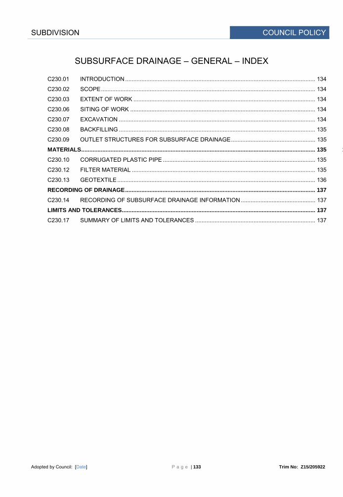
SUBDIVISION COUNCIL POLICY
Adopted by Council: [Date] P a g e | 133 Trim No: Z15/205922
SUBSURFACE DRAINAGE – GENERAL – INDEX
C230.01 INTRODUCTION ..................................................................................................................... 134
C230.02 SCOPE .................................................................................................................................... 134
C230.03 EXTENT OF WORK ................................................................................................................ 134
C230.06 SITING OF WORK .................................................................................................................. 134
C230.07 EXCAVATION ......................................................................................................................... 134
C230.08 BACKFILLING ......................................................................................................................... 135
C230.09 OUTLET STRUCTURES FOR SUBSURFACE DRAINAGE .................................................... 135
MATERIALS ................................................................................................................................................ 135 1
C230.10 CORRUGATED PLASTIC PIPE .............................................................................................. 135
C230.12 FILTER MATERIAL ................................................................................................................. 135
C230.13 GEOTEXTILE .......................................................................................................................... 136
RECORDING OF DRAINAGE ..................................................................................................................... 137
C230.14 RECORDING OF SUBSURFACE DRAINAGE INFORMATION .............................................. 137
LIMITS AND TOLERANCES ....................................................................................................................... 137
C230.17 SUMMARY OF LIMITS AND TOLERANCES .......................................................................... 137

SUBDIVISION COUNCIL POLICY
Adopted by Council: [Date] P a g e | 134 Trim No: Z15/205922
SPECIFICATION C230 : SUBSURFACE DRAINAGE - GENERAL
GENERAL
C230.01 INTRODUCTION
This is the general specification common and applicable to all types of subsurface drainage and shall be read in conjunction with subsurface drainage specifications:
C231 - Subsoil and Foundation Drains C232 - Pavement Drains C233 - Drainage Mats
as applicable to particular contracts.
Purpose
C230.02 SCOPE
The work to be executed under this Specification consists of:
(a) preparation for subsurface drainage construction;
(b) siting of subsurface drainage facilities;
(c) the supply of all materials associated with the provision of the subsurface drainage system;
(d) all activities and quality requirements associated with the supply, placement and compaction of filter material;
(e) the provision of a detailed record of all subsurface drain installations;
(f) the marking on the ground of the location of all subsurface drains.
C230.03 EXTENT OF WORK
Details of the work are shown on the Drawings or as directed by the Principal Certifying Authority and Geotechnical Engineer.
C230.06 SITING OF WORK
The Principal Certifying Authority may amend the locations or designed levels or the lengths to suit actual site conditions.
Amendments to Planned Work
Should the Contractor propose changes to the location, length, designed levels, conditions of installation or cover to suit the Contractor’s construction procedures, the Contractor shall present the proposed set-out in addition to the designed set-out for consideration by the Principal Certifying Authority. No changes shall be made unless the prior written approval of the Principal Certifying Authority is obtained.
Proposed Changes by Contractor
C230.07 EXCAVATION
The Contractor shall provide shoring, sheet piling or other stabilisation of the sides necessary to comply with statutory requirements.
Safety
Where service utilities exist in the vicinity of drainage works the Contractor shall obtain the approval of the relevant authority to the method of excavation before commencing excavation.
Approval by Public Utility Authorities
Trenches shall be excavated to the line, grade, width and depth shown on the Drawings or as directed by the Principal Certifying Authority. The bottom of the trench shall be constructed so that no localised ponding can occur. All loose material shall be removed by the Contractor.
Excavation Level
Any material at the bottom of the trench or at foundation level which the Principal Certifying Authority Unsuitable

SUBDIVISION COUNCIL POLICY
Adopted by Council: [Date] P a g e | 135 Trim No: Z15/205922
deems to be unsuitable shall be removed and disposed in accordance with the Specification for EARTHWORKS by the Contractor and replaced with backfill material in accordance with the requirements of this Specification. The bottom of the excavated trench or foundation, after any unsuitable material has been removed and replaced, shall be parallel with the specified level or grade of the pipe.
Material
C230.08 BACKFILLING
Backfilling shall be carried out in accordance with the requirements of the relevant subsurface drainage structures Specifications.
Detail
C230.09 OUTLET STRUCTURES FOR SUBSURFACE DRAINAGE
Subsurface drainage pipes shall be connected to discharge into gully pits or to outlet structures as shown on the Drawings or as directed by the Principal Certifying Authority.
Discharge
Outlets shall be spaced at a maximum interval of 80m. Spacing
Outlets shall be made rodent proof using galvanised wire netting. Rodent Proof
The outlet shall be located so that erosion of the adjacent areas does not occur or shall be protected by the placement of selected stone or similar approved treatment.
Erosion Control
Outlet pipes from curtain drains shall be unslotted. At no point shall an outlet pipe be higher than the pipe at the end of the curtain drain.
Outlet Pipe
All concrete used in the construction of outlet structures shall conform to the requirements of the Specification for MINOR CONCRETE WORKS.
Concrete Specification
MATERIALS
C230.10 CORRUGATED PLASTIC PIPE
Corrugated plastic pipe shall be Class 1000 complying with AS2439.1 of 100mm diameter unless otherwise indicated on the Drawings. All pipe shall be slotted unless otherwise indicated on the Drawings.
Specification
Joints, couplings, elbows, tees and caps shall also comply with AS2439.1 and only the manufacturer's recommended fittings shall be used.
Fittings
The Contractor shall obtain from the Manufacturer a Test Certificate demonstrating compliance with AS2439.1.
Compliance
C230.12 FILTER MATERIAL
(a) General
The filter material shall consist of clean, hard, tough, durable particles and comply with the following requirements:
Grading

SUBDIVISION COUNCIL POLICY
Adopted by Council: [Date] P a g e | 136 Trim No: Z15/205922
TEST METHOD PROPERTY REQUIREMENT
AS 1141.11 Material passing AS sieve Per cent by mass
6.7mm 4.75mm 2.36mm 1.18mm 425um
100 85 to 100 0 to 40 0 to 5 0 to 2
Table C230.1 - Filter Material
C230.13 GEOTEXTILE
(a) General
The geotextile, other than seamless tubular filter fabric, shall consist of a needle punched felt which shall be manufactured from synthetic materials other than polyamide. It shall be bio-stable and resistant to attack by alkalis, acids, dry heat, steam, moisture, brine, mineral oil, petrol, diesel and detergents.
Properties
The geotextile shall be resistant to ultra-violet light. No geotextile shall be left exposed to sunlight during storage and construction for a period longer than a total of twenty-one days. If exposure in excess of twenty-one days does occur, the geotextile shall be tested and if its characteristics have deteriorated to or below 90 per cent of the characteristics claimed by the manufacturer or the characteristics determined on unexposed geotextile, whichever is the better, it shall be removed and replaced with a geotextile complying with this Specification.
Ultra Violet Light Resistant
The geotextile shall be capable of retaining particles of particle size greater than 100 microns. Particle Retention
The minimum mass of geotextiles for different types of subsurface drainage shall be as follows: Mass
TYPE OF SUBSURFACE DRAINAGE MINIMUM MASS OF
GEOTEXTILE (Grams per square metre)
Trench Drains and Drainage Mats 250
Curtain Drains 500
Table C230.6 - Geotextile Mass
In addition to the above requirements, geotextiles for curtain drains shall consist of either polyester, polypropylene or polyethylene. When subjected to a pressure of 200 kPa applied at right angles to the plane of the fabric and to a constant head of water no greater than 50 mm applied to the top edge of the fabric, geotextiles for curtain drains shall have a rate of water transmission not less than 20 litres per hour per metre width of fabric through a 300 mm length of the fabric.
Water Transmission Rate
(b) Seamless Tubular Filter Fabric
Seamless knitted tubular filter fabric shall be used to enclose all slotted pipes and shall be manufactured from either polypropylene or polyester. The fabric shall be free of imperfections in weave or yarn and have abrasion resistant and weave stability qualities such that it shall not form holes, ladder, deweave, tear or unravel more than 5mm from a cut end.
Specification

SUBDIVISION COUNCIL POLICY
Adopted by Council: [Date] P a g e | 137 Trim No: Z15/205922
RECORDING OF DRAINAGE
C230.14 RECORDING OF SUBSURFACE DRAINAGE INFORMATION
The Contractor shall keep a detailed record of all subsurface drainage pipes and the completed subsurface drainage systems shall be shown on the work-as-executed plans.
Work As Executed Plans
The Work As Executed plans shall include:
a. Type of Drain,
b. Pipe Size,
c. Depth below FSL, and
d. Locations of Outlets.
Detail
LIMITS AND TOLERANCES
C230.17 SUMMARY OF LIMITS AND TOLERANCES
The limits and tolerances applicable to the various clauses in this Specification are summarised in Table C230.7 below.
Item Activity Tolerances Spec Clause 1. Outlets
Spacing
Max 80m
C230.09 2. Filter Material Table C230.1 C230.12 3. Geotextile (a) Exposure to sunlight <21 days
If >21 days deterioration not to exceed 10% of claimed
characteristics
C230.13
) Curtain Drains
Water Transmission
>20 litres/hr/m
C230.13
Table C230.7 - Table of Limits and Tolerances

SUBDIVISION COUNCIL POLICY
Adopted by Council: [Date] P a g e | 138 Trim No: Z15/205922
DEVELOPMENT CONSTRUCTION SPECIFICATION
C231
SUBSOIL AND
FOUNDATION DRAINS

SUBDIVISION COUNCIL POLICY
Adopted by Council: [Date] P a g e | 139 Trim No: Z15/205922
AMENDMENT RECORD FOR THIS SPECIFICATION PART
This Specification is Council’s edition of the AUS-SPEC generic specification part and includes Council’s primary amendments.
Details are provided below outlining the clauses amended from the Council edition of this AUS-SPEC Specification Part. The clause numbering and context of each clause are preserved. New clauses are added towards the rear of the specification part as special requirements clauses. Project specific additional script is shown in the specification as italic font.
The amendment code indicated below is ‘A’ for additional script ‘M’ for modification to script and ‘O’ for omission of script. An additional code ‘P’ is included when the amendment is project specific.
Amendment Sequence No.
Key Topic addressed in amendment
Clause No.
Amendment Code
Author Initials
Amendment Date

SUBDIVISION COUNCIL POLICY
Adopted by Council: [Date] P a g e | 140 Trim No: Z15/205922
SUBSOIL AND FOUNDATION DRAINS – INDEX
C231.01 SCOPE .................................................................................................................................... 141
C231.02 TERMINOLOGY ...................................................................................................................... 141
C231.04 ORDER OF CONSTRUCTION ................................................................................................ 141
CONSTRUCTION ........................................................................................................................................ 141
C231.05 SUBSOIL DRAINS .................................................................................................................. 141
C231.06 FOUNDATION DRAINS .......................................................................................................... 142
LIMITS AND TOLERANCES ....................................................................................................................... 143
C231.08 SUMMARY OF LIMITS AND TOLERANCES .......................................................................... 143

SUBDIVISION COUNCIL POLICY
Adopted by Council: [Date] P a g e | 141 Trim No: Z15/205922
SPECIFICATION C231 : SUBSOIL AND FOUNDATION DRAINS
GENERAL
C231.01 SCOPE
The work to be executed under this Specification covers the excavation, bedding, installation and backfilling of subsoil and foundation drains.
Scope
Subsoil and foundation drains shall be constructed where and as shown on the Drawings or as directed by the Geotechnical Engineer and the Principal Certifying Authority.
Location
This Specification should be read in conjunction with the Specification for SUBSURFACE DRAINAGE - GENERAL.
Associated Specification
C231.02 TERMINOLOGY
Subsoil drains are intended for the drainage of ground water and/or the pavement in cuttings. Subsoil Drains
Foundation drains are required for the drainage of seepage, springs and wet areas within and adjacent to the foundations.
Foundation Drains
C231.04 ORDER OF CONSTRUCTION
(a) Subsoil Drains
Subsoil drains shall be constructed as soon as possible after necessary earthworks are completed in the area of the drain.
Timing of Work
Where a Selected Material Zone is specified and excessive ground water is encountered, subsoil drains may be installed in two stages as follows:
Stage 1: Standard subsoil drains installed below the base of the cutting prior to placement of select material in the Selected Material Zone.
Two Stage Construction
Stage 2: Extension of subsoil drain to top of the Selected Material Zone after placement of selected material.
(b) Foundation Drains
1. Foundation drains shall be constructed after completion of clearing and stripping operations, and preceding the commencement of embankment construction.
Timing of Construction
CONSTRUCTION
C231.05 SUBSOIL DRAINS
(a) Excavation
Trenches for subsoil and foundation drains shall be excavated to the line, grade, width and depth as shown on the Drawings or as directed by the Principal Certifying Authority.
Dimensions and Grade
The bottom of the trench shall be excavated to the same grade as the design pavement surface. Where the grade of the design pavement surface in the direction of the trench is less than 0.5 per cent, the trench depth shall be increased to provide a minimum grade of fall in the trench of 0.5 per cent. The bottom of the trench shall be excavated so that no localised ponding of water occurs.
Minimum Grade
If at any location the trench is excavated below the specified floor level, the trench shall be backfilled Over-excavation

SUBDIVISION COUNCIL POLICY
Adopted by Council: [Date] P a g e | 142 Trim No: Z15/205922
with non-porous subgrade material so that when the subgrade material is compacted to a relative compaction, determined by AS 1289.5.4.1, of at least 95 per cent (standard compaction), the bottom of the trench shall be at the specified floor level.
Where a subsoil drain is constructed in two stages, the excavation for Stage 2 shall be carried out after placement and compaction of the selected material zone or the stabilised subgrade layer. The Stage 2 trench shall be excavated to the same line and width as the Stage 1 trench and to a depth to provide a clean, full contact with the filter material placed in Stage 1. All excavated material shall be disposed to waste or incorporated into fills.
Two Stage Construction
(b) Laying of Pipe
The 100mm diameter corrugated slotted plastic piping, complying with the Specification for SUBSURFACE DRAINAGE - GENERAL, shall be laid on a bed of filter material 50mm in thickness and shall be laid to the required line and grade.
Bedding
The type of filter material shall comply with Table C230.1. Filter Material
Joints in the pipeline shall be kept to the minimum number and, where required, shall be made using a suitable external joint coupling. The inlet end of the pipe shall be fitted with a cap.
Joints and Capping
(c) Backfilling
The trench shall be backfilled with filter material to the subgrade level. The filter material shall be placed and compacted in layers with a maximum compacted thickness of 300mm. Tamping around and over the pipe shall be done in such a manner as to avoid damage or disturbance to the pipe.
Filter Material
The filter material shall be compacted for its full depth to a relative compaction of not less than 100 per cent (standard compaction) as determined by AS 1289.5.4.1.
Compaction of Filter Material
(d) Outlets
Outlets are to be provided at maximum intervals of 80m. Where possible, subsoil drains shall discharge into gully pits and other stormwater drainage structures. Where not possible, an outlet shall be constructed of unslotted plastic pipe of the same diameter as the main run to discharge below the edge of the road shoulder. An outlet structure in accordance with the Drawings shall be constructed at the discharge end.
Pipes and Structures
C231.06 FOUNDATION DRAINS
(a) Excavation
Excavation shall be undertaken in accordance with the requirements of the Specification for SUBSURFACE DRAINAGE - GENERAL and Clause C231.05 of this Specification.
Associated Specification
(b) Laying of Pipe
The 100mm diameter corrugated slotted plastic piping, complying with the Specification for SUBSURFACE DRAINAGE - GENERAL, shall be laid on a bed of filter material 50mm in thickness and shall be laid to the required line and grade.
Bedding
The type of filter material shall be as shown in Table C230.1 Filter Material
Joints in the pipeline shall be kept to the minimum number and, where required, shall be made using a suitable external joint coupling. The inlet end of the pipe shall be fitted with a PVC cap.
Jointing of Pipe
(c) Backfilling
The trench shall be backfilled with filter material in accordance with the provisions of Clause C231.05(c).
Filter Material
The upper section of the trench, above the level specified for filter material backfill, shall be backfilled with suitable earth backfill material, compacted for its full depth to a relative compaction of
Earth Backfill and Compaction

SUBDIVISION COUNCIL POLICY
Adopted by Council: [Date] P a g e | 143 Trim No: Z15/205922
not less than 95 per cent (standard compaction) as determined by AS 1289.5.4.1.
Where shown on the Drawings or as directed by the Geotechnical Engineer and the Principal Certifying Authority, a geotextile, conforming with the requirements of the Specification for SUBSURFACE DRAINAGE - GENERAL, shall be provided at the interface between the filter material and adjoining materials. Laps of 500mm shall be provided at joints in the fabric.
Geotextile
(d) Outlets
An outlet structure in accordance with the detail shown on the Drawings and the Specification for SUBSURFACE DRAINAGE - GENERAL shall be constructed at the discharge end. The outlet shall be located so that erosion of the adjacent area does not occur or shall be protected by the placement of selected stone in the splash zone of the outlet.
Construction Detail
LIMITS AND TOLERANCES
C231.08 SUMMARY OF LIMITS AND TOLERANCES
The limits and tolerances applicable to the various clauses in this Specification are summarised in Table C231.1 below.
Item Activity Tolerances Spec
Clause 1. Excavation
Trench Grade
≥0.5%
C231.05(a) 2. Subsoil Drain Backfill (a) Layer thickness 300mm max C231.05(c) (b) Compaction Relative)
Filter and Backfill material
100% standard
C231.05(c) 3. Outlet Spacing 80m max C231.05(d) 4. Foundation Drain
Backfill
(a) Layer thickness 300mm max C231.05(c) (b) Compaction Relative)
Filter material
Backfill material
100% Standard
>95% Standard
C231.05(c)
Table C231.1 - Table of Limits and Tolerances

SUBDIVISION COUNCIL POLICY
Adopted by Council: [Date] P a g e | 144 Trim No: Z15/205922
DEVELOPMENT CONSTRUCTION SPECIFICATION
C233
DRAINAGE MATS

SUBDIVISION COUNCIL POLICY
Adopted by Council: [Date] P a g e | 145 Trim No: Z15/205922
AMENDMENT RECORD FOR THIS SPECIFICATION PART
This Specification is Council’s edition of the AUS-SPEC generic specification part and includes Council’s primary amendments.
Details are provided below outlining the clauses amended from the Council edition of this AUS-SPEC Specification Part. The clause numbering and context of each clause are preserved. New clauses are added towards the rear of the specification part as special requirements clauses. Project specific additional script is shown in the specification as italic font.
The amendment code indicated below is ‘A’ for additional script ‘M’ for modification to script and ‘O’ for omission of script. An additional code ‘P’ is included when the amendment is project specific.
Amendment Sequence No.
Key Topic addressed in amendment
Clause No.
Amendment Code
Author Initials
Amendment Date

SUBDIVISION COUNCIL POLICY
Adopted by Council: [Date] P a g e | 146 Trim No: Z15/205922
DRAINAGE MATS – INDEX
C233.01 SCOPE .................................................................................................................................... 147
C233.02 TERMINOLOGY ...................................................................................................................... 147
C233.04 ORDER OF CONSTRUCTION ................................................................................................ 147
CONSTRUCTION ........................................................................................................................................ 147
C233.05 TYPE A MATS ......................................................................................................................... 147
C233.06 TYPE B MATS ......................................................................................................................... 148
LIMITS AND TOLERANCES ....................................................................................................................... 149
C233.08 SUMMARY OF LIMITS AND TOLERANCES .......................................................................... 149

SUBDIVISION COUNCIL POLICY
Adopted by Council: [Date] P a g e | 147 Trim No: Z15/205922
SPECIFICATION C233 : DRAINAGE MATS
GENERAL
C233.01 SCOPE
The work to be executed under this Specification covers the installation of Drainage Mats (Blankets). Scope
Drainage mats shall be constructed where and as shown on the Drawings or as directed by the Geotechnical Engineer and Principal Certifying Authority.
Location
This Specification should be read in conjunction with the Specification for `SUBSURFACE DRAINAGE - GENERAL.
Associated Specification
C233.02 TERMINOLOGY
Type A drainage mats are intended to ensure continuity of a sheet flow of water under fills, to collect surface seepage from a wet seepage area or for protection of vegetation or habitat downstream of the road reserve where a fill would otherwise cut the flow of water.
Type A Mats
Type B drainage mats are constructed to intercept water which would otherwise enter pavements by capillary action or by other means on fills and to intercept and control seepage water and springs in the floors of cuttings.
Type B Mats
C233.04 ORDER OF CONSTRUCTION
Type A drainage mats shall be constructed after the site has been cleared and grubbed and before commencement of embankment construction.
Type A Mats
Type B drainage mats shall be constructed after completion of the subgrade construction and before construction of the pavement.
Type B Mats
CONSTRUCTION
C233.05 TYPE A MATS
Type A drainage mats shall be constructed under embankments as and where shown on the Drawings or as directed by the Geotechnical Engineer and Principal Certifying Authority.
Location
After the embankment foundation has been trimmed and any necessary trench drains installed, a geotextile complying with the requirement of the Specification for SUBSURFACE DRAINAGE - GENERAL, shall be laid on the embankment foundation. The area of geotextile laid shall be sufficient to cover the area of the Type A drainage mat and an additional amount for enclosing the sides of the drainage mat after the filter material has been placed. Laps of minimum width of 500mm shall be provided at each join in the geotextile.
Placing of Geotextile
Filter material, as shown on the Drawings or as determined by the Geotechnical Engineer and Principal Certifying Authority, shall be placed on the geotextile and compacted to the satisfaction of the Geotechnical Engineer and Principal Certifying Authority. The minimum thickness of the compacted filter material shall be 300mm plus an allowance for the expected consolidation of the embankment foundation under the embankment load or 500mm if the amount of the expected total consolidation of the embankment foundation is not known. The filter material shall be placed in two or more layers so that no layer, when compacted, has a thickness greater than 250mm.
Placing of Filter Material
After completion of placement and compaction of the filter material, geotextile shall be placed on top of and around the sides of the filter material so that the filter material is completely enclosed by geotextile. The geotextile shall be secured in such a manner as to prevent movement of the geotextile by wind or by construction plant placing subsequent layers of filter material or earth filling
Securing of Geotextile

SUBDIVISION COUNCIL POLICY
Adopted by Council: [Date] P a g e | 148 Trim No: Z15/205922
over the drainage mat.
An additional layer of geotextile shall be placed on the drainage mat under the base of any rock facing which may be placed as part of the embankment construction. The additional layer of geotextile shall extend beyond the outside and inside faces of the bottom layer of rock.
Geotextile under Rock Facing
Care shall be taken not to damage the geotextile during the construction of the drainage mat or during placement of subsequent layers of filter material, earth filling or rock facing. Any geotextile so damaged shall be repaired or replaced by the Contractor to the satisfaction of the Geotechnical Engineer and Principal Certifying Authority.
Damaged Geotextile
Type A drainage mats shall extend 2m beyond the toes of embankments and such extensions shall be covered by a 300mm thick layer of filter material, as determined by the Geotechnical Engineer and Principal Certifying Authority. This protective layer shall be placed immediately after completion of construction of each drainage mat.
Protective Layer
Outlets from Type A drainage mats may be surface outlets at the toes of embankments or piped outlets connected to other drainage systems. Where piped outlets are constructed they shall conform to the requirements of the Specification for SUBSURFACE DRAINAGE - GENERAL.
Outlets
C233.06 TYPE B MATS
Type B drainage mats shall be constructed in cuttings as and where shown on the Drawings or as directed by the Geotechnical Engineer and Principal Certifying Authority. Type B drainage mats shall be constructed for the full width of cuttings and for the pavement width in other locations.
Location and Width
After the subgrade material has been compacted and trimmed, a geotextile complying with the requirements of the Specification for SUBSURFACE DRAINAGE - GENERAL, shall be laid on the subgrade. Laps of minimum width of 500mm shall be provided at each join in the geotextile.
Placing of Geotextile
Slotted thick walled unplasticised PVC pressure pipe complying with AS 1477, shall be laid on the geotextile at a distance of 200mm from and parallel to the longitudinal edges of the drainage blanket as shown in the Drawings.
UPVC Pressure Pipe
Filter material shall be placed on the geotextile and compacted to achieve a relative compaction, determined by AS 1289.5.4.1, of at least 100 per cent (standard compaction). Alternatively, the Geotechnical Engineer and Principal Certifying Authority may approve the use of a coarser filter material having a maximum particle size of 75mm and a maximum D90/D10 ratio of three.
Placing of Filter Material
The thickness of the compacted filter material shall be as shown on the Drawings or as directed by the Geotechnical Engineer and Principal Certifying Authority. If the required thickness of compacted filter material is greater than 250mm, the filter material shall be placed in two or more layers so that no layer, when compacted, has a thickness greater than 250mm.
Thickness of Filter Material
After completion of placement and compaction of the filter material, geotextile shall be placed on top of and around the sides of the filter material so that the filter material is completely enclosed by geotextile. The geotextile shall be secured in such a manner as to prevent movement of the geotextile by wind or by construction plant placing pavement layers over the drainage mat.
Securing of Geotextile
Care shall be taken not to damage the geotextile during the construction of the drainage mat or during placement of subsequent pavement layers. Any geotextile so damaged shall be repaired or replaced by the Contractor to the satisfaction of the Geotechnical Engineer and Principal Certifying Authority.
Damaged Geotextile
The surface of the completed drainage mat shall be at the design level for the top of the drainage mat with a tolerance of plus zero and minus 40mm.
Surface Level Tolerance
Outlet structures where specified, or where directed by the Geotechnical Engineer and Principal Certifying Authority, shall be in accordance with the requirements of the Specification for SUBSURFACE DRAINAGE - GENERAL.

SUBDIVISION COUNCIL POLICY
Adopted by Council: [Date] P a g e | 149 Trim No: Z15/205922
LIMITS AND TOLERANCES
C233.08 SUMMARY OF LIMITS AND TOLERANCES
1. The limits and tolerances applicable to the various clauses in this Specification are summarised in Table C233.1 below.
Item Activity Tolerances Spec Clause
1. Filter Material (a) Layer thickness 250mm max C233.05
C233.06 2. Type B Mats ) Design level at top of mat +0, -40mm C233.06
Table C233.1 - Table of Limits and Tolerances

SUBDIVISION COUNCIL POLICY
Adopted by Council: [Date] P a g e | 150 Trim No: Z15/205922
DEVELOPMENT CONSTRUCTION SPECIFICATION
C242
FLEXIBLE PAVEMENTS

SUBDIVISION COUNCIL POLICY
Adopted by Council: [Date] P a g e | 151 Trim No: Z15/205922
AMENDMENT RECORD FOR THIS SPECIFICATION PART
This Specification is Council’s edition of the AUS-SPEC generic specification part and includes Council’s primary amendments.
Details are provided below outlining the clauses amended from the Council edition of this AUS-SPEC Specification Part. The clause numbering and context of each clause are preserved. New clauses are added towards the rear of the specification part as special requirements clauses. Project specific additional script is shown in the specification as italic font.
The amendment code indicated below is ‘A’ for additional script ‘M’ for modification to script and ‘O’ for omission of script. An additional code ‘P’ is included when the amendment is project specific.
Amendment Sequence No.
Key Topic addressed in amendment
Clause Amendment Code
Author Initials
Amendment Date
1 Modification of Primer Seal to Wearing Course
242.25 M
MB 21/01/08
1 Modification of Primer Seal to Wearing Course
242.26 M MB 21/01/08
1 Definition of Proof Roll
242.18 M MB 21/01/08

SUBDIVISION COUNCIL POLICY
Adopted by Council: [Date] P a g e | 152 Trim No: Z15/205922
FLEXIBLE PAVEMENTS – INDEX
C242.01 SCOPE .................................................................................................................................... 153
C242.02 TERMINOLOGY ...................................................................................................................... 153
C242.04 PAVEMENT STRUCTURES.................................................................................................... 153
C242.05 INSPECTION, SAMPLING AND TESTING ............................................................................. 153
MATERIALS ................................................................................................................................................ 153
C242.06 GENERAL ............................................................................................................................... 153
C242.07 TRAFFIC CATEGORY ............................................................................................................ 154
C242.08 UNBOUND BASE AND SUBBASE .......................................................................................... 154
DELIVERY, STOCKPILING AND PROCESSING OF PAVEMENT MATERIAL ......................................... 158
C242.11 DELIVERY TO SITE ...................................................................................................................... 158
C242.12 STOCKPILING OF UNBOUND MATERIALS .......................................................................... 158
SPREADING OF PAVEMENT MATERIAL ................................................................................................. 159
C242.14 SPREADING PAVEMENT MATERIALS .................................................................................. 159
TRIMMING AND COMPACTION ................................................................................................................. 159
C242.15 GENERAL REQUIREMENTS .................................................................................................. 159
ACCEPTANCE OF COMPACTED LAYERS ............................................................................................... 159
C242.17 ACCEPTANCE ........................................................................................................................ 159
C242.18 COMPACTION ASSESSMENT ............................................................................................... 160
C242.19 RELATIVE COMPACTION ...................................................................................................... 160
C242.20 REQUIREMENTS FOR ACCEPTANCE .................................................................................. 160
C242.21 REWORKING OF REJECTED UNBOUND LAYERS .............................................................. 161
C242.22 TOLERANCES ........................................................................................................................ 161
C242.23 ACTION ON REJECTION ....................................................................................................... 162
C242.24 REMOVAL AND REPLACEMENT OF REJECTED COURSES ............................................... 162
C242.25 MAINTENANCE BEFORE COMPLETION OF WEARING SURFACE ..................................... 162
OPENING PAVEMENT TO TRAFFIC ......................................................................................................... 162
C242.26 GENERAL REQUIREMENTS .................................................................................................. 162
LIMITS AND TOLERANCES ....................................................................................................................... 163
C242.27 SUMMARY OF LIMITS AND TOLERANCES .......................................................................... 163

SUBDIVISION COUNCIL POLICY
Adopted by Council: [Date] P a g e | 153 Trim No: Z15/205922
SPECIFICATION 242 : FLEXIBLE PAVEMENTS
GENERAL
C242.01 SCOPE
The work to be executed under this Specification consists of the supply, spreading, compaction and trimming of base and subbase courses of flexible pavements to the specified levels and thicknesses as shown on the Drawings.
C242.02 TERMINOLOGY
Materials designated as 'base' require the provision of a wearing surface comprising either a sprayed bituminous seal or asphalt up to 50mm thick.
Materials designated as 'subbase' require a covering course of 'base'. The subbase may consist of one or more layers.
A flexible pavement consists of a base and a subbase constructed of unbound materials. For the purpose of this Specification it also includes lightly bound pavements.
Modified material incorporates small amounts of stabilising binder to improve the properties of the material without significantly affecting structural stiffness.
Definitions
C242.04 PAVEMENT STRUCTURES
Flexible or semi-rigid pavement material types and layer thicknesses shall be as shown on the Drawings.
Material Types and Layer Thickness
C242.05 INSPECTION, SAMPLING AND TESTING
Inspection, sampling and testing of the pavement shall be undertaken by the Contractor in accordance with the requirements of this Specification before, during and after the construction of the pavement. Testing shall be carried out by a NATA registered laboratory with appropriate accreditation and suitably qualified personnel.
Contractor's Responsibility
The Contractor shall provide the Principal Certifying Authority with written notice when testing is being carried out and copies of all test reports for approval to proceed.
Written Notice
Field density tests shall be carried out in accordance with AS 1289.5.3.1, or, with the Principal Certifying Authority's concurrence, with a Nuclear Density Meter in accordance with Clause 242.12.
Density Tests
MATERIALS
C242.06 GENERAL
The Contractor shall submit details of all constituents of the proposed base and subbase materials, including sources of supply and the proposed type and proportion of any binder. These details shall be submitted to the Principal Certifying Authority, supported with test results from a NATA registered laboratory confirming that the constituents comply with the requirements of this Specification.
Details of Proposed Base and Subbase to be Submitted
No material shall be delivered until the Principal Certifying Authority has approved the source of supply.
Source of Supply
If, after the Contractor's proposals have been approved, the Contractor wishes to make changes in any of the material constituents the Contractor shall inform the Principal Certifying Authority in writing of the proposed changes. No delivery of material produced under the altered proposal shall
Variations by Contractor

SUBDIVISION COUNCIL POLICY
Adopted by Council: [Date] P a g e | 154 Trim No: Z15/205922
take place without the approval of the Principal Certifying Authority.
At least two days before placement of the material on site, the Contractor shall submit a Certificate from a laboratory with appropriate NATA registration demonstrating and stating that the unbound material or the mix and its constituents comply with the requirements of this Specification.
NATA Certificate
Ongoing testing of materials during delivery and construction shall be undertaken on samples taken from the site.
Sampling on-site
C242.07 TRAFFIC CATEGORY
Pavement materials are specified in terms of the Traffic Categories given in Table C242.1 for the calculated design traffic of the pavement.
Pavement Material Traffic Category
The Traffic Category (or Design Traffic) for the pavement materials shall be as shown on the Drawings.
Drawings
Pavement Material Traffic Category
Description
1 Roads with design traffic equal to or exceeding 107 equivalent standard axle (ESA) repetitions.
2a Roads with design traffic exceeding 4 x 10⁶ ESAs but less than 107 ESAs.
2b Roads with design traffic exceeding 106 ESAs but less than or equal to 4 x 10⁶ ESAs.
2c Roads with design traffic exceeding 105 ESAs but less than or equal to 106 ESAs.
2d Roads with design traffic less than or equal to 105 ESAs.
Table C242.1 - Pavement Material Traffic Categories
C242.08 UNBOUND BASE AND SUBBASE
Unbound materials, including blends of two or more different materials, shall consist of granular material which does not develop significant structural stiffness when compacted. Material produced by blending shall be uniform in grading and physical characteristics.
Granular Material
Unbound crushed rock materials are designated as follows:
DGB20 20mm nominal sized densely graded base DGS20 20mm nominal sized densely graded subbase DGS40 40mm nominal sized densely graded subbase
Crushed Rock
The acceptable material types for each Traffic Category are given in Table C242.2. Material Types

SUBDIVISION COUNCIL POLICY
Adopted by Council: [Date] P a g e | 155 Trim No: Z15/205922
Traffic Category Acceptable Base Material Acceptable Subbase Material
1 DGB20 DGS20, DGS40
2a DGB20 DGS20, DGS40
2b DGB20 DGS20, DGS40
2c DGB20 DGS20, DGS40
2d DGB20 DGS20, DGS40
Table C242.2 - Acceptable Pavement Material Types
Base materials shall comply with the requirements of Table C242.3. Base
Test Method
Description Base Material Requirements
DGB20
AS 1289.3.6.1
Coarse Particle Size Distribution % passing 75.0mm sieve % passing 53.0mm sieve % passing 37.5mm sieve % passing 26.5mm sieve % passing 19.0mm sieve % passing 13.2mm sieve % passing 9.5mm sieve % passing 6.7mm sieve % passing 4.75mm sieve % passing 2.36mm sieve % passing 0.425mm sieve % passing 0.075mm sieve
- - -
100 95-100
- -
50-70 -
35-55 - -
AS 1289.3.6.3
Fine Particle Size Distribution Ratios expressed as percentages (for that portion of the material passing 2.36mm sieve) Pass 425mm sieve %
35-55
Pass 75mm sieve % Pass 425mm sieve
35-55
Pass 13.5mm sieve % Pass 75mm sieve
35-60
AS 1289.3.1.1
Liquid Limit (if non plastic)
max 20
AS 1289.3.3.1
Plastic Limit (if plastic) max 20
AS 1289.3.3.1
Plasticity Index max 6
T114 Maximum Dry Compressive Strength on fraction passing 19mm sieve (only applies if Plasticity Index is less than 1)
min 1.7 MPa

SUBDIVISION COUNCIL POLICY
Adopted by Council: [Date] P a g e | 156 Trim No: Z15/205922
Test Method
Description Base Material Requirements
DGB20
AS 1141.14
Particle Shape by Proportional Calliper % mis-shapen (2 : 1)
max 35
AS 1141.22
Aggregate Wet Strength
For category 1 or 2a For category 2b or 2c For category 2d
min 80 min 70 min 60
AS 1141.22
Wet/Dry Strength Variation Dry - Wet %
Dry
For category 1 or 2a For category 2b or 2c For category 2d
max 35 max 40 max 45
AS 1289.F1.1
4 day Soaked CBR (98% Modified Compaction)
-
Table C242.3 - Unbound Base Material Properties
NOTES ON TABLE C242.3:
Material consisting of rounded river stone shall have a minimum of two fractured faces on at least 75 per cent of the particles larger than 6.70mm.
The maximum value of the Liquid Limit may be increased to 23 for non-plastic material, provided that the value determined is not influenced by the presence of adverse constituents.
For category 2d base materials the maximum Plasticity Index shall be 8.
All fractions of the sample specified by AS 1141.22 must be within specification. The fraction with the highest wet/dry strength variation is the value for determining conformance with the specification. The fractions 19.0mm to 13.2mm and 6.7mm to 4.75mm must be tested.
Subbase materials shall comply with the requirements of Table C242.4 Subbase
Test Method
Description Subbase Material Requirements
DGS20 DGS40
AS 1289.3.6.1
Coarse Particle Size Distribution % passing 75.0mm sieve % passing 53.0mm sieve % passing 37.5mm sieve % passing 26.5mm sieve % passing 19.0mm sieve % passing 13.2mm sieve % passing 9.5mm sieve % passing 6.7mm sieve % passing 4.75mm sieve % passing 2.36mm sieve % passing 0.425mm sieve % passing 0.075mm sieve
- - -
100 95-100
- -
50-70 -
35-55 - -
-
100 - -
50-85 - -
30-55 -
25-50 - -

SUBDIVISION COUNCIL POLICY
Adopted by Council: [Date] P a g e | 157 Trim No: Z15/205922
Test Method
Description Subbase Material Requirements
DGS20 DGS40
AS 1289.3.6.3
Fine Particle Size Distribution Ratios expressed as percentages (for that portion of the material passing 2.36mm sieve) Pass 425mm sieve %
35-55
35-60
B. Pass 75mm sieve % Pass 425mm sieve
35-55 35-60
C. Pass 13.5mm sieve % Pass 75mm sieve
35-60 35-65
AS 1289.3.1.1
Liquid Limit (if non plastic) max 23 max 23
AS 1289.3.3.1
Plastic Limit (if plastic) max 20 max 20
AS 1289.3.3.1
Plasticity Index max 12 max 12
T114 Maximum Dry Compressive Strength on fraction passing 19mm sieve (only applies if Plasticity Index is less than 1)
min 1.0 MPa
min 1.0 MPa
AS 1141.14
Particle Shape by Proportional Calliper % mis-shapen (2 : 1)
max 35
max 35
AS 1141.22
Aggregate Wet Strength
min 50kN min 50kN
AS 1141.22
Wet/Dry Strength Variation Dry - Wet %
Dry
max 60
max 60
AS 1289.F1.1
4 day Soaked CBR (98% Modified Compaction)
- -
Table C242.4 - Unbound Subbase Material Properties

SUBDIVISION COUNCIL POLICY
Adopted by Council: [Date] P a g e | 158 Trim No: Z15/205922
NOTES ON TABLE C242.4:
Material consisting of rounded river stone shall have a minimum of two fractured faces on at least 75 per cent of the particles larger than 6.70mm.
All fractions of the sample specified by AS 1141.22 must be within specification. The fraction with the highest wet/dry strength variation is the value for determining conformance with the specification. The fractions 19.0mm to 13.2mm and 6.7mm to 4.75mm must be tested.
Where the proposed unbound base material complies with all of the requirements of Table C242.3 except gradings (AS 1289.3.6.1 and AS 1289.3.6.3), the Contractor may propose the use of the material, subject to approval of the Council, if the material complies with the RTA Modified Texas Triaxial Classification Number (T171) requirements specified in Table C242.5, (T171 tested at not less than 85 per cent of Optimum Moisture Content and 98 per cent of Maximum Dry Density as determined by AS 1289.5.2.1).
Modified Texas Triaxial Classification
Traffic Category Modified Texas Triaxial Classification Number
(Test Method T171)
1 max 2.0
2a max 2.2
2b max 2.5
2c max 3.0
2d max 3.0
Table C242.5 - RTA Modified Texas Triaxial Classification Number Requirements
DELIVERY, STOCKPILING AND PROCESSING OF PAVEMENT MATERIAL
C242.11 DELIVERY TO SITE
Materials shall be supplied sufficiently damp to avoid segregation and loss of fines during transit. Damp Condition
C242.12 STOCKPILING OF UNBOUND MATERIALS
Stockpile sites shall be located as shown on the Drawings or as approved by the Principal Certifying Authority.
Stockpile Sites
Stockpile sites, which shall be cleared of all vegetation and extraneous matter, shall be shaped to form a crown so as to be free draining and compacted over the whole area to provide a relative compaction, determined by AS 1289.5.4.1 for standard compactive effort, of not less than 95 per cent.
Compacted and Free Draining
Stockpiles and stockpile sites shall be maintained so as to prevent the stockpiled materials from becoming intermixed or contaminated with foreign material.
Stockpile Requirements
The total height of any stockpile shall not exceed 2.5 m. Height
Stockpiles shall be of uniform shape with side slopes neither steeper than 1.5 to 1 nor flatter than 3 to 1.
Shape
The worked face of any stockpile shall be the full face of the stockpile. The stockpiled material shall be maintained at a moisture content sufficiently damp to avoid loss of fines.
Maintained Damp
At the completion of the works, stockpile sites shall be cleared of all surplus material and left in a clean and tidy condition.
Completion of Work

SUBDIVISION COUNCIL POLICY
Adopted by Council: [Date] P a g e | 159 Trim No: Z15/205922
SPREADING OF PAVEMENT MATERIAL
C242.14 SPREADING PAVEMENT MATERIALS
Unbound materials shall not be spread upon an underlying pavement layer which has a moisture content exceeding 90 per cent, the laboratory optimum moisture content as determined by AS 1289.5.2.1 or which has become rutted or mixed with foreign matter. The underlying layer shall be corrected to comply with this Specification before spreading of the next layer of pavement.
Underlying Layer Quality
Each layer of material shall be deposited and spread in a concurrent operation and, after compaction, the finished surface levels on the base and subbase courses shall be within the permitted tolerances stated in Clause C242.22(c) without subsequent addition of material. The thickness of each compacted layer shall be neither less than 100mm nor more than 200mm for all pavement layer types.
Tolerances
When spread for compaction processes the moisture content of the base or subbase materials shall be in the range of 60-90 per cent of laboratory optimum moisture content in accordance with AS 1289.5.2.1.
TRIMMING AND COMPACTION
C242.15 GENERAL REQUIREMENTS
Each layer of the base and subbase courses shall be uniformly compacted over its entire area and depth to satisfy the requirements of relative compaction set out in Clauses C242.19 and C242.20.
Uniform Compaction
On sections of pavement with one-way crossfall, compaction shall begin at the low side of the pavement and progress to the high side. On crowned sections, compaction shall begin at the sides of the pavement and progress towards the crown. Each pass of the rollers shall be parallel with the centreline of the roadway and uniformly overlap each preceding pass.
Compaction Procedure
At locations where it would be impracticable to use self-propelled compaction plant, the pavement material shall be compacted by alternative hand-operated plant approved by the Principal Certifying Authority.
Hand Operated Plant
If any unstable areas develop during rolling, the unstable material shall be rejected. The rejected material shall be removed for the full depth of the layer, disposed of and replaced with fresh material in accordance with Clause C242.24.
Unstable Areas
The placement of subsequent layers shall not be allowed until the requisite testing has been completed and the test results for each layer have been accepted by the Principal Certifying Authority.
Placing Subsequent Layers
Any unbound material in a layer that has attained the specified relative compaction but subsequently becomes wetted up shall be dried out and, if necessary, uniformly recompacted and trimmed to meet the specified density requirements and level tolerances.
Excessive Moisture Content
ACCEPTANCE OF COMPACTED LAYERS
C242.17 ACCEPTANCE
Acceptance of work, as far as compaction is concerned, shall be based on:
(a) density testing of each layer,
(b) proof rolling of each layer, and
Requirements

SUBDIVISION COUNCIL POLICY
Adopted by Council: [Date] P a g e | 160 Trim No: Z15/205922
(c) deflection testing on the completed final pavement layer.
A lot shall be nominated by the Contractor, but shall conform to the following:
(a) cover only a single layer of work which has been constructed under uniform conditions in a continuous operation and not crossing any transverse construction joints;
(b) for unbound materials it may equal a day's output using the same material.
C242.18 COMPACTION ASSESSMENT
For residential, commercial and industrial roads, the Contractor shall arrange for testing to assess compaction on the basis of either one test per 50 lin. m or 250 m2 (whichever is the greater) with a minimum of two tests in any one length. The results shall be presented to the Principal Certifying Authority for approval.
For rural roads, the Contractor shall arrange for testing to assess compaction on the basis of either one test per 100 lin. m or 500 m2 (whichever is the greater) with a minimum of two tests in any one length. The results shall be presented to the Principal Certifying Authority for approval.
Sampling
Acceptance of final pavement layer shall be determined according to the elastic rebound deflection. The elastic rebound deflection shall be taken as the maximum deflection in accordance with Test Method T160 utilising the Benkelman Beam or equivalent. The average maximum deflection for any lot shall not exceed the limits stated in AUSTROADS. The co-efficient of variation (CV) in recorded deflections shall not exceed 30 per cent. Measurements shall be taken at maximum spacings of 10 metres (alternating wheel paths) in each lane, with not less than 4 measurements per any one length of road.
Benkelman Beam Testing
Proof rolling shall be performed on all subgrades, subbases and base courses with the method, instruments and results acceptable to the Principal Certifying Authority.
Proof Roll Test
C242.19 RELATIVE COMPACTION
The relative compaction of pavement material at each location tested for in-situ dry density shall be calculated in accordance with AS 1289.5.4.1 as follows:
Relative Compaction (per cent) = In-situ dry density x 100 Comparative dry density
Calculation
The Council may approve some or all of the in-situ dry density testing to be carried out with a single probe Nuclear Density Meter in the direct transmission mode in accordance with AS 1289.5.8.1.
In-Situ Dry Density Testing
For unbound layers, the sample shall be tested in accordance with AS 1289.5.2.1 to determine the maximum dry density (modified compactive effort) for the material.
Maximum Dry Density
The maximum dry density so determined shall be used as the comparative dry density in relative compaction calculations for all like material from that lot or day's production placed in a single layer of work whichever is the lesser.
Comparative Dry Density
C242.20 REQUIREMENTS FOR ACCEPTANCE
A lot shall be accepted for compaction if:
a. for sub-base:
i. The minimum value of all calculated relative compaction for modified compactive effort is not less than 95 per cent within the lot or the area of pavement being assessed.
ii. Pass proof roll test
iii. Thickness within tolerance as determined from test pits at locations nominated by the Principal Certifying Authority.
b. for base:
i. the minimum value of all calculated relative compaction for modified compactive effort is

SUBDIVISION COUNCIL POLICY
Adopted by Council: [Date] P a g e | 161 Trim No: Z15/205922
not less than 98 per cent within the lot or the area of pavement being assessed.
ii. Pass proof roll test
iii. Thickness within tolerance as determined from test pits at locations nominated by the Principal Certifying Authority.
iv. Comply with deflection criteria of Benkelman Beam Testing.
Areas of pavement not achieving these specified values shall be rejected. Unbound layers may be reworked as provided by Clause C242.21.
Rejection
C242.21 REWORKING OF REJECTED UNBOUND LAYERS
Lots or areas of pavement that have been rejected in regard to compaction shall be reworked before resubmission for compaction assessment.
Reworking
Material that has become degraded, segregated or otherwise reduced in quality by reworking shall be rejected. The rejected material shall be removed, disposed of and replaced with fresh material complying with this Specification in accordance with Clause C242.24. When a lot or area of pavement is resubmitted for compaction assessment, testing shall be carried out in accordance with Clauses C242.18 and C242.19.
Rejected Material
C242.22 TOLERANCES
a) General
The tolerances stated are the acceptable limits of departure from the dimensions shown on the Drawings.
Tolerances
b) Width
At any cross section without kerb and/or guttering, and for pavement layers extending under the kerb and/or guttering, the horizontal dimension measured from the design centre line to the edge of the constructed pavement surface shall be neither less than 50mm less than the dimension nor more than 300 mm greater than the dimension shown on the Drawings.
Horizontal Dimensions
The average width of the layer determined from measurements at three sites selected at random by the Principal Certifying Authority over any 200 metre road length, or part thereof, shall be not less than the specified width.
Average Width
c) Levels and Surface Trim
The levels of the finished surface of the top of the unbound subbase course shall not vary from the design levels by more than ± 20 mm.
Subbase Surface Level
Level tolerances at the top of the unbound base course shall not exceed ± 10 mm. In addition, where kerb and gutter exists or is being constructed, the level of the top of the base course adjacent to the kerb and gutter shall not vary by more than ± 5mm from the lip level of the gutter minus the design thickness of the wearing surface.
Base Surface Level
The design level of the top of the subbase course shall be determined from the design level of the finished road surface less the thickness of the base course and the wearing course.
Subbase Design Level
The pavement surface after trimming and immediately prior to sealing shall be of a quality such that the deviation under a 3 metre straight edge placed in any direction does not exceed 12 mm.
Straight Edge Deviation

SUBDIVISION COUNCIL POLICY
Adopted by Council: [Date] P a g e | 162 Trim No: Z15/205922
C242.23 ACTION ON REJECTION
(a) Unbound Materials
A lot that has not complied with the requirements for width or level tolerance as set out in Clauses C242.22(b) and C242.22(c) respectively shall be rejected except as otherwise provided in this Clause. Rejected lots shall be removed, disposed of and replaced with fresh material in accordance with Clause C242.24.
Rejection Criteria
Notwithstanding the above, where the rejected lot can be corrected by further trimming, the Principal Certifying Authority may allow the surface to be corrected without complete removal and replacement with fresh material. Such trimming shall be undertaken in a manner that produces a uniform, hard surface and shall be achieved by cutting only without filling. After any such cutting, the level tolerances in Clause C242.22(c) shall apply.
Corrective Action
C242.24 REMOVAL AND REPLACEMENT OF REJECTED COURSES
Sections of the work that have been rejected shall be removed from the work and replaced with fresh material. Rejected material shall be removed from site.
Rejected Material
In rejected sections the material shall be removed over the full length of the rejected lot. Any damage to underlying or abutting layers or structures shall be made good by the Contractor using methods approved by the Principal Certifying Authority.
Length to be Removed
The Principal Certifying Authority may approve removal for less than the full width as constructed if the cause of the rejection of the work can be isolated transversely to the Principal Certifying Authority's satisfaction. In this case, the new longitudinal cold joint shall be formed and located along the centreline of the road pavement.
Superintendents Discretion
After removal of rejected base or subbase course material, the section shall be presented for inspection by the Principal Certifying Authority before replacement work is commenced.
Inspection Before Replacement
Materials used as replacement materials, and the subsequent spreading, compaction, trimming, curing and testing of the replacement materials, shall comply with the requirements of this Specification.
Replacement Material
C242.25 MAINTENANCE BEFORE COMPLETION OF WEARING SURFACE
Following the Principal Certifying Authority's acceptance of any section of the work, the Contractor shall maintain the prepared surface of the base in the condition specified for acceptance until the wearing course is completed. The wearing course shall be provided in accordance with the Specification for ASPHALTIC CONCRETE within seven days of the date of the acceptance of such sections, unless otherwise approved by the Principal Certifying Authority.
Completion Time Limit
Should the Principal Certifying Authority withdraw permission to proceed due to a deterioration of the base course during the seven day period, the Contractor shall re-prepare the base course and re-present the base course for inspection by the Principal Certifying Authority.
Contractor's Responsibility
OPENING PAVEMENT TO TRAFFIC
C242.26 GENERAL REQUIREMENTS
For unbound pavements, construction plant and vehicles not involved in the current construction or testing of the work shall not be permitted to use the pavement until the wearing course has been applied, unless otherwise approved by the Principal Certifying Authority.
Restrictions on Movement

SUBDIVISION COUNCIL POLICY
Adopted by Council: [Date] P a g e | 163 Trim No: Z15/205922
LIMITS AND TOLERANCES
C242.27 SUMMARY OF LIMITS AND TOLERANCES
The tolerances applicable to the various clauses in this Specification are summarised in the Table below:
Item Activity Tolerances Spec
Clause 1. Stockpile Sites (i) Relative Compaction >95% C242.12 (ii) Stockpile height <3m C242.12 (iii) Stockpile batter <1.5:1 and >3:1 2. Spreading Pavement
Materials
(i) Compacted Layer
Thickness 100mm min 200mm max
C242.14
3. Compaction Acceptance Minimum value of all
calculated relative compaction results
95 % (modified) - subbase 98% (modified) - base
C242.20
4. Width of Pavement
Design centre-line to edge of constructed pavement
- 50mm to +300mm of dimensions
on Drawings
C242.22(b)
(ii) Average Width The average width determined from
3 random sites over any 200m road length, or part thereof, shall be not less than the specified width.
C242.22(b)
5. Surface Level
Subbase levels
± 20mm from design level
C242.22(c)
(ii) Base levels ± 10mm from design level C242.22(c) (iii) Base levels adjacent
to Kerb and Gutter ± 5mm from the lip levels of
adjacent gutter minus design thickness of wearing surface.
C242.22(c)
(iv) Shape Deviation from a 3m long
straightedge on base surface immediately prior to sealing shall be less than 12mm
C242.22(c)
Table C242.3 - Summary of Limits and Tolerances

SUBDIVISION COUNCIL POLICY
Adopted by Council: [Date] P a g e | 164 Trim No: Z15/205922
DEVELOPMENT CONSTRUCTION SPECIFICATION
C244
SPRAYED
BITUMINOUS SURFACING

SUBDIVISION COUNCIL POLICY
Adopted by Council: [Date] P a g e | 165 Trim No: Z15/205922
AMENDMENT RECORD FOR THIS SPECIFICATION PART
This Specification is Council’s edition of the AUS-SPEC generic specification part and includes Council’s primary amendments.
Details are provided below outlining the clauses amended from the Council edition of this AUS-SPEC Specification Part. The clause numbering and context of each clause are preserved. New clauses are added towards the rear of the specification part as special requirements clauses. Project specific additional script is shown in the specification as italic font.
The amendment code indicated below is ‘A’ for additional script ‘M’ for modification to script and ‘O’ for omission of script. An additional code ‘P’ is included when the amendment is project specific.
Amendment Sequence No.
Key Topic addressed in amendment
Clause No.
Amendment Code
Author Initials
Amendment Date

SUBDIVISION COUNCIL POLICY
Adopted by Council: [Date] P a g e | 166 Trim No: Z15/205922
SPRAYED BITUMINOUS SURFACING – INDEX
C244.01 SCOPE .................................................................................................................................... 167
MATERIALS ................................................................................................................................................ 167
C244.03 BINDERS ................................................................................................................................ 167
C244.04 ADDITIVES ............................................................................................................................. 167
C244.05 AGGREGATE .......................................................................................................................... 168
C244.06 PRECOATING AGENT ............................................................................................................ 168
C244.07 SAMPLING AND TESTING OF MATERIALS .......................................................................... 168
DESIGN OF BITUMINOUS SURFACING ................................................................................................... 168
C244.08 GENERAL ............................................................................................................................... 168
APPLICATION OF SPRAYED BITUMINOUS SURFACING ....................................................................... 168
C244.09 GENERAL ............................................................................................................................... 168
C244.10 PRECOATING OF AGGREGATE ........................................................................................... 169
C244.11 PLANT ..................................................................................................................................... 169
C244.12 PREPARATION OF PAVEMENT SURFACE .......................................................................... 169
C244.13 REVIEW OF NOMINATED APPLICATION RATES ................................................................. 169
C244.14 BINDER TEMPERATURE REQUIREMENTS ......................................................................... 170
C244.15 PAVEMENT TEMPERATURE AND WEATHER CONDITIONS .............................................. 170
C244.16 INCORPORATION OF CUTTER OIL AND ADHESION AGENT ............................................. 171
C244.17 APPLICATION OF BINDER .................................................................................................... 171
C244.18 WORK RECORDS .................................................................................................................. 172
C244.19 CONTROL OF TRAFFIC ......................................................................................................... 173
C244.20 APPLICATION AND INCORPORATION OF AGGREGATE .................................................... 173
C244.21 PROTECTION OF SERVICES AND ROAD FIXTURES .......................................................... 174
NON-CONFORMANCE OF MATERIALS AND WORK .............................................................................. 174
C244.22 GENERAL ............................................................................................................................... 174
LIMITS AND TOLERANCES ....................................................................................................................... 175
C244.29 SUMMARY OF LIMITS AND TOLERANCES .......................................................................... 175

SUBDIVISION COUNCIL POLICY
Adopted by Council: [Date] P a g e | 167 Trim No: Z15/205922
SPECIFICATION C244 SPRAYED BITUMINOUS SURFACING
GENERAL
C244.01 SCOPE
1. The work to be executed under this Specification consists of the supply of all materials and the application of any or all of the following types of sprayed bituminous surfacing:
(i) Prime
The application of a primer of field or refinery cutback bitumen without aggregate to provide penetration of the surface (preferably from 5 to 10 mm) and waterproofing.
(ii) Primerseal
The application of a primerbinder of field or refinery cutback bitumen to provide surface penetration (preferably from 2mm to 5mm), into which aggregate is incorporated to provide a temporary wearing surface prior to the application of the final wearing surface.
(iii) Seal or Reseal
The application of a bitumen binder into which aggregate is incorporated to provide a durable wearing surface.
2. The locations and required types of sprayed bituminous surfacings, including types of binders and aggregate sizes, shall be as shown on the Drawings and/or as detailed in Annexure C244.A.
3. For multiple application treatments, the binder and aggregate may be required to be laid in one or more separate applications.
MATERIALS
C244.03 BINDERS
(a) Bitumen
1. Bitumen shall be Class 170 conforming to AS2008.
(b) Refinery Cutback Bitumen
1. Refinery cutback bitumen shall conform to AS 2157.
C244.04 ADDITIVES
(a) Cutter Oil
1. Cutter oil shall conform to the requirements of AS3568, displaying an Abel flash point of not less than 38oC and a viscosity at 40oC not greater than 2.0 millipascal seconds, with the following qualifications to the properties for its classification as set down in AS3568 Table 1:
(i) Either "Aniline point" or "Aromatic content" is acceptable.
(ii) There shall be no "Density" requirement.
(iii) The presence of water, assessed visually as an immiscible phase in any sample of the material, shall be grounds for its rejection. AS2341.9 shall not be demanded as a referee test if more than 0.1% of liquid water is found in any delivery or batch.
(iv) If the viscosity is calculated by the equation given in Table 1, Note 3 of AS3568, "f" shall
Cutter Specification

SUBDIVISION COUNCIL POLICY
Adopted by Council: [Date] P a g e | 168 Trim No: Z15/205922
be taken to be 0.0009 per oC.
2. Delivery and storage procedures for cutter oil delivered in drums or in bulk shall ensure that all containers are clean and free from any deleterious material prior to filling with cutter oil, and all drums are stored so as to ensure that entry of water through seals or welds in the drums is prevented.
Delivery & Storage
(b) Adhesion Agent
1. Bitumen adhesion agents shall conform to RTA Specification 3259.
Adhesion Agent
C244.05 AGGREGATE
1. Aggregate shall conform to AS 2758.2. Specification
2. The Contractor shall obtain test results for each lot/stockpile of aggregate, and certification of compliance with AS 2758.2 from a suitably accredited NATA laboratory, before aggregate from the lot is incorporated in the Works.
Test Requirements
C244.06 PRECOATING AGENT
1. Aggregate precoating agent(s) shall conform to RTA Specification 3258. Specification
C244.07 SAMPLING AND TESTING OF MATERIALS
1. Sampling and testing of materials shall be arranged by the Contractor and carried out by a NATA registered laboratory in accordance with the relevant materials specifications cited in this Specification.
NATA Registration
DESIGN OF BITUMINOUS SURFACING
C244.08 GENERAL
1. Reserved.
2. The Contractor shall carry out the design of bituminous surfacing in accordance with the procedure contained in AUSTROADS Design of Sprayed Seals (1987) and shall submit these design details to the Principal Certifying Authority. Design application rates shall be known as "nominated application rates" and materials as "nominated materials".
AUSTROADS Design Procedure
3. The following additional details are required:
(i) Test results for all nominated materials.
(ii) Aggregates - source, geological type, nominated grading, ALD.
(iii) Precoating agent and bitumen adhesion agent - types and proportions.
(iv) Bitumen - refinery source, certification of compliance with AS2008.
(v) Cutback bitumen - refinery source of bitumen, source of cutter, certification of compliance with AS2157.
Additional Information Sought
APPLICATION OF SPRAYED BITUMINOUS SURFACING
C244.09 GENERAL
1. The Contractor shall carry out sprayed bituminous surfacing so as to:
(i) provide a uniform application of binder with adequate adhesion to the underlying surface;
Work Quality

SUBDIVISION COUNCIL POLICY
Adopted by Council: [Date] P a g e | 169 Trim No: Z15/205922
(ii) provide a complete cover of interlocking aggregate particles, and
(iii) achieve effective bond between binder and aggregate.
2. The Contractor shall give the Principal Certifying Authority two days’ notice of intention to commence sprayed bituminous surfacing, confirming spray rates, nominal aggregate size and ALD, and shall obtain the Principal Certifying Authority's approval to proceed.
C244.10 PRECOATING OF AGGREGATE
1. The aggregate precoating agent shall be applied to the aggregate in a manner and at a rate and time which will provide a complete, light, uniform, effective cover of all aggregate particles at the time of spreading.
Application
2. Precoating of aggregate shall not be carried out when rain is imminent. If aggregate has been precoated and rain appears imminent, the aggregate shall be adequately covered to prevent the precoating material being washed from the aggregate particles.
Weather Conditions
3. The Contractor shall take precautions, such as covering stockpiles, to prevent settlement of dust, penetration of moisture or drying out of the precoating agent on the stockpiled aggregate.
Cover for Stockpiles
C244.11 PLANT
1. A mechanical sprayer shall be used to apply primer, primerbinder and binder. The sprayer shall have a current Sprayer Certificate (RTA Form 354) issued by the Roads and Traffic Authority of NSW.
Sprayer Certificate
2. The spray nozzles shall be of the make and type endorsed on the Sprayer Certificate. Any nozzles which may be damaged or become unduly worn or defective shall be replaced by satisfactory nozzles of similar type. A sufficient number of nozzles for this purpose shall be available at all times.
Spray Nozzles
3. Mechanical spreading equipment shall be used to spread aggregate and shall be capable of achieving a uniform spreading rate.
Aggregate Spreader
4. Rollers shall be in accordance with Clause C244.20. Rollers
5. The Contractor shall remove from the work any plant or equipment not fully operational or not in a satisfactory condition for carrying out work in accordance with this Specification.
Faulty Equipment
C244.12 PREPARATION OF PAVEMENT SURFACE
1. Before the application of primer, primerbinder or binder, the pavement surface shall be swept by the use of a mechanically-operated rotary road broom or suction broom to provide a uniformly clean surface. If necessary, additional sweeping shall be done by hand, using stiff brooms. Sweeping shall extend at least 300mm beyond each edge of the area to be sprayed.
Pavement Sweeping
2. Adherent patches of foreign material shall be removed from the surface of the pavement. Foreign Matter on Pavement
3. For the spraying of primer or primerbinder, the pavement surface shall be slightly damp so as to impede dust interfering with initial adhesion.
Damp Pavement
C244.13 REVIEW OF NOMINATED APPLICATION RATES
1. The Contractor shall select the locations where each lot of aggregate is to be incorporated in the Works.
Aggregate Lots
2. The Contractor shall review the bituminous surfacing design at each location based on the actual ALD test result for the lot of aggregate instead of the ALD value of the nominated
Target Application Rates

SUBDIVISION COUNCIL POLICY
Adopted by Council: [Date] P a g e | 170 Trim No: Z15/205922
aggregate, and using the AUSTROADS Design of Sprayed Seals (1987). The revised application rates shall be known as “target application rates”.
3. The Contractor shall submit details of the aggregate lot and target application rates of each work location to the Principal Certifying Authority for approval before commencing sprayed sealing at that location.
Contractor’s Responsibility
C244.14 BINDER TEMPERATURE REQUIREMENTS
1. Bitumen and cutback bitumen shall be within the range shown in Table C244.1 when incorporated with cutter oil.
Mixing Temperature
2. Temperature ranges for spraying of primers, primer binders and binders shall be within the ranges shown in Table C244.1.
Spraying Temperature
3. The Contractor shall measure and record the temperature of the binder, using a thermometer. The thermometer shall be verified as accurate to within 2.5 percent of the correct temperature.
Measurement of Temperature
4. If the temperature of the bituminous material is below the applicable lower limit from Table C244.1, the bituminous material may be heated providing safe heating practices are adopted. Burners shall not be used unless the level of the material in the heating tank is at least 250 mm above the tops of the heating tubes. The Contractor shall comply with the Bush Fires Act, 1949 and the Local Government Act 1993. Two or more suitable fully-charged pressurised chemical fire extinguishers shall be placed conveniently to the heaters at all times while heating is in progress.
Safe Heating Practices
5. During heating, the temperature of the bituminous material shall not exceed the applicable upper limit from Table C244.1. The temperature of the bituminous material just above the heating tubes shall be checked at regular intervals to ensure that there is no local overheating.
Heating Limits
6. Bituminous materials shall not be held at temperatures within the ranges shown in Tables C244.1 for periods in excess of ten hours.
Max Period of Heating
7. Any bituminous material which has been overheated shall not be used in the work. The Contractor shall record disposal of such material confirming its exclusion from use under this contract.
Overheated Bitumen
C244.15 PAVEMENT TEMPERATURE AND WEATHER CONDITIONS
1. The Contractor shall measure and record pavement temperatures at regular intervals during the course of the work. For this purpose, a suitable type of thermometer shall be placed in direct contact with the pavement and allowed to remain in position until the reading becomes steady. The bulb of the thermometer shall be covered from direct sunlight with a small heap of grit or similar material.
Measurement and Recording
2. If the pavement is partly in sun and partly in shade, the temperatures for both conditions shall be taken and recorded.
Sun and Shade Conditions
3. Spraying primers, primerbinders and binders shall be undertaken only if the pavement temperature has been at or above the minimum temperature shown in Table C244.1 for at least one hour before commencement of spraying and does not fall below the specified minimum pavement temperature for spraying during the period of spraying.
Minimum Pavement Temperature
4. Spraying shall not be carried out on a wet pavement, while rain appears imminent or during high winds or dust storms.
Spraying Conditions

SUBDIVISION COUNCIL POLICY
Adopted by Council: [Date] P a g e | 171 Trim No: Z15/205922
TYPE OF MATERIAL CLASS OR GRADE
EQUIVALENT % CUTTER
MAX HEATING TEMP (OC)
MIN PAVEMENT TEMP (OC)
SPRAYING TEMP (OC)
Bitumen 170 190 10 160 - 190
Cutback Bitumen
AMC 00 AMC 0 AMC 1 AMC 2 AMC 3 AMC 4 AMC 5 AMC 6 AMC 7
Conventional Cutter
56) 44) 34) 27) 21) 16) 11) 7) 3)
30 55 80
100 115 135 150 160 175
10 10 10 10 10 10 10 10 10
10 - 20 35 - 55 60 - 80
75 - 100 95 - 115 110 - 135 120 - 150 135 - 160 150 - 175
Cutback Bitumen
FC2 FC3 FC4 FC5 FC6 FC7
Fast Evaporating Cutter
25) 20) 15) 10) 7) 3)
95 95
110 140 150 160
5 5 5 10 10 10
70 - 75 80 - 90
95 - 110 120 - 140 130 - 150 140 - 160
Table C244.1 - Temperature Limits
C244.16 INCORPORATION OF CUTTER OIL AND ADHESION AGENT
(a) Cutting Back Bitumen
The Contractor shall determine and record the proportion of cutter oil required for each sprayer load, using MR Form 466 and based on the measured pavement temperatures.
Contractor's Responsibility
The cutter oil, without being previously heated, shall be pumped into the sprayer, followed by the hot bitumen. The full sprayer load of cutback bitumen shall be circulated at a rate of at least 700 litres per minute for twenty minutes to ensure that the mixture is homogeneous.
Mixing Cutter Oil
If a part sprayer load of field cutback bitumen is unused on the date of mixing, and needs to be returned to the heater tanks, it shall be placed in an empty tank reserved for that purpose. No bitumen or cutter shall be added to the returned cutback bitumen unless the tank is fitted with an effective mechanical mixing system. When the returned cutback bitumen is subsequently used as part of a sprayer load, allowance shall be made for the cutter oil contained in the returned cutback bitumen.
Unused Cutback Bitumen
(b) Bitumen Adhesion Agent
Where bitumen adhesion agent is to be included, it shall be added to the bitumen in the sprayer and the mixture circulated at a rate of at least 700 litres per minute for fifteen minutes before spraying.
Mixing Adhesion Agent
C244.17 APPLICATION OF BINDER
(a) General
The area to be sprayed with primerbinder or binder shall be limited to the area which can be covered with aggregate at the target application rate within fifteen minutes of spraying bitumen or cutback bitumen.
Limit on Spray Area
Nominated and target application rates and quantities of binder shall be based on the volumes of bitumen measured at a temperature of 15oC and shall not include any bitumen adhesion agent
Nominated and Target Rates

SUBDIVISION COUNCIL POLICY
Adopted by Council: [Date] P a g e | 172 Trim No: Z15/205922
and/or cutter oil.
Where bitumen adhesion agent and/or cutter oil have been added to the binder, the application rate of the total binder at 15oC shall be adjusted to allow for the quantities of bitumen adhesion agent and/or cutter oil in the mixture.
Adjustment of Application Rate
The Contractor shall determine the hot application rate of total binder, including bitumen adhesion agent and/or cutter oil, using MR Form 466.
Calculation of Hot Application
Where refinery cutback bitumen is used as the binder, the target application rate of binder shall be increased by the Contractor to allow for the percentage cutter oil in the mixture as indicated in Table C244.1.
Refinery Cutback Bitumen Variation
(b) Operation of the Sprayer
The type of spray nozzles to be used on the spray bar of the sprayer shall be compatible with the nature of the binder to be sprayed and its application rate.
Nozzle Type
Where the longitudinal edges of spray runs are not required to overlap, either special type end nozzles or intermediate nozzles set with a jig as end nozzles may be used. Where an overlap is required, the overlap of spray between adjacent longitudinal runs shall be in the range 50-100mm for special type end nozzles. If intermediate nozzles are to be used to overlap adjacent longitudinal sprays the nozzles shall be set in the normal manner for intermediate nozzles and the overlap shall be in the range 250-350mm.
Spray Overlap
The spraying of primer, primerbinder or binder for each run of the sprayer shall commence on a protective strip of heavy paper weighing not less than 120 grams per square metre laid across and held securely to the pavement surface beforehand. The sprayer shall commence moving at a sufficient distance in advance of the protective strip to ensure that the road speed for correct application is attained at the commencement of spraying.
Protective Paper Strip
The sprayer shall maintain a constant road speed throughout the length of each sprayer run. Road Speed
The spraying for each run shall terminate on a protective strip of paper laid across and held securely to the pavement surface beforehand. The width of paper at the commencement and/or termination of each run shall not be less than that endorsed on the Sprayer Certificate.
Terminating Paper Strip
Spraying shall cease immediately any defect develops in the spraying equipment and spraying shall not recommence until the fault has been rectified.
Equipment Defects
Where any blockage or partial blockage of nozzles occurs, spraying shall cease immediately. If the blockage is due to the condition of the binder being sprayed, that load together with any binder from the same bulk tanker or supply unit shall not be used.
Nozzle Blockage
Where a mechanical sprayer is not able to satisfactorily spray small areas or areas of irregular shape, such areas shall be sprayed by means of the hand spray equipment attached to the sprayer.
Hand Spraying
After each sprayer run, the quantity of binder sprayed shall be checked against the area covered and any necessary adjustments shall be made to ensure that the target application rate is achieved in subsequent runs. If the actual application rate of binder after three runs differs by more than 5 per cent from the target application rate, the sprayer shall not be used until a new Sprayer Certificate has been obtained.
Application Rate Checks
. Areas not within 5 percent of the target application rate of primer, primerbinder or binder shall constitute a 'Non-conformance' under the Contract.
Non- conformance
C244.18 WORK RECORDS
Particulars of the work performed shall be recorded by the Contractor on RTA Form 23 - Bituminous Surfacing Daily Record or a record of at least equivalent detail. Details of primer, primerbinder, binder and aggregate applied shall be recorded immediately after every sprayer run. Each form shall
Sprayer Run Records

SUBDIVISION COUNCIL POLICY
Adopted by Council: [Date] P a g e | 173 Trim No: Z15/205922
be signed by the Contractor's representative as a true record of the work performed. The Contractor shall supply to the Principal Certifying Authority a copy of each completed form.
C244.19 CONTROL OF TRAFFIC
The Contractor shall provide for traffic in accordance with the requirements of the Specification for CONTROL OF TRAFFIC while undertaking the work and shall take all necessary precautions to protect the work from damage until such time as the new seal coat has developed sufficient strength to carry normal traffic without disturbance of the aggregate.
Contractor's Responsibility
Where early use of the new seal is needed to facilitate the movement of traffic, vehicles may be allowed to run on the work after initial rolling has taken place provided that vehicles are controlled to such slow speeds that no displacement of aggregate occurs. Where necessary, the Contractor shall use patrol vehicles to ensure that traffic travels at an acceptable speed.
Speed Control
The Contractor shall take all necessary steps to avoid or minimise delays and inconvenience to road users during the course of the work. Where adequate detours or side tracks are included in the Contract or are otherwise available, traffic shall be temporarily diverted while the work is in progress.
Minimise Traffic Delays
If facilities for the diversion of traffic are not available, the Contractor may spray part width of the pavement in the one operation and make available to traffic the adjacent strip of roadway, except during the actual spraying operation when all traffic movement through the work shall cease. Traffic shall not be permitted to encroach upon the edge of the sprayed bituminous material until such time as it is covered with aggregate.
Part Width
Spraying
C244.20 APPLICATION AND INCORPORATION OF AGGREGATE
The application of aggregate shall proceed after spraying is commenced and shall be completed within fifteen minutes of spraying bitumen or cutback bitumen.
Time for Completion
Wet aggregate shall not be used. Wet Aggregate
The Contractor shall apply the aggregate of the specified nominal size and at the target aggregate application rate. Sufficient loaded and measured trucks of dry aggregate shall be at the site to provide full cover for the area sprayed.
Procedure
The aggregate shall be spread uniformly over the sprayed surface by means of suitable mechanical spreading equipment.
Uniform Application
Any bare or insufficiently covered areas shall be re-run by the mechanical spreader or covered by hand as necessary to give a uniform and complete coverage. Any aggregate spread in excess of the target aggregate application rate shall be removed before rolling is commenced.
Deficient or Excess Aggregate
After the aggregate has been applied to each section of the work, initial rolling shall be carried out with two or more dual axle smooth pneumatic tyred multi-wheel rollers of minimum load of one tonne per tyre and minimum tyre pressure of 550 kPa. Initial rolling shall continue until the aggregate is firmly embedded in the primerbinder or binder.
Initial Rolling
If the aggregate is not evenly distributed over the surface of the pavement, the surface shall be traversed with a light drag broom or by light hand brooming after the initial rolling. If the broom has any tendency to dislodge aggregate particles bedded in the primerbinder or binder, the Contractor shall defer or eliminate the drag brooming.
Brooming of Surface
Backrolling shall then be carried out for a minimum period of one hour per roller per 1000 square metres sprayed.
Backrolling
Where a bituminous surfacing is specified with separate applications of coarse and fine aggregate on a single application of binder, the coarse aggregate shall be applied first, rolled and any necessary brooming carried out as described above, before application of the fine aggregate and its subsequent rolling and brooming. In this case, the time limits for incorporation of aggregate
Two Aggregate Application

SUBDIVISION COUNCIL POLICY
Adopted by Council: [Date] P a g e | 174 Trim No: Z15/205922
(paragraph 1 above) shall apply only to the application of the coarse aggregate. The application of fine aggregate will proceed in any case as soon as possible after satisfactory application and embedment of the coarse aggregate.
. When the aggregate has been evenly spread and embedded in the binder, any remaining loose particles of aggregate shall be removed from the pavement not prior to two days and not later than ten days after sealing.
Removal of Loose Particles
C244.21 PROTECTION OF SERVICES AND ROAD FIXTURES
The Contractor shall take all necessary precautions to prevent primer, primerbinder, binder, aggregate or other material used on the work from entering or adhering to gratings, hydrants or valve boxes, access chamber covers, kerb and gutter, bridge or culvert decks and other road fixtures.
Contractor's Responsibility
Immediately after aggregate has been spread over the binder, the Contractor shall clean off or remove any sprayed surfacing material and leave the services and road fixtures in a condition equivalent to that existing when the Contractor commenced the sprayed surfacing work.
Services and Road Fixtures
NON-CONFORMANCE OF MATERIALS AND WORK
C244.22 GENERAL
Non-conforming materials and work shall be rejected. Replace or Correct Non-conformance

SUBDIVISION COUNCIL POLICY
Adopted by Council: [Date] P a g e | 175 Trim No: Z15/205922
LIMITS AND TOLERANCES
C244.29 SUMMARY OF LIMITS AND TOLERANCES
1. The limits and tolerances applicable to the various clauses in this Specification are summarised in Table C244.2 below:
Item Activity Limits/Tolerances Spec Clause 1. Design of Bituminous
Surfacing Contractor to provide details of design to Principal Certifying Authority at least seven days before proposed commencement of work
C244.08
2. Sweeping of Pavement
Surface Sweeping shall extend at least 300mm beyond each edge of the area to be sprayed
C244.12
3. Bitumen Heating
(a) Bitumen Temperature When incorporated with cutter oil, bitumen shall be in temperature ranges as per Table C244.1.
C244.14
(b) Refinery Cutback
Bitumen Temperature At the time of spraying shall be in temperature range as per Table C244.1.
C244.14
(c) Overheating of Bitumen Bituminous material shall not be heated above
the upper temperature limits of Table C244.1. Overheated material shall be rejected.
C244.14
(d) Retention of
Temperature Bituminous materials shall not be held at temperatures within the ranges of Table C244.1 for periods in excess of 10 hours.
C244.14
4. Spraying Temperature
(a) Pavement Temperature Bituminous surfacing shall not be undertaken if the pavement temperature has not been at or above temperatures given in Table C244.1 for at least one hour before commencement of spraying.
C244.15
5. Cutting Back Bitumen Circulation of hot bitumen and cutter oil
mixture in the sprayer shall be at the rate of 700 litres per minute for 20 minutes.
C244.16
6. Bituminous Adhesion Agent Circulation of bituminous adhesion agent with
hot bitumen shall be at the rate of 700 litres per minute for 15 minutes.
C244.16
7. Application of Bituminous
Material (a) Spray Area
Area to be sprayed shall be limited to area which can be covered by aggregate at target application rate within 15 minutes of spraying.
C244.17
(b) Application Rates Application rates and quantities shall apply to
a temperature of 15oC. C244.17
(c) Primer At least a 48 hour period shall elapse after
spraying of primer before binder for a seal is applied.
C244.17

SUBDIVISION COUNCIL POLICY
Adopted by Council: [Date] P a g e | 176 Trim No: Z15/205922
Item Activity Limits/Tolerances Spec Clause (d) Primerbinder At least a 14 day period shall elapse after
spraying of primerbinder before application of binder.
C244.17
(e) Nonconformance Areas not within 5 percent of the target
application rate of primer, primerbinder or binder shall constitute 'nonconformance' under the Contract.
C244.17
8. Application of Aggregate
(a) Spreading Time
Application of aggregate shall be completed within 15 minutes of spraying bitumen or cutback bitumen on each section.
C244.20
9. Rolling
(a) Roller Numbers and Type
Initial rolling shall be carried out with two or more dual axle smooth pneumatic tyred multi-wheeled rollers. Minimum load of one tonne per tyre and minimum tyre pressure 550KPa.
C244.20
(b) Backrolling Backrolling shall be undertaken for minimum
of one hour per roller per 1000 square metres sprayed.
C244.20
Table C244.2 - Summary of Limits and Tolerances

SUBDIVISION COUNCIL POLICY
Adopted by Council: [Date] P a g e | 177 Trim No: Z15/205922
ANNEXURE C244A - DETAILS OF WORK
Section Prime Primer Seal Seal or Reseal
From To Binder Aggregate Binder Aggregate

SUBDIVISION COUNCIL POLICY
Adopted by Council: [Date] P a g e | 178 Trim No: Z15/205922
DEVELOPMENT CONSTRUCTION SPECIFICATION
C245
ASPHALTIC CONCRETE

SUBDIVISION COUNCIL POLICY
Adopted by Council: [Date] P a g e | 179 Trim No: Z15/205922
AMENDMENT RECORD FOR THIS SPECIFICATION PART
This Specification is Council’s edition of the AUS-SPEC generic specification part and includes Council’s primary amendments.
Details are provided below outlining the clauses amended from the Council edition of this AUS-SPEC Specification Part. The clause numbering and context of each clause are preserved. New clauses are added towards the rear of the specification part as special requirements clauses. Project specific additional script is shown in the specification as italic font.
The amendment code indicated below is ‘A’ for additional script ‘M’ for modification to script and ‘O’ for omission of script. An additional code ‘P’ is included when the amendment is project specific.
Amendment Sequence No.
Key Topic addressed in amendment
Clause No.
Amendment Code
Author Initials
Amendment Date

SUBDIVISION COUNCIL POLICY
Adopted by Council: [Date] P a g e | 180 Trim No: Z15/205922
ASPHALTIC CONCRETE - INDEX
C245.01 GENERAL ............................................................................................................................... 180
C245.03 QUALITY ASSURANCE .......................................................................................................... 181
C245.04 NOTIFICATION ....................................................................................................................... 181
C245.05 SUPPLY OF ASPHALT ........................................................................................................... 181
C245.06 TRANSPORT .......................................................................................................................... 186
C245.07 PREPARATION OF PAVEMENT ............................................................................................ 186
C245.08 TACK COAT ............................................................................................................................ 186
C245.09 SPREADING ........................................................................................................................... 187
C245.10 COMPACTION ........................................................................................................................ 187
C245.11 JOINTS .................................................................................................................................... 188
C245.12 LEVEL CONTROL AND FINISHED PAVEMENT PROPERTIES............................................. 189
C245.13 TRAFFIC CONTROL ............................................................................................................... 189
C245.14 CLEANING UP ........................................................................................................................ 189
C245.15 DEFECTIVE WORK ................................................................................................................ 189
C245.16 WORK RECORDS .................................................................................................................. 192

SUBDIVISION COUNCIL POLICY
Adopted by Council: [Date] P a g e | 181 Trim No: Z15/205922
C245.01 GENERAL
1. This specification details requirements for asphalt paving of road, footpath and parking areas and includes the following work:
a) Notification of residents,
b) Supply of all materials for the manufacture of asphaltic concrete,
c) Design of asphalt meeting the requirements of this specification,
d) Heating and mixing in an approved plant,
e) Sampling and testing,
f) Sweeping and cleaning and tack coating of surfaces to be treated,
g) Key in to existing pavement, kerbs and other fixtures,
h) Hauling asphaltic concrete from plant to site of work,
i) Spreading, compacting and finishing the asphaltic concrete,
j) Removal and disposal of excess materials and waste.
C245.03 QUALITY ASSURANCE
1. Asphaltic concrete contractors shall have Third Party Quality Assurance Accreditation to Australian Standard AS 9001 for the manufacture, supply and laying of Asphaltic Concrete. Documentary evidence shall be provided to the PCA prior to placing any asphaltic concrete.
2. Records of quality assurance shall be maintained by the Contractor and be available for inspection on request.
C245.04 NOTIFICATION
1. Before commencing site operations, the Contractor shall notify all affected residents, businesses and the Principal Certifying Authority of the scheduled works.
2. Such notification shall consist of two parts:
a. Written notice delivered at least seven days in advance of proposed work; and
b. A further written or verbal confirmation delivered not less than 24 hours prior to commencement of work.
3. Such notices shall detail:
• intended date of commencement; • duration of project; • hours of work; • name of street(s) affected and limits of work; • a contact phone number of Contractor’s local representative; • description of work; • any precautions to be followed by the public.
4. A sample of proposed written notification for residents and businesses hall be submitted to the Principal Certifying Authority for approval prior to use.
C245.05 SUPPLY OF ASPHALT
1. Materials for Asphalt
(a) Aggregates
(i) Coarse Aggregate
Coarse aggregate comprises all mineral matter retained on a 4.75mm Australian Standard sieve. Coarse aggregate shall consist of crushed rock, metallurgical slag or gravel which is clean, dry, hard, tough, sound and free from dust, clay, dirt or other matter deleterious to asphalt.
The coarse aggregate shall conform to the following requirements -

SUBDIVISION COUNCIL POLICY
Adopted by Council: [Date] P a g e | 182 Trim No: Z15/205922
• Wet Strength - AS 1141.22
The wet strength shall not be less than 100kN for any fraction
• Wet/Dry Strength Variation - AS1141.22
The wet/dry strength variation shall not exceed 35 percent for any fraction or constituent.
• Particle Shape - AS1141.14
The proportion of misshapen particles in the fraction retained on the 9.50mm Australian Standard sieve shall not exceed 35 percent using a calliper ratio of 2:1.
• Fractured Faces of Coarse Aggregate - Test Method T239
Aggregate which is retained on a 6.70mm Australian Standard sieve shall consist of at least 80 percent by mass of particles with at least two fractured faces.
(ii) Fine Aggregate
Fine aggregate comprises all mineral matter passing a 4.75mm Australian Standard sieve and retained on a 0.075mm Australian Standard sieve. The fine aggregate shall generally consist of natural sand or material derived from the crushing of sound stone or gravel and be free of coatings or loose particles of clay, silt or other matter deleterious to asphalt.
(b) Mineral Filler
Mineral filler comprises all material passing a 0.075mm sieve.
Mineral filler shall comply with AS2357.
(c) Binder
1. The binder shall be bitumen conforming to the requirements of AS2008.
2. The class of bitumen to be used in the work shall be Class 320 unless otherwise specified.
3. The Contractor shall when directed by the Principal Certifying Authority provide documentary evidence of the binder quality for each delivery used in a particular work.
(d) Polymer Modified Bitumens
1. Polymer modified bitumens shall be used where the asphaltic concrete will be subjected to traffic loads which will cause shoving and/or rutting such as roundabouts and queueing areas.
2. Polymer modified bitumens shall comply with the limits shown in Table C245.1 as appropriate and the requirements set out below.
3. The binder shall be pumped and stored at the manufacturer's recommended temperatures.
Table C245.1 Specified Properties for Polymer Modified Bitumens
Test A3L Test Method
Elastic Recovery at 60oC (%) 90 min MBT 21
Consistency on ER at 60oC (Pa.s) 5000 min MBT 21
Torsional Recovery at 25oC (%) 50 min MBT 22
Viscosity at 180 oC (Pa.s) 0.6 max MBT 11
NOTE: For the purpose of assessing compliance with this Table samples shall be heated to 135°C without high shear mixing and immediately cast into test moulds.
2. Proportioning of mixes
The suppliers shall design nominal size mixes to comply with the general limits in Table C245.2. These mixes shall be known as the Nominated Mix. Mix designs For AC14, AC20 and AC28 complying with Roads and Road Traffic Specification Part R116 will be deemed to comply to this specification.

SUBDIVISION COUNCIL POLICY
Adopted by Council: [Date] P a g e | 183 Trim No: Z15/205922
TABLE C245.2
ASPHALTIC CONCRETE MIX
GENERAL LIMITS
Mix Designation
AC 5 AC 7 GG10 AC10 AC14 AC20 AC28
Marshall Stability (50 blows) kN (Min)
5 5 4 6 6.5 6.5
Flow (mm) 2-4 2-4 2-5 2-4 2-4 2-4
Voids in Compacted Mix (%)
3-7 3-7 2-6 3-7 3-7 3-7 3-7
Binder Grade Class 170 or 320 Class 320 Bitumen
Mix Designation
AC 5 AC 7 GG10 AC10 AC14 AC20 AC28
General Limits of Aggregate Grading
(job mix to be designed within these limits)
Sieve Size % Passing
37.5mm - - - - - 100
26.5mm - - - - 100 90-100
19.0mm - - - 100 95-100 72-90
13.2mm - 100 100 85-100 70-90 55-80
9.5mm - 100 90-100 90-100 70-85 55-80 45-70
6.7mm 100 80-100 65-85 70-90 60-80 45-70 35-60
4.75mm 85-100 70-90 60-80 60-80 50-72 38-60 30-50
2.36mm 55-75 45-60 55-75 40-60 35-55 27-50 20-40
1.18mm 38-57 35-50 45-65 27-45 25-44 18-40 14-30
600µm 26-43 22-35 30-50 17-35 17-32 14-29 10-25
300µm 15-28 14-25 20-30 13-26 10-24 9-22 6-18
150µm 8-18 8-16 10-18 7-16 7-16 6-15 4-14
75µm 5-11 5-8 5-11 4-10 4-8 3-7 3-7
Binder Content as percentage by mass of total mix
5-7 5-7 5.5-7.5 5-7 4.5-6.5 4-6 3.5-5.5
Ratio Filler/Binder content (by mass)
0.8 – 1.5

SUBDIVISION COUNCIL POLICY
Adopted by Council: [Date] P a g e | 184 Trim No: Z15/205922
3. Nominated Mixes
(a) Submission of Nominated Mixes
The Contractor shall submit details of each asphalt mix proposed together with test Certificates from a laboratory with appropriate N.AT.A. accreditation. Where mixes complying to the limits in Table C245.2 are already being produced, details of these mixes should be submitted in place of the design mix and be clearly defined as “Nominated Job Mix”.
Work shall not commence until a nominated mix has been approved by the Principal Certifying Authority.
The aggregate grading and binder content of a nominated mix shall be known as the “nominated aggregate grading” and “nominated binder content” respectively.
The following details of nominated mixes shall be submitted to the Principal Certifying Authority:
(i) Constituent Materials
. Aggregates - source, geological type . Mineral Filler - type, source. . Binder - source, class or grade. . Bitumen Adhesion Agent - name, type, source of supply. . Relevant test results verifying material properties for the abovementioned materials.
(ii) Mix Design
Test results of the following properties of each nominated mix are to be supplied.
• Aggregate Grading. • Binder Content, by mass of total mix. • Marshall Stability (50 blows). • Voids in the compacted mix, expressed as percent by volume. • Proportion of each constituent by percentage of mass of total asphalt mix
The required testing shall have been carried out within the twelve month period prior to the date of submission to Council. Notwithstanding this, materials tested shall be representative of those which will constitute the asphalt to be supplied. All phases of any particular test shall be performed at one laboratory.
(b) Variations to Nominated Mixes
If the Contractor proposes to vary the proportions of the constituents in a nominated mix or proposes to change the source of supply of any constituent, the Contractor shall submit a new nominated mix.
4. Production of Asphalt
(a) Plant
Mixing shall be undertaken in a manufacturing plant which complies with AS 2150. The plant shall have sufficient capacity to supply asphalt for continuous operation of the paver.
(b) Temperatures of Materials
Heating of aggregates shall be limited to such a temperature that, when mineral filler and binder are added, the temperature of the mixed asphalt shall be within the appropriate asphalt temperature range shown in Table C245.3.
TABLE C245.3
TEMPERATURE FOR PRODUCTION OF ASPHALT
Type of Binder Class 170 Bitumen Class 320 Bitumen
Binder Temperature 140oC - 165oC 145oC-170oC
Asphalt Temperature 140oC - 165oC 145oC-170oC

SUBDIVISION COUNCIL POLICY
Adopted by Council: [Date] P a g e | 185 Trim No: Z15/205922
(c) Storage of Asphalt
Asphalt shall be stored in accordance with AS2150, Section 7.
5. Properties of Plant Mix
During production, any mix produced shall not vary from the nominated mix by more than the amounts listed in Table 3.
TABLE C245.4
VARIATIONS TO NOMINATED MIX
Sieve Size Permissible Variation
Percent by Mass of Total Aggregate
4.7mm and larger +7
2.36mm and 1.18mm +5
600mm and 300mm +4
150µm +2.5
75µm +1.5
Binder Content + 0.3%
Marshall Stability, voids and Filler/Binder ratio shall not vary from the limits given in Table C245.2.
6. Sampling and Testing Asphalt
(a) Sampling. Asphalt shall be sampled at either the point of loading or the point of delivery to the work. Sampling of each nominal size of asphalt supplied shall be undertaken by the Contractor in accordance with AS2891.1.
Council may take audit samples for testing by it’s own staff or any NATA accredited organisation nominated by it.
(b) Testing. Asphalt supplied for the work shall be tested in accordance with Table C245.6 by, or on behalf of, the Contractor at his cost. Testing shall be carried out by a laboratory with appropriate N.A.T.A. accreditation.
(c) Minimum Frequency of Sampling and Testing. The minimum frequency of sampling and testing of asphalt for the quantity of asphalt supplied to the work each day shall be as specified in Table C245.5.
(d) Test Results. The Contractor shall provide copies of all test results prior to the release of the final plan of subdivision.
TABLE TABLE C245.5
MINIMUM FREQUENCY OF SAMPLING AND TESTING OF ASPHALT
Quantity of Asphalt Supplied Each Shift Minimum Frequency of Sampling and Testing
Less than 100 tonnes One per 50 tonnes, or part thereof
101 to 300 tonnes One per 100 tonnes, or part thereof
301 to 600 tonnes One per 150 tonnes, or part hereof
Over 600 tonnes One per 200 tonnes, or part thereof

SUBDIVISION COUNCIL POLICY
Adopted by Council: [Date] P a g e | 186 Trim No: Z15/205922
TABLE C245.6
TESTING OF ASPHALT
Characteristic Analysed
Test Method Minimum Frequency of Sampling
and Testing
Grading of combined aggregate AS 2891.3.1 As set out in Table C245.5
Binder Content AS 2891.3.1 As set out in Table C245.5
Voids in compacted asphalt AS 2891.9.1 As set out in Table C245.5
C245.06 TRANSPORT
1. Delivery of the mix shall be at a uniform rate within the capacity of the spreading and compacting equipment. Transport shall be as expeditious as possible to minimise cooling of the asphaltic concrete.
2. Unless approval is given to other means of measurement, the mass of all truckloads of mix shall be measured on a weighbridge certified by the Department of Consumer Affairs.
C245.07 PREPARATION OF PAVEMENT
1. Cleaning of Surface. The existing surface shall be dry, clean and free of any loose stones, dirt and foreign matter. When sweeping is required it shall extend, if feasible, beyond the edge of the proposed asphaltic concrete layer by at least 300mm. Any foreign matter adhering to the pavement and not swept off by the broom shall be removed by other means. Any areas significantly affected by oil contamination shall be cleaned by an approved method.
2. Key-in to Existing Fixtures and Surfaces. Key-in to existing kerbs and fixtures shall be such that the total asphalt cover is not less than the pavement being surfaced
3. Where an existing pavement is being overlaid, transverse Key-in joints shall be provided at the start and finish of the overlay such that:-
a. the compacted thickness of new asphalt at the joint is not less than 2.5 times the nominal size of aggregate in the mix.
b. a smooth transition from the existing to new be at a grade not greater than 3%.
C245.08 TACK COAT
1. General. Except on unsealed surfaces or as otherwise directed by the Principal Certifying Authority, the whole of the area to be sheeted with asphaltic concrete shall be lightly and evenly coated with cationic rapid setting bitumen emulsion, conforming to the requirements of AS1160.
2. The application rate of residual bitumen shall be 0.1 to 0.2 litres per square metre and shall be applied by a mechanical sprayer with spray bar, unless the areas to be sprayed are small, irregular or inaccessible to mechanical sprayers, in which case application by hand spraying or brushing may be permitted.
3. All contact surfaces or kerbs and other structures and all cold joints shall be coated with a thin uniform application of tack coat. Adequate time is to be allowed for the tack coat to break or cure before asphaltic concrete is laid. Over application of tack coat, due to existing surface depressions, shall be removed or dispersed by brushing.
4. Precautions. Care shall be taken to ensure that bitumen emulsion is not sprayed on, or allowed to coat any concrete kerbs, guardrail or bridge handrails adjacent to the pavement or shoulder. Any material so sprayed shall be removed as directed by the Principal Certifying Authority.
5. In locations with heavy pedestrian traffic, such as shopping areas, extra care shall be taken to keep pedestrians off tack coated areas.

SUBDIVISION COUNCIL POLICY
Adopted by Council: [Date] P a g e | 187 Trim No: Z15/205922
C245.09 SPREADING
1. The spreading procedure shall follow the guidelines as set out in Section 7 of AS 2734 for spreading by self-propelled paving machines. The laying temperatures shall be according to Table C245.7 below.
TABLE C245.7
MIX LAYING TEMPERATURES
Road Surface
Temperature in
Shade (oC)
Mix Temperatures oC
Layer Thickness Less Than
30mm
Layer Thickness 30mm to 40mm
Layer Thickness 45mm to 100mm
Layer Thickness Over
100mm
5-10 Not Permitted 150* 145* 130-155
10-15 150* 145* 140* 125-150
15-25 145* 140* 135* 120-145
Over 25 140* 135* 130* 115-140
* Minimum laying temperature.
2. The laying of asphaltic concrete will not be permitted when the surface of the road is wet or when cold winds chill the mix to such an extent that, in the opinion of the Principal Certifying Authority, spreading and compaction are adversely affected. The Principal Certifying Authority may reject that part of any truck load which contains lumps of cooled asphaltic concrete which are liable to affect the quality of the finished surface. Payment at the scheduled rate will be made for the actual quantity of asphaltic concrete used.
C245.10 COMPACTION
1. Plant and Equipment. Plant and equipment shall be as described in AS 2734, excepting that pneumatic rollers shall be used for secondary or intermediate rolling
2. Acceptance Criteria for Compaction. The acceptance for compaction shall be on a statistical basis where each day's work is a lot. When a days work is less than 100 tonnes of asphaltic concrete then two successive day's work may be aggregated as one lot. Any defective areas which show cracking, or bony or fatty material shall be excluded from the lot and shall be rectified by the Contractor before being tested.
3. For each lot the Contractor shall take the cores on a random basis from the whole area and perform density tests on the cores in accordance with AS2891.9.1.
4. When the depth of the course is greater than 60mm, the Principal Certifying Authority may elect to use a nuclear density gauge to measure density insitu.
5. For core tests the layer thickness shall be deemed to be the mean thickness of the cores. For nuclear tests the layer thickness is the nominal layer thickness.
6. The results shall be expressed as % voids related to the mean maximum density of the lot determined in accordance with AS2891.7.
7. The Characteristic value of in Situ Voids (SV) of a lot shall be calculated from the formula:
SV= x + ks
where x and s are the mean and standard deviation respectively of the individual void test values of the lot and k is a constant depending on the number of test values in the lot as described in Table C245.8 :-

SUBDIVISION COUNCIL POLICY
Adopted by Council: [Date] P a g e | 188 Trim No: Z15/205922
Table C245.8
k No. of Tests
1.06 3
0.98 4
0.94 5
0.92 6
0.91 7
0.90 8
0.89 9
0.88 10
8. In general, the number of tests per lot shall be six for cores and ten for nuclear density gauges. A different
number of tests may be taken at the discretion of the Principal Certifying Authority.
9. No cores or nuclear density measurements shall be taken within 150mm of a joint or free edge. Unless directed by the Principal Certifying Authority, layers less than 30mm in thickness shall not be cored.
10. The Characteristic value of in Situ Voids (SV) shall not fall outside the range designated for the mix in Table C245.2. Where the compacted layer thickness is less than 50mm the range may be increased by 1% in each direction.
C245.11 JOINTS
1. General. The location of longitudinal and transverse joints shall be as approved by the Principal Certifying Authority and at the spacing nominated in the drawings. The surface finish of the asphalt at joints shall by inspection be similar to that of the remainder of the layer.
2. Longitudinal Joints. An automatically controlled joint matching device shall be used to control the levels of adjacent runs. Care shall be taken to provide positive bond between adjoining runs. Longitudinal joints shall be:
a. continuous and parallel.
b. coincident within 150mm of line of change in crossfall.
c. offset by at least 150mm from joints in underlying layers.
d. located away from traffic wheel paths.
e. located beneath proposed traffic linemarkings in the case of a wearing course.
3. Work shall be arranged to avoid longitudinal joint faces being left exposed overnight.
4. When pavers are laying asphalt in echelon, the hot joint so produced shall be constructed by leaving an uncompacted strip approximately 150 mm wide along the edge of the first run, and after the adjoining run has been spread, both sides of the joint shall be rolled simultaneously.
5. A joint shall be considered ‘cold’ when the temperature of the asphalt has dropped below 80oC.
6. Transverse Joints. When the end of the asphalt layer has cooled due to disruption of the work, or when resuming work on the next day, a transverse joint shall be formed.
7. Transverse joints shall be at right angles to the direction of laying. They shall be staggered by at least 1.0 m between successive layers and between adjacent runs.
8. Runs shall end either against a timber bulkhead to ensure a straight vertical, well compacted edge or by feathering out and compacting. In the latter case, before continuing the run the feathered material shall be cut back to a line where the full layer thickness exists. The surface shape of the end of the run shall be checked by a straight edge to locate the line of cut. The end of the previous run shall be lightly tack coated before the laying of the next run proceeds.
9. When the asphalt layer is required to join and match the level of an existing pavement surface, bridge deck or other fixture, sufficient of the existing material shall be cut out to achieve the minimum layer thicknesses as set out in Table C245.9.

SUBDIVISION COUNCIL POLICY
Adopted by Council: [Date] P a g e | 189 Trim No: Z15/205922
C245.12 LEVEL CONTROL AND FINISHED PAVEMENT PROPERTIES
1. For RTA classified roads, the riding quality of the finished surface as measured with a calibrated NAASRA (AUSTROADS) roughness meter vehicle or laser profilometer, shall have a roughness value not exceeding 50 counts per kilometre.
2. Where the roughness value of an existing layer exceeds 70 counts per kilometre the resurfaced pavement shall have a value not exceeding the value (S).
3. The roughness value shall be determined as follows –
S = (A*0.6)+5 counts /km
Where:
A = count prior to overlay, and S and A are reported to the nearest 1 count per km
i) Each lane shall be divided into sections 100 metres long. Any length less than 100 metres shall be included with the section immediately preceding it. Start and finish joints of the entire work shall not be included in any section.
ii) The Roughness Value, reported for each 100 metre section, shall be the average of three (3) repeat runs over each 100 metre section, reported in NAASRA (AUSTROADS) roughness counts per kilometre.
iii) Roundabouts and other traffic calming devices shall not be measured according to this clause
4. The Principal Certifying Authority may require that the requirements of clause 245.11 apply to local roads with a design AADT greater than 2000 (10% heavy) or where the speed limit will be greater than 60 km/h.
5. For residential streets the finished surface shall not deviate from a 3m straight edge by more than 5 mm.
C245.13 TRAFFIC CONTROL
1. Traffic Control for the works shall comply with AS1742.3 and be guided by the Roads and Traffic Authority’s “Traffic Control at Worksites Manual”. All traffic controllers shall be accredited to RTA Standards and shall carry their current RTA endorsed Traffic Controllers Certificate.
2. Traffic arrangement diagrams (Traffic Plans) and evidence of traffic controllers accreditation shall be submitted for the Principal Certifying Authority approval at least 2 days prior to commencement of work. Records of plans used at each site shall be retained by the Contractor.
C245.14 CLEANING UP
1. The contractor shall remove and dispose of all surplus materials and waste generated by the works at the completion of the project.
C245.15 DEFECTIVE WORK
1. Work for which either the mix and/or paving work fails to meet this specification shall be rejected.
2. If the mix and/or paving work falls within the tolerances outlined in Table C245.9, Table C245.10 and Table C245.11, the Principal Certifying Authority may consider accepting the mix and/or paving work subject to the Contractor performing such remedial woks as required by and to the satisfaction of the Principal Certifying Authority.
3. Voids. The voids content of asphalt laid, when available, shall be used to determine whether the actions in Table C245.9 shall apply. In all other cases the voids in mix determined during plant control shall apply.

SUBDIVISION COUNCIL POLICY
Adopted by Council: [Date] P a g e | 190 Trim No: Z15/205922
TABLE C245.9
LABORATORY DENSITY (50 BLOW MARSHALL)
AIR VOIDS (%)
ACTION TO BE TAKEN FOR VARIATION IN SPECIFIED VOIDS (%)
DENSE GRADED GAP GRADED
Less than 1 Material to be replaced Material to be replaced
1 Contractor to show cause why the material should not be removed
Contractor to show cause why the material should not be removed
2 Contractor to show cause why the material should not be removed
Accept
3 Accept Accept
4 Accept Accept
5 Accept Accept
6 Accept Accept
7 Accept Contractor to show cause why the material should not be removed
8 Contractor to show cause why the material should not be removed
Contractor to show cause why the material should not be removed
9 Contractor to show cause why the material should not be removed
Contractor to show cause why the material should not be removed
10 Contractor to show cause why the material should not be removed
Material to be replaced
11 or greater Material to be replaced Material to be replaced
Note: In testing for voids content, the percentage of voids will be taken to the nearest whole number.
4. Compaction. The actions scheduled in Table C245.9 shall apply based on density tests taken in accordance with Clause C245.10.
5. Aggregate Grading and Binder Content. For asphalt having aggregate grading or binder content outside the limits specified in Clause 245.05, the deduction points shown in Table C245.10 shall apply, and shall be cumulative. If the combined deduction points exceed 20, the Contractor shall remove the asphalt and replace it with asphalt conforming to this specification at no cost to Council.

SUBDIVISION COUNCIL POLICY
Adopted by Council: [Date] P a g e | 191 Trim No: Z15/205922
TABLE C245.10
DEDUCTION POINTS FOR
AGGREGATE GRADING AND BINDER CONTENT
DESCRIPTION VARIATIONS* DEDUCTION
POINTS Aggregate Grading Element (% by mass of total aggregate)
Pass 37.5mm AS sieve Each 2 or part thereof 1
Pass 26.5mm AS sieve Each 2 or part thereof 1
Pass 19.0mm AS sieve Each 2 or part thereof 1
Pass 13.2mm AS sieve Each 2 or part thereof 1
Pass 9.50mm AS sieve Each 2 or part thereof 1
Pass 6.70 mm AS sieve Each 2 or part thereof 1
Pass 4.75mm AS sieve Each 2 or part thereof 1
Pass 2.36mm AS sieve Each 1 or part thereof 1
Pass 1.18mm AS sieve Each 1 or part thereof 1
Pass 0.600mm AS sieve Each 1 or part thereof 1
Pass 0.300mm AS sieve Each 1 or part thereof 2
Pass 0.150mm AS sieve Each 0.5 or part thereof 2
Pass 0.075mm AS sieve Each 0.5 or part thereof 2
Binder Content for (% by mass of total asphalt mix)
20mm asphalt or smaller Each 0.1 or part thereof 3
28mm and 40mm asphalt Each 0.1 or part thereof 2
Filler/Binder Ratio Each 0.1 or part thereof 1
Note* Outside the ranges for aggregate grading and binder content set out in Table C245.2
6. Riding Quality. For sections having riding quality outside that specified in Clause C245.12, the actions in Table C245.11 shall apply.

SUBDIVISION COUNCIL POLICY
Adopted by Council: [Date] P a g e | 192 Trim No: Z15/205922
TABLE C245.11
ACTION TO BE TAKEN FOR VARIATIONS IN RIDING QUALITY
Tolerance Action
Roughness Count Rate above specified count
(counts/km) >10
Top 30mm to be removed and replaced providing remaining thickness of layer >25mm otherwise remove and replace whole depth of layer
Deviation from a 3 m straight edge > 7mm
Top 30mm to be removed and replaced providing remaining thickness of layer >25mm otherwise remove and replace whole depth of layer
C245.16 WORK RECORDS
1. Work records shall include the following for each street treated;
• Date of treatment; • Road name; • Location of starting point from nearest intersection; • Location of finishing point from nearest intersection; • Length of work (m); • Nominal pavement width (m); • Area (including widenings) (m2); • Road temperature (oC); • Weather condition; • Details of any non-conformances.
2. A copy of the work record shown in Annexure A shall be provided to the Principal Certifying Authority prior to the release of the final plan of subdivision.
----------------

SUBDIVISION COUNCIL POLICY
Adopted by Council: [Date] P a g e | 193 Trim No: Z15/205922
ANNEXURE A
ASPHALT WORK RECORD Date: Contractor: Work Location: ch to: ch Road Name: Supplier: From: (Crossroad or landmark)towards Road No: Job No: PMS/MMS Segment Numbers: Plan No: Mix Type: New Surfacing Resurfacing Existing Surface Type:
Delivery Paving Remarks
Load No.
Time Truck
Reg’d No. Docket
No.
Nett Mass
(t)
Mix Temperature
Ex paver
Chainage Paved
Width (m)
Direction with or
Dist. from left edge Thickness
(mm)
Layer Sample No. & Lot Size
Weather Work Stoppages,
Depot Plant
Arrive Job
Depart Job
From To against chainage
to centre of run (m)
1st 2nd 3rd (tonnes) if sampled
Start & Finish etc.
Remarks: Recorder: Sampling by: Suppliers Contractor's Representative: Representative: Affiliation: Affiliation: (Signature) (Signature)

SUBDIVISION COUNCIL POLICY
Adopted by Council: [Date] P a g e | 194 Trim No: Z15/205922
DEVELOPMENT CONSTRUCTION SPECIFICATION
C247
MASS CONCRETE SUBBASE

SUBDIVISION COUNCIL POLICY
Adopted by Council: [Date] P a g e | 195 Trim No: Z15/205922
AMENDMENT RECORD FOR THIS SPECIFICATION PART
This Specification is Council’s edition of the AUS-SPEC generic specification part and includes Council’s primary amendments.
Details are provided below outlining the clauses amended from the Council edition of this AUS-SPEC Specification Part. The clause numbering and context of each clause are preserved. New clauses are added towards the rear of the specification part as special requirements clauses. Project specific additional script is shown in the specification as italic font.
The amendment code indicated below is ‘A’ for additional script ‘M’ for modification to script and ‘O’ for omission of script. An additional code ‘P’ is included when the amendment is project specific.
Amendment Sequence No.
Key Topic addressed in amendment
Clause No.
Amendment Code
Author Initials
Amendment Date

SUBDIVISION COUNCIL POLICY
Adopted by Council: [Date] P a g e | 196 Trim No: Z15/205922
MASS CONCRETE SUBBASE - INDEX
C247.01 SCOPE .................................................................................................................................... 198
C247.02 THICKNESS AND LEVELS OF SUBBASE ............................................................................. 198
C247.03 PROVISION FOR BASE SLAB ANCHORS ............................................................................. 198
MATERIALS FOR CONCRETE .................................................................................................................. 198
C247.05 CEMENT ................................................................................................................................. 198
C247.06 FLYASH .................................................................................................................................. 198
C247.07 WATER ................................................................................................................................... 199
C247.08 ADMIXTURES ......................................................................................................................... 199
C247.09 AGGREGATES ....................................................................................................................... 199
QUALITY REQUIREMENTS OF CONCRETE ............................................................................................ 200
C247.10 CEMENT AND FLYASH CONTENT ........................................................................................ 200
C247.11 COMPRESSIVE STRENGTH .................................................................................................. 200
C247.12 SHRINKAGE ........................................................................................................................... 200
C247.13 CONSISTENCY ....................................................................................................................... 201
C247.14 AIR CONTENT ........................................................................................................................ 201
DESIGN AND CONTROL OF CONCRETE MIXES ..................................................................................... 201
C247.15 GENERAL ............................................................................................................................... 201
C247.16 VARIATIONS TO APPROVED MIXES .................................................................................... 201
CONFORMANCE FOR CONCRETE STRENGTH AND THICKNESS ........................................................ 202
C247.17 CONCRETE CYLINDERS ....................................................................................................... 202
C247.18 COMPRESSIVE STRENGTH OF CONCRETE ....................................................................... 202
C247.19 SPECIMENS CUT FROM THE WORK .................................................................................... 203
C247.20 ACCEPTANCE OF CORED CONCRETE FOR COMPRESSIVE STRENGTH ....................... 204
C247.21 CONFORMANCE FOR THICKNESS ...................................................................................... 204
PRODUCTION, TRANSPORT AND CONSISTENCY OF CONCRETE ...................................................... 205
C247.22 PRODUCTION AND TRANSPORT OF CONCRETE .............................................................. 205
C247.23 HANDLING, STORAGE AND BATCHING MATERIALS .......................................................... 205
C247.24 MIXERS AND AGITATION EQUIPMENT ................................................................................ 205
C247.25 MIXING AND TRANSPORT .................................................................................................... 205
C247.26 MAXIMUM MIXING TIME ........................................................................................................ 206
C247.27 CONSISTENCY ....................................................................................................................... 206
PLACING AND FINISHING CONCRETE SUBBASE .................................................................................. 206
C247.28 GENERAL ............................................................................................................................... 206
C247.29 RATE OF EVAPORATION ...................................................................................................... 206
C247.30 MECHANICAL PAVING ........................................................................................................... 207
C247.31 HAND PLACING ...................................................................................................................... 208
C247.32 ALIGNMENT AND SURFACE TOLERANCES ........................................................................ 208
C247.33 CURING .................................................................................................................................. 209
C247.34 PROTECTION OF WORK ....................................................................................................... 209

SUBDIVISION COUNCIL POLICY
Adopted by Council: [Date] P a g e | 197 Trim No: Z15/205922
JOINTS ................................................................................................................................................ 210
C247.35 TRANSVERSE CONSTRUCTION JOINTS ............................................................................. 210
C247.36 LONGITUDINAL CONSTRUCTION JOINTS ........................................................................... 210
BOND BREAKER AND SPALL TREATMENT ........................................................................................... 210
C247.37 GENERAL ............................................................................................................................... 210
C247.38 PREPARATION OF SUBBASE ............................................................................................... 210
C247.39 TREATMENT OF SPALLING .................................................................................................. 210
C247.40 APPLICATION OF BOND BREAKER ...................................................................................... 211
C247.41 TREATMENT OF UNPLANNED CRACKS .............................................................................. 211
SUBGRADE BEAMS .................................................................................................................................. 211
C247.42 GENERAL ............................................................................................................................... 211
C247.43 EXCAVATION ......................................................................................................................... 211
C247.44 CONCRETE ............................................................................................................................ 211
C247.45 STEEL REINFORCEMENT ..................................................................................................... 211
C247.46 CONSTRUCTION AND PROTECTION ................................................................................... 211
C247.47 CURING .................................................................................................................................. 212
C247.48 BOND BREAKER .................................................................................................................... 212
LIMITS AND TOLERANCES ....................................................................................................................... 212
C247.50 SUMMARY OF LIMITS AND TOLERANCES .......................................................................... 212

SUBDIVISION COUNCIL POLICY
Adopted by Council: [Date] P a g e | 198 Trim No: Z15/205922
SPECIFICATION C247 MASS CONCRETE SUBBASE
GENERAL
C247.01 SCOPE
1. The work to be executed under this Specification consists of the construction, by mechanical or hand placement of mass concrete subbase including trial sections and subgrade beams to the dimensions and levels shown on the Drawings and in accordance with the provisions of the Contract.
C247.02 THICKNESS AND LEVELS OF SUBBASE
1. The subbase thickness and levels shall be as shown on the Drawings. Levels
C247.03 PROVISION FOR BASE SLAB ANCHORS
1. During construction of the subbase, in advance of concrete base construction the Contractor shall make provision to permit construction of base slab anchors at the locations and to the dimensions shown on the Drawings. Excavation of material, trimming of trenches, compacting of the bottom of the trench, disposal of surplus material and construction of the concrete anchors shall be carried out in accordance with the Specification for PLAIN OR REINFORCED CONCRETE BASE as part of the concrete base construction.
Base Slab Anchors
MATERIALS FOR CONCRETE
C247.05 CEMENT
1. Cement shall be Type GP Portland cement or Type GB blended cement complying with AS 3972. Cement shall be from a source included in the New South Wales Government Cement Quality Assurance Scheme.
NSW QA Scheme
2. When submitting details of the nominated mix in accordance with Clause C247.15 the Contractor shall nominate the brand and source of the cement. On approval of a nominated mix by the Principal Certifying Authority, the Contractor shall use only the nominated cement in the work.
Nominated Brand and Source
3. Documentary evidence of the quality and source of the cement shall be furnished by the Contractor to the Principal Certifying Authority upon request at any stage of the work.
Proof of Quality
4. If the Contractor proposes to use cement which has been stored for a period in excess of three months from the time of manufacture, the Principal Certifying Authority may require a retest to ensure the cement complies with AS 3972, before the cement is used in the work.
Storage Time
5. Cement shall be transported in watertight containers and shall be protected from moisture until used. Caked or lumpy cement shall not be used.
Transport and Storage
C247.06 FLYASH
1. Flyash shall be from a source included in the New South Wales Government Cement Quality Assurance Scheme. The use and the quality of flyash shall comply with AS 3582.1.
NSW QA Scheme
2. When submitting details of the nominated mix in accordance with Clause C247.15, the Contractor shall nominate the powerhouse source of the flyash. On approval of a nominated mix by the Principal Certifying Authority, the Contractor shall use only flyash from the nominated powerhouse.
Source
3. Documentary evidence of the quality and source of the flyash shall be furnished by the Contractor to the Principal Certifying Authority upon request at any stage of the work.
Documentary Evidence

SUBDIVISION COUNCIL POLICY
Adopted by Council: [Date] P a g e | 199 Trim No: Z15/205922
C247.07 WATER
1. Water used in the production of concrete shall be potable, free from materials harmful to concrete or reinforcement, and be neither salty nor brackish.
Quality
C247.08 ADMIXTURES
1. Chemical admixtures and their uses shall comply with AS 1478. Admixtures shall not contain calcium chloride, calcium formate, or triethanolamine or any other accelerator. Admixtures or combinations of admixtures other than specified below, shall not be used. An air-entraining agent may be included in the mix. If an air-entrainer is used, the air content of the fresh concrete shall comply with Clause C247.14.
Quality
2. Fresh concrete with an air content not complying with Clause C247.14 shall be rejected. Excess Air Content
3. During the warm season (October to March inclusive), a lignin or lignin-based (`ligpol') set-retarding admixture (Type Re or Type WR Re) approved by the Principal Certifying Authority, shall be used to control slump within the limits stated in Clause C247.13. The dosage shall be varied to account for air temperature and haul time in accordance with the manufacturer's recommendations. A copy of the NATA endorsed Certificate of Compliance with AS 1478 for Type Re or Type WR Re shall be submitted to the Principal Certifying Authority, together with the proposed `dosage chart' in accordance with Clause C247.15.
Retarder for Warm Season
4. During the cool season (April to September inclusive), only a lignin or lignin-based set retarding admixture containing not more than 6 per cent reducing sugars (Type WR Re complying with AS 1478) may be used in the mix or, alternatively, omitted altogether. If the Contractor proposes to vary the admixture between the warm and cool seasons such variation shall constitute a proposed change to an approved mix for the purposes of Clause C247.16.
Retarder for Cool Season
5. When submitting details of the nominated mix in accordance with Clause C247.15, the Contractor shall nominate the proprietary source, type and name of each admixture to be used. Documentary evidence of the quality shall be furnished by the Contractor to the Principal Certifying Authority upon request at any stage of the work.
Source and Type
C247.09 AGGREGATES
(a) General
1. When submitting details of the nominated mix in accordance with Clause C247.15, the Contractor shall nominate the sources of aggregate to be used and shall submit details of the geological type of each aggregate.
Source and Type
2. Aggregates shall all pass the 37.5 mm AS sieve and shall comply with AS 2758.1 in respect of bulk density, water absorption (maximum 5 per cent), material finer than 75 micrometres, impurities and reactive materials. The proportion of misshapen particles (2:1 ratio) determined by AS 1141.14 shall not exceed 35 per cent.
Quality
3. When submitting details of the nominated mix, the Contractor shall submit to the Principal Certifying Authority a NATA Certified Laboratory Test Report on the quality and grading of the aggregate proposed to be used. The grading shall be known as the "Proposed Grading".
Proposed Grading
4. If the Contractor proposes to blend two or more aggregates to provide the Proposed Grading the Test Reports for each constituent material shall be submitted separately and the Principal Certifying Authority advised of the proportions in which the various sizes and constituents are to be combined. The aggregate from each source and the combined aggregate shall comply with the requirements of this clause.
Blending of Aggregates
5. All aggregate used in the production of concrete shall be clean, hard, durable rock fragments free from the inclusion of mineral salts, oils, organic matter or other materials deleterious to the performance of concrete.

SUBDIVISION COUNCIL POLICY
Adopted by Council: [Date] P a g e | 200 Trim No: Z15/205922
(b) Grading
1. The grading of the combined aggregate used in the work, determined by AS 1141.11, shall not deviate from that of the Proposed Grading by more than the amounts shown in Table C247.1.
Australian Standard Sieve
Maximum Deviation Per Cent Passing by Mass of Total Sample
37.5 mm 19.0 mm 4.75 mm 1.18 mm 600 mm 150 mm
-5 + or -10 + or -10 + or -5 + or -5 + or -2
Table C247.1 - Aggregate Grading Deviation Limits (c) Durability
1. Any fraction of any constituent and any fraction of combined aggregate shall conform to the following requirements:-
(a) Wet Strength - AS 1141.22 - Shall not be less than 50 kN.
(b) 10 per cent Fines Wet/Dry Variation - AS 1141.22 - Shall not exceed 35 per cent.
Tolerances
(d) Storage
1. Storage and handling facilities shall be such as to prevent the aggregates becoming intermixed or mixed with foreign materials, and to prevent segregation occurring.
Facilities Required
2. The area surrounding the storage facilities and mixing plant shall be so constructed that delivery vehicles, loaders and trucks shall not be capable of introducing foreign matter to the aggregates at any time. If foreign matter is introduced or the area reaches a condition where, in the opinion of the Principal Certifying Authority, foreign matter may be introduced to the aggregates, production of concrete and delivery of materials shall cease until the condition is corrected to the satisfaction of the Principal Certifying Authority.
Introduction of Foreign Matter
QUALITY REQUIREMENTS OF CONCRETE
C247.10 CEMENT AND FLYASH CONTENT
1. When a cement and flyash blend is nominated the minimum Portland cement content shall be 90 kilograms per yielded cubic metre of concrete and the minimum flyash content shall be 100 kilograms per yielded cubic metre of concrete.
Minimum Content
C247.11 COMPRESSIVE STRENGTH
1. The compressive strength of concrete shall be determined in accordance with AS1012.9. The minimum compressive strength at 7 days shall be 4MPa and at 28 days shall not be less than 5MPa for flyash blended cement. The maximum compressive strength at 28 days shall be less than 15MPa, with the exception that where the nominated mix demonstrates a 28 day shrinkage less than 400 microstrains, then the concrete achieving a strength less than 20MPa shall be accepted.
Compressive Strength
C247.12 SHRINKAGE
1. The drying shrinkage of the nominated mix, determined by Test Method T321 shall not exceed 450 microstrain after three weeks air drying. The drying shrinkage at the nominated slump plus 10 mm shall be taken as the average of the reading or readings within 5 per cent of the median of the three readings obtained in accordance with Test Method T321.
Shrinkage Limit

SUBDIVISION COUNCIL POLICY
Adopted by Council: [Date] P a g e | 201 Trim No: Z15/205922
C247.13 CONSISTENCY
1. The Contractor's nominated slump, determined in accordance with AS 1012.3, Method 1, shall be neither less than 25 mm nor more than 40 mm for mechanically placed concrete and shall be neither less than 50 mm nor more than 65 mm for hand placed concrete.
Slump Tolerances
C247.14 AIR CONTENT
1. If an air entraining agent is used, the air content of the fresh concrete, determined in accordance with AS 1012.4, Method 2, shall be neither less than 3 per cent nor more than 7 per cent when discharged from the transport vehicle ready for placement.
Air Content Tolerances
DESIGN AND CONTROL OF CONCRETE MIXES
C247.15 GENERAL
1. The Contractor shall submit, for approval by the Principal Certifying Authority, details of the concrete mix or mixes and the materials, including source, to be used for each of mechanically placed and hand placed subbase, including nominated slump and moisture condition of the aggregates (oven dry, saturated surface dry, or other specified moisture content) on which the mix is based. Each such mix shall be known as a 'nominated mix'.
Nominated Mix
2. The Contractor shall provide a Certificate from a laboratory with appropriate NATA registration stating that each nominated mix and its constituents meet the requirements of this Specification. All relevant test results shall accompany the Certificate. All phases of any particular test must be performed at one laboratory. The certificate shall confirm that the required testing has been carried out in the twelve month period before the date of submission to the Principal Certifying Authority.
Certificate of Compliance with Specification
3. In the tests supporting the above certification, the compressive strength gain curve shall be submitted showing the compressive strengths at ages 3, 7, 10 and 28 days determined in accordance with AS1012.9. Each of the results shall be based on three specimens of concrete produced from a batch of the nominated mix. The compressive strength shall be the average of individual results within 1.0 MPa of the median.
Compressive Strength Determination
4. These details shall be submitted at least 21 days before using the nominated mix in the work. Submission of Details
C247.16 VARIATIONS TO APPROVED MIXES
1. The Contractor shall not make any changes to the approved mix, its method of production or source of supply of constituents without the prior written approval of the Principal Certifying Authority.
Approval required to vary mix
2. Where changes to an approved mix are proposed, the Contractor shall provide details of the nominated mix and materials, in accordance with Clause C247.15. If the variations to the quantities of the constituents in the approved mix are less than 10 kilograms for Portland cement, 20 kilograms for other cementitious material and 5 per cent by mass for each other constituent, except admixtures, per yielded cubic metre of concrete, the Principal Certifying Authority may approve the changes without new trials being carried out.
Contractor's Responsibility
3. Notwithstanding these tolerances, the minimum cement content shall be 90 kilograms per yielded cubic metre of concrete, the minimum flyash content shall be 100 kilograms per yielded cubic metre of concrete.
Minimum Constituent Quantities

SUBDIVISION COUNCIL POLICY
Adopted by Council: [Date] P a g e | 202 Trim No: Z15/205922
CONFORMANCE FOR CONCRETE STRENGTH AND THICKNESS
C247.17 CONCRETE CYLINDERS
(a) Test Specimens
1. Test specimens for determining the compressive strength of concrete shall be standard cylinders complying with AS 1012.8. The Contractor shall supply a sufficient number of moulds to meet the requirements for the frequency of testing specified in this Clause and shall also arrange for a laboratory with appropriate NATA registration to conduct the sampling of fresh concrete and the making, curing, delivery and testing of specimens. Copies of test results shall be forwarded to the Principal Certifying Authority.
Contractor's Responsibility
2. Samples of concrete for testing shall be taken in accordance with AS 1012.1. The selection of the batches to be sampled shall be taken randomly. The specimens shall be moulded from each sample so that they are as identical as practicable.
Sampling
3. The method of making and curing specimens shall be in accordance with AS 1012.8 with compaction by internal vibration.
4. The Contractor shall mark the specimens for identification purposes. Marking
5. Specimens shall be inspected, capped and crushed in accordance with AS 1012.8 and AS 1012.9.
(b) Frequency of Moulding of Test Specimens
1. Test specimens shall be moulded as follows:-
Moulding of Cylinders
(i) For the determination of the compressive strength at twenty-eight days.
For each lot of up to 50 cubic metres of concrete placed at the one time: One pair of specimens
(ii) For the determination of the compressive strength at seven days.
For each lot of up to 50 cubic metres of concrete placed at the one time: One pair of specimens
(iii) For the determination of compressive strength for any early testing as deemed necessary by the Contractor.
For each lot of up to 50 cubic metres of concrete placed at the one time: One pair of specimens
2. A lot is defined as a continuous pour of up to 50 cubic metres of concrete placed in the subbase.
Lot Size
C247.18 COMPRESSIVE STRENGTH OF CONCRETE
(a) General
1. The compressive strength of the concrete represented by a pair of specimens moulded from one sample shall be the average compressive strength of the two specimens.
Determination of Strength
2. At the time of approving the mix design, the Principal Certifying Authority shall nominate whether 7 day or 28 day compressive strength or both shall be the acceptance criteria for strength.
(b) Adjustment of Test Compressive Strength for Age of Specimen
1. Should any specimen be tested more than 28 days after moulding the equivalent 28 day compressive strength shall be the test compressive strength divided by the factor applying to the age of the specimen at the time of the test shown in Table C247.2. For intermediate ages the factor shall be determined on a pro-rata basis.
Strength Age Factor

SUBDIVISION COUNCIL POLICY
Adopted by Council: [Date] P a g e | 203 Trim No: Z15/205922
Age of Specimen at time of test (days)
Factor
28 35 42 49 56 70 84 112 140 168 196 224 308
365 or greater
1.00 1.02 1.04 1.06 1.08 1.10 1.12 1.14 1.16 1.18 1.20 1.22 1.24 1.25
Table C247.2 - Concrete Age Conversion Factors
(c) Conformance for Compressive Strength
1. If the compressive strength of test cylinders for any lot is less than the criteria specified in Clause C247.11, the lot represented by the test cylinders shall be removed and replaced.
Limits
2. In case of non-conformance the Contractor may request permission of the Principal Certifying Authority to core the in situ subbase for testing of the actual compressive strength to represent the particular lot. The locations for testing shall be nominated by the Principal Certifying Authority. Such locations may be determined by the use of a nuclear density meter, or any alternative method. Testing shall be carried out at the request of the Contractor. Subbase concrete failing to reach the required in situ compressive strength shall not be retested for at least 72 hours after the determination of the value of the in situ compressive strength.
Non-conformance and Coring
C247.19 SPECIMENS CUT FROM THE WORK
1. Specimens cut from the work shall be tested in a NATA registered laboratory nominated by the Contractor. Specimens shall be in the form of cylindrical cores of hardened concrete. Test Specimens
2. Cores shall be secured, accepted, cured, capped and tested in accordance with AS 1012. 14 with the following amendments:-
(a) The requirement that the concrete shall be at least 28 days old before the core is removed shall not apply. However, concrete must have hardened enough to permit removal without disturbing the bond between the mortar and the coarse aggregate.
Specimen Characteristics
(b) The preferred dimension for cores shall be 100 mm diameter but in no case shall the diameter be less than 75 mm or two and one half times the nominal size of the coarse aggregate, whichever is the greater.
(c) When inspected in the uncapped state, cores shall be rejected if any diameter departs by more than 5 mm from the mean diameter.
(d) Cores shall be rejected where the length of the core when ready for capping is less than the diameter. The test strength determined shall be adjusted for form by a factor in accordance with Table C247.3.
(e) Wet Conditioning only shall be used.

SUBDIVISION COUNCIL POLICY
Adopted by Council: [Date] P a g e | 204 Trim No: Z15/205922
Length/Diameter Ratio of Core
Adjustment Factor
1 :1 1.5:1 2 :1
0.89 0.965 1.00
NOTE: For intermediate form ratios, the factor shall be determined by interpolation
Table C247.3 - Core Strength Factor
3. Core cutting shall be carried out by the Contractor in the presence of and at the locations nominated by the Principal Certifying Authority. The frequency of coring shall be such that a core is taken to represent each lot or the area of subbase placed between any two consecutive construction joints whichever is the lesser. The lot represented by each core shall be nominated by the Contractor at the time of sampling and duly recorded prior to testing.
Frequency of Coring
4. Cores shall be despatched to arrive at the testing laboratory within 24 hours of the core being cut from the subbase. Wet curing shall commence within 24 hours of the receipt of the cores.
Curing of Cores
5. The method of restoration shall be approved by the Principal Certifying Authority.
C247.20 ACCEPTANCE OF CORED CONCRETE FOR COMPRESSIVE STRENGTH
1. Concrete shall achieve an in situ compressive strength of 5MPa within 28 days of placement. Strength Requirement
2. If the specimen cut from the subbase reaches 4MPa for in situ compressive strength, base paving may proceed.
Core Strength
C247.21 CONFORMANCE FOR THICKNESS
(a) General
1. No thickness measurements will be carried out if the surface of the subbase is within the level tolerances as specified in Clause C247.32(b).
Conforming Tolerances
2. If scabbling is required to achieve the level tolerance limits, the Principal Certifying Authority may order thickness checks to be carried out. Where the survey ground model of the subgrade is available, subbase thickness shall be calculated from levels taken on a 5m grid on the plan area. Alternatively, the Principal Certifying Authority may authorise coring and measurement at the edges of the layer.
Thickness Measurement
3. Thickness measurements shall be rounded off to the nearest 5mm.
(b) Thickness Below Specification
1. After making due allowance for the tolerances, subbase which is more than 20mm below the theoretical thickness shall be rejected and removed from the site.
Remove and Replace
2. Subbase which is 20mm or less below the theoretical thickness may be accepted by the Principal Certifying Authority providing that it represents isolated sections within a lot and such sections comprise less than 10 per cent of the area of the lot.
Acceptance

SUBDIVISION COUNCIL POLICY
Adopted by Council: [Date] P a g e | 205 Trim No: Z15/205922
PRODUCTION, TRANSPORT AND CONSISTENCY OF CONCRETE
C247.22 PRODUCTION AND TRANSPORT OF CONCRETE
1. At least four weeks before commencing work under this Specification, the Contractor shall submit, for the information of the Principal Certifying Authority, details of the proposed methods of handling, storing and batching materials for concrete, details of proposed mixers and methods of agitation, mixing and transport.
Contractor's Responsibility
C247.23 HANDLING, STORAGE AND BATCHING MATERIALS
1. The methods of handling, storing and batching materials for concrete shall be in accordance with AS 1379, with the following additional requirements:-
Methods
(a) Certificates of Calibration issued by a recognised authority shall be made available for inspection by the Principal Certifying Authority, as evidence of the accuracy of the scales.
(b) Cementatious material shall be weighed in an individual hopper, with the cement weighed first.
(c) The moisture content of the aggregates shall be determined at least daily immediately prior to batching. Corresponding corrections shall be made to the quantities of aggregates and water.
(d) Where a continuous type mixer is employed, the components shall be measured by a method of continuous weighing approved by the Principal Certifying Authority, except for liquids which may be measured by volume or flow rate meter.
C247.24 MIXERS AND AGITATION EQUIPMENT
1. Details of proposed mixers and agitation methods shall be in accordance with the plant and equipment sections of AS 1379, with the following additional requirement that in Appendix A of AS 1379 the maximum permissible difference in slump shall be 10mm.
Requirements
C247.25 MIXING AND TRANSPORT
1. Mixing and transport methods shall be in accordance with the production and delivery sections of AS 1379, with the following additional requirements:-
Methods
(a) The mixer shall be charged in accordance with the manufacturer's instructions.
(b) For the purpose of conducting mixer uniformity tests in accordance with Appendix A of AS 1379 on a split drum mixer producing centrally mixed concrete, the whole of the batch shall be discharged into the tray of a moving vehicle. The concrete shall then be sampled from the tray of the vehicle at points approximately 15 per cent and 85 per cent along the length of the tray.
(c) For truck-mixed concrete, addition of water in accordance with the batch production section of AS 1379 shall be permitted only within ten minutes of completion of batching and within 200m of the batching facilities. The delivery docket must clearly indicate the amount of water added, but in no circumstance shall the water : cement ratio be exceeded. Mixing of the concrete shall be completed at that location.
(d) After addition of the cement to the aggregate, concrete shall be incorporated into the work within:-
(i) One and a half hours, where transported by truck mixer or agitator
(ii) One hour, where transported by non-agitating trucks
Means of verification, satisfactory to the Principal Certifying Authority, of the times of addition of cement to the aggregate shall be provided.
The times within which the concrete shall be incorporated into the work may be reduced if the Principal Certifying Authority considers the prevailing weather, mix

SUBDIVISION COUNCIL POLICY
Adopted by Council: [Date] P a g e | 206 Trim No: Z15/205922
type, or materials being used warrant such a change.
(e) The size of the batch in an agitator vehicle shall not exceed the manufacturer's rated capacity nor shall it exceed 80 per cent of the gross volume of the drum of the mixer
C247.26 MAXIMUM MIXING TIME
1. Where by reason of delay, it is necessary to hold a batch in the mixer, mixing may be continued for a maximum of ten minutes except for split drum mixers where the maximum shall be five minutes.
Batch in Mixer
2. For longer periods, the batch may be held in the mixer and turned over at regular intervals, subject to the time limits specified for incorporation of the concrete into the work not being exceeded.
Long Delays
C247.27 CONSISTENCY
1. The consistency of the concrete shall be such as to allow the production of a dense, non-segregated mass with bleeding limited so as to prevent bleed water flowing over the slab edge under the conditions of placement. If bleed water does so flow, the Contractor shall cease paving until the consistency of the mix is adjusted to prevent flow or the mix is redesigned and approved by the Principal Certifying Authority. The edge produced shall maintain its shape and shall not sag or tear.
Requirements
2. The Contractor shall provide all equipment, materials and labour for consistency testing and shall carry out tests in the presence of the Principal Certifying Authority.
3. The consistency of the concrete shall be checked by use of a slump cone in accordance with AS 1012.3, Method 1. The test shall be made on concrete samples obtained in accordance with AS 1012.1.
Test Method
4. Check tests shall be done on each truckload of concrete. Check Tests
PLACING AND FINISHING CONCRETE SUBBASE
C247.28 GENERAL
1. At least one week before commencing work under this Specification, the Contractor shall submit as part of the Quality Plan, for the information of the Principal Certifying Authority, full details of the equipment and methods proposed for placing and finishing the concrete subbase together with a paving plan showing proposed paving widths, sequence and estimated daily outputs.
Contractor's Responsibility
2. The Contractor shall give the Principal Certifying Authority two days written notice of the intention to commence construction of the subbase on any section of work.
Written Notice
3. The surface on which concrete subbase is to be placed shall be clean and free of loose or foreign matter and in damp condition.
Surface Conditions
4. Concrete shall not be placed either during rain or when the air temperature in the shade is below 5°C or above 38°C.
Air Tempera-ture Limits
5. The temperature of the concrete placed in the work shall be neither less than 10°C nor more than 32°C.
Concrete Tem-perature Limits
C247.29 RATE OF EVAPORATION
1. Should the Contractor elect to use an evaporation retarder to prevent excessive moisture loss, application shall be by fine spray after all finishing operations, except minor manual bull-floating, are complete.
Evaporation Retarder
2. The Contractor shall be responsible for measuring and recording concrete temperature and Contractor's

SUBDIVISION COUNCIL POLICY
Adopted by Council: [Date] P a g e | 207 Trim No: Z15/205922
wind velocity at the point of concrete placement, and for continuously measuring and recording air temperature and relative humidity daily, at the site throughout the course of the work. The Contractor shall provide and maintain all equipment and shall provide suitable personnel necessary for all such measuring and recording.
Responsibility
Figure C247.1 - Rate of Evaporation
The graph shows the effects of air temperature, humidity, concrete temperature and wind velocity together on the rate of evaporation of water from freshly placed and unprotected concrete.
Example:
· with air temperature at 27oC · with relative humidity at 40% · with concrete temperature at 27oC · with a wind velocity of 26km/h the rate of evaporation would be 1.6 kg/m2/hour. To determine the evaporation rate from the graph, enter the graph at the air temperature (in this case 27oC), and move vertically to intersect the curve for relative humidity encountered - here 40%. From this point move horizontally to the respective line for concrete temperature - here 27oC. Move vertically down to the respective wind velocity curve - in this case interpolating for 26km per hour - and then horizontally to the left to intersect the scale for the rate of evaporation.
C247.30 MECHANICAL PAVING
1. The mechanical paver shall be a self-propelled machine with a gross operating mass of not less than 4 tonnes per lineal metre of paved width. It shall be capable of paving at a speed of one metre per minute or less as required to enable the continuous operation of the paver and obtain the required degree of compaction. It shall include the following features:-
Paving Machine Requirements
(a) An automatic control system with a sensing device to control line and level to the specified tolerances.
(b) Means of spreading the mix uniformly and regulating the flow of mix to the vibrators without segregation of the components.
(c) Internal vibrators capable of compacting the full depth of the concrete.

SUBDIVISION COUNCIL POLICY
Adopted by Council: [Date] P a g e | 208 Trim No: Z15/205922
(d) Adjustable extrusion screed and/or conforming plate to form the slab profile and produce the required finish on all surfaces.
(e) Capability of paving in the slab widths or combination of slab widths and slab depths shown on the Drawings.
2. The mechanical paver shall spread, compact, screed and finish the freshly placed concrete in such a manner that a minimum of finishing by hand will be required. A dense and homogeneous concrete with a surface exhibiting low permeability shall be provided.
Concrete Finish
3. Surface texture shall be steel screed or float finish except that a hessian dragged finish shall be provided where the subbase is to be overlain by asphaltic concrete.
4. The supporting surface for the tracks of the paver, curing machine and any other equipment in the paving and curing train shall be in a smooth and firm condition.
Supporting Surface
5. Once spreading commences, the concrete paving operation shall be continuous. The mechanical paver shall be operated so that its forward progress shall not be stopped due to lack of concrete. If disruptions occur for any reason, the Principal Certifying Authority may direct that a construction joint be formed before the recommencement of paving operations.
Continuity of Paving Operation
C247.31 HAND PLACING
1. Forms shall be so designed and constructed that they can be removed without damaging the concrete and shall be true to line and grade and braced in a substantial and unyielding manner. Forms shall be mortar tight and debonded to ensure non-adhesion of concrete to the forms.
Formwork
2. Concrete shall be delivered in agitator trucks and shall be deposited uniformly in the forms without segregation. The concrete shall be compacted by poker vibrators and by at least two passes of a hand-guided vibratory screed traversing the full width of the slab on each pass. Any build up of concrete between the forms and vibratory screed shall be prevented.
Placing in Forms
3. If disruptions occur for any reason, the Principal Certifying Authority may direct that a construction joint be formed before the recommencement of paving operations.
Disruption,
4. A dense and homogeneous concrete with a surface exhibiting low permeability shall be provided.
Concrete Finish
5. Surface texture shall be steel screed or float finish except that a hessian dragged finish shall be provided where the subbase is to be overlain by asphaltic concrete.
C247.32 ALIGNMENT AND SURFACE TOLERANCES
(a) Horizontal Alignment Tolerance
1. The outer edges of the subbase shall be square to the subgrade and shall be constructed 50mm wider than the plan position of the base formation with a tolerance of "25mm.
Outer Edge Location
2. Where an edge of a slab is to form a longitudinal construction joint line, the allowable horizontal alignment tolerances shall comply with Clause C247.36
Longitudinal Construction Joint
(b) Surface Tolerances
1. The level at any point on the top of the subbase shall not vary by more than 0 mm above or 20 mm below that shown on the Drawings or as directed by the Principal Certifying Authority. Where the concrete is found to be above the level tolerance, it shall be removed. Where the concrete is found to be below level tolerance, it shall be made up with base concrete.
Surface Levels
2. The top surface of the subbase shall also not deviate from a 3 m straightedge, laid in any direction, by more than 5 mm.
Surface Levels

SUBDIVISION COUNCIL POLICY
Adopted by Council: [Date] P a g e | 209 Trim No: Z15/205922
C247.33 CURING
1. The subbase shall be cured by the use of one of the following:
(a) Chlorinated rubber curing compound complying with AS 3799 Class C Type 1D or resin-based curing compound complying with AS 3799 Class B, Type 1D or Type 2, if an asphalt base is used, or
(b) White pigmented wax emulsion curing compound complying with AS 3799 Class A Type 2, if a concrete base is used, or
(c) Bitumen emulsion Grade CRS/170 complying with AS 1160 for either asphalt or concrete base.
Curing Compounds
2. The Contractor shall submit, for the information of the Principal Certifying Authority, a current Certificate of Compliance for the curing compound from an Australian Laboratory, approved by the Principal Certifying Authority, showing an Efficiency Index of not less than 90 per cent when tested in accordance with Appendix B of AS 3799.
Efficiency Index
3. The curing compound shall be applied using a fine spray immediately following texturing at the rate stated on the Certificate of Compliance or at a minimum of 0.2 litres per square metre, whichever rate is the greater. Bitumen emulsion shall be applied at a minimum rate of 0.35 litres of residual bitumen per square metre. When applied with a hand lance the rates should be increased by 25 per cent.
Application
4. The average application rate shall be checked by the Contractor and certified to the Principal Certifying Authority by calculating the amount of curing compound applied to a measured area representative of a lot and nominated by the Principal Certifying Authority.
Application Rate
5. The curing membrane shall be maintained intact for seven days after placing the concrete. Any damage to the curing membrane shall be made good by hand spraying of the affected areas.
Curing Period
6. Equipment and materials for curing operations shall be kept on site at all times during concrete pours.
Equipment on Site
C247.34 PROTECTION OF WORK
1. The Contractor shall ensure that the temperature of the concrete does not fall below 5°C during the first twenty-four hours after placing. The Contractor shall provide, for the information of the Principal Certifying Authority, details of procedures and equipment proposed to be used for the protection of sections recently placed in the event of low air temperatures. If the Contractor fails to maintain the temperature of the concrete at or above 5°C and if, in the opinion of the Principal Certifying Authority, the concrete exhibits any deficiencies, due to failure to comply with this Specification, the concrete shall be rejected.
Temperature Control
2. The Contractor shall protect the work from rain damage and shall provide, for the information of the Principal Certifying Authority, detailed proposals of procedures and equipment to be used for such protection.
Rain Protection
3. Neither traffic nor construction equipment, other than that associated with testing, shall be allowed on the subbase until the strength of the subbase has reached at least 4.0 MPa. Thereafter, only construction equipment necessary for the following operations shall be permitted to traffic the subbase:-
(a) Bond-breaker and spall treatment and
(b) Concrete or asphalt paving.
Traffic Restrictions
4. Notwithstanding the above, any damage caused to the subbase by the Contractor's operations shall be rectified to the Principal Certifying Authority's satisfaction.
Damage Restoration

SUBDIVISION COUNCIL POLICY
Adopted by Council: [Date] P a g e | 210 Trim No: Z15/205922
JOINTS
C247.35 TRANSVERSE CONSTRUCTION JOINTS
1. Transverse construction joints shall:
- be provided only at discontinuities in the placement of concrete determined by the Contractor's paving operations.
- be constructed normal to the edge line and to the dimensions shown on the Drawings.
- not deviate from a 3 m straightedge placed along the joint by more than 10 mm.
- be smooth across the joint.
C247.36 LONGITUDINAL CONSTRUCTION JOINTS
1. Longitudinal construction joints shall:
- be formed no closer than 300mm of the base longitudinal joints as shown in the Drawings, unless directed otherwise by the Principal Certifying Authority.
- not deviate from the plan or nominated position at any point by more than 20 mm.
- not deviate from a 3 m straightedge placed along the joint by more than 10 mm, having made due allowances for any planned curvature.
- be smooth across the joint.
BOND BREAKER AND SPALL TREATMENT
C247.37 GENERAL
1. Subbase to be covered by concrete base shall be provided with a wax emulsion bond breaker. The wax emulsion shall comply with AS 3799 Class A Type 2.
Bond Breaker
2. Where the base consists of asphaltic concrete, no bond breaker shall be used. In this case bond is essential and wax emulsion curing compounds shall not be permitted.
No Bond Breaker
3. Subbase with spalled areas shall be treated, where directed by the Principal Certifying Authority, prior to application of the bond breaker or asphaltic concrete.
Spalled Areas
C247.38 PREPARATION OF SUBBASE
1. Immediately prior to any spalled area treatment and the application of bond breaker, the subbase surface shall be cleaned to the satisfaction of the Principal Certifying Authority of all loose, foreign and deleterious material.
Subbase Preparation
C247.39 TREATMENT OF SPALLING
1. Where directed by the Principal Certifying Authority, spalled areas shall be treated before the application of the bitumen bond breaker or asphaltic concrete by infilling with 6 : 1 sand/cement mortar to provide a surface flush with the surrounding concrete. The area shall be wetted and sprinkled with neat cement before screeding the mortar into the patches.
Method
2. A spalled area, if directed to be treated, shall have such treatment completed no earlier than five working days before the application of the bond breaker. Treated spalled areas damaged by the Contractor or others shall be made good by the Contractor.
Spalling Repair Time

SUBDIVISION COUNCIL POLICY
Adopted by Council: [Date] P a g e | 211 Trim No: Z15/205922
C247.40 APPLICATION OF BOND BREAKER
1. The wax emulsion used as bond breaker should be the same as used for curing compound. This second application shall be applied at a minimum rate of 0.2 litres per square metre and not earlier than 72 hours before the placement of the base concrete.
Wax Emulsion
2. The method of application shall conform to the requirements of Clause C247.33.
C247.41 TREATMENT OF UNPLANNED CRACKS
1. The Principal Certifying Authority shall direct treatment of unplanned cracks whose width exceeds 0.3mm. This may take the form of applying an approved 300mm minimum width geotextile backed polymer modified bitumen strip (reference AUSTROADS Guide to Geotextiles) over the crack prior to placement of the first asphalt base layer or concrete base, or an extra application of wax emulsion for a width of 300mm along the crack when a concrete base is required.
2. The Contractor shall install the Stress Alleviating Membrane strip in accordance with the manufacturer's instructions.
SUBGRADE BEAMS
C247.42 GENERAL
1. Subgrade beams shall be provided below the subbase at expansion joints and isolation joints in the concrete base as shown in the Drawings or as directed by the Principal Certifying Authority. They shall extend the full length of joints unless otherwise indicated on the Drawings.
Scope
C247.43 EXCAVATION
1. Excavation for subgrade beams shall be to the dimensions shown on the Drawings. All loose material shall be removed and the vertical faces trimmed to neat lines. The bottom of the trench shall be recompacted, where required, to the degree of consolidation of the adjacent undisturbed material.
Excavation Standards
2. Excavated material shall be legally disposed of by the Contractor. Disposal of Excavated Materials
C247.44 CONCRETE
1. Concrete in subgrade beams shall comply with the requirements of the Specification for MINOR CONCRETE WORKS. The minimum compressive strength at 28 days shall be 32MPa.
Compressive Strength
C247.45 STEEL REINFORCEMENT
1. Steel reinforcement shall be of the type and size shown on the Drawings and shall be supplied and installed in accordance with the Specification for PLAIN OR REINFORCED CONCRETE BASE.
Type and Size
C247.46 CONSTRUCTION AND PROTECTION
1. Subgrade beams shall be constructed before construction of the subbase. The top surface of the subgrade beam shall be level with the top of the subgrade. Any loose subgrade material shall be recompacted to the correct level. If the contractor elects to remove any loose material, the voids shall be filled with mortar or concrete and screeded to provide a surface flush with the top of the subgrade beam and the surrounding subgrade.
Timing and Type of Finish

SUBDIVISION COUNCIL POLICY
Adopted by Council: [Date] P a g e | 212 Trim No: Z15/205922
2. A steel float shall be used to produce a smooth surface finish, free of any texture.
3. The subgrade beams shall be protected from damage by plant, motor vehicles and the paving operation. Any damage shall be made good by the Contractor.
Damage Protection
C247.47 CURING
1. The top surface of the subgrade beam shall be cured in accordance with Clause C247.33 before placing the subbase.
Curing
C247.48 BOND BREAKER
1. The top surface of the subgrade beam shall be treated with a bond breaker which shall consist of a further application of curing compound neither less than twenty-four hours nor more than seventy-two hours before placing of subbase concrete.
Time of Placement
LIMITS AND TOLERANCES
C247.50 SUMMARY OF LIMITS AND TOLERANCES
1. The tolerances applicable to the various clauses in this Specification are summarized in Table C247.4 below:
Item Activity Tolerances Spec
Clause 1. Materials for Concrete
a. Misshapen Particles 2 : 1 ratio < 35 percent C247.09a
b. Aggregates Grading Deviation from submitted sample
not greater than Table C247.1 C247.09b
c. Durability Wet Strength > 50 kN
10% Fines < 35 percent C247.09c
2. Concrete a. Shrinkage
Drying Shrinkage <450 microstrain
C247.12
b. Consistency Mechanically placed: >25mm<40mm
Hand Placed: >50mm <65mm C247.13
c. Air Content Min 3, Max 7 percent C247.14 d. Thickness Concrete shall be removed if
thickness >20mm below specified thickness.
C247.21
e. Mixing and Transport After addition of cement to the
aggregate, concrete shall be incorporated into the work within: (i) One and a half hours where
transported by truck mixer or agitator.
(ii) One hour where transported by non agitating trucks.
C247.25

SUBDIVISION COUNCIL POLICY
Adopted by Council: [Date] P a g e | 213 Trim No: Z15/205922
Item Activity Tolerances Spec Clause
f. Placing Concrete shall not be placed when
the air temperature in the shade is less than 5oC or >38oC. Temperature of concrete shall be >10oC but <32oC.
C247.28
Concrete shall not be placed when
the Rate of Evaporation exceeds 0.5kg per square metre per hour.
C247.29
3. Alignment and Surface Tolerances a. Horizontal Alignment
Outer edges not to deviate from plan position by more than "25mm.
C247.32
b. Surface Level on top surface to be no more
than +0mm or -20mm to that shown on the drawings.
C247.32
The top surface shall not deviate
from a 3m straightedge laid in any direction by more than 5mm.
C247.32
4. Joints a. Transverse Construction
Shall not deviate from a 3m straight-edge placed along the joint by more than 10mm.
C247.35
b. Longitudinal Joint (i) Shall not deviate from the plan
or nominated position at any point by more than 20mm.
C247.36
(ii) Shall not deviate from a 3m
straightedge placed along the joint by more than 10mm after allowing for any curvature.
5. Bond Breaker a. Wax Emulsion Minimum 0.2 litres per square
metre, not earlier than 72 hours before placement of base.
C247.40
Table C247.4 - Summary of Limits and Tolerances

SUBDIVISION COUNCIL POLICY
Adopted by Council: [Date] P a g e | 214 Trim No: Z15/205922
DEVELOPMENT CONSTRUCTION SPECIFICATION
C248
PLAIN OR REINFORCED
CONCRETE BASE

SUBDIVISION COUNCIL POLICY
Adopted by Council: [Date] P a g e | 215 Trim No: Z15/205922
AMENDMENT RECORD FOR THIS SPECIFICATION PART
This Specification is Council’s edition of the AUS-SPEC generic specification part and includes Council’s primary amendments.
Details are provided below outlining the clauses amended from the Council edition of this AUS-SPEC Specification Part. The clause numbering and context of each clause are preserved. New clauses are added towards the rear of the specification part as special requirements clauses. Project specific additional script is shown in the specification as italic font.
The amendment code indicated below is ‘A’ for additional script ‘M’ for modification to script and ‘O’ for omission of script. An additional code ‘P’ is included when the amendment is project specific.
Amendment Sequence No.
Key Topic addressed in amendment
Clause No.
Amendment Code
Author Initials
Amendment Date

SUBDIVISION COUNCIL POLICY
Adopted by Council: [Date] P a g e | 216 Trim No: Z15/205922
PLAIN OR REINFORCED CONCRETE BASE - INDEX
C248.01 SCOPE ............................................................................................................................... 218
C248.02 THICKNESS AND LEVELS OF BASE ................................................................................ 218
MATERIALS FOR CONCRETE ............................................................................................................. 218
C248.04 CEMENT ............................................................................................................................ 218
C248.05 FLYASH ............................................................................................................................. 218
C248.06 WATER .............................................................................................................................. 218
C248.07 ADMIXTURES .................................................................................................................... 219
C248.08 AGGREGATES .................................................................................................................. 219
QUALITY REQUIREMENTS OF CONCRETE ....................................................................................... 221
C248.09 CEMENT AND FLYASH CONTENT ................................................................................... 221
C248.10 COMPRESSIVE STRENGTH ............................................................................................. 221
C248.11 SHRINKAGE ...................................................................................................................... 222
C248.12 SLUMP (CONSISTENCY) .................................................................................................. 222
C248.13 AIR CONTENT ................................................................................................................... 222
STEEL REINFORCEMENT .................................................................................................................... 222
C248.14 MATERIAL ......................................................................................................................... 222
C248.15 BENDING ........................................................................................................................... 222
C248.16 SPLICING ........................................................................................................................... 223
C248.17 STORAGE .......................................................................................................................... 223
C248.18 PLACING ............................................................................................................................ 223
DESIGN AND CONTROL OF CONCRETE MIXES ................................................................................ 224
C248.19 GENERAL .......................................................................................................................... 224
C248.20 VARIATIONS TO APPROVED MIXES ............................................................................... 224
CONFORMANCE OF CONCRETE STRENGTH, COMPACTION AND THICKNESS ........................... 225
C248.21 CONCRETE CYLINDERS .................................................................................................. 225
C248.22 COMPRESSIVE STRENGTH OF CONCRETE .................................................................. 226
C248.23 CONFORMANCE FOR THICKNESS ................................................................................. 227
C248.24 RELATIVE COMPACTION OF CONCRETE ...................................................................... 227
PRODUCTION, TRANSPORT AND CONSISTENCY OF CONCRETE ................................................. 228
C248.25 PRODUCTION AND HANDLING OF CONCRETE ............................................................. 228
C248.26 MIXING AND TRANSPORT ............................................................................................... 229
C248.27 MIXING TIME ..................................................................................................................... 229
C248.28 CONSISTENCY .................................................................................................................. 229
PLACING AND FINISHING CONCRETE BASE .................................................................................... 230
C248.29 GENERAL .......................................................................................................................... 230
C248.30 RATE OF EVAPORATION ................................................................................................. 230
Figure C248.1 - Rate of Evaporation ................................................................................................... 231
C248.31 MECHANICAL PAVING ...................................................................................................... 232
C248.32 HAND PLACING ................................................................................................................. 232

SUBDIVISION COUNCIL POLICY
Adopted by Council: [Date] P a g e | 217 Trim No: Z15/205922
C248.33 ALIGNMENT AND SURFACE TOLERANCES ................................................................... 233
C248.34 TEXTURING OF SURFACE ............................................................................................... 233
C248.35 CURING ............................................................................................................................. 233
C248.36 PROTECTION OF WORK .................................................................................................. 234
JOINTS ........................................................................................................................................... 234
C248.40 GENERAL .......................................................................................................................... 234
C248.41 TRANSVERSE CONSTRUCTION JOINTS ........................................................................ 234
C248.42 TRANSVERSE CONTRACTION JOINTS ........................................................................... 234
C248.43 TRANSVERSE ISOLATION JOINTS .................................................................................. 237
C248.44 LONGITUDINAL TIED JOINTS .......................................................................................... 237
C248.45 LONGITUDINAL JOINT WITH KERB AND/OR GUTTER ................................................... 238
C248.46 LONGITUDINAL ISOLATION JOINTS ............................................................................... 239
SLAB ANCHORS ................................................................................................................................... 239
C248.47 GENERAL .......................................................................................................................... 239
C248.48 EXCAVATION .................................................................................................................... 239
C248.49 CONCRETE ....................................................................................................................... 240
REMOVAL AND REPLACEMENT OF BASE ........................................................................................ 240
C248.50 GENERAL .......................................................................................................................... 240
C248.51 REMOVAL AND DISPOSAL OF BASE .............................................................................. 240
C248.52 REPLACEMENT OF BASE ................................................................................................ 240
LIMITS AND TOLERANCES .................................................................................................................. 241
C248.53 SUMMARY OF LIMITS AND TOLERANCES ..................................................................... 241

SUBDIVISION COUNCIL POLICY
Adopted by Council: [Date] P a g e | 218 Trim No: Z15/205922
SPECIFICATION C248 PLAIN OR REINFORCED CONCRETE BASE
GENERAL
C248.01 SCOPE
1. The work to be executed under this Specification consists of the construction, by mechanical or hand placement of plain or reinforced concrete base, slab anchors and terminal slabs to the dimensions and levels shown on the Drawings and in accordance with the provisions of the Contract.
2. The work also includes the construction of reinforced concrete approach slabs at bridge abutments and traffic signal approach slabs where specified on the Drawings.
Approach Slabs
C248.02 THICKNESS AND LEVELS OF BASE
1. The base thickness and levels shall be shown on the Drawings.
MATERIALS FOR CONCRETE
C248.04 CEMENT
1. Cement shall be Type GP Portland cement complying with AS 3972 and shall be from a source included in the New South Wales Government Cement Quality Assurance Scheme.
NSW QA Scheme
2. When submitting details of the nominated mix in accordance with Clause C248.19 the Contractor shall nominate the brand and source of the cement. On approval of a nominated mix by the Principal Certifying Authority, the Contractor shall use only the nominated cement in the work.
Nominated Brand and Source
3. Documentary evidence of the quality and source of the cement shall be furnished by the Contractor to the Principal Certifying Authority upon request at any stage of the work.
Proof of Quality
4. If the Contractor proposes to use cement which has been stored for a period in excess of three months from the time of manufacture, a re-test shall be required to ensure the cement still complies with AS 3972, before the cement is used in the work.
Storage Time
6. Cement shall be transported in watertight containers and shall be protected from moisture until used. Caked or lumpy cement shall not be used.
Transport and Storage
C248.05 FLYASH
1. Flyash shall be from a source included in the New South Wales Government Cement Quality Assurance Scheme. The use and quality of flyash shall comply with AS 3582.1.
NSW QA Scheme
2. When submitting details of the nominated mix in accordance with Clause C248.19, the Contractor shall nominate the powerhouse source of the flyash. The Contractor shall use only flyash from the nominated powerhouse.
Source
3. Documentary evidence of the quality and source of the flyash shall be furnished by the Contractor to the Principal Certifying Authority.
Documentary Evidence
C248.06 WATER
1. Water used in the production of concrete shall be potable and free from materials harmful to concrete or reinforcement.
Quality

SUBDIVISION COUNCIL POLICY
Adopted by Council: [Date] P a g e | 219 Trim No: Z15/205922
C248.07 ADMIXTURES
1. Chemical admixtures and their use shall comply with AS 1478. Admixtures shall not contain calcium chloride, calcium formate, or triethanolamine or any other accelerator. Admixtures or combinations of admixtures other than specified below, shall not be used. An air-entraining agent shall be included in the mix and the air content of the concrete shall comply with Clause C248.13.
Quality and Use
2. Fresh concrete with an air content not complying with Clause C248.13 shall be rejected. Excess Air Content
3. During the warm season, (October to March inclusive), a lignin or lignin-based (`ligpol') set-retarding admixture (Type Re or Type WR Re) approved by the Principal Certifying Authority shall be used to control slump within the limits stated in Clause C248.12. The dosage shall be varied to account for air temperature and haul time in accordance with the manufacturer's recommendations. A copy of the NATA endorsed Certificate of Compliance with AS 1478 for Type Re or Type WR Re shall be submitted to the Principal Certifying Authority, together with the proposed `dosage chart' in accordance with Clause C248.19.
Retarder for Warm Season
4. During the cool season, (April to September inclusive), only a lignin or lignin based set-retarding admixture containing not more than 6 per cent reducing sugars (Type WR Re complying with AS 1478) may be used in the mix. If the Contractor proposes to vary the admixture between the warm and cool seasons such variation shall constitute a proposed change to an approved mix for the purposes of Clause C248.21.
Retarder for Cool Season
5. When submitting details of the nominated mix in accordance with Clause C248.19, the Contractor shall nominate the proprietary source, type and name for each admixture to be used. Documentary evidence of the quality shall be furnished by the Contractor to the Principal Certifying Authority upon request at any stage of the work.
Source and Type
C248.08 AGGREGATES
(a) General
1. At least 40 per cent by mass of the total aggregates in the concrete mix shall be quartz sand. Quartz sand is aggregate having a nominal size of less than 5 mm and shall contain at least 70 per cent quartz, by mass. Where present, chert fragments will be regarded as `quartz' for the purpose of this specification, but the ratio of chert to quartz shall not exceed unity.
Quartz Sand Content
2. When submitting details of the nominated mix in accordance with Clause C248.19, the Contractor shall nominate the sources of aggregate to be used in the concrete and shall submit details of the geological type of each aggregate.
Source and Type
(b) Fine Aggregate
1. Fine aggregate shall consist of clean, hard, tough, durable, uncoated grains uniform in quality. Fine aggregate shall comply with AS 2758.1 in respect of bulk density, water absorption (maximum 5 per cent), material finer than 2 micrometres, and impurities and reactive materials. The sodium sulphate soundness, determined by AS 1141.24, shall not exceed the limits in Table C248.1.
Quality
Australian Standard Sieve
Per Cent Loss by Mass
4.75mm to 2.36mm 2.36mm to 1.18mm 1.18mm to 600mm 600mm to 300mm
4 6 8
12
Table C248.1 - Sodium Sulphate Soundness Limits

SUBDIVISION COUNCIL POLICY
Adopted by Council: [Date] P a g e | 220 Trim No: Z15/205922
2. In the case of a blend of two or more fine aggregates, the above limits shall apply to each constituent material.
Blending
3. The grading of the fine aggregate, determined by AS 1141.11, shall be within the limits given in Table C248.2.
Grading
4. When submitting details of the nominated mix the Contractor shall submit to the Principal Certifying Authority a NATA Certified Laboratory Test Report on the quality and grading of the fine aggregate proposed to be used. The grading shall be known as the "proposed fine aggregate grading".
Proposed Grading
5. If the Contractor proposes to blend two or more fine aggregates to provide the proposed grading then Test Reports for each constituent material shall be submitted separately and the Principal Certifying Authority advised of the proportions in which the various sizes and constituents are to be combined. The fine aggregate from each source and the combined aggregate shall comply with the requirements of this clause.
Test for Each Constituent
6. The grading of the fine aggregate used in the work shall not deviate from that of the proposed grading by more than the amounts in Table C248.2.
Grading Deviation
Australian Standard Sieve
Proportion Passing (% of Mass of
Sample)
9.50mm 4.75mm 2.36mm 1.18mm 600mm 300mm 150mm 75mm
100 90 - 100 65 - 95 40 - 80 24 - 52 8 - 25 1 - 8 0 - 3
Table C248.2 - Fine Aggregate Grading (c) Coarse Aggregate
1. Coarse aggregate shall consist of clean, crushed, hard durable rock, metallurgical furnace slag or gravel. Coarse aggregate shall comply with AS 2758.1 in respect of particle density, bulk density, water absorption (maximum 2.5 per cent), material finer than 75 micrometres, weak particles, light particles, impurities and reactive materials, iron unsoundness and falling or dusting unsoundness. In all other respects, the coarse aggregate shall comply with this Specification. If required, coarse aggregate shall be washed to satisfy these requirements.
Quality
2. The grading of the coarse aggregate, determined by AS 1141.11, shall be within the limits given in Table C248.3.
Grading
3. When submitting details of the nominated mix the Contractor shall submit to the Principal Certifying Authority a NATA Certified Laboratory Test Report on the quality and grading of the coarse aggregate proposed to be used. The grading shall be known as the "proposed coarse aggregate grading".
Proposed Grading
4. If the Contractor proposes to blend two or more coarse aggregates to provide the proposed grading then Test Reports for each constituent material shall be submitted separately and the Principal Certifying Authority advised of the proportions in which the various sizes and constituents are to be combined. The coarse aggregate from each source and the combined aggregate shall comply with the requirements of this clause.
Test for Each Constituent
5. The grading of the coarse aggregate used in the work shall not deviate from that of the proposed grading by more than the amounts in Table C248.3.
Grading Deviation

SUBDIVISION COUNCIL POLICY
Adopted by Council: [Date] P a g e | 221 Trim No: Z15/205922
Australian Standard Sieve
Proportion Passing (% of Mass of
Sample)
26.50 mm 19.00 mm 13.20 mm 9.50 mm 4.75 mm 2.36 mm
100 95 - 100 (Design) 25 - 55 0 - 10 0 - 2
Table C248.3 - Coarse Aggregate Grading
6. The coarse aggregate shall also conform to the following requirements:-
(i) Wet Strength - AS 1141.22.
Shall not be less than 80 kN for any fraction and/or constituent.
Additional Tests
(ii) 10 per cent Fines Wet/Dry Variation - AS 1141.22.
Shall not exceed 35 per cent for any fraction and/or constituent.
(iii) Soundness - AS 1141.24
The loss in mass when tested with sodium sulphate shall not exceed 9 per cent for any constituent.
(iv) Particle Shape - AS 1141.14
The proportion of misshapen particles (2:1 ratio) shall not exceed 35 per cent.
(v) Fractured Faces - AS 1141.18.
At least 80 per cent by mass of the particles shall have two or more fractured faces.
(d) Storage
1. Storage and handling facilities shall be such as to prevent the aggregates becoming intermixed or mixed with foreign materials, and to prevent segregation occurring.
Facilities
2. The area surrounding the storage facilities and mixing plant shall be so constructed that delivery vehicles, loaders and trucks shall not be capable of introducing foreign matter to the aggregates at any time. If foreign matter is introduced or the area reaches a condition where, in the opinion of the Principal Certifying Authority, foreign matter may be introduced to the aggregates, production of concrete and delivery of materials shall cease until the condition is corrected to the satisfaction of the Principal Certifying Authority.
Introduction of Foreign Matter
QUALITY REQUIREMENTS OF CONCRETE
C248.09 CEMENT AND FLYASH CONTENT
1. The minimum Portland cement content shall be 270 kilograms per yielded cubic metre of concrete. The maximum flyash content shall be 50 kilograms per yielded cubic metre of concrete.
Cement and Flyash
C248.10 COMPRESSIVE STRENGTH
1. The compressive strength of concrete shall be determined in accordance with AS 1012.9.
2. For accessways within private property, the minimum compressive strength at twenty-eight days shall be 25 MPa.
3. For public roads, the minimum compressive strength at twenty-eight days shall be 32 MPa.
Compressive Strength

SUBDIVISION COUNCIL POLICY
Adopted by Council: [Date] P a g e | 222 Trim No: Z15/205922
C248.11 SHRINKAGE
1. The drying shrinkage of the nominated mix, determined by AS 1012.13, shall not exceed 450 microstrain after three weeks air drying. The drying shrinkage at the nominated slump plus 10 mm shall be taken as the average of the reading or readings within 5 per cent of the median of the three readings obtained in accordance with AS 1012.13.
Shrinkage Limit
C248.12 SLUMP (CONSISTENCY)
1. The Contractor's nominated slump, determined in accordance with AS 1012.3, Method 1, shall be neither less than 30 mm nor more than 40 mm for mechanically placed concrete and shall be neither less than 55 mm nor more than 65 mm for hand placed concrete.
Slump Tolerance
C248.13 AIR CONTENT
1. The air content of the concrete, determined in accordance with AS 1012.4, Method 2, shall be neither less than 4 per cent nor more than 7 per cent, when discharged from the transport vehicle ready for placement.
Tolerances
STEEL REINFORCEMENT
C248.14 MATERIAL
1. Steel reinforcement shall comply with the requirements of the appropriate following Australian Standards:-
(a) AS 1302 Steel Reinforcing Bars for Concrete.
(b) AS 1303 Steel Reinforcing Wire for Concrete.
(c) AS 1304 Welded Wire Reinforcing Fabric for Concrete.
Standards
2. The type and size of bars shall be as shown on the Drawings. Type and Size
3. Steel reinforcement shall be free from loose or thick rust, grease, tar, paint, oil, mud, millscale, mortar or any other coating, but shall not be brought to a smooth polished condition.
Quality
4. The Contractor shall supply evidence satisfactory to the Principal Certifying Authority that steel reinforcement complies with AS 1302, AS 1303 or AS 1304, as appropriate. Test certificates shall show the results of mechanical tests and chemical analysis.
Documentary Evidence
5. Where the material cannot be identified with a test certificate, samples shall be taken and testing arranged by the Contractor. The samples shall be selected randomly and consist of three specimens each at least 1.2 m in length.
Sampling
6. Plastic bar chairs or plastic tipped wire chairs shall be capable of withstanding a load of 200kg mass on the chair for one hour at 23 ± 5oC without malfunction. The Contractor shall demonstrate that the proposed chairs conform with these requirements.
Wire Chairs
C248.15 BENDING
1. Reinforcement shall be formed to the dimensions and shapes shown on the Drawings. Reinforcement shall not be bent or straightened in a manner that will damage the material. Bars with kinks or bends not shown on the Drawings shall not be used. Heating of reinforcement for purposes of bending will only be permitted if uniform heat is applied. Temperature shall not exceed 450oC and the heating shall extend beyond the portion to be bent. Heated bars shall not be cooled by quenching.
Bending

SUBDIVISION COUNCIL POLICY
Adopted by Council: [Date] P a g e | 223 Trim No: Z15/205922
C248.16 SPLICING
1. All reinforcement shall be furnished in the lengths indicated on the Drawings. Except where shown on the Drawings, splicing of bars shall only be permitted with the approval of the Principal Certifying Authority as to the location and method of splicing.
The length of lapped splices not shown on the Drawings shall be as follows for unhooked bars:-
Plain bars, Grade 250 - 40 bar diameters Deformed bars, Grade 400 - 35 bar diameters Hard-drawn wire - 50 bar diameters
Plan Lengths
2. Splices in reinforcing fabric shall be measured as the overlap between the outermost wire in each sheet of fabric transverse to the direction of splice. This overlap shall not be less than the pitch of the transverse wires plus 25 mm.
Splice Dimensions
3. In welded splices, bars shall only be welded by an approved electrical method. Grade 400 deformed bars shall not be welded.
Welded Splice
4. Welding shall comply with AS 1554.3. The welded splice shall meet requirements of tensile and bend tests specified for the parent metal.
Welding Standard
C248.17 STORAGE
1. Reinforcement, unless promptly incorporated into the concrete, shall be stored under a waterproof cover and supported clear of the ground, and shall be protected from damage and from deterioration due to exposure.
Protection of Reinforcement
C248.18 PLACING
1. Reinforcing bars and wire reinforcing fabric shall be accurately placed to the dimensions and details shown on the Drawings. They shall be securely held by blocking from the forms, by supporting on concrete or plastic chairs or metal hangers, as approved by the Principal Certifying Authority, and by wiring together where required using annealed iron wire not less than 1.25 mm diameter. These supports shall be in a regular grid not exceeding 1 m and steel shall not be supported on metal supports which extend to any surface of the concrete, on wooden supports, nor on pieces of aggregate.
Position
Spacing of bar chairs
2. Tack welding instead of wire ties may be used on reinforcing steel. Cold-worked reinforcing bars shall not be tack welded.
Tack Welding
3. The minimum cover of any bar to the nearest concrete surface shall be 50 mm unless otherwise shown on the Drawings.
Bar Cover
4. Tie bars shall be placed in the pavement such that after placement they remain in their specified location. Tie bars shall not be placed through the finished upper surface of the pavement. Tie bars shall be placed either ahead of paving or by a bar vibrator into the edge of the joint or by an automatic tie bar inserter on the mechanical paver. Irrespective of the method of placement, tie bars extending from any side face of base concrete or gutter shall be anchored in a manner which will develop 85 per cent of the yield strength of the bar in tension.
Tie Bars
5. Placing and fastening and support of all reinforcement in the work shall be inspected and approved by the Principal Certifying Authority before concrete is placed and adequate time shall be allowed for inspections and any corrective work which the Principal Certifying Authority may require. Notice for inspection shall not be less than twenty four hours before the intended time of commencement of concrete placement or such time as determined by the Principal Certifying Authority.
Inspection

SUBDIVISION COUNCIL POLICY
Adopted by Council: [Date] P a g e | 224 Trim No: Z15/205922
DESIGN AND CONTROL OF CONCRETE MIXES
C248.19 GENERAL
1. The Contractor shall submit, for approval by the Principal Certifying Authority, details of the concrete mix (or mixes) and the materials, including source, to be used for each of mechanically placed and hand placed base, including nominated slump and moisture condition of the aggregates (oven dry, saturated surface dry, or other specified moisture content) on which the mix is based. Each such mix shall be known as a 'nominated mix'.
Nominated Mix
2. Also, the Contractor shall provide a Certificate from a laboratory with appropriate NATA registration stating that each nominated mix and its constituents meet the requirements of this Specification. All relevant test results shall accompany the Certificate. All phases of any particular test must be performed at one laboratory. The certificate shall confirm that the required testing has been carried out in the twelve month period before the date of submission to the Principal Certifying Authority.
Certified Test Results
3. In the tests supporting the above certification, the compressive strength gain curve shall be submitted showing the compressive strengths at ages 3, 7, 10 and 28 days determined in accordance with AS1012.9. Each of the results shall be based on three specimens of concrete produced from a batch of the nominated mix. The compressive strength shall be the average of individual results within 2.0 MPa of the median. The compressive strength for 28 days shall not be less than the strength nominated.
Compressive Strength
4. These details shall be submitted at least 7 days before using the nominated mix in the work. Submission of Details
C248.20 VARIATIONS TO APPROVED MIXES
1. The Contractor shall not make any changes to the approved mix, its method of production or source of supply of constituents without the prior written approval of the Principal Certifying Authority.
Approval for Mix Variation
2. Where changes to an approved mix are proposed, the Contractor shall provide details of the nominated mix and materials, in accordance with Clause C248.19. If the variations to the quantities of the constituents in the approved mix are less than 10 kg for Portland cement and flyash and 5 per cent by mass for each other constituent, except admixtures, per yielded cubic metre of concrete the Principal Certifying Authority may approve the changes without new trials being carried out.
Contractor's Responsibility
3. Notwithstanding these tolerances the minimum Portland cement content shall be 270 kilograms per yielded cubic metre of concrete and the maximum flyash content shall be 50 kilograms per yielded cubic metre of concrete.
Content per Cubic Metre

SUBDIVISION COUNCIL POLICY
Adopted by Council: [Date] P a g e | 225 Trim No: Z15/205922
CONFORMANCE OF CONCRETE STRENGTH, COMPACTION AND THICKNESS
C248.21 CONCRETE CYLINDERS
(a) Test Specimens
1. Test specimens for determining the compressive strength of concrete shall be standard cylinders complying with AS 1012.8. The Contractor shall supply a sufficient number of moulds to meet the requirements for the frequency of testing specified in this Clause and shall also arrange for a laboratory with appropriate NATA registration to conduct the sampling of fresh concrete and the making, curing, delivery and testing of specimens. Copies of test results shall be forwarded to the Principal Certifying Authority.
Contractor's Responsibility
2. Samples of concrete for testing shall be taken in accordance with AS1012.1. The selection of the batches to be sampled shall be taken randomly. The specimens shall be moulded from each sample so that they are as identical as practicable.
Sampling
3. The method of making and curing specimens shall be in accordance with AS1012.8 with compaction by internal vibration.
Curing
4. The Contractor shall mark the specimens for identification purposes. Marking
(b) Frequency of Moulding of Test Specimens
1. Test specimens shall be moulded as follows:-
Moulding of Cylinders
(i) For the determination of the compressive strength at twenty-eight days.
For each lot of up to 50 cubic metres of concrete placed at the one time: One pair of specimens
(ii) For the determination of the compressive strength at seven days.
For each lot of up to 50 cubic metres of concrete placed at the one time: One pair of specimens
(iii) For the determination of compressive strength for any early testing as deemed necessary
by the Contractor.
For each lot of up to 50 cubic metres of concrete placed at the one time: One pair of specimens
2. A lot is defined as a continuous pour of up to 50 cubic metres of concrete placed. Lot Size
(c) Inspection, Capping and Crushing of Specimens
1. Specimens required by this Specification shall be tested at the NATA registered laboratory nominated by the Contractor.
2. Specimens shall be inspected, capped and crushed in accordance with AS1012.9. Standards
3. Before crushing, the mass per unit volume of the seven day specimens shall also be determined in accordance with AS1012.12 Method 2, so that the relative compaction of cores taken from the same lot of concrete base can be determined.
Mass Unit Volume

SUBDIVISION COUNCIL POLICY
Adopted by Council: [Date] P a g e | 226 Trim No: Z15/205922
C248.22 COMPRESSIVE STRENGTH OF CONCRETE
(a) General
1. The compressive strength of the concrete represented by a pair of specimens moulded from one sample shall be the average compressive strength of the two specimens unless the two results differ by more than 3.0 MPa, in which case the lower result shall be taken to represent the compressive strength of the lot of concrete.
Determination of Strength
(b) Adjustment of Test Compressive Strength for Age of Specimen
1. Should any specimen be tested more than twenty-eight days after moulding the equivalent twenty-eight day compressive strength shall be the test compressive strength divided by the factor applying to the age of the specimen at the time of the test shown in Table C248.4. For intermediate ages the factor shall be determined by interpolation.
Strength Age Factor
Age of Specimen at time of test (days)
Factor
28 35 42 49 56 70 84 112 140 168 196 224 308
365 or greater
1.00 1.02 1.04 1.06 1.08 1.10 1.12 1.14 1.16 1.18 1.20 1.22 1.24 1.25
Table C248.4 - Concrete Age Conversion Factors
(c) Conformance for Compressive Strength
1. If the 28 day compressive strength of test cylinders:
a. for private accessways is less than 25 MPa the lot represented by the test cylinders shall be removed and replaced in accordance with Clauses C248.50, C248.51 and C248.52.
b. for public roads is less than 32 MPa the lot represented by the test cylinders shall be removed and replaced in accordance with Clauses C248.50, C248.51 and C248.52.
Limits
2. In case of non-conformance the Contractor may elect to core the in situ base concrete for testing of the actual compressive strength to represent the particular lot. The locations for testing shall be nominated by the Principal Certifying Authority. Such locations may be determined by the use of a nuclear density meter, or any alternative method. Testing shall be carried out at the request of the Contractor. Base concrete failing to reach the required in situ compressive strength shall not be retested for at least 72 hours after the determination of the value of the in situ compressive strength.
Coring
3. After testing for compressive strength of cores, where required, the Principal Certifying Authority shall consider the test results and shall at his absolute discretion determine the compressive strength of the concrete to be either:-
Superintendent's Absolute Discretion
(i) The average of the twenty-eight day compressive strength of the pair of specimens moulded at the time of placing; or
(ii) The equivalent twenty-eight day compressive strength of the core.

SUBDIVISION COUNCIL POLICY
Adopted by Council: [Date] P a g e | 227 Trim No: Z15/205922
4. A lot is defined as a continuous pour of up to 50 cubic metres of base represented by a pair of test specimens cast from a sample of the concrete used in its construction.
Lot Size
C248.23 CONFORMANCE FOR THICKNESS
1. Thickness measurements of the concrete base shall be determined by survey, measurements at the edges or by coring. Audit checks using a suitable probe may be carried out whilst the concrete is being placed. The readings shall be rounded off to the nearest 5mm.
Thickness Measurement
2. Base which is below the specified thickness shall be removed and replaced in accordance with Clauses C248.50, C248.51 and C248.52.
Remove and Replace
3. Base which is thicker than the design thickness will be acceptable provided the finish satisfies the requirements of Clause C248.31.
C248.24 RELATIVE COMPACTION OF CONCRETE
(a) Test Specimens
1. Test specimens for determining the relative compaction of the concrete placed in the work shall be cores cut from the work. Cores shall be cut from the full depth of the concrete base to the requirements of AS 1012.14, with the following exceptions:-
(i) The requirement that the concrete shall be at least 28 days old before the core is removed shall not apply. However concrete must be not less than three days old in the warm season and six days old in the cool season, before removal.
(ii) The nominal diameter of the cores shall not be less than 75 mm.
Cores
2. The location of coring shall be chosen to exclude joints, steel reinforcement or tie bars from the core. The locations are not intended to be random, but are intended to ensure that the whole of the concrete base conforms to the minimum requirements of the Specification. Cores shall be marked for identification.
Location of Cores
3. Cores shall be placed immediately either in a tank of lime saturated water or in an individual plastic bag and sealed to prevent water loss. Cores stored in plastic bags shall be kept in the shade.
Storage
4. Cores shall not be subjected to temperatures in excess of either ambient temperature or 23oC whichever is the higher and they shall not be subjected to temperature less than 10oC, until delivered to the testing laboratory.
Temperature Control
(b) Frequency of Coring
1. The Contractor shall take a minimum of one core specimen from each lot of concrete base represented by standard cylinders moulded in accordance with Clause C248.21.
Minimum
2. In the case of hand-placed base concrete, two cores shall be taken to represent a section of work. A section of work shall be confined between construction joints. Hand-worked or placed base that is cast with machine-placed concrete and not separated from the machine-placed concrete shall be deemed to be part of the machine-placed concrete, and be cored and tested as part of the machine-placed concrete base.
Hand Placed Concrete
(c) Repair of Core Holes
1. The Contractor shall clean and restore all core holes taken in the base with non-shrink cementitious concrete having a compressive strength of not less than that in the base and a maximum nominal aggregate size of 10 mm.
Contractor's Responsibility
2. The surface of the restored hole shall be similar to the surrounding surface in texture and colour.
Surface Condition

SUBDIVISION COUNCIL POLICY
Adopted by Council: [Date] P a g e | 228 Trim No: Z15/205922
(d) Testing of Cores for Compaction
1. The core specimens shall be wet conditioned in accordance with AS 1012.14 for not less than 24 hours immediately prior to testing for compaction. Testing to determine mass per unit volume shall be carried out on specimens at age seven days.
Curing
2. The relative compaction of a core specimen shall be the ratio, expressed as a percentage, of the mass per unit volume of the core specimen to the average mass per unit volume of the standard cylinders used to determine the seven day compressive strength from the same lot of concrete base. The mass per unit volume of both standard cylinders and cores shall be determined in accordance with AS 1012.12 Method 2.
Relative Compaction
(e) Conformance for Compaction
1. If the relative compaction is less than 97.0 per cent, the lot represented by the core shall be removed and replaced in accordance with Clauses C248.50, C248.51 and C248.52.
Rejection Percentage
2. Core specimens for compressive strength testing shall be wet-conditioned, prepared and tested in accordance with AS 1012.14. Cores obtained for compaction shall not be re-used for compressive strength testing.
Core Preparation
3. The test strength shall be adjusted for age at test in accordance with Clause C248.22 and for length/diameter ratio in accordance with Table C248.5 by multiplying by the correction factor in Table C248.5.
Adjustment for Age
4. If the 28 day compressive strength of the core:
a. for private accessways is less than 25 MPa the lot represented by the test cylinders shall be removed and replaced in accordance with Clauses C248.50, C248.51 and C248.52.
b. for public roads is less than 32 MPa the lot represented by the test cylinders shall be removed and replaced in accordance with Clauses C248.50, C248.51 and C248.52..
Core Compressive Strength
Length/Diameter Ratio Correction Factor
2.00 1.00
1.75 0.98
1.50 0.96
1.25 0.93
1.00 0.89
Table C248.5 - Correction Factors
PRODUCTION, TRANSPORT AND CONSISTENCY OF CONCRETE
C248.25 PRODUCTION AND HANDLING OF CONCRETE
1. At least one week before commencing work under this Specification, the Contractor shall submit, for the information of the Principal Certifying Authority, details of the proposed methods of handling, storing and batching materials for concrete, details of proposed mixers and methods of agitation, mixing and transport.
Contractor's Responsibility
2. The methods of handling, storing and batching materials for concrete shall be in accordance with AS 1379, with the following additional requirements:-
Handling and Batching Methods
(a) Certificates of Calibration issued by a recognised authority shall be made available for inspection by the Principal Certifying Authority, as evidence of the accuracy of the scales.
(b) Cementitious material shall be weighed in an individual hopper, with the Portland cement weighed first.

SUBDIVISION COUNCIL POLICY
Adopted by Council: [Date] P a g e | 229 Trim No: Z15/205922
(c) The moisture content of the aggregates shall be determined at least daily immediately prior to batching. Corresponding corrections shall be made to the quantities of aggregates and water.
3. Details of proposed mixers and agitation methods shall be in accordance with the plant and equipment sections of AS 1379, with the additional requirement that in Appendix A of AS 1379 the maximum permissible difference in slump shall be 10 mm.
Mixer
Requirements
C248.26 MIXING AND TRANSPORT
1. Mixing and transport methods shall be in accordance with the production and delivery sections of AS 1379, with the following additional requirements:-
Methods
(a) The mixer shall be charged in accordance with the manufacturer's instructions.
(b) For the purpose of conducting mixer uniformity tests in accordance with Appendix A of AS 1379 on a split drum mixer producing centrally mixed concrete, the whole of the batch shall be discharged into the tray of a moving vehicle. The concrete shall then be sampled from the tray of the vehicle at points approximately 15 per cent and 85 per cent along the length of the tray.
(c) For truck-mixed concrete, addition of water in accordance with the batch production section of AS 1379 shall be permitted only within ten minutes of completion of batching and within 200 m of the batching facilities. The delivery docket must clearly indicate the amount of water added, but in no circumstance shall the water : cement ratio be exceeded. Mixing of the concrete shall be completed at that location.
(d) Admixtures shall be separately prediluted with mixing water and shall be incorporated by a method which ensures that no adverse interaction occurs.
(e) After addition of the cement to the aggregate, concrete shall be incorporated into the work within:-
- One and a half hours, where transported by truck mixer or agitator;
- One hour, where transported by non-agitating trucks.
Means of verification, satisfactory to the Principal Certifying Authority, of the times of addition of cement to the aggregate shall be provided. The times within which the concrete shall be incorporated into the work may be reduced if the Principal Certifying Authority considers the prevailing weather, mix type, or materials being used warrant such a change.
(f) The size of the batch in an agitator vehicle shall not exceed the manufacturer's rated capacity nor shall it exceed 80 per cent of the gross volume of the drum of the mixer.
C248.27 MIXING TIME
1. Minimum mixing time will be as determined for the approved mix and verified when trial concrete base is constructed.
2. Where by reason of delay, it is necessary to hold a batch in the mixer, mixing may be continued for a maximum of ten minutes except for split drum mixers where the maximum shall be five minutes.
Batch in Mixer
3. For longer periods, the batch may be held in the mixer and turned over at regular intervals, subject to the time limits specified for incorporation of the concrete into the work not being exceeded.
Long Delays
C248.28 CONSISTENCY
1. At all times between mixing and discharge, the slump shall be within 10mm of the Contractor's nominated slump for the nominated mix for mechanically placed concrete and within 15mm thereof for hand placed concrete.
Tolerances

SUBDIVISION COUNCIL POLICY
Adopted by Council: [Date] P a g e | 230 Trim No: Z15/205922
2. The consistency of the concrete shall be checked by use of a slump cone in accordance with AS1012.3 Method 1. The test shall be made on concrete samples obtained in accordance with AS1012.1.
Test Method
3. The consistency of the concrete shall be checked within 30 minutes of adding cement to the aggregate. If the actual haul time exceeds 45 minutes, the consistency shall also be checked immediately prior to discharge. Concrete which is non-conforming in relation to consistency shall not be incorporated into the work.
Timing of Testing
4. Check tests shall be done on each truckload of concrete. Check Tests
PLACING AND FINISHING CONCRETE BASE
C248.29 GENERAL
1. At least two weeks before commencing work under this Specification, the Contractor shall submit for the information of the Principal Certifying Authority, full details of the equipment and methods proposed for placing and finishing the concrete base together with a paving plan showing proposed paving widths, sequence and estimated daily outputs.
Contractor's Responsibility
2. The Contractor shall give the Principal Certifying Authority seven days written notice of the intention to commence construction of the base on any section of work.
Written Notice
3. The subbase surface shall be clean and free of loose or foreign matter and prepared in accordance with the Specification for MASS CONCRETE SUBBASE.
Subbase Condition
4. Concrete shall not be placed nor shall any concreteing work be carried out either during rain or when the air temperature in the shade is below 5°C or above 38°C.
Air Temperature
5. The temperature of the concrete at the point of discharge from transport vehicles shall be neither less than 10°C nor more than 32°C.
Concrete Temperature
6. Where required, slab anchors shall be constructed prior to construction of the base. Slab Anchors
C248.30 RATE OF EVAPORATION
1. When the value of Rate of Evaporation, determined from the graph in Figure C248.1, exceeds 0.50 kilograms per square metre per hour the Contractor shall take precautionary measures satisfactory to the Principal Certifying Authority for the prevention of excessive moisture loss. If, in the opinion of the Principal Certifying Authority, such precautionary measures prove to be unsatisfactory, the Contractor shall cease work while the evaporation rate is in excess of 0.50 kilograms per square metre per hour.
Evaporation Limit
2. Should the Contractor elect to use an evaporation retarder to prevent excessive moisture loss, application shall be by fine spray after all finishing operations, except minor manual bull-floating, are complete.
Use of Retarder
3. The Contractor shall be responsible for measuring and recording concrete temperature and wind velocity at the point of concrete placement, and for continuously measuring and recording air temperature and relative humidity at the site throughout the course of the work. The Contractor shall provide and maintain all equipment and shall provide suitable personnel necessary for all such measuring and recording.
Contractor's Responsibility

SUBDIVISION COUNCIL POLICY
Adopted by Council: [Date] P a g e | 231 Trim No: Z15/205922
The graph shows the effects of air temperature, humidity, concrete temperature and wind
velocity together on the rate of evaporation of water from freshly placed and unprotected concrete.
Example: · with air temperature at 27oC · with relative humidity at 40% · with concrete temperature at 27oC · with a wind velocity of 26km/h the rate of evaporation would be 1.6 kg/m2/hour. To determine the evaporation rate from the graph, enter the graph at the air temperature (in this
case 27oC), and move vertically to intersect the curve for relative humidity encountered - here 40%. From this point move horizontally to the respective line for concrete temperature - here 27oC. Move vertically down to the respective wind velocity curve - in this case interpolating for 26km per hour - and then horizontally to the left to intersect the scale for the rate of evaporation.
Figure C248.1 - Rate of Evaporation

SUBDIVISION COUNCIL POLICY
Adopted by Council: [Date] P a g e | 232 Trim No: Z15/205922
C248.31 MECHANICAL PAVING
1. The mechanical paver shall be a self-propelled machine with a gross operating mass of not less than 4 tonnes per lineal metre of paved width. It shall be capable of paving at a speed of one metre per minute or less as required to enable the continuous operation of the paver and obtain the required degree of compaction. It shall include the following features:-
Paving Machine
(a) An automatic control system with a sensing device to control line and level to the specified tolerances.
(b) Means of spreading the mix uniformly and regulating the flow of mix to the vibrators without segregation of the components.
(c) Internal vibrators capable of compacting the full depth of the concrete.
(d) Adjustable extrusion screed and/or conforming plate to form the slab profile and produce the required finish on all surfaces.
(e) Capability of paving in the slab widths or combination of slab widths and slab depths shown on the Drawings.
2. The mechanical paver shall spread, compact, screed and finish the freshly placed concrete in such a manner that a minimum of finishing by hand will be required. A dense and homogeneous concrete with a surface exhibiting low permeability, shall be provided. It shall be textured in accordance with Clause C248.34.
Concrete Finish
3. The supporting surface for the tracks of the paver, curing machine and any other equipment in the paving and curing train shall be in a smooth and firm condition.
Supporting Surface
4. Once spreading commences, the concrete paving operation shall be continuous. The mechanical paver shall be operated so that its forward progress shall not be stopped due to lack of concrete. If disruptions occur for any reason, the Principal Certifying Authority may direct that a construction joint be formed before the recommencement of paving operations.
Continuity of Paving Operation
5. Where an interruption to paving occurs, which is likely to result in a non-monolithic concrete mass, the Contractor shall form a transverse construction joint in accordance with Clause C248.41.
Interruption to Paving
6. Should subsequent testing at the location of an interruption indicate the presence of non-monolithic concrete, such concrete shall be removed and replaced in accordance with Clauses C248.50, C248.51 and C248.52.
Non-monolithic Concrete
C248.32 HAND PLACING
1. Hand placement shall only be used in areas where mechanical placement is impracticable or where it has been approved by the Principal Certifying Authority prior to commencement of work.
Restriction
2. Forms shall be so designed and constructed that they can be removed without damaging the concrete and shall be true to line and grade and braced in a substantial and unyielding manner. Forms shall be mortar tight and debonded to ensure non-adhesion of concrete to the forms.
Formwork
3. Concrete shall be delivered in agitator vehicles and shall be deposited uniformly in the forms without segregation. The concrete shall be compacted by poker vibrators and by at least two passes of a hand-guided vibratory screed traversing the full width of the slab on each pass. Any buildup of concrete between the forms and vibratory screed shall be prevented.
Placing in Forms
4. If disruptions occur for any reason, the Principal Certifying Authority may direct that a construction joint be formed before the recommencement of paving operations.
Disruption
5. A dense and homogeneous concrete with a surface exhibiting low permeability, shall be provided. It shall be textured in accordance with Clause C248.34.
Concrete Finish

SUBDIVISION COUNCIL POLICY
Adopted by Council: [Date] P a g e | 233 Trim No: Z15/205922
6. Where an interruption to placing occurs, which is likely to result in a non-monolithic concrete mass, the Contractor shall form a transverse construction joint in accordance with Clause C248.41.
Transverse Construction Joint
7. Should subsequent testing at the location of an interruption indicate the presence of non-monolithic concrete, such concrete shall be removed and replaced in accordance with Clauses C248.50, C248.51 and C248.52.
Non-Monolithic Concrete
C248.33 ALIGNMENT AND SURFACE TOLERANCES
(a) Horizontal Alignment Tolerance
1. The outer edges of the base shall be square to the subbase and shall not deviate from the plan position at any point by more than 10 mm.
Outer Edge
2. Where an edge of a slab is to form a longitudinal joint line the horizontal alignment shall not deviate from a 3 m straightedge by more than 10 mm.
Longitudinal Joint Line
(b) Tolerances and Rideability
1. The tolerance on thickness of the base shall be zero below the specified thickness and in accordance with Clause C248.23 for excess thickness.
Top of Base Level
2. The top surface of the base shall also not deviate from a 3 m straightedge, laid in any direction, by more than 5 mm. Notwithstanding this requirement, the surface shall not pond water.
Surface Level
C248.34 TEXTURING OF SURFACE
1. Texturing of the concrete surface may be effected by use of a fine broom or hessian-drag. The Contractor shall submit to the Principal Certifying Authority details of the proposed texturing method and equipment.
C248.35 CURING
1. The base shall be cured by the use of one of the following:
(a) Chlorinated rubber curing compound complying with AS 3799 Class C Type 1D or resin-based curing compound complying with AS 3799 Class B, Type 1D or Type 2, if an asphalt wearing surface is used, or
(b) White pigmented wax emulsion curing compound complying with AS 3799 Class A Type 2, if no asphalt wearing surface is used, or
(c) Bitumen emulsion Grade CRS/170 complying with AS 1160 for either asphalt wearing or non-asphalt wearing surface.
Compounds
2. The Contractor shall submit, for the information of the Principal Certifying Authority, a current Certificate of Compliance from an Australian laboratory, approved by the Principal Certifying Authority, showing an Efficiency Index of not less than 90 per cent when tested in accordance with Appendix B of AS 3799.
Efficiency Index
3. The curing compound shall be applied using a fine spray immediately following texturing at the rate stated on the Certificate of Compliance or at a minimum of 0.2 litres per square metre, whichever rate is the greater. Bitumen emulsion shall be applied at a minimum rate of 0.5 litres per square metre. When applied with a hand lance the rates shall be increased by 25 per cent.
4. The average application rate shall be checked by the Contractor and certified to the Principal Certifying Authority by calculating the amount of curing compound applied to a measured area representative of a lot and nominated by the Principal Certifying Authority.
Application Rate
5. The curing membrane shall be maintained intact for seven days after placing the concrete. Any Curing Period

SUBDIVISION COUNCIL POLICY
Adopted by Council: [Date] P a g e | 234 Trim No: Z15/205922
damage to the curing membrane shall be made good by handspraying of the affected areas.
6. Equipment and materials for curing operations shall be kept on site at all times during concrete pours.
Equipment on Site
C248.36 PROTECTION OF WORK
1. The Contractor shall ensure that the temperature of the concrete does not fall below 5°C during the first twenty-four hours after placing. The Contractor shall provide, for the information of the Principal Certifying Authority, details of procedures and equipment proposed to be used for the protection of sections recently placed in the event of low air temperatures. If the Contractor fails to maintain the temperature of the concrete at or above 5°C and if, in the opinion of the Principal Certifying Authority, the concrete exhibits any deficiencies, due to failure to comply with this Specification, the concrete shall be rejected.
Temperature Control
2. The Contractor shall protect the work from rain damage and shall provide, for the information of the Principal Certifying Authority, detailed proposals for procedures and equipment to be used for such protection.
Rain Protection
3. Neither traffic nor construction equipment, other than that associated with testing, sawcutting, groove cleaning or joint sealing, shall be allowed on the finished base until the joints have been permanently sealed and at least 10 days have elapsed since placing concrete, and the concrete has reached a compressive strength of at least 20MPa.
Traffic Restrictions
JOINTS
C248.40 GENERAL
1. Joints shall be provided at locations indicated on the Drawings or as approved by the Principal Certifying Authority.
Location
C248.41 TRANSVERSE CONSTRUCTION JOINTS
1. Transverse construction joints shall:
- be provided only at discontinuities in the placement of concrete determined by the Contractor's paving operations.
Location
- not be placed closer than 1.5 m to a transverse contraction joint. Where necessary, the Principal Certifying Authority shall authorise a change in the spacing and/or skew of transverse contraction joints to ensure that sufficient clearance is obtained.
- be constructed normal to the control line and to the dimensions and details shown on the Drawings. The tie bars shall comply with Clauses C248.14 and C248.18.
- be smooth across the joint before texturing.
- not deviate from a 3 m straightedge placed along the joint by more than 10 mm.
2. Prior to placing adjacent concrete the surface of the concrete shall be roughened to expose coarse aggregate. The roughened surface and the projecting reinforcement shall be washed clean and all excess water and loose material removed.
Placing Adjoining Concrete
C248.42 TRANSVERSE CONTRACTION JOINTS
(a) General
1. Transverse contraction joints shall be continuous across the full width of the base and shall be sawn unless otherwise approved by the Principal Certifying Authority.
Details
2. Where the concrete base is to be overlaid with asphalt wearing course, the Principal Certifying

SUBDIVISION COUNCIL POLICY
Adopted by Council: [Date] P a g e | 235 Trim No: Z15/205922
Authority may approve the joint to be formed with a suitable plastic joint inducing system.
3. Transverse contraction joints shall be constructed normal to the control line and to the dimensions and details shown on the Drawings. Where necessary, the joint may be skewed to a maximum 1 in 12 to accommodate construction joints and slab anchors.
Skewed Joints
(b) Sawcutting
1. The Contractor shall ensure that sawcutting be conducted between 6 and 24 hours after initial paving so as not to cause excessive ravelling of aggregate adjacent to the cut and so as to prevent cracking of the base concrete other than at the bottom of the 3 mm sawcut. The Contractor shall use the type of blade and equipment and the method of control best suited to the hardness of the concrete being sawn and shall have sufficient standby equipment available on site to maintain continuity of sawing.
Timing and Equipment
2. The line of the transverse contraction joint shall be without any discontinuities. No edge shall deviate from a 3 m straight edge by more than 10 mm.
Tolerances
3. The surface of the transverse contraction joint shall not exhibit more than 5 mm of vertical or horizontal edge ravelling. The length of edge ravelling shall not be more than 300 mm in any 1 m length of joint on each edge. Saw debris shall be washed from the joint and pavement immediately after sawing.
4. Sawcuts, which do not conform to the requirements of this Clause, shall be rejected by the Principal Certifying Authority. Rejected sawcuts may be repaired by a method approved by the Principal Certifying Authority.
Rejected Sawcuts
(c) Cleaning
1. Immediately after any sawing, the sawcut shall be cleaned of all debris. The cleaning method used shall not damage the sawcut nor leave any substance deleterious to the concrete or to the adhesion of the joint sealants to be used. The method shall incorporate a pressurised liquid or liquid/air jet. Cleaning liquid shall not be gravity fed from tanks.
Debris Removed
(d) Temporary Sealing
1. Immediately after cleaning following the second sawcut, if the transverse contraction joint is produced by a two-cut operation, the joint shall be temporarily sealed by a continuous closed-cell polyethylene backer rod of diameter shown on the Drawings or as required by the Principal Certifying Authority.
Material
2. The top of the sealant shall be neither higher than nor more than 10 mm below the concrete surface. The backer rod shall pass over any longitudinal joint seal already in place.
Tolerance
3. The temporary sealant shall be maintained by the Contractor until the joint is sealed permanently. Damaged or disturbed temporary sealants shall be removed, the transverse contraction joint recleaned to the satisfaction of the Principal Certifying Authority and a new temporary sealant inserted.
Maintenance
(e) Permanent Sealing
(i) General
1. Within ten days of initial sawing and immediately on removal of the temporary sealant, the permanent sealant shall be placed in the joint.
Timing
2. The permanent sealant shall be either a neoprene compression seal or an in situ cast silicone sealant. The Contractor shall submit for the approval of the Principal Certifying Authority, a full technical description of the proposed sealant, including its operating parameters and the method of installation recommended by its manufacturer.
Sealant Quality

SUBDIVISION COUNCIL POLICY
Adopted by Council: [Date] P a g e | 236 Trim No: Z15/205922
(ii) Neoprene Compression Sealants
1. Neoprene compression sealants shall comply with all the requirements of ASTM 2628. Test methods used to determine compliance with these requirements shall include Test Methods T1160, T1161 and T1163.
Standards
2. At least two weeks before installation of the sealant, the Contractor shall submit to the Principal Certifying Authority a Certificate of Compliance from a NATA registered laboratory showing that the sealant meets all the requirements of ASTM 2628.
Certification of Compliance
3. At the time of installation, the sides of the neoprene sealant shall be coated with a clear or concrete-coloured lubricant compound approved by the Principal Certifying Authority and complying with ASTM D-2835. The sealant shall be inserted into the joint by means of suitable equipment which shall not damage the sealant during its insertion. The maximum increase in length of the sealant after installation shall be 5 per cent of original length. Any sealant exceeding 5 per cent extension shall be rejected. The sealant shall be located in the transverse contraction joint in the design orientation without twist or buckle.
Installation
4. The sealant shall be continuous between formed longitudinal joints. Where such a discontinuity occurs, the sealant shall be angle butt jointed by a method approved by the Principal Certifying Authority. The top of the sealant shall be neither less than 5 mm nor more than 7 mm below the surface of the base and shall overlay any longitudinal sealants.
Tolerances
(iii) Silicone Sealants
1. Silicone sealants shall be formed using a silicone joint sealant complying with the requirements listed in Table C248.6. At least four weeks before the installation of the sealant, the Contractor shall submit to the Principal Certifying Authority a Certificate of Compliance, from a NATA registered laboratory, showing that the sealant meets all the requirements of Table C248.6.
Certificate of Compliance
2. The silicone joint sealant shall be grey in colour and shall be stored and installed in accordance with the manufacturer's written instructions. Installation of a silicone sealant shall take place only when the side walls of the groove have been grit blasted and are surface dry.
Installation
3. Immediately before introducing the silicone sealant into the groove, any foreign or disturbed material shall be cleaned from the joint and from the top of the backer rod by dry air jet. The backer rod shall then be depressed to the depth such that the bottom of the silicone sealant shall be at the planned location and of the correct shape.
Action Before Sealing
4. If the backer rod is damaged in any way it shall be replaced for the full length of the joint.
5. The method to be used for permanent sealing with silicone sealant shall be approved by the Principal Certifying Authority before permanent sealing commences. Notwithstanding any approval given by the Principal Certifying Authority to a proposed method, the Contractor shall be responsible for producing a permanent seal complying with all requirements of this Specification.
Contractor's Responsibility

SUBDIVISION COUNCIL POLICY
Adopted by Council: [Date] P a g e | 237 Trim No: Z15/205922
Test Method Test Requirements
ASTM-D-792 Specific Gravity 1.1 to 1.55
MIL-S-8802 Extrusion Rate 90 to 250 g per min
MIL-S-8802 Tack Free Time 30 to 70 min
ASTM D 2240 Durometer 10 to 25
T1192
T1193
Durability Extension to 70% Compression to 50%
ASTM C794 Adhesion to Concrete 35N minimum average peel strength
ASTM C 793-7 Accelerated Weathering at 5,000 hours
No cracks, blisters or bond loss
Table C248.6 - Silicone Joint Sealant Requirements.
C248.43 TRANSVERSE ISOLATION JOINTS
1. Transverse isolation joints shall be provided at bridge approach slabs and at slab anchors where shown on the Drawings and where directed by the Principal Certifying Authority.
Location
2. Transverse isolation joints shall be continuous across the full width of the base normal to the control line and shall be constructed in accordance with the Drawings.
Construction
3. Transverse isolation joints shall not be placed closer than 2.0 m to other transverse joints. Where necessary, the Principal Certifying Authority shall authorise a change in the spacing and/or skew of adjacent transverse contraction joints to ensure that sufficient clearance is obtained.
Spacing
4. Joint filler shall consist of preformed jointing material of bituminous fibreboard and the joint sealant shall comply with the silicone sealant requirements of Clause C248.42. They shall be installed in accordance with the Drawings and in a manner conforming to the manufacturers recommendations except that reference to backer rods shall not apply.
Standards
5. The line of the isolation joint shall not deviate from a 3m straightedge more than 10mm. Tolerance
C248.44 LONGITUDINAL TIED JOINTS
(a) General
1. Longitudinal tied joints shall be provided at the locations shown on the Drawings or where directed by the Principal Certifying Authority. The joints shall be parallel to the control line and/or to the dimensions and details shown on the Drawings.
Location
2. Longitudinal tied joints shall be formed or induced either by sawing or by machine insertion of a crack inducer ribbon.
Formation
3. The ties shall be 12mm diameter deformed steel bars Grade 400Y, 1m long and shall be inserted in accordance with Clause C248.18. Tie bars shall be located and spaced as shown on the Drawings. All parts of any tie bar shall lie within 50mm of its designed position. Tie bars shall be omitted within 500mm of a transverse joint. The epoxy to be used when installing tie bars in existing concrete shall be hydrophilic epoxy resin. The setting system used shall develop an anchorage strength at least 85 per cent of the yield strength of the bar.
Ties
4. The line of longitudinal tied joints shall not deviate from the designed position at any point by more than 10mm. The line shall also not deviate from a 3m straightedge by more than 10mm having made due allowance for any planned curvature.
Tolerances

SUBDIVISION COUNCIL POLICY
Adopted by Council: [Date] P a g e | 238 Trim No: Z15/205922
5. Where the longitudinal tied joint is formed or slipformed, the joint face shall be corrugated in accordance with the details shown on the Drawings.
Corrugated Joint Face
6. Where the multi-lane width is greater than 18m, a longitudinal isolation joint shall be constructed at each location shown on the Drawings and in accordance with Clause C248.46.
Isolation Joint
(b) Sawn-Induced Joints
1. Sawn longitudinal tied joints shall be provided to the dimensions shown on the Drawings. Sawcutting shall comply with Clause C248.42(b).
Location
2. Within twenty-four hours of sawing, the longitudinal tied joint shall be thoroughly cleaned of all debris and a neoprene backing rod, shall be inserted in accordance with the details shown on the Drawings.
Sealant Quality
3. The sealant shall be coated with a lubricant-adhesive compound approved by the Principal Certifying Authority. The compound shall have a colour compatible with the pavement colour. The sealant shall be inserted into the groove by means of suitable equipment which shall not damage the sealant during insertion. The maximum increase in length of the sealant after installation shall be 10 per cent of the original length, otherwise the sealant shall be rejected.
Sealant Insertion
4. Joints in the sealant shall be kept to a minimum and shall be cemented together by an adhesive recommended by the Manufacturer. The top of the sealant shall be neither less than 5 mm nor more than 7 mm below the surface of the base, except where the sealant is depressed to lie under the transverse joint sealant.
Sealant Joints
(c) Ribbon-Induced Joints
1. Ribbon-induced longitudinal tied joints shall be provided to the dimensions and details shown on the Drawings. The inducer ribbon shall be machine-inserted so that the top of the ribbon does not protrude above the surface of the base, nor shall it lie below the surface of the base by more than 3 mm.
Location and Insertion
2. The inducer ribbon shall be a minimum of 0.5 mm thick. When placed, it shall be within 5o of the vertical plane. Inducer ribbon which curls on placement and when cut in the base is found to be curved in transverse section by more than 3 mm from straight shall be rejected.
Finish
3. At transverse construction joints, the inducer ribbon shall be carried through the joint sufficiently to allow a connection by strong stapling, or other method approved by the Principal Certifying Authority, to the inducer ribbon to be used on the other side of the joint. When a join is necessary in the inducer ribbon during paving, the inducer ribbon on the new spool shall be similarly joined to the tail of the inducer ribbon on the old spool.
Join in Ribbon
(d) Treatment of Sawn Longitudinal Tied Joints Prior to Asphalt Overlay
1. Where asphalt surfacing over sawn longitudinal tied joints is specified, the sealant shall be depressed to a depth below the concrete surface of not less than 10 mm and, following thorough cleaning, the joint shall be sealed flush with the concrete surface with a bituminous rubber compound, approved by the Principal Certifying Authority, compatible with the narrow groove.
Bituminous Rubber Compound
C248.45 LONGITUDINAL JOINT WITH KERB AND/OR GUTTER
1. Where kerbs and/or gutters are to be constructed within the shoulder of a concrete base, they shall be formed directly onto the concrete subbase and they may be cast either integrally with the concrete base or separately.
Form
2. Where constructed separately, they shall be tied to the concrete base by 12mm diameter deformed steel tie bars Grade 250S or 400Y, 1000mm long at 1m centres.
Tie Bars
3. The longitudinal joint shall be constructed parallel to the control line (parallel to the centre line for ramps) and to the dimensions shown on the Drawings. The tie bars shall be inserted in
Location

SUBDIVISION COUNCIL POLICY
Adopted by Council: [Date] P a g e | 239 Trim No: Z15/205922
accordance with the Drawings and Clause C248.18.
4. The face of the longitudinal joint need not be scabbled and the joint need not be sealed. Face of Joint
5. The line of the longitudinal joint shall be constructed to the tolerances specified for longitudinal tied joints in accordance with Clause C248.44.
Tolerances
6. The construction of kerb and/or gutter shall be in accordance with the Specification for OPEN DRAINS INCLUDING KERB AND GUTTER regardless of method of construction except that the strength of the concrete used in the kerb and/or gutter shall be 32 MPa.
Specification
C248.46 LONGITUDINAL ISOLATION JOINTS
1. Longitudinal isolation joints shall be provided where shown on the Drawings and where directed by the Principal Certifying Authority.
Location
2. The line of the longitudinal isolation joint shall not deviate from the specified position by more than 10 mm. The line of the joint shall not deviate from a 3 m straightedge by more than 10 mm.
Tolerances
3. The joint filler shall consist of preformed jointing material of bituminous fibreboard and the joint sealant shall comply with the silicone sealant requirements of Clause C248.42. They shall be installed in accordance with the Drawings and in a manner conforming to the manufacturer's recommendations except that reference to backer rods shall not apply.
Filler and Sealant
SLAB ANCHORS
C248.47 GENERAL
1. Slab anchors shall be constructed normal to the control line, to the dimensions and at the locations shown on the Drawings.
Location
2. Slab anchors shall extend over the full width of the base and the associated transverse expansion joint shall not be placed closer than 2.0 m to other transverse joints.
Transverse Joint
C248.48 EXCAVATION
1. Excavation of trenches for slab anchors shall be to the dimensions and details shown on the Drawings.
Dimensions
2. All loose material shall be removed and the vertical faces trimmed to neat lines. The bottom of the trench shall be recompacted, where required, to the degree of consolidation of the adjacent undisturbed material.
Trim and Consolidate
3. The Contractor shall dispose of excavated material at locations approved by the Principal Certifying Authority.
Spoil
4. Where a slab anchor is required at the junction of an existing flexible pavement, a straight sawcut to the full depth of the asphaltic concrete or bituminous seal shall be made in the flexible pavement along the joint line. Excavation of the trench shall then take place as described above without disturbance or damage to the existing flexible pavement. Any disturbance or damage to the flexible pavement shall be made good as directed by the Principal Certifying Authority.
Adjacent to Flexible Pavement
5. A subsoil drain shall be provided at the bottom of the trench, in accordance with the Specification for SUBSOIL AND FOUNDATION DRAINS and details shown on the Drawings.
Sub-Soil Drains

SUBDIVISION COUNCIL POLICY
Adopted by Council: [Date] P a g e | 240 Trim No: Z15/205922
C248.49 CONCRETE
1. Concrete for slab anchors shall be produced, transported and placed in accordance with the requirements for hand-placed base concrete.
Slab Anchors
2. Slab anchors shall be poured separately from the base slabs to the dimensions and details shown on the Drawings up to the top surface of the subbase.
Detail
3. A transverse isolation joint shall be provided on the downhill side of the slab anchor. Isolation Joint
4. Steel reinforcement in slab anchors shall be of the type and size shown on the Drawings and shall be supplied and fixed in accordance with Clauses C248.14 and C248.18 of the Specification.
Steel Reinforcement
5. Bridge approach slabs, if not in the bridge contract, shall be constructed at bridge abutments to the dimensions and details shown on the Drawings and in accordance with the requirements for base concrete.
Bridge Approach Slabs
REMOVAL AND REPLACEMENT OF BASE
C248.50 GENERAL
1. Where directed by the Principal Certifying Authority, rejected base shall be removed and replaced in accordance with this Clause. Rejected base, which extends more than 25 m longitudinally, shall be replaced by mechanical means unless the slabs are odd-shaped or mismatched. Replacement shall be in full slab widths between longitudinal joints and/or external edges.
Replacement Method
2. At least seven days before the commencement of base removal, the Contractor shall submit, for the approval of the Principal Certifying Authority, details of the proposed methods of carrying out the work which shall be such as to prevent damage to the adjoining base and the underlying subbase.
Details
C248.51 REMOVAL AND DISPOSAL OF BASE
1. At each end of the section of base to be removed, a transverse sawcut shall be made for the full depth of the base layer. Such transverse sawcuts shall be normal to the control line and not closer than 1.5 m to an existing contraction joint in the base. No oversawing into the adjoining base or underlying subbase shall be permitted.
Transverse Sawcut
2. Longitudinal sawcuts shall be made along existing longitudinal joints to define the edges of the base section to be removed. Such longitudinal sawcuts shall not extend more than 250 mm past the transverse sawcut at each end of the section to be removed and shall not extend into the underlying subbase.
Longitudinal Sawcuts
3. No oversawing shall be permitted on any additional internal sawcuts the Contractor may make to aid the removal of the base.
Oversawing
4. The Contractor shall dispose of the removed base slabs at locations of his choice acceptable to the Principal Certifying Authority.
Disposal
5. Any slab, adjoining the removed slabs, damaged by the Contractor's operations shall also be removed and replaced in accordance with this Clause.
Contractor's Responsibility
C248.52 REPLACEMENT OF BASE
1. Before construction of the replacement base, the subbase shall be prepared and debonded in Subbase Preparation

SUBDIVISION COUNCIL POLICY
Adopted by Council: [Date] P a g e | 241 Trim No: Z15/205922
accordance with the Specification for MASS CONCRETE SUBBASE.
2. All work involved in the replacement of base shall comply with the Specification, including the following additional requirements:-
Additional Requirements
(a) The joint faces on the adjoining slab at the transverse sawcuts shall be deeply scabbled below the top 25 mm which shall be left smooth. Tie bars shall be provided to form a transverse construction joint in accordance with Clause C248.41.
(b) Transverse contraction joints shall be continuous across the full width of the base containing the replaced section. The length of the joint across the full width of the base shall be sealed with the same sealant as in adjacent work and in accordance with Clause C248.42.
(c) The lower two-thirds of the depth of the longitudinal joint faces shall be deeply scabbled and any concrete considered to be unsound by the Principal Certifying Authority shall be removed. A crack inducer ribbon shall be attached to the surface of any formed longitudinal joint in the replacement base and tie bars provided to form a longitudinal tied joint in accordance with Clause C248.44.
(d) Tie bars placed into hardened concrete shall be set by the use of a hydrophilic epoxy resin. The setting system used shall develop an anchorage strength at least 85 per cent of the yield strength of the bar.
(e) Neither traffic nor construction equipment other than that associated with testing, sawcutting, groove cleaning or joint sealing shall be allowed on the section of base containing the replacement base until the joints have been permanently sealed and at least ten days have elapsed since placing replacement base concrete or the concrete has reached a compressive strength of at least 20MPa.
LIMITS AND TOLERANCES
C248.53 SUMMARY OF LIMITS AND TOLERANCES
1. The tolerances applicable to the various clauses in this Specification are summarized in Table C248.7 below:
Item Activity Tolerances Spec Clause
1. Aggregates a. General
Mass of the total aggregates in concrete mix shall consist of at least 40% quartz sand
C248.08a
b. Fine Aggregate
(i) Grading To be within the limits as per Table C248.2 and shall not deviate from Proposed Grading by more than amounts in Table C248.2
C248.08b
(ii) Wet Strength Not less than 80kN for any fraction
and/or constituent C248.08c
(iii) 10% Fines Wet/Dry
Variation Not to exceed 35% for any fraction and/or constituent
C248.08c
(iv) Soundness The loss in mass when tested with
sodium sulphate to be less than 9% for any constituent
C248.08c

SUBDIVISION COUNCIL POLICY
Adopted by Council: [Date] P a g e | 242 Trim No: Z15/205922
Item Activity Tolerances Spec Clause
(v) Particle Shape The proportion of misshapen
particles (2:1 ratio) to be less than 35%
C248.08c
(vi) Fractured Faces At least 80% by mass of the
particles shall have two or more fractured faces
C248.08c
2. Concrete Quality
a. Cement Content At least 270kg per yielded cubic metre of concrete
C248.09
b. Flyash Not greater than 50kg per yielded
cubic metre of concrete C248.09
c. Compressive Strength The minimum 28 day compressive
strength shall be: 32 MPa for public roads 25 MPa for accessways
C248.10
d. Shrinkage Not to exceed 450 microstrain after
3 weeks of air drying C248.11
e. Consistency Nominated slump shall be neither
less than 30mm nor more than 40mm for mechanically placed concrete. It shall be neither less than 55mm nor more than 65mm for hand placed concrete.
C248.12
f. Air content Shall not be less than 4% nor more than 7% when discharged from the transport vehicle ready for placement
C248.13
3. Concrete Mixing and
Transport After addition of cement to the aggregate, concrete shall be incorporated into the work within: (i) One and a half hours where
transported by truck mixer or agitator.
(ii) One hour where transported by non-agitating trucks.
C248.26
4. Concrete Placing Concrete shall not be placed when
the air temperature in the shade is below 5oC or above 38oC. The temperature of the concrete shall be neither less than 10oC nor more than 32oC.
C248.29
Where the value of Rate of
Evaporation exceeds 0.50kg per square metre per hour, the Contractor shall cease work.
C248.30
5. Alignment and Surface
a. Horizontal Alignment The outer edges of the base shall not deviate from the plan position at any point by more than 10mm.
C248.33a

SUBDIVISION COUNCIL POLICY
Adopted by Council: [Date] P a g e | 243 Trim No: Z15/205922
Item Activity Tolerances Spec Clause
b. Surface Level The level at any point on the top of the base shall not vary by more than +10mm or -0mm from that shown on the Drawings or as directed by the Principal Certifying Authority. The top surface of the base shall not deviate from a 3m straightedge, laid in any direction, by more than 5mm.
C248.33b
6. Concrete Protection
a. Temperature The temperature of the concrete shall not be permitted to fall below 5oC during the first twenty-four hours after placing.
C248.36
7. Joints
a. Transverse Construction
The line of the transverse construction joints shall not deviate from a 3m straightedge placed along the joint by more than 10mm.
C248.41
b. Transverse
Contraction (i) May be reduced locally to a
skew of 1 in 12 to accommodate construction joints and slab anchors.
(ii) No edge shall deviate from a
3m straightedge by more than 10mm.
(iii) The surface of the transverse
contraction joint shall not exhibit more than 5mm of vertical or horizontal edge ravelling. The length of edge ravelling shall not be more than 300mm in any 1m length of joint on each edge.
(iv) Temporary Sealing - the top of
the sealant shall be neither higher than nor more than 10mm below the concrete surface.
(v) Permanent Sealing The top of the sealant shall be
neither less than 5mm nor more than 7mm below the surface of the base.
C248.42
c. Transverse Isolation The line of the transverse expansion
joint shall not deviate from a 3m straight edge more than 10mm.
C248.43

SUBDIVISION COUNCIL POLICY
Adopted by Council: [Date] P a g e | 244 Trim No: Z15/205922
Item Activity Tolerances Spec Clause
7. d. Longitudinal Tied Joints
(i) All parts of any tie bar shall be within 50mm of its designed position.
(ii) The line of longitudinal tied
joints shall not deviate from the designed position at any point by more than 10mm. The line shall also not deviate from a 3m straightedge by more than 10mm having made due allowance for any planned curvature.
(iii) For Sawn-Induced joints, the
maximum increase in length of the sealant after installation shall be 10% of the original length. The top of the sealant shall be neither less than 5mm nor more than 7mm below the surface of the base.
(iv) For Ribbon-Induced joints, the
inducer ribbon shall be a minimum of 0.5mm thick and when placed it shall be within 5o of the vertical plane.
C248.44
e. Longitudinal Isolation
Joints The line of the longitudinal isolation joint shall not deviate from the specified position by more than 10mm. The line of the joint shall not deviate from a 3m straightedge by more than 10mm.
C248.46
8. Slab Anchors Not placed closer than 2.0m to
transverse joints (other than associated transverse expansion joints).
C248.47
Table C248.7 - Summary of Limits and Tolerances

SUBDIVISION COUNCIL POLICY
Adopted by Council: [Date] P a g e | 245 Trim No: Z15/205922
DEVELOPMENT CONSTRUCTION SPECIFICATION
C254
SEGMENTAL PAVING

SUBDIVISION COUNCIL POLICY
Adopted by Council: [Date] P a g e | 246 Trim No: Z15/205922
AMENDMENT RECORD FOR THIS SPECIFICATION PART
This Specification is Council’s edition of the AUS-SPEC generic specification part and includes Council’s primary amendments.
Details are provided below outlining the clauses amended from the Council edition of this AUS-SPEC Specification Part. The clause numbering and context of each clause are preserved. New clauses are added towards the rear of the specification part as special requirements clauses. Project specific additional script is shown in the specification as italic font.
The amendment code indicated below is ‘A’ for additional script ‘M’ for modification to script and ‘O’ for omission of script. An additional code ‘P’ is included when the amendment is project specific.
Amendment Sequence No.
Key Topic addressed in amendment
Clause No.
Amendment Code
Author Initials
Amendment Date
1
Deletion of reference to ‘Edge Strip’ 254.14 M MB 10/10/07

SUBDIVISION COUNCIL POLICY
Adopted by Council: [Date] P a g e | 247 Trim No: Z15/205922
SEGMENTAL PAVING
C254.01 SCOPE ............................................................................................................................... 248
C254.02 TERMINOLOGY ................................................................................................................. 248
C254.03 CHOICE OF PAVER TYPE, SHAPE, CLASS AND LAYING PATTERN ............................. 248
MATERIALS ........................................................................................................................................... 248
C254.05 GENERAL .......................................................................................................................... 248
C254.06 CONCRETE SEGMENTAL PAVING UNITS ...................................................................... 249
C254.07 CLAY SEGMENTAL PAVING UNITS ................................................................................. 249
C254.08 BEDDING SAND ................................................................................................................ 249
C254.09 JOINT FILLING SAND ........................................................................................................ 249
C254.10 CONCRETE FOR EDGE RESTRAINTS ............................................................................ 250
CONSTRUCTION ................................................................................................................................... 250
C254.11 SUBGRADE PREPARATION ............................................................................................. 250
C254.12 SUBBASE .......................................................................................................................... 250
C254.13 BASE .................................................................................................................................. 250
C254.14 EDGE RESTRAINTS .......................................................................................................... 251
C254.15 SAND BEDDING COURSE ................................................................................................ 251
C254.16 LAYING PAVING UNITS .................................................................................................... 251
C254.17 BEDDING COMPACTION .................................................................................................. 252
C254.18 FILLING JOINTS ................................................................................................................ 252
C254.19 PROTECTION OF WORK .................................................................................................. 252
C254.20 OPENING TO TRAFFIC ..................................................................................................... 253
LIMITS AND TOLERANCES .................................................................................................................. 253
C254.21 SUMMARY OF LIMITS AND TOLERANCES ..................................................................... 253

SUBDIVISION COUNCIL POLICY
Adopted by Council: [Date] P a g e | 248 Trim No: Z15/205922
SPECIFICATION C254 - SEGMENTAL PAVING
GENERAL
C254.01 SCOPE
1. This Specification covers the construction of segmental paving for road pavements, medians, traffic islands, driveways, cycleways, footpaths and other pedestrian areas.
2. The work to be executed under this Specification consists of the supply, placement and compaction of segmental paving units including the provision of a sand bedding course and joint filling sand, over bound or unbound base and/or subbase layer/s.
3. This Specification should be read in conjunction with the appropriate Specifications for the construction of the base and subbase layers beneath the segmental paving, ie. FLEXIBLE PAVEMENTS, MASS CONCRETE SUBBASE.
C254.02 TERMINOLOGY
1. Concrete segmental paving units are units of not more than 0.10 square metres in gross plan area, manufactured from concrete, with plain or dentated sides, with top and bottom faces parallel and with or without chamfered edges.
Size
2. Concrete paving units are identified by shape as being one of the following types:
Shape Type A
Dentated chamfered units which key into each other on four sides, are capable of being laid in herringbone bond, and by their plan geometry, when interlocked, resist the spread of joints parallel to both the longitudinal and transverse axes of the units.
Concrete Pavers
3. Clay pavers shall only be used where specifically approved in the Notification of Determination of Development Consent.
4. Clay pavers are manufactured from clay, shale or argillaceous materials which may be mixed with additives. Clay pavers may have square, bevelled (chamfered), rounded or rumbled edges. They are generally rectangular in shape, with the length twice the width, plus 2mm.
Clay Pavers
5. Clay pavers shall be Class 4. Classification
6. Unless otherwise approved by the Principal Certifying Authority the laying pattern of segmental paving units shall be Herringbone pattern.
Pattern
C254.03 CHOICE OF PAVER TYPE, SHAPE, CLASS AND LAYING PATTERN
1. Unless otherwise approved by the Principal Certifying Authority, paving units for road pavements shall be Shape Type A concrete paving units, 80mm thick, and placed in Herringbone laying pattern.
Thickness
3. If not otherwise approved by the Principal Certifying Authority, clay pavers shall be Class 4, minimum 65mm nominal thickness, and placed in a herringbone laying pattern.
MATERIALS
C254.05 GENERAL
1. The Contractor shall submit details of all proposed segmental paving materials, including Details Required

SUBDIVISION COUNCIL POLICY
Adopted by Council: [Date] P a g e | 249 Trim No: Z15/205922
bedding sand and joint filling sand. These details shall be submitted to the Principal Certifying Authority for approval supported with test results from a nominated NATA registered laboratory, confirming that the constituents comply with the requirements of this Specification.
2. No material shall be delivered until the Principal Certifying Authority has approved the sources of supply. Such approval shall not relieve the Contractor of any responsibility for supplying materials that comply with this Specification.
Superintendent's Approval
C254.06 CONCRETE SEGMENTAL PAVING UNITS
1. Concrete segmental paving units shall comply with the requirements of MA57 - Specification for Concrete Segmental Paving Units and with the requirements of AS/NZS 4455. The category of paver shall be as shown on the Drawings.
Specification
2. Unless otherwise approved by the Principal Certifying Authority, concrete paving units shall be 80mm thick with a minimum 28 day characteristic compressive strength of 45MPa, as determined in accordance with MA57.
Strength
3. The abrasion resistance, tested in accordance with MA20 - Appendix D, shall conform to the recommended minimum abrasion indices contained in MA57.
Abrasion Resistance
C254.07 CLAY SEGMENTAL PAVING UNITS
1. Clay segmental pavers shall comply with the requirements of Part 1 - Specifying Clay Pavers of Paver Note 1 - 'Specifying and Laying Clay Pavers' and with the requirements of AS/NZS 4455.
Specification
2. The abrasion resistance as determined by the SCC Abrasion Test (Paver Note1) shall conform to the recommended characteristic abrasion losses contained in Paver Note 1.
Abrasion Resistance
C254.08 BEDDING SAND
1. The bedding sand shall be a well-graded sand, consisting of clean, hard, uncoated grains uniform in quality, generally passing a 4.75mm sieve. The bedding sand shall be from a single source or blended to achieve, when tested in accordance with AS 1141.11, the following grading:
Grading
AS Sieve % Passing
9.52mm 100 4.75 95 - 100 2.36 80 - 100 1.18 50 - 85 600mm 25 - 60 300 10 - 30 150 5 - 15 75 0 - 10
2. The sand shall be of uniform moisture content when spread. It shall be covered when stored on site to protect it from rain penetration.
Protection
3. The bedding sand shall be free of deleterious soluble salts or other contaminants which may cause, or contribute to, efflorescence.
Cleanliness
C254.09 JOINT FILLING SAND
1. The joint filling sand shall be well graded passing a 2.36mm sieve, and when tested in accordance with AS 1141.11, having the following grading:
Grading

SUBDIVISION COUNCIL POLICY
Adopted by Council: [Date] P a g e | 250 Trim No: Z15/205922
AS Sieve % Passing
2.36mm 100 1.18 90 - 100 600mm 60 - 90 300 30 - 60 150 15 - 30 75 5 - 10
2. The sand shall be dry when spread. It shall be covered when stored on site to protect it from rain penetration.
Protection
3. The sand shall be free of deleterious soluble salts or other contaminants. Cleanliness
4. Sand used for bedding is not suitable for joint filling.
C254.10 CONCRETE FOR EDGE RESTRAINTS
1. Concrete supplied and placed for the construction of edge strips shall comply with the Specification for MINOR CONCRETE WORKS.
Specification
2. Unless otherwise indicated on the Drawings, or where the edge restraint is provided by kerb and/or gutter, the concrete used for edge restraints shall have a minimum 28-day characteristic compressive strength of 32MPa for edge restraints to paving units on road pavements and trafficable areas and 25MPa for edge restraints elsewhere.
Strength
CONSTRUCTION
C254.11 SUBGRADE PREPARATION
1. The subgrade shall be formed to the required depth below finished surface level as shown on the Drawings in accordance with the Specification for EARTHWORKS.
Levels
2. The finished subgrade foundation for the provision of subbase and/or base shall be subject to the approval of the Principal Certifying Authority.
Superintendent's Approval
C254.12 SUBBASE
1. Where shown on the Drawings a subbase or working platform shall be constructed in accordance with the relevant Specification for STABILISATION, FLEXIBLE PAVEMENTS, or MASS CONCRETE SUBBASE.
Specifications
2. The subbase shall be constructed to the specified thickness, compaction and depth below finished surface level and to the design grade and crossfalls of the finished surface.
Levels
3. The finished subbase shall be subject to the approval of the Principal Certifying Authority. Superintendent's Approval
C254.13 BASE
1. The base shall be constructed to the specified thickness and depth below finished surface level, and to the design grade and crossfalls of the finished surface, as shown on the Drawings in accordance with the Specification for CONCRETE BASE.
Levels
2. The base course shall extend in width to at least the rear face of all new edge restraints. Extent
3. The finished surface of the base course for road pavements to be overlain with segmental paving shall be trimmed to within + 10mm or - 10mm of design levels. The deviation from a 3m long straight edge placed anywhere and laid in any direction on the top surface of the base course for all segmental paving shall not exceed 5 mm. Sand bedding material shall
Tolerances

SUBDIVISION COUNCIL POLICY
Adopted by Council: [Date] P a g e | 251 Trim No: Z15/205922
not be used as a levelling material to compensate for base finishing outside the above tolerances.
4. The finished surface of the base shall drain freely without ponding. Free Drainage
5. The finished base shall be subject to the approval of the Principal Certifying Authority. Superintendent's Approval
C254.14 EDGE RESTRAINTS
1. Edge restraints in the form of Kerb and/or Gutter shall be constructed along the perimeter of all segmental paving as shown on the Drawings. Concrete Kerb and/or Gutter shall be constructed in accordance with the Specifications for OPEN DRAINS INCLUDING KERB AND GUTTER and MINOR CONCRETE WORKS.
Requirements
2. Faces of edge restraints abutting paving units shall be vertical. Alternatively a silicone joint filler complying with Clause 248.42 (e)(iii) shall be applied between the paving unit and edge restraint.
3. Edge restraints shall be supported on compacted base and/or subbase of the thickness as shown on the Drawings. Where not otherwise specified or indicated, the minimum thickness of compacted base beneath the edge restraints shall be 100mm adjacent to road pavements and medians, and 50mm adjacent to footpaths, cycleways and driveways.
Support
4. Unless otherwise shown on the Drawings, contraction joints, 20mm depth shall be formed every 5m of edge restraint length.
Joints
5. After the concrete has hardened (but not less than three days after placing the spaces) the back of the edge restraint shall be backfilled with earth, compacted in layers not greater than 150mm thick, then topsoiled to meet surrounding design levels.
Backfilling
C254.15 SAND BEDDING COURSE
1. The sand bedding course shall be spread in a single uniform layer and screeded in a loose condition to the nominated design profile and levels plus that necessary to achieve a uniformly thick nominal 20-25mm layer following final compaction of the segmental paving.
Allowance Levels
2. Any depressions in the screeding sand exceeding 5mm shall be loosened, raked and rescreeded before laying paving units.
Depressions
3. For the manual placing of paving units, the bedding sand shall be maintained at a uniform loose density. For mechanised laying, the bedding sand shall be uniformly and firmly, but not fully, compacted.
Compaction
4. Screeded sand left overnight or subject to rain shall be checked for level and rescreeded where necessary before paving units are placed. The sand shall not be screeded more than two metres in advance of the laying face at the completion of work on any day.
Screeding
C254.16 LAYING PAVING UNITS
1. Paving units shall be uniformly placed on the screeded sand bedding to the nominated laying pattern. Paving units shall be placed so that they are not in direct contact with each other and shall have uniform 3mm nominal joint widths.
Joints
2. The first row shall be located next to an edge restraint or an established straight line, and laid at a suitable angle to achieve the required orientation of paving units in the completed pavement.
Sequence
3. In each row, full units shall be laid first. Edge or closer units shall be neatly cut using a paver scour, or mechanical or hydraulic guillotine, and fitted subsequently. Cut pieces of
Odd Shapes

SUBDIVISION COUNCIL POLICY
Adopted by Council: [Date] P a g e | 252 Trim No: Z15/205922
paving units which are smaller in size than one quarter of a full block shall not be used.
4. Access chambers, drainage gullies and similar penetrations through the pavement shall be finished against the paving with a concrete surround or apron designed to suit and fit the laying pattern, otherwise complying with the requirements for edge restraints.
Penetrations
5. Where pavers are placed over an isolation, contraction or expansion joint in an underlying concrete pavement, a joint is to be provided in the pavers. The joint shall consist of 10mm thick preformed jointing material of bituminous fibreboard.
Formed Joints
6. Any foot or barrow traffic shall use boards overlaying paving to prevent disturbance of units prior to compaction. No other construction traffic shall be allowed on the pavement prior to compaction and provision of joint filling sand.
Construction Traffic
7. On completion of subsequent bedding compaction and joint filling operations, no more than 10 per cent of joints along any 10 metre line along a major axis of the laying pattern shall have widths outside the range 2-4mm.
Tolerance
C254.17 BEDDING COMPACTION
1. After laying the paving units the sand bedding shall be fully compacted and the surface brought to design levels and surface profiles by not less than two passes of a high frequency low amplitude plate compactor which covers at least 12 units. Compaction shall continue until lipping between adjoining units has been eliminated.
Compaction
2. Any units which are structurally damaged during bedding compaction shall be removed and replaced. The pavement shall then be recompacted for at least one metre surrounding each replacement unit.
Damage
3. The paving operations shall be arranged so that the use of the plate compactor proceeds progressively behind the laying face without undue delay, and such that compaction is completed prior to cessation of construction activity on any day. Compaction shall not be attempted within one metre of the laying face except on completion of the pavement against an edge restraint.
Progressive Compaction
4. The finished surface level shall not vary from the design level at any point laid in any direction, by more than 5 mm. Notwithstanding this, the finished surface of the segmental paving, including where the paving abuts an edge restraint other than a drainage inlet, shall not deviate from the bottom of a 3m straight edge laid in any direction, except at grade changes, by more than 5 mm.
Finished Levels
5. All compaction shall be complete and the pavement shall be brought to design profiles before spreading or placing sand filling in the joints.
Joint Filling
C254.18 FILLING JOINTS
1. As soon as practicable after bedding compaction, and in any case prior to termination of work on any day, dry sand for joint filling shall be spread over the pavement and the joints filled by brooming.
Timing
2. To ensure complete filling of the joints, both the filling sand and paving units shall be as dry as practicable when sand is spread and broomed into the joints.
Condition
3. The pavement shall then receive one or more passes of a plate compactor and the joints then refilled with sand, with the process then repeated sufficiently to ensure that the joints are completely filled.
Process
C254.19 PROTECTION OF WORK
1. Other than wheeled trolleys, forklifts and cluster-clamp vehicles, construction and other Restricted Use

SUBDIVISION COUNCIL POLICY
Adopted by Council: [Date] P a g e | 253 Trim No: Z15/205922
traffic shall not use the pavement until bedding compaction and joint filling operations have been completed.
C254.20 OPENING TO TRAFFIC
1. As soon as practicable after the filling of joints, construction vehicles may use the pavement, and should be encouraged to traverse the greatest possible area of pavement to assist in the development of 'lock-up'.
No Tracking
2. Excess joint filling sand shall be removed prior to opening to traffic. Excess Sand
3. The pavement shall then be inspected by the Contractor at regular intervals up until the expiration of the Defects Liability Period to ensure that all joints remain completely filled.
Inspections
LIMITS AND TOLERANCES
C254.21 SUMMARY OF LIMITS AND TOLERANCES
Item Activity Tolerances Spec Clause
1. Base
(a) Surface Level Finished level of base for road pavements to be within +10mm or -0mm of design levels.
C254.13
Finished level of base other than for
road pavements, to be within ±10mm of design levels.
C254.13
The top surface of the base for all
segmental paving shall not deviate from a 3m straight edge, laid in any direction, by more than 5 mm.
C254.13
2. Laying Paving Units
(a) Joint widths No more than 10% of joints along any 10 metre line of joints along a major axis of the laying pattern shall have widths outside the range 2 -4mm.
C254.16
3. Completed Segmental
Paving (a) Surface level
Finished surface level of pavers shall not vary from design levels by more than ±5 mm.
C254.17
Finished surface of pavers shall not
deviate from a 3m straight edge, laid in any direction, by more than 5mm.
C254.17
Table C254.1 – Summary of Limits and Tolerances

SUBDIVISION COUNCIL POLICY
Adopted by Council: [Date] P a g e | 254 Trim No: Z15/205922
DEVELOPMENT CONSTRUCTION SPECIFICATION
C261
PAVEMENT MARKINGS

SUBDIVISION COUNCIL POLICY
Adopted by Council: [Date] P a g e | 255 Trim No: Z15/205922
AMENDMENT RECORD FOR THIS SPECIFICATION PART
This Specification is Council’s edition of the AUS-SPEC generic specification part and includes Council’s primary amendments.
Details are provided below outlining the clauses amended from the Council edition of this AUS-SPEC Specification Part. The clause numbering and context of each clause are preserved. New clauses are added towards the rear of the specification part as special requirements clauses. Project specific additional script is shown in the specification as italic font.
The amendment code indicated below is ‘A’ for additional script ‘M’ for modification to script and ‘O’ for omission of script. An additional code ‘P’ is included when the amendment is project specific.
Amendment Sequence No.
Key Topic addressed in amendment
Clause No.
Amendment Code
Author Initials
Amendment Date

SUBDIVISION COUNCIL POLICY
Adopted by Council: [Date] P a g e | 256 Trim No: Z15/205922
PAVEMENT MARKINGS
C261.01 SCOPE .................................................................................................................................... 257
C261.03 TYPE OF MARKINGS ........................................................................................................ 257
C261.04 TYPES OF MATERIALS TO BE APPLIED ......................................................................... 257
C261.05 MATERIAL QUALITY ......................................................................................................... 257
C261.06 SETTING OUT ................................................................................................................... 257
C261.07 SURFACE PREPARATION ................................................................................................ 258
C261.08 PROVISION FOR TRAFFIC AND PROTECTION OF WORK ............................................ 258
C261.09 MAINTENANCE OF PAVEMENT MARKINGS ................................................................... 258
PAVEMENT MARKING PAINT .............................................................................................................. 258
C261.10 MATERIALS ....................................................................................................................... 258
C261.11 MIXING OF PAINT ............................................................................................................. 258
C261.12 APPLICATION OF PAINT AND BEADS ............................................................................. 258
C261.13 FIELD TESTING ................................................................................................................. 259
THERMOPLASTIC PAVEMENT MARKING MATERIAL ....................................................................... 259
C261.14 MATERIALS ....................................................................................................................... 259
C261.15 PREPARATION OF THERMOPLASTIC MATERIAL ON SITE ........................................... 260
C261.16 APPLICATION OF THERMOPLASTIC MATERIAL AND BEADS....................................... 260
C261.17 FIELD TESTING ................................................................................................................. 261
PAVEMENT MARKING TAPE ............................................................................................................... 261
C261.18 MATERIALS ....................................................................................................................... 261
C261.19 APPLICATION OF PAVEMENT MARKING TAPE .............................................................. 261
C261.20 REMOVAL OF PAVEMENT MARKING TAPE .................................................................... 261
RAISED PAVEMENT MARKERS .......................................................................................................... 261
C261.21 MATERIALS ....................................................................................................................... 261
C261.22 INSTALLATION OF RAISED PAVEMENT MARKERS ....................................................... 261
REMOVAL OF PAVEMENT MARKINGS ............................................................................................... 262
C261.23 GENERAL .......................................................................................................................... 262
LIMITS AND TOLERANCES .................................................................................................................. 263
C261.24 SUMMARY OF LIMITS AND TOLERANCES ..................................................................... 263

SUBDIVISION COUNCIL POLICY
Adopted by Council: [Date] P a g e | 257 Trim No: Z15/205922
SPECIFICATION C261 : PAVEMENT MARKINGS
GENERAL
C261.01 SCOPE
1. The work to be executed under this Specification consists of the setting out, supply and application of pavement marking paint, thermoplastic pavement marking material, pavement marking tape and raised pavement markers as shown on the Drawings and in accordance with this Specification.
C261.03 TYPE OF MARKINGS
1. Details of the various types of pavement markings and devices are generally in accordance with the requirements of as 1742.2.
Standard
C261.04 TYPES OF MATERIALS TO BE APPLIED
1. The materials shall be applied as follows:
(a) Pavement Marking Paint
Permanent markings on all wearing surfaces. Temporary markings, other than on the final wearing surfaces. Traffic islands and kerbs where specified.
Locations for Use
(b) Thermoplastic Pavement Marking Material
Permanent markings where explicitly indicated on the Drawings.
(c) Pavement Marking Tape
Temporary markings on final wearing surfaces.
(d) Reflective Glass Beads
To be applied to all painted and thermoplastic markings.
(e) Raised Pavement Markers
To be installed as permanent and temporary markings as shown on the Drawings.
C261.05 MATERIAL QUALITY
1. The Contractor shall submit to the Principal Certifying Authority NATA Registered Laboratory Test Reports, at least seven days before work is scheduled to commence, on the quality of the materials, including paint, glass beads, raised pavement markers and thermoplastic material proposed for use.
Contractor's Responsibility
2. Only materials conforming to the requirements of the referenced Specifications/Standards shall be used.
Quality Requirements
C261.06 SETTING OUT
1. The Contractor shall set out the work to ensure that all markings are placed in accordance with the Drawings.
Contractor's Responsibility
2. The locations of pavement markings shall not vary by more than 20mm from the locations shown on the Drawings.
Tolerance

SUBDIVISION COUNCIL POLICY
Adopted by Council: [Date] P a g e | 258 Trim No: Z15/205922
C261.07 SURFACE PREPARATION
1. Pavement markings shall only be applied to clean dry surfaces. The Contractor shall clean the surface to ensure a satisfactory bond between the markings and wearing surface of the pavement.
Clean Dry Surface
2. Pavement marking shall not be carried out during wet weather or, if in the opinion of the Principal Certifying Authority, rain is likely to fall during the process.
Wet Weather
3. Where raised pavement markers are specified for pavements having a concrete wearing surface, the full area under each raised pavement marker shall be lightly scabbled to remove fine mortar material (laitance)..
Scabbling
C261.08 PROVISION FOR TRAFFIC AND PROTECTION OF WORK
1. The Contractor shall provide for traffic, in accordance with the Specification for CONTROL OF TRAFFIC, while undertaking the work and shall protect the pavement markings until the material has hardened sufficiently so that traffic will not cause damage.
Contractor's Responsibility
C261.09 MAINTENANCE OF PAVEMENT MARKINGS
1. The Contractor shall be responsible for the maintenance, and replacement if necessary, of raised pavement markers and all pavement marking during the contract period and the contract defects liability period.
Responsibility in Contract Period
PAVEMENT MARKING PAINT
C261.10 MATERIALS
1. Paint shall comply with the requirements of AS 4049.1 or AS 4049.3 as directed by the Principal Certifying Authority. In this Specification, the term 'paint' shall mean 'pavement marking paint'.
Paint Quality
2. Glass beads shall comply with the requirements of AS 2009 for drop-on beads.. Glass Beads Quality`
C261.11 MIXING OF PAINT
1. All paint shall be thoroughly mixed in its original container before use to produce a smooth uniform product consistent with the freshly manufactured product.
Uniform Product
C261.12 APPLICATION OF PAINT AND BEADS
1. All longitudinal lines shall be sprayed by an approved self-propelled machine. The two sets of lines forming a one-way or two-way barrier line pattern shall be sprayed concurrently.
Longitudinal Lines
2. Hand spraying with the use of templates to control the pattern and shape shall be permitted for transverse lines, symbols, legends, arrows and chevrons.
Hand Spraying
3. The paint shall be applied uniformly and the wet film thickness shall be neither less than 0.35 mm nor more than 0.40 mm.
Paint Thickness
4. Glass beads shall be applied by air propulsion to the surface of all longitudinal lines at a net application rate of 0.30 kilograms per square metre immediately after application of the paint. The actual application rate shall be set to overcome any loss of beads between the bead dispenser and the sprayed line.
Beads for Longitudinal Lines

SUBDIVISION COUNCIL POLICY
Adopted by Council: [Date] P a g e | 259 Trim No: Z15/205922
5. Glass beads shall be similarly applied to all other paint markings at a net application rate of 0.30 kilograms per square metre immediately after application of the paint by a method approved by the Principal Certifying Authority.
Beads for other Markings
6. Pavement markings shall be straight or with smooth, even curves where intended. All edges shall have a clean, sharp cut off. Any marking material applied beyond the defined edge of the marking shall be removed leaving a neat and smooth marking on the wearing surface of the pavement.
Pavement Marking Finish
7. The lengths of longitudinal lines shall not vary by more than 20mm from the lengths shown in AS 1742.2. The widths of longitudinal lines shall not vary by more than 10mm from the widths shown in AS 1742.2.
Longitudinal Line Tolerances
8. The lengths and widths of transverse lines shall not vary by more than 10mm from the lengths and widths shown in AS 1742.2.
Transverse Line Tolerance
9. The dimensions of arrows, chevrons, painted medians, painted left turn islands and speed markings shall not vary by more than 50mm from the dimensions shown on the Drawings or in AS 1742.2 as appropriate. Arrows and speed markings shall be placed square with the centreline of the traffic lane.
Arrows, Chevrons Tolerance
C261.13 FIELD TESTING
1. The thickness of the wet film applied to the road pavement shall be checked by the method described in C261.12.
Paint Application
2. The application rate of glass beads applied to the surface of the markings shall be checked by the method described in C261.12.
Beads Application
Volume of glass beads (ml) required in 10 seconds of operation
Road Speed km/h
Line Widths
75mm 100mm 125mm 150mm
8 371 495 619 742
13 603 804 1006 1207
16 742 990 1238 1484
NOTE:
1. Tolerance of +10% shall be permissible when measuring the above volume.
2. When two or more glass bead dispensers are to be used, each dispenser shall be checked separately to make up the totals shown.
3. Glass beads weigh approximately 1.53 grams per millilitre.
THERMOPLASTIC PAVEMENT MARKING MATERIAL
C261.14 MATERIALS
1. Thermoplastic pavement marking material shall comply with the requirements of AS 4049.2. Thermoplastic Quality
2. In this Specification, the term 'thermoplastic material' shall mean 'thermoplastic pavement marking material'.
Definition

SUBDIVISION COUNCIL POLICY
Adopted by Council: [Date] P a g e | 260 Trim No: Z15/205922
3. Glass beads shall be incorporated in thermoplastic material, in the proportion of 10 per cent of the total mass, as part of the aggregate constituent and shall comply with the requirements of AS 2009, Intermix type.
Glass Bead Proportion
4. Glass beads for surface application shall comply with the requirements of AS 2009, Drop-on beads..
Glass Bead Quality
5. Tack coat material shall be to the manufacturer's specification as approved by the Principal Certifying Authority.
Tack Coat
C261.15 PREPARATION OF THERMOPLASTIC MATERIAL ON SITE
1. Immediately before application, the thermoplastic material shall be uniformly heated in a suitable oil bath kettle to the temperature recommended by the manufacturer. The thermoplastic material shall not be heated above the temperature recommended by the manufacturer. The thermoplastic material shall not remain molten for more than six hours for hydrocarbon resins and four hours for wood and gum resins. Should over-heating occur and/or the time expire for molten materials, then the thermoplastic material shall be discarded.
Heating
C261.16 APPLICATION OF THERMOPLASTIC MATERIAL AND BEADS
1. Where the wearing surface of the pavement is smooth or polished, a tack coat of material may be required by the Principal Certifying Authority and shall be applied in accordance with the recommendations of the thermoplastic manufacturer. The tack coat shall be applied immediately before the application of the thermoplastic material in accordance with the directions of the manufacturer of the thermoplastic material and the manufacturer of the tack coat material.
Tack Coat Requirement
2. All longitudinal lines shall be sprayed by a self-propelled machine approved by the Principal Certifying Authority. The two sets of lines forming a one-way or two-way barrier line shall be sprayed concurrently. The thermoplastic material shall be applied uniformly and the cold film thickness shall be 2.0mm with a tolerance of plus or minus 0.5mm.
Longitudinal Lines
3. Glass beads shall be applied by air propulsion to the surface of all longitudinal lines at a net application rate of 0.30 kilograms per square metre immediately after application of the thermoplastic material. The actual application rate shall be set to overcome any loss of beads between the bead dispenser and the sprayed line.
Beads for Longitudinal Lines
4. All transverse lines, symbols, legends and arrows shall be screeded. The screeded thermoplastic material shall be applied using a mobile applicator, approved by the Principal Certifying Authority, and templates to control the pattern.
Screed
5. The thermoplastic material for transverse lines, symbols, legends and arrows shall be applied uniformly and the cold film thickness shall be 3.5mm with a tolerance of plus or minus 1.5mm. The surface finish shall be smooth.
Tolerance
6. Glass beads for other than longitudinal lines shall be uniformly applied to screeded markings at a net application rate of 0.30 kilograms per square metre immediately after application of the thermoplastic material by a method approved by the Principal Certifying Authority.
Beads for Other Markings
7. Pavement marking shall be straight or with smooth, even curves where intended. All edges shall have a clean, sharp cut off. Any marking material applied beyond the defined edge of the marking shall be removed leaving a neat and smooth marking on the wearing surface of the pavement.
Pavement Marking Finish
8. The lengths of longitudinal lines shall not vary by more than 20mm from the lengths shown in AS 1742.2. The widths of longitudinal lines shall not vary by more than 10mm from the widths shown in AS 1742.2.
Longitudinal Line Tolerances
9. The lengths and widths of transverse lines shall not vary by more than 10mm from the lengths Transverse Line

SUBDIVISION COUNCIL POLICY
Adopted by Council: [Date] P a g e | 261 Trim No: Z15/205922
and widths shown in AS 1742.2. Tolerances
10. The dimensions of arrows, chevrons, painted medians, painted left turn islands and speed markings shall not vary by more than 50mm from the dimensions shown on the Drawings or in AS 1742.2 as appropriate. Arrows and speed markings shall be placed square with the centreline of the traffic lane.
Arrows, Chevrons, Tolerance
C261.17 FIELD TESTING
1. The thickness of the cold film of thermoplastic material applied to the road pavement shall be checked by measurement, using a micrometer, of the thickness of thermoplastic material applied to a metal test plate.
Thickness of Thermoplastic Material
2. The application rate of glass beads applied to the surface of the markings shall be checked by the method described in Annexure C261B.
Glass Beads Application Rate
PAVEMENT MARKING TAPE
C261.18 MATERIALS
1. Pavement marking tape shall be a strippable type of tape, such as 'Staymark - Detour Grade', or equivalent tape approved by the Principal Certifying Authority.
Brands
C261.19 APPLICATION OF PAVEMENT MARKING TAPE
1. The method of application of pavement marking tape, including surface preparation, shall be in accordance with the manufacturer's recommendations.
Manufacturer's Recommendation
C261.20 REMOVAL OF PAVEMENT MARKING TAPE
1. When directed by the Principal Certifying Authority, the Contractor shall remove pavement marking tape in accordance with the manufacturer's recommendations.
Manufacturer's Recommendation
RAISED PAVEMENT MARKERS
C261.21 MATERIALS
1. Raised pavement markers, both reflective and non-reflective, shall comply with AS 1906.3 and shall have the dimensions shown on the Drawings.
Standard
2. The adhesive used for attaching the raised pavement markers to the wearing surface of the pavement shall be a hot melt bitumen adhesive or an equivalent product approved by the Principal Certifying Authority.
Bitumen Adhesive
C261.22 INSTALLATION OF RAISED PAVEMENT MARKERS
1. Raised pavement markers shall be fixed to the wearing surface of the pavement using a hot melt bitumen adhesive or an equivalent product. The adhesive shall be freshly heated to the Manufacturer’s instructions and thoroughly mixed. The adhesive shall not be allowed to cool and be reheated prior to use.
Adhesive Quality
2. The adhesive shall be spread uniformly over the underside of the raised pavement marker to a depth of approximately 10 mm. The raised pavement marker shall be pressed down onto the pavement surface in its correct position and shall be rotated slightly until the adhesive is squeezed out around all edges of the marker. The raised pavement marker shall not be
Method

SUBDIVISION COUNCIL POLICY
Adopted by Council: [Date] P a g e | 262 Trim No: Z15/205922
disturbed until the adhesive has set.
3. On rough surfaces, such as newly laid coarse sprayed bituminous seals, and where directed by the Principal Certifying Authority, an initial pad of adhesive of diameter 20mm larger than the diameter of the base of the raised pavement marker, shall be provided. The adhesive shall be applied to fill the irregularities in the pavement surface to produce a flat, smooth surface flush with the upper stone level. The adhesive pad shall be allowed to set. Additional adhesive shall be applied to the pavement, as described above, and then the raised pavement marker shall be pressed down onto the adhesive pad on the pavement surface to ensure good adhesion.
Rough Surfaces
REMOVAL OF PAVEMENT MARKINGS
C261.23 GENERAL
1. The Contractor shall remove pavement markings, no longer required, from the wearing surface of pavements without significant damage to the surface.
Undamaged Pavement
2. The method of removal shall be approved by the Principal Certifying Authority before commencement of the work.
Removal Method

SUBDIVISION COUNCIL POLICY
Adopted by Council: [Date] P a g e | 263 Trim No: Z15/205922
LIMITS AND TOLERANCES
C261.24 SUMMARY OF LIMITS AND TOLERANCES
1. The tolerances applicable to the various clauses of this Specification are as follows:
Item Activity Tolerances Spec Clause
1. Location of Markings ± 20mm from specified location C261.06 2. Longitudinal Lines
(a) Length ± 20mm from lengths shown in AS 1742.2
C261.12 C261.16
(b) Width ± 10mm from widths shown in
AS 1742.2 C261.12 C261.16
3. Transverse Lines
(a) Length ) (b) Width )
± 10mm from lengths and widths shown in AS 1742.2
C261.12 C261.16
4. Arrows, Chevrons,
Painted Medians, Speed Markings etc.
± 50mm from the dimensions shown in AS 1742.2
C261.12 C261.16
5. Application of Paint
(a) Film Thickness >0.35mm <0.40mm
C261.12
6. Application of
Thermoplastic (a) Longitudinal Lines -
Cold Film Thickness
2.0mm ± 0.5mm
C261.16
(b) Transverse Lines,
Symbols, Arrows etc. Cold Film Thickness
3.5mm ± 1.5mm C261.16
7. Glass Beads
(a) Volume used in operation
0.30 kg/sq m + 10%
C261.12 C261.16
Table C261.2 - Summary of Limits and Tolerances

SUBDIVISION COUNCIL POLICY
Adopted by Council: [Date] P a g e | 264 Trim No: Z15/205922
DEVELOPMENT CONSTRUCTION SPECIFICATION
C263
GUIDE POSTS

SUBDIVISION COUNCIL POLICY
Adopted by Council: [Date] P a g e | 265 Trim No: Z15/205922
AMENDMENT RECORD FOR THIS SPECIFICATION PART
This Specification is Council’s edition of the AUS-SPEC generic specification part and includes Council’s primary amendments.
Details are provided below outlining the clauses amended from the Council edition of this AUS-SPEC Specification Part. The clause numbering and context of each clause are preserved. New clauses are added towards the rear of the specification part as special requirements clauses. Project specific additional script is shown in the specification as italic font.
The amendment code indicated below is ‘A’ for additional script ‘M’ for modification to script and ‘O’ for omission of script. An additional code ‘P’ is included when the amendment is project specific.
Amendment Sequence No.
Key Topic addressed in amendment
Clause No.
Amendment Code
Author Initials
Amendment Date

SUBDIVISION COUNCIL POLICY
Adopted by Council: [Date] P a g e | 266 Trim No: Z15/205922
GUIDE POSTS
C263.01 SCOPE .................................................................................................................................... 267
C263.03 MATERIALS ............................................................................................................................ 267
CONSTRUCTION ........................................................................................................................................ 268
C263.04 GENERAL ............................................................................................................................... 268
C263.05 PROTECTIVE TREATMENT OF TIMBER GUIDE POSTS ..................................................... 268
C263.06 ERECTION OF GUIDE POSTS ............................................................................................... 268
C263.07 DELINEATORS ....................................................................................................................... 269

SUBDIVISION COUNCIL POLICY
Adopted by Council: [Date] P a g e | 267 Trim No: Z15/205922
SPECIFICATION C263 : GUIDE POSTS
GENERAL
C263.01 SCOPE
1. The work to be executed under this Specification consists of the setting out, supply of all materials and erection of guide posts at the locations shown on the Drawings or as directed by the Principal Certifying Authority in areas where street lighting is not provided.
C263.03 MATERIALS
(a) General
1. Guide Posts shall be of timber or flexible (driveable or non-driveable) post conforming to the requirements of this specification. The Contractor shall supply details of the proposed flexible guidepost including the manufacturer’s recommended installation procedure, technical specifications and test certificates for approval by the Principal Certifying Authority.
Posts
(b) Timber Posts
1. Timber posts shall be cut from Select Grade hardwood and conform with AS 2082. All surfaces shall be smooth and free from obvious saw marks.
Quality
2. The posts shall be of rectangular cross-section having dimensions of 100mm x 50mm and shall be 1,400mm in length. The tops of the guide posts shall be sloped so that one 100mm edge is 10mm lower than the opposite edge.
Dimensions
(c) Flexible Posts
1. Flexible guide posts shall be made to a design, and from a material, which provides the properties of strength, flexibility, impact resistance and durability. The material shall be mould resistant, solvent resistant, heat resistant and fire retardant.
Properties
2. The surface of the posts shall have a gloss or semi-gloss white finish. The surface shall be smooth and easily cleaned.
Surface Finish
3. The flexible posts shall be 1400mm in length and shall have one face of 100mm width. Dimensions
4. Flexible posts shall have certification of compliance with the following physical properties and performance characteristics when subjected to the referenced tests:
- the composition of the posts shall not vary beyond commercially accepted limits from the composition stated by the manufacturer at the time of tendering. Testing, in accordance with AS 1580.101.1, shall be carried out under standard ambient conditions of temperature 23 ± 2oC and relative humidity 45 per cent to 75 per cent.
- the mass of any individual post shall not vary more than ± 3 per cent from the mass of 20 sample posts.
- resistance to accelerated weathering - when tested in accordance with AS 1580.483.1, shall be free from crazing and blistering. The degree of chalking and colour change shall not fall below a rating of 6 when tested in accordance with AS 1580.481.1.11 and 12, and the loss of gloss shall not exceed 20 gloss units (egg shell gloss) when evaluated in accordance with AS 1580.602.2.
- resistance to heat - the post shall be conditioned at 60oC ± 1C for 2 hours in an oven. The conditioned post shall be bent 180o at the midpoint four times within 2 minutes of removal from oven. The deflection of the top of the post shall be no greater than 50mm, 30 seconds after the fourth bend.
- resistance to impacts after accelerated ageing - the test post shall be kept in an oven for 28 days at 50oC, then removed and allowed to cool. The test post shall then be conditioned in a cold box for 2 hours at 10oC, then removed and placed in a suitable

SUBDIVISION COUNCIL POLICY
Adopted by Council: [Date] P a g e | 268 Trim No: Z15/205922
holder and supported horizontally by both ends. Using a guide tube, a steel ball of mass 1.03kg is allowed to fall on the test post in 5 successive impacts on the same spot within one minute of removal from the cold box. The post shall show no evidence of fracture, cracking or splitting.
- resistance to vehicle impacts - the posts shall be manufactured from an impact resistant material and be so designed that an installed post is capable of returning to its original shape and remaining serviceable after being subjected to the following series of direct impacts by a typical passenger sedan at temperatures between 15oC and 30oC.
Posts shall be capable of withstanding a series of 10 bumper bar impacts at 60km/h and 5 bumper bar impacts at 100km/h directed at 90o to the front face of the guidepost. The impacting vehicle shall suffer little or no damage during the impact test series.
The posts to be tested shall be installed in accordance with the recommendations of the manufacturer, and shall be furnished complete with attached delineators.
(d) Delineators
1. Corner-cubed delineators, conforming to AS 1906.2 shall be attached to each post.
Standard
2. The delineators shall be neither less than 80mm nor more than 85mm diameter. Diameter
CONSTRUCTION
C263.04 GENERAL
1. The Contractor shall at all times conform to the requirements of the Specification for CONTROL OF TRAFFIC.
Traffic Control
2. Where the shoulder is in embankment or at natural surface level, the guide posts shall be placed near the outer edge of the shoulder and at a uniform distance, minimum 1m, from the pavement edge line. Where the shoulder is located in a cutting, the guide posts shall be placed on the road pavement side of the table drain, and minimum 1m from the pavement edge line, in such a manner as not to impede the flow of water in the drain.
Positioning
3. Guide posts shall be erected at the locations shown on the Drawings. Location
4. Underground services laid in proximity to the guide posts shall be located prior to erection of posts, all care shall be taken not to damage such services.
C263.05 PROTECTIVE TREATMENT OF TIMBER GUIDE POSTS
1. The portion of the guide post below ground level shall be dipped in creosote, conforming to AS 1143, heated to 90oC for a minimum period of one hour.
Creosote
2. All timber above ground level shall be painted with pink primer and any holes, cracks, or other surface imperfections in the timber, shall be stopped with white putty. This work shall be followed by painting with a white undercoat and a white enamel finishing coat.
Painting
3. Painted surfaces shall be thoroughly dry before the second coat is applied. Paints shall be handled and applied in accordance with the manufacturer's directions.
Dry Surfaces
4. All paints shall be of the best quality, durable and suitable for exterior application on timber surfaces.
Paint Quality
C263.06 ERECTION OF GUIDE POSTS
1. Guide posts shall be set vertically in the ground to a depth of approximately 500mm. In order to offset shoulder irregularities this depth shall be varied so as to give uniform display of guide posts to a height of approximately 900mm above ground level, with the tops evenly graded.
Details

SUBDIVISION COUNCIL POLICY
Adopted by Council: [Date] P a g e | 269 Trim No: Z15/205922
Each guide post shall be erected with the 100mm axis at right angles to the centre line of the road.
2. Allowance shall be made in the height of guide posts above the ground for the effects of superelevation and other road geometry in order to keep the guide posts within the range of the beam of vehicle headlights.
Vertical Alignment
3. Backfilling shall be compacted in layers of depth not more than 150mm for the full depth of the guide posts up to ground level. The density of the compacted backfilling shall not be less than that of the adjacent undisturbed ground. Guide posts shall be firm in the ground to the satisfaction of the Principal Certifying Authority.
Backfilling
4. Flexible guideposts, when installed in the ground in accordance with the recommendations of the manufacturer, shall resist overturning, twisting and displacement from wind and impact forces.
Flexible Guideposts
5. All necessary steps shall be taken to prevent people and stock from stepping into the post holes during the erection of the guide posts.
Contractor's Responsibility
C263.07 DELINEATORS
1. 'Corner Cubed' delineators, complying with AS 1906.2, shall be attached to each guide post using one way, anti-theft screws. In the case of Flexible posts, the delineators shall be glued or otherwise fastened to the post in such a manner that they are not dislodged or rendered inactive under vehicular impact.
Fixing
2. The delineators shall be mounted so that the top of the reflector is 50mm below the top of the guide post.
Position
3. The delineators shall be so arranged that drivers approaching from either direction will see only red delineators on their left side and white delineators on their right side.
Arrangement

SUBDIVISION COUNCIL POLICY
Adopted by Council: [Date] P a g e | 270 Trim No: Z15/205922
DEVELOPMENT CONSTRUCTION SPECIFICATION
C271
MINOR CONCRETE WORKS

SUBDIVISION COUNCIL POLICY
Adopted by Council: [Date] P a g e | 271 Trim No: Z15/205922
AMENDMENT RECORD FOR THIS SPECIFICATION PART
This Specification is Council’s edition of the AUS-SPEC generic specification part and includes Council’s primary amendments.
Details are provided below outlining the clauses amended from the Council edition of this AUS-SPEC Specification Part. The clause numbering and context of each clause are preserved. New clauses are added towards the rear of the specification part as special requirements clauses. Project specific additional script is shown in the specification as italic font.
The amendment code indicated below is ‘A’ for additional script ‘M’ for modification to script and ‘O’ for omission of script. An additional code ‘P’ is included when the amendment is project specific.
Amendment Sequence No.
Key Topic addressed in amendment
Clause No.
Amendment Code
Author Initials
Amendment Date
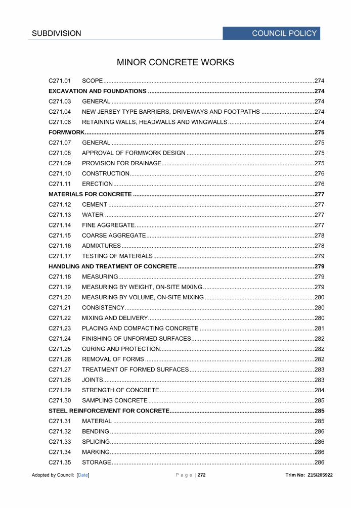
SUBDIVISION COUNCIL POLICY
Adopted by Council: [Date] P a g e | 272 Trim No: Z15/205922
MINOR CONCRETE WORKS
C271.01 SCOPE ............................................................................................................................... 274
EXCAVATION AND FOUNDATIONS .................................................................................................... 274
C271.03 GENERAL .......................................................................................................................... 274
C271.04 NEW JERSEY TYPE BARRIERS, DRIVEWAYS AND FOOTPATHS ................................ 274
C271.06 RETAINING WALLS, HEADWALLS AND WINGWALLS .................................................... 274
FORMWORK .......................................................................................................................................... 275
C271.07 GENERAL .......................................................................................................................... 275
C271.08 APPROVAL OF FORMWORK DESIGN ............................................................................. 275
C271.09 PROVISION FOR DRAINAGE............................................................................................ 275
C271.10 CONSTRUCTION ............................................................................................................... 276
C271.11 ERECTION ......................................................................................................................... 276
MATERIALS FOR CONCRETE ............................................................................................................. 277
C271.12 CEMENT ............................................................................................................................ 277
C271.13 WATER .............................................................................................................................. 277
C271.14 FINE AGGREGATE ............................................................................................................ 277
C271.15 COARSE AGGREGATE ..................................................................................................... 278
C271.16 ADMIXTURES .................................................................................................................... 278
C271.17 TESTING OF MATERIALS ................................................................................................. 279
HANDLING AND TREATMENT OF CONCRETE .................................................................................. 279
C271.18 MEASURING ...................................................................................................................... 279
C271.19 MEASURING BY WEIGHT, ON-SITE MIXING ................................................................... 279
C271.20 MEASURING BY VOLUME, ON-SITE MIXING .................................................................. 280
C271.21 CONSISTENCY .................................................................................................................. 280
C271.22 MIXING AND DELIVERY .................................................................................................... 280
C271.23 PLACING AND COMPACTING CONCRETE ..................................................................... 281
C271.24 FINISHING OF UNFORMED SURFACES .......................................................................... 282
C271.25 CURING AND PROTECTION............................................................................................. 282
C271.26 REMOVAL OF FORMS ...................................................................................................... 282
C271.27 TREATMENT OF FORMED SURFACES ........................................................................... 283
C271.28 JOINTS ............................................................................................................................... 283
C271.29 STRENGTH OF CONCRETE ............................................................................................. 284
C271.30 SAMPLING CONCRETE .................................................................................................... 285
STEEL REINFORCEMENT FOR CONCRETE ....................................................................................... 285
C271.31 MATERIAL ......................................................................................................................... 285
C271.32 BENDING ........................................................................................................................... 286
C271.33 SPLICING ........................................................................................................................... 286
C271.34 MARKING ........................................................................................................................... 286
C271.35 STORAGE .......................................................................................................................... 286

SUBDIVISION COUNCIL POLICY
Adopted by Council: [Date] P a g e | 273 Trim No: Z15/205922
C271.36 DELIVERY AND RECEIPT OF REINFORCEMENT ........................................................... 286
C271.37 PLACING ............................................................................................................................ 287
BACKFILLING ....................................................................................................................................... 287
C271.38 GENERAL .......................................................................................................................... 287
C271.39 TREATMENT AT WEEPHOLES ......................................................................................... 288
SPRAYED CONCRETE ......................................................................................................................... 288
C271.40 GENERAL .......................................................................................................................... 288
C271.41 TEST PANELS ................................................................................................................... 288
C271.42 SURFACE PREPARATION ................................................................................................ 289
C271.43 APPLICATION OF SPRAYED CONCRETE ....................................................................... 289
C271.44 CURING ............................................................................................................................. 289
LIMITS AND TOLERANCES .................................................................................................................. 291
C271.45 SUMMARY OF LIMITS AND TOLERANCES ..................................................................... 291

SUBDIVISION COUNCIL POLICY
Adopted by Council: [Date] P a g e | 274 Trim No: Z15/205922
SPECIFICATION C271 MINOR CONCRETE WORKS
GENERAL
C271.01 SCOPE
1. The Work to be executed under this Specification consists of the supply and placement of concrete, including sprayed concrete, and ancillary requirements like excavation, preparation of foundations, forming up, placement of reinforcement and backfilling for work shown on the Drawings but not having individual Specifications. These works include New Jersey type barriers, drainage pits and other supplementary structures, headwalls, box culverts, box culvert base slabs, driveways, footpaths, median toppings, retaining walls, footings, paving edge strips and works of a similar nature.
2. The work also includes supply and placement of sprayed concrete and miscellaneous minor concrete work for water and sewerage construction such as valve chambers, thrust and anchor blocks, bulkheads, pumping stations, bedding, encasement and cast-in-situ access chambers.
EXCAVATION AND FOUNDATIONS
C271.03 GENERAL
1. The subgrade, or subbase where specified, shall be formed at the required depth below the finished surface levels shown on the Drawings. Rock foundations shall be neatly excavated to form a bed for the concrete, and shall be thoroughly scraped and cleaned. Soil foundation shall, as far as possible, be excavated neatly from the solid material to coincide with the under-surface of the concrete, or of the subbase material (where specified).
Foundations
2. All soft, yielding or other unsuitable material shall be replaced with sound material approved by the Principal Certifying Authority, and the subgrade shall be compacted to provide a minimum relative compaction of 100 per cent as determined by AS 1289.5.4.1 for standard compactive effort. If the subgrade is dry it shall be sprinkled with as much water as it will readily absorb, before the concrete is placed.
Unsuitable Material
3. The Contractor shall supply all necessary sheeting and bracing to safely support the excavation in accordance with Statutory requirements. The excavation shall be kept free of water.
Shoring
C271.04 NEW JERSEY TYPE BARRIERS, DRIVEWAYS AND FOOTPATHS
1. For New Jersey type barriers, driveways and footpaths a subbase of approved quality and of minimum 150mm compacted thickness, unless otherwise shown on the Drawings, shall be placed over the subgrade. The surface shall then be checked for uniformity, line and level, and all irregularities shall be made good.
Subbase
2. The subbase material shall be compacted to provide a minimum relative compaction as determined by AS 1289.5.4.1 of 95 per cent for compactive effort or 95 per cent for modified compactive effort as appropriate.
Compaction
3. The finished subbase shall not deviate more than 12mm under a straight edge 3 metres long, subject to any necessary allowance on vertical curves.
Subgrade and Subbase Tolerances
C271.06 RETAINING WALLS, HEADWALLS AND WINGWALLS
1. In the case of rock foundations for retaining walls, headwalls and wingwalls, the excavation shall be carried into the rock for a minimum depth of 150mm. Where cut-off walls are to be
Rock Foundations

SUBDIVISION COUNCIL POLICY
Adopted by Council: [Date] P a g e | 275 Trim No: Z15/205922
provided, the depth of cut-off in rock foundations may be reduced to 100mm.
2. Prior to the construction of cast-in-situ concrete walls on earth foundations, the latter shall be covered by a mass concrete bedding layer at least 50mm thick and finished to a uniform surface. No forms or other materials shall be placed upon the bedding layer within a period of 48 hours after the concrete has been placed.
Earth Foundations
3. Unless otherwise specified, precast concrete wall sections shall be placed on a fresh concrete bedding layer while it is still in plastic state. In the case of soil foundations, the concrete shall be not less than 50mm thick, and where the foundation is in rock, the concrete shall be of such thickness as is required to provide a uniform surface at least 50mm above the highest points of rock.
Pre-cast
Concrete
FORMWORK
C271.07 GENERAL
1. Formwork shall be provided in accordance with AS 3610 to produce hardened concrete to the lines, levels and shapes shown on the Drawings or specified elsewhere. It shall have adequate strength to carry all applied loads, including the pressure of fresh concrete, vibration loads, weight of workers and equipment, without loss of shape. Forms shall be mortar tight and designed to allow removal without risk of damage to the completed structure. Joints in the formwork shall be perpendicular to the main axis of the shape of the concrete.
Formwork Requirements
2. Where concrete is placed in earth excavations, side forms shall be provided to prevent contact between concrete and the insitu earth.
Side Forms
3. Design of formwork for high sections shall be such that it shall not be necessary to drop concrete freely from a greater height than 1.2 metres or to move concrete along the formwork after deposition.
Placement of Concrete
4. Formwork material used shall be sound and suitable for the purpose intended and surface finish specified.
Material
5. Provision shall be made for the accurate location and firm support of fittings, bolts, anchorages and formers of holes as shown on the drawings. Temporary fittings used for the support of the formwork shall be arranged to permit removal without damage to the concrete. The use of wires and or bolts extending to the surface of the concrete shall not be permitted except where shown on the Drawings.
Formwork Fittings
6. Forms for edges of concrete shall be filleted and for re-entrant angles chamfered as shown on the Drawings.
Edge Treatment
7. Temporary openings shall be provided where necessary for cleaning out of formwork and inspection before concreting.
Cleaning and Inspection
C271.08 APPROVAL OF FORMWORK DESIGN
1. For box culverts and reinforced concrete retaining walls, detailed drawings, design calculations, description and/or samples of materials proposed for use shall be submitted for the Principal Certifying Authority's concurrence before manufacture of the formwork is commenced.
Approval to Design
C271.09 PROVISION FOR DRAINAGE
1. Where shown on the Drawings, or where directed by the Principal Certifying Authority, weepholes of 50mm diameter shall be provided in retaining walls and wingwalls.
Weep Holes

SUBDIVISION COUNCIL POLICY
Adopted by Council: [Date] P a g e | 276 Trim No: Z15/205922
C271.10 CONSTRUCTION
1. The type and quality of material selected for formwork and the workmanship used in construction shall be such that the surface finish specified shall be obtained. Construction shall be such that the erection tolerances shall be obtainable.
Formwork Material
2. Timber for formwork shall be well seasoned, free from defects and, where in contact with fresh concrete, free from loose knots.
Timber Requirements
3. Timber forms for exposed surfaces shall be constructed from plywood or particle board with hardwood or approved softwood studs and wales. The plywood used for forms shall comply with AS 2271, the hardwood shall comply with AS 2082 and the particle board with AS/NZS 1859.
Timber Standards
4. Formwork for exposed surfaces shall be made from panels having uniform widths of not less than 1m and uniform lengths of not less than 2m, except where the dimensions of the member formed are less than the specified panel dimensions. Plywood panels shall be placed with the grain of the outer plies perpendicular to the studding or joists. Where form panels are attached directly to the studding or joists the panel shall be not less than 15mm thick. Form panels less than 15mm thick, otherwise conforming to these requirements may be used with a continuous backing of dressed material of 20mm minimum thickness. All form panels shall be placed in a neat, symmetrical pattern.
Formwork Panels for Exposed Surfaces
5. Forms for all surfaces which will be completely enclosed or permanently hidden below the ground may be constructed from dressed or undressed timber, steel, plywood or particle board.
Hidden Surfaces
6. Mild steel form surfaces in contact with concrete shall have all bolt and rivet heads counter-sunk and all welds ground back to even and smooth surfaces.
Mild Steel Surfaces
C271.11 ERECTION
(a) General
(i) Dimensions and position of forms, shall be carefully checked after the forms are erected. Forms shall be aligned accurately and the location of all fittings, hold formers, etc. checked prior to placing concrete. Departure of the forms from the surfaces shown on the drawings shall not exceed 1/300 of the space between supports for any surface visible in the completed work and 1/150 for hidden work.
Formwork Position Tolerances
(ii) Joints as erected shall be mortar tight. Mortar Tight
(iii) The interior surface of the forms shall be treated to ensure non-adhesion of the mortar. Commercial quality form oil or grease will be acceptable, but the oil or grease used on forms against surfaces to be exposed shall not stain or discolour the concrete surface. The coating shall be uniformly spread in a thin film and any surplus shall be removed prior to placing concrete. In the case of unlined timber forms, the timber shall be thoroughly wetted before oiling. Forms shall be treated before placing reinforcement to ensure that the form release agent will not contaminate the surface of the reinforcing steel or construction joints.
Coating of Internal Surfaces
(iv) Formwork hardware shall be treated with a form release agent and so arranged that it may be removed from the concrete without excessive jarring or hammering.
Release Agent
(b) Approval by the Principal Certifying Authority
(i) Placing of concrete shall not commence until the formwork and reinforcement have been inspected and approved.
Concrete Placement
(ii) When an inspection is requested by the Contractor, a notice of not less than 24 hours, excluding Saturdays, Sundays and Public Holidays, shall be given to the Principal Certifying Authority.
Notice of Inspection

SUBDIVISION COUNCIL POLICY
Adopted by Council: [Date] P a g e | 277 Trim No: Z15/205922
MATERIALS FOR CONCRETE
C271.12 CEMENT
1. Cement shall be Type GP Portland Cement complying with AS 3972 and shall be from a source included in the New South Wales Government Cement Quality Assurance Scheme.
NSW QA Scheme
2. When submitting details of the nominated mix in accordance with Clause C271.17, the Contractor shall nominate the brand and source of the cement. On approval of the nominated mix by the Principal Certifying Authority, the Contractor shall only use the nominated cement for the work.
Nominated Brand and Source
3. Documentary or other acceptable evidence of the quality of the cement shall be furnished by the Contractor if required by the Principal Certifying Authority.
Proof of Quality
4. If the Contractor proposes to use cement which has been stored for a period in excess of 3 months from the date of testing, a re-test shall be required at the Contractor's expense before the cement is used.
Storage Time
5. All cement shall be transported in watertight containers, and shall be protected from moisture until used. Caked or lumpy cement shall not be used.
Transport and Storage
C271.13 WATER
1. Water used in the production of concrete shall be potable and free from materials harmful to concrete or reinforcement.
Quality
2. Water which is not potable for human beings shall not be used in reinforced concrete. Potability
C271.14 FINE AGGREGATE
1. Fine aggregates shall consist of clean, hard, tough, durable uncoated grains, uniform in quality, and shall conform to the requirements of AS 2758.1 in respect of bulk density, water absorption (maximum 5 per cent) material finer than 2 micrometres, impurities and reactive materials.
Quality
2. Fine aggregates shall be evenly graded within the limits shown in Table C271.1. Grading Requirements
Australian Standard
Sieve
Proportion Passing (% of Mass)
9.50mm 100
4.75mm 90 - 100
1.18mm 40 - 85
300mm 8 - 30
150mm 2 - 10
75mm 0 - 4
Table C271.1 - Fine Aggregate Grading

SUBDIVISION COUNCIL POLICY
Adopted by Council: [Date] P a g e | 278 Trim No: Z15/205922
C271.15 COARSE AGGREGATE
1. Coarse aggregate shall consist of clean, hard, durable, crushed stone, crushed river gravel, screened river gravel or metallurgical furnace slag and shall conform to the requirements of AS 2758.1 in respect of particle density, bulk density, water absorption (maximum 2.5 per cent), material finer than 75 micrometres, weak particles, light particles, impurities and reactive materials, iron unsoundness and falling or dusting unsoundness. In all other respects, the coarse aggregate shall comply with this Specification. If required, coarse aggregate shall be washed to satisfy these requirements.
Quality
2. The percentage of wear shall be determined by AS 1141.23, and the loss of weight shall not exceed 30 per cent.
Wear Test
3. When required by the Principal Certifying Authority, coarse aggregate shall be tested for conformance for any or all of the properties set out below:
Additional Tests
(i) Crushing Value - AS 1141.21 [
The aggregate crushing value shall not exceed 25 per cent.
(ii) Soundness - AS 1141.24 The loss of mass when tested with sodium sulphate shall not exceed 12 per cent.
(iii) Particle Shape - AS 1141.14 The proportion of mis-shapen particles (2:1 ratio) shall not exceed 35 per cent.
4. Coarse aggregate shall be evenly graded within the absolute limits shown in Table C271.2 and shall not deviate from the grading of the samples submitted under Clause C271.17 by more than shown.
Grading Requirements
Australian Proportion Passing (% of Mass)
Deviation
Standard Sieve
40mm Nominal
20mm Nominal
Extrusion Concrete
Proposed Grading
(mm) For Walls exceeding
150mm thickness
For all other structures
(% of Mass of Sample)
53.0 37.5 26.5 19.0 13.2 9.50 4.75 2.36
100 95 - 100
30 - 70
10 - 35 0 - 10 0 - 2
100 95 - 100
25 - 35 0 - 10 0 - 2
100
±10
±10
±5 ±5
Table C271.2 - Coarse Aggregate Gradings
C271.16 ADMIXTURES
1. Chemical admixtures and their use shall comply with AS 1478. Admixtures shall not contain calcium chloride, calcium formate, or triethanolamine or any other accelerator. Admixtures or combinations of admixtures other than specified below, shall not be used.
Quality and Use
2. During the warm season, (October to March inclusive), a lignin or lignin-based (`ligpol') set-retarding admixture (Type Re or Type WR Re) approved by the Principal Certifying Authority shall be used to control slump within the limits stated in Clause C271.21. The
Retarder for Warm Season

SUBDIVISION COUNCIL POLICY
Adopted by Council: [Date] P a g e | 279 Trim No: Z15/205922
dosage shall be varied to account for air temperature and haul time in accordance with the manufacturer's recommendations. A copy of the NATA endorsed Certificate of Compliance with AS 1478 for Type Re or Type WR Re shall be submitted to the Principal Certifying Authority, together with the proposed `dosage chart' in accordance with Clause C271.17.
3. During the cool season, (April to September inclusive), only a lignin or lignin based set-retarding admixture containing not more than 6 per cent reducing sugars (Type WR Re complying with AS 1478) may be used in the mix.
Retarder for Cool Season
C271.17 TESTING OF MATERIALS
1. The Contractor shall submit to the Principal Certifying Authority a copy of a NATA Certified Laboratory Test Report on the quality and gradings of the aggregates proposed to be used in the work.
Contractor's Responsibility
2. The materials shall only be used after receipt of the Principal Certifying Authority's notification of acceptance, and then only so long as the materials accord with the specification.
Use of Material
HANDLING AND TREATMENT OF CONCRETE
C271.18 MEASURING
1. All materials shall be measured by weight, except that:-
(a) Water may be measured by volume with an approved adjustable water-measuring and discharging device, and,
Measurement of Material
(b) Cement may be measured by bags as packed by the manufacturer in which case batches shall be proportioned on the basis of one or more unbroken bags of cement, and for this purpose one bag of cement shall be assumed to weigh 40kg. Bulk cement shall be weighed in an individual hopper and shall be kept separate from the aggregates until the components of the batch are discharged from the batching hopper.
(c) Measurement by volume for smaller works may be undertaken with the prior approval of the Principal Certifying Authority.
C271.19 MEASURING BY WEIGHT, ON-SITE MIXING
1. Where concrete is to be mixed on site, and where mix control is likely to be less efficient than at a central batching plant, the weights of cement, fine and coarse aggregate shown in Table C271.3 may be used as a guide to produce the classes of concrete specified. Small changes in the proportions of fine and coarse aggregate may be required to improve density or workability of the concrete. The use of proportions shown in Table C271.3 shall not relieve the Contractor of his obligation to provide concrete of the specified compressive strength.
Mixing by Weight on Site
MPa Cement Kg
Fine Aggregates
Kg
Coarse Aggregates
Kg
Total Aggregates
Kg
10 15 20
40 40 40
130 100 88
250 190 126
380 290 214
Table C271.3 - Materials in Batch containing 1 bag (40Kg) Cement
2. The proportions set out in Table C271.3 make allowance for moisture contents of aggregates of 6 per cent for fine aggregates and 1 per cent for coarse aggregates. Where the moisture content of aggregates exceeds 8 per cent or 3 per cent respectively, the proportions of the
Variation in Aggregate Moisture Content

SUBDIVISION COUNCIL POLICY
Adopted by Council: [Date] P a g e | 280 Trim No: Z15/205922
mix shall be changed to compensate for the excess water in the aggregate.
C271.20 MEASURING BY VOLUME, ON-SITE MIXING
1. Where measurement by volume is approved, the proportions of the materials shall be such as are required to produce a mix free of voids and having the specified strength at 28 days.
Mixing by Volume on Site
2. The nominal proportions given in Table C271.4 may be used as a guide for volume batching. Volume Batching
MPa
Parts by Volume
Cement Fine Aggregate
Coarse Aggregate
10 15 20
1 1 1
3 2.25
2
6 4.5 3
Table C271.4 - Volume Batching
3. The volumes of fine and coarse aggregates for each batch shall be measured in boxes or bins. The aggregates shall be measured loose (i.e. without compaction) in the boxes and shall be struck off level. Measurements by shovels or like methods will not be permitted. Batch proportions shall be so arranged that each batch contains 1 bag of cement. One 40kg bag of cement shall be assumed to have a volume of 27.5 litres.
Batch Measurement
C271.21 CONSISTENCY
1. A sufficient quantity of water shall be added to the mix so that the consistency of the concrete is such that it can be placed in the forms, compacted and worked into all corners without permitting the ingredients to segregate, or excess free water to collect on the surface. If required by the Principal Certifying Authority, the Contractor shall determine the consistence of the concrete in accordance with AS 1012.3, Method 1. Except for extruded concrete, the nominated slump shall not exceed 80mm, plus the field tolerance of ±15mm.
Consistency Requirements
2. In the case of concrete placed by an extrusion machine, the water in the mix shall be only sufficient to produce a slump of 10mm to 15mm.
Extruded Concrete Consistence
C271.22 MIXING AND DELIVERY
(a) General
(i) Concrete may be mixed either at the site or at a central mixing plant. All concrete shall be mixed with mechanically operated mixers. In an emergency, hand mixing may be permitted.
Mechanical Mixing
(ii) Any concrete which exhibits signs of segregation shall not be used. Segregation of Concrete
(b) Machine Mixing at Site
(i) The mixing of concrete shall be done in a batch mixer which will ensure a uniform distribution of the materials throughout the batch.
Mixer Requirements
(ii) The mixer shall be of such capacity that one or more whole bags of cement may be used per batch of concrete. The volume of the mixed material shall not exceed the manufacturer's rated capacity of the mixer.
Mixer Capacity
(iii) The mixing time for each batch shall not be less than 1.5 minutes after all ingredients are assembled in the mixer, and prior to any portion of the batch being removed.
Mixing Time

SUBDIVISION COUNCIL POLICY
Adopted by Council: [Date] P a g e | 281 Trim No: Z15/205922
(iv) The entire contents of a batch shall be discharged from the mixer before any materials are placed therein for the succeeding batch.
Total Mix Discharge
(c) Mixing in an Emergency
(i) In the case of breakdown of the mechanical mixing equipment, hand mixing in small quantities so as to complete a section of the work or reach a suitable construction joint is permitted.
Hand Mixing
(ii) Hand mixing shall be done on a water-tight platform of sufficient size to allow the mixing of at least two batches simultaneously. The amount of cement used shall be 10 per cent more than the amount specified for machine mixed concrete.
Hand Mixing Conditions
(iii) The fine aggregate and cement shall first be mixed until a uniform colour is obtained, and then spread on the mixing platform in a thin layer. The coarse aggregate, which shall have been previously drenched with water, shall then be spread over the fine aggregate and cement in a uniform layer, and the whole mass turned over as further water is added with a rose sprinkler. After the water is added, the mass shall be turned at least three times, not including shovelling into barrows or forms, until the mixture is uniform in colour and appearance. Hand-mixed batches shall not exceed 0.25 cubic metres each.
Hand Mixing Procedure
(d) Ready-Mixed Concrete
(i) The concrete shall be mixed and delivered in accordance with the requirements of AS 1379 relating to:-
(1) Mixing and Delivery; and
(2) Use of Non-Agitating Equipment,
with the exception that in (1) the time taken from the introduction of water until the concrete is completely discharged shall be not more than 1.5 hours, and in (2) not more than 30 minutes.
Mixing Standard and Discharge Times
(ii) The water used for flushing the chutes and for cleaning shall be discharged in an area acceptable to the Principal Certifying Authority. The chutes shall be long enough to permit delivery to the whole of the area enclosed by the forms.
Cleansing and Positioning of Chutes
C271.23 PLACING AND COMPACTING CONCRETE
1. No concrete shall be placed during rain nor without the approval of the Principal Certifying Authority, while the air temperature is, or is likely to be within 24 hours, below 5oC or while the shade temperature exceeds 38oC.
Air Temperature Requirements
2. The concrete shall be mixed in the quantities required for immediate use and shall be placed in position as rapidly as possible. Any concrete which has developed initial set, or which does not reach the forms within 30 minutes after the water has been added (except when transported in agitator trucks) shall not be used.
Placement within Time Limit
3. The concrete shall be deposited in the forms, without separation of the aggregates. Concrete shall not be dropped freely from a height greater than 1.2 metres, or be deposited in large quantities at any point and moved or worked along the forms. Conveying equipment, including open troughs and chutes, where used, shall be made of metal, or have metal linings. Where used on steep slopes, troughs and chutes shall be equipped with baffles, or be placed in short lengths in such a way that the direction of flow of the concrete is changed. The concrete shall be placed in horizontal layers in one continuous operation between the ends of the work and/or construction joints. Care shall be taken to fill every part of the forms and to work the coarser aggregate back from the face. The freshly placed concrete shall be compacted by continuous spading, slicing or by vibrator units. Vibrators shall not be left in one position for more than 30 seconds, and shall not be permitted to rest on reinforcement.
Placement in Forms, Vibrating
4. Exposed surfaces of the concrete shall be struck off and finished with a wooden float. Where shown on the Drawings corners and edges shall be left neatly rounded or chamfered. Re-
Exposed Surfaces

SUBDIVISION COUNCIL POLICY
Adopted by Council: [Date] P a g e | 282 Trim No: Z15/205922
entrant angles shall be neatly filleted.
5. Concrete shall not be moved after it has been in the forms for more than 10 minutes. Initial Set
6. In the case of concrete placed by an extrusion machine, small quantities of cement-sand slurry, comprised of two parts of plasterer's sand and one part of cement (by volume), together with sufficient water to bring it to a semi-fluid condition, shall be placed in the special receptacle in the machine, if the machine is so equipped and shall be fed onto the surface of the concrete at a rate sufficient to produce a smooth and uniform finish.
Slurry for Extruded Concrete
C271.24 FINISHING OF UNFORMED SURFACES
(a) Surfaces other than Wearing Surfaces
1. Unformed surfaces shall be compacted and tamped so as to flush mortar to the surface, screeded off and finally dressed with a wooden float to an even surface. Care shall be taken to drain or otherwise remove promptly any water which comes to the surface. A capping of mortar will not be permitted.
Finish for Unformed Surfaces
2. All future contact surfaces shall be left rough, with the coarse aggregate at the surface firmly embedded but not forced below the surface.
Future Contact Surfaces
(b) Wearing Surfaces
1. Where a concrete wearing surface is shown on the drawings the concrete shall be thoroughly compacted and the surface screeded off by a vibrating screed, or hand screeded where the distance between forms perpendicular to the direction of screed is no greater than 2 metres. Immediately following compaction and screeding the concrete shall be tested for high or low spots and any necessary corrections made. The surface shall be finished true and uniform and free from any glazed or trowelled finish and shall be finally dressed with a wooden template or float, or by the use of belting in an approved manner. The departure from grade shall not exceed 5mm in any 3 metre length.
Finish for Wearing Surfaces
2. Where an asphaltic concrete wearing surface is specified, the surface of the concrete, after being compacted, screeded and corrected, shall be dressed with a wooden float and finally broomed to produce a rough surface.
Surface to receive Asphalt
(c) Finished Levels
1. The finished levels of concrete structures not adjacent to road pavements shall not vary more than 25mm from the specified levels. In the case of barriers, drainage pits and other structures adjacent to road pavements, the finished concrete shall not vary more than 10mm from the specified levels and alignment. Barriers, footpaths and similar shall not deviate from level or alignment by more than 5mm from a straight-edge 3 metres long, subject to any necessary allowances on vertical and horizontal curves.
Surface Tolerance
C271.25 CURING AND PROTECTION
1. All exposed surfaces of the freshly placed concrete shall be kept moist either by the use of plastic sheeting, damp sand or commercial curing compounds, in accordance with AS 3799, for a minimum period of 3 days. During this time the work must be adequately protected from traffic and any other causes likely to damage the concrete.
Curing Requirements
C271.26 REMOVAL OF FORMS
1. All forms shall remain in place, after placement of concrete, for minimum periods specified hereinafter. These periods may be extended by the Principal Certifying Authority if the air shade temperature falls below 10oC during the periods specified.
Walls, Sumps etc.
Mass retaining walls, headwalls, wingwalls, gully pits,

SUBDIVISION COUNCIL POLICY
Adopted by Council: [Date] P a g e | 283 Trim No: Z15/205922
Sumps, and similar drainage structures 48 hours
Footpaths, driveways and similar 48 hours
Sides of reinforced concrete walls when height of each day pour is:
(i) under 0.6 metres 1 day (ii) 0.6m to 3m 2 days (iii) 3m to 6m 3 days (iv) 6m to 9m 5 days
Supporting forms under deck slabs of culverts 10 days
2. To permit the satisfactory finishing of barriers, forms shall be removed in not less than 12 hours nor more than 48 hours after placing concrete, depending upon weather conditions.
Barriers
3. Care shall be taken in removing forms so that the concrete will not be cracked, chipped or otherwise damaged. The use of crowbars or other levering devices exerting pressure on the fresh concrete to loosen the forms will not be permitted.
Protection of Concrete
4. No superimposed load shall be allowed on any part of a structure until the concrete has reached at least 70 per cent of the design strength.
Superimposed Load
5. Hole formers such as pipes and bars shall be removed as soon as the concrete has hardened sufficiently for this to be done without damage to the concrete.
Removal of Hole Formers
C271.27 TREATMENT OF FORMED SURFACES
1. All concrete surfaces shall be true and even, free from stone pockets, depressions or projections beyond the surface. All arises shall be sharp and true, and mouldings shall be evenly mitred or rounded. Care shall be exercised in removing forms to ensure this result.
Quality of Surfaces
2. As soon as the forms are removed from mass or reinforced concrete work, all rough places, holes and porous spots shall be repaired by removing defective work and filling with stiff cement mortar having the same proportions of cement and fine aggregate as used in the concrete, and shall be brought to an even surface with a wooden float.
Repair of Defects
3. Any tie wires or other fitments extending to outside surfaces, shall be cut back after removal of forms, to a depth of at least 40mm with sharp chisels or cutters. All cavities caused by removal of fitments or tie wires shall be wetted and carefully packed with cement mortar, as above.
Removal of the Wires
4. The surfaces of bolt cavities, tie wire holes, and all defects in concrete shall be coated prior to the placing of mortar, grout, or fresh concrete, with an approved bonding agent, in lieu of wetting with water. The method of application of such agent and the conditions in which it is to be used shall generally be as laid down by the manufacturer.
Coating with Bonding Agent
C271.28 JOINTS
1. Where horizontal construction joints are found to be necessary in walls, or cast-in-situ drainage structures the joints may be made at the base of walls and at other locations in the walls where approved by the Principal Certifying Authority. In order to provide for bond between the new concrete and the concrete which has already set, the surface on which the new concrete is to be placed shall be thoroughly cleaned of loose material , foreign matter and laitance. The surface shall be roughened or keyed and saturated with water. After any excess water has been removed, the surface shall be thinly coated with a neat cement grout.
Horizontal Construction Joint
2. Retaining walls shall be provided with vertical expansion joints as shown on the Drawings. The expansion joints shall consist of jointing material of approved quality, and of thickness shown on the drawings, and a depth sufficient to fill the joint. The jointing material shall be neatly cut to fit the surface of the concrete.
Vertical Expansion Joints

SUBDIVISION COUNCIL POLICY
Adopted by Council: [Date] P a g e | 284 Trim No: Z15/205922
3. Where barriers are extruded or cast in place, narrow transverse vertical grooves, 20mm deep, shall be formed neatly in the surface of the freshly placed concrete to produce contraction joints for the control of cracking. The contraction joints, shall be at intervals of 3 metres.
Barrier Contraction
4. In barriers, unless shown otherwise on the Drawings, expansion joints, 15mm in width for the full depth of the barrier, shall be constructed at intervals not exceeding 15m and where the barrier abuts against gully pits. Expansion joints shall consist of a preformed jointing material of bituminous fibreboard.
Barrier Expansion
5. In footpaths, median toppings and driveways, unless otherwise shown on the Drawings, expansion joints, 15mm in width for the full depth of paving, shall be constructed at intervals not exceeding 15m and where the pavement abuts against gutters, pits and structures. Expansion joints shall consist of a preformed jointing material of bituminous fibreboard.
6. Unless otherwise specified, all unreinforced paving shall be provided with narrow vertical grooves, 20mm deep to induce contraction joints for the control of cracking.
C271.29 STRENGTH OF CONCRETE
1. When tested in accordance with AS 1012.9, the concrete shall have a compressive strength not less than that shown on the Drawings or if not shown shall have a compressive strength not less than that specified in Table C271.5 for the particular class of work.
Strength Requirement
2. The strength shall be determined from the average of not less than two specimens, moulded from each class of concrete being used in the work, and selected to represent the whole of the concrete placed at the time of moulding.
Determination ofStrength
3. In general, two pairs of test specimens shall be moulded for each 15 cubic metres of concrete, or part thereof, one pair being intended for the 7 day test if required and the other pair for a 28 day test.
Moulding of Cylinders
Use
MPa
Minimum Cement per cu metre
Coarse Aggregate Nominal
Size
Cylinder Strength Required
7 days 28 days
Kg mm MPa MPa
Foundations, mass retaining walls
20 330 40 15 20
Mass concrete footings, pitching, linings etc.
20 330 20 15 20
Drainage structures, driveways footpaths, New Jersey barrier, miscellaneous minor concrete work
25 330 20 20 25
Reinforced concrete culverts, headwalls, base slabs, sign structure large footings, retaining walls
32 380 20 24 32
Extruded concrete 20 330 14 15 20
Table C271.5 - Concrete Strength Requirements

SUBDIVISION COUNCIL POLICY
Adopted by Council: [Date] P a g e | 285 Trim No: Z15/205922
4. The strengths specified at 28 days shall be increased by multiplying by factors as shown in Table C271.6 for tests at ages in excess of 28 days.
Strength Age Factor
*Age of test specimen in days of date of testing
Factor
28 35 42 49 56 70 84
112 140 168 196 224 308
365 and greater
1.00 1.02 1.04 1.06 1.08 1.10 1.12 1.14 1.16 1.18 1.20 1.22 1.24 1.25
*For intermediate ages the factor shall be determined on a pro-rata basis
Table C271.6 - Concrete Age Conversion Factors
5. If the test specimens fail to achieve the specified strength, the Contractor may, with the approval of the Principal Certifying Authority, arrange for cores to be taken from the work. If the average strength of such cores complies with the specified requirements nominated in Table C271.5, the concrete will be accepted.
Cores and Test Acceptance
6. If cores taken fail to satisfy the strength requirements, the concrete shall be removed. Failure of Cores
C271.30 SAMPLING CONCRETE
1. Equipment and facilities shall be provided by the Contractor for the taking and storage of samples of any materials or concrete being used, or intended to be used in the work.
Contractor's Responsibility
2. Concrete test specimens shall be cylinders 300mm long and 150mm diameter, moulded concurrently in the presence of the Principal Certifying Authority or Principal Certifying Authority’s representative, in accordance with AS 1012.8, from samples taken in accordance with AS 1012.1.
Moulding of Test Cylinders
STEEL REINFORCEMENT FOR CONCRETE
C271.31 MATERIAL
1. Steel reinforcement shall comply with the requirements of the Australian Standards AS/NZS 4671:2001 – Steel Reinforcing Materials.
Standards
2. The type and size of bars shall be as shown on the Drawings. Type and Size
3. Steel reinforcement shall be free from loose or thick rust, grease, tar, paint, oil, mud, millscale, mortar or any other coating, but shall not be brought to a smooth polished condition.
Quality
4. The Contractor shall supply evidence satisfactory to the Principal Certifying Authority that steel reinforcement complies with AS/NZS 4671:2001 – Steel Reinforcing Materials - Test certificates shall show the results of mechanical tests and chemical analysis.
Documentary Evidence
5. Where the material cannot be identified with a test certificate, samples shall be taken and

SUBDIVISION COUNCIL POLICY
Adopted by Council: [Date] P a g e | 286 Trim No: Z15/205922
testing arranged by the Contractor. The samples shall be selected randomly and consist of three specimens each at least 1.2 m in length. Sampling and testing shall be at no cost to the Principal Certifying Authority.
6. Plastic bar chairs or plastic tipped wire chairs shall be capable of withstanding a load of 200kg mass on the chair for one hour at 23 ± 5oC without malfunction. The Contractor shall demonstrate that the proposed chairs conform with these requirements.
Bar Chairs
C271.32 BENDING
1. Reinforcement shall be formed to the dimensions and shapes shown on the Drawings. It shall not be bent or straightened in a manner that will injure the material, and bars with kinks or bends not shown on the drawings will not be accepted. Heating of reinforcement for purposes of bending will only be permitted if uniform heat is applied. Temperature shall not exceed 450oC and the heating shall extend beyond the portion to be bent. Heated bars shall not be cooled by quenching.
Cutting and Bending
C271.33 SPLICING
(a) General
1. All reinforcement shall be furnished in the lengths indicated on the Drawings. If splicing is required, it shall be in accordance with the provisions of AS/NZS 4671:2001 – Steel Reinforcing Materials.
Plan Lengths
(b) Lapped Splices
1. Laps in reinforcing bars, wire or fabric shall be as shown on the Drawings. Laps not shown on the Drawings shall be as follows for unhooked bars:-
Plain bars, Grade R250N 40 bar diameters Deformed bars, Grade D500L & D500N 35 bar diameters Hard-drawn wire 50 bar diameters
Lap Dimensions
2. Splices in reinforcing fabric shall be so made that the overlap, measured between outermost transverse wires of each sheet of fabric is not less than the spacing of those wires plus 25mm.
Splice Dimensions
C271.34 MARKING
1. Bars of identical shape shall be made up in bundles of three and securely tied together by soft iron wire. Each bundle shall have a stout metal label of not less than 40mm diameter attached to it. Each metal label shall be punched with the appropriate marking in accordance with the steel list shown on the drawings. If called for on the Drawings the marking shall incorporate a prefix, and bars with different prefixes shall be stored separately.
Marking Details
C271.35 STORAGE
1. Reinforcement shall be stored above the surface of the ground and shall be protected from damage and from deterioration by exposure.
Protection of Reinforcement
C271.36 DELIVERY AND RECEIPT OF REINFORCEMENT
1. Unless the Contractor elects to have the reinforcement inspected at the site, no reinforcement shall be delivered to the site until all tests and inspections have been satisfactorily completed and permission to deliver has been granted by the Principal Certifying Authority.
Test Before Delivery
2. The Contractor shall give 10 working days’ notice to the Principal Certifying Authority for carrying out inspection and testing. The Principal Certifying Authority will carry out the
Notice to Test

SUBDIVISION COUNCIL POLICY
Adopted by Council: [Date] P a g e | 287 Trim No: Z15/205922
inspection and testing with reasonable expediency, but the Contractor shall not be entitled to an extra as a result of any delays in this connection.
C271.37 PLACING
1. Reinforcement shall be accurately placed as shown on the Drawings and shall be securely held by blocking from the forms, by supporting on concrete or plastic chairs, or metal hangers, and by wiring together at all intersections or at 0.5m centres, whichever is the greater distance, using annealed iron wire of diameter not less than 1.25mm. Steel shall not be supported on metal supports which extend to the surface of concrete, on wooden supports, or on pieces of coarse aggregate. Reinforcement shall have the minimum cover shown on the Drawings.
Reinforcement Position
2. The Principal Certifying Authority may approve the use of tack welding instead of wire ties on reinforcing wire. Tack welding of cold-worked and hard grade bars shall not be permitted.
Tack Welding
3. The reinforcement in each section of the work shall be approved by the Principal Certifying Authority before any concrete is deposited in the section and adequate time shall be allowed for inspections and any corrective work which may be required. Notice for inspection shall not be less than four normal working hours.
Inspection Required
4. Splices shall be staggered where practicable and when not shown on the drawings they shall be arranged as directed by the Principal Certifying Authority.
Splices
5. Bars forming a lapped splice shall be securely wired together in at least two places, unless welded.
Lapped Splice
6. The clear cover of any bar, including stirrups, to the nearest concrete surface shall be as shown on the Drawings. Where not so indicated it shall be as stated below:
(a) Concrete normally in contact only with air
(i) Slabs: 40mm (ii) Other than slabs: 45mm (b) Concrete in contact with earth or fresh water
(i) Slabs of box culverts: 50mm (ii) Other than culverts: 50mm In no cases shall the cover be less than 1½ times the diameter of the bar.
Bar Cover
BACKFILLING
C271.38 GENERAL
1. Backfilling at barriers, paving, etc, and minor concrete works shall not commence until after the concrete has hardened and not earlier than three days after placing.
2. No filling shall be placed against retaining walls, headwalls or wingwalls within 21 days after placing of the concrete, unless the walls are effectively supported by struts to the satisfaction of the Principal Certifying Authority, or when the Contractor can demonstrate that 85 per cent of the design strength of the concrete has been achieved.
Adjacent to Walls
3. Selected backfill shall be placed against retaining walls and cast-in-place box culverts for a horizontal distance equal to one-third of the height of the wall. It shall consist of granular material, free from clay and stone larger than 50mm gauge. The Plasticity Index of this selected backfill material shall not be less than 2 or more than 12 when tested in accordance with AS 1289.3.3.1. The material shall be placed in layers not exceeding 150mm and shall be compacted to provide a relative compaction of not less than 92 per cent as determined by AS 1289.5.4.1 for modified compactive effort.
Selected Backfill

SUBDIVISION COUNCIL POLICY
Adopted by Council: [Date] P a g e | 288 Trim No: Z15/205922
C271.39 TREATMENT AT WEEPHOLES
1. Drainage adjacent to weepholes shall be provided by either a layer of broken stone or river gravel consisting of clean, hard, durable particles graded from 50mm to 10mm such that:
(a) The maximum particle dimension shall not exceed 50mm
(b) No more than 5 per cent by mass shall pass the 9.5mm A.S. sieve.
Size & Type of Backfill Material
2. The broken stone or river gravel, enclosed in a filter fabric suitable for drainage without scour, shall be continuous in the line of the weepholes, extend at least 300mm horizontally into the fill and extend at least 450mm vertically above the level of the weepholes.
Extent of Material
3. Alternatively the Contractor may provide a synthetic membrane of equivalent drainage characteristics. It shall be stored and installed in accordance with Manufacturer's instructions. The use of a synthetic membrane shall be subject to the Principal Certifying Authority's approval.
Synthetic Membrane
SPRAYED CONCRETE
C271.40 GENERAL
1. Sprayed concrete is concrete pneumatically applied at high velocity on to a surface. Application may be either a wet or dry process. A sound homogeneous product shall be provided with surface finish reasonably uniform in texture and free from blemishes.
Definition
2. The minimum depth of sprayed concrete to be applied shall be 75mm. Depth
3. Sprayed concrete lining in open drains shall be coloured to match the adjoining rock colour. Colour
4. Sprayed concrete shall have a minimum cement content of 380 kg/m3 as discharged from the nozzle and shall have a minimum compressive strength of 25 MPa at 28 days when tested by means of 75mm diameter cores taken from in-place sprayed concrete.
Strength
5. Cores shall be secured, accepted, cured, capped and tested in accordance with AS 1012.14. Equipment and facilities shall be provided by the Contractor for the taking of cores from the work. The Contractor shall arrange for a laboratory with appropriate NATA registration for the curing and testing of the cores. Copies of test results shall be forwarded to the Principal Certifying Authority.
Test Cores
6. At least 14 days prior to applying any sprayed concrete the Contractor shall submit to the Principal Certifying Authority details of his proposed procedure, plant, materials and mix proportions. Materials shall comply with AS 3600.
Contractor's Responsibility
C271.41 TEST PANELS
1. If so required by the Principal Certifying Authority, the Contractor shall prepare at least 3 test panels for each mix proposed, in conditions similar to those in the works and in the presence of the Principal Certifying Authority. The test panels shall be made by applying a 75mm thickness of sprayed concrete to a hardboard panel approximately 750mm square. The sprayed concrete shall be applied to the panels in the same manner, using materials including steel reinforcing fabric, equipment, pressures and curing that will be used in the Works. The panels shall be submitted to the Principal Certifying Authority for examination not less than 10 days before applying concrete.
Test Panels
2. The Contractor shall cut four 75mm diameter cores from one test panel for each proposed mix approximately 48 hours after the panel has been sprayed. The cores shall be tested as for cores from in-place sprayed concrete. One core shall be compression tested at 3 days, one core at 7 days and the remaining two cores at 28 days.
Cores

SUBDIVISION COUNCIL POLICY
Adopted by Council: [Date] P a g e | 289 Trim No: Z15/205922
3. Should any of the cores reveal defects such as lack of compaction, dry patches, voids or sand pockets or should the test panel exhibit an unacceptable surface finish, the Contractor shall modify the mix design and/or method of placement and prepare fresh test panels for testing and inspection.
Defective Core
4. Sprayed concrete shall not be applied to the Works until the Contractor produces test panels for the approval of the Council.
Approval
C271.42 SURFACE PREPARATION
1. Earth surfaces shall be graded, trimmed and compacted and shall be dampened prior to applying the sprayed concrete. The Contractor shall take any precautions necessary to prevent erosion when the sprayed concrete is applied.
Earth
2. Rock surfaces shall be cleaned of loose material, mud and other foreign matter that might prevent bonding of the sprayed concrete onto the rock surface. The rock surface shall be dampened prior to applying the sprayed concrete.
Rock
3. Corrugated steel pipes shall be cleaned of loose material, mud and any other foreign matter. Steel Pipes
4. The Contractor shall remove free water and prevent the flow of water which could adversely affect the quality of the sprayed concrete.
Water Flow
C271.43 APPLICATION OF SPRAYED CONCRETE
1. Application shall begin at the bottom of the area being sprayed and shall be built up making several passes of the nozzle over the working area. The nozzle shall be held so that the stream of material shall impinge as nearly as possible perpendicular to the surface being coated. The velocity of discharge from the nozzle, the distance of the nozzle from the surface and the amount of water in the mix shall be regulated so as to produce a dense coating with minimum rebound of the material and no sagging. Rebound material shall be removed after the initial set by air jet or other suitable means from the surface as work proceeds and disposed of.
Procedure
2. Spraying shall be discontinued if wind causes separation of the nozzle stream. Wind Problem
3. Concrete shall not be sprayed in air temperatures less than 5oC. Air Temperature
4. Construction joints shall be kept to a minimum. A joint shall be formed by placing or trimming the sprayed concrete to an angle between 30o and 45o to the sprayed concrete surface. The joint edge shall be cleaned and wetted by air-water jet before recommencing concrete spraying.
Construction Joints
5. When spraying around reinforcement, concrete is to be sprayed behind the reinforcement before concrete is allowed to accumulate on the face of the reinforcement.
Spraying around Reinforcement
6. Adjoining surfaces not requiring sprayed concrete shall be protected from splash and spray rebound. Splash or rebound material on these adjoining surfaces shall be removed by air-water jet or other suitable means as work proceeds.
Protection of Adjoining Surfaces
C271.44 CURING
1. Curing shall commence within one hour of the application of sprayed concrete and may be by water or by colourless wax emulsion curing compound complying with AS 3799 and applied in accordance with manufacturer’s specifications.
Commencement
2. In water curing, the surface of the sprayed concrete shall be kept continuously wet for at least seven days.
Water Curing

SUBDIVISION COUNCIL POLICY
Adopted by Council: [Date] P a g e | 290 Trim No: Z15/205922

SUBDIVISION COUNCIL POLICY
Adopted by Council: [Date] P a g e | 291 Trim No: Z15/205922
LIMITS AND TOLERANCES
C271.45 SUMMARY OF LIMITS AND TOLERANCES
1. The tolerances applicable to the various clauses in this Specification are summarized in Table C271.7 below:
Item Activity Tolerances Spec Clause
1. Subgrade
(a) Relative Compaction ³100% (standard compactive effort)
C271.03
2. Barriers, Footpaths etc.
(a) Finished Subbase To be trimmed and compacted so that the levels do not vary more than 12mm under a straight-edge 3 metres long.
C271.04
(b) Relative Compaction
of Subbase 95% (modified compactive effort) C271.04
3. Formwork
(a) Position of Forms Forms shall be aligned accurately so that departure of the forms from the surfaces specified on the Drawings shall not exceed 1/300 of the space between supports for any surface visible in the completed work and 1/150 for hidden work.
C271.11
4. Fine Aggregate
(a) Grading To be evenly graded within the absolute limits and shall not deviate from the grading of sample aggregate as per Table C271.1.
C271.14
5. Coarse Aggregate
(a) Percentage of wear Loss of weight shall not exceed 30%
C271.15
(b) Crushing Value Crushing value shall not exceed 25% C271.15 (c) Soundness The loss of mass when tested with
sodium sulphate shall not exceed 12% C271.15
(d) Particle Shape The proportion of mis-shapen particles
(2:1 ratio) shall not exceed 35% C271.15
(e) Grading To be evenly graded within the
absolute limits and shall not deviate from the grading of sample aggregate as per Table C271.2.
C271.15
6. Aggregate Moisture
Content Where moisture content of fine aggregate exceeds 8%, or moisture content of coarse aggregate exceeds 3%, the proportion of mix shall be changed.
C271.19

SUBDIVISION COUNCIL POLICY
Adopted by Council: [Date] P a g e | 292 Trim No: Z15/205922
Item Activity Tolerances Spec Clause
7. Consistency In accordance with AS 1012.3,
Method 1 the slump shall not exceed the nominated slump ±15mm.
C271.21
In the case of concrete placed by
extrusion machine, the slump will be between 10mm and 15mm.
C271.21
8. Ready-Mixed Concrete
(a) Mixing & Delivery The time taken from the introduction of water until the concrete is completely discharged shall be not more than 1.5 hours.
C271.22
Where non-agitating equipment is
used the concrete shall be completely discharged not more than 30 minutes after the addition of water.
9. Placing & Compacting of
Concrete Concrete shall not be placed without the approval of the Principal Certifying Authority if the air temperature within 24 hours is likely to be below 5oC or the shade temperature is likely to exceed 38oC.
C271.23
10. Finishing of Unformed
Concrete Surfaces (a) Wearing Surface
To be finished true and uniform so that departure from designed grade shall not exceed 5mm in any 3 metre length.
C271.24
(b) Finished Level The finished levels of concrete
structures not adjacent to road pavements shall not vary more than 25mm from the specified levels.
C271.24
In the case of drainage pits and other
structures adjacent to road pavements the finished concrete level shall not vary more than 10mm from the specified level and alignment.
C271.24
Table C271.7 - Summary of Limits and Tolerances

SUBDIVISION COUNCIL POLICY
Adopted by Council: [Date] P a g e | 293 Trim No: Z15/205922
DEVELOPMENT CONSTRUCTION SPECIFICATION
CQC
QUALITY CONTROL
REQUIREMENTS


SUBDIVISION COUNCIL POLICY
Adopted by Council: [Date] P a g e | 295 Trim No: Z15/205922
AMENDMENT RECORD FOR THIS SPECIFICATION PART
This Specification is Council’s edition of the AUS-SPEC generic specification part and includes Council’s primary amendments.
Details are provided below outlining the clauses amended from the Council edition of this AUS-SPEC Specification Part. The clause numbering and context of each clause are preserved. New clauses are added towards the rear of the specification part as special requirements clauses. Project specific additional script is shown in the specification as italic font.
The amendment code indicated below is ‘A’ for additional script ‘M’ for modification to script and ‘O’ for omission of script. An additional code ‘P’ is included when the amendment is project specific.
Amendment Sequence No.
Key Topic addressed in amendment
Clause No.
Amendment Code
Author Initials
Amendment Date
1 Reference to Deed of Agreement and Bank Guarantee removed
Annex A
M MB 10/10/07

SUBDIVISION COUNCIL POLICY
Adopted by Council: [Date] P a g e | 296 Trim No: Z15/205922
QUALITY CONTROL REQUIREMENTS
CQC1 SCOPE .................................................................................................................................... 297
CQC3 SAMPLING AND TESTING ..................................................................................................... 297
CQC5 RECORDS ............................................................................................................................... 297
ANNEXURE CQC-A TESTING REPORTING AND HOLD POINTS ............................................................ 298
ANNEXURE CQC-B MINIMUM TEST FREQUENCIES ............................................................................... 300
GENERAL ................................................................................................................................................ 300
Sub-Annexure B1 ........................................................................................................................................ 301
EARTHWORKS ........................................................................................................................................... 301
Sub-Annexure B2 ........................................................................................................................................ 302
STORMWATER DRAINAGE - PIPE CULVERTS, BOX CULVERTS, OPEN DRAINS INCLUDING KERB & GUTTER, DRAINAGE STRUCTURES ....................................................... 302
Sub-Annexure B3 ........................................................................................................................................ 303
SUBSURFACE DRAINAGE ......................................................................................................................... 303
Sub-Annexure B5 ........................................................................................................................................ 304
FLEXIBLE PAVEMENTS ............................................................................................................................. 304
Sub-Annexure B6 ........................................................................................................................................ 305
SPRAYED BITUMINOUS SURFACING ...................................................................................................... 305
Sub-Annexure B7 ........................................................................................................................................ 306
ASPHALTIC CONCRETE ............................................................................................................................ 306
Sub-Annexure B9 ........................................................................................................................................ 308
MASS CONCRETE SUBBASE .................................................................................................................... 308
Sub-Annexure B10 ...................................................................................................................................... 309
PLAIN OR REINFORCED CONCRETE BASE ............................................................................................ 309
Sub-Annexure B12 ...................................................................................................................................... 310
SEGMENTAL PAVING ................................................................................................................................ 310
Sub-Annexure B13 ...................................................................................................................................... 311
MINOR CONCRETE WORKS ..................................................................................................................... 311

SUBDIVISION COUNCIL POLICY
Adopted by Council: [Date] P a g e | 297 Trim No: Z15/205922
SPECIFICATION CQC
QUALITY CONTROL REQUIREMENTS
GENERAL
CQC1 SCOPE
1. This Specification covers the requirements for the quality control testing by the Contractor; including the minimum test frequencies to be employed to demonstrate conformance to the requirements of the technical specifications.
Testing
CQC3 SAMPLING AND TESTING
1. Sampling shall be undertaken in a random and unbiased manner and as approved by the Principal Certifying Authority.
Sampling Locations
2. Sampling and testing shall be carried out by a NATA registered laboratory accredited for those test methods and sampling procedures. Sampling shall be conducted by personnel from the NATA registered laboratory which has been accredited for that sampling procedure and shall be supervised by the approved signatory from that laboratory. Test results shall be reported on NATA endorsed test documentation which shall include a statement by the approved signatory certifying that the correct sampling procedures have been followed.
Sampling and Testing
CQC5 RECORDS
1. Conformance records shall be stored and maintained such that they are readily retrievable and in facilities that provide a suitable environment to minimise deterioration or damage and to prevent loss.
Storage
2. The Contractor shall submit all conformance records to the Principal Certifying Authority for inspection and approval.
Copies of Records

SUBDIVISION COUNCIL POLICY
Adopted by Council: [Date] P a g e | 298 Trim No: Z15/205922
ANNEXURE CQC-A
TESTING REPORTING AND HOLD POINTS
Serial Item/Activity Hold Point Inspections / test results to be submitted to the PCA prior to
approval to proceed to next activity
Notice Required
COMMENCEMENT OF WORKS ON SITE
1 Site establishment
Pre-Construction Meeting
PCA, Contractor, Developer's Project Manager to attend Pre-Construction meeting on site. The Contractor is to: a. nominate the site supervisor for the
project, b. nominate sources and suppliers of
all materials, and c. provide written evidence that the
Contractor has current Public Liability Insurance and Workers Compensation Insurance with Council nominated as in interested party.
2 days
2 Commencement of earthworks
Soil & Water Management Measures installed Soil & Water Management Measures inspected and approved by the PCA
Field inspection by PCA. (Contractor and Developer's Project Manager to attend)
1 day
EARTHWORKS
3 Placing fill on roads and/or lots
Stripped areas inspected and approved by PCA
Field inspection by PCA and Geotechnical Engineer
1 day
ROAD CONSTRUCTION
4 Subbase Service Conduit Plan submitted to PCA Subgrade Approved by PCA
Subgrade CBR & Pavement Design Compaction Density Test results Proof Roll (Contractor's site supervisor shall be in attendance) Material grading results
3 days
5 Kerb & Gutter Subbase Approved by PCA
Compaction Density Test results Proof Roll (Contractor's site supervisor shall be in attendance) Thickness check
2 days
6 Base Kerb & Gutter Completed Subbase approved by PCA
Compaction Density Test results Proof Roll (Contractor's site supervisor shall be in attendance) Thickness check Material Grading results
2 days
7 Seal Base Approved by PCA Compaction Density Test results Proof Roll (Contractor's site supervisor shall be in attendance) Thickness check Benkelman Beam Testing
2 days

SUBDIVISION COUNCIL POLICY
Adopted by Council: [Date] P a g e | 299 Trim No: Z15/205922
SUBSOIL DRAINAGE
8 Excavation for subsoil drainage lines
Subsoil drainage plan approved by PCA.
1day
9 Backfill trench to subgrade level
Bedding and subsoil drainage pipe in trench inspected and approved by PCA
Field inspection Material quality results
1 day
STORMWATER PIPELINES
10 Pipe laying Bedding placed & compacted Manufacturer's certification for pre-cast products
Compaction Density test results for bedding Field inspection by PCA Submit manufacturer's certification for pre-cast products to PCA
1 day
11 Backfill haunch and side zone
Pipes inspected & approved by PCA
Field inspection of uncovered pipes in trench by PCA
1 day
12 Backfill to FSL or subgrade
Backfill to haunch zone approved by PCA
Field inspection by PCA Compaction Density test results for backfill
1 day
DRAINAGE STRUCTURES
13 Place concrete for pits, headwalls or culvert base slabs
Formwork & reinforcement approved by PCA Manufacturer's certification for pre-cast products
Field inspection of formwork & reinforcement by PCA.
Submit manufacturer's certification for precast units to PCA
1 day
OVERLAND FLOWPATHS
14 Topsoil & turfing Shape & grade approved by the PCA
Field inspection by PCA 1 day
ACCESSWAYS
15 Place subbase course
Subgrade approved by PCA
Proof roll Compaction Density Test results where required by the PCA
1 day
16 Place formwork Subbase inspected and approved by the PCA
Field inspection by PCA 1 day
17 Place concrete Formwork & reinforcement inspected and approved by PCA
Field inspection by PCA 1 day
CONCRETE FOOTPATHS AND CYCLEWAYS
18 Placing formwork Formation boxed out Field inspection by PCA 1 day
19 Place concrete Formwork & reinforcement inspected and approved by PCA
Field inspection by PCA 1 day
PRACTICAL COMPLETION
20 Practical Completion
Practical completion meeting and inspection
Field inspection by PCA. Contractor & Developer's Project Manager to attend. Work as Executed Plan to be provided.
5 days

SUBDIVISION COUNCIL POLICY
Adopted by Council: [Date] P a g e | 300 Trim No: Z15/205922
ANNEXURE CQC-B
MINIMUM TEST FREQUENCIES
GENERAL
1. The minimum test frequencies are specified in the following tables:
Contents of Annexure CQC-B
Item Sub- Annexure
Reference Specification
Sub-Annexure Heading
1 B1 C213 Earthworks
2 B2 C220 C221 C222 C223 C224
Stormwater Drainage - Pipe Culverts, Box Culverts, Open Drains, Kerb & Gutter, Drainage Structures
3 B3 C230 C231 C232 C233
Subsurface Drainage
5 B5 C242 Flexible Pavements
6 B6 C244 Sprayed Bituminous Surfacing
7 B7 C245 Asphaltic Concrete
9 B9 C247 Mass Concrete Subbase
10 B10 C248 Plain or Reinforced Concrete Base
12 B12 C254 Segmental Paving
13 B13 C271 Minor Concrete Works
14 B14 C261 Pavement Markings

SUBDIVISION COUNCIL POLICY
Adopted by Council: [Date] P a g e | 301 Trim No: Z15/205922
SUB-ANNEXURE B1
EARTHWORKS (SPECIFICATION C213)
ACTIVITY KEY QUALITY VERIFICATION
REQUIREMENTS MINIMUM
TEST FREQUENCY TEST
METHOD
Floor of Cuttings Material Quality - CBR Sufficient tests to assess the material variability with not less than 1 test per 100 lin m or 500 m2 (which ever yields the greater No of tests) AND not less than 1 test in any section of pavement
AS1289.F1.1
Compaction
(Residential, Commercial, Industrial)
1 test per 50 lin m or 250 m2 (which ever yields the greater No of tests) with not less than 2 tests in any section of pavement
AS1289.5.4.1
Compaction
(Rural)
1 test per 100 lin m or 500 m2 (which ever yields the greater No of tests with not less than 2 tests any section of pavement
AS1289.5.4.1
Foundation for Embankments and site filling
Compaction 1 test per 100 lin m or 500 m2 (which ever yields the greater No of tests) per layer with not less than 1 test in any section of pavement
AS1289.5.4.1
Lot Filling Material Quality
Compaction / Moisture Content
Level 1 Geotechnical Control As required by Geotechnical
Engineer
Embankments - General
Material Quality Level 1 Geotechnical Control As required by Geotechnical
Engineer
Compaction/Moisture Content Level 1 Geotechnical Control As required by Geotechnical
Engineer
- Select Material Zone (includes subgrade)
CBR Sufficient tests to assess the material variability with not less than 1 test per 100 lin m or 500 m2 (which ever yields the greater No of tests) AND not less than 1 test in any section of pavement
AS1289.F1.1
Compaction/Moisture Content
(Residential, Commercial, Industrial)
1 test per 50 lin m or 250 m2 (which ever yields the greater No of tests) per layer with not less than 2 tests per layer in any section of pavement
AS1289.5.1.1, AS1289.5.4.1 AS1289.5.7.1
Compaction/Moisture Content
(Rural)
1 test per 100 lin m or 500 m2 (which ever yields the greater No of tests) per layer with not less than 2 tests per layer in any section of pavement
AS1289.5.1.1, AS1289.5.4.1 AS1289.5.7.1
Fill Adjacent to Structures: Bridges, Retaining Walls and Cast-in-Situ Culverts
Material Quality - Maximum Particle Size - Plasticity Index
1 per 400m3 * 1 per 400m3 *
AS1289.3.3.1
Compaction/Moisture Content 1 per layer AS1289.5.1.1, AS1289.5.4.1 AS1289.5.7.1
* Note: or part thereof.

SUBDIVISION COUNCIL POLICY
Adopted by Council: [Date] P a g e | 302 Trim No: Z15/205922
SUB-ANNEXURE B2
STORMWATER DRAINAGE - PIPE CULVERTS, BOX CULVERTS, OPEN DRAINS INCLUDING KERB & GUTTER, DRAINAGE STRUCTURES
(SPECIFICATIONS C220, C221, C222, C223, C224)
ACTIVITY KEY QUALITY
VERIFICATION
REQUIREMENTS
MINIMUM TEST FREQUENCY TEST METHOD
Supply of Precast Units
Precast Quality
Manufacturer's documentary evidence and certification for each type/size/class per delivery
Manufacturer's Certification.
Field Inspection at delivery
Foundations Compaction AS1289.5.4.1
Pipe lines
1 per 50 lin m with not less than one test per section of pipeline
Box & Pipe Culverts 1 per 50 m2 with not less than one test
Arches
1 per 50 m2 with not less than one test per abutment
Headwalls 1 per structure
Bedding Material Quality
- Particle Size Distribution 1 per 400m3 * AS1141.11
- Compaction/Moisture Content
1 per 50 lin m with not less than one test per section of pipeline
AS1289.5.7.1, AS1289.5.4.1
Selected Backfill Material Quality
- Maximum Particle Size 1 per 400m3 *
- Plasticity Index 1 per 400m3 * AS1289.3.3.1
- Compaction/Moisture Content
Pipe lines Box & Pipe Culverts Arches
1 per 2 layers per 50 lin m with not less than one test per 2 layers per section of pipeline
1 per 2 layers per 50 m2 with not less than one test
1 per 2 layers per 50 m2 with not less than one test
AS1289.5.7.1, AS1289.5.4.1
Rock Fill for Gabions/
Wire Mattresses
Material Quality:
- Particle Size Distribution
1 per project
AS1141.11
- Wet Strength 1 per project AS1141.22
- Wet/Dry Strength Variation 1 per project AS1141.22
* Note: or part thereof, per lot.

SUBDIVISION COUNCIL POLICY
Adopted by Council: [Date] P a g e | 303 Trim No: Z15/205922
SUB-ANNEXURE B3
SUBSURFACE DRAINAGE (SPECIFICATIONS C230, C231, C233)
ACTIVITY KEY QUALITY VERIFICATION
REQUIREMENTS MINIMUM
TEST FREQUENCY TEST METHOD
Material Supply Material Quality - Supplier's documentary evidence and certification of:
Pipe 1 per type/size/project
Filter Material
- Grading 1 per 400m3 AS1141.11
- Coefficient of Permeability (Type B)
1 per 400m3 AS1289.E5.1 ASTM-D2434-68
- Grading Variation after Treatment (Type B)
1 per 400m3 AS1141.11
Geotextile 1 per type/project
Bedding and Backfill of Drainage Blankets
Compaction of
- Filter material
- Selected backfill
- Earth backfill
Level 1 Geotechnical Control
As required by Geotechnical Engineer
* Note: or part thereof, per lot

SUBDIVISION COUNCIL POLICY
Adopted by Council: [Date] P a g e | 304 Trim No: Z15/205922
SUB-ANNEXURE B5
FLEXIBLE PAVEMENTS (SPECIFICATION C242)
ACTIVITY KEY QUALITY VERIFICATION
REQUIREMENTS MINIMUM TEST
FREQUENCY TEST
METHOD
Base and Subbase Supply
Material Quality - Supplier's documentary evidence and certification
- Particle Size Distribution 1 per 1,000t AS1289.3.6.1
- Fine Particle Size Distribution Ratio 1 per 1,000t AS1289.3.6.3
- Liquid Limit 1 per 1,000t AS1289.3.1.1
- Plastic Limit 1 per 1,000t AS1289.3.3.1
- Plasticity Index 1 per 1,000t AS1289.3.3.1
- Maximum Dry Compressive Strength 1 per 5,000t T114
- Particle Shape 1 per 1,000t AS1141.14
- Aggregate Wet Strength 1 per 5,000t AS1141.22
- Wet/Dry Strength Variation 1 per 5,000t AS1141.22
- Modified Texas Triaxial Classification 1 per contract T171
- Unconfined Compressive Strength (Modified)
1 per 5,000t T116
- Unconfined Compressive Strength (Bound)
1 per mix design T131
Placement Geometry 1 Cross Section per 15m
10 per 100 lin m* per lane
Survey
3m Straight Edge
Deflection Control - Benkelman Beam maximum spacings of 10 metres (alternating wheel paths) in each lane, with not less than 4 measurements per any one length of road.
T160
Compaction/Moisture Content
(Residential, Commercial, Industrial)
1 test per 50 lin m or 250 m2 (which ever yields the greater No of tests) per layer with not less than 2 tests per layer in any section of pavement
AS1289.5.2.1, T130, AS1289.5.4.1 AS1289.5.8.1
Compaction/Moisture Content
(Rural)
1 test per 100 lin m or 500 m2 (which ever yields the greater No of tests) per layer with not less than 2 tests per layer in any section of pavement
AS1289.5.2.1, T130, AS1289.5.4.1 AS1289.5.8.1
* Note: or part thereof

SUBDIVISION COUNCIL POLICY
Adopted by Council: [Date] P a g e | 305 Trim No: Z15/205922
SUB-ANNEXURE B6
SPRAYED BITUMINOUS SURFACING (SPECIFICATION C244)
ACTIVITY KEY QUALITY VERIFICATION
REQUIREMENTS MINIMUM
TEST FREQUENCY TEST METHOD
Material Supply Material Quality - Suppliers documentary evidence and certification of:
- Class 170 Bitumen 1 per tanker load
- Refinery Cutback Bitumen 1 per tanker load
- Polymer Modified Binder 1 per tanker load
- Bitumen Adhesion Agent 1 per delivery
- Cutback Oils 1 per delivery/tanker
- Aggregate Precoating Agent 1 per delivery/tanker
- Aggregate 1 per 400m3 AS2758.2
Application Rates Binder Calculate per spray run
Aggregate Calculate per spray run
† One per Contract or change in material * Note: or part thereof

SUBDIVISION COUNCIL POLICY
Adopted by Council: [Date] P a g e | 306 Trim No: Z15/205922
SUB-ANNEXURE B7
ASPHALTIC CONCRETE (SPECIFICATION C245)
ACTIVITY KEY QUALITY VERIFICATION
REQUIREMENTS MINIMUM
TEST FREQUENCY TEST
METHOD
Material Supply Material Quality - Suppliers documentary evidence and certification of:
- Coarse & Fine Aggregates ⋅ Grading ⋅ Moisture Content ⋅ Wet Strength ⋅ 10% Fines Wet/Dry ⋅ Particle Shape ⋅ Fractured Faces ⋅ Resistance to Stripping ⋅ Polishing Agg Friction Value
1 per day 1 per day ) ) 1 per ) contract ) or change in ) material )
AS1141.11 AS1289.2.1.1 AS1141.22 AS1141.22 AS1141.14 AS1141.18 T230 AS1141.41
- Mineral Filler contract or 1 per month’s production
- Class 170/320 Bitumen
⋅ Viscosity at 60oC ⋅ Penetration at 15oC ⋅ Viscosity at 135oC ⋅ Flash point (oC) ⋅ Insoluble matter ⋅ Rolling thin film oven test
(a) Ductility, residue, 15oC (b) Viscosity, residue, 60oC or (c) App. viscosity, residue,
25oC ⋅ Thin film oven test (1.6mm)
(a) Ductility, residue, 25oC ⋅ Density at 15oC ⋅ Water Content and Foaming at
175oC
1 per tanker load 1 per contract or change in supplier " " " " " " " "
"
AS2341.2 AS2341.12 AS2008 AS2341.14 AS2341.8 AS2008 AS2341.11 AS2341.2 AS2008, AS2341.5 AS2008 AS2341.11 AS2341.7 T501
- Scrap Rubber/C170 Bitumen Mixture
⋅ Minimum Recovery
1 per tanker load
T1180
- Polymer Modified Bitumen
(i) SBS Modified Bitumens ⋅ Elasticity Recovery at 60oC ⋅ Viscosity on ER at 60oC ⋅ Torsional Recovery at 25oC ⋅ Viscosity at 135oC ⋅ Segregation ⋅ Flash Point (oC) ⋅ Softening Point (oC) ⋅ Ductility 4oC after RTFO ⋅ Penetration at 25oC
1 per tanker load " 1 per grade per contract or change in supplier " " " "
T741 T741 T739 AS2341.3 T740 AS2341.14 AS2341.18 AS2341.10 AS2341.11 ASTM, D5
(ii) EVA Modified Bitumens ⋅ Elasticity Recovery at 45oC ⋅ Viscosity by Elastomer at 45oC
1 per tanker load "
T741 T741 T739

SUBDIVISION COUNCIL POLICY
Adopted by Council: [Date] P a g e | 307 Trim No: Z15/205922
ACTIVITY KEY QUALITY VERIFICATION
REQUIREMENTS MINIMUM
TEST FREQUENCY TEST
METHOD ⋅ Torsional Recovery at 25oC ⋅ Softening Point (oC) ⋅ Viscosity at 135oC ⋅ Ductility 4oC after RTFO ⋅ Penetration at 25oC
1 per grade per contract or change in supplier " "
AS2341.18 AS2341.3 AS2341.10 AS2341.11 ASTM D5
- Bitumen Adhesion Agent ⋅ Resistance to Stripping
1 per contract or change in material T230
- Scrap Rubber ⋅ Grading ⋅ Shape/Length ⋅ Foaming (%) ⋅ Moisture Content (%) ⋅ Iron Content (%) ⋅ Bulk Density (%)
- Bitumen Emulsion
1 per contract or change in supplier " " " "
“
1 per tanker load/bulk delivery
T734 T731 T732 T733
AS1160
Mix Design Approval of mix and NATA certification. Supplier's documentary evidence and certification
1 per mix
Production Mix Temperature Sampling Moisture Content Grading Binder Content Voids in Compacted Mix Maximum Theoretical Density
1 per truck load 1 per 50t 1 per 100t* 1 per 100t* 1 per 100t* 1 per 100t* 1 per 100t*
Measure AS2150 AS2891.3.1 AS2891.3.1 T601 AS1507 AS1507
Laying Temperature 1 per truck load Measure
Levels 1 cross section per 25m Survey
Surface Quality 10 per 200m* lane length 3m Straight Edge
Relative Compaction/Layer Thickness 6 cores per lot 10 nuclear density tests per lot
T601
* Note: or part thereof

SUBDIVISION COUNCIL POLICY
Adopted by Council: [Date] P a g e | 308 Trim No: Z15/205922
SUB-ANNEXURE B9
MASS CONCRETE SUBBASE (SPECIFICATION C247)
ACTIVITY KEY QUALITY VERIFICATION
REQUIREMENTS MINIMUM
TEST FREQUENCY TEST METHOD
Concrete Supply
Concrete/Air Temperature 1 per 50m3 Measure
Air Content 1 per 50m3 AS1012.4
Method 2
Consistency - Slump 1 per load AS1012.3
Method 1
Compressive Strength (7 day) 1 pair per 50m3 AS1012.1 AS1012.8
AS1012.9
Compressive Strength (28 day) 1 pair per 50m3 AS1012.1 AS1012.8
AS1012.9
Placement Thickness 5m grid on plan area Survey and
Geometry 1 cross section per 15m Survey and 3m Straight Edge
Curing Material Quality - Supplier's documentary evidence and certification
1 per production batch AS3799 AS1160
Application Rate 1 per 1000m2*
Joints Geometry All joints Survey
* Note: or part thereof, per lot

SUBDIVISION COUNCIL POLICY
Adopted by Council: [Date] P a g e | 309 Trim No: Z15/205922
SUB-ANNEXURE B10
PLAIN OR REINFORCED CONCRETE BASE (SPECIFICATION C248)
ACTIVITY KEY QUALITY VERIFICATION
REQUIREMENTS MINIMUM
TEST FREQUENCY TEST METHOD
Concrete Supply
Concrete/Air Temperature 1 per 50m3 Measure
Air Content 1 per 50m3 AS1012.4
Method 2
Consistency - Slump 1 per load AS1012.3
Method 1
Compressive Strength (7 day) 1 pair per 50m3 AS1012.1 AS1012.8
AS1012.9
Compressive Strength (28 day) 1 pair per 50m3 AS1012.1 AS1012.8
AS1012.9
Placement Relative Compaction
- Machine Placed 1 per 50m3* AS1012.14
- Hand Placed 2 per 50m3 AS1012.14
Thickness 5m grid on plan area Survey
Geometry 1 cross section per 15m Survey and 3m Straight Edge
Ride Quality Profile Factor All lanes 3m Straight Edge
Surface Texture Texture Depth 2 per 50m3 T240
Curing Material Quality - Supplier's documentary evidence and certification
1 per production batch AS3799 AS1160
Application Rate 1 per 1000m2*
Joints Sealant Material Quality Supplier's documentary evidence and certification
1 per prod'n batch
Geometry All joints Survey
* Note: or part thereof

SUBDIVISION COUNCIL POLICY
Adopted by Council: [Date] P a g e | 310 Trim No: Z15/205922
SUB-ANNEXURE B12
SEGMENTAL PAVING (SPECIFICATION C254)
ACTIVITY KEY QUALITY VERIFICATION
REQUIREMENTS MINIMUM
TEST FREQUENCY TEST METHOD
Materials Supply Material Quality - Supplier's documentary evidence and certification of:
- Concrete Segmental Paving Units
1 per supplier/project
- Clay Segmental Paving Units 1 per supplier/project
- Bedding Sand
⋅ Grading
1 per supplier/project or change in material
AS1141.11
- Joint Filling Sand
⋅ Grading
1 per supplier/project or change in material
AS1141.11
- Joint Filler 1 per supplier/project
Base Geometry One cross section per 25m Survey
Surface Quality 10 per 200m2 or lot 3m Straight Edge
Edge Restraints Refer 'Minor Concrete Works' 1 per 10 lin m Measure/Survey
Laying Paver Units Joint Width All joints Measure
Geometry One cross section per 15m Survey
Surface Quality 10 per 200m2 or lot 3m Straight Edge
* Note: or part thereof, per lot

SUBDIVISION COUNCIL POLICY
Adopted by Council: [Date] P a g e | 311 Trim No: Z15/205922
SUB-ANNEXURE B13
MINOR CONCRETE WORKS (SPECIFICATION C271)
ACTIVITY KEY QUALITY VERIFICATION
REQUIREMENTS MINIMUM
TEST FREQUENCY TEST METHOD
Subgrade Compaction 1 per 50 lin m and not less than one test per section
AS1289.5.4.1
Gravel Subbase Construction
Compaction 1 per 50 lin m and not less than one test per section
AS1289.5.4.1
Subbase Geometry 1 per 25 lin m 3m Straight Edge
Steel Supply Material Quality - Suppliers documentary evidence and certification
1 per production batch
Ready-Mixed Concrete Supply
Material Quality - Suppliers documentary evidence and certification
1 per mix type
Consistency - Slump 1 per load AS1012.3 Method 1
Compressive Strength (7 and 28 day)
2 pairs per 15m3 AS1012.1, AS1012.8, AS1012.9
Concrete Placement Finished Levels 1 cross section per 15m Survey and 3m Straight Edge
Backfilling Material Quality
Maximum particle size 1 per 200m3 T106
Plasticity Index 1 per 200m3 AS1289.3.3.1
Compaction 1 per 200m2 AS1289.5.4.1
Sprayed Concrete Compressive Strength Cores 2 per 15m3 AS1012.4, AS1012.9 AS1012.14
Curing Material Quality - Supplier's documentary evidence and certification
1 per production batch
* Note: or part thereof

SUBDIVISION COUNCIL POLICY
Adopted by Council: [Date] P a g e | 312 Trim No: Z15/205922
Reference Documents
D1.03 REFERENCE AND SOURCE DOCUMENTS ................................................................... 313
D2.03 REFERENCE AND SOURCE DOCUMENTS ................................................................... 313
D3.04 REFERENCE AND SOURCE DOCUMENTS ................................................................... 313
D4.04 REFERENCE AND SOURCE DOCUMENTS ................................................................... 314
D6.03 REFERENCE AND SOURCE DOCUMENTS ................................................................... 314
D9.03 REFERENCE AND SOURCE DOCUMENTS ................................................................... 314
C213.02 REFERENCE DOCUMENTS ........................................................................................ 315
C220.04 REFERENCE DOCUMENTS ........................................................................................ 315
C221.02 REFERENCE DOCUMENTS ........................................................................................ 315
C222.02 REFERENCE DOCUMENTS ........................................................................................ 316
C223.02 REFERENCE DOCUMENTS ........................................................................................ 316
C224.03 REFERENCE DOCUMENTS ........................................................................................ 317
C230.04 REFERENCE DOCUMENTS ........................................................................................ 317
C231.03 REFERENCE DOCUMENTS ........................................................................................ 317
C233.03 REFERENCE DOCUMENTS ........................................................................................ 318
C242.03 REFERENCE DOCUMENTS ........................................................................................ 318
C244.02 REFERENCE DOCUMENTS ........................................................................................ 319
C245.02 REFERENCE DOCUMENTS ........................................................................................ 319
C247.04 REFERENCE DOCUMENTS ........................................................................................ 320
C248.03 REFERENCE DOCUMENTS ........................................................................................ 320
C254.04 REFERENCE DOCUMENTS ........................................................................................ 321
C271.02 REFERENCE DOCUMENTS ........................................................................................ 322
C263.02 REFERENCE DOCUMENTS ........................................................................................ 322
C261.02 REFERENCE DOCUMENTS ........................................................................................ 323

SUBDIVISION COUNCIL POLICY
Adopted by Council: [Date] P a g e | 313 Trim No: Z15/205922
D1.03 REFERENCE AND SOURCE DOCUMENTS
The following reference document list is not exhaustive and it is the responsibility of the designer to maintain awareness of amendments and changes to Australian Standards and other relevant documents.
(a) Council Specifications
All Specifications for Design and Construction, relevant Development Control Plans (DCP), including but not limited to DCP 49 and 6, and Local Area Traffic Management Plans (LATM).
(b) Australian Standards
AS 2890.1 Parking facilities: Off-street car parking
(c) State Authorities
Roads and Traffic Authority NSW - Road Design Guide
Department of Housing - Road Manual, 1987
(d) Other
AUSTROADS Guide to the Geometric Design of Rural Roads Guide Policy for the Geometric Design of Major Urban Roads Guide to Traffic Engineering Practice:
PART 5 : Intersections at Grade PART 6: Roundabouts PART 10: Local Area Traffic Management PART 13: Pedestrians PART 14: Bicycles
D2.03 REFERENCE AND SOURCE DOCUMENTS
(a) State Authorities
Roads and Traffic Authority, NSW - Sprayed Sealing Guide, 1992
(b) Other
AUSTROADS - Pavement Design, A Guide to the Structural Design of Road Pavements, 1992. AUSTROADS - Guide to Control of Moisture in Roads APRG No 21 - A Guide to the Design of New Pavements for Light Traffic (A supplement to
AUSTROADS Pavement Design, Jan 1998 CACA - T33 - Cement and Concrete Association, T33 - Concrete Street and Parking Area
Pavement Design, 1984 CACA - T35 - Cement and Concrete Association, T35 - Interlocking Concrete Road Pavements,
A Guide to Design and Construction, 1986 CACA - TN52 - Cement and Concrete Association, TN52 - Single-Lane Concrete Bus Bays, 1984
D3.04 REFERENCE AND SOURCE DOCUMENTS
(a) Council Specifications
D1 - Geometric Road Design D2 - Stormwater Drainage Design
(b) Australian Standards
AS1170 - Minimum design loads on structures (SAA Loading Code) AS1684 - National Timber Framing Code AS3600 - Concrete structures AS3700 - Masonry in buildings (SAA Masonry Code) AS4100 - Steel structures Other relevant codes and guidelines with the above

SUBDIVISION COUNCIL POLICY
Adopted by Council: [Date] P a g e | 314 Trim No: Z15/205922
(c) Other
AUSTROADS - Bridge Design Code I. E. Aust. - Australian Rainfall and Runoff KD Nelson - Design and Construction of Small Earth Dams
D4.04 REFERENCE AND SOURCE DOCUMENTS
(a) Council Specification
C230 - Subsurface Drainage - General C231 - Subsoil and Foundation Drains C232 - Pavement Drains C233 - Drainage Mats
(b) Australian Standards
AS2439.1 - Perforated drainage pipe and associated fittings
(c) RTA Specifications
MR Form 1160 - Supply and Delivery of Seamless Tubular Filter Fabric 3555 - Slotted Fibre Reinforced Concrete Pipe for Subsurface Drainage
(d) Other
AUSTROADS - Guide to the Control of Moisture in Roads, 1983 ARRB-SR35 - Australian Road Research Board, Special Report No. 35 - Subsurface Drainage of
Road Structures, Gerke R.J., 1987 APRG-No 21 - AUSTROADS Pavement Research Group, Report No. 21 - A Guide to the Design
of New Pavements for Light Traffic. A Supplement to AUSTROADS Pavement Design. AUSTROADS 1998
D6.03 REFERENCE AND SOURCE DOCUMENTS
(a) Council Specifications
Construction Specifications
C212 - Clearing and Grubbing C213 - Earthworks
Design Specifications
D1 - Geometric Road Design D5 - Stormwater Drain Design Code
(b) Australian Standards
AS 3798 - Guidelines on earthworks for commercial and residential developments AS 2870.1 - Residential slabs and footings - Construction.
(c) Other Publications
Managing Urban Stormwater, Soils and Construction – Vol 1 - 4th Edition
D9.03 REFERENCE AND SOURCE DOCUMENTS
(a) Council Specifications
D1 - Geometric Road Design

SUBDIVISION COUNCIL POLICY
Adopted by Council: [Date] P a g e | 315 Trim No: Z15/205922
(b) Australian Standards
AS 1742 - Manual of uniform traffic control devices AS 2890.3 - Bicycle parking facilities
(c) Other
AUSTROADS - Guide to Traffic Engineering Practice - PART 13 Pedestrians, PART 14 Bicycles
C213.02 REFERENCE DOCUMENTS
1. Documents referenced in this specification are listed in full below whilst being cited in the text in the abbreviated form or code indicated.
(a) Council Specifications
C201 - Control of Traffic C211 - Control of Erosion and Sedimentation C212 - Clearing and Grubbing C220 - Stormwater Drainage - General C273 - Landscaping
(b) Australian Standards
AS 1289.F1.1 - Determination of the California Bearing Ratio of a soil - Standard laboratory method for a remoulded specimen
AS 1289.3.3.1 - Calculation of the plasticity index of a soil AS 1289.5.1.1 - Determination of the dry density/moisture content relation of a soil using standard
compactive effort AS 1289.5.4.1 - Compaction control test - Dry density ratio, moisture variation and moisture ratio. AS 1289.5.7.1 - Compaction Control Test (Rapid Method) AS 3798-1990 Earthworks for Residential and Commercial Developments
(c) Other
EPA - Environmental Noise Control Manual
C220.04 REFERENCE DOCUMENTS
1. Documents referenced in this specification are listed in full below whilst being cited in the text in the abbreviated form or code indicated.
(a) Other Council Specifications
C211 - Control of Erosion and Sedimentation C213 - Earthworks C271 - Minor Concrete Works
(b) Australian Standards
AS 1289.5.4.1 - Compaction control test - Dry density ratio, moisture variation and moisture ratio AS 1289.5.7.1 - Compaction control test (Rapid Method) AS 3725 Loads on Buried Concrete Pipes
(c) Other Publications
Concrete Pipe Selection and Installation, Concrete Pipe Association of Australia
C221.02 REFERENCE DOCUMENTS
1. Documents referenced in this specification are listed in full below whilst being cited in the text in the abbreviated form or code indicated.

SUBDIVISION COUNCIL POLICY
Adopted by Council: [Date] P a g e | 316 Trim No: Z15/205922
(a) Council Specifications
C213 - Earthworks C220 - Stormwater Drainage - General C230 - Subsurface Drainage - General C271 - Minor Concrete Works
(b) Australian Standards
AS 1141.11 - Particle size distribution by dry sieving AS 1254 - Unplasticised PVC (UPVC) pipes and fittings for storm or surface water
applications AS 1289.3.3.1 - Calculation of the plasticity index of a soil AS 1289.D3.1 - Determination of the pH value of a soil - Standard method AS 1289.D4.1 - Determination of the electrical resistivity of sands and granular materials AS 1289.E6.1 - Compaction control test - Density index method for a cohesionless material AS 1397 - Steel sheet and strip - Hot-dipped zinc coated or aluminium/zinc coated AS 1650 - Hot-dipped galvanised coatings on ferrous articles AS 2032 - Code of practice for installation of UPVC pipe systems AS 2105 - Inorganic zinc silicate paint AS 3725 - Loads on buried concrete pipes AS 4058 - Precast concrete pipes AS 4139 - Fibre reinforced concrete pipes and fittings
C222.02 REFERENCE DOCUMENTS
1. Documents referenced in this specification are listed in full below whilst being cited in the text in the abbreviated form or code indicated.
(a) Council Specifications
C213 - Earthworks C220 - Stormwater Drainage - General C224 - Open Drains, including Kerb and Gutter C242 - Flexible Pavements C271 - Minor Concrete Works
(b) Australian Standards
AS1597.1 - Precast reinforced concrete box culverts - Small culverts AS1597.2 - Precast reinforced concrete box culverts - Large culverts AS/NZS ISO 9002 Quality Systems - Model for Quality Assurance in Production, Installation and Servicing
(c) Other
AUSTROADS - Guide to Geotextiles
C223.02 REFERENCE DOCUMENTS
1. Documents referenced in this specification are listed in full below whilst being cited in the text in the abbreviated form or code indicated.
(a) Council Specifications
C213 - Earthworks C220 - Stormwater Drainage - General C221 - Pipe Drainage C222 - Precast Box Culverts C224 - Open Drains, including Kerb and Gutter C271 Minor Concrete Works
(b) Australian Standards
AS 3996 - Metal access covers, road grates and frames

SUBDIVISION COUNCIL POLICY
Adopted by Council: [Date] P a g e | 317 Trim No: Z15/205922
C224.03 REFERENCE DOCUMENTS
1. Documents referenced in this specification are listed in full below whilst being cited in the text in the abbreviated form or code indicated.
(a) Council Specifications
C220 - Stormwater Drainage - General C221 - Pipe Drainage C222 - Precast Box Culverts C271 - Minor Concrete Works
(b) Australian Standards
AS 1141.22 - Wet/dry strength variation AS 1289.5.4.1 - Compaction control test - Dry density ratio, moisture variation and moisture ratio AS 1289.5.7.1 - Compaction control test (rapid method) AS 1650 - Hot-dipped galvanised coatings on ferrous articles AS 2876 - Concrete kerbs and channels (gutters) - Manually or machine placed
(c) Other
AUSTROADS - Guide to Geotextiles Soil & Water Management Plan
C230.04 REFERENCE DOCUMENTS 1. Documents referenced in this specification are listed in full below whilst being cited in the text in the
abbreviated form or code indicated.
(a) Council Specifications C213 - Earthworks C271 - Minor Concrete Works
(b) Australian Standards
AS 1141.11 - Particle size distribution by dry sieving AS 1141.22 - Wet/dry strength variation
AS 1289.E5.1 - Determination of minimum and maximum dry density of a cohesionless material
AS 1477 - Unplasticised PVC (UPVC) pipes and fittings for pressure applications AS 2439.1 - Perforated drainage pipe and associated fittings AS 2758.1 - Aggregates and rock for engineering purposes - Concrete aggregates ASTM-D2434-68 - Test method for permeability of granular soils (constant head)
(c) Other Soil & Water Management Plan
C231.03 REFERENCE DOCUMENTS
1. Documents referenced in this specification are listed in full below whilst being cited in the text in the abbreviated form or code indicated.
(a) Council Specifications
C213 - Earthworks C230 - Subsurface Drainage - General
(b) Australian Standards
AS 1289.5.4.1 - Compaction control test - Dry density ratio, moisture variation and moisture ratio

SUBDIVISION COUNCIL POLICY
Adopted by Council: [Date] P a g e | 318 Trim No: Z15/205922
C233.03 REFERENCE DOCUMENTS
1. Documents referenced in this specification are listed in full below whilst being cited in the text in the abbreviated form or code indicated.
(a) Council Specifications
C230 - Subsurface Drainage - General
(b) Australian Standards
AS 1289.5.4.1 - Compaction control test - Dry density ratio, moisture variation and moisture ratio
C242.03 REFERENCE DOCUMENTS
1. Documents referenced in this specification are listed in full below whilst being cited in the text in the abbreviated form or code indicated.
(a) Council Specifications
C244 - Sprayed Bituminous Surfacing C245 - Asphalt Surfacing
Wollongong City Council Specification for Asphaltic Concrete
(b) Australian Standards
AS 1141.14 - Particle shape, by proportional calliper AS 1141.22 - Wet/dry strength variation AS 1289.3.1.1 - Determination of the liquid limit of a soil - Four point Casagrande method AS 1289.3.3.1 - Calculation of the plasticity index of a soil AS 1289.3.6.1 - Determination of the particle size distribution of a soil - Standard method of
analysis by sieving AS 1289.3.6.3 - Determination of the particle size distribution of a soil - Standard method of
fine analysis using a hydrometer AS 1289.5.2.1 - Determination of the dry density/moisture content relation of a soil using
modified compactive effort AS 1289.5.3.1 - Determination of the field density of a soil - Sand replacement method using
a sand-cone pouring apparatus AS 1289.5.4.1 - Compaction control test - Dry density ratio, moisture variation and moisture
ratio AS 1289.5.8.1 - Determination of field density and field moisture content of a soil using a
nuclear surface moisture - density gauge - Direct transmission mode AS 1289.F1.1 - Determination of the California bearing ratio of a soil - Standard laboratory
method for a remoulded specimen
(c) RTA Test Methods
T114 - Maximum Dry Compressive Strength of Road Materials T116 - Unconfined Compressive Strength - Remoulded Material T130 - Dry Density Moisture Relations for Mixtures of Road Materials and Cement T131 - Unconfined Compressive Strength T160 - Benkelman Beam Deflection Test T171 - Modified Texas Triaxial Compression Test

SUBDIVISION COUNCIL POLICY
Adopted by Council: [Date] P a g e | 319 Trim No: Z15/205922
(d) AUSTROADS
APRG Special Report No 21 - A Guide to the design of new pavements for light traffic - 1998
A Guide to The Structural Design of Road Pavements - 1992
C244.02 REFERENCE DOCUMENTS
1. Documents referenced in this specification are listed in full below whilst being cited in the text in the abbreviated form or code indicated.
(a) Council Specifications
C201 - Control of Traffic
(b) Australian Standards
AS 2008 - Residual bitumen for pavements AS 2157 - Cutback bitumen AS 2341.9 - Determination of water content AS 2758.2 - Aggregate for sprayed bituminous surfacing AS 3568 - Oils for Reducing the Viscosity of Bitumen for Pavements
(c) RTA Specifications and Forms
MR466 - Sprayed Bituminous Surfacing Cutback Chart 3253 - Bitumen for Pavements 3258 - Aggregate Precoating Agents 3259 - Bitumen Adhesion Agents 3261 - Cutback Bitumen RTA Form 23 - Bituminous Surfacing Daily Record
(d) Government Legislation
Bush Fires Act, 1949 Local Government Act, 1993
(e) Other
AUSTROADS - Design of Sprayed Seals (1987).
C245.02 REFERENCE DOCUMENTS 1. Australian Standards and Roads and Traffic Authority Test Methods are referred to in abbreviated form; for
example, AS1234 or T123. For convenience, the full titles are given below.
a. Australian Standards
AS1141 Sampling and Testing Aggregates AS1160 Bituminous Emulsions for construction and maintenance of pavements AS2008 Residual Bitumen for Pavements AS2150 Asphalt (Hot Mixed) AS2357 Mineral Fillers for Asphalt AS2758.5 Aggregates and Rock for Engineering Purposes – Asphalt Aggregates AS2734 Asphalt (Hot-Mixed) Paving - Guide to Good Practice AS2891 Sampling and Testing of Asphalt AS1742.3 Traffic control devices for works on roads
b. Council Specifications
C201 - Control of Traffic
c. Roads and Traffic Authority

SUBDIVISION COUNCIL POLICY
Adopted by Council: [Date] P a g e | 320 Trim No: Z15/205922
RTA Traffic Control at Worksites Manual
C247.04 REFERENCE DOCUMENTS
1. Documents referenced in this specification are listed in full below whilst being cited in the text in the abbreviated form or code indicated.
(a) Council Specifications
C248 - Plain or Reinforced Concrete Base C271 - Minor Concrete Works
(b) Australian Standards AS 1012.1 - Sampling of fresh concrete AS 1012.3 - Determination of properties related to the consistence of concrete AS 1012.4 - Determination of air content of freshly mixed concrete AS 1012.8 - Making and curing concrete compression, indirect tensile and flexure test
specimens, in the laboratory or in the field AS 1012.9 - Determination of the compressive strength of concrete specimens AS 1012.14 - Securing and testing cores from hardened concrete for compressive
strength AS 1141.11 - Particle size distribution by sieving AS 1141.14 - Particle shape, by proportional calliper AS 1141.22 - Wet/dry strength variation AS 1160 - Bitumen emulsion for construction and maintenance of pavements AS 1379 - The specification and manufacture of concrete AS 1478 - Chemical admixtures in concrete AS 2758.1 - Concrete aggregates AS 3582.1 - Supplementary cementitious materials for use with portland cement -
Flyash AS 3799 - Liquid membrane - forming curing compounds for concrete. AS 3972 - Portland and blended cements
(c) RTA Test Methods
T 321 - Dry Shrinkage of 100 x 100 x 280mm Concrete Prisms
C248.03 REFERENCE DOCUMENTS
1. Documents referenced in this specification are listed in full below whilst being cited in the text in the abbreviated form or code indicated.
(a) Council Specifications
C224 - Open Drains including Kerb and Gutter C231 - Subsoil and Foundation Drains C247 - Mass Concrete Subbase
(b) Australian Standards
AS 1012.1 - Sampling fresh concrete AS 1012.3 - Determination of properties related to the consistence of concrete AS 1012.4 - Determination of air content of freshly mixed concrete AS 1012.8 - Making and curing concrete compression, indirect tensile and flexure test
specimens in the laboratory or in the field AS 1012.9 - Determination of the compressive strength of concrete specimens AS 1012.12 - Determination of mass per unit volume of hardened concrete AS 1012.13 - Determination of the drying shrinkage of concrete for samples prepared in
the field or in the laboratory

SUBDIVISION COUNCIL POLICY
Adopted by Council: [Date] P a g e | 321 Trim No: Z15/205922
AS 1012.14 - Securing and testing cores from hardened concrete for compressive strength or indirect tensile strength
AS 1141.11 - Particle size distribution by dry sieving AS 1141.14 - Particle shape by proportional calliper AS 1141.18 - Crushed particles of coarse aggregates AS 1141.22 - Wet/dry strength variation AS 1141.24 - Soundness (by use of sodium sulphate solution) AS 1160 - Bitumen emulsions for construction and maintenance of pavements AS 1302 - Steel reinforcing bars for concrete AS 1303 - Steel reinforcing wire for concrete AS 1304 - Welded wire reinforcing fabric for concrete AS 1379 - The specification and manufacture of concrete AS 1478 - Chemical admixtures in concrete AS 1554.3 - Welding of reinforcing steel AS 2758.1 - Concrete aggregates AS 3582.1 - Supplementary Cementitious materials - flyash AS 3799 - Liquid membrane - forming curing compounds for concrete AS 3972 - Portland and blended cement
(c) RTA Test Methods
T 1160 - Low Temperature Recovery of Preformed Polychloroprene Elastomeric Joint Seals for Bridge Structures
T 1161 - High Temperature Recovery of Polychloroprene Elastomeric Joint Seals for Bridge Structures
T 1163 - Resistance of Vulcanised Rubber to the Absorption of Oil T1192 - Adhesion of Sealant T1193 - Accelerated Ageing of Cured Sealant
(d) ASTM Standards
D792 - Test Method for Specific Gravity (Relative Density) and Density of Plastics by Displacement
C793 - Test Method for Effects of Accelerated Weathering on Elastomeric Joint Sealants
C794 - Test Method for Adhesion-in-Peel of Elastomeric Joint Sealants D2240 - Test Method for Rubber Property Durometer Hardness D2628 - Specification for Preformed Polychloroprene Elastomeric Joint Seals for
Concrete D2835 - Specification for Lubricant for Installation of Preformed Compression Seal in
Concrete Pavements
(e) US Military Specifications
MIL-S-8802 - Sealing Compound, Temperature Resistant, Integral Fuel Tanks and Fuel Cell Cavities, High Adhesion
C254.04 REFERENCE DOCUMENTS
1. Documents referenced in this specification are listed in full below whilst being cited in the text in the abbreviated form or code indicated.
(a) Council Specifications
C213 - Earthworks C224 - Open Drains including Kerb and Gutter C241 - Stabilisation C242 - Flexible Pavements C247 - Mass Concrete Subbase C271 - Minor Concrete Works

SUBDIVISION COUNCIL POLICY
Adopted by Council: [Date] P a g e | 322 Trim No: Z15/205922
(b) Australian Standards
AS 1141.11 - Particle size distribution by dry sieving AS/NZS 4455 - Masonry units and segmental pavers
(c) Concrete Masonry Association of Australia Specifications
MA20 - Specification for Concrete Segmental Paving Units.
(d) Clay Brick and Paver Institute Specifications
Paver Note 1 - Specifying and Laying Clay Pavers
C271.02 REFERENCE DOCUMENTS
1. Documents referenced in this specification are listed in full below whilst being cited in the text in the abbreviated form or code indicated:
(a) Australian Standards
AS 1012.1 - Sampling fresh concrete AS 1012.3 - Determination of properties related to the consistency of concrete AS 1012.8 - Making and curing concrete compression, indirect tensile and flexure test
specimens in the laboratory or in the field AS 1012.9 - Determination of the compressive strength of concrete specimens AS 1012.14 - Securing and testing cores from hardened concrete for compressive
strength AS 1141.14 - Particle shape by proportional calliper AS 1141.21 - Aggregate crushing value AS 1141.23 - Los Angeles value AS 1141.24 - Soundness (by use of sodium sulphate solution) AS 1289.3.3.1 - Calculation of the plasticity index of a soil AS 1289.5.1.1 - Determination of the dry density/moisture content relation of a soil using
standard compactive effort AS 1289.5.2.1 - Determination of the dry density/moisture content relation of a soil using
modified compactive effort AS 1289.5.4.1 - Compaction control test - Dry density ratio, moisture variation and moisture
ratio AS 1302 - Steel reinforcing bars for concrete AS 1303 - Steel reinforcing wire for concrete AS 1304 - Welded wire reinforcing fabric for concrete AS 1379 - The specification and manufacture of concrete AS 1478 - Chemical admixtures for concrete AS/NZS 1859 - Reconstituted wood-based panels AS 2082 - Visually stress-graded hardwood for structural purposes. AS 2271 - Plywood and blockboard for exterior use AS 2758.1 - Concrete aggregates AS 3600 - Concrete structures AS 3610 - Formwork for concrete AS 3799 - Liquid membrane-forming curing compounds for concrete, AS 3972 - Portland and blended cements
C263.02 REFERENCE DOCUMENTS
1. Documents referenced in this specification are listed in full below whilst being cited in the text in the abbreviated form or code indicated.
(a) Council Specifications
C201 - Control of Traffic

SUBDIVISION COUNCIL POLICY
Adopted by Council: [Date] P a g e | 323 Trim No: Z15/205922
(b) Australian Standards
AS 1143 - High temperature creosote for the preservation of timber AS 1580 - Paints and related materials - Methods of test AS 1580.101.1 - Air drying conditions AS 1580.481.1.11 Exposed to weathering - Degree of chalking AS 1580.481.1.12 Exposed to weathering - Degree of colour change AS 1580.483.1 - Resistance to artificial weathering (carbon-arc type instruments) AS 1580.602.2 - Measurement of specular gloss of non-metallic paint films at 20o, 60o and
85o AS 1906.2 - Retroreflective devices (non-pavement application) AS 2082 - Visually stress-graded hardwood for structural purposes
C261.02 REFERENCE DOCUMENTS
1. Documents referenced in this specification are listed in full below whilst being cited in the text in the abbreviated form or code indicated.
(a) Council Specifications
C201 - Control of Traffic
(b) Australian Standards
AS 1742.2 - Traffic control devices for general use AS 1906.3 - Raised pavement markers (retroreflective and non-retroreflective) AS 2009 - Glass beads for road-marking materials AS 4049.1 - Solvent-borne paint - For use with drop-on beads AS 4049.2 - Thermoplastic road marking materials AS 4049.3 - Waterborne paint - For use with drop-on beads

SUBDIVISION COUNCIL POLICY
Adopted by Council: [Date] P a g e | 324 Trim No: Z15/205922
SUMMARY SHEET
Responsible Division Development Assessment and Certification
Date adopted by Council [To be inserted by Corporate Governance]
Date of previous adoptions 24 February 2003
Date of next review July 2019
Authorised by Manager Development Assessment and Certification


Attachment 1 – Standard Conditions for Road Closures
Standard Conditions for Road Closures
For Special Events and Work Related activities Within Council Road Reserves.
Following approval by Wollongong City Council, road closures are subject to the additional Council conditions:
1. The Applicant must complete the Council form ‘Application to Open and Occupy or Underbore a Roadway or Footpath’ (Refer to Checklist below – relates to Section 138 of the Roads Act.)
2. NSW Police Approval: The Applicant must obtain written approval from NSW Police, where required under the Roads Act.
3. If the Road Closure is within 100m of any traffic control signals or on a ‘State Classified Road’ the Applicant must obtain a Road Occupancy Licence (ROL) from NSW Roads & Maritime Services (RMS).
4. The Applicant must advise all affected residents and business owners within the closure area of the date/s and times for the closure, at least 7 days prior to the intended date of works.
5. The Applicant must advise Emergency Services: Ambulance, Fire Brigade and Police, Taxi and Bus Companies of the closure dates and times in writing, 7 days prior to the intended date of works. The Applicant must endeavour to minimise the impact on bus services during the closure.
6. Traffic Management Plan: The closure must be set up in accordance with the approved Traffic Management Plan (TMP) prepared by an appropriately qualified traffic controller; a copy of whose qualifications must be included with the submitted TMP.
7. Traffic Management Plan Setup: The Traffic Management Plan must be set up by appropriately qualified traffic control persons or the NSW Police.
8. Access to properties affected by the road closure must be maintained where possible. Where direct access cannot be achieved, an alternative arrangement must be agreed to by both the applicant and the affected person/s.
9. Public Notice Advertisement: The Applicant must advertise the road closure in the Public Notices section of the local paper, detailing closure date/s and times at least 7 days prior to the closure.
10. Public Liability Policy: The Applicant must provide Council with a copy of their current insurance policy to a value of no less than $20 million dollars to cover Wollongong City Council from any claims arising from the closure.
Checklist:
Completed Council Form: ‘Application to Open and Occupy or Underbore a Roadway or Footpath’.
Required information as shown below MUST be attached:
A copy of the letter from the Traffic Committee authorising the closure
The Traffic Management Plan (TMP)
The Road Occupancy Licence (ROL) if required
Written approval from NSW Police
Public Liability Insurance
Applications may be lodged in the Customer Service Centre located on the Ground Floor of Council’s
Administration Building, 41 Burelli Street, Wollongong between 8.30am and 5pm Monday to Friday.
Z16/135267

Attachment 2 – Coastal Classic Trail Run – 1 of 5

Attachment 2 – Coastal Classic Trail Run – 2 of 5

Attachment 2 – Coastal Classic Trail Run – 3 of 5

Attachment 2 – Coastal Classic Trail Run – 4 of 5

Attachment 2 – Coastal Classic Trail Run – 5 of 5

Atta
chm
ent 3
– B
ravo
Cha
lleng
e –
1 of
5

Atta
chm
ent 3
– B
ravo
Cha
lleng
e –
2 of
5

Atta
chm
ent 3
– B
ravo
Cha
lleng
e –
3 of
5

Atta
chm
ent 3
– B
ravo
Cha
lleng
e –
4 of
5

Atta
chm
ent 3
– B
ravo
Cha
lleng
e –
5 of
5

Atta
chm
ent 4
– S
taff
Stre
et, W
ollo
ngon
g


![[Kotak] India Daily, July 25, 2017 - Kotak Securities](https://static.fdokumen.com/doc/165x107/63161b1a15106505030be7d5/kotak-india-daily-july-25-2017-kotak-securities.jpg)