Video Tracking in Complex Scenes for Surveillance Applications
Cosine lobes for interactive direct lighting in dynamic scenes
13
Cosine Lobes for Interactive Direct Lighting in Dynamic Scenes Sylvain Meunier, Daniel Meneveaux, Lilian Aveneau, Djamchid Ghazanfarpour To cite this version: Sylvain Meunier, Daniel Meneveaux, Lilian Aveneau, Djamchid Ghazanfarpour. Cosine Lobes for Interactive Direct Lighting in Dynamic Scenes. 2009. <hal-00401728> HAL Id: hal-00401728 https://hal.archives-ouvertes.fr/hal-00401728 Submitted on 5 Jul 2009 HAL is a multi-disciplinary open access archive for the deposit and dissemination of sci- entific research documents, whether they are pub- lished or not. The documents may come from teaching and research institutions in France or abroad, or from public or private research centers. L’archive ouverte pluridisciplinaire HAL, est destin´ ee au d´ epˆ ot et ` a la diffusion de documents scientifiques de niveau recherche, publi´ es ou non, ´ emanant des ´ etablissements d’enseignement et de recherche fran¸cais ou ´ etrangers, des laboratoires publics ou priv´ es.
-
Upload
univ-poitiers -
Category
Documents
-
view
4 -
download
0
Transcript of Cosine lobes for interactive direct lighting in dynamic scenes
Cosine Lobes for Interactive Direct Lighting in Dynamic
Scenes
Sylvain Meunier, Daniel Meneveaux, Lilian Aveneau, Djamchid
Ghazanfarpour
To cite this version:
Sylvain Meunier, Daniel Meneveaux, Lilian Aveneau, Djamchid Ghazanfarpour. Cosine Lobesfor Interactive Direct Lighting in Dynamic Scenes. 2009. <hal-00401728>
HAL Id: hal-00401728
https://hal.archives-ouvertes.fr/hal-00401728
Submitted on 5 Jul 2009
HAL is a multi-disciplinary open accessarchive for the deposit and dissemination of sci-entific research documents, whether they are pub-lished or not. The documents may come fromteaching and research institutions in France orabroad, or from public or private research centers.
L’archive ouverte pluridisciplinaire HAL, estdestinee au depot et a la diffusion de documentsscientifiques de niveau recherche, publies ou non,emanant des etablissements d’enseignement et derecherche francais ou etrangers, des laboratoirespublics ou prives.

Cosine Lobes for Interactive Direct Lightingin Dynamic Scenes
S. Meunier1, D. Meneveaux1, L. Aveneau1, D. Ghazanfarpour2
1 Xlim laboratory, CNRS UMR 6172, University of Poitiers, France2 Xlim laboratory, CNRS UMR 6172, University of Limoges, France
AbstractMany rendering systems rely on spherical harmonics or wavelets that provide a mean to solve the rendering equa-tion using scalar products. In addition, these basis of functions may represent hemispherical lighting, visibilityand reflectance with a small number of coefficients. However, their use requires the projection of each term of therendering equation, which is computationally intensive at run-time (for instance with dynamic environments), andlimits practically the number of basis functions used at the expense of precision. In this paper, we show how cosinelobes can also be used for representing each term of the rendering equation, without the drawbacks usually ex-isting in the above basis of functions. Cosine lobe representations (such as Lambert, Phong or Lafortune models)have already been used intensively by many authors for their advantage of intuitively and compactly representingreflectance functions. Using this representation also for visibility and lighting, we explain how the rendering equa-tion can be efficiently solved. As an application, we propose an interactive rendering system for direct lighting,naturally including soft shadows and spatially varying materials.
Categories and Subject Descriptors (according to ACM CCS): I.3.3 [Computer Graphics]: Bitmap and frame bufferoperations I.3.7 [Computer Graphics]: Color, shading, shadowing, and texture
1. Introduction
Several methods in the literature are proposed for producingphysically-based images with lighting simulations, complexBRDF (bidirectional reflectance distribution function), natu-ral lighting, a high number of objects and so on [PH04]. Un-fortunately, producing realistic images at interactive framerates in dynamic scenes remains a challenging task. Manyauthors have provided interesting solutions with the use oforthogonal basis functions such as spherical harmonics (SH)[SKS02], hemispherical harmonics (HSH) [Gau06] or Haarwavelets (HW) [NRH03]. This type of representation sim-plifies the rendering equation computation and replaces thecontinuous integration by products of coefficients. Neverthe-less, the projection of visibility, BRDF and/or incoming ra-diance on the basis functions remains a costly process. Thisproblem is often addressed offline, with pre-computed ra-diance transfer methods (PRT) [SKS02, NRH03], so as toprovide real time rendering. However, PRT still is difficultto manage with fully dynamic scenes because the storeddata increases rapidly, unless some parameters be fixed (e.g.
viewpoint, objects, BRDF, etc.). Some applications computeonly a few coefficients for ensuring interactivity rather thanrelying on pre-computed transfers [KLA04]. These methodsinhibit all frequency lighting environments with SH and pro-duce blocking artifacts with HW.
In this paper we propose a method for overcoming thelimitations of previous methods, using the flexibility ofspherical radial basis functions (SRBF) [TS06]. They are de-fined on the sphere, not necessarily uniformly distributed,invariant under rotation and spatially localized; they only re-quire choosing an axis and some shape parameters whichis much meaningful; the representation is compact (a smallnumber of coefficients accurately represent data). Our ap-proach is based on cosine lobes, providing a mean for usingdirectly Phong and Lafortune BRDF models, with poten-tially spatially varying, anisotropic, retro-reflection and/oroff-specular reflectance data [MLH02]. It provides practi-cal solutions to represent many reflectance properties. Ourcontributions include:
Technical Report, XLim laboratory

2 S. Meunier, D. Meneveaux, L. Aveneau, D. Ghazanfarpour / Cosine Lobes for Interactive Direct Lighting in Dynamic Scenes
• a method for solving rendering equation using a homoge-neous representation based on cosine lobes;
• an acceleration system based on table fetching and linearinterpolations;
• an application using cosine lobes for estimating shadowsand direct lighting with various types of BRDF;
• an interactive rendering system providing all-frequencyshadows and realistic materials in dynamic scenes.
This paper shows how the rendering equation can beefficiently solved when each term is represented by co-sine lobes. Our application does not address diffuse inter-reflections that should be handled using existing approxima-tions proposed in [SGNS07,GJW08].
The remaining of this paper is organized as follows: Sec-tion 2 reviews existing methods and highlights our contri-butions; Section 3 presents an overview of our approach.Section 4 details the use of cosine lobes for the renderingequation; Section 5 explains the representation of visibility,BRDF and incoming radiance using cosine lobe sums; Sec-tion 6 presents and discusses the performances provided byour method; Finally, Section 7 concludes and mentions fu-ture work.
2. Related Work
Let us consider the rendering equation :
Lo(x,!"vo ) =Z
!+fr(x,!"v ,!"vo )Li(x,!"v )(!"n ·!"v )d!"v (1)
=Z
!+fr(x,!"v ,!"vo )Li(x,!"v )d!"v (2)
where Lo denotes the outgoing radiance from a point x indirection !"vo ; !+ is the upper hemisphere with solid anglesd!"v around directions!"v ; fr is the BRDF and fr the BRDFmultiplied by (!"n ·!"v ); Li is the incoming radiance at x fromdirection !"v and n the surface normal at x.
Let Ls be the environment lighting at a point x from anydirection !"v . When objects are located between x and thelighting environment, visibility has to be considered. Equa-tion 3 can thus be rewritten :
Lo(x,!"vo ) =Z
!+fr(x,!"v ,!"vo )Ls(x,!"v )V (x,!"v )d!"v (3)
V being the visibility term.
We aim at dealing with dynamic scenes (with potentiallyvarying BRDF, moving lighting sources and objects), so thatthe triple product fr · Ls ·V be solved at run-time. Severalmethods choose SH or HW basis of functions for repre-senting fr, Ls and V , such as [KLA04, ZHL!05, RWS!06,SGNS07,GJW08].
Generally speaking, orthogonal basis functions such asSH and HW provide a useful representation of functions on
the sphere. Once the projection is performed, the integra-tion becomes a dot product, allowing real-time or interac-tive rendering for dynamic scenes. However, all the coeffi-cients have to be estimated even though some (potentiallymany) of them only contribute negligibly to lighting compu-tations [KLA04].
Shadow fields [ZHL!05] tabulate SH or HW visibilityrepresentation in the space surrounding each blocker, re-quiring large tables and many triple product computations.SH exponentiation [RWS!06,SGNS07,GJW08] replaces theSH triple products by fast coefficients accumulation in logspace. With bounding sphere sets, these methods are capableof handling more complex scenes and skinned objects. Nev-ertheless, SH limit the application to low frequency light-ing environments. Kautz et al. [KLA04] propose a hemi-spherical rasterization of blocker geometry for estimatinga SH representation of the transfer function ( fr.V in thiscase). This method also uses SH with low memory require-ments and no precomputation based on the scene geome-try. [KLA04,ZHL!05,RWS!06,SGNS07,GJW08] are com-monly denoted as blocker accumulation methods and implyvisibility computations for each shaded point.
Kozlowski and Kautz [KK07] perceptually analyze possi-ble simplifications for visibility. They propose a directionalambient occlusion method based on a piecewise constant ap-proximation ofV . SH are used to smooth the results and evenwith approximated shadows and highlights, images remainvisually plausible. Green et al. [GKMD06, GKD07] use asimilar simplification for shadows, associated with isotropicgaussian functions (SRBF) for representing BRDF and/orvisibility; incoming radiance is represented by environmentmaps, pre-filtered using gaussian functions, allowing realtime rendering. These methods have been designed for exist-ing environment maps and do not allow interactive dynamiclighting.
SRBF are well known in the computer graphics commu-nity. For instance the generalized cosine lobe [LFTG97] andthe isotropic Gaussian kernel [War92] are used to modelBRDF, leading to a compact, expressive and physically plau-sible representation. Tsai and Shih [TS06] adapt the Abel-Poisson kernel to PRT. The compactness of SRBF leads to amore efficient compression scheme than the clustered princi-pal component analysis proposed in [SHHS03] and providesfaster rendering with more realistic results.
The attractiveness of SH/HW is practically limited by theprojection cost for high-frequency environments or BRDF.For instance a small detail may require a lot of (sometimesnull) coefficients with SH/HW when only one cosine lobecan be efficiently used. In addition, some useless computa-tions have to be performed during the SH/HW projection,when null coefficients are produced. We propose to over-come this limitation with the use of an unfixed (contraryto [TS06]) set of cosine lobes for every term : visibility,lighting and reflectance.
Technical Report, XLim laboratory
S. Meunier, D. Meneveaux, L. Aveneau, D. Ghazanfarpour / Cosine Lobes for Interactive Direct Lighting in Dynamic Scenes 3
3. Overview
We propose to represent each term of the triple productfr · Ls ·V by cosine lobes in the rendering equation (Equa-tion 3). The integration is performed based on the idea thatthe product of two lobes can be approximated by anotherlobe (Sections 4). We provide an interactive application ded-icated to direct lighting (Section 5), where our approxima-tion proves efficient with freely and dynamically distributedlobes, avoiding useless computations of null coefficients(Section 6).
We have implemented a blocker accumulation system thatbenefits from SRBF (with cosine lobes) advantages, whileproviding interactive rendering in dynamic scenes with all-frequency BRDF, visibility and incoming radiance. There-fore, scene geometry is simplified using sphere sets (block-ers and light sources); from a given point, a sphere defines acone, used for constructing a lobe.
The triple product fr · Ls ·V cosine lobes are generatedusing:
• the BRDF (Lambert, Phong, Lafortune, etc.) representa-tion for fr (see Section 5.1);
• a set of spherical light sources for Ls, with one lobe foreach sphere (see Section 5.2);
• for V , a visibility mask is produced using the simplifiedobjects geometry for constructing again spheres and thuscosine lobes (see section 5.3).
4. The Rendering Equation and Cosine Lobes
A cosine lobe function is written:
c(!"v ) = s max(!"a ·!"v ,0)e (4)= s "(!"v ) (5)
where s is the scaling factor, !"a is the axis and e is the lobethickness.
Fixing x, !"vo and assuming fr, Ls and V approximated byany cosine lobe sums:
fr(!"v ) =#i
!si"i(!"v )
"(6)
Ls(!"v ) =#j
!s j" j(!"v )
"(7)
V (!"v ) =#k
!sk"k(!"v )
"(8)
Note that si"i, s j" j and sk"k do generally not correspondto the same cosine lobes (even when i= j = k).
Equation 3 can be rewritten:
Lo =Z
!#i
!si"i(!"v )
"#j
!s j" j(!"v )
"#k
!sk"k(!"v )
"d!"v
(9)
=#i#j#ksis jsk
Z
!"i(!"v )" j(!"v )"k(!"v ) d!"v (10)
YX
Z
YX
Z
X
Y
Z
X
Y
Z
X
Z
X
Z
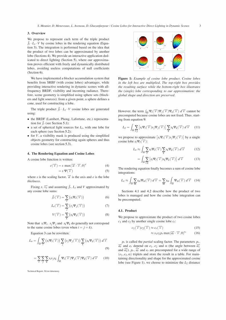
Figure 1: Example of cosine lobe product. Cosine lobesin the left box are multiplied. The top-right box providesthe resulting surface while the bottom-right box illustratesthe (single) lobe corresponding to our approximation: theglobal shape and direction are preserved.
However, the termR!"i(!"v )" j(!"v )"k(!"v ) d!"v cannot be
precomputed because cosine lobes are not fixed. Thus, start-ing from equation 9:
Lo =Z
!#i, j
#si"i(!"v )s j" j(!"v )
$#ksk"k(!"v ) d!"v (11)
we propose to approximate#si"i(!"v )s j" j(!"v )
$by a single
cosine lobe sl"l(!"v ):
Lo #Z
!#lsl"l(!"v )#
ksk"k(!"v ) d!"v (12)
=Z
!#l,k
#sl"l(!"v )sk"k(!"v )
$d!"v (13)
The rendering equation finally becomes a sum of cosine lobeintegrations:
Lo #Z
!#msm"m(!"v ) d!"v =#
msm
Z
!"m(!"v ) d!"v (14)
Sections 4.1 and 4.2 describe how the product of twolobes is managed and how the cosine lobe integration canbe precomputed.
4.1. Product
We propose to approximate the product of two cosine lobesc1 and c2 by another single cosine lobe cr:
c1(!"v )c2(!"v ) # cr(!"v ) (15)# s1s2prmax(!"ar ·!"v ,0)er (16)
pr is called the partial scaling factor. The parameters pr,!"ar and er depend on e1, e2 and $ (the angle between !"a1and !"a2). pr, !"ar and er are precomputed for a wide range of(e1,e2,$) triplets and store the result in a table. For main-taining directionality and shape for the approximated cosinelobe (see Figure 1), we choose to minimize the L2 distance
Technical Report, XLim laboratory

4 S. Meunier, D. Meneveaux, L. Aveneau, D. Ghazanfarpour / Cosine Lobes for Interactive Direct Lighting in Dynamic Scenes
between c1(!"v ) · c2(!"v ) and cr(!"v ):
{pr ,!"ar ,er} = arg min{pr ,"#ar ,er}
Z
!
!c1(!"v )c2(!"v )! cr(!"v )
"2d!"v
(17)
Since solving this optimization problem for the param-eters altogether is time-consuming and prone to numericalerrors, we propose an approach in two steps: (i) finding theaxis !"ar and (ii) fitting the partial scaling factor pr and theexponent er .
First step:
{ar} = arg max{"#ar }
c1(!"ar )c2(!"ar ) (18)
is done with the Nelder-Mead method. The algorithm is ini-tialized with
"#a1+"#a2$"#a1+"#a2 $
since !"ar is necessary between!"a1 and!"a2 .
Second step:
{pr,er} = arg min{pr ,er}
Z
!
!c1(!"v )c2(!"v )! cr(!"v )
"2d!"v (19)
is done with the Levenberg-Marquardt algorithm. er is ini-tialized with e1 + e2 which is the solution for !"a1 = !"a2 andpr with 1.
In practice e1 and e2 are sampled in [0,100000] so thatany scene type be handled. $ is ranged in [0,%]. Our sam-pling strategy is based on the cosine lobe integration varia-tion (see Figure 2). We pick 16 linearly spaced samples ineach interval [0,1], [1,10]. . . , [10000,100000], which is em-pirically an acceptable trade-off between storage, computingtime and accuracy.
10−1 100 101 1020
1
2
3
4
5
6
Cosine lobe exponent
Inte
grat
ion
valu
e
Figure 2: Integration value according to cosine lobe expo-nents (logarithmic scale), with a scaling factor s set to 1. Thelow variation for high exponents allows a sparser samplingthan with lower exponents.
Such an approximation produces precise results comparedto the actual lobe product integration: we have estimatedthe integration difference value between (i) the approxi-mated lobe product in the table and (ii) the correspondinglobe product. The integration is processed using an adaptiveSimpson quadrature with a tolerance set to 10"7; the meanerror is equal to 7.1379$ 10"4, with a variance equal to
1.2091$ 10"8 ; the median error value is 0. Note that themaximum error (Figure 3) occurs with very low exponentse1 and e2, that are practically rarely used, even with Lafor-tune model. In addition, as explained in Section 4.3, cosinelobe exponents produced during rendering always increase.
4.2. Integration
Note that the cosine lobe integration value only depends onthe exponent:
Z
!c(!"v ) d!"v =
Z
!s max(!"a ·!"v ,0)ed!"v (20)
= sZ
!max(!"X ·!"v ,0)e d!"v (21)
where c is an arbitrary lobe and!"X is any axis.
Since this integration is time-consuming, we choose topre-compute a set of values for e in the range [0,100000]using the common adaptive Gauss quadrature. For limitingmemory requirements, the table sampling strategy also re-lies on the cosine lobe integration variation (see Figure 2):the first samples are densely distributed while the last onescan be sparser; 128 linearly spaced samples are estimated ineach interval [0,1], [1,10]. . . , [10000,100000]. At run-time,the rendering process uses linear interpolation; it is fast andthe error remains low with this sampling strategy (see sec-tion 6).
4.3. Rendering
The shading of a 3D point seen from a given viewpoint isperformed using only cosine lobe sums for BRDF, visibilityand lighting. Equation 3 can be rewritten:
Lo =Z
!+
I
#i
!ci(!"v )
" J
#j
!c j(!"v )
" K
#k
!ck(!"v )
"cdot(!"v )d!"v
(22)where cdot(!"v ) is the cosine lobe !"n ·!"v .
Using approximation 16, equation 22 becomes
Lo =I·J·K#m
Z
!+cm(!"v )d!"v (23)
Many cosine lobe products only negligibly contribute tothe outgoing radiance Lo, for two main reasons: (i) whena product c1 · c2 is approximated as a new cosine lobe cr(see Equation 16), the exponent er is greater than e1 ande2 (see Figure 6); (ii) integration values of cosine lobes de-crease when exponents increase. Thus, a negligible cosinelobe multiplied with another lobe is approximated by a neg-ligible lobe.
When the product of two cosine lobe sums is expanded(see Equations 11 and 13), we propose to check the integra-tion value of each approximated cosine lobe product. If theintegration value is smaller than a given threshold ti, the new
Technical Report, XLim laboratory

S. Meunier, D. Meneveaux, L. Aveneau, D. Ghazanfarpour / Cosine Lobes for Interactive Direct Lighting in Dynamic Scenes 5
Figure 3: Lobe product approximation (Section 4.1) error: e1 and e2 correspond to the lobes exponents and $ is the anglebetween the lobes axis. The error is defined as the absolute difference between the integration of c1 · c2 and cr. The error valueis represented by a color; the white regions correspond to a low error; the black regions to a high error. An important error(# 50%) is noticeable for e1 and e2 between 0 and 1 approximatively and an angle $ around %/2. Left: full representation fore1 and e2 in range [0..100000]; Right: zoom on the region corresponding to the highest error.
cosine lobe can be neglected (removed from the expandedsum).
Figure 4 presents a statistical distribution of lobe productsintegration values (10 million of randomly generated prod-ucts). This Figure shows that even a small threshold avoidsmany lobes computations.
In our application, a single threshold ti is set manually bythe user for all shaded points (see Figure 5); other strategieswith varying thresholds depending on time constraints or thescene configuration could also be investigated.
In addition, given a product of several lobes, when the firstone can be neglected, all the remaining computations canobviously be avoided. Consequently, the ordering of compu-tations affects the number of products actually performed.Section 5.4 describes the ordering strategy we propose forour application.
5. Cosine Lobes for Direct Lighting
This section describes an application that uses our represen-tation for direct lighting. We discuss cosine lobes construc-tion for each term of the integral. Once lobes are defined, thecomputations are performed using the precomputed productsand integration described above.
10−2 10−1 100 1010
20
40
60
80
100
Integration value
Perc
enta
ge
Figure 4: Percentage of lobe products integration (ordinate)smaller than or equal to a given value. The dashed curverepresents integrated products in a low frequency environ-ment (exponents % [0,10]); the dotted curve corresponds to ahigher frequency environment (exponents % [0,100]) and thelast curve to exponents % [0,1000]. In practice, exponentsoften grow up to 15000.
5.1. Review of Cosine Lobe-Based BRDF Models
Phong and Lafortune models [Pho75, LFTG97] rely on co-sine lobes for compactly representing BRDF. This sectionexpresses those models according to our formalism.
Phong Model
fr(!"v ) = kd(!"n ·!"v )+ ksmax(!"r ·!"v ,0)es (24)= cd(!"v )+ cs(!"v ) (25)
Technical Report, XLim laboratory

6 S. Meunier, D. Meneveaux, L. Aveneau, D. Ghazanfarpour / Cosine Lobes for Interactive Direct Lighting in Dynamic Scenes
ti = 5$ 10"2 ti = 1$ 10"3 ti = 0
Figure 5: The scene is rendered using several values of ti. Visibility is represented with a high number of thin cosinus lobes(small contributions) in penumbra, while umbra require a small number of thick lobes. Consequently, when ti is too high,shadows become aliased.
0 2000
40006000
80009150
02000
40006000
80009150
0
5000
10000
15000
19 000
e2e1
er
Figure 6: Representation of er according to e1 and e2 forthe approximation of the product c1.c2 for a fixed $. Notethat er is greater or equal than e1 and e2 (the correspondingsurface is not a plane).
where
cd(!"v ) = kdmax(!"n ·!"v ,0)1 (26)
and
cs(!"v ) = ksmax(!"r ·!"v ,0)es (27)
kd defines the diffuse cosine lobe and !"n is the surfacenormal. es is the specular cosine lobe exponent, and ks thescale factor. !"r is the reflection of !"vo by !"n .
Note that the original Phong model is not physically cor-rect, but we can as well express the modified Phong model[Lew94] with our representation.
Lafortune Model
fr(!"v ) =#i&imax(!"v TMi
!"vo )ei (28)
=#ici(!"v ) (29)
where, according to [LFTG97], and using Helmoltz reci-procity :
ci(!"v ) = ki&Mi!"vo&ei max(
Mi!"vo
&Mi!"vo&
·!"v ,0)ei (30)
ki is the scale factor of ci, Mi represents the lobe axis ina local frame depending on material anisotropy and ei theexponent.
5.2. Incoming Radiance
Given a spherical light source (r, p,v) defined by a radius r,a position p and a radiance value v, the incident radiance onthe hemisphere centered around a given point x is delimitedby a spherical cap (a cone); the cosine lobe corresponding tothe incident radiance coming from this light source is:
clight(!"v ) = vmax%
p! x&p! x& ·!"v ,0
&ecap(31)
ecap parameter corresponds the the spherical cap angle $cap(see Figure 7). ecap is estimated solving the following opti-
Figure 7: $cap represents the spherical cap angle corre-sponding to sphere (p, r).
mization problem
{ecap} = arg min{ecap}
Z
!
!fcap(!"v )! ccap(!"v )
"2d!"v (32)
where fcap is a function representing a spherical cap:
fcap(!"v ) ='1 if !"v ·!"a ' cos($cap)0 else (33)
Technical Report, XLim laboratory

S. Meunier, D. Meneveaux, L. Aveneau, D. Ghazanfarpour / Cosine Lobes for Interactive Direct Lighting in Dynamic Scenes 7
and
ccap(!"v ) = 1max(!"a ·!"v ,0)ecap (34)
In practice, ecap is precomputed and stored in a table con-taining 1000 values, and linearly interpolated at run-time.
When using several light sources, the corresponding co-sine lobes may overlap. However, our visibility processing(described in the next Section) naturally handles this case.
5.3. Visibility
In the off-line process, objects are simplified by sphere setsusing the methods proposed by Wang et al. [WZS!06] or byBradshaw and O’Sullivan [BO02]; they have been alreadysuccessfully used for visibility computations by many au-thors [RWS!06, SGNS07, GJW08]. These methods closelyapproximate the object surface with only a few spheres (forinstance only 64 spheres for the Stanford bunny provide sat-isfactory shadow results in our application). The computedsphere sets strongly simplify objects geometry and are stilldeformable with articulated skeletons systems.
As for light sources, we aim at defining cosine lobes usingspherical caps (cones):
V (!"v ) = 1! focc(!"v ) (35)
where focc(!"v ) is (see Equation 33 and Figure 7):
focc(!"v ) ='1 if !"v ·!!"aocc ' cos($occ)0 else (36)
With N spheres, visibility becomes:
V (!"v ) =N'j=1
!1! f j(!"v )
"(37)
= 1!2N"1#k=1
gk(!"v ) (38)
where gk is a term corresponding to a product of sphericalcaps.
Unfortunately, this expression leads to the computation of2N terms. Replacing each spherical by only one lobe still re-quires 2N lobes and introduces imprecisions that cumulateduring the computation of the above product. The main rea-son is that one cosine lobe does not accurately approximate aspherical cap, and finally caps overlapping (that is correctlyhandled for visibility in Equation 38) produces errors withthis representation.
To tackle these problems, we propose to hierarchicallybuild a visibility mask, to control lobes generation (includ-ing overlapping problems) and to limit their number. Onevisibility mask is built for each (spherical) light source soas to precisely identify the incoming light directions and theeffective blockers. This process is repeated for each point ateach frame.
Given a point x, for each light source represented by asphere (r, p), a unit square Sunit surrounding the correspond-ing cone (see Figure 8(a)) is placed at a distance dist, de-duced from the cone angle ($cap). Blockers are clipped andthe remaining spheres are splatted onto Sunit . Note that Sunitmay be placed behind the light source.
(a) (b) (c)
Figure 8: Occluding spheres splatting: (a) a unit square isplaced according to the spherical light source; (b) uselessblockers are clipped; (c) remaining spheres are splatted ontothe unit square.
sphere 1 sphere 1 sphere 2
sphere 2 sphere 3 sphere 3
Figure 9: Quad-tree construction example. 3 spheres aresplatted and a maximal depth of 2 is used. Red leafs are sub-divided, yellow leafs are not currently considered, and greenleafs corresponding to shadows are frozen.
Splatted spheres are used to build a quad-tree (see Fig-ure 9). The quad-tree depth is practically limited to 4 or 5.We have chosen an aggressive approach where partially cov-ered leaves are ignored so as to reduce the number of cosinelobes. However, the conservative alternative can be easilyimplemented, keeping the partially covered leaves (see Fig-ure 10). A cosine lobe is built for each shadow leaf using abounding sphere (see Figure 11).
Nearby cosine lobes mutually overlap and the error mustbe corrected. Therefore, we propose to associate a weight toeach lobe:
V (!"v ) = cunit(!"v )!N"1#iwici(!"v ) (39)
where
cunit(!"v ) = 1.max(!"n ·!"v ,0)0 = 1 (40)cunit(!"v )ca(!"v ) = ca(!"v ) (41)
Technical Report, XLim laboratory

8 S. Meunier, D. Meneveaux, L. Aveneau, D. Ghazanfarpour / Cosine Lobes for Interactive Direct Lighting in Dynamic Scenes
Figure 10: Shadows artifacts when depth of visibility mask is not high enough. Top row: with aggressive visibility; bottom row:with conservative visibility. From left to right: visibility depth is equal to 2, 3 and 5.
Figure 11: Once visibility mask is built (left), one boundingsphere is constructed per shadow leaf and the associated co-sine lobes are produced (right).
and wi depends on the distance dist and on the leaves depth.When dist varies, the cosine lobes overlap varies as well (seeFigure 12). wi values are fixed experimentally for variousvalues of dist % {0.25,0.5,1,2,3,4,5,6,7,8,9,10} and foreach depth.
Figure 12: The cosine lobes overlapping vary according tothe distance dist, even with the same visibility mask.
Weights can be adjusted manually once with a singlescene (one plane, one object and one light source is enough)
so as to obtain smooth shadows. First, weight values are ini-tialized to 0; the first level weight is then chosen to obtain aperfect dark in the umbra area. The weight associated witheach successive level is then fixed so as to avoid shadowssharpness with the previous ones. This process is performedonly once and the resulting weights can be used with anyscene. At run-time, weights are linearly interpolated accord-ing to dist.
5.4. Ordering Computations
This section describes our strategy for ordering lobe prod-ucts in Equation 22, so as to reduce computing time. Letus recall that the cosine lobe cr resulting from the prod-uct of two lobes c1 and c2 depends on e1, e2 and $ (seeSection 4.1). Firstly, when $ increases, cr integration valuedecreases. Secondly, with visibility masks, all the productsbetween visibility lobes and incoming radiance lobes are ac-tually useful (cannot be neglected). Thirdly, in our applica-tion (direct lighting), incoming radiance requires less cosinelobes than visibility. Thus, firstly multiplying reflectance andlighting (before visibility) produces fast results. This strat-egy produces results remaining close to Monte-Carlo inte-gration with interactive rendering (Figure 13), though it doesnot ensure the best precision.
6. Results and Discussion
This section presents some results obtained with our appli-cation, implemented in C++. All the results have been pro-duced with an Intel Core 2 Duo T7500 (2.2GHz) CPU andan NVidia Geforce 8400 GS.
Technical Report, XLim laboratory

S. Meunier, D. Meneveaux, L. Aveneau, D. Ghazanfarpour / Cosine Lobes for Interactive Direct Lighting in Dynamic Scenes 9
(a) Reference (b) Our application
Figure 13: Shadows with direct lighting for a scene com-posed of 5 and a plane: (a) reference path tracing image and(b) image computed using our application. Maximal depth ofthe visibility mask is set to 5.
Constructing our 3 pre-computed tables (product, integra-tion and spherical caps) requires approximately 4 hours. Letus recall that these tables do not depend on the scene char-acteristics: they are computed once and for all. The mem-ory required for their storage is less than 10 MB. For thesake of clarity, the following results only corresponds tocosine lobes representation, without any optimization: foreach frame, the whole image is completely computed (nocaching technique is employed, nor spatial or temporal co-herency). Our application consists in shading a selected setof 3D points (either triangle vertices or estimated per pixel,employing a G-buffer). Shading is performed on the CPUand rasterization uses OpenGL.
Due to the flexibility and adaptivity of cosine lobes repre-sentation (number of lobes, bandwith, free distribution, etc.),computing efforts can be concentrated on regions wherelighting needs to be detailed. For instance, penumbra areasrequires a higher number of lobes for representing visibilitythan umbra areas or fully-lit regions, where only a few com-putations can produce precise results. Consequently, our ap-plication performances vary according to chosen materials(Figure 14), number of shaded points, maximum depth ofvisibility masks and chosen threshold of cosine lobe prod-ucts (Figures 16 and 5) or relative position between occlud-ers and lights. Frame rates are given in the caption of eachfigure.
Presently, many approaches dedicated to dynamic scenesare based on SH. Generally speaking such orthogonal basisfunctions are adapted to integrations. However, the projec-tion on these basis functions is costly. For instance, on Fig-ure 16, umbra and lit regions would have required the sameamount of computation and are restricted to low-frequencyeffects, contrary to our cosine-lobe based approach.
Once cosine lobe sums are defined, the approach given insection 4 approximates lobe products and uses tables for re-ducing computing time. Figure 15 shows that these approxi-mations lead to a small difference, compared to Monte-Carlointegration. For the Monte-Carlo reference image, the maxi-mum radiance value is 0.701961, the mean radiance value
Figure 14: Spatially varying BRDF are possible usingLafortune model. This scene is composed of 65536 shadedpoints, 1 spherical light source and no occluder, 13.73 frameper second.
Figure 15: Comparison between Monte-Carlo integration(top left) and our approach (top right) for the cosine lobesums integration. Lobe sums are generated using the meth-ods described in Section 5. The bottom images show the dif-ference. The bottom left image represents positive values andthe bottom right the negatives.
is 0.127906; with our approach, the maximum differenceis 0.054902 while the mean difference is 0.003884. Notethat our method introduces a bias: regions located in shad-ows, where more cosine lobes products are computed, ex-hibit more negative difference values.
We also compare the images produced by our applicationwith path tracing for direct lighting and soft shadows. Asshown in Figure 13, the results are hardly distinguishable.
Table 6 presents the computing time ratio correspondingto each rendering part, for different types of scenes, withhard and soft shadows, complex or simple material and var-ious numbers of occluders. The last row corresponds to ascene that does not contain any occluder, implying no visi-bility computations.The main part of computing time is dedi-cated to visibility mask construction, as for any other blockeraccumulation method.
Shadows are considered by many authors as a key is-
Technical Report, XLim laboratory

10 S. Meunier, D. Meneveaux, L. Aveneau, D. Ghazanfarpour / Cosine Lobes for Interactive Direct Lighting in Dynamic Scenes
ti = 0 False colors False colors ti = 0.001
f ps= 14.93 f ps= 17.27
f ps= 15.18 f ps= 15.38
0 60 120 180 240 300
Figure 16: Performance gains obtained according to the threshold ti (Section 4.3). The scene is composed of 4096 shadedpoint, one spherical light source and 64 spherical occluders (the bunny). The threshold is chosen so as to keep indistinguishablethe difference between resulting images (left and right columns). The false-color images illustrate the number of cosine lobeproducts computed (scale is given at the bottom). The specular highlight properly interacts with the shadows, our methodnaturally allows to avoid many computations due to the threshold. Note that frame rates increase when the highlight movesaway from the shadow. We can see a reduction of about 50% of the number of product computations (corresponding to 2 framesper second in practice, because of visibility mask construction cost).
Figure a b c d e14 29.6 15.5 0 0 54.918 0.3 0.2 82.7 6.1 10.717(a) 2.6 2.7 76.2 8.1 10.417(b) 1.5 1.5 63 15.8 18.217(c) 0.7 0.7 54 20.3 24.3
Table 1: CPU time (percent) for the shading loop: (a) gener-ation of cosine lobe sums for reflectance, (b) lighting, (c) vis-ibility mask construction, (d) visibility mask lobes, (e) ren-dering equation integration computation.
sue for realistic rendering; their processing is often handledspecifically. Figures 13 and 17 show that our method nat-urally produces realistic direct lighting (including hard andsoft shadows), without introducing specific processing. Ourapplication can be used with any type of material, using aspatially varying Lafortune BRDF model (see Figure 14).We do not introduce any occluder in this scene for high-lighting the low cost for representing reflectance and lightingwith cosine lobe sums. Figure 18 illustrates a difficult casefor the construction of the visibility mask. Self-shadowing isrobustly supported with adapted sphere sets.
7. Conclusion
In this paper, we present a new method for solving the ren-dering equation using approximated cosine lobe products.We propose an interactive application for direct lighting in-cluding all-frequency lighting / materials, soft shadows anddynamic scenes. As shown in the results, cosine lobes as ba-sis functions are useful for properly targeting relevant hemi-spherical directions (flexibility) in terms of BRDF, incomingradiance or visibility. In addition, their representation onlyrequires a few parameters (compactness).
Shading is only performed on the CPU and performancescan be further improved using a full GPU implementation,adapting for instance the streaming reduction algorithm pro-posed in [RAH07] for avoiding useless computations con-cerning negligible lobe products. Furthermore, our applica-tion demonstrates the feasibility of rapidly computing directlighting, without using any spatial and temporal coherency.Visibility masks are often identical for close neighborhoodsof shaded points; this coherency can be used for reducing thecomputing time.
Global illumination in dynamic scenes has been addressedusing spherical proxies and spherical harmonics [SGNS07,GJW08]. Similarly to these authors, our direct lighting ap-plication makes use of blocker accumulation. In the future,
Technical Report, XLim laboratory

S. Meunier, D. Meneveaux, L. Aveneau, D. Ghazanfarpour / Cosine Lobes for Interactive Direct Lighting in Dynamic Scenes 11
(a) 15.9 fps (b) 10.1 fps (c) 4.75 fps
Figure 17: Shadow smoothing according to the distance between plane and the Bunny. Frame rates decrease with respect tothe (increasing) shadowed area. Penumbra implies complex visibility masks and more cosine lobes. 16384 points are shadedconsidering a strictly diffuse material, 1 spherical light source, 64 spherical occluders, fixing the maximal depth of the visibilitymask to 5 and the threshold to 0.001 (Section 4.3).
Figure 18: Two chocolate-flavoured bunnies in a green box. These pictures take 6.25s for rendering. 480000 points are shaded,using 1024 spherical occluders, 2 cosine lobes for the reflectance models and 1 spherical light source. We choose 5 for themaximum depth of the visibility mask.
we aim at adapting their interesting simplifications to cosinelobes for overcoming the usual SH drawbacks.
Finally, cosine lobes can also be used in various SRBFapplications, such as the representation of high frequencyenvironment maps [TS06], anisotropic materials [LFTG97],or real-time environment map rendering applications, suchas Green et al. [GKD07] method.
References
[BO02] BRADSHAW G., O’SULLIVAN C.: Sphere-tree construction using dynamic medial axis approxima-tion. In SCA ’02: Proceedings of the 2002 ACM SIG-GRAPH/Eurographics symposium on Computer anima-tion (2002), pp. 33–40.
[Gau06] GAUTRON P.: Cache de luminance et cartesgraphiques : une approche pour la simulation d’éclairage
temps réel dans des scènes animées. PhD thesis, Univer-sité de Rennes 1, 2006.
[GJW08] GUERRERO P., JESCHKE S., WIMMER M.:Real-time indirect illumination and soft shadows in dy-namic scenes using spherical lights. Computer GraphicsForum 27, 8 (2008), 2154–2168.
[GKD07] GREEN P., KAUTZ J., DURAND F.: Efficientreflectance and visibility approximations for environmentmap rendering. Comput. Graph. Forum 26, 3 (2007), 495–502.
[GKMD06] GREEN P., KAUTZ J., MATUSIK W., DU-RAND F.: View-dependent precomputed light transportusing nonlinear gaussian function approximations. InSI3D ’06: Proceedings of the 2006 symposium on Inter-active 3D graphics and games (2006), pp. 7–14.
[KK07] KOZLOWSKI O., KAUTZ J.: Is accurate occlu-sion of glossy reflections necessary? In APGV ’07: Pro-
Technical Report, XLim laboratory
12 S. Meunier, D. Meneveaux, L. Aveneau, D. Ghazanfarpour / Cosine Lobes for Interactive Direct Lighting in Dynamic Scenes
ceedings of the 4th symposium on Applied perception ingraphics and visualization (2007), pp. 91–98.
[KLA04] KAUTZ J., LEHTINEN J., AILA T.: Hemispher-ical rasterization for self-shadowing of dynamic objects.In Proceedings of Eurographics Symposium on Render-ing 2004 (2004), pp. 179–184.
[Lew94] LEWIS R. R.: Making shaders more physicallyplausible. Computer Graphics Forum (Eurographics ’94Conference Issue) 13, 3 (1994), 1–13.
[LFTG97] LAFORTUNE E. P. F., FOO S.-C., TORRANCEK. E., GREENBERG D. P.: Non-linear approximation ofreflectance functions. In SIGGRAPH ’97: Proceedingsof the 24th annual conference on Computer graphics andinteractive techniques (1997), pp. 117–126.
[MLH02] MCALLISTER D. K., LASTRA A., HEIDRICHW.: Efficient rendering of spatial bi-directional re-flectance distribution functions. In HWWS ’02: Proceed-ings of the ACM SIGGRAPH/EUROGRAPHICS confer-ence on Graphics hardware (2002), pp. 79–88.
[NRH03] NG R., RAMAMOORTHI R., HANRAHAN P.:All-frequency shadows using non-linear wavelet lightingapproximation. In SIGGRAPH ’03: ACM SIGGRAPH2003 Papers (2003), pp. 376–381.
[PH04] PHARR M., HUMPHREYS G.: Physically BasedRendering: From Theory to Implementation. MorganKaufmann Publishers Inc., 2004.
[Pho75] PHONG B. T.: Illumination for computer gener-ated pictures. vol. 18, pp. 311–317.
[RAH07] ROGER D., ASSARSSON U., HOLZSCHUCHN.: Efficient stream reduction on the gpu. In Workshopon General Purpose Processing on Graphics ProcessingUnits (2007).
[RWS!06] REN Z., WANG R., SNYDER J., ZHOU K.,LIU X., SUN B., SLOAN P.-P., BAO H., PENG Q., GUOB.: Real-time soft shadows in dynamic scenes usingspherical harmonic exponentiation. ACM Trans. Graph.25, 3 (2006), 977–986.
[SGNS07] SLOAN P.-P., GOVINDARAJU N. K.,NOWROUZEZAHRAI D., SNYDER J.: Image-basedproxy accumulation for real-time soft global illumination.In PG ’07: Proceedings of the 15th Pacific Conference onComputer Graphics and Applications (2007), pp. 97–105.
[SHHS03] SLOAN P.-P., HALL J., HART J., SNYDER J.:Clustered principal components for precomputed radiancetransfer. In SIGGRAPH ’03: ACM SIGGRAPH 2003 Pa-pers (2003), pp. 382–391.
[SKS02] SLOAN P.-P., KAUTZ J., SNYDER J.: Precom-puted radiance transfer for real-time rendering in dy-namic, low-frequency lighting environments. In SIG-GRAPH ’02: Proceedings of the 29th annual conferenceon Computer graphics and interactive techniques (2002),pp. 527–536.
[TS06] TSAI Y.-T., SHIH Z.-C.: All-frequency precom-puted radiance transfer using spherical radial basis func-tions and clustered tensor approximation. In SIGGRAPH’06: ACM SIGGRAPH 2006 Papers (2006), pp. 967–976.
[War92] WARD G. J.: Measuring and modelinganisotropic reflection. In SIGGRAPH ’92: Proceedingsof the 19th annual conference on Computer graphics andinteractive techniques (1992), pp. 265–272.
[WZS!06] WANG R., ZHOU K., SNYDER J., LIU X.,BAO H., PENG Q., GUO B.: Variational sphere set ap-proximation for solid objects. Vis. Comput. 22, 9 (2006),612–621.
[ZHL!05] ZHOU K., HU Y., LIN S., GUO B., SHUM H.-Y.: Precomputed shadow fields for dynamic scenes. InSIGGRAPH ’05: ACM SIGGRAPH 2005 Papers (2005),vol. 24, pp. 1196–1201.
Technical Report, XLim laboratory