Converter-Station-Planning-Statement-V02.pdf - Fab Link
399
-
Upload
khangminh22 -
Category
Documents
-
view
5 -
download
0
Transcript of Converter-Station-Planning-Statement-V02.pdf - Fab Link


QUALITY MANAGEMENT
ts
Prepared by: Richard Boother
Authorised by: Simon Gamage
Date: December 2016
Project Number/Document Reference:
Converter Station Planning Statement - Final Version
COPYRIGHT © RPS
The material presented in this report is confidential. This report has been prepared for the exclusive use of FAB Link Limited and shall not be distributed or made available to any other company or person without the knowledge and written consent of RPS.

December 2016 1
CONTENTS
1 INTRODUCTION ................................................................................................................................ 3
Introduction and background to the project ........................................................................................ 3 The benefits of electricity interconnection........................................................................................... 3 The need for additional electricity interconnection ............................................................................. 4 European and Government Support for the development of Interconnectors .................................... 4 Project Overview ................................................................................................................................. 5 Consultation ........................................................................................................................................ 7 Scope of Planning Application ............................................................................................................ 8 Purpose and Structure of this Statement ............................................................................................ 9
2 SITE LOCATION AND DESCRIPTION ............................................................................................ 11 Site Location ..................................................................................................................................... 11 Description of Development .............................................................................................................. 11
3 PLANNING AND ENERGY POLICY CONTEXT ............................................................................. 13 Development Plan Policy .................................................................................................................. 13 Other Material Policy Considerations ............................................................................................... 14
4 ASSESSMENT ................................................................................................................................. 21 Development Plan ............................................................................................................................. 21 Other Material Considerations .......................................................................................................... 31 Sustainable Development ................................................................................................................. 32
5 SUMMARY AND CONCLUSION ..................................................................................................... 34
FIGURES
Figure 1 Site Location Plan 7729-0445-02
Figure 2.1 UK Converter Station Site Plan 7729-0454-05
Figure 2.2 Long Lane Improvements Red Line Boundary Plan 7729-0484-02
Figure 3 Illustrative Block Plan - Option 1 7729-0446-04
Figure 4 Illustrative Block Plan - Option 2 7729-0447-04
Figure 5 Illustrative 3D Model Option 1 7729-0449-03
Figure 6 Illustrative 3D Model Option 2 7729-0450-03
Figure 7 Parameter Plan Isometric View 7729-0463-02
Figure 8 Parameter Plan Cross Section 7729-0455-03
December 2016 2
Figure 9 Illustrative Landscape Plan 7729-0448-04
Figure 10 Converter Station Layout Option 1 Proposed Access
Figure 11 Converter Station Layout Option 2 Proposed Access
APPENDICES
Appendix 1 List of Site Selection Reports
Appendix 2 List of Relevant Policies of the East Devon Local Plan 2016
Appendix 3 Exeter Airport Technical Safeguarding Report

FAB Link Ltd; UK Converter Station: Planning Supporting Statement
December 2016 3
1 INTRODUCTION
Introduction and background to the project 1.1 The FAB (France-Alderney-Britain) Link project is a proposed subsea interconnector cable
connecting France and Great Britain via the Channel Island of Alderney. The project is being jointly developed by FAB Link Limited (‘the Applicant’) and the French grid company RTE (Réseau de Transport d’Électricité). The Applicant’s shareholders are Transmission Investment LLP and Alderney based tidal power developer Alderney Renewable Energy Limited (ARE). An interconnector provides a means of transferring electrical power between an exporting country and an importing country, and typically they are two way interconnectors (i.e. either country can be the country importing or exporting electricity at any one time).
The benefits of electricity interconnection 1.2 Electricity interconnectors provide economic, environmental and security of supply benefits to
both countries. The below paragraphs outline the principal benefits of greater inter-connectivity between European grid networks.
Economic 1.3 In terms of the economic benefits, interconnectors allow for higher cost electricity generation in
the importing country to be replaced by lower cost electricity generated in the exporting country. This results in lower cost of electricity overall, and in particular in the importing country. The lower cost of electricity should result in lower electricity prices for consumers. As well as providing lower cost electricity, interconnectors can also provide services to the operators of the electricity systems that they interconnect. These services are to a large extent required because electricity cannot be stored and so the production (generation) of electricity has to be very closely matched to the supply of electricity on a second-by-second basis. These services (typically called “Ancillary Services”) are explained in further detail in the FAB Link Connection Options Study and assist in the operation of the electricity network.
Environment 1.4 Interconnectors can provide environmental benefits in several ways. They can allow high carbon
generation in one (importing) country to be displaced by low carbon generation in another (exporting) country – this is very relevant for the FAB Link interconnector which should allow high carbon fossil fuel generation in Britain (e.g. unabated coal-fired or gas-fired generation) to be replaced by low carbon nuclear generation from France. They enable the volatility in generation output that arises from renewable (and therefore low carbon) sources of generation such as onshore and offshore wind, solar and tidal generation, to be smoothed by connecting these sources across wider geographic regions subject to different weather patterns and tides – again this will be relevant for the FAB Link interconnector which will provide additional connection between the significant amounts of wind and solar generation in Britain and Ireland with that in continental Europe. They can facilitate the connection and integration of renewable sources of generation. In the specific case of the FAB Link interconnector, this will enable the connection and integration (providing a route to market) of tidal generation planned to be developed in the waters around Alderney, which has the second largest tidal resource in North West Europe.
Energy Security 1.5 Interconnectors provide access to another source of electricity and so reduce the probability that
there will be insufficient electricity to meet consumers’ demand for it. The ability of an

FAB Link Ltd; UK Converter Station: Planning Supporting Statement
December 2016 4
interconnector to contribute effectively to energy security depends on a number of factors, including the reliability of the interconnector technology and the probability that the exporting country will have excess generation capacity itself at times of need.
1.6 These benefits are fully set out in the FAB Link Connection Options Study which can be found on the FAB Link website (www.fablink.net).
The need for additional electricity interconnection 1.7 Britain currently has interconnectors with Northern Ireland, the Republic of Ireland, France and
the Netherlands. There is, however, a need for additional interconnection, driven by challenges that the British and wider European energy systems face.
Competitiveness 1.8 Remaining economically competitive in an increasingly global market for goods and services has
become a priority for the European Union and its member states. This often translates into reducing costs and this includes the cost of electricity, which interconnectors can achieve (as noted above).
Sustainability 1.9 The need to reduce greenhouse gas emissions in order to limit global temperature rises has
resulted in the growth of significant volumes of low carbon generation and plans for considerably more. Much of this generation is variable in nature and often is remote from or at the extremity of the established high voltage grid. Interconnectors can both assist with smoothing the variability of renewable generation across different geographies and facilitate the connection and integration of renewables.
Security 1.10 Incidences such as restrictions to gas supplies by Russia have brought a focus onto the security
of Europe’s energy supply.
1.11 Electricity security in Britain and the ability to meet peak electricity demand, has been reduced through several factors:
The closure of controllable fossil fuel generation (for economic or regulatory reasons); The closure of nuclear plant as it reaches the end of its asset life; The replacement of the above with large scale renewables with varying output; and, The lack of new controllable plant being constructed (either for economic reasons or the time
it takes to permit, finance and build).
1.12 Whilst shorter term measures are also being used, in the longer term the UK Government’s response to this is the market for capacity, which is intended to provide the necessary incentives to keep open existing capacity and to construct new capacity so as to be able to meet peak demand. Additional interconnection capacity is one form of capacity that the Government is seeking to incentivise to assist it in meeting the security challenge.
European and Government Support for the development of Interconnectors
1.13 Governments at the European and national levels have recognised the benefits that greater electricity interconnection can bring. This recognition is set out in detail in the FAB Link Connection Options Study, but their support is summarised below.

FAB Link Ltd; UK Converter Station: Planning Supporting Statement
December 2016 5
European Union Support 1.14 At the invitation of the March 2014 European Council, the European Commission set a target that
all Member States should have electricity interconnectors equal to at least 15% of their electricity generation capacity by 2030. This target is aimed to be achieved mainly through the implementation of Projects of Common Interest (PCIs). The proposed FAB Link interconnector is a European Project of Common Interest (PCI) under the provisions of EU 347/2013: Regulation on guidelines for trans-European energy infrastructure (‘TEN-E Regulation’). The TEN-E Regulation is considered in more detail in Section 4 below, but as a result of this Regulation, PCIs are required to be given ‘priority status’ at a national level and should be considered by competent authorities as being in the public interest at the earliest possible stage.
UK Support 1.15 The UK Government summarised its support for greater interconnection between Great Britain
and other European Countries and the measures it was taking to promote this in ‘More interconnection: improving energy security and lowering bills’, (Department of Energy and Climate Change (DECC), December 2013).
1.16 Since this document was published, the Government has taken steps to allow interconnectors to take part in the capacity market in 2015 (and subsequent years) through an amendment to the Capacity Market Rules. This enables interconnectors to take part in capacity market auctions and if successful in those auctions, to be paid for the contribution to system security they make. The Government has also supported the Office of Gas and Electricity Markets (Ofgem) in developing and implementing a regulatory regime which will provide revenue support to interconnectors to enable them to be financed through construction and into operation.
1.17 UK Government support specifically for the FAB Link interconnector is also evidenced by a letter received from the Minister for Energy dated 6th August 2015 which states that:
““… the Government is committed to increasing electricity interconnection and is very keen to see good quality interconnection projects come forward which can deliver significant savings for the GB consumer and make a positive contribution to security of supply. I was therefore very pleased to see that Ofgem has now confirmed initial approval for the FAB Link interconnector project to be regulated under the cap and floor …”
France, Channel Island and Alderney Support 1.18 Interconnection also enjoys the support of the French Government and States of Alderney. Their
support is set out in full in the FAB Link Connection Options Study.
Project Overview 1.19 A full description of the FAB Link project can be found in the FAB Link Project Summary (also on
the FAB Link website). The main components of the FAB Link interconnector are shown on the inset below,

FAB Link Ltd; UK Converter Station: Planning Supporting Statement
December 2016 6
Inset 1: Schematic Overview of FAB Link Interconnector Project
1.20 The FAB Link project will comprise high voltage DC cables transmitting power between Britain and France. Two pairs of cables (two in each pair) will be used to achieve the capacity required of 1400MW. The offshore cable route will run from the East Devon coast in England to Corblets beach on the north Alderney coast and from Longis Bay on the south Alderney coast to La Plate on the west coast of the Contentin (or Cherbourg) peninsula in Normandy, France. Installation will be by burial in the sea-bed or by placement on the sea-bed surface with subsequent protection.
1.21 Whilst the British and French grids are both Alternating Current (AC) systems, the two systems are not synchronised and the capacity of AC underground or subsea cables to transmit, power reduces significantly with distance travelled. The current therefore needs to be converted to Direct Current (DC) across the channel and this is done in converter stations, one in England and one in France. The converter station in England is the subject of the planning application to which this Planning Statement relates.
1.22 The onshore cable route will be buried underground. The majority of the FAB Link project will therefore be subsea or underground.
Site Selection 1.23 Any interconnector or generating station on the scale of the FAB Link project can only connect to
the electricity system in Great Britain by connection to the high voltage National Electricity Transmission System (NETS) operated by National Grid Electricity Transmission (‘National Grid’). The Applicant has had to select and develop a GB grid connection for the FAB Link project. RPS has been engaged by the Applicant to assist with that process. Over the period mid-2012 to August 2015, a staged site selection process was undertaken to identify potential GB NETS connection options. A list of the reports produced over this period is given at Appendix 1. This process concluded with the selection of Exeter Substation as the NETS connection point (Stage 1). A full explanation of this process can be found in the FAB Link Connection Options Study.
1.24 Once the Exeter Substation was selected as the NETS connection point, it was then necessary to identify a location for the UK converter station through an extensive site selection process. This is set out in full in The HVDC Converter Station Site Selection Process Report Second Edition – (RPS, 2015), but is summarised below.
1.25 In late 2012/early 2013, Stage 2 of the site selection process identified a number of potential site opportunities within approximately 5 km of the Exeter NETS substation using environmental and
FAB Link Ltd; UK Converter Station: Planning Supporting Statement
December 2016 7
land use criteria. These were appraised in terms of site layout, environmental considerations and potential land availability in 2013 (Stage 3), which culminated in pre-application advice being sought from East Devon District Council (EDDC) in February 2014 on two potential sites near the existing Exeter substation.
1.26 The advice received from EDDC recommended further work to consider whether other sites may exist with less visual intrusion and better access to the road network. A review of the Exeter study area was therefore completed in 2014 (Stage 4), which included widening the study area, sieve mapping, landscape studies and environmental appraisal. This resulted in a revised short list of eight potential site areas. Following initial feedback from landowners, six shortlisted sites were identified as potentially available and these were subject to further studies in 2015 in the form of ‘potentially available site reviews’ (Stage 5).
1.27 Following these studies and further discussions with landowners, only three of six shortlisted sites were considered capable of meeting the site selection objectives for technical requirements, environmental considerations and land availability. These sites were compared in terms of performance across all the objectives leading to the selection of a preferred site. The process was completed in July 2015, and having regard to all of the relevant factors, FAB Link Limited decided that Land to the east of Antiques Complex/ Harriers Court Industrial Estate should be selected as the preferred site for the UK converter station.
1.28 The converter station will comprise two buildings of up to 20 metres in height with some external plant and equipment and will occupy an area of nearly 5ha.. Development of this nature is not appropriate in residential areas and it was established through this rigorous process that there are no existing industrial sites or allocated employment sites on which the converter station can be located. It was concluded from the process that the UK converter station could only be located in an area that would be regarded as “countryside” in the Development Plan (the planning policy context of the UK converter station development is considered in full in Section 4 of this Statement).
Consultation 1.29 FAB Link has been engaged in extensive consultation to date. The following lists the parties /
organisations that have been consulted on the proposed Converter Station planning application.
EDDC Growth Point DCC Highways Historic England Natural England Highways England Environment Agency Exeter International Airport Council for the Protection of Rural England (CPRE) University of Exeter Rockbeare, Faringdon and Clyst Honiton Parish Council / Ward Councillors Utilities companies i.e. Western Power Distribution and Wales and West Utilities Adjacent Landowners and Land Uses i.e. Rigby Group, Hampton by Hilton, Antiques
Complex, FlyBe Training Academy
1.30 Several meetings have been held with EDDC including the most recent with the Planning Officer at EDDC on 3 June 2016.

FAB Link Ltd; UK Converter Station: Planning Supporting Statement
December 2016 8
1.31 FAB Link Ltd has also had detailed discussions with Exeter International Airport to ascertain how the converter station can be designed and built without impeding the operations of the safeguarded airfield (see paragraph 4.12 below).
1.32 Three public consultation events were be held in the UK between 26 - 28 July 2016:
26 July 2016, Budleigh Salterton Methodist Church Hall, 2pm - 8pm 27 July 2016, Younghayes Centre, Cranbrook, 2pm - 8pm 28 July 2016, Woodbury Park Hotel, 2pm - 8pm
1.33 On all three occasions, Parish Councils and EDDC Ward Members were invited.
1.34 A full list of consultation responses and how they have been taken into account in finalising the FAB Link project is presented in a Consultation Report, which accompanies the outline planning application. The report notes that no comments were received from stakeholders that resulted in any changes to the reports and plans specifically associated with the UK converter station.
Scope of Planning Application 1.35 This planning application seeks outline planning permission for the erection of the converter
station on land east of Antiques Complex/ Harrier Court Industrial Estate, Long Lane, Exeter, as part of the FAB Link Project. access, appearance, landscaping, layout and scale are reserved for subsequent approval.
1.36 In May 2014, DECC set out guidance for PCI project promoters on the process for gaining consents for PCIs in ‘Manual of Procedures: The permitting process for Projects of Common Interest in the UK ‘(DECC, 2014). This describes how the existing planning and consents regimes in the UK will be used to provide the ‘permit granting process’ required in the TEN-E Regulation for delivering PCIs. In this process, DECC has delegated the task of facilitating the co-ordination of the permit granting process to the Marine Management Organisation (MMO) in the case of PCIs for which a marine licence will be the primary consent required. While the MMO has a coordinating role, the application for the converter station will be determined by EDDC, as Local Planning Authority. On 30 June 2014 the MMO accepted the proposed FAB Link interconnector into the permit granting process. The MMO has prepared a schedule of the permit granting process as required under Article 10(4)(b) of TEN-E Regulations.
1.37 In addition to outline planning permission, the following consents are being sought to enable the project to be implemented:
Planning permission for the on-shore cabling at Alderney under The Building and Development Control (Alderney) Law, 2002 – decision to be made by States of Alderney (SoA).
A Marine Licence under the Marine and Coastal Access Act 2009 – decision to be made by the Marine Management Organisation (MMO).
A marine licence (FEPA) for offshore works within Alderney & Guernsey territorial waters. Comprehensive decision under the TEN-E Regulation – decision to be made by the MMO,
on behalf of the Department of Business, Energy and Industrial Strategy.
1.38 Alongside these consents, the Applicant is applying to East Devon District Council (EDDC) for a Certificate of Lawful Development for the onshore cabling under Section 192 of the Town and Country Planning Act 1990 (on the basis that the underground cable is permitted development by virtue of Class G, Part 17, Schedule 2 of the Town and Country Planning (General Permitted Development) Order 2015 (GPDO).

FAB Link Ltd; UK Converter Station: Planning Supporting Statement
December 2016 9
1.39 A construction compound associated with the converter station, with a separate access, will be established on land adjacent to the converter station site under Class A, Part 4, Schedule 2 of the GPDO.
Purpose and Structure of this Statement 1.40 This Statement has been prepared in support of FAB Link Limited’s application for outline
planning permission for the UK converter station.
1.41 Section 2 of this Statement provides a description of the site and the proposed development. Section 3 sets out the Planning and Energy Policy Context of the proposed development, and identifies the relevant policies of the Development Plan, and other relevant material policy considerations, including the existing National and International policy support for interconnection projects. Section 4 provides an assessment of the proposal within that context. Section 5 is a summary of, and conclusion to, this Statement.
1.42 This Statement should be read in conjunction with the other plans and documents submitted with the application which are outlined in paragraphs 1.44, 1.46 and 1.47 below, as well as the Consultation Report referred to above.
1.43 In addition to the site location plan (Figure 1), the site plan (Figure 2.1) and the Long Lane Improvements Red Line Boundary Plan (Figure 2.2), the application is accompanied by two illustrative layout options showing the location and illustrative dimensions of likely components of the converter station, which are submitted for information only (Figures 3 and 4). Each illustrative layout option is supported by a series of illustrative 3D models created to give an impression of the possible scale, layout and appearance (reserved matters) of the development, also submitted for information only (Figures 5 and 6). From these, overall parameters plans have been submitted for approval (Figures 7 and 8). These show the maximum extent (or envelope) of the built development, within which the converter station will be finally designed (i.e. none of the component parts of the converter station will exceed the parameters shown on the plan). An illustrative landscaping scheme (reserved matter) is also submitted with the application for information only (Figure 9). Drawings showing the site access arrangements (reserved matters) for each option are also submitted for illustration only (Figures 10 and 11). The application is accompanied by a Design and Access Statement (DAS) which explains the design evolution of the proposed converter station, and which contains a Design Code setting out a palette of finishes and materials which will be used to inform the detailed design of the external appearance of the buildings within the development.
1.44 The proposal has been screened by EDDC, as local planning authority, under the Town and Country Planning (Environmental Impact Assessment) Regulations 2011 (as amended), and is not Environmental Impact Assessment development.
1.45 The application is supported by an Environmental Report on the Converter Station comprising the following numbered chapters:
2 Project Description; 3 Ecology and Nature Conservation; 4 Landscape and Visual Impact Assessment; 5 Archaeology and Cultural Heritage; 6 Air Quality and Health; 7 Noise and Vibration; 8 Hydrology and Flood Risk; 9 Geology, Hydrogeology, ground conditions and contamination;

FAB Link Ltd; UK Converter Station: Planning Supporting Statement
December 2016 10
10 Land Use; and, 11 Draft Code of Construction Practice.
1.46 A stand-alone Transport Assessment (TA) is also submitted. The TA provides detail on proposed improvements to the unclassified road (Long Lane) leading to the Converter Station,which demonstrate that the Converter Station construction project can be implemented safely.

FAB Link Ltd; UK Converter Station: Planning Supporting Statement
December 2016 11
2 SITE LOCATION AND DESCRIPTION 2.1 As noted above, the description of the overall FAB Link project can be found in the FAB Link
Project summary on the FAB Link website. This section describes the site location and provides a description of the UK converter station only.
Site Location 2.2 The converter station will be located on land to the east of Exeter Airport Industrial Estate, near
‘the Antiques Complex’ south east of Exeter Airport accessed from the A30 via the B3184 airport link road and Long Lane (sometimes also called Westcott Road) (see plan attached at Figure 1).
2.3 The proposed converter station site lies within a single arable field which is defined by low managed hedgerows that contain some large hedgerow trees. Topography within the site is relatively level, sloping down about 5 m from the south east corner to the northern boundary.
2.4 The reasons for selecting the site are detailed in the France-Alderney-Britain (FAB) Interconnector - HVDC Converter Station Site Selection Process Report Second Edition – RPS, August 2015, but can be briefly summarised as:
Sufficient size and conducive topography not designated, protected or environmentally sensitive in any other respect;
Proximity to the NGET Exeter substation and en-route between it and the landfall search zone;
Proximity to the A30 and other main transport routes; Site character suitability of the proposals with other nearby uses / development types; and Commercially acceptable to the project sponsors and landowners and not otherwise
constrained by existing land agreements.
2.5 The total area of the development site inclusive of landscaping (red line boundary – Figure 2.1) is 5.1 ha, of which up to approximately 1.1 ha will be occupied by the converter station buildings as shown on the illustrative converter station site layout options (Figures 3 and 4) submitted with the application for information. The converter station operational compound area is expected to be up to 3.6ha.
Description of Development 2.6 The application for the converter station is in outline form, with all matters reserved for
subsequent approval (access, appearance, landscaping, layout and scale).
2.7 Two illustrative options for the layout of buildings and equipment are shown on the site layout plans submitted with the application for information only (Figures 3 and 4), and show the types of buildings/infrastructure to be provided, along with illustrative dimensions of the component parts.
2.8 The converter station is likely to have two halls of up to 20 m in overall height and with a building footprint of up to approximately 11,000 m2 which will house the semi-conductor valves used to convert:
DC current to AC current, a process called ‘inverting’; and AC current to DC current, a process called ‘rectifying’.
2.9 The valve halls will be served by a cooling system which dissipates heat via a water circulation system of pumps and fans to the outside air as well as building air-conditioning. Similar to a conventional electricity substation, the converter station site will have external plant and
FAB Link Ltd; UK Converter Station: Planning Supporting Statement
December 2016 12
equipment in the form of 400kV transformers, switchgear and bus bars together with smaller buildings which will house control systems as well as facilities for maintenance staff.
2.10 Two new permanent accesses will be created off Long Lane to allow incoming operational traffic to be separated from vehicles leaving the site. These are shown on Figures 10 and 11. The inbound access junction will be designed in such a way as to avoid the need for vehicles to wait on Long Lane before being admitted. Additional passing places will be installed at intervals along Long Lane within the highway boundary between the site and the airport industrial estate to enable oncoming vehicles to pass each other safely. A small number of parking spaces will be provided on site for the operational staff expected to number between 3 and 5 full time equivalents.
2.11 The site will be fenced and monitored with security cameras and lighting. The lighting will be designed to avoid illumination of areas beyond the operational site.
2.12 Whilst landscaping is a reserved matter, an illustrative scheme of landscaping is provided for information to indicate how the site could be landscaped once the detailed design of the converter station has been finalised. This shows a scheme comprising of land shaping and woodland planting to soften the external appearance of the development (see Figure 9).

FAB Link Ltd; UK Converter Station: Planning Supporting Statement
December 2016 13
3 PLANNING AND ENERGY POLICY CONTEXT
Development Plan Policy East Devon Local Plan 2013 to 2031
3.1 The part of the development plan relevant to the consideration of this application is the East Devon Local Plan 2013 to 2031 (‘the Local Plan’). It was adopted on 28 January 2016, and is therefore up to date. In accordance with Section 70(2) of the Town and Country Planning Act 1990 and Section 38(6) of the Planning and Compulsory Purchase Act 2004 applications for planning permission should be determined in accordance with the development plan, unless there are material considerations that indicate otherwise.
3.2 The proposals map accompanying the Local Plan shows that the site is outside of any built up area boundary, and is therefore defined as countryside under Strategy 7 of the Local Plan. In accordance with Strategy 7 development in the countryside will only be permitted where it is in accordance with a specific Local or Neighbourhood Plan policy that explicitly permits such development and where it would not harm the distinctive landscape, amenity and environmental qualities within which it is located, including:
Land form and patterns of settlement; Important natural and manmade features which contribute to the local landscape character,
including topography, traditional field boundaries, areas of importance for nature conservation and rural buildings; and,
The adverse disruption of a view from a public place which forms part of the distinctive character of the area or otherwise causes significant visual intrusions.
3.3 The site is also shown on the proposals map as being within the Aerodrome Safeguarding Area for Exeter Airport, where, under Policy TC12, planning permission will not be granted for development that would prejudice the safe operation of protected aerodromes, or give rise to public safety concerns. Policy TC12 also states that planning permission will not be granted for developments in the vicinity of an airport (or that could impact on safe operation of aeroplanes) that would compromise air safety by creating physical obstructions that could interfere with flight paths or navigational aids, or for developments that will unduly prejudice future development or expansion programmes or potential at Exeter Airport.
3.4 Otherwise, the site is not the subject of any site specific policies.
3.5 Strategy 40 relates to Decentralised Energy Networks. This states that Decentralised Energy Networks will be developed and brought forward. New development (either new build or conversion) with a floor space of at least 1,000m2 or comprising ten or more dwellings should, where viable, connect to any existing, or proposed, Decentralised Energy Network in the locality to bring forward low and zero carbon energy supply and distribution. Where there is no existing Decentralised Energy Network in the locality, proposals for larger developments of 4 hectares (either housing or other buildings) or 200 houses should evaluate the potential for such systems and implement them where they are viable over the life of the developments in the locality. Appendix 1 (using the NPPF definition) defines decentralised energy as “Local renewable energy and local low-carbon energy usually but not always on a relatively small scale encompassing a diverse range of technologies.” The proposed FAB Link project is a transmission scheme and not an energy generation scheme. As such, Strategy 40 is not considered to be relevant to the consideration of this application.

FAB Link Ltd; UK Converter Station: Planning Supporting Statement
December 2016 14
3.6 Other than Strategy 50 relating to the delivery of infrastructure through the Community Infrastructure Levy and Section 106 agreements (and which is not therefore relevant to the consideration of this application), there are no policies guiding the development of infrastructure such as the converter station the subject of this application. There are however a number of development management policies in Part 2 of the Local Plan, against which the application should be considered:
D1 - Design and Local Distinctiveness D2 - Landscape Requirements D3 - Trees and Development Sites EN5 - Wildlife Habitats and Features EN7 - Proposals Affecting Sites which may potentially be of Archaeological Importance EN8 - Significance of Heritage Assets and their Setting EN13 - Development on High Quality Agricultural Land EN14 - Control of Pollution EN16 – Contaminated Land EN21 - River and Coastal Flooding EN22 - Surface Run-Off Implications of New Development TC2 - Accessibility of New Development TC7 - Adequacy of Road Network and Site Access TC9 – Parking Provision in New Development TC12 – Aerodrome Safeguarded Areas and Public Safety Zones
3.7 These policies are set out in Appendix 2.
3.8 The Local Plan does not (and would not be expected to) envisage and plan for development of the type and scale of FAB Link. Therefore, other material considerations are likely to play an important role in the planning balance. These are outlined in more detail in the following paragraphs of this Section.
Devon Waste Plan 2011-2031 3.9 The Devon Waste Plan 2011-2031 was adopted in December 2014. Policy W4 relates to Waste
Prevention and states that planning applications for major development must include a Waste Audit Statement (WAS) demonstrating how the demolition, construction and operational phases of the development will minimise the generation of waste and provide for the management of waste in accordance with the waste hierarchy.
3.10 There are no other policies in the Waste Plan that are relevant to the consideration of this application.
Other Material Policy Considerations European Level Policy
3.11 In 2002, the European Council set a target that all Member States should have electricity interconnections equal to at least 10% of their generation capacity by 2005. This target has proved to be difficult to meet, but has been reiterated and recently increased. At the invitation of the March 2014 European Council, the European Commission proposed in May 2014 to extend the current 10% electricity interconnection target to 15% by 2030. The October 2014 European Council mandated the Commission to report regularly to the European Council with the objective of arriving at a 15% target by 2030. This target is aimed to be achieved mainly through the implementation of PCIs.
FAB Link Ltd; UK Converter Station: Planning Supporting Statement
December 2016 15
3.12 PCIs, as noted above, have been established by the TEN–E Regulation and the European Union published the first list of PCI’s which included FAB in 2013. A new list is established every two years, and the project was retained in the 2015 list. The TEN-E Regulation sets out the benefits that being a PCI should bestow, among other things, as:
PCIs should be implemented as quickly as possible and should be closely monitored and evaluated, while keeping the administrative burden for project promoters to a minimum;
Permit granting processes should neither lead to administrative burdens which are disproportionate to the size or complexity of a project, nor create barriers to the development of the trans-European networks and market access;
The establishment of a competent authority or authorities integrating or coordinating all permit granting processes (‘one-stop shop’) should reduce complexity, increase efficiency and transparency and help enhance cooperation among Member States; and
PCIs should be eligible to receive Union financial assistance for studies and, under certain conditions, for works as soon as such funding becomes available under the relevant Regulation on a Connecting Europe Facility in the form of grants or in the form of innovative financial instruments.
3.13 The inclusion of the FAB Link interconnector in the PCI list and the network development plan is indicative of the importance of the interconnector at an international level.
National Planning Policy Framework 3.14 The National Planning Policy Framework (NPPF) sets out the Government’s planning policies for
England and how these are expected to be applied (paragraph 1).
3.15 The purpose of the planning system is to contribute to the achievement of sustainable development (paragraph 6). There are three dimensions to sustainable development (economic, social and environmental).
3.16 At the heart of the NPPF is a presumption in favour of sustainable development, which should be seen as a golden thread running through both plan-making and decision-taking. For decision-taking (unless material considerations indicate otherwise) this means:
approving development proposals that accord with the development plan without delay; and where the development plan is absent, silent or relevant policies are out‑of‑date, granting
permission unless: any adverse impacts of doing so would significantly and demonstrably outweigh the benefits,
when assessed against the policies in this Framework taken as a whole; or specific policies in this Framework indicate development should be restricted (paragraph
14).
3.17 Among the 12 core planning principles listed under paragraph 17 is that planning should proactively drive and support sustainable economic development to deliver among other things the infrastructure that the country needs.
3.18 Section 7 relates to Design. Paragraph 56 states that the Government attaches great importance to the design of the built environment. Good design is a key aspect of sustainable development, is indivisible from good planning, and should contribute to making places better for people. Much of this section is not relevant to the proposed development given the extent to which its form is driven by its function. However, paragraph 65 states that local planning authorities should not refuse planning permission for buildings or infrastructure which promote high levels of sustainability because of concerns about incompatibility with the existing townscape, if those concerns have been mitigated by good design.

FAB Link Ltd; UK Converter Station: Planning Supporting Statement
December 2016 16
3.19 Section 10 of the NPPF relates to meeting the challenge of climate change, flooding and coastal change. Paragraph 93 states that planning plays a key role in helping shape places to secure radical reductions in greenhouse gas emissions, minimising vulnerability and providing resilience to the impacts of climate change, and supporting the delivery of renewable and low carbon energy and associated infrastructure. This is central to the economic, social and environmental dimensions of sustainable development. Paragraph 97 states that to help increase the use and supply of renewable and low carbon energy, local planning authorities should recognise the responsibility on all communities to contribute to energy generation from renewable or low carbon sources, and should among other things, consider identifying suitable areas for renewable and low carbon energy sources, and supporting infrastructure, where this would help secure the development of such sources.
3.20 Section 11 deals with the conservation and enhancement of the natural environment. Paragraph 108 states that the planning system should contribute to and enhance the natural and local environment by, among other things, preventing both new and existing development from contributing to or being put at unacceptable risk from, or being adversely affected by unacceptable levels of soil, air, water or noise pollution or land instability. Paragraph 123 states that planning policies and decisions should aim to, among other things, avoid noise from giving rise to significant adverse impacts on health and quality of life as a result of new development.
3.21 Paragraph 118 states that when determining planning applications, local planning authorities should aim to conserve and enhance biodiversity by applying, among other things, the following principles:
if significant harm resulting from a development cannot be avoided (through locating on an alternative site with less harmful impacts), adequately mitigated, or, as a last resort, compensated for, then planning permission should be refused;
opportunities to incorporate biodiversity in and around developments should be encouraged; the following wildlife sites should be given the same protection as European sites:
o potential Special Protection Areas and possible Special Areas of Conservation; o listed or proposed Ramsar sites; and o sites identified, or required, as compensatory measures for adverse effects on
European sites, potential Special Protection Areas, possible Special Areas of Conservation, and listed or proposed Ramsar sites.
3.22 Paragraph 162 relates specifically to the development of infrastructure and is particularly relevant to the consideration of this application. It states:
“Local planning authorities should work with other authorities and providers to:
assess the quality and capacity of infrastructure for transport, water supply, wastewater and its treatment, energy (including heat), telecommunications, utilities, waste, health, social care, education, flood risk and coastal change management, and its ability to meet forecast demands; and;
take account of the need for strategic infrastructure including nationally significant infrastructure within their areas.”
Planning Practice Guidance 3.23 The NPPF is underpinned by Planning Practice Guidance (PPG). Those categories of PPG that
are relevant to the proposed development are detailed below:

FAB Link Ltd; UK Converter Station: Planning Supporting Statement
December 2016 17
Air Quality
3.24 This provides guiding principles on how planning can take account of the impact of new development on air quality, including the impact of increased traffic movements in the immediate vicinity of a development proposal. This guidance has been considered as part of the Transport and Air Quality Assessments (Chapters 6 and 7 of the Environmental Report respectively) in the context of the construction of the converter station. When operational, the development will have no such impacts.
Climate Change
3.25 The guidance on climate change advises on how planning can identify suitable mitigation and adaptation measures in plan-making and the application process to address the potential impacts of climate change.
Conserving and Enhancing the Historic Environment
3.26 This forms an important component of the NPPF’s drive to achieve sustainable development and has been considered in the development of the project proposals and as part of the Archaeology and Cultural Heritage Assessment (Chapter 5 of the Environmental Report).
Design
3.27 Good quality design is considered to be an integral part of sustainable development and is a Core Planning Principle in the NPPF. The guidance advises on the key points to take into account in terms of design which includes:
Ensure development can deliver a wide range of planning objectives; Enhance the quality of buildings and spaces, by considering amongst other things form and
function; efficiency and effectiveness and their impact on wellbeing; and Address the need for different uses sympathetically.
3.28 Information on the design of the Proposed Development is set out in the Project Description. The design and appearance of the Proposed Development has been an important consideration in the development of the project and is outlined in the DAS. The final design and details of the proposed converter station development would be confirmed as reserved matters.
Flood Risk and Coastal Change
3.29 Advice is provided on how planning can take account of the risks associated with flooding and coastal change in plan-making and the application process. This guidance has been taken into consideration in the development of the proposals and is considered as part of Chapter 9 Hydrology and Flood Risk of the Environmental Report and in the standalone Flood Risk Assessment.
Health and Wellbeing
3.30 This guidance requires local planning authorities to consider health and wellbeing in local and neighbourhood plans and in planning decisions. This is considered in Chapter 7 Air Quality and Health and Chapter 8 Noise and Vibration in the context of the construction of the converter station. When operational, the development will have no such impacts..
Natural Environment
3.31 This guidance references the Biodiversity 2020 Strategy and guidance on statutory obligations and it supports one of the Core Principles in the NPPF which is to recognise the intrinsic character and beauty of the countryside. This guidance has been considered in the development
FAB Link Ltd; UK Converter Station: Planning Supporting Statement
December 2016 18
of the proposed development and the assessment of effects is set out in Chapter 3 Ecology and Nature Conservation, Chapter 4 Landscape, and Visual Impact Assessment and Chapter 11 Land Use Assessment of the Environmental Report.
Noise
3.32 This note advises on how planning can manage potential noise impacts in new development. The construction noise impacts of the Proposed Development have been considered in the development of the proposals and are assessed in Chapter 8 Noise and Vibration of the Environmental Report.
Travel Plans, Transport Assessments and Transport Statements
3.33 The guidance provides information on what these documents should contain and has been considered in the transport assessment which informs Chapter 6 Traffic and Transport (appended as a separate TA) in the context of construction of the converter station..
Water Supply, Waste Water and Water Quality
3.34 This guidance advises on how planning can ensure water quality and the delivery of adequate water and wastewater infrastructure. The potential impacts of the proposed development on water quality are assessed as part of Chapter 9 Hydrology and Flood Risk Chapter.
National Policy Statements
National Policy Statements for Energy
3.35 The National Policy Statements (NPSs), approved by Parliament in July 2011, set out the most recent Government policy for the delivery of major energy infrastructure. These are a material consideration in England and Wales when determining applications for major energy infrastructure, including those which fall under the Town and Country Planning Act 1990 (as amended).
Overarching National Policy Statement for Energy (EN-1)
3.36 The overarching National Policy Statement for Energy (EN-1) notes that the visual appearance of a building is an important factor but functionality, including fitness for purpose and sustainability, is equally important. Applying good design to energy projects should produce sustainable infrastructure sensitive to place, efficient in the use of natural resources and energy used in their construction and operation, matched by an appearance that demonstrates good aesthetics as far as possible. It is acknowledged, however that the nature of much energy infrastructure development will often limit the extent to which it can contribute to the enhancement of the quality of the area.
3.37 Of particular relevance to this application is the essential need for significant energy infrastructure developments which is summarised at Paras 3.7.2 and 3.7.3:
“…it is likely that demand for electricity will increase significantly over the coming decades. Factors contributing to such growth include the development of new housing and business premises (the number of households in England is projected to grow to 27.8 million by 2031) and the increased use of electricity in domestic and industrial heat and transport. Lack of sufficiently robust electricity networks can cause, or contribute to, large scale interruptions. Existing transmission and distribution networks will have to evolve and adapt in various ways to handle increases in demand…

FAB Link Ltd; UK Converter Station: Planning Supporting Statement
December 2016 19
It is important to note that new electricity network infrastructure projects, which will add to the reliability of the national energy supply, provide crucial national benefits, which are shared by all users of the system”.
3.38 The strategy for decreasing the UK’s reliance on fossil fuels as the dominant means of fuelling electricity generation involves significant investment in renewable energy projects. To this end, the Government is legally committed to meeting 15% of the UK’s energy demand from renewable sources by 2020. However, it is acknowledged within the NPS that renewable energy sources are intermittent, and increasing use of renewable sources such as tidal, solar or wind power will drive the need for increased generation capacity by other means, to provide back-up at times when the availability of these intermittent sources is low.
3.39 Interconnection is specifically mentioned at Para 3.3.12 as one of the ‘other technologies’ that can be used to compensate for the intermittency of renewable generation, without the need for new electricity generating facilities, as a means of securing the Country’s energy security into the future.
National Policy Statement for Electricity Networks Infrastructure (EN-5)
3.40 EN-5 states that the new electricity generating infrastructure that the UK needs to move to a low carbon economy while maintaining security of supply will be heavily dependent on the availability of a fit for purpose and robust electricity network. That network will need to be able to support a more complex system of supply and demand than currently and cope with generation occurring in more diverse locations (paragraph 1.1.1).
3.41 This NPS provides specific guidance on infrastructure, including associated infrastructure such as HVDC substations and converter stations.
3.42 Paragraph 2.2.2 provides an overview of the factors that can influence the siting of new electricity network projects. It begins by stating that:
“The general location of electricity network projects is often determined by the location, or anticipated location, of a particular generating station and the existing network infrastructure taking electricity to centres of energy use. This gives a locationally specific beginning and end to a line. On other occasions the requirement for a line may not be directly associated with a specific power station but rather the result of the need for more strategic reinforcement of the network.”
3.43 Although the identification of the suitable connection point is clearly very important to new electricity network projects it does not necessarily follow that the associated infrastructure will follow the most direct route available. Paragraph 2.22 goes on to state:
“In neither circumstance is it necessarily the case that the connection between the beginning and end points should be via the most direct route (indeed this may be practically impossible), as the applicant will need to take a number of factors, including engineering and environmental aspects, into account.”
3.44 The focus of this section of EN-5 is the development of new overhead lines and underground cable routes, although the principles it sets out are relevant to new converter station developments. The overarching principle provided here is that whilst the selection of sites will be inevitably led by the geography of an anticipated NETS connection, and any generating station, the final choice of sites must also have account of other factors, including environmental considerations.

FAB Link Ltd; UK Converter Station: Planning Supporting Statement
December 2016 20
3.45 In respect of the FAB Link project and the development of a converter station, this means that proximity to the existing substation at Exeter is not in itself a defining factor in site identification. This is well understood by FAB Link, and is reflected in the site identification work that has taken place to date, which has considered sites both in the immediate vicinity, and remote from, the existing substation.
3.46 Paragraph 2.2.6 confirms the duty of electricity licence holders to have regard to Schedule 9 of the Electricity Act 1989 in respect of environmental effects, namely that they shall:
“have regard to the desirability of preserving natural beauty, of conserving flora, fauna and geological or physiographical features of special interest and of protecting sites, buildings and objects of architectural, historic or archaeological interest; and … do what [they] reasonably can to mitigate any effect which the proposals would have on the natural beauty of the countryside or on any such flora, fauna, features, sites, buildings or objects.”
3.47 The support in the NPS for the move to a low carbon economy while maintaining security of supply is relevant to the consideration of this application, for reasons that are explained in Section 4 below. The other extracts of this NPS outlined above are relevant only insofar as the site selection process that has led to the identification of the application site has been carried out in compliance with its requirements.
Manual of Procedures: The permitting process for Projects of Common Interest in the UK
3.48 As noted above, the proposed FAB Link interconnector is a European PCI under the provisions of EU 347/2013: Regulation on guidelines for trans-European energy infrastructure (TEN-E Regulation). Guidance on the operation of the TEN-E Regulation in the UK is contained in the “Manual of Procedures: The permitting process for Projects of Common Interest in the UK” issued by DECC in May 2014”. This is relevant to the consideration of the application only insofar as it summarises the UK Government’s support for greater interconnection between Great Britain and other European Countries and the measures it was taking to promote this.

FAB Link Ltd; UK Converter Station: Planning Supporting Statement
December 2016 21
4 ASSESSMENT 4.1 This section considers the proposed converter station within the context of the planning and
energy polices outlined in Section 3 above. This section considers the principle of the proposed development in the proposed location in the context of the development plan (Local Plan) The section then outlines the findings of the relevant parts of the Environmental Report and considers the proposals against the topic-specific development management policies in Part 2 of the Local Plan, and against the topic-specific policies of the NPPF. From this point it can be established whether the proposal accords with the development plan, and if not whether there are any material considerations that indicate the determination should be made otherwise in accordance with the development plan. This assessment of the proposal against these aspects of planning and energy policy then allows the proposal to be considered in the context of the presumption in favour of sustainable development set out in Paragraph 14 of the NPPF.
Development Plan Principle of Development
4.2 Section 70 (2) of the Town and Country Planning Act 1990 and Section 38 (6) of the Planning and Compulsory Purchase Act 2004 require that applications for planning permission must be determined in accordance with the development plan, unless material considerations indicate otherwise. In this case, the Local Plan does not envisage strategic infrastructure similar to that the subject of this application, and there are no policies in the plan that have been drafted with any such development in mind.
4.3 Strategy 7 of the Local Plan defines the countryside as all those parts of the plan area that are outside the built-up area boundaries and outside of site specific allocations shown on the Proposals Map. On that basis, for the purposes of the Local Plan, the site is within the countryside. Under Strategy 7, development in the countryside will only be permitted where it is in accordance with a specific Local or Neighbourhood Plan policy that explicitly permits such development. In addition to this, development will also only be permitted where it would not harm the distinctive landscape, amenity and environmental qualities within which it is located, including the consideration of the factors listed as bullet points in paragraph 3.3 above. In this respect, for the reasons set out in more detail below, the proposed converter station will not have an adverse impact on the distinctive landscape, amenity and environmental qualities within which it is located, and so is compliant with this part of the Policy.
4.4 However, the application site is not in accordance with a Local or Neighbourhood Plan policy that explicitly permits this development and so the proposed converter station conflicts with Strategy 7.
4.5 It then falls for the development to be considered alongside the topic-specific development management policies in Part 2 of the Local Plan. These, along with other relevant parts of the NPPF, are considered below.
Aerodrome Safeguarding 4.6 The site is located within the Exeter Airport Safeguarding Zone. However, the proposed
development will not prejudice the safe operation of protected aerodromes or give rise to public safety concerns. The development would not create a physical obstruction such that air safety would be compromised through interference with flight paths or navigational aids. An Airport Technical Safeguarding Report has been prepared by Cyrrus (attached at Appendix 3).This concludes that subject to the recommendations in the report, the construction of the current

FAB Link Ltd; UK Converter Station: Planning Supporting Statement
December 2016 22
converter station is not expected to cause unacceptable disturbance or degradation to the radio navigation and radar surveillance systems at Exeter International Airport. This report has been agreed with Exeter International Airport and the Applicant is committed to implementing its recommendations. The proposal therefore accords with Policy TC12 of the Local Plan (Aerodrome Safeguarded Areas and Public Safety Zones).
Design
4.7 As stated previously, the application is submitted in outline with all matters reserved for subsequent approval (access, appearance, landscaping, layout and scale) The application is accompanied by a DAS which describes and explains the design rationale behind the proposal options. This and particularly focusses on how the design has been influenced by the functional requirements of a converter station, and through consultation with consultees and by an assessment of the local context and character. The DAS is supported by a Design Code, which sets out a palette of possible colour treatments and external finishes for the buildings and security fences, which will inform the final detailed design of the converter station..
4.8 The DAS references the site selection process that identified the application site (as summarised above) as the most suitable location for converter station. It also notes that structures and equipment required at the converter station will be utilitarian in form, and there are few opportunities to positively influence the scale, design and appearance of the development in this respect.
4.9 The proposed development can be considered against Policy D1 (Design and Local Distinctiveness) of the Local Plan, albeit to a more limited extent given the outline form of the application.
1. Key characteristics and special qualities of the area
4.10 The site selection process considered a range of potential environmental effects including landscape and visual impact, noise, traffic and access, cultural heritage, ecology and community and socio-economics. The Environmental Report has also considered the key characteristics and special qualities of the area and identified where mitigation is required. These key characteristics and special qualities will be respected insofar as the functional and utilitarian form of the infrastructure comprising the converter station allows, through the implementation of the Design Code appended to the DAS, and through the final landscaping scheme to be considered at the reserved matters stage.
2. Scale, massing, density, height, fenestration and materials
4.11 The scale, massing, density and external appearance of the infrastructure required for the converter station is led by necessity, with all plant and equipment proposed being essential to the managed operation of the FAB Link project. This places limits on the way the site can be laid out and how and where the component parts are sited, although this can be done within the parameters shown on the parameters plans (Figure 7 and 8). As with criterion 1 above, the scale, massing, density, height, fenestration and materials will relate to their context insofar as the functional and utilitarian form of the infrastructure comprising the converter station allows through the implementation of the Design Code and through the landscaping scheme.
3. Adverse Impact
4.12 Criterion 3 lists six considerations that proposed development must not adversely affect. Chapter 5 of the Environmental Report considers the impact of the proposed development on heritage assets, and demonstrates that the development would not have an adverse impact (a) (this is

FAB Link Ltd; UK Converter Station: Planning Supporting Statement
December 2016 23
considered in more detail in the ‘Cultural Heritage’ subsection below). Sub-criterion (b) relates to urban form and is not considered to be relevant to this application, given the rural location of the converter station. The Landscape and Visual Impact Chapter of the Environmental Report notes that the proposed development would sit within the context of established industrial scale development and concludes that it would not be out of character with the landscape. There are no prominent topographical features within the application site, and Chapter 3 of the Environmental Report demonstrates that there would be no adverse impact on ecological features (this is also considered in more detail below in the ‘Ecology’ subsection)(c). All the trees along the site boundary are to be retained and incorporated in to the landscaping of the site (d). The nearest residential property is 250m to the west of the site boundary at the Antiques Centre, where there are three residential units, The relevant chapters of the Environmental Report demonstrate that the proposed development would not have an adverse impact on the levels of amenity currently enjoyed by local residents, including the next closest residential properties at Higher Southwood Farm 350m to the east and Lower Southwood Farm 390m to the east)(e). Sub-criterion (f) is not relevant to the consideration of this application, relating as it does to open space and storage within new residential properties.
4. Detail and Quality
4.13 Criterion 4 requires development to have due regard to important aspects of detail and quality and should incorporate a range of specified measures (criterion (a) to (f)). These measures are largely not relevant to the consideration of this application, relating as they do to community accessibility ((a) and (b)), street lighting and street furniture (e), and the need to maintain good levels of daylight and sunlight into and between buildings (f). However, in terms of the use of appropriate building materials and techniques and contributing to low embodied energy and CO2 reduction, this will be complied with insofar as the functional appearance of the development allows (c). The landscaping of site and the permeability of hard surfaces is considered in more detail below (f), but will comply with this aspect of criterion 4..
5. Reducing Carbon Emission and minimise risk associated with climate change.
4.14 As noted above, the route of the interconnector will be via Alderney, where it is intended to connect to a future tidal power station. As noted above, the interconnector will also create an opportunity to manage the distribution of power between the United Kingdom and France where most of the power generated is not from fossil fuels. Measures to reduce carbon emissions are therefore an inherent part of the rationale behind the FAB link project. In terms of the Converter Station itself, this will be erected in accordance with the relevant Building Regulations.
4.15 This criterion also seeks to secure measures to secure the management of waste in accordance with the waste hierarchy. Matters relating to waste management during the operational phase can suitably be addressed through planning conditions so that the development can accord with this criterion.
4.16 When considered in this context, the proposed converter station is compliant with criterion 5.
6. Green Infrastructure
4.17 This criterion relates to the layout of green infrastructure and open spaces, so safe and secure places for the general public to enjoy are created. As the converter station is not open to the public, this criterion is not relevant to the consideration of this application. It is worthy of note however, that the landscaping of the site will integrate with the security arrangements for the site.
FAB Link Ltd; UK Converter Station: Planning Supporting Statement
December 2016 24
7. Mitigate adverse impact from noise, smell and dust
4.18 Chapter 7 of the Environmental Report considers the impact of the development in terms of Air Quality. This is also considered in more detail below in the ‘Air Quality’ subsection, but the assessment found that through the implementation of Institute of Air Quality Management (IAQM) recommended mitigation measures would reduce the residual dust effects to a level categorised as not significant.
4.19 Chapter 8 of the Environmental Report considers the potential for noise and vibration effects from the proposed converter station. This is considered in more detail below, but the Chapter states that construction noise will be controlled using best practicable means, and operational noise will be controlled by ensuring the plant used complies with the specifications in the assessment.
4.20 For the reasons outlined above, the proposed converter station accords with Policy D1 (Local Design and Distinctiveness) of the Local Plan. The detailed design of the converter station will have to be re-assessed against this policy at the reserved matters stage. The proposal is also consistent with the guidance in the NPPF on Design, to the extent that it is relevant to a proposal of this nature, which will be functional in form and utilitarian in appearance. The detailed design of the converter station will be reassessed against this policy at the reserved matters stage.
Landscape and Visual Impact 4.21 The application is accompanied by a Landscape and Visual Impact Assessment (Chapter 4 of the
Environmental Report). This provides an assessment of the site within the context of the immediate application site and surrounding landscape. It outlines the existing baseline conditions in terms of topography, vegetation cover and land uses, published landscape character studies and other relevant designations, and the current visibility of the site. The likely landscape and visual effects of the illustrative layout options for the converter station based on the details shown in figures 3 and 4 have been assessed against the existing baseline scenario.
4.22 The Assessment of the two illustrative options concludes that they would not appear out of context with existing development in the local area such as that at the adjacent Antiques Complex, the development associated with Exeter International Airport and the Business Park. The proposed development, as represented in the illustrative options, would not constitute a noticeable change to the character of the wider landscape such as the district and county landscape character areas, and the Chapter notes that it is within the capacity of the local and wider landscape to absorb this type of development.
4.23 In terms of Strategy 7 (Development in the Countryside) of the Local Plan, the Chapter concludes that in landscape terms, both of the development options occupy the same operational area and so there would be no variance in landscape effects between the two options, and that as such, the landscape effects identified apply to both development options. The operational area of the proposed converter station is fixed through the parameters plans (Figures 7 and 8), and so this statement applies equally to any variation of in the layout of the converter station within these parameters that is designed and approved under reserved matters. This assessment therefore demonstrates that in landscape terms, the development will not harm distinctive landscape, amenity and environmental qualities within which the converter station will be located, including: land form and patterns of settlement (criterion 1); important natural and manmade features which contribute to the local landscape character (criterion 2); and important views (criterion 3). In visual terms, the detailed design of the converter station will have to be re-assessed against this aspect of Strategy 7 at the reserved matters stage.

FAB Link Ltd; UK Converter Station: Planning Supporting Statement
December 2016 25
Landscaping
4.24 Landscaping is a reserved matter. However, as noted above, an illustrative landscaping scheme has been submitted for information. The ground level for the proposed development would be established at 39.35m, with the required cut and fill generating an excess of approximately 2500m3 of soil. Where cuttings and embankments are required to achieve the required ground level, they would be installed with a maximum gradient of 1:3, except along the northern boundary where the available space restricts the gradient to 1:2. The excess topsoil would be mounded on the land within the field boundary to the east of the proposed development to create an earth bund with a maximum height of 1.5m above the existing ground level to assist in screening the site.
4.25 Woodland planting on the land between the edge of the proposed development and the field boundaries on the northern and eastern sides will help to provide mitigation for the scheme and would offer an element of visual screening as it matures over time. Similarly, shrub planting on the land between the edge of the proposed development and the field boundaries of the southern and western sides will serve to soften the development. Planting mixes will reflect the composition of the area, aiming to reflect the character of the local landscape while enhancing biodiversity potential.
4.26 Within terms of Policy D2 (Landscape Requirements) of the Local Plan, the landscaping is based on a site survey of the site, and existing landscape features, including the trees to the front (south) of the site, which will be retained and incorporated into the scheme (criteria i and ii). Only a short section of hedgerow will be removed to gain access to the site. For reasons of health and safety and security, public access to the converter station will be prohibited (criterion iii). The landscaping will be maintained as part of the wider management and operation of the facility (criterion iv). As noted above the landscaping scheme makes provision for the planting of trees and hedgerows (criterion v). Both site layout options show a safe and convenient network of internal roads around the site to assist in the operation of the facility, with a suitable level of car parking. The landscaping scheme has been designed to soften the visual impact of the development when viewed from the street scene (criterion vi).
4.27 The illustrative landscaping scheme associated with the converter station therefore demonstrates that landscaping, as a reserved matter, is capable of being fully compliant with Policy D2 of the Local Plan. As with matters of siting, layout and external appearance in relation to Policy D1, the final landscaping scheme will have to be re-assessed against Policy D2 at the reserved matters stage.
4.28 As noted above, existing trees around the periphery of the site will be retained and enhanced as part of the development. Protection measures will be put in place during the construction and operational phases of the development to ensure their long term health. There will not therefore be a net loss in the quality of trees or hedgerows resulting from the development, which delivers a harmonious and sustainable relationship between structures and trees. The proposal therefore accords with Policy D3 (Trees and Development Sites) of the Local Plan
Ecology
4.29 A series of ecological studies were undertaken to characterise the site and its surroundings, These included a desk study based on a 2km radius study area around the site, an Extended Phase 1 Habitat Survey, an assessment of the trees present on the site for their potential to support bat roosts, bat activity surveys, pond habitat suitability index (HSI) assessment for great crested newts and great crested newts survey of selected ponds were undertaken. The results of these assessments are set out in Chapter 3 of the accompanying Environmental Report.

FAB Link Ltd; UK Converter Station: Planning Supporting Statement
December 2016 26
4.30 The surveys found that the nearest statutorily designated site for nature conservation was the East Devon Heaths site which is a Special Area of Conservation (SAC), Special Protection Area (SPA) and Site of Special Scientific Interest (SSSI). This site is of international importance for its diverse heathlands that support a number of very rare species of plants, invertebrates and birds. It lies some 3.5km from the proposed development site. A number of locally designated sites occur much closer, including the Beautiport County Wildlife Site, designated for its ponds with amphibian interest, Exeter Airport Other Site of Wildlife Interest, listed for its marshy grassland and Great Covert Unconfirmed Wildlife Site, listed for its secondary woodland habitat.
4.31 The development site is an intensively managed arable field with typical Devon hedgerows forming its boundaries. The hedgerows contain earth banks and the southern and western boundaries also have a number of mature standard oak trees.
4.32 A number of ponds were identified within 500m of the site and as these lay within a Devon great crested newt consultation zone, further investigation into the potential for the presence of great crested newts has been undertaken, including a HSI assessment of all ponds, followed up with presence/absence survey for those ponds with average or better indices. No great crested newts were discovered.
4.33 An assessment of the trees around the boundary of the proposed site, the adjacent lay down area and the proposed site access along Long Lane, was undertaken. This showed that that three had high potential and a further ten had moderate potential for bat roosting, although the design of the proposed development was able to retain all of these trees. Bat activity survey showed that common species of bats utilise the hedgerows surrounding the development site as flight-lines for foraging, particularly around the areas with mature trees.
4.34 Based on the nature of the hedges, the presence of dormice was felt to be very unlikely but could not be completely ruled out in the assessment. Badgers were found to utilise the site for foraging and a sett was found nearby (although not in a location which would be affected by the scheme). The site also has some limited value for birds. In particular, the hedges would be of use to farmland nesting birds, although the current arable regime would make the field itself unsuitable for ground-nesting species.
4.35 The proposed development has limited potential for some negative effects on the above species during its construction through possible disturbance from light and increased human activity, although this will be mitigated by the implementation of appropriate working practices and through temporary lighting design which reduces effects on the hedgerows.
4.36 A limit on night time working will also further reduce the potential for disturbance impacts, especially when coupled with measures put in place to protect the hedgerows around the site which are to be retained and enhanced with buffer strips of new woodland planting to be created between the hedges and the proposed converter station itself.
4.37 The Ecology Chapter concluded that negative impacts on the designated East Devon heaths are unlikely due to the distance and topography. Potential negative impacts on the closer locally designated sites can be avoided by careful implementation of good construction site management, particularly in relation to dust suppression, management of temporary drainage and run-off, and careful storage and use of fuels and other possible contaminants.
4.38 During the operational phase, the proposed development of the converter station is likely to have positive effects for the wildlife which currently utilise the site, particularly birds, bats and possibly dormice (if present), due to the establishment of additional woodland strips which will offer more shelter and foraging habitat as it establishes. Measures to replace hedgerows in existing access points which will no longer be required will more than compensate for the creation of new

FAB Link Ltd; UK Converter Station: Planning Supporting Statement
December 2016 27
accesses to the site, meaning that the net length of hedgerow around the site would be slightly increased.
4.39 The limited potential for some negative effects on all of the above species during the construction and operational phases can be successfully mitigated and the resulting development will have a net benefit to the wildlife value of the site, with the creation of new habitats. The proposal therefore accords with Policy EN5 (Wildlife and Habitats Features) of the Local Plan, and the NPPF with regard to the conservation and enhancement of the natural environment (particularly paragraph 118).
Flood Risk and Hydrology
4.40 Chapter 9 of the Environmental Report appraises the likelihood of impacts on the hydrological environment and flood risk from the proposed converter station in line with the NPPF and PPG, as well as all other relevant legislation, guidance, planning policy and technical documentation. Appended to the Chapter is a Flood Risk Assessment (FRA). The Chapter notes that the application site is located within Flood Zone 1. The assessment within the Chapter indicates that there are no major impacts on surrounding surface watercourses or natural runoff characteristics to the surrounding areas arising from the proposed development following the implementation of the proposed mitigation measures.
4.41 In view of the application sites’ location in Flood Zone 1 (land assessed as having a less than 1 in 1,000 annual probability of river or sea flooding), the development accords with Policy EN21 (River and Coastal Flooding) of the Local Plan.
4.42 Policy EN22 (Surface Run-Off Implications of New Development) of the Local Plan is a criteria based policy. The surface water run-off implications of the proposal have been fully considered in Chapter 9 of the Environmental Report and within the accompanying FRA, and has, with the implementation of a surface water drainage strategy, been found to be acceptable, thus complying with criterion 1 (the converter station will not have any implications for coastal erosion). The Draft Mitigation Measures set out in Chapter 9 of the Environmental Report detail a series of remedial measures which include adoption of best practise measures and pollution prevention measures in compliance with criterion 2. In terms of criterion 3, all mitigation will be provided within the application boundary of the converter station. The Drainage Impact Assessment required under criterion 4 is included in the FRA. In terms of the use of sustainable drainage systems, the FRA details the creation of a drainage ditch as part of the surface water attenuation system within the application site, thus complying with criterion 5. Infiltration testing has been carried out on the application site, and the use of soakaways has been found to be impractical given the underlying geology. Overall, therefore, the proposed converter station accords with Policy EN22.
Ground Conditions
4.43 Chapter 10 of the Environmental Report considers the impact of the proposed development on the geological and hydrogeological resources underlying the site and takes into account the existing ground conditions and potential for contamination. The chapter notes that the site comprises open land which has been used for agricultural purposes, and concludes that the potential for widespread contamination to have occurred as a result of this use is low. The underlying geology is not a sensitive groundwater resource. Disturbance of the aquifer and mobilisation of existing contaminants during construction is unlikely to occur given the former land use and the characteristics of the underlying aquifer. The likelihood for localised soil contamination and groundwater to occur during construction and operation as a result of spillages and leaks would be reduced by implementing the mitigation measures recommended in

FAB Link Ltd; UK Converter Station: Planning Supporting Statement
December 2016 28
the Chapter and following good practice. The proposed development therefore accords with criterion 2 of Policy EN14 (Control of Pollution of the Local Plan) (criteria 1, 3, 4, 5, 6 and 7 of Policy EN14 are considered under the ’Landscape’, ‘Ecology’, ‘Air Quality’, and ‘Noise’ subsections of Section 4 of this Statement) and Policy EN16 (Contaminated Land).
4.44 Chapter 10 also demonstrates that the converter station will not contribute to or be at unacceptable risk from soil or water pollution, in compliance with paragraph 108 of the NPPF.
4.45 In terms of agricultural land quality, Chapter 11 of the Environmental Report sets out the assessment of effects on land use, agriculture and soils arising from the proposed development. This identifies that the site comprises a mixture of 5.1 ha of subgrade 3a and 0.2 ha subgrade 3b land (Agricultural Land Classification). The site therefore comprises a small area of the lowest quality land within the definition of the “best and most versatile” (i.e. grades 1, 2 and 3a land). However, the distribution of agricultural land quality in the wider area shows that the quality of land on this site is typical, if not of lower quality than large areas of land around Exeter that have also been surveyed.
4.46 Policy EN13 (Development of High Quality Agricultural Land) of the Local Plan states that planning permission for development affecting such land will only be granted exceptionally if there is an overriding need for the development and either: sufficient land of a lower grade (Grades 3b, 4 and 5) is unavailable or available lower grade land has an environmental value recognised by a statutory wildlife, historic, landscape or archaeological designation and outweighs the agricultural considerations; or the benefits of the development justify the loss of high quality agricultural land. In this case, the need for and benefits of the development are set out in Section 1 of this Statement. These justify the loss of relatively small amount of high quality agricultural land and the development therefore accords with Policy EN13 of the Local Plan.
Heritage Impact 4.47 Chapter 5 of the Environmental Report considers the potential direct and indirect impact of the
proposed development on archaeological and cultural heritage resources (collectively referred to as ‘heritage assets’). The assessment has found that the proposed development would result in a slight loss of significance with regard to one Grade I and three Grade II listed buildings and also one Grade II Registered Historic Park and Garden. There would also be a very slight loss of significance with regard to two Grade II listed buildings. In each case this is the result of change within the settings of these heritage assets. Recent case law has established that the bar for substantial harm is very high. Any harm resulting from the development of the converter station would represent less than substantial harm.
4.48 Some mitigation with regard to visual impacts has been designed into the proposed development. This is in the form of earth bunds around the perimeter of the converter station, topped with vegetation. No further mitigation is proposed in respect of changes within the settings of heritage assets.
4.49 The assessment also found that the proposed development would not have any significant effect on the character of the overall historic landscape in the vicinity of the proposal site. No significant effects are predicted with regard to buried archaeological remains. A programme of desk-based study and geophysical survey has identified that the proposal site contains remains associated with the use of the airfield in WWII, also features associated with agricultural activity such as former field boundaries and extraction pits subsequently used as ponds.
4.50 Mitigation for any impacts on buried archaeological remains would be in the form of archaeological investigation. Initially this would be in the form of trial trenches targeting a linear

FAB Link Ltd; UK Converter Station: Planning Supporting Statement
December 2016 29
anomaly identified by geophysical survey. Further, more detailed, investigation may be undertaken depending on the results of the trial trenching.
4.51 In terms of the development plan policy, the desk-based assessment has been carried out in accordance with Policy EN7 (Proposals Affecting Sites which may potentially be of Archaeological Importance) of the Local Plan. Intrusive investigation in the form of mitigation would also be consistent with this Policy. Similarly, the significance of heritage assets and their settings has been identified in relation to this proposal through this Chapter of the Environmental Report in accordance with Policy EN8 of the Local Plan, which in turn will inform the design and landscaping of the site.
4.52 As per the findings of Chapter 5 of the Environmental Report outlined above, the effects on designated heritage assets represent less than substantial harm and the proposal should therefore be considered against paragraph 134 of the NPPF. The benefits to the public of the FAB Link interconnector outlined in the introduction of this Statement, of which the converter station is an essential part, clearly outweigh the harm to any designated heritage assets.
Noise
4.53 Chapter 8 of the Environmental Report considers the potential for noise and vibration effects from the proposed converter station.
4.54 An assessment of construction noise effects has been carried out in accordance with BS 5228-1:2009+A1:2014. Construction noise will be controlled using best practicable means, and the assessment indicates that, significant noise effects are unlikely. Due to the separation distances from any piling activities, vibration is unlikely to be noticeable and would not be intrusive.
4.55 Similarly, an assessment of the operational noise effects from both of the proposed options has been carried out in accordance with BS 4142:2014. Operational noise will be controlled by ensuring the plant used complies with the specifications in the assessment, and the overall operational impact is expected to be low.
4.56 Policy EN14 (Control of Pollution) of the Local Plan states that permission will not be granted for development which would result in unacceptable levels, either to residents or the wider environment of noise and/or vibration (criterion 3). The noise and vibration assessment demonstrates that the development would accord with this aspect of Policy EN14 (criteria 1, 2, 4, 5, 6 and 7 of Policy EN14 are considered under the ‘Landscape’, ‘Ecology’, ‘Ground Conditions’ and ‘Air Quality’ subsections of Section 4 of this Statement). In the same way, the development accords with paragraphs 109 and 123 of the NPPF.
Transport and Highways
4.57 The application is supported by a Transport Assessment (TA). This sets out the transport aspects relating to the construction and operation of the proposed converter station, examines the existing transport conditions and assesses the impact of the proposals in accordance with the scale of the proposed development.
4.58 Once operational, 3-5 Full-time equivalent employees will be based on site and so the converter station will generate only a very limited number of vehicular movements The Transport Assessment has therefore focussed on the construction phase and the implications associated with the temporary construction vehicles generated. Over the 34 month construction period, the construction process would generate an average of 155 two-way vehicle movements per day, 40 of which would be HGVs, 4 of which would be vans and 111 of which would be cars. There will be periods during the construction period when construction vehicles peak. The number of daily HGV movements will peak at up to 85 two-way movements per day, whilst the maximum number

FAB Link Ltd; UK Converter Station: Planning Supporting Statement
December 2016 30
of total daily movements (HGVs plus vans plus cars) will peak at up to 274 two-way movements per day. The proposals will generate approximately seven Abnormal Indivisible Loads.
4.59 Access to the site is proposed via Long Lane and the B3184 which in turn leads to the A30 (T) and the remainder of the strategic road network. A comprehensive access strategy has been devised which has confirmed Long Lane as being suitable for access following the provision of mitigation. Minor widening works will be required to Long Lane to accommodate the Abnormal Indivisible Loads, whilst passing places will be provided along its length to allow for the construction HGVs to travel in a safe and efficient manner (as shown as a dotted red line on the Long Lane Improvements Red Line Boundary Plan (Figure 2.2). The passing places that will be provided are suitable to accommodate the temporary construction vehicles but would, however, also provide a longer term benefit by providing safer highways access to the surrounding allocated employment land.
4.60 The TA has identified that the construction traffic flows would not impact upon highway capacity or upon road safety.
4.61 As far as Policy TC2 (Accessibility of New Development) of the Local Plan is concerned, the location of the proposed converter station has been established through consideration of a range of environmental factors including traffic/access. The TA sets out in Section 2 the extent to which the site is accessible by sustainable modes of transport. The proposed converter station will attract very few visitors, so the requirement of the Policy that it must be accessible by public transport available to all sectors of the community is not relevant to the consideration of this application. Similarly, the proposed development does not involve public open space, car parking area, highways and other areas to which the public have access, and so the requirement to provide adequate provision for persons with reduced mobility, is also not relevant to the consideration of this application. Overall, the proposed converter station accords with Policy TC2.
4.62 The TA demonstrates that the proposed access and the traffic generated by the converter station would not be detrimental to the safe and satisfactory operation of the local, or wider, highway network. As noted above, the TA highlights areas where off-site works will be required to mitigate the impact of the proposed construction of the development, and these works will be secured through an agreement under S278 of the Highways Act 1980. The proposed converter station therefore accords with Policy TC7 (Adequacy of Road Network and Site Access).
4.63 The first two paragraphs of Policy TC9 (Parking Provision in New Development) of the Local Plan relate to parking provision for residential and town centre developments and so are not relevant to this application. It is worth noting however that car parking spaces can be accommodated on the site (as well as cycle parking) and the quantum, location, dimensions and layout will be provided in accordance with current adopted parking standards at the time of submitting a reserved matters application with the detailed site layout design. The Policy does however require that all small scale and large scale major developments should include charging points for electric cars. No such provision is proposed as part of this application, and so the proposed development does not comply with this aspect of Policy TC9, although its applicability to this form of development is questionable..
Air Quality and Health
4.64 As noted above, Chapter 7 of the Environmental Report appraises the likelihood of air quality impacts from the proposed converter station. The chapter draws on relevant guidance and consultation to inform the appraisal and sets out the proposed measures to mitigate any potential adverse impacts. The potential impact to air quality from dusts and particulates generated during the construction phase of the proposed converter station has been assessed qualitatively, using

FAB Link Ltd; UK Converter Station: Planning Supporting Statement
December 2016 31
the IAQM method ‘Guidance on the assessment of dust from demolition and construction’ (2014). This assessment method takes into consideration current air quality conditions informed by the results of available local monitoring and data available in Department for Food and Rural Affairs (DEFRA) maps. The results of the risk assessment of construction dust impacts undertaken using the IAQM dust guidance, indicates that before the implementation of mitigation and controls, the risk of dust impacts will be medium. The IAQM dust guidance lists mitigation measures for low, medium and high dust risks and it is proposed to implement the highly-recommended mitigation measures appropriate to the level of risk at the site. Implementation of these mitigation measures described in this guidance should reduce the residual dust effects to a level categorised as “not significant”.
4.65 For this reason, the converter station will not result in unacceptable levels, either to residents or the wider environment of pollution of the atmosphere by gas or particulates, including. smell, fumes, dust, grit, smoke and soot, in accordance with Criterion 1 of EN14 (Control of Pollution) (criteria 2, 3, 4 and 6 of Policy EN14 are considered under the, ‘Landscape’, ‘Ecology’, ‘Ground Conditions’ and ‘Noise’ subsections of this Statement). The Air Quality assessment demonstrates that the converter station will not contribute to or be put at unacceptable risk from unacceptable levels of air pollution, and is thus in accordance with paragraph 108 of the NPPF. Whilst chapter 7 has not considered fly nuisance or odour, the proposed development will not conflict with criteria 5 and 7 of Policy EN14 of the Local Plan.
Waste 4.66 As noted above, Policy W4 of the Devon Waste Plan requires planning applications for major
development to include a WAS demonstrating how the demolition, construction and operational phases of the development will minimise the generation of waste and provide for the management of waste in accordance with the waste hierarchy. It is expected that further detail on waste types and quantities will be available when contractors are appointed and reserved matters are discharged towards the end of 2017. It is accepted that a WAS will likely be included as a preconstruction condition attached to the permission for the converter station including details on construction site management which will include measures to minimise soil removal from the site.
Summary 4.67 It will be seen from the assessment of the proposed converter station against the development
plan, that the development generally accords with the development management policies of the Local Plan. There is, however, a clear conflict with Strategy 7, which seeks to prevent development in the “countryside”, unless it is identified in a Local or Neighbourhood Plan. In this context, it should be noted that the Local Plan does not include policies relating to this form of development. Furthermore, it is evident from the nature of the converter station and the comprehensive site selection process that has been undertaken, that the development cannot take place within the built-up area boundaries or site specific allocations shown on the Proposals Map of the Local Plan. It can only therefore only take place in the defined countryside. In considering whether the determination of the planning application should be otherwise than in accordance with Strategy 7 of the development plan, it becomes a question of whether there are other material considerations that should be taken into account.
Other Material Considerations 4.68 In this case, the specific and significant international and national benefits of the development of
FAB, and the inherent importance of the new converter station as part of that project, together
FAB Link Ltd; UK Converter Station: Planning Supporting Statement
December 2016 32
with the further policy guidance for large scale infrastructure projects provided at European level and at National level through the NPS’s and the NPPF, are considered to be key, and are considered below.
European Policy 4.69 As noted above, the proposed FAB Link interconnector is a European PCI under the TEN-E
Regulation. The TEN-E Regulation has “direct application” in the UK. It states that PCIs should be implemented as quickly as possible and should be closely monitored and evaluated, while keeping the administrative burden for project promoters to a minimum. PCIs are required to be given ‘priority status’ at a national level to ensure rapid administrative treatment and should be considered by competent authorities as being in the public interest.
4.70 The principle of interconnection is an essential part of a plan to secure energy supplies. The interconnector will create an opportunity to manage the distribution of power between the United Kingdom and mainland Europe (including France where most of the power generated in France is not from fossil fuels) and an opportunity to connect a new renewable energy source at a location, the Channel Island of Alderney, which has some of the strongest tidal currents in Europe. As outlined in section 1 of this Statement, there are significant economic, environmental, sustainability and energy security benefits from the FAB Link project, which will only be realised if a converter station is permitted.
4.71 The project’s status as a PCI and the significant benefits of the interconnector therefore weigh heavily in favour of the proposed development in the planning balance.
National Energy Policy 4.72 The UK government’s support for electricity interconnectors generally and the FAB Link
interconnection specifically are also important material considerations that should carry significant weight. Interconnection is specifically mentioned at Para 3.3.12 of EN-1 as one of the ‘other technologies’ that can be used to compensate for the intermittency of renewable generation, without the need for new electricity generating facilities, as a means of securing the Country’s energy security into the future. EN-1 therefore provides support for the development of new interconnectors and their associated infrastructure.
National Planning Policy 4.73 As noted above, the NPPF states that planning should proactively drive and support sustainable
economic development to deliver the infrastructure that the country needs (paragraph 17), and local planning authorities should work with other authorities and providers to take account of the need for strategic infrastructure including nationally significant infrastructure within their areas (paragraph 162). As national policy, this also weighs heavily in favour of the development.
4.74 In summary, therefore, whilst the development does not accord with Strategy 7 of the Local Plan, the status the FAB project as a PCI, the strong support given to interconnectors in NPSs and to the provision of infrastructure in the NPPF are all material considerations that indicate that outline planning consent should be granted. In this context, the extent to which the presumption in favour of sustainable development can be applied to this development is considered in more detail in the next sub section.
Sustainable Development 4.75 As far as the three strands of sustainability set out in the NPPF are concerned, the proposed
development has an economic, social and environmental role in achieving a sustainable form of development.

FAB Link Ltd; UK Converter Station: Planning Supporting Statement
December 2016 33
4.76 In economic terms, the wider FAB Link project will have a beneficial role in the operation of the energy market. The interconnector will improve access to the European market, which is likely to mean more competition in the supply market and lower consumer bills. The project will result in a more energy secure future because interconnectors mean that no one country need be solely reliant on generating all the electricity it uses. As stated above, the European Commission has called for 15% of Europe’s electricity network capacity to be interconnected by 2030. Subject to these interconnection targets being met, it is estimated that UK consumers could save £1 billion per year because of the ability to access lower wholesale prices and through increased competition.
4.77 In social terms, whilst employment during the operational phases will be limited, new jobs will be created during the construction phase both directly and indirectly through the supply chain. The resilience of the energy supply network plays an important role in the social fabric of the nation. The Applicant has adopted a consultative and inclusive approach to the design and development of this proposal.
4.78 In environmental terms, the route via Alderney will enable a connection to be made to a future tidal power station to be developed by ARE. As noted above, the waters around Alderney have some of the world’s strongest tides and have the potential to produce enough electricity to power up to 1.8 million homes. The increased use of interconnectors means that consumers can look forward to using more low-carbon energy because ‘green’ electricity, such as tidal and solar, can be used a long way from where it is generated.
4.79 As noted above, the proposed converter station does not accord with the development plan (Strategy 7 of the Local Plan) by virtue of its countryside location. In this case, there are material considerations in the form of strong International and National Policy support for interconnectors in general and the FAB Link scheme more specifically, of which the converter station is an essential part, that collectively justify a departure from the development plan, As such, the presumption in favour of sustainable development as set out in paragraph 14 of the NPPF should be applied to the consideration of this development, which means approving this application.

December 2016 34
5 SUMMARY AND CONCLUSION 5.1 This Planning Supporting Statement has been prepared in support of the application for a converter
station at land east of Antiques Complex/ Harriers Court Industrial Estate, Long Lane, Exeter. The Converter Station is required in connection with the FAB Link project for a proposed interconnector cable connecting France and Great Britain via the Channel Island of Alderney.
5.2 Interconnectors provide economic, environmental and security of supply benefits to the countries that they connect. Britain currently has interconnectors with several countries, but there is a need for additional interconnection driven by challenges that the British and wider European energy system face of delivering competitiveness, sustainability and security.
5.3 The need for more interconnection is recognised in the policies and regulations of the European Council and the UK and French Governments. The FAB Link interconnector is supported specifically through its identification as a Project of Common Interest (PCI). FAB Link is also supported by the French Energy Ministry and the Government of the States of Alderney.
5.4 Any interconnector on the scale of FAB Link can only connect to the electricity system in Great Britain by connection to the high voltage National Electricity Transmission System (NETS) operated by National Grid Electricity Transmission. Exeter Substation was identified as the optimum NETS connection point for the project through a rigorous site selection process, and this process was continued to identify the location of the site the subject of this application for the UK converter station required as part of the FAB Link project. A programme of consultation with key stakeholders has been carried out in relation to the overall project and the design, and landscape and visual mitigation of the converter station. A series of public consultation events in relation to the FAB Link project, including the proposals for the converter station was held during July and August 2016. Feedback from this programme of consultation and how it has shaped the proposed development is reported in more detail in the separate Consultation Report that will be attached to the final version of this Statement.
5.5 The application is submitted in outline form, with access, appearance, landscaping, layout and scale reserved for subsequent approval. The application is supported by a Design and Access Statement (DAS)(including a Design Code for the external appearance of the building) and a series of illustrative plans (submitted for information only) and an overall Parameters Plan (submitted for consideration) to provide sufficient information to enable the Local Planning Authority to make a planning decision, and to give the Applicant some flexibility to refine the detailed design once suppliers and contractors have been appointed.
5.6 An illustrative landscaping scheme has also been submitted for information only which shows how the visual impact of the proposed development can be mitigated through the incorporation of bunding and woodland and shrub planting around the boundary Access will be possible via two points from Long Lane. The Transport Assessment accompanying this application concludes that the construction and operational traffic flows would not impact upon highway capacity or upon road safety.
5.7 The application is supported by an Environmental Report which covers a range of environmental topics. Each of the environmental topic assessments has been undertaken in accordance with recognised industry guidance and national policy.
5.8 At the heart of the National Planning Policy Framework is presumption in favour of sustainable development. Through the findings and conclusions of the Environmental Report, the proposed development has been assessed against the relevant development management policies of the
December 2016 35
relevant parts of the development plan (the Local Plan), and the proposed development has been found to be broadly compliant with its provisions. Compliance with other parts of the NPPF has also been demonstrated as part of this assessment. The proposed development does not, however, accord with the development plan by virtue of its countryside location. In this case there are material considerations in the form of International and National Policy support for interconnectors in general and the FAB Link scheme more specifically, of which the converter station is an essential part, that collectively justify a departure from the development plan and indicate that planning permission should be granted. As such, the presumption in favour of sustainable development, set out at paragraph 14 of the NPPF, should be applied to the consideration of this development, which means approving this application.

December 2016
FIGURES

December 2016
FIGURE 1
Site Location Plan 7729-0445-02

Rev Description InitialDate Checked
Job Ref Scale @ A3 Date Created
Client
Project
Title
Status Drawn By PM/Checked By
RevFigure Number
RM
-
0 0.50.25 km
O:\7729 FAB Interconnector\Tech\Drawings\7729-0445-03.mxd
O:\7
729
FAB
Inte
rcon
nect
or\T
ech\
Dra
win
gs\7
729-
0445
-03.
mxd
FAB Link Ltd.
rpsgroup.com/uk
Proposed UK Converter Station
UK Converter station location plan
OXF7729
NF
Legend
Converter Station Site
© Crown copyright, All rights reserved. 2016 License number 0100031673,10001998,100048492. Contains Ordnance Survey data © Crown copyright and database right 2016.
DEC 20161:25,000
FINAL
1
±
20 Western Avenue, Milton Park, Abingdon, Oxfordshire, OX14 4SHT: +44(0)1235 821 888 E: [email protected] F: +44(0)1235 834 698
December 2016
FIGURE 2.1
UK Converter Station Site Plan 7729-0454-05

Legend
Scale @ A3 Date Created
20 Western Avenue, Milton Park, Abingdon, Oxfordshire, OX14 4SHT: +44(0)1235 821 888 E: [email protected] F: +44(0)1235 834 698
Client
Title
Status PM/Checked byDrawn By
Figure Number Rev
Project
2016 RPS Group
Job Ref
Rev Description Date Initial Checked
c
© Crown copyright, All rights reserved. 2016 License number 0100031673
N
FAB Link Ltd.
Converter Station Site Plan
Proposed UK Converter Station
FINAL
OXF7729
AVG
-
0 25 50m
1:2,500
O:\7729 FAB Interconnector\Tech\Drawings\7729-0454-06.dwg
O:\7
729
FAB
Inte
rcon
nect
or\T
ech\
Dra
win
gs\7
729-
0454
-06.
dwg
NF
rpsgroup.com/uk
DEC 2016
2.1
Application site boundary (5.10ha)Converter station area- 5.09HaAreas along the road - 0.0102Ha
Ownership boundary
Temporary laydown area and sitecompound (2.0ha)
Scale: 1:5,000 S278 boundary
AutoCAD SHX Text
1
AutoCAD SHX Text
2
AutoCAD SHX Text
34.7m
AutoCAD SHX Text
5
AutoCAD SHX Text
2
AutoCAD SHX Text
4
AutoCAD SHX Text
7
AutoCAD SHX Text
Car Park
AutoCAD SHX Text
1
AutoCAD SHX Text
2
AutoCAD SHX Text
1
AutoCAD SHX Text
4
AutoCAD SHX Text
5
AutoCAD SHX Text
Merlin
AutoCAD SHX Text
CLOSE
AutoCAD SHX Text
Business
AutoCAD SHX Text
Skyways
AutoCAD SHX Text
Park
AutoCAD SHX Text
35.1m
AutoCAD SHX Text
7
AutoCAD SHX Text
4a
AutoCAD SHX Text
Newbery
AutoCAD SHX Text
2
AutoCAD SHX Text
5
AutoCAD SHX Text
Shelter
AutoCAD SHX Text
OAK
AutoCAD SHX Text
FAIR
AutoCAD SHX Text
3
AutoCAD SHX Text
1
AutoCAD SHX Text
3
AutoCAD SHX Text
House
AutoCAD SHX Text
1
AutoCAD SHX Text
Revill Ind Units
AutoCAD SHX Text
3
AutoCAD SHX Text
6
AutoCAD SHX Text
7
AutoCAD SHX Text
1
AutoCAD SHX Text
1
AutoCAD SHX Text
FAIR OAK COURT
AutoCAD SHX Text
Drain
AutoCAD SHX Text
33.5m
AutoCAD SHX Text
Fair Oak
AutoCAD SHX Text
37.2m
AutoCAD SHX Text
Cottage
AutoCAD SHX Text
ESS
AutoCAD SHX Text
Drain
AutoCAD SHX Text
0.91m RH
AutoCAD SHX Text
ED & Ward Bdy
AutoCAD SHX Text
6
AutoCAD SHX Text
Tank
AutoCAD SHX Text
29.3m
AutoCAD SHX Text
28.7m
AutoCAD SHX Text
Posts
AutoCAD SHX Text
6
AutoCAD SHX Text
Hotel
AutoCAD SHX Text
Orchard
AutoCAD SHX Text
Shelter
AutoCAD SHX Text
Cottage
AutoCAD SHX Text
Training Centre
AutoCAD SHX Text
New Walker Hangar
AutoCAD SHX Text
Exeter Airport
AutoCAD SHX Text
Harrier Court
AutoCAD SHX Text
Tank
AutoCAD SHX Text
37.2m
AutoCAD SHX Text
0.91m RH
AutoCAD SHX Text
Def
AutoCAD SHX Text
0.91m RH
AutoCAD SHX Text
Drain
AutoCAD SHX Text
Pond
AutoCAD SHX Text
39.3m
AutoCAD SHX Text
0.91m RH
AutoCAD SHX Text
ED & Ward Bdy
AutoCAD SHX Text
32.0m
AutoCAD SHX Text
Pond
AutoCAD SHX Text
Ponds
AutoCAD SHX Text
41.1m
AutoCAD SHX Text
0.91m RH
AutoCAD SHX Text
Depot
AutoCAD SHX Text
Depot
AutoCAD SHX Text
Track
AutoCAD SHX Text
ESS
AutoCAD SHX Text
Harrier Court
AutoCAD SHX Text
Tank
AutoCAD SHX Text
37.2m
AutoCAD SHX Text
0.91m RH
AutoCAD SHX Text
Def
AutoCAD SHX Text
0.91m RH
AutoCAD SHX Text
Pond
AutoCAD SHX Text
39.3m
AutoCAD SHX Text
32.0m
AutoCAD SHX Text
Pond
AutoCAD SHX Text
Ponds
AutoCAD SHX Text
41.1m
AutoCAD SHX Text
39.3m
AutoCAD SHX Text
36.0m
AutoCAD SHX Text
0.91m RH
AutoCAD SHX Text
Depot
AutoCAD SHX Text
Depot
AutoCAD SHX Text
Track
AutoCAD SHX Text
ESS
AutoCAD SHX Text
Track
AutoCAD SHX Text
38.7m
AutoCAD SHX Text
A 30
AutoCAD SHX Text
0.91m RH
AutoCAD SHX Text
Pond
AutoCAD SHX Text
Ponds

December 2016
FIGURE 2.2
Long Lane Improvements Red Line Boundary Plan 7729-0484-02
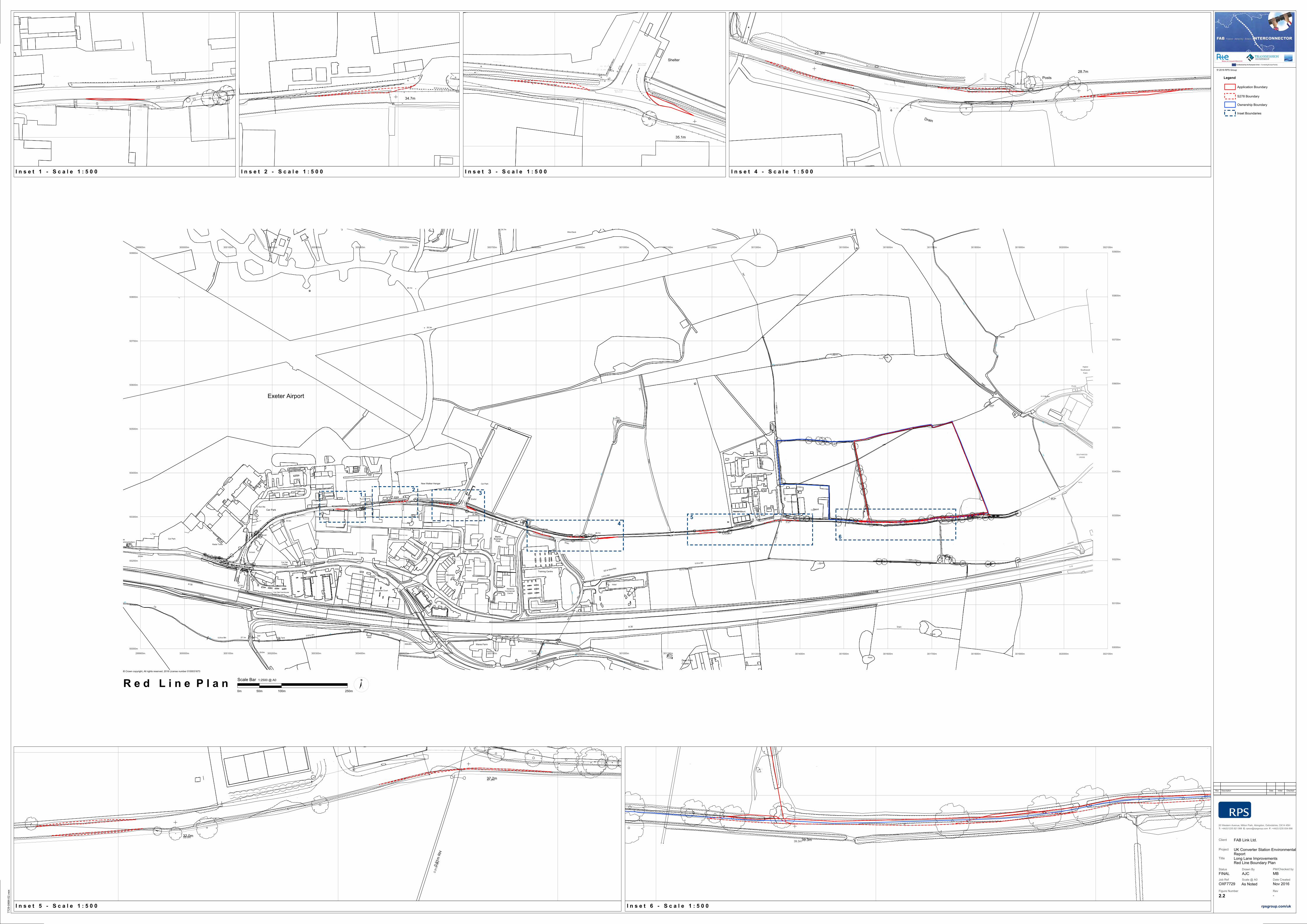
4
32.0m
0.91
m R
H
37.2m37.2m
0.91
m R
H
32.0m
Woo
d P
/RFe
nce
1.0h
FH
CL36.35
IC
StPo
StPo
CL34.97
IC
StL36.18
TP
TP
TP
TP
TP
VP
Conc
Conc
Conc
Conc
Gravel
Gravel
Grass
Gravel/Grass
Flower
Bed
Tarmac
Tarmac
Flower
Bed
Tarmac
Tarmac
Tarmac
Tarmac
Tarmac
TEL (BT)
CatL38.53
33.90
33.86
33.86
34.95
35.14
35.29
35.50 35.69
35.92
36.18
36.39
36.53
36.72
StL36.48
35.62
Security Palisade
Fence 2.3h
Security Palisade
Fence 2.3h
StuStu
37.27
38.38
38.30
ConcreteBlock Wall
38.27
Hedge 3.0h
Hedge 3.0h
Metal MeshFence 2.0h
Wood P/RFence 1.2h
38.11
CatL45.63
CatL43.81
CatL40.09
CatL39.24
32.61
32.81
33.12
33.35
33.78
34.10
34.44
34.64
34.87
34.9
7
35.0
1
35.0
3
35.01
34.96
Vegetation
Vegetation
Vegetation
Vegetation
Tree Canopy
Tree Canopy
Vegetation
Vegetation
Grass
Grass
Drain
29.3m
28.7m
Posts
CL28.73
IC
28.93
29.01
BdL27.35
BdL27.69
Concrete
FL28.76
IL28.45
IL28.40
IL28.37
IL28.34 IL28.34IL28.33
IL28.31 IL28.30 IL28.29IL28.26
LK
JIHGF
ED
C
B
M
450Ø
IL27.91
450Ø
IL27.94
TP
TP
TP
TP
Conc
Conc
Beany
Kerbline Beany
Kerbline
Beany
Kerbline
28.85
Concrete
Pillar
28.90
Concrete
Pillar
BeL34.93
28.9
028
.82
28.78 28.78
29.4
0
28.72
28.69
28.67
28.59
28.6128.62 28.59 28.58 28.60
28.62
28.62
28.61
28.61
28.6028.59
28.64
28.64
28.70
StL30.17
StL30.10
06/04/2016
WL27.78
06/04/2016
WL28.03
A=100Ø IL 28.49
B=100Ø IL 28.50
C=100Ø IL 28.47
D=100Ø IL 28.39
E=100Ø IL 28.37
F=100Ø IL 28.43
G=100Ø IL 28.41
H=100Ø IL 28.44
I=100Ø IL 28.41
J=100Ø IL 28.40
K=100Ø IL 28.43
L=100Ø IL 28.45
M=150Ø IL 27.99
A
CatL36.21
CatL36.56
CatL36.74
CatL36.67
Brambles
Vegetation
Vegetation
Vegetation
Vegetation
Grass
Grass
Grass
Grass
Grass
W
G
G
LP
LP
TP
TP
Gas
MH
Bol
30.54
28.53
28.64
28.73
28.92
28.52
28.31
28.18
28.2328.15
Conc
Tac
F/Bed
IC
MH
Tac
Asphalt
Hedgebank
CL= 29.38m
BT
Hedgebank
Hedgebank
Post and Rail Fence h= 1.2m
Asphalt Path
Asphalt Path
RoughGround
Drainage Ditch
Culvert
Culvert
Conc. Drainage Channel
Drainage Ditch
F/Bed
35.1m
Shelter
TP
Top Post No Wires
CatL44.07
CatL42.78
CatL42.47
CatL41.55
EP
G
G
G
LP
LP
LP
LP
NB
RS
RS
TP
TP
Elc
Elc
Elc
Bol
Hedge h= 1.5m
Tac
Tac
Boulders
Post and Wire Fence h= 1.5m
Hedgebank
White Chevrons
UC
Palisade Fence h= 2.5m
CL= 35.32mMH
CL= 35.54mMH
MH
MH
CL= 35.47m
CL= 35.44m
CBX
BT
CBXFence Continues
CBX
Grass Bank
CBX
Asphalt Path
Asphalt Path
Asphalt Path
Post and Rail Fence h= 1.25m
Foliage
(Cables)
Worn RoadMarkings
Worn RoadMarkings
34.7mCatL41.22
Across Road
CatL42.28
Along Road
CatL42.52
G
G
G
G
LP
LP
LP
RS
TP
TP
Elc
Elc
Elc
Elc
Elc
Tac
Tac
Security Fence h= 2m
Chainlink Fence h= 2
m
BT
BT
Conc. Edging
Conc. Edging
Grass Verge
INDUSTRIAL UNIT
Grass Bank
Asphalt Path
Asphalt Path
Legend
Scale @ A0 Date Created
20 Western Avenue, Milton Park, Abingdon, Oxfordshire, OX14 4SHT: +44(0)1235 821 888 E: [email protected] F: +44(0)1235 834 698
Client
Title
Status PM/Checked byDrawn By
Figure Number Rev
Project
2016 RPS Group
Job Ref
Rev Description Date Initial Checked
c
© Crown copyright, All rights reserved. 2016 License number 0100031673
FAB Link Ltd.
Long Lane Improvements Red Line Boundary Plan
UK Converter Station Environmental Report
FINAL
OXF7729
AJC
-
MB
rpsgroup.com/uk
Nov 2016
2.2
As Noted
Ponds
FarmSouthwood
36.0m
39.3m
A 30
Ponds
Track
Pond
Ponds
DepotHarrier Court
0.91m RH
0.91m R
H
Tank
32.0m
301200m
301300m
301400m
301500m
301600m
CROSS
Pond
301700m
Higher
0.91m RH
38.7m
SOUTHWOOD
301800m
Pond
Ponds
301900m
41.1m
Pond
Depot
ESS
302000m
Def
0.91
m R
H
302100m
Track
39.3m
37.2m
301200m
93000m
301300m
93100m
301400m
301500m
301600m
93200m
301700m
93300m
301800m
301900m
302000m
93400m
302100m
93000m
93500m
93100m
93600m
93200m
93300m
93400m
93700m
93500m
93800m
93600m
93700m
93900m
93800m
93900m
L Twr
CS
Car Park
Mast (Telecommunication)Met Office
29.6m
29.0m
Northfields
Pond
0.91m FB
Def
Def
26
4
1
2
3
5
Lancaster Court
Lay-by
34.7m
5
2
4
ESS
ESS
Tk
Track
A 30
Lay-by
Orchard
Pond
34.1m
27.1m
33.2m
El Sub Sta
CC
S Def0.91m RH
7
7
Car Park
1
2
1
14
B 3184
4 5
Merlin
CLOSE
24.7m
Business
Skyways
Park
35.1m
7
4a
Newbery
2
5
Shelter
OAKFAIR
3
1
3
House
Wares Farm
DefDef
FW
1Revill Ind Units3
6
ISSUES
7
24.1m
Issues
1
25.3m
Mast
1
Ward Bdy
FAIR OAK COURT
Drain
Car Park
33.5m
Tank
Fair Oak
37.2mCottage
ESS
0.91m RH
Drain
0.91m RH
ED & Ward Bdy
6
Tank
10
29.3m
FW
Def0.91m RH CS
Def
28.7mPosts
6
6
Hotel
Centre
Orchard
NewberyCommercial
Shelter
Cottage
Training Centre
Wind Sock
Trac
k
Radar Tower
New Walker Hangar
Fair Oak Farmhouse
B 3184
32.0m
Exeter Airport
30.8m
Pond
CopseDeer Park
B 3184
Def
Harrier Court
Tank
37.2m
0.91m R
H
Def
0.91
m R
H
Drain
Pond
Pond
39.3m
0.91m RH
ED & Ward Bdy
32.0m
A 30
Ponds
Pond
Ponds
Ponds
41.1m
39.3m
36.0m
Ponds
0.91m RH
Drain
Depot
Depot
Track
ESS
Runway Approach Lights
Track
301100m301000m300900m300800m300700m300600m300500m300400m300300m300200m300100m300000m299900m
301100m301000m300900m300800m300700m300600m300500m300400m300300m300200m300100m300000m299900m
Wood P/RFence 1.3h
CATV
CATV
FH
CL34.40
IC
CL32.44
IC
32.60 32.65
EP
EP
Conc
Grass
Grass
Tac
Tac
Tac
Tac
Tac
Tac
Tarmac
Tarmac
Tarmac
Tarmac
Tarmac
Tarm
ac
Tarmac
Tarm
ac
Tarmac
Tarmac
Tarmac
SV
SV
TEL (TS)
TEL (TS)
TEL (TS)
TEL (BT)
TEL (BT)
TEL (BT)
TEL (BT)
TEL (BT)
TEL (TS)
CATV
CATV
CATV
Meta
l P
/RF
ence 1
.1h
Meta
l P
/RF
ence 1
.1h
Me
tal P
/RF
en
ce 1
.1h
CL33.55
IC
TREETOP
Conc
Conc
Gravel
Gra
ss
Grass
Tac
Tac
Tac
Tac
Tarmac
Tarm
ac
Tarmac
Tarm
ac
Tarmac
Tarmac
Tarmac
Tarmac
Tarmac
Tarmac
TEL (TS)
TEL (BT)
TEL (BT)
TEL (C&W)
CL28.73
IC
28.9329.01
BdL27.35
BdL27.69
ConcreteFL28.76
IL28.45
IL28.40IL28.37 IL28.34 IL28.34 IL28.33
IL28.31 IL28.30 IL28.29 IL28.2
6
LKJIHG
FED
C
B
M
450ØIL27.91
450ØIL27.94
TP
TP
TP
TP
Conc
Conc
Beany
Kerbline BeanyKerbline
BeanyKerbline
28.85
Concrete Pillar
28.90
Concrete
Pillar
Wood P/R
Fence 1.1h
Wood P/RFence 0.5h
Wood
P/R
Fence 1
.0h
FH
CL36.35IC
StPo
StPo
CL34.97
IC
StL36.18
TP
TP
TP
TP
TP
TP
TP
VP
Conc
Conc
Conc
Conc
Gravel
Gravel
Grass
Gravel/Grass
Flower
Bed
Tarmac
Tarmac
Tarmac
Flower Bed
Tarmac
Tarmac
Tarm
ac
Tarmac
Tarm
ac
TEL (BT)
TEL (BT)
WM
32.59
32.5
4
32.5632.66
32.7
5
32.69
32.48
32.38
32.35
32.26
32.17
32.10
32.02
31.95
31.87
31.80
31.75
31.71
31.68
31.64
31.61
31.53
33.8
9
33.96
33.99
34.12
34.21
34.32
34.43
33.3
3
32.75 32.8532.98
33.07
33.26
33.4
3
33.5
1
33.5
3
33.5
8
33.6
2
33.6
6
33.6
8
33.6
7
33.6
5
33.6
3
33.6
3
33.6
1
33.5
9
33.5
7
33.5
6
33.5
533.5
7
33.5
5
33.5
4
Meta
l P
/RF
ence 1
.1h
31.68
31.77
31.84
31.90
31.98
32.05
32.13
32.21
32.29
32.40
32.49
CatL38.53
33.9
0
33.86
33.86
34.9
5
35.1
4
35.29
35.50 35.69
35.92
36.18
36.39
36.53
36.72
P/W 1.1h
Stock Piles ofManure
Unable to Survey
P/W1.0h
Unable to Survey
Further due to denseVegetation
Hawthorn
Hedge 1.6h
Ha
wth
orn
Hed
ge
row
1.8
h
Stock Piles ofManure
Unable to Survey
EP
WL40.42
Earth
Grass
Vegetation
Vegetation
Vegetation
Scar
Vegetation
Vegetation
Vegetation
Vegetation
EarthEarth
Earth
Earth
VegetationVegetation
Vegetation
VegetationVegetation
Vegetation
Vegetation
Vegetation
EP
EP
EP
EP
EP
EP (Transformer on Pole)
StPo
IL39.09
SPREAD
Corrugated Sheeting
Wood P/R
Fence 1.5h
EP
StPo
StPo
StPo
SV
Watering Trough
StL36.48
35.62
Security Palisade
Fence 2.3h
Security Palisade
Fence 2.3h
38.8
4
38.8
8
BeL46.98
BeL46.63
BeL46.73
38
.56
38
.56
Co
ncre
teB
lock
Wa
ll3
8.6
23
8.6
93
8.6
93
8.6
63
8.5
13
8.4
73
8.4
9
Co
ncre
teB
lock
Wa
ll
38.33
ConcreteBlock Wall38.34
38.36
38.38
38.36
38.27
38.24
38.10 ConcreteBlock Wall
38.28
ChainlinkFence 2.0h
Chainlink
Fence 2.0h
BeL36.74
BeL34.93
28
.90
28
.82
28.78 28.78
29.4
0
28.7228.69
28.6728.59
28.6128.62 28.59
28.58 28.6028.62
28.62
28.61
28.61
28.6028.5928.64
28.64
28.70
StPo
TP
TP
TP
BeL35.62
StL30.17
StL30.10
06/04/2016 WL27.78
06/04/2016
WL28.03
A=100Ø IL 28.49B=100Ø IL 28.50C=100Ø IL 28.47D=100Ø IL 28.39
E=100Ø IL 28.37F=100Ø IL 28.43G=100Ø IL 28.41H=100Ø IL 28.44
I=100Ø IL 28.41J=100Ø IL 28.40K=100Ø IL 28.43L=100Ø IL 28.45
M=150Ø IL 27.99
A
BambooFence 1.0h
33.7
1
33.5
9
Con
cret
e
Wall 0.9
h
33.7
2
33.65
Concre
teW
all
0.9
h
33.8
7
33.8
9
33.8
7
33.9
5
33.9
5
34.0
4
34.1
6
34.2
1
34.1
8
Fre
sh T
arm
ac
Small Trees/Bushes
33.44
33.29
33.08
33.6
6
33.6
9
33.7
7
34.01
33.89
33.69
33.65
33.9
833.9
6
34.0
0
33.4
1
33.1
5
33.05
32.90
32.75
32.58
Fre
sh T
arm
ac
33.6
2
33.6
8
33.70
33.5
4
33.53
33.6
3
34.04
Tree
Can
opy
Tree Can
opy
Garage
Me
tal M
esh
Fe
nce 2
.0h
Me
tal M
esh
Fe
nce 2
.0h
Metal MeshFence 2.0h
Metal MeshFence 2.0h
P/W 1.0h
Stu Stu
Secu
rity P
alisade
Fence
2.3
h
37.27
37.44
38.38
38.30 ConcreteBlock Wall
38.27
Hedge 3.0h
Hedge 3.0h
33.7
2
CatL41.22
CatL36.21
Metal MeshFence 2.0h
Wood P/RFence 1.2h
38.11
CatL45.63
CatL43.81
CatL40.09
CatL39.24
WM
Wood P/RFence 1.5h
Wood P/RFence 1.5h
Hedge 0.8h
Hedge 0.8h
Metal P/RFence 1.0h
CatL41.67
Plastic/Grass
Anti Skid
Anti Skid
Anti Skid
33.6
7
33.6
6
33.6
8
33.7
1
33.7
4
33.7
8
33.8
0
33.8
3
33.8
4
33
.84
33.8
5
Grass
Grass
Grass
ChainlinkFence 1.8h
ChainlinkFence 1.8h
ChainlinkFence 1.8h
Chain
link
Fence 1
.8h
Chain
link
Fence 1
.8h
Grass
Tarmac
Grass
Grass
B 3184
B3184
Top Post No WiresCatL44.07
CatL41.62
Across RoadCatL42.28
Along RoadCatL42.52
CatL42.78
CatL42.47
CatL41.55
CatL40.85
CatL40.06
CatL36.56
CatL36.74
CatL36.67
Brambles
32.61
32.81
33.12
33.35
33.78
34.10
34.44
34.64
34.87
34.9
7
35.0
1
35
.03
35.0
1
34.9
6
Earth
Earth
Earth
CatL46.12
CatL45.17
CatL46.41
Unable to SurveyDense Vegetation
Unable to SurveyDense Vegetation
Crops
Crops
Crops
Crops
Crops
Crops
Crops
Brambles/ Small Trees Unable to Survey
Brambles/ Small Trees Unable to Survey
Vegetation
Vegetation
Vegetation
Vegetation
Vegetation
VegetationVegetation
Vegeta
tion
Vegeta
tion
Vegeta
tion
Vegetation
Vegetation
Vegetation
Vegetation
Vegetation
Vegetation
Vegetation
CatL46.19
Vegetation
Vegetation
Vegetation
CatL46.82
Vegeta
tion
Vegeta
tion
Vegeta
tion
Vegetation
Vegetation
Vegetation
Vegetation
Vegetation
Vegetation
Tree C
anopy
Tree Canopy
Vegetation
Vegetation
Vegetation
Vegetation
Vegetation
Vegetation
Vegetation
Vegetation
Vegetation
Vegetation
STOP
CatL47.71
Grass
Grass
Grass
Grass
Grass
Grass
Grass
Grass
Grass
Grass
Grass
Grass
Grass
Grass
Grass
Conifer
Hedge
Conife
r
Hedge
W
EP
FHFH
G
G
G
G
G
G
G
G
G
G
G
G
G
G
G
G
G
G
G
G
G
G
G
LP
LP
LP
LP
LP
LP
LP
LP
LP
LP
LP
LP
LP
LP
LP
LP
LP
LP
Mkr
Mkr
NB
NB RS
RS
RS
RS
RS
SV
TP
TP
TP
TP
TPTP
TP
TP
Gas
MH
MH
ThlThl
Elc
Elc
ElcElc
Elc
Elc
Elc
ElcElc
ElcElc
Elc
Elc
Elc
Elc
ICIC
StuStuStu
Stu
Bol
Bol
Bol
30.92
30.54
35.0635.10
31.57
28.53
28.64
28.73
28.9228.52
28.31
28.18
28.23 28.15
Hedge h= 1.5m
Conc
Boulder
Wooden Fence h= 1m
Security Fence h= 2m
Plant Pots
Tac
Tac
Tac
F/Bed
IC
MH
Tac
Asphalt
Tac
Tac
Boulders
Tac
Grass
Grass
Security Fence h= 2m
Chainlink Fence h= 2m
Chainlink
Fence h= 2
m
Crushed Stone Surface
Asphalt Path
Building h= 5m
Security Fence h= 2m
Chainlink Fence h= 2
m Post and Wire Fence h= 1.5m
Hedgebank
Hedgebank
Depot Entrance
Depot En
trance
Depot Entrance
RNP
RNP
BT
CL= 34.00m
MH
Silted
IC
CL= 33.68m
MH
BT
MHCL= 34.54m
MHCL= 35.00m
CL= 29.38m
BT
CL= 32.79m
CL= 34.43m
CL= 35.13mMH
BT
BT
BT
Conc. Slab
Conc. Block
Conc.Post
White Chevrons
UC
Palisade Fence h= 2.5m
Edge of asphalt
Cobbles
UC
FoliageNo Access
Hedgebank
Hedgebank
Post and Rail Fence h= 1.2m
CL= 35.32mMH
CL= 35.54mMH
MH
MH
CL= 35.47m
CL= 35.44m
CBXBT
CBX
BT
MHCL= 34.43m
BT
CL= 32.17mMH
CL= 35.39mMH
CL= 34.14mMH
BT
CL= 33.79mMH
Chevrons
Post and Rail Fence h= 1.2m
MH
Depot En
trance
Depot Entrance
Depot Entrance
RS
Low BrickWall
CBX
Grass Bank
INDUSTRIAL UNIT
STORAGE UNIT
G
Grass Bank
Foliage
Conc. Edging
Conc. Edging
Grass Verge
INDUSTRIAL UNIT
Grass Bank
Grass Verge
Fence Continues
CBX
Grass Bank
CBX
Asphalt Path
Asphalt Path
Asphalt Path
Asphalt Path
Asphalt Pa
th
Asphalt Path Asphalt Path
Asphalt Path
Asphalt Path
Asphalt Path
Asphalt Path
Asphalt Path
Asphalt Path
Post and Rail Fence h= 1.25m
Asphalt Path
Foliage
(Cables)
MH
Security Fen
ce h= 2m
Worn RoadMarkings
Worn RoadMarkings
RoughGround
Drainage Ditch
Culvert
Culvert
Conc. Drainage Channel
Drainage Ditch
Hedgebank
F/Bed
Max Legal Length (UK) Articulated Vehicle (16.5m)
Application Boundary
S278 Boundary
Ownership Boundary
Inset Boundaries
Scale Bar 1:2500 @ A0
0m 50m 100m 250m
N
G
G
LPNB
SV
Thl
Thl
Elc
ICIC
Boulder
Wooden Fence h= 1m
Security Fence h= 2m
Security Fence h= 2m
Building h= 5m
Depot Entrance
MH
CL= 34.54m
MHCL= 35.00m
CL= 35.13mMH
Edge of asphalt
Cobbles
BT
MH
CL= 34.43m
CL= 35.39mMH
Depot Entrance
Depot Entrance
Grass Bank
INDUSTRIAL UNIT
STORAGE UNIT
G
Grass Bank
Foliage
Asphalt Path
Asphalt Path
Asphalt Path
39.3m39.3m
Haw
thorn Hedgerow
1.8h
EP
Earth
Grass
Scar
Vegetation
Vegetation
Vegetation
Vegetation
Vegetation
IL39.09
Corrugated
Sheeting
38.8
4
38.8
8
Earth
Crops
Crops
Vegetation
Vegetation
Vegetation
Vegetation
Vegetation
Vegetation
Vegetation
CatL47.71
Grass
Grass
R e d L i n e P l a n
I n s e t 1 - S c a l e 1 : 5 0 0 I n s e t 2 - S c a l e 1 : 5 0 0 I n s e t 3 - S c a l e 1 : 5 0 0 I n s e t 4 - S c a l e 1 : 5 0 0
I n s e t 5 - S c a l e 1 : 5 0 0 I n s e t 6 - S c a l e 1 : 5 0 0
12 3
5
6
7729
-048
4-02
.vw
x

December 2016
FIGURE 3
Illustrative Block Plan - Option 1 7729-0446-04

Converter Hall
Converter Hall
Control
Building
Control
Building
TransformersTransformers
SpareTransformer
DC Cable
Terminations
DC Cable
Terminations
DC Cable
Terminations
DC Cable
Terminations
ValveCoolers
ValveCoolers
400kV AC
Switch Yard
400kV AC
Switch Yard
Auxiliary
Transformer
Auxiliary
Transformer
Standby
GeneratorStandby
GeneratorParking
Parking
400kV Cable Termination Circuit
Breakers and Disconnectors
Sound wallSound wall
SparesBuilding
41.1m
39.3m
Legend
Scale @ A3 Date Created
20 Western Avenue, Milton Park, Abingdon, Oxfordshire, OX14 4SHT: +44(0)1235 821 888 E: [email protected] F: +44(0)1235 834 698
Client
Title
Status PM/Checked byDrawn By
Figure Number Rev
Project
2016 RPS Group
Job Ref
Rev Description Date Initial Checked
c
© Crown copyright, All rights reserved. 2016 License number 0100031673
N
FAB Link Ltd.
Illustrative Block Plan - Option 1
FINAL
OXF7729
RM
-
0 10 20m
1:1,000
O:\7729 FAB Interconnector\Tech\Drawings\7729-0446-06.dwg
O:\7
729
FAB
Inte
rcon
nect
or\T
ech\
Dra
win
gs\7
729-
0446
-06.
dwg
MB
rpsgroup.com/uk
DEC 2016
3
Buildings: 1.1ha
Road / parking
Proposed UK Converter Station
Ownership boundary
Operational area
Application site boundary

December 2016
FIGURE 4
Illustrative Block Plan - Option 2 7729-0447-04

Converter Hall
Converter Hall
Control
Building
Transformers
SpareTransformer
ValveCoolers
400kV AC
Switch Yard
Transformers
400kV AC
Switch Yard
400kV Cable Termination
Circuit Breakers and
Disconnectors
ValveCoolers
400kV Cable Termination
Circuit Breakers and
Disconnectors
Auxiliary
Transformer
Standby
Generator
Standby
Generator
Auxiliary
Transformer
Soun
d w
all
Soun
d w
all
Parking
SparesBuilding
41.1m
39.3mScale @ A3 Date Created
20 Western Avenue, Milton Park, Abingdon, Oxfordshire, OX14 4SHT: +44(0)1235 821 888 E: [email protected] F: +44(0)1235 834 698
Client
Title
Status PM/Checked byDrawn By
Figure Number Rev
Project
2016 RPS Group
Job Ref
Rev Description Date Initial Checked
c
© Crown copyright, All rights reserved. 2016 License number 0100031673
N
FAB Link Ltd.
Illustrative Block Plan - Option 2
FINAL
OXF7729
RM
-
0 10 20m
1:1,000
O:\7729 FAB Interconnector\Tech\Drawings\7729-0447-06.dwg
O:\7
729
FAB
Inte
rcon
nect
or\T
ech\
Dra
win
gs\7
729-
0447
-06.
dwg
MB
rpsgroup.com/uk
DEC 2016
4
Legend
Buildings: 1.1ha
Road / parking
Ownership boundary
Operational area
Application site boundary
Proposed UK Converter Station

December 2016
FIGURE 5
Illustrative 3D Model Option 1 7729-0449-03

Legend
Scale @ A3 Date Created
20 Western Avenue, Milton Park, Abingdon, Oxfordshire, OX14 4SHT: +44(0)1235 821 888 E: [email protected] F: +44(0)1235 834 698
Client
Title
Status PM/Checked byDrawn By
Figure Number Rev
Project
2016 RPS Group
Job Ref
Rev Description Date Initial Checked
c
FAB Link Ltd.
OXF7729 June 2016
rpsgroup.com/uk
NTS
RM MB
Illustrative 3D Model Option 1
Proposed UK Converter Station
FINAL
DEC 2016
5a
Ref
: 772
9-04
49-0
5

Legend
Scale @ A3 Date Created
20 Western Avenue, Milton Park, Abingdon, Oxfordshire, OX14 4SHT: +44(0)1235 821 888 E: [email protected] F: +44(0)1235 834 698
Client
Title
Status PM/Checked byDrawn By
Figure Number Rev
Project
2016 RPS Group
Job Ref
Rev Description Date Initial Checked
c
FAB Link Ltd.
OXF7729 June 2016
rpsgroup.com/uk
NTS
RM MB
Illustrative 3D ModelOption 1
5b
Ref
: 772
9-04
49-0
5
Proposed UK Converter Station
FINAL
DEC 2016

December 2016
FIGURE 6
Illustrative 3D Model Option 2 7729-0450-03

Legend
Scale @ A3 Date Created
20 Western Avenue, Milton Park, Abingdon, Oxfordshire, OX14 4SHT: +44(0)1235 821 888 E: [email protected] F: +44(0)1235 834 698
Client
Title
Status PM/Checked byDrawn By
Figure Number Rev
Project
2016 RPS Group
Job Ref
Rev Description Date Initial Checked
c
FAB Link Ltd.
OXF7729 June 2016
rpsgroup.com/uk
NTS
RM MB
Illustrative 3D Model Option 2
Proposed UK Converter Station
6a
Ref
: 772
9-04
50-0
5
FINAL
DEC 2016
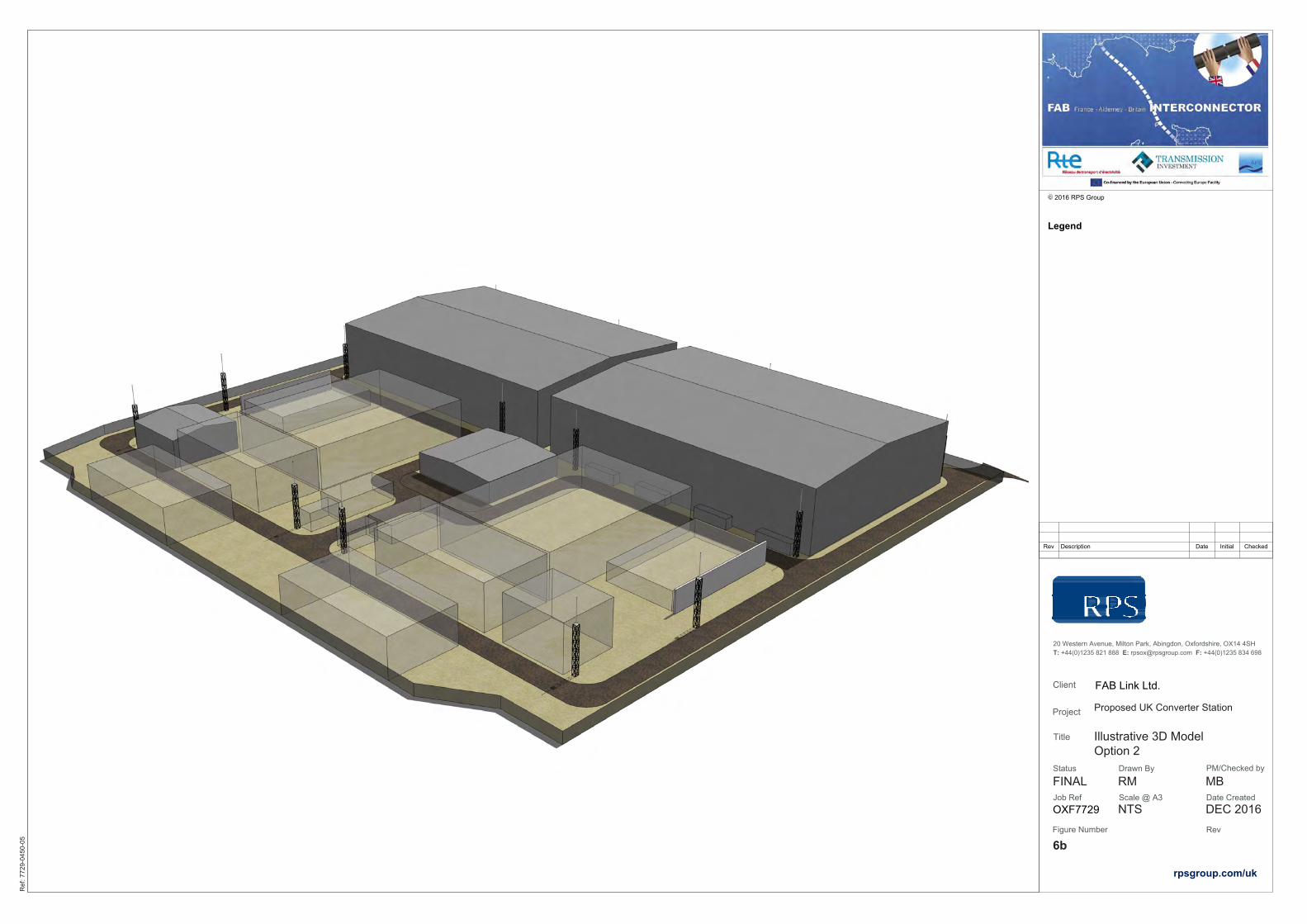
Legend
Scale @ A3 Date Created
20 Western Avenue, Milton Park, Abingdon, Oxfordshire, OX14 4SHT: +44(0)1235 821 888 E: [email protected] F: +44(0)1235 834 698
Client
Title
Status PM/Checked byDrawn By
Figure Number Rev
Project
2016 RPS Group
Job Ref
Rev Description Date Initial Checked
c
FAB Link Ltd.
OXF7729 June 2016
rpsgroup.com/uk
NTS
RM MB
Illustrative 3D Model Option 2
Proposed UK Converter Station
FINAL
DEC 2016
6b
Ref
: 772
9-04
50-0
5

December 2016
FIGURE 7
Parameter Plan Isometric View 7729-0463-02

Legend
Scale @ A3 Date Created
20 Western Avenue, Milton Park, Abingdon, Oxfordshire, OX14 4SHT: +44(0)1235 821 888 E: [email protected] F: +44(0)1235 834 698
Client
Title
Status PM/Checked byDrawn By
Figure Number Rev
Project
2016 RPS Group
Job Ref
Rev Description Date Initial Checked
c
FAB Link Ltd.
OXF7729 June 2016
rpsgroup.com/uk
NTS
RM MB
Parameter Plan Isometric View
Proposed UK Converter Station
FINAL
7
Ref
: 772
9-04
63-0
4
DEC 2016

December 2016
FIGURE 8
Parameter Plan Cross Section

Legend
20m Parameter Block
Existing Ground Level
Scale @ A1 Date Created
20 Western Avenue, Milton Park, Abingdon, Oxfordshire, OX14 4SHT: +44(0)1235 821 888 E: [email protected] F: +44(0)1235 834 698
Client
Title
Status PM/Checked byDrawn By
Figure Number Rev
Project
2016 RPS Group
Job Ref
Rev Description Date Initial Checked
c
© Crown copyright, All rights reserved. 2016 License number 0100031673
FAB Link Ltd.
Parameter Plan SectionNorth - South Section
FAB Link Interconnector
FINAL
OXF7729
RM
DEC 2016
8 -
0 5 10m
1:500
O:\7729 FAB Interconnector\Tech\Drawings\7729-0455-04.dwg
O:\7
729
FAB
Inte
rcon
nect
or\T
ech\
Dra
win
gs\7
729-
0455
-04.
dwg
MB
rpsgroup.com/uk
AutoCAD SHX Text
North-south
AutoCAD SHX Text
Horiz. 1:50
AutoCAD SHX Text
Vert. 1:50
AutoCAD SHX Text
Start Chainage E = 301644.361 N = 93499.687
AutoCAD SHX Text
Section bearing = 169d48'27"
AutoCAD SHX Text
LEVEL
AutoCAD SHX Text
CHAINAGE
AutoCAD SHX Text
35.00 A.O.D.
AutoCAD SHX Text
12.78
AutoCAD SHX Text
20.00
AutoCAD SHX Text
30.00
AutoCAD SHX Text
40.00
AutoCAD SHX Text
50.00
AutoCAD SHX Text
60.00
AutoCAD SHX Text
70.00
AutoCAD SHX Text
80.00
AutoCAD SHX Text
90.00
AutoCAD SHX Text
100.00
AutoCAD SHX Text
110.00
AutoCAD SHX Text
120.00
AutoCAD SHX Text
130.00
AutoCAD SHX Text
140.00
AutoCAD SHX Text
150.00
AutoCAD SHX Text
160.00
AutoCAD SHX Text
170.00
AutoCAD SHX Text
180.00
AutoCAD SHX Text
190.00
AutoCAD SHX Text
200.00
AutoCAD SHX Text
210.00
AutoCAD SHX Text
220.00
AutoCAD SHX Text
230.00
AutoCAD SHX Text
231.28
AutoCAD SHX Text
36.00
AutoCAD SHX Text
36.00
AutoCAD SHX Text
37.00
AutoCAD SHX Text
37.00
AutoCAD SHX Text
38.00
AutoCAD SHX Text
38.00
AutoCAD SHX Text
39.00
AutoCAD SHX Text
39.00
AutoCAD SHX Text
40.00
AutoCAD SHX Text
40.00
AutoCAD SHX Text
41.00
AutoCAD SHX Text
41.00
AutoCAD SHX Text
42.00
AutoCAD SHX Text
42.00
AutoCAD SHX Text
12.778
AutoCAD SHX Text
37.642
AutoCAD SHX Text
13.000
AutoCAD SHX Text
37.722
AutoCAD SHX Text
14.000
AutoCAD SHX Text
37.691
AutoCAD SHX Text
15.000
AutoCAD SHX Text
37.396
AutoCAD SHX Text
16.000
AutoCAD SHX Text
37.461
AutoCAD SHX Text
17.000
AutoCAD SHX Text
37.473
AutoCAD SHX Text
18.000
AutoCAD SHX Text
37.485
AutoCAD SHX Text
19.000
AutoCAD SHX Text
37.497
AutoCAD SHX Text
20.000
AutoCAD SHX Text
37.511
AutoCAD SHX Text
21.000
AutoCAD SHX Text
37.530
AutoCAD SHX Text
22.000
AutoCAD SHX Text
37.549
AutoCAD SHX Text
23.000
AutoCAD SHX Text
37.568
AutoCAD SHX Text
24.000
AutoCAD SHX Text
37.588
AutoCAD SHX Text
25.000
AutoCAD SHX Text
37.608
AutoCAD SHX Text
26.000
AutoCAD SHX Text
37.628
AutoCAD SHX Text
27.000
AutoCAD SHX Text
37.648
AutoCAD SHX Text
28.000
AutoCAD SHX Text
37.668
AutoCAD SHX Text
29.000
AutoCAD SHX Text
37.689
AutoCAD SHX Text
30.000
AutoCAD SHX Text
37.710
AutoCAD SHX Text
31.000
AutoCAD SHX Text
37.731
AutoCAD SHX Text
32.000
AutoCAD SHX Text
37.752
AutoCAD SHX Text
33.000
AutoCAD SHX Text
37.773
AutoCAD SHX Text
34.000
AutoCAD SHX Text
37.793
AutoCAD SHX Text
35.000
AutoCAD SHX Text
37.814
AutoCAD SHX Text
36.000
AutoCAD SHX Text
37.834
AutoCAD SHX Text
37.000
AutoCAD SHX Text
37.854
AutoCAD SHX Text
38.000
AutoCAD SHX Text
37.874
AutoCAD SHX Text
39.000
AutoCAD SHX Text
37.894
AutoCAD SHX Text
40.000
AutoCAD SHX Text
37.914
AutoCAD SHX Text
41.000
AutoCAD SHX Text
37.932
AutoCAD SHX Text
42.000
AutoCAD SHX Text
37.950
AutoCAD SHX Text
43.000
AutoCAD SHX Text
37.968
AutoCAD SHX Text
44.000
AutoCAD SHX Text
37.987
AutoCAD SHX Text
45.000
AutoCAD SHX Text
38.004
AutoCAD SHX Text
46.000
AutoCAD SHX Text
38.021
AutoCAD SHX Text
47.000
AutoCAD SHX Text
38.038
AutoCAD SHX Text
48.000
AutoCAD SHX Text
38.054
AutoCAD SHX Text
49.000
AutoCAD SHX Text
38.071
AutoCAD SHX Text
50.000
AutoCAD SHX Text
38.088
AutoCAD SHX Text
51.000
AutoCAD SHX Text
38.106
AutoCAD SHX Text
52.000
AutoCAD SHX Text
38.124
AutoCAD SHX Text
53.000
AutoCAD SHX Text
38.143
AutoCAD SHX Text
54.000
AutoCAD SHX Text
38.161
AutoCAD SHX Text
55.000
AutoCAD SHX Text
38.174
AutoCAD SHX Text
56.000
AutoCAD SHX Text
38.186
AutoCAD SHX Text
57.000
AutoCAD SHX Text
38.197
AutoCAD SHX Text
58.000
AutoCAD SHX Text
38.209
AutoCAD SHX Text
59.000
AutoCAD SHX Text
38.222
AutoCAD SHX Text
60.000
AutoCAD SHX Text
38.237
AutoCAD SHX Text
61.000
AutoCAD SHX Text
38.252
AutoCAD SHX Text
62.000
AutoCAD SHX Text
38.266
AutoCAD SHX Text
63.000
AutoCAD SHX Text
38.281
AutoCAD SHX Text
64.000
AutoCAD SHX Text
38.296
AutoCAD SHX Text
65.000
AutoCAD SHX Text
38.307
AutoCAD SHX Text
66.000
AutoCAD SHX Text
38.315
AutoCAD SHX Text
67.000
AutoCAD SHX Text
38.324
AutoCAD SHX Text
68.000
AutoCAD SHX Text
38.332
AutoCAD SHX Text
69.000
AutoCAD SHX Text
38.341
AutoCAD SHX Text
70.000
AutoCAD SHX Text
38.354
AutoCAD SHX Text
71.000
AutoCAD SHX Text
38.368
AutoCAD SHX Text
72.000
AutoCAD SHX Text
38.383
AutoCAD SHX Text
73.000
AutoCAD SHX Text
38.398
AutoCAD SHX Text
74.000
AutoCAD SHX Text
38.413
AutoCAD SHX Text
75.000
AutoCAD SHX Text
38.427
AutoCAD SHX Text
76.000
AutoCAD SHX Text
38.443
AutoCAD SHX Text
77.000
AutoCAD SHX Text
38.460
AutoCAD SHX Text
78.000
AutoCAD SHX Text
38.476
AutoCAD SHX Text
79.000
AutoCAD SHX Text
38.492
AutoCAD SHX Text
80.000
AutoCAD SHX Text
38.509
AutoCAD SHX Text
81.000
AutoCAD SHX Text
38.525
AutoCAD SHX Text
82.000
AutoCAD SHX Text
38.541
AutoCAD SHX Text
83.000
AutoCAD SHX Text
38.557
AutoCAD SHX Text
84.000
AutoCAD SHX Text
38.573
AutoCAD SHX Text
85.000
AutoCAD SHX Text
38.589
AutoCAD SHX Text
86.000
AutoCAD SHX Text
38.605
AutoCAD SHX Text
87.000
AutoCAD SHX Text
38.621
AutoCAD SHX Text
88.000
AutoCAD SHX Text
38.638
AutoCAD SHX Text
89.000
AutoCAD SHX Text
38.653
AutoCAD SHX Text
90.000
AutoCAD SHX Text
38.667
AutoCAD SHX Text
91.000
AutoCAD SHX Text
38.681
AutoCAD SHX Text
92.000
AutoCAD SHX Text
38.696
AutoCAD SHX Text
93.000
AutoCAD SHX Text
38.710
AutoCAD SHX Text
94.000
AutoCAD SHX Text
38.724
AutoCAD SHX Text
95.000
AutoCAD SHX Text
38.738
AutoCAD SHX Text
96.000
AutoCAD SHX Text
38.752
AutoCAD SHX Text
97.000
AutoCAD SHX Text
38.766
AutoCAD SHX Text
98.000
AutoCAD SHX Text
38.785
AutoCAD SHX Text
99.000
AutoCAD SHX Text
38.811
AutoCAD SHX Text
100.000
AutoCAD SHX Text
38.836
AutoCAD SHX Text
101.000
AutoCAD SHX Text
38.862
AutoCAD SHX Text
102.000
AutoCAD SHX Text
38.888
AutoCAD SHX Text
103.000
AutoCAD SHX Text
38.913
AutoCAD SHX Text
104.000
AutoCAD SHX Text
38.939
AutoCAD SHX Text
105.000
AutoCAD SHX Text
38.965
AutoCAD SHX Text
106.000
AutoCAD SHX Text
38.990
AutoCAD SHX Text
107.000
AutoCAD SHX Text
39.016
AutoCAD SHX Text
108.000
AutoCAD SHX Text
39.042
AutoCAD SHX Text
109.000
AutoCAD SHX Text
39.063
AutoCAD SHX Text
110.000
AutoCAD SHX Text
39.076
AutoCAD SHX Text
111.000
AutoCAD SHX Text
39.090
AutoCAD SHX Text
112.000
AutoCAD SHX Text
39.103
AutoCAD SHX Text
113.000
AutoCAD SHX Text
39.117
AutoCAD SHX Text
114.000
AutoCAD SHX Text
39.130
AutoCAD SHX Text
115.000
AutoCAD SHX Text
39.143
AutoCAD SHX Text
116.000
AutoCAD SHX Text
39.157
AutoCAD SHX Text
117.000
AutoCAD SHX Text
39.176
AutoCAD SHX Text
118.000
AutoCAD SHX Text
39.198
AutoCAD SHX Text
119.000
AutoCAD SHX Text
39.219
AutoCAD SHX Text
120.000
AutoCAD SHX Text
39.241
AutoCAD SHX Text
121.000
AutoCAD SHX Text
39.262
AutoCAD SHX Text
122.000
AutoCAD SHX Text
39.284
AutoCAD SHX Text
123.000
AutoCAD SHX Text
39.306
AutoCAD SHX Text
124.000
AutoCAD SHX Text
39.327
AutoCAD SHX Text
125.000
AutoCAD SHX Text
39.349
AutoCAD SHX Text
126.000
AutoCAD SHX Text
39.370
AutoCAD SHX Text
127.000
AutoCAD SHX Text
39.392
AutoCAD SHX Text
128.000
AutoCAD SHX Text
39.412
AutoCAD SHX Text
129.000
AutoCAD SHX Text
39.432
AutoCAD SHX Text
130.000
AutoCAD SHX Text
39.454
AutoCAD SHX Text
131.000
AutoCAD SHX Text
39.475
AutoCAD SHX Text
132.000
AutoCAD SHX Text
39.497
AutoCAD SHX Text
133.000
AutoCAD SHX Text
39.518
AutoCAD SHX Text
134.000
AutoCAD SHX Text
39.540
AutoCAD SHX Text
135.000
AutoCAD SHX Text
39.560
AutoCAD SHX Text
136.000
AutoCAD SHX Text
39.580
AutoCAD SHX Text
137.000
AutoCAD SHX Text
39.600
AutoCAD SHX Text
138.000
AutoCAD SHX Text
39.620
AutoCAD SHX Text
139.000
AutoCAD SHX Text
39.640
AutoCAD SHX Text
140.000
AutoCAD SHX Text
39.660
AutoCAD SHX Text
141.000
AutoCAD SHX Text
39.681
AutoCAD SHX Text
142.000
AutoCAD SHX Text
39.703
AutoCAD SHX Text
143.000
AutoCAD SHX Text
39.725
AutoCAD SHX Text
144.000
AutoCAD SHX Text
39.747
AutoCAD SHX Text
145.000
AutoCAD SHX Text
39.769
AutoCAD SHX Text
146.000
AutoCAD SHX Text
39.791
AutoCAD SHX Text
147.000
AutoCAD SHX Text
39.812
AutoCAD SHX Text
148.000
AutoCAD SHX Text
39.831
AutoCAD SHX Text
149.000
AutoCAD SHX Text
39.850
AutoCAD SHX Text
150.000
AutoCAD SHX Text
39.869
AutoCAD SHX Text
151.000
AutoCAD SHX Text
39.889
AutoCAD SHX Text
152.000
AutoCAD SHX Text
39.910
AutoCAD SHX Text
153.000
AutoCAD SHX Text
39.931
AutoCAD SHX Text
154.000
AutoCAD SHX Text
39.958
AutoCAD SHX Text
155.000
AutoCAD SHX Text
39.989
AutoCAD SHX Text
156.000
AutoCAD SHX Text
40.019
AutoCAD SHX Text
157.000
AutoCAD SHX Text
40.049
AutoCAD SHX Text
158.000
AutoCAD SHX Text
40.079
AutoCAD SHX Text
159.000
AutoCAD SHX Text
40.108
AutoCAD SHX Text
160.000
AutoCAD SHX Text
40.138
AutoCAD SHX Text
161.000
AutoCAD SHX Text
40.167
AutoCAD SHX Text
162.000
AutoCAD SHX Text
40.196
AutoCAD SHX Text
163.000
AutoCAD SHX Text
40.225
AutoCAD SHX Text
164.000
AutoCAD SHX Text
40.247
AutoCAD SHX Text
165.000
AutoCAD SHX Text
40.264
AutoCAD SHX Text
166.000
AutoCAD SHX Text
40.281
AutoCAD SHX Text
167.000
AutoCAD SHX Text
40.298
AutoCAD SHX Text
168.000
AutoCAD SHX Text
40.317
AutoCAD SHX Text
169.000
AutoCAD SHX Text
40.337
AutoCAD SHX Text
170.000
AutoCAD SHX Text
40.357
AutoCAD SHX Text
171.000
AutoCAD SHX Text
40.376
AutoCAD SHX Text
172.000
AutoCAD SHX Text
40.396
AutoCAD SHX Text
173.000
AutoCAD SHX Text
40.418
AutoCAD SHX Text
174.000
AutoCAD SHX Text
40.446
AutoCAD SHX Text
175.000
AutoCAD SHX Text
40.474
AutoCAD SHX Text
176.000
AutoCAD SHX Text
40.502
AutoCAD SHX Text
177.000
AutoCAD SHX Text
40.530
AutoCAD SHX Text
178.000
AutoCAD SHX Text
40.558
AutoCAD SHX Text
179.000
AutoCAD SHX Text
40.586
AutoCAD SHX Text
180.000
AutoCAD SHX Text
40.615
AutoCAD SHX Text
181.000
AutoCAD SHX Text
40.642
AutoCAD SHX Text
182.000
AutoCAD SHX Text
40.668
AutoCAD SHX Text
183.000
AutoCAD SHX Text
40.686
AutoCAD SHX Text
184.000
AutoCAD SHX Text
40.699
AutoCAD SHX Text
185.000
AutoCAD SHX Text
40.713
AutoCAD SHX Text
186.000
AutoCAD SHX Text
40.726
AutoCAD SHX Text
187.000
AutoCAD SHX Text
40.739
AutoCAD SHX Text
188.000
AutoCAD SHX Text
40.753
AutoCAD SHX Text
189.000
AutoCAD SHX Text
40.766
AutoCAD SHX Text
190.000
AutoCAD SHX Text
40.779
AutoCAD SHX Text
191.000
AutoCAD SHX Text
40.793
AutoCAD SHX Text
192.000
AutoCAD SHX Text
40.806
AutoCAD SHX Text
193.000
AutoCAD SHX Text
40.819
AutoCAD SHX Text
194.000
AutoCAD SHX Text
40.831
AutoCAD SHX Text
195.000
AutoCAD SHX Text
40.842
AutoCAD SHX Text
196.000
AutoCAD SHX Text
40.853
AutoCAD SHX Text
197.000
AutoCAD SHX Text
40.864
AutoCAD SHX Text
198.000
AutoCAD SHX Text
40.875
AutoCAD SHX Text
199.000
AutoCAD SHX Text
40.886
AutoCAD SHX Text
200.000
AutoCAD SHX Text
40.897
AutoCAD SHX Text
201.000
AutoCAD SHX Text
40.905
AutoCAD SHX Text
202.000
AutoCAD SHX Text
40.914
AutoCAD SHX Text
203.000
AutoCAD SHX Text
40.922
AutoCAD SHX Text
204.000
AutoCAD SHX Text
40.908
AutoCAD SHX Text
205.000
AutoCAD SHX Text
40.898
AutoCAD SHX Text
206.000
AutoCAD SHX Text
40.891
AutoCAD SHX Text
207.000
AutoCAD SHX Text
40.883
AutoCAD SHX Text
208.000
AutoCAD SHX Text
40.876
AutoCAD SHX Text
209.000
AutoCAD SHX Text
40.869
AutoCAD SHX Text
210.000
AutoCAD SHX Text
40.862
AutoCAD SHX Text
211.000
AutoCAD SHX Text
40.854
AutoCAD SHX Text
212.000
AutoCAD SHX Text
40.847
AutoCAD SHX Text
213.000
AutoCAD SHX Text
40.839
AutoCAD SHX Text
214.000
AutoCAD SHX Text
40.825
AutoCAD SHX Text
215.000
AutoCAD SHX Text
40.812
AutoCAD SHX Text
216.000
AutoCAD SHX Text
40.798
AutoCAD SHX Text
217.000
AutoCAD SHX Text
40.784
AutoCAD SHX Text
218.000
AutoCAD SHX Text
40.770
AutoCAD SHX Text
219.000
AutoCAD SHX Text
40.756
AutoCAD SHX Text
220.000
AutoCAD SHX Text
40.754
AutoCAD SHX Text
221.000
AutoCAD SHX Text
40.803
AutoCAD SHX Text
222.000
AutoCAD SHX Text
40.938
AutoCAD SHX Text
223.000
AutoCAD SHX Text
40.873
AutoCAD SHX Text
224.000
AutoCAD SHX Text
40.808
AutoCAD SHX Text
225.000
AutoCAD SHX Text
40.430
AutoCAD SHX Text
226.000
AutoCAD SHX Text
40.428
AutoCAD SHX Text
227.000
AutoCAD SHX Text
40.426
AutoCAD SHX Text
228.000
AutoCAD SHX Text
40.421
AutoCAD SHX Text
229.000
AutoCAD SHX Text
40.487
AutoCAD SHX Text
230.000
AutoCAD SHX Text
40.885
AutoCAD SHX Text
231.000
AutoCAD SHX Text
40.835
AutoCAD SHX Text
231.281
AutoCAD SHX Text
40.693

December 2016
FIGURE 9
Illustrative Landscape Plan 7729-0448-04

1:21:
3
1:3
1:3AO
D + 1.5
93250 N
93300 N
93250 N
93300 N
93500 N
93350 N
93400 N
93450 N
93350 N
93400 N
93450 N
3
7
.0
3
7
.
0
3
7
.
0
3
7
.0
3
7
.0
3
7
.0
3
7
.
0
3
7
.
0
3
7
.
0
3
7
.0
3
7
.
0
3
7
.
0
3
8
.0
3
8
.0
3
8
.0
3
8
.
0
3
8
.
0
3
8
.
0
38
.0
3
8
.
0
3
9
.
0
3
9
.
0
3
9
.
0
3
9
.
0
3
9
.
0
39.
0
3
9
.
0
39.0
39.0
39.
0
4
0
.
0
4
0
.
0
4
0
.0
40.0
40.0
40.0
40.0
4
0
.0
40.0
4
0
.
0
40.0
40.0
40.0
40.0
40.0
4
0
.
0
4
0
.
0
4
1
.
0
41.
0
41.0
4
1
.
0
41.
0
41.
0
4
1
.0
41.0
4
1
.
0
4
1
.0
41.0
41.
0
41
.0
4
1
.0
41.0
4
1
.
0
4
1
.
0
41.0
41.0
4
1
.0
4
1
.
0
4
1
.0
4
1
.0
41.0
41
.0
41.0
4
1
.
0
4
2
.
0
4
2
.0
4
2
.0
42
.0
4
2
.
0
4
2
.
0
42.0
4
2
.0
42.0
4
2
.
0
42.0
4
2
.
0
42
.0
42.0
42.
0
42.0
42.0
42.0
4
2
.
0
4
2
.
0
4
2
.
0
42.0
STN201E/X=301592.618N/Y=93281.704Ht/Z=39.515
STN202E/X=301813.753N/Y=93304.715Ht/Z=41.289
No.004045
No.004048
No.004050
Haw
thorn Hedgerow
1.8h
39.68G
39.76G
41.26G
41.09G
41.15G
P
Earth
Grass
42.4742.2342.3142.20
42.22
42.29
42.31
42.1542.43
42.18
42.22
42.14
42.08
42.35
40.66G
Scar
41.16
41.41 41.66
41.79
41.6
7
41.83
Vegetation
Vegetation
40.92
41.5141.47
41.74
41.7441.58
41.43
41.33
41.6841.61
41.8341.76
41.5941.67
40.7
8
VegetationVegetation
39.78
40.61
40.73
40.84
40.75
39.9839.87
39.81
39.8239.62
39.56
39.71 40.76
40.8040.76 40.65
40.84
41.17
41.27
41.3041.41
41.51
41.51
41.58
41.72
Vegetation
Vegetation
Vegetation
G=2.8mS=6.0mHt=13m
G=4.2mS=7.0mHt=13m
G=2.4mS=7.0mHt=13m
G=3.3mS=7.0mHt=14m
G=4.3mS=8.0mHt=14m
G=0.5mS=2.0mHt=3m
G=2.7mS=6.0mHt=12m
41.5841.2941.5041.4641.35
41.46
41.59 41.55
41.60
41.5241.45
41.4941.39
41.39
41.43
41.0140.96
41.04
41.0341.17
41.14
37.4437.29
39.63
39.5
7
39.5
5
39.6
3
39.6
1
39.6239.69
39.6
6
39.4
7
EP
EP
EP
EP
StPo
IL39.09
Corrugated Sheeting
EP
StPo
StPo
StPo
SV
40.61
42.09
42.18
42.05
42.2342.21
42.20
42.08
42.2442.1342.23
42.19
42.09
42.0641.98
42.0942.0642.06
42.2542.1542.05
41.9341.9541.5641.5241.90
41.87
41.8841.69
41.6841.76
41.9341.73
41.62
41.78
41.87 41.9441.4141.52
42.0442.01 41.86 42.15 42.26 41.89
41.91 41.89
41.7241.87
42.08
41.9841.96
42.0642.00
41.9842.17
42.12
42.18 42.1242.38
42.18
39.25
39.26
39.46
39.65
39.6839.74
39.66
39.6739.65
39.88 39.9239.98 40.20 40.20 40.31
40.4540.60
40.69
40.77
40.84
40.91 40.83
40.6
4
40.52
40.47
40.4340.31
40.32
40.2340.1440.1040.00
39.7339.7239.7239.55
41.45
41.47
41.39
41.36
41.36
41.19
41.21
39.12
39.06
39.44
39.49
39.73
39.93
40.25
40.23
40.34
40.49
40.62
40.80
41.84
42.32
42.16
42.15
41.93
41.61
41.39
37.57
37.58
37.43
37.61
37.73
37.8937.64 37.53
37.60
37.6437.87 38.08
38.17
38.12
38.11
38.13
38.11
38.17
38.41
38.46
38.63
38.81
38.91
39.12
39.12
38.9439.15
36.90 36.83
36.95
36.90
36.89
36.96
37.00
37.08
37.27
37.13
37.26
37.40
37.47
36.51
39.4739.48
39.5239.41
39.3
939
.47
39.3
8
39.1
8
39.1
5
Watering Trough
G=2.1mS=5.0mHt=11m
G=3.0mS=8.0mHt=12m
G=2.1mS=8.0mHt=11m
G=2.4mS=11.0mHt=14m
G=2.7mS=8.0mHt=13m
G=2.4mS=8.0mHt=11m
G=2.7mS=8.0mHt=14m
41.09
40.99
41.27
41.01
40.64
40.58
40.64
40.11
40.10
40.04
39.81
39.15
40.31
40.4
4
40.37
40.33
40.43 40.4140.42
40.2340.47 40.72
41.15 41.10 41.28 41.2141.25
41.57 41.30
41.33
41.7541.73
41.53
41.6041.67
41.6941.55
41.5141.70
41.66
41.4741.37
41.5041.35
41.2041.27
41.0941.1440.8740.5440.1240.40
40.3140.29
40.3340.17
39.75
39.75
39.82
39.9740.03
40.09
40.25
41.41
41.3941.34
41.28
41.21
41.14
41.03
40.95
40.9040.79
40.7540.7340.71
40.64
40.56
40.39
40.37
40.31
40.1739.95
39.9239.7639.5939.56
39.41
39.0939.04
39.02
38.86
38.82
40.51
BeL46.98
Top Hedge 41.10 Top Hedge
41.45
Top Hedge 41.49
Top Hedge 41.93
Top Hedge 42.08
Top Hedge 42.30
Top Hedge 42.21
Top Hedge 42.30
Top Hedge 42.45
Top Hedge 37.64
Top Hedge 38.24
Top Hedge 37.89 Top Hedge
37.72
Top Hedge
37.75
Top Hedge
37.83
Top Hedge
38.10
Top Hedge
38.54
Top Hedge 38.91
Top Hedge 39.33
Top Hedge
39.92
Top Hedge
40.37
Top Hedge 41.11
Top Hedge 41.12
Top Hedge 40.64
Top Hedge 40.37
G=3.0mS=6.0mHt=10mMB
G=0.4mS=2.0mHt=6m
G=2.9mS=4.0mHt=10m
G=3.3mS=6.0mHt=13m
G=2.8mS=6.0mHt=10m
G=3.2mS=10.0mHt=14mG=1.7m
S=5.0mHt=9m
G=3.3mS=9.0mHt=16m
G=3.0mS=8.0mHt=14m
G=3.1mS=8.0mHt=13m
41.84
41.51
41.62
41.77 41.5841.47
41.38
41.3841.50
41.60
41.43
41.55
41.4741.3841.31
41.13
41.18
41.1641.0040.96
40.9040.90
40.7640.74
40.84
40.98
41.05
41.11
41.30
41.35
41.49
41.33
41.30
41.95 42.05
41.93 42.16
41.93
42.05
42.1142.10 42.10
41.8041.8541.80
41.5941.77
41.78
41.9
1
42.0
2
41.93
41.59
39.4
7
39.75
39.7839.86
40.02 39.95 40.00 40.05
40.1740.22
40.44
40.5940.64
40.81
40.88
40.91
40.57
40.64
40.49
40.4140.34
40.26
40.1040.02
40.87
39.6639.69
41.60
41.82
39.77
39.77
39.8340.00
39.9140.02 39.95
40.0139.99
39.83
39.75
39.69
39.03
39.04
39.30
39.33 39.59 39.65
39.6
2
39.41
39.2139.11
39.07
38.96
38.8938.83
38.75
39.10
39.31
39.47
39.54
39.70 39.59
39.76
Earth
Top Hedge 42.79
Top Hedge 41.96
Top Hedge 41.34
Top Hedge 40.76
Top Hedge 40.51
Top Hedge 39.86
Top Hedge 39.14
Top Hedge 39.23
Top Hedge 39.35
Top Hedge 38.95
Top Hedge 38.92
CatL45.17
CatL46.41
40.99
40.91
40.9040.98
40.8941.08
41.0541.09
41.14
40.9641.01
41.08 41.2141.23 41.40
41.28 41.21
41.46 41.48
41.3
8
41.17
41.14
41.30
41.33
41.23
41.10
41.01
41.06
41.00
40.94
40.73
40.6840.7240.69
40.6040.55
40.7
8
37.30
37.36
37.17
37.04
37.15
36.86
36.71
36.58
36.74
36.59
36.39
36.73
36.91
36.82
36.97
36.76
36.56
36.29
36.3
8
36.3936.74
36.74
36.78
36.94
37.06
37.19
37.33
37.49
37.73
37.88
38.22
38.38
38.44
38.31
38.89
39.21
39.39
39.48
39.55
39.50
39.67
39.8
8
39.63
39.76
39.78
39.68
39.34
39.13
39.00
38.79
38.67
38.33
38.24
37.97
37.75
37.42
37.25
37.00
36.86
36.79
36.51
36.47
36.39
36.16
36.25
36.4336.21
Vegetation
Vegetation
Vegetation
Vegetation
Vegetation
VegetationVegetation
Vegetation
Vegetation
Vegetation
Vegetation
38.79
39.0339.00 39.24
39.1639.34
39.1839.28
39.21
39.09
39.16
Vegetation
Vegetation
Vegetation
CatL46.19
39.41
39.48
39.37
39.17
39.03
38.73
38.69
38.60
38.39
38.29
38.66
38.55
38.46
38.82
38.65
38.4238.24
38.42
38.30
38.0038.45
38.41
38.14
38.24
38.22
38.15Vegetation
Vegetation
Vegetation
CatL46.82
Vegetation
Vegetation
Vegetation
Vegetation
37.00 36.96 36.66
36.8537.09
37.3237.42
37.39
37.26
37.5137.57
37.32
37.67
37.6737.90
37.9938.35
38.35
38.37
38.57
38.88
38.82
38.93
38.9138.81
39.14
39.62
39.74
39.66
39.96
39.79
39.6640.14
40.2740.11
40.24
40.32
39.98
40.1340.43
39.89
39.78
39.92
39.64
39.77
39.54
39.22
38.79
38.90
38.89
38.80
38.78
38.57
38.35
38.43
38.2837.97
38.07
37.66
37.73
37.29
37.61
37.37
37.20
37.45
37.3037.23
37.1837.22
37.15
37.13
37.28 36.5
636
.50
37.41
36.93
37.50
37.40
37.47
37.33
37.58
37.66
37.75
37.80
37.87
Grass
Grass
Grass
Grass
93500 N
93300 N
93350 N
93400 N
93450 N
93250 N
93300 N
93350 N
93400 N
93450 N
41.1m
39.3m
Overhead line to be diverted Legend
Scale @ A3 Date Created
20 Western Avenue, Milton Park, Abingdon, Oxfordshire, OX14 4SHT: +44(0)1235 821 888 E: [email protected] F: +44(0)1235 834 698
Client
Title
Status PM/Checked byDrawn By
Figure Number Rev
Project
2016 RPS Group
Job Ref
Rev Description Date Initial Checked
c
© Crown copyright, All rights reserved. 2016 License number 0100031673
N
FAB Link Ltd.
Illustrative Landscape Plan
Proposed UK Converter Station
FINAL
OXF7729
RM
-
0 10 20m
1:1,000
O:\7729 FAB Interconnector\Tech\Drawings\7729-0448-06.dwg
O:\7
729
FAB
Inte
rcon
nect
or\T
ech\
Dra
win
gs\7
729-
0448
-06.
dwg
MB
rpsgroup.com/uk
DEC 2016
9
Shrub Mix
Woodland Mix
Ownership boundary
Levelled Operational Area
Application site boundary
Topographical survey base

December 2016
FIGURE 10
Converter Station Layout Option 1 Proposed Access
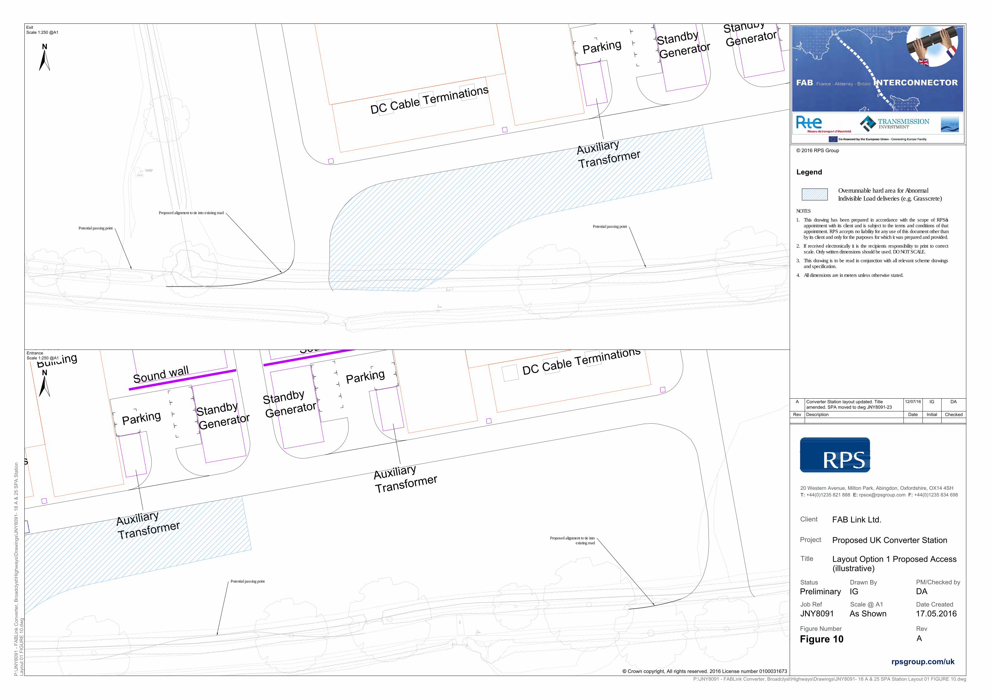
39.68G
39.76G
IL39.09
Corrugated Sheeting
DC Cable Terminations
Auxiliary
Transformer
Standby
GeneratorStandby
GeneratorParking
40.66G
Scar
Control
BuildingDC Cable Terminations
DC Cable Terminations
Auxiliary
Transformer
Auxiliary
Transformer
Standby
GeneratorStandby
GeneratorParking
ParkingSound wall
Sound wall
Legend
Scale @ A1 Date Created
20 Western Avenue, Milton Park, Abingdon, Oxfordshire, OX14 4SHT: +44(0)1235 821 888 E: [email protected] F: +44(0)1235 834 698
Client
Title
Status PM/Checked byDrawn By
Figure Number Rev
Project
2016 RPS Group
Job Ref
Rev Description Date Initial Checked
A Converter Station layout updated. Titleamended. SPA moved to dwg JNY8091-23
12/07/16 IG DA
c
© Crown copyright, All rights reserved. 2016 License number 0100031673
N
FAB Link Ltd.
Layout Option 1 Proposed Access(illustrative)
Proposed UK Converter Station
Preliminary
JNY8091
IG
17.05.2016
Figure 10 A
P:\JNY8091 - FABLink Converter, Broadclyst\Highways\Drawings\JNY8091- 18 A & 25 SPA Station Layout 01 FIGURE 10.dwg
P:\J
NY
8091
- FA
BLi
nk C
onve
rter,
Bro
adcl
yst\H
ighw
ays\
Dra
win
gs\J
NY
8091
- 18
A &
25
SP
A S
tatio
nLa
yout
01
FIG
UR
E 1
0.dw
g
DA
rpsgroup.com/uk
Proposed alignment to tie into existing road
Proposed alignment to tie intoexisting road
ExitScale 1:250 @A1
EntranceScale 1:250 @A1
Overrunnable hard area for AbnormalIndivisible Load deliveries (e.g. Grasscrete)
N
As Shown
NOTES1. This drawing has been prepared in accordance with the scope of RPS’s
appointment with its client and is subject to the terms and conditions of thatappointment. RPS accepts no liability for any use of this document other thanby its client and only for the purposes for which it was prepared and provided.
2. If received electronically it is the recipients responsibility to print to correctscale. Only written dimensions should be used. DO NOT SCALE.
3. This drawing is to be read in conjunction with all relevant scheme drawingsand specification.
4. All dimensions are in meters unless otherwise stated.
Potential passing point
Potential passing point Potential passing point

December 2016
FIGURE 11
Converter Station Layout Option 2 Proposed Access
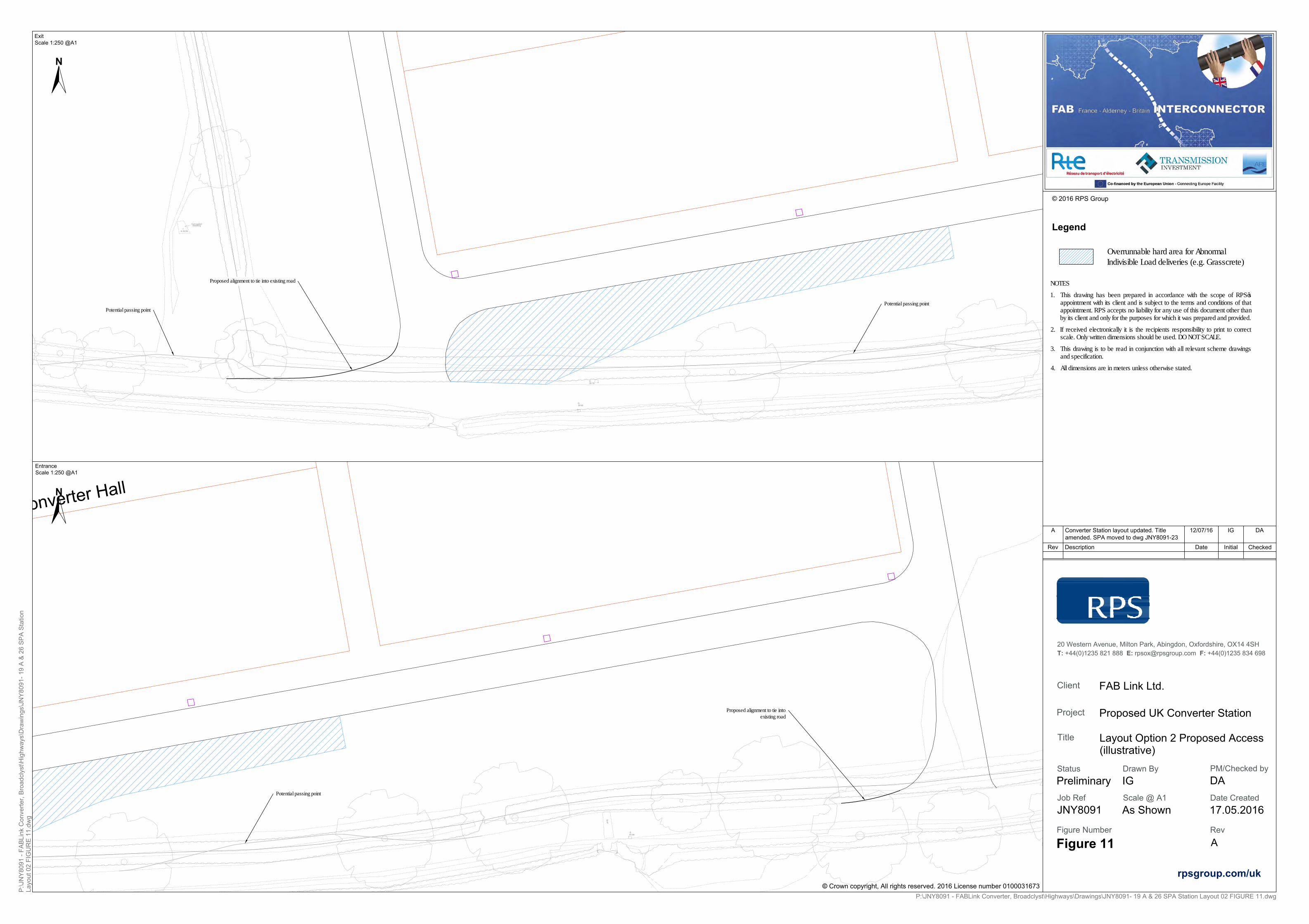
39.68G
39.76G
IL39.09
Corrugated Sheeting
40.66G
Scar
Converter Hall
Legend
Scale @ A1 Date Created
20 Western Avenue, Milton Park, Abingdon, Oxfordshire, OX14 4SHT: +44(0)1235 821 888 E: [email protected] F: +44(0)1235 834 698
Client
Title
Status PM/Checked byDrawn By
Figure Number Rev
Project
2016 RPS Group
Job Ref
Rev Description Date Initial Checked
A Converter Station layout updated. Titleamended. SPA moved to dwg JNY8091-23
12/07/16 IG DA
c
© Crown copyright, All rights reserved. 2016 License number 0100031673
N
FAB Link Ltd.
Layout Option 2 Proposed Access(illustrative)
Proposed UK Converter Station
Preliminary
JNY8091
IG
17.05.2016
Figure 11 A
P:\JNY8091 - FABLink Converter, Broadclyst\Highways\Drawings\JNY8091- 19 A & 26 SPA Station Layout 02 FIGURE 11.dwg
P:\J
NY
8091
- FA
BLi
nk C
onve
rter,
Bro
adcl
yst\H
ighw
ays\
Dra
win
gs\J
NY
8091
- 19
A &
26
SP
A S
tatio
nLa
yout
02
FIG
UR
E 1
1.dw
g
DA
rpsgroup.com/uk
Proposed alignment to tie into existing road
Proposed alignment to tie intoexisting road
ExitScale 1:250 @A1
EntranceScale 1:250 @A1
Overrunnable hard area for AbnormalIndivisible Load deliveries (e.g. Grasscrete)
N
As Shown
NOTES1. This drawing has been prepared in accordance with the scope of RPS’s
appointment with its client and is subject to the terms and conditions of thatappointment. RPS accepts no liability for any use of this document other thanby its client and only for the purposes for which it was prepared and provided.
2. If received electronically it is the recipients responsibility to print to correctscale. Only written dimensions should be used. DO NOT SCALE.
3. This drawing is to be read in conjunction with all relevant scheme drawingsand specification.
4. All dimensions are in meters unless otherwise stated.
Potential passing point
Potential passing pointPotential passing point

December 2016
APPENDICES

December 2016
APPENDIX 1
List of Site Selection Reports

APPENDIX 1 LIST OF SITE SELCTION REPORTS
A. FAB Link Connection Options Study (the TI report), June 2016
B. HVDC Converter Station Site Selection Process Report, August 2015
C. Landfall Selection Process Report, July 2016
D. Cable Corridors Selection Process Report, July 2016

APPENDIX 1A
FAB Link Connection Options Study (the TI report), June 2016

14th June 2016
FAB Link Connection Options Study
FAB France Alderney Britain
Interconnector

FAB Link Connection Options Study
14th June 2016 2 FAB_Connection Point Selection Report_FINAL
{Intentionally left blank}

FAB Link Connection Options Study
14th June 2016 3 FAB_Connection Point Selection Report_FINAL
1 Contents 2 Benefits of and need for additional interconnection ..................................................................... 6
2.1 The benefits of electricity interconnection ............................................................................. 6
2.1.1 Economic ......................................................................................................................... 6
2.1.2 Environmental ................................................................................................................. 6
2.1.3 Energy Security ............................................................................................................... 7
2.2 The need for additional electricity interconnection ............................................................... 7
2.2.1 Competitiveness .............................................................................................................. 8
2.2.2 Sustainability ................................................................................................................... 8
2.2.3 Security ........................................................................................................................... 8
3 European and Government Support for infrastructure development ........................................... 9
3.1 EU Support .............................................................................................................................. 9
3.2 UK support ............................................................................................................................ 10
3.3 France support ...................................................................................................................... 11
3.4 Channel Islands & Alderney support ..................................................................................... 12
4 Description of the project ............................................................................................................. 13
4.1 The trading of electricity between the high voltage electricity grids in Britain and France . 13
4.1.1 AC v DC .......................................................................................................................... 13
4.1.2 Use of high voltage cables ............................................................................................ 14
4.2 The connection of proposed tidal generation in the waters around Alderney .................... 14
4.3 The main components of the FAB Link interconnector ........................................................ 14
4.3.1 High voltage DC electricity cables offshore .................................................................. 14
4.3.2 High Voltage Direct Current (HVDC) electricity cables onshore ................................... 15
4.3.3 AC/DC converter stations in Britain, France and Alderney ........................................... 16
4.3.4 AC onshore cables from the converter stations to substations in Britain and France . 16
4.3.5 Minor works at existing onshore substations ............................................................... 16
5 Connection options ....................................................................................................................... 17
5.1 Introduction and Approach ................................................................................................... 17
5.2 Step 1 – Identifying Potential Connection Options ............................................................... 19
5.2.1 The Existing NETS and Substations ............................................................................... 19
5.2.2 Identifying Sites Close to the South Coast .................................................................... 20
5.2.2.1 West and Southwest ................................................................................................. 20
5.2.2.2 Southampton/Portsmouth ........................................................................................ 21
5.2.2.3 Further East ............................................................................................................... 21

FAB Link Connection Options Study
14th June 2016 4 FAB_Connection Point Selection Report_FINAL
5.2.3 Other Alternatives Further Inland ................................................................................. 21
5.3 Step 2 – Review of Initial Connection Options ...................................................................... 22
5.3.1 Coastal Sites .................................................................................................................. 22
5.3.2 Environmental Ranking of Coastal Sites ....................................................................... 24
5.3.3 Inland sites .................................................................................................................... 25
5.3.4 Potential New Substation Sites ..................................................................................... 25
5.4 Step 3 –Economic and Environmental Assessment of Options ............................................ 25
5.4.1 Economic assessment ................................................................................................... 25
5.4.1.1 Review of sites capacity for Import to GB and Export to France .............................. 25
5.4.1.1.1 Import to GB ....................................................................................................... 25
5.4.1.1.2 Export to France .................................................................................................. 26
5.4.1.2 Cost Assessment for Connection Options ................................................................. 29
5.4.1.3 Costs of Onshore Grid Reinforcements .................................................................... 29
5.4.1.4 Cost per km of FAB Link Onshore and Offshore Cables ............................................ 30
5.4.1.5 Cost of Export from GB limitation ............................................................................. 31
5.4.1.6 Cost Comparison of Sites .......................................................................................... 32
5.4.2 Environmental Assessment of Options ......................................................................... 32
5.4.3 Other Considerations and Preferred Option Selection ................................................. 33
5.4.4 Conclusion ..................................................................................................................... 34
5.5 Step 4 – Environmental and Site Opportunities Assessment ............................................... 34
6 Summary and conclusion .............................................................................................................. 36
7 References .................................................................................................................................... 39

FAB Link Connection Options Study
14th June 2016 5 FAB_Connection Point Selection Report_FINAL
1 Introduction FAB (France-Alderney-Britain) Link is a proposed 1,400 MW subsea interconnector cable connecting France and Great Britain via the Channel Island of Alderney. The interconnector is being developed by Transmission Investment, together with the French grid company RTE (Réseau de Transport d’Électricité) and Alderney based tidal power developer Alderney Renewable Energy (ARE). FAB Link Limited is a joint venture between Transmission Investment and ARE. FAB Link Limited will own the assets in Alderney and Britain (the subject of this report) and RTE will own the assets in France.
Any interconnector on the scale of FAB Link can only connect to the electricity system in Great Britain by connection to the high voltage National Electricity Transmission System (NETS) operated by National Grid Electricity Transmission (‘National Grid’). In 2012 FAB Link Limited, in conjunction with National Grid, selected the NETS substation east of Broadclyst near Exeter as the most suitable UK connection point.
The purpose of this report is to set out the considerations taken into account by FAB Link leading to the selection of Exeter in 2012.
Following the selection of Exeter, in November 2012 FAB Link Limited formally applied to and subsequently entered into a connection agreement with NGET for the connection of FAB Link to the NETS at Exeter.
The work leading to the selection of the Exeter in 2012 was originally reported in March 2013i. This report reviews and updates the 2013 report and, where possible, takes into account material considerations that may have changed since the selection decision was taken in 2012. This has not been possible in every instance, due to the complex nature of the NETS system and its continuously developing nature. However, both FAB Link Limited and NGET consider that the basis of the decision made in 2012 remains valid.

FAB Link Connection Options Study
14th June 2016 6 FAB_Connection Point Selection Report_FINAL
2 Benefits of and need for additional interconnection Britain currently has electricity interconnectors with Ireland (with both Northern Ireland and the Republic of Ireland), and continental Europe (specifically with France and the Netherlands). These interconnectors provide a means of transferring electrical power between the exporting country and the importing country, and typically they are “two-way” interconnectors (i.e. either country can be the country importing or exporting electricity at any one time).
2.1 The benefits of electricity interconnection These interconnectors provide economic, environmental and security of supply benefits to both countries.
2.1.1 Economic Interconnectors allow for higher cost electricity generation in the importing country to be replaced by lower cost electricity generated in the exporting country. This results in a lower cost of electricity overall, and in particular in the importing country. The lower cost of electricity should result in lower electricity prices for consumers.
Analysis undertaken by National Gridii has estimated the impacts on wholesale electricity prices resulting from the doubling of Britain’s current interconnection capacity from about 5% of existing electricity generation capacity to align with the 10% European Commission benchmark. National Grid estimated that each 1GW of new interconnector capacity could reduce Britain’s wholesale power prices up to 1-2%. In total 4-5GW of new links built to mainland Europe could unlock up to £1 billion of benefits to energy consumers per year, equating to nearly £3 million per day by 2020. This benefit will arise because the analysis expects British wholesale electricity prices to remain higher than those in neighbouring countries into the early 2020s, benefiting British consumers through net imports.
As well as providing lower cost electricity, interconnectors can also provide services to the operators of the electricity systems that they interconnect. These services are to a large extent required because electricity cannot be stored and so the production (generation) of electricity has to be very closely matched to the supply of electricity on a second-by-second basis. These services (typically called “Ancillary Services”) include:
Black Start – the ability to provide electricity into a system that is shut-down (“blacked out”) to enable it to return to a normal state
Frequency Response – the ability to provide varying amounts of electricity in response to the varying frequency of the system (e.g. in Britain deviations from the set point, nominally 50Hz)
Reserve – holding capacity back in case it is needed in response to a system event (such as a sudden increase in demand or failure of a generating unit).
Interconnectors can provide these services at a lower cost than other providers (typically generators), thereby further reducing costs to consumers.
2.1.2 Environmental Interconnectors can provide environmental benefits in several ways:

FAB Link Connection Options Study
14th June 2016 7 FAB_Connection Point Selection Report_FINAL
They can allow high carbon generation in one (importing) country to be displaced by low carbon generation in another (exporting) country – this is very relevant for the FAB Link interconnector which should allow high carbon fossil fuel generation in Britain (e.g. unabated coal-fired or gas-fired generation) to be replaced by low carbon nuclear generation from France;
They enable the volatility in generation output that arises from renewable (and therefore low carbon) sources of generation such as onshore and offshore wind, solar and tidal generation, to be smoothed by connecting these sources across wider geographic regions subject to different weather patterns and tides – again this will be relevant for the FAB Link interconnector which will provide additional connection between the significant amounts of wind and solar generation in Britain and Ireland with that in continental Europe;
They can facilitate the connection and integration of renewable sources of generation. In the specific case of the FAB Link interconnector this will enable the connection and integration (providing a route to market) of tidal generation planned to be developed in the waters around Alderney. Alderney has the second largest tidal resource in North West Europe. Independent estimates of the energy that could be harvested using current technology from tidal flows within the 3nm limit range from 1GW to 3GW1 iii.
2.1.3 Energy Security Interconnectors provide access to another source of electricity and so reduce the probability that there will be insufficient electricity to meet consumers’ demand for it.
The ability of an interconnector to contribute effectively to energy security depends on a number of factors, including the reliability of the interconnector technology and the probability that the exporting country will have excess generation capacity itself at times of need.
The UK government recognises the contribution that interconnectors make to energy security through awarding capacity contracts to interconnectors through the capacity market. In the first capacity market auction in which interconnectors were eligible (held in 2015) interconnectors to France were set a 60% “country flow” de-rating factoriv (effectively saying that a fully reliable interconnector to France will be 60% as effective as a fully reliable generating unit in Britain in contributing to energy security at the critical times).
2.2 The need for additional electricity interconnection Britain has had a relatively self-sufficient electricity supply system since its inception at the beginning of the last century. Until the interconnector with Northern Ireland went into service in 2001, Britain was only connected to one other country (France) and that by an interconnector commissioned in 1985. Britain currently has electricity interconnectors with Northern Ireland, the Republic of Ireland, France and the Netherlands.
There is however a need for additional interconnection, driven by challenges that the British and wider European energy system face. These challenges, often termed the energy trilemma, are of competitiveness, sustainability and security. Interconnectors, and the benefits they provide, can assist in meeting those challenges:
1 1 GW = 1,000MW = 1,000,000 kW

FAB Link Connection Options Study
14th June 2016 8 FAB_Connection Point Selection Report_FINAL
2.2.1 Competitiveness Remaining economically competitive in an increasingly global market for goods and services has become a priority for the European Union and its member states. This often translates into reducing costs and this includes the cost of electricity. Additional electricity interconnection can reduce the cost of electricity (as set out in 2.1.1 above) and therefore assist the EU in meeting its goal to be competitive.
2.2.2 Sustainability The need to reduce greenhouse gas emissions in order to limit global temperature rises has resulted in the growth of significant volumes of low carbon generation and plans for considerably more. Much of this generation is variable in nature and often is remote from or at the extremity of the established high voltage grid. Interconnectors can both assist with smoothing the variability of renewable generation across different geographies and facilitate the connection and integration of renewables (see 2.1.2 above).
2.2.3 Security Incidences such as restrictions to gas supplies by Russia have brought a focus onto the security of Europe’s energy supply.
Electricity security in Britain, the ability to meet peak electricity demand, has been reduced through several factors:
The closure of controllable fossil fuel generation (for economic or regulatory reasons) The closure of nuclear plant as it reaches the end of its asset life The replacement of the above with large scale renewables with varying output The lack of new controllable plant being constructed (either for economic reasons or the time
it takes to permit, finance and build).
Whilst shorter term measures are also being used, in the longer term the UK government’s response to this is the market for capacity, which is intended to provide the necessary incentives to keep open existing capacity and to construct new capacity so as to be able to meet peak demand. Additional interconnection capacity is one form of capacity that the government is seeking to incentivise to assist it in meeting the security challenge (see section 2.1.3 above).

FAB Link Connection Options Study
14th June 2016 9 FAB_Connection Point Selection Report_FINAL
3 European and Government Support for infrastructure development Governments at the European and national levels have recognised the benefits that greater electricity interconnection can bring.
3.1 EU Support In 2002, the European Council set a target that all Member States should have electricity interconnections equal to at least 10% of their generation capacity by 2005v.
This target has proven to be difficult to meet, but has been reiterated and recently increased. At the invitation of the March 2014 European Council, the Commission proposed in May 2014 to extend the current 10% electricity interconnection target to 15% by 2030. The October 2014 European Council mandated the Commission to report regularly to the European Council with the objective of arriving at a 15% target by 2030. This target is aimed to be achieved mainly through the implementation of Projects of Common Interest (PCIs)vi.
PCIs have been established by the Infrastructure Regulation as projects which comply with common, transparent and objective criteria in view of their contribution to the energy policy objectivesvii. The Union published the first list in 2013viii. A new EU list is established every two years.
The Infrastructure Regulation sets out the benefits that being designated as a PCI should bestow, inter
alia, as:
- PCIs should be implemented as quickly as possible and should be closely monitored and evaluated, while keeping the administrative burden for project promoters to a minimum;
- Permit granting processes should neither lead to administrative burdens which are disproportionate to the size or complexity of a project, nor create barriers to the development of the trans-European networks and market access.
- The establishment of a competent authority or authorities integrating or coordinating all permit granting processes (‘one-stop shop’) should reduce complexity, increase efficiency and transparency and help enhance cooperation among Member States
- PCIs should be eligible to receive Union financial assistance for studies and, under certain conditions, for works as soon as such funding becomes available under the relevant Regulation on a Connecting Europe Facility in the form of grants or in the form of innovative financial instruments.
The FAB Link interconnector was included in the first PCI list published in 2013 and has been retained in the second list published in 2015.
In order to be eligible for inclusion in the second and subsequent Union lists, projects should be part of the latest available ENTSO-E 10-year network development plan. The FAB Link interconnector is also included in the most recent (2014) ENSTO-E ten year network development planix and again is expected to be included when this is revised in 2016. The inclusion of the FAB Link interconnector in the PCI list and the network development plan is indicative of the importance of the interconnector at a European level.

FAB Link Connection Options Study
14th June 2016 10 FAB_Connection Point Selection Report_FINAL
3.2 UK support The UK government supports greater interconnection between Great Britain and other European Countries. It summarised its support for this and the measures it was taking to promote this in a document published in December 2013x. In this document DECC states that:
“Government supports appropriate further interconnection
3. Interconnection has the potential to contribute to Government’s energy security,
affordability and decarbonisation objectives, including through facilitating the single European
electricity market. Government supports an appropriate increase in interconnection capacity
through projects that efficiently deliver on these objectives.
4. Evidence commissioned by Government, [published alongside this document,] shows that
more interconnection than we currently have is likely to be in GB’s interest. Under some
scenarios, GB consumers could see benefits to 2040 of up to £9billion (net present value).
5. It is clear from the analysis that GB’s security of supply would be enhanced by further
interconnection, providing that electricity prices reflect scarcity and interconnector flows
reflect prices. Interconnection is also one of the technologies that can assist with the
integration of further low-carbon generation.
6. Government is already taking action and recently supported projects to Norway, Belgium,
France and the Republic of Ireland to become European Projects of Common Interest (PCI).
Government is also seeking views, through the current Electricity Market Reform (EMR)
consultation, on how non-GB interconnected capacity might participate in the GB capacity
market in time for the 2015 auction, in recognition of the potential for further interconnection
to contribute to security of supply.”
Since this document was published the government has taken steps to allow interconnectors to take part in the capacity market in 2015 (and subsequent years) through an amendment to the Capacity Market Rulesxi. This enables interconnectors to take part in capacity market auctions and if successful in those auctions to be paid for the contribution to system security they make. The government has also supported Ofgem2 in developing and implementing a regulatory regime which will provide revenue support to interconnectors to enable them to be financed through construction and into operationxii.
The government recognition that interconnection would assist in the integration of renewables through compensating for the intermittency of renewable generation is also noted in the Overarching National Policy Statement for Energyxiii.
UK government support specifically for the FAB Link interconnector is also evidenced by a letter received from the Minister for Energy dated 6th August 2015 which states that:
“… the Government is committed to increasing electricity interconnection and is very keen to
see good quality interconnection projects come forward which can deliver significant savings
2 Ofgem is the Office of Gas and Electricity Markets. Ofgem is a non-ministerial government department and an independent National Regulatory Authority, recognised by EU Directives. Its principal objective when carrying out its functions is to protect the interests of existing and future electricity and gas consumers.

FAB Link Connection Options Study
14th June 2016 11 FAB_Connection Point Selection Report_FINAL
for the GB consumer and make a positive contribution to security of supply. I was therefore
very pleased to see that Ofgem has now confirmed initial approval for the FABLink
interconnector project to be regulated under the cap and floor …”.
Ofgem regulates investment in new interconnector infrastructure either as merchant projects or in a system known as the cap and floor regime. Cap and floor projects are submitted by project promoters to Ofgem for assessment in the interests of consumers. Ofgem has accepted FAB Link into the cap and floor regime.
3.3 France support In France there is a strong support for the development and construction of new electricity interconnectors to neighbouring countries. As the monopoly transmission system owner and operator in France, Réseau de Transport d’Électricité (RTE) has the legal responsibility for developing, constructing and owning the parts of interconnectors in France and within French territorial waters. RTE’s plans for the capital expenditure on the development of its system, and the consequential need to ultimately recover this investment from consumers, are regulated by the French energy regulator, the Commission de Régulation de l'Énergie (CRE).
In respect of interconnector projects, the CRE reviews and approves these through its annual review and approval of the French Ten Year Network Development Plan (TYNDP). The strength of the commitment in France to new interconnection can be seen in the 10,000MW of new interconnection capacity that is included and has therefore been approved within the current French TYNDP, including FAB Link.
At a political level the French government expressed support for more interconnectors between France and Britain at the Franco-British summit meeting held in Paris on 17th February 2012 at which the French Energy Minister, Eric Besson, and the UK Secretary of State for Energy and Climate Change, Ed Davey, signed a Franco-British declaration of energy which included the follow statementxiv:
“We acknowledge the importance of developing new electricity interconnectors between our
two countries in order to strengthen further the linking of our grids, improve the security of
our energy supplies and facilitate the integration of intermittent energy sources. We
encourage further studies to be undertaken on the interconnector projects currently under
consideration, namely the … FAB Link (France-Alderney-Britain) … “
In February 2013 the French government, along with the British government, supported the application by the FAB Link project to become a Project of Common Interest.
In July 2014 the French government (via the Ministry for Ecology) yet again supported the project in its application for funding under the Connecting Europe facility.
More recently in October 2015 the French Minister of Ecology, Ségolène Royal, expressed support for the development of interconnectors in Europe by referring to the 10% goal at a conference organised by the French Union of Electricity (UFE).
In March 2015, the French Ministry of Energy approved the cable route corridor for which environmental assessment will be carried out prior to submission of the planning application in France. This shows strong support for the project and its proposed routing in France and French territorial waters.

FAB Link Connection Options Study
14th June 2016 12 FAB_Connection Point Selection Report_FINAL
3.4 Channel Islands & Alderney support There is strong support from the government of the States of Alderney for the proposed interconnector, as it will facilitate the development of tidal energy resources in Alderney waters, provide increased bandwidth and more reliable telecoms links to the island and potentially cheaper and more reliable supplies of electricity. A statement of support was received dated 26th November 2015xv which states the following:
“The Government of the States of Alderney is firmly in support of the FAB interconnector. It has
recently entered into a legally binding agreement with FAB to facilitate the laying of the necessary
cable works both on-shore and off-shore. The close working relationship between the States and
Alderney Renewable Energy is testament to the island’s commitment to the Tidal energy Project,
which is a major driver for the FABlink in Alderney. Moreover it is proof of the Government’s
commitment to working in partnership with its near neighbours in the larger jurisdictions of the
UK and France to assist them in securing resilient and reliable energy sources for its populations.”

FAB Link Connection Options Study
14th June 2016 13 FAB_Connection Point Selection Report_FINAL
4 Description of the project This section describes the components of the project necessary:
i) To enable the trading of electricity between the high voltage electricity grids in Britain and France; and
ii) For the connection of proposed tidal generation in the waters around Alderney.
In essence the FAB Link project will be a controllable electricity link between the British and French grids which will be able to transmit electricity in either direction such that at any time it can deliver up to 1400MW of electricity to the British or French grids. In addition it will also be able to take power from tidal generation facilities constructed in the waters around Alderney and, subject to the 1400MW limit, deliver that to the power grids of Britain and/or France.
4.1 The trading of electricity between the high voltage electricity grids in Britain and
France The trading of electricity between the high voltage electricity grids in Britain and France requires an electricity connection to be made between these grids. At least part of the route of this connection would need to be effected by subsea electricity cables to cross the channel.
4.1.1 AC v DC Electricity can be generated and transmitted either as alternating current or direct current:
i) Alternating Current (AC) in which electrical current changes direction and then changes back periodically even whilst the direction of power flowed is maintained;
ii) Direct Current (DC) in which the direction of electrical current is constant for a given direction of power flow.
The British and French grids are AC systems in which the direction of current changes (and then changes back) on average fifty times a second (in practice the frequency at which this change occurs varies slightly from second to second in line with small imbalances in electricity supply and demand).
Electrically connecting the British and French AC grids with an AC interconnector (i.e. a simple cable connection between the two grids) is not technically and economically feasible as:
i) The British and French grids are not “synchronized”, i.e. the current reversals are not happening at the same times – without this synchronization, power cannot be successfully transmitted between the grids with an AC interconnector; and
ii) The capacity of AC underground or subsea cables to transmit power reduces significantly with distance travelled such that a circa 200km AC interconnector would not be an economic means to transmit power between Britain and France.
However, the interconnection can be effected by use of a DC interconnector by converting the AC into DC, transmitting power using DC across the channel, and then converting it back to AC. The conversion of AC to DC and then back again is carried out in an AC/DC converter station.

FAB Link Connection Options Study
14th June 2016 14 FAB_Connection Point Selection Report_FINAL
A DC interconnector does not have the drawbacks of an AC interconnector as it does not require synchronization of the two AC grids nor does the capacity of DC underground or subsea cables significantly reduce with distance travelled.
The FAB Link interconnector therefore plans the use of AC/DC converter stations in Britain and France, and DC cables between these converters stations in order to trade power between Britain and France.
4.1.2 Use of high voltage cables The transmission of electricity results in electrical losses which emanates from electrical equipment in the form of heat. The losses are proportional to the square of the current flowing through the electrical equipment, whilst the power transmitted is proportional to the current multiplied by the voltage of the electrical equipment. Losses can therefore be reduced for a given power transmission capability by having a higher voltage and a lower current.
The FAB Link project therefore plans to utilise high voltage cables to transmit power between Britain and France.
4.2 The connection of proposed tidal generation in the waters around Alderney There is a potential for many thousands of MW of tidal energy to be generated from the waters around Alderney. The first project has a planned capacity of circa 300MW. This is far in excess of the circa 2MW electricity demand on the island of Alderney and so the vast majority of the electricity generated from the waters around Alderney would need to be exported to Britain or France.
The FAB Link project will enable this. It is expected that the electrical power generated from the waters around Alderney will be AC and so an AC/DC converter station will be required to convert this power to DC in order for it to be transmitted along the DC cables to Britain and/or France.
4.3 The main components of the FAB Link interconnector The main components of the FAB Link interconnector are shown on the figure below and are described further in the sections below.
4.3.1 High voltage DC electricity cables offshore As described above, the FAB Link project proposes to use high voltage DC cables to transmit power between Britain and France. Two pairs of two cables (in each pair) will be used to achieve the capacity required of 1400MW. Each pair of cables will operate with one cable at a nominal operating voltage of +320kV and one at -320kV. The voltage choice of +/-320kV was selected to achieve the lowest electrical losses and economies of scale whilst still selecting proven technology.

FAB Link Connection Options Study
14th June 2016 15 FAB_Connection Point Selection Report_FINAL
Each pair of cables is expected to be bundled on-board the cable lay vessel prior to being installed (although the final decision as to whether to install as a bundled pair or to lay each separately has yet to be taken). Installation will be by burial in the sea-bed or by placement on the sea-bed surface and subsequent protection. If protection is required after cable installation this would be through placing, rocks, concrete mattresses or other similar hard substances on the cable.
The two pairs of cables are expected to be laid up to 600m apart along the majority of their route (coming closer together as they approach the shore).
The cable technology is likely to be cross-linked polyethylene (XLPE) or mass impregnated (MI). Examples of such cables are shown in the figure below.
Typical Mass-Impregnated Submarine Power Cable
Example of XLPE Submarine Cable from ABB
The offshore cable route will run from the East Devon coast in England to Corblets beach on the north Alderney coast and from Longy Bay on the south Alderney coast to La Plate on the west coast of the Contentin (or Cherbourg) peninsula in Normandy, France.
4.3.2 High Voltage Direct Current (HVDC) electricity cables onshore Onshore high voltage DC cables will be required between the shore landing points and the AC/DC converter stations. The onshore DC cables will be laid in trenches between “transition pits” at each landfall location to the relevant converter station. The “transition pits” are underground chambers at which the offshore cables are joined to the onshore cables. The onshore DC cables will be of a similar design to the offshore cables.
The onshore cables will therefore run:
In Britain from the East Devon coast to the British converter station location near Exeter Airport;
In Alderney from Corblets beach on the north coast and to Longy Bay on the south coast via the proposed Alderney converter station site at Mannez Quarry; and
In France from La Platé on the west coast of the Contentin peninsula to the French converter station location at Menuel to the east of Bricquebec.

FAB Link Connection Options Study
14th June 2016 16 FAB_Connection Point Selection Report_FINAL
4.3.3 AC/DC converter stations in Britain, France and Alderney Conversion of AC current to DC and vice-versa is carried out by mean of a high voltage AC/DC converter station. AC/DC converter stations will be required in Britain and France; and in Alderney to connect proposed tidal generation. AC/DC converter stations comprise indoor and outdoor electrical equipment located with a substation compound. The main components are:
Valve halls – indoor equipment used to carry out the conversion from AC to DC and vice-versa; Transformers – usually outdoor and necessary to step up/down the AC connection voltage to
the voltage used by the valve halls; Harmonic filters – electrical equipment used to improve the quality of the electricity may be
required at the AC side of the converter station; Smoothing reactors – equipment that may be used to improve the quality of the electricity at
the DC side of the converter station; Protection and Control equipment – usually housed indoors.
It is expected that the converter stations required for the FAB Link project will be located on sites of about 3.6 hectares (operational area) with buildings of height up to 20m.
4.3.4 AC onshore cables from the converter stations to substations in Britain and France Onshore high voltage AC cables will be required between the AC/DC converter stations and the connection points to the existing high voltage grids in Britain and France (respectively at Exeter 400kV substation and Menuel 400kV substation). These cables will also be at 400kV (matching the voltage of the existing grid and thereby obviating the need for voltage transformation upon connection to the existing grid). Two cabled AC circuits are expected to be required at each end to provide the 1400MW capacity, each cabled circuit will comprise three separate cables making six cables in total.
As with the onshore HVDC cables the HVAC cables will be laid in trenches.
An example of such cables are shown in the figure below.
4.3.5 Minor works at existing onshore substations Minor works will be required to connect the AC cables into the existing 400kV AC substations at Exeter in Britain and Menuel in France. It is expected that these works will be contained within the existing site boundaries.
The FAB Link interconnector does not include any overhead lines.
FAB Link Connection Options Study
14th June 2016 17 FAB_Connection Point Selection Report_FINAL
5 Connection options
5.1 Introduction and Approach Any interconnector or generating station with a capacity of the scale of FAB Link can only connect to the electricity system of Great Britain by connection to the high voltage National Electricity Transmission System (NETS) operated by National Grid Electricity Transmission Plc (“National Grid”). The NETS operates at high voltages of 275 and 400kV (mainly 400kV) and the local distribution networks that provide electricity to all homes and businesses in England, Wales and Scotland at lower voltages are connected to it.
The NETS, and any interconnector or distribution network that connects to it, operates within a commercial environment that is defined in legislation and industry codes and which is overseen by the electricity and gas regulator, Ofgem. The operators of electricity infrastructure within the regulated framework are required to respond to demand from generators and consumers of electricity by developing and maintaining economical and efficient networks whilst having regard to various non-financial considerations as follows.
As a transmission licence holder National Grid has a duty under the Electricity Act 1989 (Section 9) to:
“develop and maintain an efficient, co-ordinated and economical system of electricity
transmission”.
Amendments to Section 4 of the 1989 Act, which were introduced by Section 145 of the Energy Act 2004, provide that a person who participates in the operation of an electricity interconnector without a licence shall be guilty of an offence. FAB Link Limited was issued with a licence on 26 March 2014 authorising FAB Link Ltd to participate in the operation of the FAB Link interconnector. Standard Condition Section F, Clause 19.2 of the licence also requires FAB Link to:
“operate, maintain and develop an economic, efficient, secure and reliable interconnector.”
These criteria are shortened to “economical” after this point.
Both FAB Link Limited and National Grid also have duties under the Electricity Act 1989 (Schedule 9 - Preservation of amenity: England and Wales):
“In formulating any relevant proposals, a licence holder or a person authorised by exemption
to generate, transmit, distribute or supply electricity:
(a) shall have regard to the desirability of preserving natural beauty, of conserving flora, fauna
and geological or physiographical features of special interest and of protecting sites, buildings
and objects of architectural, historic or archaeological interest; and
(b) shall do what he reasonably can to mitigate any effect which the proposals would have on
the natural beauty of the countryside or on any such flora, fauna, features, sites, buildings or
objects.”
In order to develop an electricity interconnector that will operate within this regulatory framework, the developer of the interconnector and the operators of the respective member state transmission systems need to work together to identify options that meet the relevant economic and other criteria.
FAB Link Connection Options Study
14th June 2016 18 FAB_Connection Point Selection Report_FINAL
In this case, the relevant parties are FAB Link Limited and the operators of the transmission systems in France (RTE), and Great Britain (National Grid).
The factors that determine the locations where a suitable grid connection with the NETS might be available for FAB Link include:
i) The location of the existing high voltage grid infrastructure in the south of England; this is shown in Figure 1);
ii) The availability of suitable connection points. It is likely that the most efficient and economical will be at an existing substation (as shown on Figure 1), rather than building a new substation. These are the existing connection nodes where parts of the electricity grid join together and/or generating stations and the distribution networks connect to it. Connecting at one of these existing substations is likely to be the most efficient and economical option because: It makes use of existing high voltage connection infrastructure, which can be shared
between sources of generation and demand; It is more likely to avoid requiring sections of the NETS to be temporarily out of service
(outages) while existing towers and conductors are reconfigured to provide a new substation. All outages on the NETS have to be the subject of long term planning to avoid disruption to consumer supply. For the connection of a new substation, outages might not be possible at all at the times required for the timely delivery of the connection, as a PCI. Alternatively the outages might only be available on one or two fixed occasions, thus making programming of the new works of critical importance and elevating programme risk if there is any delay in consents or construction.
iii) The ‘strength’ of the connection point in terms of the capacity of the grid to import and export electricity to or from GB via the interconnector. The ‘strength’ will depend on the number and capacity of the components (overhead lines, cables, transformers) network at the connection point to transmit electricity. A strong connection point will be able to accommodate the full additional import or export of electricity of the FAB Link interconnector at that point without breaching network component capacity limits. A weaker connection point might not, with the consequential need either to replace or upgrade components (with resultant additional costs) or to restrict the amount of import and /or export allowed (with resultant reduction in interconnection benefit that would otherwise have been possible). As the South Coast area is characterised by high power demand relative to generation and is therefore likely to be able to accept substantial imports from France, importing electricity was not expected to be constrained at any of the connection points considered. The analysis below therefore summarises only those export constraints that were identified.
iv) The need to preserve the natural environment and take into account likely environmental effects in accordance with the duties under Schedule 9 outlined above;
v) The relative financially quantifiable costs and benefits of a connection at a given location, including the length and costs of the interconnector, the cost of any new infrastructure required at the connection point and the cost of any other reinforcement of the grid required to accommodate the new import and/or export capacity; and,
vi) Other considerations such as the availability of land to accommodate the connection infrastructure and cable routes.

FAB Link Connection Options Study
14th June 2016 19 FAB_Connection Point Selection Report_FINAL
In the first instance the FAB Link connection options study focused on the existing substations on the NETS. Looking at these connection points also allowed the relevant characteristics of parts of the NETS to be determined for the operational purposes of FAB Link.
Having regard to these factors the approach adopted involved the following steps3.
Step 1 The potential options were identified based on the location of existing infrastructure and connection points
Step 2 These potential options were then subject to a high level appraisal of their relative merits in terms of grid connection in order to identify the locations which were likely to best meet the duties of National Grid and FAB Link Limited.
Having identified those parts of the grid NETS that might offer suitable connection capacity, the possible advantages of new connection points (i.e. locations other than existing 400kV or 275kV substations) were also considered.
Step 3 The likely options identified in Step 2 were then subject to detailed appraisal of the relative costs and benefits of the required transmission infrastructure and other considerations in order to identify the most feasible grid connection options.
Step 4 The most feasible grid options were then subject to further studies of environmental constraints and the availability of feasible sites for a converter station.
5.2 Step 1 – Identifying Potential Connection Options
5.2.1 The Existing NETS and Substations FAB Link will provide a new interconnector with an area of the transmission network in France where there is significant bidirectional transmission capacity, together with the potential to connect renewable energy resources from Alderney. As the project needs to connect to the French network via Alderney, a connection to the GB NETS in southern England would be most efficient and economical.
The assessment undertaken by FAB Link Limited and National Grid to identify and evaluate potential connection options considered reinforcements to the existing NETS, but did not consider new extensions to the NETS (i.e. construction of new overhead lines in southern England). Building new high voltage overhead lines was unlikely to be acceptable taking into account cost, risk, delay and environmental effects unless no economical connections to the existing infrastructure were otherwise available.
The existing NETS and substations in southern England are shown on Figure 1.
3 Steps 1 to 4 here were referred to as ‘Stages 1 to 4’ in the March 2013 report but are referred to here as ‘Steps 1 to 4’ in order to avoid confusion with the terminology that was adopted subsequently for the stages of selection for the UK converter station site. Steps 1 to 4 have also been updated and reviewed in this report.

FAB Link Connection Options Study
14th June 2016 20 FAB_Connection Point Selection Report_FINAL
5.2.2 Identifying Sites Close to the South Coast In consultation with National Grid, FAB Link Limited reviewed the relevant operational characteristics of the network across southern England with a view to deselecting those sites which had no advantages when compared to other sites and could easily be identified as having some clear disadvantages with no compensating advantages. The following factors were considered: distance of cabling required, strength of connection to the NETS and substation layout.
5.2.2.1 West and Southwest
In the west and south west, Exeter was identified as a potential connection opportunity (and is discussed further below). However, no connection options were identified to the west of Exeter as they had clear disadvantages and no clear advantages when compared to Exeter. In particular:
Six circuits on the NETS converge at Exeter providing a relatively ‘strong’ connection point; the strength of connection was weaker at locations to the west of Exeter ;
All the substations to the west of Exeter require significant work in order to provide the “double-busbar configuration” that would allow FAB Link to connect;4
Increasing distance from Alderney and overall connection length at locations further to the west (all would have longer cable lengths than Exeter with the exception of Abham which is only slightly closer to Alderney, does not have a double busbar arrangement and is only connected by four circuits); and
The sites to the west had no clear advantages e.g. in terms of cable lengths, import/export capabilities or lower grid reinforcement costs.
4 The double-busbar design is required for more important substations and for those connecting generation or interconnectors. In most cases provision of a double-busbar connection where one does not currently exist will require either the construction of an entire new double-bus substation alongside the existing substation or complete replacement of the existing substation.

FAB Link Connection Options Study
14th June 2016 21 FAB_Connection Point Selection Report_FINAL
5.2.2.2 Southampton/Portsmouth
There are a number of substations in the Southampton/Portsmouth area including Fawley, Nursling, Marchwood, Chilling5, Botley Wood and Lovedean. In terms of their location on the NETS all of these locations were considered to be broadly similar to Fawley. Fawley was the closest of these locations to Alderney and so Fawley was taken forward for further consideration in the assessment.
5.2.2.3 Further East
As set out below, significant export-from-GB constraints6 exist for any interconnector connecting near the south coast of England as this area is characterised by a high population and energy demand, only modest local generation and has limited connection to the remainder of the NETS. In addition, it already has a 2000MW link to France and there is a proposed 1000MW link to Belgium. These export-from-GB constraints were quantified at Fawley (as set out in Table 3 in section 4.4.1.1.2 below). All of the potential sites to the east of the Fawley/Portsmouth area were found to have a similar or greater degree of export-from-GB constraint relative to Fawley, but moving further east all of the potential sites (e.g. Bolney, Ninfield, Dungeness) were also at progressively greater connection length from Alderney. For these reasons no connection options were considered further to the east of Fawley.
Figure 2 shows the possible connection points considered close to the south coast (the Coastal sub area).
5.2.3 Other Alternatives Further Inland In reviewing the relevant characteristics of the NETS with National Grid, it was apparent that stronger connections could also be achieved by connecting to parts of the NETS that are significantly further
5 Chilling is a cable sealing end compound between Portsmouth and Southampton (for the 400kV cables that run under Southampton Water) rather than a full substation and is therefore not shown on Figure 2. 6 An export –from-GB-constraint is a restriction on the amount of electricity that can be exported from GB to France via an interconnector at any time due to the need to ensure that the capacity of the network is not exceeded. See 4.4.1.1.2 for further detail on this constraint.

FAB Link Connection Options Study
14th June 2016 22 FAB_Connection Point Selection Report_FINAL
inland from the coast. Despite being at greater distances inland, Melksham and Bramley were also included in the assessment because they provided very strong connections to the grid with 8-10 circuits. Figure 3 shows the Inland Sites sub area.
5.3 Step 2 – Review of Initial Connection Options The five potential sites in the Coastal sub area were assessed in detail in Step 2 against the criteria described in 4.3.1 below to determine whether there were any sites that should not be taken forward to leave a smaller number for consideration in Step 3.
5.3.1 Coastal Sites The next stage of the process was to rank the identified potential coastal sites in terms of the following criteria:
Strength of the grid connection (no. of circuits); Strength of the grid connection (export constraints); Distance to Alderney – i.e. cable length and associated cost; Requirement for double-busbar configuration – i.e. cost of the substation upgrade; Environmental issues.
Tables 1A to 1E below set out how the sites compared to the criteria, and the reasons why sites were taken forward or discounted.
Table 1A: Coastal Sites: Strength of Grid Connection (no of circuits)
Site Commentary Rank
Exeter A relatively strong connection point with six 400kV circuits. 1
Fawley &
Mannington
Moderate connection points with four 400kV circuits. =2
Chickerell A moderate connection point with 3* 400kV circuits. 4
Axminster A moderate connection point with 2* 400kV circuits. 5

FAB Link Connection Options Study
14th June 2016 23 FAB_Connection Point Selection Report_FINAL
*: Chickerell and Axminster could be upgraded to 4 circuits.
Table 1B: Coastal Sites: Strength of Grid Connection (export constraints)
Site Commentary Rank
Exeter The location further west (and further away from other interconnectors to continental Europe) reduces the impact of export-from-GB constraints.
1
Chickerell
Mannington
Axminster
Export-from-GB constraints are intermediate in severity between Exeter and Fawley.
=2
Fawley All of the sites in the Fawley to Lovedean area are geographically and electrically close and all suffer similarly from export-from-GB constraints. Analysis undertaken with National Grid (see below) shows these constraints to be severe (see Table 2 below).
5
Table 1C: Coastal Sites: Interconnector Length (Distance to Alderney)
Site Commentary Rank
Chickerell 100km from Alderney 1
Axminster 130km from Alderney 2
Fawley 142km from Alderney 3
Exeter
Mannington
149km from Alderney
150 km from Alderney
=4
Note: as subsea cable routing work has not been undertaken for all of these sites, submarine cable length is based on straight-line distances to a possible landfall location for all sites in order to ensure a fair comparison.
Table 1D: Coastal Sites: Substation Capacity (Double Busbar Available)
Site Commentary Rank
Exeter &
Fawley
Existing Double Busbar =1
Mannington Existing Double Busbar; some modifications required before FAB can connect.
3
Axminster &
Chickerell
Need upgrading to double busbar, or the existing substation needs to be supplemented by an adjacent double-busbar facility solely for the connection of FAB
=4

FAB Link Connection Options Study
14th June 2016 24 FAB_Connection Point Selection Report_FINAL
Table 1E: Coastal Sites: Ranking Overview
Site Commentary
Exeter Rank 1 - Strength of grid connection (No of circuits)
Rank 1 - Strength of grid connection (Export from GB capacity);
Rank 1 - Substation Capacity
Chickerell Rank 1 - Interconnector Length
Fawley Rank 1 - Substation Capacity
Mannington No distinct advantages relative to other connection options
Axminster No distinct advantages relative to other connection options
On the basis of these criteria, three sites within the Coastal sub area were taken forwards for further consideration. These were:
Exeter: on the basis of its combined proximity to Alderney, its existing infrastructure and the strength of its connection relative to other sites;
Chickerell: on the basis that its proximity to Alderney leads to savings in cable length which might outweigh the need for an upgraded substation;
Fawley: on the basis that is the best of the sites in the Southampton/Portsmouth Area due to its proximity to Alderney and the fact that it does not require upgrading of the substation.
Mannington and Axminster were excluded on the basis that they have no distinct advantages relative to the other connection options and fared worse when compared to others in some respects.
5.3.2 Environmental Ranking of Coastal Sites On reviewing Step 2 in 2015, a ranking table was also prepared for environmental issues which had not been considered in detail until Step 4 in 2012. This is set out in Table 1F.
Table 1F: Coastal Sites: Substation Environmental Issues
Site Commentary Rank
Exeter Ranked 1 on environmental issues for all three main criteria i.e. Exeter avoided proximity and/or potential effects on AONB/National Parks; statutory nature conservation designations; and nearby settlements.
1
Mannington
Axminster
Mannington Rank =1 on distance/avoiding effects on AONB/National Park but Ranked =3 and =4 on other categories; Axminster Ranked =4 (worst) for proximity to and AONB/National Park but ranked =1 for national Nature Conservation designations and proximity to settlement.
=2
Chickerell Ranked =4 (worst) for proximity settlement; ranked 3 for proximity to AONB/National Park and =3 for national Nature Conservation designations.
4
Frawley Ranked = 4 (worst) in terms of proximity to AONB/National Parks and Ranked 5 for proximity to statutory nature conservation designations.
5

FAB Link Connection Options Study
14th June 2016 25 FAB_Connection Point Selection Report_FINAL
Table 1F shows that Exeter also ranked first on environmental issues. No distinct environmental advantages were identified in respect of Mannington and Axminster through the ranking of environmental issues relative to the other connection options that would have led to those sites being taken forward.
5.3.3 Inland sites As identified above, the inland sites at Bramley and Melksham were also taken forward for further consideration because the strength of grid connection offered at these locations might potentially outweigh the disbenefits of the longer onshore cables required.
5.3.4 Potential New Substation Sites Some consideration was given to whether a new substation site could be identified that would have advantages over the existing substations at Exeter, Chickerell and Fawley. However, it was concluded that any potential site would have significant disadvantage compared to existing sites in terms of impact on the environment and the cost of works required. In particular:
No new site would offer greater strength of connection than Exeter, Melksham or Bramley; No new site would offer significantly shorter connection distance to Alderney than Chickerell; No potential new substation location provided better use of existing infrastructure than
existing substations; and, Any new substation location would require a new double-busbar substation development; A new substation and any required overhead line diversion or new tower configuration is likely
to have environmental impacts.
Accordingly, no new substation locations were identified for consideration in Step 3.
5.4 Step 3 –Economic and Environmental Assessment of Options The five identified options were then appraised in economic and environmental terms.
5.4.1 Economic assessment The economic factors considered in this part of the appraisal were:
Capacity for import to GB and export to France; Costs associated with onshore grid reinforcements required to support the connection of the
FAB Link Limited project at the identified connection option sites; The cost of providing additional connection infrastructure at substations, where necessary;
and The costs of curtailment of energy flows.
The economic assessment was completed jointly by FAB Link Limited and National Gridxvi.
5.4.1.1 Review of sites capacity for Import to GB and Export to France
5.4.1.1.1 Import to GB
The South Coast area is characterised by high power demand relative to generation and is therefore likely to be able to accept substantial imports from France.
Of the three sites within the coastal sub-area, studies by National Grid indicated that all three sites would have sufficient capacity to accept up to 2000MW from FAB Link.
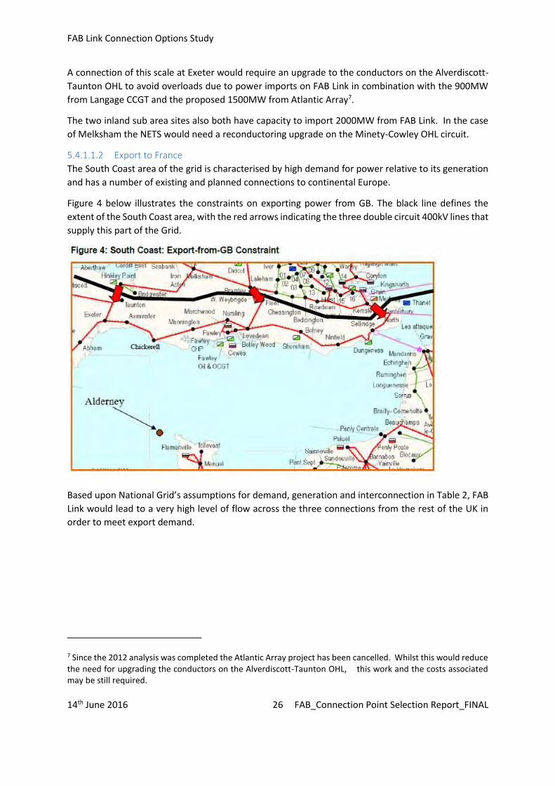
FAB Link Connection Options Study
14th June 2016 26 FAB_Connection Point Selection Report_FINAL
A connection of this scale at Exeter would require an upgrade to the conductors on the Alverdiscott-Taunton OHL to avoid overloads due to power imports on FAB Link in combination with the 900MW from Langage CCGT and the proposed 1500MW from Atlantic Array7.
The two inland sub area sites also both have capacity to import 2000MW from FAB Link. In the case of Melksham the NETS would need a reconductoring upgrade on the Minety-Cowley OHL circuit.
5.4.1.1.2 Export to France
The South Coast area of the grid is characterised by high demand for power relative to its generation and has a number of existing and planned connections to continental Europe.
Figure 4 below illustrates the constraints on exporting power from GB. The black line defines the extent of the South Coast area, with the red arrows indicating the three double circuit 400kV lines that supply this part of the Grid.
Based upon National Grid’s assumptions for demand, generation and interconnection in Table 2, FAB Link would lead to a very high level of flow across the three connections from the rest of the UK in order to meet export demand.
7 Since the 2012 analysis was completed the Atlantic Array project has been cancelled. Whilst this would reduce the need for upgrading the conductors on the Alverdiscott-Taunton OHL, this work and the costs associated may be still required.
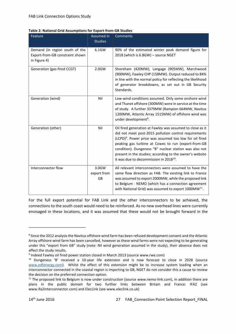
FAB Link Connection Options Study
14th June 2016 27 FAB_Connection Point Selection Report_FINAL
Table 2: National Grid Assumptions for Export-from-GB Studies
Feature Assumed in Studies
Comments
Demand (in region south of the Export-from-GB constraint shown in Figure 4)
6.1GW 90% of the estimated winter peak demand figure for 2018 (which is 6.8GW) – source NGET
Generation (gas-fired CCGT)
2.0GW
Shoreham (420MW), Langage (905MW), Marchwood (900MW), Fawley CHP (158MW). Output reduced to 84% in line with the normal policy for reflecting the likelihood of generator breakdowns, as set out in GB Security Standards.
Generation (wind)
Nil
Low-wind conditions assumed. Only some onshore wind and Thanet offshore (300MW) were in service at the time of study. A further 3379MW (Rampion 664MW, Navitus 1200MW, Atlantic Array 1515MW) of offshore wind was under development8.
Generation (other)
Nil
Oil fired generation at Fawley was assumed to close as it did not meet post-2015 pollution control requirements (LCPD)9. Power price was assumed too low for oil fired peaking gas turbine at Cowes to run (export-from-GB condition). Dungeness “B” nuclear station was also not present in the studies; according to the owner’s website it was due to decommission in 201810.
Interconnector flow
3.0GW export from
GB
All relevant interconnectors were assumed to have the same flow direction as FAB. The existing link to France was assumed to export 2000MW, while the proposed link to Belgium - NEMO (which has a connection agreement with National Grid) was assumed to export 1000MW11.
For the full export potential for FAB Link and the other interconnectors to be achieved, the connections to the south coast would need to be reinforced. As no new overhead lines were currently envisaged in these locations, and it was assumed that these would not be brought forward in the
8 Since the 2012 analysis the Navitus offshore wind farm has been refused development consent and the Atlantic Array offshore wind farm has been cancelled, however as these wind farms were not expecting to be generating under this “export from GB” study (note: Nil wind generation assumed in the study), their absence does not affect the study results. 9 Indeed Fawley oil fired power station closed in March 2013 (source www.rwe.com) 10 Dungeness ‘B’ received a 10-year life extension and is now forecast to close in 2028 (source www.edfenergy.com). Whilst the effect of this extension might be to increase system loading when an interconnector connected in the coastal region is importing to GB, NGET do not consider this a cause to review the decision on the preferred connection option. 11 The proposed link to Belgium is now under construction (source www.nemo-link.com), in addition there are plans in the public domain for two further links between Britain and France: IFA2 (see www.ifa2interconnector.com) and ElecLink (see www.eleclink.co.uk)

FAB Link Connection Options Study
14th June 2016 28 FAB_Connection Point Selection Report_FINAL
timescales required for the operation of FAB Link, it was instead assumed that re-conductoring12 would be employed to where additional transmission capacity is required. Based on reconductoring using the highest capacity conductors technically feasible, the export capacities of the three sites within the Coastal sub-area are shown in Table 3 below.
Table 3: Grid Reinforcements and Capacities at Coastal Options
Connection Option
Reconductoring Required Import to-GB Capacity
Export-from-GB Capacity with reconductoring
Comments
Fawley
Bramley – Fleet (2 circuits)
Fleet – Lovedean (2 circuits)
Feckenham – Minety (1 circuit)
2000MW 260MW 2000MW was largest link size studied.
Chickerell
Bramley – Fleet (2 circuits)
Fleet – Lovedean (2 circuits)
Feckenham – Minety (1 circuit)
2000MW 710MW 2000MW was largest link size studied.
Exeter
Bramley – Fleet (2 circuits)
Fleet – Lovedean (2 circuits)
Feckenham – Minety (1 circuit)
Increase the operating temperature of the Alverdiscot-Taunton circuits to 75°C (or reconductor)
2000MW 1020MW 2000MW was largest link size studied.
Table 3 shows that Exeter would have the largest capacity for export via FAB Link.
For the two Inland area sites, Table 4 shows that both would be able to import or export up to the full capacity of FAB Link Limited.
Table 4: Grid Reinforcements and Capacities at Inland Options
Connection Option
Reconductoring Required Import-to--GB Capacity with reconductoring
Export-from--GB Capacity with reconductoring
Comments
Bramley None
2000MW
2000MW 2000MW was largest link size studied.
Melksham
Minety-Cowley (1 circuit)
2000MW
2000MW 2000MW was largest link size studied.
12 Re-conductoring involves the replacement of existing conductors (the wires that run between the towers on an overhead line) with new conductors of a higher capacity

FAB Link Connection Options Study
14th June 2016 29 FAB_Connection Point Selection Report_FINAL
5.4.1.2 Cost Assessment for Connection Options
The following costs were assessed for each connection option:
Costs of Onshore Grid Reinforcements; Cost per km of FAB Link cable, onshore and offshore; The cost of any ‘Export from GB’ limitation.
5.4.1.3 Costs of Onshore Grid Reinforcements
Two forms of reinforcement could be required:
Reconductoring to increase rating of OHL circuits; Provision of new double busbar substation for any FAB Link connection at Chickerell.
To assess the costs of reconductoring on the NETS required for each option it was noted that the cost of reconductoring would be incurred, in any event, once the existing conductor on these overhead lines needs replacement due to ageing (the typical life expectancy of overhead line conductor is 60 years). The cost analysis therefore took into account the present cost of bringing forward the reconductoring work from the date that it would otherwise take place.
Table 5 shows the estimated cost of the reconductoring of each relevant OHL circuit. Costs are stated in euro for compatibility with cost estimates of the FAB cables and estimates of energy trading value, both of which are in euro.
Table 5: Grid Reinforcement Net Present Costs
Circuit(s) Length Year installed (existing conductor)
Years early (i.e. difference between 2017 and year when existing conductor would be 60 years old)
Net present cost of advancing the reconductoring (€m)
Feckenham-Minety (1 circuit)
79km 1986 29 €31m
Cowley-Minety (1 circuit)
30km
70km
1986
1969
29
12
€28m
Bramley – Fleet (2 circuits)
18km x 2 1968 11 €9m
Fleet – Lovedean (2 circuits)
39km x 2 1988 31 €32m
Alverdiscott – Taunton (2 circuits). Modify for operation at 75°C conductor temperature
72km x 2
1990
€7m (based on €50k/circuit-km for survey, analysis and retensioning or reconductoring where necessary)
In addition to this, the estimated cost of the substation work which would be required at Chickerell would be between €17m and €33m.

FAB Link Connection Options Study
14th June 2016 30 FAB_Connection Point Selection Report_FINAL
5.4.1.4 Cost per km of FAB Link Onshore and Offshore Cables
Each potential connection point would require a different length of onshore cable. A margin of error was also built in13. In addition, for some connection points the FAB Link converter station might be some distance from the connection point with an AC cable being used to connect the two. The costs of the AC cable connection would be approximately three times that of the HVDC cable.
It was assumed that the onshore cables would be routed along roads in order to reduce consenting and land ownership constraints. It was acknowledged that slightly shorter routes would be possible if the route was to be routed through the countryside but it was assumed this would not have a material effect upon the overall cost for the purposes of this assessment.
The costs included allowance for cable laying but did not include any costs associated with acquisition of land or easements, street works or planning consents.
The potential offshore cable routes are shown in Figure 5 below:
13 It was assumed that the cable cost will be:
Offshore cable: €1.6m/km +/- €0.3m/km Onshore cable: €1.3m/km +/- €0.2m/km
(These costs are based on a cable rating of 1400MW, which is in the centre of the 1000-1800MW range being investigated by FAB Link Ltd. A sensitivity study by FAB Link Limited confirmed that changing the cable rating within this range will not materially change the conclusions of the quantitative economic assessment of the options).

FAB Link Connection Options Study
14th June 2016 31 FAB_Connection Point Selection Report_FINAL
The two western routes would be options to Exeter, the central route would serve Chickerell and Melksham, and the eastern route would serve Bramley. Fawley could be served by either the eastern route or by extending the eastern route up the Solent. Table 6 below shows the relative cable length and costs.
Table 6: Cable Lengths from Alderney to GB Connection Points
Connection Site km from Alderney to GB landfall (km)
km onshore GB cable (km)
Part of onshore cable that is AC (km)
Cost of cable at benchmark price (€m)
Fawley 140 5 Negligible 231
Chickerell 106 3 Negligible 174
Exeter 137 21 0-4 247-257
Melksham 106 105 Negligible 306
Bramley 122 91 2-7 319-332
5.4.1.5 Cost of Export from GB limitation
In order to estimate the true cost it was necessary to factor in the opportunity costs of the restriction in power exported to France. The restriction would have less impact than might be expected because analysis has shown that the benefits of the FAB Link interconnector would result predominantly from the import of power from France to Britain. Analysis carried out by the project developers showed that the available Britain-to-France export capacity would have a value of €200m per GW based on weighted scenarios for the future economic benefit from trading on the link. Analysis by RTE has also shown that there would be an overriding restriction on importing power into France leading to an average maximum import capacity of 1100MWxvii. Table 7 shows the costs of the Export-from-GB restriction, based on a 1400MW link subject to this 1100MW average restriction in France:
Table 7: Net Present Cost of Capacity Restrictions
Connection Site Available Export-from-GB capacity
(MW)
Export-from-GB capacity lost relative to 1400MW rating
(MW)
Additional effective capacity loss due to
N-314 criteria for 15% of year (MW)
Total effective
capacity loss (MW)
Net present
cost (€m)
Fawley 260 1140 35 1175 235
Chickerell 710 690 105 795 160
Exeter 1020 380 120 500 100
Melksham 1100 300 0 300 60
Bramley 1100 300 0 300 60
14 Note: the “N-3 criteria” refers to particularly severe export-from-GB constraints that may occur when one of the 400kV circuits connecting the south coast to the rest of the NETS is out of service. The figures shown in the “N-3” column are the annual average additional constraint resulting from this phenomenon.

FAB Link Connection Options Study
14th June 2016 32 FAB_Connection Point Selection Report_FINAL
5.4.1.6 Cost Comparison of Sites
Overall, the costs for each potential option taking in to account the opportunity costs associated with the loss of export-from-GB capacity are set out in Table 7. This shows that, with the exception of Fawley, the cost of the other four potential UK connection sites would be relatively similar being between €410m to €439 or €425m +/- €15m which is less than 2% of the overall project costs.
Table 8: Cost Comparison of All Sites
Connection Site
Present cost of GB grid
reinforcement (€m)
Cost of new 400kV substation
(€m)
Present cost of loss of Export-
from-GB capacity (€m)
Cost of FAB cable from Alderney to GB connect point
(€m)
Total relative effective cost
(€m)
Fawley 72 - 235 231 538
Chickerell 72 17-33 160 174 423-439
Exeter 79 - 100 247-257 426-436
Melksham 59 - 60 306 425
Bramley 31 - 60 319-332 410-423
5.4.2 Environmental Assessment of Options The environmental factors considered in this part of the appraisal were national or higher level features and designations as follows:
Heritage assets and designations namely listed buildings, Scheduled Monuments, Registered Parks and Gardens and World Heritage Sites;
Areas of Outstanding Natural Beauty and National Parks; Statutory nature conservation designations namely Local Nature Reserves, Sites of Special
Scientific Interest, National Nature Reserves, Special Areas of Conservation, Special Protection Areas and Ramsar Sites;
Urban areas where the amenity of residential areas might be affected by substation and/or converter station development.
These were mapped and listed within 0-1km and 1-5km of each of the five identified options.
The relative ranking of the sites across these factors is discussed below. There are two issues that might arise from the presence of these constraints and features in proximity to the identified options. First, these are features and designations are of national or international importance and the development of a UK connection option would be more likely to have significant environmental effects where receptors of this importance are present. Second, the presence and abundance of these features and designations will affect the likelihood of finding suitable sites in proximity to the existing substation option concerned. In either case, the performance of the options was assessed in terms of these environmental factors in arriving at the overall performance ranking in Table 9.

FAB Link Connection Options Study
14th June 2016 33 FAB_Connection Point Selection Report_FINAL
Table 9: Overall Substation Option Environmental Ranking in Step 3 - Including Inland Options
Site Commentary Rank
Exeter Ranked 1 or =1 on environmental issues for three main criteria i.e. Exeter avoids proximity and/or potential effects on AONB/National Parks; statutory nature conservation designations; and nearby settlements. Ranked 2= on heritage assets.
1
Bramley and Melksham
Melksham and Bramley ranked =1 on distance/avoiding effects on AONB/National Park and Melksham ranked =1 for SSSI/statutory nature conservation sites.
Bramley ranked 3 for proximity to SSSI/statutory nature conservation sites. Melksham ranked 4 for proximity to settlement and 5 (worst) for proximity to Heritage assets.
=2
Chickerell Ranked 5 (worst) for proximity settlement; ranked 4 for heritage assets, proximity to AONB/National Park and for proximity to statutory nature conservation designations.
4
Fawley Ranked 5 (worst) in terms of proximity to AONB/National Parks and for proximity to statutory nature conservation designations.
5
Exeter performed best of the five options. Although there are a number of listed buildings and two Registered Parks and Gardens within 5km, it has the lowest number of listed buildings (3) and no Scheduled Monuments or Registered Parks and Gardens within 1 km of the existing substation. The nearest AONB or National Park is 6.3km to the south east. The nearest SSSI is 4km to the north-west and there are no international sites within 5km. The area around the existing substation is sparsely populated with villages but the nearest settlements are about 2km away.
Bramley and Melksham also performed relatively well being located in rural areas with villages at intervals, but in these cases the towns of Tadley and Melksham are within 3.2km and 1km respectively. Neither has AONB or National Park within 5km. Melksham does have a large number of listed buildings (766) within 5km of which 32 lie within 1km. Bramley has the SSSIs of Pamber Forest and Silchester Common within 2km.
Chickerell and Fawley performed worst. Both are close to AONBs or National Parks. In the case of Chickerell the Dorset AONB is located 1.5km from the site and lies both to the east and the north. In the case of Fawley, the New Forest National Park surrounds the site and is within 150m of the existing site boundary. Fawley also performs worst in terms of statutory nature conservation sites with the Hythe to Calshot Marshes SSSI and SAC within 125m of the existing site and the New Forest SSSI and SAC also within 5km. Chickerell also has a number of SSSI, and a SAC, SPA and Ramsar site within 5km. Chickerell is also the site which is most constrained by the proximity of existing residential areas.
5.4.3 Other Considerations and Preferred Option Selection Based on the analysis of the connection options in terms of grid capacity and grid reinforcement required, all of the identified options were considered to be potential options with the exception of Fawley. Of all the options, Fawley performed worst because it was the most constrained option in terms of export from GB capacity and there were no other significant areas of benefit to offset that disadvantage. Fawley, therefore, was considered unlikely to pass the requirement to be economical

FAB Link Connection Options Study
14th June 2016 34 FAB_Connection Point Selection Report_FINAL
and was dropped from further consideration at this stage. It also suffered from the fact that the Fawley connection option would have been the most exposed to the risk of the value in the FAB Link interconnector unexpectedly shifting towards export from GB capacity (due to changes in the underlying market prices in GB and continental Europe). The area surrounding Fawley substation also would have the greatest degree of environmental constraint of the identified sites and opportunities to find an environmentally acceptable converter station site might have been limited.
The overall advantages and disadvantages of the coastal sites and the inland sites were then compared. The inland sites showed better grid capacity in terms of strength of connection for both import and export of electricity from GB and less requirement for reinforcement of the grid. However, these benefits were offset by the greater distance from Alderney and cable length.
While overall the inland options had similar performance to the coastal sites in terms of the economic criteria, the assessment only included estimated cable costs and installation costs for the cable route from Alderney. It took no account of the risks of delay and consenting costs15 for onshore cable installation which would be more complicated than for installation offshore. The inland sites had substantially longer onshore cable routes and the coastal sites were also preferred for this reason. The inland sites did not show any clear environmental advantage over the coastal site at Exeter, although they did perform better than Chickerell and Fawley.
5.4.4 Conclusion Based on the grid-related factors leading to the identification and assessment of potential connection options, the cost analysis and the environmental and other considerations, the coastal sub-area options of Exeter and Chickerell were retained as the preferred options after Step 3. Although Chickerell performed relatively poorly in environmental terms, it was retained as a preferred option at this stage because it had the shortest cable route and lowest cable route costs.
5.5 Step 4 – Environmental and Site Opportunities Assessment The Exeter and Chickerell options were then subject to further studies of environmental constraints and availability of feasible sites for a converter station. These studies are reported in full in the March 2013 reporti and are summarised below.
Within defined study areas at each connection option, national and international environmental designations were plotted, together with National Trust land and information from local planning documents. Mapping was reviewed to identify existing residential areas and other known constraints.
Having regard to its likely environmental effects, it was considered that the preferred area should present opportunities to identify sites for a new converter station that:
• Were not constrained by environmental designations; and
• Avoided close proximity to residential receptors or densely populated locations.
This assessment concluded that the Chickerell study area was heavily constrained by local, regional, national and international environmental designations, which restricted options for converter station development (and opportunities for the required landfall sites and connecting cable routes). Where
15 Consenting costs in terms of both planning and/or street works consents and landowner consents for easements or wayleaves.
FAB Link Connection Options Study
14th June 2016 35 FAB_Connection Point Selection Report_FINAL
potential converter station sites outside these designated areas exist, they were found to be constrained by their proximity to sensitive receptors and limited site size. Consequently, no feasible site opportunities were identified for an HVDC converter station for connection to the Chickerell substation. In addition, significant additional work would be required at the existing substation to provide the required connection infrastructure at this location.
The Exeter study area did not exhibit such constraints. Feasible site opportunities were identified on the periphery of the existing Exeter NETS substation and significant current and planned employment development was identified in and around Exeter International Airport, which could also provide suitable site options.

FAB Link Connection Options Study
14th June 2016 36 FAB_Connection Point Selection Report_FINAL
6 Summary and conclusion The FAB Link interconnector is a proposed 1,400 MW subsea interconnector cable connecting France and Great Britain via the Channel Island of Alderney.
Interconnectors provide economic, environmental and security of supply benefits to the countries that they connect. Britain currently has interconnectors with Northern Ireland, the Republic of Ireland, France and the Netherlands. However, there is a need for additional interconnection. This is driven by challenges that the British and wider European energy system face of delivering competitiveness, sustainability and security.
The need for more interconnection is recognised in the policies and regulations of the European Council and the UK and French Governments. The FAB Link interconnector is supported specifically through its identification as a Project of Common Interest (PCI). FAB Link is also supported by the French Energy Ministry and the Government of the States of Alderney.
Any interconnector on the scale of FAB Link can only connect to the electricity system in Great Britain by connection to the high voltage National Electricity Transmission System (NETS) operated by National Grid Electricity Transmission (‘National Grid’). The first stage of the site selection process for the UK infrastructure was to identify the optimum NETS connection point for the project. This was originally undertaken in 2012 leading to the selection the NETS substation east of Broadclyst, near Exeter, as the most suitable UK connection point. That selection is outlined in this report which also considers changes in material considerations in the intervening years and the environmental information used in the site selection.
Step 1 of the connection point selection process was to identify potential options for grid connection based on the location of existing infrastructure and connection points. In consultation with National Grid, FAB Link Limited identified the potential connection points for the project taking into account the relevant operational characteristics of the network across southern England, the distance of cabling required, the strength of connection to the NETS and substation layouts. The optimal connection point was identified as being either a coastal site on the NETS from Exeter in the west to the Southampton/Portsmouth area in the east or potentially further inland at Melksham or Bramley.
Step 2 reviewed the relative merits of potential alternative connection points in the coastal sub area including existing substations and the potential for new substation sites. The five alternative locations that were identified were the existing substation sites at Exeter, Axminster, Mannington, Chickerell and Fawley. These were ranked according to the relative merits in terms of: the number of circuits; strength of the grid connection in respect of export constraints from the UK; interconnector length; existing substation capacity and environmental issues.
Those connection sites that showed some clear advantages across these factors were carried through to the next step and those sites having no advantages when compared to other sites and/or that could easily be identified as having some clear disadvantages were deselected. Exeter was carried forward on the basis of its proximity to Alderney, its existing infrastructure, the strength of its connection relative to other sites and its ranking on environmental issues. Chickerell and Fawley were also taken forward; Chickerell because of its proximity to Alderney and Fawley because it was the best of the sites in the Southampton/Portsmouth Area and also had reasonable proximity to Alderney and existing substation capacity. Mannington and Axminster were excluded on the basis that they had no

FAB Link Connection Options Study
14th June 2016 37 FAB_Connection Point Selection Report_FINAL
distinct advantages relative to the other connection options and fared worse when compared to others in some respects.
Step 3 then appraised the three coastal options and the two inland options in economic and environmental terms. The economic assessment was completed jointly by FAB Link Limited and National Grid and included appraisal of the costs associated with following factors:
Capacity for import to GB and export to France; Costs associated with onshore grid reinforcements required to support the connection of the
project; The cost of providing additional connection infrastructure at substations, where necessary;
and The costs of curtailment of energy flows.
With the exception of Fawley, which had the highest costs, the cost of the other four potential UK connection sites was relatively similar being between €410m to €439 or €425m +/- €15m (which is less than 2% of the overall project costs).
The environmental factors considered in Step 3 of the appraisal related to national or higher level features and designations as follows:
Heritage assets and designations namely listed buildings, Scheduled Monuments, Registered Parks and Gardens and World Heritage Sites;
Areas of Outstanding Natural Beauty and National Parks; Statutory nature conservation designations namely Local Nature Reserves, Sites of Special
Scientific Interest, National Nature Reserves, Special Areas of Conservation, Special Protection Areas and Ramsar Sites;
Urban areas where the amenity of residential areas might be affected by substation and/or converter station development.
These were mapped and appraised within 0-1km and 1-5km of each of the five identified options. Exeter performed best of the five options. Bramley and Melksham also performed relatively well. Chickerell and Fawley performed worst.
Based on the analysis of the connection options in terms of connection costs, all of the identified options were considered to be potential options with the exception of Fawley which was considered unlikely to pass the statutory and interconnector licence requirement to be economical. As Fawley had no other significant areas of benefit, it was dropped from further consideration at this stage.
Whilst the inland sites showed better grid capacity in terms of strength of connection for both import and export of electricity from GB and less requirement for reinforcement of the grid, these benefits in terms of cost were offset by the greater distance from Alderney and cable length and these options did not show any clear environmental advantages. The inland sites had substantially longer onshore cable routes and, taking account of the potential risks of delay and consenting costs for onshore cable installation, the coastal sites were preferred.
The coastal sub-area options of Exeter and Chickerell were retained as the preferred options after Step 3. Although Chickerell performed relatively poorly in environmental terms, it was retained as an option at this stage because it had the shortest cable route and lowest cable route costs.

FAB Link Connection Options Study
14th June 2016 38 FAB_Connection Point Selection Report_FINAL
Step 4 was the assessment of environmental constraints and site opportunities for the Exeter and Chickerell options consisting of further studies of environmental constraints and availability of feasible sites for a converter station.
These studies concluded that the Chickerell study area was heavily constrained by local, regional, national and international environmental designations which restricted options for converter station development. Where potential converter station sites outside these designated areas were identified, they were found to be constrained by their proximity to sensitive receptors and limited site size. Consequently, no feasible site opportunities were identified for a converter station for connection to the Chickerell substation. Significant additional work would also be required at the existing substation to provide the required connection infrastructure at Chickerell.
The Exeter study area did not exhibit such constraints. Feasible site opportunities were identified on the periphery of the existing Exeter NETS substation and significant current and planned employment development was identified in and around Exeter International Airport, which could also provide suitable converter station site options.
Taking all of these studies into account, FAB Link Limited selected Exeter substation as the preferred UK connection point, subject to further consideration of connection agreements, land availability and environmental effects.

FAB Link Connection Options Study
14th June 2016 39 FAB_Connection Point Selection Report_FINAL
7 References
i France-Alderney-Britain Interconnector (FAB Link Ltd) - Connection Infrastructure. GB Connection Options Report. RPS, March 2013. ii “Getting More Connected”, National Grid Interconnector Holdings Limited, March 2014 iii Source: http://www.acre.gov.gg/about-alderney iv Letter from Amber Rudd, Secretary of State for the Department of Energy & Climate Change to John Pettigrew, Executive Director UK, National Grid, 29 June 2015 v Presidency Conclusions, Barcelona European Council, 15 and 16 March 2002 vi ENERGY UNION PACKAGE COMMUNICATION FROM THE COMMISSION TO THE EUROPEAN PARLIAMENT AND THE COUNCIL Achieving the 10% electricity interconnection target Making Europe's electricity grid fit for 2020 vii REGULATION (EU) No 347/2013 OF THE EUROPEAN PARLIAMENT AND OF THE COUNCIL of 17 April 2013 on guidelines for trans-European energy infrastructure and repealing Decision No 1364/2006/EC and amending Regulations (EC) No 713/2009, (EC) No 714/2009 and (EC) No 715/2009 (Text with EEA relevance) viii Final Regional Lists of Electricity Projects of Common Interest – meeting document, European Commission, 24 July 2013 ix 10-YEAR NETWORK DEVELOPMENT PLAN 2014, European Network of Transmission System Operators for Electricity (ENTSO-E) x More interconnection: improving energy security and lowering bills, DECC, December 2013 xi The Capacity Market (Amendment) Rules 2015, Secretary of State, DECC, June 2015. xii Decision letter to roll out a cap and floor regime to near-term electricity interconnectors, Kersti Berge, Partner, Smarter Grids and Governance, Transmission Ofgem, August 2014. xiii Overarching National Policy Statement for Energy (EN-1) - Planning for new energy infrastructure, DECC, July 2011. (Paragraphs 3.3.12 et seq. and 3.3.33.) xiv Franco-British summit Declaration on Energy, Paris, 17th February 2012 xv Statement of support signed by Victor Brownlees, Chief Executive of the States of Alderney, 26th November 2015 xvi Cost – Benefit Assessment of GB Tie-in Points, Transmission Capital (on behalf of FAB Link Limited) Memo to Ofgem, 28 June 2012 xvii ibid

APPENDIX 1B
HVDC Converter Station Site Selection Process Report, August 2015

rpsgroup.com/uk
Date: 21st August 2015 Our Ref: OXF7729 RPS 20 Western Avenue Milton Park Abingdon Oxon OX14 4SH Tel: 01235 821888 Email: [email protected]
France-Alderney-Britain (FAB) Interconnector HVDC Converter Station Site Selection Process Report
Second Edition - August 2015

QUALITY MANAGEMENT
Prepared by: Amy Robinson, Simon Gamage, Nina Fionda
Authorised by: David Cowan
Date:
10th April 2015 - Issued
11th June 2015 – Revised Draft (process updated)
15th July 2015 – Revised Draft of Sections 3 & 4 (Site Selection Workshop)
21st August 2015 – Second Edition Issued (Post Workshop)
Project Number/Document Reference:
OXF7729/Oxford Reports/Planning/Reports/Site Selection Process
COPYRIGHT © RPS
The material presented in this report is confidential. This report has been prepared for the exclusive use of FAB Link Limited and shall not be distributed or made available to any other company or person without the knowledge and written consent of RPS.

CONTENTS
1 INTRODUCTION ..................................................................................................................................... 12 REVIEW OF SITE SELECTION PROCESS ........................................................................................... 2 3 FURTHER EVALUATION OF SHORTLISTED SITES ......................................................................... 12 4 PREFERRED SITE SELECTION .......................................................................................................... 20 5 CONCLUSIONS .................................................................................................................................... 36 6 REFERENCES ...................................................................................................................................... 38 FIGURES Figure 1: Sieve Mapping
Figure 2: Shortlist of Areas
Figure 3: Overview of Site Selection Stages
Figure 4: Selection of Preferred Site(s)
Figure 5: Typical Site Arrangement Assumed for Layout Evaluation and Assessment
Appendices
Appendix 1: Stage 4 Sieve Mapping Constraints
Appendix 2: Stage 4 Long List Appraisal Matrix
Appendix 3: Meeting Records with East Devon District Council, March and June 2015
Appendix 4: FAB Link: Sites for Converter Station – Summary of Landownership Responses
Appendix 5: Summary of Assessment Tables for Potentially Available Sites
Planning & Development rpsgroup.com/uk
GLOSSARY
AC: Alternating Current
AONB: Area of Outstanding Natural Beauty
ARE: Alderney Renewable Energy
DC: Direct Current
FAB: France-Alderney-Britain
GB: Great Britain
HVDC: High Voltage Direct Current
INSM: Initial Noise Screening Model
LNR: Local Nature Reserve
NETS: National Electricity Transmission System
NNR: National Nature Reserve
NSR: Noise Sensitive Receptor
OS: Ordnance Survey
RTE: Réseau de Transport d’Électricité
SAC : Special Area of Conservation
SGT : Super Grid Transformer
SPA : Special Protection Area
SSSI : Site of Special Scientific Interest
TI : Transmission Investment
WHS : World Heritage Site

1Planning & Development August 2015 rpsgroup.com/uk
1 INTRODUCTION
Introduction to the Project
1.1 The FAB (France-Alderney-Britain) Link project is a proposed subsea interconnector cable connecting France and Great Britain via the Channel Island of Alderney. The project is being developed by Transmission Investment, together with the French grid company RTE (Réseau de Transport d’Électricité) and Alderney based tidal power developer Alderney Renewable Energy (ARE).
1.2 The UK Government supports interconnection projects (DECC 2013). It believes they will contribute to the three pillars of UK energy policy i.e. affordability, security and decarbonisation, including through facilitating a single European electricity market. The proposed FAB Link interconnector would create an opportunity to manage the distribution of power between Great Britain (GB) and mainland Europe and an opportunity to connect a new renewable energy source at Alderney, which has some of the strongest tidal currents in Europe.
1.3 Any interconnector or generating station on the scale of the FAB Link project can only connect to the electricity system in Great Britain by connection to the high voltage National Electricity Transmission System (NETS) operated by National Grid Electricity Transmission (‘National Grid’). FAB Link Limited t has to select and develop a GB grid connection for the FAB Link project. RPS has been engaged by FAB Link Limited to assist with that process. This includes the identification of potential sites on which to develop a High Voltage Direct Current (HVDC) converter station and the onward connection between the converter station and the NETS connection point.
Purpose and Structure of this Report
1.4 A staged site selection process has been undertaken to identify potential GB connection options and potential converter station sites for the FAB Link project.
1.5 The purpose of this report is to provide an overview of the site selection process. Section 2 of the report provides an overview of the process leading to the selection of a shortlist of potential sites and Section 3 of the report sets out how these were then evaluated to inform the selection of the preferred site. The preferred site selection process is described in Section 4. Section 5 sets out the conclusions.

2Planning & Development August 2015 rpsgroup.com/uk
2 REVIEW OF SITE SELECTION PROCESS
2.1 The site selection process has included a number of stages, summarised in this section of the report.
Stage 1: Review of GB Connection Options
2.2 Stage 1 of the site selection process focussed on identification of the optimum NETS connection point for the FAB Link project, having regard to a combination of technical, electrical and environmental considerations. This stage of the site selection process was reported in the Stage 1 report ‘GB Connection Options Report’ (RPS 2013a).
Identification of Grid Connection Options
2.3 The identification of potential grid connection points focussed on existing NETS substations in southern England. Based on the need to connect to Alderney and the location of existing GB grid infrastructure, the initial search area was determined to be between Exeter in the west and Fawley, near Southampton, in the east. Coastal sites at Exeter, Axminster, Fawley, Mannington and Chickerell were identified as potential connection opportunities together with sites at Melksham and Bramley further in land.
2.4 The identified connection options were ranked based on the following criteria:
Distance to Alderney, as an indicator of cable length and likely cable costs;
Whether the existing substations were in the required configuration for the FAB Link project to connect and, if not, the likely costs of substation upgrade;
The capacity of the grid at that location to import electricity to GB from the interconnector; and
The capacity of the grid at that location to export electricity from GB to the interconnector.
2.5 This stage of the appraisal concluded that Exeter, Fawley, Chickerell, Bramley and Melksham had better potential to meet the FAB Link project’s requirements and should be subject to further analysis.
2.6 These five options were appraised using quantitative electrical engineering and economic criteria related to the project requirement to achieve economic and efficient development and operation of the interconnector.
2.7 The quantitative and economic assessment was completed jointly by FAB Link Ltd and National Grid (Transmission Capital 2012). Fawley was discounted from further consideration because it performed worst overall in terms of total relative cost. Melksham and Bramley were discounted from further consideration because, although similar in terms of total relative cost to the other options, there was greater risk and potential impact attached to the substantially greater interconnector length.
2.8 Based on the grid-related factors, the cost analysis and other considerations, the coastal options of Exeter and Chickerell were the shortlisted options.

3Planning & Development August 2015 rpsgroup.com/uk
Analysis of Shortlisted Options
2.9 For each of the two shortlisted options, a study area1 of 5 kilometres (km) around the Exeter and Chickerell NETS substations was defined as the basis for a site search for potential converter station sites.
2.10 Within the defined study areas, national and international environmental designations were plotted, together with National Trust land and information from local planning documents (to consider adopted and emerging local plans and core strategies). Mapping was reviewed to identify existing residential areas and other known constraints.
2.11 Having regard to the likely environmental effects of a new converter station, it was considered that the preferred area should present opportunities to identify sites that:
Were not constrained by environmental designations; and
Avoided close proximity to residential receptors or densely populated locations.
2.12 This assessment concluded that the Chickerell study area was heavily constrained by local, regional, national and international environmental designations, which restricted options for converter station development (and opportunities for the required landfall sites and connecting cable routes). Where potential converter station sites outside these designated areas exist, they were found to be constrained by their proximity to sensitive receptors and limited site size. Consequently, no feasible site opportunities were identified for an HVDC converter station for connection to the Chickerell substation and significant additional work would also be required at the existing substation to provide the required connection infrastructure at this location.
2.13 The Exeter study area did not exhibit such constraints. Feasible site opportunities were identified on the periphery of the existing Exeter NETS substation and significant current and planned employment development was identified in and around Exeter International Airport, which could also provide suitable site options.
2.14 Based on this assessment, it was concluded that Exeter should be taken forward as the preferred grid connection option, subject to further consideration of connection agreements, land availability and environmental effects.
Stages 2 and 3: Identification of Site Opportunities
Stage 2
2.15 Stage 2 of the site selection process evaluated the feasibility of connection at Exeter through the consideration of potential site opportunities using environmental and land use criteria. This stage of the process is reported in the Stage 2 report ‘Exeter Search Zone – Options Report’ (RPS 2013b).
2.16 The Stage 2 assessment was based on an approximately 5 km radius study area covering 62 km2
centred on the existing Exeter NETS substation. The study area extended to just south of the A30, which bounds the southern perimeter of Exeter International Airport and the surrounding
1 Study Area: Defined by a 5 km area of search around Exeter and Chickerell substations, extending to 10 km at Chickerell to include the northern extent of Portland.

4Planning & Development August 2015 rpsgroup.com/uk
development area. The study area diameter was reduced to the north because it was known that most of the land was owned by the National Trust and stopped at the M5 motorway to the west. A meeting was held between FAB Link Limited and East Devon District Council officers to discuss the broad principles of the project and the approach to site selection.
2.17 Within this study area, two areas of opportunity2 were identified. These were:
In the vicinity of the existing Exeter NETS substation (referred to as ‘Area ES’); and
Within, or close to, the existing employment development areas/employment allocation areas in and around the Exeter and East Devon Growth Point (referred to as ‘Area EA’).
2.18 Constraints mapping indicated that potentially feasible site opportunities could be identified within the 5 km study area and seven potential site opportunities were identified.
Stage 3
2.19 Stage 3 of the site selection process incorporated input from Transmission Investment’s land agent (Dalcour Maclaren) to consider the availability of the potential site opportunities. The available sites were subject to further analysis including site visits and landscape appraisals. Stage 3 of the process is described within the following reports:
Abnormal Load Route (Desktop Study) (RPS 2013c);
Landscape and Visual Site Appraisal (RPS 2014a); and
Pre-application Submission (RPS 2014b) - Confidential Report.
2.20 Pre-application consultation was undertaken with East Devon District Council officers in February 2014 in relation to the site selection process undertaken to date and with regard to two potential sites identified close to the Exeter NETS substation. A response was received from officers in March 2014, which expressed concern in relation to the potential sites in terms of development pressure, accessibility and visual impact. The officers recommended further work to consider whether other sites may exist with less visual intrusion and better access to the road network.
Exeter Study Area Review (Stage 4)
2.21 Stage 4 of the site selection process is described within the following reports:
Exeter Study Area Review (RPS 2014c);
Exeter Study Area Review: Landscape and Visual Assessment Study (RPS 2014d);
Exeter Study Area Review: Review of Long List (RPS 2014e).
2 ‘Area of Opportunity’: Distinct areas of opportunity identified within the study areas considered to merit further investigation. Areas of opportunity primarily consist of land around existing substations and adjacent, or closely related to, existing or planned employment development.

5Planning & Development August 2015 rpsgroup.com/uk
Review of Study Area Limits
2.22 In response to the comments from the Local Planning Authority officers regarding the sites identified to date, a review of the study area limits was undertaken. The boundaries of an extended study area were drawn to include wide practical geographical limits and were determined as follows:
To the south east and east: the East Devon Area of Outstanding Natural Beauty (AONB);
To the south west and north west, the River Exe;
To the west, the eastern edge of Exeter; and
To the north and north east, a 10 km radius.
2.23 Within this area, which represented approximately 320 km2, a ‘principal area of search’ was identified. The principal area of search was based principally on distance from the Exeter NETS substation and extended 5 km to the north of the substation and 10 km to the south/south west. It extended further to the south than to the north because locations to the north of the substation would require the cable route from the English Channel and landfall to run past the connection point and back again. The Alternating Current (AC) stage of the interconnector between the converter station and the connection point also requires up to three times more cable than the Direct Current (DC) stage. The resulting principal area of search covered approximately 150 km2.
2.24 Within the principal area of search, a sieve mapping approach was applied using known physical features that would be avoided in converter station site selection and that could be mapped from desk study sources.
Sieve Mapping
2.25 All European and national designations and other likely constraints available as mappable datasets were mapped together with additional constraints including residential areas/properties, flood zones and local plan designations. Appendix 1 sets out details of the constraints considered within the sieve mapping exercise. The mapping output is shown at Figure 1.
2.26 Approximately two thirds of the principal area of search was covered by one or more of the mappable constraints.
Non-Mappable Preference Criteria and Other Factors
2.27 The constraints mapping showed parts of the principal area of search that were unlikely to be suitable for a converter station site based on mappable constraints data.
2.28 A number of preference factors were identified to indicate relative performance3 of the areas not covered by constraints in the sieve mapping. These were:
3 Relative performance categorised areas as better performing, medium performing and worse performing.

6
rpsgroup.com/uk Planning & Development August 2015
Figure 1: Sieve Mapping

7
Planning & Development August 2015 rpsgroup.com/uk
Site area;
Landscape character;
Visual impact;
Access;
Proximity to residential properties/areas;
Other factors (e.g. physical factors such as topography and existing or proposed uses including other development and infrastructure).
2.29 The application of the above factors through a desk study identified 54 ‘Broad Areas of Search’ (BAS), which were large enough to meet the project requirements and avoided the areas that were ‘worse performing’ in terms of landscape and visual impact. These broad areas of search were then subject to site-based landscape and visual appraisal in August 2014. The desk study and the findings of the on-site appraisals are set out in the Landscape and Visual Assessment Study (RPS 2014d). The broad areas of search that were identified as ‘better performing’ in the landscape and visual assessment were identified for further study.
Identification of a Longlist of Site Options
2.30 The broad areas of search identified through the constraints mapping process and landscape and visual study were consolidated with other potential site areas identified previously in the Stage 2 Exeter Search Zone Options Report and included the following areas:
Table 1: Long List of Broad Areas of Search and/or Site Opportunities
Area Reference
Location Approx. Site Area (ha)
Approx. Distance from Substation (km)
1 Foxenhole Quarry, West Hill 7.1 6.8 2 The Ride, south of Whimple 4.3 4.4 3 Land west of Treasbeare Farm 20.8 2.7 4 Land east of Treasbeare Farm 86.1 2.2 5 Land east of Antiques Complex/
Harriers Court Industrial Estate 39.8 3.3
6 South east of Airport Business Park 13.8 4.0 7 Land at Hill Barton Landfill 18.3 5.7 8 Land east of Showground 13.5 5.7 9 Windmill Hill, Higher Greendale 26.0 6.9 10 Land east of Greendale Barton 14.1 7.7 11 Poltimore, west of the M5 40.5 3.6 12 Land west of Exeter substation 24.4 0.4 13 Clyst Valley, Whimple 17.5 1.6 14 North east of Airport Business Park* 8.5 3.5 15 Saundercroft Farm* 2.6 0.1
* Sites from the previous Exeter Search Zone Options Report (Stage 2).
Appraisal of Longlist Options
2.31 An appraisal of the long list was undertaken by RPS in September 2014, which was summarised in an initial appraisal matrix. The criteria used and the scoring of performance against them were based on previous strategic environmental assessment/sustainability appraisal studies with

8
Planning & Development August 2015 rpsgroup.com/uk
comparable objectives to this stage of site selection and similar levels of environmental information available.
2.32 A workshop was held in September 2014 attended by Transmission Investment, Dalcour Maclaren and RPS to consider the information available following which the appraisal framework matrix at Appendix 2 was completed by RPS. Based on the information available, seven of the 15 long listed options were either ruled out or further work on them was discontinued. The options remaining to form a shortlist are shown on Figure 2 and are set out in Table 2.
Table 2: Shortlist of Areas
Area Reference
Location Approx. Site Area (ha)
Approx. Distance from Substation (km)
1 Foxenhole Quarry, West Hill 7.1 6.8 3 Land west of Treasbeare Farm 20.8 2.7 5 Land east of Antiques Complex/ Harriers
Court Industrial Estate 39.8 3.3
6 South east of Airport Business Park 13.8 4.0 7 Land at Hill Barton Landfill 18.3 5.7 12 Land west of Exeter substation 24.4 0.4 13 Clyst Valley, Whimple 17.5 1.6 14 Land north east of Airport Business Park 8.5 3.5
* Excluding allocated and existing employment sites
Figure 2: Shortlist of Areas
2.33 Consideration was discontinued for those options that were not included on the shortlist for the following reasons:
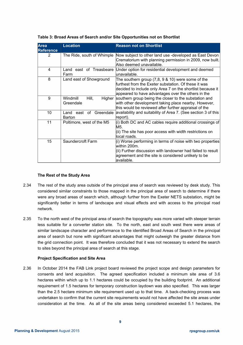
9
Planning & Development August 2015 rpsgroup.com/uk
Table 3: Broad Areas of Search and/or Site Opportunities not on Shortlist
Area Reference
Location Reason not on Shortlist
2 The Ride, south of Whimple Now subject to other land use -developed as East Devon Crematorium with planning permission in 2009, now built. Also deemed unavailable.
4 Land east of Treasbeare Farm
Under option for residential development and deemed unavailable.
8 Land east of Showground
The southern group (7,8, 9 & 10) were some of the furthest from the Exeter substation. Of these it was decided to include only Area 7 on the shortlist because it appeared to have advantages over the others in the southern group being the closer to the substation and with other development taking place nearby. However, this would be reviewed after further appraisal of the availability and suitability of Area 7. (See section 3 of this report).
9 Windmill Hill, Higher Greendale
10 Land east of Greendale Barton
11 Poltimore, west of the M5 (i) Both DC and AC cables require additional crossings of M5. (ii) The site has poor access with width restrictions on local roads.
15 Saundercroft Farm (i) Worse performing in terms of noise with two properties within 200m. (ii) Further discussion with landowner had failed to result agreement and the site is considered unlikely to be available.
The Rest of the Study Area
2.34 The rest of the study area outside of the principal area of search was reviewed by desk study. This considered similar constraints to those mapped in the principal area of search to determine if there were any broad areas of search which, although further from the Exeter NETS substation, might be significantly better in terms of landscape and visual effects and with access to the principal road network.
2.35 To the north west of the principal area of search the topography was more varied with steeper terrain less suitable for a converter station site. To the north, east and south west there were areas of similar landscape character and performance to the identified Broad Areas of Search in the principal area of search but none with significant advantages that might outweigh the greater distance from the grid connection point. It was therefore concluded that it was not necessary to extend the search to sites beyond the principal area of search at this stage.
Project Specification and Site Area
2.36 In October 2014 the FAB Link project board reviewed the project scope and design parameters for consents and land acquisition. The agreed specification included a minimum site area of 3.6 hectares within which up to 1.1 hectares could be occupied by the building footprint. An additional requirement of 1.5 hectares for temporary construction laydown was also specified. This was larger than the 2.5 hectare minimum site requirement used up to that time. A back-checking process was undertaken to confirm that the current site requirements would not have affected the site areas under consideration at the time. As all of the site areas being considered exceeded 5.1 hectares, the

10
Planning & Development August 2015 rpsgroup.com/uk
project specification did not change the work being undertaken or the conclusions reached at that time.
Summary
2.37 The site selection process leading to the shortlist is summarised in Figure 3. A staged site selection process was undertaken, incorporating a sieve mapping process to avoid sites subject to environmental designations. Taking a range of environmental, planning, cost, land availability and other factors into account, potential sites areas were identified.
2.38 Section 3 of this report sets out the approach taken to the evaluation of potential site options prior to final site selection (Stage 5 and Section 4 of this report).

11
Planning & Development August 2015 rpsgroup.com/uk
Figure 3: Site Selection Process

12
Planning & Development August 2015 rpsgroup.com/uk
3 FURTHER EVALUATION OF SHORTLISTED SITES
Introduction
3.1 This section summarises the approach that was taken to evaluate potential site options prior to final site selection (i.e. in Stage 5).
3.2 Project and operational requirements (including cost), environmental effects and land availability factors were taken into account in the appraisal of potential site options as illustrated in Figure 4. The factors that were taken into account are described further below. Further site evaluation was applied to those potential sites that were considered likely to be available in order to avoid potentially abortive work. These sites were the subject of ‘Potentially Available Site’ review reports and other studies where appropriate. The results of these studies are also summarised in this section.
Figure 4: Selection of Preferred Site

13
Planning & Development August 2015 rpsgroup.com/uk
Project Requirements and Costs
Site Requirements
3.3 For the purposes of Stage 5 of the site selection process, the following site requirements and/or parameters were assumed in relation to the proposed development:
Table 4: Operational Requirements
Parameter Assumption
Operational area 3.6 hectares
Building area (within operational area) 1.1 hectares
Temporary Construction Area (‘laydown area’) 1.5 hectares
Maximum height 20 metres
Number of buildings One or two large buildings (converter halls)
Technology HVDC
3.4 The minimum site area requirement of 3.6 hectares is for operational purposes. In addition, landscape mitigation/planting is likely to be required unless the site is already well screened. The amount of land required for landscape mitigation/ planting (in addition to the 3.6 hectares of operational land) would be site specific, depending on factors such as the number and sensitivity of nearby visual receptors and/or making best use of residual areas within existing field boundaries. Additional land might also be required for site access.
3.5 Approximately 1.5 hectares of land would also be required on a temporary basis for a laydown area during the construction phase. This could be located immediately adjacent to the operational area or at another suitable nearby location. If it is on adjacent land, then the laydown area might also be used after construction as part of the landscape/mitigation scheme.
3.6 For the purposes of verifying that potentially available sites could accommodate the proposed development, a notional site arrangement was developed, typically as shown in Figure 5. The layout of buildings and equipment shown does not represent a design and was undertaken without any electrical engineering input. It was used solely for the purpose of understanding how the scale and type of infrastructure to be provided might be accommodated on the site. The type of layout shown related only to one of several possible forms of the HVDC technology that might be provided. This form was chosen because it has been used and accepted for illustrative purposes in other recent consent applications for HVDC technology of similar size for which bespoke designs have not been available.

14
Planning & Development August 2015 rpsgroup.com/uk
Figure 5: Typical Site Arrangement Assumed for Layout Evaluation and Assessment
3.7 It is a condition of the licence under which the FAB Link project would operate that ‘the licensee shall
operate, maintain and develop an economic, efficient, secure and reliable interconnector’. Consideration was given to the ability to connect the interconnector to the national grid via the converter station site using electrical engineering methods and equipment that are efficient, secure and reliable and to project costs, which included site acquisition costs. The cost considerations that were taken into account are set out below.
Cable Route Costs
3.8 The electrical infrastructure costs took into account the distance between the potential converter station site and the NETS Exeter substation. The AC stage of the interconnector between the converter station and the NETS Exeter substation requires two AC circuits (i.e. 2 x 3 cables). The DC stage of the interconnector between the landfall and the converter station requires two DC circuits (i.e. 2 x 2 cables). Therefore, increasing the distance between the converter station and the NETS Exeter substation is likely to add to the project costs. Other constraints on the cable route, such as physical features requiring directional drilling or diversions, may also be relevant cost factors but it was not possible to estimate these at this stage and all other factors on the cable routes were assumed to be the same.
3.9 The project specification was updated in June 2015, when it was confirmed that the design would include twin symmetrical monopoles with two DC circuits of 320 kV to 400 kV; two 700 MW converter halls and two 400 kV AC circuits connecting to the NETS Exeter substation. It is anticipated that the DC cable circuits would be laid within existing road networks, while AC cable circuits are likely to take the most direct feasible route.
Transformers
Valve Cooling Radiator (VCR)
Control Room
Air Handling Units (AHUs)
Converter Hall(s)
Operational site area (3.60 hectares)
Total site area (variable)

15
Planning & Development August 2015 rpsgroup.com/uk
3.10 The estimated cable route costs for potentially available sites were updated in June and July 2015 to reflect the updated project design parameters and whole life cable route costs. The DC cable routes were assumed to follow the shortest possible road route. AC cable route corridors were assumed to follow the shortest possible direct route avoiding known pinch points and constraints, such as Exeter International Airport operational land and proposed residential areas at Cranbrook.
Site Acquisition Costs
3.11 Site acquisition costs were identified by FAB Link Limited, including both the discounted costs of securing and maintaining an option on the land and the anticipated land costs on acquisition or entering into a lease. These were not included in the site appraisal because they were commercial and in confidence.
3.12 FAB Link Limited took the view that the site acquisition costs across all potentially available sites were within a range that would not be a deciding factor for site selection on their own. However, where likely site acquisition costs were at the upper end of the range they might be relevant when considered together with likely cable route costs.
Engineering Costs
3.13 During Stage 5, consideration was also given to the costs associated with any key engineering or development constraints identified. This included, for example, estimates of:
i) Site access and highway improvements, including off site highway works to allow access for abnormal loads and the estimated cost for creating a site access road from the highway to the site, where required; and
ii) Site preparation costs in terms of earthworks (cut and fill) required to produce a level development platform where the site was currently on a gradient.
3.14 Other potential costs were noted, for example the requirement for any additional noise or flood mitigation that might be required or any known utilities diversions. However, at this stage it was not possible to quantify these costs.
Environmental Effects
3.15 Where sites were identified as potentially available, the relative sensitivity of the site in terms of environmental factors was considered. This included the following:
Landscape and visual: Review of baseline conditions and identification of a preferred site location within the Broad Areas of Search; an indicative landscape mitigation strategy; and an appraisal of landscape and visual impact;
Noise: High level assessment based on Initial Noise Screening Model (INSM) to identify noise sensitive receptors and an indication of the degree of mitigation likely to be necessary at the site;
Traffic/access: A review of potential options for accessing the site during construction and operation and identification of any key constraints and mitigation measures likely to be needed;

16
Planning & Development August 2015 rpsgroup.com/uk
Cultural heritage: A review of designated site information and data from the Historic Environment Record (HER);
Ecology and biodiversity: A review of designated site information and data from the Devon Biodiversity Records Centre;
Water environment: A review of available information in relation to water quality and flood risk;
Soils and geology: A review of available information in relation to agricultural land quality, geology and landfill site data; and
Community and socio-economics: A review of existing community land uses, community facilities and public rights of way.
3.16 Existing air quality information (such as the location of Air Quality Management Areas) was not considered as a likely material factor in the site selection process given that there would be no operational process emissions from the converter station and that the amount of operational traffic associated with the development would be minimal.
3.17 In some cases, the information available from this desk study (together with site visits undertaken at earlier stages) was sufficient to inform the site selection process. However, in addition to the desk study, further site visits or surveys for landscape and transport assessment were undertaken where necessary.
Effects on Land Use and Planning Policy
3.18 Where sites were identified as potentially available, consideration was given to the following:
Existing uses of the site;
Adopted local planning policy for the site and surrounding land;
Emerging local planning policy for the site and surrounding land; and
Relevant planning history of the site and surrounding land.
3.19 The planning appraisal of the sites set out the consultants’ opinion on the extent to which the proposed development is in accordance with adopted and emerging local plans along with the planning policy context created by the overarching National Policy Statements (NPSs) and the project’s status as a European Project of Common Interest. It drew together work previously undertaken for the site in question and identified the relevant planning issues.
3.20 Further pre-application consultation was also undertaken with East Devon District Council (EDDC) planning officers. On 18th March 2015 Transmission Investment and RPS met with EDDC officers to provide an update on the site selection review process undertaken since the previous meeting in 2014. The site selection process was presented and comments sought on the methodology that had been adopted. On 25th June 2015 Transmission Investment and RPS presented to EDDC officers information on the six sites being considered at that time. EDDC also provided information on other potential site opportunities in the Exeter and East Devon Growth Point. Following the meeting, a response was received on 10th July 2015 stating that the Development Manager was ‘happy with the
site selection process in terms of the extent of the search area, sieve mapping and landscape

17
Planning & Development August 2015 rpsgroup.com/uk
assessment.’ In addition, the response stated a preference for a site around the Exeter and East Devon Growth Point (specifically the multi-modal interchange site) or land at Long Lane (Sites 5 or 14) subject to improvements to Long Lane.
3.21 The records from these meetings are presented at Appendix 3.
Land Availability and Deliverability
3.22 For each of the shortlisted sites, work was undertaken to identify whether the sites were likely to be available for the proposed development. This work included discussions with the land owner(s) of each site to identify the current status in terms of land availability, any options for development already held on the land and its potential availability for construction and operation of a converter station. The results of these discussions are summarised at Appendix 4. Where it was established that the land was already under option for development, FAB Link Limited’s land agent Dalcour Maclaren sought to establish the aspirations of the option holder and whether a converter station could be accommodated alongside any other plans they might have for the land.
3.23 Where a land owner (or option holder) confirmed that they did not wish to consider the proposed development, no further work was undertaken for that site.
3.24 Where land owners confirmed that the site was potentially available, discussions took place regarding the terms on which the site could be delivered, having regard to the availability of the site in the medium to long term. It would not be possible, for example, for the FAB Link project to acquire sites in advance of a final investment decision, which cannot take place until all of the relevant consents and licences for the entire project are in place (estimated to be 2018). It is therefore necessary for the preferred site to be available with a suitable option to purchase in the future, with an appropriate level of flexibility on the date when acquisition is likely to be possible.
3.25 In order for a site to be considered available, it had to be possible to agree terms including the following:
3.26 FAB Link Limited had to be able to secure an option that would allow it to acquire or lease the site when the project was ready to proceed, after the final investment decision. A binding option to allow FAB Link to acquire the site was necessary to avoid abortive project development and consents work for the converter station and the cable route; and
i) Land purchase was preferred but if land was to be leased a lease must be available for the anticipated life of the project of 50 years.
ii) The responses from land owners and the potentially available sites subsequently evaluated in Stage 5 are summarised in Appendix 4 of this report.
Evaluation of Potentially Available Sites
3.27 For each potentially available site, the findings of the assessments outlined above were provided in a Potentially Available Site report format. Potentially Available Site reports were prepared for the following sites:

18
Planning & Development August 2015 rpsgroup.com/uk
Table 5: Potentially Available Sites
Site Reference Location 3 Land west of Treasbeare Farm 5 Land east of Antiques Complex/ Harriers Court Industrial Estate 7 Land at Hill Barton Landfill 10 Land east of Greendale Barton 12 Land west of Exeter substation 14 Land north east of Airport Business Park
3.28 The following shortlisted sites did not progress to the Potentially Available Site report stage, for the following reasons:
Table 6: Short Listed Site Confirmed as ‘Not Potentially Available’
Site Reference
Location Reason
1 Foxenhole Quarry, West Hill Landowner did not wish to proceed. 6 South east of Airport Business Park Land was in multiple land ownership and
under option for development. Optionholder did not wish to proceed.
13 Clyst Valley, Whimple Landowner did not wish to proceed.
3.29 The potentially available sites included Site 10, which was not originally included on the short list. As set out above (see Table 3), it had been intended to review the need for further appraisal of the southern group of sites: Broad Areas of Search 7, 8, 9 and 10. Area 7 had been included on the shortlist but the area originally identified was found to have planning permission for an extension to a landfill site. Site 7 was identified by extending the Broad Area of Search on to adjacent land and was found to have reasonable potential in terms of being adjacent to existing industrial areas. In view of that it was decided to reappraise all of the southern sites on the long list. The appraisal of opportunities at Greendale Barton (sites 9 and 10) was also suggested by the EDDC planning office at the meeting on 18th March.
3.30 Among this group, a potential site area was identified in the vicinity of Site 8 but this was not included on the short list because it did not have any advantages over the other the sites being considered and was not adjacent to any area of existing commercial development. The land adjacent to existing development in the vicinity of area 9 was found to have steep topography and was unsuitable. A site area on the boundary of area 9 to the south of Greendale Barton was identified but the landowner confirmed that this site was not available. Land in the vicinity of area 10 to the east of Greendale Barton was identified and was confirmed to be potentially available. Therefore, following this review, the only additional site within the southern group that was added to the shortlist and considered as a potentially available site was Site 10.
3.31 The findings of the Potentially Available Site reports were compared using the criteria provided in Table 7 below. Professional judgement was used in comparing the results of the site evaluation exercise.

19
Planning & Development August 2015 rpsgroup.com/uk
Table 7: Criteria for Site Selection Matrix
Red Significant project risks identified. Effects, policy conflicts and/or consenting risks are likely to remain after mitigation that are likely to carry significant weight and may lead to reasons for refusal of planning permission. Land owner consent may not be deliverable. Engineering feasibility and/or cost criteria may not be achievable.
Amber Feasible option. Environmental effects and/or consenting risks may arise but appear likely to be acceptable on balance with mitigation. Land agreements, engineering and cost requirements may not be ideal but appear achievable.
Green Good solution. Appears likely to be acceptable in terms of the topic with identified measures. Environmental effects and/or consenting risks appear capable of mitigation. Meets land availability, engineering and cost criteria.
3.32 The assessment summary tables for each site are attached at Appendix 5.
Review of Allocated Sites
3.33 A meeting had taken place with officers of East Devon District Council in July 2012 to introduce the project and to discuss the approach to site selection. At that meeting it was agreed that current or allocated employment sites would not be included in the site selection process. Given the time that had elapsed and the possibility of change during the emerging East Devon Local Plan process, in parallel with the site selection process the possibility of using an allocated site was also reviewed in 2015. This was also discussed with East Devon District Council officers in June 2015.
3.34 As a result of this review4, one possibility was considered on the site allocated in the adopted Local Plan for the Exeter Gateway Intermodal Freight Terminal north of the B3174 at Clyst Honition. Developing a converter station on this site appeared feasible in terms of site requirements, planning and environmental issues and so enquiries were made with both landowners (and their agents) who together controlled the land on this site. In both cases it was confirmed that the landowners had other intentions for the development and/or disposal of the land they controlled which precluded any agreement with FAB Link Limited for a converter station site.
3.35 Accordingly, no other potentially available sites were identified on allocated sites.
4 Allocated Sites Report – July 2015

20
Planning & Development August 2015 rpsgroup.com/uk
4 PREFERRED SITE SELECTION
4.1 The purpose of the site selection process was to identify a site for the FAB Link HVDC converter
station which met the project requirements and was available, environmentally acceptable and
capable of being granted planning permission and any other consents that might be required to
deliver the project within the required project timescales.
4.2 The final site selection had to be completed by the end of July 2015 in order to maintain the project
programme. In undertaking that selection, the following objectives were identified by FAB Link
Limited in discussion with its consultants and advisors:
Table 9: Site Selection Objectives
Objectives Project Requirements
The site must be capable of accommodating the FAB Link HVDC converter station for the UK grid
connection to Exeter substation by meeting the site requirements set out in the project
specification and be consistent with the project’s efficiency and cost requirements.
Land Availability
The land owner and/or other parties with a controlling interest in the site must be willing to grant
rights to acquire or lease the site on terms that are acceptable for the purpose of the project and
meet the required project timescales.
Environment and Sustainability
The development of the site for an HVDC converter station would be sustainable development in
terms of the policies for the environment in the National Planning Policy Framework (NPPF) and
the Overarching National Policy Statement for Energy (EN-1).
Planning Policy and Consenting Risk
Some conflicts with the local plan are inevitable but development of the site should have regard to
the policies of the adopted and emerging local plan where possible. The proposal should be
capable of being granted planning permission when other material considerations are taken into
account, such as the status of the project as a European Project of Common Interest; the policies
in the National Planning Policy Framework (NPPF) and the Overarching National Policy Statement
for Energy (EN-1); grid capacity and grid connection opportunities that are available.

21
Planning & Development August 2015 rpsgroup.com/uk
4.3 To conclude the final site selection process, a workshop was held on 16 July 2015 which was
attended by representatives from FAB Link Limited, Transmission Investment, RPS, Dalcour
Maclaren and Squire Patton Boggs. Each site that had been considered in Stage 5 was appraised
against each of the above objectives. Sites failing to meet these objectives were not selected. In the
event that these objectives were met by more than one site then consideration was given to which
site performed best across these objectives.
4.4 The Stage 5 approach set out in the previous section set the context for the workshop which
reviewed the site summaries presented at Appendix 5 and had reference to the site plans, the
Potentially Available Site reports and the feedback from landowner negotiations as set out by
Dalcour Maclaren at Appendix 4. The conclusions are presented below.
Site 3 – Land west of Treasbeare Farm
Project Requirements
4.5 Site 3 was capable of meeting the project requirements in terms of the site area available and
physical characteristics. It was noted that because it occupied defined plots within the layout of the
Cranbrook expansion masterplan (planning application 15/0046/MOUT, currently under
consideration by East Devon District Council) and there were residual areas within the plot
boundaries, the total site area on the indicative layout (7.25 hectares) was considerably in excess of
the operational area required. The additional land could provide laydown areas during construction
and would also provide land for the landscaping requirement in proximity to the proposed housing.
The phasing and timing of the Cranbrook expansion also created uncertainty regarding the location
and cost of the access road for the converter station which might be via the Cranbrook expansion
access roads (if they were developed first), or alternatively might need to be built to serve the
converter station construction in advance of construction of the Cranbrook expansion development.
4.6 Additional costs were also identified associated with earthworks to address a gradient across the
site, achieving access from the B3174 which also included a level difference, and potentially for
additional flood risk and noise mitigation. However, these matters were not considered as significant
constraints on the development of the site.
4.7 The onshore cable route cost estimate for this site (€72-75m) was the second lowest of the
potentially available sites.
Land Availability
4.8 The land was controlled by the developers who had applied (in December 2014) for the Cranbrook
expansion on land at Treasbeare Farm and had acquired an option to develop the land pertaining to
Site 3. The existence of an option on the land was established in 2012 when it was concluded that
the site would not be available. In 2014, however, the option holders were contacted on behalf of
FAB Link Limited to establish whether the plans and timescales for the proposed development would

22
Planning & Development August 2015 rpsgroup.com/uk
allow any scope for the converter station on Site 3. It was then established that the part of
Treasbeare Farm on which Site 3 was located was likely to be included in the masterplan for non-
residential use and this might provide an opportunity for FAB Link.
4.9 Further studies were commissioned by FAB Link Limited to establish how a converter station would
sit on the land and whether issues such as noise and visual impact from the converter station would
be compatible with the residential uses proposed on the adjacent land. It was concluded that this
was feasible in the context of the proposed development.
4.10 In May 2015, Dalcour Maclaren discussed with the option holders whether terms could be agreed for
an option for FAB Link Limited. They were informed that, based on the developer’s programme, it
was anticipated that planning permission would be granted and the land available for development
within about two years. The developers were therefore not able to commit the land for the length of
time required for the FAB Link converter station option (which would require an option period of at
least 5 years).
4.11 It was concluded that terms could not be agreed that met the project requirements and Site 3 did not
meet the land availability objective.
Environment and Sustainability
4.12 The site met the environmental objectives with respect to landscape and visual impact, traffic and
land quality impacts. The site would be viewed in the context of existing development at the E.ON
Energy Centre and the buildings on the north side of Exeter Airport. When developed, Skypark
would also be an adjacent feature in the landscape.
4.13 Although there was some uncertainty on the form of the access to the site and timing relative to the
proposed Cranbrook expansion, the access route would join to the B3174 where the impact of
construction traffic would be small, in terms of both the highway network itself, communities and
other receptors that might be affected by traffic.
4.14 The principal consideration with respect to noise from the converter station was the likelihood of new
residential development to the north and east of the site. However, the initial screening of potential
noise impacts concluded that through arrangement of the converter hall buildings on the site and
some additional mitigation of the external noise sources, the required mitigation for noise levels at
the proposed residential receptors could be achieved.
4.15 None of the other environmental factors were considered likely to give rise to unacceptable impacts.
The south west part of the site was liable to flooding and a flood risk assessment would be required.
However, the location of the buildings would avoid the land liable to flood and flood storage areas
could be maintained in the undeveloped part of the site.
4.16 It was concluded that the site would be capable of meeting the environmental objective.

23
Planning & Development August 2015 rpsgroup.com/uk
Planning Policy and Consenting Risk
4.17 In terms of planning policy, the site was covered by adopted and emerging local plan policies for the
countryside and development of the site for a converter station would not be in accordance with
those policies. However, there were other material considerations. The site was adjacent to Exeter
and East Devon Growth Point proposals which include a wide range of developments over the next
twenty years. There were existing and allocated employment and airport-related uses on land
adjacent to the site and development of adjacent land had been proposed and consulted upon in the
Airport Master Plan.
4.18 As noted above, the current status of the land in planning was also in a state of flux by virtue of the
planning application (15/0046/MOUT) for the Cranbrook expansion submitted in December 2014 and
which remained under consideration. Planning permission could still be gained on Site 3 for a
converter station as a stand-alone application, although some delay would arise if the Cranbrook
expansion application was still being determined and the interrelationships proved to be a
complicating factor.
Conclusion
4.19 Site 3 met the site selection objectives for project requirements; environment and sustainability; and
planning and consenting risk, although the determination of the current planning application for the
Cranbrook expansion was likely to complicate some issues such as the phasing and location of the
access route.
4.20 The site did not, however, meet the land availability objective and thus was not considered further for
selection as the preferred site.
Site 5 - Land east of Antiques Complex/ Harriers Court Industrial Estate
Project Requirements
4.21 Site 5 was capable of meeting the project requirements in terms of the site area available and
physical characteristics. Several alternative siting arrangements for this site within the surrounding
block of land had been considered. Based on the indicative layout and preliminary consideration of
landscape proposals, the total site area on the indicative layout was 5.11 hectares. An area
potentially suitable for use as a temporary laydown area during construction was identified to the
west of the proposed boundary for Site 5.
4.22 Access routes to the site for abnormal load vehicles are currently constrained and therefore
additional costs would be incurred either from the provision of improvements to existing highways or
from the provision of an alternative route. Three alternative routes for abnormal load access had
been identified. Further work was required to establish which route would be the best route

24
Planning & Development August 2015 rpsgroup.com/uk
deliverable at the time required by the project, but it was agreed for the purposes of site selection
that sufficient information had been obtained to establish a reasonable likelihood that the Devon
County Council Long Lane Improvement through the Airport Business Park was deliverable. Failing
that, a dedicated off-slip from the A30 for abnormal loads appeared feasible. The third alternative
was to gain access across the airport but it would not be possible to pursue that option with Exeter
International Airport until nearer to the time when access would be required.
4.23 For site selection purposes, it was assumed that an abnormal load route was deliverable. It was
noted, however, that further work was required to confirm the load width and if land ownership
constraints existed for either the minimum works to move street furniture and utilities (in the absence
of the full Long Lane improvement) or to deliver the A30 off-slip route.
4.24 Other transport issues such as conflicts with other users on the stretch of Long Lane past Harrier
Court and the Antiques Complex were noted but capable of being resolved through construction
traffic management measures.
4.25 The Western Power Distribution 11 kV overhead line on part of the site was not a significant cost
issue, nor other site preparation costs.
4.26 The onshore cable route cost estimate for this site (€69-70m) was the third lowest of the potentially
available sites.
Land Availability
4.27 Dalcour Maclaren had made good progress on this site and heads of terms had been put to the
owners’ Trustees who had confirmed they were willing to proceed and instruct solicitors to conclude
an agreement.
4.28 The terms included an area that was identified for construction laydown and there remained flexibility
over access requirements on land within the owners’ control.
4.29 As noted above, further work was required to confirm if there were any land ownership constraints on
two of the potential abnormal load routes. However, for the purposes of site selection, Site 5 met the
land availability objective.
Environment and Sustainability
4.30 The site met the environmental objectives with respect to noise, hydrology/flood risk impacts and
effects on community facilities e.g. public rights of way.
4.31 The site had the ability to accommodate an appropriately designed converter station without
unacceptable landscape impacts. It would be viewed in the context of existing industrial scale
development and other commercial, leisure and industrial development in the vicinity of Exeter

25
Planning & Development August 2015 rpsgroup.com/uk
International Airport, the Antiques Complex and Harrier Court. It was noted, however, that
development would be extended further into the countryside with this site option.
4.32 The access route issue for abnormal loads and construction traffic were noted above.
4.33 It was concluded that the site would be capable of meeting the environmental objective.
Planning Policy and Consenting Risk
4.34 In terms of planning policy, the site was covered by adopted and emerging local plan policies for the
countryside and development of the site for a converter station would not be in accordance with
those policies. However, there were other material considerations.
4.35 The wider area includes other employment and airport-related allocations on Long Lane as part of
the Exeter and East Devon Growth Point and further development has also been proposed and
consulted upon in the Airport’s Master Plan. In this context, and the other policies contained in the
NPPF and NPS for energy infrastructure, the site was capable of being granted planning permission
for the converter station.
Conclusion
4.36 Site 5 met the site selection objectives for project requirements; land availability; environment and
sustainability; and planning and consenting risk. Therefore, the site was able to be considered for
selection.
Site 7 - Land at Hill Barton
Project Requirements
4.37 Site 7 was capable of meeting the project requirements in terms of the site area available and
physical characteristics. Based on an indicative layout and preliminary consideration of landscape
proposals, the total site area on the indicative layout was 6.11 hectares. Land to the south east or
west may be available as a temporary laydown area during construction.
4.38 Additional costs were also likely as a result of the need to undertake earthworks to address a
gradient across the site. In addition, the presence of neighbouring receptors at Denbow House,
Swiss Cottage and Parsonage Copse would need to be considered when locating the main buildings
and infrastructure within the site to minimise noise and visual impacts. Noise mitigation may also
require incorporation of measures within the design. None of these factors were likely to affect the
feasibility of the site meeting the project requirements.
4.39 The onshore cable route cost estimate for this site (€93-96m) was the fifth lowest (or second highest)
of the potentially available sites.
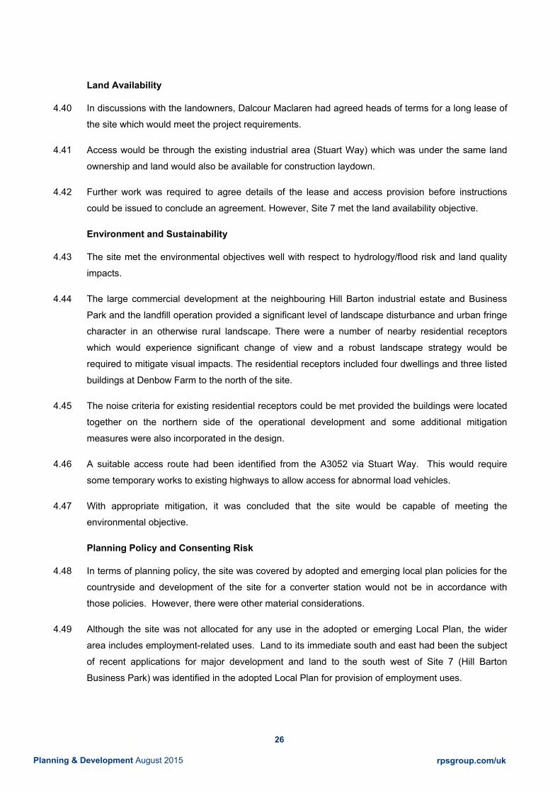
26
Planning & Development August 2015 rpsgroup.com/uk
Land Availability
4.40 In discussions with the landowners, Dalcour Maclaren had agreed heads of terms for a long lease of
the site which would meet the project requirements.
4.41 Access would be through the existing industrial area (Stuart Way) which was under the same land
ownership and land would also be available for construction laydown.
4.42 Further work was required to agree details of the lease and access provision before instructions
could be issued to conclude an agreement. However, Site 7 met the land availability objective.
Environment and Sustainability
4.43 The site met the environmental objectives well with respect to hydrology/flood risk and land quality
impacts.
4.44 The large commercial development at the neighbouring Hill Barton industrial estate and Business
Park and the landfill operation provided a significant level of landscape disturbance and urban fringe
character in an otherwise rural landscape. There were a number of nearby residential receptors
which would experience significant change of view and a robust landscape strategy would be
required to mitigate visual impacts. The residential receptors included four dwellings and three listed
buildings at Denbow Farm to the north of the site.
4.45 The noise criteria for existing residential receptors could be met provided the buildings were located
together on the northern side of the operational development and some additional mitigation
measures were also incorporated in the design.
4.46 A suitable access route had been identified from the A3052 via Stuart Way. This would require
some temporary works to existing highways to allow access for abnormal load vehicles.
4.47 With appropriate mitigation, it was concluded that the site would be capable of meeting the
environmental objective.
Planning Policy and Consenting Risk
4.48 In terms of planning policy, the site was covered by adopted and emerging local plan policies for the
countryside and development of the site for a converter station would not be in accordance with
those policies. However, there were other material considerations.
4.49 Although the site was not allocated for any use in the adopted or emerging Local Plan, the wider
area includes employment-related uses. Land to its immediate south and east had been the subject
of recent applications for major development and land to the south west of Site 7 (Hill Barton
Business Park) was identified in the adopted Local Plan for provision of employment uses.

27
Planning & Development August 2015 rpsgroup.com/uk
4.50 It was noted, however, that the emerging Local Plan did not include an allocation at Hill Barton
Business Park. It was also clear that significant weight was attached to landscape, visual and noise
impacts in the determination of the recent gasification plant application nearby to the south east.
4.51 Having regard to the context of the site and its surroundings and the other policies contained in the
NPPF and NPS for energy infrastructure, the site remained capable of being granted planning
permission for the converter station.
Conclusion
4.52 Although it was noted that the site would require mitigation for landscape and potential noise and
visual impacts, Site 7 met the site selection objectives for project requirements; land availability;
environment and sustainability; and planning and consenting risk. Therefore, the site was able to be
considered for selection.
Site 10 - Land east of Greendale Barton
Project Requirements
4.53 The Site 10 arrangement considered at the workshop was not the same as that considered in the
Potentially Available Site report. Since the production of the report , the landowner had advised
Dalcour Maclaren that part of the land on Hogsbrook Lane was already under lease and not
available. An alternative arrangement which extended the site boundary further to the east was
therefore considered in an amended site summary as an addendum to the report. This arrangement
included a stepped development to take into account gradients across the site. This appeared
feasible even if the precise earthworks and site levels would require further design work before the
site could be progressed.
4.54 Based on this revised indicative layout and preliminary consideration of landscape proposals, the
total site area on the indicative layout was 6.2 hectares. Other land to the east or west was assumed
to be available as a temporary laydown area during construction.
4.55 Additional costs would result from the need to undertake earthworks and/or provide retaining walls to
address gradients across the site. In addition, a National Grid pipeline was present to the south of
the site, which constrains the southern boundary. Neither of these issues affected the feasibility of
the site for a converter station.
4.56 The onshore cable route cost estimate for this site (€93-101m) was the sixth lowest (or highest) of
the potentially available sites.
Land Availability
4.57 In discussions with the landowners, Dalcour Maclaren had established that the site was potentially
available for a long lease which would cover the project design life. However, the terms sought by

28
Planning & Development August 2015 rpsgroup.com/uk
the land owner were based on annual rent which would not be at an appropriate or acceptable level
compared to the preferred option of purchasing a site.
4.58 It was assumed that access would be available through the existing Business Park and land under
the same ownership would also be available for construction laydown.
4.59 However, having regard to the rental terms being stipulated, it was concluded that terms could not be
agreed that met the project requirements and Site 10 did not meet the availability objective.
Environment and Sustainability
4.60 The site had the ability to accommodate an appropriately designed converter station without
unacceptable landscape and visual impacts. The existing large scale industrial and commercial
buildings adjacent to the site would allow the development to be accommodated without significant
changes in views or landscape character.
4.61 There were some residential properties nearby that might require noise mitigation measures.
However, there is existing environmental sound from local roads and neighbourhood sound from
industrial, commercial and distribution uses during the daytime, and probably during the night time
and/or early morning. It was likely that existing environmental sound coupled with screening from
existing buildings and structures would mean that significant adverse noise effects from the
converter station would be avoided.
4.62 An access route through Greendale Business Park was identified which would not impact other road
users or communities. This would require some temporary works to existing highways to allow
access for abnormal load vehicles.
4.63 Although further design work would be required to ensure that appropriate mitigation could be
incorporated with the site levels and gradients on this site, it was concluded that the site would be
capable of meeting the environmental objective.
Planning Policy and Consenting Risk
4.64 In terms of planning policy, the site was covered by adopted and emerging local plan policies for the
countryside and development of the site for a converter station would not be in accordance with
those policies. However, there were other material considerations which, being adjacent to an
existing employment site, were very similar at Greendale Barton as for Site 7 above.
4.65 Having regard to the context of the site and its surrounding and the other policies contained in the
NPPF and NPS for energy infrastructure, the site remained capable of being granted planning
permission for the converter station.

29
Planning & Development August 2015 rpsgroup.com/uk
Conclusion
4.66 Although the site had the highest estimated cable route costs of any of the potentially available sites,
Site 10 met the site selection objectives for project requirements; environment and sustainability; and
planning and consenting risk.
4.67 The site did not, however, meet the land availability objective and thus was not considered further for
selection as the preferred site.
Site 12 - Land west of Exeter substation
Project Requirements
4.68 Site 12 was capable of meeting the project requirements in terms of the site area available and
physical characteristics. Based on the indicative layout and preliminary consideration of landscape
proposals, the total site area on the indicative layout was 5.7 hectares. An area potentially suitable
for use as a temporary laydown area during construction had been identified to the west of the site.
4.69 The access routes to the site for abnormal loads and construction vehicles would be from the M5 via
Pinhoe and Dog Village. There is a considerable distance over which highway and street furniture
works would be required to accommodate abnormal loads but the route had been assessed as
feasible. Based on previous applications in the area, an access route into the site from the north, via
Burrowton Solar Farm was also likely to be required. Although this was in different land ownership to
Site 12, for site selection purposes it was assumed that and an access route from the north was
deliverable.
4.70 There was a significant gradient across this site which would also require earthworks during site
preparation.
4.71 Site 12 was the closest of the potentially available sites to the Exeter substation. The onshore cable
route cost estimate for this site (€56-59m) was the lowest of the potentially available sites.
Land Availability
4.72 Dalcour Maclaren had made relatively good progress on this site and terms were available for an
option for freehold purchase of the site and additional land in the same ownership was available for
construction laydown.
4.73 Further work was required to confirm if land access can be obtained for an access route to the north,
if that is required by the highway authority. However, for the purposes of site selection, Site 12 met
the land availability objective.
Environment and Sustainability
4.74 Although there would be some large scale changes in views from a public footpath and some
residential receptors at Loxbrook Farm and Lower Burrowton, the nearby solar farms, the Exeter

30
Planning & Development August 2015 rpsgroup.com/uk
substation and the overhead power lines formed a series of large scale, prominent energy
infrastructure developments within a rural landscape context of the site. With a robust landscape
strategy, the site had the ability to accommodate an appropriately designed converter station without
unacceptable impacts on landscape character.
4.75 A limited number of residential receptors would be potentially affected by noise and suitable
mitigation would be possible to avoid significant noise impacts.
4.76 The access route issue for abnormal loads and construction traffic are noted above. There was some
potential for traffic impacts to affect the built up areas through which the route passes at Pinhoe and
Dog Village, although these could be mitigated with construction traffic management.
4.77 Although Site 12 was set in a more rural context than the other potentially available sites and there
were some potential traffic impacts, other developments of similar scale have taken place in the
vicinity and it was concluded that the site would be capable of meeting the environmental objective.
Planning Policy and Consenting Risk
4.78 In terms of planning policy, the site was covered by adopted and emerging local plan policies for the
countryside and development of the site for a converter station would not be in accordance with
those policies. However, there were other material considerations.
4.79 The wider area included other energy infrastructure and this was the closest site to the Exeter
substation with the lowest cable route costs. In this context, and the other policies contained in the
NPPF and NPS for energy infrastructure, the site was capable of being granted planning permission
for the converter station.
Conclusion
4.80 Site 12 met the site selection objectives for project requirements; land availability; environment and
sustainability; and planning and consenting risk. Therefore, the site was able to be considered for
selection.
Site 14 - Land north east of Airport Business Park
Project Requirements
4.81 Site 14 was capable of meeting the project requirements in terms of the site area available and
physical characteristics. Based on an indicative layout and preliminary consideration of landscape
proposals, the total site area on the indicative layout was 6.7 hectares. An area potentially suitable
for use as a temporary laydown area during construction had been identified to the north east of the
site.

31
Planning & Development August 2015 rpsgroup.com/uk
4.82 Access routes to the site for abnormal loads vehicles were subject to the same considerations and
constraints as set out for Site 5 above and for site selection purposes it was assumed that an
abnormal load route was deliverable.
4.83 The onshore cable route cost estimate for this site (€77-80m) was the fourth lowest of the potentially
available sites (and very similar to Site 5).
Land Availability
4.84 It was established that the site was under option for development as part of the Exeter Airport
masterplan and Dalcour Maclaren had discussed whether terms could be agreed to accommodate
the converter station. Whilst it was established that the site was potentially available in the future, the
option holders would not be able to determine if the site was indeed available for the foreseeable
future until and not before the whole land portfolio at Exeter International Airport had been reviewed
and a revised Airport Masterplan developed. There was no indication given as to when that might be.
4.85 It was therefore concluded that Site 14 did not meet the land availability objective.
Environment and Sustainability
4.86 The site met the environmental objectives with respect to landscape and visual impact; noise; and
hydrology/flood risk impacts. The site would be viewed in the context of existing industrial scale
development in the vicinity of Exeter International Airport and is likely to have the ability to
accommodate an appropriately designed converter station without significant landscape impacts.
4.87 The principal consideration with respect to environmental factors was access for abnormal load
vehicles which were the same as for Site 5 and were assumed to be deliverable.
4.88 It was concluded that the site would be capable of meeting the environmental objective.
Planning Policy and Consenting Risk
4.89 In terms of planning policy, the site was covered by adopted and emerging local plan policies for the
countryside and development of the site for a converter station would not be in accordance with
those policies. However, there were other material considerations.
4.90 The wider area includes other employment and airport-related allocations and development on Long
Lane where further development, including this land, has also been proposed and consulted upon in
the Airport’s Masterplan. The site is also adjacent to land allocated in the emerging development
plan for future expansion of the Airport Business Park as part of the Exeter and East Devon Growth
Point.
4.91 In this context, and the other policies contained in the NPPF and NPS for energy infrastructure, the
site was capable of being granted planning permission for the converter station.

32
Planning & Development August 2015 rpsgroup.com/uk
Conclusion
4.92 Site 14 met the site selection objectives for project requirements; environment and sustainability; and
planning and consenting risk. However, the site did not meet the land availability objective and thus
was not considered for selection as the preferred site.
Preferred Site Selection
4.93 Having reviewed the information available for each potentially available site against the site selection
objectives there were three sites that met the objectives which could be considered for selection.
These were:
Site 5 - Land east of Antiques Complex/ Harriers Court Industrial Estate
Site 7 - Land at Hill Barton
Site 12 - Land west of Exeter substation.
4.94 This section set out how these sites were compared in terms of performance across all the
objectives, leading to the selection of the preferred site.
Project Requirements
4.95 In the second stage of the workshop, the performance of the three sites was compared in terms of
the site considerations, i.e.: the site area; factors affecting the design and layout flexibility for
buildings and equipment within the site; and earthworks and site preparation requirements. Site 5
performed best in these terms. There was less gradient across the site requiring earthworks and site
levelling than on both Sites 7 and 12. Site 12 would require the most earthworks. The shape of the
plot, noise and visual impact considerations would dictate how the buildings and other equipment
were laid out on Site 7 and to a lesser extent Site 12. Site 5 had the least constraints and issues that
might affect design layout and site preparation.
4.96 Site access considerations were compared. Site 7 performed best in terms of access with a well-
established route which was already used for heavy vehicular traffic. The access for abnormal loads
would require significant highway works for both Sites 5 and 12. Site 5 required the proposed DCC
Long Lane improvement to be implemented or, failing that, other works along Long Lane or a direct
access from the A30. Site 12 was furthest from the motorway and A-roads, accessed from principally
rural roads and would be likely to require access across third party land from the north. Overall, there
was little to choose between Sites 12 and 5 in terms of access as both had issues. However, the
proposed DCC Long Lane improvement was a planned scheme and if implemented, Site 5 would
also perform well in terms of being close to the principal road network and having an access route
already used for commercial and industrial traffic.

33
Planning & Development August 2015 rpsgroup.com/uk
4.97 In terms of infrastructure costs, the only significant consideration taken into account was the
estimated cable route cost. Site 12 performed best (€56-59m), followed by Site 5 (€76-77m) and Site
7 (€93-96m).
4.98 In overall terms, Sites 5 and 12 were appraised as better performing in terms of site requirements
than Site 7, where there were constraints on the layout. Site 12 was appraised as best performing
overall, having regard to its cable route cost advantage which was not outweighed by the other
benefits of Site 5.
Land Availability
4.99 There were some differences in the terms being offered between the three sites. Sites 5 and 12 were
available for freehold purchase while Site 7 would be leasehold. The terms being offered for the
option to purchase Site 5 were more straightforward than for Sites 12 and 7.
4.100 Overall, however, all three sites were considered to be equally available and no weight was attached
to the differences in terms being offered in the overall site selection.
Environment and Sustainability
4.101 Site 7 was appraised as worst performing of the three sites in terms of the environment and
sustainability objective because of the likely visual impact on the occupiers of properties at Denbow
Farm, including three listed buildings, and the potential noise impacts that would require mitigation.
4.102 Differences in performance across the environmental and sustainability objectives between Sites 5
and 12 were less clear-cut. Site 12 was located in a more rural area close to the National Trust
estate but the landscape context of Site 12 was already affected by other energy infrastructure. Site
5 was in an area where the Airport and other commercial and industrial development at the Airport
Business Park and the Antiques Complex already affected the landscape character. Other
development was also proposed in this area in the Exeter and East Devon Growth Point and the
Airport masterplan. East of the Antiques Complex, however, the landscape was more open and rural.
4.103 There were fewer noise and visual receptors such as dwellings affected at Site 5. The nearest
dwellings, a bungalow subdivided into three addressed within the Antiques Complex, was already
within an industrial setting. Site 5 performed better in terms of noise impact.
4.104 Site 5 also performed better in terms of the potential impacts from construction traffic. Site 12 would
require construction traffic to pass rural dwellings and through residential areas at Pinhoe and Dog
Village but the access route to Site 5 would be an established route for heavy vehicles.
4.105 Overall, Site 5 was appraised as the best performing of the three sites in terms of the environmental
and sustainability objectives.

34
Planning & Development August 2015 rpsgroup.com/uk
Planning Policy and Consenting Risk
4.106 All three sites were covered by adopted and emerging local plan policies for the countryside where
the development of a converter station would not be in accordance with those policies. Other
material considerations applied in each case, including other policies contained in the NPPF and
NPS for energy infrastructure and the local development plan context.
4.107 Site 5 was on Long Lane where other development is proposed as part of the Exeter and East
Devon Growth Point which includes a wide range of developments over the next twenty years.
There is significant existing development in this area and further development has also been
proposed and consulted upon in the Airport Master Plan.
4.108 Previous discussions with East Devon District Council officers indicated that sites adjacent to
existing commercial development would be preferred, where the landscape character was already
affected by development. Site 7 was adjacent to, but outside of, another area of employment at Hill
Barton Business Park and was therefore compatible with these recommendations in the respect of
pre-existing effects on the landscape.
4.109 Site 12 was more rural and not located in or near to areas proposed for commercial or industrial
development.
4.110 FAB Link Limited had also recently received feedback from East Devon District Council officers on
the site search activities to date. This latest feedback suggested one of the sites allocated in the East
Devon Local Plan might be suitable, which continues to be investigated, but failing that, suggested
that ‘land adjoining the airport off Long Lane subject to improvements to Long Lane’ might also be
suitable.
4.111 Based on the planning merits of being in the Long Lane area and adjacent to other development
proposals including the Growth Point and the feedback received from East Devon District Council
Officers, Site 5 was appraised as the best performing site in terms of planning policy and consenting
risk, followed by Site 7. Site 12 was still considered to meet the objective, but was appraised as the
worst performing site of the three.
Overall Site Selection
4.112 In overall terms the performance of the sites was summarised as follows:
Objective Best Performing Worst Performing Site Requirements 12 5 7 Land Availability No Significant Difference Environment and Sustainability 5 12 7 Planning Policy and Consenting Risk 5 7 12

35
Planning & Development August 2015 rpsgroup.com/uk
4.113 Having regard to all of the above, FAB Link Limited decided that, on balance, relative to the
alternative sites, the environmental and planning merits of Site 5 outweighed the better performance
in terms of site requirements (i.e. cable route cost benefits) and that Site 5 should be selected as the
preferred site.
4.114 Site 5 was therefore selected as the preferred site subject to the following:
i) Further testing of the feasibility of the abnormal load access route either via Long Lane
improvements or from the A30;
ii) Consultation with Exeter International Airport on aerodrome safeguarding and any other airport
operational issues;
iii) Satisfactory conclusion of the land option agreement.

36
Planning & Development August 2015 rpsgroup.com/uk
5 CONCLUSIONS
5.1 A staged site selection process has been undertaken to identify potential GB connection options and
converter station sites for the FAB Link project. The stages have been set out in Section 2 of this
report and are summarised on Figure 3.
5.2 Based on technical, electrical, cost and environmental considerations, in 2012 the first stage of this
process concluded that Exeter was the preferred GB connection option.
5.3 In late 2012/early 2013, Stage 2 of the site selection process identified a number of potential site
opportunities within approximately 5 km of the Exeter NETS substation using environmental and land
use criteria. These were appraised in terms of site layout, environmental considerations and
potential land availability in 2013 (Stage 3) which culminated in pre-application advice being sought
from East Devon District Council (EDDC) in February 2014 on two potential sites near the existing
Exeter substation.
5.4 The advice received from EDDC recommended further work to consider whether other sites may
exist with less visual intrusion and better access to the road network. A review of the Exeter study
area was therefore completed in 2014 (Stage 4) which included widening the study area, sieve
mapping, landscape studies and environmental appraisal. This resulted in a revised short list of 8
potential site areas.
5.5 Following initial feedback from landowners, six shortlisted sites were identified as potentially
available and these were subject to further studies in 2015 in the form of ‘potentially available site
reviews’ (Stage 5). The potentially available sites were:
Site 3 - Land west of Treasbeare Farm
Site 5 - Land east of Antiques Complex/ Harriers Court Industrial Estate
Site 7 - Land at Hill Barton
Site 10 - Land east of Greendale Barton
Site 12 - Land west of Exeter substation
Site 14 - Land north east of Airport Business Park.
5.6 Following these studies and further discussions with landowners, a site selection process was
completed in July 2015. Only three of these, sites 5, 7 and 12, were considered capable of meeting
the site selection objectives for technical requirements, environmental considerations and land
availability.

37
Planning & Development August 2015 rpsgroup.com/uk
5.7 These sites were compared in terms of performance across all the objectives leading to the selection
of a preferred site. Having regard to all of the relevant factors, FAB Link Limited decided that Site 5
should be selected as the preferred site. Site 5 - Land east of Antiques Complex/ Harriers Court
Industrial Estate – is located to the south east of Exeter Airport on Long Lane.

38
Planning & Development August 2015 rpsgroup.com/uk
6 REFERENCES
Department of Energy and Climate Change (DECC) (2013) More Interconnection: Improving Energy Security and Lowering Bills. December 2013.
RPS (2013a) France-Alderney-Britain Interconnector (FAB Link UK) Connection Infrastructure: GB Connection Options Report. March 2013.
RPS (2013b) France-Alderney-Britain Interconnector (FAB) Connection Infrastructure: Exeter Search Zones – Options Report. March 2013.
RPS (2013c) FAB Link Converter, Broadclyst, Exeter: Abnormal Load Route (Desktop Study). November 2013.
RPS (2014a) FAB Link Interconnector: Landscape and Visual Site Appraisal. January 2014.
RPS (2014b) France-Alderney-Britain Interconnector (FAB) Interconnector: Pre-Application Submission. Confidential Report. January 2014.
RPS (2014c) FAB Link Ltd: Exeter Study Area Review 2014.
RPS (2014d) FAB Link: Exeter Study Area Review– Landscape and Visual Assessment Study. September 2014.
RPS (2014e) FAB Link Ltd: Exeter Study Area Review 2014 – Review of Long List. September 2014.
Transmission Capital (2012) Cost-Benefit Assessment of GB Tie-in Points. Memorandum to Ofgem, 28 June 2012.

APPENDIX 1: Stage 4 Sieve Mapping Constraints
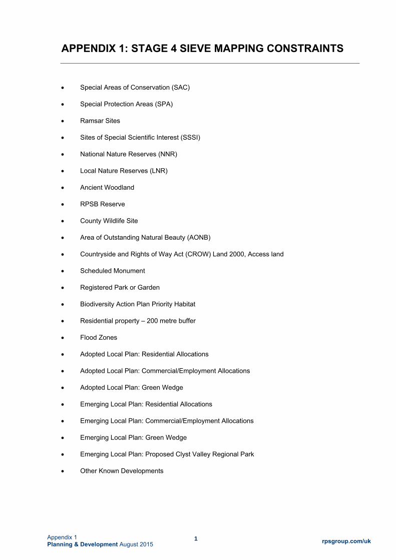
1 rpsgroup.com/uk Appendix 1
Planning & Development August 2015
APPENDIX 1: STAGE 4 SIEVE MAPPING CONSTRAINTS
Special Areas of Conservation (SAC)
Special Protection Areas (SPA)
Ramsar Sites
Sites of Special Scientific Interest (SSSI)
National Nature Reserves (NNR)
Local Nature Reserves (LNR)
Ancient Woodland
RPSB Reserve
County Wildlife Site
Area of Outstanding Natural Beauty (AONB)
Countryside and Rights of Way Act (CROW) Land 2000, Access land
Scheduled Monument
Registered Park or Garden
Biodiversity Action Plan Priority Habitat
Residential property – 200 metre buffer
Flood Zones
Adopted Local Plan: Residential Allocations
Adopted Local Plan: Commercial/Employment Allocations
Adopted Local Plan: Green Wedge
Emerging Local Plan: Residential Allocations
Emerging Local Plan: Commercial/Employment Allocations
Emerging Local Plan: Green Wedge
Emerging Local Plan: Proposed Clyst Valley Regional Park
Other Known Developments

APPENDIX 2: Stage 4 Long List Appraisal Matrix

FAB LINK LTD: EXETER STUDY AREA CONVERTER STATION SITING REVIEW
REVIEW OF LONG LIST – SEPTEMBER 2014 POST-WORKSHOP APPRAISAL SUMMARY MATRIX SEPTEMBER 2014 REVB
ConsiderationsEnvironment & Sustainability
Project Requirements (including Project Costs)
Land Availability & Deliverability
Performance BETTER MEDIUM WORSE
Site ID Noise Landscape Cultural Heritage Ecology and Biodiversity Water Environment Soils and Geology (1) Transport Assessment Approx. Cable Route Distance (km). (AC/DC - from closest Landfall)*
Site Area (ha) Developable Landform and Ground Conditions
Feasibility of Access (including abnormal
loads)
Cable Route Cost Estimate (Ranked)
Feasible Cable Route Access
Landowner Assessment/ Availability
Land Use & Planning History Existing Infrastructure (Overhead Lines, underground gas/electricity/water
main/telecommunications)
1 38 BAS 9
No recorded heritage features on site. Within
500m of 1 x Grade II Listed Building within 1km.
No known sites or habitatsProvisional grade 3. Part of site
indicated as historic landfill.Better 6.8/8.8 7.1
Slight gradient <1:20. Part of site indicated as historic
landfill.
Access routes from B3174 and abnormal
load access to be confirmed.
13 1 landowner/ unknown.
Unknown
2 31 BAS 10 (*Other Known Development)
No recorded heritage features on site. 3 x Grade II Listed Buildings within 500m
and 1 x Grade I Listed Building within 1km.
No known sites or habitats. Unconfirmed wildlife site on
western part.Provisional grade 3 Better 4.4/11.0 4.3 Gently sloping gradients
1:20 to 1:10.9
3 landowners/ unknown. Now
developed as east Devon Crematorium.
East Devon Crematorium planning permission 2009.
Now built.Unknown
3 134 BAS 14
1 x heritage record on site. 2 x Grade II Listed Buildings
within 500m. No Grade I or Grade II* Listed Buildings
within 1km. Heritage Feature Areas on part of site.
No known sites or habitats Grades 2, 3a and 3b. Better 2.65/13.67 20.8 Mostly slight gradient <1:20 5 1 landowner/ unknown.
Unknown
4 206 BAS 15 (with amended boundary)
No recorded heritage features on site. 6 x Grade II
Listed Buildings within 500m. 2 x Grade I Listed Buildings and 1 x Grade I
Listed Building within 1km. Heritage Feature Areas on
part of site.
No known sites or habitats Grades 2, 3a and 3b. Better 2.24/12.54 86.1 Ridge slopes down to east of farm.
4
2 landowners. Unavailable -
residential planning application
understood to be in preparation.
Unknown
5 10 BAS 16
No recorded heritage features on site. 2 x Grade II
Listed Buildings within 500m. No Grade I or Grade II* Listed Buildings within
1km. Heritage Feature Areas on part of site.
No known sites or habitats Mainly Grade 3a Medium 3.34/12.16 39.8 Slight gradient <1:20
Potential route standard and geometry
constraints between Exeter Airport and site
area
6 1 landowner/ unknown.
Unknown
6 9 BAS 17
No recorded heritage features on site. 1 x Grade II
Listed Buildings within 500m. No Grade I or Grade II* Listed Buildings within
1km. Heritage Feature Areas on part of site.
No known sites or habitats. Records of great crested newt
on or adjacent to site area.Grades 3a and 3b Medium 3.96/12.09 13.8 Slight gradient <1:20
Potential route standard and geometry
constraints between Exeter Airport and site
area
8 3 landowners/ unknown.
Unknown
7 39 BAS 21
2 recorded heritage features on site. 4 x Grade II Listed Buildings within 500m. 1 x Grade II* Listed Buildings
within 1km. Heritage Feature Areas on part of site.
No known sites or habitatsGrade 3b/Non Agric. Most of
site indicated as landfill.Better 5.71/10.67 18.3
Gently sloping gradients 1:20 to 1:10 on southern
part. Most of site indicated as landfill.
11 1 landowner/ unknown.
Numerous landfill applications 1992-2014. Wood gasification plant
application 2014.
Unknown
8 135 BAS 23
3 x recorded heritage features on site (1
periphery). 2 x Grade II Listed Buildings within
500m. 2 x Grade I Listed Buildings within 1km.
No known sites or habitats Grades 2 and 3aBetter (direct access
from A3052 or Showground)
5.73/11.65 13.5 Mostly slight gradient <1:20Requires additional access to A3052 or
through Showground12 2 landowners/
unknown.Unknown
9 16 BAS 28
2 x recorded heritage features on site (1
periphery). 5 x Grade II Listed Buildings within
500m. 1 x Grade II* Listed Buildings within 1km.
Heritage Feature Areas on part of site.
No known sites or habitatsUnknown Grade. Part of site indicated as historic landfill.
Better 6.89/9.21 26
Ridge slopes down to south across middle of area. Part of site indicated as historic
landfill.
14 1 landowner/ unknown.
Planning permissions for extension of Greendale
Business Park 2009 & 2012 (on part)
Unknown
10 19 BAS 31
No recorded heritage features on site. 2 x Grade II
Listed Buildings within 500m. No Grade I or Grade II* Listed Buildings within
1km.
No known sites or habitats Provisional Grade 3Better (assuming access
from Greendale Business Park)
7.67/8.23 14.1Gently sloping gradients
1:20 to 1:10 towards Grindle Brook to north
May require additional land for access through
Greendale Business Park15 1 landowner/
unknown.National Grid gas pipeline through site
11 73 BAS 40
1 x recorded heritage feature on site. 17 x Grade II Listed
Buildings within 500m and 1 x Grade I and 1 x Grade II*
Listed Buildings within 1km. Heritage Feature Areas on
part of site.
Part of site covered by UKBAP priority habitats.
Provisional Grade 1 Worse 3.57/17.09 40.5 Slight gradient <1:20Width restriction on local road network
10
Both DC and AC cables require
additional crossings of M5.
x landowners/ unknown.
400 kV (TBC) Overhead Lines Adjacent (North)

Site ID Noise Landscape Cultural Heritage Ecology and Biodiversity Water Environment Soils and Geology (1) Transport Assessment Approx. Cable Route Distance (km). (AC/DC - from closest Landfall)*
Site Area (ha) Developable Landform and Ground Conditions
Feasibility of Access (including abnormal
loads)
Cable Route Cost Estimate (Ranked)
Feasible Cable Route Access
Landowner Assessment/ Availability
Land Use & Planning History Existing Infrastructure (Overhead Lines, underground gas/electricity/water
main/telecommunications)
12 22 BAS 43
2 x recorded heritage features on perimeter of site. 4 x Grade II Listed Buildings within 500m and 1 x Grade
II* Listed Building within 1km.
No known sites or habitats Provisional Grades 3 and 4 Medium 0.41/15.51 24.4 Mostly slight gradient <1:20
Access route standards and geometry may
require some improvements
21 landowner.
Understood to be available.
Some planning applications relating to solar park on
adjacent land
400kV (TBC) Overhead Lines Adjacent (North)
13 12 BAS 46
1 recorded heritage feature on edge of site. 5 x Grade II
Listed Buildings within 500m. No Grade I or Grade II* Listed Buildings within
1km.
No known sites or habitats Provisional Grades 3 and 4 Medium 1.59/13.32 17.5 Slight gradient <1:20
Access route standards and geometry may
require some improvements
3 1 landowner/ unknown.
Unknown
14 6 Other Known Development- Exeter Airport
No recorded heritage features on site. No Grade II
Listed Buildings within 500m. No Grade I or Grade II* Listed Buildings within
1km. Heritage Feature Areas on part of site.
No known sites or habitats Mainly Grade 3a Medium 3.5/12.61 8.5 Slight gradient <1:20
Potential route standard and geometry
constraints between Exeter Airport and site
area
7 x landowners/ unknown.
Unknown
15 3 (2 within 200m)
1 x recorded heritage feature on edge of site. No Grade II
Listed Buildings within 500m. No Grade I or Grade II* Listed Buildings within
1km.
Part of site covered by UKBAP priority habitats and
unconfirmed wildlife site.
Provisional Grades 3 and Non-Agricultural
Medium 0.1/14.9 2.6 Mostly slight gradient <1:20
Access route standards and geometry may
require some improvements
1
1 landowner. Previous discussions had been
unable to reach agreement.
132kV Overhead Lines adjacent (west)
Notes No. = Residential properties within 400m
BAS = Broad Area of Search Ref in Landscape and Visual
Study Report
Based on Historic Environment Records
provided by Devon County Council. Note that an
absence of records on finds does not necessarily equate to an absence of potential.
Updated following receipt of Devon biological records
December 2014.
Avoids flood zones 2 and 3 and known watercourses unless
noted above. No further water environment attributes considered at this stage.
* Where there is no reference to known landfill, there is no record of landfill on the EA
website.
Distance covered in straight line. Cable route
length will exceed this depending on extent of deviation from shortest
possible route.
Ranked 1 = lowest cost to 15 = highest cost
All site areas require either DC or AC
crossings of the A30 and the railway line
in the study area.
Only major infrastructure constraints identified at this time, including
overhead lines and major pipelines.
To assist in screening for potential for effects on the settings of Listed Buildings all Grade II Listed Buildings within 500m of all sites and Grade II* and Grade I Listed Buildings within 1km of all sites have been identified.
AC= approx. distance to Exeter substation. DC= distance to closest of two assumed landfall
alternatives.
No constraints preventing cable
route access to site area or NETS
substation identified at this stage.
Smaller utilities may exist. These could influence siting but are unlikely to lead to
a site being conclusively included/excluded from the site search.

APPENDIX 3: Meeting Records with East Devon District Council, March and June 2015

Sixth Floor · 135 Cannon Street · London · EC4N 5BP T +44 20 3668 6680 www.transmissioninvestment.com
Transmission Investment Services Limited - Registered in England No. 08915797
Chris Rose Principal Planning Officer East Devon District Council Knowle Sidmouth Devon EX10 8HL 10th April 2015 Dear Chris France-Alderney-Britain (FAB) Interconnector Project We are very grateful for your time on Wednesday 18th March. As we discussed we would welcome your formal feedback on the site selection process that we are undertaking for the converter station for the FAB Interconnector Project. I enclose a Site Selection Process report that has been prepared by RPS. The report outlines the work that has been undertaken to date and the ongoing work to identify a site for the converter station1. As we explained at the meeting, there are a number of underlying reports that explain the process in more detail. These reports are listed in the Site Selection Process report and will be sent to you separately on a CD. We have sought to readdress the site selection process and geographical scope comprehensively in the light of the comments we received from you in March last year. In providing your feedback, we would be grateful if you could confirm whether you are now satisfied with the site selection process to date and the proposed future work to identify an appropriate site for the proposed converter station. If not, please can you identify what other work you consider should be undertaken as part of the site selection process. If there are any other specific sites that you believe should be considered, please let us know. We would be happy to provide you with a hard copy of any or all of the reports listed in the Site Selection Process report if that would assist you in providing your feedback. Please let me know which reports you would like. We would be grateful if the reports could be kept confidential at this stage, as they are commercially sensitive while we are negotiating with landowners. We envisage that the information contained in the reports will form part of the documentation that is available to the public when the planning application for the converter station is submitted. We look forward to continuing to liaise with you on narrowing down the options prior to reaching a decision on the preferred converter station site.
1 Whilst not explicitly noted in this report, following our meeting we are also reviewing the site opportunities at Greendale Barton Business Park

2
Finally, when we met you agreed to consult with your colleagues managing the policies for the allocated and/or emerging sites in the West End and Exeter Airport areas. We would welcome your feedback on those discussions, particularly if the FAB Link converter station might now be considered compatible with the development currently expected on any of the commercial allocations. Yours sincerely
Dr Christopher Veal Encl.

1 | P a g e
Meeting with East Devon District Council
Project Title FAB Link Purpose of Meeting Substation Site Selection Process Date of Meeting: 25th June 2015
Held at: Younghayes Centre, 169 Younghayes Road, Cranbrook, Exeter, Devon EX5 7DR
Present: Chris Rose – Principal Planning Officer/Team Leader, East Devon District Council Andy Wood – Projects Director, Exeter and East Devon Growth Point, EDDC David Cowan – RPS Simon Gamage ‐ RPS Chris Jenner – Development Manager, Transmission Investment Apologies from Ed Freeman, Service Lead – Planning, EDDC
Copies to: CV, IS, ML Compiled by: CJ
Item: Introduction: Action by:
1
CJ and DC gave an overview presentation:
AW gave an overview of the Growth Point and the individual projects with reference to the Growth Point A3 leaflet.
2
CJ gave introduction to FAB Link Project to AW, noting the benefits to UK electricity supply and the needs case demonstrated through the Project of Common Interest (PCI) allocated to FAB Link, noting an overview of timelines, future key milestones and recent engagement with stakeholders since appointment of CJ.
AW noted Cranbrook development was fastest selling development and fastest growing school in the UK.
3 AW and CR noted local power scheme for Cranbrook and also that Western Power Distribution (WPD) have recently refused connection
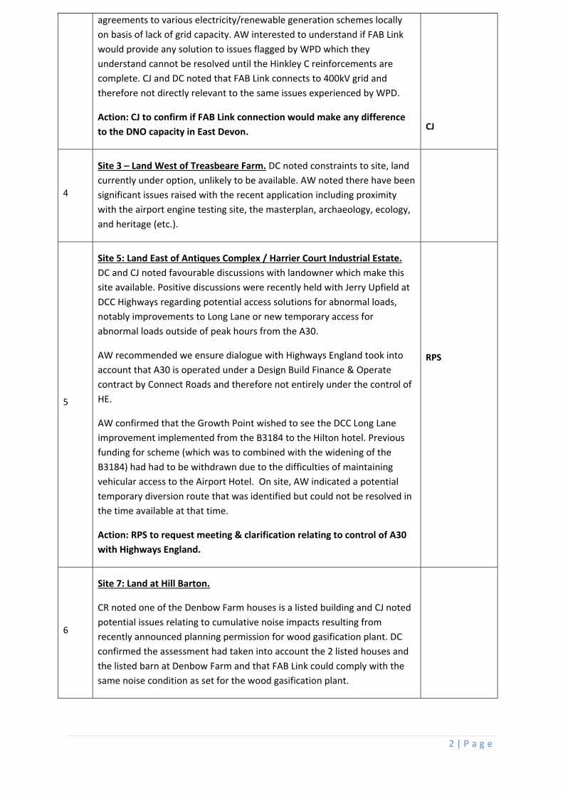
2 | P a g e
agreements to various electricity/renewable generation schemes locally on basis of lack of grid capacity. AW interested to understand if FAB Link would provide any solution to issues flagged by WPD which they understand cannot be resolved until the Hinkley C reinforcements are complete. CJ and DC noted that FAB Link connects to 400kV grid and therefore not directly relevant to the same issues experienced by WPD.
Action: CJ to confirm if FAB Link connection would make any difference
to the DNO capacity in East Devon.
CJ
4
Site 3 – Land West of Treasbeare Farm. DC noted constraints to site, land currently under option, unlikely to be available. AW noted there have been significant issues raised with the recent application including proximity with the airport engine testing site, the masterplan, archaeology, ecology, and heritage (etc.).
5
Site 5: Land East of Antiques Complex / Harrier Court Industrial Estate.
DC and CJ noted favourable discussions with landowner which make this site available. Positive discussions were recently held with Jerry Upfield at DCC Highways regarding potential access solutions for abnormal loads, notably improvements to Long Lane or new temporary access for abnormal loads outside of peak hours from the A30.
AW recommended we ensure dialogue with Highways England took into account that A30 is operated under a Design Build Finance & Operate contract by Connect Roads and therefore not entirely under the control of HE.
AW confirmed that the Growth Point wished to see the DCC Long Lane improvement implemented from the B3184 to the Hilton hotel. Previous funding for scheme (which was to combined with the widening of the B3184) had had to be withdrawn due to the difficulties of maintaining vehicular access to the Airport Hotel. On site, AW indicated a potential temporary diversion route that was identified but could not be resolved in the time available at that time.
Action: RPS to request meeting & clarification relating to control of A30
with Highways England.
RPS
6
Site 7: Land at Hill Barton.
CR noted one of the Denbow Farm houses is a listed building and CJ noted potential issues relating to cumulative noise impacts resulting from
recently announced planning permission for wood gasification plant. DC confirmed the assessment had taken into account the 2 listed houses and the listed barn at Denbow Farm and that FAB Link could comply with the same noise condition as set for the wood gasification plant.

3 | P a g e
7
Site 8: East of Showground
DC noted that a review of this site area had been initiated but it did not appear to have advantages over the other southern site areas.
CR stated that this site is close to an area used to bury livestock with Anthrax.
8
Site 10: Land at Greendale Barton
CR stated that there is no plan to allow for the expansion of either Hill Barton or Greendale Barton in the emerging Local Plan. The EDDC view is that there was sufficient employment land allocated elsewhere. CR noted there was also a history of complaints relating to noise and dust from local residents at Woodbury Salterton regarding previous expansion of development at Greendale Barton. The development that had taken place there was originally linked to the landfill operations.
9
Site 12: Land West of Exeter Substation
CR asked if FAB has approached National Trust, noting their recent objections to surrounding developments. DC stated FAB are aware of the Killerton Study and the issues as raised by NT on other projects.
10
Site 14: Land NE of Airport Business Park
DC noted that no progress had been made progressing discussions with Rigby Group on this site. AW confirmed Rigby Group had made representations to increase the business park allocation from the currently allocated 5ha (Strategy 18n in the emerging Local Plan) to a total of 15ha, to include additional land south of Long Lane. Rigby Group wished to provide for a wider range of uses than solely airport‐related uses.
11
Allocated Sites
AW stated that Parcels 3 or 6 on the RPS Allocated Sites slide 24 would suit best if FAB Link converter station were progressed on allocated land.
1. Sainsbury’s Site (Parcel 3 on Allocated Plan on Slide 24). AW
noted site of 550,000 sq ft has been levelled & prepared for 2 years and consists of a parcel of land acquired by Sainsbury’s bought outright from the Church Commissioners. However, a corporate realignment subsequently resulted in Sainsbury’s wanting to dispose of this land. AW suggested the site at the back of the Sainsbury’s land holding abutting the railway might be available and this might be larger than currently shown but DC did not think Sainsbury’s would entertain an option to purchase. If FAB were to look at Phase 2 land to the east, AW stated FAB would need to approach the Church Commissioners. AW and CR noted

4 | P a g e
that in context of reduced uptake in allocated land together with the fact that this land may not be taken up for rail freight terminal because of difficulties with the gradient of railway track, then it may be possible that potential policy objections regards loss of employment land could be overcome.
Action: AW to provide aerial photo of site with aforementioned
boundaries [post meeting note: AW emailed aerial photos]
Action: RPS to determine if 5ha footprint would fit within available land
Action: FAB Link to contact John Weir at Church Commissioners to
discuss appetite for selling option (if sufficient land available) before end
of July [post meeting note: FAB Link Land Agent (James Neil, Dalcour
McClaren) left message with John Weir on 26/6]
1. Parcel 6 on Allocated Plan on Slide 24. AW noted that land currently owned by Balfour Beatty could potentially be suitable subject to Long Lane improvements. AW highlighted potential for temporary access solution for Hilton Hotel using the lane around the back of the FlyBe Training Academy which would require joining up a small (~5m) overgrown gap with some minor engineering to alleviate the short steep slope in this vicinity. AW
inferred that both FlyBe and Askews were amenable to such a solution in the past when the Council had sufficient funds allocated, however this funding has subsequently been lost.
CR noted that he was unable to comment on Strategy 18n in the emerging Local Plan relevant to this area as Ed Freeman was not present at meeting.
12
Next steps
Action: CR to respond to site selection process and potentially available
sites before 9th July.
Action: FAB to request pre‐application opinion on preferred site.
Action: FAB to submit request for Screening Opinion before end 2015.
13 Meeting adjourned for site visit to Sainsbury’s site and Long Lane.
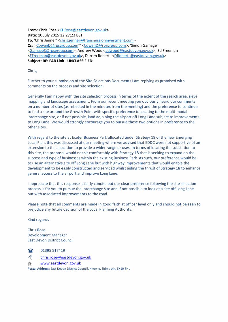
From: Chris Rose <[email protected]> Date: 10 July 2015 12:27:23 BST To: 'Chris Jenner' <[email protected]> Cc: "'[email protected]'" <[email protected]>, 'Simon Gamage' <[email protected]>, Andrew Wood <[email protected]>, Ed Freeman <[email protected]>, Darren Roberts <[email protected]> Subject: RE: FAB Link ‐ UNCLASSIFIED:
Chris, Further to your submission of the Site Selections Documents I am replying as promised with comments on the process and site selection. Generally I am happy with the site selection process in terms of the extent of the search area, sieve mapping and landscape assessment. From our recent meeting you obviously heard our comments on a number of sites (as reflected in the minutes from the meeting) and the preference to continue to find a site around the Growth Point with specific preference to locating to the multi‐modal interchange site, or if not possible, land adjoining the airport off Long Lane subject to improvements to Long Lane. We would strongly encourage you to pursue these two options in preference to the other sites. With regard to the site at Exeter Business Park allocated under Strategy 18 of the new Emerging Local Plan, this was discussed at our meeting where we advised that EDDC were not supportive of an extension to the allocation to provide a wider range or uses. In terms of locating the substation to this site, the proposal would not sit comfortably with Strategy 18 that is seeking to expand on the success and type of businesses within the existing Business Park. As such, our preference would be to use an alternative site off Long Lane but with highway improvements that would enable the development to be easily constructed and serviced whilst aiding the thrust of Strategy 18 to enhance general access to the airport and improve Long Lane. I appreciate that this response is fairly concise but our clear preference following the site selection process is for you to pursue the Interchange site and if not possible to look at a site off Long Lane but with associated improvements to the road. Please note that all comments are made in good faith at officer level only and should not be seen to prejudice any future decision of the Local Planning Authority. Kind regards Chris Rose Development Manager East Devon District Council
01395 517419
[email protected] www.eastdevon.gov.uk
Postal Address: East Devon District Council, Knowle, Sidmouth, EX10 8HL

APPENDIX 4: FAB Link: Sites for Converter Station– Summary of Landownership Responses

FAB Link Converter Station Sites – Land Ownership - July 2015
Appendix 4: FAB Link: Sites for Converter – Summary of Landownership Responses
Area Reference
Location Summary of Landowner Contact
Land Availability
1 Foxenhole Quarry, West Hill Dalcour Maclaren spoke to the landowners in March 2015 and subsequently they confirmed they did not want to consider the proposal any further. A letter was received from the landowners in April 2015 confirming they did not wish the site to be considered.
Not available.
3 Land west of Treasbeare Farm The landowner was originally contacted in 2012, who stated the site was unavailable because it was under option for residential development.
RPS contacted the option holder in August 2014 and established that the part of the land under option that was of interest might be available for non-residential use e.g. FAB Link.
Dalcour Maclaren contacted the option-holder in May 2015 to discuss the possibility of an option arrangement. They indicated that a mixed use of residential and commercial development was planned for the land. Their intention was to be in a position to sell the commercial land within two years, so not able to entertain tying up the land for longer than this period by entering into a lengthy option agreement running beyond that timescale.
Not available.
5 Land east of Antiques Complex/ Harriers Court Industrial Estate
The land is potentially available. Heads of Terms have been agreed with the agent acting for the landowner.
Available

FAB Link Converter Station Sites – Land Ownership - July 2015
Area Reference
Location Summary of Landowner Contact
Land Availability
6 South east of Airport Business Park See also Site 14 below. Dalcour Maclaren first contacted the new option holders in October 2014 and had subsequent contact to try to establish if the land was available for option. Although they were willing to consider a proposal, they would only move forward once their whole portfolio at Exeter was reviewed in light of the Local Plan which included representations for the allocation of this land.
They are unlikely to move forward with this if allocated for airport-development in the Local Plan.
This site is also further complicated by the fact that the current option expires in 2018 and therefore further negotiations will be needed with the freeholders.
Not currently available
Land potentially available in the longer term but not in the required timescale. Further complicated by multi party agreement
being required and other Local Plan aspirations.
7 Land at Hill Barton Landfill Dalcour Maclaren contacted the landowners in September 2014 concerning the land to the north/east of the Hill Barton. This was unavailable as an extension to the landfill site had been granted planning permission. However, the land to the north of Hill Barton might be available if suitable for FAB Link.
Following further feasibility studies on this alternative site, Heads of Terms were agreed in June 2015 for a lease for a 125 year period. Access would be through existing industrial area (Stuart Way).
Available for long leasehold

FAB Link Converter Station Sites – Land Ownership - July 2015
Area Reference
Location Summary of Landowner Contact
Land Availability
9
Windmill Hill, Higher Greendale
Dalcour Maclaren met with the site agent for Greendale Barton in April 2015. Field of interest to south west of business park is constrained by highway to south and business park to north and east. A brook runs along boundary which occasionally floods. Tree belts have been planted on two sides as one of the planning conditions attached to business park developments. Landowners were expecting to build their own units on this land and offered instead land at Hogsbrook Farm.
Not available
10
Land east of Greendale Barton (Hogsbrook Farm).
Dalcour Maclaren met with the site agent for Greendale Barton in April 2015. Although the land to south west of the commercial area (Site 9 above) was not available, land to the north/east of Hogsbrook Farm (Site 10) was potentially available. This included land formerly occupied by the National Grid Gas contractor’s depot which had previously been assumed to have already been developed and in an alternative use. In July 2015 the potential site boundaries were amended by the landowner in response to existing uses of the land. Heads of Terms were discussed and rentals would be based on those obtained for existing short commercial leases. Also only prepared to offer a maximum of a 60 year lease and not a freehold purchase.
Not available. (Unable to agree terms for rental on
basis offered)
12
Land west of Exeter substation
Heads of terms have been negotiated with agent for freehold acquisition. These are not completed and have been left on hold pending completion of the site selection process. If required for access, land to the north is a separate landowner not yet contacted.
Available

FAB Link Converter Station Sites – Land Ownership - July 2015
Area Reference
Location Summary of Landowner Contact
Land Availability
13
Clyst Valley, Whimple
Dalcour Maclaren made contact with landowner in April 2015. They have lived at property for a long time and do not want to sell part of the farm for the converter station. Confirmed in writing that they do not wish site to be considered in April 2015.
Not Available
14
Land north east of Airport Business Park
Dalcour Maclaren contacted the new option holders in January 2015 and had subsequent contact to try to establish if the land was available for option. Although they were willing to consider a proposal they would only move forward once their whole portfolio at Exeter was reviewed in light of the Local Plan. They are not in a position to move forward with this. This site is further complicated by the fact that the current option expires in 2018 and therefore further negotiations will be needed with the freeholder.
Not currently available
Land potentially available in
the longer term but not in the required timescale and further complicated by multi
party agreement being required.

APPENDIX 5: Summary of Assessment Tables for Potentially Available Sites

1 rpsgroup.com/uk Appendix 5 - Site 3
Planning & Development August 2015
APPENDIX 5: SUMMARY OF ASSESSMENT TABLES FOR POTENTIALLY AVAILABLE SITES
Key: Red High risk option. Effects, policy conflicts and/or consenting risks that are likely to
remain after mitigation are likely to carry such weight that the site is unlikely to be granted planning permission. Land owner consent may not be deliverable.Engineering feasibility and/or cost criteria may not be achievable.
Amber Feasible option. Environmental effects and/or consenting risks may arise butappear likely to be acceptable on balance with mitigation. Land agreements,engineering and cost requirements may not be ideal but appear achievable.
Green Good solution. Appears likely to be acceptable in terms of the topic withidentified measures. Environmental effects and/or consenting risks appearcapable of mitigation. Meets land availability, engineering and cost criteria.
Site 3 ‘Land West of Treasbeare Farm’
Parameter Assessment Project Requirements & Costs Operational Area 3.80 hectares Building Area Provision of up to 1.1 hectare for the buildings can be achieved easily. It
should be noted, however, that: The site shape is slightly irregular because of the plot within which it
sits within the Cranbrook expansion masterplan for Treasbeare Farm.
Achieving the required noise mitigation for the proposed residential development to the north and east is likely to dictate how the buildings and other infrastructure are to be laid out on the site.
Total Site Area 7.25 hectares (excluding site access road). ‘Laydown’ Area A laydown area during construction would be available within the 7.25
hectare wider plot area which would be incorporated into the site landscape scheme after construction is complete.
Building Height RPS screening assessment – 20m height not constrained by aerodrome safeguarding
Cable Route Access
Open agricultural land (within the same land ownership as the site) lies to the north and east. Immediate access to the site with cable routes is not constrained in these areas but will have to be protected from development in any land agreement.
Distance from potential landfalls
Straight line distance: Sidmouth: 14.1km; Budleigh Salterton 13.8km Shortest road route: Sidmouth: 19.4km; Budleigh Salterton 20.6km
Distance from NETS substation
Straight line distance: 2.9km Indicative cable route corridor distance: 3.3km
Onshore Cable Route Cost Est.
€72-75m (Second lowest cost of six potentially available sites in the final appraisal).
Site Access & Highways Cost
£0.36m - Approximate cost for new access to B3174. This cost would reduce if the existing access to the E.ON energy centre or an access road built for the proposed Cranbrook extension was available at the time of construction.
Utilities & Other Infrastructure
No exceptional costs identified.

2 rpsgroup.com/uk Appendix 5 - Site 3
Planning & Development August 2015
Parameter Assessment Site Preparation £0.51m - The site is located on a gradient which will require engineering in
order to create a level platform to accommodate the converter station. Approximate costs assume 16,200m3 of cut and 11,700m3 of fill.
Other costs (e.g. mitigation)
Other mitigation measures which have not been costed include: flood compensation and prevention measures that may need to be
incorporated into the site design following a full flood risk assessment; Some additional noise mitigation may be required but this will probably
be achieved through the layout of the buildings and other infrastructure on the site.
Land Availability Availability/ Deliverability
The site is held under an option agreement with a third party. The option holder has stated that an agreement for FAB Link to acquire the site would not be possible for the length of time required to meet the project requirements because planning permission and commencement of the Cranbrook expansion (15/0046/MOUTH, submitted December 2014) was expected sooner than the option period sought for FAB Link. The option holder intends to sell the land in about two years’ time and therefore does not wish to tie up the land. Concluding any FAB Link agreement may be further complicated if granting planning permission for the Cranbrook expansion application is delayed.
Laydown Area Would be available within the 7.25 hectare wider plot area and incorporated into the site landscape scheme after construction is complete.
Access Route(s) Uncertain due to the phasing and timing of the Cranbrook expansion and whether the access road for the converter station would be via a Cranbrook expansion access road or required first to serve the converter station construction. Negotiations with other parties (e.g. Skypark) may be undertaken about alternative access for construction. However a solution is likely to be available with the same land ownership as the main option.
Environmental Effects Landscape/visual The site has the ability to accommodate an appropriately designed converter
station without unacceptable landscape impacts. The landscape design would take into account the local landscape and potential future open space strategy for the mixed use development and support the aims and objectives of the East Devon Green Infrastructure Strategy. There are likely to be some large scale changes in views gained by receptors within the airport, which lie in close proximity to the site. Neighbouring receptors at the airport and nearby receptors using the B3174 and at Treasbeare Farm on higher ground to the east would need to be considered when locating the main buildings and infrastructure within the development to minimise visual impacts. A robust landscape strategy would minimise effects.
Noise A limited number of existing residential receptors are potentially affected. However, it is proposed that adjacent land is developed for residential use. The area is affected by existing environmental sound from a main road and, but to a lesser extent, an airport during the daytime. Initial modelling indicates that noise criterion for residential receptors could be met with suitable on site mitigation. The site may require additional mitigation to ensure suitability in terms of proposed future residential dwellings.
Traffic/access Access options from the B3174 appear feasible. Some further topographical survey would be required to verify that the route is acceptable. The route would need to either make use of a currently unconstructed proposed access route on the Cranbrook expansion or use a new temporary haul route. This land is in the same control/ownership as the site and access will need to be included in the option agreement.

3 rpsgroup.com/uk Appendix 5 - Site 3
Planning & Development August 2015
Parameter Assessment Heritage & Buried Archaeology
Grade II listed buildings are within 500 metres of the site. No Grade I or Grade II* listed buildings have been identified within 1 km. The site is subject to no heritage designations. The site includes three historic records and there are records in the wider area predominantly associated with World War II use of the airfield.
Ecology The site is subject to no designations for habitat or species value. There are records in the wider area of great crested newt. Other species records are present in the surrounding area. The extent of potential species mitigation is currently uncertain but no constraints on development have been identified.
Water The western areas of the site encroach on floodplain at a high annual probability of flooding (Flood Zones 2 and 3). A flood risk assessment will be required but it appears possible to keep the main buildings outside of the flood zone with some remodelling of the flood storage areas. The site does not lie within a groundwater Source Protection Zone.
Soils/geology The majority of the site is mapped as Grade 3b agricultural land, with Grade 3a agricultural land located in the south eastern corner. The site is not indicated as having been used for landfill. The closest historic landfill record is at Wares Farm to the west of the site. This record is for inert and industrial waste. Most of the higher quality land has been avoided.
Community No public rights of way are present within the site. Given the distance to community facilities and the presence of Exeter International Airport, significant effects on community facilities are unlikely.
Planning Policy & Consents Planning Policies Site 3 is not allocated for any development in the adopted plan, but overlaps
with land shown as allocated as part of the Clyst Valley Regional Park (green infrastructure strategy) on the emerging Local Plan Proposals Map. It would be possible to design the site such that built development could be avoided within this area. The site is covered by adopted and emerging local plan policies for the countryside and development of the site for a converter station would not be in accordance with those policies. However, there are other material considerations. The site is adjacent to Exeter and East Devon Growth Point sites where a wide range of development is proposed. EDDC officers have indicated a preference to locating the converter station in the Growth Point. There are existing and allocated employment and airport-related uses on land adjacent to the site and development of adjacent land has been proposed and consulted upon in the Airport Master Plan. The site is currently part of a larger site subject to a planning application for a residential-led mixed use development which, if approved, would form an expansion of the Cranbrook new community. It is understood that the application is unlikely to be determined before the end of 2015.
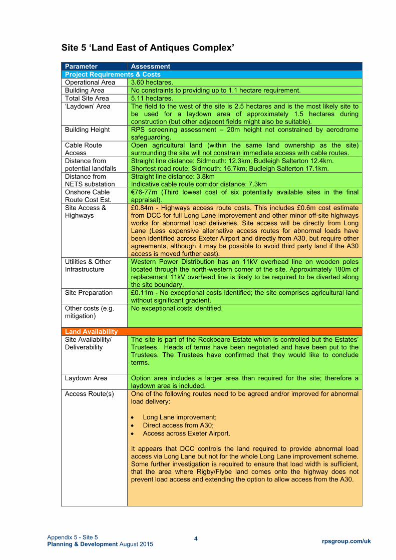
4 rpsgroup.com/uk Appendix 5 - Site 5
Planning & Development August 2015
Site 5 ‘Land East of Antiques Complex’
Parameter Assessment Project Requirements & Costs Operational Area 3.60 hectares. Building Area No constraints to providing up to 1.1 hectare requirement. Total Site Area 5.11 hectares. ‘Laydown’ Area The field to the west of the site is 2.5 hectares and is the most likely site to
be used for a laydown area of approximately 1.5 hectares during construction (but other adjacent fields might also be suitable).
Building Height RPS screening assessment – 20m height not constrained by aerodrome safeguarding.
Cable Route Access
Open agricultural land (within the same land ownership as the site) surrounding the site will not constrain immediate access with cable routes.
Distance from potential landfalls
Straight line distance: Sidmouth: 12.3km; Budleigh Salterton 12.4km. Shortest road route: Sidmouth: 16.7km; Budleigh Salterton 17.1km.
Distance from NETS substation
Straight line distance: 3.8km Indicative cable route corridor distance: 7.3km
Onshore Cable Route Cost Est.
€76-77m (Third lowest cost of six potentially available sites in the final appraisal).
Site Access & Highways
£0.84m - Highways access route costs. This includes £0.6m cost estimate from DCC for full Long Lane improvement and other minor off-site highways works for abnormal load deliveries. Site access will be directly from Long Lane (Less expensive alternative access routes for abnormal loads have been identified across Exeter Airport and directly from A30, but require other agreements, although it may be possible to avoid third party land if the A30 access is moved further east).
Utilities & Other Infrastructure
Western Power Distribution has an 11kV overhead line on wooden poles located through the north-western corner of the site. Approximately 180m of replacement 11kV overhead line is likely to be required to be diverted along the site boundary.
Site Preparation £0.11m - No exceptional costs identified; the site comprises agricultural land without significant gradient.
Other costs (e.g. mitigation)
No exceptional costs identified.
Land Availability Site Availability/ Deliverability
The site is part of the Rockbeare Estate which is controlled but the Estates’ Trustees. Heads of terms have been negotiated and have been put to the Trustees. The Trustees have confirmed that they would like to conclude terms.
Laydown Area Option area includes a larger area than required for the site; therefore a laydown area is included.
Access Route(s) One of the following routes need to be agreed and/or improved for abnormal load delivery: Long Lane improvement; Direct access from A30; Access across Exeter Airport. It appears that DCC controls the land required to provide abnormal load access via Long Lane but not for the whole Long Lane improvement scheme. Some further investigation is required to ensure that load width is sufficient, that the area where Rigby/Flybe land comes onto the highway does not prevent load access and extending the option to allow access from the A30.

5 rpsgroup.com/uk Appendix 5 - Site 5
Planning & Development August 2015
Parameter Assessment Environmental Effects Landscape/visual The site has the ability to accommodate an appropriately designed converter
station without unacceptable landscape impacts. However, a converter station would considerably change the character of the site that is not currently adjacent to existing development or allocated land. There are likely to be some large scale changes in views gained by some receptors within the residential properties, hotel and users of the A30 and Long Lane, which lie in close proximity to the site. A robust landscape strategy would be required to minimise effects.
Noise A limited number of residential receptors are potentially affected. In addition, employment related uses are present in this area. The area is affected by existing environmental sound from a main road and an airport during the daytime. The development is unlikely to affect the acoustic character of the area during the daytime. Initial modelling indicates that noise criteria for existing residential receptors could be met with suitable on site mitigation.
Traffic/access There are potentially significant access considerations due to the narrow nature of the route to the site and the presence of utilities and other businesses. However, there are alternative options for transformer delivery that would appear to be feasible and traffic management measures should be achievable to allow access via Long Lane.
Heritage & Buried Archaeology
No Grade I or Grade II* listed buildings have been identified within 1 km. Three Grade II listed buildings have been identified within 1km and two Grade II listed buildings have been identified within 500 metres of the site, although, these appear some way off in terms of setting and only just within 500m. The site is subject to no heritage designations. There has been some purposeful study of heritage issues around the airport and there is nothing to suggest constraints to the development. The area includes several heritage records associated with World War II use of the airfield, although most of these have been demolished.
Ecology The site is subject to no designations for habitat or species value. There are ponds to the south and southwest of the site that have records of great crested newt. Other species records are present in the surrounding area. The extent of potential species mitigation is currently uncertain.
Water Site 5 lies within Flood Zone 1. The site is therefore at low risk of flooding or less than 1 in 1,000 (0.1%) annual probability. The site does not lie within a Groundwater Source Protection Zone.
Soils/geology The site is mapped as Grade 3a agricultural land, with some Grade 3b land in the southwest corner of the site. The site is not indicated as having been used for landfill. The closest historic landfill record is at Wares Farm to the west of the site. This record is for inert and industrial waste.
Community No public rights of way are present within the site. Given the distance to nearby settlements and community facilities, and the presence of Exeter International Airport, significant effects are unlikely.
Planning Policies and Consents Planning Policies Site 5 is not allocated for any development in the adopted or emerging Local
Plan. The site is covered by adopted and emerging local plan policies for the countryside and development of the site for a converter station would not be in accordance with those policies. There are existing and allocated employment and airport-related uses on land near to the site. Officer level consultations with EDDC have indicated that a site location on Long Lane may be acceptable and this site would appear to meet all of the criteria covered in pre-application discussions.

6 rpsgroup.com/uk Appendix 5 - Site 7
Planning & Development August 2015
Site 7 ‘Land at Hill Barton’
Parameter Assessment Project Requirements & Costs Operational Area 3.7 hectares. Building Area Provision of up to 1.1 hectare for the buildings can be achieved. It
should be noted, however, that: The site shape is irregular because of the shape of the field within
which it sits. Achieving the required noise and landscape mitigation for the
dwellings at Denbow Farm to the north is likely to dictate how the buildings and other infrastructure are to be laid out on the site.
Total Site Area 6.1 hectares. ‘Laydown’ Area Agricultural land to south east could be used depending on the timing
of proposed landfill operations, or land to the west; both areas are in the same ownership.
Building Height RPS screening assessment – 20m height not constrained by aerodrome safeguarding
Cable Route Access Surrounding agricultural land (apart from residential land to north) and the business park are in the same land ownership as the site. It is assumed that cable route access to the site will be achievable.
Distance from potential landfalls
Straight line distance: Sidmouth: 12.5km; Budleigh Salterton 11.2km Shortest road route: Sidmouth: 16.0km; Budleigh Salterton 17.3km
Distance from NETS substation
Straight line distance: 5.6km Indicative cable route corridor distance: 7.3km
Onshore Cable Route Cost Est.
€93-96m (Fifth lowest cost of six potentially available sites in the final appraisal).
Site Access & Highways £0.13m - Minor works on off-site highways for abnormal load delivery and site access from Hill Barton Business Park via Stuart Way.
Utilities & Other Infrastructure
No exceptional costs identified.
Site Preparation £0.86m - The site is located on a gradient which will require engineering in order to create a level platform to accommodate the converter station. Approximate costs assume 13,100m3 of cut and 24,600m3 of fill.
Other costs (e.g. mitigation)
Other mitigation measures which have not been costed include some additional noise mitigation that may be required but this will probably be achieved through the layout of the buildings and other infrastructure on the site.
Land Availability Land Availability Initial discussions indicate that it may be available for development as
a converter station on a leasehold basis. Heads of terms have been negotiated for lease for a 125 year period. Current negotiations are on Ground Rent. There will be additional changes to the terms if negotiations proceed but the site should be considered ‘available’.
Laydown Area Additional land is available in the same land ownership but has not been included in discussions over land agreements to date.
Access Route(s) Access would be through the existing industrial area (Stuart Way), also within the same land ownership.
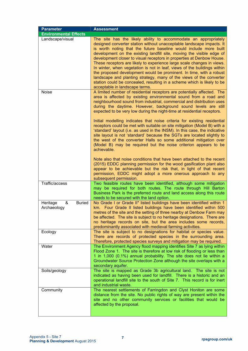
7 rpsgroup.com/uk Appendix 5 - Site 7
Planning & Development August 2015
Parameter Assessment Environmental Effects Landscape/visual The site has the likely ability to accommodate an appropriately
designed converter station without unacceptable landscape impacts. It is worth noting that the future baseline would include more built development on the existing landfill site, moving the visible edge of development closer to visual receptors in properties at Denbow House. These receptors are likely to experience large scale changes in views. In winter, when vegetation is not in leaf, views of the buildings within the proposed development would be prominent. In time, with a robust landscape and planting strategy, many of the views of the converter station could be concealed, resulting in a scheme which is likely to be acceptable in landscape terms.
Noise A limited number of residential receptors are potentially affected. The area is affected by existing environmental sound from a road and neighbourhood sound from industrial, commercial and distribution uses during the daytime. However, background sound levels are still expected to be very low during the night-time at residential receptors. Initial modelling indicates that noise criteria for existing residential receptors could be met with suitable on site mitigation (Model B) with a ‘standard’ layout (i.e. as used in the INSM). In this case, the indicative site layout is not ‘standard’ because the SGTs are located slightly to the west of the converter Halls so some additional mitigation over (Model B) may be required but the noise criterion appears to be achievable. Note also that noise conditions that have been attached to the recent (2015) EDDC planning permission for the wood gasification plant also appear to be achievable but the risk that, in light of that recent permission, EDDC might adopt a more onerous approach to any subsequent permission.
Traffic/access Two feasible routes have been identified, although some mitigation may be required for both routes. The route through Hill Barton Business Park is the preferred route and land access along this route needs to be secured with the land option.
Heritage & Buried Archaeology
No Grade I or Grade II* listed buildings have been identified within 1 km. Four Grade II listed buildings have been identified within 500 metres of the site and the setting of three nearby at Denbow Farm may be affected. The site is subject to no heritage designations. There are no heritage records on site, but the area includes some records, predominantly associated with medieval farming activities.
Ecology The site is subject to no designations for habitat or species value. There are records of protected species in the surrounding area. Therefore, protected species surveys and mitigation may be required.
Water The Environment Agency flood mapping identifies Site 7 as lying within Flood Zone 1. The site is therefore at low risk of flooding or less than 1 in 1,000 (0.1%) annual probability. The site does not lie within a Groundwater Source Protection Zone although the site overlaps with a secondary aquifer.
Soils/geology The site is mapped as Grade 3b agricultural land. The site is not indicated as having been used for landfill. There is a historic and an operational landfill site to the south of Site 7. This record is for inert and industrial waste.
Community The nearest settlements of Farringdon and Clyst Honiton are some distance from the site. No public rights of way are present within the site and no other community services or facilities that would be affected by the proposal.

8 rpsgroup.com/uk Appendix 5 - Site 7
Planning & Development August 2015
Parameter Assessment Planning Policies & Consents Planning Policies Site 7 is not allocated for any development in the adopted or emerging
Local Plan. The site is covered by adopted and emerging local plan policies for the countryside and development of the site for a converter station would not be in accordance with those policies. However, there are other material considerations. There are existing employment uses on land adjacent to the site and land to the immediate east has recently been granted planning permission for the development of a wood gasification plant, with a height to 12.4m. The site also meets the criteria that have been discussed with EDDC with regard to transport access and proximity to existing commercial development. It is also noted however that the extension of those uses is specifically excluded by the relevant policies in the Revised Draft Replacement Local Plan. EDDC officers have indicated that in their view further expansion of Hill Barton is not necessary because there is sufficient employment land available elsewhere. Hill Barton is not in the Exeter and East Devon Growth Point and offices have also indicated they would prefer to see the FAB Link converter station located within the Growth Point.

9 rpsgroup.com/uk Appendix 5 - Site 12
Planning & Development August 2015
Site 10 ‘Land at Greendale Barton’
Parameter Assessment Project Requirements & Costs Operational Area 3.9 hectares. This is likely to be larger than other sites in order to
accommodate level changes within the operational site area. Building Area The site has sufficient area to provide 1.1ha for buildings. However, the
gradient across the revised site will probably require the building areas to be split onto at least two stepped platforms which may cause issues in construction and moving around the operational site.
Total Site Area 6.2 hectares. ‘Laydown’ Area Adjacent agricultural land to east and south east is in the same ownership
and it is assumed could be available for construction laydown. Building Height RPS screening assessment - the land rises in this area and on the highest
part of the site (c.80m AOD) the ground level is within about 25m of the surfaces protected for aerodrome safeguarding. However, the site levels for the buildings still provide 27-30m clearance and will not constrain building height.
Cable Route Access
Surrounding agricultural land (apart from part of the developed land to north) and the business park are in the same land ownership as the site. It is assumed that cable route access to the site will be achievable.
Distance from potential landfalls
Straight line distance: Sidmouth: 10.3km; Budleigh Salterton 8.5km Shortest road route: Sidmouth: 14.5km; Crab Ledge 11.4km
Distance from NETS substation
Straight line distance: 7.7km Indicative cable route corridor distance: 9.0km
Onshore Cable Route Cost Est.
€93-101m (Highest cost of six potentially available sites in the final appraisal).
Site Access & Highways
£0.37m - Minor works on off-site highways for abnormal load delivery and site access from Greendale Barton Business Park. Engineering calculations assume two accesses are required into the site to access the higher and lower level platforms.
Utilities & Other Infrastructure
No exceptional costs identified. The site is within the closest HSE consultation zone for the National Grid pipeline (inner zone), but the HSE advice using its matrix in PADHI is anticipated to be ‘Don’t Advise Against’, taking into account the level of sensitivity of the proposed use, which is Level 1 (the least sensitive).
Site Preparation £1.9m - The site is located on a gradient which will require engineering in order to create a level platform to accommodate the converter station, probably on two levels. Approximate costs for the site include on 14,500m3 of cut and 37,450m3 of fill on the higher level site and 35,750m3 of cut and 13,650m3 fill on the lower level site. It is assumed that an embankment of 10,000m3 would be required between the two levels.
Other costs (e.g. mitigation)
Other mitigation measures which have not been costed include a potential requirement for some additional noise mitigation that may be required on the northern converter hall but this will probably be achieved through the layout of the buildings and other infrastructure on the site.
Land Availability Availability/ Deliverability
Initial discussions indicated that the site may be available for development as a converter station on a leasehold basis (longest leasehold under consideration is 60 years). Heads of terms have been discussed, but there are significant issues around the annual rental levels being sought which are based on existing short term rental agreements elsewhere on the site and there appears to be no realistic prospect of agreement.
Laydown Area Additional land is available in the same land ownership which has been indicated as available.
Access Route(s) Negotiations with land owner must secure access to the site through the central part of Greendale Barton Business Park, particularly for construction.

10 rpsgroup.com/uk Appendix 5 - Site 12
Planning & Development August 2015
Environmental Effects Landscape/visual The site has the ability to accommodate an appropriately designed converter
station without unacceptable landscape impacts. Whilst some sensitive receptors in residential properties are located in relatively close proximity to the proposals, they are unlikely to experience significant changes in views due to screening provided by existing mature hedgerows and woodlands and the large scale industrial and commercial buildings within the intervening landscape. Large scale changes in views are only likely to occur for receptors in adjacent commercial and industrial premises. The sloping nature of the natural topography would require sufficient land around the operational area to accommodate cuttings/embankments and a series of stepped platforms, which would result in complex changes to the landform.
Noise The area is affected by existing environmental sound from local roads and neighbourhood sound from industrial, commercial and distribution uses during the daytime. It is probable that traffic associated with some employment uses influences the environmental sound levels at some receptors during the night time and/or early morning. Neighbourhood sound from plant at an anaerobic digester plant adjacent to the site may slightly influence background sound levels on quiet nights. Background sound levels are still expected to be low during the night time at many residential receptors. Rossili and Redclyst House, which are two address points to the north, are within the significant effect contour and might require additional mitigation on the northern converter hall.
Traffic/access There is a feasible route option available for transformer delivery via Greendale Business Park, although some mitigation may be required in the form of island removal and reinstatement, car park removal and reinstatement, verge overruns and mitigation for potential impacts on hedges and tree root protection areas.
Heritage & Buried Archaeology
No Grade I or Grade II* listed buildings have been identified within 1 km. Fourteen Grade II listed buildings have been identified within 1 km of the site and two Grade II listed buildings have been identified within 500 metres of the site. The site is subject to no heritage designations. The area includes some heritage records, Many of these relate to buildings that are likely to date back to the early medieval period.
Ecology The site is subject to no designations for habitat or species value. There are no species records within the site, although there are records of protected species records in the surrounding area. Therefore, protected species surveys and mitigation may be required
Water Site 10 lies within Flood Zone 1. The site is therefore at low risk of flooding or less than 1 in 1,000 (0.1%) annual probability. Part of the site overlaps with a Groundwater Source Protection Zone.
Soils/geology Part of the site is mapped as Grade 3 agricultural land, although further work could be undertaken to clarify which subset classification the site falls within. At this stage, it is noted that the site may include best and most versatile agricultural land. The site is not indicated as having been used for landfill. The closest historic landfill record is at Greendale Barton to the northwest of the site.
Community No public rights of way are present within the site. Given the distance to nearby settlements and community facilities at Woodbury Salterton, the use of Site 10 as a converter station would not affect the users of community facilities at this village. There may be a perceived impact on Woodbury Salterton from construction traffic due to the large volume of material that is likely to be excavated during site levelling. However it is anticipated that construction traffic impacts can be mitigated.

11 rpsgroup.com/uk Appendix 5 - Site 12
Planning & Development August 2015
Planning Policies & Consents Planning Policies Site 10 is not allocated for any development in the adopted or emerging
Local Plan. The site is covered by adopted and emerging local plan policies for the countryside and development of the site for a converter station would not be in accordance with those policies. However, there are other material considerations. There are existing employment related uses on land adjacent to the site and this general area is characterised by existing commercial development at Greendale Barton and Mill Lane Industrial Estate. Although Hogsbrook Farm is still largely an agricultural site, it is noted that recent permissions have been granted for the development of commercial and energy related uses in and around the farm complex.

12 rpsgroup.com/uk Appendix 5 - Site 12
Planning & Development August 2015
Site 12 ‘Land West of Exeter Substation’
Parameter Assessment Project Requirements & Costs Operational Area 3.6 hectares Building Area No constraints to providing up to 1.1 hectare requirement. Total Site Area 5.7 hectares (excluding site access road). ‘Laydown’ Area Agricultural land to south and west is in the same ownership as the site
and it is assumed 1.5 hectares could be made available. Building Height RPS screening assessment – 20m height not constrained by
aerodrome safeguarding. Cable Route Access Open agricultural land (within the same land ownership as the site) lies
to the south and west. Immediate access to the site with DC cable routes is not constrained in these areas. There may be some routing constraints imposed by the solar farm infrastructure between the site and the substation.
Distance from potential landfalls
Straight line distance: Sidmouth: 15.6km; Budleigh Salterton 16.3km Shortest road route: Sidmouth: 20.9km; Budleigh Salterton 22.1km.
Distance from NETS substation
Straight line distance: 0.5km Indicative cable route corridor distance: 0.59km
Onshore Cable Route Cost Est.
€56-59m (Lowest cost of six potentially available sites in the final appraisal).
Site Access & Highways Cost
£0.38m. Approximate cost for highway works to enable abnormal load access from M5 on the route via Dog Village and an access from the north, via Burrowton Farm solar park. There are a number of issues that would need to be resolved with adjacent land owner and highway authority about the access to the site.
Utilities & Other Infrastructure
No exceptional costs identified.
Site Preparation £0.9m - The site is located on a gradient which will require engineering in order to create a level platform to accommodate the converter station. Approximate costs assume 49,200m3 of cut and 14,100m3 of fill.
Other costs (e.g. mitigation)
No exceptional costs identified.
Land Availability Availability/Deliverability Initial discussions indicate that the site would be available for
development as a converter station. Heads of terms have been negotiated for freehold, although further negotiations are required to determine a cost. A larger option than the site area is potentially available.
Laydown Area Additional land is available in the same land ownership but has not been included in discussions over land agreements to date.
Access Route(s) Negotiations with other parties are likely to be required to secure site access to the north.

13 rpsgroup.com/uk Appendix 5 - Site 12
Planning & Development August 2015
Environmental Effects Landscape/visual The site has the capacity to absorb the proposed development. The nearby
solar farms, the Exeter substation and the overhead power lines form a series of large scale, prominent energy infrastructure developments within a rural landscape context of the site. There is the potential for some large scale change in views gained by walkers using the public footpath and receptors at Loxbrook Farm or Lower Burrowton, which lie in relatively close proximity to the site. There is some potential for cumulative effects with other developments. However, in time, as the landscape proposals mature, trees and shrubs would provide a new barrier in the landscape on the west side of the proposal site and supplement existing hedgerows and trees and form a positive addition to the landscape, concealing many views of the converter station.
Noise A limited number of residential receptors are potentially affected. Nearby NSRs are already affected by environmental sound from road traffic on local roads, the M5 and neighbourhood sound from electrical equipment at Exeter substation and the solar farm. However, given the distances of these NSRs from these sources, baseline environmental and neighbourhood sound levels are likely to be low and the ambient soundscape may be primarily influenced by natural sound (e.g. from wind, rain and animals) and mechanised farming activities in adjacent and nearby fields. Initial modelling indicates that noise criteria for most existing residential receptors could be met with suitable on site mitigation (Model B). Some additional mitigation may be required to avoid significant effects at Redroof Cottage.
Traffic/access Access appears to be feasible using the route used for the Burrowton Farm solar development. This would require agreement with a third party regarding access across the solar farm or adjacent land during the construction phase. In addition, a stream crossing is likely to be required for the construction phase. The proposed route would require mitigation for the abnormal load vehicle in the form of island removal and reinstatement, partial roundabout removal and reinstatement, signage and signal heads removal and reinstatement in a number of locations. There would be some potential for traffic impacts to affect the built up areas through which the route passes at Pinhoe and Dog Village, although these could be mitigated with construction traffic management
Heritage & Built Archaeology
No Grade I or Grade II* listed buildings have been identified within 1 km. There are several Grade II listed buildings within 1km of the site and the closest Grade II listed building, Loxbrook Farmhouse, is located approximately 350m to the west. The site is subject to no heritage designations. The area includes some heritage records, predominantly associated with former farmsteads and settlements in the vicinity of the site.
Ecology The site is subject to no designations for habitat or species value. There are records of protected species in the surrounding area therefore protected species surveys may be required.
Water Site 12 lies within Flood Zone 1. The site is therefore at low risk of flooding or less than 1 in 1,000 (0.1%) annual probability. The site does not lie within a Groundwater Source Protection Zone, although the site overlaps with a secondary aquifer.
Soils/geology The site is mapped as Grade 3 (undifferentiated) agricultural land. Therefore, the land may include best and most versatile land. The site is not indicated as having been used for landfill. The closest historic landfill record is at Hayes Farm to the south west of the site.
Community No public rights of way are present within the site, although the proposal may affect the visual amenity of a public right of way to the east of the site. There may be an impact on Dog Village from construction traffic due to the large volume of material that is likely to be excavated during site levelling. However it is anticipated that construction traffic impacts can be mitigated.

14 rpsgroup.com/uk Appendix 5 - Site 12
Planning & Development August 2015
Planning Policies & Consents Planning Policies Site 12 is not allocated for any development in the adopted or emerging Local
Plan. The site is covered by adopted and emerging local plan policies for the countryside and development of the site for a converter station would not be in accordance with those policies. However, there are other material considerations and a case can still be made for obtaining planning permission on this site including the existing electricity infrastructure features in the immediate landscape and the site being visually related to those. This site was the subject of previous pre-application discussions with EDDC, with a smaller proposed development, and the initial response to the proposed development was negative. TI was advised to look for other sites with less visual impact and better access to the highway network. The layout presented in Figure 3.3 will have a greater visual impact than the scheme considered by EDDC previously and recent discussions with EDDC officers indicate that there is a high likelihood of a recommendation for refusal of planning permission on this site.

15 rpsgroup.com/uk Appendix 5 - Site 14
Planning & Development August 2015
Site 14 ‘Land North East of Airport Business Park’
Parameter Assessment Project Requirements & Costs Operational Area 3.7 hectares Building Area No constraints to providing up to 1.1 hectare requirement. Total Site Area 6.7 hectares. ‘Laydown’ Area Agricultural land to north east is in the same ownership as the site and it is
assumed 1.5 hectares could be made available. Building Height RPS screening assessment – 20m height not constrained by aerodrome
safeguarding. Cable Route Access
Open agricultural land in the same land ownership as the site lies to the south, west and north and will not constrain immediate access to the site for cable routes. There are development aspirations to the south which may impose some constraints, but a cable corridor should still be achievable.
Distance from potential landfalls
Straight line distance: Sidmouth: 12.8km; Budleigh Salterton 12.6km Shortest road route: Sidmouth: 16.4km; Budleigh Salterton 17.6km
Distance from NETS substation
Straight line distance: 3.7km Indicative cable route corridor distance: 4.97km
Onshore Cable Route Cost Est.
€77-80m (Fourth lowest of six potentially available sites in the final appraisal).
Site Access & Highways Cost
£0.84m - Highways access route costs. This includes £0.6m cost estimate from DCC for full Long Lane improvement and other minor off-site highways works for abnormal load deliveries. Site access will be directly from Long Lane (Less expensive alternative access routes for abnormal loads have been identified across Exeter Airport and directly from A30, but require other agreements).
Utilities & Other Infrastructure
No exceptional costs identified.
Site Preparation £0.45m - The site is located on a slight gradient which will require engineering in order to create a level platform to accommodate the converter station. Approximate costs assume 24,600m3 of cut and 7,100m3 of fill.
Other costs (e.g. mitigation)
No exceptional costs identified.
Land Availability Availability/ Deliverability
The site is under option to a third party. Initial discussions with the option holder indicated that it may be available for development as a converter station. However, the option holder has recently confirmed he is not able to enter into an agreement on this site at present. In summary, whilst the land is potentially available in the longer term, it is unlikely that this site will be available within the required project timescales. Land acquisition is further complicated by needing a multi-party agreement.
Laydown Area The field to the north east of the site (2.5 hectares) is understood to be available for temporary use during construction (on the condition of availability of the main site).
Access Route(s) One of the following routes need to be agreed and/or improved for abnormal load delivery: Long Lane improvement; Direct access from A30; Access across Exeter Airport.
It appears that DCC controls the land required to provide abnormal load access via Long Lane but not for the whole Long Lane improvement scheme. Some further investigation is required to ensure that load width is sufficient, that the area where Rigby/Flybe land comes onto the highway does not prevent load access and extending the option to allow access from the A30.

16 rpsgroup.com/uk Appendix 5 - Site 14
Planning & Development August 2015
Environmental Effects Landscape/visual The site is located in arable farmland, within an urban fringe location, and
has the ability to accommodate an appropriately designed converter station without unacceptable landscape impacts. The implementation of the converter station would considerably change the character of the site, however a robust landscape strategy would minimise effects. There are likely to be some large scale changes in views gained by receptors within the hotel and training centre, which lie in close proximity to the site. However, in time, as the landscape proposals mature, trees and shrubs would form an attractive addition to the landscape and conceal many views of the converter station.
Noise A limited number of residential receptors are potentially affected. In addition, the airport hotel and employment related uses are present in this area. The area is affected by existing environmental sound from a main road and, but to a lesser extent, an airport during the daytime. Initial modelling indicates that noise criteria for existing residential receptors could be met with suitable on site mitigation (Model B).
Traffic/access There are potentially significant access considerations due to the narrow nature of the route to the site and the presence of utilities and other businesses. However, there are alternative options for transformer delivery that would appear to be feasible and traffic management measures should be achievable to allow access via Long Lane.
Heritage & Buried Archaeology
No Grade I or Grade II* listed buildings have been identified within 1 km. No Grade II listed buildings have been identified within 500 metres of the site. The site is subject to no heritage designations. There has been some purposeful study of heritage issues around the airport covering both sites and there is nothing in that to suggest constraints to the development. The area includes some heritage records, predominantly associated with World War II use of the airfield.
Ecology The site is subject to no designations for habitat or species value. There are ponds to the south of the site that have records of great crested newt. Other species records are present in the surrounding area. Therefore, protected species surveys and mitigation may be required.
Water Site 14 lies within Flood Zone 1. The site is therefore at low risk of flooding or less than 1 in 1,000 (0.1%) annual probability. The site does not lie within a Groundwater Source Protection Zone.
Soils/geology The site is mapped as Grade 3a agricultural land, with a small area of Grade 3b in the north western corner. The site is not indicated as having been used for landfill. The closest historic landfill record is at Wares Farm to the west of the site. This record is for inert and industrial waste.
Community No public rights of way are present within the site. Given the distance to nearby settlements and community facilities, and the presence of Exeter International Airport, significant effects are unlikely.
Planning Policies & Consents Planning Policies Site 14 is not allocated for any development in the adopted or emerging
Local Plan. The site is covered by adopted and emerging local plan policies for the countryside and development of the site for a converter station would not be in accordance with those policies. However, there are other material considerations. There are existing and allocated employment and airport-related uses on land adjacent to the site and development of this land has been proposed and consulted upon in the Airport Master Plan. Officer level consultations with EDDC have indicated that a site location on Long Lane may be acceptable and this site would appear to meet all of the criteria covered in pre-application discussions.

APPENDIX 1C
Landfall Selection Process Report, July 2016

i
FAB
France Alderney Britain Interconnector
Landfall Selection Process Report
July 2016

i
QUALITY MANAGEMENT
Prepared by: Nina Fionda, Mark Barrett
Authorised by: David Cowan
Date: 20th July 2016
Project Number/Document Reference:
OXF7729/Oxford Reports/Planning/Landfall Selection Process Report
COPYRIGHT © RPS
The material presented in this report is confidential. This report has been prepared for the exclusive use of FAB Link Ltd and shall not be distributed or made available to any other company or person without the knowledge and written consent of RPS.
ii
CONTENTS
1 INTRODUCTION ..................................................................................................................................... 1
Introduction to the Project ....................................................................................................................... 1 Purpose and Structure of this Report ...................................................................................................... 2 Progress So Far ...................................................................................................................................... 3
2 DEFINING THE PROJECT REQUIREMENTS AND MAIN ASSUMPTIONS ........................................ 4 Objectives ................................................................................................................................................ 4 Principal Project Requirements ............................................................................................................... 4 Assumptions for Assessment .................................................................................................................. 5
3 LANDFALL SELECTION PROCESS METHODOLOGY ..................................................................... 11 4 STAGE 1: IDENTIFICATION OF THE LANDFALL STUDY AREA ..................................................... 16 5 STAGE 2: IDENTIFICATION OF LANDFALL OPTIONS .................................................................... 17 6 STAGE 3: ENVIRONMENTAL APPRAISAL ....................................................................................... 19
Introduction ............................................................................................................................................ 19 Sidmouth Seafront (Bedford Lawn Car Park) ........................................................................................ 19 Sidmouth Seafront Cliff (Peak Hill) ........................................................................................................ 27 Crab Ledge ............................................................................................................................................ 33 Budleigh Salterton ................................................................................................................................. 39
7 STAGE 4: CONCLUSIONS AND RECOMMENDATIONS................................................................... 47 8 REFERENCES ...................................................................................................................................... 49
INSETS
INSET 2: TYPICAL HDD COMPOUND ARRANGEMENT ........................................................................... 8 INSET 1: STAGES IN LANDFALL SELECTION PROCESS ...................................................................... 11
TABLES
TABLE 1: LANDFALL SELECTION OBJECTIVES .................................................................................... 4 TABLE 3: SUMMARY OF OPEN CUT CONSTRUCTION PARAMETERS ............................................... 7 TABLE 4: SUMMARY OF LANDFALL HDD CONSTRUCTION PARAMETERS ....................................... 9 TABLE 2A: LANDFALL SITE APPRAISAL RISK CRITERIA FOR RPS’ CONSIDERATION ..................... 15 TABLE 2B: LANDFALL SITE APPRAISAL RISK CRITERIA FOR FAB LINK LTD’S
CONSIDERATION .................................................................................................................... 15 TABLE 5: BEDFORD LAWN CAR PARK (HDD OPTION) - SUMMARY OF SITE FAVOURABILITY..... 26 TABLE 6: BEDFORD LAWN CAR PARK (OPEN-CUT OPTION) - SUMMARY OF SITE
FAVOURABILITY ..................................................................................................................... 27 TABLE 6: SIDMOUTH CLIFF - SUMMARY OF SITE FAVOURABILITY ................................................. 33 TABLE 7: CRAB LEDGE - SUMMARY OF SITE FAVOURABILITY ........................................................ 39

iii
TABLE 8: BUDLEIGH SALTERTON (HDD OPTION)- SUMMARY OF SITE FAVOURABILITY ............. 46 TABLE 9: BUDLEIGH SALTERTON (OPEN CUT OPTION)- SUMMARY OF SITE
FAVOURABILITY ..................................................................................................................... 46
APPENDICES
Appendix 1 Schematic Overview of FAB Link Interconnector Project
Appendix 2 Landfall Appraisal Summary Matrix
FIGURES
Figure 1 Landfall Search Area
Figure 2 Candidate Landfall Sites
Figure 3 Sidmouth Seafront and Sidmouth Cliff Landfall Constraints Map
Figure 4 Sidmouth Seafront and Sidmouth Cliff Utilities Plan
Figure 5 Crab Ledge Landfall Constraints Map
Figure 6 Crab Ledge Utilities Plan
Figure 7 Budleigh Salterton Landfall Constraints Map
Figure 8 Budleigh Salterton Utilities Plan

iv
GLOSSARY
AOD Above Ordnance Datum
AONB Area of Outstanding Natural Beauty
ARE Alderney Renewable Energy Limited
ARE Alderney Renewable Energy Limited
CEMP Construction Environmental Management Plan
CWS County Wildlife Site
GB Great Britain
HDD Horizontal Directional Drilling
HVDC High Voltage Direct Current
LNR Local Nature Reserve
NETS National Electricity Transmission System
NNR National Nature Reserve
NSHR Noise Sensitive Human Receptor
PRoW Public Right of Way
RTE Réseau de Transport d’Électricité
WGK Wood Group Kenny
SAC Special Area of Conservation
SSSI Site of Special Scientific Interest
SPA Special Protection Area
SWCP South West Coast Path

1
1 INTRODUCTION
Introduction to the Project
1.1 FAB (France-Alderney-Britain) Link is a proposed 1,400 MW subsea interconnector cable connecting France and Great Britain via the Channel Island of Alderney. The interconnector is being developed by Transmission Investment, together with the French grid company RTE (Réseau de Transport d’Électricité) and Alderney based tidal power developer Alderney Renewable Energy (ARE). FAB Link Limited is a joint venture between Transmission Investment and ARE. FAB Link Limited will own the assets in Alderney and Britain (the subject of this report) and RTE will own the assets in France.
1.2 The main components of the FAB Link interconnector are shown at Appendix 1 and comprise:
High Voltage Direct Current (HVDC) electricity cables buried in or placed (and protected) upon the sea bed between the Contentin (or Cherbourg) Peninsula, Normandy, France and the South Devon coast of Britain – the Offshore Cable Route;
HVDC electricity cable landing and traverse (as underground cables) of the Channel Island of Alderney;
HVDC onshore and offshore cable ‘transitions’ at the shorelines of all three territories;
HVDC to High Voltage Alternating Current (HVAC) converter stations in both Normandy and Devon; and
HVDC onshore cables from the transition points to the converter stations and HVAC onshore cables from the converter stations to substations in both territories – the Onshore Cable Route. The FAB Link interconnector does not include any overhead lines.
1.3 Any interconnector on the scale of FAB Link can only connect to the electricity system in Great Britain by connection to the high voltage National Electricity Transmission System (NETS) operated by National Grid Electricity Transmission (‘National Grid’). FAB Link has selected (and subsequently agreed with National Grid) a suitable connection point at the substation east of Broadclyst near Exeter. FAB Link Ltd has selected a converter station site near to Exeter Airport.
1.4 Ofgem regulates investment in new interconnector infrastructure either as merchant projects or in a system known as the cap and floor regime. Cap and floor projects are submitted by project promoters to Ofgem for assessment in the interests of consumers. Ofgem has accepted FAB Link into the cap and floor regime.
1.5 FAB Link also applied to become a European Project of Common Interest (PCI) as defined by EU Regulation 347/2013 on Trans-European Networks for Energy, the ‘TEN-E Regulation’. It was accepted as ‘1.7.1 France – UK interconnection between Cotentin (FR) and the vicinity of Exeter (UK) (FAB project)’ in 2013. A PCI is a project which is recognised as being crucial to an integrated EU energy market. PCI projects benefit from accelerated licensing procedures, improved regulatory conditions, and access to European financial support.

2
1.6 In May 2014, DECC set out guidance for PCI project promoters on the process for gaining consents for PCIs. This describes how the existing planning and consents regimes in the UK will be used to provide the ‘permit granting process’ required in the TEN-E Regulation for delivering PCIs. In this process DECC has delegated the task of facilitating the co-ordination of the permit granting process to the MMO in the case of PCIs for which a marine licence will be the primary consent required. On 30 July 2014 the Marine Management Organisation (MMO) accepted the proposed FAB Link interconnector into the permit granting process. The MMO has prepared a schedule of the permit granting process as required under Article 10(4)(b) of TEN-E Regulation.
1.7 Briefly, the decisions and opinions to be obtained from UK authorities include:
Environmental Impact Assessment screening under the Marine Works (Environmental Impact Assessment) Regulations 2007 (as amended) and the Town and Country Planning (Environmental Impact Assessment) Regulations 2011 (as amended) for the marine cable route;
Environmental Impact Assessment scoping under the Marine Works (Environmental Impact Assessment) Regulations 2007 (as amended) and the Town and Country Planning (Environmental Impact Assessment) Regulations 2011 (as amended), should the proposed interconnector be screened into either Regulation;
Planning permission under the Town and Country Planning Act 1990 (the 1990 Act) – decision to be made by East Devon District Council (EDDC) for the converter station; and
A marine licence under the Marine and Coastal Access Act 2009 (the 2009 Act) – decision to be made by the Marine Management Organisation (MMO) for the marine cables.
1.8 The mainland UK elements of the proposed interconnector are underground electricity cables (including the shoreline transition point) and a HVDC to HVAC Converter Station. The UK underground cables and offshore transition point (the landfall) to mean low water are permitted development on land in the UK and do not require environmental impact assessment under either the EIA Directive or the EIA Regulations in England. The Converter Station will require planning permission from East Devon District Council.
Purpose and Structure of this Report
1.9 The purpose of the report is to describe the selection process of the preferred landfall location and includes an appraisal of landfall options which takes into account engineering, cost, environmental and land use factors.
1.10 In terms of the statutory planning framework, as the onshore cable route inclusive of the landfall falls under Permitted Development rights and no planning application will be required, this report also demonstrates that FAB Link Ltd, as a licence holder, has appraised the the environmental and sustainability risks of the candidate landfall options as part of its ‘Duty to Preserve Amenity’ under Schedule 9 of the Electricity Act 1989. This Schedule states that:

3
Have regard to the desirability of preserving natural beauty, of conserving flora, fauna and geological or physiographical features of special interest and of protecting sites, buildings and objects of architectural, historic or archaeological interest; and
Do what he reasonably can to mitigate any effect which the proposals would have on the natural beauty of the countryside or on any such flora, fauna, features, sites, buildings or objects.
1.11 The report will summarise the process FAB Link has undertaken to select the preferred landfall i.e. the point at which the FAB Link interconnector marine cables come ashore in the UK en-route to the converter station and is structured as follows:
Methodology – describes the process used to identify and evaluate the candidate landfall sites;
Defining Landfall Study Area – describes the project requirements and the selection of the landfall study area;
Identifying Landfall Options– describes the engineering parameters of the landfall construction activities;
Landfall Appraisal – describes how the landfalls were appraised in terms of environmental, land use and planning impacts;
Conclusion – describes the selection of the preferred landfall site.
1.12 Landfall Selection Process As described above, the planning of a cable route from the point of landfall to the National Grid substation via the converter station site is part of the overall project concept to deliver an interconnector with France (via Alderney). The commencement of the construction phase is planned for 2018 with the interconnector becoming operational by 2020-2022.
1.13 Although decisions on one element of the project cannot be made in isolation of the others, the decision making process has in each case remained consistent. The process has involved the following decisions:
National Grid substation selection – environmental, engineering and economic factors, including overall cable length from Cherbourg and the capacity of the electricity grid in southern England, led to the selection of Exeter substation as the preferred UK connection option in 2013. The detail of the selection process is provided in the GB Connection Options Report (Transmission Investment, 2016) .
Converter Station site selection – factors such as land availability, proximity to the National Grid substation, access, planning and environmental constraints led to the selection of the preferred converter station site near to Exeter airport in 2015. The detail of the selection process is provided in the HVDC Converter Station Site Selection Process Report (RPS, 2015).
Cable Corridor selection – this process, dependent on the outcomes of this landfall selection report, appraised a number of cable corridor options in Devon and resulted in the selection of a preferred corridor option based on engineering, cost, land use, environmental and planning factors (RPS, 2016).

4
2 DEFINING THE PROJECT REQUIREMENTS AND MAIN ASSUMPTIONS
2.1 This section of the report describes the project requirements of a candidate landfall site and the main assumptions used in the appraisal of site suitability.
Objectives
2.2 The aim of the process was to select a candidate landfall site which could be developed, which met the project objectives set out in Table 1 below.
Table 1: Landfall Selection Objectives
Objectives
Project Requirements
The landfall site must be compatible with the offshore cable route requirements and offer a
viable onshore cable route to the converter station site and generally be consistent with the
project’s efficiency and cost requirements.
Land Acquisition
The landfall site must be capable of accommodating land owner and/or other parties’
requirements and minimise impacts on land uses where possible but otherwise provide an
optimum site to meet the project requirements.
Environment and Sustainability
The landfall site must be capable of accommodating the FAB Link cables whilst satisfying
environmental and sustainable development objectives for the project as described in the FAB
Link Schedule 9 Statement (FAB Link Ltd, 2016). These objectives align with environmental
protection policies set out in the National Planning Policy Framework (NPPF), the Overarching
National Policy Statement for Energy (EN-1) and the National Policy Statement for Electricity
Networks Infrastructure (EN-5).
2.3 The first stage was to identify the principal project requirements for the UK landfall sites and the main parameters which would determine the feasibility of options.
Principal Project Requirements
2.4 The principal project requirements identified are as follows:
The electrical design of the interconnector comprises of two HVDC symmetrical monopoles capable of transmitting up to 700MW each.

5
The onshore HVDC cables will be laid in trenches between “transition pits” at the landfall location towards the converter station. The “transition pits” are underground chambers at which the offshore cables are joined to the onshore cables. The onshore HVDC cables will be of a similar design to the offshore cables, albeit that offshore cables have more armouring.
The onshore HVDC cable route will run from the landfall to the preferred HVDC converter station site, in the most efficient manner (see Table 1).
2.5 As set out above, FAB Link undertook work in 2013 to select a UK National Grid substation for the project based on environmental, engineering and economic factors, including overall cable length from Alderney and the capacity of the electricity grid in southern England. This led to the selection of Exeter substation as the preferred UK connection option in 2013. Following this process, FAB Link then entered a process to select an HVDC Converter Station site. After taking into account factors such as land availability, proximity to the National Grid substation, access, planning and environmental constraints, a preferred converter station site was selected near to Exeter Airport in 2015 (RPS, 2015).
2.6 Consequently, the onshore HVDC cable route will run from the landfall to the preferred HVDC converter station site near to Exeter Airport.
Assumptions for Assessment
Open Cut Trench
2.7 Establishing landfall via open-cut trenching broadly involves the excavation of either one trench per circuit (two circuits with two cables per circuit) or one trench per cable (total of 4) from the transition pit area to the extent of the reach of land-based construction. Continuous cable conduits would be installed for subsequent cable installation in a later campaign prior to backfilling and reinstatement.
2.8 Opening of trenches will be driven by the substrate material. In firm ground, box trenches or trenches with steeply battered sides can be used minimising the total construction area. However, in very loosely consolidated materials such as pebble or sandy beaches a much wider trench with shallow sloping sides would be required.
2.9 For the purposes of landfall selection, it has been assumed that a maximum of 4 cable conduits would be required at 4m centres. Installation across a beach section would involve opening a wide, shallow-sloped trench shored at intervals with gabion baskets and filled with beach materials to prevent the trench from collapsing. Vehicular access both sides of the trench and materials storage would mean that a fenced construction corridor across the beach of up to 50m would be required.
2.10 Cable landfalls in the nearshore region usually have a burial depth in the order of 2-3m below minimum beach level taking into account variations in beach erosion profiles and security/integrity of the cable. A depth (conservative) of 3m maximum would be excavated. It is not envisaged that imported bedding material would be required around the conduits.
2.11 The conduits may need to extend from the transition pit to a point beyond the intertidal zone (perhaps 100m from high water mark) in order to facilitate the 'pull-in' from the cable laying vessel.
2.12 Following reinstatement of the beach, the cables would be pulled in, in pairs, at a later date to suit the offshore and onshore installation schedules. For each pair, a smaller work site established around the relevant conduit entry points as required.

6
2.13 A single cable lay vessel (CLV) would be deployed to install two cables (one circuit) concurrently. Over the offshore section of the route, the cables are bundled together or at least surface-laid as a pair for later burial. At the landfall, the cables are pulled ashore individually through the associated conduits, each by a separate pull-in winch.
Open Cut Trench – Programme Duration
2.14 It is assumed that conduit installation operations would take place within normal working hours, spanning a 12 hour period and that the works would be conducted both outside of the peak summer holiday season (July to September) and period of most frequent and violent storms i.e. March - April and October. The total trenching and conduit installation task duration is likely to be carried out over approximately two months. The separate cable pull-in and jointing operation could take approximately 3 weeks.
Access Requirements and Vehicle Movements
2.15 It is expected that vehicle types utilising the public highway during construction would be very similar to a cross-country cable section i.e. a mixture of cars, vans, articulated HGVs and rigid HGVs. Excavation equipment, dumpers and cranes would operate within the works. Additionally, vehicle movements generated during the separate cable pull-in and jointing operation would include HGVs bearing winches, cranes, cars and vans.
2.16 Movements on the highway would be generated by construction staff, articulated HGVs and rigid HGVs associated with the compound construction, site mobilisation, site operations, materials deliveries, cable pull-in, site demobilisation and site reinstatement. No abnormal indivisible loads are expected.
2.17 The HGV vehicle movements generated by an open cut landfall option have been estimated at this stage using experience of working on other similar sites and will comprise deliveries of:
conduits (2)
gabion baskets (2)
fencing (1)
temporary tracking (if required) (1)
concrete and reinforcing for the join bays (2)
2.18 This is in addition to the inputs required to establish the compound and its accommodation together with delivery of plant and machinery. Demobilisation will generate a similar number
2.19 It is expected that the trenching operations could typically generate approximately 20 HGV movements per day at its peak with a further 40 car movements per day. These estimates are based on experience of other similar projects and are suitable for the purposes of these assessments at this stage.
2.20 HGVs, tippers, low-loaders, etc. would access the site between the hours of 0700 and 1900 hrs

7
Table 3: Summary of Open Cut Construction Parameters
Parameter Description Number of Conduits 4
Working Hours 12 hours a day Monday to Friday and typically 0800 till 1300 on Saturdays
Compound Area 50 m x 50 m HGVs c.20
Construction programme Up to 2 months Pull in programme Up to 3 weeks
HDD Requirements
2.21 For the purposes of this selection process and a high level assessment of sites, a number of HDD requirements are assumed. However, the actual requirements and methods during drilling and construction would be determined on employment of a specialist HDD contractor.
2.22 The cables would need to be landed in separate bores; therefore up to four bores may be constructed. The installation of ducts is required so that HDD operations are separated from cable installation, i.e. cables can be pulled through the ducts in a separate operation. Therefore a minimum of four ducts would be required.
2.23 Based on other projects with similar drill lengths, it is envisaged that the HDD operation would require the use of a large or maxi HDD rig of 25 to 60 tonnes.
2.24 It is assumed that only one drill rig would be employed for the HDD operations and that the location of this would be moved following completion of each bore.
2.25 A non-saline water supply is generally required on site for making drilling fluid, to lubricate the drill and also remove the drill cuttings. It is assumed that water would be regularly delivered to site by tanker during the HDD construction period.
2.26 The construction site would use low level, inward and downward facing floodlights to provide sufficient light for personnel to move around the site and operate machinery safely. The lights would be mounted and directed to minimise the light escaping beyond the site boundary.
2.27 A temporary mud lagoon will be required to capture and recycle the mud during the drilling process and to ensure it does not exit the site. On completion of the HDD works, the lagoons would be drained into a tanker and the arisings disposed of at a suitably licensed waste management facility.
2.28 A temporary compound area (approximately 50 m x 50 m) will contain all necessary plant and equipment plus parking and welfare facilities required for the landfall construction works.
2.29 Jointing of the onshore and offshore cables typically occurs at the HDD entry points. A permanent transition joint bay is required for each cable. Transition joint bays (or pits) are typically 10 m long, 2 m wide and 2 m deep and made of concrete. Transition pits would be accessible during the project life and will therefore have access covers. Separation distances between transition pits are typically 3 m.
2.30 Typical plant and equipment required at an HDD compound is listed below and a typical HDD compound arrangement (taken from WGK Report, 2014) is provided in Inset 2 below.
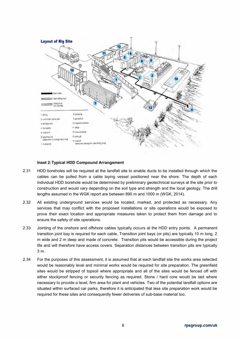
8
Inset 2: Typical HDD Compound Arrangement
2.31 HDD boreholes will be required at the landfall site to enable ducts to be installed through which the cables can be pulled from a cable laying vessel positioned near the shore. The depth of each individual HDD borehole would be determined by preliminary geotechnical surveys at the site prior to construction and would vary depending on the soil type and strength and the local geology. The drill lengths assumed in the WGK report are between 890 m and 1000 m (WGK, 2014).
2.32 All existing underground services would be located, marked, and protected as necessary. Any services that may conflict with the proposed installations or site operations would be exposed to prove their exact location and appropriate measures taken to protect them from damage and to ensure the safety of site operations.
2.33 Jointing of the onshore and offshore cables typically occurs at the HDD entry points. A permanent transition joint bay is required for each cable. Transition joint bays (or pits) are typically 10 m long, 2 m wide and 2 m deep and made of concrete. Transition pits would be accessible during the project life and will therefore have access covers. Separation distances between transition pits are typically 3 m.
2.34 For the purposes of this assessment, it is assumed that at each landfall site the works area selected would be reasonably level and minimal works would be required for site preparation. The greenfield sites would be stripped of topsoil where appropriate and all of the sites would be fenced off with either stockproof fencing or security fencing as required. Stone / hard core would be laid where necessary to provide a level, firm area for plant and vehicles. Two of the potential landfall options are situated within surfaced car parks, therefore it is anticipated that less site preparation work would be required for these sites and consequently fewer deliveries of sub-base material too.

9
HDD Programme Duration
2.35 It is assumed that general site preparations would take place within normal working hours, spanning a 12 hour period and that the HDD operations will require 24 hour working as once started, the operation is difficult to halt. Works in areas that facilitate public access to the beach would be conducted both outside of the peak summer holiday season (July and August). Overall, the process of set up, drilling and demobilisation will take place over a one to two month period, depending on the duration of drilling.
Access Requirements and Vehicle Movements
2.36 It is expected that vehicle movements would be generated by construction staff, articulated HGVs and rigid HGVs associated with the compound construction, site mobilisation, drilling equipment mobilisation, drilling operations, site operations, drilling equipment demobilisation, site demobilisation and site reinstatement.
2.37 There will therefore be a mixture of cars, vans, articulated HGVs, rigid HGVs, cranes and drilling rigs. The cranes and drilling rigs may be up to 60 tonnes in weight, however, they are transported using vehicles that are of similar dimensions to rigid HGVs. Therefore, such vehicles would not be classified as abnormal indivisible loads (AIL) by account of their dimensions or weight and there are no abnormal indivisible loads expected.
2.38 At this stage, for simplicity, it has been assumed that each of the landfall site options would generate the same number of HGV movements.
2.39 Although this may not take account of any unique features associated with each landfill site option, such as topography, compound size, current surfacing, drilling distance or any unique construction methodologies, it does enable the access routes to be considered on a like-for-like basis in terms of their geometric characteristics and their ability to physically accommodate the construction vehicles. In the context of the total construction vehicles generated, this is more important than the variance in quantum given that such features make only negligible changes to the daily vehicle movements.
2.40 The vehicle movements generated by the landfall have been estimated at this stage using experience of working on other similar sites.
2.41 It is expected that the complete landfall construction operations would last up to 2 months and could typically generate around 40 HGV movements per day when drilling is taking place plus potentially 40 car movements per day. These estimates are based on experience of other similar projects and are suitable for the purposes of these assessments at this stage.
2.42 All HGVs, tippers, low-loaders, etc. would access the site only between the hours of 0700 and 1900 hrs, with the potential exception of craneage during mobilisation and demobilisation operations.
Table 4: Summary of Landfall HDD Construction Parameters
Parameter Description Number of bores 4 Working Hours 12 hours a day Monday to Friday and typically 0800 till
1300 on Saturdays HDD Compound Area 50 m x 50 m
HGVs c.40 Construction programme Up to 2 months Approximate drill length Up to 1000 m

10
Cable Route from Landfall
2.43 From the landfall site, the cables must have a clear exit pathway to the onshore cable route corridors and the number of obstacles minimised. The design of the cable route installation is not fixed at this stage. Based on initial advice received on cable design and installation and FAB Link’s own requirements the following parameters were identified:
Cable Installation on Agricultural Land
The installation on agricultural land would include two trenches with a minimum 3 m cable circuit separation and 1.5 m burial depth.
The working width for installation would be a maximum of 30 m.
A permanent easement for the cables would be required outside of highway land, and subject to further design this was likely to be a maximum of 12 m width.
Field drainage and local land drainage would be reinstated.
Cable Installation in Roads
Two circuit trenches would be required. If both circuits were laid together in the same trench project costs and efficiency would be adversely affected and both circuits would need to be taken out of operation during future maintenance and repair work.
Trench separation and working width would require a minimum 6 m wide highway for in-road cable laying. The required road width would be increased where existing utilities also had to be accommodated.
Extensive road closures are likely to be required. Road closures would require highways consents and lengthy road closures on important local road links might not be acceptable.

11
3 LANDFALL SELECTION PROCESS METHODOLOGY
3.1 This section of the report describes the process used to select the candidate landfall sites and appraises them of their favourability in terms of minimising impacts to amenity as described above. The main stages of the process adopted are summarised in Inset 1 below.
Inset 1: Stages in Landfall Selection Process
3.2 The performance of each potential landfall was appraised against the environmental, planning and land use risks and allocated a qualitative risk descriptor as set out in Table 2a below.

12
3.3 FAB Link Ltd has separately considered differentiation of cost and engineering feasibility risks both onshore and nearshore against the criteria set out in Table 2b. .
3.4 Offshore and nearshore surveys were progressed in parallel to this landfall selection process in order to feed in site-specific information on ground conditions that would ultimately influence the decision for the preferred landfall.
Stage 1: Setting the Study Area
3.5 The methodology used to set the study area for landfall selection was a desk-top exercise looking at the coastal zone (nearshore approaches and land constraints) driven by the following principles:
Principles for Landfall Site Selection Study Area
Select the shortest route between Alderney and Exeter Airport, where possible – to minimise cost and achieve greatest efficiency.
Either open cut or trenchless techniques would be considered for bringing the cables ashore.
Avoid designated sites of European Importance.
3.6 Previous analysis (WGK 2014) had demonstrated that the study area for the candidate landfall sites should be confined to a cone shaped zone between the mouth of the River Exe and Sidmouth. Routes to the east of Sidmouth are constrained by the Lyme Bay and Torbay Offshore Candidate Special Area of Conservation (Site of Community Importance). Routes to the west are constrained by the River Exe Special Protection Area and Exe Estuary Ramsar and Special Protection Area designations.
Stage 2: Identification of Landfall Site Options
Methodology for Initial Screening Process
3.7 It was necessary to apply a number of assumptions and limiting criteria to the coastline screening process to eliminate unfeasible areas within the identified Study Area.
Construction Assumptions
There are two principal methods by which the landfall cables may be installed;
o Open-cut trench; and
o Horizontal Directional Drilling (HDD) - this is a trenchless technique for cable installation, whereby a hole is drilled at depth through the ground between two points through which the cable will be installed.
Limiting Criteria (Near Shore)
3.8 The satellite imagery was used to identify obvious near shore constraints and informed the limiting criteria for offshore routing, including:
Offshore areas of high sediment mobility would not be feasible for cable routes due to the potential for cable exposure.

13
Limiting Criteria (Onshore)
3.9 The maps, satellite imagery and site visits were used to identify obvious constraints such as urban or recreational land uses, woodland cover, cliff height and evidence of coastal erosion. This informed a set of onshore limiting criteria, including:
An approximate cliff height of between 30 m – 40 m was assumed as the maximum viable elevation for HDD technology.
A precautionary 200 m set-back distance from the cliff edge was assumed to account for any coastal retreat or landslides;
Areas of woodland cover would be avoided where possible;
Areas with signs of coastal landslide would be avoided where possible; and
Areas of obvious recreational land use would be avoided if possible, e.g. caravan parks, golf courses, etc.
Stage 3: Environmental Appraisal
3.10 The following environmental and planning constraints were considered within the appraisal:
Hydrology:
Source Protection Zones (SPZ).
Lakes, Ponds, Main Rivers, Small Watercourses, flood risk areas, aquifers.
Ground Conditions:
Contaminated Land (pollution incidents and UXO).
Landfill sites.
Quarries.
Habitats and Species:
European statutory designations (Ramsar Sites, Special Protection Areas (SPA), Special Areas of Conservation (SAC).
National statutory designations (Sites of Special Scientific Interest (SSSI), National Nature Reserves (NNR).
Local or regional designations (Local Nature Reserves (LNRs), County Wildlife Sites (CWS).
National Inventory of Woodland and Trees.

14
Priority Habitat Inventory.
Human Environment:
Historic Environment Record (HER).
Scheduled Monuments, registered parks and gardens, historic battlefields, world heritage sites, listed buildings, conservation areas; public access.
Public rights of way (PRoW) including public car parks.
Sports, recreational and tourism facilities.
Hospitals, health care sites, care homes, sheltered housing.
Schools, training centres etc. (noise sensitive uses).
Individual dwellings (incl. curtilage).
Country Parks, Parks, Village Greens, informal recreation areas.
Utilities and river, road or rail crossings.
Areas of Outstanding Natural Beauty (AONB), national parks, countryside character areas, local landscape designations.
3.11 A range of data sources have been consulted during the appraisal process including:
1:50,000 and 1:25,000 scale digital mapping and road map data;
Local Plans and Local Development Documents;
Interactive multi-agency geographic information about the natural environment (www.magic.gov.uk);
Agricultural Land Classification Mapping; and
Data searches from utilities companies, including public water supplies and sewage networks, electricity cables and overhead lines, telecommunications and gas pipelines.
Appraisal Criteria
3.12 Each landfall site was appraised against the following criteria for a range of environmental and sustainability topics as well as planning and land use issues:

15
Table 2a: Landfall Site Appraisal Risk Criteria for RPS’ Consideration
Unfavourable Option Environment, Planning, Land Use and Access
Impacts will occur that conflict with FAB Link’s obligations under Schedule 9 of the Electricity Act and/or raise licensing risks that are likely to remain after mitigation and are likely to carry such weight that the site is unlikely to be acceptable to the responsible agency and/or local planning authority.
Less Favourable Option Environment, Planning, Land Use and Access
Impacts and/or licensing risks that conflict with FAB Link’s obligations under Schedule 9 of the Electricity Act are likely but may be resolved through appropriate mitigation which may not yet be identified.
Favourable Option Environment, Planning, Land Use and Access
Impacts and/or licensing risks are possible but are likely to be acceptable with identified mitigation. The residual impacts will be consistent with FAB Link’s obligations under Schedule 9 of the Electricity Act.
Appraisal Limitations
3.13 The appraisal of site suitability was a high level desk-top exercise based on assumptions relating to engineering feasibility (both onshore and offshore), acceptability of impacts and availability of land. Whilst the sites were not visited by RPS, site walkovers were conducted by WGK and FAB Link Ltd. In considering the suitability of landfall options and in comparing the options with each other, FAB Link Ltd were aware of the issues raised by RPS and were able to rank the candidate landfalls as follows:
Table 2b: Landfall Site Appraisal Risk Criteria for FAB Link Ltd’s Consideration
Unfavourable Option Engineering, Property, Cost
Engineering feasibility and/or cost criteria may not be achievable.
Less Favourable Option Engineering, Property, Cost
Engineering requirements and cost implications may not be ideal but appear achievable.
Favourable Option Engineering, Property, Cost
Appears capable of meeting land availability, engineering and cost criteria.
Stage 4: Site Selection
3.14 The outcome of the appraisal was utilised in an overall decision to select a preferred option that would be subject to further detailed assessment. Should that detailed assessment raise unacceptable risks for the project, the process would recycle back to Stage 2.

16
4 STAGE 1: IDENTIFICATION OF THE LANDFALL STUDY AREA
4.1 The first stage was to identify the target coastline. In 2014, FAB Link commissioned Wood Group Kenny (WGK) to undertake a desktop study of Alderney to Britain offshore cable routes to help identify a preferred landfall site. An initial screening process took place which involved the analysis of satellite imagery to divide the coastline into seven search zones featuring similar physical environmental and/or similar landfall engineering / construction parameters, both onshore and nearshore. The main considerations affecting the feasibility of landfall construction included:
overall route length (Alderney to Exeter Substation);
onshore jointing;
onshore routing;
feasibility of open cut trenching as a landfall installation technique;
feasibility of HDD as a landfall installation technique;
nearshore burial feasibility;
nearshore water depth; and
onshore and nearshore third party limitations.
4.2 The seven coastal zones of similar characteristics are shown on Figure 1 and are briefly described as follows:
Area 1: Exmouth Town – Mouth of the River Ex
Area 2: Mouth of the River Ex – Sandy Bay
Area 3: Sandy Bay – East Devon Golf Club
Area 4: East Devon golf Club – Otter River mouth
Area 5: Otter River mouth – Holiday Home Park
Area 6: Holiday Home Park – West of Sidmouth
Area 7: Sidmouth
17
5 STAGE 2: IDENTIFICATION OF LANDFALL OPTIONS
5.1 The second stage was to identify landfall site options within the study area focussing on the main parameters which would determine the feasibility of options, but also with regard to some primary environmental constraints both onshore and offshore. The first sift of sites included the following locations shown on Figure 2:
Area 1: Exmouth Town – Mouth of the River Exe
5.2 This zone was discarded on the basis that shallow offshore banks and high rates of dynamic sediment transport would impede cable lay vessel operations and could also potentially lead to cable exposure over time, which could in turn lead to increased risk of cable undermining or cable being snagged by dragged anchors or fishing trawling gear. High concentrations of vessel traffic and the numerous environmental protection designations also meant that this zone would be high risk.
Area 2: Mouth of the River Exe– Sandy Bay
5.3 Within this zone, open cut trench installation would not be feasible due to limited safe refuge on the beach between the high water mark and the bottom of the cliffs. A suitable HDD location would need to be located between the mouth of the River Exe and the Sandy Bay holiday park to the east. Three potential sites were identified within the zone, although two were discarded on the basis of proximity to the mouth of the River Exe and cliff heights of approx.50 m. One potential landing site was identified west of Sandy Bay Holiday Park albeit at 40 m elevation noting that that cliff height and erosion seemed high risk.
Area 3: Sandy Bay – East Devon Golf Club
5.4 This zone was discarded on the basis that the cliff line appeared highly eroded and there were some signs of coastal landslides. Moreover, the cliff height was between 70 – 80 m and therefore beyond the maximum viable elevation for HDD technology.
Area 4: East Devon golf Club – Otter River mouth
5.5 Several feasible options were identified. A field on the western side of Budleigh Salterton would present a HDD option through a 30 m cliff, although tree felling would be required and construction access appeared problematic. An alternative landing site is located within Lime Kiln car park to the east of Budleigh Salterton. The car park site seemed to offer potential for both construction options of HDD and open-cut trench and was recommended for further study.
Area 5: Otter River mouth – Holiday Home Park
5.6 The entire cliff line features similar HDD construction conditions. To account for potential erosion, a precautionary 200 m set back distance from the cliff edge was assumed. Two sites which seemed technically equivalent were identified as potential landfall points: Crab Ledge and Chiselbury Bay. Crab Ledge was preferred over Chiselbury Bay on the basis that there would be a shorter drill length and there is an existing access road to Otterton Waste Water Treatment Plant. Crab Ledge was recommended for further study.

18
Area 6: Holiday Home Park – Edge of Sidmouth town
5.7 This coastline featured a highly eroded cliff line with some signs of landslides. Areas of significant forest cover were excluded as locations within which to land cables. No suitable landfall options were identified based on extremely challenging drilling conditions for landing the cables.
Area 7: Sidmouth
5.8 The western edge of this zone is constrained by a 90 m high cliff surrounded by trees and a small golf course. Urban development towards Sidmouth has limited the number of open spaces for landfall options to a field behind a 20-25 m high cliff known as Sidmouth Cliff and an alternative site at Bedford Lawn car park within Sidmouth. Offshore and shoreline environmental designations as well as evident land use constraints were issues to be considered further.
5.9 In summary, five landfall site options were identified for further appraisal and comparison. These included:
Sandy Bay (Area 2);
Budleigh Salterton (Area 4);
Crab Ledge (Area 5);
Sidmouth Cliff (Area 7); and
Bedford Lawn Car Park (Area 7)
5.10 However, further consideration of factors including the proximity of the site to the Exe Estuary Special Protection Area and cliff heights at Sandy Bay reduced this list to four feasible landfall options. These landfall site options are considered in this report and are as follows:
1) Sidmouth Seafront, Bedford Lawn car park;
2) Sidmouth Cliff;
3) Crab Ledge; and
4) Budleigh Salterton, Lime Kiln car park.

19
6 STAGE 3: ENVIRONMENTAL APPRAISAL
Introduction
6.1 The purpose of this stage is to provide an appraisal of the relevant environmental, planning and land use factors affecting the landfall locations within a study area of 1km which encompasses both the onshore and nearshore environments. The detailed consideration of offshore cable routing feasibility was reported to FAB Link Ltd by Wood Group Kenny (WGK 2014, 2105). The focus of this appraisal is the environmental, planning, land use and physical constraints (inclusive of existing accessibility) at each landing site, including consideration of nearshore and onshore cable routes within approximately 1 km of the landfall candidate landfall options.
Sidmouth Seafront (Bedford Lawn Car Park)
Introduction
6.2 This landfall option is located in the Bedford Lawn Car Park on the esplanade, in Sidmouth. Figure 3 shows the landfall site option location on a constraints plan and Figure 4 shows the result of a desktop utilities search. The car park is accessed from Station Road and is listed on the Sidmouth Town Council website as being privately owned. The recommended method of construction identified in the WGK Report (WGK, 2014) would be the use of either HDD or open cut trench to land the cables. However, the car park itself is quite small and this appraisal has been undertaken on the understanding that the limited space available within the car park will be sufficient for either construction method.
Landscape and Visual
6.3 The site is located within a character area defined as ‘Urban’ within the East Devon District landscape character study. The location lies near to the ‘Coastal Cliff’ character type, the key characteristics of which are steep cliffs above narrow shingle beaches which are generally inaccessible, although cliff tops allow extensive views along the coastline (East Devon District Council et al, 2008). The location lies within National Seascape Character Unit 6 ‘Land’s End to Portland Bill’.
6.4 The site comprises a car park set beside a coast road and the esplanade, behind the shingle beach within the centre of the settlement. The Sidmouth Cricket Club, bowls lawns and tennis courts form a large area of recreational open space, incorporating club houses, to the north and west. Hotels, residential properties and cafes surround the open space and extend up to the coast road, forming a typical tourist town of predominantly 19th century origin. The land rises to the west beyond the urban edge of the settlement to pasture fields and a golf course development.
6.5 The site lies in close proximity to the East Devon AONB and the Dorset and East Devon Coast World Heritage Site to the east and west, and the Registered Park and Garden at Connaught House to the west.
HDD Option
6.6 There are no apparent existing site features that would be physical constraints to the HDD construction. All of the car park would be occupied by the construction compound for a short period

20
of time. The car park is of low scenic quality, however, the town centre has a good scenic quality and is characteristic of the settlement. The temporary construction activities, although confined to a small area, would be discordant in nature and conspicuous in the open coastal context and would have an adverse influence over the surrounding townscape and seascape.
6.7 High sensitivity visual receptors in close proximity to the site include walkers using the South West Coast Path (SWCP), tourists in hotels and gardens, especially the Bedford Hotel immediately to the east and Connaught House Registered Park and Garden to the west, the Fort Café and Fort Apartments to the west, residents within properties, and people using the beach and esplanade. Occupiers of vehicles, people using the car park and people using the sports facilities would be of lower sensitivity. The availability of open views by the aforementioned receptors will be dependent upon construction site screening.
6.8 Occupiers of other more distant residential properties to the north and west are also considered to be high sensitivity receptors that may also gain partially filtered views of the construction works through vegetation.
6.9 Direct impacts on the fabric of the townscape would comprise the temporary loss of the car park. Upon completion the car park surface would be fully reinstated. During construction, there may be localised impacts on townscape character in the short term. Long term impacts are not predicted. Temporary impacts on the wider seascape, although adverse in nature, would not compromise the favourability of this landfall site in terms of meeting the Schedule 9 obligations.
6.10 Due to the location of the construction site within the centre of Sidmouth, outside of the East Devon AONB, there are unlikely to be any adverse impacts on this landscape designation. Any adverse influence over the nearby important, geomorphological features of the East Devon Coast World Heritage Site would be unlikely as a result of the construction activities. There would be limited adverse impacts on the character of the Connaught House Registered Park and Garden during the construction phase, which would be intervisible with the construction site.
6.11 Due to the close proximity of the visually discordant activities, the location of the construction compound within the car park would lead to impacts on views gained by people walking on the SWCP, esplanade, sports facilities and using the beach, tourists within hotels and cafes and residents within properties. However, with the exception of the sporting facilities, the focus for most views in these locations is out to sea and along the coast, which would remain largely unaffected by the proposals. Impacts on receptors within passing vehicles would pose less of a risk to the favourability of this landfall site due to the lower sensitivity of these receptors. There would be no long term adverse impacts on views.
6.12 The incorporation of appropriate mitigation measures including hoarding or screening during the construction phase may offer the opportunity to reduce potential impacts on townscape, seascape and visual resources.
Open Cut Option
6.13 The use of open-cut trenching to establish a cable landfall at Sidmouth would add to the extent of construction effects described above for the HDD option. A wide trench with shallow sides would be cut across the shingle beach, located within a construction corridor up to 50 m wide. It is expected that the esplanade would also need to be closed or partially closed for a short period.

21
6.14 The beach at Sidmouth has a good scenic quality and the temporary construction activities would be discordant in character in this open coastal context. The scale and nature of the trenching works would have an adverse effect on the seascape and neighbouring townscape.
6.15 The high sensitivity receptors described above for the HDD option would experience more extensive views of construction activities, particularly users of the beach, esplanade and people using the sea in close proximity to the trenching works. In these locations, views may temporarily be dominated by the construction corridor and activities including heavy plant and HGV’s.
6.16 Direct impacts on the fabric of the seascape would arise through the temporary loss of part of the beach. The beach would be reinstated and no visible signs of the construction works would remain in the long term.
6.17 Impacts on the East Devon AONB, Dorset and East Devon Coast World Heritage Site and Connaught House Registered Park and Garden would be as described above for the HDD option.
Transport and Access
6.18 Bedford Lawn car park is accessed directly from the B3176 Station Road, which routes north to south and forms the main route from the A3052 into Sidmouth. In the vicinity of the car park, the B3176 Station Road is approximately 6.5 m wide with footways on both sides of the carriageway, a 30 mph speed restriction, some on-street parking, direct access to properties and environs typically associated with a seaside esplanade location.
6.19 To the north of the car park, there are two priority controlled shuttle workings through which the carriageway narrows to single track and one direction has priority over the other. Within the built up area of Sidmouth, the B3176 Station Road retains a carriageway width of approximately 6.0 m to 6.5 m wide before continuing north to the A3052 at generally 6.0 m wide.
HDD Option
6.20 HGV movements already travel along the B3176 Station Road and there does not appear to be any locations where the road geometry restricts such movement.
6.21 The existing car park access junction onto the B3176 Station Road is in the form of a dropped kerb arrangement, thus providing a continuous and unbroken footway facility for pedestrians across it. It is likely that this would need to be altered to provide a bell-mouth access to prevent damage occurring to the footway by the construction HGVs, thus creating a break in the footway. Such works are also likely to require a slight widening of the existing access to enable HGVs to turn into and out of the access simultaneously.
6.22 Visibility exiting the access to a requisite design standard appears to be constrained to the left (north) due to a grassed bank. However, it is unlikely that this would be a constraint to construction given that adequate visibility could be achieved to a reduced standard for a temporary construction use.
6.23 The level of vehicle movements would be unlikely to result in impacts upon the capacity and operation of the highway network that would pose a risk to the favourability of the landfall site. However, given the seaside esplanade location and the two priority controlled shuttle workings, there may be a local perception of such an impact during peak tourist months.
6.24 Due to the location and the associated uses, HGV movements in particular could create some environmental impacts on pedestrian amenity during peak tourist months.

22
6.25 Other routes to the car park run along the seafront, through residential areas are a longer distance through such environs, therefore have not been considered further due to the likely visual, noise and traffic disruption impacts.
6.26 Given likely demand for parking, especially during peak tourist months, any spaces lost would likely have to be provided elsewhere. . The most immediate issue is likely to be caused by a need to provide parking for the sports facilities in very close proximity to the existing provision. Again this requirement may vary dependent upon the season.
Open Cut Option
6.27 The constraints identified along the highway network would remain if an open cut methodology was employed, albeit the volume of HGV traffic on the network would be smaller. It is envisaged that the car park would still serve as a compound for deliveries. Where the trench crosses the Esplanade and the road south of the car park, some temporary traffic management would need to be provided. A half road closure would be likely, meaning that traffic can still flow under traffic management. Provided this is undertaken outside of the peak tourist season, this is likely to be acceptable.
Noise
6.28 The site is located within a central area of Sidmouth Seafront. There are hotels and residential flats on the east side of Station Road, about 20 m away and adjacent to the west boundary of the Bedford Lawn car park. There are also several residential and hotel uses to the north-west, approximately 130 m away.
6.29 Baseline noise levels are likely to be moderate during the daytime and low during the evening and night-time, dependent on road traffic flows and weather/sea conditions.
6.30 There are two SSSIs within the vicinity of the site; Ladram Bay to Sidmouth, approximately 380 m to the south west; and Sidmouth to Beer Coast, approx. 500 m to the east. However, the qualifying attributes of these designations are not noise sensitive; therefore no specific mitigation would be required.
HDD Option
6.31 The arrangement of this location with overlooking residential and hotel properties (noise sensitive human receptors (NSHRs)) presents a substantial constraint for the HDD option. There may need to be a seasonal restriction on HDD works, so that the summer tourist season is avoided, when hotels are most busy and residential windows are more likely to be open. There is a considerable risk of noise disturbance at such close proximity, particularly in the evening and night time periods.
6.32 With regards to non-residential NSHRs, there are recreational uses to the north, including the Bedford Lawn recreation ground; bowling green; Sidmouth Cricket, Tennis, Croquet and Hockey Club; and to the south on the beach and Esplanade. There are also numerous cafes/restaurants within 500 m of the site. A seasonal constraint on HDD works may be required to avoid the peak holiday season when there would be a loss of daytime amenity in recreational areas.
Open Cut Trench
6.33 The duration of construction works would be the same as HDD but there would be no requirement for any night time working, so in this respect, there would be less of an impact on residential receptors. A seasonal constraint on works would likely be required in any case due to the disruption to the beach as a recreational resource.

23
6.34 In summary, this is a site with substantial residential development and recreation resources surrounding it. Loss of amenity for residential and recreational uses due to noise impacts and the potential for sleep disturbance from any night time working would present a risk to the favourability of this landfall site.
Cultural Heritage
6.35 This landfall option and the incoming offshore cable would not be located within the Dorset and East Devon Coast World Heritage Site. This designation relates to the coastal geomorphology visible along the length of the Dorset and East Devon coastline but with breaks in the designation where it is not coincident with the AONB, a geological SSSI or a Geological Conservation Review (GCR) unit. It is therefore not continuous and the part of the beach fronting the built up part of Sidmouth is excluded from this designation.
6.36 There are no Scheduled Monuments within 2 kilometres (km) of the landfall location. The nearest Scheduled Monument is High Peak Camp, located approximately 2.5 km to the south west, along the coast.
6.37 The site is located within the Sidmouth Conservation Area (Area 1- Town Centre and Seafront), and there are several listed buildings in the immediate vicinity of the site. The nearest listed buildings include:
The Bedford Hotel (Grade II*);
The Sussex Hotel (Grade II);
Gateway to the Belmont Hotel (Grade II); and
Riviera Hotel (Grade II).
6.38 There is a Grade II Registered Park and Garden (Connaught Gardens) located approximately 400 m south west of the proposed landfall location.
6.39 There are no Protected Wreck Sites within 2 km of the incoming offshore cable route.
Ecology and Nature Conservation
6.40 The proposed landfall location is positioned within Bedford Lawn car park and therefore it is not located within any international, national, regional or local statutory designations for ecology or nature conservation.
6.41 With respect to international designations in the surrounding area, the closest Special Area of Conservation (SAC) is the Sidmouth to West Bay SAC, designated primarily for its vegetated sea cliffs, typical of Atlantic and Baltic coasts and sycamore woodlands forming on slopes, screes and ravines. This designation lies approximately 500 m east of the proposed landfall therefore this presents a risk to the favourability of this landfall site. An inshore SAC (Lyme Bay and Torbay) is located approx. 7km to the east.
6.42 There are no Special Protection Areas (SPAs) or Ramsar sites within 2 km of the site. The closest SPA is the East Devon Heaths SPA, located approximately, 5.7 km north west at its closest point. The closest Ramsar site is the Exe Estuary, located more than 13.5 km to the west. The Exe Estuary is also designated as an SPA.

24
6.43 In terms of national designations, the Ladram Bay to Sidmouth SSSI is located approximately 350 m to the south west. This is primarily designated for its coastal geomorphological interest. The Sidmouth to Beer Coast SSSI is coincident with the Sidmouth to West Bay SAC and lies approximately 500 m to the east of the landfall site. The SSSI is designated primarily for chalk grassland habitat, but also geological features and invertebrate fauna. There are no National Nature Reserves (NNRs) within 2 km of the site.
6.44 The landfall site does not overlap with any County Wildlife Sites (CWS). The nearest CWS is the Windgate Cliffs located to the west of Sidmouth town. The nearest Local Nature Reserve (LNR) is the Fire Beacon Hill LNR, located approximately 3.6 km to the north.
6.45 There is no Ancient Woodland or Priority Habitats located at the site. The nearest priority habitat is some deciduous woodland within the Blackmore Coronation Plantation approximately 200 m to the north east.
6.46 The offshore cable and landing point would not overlap with any statutory marine ecological designations. The nearest designation is the Sidmouth to West Bay Special Area of Conservation (with Marine Components), located approximately 500 m to the east.
Water Environment
6.47 The National Planning Policy Framework (DCLG, 2012) and its accompanying National Planning Practice Guidance (DCLG, 2014) sets out Government policy on development and flood risk. Its aims are to ensure that flood risk is taken into account at all stages in the planning process to avoid inappropriate development in areas at risk of flooding, and to direct development away from the areas of highest risk.
6.48 The National Planning Practice Guidance advocates the use of the risk-based sequential test, in which new development is steered towards the areas at lowest probability of flooding. These are identified by Flood Zones from Flood Zone 1 (low probability) to Flood Zone 3 (high probability and/or functional flood plain).
6.49 The Environment Agency flood mapping shows that the landfall site is located within land identified as Flood Zone 1 and is therefore at low risk of flooding. Glen Road (to the west), the Esplanade and land east of the B3176 road fall within Flood Zone 3. The works would need to be designed to ensure that the risk of river or sea flooding at these locations is not increased by the project, whether HDD is adopted or an open cut construction methodology is adopted.
6.50 The landfall location does not lie within a ground water source protection zone, meaning that there are no nearby groundwater abstraction sources that might provide a public drinking water supply.
Soils and Geology
6.51 The site within a car park and is therefore not in agricultural use. It is not subject to any national geological designations. The Dorset and East Devon Heritage Coast World Heritage Site extends to the east and west of Sidmouth and would be unaffected. Also in the vicinity lie the Ladram Bay to Sidmouth SSSI, designated for coastal geomorphology, and the Sidmouth to Beer Coast SSSI, partly designated for its geological importance. These would also be unaffected.
6.52 There are no landfill sites in the vicinity of the landfall location. The nearest landfill site is at Lower Sweetcombe Farm, more than 5 km to the northeast.

25
6.53 Given the existing use as a car park, there is potential for some localised contamination from fuel leaks, however the presence of a tarmac impermeable surface effectively limits any infiltration. This does not pose a risk to the favourability of the site.
Community and Socio-Economics
6.54 Sidmouth is a popular seaside town and the use of HDD at the landfall location would avoid the disruption to recreational users of the beach and esplanade that would otherwise occur if cable installation was undertaken via an open cut trench. The landfall location is within Bedford Lawn car park which would require closure during construction; therefore there would be some disruption to amenities for recreational users, the local community and loss of income for the car park owners, particularly if carried out during the tourist season. There is also a public right of way that runs along the northern edge of the car park and users of this footpath may experience some impact on visual amenity/ noise disturbance during construction.
6.55 Bedford Lawn car park is a well-used private car park in the principal holiday accommodation area of Sidmouth. There are key recreational uses adjacent to the north of the car park including Sidmouth Croquet and Tennis Lawns and the Cricket Club and the Esplanade which lies adjacent to the south. There are hotels and cafes to the east of the car park. There is some potential for economic impacts on these businesses during construction from closure of the car park and any noise impacts from construction activities. The requirement for HDD works to run on through the evening and night time is a considerable constraint in the consideration of this landfall.
6.56 Dependent upon the time of year, the employment of an open-cut methodology could create a high level of disruption to recreational users of the beach which consequently poses a substantial risk to the favourability of the landfall site. It is likely that East Devon District Council would impose a seasonal constraint on construction works to reduce impacts on recreational users.
Utilities
6.57 All of the roads running north from the Esplanade in this area, namely Station Road, Glen Road and Manor Road already carry buried services for gas, telecommunications (BT) and low voltage and high voltage electricity. These three roads also carry South West Water distribution pipes and sewers (Figure 4).
Landward Cable Route Options Within 1 km from Landfall
6.58 Bedford Lawn car park is located within Sidmouth town centre and it is surrounded by at least 1 km of predominantly residential urban land uses. The onward cable routes from the landfall would therefore be restricted to road routes. The most likely route is the B3176 Station Road, which is the main road into Sidmouth from the principal road network. The road width is between 6.0 - 6.5 m.
6.59 Given the road width, traffic flows and the constraints of working around other utilities known to be in this road, lane closures would be required during cable laying with one way shuttle working. It is not clear whether the space required to accommodate the HVDC cable circuits would be available without the diversion of other utilities. Furthermore, the risk of not being able to construct the cable trenches whilst providing an acceptable level of flowing traffic reduces the favourability of this landfall site. A full survey of existing services and further investigation into cable construction feasibility would be required before an in-road route could be countenanced.

26
Summary
6.60 The Sidmouth landfall at Bedford Lawn car park is on a well-used private car park in the principal holiday accommodation area of Sidmouth. The Bedford Hotel and Bedford Flats properties lie adjacent on Station Road to the east and The Fort Café and Fort Apartments lie adjacent to the car park to the west. There are key recreational uses adjacent to the north on Sidmouth Croquet and Tennis Lawns and the Cricket Club and the Esplanade lies adjacent to the south. These could potentially be impacted by a loss of revenue resulting from closure of the carpark and impacts on amenity during the landfall construction works.
6.61 The landward cable route would head north along the B3176 Station Road, which is the principal route between Sidmouth and the wider road network. Available space for the cables would be constrained by other buried services and there would potentially be adverse impacts on the local traffic network. There are constraints on the candidate landfall site imposed by noise and amenity impacts of the HDD option and additional constraints on recreational amenity for the open cut trenching of the beach option. Both the HDD and open cut options are highly likely to be the subject of seasonal restrictions.
6.62 There are further unfavourable constraints on the landward cable route imposed by the restricted space available on the B3176 Station Road. These factors may, in turn, affect the feasibility of the site in terms of engineering and construction.
6.63 The aforementioned constraints indicate that the site is ‘Unfavourable,’ for a HDD option as they are likely to present impacts that, even with mitigation, would compromise FAB Link’s Duty to Preserve Amenity under Schedule 9 of the Electricity Act. Noise impacts of an open-cut trench would mean that the site is ‘Less Favourable’ with respect to meeting the Schedule 9 obligations.
6.64 The site lies within the Sidmouth Conservation Area and some of the adjacent buildings are listed. Whilst the car park itself is not a particularly sensitive townscape feature, it is surrounded sensitivity visual receptors. It is likely that with mitigation, visual, landscape and heritage impacts would be alleviated such that the residual impact would not comprise the Schedule 9 obligations.
6.65 There are no statutory or non-statutory nature conservation or geological designations. There is known geomorphological interest along this entire coastline but that appears unlikely to be a constraint at this location. Additionally, the water environment is unlikely to present a constraint at this site. Consequently, with respect to these topics, the site is Favourable in terms of its ability to meet the Schedule 9 obligations.
Table 5: Bedford Lawn Car Park (HDD Option) - Summary of Site Favourability
Unfavourable Option Utilities, Noise, Access and Traffic, Community & Socio-economics, Onshore Cable Route From Landfall
Less Favourable Option Ecology Landscape Character and Visual Amenity, Cultural Heritage, Access
Favourable Option Soils and Geology, Water Environment

27
Table 6: Bedford Lawn Car Park (Open-Cut Option) - Summary of Site Favourability
Unfavourable Option Utilities, Access and Traffic, Community & Socioeconomics, Onshore Cable Route From Landfall
Less Favourable Option Ecology, Landscape Character and Visual Amenity, Cultural Heritage, Access, Noise.
Favourable Option Soils and Geology, Water Environment
Sidmouth Seafront Cliff (Peak Hill)
Introduction
6.66 This landfall option is located in a grass field above Sidmouth Cliff at about 30 m Above Ordnance Datum (AOD). The HDD site would be located about 150 m inland from the beach, in a field behind the cliff. The field has a perimeter wall which appears to be associated with Peak House, Cotmaton Road. The only access from Peak Hill Road into the field is from the south east corner. A continuous stone wall of about 2 m height runs along the entire length of the field adjoining Peak Hill Road. There does not appear to be any public access to the field.
6.67 Figure 3 shows the landfall site option location on a constraints plan and Figure 4 shows the result of a desktop utilities search. HDD would be the only feasible method of construction at this site, as identified in the Wood Group Kenny Report (WGK, 2014).
Landscape and Visual
6.68 The site is located within an area defined as ‘Urban’ within the East Devon District landscape character study. The location lies immediately adjacent to the ‘Coastal Cliff’ character type, the key characteristics of which are steep cliffs above narrow shingle beaches which are generally inaccessible, although cliff tops allow extensive views along the coastline (East Devon District Council et al, 2008). The location lies within National Seascape Character Unit 6 ‘Land’s End to Portland Bill’.
6.69 The site comprises part of an area of grassland and potential remnant parkland at Peak House, behind the sea cliffs within Sidmouth. Peak Hill Road lies to the south at the base of a stone retaining wall. A tree-lined driveway to Peak House divides the site area from a car park to the east. Residential properties in large gardens lie beyond grassland to the north and parkland at Peak House to the west. The terraced landform, walls and mature trees of Connaught Gardens lie on the coast to the south-east.
6.70 The site lies within the East Devon AONB and Coastal Preservation Area of the emerging East Devon Local Plan. The site is in close proximity to the Dorset and East Devon Coast World Heritage Site and the Registered Park and Garden at Connaught House.
6.71 There are no apparent existing site features within the field that would be physical constraints to the proposed temporary use. However, the creation of access into the field would likely affect the perimeter wall and possibly also perimeter vegetation (see transport below). Part of the area of grassland would be occupied by the construction compound and activities for a short period of time. The grassland is of very good scenic quality and is rare in the urban context of Sidmouth. The construction site, although confined to a small area, would be conspicuous in the open cliff top
28
context and discordant in nature in a coastal settlement. These temporary activities would have an adverse influence over the immediate surroundings of open land within a townscape context and wider seascape.
6.72 High sensitivity visual receptors in close proximity to the site include walkers using the SWCP National Trail, residents within the property and grounds at Peake House and other neighbouring properties and people visiting Connaught Gardens. Occupiers of vehicles would be of lower sensitivity. Open views of the construction site would be available to receptors in these locations. Occupiers of residential properties on surrounding residential streets may also gain views of the construction site, albeit that they would be partially filtered views through vegetation.
6.73 Direct impacts on the fabric of the landscape would comprise the temporary loss of grassland within a larger parcel of parkland and any loss of the perimeter wall and boundary vegetation. During construction, there may be localised impacts on townscape character in the short term. Long term impacts are not predicted. Temporary impacts on the wider seascape, although adverse in nature, would not present a risk to the favourability of this landfall site.
6.74 The temporary loss of a small area of grassland within the East Devon AONB during the construction phase would result in localised impacts on the scenic quality of the coastal landscape within a settlement. However, in the long term these impacts would not be material and would not compromise the purpose of the designation. Any adverse influence over the nearby important, geomorphological features of the East Devon Coast World Heritage Site would be unlikely as a result of the construction work. The close proximity of the construction site to the Connaught House Registered Park and Garden would lead to some adverse, but short term impacts on the designated feature. However, these potential impacts would not pose a risk to the favourability of the landfall site and would not lead to long term impacts during operation. Temporary construction activities within the Coastal Preservation Area of the adopted East Devon Local Plan would not conflict with the aspirations of this policy.
6.75 Due to the close proximity of the visually discordant construction activities, visual impacts on people walking on the SWCP and using the cliff top open space may pose a risk to the favourability of this site, subject to the location of the construction compound within the field and any screening. However, the focus for views in this location is out to sea and along the coast, which would not be affected by the proposals. Impacts on receptors within residential properties, vehicles and those visiting Connaught Gardens are unlikely to present a risk to the favourability of the site due to the largely concealed nature of views due to walls and vegetation and/or greater viewing distances involved. In this respect it would therefore be necessary to retain the integrity of that screening. There would be no long term adverse impacts on views.
6.76 The incorporation of appropriate mitigation measures including hoarding or screening during construction may offer the opportunity to reduce potential impacts on townscape, seascape and visual resources.
Transport and Access
6.77 The landfall site is a walled field along its southern side which appears to be associated with Peak House, Cotmaton Road. Cotmaton Road abuts the northern boundary of the site which is a single track road providing access to residential properties. It is likely that access via this route would be inappropriate.

29
6.78 The entire length of the field along Peak Hill Road is bounded by a wall and there does not appear to be any public access to the field. The only existing access from Peak Hill Road into the field appears to be from the south east corner utilising the access road into Peak House.
6.79 However, Peak Hill Road narrows in this location with an unprotected wall on its southern side which reduces the effective carriageway to approximately 4.5 m wide. Right turning HGVs into Peak House would have to wait within this section of carriageway to give way to oncoming vehicles and the existing road width would not permit two-way movement. Therefore, access in this location is likely to result in road safety and operational issues.
6.80 There is a 6’ (1.8 m) width restriction (Order direction, not a physical restriction) along Peak Hill Road approximately 0.5 miles west of the field, therefore, HGVs would be unable to access from the west to turn left into Peak House in this location.
6.81 If a new access was to be created through the wall onto Peak Hill Road then there are two issues that would need to be overcome. Firstly, there is on-street parking along its southern side that reduces the available carriageway width to approximately 4.5 m and would be unable to accommodate a HGV passing a car. Associated with this is a road safety issue of HGVs passing closely to parked cars with potential for children to open doors or run onto the road from between cars. Secondly, the length of wall removal to enable suitable visibility splays to be provided at an access would amount to a total of some 100 m. Due to the visibility requirements and the location of the on-street car parking, there would be a requirement to temporarily suspend the parking at its eastern end to enable construction HGVs to enter and exit the site via Peak Hill Road through the wall in a satisfactory manner. Given likely demand for parking, especially during peak tourist months, any spaces lost would likely have to be provided elsewhere. Overall, it would be difficult to achieve a suitable access arrangement through the wall along Peak Hill Road and therefore an alternative is considered.
6.82 An alternative option to access the field may be possible via the public car park on Manor Road and then crossing the Peak House driveway into the field. The Manor Road car park is already used by large coaches and so the turning movements for HGVs should be achievable satisfactorily. It would be necessary to reconfigure the car park layout to separate public users from the construction HGVs or temporarily suspend some spaces along the northern edge requiring approval of the land owners and removal of some mature trees lining the Peak House driveway.
6.83 Access to the Manor Road car park on can be gained from two routes; from the north via the B3176 Station Road (as described above) and directly onto Manor Road before turning right into the car park, or from the south via the Esplanade, Peak Hill Road and Manor Road before turning left into the car park.
6.84 From the B3176 Station Road, buses are signposted directly to the Manor Road car park at its junction with Manor Road. From the sea front, buses are also signposted to the Manor Road car park on Peak Hill Road. Buses are therefore currently able to travel along both of these routes and turn into the car park. On this basis HGVs should also be able to travel along these routes.
6.85 From the north, Manor Road is a residential street approximately 5.5 m to 6.0 m wide with footways on both sides. Oncoming HGVs and buses appear able to pass one another. The approach from the south along the Esplanade and Peak Hill Road presents an unprotected wall along the southern side in the vicinity of the Manor Road junction which reduces the effective carriageway width to approximately 5.0 m to 5.5 m wide, which is unable to accommodate two oncoming HGVs.
30
6.86 Visibility from Manor Road at its junction with Peak Hill Road appears to be sub-standard and HGVs turning left on this movement would need to utilise the opposite side of the carriageway, as would HGVs turning right onto Manor Road from Peak Hill Road. Right turning HGVs onto Manor Road would have to wait within the section of carriageway on Peak Hill Road to give way to oncoming vehicles where its geometries would not permit two-way movement. Therefore, HGVs turning right in this location could result in road safety and operational issues.
6.87 On this basis, there would be visibility and operational constraints at the Manor Road / Peak Hill Road junction for HGV movements in either direction (arrivals or departures). Such constraints would likely be of particular note during peak tourist months. It is therefore likely that there would be operational and road safety issues associated with construction HGVs routeing along the Esplanade and Peak Hill Road to Manor Road.
6.88 Manor Road from the north via Station Road appears able to accommodate two-way HGV movements, however, it is residential in nature with direct access to properties and pedestrian activity. HGV movements in particular could therefore generate impacts on residential and pedestrian amenity, particularly during peak tourist months.
Noise
6.89 The Sidmouth Cliff landfall site is located on the western outskirts of Sidmouth. There are residential properties and hotels less than 100 m to the north and east and the site is overlooked by the Peak House apartments less than 200 m to the west. Residential NSHRs represent a substantial risk to the feasibility of HDD works at this location particularly during the evening and night time (only marginally less constrained than Sidmouth Seafront).
6.90 There are recreational land uses adjacent to the north and west including tennis courts at Peak House 200 m to the west; the SWCP and green open space lie to the south and several cafes / restaurants are located within 500 m of the site. A seasonal constraint on HDD works may be required to avoid impacts on non-residential NSHRs and a loss of daytime amenity in recreational areas.
6.91 There is a ecological designation of national importance located approximately 1km (Sidmouth to Beer Coast SSSI). However, the designation for this site is not for species that are noise sensitive.
6.92 Baseline noise levels are likely to be moderate during the daytime and low during the evening and night-time, dependent on road traffic flows and weather/sea conditions.
6.93 The site presents a relatively high risk of loss of amenity for residential and recreational uses due to noise from the HDD works. The potential for sleep disturbance from any night time working will be difficult to mitigate.
Cultural Heritage
6.94 The HDD compound would not be located within the Dorset and East Devon Coast World Heritage Site but the cables would pass beneath it. The designation relates to the coastal geomorphology visible along the length of the Dorset and East Devon coastline where it is coincident with the AONB, a geological SSSI or a Geological Conservation Review (GCR) unit. By employing HDD technology, the visible strata along the coast would be preserved and temporary effects are unlikely to be a constraint to the works.
6.95 There is one Scheduled Monument within 2 km of the landfall site. This is ‘High Peak Camp’ approximately 1.8 km to the south west, along the coast.

31
6.96 The site is not located within the Sidmouth Conservation Area. However, there several listed buildings in the immediate vicinity of the site. The nearest listed buildings include:
Peak House (Grade II) approximately 200 m to the west;
Lower Lodge (Grade II) in the southeast corner of the field, at the junction between Peak Hill Road and entrance road to Peak House;
Jacob’s Ladder (Grade II) approximately 190 m to the southeast; and
Clock Tower (Grade II) approximately 200 m to the south.
6.97 There is a Grade II Registered Park and Garden (Connaught Gardens) located approximately 100 m south east of the proposed landfall location, south of Peak Hill Road.
6.98 There are no Protected Wreck Sites within 2 km of the incoming offshore cable route.
Ecology and Nature Conservation
6.99 The proposed landfall location is not located within any international, national, or local statutory designations for ecology or nature conservation. The offshore cable and landing point would not overlap with any statutory marine ecological designations.
6.100 With respect to international designations in the surrounding area, the closest Special Area of Conservation (SAC) is the Sidmouth to West Bay SAC (with Marine Components), which lies approximately 1km to the east. The closest SPA is the East Devon Heaths SPA, located approximately 5.4 km north west at its closest point. The closest Ramsar site is the Exe Estuary, located more than 13.1 km to the west. The Exe Estuary is also designated as an SPA.
6.101 In terms of national designations, the Ladram Bay to Sidmouth SSSI is located approximately 170 m to the south east and is close to the potential incoming offshore cable route, however this is a geological SSSI rather than one designated for its ecology interest. Sidmouth to Beer SSSI lies approximately 1 km to the east of the proposed landfall site. There are no NNRs within 2 km of the site. The nearest NNR is the Dawlish Warren NNR, approximately 14.5 km to the south west.
6.102 The nearest Local Nature Reserve (LNR) is the Fire Beacon Hill LNR, located approximately 3.6 km to the north.
6.103 The Windgate Cliffs County Wildlife Site (CWS) non-statutory designation covers the cliff area up to Peak Hill Road, therefore the cable route would infringe on this designation. The nearest priority habitat is maritime cliffs and slope habitat along Sidmouth Cliff, approximately 80 m south. However, the use of HDD technology means that cliff ecology would be protected. There is no Ancient Woodland or other Priority Habitats located at the proposed landfall site.
Water Environment
6.104 The Environment Agency flood mapping shows that the landfall site is located within land identified as Flood Zone 1 and is therefore at low risk of flooding. Peak Hill Road also falls within Flood Zone 1.
6.105 The landfall location does not lie within a ground water source protection zone, meaning that there are no nearby groundwater abstraction sources that might provide a public drinking water supply.

32
Soils and Geology
6.106 Although the site is located within a field, it does not appear to be in agricultural use; rather, it appears to be associated with Peak House and could be a former garden to the house. The site itself is not subject to any national geological designations; however the Ladram Bay to Sidmouth SSSI, designated for coast geomorphology, is located approximately 170 m to the southeast.
6.107 There are no landfill sites in the vicinity of the landfall location. The nearest landfill site is at Lower Sweetcombe Farm, more than 5 km to the northeast.
6.108 Previous land use is not known, but it is assumed that the field has existed as land pertaining to Peak House for some time. The potential for contamination is limited.
Community & Socio-economics
6.109 The proposed landfall location is within a field that appears to be a part of Peak House, therefore its use would not give rise to as much disruption for recreational users as the Bedford Lawn car park on the sea front. However, if the recommended access option via the Manor Road car park is adopted, there would be disruption to the use of part of that car park.
6.110 Peak house is a Grade II Listed building that has been converted into a number of privately owned apartments. Pilgrim cottage is in close proximity (possibly a former gatehouse to Peak House) and Connaught Gardens are located to the south of Peak Hill Road. There are fewer commercial uses in the immediate vicinity in comparison to the Bedford Lawn car park.
6.111 The SWCP National Trail runs along the cliff top to the south of Peak Hill Road and there is a possibility that some users of the path and adjoining green space may experience some impact on visual amenity/ noise disturbance during construction.
6.112 As discussed above, there are likely to be some impacts on the community within Sidmouth from disruption in terms of noise from construction and construction traffic.
Utilities
6.113 All of the roads running north from the Esplanade in this area, namely Station Road, Glen Road and Manor Road already carry buried services for gas, telecommunications (BT) and low voltage and high voltage electricity. These three roads also carry South West Water distribution pipes and sewers (Figure 4).
Cable Routes Within 1 km from Landfall
6.114 The landfall location is surrounded by residential uses to the west, north and east. To the south west of Peak Hill House, Peak Hill road turns into a minor road with a steep gradient that appears unsuitable as an onward cable corridor. Therefore, it is assumed that any landward HVDC cable route would have to run eastwards along Peak Hill Road and either via Manor Road or The Esplanade to Station Road.
6.115 The cable route from Sidmouth Cliff would therefore be subject to the same constraints and uncertainty in terms of utilities as the Bedford Lawn location. A full survey of existing services and further investigation into cable construction feasibility would be required before an in-road route could be countenanced.

33
Summary
6.116 One of the principal issues for this candidate landfall will be the method of access. There is no access available at present. Two options have been considered involving breaking through the existing perimeter wall on Peak Hill Road or breaking through from the back of the Manor Road car park. In either case, considerable work would be required to consider the feasibility of these options.
6.117 The landward cable route would head north along Manor Road and the B3176 Station Road, which is the principal route between Sidmouth and the wider road network. Available space for the cables would be constrained by other buried services which comprises the feasibility of laying the interconnector cable within the road. There would also potentially be adverse impacts on the local traffic network. The proximity to residential properties and hotels to the north, east and west means represent a constraint in terms of noise impacts from the HDD particularly during the evening and night time. The works are highly likely to be the subject of seasonal restrictions.
6.118 With respect to the above constraints, the site is deemed to be ‘Unfavourable’ and unlikely to comply with the Schedule 9 obligations.
6.119 With regard to other environmental considerations, the cable route would infringe on the Windgate Cliffs CWS, although the HDD technology would mean the cliff ecology would be protected. The coastline at this point is part of the WHS but no effect on the designation is expected. The site is not within the Sidmouth Conservation Area but is within the AONB. No effect on the AONB is expected in the long term. There would likely to temporary impacts on the setting of nearby listed buildings. The site is considered to be ‘Less Favourable’ in consideration of these aspects.
6.120 The site is considered to be ‘Favourable’ for impacts of geology and soils and hydrology and flood risk.
Table 6: Sidmouth Cliff - Summary of Site Favourability
Unfavourable Option Access and Traffic, Utilities, Noise, Onshore Cable Route From Landfall
Less Favourable Option Ecology, Community & Socio-economics, Cultural Heritage, Landscape Character and Visual Amenity
Favourable Option Soils and Geology, Water Environment
Crab Ledge
Introduction
6.121 The proposed landfall at Crab Ledge is located in an arable field at approximately 40 m AOD, approximately 100 m south from Otterton Water Treatment Plan. Figure 5 shows the landfall site option location on a constraints plan and Figure 6 shows the result of a desktop utilities search. HDD would be the only feasible method of construction at this site, as identified in the Wood Group Kenny Report (WGK, 2014). In the event that HDD could not be employed at this site, there would also be no option to employ an open-cut methodology due to the cliff height.
Landscape and Visual
6.122 The site is located within the ‘Open Coastal Plateaux’ East Devon District landscape character type (East Devon District Council et al, 2008). Key characteristics of this landscape include high open
34
plateaux of mixed farmland, with a regular field pattern and wind-blown hedgerows allowing extensive views along the coast. The location lies within National Seascape Character Unit 6 ‘Land’s End to Portland Bill’.
6.123 The site comprises part of an arable field surrounded by low managed hedgerows and scattered hedgerow trees in a relatively remote stretch of coastline. The farmland is located in a cliff top location above a rocky beach with nearby woodland blocks and a water treatment works. A minor road forms a farm access approximately 400 m to the north-west.
6.124 The site lies within the East Devon AONB and Coastal Preservation Area of the emerging East Devon Local Plan. The cliffs and exposed rock ledge are within the Dorset and East Devon Coast World Heritage Site.
6.125 There are no existing site features that would be physical constraints to the HDD construction compound. Part of the arable field would be occupied by the works for a short period of time. The exposed farmland is of good scenic quality and is typical of the ‘Open Coastal Plateaux’ landscape character type. The HDD compound although confined to a small area, would be conspicuous in the open coastal context and discordant in nature in a rural environment. The construction site would have an adverse influence over the immediate surroundings of farmed landscape and wild seascape temporarily.
6.126 High sensitivity visual receptors in close proximity to the site are confined to walkers using the SWCP National Trail. Open views of all construction activities would be available to receptors as part of a journey along the cliff-top. Occupiers of vehicles would gain barely perceptible views of the activities over intervening hedgerows. People using the sea would potentially gain views of the construction compound in a cliff-top location.
6.127 Direct impacts on the fabric of the landscape would comprise the temporary loss of arable land within a larger field context. The temporary impacts on the adjacent landscape and seascape, although adverse in nature, would not pose a risk to the favourability of the site. No long term impacts are predicted.
6.128 The temporary loss of a small area of arable farmland within the East Devon AONB during the construction phase would result in localised impacts on the scenic quality of the rural coastal landscape. However, in the long term these impacts would not be pose a risk to the favourability of the site and would not compromise the purpose of the designation. Any adverse influence over the nearby important, geomorphological features of the East Devon Coast World Heritage Site would be unlikely as a result of the HDD construction. Similarly, construction within the Coastal Preservation Area of the adopted East Devon Local Plan would not conflict with the aspirations of this policy
6.129 The HDD construction would impact people walking on the SWCP for a short period of time and would not pose a risk to the favourability of the landfall site. Occupiers of vehicles and people using the sea would not be greatly affected due to the greater distant over which views would be gained and their partially obscured nature. There would be no long term adverse impacts on views.
Transport and Access
6.130 The site is a field to the south east of the village of Otterton, where the Otterton Waste Water Treatment Plant is located. Sleap Hill and Fore Street route east to west through Otteron from the B3178 which itself routes north to south from the A3052. The B3178 is approximately 6.0 m wide and able to accommodate two-way HGV movement. There is a monument located within the
35
bellmouth of the B3178 / Sleap Hill junction, however, it appears that this does not restrict HGV turning movements.
6.131 Sleap Hill and Fore Street are approximately 6.0 m wide and able to accommodate two-way HGV movement, with some minor improvements to the highway verge. As Fore Street routes through Otterton, it widens and there is on-street parking, pedestrian activity and residential properties fronting directly onto the carriageway. There are two routes south to the site from Otterton; via Maunders Hill or via Stantyway Road.
6.132 Option 1 is via Maunders Hill. The Maunders Hill / Fore Street junction is constrained by two residential properties. HGV movements would require the full extent of the carriageway on both Maunders Hill and Fore Street to turn through the junction. Visibility is sub-standard due to the location of the properties and given this, would result in operational and road safety issues for such movements. At its northern end, Maunders Hill is a single carriageway road approximately 5.0 m to 6.0 m wide with on-street parking in places and some residential properties fronting directly onto the carriageway. Two-way HGV movement would be difficult to sustain. South of the built up area, Maunders Hill becomes a single track with hedgerow on both sides, limiting passing opportunities and causing poor forward visibility. At its southern end, Maunders Hill becomes unsurfaced and, with the hedgerows bounding the single track, would be difficult for HGVs to travel along in its current state. At its southern end, HGVs would turn left onto Stantyway Road and then right into the Otterton Waste Water Treatment Plant. These roads remain single track and the turning movements appear to require localised widening of the roads.
6.133 Option 2 is via Stantyway Road. Fore Street continues through eastern sections of Otterton as Bell Street, a narrow single carriageway road with direct frontage access which is unable to accommodate two-way HGV movement along the majority of its length. Stantyway Road routes south to the site from Bell Street, however, the junction is severely constrained by bordering hedgerow and trees, visibility is sub-standard and HGVs are unable to turn through it. To enable HGVs to turn, the junction would require hedgerow and tree removal and it appears that these may be outside of the adopted highway and on third party land. Stantyway Road continues south as a single track road and within the vicinity of Otterton is lined with hedgerow and trees on both sides. South of Otterton, it remains as a single track but has wide verges and good forward visibility. At its southern end, HGVs would turn left into the Otterton treatment plant. These roads remain single track at this location and the turning movement appears to require localised widening of the junction.
6.134 Neither of the route options is currently at a sufficient standard to accommodate construction HGVs. The Maunders Hill route would need to be surfaced as a minimum which would generate further construction vehicles. However, geometric issues would remain for both options. The long sections of single track road would require shuttle working under a Traffic Management Plan to avoid construction vehicles passing any kind of oncoming vehicle on the single track sections. Furthermore, due to the residential nature and proximity of properties to the carriageway in Otterton village, HGV movements would generate amenity impacts.
6.135 In summary, the HGV access to the Crab Ledge site using existing infrastructure appears difficult and would require onerous mitigation measures to ensure that the HGVs can be accommodated. Even with these measures, there would be impacts on amenity for properties in Otterton. If the cable were routed across agricultural land, it may be possible to construct a haul road along the cable towards the landfall site that avoids Otterton, but this would require third party land and a bridge over the River Otter. For these reasons, the site is deemed ‘Unfavourable’ for traffic and access.

36
Noise
6.136 The site is located in a rural area approximately 900 m from the nearest residential property to the north. There are likely to be relatively few residential properties adversely affected by HDD noise. Impacts on residential NSHRs are likely to represent a low constraint on the HDD construction works.
6.137 The SWCP is adjacent to the east, however impacts on non-residential NSHRs are considered to represent a low constraint. It is unlikely that a seasonal constraint on construction works, including the HDD works, would be required at this location.
6.138 There are two SSSIs within the vicinity of the site; Ladram Bay to Sidmouth, 1.1 km to the northwest of the site and the Otter Estuary 1.4 km to the west of the site. However, the designations for these sites are not for species that are noise sensitive.
6.139 Baseline noise levels are likely to be low at all times depending on weather and/or sea conditions.
6.140 In summary, this landfall site is distant from any significant development, but with isolated houses in the area and public rights of way in the vicinity. There may be some loss of amenity for recreational users of the SWCP from construction noise over a short period. Loss of residential amenity and sleep disturbance are possible but unlikely.
Cultural Heritage
6.141 Although the HDD rig and compound would not be located within the Dorset and East Devon Coast World Heritage Site, the incoming offshore cable route would overlap with this designation. By employing HDD technology, the visible strata along the coast would be preserved, hence there is unlikely to be an impact on the integrity of this designation.
6.142 There are no Scheduled Monuments within 2 km of the landfall site. The nearest Scheduled Monuments are as follows:
High Peak Camp is approximately 2.4 km to the north east, along the coast;
Bowl barrow 130 m southeast of St Mary’s Church, approximately 2.5 km to the northwest; and
Old church (remains of), approximately 2.6 km to the northwest.
6.143 The site is not located within any Conservation Areas. There are also no listed buildings within 1 km of the site. There are several listed buildings at Otterton. There nearest listed buildings include:
Conway (Grade II) approximately 1.4 km to the northwest, at Otterton;
Ladram Cottage (Grade II) approximately 1.5 km to the northwest at Ladram Bay;
6.144 There are no Registered Parks or Gardens within 1 km of the site. The nearest is Bicton (Grade I) located approximately 2.4 km to the northwest.
6.145 There are no Protected Wreck Sites within 2 km of the incoming offshore cable route.

37
Ecology & Nature Conservation
6.146 The proposed landfall location is not located within any international, national, or local statutory designations for ecology or nature conservation.
6.147 With respect to international designations in the surrounding area, the closest SAC is the East Devon Pebblebed Heaths SAC, which lies approximately 4.3 km to the northwest at its closest point. This site is broadly coincident with the East Devon Heaths SPA designation. There are no Ramsar sites within 2 km of the site. The closest Ramsar site is the Exe Estuary, located more than 8.3 km to the west. The Exe Estuary is also designated as an SPA.
6.148 In terms of national designations, the Otter Estuary SSSI is located approximately 1.4 km west at its closest point. This site is designated primarily for its wide range of saltmarsh communities, which support high numbers of breeding and overwintering bird species. The Ladram Bay to Sidmouth (geological) SSSI is located approximately 1.1 km to the northwest. There are no NNRs within 2 km of the site. The nearest NNR is the Dawlish Warren NNR, approximately 10.5 km to the south west.
6.149 The nearest LNR is the The Maer LNR, located approximately 9.0 km to the south west.
6.150 The Otter Estuary to Green Point CWS is located along the cliff edge and clifftop in the immediate vicinity of the landfall. This is designated for coastal grassland, cliffs and breeding seabirds.
6.151 There is no Ancient Woodland or Priority Habitats located at the proposed landfall site. The nearest priority habitat is maritime cliffs and slope habitat along Crab Ledge, approximately 100 m east. However, the use of HDD technology means that drilling for the cable route would be directed down and behind the cliff and beyond the intertidal rock platform so that cliff ecology of the CWS and the priority habitat would be protected.
Water Environment
6.152 The Environment Agency flood mapping shows that the Crab Ledge landfall site is located within land identified as Flood Zone 1 and is therefore at low risk of flooding.
6.153 The Crab Ledge landfall location does not lie within a ground water source protection zone, although the Otterton Waste Water Treatment Plant marks the approximate eastern limit of Zone 3 of a groundwater source protection zone centred on the River Otter. Zone 3 is defined as the area around a source within which all groundwater recharge is presumed to be discharged at the source. Consequently, there is the potential, albeit slight, for disruptions to groundwater quality to affect the catchment of the groundwater source.
Soils and Geology
6.154 The site appears to be located on the boundary between Grade 2 agricultural land (very good quality) and Grade 3 (good to moderate quality). There would be some temporary loss of agricultural land during construction from the establishment of the temporary working compound. During operation, the land would be restored to a field, with the only permanent loss of agricultural land resulting from the manhole covers over the jointing bays.
6.155 The Ladram Bay to Sidmouth (geological) SSSI is located approximately 1.1 km to the northwest.
6.156 There is no landfill history at the site. The nearest landfill to the site is at South Farm Road, approximately 1.9 km to the southwest of the landfall site. This is a historic landfill, which closed in

38
1978. This landfill used to accept inert, industrial, commercial, and household waste. As the site is located on good quality agricultural land, the potential for contamination would be limited.
Community and Socio-economics
6.157 The landfall site is fairly isolated from tourist and recreational land uses, with the exception of the SWCP that runs in close proximity along the cliff top. Users of this path may experience a reduction in amenity in terms of noise and visual during construction. However, given the distance, the visual and noise impacts from HDD works on the local community of Otterton would be limited.
6.158 The Otterton village community would likely experience some temporary impacts from increased traffic during construction. Mitigation could include a restriction on the timing of HGV movements to minimise impacts.
Utilities
6.159 Due to the rural location, there are limited utilities located within the vicinity of the landfall site (Figure 6). There is a sewer pipe that runs in an easterly direction from East Budleigh along the access road to the Otterton Waste Water Treatment Works, crossing Stantyway Road. There is also a water distribution pipe that runs in an easterly direction from East Budleigh, also crossing Stantyway Road. An outfall pipe is present in the cliff, presumably from the Water Treatment Works, a couple of metres above mean sea level.
Landward Cable Route Options Within 1 km from Landfall
6.160 This landfall option has the fewest constraints to landward cable routing in terms of built development and utilities compared with other landfall options. Beyond 1 km the cable route would need to cross the River Otter. Therefore the site is considered ‘Favourable’ in terms of impacts on existing utilities.
6.161 In terms of feasibility of installing a landward cable route, the access and traffic issues not only present a constraint for works at the landfall site, but cable installation within the roads would not be feasible. Access to Crab Ledge was considered via either Maunders Hill and Stantyway Road. Both routes were found to have long sections of single track road so there would be insufficient width within the carriageway to maintain a separation distance between the cable circuits. A cable route across agricultural land may be feasible in terms of construction, although this may require acquisition of third party land and the cable would be required to cross the River Otter, which may present issues with maintaining water quality for the Otter Estuary SSSI designation downstream. On balance, this landfall site is ‘Less Favourable’ in terms of an onshore cable route.
Summary
6.162 Access to site is poor and may not be a feasible without additional 3rd party land. If a solution could be found to safely access the site, construction traffic routed through Otterton village would still generate amenity impacts. Therefore this site is an ‘Unfavourable’ option in terms of access and traffic.
6.163 This landfall option is less favourable in terms of ecology and community impacts. Impacts on tourist and recreational land uses would likely to limited to amenity impacts on the SWCP that runs in close proximity along the cliff top. However the Otterton village community would likely experience some temporary impacts from increased traffic during construction and some mitigation would be required.

39
The cable route would infringe on the Otter Estuary to Green Point CWS, although the HDD technology would mean the cliff ecology would be protected.
6.164 In terms of impacts on local receptors, this landfall location is more remote than the other sites and therefore is unlikely to represent the same level of disruption in terms of noise and visual amenity to recreational users, and impacts on cultural heritage as the other landfall options. It is also unlikely to present constraint in terms of impacts on existing utilities, the water environment and soils and geology (providing HDD is feasible). With respect to these topics, the site is considered ‘Favourable’.
Table 7: Crab Ledge - Summary of Site Favourability
Unfavourable Option Access and Traffic
Less Favourable Option Ecology, Community & Socio-economics, Onshore Cable Route From Landfall
Favourable Option Soils and Geology, Water Environment, Cultural Heritage, Landscape Character and Visual Amenity, Noise, Utilities
Budleigh Salterton
Introduction
6.165 The Budleigh Salterton candidate landfall site is located within Lime Kiln car park, to the east of Budleigh Salterton town centre. The car park is located north of the beach and west of the River Otter Estuary. The car park can be accessed via Salting Hill road. A skateboarding area and South West Water pumping station are located adjacent to the car park and a child’s play area is located to the north within an area of recreational open space. The SWCP is routed along the southern and eastern boundary of the car park and a cricket club is located beyond the car park to the north.
6.166 Figure 7 shows the landfall site option location on a constraints plan and Figure 8 shows the result of a desktop utilities search. HDD or an open-cut methodology could be adopted for this site as identified in the Wood Group Kenny Technical Note (WGK, 2015).
Landscape & Visual
6.167 The site is located within the ‘Unsettled Farmed Valley Floors’ East Devon District landscape character type. Key characteristics of this landscape are open, flat pastoral farmland with a vegetated floodplain edge (East Devon District Council et al, 2008). The location lies within National Seascape Character Unit 6 ‘Land’s End to Portland Bill’.
6.168 The site comprises a car park set behind the shingle beach on the eastern edge of the settlement. Wetlands and watercourses lie to the east and west. A cricket club is located to the north and beyond that the grazing marsh area associated with the River Otter Estuary. The estuarine environment of the River Otter is delineated by an elevated footpath. Beyond the estuary to the east the land rises sharply to towards the Crab Ledge site. The residential edge of the town lies on rising land to the west.
6.169 The site lies within the East Devon AONB and Coastal Preservation Area of the emerging East Devon Local Plan. The shingle beach is within the Dorset and East Devon Coast World Heritage Site.
40
HDD Option
6.170 There are no apparent existing site features that would be physical constraints to the HDD construction. Part of the car park would be occupied by the construction compound for a short period of time. The car park is of low scenic quality and the edge of settlement location is not typical of the ‘Unsettled Farmed Valley Floors’ landscape character type. The construction site although confined to a small area, would be slightly discordant in nature in this coastal context and would have an adverse influence over the adjacent beach seascape and estuary landscape.
6.171 High sensitivity visual receptors in close proximity to the site include walkers using the SWCP National Trail and the circular route around the grazing marshes, people using the beach, play facilities and recreational open space. Occupiers of vehicles and people using the car park would be of lower sensitivity. Open views of all construction activities would be available to receptors in these locations. Occupiers of residential properties on the edge of Budleigh Salterton, including four storey apartments on the sea front, are located on higher ground to the west. People using the sea front and accessing beach huts at the back of the beach would also have relatively open and near views of the construction activities.
6.172 Direct impacts on the fabric of the landscape would comprise the temporary loss of part of a car park on the edge of a coastal settlement. Temporary impacts on the adjacent landscape, townscape of Budleigh Salterton and seascape during construction or operation, are unlikely to pose a risk to the favourability of the site.
6.173 The temporary loss of a small area of car park within the East Devon AONB during the construction phase would result in limited, localised impacts on the scenic quality of the coastal landscape on the edge of a settlement. However, in the long term, these impacts would not compromise the purpose of the designation and would not pose a risk to the favourability of the site. Any adverse influence over the nearby important, geomorphological features of the East Devon Coast World Heritage Site would be unlikely as a result of the construction activities. Temporary construction activities within the Coastal Preservation Area of the emerging East Devon Local Plan would not conflict with the aspirations of this policy.
6.174 Due to the close proximity of the visually discordant activities, visual impacts on people using the beach, recreational facilities and SWCP could impact upon the favourability of the landfall site. Due to the partially concealed nature of views and greater viewing distances, likely impacts on receptors within residential properties, vehicles and those using the sea or river would not affect the favourability of the site. No long term adverse impacts on views are predicted.
6.175 The incorporation of appropriate mitigation measures including hoarding or screening during construction may offer the opportunity to reduce potential impacts on landscape, townscape, seascape and visual resources.
Open Cut Option
6.176 The use of open-cut trenching to establish a cable landfall would add to the extent of construction effects described above for the HDD approach. A wide trench with shallow sides would be opened across the shingle beach, located within a construction corridor up to 50 m wide.
6.177 The beach and estuary at Budleigh Salterton has a good scenic quality and the temporary construction activities would be conspicuous in this open context and discordant with the character of the coastline. Due to the scale and nature of the trenching works there would be a temporary adverse effect on the seascape and neighbouring townscape.

41
6.178 The high sensitivity receptors described for the HDD option above would experience more extensive views of construction activities as a result of the open-cut option, particularly users of the beach and beach huts, walkers on the SWCP National Trail and people using the sea in close proximity to the trenching works. In these locations views may temporarily be dominated by the construction corridor and activities due to their scale which would be difficult to screen.
6.179 Direct impacts on the fabric of the seascape would arise through the temporary loss of part of the beach. The beach would be reinstated and no visible signs of the construction works would remain in the long term. In addition to the direct, temporary impact on the Dorset and East Devon Coast World Heritage Site identified above for the HDD option, it also would need to be demonstrated that the visual beach profile can be restored and indeed the geomorphological integrity of the beach in terms of reinstating material in the same order of excavation. Impacts on the East Devon AONB and the Coastal Preservation Area of the adopted East Devon Local Plan would be similar to those described above for the HDD option.
Transport & Access
HDD Option
6.180 Access to Lime Kiln car park can be achieved via the B3178 East Budleigh Road, Coastguard Road and Salting Hill. An alternative access route via Granary Lane is not preferable as it is a narrow residential road with on-street parking both sides of the road. During construction, access into the car park may need to be segregated in order to separate public users from the construction HGVs resulting in the suspension of some parking spaces in addition to those spaces occupied by the construction compound.
6.181 The B3178 routes south from the A3052 through Colaton Rayleigh and East Budleigh and into Budleigh Salterton. It is approximately 6.0 m wide and able to accommodate two-way HGV movement. The B3178 routes south through Budleigh Salterton as East Budleigh Road. It is a single carriageway road generally 6.0 m to 6.5 m wide with footways on both sides and frontage access to residential properties. Within Budleigh Salterton, westbound through traffic is signposted to turn off the B3178 and onto Upper Stoneborough Lane. South of this, there is an advisory sign that the remainder of the B3178 is unsuitable for HGVs. This is not an Order direction sign and is only advisory.
6.182 The B3178 continues south towards the seafront and is generally 6.0 m to 6.5 m wide with footways on both sides and frontage access to residential properties. The route turns 90 degrees left where it becomes Coastguard Road and then turns 180 degrees right where it becomes Marine Parade at the junction with Salting Hill. It appears that HGV movements can turn through the Coastguard Road / Salting Hill junction satisfactorily. There is an advisory sign at the junction that Salting Hill is unsuitable for HGVs. This is not an Order direction sign and is only advisory.
6.183 Salting Hill is a narrow single carriageway road which terminates at its junction with the car park and Granary Lane. Salting Hill has an unprotected wall on its northern side that creates an effective carriageway of approximately 5.0 m wide, thus HGVs are unable to pass one-another along its short length.
6.184 The route to Lime Kiln car park from the A3052 appears to be of a sufficient standard for all construction HGVs with the exception of Salting Hill where the narrow single carriageway may cause operational issues as HGVs are unable to pass one-another. A Traffic Management Plan that

42
controls HGV arrivals and departures to avoid passing each other on this section could be implemented.
6.185 Due to the residential nature of the southern section of the route, HGV movements some amenity impacts are anticipated. Dependent upon the season, lost parking spaces may need to be re-provided elsewhere. No assessment has yet been made of the possibility for further parking provision nearby.
Open Cut Option
6.186 The constraints identified along the highway network would remain if an open cut methodology would be employed, albeit the volume of HGV traffic on the network would be smaller. It is envisaged that the car park would still serve as a compound for deliveries.
Noise
6.187 The site is located on the outskirts of Budleigh Salterton. There are residential properties approximately 50 m to the west of the car park. Budleigh Salterton is a compact town and a considerable number of properties might be affected by construction noise from an HDD compound. Residential NSHRs are considered to represent a medium constraint on the construction works.
6.188 Baseline noise levels likely to be low at all times depending on weather/sea conditions. No additional mitigation considerations in respect of baseline noise levels.
6.189 There are two SSSIs within the vicinity of the site; the Otter Estuary adjacent to the east and Budleigh Salterton Cliffs 50 m to the south-west. However, the designations for these sites are not for species that are noise sensitive.
HDD Option
6.190 Residential properties overlook the site from the northwest with the nearest being approx. 50 m away from the car park. Night time construction noise impacts to these properties pose a risk to the favourability of HDD at this location. The SWCP, beach and beach huts are located in the immediate vicinity. There is a recreation ground and children’s play area adjacent to the north and a skate park adjacent to the west. Again, this represents a medium constraint on construction works and a seasonal restriction on construction would be likely.
Open Cut Option
6.191 The duration of construction works would be the same as HDD but there would be no requirement for any night time working, so in this respect, there would be less of an impact on residential receptors. A seasonal constraint on works would likely be required in any case due to the disruption to the beach as a recreational resource.
6.192 In summary, this is a site with some residential development and recreational resources around it. Loss of amenity for residential and recreational uses due to construction noise is likely, and there is potential for sleep disturbance from any night time working, although this would be short term in nature and only for a limited period during the construction programme whilst HDD operations take place.
Cultural Heritage
6.193 The shingle beach forms part of the Dorset and East Devon Coast World Heritage Site by virtue of the fact that it is within the AONB and listed in the Geological Conservation Review. This designation

43
relates to the geomorphological and coastal processes interest of the beach and its donor cliffs further west and landfall construction methods would need to ensure that the beach profile and sorting are maintained.
6.194 The landfall site is not located within a Conservation Area. However, there is a Conservation Area in Budleigh Salterton which covers part of the Marine Parade, the town centre and the wedge between the High Street and the coastline, therefore this landfall location is in close proximity to this.
6.195 There are several listed buildings within Budleigh Salterton and the nearest Listed Building to the car park is a Grade II Listed Building located approximately 250 m to the west. This is referred to as 20-38 Coastguard Road and associated outbuildings, including the rocket cart house and wash house, boundary wall, coal sheds and WCs and linking steps to the boathouse.
6.196 There are no Scheduled Monuments within 2 km of the car park. The nearest Scheduled Monument is Bowl barrow 130 m south east of St Mary's Church at Bicton, approximately 3.6 km to the north.
6.197 There are no Registered Parks or Gardens within 1 km of the site. The nearest is Bicton (Grade I) to the north. A remnant lime kiln on a traffic island at the entrance to the car park is not protected.
6.198 There are no Protected Wreck Sites within 2 km of the incoming offshore cable route.
Ecology and Nature Conservation
6.199 The proposed landfall location is not located within any international, national, regional or local statutory designations for ecology or nature conservation.
6.200 With respect to international designations in the surrounding area, East Devon Pebblebed Heaths SAC and East Devon Heaths SPA both lie approximately 2.9 km to the northwest at their closest points.
6.201 There are no Ramsar sites within 2 km of the site. The closest Ramsar site is the Exe Estuary, located more than 5.7 km to the south west. The Exe Estuary is also designated as an SPA.
6.202 In terms of national designations, the candidate landfall site is positioned between the Budleigh Salterton Cliffs SSSI (designated for its geological interest) and the Otter Estuary SSSI, which is designated for its saltmarsh communities that support high numbers of breeding birds and overwintering bird species. This SSSI is located immediately east of the carpark.
6.203 The nearest LNR is the The Maer LNR, located approximately 6.4 km to the south west.
6.204 The Otter Meadows CWS is located approximately 150 m to the north of the landfall site. This is designated for semi-improved neutral grassland with remnant unimproved marshy grassland and species-rich ditches. The Otter Estuary to Green Point CWS is also located approximately 450 m to the east of the landfall location, at Otterton Point.
6.205 There is no Ancient Woodland at the proposed landfall site. There are several coastal priority habitats in the vicinity of the car park; within the Otter Estuary SSSI boundary there is coastal saltmarsh, mudflats and coastal vegetated shingle. To the west of the car park, the beach is classified as maritime cliffs and slopes priority habitat. The beach immediately to the south of the car park has no priority habitats.
6.206 Regarding marine designations, the River Otter Estuary is a recommended Marine Conservation Zone, although its status is currently on hold.

44
Water Environment
6.207 The estuary of the River Otter is located to the east of the car park and a drain from the grazing marsh flows to the west of the car park, adjacent to Granary Lane. The Environment Agency flood mapping identifies the majority of the landfall site being within both Flood Zone 2 and Flood Zone 3, associated with the River Otter. The works would need to be designed to ensure that the risk of river or sea flooding is not increased by the project.
6.208 The landfall location does not lie within a ground water source protection zone, meaning that there are no nearby groundwater sources that might provide a public drinking water supply that would be affected.
Soils and Geology
6.209 The landfall location is situated within Lime Kiln car park and therefore comprises urban land use. The nearest historic landfill is at South Farm Road, approximately 850 m north.
6.210 Given the existing use as a car park, there is potential for some localised contamination from fuel leaks, however the presence of a tarmac impermeable surface effectively limits any infiltration. This does not pose a risk to the favourability of the site.
6.211 The site is not subject to any national geological designations, although the Budleigh Salterton Cliffs SSSI is located approximately 50 m to the southeast of Lime Kiln car park marked by the end of the line of beach huts. The beach area to the south of the car park falls under the WHS designation as described above. These designations would be unaffected by the HDD works.
6.212 An open-cut methodology option would result in visual disturbance to the pebble beach and would therefore have an impact on temporary WHS designation. It would need to be demonstrated that the trench could be backfilled in the order of exaction to maintain the geomorphology conditions of the pebblebeds and the beach profile should be restored.
Community & Socio-economics
6.213 Budleigh Salterton is a popular seaside town and the use of part of the Lime Kiln car park for HDD at the landfall location would avoid the disruption to recreational users of the beach that would otherwise occur if cable installation was undertaken via an open trench. The partial loss of the car park could affect users depending on the time of year.
6.214 The landfall construction would require the partial closure of Lime Kiln car park generating disruption to amenities for recreational users and the local community, particularly if carried out during the tourist season. The SWCP national trail also navigates the car park and users would experience some temporary impacts on visual amenity/ noise disturbance during construction.
6.215 Lime Kiln car park is a well-used public car park and the SWCP trail, the beach to the south, the adjacent skateboarding area and child’s play area immediate to the north of the car park are the principal recreational uses in the immediate area. There are hotels and cafes to within the town to the west. There may be some potential for minor impacts on these businesses during construction from partial closure of the car park and any noise impacts from construction activities. There may also be a temporary impact on local highways from the temporary closure of part of the car park, such as increased pressure on on-road parking elsewhere.
6.216 The option of an open cut trench would have a greater impact on the beach as a recreational resource than HDD, as a large section of the beach would need to be closed and there is potential

45
for daytime noise disturbance and impacts on visual and recreational amenity, albeit temporary. However, HDD operations risk could cause sleep disturbance impacts which would not be the case for the open cut trench method. Community impacts are likely to affect the favourability of the site.
Utilities
6.217 The utilities plan for Budleigh Salterton is shown on Figure 8. The plan shows that road routes leading away from Lime Kiln car park host a variety of utilities including communications, water, sewage, gas and electricity. The sewage infrastructure is also present in the car park itself, associated with the South West Water pumping station, located adjacent to the car park. An underground 11kV line extends north from the pumping station along the tributary of the River Otter. There are low voltage overhead lines that run along Granary Lane and Ottervale Road. There is also an underground low voltage cable that runs along the northern extent of beach, presumably to provide lighting for the beach huts and kiosk.
Landward Cable Route Options Within 1 km from Landfall
6.218 The Budleigh Salterton landfall option presents two possible landward cable route options either via open land to the north or via the same roads used for access mentioned above. If the road route were selected, a full survey of the existing utilities would be required before available space could be confirmed.
6.219 The off road cable route option would skirt the western perimeter of the Otter Valley grazing marshes. In this location, a public right of way runs along the foot of cliffs forming the end of residential gardens on Granary Lane. The grazing marshes are designated as a CWS and the Otter Valley has high value ecological receptors including over-wintering bird interest. Construction of a cable route along the footpath would require it’s complete closure to the public for a short period.
Summary
6.220 The potential for sleep disturbance from any night time working from an HDD option would be difficult to mitigate, although this impact would be short term in nature and only for a limited period during the construction programme whilst HDD operations take place. In addition to the beach and beach huts, there are other recreational uses in close proximity to the car park that are likely to be affected by construction noise. A seasonal constraint on HDD works would help to minimise this. This site is ‘Unfavourable’ as a landfall site with respect to noise impacts if an HDD technology is employed and ‘Less Favourable’ if an open cut methodology is employed. This landfall site would require partial closure of the Lime Kiln car park and there are also lots of recreational uses surrounding the site that would experience adverse impacts on amenity. The site is considered to be ‘Unfavourable’ in terms of community impacts if an open cut trench is adopted on the basis that beach access and SWCP would be disrupted during construction. Otherwise, the site is considered ‘Less Favourable’.
6.221 The car park is overlooked by residential properties on elevated land to the northwest. The works would be screened although it may be difficult to screen effectively due to the elevated nature of the Marine Parade, beach profile and footpath. There would be visual amenity impacts on people using the beach and beach hut and users of the SWCP from this landfall site, albeit they would be slightly more extensive that the HDD option, as the HDD works would be contained within the car park. The site is considered ‘Less Favourable’ landscape and visual impacts.
6.222 Onshore access for plant and equipment is feasible via the B3178 road with a Traffic Management Plan in place to shuttle vehicles through the narrow section called Salting Hill. However,

46
consideration would also need to be given to phasing of the cable installation works if the cable circuits were also to be laid along the same route. Access to the site and cable installation away from the landfall location would be feasible with some mitigation. Based on this, the site is ‘Less Favourable’.
6.223 This landfall site is on the periphery of Budleigh Salterton town and is bounded to the east by the Otter Estuary SSSI. However the works would not impact this designation, assuming best practice measures are incorporated into the construction works. In terms of ecological impacts, this landfall site is ‘Favourable’.
6.224 An open cut trench across the beach would not impact any geological designations, but the pebble beach is of importance to the World Heritage Designation. Stringent construction measures would need to be employed to reinstate the cable trench so as to preserve the geomorphological features and to restore the profile of the beach. For this reason, an open cut methodology at this landfall site is ‘Less Favourable’ with respect to impacts on geology and cultural heritage, whereas this site would be ‘Favourable’ for an HDD method.
6.225 There are onshore cable route options available for this landfall site, albeit there are some utilities present within the road routes. Some mitigation may be required for the off-road cable route option which would follow a footpath. If the road route were selected, a full survey of the existing utilities would be required before available space could be confirmed and more onerous work may be required to avoid them. For these reasons, the site is ‘Less Favourable’ with respect to utilities and onshore cable route options.
Table 8: Budleigh Salterton (HDD Option) - Summary of Site Favourability
Unfavourable Option Noise
Less Favourable Option Community & Socio-economics, Landscape Character and Visual Amenity, Access, Traffic, Onshore Cable Route From Landfall, Utilities.
Favourable Option Ecology, Water Environment, Cultural Heritage, Soils and Geology.
Table 9: Budleigh Salterton (Open Cut Option) - Summary of Site Favourability
Unfavourable Option Community & Socioeconomics
Less Favourable Option Access, Noise, Landscape Character and Visual Amenity, Soils and Geology, Traffic, Cultural Heritage, Onshore Cable Route From Landfall, Utilities.
Favourable Option Ecology, Water Environment.
6.226 The matrix (Appendix 2) provides a summary of the environmental appraisal for each landfall site option and offers a comparison for site favourability.

47
7 STAGE 4: CONCLUSIONS AND RECOMMENDATIONS
7.1 This report provides a desktop environmental appraisal of the potential landfall options put forward in the WGK report (2014) for the FAB Link interconnector. The objective of the appraisal was to recommend a landfall site that had the potential to satisfy the environmental and sustainability objectives listed above. It is acknowledged that prior to definition of the landfall footprint and cable easement boundaries, the appraisal could not conform to a formal assessment of effects but rather comprised a risk assessment (looking at areas of potential sensitivity) based on the ability to meet the project objectives in compliance with the FAB Link Schedule 9 Statement.
7.2 None of the sites under consideration is located within a statutory designation for nature conservation or historic interest. However, one site at Sidmouth Cliff is located within a site of local ecological interest (CWS) and another at Budleigh Salterton is located immediately adjacent to a SSSI and a CWS.
7.3 Much of the Devon coastline is covered by the East Devon AONB which affects all but one of the candidate landfall sites (Sidmouth Seafront). One of the landfall options (Budleigh Salterton) would directly affect the Dorset and East Devon Coast World Heritage Site if cables were installed through the beach using open cut techniques.
7.4 However, it would be feasible to construct all of the landfall options with appropriate mitigation in place such that none of the aforementioned designations would be impacted in the long term.
7.5 When considering the offshore and onshore cable routes within 1 km of the landfall sites, it is noted that the Sidmouth Seafront option is located in fairly close proximity (c. 500 m) to the Sidmouth and West Bay SAC which may pose a risk to the favourability of this option dependent upon the predicted effects of sediment transport from cable construction. One of the onshore cable route options for the Budleigh Salterton candidate landfall site would entail running up the edge of the Otter Valley grazing marshes CWS noted for its wetland bird interest.
7.6 Human impacts of noise, visual amenity, disruption to recreational and community facilities and traffic are greatest for urban sites such as the two options in Sidmouth and the Budleigh Salterton site particularly if combined with effects of cable installation in residential streets which may also offer limited space due to existing utilities.
7.7 Access for the Crab Ledge site is difficult without recourse to additional 3rd party land due to narrow lanes, poor junction geometries within Otterton and long sections of road with poor forward visibility. One of the road routes would also need to be surfaced.
7.8 Three of the options entail suspending parking spaces in busy seaside resorts. The construction works at Sidmouth Seafront are likely to occupy the entire car park. Knock-on issues of traffic congestion and access to businesses and recreational facilities may result from these options dependent upon the seasonal parking demand and possibility of alternative provision. No studies have yet been done to consider whether it would be necessary or possible to re-provide those spaces elsewhere to an acceptable standard.
7.9 The HDD construction technique raises a risk of noise disturbance at sites in close proximity to residential receptors. This includes all sites except Crab Ledge. The Sidmouth Seafront and Budleigh Salterton sites both have the additional option of cable installation through trenches opened in the beach which would avoid sleep disturbance at these locations as night time working is not necessary.
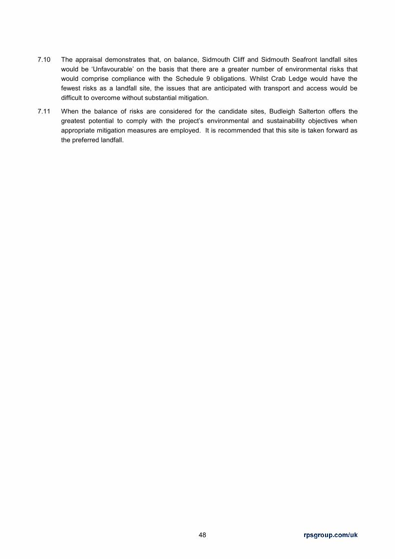
48
7.10 The appraisal demonstrates that, on balance, Sidmouth Cliff and Sidmouth Seafront landfall sites would be ‘Unfavourable’ on the basis that there are a greater number of environmental risks that would comprise compliance with the Schedule 9 obligations. Whilst Crab Ledge would have the fewest risks as a landfall site, the issues that are anticipated with transport and access would be difficult to overcome without substantial mitigation.
7.11 When the balance of risks are considered for the candidate sites, Budleigh Salterton offers the greatest potential to comply with the project’s environmental and sustainability objectives when appropriate mitigation measures are employed. It is recommended that this site is taken forward as the preferred landfall.

49
8 REFERENCES
Department for Communities and Local Government (2012) National Planning Policy Framework, March 2012.
Department for Communities and Local Government (2014) Planning Practice Guidance, March 2014.
East Devon District Council, East Devon Area of Outstanding Natural Beauty and Blackdown Hills Area of Outstanding Natural Beauty (2008) Landscape Character Assessment & Management Guidelines,
FAB Link Ltd, Schedule 9 Statement, March 2016.
RPS (2015) France-Alderney-Britain (FAB) Interconnector: HVDC Converter Station Site Selection Process Report. Second Edition, August 2015.
Transmission Investment: GB Connection Options Report, 2013
Wood Group Kenny (2014) Desktop Study of Alderney-Britain Cable Route, October 2014.
Wood Group Kenny (2015) Marine Engineering Services for the FAB Link Project – Technical Note

APPENDICIES

APPENDIX 1 – SCHEMATIC OVERVIEW OF FAB LINK INTERCONNECTOR PROJECT

Existing National Grid SubstationFAB Onshore
Converter SubstationFAB Transition Pit
Sea DefenceMean High Water Springs (MHWS)
Mean Low Water Springs (MLWS)
FABTransition Pit
FAB Transition Pit
MHWS
MLWSMHWS
MLWS
FAB Link LimitedNGETAt the busbarclamps on the transmission circuit at Exeter 400kV substation
RTE
Schematic – not to scale
AlderneyFranceEngland
RTE Onshore Converter Substation
RTE Transition Pit
Existing National Grid Substation
Marine Licence (MMO)
Permitted Development Rights
Outline Planning Permission (EDDC)
Permitted Development Rights
FEPA Licence ‐ Guernsey
Onshore Planning ‐ Building and Development Control (Alderney) Law 2002
MHWS
MLWS
HVDC
PlanningConsents
Schematic overview of Planning Consents and Property Rights for the FAB Link Interconnector Project
Version 1.4, 19th Nov 2015
HVAC
HVDC
HVAC
HVDC
HVDC
UK –
France Maritim
e Boundary
ARE converter station
(not included in FAB Link project)
Alderney Territorial Waters (3 nm
)
France Median Line –
Alderney (1992 Accord)
UK 12nm
Limit
Marine Licence (MMO) only for cable protection
& soil disposal
HVDC
Alderney Territorial Waters (3 nm
)
Atlantic Crossing 1
TAT 14
SEA‐ME‐W
E 3
FEPA Licence ‐ Guernsey
Alderney (12 nm) –
France Maritim
e Boundary
No licence needed, but information required for
French Authorities

APPENDIX 2 - LANDFALL APPRAISAL SUMMARY MATRIX

Topic: Bedford Lawn Carpark (HDD) Bedford Lawn Carpark (Open Cut) Sidmouth Cliff Crab Ledge Budleigh Salterton (HDD Option) Budleigh Salterton (Open Cut) Landscape & Visual
Not within any landscape designations.
Temporary loss of part of a car park. Although short term, construction works have the potential to impact on townscape character. Mitigation in the form of temporary fencing /screening would be required.
Impacts on views for a large number of receptors including people walking on the SWCP, esplanade and using the beach, tourists within hotels and cafes and residents within properties.
Not within any landscape designations.
Although short term, construction works have the potential to result in localised significant adverse effects on townscape character. Mitigation in the form of temporary fencing /screening would be required.
Effects on views gained by people are as for the HDD option.
Within AONB and Coastal Preservation Area.
Temporary loss of grassland within a larger parcel of parkland.
Although short term, construction works have the potential to adversely impact on townscape character.
Temporary visual impacts on people walking on the SWCP and using the cliff top open space have the potential to be significant due to the close proximity of the visually discordant activities.
Within AONB and Coastal Preservation Area
Temporary loss of arable land within a larger field context.
Temporary adverse impacts on the adjacent landscape and seascape, although adverse in nature.
Temporary visual effects on people walking on the SWCP and using the cliff top open space.
Within AONB and Coastal Preservation Area
Temporary loss of part of a car park.
Temporary adverse impacts on the adjacent landscape, townscape and seascape. Mitigation in the form of temporary fencing /screening would be required.
Temporary visual effects on people using the beach and SWCP have the potential to be significant due to the close proximity of the visually discordant activities.
Within AONB and Coastal Preservation Area
Temporary loss of part of a car park.
Temporary adverse impacts on the adjacent landscape, townscape and seascape. Mitigation in the form of temporary fencing /screening would be required. Beach profile would need to be restored.
Temporary visual effects on people using the beach, beach huts and SWCP have the potential to be significant due to the close proximity of the visually discordant activities that are slightly more extensive than the HDD option.
Access & Traffic
HGV access appears possible via the B3176 Station Road.
It is located in a tourist area, routes through a built up area and there may be some environmental impacts as a result of the construction HGV movements.
Amendments would be required to the access junction which would be to the disbenefit of pedestrians.
Impacts as for HDD option, albeit volume of traffic would be smaller.
Open cut trench would cross
Esplanade and would require traffic management.
HGV access likely to be taken from the Manor Road car park, Manor Road and the B3176.
Potential operational and road safety issues were identified with access via Esplanade and Peak Hill Road onto Manor Road, direct from Peak Hill Road and direct from Cotmaton Road.
Manor Road and the B3176 through Sidmouth are built up residential areas and there may be some environmental impacts as a result of the construction HGV movements.
Access to Crab Ledge was considered via Maunders Hill and Stantyway Road. Both routes were found to have long sections of single track road on which there would operational and road safety issues associated with HGV movement.
Furthermore, Otterton is residential area and there may be some environmental impacts as a result of the construction HGV movements.
Access was considered via Granary Lane and via Salting Hill and Coastguard Road. Both routes have advisory signs that they are unsuitable for HGVs.
There are regular sections along Granary Lane where oncoming vehicles are unable to pass one-another, which is likely to result in operational issues.
HGVs are unable to pass one-another on Salting Hill, therefore a Traffic Management Plan would be required or some localised widening to enable a passing place.
Both routes are through residential areas and there may be some environmental impacts as a result of the construction HGV movements.
As for HDD option, albeit volume of HGV traffic would be smaller.
Noise A site with substantial residential development and recreational resources surrounding it.
Significant losses of amenity for residential and recreational uses due to noise are likely
there is potential for sleep disturbance from night time working.
A possible requirement for a seasonal constraint on HDD works is likely.
A site with substantial residential development and recreational resources surrounding it.
Significant losses of amenity for residential and recreational uses due to noise are likely but can be mitigated.
A possible requirement for a
seasonal constraint on HDD works is likely.
A site with some residential development and recreational resources around it.
Some loss of amenity for residential and recreational uses due to noise is likely
There is potential for sleep disturbance from night time working.
A possible requirement for a seasonal constraint on HDD works is likely
This landfall site is distant from any significant development but with isolated houses in the area, and public rights of way in the vicinity.
There may be some loss of amenity for recreational uses due to noise.
Loss of residential amenity and sleep disturbance are possible but unlikely.
A site with some residential development and recreational resources around it.
Some loss of amenity for residential
and recreational uses due to noise is likely
There is potential for sleep
disturbance from night time working. A possible requirement for a seasonal constraint on HDD works is likely
A site with some residential development and recreational resources around it.
Some loss of amenity for residential
and recreational uses due to noise is likely

Topic: Bedford Lawn Carpark (HDD) Bedford Lawn Carpark (Open Cut) Sidmouth Cliff Crab Ledge Budleigh Salterton (HDD Option) Budleigh Salterton (Open Cut) Cultural Heritage
Not located within the Dorset and East Devon Coast WHS.
No Scheduled Monuments within 2 km of the landfall location.
Located within the Sidmouth Conservation Area.
Several Grade II listed buildings and one Grade II* listed buildings in the immediate vicinity of the site.
As for HDD option Overlap with Dorset and East Devon Coast WHS
Nearest Scheduled Monument is approximately 1.8 km to the south west.
Not located within the Sidmouth Conservation Area.
Several listed buildings in the immediate vicinity of the site, the nearest being Lower Lodge (Grade II) in the southeast corner of the field.
Grade II Registered Park and Garden (Connaught Gardens) located approximately 100 m south east of the landfall location, south of Peak Hill Road
Overlaps with Dorset and East Devon Coast WHS.
No Scheduled Monuments within 2 km of the landfall site.
Not located within any Conservation Areas.
No listed buildings within 1 km of the site.
No Registered Parks or Gardens within 1 km of the site.
Overlaps with the Dorset and East Devon Coast WHS.
The landfall site is not located within a Conservation Area.
Several listed buildings within Budleigh Salterton and the nearest being 20-38 Coastguard Road and associated outbuildings (Grade II) approximately 250 m to the west.
No Scheduled Monuments within 2 km of the car park.
No Registered Parks or Gardens within 1 km of the site.
Open cut construction methods would need to ensure that the beach profile and sorting are maintained in order to reduce impacts on WHS designation
Ecology & Nature Conservation
Sidmouth to West Bay SAC lies approximately 500 m east of the proposed landfall.
No SPAs or Ramsar sites, NNRs or LNRs within 2 km of the site.
Sidmouth to Beer SSSI lies approximately 500 m to the east of the landfall site
The nearest CWS is the
Windgate Cliffs CWS located to the west of Sidmouth town and would be unaffected.
No Ancient Woodland or Priority Habitats located at the site.
As for HDD option Sidmouth to West Bay SAC, lies approximately 1km to the east.
No SPAs or Ramsar sites, NNRs or LNRs within 2 km of the site.
Sidmouth to Beer SSSI lies approximately 1 km to the east of the proposed landfall site.
The incoming offshore cable route would overlap with the Windgate Cliffs CWS, but this is avoided with HDD technology
No Ancient Woodland or other Priority Habitats located at the proposed landfall site although there is maritime cliffs and slope priority habitat along Sidmouth Cliff, approximately 80 m south, although this is avoided with HDD technology.
No SACs, SPAs, Ramsar sites, NNRs or LNRs within 2 km of the site.
The Otter Estuary SSSI is located approximately 1.4 km west at its closest point.
The Otter Estuary to Green Point CWS is located along the cliff edge and clifftop, but this is avoided with HDD technology
No Ancient Woodland or Priority Habitats located at the proposed landfall site. The nearest priority habitat is maritime cliffs and slope habitat along Crab Ledge, approximately 100 m east although this is avoided with HDD technology.
There are no SACs, SPAs, NNRs and LNRs Ramsar sites within 2 km of the site.
In terms of national designations, it is positioned in between the Budleigh Salterton Cliffs (geological) SSSI and the Otter Estuary SSSI.
Otter Meadows CWS is located approximately 150 m to the north of the landfall site and might be affected by onshore cable route.
The Otter Estuary to Green Point CWS is also located approximately 450 m to the east of the landfall location, at Otterton Point and would be unaffected
No Ancient Woodland at the
proposed landfall site.
There are several coastal priority habitats in the vicinity of the car park, but these would be unaffected. The beach immediately to the south of the carpark has no priority habitats.
As for HDD option

Topic: Bedford Lawn Carpark (HDD) Bedford Lawn Carpark (Open Cut) Sidmouth Cliff Crab Ledge Budleigh Salterton (HDD Option) Budleigh Salterton (Open Cut) Water Environment
Flood Zone 1.
Glen Road (to the west), the Esplanade and land east of the B3176 road fall within Flood Zone 3.
Does not lie within a ground water source protection zone.
Underlain bedrock that forms a Principal Aquifer and superficial deposits that form a Secondary Aquifer.
As for HDD option. Flood Zone 1.
Does not lie within a ground water source protection zone.
Underlain bedrock that forms a Principal Aquifer bedrock and also superficial deposits that form a Secondary Aquifer.
Flood Zone 1.
Does not lie within a ground water source protection zone, although the Otterton Water Treatment Plant marks the limit of Zone 3 of a groundwater source protection zone.
Underlain by bedrock that forms a Principal Aquifer and also superficial deposits that form a Secondary Aquifer.
Majority of the landfall site is located within Flood Zone 2 and Flood Zone 3.
Does not lie within a ground water source protection zone.
Underlain bedrock that forms a Principal Aquifer and also possibly superficial deposits that form a Secondary Aquifer.
As for HDD option.
Soils & Geology
Existing urban land use.
No impacts on geological SSSIs.
No nearby landfill.
As for HDD option. Site is located within a grass field that is probably parkland. It is unclear whether this has ever been used for agriculture.
Ladram Bay to Sidmouth SSSI, designated for coast geomorphology, is located approximately 170 m to the southeast. This would be an important consideration for the incoming offshore cable.
No nearby landfill.
Land appears on the boundary between good/moderate to very good agricultural land therefore there would be temporary effects during construction and some minor loss from land take of permanent man hole covers.
No impacts on geological SSSI.
No nearby landfill.
Existing urban land use within car park.
No impact on geological SSSIs.
Former landfill approximately 850 m north of the landfall site.
Existing urban land use within car park.
No impact on geological SSSIs.
Former landfill approximately 850 m north of the landfall site.
It would need to be demonstrated that the trench could be backfilled in the order of exaction to maintain the geomorphology conditions of the pebblebeds and the beach profile should be restored.
Community & Socio-economics
Disruption to recreational users from closure of the car park.
Lost revenue from car park owners.
Impact on amenity of public right of way.
Potential economic impacts on these adjacent commercial or leisure uses during construction from closure of the car park and construction noise.
Impacts on Sidmouth community from construction traffic being routed through the town.
Impact on amenity of SWCP National Trail.
Impacts on Sidmouth community from construction traffic being routed through the town and residential areas.
Impact on amenity of SWCP National Trail.
Site is fairly isolated from other recreational or commercial land uses.
The Otterton village community would likely experience some impacts from increased traffic and HGVs during construction.
Disruption to recreational users from partial closure of the car park.
Impact on amenity of SWCP National Trail.
Potential disruption to adjacent uses such as the skateboarding area and child’s play area immediate to the north of the car park.
Potential economic impacts on businesses during construction from partial closure of the car park and any noise impacts from construction activities.
Impacts on Budleigh Salterton community from construction traffic being routed through residential areas.
Disruption to recreational users from partial closure of the car park.
Impact on access and amenity of SWCP National Trail from open cut option.
Potential disruption to adjacent uses such as the skateboarding area and child’s play area immediate to the north of the car park.
Potential economic impacts on businesses during construction from partial closure of the car park and any noise impacts from construction activities.
Impacts on Budleigh Salterton community from construction traffic being routed through residential areas.

Topic: Bedford Lawn Carpark (HDD) Bedford Lawn Carpark (Open Cut) Sidmouth Cliff Crab Ledge Budleigh Salterton (HDD Option) Budleigh Salterton (Open Cut) Utilities All of the roads running north
from the Esplanade in this area, namely Station Road, Glen Road and Manor Road already carry buried services for gas, telecommunications (BT) and low voltage and high voltage electricity. These three roads also carry water South West Water distribution pipes and sewers.
As for HDD option. A BT telecommunications line runs along the route of Peak Hill Road.
An elevated sewer pipe is present along the access road to Peak Hill House. No other water distribution pipes in the immediate vicinity of the Sidmouth Cliff Landfall location.
A sewer pipe runs in an easterly direction from East Budleigh along the access road to the Otterton Water Treatment Works, crossing Stantyway Road.
There is a SWW water distribution pipe that runs in an easterly direction from East Budleigh, also crossing Stantyway Road.
Water Treatment Works outfall pipe is present in the cliff.
Water distribution and sewer pipes are also present in Fore Street at Otterton.
BT underground line that runs north of the car park and west onto Granary Lane, where it turns into an overhead line that runs along the road.
SWW distribution pipes run along the carriageway of Granary Lane as well as Coast Guard Road to the west.
Sewage pipes and low pressure gas pipes present in Granary Lane, Salting Hill and Coastguard Road.
The sewage infrastructure is also present in the car park itself, associated with the South West Water pumping station.
An underground 11kV line extends north from the pumping station along the tributary of the River Otter.
There are low voltage overhead lines that run along Granary Lane and Ottervale Road.
There is also an underground low voltage cable that runs along the northern extent of beach, presumably to provide lighting for the beach huts present here.
As for HDD option.
Onshore Cable Route from Landfall
Site is located within town centre and it is surrounded predominantly residential urban land uses so cable installation would be restricted to road routes.
The most likely route is the B3176 Station Road. The road width is between 6.0-6.5 m. Given the constraints of working around other utilities known to be in this road, road closures are highly likely to be required.
Other utilities in roads might prevent sufficient space being available for two HVDC circuits to be laid without other utility diversions.
As for HDD option. The site is surrounded to the west, north and east by residential urban land uses so cable installation would be restricted to road routes.
Beyond Peak Hill House to the west, Peak Hill road turns into a minor road.
Cable installation would have to be routed eastwards along Peak Hill Road and either via Manor Road or The Esplanade. Therefore constraints on cable route in terms of utilities would be the same as of Sidmouth Seafront; road closures are highly likely to be required.
Fewest constraints in terms of utilities compared with other landfall options.
The most significant constraint for this landfall site would be road width. The cables could be routed through Stantyway Road and the village of Otterton; road closures are highly likely.
Off-road cable route corridors appear feasible.
Onshore access of plant and equipment is feasible via Salting Hill with Traffic Management and possibly via Granary Lane.
The onshore cables could be routed via Salting Hill road or Granary Lane. Although there are some utilities currently under the carriageway of these roads, the roads should be sufficiently wide to enable installation of the interconnector cables, with some traffic management.
Off-road cable route corridors appear feasible.
As for HDD option.

FIGURES

FIGURE 1 – LANDFALL SEARCH AREA

_̂
_̂
_̂
_̂
Crab Ledge
Sidmouth Cliff
Sidmouth Seafront
Budleigh Salterton
MXD REF:
TITLE
SCALE AS SHOWN
CLIENT
PROJECTREV DATE DESCRIPTION BY CHK ENG PM FAB
SLDRAFT04.05.1600
REFERENCES
DRAWING / DOC No. TITLE
MARINE ENGINEERING SERVICESFOR THE FAB ELECTRICAL
INTERCONNECTOR PROJECT
UNITED KINGDOMLANDFALL CORRIDOR
RPS Landfalls Map 00
1. MUSSEL FARM BOUNDARIES PROVIDED BY OFFSHORESHELLFISH LTD VIA EMAIL. SEAZONE DATA DOES NOT SHOWFULL EXTENT OF FUTURE MUSSEL FARM DEVELOPMENT.2. SEAZONE DATA ALSO DOES NOT SHOW MANY OF THEOFFSHORE PROTECTED AREAS. OFFSHORE PROTECTEDAREAS SHOWN HAVE BEEN COLLATED FROM PUBLICSOURCES BY WGK.3. LAYERS/AREAS SHOWN ARE THE KNOWN MAINCONSTRAINTS ALONG THE ROUTE CORRIDOR. OTHERCONSTRAINTS MAY EXIST WHICH ARE NOT SHOWN ON THEMAP,
NOTES
JB
Legend_̂ LANDFALLS
FIRING PRACTICE AREACable Live
JNCC Marine Protected Areas
Mussel Farms (Note 1)WRECKSOFFSHORE INSTALLATIONMOORING BUOY
Environmentally Sensitive Area, UndefinedLocal Nature Reserves, LNRAreas of Outstanding Natural Beauty, AONB
ROUTE CORRIDOR12nm Limit
MusselFarm
Firing Range
JNCC Marine Protected Area
River Exe SPA
Route Corridor
0 5 102.5Kilometers
Area 2Area 3
Area 4
Area 5
Area 6
Area 1
Area 7
East Devon Heaths SPA
JB PF

FIGURE 2 – CANDIDATE LANDFALL SITES

GFGF
GF
GF
BudleighSalterton
CrabLedge
SidmouthCliff
SidmouthSeafront
Figure No: 2 Revision: 1
Date: 09/06/2016
Drawn:
Datum:
Checked:
Projection:
Job Ref:MS - OXF7729
OSGB36 BNG
1:25,000Scale: A3 @0 10.5 km
Title: Candidate Landfall Sites
Client: FAB Link Ltd.Project: FAB Interconnector Ltd.
20 Milton Park Abingdon Oxon OX14 4SHT 01235 821888 F 01235 820351 E [email protected] W rpsgroup.com
Status: DRAFT
Data Source: RPS 2016Rev: Date: Amendment: Name: Checked:
±
Proj
ect R
ef: O
:\772
9 FA
B In
terc
onne
ctor
\Tec
h\D
raw
ings
\772
9-03
00-0
3.m
xd
Dat
e S
aved
: 09/
06/2
016
© Crown copyright, All rights reserved. 2016 License number 0100031673, Contains Ordnance Survey data © Crown copyright and database right 2016
Legend
GF Possible Landfalls

FIGURE 3 – SIDMOUTH SEAFRONT AND SIDMOUTH CLIFF LANDFALL CONTRAINTS MAP
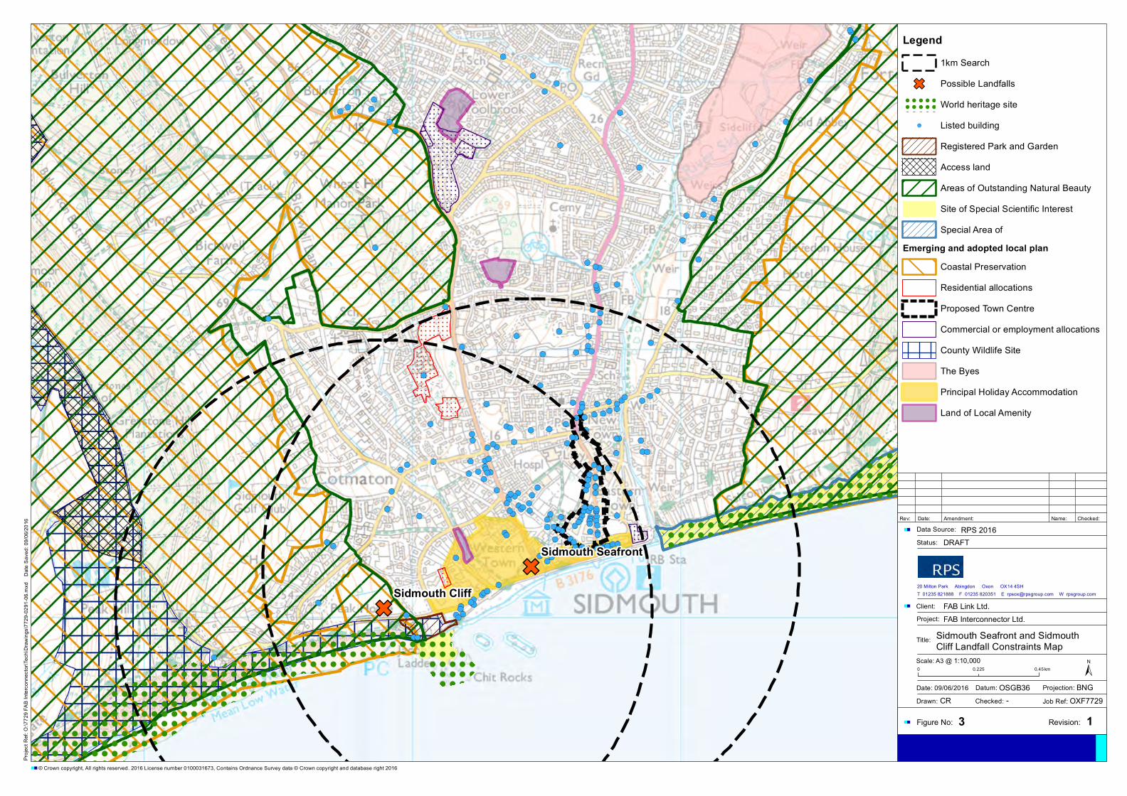
! ! ! ! ! ! ! ! ! ! ! ! ! ! ! ! ! ! ! ! ! ! ! ! ! !
! ! ! ! ! ! ! ! ! ! ! ! ! ! ! ! ! ! ! ! ! ! ! ! ! !
! ! ! ! ! ! ! ! ! ! ! ! ! ! ! ! ! ! ! ! ! ! ! ! ! !
! ! ! ! ! ! ! ! ! ! ! ! ! ! ! ! ! ! ! ! ! ! ! ! ! !
! ! ! ! ! ! ! ! ! ! ! ! ! ! ! ! ! ! ! ! ! ! ! ! ! !
! ! ! ! ! ! ! ! ! ! ! ! ! ! ! ! ! ! ! ! ! ! ! ! ! !
! ! ! ! ! ! ! ! ! ! ! ! ! ! ! ! ! ! ! ! ! ! ! ! ! !
! ! ! ! ! ! ! ! ! ! ! ! ! ! ! ! ! ! ! ! ! ! ! ! ! !
! ! ! ! ! ! ! ! ! ! ! ! ! ! ! ! ! ! ! ! ! ! ! ! ! !
! ! ! ! ! ! ! ! ! ! ! ! ! ! ! ! ! ! ! ! ! ! ! ! ! !
! ! ! ! ! ! ! ! ! ! ! ! ! ! ! ! ! ! ! ! ! ! ! ! ! !
! ! ! ! ! ! ! ! ! ! ! ! ! ! ! ! ! ! ! ! ! ! ! ! ! !
! ! ! ! ! ! ! ! ! ! ! ! ! ! ! ! ! ! ! ! ! ! ! ! ! ! ! ! ! ! ! ! ! ! ! ! ! ! ! ! ! ! ! ! ! !
! ! ! ! ! ! ! ! ! ! ! ! ! ! ! ! ! ! ! ! ! ! ! ! ! ! ! ! ! ! ! ! ! ! ! ! ! ! ! ! ! ! ! ! ! !
! ! ! ! ! ! ! ! ! ! ! ! ! ! ! ! ! ! ! ! ! ! ! ! ! ! ! ! ! ! ! ! ! ! ! ! ! ! ! ! ! ! ! ! ! !
! ! ! ! ! ! ! ! ! ! ! ! ! ! ! ! ! ! ! ! ! ! ! ! ! ! ! ! ! ! ! ! ! ! ! ! ! ! ! ! ! ! ! ! ! !
! ! ! ! ! ! ! ! ! ! ! ! ! ! ! ! ! ! ! ! ! ! ! ! ! ! ! ! ! ! ! ! ! ! ! ! ! ! ! ! ! ! ! ! ! !
! ! ! ! ! ! ! ! ! ! ! ! ! ! ! ! ! ! ! ! ! ! ! ! ! ! ! ! ! ! ! ! ! ! ! ! ! ! ! ! ! ! ! ! ! !
! ! ! ! ! ! ! ! ! ! ! ! ! ! ! ! ! ! ! ! ! ! ! ! ! ! ! ! ! ! ! ! ! ! ! ! ! ! ! ! ! ! ! ! ! !
! ! ! ! ! ! ! ! ! ! ! ! ! ! ! ! ! ! ! ! ! ! ! ! ! ! ! ! ! ! ! ! ! ! ! ! ! ! ! ! ! ! ! ! ! !
! ! ! ! ! ! ! ! ! ! ! ! ! ! ! ! ! ! ! ! ! ! ! ! ! ! ! ! ! ! ! ! ! ! ! ! ! ! ! ! ! ! ! ! ! !
! ! ! ! ! ! ! ! ! ! ! ! ! ! ! ! ! ! ! ! ! ! ! ! ! ! ! ! ! ! ! ! ! ! ! ! ! ! ! ! ! ! ! ! ! !
! ! ! ! ! ! ! ! ! ! ! ! ! ! ! ! ! ! ! ! ! ! ! ! ! ! ! ! ! ! ! ! ! ! ! ! ! ! ! ! ! ! ! ! ! !
! ! ! ! ! ! ! ! ! ! ! ! ! ! ! ! ! ! ! ! ! ! ! ! ! ! ! ! ! ! ! ! ! ! ! ! ! ! ! ! ! ! ! ! ! !
! ! ! ! ! ! ! ! ! ! ! ! ! ! ! ! ! ! ! ! ! ! ! ! ! ! ! ! ! ! ! ! ! ! ! ! ! ! ! ! ! ! ! ! ! !
! ! ! ! ! ! ! ! ! ! ! ! ! ! ! ! ! ! ! ! ! ! ! ! ! ! ! ! ! ! ! ! ! ! ! ! ! ! ! ! ! ! ! ! ! !
! ! ! ! ! ! ! ! ! ! ! ! ! ! ! ! ! ! ! ! ! ! ! ! ! ! ! ! ! ! ! ! ! ! ! ! ! ! ! ! ! ! ! ! ! !
GF
GFSidmouth Cliff
Sidmouth Seafront
Figure No: 3 Revision: 1
Date: 09/06/2016
Drawn:
Datum:
Checked:
Projection:
Job Ref:CR - OXF7729
OSGB36 BNG
1:10,000Scale: A3 @0 0.450.225 km
Title: Sidmouth Seafront and SidmouthCliff Landfall Constraints Map
Client: FAB Link Ltd.Project: FAB Interconnector Ltd.
20 Milton Park Abingdon Oxon OX14 4SHT 01235 821888 F 01235 820351 E [email protected] W rpsgroup.com
Status: DRAFT
Data Source: RPS 2016Rev: Date: Amendment: Name: Checked:
±
Proj
ect R
ef: O
:\772
9 FA
B In
terc
onne
ctor
\Tec
h\D
raw
ings
\772
9-02
91-0
6.m
xd
Dat
e S
aved
: 09/
06/2
016
© Crown copyright, All rights reserved. 2016 License number 0100031673, Contains Ordnance Survey data © Crown copyright and database right 2016
Legend
1km Search
GF Possible Landfalls
! ! ! ! ! !
! ! ! ! ! !
! ! ! ! ! !
! ! ! ! ! !
World heritage site
!( Listed building
Registered Park and Garden
Access land
Areas of Outstanding Natural Beauty
Site of Special Scientific Interest
Special Area of
Emerging and adopted local plan
Coastal Preservation
Residential allocations
Proposed Town Centre
Commercial or employment allocations
County Wildlife Site
The Byes
Principal Holiday Accommodation
Land of Local Amenity

FIGURE 4 – SIDMOUTH SEAFRONT AND SIDMOUTH CLIFF UTILITIES PLAN
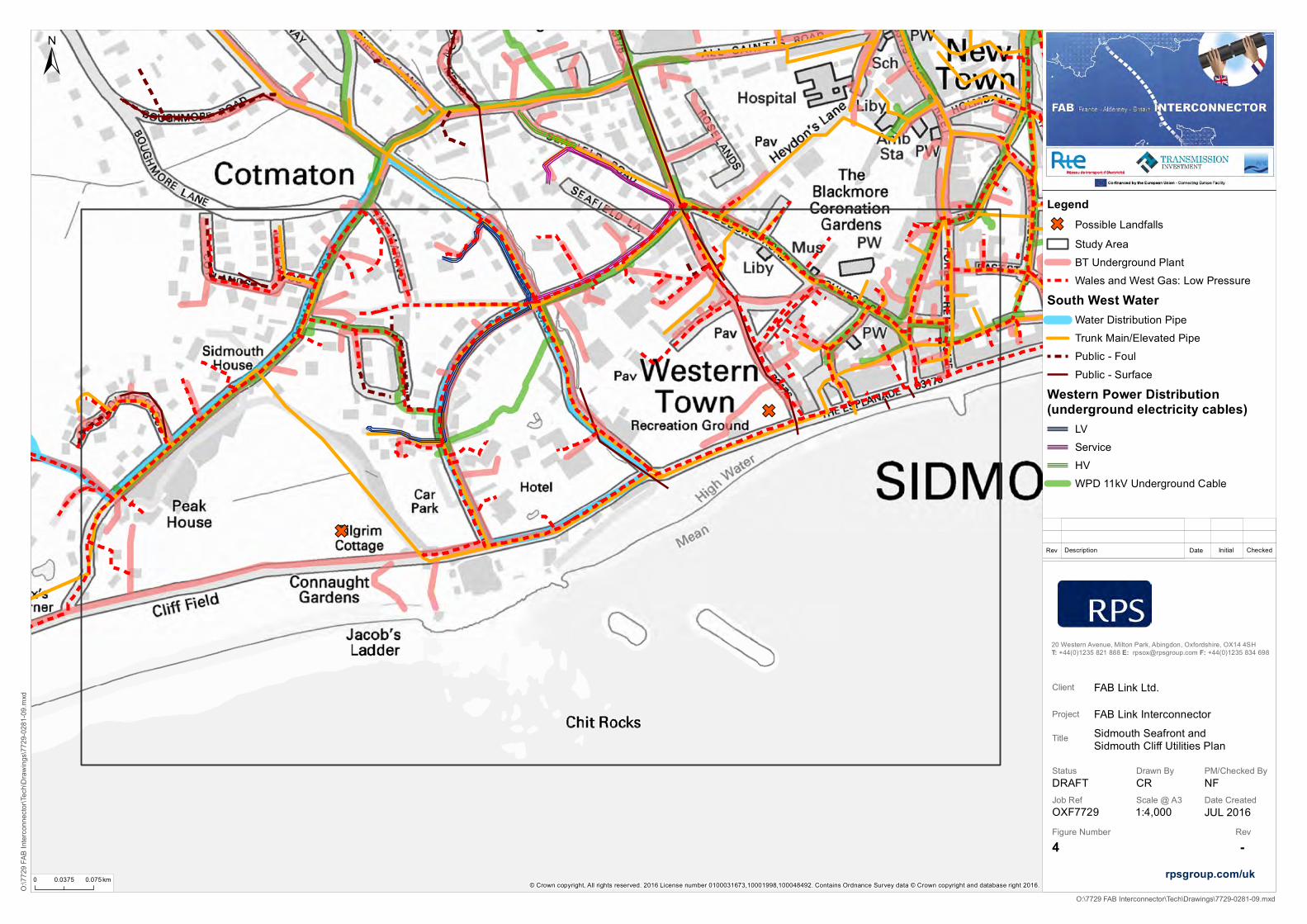
Rev Description InitialDate Checked
Job Ref Scale @ A3 Date Created
Client
Project
Title
Status Drawn By PM/Checked By
RevFigure Number
GF
GF
CR
-
0 0.0750.0375 km
O:\7729 FAB Interconnector\Tech\Drawings\7729-0281-09.mxd
O:\7
729
FAB
Inte
rcon
nect
or\T
ech\
Dra
win
gs\7
729-
0281
-09.
mxd
FAB Link Ltd.
rpsgroup.com/uk
FAB Link Interconnector
Sidmouth Seafront andSidmouth Cliff Utilities Plan
OXF7729
NF
Legend
GF Possible Landfalls
Study Area
BT Underground Plant
Wales and West Gas: Low Pressure
South West WaterWater Distribution Pipe
Trunk Main/Elevated Pipe
Public - Foul
Public - Surface
Western Power Distribution(underground electricity cables)
LV
Service
HV
WPD 11kV Underground Cable
© Crown copyright, All rights reserved. 2016 License number 0100031673,10001998,100048492. Contains Ordnance Survey data © Crown copyright and database right 2016.
JUL 20161:4,000
DRAFT
4
±
20 Western Avenue, Milton Park, Abingdon, Oxfordshire, OX14 4SHT: +44(0)1235 821 888 E: [email protected] F: +44(0)1235 834 698

FIGURE 5 – CRAB LEDGE LANDFALL CONSTRAINTS MAP

! ! ! ! ! ! ! ! ! ! ! ! ! ! ! ! ! ! ! ! ! ! ! ! ! ! ! ! ! ! ! ! ! ! ! ! ! !
! ! ! ! ! ! ! ! ! ! ! ! ! ! ! ! ! ! ! ! ! ! ! ! ! ! ! ! ! ! ! ! ! ! ! ! ! !
! ! ! ! ! ! ! ! ! ! ! ! ! ! ! ! ! ! ! ! ! ! ! ! ! ! ! ! ! ! ! ! ! ! ! ! ! !
! ! ! ! ! ! ! ! ! ! ! ! ! ! ! ! ! ! ! ! ! ! ! ! ! ! ! ! ! ! ! ! ! ! ! ! ! !
! ! ! ! ! ! ! ! ! ! ! ! ! ! ! ! ! ! ! ! ! ! ! ! ! ! ! ! ! ! ! ! ! ! ! ! ! !
! ! ! ! ! ! ! ! ! ! ! ! ! ! ! ! ! ! ! ! ! ! ! ! ! ! ! ! ! ! ! ! ! ! ! ! ! !
! ! ! ! ! ! ! ! ! ! ! ! ! ! ! ! ! ! ! ! ! ! ! ! ! ! ! ! ! ! ! ! ! ! ! ! ! !
! ! ! ! ! ! ! ! ! ! ! ! ! ! ! ! ! ! ! ! ! ! ! ! ! ! ! ! ! ! ! ! ! ! ! ! ! !
! ! ! ! ! ! ! ! ! ! ! ! ! ! ! ! ! ! ! ! ! ! ! ! ! ! ! ! ! ! ! ! ! ! ! ! ! !
! ! ! ! ! ! ! ! ! ! ! ! ! ! ! ! ! ! ! ! ! ! ! ! ! ! ! ! ! ! ! ! ! ! ! ! ! !
! ! ! ! ! ! ! ! ! ! ! ! ! ! ! ! ! ! ! ! ! ! ! ! ! ! ! ! ! ! ! ! ! ! ! ! ! !
! ! ! ! ! ! ! ! ! ! ! ! ! ! ! ! ! ! ! ! ! ! ! ! ! ! ! ! ! ! ! ! ! ! ! ! ! !
! ! ! ! ! ! ! ! ! ! ! ! ! ! ! ! ! ! ! ! ! ! ! ! ! ! ! ! ! ! ! ! ! ! ! ! ! !
! ! ! ! ! ! ! ! ! ! ! ! ! ! ! ! ! ! ! ! ! ! ! ! ! ! ! ! ! ! ! ! ! ! ! ! ! !
! ! ! ! ! ! ! ! ! ! ! ! ! ! ! ! ! ! ! ! ! ! ! ! ! ! ! ! ! ! ! ! ! ! ! ! ! !
! ! ! ! ! ! ! ! ! ! ! ! ! ! ! ! ! ! ! ! ! ! ! ! ! ! ! ! ! ! ! ! ! ! ! ! ! !
! ! ! ! ! ! ! ! ! ! ! ! ! ! ! ! ! ! ! ! ! ! ! ! ! ! ! ! ! ! ! ! ! ! ! ! ! !
! ! ! ! ! ! ! ! ! ! ! ! ! ! ! ! ! ! ! ! ! ! ! ! ! ! ! ! ! ! ! ! ! ! ! ! ! !
! ! ! ! ! ! ! ! ! ! ! ! ! ! ! ! ! ! ! ! ! ! ! ! ! ! ! ! ! ! ! ! ! ! ! ! ! !
! ! ! ! ! ! ! ! ! ! ! ! ! ! ! ! ! ! ! ! ! ! ! ! ! ! ! ! ! ! ! ! ! ! ! ! ! !
! ! ! ! ! ! ! ! ! ! ! ! ! ! ! ! ! ! ! ! ! ! ! ! ! ! ! ! ! ! ! ! ! ! ! ! ! !
! ! ! ! ! ! ! ! ! ! ! ! ! ! ! ! ! ! ! ! ! ! ! ! ! ! ! ! ! ! ! ! ! ! ! ! ! !
! ! ! ! ! ! ! ! ! ! ! ! ! ! ! ! ! ! ! ! ! ! ! ! ! ! ! ! ! ! ! ! ! ! ! ! ! !
! ! ! ! ! ! ! ! ! ! ! ! ! ! ! ! ! ! ! ! ! ! ! ! ! ! ! ! ! ! ! ! ! ! ! ! ! !
! ! ! ! ! ! ! ! ! ! ! ! ! ! ! ! ! ! ! ! ! ! ! ! ! ! ! ! ! ! ! ! ! ! ! ! ! !
! ! ! ! ! ! ! ! ! ! ! ! ! ! ! ! ! ! ! ! ! ! ! ! ! ! ! ! ! ! ! ! ! ! ! ! ! !
! ! ! ! ! ! ! ! ! ! ! ! ! ! ! ! ! ! ! ! ! ! ! ! ! ! ! ! ! ! ! ! ! ! ! ! ! !
! ! ! ! ! ! ! ! ! ! ! ! ! ! ! ! ! ! ! ! ! ! ! ! ! ! ! ! ! ! ! ! ! ! ! ! ! !
! ! ! ! ! ! ! ! ! ! ! ! ! ! ! ! ! ! ! ! ! ! ! ! ! ! ! ! ! ! ! ! ! ! ! ! ! !
! ! ! ! ! ! ! ! ! ! ! ! ! ! ! ! ! ! ! ! ! ! ! ! ! ! ! ! ! ! ! ! ! ! ! ! ! !
! ! ! ! ! ! ! ! ! ! ! ! ! ! ! ! ! ! ! ! ! ! ! ! ! ! ! ! ! ! ! ! ! ! ! ! ! !
! ! ! ! ! ! ! ! ! ! ! ! ! ! ! ! ! ! ! ! ! ! ! ! ! ! ! ! ! ! ! ! ! ! ! ! ! !
! ! ! ! ! ! ! ! ! ! ! ! ! ! ! ! ! ! ! ! ! ! ! ! ! ! ! ! ! ! ! ! ! ! ! ! ! !
! ! ! ! ! ! ! ! ! ! ! ! ! ! ! ! ! ! ! ! ! ! ! ! ! ! ! ! ! ! ! ! ! ! ! ! ! !
! ! ! ! ! ! ! ! ! ! ! ! ! ! ! ! ! ! ! ! ! ! ! ! ! ! ! ! ! ! ! ! ! ! ! ! ! !
! ! ! ! ! ! ! ! ! ! ! ! ! ! ! ! ! ! ! ! ! ! ! ! ! ! ! ! ! ! ! ! ! ! ! ! ! !
! ! ! ! ! ! ! ! ! ! ! ! ! ! ! ! ! ! ! ! ! ! ! ! ! ! ! ! ! ! ! ! ! ! ! ! ! !
! ! ! ! ! ! ! ! ! ! ! ! ! ! ! ! ! ! ! ! ! ! ! ! ! ! ! ! ! ! ! ! ! ! ! ! ! !
! ! ! ! ! ! ! ! ! ! ! ! ! ! ! ! ! ! ! ! ! ! ! ! ! ! ! ! ! ! ! ! ! ! ! ! ! !
! ! ! ! ! ! ! ! ! ! ! ! ! ! ! ! ! ! ! ! ! ! ! ! ! ! ! ! ! ! ! ! ! ! ! ! ! !
! ! ! ! ! ! ! ! ! ! ! ! ! ! ! ! ! ! ! ! ! ! ! ! ! ! ! ! ! ! ! ! ! ! ! ! ! !
! ! ! ! ! ! ! ! ! ! ! ! ! ! ! ! ! ! ! ! ! ! ! ! ! ! ! ! ! ! ! ! ! ! ! ! ! !
! ! ! ! ! ! ! ! ! ! ! ! ! ! ! ! ! ! ! ! ! ! ! ! ! ! ! ! ! ! ! ! ! ! ! ! ! !
! ! ! ! ! ! ! ! ! ! ! ! ! ! ! ! ! ! ! ! ! ! ! ! ! ! ! ! ! ! ! ! ! ! ! ! ! !
! ! ! ! ! ! ! ! ! ! ! ! ! ! ! ! ! ! ! ! ! ! ! ! ! ! ! ! ! ! ! ! ! ! ! ! ! !
! ! ! ! ! ! ! ! ! ! ! ! ! ! ! ! ! ! ! ! ! ! ! ! ! ! ! ! ! ! ! ! ! ! ! ! ! !
! ! ! ! ! ! ! ! ! ! ! ! ! ! ! ! ! ! ! ! ! ! ! ! ! ! ! ! ! ! ! ! ! ! ! ! ! !
! ! ! ! ! ! ! ! ! ! ! ! ! ! ! ! ! ! ! ! ! ! ! ! ! ! ! ! ! ! ! ! ! ! ! ! ! !
! ! ! ! ! ! ! ! ! ! ! ! ! ! ! ! ! ! ! ! ! ! ! ! ! ! ! ! ! ! ! ! ! ! ! ! ! !
! ! ! ! ! ! ! ! ! ! ! ! ! ! ! ! ! ! ! ! ! ! ! ! ! ! ! ! ! ! ! ! ! ! ! ! ! !
! ! ! ! ! ! ! ! ! ! ! ! ! ! ! ! ! ! ! ! ! ! ! ! ! ! ! ! ! ! ! ! ! ! ! ! ! !
! ! ! ! ! ! ! ! ! ! ! ! ! ! ! ! ! ! ! ! ! ! ! ! ! ! ! ! ! ! ! ! ! ! ! ! ! !
! ! ! ! ! ! ! ! ! ! ! ! ! ! ! ! ! ! ! ! ! ! ! ! ! ! ! ! ! ! ! ! ! ! ! ! ! !
! ! ! ! ! ! ! ! ! ! ! ! ! ! ! ! ! ! ! ! ! ! ! ! ! ! ! ! ! ! ! ! ! ! ! ! ! !
! ! ! ! ! ! ! ! ! ! ! ! ! ! ! ! ! ! ! ! ! ! ! ! ! ! ! ! ! ! ! ! ! ! ! ! ! !
! ! ! ! ! ! ! ! ! ! ! ! ! ! ! ! ! ! ! ! ! ! ! ! ! ! ! ! ! ! ! ! ! ! ! ! ! !
! ! ! ! ! ! ! ! ! ! ! ! ! ! ! ! ! ! ! ! ! ! ! ! ! ! ! ! ! ! ! ! ! ! ! ! ! !
! ! ! ! ! ! ! ! ! ! ! ! ! ! ! ! ! ! ! ! ! ! ! ! ! ! ! ! ! ! ! ! ! ! ! ! ! !
! ! ! ! ! ! ! ! ! ! ! ! ! ! ! ! ! ! ! ! ! ! ! ! ! ! ! ! ! ! ! ! ! ! ! ! ! !
! ! ! ! ! ! ! ! ! ! ! ! ! ! ! ! ! ! ! ! ! ! ! ! ! ! ! ! ! ! ! ! ! ! ! ! ! !
! ! ! ! ! ! ! ! ! ! ! ! ! ! ! ! ! ! ! ! ! ! ! ! ! ! ! ! ! ! ! ! ! ! ! ! ! !
! ! ! ! ! ! ! ! ! ! ! ! ! ! ! ! ! ! ! ! ! ! ! ! ! ! ! ! ! ! ! ! ! ! ! ! ! !
! ! ! ! ! ! ! ! ! ! ! ! ! ! ! ! ! ! ! ! ! ! ! ! ! ! ! ! ! ! ! ! ! ! ! ! ! !
! ! ! ! ! ! ! ! ! ! ! ! ! ! ! ! ! ! ! ! ! ! ! ! ! ! ! ! ! ! ! ! ! ! ! ! ! !
! ! ! ! ! ! ! ! ! ! ! ! ! ! ! ! ! ! ! ! ! ! ! ! ! ! ! ! ! ! ! ! ! ! ! ! ! !
! ! ! ! ! ! ! ! ! ! ! ! ! ! ! ! ! ! ! ! ! ! ! ! ! ! ! ! ! ! ! ! ! ! ! ! ! !
! ! ! ! ! ! ! ! ! ! ! ! ! ! ! ! ! ! ! ! ! ! ! ! ! ! ! ! ! ! ! ! ! ! ! ! ! !
! ! ! ! ! ! ! ! ! ! ! ! ! ! ! ! ! ! ! ! ! ! ! ! ! ! ! ! ! ! ! ! ! ! ! ! ! !
! ! ! ! ! ! ! ! ! ! ! ! ! ! ! ! ! ! ! ! ! ! ! ! ! ! ! ! ! ! ! ! ! ! ! ! ! !
! ! ! ! ! ! ! ! ! ! ! ! ! ! ! ! ! ! ! ! ! ! ! ! ! ! ! ! ! ! ! ! ! ! ! ! ! !
! ! ! ! ! ! ! ! ! ! ! ! ! ! ! ! ! ! ! ! ! ! ! ! ! ! ! ! ! ! ! ! ! ! ! ! ! !
GF
Figure No: 5 Revision: 1
Date: 09/06/2016
Drawn:
Datum:
Checked:
Projection:
Job Ref:CR - OXF7729
OSGB36 BNG
1:10,000Scale: A3 @0 0.450.225 km
Title: Crab Ledge LandfallConstraints Map
Client: FAB Link Ltd.Project: FAB Interconnector Ltd.
20 Milton Park Abingdon Oxon OX14 4SHT 01235 821888 F 01235 820351 E [email protected] W rpsgroup.com
Status: DRAFT
Data Source: RPS 2016Rev: Date: Amendment: Name: Checked:
±
Proj
ect R
ef: O
:\772
9 FA
B In
terc
onne
ctor
\Tec
h\D
raw
ings
\772
9-02
91-0
6.m
xd
Dat
e S
aved
: 09/
06/2
016
© Crown copyright, All rights reserved. 2016 License number 0100031673, Contains Ordnance Survey data © Crown copyright and database right 2016
Legend
1km Search
GF Possible Landfalls
Wales and West Utilities selectedintermediate pressure pipeline(approximate location).
Wales and West Utilities selectedintermediate pressure pipeline(approximate location).
! ! ! ! ! !
! ! ! ! ! !
! ! ! ! ! !
! ! ! ! ! !
World heritage site
Scheduled Monument
!( Listed building
Registered Park and Garden
Areas of Outstanding Natural Beauty
County Wildlife Site
Site of Special Scientific Interest
Emerging and adopted local plan
Coastal Preservation

FIGURE 6 – CRAB LEDGE UTILITIES PLAN

Track
Track
29.6m
Trac
k
Track
Home Down Barn
37.2m
44.0m
35.2m
STANTY
WAY R
OAD (T
rack)
33.7m
Track
Home Down Plantation
Rock53.4m
40.3m
36.6m
Track
Mea
n H
igh
Wat
er
30.2mBore Hole
Sewage Works
29.1m
COLLIVER CROSS
25.8m
COLLIVER LANE (T
rack)
STA
NTY
WAY
RO
AD
39.8m
GF
CR
-
0 0.10.05 km
O:\7729 FAB Interconnector\Tech\Drawings\7729-0299-07.mxd
O:\7
729
FAB
Inte
rcon
nect
or\T
ech\
Dra
win
gs\7
729-
0299
-07.
mxd
FAB Link Ltd.
rpsgroup.com/uk
FAB Link Interconnector
Crab Ledge Utilities Plan
OXF7729
NF
Legend
GF Possible Landfalls
Study
South West WaterCommunication PipeDistribution MainRaw Mains PipeTrunk Main
Western Power DistributionWPD 11kV Overhead ConductorHV- Underground Cable
© Crown copyright, All rights reserved. 2016 License number 0100031673,10001998,100048492. Contains Ordnance Survey data © Crown copyright and database right 2016.
JUL 20161:5,000
DRAFT
6
±
20 Western Avenue, Milton Park, Abingdon, Oxfordshire, OX14 4SHT: +44(0)1235 821 888 E: [email protected] F: +44(0)1235 834 698
Job Ref Scale @ A3 Date Created
Client
Project
Title
Status Drawn By PM/Checked By
RevFigure Number

FIGURE 7 – BUDLEIGH SALTERTON LANDFALL CONSTRAINTS MAP

! ! ! ! ! ! ! ! ! ! ! ! ! ! ! ! ! ! ! ! ! ! ! ! ! ! ! ! ! ! ! ! ! ! ! ! ! ! ! ! ! ! ! ! ! ! ! ! ! ! ! ! ! ! ! ! ! ! ! ! ! ! ! ! ! ! ! ! ! ! ! ! ! ! ! ! ! ! ! ! ! ! ! ! ! ! ! ! !
! ! ! ! ! ! ! ! ! ! ! ! ! ! ! ! ! ! ! ! ! ! ! ! ! ! ! ! ! ! ! ! ! ! ! ! ! ! ! ! ! ! ! ! ! ! ! ! ! ! ! ! ! ! ! ! ! ! ! ! ! ! ! ! ! ! ! ! ! ! ! ! ! ! ! ! ! ! ! ! ! ! ! ! ! ! ! ! !
! ! ! ! ! ! ! ! ! ! ! ! ! ! ! ! ! ! ! ! ! ! ! ! ! ! ! ! ! ! ! ! ! ! ! ! ! ! ! ! ! ! ! ! ! ! ! ! ! ! ! ! ! ! ! ! ! ! ! ! ! ! ! ! ! ! ! ! ! ! ! ! ! ! ! ! ! ! ! ! ! ! ! ! ! ! ! ! !
! ! ! ! ! ! ! ! ! ! ! ! ! ! ! ! ! ! ! ! ! ! ! ! ! ! ! ! ! ! ! ! ! ! ! ! ! ! ! ! ! ! ! ! ! ! ! ! ! ! ! ! ! ! ! ! ! ! ! ! ! ! ! ! ! ! ! ! ! ! ! ! ! ! ! ! ! ! ! ! ! ! ! ! ! ! ! ! !
! ! ! ! ! ! ! ! ! ! ! ! ! ! ! ! ! ! ! ! ! ! ! ! ! ! ! ! ! ! ! ! ! ! ! ! ! ! ! ! ! ! ! ! ! ! ! ! ! ! ! ! ! ! ! ! ! ! ! ! ! ! ! ! ! ! ! ! ! ! ! ! ! ! ! ! ! ! ! ! ! ! ! ! ! ! ! ! !
! ! ! ! ! ! ! ! ! ! ! ! ! ! ! ! ! ! ! ! ! ! ! ! ! ! ! ! ! ! ! ! ! ! ! ! ! ! ! ! ! ! ! ! ! ! ! ! ! ! ! ! ! ! ! ! ! ! ! ! ! ! ! ! ! ! ! ! ! ! ! ! ! ! ! ! ! ! ! ! ! ! ! ! ! ! ! ! !
! ! ! ! ! ! ! ! ! ! ! ! ! ! ! ! ! ! ! ! ! ! ! ! ! ! ! ! ! ! ! ! ! ! ! ! ! ! ! ! ! ! ! ! ! ! ! ! ! ! ! ! ! ! ! ! ! ! ! ! ! ! ! ! ! ! ! ! ! ! ! ! ! ! ! ! ! ! ! ! ! ! ! ! ! ! ! ! !
! ! ! ! ! ! ! ! ! ! ! ! ! ! ! ! ! ! ! ! ! ! ! ! ! ! ! ! ! ! ! ! ! ! ! ! ! ! ! ! ! ! ! ! ! ! ! ! ! ! ! ! ! ! ! ! ! ! ! ! ! ! ! ! ! ! ! ! ! ! ! ! ! ! ! ! ! ! ! ! ! ! ! ! ! ! ! ! !
! ! ! ! ! ! ! ! ! ! ! ! ! ! ! ! ! ! ! ! ! ! ! ! ! ! ! ! ! ! ! ! ! ! ! ! ! ! ! ! ! ! ! ! ! ! ! ! ! ! ! ! ! ! ! ! ! ! ! ! ! ! ! ! ! ! ! ! ! ! ! ! ! ! ! ! ! ! ! ! ! ! ! ! ! ! ! ! !
! ! ! ! ! ! ! ! ! ! ! ! ! ! ! ! ! ! ! ! ! ! ! ! ! ! ! ! ! ! ! ! ! ! ! ! ! ! ! ! ! ! ! ! ! ! ! ! ! ! ! ! ! ! ! ! ! ! ! ! ! ! ! ! ! ! ! ! ! ! ! ! ! ! ! ! ! ! ! ! ! ! ! ! ! ! ! ! !
! ! ! ! ! ! ! ! ! ! ! ! ! ! ! ! ! ! ! ! ! ! ! ! ! ! ! ! ! ! ! ! ! ! ! ! ! ! ! ! ! ! ! ! ! ! ! ! ! ! ! ! ! ! ! ! ! ! ! ! ! ! ! ! ! ! ! ! ! ! ! ! ! ! ! ! ! ! ! ! ! ! ! ! ! ! ! ! !
! ! ! ! ! ! ! ! ! ! ! ! ! ! ! ! ! ! ! ! ! ! ! ! ! ! ! ! ! ! ! ! ! ! ! ! ! ! ! ! ! ! ! ! ! ! ! ! ! ! ! ! ! ! ! ! ! ! ! ! ! ! ! ! ! ! ! ! ! ! ! ! ! ! ! ! ! ! ! ! ! ! ! ! ! ! ! ! !
! ! ! ! ! ! ! ! ! ! ! ! ! ! ! ! ! ! ! ! ! ! ! ! ! ! ! ! ! ! ! ! ! ! ! ! ! ! ! ! ! ! ! ! ! ! ! ! ! ! ! ! ! ! ! ! ! ! ! ! ! ! ! ! ! ! ! ! ! ! ! ! ! ! ! ! ! ! ! ! ! ! ! ! ! ! ! ! !
! ! ! ! ! ! ! ! ! ! ! ! ! ! ! ! ! ! ! ! ! ! ! ! ! ! ! ! ! ! ! ! ! ! ! ! ! ! ! ! ! ! ! ! ! ! ! ! ! ! ! ! ! ! ! ! ! ! ! ! ! ! ! ! ! ! ! ! ! ! ! ! ! ! ! ! ! ! ! ! ! ! ! ! ! ! ! ! !
! ! ! ! ! ! ! ! ! ! ! ! ! ! ! ! ! ! ! ! ! ! ! ! ! ! ! ! ! ! ! ! ! ! ! ! ! ! ! ! ! ! ! ! ! ! ! ! ! ! ! ! ! ! ! ! ! ! ! ! ! ! ! ! ! ! ! ! ! ! ! ! ! ! ! ! ! ! ! ! ! ! ! ! ! ! ! ! !
! ! ! ! ! ! ! ! ! ! ! ! ! ! ! ! ! ! ! ! ! ! ! ! ! ! ! ! ! ! ! ! ! ! ! ! ! ! ! ! ! ! ! ! ! ! ! ! ! ! ! ! ! ! ! ! ! ! ! ! ! ! ! ! ! ! ! ! ! ! ! ! ! ! ! ! ! ! ! ! ! ! ! ! ! ! ! ! !
! ! ! ! ! ! ! ! ! ! ! ! ! ! ! ! ! ! ! ! ! ! ! ! ! ! ! ! ! ! ! ! ! ! ! ! ! ! ! ! ! ! ! ! ! ! ! ! ! ! ! ! ! ! ! ! ! ! ! ! ! ! ! ! ! ! ! ! ! ! ! ! ! ! ! ! ! ! ! ! ! ! ! ! ! ! ! ! !
! ! ! ! ! ! ! ! ! ! ! ! ! ! ! ! ! ! ! ! ! ! ! ! ! ! ! ! ! ! ! ! ! ! ! ! ! ! ! ! ! ! ! ! ! ! ! ! ! ! ! ! ! ! ! ! ! ! ! ! ! ! ! ! ! ! ! ! ! ! ! ! ! ! ! ! ! ! ! ! ! ! ! ! ! ! ! ! !
! ! ! ! ! ! ! ! ! ! ! ! ! ! ! ! ! ! ! ! ! ! ! ! ! ! ! ! ! ! ! ! ! ! ! ! ! ! ! ! ! ! ! ! ! ! ! ! ! ! ! ! ! ! ! ! ! ! ! ! ! ! ! ! ! ! ! ! ! ! ! ! ! ! ! ! ! ! ! ! ! ! ! ! ! ! ! ! !
! ! ! ! ! ! ! ! ! ! ! ! ! ! ! ! ! ! ! ! ! ! ! ! ! ! ! ! ! ! ! ! ! ! ! ! ! ! ! ! ! ! ! ! ! ! ! ! ! ! ! ! ! ! ! ! ! ! ! ! ! ! ! ! ! ! ! ! ! ! ! ! ! ! ! ! ! ! ! ! ! ! ! ! ! ! ! ! !
! ! ! ! ! ! ! ! ! ! ! ! ! ! ! ! ! ! ! ! ! ! ! ! ! ! ! ! ! ! ! ! ! ! ! ! ! ! ! ! ! ! ! ! ! ! ! ! ! ! ! ! ! ! ! ! ! ! ! ! ! ! ! ! ! ! ! ! ! ! ! ! ! ! ! ! ! ! ! ! ! ! ! ! ! ! ! ! !
! ! ! ! ! ! ! ! ! ! ! ! ! ! ! ! ! ! ! ! ! ! ! ! ! ! ! ! ! ! ! ! ! ! ! ! ! ! ! ! ! ! ! ! ! ! ! ! ! ! ! ! ! ! ! ! ! ! ! ! ! ! ! ! ! ! ! ! ! ! ! ! ! ! ! ! ! ! ! ! ! ! ! ! ! ! ! ! !
! ! ! ! ! ! ! ! ! ! ! ! ! ! ! ! ! ! ! ! ! ! ! ! ! ! ! ! ! ! ! ! ! ! ! ! ! ! ! ! ! ! ! ! ! ! ! ! ! ! ! ! ! ! ! ! ! ! ! ! ! ! ! ! ! ! ! ! ! ! ! ! ! ! ! ! ! ! ! ! ! ! ! ! ! ! ! ! !
! ! ! ! ! ! ! ! ! ! ! ! ! ! ! ! ! ! ! ! ! ! ! ! ! ! ! ! ! ! ! ! ! ! ! ! ! ! ! ! ! ! ! ! ! ! ! ! ! ! ! ! ! ! ! ! ! ! ! ! ! ! ! ! ! ! ! ! ! ! ! ! ! ! ! ! ! ! ! ! ! ! ! ! ! ! ! ! !
! ! ! ! ! ! ! ! ! ! ! ! ! ! ! ! ! ! ! ! ! ! ! ! ! ! ! ! ! ! ! ! ! ! ! ! ! ! ! ! ! ! ! ! ! ! ! ! ! ! ! ! ! ! ! ! ! ! ! ! ! ! ! ! ! ! ! ! ! ! ! ! ! ! ! ! ! ! ! ! ! ! ! ! ! ! ! ! !
! ! ! ! ! ! ! ! ! ! ! ! ! ! ! ! ! ! ! ! ! ! ! ! ! ! ! ! ! ! ! ! ! ! ! ! ! ! ! ! ! ! ! ! ! ! ! ! ! ! ! ! ! ! ! ! ! ! ! ! ! ! ! ! ! ! ! ! ! ! ! ! ! ! ! ! ! ! ! ! ! ! ! ! ! ! ! ! !
! ! ! ! ! ! ! ! ! ! ! ! ! ! ! ! ! ! ! ! ! ! ! ! ! ! ! ! ! ! ! ! ! ! ! ! ! ! ! ! ! ! ! ! ! ! ! ! ! ! ! ! ! ! ! ! ! ! ! ! ! ! ! ! ! ! ! ! ! ! ! ! ! ! ! ! ! ! ! ! ! ! ! ! ! ! ! ! !
! ! ! ! ! ! ! ! ! ! ! ! ! ! ! ! ! ! ! ! ! ! ! ! ! ! ! ! ! ! ! ! ! ! ! ! ! ! ! ! ! ! ! ! ! ! ! ! ! ! ! ! ! ! ! ! ! ! ! ! ! ! ! ! ! ! ! ! ! ! ! ! ! ! ! ! ! ! ! ! ! ! ! ! ! ! ! ! !
! ! ! ! ! ! ! ! ! ! ! ! ! ! ! ! ! ! ! ! ! ! ! ! ! ! ! ! ! ! ! ! ! ! ! ! ! ! ! ! ! ! ! ! ! ! ! ! ! ! ! ! ! ! ! ! ! ! ! ! ! ! ! ! ! ! ! ! ! ! ! ! ! ! ! ! ! ! ! ! ! ! ! ! ! ! ! ! !
! ! ! ! ! ! ! ! ! ! ! ! ! ! ! ! ! ! ! ! ! ! ! ! ! ! ! ! ! ! ! ! ! ! ! ! ! ! ! ! ! ! ! ! ! ! ! ! ! ! ! ! ! ! ! ! ! ! ! ! ! ! ! ! ! ! ! ! ! ! ! ! ! ! ! ! ! ! ! ! ! ! ! ! ! ! ! ! !
! ! ! ! ! ! ! ! ! ! ! ! ! ! ! ! ! ! ! ! ! ! ! ! ! ! ! ! ! ! ! ! ! ! ! ! ! ! ! ! ! ! ! ! ! ! ! ! ! ! ! ! ! ! ! ! ! ! ! ! ! ! ! ! ! ! ! ! ! ! ! ! ! ! ! ! ! ! ! ! ! ! ! ! ! ! ! ! !
! ! ! ! ! ! ! ! ! ! ! ! ! ! ! ! ! ! ! ! ! ! ! ! ! ! ! ! ! ! ! ! ! ! ! ! ! ! ! ! ! ! ! ! ! ! ! ! ! ! ! ! ! ! ! ! ! ! ! ! ! ! ! ! ! ! ! ! ! ! ! ! ! ! ! ! ! ! ! ! ! ! ! ! ! ! ! ! !
! ! ! ! ! ! ! ! ! ! ! ! ! ! ! ! ! ! ! ! ! ! ! ! ! ! ! ! ! ! ! ! ! ! ! ! ! ! ! ! ! ! ! ! ! ! ! ! ! ! ! ! ! ! ! ! ! ! ! ! ! ! ! ! ! ! ! ! ! ! ! ! ! ! ! ! ! ! ! ! ! ! ! ! ! ! ! ! !
! ! ! ! ! ! ! ! ! ! ! ! ! ! ! ! ! ! ! ! ! ! ! ! ! ! ! ! ! ! ! ! ! ! ! ! ! ! ! ! ! ! ! ! ! ! ! ! ! ! ! ! ! ! ! ! ! ! ! ! ! ! ! ! ! ! ! ! ! ! ! ! ! ! ! ! ! ! ! ! ! ! ! ! ! ! ! ! !
! ! ! ! ! ! ! ! ! ! ! ! ! ! ! ! ! ! ! ! ! ! ! ! ! ! ! ! ! ! ! ! ! ! ! ! ! ! ! ! ! ! ! ! ! ! ! ! ! ! ! ! ! ! ! ! ! ! ! ! ! ! ! ! ! ! ! ! ! ! ! ! ! ! ! ! ! ! ! ! ! ! ! ! ! ! ! ! !
! ! ! ! ! ! ! ! ! ! ! ! ! ! ! ! ! ! ! ! ! ! ! ! ! ! ! ! ! ! ! ! ! ! ! ! ! ! ! ! ! ! ! ! ! ! ! ! ! ! ! ! ! ! ! ! ! ! ! ! ! ! ! ! ! ! ! ! ! ! ! ! ! ! ! ! ! ! ! ! ! ! ! ! ! ! ! ! !
! ! ! ! ! ! ! ! ! ! ! ! ! ! ! ! ! ! ! ! ! ! ! ! ! ! ! ! ! ! ! ! ! ! ! ! ! ! ! ! ! ! ! ! ! ! ! ! ! ! ! ! ! ! ! ! ! ! ! ! ! ! ! ! ! ! ! ! ! ! ! ! ! ! ! ! ! ! ! ! ! ! ! ! ! ! ! ! !
! ! ! ! ! ! ! ! ! ! ! ! ! ! ! ! ! ! ! ! ! ! ! ! ! ! ! ! ! ! ! ! ! ! ! ! ! ! ! ! ! ! ! ! ! ! ! ! ! ! ! ! ! ! ! ! ! ! ! ! ! ! ! ! ! ! ! ! ! ! ! ! ! ! ! ! ! ! ! ! ! ! ! ! ! ! ! ! !
! ! ! ! ! ! ! ! ! ! ! ! ! ! ! ! ! ! ! ! ! ! ! ! ! ! ! ! ! ! ! ! ! ! ! ! ! ! ! ! ! ! ! ! ! ! ! ! ! ! ! ! ! ! ! ! ! ! ! ! ! ! ! ! ! ! ! ! ! ! ! ! ! ! ! ! ! ! ! ! ! ! ! ! ! ! ! ! !
! ! ! ! ! ! ! ! ! ! ! ! ! ! ! ! ! ! ! ! ! ! ! ! ! ! ! ! ! ! ! ! ! ! ! ! ! ! ! ! ! ! ! ! ! ! ! ! ! ! ! ! ! ! ! ! ! ! ! ! ! ! ! ! ! ! ! ! ! ! ! ! ! ! ! ! ! ! ! ! ! ! ! ! ! ! ! ! !
! ! ! ! ! ! ! ! ! ! ! ! ! ! ! ! ! ! ! ! ! ! ! ! ! ! ! ! ! ! ! ! ! ! ! ! ! ! ! ! ! ! ! ! ! ! ! ! ! ! ! ! ! ! ! ! ! ! ! ! ! ! ! ! ! ! ! ! ! ! ! ! ! ! ! ! ! ! ! ! ! ! ! ! ! ! ! ! !
! ! ! ! ! ! ! ! ! ! ! ! ! ! ! ! ! ! ! ! ! ! ! ! ! ! ! ! ! ! ! ! ! ! ! ! ! ! ! ! ! ! ! ! ! ! ! ! ! ! ! ! ! ! ! ! ! ! ! ! ! ! ! ! ! ! ! ! ! ! ! ! ! ! ! ! ! ! ! ! ! ! ! ! ! ! ! ! !
! ! ! ! ! ! ! ! ! ! ! ! ! ! ! ! ! ! ! ! ! ! ! ! ! ! ! ! ! ! ! ! ! ! ! ! ! ! ! ! ! ! ! ! ! ! ! ! ! ! ! ! ! ! ! ! ! ! ! ! ! ! ! ! ! ! ! ! ! ! ! ! ! ! ! ! ! ! ! ! ! ! ! ! ! ! ! ! !
! ! ! ! ! ! ! ! ! ! ! ! ! ! ! ! ! ! ! ! ! ! ! ! ! ! ! ! ! ! ! ! ! ! ! ! ! ! ! ! ! ! ! ! ! ! ! ! ! ! ! ! ! ! ! ! ! ! ! ! ! ! ! ! ! ! ! ! ! ! ! ! ! ! ! ! ! ! ! ! ! ! ! ! ! ! ! ! !
! ! ! ! ! ! ! ! ! ! ! ! ! ! ! ! ! ! ! ! ! ! ! ! ! ! ! ! ! ! ! ! ! ! ! ! ! ! ! ! ! ! ! ! ! ! ! ! ! ! ! ! ! ! ! ! ! ! ! ! ! ! ! ! ! ! ! ! ! ! ! ! ! ! ! ! ! ! ! ! ! ! ! ! ! ! ! ! !
! ! ! ! ! ! ! ! ! ! ! ! ! ! ! ! ! ! ! ! ! ! ! ! ! ! ! ! ! ! ! ! ! ! ! ! ! ! ! ! ! ! ! ! ! ! ! ! ! ! ! ! ! ! ! ! ! ! ! ! ! ! ! ! ! ! ! ! ! ! ! ! ! ! ! ! ! ! ! ! ! ! ! ! ! ! ! ! !
! ! ! ! ! ! ! ! ! ! ! ! ! ! ! ! ! ! ! ! ! ! ! ! ! ! ! ! ! ! ! ! ! ! ! ! ! ! ! ! ! ! ! ! ! ! ! ! ! ! ! ! ! ! ! ! ! ! ! ! ! ! ! ! ! ! ! ! ! ! ! ! ! ! ! ! ! ! ! ! ! ! ! ! ! ! ! ! !
! ! ! ! ! ! ! ! ! ! ! ! ! ! ! ! ! ! ! ! ! ! ! ! ! ! ! ! ! ! ! ! ! ! ! ! ! ! ! ! ! ! ! ! ! ! ! ! ! ! ! ! ! ! ! ! ! ! ! ! ! ! ! ! ! ! ! ! ! ! ! ! ! ! ! ! ! ! ! ! ! ! ! ! ! ! ! ! !
! ! ! ! ! ! ! ! ! ! ! ! ! ! ! ! ! ! ! ! ! ! ! ! ! ! ! ! ! ! ! ! ! ! ! ! ! ! ! ! ! ! ! ! ! ! ! ! ! ! ! ! ! ! ! ! ! ! ! ! ! ! ! ! ! ! ! ! ! ! ! ! ! ! ! ! ! ! ! ! ! ! ! ! ! ! ! ! !
! ! ! ! ! ! ! ! ! ! ! ! ! ! ! ! ! ! ! ! ! ! ! ! ! ! ! ! ! ! ! ! ! ! ! ! ! ! ! ! ! ! ! ! ! ! ! ! ! ! ! ! ! ! ! ! ! ! ! ! ! ! ! ! ! ! ! ! ! ! ! ! ! ! ! ! ! ! ! ! ! ! ! ! ! ! ! ! !
! ! ! ! ! ! ! ! ! ! ! ! ! ! ! ! ! ! ! ! ! ! ! ! ! ! ! ! ! ! ! ! ! ! ! ! ! ! ! ! ! ! ! ! ! ! ! ! ! ! ! ! ! ! ! ! ! ! ! ! ! ! ! ! ! ! ! ! ! ! ! ! ! ! ! ! ! ! ! ! ! ! ! ! ! ! ! ! !
! ! ! ! ! ! ! ! ! ! ! ! ! ! ! ! ! ! ! ! ! ! ! ! ! ! ! ! ! ! ! ! ! ! ! ! ! ! ! ! ! ! ! ! ! ! ! ! ! ! ! ! ! ! ! ! ! ! ! ! ! ! ! ! ! ! ! ! ! ! ! ! ! ! ! ! ! ! ! ! ! ! ! ! ! ! ! ! !
! ! ! ! ! ! ! ! ! ! ! ! ! ! ! ! ! ! ! ! ! ! ! ! ! ! ! ! ! ! ! ! ! ! ! ! ! ! ! ! ! ! ! ! ! ! ! ! ! ! ! ! ! ! ! ! ! ! ! ! ! ! ! ! ! ! ! ! ! ! ! ! ! ! ! ! ! ! ! ! ! ! ! ! ! ! ! ! !
! ! ! ! ! ! ! ! ! ! ! ! ! ! ! ! ! ! ! ! ! ! ! ! ! ! ! ! ! ! ! ! ! ! ! ! ! ! ! ! ! ! ! ! ! ! ! ! ! ! ! ! ! ! ! ! ! ! ! ! ! ! ! ! ! ! ! ! ! ! ! ! ! ! ! ! ! ! ! ! ! ! ! ! ! ! ! ! !
! ! ! ! ! ! ! ! ! ! ! ! ! ! ! ! ! ! ! ! ! ! ! ! ! ! ! ! ! ! ! ! ! ! ! ! ! ! ! ! ! ! ! ! ! ! ! ! ! ! ! ! ! ! ! ! ! ! ! ! ! ! ! ! ! ! ! ! ! ! ! ! ! ! ! ! ! ! ! ! ! ! ! ! ! ! ! ! !
! ! ! ! ! ! ! ! ! ! ! ! ! ! ! ! ! ! ! ! ! ! ! ! ! ! ! ! ! ! ! ! ! ! ! ! ! ! ! ! ! ! ! ! ! ! ! ! ! ! ! ! ! ! ! ! ! ! ! ! ! ! ! ! ! ! ! ! ! ! ! ! ! ! ! ! ! ! ! ! ! ! ! ! ! ! ! ! !
! ! ! ! ! ! ! ! ! ! ! ! ! ! ! ! ! ! ! ! ! ! ! ! ! ! ! ! ! ! ! ! ! ! ! ! ! ! ! ! ! ! ! ! ! ! ! ! ! ! ! ! ! ! ! ! ! ! ! ! ! ! ! ! ! ! ! ! ! ! ! ! ! ! ! ! ! ! ! ! ! ! ! ! ! ! ! ! !
! ! ! ! ! ! ! ! ! ! ! ! ! ! ! ! ! ! ! ! ! ! ! ! ! ! ! ! ! ! ! ! ! ! ! ! ! ! ! ! ! ! ! ! ! ! ! ! ! ! ! ! ! ! ! ! ! ! ! ! ! ! ! ! ! ! ! ! ! ! ! ! ! ! ! ! ! ! ! ! ! ! ! ! ! ! ! ! !
! ! ! ! ! ! ! ! ! ! ! ! ! ! ! ! ! ! ! ! ! ! ! ! ! ! ! ! ! ! ! ! ! ! ! ! ! ! ! ! ! ! ! ! ! ! ! ! ! ! ! ! ! ! ! ! ! ! ! ! ! ! ! ! ! ! ! ! ! ! ! ! ! ! ! ! ! ! ! ! ! ! ! ! ! ! ! ! !
! ! ! ! ! ! ! ! ! ! ! ! ! ! ! ! ! ! ! ! ! ! ! ! ! ! ! ! ! ! ! ! ! ! ! ! ! ! ! ! ! ! ! ! ! ! ! ! ! ! ! ! ! ! ! ! ! ! ! ! ! ! ! ! ! ! ! ! ! ! ! ! ! ! ! ! ! ! ! ! ! ! ! ! ! ! ! ! !
! ! ! ! ! ! ! ! ! ! ! ! ! ! ! ! ! ! ! ! ! ! ! ! ! ! ! ! ! ! ! ! ! ! ! ! ! ! ! ! ! ! ! ! ! ! ! ! ! ! ! ! ! ! ! ! ! ! ! ! ! ! ! ! ! ! ! ! ! ! ! ! ! ! ! ! ! ! ! ! ! ! ! ! ! ! ! ! !
GF
GF
Figure No: 7 Revision: 1
Date: 09/06/2016
Drawn:
Datum:
Checked:
Projection:
Job Ref:CR - OXF7729
OSGB36 BNG
1:10,000Scale: A3 @0 0.450.225 km
Title: Budleigh Salterton LandfallConstraints Map
Client: FAB Link Ltd.Project: FAB Interconnector Ltd.
20 Milton Park Abingdon Oxon OX14 4SHT 01235 821888 F 01235 820351 E [email protected] W rpsgroup.com
Status: DRAFT
Data Source: RPS 2016Rev: Date: Amendment: Name: Checked:
±
Proj
ect R
ef: O
:\772
9 FA
B In
terc
onne
ctor
\Tec
h\D
raw
ings
\772
9-02
91-0
6.m
xd
Dat
e S
aved
: 09/
06/2
016
© Crown copyright, All rights reserved. 2016 License number 0100031673, Contains Ordnance Survey data © Crown copyright and database right 2016
Legend
1km Search
GF Possible Landfalls
! ! ! ! ! !
! ! ! ! ! !
! ! ! ! ! !
! ! ! ! ! !
World heritage site
!( Listed building
Areas of Outstanding Natural Beauty
County Wildlife Site
Site of Special Scientific Interest
Emerging and adopted local plan
Coastal Preservation
Residential allocations
Commercial or employment allocations
Land of Local Amenity

FIGURE 8 – BUDLEIGH SALTERTON UTILITIES PLAN

GFGF
Mean High WaterMean Low Water
Shingle
Shingle
MLWOutfallMLWS
ShelterPCs
Path
6.4m
6.8m20.9m
14.1m
7 to
9
4 to
6
Path River Otter
18
Blueberry Downs
1 to
3
Shingle
Mud
Mud
to
MHW
10
10.3m
SALTING HILL
MHW
WarMeml
B 3178
Posts
Drain
Pond
Ponds
FB
9a
Play Area
Sports Pavilion
56
30
Path (um)
a
Mean High Water
Drain
Mean High Water
54
River
Ott
er
Pumping Station
Slopin
g masonry
Cricket Ground
7
2
11
Mud
Court
Gas Governor
El Sub St
a
Mean High Water
Mud
3
3
1
Mimosa
Mud
10
13
16
7.0m
Mean High Water
3.4m
1
8
19
Mud
Mud
MudMean High Water
Drain
Drain
SinksMHW
Blueberry Downs
FB
Path (um)
PondDra
in
Drain
Drain
4.9m
MLW
MLW
BS
BS
Mud
Mean High Water
Sluice
MHW
20
Car Park
21
MLW
Pond
FB
Path (um)
Mean High Water
Mean High Water
Mean High Water
Drain
Drain
Mean High Water
94
Path
2
1
Mud
18
FSDrain
OTTERVALE ROAD
Path
Mud
MLW
MLW
MLW
MLW
MLW
Ward Bdy
Und
CCLW
Und
66a
19
68
21
94aGRANARY LANE
92a96a
94b
El Sub Sta
66
8096
42
40
7
6
31
6
18
175
OTTE
R CO
URT
11
1
29
54
LB
12
58
16
11.6m
18
36
11.0m
100
37
2
12
9
1
BRAM
BLE
CLOSE
8
21
35
38
11
6
25
12
B 3178
7
14
14
5
FB
7Close
Posts
6.7m
MARINE PARADE
87
12a
10
Madeira Walk
Nineteen Steps
2
12
1 to 7
Marine
8.5m
6.2m
12
Court
FS
Thornton
Shingle
7.3m
9
16
3
2
FORE STREET HILL
Museum
36
POPLAR ROW
1
FBs
FORE STREET
4 El Sub Sta
Shingle
1
Mean Low W
ater
Posts
Sunday
4
Park
's
1Meth Church
SOUTH
46
1
Mean High
Water
5
16.6m
2
Outfall
PARADE
6
129
8
RILL LANE
4
Club
53
40a
14.1m
Pebble
Lane
Sinks
Lane
23
1a
FB
40
5.6m
LB
6
EAST TERRACE
School
3834
25
32
10
18
9.1m
8.7m
The Temple
11
3
1
TCB
14
Coastguard
3638
House1416
18
COASTGUARD HIL
L
Shelter1
7
10
12a
9a
Sports Pavilion Sports Pavilion
13
4b
10
18
1
6
2
11a
2
2
6039
36
Raleigh Court
LB
43
52
42
WARREN DRIVE
50
4
38
21.0m
40
6 to 91 to 5
1
2
64
Maple Mews
3
51a
2
Path
34
1
3b
4c6
1
20a
13
29
COPP
HILL LA
NE
24
HONEY PARK ROAD
42.4m
1
BRIDGE ROAD
22
42
21
31a
21a
21
17a
38
23
20
16
El Sub Sta
33
8
27
35
24
5
31
22a
VISION HILL ROAD
19
3a
LONG COPP
18a
46
22
El Sub Sta39.6m
Path
LTwrs
LTwrs
1412
15
Games Club
Mast
Green
2
3
Kyrle Lodge
42.7m
Bowling
Summerlands
Reservoir(covered)
Green
5Tennis Courts
Treyarnon
3a
Bowling
22
2421
Elvestone13
1816
14
2
17
Burford House
10
11a
35.4m
1
Path
15
12
Orchard End
Catkins
2
18
4c
115
6
11
9
4b
10
1
10
6
4
5
14
12
4a
34.4m
STONEYFORD PARK
14
1 to 5
CRICKE
T FIELD
LANE
32.0m
39.0m
10
9
Garden
20.1m
10
3
3
Court
1
Field
2
Court
HouseShire
41
3
7
Stand
21b
22
16
21A
14
Court
18
1
Sub
17
1a
LB
11
1
Sta 11
El
23
Vales Court
19
22.6m
5
BOUCHER WAY
6
STONEBOROUGH LANE
9
5
8
Poppylands
1
11
1b 3
12
17
1
28.3m
3
El Sub Sta
Meldon
2
9
31
2 4
53
to4
LB
to
5a
7
Carisma
2b
1
WhiteLodge
12
19
7
41
SWAINS ROAD
7
9
5
15
5
1
GRANARY LANE
22
32
24
10
13.7m
ESTUARY VIEW
7
2834
4
104
7
20
1
1 to 8
17
3
47
4EAST BUDLEIGH ROAD
31El
Sub Sta
29a
Path
10
4
4a
26
MANSFIELD TERRACE
1
2
26.5m
2
2
14
8
25
2
CORNER
1816
18
Stoneborough
12
15
12a
STONEBOROUGH
24
20
Chandlers
22
8
19
14.0m
Clinton
1
5
VALES ROAD
29
8
10
70
Reach
5a
8
34
5
1
1
3
11d
Cottage
51
13
3
Otters
RALEIGH RO
AD
3
8
7
8a
Court
1 to 610
15
2
Cottage
16
Hospital
1
COASTGUARD ROAD
4
2
1
BARNS ROAD
Cour
t
29.6m
1
8 Court
3
B 317
8
1
BOUCHER ROAD
Anton
19
Elvestone
9
2
1
17a
Marantha
1511a
14
Cottage
2a
4
4
2
2
16
Vine H
ouse
Otterbourne
1 to 9
Palm Court86
1197
1
4
16a
26
UpperElvestone
FB
1
5
Wildflowers
CR
-
0 0.0750.0375 km
O:\7729 FAB Interconnector\Tech\Drawings\7729-0297-07.mxd
O:\7
729
FAB
Inte
rcon
nect
or\T
ech\
Dra
win
gs\7
729-
0297
-07.
mxd
FAB Link Ltd.
rpsgroup.com/uk
FAB Link Interconnector
Budleigh Salterton Utilities Plan
OXF7729
NF
Legend
GF Possible Landfalls
Study AreaBT Underground Plant
Wales and West GasLow Pressure
Medium PressureSouth West Water
Trunk Main/Elevated Pipe
Public - Foul
Public - SurfaceCommunication Pipe
Distribution Main
Trunk Main
Western Power DistributionLV- Underground Cable
PL- Underground Cable
WPD 11kV Overhead Conductor
WPD 11kV Underground Cable
© Crown copyright, All rights reserved. 2016 License number 0100031673,10001998,100048492. Contains Ordnance Survey data © Crown copyright and database right 2016.
JUL 20161:4,000
DRAFT
8
±
20 Western Avenue, Milton Park, Abingdon, Oxfordshire, OX14 4SHT: +44(0)1235 821 888 E: [email protected] F: +44(0)1235 834 698
Job Ref Scale @ A3 Date Created
Client
Project
Title
Status Drawn By PM/Checked By
RevFigure Number

APPENDIX 1D
Cable Corridors Selection Process Report, July 2016

FAB France Alderney Britain Interconnector Cable Route Corridor Selection Process Report DRAFT 0 January 2016
FAB
France Alderney Britain Interconnector
Cable Route Corridor Selection Process Report
DRAFT 01
February 2016
FAB
France Alderney Britain Interconnector
Cable Corridor Selection Process Report
July 2016

QUALITY MANAGEMENT
RPS 20 Western Avenue Milton Park Abingdon Oxon OX14 4SH Tel: 01235 821888 Email: [email protected]
The European Union is not responsible for this publication nor for any use that may be made of the information contained therein.
Prepared by: Mark Barrett, Nina Fionda
Authorised by: David Cowan
Date:
19th July 2016
Project Number/Document Reference:
OXF7729 Cable Corridor Process Report
COPYRIGHT © RPS
The material presented in this report is confidential. This report has been prepared for the exclusive use of Fab Link Limited and shall not be distributed or made available to any other company or person without the knowledge and written consent of RPS.
CONTENTS
1 INTRODUCTION ........................................................................................................................... 1 2 THE CABLE CORRIDOR OPTION SELECTION PROCESS METHODOLOGY ......................... 5 3 DEFINING ALTERNATIVE CABLE ROUTE CORRIDORS ....................................................... 20 4 CABLE ROUTE CORRIDOR APPRAISAL ................................................................................ 26 5 CONCLUSIONS .......................................................................................................................... 49 6 REFERENCES ............................................................................................................................ 50
FIGURES
Figure 1 Study Area for Cable Route Corridor Selection
Figure 2 Overview of Potential Route Corridors proposed by Energyline
Figure 3 Overview Route Corridor Options for Stage 3 Appraisal
Figure 4 Overview of Preferred Route Corridor
INSETS
Inset 1: Locations of Selected Assets 4
Inset 2: Stages in Route Corridor Selection 6
Inset 3: Selection of Route Corridor 15
TABLES
Table 1: Cable Route Corridor Selection Objectives 5
Table 2: Advantages and Disadvantages of Routing through Open Countryside and Roads. 8
Table 3: Principal Risk and Opportunities Identified at Workshop 1 11
Table 4: Development considerations of National / International Importance 13
Table 5: Development considerations of Regional /Local Importance 13
Table 6: Energyline Considerations in Comparison of Route Corridors 15
Table 7: Environmental Considerations in Comparison of Route Corridors 16
Table 8: Land Use Considerations in Comparison of Route Corridors 17
Table 9a: Corridor Appraisal Risk Criteria for RPS’ Consideration 18
Table 9b: Corridor Appraisal Risk Criteria for FAB Link Ltd’s Consideration 18
APPENDICES
Appendix 1 Schematic Overview of FAB Link Interconnector Project and Consents
Appendix 2 Stage 3 constraints map book
Appendix 3 Stage 4 constraints map book
Appendix 4 Appraisal Summary Matrix

GLOSSARY
AC: Alternating Current
AED: Area of Engineering Difficulty
AONB: Area of Outstanding Natural Beauty
ARE: Alderney Renewable Energy
CWS: County Wildlife Site
DC: Direct Current
FAB: France-Alderney-Britain
GB: Great Britain
GCN: Great Crested Newt
HVDC: High Voltage Direct Current
INSM: Initial Noise Screening Model
LNR: Local Nature Reserve
NETS: National Electricity Transmission System
NNR: National Nature Reserve
NSR: Noise Sensitive Receptor
OS: Ordnance Survey
RTE: Réseau de Transport d’Électricité
SAC : Special Area of Conservation
SGT : Super Grid Transformer
SPA : Special Protection Area
SPZ: Source Protection Zone
SSSI : Site of Special Scientific Interest
TI : Transmission Investment
UWS: Unconfirmed Wildlife Site
WHS : World Heritage Site

1
1 INTRODUCTION
Introduction to the Project
FAB (France-Alderney-Britain) Link is a proposed 1,400 MW subsea interconnector cable connecting 1.1France and Great Britain via the Channel Island of Alderney. The interconnector is being developed by Transmission Investment, together with the French grid company RTE (Réseau de Transport d’Électricité) and Alderney based tidal power developer Alderney Renewable Energy (ARE). FAB Link Limited is a joint venture between Transmission Investment and ARE. FAB Link Limited will own the assets in Alderney and Britain (the subject of this report) and RTE will own the assets in France.
The main components of the FAB Link interconnector are shown at Appendix 1 and comprise: 1.2
High Voltage Direct Current (HVDC) electricity cables buried in or placed (and protected) upon the sea bed between the Contentin (or Cherbourg) Peninsula, Normandy, France and the South Devon coast of Britain – the Offshore Cable Route;
HVDC electricity cable landing and traverse (as underground cables) of the Channel Island of Alderney;
HVDC onshore and offshore cable ‘transitions’ at the shorelines of all three territories;
HVDC to High Voltage Alternating Current (HVAC) converter stations in both Normandy and Devon; and
HVDC onshore cables from the transition points to the converter stations and HVAC onshore cables from the converter stations to substations in both territories – the Onshore Cable Route. The FAB Link interconnector does not include any overhead lines.
Any interconnector on the scale of FAB Link can only connect to the electricity system in Great 1.3Britain by connection to the high voltage National Electricity Transmission System (NETS) operated by National Grid Electricity Transmission (‘National Grid’). FAB Link has selected (and subsequently agreed with National Grid) a suitable connection point at the substation east of Broadclyst near Exeter. FAB Link Ltd has selected a converter station site near to Exeter Airport.
Ofgem regulates investment in new interconnector infrastructure either as merchant projects or in a 1.4system known as the cap and floor regime. Cap and floor projects are submitted by project promoters to Ofgem for assessment in the interests of consumers. Ofgem has accepted FAB Link into the cap and floor regime.
FAB Link also applied to become a European Project of Common Interest (PCI) as defined by EU 1.5Regulation 347/2013 on Trans-European Networks for Energy, the ‘TEN-E Regulation’. It was accepted as ‘1.7.1 France – UK interconnection between Cotentin (FR) and the vicinity of Exeter (UK) (FAB project)’ in 2013. A PCI is a project which is recognised as being crucial to an integrated EU energy market. PCI projects benefit from accelerated licensing procedures, improved regulatory conditions, and access to European financial support.

2
In May 2014, DECC set out guidance for PCI project promoters on the process for gaining consents 1.6for PCIs. This describes how the existing planning and consents regimes in the UK will be used to provide the ‘permit granting process’ required in the TEN-E Regulation for delivering PCIs. In this process DECC has delegated the task of facilitating the co-ordination of the permit granting process to the MMO in the case of PCIs for which a marine licence will be the primary consent required. On 30 July 2014 the Marine Management Organisation (MMO) accepted the proposed FAB Link interconnector into the permit granting process. The MMO has prepared a schedule of the permit granting process as required under Article 10(4)(b) of TEN-E Regulation.
Briefly, the decisions and opinions to be obtained from UK authorities include: 1.7
Environmental Impact Assessment screening under the Marine Works (Environmental Impact Assessment) Regulations 2007 (as amended) and the Town and Country Planning (Environmental Impact Assessment) Regulations 2011 (as amended) for the marine cable route;
Environmental Impact Assessment scoping under the Marine Works (Environmental Impact Assessment) Regulations 2007 (as amended) and the Town and Country Planning (Environmental Impact Assessment) Regulations 2011 (as amended), should the proposed interconnector be screened into either Regulation;
Planning permission under the Town and Country Planning Act 1990 (the 1990 Act) – decision to be made by East Devon District Council (EDDC) for the converter station; and
A marine licence under the Marine and Coastal Access Act 2009 (the 2009 Act) – decision to be made by the Marine Management Organisation (MMO) for the marine cables.
The mainland UK elements of the proposed interconnector are underground electricity cables 1.8(including the shoreline transition point) and a HVDC to HVAC Converter Station. The UK underground cables and offshore transition point (the landfall) to mean low water are permitted development on land in the UK and do not require environmental impact assessment under either the EIA Directive or the EIA Regulations in England. The Converter Station will require planning permission from East Devon District Council.
Purpose and Structure of this Report
The purpose of this report is to describe the selection process of the onshore UK interconnector 1.9cable corridor and this report includes an appraisal of corridor options which take into account engineering, cost, land use, environmental and planning factors.
In terms of the statutory planning framework, as the onshore cable route (inclusive of the landfall) 1.10falls under Permitted Development rights and no planning application will be required, this report also demonstrates that FAB Link Ltd, as a licence holder, has appraised the environmental and sustainability risks of the candidate cable route options as part of its ‘Duty to Preserve Amenity’ under Schedule 9 of the Electricity Act 1989. This Schedule states that:
Have regard to the desirability of preserving natural beauty, of conserving flora, fauna and geological or physiographical features of special interest and of protecting sites, buildings and objects of architectural, historic or archaeological interest; and

3
Do what he reasonably can to mitigate any effect which the proposals would have on the natural beauty of the countryside or on any such flora, fauna, features, sites, buildings or objects.
The report summarises the process FAB Link has undertaken to select the preferred cable route 1.11between the point at which the FAB Link interconnector marine cables come ashore in the UK and the selected converter station site near Exeter Airport and onward to the Exeter Main Substation. The report structure is as follows:
Methodology – describes the process used to identify and evaluate cable route corridor options;
Defining Alternative Cable Route Corridors – describes the engineering parameters of the cable circuit design and its construction methodology that define the land use requirements of the project and factors leading to the identification of the alternative cable route corridors;
Cable Route Corridor Appraisal – describes how the cable corridors were appraised in terms of engineering, environmental and land use effects; and
Conclusion – describes the selection of the preferred route corridor.
The Cable Corridor Selection Progress
As described above, the planning of a cable route from the point of landfall to the NGET substation 1.12via the converter station site is part of the overall project concept to deliver an interconnector with France (via Alderney). The commencement of the construction phase is planned for 2018 with the interconnector becoming operational by 2020-2022. Although decisions on one element of the project cannot be made in isolation of the others, the decision making process has in each case remained consistent. So far, progress has been made on the following:
NGET substation selection – environmental, engineering and economic factors, including overall cable length from Cherbourg and the capacity of the electricity grid in southern England, led to the selection of Exeter substation as the preferred UK connection option in 2013. The detail of the selection process is provided in the GB Connection Options Report (Transmission Investment, 2016)
Converter station site selection – factors such as land availability, proximity to the NGET substation, access, planning and environmental constraints led to the selection of the preferred converter station site near to Exeter Airport in 2015 which overall was felt to be most consistent with the project’s efficiency and cost requirements. The detail of the selection process is provided in the HVDC Converter Station Site Selection Process Report (RPS 2015).
Landfall selection – engineering feasibility studies led to four potential landfall locations being identified in 2014 (WGK, 2014). The evaluation and selection of the preferred landfall is described in the Landfall Selection Process Report (RPS 2016).
The locations of the selected assets are provided on Inset 1 below. 1.13

4
Inset 1: Locations of Selected Assets

5
2 THE CABLE CORRIDOR OPTION SELECTION PROCESS METHODOLOGY
This section of the report describes the process used to select cable route corridor options. 2.1
The aim of the process was to select route corridors within which a fixed cable route could ultimately 2.2be developed which met the project objectives as set out in Table 1.
Table 1: Cable Route Corridor Selection Objectives
Objectives Project Requirements
The route corridor must be capable of accommodating the FAB Link onshore HVDC cables
between the landfall and the converter station and HVAC cables between the converter station
and the UK grid connection at Exeter substation by meeting the requirements set out in
engineering specification and be consistent with the project’s efficiency and cost requirements.
Land Acquisition
The route corridor must be capable of accommodating land owner and/or other parties’
requirements and minimise impacts on land uses where possible but otherwise provide an
optimum route to meet the project’s efficiency and cost requirements.
Environment and Sustainability
The route corridor must be capable of accommodating the FAB Link cables whilst satisfying
environmental and sustainable development objectives for the project as described in the FAB
Link Schedule 9 Statement (FAB Link Ltd, 2016). These objectives align with environmental
protection policies set out in the National Planning Policy Framework (NPPF), the Overarching
National Policy Statement for Energy (EN-1) and the National Policy Statement for Electricity
Networks Infrastructure (EN-5).
The stages adopted in the selection and development of the cable route corridor are summarised in 2.3Inset 2 and described below.
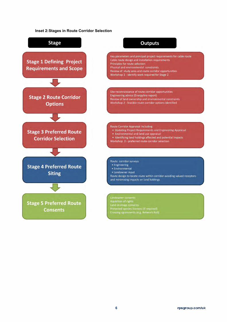
6
Inset 2: Stages in Route Corridor Selection

7
Stage 1: Defining Project Requirements and Scope
The first stage identified the principal project requirements for the UK onshore cable route and the 2.4main parameters which will determine the feasibility of options. These were reviewed at a FAB Link project workshop in October 2015 (Workshop 1).
Principal Project Requirements
The principal project requirements identified are as follows: 2.5
The electrical design of the interconnector comprises of two HVDC symmetrical monopoles capable of transmitting up to 700MW each.
Each monopole is comprised of a converter at either end linked by 2 HVDC cables and a communications cable.
The onshore HVDC cable route will run from the landfall to the preferred HVDC converter station site near to Exeter Airport, East Devon.
The HVAC onshore cable route is comprised of 2 HVAC circuits each consisting of 3 HVAC cables capable of transmitting up to 700MW each and a communications cable.
The onshore HVAC cable route will run from the converter station site to the existing NETS Exeter Main substation which lies east of Broadclyst, East Devon.
Underground cables will be jointed at a range of between 600 m and 1,200 m.
Cable Route Design and Installation Requirements
The design of the cable route installation was not fixed at this stage. Based on initial advice received 2.6on cable design and installation (Jacobs, 2015) and FAB Link’s own requirements the following parameters were identified:
In agricultural land
The installation on agricultural land would include two trenches with a minimum 3m cable circuit separation and 1.5m burial depth.
The working width for installation would be a maximum of 30 m.
A permanent easement for the cables would be required outside of highway land, subject to further design this is likely to be a maximum of 12 m width.
Field drainage and local land drainage would be reinstated.

8
In roads
Two circuit trenches would be required to remain in full compliance with the project cost and efficiency requirements. However, in some limited circumstances, a single trench formation is feasible but not desirable
Trench separation and working width would require a minimum 6m wide highway for in-road cable laying. The required road width would be increased where existing utilities also had to be accommodated.
Extensive road closures would likely be required. Further work was required to confirm the minimum working width feasible for road installation without road closure. Road closures would require highways consents and lengthy road closures.
General requirements
Cables would be installed into pre-laid ducts.
30 x 30m compounds on level (or levelled) ground would be required either side of any crossing requiring HDD.
A number of temporary works compounds and access routes would need to be identified along the route to ensure sufficient land and access will be available in order to install the onshore cable route.
FAB Link would commission further work to confirm other engineering and installation requirements including cable separation, duct radii, working width requirements and working constraints on steep gradients and sidelong ground.
Summary of advantages and disadvantages of cross-country vs. road routes
The below table lists the main advantages and disadvantages of routing through open countryside 2.7and roads. It can be seen that there is overwhelming evidence that the types of roads found within the study area largely preclude a mainly road-based route albeit that in-road construction may be preferred at some locations.
Table 2: Advantages and Disadvantages of Routing through Open Countryside and Roads.
Advantages Disadvantages Construction In-Road
Single landowner consent. No sterilisation of land for future
development. Little or no risk to ecology Previously developed land with little risk
to heritage, geology etc.
Insufficient width to allow shuttle working resulting in complete road closure
Road closures could be lengthy and diversion options are undesirably long so consents may not be forthcoming
If both circuits were laid together in the same trench project costs and efficiency

9
Advantages Disadvantages No effect to high value soils and
agricultural businesses. would be adversely affected and both circuits would need to be taken out of operation during future maintenance and repair work1.
Other land would still be required for storage and logistics
Joint bays are likely to be sited on agricultural land
Where a road can only accommodate one cable, the second cable would need to take an alternative route thereby increasing disruption
Off-line construction haul roads would still be required in areas of insufficient width
Many roads are not wide enough for even a single trench construction so an entirely road route is not possible
Affected roads would require substantial reinstatement / rebuilding upon completion inclusive of culverts.
Larger culverts, culvert bridges and other structures may not have sufficient cover for cables requiring major works to structures
Fewer opportunities to balance cut and fill. No space to store spoil resulting in greater traffic movements.
Construction across agricultural land
Sufficient space for optimal cable separation.
Faster construction with fewer joints. Fewer conflicts with other utilities. Sufficient space for all construction
equipment, material storage and logistics.
Achieves the shortest route possible from landfall to connection point.
Multiple landowner consents required Disruption to agricultural practices /
businesses Greater risk to productive soils,
hydrology, ecology and heritage
It is clear from the above table that project cost and efficiency will be severely affected by in-road 2.8construction in comparison to the alternative and human impacts of traffic disruption, safety, amenity and economy would be impacted to a significant degree. The route selection process therefore proceeded on the basis that a cross-country route would be selected albeit that locations of in road construction would be preferred where they present a viable alternative to resolving a sensitive area.
1 This arrangement would only be considered for locations with specific constraints where there would be no other alternative.
10
Principles for Route Selection
The following principles for route selection in accordance with the project requirements were 2.9identified:
Select the shortest route where possible – to deliver the most sustainable use of materials, minimise cost and achieve greatest efficiency.
The feasibility of installing the DC cables in roads would continue to be evaluated, although it was recognised that the minimum road width of 6 m could not be achieved on many of the roads in this part of East Devon.
The need for road closures should be minimised and would need careful case by case consideration.
Major crossings (main rivers, rail lines, major roads) should be minimised although some are unavoidable.
Cross-country cable routes should avoid designated nature conservation sites i.e. Sites of Special Scientific Interest (SSSI), Special Protection Area (SPA), Special Area of Conservation (SAC) and Ramsar sites unless there was no alternative2. Cables should also be buried to minimise impacts on the Areas of Outstanding Natural Beauty (AONB).
Land allocated for development in the existing or emerging Local Plan should be avoided unless appropriate gaps, roads or greenspace existed which could accommodate cable routes.
Physical and Environmental Constraints
The major physical and environmental constraints determining the location of route corridor options 2.10were the candidate landfall, the converter station location and Exeter NETS substation, the Pebblebed Heaths SSSI/SAC/SPA site, the Otter Estuary SSSI, sites allocated in the adopted East Devon Local Plans (including the Cranbrook new community and commercial developments around the airport), Exeter Airport and location of major crossings (gas pipelines, main rivers, rail lines and roads).
Review of Study Area and Route Corridor Opportunities
Following the review of the above, a number of potential route corridor opportunities were identified 2.11for further review of engineering feasibility, land uses affected and environmental constraints in the study area shown on Figure 1.
2 Devon Wildlife Trust and Natural England had already confirmed they would consider an in-road crossing through the SSSI/SAC/SPA as not impacting the site.

11
Workshop 1 was held as part of the Stage 1 process (see Inset 2) in October 2015. The broad area 2.12of search agreed at the Workshop was reviewed on site and further evaluated by Energyline. This review identified the principal risks and opportunities for the project as follows:
Table 3: Principal Risk and Opportunities Identified at Workshop 1
Issue Risk Opportunity
Built Development
Potential impacts on Budleigh Salterton, East Budleigh, Collerton Raleigh, Aylesbeare, Exeter Airport, Cranbrook as well as other small villages and isolated rural properties. Some pinch points at the exit from the landfall, Hawkerland, Cranbrook new development were apparent when combined with other principal risks (see below).
Agricultural land and primary road routes provide sufficient opportunity to avoid most development. Adapt construction methods / easement widths at pinch points. Avoidance of Budleigh Salterton may require corridor to encroach on Otter Meadows (see below).
Historic properties, curtilages and gardens
Potential impacts on Bicton Park and Rockbeare Manor Registered Parks and Gardens
Agricultural land and primary road routes provide ample opportunity to avoid Rockbeare Manor. Avoidance of Bicton Park to the west between the SSSI and to the east between the flood plain may require compromises in construction methodology (see below)
Ecological Designations
Potential impacts on Pebblebed Heaths SSSI/SAC/SPA, Otter Estuary SSSI, Otter Meadows SNCI, Bicton Park SNCI and other wildlife sites.
Undesignated land at Hawkerland or the undesignated public highways provide opportunity to cross Pebblebed Heaths area. Wildlife sites associated with the river Otter and its floodplain require alternative construction solution. Sufficient land available to avoid other designated and undesignated wildlife sites.
Main rivers and their flood plains (flood zones 2 & 3)
Potential impacts on River Otter and River Clyst, inclusive of tributaries. Corridor within functional floodplain of River Otter and River Clyst. First section of cable corridor below MHW.
Seek to avoid long sections of cable within the functional flood plain. Adapt construction methodology for remaining sections and section below MHW.
The identification of the principal risks and opportunities led to the following decision points for Stage 2.132:
Opportunities to cross between the Pebblebed Heaths SSSI designation at either Hawkerland, Harpford Hill (A3052 corridor) or within highways.
12
Bespoke construction methods to avoid built development, wildlife sites and flood risk north of the Budleigh Salterton landfall.
Opportunities to avoid long sections within the functional flood plain of the River Otter but avoiding East Budleigh and Bicton Park.
Opportunities to pass through the Cranbrook development taking cognisance of the River Clyst functional flood plain
Feasibility of avoiding impacts to Exeter Airport and its navigation aids.
Avoidance of impacts on commercial development such as operational solar farms south of Exeter Substation and various agricultural business types sensitive to the development such as fruit farms, organic livestock, equestrian operations, etc.
These potential corridors were taken forward to further feasibility studies including site visits. 2.14
Stage 2: Identifying Alternative Route Corridors
The objective of Stage 2 was to identify feasible alternative route corridors taking into account: 2.15
Further advice commissioned from Energyline on the engineering feasibility and cable route construction advice;
Land ownership boundaries obtained by Dalcour MacLaren from the Land Registry and initial enquiries;
Desk study of environmental and land use constraints;
Site reconnaissance from publicly accessible viewpoints.
Site visits were undertaken by representatives of FAB Link, Energyline, Dalcour Maclaren and RPS 2.16in November 2015. The output from the site visits was summarised by Energyline and reviewed at a Workshop in December 2015 (Workshop 2).
Energyline provided high-level appraisal of constructability and engineering constraints including 2.17areas of engineering difficulty (AEDs) within the study area. Varying road widths and narrow sections limited the use of roads and no road-only routes were identified. Energyline identified a number of potential route corridors that it considered feasible in terms of engineering and constructability. These are shown at Figure 2.
Dalcour Maclaren provided an overview of the principal land ownerships in the study area. 2.18
RPS provided information and mapping on the environmental constraints set out in Tables 4 and 5 2.19below which would be avoided where possible.

13
Table 4: Development considerations of National / International Importance
Development considerations of National / International Importance
Ancient Woodlands
Areas of Outstanding Natural Beauty (AONB)
National Nature Reserves (NNR)
National Parks
Ramsar Wetlands
Registered Battlefields
Registered Parks and Gardens,
Scheduled Monument
Special Area of Conservation (SAC)
Special Protection Area (SPA)
Special Sites of Scientific Interest (SSSI)
World Heritage Sites
Table 5: Development considerations of Regional /Local Importance
Development considerations of Regional /Local Importance
Allocated housing areas in the Local Plan Built development (both rural and urban) Existing Commercial and industrial areas Flood Risk Zones (2 & 3)
Listed buildings Local Nature Reserves (LNR) Local Wildlife Sites (LWS) Railways Existing renewable energy sites Rivers (main) RSPB Reserves County Wildlife Sites/Sites of Nature Conservation Importance (SNCI) Undesignated or unofficial wildlife sites Waste and Landfill Sites Wildlife Trust Reserves
High and medium pressure gas pipelines Woodland
In addition to these features identified by desk study, features such as woodland and mature 2.20vegetation, important hedgerows lakes, ponds, watercourses and residential dwellings including their curtilage identified on site reconnaissance would also be avoided where possible.
Based on conclusions from Energyline, the study area was divided into 5 sections within which to 2.21consider corridor options.

14
A) NETS Substation to Converter Station
B) Converter Station to the Pebblebed Heaths SSSI/SAC/SPA
C) Through the Pebblebed Heaths
D) The Pebblebed Heaths to East Budleigh
E) East Budleigh to Landfall.
The review of engineering requirements and feasible route options was set out in a report by 2.22Energyline in January 2016. These are summarised in the Chapter 3 of this report including the factors leading to the selection of these alternative route corridors.
Stage 3: Route Corridor Evaluation
The route corridors identified were then subject to further evaluation which is reported in Chapter 4 of 2.23this report.
The alternative route corridors were reviewed within each section identified above. Project and 2.24operational requirements (including cost), environmental effects and land availability factors were taken into account in the appraisal of potential corridor options as illustrated in Figure 3. The other factors that were taken into account are described further below.
Further site reconnaissance was undertaken where necessary. 2.25
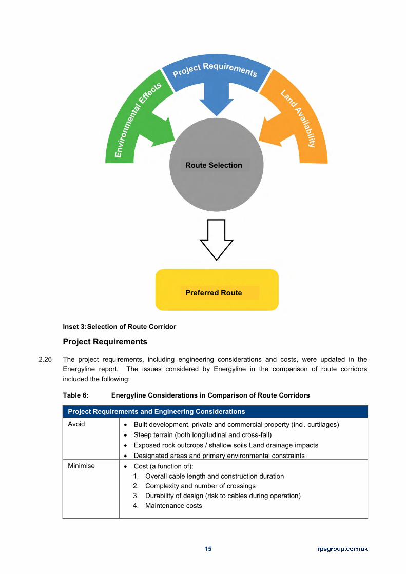
15
Inset 3: Selection of Route Corridor
Project Requirements
The project requirements, including engineering considerations and costs, were updated in the 2.26Energyline report. The issues considered by Energyline in the comparison of route corridors included the following:
Table 6: Energyline Considerations in Comparison of Route Corridors
Project Requirements and Engineering Considerations
Avoid
Built development, private and commercial property (incl. curtilages) Steep terrain (both longitudinal and cross-fall) Exposed rock outcrops / shallow soils Land drainage impacts Designated areas and primary environmental constraints
Minimise Cost (a function of): 1. Overall cable length and construction duration 2. Complexity and number of crossings 3. Durability of design (risk to cables during operation) 4. Maintenance costs
Route Selection
Preferred Route

16
Project Requirements and Engineering Considerations Traffic disruption / traffic management Principal Crossings (Main Rivers, Trunk Roads, Railways, Gas Pipelines,
High Voltage Transmission Lines) Construction haul road length to nearest suitable highway Seasonal restrictions / programme constraints Risk to public and workforce both during construction and operation
(maintenance) Optimise Safety
Secondary environmental constraints Working time / construction efficiency Temporary compound locations / construction logistics Bend radii / pulling stresses / cable separation Materials and waste strategy Easement widths and joint bay locations
Environmental Appraisal
A high level Environmental Appraisal of corridors was carried out using additional desk study 2.27information and site reconnaissance. Prior to definition of the cable easement boundaries, the appraisal could not conform to a formal assessment of effects but rather comprised a risk assessment (looking at areas of potential sensitivity) based on the ability to meet the project objectives in compliance with the FAB Link Schedule 9 Statement.
As the corridor options narrowed, it was possible to incorporate an increasing level of detail into the 2.28appraisal on issues that might affect route decision making. Additional desk study information collected included:
Table 7: Environmental Considerations in Comparison of Route Corridors
Environmental Considerations
Hydrology
Groundwater Vulnerability Mapping Source Protection Zones (SPZ) Land drainage Private Water Abstractions Lakes, Ponds and Small Watercourses
Ground Conditions
Contaminated Land (pollution incidents and UXO) Landfill sites Quarries
Habitats and Species
National Inventory of Woodland and Trees (National Forest Inventory) Priority Habitat Inventory Ecological Species Data - Terrestrial Important Bird Areas Water and Wetland Bird Concentrations Mature trees and their root zones (>150mm DBH) Non-statutory Environmental Designations

17
Environmental Considerations
Human Environment
Historic Environment Record (HER) Public access and Public Rights of Way (PRoW) incl. public car parks Sports and recreational facilities Hospitals, health care sites, care homes, sheltered housing etc. Schools, training centres etc. (noise sensitive uses) Individual dwellings (incl. curtilage) Country Parks, Parks, Village Greens, informal recreation areas
Landownership and Land Use
Land ownership and land use information was collected in an effort to reduce the total number of 2.29landowners affected and to take into account particularly sensitive land uses. The types of information collected included:
Table 8: Land Use Considerations in Comparison of Route Corridors
Landownership and Land Use Considerations
Land Use National Trust Property Woodland Trust Land Woodland Grant Schemes, Conservation Enhancement Agreements,
Wildlife Enhancement Scheme Agreements Organic livestock practices Equestrian businesses Orchards / fruit farms Tourist businesses incl. hotels, B&Bs, camp sites, leisure facilities /
attractions etc.
Appraisal Criteria
The cable corridors were appraised against the following criteria for a range of environmental and 2.30sustainability topics as well as planning and land use issues:

18
Table 9a: Corridor Appraisal Risk Criteria for RPS’ Consideration
Unfavourable Option Environment, Planning, Land Use and Access
Impacts will occur that conflict with FAB Link’s obligations under Schedule 9 of the Electricity Act and/or raise licensing risks that are likely to remain after mitigation and are likely to carry such weight that the site is unlikely to be acceptable to the responsible agency and/or local planning authority.
Less Favourable Option Environment, Planning, Land Use and Access
Impacts and/or licensing risks are likely but may be resolved through appropriate mitigation which may not yet be identified.
Favourable Option Environment, Planning, Land Use and Access
Impacts and/or licensing risks are possible but are likely to be acceptable with identified mitigation. The residual impacts will be consistent with FAB Link’s obligations under Schedule 9 of the Electricity Act.
Appraisal Limitations
The corridor appraisal was at a high level desk-top exercise. The routes were not walked in detail by 2.31RPS prior to the preferred corridor selection and several assumptions were made on issues relating to engineering feasibility, acceptability of impacts and availability of land. In considering the suitability of corridor options and in comparing the options with each other, FAB Link Ltd were aware of the issues raised by RPS and were able to rank the candidate landfalls as follows:
Table 9b: Corridor Appraisal Risk Criteria for FAB Link Ltd’s Consideration
Unfavourable Option Engineering, Property, Cost
Engineering feasibility and/or cost criteria may not be achievable.
Less Favourable Option Engineering, Property, Cost
Engineering requirements and cost implications may not be ideal but appear achievable.
Favourable Option Engineering, Property, Cost
Appears capable of meeting land availability, engineering and cost criteria.
Selection of Preferred Route Corridor
The outcome of the appraisal of environmental and land use issues was utilised in an overall 2.32decision making process at workshops in February 2016 (Workshop 3 – 8th and 24th February). The objective of Workshop 3 was to select a preferred cable corridor option that would be subject to further detailed assessment and consultation. The preferred route corridor is shown at Figure 4 and the main decision making points influencing the selection were:
Feasibility of an HDD through the Pebblebed Heaths.

19
Non-statutory nature conservation designations.
Topographical constraints and ease of construction.
Flood risk.
Stage 4: Preferred Route Siting and Easement Definition
Following the selection of the preferred route corridor, further engineering and environmental surveys 2.33will be undertaken, together with landowner consultation to determine the optimum route location of easements FAB Link will seek to acquire. Activities in the definition of a final easement include:
The entire cable route would be walked to confirm feasibility in terms of engineering/construction.
Phase 1 habitat survey
Drainage surveys
Ground Conditions and Thermal Resistivity Surveys
Assessment of locations where corridor could be accessed by road
Landowner negotiations
Further Consultation
Consultation with the public, businesses, landowners and parish councils;
Consultation with specialist council officers at both East Devon District Council, Devon County Council, managers of the Dorset and East Devon World Heritage Site, Natural England etc; and
Consultation with the Environment Agency regarding main rivers, source protection zones etc.

20
3 DEFINING ALTERNATIVE CABLE ROUTE CORRIDORS
As described above, the primary inputs to the cable corridor selection process are the engineering 3.1parameters and commercial requirements of the project. These were combined with existing data on environmental and land use constraints to inform decision making on risks and opportunities. Figure 2 provides an overview of the corridors proposed by Energyline.
For ease of description, the study area was divided into sections A to E. The boundaries of the 3.2section are drawn at major decision making points along the route. Further development of the input data, project assumptions and the strategic decisions taken is described below with respect to each section of the route to Budleigh Salterton. Figure 3 shows the output of the corridor definition stage and Appendix 2 provides the detail of the constraints used in the decision making process.
Engineering and Commercial Requirements
The engineering assumptions are outlined in the Energyline Report (2016). These include: 3.3
Construction swathe with temporary haul road through open countryside approximately 34 m;
Permanent easement with temporary haul road requirement approximately 24 m;
Construction swathe for temporary side haul road approximately 22.5 m;
Permanent easement approximately 12-15 m;
The minimum construction easement required for single carriageway working is 4 m from the centre of the road. This requirement is necessary on both sides to allow for single lane working;
Land owner consents being granted;
Open cut for road crossings where possible;
Installation of a fully ducted system;
Horizontal Directional Drill (HDD) solutions for all road crossings where open cut methods aren’t possible and where practical, at areas of engineering difficulty;
Trenchless crossing solutions at the rail crossing;
All major utility crossings will be crossed at 90° where practical.
Section A - Exeter Substation to Converter Station
Options for selecting a corridor between the NGET substation and the converter station site were 3.4influenced by the differentiation in the following factors:
The overall length of the section;

21
National Trust land associated with Killerton House;
Rockbeare Village and other properties;
Rockbeare Manor Registered Park and Garden;
The new Cranbrook Development (both sides of the B3174);
Existing solar farms;
Exeter Airport runway and landing lights;
Main river crossings and cable length within the floodplain;
Ordinary watercourse crossings and their riparian corridors;
Accessibility of the section from local roads;
Mature woodland near the NGET substation, parkland trees and mature field boundary vegetation; and
The entry/exit point at the NGET substation.
Any route corridor will need to cross the River Clyst and its tributaries, the B3174, several minor 3.5roads, a high pressure gas pipeline, beneath high voltage overhead lines (OHL) and a railway line. Any route will need to either negotiate the new Cranbrook development or avoid it with a wide diversion. Opportunities to pass through the Cranbrook development are presented within the functional floodplain of the River Clyst and its tributaries or via the planned road network. The entry and exit points for the HDD under the railway have the potential to be within the floodplain for both options.
In comparing these options, routes to the east of Rockbeare avoid the runway approach lights and 3.6cross 5 minor roads in addition to the B3174. The route is approximately 1km longer than the more direct route to the west of Rockbeare (see below). The route would need to either pass through existing solar farm development or a plantation for substation entry points on the south or east sides.
Routes to the west of Rockbeare cross 3 minor roads in addition to the B3174. National Trust land is 3.7encountered both sides of the railway line. The route can avoid all existing solar farm development for an entry point on the west side of the substation.
The defining selection factor for this section is the choice of crossing location of the new Cranbrook 3.8development. Therefore, the corridor options to be evaluated are:
Option 1: Passing under (or avoiding) the runway approach lights, west of Rockbeare, through the proposed new Cranbrook Country Park and to the west of the solar farms.
Option 2: Diverting away from the runway approach lights, east of Rockbeare and through planned green space in the new Cranbrook development marked by an existing OHL corridor and the floodplain.

22
Section B - Converter Station to the Pebblebed Heaths SSSI/SAC/SPA
Options for selecting a corridor between the converter station site and the Pebblebed Heaths SSSI 3.9are influenced by the differentiation in the following factors:
The overall length of the section;
Farringdon Village, Aylesbeare Village and other properties;
The crossing locations of the A30, A3052 and B3180 major roads;
Agricultural practices inclusive of a fruit farm, fishery and other equestrian properties;
Commercial and tourism development;
Stallcombe House and Willows Residential long stay care facilities;
Accessibility of the section from local roads;
Slope steepness (both longitudinal and cross fall).
Mature woodland, wooded riparian corridors (ordinary watercourses) and mature field boundary vegetation; and
The crossing point of the Pebblebed Heaths SSSI.
Any route will need to cross the A30, the B3180 and A3052, several minor roads (including Long 3.10Lane), several gas pipelines and watercourses. Some of the ordinary watercourses have gullies associated with them and are classed as major crossings.
Routes to the east of Aylesbeare avoid a number of large watercourse crossings and associate 3.11habitats. The route is approximately 1km longer. The corridor includes an additional gas pipeline crossing.
Routes to the west of Aylesbeare pass close to Sanctuary Farm fruit farm, deciduous woodland and 3.12riparian corridors associated with Grindle Brook and a tributary of the River Clyst to the east of Farringdon Wood.
The defining selection factor for this section is the choice of crossing location for the Pebblebed 3.13Heaths SSSI. Therefore, the corridor options to be evaluated are:
Option 1: Passing under the A30 south of the converter station, west of Aylesbeare but east of Farringdon and under the A3052 near Nine Oaks.
Option 2: Diverting to the east before crossing under the A30, east of Aylesbeare and under the A3052 near to the Half Way Inn.
Section C - Through the Pebblebed Heaths

23
Options for selecting a corridor through the Pebblebed Heaths SSSI are influenced by the 3.14differentiation in the following factors:
The overall length of the section;
Specialist crossings (type and number);
Geology, hydrogeology and drainage;
Commercial and residential properties;
The crossing locations of the A3052 and B3180 major roads;
Agricultural practices inclusive of forestry and equestrian businesses;
Commercial and tourism development;
Accessibility of the section from local roads;
Mature woodland, wooded riparian corridors and mature field boundary vegetation; and
Slope steepness (both longitudinal and cross fall).
The defining selection factor for this section is the choice of crossing location for the Pebblebed 3.15Heaths SSSI. Therefore, the corridor options to be evaluated are:
Option 1: Passing through the undesignated section of the Hawkerland Valley (the Hawkerland gap)
Option 2: Passing under the SSSI at Harpford Hill.
Section D - The Pebblebed Heaths to Otterton
Options for selecting a corridor between the Pebblebed Heaths SSSI and East Budleigh are 3.16influenced by the differentiation in the following factors:
The overall length of the section;
Length of section in River Otter flood plain;
Colaton Raleigh, Kingston Village and other properties;
The crossing location of the B3178 road and a gas pipeline;
Commercial and tourism development;
Agricultural practices inclusive of an organic dairy business;
Bicton Park Registered Park and Garden

24
Accessibility of the section from local roads;
Slope steepness (both longitudinal and cross fall);
Potable water abstraction points;
Mature woodland, wooded riparian corridors and mature field boundary vegetation; and
The exit point from the Pebblebed Heaths SSSI.
Routes to the north of Colaton Raleigh avoid a number of properties and source protection zones. 3.17Routes to the west of Kingston avoid Bicton Park and central routes are shorter.
The defining selection factors for this section are the exit point from the Pebblebed Heaths SSSI, 3.18Colaton Raleigh and Bicton Park. Therefore, the corridor options to be evaluated are:
Option 1: Passing to the east of Kingston Village and crossing the B3178 south of Colaton Raleigh.
Option 1D: A diversion around the north of Colaton Raleigh to join the disused railway line at Otter Farm.
Option 2: as per option one except for the alternative exit point from the SSSI.
Option 5D: Diverting to the east of Bicton Park parallel to the local road network.
Section E - Otterton to Landfall
Options for selecting a corridor between East Budleigh and the landfall are influenced by the 3.19differentiation in the following factors:
The overall length of the section;
Length of section in River Otter flood plain and below Otter Estuary MHW;
Viability of in-road installation through Budleigh Salterton;
Viability of specialist installation methods on the PRoW along the western edge of the Otter Meadows;
Residential, commercial and tourism development;
Health care facilities e.g. Budleigh Hospital;
Agricultural practices inclusive of an organic dairy business;
Otter Estuary SSSI and other wildlife designations;
Accessibility of the section from local roads and the landfall;

25
Mature woodland, wooded riparian corridors and mature field boundary vegetation; and
Recreational impacts such as the Cricket Club, PRoW, bird watching, beach visitors and children’s play facilities.
The defining selection factors for this section are the engineering and logistical viability of installation 3.20in roads through Budleigh Salterton and the alternative solution provided by the PRoW to the west of the Otter Meadows. Therefore, the corridor options to be evaluated were:
Option 1: Passing to the west of Otter Meadows and Grazing Marshes via the disused railway line and PRoW; and
Option 2: In-road construction along the B3178 through Budleigh Salterton.

26
4 CABLE ROUTE CORRIDOR APPRAISAL
This section details the selection of the preferred route corridor. An appraisal of Options 1 and 2 as 4.1identified in Stage 3 above and shown in overview at Figure 3 resulted in selection of the preferred corridor as shown on Figure 4. Appendix 3 shows the environmental and land use constraints information considered in the appraisal. An appraisal summary matrix is provided at Appendix 4.
Section A: Exeter Substation to Converter Station
Project Requirements including Engineering and Cost
Option 1 - Access and Logistics
The length of this section of cable route is approximately 4.6 km, and it follows the perimeter of solar 4.2farms to the south of the Substation, through the proposed new Cranbrook Country Park and passes under (or avoiding) the runway approach lights.
North of the railway line, the route is accessible only from the NGET substation access road. 4.3
South of the railway line the route is accessible from the B3174 London Road and the converter 4.4station site.
Option 1 - Crossings
The corridor is required to cross the following obstacles: 4.5
The Railway line - a trenchless solution is proposed
Gas pipeline, 2 No. 400kV and 1 No. 132kV OHL
Exeter Airport runway approach lights
3 No. minor roads at surface (roads to be temporarily closed)
1 No. B-road crossing (B3174 London Road) – Open cut, half and half installation methodology is likely to be feasible.
A number of minor watercourse crossings
Option 2 - Access and Logistics
The length of this section of cable route is approximately 5.6 km. From Exeter grid substation, the 4.6route corridor heads southeast around the solar farm to the south of the substation. This has been provided in the event that the Cranbrook country park area is deemed unsuitable or planning constraints affect the option to route the AC cables through this area. Option 2 runs through the planned green space in the new Cranbrook development marked by an existing OHL corridor and the floodplain. It is diverted away from the runway approach lights, east of Rockbeare.
North of the railway line, the route is accessible only from the NGET substation access road. 4.7
27
South of the railway line the route is accessible from the B3174 London Road and the converter 4.8station site.
Option 2 – Crossings
Similar crossings to Option 1 would be required: 4.9
The Railway line
Gas pipeline, 2 No. 132 kV OHL tower lines to cross beneath
6 No. minor road at surface (roads to be temporarily closed)
1 No. B road crossing (B3174 London Road)
A number of minor watercourse crossings (amount to be confirmed with full land access)
Following 132 kV OHL through Cranbrook Housing Development
A number of minor watercourse crossings.
Environmental Appraisal
Option 1
Hydrology
This route corridor crosses a tributary that feeds into the River Exe and therefore land situated within 4.10Flood Zone 2 and 3 (high probability of flooding). This corridor would not only cross an existing tributary, it also runs through the proposed new Cranbrook Country Park, parallel to an existing watercourse. It is likely that stringent mitigation measures would need to be employed during construction within the flood plain to ensure that the works do not increase flooding elsewhere, affect water quality, or present a risk to construction workers.
There is no Source Protection Zones (SPZ) in this area. The corridor overlaps with a groundwater 4.11vulnerability zone for minor aquifers. There is one record of a pollution incident to the stream at Cranbrook from sewerage material in 2003. A small scale groundwater abstraction is located at Tillcrest located within this route corridor.
Ground Conditions
There is no record of landfill or quarries within this cable corridor therefore there is limited potential 4.12for contaminated land.
Habitats and Species
There are no statutory or non-statutory designations within this section of the corridor. Parts of the 4.13corridor are within a Great Crested Newt (GCN) consultation zone.

28
Within this corridor, there is some deciduous woodland at Higher Burrowton, which is a priority 4.14habitat3. Further south, there is also some young woodland that features on the National Forest Inventory at Woodside. It should be possible to avoid these areas.
Human Environment
The corridor overlaps with the site of a former farmstead at Lower Burrowton as identified on the 4.15Historic Environment Records obtained from Devon County Council. This should be avoided; if any route crossed this record, it would need to be excavated. South of the Saundercroft Road junction, the corridor also overlaps with a site of a former house. Again, this would need to be avoided and if not, would require excavation works. This corridor crosses the Roman Road from Exeter to Honiton, which is beneath or close to the B3174 road.
The corridor also overlaps with an old road bridge (Grade II listed building) within the proposed 4.16Country Park. As the corridor runs south through the airfield it may overlap with a World War II military structure, possibly a pill box, that should be avoided. Routes within this corridor would need to be aware of a World War II anti-aircraft battery and dispersed World War II sites east of Exeter Airport.
Land to the north of the substation is owned by the National Trust, in association with Killerton House 4.17Grade II* Registered Park and Garden, although the actual designation boundary is approximately 3.7 km from the substation.
There is a footpath that runs from Newlands Farm, north of the Substation, down to Lower 4.18Burrowton. The cable corridor crosses this footpath therefore it is likely that temporary diversions would need to be put in place to maintain access and ensure safe passage of users. There may also be a temporary impact on visual amenity during cable installation. This option could potentially result in the temporary closure of 3 minor roads during cable installation. There would consequently be an impact on local traffic and may result in traffic diversions.
Option 2
Hydrology
This route corridor crosses a tributary that feeds into the River Exe and therefore land situated within 4.19Flood Zone 2and 3 (high probability of flooding). There are no Source Protection Zones (SPZ) in this area. The corridor overlaps with a groundwater vulnerability zone for minor aquifers. A medium scale groundwater abstraction is located to the east of Lower Southbrook located within this route corridor.
Ground Conditions
There is no record of landfill or quarries within this cable corridor therefore there is limited potential 4.20for contaminated land.
Habitats and Species
3 The Priority Habitat Inventory is a spatial dataset that describes the geographic extent and location of Natural Environment and Rural Communities Act (2006) Section 41 habitats of principal importance.
29
To the southeast corner of the Exeter substation lies Addlehole Copse, which is large area of 4.21deciduous woodland. This woodland is a priority habitat and an Unconfirmed Wildlife Site4 (UWS). Further south below the B3174, the corridor runs through Woodpasture and Parkland BAP Priority Habitat (England) at The Grange. This area is also identified as a UWS. It also runs through young woodland habitat to the southeast of Rockbeare that is identified on the National Forest Inventory.
Parts of the corridor are within a GCN consultation zone. 4.22
Human Environment
There is a possible ring-ditch southwest of Tub Corner, east of Saundercroft Solar Farm. This should 4.23be avoided. This corridor crosses the Roman Road from Exeter to Honiton, which is beneath or close to the B3174 road. There is a military structure northwest of Higher Southwood Farm that should be avoided if this is still extant. There are also dispersed World War II activity sites and military structures to the east of Exeter Airport, including a World War II searchlight battery.
South of the B3174 (London Road), the corridor runs south of The Grange Court Hotel and there 4.24would be potential socio-economic, noise, visual and access impacts, albeit on a temporary basis.
As Option 2 corridor runs south of Rockbeare, it runs in very close proximity to Rockbeare Manor 4.25which is listed on the register of parks and gardens of special historic interest. This would result in a temporary impact on the setting of this historic landscape.
There are no public rights of way identified within this corridor. However, this option could potentially 4.26result in the temporary closure of 6 minor roads during cable installation. There would consequently be an impact on local traffic and may result in traffic diversions.
Land Ownership
Option 1
Option 1 crosses over land owned by the Solar Farm developments, but routes that avoid the solar 4.27infrastructure are possible. The corridor runs south through agricultural land to the new Cranbrook development and Country Park south of the railway line and Hallam Land are seeking planning permission for this land as part of the expansion of Cranbrook. . Negotiations with Hallam Land have indicated that a cable corridor through the Cranbrook development may be possible, subject to a commercial agreement.
Between the Cranbrook Development and the Converter Station, the corridor would overlap with 4.28Land belonging to the Rockbeare Estate and Pyle Estate. Landowner negotiations have indicated that land owned by the Pyle Estate is not available, which would ultimately influence any route within the Option 1 corridor.
The corridor runs through the airfield at Exeter Airport to the east of the runway, which is acceptable 4.29provided it avoids or passes underneath the runway approach lights.
4 Sites which have possible interest, but which have not been fully surveyed. Some of these sites will be areas of significant wildlife interest.

30
Option 2
Option 2 would also cross over land owned by the Solar Farm developments. Any route option to 4.30avoid the woodland would likely result in the encroachment onto solar infrastructure which could result in multiple cable crossings, the requirement for solar panels to be removed, a restriction on working width and potential compensation for loss of earnings for the solar farm operator.
To the north of the B3174 (London Road) the corridor would cross predominately agricultural land. 4.31
Option 2 runs through the planned green space in the new Cranbrook development marked by an 4.32existing OHL corridor and would be the same land ownership as the Country Park (Hallam Land).
Summary
In summary, Option 2 would be less able meet the project requirements compared with Option 1 on 4.33the basis that it is more than 1 km longer than Option 1 due to the diversion around the east of the current Cranbrook development extent. In addition, the exit from Exeter substation is constrained to the east and south by a woodland and solar farm respectively. Option 1 would also present less traffic disturbance as fewer roads would require temporary closures during construction and hence would present less of a disturbance to local traffic and road users.
Section B: Converter Station to the Pebblebed Heaths SSSI/SAC/SPA
Project Requirements including Engineering and Cost
Option 1 - Access and Logistics
Option 1 passes under the A30 south of the converter station, west of Aylesbeare but east of 4.34Farringdon and under the A3052 near Nine Oaks.
This corridor is between approximately 5.2 km and 5.8 km in length. 4.35
Roads within the Aylesbeare area are generally very restrictive with no roads in the area capable of 4.36two-way traffic without the requirement for passing places. To the south of Aylesbeare is the A3052, a two-way single carriageway road with an intermittent white line, generally with road widths of between 6 - 7 m.
The A3052, B3184 and Long Lane (Converter station access road, subject to potential upgrade 4.37required for construction of converter station) would be suitable for construction traffic to access the haul roads.
Option 1 – Crossings
1 x 132 kV OHL tower lines to cross beneath.
2 x major road crossings A30 & A3052. Due to the importance of the A30 to local traffic and the topography and space available, it is proposed that a HDD is utilised to cross this road. An open cut, half and half installation methodology would be feasible on the A3052 due to the available lane widths.

31
4 x minor road crossings (roads to be temporarily closed or trenchless techniques).
Intermediate pressure gas main crossing.
A number of minor watercourse crossings (quantity to be confirmed with full land access).
Option 2 - Access and Logistics
Option 2 consists of diverting to the east from the converter station before crossing under the A30, 4.38east of Aylesbeare and under the A3052 near to the Half Way Inn. This slightly more easterly option leaves the converter station through slightly undulating agricultural land, loosely following the high pressure gas main route. There is a steep valley with a small stream running through it to the east of Aylesbeare.
Roads suitable for access would be the A3052, B3180 and Long Lane (subject to an upgrade 4.39required for construction of the converter station).
This section of Option 2 is approximately 3.9 km in length. 4.40
Option 2 – Crossings
6 x minor road crossings roads to be temporarily closed or trenchless techniques.
1 x major road crossing of the A30. Due to the importance of the A30 to local traffic and the topography and space available, it’s proposed a HDD is utilised to cross this road.
High pressure gas main crossing.
Aylesbeare steep valley with stream.
A number of minor watercourse crossings (amount to be confirmed with full land access).
Environmental Appraisal
Option 1
Hydrology
This route crosses (and for 500 m runs parallel with) a tributary of the River Clyst and Grindle Brook 4.41and their associated floodplains classified as Flood Zones 2 & 3. The route corridor also incorporates a number of surface water features associated with Upham Farm and Lyndhayne Farm. It is likely that stringent mitigation measures would need to be employed during construction within the floodplain to ensure that the works do not increase flooding elsewhere, affect water quality, or present a risk to construction workers.
There are no groundwater SPZs within this area. The corridor overlaps with a groundwater 4.42vulnerability zone for minor intermediate aquifers.
Ground Conditions

32
1.39 There are no historic or active landfill or quarry sites within this corridor. There is record of a significant pollution incident located close to Lower Hawkerland Farm in the eastern extents of the corridor. The incident, recorded in May 2001, involved the discharge of contaminated water causing significant impacts to the water environment.
Habitats and Species
This corridor does not overlap with any statutory ecological designations. 4.43
As the corridor runs south from the A30, it crosses a strip of riparian woodland (Nether Mead Copse) 4.44which comprises deciduous, broadleaved woodland (priority habitat) which appears on the National Forest Inventory. Further south, the corridor does overlap with an area identified as Faringdon UWS, north of Faringdon. This area has Woodpasture and Parkland BAP Priority Habitat (England).
Below the A3052, the corridor runs through Trixhayes Farm, which is identified as ‘Other Site of 4.45Wildlife Interest’5.
A large proportion of this section of the corridor is within a GCN consultation zone. 4.46
Human Environment
There are dispersed World War II activity sites associated with Exeter Airport and locations of World 4.47War II searchlight batteries. There are also known and potential Roman Roads in the area, which should be considered through this corridor.
Farringdon House is Grade II listed (as are the gate piers). Although this house falls within the broad 4.48corridor of Option 1, in reality any cable route would not directly affect this house. There may be a temporary effect on the setting of this listed building from construction works for cable installation.
Between the A30 and A3052, the corridor runs across agricultural fields. Between the A3052 and the 4.49B3180, there are quite a few farm businesses present within the corridor. In particular, Sunnyhaye Fruit Farm presents a particular constraint along the south of the corridor and influencing its alignment into the Hawkerland Gap. The corridor is similarly constrained by the presence of Stallcombe House residential facility. The Option 1 corridor has therefore been kept purposely wide to allow the possibility of cable routes that could be considered to the north or south of Sunnyhaye Fruit Farm.
An alternative route corridor to the south of the Sunnyhaye Fruit Farm would add approximately 700 4.50metres length and 2 x minor road crossing to the section. The topography of the land in this area also means that there may be the requirement for multiple bends to negotiate around Stallcombe House.
There is a public footpath that extends from the B3184 to Perkin’s Village and then south to Lower 4.51Hawkerland Farm. This footpath could potentially experience temporary closure and diversions if a cable route was selected within this corridor. There is a footpath running from Scott’s Cottage to
5 These are sites that have been surveyed but they do not reach CWS standard. They will include the old designation of Local Wildlife Site (LWS).
33
Winkleigh Farm, but there would be sufficient area within the corridor to avoid this path. There is also a footpath that extends from approximately Sunnyhaye Fruit Farm to the B3180. Any cable route within this corridor would likely run parallel to this footpath. Consequently, this path is unlikely to be affected in terms of access, but there may be a temporary impact on visual amenity during cable installation.
Option 2
Hydrology
This option is located entirely within flood zone 1 which is land classed as having a low risk of 4.52flooding. The route corridor overlaps with an area classified as groundwater SPZ 3 (Total Catchment) within which all groundwater recharge is presumed to be discharged at the source. In addition the corridor overlaps with groundwater vulnerability zone for minor aquifers.
Ground Conditions
There is no record of landfill or quarries within this cable corridor therefore there is limited potential 4.53for contaminated land
Habitats and Species
This corridor does not overlap with any statutory ecological designations but could potentially affect a 4.54number of non-statutory designations.
As the corridor runs east and south of the converter station, it would impact on an area of deciduous, 4.55broadleaved woodland at Great Covert identified as a priority habitat and listed on the National Forest Inventory. This area of woodland is also a UWS. Adjacent and to the southeast of this woodland, lies an area of good quality semi-improved grassland that forms the Beautiport Farm County Wildlife Site (CWS)6.
The corridor then runs in a more south-easterly direction, to the east of Aylesbeare, but to the west 4.56of a further CWS and UWS but it should be possible to avoid these non-statutory designations. There are small, discrete patches of priority habitat deciduous woodland along this corridor, but it should be possible for any routes within this corridor to avoid them.
The majority of this corridor runs through a GCN consultation zone. 4.57
Human Environment
North of the A30, there are dispersed World War II activity sites associated with Exeter Airport and a 4.58pillbox and possible military structure north west of Southwood Cross. There are several barrows (tumuli) on Aylesbeare Common (some of these are Scheduled Monuments), but the corridor would not run directly through these. There are also known and potential Roman Roads in the area, which should be avoided by this corridor if possible.
6 A County Wildlife Site is a discrete area of land, water, foreshore or seabed which is considered to be of nature conservation significance for its constituent wildlife (or biodiversity) in, at least, a County context

34
The corridor would cross two footpaths to the south of the A30, a public access route at Aylesbeare, 4.59and a further footpath at the Halfway Inn. Temporary closures and diversions would need to be put in place along these rights of way to ensure safe passage of users. There may also be a temporary impact on visual amenity from the construction works.
There would also likely be some disruption in terms of access and noise to the Halfway Inn from 4.60works to cross the A3052.
Land Ownership
Option 1
The corridor crosses predominantly freehold land that belongs to a large number of landowners. 4.61Lengthy landowner negotiations therefore could present a risk to the project programme and the prospect of Compulsory Purchase Order (CPO) to acquire the necessary land and rights must be considered.
Option 2
The corridor crosses predominantly freehold land that belongs to a large number of landowners. 4.62Lengthy landowner negotiations therefore would present a risk to the project programme and the prospect of CPO to acquire the necessary land and rights must be considered.
Summary
Both corridor options are viable options in terms of engineering and cost and the constraints 4.63identified are not of the magnitude that an option should be discarded. Option 1 is marginally more favourable than Option 2 on the basis that there would be fewer impacts on non-statutory ecological designations and that the topography of the corridor would present fewer difficulties with construction than the steep valleys in Aylesbeare. However, the determining factor for this section is likely to be the choice of route through section C (see below).
Section C: Through the Pebblebed Heaths
Project Requirements including Engineering and Cost
Option 1 - Access and Logistics
Option 1 passes through the undesignated section of the Hawkerland Valley. Discussions with 4.64Clinton Devon Estates have indicated that there are notable clay ground conditions here, which has implications for how long the ground would take to recover and the possibility of drainage issues. This length of corridor would be approximately 1.5 km.
A route corridor through the Hawkerland Gap would be restricted due to the Pebblebed Heaths. It 4.65may be possible to establish a route through the open fields and paddocks or within (or adjacent to) the Hawkerland Road.
The B3180 is appropriate for construction plant and machinery access to the easement haul road. 4.66

35
Option 1 – Crossings
There would be one minor road crossing of the B3180. At this crossing, it may be possible to utilise a 4.67half cut method to install the cable (though it is noted that this road can be busy and traffic can include quarry trucks as well as other large vehicles). Where road closures aren’t possible trenchless methods may be considered.
Option 2 - Access and Logistics
The Option 2 corridor extends from north of the Halfway Inn, crossing the A3052 and follows the 4.68southern site of the A3052 via a stitched (back to back) HDD crossing through (under) the Pebblebed Heaths SSSI. A HDD compound may be possible within a square area of coniferous woodland on the south side of the A3052 that is not within the designated boundary of the SPA/SSSI.
The length of this section of corridor is approximately 1.9 km. 4.69
Construction access to the haul road and the HDD compound would be via the A3052. 4.70
Option 2 – Crossings
1 No. minor road crossing
1 x major road crossing of the A3052. The A3052 is also a busy road operating two-lane opposing direction traffic flow. For the crossing of this road it is anticipated that open cut half and half installation methodology would be feasible due to the available lane widths.
1 x stitch trenchless crossing through the East Devon Pebblebed Heaths SSSI.
Environmental Appraisal
Option 1
Hydrology
There is a stream that runs on the south side of Hawkerland Road and also one that runs down 4.71Hawkerland Valley. However, this area is not at risk of flooding. The eastern end of the Hawkerland Gap is catchment boundary (Zone 3) of a Source Protection Zone. The corridor does not lie within a groundwater vulnerability zone.
Ground Conditions
A small historic landfill site is located at Canterbury House Farm in the northern extents of this 4.72corridor. The landfill site contains inert and industrial waste and therefore may be a source of ground contamination.
Habitats and Species
There are no statutory or non-statutory designations within this section of the corridor. The corridor 4.73runs through the Hawkerland Gap and is therefore confined to the north and south by the East Devon Heaths SPA and East Devon Pebblebed Heaths SSSI, although any route within this corridor

36
would avoid these designations. However, due to the location within close proximity of the boundaries of the SSSI, this corridor does lie within a SSSI Impact Risk Zone.
There are no priority habitats within the corridor with the exception of deciduous woodland and 4.74broadleaved woodland that appears on the National Forest Inventory to the south of Hawkerland Road. Mature vegetation should be avoided where possible.
A possible route within this corridor is through the paddocks and open fields, however these are 4.75bounded by hedgerows and lined with mature trees. The option of cabling along the Hawkerland Road would be minimise ecological impacts, although it would have to be routed to avoid Valley Barn and the mature trees that line Hawkerland Road to the east.
This section of the route corridor does not lie in a Great Crested Newt Consultation Zone. 4.76
Human Environment
There is a World War II searchlight battery along the southern side of the Hawkerland Road. 4.77
There is a potential World War II military site that covers an extensive area of the Hawkerland Valley 4.78(south of the A3052). The Option 1 corridor does not appear to run through this area, but there is a risk of encountering archaeological features that could be associated with this site.
To the north of the Hawkerland Gap, the East Devon Way long distance footpath runs southwards 4.79through the SPA/SSSI to cross the Hawkerland Road, where it then continuous in a westerly direction through the southern boundary of the SPA/SSSI designation. Temporary diversions would be necessary during open cut cable installation to ensure access is maintained and safe passage of users. There may also be a temporary effect on visual amenity of users of this access route during cable installation.
Option 2
Hydrology
Part of the cable corridor lies within a groundwater vulnerability zone for a major aquifer and also a 4.80catchment boundary (Zone 3) of a Source Protection Zone. This corridor does not overlap with land that is at risk of flooding. A small scale groundwater abstraction is located at Hillside House located within this route corridor.
Ground Conditions
A disused quarry (Aylesbeare Quarry) lies on the north side of the A3052 and would therefore be 4.81unaffected by the proposals. There are no landfill sites within this corridor and there is limited potential for encountering contaminated land.
Habitats and Species
This corridor overlaps with the boundaries of the East Devon Heaths SPA and East Devon 4.82Pebblebed Heaths SSSI, albeit, HDD would be the required installation methodology for this section of the route. Option 2 extends from north of the Halfway Inn, crossing the A3052 and follows the southern site of the A3052 via a stitched (back to back) HDD crossing through the Pebblebed Heaths SSSI. A temporary HDD compound would be possible within a square of plantation woodland that is

37
located outside the SPA/SSSI designation boundary. This square woodland is identified as Coniferous woodland on the National Forest Inventory.
This section of the route corridor does not lie in a GCN consultation zone. 4.83
Human Environment
There is a potential World War II military site that covers an extensive area of the Hawkerland Valley 4.84(south of the A3052) the corridor does run through this area. There is also a ring-cairn on Harpford Common and a possible ditch enclosure, but these should be avoided by a HDD corridor.
The East Devon Way long distance footpath runs southwards from Harpford Hill, crossing the A3052 4.85(Exeter Road) towards Hawkerland Valley. The project is unlikely to disrupt access to this footpath, although there may be a temporary loss of visual amenity from this footpath during construction from views of the HDD compound.
Land Ownership
Option 1
At the western end of the Hawkerland Gap, Canterbury Green Cottage lies to the south of 4.86Hawkerland Road and Canterbury Green Farm which is a bed and breakfast business establishment lies to the north of Hawkerland Road.
At the eastern end of the Gap lies Valley Barn (which operates a trailer business), and Hawkerland 4.87Farm, which is also a bed and breakfast. The majority of land above Hawkerland Road belongs to the Clinton Devon Estate. The majority of the land to the south of Hawkerland Road belongs to Hawkerland Brakes.
The land use above and below the road appears to be predominantly agricultural and therefore there 4.88would be no constraints in terms of land uses. There may be some disruption to the bed and breakfasts in terms of amenity. In the case of Hawkerland Farm and Valley Barn, the option of taking the cable along Hawkerland Road, may present some temporary access issues.
Option 2
To the north of the A3052 the land comprises Aylesbeare and Harpford Common which forms part of 4.89the SPA/SSSI designation.
Below the A3052, the land use is a mixture of heathland associated with the SPA/SSSI designation, 4.90agricultural land and commercial forestry. There is a public car park located on the south side of the A3052, but this is unlikely to be affected by the proposal nor pose a risk to the project requirements.
Summary
A desktop Investigation of borehole datasets indicated that HDD would not be feasible through the 4.91SPA/SSSI boundary due to the likely presence of pebbles at the required drilling depth. Additionally, Option 2 also presents the likely requirement for traffic management measures on the A3052 for an extended period during construction. For these reasons, Option 1 is the preferred corridor option. This subsequently dictates that Option1 should also be the preferred corridor option for Section B.

38
Section D: The Pebblebed Heaths to East Budleigh
Project Requirements including Engineering and Cost
Option 1 - Access and Logistics
Option 1 runs southeast through moderately undulating agricultural land, passing to the east of 4.92Kingston Village and crosses the B3178 south of Colaton Raleigh. To the southern part of this section, the route corridor enters the River Otter flood plain.
The length of this section of corridor is approximately 5.1 km. 4.93
The areas of incline, decline and side slope viewed do not raise any concerns relating to installation. 4.94Levelling of the working easement may be required for working on side slopes. Installation should ensure that each circuit is adequately buried, but this should be feasible.
B3178 is appropriate for the construction plant and machinery access to the easement haul road. 4.95
Option 1 – Crossings
Minor watercourse crossing at Hawkerland.
Intermediate pressure gas main crossing (feasible, providing the corridor crosses at 90°). Crossing methodology and calculations will be required by the asset owner as well as a watching brief during construction works.
5 x minor road crossings (temporary road closures or trenchless crossings would be required).
1 x major road crossing (trenchless options or half and half, open cut methodology are feasible).
Flood plain east of Bicton College of Agriculture.
A number of minor watercourse crossings (number to be confirmed with full land access).
Option 1D - Access and Logistics
Option 1D extends from the Hawkerland gap and runs north of Kingston to join the disused railway 4.96line at Otter Farm.
The length of this section of corridor is approximately 4.8 km. 4.97
B3178 is appropriate for the construction plant and machinery access to the easement haul road. 4.98
A rock outcrop with a vertical face of approximately 5 m is identified as an area of engineering 4.99difficulty between Stonyford Cottage and Stoneyford Farmhouse. Although, a trenchless solution could possibly be used, it is preferable to avoid it altogether by routing to the south.
Option 1D – Crossings
This option adds 600 m and 3 x minor road crossings in comparison to Option 1. 4.100

39
Option 2 - Access and Logistics
Once clear of the East Devon Pebblebed Heaths SSSI, Option 2 turns south over moderately 4.101undulating agricultural land to the point where it meets the corridor of Option 1.
This length of Option 2 is approximately 1.7 km. 4.102
Option 2 - Crossing
2 x minor road crossings
1 x stitch trenchless crossing through the East Devon Pebblebed Heaths SSSI
A number of minor watercourse crossings (amount to be confirmed with full land access)
Roads within the locality of Option 2 are generally very restrictive with no roads in the area capable 4.103of two-way traffic without the requirement for passing places. Construction access would be via the A3052 through Newton Poppleford and the B3178.
Option 5D – Access and Logistics
Option 5D shares the same corridor as Option 1 as it exits the Hawkerland Gap but then diverts and 4.104runs southwards, west of Kingston, parallel to a minor road. This corridor extends as far south as Yettington and then diverts eastwards until the disused railway line. The objective of this option is to provide an alternative route around Bicton Park should other options prove infeasible.
The length of this section of corridor is approximately 4.9 km. 4.105
The main constraint for Option 5D is the lack of serviceable road network to take access onto the 4.106working easement. Roads within the direct locality of Option 5D are generally very restrictive with some roads measuring as little as 3 m.
Construction access would therefore be limited to the B3178 and a haul road along the entire length 4.107of the route, capable of accommodating all construction vehicles required for the installation.
Option 5D –Crossings
This option adds approximately 800 m and 3 x minor road crossings to the section in comparison to 4.108Option 1.
Environmental Appraisal
Option 1
Hydrology
The route crosses an area of Flood Zone 3 to the south of Kingston (high risk of flooding) associated 4.109with a tributary of the River Otter. Further south the route corridor approaches the River Otter and enters the wide expanse of Flood Zone 3 on the western bank and follows the course of the river. The following control methods would be necessary to ensure this corridor is feasible:
Programming of the works – Summer/Autumn months

40
Ground Investigation to inform a robust drainage design (pre-construction, and post designs)
De-watering solutions including large sump holes, pumping and if required, ground solidification
The route corridor is located in its entirety within an outer zone and catchment zone of a groundwater 4.110SPZ as well as a groundwater vulnerability zone for a major aquifer.
Ground Conditions
There is no record of landfill or quarries within this cable corridor therefore there is limited potential 4.111for contaminated land.
Habitats and Species
There are no statutory ecological designations within this section of the corridor. 4.112
There is an area of coniferous woodland to the north of Kingston, but this is not identified as a priority 4.113habitat. On the eastern side of the B3178, the corridor runs through Tilke’s Plantation, which is an area of deciduous, priority habitat woodland, which should be avoided. On the approach to the disused railway line, the corridor runs through Otterton Park – Colaton Raleigh Marsh, which is a UWS. This land comprises coastal and floodplain grazing marsh, which is also a priority habitat.
This corridor is not within a GCN consultation zone. 4.114
Human Environment
As mentioned above, there is a potential World War II military site that covers an extensive area of 4.115the Hawkerland Valley (south of the A3052). As the Option 1 corridor leaves the Hawkerland Gap, there is a risk of encountering archaeological features that could be associated with this site.
Bicton Park is a Grade I registered Park and Garden with numerous listed buildings. The corridor 4.116would not directly impact the Park, but could potentially have temporary impacts on the setting of the historic landscape from views of a cable route during construction. There is a small ring ditch that falls within the corridor to the west of Colaton Raleigh and also an enclosure or large barrow. There is also an enclosure or large barrow within the corridor, to the north east of Tilke's Plantation. These features should be avoided. Option 1 follows the line of the Budleigh Salterton railway which closed in 1967 and is considered a historic feature.
In terms of access, the corridor crosses the East Devon Way footpath, a bridleway, a public access 4.117route along Black Lane , a public access route extending from Colaton Raleigh and a footpath across the disused railway track at Otterton. These routes would need to be closed or diverted on a temporary basis while construction works take place. There may also be a temporary impact on visual amenity on these routes during cable installation.
Option 1D
Hydrology
The route corridor is located in its entirety within a catchment boundary of a groundwater SPZ with 4.118short sections located within an inner zone (zone 1) to the north of Colaton Raleigh as well as a groundwater vulnerability zone for a major aquifer.

41
The southern section of this route (east of Colaton Raleigh) corridor follows closely the course of the 4.119River Otter and is located within Flood Zone 3 (high risk of flooding).
A large ground water extraction site is located within the southern extent of this corridor to the north 4.120of Colaton Raleigh.
Ground Conditions
There is no landfill or quarries within this cable corridor therefore there is limited potential for 4.121contaminated land.
Habitats and Species
There are no statutory ecological designations within this section of the corridor. 4.122
Option 1D extends eastwards from the Hawkerland Gap. There is some priority woodland habitat at 4.123the Water Treatment Works and at Yonder Hill that fall within the corridor. As the corridor bends towards the south to cross the disused railway, there is deciduous woodland that lines the railway that would be impacted. The corridor then continues south across coastal and floodplain grazing marsh (priority habitat / UWS) to meet the corridor of Option 1.
This corridor is not within a GCN consultation zone. 4.124
Human Environment
As the Option 1D corridor leaves the Hawkerland Gap, there is a risk of encountering archaeological 4.125features that could be associated with potential World War II military site which covers an extensive area of the Hawkerland Valley.
To the south of Naps Lane, there is a record of a Bronze Age bowl barrow and a possible ditch 4.126enclosure. These should be avoided where possible.
There is a prehistoric enclosure south of Colaton Raleigh, within Otter Farm. This is close to, but not 4.127within the corridor. The corridor runs through two possible ring ditches to the south of Dotton Lane.
Like Option 1, this then joins the disused Budleigh Salterton railway which is recorded as an historic 4.128feature.
In terms of access Option 1D would cross the East Devon Way footpath as it leaves the Hawkerland 4.129Gap and Naps Lane public access track. It would potentially cross three sections of footpath at Yonder Hill and also potentially a short section of footpath at Otter Farm. It would then have the same access impacts as Option 1. These routes would need to be closed or diverted on a temporary basis while construction works take place. There may also be a temporary impact on visual amenity for these routes during cable installation.
Option 2
Hydrology
The majority of this option follows the route of Option 1 with the exception of the northern section. As 4.130with option 1 the route corridor is located in its entirety within an outer zone and catchment zone of a groundwater SPZ as well as a groundwater vulnerability zone for a major aquifer. This route corridor only enters an area of Flood Zone 3 as the route nears the River Otter towards it southern extent.

42
Ground Conditions
There is no record of landfill or quarries within this cable corridor therefore there is limited potential 4.131for contaminated land.
Habitats and Species
4.97 This section of the Option 2 corridor begins on the eastern side of the SPA/SSSI designation boundary. The corridor then runs in a southeast direction towards Kingston, where it joins the corridor of Option 1 and beyond which it would share the same environmental constraints as Option 1. Within this section, the corridor marginally overlaps with deciduous woodland within Venning’s Copse, but this could easily be avoided.
This corridor is not within a GCN consultation zone. 4.132
Human Environment
There is a record of a Bronze Age bowl barrow and a possible ditch enclosure to the south of Naps 4.133Lane (track) that sit within the corridor of Option 2. These should be avoided where possible. The corridor then shares the same historic environmental constraints as Option 1.
In terms of access, Option 2 would cross several footpaths in the vicinity of the Pebblebed Heaths 4.134and the Naps Lane public access track. It would then share the same access impacts as Option 1. These routes would need to be closed or diverted on a temporary basis while construction works take place. There may also be a temporary impact on visual amenity for these routes during cable installation.
Option 5D 4.135
Hydrology
A small area of this corridor to the south west of Kingston crosses an area of Flood Zone 3 4.136associated with a tributary of the River Otter. The route corridor is located in its entirety within an outer zone and catchment zone of a groundwater SPZ as well as a groundwater vulnerability zone for a major aquifer.
Ground Conditions
There is no record of landfill or quarries within this cable corridor therefore there is limited potential 4.137for contaminated land.
Habitats and Species
Although the corridor appears to overlap slightly with the eastern boundary of the SPA/SSSI 4.138designation near Bicton Park, any routes that directly impact these designations would be contrary to the project requirements. It is likely that any routes within this corridor would be located outside such boundaries.
Regarding priority habitats along this route corridor, there is an area of deciduous woodland to the 4.139southwest of Kingston that falls within the corridor. Any cable routes within this section should be able to avoid this woodland.

43
This option does run very close to Bicton Arena UWS which holds Woodpasture and Parkland BAP 4.140Priority Habitat and deciduous woodland. To the south of Bicton Arena, the corridor could cross some coniferous woodland, although this is not identified as a priority habitat.
The corridor then runs east towards the disused railway, where it does not impact any other non-4.141statutory sites or priority habitats until it reaches the Otterton Park – Colaton Raleigh Marsh UWS.
This corridor is not within a GCN consultation zone. 4.142
Human Environment
This option would share the same historic environment constraints as Option 1 for the first 1.1 km of 4.143its corridor. A curvilinear ditched enclosure is present to the south of Stowford, which is likely to fall within the corridor of Option 5D. This should be avoided if possible.
The corridor for Option 5D extends south and appears to partially overlap with Bicton Park (Grade I 4.144Registered Park and Garden with numerous listed buildings). However, in reality, any routes within this corridor would be located outside of the designated area where possible. The Registered Parks and Garden designation, which protrudes to the south of Bicton, would have to either be:
Avoided by completing a deviation resulting in several sharp bends, or
Utilising a HDD underneath Bicton gates
There is complex group of adjoining enclosures to the northeast of Yettington, in a field to the west of 4.145Bicton Arena. It should be possible to avoid these features. The corridor then continues east to the line of Budleigh Salterton railway.
In terms of access, Option 5D would share the same access impacts as Option 1 between the 4.146Hawkerland Gap and Kingston. Option 5D would potentially cross a public access track that extends from Kingston towards the Pebblebed Heaths, a bridleway at Bicton Park and a footpath towards East Budleigh. These routes would need to be closed or diverted on a temporary basis while construction works take place. There may also be a temporary impact on visual amenity for these routes during cable installation.
Land Ownership
Option 1
The land within this corridor is owned by Clinton Devon Estates. 4.147
Option 1D
The land within this corridor is owned by Clinton Devon Estates. 4.148
Option 2
The land within this corridor is owned by Clinton Devon Estates. 4.149
Option 5D
The land within this corridor is owned by Clinton Devon Estates. 4.150

44
Summary
Option 5D was discounted because of difficult access, variable topography and difficulty in avoiding 4.151impacts on Bicton Park. Based on the outcome of a desktop study of borehole data, the HDD option through the Pebblebed Heaths is not likely to be viable. Therefore, as Option 2 is the only corridor option in Area D that is connected to the HDD option through the Pebblebed Heaths, this option is not considered feasible. Corridor Option 1D is longer than Option 1 and would impact on the River Otter floodplain for a greater length. On this basis, the Option 1 corridor was preferred.
Section E: East Budleigh to Landfall
Option 1 - Access and Logistics
Option 1 passes to the west of Otter Meadows and Grazing Marshes via the disused railway line and 4.152public right of way (PRoW).
From the southern side of the Otterton old railway station the corridor heads south on generally flat 4.153land through the River Otter floodplain following the old disused railway line. From the old railway line, the corridor joins a public right of way (PROW) to the north of Budleigh Salterton and follows this within the floodplain, past the cricket pitch and into Lime Kiln car park through a children’s play area to the landfall site.
The length of this section of corridor is approximately 3 km. 4.154
The B3178 (via Sleap Hill) has been identified as suitable for access (between 6-7m wide), subject to 4.155a potential upgrade/widening for the construction plant and machinery access to the easement haul road. Should upgrades not be a possibility on Sleap Hill, access to the haul road would be achieved between Colaton Raleigh and Bicton directly from the B3178.
Discussions with the Environment Agency (EA) are ongoing regarding the possible betterment of an 4.156existing PRoW which could result in heightening and widening the path in line with further flood defence mitigation planned for the area.
Option 1 - Crossings
2 x minor road crossings (temporary road closure or trenchless construction methodology)
Flood plain installation
Exiting Lime Kiln car park avoiding play area and cricket pitch
Option 2 - Access and Logistics
Option 2 involves in-road construction along the B3178 through Budleigh Salterton. This provides an 4.157alternative route corridor out of Lime Kiln car park utilising the roads east of the town.
This corridor would leave Option 1 just south of Pulhayes Farm and run westwards to B3178 for 4.158installation within the road. It crosses a generally flat paddock before crossing in the vicinity of the Granary Lane/South Farm Road intersection.

45
The cable could either be routed along the B3178 via Granary Lane or it could be routed further 4.159along the B3178 and along Coastguard Road and Salting Hill. Granary Lane is a single width road that passes directly in front of residential properties that use on-road parking, restricting access. Coastguard Road is a two-way road that is generally busy even during the off peak season. Salting Hill narrows further to a single track width. This option is also approximately 400 m longer, than a route via Granary Lane.
Due to the road widths available on both Salting Hill and Granary Lane and an inability to maintain a 4.160separate distance between each circuit, it would be necessary to split the circuits.
To install cables within the roads described above would require total temporary closure of both 4.161Salting Hill and Granary Lane, as well as a traffic management plan for Budleigh Salterton town centre.
The length of this section of corridor is between approximately 2.1 km and 2.7 km. 4.162
Option 2 – Crossings
1 x culvert crossing beneath the entrance road at the west side of Lime Kiln car park. It is proposed that an open-cut crossing would be feasible.
Areas of special consideration within this section are a minor road crossing to consider north of 4.163Budleigh Salterton. This road may need to be fully closed during construction due to its size/width. Where road closures aren’t possible trenchless methods may be considered.
Environmental Appraisal
Option 1
Hydrology
This route follows the course of the River Otter towards its mouth at the English Channel and 4.164therefore the western extent lies within the associated Flood Zone 3. The route also crosses Budleigh Brook main river and aqueduct and two further small areas of Flood Zone 3 associated with tributaries of the River Otter. The route lies in its entirety within the groundwater vulnerability zone for a major aquifer and in places passes through the catchment boundary for a groundwater SPZ and the inner and outer zones for a SPZ located at Kersbrook.
Surface water and groundwater abstraction licences are located in Kersbrook for drinking water and 4.165agricultural use. Further surface water abstraction licences are located close to the banks of the River Otter for drinking water, industrial and irrigation purposes.
Ground Conditions
A historic landfill site is located in the far eastern extents of the corridor at South Farm Road. This 4.166landfill contains inert, commercial, industrial and household waste and therefore may be a source of contamination. A significant pollution incident took place near to Pulhayes Farm in the western extents of the corridor in March 2003. The Incident, involving sewage materials, had no impact on the land but a significant impact on the water environment.
Unknown material was identified in the ground along the disused railway during an initial engineering 4.167feasibility survey, therefore there may be potential for contamination.

46
Habitats and Species
This section extends from the disused railway line at Otterton to the landfall. It runs through the 4.168Otterton Park – Colaton Raleigh Marsh UWS, which supports coastal saltmarsh and coastal and floodplain grazing marsh. Further south, the disused railway also marks the boundary of the Otter Meadows CWS, therefore the corridor overlaps within this non-statutory designation boundary.
The Otter Estuary is designated as a SSSI and is adjacent to the cable corridor and landfall location, 4.169but the project would not have a direct impact on this designation.
This section of the cable route is not located in a GCN consultation zone. 4.170
Human Environment
A World War II military camp and searchlight battery is recorded at East Budleigh (north of Pulhayes 4.171Farm), which falls within the corridor for Option1. This option also follows the line of the disused Budleigh Salterton railway.
A limekiln and a World War II pillbox are recorded to the southwest of the Limekiln car park. These 4.172are unlikely to be affected by the cable corridor for Option 1, but care must be taken with regards to the landfall construction works and the approach of the offshore cable route.
A saltings site is shown on early 20th century map in the estuary to the northwest of Otterton Point. 4.173This is in close proximity to the landfall works but would be unaffected by the cable corridor.
In terms of access, this section of the Option 1 corridor would cross a footpath that intersects the 4.174disused railway at East Budleigh. This route would need to be closed or diverted on a temporary basis while construction works take place. There may also be a temporary impact on visual amenity for this route during cable installation.
There is a public right of way that extends along the disused railway line from Pulhayes Farm to 4.175Limekiln car park (nearly 2 km distance). Sections of this route would need to be closed or diverted on a temporary basis while construction works take place. There would also be a temporary impact on visual amenity for users of this footpath from a perception of sustained construction activities along this route during cable installation.
There would also be an impact on visual amenity for the South West Coast Footpath that runs 4.176parallel to the River Otter.
Option 2
Hydrology
As with option 1, this route follows close to the course of the River Otter and the western extent of 4.177the route lies within Flood Zone 3. Towards the landfall site the route passes through an area at risk of flooding from the sea and a crosses minor watercourses and their associated flood zones. The route lies in its entirety within the groundwater vulnerability zone for a major aquifer and in places passes through the catchment boundary for a groundwater SPZ and the inner and outer zones for a SPZ located at Kersbrook.
Surface water and groundwater abstraction licences are located in Kersbrook for drinking water and 4.178agricultural use. Further surface water and ground abstraction licences are located within Budleigh

47
Salterton and close to the banks of the River Otter for drinking water, industrial and irrigation purposes.
Ground Conditions
There are no historic or active landfill or quarry sites located within this route corridor. A significant 4.179pollution incident has been recorded in the far western extents of the corridor within Budleigh Salterton. The incident took place in April 2010 involving sewage materials which had a minor pollution impact on land and water.
Habitats and Species
4.136 This corridor would leave Option 1 just south of Pulhayes Farm and run westwards to the B3178 for installation within the road. This corridor would cross two areas that are identified as traditional orchards and which are priority habitats. It would then continue across a field towards the B3178.
As construction is within the road, there would be limited habitat impacts along the remaining 4.180corridor.
This section of the cable route is not located in a GCN consultation zone. 4.181
Human Environment
In terms of the historic environment, Option 2 would leave Option 1 and the line of disused Budleigh 4.182Salterton railway and run westwards to B3178 for installation within the road.
A limekiln and a World War II pillbox are recorded to the southwest of the Budleigh Salterton carpark 4.183and may be affected by Option 2 road options. A saltings site is shown on early 20th century map in the estuary to the northwest of Otterton Point. This is in close proximity to the landfall works but would be unaffected by the cable corridor.
The in-road construction options are surrounded by residential and urban land uses, and the Salting 4.184Hill option runs past Budleigh Salterton Hospital, therefore any proposals for this corridor option would need to ensure robust traffic management procedures are in place and that access for emergency vehicles is maintained at all times.
As Option 2 involves in-road construction, there would be limited impacts on public rights of way. 4.185However, the South West Coast Footpath runs along the seafront, therefore users may experience a temporary visual impact during construction.
Land Ownership
Option 1
The land affected by this option is owned by Clinton Devon Estates. 4.186
The area between Lime Kiln Car Park and the proposed improved PRoW currently crosses a 4.187drainage ditch, children’s play area, and the entrance to Budleigh Salterton cricket ground. Discussions with the cricket club, local council, and the EA would be required to confirm the suitability of using an open-cut technique for installation. If these discussions discounted this technique, a trenchless solution could be considered to achieve the various crossings with minimum disruption to the stakeholders.

48
Option 2
The road options within Corridor Option 2 are surrounded by residential and urban land uses. The 4.188cable routing need to be installed within the adopted highway boundary and not have any impact on residential curtilages.
Summary
Preferred cable corridor to incorporate both the Option 1 route (along the footpath) and the Option 2 4.189road route past the Hospital, until detailed installation methodology can confirm feasibility. The Option 2 variation via Granary Lane is discounted on the basis that there is insufficient working width.

49
5 CONCLUSIONS
The Stage 3 process of selecting a preferred route corridor has taken into account the project 5.1requirements, likely environmental impacts and land ownership and land use issues at a high level.
The selection of the preferred route corridor has largely been dictated by significant pinch points and 5.2the requirement to avoid statutory designations of national and European importance. The presence of the Pebblebed Heaths SPA/SSSI presents the largest constraint for corridor options as the large geographical extent of the designations limits options to cross it. Corridors to the south and west of the designation were not considered at Stage 3 on the basis that routes would be constrained by urban and residential land uses and the associated difficulties of routing the cables within roads that are likely to be heavily laden with utilities. Corridors that continue on the eastern side of the designation and are located to the north of the designations were also ruled out at Stage 3 on the basis that the urban area of Newton Poppleford presented an obvious land use constraint.
The feasibility of an HDD installation methodology underneath the Pebblebed Heaths is unlikely 5.3given the geology of the area. The Hawkerland ‘Gap’ presents a break in the designations boundaries that provides an opportunity for any corridor to cross this land.
The preferred corridor shown on Figure 4 provides an optimal corridor in terms of cost, engineering 5.4feasibility and environmental impact, although it is noted that further investigative work and site walkovers should be undertaken by environmental and engineering specialists to determine a cable route within the preferred corridor that is feasible and satisfies the project requirements with a minimal environmental impact (Stage 4).
Stage 4 will comprise substantive time on site seeking views of landowners, minimising impact on 5.5important hedgerows and mature trees, resolving any remaining areas of engineering difficulty and ensuring that the cable route can be built and maintained safely.

50
6 REFERENCES
Jacobs (2015) FAB Link – Specification of Land Agreement and Consenting Envelope for Onshore Cables. June 2015.
Wood Group Kenny (WGK) (2014) Desktop Study of Alderney-Britain Cable Route, October 2014.
RPS (2013a) France-Alderney-Britain Interconnector (FAB Link UK) Connection Infrastructure: GB Connection Options Report. March 2013.
RPS (2013b) France-Alderney-Britain Interconnector (FAB) Connection Infrastructure: Exeter Search Zones – Options Report. March 2013
RPS (2016) France-Alderney-Britain Connections Options Study – Environmental Constraints Analysis, January 2016.
RPS (2015) France-Alderney-Britain (FAB) Interconnector HVDC Converter Station Site Selection Process Report, Second Edition. August 2015.
RPS (2016) France-Alderney-Britain (FAB) Interconnector: Landfall Selection Process Report, 2016

APPENDICES

APPENDIX 1 SCHEMATIC OVERVIEW OF FAB LINK INTERCONNECTOR PROJECT AND CONSENTS

Existing National Grid SubstationFAB Onshore
Converter SubstationFAB Transition Pit
Sea DefenceMean High Water Springs (MHWS)
Mean Low Water Springs (MLWS)
FABTransition Pit
FAB Transition Pit
MHWS
MLWSMHWS
MLWS
FAB Link LimitedNGETAt the busbarclamps on the transmission circuit at Exeter 400kV substation
RTE
Schematic – not to scale
AlderneyFranceEngland
RTE Onshore Converter Substation
RTE Transition Pit
Existing National Grid Substation
Marine Licence (MMO)
Permitted Development Rights
Outline Planning Permission (EDDC)
Permitted Development Rights
FEPA Licence ‐ Guernsey
Onshore Planning ‐ Building and Development Control (Alderney) Law 2002
MHWS
MLWS
HVDC
PlanningConsents
Schematic overview of Planning Consents and Property Rights for the FAB Link Interconnector Project
Version 1.4, 19th Nov 2015
HVAC
HVDC
HVAC
HVDC
HVDC
UK –
France Maritim
e Boundary
ARE converter station
(not included in FAB Link project)
Alderney Territorial Waters (3 nm
)
France Median Line –
Alderney (1992 Accord)
UK 12nm
Limit
Marine Licence (MMO) only for cable protection
& soil disposal
HVDC
Alderney Territorial Waters (3 nm
)
Atlantic Crossing 1
TAT 14
SEA‐ME‐W
E 3
FEPA Licence ‐ Guernsey
Alderney (12 nm) –
France Maritim
e Boundary
No licence needed, but information required for
French Authorities

APPENDIX 2 STAGE 3 CONSTRAINTS MAP BOOK

MS
-
0 0.40.2 km
O:\7729 FAB Interconnector\Tech\Drawings\7729-0406-04.mxd
O:\7
729
FAB
Inte
rcon
nect
or\T
ech\
Dra
win
gs\7
729-
0406
-04.
mxd
FAB Link Interconnector
rpsgroup.com/uk
Cable corridor selection process report
Stage 3 constraints map book
OXF7729
-
© Crown copyright, All rights reserved. 2016 License number 0100031673,10001998,100048492. Contains Ordnance Survey data © Crown copyright and database right 2016.
JUL 20161:20,000
DRAFT
1
±
20 Western Avenue, Milton Park, Abingdon, Oxfordshire, OX14 4SHT: +44(0)1235 821 888 E: [email protected] F: +44(0)1235 834 698
Converter station siteExeter substationE.L. Route Options
Special Area ofConservation
Special ProtectionArea
RamsarSite of SpecialScientific Interest
Ancient woodlandBAP priority habitatRSPB reserveCounty Wildlife Site,Unconfirmed WildlifeSites & Other Sites ofWildlife Interest*
World heritage siteAreas of OutstandingNatural Beauty
Registered park andgarden
Scheduled monument!( Listed building
Flood Zone 2Flood Zone 3National Grid OverHead Line (400kV)
National Grid GasPipeline
EA Main Rivers
Adopted local plan*Commercial/employ...allocations
Green Wedge(Strategy 8)
Residential allocations
Other knowndevelopments*
Residential allocations
* Principal area of search only
Rev Description InitialDate Checked
RevFigure Number
Job Ref Scale @ A3 Date Created
Project
Report
Title
Status Drawn By PM/Checked By

APPENDIX 3 STAGE 4 CONSTRAINTS MAP BOOK

!(
!(
!(
!(
!(
!(
!(
!(
!(!(
!(
!(
!(
!(
!(
!(
!(
!(
!(
!(
!(
!(!(
!(
!(
!(
!(
!(
!(
!(
!(
!(
!(
!(
!( !(
!(
!(!(
!(
!(
!(
!(
SAUNDERCROFT ROAD
Riv
er C
rann
y
51FP1
9FP
28
9FP
26
9FP
28
-
-
0 0.20.1 km
O:\7729 FAB Interconnector\Tech\Drawings\7729-0407-02.mxd
O:\7
729
FAB
Inte
rcon
nect
or\T
ech\
Dra
win
gs\7
729-
0407
-02.
mxd
FAB Link Interconnector
rpsgroup.com/uk
Cable corridor selection processreportStage 4 constraints map book
OXF7729
-
Corridor
Converter Station Site
Special Protection
Special Area of
Site of Special ScientificInterest
BAP priority habitat
RSPB Reserve
Country Wildlife Sites
Unconfirmed Wildlife Sites
Other Sites of WildlifeInterest
World heritage site
Areas of Outstanding NaturalBeauty
Registered park and garden
") Listed building
Flood Zone 2
Flood Zone 3
!( HER Feature
HER Entries
National Grid Over Head Line(400kV)
National Grid Gas Pipeline
EA Main Rivers
Utility
Public right of way
Adopted local plan*Commercial/employmentallocations
Green Wedge (Strategy 8)
Residential allocations
Other known developments*
Residential allocations
© Crown copyright, All rights reserved. 2016 License number 0100031673,10001998,100048492. Contains Ordnance Survey data © Crown copyright and database right 2016.
JUL 20161:10,000
DRAFT
3
±
20 Western Avenue, Milton Park, Abingdon, Oxfordshire, OX14 4SHT: +44(0)1235 821 888 E: [email protected] F: +44(0)1235 834 698
Rev Description InitialDate Checked
RevFigure Number
Job Ref Scale @ A3 Date Created
Project
Report
Title
Status Drawn By PM/Checked By

!(
!(
!(
!(
!(
!(
!(
!(
!(
!(!(
!(!(!(
!(
!(
!(
!(
!(
!(
!(
!(!(
!(
!(
!(
!(
A30
PARSONS LANE
Riv
er C
rann
y
Ford Stream
51FP
7
4FP4
51BR8
51FP1
-
-
0 0.20.1 km
O:\7729 FAB Interconnector\Tech\Drawings\7729-0407-02.mxd
O:\7
729
FAB
Inte
rcon
nect
or\T
ech\
Dra
win
gs\7
729-
0407
-02.
mxd
FAB Link Interconnector
rpsgroup.com/uk
Cable corridor selection processreportStage 4 constraints map book
OXF7729
-
Corridor
Converter Station Site
Special Protection
Special Area of
Site of Special ScientificInterest
BAP priority habitat
RSPB Reserve
Country Wildlife Sites
Unconfirmed Wildlife Sites
Other Sites of WildlifeInterest
World heritage site
Areas of Outstanding NaturalBeauty
Registered park and garden
") Listed building
Flood Zone 2
Flood Zone 3
!( HER Feature
HER Entries
National Grid Over Head Line(400kV)
National Grid Gas Pipeline
EA Main Rivers
Utility
Public right of way
Adopted local plan*Commercial/employmentallocations
Green Wedge (Strategy 8)
Residential allocations
Other known developments*
Residential allocations
© Crown copyright, All rights reserved. 2016 License number 0100031673,10001998,100048492. Contains Ordnance Survey data © Crown copyright and database right 2016.
JUL 20161:10,000
DRAFT
3
±
20 Western Avenue, Milton Park, Abingdon, Oxfordshire, OX14 4SHT: +44(0)1235 821 888 E: [email protected] F: +44(0)1235 834 698
Rev Description InitialDate Checked
RevFigure Number
Job Ref Scale @ A3 Date Created
Project
Report
Title
Status Drawn By PM/Checked By

!(
!(
!(
!(
!(
!(
!(
!(
!(
!(
!(
!(
!(
!(
!(!(!(
!(
!(
!(
!(
!(
!(
!(
!(
!(
!( !(
!(
!(
!(
!(
!(
A3052
B3184
A30
WITHEN LANE
MARWOOD LANE
4FP6
51FP
7
4FP10
4FP1
28FP3
4FP4
28FP11
4FP7
4FP5
4FP2
4FP1
-
-
0 0.20.1 km
O:\7729 FAB Interconnector\Tech\Drawings\7729-0407-02.mxd
O:\7
729
FAB
Inte
rcon
nect
or\T
ech\
Dra
win
gs\7
729-
0407
-02.
mxd
FAB Link Interconnector
rpsgroup.com/uk
Cable corridor selection processreportStage 4 constraints map book
OXF7729
-
Corridor
Converter Station Site
Special Protection
Special Area of
Site of Special ScientificInterest
BAP priority habitat
RSPB Reserve
Country Wildlife Sites
Unconfirmed Wildlife Sites
Other Sites of WildlifeInterest
World heritage site
Areas of Outstanding NaturalBeauty
Registered park and garden
") Listed building
Flood Zone 2
Flood Zone 3
!( HER Feature
HER Entries
National Grid Over Head Line(400kV)
National Grid Gas Pipeline
EA Main Rivers
Utility
Public right of way
Adopted local plan*Commercial/employmentallocations
Green Wedge (Strategy 8)
Residential allocations
Other known developments*
Residential allocations
© Crown copyright, All rights reserved. 2016 License number 0100031673,10001998,100048492. Contains Ordnance Survey data © Crown copyright and database right 2016.
JUL 20161:10,000
DRAFT
3
±
20 Western Avenue, Milton Park, Abingdon, Oxfordshire, OX14 4SHT: +44(0)1235 821 888 E: [email protected] F: +44(0)1235 834 698
Rev Description InitialDate Checked
RevFigure Number
Job Ref Scale @ A3 Date Created
Project
Report
Title
Status Drawn By PM/Checked By

!(
!(
!(
!(
!(
!(!(
!(
!(
!( !(
!(
!(!(
!(
!(
!( !(
!(
!(
!(
B318
0
A3052
WITHEN LANE
GrindleBrook
East DevonPebblebed
Heaths
East DevonPebblebed
Heaths
East DevonPebblebed
Heaths
19BR22
19BR27
4FP6
4FP9
19FP24
66BR16
19FP23
19FP18
19FP17
19BR26
19FP25
4FP12
-
-
0 0.20.1 km
O:\7729 FAB Interconnector\Tech\Drawings\7729-0407-02.mxd
O:\7
729
FAB
Inte
rcon
nect
or\T
ech\
Dra
win
gs\7
729-
0407
-02.
mxd
FAB Link Interconnector
rpsgroup.com/uk
Cable corridor selection processreportStage 4 constraints map book
OXF7729
-
Corridor
Converter Station Site
Special Protection
Special Area of
Site of Special ScientificInterest
BAP priority habitat
RSPB Reserve
Country Wildlife Sites
Unconfirmed Wildlife Sites
Other Sites of WildlifeInterest
World heritage site
Areas of Outstanding NaturalBeauty
Registered park and garden
") Listed building
Flood Zone 2
Flood Zone 3
!( HER Feature
HER Entries
National Grid Over Head Line(400kV)
National Grid Gas Pipeline
EA Main Rivers
Utility
Public right of way
Adopted local plan*Commercial/employmentallocations
Green Wedge (Strategy 8)
Residential allocations
Other known developments*
Residential allocations
© Crown copyright, All rights reserved. 2016 License number 0100031673,10001998,100048492. Contains Ordnance Survey data © Crown copyright and database right 2016.
JUL 20161:10,000
DRAFT
3
±
20 Western Avenue, Milton Park, Abingdon, Oxfordshire, OX14 4SHT: +44(0)1235 821 888 E: [email protected] F: +44(0)1235 834 698
Rev Description InitialDate Checked
RevFigure Number
Job Ref Scale @ A3 Date Created
Project
Report
Title
Status Drawn By PM/Checked By

!(
!(
!( !(
!(
!(
!(
!(
!(
!(
!(
!(
!(
!(
!(
!(
!(
!(
!(
!(
!(
!(
!(
!(
!(
!(!(
!(
!(!(
!(
!(
!(
!(
!(
!(
!(
!(
!(
!(
!(
!(
!(
!(
!(
!(
B317
8
B3178
HAWKERLANDROAD
BACK LANE
B3178
East DevonPebblebed
Heaths
East DevonPebblebed
Heaths
East DevonPebblebed
Heaths
19BR27
42FP9
42FP71
42BR
29
19FP6
42FP9
19BR26
19BR15
19FP28
19BR14
19FP11
19FP20
19FP25
19FP4
19BR22
42FP10
19FP3
19BR22
19FP
3
19B
R16
-
-
0 0.20.1 km
O:\7729 FAB Interconnector\Tech\Drawings\7729-0407-02.mxd
O:\7
729
FAB
Inte
rcon
nect
or\T
ech\
Dra
win
gs\7
729-
0407
-02.
mxd
FAB Link Interconnector
rpsgroup.com/uk
Cable corridor selection processreportStage 4 constraints map book
OXF7729
-
Corridor
Converter Station Site
Special Protection
Special Area of
Site of Special ScientificInterest
BAP priority habitat
RSPB Reserve
Country Wildlife Sites
Unconfirmed Wildlife Sites
Other Sites of WildlifeInterest
World heritage site
Areas of Outstanding NaturalBeauty
Registered park and garden
") Listed building
Flood Zone 2
Flood Zone 3
!( HER Feature
HER Entries
National Grid Over Head Line(400kV)
National Grid Gas Pipeline
EA Main Rivers
Utility
Public right of way
Adopted local plan*Commercial/employmentallocations
Green Wedge (Strategy 8)
Residential allocations
Other known developments*
Residential allocations
© Crown copyright, All rights reserved. 2016 License number 0100031673,10001998,100048492. Contains Ordnance Survey data © Crown copyright and database right 2016.
JUL 20161:10,000
DRAFT
3
±
20 Western Avenue, Milton Park, Abingdon, Oxfordshire, OX14 4SHT: +44(0)1235 821 888 E: [email protected] F: +44(0)1235 834 698
Rev Description InitialDate Checked
RevFigure Number
Job Ref Scale @ A3 Date Created
Project
Report
Title
Status Drawn By PM/Checked By

!(
!(
!(
!(!(
!(
!(
!(
!(
!(
!(!(
!(
!(
!(
!(
!(
!(
!(
!(
!(!(!(
!(
!(
!(
!(
!(
!(
!(
!(
!(
!(
!(!(
!(
!(
!(
!(
!(
!(
!(
!(
!(
!(
!(
!(
!(
!(
!(
!(
!( !(
!(!(
!( !(
!(
!(
!(
!(!(
!(
!(
!(
!(
!(
!(
!(
!(
!(
!(
!(
!(
!(
!(
!(
!(
!(
!(
!(
!(
!(
!(
!(!( !(
!(!(!(!(!(
!(!(!(!(
!(!(!(!(!(!(
!(!(
!(
!(!(
!(
!(
!(
!(!(!(
!(!(!(!(
!(!(
!(
!(!(!(
!(
!(
!(!(
!(
!(
!(
!(
!(
!(!(
!(
!(!(!(
!(
!(
!(!(
!(
!(!(
!(
!(
BU
DLE
IGH
HIL
L
B3178
FORESTREET
B3178
FRO
GM
OR
E R
OA
D
STAN
TYW
AY R
OAD
B317
8
BudleighBrook
East DevonPebblebed
Heaths
OtterEstuary
45FP5
45FP1b
45FP
1
26FP3
26FP14
45FP13
45FP1a
45FP4
26FP
15
26FP1
26FP13
45FP14
26FP12
6FP3
45BR3
6FP
2
6BR1
45FP
15
19FP
7
-
-
0 0.20.1 km
O:\7729 FAB Interconnector\Tech\Drawings\7729-0407-02.mxd
O:\7
729
FAB
Inte
rcon
nect
or\T
ech\
Dra
win
gs\7
729-
0407
-02.
mxd
FAB Link Interconnector
rpsgroup.com/uk
Cable corridor selection processreportStage 4 constraints map book
OXF7729
-
Corridor
Converter Station Site
Special Protection
Special Area of
Site of Special ScientificInterest
BAP priority habitat
RSPB Reserve
Country Wildlife Sites
Unconfirmed Wildlife Sites
Other Sites of WildlifeInterest
World heritage site
Areas of Outstanding NaturalBeauty
Registered park and garden
") Listed building
Flood Zone 2
Flood Zone 3
!( HER Feature
HER Entries
National Grid Over Head Line(400kV)
National Grid Gas Pipeline
EA Main Rivers
Utility
Public right of way
Adopted local plan*Commercial/employmentallocations
Green Wedge (Strategy 8)
Residential allocations
Other known developments*
Residential allocations
© Crown copyright, All rights reserved. 2016 License number 0100031673,10001998,100048492. Contains Ordnance Survey data © Crown copyright and database right 2016.
JUL 20161:10,000
DRAFT
3
±
20 Western Avenue, Milton Park, Abingdon, Oxfordshire, OX14 4SHT: +44(0)1235 821 888 E: [email protected] F: +44(0)1235 834 698
Rev Description InitialDate Checked
RevFigure Number
Job Ref Scale @ A3 Date Created
Project
Report
Title
Status Drawn By PM/Checked By

!(!(
!(!(
!(
!(
!(
!(
!(
!(
!(
!(
!(
!(
!(
!(
!(
!(
!(
!(
!(
!(
!(
!(!(!(
!(!(
!(
!(
!(
!(
!(
!(!(!(
!(
!(
!(!(
!(
!(
!(
!( !(
B3178
BU
DLE
IGH
HIL
L
B3178
EA
ST
BU
DLE
IGH
RO
AD
B31
78
SOUTH FARMROAD
STAN
TYW
AY R
OAD
B31
78
BudleighBrook
Budleigh SaltertonCliffs
OtterEstuary
26FP16
12FP17
12FP
33
12FP
28
12FP35
12FP56
12FP
17
12FP18
12FP
42
12FP66
45FP5
12FP1
12FP
52
12FP55
12FP
41
45FP
1
12FP30
12FP
68
12FP
60
12FP54
12FP
59
12FP8
12FP
34
12FP44
12FP47
26FP1a
12FP52
12FP70
12FP40
12FP53
45FP2
12FP
50
45FP1b
12FP45
12FP35
12FP11
26FP
12
26FP3
12FP
38
45FP1a
45FP
1
12FP30
26FP1
45FP4
45BR3
26FP2
12FP12
26FP4
26FP
3
45FP
10
-
-
0 0.20.1 km
O:\7729 FAB Interconnector\Tech\Drawings\7729-0407-02.mxd
O:\7
729
FAB
Inte
rcon
nect
or\T
ech\
Dra
win
gs\7
729-
0407
-02.
mxd
FAB Link Interconnector
rpsgroup.com/uk
Cable corridor selection processreportStage 4 constraints map book
OXF7729
-
Corridor
Converter Station Site
Special Protection
Special Area of
Site of Special ScientificInterest
BAP priority habitat
RSPB Reserve
Country Wildlife Sites
Unconfirmed Wildlife Sites
Other Sites of WildlifeInterest
World heritage site
Areas of Outstanding NaturalBeauty
Registered park and garden
") Listed building
Flood Zone 2
Flood Zone 3
!( HER Feature
HER Entries
National Grid Over Head Line(400kV)
National Grid Gas Pipeline
EA Main Rivers
Utility
Public right of way
Adopted local plan*Commercial/employmentallocations
Green Wedge (Strategy 8)
Residential allocations
Other known developments*
Residential allocations
© Crown copyright, All rights reserved. 2016 License number 0100031673,10001998,100048492. Contains Ordnance Survey data © Crown copyright and database right 2016.
JUL 20161:10,000
DRAFT
3
±
20 Western Avenue, Milton Park, Abingdon, Oxfordshire, OX14 4SHT: +44(0)1235 821 888 E: [email protected] F: +44(0)1235 834 698
Rev Description InitialDate Checked
RevFigure Number
Job Ref Scale @ A3 Date Created
Project
Report
Title
Status Drawn By PM/Checked By

APPENDIX 4 APPRAISAL SUMMARY MATRIX

Crossings /specialist construction Access and logistics Section length / cost Engineering Feasibility and Safety Amenity Ecology Historic Environment* Hydrology and Flood Risk Land Use and Ownership
1A
HVAC corridor between converter station and NETS substation running through Cranbrook Country Park
Exeter Airport runway approach lightsRailway line HDD4 minor roads at surfaceCranbrook district heating pipesHigh Pressure Gas MainTwin 400kV OHL route
B3174, Substation Access Road and Long Lane (subject to potential upgrade) should be appropriate for construction plant and machinery access to the haul road.Minor roads may need to be fully closed during construction due to their size/width.
Crossing the airport runway approach lights is feasible providing cable doesn’t infringe on NAVAID area and keeps a restricted working height of c.5 m.HDD across railway line at 90 degrees feasible.Minor road crossings ‐ where road closures are not possible, trenchless techniques may be required.
Intensive use of Substation access road, proximity to Elbury Cottages, Cranbrook and Lower Burrowton
No statutory or non statutory designationsWithin GCN consultation zoneParallel running with riparian corridor north and south of B3174Mature field boundary vegetation west of solar farm
No significant constraintsWWII bomb craters
Crosses Flood Zone 2/3 through Country Park and west of Coppice FarmSecondary B bedrock aquifer and Secondary A superficial depositsRailway HDD close to watercoursesCrosses two main rivers at Cranbrook
Solar FarmsExeter Airport landing lightsCranbrook new development and Country ParkNational Trust Land – Killerton House
1A(i)Same as 1A but routed further east for clearance around airport lighting
Clearance around airport may not be required given that Option 1A is feasible.
Same as Option 1A 300m additional length Same as Option 1A Same as Option 1A Same as Option 1A Same as Option 1A Same as Option 1A Solar FarmsCranbrook new development and Country Park
1BHVDC corridor runs south of converter station to Hawkerland gap
HDD for A30Open half cut cable installation methodology for A30524 Minor road crossingsIntermediate pressure gas main132kV OHL2 x National Grid gas pipe crossing
A3052, B3180 and Long Lane (subject to potential upgrade) should be appropriate for construction plant and machinery access to the haul road.If surface cut, the A3052 could remain open with traffic management. Minor roads may need to be fully closed during construction due to their size/width.
HDD for A30 at 90 degrees feasible. Minor road crossings ‐ where road closures are not possible, trenchless techniques may be required.
Large property (the Mill and Mill Cottage) due east of Farringdon House.Very close to Linhayes House, Perkins Cross, Hayes Little and Clarendon Farm.B3184 limited width and hump‐back bridge
No statutory or non statutory designationsWithin GCN consultation zoneParallel running with riparian corridorIntersects large trees due east of Farringdon HouseMature vegetation both sides of A3052Grindle Brook crossing – wooded riparian zoneWood and riparian zone within Sunnyhaye Fruit Farm
No significant constraints Crosses Flood Zone 2/3Secondary B bedrock aquifer and Secondary superficial depositsA number of minor water crossingsGrindle Brook crossing
No significant obstaclesEntrances to businesses and residents off B3184 to be protected
1B(i)An alternative route to 1B to the south of Sunnyhaye Fruit Farm
HDD for A30Open half cut cable installation methodology for A30526 Minor road crossingsIntermediate pressure gas main132kV OHL2 x National Grid gas pipe crossing
Same as Option 1B 700m additional length Topography of the land means that there may be a requirement for multiple bends to negotiate around Stallcombe House, leading to increased cable pulling tensions. Minor road crossings are likely to require full closures.
Routed through Stallcombe House residential centre, a facility for adults with learning difficulties. Potential for loss of amenity at Stallcombe House and Willows ResidentialRoad closures and diversions could affect residentsRouted close to Upham Farm fishery2 x PRoW crossings
Farringdon UWS affected No statutory designationsWithin GCN consultation zone
No significant constraints Crosses Flood Zone 2/3 (wider area than 1B)Secondary B bedrock aquifer and Secondary superficial depositsA number of minor water crossingsGrindale Brook crossing
Entrances to businesses and residents off Sanctuary Lane to be protected
1CThrough the Hawkerland gap, through a large equestrian property with paddocks
Crossing of B3180 at surface or trenchlessCrossing Hawkerland Road and watercourse at junction ‐ east end. May require HDD or other trenchless technique
The B3180 is a two‐lane road but is restricted in width and it has a steady flow of HGVs due to the proximity of Aggregate Industries Quarry. Half and Half open cut installation methodology may be adequate, but a full survey and traffic management plan would need to consider this further. The B3180 is suitable for construction plant and machinery access.No access to site from east end of Hawkerland
The entrance and exit from the strip of land from the north of the road dissecting the Hawkerland gap may require the use of trenchless techniques.The entry point from the eastern end crosses two minor roads, a small watercourse and undulations either side of a small valley. This is feasible, but HDD should be considered to remove the difficulties associated with the obstacles.
Residential properties on Hawkerland road sensitive to HDD noise and loss of accessRoute crosses PRoW at the eastern entrance
No statutory or non statutory designations (route avoids Pebblebed heaths designated land)Mature field boundaries with large treesTwo wooded riparian corridors
No significant constraints Flood Zone 1Secondary A and Principal bedrock aquifer, Secondary A depositsTwo watercourse crossingsWatercourse south of road & passing under crossroads
Numerous equestrian businesses incl. Canterbury Ho. FmCanterbury Green Fm B&BOther B&B on Hawkerland Rd.New house on Hawkerland Rd.Crossing point for East Devon WayHawkerland Road accessed directly by residential propertiesHDD noise issue at nearby properties
1C(i)Alternative entry to Hawkerland gap, following on from 1B(i)
As per Option 1B(i). Additional watercourse crossing.
Same as Option 1C Same as Option 1C Same as Option 1C with one additional PRoW crossing
Same as Option 1C. Additional wooded riparian corridor crossing south of Hawkerland Road
No significant constraints Flood Zone 1Secondary A and Principal bedrock aquifer, Secondary A superficial depositsthree water course crossingsWatercourse south of road & passing under crossroads
Large residential properties on Sanctuary Lane.Access to Sunnyhaye Fruit FarmAccess to Stallcombe House
1DFrom the eastern side of the Hawkerland gap, running in a southeast direction
Crossing intermediate gas mainB3178 either at surface or trenchless5 minor roads at surface requiring closureCrossing of East Devon Way
The B3178 would be a suitable road suitable for construction access5 minor road crossings. These roads may need to be fully closed during construction due to their size/width.
Hill climb out of StonyfordCrossing of intermediate gas main. A watching brief may be required. Some levelling of the working easement may be required. Where road closures are not possible, trenchless techniques may be required.Although within floodplain, option is still feasible with:Programming of works is for summer/autumn monthsGround investigation to inform a robust drainage design. De‐watering solution
Nature reserve signed walk – well usedDisruption to PRoW along River OtterDisruption to properties at east end of HawkerlandCrosses East Devon Way
Otterton Park – Colaton Raleigh Marsh UWS affectedIntersects Tilke’s PlantationOld railway line heavily wooded
No significant constraints Crosses Flood Zone 2/3Principal bedrock aquifer, Secondary A superficial depositsA number of minor watercourse crossingsWatercourse under Stonyford crossroads (Hawkerland)Potable supply borehole at Pophams FarmClose proximity to River Otter which has a downstream abstraction point
Otterton Mill car park and café / shop
1D(i) and 1D(ii)Provides an alternative to 1D to the north and east of Colaton Raleigh
Areas of engineering difficulty are the same as Option 1D. Route deviation or HDD required to avoid a rock outcrop1 watercourse crossing
As Option 1D 600m additional length same as 1D Rights of way north of Colaton Rayleigh including East Devon Way and along River Otter
Otterton Park – Colaton Raleigh Marsh UWS affectedHeavily wooded exit from HawkerlandOtterton park ‐ Colaton Raleigh Marsh UWS
Possible barrow recorded from aerial photography on route alignment (HER number MDV37591)Just west of River Otter, a flint scatter is recorded (HER number MDV40301)
Crosses Flood Zone 2/3Within groundwater source protection zonePrincipal bedrock aquifer, Secondary A superficial deposits
Close proximity to residential at Hawkerland – passes beneath gardensOtterton Mill Nature reserve signed walkDisruption to PRoWAccess only from B3178Operational access for Otter Farm
5DProvides an alternative route to the south and west of Bicton College of Agriculture
B3178 either at surface or trenchless8 minor road crossings5 water course crossings
Lack of serviceable road network to take access onto the working easement. Access would be taken from the intersection between 1E in the south and 1D in the north. This would result in a haul road capable of accommodating all construction vehicles.
800m additional length The Registered Parks and Garden designation would have to be avoided by completing a deviation resulting in several sharp bends.
Proximity to properties at Stowford. No statutory or non statutory designationsLittle Mead Copse – wooded riparian corridorSandy Cross copseOtterton park ‐ Colaton Raleigh Marsh UWS
Route passes immediately adjacent to SW corner of Bicton Park – Registered Park & Garden. Complex group of undated adjoining enclosures nearby (HER number MDV38890), which may be prehistoric or later, located northeast of Bicton. Obelisk within 70m of route
Primarily Flood zone 1, although eastern section is within Flood Zone 2/3Principal bedrock aquifer, Secondary A superficial depositsSource protection zone5 watercourse crossings
Bicton ParkStowford House
5D(i)Utilising an HDD underneath Bicton gates
As per Option 5D utilising an HDD underneath Bicton gates
Same access issues as 5D. Same as Option 5D Same as Option 5D HDD under Bicton Arena UWS No statutory or non statutory designationsLittle Mead Copse – wooded riparian corridorOtterton park ‐ Colaton Raleigh Marsh UWS
Route passes immediately adjacent to SW corner of Bicton Park – Registered Park & Garden.Through Bicton Arena UWS
Flood Zone 1Principal bedrock aquifer, Secondary A superficial depositsSource protection zone
Difficult negotiations with Clinton Devon is likely, who is the main stakeholder for a large proportion of the DC route.
1E
Through the River Otter floodplain, following a disused railway line and a public footpath
2 minor road crossingsundefined exit from Lime Kiln car park
B3178 (via Sleap hill) is suitable for construction plant and machinery access, subject to potential upgrade/widening of Sleap Hill. If upgrades are not possible, access to the haul road would be achieved between Colaton Raleigh and Bicton (as for Option 1D)
Considerations for installing in a floodplain as the same as Option 1D above. Possible betterment of existing PRoW, with further flood defence mitigation. Trenchless option could be considered to minimise impacts on landowners and stakeholders
Children’s play area and Budleigh Salterton Cricket Ground. Bird watching on Grazing MarshWell used PRoW
Otterton Park – Colaton Raleigh Marsh UWS affectedRiver Otter Meadows CWS affected
No significant constraints Crosses Flood Zone 2/3 for majority of its lengthInterferes with flood defencesWithin groundwater source protection zonePrincipal bedrock aquifer, Secondary A superficial depositsSome works could be below MHW
Children’s play area and Budleigh Salterton Cricket Ground. Bird watching on Grazing MarshWell used PRoW
Project Requirements Land AvailabilityEnvironment & Planning
ANGET Substation to Converter Station
BConverter Station to Hawkerland Gap
CHawkerland Gap
DHawkerland Gap to
Otterton
Cable Corridor Options
Section Route Corridor Option Brief Description

Crossings /specialist construction Access and logistics Section length / cost Engineering Feasibility and Safety Amenity Ecology Historic Environment* Hydrology and Flood Risk Land Use and Ownership
Project Requirements Land AvailabilityEnvironment & Planning
Cable Corridor Options
Section Route Corridor Option Brief Description
3E & 1E(i) Along Granary Lane
In road construction Total closures would be required as well as traffic management for Budleigh Salterton town centre.
400m additional length Due to road widths, it would be necessary to split the circuits. Granary Lane is extremely tight and is lined by houses on either side. Even if the road was wide enough, maintaining access along the road would prove difficult
Residential properties on Granary Lane sensitive to HDD noise and loss of access
No statutory or non statutory designations There is an undated (but apparently post medieval) salt works (HER number MDV10399) near to Salting Hill which may be a significant constraint.
Very short sections of route overlap with Flood Zone 2/3, otherwise it is in Flood Zone 1. Northern sections Option 3E (along B3178) is within a groundwater source protection zone. Principal bedrock aquifer, Secondary A superficial deposits
Residential properties along Granery Lane would be significantly disrupted.
4E & 1E(i)Along the B3178, Coastguard Road and Salting Hill
In road construction Total closures would be required as well as traffic management for Budleigh Salterton town centre.Special consideration would be required as route passes directly past Budleigh Salterton Hospital
Due to road widths, it would be necessary to split the circuits. Salting Hill is a small access road to the car park and as such does not provide enough room for installation of one of the circuits.There is an area of garden belonging to a block of flats to the north that could potentially provide the space required.
Residential properties and businesses on local roads sensitive to HDD noise and loss of access.Budleigh Salterton HospitalTraffic disruption on East Budleigh road may have wider implications for Budleigh Salterton particularly in the holiday season.
No statutory or non statutory designations There is an undated (but apparently post medieval) salt works (HER number MDV10399) near to Salting Hill which may be a significant constraint.
Salting Hill is within Flood Zone 2/3, the rest of the route is Flood Zone 1Principal bedrock aquifer, Secondary A superficial deposits
Availability of land within block of flats would be subject to agreement with the stakeholders.
Crossings /specialist construction Access and logistics Section length / cost Engineering Feasibility and Safety Amenity Ecology Historic Environment* Hydrology and Flood Risk Land Use and Ownership
2A
HVAC corridor between converter station and NETS substation running through Cranbrook along the easement of an OHL
2 X 132Kv OHL corridors6 minor road crossingsCrossing B3174High pressure gas mainRailway line
B3174, Substation Access Road and Long Lane (subject to potential upgrade) should be appropriate for construction plant and machinery access to the haul road.
No issues following the 132kV OHL. Space for installation would need to be confirmed.
Intensive use of Substation access road, proximity to The Grange and Woodhouse Farm
Addlehole Copse UWS affectedUWS near The Grange affectedNo statutory designations
No significant constraints Crosses Flood Zone 2/3Secondary B bedrock and Secondary superficial depositsTwo main river crossings and parallel running with watercourse at Lower Southbrook.A number of minor watercourse crossings
Avoids solar farmsAvoids landing lights
2A(i)200m shorter than Option 2A, running along the edge of the existing solar farm.
Same as Option 2A Same as Option 2A 200m shorter Route would directly impact solar farm.This would result in multiple cable crossings, would require solar panels to be removed and a restriction on working width.
Same as Option 2A Addlehole Copse UWS avoidedUWS near The Grange affectedNo statutory designationsBlacklands Plantation
No significant constraints No additional constraints to 2A May encroach on solar farmAvoids landing lights
2B & 3BAn easterly HVDC corridor option from the converter station, using Long Lane
6 minor road crossingsHDD crossing A30High pressure gas mainAylesbeare gullyOption 3B utilising Long LaneNational Grid gas pipe
B3180 and Long Lane (subject to potential upgrade) should be appropriate for construction plant and machinery access to the haul road.6 minor road crossings. These roads may need to be fully closed during construction due to their size/width.
Levelling of working easements required due to undulating topographyIssues of pulling tensions would need to be considered further. Route runs parallel with and crosses a high pressure gas main. A watching brief would likely be required. Where road closures are not possible, trenchless techniques may be required.HDD f A30 i
No significant amenity issues beyond traffic disruption
No statutory or non statutory designationsWithin GCN consultation zoneWooded riparian corridor at Aylesbeare
No significant constraints Flood Zone 1Southern section (at Aylesbeare Common) is within a groundwater source protection zonePredominantly Secondary B bedrock aquifer, Secondary superficial deposits A number of minor watercourse crossings
No significant land ownership issues.Access to Higher and Lower Southwood Farms likely to be disrupted by works on Long Lane east of Converter Station.
2B(i)
An easterly HVDC corridor option from the converter station across agricultural land
Same as Option 2B As for Option 2B As for Option 2B As for Option 2BCrosses 2 x PRoW
Great Covert UWS affectedBeautiport Farm CWS affectedWithin GCN consultation zone
No significant constraints Flood Zone 1As Option 2B above regarding aquifersA30 HDD adjacent to watercourse. Parallel running with watercourse south of A30
As for Option 2B
CA3052 Corridor
2C
Follows the southern side of the A3052 via an HDD crossing under the Pebblebed Heaths SSSI, utilising an area of private woodland as a potential start/finish point of the trenchless crossings
2 X HDD crossing A30521 minor road crossingHDD stitch drill under SSSI
A3052 should be appropriate for construction plant and machinery access to the haul road.1 minor road crossings. These roads may need to be fully closed during construction due to their size/width.
HDD through the Pebblebed Heaths SSSI. Substantial tree clearance would be required within the central landing field.A further HDD could be required around the Halfway Inn to get north of the A3052Where road closures are not possible, trenchless techniques may be required.
No significant amenity issues beyond traffic disruptionCrosses East Devon Way and other PRoWs
Trenchless crossing through SSSI/SPA/SACSubstantial tree clearance would be required within the central landing field. Plantation of immature coniferRSBP reserve extends beyond SSSI boundary on west side (banana paddock)
No significant constraints Flood Zone 1Overlaps with groundwater source protection zone ‐ boreholeSecondary A and Principal bedrock aquifer, Secondary A superficial depositsTwo watercourse crossings
Section is underground so no land use issues.Option relies on the availability of undesignated coniferous plantation off the A3052 being available (and cleared). Consequential cost of tree loss compensation.
DA3052 to Otterton
2DRuns south over agricultural land to meet Option 1D to the north of Colaton Raleigh.
2 minor road crossings Construction access to this area is through Newton Poppleford via the A3052 and the B3178Two minor road crossings. Road widths are restrictive – not capable of two‐way traffic without passing places.
Undulating ground south of Harpford Hill. Access not possible through Stoneyford or Kingston.
As for Option 1D No statutory or non statutory designations No significant constraints Crosses Flood Zone 2/3Within a groundwater source protection zonePrincipal aquifer and Minor watercourse crossings
Mainly single ownership (CDE)
Corridor Appraisal Risk Criteria for RPS’ Consideration
Environment, Planning, Land Use and Access
Environment, Planning, Land Use and Access
Environment, Planning, Land Use and Access
Corridor Appraisal Risk Criteria for FAB Link Ltd’s Consideration
Engineering, Property, Cost
Engineering, Property, Cost
Engineering, Property, Cost
Appears capable of meeting land availability, engineering and cost criteria.
Unfavourable OptionImpacts will occur that conflict with FAB Link’s obligations under Schedule 9 of the Electricity Act and/or raise licensing risks that are likely to remain after mitigation and are likely to carry such weight that the site is unlikely to be acceptable to the responsible agency and/or local planning
Less Favourable Option
Impacts and/or licensing risks are likely but may be resolved through appropriate mitigation which may not yet be identified.
Favourable OptionImpacts and/or licensing risks are possible but are likely to be acceptable with identified mitigation. The residual impacts will be consistent with FAB Link’s obligations under Schedule 9 of the Electricity Act.
Unfavourable Option
Engineering feasibility and/or cost criteria may not be achievable.
Less Favourable Option
Engineering requirements and cost implications may not be ideal but appear achievable.
Favourable Option
ANGET Substation to Converter Station
BConverter Station to Half
Way Inn
Cable Corridor Options
Project Requirements Land AvailabilityEnvironment & Planning
EOtterton to Budleigh Salterton Landfall
Section Route Corridor Option Brief Description

FIGURES

National Gridsubstation
Proj
ect R
ef: O
:\772
9 FA
B In
terc
onne
ctor
\Tec
h\D
raw
ings
\772
9-03
62-0
1.m
xd
Dat
e Sa
ved:
18/
05/2
016
© Crown copyright, All rights reserved. 2016 License number 0100031673, Contains Ordnance Survey data © Crown copyright and database right 2016
Figure No: 1 Revision:
Date: 18/05/2016
Drawn:
Datum:
Checked:
Projection:
Job Ref:CR NF OXF7729
OSGB36 BNG
1:23,000Scale: A3 @0 1.50.75 km
Title: Study Area for Route Corridor Selection
Client: FAB Link LtdProject: FAB Interconnector
20 Milton Park Abingdon Oxon OX14 4SHT 01235 821888 F 01235 820351 E [email protected] W rpsgroup.com
Status: DRAFT
Data Source: RPS 2016
±
Study Area
Converter stationsite
Exeter substation
National Grid OverHead Line
National Grid GasPipe
Environment
Special Area ofConservation
Special Area ofProtection
Ramsar
Site of SpecialScientific Interest
Areas ofOutstanding NaturalBeauty
World heritage site
Adopted local plan*
Commercial/empl...allocations
Green Wedge (S6)
Residentialallocations
Emerging local plan*
Commercial/empl...allocations
Green Wedge(Strategy 8)
Residentialallocations
Other factors
Other knowndevelopments*
Wales and West Utilitiesselected high pressurepipeline (approximatelocation).
High pressure
Intermediatepressure
* Principal area of search only

Pro
ject
Ref
: O:\7
729
FAB
Inte
rcon
nect
or\T
ech\
Dra
win
gs\7
729-
0363
-02.
mxd
D
ate
Sav
ed: 1
8/05
/201
6
© Crown copyright, All rights reserved. 2016 License number 0100031673, Contains Ordnance Survey data © Crown copyright and database right 2016
Figure No: 2 Revision:
Date: 18/05/2016
Drawn:
Datum:
Checked:
Projection:
Job Ref:CR NF OXF7729
OSGB36 BNG
1:45,000Scale: A3 @0 1.50.75 km
Title: Cable Corridor Options Proposed By Energyline
Client: FAB Link LtdProject: FAB Interconnector
20 Milton Park Abingdon Oxon OX14 4SH
T 01235 821888 F 01235 820351 E [email protected] W rpsgroup.com
Status: DRAFT
Data Source: RPS 2016
±
Exeter Substation
Converter Station Site
E.L. Route Options

Pro
ject
Ref
: O:\7
729
FAB
Inte
rcon
nect
or\T
ech\
Dra
win
gs\7
729-
0365
-03.
mxd
D
ate
Sav
ed: 2
3/05
/201
6
© Crown copyright, All rights reserved. 2016 License number 0100031673, Contains Ordnance Survey data © Crown copyright and database right 2016
Figure No: 3 Revision:
Date: 23/05/2016
Drawn:
Datum:
Checked:
Projection:
Job Ref:CR NF OXF7729
OSGB36 BNG
1:45,000Scale: A3 @0 1.50.75 km
Title: Route Corridors for Stage 3 Appraisal
Client: FAB Link LtdProject: FAB Interconnector
20 Milton Park Abingdon Oxon OX14 4SH
T 01235 821888 F 01235 820351 E [email protected] W rpsgroup.com
Status: DRAFT
Data Source: RPS 2016
±
Exeter Substation
Converter Station Site
Route Sections
Option 1
Option 2
A
B
C
D
E
Option 1d
Option 5d

Pro
ject
Ref
: O:\7
729
FAB
Inte
rcon
nect
or\T
ech\
Dra
win
gs\7
729-
0364
-02.
mxd
D
ate
Sav
ed: 2
6/05
/201
6
© Crown copyright, All rights reserved. 2016 License number 0100031673, Contains Ordnance Survey data © Crown copyright and database right 2016
Figure No: 4 Revision:
Date: 26/05/2016
Drawn:
Datum:
Checked:
Projection:
Job Ref:CR NF OXF7729
OSGB36 BNG
1:45,000Scale: A3 @0 1.50.75 km
Title: Preferred Route Corridor
Client: FAB Link LtdProject: FAB Interconnector
20 Milton Park Abingdon Oxon OX14 4SH
T 01235 821888 F 01235 820351 E [email protected] W rpsgroup.com
Status: DRAFT
Data Source: RPS 2016
±
Exeter Substation
Converter Station Site
Preferred Route Corridor

December 2016
APPENDIX 2
List of Relevant Policies of the East Devon Local Plan 2016

APPENDIX 2 LIST OF RELEVANT POLICIES OF EAST DEVON LOCAL PLAN 2016
Strategy 7 - Development in the Countryside
The countryside is defined as all those parts of the plan area that are outside the Built-up Area Boundaries and outside of site specific allocations shown on the Proposals Map. Development in the countryside will only be permitted where it is in accordance with a specific Local or Neighbourhood Plan policy that explicitly permits such development and where it would not harm the distinctive landscape, amenity and environmental qualities within which it is located, including:
1. Land form and patterns of settlement.
2. Important natural and manmade features which contribute to the local landscape character, including topography, traditional field boundaries, areas of importance for nature conservation and rural buildings.
3. The adverse disruption of a view from a public place which forms part of the distinctive character of the area or otherwise causes significant visual intrusions.
D1 - Design and Local Distinctiveness
In order to ensure that new development, including the refurbishment of existing buildings to include renewable energy, is of a high quality design and locally distinctive, a formal Design and Access Statement should accompany applications setting out the design principles to be adopted should accompany proposals for new development. Proposals should have regard to Village and Design Statements and other local policy proposals, including Neighbourhood Plans, whether adopted as Supplementary Planning Guidance or promoted through other means.
Proposals will only be permitted where they:
1. Respect the key characteristics and special qualities of the area in which the development is proposed.
2. Ensure that the scale, massing, density, height, fenestration and materials of buildings relate well to their context.
3. Do not adversely affect:
a) The distinctive historic or architectural character of the area.
b) The urban form, in terms of significant street patterns, groups of buildings and open spaces.
c) Important landscape characteristics, prominent topographical features and important ecological features.
d) Trees worthy of retention.
e) The amenity of occupiers of adjoining residential properties.

f) The amenity of occupants of proposed future residential properties, with respect to access to open space, storage space for bins and bicycles and prams and other uses; these considerations can be especially important in respect of proposals for conversions into flats.
4. Have due regard for important aspects of detail and quality and should incorporate:
a) Secure and attractive layouts with safe and convenient access for the whole community, including disabled users.
b) Measures to create a safe environment for the community and reduce the potential for crime.
c) Use of appropriate building materials and techniques respecting local tradition and vernacular styles as well as, where possible, contributing to low embodied energy and CO2 reduction.
d) Necessary and appropriate street lighting and furniture and, subject to negotiation with developers, public art integral to the design.
e) Features that maintain good levels of daylight and sunlight into and between buildings to minimise the need for powered lighting.
f) Appropriate ‘greening’ measures relating to landscaping and planting, open space provision and permeability of hard surfaces.
5. Incorporate measures to reduce carbon emissions and minimise the risks associated with climate change. Measures to secure management of waste in accordance with the waste hierarchy (reduce, reuse, recycle, recovery, disposal) should also feature in proposals during the construction and operational phases.
6. Green Infrastructure and open spaces should be designed and located in a way that will minimise any potential security concerns for users.
7. Mitigate potential adverse impacts, such as noise, smell, dust, arising from developments, both during and after construction.
D2 - Landscape Requirements
Landscape schemes should meet all of the following criteria:
1. Existing landscape features should be recorded in a detailed site survey, in accordance with the principles of BS 5837:2012 ‘Trees in Relation to Construction’ (or current version)
2. Existing features of landscape or nature conservation value should be incorporated into the landscaping proposals and where their removal is unavoidable provision for suitable replacement should be made elsewhere on the site. This should be in addition to the requirement for new landscaping proposals. Where appropriate, existing habitat should be improved and where possible new areas of nature conservation value should be created.
3. Measures to ensure safe and convenient public access for all should be incorporated.

4. Measures to ensure routine maintenance and long term management should be included.
5. Provision for the planting of trees, hedgerows, including the replacement of those of amenity value which have to be removed for safety or other reasons, shrub planting and other soft landscaping.
6. The layout and design of roads, parking, footpaths and boundary treatments should make a positive contribution to the street scene and the integration of the development with its surroundings and setting.
D3 - Trees and Development Sites
Permission will only be granted for development, where appropriate tree retention and/or planting is proposed in conjunction with the proposed nearby construction. The council will seek to ensure, subject to detailed design considerations, that there is no net loss in the quality of trees or hedgerows resulting from an approved development. The development should deliver a harmonious and sustainable relationship between structures and trees. The recommendations of British Standard 5837:2012 (or the current revision) will be taken fully into account in addressing development proposals.
No building, hard surfacing drainage or underground works will be permitted that does not accord with the principles of BS 5837 or Volume 4 National Joint Utilities Group (NJUG) Guidelines for the Planning, Installation and Maintenance of Utility Apparatus in Proximity to Trees – Issue 2 (or the current revision or any replacement) unless, exceptionally, the Council is satisfied that such works can be accommodated without harm to the trees concerned or there are overriding reasons for development to proceed.
The Council will as a condition of any planning permission granted, require details as to how trees, hedges and hedge banks will be protected prior to and during and after construction. The Council will protect existing trees and trees planted in accordance with approved landscaping schemes through the making of Tree Preservation Orders where appropriate or necessary.
Planning permission will be refused for development resulting in the loss or deterioration of ancient woodland and the loss of aged or veteran trees found outside ancient woodland, unless the need for, and benefits of, the development in that location clearly outweigh the loss.
EN5 - Wildlife Habitats and Features
Wherever possible sites supporting important wildlife habitats or features not otherwise protected by policies will be protected from development proposals which would result in the loss of or damage to their nature conservation value, particularly where these form a link between or buffer to designated wildlife sites. Where potential arises positive opportunities for habitat creation will be encouraged through the development process.

Where development is permitted on such sites mitigation will be required to reduce the negative impacts and where this is not possible adequate compensatory habitat enhancement or creation schemes will be required and/or measures required to be taken to ensure that the impacts of the development on valued natural features and wildlife have been mitigated to their fullest practical extent.
EN7 - Proposals Affecting Sites which may potentially be of Archaeological Importance
When considering development proposals which affect sites that are considered to potentially have remains of archaeological importance, the District Council will not grant planning permission until an appropriate desk based assessment and, where necessary, a field assessment has been undertaken.
EN8 - Significance of Heritage Assets and their Setting
When considering development proposals the significance of any heritage assets and their settings, should first be established by the applicant through a proportionate but systematic assessment following East Devon District Council guidance notes for ‘Assessment of Significance’ (and the English Heritage guidance “The Setting Of Heritage Assets”), or any replacement guidance, sufficient to understand the potential impact of the proposal on the significance of the asset. This policy applies to both designated and non-designated heritage assets, including any identified on the East Devon local list.
EN13 - Development on High Quality Agricultural Land
The best and most versatile agricultural land (Grades 1, 2 and 3a) will be protected from development not associated with agriculture or forestry. Planning permission for development affecting such land will only be granted exceptionally if there is an overriding need for the development and either:
1. Sufficient land of a lower grade (Grades 3b, 4 and 5) is unavailable or available lower grade land has an environmental value recognised by a statutory wildlife, historic, landscape or archaeological designation and outweighs the agricultural considerations. Or
2. The benefits of the development justify the loss of high quality agricultural land.
If best and most versatile land needs to be developed and there is a choice between sites in different grades, land of the lowest grade available must be used except where other sustainability considerations, including intrinsic nature conservation value of a site, outweigh land quality issues.

EN14 - Control of Pollution
Permission will not be granted for development which would result in unacceptable levels, either to residents or the wider environment of:
1. Pollution of the atmosphere by gas or particulates, including. smell, fumes, dust, grit, smoke and soot.
2. Pollution of surface or underground waters including:
a) Rivers, other watercourses, water bodies and wetlands.
b) Water gathering grounds including water catchment areas, aquifers and groundwater protection areas.
c) Harbours, estuaries or the sea.
3. Noise and/or vibration.
4. Light intrusion, where light overspill from street lights or floodlights on to areas not intended to be lit, particularly in areas of open countryside and areas of nature conservation value.
5. Fly nuisance.
6. Pollution of sites of wildlife value, especially European designated sites or species.
7. Odour.
EN16 – Contaminated Land
Where it is anticipated that contamination may be present on or near to a development site, a contaminated land assessment will be required. The assessment must be agreed with the Council and must:
a) Identify and characterise the contamination;
b) Identify the risks; and
c) Identify remediation and/or mitigation measures.
Where identified as necessary, the agreed measures must be taken to remediate the site prior to or during the development.
Development on or in close proximity to active or former waste sites will only be permitted where it can be demonstrated that there will be no harm to future occupiers of the site from leachate or landfill gas or other waste arisings.

EN21 - River and Coastal Flooding
A sequential approach will be taken to considering whether new developments excluding minor developments and changes of use (minor development includes non residential extensions with a footprint of less than 250 square metres, development that does not increase the size of the building or householder development unless it would create a separate dwelling) will be permitted in areas subject to river and coastal flooding.
Wherever possible developments should be sited in Flood Zone 1 as defined in the East Devon District Council Strategic Flood Risk Assessment106. Only if there is no reasonably available site in Flood Zone 1 will locating the development in Flood Zone 2 and then Flood Zone 3 be considered. The flood vulnerability of proposed development, as set out in Appendix D of the East Devon Strategic Flood Risk Assessment will be taken into account.
If, after following this sequential approach, acceptable sites cannot be found and the development is necessary for wider sustainable development reasons, development may be permitted if all of the following criteria are met.
1. It is demonstrated that the development provides wider sustainability benefits to the community that outweigh flood risk.
2. The proposed development is on previously developed land that is suitably located and available for development, unless no reasonable alternative sites are available.
3. A flood risk assessment demonstrates that the development will be safe, without increasing flood risk elsewhere and, where possible, will reduce flood risk overall.
This shall not apply to ‘highly vulnerable’ development in Flood Zone 3a or ‘less vulnerable’; ‘more vulnerable’; or ‘highly vulnerable’ development in Flood Zone 3b as defined in the East Devon Strategic Flood Risk Assessment.
EN22 - Surface Run-Off Implications of New Development
Planning permission for new development will require that:
1. The surface water run-off implications of the proposal have been fully considered and found to be acceptable, including implications for coastal erosion.
2. Appropriate remedial measures are included as an integral part of the development, and there are clear arrangements in place for ongoing maintenance over the lifetime of the development.
3. Where remedial measures are required away from the application site, the developer is in a position to secure the implementation of such measures.
4. A Drainage Impact Assessment will be required for all new development with potentially significant surface run off implications.

5. Surface water in all major commercial developments or schemes for 10 homes or more (or any revised threshold set by Government) should be managed by sustainable drainage systems, unless demonstrated to be inappropriate.
TC2 - Accessibility of New Development
New development should be located so as to be accessible by pedestrians, cyclists and public transport and also well related to compatible land uses so as to minimise the need to travel by car. Where proposals are likely to attract large numbers of visitors they must be accessible by public transport available to all sectors of the community. Development involving the creation of public open space, car parking area, highways and other areas to which the public have access, must provide adequate provision for persons with reduced mobility.
TC7 - Adequacy of Road Network and Site Access
Planning permission for new development will not be granted if the proposed access, or the traffic generated by the development, would be detrimental to the safe and satisfactory operation of the local, or wider, highway network.
Where new development requires off-site highway improvements any planning permission granted will be subject to a planning obligation requiring these works to be carried out either by the developer, or through an agreement with the Highway Authority to ensure that:
1. The required highway improvements are included in, and, will be constructed as an integral part of the development or are part of a programmed improvement scheme to be undertaken by the Highway Authority. In the case of programmed schemes the planning permission will be subject to a condition delaying its implementation until the highway improvements have been carried out, unless otherwise agreed by the Highway Authority..
2. The applicant is in a position to secure the implementation of the required highway improvements.
TC9 - Parking Provision in New Development
Spaces will need to be provided for Parking of cars and bicycles in new developments. As a guide at least 1 car parking space should be provided for one bedroom homes and 2 car parking spaces per home with two or more bedrooms. At least 1 bicycle parking space should be provided per home.
In town centres where there is access to public car parks and/or on-street parking lower levels of parking and in exceptional cases where there are also very good public transport links, car parking spaces may not be deemed necessary.
All small scale and large scale major developments should include charging points for electric cars.

TC12 - Aerodrome Safeguarded Areas and Public Safety Zones
The outer boundary of the aerodrome safeguarded areas and the Public Safety Zones for Exeter International Airport are shown on the Proposals Map. Within these areas planning permission will not be granted for development that would prejudice the safe operation of protected aerodromes or give rise to public safety concerns.
Planning permission will not be granted for developments in the vicinity of an airport (or that could impact on safe operation of aeroplanes) that would compromise air safety by creating physical obstructions that could interfere with flight paths or navigational aids. Permission will not be granted for developments that will unduly prejudice future development or expansion programmes or potential at Exeter airport.

December 2016
APPENDIX 3
Exeter Airport Technical Safeguarding Report

Exeter Airport Technical Safeguarding
FAB Interconnector Project

Commercial in Confidence
Exeter Airport Technical Safeguarding
CL-5150-RPT-003 Issue 3.0 Cyrrus Limited 1 of 44
Document information Document title Exeter Airport Technical Safeguarding
Author Simon McPherson
Produced by
Cyrrus Limited Cyrrus House Concept Business Court Allendale Road Thirsk North Yorkshire YO7 3NY
T: +44 (0) 1845 522 585 F: +44 (0) 8707 622 325 E: [email protected] W: www.cyrrus.co.uk
Produced for Transmission Investment
Cyrrus Limited Contact
Martyn Wills T: +44 (0) 1845 522 585 F: +44 (0) 8707 622 325 E: [email protected]
Produced under contract CYB233
Version Issue 3.0
Copy Number 1 of 2
Date of release 8th July 2016
Document reference CL-5150-RPT-003 Issue 3.0
Change History Record
Issue Change
Reference Date Details
Draft A N/A 24/09/15 Internal review
1.0 28/09/15 Initial issue
2.0 20/10/15 Update to address concerns regarding possible electromagnetic disturbance.
3.0 08/07/16 Addendum issue 1.0 incorporated into report.

Commercial in Confidence
Exeter Airport Technical Safeguarding
CL-5150-RPT-003 Issue 3.0 Cyrrus Limited 2 of 44
Controlled Copy Distribution
Copy Number Ownership
1. Transmission Investment
2. Cyrrus Limited
Document Release
Organisation Name and signature Position Date
Cyrrus Limited Simon McPherson
Safeguarding Officer 08/07/16
Cyrrus Limited
Martyn Wills
Director 08/07/16
COPYRIGHT © 2015 Cyrrus Limited
This document and the information contained therein is the property of Cyrrus Limited. It must not be reproduced in whole or part or otherwise disclosed to parties outside of Cyrrus Limited without written consent.
Cyrrus Limited is a company registered in England and Wales: Company Number 06455336. Registered Office: Cyrrus House, Concept Business Court, Thirsk, YO7 3NY.

Commercial in Confidence
Exeter Airport Technical Safeguarding
CL-5150-RPT-003 Issue 3.0 Cyrrus Limited 3 of 44
Executive Summary Transmission Investment has proposed the development of a current converter station on a site approximately 530m to the southeast of the Runway 26 threshold at Exeter International Airport (EIA). Cyrrus Limited has been engaged to assess the impact of the development on the Airport Air Navigation Equipment (AANE).
Evaluation of the AANE safeguarded areas and the types of equipment installed at EIA, suggests that the converter station could potentially affect the Instrument Landing System (ILS) Localiser serving Runway 08, the ILS Localiser and Glidepath serving Runway 26, and the Primary Surveillance Radar (PSR).
Worst-case modelling indicates that the proposed current converter station would have no effect on the performance of the ILS Localiser Runway 08. Similarly, worst-case modelling indicates that the proposed current converter station would have a noticeable effect on the performance of the ILS Localiser Runway 26, however the Localiser structure would remain well within acceptable Category I limits. Refinement of the model to take into account screening and to more accurately represent the shape of the converter halls reduces the impact to an acceptable level.
Worst-case modelling indicates that the proposed current converter station would have a noticeable effect on the performance of the ILS Glidepath Runway 26, however the Glidepath course structure would remain well within acceptable Category I limits. Refinement of the model to more accurately represent the shape of the converter halls reduces the impact to a negligible level.
The potential for Lower Than Standard Category I (LTSC-I) operations at EIA on Runway 08 is unaffected by the proposed development.
The worst-case overall disturbance to Localiser 26 resulting from the proposed development is significantly lower than the maximum tolerance for LTSC-1 operations. Future LTSC-I operations will be unaffected.
The predicted ILS disturbance by this proposed development has been considered in terms of other known planned developments around EIA. The cumulative impact will remain within facility performance category I limits. Any additional disturbance caused by this development is not predicted to compromise future LTSC-I operations.
There is the potential for radar reflections from the westernmost converter hall to be detected by the PSR at EIA and generate unwanted radar returns. Modifications to the surface on the west-facing side of this converter hall to direct radar energy down to the ground would resolve this issue. This is discussed within the body of this report.
The potential for Radio Frequency Interference (RFI) to cause problems for the navigational aid systems installed at EIA has been investigated. From analysis of similar converter stations, measurable converter generated disturbances within AANE frequency bands have never been reportedly detected beyond a range of 200 m, thus converter station RFI is not expected to have an impact on AANE at EIA.
In summary, subject to the recommendations in this report, the construction of the current converter station is not expected to cause unacceptable disturbance or degradation to the radio navigation and radar surveillance systems at Exeter International Airport.

Commercial in Confidence
Exeter Airport Technical Safeguarding
CL-5150-RPT-003 Issue 3.0 Cyrrus Limited 4 of 44
This report addresses the effect of the proposed development on the performance of the AANE systems at EIA. No assessment has been made within this report of Obstacle Limitation Surfaces, Instrument Flight Procedures, Visual or Glare interference.

Commercial in Confidence
Exeter Airport Technical Safeguarding
CL-5150-RPT-003 Issue 3.0 Cyrrus Limited 5 of 44
Abbreviations
AANE Airport Air Navigation Equipment
AGL Above Ground Level
AIP Aeronautical Information Publication
AOD Above Ordnance Datum
BBP Beam Bend Potential
CAA Civil Aviation Authority
CAP Civil Aviation Publication
CW Carrier Wave
DME Distance Measuring Equipment
EIA Exeter International Airport
EMC Electromagnetic Compatibility
HVDC High Voltage Direct Current
ICAO International Civil Aviation Organisation
IF Intermediate Frequency
ILS Instrument Landing System
ILS Point A A point on the extended runway centreline in the approach direction 4 Nautical Miles from threshold.
ILS Point B A point on the extended runway centreline in the approach direction 3500 feet from threshold.
ILS Point C A point through which the ILS Glidepath passes at 100 feet above the horizontal plane of the threshold.
ILS Zone 2 Between ILS Point A and ILS Point B.
ILS Zone 3 Between ILS Point B and Threshold.
LTSC-I Lower Than Standard Category I
PSR Primary Surveillance Radar
RFI Radio Frequency Interference
RSS Root Sum Squared
VHF Very High Frequency

Commercial in Confidence
Exeter Airport Technical Safeguarding
CL-5150-RPT-003 Issue 3.0 Cyrrus Limited 6 of 44
References [1] UK CAA CAP 670 Air Traffic Services Safety Requirements, May 2014
[2] ICAO EUR DOC 015 European Guidance Material on Managing Building Restricted Areas, Second Edition, September 2009

Commercial in Confidence
Exeter Airport Technical Safeguarding
CL-5150-RPT-003 Issue 3.0 Cyrrus Limited 7 of 44
Contents DOCUMENT INFORMATION .................................................................................................. 1
EXECUTIVE SUMMARY .......................................................................................................... 3
ABBREVIATIONS ................................................................................................................... 5
REFERENCES ......................................................................................................................... 6
CONTENTS ............................................................................................................................ 7
1. BACKGROUND ....................................................................................................... 10
1.1. Introduction ................................................................................................................................10
1.2. General ........................................................................................................................................10
1.3. Rationale .....................................................................................................................................10
2. EVALUATION TOOLS USED ..................................................................................... 12
2.1. Software ......................................................................................................................................12
2.2. Data provided by client ...............................................................................................................12
2.3. Other data ...................................................................................................................................12
3. DEVELOPMENT ...................................................................................................... 13
3.1. Background .................................................................................................................................13
3.2. AANE under consideration at EIA ...............................................................................................13
4. ILS TECHNICAL SAFEGUARDING PROCESS ............................................................... 18
4.1. Steps ............................................................................................................................................18
5. SPECIFICATIONS .................................................................................................... 20
5.1. ILS Localiser Runway 08 ..............................................................................................................20
5.2. ILS Localiser Runway 26 ..............................................................................................................20
5.3. ILS Glidepath Runway 26 ............................................................................................................20
5.4. Proposed development ...............................................................................................................20
6. ANALYSIS .............................................................................................................. 21
6.1. Behaviour characteristics of the modelling tools .......................................................................21
6.2. ILS Localiser and Glidepath tolerances .......................................................................................21
6.3. ILS Localiser Runway 08 modelling .............................................................................................21
6.3.1. AXIS110 configuration .................................................................................................................21
6.3.2. Simulation analysis ......................................................................................................................23
6.4. ILS Localiser Runway 26 modelling .............................................................................................25
6.4.1. AXIS110 configuration .................................................................................................................25
6.4.2. Simulation analysis ......................................................................................................................27

Commercial in Confidence
Exeter Airport Technical Safeguarding
CL-5150-RPT-003 Issue 3.0 Cyrrus Limited 8 of 44
6.4.3. Refining the model ......................................................................................................................29
6.5. ILS Glidepath Runway 26 modelling ...........................................................................................32
6.5.1. AXIS330 configuration .................................................................................................................32
6.5.2. Simulation analysis ......................................................................................................................33
6.5.3. Refining the model. .....................................................................................................................36
7. LOWER THAN STANDARD CATEGORY I ................................................................... 38
7.1. Requirements ..............................................................................................................................38
7.2. ILS Localiser Runway 08 ..............................................................................................................38
7.3. ILS Localiser Runway 26 ..............................................................................................................38
8. PSR ASSESSMENT .................................................................................................. 39
9. POTENTIAL FOR ELECTROMAGNETIC INTERFERENCE .............................................. 41
9.1. General ........................................................................................................................................41
9.2. ILS ................................................................................................................................................41
9.3. DME .............................................................................................................................................41
9.4. VHF Communications ..................................................................................................................41
9.5. RFI frequency range ....................................................................................................................42
10. SUMMARY ............................................................................................................ 43
A. ANNEX A – FLIGHT INSPECTION REPORTS............................................................... 44
List of figures
Figure 1: 3D model of proposed converter station ....................................................................................13
Figure 2: Converter Station site relative to AANE at EIA ............................................................................14
Figure 3: Safeguarded areas at EIA .............................................................................................................16
Figure 4: Nominal ILS Safeguarding Process...............................................................................................18
Figure 5: Localiser Runway 08 modelling configuration ............................................................................22
Figure 6: Localiser Runway 08 approach course structure baseline – no scattering objects ....................22
Figure 7: Localiser Runway 08 CDI orbit - no scattering objects ................................................................23
Figure 8: Converter hall and boundary fence illuminated by Localiser 08 .................................................23
Figure 9: Converter hall and fence scattering objects................................................................................24
Figure 10: Localiser Runway 08 approach course structure - scattering objects .......................................24
Figure 11: Localiser Runway 08 CDI orbit – scattering objects ..................................................................25
Figure 12: Localiser Runway 26 modelling configuration ..........................................................................26

Commercial in Confidence
Exeter Airport Technical Safeguarding
CL-5150-RPT-003 Issue 3.0 Cyrrus Limited 9 of 44
Figure 13: Localiser Runway 26 approach course structure baseline – no scattering objects ..................26
Figure 14: Localiser Runway 26 CDI orbit - no scattering objects ..............................................................27
Figure 15: Converter hall and boundary fence illuminated by Localiser 26 ...............................................27
Figure 16: Converter hall and fence scattering objects..............................................................................28
Figure 17: Localiser Runway 26 approach course structure - scattering objects .......................................28
Figure 18: Localiser Runway 26 CDI orbit – scattering objects ..................................................................29
Figure 19: Screening of Localiser 26 ...........................................................................................................30
Figure 20: Refined scattering objects .........................................................................................................30
Figure 21: Localiser Runway 26 approach course structure – refined model ............................................31
Figure 22: Localiser Runway 26 CDI orbit – refined model ........................................................................31
Figure 23: Glidepath Runway 26 modelling configuration .........................................................................32
Figure 24: Glidepath Runway 26 approach course structure baseline – no scattering objects .................33
Figure 25: Glidepath Runway 26 window baseline – no scattering objects ...............................................33
Figure 26: Converter hall and boundary fence illuminated by Glidepath 26 .............................................34
Figure 27: Converter hall and fence scattering objects..............................................................................34
Figure 28: Glidepath Runway 26 approach course structure baseline – scattering objects ......................35
Figure 29: Glidepath Runway 26 window baseline – scattering objects ....................................................35
Figure 30: Refined scattering objects .........................................................................................................36
Figure 31: Glidepath Runway 26 approach course structure – refined model ..........................................36
Figure 32: Glidepath Runway 26 window – refined model ........................................................................37
Figure 33: Generation of a false aircraft plot .............................................................................................39
Figure 34: Directing reflected radar pulses towards the ground ...............................................................40
List of tables
Table 1: Safeguarded areas colour reference ............................................................................................16

Commercial in Confidence
Exeter Airport Technical Safeguarding
CL-5150-RPT-003 Issue 3.0 Cyrrus Limited 10 of 44
1. Background
1.1. Introduction
1.1.1. As part of a project being developed to increase interconnector capacity between France and Britain, Transmission Investment has proposed the development of a High Voltage Direct Current (HVDC) to Alternating Current converter station on a site south of Exeter International Airport (EIA). At its closest point the proposed site lies approximately 530m to the southeast of the threshold for Runway 26.
1.1.2. Cyrrus Limited has been engaged by Transmission Investment to assess the impact of the development on the Airport Air Navigation Equipment (AANE).
1.2. General
1.2.1. Prior to the construction of a new development near an Airport, it is important to consider the potential resultant effect on the performance of the AANE.
1.2.2. The Instrumental Landing System (ILS) provides both lateral and vertical guidance by means of radio signals to enable aircraft to approach and land without visual reference to the ground in times of poor visibility. By using this system, approach and landing may be carried out either automatically or by suitable instrument guidance to the pilot. To ensure the safety and integrity of such systems, it is necessary to provide a high level of safeguarding of the system performance.
1.2.3. From evaluation of the radio navigation system safeguarded areas at EIA, the systems of concern regarding this proposed development are the ILS Localiser serving Runway 08 and the ILS Localiser and Glidepath serving Runway 26.
1.2.4. Site modelling of ILS performance allows the potential impact of a new development to be assessed. This may allow the airport operator to support the development, or propose changes which would make the development acceptable in terms of navigation aid performance and, hence, user safety.
1.2.5. Cyrrus Limited can provide the airport operator with data and recommendations, but the final decision on the response to a proposed development must remain the responsibility of the airport operator once all of the factors affecting such a decision have been taken into account.
1.3. Rationale
1.3.1. The approach taken for this evaluation is detailed in the following paragraphs. Each study is unique, but the steps taken are similar.
1.3.2. The first stage is to evaluate the proposed development. This includes building details, position, and the local environment.

Commercial in Confidence
Exeter Airport Technical Safeguarding
CL-5150-RPT-003 Issue 3.0 Cyrrus Limited 11 of 44
1.3.3. A detailed examination of flight inspection data follows, with due regard to equipment type and configuration. This gives an overview of the existing system performance and is also used later to validate the computer model.
1.3.4. A survey may be carried out to determine the building position and also the local topography. The visibility of the development from the AANE under investigation is assessed; terrain or existing buildings may mask part or all of the proposed development. This is a data gathering exercise for computer modelling later.
1.3.5. The development is modelled using AXIS ILS modelling software. At this stage, a ‘worst case’ scenario model is set up, i.e. reflecting objects are modelled to provide maximum reflection and hence potential disruption to the navigational aid performance.
1.3.6. The Beam Bend Potential (BBP) is evaluated from this worst-case model. If the subsequent degradation is substantial, iteration to a more representative model is taken, and significantly more data is entered. If the BBP is within acceptable limits, then this will be reported to the airport operator.
1.3.7. Often, the modelling tool can be used to mitigate the effects of new developments, by using a ‘what if’ scenario to vary building, siting and equipment parameters which may optimise the performance of the radio navigation aid in the presence of the development.

Commercial in Confidence
Exeter Airport Technical Safeguarding
CL-5150-RPT-003 Issue 3.0 Cyrrus Limited 12 of 44
2. Evaluation Tools Used
2.1. Software
NANCO AXIS110 ILS Localiser Modelling Software R44; NANCO AXIS330 ILS Glidepath Modelling Software R44; ZWCAD+ 2015 Professional.
2.2. Data provided by client
7729-0187-03 - Site Location.pdf; 7729-0191-05 - Landscape Proposal.pdf; 7729-0248-01.pdf (Converter Station 3D model); 7729-0251-01.pdf (Alternative Converter Hall Location for ILS Study); 7729-0245-02.dwg.
2.3. Other data
EGTE_08_ILS_1507_R.pdf - ILS 08 Flight Inspection Report 10/07/2015; EGTE_26_ILS_1507_A.pdf - ILS 26 Flight Inspection Report 10/07/2015; EG_AD_2_EGTE_en_2015-06-25.pdf – EIA details in UK Aeronautical Information
Publication (AIP).

Commercial in Confidence
Exeter Airport Technical Safeguarding
CL-5150-RPT-003 Issue 3.0 Cyrrus Limited 13 of 44
3. Development
3.1. Background
3.1.1. The proposed development consists largely of two HVDC converter station halls, with external ancillary equipment including transformers, valve coolers and a control room, as shown in Figure 1. The height of the converter halls is planned to be 20m AGL.
Figure 1: 3D model of proposed converter station
3.2. AANE under consideration at EIA
3.2.1. The proposed development site relative to the AANE under consideration at EIA is shown in Figure 2. In addition to the station site, it is planned to utilise the field to the west as a temporary laydown area and site compound. For the purposes of this report the compound will be considered as a 4.5m high boundary fence.

Commercial in Confidence
Exeter Airport Technical Safeguarding
CL-5150-RPT-003 Issue 3.0 Cyrrus Limited 14 of 44
Figure 2: Converter Station site relative to AANE at EIA
3.2.2. The AANE under consideration at EIA consists of an ILS Localiser and Glidepath at Runways 08 and 26, Primary Surveillance Radar (PSR), and an ILS DME.
3.2.3. The ILS Localiser provides lateral guidance to approaching aircraft and is capable of guiding aircraft to within 200 feet above the runways at EIA without the pilot having a visual reference.
3.2.4. The ILS Glidepath provides vertical guidance to approaching aircraft and is capable of guiding aircraft to within 200 feet above the runways at EIA without the pilot having a visual reference.
3.2.5. The DME provides the pilot of an aircraft with direct and continuous visual indication of the distance between the DME antenna and the aircraft.
3.2.6. The minimum safeguarded areas for technical facilities are defined in the UK Civil Aviation Authority (CAA) CAP670 [1].
3.2.7. The ILS Localiser safeguarded area is defined as follows:-
“A sector of 750 metres radius centred on the localiser and ±60° about the runway centreline at ground level, in the direction of the runway threshold.”
“A sector, centred on the localiser, ±15° about the runway centreline and 1500 m along the runway, at ground level, in the direction of the runway threshold”.
3.2.8. The ILS Glidepath safeguarded area is defined as follows:-
Converter station
ILS Localiser Rwy 08
ILS Glidepath Rwy 26
DME
PSR
ILS Glidepath Rwy 08
ILS Localiser Rwy 26
Site compound

Commercial in Confidence
Exeter Airport Technical Safeguarding
CL-5150-RPT-003 Issue 3.0 Cyrrus Limited 15 of 44
“A sector of 750 metres radius ±60° about a line originating at the base of the glide path aerial parallel to the approach runway centreline.”
3.2.9. The DME safeguarded area is defined as follows:-
DME Associated with ILS
“An inverted cone of 500 m radius with a 2% (1:50) slope, originating at the base of the DME aerial.”
DME non-ILS
“A 2% slope surface originating at the Ground Level extending 300 m radially.”
3.2.10. CAP670 no longer gives generic PSR technical safeguarding criteria, but refers to manufacturer’s guidance and operational requirements. CAP670 used to define a sterile zone from 3m below the radar phase centre out to 150m, with a further slope of 1:100 to 4,600m.
3.2.11. Generic PSR technical safeguarding criteria are quoted in ICAO EUR DOC 015 [2] as:
“A Sterile Zone of 500 m radius, originating at the base of the antenna at ground level.”
“An inverted cone of 15000 m radius with a 0.25° slope, originating at the base of the antenna at ground level.”
3.2.12. The ICAO EUR 015 recommendation is considered to be overly restrictive. Most manufacturers and ANSPs consider the EUR 015 slope to emanate from the phase centre or a point 3m below the antenna phase centre.
3.2.13. The AANE safeguarded areas for EIA are illustrated in Figure 3 and Table 1.

Commercial in Confidence
Exeter Airport Technical Safeguarding
CL-5150-RPT-003 Issue 3.0 Cyrrus Limited 16 of 44
Figure 3: Safeguarded areas at EIA
Area Colour Description
Blue Glidepath Runway 08
Green Localiser Runway 26
Magenta Localiser Runway 08
Yellow Glidepath Runway 26
Red DME
Table 1: Safeguarded areas colour reference
3.2.14. Figure 3 shows that the proposed converter station does not lie within any of the ILS safeguarded areas, but that the site compound infringes the safeguarded areas of the ILS Localiser Runway 08 and the ILS Glidepath Runway 26. An assessment of the impact of the site compound on these navigation aids is required and, due to the proximity of the converter station, modelling of the station’s impact will also be undertaken.
3.2.15. Although the proposed sites are outside the minimum safeguarded area of the ILS Localiser Runway 26, previous experience indicates that development there could have a negative impact on the Localiser signal. It is therefore prudent to model the possible impact on Localiser 26 to ensure its performance is not degraded. Note that the types of ILS equipment installed at EIA are more prone to disturbance from objects outside the defined minimum safeguarded areas compared to current generation systems.
3.2.16. The proposed site compound and converter station are beyond the inverted cone defining the DME’s safeguarded area. No technical assessment is considered necessary for this navigation aid.
Converter station Site compound

Commercial in Confidence
Exeter Airport Technical Safeguarding
CL-5150-RPT-003 Issue 3.0 Cyrrus Limited 17 of 44
3.2.17. The PSR Technical Safeguarding Area encompasses the entire converter station site; hence an assessment of the site’s possible impact is required.

Commercial in Confidence
Exeter Airport Technical Safeguarding
CL-5150-RPT-003 Issue 3.0 Cyrrus Limited 18 of 44
4. ILS Technical Safeguarding Process
4.1. Steps
4.1.1. The primary objective of ILS Safeguarding is to ensure the on-going safe operation of the ILS. The secondary objective is to allow development in a controlled manner whilst ensuring that the primary objective continues to be met.
4.1.2. If a development falls within the safeguarded area, the safeguarding process for a proposed development in the presence of ILS can normally be considered in six stages. This process is illustrated in Figure 4 below.
Figure 4: Nominal ILS Safeguarding Process

Commercial in Confidence
Exeter Airport Technical Safeguarding
CL-5150-RPT-003 Issue 3.0 Cyrrus Limited 19 of 44
4.1.1. The stages of safeguarding are normally undertaken as follows:-
A worst-case computer simulation is made outlining the development as a series of perfectly reflecting smooth metal sheets. If the results of the worst-case model show acceptable degradation to the ILS signal parameters, then no further investigation is normally needed and the development is accepted. If the effects are unacceptable, then the safeguarding process moves on to stage 2;
The worst-case computer simulation is now refined to more accurately represent the proposed development. This includes using actual proposed building dimensions, orientations and better representation of the construction materials proposed. If the results show acceptable degradation to the ILS signal parameters, then no further investigation is normally needed and the development is accepted. If the effects are unacceptable, then the safeguarding process moves on to stage 3;
The third stage is to identify possible mitigations in the design of the proposed development. These may include reducing building heights, changing the orientation of buildings, change of building materials, change of building layout, modifications to building shapes or the addition of screening or shadowing structures. If the results show acceptable degradation to the ILS signal parameters, then no further investigation is normally needed and the development is accepted. If the effects are unacceptable, then the safeguarding process moves on to stage 4.
It is possible to optimise the ILS signal to some extent by electrical and/or mechanical modifications to the ILS equipment’s and antennas. The degree of optimisation available depends on the configuration of the system, and optimisation is not always possible. Generally, ILS can only be optimised to deal with one specific problem and cannot be adapted for multiple developments. If the results show acceptable degradation to the ILS signal parameters, then no further investigation is normally needed and the development is accepted. If the effects are unacceptable, then the safeguarding process moves on to stage 5.
A more radical step may be to consider upgrading the ILS equipment’s to a configuration that is unaffected by the proposed development, or even relocation of the equipment’s. If this stage is ineffective then only option 6 remains.
If all other mitigation measures fail to safeguard the ILS performance, then downgrading of the ILS facility performance category may be considered as the only option for the development to proceed. This decision is not taken lightly, for example, an Airport operator may be prepared to sacrifice ILS performance for the sake of building a new terminal following a cost benefit analysis.

Commercial in Confidence
Exeter Airport Technical Safeguarding
CL-5150-RPT-003 Issue 3.0 Cyrrus Limited 20 of 44
5. Specifications
5.1. ILS Localiser Runway 08
Equipment type – Normarc NM3511B 12 element single frequency; Localiser Frequency – 109.9MHz; Localiser Position – 301514.81E, 93966.24N; Localiser Height – 29.18m AOD; Facility Performance Category I tolerances applied; The equipment is assumed to be of standard configuration of feeder distribution and
signal ratios.
5.2. ILS Localiser Runway 26
Equipment type – Racal DN811 8 element single frequency; Localiser Frequency – 109.9MHz; Localiser Position – 299173.89E, 93436.04N; Localiser Height – 27.32m AOD; Facility Performance Category I tolerances applied; The equipment is assumed to be of standard configuration of feeder distribution and
signal ratios.
5.3. ILS Glidepath Runway 26
Equipment type – Racal DN811; Glidepath type – Sideband Reference; Glidepath Frequency – 333.80MHz; Glidepath Position – 300956.68E, 93980.34N; Glidepath Height – 42.26m AOD; Facility Performance Category I tolerances applied; The equipment is assumed to be of standard configuration of feeder distribution and
signal ratios.
5.4. Proposed development
Converter hall floor level – approximately 40m AOD; Converter hall roof height – 20m AGL; Temporary laydown area and site compound – 4.5m AGL boundary fence.

Commercial in Confidence
Exeter Airport Technical Safeguarding
CL-5150-RPT-003 Issue 3.0 Cyrrus Limited 21 of 44
6. Analysis
6.1. Behaviour characteristics of the modelling tools
6.1.1. ILS signals will be reflected and diffracted by any objects that are illuminated by the Radio Frequency (RF) radiation from the ILS antennas. If the antenna is considered as a light bulb, light will be reflected from objects that the light falls on. Similarly, if an object is not illuminated by the ILS, it will not reflect the RF energy which causes distortions to the ILS pattern. Therefore, when modelling a development, only those faces illuminated by the ILS are considered.
6.1.2. The beam guidance structure of the ILS will be the vector sum of the directly radiated signal and signals that are reflected from other objects illuminated by the ILS antennas. In the case of EIA, signals will be reflected from the ground, the existing buildings, plus moving vehicles. It is not possible to accurately simulate all of these variables. It is therefore necessary to consider the effects of the development in isolation. The additional disturbance predicted may then be compared with the existing disturbance determined by flight measurement.
6.1.3. The modelling software, NANCO AXIS110 and NANCO AXIS330, takes into account the height and width of an obstacle, its distance from the Localiser or Glidepath and offset from the Localiser or Glidepath centreline, its angle in relation to the runway centreline and tilt relative to the vertical.
6.2. ILS Localiser and Glidepath tolerances
6.2.1. Ideally, the ILS Localiser or Glidepath beam would be a straight line. Reflections from terrain and objects illuminated by the Localiser or Glidepath signal will distort the beam, introducing disturbances. The limits of these disturbances are defined in Annex 10 by the International Civil Aviation Organisation (ICAO). ICAO requirements are adopted under UK legislation under the Air Navigation Order, and embodied in UK CAA CAP 670 [1].
6.2.2. The Localiser Category I tolerance for course bends is ±30µA at ILS Point A (4 Nautical Miles from the runway threshold), reducing linearly to ±15µA at ILS Point B (3,500 feet from the runway threshold), then remaining at ±15µA to ILS point C (where the aircraft height is 100 feet above the threshold elevation).
6.2.3. The Glidepath Category I tolerance for course bends is ±30µA from ILS Point A (4 Nautical Miles) to the runway threshold.
6.3. ILS Localiser Runway 08 modelling
6.3.1. AXIS110 configuration
6.3.1.1. The configuration of the modelling software used for the assessment is shown in Figure 5.

Commercial in Confidence
Exeter Airport Technical Safeguarding
CL-5150-RPT-003 Issue 3.0 Cyrrus Limited 22 of 44
Figure 5: Localiser Runway 08 modelling configuration
6.3.1.2. Initial modelling is undertaken with no reflecting objects introduced into the model. This establishes a baseline, the results of which are shown in Figure 6 and Figure 7.
Figure 6: Localiser Runway 08 approach course structure baseline – no scattering objects
Category I tolerances

Commercial in Confidence
Exeter Airport Technical Safeguarding
CL-5150-RPT-003 Issue 3.0 Cyrrus Limited 23 of 44
Figure 7: Localiser Runway 08 CDI orbit - no scattering objects
6.3.2. Simulation analysis
6.3.2.1. The model is configured with scattering objects which are representative of the areas of the development that are in view of the Localiser. Only the areas which will be illuminated by the Localiser need to be considered for the simulation.
6.3.2.2. The westernmost converter hall and the boundary fence for the site compound will be illuminated by Localiser 08, as shown in Figure 8.
Figure 8: Converter hall and boundary fence illuminated by Localiser 08
Scatter object 1 Scatter objects 2, 3, 4
Localiser 08
Site compound

Commercial in Confidence
Exeter Airport Technical Safeguarding
CL-5150-RPT-003 Issue 3.0 Cyrrus Limited 24 of 44
6.3.2.3. The easternmost converter hall is effectively behind the Localiser 08 array and thus has no impact in this scenario.
6.3.2.4. The north-facing side of the converter hall is represented as a 20m high plate and the fence as 4.5m high plates, as shown in Figure 9. For this scenario the scattering objects are modelled for maximum reflectivity, i.e. as smooth metal surfaces.
Figure 9: Converter hall and fence scattering objects
6.3.2.5. The results of the simulation of the proposed development are shown in Figure 10 and Figure 11.
Figure 10: Localiser Runway 08 approach course structure - scattering objects
Runway 08 Threshold
Category I tolerances
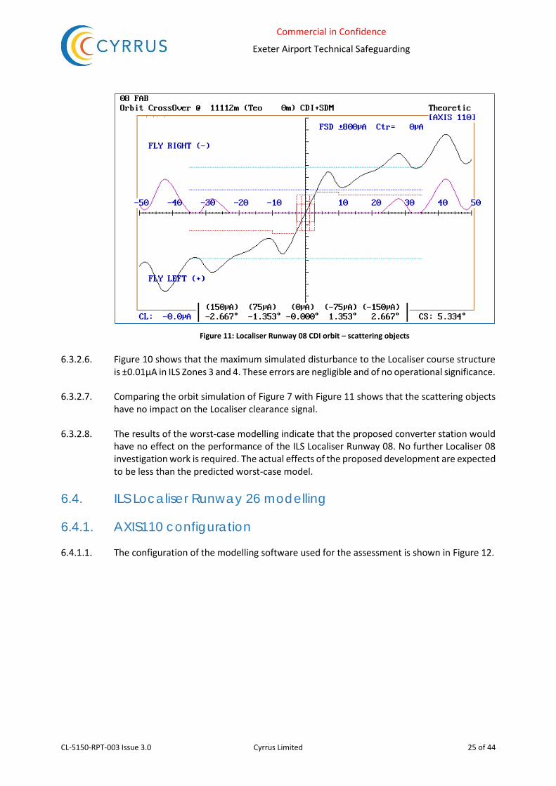
Commercial in Confidence
Exeter Airport Technical Safeguarding
CL-5150-RPT-003 Issue 3.0 Cyrrus Limited 25 of 44
Figure 11: Localiser Runway 08 CDI orbit – scattering objects
6.3.2.6. Figure 10 shows that the maximum simulated disturbance to the Localiser course structure is ±0.01µA in ILS Zones 3 and 4. These errors are negligible and of no operational significance.
6.3.2.7. Comparing the orbit simulation of Figure 7 with Figure 11 shows that the scattering objects have no impact on the Localiser clearance signal.
6.3.2.8. The results of the worst-case modelling indicate that the proposed converter station would have no effect on the performance of the ILS Localiser Runway 08. No further Localiser 08 investigation work is required. The actual effects of the proposed development are expected to be less than the predicted worst-case model.
6.4. ILS Localiser Runway 26 modelling
6.4.1. AXIS110 configuration
6.4.1.1. The configuration of the modelling software used for the assessment is shown in Figure 12.

Commercial in Confidence
Exeter Airport Technical Safeguarding
CL-5150-RPT-003 Issue 3.0 Cyrrus Limited 26 of 44
Figure 12: Localiser Runway 26 modelling configuration
6.4.1.2. Initial modelling is undertaken with no reflecting objects introduced into the model. This establishes a baseline, the results of which are shown in Figure 13 and Figure 14.
Figure 13: Localiser Runway 26 approach course structure baseline – no scattering objects
Category I tolerances
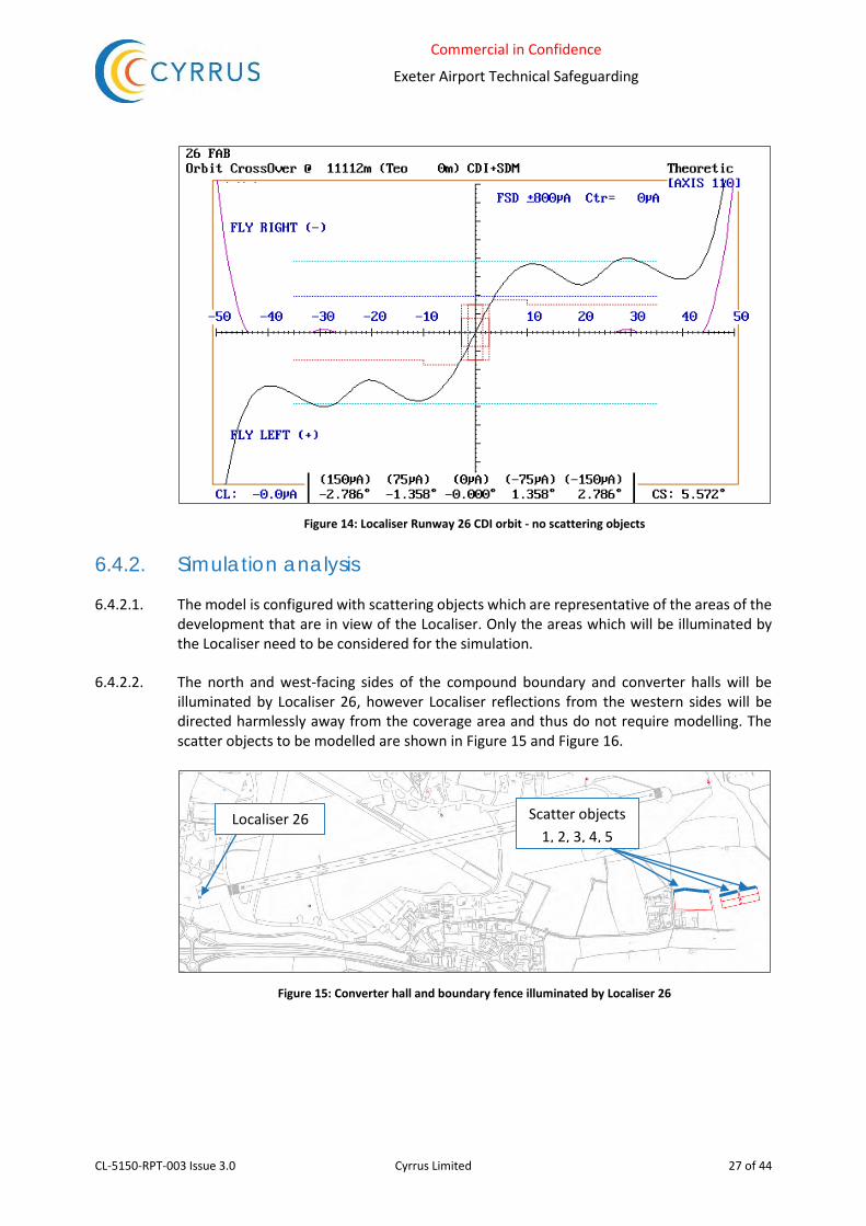
Commercial in Confidence
Exeter Airport Technical Safeguarding
CL-5150-RPT-003 Issue 3.0 Cyrrus Limited 27 of 44
Figure 14: Localiser Runway 26 CDI orbit - no scattering objects
6.4.2. Simulation analysis
6.4.2.1. The model is configured with scattering objects which are representative of the areas of the development that are in view of the Localiser. Only the areas which will be illuminated by the Localiser need to be considered for the simulation.
6.4.2.2. The north and west-facing sides of the compound boundary and converter halls will be illuminated by Localiser 26, however Localiser reflections from the western sides will be directed harmlessly away from the coverage area and thus do not require modelling. The scatter objects to be modelled are shown in Figure 15 and Figure 16.
Figure 15: Converter hall and boundary fence illuminated by Localiser 26
Localiser 26 Scatter objects 1, 2, 3, 4, 5

Commercial in Confidence
Exeter Airport Technical Safeguarding
CL-5150-RPT-003 Issue 3.0 Cyrrus Limited 28 of 44
Figure 16: Converter hall and fence scattering objects
6.4.2.3. For this scenario the scattering objects are modelled for maximum reflectivity, i.e. as smooth metal surfaces.
6.4.2.4. The results of the simulation of the proposed development are shown in Figure 17 and Figure 18.
Figure 17: Localiser Runway 26 approach course structure - scattering objects
Category I tolerances
Runway 26 Threshold

Commercial in Confidence
Exeter Airport Technical Safeguarding
CL-5150-RPT-003 Issue 3.0 Cyrrus Limited 29 of 44
Figure 18: Localiser Runway 26 CDI orbit – scattering objects
6.4.2.5. Figure 17 shows the maximum simulated disturbance to the Localiser course structure in ILS Zone 2 (ILS Point A to ILS Point B) is ±3.82µA and in ILS Zone 3 (ILS Point B to Threshold) is ±0.70µA.
6.4.2.6. Assessment of the Localiser clearance signal from the orbit simulation, see Figure 18, shows a minor increase in noise for aircraft to the right of the extended runway centreline.
6.4.2.7. Examination of the existing disturbance as measured by flight inspection (Annex A) indicates a figure of circa ±3.5µA in Zone 2 and ±2.0µA in Zone 3.
6.4.2.8. To find the worst-case overall disturbance in Zone 2, the existing measured disturbance is combined with the predicted simulated disturbance using vector addition (Root Sum Squared) to give an overall disturbance of ±5.2µA.
6.4.2.9. Similarly, the overall worst-case disturbance in Zone 3 is ±2.1µA.
6.4.2.10. The simulated disturbance in Zone 2 of the course structure is particularly significant in comparison with the existing disturbance when using this initial worst-case model, and would have a noticeable impact. Refinement of the model may yield a more realistic, and acceptable, result.
6.4.3. Refining the model
6.4.3.1. A building approximately 230m to the west of the converter halls provides partial screening of the Localiser signal. Examination of customer supplied 2m LIDAR surface model data indicates that the building varies in height between 6m AGL and 7.5m AGL. The building will thus completely screen the boundary fence, and provide partial screening of both converter halls, as shown in Figure 19. The blue and magenta hatched areas show where the building
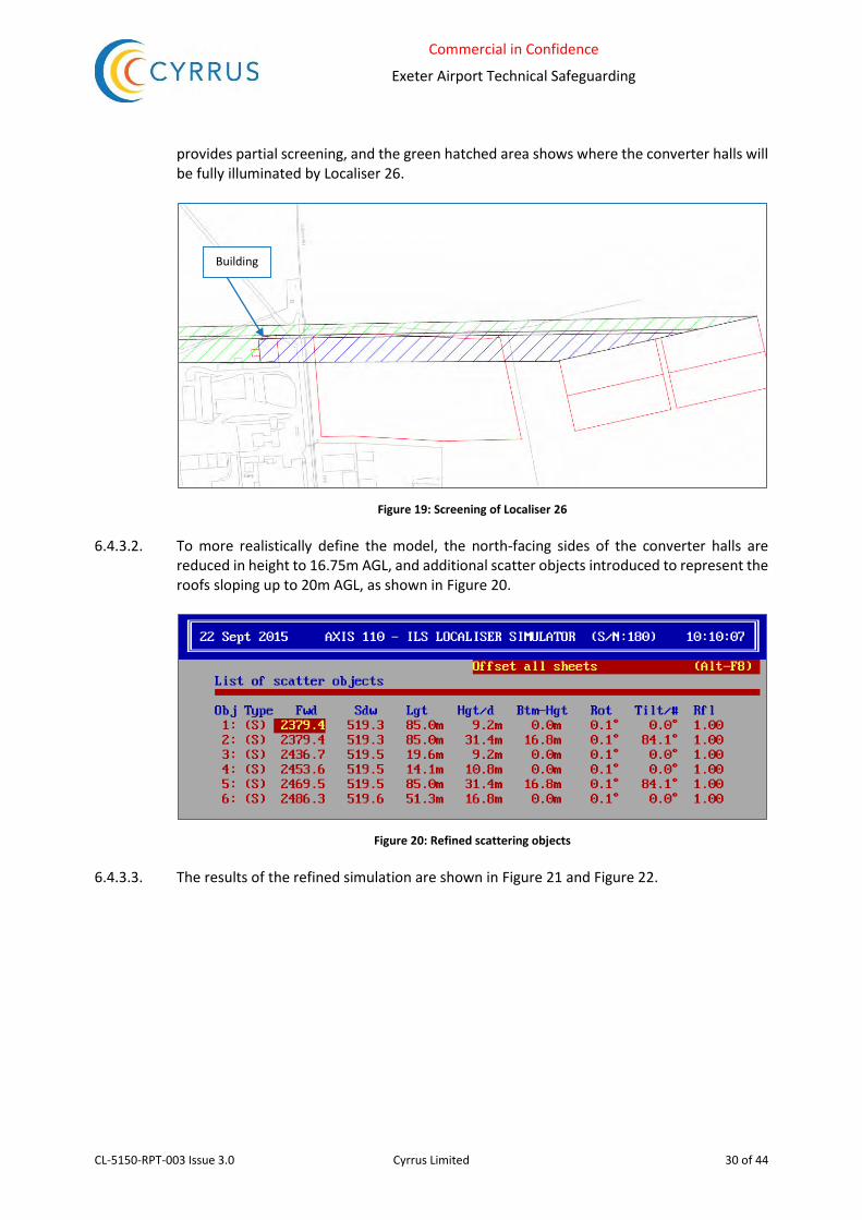
Commercial in Confidence
Exeter Airport Technical Safeguarding
CL-5150-RPT-003 Issue 3.0 Cyrrus Limited 30 of 44
provides partial screening, and the green hatched area shows where the converter halls will be fully illuminated by Localiser 26.
Figure 19: Screening of Localiser 26
6.4.3.2. To more realistically define the model, the north-facing sides of the converter halls are reduced in height to 16.75m AGL, and additional scatter objects introduced to represent the roofs sloping up to 20m AGL, as shown in Figure 20.
Figure 20: Refined scattering objects
6.4.3.3. The results of the refined simulation are shown in Figure 21 and Figure 22.
Building
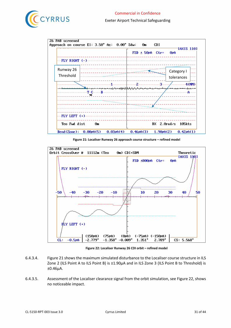
Commercial in Confidence
Exeter Airport Technical Safeguarding
CL-5150-RPT-003 Issue 3.0 Cyrrus Limited 31 of 44
Figure 21: Localiser Runway 26 approach course structure – refined model
Figure 22: Localiser Runway 26 CDI orbit – refined model
6.4.3.4. Figure 21 shows the maximum simulated disturbance to the Localiser course structure in ILS Zone 2 (ILS Point A to ILS Point B) is ±1.90µA and in ILS Zone 3 (ILS Point B to Threshold) is ±0.46µA.
6.4.3.5. Assessment of the Localiser clearance signal from the orbit simulation, see Figure 22, shows no noticeable impact.
Category I tolerances
Runway 26 Threshold

Commercial in Confidence
Exeter Airport Technical Safeguarding
CL-5150-RPT-003 Issue 3.0 Cyrrus Limited 32 of 44
6.4.3.6. To find the worst-case overall disturbance in Zone 2, the existing measured disturbance is combined with the predicted simulated disturbance using vector addition (Root Sum Squared) to give an overall disturbance of ±4.0µA.
6.4.3.7. Similarly, the overall worst-case disturbance in Zone 3 is ±2.1µA.
6.4.3.8. The additional disturbance contributed by the proposed development would have a small impact on the existing disturbance but the Localiser structure would remain well within acceptable Category I limits.
6.5. ILS Glidepath Runway 26 modelling
6.5.1. AXIS330 configuration
6.5.1.1. The configuration of the modelling software used for the assessment is shown in Figure 23.
Figure 23: Glidepath Runway 26 modelling configuration
6.5.1.2. Initial modelling is undertaken with no reflecting objects introduced into the model. This establishes a baseline, the results of which are shown in Figure 24 and Figure 25.

Commercial in Confidence
Exeter Airport Technical Safeguarding
CL-5150-RPT-003 Issue 3.0 Cyrrus Limited 33 of 44
Figure 24: Glidepath Runway 26 approach course structure baseline – no scattering objects
Figure 25: Glidepath Runway 26 window baseline – no scattering objects
6.5.2. Simulation analysis
6.5.2.1. The model is configured with scattering objects which are representative of the proposed building. Only the sides of the building that are in view of the Glidepath need to be considered for the simulation.
Category I tolerances

Commercial in Confidence
Exeter Airport Technical Safeguarding
CL-5150-RPT-003 Issue 3.0 Cyrrus Limited 34 of 44
6.5.2.2. The north-facing sides of the boundary fence and converter halls will be illuminated by the Glidepath 26, as shown in Figure 26. Figure 27 shows how they are represented as scattering objects in the simulation.
Figure 26: Converter hall and boundary fence illuminated by Glidepath 26
Figure 27: Converter hall and fence scattering objects
6.5.2.3. For this scenario the scattering objects are modelled for maximum reflectivity, i.e. as smooth metal surfaces.
6.5.2.4. The results of the simulation of the proposed development are shown in Figure 28 and Figure 29.
Glidepath 26
Site compound
Scatter objects 4, 5 Scatter objects 1, 2, 3

Commercial in Confidence
Exeter Airport Technical Safeguarding
CL-5150-RPT-003 Issue 3.0 Cyrrus Limited 35 of 44
Figure 28: Glidepath Runway 26 approach course structure baseline – scattering objects
Figure 29: Glidepath Runway 26 window baseline – scattering objects
6.5.2.5. Figure 28 shows a maximum predicted disturbance to the course structure of ±3.59µA in ILS Zone 3 (ILS Point B to Threshold), between approximately 0.3NM and 0.4NM from Runway 26 Threshold. The window simulation, Figure 29, shows no noticeable increase in signal disturbance.
6.5.2.6. The additional course disturbance contributed by the proposed development is significant but is well within the acceptable limit of ±30µA. It may be reduced by refinement of the model.
Category I tolerances
Runway 26 Threshold

Commercial in Confidence
Exeter Airport Technical Safeguarding
CL-5150-RPT-003 Issue 3.0 Cyrrus Limited 36 of 44
6.5.3. Refining the model.
6.5.3.1. To make the model more representative, the north-facing sides of the converter halls are reduced in height to 16.75m AGL, and additional scatter objects introduced to represent the roofs sloping up to 20m AGL, as shown in Figure 30.
Figure 30: Refined scattering objects
6.5.3.2. The results of the refined simulation are shown in Figure 31 and Figure 32.
Figure 31: Glidepath Runway 26 approach course structure – refined model
Category I tolerances
Runway 26 Threshold
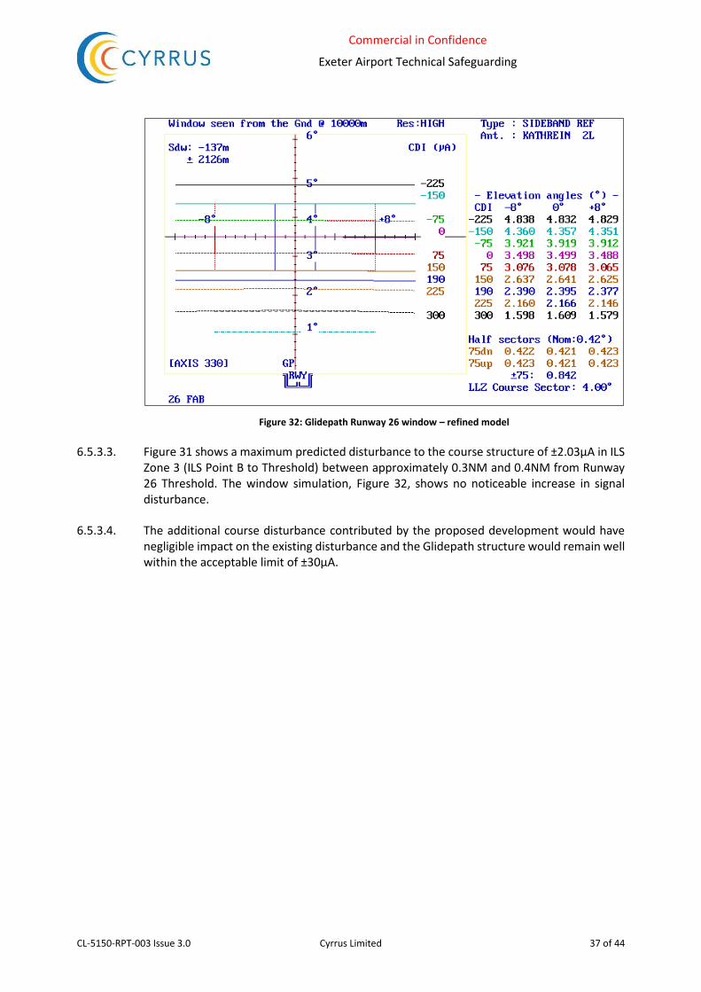
Commercial in Confidence
Exeter Airport Technical Safeguarding
CL-5150-RPT-003 Issue 3.0 Cyrrus Limited 37 of 44
Figure 32: Glidepath Runway 26 window – refined model
6.5.3.3. Figure 31 shows a maximum predicted disturbance to the course structure of ±2.03µA in ILS Zone 3 (ILS Point B to Threshold) between approximately 0.3NM and 0.4NM from Runway 26 Threshold. The window simulation, Figure 32, shows no noticeable increase in signal disturbance.
6.5.3.4. The additional course disturbance contributed by the proposed development would have negligible impact on the existing disturbance and the Glidepath structure would remain well within the acceptable limit of ±30µA.
Commercial in Confidence
Exeter Airport Technical Safeguarding
CL-5150-RPT-003 Issue 3.0 Cyrrus Limited 38 of 44
7. Lower Than Standard Category I
7.1. Requirements
7.1.1. Subpart E of the European Union Commission Regulation (EC) No. 859/2008 (Commonly known as EU-OPS 1) introduces revised requirements for All Weather Operations which allows operation to Lower Than Standard Category I (LTSC-I) minima provided certain conditions are met by the airport.
7.1.2. One of the requirements is that the Localiser shall meet the Localiser Course Structure requirement for Category 2 as detailed in CAA CAP 670 ILS 02 Table 1.
7.1.3. The course structure requirements for LTSC-I operations are 30μA from the edge of coverage to point A, then decreasing at a linear rate to 5μA at point B. 5μA from point B to the runway threshold. The ILS Localisers at Exeter currently meet these more stringent requirements.
7.1.4. ±5µA is the overall tolerance in Zone 3. However, it is standard practice to divide the overall disturbance budget between static and dynamic disturbance. Static disturbance is created by fixed objects, structures, and the surrounding terrain. Static disturbance remains the same provided no changes to the environment occur. Dynamic disturbance is a temporary disturbance as a result of taxying aircraft, moving vehicles, weather disturbance, and temporary objects such as cranes, etc. A portion of the overall disturbance budget is retained to accommodate dynamic disturbance. It is standard practice that 50% of the overall budget is retained to accommodate dynamic disturbance. As the disturbance is the result of a vector sum of wanted and unwanted signal, a straightforward arithmetic 50% is inappropriate. Instead, the 50% is allocated by Root Sum Squared method. By vector addition, 50% allowance for static disturbance = √ (52/2) = ±3.53µA, the maximum desired static disturbance in ILS Zone 3.
7.2. ILS Localiser Runway 08
7.2.1. Simulation analysis in Section 6.3 has shown that the existing disturbance to ILS Localiser Runway 08 will not be impacted by the proposed current converter development.
7.3. ILS Localiser Runway 26
7.3.1. Simulation analysis in Section 6.4 has shown the worst-case predicted disturbance to ILS Localiser Runway 26 in Zone 3 to be ±0.70µA. This disturbance is reduced to ±0.46µA when the model is refined. In either scenario, combining predicted with existing Zone 3 disturbance results in an overall disturbance of ±2.1µA. This figure is well within the maximum desired static disturbance of ±3.53µA for LTSC-1 operations.

Commercial in Confidence
Exeter Airport Technical Safeguarding
CL-5150-RPT-003 Issue 3.0 Cyrrus Limited 39 of 44
8. PSR Assessment 8.1. PSR transmits pulses of energy that are reflected back to the radar’s receiver by aircraft that
are within radar line of sight. Large static structures can act as unwanted reflectors, with the potential to generate false aircraft plots on the radar display and to desensitise the radar in the area of the structure.
8.2. The mechanism for creating a false aircraft plot is illustrated in Figure 33 below, where radar energy is reflected by the building face to an airborne target. If the radar detects a reflection from the aircraft arriving via the face of the building, then it will falsely plot the aircraft’s position beyond the building.
Figure 33: Generation of a false aircraft plot
8.3. The radar’s Moving Target Indicator will suppress the display of ‘permanent echoes’ from large stationary objects. However, large reflections from static objects raise the noise threshold in the object’s locality and will have the effect of reducing the radar’s sensitivity to smaller, and wanted, targets in the same area.
8.4. The phase centre of the PSR at EIA is approximately 45m AOD. The maximum height of the proposed converter halls is approximately (40m + 20m) = 60m AOD, thus there is the potential for approximately the top 15m of the west-facing side of the westernmost converter hall to reflect transmitted energy back to the PSR. The distance between the radar and the nearest converter hall is approximately 1500m, so radar pulses up to an elevation of 0.6° above the horizontal could potentially be reflected by the building.
8.5. If the reflected energy is directed towards the ground, then the radar will not detect any unwanted returns from the converter hall.
8.6. This may be accomplished by constructing the western face of the converter hall with a tilt towards the ground of, say, 2°, or by designing a slatted surface for the upper 15m of the western face as shown in Figure 34. A downward tilt of 2° would ensure that reflections from

Commercial in Confidence
Exeter Airport Technical Safeguarding
CL-5150-RPT-003 Issue 3.0 Cyrrus Limited 40 of 44
the building will be reflected towards the ground where they will be scattered or absorbed. These measures will also significantly reduce any potential desensitisation of the radar in the vicinity of the proposed development.
Figure 34: Directing reflected radar pulses towards the ground
Converter hall
2° downward tilt
1500m

Commercial in Confidence
Exeter Airport Technical Safeguarding
CL-5150-RPT-003 Issue 3.0 Cyrrus Limited 41 of 44
9. Potential for Electromagnetic Interference
9.1. General
9.1.1. There are concerns that the current converter station will generate unwanted electromagnetic propagation in the process of converting direct to alternating current, and that this may impact on the electromagnetic propagation of the navigational aids at EIA.
9.1.2. For the converter station to have an impact on navigational aids and communications it would need to be emitting Radio Frequency Interference (RFI) in the appropriate frequency bands of signal strength exceeding -90 dBm at ranges at least 500 m from the station.
9.1.3. It is assumed that the converter equipment will meet the requirements of EN 61000-6 in terms of Electromagnetic Compatibility (EMC) emissions for the CE Mark, so compatibility issues with the AANE at EIA are not anticipated.
9.2. ILS
9.2.1. In terms of ILS, the signal field strength will be quite high in the area of the converter station (-60dBm to -80dBm) so RFI would have to be at a very significant level to have any impact.
9.2.2. Aircraft ILS receivers have very strong signal rejection outside of the ILS passband (10kHz for Localiser and 20kHz for Glidepath). A significant interfering signal within the passband would desensitise the receiver which could result in loss of guidance and warning flags to the pilot. For a Category I system this would be inconvenient, but not inherently unsafe.
9.2.3. Interference causing false ILS guidance would require either a valid ILS signal to interfere, or a modulating tone (90Hz or 150Hz) phase locked to the actual guidance signal. Unless using a navigational aid signal generator, this scenario is extremely unlikely to arise from RFI.
9.3. DME
9.3.1. DME is a coded pulse system. The DME receiver has a logarithmic Intermediate Frequency (IF) section and will not be subject to desensitisation. The processor will reject any pulses which do not conform to the strict specification of pulse width and rise time. Only conforming interfering pulse pairs that are synchronised to the interrogator random squitter could give rise to false ranges. Obviously, the likelihood is extremely remote. DME is very difficult to jam or spoof.
9.3.2. Carrier Wave (CW) signals could potentially cause problems for the DME ground transponder, but the CW would have to be radiated at exceptionally high levels to cause an effect. Free-space path loss between the converter station and the EIA DME would be in the order of 95dB. Again, this interference would be inconvenient but not inherently unsafe.
9.4. VHF Communications
9.4.1. The most likely area of RFI impact is with Very High Frequency (VHF) communications. These signals are amplitude modulated and very susceptible to external RFI.

Commercial in Confidence
Exeter Airport Technical Safeguarding
CL-5150-RPT-003 Issue 3.0 Cyrrus Limited 42 of 44
9.5. RFI frequency range
9.5.1. Confidential technical information on RFI from an existing converter station 1 has been supplied by the client in the frequency range of 50 kHz to 10 MHz. Subsequent clarification2 confirms that ‘…converter noise sources are producing noise mainly in the lower frequency range, especially the frequency range below 10 MHz.’ Additionally, ‘Converter generated disturbances above 10 MHz have never been detected at 200 m distance from an HVDC Light installation. The fields will be below the background noise at this distance and not possible to measure.’
9.5.2. The frequency bands of concern for the AANE at EIA are as follows:
ILS Localiser 108 MHz to 112 MHz; ILS Glidepath 328 MHz to 336 MHz; ILS DME 960 MHz to 1215 MHz; VHF communications 118 MHz to 137 MHz.
9.5.3. It can be safely inferred from the above that converter station RFI will not have an impact on the AANE at EIA.
1 Email from Chris Jenner to Simon McPherson, 21/12/15 2 Email from Chris Jenner to Simon McPherson, 30/12/15

Commercial in Confidence
Exeter Airport Technical Safeguarding
CL-5150-RPT-003 Issue 3.0 Cyrrus Limited 43 of 44
10. Summary 10.1. Worst-case modelling indicates that the proposed current converter station would have no
effect on the performance of the ILS Localiser Runway 08.
10.2. Worst-case modelling indicates that the proposed current converter station would have a noticeable effect on the performance of the ILS Localiser Runway 26, however the Localiser structure would remain well within acceptable Category I limits. Refinement of the model to take into account screening and to more accurately represent the shape of the converter halls reduces the impact to a more acceptable level.
10.3. Worst-case modelling indicates that the proposed current converter station would have a noticeable effect on the performance of the ILS Glidepath Runway 26, however the Glidepath structure would remain well within acceptable Category I limits. Refinement of the model to more accurately represent the shape of the converter halls reduces the impact to a negligible level.
10.4. The potential for LTSC-I operations at EIA on Runway 08 is unaffected by the proposed development.
10.5. The worst-case overall disturbance to Localiser 26 resulting from the proposed development is significantly lower than the maximum tolerance for LTSC-1 operations.
10.6. The predicted disturbance by this proposed development to the ILS has been considered in terms of other known planned developments around EIA. The cumulative impact will remain within facility performance category I limits. Any additional disturbance caused by this development is not predicted to compromise future LTSC-I operations.
10.7. There is the potential for radar reflections from the westernmost converter hall to be detected by the PSR at EIA and generate unwanted radar returns. A slatted surface on the west-facing side of this converter hall to direct radar energy down to the ground would resolve this issue.
10.8. The potential for RFI to cause problems for the navigational aid systems installed at EIA has been investigated:
A significant interfering signal within the passband of an aircraft ILS receiver could potentially cause desensitisation resulting in possible loss of guidance or warning flags;
CW could potentially cause problems for the DME ground transponder, but only if radiated at exceptionally high levels;
VHF communications are susceptible to RFI.
10.9. Notwithstanding the above, measurable converter generated disturbances within AANE frequency bands have never been reportedly detected beyond a range of 200 m, thus converter station RFI will not have an impact on AANE at EIA.

Commercial in Confidence
Exeter Airport Technical Safeguarding
CL-5150-RPT-003 Issue 3.0 Cyrrus Limited 44 of 44
A. Annex A – Flight Inspection Reports
Section Removed