Conversion of Process Controls From PLC to Stand ... - CORE
22
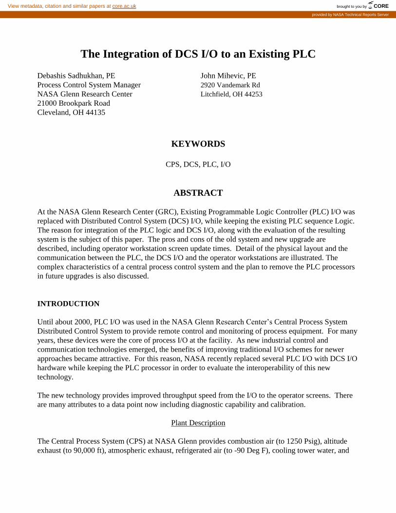
The Integration of DCS I/O to an Existing PLC Debashis Sadhukhan, PE John Mihevic, PE Process Control System Manager 2920 Vandemark Rd NASA Glenn Research Center Litchfield, OH 44253 21000 Brookpark Road Cleveland, OH 44135 KEYWORDS CPS, DCS, PLC, I/O ABSTRACT At the NASA Glenn Research Center (GRC), Existing Programmable Logic Controller (PLC) I/O was replaced with Distributed Control System (DCS) I/O, while keeping the existing PLC sequence Logic. The reason for integration of the PLC logic and DCS I/O, along with the evaluation of the resulting system is the subject of this paper. The pros and cons of the old system and new upgrade are described, including operator workstation screen update times. Detail of the physical layout and the communication between the PLC, the DCS I/O and the operator workstations are illustrated. The complex characteristics of a central process control system and the plan to remove the PLC processors in future upgrades is also discussed. INTRODUCTION Until about 2000, PLC I/O was used in the NASA Glenn Research Center’s Central Process System Distributed Control System to provide remote control and monitoring of process equipment. For many years, these devices were the core of process I/O at the facility. As new industrial control and communication technologies emerged, the benefits of improving traditional I/O schemes for newer approaches became attractive. For this reason, NASA recently replaced several PLC I/O with DCS I/O hardware while keeping the PLC processor in order to evaluate the interoperability of this new technology. The new technology provides improved throughput speed from the I/O to the operator screens. There are many attributes to a data point now including diagnostic capability and calibration. Plant Description The Central Process System (CPS) at NASA Glenn provides combustion air (to 1250 Psig), altitude exhaust (to 90,000 ft), atmospheric exhaust, refrigerated air (to -90 Deg F), cooling tower water, and brought to you by CORE View metadata, citation and similar papers at core.ac.uk provided by NASA Technical Reports Server
-
Upload
khangminh22 -
Category
Documents
-
view
1 -
download
0
Transcript of Conversion of Process Controls From PLC to Stand ... - CORE
The Integration of DCS I/O to an Existing PLC Debashis Sadhukhan, PE John Mihevic, PE
Process Control System Manager 2920 Vandemark Rd
NASA Glenn Research Center Litchfield, OH 44253
21000 Brookpark Road
Cleveland, OH 44135
KEYWORDS
CPS, DCS, PLC, I/O
ABSTRACT
At the NASA Glenn Research Center (GRC), Existing Programmable Logic Controller (PLC) I/O was
replaced with Distributed Control System (DCS) I/O, while keeping the existing PLC sequence Logic.
The reason for integration of the PLC logic and DCS I/O, along with the evaluation of the resulting
system is the subject of this paper. The pros and cons of the old system and new upgrade are
described, including operator workstation screen update times. Detail of the physical layout and the
communication between the PLC, the DCS I/O and the operator workstations are illustrated. The
complex characteristics of a central process control system and the plan to remove the PLC processors
in future upgrades is also discussed.
INTRODUCTION
Until about 2000, PLC I/O was used in the NASA Glenn Research Center’s Central Process System
Distributed Control System to provide remote control and monitoring of process equipment. For many
years, these devices were the core of process I/O at the facility. As new industrial control and
communication technologies emerged, the benefits of improving traditional I/O schemes for newer
approaches became attractive. For this reason, NASA recently replaced several PLC I/O with DCS I/O
hardware while keeping the PLC processor in order to evaluate the interoperability of this new
technology.
The new technology provides improved throughput speed from the I/O to the operator screens. There
are many attributes to a data point now including diagnostic capability and calibration.
Plant Description
The Central Process System (CPS) at NASA Glenn provides combustion air (to 1250 Psig), altitude
exhaust (to 90,000 ft), atmospheric exhaust, refrigerated air (to -90 Deg F), cooling tower water, and
https://ntrs.nasa.gov/search.jsp?R=20150009517 2019-08-31T10:33:44+00:00Zbrought to you by COREView metadata, citation and similar papers at core.ac.uk
provided by NASA Technical Reports Server
2
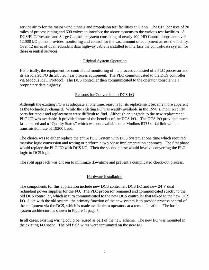
service air to for the major wind tunnels and propulsion test facilities at Glenn. The CPS consists of 20
miles of process piping and 600 valves to interface the above systems to the various test facilities. A
DCS/PLC/Pressure and Surge Controller system consisting of nearly 100 PID Control loops and over
12,000 I/O points provides monitoring and control for the vast amount of equipment across the facility.
Over 12 miles of dual redundant data highway cable is installed to interface the control/data system for
these essential services.
Original System Operation
Historically, the equipment for control and monitoring of the process consisted of a PLC processor and
its associated I/O distributed near process equipment. The PLC communicated to the DCS controller
via Modbus RTU Protocol. The DCS controller then communicated to the operator console via a
proprietary data highway.
Reasons for Conversion to DCS I/O
Although the existing I/O was adequate at one time, reasons for its replacement became more apparent
as the technology changed. While the existing I/O was readily available in the 1990’s, more recently
parts for repair and replacement were difficult to find. Although an upgrade to the new replacement
PLC I/O was available, it provided none of the benefits of the DCS I/O. The DCS I/O provided much
faster speed and a “Quality Status” which was not available on a Modbus RTU serial link with a
transmission rate of 19200 baud.
The choice was to either replace the entire PLC System with DCS System at one time which required
massive logic conversion and testing or perform a two phase implementation approach. The first phase
would replace the PLC I/O with DCS I/O. Then the second phase would involve converting the PLC
logic to DCS logic.
The split approach was chosen to minimize downtime and prevent a complicated check-out process.
Hardware Installation
The components for this application include new DCS controller, DCS I/O and new 24 V dual
redundant power supplies for the I/O. The PLC processor remained and communicated strictly to the
old DCS controller, which in turn communicated to the new DCS controller that talked to the new DCS
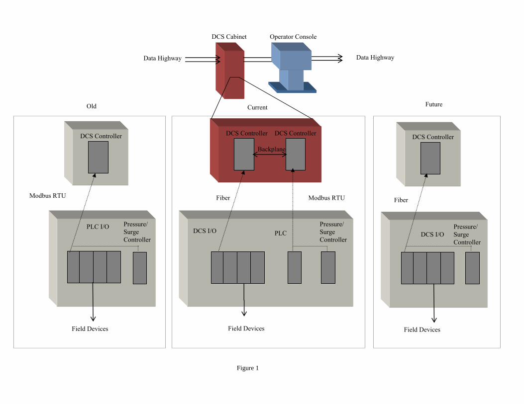
I/O. Like with the old system, the primary function of the new system is to provide process control of
the equipment via the DCS, which is made available to operators at a remote location. The basic
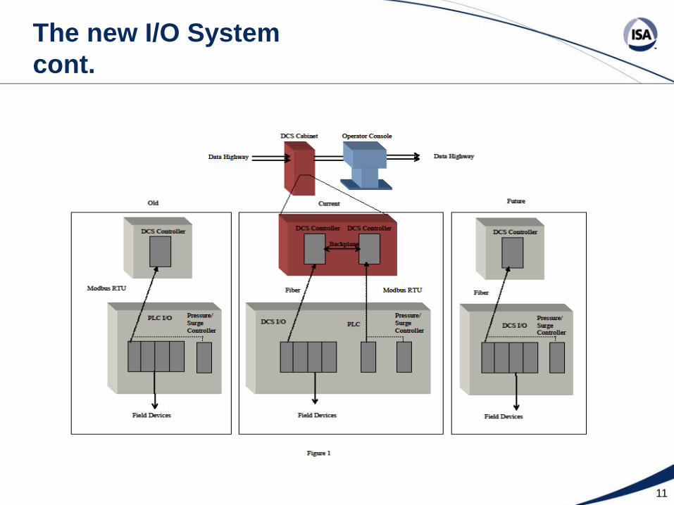
system architecture is shown in Figure 1, page 5.
In all cases, existing wiring could be reused as part of the new scheme. The new I/O was mounted in
the existing I/O space. The old field wires were terminated on the new I/O.
3
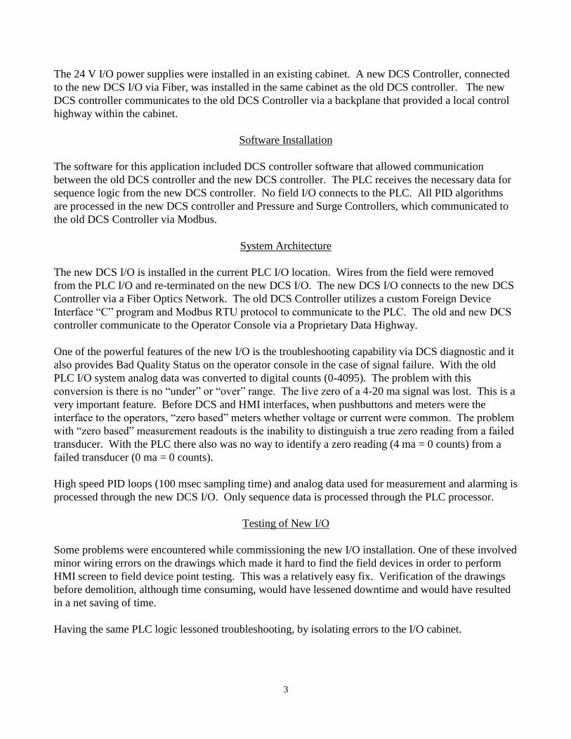
The 24 V I/O power supplies were installed in an existing cabinet. A new DCS Controller, connected
to the new DCS I/O via Fiber, was installed in the same cabinet as the old DCS controller. The new
DCS controller communicates to the old DCS Controller via a backplane that provided a local control
highway within the cabinet.
Software Installation
The software for this application included DCS controller software that allowed communication
between the old DCS controller and the new DCS controller. The PLC receives the necessary data for
sequence logic from the new DCS controller. No field I/O connects to the PLC. All PID algorithms
are processed in the new DCS controller and Pressure and Surge Controllers, which communicated to
the old DCS Controller via Modbus.
System Architecture
The new DCS I/O is installed in the current PLC I/O location. Wires from the field were removed
from the PLC I/O and re-terminated on the new DCS I/O. The new DCS I/O connects to the new DCS
Controller via a Fiber Optics Network. The old DCS Controller utilizes a custom Foreign Device
Interface “C” program and Modbus RTU protocol to communicate to the PLC. The old and new DCS
controller communicate to the Operator Console via a Proprietary Data Highway.
One of the powerful features of the new I/O is the troubleshooting capability via DCS diagnostic and it
also provides Bad Quality Status on the operator console in the case of signal failure. With the old
PLC I/O system analog data was converted to digital counts (0-4095). The problem with this
conversion is there is no “under” or “over” range. The live zero of a 4-20 ma signal was lost. This is a
very important feature. Before DCS and HMI interfaces, when pushbuttons and meters were the
interface to the operators, “zero based” meters whether voltage or current were common. The problem
with “zero based” measurement readouts is the inability to distinguish a true zero reading from a failed
transducer. With the PLC there also was no way to identify a zero reading (4 ma = 0 counts) from a
failed transducer (0 ma = 0 counts).
High speed PID loops (100 msec sampling time) and analog data used for measurement and alarming is
processed through the new DCS I/O. Only sequence data is processed through the PLC processor.
Testing of New I/O
Some problems were encountered while commissioning the new I/O installation. One of these involved
minor wiring errors on the drawings which made it hard to find the field devices in order to perform
HMI screen to field device point testing. This was a relatively easy fix. Verification of the drawings
before demolition, although time consuming, would have lessened downtime and would have resulted
in a net saving of time.
Having the same PLC logic lessoned troubleshooting, by isolating errors to the I/O cabinet.
4
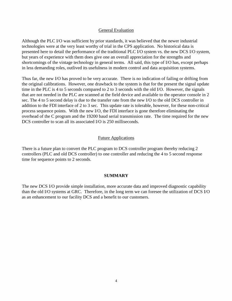
General Evaluation
Although the PLC I/O was sufficient by prior standards, it was believed that the newer industrial
technologies were at the very least worthy of trial in the CPS application. No historical data is
presented here to detail the performance of the traditional PLC I/O system vs. the new DCS I/O system,
but years of experience with them does give one an overall appreciation for the strengths and
shortcomings of the vintage technology in general terms. All said, this type of I/O has, except perhaps
in less demanding roles, outlived its usefulness in modern control and data acquisition systems.
Thus far, the new I/O has proved to be very accurate. There is no indication of failing or drifting from
the original calibrations. However, one drawback to the system is that for the present the signal update
time in the PLC is 4 to 5 seconds compared to 2 to 3 seconds with the old I/O. However, the signals
that are not needed in the PLC are scanned at the field device and available to the operator console in 2
sec. The 4 to 5 second delay is due to the transfer rate from the new I/O to the old DCS controller in
addition to the FDI interface of 2 to 3 sec. This update rate is tolerable, however, for these non-critical
process sequence points. With the new I/O, the FDI interface is gone therefore eliminating the
overhead of the C program and the 19200 baud serial transmission rate. The time required for the new
DCS controller to scan all its associated I/O is 250 milliseconds.
Future Applications
There is a future plan to convert the PLC program to DCS controller program thereby reducing 2
controllers (PLC and old DCS controller) to one controller and reducing the 4 to 5 second response
time for sequence points to 2 seconds.
SUMMARY
The new DCS I/O provide simple installation, more accurate data and improved diagnostic capability
than the old I/O systems at GRC. Therefore, in the long term we can foresee the utilization of DCS I/O
as an enhancement to our facility DCS and a benefit to our customers.
DCS Cabinet Operator Console
Data Highway Data Highway
Backplane
DCS Controller DCS Controller
DCS I/O
Fiber
PLC
Modbus RTU
Field Devices
DCS Controller
DCS I/O
Fiber
Field Devices
DCS Controller
PLC I/O
Field Devices
Old Current Future
Figure 1
Modbus RTU
Pressure/
Surge
Controller
Pressure/
Surge
Controller
Pressure/
Surge
Controller
Standards
Certification
Education & Training
Publishing
Conferences & Exhibits
The Integration of DCS
I/O to an Existing PLC
Debashis Sadhukhan, PE
&
John A. Mihevic, PE
2
Presenter
• Debashis Sadhukhan – Process Controls System
Manager an NASA Glenn Research Center (GRC).
Employed at GRC since 1991. Experienced in integration
of DCS and PLC systems.
• John Mihevic – DCS Control System Manager while
employed at GRC. Retired in 2007.
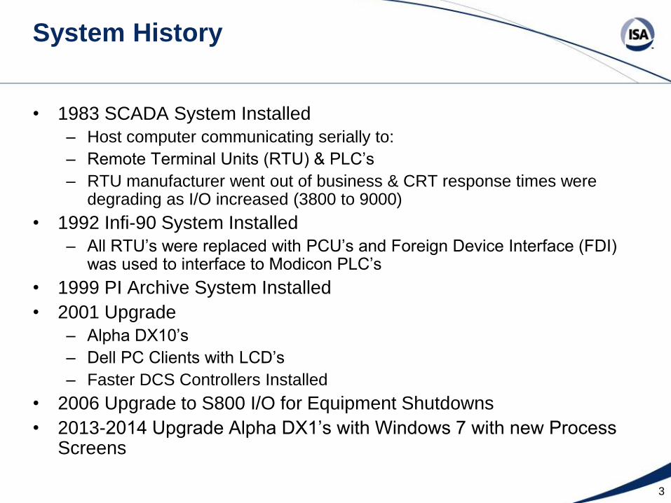
System History
• 1983 SCADA System Installed
– Host computer communicating serially to:
– Remote Terminal Units (RTU) & PLC’s
– RTU manufacturer went out of business & CRT response times were degrading as I/O increased (3800 to 9000)
• 1992 Infi-90 System Installed
– All RTU’s were replaced with PCU’s and Foreign Device Interface (FDI) was used to interface to Modicon PLC’s
• 1999 PI Archive System Installed
• 2001 Upgrade
– Alpha DX10’s
– Dell PC Clients with LCD’s
– Faster DCS Controllers Installed
• 2006 Upgrade to S800 I/O for Equipment Shutdowns
• 2013-2014 Upgrade Alpha DX1’s with Windows 7 with new Process Screens
3
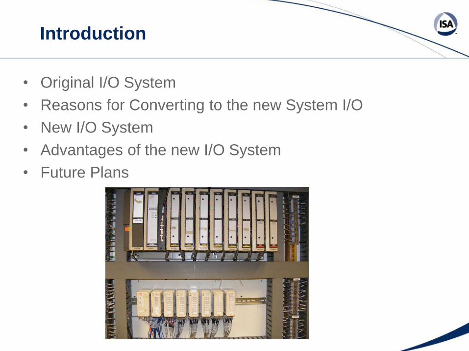
Introduction
• Original I/O System
• Reasons for Converting to the new System I/O
• New I/O System
• Advantages of the new I/O System
• Future Plans
Plant
• The Central Process System (CPS) at NASA Glenn provides
combustion air (to 1250 Psig), altitude exhaust (to 90,000 ft),
refrigerated air (to -90 Deg F), cooling tower water, and service air to
for the major wind tunnels and propulsion test facilities at Glenn.
• The CPS consists of 20 miles of process piping and 600 valves to
interface the above systems to the various test facilities.
• A DCS/PLC/Pressure and Surge Controller system consisting of
nearly 100 PID Control loops and over 12,000 I/O points provides
monitoring and control for the vast amount of equipment across the
facility.
• Over 12 miles of dual redundant data highway cable is installed to
interface the control/data system for these essential services.
5
6
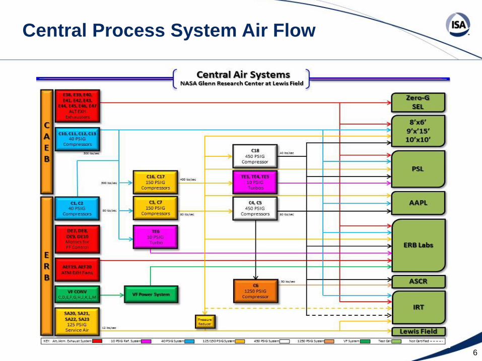
Central Process System Air Flow
Original I/O System
• PLC I/O
– PLC Processor communicating to analog and discrete I/O that
was near the field equipment
• PLC communicated to DCS via Modbus RTU Protocol
• DCS controller then communicated to the operator
console via a proprietary data highway
Reasons for Conversion to the New System
• Parts to repair old PLC I/O and direct replacements are
difficult to find
• New replacement of PLC I/O is available, but it does not
provide some the benefits of the DCS I/O
• The DCS I/O provided much faster speed and Quality
Status which was lost using a Modbus RTU serial link
with a transmission rate of 19,200 baud
Reasons for Conversion to the New System
cont.
• Replacing the entire PLC System with DCS System at
one time which required massive logic conversion and
testing
• Two Phase approach:
– The first phase would replace the PLC I/O with DCS I/O
– The second phase would actually convert the PLC logic to DCS
logic
• The split approach was chosen to minimize downtime
and prevent a complicated check-out process
The new I/O System
• New DCS controller
• New DCS I/O
• New 24 V dual redundant power supplies for the I/O
• The PLC processor remained to communicate sequence
logic to the old DCS controller
• PLC communicated to the new DCS controller that talked
to the new DCS I/O
• The primary function of the new system is to provide
process control of the equipment via the DCS, which is
made available to operators at a remote location. The
basic system architecture is shown in Figure I
The new I/O System
cont.
11
The new I/O System
cont.
• Existing wiring was reused as part of the new scheme
• The new I/O was mounted in the existing I/O space. The
old field wires were then terminated on the new I/O
• The 24 V I/O power supplies were installed in an existing
cabinet
• A new DCS Controller, connected to the new DCS I/O
via Fiber, was installed in the same cabinet as the old
DCS controller
• The new DCS controller communicates to the old DCS
Controller via a backplane that provided a local control
highway within the cabinet
The new I/O System
cont.
• The software for this application included DCS controller
software that allowed communication between the old
DCS controller and the new DCS controller
• The PLC received the necessary data for sequence logic
from the new DCS controller. No field I/O connects to
the PLC
• All PID algorithms are processed in the new DCS
controller and hardware specific pressure and surge
controllers. The pressure and surge controllers
communicate to the old DCS Controller via Modbus
Advantages of the new I/O System
• One of the powerful features of the new I/O is the troubleshooting
capability via DCS diagnostics
• It also provides Bad Quality Status on the operator console in the
case of signal failure
• With the old PLC I/O system analog data was converted to digital
counts (0-4095)
– The problem with this conversion is there is no “under” or “over” range.
– The live zero of a 4-20 ma signal was lost
– The problem with “zero based” measurement readouts is the inability to
distinguish a true zero reading from a failed transducer
– With the PLC there also was no way to identify a zero reading (4 ma = 0 counts)
from a failed transducer (0 ma = 0 counts)
Disadvantages of the new I/O System
• One drawback to the system is that for the present the signal update
time in the PLC is 4 to 5 seconds compared to 2 to 3 seconds with
the old I/O
– The 4 to 5 second delay is due to the transfer rate from the new I/O to the old
DCS controller in addition to the FDI interface of 2 to 3 sec
– This update rate is tolerable, however, for these non-critical process sequence
points
• However, the signals that are not needed in the PLC are scanned at
the field device and available to the operator console in 1 sec
– With the new I/O, the FDI interface is gone therefore eliminating the overhead of
the C program and the 19,200 baud serial transmission rate. The time required
for the new DCS controller to scan all its associated I/O is 250 milliseconds
FUTURE APPLICATION
• There is a future plan to convert the PLC program to
DCS controller program thereby reducing 2 controllers
(PLC and old DCS controller) to one controller and
reducing the 4 to 5 second response time for sequence
points to 2 seconds
SUMMARY
• The new DCS I/O provide simple installation, more
accurate data and improved diagnostic capability
than the old I/O systems at GRC
• Therefore, in the long term we can foresee the
utilization of DCS I/O as an enhancement to our
facility DCS and a benefit to our customers