Controller Area Network For Intelligent Vehicular Systems
10
Controller Area Network For Intelligent Vehicular Systems Mansi Desai, Rahul Shetty, Viraj Padte, Mayur Parulekar, Samuel Ramrajkar [email protected],[email protected], [email protected], [email protected], [email protected]
Transcript of Controller Area Network For Intelligent Vehicular Systems

Controller Area Network For Intelligent Vehicular Systems
Mansi Desai, Rahul Shetty, Viraj Padte, Mayur Parulekar, Samuel Ramrajkar [email protected],[email protected], [email protected],
ABSTRACT—With the advent of the 21st
century the inclusion of electronicsystems in almost all the aspects oflife is very common. Technologyadvancements have provided intelligentsystems with advanced functionalitiesthat could ease any given process. The21st century has been evident of theground breaking research carried out invehicular technologies. Variouselectronic driver assist systems havebeen employed for ensuring ease andsafety of the users. Modern day carsrepresent a symbiosis of severalelectronic subsystems thatcollaboratively give a safe and sounddriving experience. The complexity ofthe functions implemented in thesesystems necessitates an exchange ofdata between them. With conventionalsystems, data is exchanged by means ofdedicated signal lines, but this isbecoming increasingly difficult andexpensive as control functions becomeever more complex. Controller AreaNetwork is a high performance and highreliable advanced serial communicationprotocol which effectively supportsdistributed real time control. Theconcept plans to make a prototypedisplaying communication patternbetween various electronic modules of acar.
1. INTRODUCTION
CAN stands for Controller Area Network.It is a serial communication protocolinternationally standardized by ISO [1].The CAN bus was traditionally used in
automotive applications. The scenariohas changed drastically today. CAN isnow one of the best choices for"embedded networking applications"[7]
where there is a need for communicationbetween several embedded 8-bit and 16-bit microcontrollers. It has gainedrampant popularity in embedded machinecontrol applications like homeappliances, industrial machines orother machinery that use multiplemicrocontrollers that need tocommunicate with each other. Also CANis being used for medical equipments,test equipments and mobile machines.One such example would be a high-endcoffee machine that usesmicrocontrollers that areinterconnected via CAN
CAN was designed and improved upon forsystems that need to transmit andreceive relatively small amounts ofinformation (as compared to Ethernet orUSB, which are designed to move muchlarger blocks of data) reliablyto any or all other nodes on thenetwork.
Applications of CAN in intelligentvehicular systems are evident. Thebasis of an intelligent vehicle isability of the vehicle to navigate andmanoeuvre in a rapidly changingenvironment without compromising on thesafety of the commuters. For this the
vehicle not only has to communicatewith an intelligent guidingarchitecture but also has to provide areliable and fast communication withinits internal modules which would beworking in sync for providingcorrective navigation. Now the bestprotocol available for this intravehicular communications is CAN. TheCAN thus can be considered as theinternal architecture whichcontinuously interacts with theexternal guiding architecture in orderto perform the required functions forefficient navigation.
2. CONTROLLER AREA NETWORK (CAN) PROTOCOL This protocol is message-based, notaddress based, all messages on the busreceive every message and acknowledgeevery message, regardless of whether inneeds the data or not. This allows thebus to operate in node-to-node ormulticast messaging formats withouthaving to send different types ofmessages. Fast, robust messagetransmission with fault confinement isa big advantage for CAN because faultynodes will automatically drop off thebus not allowing any one node frombringing a network down. Thiseffectively guarantees that bandwidthwill always be available for criticalmessages to be transmitted. Itbasically follows a broadcast approachin which the transmitting node sendsits message throughout the network butis received by the receiving node whosefilter address matches with the sendingnode’s identifier field. There is nonetwork downtime as in the case of LAN
in which the occurrence of an errori.e. message collision causes thesystem to
Fig. 1[3]
collapse and recover back after aparticular time interval and causingloss of transmission data.
One advantage of CAN is theprice/performance ratio.
Some of features of CAN can be listedas follows:
a) Speed of communication up to 1Mbps.In vehicular applicationscommunications need to be fast. Aloss of a second could also causemajor damage. As a result, speedof 1 Mbps is nothing less thandesirable.
b) No. of nodes up to 220.A modern vehicle has a number offeatures working at the sametime. These all need tocoordinate with each other. CANproves to be able to satisfy thisneed, allowing a high number ofnodes to be connected reliably
c) Data integrity with errorrecovery.CAN allows for error recovery anderror confinement along witherror correction. This ensures nodata loss even in case of anerror.
d) Time criticality.Vehicular applications are a areawhere time is of utmostimportance and it cannot be
ignored under any circumstances.CAN helps achieve thisfruitfully.
e) Cost EffectiveOne advantage of CAN is theprice/performance ratio.CAN is one of the most affordablenetworks. Replacing a8 or 16 bit microcontroller withone that features a CAN interfacecosts about $1.Tranceiver wouldcost $1 more and $1 forconnectors and additional PCBarea. Thus to replace existingmicrocontrollers with CANcontrollers would cost no morethan $3.
On a Real Time (RT) bus, response timeof messages should be bounded. TheEthernet Protocol uses the BEB (binaryexponentially back off) algorithm tosolve collisions in a non-deterministicmanner and does not support any messageprioritization. Ethernet is not suitedfor traffic with RT requirements. Whenthe node has to send the highestpriority message, the CAN arbitrationmechanism allows it to immediatelyaccess the bus and transmit without anydelay. In CAN protocol, the worst caseresponse time for highest prioritymessage is deterministic, andpriorities can be allocated to messagesaccording to their importance in orderto meet their timing requirements.For control systems with short and/orprioritized messages, CAN offers abetter performance.
Some of the CAN message frames areshown below.
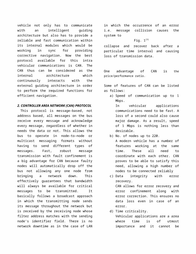
1. Data Frame:
Fig. 2[3]
This frame is used by the transmit unitto send a message to the receive unit.
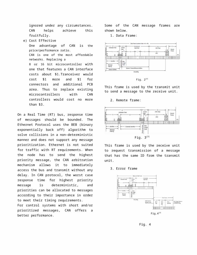
2. Remote frame:
Fig. 3[3]
This frame is used by the receive unitto request transmission of a messagethat has the same ID from the transmitunit.
3. Error frame
Fig.4[3]
Fig. 4
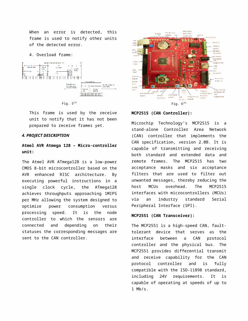
When an error is detected, thisframe is used to notify other unitsof the detected error.
4. Overload frame:
Fig. 5[3]
This frame is used by the receiveunit to notify that it has not beenprepared to receive frames yet.
4. PROJECT DESCRIPTION
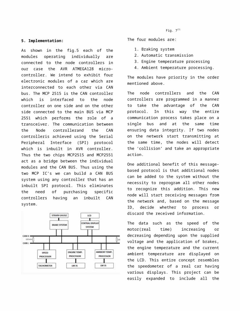
Atmel AVR Atmega 128 – Micro-controllerunit:
The Atmel AVR ATmega128 is a low-powerCMOS 8-bit microcontroller based on theAVR enhanced RISC architecture. Byexecuting powerful instructions in asingle clock cycle, the ATmega128achieves throughputs approaching 1MIPSper MHz allowing the system designed tooptimize power consumption versusprocessing speed. It is the nodecontroller to which the sensors areconnected and depending on theirstatuses the corresponding messages aresent to the CAN controller.
Fig. 6[9]
MCP2515 (CAN Controller):
Microchip Technology’s MCP2515 is astand-alone Controller Area Network(CAN) controller that implements theCAN specification, version 2.0B. It iscapable of transmitting and receivingboth standard and extended data andremote frames. The MCP2515 has twoacceptance masks and six acceptancefilters that are used to filter outunwanted messages, thereby reducing thehost MCUs overhead. The MCP2515interfaces with microcontrollers (MCUs)via an industry standard SerialPeripheral Interface (SPI).
MCP2551 (CAN Transceiver):
The MCP2551 is a high-speed CAN, fault-tolerant device that serves as theinterface between a CAN protocolcontroller and the physical bus. TheMCP2551 provides differential transmitand receive capability for the CANprotocol controller and is fullycompatible with the ISO-11898 standard,including 24V requirements. It iscapable of operating at speeds of up to1 Mb/s.
5. Implementation:
As shown in the fig.5 each of themodules operating individually areconnected to the node controllers inour case the AVR ATMEGA128 micro-controller. We intend to exhibit fourelectronic modules of a car which areinterconnected to each other via CANbus. The MCP 2515 is the CAN controllerwhich is interfaced to the nodecontroller on one side and on the otherside connected to the main BUS via MCP2551 which performs the role of atransceiver. The communication betweenthe Node controllerand the CANcontrolleris achieved using the SerialPeripheral Interface (SPI) protocolwhich is inbuilt in AVR controller.Thus the two chips MCP2515 and MCP2551act as a bridge between the individualmodules and the CAN BUS. Thus using thetwo MCP IC’s we can build a CAN BUSsystem using any controller that has aninbuilt SPI protocol. This eliminatesthe need of purchasing specificcontrollers having an inbuilt CANsystem.
Fig. 7[7]
The four modules are:
1. Braking system2. Automatic transmission3. Engine temperature processing4. Ambient temperature processing.
The modules have priority in the ordermentioned above.
The node controllers and the CANcontrollers are programmed in a mannerto take the advantage of the CANprotocol. In this way the entirecommunication process takes place on asingle bus and at the same timeensuring data integrity. If two nodeson the network start transmitting atthe same time, the nodes will detectthe ‘collision’ and take an appropriateaction.
One additional benefit of this message-based protocol is that additional nodescan be added to the system without thenecessity to reprogram all other nodesto recognize this addition. This newnode will start receiving messages fromthe network and, based on the messageID, decide whether to process ordiscard the received information.
The data such as the speed of themotor(real time) increasing ordecreasing depending upon the suppliedvoltage and the application of brakes,the engine temperature and the currentambient temperature are displayed onthe LCD. This entire concept resemblesthe speedometer of a real car havingvarious displays. This project can beeasily expanded to include all the

features of a modern car by just addingthe individual node controllers-CANcontroller-CAN transceiver to the mainBUS. Thus it offers reliable means ofcommunication using less wires and easeof expansion.
Fig. 8[5]
5.1Transducers:For practical implementation andobservation of the project the belowmentioned transducers are used:
1. LM35-precision centigradetemperature sensor
2. Strain gauge for sensing brakepressure.
3. Tachometer for speed sensing.
The preprocessing operation is done atthe individual Node controller and thenthe data is transmitted to the CANcontroller in a fixed frame format.
In an actual vehicle the format inwhich the CAN sensor network is laiddown is illustrated in the figurebelow.
Fig. 9[3]
4.2 Sate diagram implementation
The process flow used for practicalimplementation can be represented inbrief as follows:
Initialization:1. Initialize the node controller as
the master of the SPI protocoland the CAN controller as theslave.
2. Reset the CAN controllerregisters.
3. Configure the CAN controllerCNF1, CNF2 and CNF3 for definingthe bit timing.The calculation for bit timinghas been done using the MicrochipCAN Bit Timing Calculatorapplication
4. Fill in the transmit identifiersand receive masks and filters.

Fig. 10
Fig.11
In CAN at a time a node can eithertransmit or receive.This decision is time bound and it ishard coded in the program. Now let’sdiscuss the two modes for CAN nodeoperation.
Mode Selection1. Transmit mode:
Set data length, data and makethe RTS pin/bit high usinghardware/software respectively.Poll the appropriate flags toensure error free communication.Error handling is implementedusing ARQ.
2. Receive mode:Enable all masks and fill thefilters of the desireddestination with the identifierof the transmitter.Enable message reception.
Error handling is implemented usingflags. IF error is detected and errorfree frame is send back.
In the system the data of thespeedometer and the engine temperaturecontrol sensor will be continuouslytransmitted to the LCD MCU with thelatter having a higher priority.Whenever the air-condition unit isswitched ON the ambient temperatureprocessing unit comes into picture withleast priority by transmitting thetemperature of the car cabin and at thesame time maintaining its value at theprogrammed temperature by turningON/OFF the AC compressor pump. As thespeed of the car varies thecorresponding gear is automaticallyselected and displayed. Hence the LCDrepresents the dash board of the car.This module has the second priority.The brake module has the highestpriority and it takes over the bus fromother modules to reduce the speed ofthe vehicle directly proportional tothe magnitude of stress observed on thestrain gauge for safety measures andthe corresponding decrease in speed isdisplayed on the LCD.
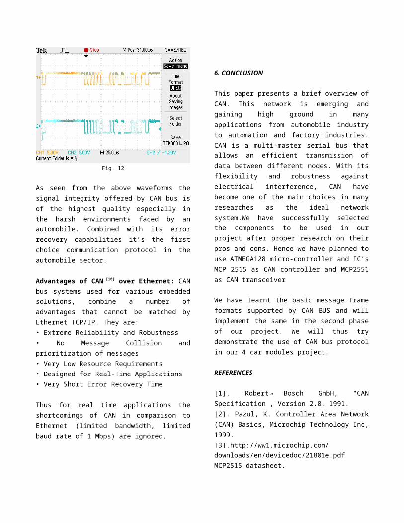
Fig. 12
As seen from the above waveforms thesignal integrity offered by CAN bus isof the highest quality especially inthe harsh environments faced by anautomobile. Combined with its errorrecovery capabilities it’s the firstchoice communication protocol in theautomobile sector.
Advantages of CAN [10] over Ethernet: CANbus systems used for various embeddedsolutions, combine a number ofadvantages that cannot be matched byEthernet TCP/IP. They are:• Extreme Reliability and Robustness• No Message Collision andprioritization of messages• Very Low Resource Requirements• Designed for Real-Time Applications• Very Short Error Recovery Time
Thus for real time applications theshortcomings of CAN in comparison toEthernet (limited bandwidth, limitedbaud rate of 1 Mbps) are ignored.
6. CONCLUSION
This paper presents a brief overview ofCAN. This network is emerging andgaining high ground in manyapplications from automobile industryto automation and factory industries.CAN is a multi-master serial bus thatallows an efficient transmission ofdata between different nodes. With itsflexibility and robustness againstelectrical interference, CAN havebecome one of the main choices in manyresearches as the ideal networksystem.We have successfully selectedthe components to be used in ourproject after proper research on theirpros and cons. Hence we have planned touse ATMEGA128 micro-controller and IC’sMCP 2515 as CAN controller and MCP2551as CAN transceiver
We have learnt the basic message frameformats supported by CAN BUS and willimplement the same in the second phaseof our project. We will thus trydemonstrate the use of CAN bus protocolin our 4 car modules project.
REFERENCES
[1]. Robert Bosch GmbH, “CANSpecification”, Version 2.0, 1991.[2]. Pazul, K. Controller Area Network(CAN) Basics, Microchip Technology Inc,1999.[3].http://ww1.microchip.com/downloads/en/devicedoc/21801e.pdfMCP2515 datasheet.
[4].http://www.renesas.com/http://documentation.renesas.com/doc/products/mpumcu/apn/rej05b0804_m16cap.pdf[5]. http://www.can-cia.de, 2004.Homepage of the organization CAN inAutomation (CiA).[6].http://ww1.microchip.com/downloads/en/DeviceDoc/21883A.pdf.Microchip Interface Products DesignGuide.[7] CAN Tutorial-Atmel wireless andmicrocontrollers.[8]http://www.s3.kth.se/~kallej/papers/can_necs_handbook05.pdf[9]http://dce.felk.cvut.cz/nms/files/m68k/mo_cpu2/datasheets/can-intro-e.pdf[10]http://www.scribd.com/doc/81352472/uNiBoardv1-1-Reference-Manual[11]http://www.matrixmultimedia.com/resources/files/misc/presentation%20-%20CAN%20bus.pdf[12]http://ww1.microchip.com/downloads/en/appnotes/00228a.pdf