
Contents - TP Southern Odisha Distribution Limited (TPSODL)
97
TP SOUTHERN ODISHA DISTRIBUTION LIMITED, BERHAMPUR TECHNICAL SPECIFICATION Doc. Title SPECIFICATION FOR 3.15/5/8/10 MVA POWER TRASNFORMERS Doc. No ENG-HV -104 Eff. Date: 01.03.2021 Rev. No 00 Page 1 of 94 Prepared by: Reviewed by: Approved by: Issued by: Initiator HOG (Engg) Property of TPSODL – Not to be reproduced without permission of TPSODL Contents 3.15/5/8/10 MVA Power Transformers ........................................................... 2 1. SCOPE ................................................................................................................................................... 2 2. SPECIFIC TECHNICAL REQUIREMENTS ................................................................................................. 3 3. SERVICE CONDITIONS........................................................................................................................... 8 4. SYSTEM CONDITIONS ........................................................................................................................... 9 5. CODES & STANDARDS .......................................................................................................................... 9 6. GENERAL CONSTRUCTIONAL FEATURES ............................................................................................ 11 7. DETAILED DESCRIPTION ..................................................................................................................... 15 8. INSPECTION AND TESTING ................................................................................................................. 55 8.4.1 Receipt and Storage Checks ....................................................................................................... 67 8.4.2 Installation Checks ..................................................................................................................... 68 8.4.3 Pre-Commissioning Tests ........................................................................................................... 68 8.4.4 The following additional checks shall be made: ........................................................................ 68 8.5 PERFORMANCE .............................................................................................................................. 68 8.6 FAULT CONDITIONS........................................................................................................................ 69 8.7 WITNESSING OF TESTS AND EXCESSIVE LOSSES ............................................................................ 69 9. LIQUIDATED DAMAGES FOR EXCESSIVE LOSSES ............................................................................... 69 10. SPARE PARTS .................................................................................................................................. 69 10.1 INSTRUCTION MANUAL ................................................................................................................. 70 10.2 COMPLETENESS OF EQUIPMENT ................................................................................................... 70 11. COMMISSIONING ........................................................................................................................... 70 12. GUARANTEE ................................................................................................................................... 71 13. Technical data schedule for 3.15/5/8/10 MVA, 33/11 kV Power Transformer ............................ 84
-
Upload
khangminh22 -
Category
Documents
-
view
1 -
download
0
Transcript of Contents - TP Southern Odisha Distribution Limited (TPSODL)

TP SOUTHERN ODISHA DISTRIBUTION LIMITED, BERHAMPUR
TECHNICAL SPECIFICATION
Doc. Title SPECIFICATION FOR 3.15/5/8/10 MVA POWER TRASNFORMERS
Doc. No ENG-HV -104 Eff. Date: 01.03.2021
Rev. No 00 Page 1 of 94
Prepared by: Reviewed by: Approved by: Issued by:
Initiator HOG (Engg)
Property of TPSODL – Not to be reproduced without permission of TPSODL
Contents
3.15/5/8/10 MVA Power Transformers ........................................................... 2
1. SCOPE ................................................................................................................................................... 2
2. SPECIFIC TECHNICAL REQUIREMENTS ................................................................................................. 3
3. SERVICE CONDITIONS ........................................................................................................................... 8
4. SYSTEM CONDITIONS ........................................................................................................................... 9
5. CODES & STANDARDS .......................................................................................................................... 9
6. GENERAL CONSTRUCTIONAL FEATURES ............................................................................................ 11
7. DETAILED DESCRIPTION ..................................................................................................................... 15
8. INSPECTION AND TESTING ................................................................................................................. 55
8.4.1 Receipt and Storage Checks ....................................................................................................... 67
8.4.2 Installation Checks ..................................................................................................................... 68
8.4.3 Pre-Commissioning Tests ........................................................................................................... 68
8.4.4 The following additional checks shall be made: ........................................................................ 68
8.5 PERFORMANCE .............................................................................................................................. 68
8.6 FAULT CONDITIONS ........................................................................................................................ 69
8.7 WITNESSING OF TESTS AND EXCESSIVE LOSSES ............................................................................ 69
9. LIQUIDATED DAMAGES FOR EXCESSIVE LOSSES ............................................................................... 69
10. SPARE PARTS .................................................................................................................................. 69
10.1 INSTRUCTION MANUAL ................................................................................................................. 70
10.2 COMPLETENESS OF EQUIPMENT ................................................................................................... 70
11. COMMISSIONING ........................................................................................................................... 70
12. GUARANTEE ................................................................................................................................... 71
13. Technical data schedule for 3.15/5/8/10 MVA, 33/11 kV Power Transformer ............................ 84
TP SOUTHERN ODISHA DISTRIBUTION LIMITED, BERHAMPUR
TECHNICAL SPECIFICATION
Doc. Title SPECIFICATION FOR 3.15/5/8/10 MVA POWER TRASNFORMERS
Doc. No ENG-HV -104 Eff. Date: 01.03.2021
Rev. No 00 Page 2 of 94
Prepared by: Reviewed by: Approved by: Issued by:
Initiator HOG (Engg)
Property of TPSODL – Not to be reproduced without permission of TPSODL
3.15/5/8/10 MVA Power Transformers
1. SCOPE
1.1 This specification provides for design, engineering, manufacture, assembly, stage inspection, final
inspection and testing before dispatch, packing and delivery at destination stores by road transport,
transit insurance of 3.15/5/8/10 MVA, 33/11kV Power Transformer(s), complete with all fittings,
accessories, associated equipment’s, spares, 10% extra Transformer Oil, required for its satisfactory
operation in any of the sub-stations of the purchaser.
The Transformer shall be of outdoor type with tap changers as detailed below.
3.15 MVA - OFF Load Tap Changer 5.00 MVA - ON Load in Tank/Flange Mounted type Tap Changer (with TMU Control Panel) 8.00 MVA - ON Load in Tank/Flange Mounted type Tap Changer (with TMU Control Panel) 10.00 MVA - ON Load in Tank/Flange Mounted type Tap Changer (with TMU Control Panel)
1.2 The core shall be constructed from high grade, non-aging Cold Rolled Grain Oriented (CRGO) annealed
silicon steel laminations, having low loss and good grain properties, coated with hot oil proof
insulation conforming to HIB grade of BIS certified with lamination thickness not more than 0.23mm
to 0.27mm or better (Quoted grade and type shall be used) bolted together to the frames firmly to
prevent vibration or noise. The grade of core shall be M3 or better. All core clamping bolts (If any)
shall be effectively insulated. Only one grade and one thickness of core shall be accepted and no
mixing of different grades shall be allowed. The complete design of the core must ensure permanency
of the core losses with continuous working of the transformers. The value of the maximum flux
density allowed in the design & grade of laminations used shall be clearly stated in the offer.
1.3 The maximum flux density in any part of the cores and yoke at normal voltage and frequency shall be
such that it should under 10% overvoltage condition should not be more than 1.9 Tesla. The supplier
shall provide saturation curve of the core material, proposed to be used. Laminations of different
grade(s) and different thickness (s) are not allowed to be used in any manner or under any
circumstances.
1.4 The scope of supply includes the provision of type test. The equipment offered should have been
successfully type tested within five years from date of tender and the designs should have been in
satisfactory operation for a period not less than three years as on the date of order. Compliance
shall be demonstrated by submitting, (i) authenticated copies of the type test reports and (ii)
performance certificates from the users, specifically from Central Govt./State Govt. or their
undertakings.
1.5 The Power Transformer shall conform in all respects to highest standards of engineering, design,
workmanship, this specification and the latest revisions of relevant standards at the time of offer and
the employer shall have the power to reject any work or material, which, in his judgment, is not in

TP SOUTHERN ODISHA DISTRIBUTION LIMITED, BERHAMPUR
TECHNICAL SPECIFICATION
Doc. Title SPECIFICATION FOR 3.15/5/8/10 MVA POWER TRASNFORMERS
Doc. No ENG-HV -104 Eff. Date: 01.03.2021
Rev. No 00 Page 3 of 94
Prepared by: Reviewed by: Approved by: Issued by:
Initiator HOG (Engg)
Property of TPSODL – Not to be reproduced without permission of TPSODL
full accordance therewith. The Transformer(s) offered, shall be complete with all components,
necessary for their effective and trouble free operation. Such components shall be deemed to be
within the scope of supply, irrespective of whether those are specifically brought out in this
specification and / or the commercial order or not.
The Engineer reserves the right to reject the transformers if on testing the losses exceed the declared
losses beyond tolerance limit as per IS or the temperature rise in oil and / or winding exceeds the value,
specified in technical particular or impedance value differ from the guaranteed value including tolerance as
per this specification and if any of the test results do not match with the values, given in the guaranteed
technical particulars and as per technical specification.
2. SPECIFIC TECHNICAL REQUIREMENTS
1 Natural Cooling Rating (MVA) (ONAN) 3.15 |5.00| 8.00 | 10.00 MVA
2 No. of phases 3
3 Type of installation Outdoor
4 Frequency 50 Hz (± 5%)
5 Cooling medium Insulating Oil (ONAN)
6 Type of mounting On Wheels, Mounted on rails.
7 Rated voltage
7 (a) High voltage winding 33kV
7 (b) Low voltage winding 11kV
8 (a) Highest continuous system voltage
a) Maximum system voltage ratio (HV / LV )
36KV / 12 KV
8 (b) b) Rated voltage ratio (HV / LV ) 33KV /11KV
9 No. of windings Two winding Transformers
10 Type of cooling ONAN (Oil natural / Air natural)
11 MVA Rating corresponding to ONAN Cooling system 100%
12 Method of connection:
HV :
LV :
Delta
Star
13 Connection symbol Dyn 11
14 System earthing Neutral of LV side to be solidly
earthed.
15 Percentage impedance voltage on Normal tap and MVA base at 750C corresponding to HV/ LV rating and applicable tolerances (No negative tolerance will be allowed)
% Impedance for 3.15 MVA - 6.25%, 5 MVA - 7.15% 8 MVA - 8.35% 10 MVA-8.35% (Tolerance +10%)

TP SOUTHERN ODISHA DISTRIBUTION LIMITED, BERHAMPUR
TECHNICAL SPECIFICATION
Doc. Title SPECIFICATION FOR 3.15/5/8/10 MVA POWER TRASNFORMERS
Doc. No ENG-HV -104 Eff. Date: 01.03.2021
Rev. No 00 Page 4 of 94
Prepared by: Reviewed by: Approved by: Issued by:
Initiator HOG (Engg)
Property of TPSODL – Not to be reproduced without permission of TPSODL
16 Intended regular cyclic overloading of windings As per IEC –76-1, Clause 4.2
17(a) Anticipated unbalanced loading Around 10%
17(b) Anticipated continuous loading of windings (HV / LV) 110 % of rated current
18(a) Type of tap changer On load In-tank or flange mounted tap changer for 5 MVA ,8 MVA , 10 MVA and OFF load tap changer in 3.15 MVA
18(b) Range of taping + 5% to – 15% in 8 equal steps of
2.5% each on HV winding, 9 tap
positions. Tap no 3 will be the
principal tap position
19 Neutral terminal to be brought out On LV side only
20 Over Voltage operating capability and duration 112.5 % of rated voltage
(continuous)
21 Maximum Flux Density in any part of the core and
yoke at rated MVA with +112.5% combined voltage
and frequency variation from rated voltage i.e. 33
kV/11 kV and frequency of 50 Hz.
1.9 Tesla
22 Insulation levels for windings: -
1.2 / 50 microsecond wave shape Impulse withstand
(KVP)
33kV 11kV
170kV 75kV
22(a) Power frequency voltage withstand (KV rms) 70kV 28kV
23 Type of winding insulation
23(a) HV winding Uniform
23(b) LV winding Uniform
24 Withstand time for three phase short circuit 2 Seconds
25 Noise level at rated voltage and frequency As per NEMA Publication No. TR-
1.
26 Permissible Temperature rise over ambient temperature of 40/45°C
26 (a) Of top oil measured by thermometer 40 °C
26(b) Of winding measured by resistance 45 °C

TP SOUTHERN ODISHA DISTRIBUTION LIMITED, BERHAMPUR
TECHNICAL SPECIFICATION
Doc. Title SPECIFICATION FOR 3.15/5/8/10 MVA POWER TRASNFORMERS
Doc. No ENG-HV -104 Eff. Date: 01.03.2021
Rev. No 00 Page 5 of 94
Prepared by: Reviewed by: Approved by: Issued by:
Initiator HOG (Engg)
Property of TPSODL – Not to be reproduced without permission of TPSODL
27 Minimum clearances in air (mm) :- Phase to Phase Phase to
ground
27(a) HV 400 320
27(b) LV 280 140
28 Terminals
28(a) HV winding line end 36 KV oil filled communicating type porcelain bushings (Anti-fog
type)
28(b) LV winding 12 KV porcelain type of bushing (Anti-fog type) – for outdoor 11 KV breakers
(11KV Power cables shall be used for extending supply to 11KV breakers in case of
indoor circuit breakers. The termination of 11 KV cables on LV bushing shall be through
extended copper bus bars suitable to hold power cables termination. A metallic cable
termination box, completely sealed, shall be installed on LV side of the transformer
in which cables shall enter from bottom gland plates.)
29 Insulation level of bushing HV LV
29(a) Lightning Impulse withstand (KVP) 170 75
29(b) 1 Minute Power Frequency withstand voltage (KV –
rms )
70 28
29(c) Creepage distance (mm) (minimum) 900 300
30 Material of HV & LV Conductor Electrolytic Copper
31 Maximum current density for HV and LV winding for
rated current
2.6tap A/MM2
32 Polarization index (HV to LV, HV to Earth & LV to
earth)
IR Test = 1 minute value/ 15
seconds value will not be less
than 1.5.
IR Test = 10 minutes value / 1
minute value will not be more
than 5 and less than 1.5.
33 Core Assembly Boltless type
34 Temperature Indicator
34(a) Oil One number
34(b) Winding One number
35 Paper covering thickness of HV winding 0.6 mm(minimum)
36 Paper covering thickness of LV winding 0.5 mm(minimum)
37 Clearances
37(a) Gap between HV coil to the inside of the tank on the
longer side
65 mm(minimum)

TP SOUTHERN ODISHA DISTRIBUTION LIMITED, BERHAMPUR
TECHNICAL SPECIFICATION
Doc. Title SPECIFICATION FOR 3.15/5/8/10 MVA POWER TRASNFORMERS
Doc. No ENG-HV -104 Eff. Date: 01.03.2021
Rev. No 00 Page 6 of 94
Prepared by: Reviewed by: Approved by: Issued by:
Initiator HOG (Engg)
Property of TPSODL – Not to be reproduced without permission of TPSODL
37(b) Gap between HV coil to the inside of the tank on the longer side(LV Side)
65 mm(minimum)
37(c) Gap between HV coil to the inside of the tank on the
width side (HV side to accommodate delta and tapping
leads)
115 mm(minimum)
37(d) Gap between core yoke to tank bottom 55mm (minimum)
37(e) Gap between core yoke to tank bottom 55mm (minimum)
37(f) Gap between core yoke to tank bottom 20 mm(minimum)
37(g) Gap between core yoke to tank bottom 20 mm(minimum)
37(h) Radial clearance between core to LV coil 12.5mm(minimum)
38 The difference of Ampere Turns at each location shall not be more than 5 % at all percentages of tappings
39 Winding to winding clearance should have minimum 20% of sum of pressboard Cylinder/Barrier.
40 Tap changing gear
Type In Tank/Flange mounted, High
speed Resistor type
Provided on HV side
Tap Range -15% to +5%
Tap step 2.5% of 33kV (8 equal steps)
Minimum rated current For 3.15 MVA-100A, 5MVA-
150A ,8 MVA-200A, 10 MVA-
320A
Minimum rated short circuit current 3kA
Automatic control required Yes
Remote control panel required Yes
Marshalling kiosk required Yes
Minimum air core reactance of HV winding 20%
Type of oil preservation Air-cell-type
34 Losses: - The losses shall not exceed the value given below
MVA Rating No-load losses
(Fixed loss) KW
Load losses at
75°C KW
Percentage impedance voltage on
normal tap and MVA base at 75o C
3.15 3 16 7.15
5 4 23 7.15

TP SOUTHERN ODISHA DISTRIBUTION LIMITED, BERHAMPUR
TECHNICAL SPECIFICATION
Doc. Title SPECIFICATION FOR 3.15/5/8/10 MVA POWER TRASNFORMERS
Doc. No ENG-HV -104 Eff. Date: 01.03.2021
Rev. No 00 Page 7 of 94
Prepared by: Reviewed by: Approved by: Issued by:
Initiator HOG (Engg)
Property of TPSODL – Not to be reproduced without permission of TPSODL
8 5.5 40 8.35
10 7 50 8.35
2.1 MARSHALLING BOX
A metal enclosed, weather, vermin and dust proof marshalling box fitted with required glands,
locks, glass door, terminal Board, heater with switch, illumination lamp with switch etc. shall be
provided with each transformer to accommodate temperature indicators, terminal blocks etc. It shall
have degree of protection of IP 55 or better as per IS: 2147 (Refer Clause 3.12).
2.2 CAPITALIZATION OF LOSSES AND LIQUIDATED DAMAGES
Capitalization of losses will be as per Annexure B which is attached herewith. No (+)ve tolerance shall
be allowed at any point of time, on the quoted losses after the award. In case, the losses during
type testing, routine testing etc. are found above the quoted losses, the award shall stand cancelled.
In such a case, the CPG money shall also be forfeited.
2.3 PERFORMANCE
i) Transformer shall be capable of withstanding for two seconds without damage to any external
short circuit, with the short circuit MVA available at the terminals.
ii) The maximum flux density in any part of the core and yoke at rated Voltage and frequency
shall be such that the flux density with +12.5% combined voltage and frequency variation from
rated voltage and frequency shall not exceed 1.9Tesla.
iii) Transformer shall under exceptional circumstances due to sudden disconnection of the load, be
capable of operating at the voltage approximately 25% above normal rated voltage for a period
of not exceeding one minute and 40% above normal for a period of 5 seconds.
iv) The transformer may be operated continuously without danger on any particular tapping at
the rated MVA± 1.25% of the voltage corresponding to the tapping.
v) The thermal ability to withstand short circuit shall be demonstrated by calculation.
vi) Transformer shall be capable of withstanding thermal and mechanical stress caused by any
symmetrical and asymmetrical faults on any winding.
2.4 DRAWINGS/ DOCUMENTS INCORPORATING THE FOLLOWING PARTICULARS SHALL BE
SUBMITTED WITH THE BID
a) General outline drawing showing shipping dimensions and overall dimensions, net weights
and shipping weights, quality of insulating oil, spacing of wheels in either direction of
motion, location of coolers, marshalling box and tap changers etc.
b) Assembly drawings of core, windings etc. and weights of main components / parts.
c) Height of center line on HV and LV connectors of transformers from the rail top level.
d) Dimensions of the largest part to be transported.

TP SOUTHERN ODISHA DISTRIBUTION LIMITED, BERHAMPUR
TECHNICAL SPECIFICATION
Doc. Title SPECIFICATION FOR 3.15/5/8/10 MVA POWER TRASNFORMERS
Doc. No ENG-HV -104 Eff. Date: 01.03.2021
Rev. No 00 Page 8 of 94
Prepared by: Reviewed by: Approved by: Issued by:
Initiator HOG (Engg)
Property of TPSODL – Not to be reproduced without permission of TPSODL
e) GA drawings / details of various types of bushing
f) Tap changing and Name Plate diagram
g) Type test certificates of similar transformers.
h) Illustrative & descriptive literature of the Transformer.
i) Maintenance and Operating Instructions.
2.5 MISCELLANEOUS
i) Padlocks along with duplicate keys as asked for various valves, marshalling box etc. shall be
supplied by the contractor, wherever locking arrangement is provided.
ii) Foundation bolts for wheel locking devices of Transformer shall be supplied by the Contractor.
2.6 DELIVERY
The full quantity of the equipment’s shall be delivered as per the delivery schedule appended to this
specification.
2.7 SCHEDULES
All Schedules annexed to the specification shall be duly filled by the bidder separately.
2.8 ALTITUDE FACTOR
Necessary correction factors as given in the Indian Standard for oil temperature rise, insulation
level etc. shall be applied to the Standard Technical Parameters given above.
2.9 NAME PLATE
Transformer rating plate shall contain the information as given in clause 15 of IS-2026 (part-I). The
details on rating plate shall be finalized during the detailed engineering. Further, each
transformer shall have inscription of Employer’s name. The name plate shall also include (i) The
short circuit rating , (ii) Measured no load current and no load losses at rated voltage and rated
frequency, (iii) measured load losses at 75° C ( normal tap only ), (iv) D.C resistance of each
winding at 75° C.
3. SERVICE CONDITIONS
CLIMATIC CONDITIONS The service conditions shall be as follows: 1. Maximum altitude above sea level 1,000m 2. Maximum ambient air temperature 50°C 3. Maximum daily average ambient air temperature 35°C 4. Minimum ambient air temperature 0°C 5. Maximum relative humidity 95%

TP SOUTHERN ODISHA DISTRIBUTION LIMITED, BERHAMPUR
TECHNICAL SPECIFICATION
Doc. Title SPECIFICATION FOR 3.15/5/8/10 MVA POWER TRASNFORMERS
Doc. No ENG-HV -104 Eff. Date: 01.03.2021
Rev. No 00 Page 9 of 94
Prepared by: Reviewed by: Approved by: Issued by:
Initiator HOG (Engg)
Property of TPSODL – Not to be reproduced without permission of TPSODL
6. Average number of thunderstorm days per annum (isokeraunic level) 70 7. Average number of rainy days per annum 120 8. Average annual rainfall 150cm 9. Earthquakes of an intensity in horizontal direction - equivalent to seismic acceleration of 0.3g 10. Earthquakes of an intensity in vertical direction - equivalent to seismic acceleration of 0.15g (g being acceleration due to gravity) 13 .Wind velocity: 300 km/hr., 200 km/hr. and 160 km/hr.
Environmentally, the region where the equipment will be installed includes coastal areas, subject to high relative
humidity, which can give rise to condensation. Onshore winds will frequently be salt laden. On occasions,
the combination of salt and condensation may create pollution conditions for outdoor insulators. Therefore,
outdoor material and equipment shall be designed and protected for use in exposed, heavily polluted, salty,
corrosive, tropical and humid coastal atmosphere.
4. SYSTEM CONDITIONS
The equipment shall be suitable for installation in supply systems of the following characteristics.
Frequency 50 Hz± 5%
Nominal system voltages 33 KV
11 KV
Maximum system voltages 33KV System 36.3 KV
11 KV System 12 KV
Nominal short circuit level
(Basing on apparent power)
33KV System 31.5KA
11 KV System 13.1KA
Insulation levels : 1.2/50 μ sec
impulse withstand voltage
33KV System 170KV (peak)
11 KV System 75 KV (peak)
Power frequency one minute
withstand (wet and dry)
voltage
33KV System 70KV (rms)
11 KV System 28KV (rms)
Neutral earthing arrangements 11 KV System Solidly earthed
5. CODES & STANDARDS
5.1 The design, material, fabrication, manufacture, inspection, testing before dispatch and performance
of power transformers at site shall comply with all currently applicable statutory regulations
and safety codes in the locality where the equipment will be installed. The equipment shall also
conform to the latest applicable standards and codes of practice. Nothing in this specification
shall be construed to relieve the contractor of this responsibility.
5.2 The equipment and materials covered by this specification shall conform to the latest applicable
provision of the following standards.

TP SOUTHERN ODISHA DISTRIBUTION LIMITED, BERHAMPUR
TECHNICAL SPECIFICATION
Doc. Title SPECIFICATION FOR 3.15/5/8/10 MVA POWER TRASNFORMERS
Doc. No ENG-HV -104 Eff. Date: 01.03.2021
Rev. No 00 Page 10 of 94
Prepared by: Reviewed by: Approved by: Issued by:
Initiator HOG (Engg)
Property of TPSODL – Not to be reproduced without permission of TPSODL
IS: 5 Color for ready mixed paints
IS: 325 Three Phase Induction Motors
IS: 335 New insulating oil for transformers, switch gears
IS: 1271 Classification of insulating materials for electrical machinery
and apparatus in relation to their stability in services
IS: 2026(Part I to IV) Power Transformer
IS: 2071 Method of high voltage testing
IS: 2099 High voltage porcelain bushings
IS: 2147 Degree of protection
IS: 2705 Current Transformers
IS: 3202 Code of practice for climate proofing of electrical equipment
IS: 3347 Dimensions for porcelain Transformer Bushings
IS: 3637 Gas operated relays
IS: 3639 Fittings and accessories for power Transformers
IS: 5561 Electric Power Connectors
IS: 6600/BS: CP‟10:0 Guide for loading of oil immersed Transformers
IS: 10028 Code of practice for selection, instal lation and
maintenance of transformers, Part I. II and III
C.B.I.P. Publication Manual on Transformers
If the standard is not quoted for any item, it shall be presumed that the latest version of Indian Standard
shall be applicable to that item. The equipment complying other internationally accepted standards,
may also be considered if they ensure performance superior to the Indian Standards.
5.3 DRAWINGS
a) The contractor shall furnish, within fifteen days after issuing of Letter of Award. Six copies each of
t h e following drawings/documents incorporating the transformer rating for approval.
i) Detailed overall general arrangement drawing showing front and side elevations and plan
of the transformer and all accessories including radiators and external features with details
of dimensions, spacing of wheels in either direction of motion, net weights and shipping
weights, crane lift for un-tanking, size of lugs and eyes, bushing lifting dimensions,
clearances between HV and L.V terminals and ground, quantity of insulating oil etc.
ii) Assembly drawings of core and winging and weights of main components / parts
iii) Foundation plan showing loading on each wheel land jacking points with respect to center
line of transformer.
iv) GA drawings details of bushing and terminal connectors.
v) Name plate drawing with terminal marking and connection diagrams.
vi) Wheel locking arrangement drawing.

TP SOUTHERN ODISHA DISTRIBUTION LIMITED, BERHAMPUR
TECHNICAL SPECIFICATION
Doc. Title SPECIFICATION FOR 3.15/5/8/10 MVA POWER TRASNFORMERS
Doc. No ENG-HV -104 Eff. Date: 01.03.2021
Rev. No 00 Page 11 of 94
Prepared by: Reviewed by: Approved by: Issued by:
Initiator HOG (Engg)
Property of TPSODL – Not to be reproduced without permission of TPSODL
vii) Transportation dimensions drawings.
viii) Magnetization characteristic curves of PS class neutral and phase side current transformers,
if applicable.
ix) Interconnection diagrams.
x) Over fluxing withstand time characteristic of transformer.
xi) GA drawing of marshalling box.
xii) Control scheme/wiring diagram of marshalling box.
xiii) Technical leaflets of major components and fittings.
xiv) As built drawings of schematics, wiring diagram etc.
xv) Setting of oil temperature indicator, winding temperature indicator.
xvi) Completed technical data sheets.
xvii) Details including write-up of tap changing gear.
xviii) HV & LV bushing.
xix) Bushing Assembly.
xx) Bi-metallic connector suitable for connection to 100 mm2 up to 232 mm2 AAAC Conductor.
xxi) GA of LV cable Box.
xxii) Radiator type assembly.
b) All drawings, documents, technical data sheets and test certificates, results calculations shall be
furnished.
5.4 Any approval given to the detailed drawings by the Employer’s shall not relieve the contractor of
the responsibility for correctness of the drawing and in the manufacture of the equipment. The
approval given by the employer shall be general with overall responsibility with contractor.
6. GENERAL CONSTRUCTIONAL FEATURES
6.1 All material used shall be of best quality and of the class most suitable for working under the
conditions specified and shall withstand the variations of temperature and atmospheric conditions
without distortion or deterioration or the setting up of undue stresses which may impair suitability
of the various parts for the work which they have to perform.
6.2 Similar parts particularly removable ones shall be interchangeable.
6.3 Pipes and pipe fittings, screws, studs, nuts and bolts used for external connections shall be as per
the relevant standards. Steel bolts and nuts exposed to atmosphere shall be galvanized.
6.4 Nuts, bolts and pins used inside the transformers and tap changer compartments shall be
provided with lock washer or locknuts.

TP SOUTHERN ODISHA DISTRIBUTION LIMITED, BERHAMPUR
TECHNICAL SPECIFICATION
Doc. Title SPECIFICATION FOR 3.15/5/8/10 MVA POWER TRASNFORMERS
Doc. No ENG-HV -104 Eff. Date: 01.03.2021
Rev. No 00 Page 12 of 94
Prepared by: Reviewed by: Approved by: Issued by:
Initiator HOG (Engg)
Property of TPSODL – Not to be reproduced without permission of TPSODL
6.5 Exposed parts shall not have pockets where water can collect.
6.6 Internal design of transformer shall ensure that air is not trapped in any location.
6.7 Material in contact with oil shall be such as not to contribute to the formation of acid in oil.
Surface in contact with oil shall not be galvanized or cadmium plated
6.8 Labels, indelibly marked, shall be provided for all identifiable accessories like Relays, switches
current transformers etc. All label plates shall be of in corrodible material.
6.9 All internal connections and fastenings shall be capable of operating under overloads and over-
excitation, allowed as per specified stands without injury.
6.10 Transformer and accessories shall be designed to facilitate proper operation, inspection,
maintenance and repairs.
6.11 No patching, plugging, shimming or other such means of overcoming defects, discrepancies or
errors will be accepted.
6.12 Schematic Drawing of the wiring, including external cables shall be put under the propane sheet on
the inside door of the transformer marshalling box.
6.13 Painting
6.13.1 All paints shall be applied in accordance with the paint manufacturer’s recommendations.
Particular attention shall be paid to the following:
a) Proper storage to avoid exposure as well as extremes of temperature.
b) Surface preparation prior to painting.
c) Mixing and thinning
d) Application of paints and the recommended limit on time intervals between coats.
e) Shelf life for storage.
6.13.2 All paints, when applied in normal full coat, shall be free from runs, sags, wrinkles, patchiness, brush
marks or other defects.
6.13.3 All primers shall be well marked into the surface, particularly in areas where painting is evident, and
the first priming coat shall be applied as soon as possible after cleaning. The paint shall be applied by
airless spray according to the manufacturer’s recommendations. However, wherever airless spray is

TP SOUTHERN ODISHA DISTRIBUTION LIMITED, BERHAMPUR
TECHNICAL SPECIFICATION
Doc. Title SPECIFICATION FOR 3.15/5/8/10 MVA POWER TRASNFORMERS
Doc. No ENG-HV -104 Eff. Date: 01.03.2021
Rev. No 00 Page 13 of 94
Prepared by: Reviewed by: Approved by: Issued by:
Initiator HOG (Engg)
Property of TPSODL – Not to be reproduced without permission of TPSODL
not possible, conventional spray be used with prior approval of Employer.
6.13.4 The supplier shall, prior to painting protect nameplates, lettering gauges, sight glasses, light fittings
and similar such items.
6.13.5 Cleaning and Surface Preparation
1. After all machining, forming and welding has been completed, all steel work surfaces shall be
thoroughly cleaned of rust, scale, welding slag or spatter and other contamination prior to any
painting.
2. Steel surfaces shall be prepared by Sand/Shot blast cleaning or chemical cleaning by seven tank
process including Phosphate to the appropriate quality.
3. The pressure and Volume of the compressed air supply for the blast cleaning shall meet the work
requirements and shall be sufficiently free from all water contamination prior to any painting.
4. Chipping, scraping and steel wire brushing using manual or power driven tools cannot remove
firmly adherent mill-scale and shall only be used where blast cleaning is impractical.
5. Protective Coating As soon as all items have been cleaned and within four hours of the subsequent
drying, they shall be given suitable anticorrosion protection.
6.13.6 Paint Material
Followings are the type of paints that may be suitably used for the items to be painted at shop and supply
of matching paint to site:
i) Heat resistant paint (Hot oil proof) for inside surface.
ii) For external surfaces one coat of Thermo Setting Paint or 2 coats of Zinc chromate
followed by 2 coats of POLYURETHANE. The color of the finishing coats shall be dark
admiral grey conforming to No.632 or IS 5:1961.
6.13.7 Painting Procedure
1. All painting shall be carried out in conformity with both specifications and with the paint
manufacture’s recommendations. All paints in any one particular system. Whether shop or site
applied, shall originate from one paint manufacturer.
2. Particular attention shall be paid to the manufacturer’s instructions on storage, mixing, thinning
and pot life. The paint shall only be applied in the manner detailed by the manufacturer e.g.
brush, roller, conventional or airless spray and shall be applied under the manufacturer’s
recommended conditions. Minimum and maximum time intervals between coats shall be closely
followed.
3. All prepared steel surfaces should be primed before visible re-rusting occurs or within 4 hours
whichever is sooner. Chemical treated steel surfaces shall be primed as soon as the surface is dry
and while the surface is warm.

TP SOUTHERN ODISHA DISTRIBUTION LIMITED, BERHAMPUR
TECHNICAL SPECIFICATION
Doc. Title SPECIFICATION FOR 3.15/5/8/10 MVA POWER TRASNFORMERS
Doc. No ENG-HV -104 Eff. Date: 01.03.2021
Rev. No 00 Page 14 of 94
Prepared by: Reviewed by: Approved by: Issued by:
Initiator HOG (Engg)
Property of TPSODL – Not to be reproduced without permission of TPSODL
4. Where the quality of film is impaired by excess film thickness, (wrinkling, mud cracking or general
softness) the supplier shall remove the unsatisfactory paint coatings and apply another. As a
general rule, dry film thickness should not exceed the specified minimum dry film thickness by
more than 25%. In all instances, where two or more coats of the same paints are specifies, such
coatings may or may not be of contrasting colors.
5. Paint applied to items that are not be painted, shall be removed at supplier's expense, leaving
the surface clean, un-stained and undamaged.
6.13.8 Damages to Paints Work
1. Any damage occurring to any part of the painting scheme shall be made good to the same
standard of corrosion protection and appearance as that originally employed.
2. Any damaged paint work shall be made as follows:
a) The damaged area, together with an area extending 25mm around its boundary, shall be cleaned
down to bare metal.
b) A priming coat shall immediately applied, followed by a full paint finish equal to that originally
applied and extending 50mm around the perimeter of the originally damaged.
3. The repainted surface shall present a smooth surface. This shall be obtained by carefully chamfering
the paint edges before & after priming.
6.13.9 Dry Film Thickness
1. To the maximum extent practicable, the coats shall be applied as a continuous film of uniform
thickness and free of pores. Over-spray, skips, runs, sags and drips should be avoided. The different
coats may or may not be same color.
2. Each coat of paint shall allowed to harden before the next is applied as per manufacture’s
recommendations.
3. Particular attention must be paid to full film thickness at edges.
4. The requirement for the dry film thickness (DFT) of paint and the material to be used shall be as
given below:
Sl. No Paint Type Area to be
painted
No of
Coats
Total Dry film
thickness(Min)
1 Liquid paint
a) Zinc
Chromate(Primer)
b) POLYURETHANE
Paint (Finish
Coat)
c) Hot Oil paint
Outside
Outside
Inside
02
02
01
45 micron
35 micron
35 micron

TP SOUTHERN ODISHA DISTRIBUTION LIMITED, BERHAMPUR
TECHNICAL SPECIFICATION
Doc. Title SPECIFICATION FOR 3.15/5/8/10 MVA POWER TRASNFORMERS
Doc. No ENG-HV -104 Eff. Date: 01.03.2021
Rev. No 00 Page 15 of 94
Prepared by: Reviewed by: Approved by: Issued by:
Initiator HOG (Engg)
Property of TPSODL – Not to be reproduced without permission of TPSODL
7. DETAILED DESCRIPTION
7.1 Tank
7.1.1 The Transformer tank and cover shall be fabricated from high grade low carbon plate steel of
tested quality. The tank shall be of welded construction.
7.1.2 Tank shall be designed to permit lifting by crane or jacks of the complete transformer assembly
filed with oil. Suitable lugs and bossed shall be provided for this purpose.
7.1.3 All breams, flanges, lifting lugs, braces and permanent parts attached to the tank shall be
welded and where practicable, they shall be double welded.
7.1.4 The main tank body of the transformer, excluding tap changing compartments and radiators,
shall be capable of withstanding pressure of 760mm of Hg.
The side Tank wall shall be of 6mm thickness (minimum) for 3.15MVA and 8mm (minimum) for
5MVA and 10 mm for 8MVA & 10 MVA. The bottom and Top Plate of the Tank shall be of 8mm
thickness (minimum) for 3.15MVA, 10mm (minimum) for 5MVA and 12mm.(minimum) for 8MVA &
10MVA. Thickness for conservator tank shall be 06 mm minimum.
7.1.5 Inspection hole(s) with welded flange(s) and bolted cover(s) shall be provided on the tank cover. The
inspection hole(s) shall be of sufficient size to afford easy access to the lower ends of the bushings,
terminals etc.
7.1.6 Gaskets of nitrile rubber or equivalent shall be used to ensure perfect oil tightness. All gaskets
shall be closed design (without open ends) and shall be of one piece only. Rubber gaskets used for
flange type connections of the various oil compartments, shall be laid in grooves or in groove-
equivalent sections on bolt sides of the gasket, throughout their total length. Care shall be taken to
secure uniformly distributed mechanical strength over the gaskets and retains throughout the total
length. Gaskets of neoprene and / or any kind of impregnated / bonded core or cork only which
can easily be damaged by over-pressing are not acceptable. Use of hemp as gasket material
is also not acceptable.
7.1.7 Suitable guides shall be provided for positioning the various parts during assemble or dismantling.
Adequate space shall be provided between the cores and windings and the bottom of the tank for
collection of any sediment.
7.1.8 The transformer tank and cover shall be fabricated from good commercial grade low carbon steel
suitable for welding and shall be of adequate thickness.
7.1.9 The tank and the cover shall be of welded construction. All seams shall be welded and where
practicable they shall be double welded.
7.1.10 The tank shall have sufficient strength to withstand without permanent distortion (i) filling by vacuum
and (ii) continuous internal gas pressure of 0.35 atmospheric with oil and operating level.
7.1.11 The tank material shall be as per IS: 2026 or equivalent with ultrasonic testing done for elimination
of defects in rolled plates.

TP SOUTHERN ODISHA DISTRIBUTION LIMITED, BERHAMPUR
TECHNICAL SPECIFICATION
Doc. Title SPECIFICATION FOR 3.15/5/8/10 MVA POWER TRASNFORMERS
Doc. No ENG-HV -104 Eff. Date: 01.03.2021
Rev. No 00 Page 16 of 94
Prepared by: Reviewed by: Approved by: Issued by:
Initiator HOG (Engg)
Property of TPSODL – Not to be reproduced without permission of TPSODL
7.1.12 The welding shall be as per prior approved WPS (Welding Procedure Specs) by trained and tested
welders.
7.1.13 The welding plan shall be shown in general i.e. Category-wise or for each type of weld in the
mechanical fabrication drawing, which shall be submitted to Purchaser.
7.1.14 All fittings like elbows, bends etc. shall be seamless as per applicable American or Indian Standards.
7.1.15 No resistance welding of fasteners shall be done anywhere on the transformer.
7.1.16 The tank shall have an oil tight bolted flanged joint near the base of the transformer so that the tank
can be lifted off to provide access to the core and coils.
7.1.17 To ensure oil tightness, recessed neoprene or equivalent gaskets shall be used.
7.1.18 Manholes with welded flange and bolted covers shall be provided on the tank.
7.1.19 The manhole shall be of sufficient size to afford easy access to the lower ends of all the bushings,
OLTC terminals etc. to permit replacement of auxiliaries without removing tank covers.
7.1.20 Inspection covers on elevation (on vertical plane) shall be provided for all HV bushing turrets.
7.1.21 Suitable guides shall be provided for positioning the various parts during assembly or dismantling.
7.1.22 Adequate space shall be provided between the cores and windings and the bottom of the tank for
collection of any sediment.
7.1.23 All joints including bolted as well as flanged, shall have machined matching surfaces/inner edges with
smooth finish, to ensure leak proof joints.
7.1.24 Lifting eyes or lugs shall be provided on all parts of the transformer requiring independent handling
during assembly or dismantling. In addition, the transformer tank shall be provided with lifting lugs
and bosses properly secured to the sides of the tank, for lifting the transformer either by crane or by
jacks.
7.1.25 The design of the tank, the lifting lugs and bosses shall be such that the complete transformer
assembly filled with oil can be lifted with the use of these lugs without any damage or distortions.
7.1.26 The tank shall be provided with two nos. of suitable copper alloy lugs for the purpose of grounding.
7.1.27 The grounding pads should be mirror finished. Two grounding pads, located on opposite sides of the
tank shall be provided with two tapped holes for connecting it with station ground mat. Necessary
hardware like M10 GS bolts and spring washers shall also be provided for connections.
7.1.28 Each tank shall be equipped with the following valves with standard flange connection for external
piping:
a) One drain valve located on the low voltage side of the transformer and placed to completely drain
the tank. At the option of the Purchaser’s a large valve may be furnished with an eccentric reducer.
This valve shall be equipped with a small sampling cock.
b) One filter valve located at the top of the tank on the high-voltage side. The opening of this valve
shall be baffled to prevent aeration of the oil.
c) One filter valve, located slightly above the bottom of the tank.
d) One relief valve to operate at a pressure below the test pressure for the tank.
e) Other two nos. valves shall also be provided, as required for proper functioning of the transformer.

TP SOUTHERN ODISHA DISTRIBUTION LIMITED, BERHAMPUR
TECHNICAL SPECIFICATION
Doc. Title SPECIFICATION FOR 3.15/5/8/10 MVA POWER TRASNFORMERS
Doc. No ENG-HV -104 Eff. Date: 01.03.2021
Rev. No 00 Page 17 of 94
Prepared by: Reviewed by: Approved by: Issued by:
Initiator HOG (Engg)
Property of TPSODL – Not to be reproduced without permission of TPSODL
f) A suitable locking arrangement shall be provided for locking these valves in close/open position.
7.1.29 All valves should be provided with clear open/close position indications. Wherever rising spindle type
valves are provided the valves should be clockwise rotating for closing operations.
7.1.30 For the auxiliary lead wiring from individual instrument to marshalling box, the cables shall be
provided in the conduits.
7.1.31 All the transformers shall be provided with a ladder having 'anti-climbing' device.
7.1.32 Transformer tank shall be of welded sheet steel construction and provided with gaskets steel cover
plates.
7.1.33 Base shall be suitably reinforced to prevent any distortion during lifting. Base channels shall be
provided with skids and pulling eyes to facilitate handling.
7.1.34 All seams shall be electrically double welded for absolute oil tightness.
7.1.35 Equipotential strips to be provided at the gasket joints and at any other suitable locations.
7.1.36 Suitable arrangement shall be made for mounting HV and LV lightning arrestors of the transformer.
7.1.37 Guards shall be provided for drain, bottom sampling and filter valves to prevent oil pilferage.
7.2 Tank Cover
The transformer top shall be provided with a detachable tank cover with bolted flanged gasket joint.
Lifting lugs shall be provided for removing the cover. The surface of the cover shall be suitable sloped
so that it does not retain rain water.
7.3 UNDER CARRIAGE
The transformer tank filled with oil shall be supported on steel structure with detachable plain rollers.
Suitable channels for movement of roller with transformer shall be space accordingly, rollers wheels
shall be provided with suitable rollers bearings, which will resist rust and corrosion and shall be
equipped with fittings for lubrication.
7.4 CORE
7.4.1 Each lamination shall be insulated such that it will not deteriorate due to mechanical pressure and
the action of hot transformer oil.
7.4.2 The core shall be constructed either from high grade, non-aging Cold Rolled Grain Oriented (CRGO)
silicon steel laminations conforming to HIB grade with lamination thickness not more than 0.23mm
to 0.27mm or better( Quoted grade and type shall be used). The maximum flux density in any part of
the cores and yoke at normal voltage and frequency shall not be more than 1.69 Tesla. The Bidder
shall provide saturation curve of the core material, proposed to be used. Laminations of different
grade(s) and different thickness (s) are not allowed to be used in any manner or under any
circumstances.

TP SOUTHERN ODISHA DISTRIBUTION LIMITED, BERHAMPUR
TECHNICAL SPECIFICATION
Doc. Title SPECIFICATION FOR 3.15/5/8/10 MVA POWER TRASNFORMERS
Doc. No ENG-HV -104 Eff. Date: 01.03.2021
Rev. No 00 Page 18 of 94
Prepared by: Reviewed by: Approved by: Issued by:
Initiator HOG (Engg)
Property of TPSODL – Not to be reproduced without permission of TPSODL
CRGO steel for core shall be purchased only from the approved vendors, list of which is available at
http://apps.powergridindia.com/ims/ComponentList/Power-former%20upto%20420%20kV-
CM%20List.pdf
7.4.3 The bidder should offer the core for inspection starting from the destination port to enable
Employer for deputing inspecting officers for detail verification as given below and approval by the
Employer during the manufacturing stage. Bidder’s call notice for the purpose should be
accompanied with the following documents as applicable as a proof towards use of prime core
material: The core coils, if found suitable, are to be sealed with proper seals which shall be
opened in presence of the inspecting officers during core- cutting at the manufacturer’s or it’s sub-
vendor’s premises as per approved design drawing.
a) Purchase Order No. & Date.
b) Invoice of the supplier
c) Mills test certificate
d) Packing list
e) Bill of lading
f) Bill of entry certificate to customs
Core material shall be directly procured either from the manufacturer or through their
accredited marketing organization of repute, but not through any agent.
Please refer to “Check-list for Inspection of Prime quality CRGO for Transformers” attached at
Annexure-A. It is mandatory to follow the procedure given in this Annexure.
7.4.4 The laminations shall be free of all burrs and sharp projections. Each sheet shall have an
insulting coating resistant to the action of hot oil.
7.4.5 Purchaser shall impose heavy penalty or black list bidders using seconds/ defective CRGO sheets or
load losses found to be more than stipulated limit
7.4.6 The core frame shall be provided with lugs suitable for lifting the complete core and coil assembly
of the transformer.
7.4.7 The insulation structure for the core to bolts and core to clamp plates, shall be such as to withstand
2000 V DC voltage for one minute.
7.4.8 The completed core and coil shall be so assembled that the axis and the plane of the outer surface
of the core assemble shall not deviate from the vertical plane by more than 25mm.

TP SOUTHERN ODISHA DISTRIBUTION LIMITED, BERHAMPUR
TECHNICAL SPECIFICATION
Doc. Title SPECIFICATION FOR 3.15/5/8/10 MVA POWER TRASNFORMERS
Doc. No ENG-HV -104 Eff. Date: 01.03.2021
Rev. No 00 Page 19 of 94
Prepared by: Reviewed by: Approved by: Issued by:
Initiator HOG (Engg)
Property of TPSODL – Not to be reproduced without permission of TPSODL
7.4.9 All steel sections used for supporting the core shall be thoroughly shot or sand blasted, after cutting,
drilling and welding.
1. The finally assembled core with all the clamping structures shall be free from deformation
and shall not vibrate during operation.
7.4.10 The core clamping structure shall be designed to minimize eddy current loss.
7.4.11 The framework and clamping arrangements shall be securely earthed.
7.4.12 The core shall be carefully assembled and rigidly clamped to ensure adequate mechanical
strength.
7.4.13 Oil ducts shall be provided, where necessary, to ensure adequate cooling inside the core. The
welding structure and major insulation shall not obstruct the free flow of oil through such ducts.
7.4.14 The design of magnetic circuit shall be such as to avoid static discharges, development of short
circuit paths within itself or to the earth clamping structure and production of flux component at
right angle to the plane of the lamination, which may cause local heating. The supporting
framework of the cores shall be so designed as to avoid the presence of pockets, which would
prevent complete emptying of the tank through the drain valve or cause trapping of air during
filling.
7.4.15 The construction is to be of boltless core type. The core shall be provided with lugs suitable for
lifting the complete core and coil assembly. The core and coil assemble shall be so fixed in the tank
that shifting will not occur during transport or short circuits. The supporting frame work of the core
shall be so designed as to avoid presence of pockets which would prevent complete emptying of
tank through drain valve or cause trapping of air during oil filling
7.4.16 The temperature gradient between core & surrounding oil shall be maintained less than 20 deg.
Centigrade. The manufacturer shall demonstrate this either through test (procurement to be
mutually agreed) or by calculation.
7.4.17 Suitable buffer locking arrangement to be provided by providing guide channel, stopper and other
suitable insulating material so that core and its associated channel do not move during
transportation.
7.5 INTERNAL EARTHING
7.5.1 All internal metal parts of the transformer, with the exception of individual laminations and their

TP SOUTHERN ODISHA DISTRIBUTION LIMITED, BERHAMPUR
TECHNICAL SPECIFICATION
Doc. Title SPECIFICATION FOR 3.15/5/8/10 MVA POWER TRASNFORMERS
Doc. No ENG-HV -104 Eff. Date: 01.03.2021
Rev. No 00 Page 20 of 94
Prepared by: Reviewed by: Approved by: Issued by:
Initiator HOG (Engg)
Property of TPSODL – Not to be reproduced without permission of TPSODL
individual clamping plates shall be earthed.
a) The grounding lead from the core shall be brought out of the tank through a 11 kV class
bushing and grounded externally.
7.5.2 A protective cover shall be provided for the bushing.
7.5.3 The core grounding rod (stem) through the bushing shall be solid rod (stem).
7.5.4 The design of core grounding arrangement shall be such that the grounding links shall not come out
of core during installation as well service conditions.
7.5.5 The supplier shall submit a drawing clearly showing the details of core grounding.
7.5.6 The core / frame grounding’s both connections shall be brought out through a suitable bushing for
provision of external grounding.
7.5.7 The magnetic circuit shall be connected to the clamping structure at one point only and this shall be
brought out of the top cover of the transformer tank through a suitably rated insulator. A
disconnecting link shall be provided on transformer tank to facilitate disconnections from ground for
IR measurement purpose.
7.5.8 Coil clamping rings of metal at earth potential shall be connected to the adjacent core clamping
structure on the same side as the main earth connections.
7.6 WINDING
7.6.1 Winding shall be subjected to a shrinking and seasoning process, so that no further shrinkage
occurs during service. Adjustable devices shall be provided for taking up possible shrinkage in
service.
7.6.2 All low voltage windings for use in the circular coil concentric winding shall be wound on a
performed insulating cylinder for mechanical protection of the winding in handling and placing
around the core.
7.6.3 Winding shall not contain sharp bends which might damage the insulation or produce high
dielectric stresses. No strip conductor wound on edge shall have width exceeding six times the
thickness.
The conductors shall be of electrolytic grade copper free from scales and burrs. The conductor
insulation shall be made from high-density (at least 0.75 gm. /cc) paper having high mechanical
strength. The barrier insulation including spacers shall be made from high- density pre- compressed
pressboard (1.1 gm./cc minimum for load bearing and 1 to 1.3 gm./cc minimum for non-load
bearing) to minimize dimensional changes.
7.6.4 Materials used in the insulation and assembly of the windings shall be insoluble, non-catalytic and
chemically inactive in the hot transformer oil and shall not soften or the otherwise affected
under the operating conditions.

TP SOUTHERN ODISHA DISTRIBUTION LIMITED, BERHAMPUR
TECHNICAL SPECIFICATION
Doc. Title SPECIFICATION FOR 3.15/5/8/10 MVA POWER TRASNFORMERS
Doc. No ENG-HV -104 Eff. Date: 01.03.2021
Rev. No 00 Page 21 of 94
Prepared by: Reviewed by: Approved by: Issued by:
Initiator HOG (Engg)
Property of TPSODL – Not to be reproduced without permission of TPSODL
7.6.5 Winding and connections shall be braced to withstand shocks during transport or short circuit.
7.6.6 Permanent current carrying joints in the windings and leads shall be welded or brazed. Clamping
bolts for current carrying parts inside oil shall be made of oil resistant material which shall not be
affected by acidity in the oil steel bolts, if used, shall be suitably treated.
1. Terminals of all windings shall be brought out of the tank through bushings for external
connections. The winding shall be brought out through bushing and provided with suitable
terminal connectors, the details of which will be forwarded later.
2. The tolerance for the winding resistance measurement for different phases but at same taps shall
be limited to 1%. The windings shall be brought out through bushing. The windings shall be
designed to withstand the specified thermal and dynamic short-circuit stresses.
3. The end turns of the high voltage windings shall have reinforced insulation to take care of the
voltage surges likely to occur during switching or any other abnormal condition.
4. Winding shall be suitable for connection of reactors or capacitors which would be subjected to
frequent switching. All the windings shall be capable of withstanding stresses that may be caused
by such switching.
5. Primary and secondary windings shall be constructed from high- conductivity (copper conductors),
Double Paper Covered (DPC) with minimum 30% overlapping of insulation at each layer copper
conductor.
6. The insulation between core and bolts and core and clamps shall withstand 2.5 kV for one minute.
7. Proper bonding of inter layer insulation with the conductor shall be ensured. Test for bonding
strength shall be conducted as per standards.
8. All turns of windings shall be adequately supported (by which material) to prevent movement. The
core/coil assembly shall be securely held in position to avoid any movement under short circuit
conditions.
9. The joints in the winding shall be avoided but if it is necessary then, these shall be properly
brazed and the resistance of the joints shall be less than that of parent conductor. Crimping is
not allowed at any joints.
7.6.7 The completed core and coil assemble shall be dried in vacuum at not more than 0.5mm of mercury
absolute pressure and shall be immediately impregnated with oil after the drying process to ensure
the elimination of air and moisture within the insulation. Vacuum may be applied in either vacuum
over or in the transformer tank.
7.6.8 The winding shall be so designed that all coil assembles of identical voltage ratings shall be
interchangeable and field repairs to the winding can be made readily without special equipment. The
coils shall have high dielectric strength.

TP SOUTHERN ODISHA DISTRIBUTION LIMITED, BERHAMPUR
TECHNICAL SPECIFICATION
Doc. Title SPECIFICATION FOR 3.15/5/8/10 MVA POWER TRASNFORMERS
Doc. No ENG-HV -104 Eff. Date: 01.03.2021
Rev. No 00 Page 22 of 94
Prepared by: Reviewed by: Approved by: Issued by:
Initiator HOG (Engg)
Property of TPSODL – Not to be reproduced without permission of TPSODL
7.6.9 Coils shall be made of continuous smooth high grade electrolytic copper conductor, shaped and
braced to provide for expansion and contraction due to temperature changes.
7.6.10 Adequate barriers shall be provided between coils and core and between high and low voltage coil.
End turn shall have additional protection against abnormal line disturbances.
7.6.11 The insulation of winding shall be designed to withstand voltage stress arising from surge in
transmission lines due to atmospheric or transient conditions caused by switching etc.
7.6.12 Tapping shall not be brought out from inside the coil or from intermediate turns and shall be so
arranged as to preserve as far as possible magnetic balance of transformer at all voltage ratios.
7.6.13 Magnitude of impulse surges transferred from HV to LV windings by electromagnetic induction and
capacitance coupling shall be limited to BILL of LV winding.
7.6.14 The coils shall be supported between adjacent sections by insulating spacers, and the barriers
bracings and other insulation used in the assembly of the windings shall be arranged to ensure a free
circulation of the oil and to reduce hot spots in the windings
7.6.15 Coils should be transposed to minimize magnetic forces and extra supports shall provide for inter-
disc connection.
7.6.16 All materials used in the insulation and assembly of the winding shall be new, insoluble, non-catalytic,
and chemically inactive in the hot transformer oil, and shall not soften or otherwise be adversely
affected under the operating conditions.
7.6.17 The current density of coil shall not exceed 2.4 Amps/ square mm at min tap of respective PTR’s
higher rating.
7.6.18 All threaded connections shall be provided with locking facilities. All leads from the winding to the
terminal board and bushings shall be rigidly supported to prevent injury from vibration. Guide tubes
shall be used where practicable.
7.7 Insulating paper and insulating press board
1. The bidder shall submit characteristics along with make for all the type of insulation papers and
Pressboards to be used with the offer.
2. Inter layer insulation both for HV and LV windings shall be Epoxy diamond dotted Kraft paper and
compressed pressboard of reputed make (subject to approval of TPSODL).

TP SOUTHERN ODISHA DISTRIBUTION LIMITED, BERHAMPUR
TECHNICAL SPECIFICATION
Doc. Title SPECIFICATION FOR 3.15/5/8/10 MVA POWER TRASNFORMERS
Doc. No ENG-HV -104 Eff. Date: 01.03.2021
Rev. No 00 Page 23 of 94
Prepared by: Reviewed by: Approved by: Issued by:
Initiator HOG (Engg)
Property of TPSODL – Not to be reproduced without permission of TPSODL
3. For Winding insulation, only Double Paper Covered insulation is acceptable with laying in opposite
direction to each other and each paper must have overlapping more than 60% of its width.
4. Kraft paper and Pressboard should be made of pure Cellulose from soft wood pulp manufactured from
sulphate process. No additive, adhesive or coloring matter shall be present.
5. Kraft paper and Pressboard should be of class A (105°C) insulation material.
6. All spacers, axial wedges / runners used in windings shall be made of pre-compressed solid pressboard.
7. All axial wedges/runners shall be properly milled to dovetail shape so that they pass through the
designed spacers freely.
8. Insulation shearing, milling and punching operations shall be carried out in such a way, that there
should not be any burr, sharp edges and dimensional variations.
9. Kraft paper self-adhesive tape to be used for bonding of insulating paper layer, spanner and
paperboards that are immersed in the oil filled transformer.
Below required values could be verified if required at any stage of the inspection and it should fulfill
the requirement as per below table:
Characteristics Kraft Paper Pressboard (all Sizes)
1. Dimension As specified by bidder with +5%
tolerance.
As specified by bidder with
tolerance as per IS1576.
2. Apparent Density >0.80 g/cm3 as per IS1576 w.r.t
Thickness
3. pH of Aqueous extract 6-8% 6-8%
4. Electrical strength i) in
air
ii) In Oil
7KV/mm
----------
12KV/mm
35KV/mm
5. Ash content Maximum 1% Maximum 0.7
6. Moisture content Maximum 8% Maximum 8%
7. Oil absorption ----------------- Minimum 9%
Bidder has to submit the test certificates as per IS-9335, IS-1576 for all type of insulating materials covering
above stated parameters along with below parameters during stage inspection:
1. Substance (Grammage) (g/m2)
2. Compressibility
3. Tensile strength
4. Conductivity of water extract
5. Shrinkage in air
6. Flexibility
7. Cohesion between plies1.
8. Elongation

TP SOUTHERN ODISHA DISTRIBUTION LIMITED, BERHAMPUR
TECHNICAL SPECIFICATION
Doc. Title SPECIFICATION FOR 3.15/5/8/10 MVA POWER TRASNFORMERS
Doc. No ENG-HV -104 Eff. Date: 01.03.2021
Rev. No 00 Page 24 of 94
Prepared by: Reviewed by: Approved by: Issued by:
Initiator HOG (Engg)
Property of TPSODL – Not to be reproduced without permission of TPSODL
9. Air permeability
10. Tear index
11. Heat stability
7.8 INSULATING OIL
7.7.1 The insulating oil for the transformer shall be of EHV grade, generally conforming to IS: 335. No
inhibitors shall be used in the oil.
7.7.2 The quantity of oil required for the first filling of the transformer and its full specification shall be
stated in the bid. transformer shall supplied complete with all fittings, accessories and new
transformer oil required for first filling plus 10% extra oil. The extra quantity of oil shall be
supplied in non-returnable drums along with the oil required for the radiator banks.
7.7.3 The design and materials used in the construction of the transformer shall be such as to reduce
the risk of the development of acidity in the oil.
7.7.4 The oil parameters shall be as per Table-1 of IS 335.
7.9 VALVES
i) Valves shall be of forged carbon steel up to 50mm size and of gun mental or of cast iron bodies
with gun metal fittings for sizes above 50mm. They shall be of full way type with screwed ends and
shall be opened by turning counter clockwise when facing the hand wheel. There shall be no oil
leakage when the valves are in closed position.
Each valve shall be provided with an indicator to show the open and closed positions and shall be
provided with facility for padlocking in either open or closed position. All screwed valves shall be
furnished with pipe plugs for protection. Padlocks with duplicate keys shall be supplied along
with the valves.
ii) All valves except screwed valves shall be provided with flanges having machined faced drilled to suit
the applicable requirements, oil tight blanking plates shall be provided for each connection for use
when any radiator is detached and for all valves opening to atmosphere. If any special radiator
valve tools are required the contractor shall supply the same.
iii) Each transformer shall be provided with following valves on the tank:
a) Drain valve so located as to completely drain the tank & to be provided with locking
arrangement.
b) Two filter valves on diagonally opposite corners of 50mm size & to be provided with locking
arrangement.

TP SOUTHERN ODISHA DISTRIBUTION LIMITED, BERHAMPUR
TECHNICAL SPECIFICATION
Doc. Title SPECIFICATION FOR 3.15/5/8/10 MVA POWER TRASNFORMERS
Doc. No ENG-HV -104 Eff. Date: 01.03.2021
Rev. No 00 Page 25 of 94
Prepared by: Reviewed by: Approved by: Issued by:
Initiator HOG (Engg)
Property of TPSODL – Not to be reproduced without permission of TPSODL
c) Oil sampling valves not less than 8mm at top and bottom of main tank & to be provided with
locking arrangement.
d) One 15mm air release plug.
e) Valves between radiators and tank. Drain and filter valves shall be suitable for applying vacuum
as specified in the specifications.
7.10 ACCESSORIES
7.10.1 Bushing
i) All porcelain used in bushings shall be homogeneous, non-porous, uniformly glazed to brown
color and free from blisters, burns and other defects.
ii) Stress due to expansion and contraction in any part of the bushing shall not lead to deterioration.
iii) Bushing shall be designed and tested to comply with the applicable standards.
iv) Bushing rated for 400A and above shall have non-ferrous flanges and hardware.
v) Fittings made of steel or malleable iron shall be galvanized
vi) Bushing shall be so located on the transformers that full flashover strength will be utilized.
Minimum clearances as required for the BIL shall be realized between live parts and live parts to
earthed structures.
vii) All applicable routine and type tests certificates of the bushings shall be furnished for approval.
viii) Bushing shall be supplied with bi-metallic terminal connector/ clamp/ washers suitable for fixing to
bushing terminal and the Employers specified conductors. The connector/clamp shall be rated to
carry the bushing rated current without exceeding a temperature rise of 550 Co ver an ambient
of 500 C. The connector/clamp shall be designed to be corona free at the maximum rated line to
ground voltage.
ix) Bushing of identical voltage rating shall be interchangeable.
x) The insulation class of high voltage neutral bushing shall be properly coordinated with the
insulation class of the neutral of the low voltage winding.
xi) Each bushing shall be so coordinated with the transformer insulation that all flashover will occur
outside the tank.
xii) The extended bushing bus bars shall be used for termination of 11 KV cables. LV busing shall be
housed in completely sealed metallic enclosure.
xiii) Sheet steel, weather, vermin and dust proof cable box fitted with required glands, locks, glass
door, terminal Board, heater with switch, illumination lamp with switch, water- tight hinged and
padlocked door of a suitable construction shall be provided with each transformer to
accommodate 11 KV cables etc. The box shall have slopping roof and the interior and exterior
painting shall be in accordance with the specification. Padlock along with duplicate keys shall be
supplied for marshaling box. The degree of protection shall be IP-55 or better. To prevent
internal condensation, a metal clad heater with thermostat shall be provided. The heater shall

TP SOUTHERN ODISHA DISTRIBUTION LIMITED, BERHAMPUR
TECHNICAL SPECIFICATION
Doc. Title SPECIFICATION FOR 3.15/5/8/10 MVA POWER TRASNFORMERS
Doc. No ENG-HV -104 Eff. Date: 01.03.2021
Rev. No 00 Page 26 of 94
Prepared by: Reviewed by: Approved by: Issued by:
Initiator HOG (Engg)
Property of TPSODL – Not to be reproduced without permission of TPSODL
be controlled by a MCB of suitable rating mounted in the box. The ventilation louvers, suitably
padded with felt, shall also be provided. The louvers shall be provided with suitable felt pads to
prevent ingress of dust. All incoming cables shall enter the kiosk from the bottom and the
minimum 4mm thick, non-magnetic, gland plate shall not be less than 600 mm from the base of
the box. The gland plate and associated compartment shall be sealed in suitable manner to
prevent the ingress of moisture from the cable trench – for those transformers which are used in
partly indoor substation, if required as per BOQ, a cable box for LV bushings shall be provided.
7.10.2 Protection & Measuring Devices
i) Oil Conservator Tank
a) The Conservator tank shall have adequate capacity between highest and lowest visible levels
to meet the requirement of expansion of the total cold oil volume in the transformer and cooling
equipment.
b) The conservator tank shall be bolted into position so that it can be remove for cleaning
purposes.
c) The conservator shall be fitted with magnetic oil level gauge with low level electrically insulated
alarm contact.
d) Plain conservator fitted with silica gel breather.
ii) Oil preserving equipment shall be conservator (expansion tank) type. The conservator shall have two
filter valves, one at the bottom at one end, the other at the top, opposite end, in addition to the valve
specified in the Accessories for the main tank. The conservator or expansion tank shall also have a
shutoff valve and a small drain valve and sampling cock, the latter so arranged as not to interfere with
oil lines. The oil level gauges (prismatic and magnetic) shall be mounted on the conservator or
expansion tank. The top of the conservator shall have contact with atmosphere through two silica gel
breathers to facilitate replacement of breather without having to keep Buchholz relay inoperative.
The silica gel breathers shall have Polyurethane Type body & it should be transparent and UV
protected.
iii) Conservator oil preservation bag (atmoseal bag) shall be provided with a design such that it can be
installed at site with ease without any special tools and tackles. The price for COPS bag shall be clearly
mentioned in the price schedule at the specified place. With COPS type conservator shall supply air
or nitrogen filing arrangement with all accessories needed at the time of commission and pressure
gauge arrangement shall be provided for monitoring COPS bag pressure.
iv) Proper valve arrangement (Two top valve & one bottom valve on conservator) is to be provided for
proper oil filling.
v) Prismatic oil level indicators with red color float shall be provided on main tank and OLTC tank
Conservator. Dual contacts are required for both MOGs (Main Tank & OLTC conservator).
Separate conservator tank shall be provided for OLTC. 120L tank shall be used for 66KV.

TP SOUTHERN ODISHA DISTRIBUTION LIMITED, BERHAMPUR
TECHNICAL SPECIFICATION
Doc. Title SPECIFICATION FOR 3.15/5/8/10 MVA POWER TRASNFORMERS
Doc. No ENG-HV -104 Eff. Date: 01.03.2021
Rev. No 00 Page 27 of 94
Prepared by: Reviewed by: Approved by: Issued by:
Initiator HOG (Engg)
Property of TPSODL – Not to be reproduced without permission of TPSODL
vi) Pressure Relief Device.
The pressure relief device provided shall be of sufficient size for rapid release of any pressure that
may be generated in the tank and which may result in damage of the equipment. The device shall
operate at a static pressure of less than the hydraulic test pressure of transformer tank. It shall be
mounted direct on the tank. A pair of electrically insulated contract shall be provided for alarm
and tripping.
vii) Buchholz Relay
A double float type Buchholz relay shall be provided with reed switch. Any gas evolved in the
transformer shall collect in this relay. The relay shall be provided with a test cock suitable for a
flexible pipe connection for checking its operation. A copper tube shall be connected from the gas
collector to a valve located about 1200 mm above ground level to facilitate sampling with the
transformer in service. The device shall be provided with two electrically independent potential free
contracts, one for alarm on gas accumulation and the other for tripping on sudden rise of pressure.
viii) Temperature Indicator
a) Oil Temperature Indicator (OTI)
The transformers shall be provided with a micro switch contact type thermometer with 150 mm
dial for top oil temperature indication. The thermometer shall have adjustable, electrically
independent potential free alarm and trip contacts. Maximum reading pointer and resetting
device shall be mounted in the local control panel. A temperature sensing element suitably
located in a pocket on top oil shall be furnished. This shall be connected to the OTI by means of
capillary tubing. Accuracy class of OTI shall be ± 1% or better. One No electrical contact capable of
operating at 5 A ac at 230 volt supply.
b) Winding Temperature indicator (WTI)
A device for measuring the hot spot temperature of the winding shall be provided. It shall
comprise the following.
i) Temperature sensing element.
ii) Image Coil.
iii) Micro switch contacts.
iv) Auxiliary CTS, if required to match the image coil, shall be furnished and mounted in the local
control panel.
v) 150mm dial local indicating instrument with maximum reading pointer mounted in local panel
and with adjustable electrically independent ungrounded contacts, besides that required for
control of cooling equipment, one for high winding temperature alarm and on for trip.

TP SOUTHERN ODISHA DISTRIBUTION LIMITED, BERHAMPUR
TECHNICAL SPECIFICATION
Doc. Title SPECIFICATION FOR 3.15/5/8/10 MVA POWER TRASNFORMERS
Doc. No ENG-HV -104 Eff. Date: 01.03.2021
Rev. No 00 Page 28 of 94
Prepared by: Reviewed by: Approved by: Issued by:
Initiator HOG (Engg)
Property of TPSODL – Not to be reproduced without permission of TPSODL
vi) Two number electrical contact each capable of operating at 5 A ac at 230 Volt supply.
7.10.3 Oil Preservation Equipment
7.10.3.1 O i l Sealing
The oil preservation shall be diaphragm type oil sealing in conservator to prevent oxidation and
contamination of oil due to contact with atmospheric moisture.
The conservator shall be fitted with a dehydrating filter breather. It shall be so designed that.
i) Passage of air is through a dust filter & Silica gel.
ii) Silica gel is isolate from atmosphere by an oil seal.
iii) Moisture absorption indicated by a change in color of the crystals of the silica gel can be easily
observed from a distance.
iv) Breather is mounted not more than 1400 mm above rail top level.
7.11 MARSHALLING BOX
i) Sheet steel, weather, vermin and dust proof marshaling box fitted with required glands, locks, glass
door, terminal Board, heater with switch, illumination lamp with switch, water- tight hinged
and padlocked door of a suitable construction shall be provided with each transformer to
accommodate temperature indicators, terminal blocks etc. The box shall have slopping roof and the
interior and exterior painting shall be in accordance with the specification. Padlock along with
duplicate keys shall be supplied for marshaling box. The degree of protection shall be IP-55 or better.
ii) The schematic diagram of the circuitry inside the marshaling box be prepared and fixed inside the
door under a propone sheet.
iii) The marshaling box shall accommodate the following equipment:
a) Temperature indicators.
b) Terminal blocks and gland plates for incoming and outgoing cables.
All the above equipment except c) shall be mounted on panels and back of panel wiring shall be used
for inter-connection. The temperature indicators shall be so mounted that the dials are not more
than 1600 mm from the ground level and the door(s) of the compartment(s) shall be provided
with glazed window of adequate size. The transformer shall be erected on a plinth which shall
be 2.5 feet above ground level.
iv) To prevent internal condensation, a metal clad heater with thermostat shall be provided. The
heater shall be controlled by a MCB of suitable rating mounted in the box. The ventilation
louvers, suitably padded with felt, shall also be provided. The louvers shall be provided with

TP SOUTHERN ODISHA DISTRIBUTION LIMITED, BERHAMPUR
TECHNICAL SPECIFICATION
Doc. Title SPECIFICATION FOR 3.15/5/8/10 MVA POWER TRASNFORMERS
Doc. No ENG-HV -104 Eff. Date: 01.03.2021
Rev. No 00 Page 29 of 94
Prepared by: Reviewed by: Approved by: Issued by:
Initiator HOG (Engg)
Property of TPSODL – Not to be reproduced without permission of TPSODL
suitable felt pads to prevent ingress of dust.
v) All incoming cables shall enter the kiosk from the bottom and the gland plate shall not be less
than 450 mm from the base of the box. The gland plate and associated compartment shall be
sealed in suitable manner to prevent the ingress of moisture from the cable trench.
7.12 TAPCHANGER
7.12.1 OFF-LOAD TAP-CHANGERS(For 3.15 MVA transformers) i) The transformers shall be provided with Off-load Taps. ii) The Transformer with off-load tap changing gear shall have taps ranging from +5% to -15% in 8 equal
steps of 2.5% each on HV winding for voltage variation. iii) The tap changing switch shall be located in a convenient position so that it can be operated from
ground level. The switch handle shall be provided with locking arrangement along with tap position indication, thus enabling the switch to be locked in position.
7.12.2 ON-LOAD TAP-CHANGERS i) The 5/8/10 MVA transformers shall be provided with On-load Taps. Specification of OLTC is
attached herewith as Annexure.
ii) The Transformer with off-load tap changing gear shall have taps ranging from +5% to -15% in 9
equal steps of 2.5% each for Off Load Tap.
iii) The tap changing switch shall be located in a convenient position so that it can be operated from
ground level. The switch handle shall be provided with locking arrangement along with tap
position indication, thus enabling the switch to be locked in position
iv) The tapping range of On Load Tap Changer shall be +5% to -15% in steps of 1.25% each. The
no of taps shall be 17. The On Load Tap Changer shall be supplied with RTCC panel and AVR
(Automatic Voltage Regulating Relay)
v) The Continuous current rating of the tap changer shall be based on connected winding rating and
shall have liberal and ample margin. Lower rated tap changers connected in parallel are not
acceptable.
vi) The on-load tap changing equipment shall have the provision for mechanical and electrical
control from a local position and electrical control from a remote position. For local mechanical
operation, the operating handle shall be brought outside the tank for operation from floor level
with provision to lock the handle in each tap position. Remote electrical operation shall have
an AUTO-MANUAL selection at the remote location. When selected AUTO, the tap changing gear
shall maintain steady voltage within practical limit on the transformers secondary bus from which
the reference shall not respond to transient variation of voltage due to grid disturbance and
system fault.
vii) The required voltage relay shall not be sensitive to frequency variation and shall be suitable

TP SOUTHERN ODISHA DISTRIBUTION LIMITED, BERHAMPUR
TECHNICAL SPECIFICATION
Doc. Title SPECIFICATION FOR 3.15/5/8/10 MVA POWER TRASNFORMERS
Doc. No ENG-HV -104 Eff. Date: 01.03.2021
Rev. No 00 Page 30 of 94
Prepared by: Reviewed by: Approved by: Issued by:
Initiator HOG (Engg)
Property of TPSODL – Not to be reproduced without permission of TPSODL
for sensing voltage from the secondary of potential transformers mounted on the 33KV, or 11KV
bus.
viii) The tap changer shall be provided with over-current protection in order to prevent the tap-
change operation during a short circuit, which would to greatly stress the contacts of the diverter
switch. The function of protection shall be arranged as follows;
(i) Whenever over current occurs, the control circuit for commanding OLTC motor operation shall
be blocked by the normally close contracts of the over current relays.
(ii) If during tap change over current occurs, the OLTC motor circuit shall be blocked through the
mechanical cam switch, which is close from the very beginning to the very end of every
tap change operation and to the normally open contacts of the over current relays. The stop
action of the motor shall be made through the motor brake contactor.
ix) The design of the tap changing equipment shall be such that the mechanism will not stop in any
intermediate position; however, if the mechanism through faulty operation does stop in an
intermediate position, the full load must be carried by the transformer without injury to the
equipment. The mechanical position indicator shall be equipped in the motor drive cubicle. The
motor shall be designed to be of step control. In any case the operation shall be of step by step.
x) The voltage regulating relay shall be supplied together with the timer and under voltage relay. The
signal order from the voltage regulating relay to execute the tap changer operation, when the
regulating voltage is out of the voltage regulating level shall be designed to be delayed by the
adjustable timer. If the control voltage abnormally falls, the movement of the tap changer shall be
locked by the contact of the under voltage relay, even if the contacts of the voltage regulating relay
are working.
xi) The control circuit of the transformer shall be completely designed and provisions shall be made for
parallel operation with another transformer.
xii) The following accessories, control and selector switches and other necessary accessories shall be
furnished.
Remote tap changer control board
(Placed in the control room)
Voltmeter
“AUTO-MANUAL” control switch
“RAISE-LOWER” control switch
Tap position indicator
Tap changer operation program indicator.
Transformer Tap Changer driving mechanism control cubicle
“REMOTE-LOCAL-TEST” selector switch

TP SOUTHERN ODISHA DISTRIBUTION LIMITED, BERHAMPUR
TECHNICAL SPECIFICATION
Doc. Title SPECIFICATION FOR 3.15/5/8/10 MVA POWER TRASNFORMERS
Doc. No ENG-HV -104 Eff. Date: 01.03.2021
Rev. No 00 Page 31 of 94
Prepared by: Reviewed by: Approved by: Issued by:
Initiator HOG (Engg)
Property of TPSODL – Not to be reproduced without permission of TPSODL
“AUTOMATIC-MANUAL” control switch
“RAISE-LOWER” control switch
Tap position indicator
Tap changer operation program indicator
Voltmeter
Tap change operation counter
Means for manual operation when power supply is lost
1. OLTC shall have the entire feature to meet the requirement. The equipment shall conform to the latest
applicable Indian standard / IEC standard. Equipment complying with any other authoritative standards such
as British, VDE etc. shall also be considered if offered.
2. The OLTC gear shall be designed to complete successfully tap changes for the maximum current to which
transformer can be loaded i.e. 120% of the rated current. Devices shall be incorporated to prevent tap change
when the through current is in excess of the safe current that the tap changer can handle. The OLTC gear shall
withstand through fault currents without injury.
3. When a tap change has been commenced it shall be completed independently of the operation of the control
relays and switches. Necessary safeguards shall be provided to allow for failure of auxiliary power supply or any
other contingency which may result in the tap changer movement not being completed once it is commenced.
4. OLTC shall be a separate compartment & should be external to transformer tank. Oil in compartments which
contain the making and breaking contacts of the OLTC shall not mix with oil in other compartments of the OLTC
or with transformer oil. Gases released from these compartments shall be conveyed by a pipe to a separate oil
conservator or to a segregated compartment within the main transformer conservator. A OSR with shut off
valves and MOG shall be installed between OLTC and conservator tank. The OLTC conservator shall be provided
with prismatic oil level gauges with red color float. The length and alignment of the MOG and OSR pipe shall be
such that, the transformer does not trip by the vibration of the pipe.
5. Oil in compartments of OLTC which do not contain the make and break contacts, shall be maintained under
conservator head through valve pipe connections. Any gas leaving these compartments shall pass through the
OSR relay before entering the conservator. The cable entry of OSR should be from bottom end instead from
side
6. Oil filled compartments shall be provided with filling plug, drain valve with plug, air release vent, oil sampling
device, inspection opening with gasket and bolted cover with lifting handles.
7. The OLTC motor shall be provided with 415 V auto changeover facilities. For the control of OLTC, Tap change
control relay (A-Eberle make) shall be provided by purchaser. Tap position indication along with the various
alarms of tap changer shall be indicated in the marshaling box.
8. Separate OLTC tank should be provided at a height lower than that of the main conservator tank so that the
same is easily accessible for maintenance.

TP SOUTHERN ODISHA DISTRIBUTION LIMITED, BERHAMPUR
TECHNICAL SPECIFICATION
Doc. Title SPECIFICATION FOR 3.15/5/8/10 MVA POWER TRASNFORMERS
Doc. No ENG-HV -104 Eff. Date: 01.03.2021
Rev. No 00 Page 32 of 94
Prepared by: Reviewed by: Approved by: Issued by:
Initiator HOG (Engg)
Property of TPSODL – Not to be reproduced without permission of TPSODL
9. OLTC driving mechanism and its associated control equipment shall be mounted in an outdoor, weather proof
cabinet, which shall include:
• Driving motor (415 V - 3 phase, 50 Hz, AC squirrel cage)
• Motor starting contactor with thermal overload relays, isolating switch and HRC fuses.
• Duplicate sources of power supply with automatic changeover from the running source to the standby source
and vice versa.
• End Limit Switch shall be provided to prevent operation beyond extreme taps & Contacts shall be provided
for operation through SCADA.
• Limit switch to cut off electrical operation on insertion of manual handle (Contacts shall be provided for
operation through SCADA).
• Local/Remote selector switches shall be provided with status indication.
• Control switch: Raise/off/lower (spring return to normal type). (Contacts shall be provided for operation
through SCADA).
• Remote/local selector switch (maintained contact type). (Contacts shall be provided for operation through
SCADA).
• Mechanical tap position indicator showing rated tap voltage against each position and resettable maximum
and minimum indicators.
• Limit switches to prevent motor over travel in either direction & final mechanical stops.
• Brake or clutches to permit only one tap change at a time on manual operation.
• Emergency manual operating device (hand crank or hand wheel).
• Electrically interlocked reversing contactors (preferably also mechanically interlocked).
• 240V, 50 HZ, AC space heaters with switch and MCB.
• Interior lighting fixture with lamp door switch and MCB.
• Gasketed and hinged door with locking arrangement.
• Terminal blocks, internal wiring, earthing terminals and cable glands for power and control cables.
• Necessary relays, contactors, current transformers etc.
• Thermal device or other means shall be provided to protect the motor and control circuit. All relays, switches,
fuses etc. shall be mounted in local OLTC control cabinet and shall be clearly marked for the purpose of
identification.
• A five digit counter shall be fitted to the tap changing equipment to indicate the number of operation
completed.
• The equipment shall be suitable for supervisory control and indication with make before break multi-way
switch, having one potential free contact for each tap position. This switch shall be provided in addition to any
other switch/switches which may be required for remote tap position indication.’
• Operation from the local or remote control switch shall cause one tap movement only until the control switch
is returned to the off position between successive operations.
• OLTC shall be provided with PRV.

TP SOUTHERN ODISHA DISTRIBUTION LIMITED, BERHAMPUR
TECHNICAL SPECIFICATION
Doc. Title SPECIFICATION FOR 3.15/5/8/10 MVA POWER TRASNFORMERS
Doc. No ENG-HV -104 Eff. Date: 01.03.2021
Rev. No 00 Page 33 of 94
Prepared by: Reviewed by: Approved by: Issued by:
Initiator HOG (Engg)
Property of TPSODL – Not to be reproduced without permission of TPSODL
• Suitable manholes covers should be provided on the sidewalls to give access to the selector switches of the
OLTC. There should be ample access for opening /Reconnecting tap-leads to the OLTC from all sides.
• Suitable valves shall be provided to take sample of oil from the OLTC chamber during operation of the
transformer.
10. Control Requirements for OLTC-
The following electrical control features shall be provided:
• Positive completion of load current transfer, once a tap change has been initiated, without stopping on any
intermediate position, even in case of failure of external power supply.
• Only one tap change from each tap change impulse even if the control switches or push button is maintained
in the operated position.
• Cut-off of electrical control when manual control is resorted to. It shall not be possible to operate the electric
drive when the manual operating gear is in the use.
• Cut-off of a counter impulse for a reverse tap change until the mechanism comes to rest and resets the circuits
for a fresh operation.
• Cut-off of electrical control when it tends to operate the tap beyond its extreme position. Mechanical limit
switches shall be provided for this purpose to achieve suitable interlocking.
11. Automatic / Parallel Operation with OLTC
OLTC shall be able to do automatic / parallel operations through Transformer Monitoring Unit (TMU).
12. Alarms-
The following alarms shall be provided with the additional contact arrangement for connection to SCADA.
• End Limit Switch
• Manual Operation Insertion
• A.C. supply failure
• Drive motor auto tripped
• Tap Stuck up change delayed
• OSR trip
• MOG Alarms
• PRV Trip
• TC in Progress.
• Any other protective feature, if considered essential by the Bidder.
13. Tap Changer Control and Transformer Monitoring Unit (TMU) is not to be supplied by the bidder of the
Transformer.
14. Auxiliary Power Supply of OLTC, Cooler Control and Power Circuit :
i. Two auxiliary power supplies, 415 volt, three phase four wire shall be provided by the Purchaser for OLTC and
power circuit.

TP SOUTHERN ODISHA DISTRIBUTION LIMITED, BERHAMPUR
TECHNICAL SPECIFICATION
Doc. Title SPECIFICATION FOR 3.15/5/8/10 MVA POWER TRASNFORMERS
Doc. No ENG-HV -104 Eff. Date: 01.03.2021
Rev. No 00 Page 34 of 94
Prepared by: Reviewed by: Approved by: Issued by:
Initiator HOG (Engg)
Property of TPSODL – Not to be reproduced without permission of TPSODL
ii. All loads shall be fed by one of the two feeders through an electrically interlocked automatic transfer switch
housed in the marshalling box for on load tap changer control and cooler circuits.
iii. Design features of the transfer switch shall include the following:
a) Provision for the selection of one of the feeder as normal source and other as standby.
b) Upon failure of the normal source, the load shall be automatically transferred after an adjustable time delay
to standby sources.
c) Indication to be provided at marshalling box for failure of normal source and for transfer to standby source
and also for failure to transfer.
d) Automatic re-transfer to normal source without any intentional time delay following re-energization of the
normal source.
e) Both the transfer and the re-transfers shall be dead transfers and AC feeders shall not be paralleled at any
time.
15. Manual Control
The cranking device for manual operation of the OLTC gear shall be removable and suitable for operation by a
man standing at ground level.
The mechanism shall be complete with the following :
a) Mechanical tap position indicator which shall be clearly visible from near the transformer.
b) A mechanical operation counter.
c) Mechanical stops to prevent over-cranking of the mechanism beyond the extreme tap positions.
d) The manual control considered as back up to the motor operated load tap changer control shall be
interlocked with the motor to block motor start-up during manual operation. The manual operating mechanism
shall be able to show the direction of operation for raising the HV terminal voltage and vice-versa.
1. Bushings provided by the bidder shall be as per IS2099-1986. The bushings shall have high factors of safety
against leakage to ground and shall be so located as to provide adequate electrical clearance between bushings
and grounded parts. Bushings of identical voltage rating shall be interchangeable. All bushings shall be equipped
with suitable terminals of approved type and size and all external current carrying contact surfaces shall be
plated, adequately. The insulation class of the high voltage neutral bushing shall be properly co-ordinate with
the insulation class of the neutral of the high voltage winding.
2. All main winding leads shall be brought out through outdoor type bushings as specified which shall be so located
that the full flashover strength will be utilized and the adequate phase clearance shall be realized.
3. Each bushing shall be so coordinated with the transformer insulation that all flash-over will occur outside the
tank.
4. All porcelain used in bushings shall be of the wet process, homogeneous and free from cavities or other flaws.
The insulation (porcelain) shall be without any joint up to 145kV class. The glazing shall be uniform in colour
and free from blisters, burns and other defects. Stresses due to expansion and contraction in any part of the
bushing shall not lead to deterioration.

TP SOUTHERN ODISHA DISTRIBUTION LIMITED, BERHAMPUR
TECHNICAL SPECIFICATION
Doc. Title SPECIFICATION FOR 3.15/5/8/10 MVA POWER TRASNFORMERS
Doc. No ENG-HV -104 Eff. Date: 01.03.2021
Rev. No 00 Page 35 of 94
Prepared by: Reviewed by: Approved by: Issued by:
Initiator HOG (Engg)
Property of TPSODL – Not to be reproduced without permission of TPSODL
5. All oil filled bushing shall be provided with prismatic type oil gauge with red colored float inside the gauge for
oil level indication. The oil gauge glass shall be so designed that it shall give satisfactory service (without
melting/cracking or bulging) at specified site conditions, throughout the life of transformer/bushing. It shall
not turn opaque during the service.
6. In case of oil communicating type bushing (for 33 KV & 11 KV), venting screw of the hollow stud, shall be
provided with Teflon gaskets, to avoid oil leakage problem through the same. Angle of inclination to vertical for
any bushing shall not exceed 30 deg. All bushings shall have puncture strength greater than the dry flash-over
value.
7. Main terminals shall be solder less terminals, and shall be of the type and size specified in the drawings. The
spacing between the bushings must be adequate to prevent flashover between phases under all conditions of
operation.
8. The Bidder shall give the guaranteed withstand voltages for the above and also furnish a calibration curve with
different settings of the co-ordination gap, to the purchaser to decide the actual gap setting. Bidder’s
recommendations are also invited in this respect.
9. The following routine tests shall be carried out on all bushings in the presence of purchaser’s representative, in
addition to any other specified in the IS:
a) Visual examination
b) One minute dry withstand test
c) Oil tightness test
10. The bushings shall have a link type isolating facility for tap for maintenance tests viz. power factor measurement
etc. (Terminal shall be provided for the measurement of power factor and tan delta).
7.13.2 Gaskets
1. All bolted connection to the tank shall be fitted with suitable oil-tight gaskets which shall give
satisfactory service under the operating conditions. Gaskets shall be of rubber/Nitrate.
2. Special attention shall be given to the methods of making the oil-tight joints between the tank and the
cover as also between the cover and the bushings and all other outlets to ensure that the joints can
be remade satisfactorily and with ease, with the help of semi-skilled labor.
3. Where compressible gaskets are used, steps shall be provided to prevent over compression.
4. All the bolts provided shall be of hot dip galvanized.
5. All bolts shall be provided with one spring washer and two numbers of flat washers and with locking
bolts.
All gasket joints shall be provided with equalizing links to extend earth connections.
7.13.3 Radiators
1. The radiators of cooler units shall be epoxy painted the entire surface including edges should be
cleaned properly before painting to avoid peeling of paint at the edges.
2. Radiators shall be metal spray painted.

TP SOUTHERN ODISHA DISTRIBUTION LIMITED, BERHAMPUR
TECHNICAL SPECIFICATION
Doc. Title SPECIFICATION FOR 3.15/5/8/10 MVA POWER TRASNFORMERS
Doc. No ENG-HV -104 Eff. Date: 01.03.2021
Rev. No 00 Page 36 of 94
Prepared by: Reviewed by: Approved by: Issued by:
Initiator HOG (Engg)
Property of TPSODL – Not to be reproduced without permission of TPSODL
3. Bidder shall submit procedure for surface preparation and painting/galvanizing of radiators along with
the bid.
4. Price for galvanized radiators shall be quoted separately.
5. The color shade for the radiator shall be shade 631 as per IS: 5.
6. Tank mounted radiators/coolers shall be of the detachable type with bolted and gasketed flanged
connections.
7. The following accessories shall be provided for radiator:
a) Shut off valves and blanking plates on transformer tank at each point of connection.
b) Top and bottom shut off valves and blanking plates on each radiator.
c) Lifting lugs
d) Top oil filling plug.
e) Air release plug at top.
f) Oil drain plug at bottom.
g) Top oil filling pump.
8. All radiators shall be tested for:
a) Vacuum test for one hour
b) Hydraulic pressure test using transformer oil for one and half hour (as per ASME)
c) Air test can be done in place of hydraulic pressure test provided.
d) Water tank will be made available for submerging the radiators into water for leak detection.
e) All the tests shall be done in black condition (i.e. before applying any paint).
9. The transformer design shall be such that the radiators and conservator can be mounted on either side
of the tank.
7.13.4 Cooling equipment and its control
1. Expansion joint shall be provided, one each on top and bottom cooler pipe connections. Air release
device and oil plug shall be provided on oil pipe connections. Drain valves shall be provided in order
that each section of pipe work can be drained independently.
2.
3. Anodized aluminum plate showing details of all terminals nos. & drawing shall be provided along with
marshalling box.
4. Wiring from the current transformers and other control and alarm equipment shall be carried out in
conduits or alternatively in concealed trays and terminated in marshalling box.
5. All terminal blocks for WTI, OTI etc. shall be of disconnecting type. Terminal blocks for short circuiting
the current transformer shall be provided separate from the terminal blocks accommodating the
control and indicating circuits. The direct and alternating current terminals shall be isolated from each
other.
6. All tapings of all CTs shall be brought to terminals in the marshalling box. The terminals for the current
transformer leads shall be suitable for accommodating , 6 sq.mm cable leads, with disconnecting type

TP SOUTHERN ODISHA DISTRIBUTION LIMITED, BERHAMPUR
TECHNICAL SPECIFICATION
Doc. Title SPECIFICATION FOR 3.15/5/8/10 MVA POWER TRASNFORMERS
Doc. No ENG-HV -104 Eff. Date: 01.03.2021
Rev. No 00 Page 37 of 94
Prepared by: Reviewed by: Approved by: Issued by:
Initiator HOG (Engg)
Property of TPSODL – Not to be reproduced without permission of TPSODL
links, while the terminals for the control and other circuits shall be suitable for accommodating 4
sq.mm. cable leads. All wires shall be stranded copper, 1.1kV grade insulation, fire resistant and shall
be of reputed make. A minimum of ten spare terminals for control wiring shall be provided.
7. Suitably rated switches shall be provided to enable the control supply to the transformer to be cut off
from the cabinet.
8. Enough Space shall be provided at the bottom of the operating cabinet to mount the Purchaser's
control cables double compression type glands. The number and size of the cable glands shall be
intimated later. All terminal blocks for control shall be rated for 10 Amps.
9. Wire and cable bunching rods shall be provided on all terminal blocks on either side. The wire terminals
shall be engraved or otherwise indelibly marked ferrules and the wires shall be color coded.
10. All terminal blocks shall have terminal nos. on either side of terminals.
11. Stud type fuse mounts shall be provided with an insulating cover as protection against accidental
contact with live terminals.
12. Drawing pouch with cooler control scheme drawings and TB Schedule covered in the polythene paper
shall be provided inside marshalling box on the door.
13. Additional 230V, 15 Amps, 3 pin plug point shall be provided for testing purposes inside the marshalling
box.
14. A suitably rated light point with its associated control switches shall be provided inside the housing for
use in emergency.
15. All alarm and control devices shall be ungrounded.
16. Bidder shall furnish a list of the relays, control switches, timers, and other accessories like Bidder,
bushing, MOG etc. indicating the make, type, auxiliary supply requirements, contact rating etc. along
with quotation.
17. The make of devices shall be subject to approval by purchaser, after finalization of order. The bidder
shall furnish O & M manual for all the auxiliary equipment’s.
18. A single metal-enclosed main isolating switch, with HRC fuses, shall be provided for the cooling plant.
19. The contactors, starters and relays provided in the marshalling box shall be reputed make such as
Siemens, L&T, ABB or equivalent make as per purchaser’s approval.
20. The switching in or out of the cooling equipment shall be controlled by winding/oil temperature and
there shall be provided for automatic switching in or out at predetermined temperature levels which
should be capable of adjustment in settings.
21. The local mechanical indication scheme for all annunciation shall be provided in the marshalling box
with mechanical target relays/contactors.
22. The following alarm indication shall be provided each with 2NO contacts.
i. Failure of power supply/control supply.
ii. Conservator oil level low (MOG)/ Oil Level High
iii. PRD Trip./PRV TRIP
iv. Buchholz relay trip/alarm.

TP SOUTHERN ODISHA DISTRIBUTION LIMITED, BERHAMPUR
TECHNICAL SPECIFICATION
Doc. Title SPECIFICATION FOR 3.15/5/8/10 MVA POWER TRASNFORMERS
Doc. No ENG-HV -104 Eff. Date: 01.03.2021
Rev. No 00 Page 38 of 94
Prepared by: Reviewed by: Approved by: Issued by:
Initiator HOG (Engg)
Property of TPSODL – Not to be reproduced without permission of TPSODL
v. Winding Temperature high.
vi. Winding Temperature high-high.
vii. Oil Temperature high.
viii. Oil Temperature high-high.
ix. Buchholz/OSR of OLTC trip
x. OLTC oil level low / OLTC oil level high
SPR Trip
7.13.5 Indicating devices
Following lamp indications shall be provided in Marshalling Box:
a) Control Supply failure.
b) Common thermal overload trip.
c) One potential free initiating contact for all the above conditions shall be wired independently to
the terminal blocks of marshalling box cabinet
7.13.6 Valves
1. All valves up to and including 100 mm shall be of gun metal or of cast steel. Larger valves may be of
gun metal or may have cast iron bodies with gun metal fittings. They shall be of full way type with
internal screw and shall open when turned counter clock wise when facing the hand wheel.
2. Suitable means shall be provided for locking the valves in the open and close positions. Provision is not
required for locking individual radiator valves.
3. Each valve shall be provided with the indicator to show clearly the position of the valve.
4. All valves flanges shall have machined faces.
5. All valves in oil line shall be suitable be suitable for continuous operation with transformer oil at 100°C.
6. The oil sampling point for main tank shall have two identical valves to be put in series .Oil sampling
valve shall have provision to fix rubber hose of 10 mm size to facilitate oil sampling.
7. A valve or other suitable means shall be provided to fix the on line dissolved gas monitoring system to
facilitate continuous dissolved gas analysis. The location & size of the same shall be finalized during
detail engineering stage.
8. After testing, inside surface of all cast iron valves coming in contact with oil shall be applied with one
coat of oil resisting paint/varnish with two coats of red oxide zinc chromate primer followed by two
coats of fully glossy finishing paint conforming to IS: 2932 and of a shade (preferably red or yellow)
distinct and different from that of main tank surface.
9. Outside surface except gasket setting surface of butterfly valves shall be painted with two coats of red
oxide zinc chromate conforming to IS: 2074 followed by two coats of fully glossy finishing paint.
All hardware used shall be cadmium plated/electro galvanized
7.13.7 Insulation

TP SOUTHERN ODISHA DISTRIBUTION LIMITED, BERHAMPUR
TECHNICAL SPECIFICATION
Doc. Title SPECIFICATION FOR 3.15/5/8/10 MVA POWER TRASNFORMERS
Doc. No ENG-HV -104 Eff. Date: 01.03.2021
Rev. No 00 Page 39 of 94
Prepared by: Reviewed by: Approved by: Issued by:
Initiator HOG (Engg)
Property of TPSODL – Not to be reproduced without permission of TPSODL
1. The dielectric strength of the winding insulation and of the bushings shall conform to the values given
in IS 2026 (latest version).
2. For rated system voltage 36 the following impulse test voltage shall be offered. System voltage : 12
KV, 36KV, Impulse Test Voltage: 75 kV, 170KV,
3. The transformer shall be capable of operating continuously at its normal rating without exceeding
temperature limits as specified below:
Type of cooling Temperature rise
Winding Natural-oil Natural-air cooled (ONAN) 55 deg.C
Oil All types 45 deg.C
7.13 FITTINGS AND ACCESSORIES
The following fittings and accessories shall be provided on the transformers:
i) Conservator with isolating valves, oil filling hole with cap and drain valve. The conservator vessel
shall be filled with constant oil pressure diaphragm oil sealing system.
1. Magnetic type oil level gauge (150 mm dia.) with low oil level alarm contacts. One magnetic-
type oil-level gauge each in Main Tank and OLTC Tank with low and high level alarm contacts for main
tank MOG and low level alarm for OLTC tank MOG and a dial showing minimum, maximum and normal
oil levels. The gauge shall be readable from the transformer base level. It should have cable
disconnecting facility at top of MOG, to facilitate testing of MOG. Along with MOG, prismatic type oil
level indicator (glass window) shall also be provided on conservator.
MOG technical parameters should be according to the below mentioned specifications.
General Technical Requirements for MOG:
S No DESCRIPTION UNITS
1 Mounting Pad
Diameter Mm 150
2 Electric Switch Two no’s Micro Switches
3 Contact Rating 5 Amps 240V AC, 0.25 Amp 24V DC.
4 Switch Operation
Normally open, closes when oil level drops to
near empty condition.
Switch recovers automatically on rising of oil
level
5 Mounting of
indicator Vertical

TP SOUTHERN ODISHA DISTRIBUTION LIMITED, BERHAMPUR
TECHNICAL SPECIFICATION
Doc. Title SPECIFICATION FOR 3.15/5/8/10 MVA POWER TRASNFORMERS
Doc. No ENG-HV -104 Eff. Date: 01.03.2021
Rev. No 00 Page 40 of 94
Prepared by: Reviewed by: Approved by: Issued by:
Initiator HOG (Engg)
Property of TPSODL – Not to be reproduced without permission of TPSODL
6 Dial Marking Maximum, Minimum, 1/4, 1/2 & 3/4
7 Movement of float
arm In the plane perpendicular to seating face
8 Conservator Dia mm 900 mm
9 Air cell in
conservator Yes
10 Switches for Low Oil level Alarm, High oil level Alarm.
11 Color Black marking with white/yellow background.
12
Readable from
transformer base
level
Yes
13
Cable
disconnecting
facility at top of
MOG to facilitate
testing of MOG
Yes
14 Mechanical
Protection degree IP55
15 Suitable for
transformer rating MVA
16 Packing
Supplier shall ensure that the equipment
covered by this specification shall be
prepared for rail/road transport (local
equipment) and be packed in such a manner
so as to protect the equipment from damage
in transit.
17 Marking
The unit shall be appropriately marked as "P
ROPERTY OF TPSODL, BERHAMPUR" and with
the name of the vendor, Manufacturer
type/serial no. , and year of manufacturing
at suitable location.
18 Warranty
2 years from the date of purchase. In case any
defects are found, the vendor shall replace
the product free of cost.
19 Test Reports
Test certificates to be provided :
1) Specified levels.
2) Switch operation

TP SOUTHERN ODISHA DISTRIBUTION LIMITED, BERHAMPUR
TECHNICAL SPECIFICATION
Doc. Title SPECIFICATION FOR 3.15/5/8/10 MVA POWER TRASNFORMERS
Doc. No ENG-HV -104 Eff. Date: 01.03.2021
Rev. No 00 Page 41 of 94
Prepared by: Reviewed by: Approved by: Issued by:
Initiator HOG (Engg)
Property of TPSODL – Not to be reproduced without permission of TPSODL
3) HV Test
4) Leakage Test
5) Insulation Test
20 Acceptance test
Following tests shall be carried out:
1) Specified levels
2) Switch operation
3) HV Test
4) Leakage Test
5) Insulation Test
2. One oil filling valve (inlet)
3. One oil drain valve
4. One filter valve located at the top of the tank on the HV side.
5. Oil sampling valves.
ii) Prismatic/ toughened glass oil level gauge.
iii) Silica gel breather with oil seal and connecting pipe complete with first fill of activated silica gel or
Alumina mounted at a level of 1300 mm above ground level.
iv) One double float gas detector relay (Buchholz relay) with alarm and tripping contacts to detect
accumulation of gas and sudden changes of oil pressure complete with shut off valves between Relay
and Conservator Tank flange-couplings to permit easy removal without lowering oil level in the main
tank, a bleed valve for gas venting and test valve. The installation shall be weather proof to avoid any
water seepage inside the relay. The cable entry should be from bottom end of Buchholz relay instead
from side.
v) Buchholz relays: should be according to the following general technical parameters as mentioned in below
table.
S. No. Description Unit Requirements
1 Type of relay
Magnetic reed switch type Buchholz relays suitable for nominal pipe bore of 80 mm with 2 sets of potential free contacts suitable for 24V to 48V DC.
2 No. of Switching systems 2
3 Suitable for Transformer Rating MVA above 10

TP SOUTHERN ODISHA DISTRIBUTION LIMITED, BERHAMPUR
TECHNICAL SPECIFICATION
Doc. Title SPECIFICATION FOR 3.15/5/8/10 MVA POWER TRASNFORMERS
Doc. No ENG-HV -104 Eff. Date: 01.03.2021
Rev. No 00 Page 42 of 94
Prepared by: Reviewed by: Approved by: Issued by:
Initiator HOG (Engg)
Property of TPSODL – Not to be reproduced without permission of TPSODL
4 Nominal Pipe Bore mm 80
5 Type of Flange Round
6 Diameter of flange mm 185
7 Diameter of bolt circle mm 145
8 Number of the bolts 4
9 Size of the bolts M16
10 Flange Thickness mm 16
11 Surge Test (TRIP ) cm/s 90 to 160
12 Gas Volume (ALARM) cc 200 to 300
13 Velocity Test cm/s 90 to 160
14 Relay operating range: Oil Temperature
10°C to 100°C
15 Relay operating range: Oil Viscosity
65 to 75 centistokes at 10°C, 2 to 3.5 centistokes at 100°C
16 Element Test With oil, at 1.75Kg/cm2 for 15 minutes,
17 High Voltage Test
Shall be able to withstand 2000 V at 50 Hz for 1 minute
18 Insulation Resistance Test
Shall be Greater than 10 Mega ohms with 500 V megger
19 Porosity Test
With oil, at 1.5 kg/cm2 for 4 hours - There shall not be any leakage or mechanical damage
20 Mechanical Strength Test With oil at 8 kg/cm2 for 1 minute
21 Resistance of the Switch
Not to exceed 0.1 ohm across the electrodes of magnetic switch
22 Cable entry in terminal box From bottom side

TP SOUTHERN ODISHA DISTRIBUTION LIMITED, BERHAMPUR
TECHNICAL SPECIFICATION
Doc. Title SPECIFICATION FOR 3.15/5/8/10 MVA POWER TRASNFORMERS
Doc. No ENG-HV -104 Eff. Date: 01.03.2021
Rev. No 00 Page 43 of 94
Prepared by: Reviewed by: Approved by: Issued by:
Initiator HOG (Engg)
Property of TPSODL – Not to be reproduced without permission of TPSODL
vi) Pressure relief devices (including pressure relief valve) and necessary air equalizer connection
between this and the conservator with necessary alarm and trip contacts. Pressure relief device
a). Spring-loaded Pressure Relief Device (PRV) with mechanical flag indicator shall be provided on the
main tank top of the transformer.
b). Oil splashguard along with draining arrangement (with wire net on both side) up to ground level to
be provided for prevention of oil splashing.
c). Arrangement for air-release through a gate valve should be provided at the base of the PRV.
d). The PRV shall not be located in the vicinity of the Marshalling Box or OLTC Box for safety of
operating personnel.
e). A pair of potential free contacts shall be provided to trip the transformer on action of the pressure
relief device.
f). It shall have the limit switch with 2NO and 2NC contacts, flag, switch operated rod etc.
g). PRV shall be tested for all the applicable test such as Leakage Test, Switch operation, break down
test.
vii) Air release plugs in the top cover.
viii) Inspection cover, access holes with bolted covers for access to inner ends of bushing etc.
ix) Winding temperature (hot spot) indicating device for local mounting complete in all respects.
Winding Temperature Indicator (WTI) in one winding of each phase as described below:
a) It shall be indicating type, responsive to the combination of top oil temperature and winding
current, calibrated to follow the hottest spot temperature of the transformer winding.
b) The winding temperature detector shall operate a remote alarm in the event the hottest spot
temperature approaches a dangerous level and in the case of ONAN (Oil Natural and Air Natural)
Thus WTI shall have 4 independent NO contacts for alarm and trip and cooler control.
x) Equipment for remote winding and oil temperature Indicators including these to be installed in the
Purchaser's control room shall be provided. Pocket with heater coil and CT for RTD for winding hot
spots shall be provided.
xi) For purpose of remote recording and data acquisition system Top oil temperature detector along
with suitable transducer and other necessary devices to provide two sets of 4-20 mA signals with PT-
100 type of sensors. Winding temperature indicator shall have two set of contacts to operate at
different settings :
a) To provide winding temperature high alarm
b) To provide temperature too high trip
xii) Dial thermometer with pocket for oil temperature indicator with one set of alarm and one set of trip
contacts and maximum reading pointer.
xiii) Lifting eyes or lugs for the top cover, core and coils and for the complete transformer.
xiv) Jacking pads
xv) Haulage lugs.
xvi) Protected type mercury / alcohol in glass thermometer and a pocket to house the same.

TP SOUTHERN ODISHA DISTRIBUTION LIMITED, BERHAMPUR
TECHNICAL SPECIFICATION
Doc. Title SPECIFICATION FOR 3.15/5/8/10 MVA POWER TRASNFORMERS
Doc. No ENG-HV -104 Eff. Date: 01.03.2021
Rev. No 00 Page 44 of 94
Prepared by: Reviewed by: Approved by: Issued by:
Initiator HOG (Engg)
Property of TPSODL – Not to be reproduced without permission of TPSODL
xvii) Top and bottom filter valves on diagonally opposite ends with pad locking arrangement on both
valves.
xviii) Top and bottom sampling valves.
xix) Drain valve with pad locking arrangement
xx) Rating and connection diagram plate.
xxi) Two numbers tank earthing terminals with associated nuts and bolts for connections to Employer’s
grounding strip.
xxii) Marshaling Box (MB)
xxiii) Shut off valve on both sides of flexible pipe connections between radiator bank and transformer
tank.
xxiv) Cooling Accessories :
a) Requisite number of radiators provided with :-
- One shut off valve on top
- One shut off valve at bottom
- Air release device on top
- Drain and sampling device at bottom
- Lifting lugs.
b) Air release device and oil drain plug on oil pipe connectors:
xxv) Terminal marking plates for Current Transformer and Main Transformer
xxvi) On Load Tap changer as per BOQ
xxvii) Oil Preservation Equipment
1. Oil Temperature indicator. A dial-type indicating thermometer of robust pattern mounted on the
side of the transformer at a convenient height to read the temperature in the hottest part of the oil
and fitted with alarm and trip contacts and contacts for switching in and switching out the cooling
system at predetermined temperatures.
2. Tap changer indicator of OLTC along with suitable transducer and other necessary devices to provide
two sets of 4-20 mA signals along with one set of 1-16K resistance output shall be provided.
3. All digital outputs for remote annunciation/control/DAS shall be provided with two changeover (NO)
contacts for alarm condition and two changeover (NO) contacts for trip condition. The OTI & WTI shall
be provided with micro switches, instead of mercury switches for alarm and trip purpose. All the
interconnected wiring between TJB, Marshalling box and OLTC etc. shall be done by the bidder and
schematics drawings of the same shall be supplied.
4. Oil Surge Relay should be according to the following general technical parameters as mentioned in below table.
S. No.
Description Unit Requirements

TP SOUTHERN ODISHA DISTRIBUTION LIMITED, BERHAMPUR
TECHNICAL SPECIFICATION
Doc. Title SPECIFICATION FOR 3.15/5/8/10 MVA POWER TRASNFORMERS
Doc. No ENG-HV -104 Eff. Date: 01.03.2021
Rev. No 00 Page 45 of 94
Prepared by: Reviewed by: Approved by: Issued by:
Initiator HOG (Engg)
Property of TPSODL – Not to be reproduced without permission of TPSODL
1 Type of relay
Magnetic reed switch type OSR suitable for 25 mm nominal pipe bore with 1 set of potential free contact to be used for 24 to 48V
2 No. of Switching systems 1
3 Suitable for OLTC
4 Nominal Pipe Bore mm 25
5 Type of Flange Square
6 Diameter of flange mm 78 square
7 Diameter of bolt circle mm 72
8 Number of the bolts 4
9 Size of the bolts M10
10 Flange Thickness mm 6 mm
11 Surge Test (TRIP ) cm/s 70 to 130
12 Velocity Test cm/s 70 to 130
13 Relay operating range: Oil Temperature
10°C to 100°C
14 Relay operating range: Oil Viscosity
66 to 75 centistokes at 10°C, 2 to 3.5 centistokes at 100°C
15 Element Test With oil, at 1.75Kg/cm2 for 15 minutes,
16 High Voltage Test
Shall be able to withstand 2000 V at 50 Hz for 1 minute
17 Insulation Resistance Test
Shall be Greater than 10 Mega ohms with 500 V megger
18 Porosity Test
With oil, at 1.5 kg/cm2 for 4 hours - There shall not be any leakage or mechanical damage
19 Mechanical Strength Test With oil at 8 kg/cm2 for 1 minute

TP SOUTHERN ODISHA DISTRIBUTION LIMITED, BERHAMPUR
TECHNICAL SPECIFICATION
Doc. Title SPECIFICATION FOR 3.15/5/8/10 MVA POWER TRASNFORMERS
Doc. No ENG-HV -104 Eff. Date: 01.03.2021
Rev. No 00 Page 46 of 94
Prepared by: Reviewed by: Approved by: Issued by:
Initiator HOG (Engg)
Property of TPSODL – Not to be reproduced without permission of TPSODL
20 Resistance of the Switch
Not to exceed 0.1 ohm across the electrodes of magnetic switch
22 Cable entry in terminal box From bottom side
xxviii) Transformer shall be supplied with all control cable, WTI & OTI, sensing cable, glands, lugs etc
(complete control).
xxix) Oil Preserving Equipment
xxx) Eye bolts and lugs on all parts for ease of handling.
xxxi) Two grounding terminals.
xxxii) Diagram and rating plate.
xxxiii) One set of equipment for control, protection, indication and annunciation for each transformer
comprising motor contactors, detecting elements or devices, indicating apparatus instruments, relay,
annunciators, etc.
xxxiv) Separate tank mounted marshalling box for terminal blocks for current transformer secondary only
with Cable conduits for cables from devices to marshalling box.
xxxv) Provision shall be made for installing resistance temperature detectors for temperature recording
instruments arranged separately for the following:
a) Hot oil
b) Winding hot spot
xxxvi) Two silica gel breathers (more than 5kg) each of 100% capacity for main tank.
xxxvii) Ladder with ant-climbing arrangement and lock. Ladder should mount on side of transformer and not
on HV/ LV side bushing.
xxxviii) Inspection covers for transformer inspections on all phases (on vertical plane)
xxxix) The equipment and accessories furnished with the transformer shall be suitably mounted on the
transformer for ease of operation, inspection and maintenance, and the mounting details shall be
subject to the approval of the purchaser. All valves shall be provided either with blind companion
flanges or with pipe plugs, for protection. All valves shall have open/close position clearly marked.
Indication, alarm and relay equipment shall have contacts suitable for operation with 24/48V Volts
DC supply. Any other accessories or appliances recommended by the Bidder for the satisfactory
operation of the transformers shall be supplied
Note:
1. The fittings listed above are indicative and any other fittings which are generally required for
satisfactory operation of the transformer are deemed to be included in the quoted price of the
transformer.
2. The contacts of various devices required for alarm and trip shall be potential free and shall be

TP SOUTHERN ODISHA DISTRIBUTION LIMITED, BERHAMPUR
TECHNICAL SPECIFICATION
Doc. Title SPECIFICATION FOR 3.15/5/8/10 MVA POWER TRASNFORMERS
Doc. No ENG-HV -104 Eff. Date: 01.03.2021
Rev. No 00 Page 47 of 94
Prepared by: Reviewed by: Approved by: Issued by:
Initiator HOG (Engg)
Property of TPSODL – Not to be reproduced without permission of TPSODL
adequately rated for continuous, making and breaking current duties as specified.
ANTI RUSTING/ CORROSION TREATMENT
1. The bidder shall ensure that all fabrication i.e. transformer tank, radiators, marshalling boxes and other
accessories are treated for highest quality performance for the entire life of the transformer. The
Bidder shall submit plan for extra measures he is taking for prevention of corrosion, along with the
offer.
2. Finishes on transformer and appurtenant parts, edges (exposed to atmosphere)
3. NO GAS CUT EDGE OR SURFACE shall be acceptable unless smoothly ground to plane surface without
irregular projections and corners (which cannot be blasted to the required roughness).
4. For all radiators the following painting procedure shall be followed. The metal spray (99.95% assay
zinc) to a thickness about 100 microns with surface roughening and two coats of paints with proper
supervision and quality checks. Bidder shall indicate separate price for metal spray of radiators.
5. In this corrosion prevention measure it is imperative that the job is fully monitored for optimizing the
proper conduct of the procedure as given in the various national standards. The coating shall be as per
BS: 2569 (latest revision). The coating requirement shall be to BS: 5493 Gr. SC10Z.
6. The Bidder shall submit a Quality Plan, giving the parameters and checking methods, (major, critical,
minor).
7. The paint shade used shall be shade 631 as per IS: 5.
The following shall be the check points for the metal spray of Radiators:-
a) Metal Spray
b) Surface preparation
c) Chemical analysis of actual material used for spray (batch wise identification).
d) Coating Process (the first trial job will be witnessed to see if the written procedure is
followed).
e) Coating thickness test, adhesion test as per BS.
f) Repair area classification major or minor and accordingly the repair from blasting onwards
otherwise.
Bidder may quote for galvanized radiators instead of metal spray radiators as an alternative.
Centre of Gravity
The center of gravity of the assembled transformer shall be low and as near the vertical center line as possible.
The transformer shall be stable with or without oil. If the center of gravity is eccentric relative to track either
with or without oil, its location shall be shown on the outline drawing.
CENTRAL LINE MARKING
Central line of the transformer, tank, cooler bank, cable box etc. shall be marked properly with indication to
avoid any confusion during installation of the transformer

TP SOUTHERN ODISHA DISTRIBUTION LIMITED, BERHAMPUR
TECHNICAL SPECIFICATION
Doc. Title SPECIFICATION FOR 3.15/5/8/10 MVA POWER TRASNFORMERS
Doc. No ENG-HV -104 Eff. Date: 01.03.2021
Rev. No 00 Page 48 of 94
Prepared by: Reviewed by: Approved by: Issued by:
Initiator HOG (Engg)
Property of TPSODL – Not to be reproduced without permission of TPSODL
Painting
1. Before painting, surface preparation shall be done by sand blasting and procedure for sand blasting
has to be submitted by the Vendor along with the bid. The surface preparation for all external surface
prior to painting or coating shall be witnessed by customer or shall be treated as customer hold points.
After sand blasting at all edges Belzona E metal to be applied.
2. Before shipment all steelwork not under oil shall be painted with a primary coat of anti-corrosive paint
of durable nature and two coats of battleship grey paint (Shade 631 of IS: 5). Paint shall be epoxy type.
The interior surfaces shall be painted as per bidder’s standard practice. All the paint including primer
shall be applied after testing such as air test, hydraulic test etc. Bidder shall submit their procedure for
painting for Purchaser’s approval, along with the offer.
3. Painting of Marshalling box: Two coats of red oxide primer & two coats of synthetic enameled paint
after chemical treatment.
4. Metal parts not accessible for painting shall be made of corrosion resistant material.
5. Paint shall be as per Indian Standard/International Standard for quality, surface preparation,
application method, thickness check and any other test.
Additional paint shall be supplied along with the transformer for applying touch up paint at site during
installation. The shade of the paint used shall be shade 631 as per IS: 5
NITROGEN INJECTION DRAIN AND STIR SYSTEM
1. Fire prevention and extinguishing system shall work on the oil drain, nitrogen injection and stir
method. The system shall operate during internal fault in transformer or external fire on transformer,
which includes fire due to bursting of transformer bushing and Fire in OLTC tank.
2. Fire detector provided on the transformer shall take minimum time for detection of fire and initiate
the fire protection system on receipt of other required signals.
3. System shall operate on station’s DC auxiliary supply (24/48 VDC). The system shall be capable of
working in Auto/Remote Electrical/Local manual modes.
4. Provision shall be available to keep the system “ISOLATED” /”OUT OF SERVICE” which is necessary for
preventing any mal-operation during transformer maintenance.
5. The protection system shall be compatible of being hooked on to the SCADA or fire alarm system.
Suitable spare contacts shall be made available for operation of fire system. System using PLC shall be
only considered.
6. Fire protection system shall operate in Auto mode under two logic:
a. In Transformer Explosion prevention Logic it shall operate on receipt of minimum three positive
feedback signals, namely differential relay, pressure relief valve or rapid pressure rise relay or Buchholz
relay and electrical isolation of transformer through master trip relay or HV & LV circuit breaker in
series to avoid any mal-operation of system .

TP SOUTHERN ODISHA DISTRIBUTION LIMITED, BERHAMPUR
TECHNICAL SPECIFICATION
Doc. Title SPECIFICATION FOR 3.15/5/8/10 MVA POWER TRASNFORMERS
Doc. No ENG-HV -104 Eff. Date: 01.03.2021
Rev. No 00 Page 49 of 94
Prepared by: Reviewed by: Approved by: Issued by:
Initiator HOG (Engg)
Property of TPSODL – Not to be reproduced without permission of TPSODL
b. In Transformer Fire Prevention logic, Fire protection system shall operate in Auto mode on receipt
of minimum three positive feedback signals, namely fire detector, pressure relief valve or rapid
pressure rise relay or Buchholz relay / OSR (in case of fire in OLTC and electrical isolation of transformer
through master trip relay or HV & LV circuit breaker in series to avoid any mal-operation of system.
c. Provision shall be made in system so that any of the above two logic can be disabled by operator
from local panel only.
d. Supply and installation of Rapid Pressure Rise Relay shall be in the scope of the bidder.
7. Fire protection system shall operate in Remote electrical mode on receipt of signal for electrical
isolation of transformer and by operating switch provided in a box which shall be accessible only after
breaking the glass cover on control panel.
8. The Local manual operating system shall be used only in case if the system fails in Auto mode/ Remote
electrical mode/ power failure. System if kept in manual mode must be clearly visible by a different
alarm / LED.
9. The system shall start operation in auto or remote electrical or local manual, initially draining a pre-
determined quantity of oil from the tank top through outlet valve to reduce the tank pressure and
simultaneously closing Isolation valve in the conservator line and then inject nitrogen gas with
appropriate flow rate at high pressure from lower side of the tank through inlet valves to create stirring
action and reduce the temperature of top oil surface below flash point to extinguish the fire.
10. Isolation valve in the conservator line shall operate mechanically on transformer oil flow rate with
electrical signal for monitoring on control panel. However in case of bursting of transformer bushing
conservator oil should be isolated from main transformer tank without any additional signal to operate
isolation valve.
11. Provision shall be available so that in case of accidental leakage of Nitrogen, the same should not affect
the operation of Transformer.
6 The system shall have built in facility for monitoring or display of the following.
i) Open /Close status of valves.
iii) Healthiness of all sensors.
iv) Operation of PRV
v) Healthiness of control cable
vi) Healthiness of control supply
7 Provision shall be available for annunciation (along with audible alarm) and a mimic panel of the
following.
i) Detection of fire due to external causes
iii) Low nitrogen pressure.
iv) System initiated
v) Tank pressure beyond the set limit
vi) Operating signal cable faulty.
vii) Operation of conservator isolation valve (PNRV)

TP SOUTHERN ODISHA DISTRIBUTION LIMITED, BERHAMPUR
TECHNICAL SPECIFICATION
Doc. Title SPECIFICATION FOR 3.15/5/8/10 MVA POWER TRASNFORMERS
Doc. No ENG-HV -104 Eff. Date: 01.03.2021
Rev. No 00 Page 50 of 94
Prepared by: Reviewed by: Approved by: Issued by:
Initiator HOG (Engg)
Property of TPSODL – Not to be reproduced without permission of TPSODL
viii) Supply failure.
12. However bidder shall confirm whether it is advisable to initiate the system even when transformer is
not electrically isolated due to stuck breaker problem etc.
13. The system shall have built-in-on-line testing facility, which will be operable without affecting the
functioning of the transformer.
14. All valves used in system shall be stainless steel ball / butterfly type and of Legris make or equivalent
as per the purchaser’s approval. Limit switches shall be provided wherever required.
15. The connecting cables shall be fire retardant low smoke (FRLS) armored cable. Cables passing along
the top of the transformer shall be the fire survival (FS) type.
16. The Pipe Line used for the system shall be of Class ‘C’ type.
17. All the hardware used in the system shall be stainless steel.
18. Limit switches used in the panel shall be of Schmersal make or equivalent as per the purchaser’s
approval.
19. Control cable gland used in system shall be of Lapp, Germany make or equivalent as per the
purchaser’s approval.
20. Fire extinguishing cubicle shall be of 3mm thick CRCA sheet with PU painting and IP 55 enclosure
protection class and shall accommodate nitrogen gas cylinder of adequate capacity and associated
accessories like regulator, high pressure tubing etc.
21. The remote control panel, to be mounted inside the control room shall accommodate the necessary
control units, operating switches push buttons etc. and also alarm annunciation unit.
22. The bidder shall, furnish the complete details including bill of materials of the fire prevention and
extinguishing system offered. The list of all accessories including FRLS, fire survival cable, pipes, valves,
sensors, control cubicle, nitrogen gas cylinder etc. shall be listed out and furnished in the offer.
23. The bidder shall ensure that fire prevention and extinguishing system offered is full proof and reliable.
Installation, testing and commissioning of the fire protection system shall also be in the successful
bidder’s scope.
24. Bidder shall ensure that fire prevention and extinguishing system shall not affect the normal operation
of power transformer.
25. Fire protection scheme to the power transformer should have authentic certification regarding
performance similar to one issued by LAPEM (MEXICO)/TAC/RDSO /any other approved standard
laboratory.
26. Similar units offered by bidder shall be in successful operation for a minimum period of two years.
27. The bidder shall also furnish performance certificate for similar systems in proof of the satisfactory
operation.
28. NIDS is to be supplied with transformer unless specified elsewhere in the Bidding document.
29. In All conditions Transformer shall have provision for future implementation of NIDS.
In any condition OEM (PTR) guarantee shall remain the same as mention in “Guarantee” clause

TP SOUTHERN ODISHA DISTRIBUTION LIMITED, BERHAMPUR
TECHNICAL SPECIFICATION
Doc. Title SPECIFICATION FOR 3.15/5/8/10 MVA POWER TRASNFORMERS
Doc. No ENG-HV -104 Eff. Date: 01.03.2021
Rev. No 00 Page 51 of 94
Prepared by: Reviewed by: Approved by: Issued by:
Initiator HOG (Engg)
Property of TPSODL – Not to be reproduced without permission of TPSODL
Surface preparation and painting
1. The paint shall be applied by airless spray.
2. Steel surfaces shall be prepared by shot blast cleaning (IS-9954) to grade Sq.2.5 of ISO 8501-1 or chemical
cleaning including phosphating of the appropriate quality (IS 3618).
3. Heat resistant (Hot oil proof) paint shall be used for the inside surface and whereas for external surface
one coat of thermosetting powder paint or one coat of epoxy primer (zinc chromate) followed by two
coats of polyurethane (P.U.) base paint. as per table given below:
S. No. Paint type
(should be UV
restraint, non-fading)
Area to
be
painted
No of
coats
Total dry film
thickness (min);
micron
1. Thermosetting powder
paint
Inside
Outside
01
01
30
60
2. Liquid Paint
a. Epoxy (primer) Outside 01 30
b. P.U. Paint (finish paint) Outside 02 25 (each)
c. Hot oil resistant paint Inside 01 35
The two coats shall be of oil and weather-resistant nature with final coat as flossy and non-fading paint of
shade 631 as per IS 5 or RAL 7032.
4. The dry film thickness shall not exceed the specified minimum dry film thickens by more than 25%.
5. Any damaged part shall be cleaned to bare metal with an area extending 25 mm around its boundary. A
priming coat shall be immediately applied followed by full paint finish equal to that originally applied and
extending 50 mm around the perimeter of the original damage. The repainted surface shall present a
smooth surface which shall be obtained by carefully chamfering the paint edges before and after priming.
6. Painting shall not affect by weather changes & performance against pilling out or fading etc. to be
guaranteed for 5 Years.
Name plate and marking
1. A stainless steel rating plate, of at least 1 mm thickness, shall be fitted to each transformer in a visible
position and shall carry all the information as specified in the standards.
2. The letters on the rating plate shall be engraved black on the white/silver back ground.
3. Fixing screws for outdoor use shall be of stainless steel or any other corrosion resistant metals.
4. The Name plate shall be embossed with “PO no. with date” & “PROPERTY OF TPSODL”.
5. Danger notice shall have red lettering on a white background or they may be pictorial as approved by
the Purchaser.
The name plate shall contain following information:

TP SOUTHERN ODISHA DISTRIBUTION LIMITED, BERHAMPUR
TECHNICAL SPECIFICATION
Doc. Title SPECIFICATION FOR 3.15/5/8/10 MVA POWER TRASNFORMERS
Doc. No ENG-HV -104 Eff. Date: 01.03.2021
Rev. No 00 Page 52 of 94
Prepared by: Reviewed by: Approved by: Issued by:
Initiator HOG (Engg)
Property of TPSODL – Not to be reproduced without permission of TPSODL
a) Type of transformer (Two Winding Transformer)
b) Relevant standard.
c) Manufacturer’s Name
d) Manufacturer’s Serial No.
e) Year of Manufacture
f) No. of phases
g) Rated kVA
h) Rated frequency
i) Rated Voltage
j) Rated current
k) Connection symbol
l) Percentage impedance voltage at rated current.
m) Type of cooling (ONAN).
n) Total Mass.
o) Mass and Volume of insulating Oil.
p) Connection diagram showing the internal connections.
q) Temperature rise
r) Insulation levels of the windings, including neutral end of windings with non-uniform
insulation.
s) Transportation weight
t) Un-tanking weight.
u) Core and windings weight
v) Table giving the tapping voltage, tapping current and tapping power for each tapping.
w) Values of short circuit impedance on the extreme tapings and on the principal tapping and
indication of the winding to which the impedance is related.
x) A table of all guaranteed particulars.
y) Quantity of oil required for normal filling.
z) HV and LV phase to phase clearances.
aa) Vector diagram
bb) Indication of the winding which is fitted with tapping.
cc) Table giving the tapping voltage, the tapping current and the tapping power of each winding,
for each tap.
dd) Value of short circuit impedance on the extreme tapping and on the principal tapping and
indication of the winding to which the impedance is related.
ee) Information of the ability of the transformer to operate at a voltage exceeding 110 % of the
tapping voltage or, for the principal tapping, 110 % of the rated voltage
Valve schedule plate
TP SOUTHERN ODISHA DISTRIBUTION LIMITED, BERHAMPUR
TECHNICAL SPECIFICATION
Doc. Title SPECIFICATION FOR 3.15/5/8/10 MVA POWER TRASNFORMERS
Doc. No ENG-HV -104 Eff. Date: 01.03.2021
Rev. No 00 Page 53 of 94
Prepared by: Reviewed by: Approved by: Issued by:
Initiator HOG (Engg)
Property of TPSODL – Not to be reproduced without permission of TPSODL
The name plate shall contain information of all the valves, their locations, quantities and schematic for the
valves
On load tap changer plate
The name plate shall contain following information:
a) Type
b) S.No.
c) Year of Manufacturing
d) Motor
i. Operating Voltage ii. Normal Working Current iii. Max. rated Though current
e) Phase
f) Frequency (Hz)
g) Steps (Numbers)
h) Step Voltage
i) Weight / Volume
i. Tap Changer without Oil (Kg)
ii. Oil (Kg)
iii. Total
j) Control Voltage (V)
k) Transition resistance (ohms)
Marshalling box
a) Manufacture’s Name.
b) Manufacture’s Serial No.
c) Year of Manufacturing.
d) Purchase Order No.
The following shall be clearly mentioned / Engraved on the Plate: “Property of TPSODL,
Berhampur” Engraved drawing of control circuit, CT / PT circuit and TB shall be available on
Marshalling Box and OLTC Box
Oil filling instruction plate for conservator
The name plate shall contain
a) Step wise process for filling oil in conservator
b) Table of fittings with functions
c) Conservator diagram with oil filling process
d) Precautions in detail

TP SOUTHERN ODISHA DISTRIBUTION LIMITED, BERHAMPUR
TECHNICAL SPECIFICATION
Doc. Title SPECIFICATION FOR 3.15/5/8/10 MVA POWER TRASNFORMERS
Doc. No ENG-HV -104 Eff. Date: 01.03.2021
Rev. No 00 Page 54 of 94
Prepared by: Reviewed by: Approved by: Issued by:
Initiator HOG (Engg)
Property of TPSODL – Not to be reproduced without permission of TPSODL
7.14 CONTROL CONNECTIONS AND INSTRUMENT AND WIRING TERMINAL BOARD AND FUSES
i) Normally no fuses shall be used anywhere instead of fuses MCB‟s (both in AC & DC circuits) shall
be used. Only in cases where a MCB cannot replace a fuse due to system requirements, a HRC
fuse can be accepted.
ii) All wiring connections, terminal boards, fuses MCB‟s and links shall be suitable for tropical
atmosphere. Any wiring liable to be in contact with oil shall have oil resisting insulation and the
bare ends of stranded wire shall be sweated together to prevent seepage of oil along the wire.
iii) Panel connections shall be neatly and squarely fixed to the panel. All instruments and panel
wiring shall be run in PVC or non-rusting metal cleats of the compression type. All wiring to a
panel shall be taken from suitable terminal boards.
iv) Where conduits are used, the runs shall be laid with suitable falls, and the lowest parts of the run
shall be external to the boxes. All conduit runs shall be adequately drained and ventilated. Conduits
shall not be run at or below ground level.
v) When 400 volt connections are taken through junction boxes or marshaling boxes, they shall be
adequately screened and 400 volts Danger Notice must be affixed to the outside of the junction
boxes or marshaling box. Proper color code for Red, Yellow, Blue wires shall be followed.
vi) All box wiring shall be in accordance with relevant ISS. All wiring shall be of stranded copper (48
strands ) of 1100 Volt grade and size not less than 2.5 sq.mm
vii) All wires on panels and all multi-core cables shall have ferrules, for easy identifications, which bear
the same number at both ends, as indicated in the relevant drawing.
viii) At those points of interconnection between the wiring carried out by separate contractors,
where a change of number cannot be avoided double ferrules shall be provided on each wire.
The change of numbering shall be shown on the appropriate diagram of the equipment.
ix) The same ferrule number shall not be used on wires in different circuits on the same panels.
x) Ferrules shall be of white insulating material and shall be provided with glossy finish to prevent the
adhesion of dirt. They shall be clearly and durably marked in black and shall not be affected by
dampness or oil.
xi) Stranded wires shall be terminated with tinned Ross Courtney terminals, claw washers or crimped
tubular lugs. Separate washers shall be suited to the size of the wire terminated. Wiring shall, in
general, be accommodated on the sides of the box and the wires for each circuit shall be separately
grouped. Back of panel wiring shall be arranged so that access to the connecting items of relays
and other apparatus is not impeded.
xii) All circuits in which the voltage exceeds 125 volts, shall be kept physically separated from the
remaining wiring. The function of each circuit shall be marked on the associated terminal
boards.
xiii) Where apparatus is mounted on panels, all metal cases shall be separately earthed by means of

TP SOUTHERN ODISHA DISTRIBUTION LIMITED, BERHAMPUR
TECHNICAL SPECIFICATION
Doc. Title SPECIFICATION FOR 3.15/5/8/10 MVA POWER TRASNFORMERS
Doc. No ENG-HV -104 Eff. Date: 01.03.2021
Rev. No 00 Page 55 of 94
Prepared by: Reviewed by: Approved by: Issued by:
Initiator HOG (Engg)
Property of TPSODL – Not to be reproduced without permission of TPSODL
stranded (48 No.) copper wire of strip having a cross section of not less than 2 sq. mm where
strip is used, the joints shall be sweated. The copper wire shall have green colored insulation for
earth connections.
xiv) All wiring diagram for control and relay panel shall preferably be drawn as viewed from the back
and shall show the terminal boards arranged as in services.
xv) Terminal block rows should be spaced adequately not less than 100 mm apart to permit convenient
access to external cables and terminations.
xvi) Terminal blocks shall be placed with respect to the cable gland (at a minimum distance of 200 mm)
as to permit satisfactory arrangement of multicore cable tails.
xvii) Terminal blocks shall have pairs of terminals for incoming and outgoing wires. Insulating barriers
shall be provided between adjacent connections. The height of the barriers and the spacing
between terminals shall be such as to give adequate protection while allowing easy access to
terminals. The terminals shall be adequately protected with insulating dust proof covers. No live
metal shall be exposed at the back of the terminal boards. CT terminals shall have shorting
facilities. The terminals for CTs should have provision to insert banana plugs and with isolating
links.
xviii) All interconnecting wiring, as per the final approved scheme between accessories of transformer
and marshaling box is included in the scope of this specification and shall be done by the
Transformer supplier.
xix) The schematic diagram shall be drawn and fixed under a transparent propane sheet on the inner
side of the marshaling box cover.
xx) To avoid condensation in the Marshaling Box, a space heater shall be provided with an MCB and
thermostat.
xxi) Suitable MV, CFL light shall be provided in the Marshaling Box for lightning purpose.
7.15 RADIO INTERFERENCE AND NOISE LEVEL
Transformers shall be designed with particular care to suppress at least the third and fifth
harmonic voltages so as to minimize interference with communication circuits. Transformer noise
level when energized at normal voltage and frequency shall be as per NEMA stipulations.
8. INSPECTION AND TESTING
(i) The Contractor shall carry out a comprehensive inspection and testing program during manufacture
of the transformer. This is, however, not intended to form a comprehensive programme as it is
contractor’s responsibility to draw up and carry out such a programme duly approved by the
Employer.
(ii) Transformer of each rating will be as per pre-type tested design.
(iii) The pre-shipment checks shall also be carried out by the contractor.

TP SOUTHERN ODISHA DISTRIBUTION LIMITED, BERHAMPUR
TECHNICAL SPECIFICATION
Doc. Title SPECIFICATION FOR 3.15/5/8/10 MVA POWER TRASNFORMERS
Doc. No ENG-HV -104 Eff. Date: 01.03.2021
Rev. No 00 Page 56 of 94
Prepared by: Reviewed by: Approved by: Issued by:
Initiator HOG (Engg)
Property of TPSODL – Not to be reproduced without permission of TPSODL
(iv) The requirements on site tests are as listed in the specifications.
(v) Certified test report and oscillograms shall be furnished to the Employer Consultants for evaluation
as per the schedule of distribution of documents. The Contractor shall also evaluate the test results
and rectify the defects in the equipment based on his and the Employers evaluations of the tests
without any extra charges to the Employer. Manufacturer’s Test Certificates in respect of all
associated auxiliary and ancillary equipment shall be furnished.
(vi) The bidder shall state in his proposal the testing facilities available at his works. In case full testing
facilities are not available, the bidder shall state the method proposed to be adopted so as to
ascertain the transformer characteristics corresponding to full capacity.
8.1 INSPECTION
Transformers not manufactured as per Type- Tested design shall be rejected.
I. Tank and Conservator
a) Inspection of major weld.
b) Crack detection of major strength weld seams by dye penetration test.
c) Check correct dimensions between wheels, demonstrate turning of wheels, through 900 and further
dimensional check.
d) Leakage test of the conservator.
II. Core
a) Sample testing of core materials for checking specific loss, properties, magnetization characteristics
and thickness.
b) Check on the quality of varnish if used on the stampings.
c) Check on the amount of burrs.
d) Visual and dimensional check during assembly stage.
e) Check on completed core for measurement of iron loss, determination of maximum flux density,
f) Visual and dimensional checks for straightness and roundness of core, thickness of limbs and suitability
of clamps.
g) High voltage DC test (2 KV for one minute) between core and clamps.
Please refer to “Check-list for Inspection of Prime quality CRGO for Transformers” attached at Annexure-A.
It is mandatory to follow the procedure given in this Annexure.
iii) Insulating Material
a) Sample check for physical properties of materials.
b) Check for dielectric strength
c) Check for the reaction of hot oil on insulating materials.

TP SOUTHERN ODISHA DISTRIBUTION LIMITED, BERHAMPUR
TECHNICAL SPECIFICATION
Doc. Title SPECIFICATION FOR 3.15/5/8/10 MVA POWER TRASNFORMERS
Doc. No ENG-HV -104 Eff. Date: 01.03.2021
Rev. No 00 Page 57 of 94
Prepared by: Reviewed by: Approved by: Issued by:
Initiator HOG (Engg)
Property of TPSODL – Not to be reproduced without permission of TPSODL
iv) Winding
a) Sample check on winding conductor for mechanical and electrical conductivity.
b) Visual and dimensional checks on conductor for scratches, dent mark etc.
c) Sample check on insulating paper for PH value, electric strength.
d) Check for the bonding of the insulating paper with conductor.
e) Check and ensure that physical condition of all materials taken for windings is satisfactory and
free of dust.
f) Check for absence of short circuit between parallel strands.
v) Checks Before Drying Process
a) Check condition of insulation on the conductor and between the windings.
b) Check insulation distance between high voltage connections, between high voltage connection cables
and earth and other live parts.
c) Check insulating distances between low voltage connections and earth and other parts.
d) Insulating test for core earthing.
vi) Check During Drying Process
a) Measurement and recording of temperature and drying time during vacuum treatment.
b) Check for completeness of drying
vii) Assembled Transformer
a) Check completed transformer against approved outline drawing, provision for all fittings, finish level
etc.
b) Jacking test on the assembled transformer.
viii) Oil: All standard tests in accordance with IS: 335 shall be carried out on transformer oil sample
before filling in the transformer.
ix) Test Report for bought out items: The contractor shall submit the test reports for all bought out /
sub contracted items for approval.
a) Buchholz relay
b) Sudden pressure rise relay on main tank
c) Winding temperature indicators
d) Oil temperature indicators
e) Bushings
f) Marshaling box
g) On/Off Load Tap changer as per BOQ
h) Any other item required to complete the works.

TP SOUTHERN ODISHA DISTRIBUTION LIMITED, BERHAMPUR
TECHNICAL SPECIFICATION
Doc. Title SPECIFICATION FOR 3.15/5/8/10 MVA POWER TRASNFORMERS
Doc. No ENG-HV -104 Eff. Date: 01.03.2021
Rev. No 00 Page 58 of 94
Prepared by: Reviewed by: Approved by: Issued by:
Initiator HOG (Engg)
Property of TPSODL – Not to be reproduced without permission of TPSODL
i) Porcelain, bushings, winding coolers, control devices, insulating oil and other associated
equipment shall be tested by the contractor in accordance with relevant IS. If such requirement
is purchased by the contractor on a sub-contract, he shall have them tested to comply with these
requirements.
8.2 FACTORY TESTS
i) All standards routine tests in accordance IS: 2026 with dielectric tests corresponding as per latest
amendments to IS: 2026 shall be carried out.
ii) All routine, acceptance & type tests shall be carried out in accordance with the relevant IS/IEC. All
routine/acceptance tests shall be witnessed by the purchaser/his authorized representative. All the
components and fittings shall also be type tested as per the relevant standards. Following tests shall
be necessarily conducted on the Power Transformers in addition to others specified in IS/IEC
standards. Test for the OLTC shall be done as per the IS 8468
iii) All auxiliary equipment shall be tested as per the relevant IS. Test certificates shall be submitted for
bought out items.
iv) High voltage withstand test shall be performed on auxiliary equipment and wiring after complete
assembly.
v) Following additional routine tests shall also be carried out on each transformer:
a) Magnetic Circuit Test Each core shall be tested for 1 minute at 2000 Volt AC
b) Oil leakage test on transformer
8.2.1 Type Test
8.2.1.1 The measurements and tests should be carried out in accordance with the standard specified in
each case as indicated in the following table if the same tests were not conducted earlier at CPRI
or any NABL accredited Laboratory on the transformers of the offered design without any cost
implication on employer.
8.2.1.2 Transformer type tests
Type Test Standard
Temperature Rise Test IEC 76/IS 2026/IS6600
Impulse Volt age Withstand Test, including Full
Waves and Chopped Waves as listed below
IEC 76/IS 2026
Noise Level Measurement IEC 551
In accordance with IEC 76-3 the following sequence of impulses should have been/ should be
applied;

TP SOUTHERN ODISHA DISTRIBUTION LIMITED, BERHAMPUR
TECHNICAL SPECIFICATION
Doc. Title SPECIFICATION FOR 3.15/5/8/10 MVA POWER TRASNFORMERS
Doc. No ENG-HV -104 Eff. Date: 01.03.2021
Rev. No 00 Page 59 of 94
Prepared by: Reviewed by: Approved by: Issued by:
Initiator HOG (Engg)
Property of TPSODL – Not to be reproduced without permission of TPSODL
• One full wave at 50% BIL;
• One full wave at 100% BIL;
• One chopped wave at 50% BIL
• Two chopped waves at 100% BIL and
• Two full waves at 100% BIL.
The type tests to be carried out by the Bidder shall include but not limited to the following:
1. Measurement of winding resistance.
2. Measurement of voltage ratio and check of voltage vector relationship.
3. Measurement of impedance voltage / short-circuit impedance (Principal tapping) and load loss.
4. Measurement of no load loss and current.
5. Measurement of insulation resistance.
6. Dielectric Test.
7. Temperature rise for determining the maximum temperature rise after continuous full load run. The ambient
temperature and time should be stated in the test certificate.
8. Tests on on-load tap-changer.
9. Short Circuit withstand test
10. Test to verify IP55 of Marshalling and cable boxes.
11. Lightning Impulse voltage test with chopped wave.
Note: The bidder shall submit the test report from CPRI or ERDA for g, i and k of the above mentioned.
Following type tests shall be carried out on one transformer of each rating, at the works of the bidder, in presence of
Purchaser’s representative.
1. Temperature rise test including DGA (DGA shall be done before & after the heat run test).
2. Impulse Test (Including chopped wave on all the three limbs of HV & LV).
The NIDS shall be subjected to the operational test at manufacturing works of Nitrogen Injection Fire
Prevention and extinguishing system in presence of Purchaser’s representative. The manufacture’s test
certificates of various accessories of NIDS shall be furnished at the time of Inspection to the inspecting officer.
8.2.1.3 If the type test report(s) submitted by the bidder do not fulfill the criteria, as stipulated in this
technical specification/ Bidder’s offer, the relevant type test(s) has/ have to be conducted by the
Bidder at his own cost in CPRI/ NABL accredited laboratory in the presence of employers
representative(s) without any financial liability to employer in the event of order placed on him.
8.2.1.4 The offered transformer must be manufactured as per type tested design. A copy of type test
certificate must be submitted by manufacturer to Engineer/Employer. Transformers offered
without type tested however design shall not be accepted. In case manufacturer agrees for type

TP SOUTHERN ODISHA DISTRIBUTION LIMITED, BERHAMPUR
TECHNICAL SPECIFICATION
Doc. Title SPECIFICATION FOR 3.15/5/8/10 MVA POWER TRASNFORMERS
Doc. No ENG-HV -104 Eff. Date: 01.03.2021
Rev. No 00 Page 60 of 94
Prepared by: Reviewed by: Approved by: Issued by:
Initiator HOG (Engg)
Property of TPSODL – Not to be reproduced without permission of TPSODL
testing of transformers, testing shall be conducted on manufacturer’s cost. No claim shall be
acceptable towards type testing. The transformers shall be accepted only on acceptance of type
testing results by employer.
8.2.1.5 The supplier shall furnish calculations in accordance with IS: 2026 to demonstrate the Thermal
ability of the transformers to withstand Short Circuit forces.
8.2.1(A) Special Test
The short circuit test shall be a mandatory test for each design shall be supplied by the manufacturer
and no exception shall be allowed. The test shall be conducted as per latest standard tabled below:
The following tests shall be carried out by mutual agreement between the purchaser and the bidder.
All Tests shall be done as per the relevant standard. Test certificates shall be submitted for bought
out items. High voltage withstand test shall be performed on auxiliary equipment and wiring after
complete assembly.
a) Measurement of the harmonics of the No-Load Current.
b) Determination of transient voltage transformer characteristics.
c) Measurement of insulation resistance to earth of the windings, and / or measurement of
Dissipation factor (tan δ) of the insulation system capacitances.( Theses are reference
values for comparison with later measurement in the field. No limitation for the values are
given here.).
d) Lightning impulse test on Neutral terminals.
e) Long duration induced AC voltage test (ACLD) transformer winding 72.5 <Um≤ 170kV.
f) Magnetic circuit (isolation) test.
g) SFRA Test.
8.2.2 Stage Inspection
The supplier shall offer the core, windings and tank of each transformer for inspection by the
Employers representative(s). During stage Inspection, all the measurements like diameter, window
height, leg Centre, stack width, stack thickness, thickness of laminations etc. for core assembly,
conductor size, Insulation thickness, I.D., O.D, winding height, major and minor insulations for
both H.V and L.V windings, length, breadth, height and thickness of plates of Transformer tank,
the quality of fittings and accessories will be taken / determined. The supplier can offer for final
inspection of the transformers subject to clearance of the stage Inspection report by the Employer.
Short Circuit Test IEC 76 / IS 2026

TP SOUTHERN ODISHA DISTRIBUTION LIMITED, BERHAMPUR
TECHNICAL SPECIFICATION
Doc. Title SPECIFICATION FOR 3.15/5/8/10 MVA POWER TRASNFORMERS
Doc. No ENG-HV -104 Eff. Date: 01.03.2021
Rev. No 00 Page 61 of 94
Prepared by: Reviewed by: Approved by: Issued by:
Initiator HOG (Engg)
Property of TPSODL – Not to be reproduced without permission of TPSODL
8.2.3 Routine Tests
Transformer routine tests shall include tests stated in latest issue of IS: 2026 (Part –1). These tests
shall also include but shall not be limited to the following:
(i) Measurement of winding DC resistance.
(ii) Voltage ratio on each tapping and check of voltage vector relationship.
(iii) Impedance voltage at all tapping’s.
(iv) Magnetic circuit test as per relevant ISS or CBIP manual or latest standard being followed.
(v) Measurement of Load losses at normal tap and extreme taps.
(vi) No load losses and no load current at rated voltage and rated frequency, also at 25% to 120 %
of rated voltage in steps.
(vii) Absorption index i.e. insulation resistance for 15 seconds and 60 seconds (R 60/ R 15) and
polarization index i.e. Insulation Resistance for 10 minutes and one minute (R 10 mt / R 1 mt).
(viii) Induced over voltage withstand test.
(ix) Separate source voltage withstand test.
(x) Tan delta measurement and capacitance of each winding to earth (with all other windings
earthed) & between all windings connected together to earth.
(xi) Measurement of zero sequence impedance
(xii) Tests on On/Off Load Tap changer as per BOQ (fully assembled on transformer) as per IS 2026
(xiii) Auxiliary circuit tests
(xiv) Oil BDV tests
(xv) Measurement of neutral unbalance current which shall not exceed 2% of the full rated current
of the transformer.
(xvi) Magnetic balance test
(xvii) Leakage test.
Sr.
No.
Test to be done Reference BIS Clause
no.
1 Measurement of Winding Resistance IS 2026 (Part 1) 16.2.1 &
16.2..3
2 Measurement of voltage ratio, polarity and
vector group check
IS 2026 (Part 1)
16.3, 8.6,
8.7
3 Measurement of short impedance and load
loss at 50% and 100% load
IS 2026 (Part 1) 16.4
4 Measurement of no load losses and
magnetizing current at rated frequency and
90%, 100% and 112.5% of rated voltage
IS 2026 (Part 1) 16.5
5 Measurement of insulation resistance IS 2026 (Part 1) 16.6

TP SOUTHERN ODISHA DISTRIBUTION LIMITED, BERHAMPUR
TECHNICAL SPECIFICATION
Doc. Title SPECIFICATION FOR 3.15/5/8/10 MVA POWER TRASNFORMERS
Doc. No ENG-HV -104 Eff. Date: 01.03.2021
Rev. No 00 Page 62 of 94
Prepared by: Reviewed by: Approved by: Issued by:
Initiator HOG (Engg)
Property of TPSODL – Not to be reproduced without permission of TPSODL
6 Dielectric Test. IS : 2026 (Part
III)-2009
7 Test on -Load Tap Changer. IS : 2026-2011
(Part I)
10.8
8 Measurement of Zero-sequence impedance
on three phase transformer.
IS : 2026-2011
(Part I)
3.7.3
9 Bushing shall be tested for Capacitance and
Power factor and shall meet the
manufacture’s requirement.
IS : 2026 (Part
III)
10
10 All CTs and resistance of image coil for
winding temperature indicator shall be
checked for ratio test, polarity and knee point
voltage test.
11 Determination of Capacitances and
dissipation factor winding-to-earth and
between windings.
12 Magnetic balance test.
13 Measurement of Magnetizing current at low
voltage.
14 Vacuum withstand test on tanks and
radiators.
15 The total Losses shall comprise of the No Load
Losses, Load Losses (I²R loss + stray loss) and
Auxiliary Losses at rated output duly
converted at 75 °C average winding
temperature and shall also be indicated in the
test report. Load loses shall be that
corresponding to rated load on HV, LV
windings.
16 Physical Verification of complete
Transformer with all assembly including test
rollers, radiators, cable boxes etc.
17 Voltage Regulation at rated load and at unit,
0.9, 0.8 lagging power factor.
18 Measurement of Acoustic Noise Level.
19 Functional tests on auxiliary equipment:-

TP SOUTHERN ODISHA DISTRIBUTION LIMITED, BERHAMPUR
TECHNICAL SPECIFICATION
Doc. Title SPECIFICATION FOR 3.15/5/8/10 MVA POWER TRASNFORMERS
Doc. No ENG-HV -104 Eff. Date: 01.03.2021
Rev. No 00 Page 63 of 94
Prepared by: Reviewed by: Approved by: Issued by:
Initiator HOG (Engg)
Property of TPSODL – Not to be reproduced without permission of TPSODL
i. Test on OTI and WTI
ii. High Voltage test on insulation test for
Auxiliary Wiring.
iii. High Voltage test on insulation test for
Auxiliary Wiring
20 Test on Oil filled in Transformer:
i. Dielectric Strength of Oil
ii. Water Content.
iii. Dielectric Dissipation factor (tan
delta at 90° C.
iv. Resistivity
6 Induced over voltage withstand test IS 2026 (Part 3) 11
7 Separate Source voltage withstand test IS 2026 (Part 3) 10
8 Oil Pressure test on completely assembled
transformer at 0.35kg/sq.cm. for 8 hrs.
IS 1180 (Part 1) 21.5.1.2 &
21.5.1.3
9 BDV and moisture content of oil in
transformer (Type-2 oil)
For mineral oil
: IS 335 (2018)
For
mineral
oil : IS
335Table
2
Six (6) set of certified test reports and oscillographs shall be submitted for evaluation prior to dispatch of
the equipment. The contractor shall also evaluate the test results and shall correct any defect indicated by
his and Employers evaluation of the tests without charge to the Employer.
Acceptance Tests
1. At least 10% transformer of the offered lot (minimum of one) shall be subjected to all the tests
mentioned under the section 'ROUTINE Test” in presence of TPSODL representative at the
place of manufacture before dispatch without any extra charges. The testing shall be carried
out in accordance with IS: 2026.
2. Oil Leakage test for acceptance shall be conducted at pressure of 0.35kg/sq.cm for one hour
as per IS2026.
3. Temperature Rise Test (on one unit of first lot against every release order / PO for each rating,
for further lots, TPSODL also reserves the right to perform Temperature rise if required) [As
per IS 2026 (Part 2) Clause no.4]
4. The painted surface shall pass the Cross Adhesion Test (IS1180 part 1 clause no. 21.4.d).
5. At stage inspection -Checking of weight, dimensions, fitting and accessories, tank sheet
thickness, oil quantity, material finish and workmanship, physical verification of core coil

TP SOUTHERN ODISHA DISTRIBUTION LIMITED, BERHAMPUR
TECHNICAL SPECIFICATION
Doc. Title SPECIFICATION FOR 3.15/5/8/10 MVA POWER TRASNFORMERS
Doc. No ENG-HV -104 Eff. Date: 01.03.2021
Rev. No 00 Page 64 of 94
Prepared by: Reviewed by: Approved by: Issued by:
Initiator HOG (Engg)
Property of TPSODL – Not to be reproduced without permission of TPSODL
assembly and measurement of flux density on one unit of each rating of the offered lot with
reference to the GTP and contract drawings.
6. At Final inspection, the incoming raw material and its movement/consumption record in the
related jobs of TPSODL will be verified by inspecting officer. In case of any deviation or non-
availability of such records, the offered lot may get rejected.
The format of final inspection as per annexure
Further tests
The purchaser reserves the right of having any other reasonable tests carried out at his own expense either
before shipment, or at site to ensure that the transformer complies with the requirements of this
specification.
8.2.4 TANK TESTS
a) Oil leakage Test :
The tank and oil filled compartments shall be tested for oil tightness completely filled with air or oil of viscosity
not greater than that of insulating oil conforming to IS : 335 at the ambient temperature and applying a
pressure equal to the normal pressure plus 35 KN/ m2 measured at the base of the tank. The pressure shall
be maintained for a period of not less than 12 hours of oil and one hour for air and during that time no leak
shall occur.
b) Pressure Test
Where required by the Employer, one transformer tank of each size together with its radiator, conservator
vessel and other fittings shall be subjected to a pressure corresponding to twice the normal head of oil or to
the normal pressure plus 35 KN / m2 whichever is lower, measured at the base of the tank and maintained
for one hour.
c) Vacuum Test
One transformer tank of each size shall be subjected to the vacuum pressure of 60 mm of mercury.
The tanks designed for full vacuum shall be tested at an internal pressure of 3.33 KN/m2 (25 mm of
mercury) for one hour. The permanent deflection of flat plates after the vacuum has been released shall
not exceed the value specified in C.B.I.P. Manual on Transformers (Revised 1999) without affecting the
performance of the transformer.
8.3 PRE-SHIPMENT CHECK AT MANUFACTURERS WORKS
i) Check for proper packing and preservation of accessories like radiators, bushings, explosions
vent, dehydrating breather, rollers, buchholz relay, control cubicle connecting pipes and
conservator etc.
ii) Check for proper provision of bracing to arrest the movement of core and winding assembly

TP SOUTHERN ODISHA DISTRIBUTION LIMITED, BERHAMPUR
TECHNICAL SPECIFICATION
Doc. Title SPECIFICATION FOR 3.15/5/8/10 MVA POWER TRASNFORMERS
Doc. No ENG-HV -104 Eff. Date: 01.03.2021
Rev. No 00 Page 65 of 94
Prepared by: Reviewed by: Approved by: Issued by:
Initiator HOG (Engg)
Property of TPSODL – Not to be reproduced without permission of TPSODL
inside the tank.
iii) Gas tightness test to conform tightness.
1. Equipment shall be subject to inspection by a duly authorized representative of the Purchaser.
Inspection may be made at any stage of manufacture at the option of the purchaser and the equipment
if found unsatisfactory as to workmanship or material, the same is liable to rejection.
2. Bidder shall grant free access to the places of manufacture to Purchaser’s representatives at all times
when the work is in progress.
3. Inspection by the Purchaser or its authorized representatives shall not relieve the supplier of his
obligation of furnishing equipment in accordance with the specifications.
4. Material shall be dispatched after specific MDCC (Material Dispatch Clearance Certificate) is issued by
Purchaser.
Following documents shall be sent along with material:
a) Test reports
b) MDCC issued by TPSODL
c) Invoice in duplicate
d) Packing list
e) Drawings & catalogue
f) Guarantee / Warrantee card
g) Delivery challan
h) Other Documents (as applicable)
5. In respect of raw material such as core stampings, winding conductors, insulating paper and oil, bidder
shall use materials manufactured/supplied by standard manufacturers and furnish the manufacturers’
test certificate as well as the proof of purchase from these manufacturers (excise gate pass) for
information of the purchaser. The bidder shall furnish following documents along with their offer in
respect of the raw materials:
a) Invoice of supplier.
b) Mill’s certificate
c) Packing List.
d) Bill of Landing
e) Bill of entry certificate by custom
6. After the main raw-material i.e. core and coil material and tanks are arranged and transformers are
taken for production on the shop floor, to ensure the quality of transformers, the inspection shall be
carried out by the purchase’s representative at following stages:
i. Stage Inspection I – Bidder has to facilitate for stage inspection of Tank, HV and LV windings
and Core of the offered transformers. Bidder has to facilitate for stage inspection of Tank, HV

TP SOUTHERN ODISHA DISTRIBUTION LIMITED, BERHAMPUR
TECHNICAL SPECIFICATION
Doc. Title SPECIFICATION FOR 3.15/5/8/10 MVA POWER TRASNFORMERS
Doc. No ENG-HV -104 Eff. Date: 01.03.2021
Rev. No 00 Page 66 of 94
Prepared by: Reviewed by: Approved by: Issued by:
Initiator HOG (Engg)
Property of TPSODL – Not to be reproduced without permission of TPSODL
and LV windings in one inspection call without any extra charges. Multiple inspections calls for
stage inspection-I will not be considered and the delay will be accountable at bidder end. At
this stage checking of weights, dimensions, tank sheet thickness, Pressure and vacuum test
and quality of material, finish & workmanship as per GTP/QA plan and approved drawings.
During stage inspection TPSODL reserves the rights to dismantle the assembled core to ensure
that the CRGO laminations used are of good quality.
ii. Stage inspection II – Bidder has to facilitate for stage inspection -II for Core coil assembly of
the offered transformers in without any extra charges. The testing shall be carried out in
accordance with IS: 2026 and as per GTP/QA plan/Drawing.
Note: For Stage inspection, Annexure –II will be referred.
iii. Final Inspection - Bidder has to facilitate for final inspection once the offered transformer is
ready for dispatch. Inspection will be done as per w.r.t tests mentioned in Clause 7.2 and
inspection test plan format in Annexure-III.
7. To ascertain the quality of the transformer oil, the original manufacturer’s tests report shall be
submitted at the time of inspection. Arrangements shall also be made for testing of transformer oil,
after taking out the sample from the manufactured transformers and tested in the presence of
purchaser’s representative.
8. The Bidder shall intimate the purchaser in advance for inspection, so that an officer for carrying out
inspection could be deputed, as far as possible within 07days (Within Berhampur)/ 12Days (outside
Berhampur) from the date of intimation.
9. Further, about the readiness of the transformers, for final inspection for carrying out tests as per
relevant IS/IECs shall be sent by the Bidder along with routine test certificates. The inspection shall
normally be arranged by the purchaser at the earliest after receipt of offer for pre-delivery inspection.
10. In case of any defect/ defective workmanship observed at any stage by the purchaser’s Inspecting
officer, the same shall be pointed out to the Bidder in writing for taking remedial measures. Further
processing shall only be done after clearance from the inspecting officer / purchaser.
11. All tests and inspection shall be carried out at the place of manufacture unless otherwise specifically
agreed upon by the manufacturer and purchaser at the time of purchase/tender.
12. The manufacturer shall offer the inspector representing the Purchaser all reasonable facilities, without
charges, to satisfy him that the material is being supplied in accordance with this specification. This
will include Stage Inspection during manufacturing stage as well as during Acceptance Tests.
13. The bidder shall provide all services to establish and maintain quality of workmanship in his works and
to ensure the mechanical / electrical performance of components, compliance with drawings,
identification and acceptability of all materials, parts and equipment as per latest quality standards of
ISO 9000.

TP SOUTHERN ODISHA DISTRIBUTION LIMITED, BERHAMPUR
TECHNICAL SPECIFICATION
Doc. Title SPECIFICATION FOR 3.15/5/8/10 MVA POWER TRASNFORMERS
Doc. No ENG-HV -104 Eff. Date: 01.03.2021
Rev. No 00 Page 67 of 94
Prepared by: Reviewed by: Approved by: Issued by:
Initiator HOG (Engg)
Property of TPSODL – Not to be reproduced without permission of TPSODL
The Purchaser has the right to have the test carried out at his own by an independent agency wherever there
is a dispute regarding the quality supplied. Purchaser has right to test 1% of the supply selected either from
the stores or field to check the quality of the product. In case of any deviation purchaser have every right to
reject the entire lot or penalize the bidder, which may lead to blacklisting, among other things
8.4 INSPECTION AND TESTING AT SITE
On receipt of transformer at site, shall be performed detailed inspection covering areas right
from the receipt of material up to commissioning stage. An indicative program of inspection as
envisaged by the Engineer is given below.
8.4.1 Receipt and Storage Checks
i) Check and record conditions of each package visible parts of the transformers etc. for any
damage.
ii) Check and record the gas pressure in the transformer tank as well as in the gas cylinder.
iii) Visual check of core and coils before filling up with oil and also check condition of core and
winding in general.
iv) The material received at Purchaser’s store shall be inspected for acceptance and shall be liable for
rejection, if found different from the reports of the pre-dispatch inspection and one copy of the report
shall be sent to Project Engineering department.
v) In case the transformers proposed for supply against the order are not exactly as per the tested
design, the Bidder shall be required to carry out the short circuit test and impulse voltage withstand
test at its own cost in the presence of the representative of the Purchaser. The supply shall be
accepted only after such test is done successfully, as it confirms on successful withstand of short
circuit and healthiness of the active parts thereafter on un-tanking after a short circuit test. Apart
from dynamic ability test, the transformers shall also be required to withstand thermal ability test or
thermal withstand ability will have to be established by way of calculations.
vi) The Purchaser reserves the right to conduct all tests on Transformer after arrival at site / stores and
the manufacturer shall guarantee test certificate figures under actual service conditions.
vii) The Purchaser reserves the right to conduct short circuit test and impulse voltage withstand test in
accordance to IS, afresh on each ordered rating at purchaser cost, even if the transformer of the same
rating and similar design are already tested. This test shall be carried out on a transformer to be
selected by the purchaser either at the manufacturer’s works when they are offered in a lot for supply
or randomly from the supplies already made to purchaser’s stores. The findings and conclusions of
these tests shall be binding on the bidder.
viii) Test at TPSODL store/Site: after receipt of transformers at TPSODL stores/Site, following minimum
tests will be carried out.
a) Total weight of the transformer. (It should be as per the offer, subjected to tolerance as per
approved drawings & GTPs).

TP SOUTHERN ODISHA DISTRIBUTION LIMITED, BERHAMPUR
TECHNICAL SPECIFICATION
Doc. Title SPECIFICATION FOR 3.15/5/8/10 MVA POWER TRASNFORMERS
Doc. No ENG-HV -104 Eff. Date: 01.03.2021
Rev. No 00 Page 68 of 94
Prepared by: Reviewed by: Approved by: Issued by:
Initiator HOG (Engg)
Property of TPSODL – Not to be reproduced without permission of TPSODL
b) Oil level in the transformer
c) Verifications of all the fittings.
d) Physical verification of all the transformers for any damages, oil leakage, quality of painting etc.
ix) Test at site: The purchaser reserves the right to conduct all tests on Transformer after arrival at
site/stores and the manufacturer shall guarantee test certificate figures under actual service
conditions.
Shock/impact recorder data analysis to be submitted by bidder to ascertain the concealed damage if any
during transportation/movement of transformer.
8.4.2 Installation Checks
i) Inspection and performance testing of accessories like tap changers etc.
ii) Check choking of the tubes of radiators
iii) Test on oil samples taken from main tank top and bottom and cooling system. Samples should be
taken only after the oil has been allowed to settle for 24 hours.
iv) Check the whole assembly for tightness, general appearance etc.
v) Oil leakage tests.
8.4.3 Pre-Commissioning Tests
After the transformer is installed, the following pre-commissioning tests and checks shall be done before
putting the transformer in service.
i) Megger Test
ii) Phase relationship test ( Vector group test )
iii) Buchholz relay alarm & surge operation test (Physical)
iv) Ratio test on all taps
v) Low oil level ( in conservator ) alarm
vi) Temperature Indicators (Physical)
vii) Marshaling kiosk (Physical)
8.4.4 The following additional checks shall be made:
i) All oil valves are incorrect position closed or opened as required
ii) All air pocket are cleared.
iii) Thermometer pockets are filled with oil
iv) Oil is at correct level in the bushing, conservator, diverter switch & tank etc.
v) Earthing connections are made.
vi) Bushing arcing horn is set correctly and gap distance is recorded.
vii) C T polarity and ratio is correct.
8.5 PERFORMANCE

TP SOUTHERN ODISHA DISTRIBUTION LIMITED, BERHAMPUR
TECHNICAL SPECIFICATION
Doc. Title SPECIFICATION FOR 3.15/5/8/10 MVA POWER TRASNFORMERS
Doc. No ENG-HV -104 Eff. Date: 01.03.2021
Rev. No 00 Page 69 of 94
Prepared by: Reviewed by: Approved by: Issued by:
Initiator HOG (Engg)
Property of TPSODL – Not to be reproduced without permission of TPSODL
The performance of the transformer shall be measured on the following aspects.
i) The transformer shall be capable of being operated without danger on any tapping at the rated
KVA with voltage variations and ± 10% corresponding to the voltage of the tapping
ii) Radio interference and Noise Level
iii) The transformer shall be designed with particular attention to the suppression of third and fifth
harmonics so as to minimize interference with communication circuits.
iv) The all accessories of transformer viz. OTI, WTI, buchholz relay, etc. shall be SCADA compatible.
8.6 FAULT CONDITIONS
a) The transformer shall be capable of withstanding for two(2) seconds without damages any
external short circuit to earth
b) Transformer shall be capable of withstanding thermal and mechanical stresses conveyed by
symmetrical or asymmetrical faults on any winding. This shall be demonstrated through calculation
as per IS : 2026.
c) Transformer shall accept, without injurious heating, combined voltage and frequency fluctuation
which produce the 125% over fluxing condition for one minute and 140% for 5 seconds.
8.7 WITNESSING OF TESTS AND EXCESSIVE LOSSES
The Employer reserves the right to reject the Transformer if losses exceed the maximum specified
as per Clause No 2. SPECIFIC TECHNICAL REQUIREMENTS (STANDARD CONDITIONS), item-35of
this specification or if temperature rise of oil and winding exceed the values specified at item -26 of
the above clause.
9. LIQUIDATED DAMAGES FOR EXCESSIVE LOSSES
There is no positive tolerance on the guaranteed losses offered by the bidder. However, the
transformer(s) shall be rejected out rightly, if any of the losses i.e. no load loss or load loss or both
exceed (s) the guaranteed maximum permissible loss figures quoted by the bidder in the Technical
Data Schedule with the bid.
10. SPARE PARTS
In case the manufacturer goes out of production of spare parts, then he shall make available the
drawings of spare parts and specification of materials at no extra cost to the Employer to
fabricate or procure spare parts from other sources.
Mandatory Spare Parts
The suppliers shall provide the following mandatory spare s for each of Transformer supplied
1. H.V. & L.V. Bushing & Studs –Each 2 No’s
2. Bimetallic connector for H.V & L.V. Bushings – Each 2 sets

TP SOUTHERN ODISHA DISTRIBUTION LIMITED, BERHAMPUR
TECHNICAL SPECIFICATION
Doc. Title SPECIFICATION FOR 3.15/5/8/10 MVA POWER TRASNFORMERS
Doc. No ENG-HV -104 Eff. Date: 01.03.2021
Rev. No 00 Page 70 of 94
Prepared by: Reviewed by: Approved by: Issued by:
Initiator HOG (Engg)
Property of TPSODL – Not to be reproduced without permission of TPSODL
10.1 INSTRUCTION MANUAL
Eight sets of the instruction manuals shall be supplied at least four (4) weeks before the actual
dispatch of equipment. The manuals shall be in bound volumes and shall contain all the drawings
and information required for erection, operation and maintenance of the transformer. The
manuals shall include amongst other, the following particular:
a) Marked erection prints identifying the components, parts of the transformer as dispatched with
assembly drawings.
b) Detailed dimensions, assembly and description of all auxiliaries.
c) Detailed views of the core and winding assembly, winding connections and tapings tap changer
construction etc. These drawings are required for carrying out overhauling operation at site.
d) Salient technical particulars of the transformer.
e) Copies of all final approved drawings.
f) Detailed O&M instructions with periodical check lists and Performa etc.
10.2 COMPLETENESS OF EQUIPMENT
All fittings and accessories, which may not be specifically mentioned in the specification but
which are necessary for the satisfactory operation of the transformer, shall be deemed to be
included in the specification and shall be furnished by the supplier without extra charges. The
equipment shall be complete in all details whether such details are mentioned in the specification
or not, without any financial liability to the Employer under any circumstances.
11. COMMISSIONING
The utility will give a 10 days’ notice to the supplier of transformer before commissioning. The
manufacturer will depute his representative to supervise the commissioning. In case, the
manufacturer fails to depute his representative, the utility will go ahead with the commissioning and
under these circumstances, it would be deemed that commissioning is done as per recommendations
of manufacturer.
Packing
1. Bidder shall ensure that all the equipment covered under this specification shall be prepared for
rail/road transport in a manner so as to protect the equipment from damage in transit.
2. The packing may be in accordance with the bidder’s standard practice but he should give full
particulars of packing for the approval of the purchaser. Special arrangement should be made to
facilitate handling and to protect the projecting connections from damage in transit.
3. The transformer shall be shipped filled with oil/without oil but with the tank filled with Nitrogen under
pressure complete with gas cylinder reducer, connection and pressure gauges. (After testing dew point
of the Nitrogen filled. Dispatch clearance will be given only after achieving satisfactory dryness i.e. dew
point measurement results). These accessories will be part of purchase. However, if neutral grounding

TP SOUTHERN ODISHA DISTRIBUTION LIMITED, BERHAMPUR
TECHNICAL SPECIFICATION
Doc. Title SPECIFICATION FOR 3.15/5/8/10 MVA POWER TRASNFORMERS
Doc. No ENG-HV -104 Eff. Date: 01.03.2021
Rev. No 00 Page 71 of 94
Prepared by: Reviewed by: Approved by: Issued by:
Initiator HOG (Engg)
Property of TPSODL – Not to be reproduced without permission of TPSODL
transformer and reactors are included in the scope, these can be transported with oil. (Whichever way
desired by the purchaser depending on the size etc.)
4. Provisions for monitoring of oil and gas pressure during transport and storage and a make-up Nitrogen
cylinder shall be made.
5. A shock recorder also shall be provided during transport.
6. Bushings shall be packed in proper containers for transport.
7. All parts shall be adequately marked to facilitate field erection.
8. Boxes and crates shall be marked with the contract number and shall have a packing list enclosed
showing the parts contained therein.
9. Unloading, dragging of transformer up to 50 meters & keeping it on foundation at TPSODL site/stores
will be in the scope of supplier. The bidder shall take care of this point while quoting the rates for
Freight & Insurance charges.
10. Impact recorder to be mounted on the transformer at strategic locations after discussing with
purchaser so that any impact due to transportation can be recorded and accordingly necessary action
can be taken. Suitable software and diagnosis tool to be provided that of impact recorder.
Note: One use plastic not to be used for packing of the material
12. GUARANTEE
The manufacturers of the transformer shall provide a guarantee of 60 months from the date of receipt
of transformer at the stores of the Utility. In case the transformer fails within the guarantee period,
the supplier will depute his representative within 15 days from date of intimation by the utility for
joint inspection. In case, the failure is due to the reasons attributed to supplier, the transformer will
be replaced/repaired by the supplier within 2 months from the date of joint inspection.
1. Bidder shall stand guarantee towards design, materials, workmanship & quality of process/
manufacturing of items under the contract for due and intended performance of the same, as an
integrated product delivered under this contract.
2. In the event any defect is found by the Purchaser up to a period of 48 months from the date of
commissioning or 60 months from the date of last supplies made under the contract, whichever is
earlier.
3. Bidder shall be liable to undertake to replace/rectify such defects at his own costs, within mutually
agreed timeframe, and to the entire satisfaction of the Purchaser, failing which the Purchaser will be
at liberty to get it replaced/rectified at Bidder’s risks and costs and recover all such expenses plus the
Purchaser’s own charges (@ 20% of expenses incurred), from the Bidder or from the “Security cum
Performance Deposit” as the case may be.
4. In case of Two Winding Power Transformer fails within the guarantee period the purchaser will
immediately inform the Bidder who shall take back the failed Two Winding Power Transformer within
15 days from the date of intimation at his own cost and replace / repair the transformer within forty
five days of date of intimation with a roll over guarantee.

TP SOUTHERN ODISHA DISTRIBUTION LIMITED, BERHAMPUR
TECHNICAL SPECIFICATION
Doc. Title SPECIFICATION FOR 3.15/5/8/10 MVA POWER TRASNFORMERS
Doc. No ENG-HV -104 Eff. Date: 01.03.2021
Rev. No 00 Page 72 of 94
Prepared by: Reviewed by: Approved by: Issued by:
Initiator HOG (Engg)
Property of TPSODL – Not to be reproduced without permission of TPSODL
5.
The outage period i.e. period from the date of failure till unit is repaired / replaced shall not be
counted for arriving at the guarantee period.
Bidder shall further be responsible for ‘free replacement’ for another period of THREE years from the
end of the guarantee period for any ‘Latent Defects’ if noticed and reported by the Purchaser
Quality control
1. The bidder shall submit with the offer Quality assurance plan indicating the various stages of
inspection, the tests and checks which will be carried out on the material of construction, components
during manufacture and bought out items and fully assembled component and equipment after
finishing.
2. As part of the plan, a schedule for stage and final inspection within the parameters of the delivery
schedule shall be furnished.
3. The Purchaser's engineer or its nominated representative shall have free access to the
manufacturer’s/sub-supplier's works to carry out inspections.
4. The Bidder shall invariably furnish following information along with his bid, failing which the bid shall
be liable for rejection. Information shall be separately given for individual type of equipment offered.
i. Statement giving list of important raw materials, names of sub-suppliers for the raw materials,
list of standards according to which the raw materials are tested.
ii. List of tests normally carried out on raw materials in the presence of Bidder’s representative,
copies of test certificates.
iii. Information and copies of test certificates as in (I) above in respect of bought out accessories.
iv. List of manufacturing facilities available.
v. Level of automation achieved and list of areas where manual processing exists.
vi. List of areas in manufacturing process, where stage inspections are normally carried out for
quality control and details of such tests and inspection.
vii. List of testing equipment available with the bidder for final testing of equipment along with
valid calibration reports shall be furnished with the bid. Manufacturer shall possess 0.1 class
instruments for measurement of losses.
viii. Quality Assurance Plan (QAP) withholds points for purchaser’s inspection.
5. The successful Bidder shall within 30 days of placement of order, submit following information to the
purchaser.
i. List of raw materials as well as bought out accessories and the names of sub-Suppliers selected from
those furnished along with offer.
ii. Type test certificates of the raw materials and bought out accessories.

TP SOUTHERN ODISHA DISTRIBUTION LIMITED, BERHAMPUR
TECHNICAL SPECIFICATION
Doc. Title SPECIFICATION FOR 3.15/5/8/10 MVA POWER TRASNFORMERS
Doc. No ENG-HV -104 Eff. Date: 01.03.2021
Rev. No 00 Page 73 of 94
Prepared by: Reviewed by: Approved by: Issued by:
Initiator HOG (Engg)
Property of TPSODL – Not to be reproduced without permission of TPSODL
The successful Bidder shall submit the routine test certificates of bought out accessories and central
excise passes for raw material at the time of routine testing
Minimum testing facilities
Bidder shall have adequate in house testing facilities for carrying out all routine tests, acceptance tests
and pre-dispatch inspection as per relevant International / Indian standards.
The bidder shall have minimum testing facilities in house for following:
a) Heat run test
b) SFRA
c) Pre dispatch inspections.
Manufacturing activities
1. The successful bidder will have to submit the bar chart for various manufacturing activities clearly
elaborating each stage, with quantity.
2. This bar chart should be in line with the Quality assurance plan submitted with the offer.
This bar chart will have to be submitted within 15 days from the release of the order.
Spares accessories and tools
1. Bidder shall provide a list of recommended spares with quantity and unit prices for 5 years of operation
after commissioning.
2. The Purchaser may order all or any of the spare parts listed at the time of contract award and the spare
parts so ordered shall be supplied as part of the definite works.
3. The Purchaser may order additional spares at any time during the contract period at the rates stated
in the Contract Document.
4. Bidder shall give an assurance that spare parts and consumable items will continue to be available
through the life of the equipment which shall be 25 years minimum.
5. However, the Purchaser shall be given a minimum of 12 months’ notice in the event that the Bidder
or any sub-vendor plans to discontinue manufacture of any component used in this equipment.
6. Any spare apparatus, parts or tools shall be subject to the same specification, tests and conditions as
similar material supplied under the Contract. They shall be strictly interchangeable and suitable for
use in place of the corresponding parts supplied with the equipment and must be suitably marked and
numbered for identification.
The bidder shall also provide the following mandatory spares along with the transformer.
i) HT Bushing (1 no.)
ii) LT Bushing (1no.)
iii) Neutral Bushing (1 no.)
iv) Buchholz Relay (1 no.)

TP SOUTHERN ODISHA DISTRIBUTION LIMITED, BERHAMPUR
TECHNICAL SPECIFICATION
Doc. Title SPECIFICATION FOR 3.15/5/8/10 MVA POWER TRASNFORMERS
Doc. No ENG-HV -104 Eff. Date: 01.03.2021
Rev. No 00 Page 74 of 94
Prepared by: Reviewed by: Approved by: Issued by:
Initiator HOG (Engg)
Property of TPSODL – Not to be reproduced without permission of TPSODL
v) Valves (1Set)
vi) OTI, WTI (1 each)
vii) PRV (1 no); OSR (1 no); MOG (1 no)
viii) Transducers for OTI, WTI, PTI
ix) Air cell (1 no.)
xii) Set of gaskets (1 no.)
xiii) Set of mandatory spares for tap changer (1 set)
xiv) Oil – 10% extra
xv) Radiator tube plug – 5 No
xvi) Radiator tube valves – 2 No
xvii) Radiator tube plug oil seals – 12 No
xviii) MCCB (1 no.)
xix) MCB (1 no.)
xx) L/R switch (1 no.)
xxi) R/L switch (1 no.)
xxii) OLTC counter (1 no.)
xxiii) Space heater & thermostat (1 no.)
Drawing and Documents
a. Following drawings and documents shall be prepared based on TPSODL specifications and statutory
requirements and shall be submitted with the bid:
b. Completely filled in Technical Particulars and compliance to each clause of the specification
General Technical Requirements to Additional Details.
c. Description of the transformer and all components including brochures.
d. General arrangement for Transformer.
e. Bill of material.
f. Experience Certificate and list
g. Type test certificates.
h. List of makes of major components as listed above.
1. Drawings / documents to be submitted after the award of the contract are as under:
Sr. No Description For
Approval
For Review
Information
Final
Submission
1. Technical Parameters √ √ √
2. GA Drawing of
Transformer
√ √ √

TP SOUTHERN ODISHA DISTRIBUTION LIMITED, BERHAMPUR
TECHNICAL SPECIFICATION
Doc. Title SPECIFICATION FOR 3.15/5/8/10 MVA POWER TRASNFORMERS
Doc. No ENG-HV -104 Eff. Date: 01.03.2021
Rev. No 00 Page 75 of 94
Prepared by: Reviewed by: Approved by: Issued by:
Initiator HOG (Engg)
Property of TPSODL – Not to be reproduced without permission of TPSODL
Sr. No Description For
Approval
For Review
Information
Final
Submission
3. HV and LV bushing
internal view with
terminal connector
√ √ √
4. Internal coil
arrangement with
dimensions
√ √ √
5. Breather Drawing √ √
6. Rating Plate √ √ √
7. Cooling calculation with
no. of radiators and fins
mentioned specifically
√ √ √
8. Prismatic oil level gauge
drawing
√
9. Installation Instruction √ √
10. QA & QC Plan √ √
11. Test Certificates √ √ √
12. Shipping drawings
showing dimensions and
weights of each
package.
√ √ √
13. Assembly drawings and
weight of main
component parts.
√ √ √
14. Drawings giving Weights
for foundations
√ √ √
15. Tap changing and name
plate diagram.
√ √ √
16. Schematic control along
with logic block diagram
and wiring diagram for
all auxiliary equipment.
√ √
17. Schematic diagram
showing the flow of oil
in the cooling system as
well as each limb and
√ √ √

TP SOUTHERN ODISHA DISTRIBUTION LIMITED, BERHAMPUR
TECHNICAL SPECIFICATION
Doc. Title SPECIFICATION FOR 3.15/5/8/10 MVA POWER TRASNFORMERS
Doc. No ENG-HV -104 Eff. Date: 01.03.2021
Rev. No 00 Page 76 of 94
Prepared by: Reviewed by: Approved by: Issued by:
Initiator HOG (Engg)
Property of TPSODL – Not to be reproduced without permission of TPSODL
Sr. No Description For
Approval
For Review
Information
Final
Submission
winding. Longitudinal
and cross-sectional
views showing the duct
sizes, cooling pipes etc.
18. Large scale drawings of
high and low tension
windings of the
transformers showing
the nature and
arrangement of
insulation and terminal
connections.
√ √ √
19. Bushing drawing and
specifications.
√ √ √
20. Crane requirement for
assembly and
dismantling.
√ √
21. Overhead Conductor
Connections.
√ √
22. Foundation drawing of
transformer, radiator
supports, etc.
√ √ √
23. Valve Schedule details √ √ √
24. HV , LV Bushing fixing
and connection Details
√ √
25. Radiator drawing and
their fixing
arrangement.
√ √
26. Marshaling junction box
details
√ √ √
27. Thermo junction box
details.
√ √ √
28. Neutral arrangement √ √ √
29. Drawing showing
conservator with air bag
√ √ √

TP SOUTHERN ODISHA DISTRIBUTION LIMITED, BERHAMPUR
TECHNICAL SPECIFICATION
Doc. Title SPECIFICATION FOR 3.15/5/8/10 MVA POWER TRASNFORMERS
Doc. No ENG-HV -104 Eff. Date: 01.03.2021
Rev. No 00 Page 77 of 94
Prepared by: Reviewed by: Approved by: Issued by:
Initiator HOG (Engg)
Property of TPSODL – Not to be reproduced without permission of TPSODL
Sr. No Description For
Approval
For Review
Information
Final
Submission
and oil filling
instructions
In addition to the above, the following drawing / information for each
item pertaining to marshalling box and OLTC shall also be supplied.
30. General arrangement
drawing of the
marshaling box
√ √ √
31. Shipping drawings
showing dimensions and
weight of each package
√ √ √
32. Drawing giving the
weight for its
foundation.
√ √ √
33. Schematic control
drawing and TB
schedule / wiring
diagram for all elements
√ √ √
34. Valve Schedule √ √ √
35. Test report of all bought
out elements.
√ √ √
36. Cooler Control drawing √ √ √
37. The tightening torque
chart
√ √ √
2. List of Calculations to be submitted:
All the calculations shall be step by step showing the use of formulas and other practical
considerations. Concise calculations in table or excel sheet shall not be accepted. Also, the reference
(only standard sources as IS, IEC or any such standard is acceptable) of the formulas shall be
mentioned.
1. Resistance Calculation ( 75 deg. C )
2. Load Losses Calculation ( at 75 deg. C )
3. No load Loss Calculation.
4. Auxiliary & Stray Loss Calculation.
5. Weight of Copper (Bare and with Insulation also).
6. Weight of Core.
7. BH curve & Loss/Kg graph of core material offered.

TP SOUTHERN ODISHA DISTRIBUTION LIMITED, BERHAMPUR
TECHNICAL SPECIFICATION
Doc. Title SPECIFICATION FOR 3.15/5/8/10 MVA POWER TRASNFORMERS
Doc. No ENG-HV -104 Eff. Date: 01.03.2021
Rev. No 00 Page 78 of 94
Prepared by: Reviewed by: Approved by: Issued by:
Initiator HOG (Engg)
Property of TPSODL – Not to be reproduced without permission of TPSODL
8. Flux Density calculations.
9. Efficiency vs Load curve of the offered design.
10. Current Density Calculations.
11. Short Circuit withstand.
12. Temperature Rise Calculations.
13. Cooling Calculations.
14. Calculation sheet for Lifting lug design and mounting lug design to be submitted by
Bidder.
3. Additional Documents to be submitted :
1. List of raw materials as well as bought out accessories and the names of sub-suppliers
selected from those furnished along with offer.
2. Type test certificates of the raw materials and bought out accessories.
3. The successful Bidder shall submit the routine test certificates of bought out accessories
and central excise passes for raw material at the time of routine testing.
All the documents & drawings shall be in English language. After the receipt of the order, the successful bidder
will be required to furnish all relevant drawings/parameters/ calculation to TPSODL for approval.
Instruction Manuals: Bidder shall furnish two softcopies (CD) and four (4) hard copies of nicely bound
manuals (In English language) covering erection and maintenance instructions and all relevant
information and drawings pertaining to the main equipment as well as auxiliary devices

TP SOUTHERN ODISHA DISTRIBUTION LIMITED, BERHAMPUR
TECHNICAL SPECIFICATION
Doc. Title SPECIFICATION FOR 3.15/5/8/10 MVA POWER TRASNFORMERS
Doc. No ENG-HV -104 Eff. Date: 01.03.2021
Rev. No 00 Page 79 of 94
Prepared by: Reviewed by: Approved by: Issued by:
Initiator HOG (Engg)
Property of TPSODL – Not to be reproduced without permission of TPSODL
Annexure - A
Check-list for Inspection of Prime quality CRGO for Transformers
During inspection of PRIME CRGO, the following points needs to be checked by the Transformer
manufacturer. Utility’s inspector shall verify all these points during inspection:-
i) In case PRIME CRGO cutting is at works of Transformer Manufacturer:
Review of documents:
Purchase Order (unpriced) to PRIME CRGO supplier/Authorized Agency
Manufacturer’s test certificate
Invoice of the Supplier
Packing List
Bill of Lading
Bill of Entry Certificate by Customs Dep’t.
Reconciliation Statement as per format below
Certificate of Origin
BIS Certification
Format for Reconciliation/Traceability records
Packing List No. /date /Quantity of PRIME CRGO received
Name of Manufacturer
Manufacturer test certificate no. /date
Serial
No.
Details of
Package/Job
Drawing
Reference
Quantity
Involved
Cumulative
Quantity
Consumed
Balance
Stock
(i) 2.1 Inspection of PRIME CRGO Coils:
PRIME CRGO-Manufacturer’s Identification Slip on PRIME CRGO Coils
Visual Inspection of PRIME CRGO Coils offered as per packing list (for verification of coil details as
per Test certificate & healthiness of packaging).
Unique numbering inside of each sample of PRIME CRGO coil and verification of records to be
maintained in the register for consumption of CRGO coil.
ISI logo sticker on packed mother coil and ISI logo in Material TC.
2.2. During inspection of PRIME CRGO, surveillance testing of sample shall be carried out for Stacking
Factor, Permeability, Specific watt loss at 1.5 Tesla and/or 1.7 Tesla depending on the grade of PRIME

TP SOUTHERN ODISHA DISTRIBUTION LIMITED, BERHAMPUR
TECHNICAL SPECIFICATION
Doc. Title SPECIFICATION FOR 3.15/5/8/10 MVA POWER TRASNFORMERS
Doc. No ENG-HV -104 Eff. Date: 01.03.2021
Rev. No 00 Page 80 of 94
Prepared by: Reviewed by: Approved by: Issued by:
Initiator HOG (Engg)
Property of TPSODL – Not to be reproduced without permission of TPSODL
CRGO and aging test etc. applicable as per relevant IS/ IEC standard, Tech. Spec., MQP and
Transformer manufacturer plant standard.
Inspection Clearance Report would be issued after this inspection
3 Inspection of PRIME CRGO laminations: Transformer manufacturer will maintain records for
traceability of laminations to prime CRGO coils and burr/bow on laminations shall be measured.
Utility can review these records on surveillance basis.
4. Inspection at the time of core building:
Visual Inspection of PRIME CRGO laminations. In case of suspected mix-up/ rusting/discoloration,
samples may be taken for testing on surveillance basis for tests mentioned in A.2.2 above.
Above tests shall be witnessed by Utility. In case testing facilities are not available at Manufacturer’s
work, the sample(s) sealed by Utility to be sent to approved labs for testing.
Inspection Clearance Report would be issued after this inspection
(i) In case PRIME CRGO cutting is at Sub-vendor of Transformer Manufacturer:
Review of documents:
Purchase Order (unpriced) to PRIME CRGO supplier/ Authorized Agency
Purchase Order (unpriced) to Core Cutter
Manufacturer test certificate
Invoice of the Supplier
Packing List
Bill of Lading
Bill of Entry Certificate by Customs Dep’t.
Reconciliation Statement as per format below
Certificate of origin
BIS Certification
Format for Traceability records as below:-
Packing List No. /date /Quantity of PRIME CRGO received
Name of Manufacturer
Manufacturer test certificate no. /date
Serial
No.
Name of
Customer
Details of
Package/Job
Drawing
Reference
Quantity
Involved
Cumulative
Quantity
Consumed
Balance
Stock
Dispatch
details

TP SOUTHERN ODISHA DISTRIBUTION LIMITED, BERHAMPUR
TECHNICAL SPECIFICATION
Doc. Title SPECIFICATION FOR 3.15/5/8/10 MVA POWER TRASNFORMERS
Doc. No ENG-HV -104 Eff. Date: 01.03.2021
Rev. No 00 Page 81 of 94
Prepared by: Reviewed by: Approved by: Issued by:
Initiator HOG (Engg)
Property of TPSODL – Not to be reproduced without permission of TPSODL
(ii) 1 Inspection of PRIME CRGO Coils:
PRIME CRGO-Manufacturer’s Identification Slip on PRIME CRGO Coils
Visual Inspection of PRIME CRGO Coils offered as per packing list (for verification of coil details as
per Test certificate & healthiness of packaging).
Unique numbering inside of each sample of PRIME CRGO coil and verification of records to be
maintained in the register for consumption of CRGO coil.
ISI logo sticker on packed mother coil and ISI logo in Material TC.
2.2.During inspection of PRIME CRGO, surveillance testing of sample shall be carried out for Stacking
Factor, Permeability, Specific watt loss at 1.5 Tesla and/or 1.7 Tesla, thickness depending on the grade
of PRIME CRGO and aging test etc. applicable as per relevant IS/ IEC standard, Tech. Spec., MQP and
Transformer manufacturer plant standard.
Inspection Clearance Report would be issued after this inspection
3 Inspection of PRIME CRGO laminations:
Transformer manufacturer representative will inspect laminations and issue their internal Inspection
Clearance Report. Inspection will comprise of review of traceability to prime CRGO coils, visual
Inspection of PRIME CRGO laminations and record of burr/bow. After clearance given by transformer
manufacturer, Utility will issue an Inspection Clearance Report after record review. If so desired by
Utility, their representative may also join transformer manufacturer representative during this
inspection.
Inspection Clearance Report would be issued after this inspection
vi) Inspection at the time of core building:
Visual Inspection of PRIME CRGO laminations. In case of suspected mix-up/rusting/discoloration,
samples may be taken for testing on surveillance basis for tests mentioned in B.2.2.
Inspection Clearance Report would be issued after this inspection
NOTE:-
a) Transformer Manufacturer to ensure that PRIME CRGO is procured from POWERGRID approved
vendors and CRGO manufacturer should have valid BIS Certificate for respective offered Grade.
14.1 Transformer Manufacturer should also involve themselves for ensuring the quality of CRGO
laminations at their Core Cutter’s works. They should visit the works of their Core cutter and carry out

TP SOUTHERN ODISHA DISTRIBUTION LIMITED, BERHAMPUR
TECHNICAL SPECIFICATION
Doc. Title SPECIFICATION FOR 3.15/5/8/10 MVA POWER TRASNFORMERS
Doc. No ENG-HV -104 Eff. Date: 01.03.2021
Rev. No 00 Page 82 of 94
Prepared by: Reviewed by: Approved by: Issued by:
Initiator HOG (Engg)
Property of TPSODL – Not to be reproduced without permission of TPSODL
necessary checks.
a) General
If a surveillance sample is drawn and sent to TPL (if testing facility not available with the manufacturer),
the Transformer manufacturer can continue manufacturing at their own risk and cost pending TPL test
report on PRIME CRGO sample drawn. Decision for acceptance of PRIME CRGO shall be based upon
report of the sample drawn.
These checks shall be read in-conjunction with approved Quality Plan, specification as a whole and
conditions of contract.
Sampling Plan (PRIME CRGO)
33 / 11 kV -1st transformer and subsequently at random 10% of
Transformers (min. 1) offered for inspection.
DTs and other ratings -1st transformer and subsequently at random 2% of
Transformers (min. 1) offered for inspection.
NOTE: - One sample for each lot of CRGO shall be drawn on surveillance basis.
CRGO has to be procured only from POWERGRID approved vendors. List of such vendors is available at the
following website. Since the list is dynamic in nature, the site may be checked from time to time to see the
list of approved vendors.
http://apps.powergridindia.com/ims/ComponentList/Power-former%20upto%20420%20kV-CM%20List.pdf

TP SOUTHERN ODISHA DISTRIBUTION LIMITED, BERHAMPUR
TECHNICAL SPECIFICATION
Doc. Title SPECIFICATION FOR 3.15/5/8/10 MVA POWER TRASNFORMERS
Doc. No ENG-HV -104 Eff. Date: 01.03.2021
Rev. No 00 Page 83 of 94
Prepared by: Reviewed by: Approved by: Issued by:
Initiator HOG (Engg)
Property of TPSODL – Not to be reproduced without permission of TPSODL
Annexure-B
Methodology for computing total owning cost for
Power Transformer
TOC = IC + (A xWi) + (B xWc) ; Losses in KW
Where,
TOC = Total Owning Cost
IC = Initial cost
including
taxe
s
of transform
er
as quote
d
by the
manufacturer
A factor = Cost of no load losses in Rs/KW (A = 334447)
B factor = Cost of load losses in Rs/KW (B = 151616)
Wi = No load losses quoted by the manufacturer in KW
Wc = Load losses quoted by the manufacturer in KW

TP SOUTHERN ODISHA DISTRIBUTION LIMITED, BERHAMPUR
TECHNICAL SPECIFICATION
Doc. Title SPECIFICATION FOR 3.15/5/8/10 MVA POWER TRASNFORMERS
Doc. No ENG-HV -104 Eff. Date: 01.03.2021
Rev. No 00 Page 84 of 94
Prepared by: Reviewed by: Approved by: Issued by:
Initiator HOG (Engg)
Property of TPSODL – Not to be reproduced without permission of TPSODL
13. Technical data schedule for 3.15/5/8/10 MVA, 33/11 kV Power Transformer S.No. Description Particulars
1 Name of Manufacturer
2 Address
3 Country of origin
4 Applicable standard
5 Maximum continuous rating (in MVA) in ONAN conditions
6 No load voltage ratio at Principal (Nominal) tap (in KV/KV)
7 Rated frequency (in Hz)
8 Number of phases
9 Type of cooling
10 Connections
(i) H.V. Winding
(i) L.V. Winding
11 Vector Symbol
12 Tapping
(a) Range
(b) Number of Steps
(c) Variation of voltage in each step (in KV)
(d) No load voltage ratio in each tap (in KV/KV) for 33/11 KV
Tap Number Voltage Ratio in KV/KV
1 5.456
2 5.391
3 5.326
4 5.261
5 5.196
6 5.131
7 5.066
8 5.001
9 4.936
13 (i)Temperature rise under normal operating condition above 50
Deg C ambient temperature
(a) Top oil (in degree C)
(b) Windings (in degree C)
(ii) Maximum hot spot temperature of copper windings (in degree
C)
14 Magnetizing current referred to H.V. AT Rated frequency
(a) at 90% rated voltage : (in Amps)
(b) at 100% rated voltage ; (in Amps)
(c) at 110% rated voltage ; (in Amps)

TP SOUTHERN ODISHA DISTRIBUTION LIMITED, BERHAMPUR
TECHNICAL SPECIFICATION
Doc. Title SPECIFICATION FOR 3.15/5/8/10 MVA POWER TRASNFORMERS
Doc. No ENG-HV -104 Eff. Date: 01.03.2021
Rev. No 00 Page 85 of 94
Prepared by: Reviewed by: Approved by: Issued by:
Initiator HOG (Engg)
Property of TPSODL – Not to be reproduced without permission of TPSODL
15 Power factor of magnetizing current at 100% Rated Voltage &
Frequency
16 No load current at rated voltage and at rated frequency
17 No load loss in KW at rated frequency and voltage
(a) at Lowest Tap
(b) at principal Tap
(c) at highest Tap
18 Load loss in KW AT 75 Deg. C. at rated output and frequency
(a) at Lowest Tap
(b) at principal Tap
(c) at highest Tap
19 Percentage Regulation at full load 75 Deg.C
(a) at unity power factor
(b) at 0.8power factor lagging
20 Efficiencies at 75 Deg.C (I percentage)
(a) at full load
(i) at unity power factor
(ii) at 0.8power factor lagging
(b) at 3/4 full load
(i) at unity power factor
(ii) at 0.8power factor lagging
(c) at 1/2 full load
(i) at unity power factor
(ii) at 0.8power factor lagging
21 Impendence voltage on rated MVA base at rated current and
frequency for the Principal tapping 75 Deg. C. (in percentage)
22 (a) Reactance voltage at rated current and frequency for
the principal tapping at 75 degree C. (in percentage)
(b) resistance voltage at rated current and frequency for the
principal tapping at75 degree C. (in percentage)
23 Resistance at 75 Deg, C.
(a) HV at Principal Tap
(b) LV
24 Reactance at H.V. base at 75 Deg, C.
(a) at Lowest Tap
(b) at principal Tap
(c) at highest Tap
25 Withstand time without injury for three phase dead short circuit at
terminal (in seconds)
26 Short time current rating for short circuit with duration
(a) HV winding (in K.Amps)

TP SOUTHERN ODISHA DISTRIBUTION LIMITED, BERHAMPUR
TECHNICAL SPECIFICATION
Doc. Title SPECIFICATION FOR 3.15/5/8/10 MVA POWER TRASNFORMERS
Doc. No ENG-HV -104 Eff. Date: 01.03.2021
Rev. No 00 Page 86 of 94
Prepared by: Reviewed by: Approved by: Issued by:
Initiator HOG (Engg)
Property of TPSODL – Not to be reproduced without permission of TPSODL
(b) LV winding (in K.Amps)
(c) Duration (in seconds)
27 Permissible overloading with time
28 Core :
i) Type
ii) Flux density of core and yoke at principal tap
iii) Type of construction
iv) Core assembly details
a) at 100% rated voltage at 50 Hz (in Tesla)
b) at 112.5% rated voltage at 50 Hz (in Tesla)
iii) Thickness of stamping (in mm)
iv) Type of insulation between core laminations
v) Core bolt withstand insulation (in KV rms for 1 min)
vi) Approximate area of cross section of core and yoke (on sq. mm)
vii) Material of core clamping plate
viii) Thickness of core clamping plate (in mm)
ix) Insulation of core clamping plate
x) Describe location / Method of core grounding
29 Terminal Arrangement
i) High voltage
ii) Low voltage
30 Positive sequence Impendence at reference temperature of 75
Deg. C at principal tap (in percentage)
i) at principal tapping (in percentage)
ii)at lowest tapping (in percentage)
at highest tapping (in percentage)
31 Zero sequence impedance at reference temperature of 75 degree
.C at principal tap (in percentage)
32 Details of Windings
i) Type of winding
(a) High voltage
(b) Low voltage
33
i)
Winding conductor
Material of the conductor
(a) High voltage
(b) Low voltage
(c) LV conductor size (mm)
(d) HV conductor size (mm)

TP SOUTHERN ODISHA DISTRIBUTION LIMITED, BERHAMPUR
TECHNICAL SPECIFICATION
Doc. Title SPECIFICATION FOR 3.15/5/8/10 MVA POWER TRASNFORMERS
Doc. No ENG-HV -104 Eff. Date: 01.03.2021
Rev. No 00 Page 87 of 94
Prepared by: Reviewed by: Approved by: Issued by:
Initiator HOG (Engg)
Property of TPSODL – Not to be reproduced without permission of TPSODL
ii)
iii)
IV)
v)
VI)
VII)
VIII)
(e) HV conductor size (mm)
Conductor Area
(a) High voltage (in sq. mm)
(b) Low voltage (in sq. mm)
Current density of windings at rated MVA
(a) High voltage (Amp. per sq. mm)
(b) Low voltage (Amp. per sq. mm)
Insulation material used for
(a) High voltage Winding
(b) Low voltage winding
Insulation material used between
(a) High Voltage and low voltage winding
(b) Low Voltage winding and core
Whether adjustable coil clamps are provided for H.V. & L.V.
winding (if yes, details may be given)
Type of axial coil supports
(a) HV winding
(b) LV winding
Type of Radial Coil Supports
(a) HV winding
(b) LV winding
34 Insulation withstand Test voltages
i) Lightning Impulse withstand test voltages (kv peak)
ii) Power frequency withstand test voltage (in kv rms for 1 min)
iii) Induced over voltage with stand test (in kv rms)
35 Current in the winding at rated MVA
(a) High voltage (in Amps)
(b) Low voltage (in Amps)
36 Voltage per turn (kv per turn)
37 Ampere turn
38 Number of turns
(a) High voltage
(b) Low voltage
39 Details of tap changer
i) Number of steps
ii) Number of Plus taps

TP SOUTHERN ODISHA DISTRIBUTION LIMITED, BERHAMPUR
TECHNICAL SPECIFICATION
Doc. Title SPECIFICATION FOR 3.15/5/8/10 MVA POWER TRASNFORMERS
Doc. No ENG-HV -104 Eff. Date: 01.03.2021
Rev. No 00 Page 88 of 94
Prepared by: Reviewed by: Approved by: Issued by:
Initiator HOG (Engg)
Property of TPSODL – Not to be reproduced without permission of TPSODL
iii) Number of minus taps
iv) Position of taps on HV
v) Type of tap changing arrangement
40
i)
ii
)
iii
)
iv
)
a)
b)
v)
vi)
vii)
Bushing:
Make
Type
Application standard
Bushing:
Lightning Impulse withstand test voltage (1.2x50 mcs in kv Peak)
Power frequency with stand test voltage (in KV rms for 1 min)
1) Dry
2) Wet
Creepage distance (total in mm)
Minimum height of the bushing
Mounting
41 Minimum clearance (in mm)
i) H.V.
ii) L.V.
iii) Core- LV
iv) LV-HV
v) Ph-Ph
vi) HV-Tank
42 Particulars of bushing & Neutral
C.T.
i) Type
ii) Ratio
iii) Accuracy class
iv) Knee point voltage
v) RCT at 75 deg.C
vi) Magnetizing current at knee point voltage
vii) Additional winding particulars of testing on CT
viii) Short time rating
ix) Reference standard
43 Approximate weight of transformers in KG
i) Core with clamping

TP SOUTHERN ODISHA DISTRIBUTION LIMITED, BERHAMPUR
TECHNICAL SPECIFICATION
Doc. Title SPECIFICATION FOR 3.15/5/8/10 MVA POWER TRASNFORMERS
Doc. No ENG-HV -104 Eff. Date: 01.03.2021
Rev. No 00 Page 89 of 94
Prepared by: Reviewed by: Approved by: Issued by:
Initiator HOG (Engg)
Property of TPSODL – Not to be reproduced without permission of TPSODL
ii) Core with insulation
iii) Core and winding
44 Tank and fitting with accessories
i) Un-tanking weight
ii) Oil required for first filling
iii) Total weight with core ,winding , oil, fittings (Kg)
45
i)
ii)
iii
)
iv)
v)
Details of tank
Type of tank
a) Tank length (mm)
b) Tank width (mm)
c) Tank Height (mm)
Approximate thickness of sheet (in mm)
a) sides
b) Bottom
c) Cover
d) Radiators
Vacuum recommended for hot oil
Vacuum to which the tank can be subjected without distortion (in
torr.)
Under carriage dimensions
a) No. of directional wheels provided
b) Track gauge required for the wheels
Dimension of base channel (in mm x mm)
vi)
vii)
Type of pressure relief device/ Explosion Vent and pressure at which
operates
Tank Material
46 Conservator
i) Total volume (in liter)
ii) Volume between the highest and lowest visible oil level (in liters)
iii) Type
iv)Thickness of sheet
v) Dimension ( Día x Length ) (mm x mm)
47 Oil Quality
i) Applicable standard
ii) Total quantity of oil (in liter)
ii) BDV value of oil
a) New unfiltered oil (KV rms) (Min)
b) After Filtration of oil (KV rms) (Min)
48 Radiator

TP SOUTHERN ODISHA DISTRIBUTION LIMITED, BERHAMPUR
TECHNICAL SPECIFICATION
Doc. Title SPECIFICATION FOR 3.15/5/8/10 MVA POWER TRASNFORMERS
Doc. No ENG-HV -104 Eff. Date: 01.03.2021
Rev. No 00 Page 90 of 94
Prepared by: Reviewed by: Approved by: Issued by:
Initiator HOG (Engg)
Property of TPSODL – Not to be reproduced without permission of TPSODL
i) Number of radiators banks
ii) Number of tubes/fins in each radiator bank
iii) Thickness of tubes/fins (in mm)
iv) Overall dimensions (in mm)
a) Center to center
b) Breadth
c) Number of tubes/fins in each radiator bank
v) Type of mounting
vi) Vacuum withstand capability
49 Gas and Oil Actuated relay
i) Make
ii) Type
iii) Number of float contacts
50 Temperature indicators
i) Make
ii) Type
iii) Permissible setting ranges for alarm and trip
iv) Number of contacts
v) Current rating of each contact
51 Approximate overall dimensions (in mm)
a) Length
b) Breadth
c) Height
d) Minimum height of bottom most portion of bushing from bottom
of base channel
52 Minimum clearance height for lifting tank cover(in mm)
53 Make of OLTC
54 Whether OLTC is Type tested
55 Whether OLTC is in line with the specification
56 Make of RTCC
57 Highest System voltage
58 Maximum system voltage ratio
59 System earthing details
60 No of winding
61 Type of Mounting (Transformer)
62 MVA Rating corresponding to ONAN cooling system
63 Paint Shade
64 Polarization Index
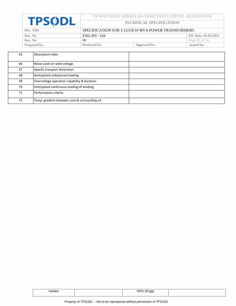
TP SOUTHERN ODISHA DISTRIBUTION LIMITED, BERHAMPUR
TECHNICAL SPECIFICATION
Doc. Title SPECIFICATION FOR 3.15/5/8/10 MVA POWER TRASNFORMERS
Doc. No ENG-HV -104 Eff. Date: 01.03.2021
Rev. No 00 Page 91 of 94
Prepared by: Reviewed by: Approved by: Issued by:
Initiator HOG (Engg)
Property of TPSODL – Not to be reproduced without permission of TPSODL
65 Absorption index
66 Noise Level at rated voltage
67 Specify transport dimension
68 Anticipated unbalanced loading
69 Overvoltage operation capability & duration
70 Anticipated continuous loading of winding
71 Performance criteria
72 Temp. gradient between core & surrounding oil

TP SOUTHERN ODISHA DISTRIBUTION LIMITED, BERHAMPUR
TECHNICAL SPECIFICATION
Doc. Title SPECIFICATION FOR 3.15/5/8/10 MVA POWER TRASNFORMERS
Doc. No ENG-HV -104 Eff. Date: 01.03.2021
Rev. No 00 Page 92 of 94
Prepared by: Reviewed by: Approved by: Issued by:
Initiator HOG (Engg)
Property of TPSODL – Not to be reproduced without permission of TPSODL
A) INSPECTION TEST PLAN FOR STAGE INSPECTION- II OF POWER TRANSFORMER
S No. Particulars Details
( A ) GENERAL INFORMATION:
1 Name of firm
2 Order No. and Date
3 Details of offer
a) Rating
b) Quantity
c) Serial Numbers
4 Details of last stage inspected lot:
a) Total quantity inspected
b) Serial Numbers
c) Date of stage inspection
d) Quantity offered for final inspection of (a) above with date
(B) Position of manufacturing for the offered quantity:
a) Complete tanked assembly
b) Core and coil assembly ready
c) Core assembled
d) Coils ready for assembly
i) HV coils
ii) LV coils
Note: i) The stage inspection-II shall be carried out in case:-
a) 100% quantity of core coil assembly shall be ready for inspection.

TP SOUTHERN ODISHA DISTRIBUTION LIMITED, BERHAMPUR
TECHNICAL SPECIFICATION
Doc. Title SPECIFICATION FOR 3.15/5/8/10 MVA POWER TRASNFORMERS
Doc. No ENG-HV -104 Eff. Date: 01.03.2021
Rev. No 00 Page 93 of 94
Prepared by: Reviewed by: Approved by: Issued by:
Initiator HOG (Engg)
Property of TPSODL – Not to be reproduced without permission of TPSODL
ii) Quantity offered for stage inspection should be offered for next level of Inspection within 15 days from the date
of issuance of clearance for stage inspection, otherwise stage inspection already cleared shall be liable for
cancellation.
ANNEXURE-C
Inspection Test Plan for Power Transformers
1 Name of the firm / BA
2 Date of inspection
3 Details of offer made
(i) Order No. and date
(ii) Rating
(iii) Quantity
(iv) Sl. No. of transformers
4 Date of stage inspection of the lot
5 Reference of stage inspection clearance
6 Sample Quantity (10% of the offered lot, min. one) Sr. No.------------------------------------------
S.
No. Name of test
Specified
value(Range)
Reference
documents Test Result Pass/Fail
1 Visual inspection for material, finish and
workmanship
Free from cracks,
nicks, protrusion and
other visible defects.
TPSODL
specification
2
Physical Verification of complete
Transformer with all assembly including test
rollers, radiators, cable boxes etc. and
Checking of weights, Dimensions.
GTP Values TPSODL
specification

TP SOUTHERN ODISHA DISTRIBUTION LIMITED, BERHAMPUR
TECHNICAL SPECIFICATION
Doc. Title SPECIFICATION FOR 3.15/5/8/10 MVA POWER TRASNFORMERS
Doc. No ENG-HV -104 Eff. Date: 01.03.2021
Rev. No 00 Page 94 of 94
Prepared by: Reviewed by: Approved by: Issued by:
Initiator HOG (Engg)
Property of TPSODL – Not to be reproduced without permission of TPSODL
3 Measurement of Winding Resistance GTP Values IS : 2026-2011
(Part I) cl. 10.2
4 Measurement of voltage ratio and phase
displacement GTP Values
IS : 2026-2011
(Part I) cl. 10.3
5 Verification of vector group relationship DYn11
IS : 2026-2011
(Part I) cl. 8.6,
8.7
6 Measurement of short-circuit impedance
and Load Loss. GTP Values
IS : 2026-2011
(Part I) cl. 10.4
7
Measurement of No-Load Loss and Current
(Losses at 90, 100 and 110% of rated
voltage).
GTP Values IS : 2026-2011
(Part I) cl. 10.5
8 Measurement of insulation resistance.
GTP Values
IS : 2026-2011
(Part I) cl.
10.1.3
9 Dielectric Test GTP Values/TPSODL
Specification
IS : 2026 (Part
III)-2009
10 Test on ON-Load Tap Changer GTP Values/TPSODL
Specification
IS : 2026-2011
(Part I) cl. 10.8
11 Zero-Phase sequence Measurement GTP Values IS : 2026-2011
(Part I) cl. 10.7
12
Oil Pressure/leakage test on completely
assembled transformer at 0.35kg/sq.cm for 8
hrs.
Should withstand TPSODL
Specification
13
Bushing shall be tested for Capacitance and
Power factor and shall meet the
manufacture’s requirement.
GTP / TPSODL
Specification
IS : 2026 (Part
III) cl. 10
14
All CTs and resistance of image coil for
winding temperature indicator shall be
checked for ratio test, polarity and knee
point voltage test
GTP / TPSODL
Specification
TPSODL
Specification
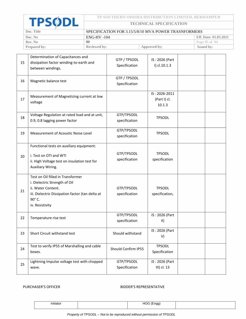
TP SOUTHERN ODISHA DISTRIBUTION LIMITED, BERHAMPUR
TECHNICAL SPECIFICATION
Doc. Title SPECIFICATION FOR 3.15/5/8/10 MVA POWER TRASNFORMERS
Doc. No ENG-HV -104 Eff. Date: 01.03.2021
Rev. No 00 Page 95 of 94
Prepared by: Reviewed by: Approved by: Issued by:
Initiator HOG (Engg)
Property of TPSODL – Not to be reproduced without permission of TPSODL
15
Determination of Capacitances and
dissipation factor winding-to-earth and
between windings.
GTP / TPSODL
Specification
IS : 2026 (Part
I) cl.10.1.3
16 Magnetic balance test GTP / TPSODL
Specification
17 Measurement of Magnetizing current at low
voltage
IS : 2026-2011
(Part I) cl.
10.1.3
18 Voltage Regulation at rated load and at unit,
0.9, 0.8 lagging power factor
GTP/TPSODL
specification TPSODL
19 Measurement of Acoustic Noise Level GTP/TPSODL
specification TPSODL
20
Functional tests on auxiliary equipment:
i. Test on OTI and WTI
ii. High Voltage test on insulation test for
Auxiliary Wiring.
GTP/TPSODL
specification
TPSODL
specification
21
Test on Oil filled in Transformer
i. Dielectric Strength of Oil
ii. Water Content.
iii. Dielectric Dissipation factor (tan delta at
90° C.
iv. Resistivity
GTP/TPSODL
specification
TPSODL
specification,
22 Temperature rise test GTP/TPSODL
specification
IS : 2026 (Part
II)
23 Short Circuit withstand test Should withstand IS : 2026 (Part
V)
24 Test to verify IP55 of Marshalling and cable
boxes. Should Confirm IP55
TPSODL
Specification
25 Lightning Impulse voltage test with chopped
wave.
GTP/TPSODL
Specification
IS : 2026 (Part
III) cl. 13
PURCHASER’S OFFICER BIDDER’S REPRESENTATIVE

TP SOUTHERN ODISHA DISTRIBUTION LIMITED, BERHAMPUR
TECHNICAL SPECIFICATION
Doc. Title SPECIFICATION FOR 3.15/5/8/10 MVA POWER TRASNFORMERS
Doc. No ENG-HV -104 Eff. Date: 01.03.2021
Rev. No 00 Page 96 of 94
Prepared by: Reviewed by: Approved by: Issued by:
Initiator HOG (Engg)
Property of TPSODL – Not to be reproduced without permission of TPSODL
DATE OF INSPECTION
ANNEXURE – D
SOURCE OF MATERIAL/PLACES OF MANUFACTURE, TESTING AND INSPECTION
S No. Item Source of Material Place of Manufacture Place of testing and
Inspection
1. Core Laminations
2. Copper Conductor
3. Insulating winding wires
4. Transformer Oil
5. Press Boards
6. Kraft paper
7. Tank material
8. Gaskets
9. Bushing HV/LV
10. Paint

TP SOUTHERN ODISHA DISTRIBUTION LIMITED, BERHAMPUR
TECHNICAL SPECIFICATION
Doc. Title SPECIFICATION FOR 3.15/5/8/10 MVA POWER TRASNFORMERS
Doc. No ENG-HV -104 Eff. Date: 01.03.2021
Rev. No 00 Page 97 of 94
Prepared by: Reviewed by: Approved by: Issued by:
Initiator HOG (Engg)
Property of TPSODL – Not to be reproduced without permission of TPSODL
11. OLTC
12 NIDS
13 CTs
14 WTI
15 OTI