The Importance and Level of Adaptation of STP Strategies for ...
Upload
khangminh22Category
view
1download
0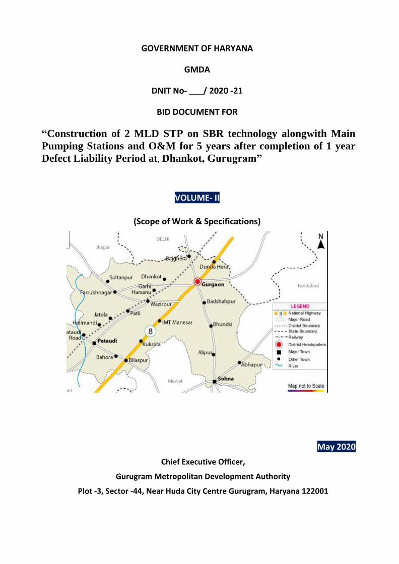
GOVERNMENT OF HARYANA
GMDA
DNIT No- ___/ 2020 -21
BID DOCUMENT FOR
“Construction of 2 MLD STP on SBR technology alongwith Main
Pumping Stations and O&M for 5 years after completion of 1 year
Defect Liability Period at, Dhankot, Gurugram”
VOLUME- II
(Scope of Work & Specifications)
May 2020
Chief Executive Officer,
Gurugram Metropolitan Development Authority
Plot -3, Sector -44, Near Huda City Centre Gurugram, Haryana 122001

GOVERNMENT OF HARYANA
GURUGRAM METROPOLITAN DEVELOPMENT AUTHORITY
BID DOCUMENT
FOR
“Construction of 2 MLD STP on SBR technology alongwith Main
Pumping Stations and O&M for 5 years after completion of 1 year
Defect Liability Period at, Dhankot, Gurugram”
VOLUME- II
(Scope of Work & Specifications)
Issued on: ___________ 2020
DNIT No- _______________/ 2020-21
Package No.: GMDA/Dhankot/ ___
Employer: Gurugram Metropolitan Development Authority
Represented by Chief Executive Officer, Gurugram Metropolitan Development Authority, Gurugram, Haryana
Country: India

Construction of 2 MLD Sewage Treatment Plant, Dhankot Bid Document
Volume – II – Scope of Work & Specifications i
Volume – II (Scope of Work & Specifications)
Table of Contents
PART-1 PROJECT REQUIREMENT
PART-2 DESIGN REQUIREMENT
PART-3 CIVIL AND STRUCTURAL REQUIREMENT
PART-4 SPECIFICATIONS OF MECHANICAL WORKS
PART-5 ELECTRICAL REQUIREMENT
PART-6 INSTRUMENTATION, AUTOMATION & CONTROL SYSTEM
PART-7 SIP IMPLEMENTATION
PART-8 DETAILED GENERAL SPECIFICATIONS
PART-9 DOUBLE WALL CORRUGATED (DWC) HDPE PIPES
PART-10 DUCTILE IRON (DI) PIPES
PART-11 RCC PIPES
PART-12 MANHOLES
PART-13 MANHOLE FRAME & COVERS
PART-14 PLASTIC ENCAPSULATED STEEL REINFORCED MANHOLE SAFETY STEPS
PART-15 ERRECTION, TESTING, TRIAL RUN, COMMISSIONING & TESTS AFTER COMPLETION
PART-16 OPERATION & MAINTENANCE OF MAIN PUMPING STATION & STP

Construction of 2 MLD Sewage Treatment Plant, Dhankot Bid Document
Volume – II
PART – 1
PROJECT REQUIREMENT
1.1 DEFINITIONS
The words, terms and expressions beginning with capital letters and defined under
various sections including General Conditions and Special Conditions of Contract shall,
unless the context otherwise requires, have the meanings as described thereto / herein:
a) “Battery Limits” shall mean the boundary within which the Contractor has the
responsibility of providing services in accordance to the terms and conditions
under this Contract;
b) “GMDA” means Gurugram Metropolitan Development Authority, Gurugram
c) “Customer Relation Management Centres” means the special centres, planned
and established by the Contractor to provide commercial and public relations
services to Customers;
d) “Customer or Consumer” means the registered user of the water supplied
through the meter at the private tap;
e) “Contract Commencement Date” means the stipulated date of commencement of
contract indicated in work order issued after signing of the agreement or as
decided by the Department.
f) “Contract Completion” means the Contract Completion Date as mentioned in the
Contract Completion Certificate issued by the Department’s Representative to the
contractor on fulfillment of his obligations in respect of both the Design-Build and
the Operation Service;
g) “Contract Date” means the date on which the contract is signed;
h) “Contractor/Bidder”are synonymous words and shall means the agency
responsible for Design Build & Operating & Maintaining theentiresewage
treatment plant and main pumping station as specified in Scope of work;
i) “Contractor's Personnel” means personnel hired and deployed by the Contractor
under provision of Works and Services but excluding the GMDAPersonnel;
j) “CPHEEO” means the Central Public Health and Environmental Engineering
Organization under the Ministry of Urban Development, Government of India;
k) “Critical Measurement Points” means the locations agreed for undertaking
measurement for facilitating the monitoring of minimum Service levels stipulated
in Clause of Performance Standards;
l) “Design Build Period” means the period commencing from contract
commencement date to completion of design and construction testing

Construction of 2 MLD Sewage Treatment Plant, Dhankot Bid Document
Volume – II
commissioning and trial runs of the permanent works;
m) “Development Period” has the same meaning as Design Build Period;
n) “Electricity Department” means the local service provider supplying electricity for
facilitating Operation of the facilities;
o) “Employer” means GMDA;
p) “ESR” means Elevated Service Reservoir; OHSR (Over Head Service Reservoir),
OHT (Over Head Tank) has the same meaning as ESR;
q) “Existing Assets” means infrastructure components, plant, machinery, equipment
and any other units existing at the site as on the Commencement Date in the
Departments custody;
r) “MPS” means Main Pumping Station;
s) “Government Agencies” means all those agencies comprising of local, state and
central government authorities directly or indirectly connected to provision of
water and wastewater collection services to the customers in Gurugram;
t) “IPS” means Intermediate Pumping Station/Sewage Pumping Station;
u) “Mandatory Works” means, works which are listed in the Bill of Quantities and
are required to be constructed, installed or erected and commissioned and/or
rehabilitated including those during Operation and Maintenance period and in
line with the provisions of this Contract unless such works require change of
scope or design as agreed, as part of the works;
v) “Minimum Service Levels" means the levels of service to be maintained in the
operations, maintenance and management as described under Operation and
Maintenance
w) “Minor Maintenance” means routine preventive or corrective maintenance works
such as minor repair, reconditioning, or replacement of spare parts to ensure
serviceability of existing and new infrastructure assets procured and installed by
the Contractor including, pipes, electrical equipment, flow meters, pressure
monitoring equipment, and Customer meters, starter panel, electro-mechanical
equipment etc.;
x) “Mobilization Period” means the period in which activities defined
inthisvolumewould be completed. It is the period commencing from the Contract
Commencement Date and extends up to limit mentioned further in this
document;
y) “New Assets” means infrastructure components, plant, machinery, equipment
and any other units procured, supplied, installed, erected and commissioned by
the Contractor during the Implementation period other than those existing on the
site as on the Commencement Date;

Construction of 2 MLD Sewage Treatment Plant, Dhankot Bid Document
Volume – II
z) “Operating Payments” means the eligible payments towards operation,
maintenance, repairs and service delivery after meeting the stipulated
performance indicators;
aa) “Performance Standards” mean the Minimum Service Levels to be achieved and
maintained during Contract period set forthunder Operation and Maintenance.
bb) “PHED” means the Public Health Engineering Department, Govt. of Haryana;
cc) “Planned Maintenance” means activities required to undertake preventive
maintenance of any or all assets existing or proposed to be installed under the
Contract and /or those taken over for operations under this contract;
dd) "Project" means “Sewage Treatment Plant & MPS for Dhankot, Gurugramcity;
ee) “Project Report” means the Reports of Sewage Treatment Plant & MPS for
Dhankot, Gurugram city;
ff) “Release Event” shall mean an event such as non-availability of electricity etc., or
an event of force majeure;
gg) “GMDA” means Gurugram Metropolitan Development Authorityor its successor
agency and is synonymous with “Department”
hh) “SBR” means Sequential Batch Reactor;
ii) “Scheduled Design Build Completion Date” or “SDBCD” shall mean the date by
which the construction of all the Works as per the agreed Service Improvement
Plan are to be completed, commissioned and certified by the Department’s
Representative;
jj) “Schedules or Schedule” means the schedules forming part of this contract, or any
one of them, as the context requires;
kk) “Scope of Services” shall mean all those services to be provided by the
Contractor in accordance to the obligations, activities, responsibilities and tasks in
implementing the contract;
ll) “Service Area” means the area where Contractor and/or GMDA or its successors is
responsible for collection of sewerage from the Customers;
mm) “Sewerage Charges" shall mean the charges of sewerage services to the
customers payable to the Department as fixed by the Department from time to
time;
nn) “Services” means all those activities, interventions, actions and tasks required as
part of the implementation of design built works including all planning, design,
detailed engineering, procurement, construction, rehabilitation and operations,
maintenance, and management in sewerage services to the Customers in
Gurugram city; including all those activities as defined in the Scope of Services;

Construction of 2 MLD Sewage Treatment Plant, Dhankot Bid Document
Volume – II
oo) “SPS” means Sewage Pumping Station which may include Intermediate Pumping
Station also;
pp) “STP” means Sewerage Treatment Plant;
1.2 PROGRAM BACKGROUND AND OBJECTIVES
Gurugram Metropolitan Development Authority (GMDA) has empaneled consultants who
will be required to provide assistance in planning, designing of water infrastructure
development i.e. water supply, sewerage systems, storm water drainage works etc. in
line with Master Plan 2031. In this regard, a Sewage Treatment Plant (STP) at village
Dhankot, Gurugram has been proposed to be built.
1.3 PROJECT OBJECTIVE
The Program objective is to improve the economic development by providing the
infrastructure and service in the sewerage sector. The improvement of quality of life and
thereby effective contribution of beneficiary people in the economic activity is expected.
The project therefore focuses on service delivery along with the creation of quality assets
and service delivery monitoring systems. Objective of the project is to collect all sewage
generated within the project area of Dhankot, Gurugram cityprovidetreatment facilities
at Dhankoti.e. where sewage network has already been developed. Services under this
contract shall cover:
✓ Design & Build (Design, Construction and commissioning of the project
components, including continual designs submissions and approval.
✓ Operating & Maintenance of created assets for 5 years after defect liability period
of 1 year.
1.4 INTRODUCTION OF PROJECT TOWN
Dhankot is a village in Gurgaon Mandal, Gurgaon District, Haryana, in India. Dhankot is
6.842 km distance from its mandal main town Gurgaon. Dhankot is 8.327 km distance
from its district main city Gurgaon. It lies on Basi road towards Farukh Nagar. According
to the data of 2010 shows that village Dhankot has excelled in terms of sex ratio where
the number of girls is 1238 against 1000 boys.
The city has a pre-historic past and it has mythological significance. It is believed that it
was from this place that milk was supplied to Guru Dronacharya and his pupils at
Gurugram (Gurgaon). According to Buddhist literature, Dhankot is also known as
Thullkottiha (or Dhoolkot, in common language) and Lord Buddha is said to have visited
this place.
Until 1947 Dhankot was in the possession of Ranghar Muslim Chauhans (Dhundhoti). The
majority of those ranghars settled in Sikandarabad in [Multan District of Pakistan] after
migration. After their departure to Pakistan, the land was allotted to the arriving Hindu

Construction of 2 MLD Sewage Treatment Plant, Dhankot Bid Document
Volume – II
refugees from Pakistan and its name was changed from Dhoolkot to Dhankot.
Climate
The climate of the district can be classified as Tropical Steppe, Semi-Arid and Hot which is
mainly characterized by the extreme dryness of the air except during monsoon months,
intensely hot summers and cold winters. During three months of south west monsoon
from last week of June to September, the moist air of oceanic origin penetrates into the
district and causes high humidity, cloudiness and monsoon rainfall. The period from
October to December constitutes post-monsoon season. The cold weather season
prevails from January to the beginning of March and followed by the hot weather or
summer season which prevails up to the last week of June. The mean daily maximum
temperature is about 41°C in the months of May and June. It may go up to 45°C or more
in June. During winter the mean daily maximum temperate in January in 21°C and
minimum is about 3-4°C. May and June are the hottest months and January is the coldest
month.
The district experiences dry air except during the monsoon, hot summer and cold winter.
The average annual rainfall for the five years i.e. 1995-99, 1996-2000 and 1997-2001 was
665.2, 628.4 and 560.1 mm respectively it increases towards east. About 77 per cent of
annual rainfall in the district is received during the monsoon months. The normal annual
rainfall in Gurgaon district is about 596 mm spread over 28 days. The south west
monsoon sets in the last week of June and withdraws towards the end of September and
contributes about 85% of the annual rainfall. July and August are the wettest
months.15% of the annual rainfall occurs during the non-monsoon months in the wake of
thunderstorms and western disturbances.
1.5 EXISTING SEWERAGE SYSTEM
Sewage disposal in the Dhankot village is a big challenge currently for the GMDA and it is
necessary to construct a new STP for Dhankot village to check illegal disposal by people in
the open, drains and elsewhere.
With increasing pressure on water as a result of limited availability, increasing
urbanization in Dhankot village and deterioration of water quality of surface as well as
ground water, primarily due to pollution of sources of supplies, problem of sewage
handling and its treatment is becoming a big issues and threats for life.
1.6 SCOPE OF WORK DURING DESIGN-BUILD PERIOD
1.6.1 This part describes extent of work and department requirements for works in brief:
Table: Scope of work and services – Sewerage
S.N. Components Indicative Works
Sewage Treatment Plant
1 Detailed design and construction of Sewage (Average Discharge)

Construction of 2 MLD Sewage Treatment Plant, Dhankot Bid Document
Volume – II
Pumping Station at Dhankot village.
Tapping of sewerage from the village to the
STP.
All other development works building,
electrical, mechanical, civil, works in the
campus.
Dhankot – 2MLD;
MPS is to be designed for peak
flow with a Peak Factor of 3
2 Detailed design, construction &
commissioning of Sewage Treatment Plant on
SBR technology with Primary treatment
(screening and grit removal etc), and other
components required. The scope includes all
other development works building, electrical,
mechanical, civil, works in the campus.
Dhankot – 2 MLD;
3 Design, Supply and Installation of SCADA
system required for effective management of
the Wastewater System based on the data, its
analysis and management.
Instrumentation and automation
work with PLC system shall be
provided for Sewage Treatment
Plant and Sewage Pumping Station
and STP mentioned at Sr. no. 1 &2.
4 Detailed design, supply & installation of
pumping main DI(K-7) pipe for carrying
untreated wastewater from MPS to STP
• As per Tender
5 Site leveling and development works at site. Site development works including
landscaping, drainage, street
lighting and other related works for
all the sitesoftreatment plantsand
MPS.
Operation and Maintenance Part
6 Operation and Maintenance of:
i) Main Pumping Station and 2 MLDSewage
Treatment Plantfor a period of 6 years
including 1 year as Defect Liability period.
From Initial commissioning date till
contract completion date (1-year
DLP+ 5 years O&M thereafter)
7 Provision for inauguration of project including
all tenting arrangement, flowering and
foundation stone laying ceremony.
The Scope of Services shall include all technical, managerial, administrative, commercial,
environmental, and social interventions as required in accordance with acceptableand
management practices. The Scope of Services mentioned in Table above is indicative only
and the contractor is required to undertake his own detailed investigation of the Project
Facilities to determine the complete Scope of Services for achieving the Minimum
specified Service Levels.

Construction of 2 MLD Sewage Treatment Plant, Dhankot Bid Document
Volume – II
1.7 DETAILED SCOPE OF WORK FOR STP AND MPS
The STP shall be based on sequential batch reactor (SBR) technology. The department
proposal includes construction of 2 MLD STP with MPS alongwith development of campus
complete in all respect as detailed in table below:
Table: Proposed STP and MPS, DhankotGurugram
STP details
Available Land (Area) Sqm 6570
Dimensions As per Drg.
Incoming gravity sewer pipe to MPS 400mm
G.L. at STP (m) 212.00
IL of incoming sewer at STP (m) -
Capacity of STP on SBR technology 2 MLD
Capacity of main pumping station with peak factor
6 MLD
Silent Diesel set 1 no. diesel generating set as per maximum demand of power to be consumed in various components of STP/MPS
Transformer (if required)
Development work in campus
Boundary wall construction alongwith gates
As per drawing
Road Pavement 3.75m wide road and 2m wide footpath within thecampus with 80mm thick CC block tiling work as per drawing having minimum approx. area 850sqm
Site leveling, jungle clearance, bushes removal, dewatering and soil stabilization of plant area, required at location of STP and MPS site
Finished ground level (FGL) of plant area to be maintained by Bidder in steps by bidder as per ground levels existing at site.
Pumping Machinery & Disposal of treated wastewater
Apart from pumping machinery of plant, separate pumps are to be installed at STP campus area near chlorination tank for disposal of the treated wastewater to nearby drain if required.
Intercepting sewer upto STP plant Tapping of sewerage from the village to the STP/MPS.Main sewer to be extended up to inlet point of STP/MPS.
Disposal of treated wastewater. Treated wastewater shall be discharged into nearby drainage system or greenbelt along master road for reuse
The Quantities and proposals mentioned in above table are indicative only and the
contractor is required to undertake his own detailed investigation of the Project Facilities
and designs to determine the complete Scope of Services for achieving the Minimum
specified Service Levels. As this contract is lumpsum basis for STP, the bidder is required to
make the detailed design after topographical survey, site visits and detailed soil
investigation.

Construction of 2 MLD Sewage Treatment Plant, Dhankot Bid Document
Volume – II
1.7.1 However, the Scope of Work under this contract includes but is not limited to the
following in relation to the design, construction, commissioning and operation of the
above works:
• Site Topographic Survey and Geotechnical Investigations as deemed necessary by the
Contractor
• Setting out of the works
• Site Clearing, Excavation, Leveling, Grading, Dewatering and Backfilling activities along
with preparation of Finished Ground Level(FGL) of campus.
• Process and Hydraulic Design
• Preparation of GA Drawings, Site Layout,Unit Process/Equipment/Facility/Building
layouts, Hydraulic Profile, Process Flow Diagram, Process and Instrumentation Diagram
(P&ID)
• Detailed Sizing, Design, and Engineering, of all treatment units, buildings, structures,
and equipment (including all civil, mechanical, electrical, architectural,
instrumentation, control, automation)
• Design and Construction of all Civil Structures and Building Works
• Design, Construction and Commissioning of Bypass Lines
• Design, construction and laying of intercepting sewer approaching to STP and
pipesfrom effluent sump to disposal point.
• Submission of Detailed Engineering Designs, Drawings, Process Calculations, Data
Sheets as per bid requirements
• Procurement, Supply and Installation, Erection of all Mechanical, Electrical and
Instrumentation.
• Execution of all Civil, Mechanical, Electrical, Instrumentation, SCADA Works at Site
including Construction, Erection, Testing
• Construction of Internal Plant Roads, Curbs, Pavements, Parking Spaces, Compound
Wall, and Storm Water Drains
• Plant water supply:The Bore Wells and Tank system shall be designed such that the
stored water can be used for multiple applications including but not limited to alum
and polymer solution preparation, human domestic non-potable needs, laboratory
needs, and other general cleaning and flushing needs.
• Disposal of sludge by the contractor at his own cost. No land for the same shall be
provided by GMDA Gurugram.
• Plantation and Landscaping work
• Receiving Raw Inlet Sewage at site and discharge of Plant treated effluent to nearby

Construction of 2 MLD Sewage Treatment Plant, Dhankot Bid Document
Volume – II
water body as specified in Employer’s requirements
• Design, procuring, and commissioning of pipelines, conduits for the disposal of plant
effluent from chlorine contact tank to nearby water body at each sitealongwith
construction of sump (wherever required) and pumping mainupto disposal point.
• Plant Testing, Commissioning, Stabilization, Demonstration of Performance Guarantee.
This item shall include proper maintenance according to manufacturers’ instructions of
entire plant and its components during any inactive period that may be required if
influent wastewater is not available at the time of STP completion.
• Installation of equipment for on-line measurement of various parameters of untreated
and treated effluent e.g. Flow, pH, Suspended solids, Dissolved Oxygen, BOD, COD, etc.
• Installation of CCTV cameras as per specifications and directions of Engineer- in -
Charge.
• Submission of Operation and Maintenance Manuals
• Five (5) years Operation and Maintenance of Sewage Treatment Plants and MPSafter
successful completion of trial run and 12 months of Defect Liability Period as per the
Conditions of Contract given in Volume-1 of bid document.
• Providing Training Services to Employer’s Personnel
• Preparation and Submission of As-Built drawings for all Civil, Mechanical, Electrical,
Instrumentation, SCADA Works.
• Civil works, Campusdevelopment Administrative Building, General toilet, Storage
Room, Guard Room , Laboratory with equipmentsand all such ancillary structures, road
works, storm water drains, RCC chambers, horticulture, electrical works, forming part
of the work of Sewage Pumping stations, Sewage treatment plant, Main Control
Centre at appropriate locations as indicated by the Departments representative and as
defined herein after.
1.7.2 General Principles
a) The Contractor shall carryout all works, wholly, in accordance with the terms and
conditions of the contract to fulfill the requirement of the project. All the materials
used, and the equipment installed shall be as per the specifications defined in the
contract.
b) The Contractor shall conduct site investigations, execute the basic and detailed design
and Engineering work in compliance with the provisions of the Contract, or where not
so specified, in accordance with good Engineering practice followed internationally.
c) The design parameters of various component stated in the Department’s
Requirement, General Technical Specifications and Standard Specifications are
indicative and are for guiding the bidder.

Construction of 2 MLD Sewage Treatment Plant, Dhankot Bid Document
Volume – II
(i) The Contractor shall design all components of STP provided in the bid document
to meet the minimum requirements and specifications stated in Department’s
Requirement, General Technical Specifications and Standard Specifications
ofGMDA (as prevalent in the PHED).
d) The Contractor shall supply all plants, construction materials, manufactured goods,
labour, machineries, equipment, etc necessary for the installation of the works in
accordance with Department’s Requirement and Specifications. The said plants and
materials shall include, but not limited to the following:
(i) All pipes, fittings, valves and accessories required for the pipelines,
treatment plant, reservoirs and pumping stations, etc.
(ii) All mechanical equipment, accessories and instrumentations
(iii) All electrical equipment, accessories and instrumentations
(iv) All SCADA and related Automation components.
(v) All materials for concrete, grout, blockwork mortar and similar products,
(vi) Paint, whitewash, sealing compounds, painting repair material including
primer, etc.
(vii) Steel reinforcement.
(viii) All materials, forms and appurtenances.
(ix) All materials required for street and roadway resurfacing, and other road
restoration, restoration and/or correction to existing pipes, reconstruction of
drains and sewers, etc.
(x) All materials including water, required for testing, flushing and chlorinating
of pipelines.
(xi) All machineries, equipment and labour required for installations of the
works.
(xii) All materials used for permanent installation in the works shall be new and
shall conform to the respective clauses of the specifications and if not
specified they shall conform to good standards of construction practice.
e) Preparation of Process, Hydraulic, Civil, Mechanical, Piping, Electrical and Instrumentation
Design and Drawings including Construction, Architectural and As-built Drawings. All the
Designs and Drawings shall be got vetted by any NIT/ IIT
f) Department reserves the right to construct any work or any part thereof on, over,
under, in or through the site. Department may use or occupy any part of the
permanent work.
g) The Contractor shall be responsible for any discrepancies, errors or omissions in the
specifications, drawings and other technical documents, desired output/performance

Construction of 2 MLD Sewage Treatment Plant, Dhankot Bid Document
Volume – II
of the Works, whether specifications, drawings and other documents have been
approved by the Department/Departments Representative or not, provided that such
discrepancies, errors or omissions are not because of inaccurate information
furnished in writing to the Contractor by or on behalf of the Department
Representative. Contractor shall not deviate from the specifications prescribed by the
Department Representative unless the proposed changes will result in better
performance and cost effectiveness.
1.7.3 Generally, the following activities shall be carried out for each component of this contract
but shall not be limited to:
➢ Site leveling, jungle clearance, bush clearance, dewatering, pumping and bailing out
water from existing pond within the campus, making Finished Ground Level (FGL) of
the plant area at the existing shoulder of access road and stabilization of soil for
construction of STP.
➢ Detail survey and investigations to be done for design of Proposed Sewage Pumping
Station, Proposed Sewage Treatment Plant and other ancillary units of STP.
➢ Conducting required soil/ strata investigations as per specifications for Proposed
Sewage Pumping Station, Sewage Treatment Plant and all other civil works in all type
of soil conditions. The Contractor is also required to prepare and submit the layout
plans of all the components of the Works.
➢ All designs shall conform to latest Indian Standard (I.S.) Specifications and Codes of
Practice unless otherwise specified in the Bid Specifications. The design standards
adopted shall follow the best modern engineering practice in the field based on any
other international standard or specialist literature subject to such standard reference
or extract of such literature in the English language being supplied to and approved by
the Department’s Representative. In case of any variation or contradiction between
the provisions of the I.S. Standards or Codes and the specifications given in the bid
document, the provision given in this bid document shall be followed.
➢ Preparation and submission of all detailed working drawings based on conceptual
designs and plans approved by the Department’s Representative.
➢ Design reviews and appraisals at regular interval, prior to construction of works.
➢ Submission of the credential of manufacturer for supply of various materials,
machinery, equipment/instruments for approval of Departments representative.
➢ Submission of the design/specifications, product brochures, technical data sheets,
test, Quality Assurance Plan (QAP) and performance certificates etc., of all mechanical
plant and works (pumps, valves, fittings etc.), instrumentation/ automation SCADA
system, design of the mechanical, electrical components, taking into account the
interfaces to the other project components/ packages and future extensions of the
project.
➢ Electric design and electric load calculation, and fulfillment of IEC requirement.

Construction of 2 MLD Sewage Treatment Plant, Dhankot Bid Document
Volume – II
➢ Construction/ Installation, testing and commissioning of all civil, mechanical, electrical
and instrumentation SCADA works strictly as per scope of work, approved drawings,
designs, relevant IS codes and specifications.
➢ Pre- commissioning checks and inspections as per requirement.
➢ Testing of hydraulic, mechanical, electrical and instrumentation system as per relevant
IS codes and specifications and guidelines.
➢ Optimization of the whole system as per design parameters and commissioning of all
the components including but not limited to Proposed Sewage Pumping Stations,
Sewage Treatment Plants.
➢ Getting approval of all designs and drawings, material to be used, machinery and
equipment specifications and the samples, prior to dispatch by manufacturer or
supplier/ installation/ commissioning of work at site is the sole responsibility of the
contractor. If any specific provision/references have been made in more than one
specification, at different places in the tender document, the provision which is more
stringent, shall apply.
➢ Manufacturing, shop testing, pre-dispatch inspection, transportation to site, providing
transit insurance, storage, handling at site, installation, sectional testing, pre-
commissioning testing, commissioning and trial runs for all components of the system
and the system as a whole, including the hydraulic, mechanical, electrical, Electro-
Mechanical and instrumentation equipment.
➢ The submission of As-built drawings of the works submitted in 5 copies on linen bound
in an album of an approved size shall be prerequisite for making final payment. The
contractor shall submit all the completion drawings and approved design calculations
on CD ROM/DVD in two sets with proper directory structure.
➢ Submission of operation and maintenance manual as per scope of works,
requirements and specifications.
➢ Providing mandatory spares, tools and tackles at the end of the execution of physical
works as per list required to be submitted along with the bid.
➢ Arrangement of adequate security, watch and ward of the system during the
execution period to safeguard the equipment and completed section of the work from
any type of mishandling, theft, fire and other hazards, etc.
1.7.4 Site / Campus Development Works
The bidder is advised to visit the site at Dhankotand needs substantial works for
development of campus including site leveling, jungle clearance, removing heavy bushes and
trees, filling the existing ponds and construction of boundary wall.
1.8 SCOPE OF OPERATION AND MAINTENANCEPHASE
The Contractor will be required to operate and maintain the MPS, STPand other related
works created under the contract in such way to meet the performance requirements from

Construction of 2 MLD Sewage Treatment Plant, Dhankot Bid Document
Volume – II
the design, build completion date (which shall also mean completion date).
1.8.1 Operating Obligations for the Works
The contractor, under the scope of this work shall carry out the following activities, but these
shall not limit requirement of other activities, which otherwise are required as per terms and
conditions of contract or to fulfill contractual responsibilities or are essential as per good
industrial practices. The contractor shall be responsible for:
(i) Operation and maintenance ofthe entire works and all other allied works under this
contract, for the DLP of one year and thereafter O&M for 5 yrs. It is to be noted that all
costs for repairs of civil and E&M during the DLP, is to be borne by the contractor.
Within his quoted cost, the contractor is to ensure that all works covered under the
contract of this bid document are maintained during the1-year defect liability period
(DLP) and 5 yrsO&M period. Power charges shall be borne by the department whereas
fuel i.e. HSD etc shall be reimbursed to the agency by the department after submitting
the bills supported with proof of its consumption.
(ii) Providing on the job training to the Departments staff as per specifications.At the end
of the one year of O&M period, an assessment of the condition of the plant will be
done by Departments Representative and based on the assessment, the contractor
shall, at no extra cost to the Department/GMDA, repair and re-condition all the civil
works, electrical & mechanical instrumentation, equipments in the concluding month
of the O&M period to a condition so that they are in running condition.
(iii) Providing the minimum following specified staff during operation and maintenance
period and in emergencies.
Minimum total Manpower requirement for Operation in 3 shifts for STP
S.No. Manpower Number Qualification & Experience
1. Plant Manager Cum Lab
Technician
1 B.Tech and 10 years of
Experience
2. Plant Operator/shift In-charge 5 Graduate and 2 yrs Experience
3. Helper 1
4. Cleaner/sweeper 1
5. Security Guards/Gardener 2
(iv) Providing all required consumables required for functioning / operation& maintenance
of plants.
(v) Preventive/breakdown maintenance of all pumps, electrical, mechanical &
instrumentation equipment, installed under the contract. All costs including costs of
all material, equipment, etc required for operation and/or maintenance (preventive
and / or breakdown) to be borne by the contractor.
(vi) Maintenance of the lighting fixtures and the lighting system of the areasand

Construction of 2 MLD Sewage Treatment Plant, Dhankot Bid Document
Volume – II
replacement of all nonfunctional lighting fixtures within 24 hours.
(vii) To maintain;
• Repair history of all mechanical, electrical and instrumentation control equipment
Logbooks.
• Everyday power availability, input voltages, KWH meter, and power factor readings
at STP&MPS.
• Daily operation of pumps with every hour readings for operating voltage, amperage
and power factor, pressure on the manifold, pressure at outlet of pumps and flow
rate in manifold.
• In addition to maintenance of above log-books, the contractor is required to
maintain one inspection book at each STP. The complaint register must be
investigated, and remedial measures must immediately be taken.
(viii) Providing adequate spares and maintaining adequate inventory of accessories or
equipment itself for repair of system so that the electrical, mechanical, pipe and
pipe appurtenances, can work efficiently as per the guarantees given or minimum
required efficiencies asked for in the contract, without any additional cost.
At the end of the contract the contractor shall hand over thespares, tools, tackles.
(ix) Maintenance of the stores for the electrical, mechanical and instrumentation
equipment. The maintenance of stores will include but shall not be limited to:
• Loading / unloading materials received and issued for works.
• Proper arrangement of material in stores to ensure its safety and easy availability.
• Maintaining store area neat and tidy.
• Keeping records and Accounting the incoming materials.
• Keeping records and Accounting the consumed materials
The contractor shall be solely responsible for the safety and security of the goods in the
store and its accountability and will be responsible for any loss or damages in stores for
any reason. He shall maintain insurance cover against the value of the goods in the
stores without any additional costs on the Department.
(x) Periodic routine maintenance of buildings & other infrastructures built in the contract
such maintenance must ensure adequate cleanliness, ventilation, illumination and
structural safely. In addition to this the general hygienic standards must be maintained,
and adequate plantation should be done.
(xi) Updating and periodic submissions of the operation and maintenance manual as
defined in specifications for O&M works. The contractor shall take up all periodic
maintenance works provided in the approved O&M manual.

Construction of 2 MLD Sewage Treatment Plant, Dhankot Bid Document
Volume – II
(xii) Submission of monthly report.
(xiii) Operation of all valves quarterly and checks its proper functioning. Maintenance, of all
valves in leak-less conditions.
1.8.2 Failure to Achieve Performance Target
If the Contractor fails to achieve the services defined in performance targets, then the
Contractor shall be levied with penalties as specified under Operation &Maintenance in
Volume-Il. The Contractor shall not be liable for Non-Performance penalty to the extent such
failure is attributable to an Event in which the Contractor shall take necessary steps to
mitigate the effects of the event and operate the system in accordance with the standards of
a reasonable and prudent way.
Replacement of equipment, assets or infrastructure which is not part of the contractor’s
work shall be paid separately. Contractor will include costs for repairs of flow meters, valves,
panels, motor pumps and all other equipment and its spares including battery, and other
equipment in his quoted price. Any equipment supplied and installed by the contractor shall
not be paid separately for replacement or repairsetc.
1.8.3 Tests to Be Carried Out During O&M Period
The minimum requirement of sampling and testing is to be carried out daily. This schedule
shall also be maintained during the O&Mperiod.
➢ Flow, pH, BOD, COD, Suspended solids/ MLSS, Dissolved oxygen, Alkalinity, Total Nitrogen, Sulphate, Total Phosphate, Residual Chlorine for raw sewage and treated sewage on dailybasis.
➢ Fecal coliform for treated sewage shall be tested on monthly basis.
1.9 PHASING OF CONTRACT
The Contract is divided into two stages i.e.(i) Design and Build and (ii) Operation and
Maintenance Services, spread over the contract period; from the stipulated date of Contract
Commencement up to the Contract Completion Date.
(i) Mobilization, preparatory and construction period as per approved designs and
(ii) Operation, Maintenance, Manage, Repairs and Service Delivery Period during the
contract period as per the sectional completion of work from commencement date
(in case of sectional completion), till contract completion date.
1.9.1 Mobilization Period
During the 30 days mobilization period the contractor is required to:
• Establish a furnished project office in Gurugram.
• Employ/ mobilize the staff required for starting the preparatory work
• Mobilize the survey teams
• Provide GIS based maps, project management etc. along with connectivity with EIC.

Construction of 2 MLD Sewage Treatment Plant, Dhankot Bid Document
Volume – II
• Establish Employer Representative office
• Mobilize vehicles, office (furnished), equipment, communication equipment.
1.9.2 Preparatory Period (Preparation of design during preparatory period)
During the Preparatory Period, the Contractor is required to:
• Familiarize himself with the project site condition after required consultation
• Collect data and maps etc. and review designs of sewer network, pumping mains
etc.
• Confirm/ conduct topographic survey to ascertain the level, road width, existing
services, obstacles, etc.
• Fix ground level of STP which may be at the shoulder level of existing access road
looking to the undulating site of Dhankot.
• Prepare and get approval of designs of Sewage treatment plant, pumping station,
infrastructure for treated effluent including civil, mechanical, electrical,
instrumentation etc complete.
• Prepare an asset inventory report, strategy for improving services.
1.9.3 Design Refinement
The Contractor during DB period will be allowed for refinement of overall design of the
systems for long term efficiency, effectiveness and sustainability.
1.9.4 Deliverable Documents
(i) Detailed design &drawings;
(ii) Work plan, Methodology and timelines for implementation should be in line with the
Employer’s intentions;
(iii) Detailing of integrated Contract Management Information System by using latest
software like Primavera, MS project, data capture, management and reporting
structures, protocols including all related hardware, software, installation;
(iv) Contractor Personnel Deployment Plan;
(v) Construction Plant and equipment deployment plan;
(vi) Asset Replacement Schedule with justification;
(vii) Detailed methodology for continuous monitoring of the performance of the
Contractor in achieving and maintaining the Performance Standards for release of the
eligible Operating Payments;
(viii) Design Report on Sewage Treatment Plant, Pumping Systems for developing
Infrastructure for disposal of treated effluent shall be prepared and submitted for
due diligence;
1.9.5 Operating and Management related Deliverable
(i) Annual Operating Plan (AOP) covering all operations, maintenance and management
Construction of 2 MLD Sewage Treatment Plant, Dhankot Bid Document
Volume – II
requirements in the Service Area;
(ii) Emergency Response Plan (ERP); this shall also separately include response plan for
effective emergency rectifications against any major break downs occurring from the
STP and Pumping Station up to the service area of this contract;
(iii) Public Relations Plan;
(iv) Standard Operating Procedures (SOPs) for routine operations and emergency
responses;
(v) Sewage Quality Monitoring Program;
(vi) Energy optimization program;
(vii) Periodic reporting plan including the formats for different performance reports;
(viii) The computer hardware and software improvement plan for continued operation of
the MIS, instrumentation and SCADA
1.10 Survey, Mapping& Drawings
A detailed topographical survey of the area shall be carried out and the spot levels and the
contours at 0.5 m interval shall be drawn using Total Station equipment and GIS based
digitized map in ArcGIS shall be prepared.
1.10.1 Pre-Construction Surveys and Setting Out
The Contractor shall verify all measurements and be responsible for their correctness. Any
differences which may be found between actual measurements and the dimensions given in
the Contract Documents shall be submitted to the Department’s Representative, in writing,
for consideration and directivesbefore proceeding with the Works.
Site benchmarks shall be accurately and safely established, maintainedand removed upon
completion of the Works, all to the satisfaction of the Department’s Representative. The
Department’s Representative will indicate the position, co-ordinates and elevationof
benchmarks near the works, as shown on the Drawings.
The Contractor shall prepare a plan detailing the location of the benchmarks and keep this
up to date throughout the period of the Contract. Reproducible copies of the plan so
prepared shall be supplied to the Department’s Representative, as and when he may
require.
The Department’s Representative reserves the right to order levels, considered necessary
forthe full and proper supervision and measurement of the works, to be takenat any time.
Before the Works, or any part thereof, are commenced, the Contractor andthe Department’s
Representative shall together make a complete survey, and take levels, of the Site and agree
on the dimensions and elevations upon which setting out ofthe Works shall be based.
These levels shall be related to the benchmarks and shall be plottedand drawn up by the
Contractor. After agreement of the drawings, whichshall be signed by the Department’s
Representative and the Contractor, these levels shall formthe basis of setting out of the
Works.

Construction of 2 MLD Sewage Treatment Plant, Dhankot Bid Document
Volume – II
The Contractor shall be responsible for the true and proper setting out of theWorks in
relation to reference data given on the Drawings and shallaccurately set out the positions,
levels and dimensions of all parts of the Works. Any delay or loss resulting from errors in the
setting out of the works shall be the responsibility of the Contractor.
Setting out shall be reviewed by the Department’s Representative before commencing the
Works, but any approval shall, in no way, relieve the Contractor of hisresponsibility for the
correct execution of the Work.
1.10.2 Working Drawings
Working Drawings of the designs carried out by the Contractor shall be submitted by the
Contractor to the Department’s Representative. Working Drawings shall include, but not be
restricted to, pipeline plans and profiles, reinforcement detail drawings and bending
schedules, equipment drawings, drawings for approval of equipments, equipment
installation drawings, shop drawings for structural steel and miscellaneous metal work, and
drawings for other work for which the Department’s Representative's approval is required.
It shall be the Contractor's own responsibility to prepare such Working Drawings as he may
require for the proper setting out and construction of all structures and facilities. Work shall
not commence on an individual structure or facilities until the relevant Working Drawings
have been approved by the Department’s Representative.
All dimensions shall be in SI units and each drawing shall be properly identified by a drawing
head and a numbering code in the form prescribed by the Department’s Representative after
contract commencement.
The Contractor shall submit 5 (five) copies of all drawings for approval.
Any changes or modifications to the Working Drawings that the Department’s
Representative considers necessary shall be made by the Contractor promptly and the
drawings resubmitted for approval.
Approval of Working Drawings will be given by the Department’s Representative in the form
of a stamp "Released for Construction" together with the date and signature of the
authorized representative. Only those Working Drawings carrying the signed and dated
stamp shall be used for execution.
Copies of all such approved Working Drawings together with one unreduced transparency
shall be supplied to the Department’s Representative by the Contractor immediately after
approval. The cost of preparing and providing all Working Drawings shall be included in the
Contract Rates.
It should be found at any time after approval has been given by the Department’s
Representative to a Working Drawing submitted by the Contractor that the said Working
Drawing does not comply with the terms and conditions of the Contract or that the details
do not agree with the Working Drawings previously approved, such alterations and additions

Construction of 2 MLD Sewage Treatment Plant, Dhankot Bid Document
Volume – II
as may be deemed necessary by the Department’s Representative shall be made therein by
the Contractor and the work carried out accordingly without entitling the Contractor to extra
payment on account thereof, except where such alternations and additions are to be made
in direct consequence of written order by the Department’s Representative to vary the
Works. Contractor shall be wholly responsible for correctness of all the drawings and designs
for all the components of the project.
No examination by the Department’s Representative of any document submitted by the
Contractor or of the Contractor's Working Drawings, nor the approval expressed by the
Department’s Representative in regard thereto, either with or without modification, shall
absolve the Contractor from any liability imposed upon him by any provision of the Contract.
Notwithstanding the Department’s Representative's approval of the Working Drawings the
Contractor shall be responsible for any dimensional or other errors.
1.10.3 As-Built Drawings and GIS Data Creation
On the basis of the Working Drawings as approved by the Department and after accounting
any changes due to site conditions during the execution of work “As built drawing” shall be
got prepared from contractor. Such drawings shall show the actual arrangements and exact
locations of all sewer lines, structures and items of equipment installed under the Contract.
The Contractor shall submit 5(five) no. of such As-Built Drawings clearly named as such to
the Department’s Representative for approval before applying for the Taking-Over
Certificate for the respective Section of the Works. After approval of the As Built Drawing the
Contractor shall supply an electronic copy of the drawing in together with a licensed copy of
the drafting software.
During the course of the Works, the Contractor shall maintain a fully detailed record of all
changes from the approval to facilitate easy and accurate preparation of the As-Built
Drawing.
Irrespective of the other contractual prerequisites no Section of the Works will be
considered substantially completed until the respective As-Built Drawings have been
approved by the Department’s Representative.
In parallel with the preparation of as-built drawings, the Contractor shall produce GIS data of
the constructed works. The contractor conducts all necessary survey work and shall ensure
that vertical and horizontalmeasurements shall be captured at an accuracy of +/- 0.5m at a
95% confidence level, using the most suitable and cost-effective field data collection
technology and methodology. All horizontal and vertical survey measurements will be
referenced to the present Survey of India GIS geo reference.
1.11 CONSTRUCTION PROGRAM AND PROGRESS OF WORKS
Contractor shall prepare Construction Program in the form of a Critical Path Method (CPM)

Construction of 2 MLD Sewage Treatment Plant, Dhankot Bid Document
Volume – II
Diagram showing, sequences, dependencies, durations and dates for execution of all major
items including sectional completion following the sub-divisions in the Bills of Quantities for
the execution of the Works within the periods stated in the Contract. It shall be supportedby:
a. Data of the constructionmethods
b. Equipment UtilizationSchedule
c. Manpower UtilizationSchedule
d. SubcontractingSchedule
e. Mobilization/DemobilizationSchedule
The CPM diagram incorporating the above-mentioned schedules shall be prepared using
Microsoft Project, or similar approved project management software, and shall be presented
in hard copy and electronic form to the Department’s Representative.
In carrying out the Works due attention shall be paid to all measures which can reasonably
be taken in order to diminish the inconvenience which the work may cause to services and
access toproperty.
Note: -The specific design and performance requirements for all equipment are given in this Specifications are general in nature and specifications related to scope of work in bid document are only applicable.The Requirement specified and related to this project shall be fully met with by the Contractor.
(End of Part – 1)

Construction of 2 MLD Sewage Treatment Plant, Dhankot Bid Document
Volume – II
PART – 2
DESIGN REQUIREMENT
2.1 DESIGN REQUIREMENT FOR MAIN PUMPING STATION (MPS) & TREATMENT PLANT
2.1.1 General
The following general design requirements shall be met for MPS, Pumping Main, and STP.
These requirements shall be fully met regardless of whether or not such requirements or any
related components are shown in any drawings included in the contract documents.
(i) All units shall have walkways all around with handrails and access stairs, ladders are
permissible only for accessing roof tops of buildings. PVC/FRP encapsulated rungs to be
provided to enter each tank. SBRs should have rungs near the pumps and also at
opposite side of the tanks.
(ii) All Submersible pumps and mixers shall have min 1.5mx1.5m concrete service platform
right next to them.
(iii) No valve handle shall be over the chest height of an operator. Provide elevated
operation platforms where necessary.
(iv) Every unit on the plant shall have warning safety signs at the approach and on
walkways per the hazard identified in the safety audit report. Plant boundary shall have
warning signs and notices visible to warn unwanted persons from entering. Important
phone numbers for emergency shall be displayed at all operating units / buildings.
(v) All deep tanks to have lifebuoys with ropes installed on the elevated walkways.
(vi) Forced ventilation to be provided in every plant building.
(vii) Fire extinguishers of ABC type (5kg) to be located at safe accessible locations.
Quantities provided as per following information: - 5 No. at STP as per the direction of
Engineer in charge.
(viii) All confined spaces shall have restricted entry and displayed warnings.
(ix) All components (including but not limited to equipment such as pumps, blowers,
screens, diffusers, inline devices; instruments such as flow meters; and distribution and
collection channels or pipes) shall be provided with appropriate isolation devices such
as valves, gates, or other devices in order to allow isolation, drainage, cleaning,
calibration, servicing, and maintenance of such components. Bypasses shall be
provided around all pipe flow meters and other in-line instrumentation such that the
instrument can be isolated and removed for calibration and maintenance without
interrupting the flow, regardless of whether or not such bypasses are shown in any
drawings included in the contract documents.

Construction of 2 MLD Sewage Treatment Plant, Dhankot Bid Document
Volume – II
(x) Where necessary, equipment shall be provided with acoustic, sound-dampening
enclosures to limit ambient noise during normal operation to the limits detailed in the
General Requirements.
(xi) All equipment shall be arranged and buildings and structures designed to permit safe
and easy access to and removal of all equipment.
(xii) Fixed runways, lifting eyes, cranes, hoists, or other appropriate devices and means shall
be provided to permit safe and easy removal of all equipment for maintenance or any
other purpose
(xiii) All structures, whether liquid-holding or not, shall be designed such that they can be
fully and completely drained and will not float or move when empty, because of
groundwater buoyancy or any other reason. The structures shall be designed to
counteract any possible floatation without the use of any type of groundwater pressure
relief valves.
(xiv) The floors of all liquid-holding structures shall be appropriately sloped and trenches
and drain sumps shall be provided at the bottoms of such slopes to facilitate complete
drainage of liquid. Appropriate drainpipes and valves connected to the drain sump(s)
shall be provided for all structures. Where the drainpipe connects to the structure, the
top-of-pipe elevation shall be at least 150 mm lower than the lowest floor elevation for
the structure. The drain piping shall be routed from the structure being drained to the
Plant Drain Pump Station and shall be continuously sloped downward in the direction
of flow with a minimum slope of 1 percent. For liquid-holding structures, the drain
piping and fittings shall be sized such that the entire structure can be drained by gravity
in no more than six (6) hours. The Plant Drain Pump Station, Plant Drain Pumps, and
other related equipment and controls shall be designed and sized to allow draining of
the structure with the largest volume from full to empty within six (6) hours. The
highest design water level (High High Alarm) in the Plant Drain Pump Station wet well
shall be at least 300 mm lower than the lowest pipe invert elevation amongst all
drainpipes connecting to the wet well.
(xv) Non-liquid-holding areas, structures, or buildings where leakage or other wet activities
can occur, whether in normal use or during maintenance, shall be provided with
covered drainage channels which shall direct the spillage either to a suitable gravity
drain or to a sump equipped with standard submersible sump pumps discharging to
the Plant Drain Pump Station.
(xvi) All concrete structures in contact with sewage and/or sludge upstream of the Aeration/
SBR Basins shall be provided with full interior corrosion protection linings and/or
coatings of appropriate material and thickness – to be approved by Employer and
Engineer. This also applies to all concrete structures in contact with any type of sewage
sludge anywhere in the plant.
(xvii) Inlets into tanks, reactors, or other structures via pipes, channels, valves, or gates shall
Construction of 2 MLD Sewage Treatment Plant, Dhankot Bid Document
Volume – II
be designed such that the incoming flow does not cause any damage or excessive wear
whatsoever to the structure or any equipment in the vicinity under any hydraulic
condition, including but not limited to the condition when the structure is empty.
(xviii) All piping shall be of corrosion–resistant material appropriate for the service and shall
be provided with interior lining, exterior coating, and other corrosion protection as
appropriate. All piping shall be fully and adequately supported and braced to comply
with all applicable codes and standards. All supporting hardware shall also be of
corrosion-resistant material. The design of pipe supports, and anchors shall fully
account for static and dynamic vertical, lateral, longitudinal, and seismic loads, fluid
flow, and thermal expansion. Seismic bracing thrust restraints and/or thrust blocks, and
appropriate expansion joints or loops shall be provided as needed. Pipe lengths and
joints shall be assembled and arranged for ease of removal in such a way that individual
runs can be changed without dismantling adjacent pipes, by providing dismantling
joints at regular intervals.
(xix) For liquids and sludge, the minimum pipe flow velocity shall be not less than 0.6 m/s
and the maximum pipe flow velocity shall be not more than 1.5 m/s for pumped
suction and not more than 2.5 m/s for pumped discharge or gravity flow. All mixed
liquor and sludge lines shall be minimum 100 mm diameter and shall be provided with
appropriate cleanouts and flushing arrangements for safe and easy flushing using high-
pressure water.
(xx) All liquid service pipes shall be provided with appropriate means for safe and easy
drainage of the pipes when not in service.
(xxi) All pipes shall be suitably labeled with the stream designation and direction of flow to
enable individual lines to be identified throughout their run.
(xxii) Particular attention shall be paid to the layout of the chemical piping, which shall be
arranged without clutter and shall be functional and neat in appearance. Generally,
where piping is installed in ducts, it shall be supported not less than 150 mm clear of
the floor.
(xxiii) All piping routed under any type of structure or equipment shall be fully and
completely encased in reinforced cement concrete, with the encasement thickness
beyond the outer diameter of the pipe being at least 200 mm on all sides. The
encasement shall extend along the pipe length for a minimum horizontal distance of
1500 mm in each direction beyond the footprint of the overlying structure or
equipment.
(xxiv) All piping connecting to, entering, or exiting any and all structures shall be provided
with appropriate restrained flexible connections and/or joints at all such interfaces
with structures to allow for differential movement between pipe and structure in all
directions without stressing or breaking the pipes.

Construction of 2 MLD Sewage Treatment Plant, Dhankot Bid Document
Volume – II
(xxv) Appropriate restrained flexible connections and/or joints shall be provided for all pipes
where they connect to any and all the following:
o Equipment such as pumps, blowers, or inline devices
o Valves
o Wall, floor, or roof penetrations
(xxvi) Where piping or other materials susceptible to damage from ultraviolet radiation are
employed, they shall be protected from such radiation through the use of appropriate
additives and/or coatings and shall be physically shielded from direct sunlight at all
times in their normal service location using enclosures, covers, canopies, roofs, and/or
other similar means.
(xxvii) Platforms, handrails/guardrails, ladders, and stairs shall be provided where necessary
for proper, safe, and easy access to and/or operation of valves, gates, instruments,
control panels, and other devices, equipment, or structures.
(xxviii) Appropriate sampling ports and/or sampling valves shall be provided to allow easy, safe
sampling of all process streams without spillage or contamination and without the
need to interrupt normal operation.
(xxix) The influent flow meter and influent sampling location shall be selected such that the
true influent flow and characteristics will be measured without inclusion of in-plant
recycles or other extraneous streams. Separate flow measurement and sampling shall
be provided for the recycle streams.
(xxx) Foam, scum, fats, oil, grease, or any other floating material removed from any location
in the STP shall be completely removed from the process flow path along with waste,
digested, and/or dewatered solids leaving the STP and shall under no circumstances be
recycled or returned to any location in the plant.
2.1.2 STP Process Requirement
This part outlines the process requirements for the components covered under the contract in
the following paras.
The process adopted is Primary Treatment followed by Biological Treatment with nitrification
and de-nitrification for consistently delivering the required quality of treated effluent i.e. BOD
less than 10 mg/l, COD less than 50 mg/l, TSS less than 10 mg/l, TP less than 1 mg/l and with
Total-N less than 10 mg/l in line with CPHEEO recommendations/NGT norms as the treated
water is proposed to be reused and balance water discharged into water bodies, drains and
canals that ultimately lead into rivers which are the source of raw drinking water downstream.
The sludge from the treatment shall be stabilized sludge for safe disposal and reuse.
(i) All the interconnecting pipes and channels to, from and between the treatment
units are designed to convey water at maximum design peak flow plus return flows
(if any).
(ii) Overflows/by-pass are designed for the maximum flow.
Construction of 2 MLD Sewage Treatment Plant, Dhankot Bid Document
Volume – II
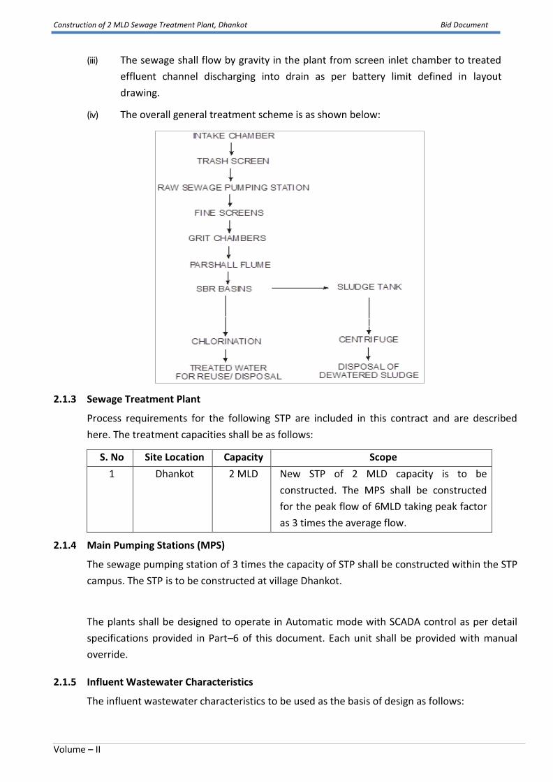
(iii) The sewage shall flow by gravity in the plant from screen inlet chamber to treated
effluent channel discharging into drain as per battery limit defined in layout
drawing.
(iv) The overall general treatment scheme is as shown below:
2.1.3 Sewage Treatment Plant
Process requirements for the following STP are included in this contract and are described
here. The treatment capacities shall be as follows:
S. No Site Location Capacity Scope
1 Dhankot 2 MLD New STP of 2 MLD capacity is to be
constructed. The MPS shall be constructed
for the peak flow of 6MLD taking peak factor
as 3 times the average flow.
2.1.4 Main Pumping Stations (MPS)
The sewage pumping station of 3 times the capacity of STP shall be constructed within the STP
campus. The STP is to be constructed at village Dhankot.
The plants shall be designed to operate in Automatic mode with SCADA control as per detail
specifications provided in Part–6 of this document. Each unit shall be provided with manual
override.
2.1.5 Influent Wastewater Characteristics
The influent wastewater characteristics to be used as the basis of design as follows:
Construction of 2 MLD Sewage Treatment Plant, Dhankot Bid Document
Volume – II
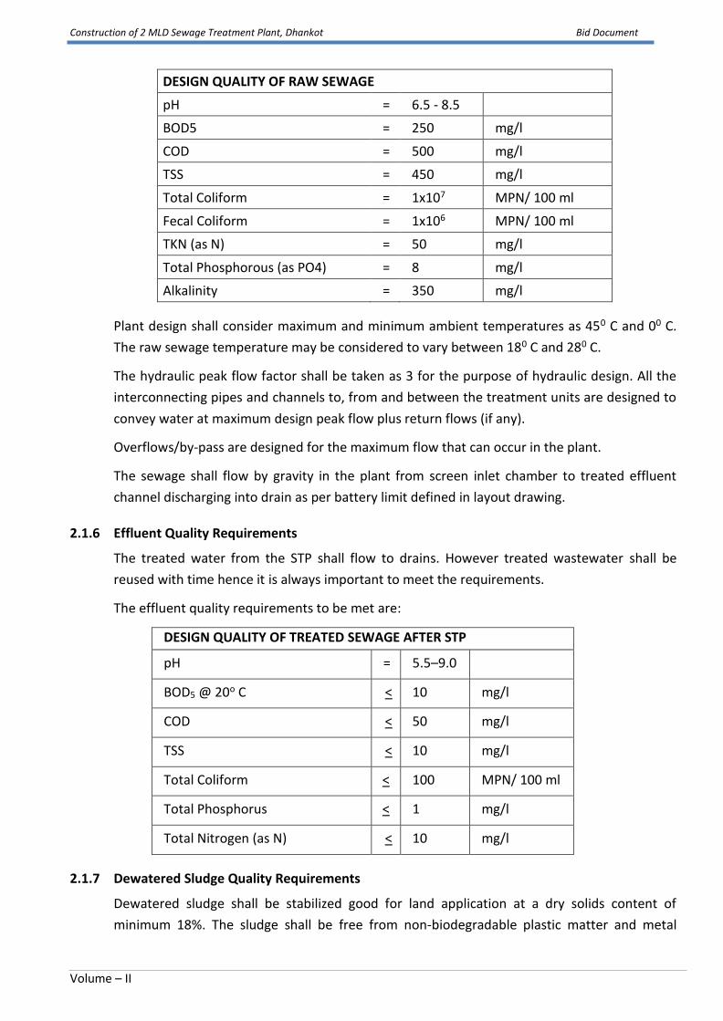
DESIGN QUALITY OF RAW SEWAGE
pH = 6.5 - 8.5
BOD5 = 250 mg/l
COD = 500 mg/l
TSS = 450 mg/l
Total Coliform = 1x10⁷ MPN/ 100 ml
Fecal Coliform = 1x10⁶ MPN/ 100 ml
TKN (as N) = 50 mg/l
Total Phosphorous (as PO4) = 8 mg/l
Alkalinity = 350 mg/l
Plant design shall consider maximum and minimum ambient temperatures as 450 C and 00 C.
The raw sewage temperature may be considered to vary between 180 C and 280 C.
The hydraulic peak flow factor shall be taken as 3 for the purpose of hydraulic design. All the
interconnecting pipes and channels to, from and between the treatment units are designed to
convey water at maximum design peak flow plus return flows (if any).
Overflows/by-pass are designed for the maximum flow that can occur in the plant.
The sewage shall flow by gravity in the plant from screen inlet chamber to treated effluent
channel discharging into drain as per battery limit defined in layout drawing.
2.1.6 Effluent Quality Requirements
The treated water from the STP shall flow to drains. However treated wastewater shall be
reused with time hence it is always important to meet the requirements.
The effluent quality requirements to be met are:
DESIGN QUALITY OF TREATED SEWAGE AFTER STP
pH = 5.5–9.0
BOD5 @ 20o C < 10 mg/l
COD < 50 mg/l
TSS < 10 mg/l
Total Coliform < 100 MPN/ 100 ml
Total Phosphorus < 1 mg/l
Total Nitrogen (as N) < 10 mg/l
2.1.7 Dewatered Sludge Quality Requirements
Dewatered sludge shall be stabilized good for land application at a dry solids content of
minimum 18%. The sludge shall be free from non-biodegradable plastic matter and metal
Construction of 2 MLD Sewage Treatment Plant, Dhankot Bid Document
Volume – II
objects so that it is safe for application in the fields or green belts.
2.1.8 Plant Layout and Hydraulic Profile
Site area layout for each STP has been provided in Volume– III of these bid documents. These
drawings shall be considered representative only. In the event of any conflicts between
information in the drawings and various clauses enumerated of forthcoming paras of this Part-
2 “Process Requirements” shall govern.
• The Contractor shall ensure that the layouts and hydraulic profiles submitted as part of
the Contractor’s bid comply with the following specific constraints and all other
requirements described in the Bid Documents:
• For all structures containing water or process liquid, the minimum freeboard (distance
by which top of wall is higher than the maximum water surface level at receiving water
high flood level and peak plant flow shall be 500mm unless specified otherwise.
• The Contractor shall provide at STP necessary facilities for overflow bypass of the
process liquid at various locations in the flow path as indicated below:
✓ Bypass at Sewage Pumping Station
Topographical survey information, benchmarks, contour maps, geotechnical/ soil
investigations, and effluent receiving water body high flood level (HFL) elevations for
the STP sites to be collected by the bidder on its own.
All aspects of Contractor’s technical design shall also be subject to review and approval
by Employer and Engineer.
2.1.8.1 Plant Layout and Orientation
The STP components shall be laid out and fully contained within the respective designated site
boundaries so as to logically interface with any and all existing infrastructure that may be
present at the site and that must remain in service. Contractor’s proposed site layout shall
clearly show the space allocated for all plant components, including those components and/or
unit processes that may be designated for future construction or installation. Setbacks and
clearances from the site boundary shall be provided as appropriate and as required by law. All
existing utilities (including water, sewer, power, or others, whether overhead or underground
and whether physically located on the site or not) requiring to be relocated to accommodate
the Contractor’s proposed and approved site layout shall be relocated by the Contractor at no
additional cost and without interrupting provision of such utility services to users and
customers. Such relocations shall be fully coordinated with the Department.
The plant layout shall adhere to the following general rules:
• Minimum clear distance provided to permit safe and convenient access for operation and
maintenance shall be 3 m between adjacent treatment units or fixed structures and 1 m
between pieces of equipment
• An area adjacent to all mechanical equipment shall be provided as a maintenance lay

Construction of 2 MLD Sewage Treatment Plant, Dhankot Bid Document
Volume – II
down area
• All electrical equipment (except for motors) shall be located above the high flood level
elevation for the site or for the effluent receiving water body, whichever is higher.
2.1.9 Modular Design, Construction, and Operation for Reliability, Redundancy, Turndown, and Easy Future Expansion
1. All components of STP that are not easy to replace or expand in the future, including but
not limited to below-ground wet wells or other below-ground structures; header pipes;
and collection and distribution and other common channels shall be designed and
constructed to provide the ultimate build out design capacity in this contract. For STP
components that can be easily expanded in the future, the design and construction of the
initial design capacity under this contract shall be performed such that future expansion,
where required, to the ultimate build out capacity can be accomplished easily and in a
modular manner while maintaining the initial capacity fully operational at all times. Space
shall be reserved within the STP site boundary for the required future modules, and the
design shall include features (including but not limited to caps or blind flanges for common
header pipes and knock-out and stub walls for common channels and other
structures) that will allow easy future extension/expansion with minimal disturbance
to initial components. The contractor submittals and drawings shall clearly show and
describe such features as well as the space reserved for future expansion. The design shall
ensure that all future modules can be fully integrated with the initial modules to provide a
single plant and a single process stream – multiple parallel plants will not be allowed. Such
integration shall be accomplished by means of common collection and distribution
channels, boxes, or header pipes in between unit processes that combine the flow from
multiple modules of the upstream unit process and redistribute it to multiple modules of
the downstream unit process. Designs where each future module operates independently
of other modules will not be allowed and will not be accepted by the Employer.
2. Main sewage pumping station in this contract shall be designed and constructed for their
full respective Ultimate Build out Design Capacities, except that the number of pumps and
motors shall be limited to that needed for the Initial Design Capacity, with space reserved
for additional future identically-sized units required to provide the full Ultimate Build out
Design Capacity.
3. Further for all components under this contract, the capacity to be provided shall be
designed and constructed using multiple, suitably sized unit process modules to ensure
reliability, redundancy, and appropriate turndown for optimum capacity utilization and
process efficiency.
2.1.10 Demolition of or Interfaces and Tie-Ins with Existing Facilities
Where necessary existing facilities that are to be demolished shall be properly
decommissioned, removed, and appropriately disposed of by the Contractor in accordance

Construction of 2 MLD Sewage Treatment Plant, Dhankot Bid Document
Volume – II
with all applicable laws, regulations, and standards. Items, components, or materials, whether
buried, exposed, submerged, or otherwise, shall not be abandoned or left on site unless
explicitly indicated in the Tender Documents. For facilities that are to be eventually
demolished but must remain in service until alternate or replacement facilities are constructed
and commissioned, whether under this contract or a different contract, the Contractor shall
ensure that the facilities are protected and remain functional until such time as the alternate
or replacement facilities are constructed, tested, commissioned, and accepted by Employer.
All existing facilities that must remain in service permanently shall be protected by the
Contractor such that they remain fully functional, operable, and serviceable throughout
construction, testing, and commissioning of the new facilities. The Contractor shall be fully
responsible for installation and, if necessary, ultimate removal of any temporary facilities or
connections (piping, utilities, power, controls, etc.) that may be necessary to maintain existing
facilities fully operational throughout construction and commissioning. Temporary or
permanent interfaces between existing and new facilities may involve making connections or
“tie-ins” to existing live structures, piping, wiring, cabling, equipment or other components.
The Contractor shall be fully responsible for detailed design, planning, and implementation of
such interfaces in a safe and secure manner.
2.1.11 Process and Facilities Description
This Process and Facilities description is intended to provide a general indication of the
processes and a type of facilities that the Contractor shall be required to design, construct, and
operate, and applies to STP in this contract unless specifically indicated otherwise. The
Contractor shall use this description together with other specific information for STP provided
elsewhere in these bid documents, all of which are integral to this Process and Facilities
Description and are incorporated herein by reference. The Contractor may propose alternate
implementation details such as detailed site layouts and elevations of specific components.
However, the Contractor shall strictly comply with the specified treatment concept, treatment
unit processes, flow configuration (connectivity between unit processes and facilities),
performance requirements (such as effluent and sludge quality and equipment efficiencies),
and design criteria (such as design operating conditions, various process loading rates and/or
detention times, volumes, and dimensions where specified) such as the minimum
requirements.
2.1.12 Design/Sizing Criteria and Other Requirements for various Units/Processes
(i) The general hydraulic capacities of the plant shall be considered in accordance with
internal flows which shall vary according to operating pump capacities and durations,
re-circulations and decanting cycle durations. In general units from Inlet chamber to
SBR basins shall be made in be in R.C.C- M-30 in Sulphate Resistance Cement (SRC)
including sludge treatment units. All water retaining structures shall be in accordance
with the tender specifications.

Construction of 2 MLD Sewage Treatment Plant, Dhankot Bid Document
Volume – II
1.0 Receiving Chamber
The gravity outfall sewer will discharge the raw sewage into a Receiving chamber. The function of the
receiving chamber is to distribute the flow for process units. Inspection as well as operation by standing on a
platform constructed at a suitable elevation adjoining and circumventing the inlet chamber. The receiving
chamber shall be of adequate size to meet the requirements of workability inside it. The receiving chamber
shall be open to sky and shall be water tight to prevent seepage of the sewage out of the inlet chamber. The
entire construction is in M30 grade concrete and as per IS 3370. The information on receiving chamber is
summarized in the following table.
Peak Flow 250 m3/h
No. of Units 1
MOC RCC
Detention Time 30 s at peak flow
Dimension 1.1 m x 1.3 m x 1.5m SWD
2.0 Coarse Screen Channel
One mechanical screen of 20 mm spacing shall be designed for peak flow.Any material like plastic bags etc.,
will be removed in the screen. Mechanical screens shall be operated through timers, so that, the raking
mechanisms runs at certain interval.
The mechanical and manual bar screens shall be of 10 mm thick Stainless Steel (SS304) flats with 20 mm
clear opening. Manually operated CI gates are provided at the upstream and downstream ends to regulate
the flow.
The entire structure is to be M 30 concrete and as per IS 3370 including the platform for the gates.
Information related to fine screen is summarized below:
Number of screen channels 2 nos.
Number of Screens 1 Mechanical working + 1 Manual standby
Design flow considered to each
channel
0.069 m3/sec
Approach Velocity at Average
Flow (m/sec.)
0.3 minimum
Velocity through Screen at
Average Flow (m/sec.)
0.6 minimum
Velocity through Screen at Peak
Flow (m/sec.)
1.2 maximum
Opening in screen 20 mm
Channel Size 5.5 m x 0.5 m wide x 0.6 m water depth + 0.3 m Free
board
MOC SS 304
Operation Timer operated
Reduction Gear Box Type Worm / helical
Reduction gear Material of
Construction
Standard
Accessories Conveyor belt for conveying away the screened
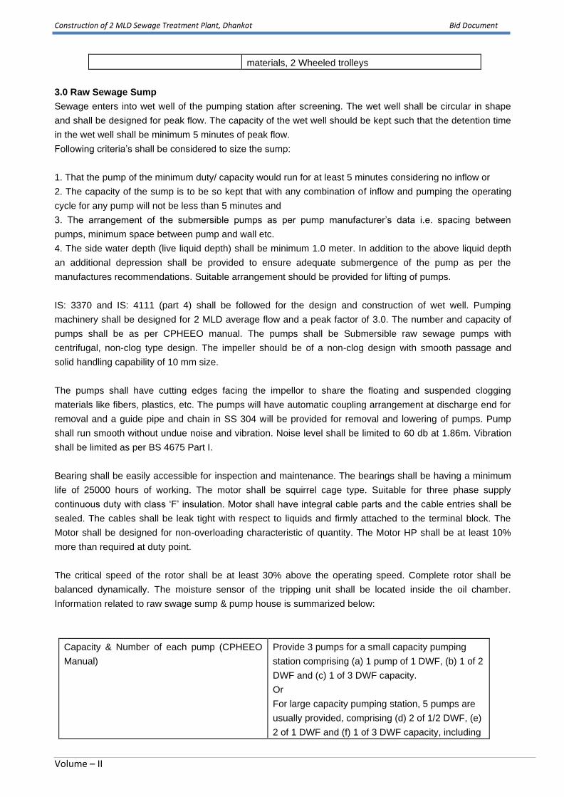
Construction of 2 MLD Sewage Treatment Plant, Dhankot Bid Document
Volume – II
materials, 2 Wheeled trolleys
3.0 Raw Sewage Sump
Sewage enters into wet well of the pumping station after screening. The wet well shall be circular in shape
and shall be designed for peak flow. The capacity of the wet well should be kept such that the detention time
in the wet well shall be minimum 5 minutes of peak flow.
Following criteria’s shall be considered to size the sump:
1. That the pump of the minimum duty/ capacity would run for at least 5 minutes considering no inflow or
2. The capacity of the sump is to be so kept that with any combination of inflow and pumping the operating
cycle for any pump will not be less than 5 minutes and
3. The arrangement of the submersible pumps as per pump manufacturer’s data i.e. spacing between
pumps, minimum space between pump and wall etc.
4. The side water depth (live liquid depth) shall be minimum 1.0 meter. In addition to the above liquid depth
an additional depression shall be provided to ensure adequate submergence of the pump as per the
manufactures recommendations. Suitable arrangement should be provided for lifting of pumps.
IS: 3370 and IS: 4111 (part 4) shall be followed for the design and construction of wet well. Pumping
machinery shall be designed for 2 MLD average flow and a peak factor of 3.0. The number and capacity of
pumps shall be as per CPHEEO manual. The pumps shall be Submersible raw sewage pumps with
centrifugal, non-clog type design. The impeller should be of a non-clog design with smooth passage and
solid handling capability of 10 mm size.
The pumps shall have cutting edges facing the impellor to share the floating and suspended clogging
materials like fibers, plastics, etc. The pumps will have automatic coupling arrangement at discharge end for
removal and a guide pipe and chain in SS 304 will be provided for removal and lowering of pumps. Pump
shall run smooth without undue noise and vibration. Noise level shall be limited to 60 db at 1.86m. Vibration
shall be limited as per BS 4675 Part I.
Bearing shall be easily accessible for inspection and maintenance. The bearings shall be having a minimum
life of 25000 hours of working. The motor shall be squirrel cage type. Suitable for three phase supply
continuous duty with class ‘F’ insulation. Motor shall have integral cable parts and the cable entries shall be
sealed. The cables shall be leak tight with respect to liquids and firmly attached to the terminal block. The
Motor shall be designed for non-overloading characteristic of quantity. The Motor HP shall be at least 10%
more than required at duty point.
The critical speed of the rotor shall be at least 30% above the operating speed. Complete rotor shall be
balanced dynamically. The moisture sensor of the tripping unit shall be located inside the oil chamber.
Information related to raw swage sump & pump house is summarized below:
Capacity & Number of each pump (CPHEEO
Manual)
Provide 3 pumps for a small capacity pumping
station comprising (a) 1 pump of 1 DWF, (b) 1 of 2
DWF and (c) 1 of 3 DWF capacity.
Or
For large capacity pumping station, 5 pumps are
usually provided, comprising (d) 2 of 1/2 DWF, (e)
2 of 1 DWF and (f) 1 of 3 DWF capacity, including

Construction of 2 MLD Sewage Treatment Plant, Dhankot Bid Document
Volume – II
standby.
or
Alternatively, the number of pumps can also be
chosen to be in multiples of DWF flow and provide
a 100% standby capacity for peak flow.
Head 15 m
Wet Well Dimensions 5.5Dia x1.0 m SWD
Detention time 5 min at peak flow
MOC CI casing, CF-8M impeller, SS-410 shaft
Insulation Class F
Protection IP 68
Hrs of operation 24 hrs
Type of pump Centrifugal Submersible Type
MOC of pumps CI
MOC of gates CI
Level switch Level switch in pump for tripping off at low level
and high level alarm
Accessories MS rigid type base plate suitable for mounting
both pump and motor, flexible coupling, coupling
guards, foundation bolts.
4.0 Valve Chamber
Valve chamber of size 4.0 x 2.0 x 0.3 m shall be provided as per the attached drawing
5.0 Flow meter chamber
Valve chamber of size 3.1 x 1.75 x 2.1 m shall be provided as per the attached drawing. Online Flow
measurement shall be done by installing an ultrasonicflow measurement device flow meter chamber.
6.0 DG Room
There should be the provision of 1W+1SB silet DG with proper acoustics. DG Room of size 4.8 x 3.15 x 3.5
m shall be provided as per the attached drawing.
7.0 Control Room
ControlRoom of size 4.8 x 3.15 x 3.5 m shall be provided as per the attached drawing.
8.0 Security Cabin
Security Cabin (Guard Room) of size 6.0 x 3.0 x 3.5 m shall be provided as per the attached drawing.
INDICATIVE CIVIL ITEMS FOR 2 MLD MPS
S.No DESCRIPTION QTY. L/DIA
(m)
B
(m)
SWD
(m)
F.B
(m)
1 RECEIVING CHAMBER 1 1.3 1.1 4.5 -
2 SCREEN CHANNEL (Mechanical & Manual) 2 5.5 0.5 0.6 -
3 COMMON OUTLET CHAMBER 1 1.00 1.75 0.40 -

Construction of 2 MLD Sewage Treatment Plant, Dhankot Bid Document
Volume – II
4 WET WELL 1 5.5 dia 1.0 -
5 VALVE CHAMBER 1 4.00 2.00 0.30
6 FLOW METER CHAMBER 1 3.10 1.75 2.10 -
7 DG ROOM 1 4.80 3.15 3.50 -
8 CONTROL ROOM 1 4.80 3.15 3.50
9
SECURITY CABIN (GUARD ROOM) 1 6.00 3.00 3.50 -
10 DEVELOPMENT WORK FOR STP
(LEVELLING,
INTERNAL ROADS & PATHS, STORM WATER
DRAIN, HORTICULTURE & SIGN BOARD)
1
242
sqm
9.0 Pumped Waste Water Conveyance
The pumped flow from the pumping station to the elevated head works inlet chamber of the plant shall be
taken through a CI / DI K-9 Class pipeline of minimum dia 200mm. The rising main shall be designed for
2.0 MLD average flow with a peak factor of 3.0
(a) The pipeline shall be adequately sized to have a minimum velocity of at least 1.2 m/s at minimum
flow conditions and not more than 2.5 m/sec at pumped peak flow.
(b) The pump head shall be adequately sized to give a residual discharge head as per CPHEEO manual.
10. Inlet Chamber of STP
Stilling Chamber will receive raw sewage from the raw sewage pumping station. Stilling chamber shall be
designed for peak flow of 6.0 MLD. The entire construction is in M30 grade concrete and as per IS 3370.
RCC access platform minimum 1000 wide with railing as per specifications shall be provided on one side of
the chamber: RCC staircase 900 mm wide shall be provided for access from ground level to the top of the
unit & to the operating platforms. Information related to inlet chamber is summarized below:
Total Average flow 2.0MLD
Peak factor 3
Number of Units One
Detention period 30 sec at peak flow
Min Free board 0.5 m
Size of inlet chamber 1.1 m x 1.3 m x 1.5 m water depth + 0.5 m
FB

Construction of 2 MLD Sewage Treatment Plant, Dhankot Bid Document
Volume – II
11Mechanical Fine Screen Channels
Oneworking mechanical screens of 6 mm spacing with one manual standby screen of 10mm spacing are
proposed in the screen channels. The screen channels shall be designed for peak flow of 6.0 MLD.
The clear opening for mechanical screen shall be 6mm. The mechanical and manual bar screens shall be of
3 mm and 8-10 mm thick Stainless Steel (SS304) flats. Conveyor Belt and chute arrangement shall be
provided to take the screenings to the screenings dropped from chute will be collected in an approx.0.5 m3
capacity. This trolley will be housed in a roofed enclosure with proper access, screen washing arrangement
and drain. Manually operated aluminiumgates are provided at the upstream and downstream ends to
regulate the flow.
RCC Platforms shall be provided at the upper level to enable operation of the railings shall be provided
around the entire periphery of the as well as for the platform. The entire structure is to be M 30 concrete and
as per IS 3370 including the platform for the gates. Information related to fine screen is summarized below:
Number of screen channels 2 nos.
Number of Screens 1 Mechanical working + 1 Manual standby
Design flow considered to each channel 0.069 m3/sec
Approach Velocity at Average Flow
(m/sec.)
0.3 minimum
Velocity through Screen at Average Flow
(m/sec.)
0.6 minimum
Velocity through Screen at Peak Flow
(m/sec.)
1.2 maximum
Opening in screen 6 mm for mechanical and 10 mm for manual
Channel Size 6.5 m x 0.5 m wide x 0.6 m water depth + 0.3 m Free
board
MOC MS with proper coating
Operation Timer operated
Reduction Gear Box Type Worm / helical
Reduction gear Material of Construction Standard
Accessories Conveyor belt for conveying away the screened
materials, 2 Wheeled trolleys
12. Mechanical Grit Chambers
One working and one Standby mechanical grit chamber is proposed after screen mechanical unit. The
mechanical grit chambers shall Square Mechanical Detritus Tank designed for peak flow of 6.0 MLD.Detritus
tank chamber shall have the following:
One tapered inlet channel running along one side with deflectors for entry sewage into the grit chamber.
The minimum SWD of the units shall be adopt on the basis of design requirement of the unit.
One tapered outlet channel for collecting the degritted sewage, which overflow over a weir into the outlet
channel. Outlet channel of adequate size and she to ensure that no settling takes place.
One sloping grit classifying channel into which the collected grit will classified.
The grit from classifier will be collected in a wheeled trolley of approx. 0.5-1.0 m3 capacity. This trolley
will be housed in a roofed enclosure with proper access, grit washing arrangement and drain.
A grit scraping mechanism.
Adjustable influent deflector.

Construction of 2 MLD Sewage Treatment Plant, Dhankot Bid Document
Volume – II
Reciprocating rake mechanism to remove the grit.
Organic matter return pump
Manually operated Aluminum gates shall be provided at the entrance and at the outlet of the chamber. To
enable easy operation of the gates, RCC platforms with Gl railing shall be provided at the upper level. Also
access is provided from this level to 1 mechanism support beam of the grit chamber. The entire construction
shall be M30 grade concrete and as per IS 3370.
13. SBR Process Units
13.1 SBR Tanks
The biological treatment section comprising SBR process has to be installed and equipped for the present
average flow of 2.0 MLD only. However, suitable space provisions shall be made for the future unit while
planning the layout and civil works shall be carried out in such a way that the additional unit can be
integrated into the system without any shut downs.
The complete biological system has to be designed for handling peak flow capacity. The SBR design
shall be such that, proposed cycle time, number of cycles per day and phase time within each cycle
shall all remain fixed up to the specified design peak flow. No acceleration or premature advancing of
cycles shall be allowed up to the peak flow.
Minimum Two tanks shall be provided. In addition, 0.5m free board shall be provided to each tank.
Maximum liquid depth of tank shall be restricted to 6m.
SBR Process basins will be constructed in M 30 grade concrete and as per IS 3370. RCC staircase
900 mm wide is provided to each basin for access from the ground level to the operating platforms.
All platforms and walkways shall be provided hand railings as per tender specifications. 1.2 m Plinth
protection along periphery shall be provided as per technical specifications.
The system should work on an intermittent influent condition. No influent / effluent equalization tanks
or flash filling is accepted.The design criteria as per CPHEEO Manual is as follows;
S. No. Parameters units Intermittent Flow and
Intermittent Decant
1. F/M ratio d-1 0.05-0.3
2. Sludge Age d 14-20 days
3. Sludge Yield Kg dry solids/kg BOD 0.75-1.0
4. MLSS mg/L 4000-5000
5. Cycle Time h 4-6
No. of grit chambers 2 no (1 Mechanical W+1 Manual SB)
Design flow consider for grit chamber 0.069 m3/s
Type Square type RCC construction
SOR 960 m3/m2.d
Particle size to be removed 0.15 mm or more
Grit storage space 200 mm
Free board to be provided 300 mm
Dimensions 2.5 m x 2.5 m x 1.0 m water depth + 0.3 m
Free Board
MOC RCC
Accessories Scraper mechanism, screw conveyor,
chute for grit dumping
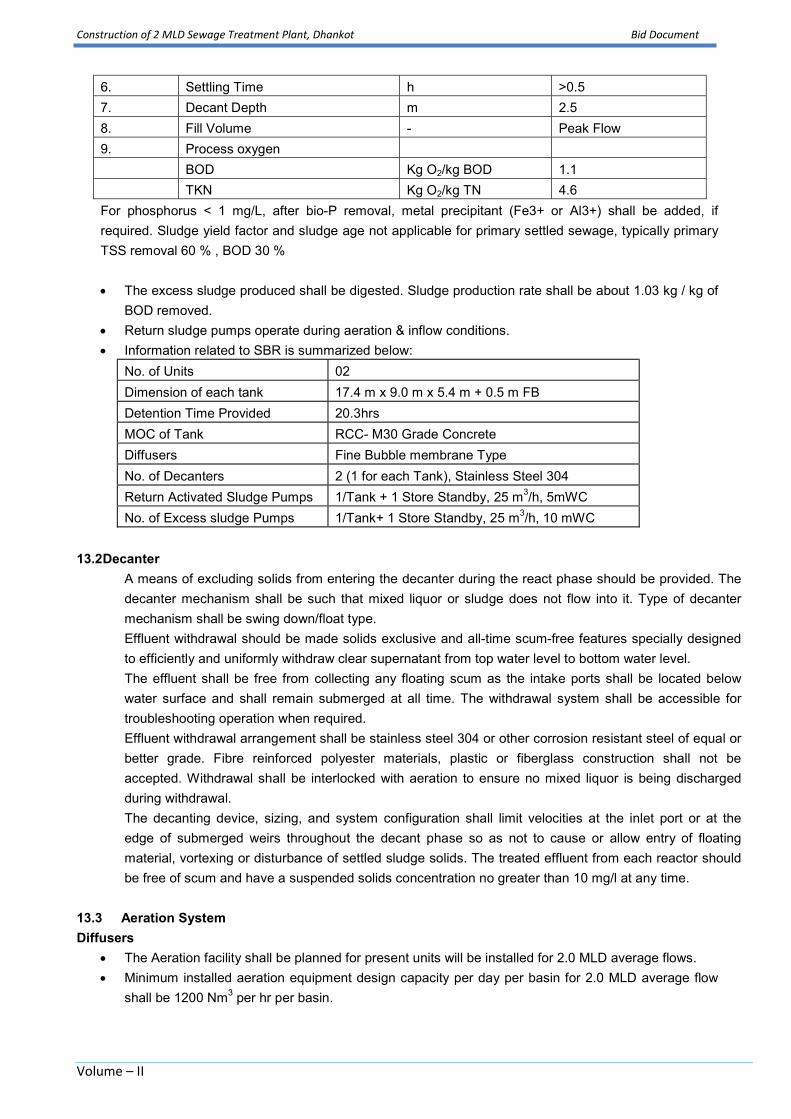
Construction of 2 MLD Sewage Treatment Plant, Dhankot Bid Document
Volume – II
6. Settling Time h >0.5
7. Decant Depth m 2.5
8. Fill Volume - Peak Flow
9. Process oxygen
BOD Kg O2/kg BOD 1.1
TKN Kg O2/kg TN 4.6
For phosphorus < 1 mg/L, after bio-P removal, metal precipitant (Fe3+ or Al3+) shall be added, if
required. Sludge yield factor and sludge age not applicable for primary settled sewage, typically primary
TSS removal 60 % , BOD 30 %
The excess sludge produced shall be digested. Sludge production rate shall be about 1.03 kg / kg of
BOD removed.
Return sludge pumps operate during aeration & inflow conditions.
Information related to SBR is summarized below:
No. of Units 02
Dimension of each tank 17.4 m x 9.0 m x 5.4 m + 0.5 m FB
Detention Time Provided 20.3hrs
MOC of Tank RCC- M30 Grade Concrete
Diffusers Fine Bubble membrane Type
No. of Decanters 2 (1 for each Tank), Stainless Steel 304
Return Activated Sludge Pumps 1/Tank + 1 Store Standby, 25 m3/h, 5mWC
No. of Excess sludge Pumps 1/Tank+ 1 Store Standby, 25 m3/h, 10 mWC
13.2 Decanter
A means of excluding solids from entering the decanter during the react phase should be provided. The
decanter mechanism shall be such that mixed liquor or sludge does not flow into it. Type of decanter
mechanism shall be swing down/float type.
Effluent withdrawal should be made solids exclusive and all-time scum-free features specially designed
to efficiently and uniformly withdraw clear supernatant from top water level to bottom water level.
The effluent shall be free from collecting any floating scum as the intake ports shall be located below
water surface and shall remain submerged at all time. The withdrawal system shall be accessible for
troubleshooting operation when required.
Effluent withdrawal arrangement shall be stainless steel 304 or other corrosion resistant steel of equal or
better grade. Fibre reinforced polyester materials, plastic or fiberglass construction shall not be
accepted. Withdrawal shall be interlocked with aeration to ensure no mixed liquor is being discharged
during withdrawal.
The decanting device, sizing, and system configuration shall limit velocities at the inlet port or at the
edge of submerged weirs throughout the decant phase so as not to cause or allow entry of floating
material, vortexing or disturbance of settled sludge solids. The treated effluent from each reactor should
be free of scum and have a suspended solids concentration no greater than 10 mg/l at any time.
13.3 Aeration System
Diffusers
The Aeration facility shall be planned for present units will be installed for 2.0 MLD average flows.
Minimum installed aeration equipment design capacity per day per basin for 2.0 MLD average flow
shall be 1200 Nm3 per hr per basin.
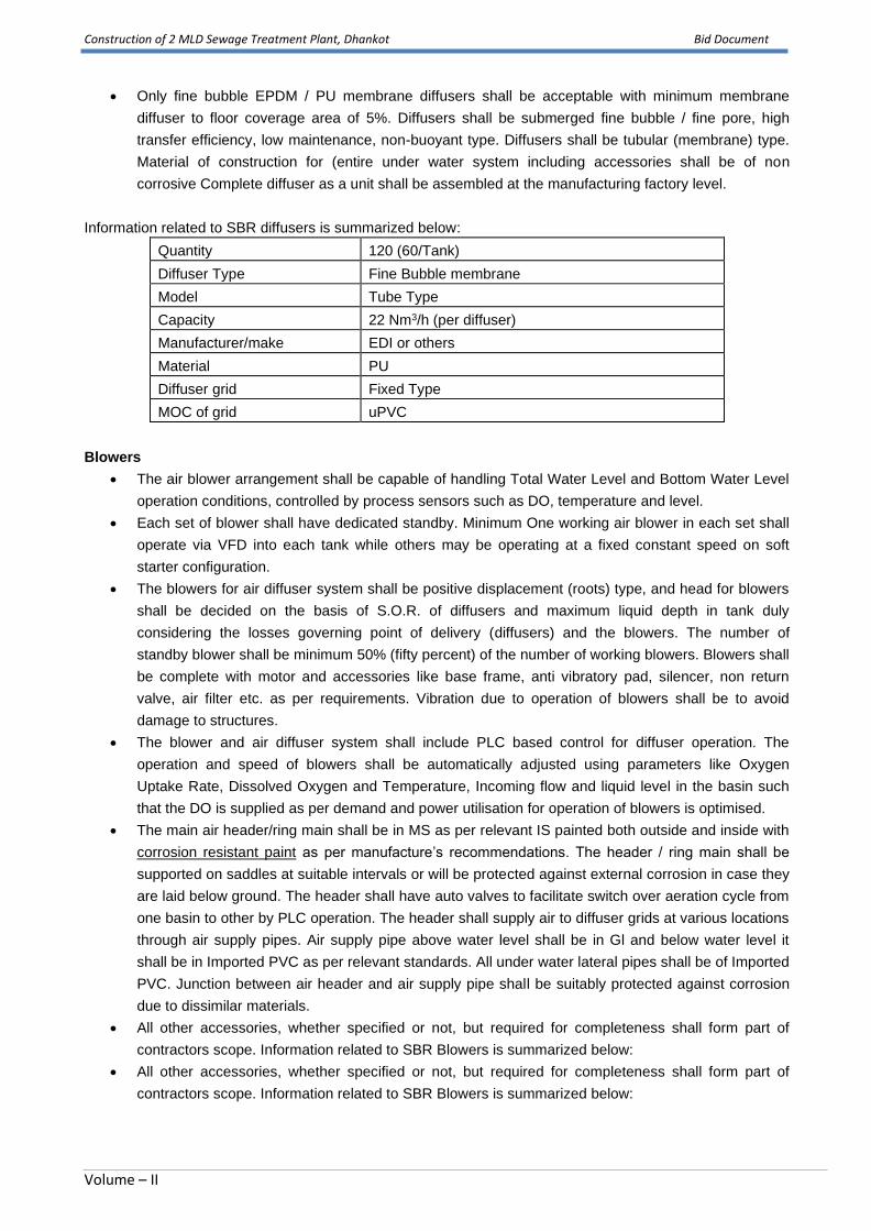
Construction of 2 MLD Sewage Treatment Plant, Dhankot Bid Document
Volume – II
• Only fine bubble EPDM / PU membrane diffusers shall be acceptable with minimum membrane
diffuser to floor coverage area of 5%. Diffusers shall be submerged fine bubble / fine pore, high
transfer efficiency, low maintenance, non-buoyant type. Diffusers shall be tubular (membrane) type.
Material of construction for (entire under water system including accessories shall be of non
corrosive Complete diffuser as a unit shall be assembled at the manufacturing factory level.
Information related to SBR diffusers is summarized below:
Quantity 120 (60/Tank)
Diffuser Type Fine Bubble membrane
Model Tube Type
Capacity 22 Nm3/h (per diffuser)
Manufacturer/make EDI or others
Material PU
Diffuser grid Fixed Type
MOC of grid uPVC
Blowers
• The air blower arrangement shall be capable of handling Total Water Level and Bottom Water Level
operation conditions, controlled by process sensors such as DO, temperature and level.
• Each set of blower shall have dedicated standby. Minimum One working air blower in each set shall
operate via VFD into each tank while others may be operating at a fixed constant speed on soft
starter configuration.
• The blowers for air diffuser system shall be positive displacement (roots) type, and head for blowers
shall be decided on the basis of S.O.R. of diffusers and maximum liquid depth in tank duly
considering the losses governing point of delivery (diffusers) and the blowers. The number of
standby blower shall be minimum 50% (fifty percent) of the number of working blowers. Blowers shall
be complete with motor and accessories like base frame, anti vibratory pad, silencer, non return
valve, air filter etc. as per requirements. Vibration due to operation of blowers shall be to avoid
damage to structures.
• The blower and air diffuser system shall include PLC based control for diffuser operation. The
operation and speed of blowers shall be automatically adjusted using parameters like Oxygen
Uptake Rate, Dissolved Oxygen and Temperature, Incoming flow and liquid level in the basin such
that the DO is supplied as per demand and power utilisation for operation of blowers is optimised.
• The main air header/ring main shall be in MS as per relevant IS painted both outside and inside with
corrosion resistant paint as per manufacture’s recommendations. The header / ring main shall be
supported on saddles at suitable intervals or will be protected against external corrosion in case they
are laid below ground. The header shall have auto valves to facilitate switch over aeration cycle from
one basin to other by PLC operation. The header shall supply air to diffuser grids at various locations
through air supply pipes. Air supply pipe above water level shall be in Gl and below water level it
shall be in Imported PVC as per relevant standards. All under water lateral pipes shall be of Imported
PVC. Junction between air header and air supply pipe shall be suitably protected against corrosion
due to dissimilar materials.
• All other accessories, whether specified or not, but required for completeness shall form part of
contractors scope. Information related to SBR Blowers is summarized below:
• All other accessories, whether specified or not, but required for completeness shall form part of
contractors scope. Information related to SBR Blowers is summarized below:

Construction of 2 MLD Sewage Treatment Plant, Dhankot Bid Document
Volume – II
Quantity 2 Working + 1Standby
Type Twin Lobe
Discharge Pressure 0.6 kg/cm2
Airflow 600 Nm3/h
Chain Pulley Blocks 3 Ton, 6 m Lift
Accessories VFD, soft starters., V-Belt drive, Flexible expansion
joints, Drive, Inlet silencer, Discharge silencer
pressure relief valve etc.,
13.4 Surplus Activated Sludge (SAS) Pumps
Surplus Activated sludge pumps shall be provided for each basin. The pump shall be of submersible /
horizontal centrifugal type suitable for handling biological sludge of 1- 2% solids consistency. Capacity and
heads shall be decided based on SBR Process requirements. Each SBR Process basin shall be provided
with suitable lifting arrangements to facilitate lifting of pump, if required for maintenance. Information related
to Excess sludge pumps is summarized below:
Type Submersible non-clog wastewater pumps
No. of pumps 2 nos.+ 1 Store Standby
Capacity of each pump 25 m3/h
Head 10 m
Speed (nominal) 980 RPM
MOC ASTM A-48, Class 30B
Hrs of operation 10 min/cycle
13.5Return Sludge Pumps
Return sludge pumps shall be provided for each basin. The pump shall be of submersible / horizontal
centrifugal type suitable for handling biological sludge of 1 – 2% solids consistency. Capacity and heads
shall be decided based on SBR Process requirements. Each SBR Process basin shall be provided with
suitable lifting arrangements to facilitate lifting of pump, if required for maintenance. Information related to
Returns sludge pumps is summarized below:
Type Submersible non-clog wastewater pumps
No. of pumps 2 nos.+ 1 Store Standby
Capacity of each pump 25 m3/h
Head 5 m
Speed (nominal) 980 RPM
MOC ASTM A-48, Class 30B
Hrs of operation 60-90 min/cycle (During Inflow & Aeration)
13.6 Automation and Control of SBR Unit
• PLC based automation system with application software to control all pumps, valves, blowers, VFD,
decanters, limit switches and probes as per bidder’s design including I/Os with 20 % spares, power
supplies, UPS.
• HMI Panel to comprise up-to-date standard PC with monitor, printer, mouse, internet connection,
RS-view, RS-links (gateway version), entire process and operator software with dynamic flow charts,
pictures, screens, alarms, historical trends, reports etc.

Construction of 2 MLD Sewage Treatment Plant, Dhankot Bid Document
Volume – II
• SCADA based Automation system to monitor continuously in each tank the followings:
a. Filling volume
b. Filling quantity
c. Discharge quantity
d. DO-level
e. Temperature
f. Oxygen Uptake Rate
g. Energy requirements
h. Blower speeds
i. Decanter speed
j. Equipment operation hours
14. FeCl3 Dosing System
FeCl3 dosing is provided in aeration tank for the phosphorus precipitation. The FeCl3 dosing system consists
of one 500 L FRP for supplying FeCl3 coagulant through coagulant dosing pumps to SBR. The coagulants
are dosed by PVC pipes. The coagulant storage capacity in tank shall be more than 3 days. Hydraulic
diaphragm pump for accurate dosing of FeCl3 shall incorporate a highly reliable driving unit and unique
hydraulic system to assure high, stable performance over long term continuous operation.
Specifications and requirement related to FeCl3 dosing system is summarized herewith;
COAGULANT DOSING SYSTEM
Model Vertical/horizontal dosing system
Chemical FeCl3
Tank
Number of Tanks 1
Volume, litres 500
MOC FRP
Agitator
Power 0.5
RPM 1000 rpm
Dosing Pump
No. 1 W + 1 S
Capacity ,lph 20
Head, bar 2
MOC PP
Electrical supply 220 V AC+ 10 Single
Phase
15. Chlorine Contact Tank:
Decanted treated water from SBR Process shall be taken to chlorine contact tank by RCC channel/pipe.
Tank shall be provided for dosing of chlorine from the chlorination system to the sewage from SBR Process.
The tank shall be constructed in M 30 grade concrete and as per IS 3370. RCC platform 1000mm as per
specifications shall be provided. RCC staircase 900 mm wide shall be provided for access from the ground
level to the top of the unit and to the operating platforms.

Construction of 2 MLD Sewage Treatment Plant, Dhankot Bid Document
Volume – II
Baffle walls shall be provided to achieve proper disinfection. The baffle walls shall be constructed in M 30
grade concrete and 20 cm thick plaster in CM 1:3 on either side. Information related to chlorination tank is
summarized below:
No. 1
Design Flow 167 m3/h (Decant Flow)
MOC RCC
Internal mixing arrangement Longitudinal Baffle Wall
Dimensions 9.0m x 5.0 m x 2.0 m (Water Depth)
Free Board 0.5 m
16. Chlorine House
There will be one chlorinator with evaporator in the chlorination plant. Liquid chlorine shall be drawn from
chlorine tonner and it will then passed through evaporator for vaporization. The gaseous chlorine shall be
injected through ejector after mixing with water. Ultimate chlorine solution shall be dosed in chlorine contact
tank. In chlorine contact tank, chlorine solution diffuser shall be provided for proper mixing of the solution.
Besides chlorinators in chlorination plant there will be 2nos chlorine tonners to supply chlorine. One toner
shall be connected to the chlorinator and other shall remain as standby.
Chlorination system covering chlorine tonners (3 nos.), chlorinator, water feed pumps, piping, booster
pumps, ejector, trunions, lifting device with weighing scale, leak detection and leak absorption system, safety
equipments like canisters, gasmasks etc. and other ancillary shall be provided in the chlorine house.
Chlorine house of minimum 12-sqm plinth area shall be provided. It shall have sufficient ventilation as per the
latest norms for safety purpose with necessary lifting arrangement and EOT of minimum 3 T capacity etc.
complete. All other accessories, whether specified or not, but required for completer shall form part of
contractors scope. The entire construction shall be M30 grade concrete and as per IS 3370.
Information related to chlorinator is summarized below:
No. 1W +1SB
Capacity 2 kg/hr
Type Vacuum Type
No. of evaporator 1
Chlorine leak detector One no. to sense chlorine in atmosphere and to give
alarm
Safety and handling devices One set
Chlorinator Room & Chlorine Tonner
House
5 m x 3 m x 4.5 m (H)
Chlorine absorption system for leakage One set consisting of absorption tower, caustic
solution tank, caustic solution recirculation pump,
exhaust fan and hood
Chlorination
A separate room shall house one floor-standing chlorinator. The chlorinator shall have capacity to
dose upto 5 mg/l of chlorine. The chlorinator flow shall be manually adjusted.
All the chlorinators shall be of the vacuum type. Hence, since as the chlorine gas is fed to the
injector (located close to the chlorinators) at a pressure lower than atmospheric, no leak will
occur.

Construction of 2 MLD Sewage Treatment Plant, Dhankot Bid Document
Volume – II
One injector motive water pumping set shall be provided for each chlorinator.Chlorine with
motive water will be delivered to the application point using a pipelineencased inside a larger dia
pipe for protection.
Chlorine Leak Detection and Safety Equipments
These equipments shall be provided as described below:
Safety Equipment for Chlorination
One set of safety equipment and emergency repair tool kit shall be provided in chlorinator Room.
Safety charts and printed operating instruction in bold readable prints shall be paste on walls of
Chlorinator Room.
Chlorine safety equipment comprising of mask, canister leak detection etc. shall be provided in
chlorine room.
Firefighting extinguishers, first aid equipment as per statuary requirement shall have to be
provided in chlorine room and in chlorine store.
Materials and equipment necessary to ensure the safety of personnel operating the chlorination
plant and others shall be provided.
The chlorination house and chlorine drum room shall have chlorine fume detectors and be force
ventilated.
Other safety equipment shall be provided including emergency blowers, resuscitators, breathing
apparatus and suits.
Provision for an alkali pit shall be made so as any leaking drum can be dumped into it by lifting and
moving it by electrical hoist. A pit and alkali absorption system shall be provided to contain and
neutralize chlorine in the event of a leak. The system shall comprise a pit located in the drum
room and accessible by the overhead crane system. The pit shall be provided with load bearing
covers which can be easily removed manually in an emergency and shall be surrounded with
removable guard railing. The pit shall be kept full of a neutralizing solution of lime. The pit shall be
capable of holding side by side two 1-ton nominal capacity chlorine drums. A pump shall be
provided in the base of the pit to facilitate emptying.
Special consideration shall be given to ensure that chlorine gas cannot escape into other system.
All leader tubes carrying cables or pipes out of the building shall be sealed at either ends to
prevent any chlorine gas leaking out.
The safety equipment shall include but shall not be limited to:
- two sets of approved self-contained breathing apparatus, each comprising an air set, carrying
harness, face mask and valves and ancillary equipment. Each set shall be provided with three
200 litre capacity, 140 mm diameter, air cylinders;
- two sets of approved positive airline breathing apparatus, each comprising body harness, face
masks and valves and 30 m of airline. One air trolley, comprising wheeled frame with two air

Construction of 2 MLD Sewage Treatment Plant, Dhankot Bid Document
Volume – II
cylinders, control manifold, airline hose and hose winding drum. Two spare cylinders suitable
for changeover shall be provided;
- one portable electric motor driven air compressor for recharging air cylinders, complete with
quick-release air hose couplings;
- two ‘instant action' resuscitators.
- four sets of safety clothing in various sizes, each comprising PVC overalls, wellington boots
with steel toe caps, goggles, gloves and safety helmets.
Each set of safety equipment shall be mounted in a glass-fronted, non-locking PVC coated steel
cabinet in approved locations on the outside of the building. Two emergency showers shall be
provided and shall be installed outside on either side of the drum room. Each shower shall be
operated automatically by a quick acting hand or foot valve.
Two eyebaths shall be supplied which shall be adjacent to each of the showers. Water for the
showers, etc, shall be drawn from the service reservoir.
Provision for one or more electrically operated hoist of two shall be made for loading and
unloading of drums from the lorry as well as for handling of drums in the chlorine store. Hoist shall
be suitable for lifting any of the drum from any location of the drum store and for its movement
within drum store, loading unloading location and up to neutralization pit.
Contractor will have to obtain necessary approvals for storing of Chlorine Drums from Explosive
Inspector’s office and all other statutory approvals required for handling, storage and use of
chlorine gas in pressurized cylinder.
Design and safety features outlined in CPHEEO Manual should be adhered to.
Chlorine Leak Detectors
Leak detector with alarm system shall be located in Chlorinator Room. Signal from leak detector
shall activate exhaust system. Not less than three chlorine gas leak detectors shall be provided
each with a single detector cell. At least one sensor shall be provided in the chlorination room.
The chlorine leak detectors shall have two adjustable alarm levels sensitive to chlorine
concentrations above 1 ml/m3. The range of adjustment of alarm levels shall facilitate selection of
the following alarms:
- low level 2 ml
- high level 4 ml
The low-level alarm shall:
- initiate a local audible and visual alarm;
- start the ventilation fans in the drum and chlorination rooms;
- raise an alarm at the local control panel and at the central HMI. The high-level
alarm shall:

Construction of 2 MLD Sewage Treatment Plant, Dhankot Bid Document
Volume – II
- initiate local audible and visual alarm;
- initiate an audible and visual alarms outside the buildings (the alarm shall be
sufficiently loud to be heard in all buildings located within the Water Treatment
Plant Campus);
- raise an alarm at the local control panel and at the central HMI;
- shut down the chlorination systems;
- top the drum room and chlorination room extract fans.
The chlorine detectors system shall be provided with a back-up power supply to maintain the units
and alarm system in operation for 4 hours in the event of a power failure. The chlorine detectors
shall have self-checking circuitry and detector failure. Alarms shall be provided at the local control
panel and central HMI. Detector failure alarms shall not be combined with the leak alarms.
Statutory warning notices relating to the storage and handling of chlorine shall be provided. The
signs shall either be pictorial or provided in Hindi and English.
Ventilation System
Each area where chlorine is stored or used as gas or liquid shall be provided with a forced
ventilation system. Air intakes shall be sized to allow uniform ventilation and positioned to
prevent possible recirculation. Extract air shall be ducted from low level and discharged at high
level.
The ventilation systems shall be designed to provide for general day to day use an air change rate
of four per hour and a minimum of twenty changes of air per hour for use in the event that a
chlorine leak is detected. Extract fans shall be heavy duty industrial pattern manufactured from
chlorine resistant materials.
Ductwork shall be manufactured from U-PVC extruded sheets or circular sections complying with
BS 3757 and BS 3506. Fan controls shall be linked to the gas leak detection system. Hardwired fan
controls shall be provided and shall be manually controlled. An override shall be provided to
operate the fans as required in the event of a chlorine leak alarm. Fan controls shall be grouped in
an enclosure outside the ventilated area and shall include the following:
- fan off/on;
- fan running/failed indication lights;
- low and high gas leakage indication alarm light.
An override facility shall be provided to permit, under manual supervision only, the ventilation
fans to be operated in order to disperse gas after isolation of a gas leak. Indicator lights shall be
provided at the entrances to the chlorination room and the drum room to indicate whether the
ventilation system running.
Chlorine Residual Monitors
Chlorine residual monitors shall be provided for monitoring final treated water downstream of the

Construction of 2 MLD Sewage Treatment Plant, Dhankot Bid Document
Volume – II
chlorine injection points.
The monitor installation shall be located in a covered location easily accessible for viewing and
maintenance and shall be provided complete with sample pumps as necessary to ensure the
continuity of the sample.
The sampling pipe work complete with isolation valves etc. shall be designed to ensure the
sample reaches the monitor in a time not greater than 1 minute. The monitor drainage pipe work
shall permit the visual checking of the presence of flow and shall discharge to the foul drain.
Sample water not passed through the monitor shall be returned to the process.
The residual signals shall be displayed at the local control panel and at the central HMI. High and
low chlorine residual levels shall raise alarms at the local control panel and at the central HMI.
Chlorination Power and Control
A combined MCC and control panel shall be provided and located in a suitable location protected
from the weather and the effects of the process. The control panel shall provide facilities for the:
- display status and values associated with the chlorination systems;
- duty pump selection;
- annunciate alarms associated with the chlorination systems;
- Contractor adjustment of process set points.
The chlorination systems shall operate using a fixed manually/ automated set dose rate. The
quantity of chlorine dosed will therefore be adjusted in direct proportion to the process flow at
the dosing point through PLC/ SCADA. The chlorine residual monitors to be provided shall be used
for monitoring and alarm purposes only.
The duty booster pumps shall be manually started at the control panel. The action of starting the
duty booster pump shall start the chlorination process concerned. The operation of the room
ventilation and fume detection systems shall be independent of any PLC controls and shall operate
in any mode. Cable support systems throughout the chlorine installation shall be constructed of U-
PVC.
17. Treated Water Disposal
Treated water shall be pumped in future for reuse in public gardens and green belts. The bidders to identify the
requirements for pumping arrangements for treated water disposal to green belt on their own and make
necessary arrangement. Suitable arrangement in the shape of Tee/gate/Sluice valve shall be provided by the
contractor in the treated water conveyance pipe/channel form where the further arrangement for carrying treated
water to the green belt
18. Sludge Sump
Sludge sump shall be provided to collect the excess sludge from SBR Process Basins. There shall be one
common sludge sump for both basins. There shall be auto gate valves on discharge sludge pipe of each
SBR Process basin. Diameter of valve shall be same as that of sludge pipe. Sludge sump shall be
Construction of 2 MLD Sewage Treatment Plant, Dhankot Bid Document
Volume – II
constructed in M 30 grade concrete and as per IS3370. The sump shall be equipped agitator to facilitate
mixing of contents of sludge sump on continuous basis.
The minimum sludge retention time in sludgesump shall be 8.0 h. The minimum size of the sludge sump is
2.5 m x 5.0 x 2.0 m HT + 0.5 m FB.
Sludge sump shall be painted inside with bituminous paint. Information related to sludge sump blower is as
follows:
Quantity 1
Capacity 50 m3/h @0.25 kg/cm2
All other accessories, whether specified or not, but required for complete shall form part of contractors
scope.
19. Sludge Pump House
Centrifuge feed pumps shall be provided in Sludge Pump House to feed secondary Sludge to centrifuge.
The pump shall be of screw type suitable for handling biological sludge of 1- 2% solids consistency.
Minimum size of the pump house is4.0 m x 3.5 m x 4.5 m HT.Sludge sump blower shall also be placed in
sludge pump house. The entire construction shall be M25 grade concrete and as per IS 3370.Information
related to Sludge Transfer pumps is summarized below:
20.CENTRIFUGE HOUSE
The excess SBR Basins operate on an Extended Aeration Mode to generate fully digested sludge. The
excess sludge from the SBR Basins is pumped through excess sludge pumps and collected in the Sludge
tank. The consistency of this sludge is 0.8 to 1.0%.
The sludge is then pumped to Solid Bowl Centrifuge for dewatering up to 20%. Two nos. of Solid Bowl
Centrifuges of capacity 4 m3/h each are provided. Two nos. of Centrifuge Feed Pumps of capacity 4 m3/h
each are provided. Centrifuge Feed Pumps are of Positive Displacement type Screw Pumps. Provision has
been made to dose Dewatering Polymer online prior to Centrifuge Feed to enhance the Dewatering capacity
of Centrifuge. The Dosing System includes one no of solution preparation and one no of Solution Dosing
Tank of minimum 12 Hrs capacity. Each Tank is equipped with Slow Speed agitator.
Mixers and Metering Type Positive Displacement Pumps (1W + 1S) to dose the Dewatering Polymer.The
Dewatered Sludge in the form of Truckable Sludge with 20% consistency from Centrifuges will be collected
and disposed off suitably. This Sludge Can also be used as Manure for Green Belt. The supernatant from
centrifuge shall be collected in centrate sump while sludge cakes shall be disposed off by vehicle. The
Quantity 2 (1 W + 1 SB)
Pumps Capacity and Head 4 m3/hr @ 15 mWC, 5 HP
Type Screw Type
Hours of Operation 16hrs/day maximum
Liquid Bio-sludge of 1 – 2% solids
consistency
Specific gravity 1.05
Solid size 40 mm (Maximum)
Temperature Min. 5 C
Efficiency more than 30%

Construction of 2 MLD Sewage Treatment Plant, Dhankot Bid Document
Volume – II
centrifuge building is two storied building, Centrifuge shall be placed on first floor dosing system shall be
located in ground floor. The size of centrifuge building shall be 5.0 m x 5.0 m x 9.5 m Ht.The entire
construction shall be M25 grade concrete and as per IS 3370.
Quantity 2 (1 W + 1 SB)
Centrifuge 4 m3/h, Solid Bowl Type, SS 304, Wetted Parts
Number of DWPE Pumps 2 (1 W + 1 SB)
Hours of Operation 16 hrs maximum
DWPE Dosing Pumps 110 LPH
No. of DWPE tanks 2
Volume of Tanks 1 m3
DWPE Dosing Tank Agitators 0.5 HP
21.Centrate Sump & pump House
A small centrate collection sump with 1.5.x1.5 x 1.0 m SWD with 0.3 m Freeboard is provided to pump the
centrate at the stilling chamber. 1 W + 1 SB pump of 5 m3/h capacity @ 10 m head is provided for pumping
of centrate.
22 SBR AIR BLOWER/MCC & CONTROL BUILDING
The administration building shall be G + 1 structure. Each floor shall be of 72 m2 of area. The admin block
shall have workshop cum toolroom, Blower room, office cum conference room, MCC ,Control Room and
Laboratory for the easy and smooth operation of plant. The structure will be for the sole use of the
Employers representative, his staff and consultants that shall be provided by the contractor at site. The
contractor shall provide, erect, furnish, clean, maintain and subsequently hand over the office and associated
furniture/items to the employer after the completion of the works.
The walls shall be 230 thick brick masonry, plastered and painted with oil bound distemper on the inner face
and snowcem on the outer face. RC slab roofing with roof height of 3 meters from the floor painted with all
bound distemper shall be provided. The doors shall be of first quality wood and aluminium sliding windows of
approved quality shall be provided.
Before commencing the construction of the office, the contractor shall submit to the Employers
Representative for his approval a drawing of the proposed building with all the architectural and finishing
details fully shown. The location of the office building shall be finalized after taking approval of the
Employer’s representative. The Employer’s representative’s office should be ready in all respects within 90
days of handling over the site. The office shall be maintained through out the contract period with office boy,
power, water and house keeping. Power and water supply shall be arranged by the contractor either with the
available resources or from independent sources (DG sets, bore well, etc.)
A. Office:
The office building shall be provided with adequate forced ventilation and exhaust fans. Flooring for the office
shall be of vitrified tiles.
Toilets shall be provided on the each floor. Adequate number of toilets and washbasins shall be provided. A
covered service water tank shall be suitable provided to cater to the water requirements laboratory and office
building. Space for keeping plant records shall be provided in the administration building. Following furniture
shall be provided in the office.

Construction of 2 MLD Sewage Treatment Plant, Dhankot Bid Document
Volume – II
Furniture to be supplied at STP:-
(i) 1 No. of steel Almirah of size 78" x 36" x 19" with 4 fix shelves making 5 compartments.
Almirah should be made of 22 gauge steel whereas doors and shelves should be made
in 20 gauge steel. Almirah should have two way locking device with duplicate CP keys.
Almirah should be spray painted with 2 coats of metallic paint of approved colour over
a coat of approved primer. Welding etc. should be grinded smooth and holes filled with
filler before primer coat.
(ii) One steel Office table of size 762mm in height (1825mm x 1220 mm one number,
1525mm x 915mm one numbers, 1220mm x 762mm one numbers). Table should be
made of steel frame consisting of 18-gauge 25mm square tubes. The board should be
18/19 thick pre-laminated on both sides wood finish IS marked. Table should have two
drawers on one side and other side one cupboard with separate locks. Outer body of
cabinet shall be in 22-gauge sheet, drawer in 24-gauge, front of drawer is 20 gauge,
sliding range is 18 gauge, the welding marks should be properly grinded having smooth
finish. All holes, scratch etc. should be filled with filler before priming coat. The table
should be spray painted with 2 coats of metallic paint of approved colour over a coat of
approved primer.
(iii) 2 Nos of steel office chairs made of steel frame of 1" x 14-gauge pipe duly powder
coated epoxy finish. Cushion should be 3" thick in seat and 2" thick in back. Cushion
should be covered with approved quality tapestry and should be mounted on 12mm
thick moulded ply. Chair should have PU arms etc. and it should be complete in all
respect.
(iv) 6 Nos. of Tubular steel chairs of approved quality with 300mmx 300mm x 12mm (thick)
single side pre-laminated white writing table fixed to right handrail with cane seat and
back. The chairs shall have no left arm. The writing table shall be fixed at 250mm higher
than the seat. The seat shall be 350mm wide and 400mm deep and fixed at a height of
400mm from ground level. The back shall be of same size as that of the seat. the chair
shall be painted with two coats of white synthetic enamel paint over two coats of
primer of approved quality complete.
At MPS Dhankot, one table of 1525 x 915 x 762 mm height and 4 chairs of above size shall be
provided.
The fittings shall include:
• 4’-0’ long tube lights in each room except in conference room and toilet (11 per 3 sq.m. floor area)
• 6 tube lights 4’-0” long in conference room
• Nos. of 48” ceiling fan in conference room
• All rooms with 4 plug point each
• Passage 4” long tube light at every 20” distance

Construction of 2 MLD Sewage Treatment Plant, Dhankot Bid Document
Volume – II
The office shall comprise of following:
Sr.
Item of work
Work
1
Personal Computer
01 No: P IV or latest Version & Configuration, with latest microprocessors,
60 GB HD 02 nos., 512 R DVD CD ROM, CD writer ROM additional, 17 “
Screen monitor, 1500 w speaker system etc.
2
Printer
01 No: HP or equivalent- All in one- A3 size X0 Scanner, Fax, Printer and
Laser Mode
.
3
Telecommunication
Facility
Min 01 Telephone line, with a Broad Band connection Chargers will be
beard by the contractor up to the O & M period.
4 Air conditioner Adequate no. of Air conditioners shall be provided for Conference and
Control Room as directed by engineer in charge.
B. Workshop/Tool Room;
In addition, to the above, a separate workshop and tool room of 4m x 4m each shall be provided. Both
workshop and tool rooms shall be provides with working platforms and cabinets to store spares and
accessories. The tool room shall also be provided with lockers (minimum 6 nos.).
The Contractor shall provide the following tools and equipment for routine operation and maintenance works,
as well as for emergency breakdowns and limited specials repairs, which can be made locally. Replacement
of parts of various machine, equipment (mechanical and electrical) shall be carried out by specialists or at
the manufacturer’s workshop.
Standard tool kits for following trades shall be supplied (1 set in a suitable toolbox each) for:
a. Machine mechanic
b. Electrician
c. Plumber
Following special tools/equipment are to be provided (1 set of each item)
i. Set of 3 large spanners,
ii. 2 large pliers
iii. 2 Buckets 20 I drum 100
iv. Cutters, hacksaws
v. Pipe threading equipment
vi. Super sieve pipe cutters
vii. Grease gun
viii. Large scissors, tongs
ix. Lubrication cans with long necks
x. Pipe wrench
xi. Sheer legs and tripods
xii. Set of 4 large screw drivers
xiii. Chain pulley blocks with hooks, portable, 1000 kg
xiv. 2 shovels
xv. Man winch
xvi. Set of 4 chisels

Construction of 2 MLD Sewage Treatment Plant, Dhankot Bid Document
Volume – II
xvii. Ladders, telescopic aluminum, max. height 5 m
xviii. Set of 3 hammers
The following consumables shall be supplied :
i. Cotton waste
ii. Oils of different grades
iii. Greases of different grades
iv. Kerosene, Diesel, petrol, spirit as per the requirements for the plant machinery operation
v. Nuts, bolts, washers, nipples etc. shall be as per the compilation on the basis of manufacturer’s
recommendations for various equipments.
vi. Rubber hose 1”, L =50 m with coupling
vii. Neoprene rubber pads
Various consumable for different trades –
d. Electrician Wires, fuses, insulation tapes, switches etc.
e. Plumber Pipes, fittings, specials
f. Painter Brushes, paints, varnishes
The workshop shall have at least the following equipment:
i. 1 work benches
ii. 6 running meters of shelves, 2 m high
iii. 1 steel almirahs, 1 m wide, 2 m high, with shelves
iv. 2 vices
v. 1 grinder
vi. Drilling machine for metals and concrete (hammer) (1 kW)
vii. Various type of bits for drilling of steel and concrete
viii. Small universal milling machine
ix. Single phase welding transformer
x. The tools shall not be used for the erection of the equipment being supplied and must be handed
over to Engineer in a completely new and unused condition during the commissioning period. The tools
provided shall include wrenches, grease guns and any other special tools, gauges, test rings, jigs, which may
be required during the life of the plant.
C Blower Room
There should be a provision of a Blower room of minimum 30 sqm areaFurther, blowers shall have acoustic
to ensure that the noise level at 1.5 m from blowers is below 85db. Theblower room shall have sufficient
ventilation, lighting and working space. The room will be equipped with sufficient capacity EOT (Min 2 T or
1.5 times the weight of blower, whichever is more) to facilitate removal of blower/motor etc. for repairs. The
room will also have rollingshutter. The entire construction shall be M25 grade concrete and as per IS 3370.
D Laboratory
There should be a provision of a laboratory of minimum 20 sqm area. The laboratory should have
following equipments.
1. Analytical Balance
2. Autoclave
3. Dissolved Oxygen Sampler
4. Drying Oven (Hot Air)
5. Hot Plates
6. Incubator 20°C (BOD) and for Fecal and total coliforms

Construction of 2 MLD Sewage Treatment Plant, Dhankot Bid Document
Volume – II
7. Microscope, Binocular with oil immersion and movable stage counting cell
8. Membrane Filter Assembly
9. Muffle Furnace
10. pH Meter portable
11. Refrigerator (200 ltr.)
12. Sludge Sampler
13. Soxhlet extraction unit
14. Turbidity meter
15. Vacuum pump
16. Water bath (thermostat controlled)
17. Glassware and analytical chemicals as required
18. Hach DR 6500 for COD, NH4-N, NO3-N, PO4-P analysis
19. Digestion apparatus
20. COD digestion apparatus
21. Colorimeter& necessary equipment for measurement of Nitrogen and phosphorous.
If equipments other than above are required for laboratory analysis shall be provided without additional
cost.
23. Transformer Room
There should be the provision transformer Yard with proper safety measures. The minimum size shall be 5 m
x 5.0 m x 4.0 m H.
24. HT Panel and Metering Room
There should be the provision HT Substation with proper safety measures. The minimum size shall be 5 m x
4.0 m x 4.0 mH
25. DG Set House
There should be the provisionof DG set house with proper acoustics. The minimum size of the DG set house
shall be 4 m x 4 m x 4.5 m H
26 Security cabin
A security cabin shall be provided as per the tender specifications at each entry gate to plant. Minimum size
of security cabin shall be 4.0 m x 4.0 m x 3 m H
27Compound Wall and Gate
Contractor has to take provision of construction of boundary wall at STP and MPS along with provision of
suitable MS fabricated gates and cow catcher as per approval of Departments Representative. The boundary
wall height shall be 1.5 m from formation level alongwith 0.6m height MS grill. Foundation of boundary wall shall
be minimum 0.90 m below natural ground level. Construction up to plinth level and above the plinth shall be
made as per drawing provided in the bid document with provision of columns of 45×45 cm at an interval of 3 m
along with suitable joints provision shall be constructed in CM 1:6 The gates shall be made of MS duly painted
as per drawing. Width of gates shall be 3 m at each place. The design of gates & wall shall be as per approval of
the Department’s Representative. At MPS & STP, there shall be provision of coping of CC of 50 mm thick in
1:2:4. The wall shall be plastered with ornamental work in CM 1:5 on both sides as per approval of the
Department or his representative. Boundary wall shall be painted inside and outside with snowcem or other
paints as per approval of the Department’s representative.
Construction of 2 MLD Sewage Treatment Plant, Dhankot Bid Document
Volume – II
Building works
Bidder shall make provision for:
Various Buildings
The requirement of room wise floor area, laboratory equipment, Furniture and other articles is as
below. RCC water tank of minimum 5 m3 storage capacity for service water requirement, or larger as
per requirements, shall be constructed over the building with necessary pumping arrangement and
piping system for filling the tank in two hours, piping system for internal water supply to various
requirements etc.
MCC Room
i. Quantity 1 No
ii. Type Preferably Rectangular in Shape
iii. Material of Construction RCC M30 upto Ground Floor level and Brick work with RCC M30 beam, column, and roof framing structure above ground floor level.
iv. Size of the MCC room The size shall be as per contractor design to accommodate Panel as per prevailing regulation of electrical authority. However, the minimum size of the MCC room cum office shall be 50 sq. m
v. Floor Height 4 m (Minimum)
PLC Room cum Office
i. Quantity 1 No
ii. Type Preferably Rectangular in Shape
iii. Material of Construction RCC M30 upto Ground Floor level and Brick work with RCC M30 beam, column, and roof framing structure above ground floor level.
iv. Size of the MCC room The minimum size shall be 25 sqm.
v. Floor Height 4 m (Minimum)
General Toilet
i. Quantity 1 No
ii. Type Preferably Rectangular in Shape
iii. Size The minimum size shall be 5 sqm to accommodate all sanitary fixtures.
Guard Room (Security Room)
i. Quantity 1 No
ii. Type Preferably Rectangular in Shape

Construction of 2 MLD Sewage Treatment Plant, Dhankot Bid Document
Volume – II
iii. Material of Construction RCC M30 upto Ground Floor level and Brick work with RCC M30 beam, column, and roof framing structure above ground floor level.
iv. Size of the Guard Room The minimum size of Guard Room shall be 3 m X 3 m
v. Floor Height 3 m (Minimum)
Storage Room
i. Quantity 1 No
ii. Type Preferably Rectangular in Shape
iii. Material of Construction RCC M30 upto Ground Floor level and Brick work with RCC M30 beam, column, and roof framing structure above ground floor level.
iv. Size of the Storage room
The minimum size of Storage room shall be 4m x 3m
v. Floor Height 4 m (Minimum)
Laboratory
i. Quantity 1 No
ii. Type Preferably Rectangular in Shape
iii. Material of Construction RCC M30 upto Ground Floor level and Brick work with RCC M30 beam, column, and roof framing structure above ground floor level.
iv. Size The minimum size of laboratory shall be 25 sqm
v. Floor Height 4 m (Minimum)
The buildings shall be complete with electrical, internal water supply, cooling system (AC in
laboratory & one office room is desirable), office Furniture & sanitary requirement and treated
sewage connection point in laboratory for analysis and all other works contingent thereto.
Interior wall:
All interior walls of Administrative buildings should be painted by approved quality of paint as
per specifications.
Exterior Wall:
The type of finishing & the colour scheme of the external surfaces of the building shall be as
per specifications.
Flooring, doors & windows:
Unit name Floor finish
Unit name Floor Doors Windows
Control Room/ office
Vitrified tiles Solid core flush door with heavy duty Aluminumaldrop tower bolts,
Aluminum glazed

Construction of 2 MLD Sewage Treatment Plant, Dhankot Bid Document
Volume – II
hinges, handles, etc.
Laboratory Vitrified tiles /Ceramic tiles
Double shutter/ frame in Aluminum with 6 mm thick float glass panes.
Aluminum glazed
Bathroom Ceramic/ glazed tiles
Solid core flush door with heavy duty Aluminum aldrop tower bolts
Aluminum glazed
E.W.C Ceramic/ glazed tiles
Solid core flush door with heavy duty Aluminum aldrop tower bolts
Aluminum glazed
28. DEVELOPMENTAL WORK FOR STP
Storm Water Drainage
Suitable storm water drainage shall be constructed in STP area. Storm water drains adjacent to the
proposed approach road shall be sized for rainfall intensity of 50 mm/hr, allowing for 100% runoff. The storm
water drainage system shall be designed and connected to the run-off from the plot and structures, and
discharged into the nearby storm drain or nallah.
Approach Road, Pathways
An access road through the site along with a network of pathway provided to link the existing approach road
and permit access to the STP site for necessary maintenance, delivery of consumables and personnel
access. All internal roads shall be of WBM with asphalting BM + AC and minimum 3m wide. Vehicular
access shall be provided for such plant units that may require frequent access. All roads shall be provided
with drainage and constructed to prevent standing water. The approach road shall be 3 m WBM with
asphalting BM + AC and pathways shall be in PCC M15 with nominal reinforcement or pre cast blocks given
in the drawing.
WBM shall be constructed with 80 mm metal 150 mm thick, 40 mm gravel, 100 mm thick with hard murum
casing. BM shall be 75 mm thick with 4% and AC shall be 40 mm thick with 6.25% bitumen content.
Paved pedestrian (Pathways) access ways shall be constructed to network of logical routes inter-linking
entire plant areas and road Minimum width of pathways shall be 2 m. Pathways shall be in coloured glossy
interlocking blocks. Damage to any existing roads, on account of their use by the Contractor shall be made
good to the satisfaction of the UPHB.
Hard standing areas in coloured and glossy interlocking blocks shall be to permit the parking of vehicles
involved in the delivery of consumables from blocking site roadways during unloading or loading. The road
system designed such that vehicles involved in the delivery of consumables can continuous route through
the works and out again.The work of approach road and storm water drainage shall be carried approved
layout during execution of the contract.
Landscaping involves beautification of Sewage Treatment Plant site by cultivating Lands, Plants and Trees
of environmental value and suitably modifying the appearance of STP site. It shall add scenic value to the
STP site to obtain maximum visual impact. Contractor has to develop proper landscaping in the STP site
from professional landscaper approved by GMDA. Area for future expansion shall also be considered for
landscaping.
INDICATIVE CIVIL ITEMS FOR 2 MLD STP
.No DESCRIPTION QTY. L/DIA B SWD F.B

Construction of 2 MLD Sewage Treatment Plant, Dhankot Bid Document
Volume – II
(m) (m) (m) (m)
1 INLET CHAMBER-STP 1 1.1 1.3 1.5 0.50
2 FINE BAR SCREEN CHANNEL (Mechanical
& Manual)
2 6.5 0.5 0.6 0.30
3 DISTRIBUTION CHAMBER 1 4.50 1.30 0.30 0.30
4 GRIT CHAMBER 2 2.50 2.50 1.00 0.30
5 BYPASS CHANNEL 1 5.0 0.30 0.30 0.30
6 SBR BASINS INLET CHANNEL 1 0.30 0.30 0.30 0.30
7 SEQUENTIAL BATCH REACTOR 2 17.4 9.00 5.4 0.50
8 CHLORINATION TANK 1 9.00 5.00 2.0 0.30
9 SLUDGE SUMP 1 5.0 2.5 2.0 0.30
10 CENTRATE COLLECTION SUMP 1 1.5 1.5 1.0 0.30
11 POLYMER DOSING TANKS 2 0.8 0.8 1.0 0.50
12 SLUDGE PUMP HOUSE 4 3.5 4.5 m
H
13 CHLORINATOR ROOM, AND CHLORINE
TONNER HOUSE
1 5.0 3.0 4.5 M Ht
14 CENTRIFUGE HOUSE G+1 5.00 5.00 9.5 m Ht
15 SBR AIR BLOWER/MCC & CONTROL
BUILDING
G+1 12.00 6.00 5.00 m Ht
16 HT PANEL ROOM & METERING ROOM 1 5.00 4.00 4.00 m Ht
17 TRANSFORMER ROOM 1 5.00 5.00 4.00 m Ht
18 D G SET ROOM & BATTERY ROOM 1 4.00 4.00 4.50 m Ht
19 ADMIN BLOCK CUM LABORATORY G+1 10.0 10.0 3.5 m Ht
20 SECURITY CABIN (GUARD ROOM) 1 4.00 4.00 3.00 m Ht
21 COMPOUND WALL 1 340 -- 1900 m Ht
22 DEVELOPMENT WORK FOR STP
(LEVELLING, INTERNAL ROADS & PATHS,
STORM WATER DRAIN, HORTICULTURE
& SIGN BOARD)
1
5977
sqm
--
--

Construction of 2 MLD Sewage Treatment Plant, Dhankot Bid Document
Volume – II
PART – 3
CIVIL & STRUCTURAL REQUIREMENT
3.1 CIVIL STRUCTURES DESIGN REQUIREMENTS
This section specifies the Design requirements pertaining to Civil RCC Structural works. The Civil General Technical Specifications and Standard Specifications included in the tender shall be read in conjunction with theserequirements.
3.1.1 Design Submissions
The Contractor shall submit 5 (Five) copies of complete detailed design calculations of each of the components such as substructure and superstructure together with general arrangement drawings, construction drawings and explanatory sketches as required by the Department. Separate calculations for substructures or superstructures submitted independent of each other shall be deemed to be incomplete and will not be accepted by theDepartment.
The design considerations described hereunder establish the minimum basic design requirements of plain and reinforced concrete structures, architectural details, masonry structures and structural steel works. However, any particular structure shall be designed for the satisfactory performance fulfilling the functions for which the same is being constructed. The Contractor shall also check the stability of completed structures to be used for theproject.
3.1.2 Design Standards
All designs shall be based on the latest Indian Standard (I.S.) Specifications or Codes of Practice. The design standards adopted shall follow the best, modern and sound Engineering practice in the field based on any other international standard or specialist literature subject to such standard reference or extract of such literature in the English language being supplied to and approved by the Department’sRepresentative.
All the designs of reinforced concrete structures shall generally confirm to the recommendations made in the following publications (latest versions) of the Bureau of IndianStandards:
i. IS : 456: Code of Practice for plain and reinforcedconcrete
ii. IS: 875: Code of Practice for design loads for buildings and structures other than Earthquake loads (Part 1 to5).
iii. IS:3370:Code of Practice for concrete structures for the storage of liquids (PartItoIV)
iv. IS: 1893: Criteria for earthquake resistant design ofstructures.
v. IS:2974:Code of Practice for design and construction of machine foundations (Part1to4)
vi. IRC: 6 Part II: Standard specification and Code of Practice for road bridges Loads

Construction of 2 MLD Sewage Treatment Plant, Dhankot Bid Document
Volume – II
and Stresses
vii. SP: 34: Handbook on concrete reinforcement andDetailing.
All structural steel design shall generally conform to the following recommended latest publications of the Indian StandardsInstitution:
i. IS : 800 :Code of Practice for general construction insteel
ii. IS : 806 :Code of Practice for use of steel tubes in general buildingconstruction
3.1.3 Design Life
The minimum design life of all structures and buildings shall be 30years.
3.1.4 Design Loads
All buildings and structures shall be designed to resist the worst combination of the following loads/stresses under test and working conditions; which includes dead load, live load, wind load, seismic load, stresses due to temperature changes, shrinkage and creep in materials, dynamic loads.
3.1.5 Dead Load
This shall comprise loads arising due to all permanent construction including walls, floors, roofs, partitions, stairways, fixed service equipments and other items of machinery. In estimating the loads of process equipment all fixtures and attached piping shall be included butexcludingitscontents.
The minimum Dead Loads shall be as per IS: 875 (Part1).
3.1.6 Live Load
Live loads shall be in general as per IS: 875 (Part 2). However, the following minimum loads shall be considered in the design ofstructures:
i. Live loadonroofs : 1.50kN/sqm
ii. Live load on floors supporting equipment such aspumps, blowers, compressors, valves etc. : 10.00kN/sqm
iii. Live load on all other floors, walkways, stairwaysandplatforms. : 5.00kN/sqm
In the absence of any suitable provisions for live loads in I.S. Codes or as given above for any particular type of floor or structure, assumptions made must receive the approval of the Department’s Representative prior to starting of the design work. Apart from the specified live loads or any other load due to storage of materials, any other equipment loads or possible overloading during maintenance or erection/construction in part or full, most critical condition shall be considered in the design.
3.1.7 Wind Load
Wind loads shall be as per IS: 875(part3).

Construction of 2 MLD Sewage Treatment Plant, Dhankot Bid Document
Volume – II
3.1.8 Earthquake Load
This shall be computed as per IS: 1893. The project area falls in seismic zone2.
3.1.9 Dynamic Load
Dynamic loads due to working of plant items such as pumps, blowers, compressors, switch gears, traveling cranes, etc. shall be considered in the design ofstructures.
3.1.10 Equipment Loads
Loads of all equipment like pumps (static and dynamic), valve, switchgear, electrical control and relay panels, cable load, pipe load (static and dynamic), etc. shall be considered over and above the imposedloads.
3.1.11 Crane Loads
For crane loads, an impact factor of 25% and lateral crane surge of 10% (of lifted weight + trolley weight) shall be considered in the analysis of frame according to the provisions of IS: 875. The longitudinal crane surge shall be 5% of the static wheelload.
3.1.12 Temperature Load
For temperature loading, the total temperature variation shall be considered as 2/3 of the average maximum annual variation in temperature. The structure shall be designed to withstand stresses due to 50% of the total temperature variation. Suitable expansion joints shall be provided in the longitudinal direction whenever necessary with provision of twin columns. The maximum distance of expansion joint shall be as per provision of IS: 800 and IS: 456-2000 for steel and concrete structure respectively.
3.1.13 Individual Members Load
Individual members of the frame shall be designed for the worst combination of forces such as bending moment, axial force, shear force, torsion, etc.
3.1.14 Non-Destructive Testing of RCC Structures
Non-Destructive Testing (NDT) shall be carried out as per latest version of IS: 13311 codes as per the instruction given byDepartment.
3.2 CIVIL WORKS TECHNICAL REQUIREMENTS
This section specifies the technical requirements pertaining to civil works. The General Civil requirements and standard specifications included in the tender shall be read in conjunction with these requirements.
The various structures covered under this specification for Civil technical requirements comprises off all structures for water & wastewater system under the contract as mentioned below but not limited to:
• Clear waterPumping
• Stillingchamber

Construction of 2 MLD Sewage Treatment Plant, Dhankot Bid Document
Volume – II
• Inlet Chamber/RCC Channel
• Clear water Reservoirs/ Elevated Service Reservoir (ESR)
• Water Distribution Network
• Sewage Pumping Station
• Sewage Treatment Plant & Associated buildings &Structures
• Sewerage Network
• Any and all other water/Sewage retaining structures
All other structures not listed above but mentioned elsewhere in the bid document shall also follow the civil works technical requirements and specification of the biddocument.
Submissions of detailed design calculations and Good for Construction drawings shall include the following as aminimum:
A. Detailed DesignCalculations
1. Five (5) set of CD/DVD containing electronic files relevant to the structure’s modelling,
analysis and design calculations (Microsoft Excel, Staad Pro, etc.). Files submitted shall
be in editableformat.
2. Print copy (5 Copies) of the contents as submitted in theCD/DVD.
B. Good for ConstructionDrawings
1. Five (5) set of a CD/DVD containing Autocad files (Civil General Arrangement,
Structural Dimensions and Reinforcement Details) pertaining to the structure. Files
submitted shall be in editableformat.
2. Print copy (5 Copies) of the contents as submitted in the CD/DVD. Prints to be
submitted on A1 Size Sheet as a minimum or A0 Size Sheet as required by the
Department’sRepresentative.
3. Bar-bending schedule indicating the number, shape and size of the rebars shall be
submitted as part of the ReinforcementDetails
4. Detailed drawing showing the location, number and depth of inserts shall be included
for any structural steel inserts/Metal inserts in the structure such as rungs, bolted
connections for ladders/railings, etc.
5. Location of Construction Joints and pour sequence shall be included on the drawing
for base slabs, walls and topslabs.
6. Revised drawings shall be submitted by clouding at the location with the latest
revision number and also show the history of revisions in a table format just above the

Construction of 2 MLD Sewage Treatment Plant, Dhankot Bid Document
Volume – II
title block.
The design considerations described hereunder establish the minimum basic requirements of plain and reinforced concrete structures, masonry structures and structural steel works. However, any particular structure shall be designed for the satisfactory performance of the functions for which the same is being constructed. The Contractor shall also take care to check the stability of partly completed structures.
All the designs shall be based on the latest Bureau of Indian Standard (BIS) Specifications or Codes of Practice. The design standards adopted shall follow the best modern engineering practice in the field based on any other International Standard or specialist literature subject to such standard reference or extract of such literature in the English language being supplied to and approved by the Department’s Representative. In case of any variation or contradiction between the provisions of the BIS Standards or Codes and the specifications given along with the tender document, the provision given in this Specification shall be followed. All civil structures/ units/ works, which are in contact with raw/ treated sewage, shall be built/ constructed using sulphate resistantcement.
3.2.1 Partly/Fully Underground Liquid Retaining Structures- Basis for Design
All underground or partly underground liquid containing structures shall be designed for the following conditions:
i. liquid depth up to full height of wall and free board: no relief due to lateral soil pressure from outside to be considered;
ii. Reservoir empty (i.e. no liquid or any material inside the storage area): full lateral earth pressure at rest due to surrounding saturated soil and surcharge pressure as applicable, shall be considered;
iii. partition wall between dry sump and wet sump to be designed for full liquid depth up to full height of wall;
iv. partition wall between two compartments to be designed as one compartment empty and other full;
v. Structures shall be designed for uplift in empty conditions considering the depth of the highest water table recorded in thearea.
vi. walls shall be designed under operating conditions to resist earthquake forces developed due to mobilization of earth and dynamic liquid loads;
vii. Underground or partially underground structures shall also be checked against stresses developed due to any combination of full and empty compartments with appropriate ground/uplift pressures on the base slab. A minimum factor of 1.2 shall be ensured against uplift orfloatation.
3.2.2 Foundations
(i) The minimum depth of foundations for all structures, equipments, buildings and frame foundations and load bearing walls shall be as per IS:1904.
(ii) Care shall be taken to avoid the interference of the foundations or any other component of the new building with the foundations of adjacent buildings or structure. Suitable adjustments in depth, location and sizes may have to be made

Construction of 2 MLD Sewage Treatment Plant, Dhankot Bid Document
Volume – II
depending on site conditions. The Department’s Representative shall accept no extra claims for suchadjustments.
(iii) Special attention is drawn to danger of uplift being caused by the ground water table. Base raft for underground structure shall be designed for uplift forces that are likely to bedeveloped.
(iv) Where there is level difference between the natural/ existing ground level and the foundations of structure or floor slabs, this difference shall be filled up in the followingways:
• In case of non-liquid retaining structures, the natural topsoil shall be removed till a firm stratum is reached (minimum depth of soil removed shall be 500 mm.) and the level difference shall be made up by compacted backfill as per specifications. However, the thickness of each layer of the backfill shall not exceed 150 mm. The area of backfilling for floor slabs shall be confined to prevent soil from slipping out during compaction. The safe bearing capacity of this well compacted backfilled soil for design calculations shall not exceed 100 KN/.
• In case of liquid retaining structures, the natural topsoil shall be removed as described above and the level difference shall be made up with Plain Cement Concrete(1:5:10)
3.2.3 Requirements for Reinforced and Plain Concrete Works (Structures)
The following are the design requirements for all reinforced or plain concretestructures:
a. All bedding and leveling concrete shall be a minimum 100 mm thick with minimum concrete M10grade.
b. All structural reinforced concrete other than for water retaining structures shall at least be of M-25 grade with a maximum 40 mm aggregate size for footings and base slabs and with a maximum 20 mm aggregate size for all other structural member. The RCC work shall be carried out with SRC cement where the structure will remain in touch with sewage / sludge in design mix of minM-30 as per HSR item 10.66.
c. The minimum grade of concrete for water retaining structures shall be M-30 having minimum cement content as per HSR with a maximum 40 mm aggregate size for footings and base slabs and with a maximum 20 mm aggregate size for all other structuralmember.
d. As a design consideration to control crack, though general requirements of IS 3370 shall be followed, all liquid retaining structures shall be designed based on the serviceability crack width limit state (i.e. 0.1 mm crack width) and other limits including the ultimate limitstates.
e. The minimum clear cover to all reinforcement including stirrups and links shall be 40 mm for all water retaining structures including the bottom of roof. For other structures the minimum clear cover shall be as specified in IS:456.
f. Any structure or pipeline crossing below roads shall be designed for a minimum of Class A of IRC loading.
g. The bridges and supporting structure (for clarifiers, pipeline crossing river, etc.) shall be designed to safely withstand the loadings such as loads and torque transmitted through scrapper blades, motor, water force in the river, etc. depending on the

Construction of 2 MLD Sewage Treatment Plant, Dhankot Bid Document
Volume – II
arrangement offered besides otherloads.
h. All pipes and conduits laid below the structural plinth, road works, riverbed, nallahcrossing, etc. except those crossing National Highway/Railway line, shall be embedded in reinforced concrete of minimum grade M25 having minimum 300 mm thick concrete cover allaround.
i. Approved quality water proofing compound (chloride free) shall be added during concreting of all liquid containing structure, in the proportion specified by manufacturer.
j. For walls of liquid retaining structures, the following shall beconsidered.
• Minimum reinforcement shall be as per IS: 3370 part 2.
• Maximum length of panel to be concreted considering partial construction joints shall be 7.5 m. The adjacent panels shall be poured with a minimum time gapof 4 days. Height of pour shall not exceed 2m.
k. The following minimum thickness shall be used for different reinforced concrete members, irrespective of designthickness:
(i) Walls for liquidretainingstructures : 150mm
(ii) Roof slabs for liquidretainingstructures: 150mm
(iii) Bottom slabs for liquidretainingstructures :200mm
(iv) Floor slabs including roof slabs, walkways, canopy slabs:150 mm
(v) Walls of cables / pipe trenches, underground pits etc:125 mm
(vi) Column footings :300 mm
(vii) Parapets, Chajja :100 mm
(viii) Precast trench cover :75 mm
3.2.4 Requirements for Building Works
Unless otherwise specified, all the building works shall generally comply with the following
a. All buildings shall have Reinforced Concreteframework.
b. 75 mm thick RCC Damp Proofing Course in M15 shall be provided to all buildingwalls.
c. Anti-termite treatment as per IS: 6313 part-III – 1971 with injection of chloropyriousemulsifiable concrete (1%) timber care ground treatment chemically emulsion 1:3 and creating a chemical barrier under and around the column pits, wall trenches, basement excavation, top surface of plinth filling, junction of wall and floor along the external perimeter of building, expansion joints, surrounding of pipes and conduitsetc.
d. All external walls shall be in 230 mm thick brick masonry built in cement mortar in (1:4). Transoms and mullions shall be of 115 mm x 230 mm size of cement concrete in M15 with four numbers 6 mm bars and 6 mm links at 150 mm c/c shall be provided to form panels not exceeding 3500 mm x 3500 mm insize.
e. All internal partition walls except for toilets shall be in 230 mm thick brick masonry built in cement mortar 1:4 with transoms and mullions as stated above. Toilet partition walls shall be in 115 mm thick brick masonry built in cement mortar 1:4 and

Construction of 2 MLD Sewage Treatment Plant, Dhankot Bid Document
Volume – II
shall have transoms and mullions as stated above to form panels not exceeding 1200 mm x 1200 mmsize.
f. All internal masonry surfaces shall be finished with 12 mm thick smooth faced cement plaster in cement mortar(1:4).
g. All external masonry surfaces shall be plastered in two coats with sand faced cement plaster in cement mortar (1:4) and shall have total thickness of 20 mm. Waterproofing compound of approved make and quality shall be added to the cement mortar in proportions as specified by themanufacturer.
h. Bathroom/ W.C. floor slab shall be sunk and filled with brickbat coba (broken bricks set in lime) and provided with waterproofing as per the specifications of an approved specialist waterproofing company.The finished floor level in Bathroom / W.C. areas shall be normally 12 mm below the finished floor level on the outerside.
i. Toilet facilities shall be provided at all New Pumping stations, Master Control Centre, for men and women usage separately and shall include at least:
(i) 1 No. Water closet with white porcelain EWC/ Orissa pan minimum 580 mm long with PVC flushing cistern of 10 literscapacity.
(ii) 1 No. Urinal of sizes 600 mm x 400 mm x 300 mm flat back type in white porcelain separated by a Kota stone partition of size 680 mm x 300 mm shall be provided outsidetoilet.
(iii) 1 No. Washbasin of size 510 mm x 400 mm in white Porcelain with inlet, outlet with bottletrap.
(iv) 1 No. Mirror of size 400 mm x 600 mm PVC moulding wall mounted type fitted overwashbasins.
(v) 1 No. Plastic liquid soapbottles
(vi) 1 No. Chromium plated brass towel rails minimum 750 mmlong.
(vii) All stopcocks, valves and pillar cocks shall be of chromium-plated brass, heavyduty.
(viii) All fittings such as `P’ or `S’ traps, floor traps, pipes, down-take pipes etc.
(ix) Laying of sewer line from toilet blocks to nearest functional public sewer as directed by theDepartment.
j. Wherever specified, staircases shall be finished with 25 mm thick Kota Stone treads and 20 mm thick Kota Stone skirting. The rise of stairs shall not exceed 170 mm and minimum width of the tread shall not be less than 275 mm. All steps shall have 20 mm nosing. R.C.C. stairways shall be provided to permit access between different levels within buildings. All roof tops and tops of overhead tanks shall be made accessible with ladder provision. Vertical ladders fitted with landing point extensions will be permitted where considered appropriate by the Department’s Representative to access areas not frequently visited.
k. For all structures other than constructed for sewerage works, floor cutouts and cable ducts, etc. shall be covered with pre-cast concrete covers in outdoor areas and G.I. chequered plates of adequate thickness in indoor areas. All uncovered openings around the platforms, balcony, stairs, and landing shall be protected with G.I. hand railing of 20mm diameter medium class GI placed and fixed in two rows. Top railing

Construction of 2 MLD Sewage Treatment Plant, Dhankot Bid Document
Volume – II
and vertical of the G.I hand railing shall be 20 mm dia. G. I. Pipe of Class-A. The lower railing shall be 25 mm dia. G.I. pipe of Class A.
l. All staircases shall be provided with steel railing with PVC cover or wooden handrail.
m. The reinforced concrete roofs shall be made waterproof by application of approved cement/ lime based waterproofing treatment. The finished roof surface shall have adequate slope to drain quickly the rainwater to R.W down-take points.
n. For roofing drainage, PVC rainwater down-takes with khurra and door bend with grating at top shall be provided. For roof areas up to 40 m2. minimum two nos. 100 mm diameter down-take pipes shall be provided. For every additional area of 40 m2 or part thereof, at least one no. 100 mm dia. down take pipe shall be provided. The RW pipes shall be concealed.
o. Top surfaces of chajjas and canopies shall be made waterproof by providing a screed layer of adequate slope or application of an approved roof membrane and sloped to drain the rainwater.
p. Building plinth shall be minimum 450 mm above average finished ground level around building and shall not be less than plinth level of existing buildings.
q. All buildings shall have a minimum 1.0 m wide, 100 mm thick plinth protection paving in M15 grade concrete finished with stone slabs/ tiles. All plinth protection shall be supported on well-compacted stratum.
r. All concrete channels and ducts used for conveying liquid shall have smooth finish from inside. The width of concrete channels shall not be less than 500 mm. All open channels shall be provided with G.I. hand railings.
s. Kerbs to be provided below the hand railing on the catwalks/pathways should be as per relevant sections of the Factory Act.
t. All rooms in the treatment plant buildings and MPS shall be provided with appropriate signboards indicating the function of the rooms involved.
u. Wherever equipment and machinery is required to be moved for inspection, servicing, replacement etc., suitable movable gantry of required capacity shall be provided.
v. The design of buildings shall reflect the climatic conditions existing on site and it shall as far as possible permit the entry of natural light.
w. Emergency exit doorways shall be provided from all buildings in order to comply with local and international regulations. Stairways and paved areas shall be provided at the exit points.
x. Toilet blocks in process building shall be provided with two drinking water taps of 12mm size and sink with appropriate drainage with dual botton system
y. All chequered Plates shall be hot dip galvanized.
z. All types of opening such as doors, windows and ventilators shall be minimum 25% of the floor area.
aa. Glass shall be minimum 5 mm thick, pin headed or opaque.
bb. All roof tops and overhead tanks shall be made accessible with ladder provision. Vertical step ladders fitted with landing point extensions willbe permitted where considered appropriate by the Department’s Representative to access areas not frequently visited.
cc. Steel staircases shall be constructed of standard channel stringers with M.S. grating

Construction of 2 MLD Sewage Treatment Plant, Dhankot Bid Document
Volume – II
treads 25mm thick with nonskid nosing. Steel Ladders shall be minimum 600mm wide and shall not exceed 6m of straight run. The ladders shall be painted with epoxy paint.
dd. All doors, windows and ventilators shall be made of aluminum confirming to latest version of IS: 1948. All fixtures for doors, windows and ventilators shall also be of aluminum. Aluminum grills shall be provided in all the windows. Doors shall be in two panel and both panels shall be glazed/unglazed. Minimum weight of aluminum doors and windows shall be as follows:
I. Single Glazed Window (Openable): (Weights indicated shall bealuminum)
OuterFrame : Weight 0.70kg/Rmt
ShutterFrame : Weight0.97kg/Rmt
IntermediateMullion : Weight0.97kg/RMt
Beading : Weight 0.31 kg/RmtFixing Louverswindows/ventilatorsOuterFrame: Weight0.46kg/Rmt
II. Double GlazedWindow
OuterFrame : Weight 0.72kg/Rmt
ShutterFrame : Weight0.97kg/Rmt
IntermediateMullion : Weight0.98kg/Rmt
Beading : Weight 0.31 kg/Rmt
III. SlidingWindows
Bottom and TopFrame : Weight0.70kg/m
ShutterFrame : Weight0.42kg/m
InterlockingSection : Weight 0.47kg/m
IV. AluminumDoor
OuterFrame : Weight 2.508kg/Rmt
ShutterFrame : Weight 2.508kg/Rmt
Bottoms tile : Weight2.508kg/Rm
Glazing shall be 5.5 mm thickglass.
3.2.5 Concrete Reinforcement
All major structures, buildings, Pump Station, Electrical sub stations, thrust blocks, and all water retaining structures including all other structures in the Contract will use TMT Fe 415 or Fe500 of approved make/manufacturer for concretereinforcement.
3.2.6 Joints
Movement joints such as expansion joints, complete contraction joints, partial contraction joints and sliding joints shall be designed to suit the requirements. However, contraction joints shall be provided at specified locations spaced not more than 7.5 m in both directions right angle to each other for walls andrafts.
Suitable gap at the location of expansion joints placed at a suitable interval not more than 30m shall be provided in walls, floors and roof slabs of allstructures.

Construction of 2 MLD Sewage Treatment Plant, Dhankot Bid Document
Volume – II
Construction joints shall be provided at right angles to the general direction of the member. The locations of construction joints shall be decided as per convenience of construction. To avoid segregation of concrete in walls, horizontal construction joints are normally to be provided at every 2 m height. Approved PVC water-stops of 150 mm width shall be used for walls and 230 mm width for baseslabs. Expansion joints for non-liquid retaining structures shall be provided asper IS-3414.
3.3 HYDRAULIC TESTING OF LIQUID RETAINING STRUCTURES
In addition to the structural test of structures as applicable, the liquid retaining structures shall also be tested for water tightness test at full supply level as described in clauses of latest version of IS 3370 (PartI).
On completion of the structure and before its commissioning, the Contractor shall carry out a water tightness test for the maximum water head condition i.e. with the water standing at Full Supply Level (FSL). This test shall be carried out preferably in dry season and prior to internal lining in accordance with the procedure givenbelow:
The water tightness test shall be carried out when the construction of liquid retaining structure is done and when it is possible to fill the structure and ensure that uniform settlement of the structure as a whole or as directed by the Engineer. Before the filling operations are started the structure shall be inspected by the Engineer and the Contractor's Representative and the condition of surfaces of walls, contraction joints sh all be noted and it shall be ensured that the jointing material filled in the joint is in position and all openings are closed. The Contractor shall make necessary arrangement for ventilation and lighting of the structure by way of floodlights, circulators etc. for carrying out proper inspection of the surfaces and inner conditions if so desired by the Engineer. Records of leakages starting at different levels of water in the reservoir, if any, shall bekept.
The liquid retaining structure once filled shall be allowed to remain so for a period of seven days before any readings of drop in water level are recorded. The level of the water shall be recordedagainst thesubsequent intervals of 24 hours over a periodof seven days. The total drop in surface level over a period of seven days shall be taken as an indication of the water tightness of the structure, which for all practical purposes shall not exceed 40 mm. Also, there shall be no indications of the leakages around the opening or on thewalls.
If the structure does not satisfy the condition of test and the daily drop in water level is decreasing, the period of test may be extended for a further period of seven days and it the specified limit is then reached the structure may be considered assatisfactory.
The external faces of structure shall not show any signs of leakage and shall remain apparentlydry over the period of observation of seven days after allowing a seven-day period for absorption afterfilling.
In case the drop-in level exceeds the permissible level limit and signs of leakage with the stipulated period of test, the Contractor shall carry out such additional works and adopt such measures as may be directed by the Engineer to reduce the leakage within the permissible limits. The entire rectification work that shall be carried out in this connection shall be at the Contractor's cost. The water required for subsequent testing shall be supplied to the Contractor free of cost, if the same is available near the site. Contractor shall have to make arrangement for filling emptying the structure at his owncost.

Construction of 2 MLD Sewage Treatment Plant, Dhankot Bid Document
Volume – II
If the test results are unsatisfactory, the Contractor shall ascertain the cause and make all necessary repairs and repeat the water retaining structures test procedures, at his own cost. Should the re-test results still be unsatisfactory after the repairs, the structure will be condemned, and the Contractor will dismantle and reconstruct the structure, to the original specification, at his own cost.
During testing and during defect liability period the impression marks created due to seepage shall be rectified and madegood.
No separate payment shall be made for water tightness test and the cost thereof shall deem to be covered in the rates quoted of different items of work of Treatment Plant.
3.4 NON-DESTRUCTIVE TESTING OF RCC STRUCTURES
Non-Destructive Testing (NDT) shall be carried out as per latest version of IS: 13311 codes as per the instruction given by Department.
(End of Part – 3)

Construction of 2 MLD Sewage Treatment Plant, Dhankot Bid Document
PART – 4
SPECIFICATIONS OF MECHANICAL WORKS
4.1 GENERAL SPECIFICATIONS FOR MECHANICAL WORKS
4.1.1 LIST OF IS CODES
IS CodeNo. Description
IS 14602-1999/2004 Installation methods of positive displacement Hydraulic pumps and motors guidelines
IS 14601- 1998/2003 Method of presenting performance data for hydraulic pumps.
IS 8304- 2002 Submersible pump set specifications
IS 15310- 2003 Hydraulic design of pump sumps and intakes guidelines
IS 4111- 2007 Part- I- Code of practice for ancillary structures in sewage systems-Manholes (1986) Part-II - Finishing Tanks (1985) Part-III- Inverted syphons (1985) Part-IV- Pumping stations & pumping mains (1968) Part-V- Tidal outfalls (1993)
IS 10069- 1992/2002 Hyd. Fluid power- Positive displacement pumps, motors and integral transmissions & determination of steady state performance.
IS 10572- 1983/2005 Method of sampling pumps
IS 8472 – 1998/2004 Pumps –regenerative for clear, cold water-specifications.
IS 3042- 2003 Specifications for single faced sluice gates
IS 11485- 1985/2000 Criteria for hydraulic design of sluices in concrete and masonry dams
IS 2685 – 1971/2003 Code practice for selection, installation and maintenance of sluice valves
IS 9890- 1981/2003 Specifications for general purpose for ball valves
IS 10459- 1983 Specification for general purpose for plug valves
IS 11791- 1986 Specifications for diaphragm type valves for general purposes
IS 11149-1984/2004 Specs for rubber gaskets.
IS 3549 Rubber hoses.
IS 11855-2004 Guideline for design and use for different typesof Rubber seals for hydraulic gates.
IS 5382-1982/2003 Specs for rubber sealing ring for gas mains, water Mains and sewers.
IS 5189-1985/2005 Specs for cold polymerized raw styrene-butadiene Rubber.
IS 14803 Part 1-2000-Plain bearings fits Part 2-Tolerances on form and position and surface Roughness for shafts, flanges and thrust collars.
IS 12820-2004 Dimension requirements of rubber gaskets for mechanical joints and push on joints for use with cast iron pipes and fitting for carrying water, gas and sewage.
IS 4826-1979/2006 Hot dip galvanizing on round steel wires.

Construction of 2 MLD Sewage Treatment Plant, Dhankot Bid Document
IS 1367-2002 Technical supply conditions for threaded steel fasteners part 1 to20.
IS 13229 Zinc for galvanizing
IS 12313 Specs for hot dipterne created steel sheets.
IS 1001 Specs for performance requirement for constant speed compression ignition (Diesel) engines for general proposed (up to 20kw)
IS 1002 Specs for performance requirement for constant speed compression ignition (Diesel) engines for general proposed (Above 20kw)
IS 15217 Fuel oil for diesel generator sets specs
IS 14691 Rolling bearings -Taper rolling bearing tapered rollers metric series specs.
IS 10037-1981/2005 Requirement for sludge dewatering equipment part 1to3
IS 11630-2005 Method of ultrasonic testing ofsteel plates for pressure
IS 5456-2006 Testing of positive displacement type air compressors and exhausters-code of practice.
IS 13256-1992/2004 Air compressor lubricants types DAA and DAB-specs
IS 11119-1984/2007 Technical supply condition for sliding vane rotary air compressor
IS 1092-1984 Technical supply conditions for reciprocating air compressor above 60kW.
IS 9242-1986 Rated pressure of air compressor
IS 14642 Part-1 Compressed air for general use contaminants & quality classes-(2004) Part-2 Test methods for aerosol oil contents (2004)
IS 7938-1976 Specs for air receivers for compressed air installation.
IS 10431- 1994/2004 Measurement of air flow of compressors and exhausters by nozzles.
IS 14740- 1999 Pneumatic fluid power – general rules using compressible fluid- determination at flow rate characteristics.
IS 15045- 2001 Pneumatic fluid power – Five port directional control valves- part 1 to3.
IS 12725- 2002 Pneumatic fluid power – general rules relating to system.
IS 15331-2003 Identification of ports and control mechanism of control valves and other components- Pneumatic fluid power.
IS 10527- 1983 Specification for pressure ranges of compressed air system for Inland vessels.
IS 9683- 1980 Carbon and low alloy steel forgings for fired and unfired pressure vessels.
IS 2825- 1969/2007 Code of un-fired pressure vessels.
IS 1536 Centrifugally cast (spun) iron pressure pipes for water, gas and sewage.
IS 1537 Vertically cast-iron pressure pipes for water gas and sewage
IS 14333 High density polythene pipes for sewage-specification
IS 6908 Specification for asbestos cement pipe.

Construction of 2 MLD Sewage Treatment Plant, Dhankot Bid Document
IS 14402- 1996/2001 Specification for GRP pipe joints and fittings for sewage, industrial waste and water (other than potable)
IS 14787- 2000 Unplasticised PVC pipes (ducts) and fittings for underground telecommunication cable installation- specification.
IS 6418 Cast iron and malleable cast iron flanges for general engineering purposes.
IS 6392 Steel pipe flanges.
IS 4867 Welded neck shell flanges for carbon steel pressure vessels and equipments
IS 4866 Welded shell flanges for carbon steel pressure vessels and equipments
IS 4869 Welded shell flanges with hub for stainless steel pressure vessels and equipments.
IS 4868 Welded shell flanges for stainless steel pressure vessels and equipments.
IS 5986 Hot rolled steel flat products for structural forming and flanges purposes.
IS 4864 Specifications for shell flanges for vessels and equipments
IS 4870 Flat gaskets for shell flanges.
IS 15225- 2002 Chlorinated polyvinyl chloride compounds used for pipes and fitting specifications.
IS 4985- 2000 Unplasticized PVC pipes for potable water supplies- specification.
IS 4984- 1995 Specifications for low density polyethylene pipes for potable water supplies.
IS 3076- 1985/2003 Specifications for high density polyethylene pipes for potable water supplies.
IS 15450- 2004 Polyethylene/ Aluminum/ Polyethylene composite pressure pipes for hot &cold water supplies.
IS 13592- 1992 Specifications for UPVC pipes for soil & waste discharge systems inside building including ventilation and rainwater system.
IS 15328- 2003 Unplasticized non-pressure polyvinyl chloride (PVC)pipes for use in underground drainage and sewage systems- specifications
IS 14735- 1999/2007 UPVC injection molded fittings for soil and waste discharge system, inside and outside buildings including ventilation and rainwater system.
IS/ISO 9373- 1989 Cranes and related equipments –Accuracy requirements for measuring parameters during testing.
IS 13834 Part-1-1994 Cranes- Classification–General
Part-5- 2003 Over head traveling and portal bridge scranes
IS 807- 2006 Design, Erection, testing (structural portion) of cranes and hoists- code of practice.
IS 14475- 1997 Cranes- Condition monitoring Part-1-General
IS 13558- Part 1 to 5 Part-1- Cranes- controls- layout & characteristics – general principles.

Construction of 2 MLD Sewage Treatment Plant, Dhankot Bid Document
Part-5- Overhead Traveling cranes & portal bridge works.
IS 3177- 1999/2006 Code of practice for heavy duty electric overhead Traveling cranes and gantry cranes other than steel work cranes
IS 14473- Part 1- 1997 Cranes – Inspection –General
IS/ISO 8686 Part-1 Cranes – Design principle for loads & load combinations. Part-5 Overhead traveling and portal bridge crane
IS 4137- 1985/2006 Code practice for heavy duty electric overhead traveling cranes including special service machines for use in steel works.
IS 14470- 1997 Cranes- Test code and procedures.
IS 14471 Cranes and lifting appliances- Technical characteristics and acceptance documents.
4.2 PUMPING MACHINERIES FOR STP, MPS AND IPS
4.2.1. General
• For Sewage Pumping Station (SPS) included in this bid, coarse-screened sewage shall be
pumped by the SPS Pumps via one pumping main as specified in this bid document, to
STP, the pumping main shall convey the sewage to the Medium Screen Influent Channel
of that STP. Pump speed and sequencing shall be automatically controlled based on wet
well level.
• The pump shall be vertical, submersible, non-clog, single stage, bottom suction,
monoblock type driven by single speed submersible motor suitable for pumping all kinds
of sewage / sludge / containing plastics and fibrous materials.
• The pumps should develop the required total dynamic head at rated capacity. The head
capacity curve of the pump shall be continuously rising towards the shut-off with highest
head at shut-off.
• All pump motors shall be submersible type and with adequate capacity heavy duty
continuous rated motor provided with all protective devices viz. RTD BTD and moisture
sensor, and enclosure protection of IP68/IP55 as per relevant standard and IS: 325.
• The pumps shall be suitable for under floor wet installation with pedestal and guide
arrangement. The pedestal shall be provided with auto-coupling arrangement to
facilitate installation/ removal from the well top without entering into the well.
• The pump shall be suitable for parallel and continuous operation.
• The capacity of pumps shall be adequate to meet the peak rate of flow with standby.
• The suction and delivery openings of Pump shall be of minimum 100 mm dia for
protection against clogging.
• The design period of Pumping machinery shall be 15 years.

Construction of 2 MLD Sewage Treatment Plant, Dhankot Bid Document
• The pump shall be designed to be protected against reverse direction of rotation due to
the sewerage returning through the pump.
• The pumps shall operate trouble free, smooth and without any undue noise and
vibrations. The magnitude of peak-to-peak vibration at shop and at site installation shall
be limited to 75 microns and 50 microns respectively at the bearing housing.
• The pumps shall be of identical configuration to facilitate in inter -changeability
• Pumps shall be designed for continuous operation under submerged or partially
submerged conditions, and intermittent operation when totally dry without damage to
pump or motor.
• Pumping unit shall be complete with motor, control system, guide rail, anchoring
brackets, base elbow, power cable, and pump lifting cable and control panel and level
switches.
• Pumps shall be fitted with dynamically balanced non clog impellers designed to pass
course solids of at least 50 mm diameter
• Minimum 15% margin over the power input to pump at duty point shall be kept while
selecting the motor rating. Specific gravity of 1.1 shall be considered for wastewater for
calculation of power input to pump.
• The name plate KW rating of the pump motor shall be sufficient to drive the pump
through the entire range of head of capacity curve.
• Thermostats shall be provided to monitor temperature raise in motor winding and
bearings.
• Moisture sensor shall be provided to monitor motor housing.
• Mating surfaces to be watertight and fitted with nitrile O-rings
• Rising Mains
• The following are design requirements for rising mains
• Rising mains shall be of Ductile iron class K-9 with internal cement mortar lining suitable
for sewerage.
• Pump discharge pipe and rising mains shall be sized to maintain the velocity ≤2.1 m/sec.
• Inside lining shall be Sulphate Resisting Cement (SRC) in accordance with IS code relevant
for sewage application.
• All the pipes and fittings above the ground level shall be flanged type. All buried pipes
and fittings shall be socket and spigot rubber ring jointed
4.2.2. DEFINITIONS
For this Specification, the following definitions shall apply: -

Construction of 2 MLD Sewage Treatment Plant, Dhankot Bid Document
Design duty The total head to be developed and the quantity of fluid tobedischarged when the pump is running at rated speed;
Static head The difference between free water surface level on the suction side of the pump and the delivery level;
External friction head The head required to overcome friction external to the Works (Frictional loss in the transmission main) and the velocity head at the outlet of the pumping main;
Station losses The friction losses in valves and pipes within pump room;
Internal losses The frictional losses in the pump suspension main and head bend up to the delivery flange of vertical wet well pumps
Total head The sum of (b), (c), (d) and(e);
Design duty head The sum of (b) and(c);
NPSHa Net positive suction head available at site
NPSHr Net positive suction head required by the pump
LWL Low Water Level at free water surface level on the suction side of the pump.
HWL High Water Level at free water surface level on the suction side of the pump (during flooding)
4.2.3. PUMP DESIGN AND LAYOUT: GENERAL
The head/quantity characteristics of pumps shall be stable at all rates of flow between closed
valve and fully open valve, and the characteristics shall be steep enough for satisfactory operation
in parallel under all conditions specified.
Pump efficiency shall be well maintained over the whole of the specified duty range.
Lubrication arrangements shall be designed to avoid any contamination of the pumped fluid, with
shaft bearings lubricated by filtered water.
Pumps and associated pipe work shall be arranged so that air can be completely removed during
priming, using air-release valves at high points, and complete drainage is provided from low
points by drain valves.
Pump suction and discharge flanges shall each be provided with 2 opposed plugged tapings for
fitting pressure gauges and the like. The tapings shall be fitted with suitable metallic plugs for
transport.
Arrangements for the easy handling of all pumping machinery shall be provided, by using lifting
lugs or eyes as appropriate.
4.2.4. DRIVING ARRANGEMENTS
Unless otherwise specified, pumps shall be driven by electric motors and be directly coupled.
Motors shall provide a power margin of not less than 10% above the maximum power absorbed
by the pump in any possible operating condition.

Construction of 2 MLD Sewage Treatment Plant, Dhankot Bid Document
4.2.5. SEALS, GLANDS AND SLEEVES
If pumps are fitted with packed glands, the shafts shall be fitted with replaceable sleeves where
they pass through the gland. Packing shall be readily replaceable and adjustable. If packed glands
are used, effective means shall be provided for collection of the gland leakage water which shall
be piped into the drainage system.
Pumps may be fitted with mechanical seals in place of packed glands only if the seals have a
proven record of satisfactory running when fitted to the pump design in question, and with prior
approval. Mechanical seals shall be readily adjustable and replaceable
Flushing facilities shall be provided for mechanical seals or packed glands if the pumped fluid may
include abrasive material.
4.2.6. BEARINGS
Pump bearings shall have a design running life of not less than 75 000 hours. Bearings shall be
designed for loadings 20% in excess of calculated maximum loading and shall be suitable for
reverse rotation at 150% of rated speed or the maximum reverse speed the pump can reach in
installed conditions when driven backwards by reverse flow if this is greater.
Bearing cooling arrangements shall use closed circuits. Open discharge of cooling water into the
pumping station drainage system is not permissible. The coolant flow shall be easily visible and
local indication of bearing metal temperature shall be provided. Excessive metal temperatures
shall result in safe shutdown of the pump.
4.2.7. BALANCING
Rotating assemblies shall be statically and dynamically balanced in accordance with ISO 1940–1
and designed so that the first critical speed of the pump and its drive is at least 50% higher than
the maximum operating speed. If the rotating assemblies are small and any out of balance forces
are negligible, the Employers Representative may waive this requirement. For each pump, the
manufacturer shall state whether or not balancing has been completed.
4.2.8. NPSH
The NPSH requirements of pumps, based on the 2% output drop criterion, shall be atleast 1m less
than the NPSH available at every working condition at site maximum ambient temperature.
4.2.9. PRIMING
Unless otherwise approved, pumps shall be set at levels which ensure they are primed
automatically at the lowest inlet water level which is possible in normal operation.
4.2.10. BASE PLATES
If pump and motor are mounted on a combined bed plate, the bed plate shall be a substantial

Construction of 2 MLD Sewage Treatment Plant, Dhankot Bid Document
fabricated-steel construction or of cast iron. Holes for holding-down bolts shall be included, and
all packing for levelling, and all holding-down bolts and the like shall be provided. Steel dowels
shall be fitted after final alignment of pump and motor to facilitate dismantling and reassembly.
4.2.11. PUMP PERFORMANCE
Pump performance guarantees shall relate to the flow rate, the total head and the efficiency of
the pump when tested at the manufacturer’s works. Verification of factory test results shall form
part of the Site Tests on Completion.
Pumps shall operate at design duty within the acceptance tolerances for flow and total head laid
down in IS 9137-2002, IS 10981or ISO3555.
Unless otherwise specified, at the time of tender the Contractor shall supply the performance
curves for the pumps he is providing. The curves shall show total head, pump efficiency, power
absorbed by the pump, and NPSHr plotted against flow rate for the full operating range required.
The curves shall be extended to show shut valve conditions, and to show performance at flow
rates at least 20% in excess of the maximum flow rate expected in normal operation at site
conditions.
Where appropriate, curves shall also be included to show the variations in station losses and
internal plant losses plotted against flow rate, to enable the complete pump performance curves
to be shown.
If the Purchaser’s estimated system curves for head against flow have been provided, the
Contractor’s pump curves shall be superimposed on the system curves to show conveniently the
expected performance in site conditions.
4.3 NON-CLOG SUBMERSIBLE PUMPING SETS
The contractor shall select suitable pumps for operation of non-clog sewerage pumps in the
specified operating range. All the pumps shall be of similarcharacteristics.
The type of pumps shall be non-clog type Submersible pumps and all the pumps shall be provided
with suitable motors andaccessories.
The pump shall have a stable head curve, i.e. the total head-capacity curve shall be continuously
rising towards the shut off head. The shut off head shall be at least 10% more than pump head at
intersecting point of the pump curve with the upper range system headcurve.
A minimum overall (combined pump & motor) efficiency as 65% for each pump set and motor
selection shall bemade. Bidders are encouraged to use high efficiency equipment to bring down
the power consumption which shall form part of the overall evaluation.
Pump must be suitable for operating in parallel over the entire operating range. The pump shall
operate satisfactorily at any point between the maximum and minimum systemresistance.
The pump shall be designed to be protected against reverse direction of rotation due to the
sewerage returning through thepump
The specifications for flanges shall be as per the relevant IScode.

Construction of 2 MLD Sewage Treatment Plant, Dhankot Bid Document
Spare parts supplied with the pump shall be identical to respective pump components and shall
be from originalmanufacturer.
Pumps shall run smooth without undue noise or vibration. Noise levels and velocity of vibrations
shall be within acceptable limits. Noise level shall be limited to 85 dB(A) at a distance of 1 m.
Velocity of vibrations shall be as per relevant Hydraulic Institutes Standards andIS.
Unless otherwise specified the drive unit power rating shall be at least 15% higher than the
maximum power consumed with in the operating range of +10% & -25% of duty conditions.
4.4 MECHANICAL TECHNICAL REQUIREMENTS
4.4.1 Submersible sewage pumping sets
It is proposed to provide Submersible sewage pumping sets of following specifications in the
pumping station.
Contractor has to design these pumps Stations complete for Civil, Mechanical, Electrical and
Instrumentation works. The pump Stations shall be designed to accommodate installation of
pump sets for different sections as per scope of work and as mentionedbelow.
4.4.1.1 General Features of Pumps
Pump:
The pump shall be of heavy duty, vertical, direct- drive, non-clog, single stage, bottom suction,
centrifugal, submersible type driven by submersible motor. The pump shall be designed and
constructed for 1450 RPM to pump all kinds of sewage/ sludge/ storm water having specific
gravity 1.1 containing plastic and fibrous materials without injurious damage during operation. It
shall have single stage, bottom suction pump, with overhung non clogging impeller. The pump
should be suitable for stationary arrangement. It shall be supplied with pump connector unit,
which shall connect to pump support bracket with rubber diaphragm to make it leak proof joint.
Pump Casing: The casing shall be so designed; so as to reduce radial thrust and ensure vibration
free performance. The volute should be sufficiently large to ensure non-clogging operation of the
pump. It shall be of radically split volute type with integral suction and delivery nozzle.
Impeller: It shall be of non-clog-type to allow smooth passage of long fibrous materials i.e.
clothes, poly bags, etc., solid admixes & sludge. It shall be of single/double vane in semi open
type.
Shaft: It shall be made of high tensile steel shaft accurately machined and duly supported in ball
bearings in the motor above impeller. It shall be so designed to transmit the power without
undue vibrations and deflections.
Mechanical Seals: Mechanical seals shall be provided to ensure no ingress of sewage in motor.
Bearings: The motor bearings shall be anti-friction deep ball, grease lubricated duly sealed to
have virtually maintenance free for its life.
Rotational Direction: The direction of rotation shall be clockwise when looking from motor top.
The casting of pump set should be of 2 to 2.5 % Ni Cast Iron constructions and the impeller should

Construction of 2 MLD Sewage Treatment Plant, Dhankot Bid Document
be made up of stainless steel (SS) CF8M. The pump set shall be supplied along with the guide rail,
duck food bend lifting chain with shackles enough guide wire / pipe, SS foundation bolts and nuts
complete. The pump shall have reputed make mechanical seal &in built safeties of moisture
sensor and thermostat for tripping of pumps in case of any leakages or high temp. It shall be
provided with the electronic control unit for such protection. For easy installation and removal of
the pump, a single guide rail system is used in the permanent installation of the pump. For
permanent installation a Pedestal and Bracket should be provided. This enables the pump to be
removed from sump without the necessity of removing any nuts and bolts. The pumps should be
provided with a reverse rotation trip feature, which stops the unit instantly if connected to start
in the wrong direction.
The pump shall be provided with stainless steel lifting chain of suitable size. One end of the chain
shall be attached to the pump and the other end fixed near the upper bracket for guiding suitably
by means of SS 304 Shackle. The chain shall have SS 304 rings fixed at an interval of 1 meter for
engaging the hook of the external lifting device.
The installed pump should be supplied with one spare impeller duly machined, one set of
Mechanical seals one set of wear rings (if applicable) and one set of O-rings and gasket, Bearing
set of spanners.
Performance Test Report: The performance test report as per relevant IS-Code or latest from the
manufacturer that the pump satisfies of required duties shall be submitted at the time of
inspection. A test report from the manufacturer that the motor conforms to relevant I.S. shall be
also submitted at the time of inspection.
Following information to be provided by the Bidder for pump performance
Duty Head
in m
+10% of Duty
Head in m
-12.5% Duty
Headin m
-25%Duty
Headin m
Dischargein m3/hr
Power consumption
in kW
The motor should never be overloaded throughout the entire pump operating range as shown in
the performance curve. The pump performance must be stable from zero discharge to run out
condition.
The design, manufacture and performance of the pumps specified herein shall comply with the
requirements of the applicable Codes and Standards, as follows, but not limitedto:
Table: Specification for Submersible sewagepumps
No. Standard Title
1 IS9137 Code for Acceptance Tests for Centrifugal, Mixed flow and Axial
pumps.
2 IS13537 Technical specification for centrifugal pumps - Class2
3 ISO5199 Standards of the Hydraulic Institute ofUSA.

Construction of 2 MLD Sewage Treatment Plant, Dhankot Bid Document
4 ISO2373 Balancing ofimpeller.
5 IS5120 Performance test ofpumps
6 IS11723 MechanicalBalancing
Features and Material of Construction
Table: Features and Material of Construction Split CasingPumps
Casing Cast Iron, IS:210, FG260
Impeller SS ASTM A743 CF8M / AISI329
Shaft SS ASTM A276 Type410/420
Motorhousing Cast Iron, IS:210, FG260
Stator/ rotorcore CRGOSteel
Stator/ rotorwinding Electrolytic grade copper wire/bar
Fasteners Stainless Steel,AISI:316
Auto couplingsystem Cast Iron, IS:210, FG260
Lifting chain, guidepipe Stainless Steel,AISI:410
LiftingHook S.S. AISI316
Mechanicalseal Lower with silicon carbide/silicon carbide & upper with carbon
face/chrome steelface
Protective Coating The pumps shall be epoxy painted
Material of Construction of any other International Standard mayalso be considered
4.4.1.2 Constructional Features
A. Submersible Motor:
i) General-:
a) The submersible motor shall be of dry type and cooled by liquid being handled, the
degree of portion shall be IP 68 as per IS-2147. Both pump & motor shall run at as per
speed given in the following table, 3 phase, 50 Hz + 3% frequency & voltage as 415 V
+6% and – 15%, with ‘F’ class insulation. Aluminium die cast rotor to be provided for
better starting torque characteristics.
b) The terminal voltage differing from rated voltage of 415V by +6% and – 15%
c) The frequency differing from its rated value of 50 Hz by not more than + 3 %
d) Any combination of (a) and (b)
Motor shall be hermetically sealed in air and shall be cooled by surrounding liquid/air. The
motor shall be oil filled, so that heat generated by motor is effectively transferred by the oil
to the surrounding liquid that is being pumped.
Terminal Box: The terminal box of at the motor top shall be fully waterproof with terminal
for connection to external main supply & control circuit.
On/Off Arrangement: It shall be provided with a float type ON-OFF switch. Motor shall start
automatically when water in the collecting tank is at its maximum and shall stop when it is at
its lowest.

Construction of 2 MLD Sewage Treatment Plant, Dhankot Bid Document
Moisture sensor: A moisture detector shall be installed in the motor housing.
Lifting arrangement: A Stainless-Steel handle shall be provided for ease of raising and
lowering.
Motor shall be suitable for operating satisfactorily in submerged corrosive atmosphere as
found in sewage sumps within a maximum ambient temperature of 50 degree centigrade
and an altitude not exceeding 1000 meters above mean level.
The submersible pump motors shall be designed for minimum 10 starts & stops per hour.
Motors upto 50 HP shall be with Star/ Delta starters & for higher rating Auto Transformer
starters shall be incorporated.
The motors working in the voltage range of 415 (+/ -) 10% V the starting current shall be
limited to 3 times the full load current.
Each motor shall be provided with 2 sets of any special tools required for dismantling and
maintenance of the motor and with suitable length of power & control cables and lifting
chain.
A name - plates as required under IS: 325 shall be provided on each motor.
The motor shall be tested in accordance with IS: 325 and IS: 4029 and the test report should
be submitted for approval before actual supply.
ii) Performance andCharacteristics
a) The submersible motor shall conform to IS:325/IS:9283 and the submersible cable
shall conform toIS:9968.
b) The motor shall be two phases, dry induction type with non-
overloadingcharacteristics.
c) Motors shall be capable of giving rated output without reduction in the expected
life span when operated continuously under the following supplyconditions:
d) The starting current of motor shall not exceed 200% of rated full load current for
star / delta starting under any circumstances.
e) Motor shall be suitable for full voltage star / deltastarting.
f) Motors shall be capable of starting and accelerating the load with the applicable
method of starting, without exceeding acceptable winding temperatures, when
the supply voltage is in the range 85% of the rated motor voltage to maximum
permissiblevoltage.
g) The locked rotor current of the motor shall not exceed 600% of full load current
(subject to tolerance as per the applicable standard) unless otherwisespecified.
h) Motors shall be designed to withstand 120% of rated speed for two minutes
without any mechanical damage, in either direction ofrotation.

Construction of 2 MLD Sewage Treatment Plant, Dhankot Bid Document
i) The motor vibrations shall be within the limits specified in applicable standard
unless otherwise specified for the drivenequipment.
j) Except as mentioned herein, the guaranteed performances of the motor shall be
met with tolerances specified in applicable standard,IS:9283-1979.
k) Protection against increase in motor winding temperature above 150°C shall be
provided. Two nos. thermic (1 each in every phase) are to be provided to sense the
stator winding temperaturerise.
iii) Testing
a) Material test certificate for casing, impeller andshaft.
b) Hydrostatic test at 1.5 times the shut-off head or twice the rated discharge head,
whichever isgreater
c) Performance test as per IS:5120 & IS:9137 at fullspeed
d) Mechanical balancing as per ISO:1940, Gr. 6.3 orbetter
e) Pumps shall be offered for visual inspection before shipment. The pump
components shall not be painted beforeinspection
f) Field performance tests required for satisfactoryoperation
B. Submersible Cable
Each pump shall be provided with submersible cables of equal length for power and control
so that the pump positions can be interchanged with each other. The cable shall be
terminated in a common weatherproof junctionbox.
C. Earthing
a) Earthing of the motor shall be done in accordance with the relevant provisions of
IS:.3043:1966.
b) For the purpose of earthing these motors, earthing connection may be made to the
dischargepipe.
D. Insulation
a) Any joints in the motor insulation such as at coil connections or between slot and
end winding section, shall have strength equivalent to that of the slot sections of
thecoil.
b) The insulation shall be given tropical and fungicidal treatment for successful
operation of the motor in hot, humid and tropical climate. The tropicalizing
treatment shall be as per the applicablestandard.
c) The stator winding shall be made from high conductivity annealed copper
conductor, winding insulation shall be of class-F insulation, conforming to IS:325.
The stator winding shall be of high conductivity annealed copper enamelled
insulated wires conforming to IS:4800 (Part-VII): 1970 for dry typemotors.

Construction of 2 MLD Sewage Treatment Plant, Dhankot Bid Document
The temperature-rise test of the motor shall be taken with the motor coupled to the
suitable pump to give the full load output of the motor. When the various
temperatures are stabilized, the set is stopped and the temperature-rise of the stator
winding by the resistance method shall not exceed 35°C. During the test, the
temperature of the cooling water may not exceed 35°C. As the cable resistance will also
be substantial, it is necessary that while calculating the temperature rise by resistance
method, due care is taken to account for the correct hot and cold resistance
ofwindings.
E. Routine Tests
All routine tests shall be carried out as per the latest edition ofIS:325.
i) Acceptance Tests
Full load test to determine efficiency, power factor and slip shall be conducted on all
the motors.
ii) Type Tests
The following type tests shall be carried out on one motor of eachrating:
i) Temperature risetest
ii) Momentary overloadtest
iii) Over speedtest
iv) Full load test to determine efficiency, power factor andslip
Starting current, starting torque and pullout torque at reducedvoltage
4.4.2 SPECIFICATIONS OF HORIZONTAL SPLIT CASING PUMPS (For Pumping Treated Effluent, if
required as per site requirement)
4.4.2.1 Codes and standards
The design, manufacture and performance of the pumps specified herein shall comply with
the requirements of the applicable Codes and Standards, as follows, but not limited to:
No. Standard Title
1 IS: 6595 (Part 2) Horizontal centrifugal pumps for clear, cold and fresh water
2 IS: 9137 Code for acceptance tests for Centrifugal, Mixed flow and Axial pumps
3 IS : 13537 Technical specification for centrifugal pumps - Class 2
4 ISO 5199 Technical specification for centrifugal pumps – Class II
5 ISO 2373 Mechanical vibrations of certain rotating electrical machines
6 IS 5120 Technical requirements for Roto-dynamic, special purpose pumps.
7 IS 9542 Horizontal Centrifugal moonset pumps for cold, fresh water
8 IS 10572 Methods of sampling pumps

Construction of 2 MLD Sewage Treatment Plant, Dhankot Bid Document
9 IS 210 Grey Iron Casting – Specifications
4.4.2.2 Features of construction
Impeller
The impeller shall be an enclosed impeller, made in one piece and securely keyed on the
shaft. The impeller shall be machined to close limits and hand finished. The impeller shall be
statically and dynamically balanced to prevent vibration, as per ISO 2373.
Casing rings
The pump shall be provided with a renewable type casing ring, to offer wearing resistance.
Hardness of the casing ring shall be 50 BHN (Brinnel Hardness Number units), lower than the
impeller.
Shaft
The shaft shall be of sufficient size so as to withstand maximum stresses & vibration
developed at high speed. It shall have specially designed stuffing boxes so as to
accommodate liberal packing in addition to the split lantern rings. The shaft shall be of
tensile steel duly proportioned to transmit the maximum power without undue strain or
deflection.
Shaft Sleeves
Replaceable stainless-steel shaft sleeves shall be provided to protect the shaft from
corrosion/ abrasive action where it passes through stuffing boxes. The end of the shaft
sleeve assembly shall extend through the packing gland. Shaft sleeves shall be securely
locked or keyed to the shaft to prevent loosening. Shaft and shaft sleeve assembly shall
ensure concentric rotation.
Stuffing boxes
Stuffing boxes at driving end and non-driving end shall be of such design that they can be
repacked, without removing any part, other than the gland and lantern ring. An axially split
gland should be used to facilitate changing the gland packing. The stuffing boxes shall be
extra deep to accommodate the liberal packing in addition to water ring. The water seals are
provided to seal the stuffing boxes against air leakage when the pump is working under
suction lift. The packing material shall be suitable to withstand temperature, corrosion etc.
Air release valves
Pump shall be provided with arrangement of valve to vent air which may get accumulated in
the pump.
Sealing
Self-sealing water connections should be provided.
Flanges
Flanges shall be machined flat, with flange faces vertical and at right angles to the pump

Construction of 2 MLD Sewage Treatment Plant, Dhankot Bid Document
mounting surface. Cast iron flange drilling and thickness shall conform to IS 1538, (part IV
and VI) for ID upto 1500mm and to IS 6392 for ID greater than 1500mm.
Bearings
Bearing shall be either grease or oil lubricated and should absorb the radial and axial thrust,
under all operating conditions. Anti-friction bearing shall be of standard type and shall be
selected to give 20,000 hours continuous operation at rated operating conditions. The rise in
bearing oil/grease temperature with continuous running of the pump shall be within the
allowable limits which shall not exceed 20°C for grease and 30°C for oil lubricated bearings
above ambient temperature. Cooling arrangements shall be provided if required. The bush
bearing shall not be acceptable.
Base Plate
The common base plate for pump and motor shall be fabricated from mild steel section and
have sufficient rigidity to resist vibration and distortion. Suitable holes shall be provided for
grouting and they shall be so located that the base will be able to be grouted in place,
without disturbing the pump and motor. All pumps and motors shall be properly and
accurately aligned, bolted and doweled to the base plate. An adequate space shall be
provided between pump drainage connections and base plate for installation of minimum
20mm diameter drainpipe. Foundation bolts shall be complete with nuts and flat and shake
proof washers.
Coupling
Forged steel, gear type flexible shaft coupling or Fenner “tyre type” with spacer to connect
pump and motor; designed to transmit full power limit end play of motor; absorb angular
and parallel misalignment as well as axial movement due to vibration or thermal expansion
and contraction of pump and motor.
Accessories
All specified accessories and any other standard accessories required for correct and safe
operation of the pump shall be furnished with the pumps. All incidental piping (including
valves) required for sealing, lubrication and cooling of stuffing box packing and / or pump
bearing shall be furnished by the Bidder. A mild steel lubricated coupling guard shall be
provided to provide a safeguard against the open rotating parts of the pump and motor.
Eye bolts (as many per pump as required for safety), shall be provided for ease of lifting and
installation.
4.4.2.3 TECHNICAL PARTICULARS OF PUMPS
FEATURES AND MATERIALS OF CONSTRUCTION
1. Casing Horizontal Split Casing
2. Drive Direct
3. Flange Drilling IS 1538/IS 6392

Construction of 2 MLD Sewage Treatment Plant, Dhankot Bid Document
4. Prime mover Electric Motor (refer electrical section)
5. Casing Cast Iron IS: 210-Gr FG 260
6. Impeller S.S (CF8M)
7. Shaft Carbon Steel (C 40) or EN 24/EN 19/ BS 970
8. Shaft Sleeve S.S. (AISI 410)
9. Casing rings SS (CF8M, CA15)
10. Glands Bronze grade LTB2 of IS 318
11. Gland Packing Graphite Asbestos
12. Lantern Rings CI
13. Gaskets Manufacturers Standards durable
14. Fasteners (bolts) Forged Steel for pressure parts and carbon steel for non-pressure parts
DRIVE DATA
1 Motor 415 V motor (TEFC) Squirrel cage induction motors FOR
details refer to Motor Specifications
4.4.2.4 ACESSORIES AND SERVICES REQUIRED TO BE SUPPLIED BY THE BIDDER WITH PUMP
The bidder is supposed to provide at least the following accessories:
➢ Base Plate
➢ Foundation Bolts
➢ Coupling
➢ Coupling Guard
4.5 DRAWINGS AND INFORMATION TO BE PROVIDED
During detailed engineering the Bidder shall submit the following:
➢ General arrangement, cross-sectional and dimensional drawings/data pertaining to
selected model.
➢ Complete performance curve with
o H - Q curves for complete range of impellers between minimum and maximum size
of impellers and efficiency curves super imposed on them, highlighting selected
impeller diameter.
o Shaft power – Q curves for complete range of impellers.
o Efficiency – Q curves for maximum impeller diameter and selected impeller
diameter.
o NPSHR- - Q curves for maximum, minimum and selected impeller diameter.
Construction of 2 MLD Sewage Treatment Plant, Dhankot Bid Document
➢ Torque speed curve of pump superimposed on motor corresponding to 80 %, 90%,
100% voltage.
➢ Test reports, performances curves and other particulars, as required by the applicable
clauses of these specifications.
Instruction Manuals:
➢ Instruction manual for Erection
➢ Instruction for pre-commissioning checkup, operation, abnormal conditions,
maintenance and repair
➢ Write up on Controls and interlocks provided
➢ Recommended inspection points and periods of inspection
➢ Schedule of preventive maintenance
➢ Ordering information for all replaceable parts
➢ Recommendations for types of lubricants, lubricating points, frequency of lubrication
and lubricant changing schedule
4.6 Delivery & Suction Pipes – Design Considerations
The sizes of manifold pipes will not be less than that mentioned in the scope of work. The column
pipes, suction pipe and delivery pipes for pumps shall be sized to limit the velocity of flow in
respective pipes, below 2 m/sec. The velocity in the suction pipe shall not exceed 1.8 m/s and
velocity in delivery pipe shall not be more than 2.0 m/s.
4.7 Erection of Pumping Machinery:
i. Safeguarding & Protection
All machinery, equipment, pipes, specials accessories, name plates, gauges etc. supplied by the
contractors shall be safeguarded by him until completely erected, tested and handed over to and
taken over by the deptt. All openings shall be protected to prevent entry of foreign matter, by
blinds/plugs. The machinery shall be carefully handed over. case of loss or damage to any
machinery or to any part thereof, the contractor shall bear the responsibility and loss.
The machinery shall be protected by the contractor against weather conditions and other chances
of deterioration. If required by the Engineer-in-Charge, these shall be covered with tarpaulins and
with tin or G.I. Sheets.
The components, parts etc shall be thoroughly cleaned before assembly and assembled as per
drawing and instructions contained in the supplier’s booklets and literature for installation or as
per instructions by the Engineer-in-Charge. The contractor shall be responsible for checking levels
and orientation plan of all foundation diameter length and disposition of anchor bolts in
accordance with above instruction well in advance of taking up the actual erection of machinery.
In case of any variation in levels, etc. the contractor shall do the necessary rectification at his own
cost.

Construction of 2 MLD Sewage Treatment Plant, Dhankot Bid Document
After completion of pre-erection works to the satisfaction of the Engineer-in-Charge, the
contractor shall commence the erection of machinery or foundations.
ii. General
The contractor shall supply the manufacturers recommendations and instruction for installation
and operation so as to ensure proper erection of machinery and its operation. These instructions
and directions of the manufactures shall be studied and checked up at site before final grouting is
taken in hand.
The contractor shall provide all tools and gauges for erection and alignment. The contractor for
the purposes of erection shall employ, at his own cost, suitable lifting shackles, cranes and skilled
men, to the satisfaction of the Engineer-in-Charge.
The contractors shall be responsible for arranging and executing the work of centring, scaffolding,
staffing, planting, timbering, strengthening, shoring, pumping fencing, watching and lighting at
night as well as in day. The contactor shall himself provide huts, shed or godowns for safe storage
of material & for labour etc.
The contractor shall give all necessary personal superintendence during the execution of the work
and as long thereafter the Engineer-in-Charge may consider necessary, until the expiration of the
“Guarantee Period” stated in a separate sheet attached herein.
All machinery before erection shall be cleaned, even if opening of some of the parts is required, to
bring it in its original condition. No extra payment for such work shall be made.
4.8 Other items:
i)CI/DI Double Flanged Pipes.
These shall be horizontally cast-iron double flanged pipes class-B conforming to IS-7181-1986 as
amended upto date or DI double flanged pipes conforming to IS 8329:2000 as amended upto date
and bearing ISI certification marks in maximum length upto 2.75 meter each or shorter
lengths/pieces as per site requirements. Supply and erection of the same shall include cost of
labour and material required for fabrication for double flanged smaller piece lengths and jointing
the delivery lines with flanged joints, inclusive of cost and labour for other material like nuts,
bolts, rubber insertion etc. as per site requirements.
ii) CI/DI Specials.
The D/F and other CI or DI specials will be supplied by the contractor and fixed/erected at site as
per requirements. The CI specials shallbe IS marked confirming to IS-1538-1993 (Part 1 to 24) as
amended upto date, suitable for centrifugal, cast (spun) pressure pipes conforming to IS-1536-
2001 or DI specials shallbe IS marked confirming to IS 9523:2000 as amended upto date.
.
iii) Non return valve and Sluice valve.
The sluice valve and non-return valve of the require sizes shall be supplied and erected by the

Construction of 2 MLD Sewage Treatment Plant, Dhankot Bid Document
contractor, which shall be flanged type of PN 1.6 type and duly ISI marked as per IS 14846-2000 &
IS 5312 Part I – 2004 or latest respectively.
iv) Pressure gauges.
Pressure gauges with siphon cock as per IS 3624 – 1987 or latest having dial gauge of 150mm dia
will be provided with the pump set and suitably fixed at site.
v) Painting Schedule:
All parts of the electrical equipments and pumping machinery, base plate, accessories, piping and
other iron or steel work not finished shall be filled and painted with three coats of approved paint
which shall be applied after erection.
vi) Performance: -
The material supplied & fixed by the contractor shall be subject to no tolerance and the result
shall be obtained during the official tests on the plant. If less satisfactory result then those
guaranteed are obtained, the Engineer-in-Charge reserves the right to reject the same.
vii) Manual Instructions: -
Three copies of comprehensive manuals for the use by the Engineer-in-Charge before and during
the erection and subsequent operation and maintenance of the plant shall be furnished after the
approval of the drawings.
The contractor shall furnish and install in the pump house neatly prepared set of operating
instructions, securely framed and planned and shall also furnish tracings.
4.9 Technical Specifications for silent DGSet
Providing, installing and commissioning of water cooled silent water cooled Diesel Generating set
of minimum capacity 150 kva (CPCB norms compliance) mounted and aligned on a common
M.S. base frame complete with M.S.fueltank, Generating control panel, residential exhaust
Silent, AVM pads fitted on base frame battery, Battery Leads, Ist fill of lube oil all housed in
sound proof acoustic enclosed with 4N.GI earthing etc.compete in all respects.
4.9.1 Diesel Engine:
Thewater-cooled engineshouldconformtoIS-10002-1981at1500RPM and should be capable of
running the coupled alternator under conditions specified there in. It should be supplied with
the following accessories.
a) Fly wheel withStarter Ringfor GeneratingSet.
b) Dry type airfilter
c) Lubeoil coolerAssemblywithaccessories
d) Exhaustair manifold
e) Exhaust Silencer
f) Expansion Bellow

Construction of 2 MLD Sewage Treatment Plant, Dhankot Bid Document
g) Exhaust gas turbo charger
h) Fuel Filters (preandmacro)
i) Lube oil filter (Spinontype)
j) Radiator withpusher type fan,with fanguard,coolant pump
k) 12Velectrical startingsystem withstarter motor andbatterychargingalternator
l) In- linemonoblockFuel InjectionPumpwithgovernor andfuelfeed pump
m) 6cylinders,Inline,displacement6.49ltrs.
n) Bore&Stroke105x125mm
o) Front&Rear engine mountingsupports.
p) EnginecontrolpanelconsistingofOFF/ON/STARTkeys.LubeOilPressureGauge,
Ammeter,ElectronicHour meter,CoolantTemperatureGauge.
q) Safeties againstLowLubeOil Pressure&High CoolantTemperature
r) EngineOperation/Maintenance&SpareParts Manual
s) Loadingpermitted110%for1Hr.onceinevery12hrs.
t) EngineWarrantyCertificate
u) Enginetestcertificate
v) Theengineshouldbeofasper listofmakeattested
4.9.2 ALTERNATOR:
It should conform to IS4722-1968. It should be capable of giving supply of 3 phase, 50cycle
415volts, 0.8 powerfactor. It should have speed of 1500RPM. It should be capable of giving
continuous duty asper IS4722-1968. It should be capable of sustaining ten percent over load
for one hour in any twelve hours. The alternator should be screened protected fitted with
end shield. The type of insulation should be class‘B’ asper ISI4722-1968. Efficiency of
alternator at 0.8 power factor should be quoted. The alternator should be as per make list
attested asper following specifications:
a) Type Silent pole, Brushless type, suitable for direct coupling to engine
b) Voltage Regulation: -Provided with f a s t r e s p o n s e thyrist or t y p e electronic
automatic voltage regulator, which holds output voltage within desired limit (+/-1%)
c) Over Speed capability–150 %for 30seconds.
d) Excitation: -Brushless type, self-excited – self regulated.
e) Alternator Loading Suitable for taking rated load immediately after machine reaches
rated voltage and speed.
f) Vibration: Suitable for direct coupling with Engine and mounted on common M.S.
channel base frame.
g) Enclosure: Screen protected drip proof enclosure with IP-23 degree of protection
h) Cooling: Air cooled type with radial fan mounted on Rotor.
i) Winding and Insulation: Insulation class H.
4.9.3 Essential Accessories

Construction of 2 MLD Sewage Treatment Plant, Dhankot Bid Document
One set of essential accessories shall be supplied with DGset. This set of accessories housed inside
the enclosure shall comprise of the following”-
a) OneNo.M.S.base Frame Suitable for mounting of the offered engine
and alternator.
b) One No. inbuilt Daily fueltank of suitable capacity complete fuel
gauge, inlet/outlet connections, drain plug etc.
c) One No.12Volts DC Battery Exide make of 1x 150 A capacity with leads
d) 1Setof AVM Pads fitted on Base Frame.
4.9.4 BASE PLATE:-
Engine and alternator should be directly coupled through asset of flexible couplings and mounted
on a common fabricated base plate.
4.9.5 Automatic Control Panel
The automatic control panel should be complete with fabricated steel sheetI. T. Switch board
suitable for indoor and conductor mounting installation and for controlling the above set. It
should be equipped with:-
a) 2 No. Contractor of suitable capacity
b) 1No. automatic relay
c) One No. MCCB of suitable capacity
d) Bus Bar of suitable capacity provided with termination
e) One No. AC Voltmeter with Selector Switch of L&T Make.
f) One No. ACA m meter with Selector Switch of L&T Make.
g) One No. Frequency Meter.
h) 3 Nos. Current Transformers of Suitable.
i) One set of Indication lamps for ‘ Load ON’ Set
running
j) One set of instrument fuses.
4.9.6 SPECIFICATIONS OF SOUND PROOF ENCLOSURE”
1. Construction: -
a) The Container is designed for easy access to service able
parts.
b ) Modular construction for easy assembling and
dismantling
c) Fabricated out of CRCA sheet of 14 SWG Base frame is made out of
ISMC of suitable sections or made out of sheet minimum of
thickness 4mm.
d) The hardware is high tensile grade i.e. bolts of 10.9/8.8 grade. Hard
ware is of SS or Elector ZN plated.
e) Fuel tank is fitted in the base frame having capacity of min. 8hrs.
running, Fitted with breather and all other necessary assemblies.

Construction of 2 MLD Sewage Treatment Plant, Dhankot Bid Document
f) The fuel level measurable through a mechanical fuel
gauge.
g) There is provision for filling the fuel from inside the
enclosure.
h) Incase of integral Fuel tank, connected to engine with flexible fuel
pipes.
i) Batteries are accommodated in a separate tray in the
container.
j) There is provision for drain plugs for draining mobile oil/diesel.
k) The doors are gasket with high quality EPDM gaskets to avoid
leakage of sound.
l) The doors handles are lockable.
m) The noise level confirms to CPCB norms i.e. less than 75 db at a
distance of 1m at ground level.
2. Painting: -
a) The sheet metal components are hot dip seven tanks pre-treated.
b) To have long life to container itis PP based powder coated (inside
as well outside)
c) Base frame is epoxy quoted when fabricated.
3. Acoustic Insulation: -
a) Sound Proofing of enclosure is done with quality acoustic
insulation.
b) Residential silencer is provided to control exhaust
noise.
c) Inter connection between silencer and engine is thorough stainless
steel flexible hose/ pipe. Attenuators are provided to control sound
at air entry to the container and exist from the container.
4. Ventilation & Air Circulation:-
The system is designed to provide air inlet/exhaust acoustic louvers for efficient air
circulation and having following special features.
Adequate Ventilation is provided to meet air requirement for combustion and heat removal.
The temperature in side the enclosure limited to 5-7o over and above ambient temperature
near suction point.
5. Electrical
Provision for Neutral/Body Earthling“-
a) Points are available at site of the enclosure with the help of flexible copper wires from
alternator neutral and electrical panel body respectively. The neutral earthling point
Construction of 2 MLD Sewage Treatment Plant, Dhankot Bid Document
is isolated through DMC insulator mounted on enclosure.
b) Engine Panel is mounted in the container itself. All parameters are visible from
outside and all operation buttons are accessible.
4.10 SUBMERSIBLE SUMP DRAINAGE PUMPS
Sump pumps shall be of the open-impeller centrifugal-type, vertically-mounted and close coupled
to their fully-submersible electric motors.
Sump pumps of 1.5kW and under shall incorporate an integral level detector, control and motor
starter and shall be powered only with a suitably-fused three-phase or single-phase low-
voltage supply and with supply isolation at the supply point.
Sump pumps over 1.5kW shall be controlled and started from the supply point. Control shall be
by means of adjustable float level switches mounted near the pump.
Pumps shall be supplied with all necessary pipe work to discharge to surface drainage. Each pump
shall be provided with delivery reflux and isolating valves, and suitable lifting gear for
lowering and lifting the pump from the sump.
Pumps weighing 40kg or more shall be lowered into the sump on guide rails and be located to
their respective discharge pipe work with an angle flange connection and self- locating
clamps.
Pump impellers shall be designed to pass solids of the sizes which pass through the inlet ports of
the pump and shall be capable of pumping solids of up to 50mm diameter.
4.11 SLUICE GATES
The construction of sluice gates shall be in accordance with the specification and generally as per
AWWA C 501 or IS 13349. The sluice gates shall be capable of performing the duties set in the
specification without undue wear or deterioration. They shall be constructed so that
maintenance is kept to a minimum. All parts of sluice gate, including mechanism components
shall be designed for the heads specified with a minimum safety factor of five. All sluice gates
shall be of the raising spindle type.
All sluice gates at pumping station shall be manually operated whereas all other sluice gates shall
be motorized.
4.11.1 CONSTRUCTIONAL FEATURES
The sluice gates shall be standard design of manufacturer’s and of robust construction. The
special features shall be as follows
4.11.2 FRAME:
The frames shall be of ample section and cast in one piece. All surface forming joints and bearings
shall be machined. The frame shall be of the flange back type and shall be machined on the
rear face to bolt directly to the machined face of the wall thimble.

Construction of 2 MLD Sewage Treatment Plant, Dhankot Bid Document
4.11.3 GUIDE:
The guide shall be bolted to the frame or cast integrally with it and shall be machined on all
bearing and contact faces. The length of the guide shall be such that it should support the
gate upon the horizontal line of stem nut pocket. Arrangements shall be such that it should
support the gate upon the horizontal line of stem nut pocket. Arrangements shall be made to
prevent lateral movement of bolted on guides. They shall be capable of taking the entire
thrust produced by water pressure and wedging action. Wedges or wedge facings shall be
attached to the guides at point where, in the closed position, they will make full contact with
the wedging surface on the slides.
4.11.4 SEATING FACES
The seating faces shall be of full width, solid section. They shall be secured firmly by means of
counter sunk fixings in finished grooves in the frame and slide faces in such a way as to ensure
that they will remain permanently in place as well as free from distortion and loosening
during the life of the sluice gates.
4.11.5 WEDGING DEVICES
Sluice gates shall be equipped with adjustable side, top and bottom wedging devices required
providing contact between the slide and frame facing when the gate is closed position. All
faces shall be machined accurately to give maximum contact and wedging action. Wedges
shall be fully adjustable with suitable adjusting screws and lock nuts and so designed that
they will remain in the fixed position after adjustment.
4.11.6 GATE SLIDES
The slide shall be with strengthening ribs where required and reinforced section toreceive the
seating faces. The slide shall have tongues on each side extending its full length and tongues
shall be machined accurately on contact surfaces. Surfaces of the slide that in come in contact
with the seat facing and wedges shall be machined accurately. The maximum allowable
clearances between the slide and slide gate shall be 1.6 mm. An integrally cast stem nut
pocket with reinforced ribs shall be provided above the central line of the slide.
4.11.7 STEM NUT AND LIFT NUT
A gate shall be provided with lower fixed stem nuts for connecting the stem to the slide and
revolving lift nut located in the lifting mechanism in the head stock. They shall be of ample
design to endure the thrust developed during gate operating under maximum gate operating
condition loads in opening and closing direction. The stem nut and slide shall be constructed
to prevent turning of the stem nut in the pocket in the slide. The stem nut shall be threaded
and keyed or threaded and pinned to the stem.
4.11.8 STEM
The operating stem shall be designed for a tensile strength to withstand 90 kg effort on the crank
Construction of 2 MLD Sewage Treatment Plant, Dhankot Bid Document
and for a critical buckling compressive load assuming a 36 kg effort on the crank. The threads
of the stem be machine cut or rolled and of the square or acme type. The number of threads
per inch shall be such as to work most effectively with the lift mechanism used. The top of the
stem be provided with a stop collar. Stem shall be provided with polycarbonate cover fixed to
the headstock.
4.11.9 STEM COUPLING
The coupling shall be threaded and keyed or threaded and bolted and shall be of greater strength
than the stem
4.11.10 STEM GUIDE
Stem guides shall be cast, with bushings and mounted on cast brackets. Guides shall be
adjustable in two directions and shall be so constructed that when properly spaced they shall
hold the stem in alignment. The number of stem guides shall be such that the unsupported
length of stem shall not exceed one hundred times its diameter.
4.11.11 LIFTING MECHANISM
Sluice gates shall be operated through a suitable lifting mechanism, which shall incorporate
gearing if required. The lifting mechanism shall be suitable for operation by one man under all
conditions. The lifting mechanism shall incorporate a strong locking device suitable for use
with a padlock or padlock and chain. The manual operation shall be of the hand wheel crank
operated type and shall have a lift nut threaded to fit the operating stem. The crank shall be
removable. Ball or roller thrust bearings shall be provided above and below flange on the lift
nut to take the load developed in opening and closing the gate with torque of 14 kg-m on the
crank. Fittings shall be provided to lubricate gears and bearing. The design of the lift
mechanism of the hand operated gates shall be such that the slide can be operated with
torque is not more than 7 kg-m on the operator after the slide is unseated from wedges
based on the operating head. The maximum crank radius shall be 380mm.
4.11.12 GEARS AND BEARINGS
All gears and bearings shall be enclosed in cast iron housing with labyrinth seals. The lifting
mechanism shall be of cast iron pedestal, machined and drilled to receive the gear housing
and suitable for bolting to the operating floor. The gates shall close with clockwise rotation of
the crank. The direction of rotation to close the gates shall be indicated on the lift
mechanism. A suitable means shall be provided for lubricating the stem threads directly
adjacent to the lift nut. An inspection cover shall be provided to access the lift nut and
gearing.
4.11.13 FASTENERS
All anchor bolts, assembly bolts, screw, nuts etc., shall be of ample section to safely withstand the
forces created by the operation of the gate.

Construction of 2 MLD Sewage Treatment Plant, Dhankot Bid Document
4.11.14 WALL THIMBLES
The wall thimbles shall be made of cast iron and shall be supplied along with the gate. The wall
thimbles shall provide a rigid mounting and designed to prevent warping of the gate frame
during installation. The cross section of the thimble shall have the shape of the letter ‘F’. The
front, or mounting flange, shall be machined and shall be attached to the thimble with bolts
and studs. The depth of the wall thimbles shall not be less than 300mm. To permit entrapped
air to escape as the thimbles are being encased in the concrete, holes not less than 35 mm
diameter at not more than 600 mm span, shall be cast or drilled in each entrapment zone
formed by the reinforcing ribs or flange and waterstop.
4.11.15 MATERIAL OF CONSTRUCTION
Frame, Guide, Thimble, Stem
Guide Bracket Wedges C I conforming to IS 210 Gr260
Door Sealing faces Bronze conforming to IS 318 Gr LTB 2
Spindle SS AISI 431
Flush bottom resilient seal Natural or synthetic rubber conforming to IS:1855
Anchor bolts SS conforming to IS 6603
Hand wheel Cast iron
Stem cover Polycarbonate transparent tube.
4.11.16 PARAMETERS
Type Rectangular rising spindle
Size As per requirement
Applicable code IS 13349 Class1
Maximum seating head As per contractors design
Unseating head As per contractors design
Maximum distances between gates Centre line and operating platform - As per contractors
design.
Tests Seat clearance check, moving tests, leakage tests and Hydrostatic tests as per IS 13349/
AWWA C 501 shall be conducted at Manufacturer’s works in accordance with the Inspection
category.
4.12 FLOW MEASURING SYSTEM
4.12.1 General
i. Electromagnetic system shall consist of flow sensor/ transducers, flow transmitter,
Construction of 2 MLD Sewage Treatment Plant, Dhankot Bid Document
digital flow indicator and integrator and any other item required to complete the
system.
ii. Flow transducers shall be rugged in construction and shall be suitable for continuous
operation. Flow transducers shall have waterproof construction and shall be suitable for
installation on underground /above ground pipelines.
iii. To avoid the effects of disturbances in the velocity profile, a straight and uninterrupted
run, upstream as well as downstream from the location of the flow sensor shall be
provided, as required by the flow meter manufacturer and in line with applicable
standards.
Contractor shall finalize the exact location of flow transducers in consultation with Employer’s Representative.
iv. The flow transmitter shall be suitable for field mounting and shall accept input from the
flow transducer. It shall process the input signal and provide 4-20 mA DC output
proportional to flow rate. Flow transmitters shall have LCD display to indicate
instantaneous flow rate. The flow range shall be adjustable.
v. For ultrasonic flow meters, an insertion / retraction tool assembly shall be provided so
that the flow transducers can be removed or inserted without de pressurizing the
pipeline. The same shall be made of anti-corrosive material.
vi. The flow computer shall be microprocessor based and shall have self-diagnosis facilities.
vii. The following standards shall be followed:
- BS EN 24185 - Measurement of fluid flow in closed conduits - Weighing Method.
- BS ISO 12765 – Measurement of fluid flow in closed conduits – Methods using
transit-time ultrasonic flow meters
- ISO 8316 – Measurement of fluid flow in closed conduits – Method by collection of
the liquid in a volumetric tank
- BS EN ISO 6817 – Measurement of conductive liquid flow in closed conduits
- Method using electromagnetic flow meters
- BS EN 29104 (ISO 9104) – Measurement of fluid flow in closed conduit – Method of
evaluating the performance of electromagnetic flow measuring system for liquid
- ISO 9826: Measurement of liquid flow in open channel – Parshall Flume
4.12.2 Ultrasonic Flow Measuring System for Pipes
a) Ultrasonic Transducers shall work on transit (time of flight) time principle.
b) The transducer probe shall be of the wet insertion type with facility for online insertion
and retraction.
c) The flow computer shall be microprocessor based and shall have facilities for on-line
diagnosis, entering pipe size, engineering units, measuring span etc.

Construction of 2 MLD Sewage Treatment Plant, Dhankot Bid Document
d) The Contractor shall provide a section of pipe having uniform diameter, for installation
of flow probes so as to configure a flow meter. The section of pipe shall be installed in
the pipeline at site. The exact inside diameter of the pipe at the location of flow
transducer shall be used for flow computation.
e) Contractor shall construct a suitable concrete chamber for enclosing flow transducers to be mounted on underground pipelines. A concrete enclosure shall be constructed above the chamber for housing the flow transmitter. For surface pipelines, a concrete cabin shall be constructed around the pipeline for housing the flow transducer and the flow transmitter. A lockable enclosure shall be provided for the flow transmitter cum computing unit.
f) In order to facilitate the removal / reinsertion of the flow transducers when the pipe-
line is pressurized, the Contractor shall provide an insertion-retraction tool assembly
which shall be leak proof at 1.5 times the working pressure.
Accuracy of flow sensor and transmitter duringFAT
±1% of fullscale
Overall accuracy of measurement loop
±1.5% of fullscale
Material ofpipe MS
Application Raw water and Clear water pumping mains
II)Flow Sensor/Transducer:
Type Multipath, Insertion type (Clamp-on type not acceptable)
No. of paths Four paths (8 transreceiver transducers).
Measuring principle Transit time (Time off light)
Weather Protection Class IP 68 as per IS 13947 PartI
Surge protection devices (SPD) between each flow sensor and flow computing unit/ flow transmitter
Required for protection from lightning surges
Flow problem aterial SS 316
Other wetted parts SS 316
Provision for online removal/ insertion of flow sensors without depressurization of the line
Required
Accessories i) Prefabricated integral cables for connecting sensors and flow computer/transmitter ii) Insertion / Retraction assembly and isolation valve. iii) Sensor mounting nozzles /couplings iv) Mounting bracket
Name plate/ Metal tag
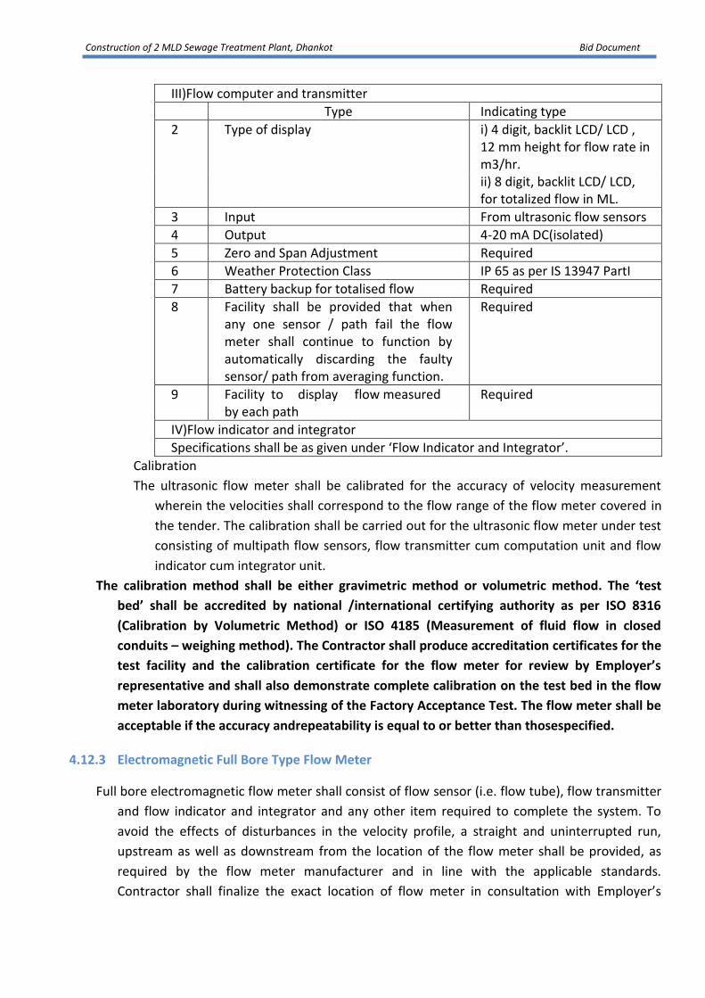
Construction of 2 MLD Sewage Treatment Plant, Dhankot Bid Document
III)Flow computer and transmitter
Type Indicating type
2 Type of display i) 4 digit, backlit LCD/ LCD , 12 mm height for flow rate in m3/hr. ii) 8 digit, backlit LCD/ LCD, for totalized flow in ML.
3 Input From ultrasonic flow sensors
4 Output 4-20 mA DC(isolated)
5 Zero and Span Adjustment Required
6 Weather Protection Class IP 65 as per IS 13947 PartI
7 Battery backup for totalised flow Required
8 Facility shall be provided that when any one sensor / path fail the flow meter shall continue to function by automatically discarding the faulty sensor/ path from averaging function.
Required
9 Facility to display flow measured by each path
Required
IV)Flow indicator and integrator
Specifications shall be as given under ‘Flow Indicator and Integrator’.
Calibration
The ultrasonic flow meter shall be calibrated for the accuracy of velocity measurement
wherein the velocities shall correspond to the flow range of the flow meter covered in
the tender. The calibration shall be carried out for the ultrasonic flow meter under test
consisting of multipath flow sensors, flow transmitter cum computation unit and flow
indicator cum integrator unit.
The calibration method shall be either gravimetric method or volumetric method. The ‘test
bed’ shall be accredited by national /international certifying authority as per ISO 8316
(Calibration by Volumetric Method) or ISO 4185 (Measurement of fluid flow in closed
conduits – weighing method). The Contractor shall produce accreditation certificates for the
test facility and the calibration certificate for the flow meter for review by Employer’s
representative and shall also demonstrate complete calibration on the test bed in the flow
meter laboratory during witnessing of the Factory Acceptance Test. The flow meter shall be
acceptable if the accuracy andrepeatability is equal to or better than thosespecified.
4.12.3 Electromagnetic Full Bore Type Flow Meter
Full bore electromagnetic flow meter shall consist of flow sensor (i.e. flow tube), flow transmitter
and flow indicator and integrator and any other item required to complete the system. To
avoid the effects of disturbances in the velocity profile, a straight and uninterrupted run,
upstream as well as downstream from the location of the flow meter shall be provided, as
required by the flow meter manufacturer and in line with the applicable standards.
Contractor shall finalize the exact location of flow meter in consultation with Employer’s

Construction of 2 MLD Sewage Treatment Plant, Dhankot Bid Document
Representative.
Flow measurement shall not be affected by physical properties of water viz., temperature,
pressure etc., within given limits. Contractor shall provide compensating electronic circuits, if
required.
Contractor shall construct a suitable concrete chamber for enclosing flow meter if it is to be
mounted on underground pipe lines. A concrete enclosure shall be constructed above the
chamber for housing the flow transmitter. For surface pipelines, a concrete cabin shall be
constructed around the pipeline for housing the flow meter and the flow transmitter.
A lockable enclosure shall be provided for the flow transmitter cum computing unit.
Flow meters shall be suitable for the water turbidity at site during various seasons. Flow tube
shall be rugged in construction and shall be suitable for continuous operation. Flow tube shall
have waterproof construction and shall be suitable for installation on underground /above
ground pipelines.
The flow computer and transmitter shall be a single unit suitable for field mounting. It shall
accept inputs from flow tube process the signals and shall provide an output proportional to
the flow rate. The output shall be suitable for transmitting over a long distance.
a)General:
Accuracy of flow measurement
0.5% of measured value during FAT
2. Overall accuracy of flow measurement loop.
1.0 % of measured value
b) Flowtube
(i) Application : a) Raw water pumping mains
b) Treated water pumping mains.
c) Treated water supply lines.
d) Raw sewage pumping mains
e) Treated effluent
(ii) Type : In line full bore electromagnetic
(iii) Size of flowtube : Same as pipe size
(iv) Process connection : Flanged
(v) Weather Protection Class : IP 68 as per IS13947
(vi) Surge protection devices (SPD) between flow tube and flow transmitter
: Required for protection from lightning surges
(vii) Material of Construction:
Electrodes : SS 316
Coil Housing : SS 316
Flanges : SS.316

Construction of 2 MLD Sewage Treatment Plant, Dhankot Bid Document
Grounding ring : SS316
(viii) Flow tube Lining : Hard Rubber
c) Flow Transmitter Unit
(i) Type : Microprocessor based with facility to configure the ranges.
(ii) Type of display : 4 digit backlit LCD/ LCD , for flow rate in m3/hr. 8 digit backlit LCD/ LCD for totalized flow in ML
(iii) Units of display : Flow rate -m3 / hr Totalized flow – ML
(iii) Input : From flow tube
(iv) Output : 4-20 mA DC (isolated) proportional to flow rate
(v) Power Supply : 24 V DC
(vi) Zero and Span Adjustment : Required
(vii) Weather ProtectionClass : IP 65 as per IS 13947
(viii) Battery backup for totalized flow Type Capacity BackupTime
: Online
2.5 mVA 8 hours.
(xi) Facility for on line diagnosis : Required
d)Flow indicator and integrator
Specifications shall be as given under ‘Flow Indicator and Integrator’.
Calibration:
The Electromagnetic flow meter shall be calibrated for the full flow range specified as per BS EN 29104 (Methods of evaluation of electromagnetic flow meters).
The calibration method shall be either gravimetric method as per ISO 4185 (Measurement of fluid flow in closed conduits – weighing method) or volumetric method as per ISO 8316 (Calibration by Volumetric Method). The ‘test bed’ shall be accredited by national /international certifying authority. The Contractor shall produce accreditation certificates for the test facility and calibration certificate for the flow meter for the review by Employer’s representative. The Contractor shall also demonstrate complete calibration on the test bed in the flow meter laboratory. The flow meter shall be acceptable if the accuracy and repeatability is equal to or better than those specified.
4.12.5 FLOW INDICATOR AND INTEGRATOR
Flow indicator and integrators shall be modular in design. It shall consist of two separate dedicated displays for flow rate indication and total flow indication. It shall accept 4-20 mA DC isolated input. The flow integration shall be carried out in the Programmable Logic Controller (PLC). The flow indicator cum flow integrator shall provide 4-20 mA retransmission output proportional to flow rate.
Details Description
Type Microprocessor based
Mounting Front facia of Control Panel
Display Digital, seven segment back lit LCD / LED display
Digit Height 14 mm or Higher

Construction of 2 MLD Sewage Treatment Plant, Dhankot Bid Document
No. of Digits for Flow indicator Flow integrator
4 Digits 6 Digits
Input 4-20 mA DC (Isolated) from flow transmitter through analogue signal multiplier (Refer Note2)
Zero and span adjustment
Required
Manual Reset Facility for flow integrator
Required (shall be password protected)
Engineering units:
-Flow rate indicator -Flowintegrator
Cum/hrML
Battery backup for integrator
Required
Retransmitted output 4-20 mA proportional to flow rate
Alarm outputs 1 NO + 1 NC for high and low alarms (adjustable)
Communication port RS-485 (With Modbus protocol) for interfacing with PLC
Weather Protection Class
IP-52 of IS 13947 PartI
Accuracy ± 0.25% of span or better.
Notes:
1. Digital flow indicator and flow integrator shall be a combined unit.
2. Facility shall be available in the analog signal multipliers and in the flow indicator and
integrator for providing excitation voltage for the flow transmitter in case of 2-wire
flow transmitters.
4.13 PRESSURE GAUGES
a) Pressure gauges and vacuum gauges shall comply with IS 3624 / BS 1780. Glycerin
filled dial shall be provided where the gauge is subjected to pressure pulsation and /
or vibrations. The internal parts of pressure gauge shall be stainless steel.
b) Pressure gauges shall be provided on discharge and on suction of each pump. Pressure
gauges shall be bourdon type and calibrated for the required range. The gauge shall
be supplied complete with impulse tubing, two valve manifold with drain cock, fittings
etc.
c) The minimum diameter for pressure gauges shall be 150 mm. However, where the
pressure gauge forms part of an equipment, the equipment manufacurer’s standard
sizes will be acceptable.
1 Accuracy + 1% of full scale
2 Dial size 150mm

Construction of 2 MLD Sewage Treatment Plant, Dhankot Bid Document
3 Glass Shatter proof
4 Over range Protection 125% of maximum pressure
5 Housing Material Die Cast Aluminium
6 Material of sensor and other wetted parts
SS316
7 Accessories 2-valve manifold with drain cock, impulse tubing, snubbers and all installation hardware
4.14 ON-LINE PH MEASURING SYSTEM
a) The pH measuring system shall consist of a pH electrode, pH transmitter, digital pH
indicator, electrode holder assembly and any other item required to complete the pH
measuring system.
b) The pH transducer shall be rugged in construction and shall be suitable for continuous
operation. pH transducer shall include measuring electrode, reference electrode, and
a temperature compensator electrode. All wetted parts of the transducers shall be of
non-corrosive material.
c) The pH transmitter output shall be isolated, and shall be suitable for transmitting over
long distances.
d) The electrode holder assembly shall be of such a design that it contains some water
even when sampling pump is cut off and shall be provided with flow regulating device.
e) A sampling system consisting of sampling pump / pressure reducing valves, flow
regulator, rotameter, filter assembly etc. shall be provided. The sample water will be
connected to a cabinet containing pH analyzer equipment and pH transmitter.
I) General
1 Overall accuracy of measurementloop
±1% of measuredvalue
2 Standard pH solutions for on site calibration
For pH 4,7 and 10 shall be provided
II) pH Sensor
1 Type Encapsulated combined electrode
2 Mounting On flow through assembly
3 Automatic temperature compensation
Required
4 Standard cable for connecting sensor and transmitter
Required
III)pH Transmitter
1 Type Indicating type with Back-lit LCD / LCD display
2 Mounting Field
3 Input From pH electrodes and temperature compensator
4 Zero and span Adjustment Required
5 Enclosure material Non corrosive

Construction of 2 MLD Sewage Treatment Plant, Dhankot Bid Document
6 Enclosure Protection IP-65 of IS 13947 PartI
7 Output 4 to 20 mA(Isolated) for connecting to pH indicator
IV)Digital pH Indicator
Specifications shall be as given under ‘Digital PanelMeters’.
4.15 ON-LINE ANALYZER
1. The parameter i.e. , pH, TSS, COD, BOD, and Ammonia will be monitored by installing Real Time Monitoring Systems. Other parameters specified in the consent to operate/Environmental Clearance will be monitored on quarterly basis using the established laboratory methods.
2. The software should be capable of transmitting the data along with diagnostics of the instrument.
3. Make of Analyzer should be such that manufacturer should have experience of installing the analyzer for any Govt deptt. Make should be approved by Engineer-in-charge before installation by contractor
4. Measurement method : Non sampling type( continuous ) , no external sample preparation shallbe required for measurement , measurement method must be in line as per CPCB andHSPCB
5. The complete analyzer unit must be include sensor probes required for system , extension cables, various mounting accessories ( if any required) . the digital analyzer itself to display all the parameters such as flow, pH, TSS, BOD &COD etc. with auto calibration facilities and auto temperature, pressure compensation facility but manual calibration must be incorporated .Analyzer should have inbuilt features for automatic water matrix change. The analyzer must have the facility to communicate the displayed as well as stored data by means of RS485/ RS2321 MODBUS/ Ethernet to PC or any other compatibledevice.
6. The data storage capacity would be 05 years minimum.
7. The instrument and analyzer must be made of highly resistant materials such as Peek or SS316L or Titanium and tested according to the highest qualitystandards.
8. All spectrometer probes for organic analysis must operate using Dual Beam UV- Visible spectrometry to as measuring principle.
9. pH & temperature measuring principal must be unique ,non porous / non leaking combined reference electrode for technically consistent pH performance, long term stable and maintenance free in operation.
10. Sensor must have automatic ultrasoniccleaning.
11. Sensor must have multi-wavelength scanning double beam spectrophotometer in wavelength range of 200-720NM.
12. System must have provision for independent analysis , validation , calibration & data transmission parameter ( pH, DO,TSS, BOD & COD).
13. Measuring accuracy as per CPCB guidelines
a. pH accuracy+-0.2 b. TSS accuracy+-10%

Construction of 2 MLD Sewage Treatment Plant, Dhankot Bid Document
c. COD accuracy+-10% d. BOD accuracy+.10%
14. Data communication system : The supplier has to establish complete data / information communication system in order to send the online analyzer data to GMDA, CPCB & HSPCB server.
4.16 ON LINE RESIDUAL CHLORINEMETER
a) Residual chlorine (RCl) measuring system shall consist of RCl
transducer, RCl transmitter, digital RCl indicator and any other item
required to complete the RC measuring system.
b) RCl transducer shall be rugged in construction and shall be suitable for
continuous operation. RCl transducer shall work on Amperometric/
Colorimetric Principle. It shall also consist of an integral pH sensor for
compensating against pH changes and integral temperature sensor for
compensating against temperature changes.
c) A sampling system consisting of sampling pump / pressure reducing
valves, flow regulator, rotameter, filter assembly etc. shall be
provided. The sample water will be connected to a cabinet containing
RCl analyzer equipment and RCl transmitter.
d) The RCl sensor enclosure shall be of such a design that it contains
some water even when sampling pump is cut off and shall be
provided with flow regulating devices.
e) The RCl transmitter output shall be suitable for transmitting over long
distance.
I)General
1 Overall accuracy of measurement loop
± 5% of measured value
II) Residual Chlorine Sensor
1 Type Amperometric/Colorimetric
2 Automatic Temperature Compensation electrode
Required
3 Automatic pH compensation electrode
Required
4 Range Adjustable over full span
5 Sensitivity 0.1mg/Lit
6 Standard Cable Connecting sensor and Transmitter
Required
III)Residual Chlorine Transmitter
7 Type Indicating type having back-lit LCD/LED display
8 Mounting Field
9 Input From Residual chlorine sensor
10 Output 4-20 mA (Isolated)

Construction of 2 MLD Sewage Treatment Plant, Dhankot Bid Document
11 Zero and Span Adjustment Required
12 Enclosure material Non corrosive
13 Enclosure Protection IP-65 of IS 13947 PartI
IV)Digital Residual Chlorine Indicator
Specifications shall be as given under ‘Digital Panel Meters’.
4.17 ALARM ANNUNCIATOR
4.17.1 General a) Microprocessor based alarm annunciators shall be provided for generating audio
visual alarms for each abnormal condition as defined in scope of work. Alarms shall be
initiated by the opening and closing of volt-free contacts which shall remain
unchanged throughout the periods in which the alarm conditions exist. Alarm circuits
shall be capable of conversion from open-healthy to open-alarm or vice versa by a
simple modification after installation requiring no additional parts or special
equipment. Each alarm shall initiate the operation of both visual and audible devices.
The sound intensity of each audible device shall be suitable for the maximum sound
level of its environment. The sequence of alarm should be user selectable by dip
switch.
b) The operation or acceptance of one alarm shall not inhibit the operation of the
audible device or the flashing of the appropriate alarm indicator if a future alarm
condition occurs.
c) Alarm circuitry shall be arranged so that spurious or transient alarm states persisting
for less than 0.5 seconds (adjustable) do not initiate any action.
d) Isolation facilities shall be provided for the hooter using anMCB.
e) The annunciator will be split architecture type and the facia will have LEDs.
4.17.2 Alarm Annunciation
Alarms shall be annunciated at three locations, at the drive starter, at the local HMI and at the central HMI. A philosophy shall be adopted that all alarms associated with a drive shall be annunciated at the starter whilst a general alarm only for that drive shall be annunciated at the HMIs. Therefore the operator observing a general alarm at an HMI shall have to go to the starter concerned to determine the exact cause of the alarm condition.
A typical alarm schedule is detailed in Table below: Table - Alarm Schedule
Device Alarm at the Starter/Panel
Alarm at the relevant local and central MMIs
1. Power System
- transformer fault - mains incomer tripped - generator - incomer tripped
2. Pump and blower drives
- overload (see note1)
- earth fault (see
- drive fault (see note2)

Construction of 2 MLD Sewage Treatment Plant, Dhankot Bid Document
note1) - - emergency stop
operated - run dry protection
operated
3. Valve actuators
- drive fault - drive fault
4. Alum Dosing system
See note5 See note5
5. Service Water tank level
- high high level - high level - low level - low low level
6. Chlorination system
-As per sub vendor recommendation
7 Thickened sludge holding tank
- high - low (run dry protection)
8. Service water tank
- high - low (run dry protection)
9.Filter Press (if any)
-As per subvendorrecomendation
16 Clear water reservoir level
- high high water level - high water level - low water level - low low water level
17.Turbidity - high high level - high level
18 Chlorine residual
- high high level - high level - lowlevel - low lowlevel
19. Control system
- SCADA to PLC and PLCto PLC communication faults (various)
20. UPSs - fault - battery low
Notes: 1. These alarms may be displayed on the motor starter panel. If this is flush mounted,
further individual indication may not be necessary.
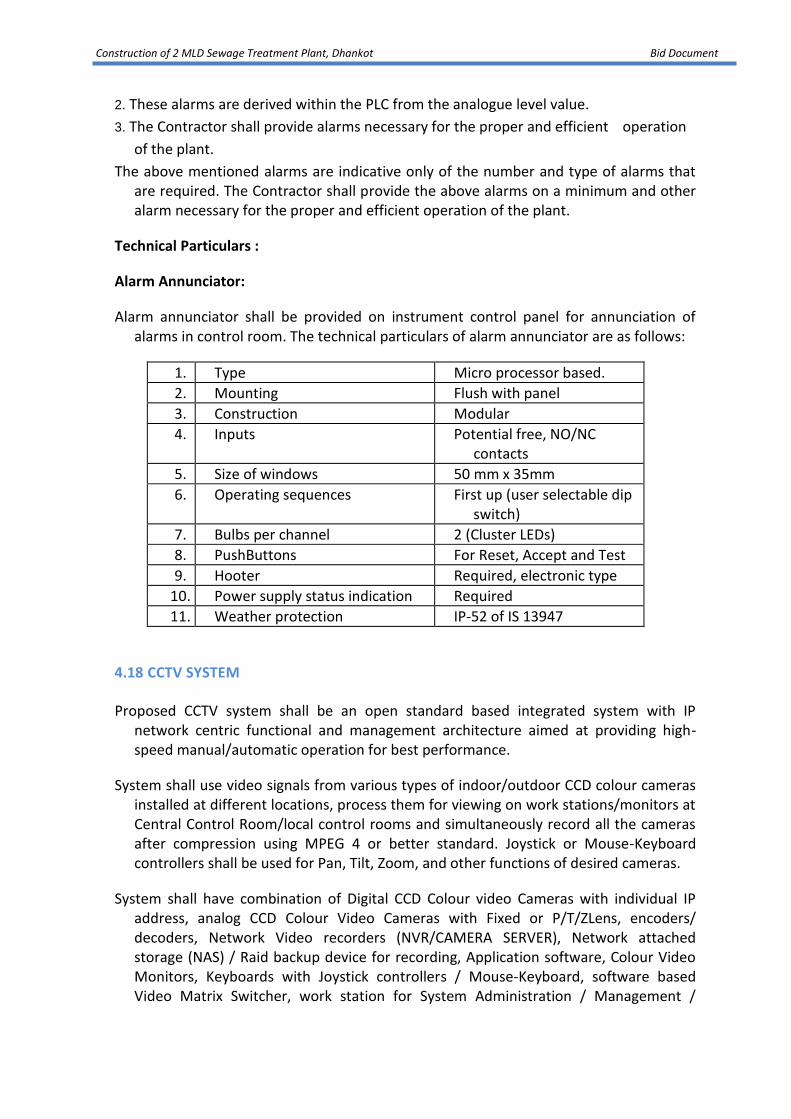
Construction of 2 MLD Sewage Treatment Plant, Dhankot Bid Document
2. These alarms are derived within the PLC from the analogue level value.
3. The Contractor shall provide alarms necessary for the proper and efficient operation
of the plant.
The above mentioned alarms are indicative only of the number and type of alarms that are required. The Contractor shall provide the above alarms on a minimum and other alarm necessary for the proper and efficient operation of the plant.
Technical Particulars :
Alarm Annunciator:
Alarm annunciator shall be provided on instrument control panel for annunciation of alarms in control room. The technical particulars of alarm annunciator are as follows:
1. Type Micro processor based.
2. Mounting Flush with panel
3. Construction Modular
4. Inputs Potential free, NO/NC contacts
5. Size of windows 50 mm x 35mm
6. Operating sequences First up (user selectable dip switch)
7. Bulbs per channel 2 (Cluster LEDs)
8. PushButtons For Reset, Accept and Test
9. Hooter Required, electronic type
10. Power supply status indication Required
11. Weather protection IP-52 of IS 13947
4.18 CCTV SYSTEM
Proposed CCTV system shall be an open standard based integrated system with IP network centric functional and management architecture aimed at providing high-speed manual/automatic operation for best performance.
System shall use video signals from various types of indoor/outdoor CCD colour cameras installed at different locations, process them for viewing on work stations/monitors at Central Control Room/local control rooms and simultaneously record all the cameras after compression using MPEG 4 or better standard. Joystick or Mouse-Keyboard controllers shall be used for Pan, Tilt, Zoom, and other functions of desired cameras.
System shall have combination of Digital CCD Colour video Cameras with individual IP address, analog CCD Colour Video Cameras with Fixed or P/T/ZLens, encoders/ decoders, Network Video recorders (NVR/CAMERA SERVER), Network attached storage (NAS) / Raid backup device for recording, Application software, Colour Video Monitors, Keyboards with Joystick controllers / Mouse-Keyboard, software based Video Matrix Switcher, work station for System Administration / Management /

Construction of 2 MLD Sewage Treatment Plant, Dhankot Bid Document
Maintenance etc.
The NVR / CAMERA SERVER can be embedded type or server based. However the NVR / CAMERA SERVER software shall run on common off the shelf available servers (Camera server & Database server). Each NVR / Camera Server shall be able to handle 12 or more cameras.
Network Video Recorder shall offer both video stream management and video stream storage management. Recording frame rate & resolution in respect of individual channel shall be programmable.
System should ensure that once recorded, the video cannot be altered, ensuring the audit trail is intact for evidential purposes.
System shall provide sufficient storage of all the camera recordings for a period of 30 days or more
@ 25 FPS, at 4 CIF or better quality using necessary compression techniques for all cameras (extended capacity of cameras i.e. present capacity + 25%).
System shall use a combination of IP enabled cameras & analog CCD cameras with external encoder. The video shall be compressed using MPEG-4 or better standard and streamed over the IP network.
Encoders shall digitize analog video, compress the digital video using various compression algorithms for outdoor installations, shall be suitable to work from (-) 10o C to (+) 50o C with RH up to 90% non-condensing.
4.18.1 System requirements
Camera with external encoder or IP Camera shall be used for image capture.
Indoor cameras shall be either with fixed focal length lens or with Pan/Tilt &Zoom lens as per site requirement. All outdoor Cameras shall be Day/Night cameras.
Housing of cameras meant for indoor use shall be of IP 42 rating whereas outdoor camera housing shall be of IP 66 or better rating. These must be integrated by the camera manufacturer.
System must provide built-in facility of water marking or Digital certificate to ensure tamper proof recording so that these can be used as evidence at a later date, if so desired. The recording shall support audit trail feature.
All camera recordings shall have Camera ID &location/area of recording as well as date/time stamp. Camera ID, Location/Area of recording &date/time shall be programmable by the system administrator with user ID &Password.
Facility of camera recording in real-time mode (25 FPS)/15/12.5/10 or lower FPS as well as in any desired combination must be available in the system.

Construction of 2 MLD Sewage Treatment Plant, Dhankot Bid Document
Facility of Camera recording in CIF, 2CIF, 4 CIF as well as in any combination i.e. any camera can be recorded in any quality .Selectiveor Group of cameras must be available in the system.
System shall have facility of additional camera installation beyond the originally planned capacity.
In order to optimize the memory, while recording, video shall be compressed using MPEG-4 or better standard and streamed over the IP network. Once on the network, video can be viewed on a Control room work station or on analog monitor using a hardware decoder (MPEG-4/compatible standard receiver) and shall be recorded on NVR/CAMERA SERVER and shall be backed up on NAS/RAID backup device.
System shall be triplex i.e. it should provide facility of viewing, recording & replay simultaneously.
The offered system shall have facility to export the desired portion of clipping (from a desired date/time to another desired date/time) on CD or DVD. Viewing of this recording shall be possible on standard PC using standard software like windows media player etc.
PTZ Cameras shall have 64 or more pre-defined positions, to be selected through suitable input alarm.
System shall have provision of WAN connectivity for remote monitoring.
System design
Each camera should be connected to a Hardware Encoder, through cable, which shall support minimum dual streams. Alternatively, the camera shall be IP based, UTP ready. The encoders should be capable of producing streams @ 25 fps for each camera for viewing on LAN and on monitors and also recording into the NVR/CAMERA SERVER/Camera servers and NAS box/Raid backup device @ 25 fps or lower frame rate, user selectable as per requirement, for each individual camera.
Encoders shall be Power Over Ethernet (POE) compliant and connected to Layer 2 or Layer 3 switch as per system design using UTP CAT 6 Cable or fiber optic cable and the required connectors as per standards.
For monitoring purposes, Video monitors/Plasma monitors/Video wall shall be set up with suitable mounting arrangements, as per user requirements. Facility for viewing and controlling all the cameras at various other locations, as required, shall be provided.
Monitoring at Local control rooms may be restricted to operation of certain cameras only &system administrator should be able to configure the system, accordingly.
There shall be a Control System with Video Control Software to manage all the video surveillance devices.
Video Surveillance Application Software

Construction of 2 MLD Sewage Treatment Plant, Dhankot Bid Document
The software shall operate on open architecture for integration with perimeter safety, access control, PA and fire / safety systems based on open standards.
Digital video surveillance control software should be capable to display and manage the entire surveillance system. It should be capable of supporting variety of devices such as cameras, video encoders, video decoders, PTZ controller, NVR, NASboxes/Raid backup device etc.
The software should have inbuilt facility to store configuration of encoders / decoders and cameras.
The software should support flexible 1/2/4 Windows split screen display mode or scroll mode on the PC monitor or on preview monitor as per site requirement.
The software should be able to control all cameras i.e. PTZ control, Iris control, auto / manual focus, and color balance of camera, selection of presets, Video tour selection etc.
The software should have user access authority configurable on per device or per device group basis. The user shall have the facility to request the access of any camera and can control the camera for a reservation period. Controlofcamera isreleased after the reservation period.
The system shall provide User activity log (audit trail) with user ID, time stamp, and action performed etc.
The administrator should be able to add, edit &delete users with rights. It shall be possible to view ability / rights of each user or the cameras which can be viewed &controlled as per the permission assigned by the administrator.
It should have recording modes viz. continuous, manual, or programmed modes on date, time and camera-wise. All modes should be disabled and enabled using scheduled configuration. It should also be possible to search and replay the recorded images on date, time and camera-wise. It should provide onscreen controls for remote operation of PTZ cameras. It should have the facility for scheduled recording. Different recording speeds(fps) and resolution for each recording mode for each camera should be possible.
Retrieval: The CCTV application should allow retrieval of data instantaneously or any date / time interval chosen through search functionality of the application software. In case data is older than 30 days and available, the retrieval should be possible. The system should also allow for backup of specific data on any drives like CD/DVD/BlurayRecorders or any other device in a format which can be replayed through a standard PC based software. Log of any such activity should be maintained by the system which can be audited at a later date.

Construction of 2 MLD Sewage Treatment Plant, Dhankot Bid Document
DETAILED TECHNICAL SPECIFICATIONS
Colour video Dome Camera with PTZ
Image Device Inter line transfer 1/4"or better format CCD sensor
Focal length 4mm to72 mm or better
Optical zoom (For Indoor Camera) 18X or better
Optical zoom(For OutdoorCamera) 26X or better
Number of Pixels 720X576
Scanning System PAL
Resolution 480 TVL or better
Illumination (For Indoor camera) 1.0 Lux (Color),0.1Lux(B/W) or better
Illumination (For Outdoorcamera) 1.0 Lux(Color),0.05Lux(B/W) or better
PanTravel 3600Continuous
Tilt Travel 0-900
Manual Tilt Speed 0.5°/SEC to 90°/SEC
Manual pan speed 0.5°/SECto90°/SEC
Preset Tilt speed 0.5°/SEC to90°/SEC
Preset Pan speed 0.5°/SEC to 300°/SEC
Preset positions Min.64
Iris Control Auto
Focus Auto
Back Light compensation Required with black masking or other suitable technology
White balance Auto
Electronic shutter Auto
S/N ratio >=48 dB
Power supply As per OEM's design, however generally AC 230V@50Hz/12Vor 24 VAC Rectifier and SMPS if DC supply
Bullet Camera
Signal System NTSC/PAL
Image Sensor 1/3" Sony Super HAD
Scanning System 2:1 Interlace
Horizontal Resolution 600 TV Lines
Synchronization Internal
Luminance S/N More than 50dB (AGC
Min. Illumination 0 Lux (IR LED On)
Gamma Adjustable / User

Construction of 2 MLD Sewage Treatment Plant, Dhankot Bid Document
Video Output Level 1.0 Vp-p Composite
Day and night True Day and Night
IRLED 850nm, 20ea, Up to 30m
IR LED Operation On: 1Lux, Off: 3Lux
IP Rating IP66 (Water Repellent)
OSD Display Built-in
Sense-Up Auto Adjustable
3DDNR 0~100 Level Adjustable
D-WDR Off/Indoor/Outdoor
BLC Off/BLC/HSBLC
Image Freeze / Mirror /D-zoom / Sharpness /NEG Image
GainControl Off/Low/Middle/High
White Balance ATW/ PUSH/PUSH-LOCK/MANUAL/INDOOR
Motion Zone 4ea (Mask On/
Privacy Masking Zone 8ea (Mask On/
Function
Language Standard :English
OperatingTemperature -10°C~50°C (14°F~122°F)
StorageTemperature -20°C~60°C (-4°F~140°F)
Power Supply Dual: DC12V±10% /AC 24V±10%
Fixed Colour Dome Camera Varifocal
MPEG4 ENCODER (HARDWARE BASED)
The encoder shall be built on embedded processor and real time operating system. The Encoder should convert Analog Composite/S-Video input into good quality digital stream on real time basis and shall be able to transmit as Unicast /Multicast IP packet with low latency (less than 200 msec.) for live viewing as well as for recording.
The video resolution should be configurable at either of 4 CIF, 2 CIF, CIF@25 fps or at lower frame rate per camera, user selectable.
ImageDevice 1/3”or ¼”CCD Sensor
Number of Pixels Minimum 720x576
Scanning System PAL
Resolution 480 TV Lines or better
Min Illumination 1 Lux at F1.2
S/NRatio >=48 dB
Electronic Shutter AUTO
Lens Built-inVarifocal lens. Auto Iris, lens f=4–9mm. (approx.)
Back light compensation Required
Power supply As per OEM's design
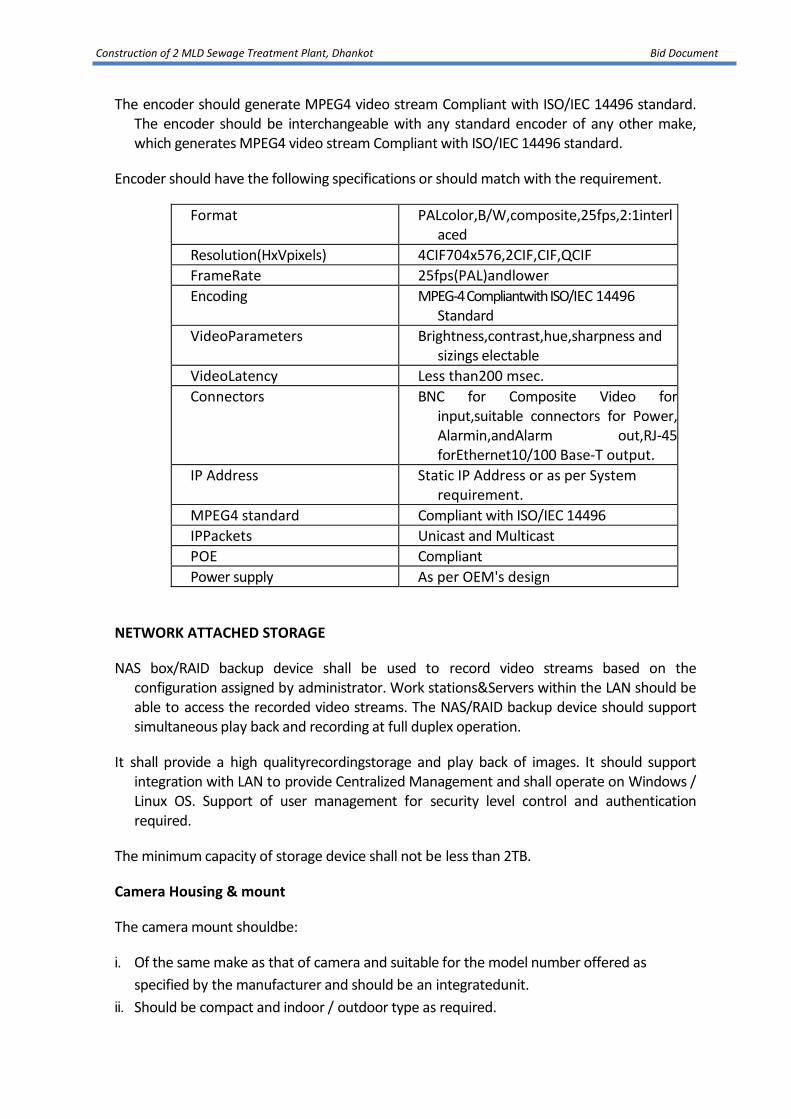
Construction of 2 MLD Sewage Treatment Plant, Dhankot Bid Document
The encoder should generate MPEG4 video stream Compliant with ISO/IEC 14496 standard. The encoder should be interchangeable with any standard encoder of any other make, which generates MPEG4 video stream Compliant with ISO/IEC 14496 standard.
Encoder should have the following specifications or should match with the requirement.
Format PALcolor,B/W,composite,25fps,2:1interlaced
Resolution(HxVpixels) 4CIF704x576,2CIF,CIF,QCIF
FrameRate 25fps(PAL)andlower
Encoding MPEG-4 Compliantwith ISO/IEC 14496 Standard
VideoParameters Brightness,contrast,hue,sharpness and sizings electable
VideoLatency Less than200 msec.
Connectors BNC for Composite Video for input,suitable connectors for Power, Alarmin,andAlarm out,RJ-45 forEthernet10/100 Base-T output.
IP Address Static IP Address or as per System requirement.
MPEG4 standard Compliant with ISO/IEC 14496
IPPackets Unicast and Multicast
POE Compliant
Power supply As per OEM's design
NETWORK ATTACHED STORAGE
NAS box/RAID backup device shall be used to record video streams based on the configuration assigned by administrator. Work stations&Servers within the LAN should be able to access the recorded video streams. The NAS/RAID backup device should support simultaneous play back and recording at full duplex operation.
It shall provide a high qualityrecordingstorage and play back of images. It should support integration with LAN to provide Centralized Management and shall operate on Windows / Linux OS. Support of user management for security level control and authentication required.
The minimum capacity of storage device shall not be less than 2TB.
Camera Housing & mount
The camera mount shouldbe:
i. Of the same make as that of camera and suitable for the model number offered as
specified by the manufacturer and should be an integratedunit.
ii. Should be compact and indoor / outdoor type as required.

Construction of 2 MLD Sewage Treatment Plant, Dhankot Bid Document
iii. Should support the weight of camera and accessories such as housing, pan &tilt head in
any vertical or horizontal position etc.
Speed dome controller/PTZcontroller
Speed DomeController should have variable speed joystick, LCD display for Programming and it should be able to control the speed dome for PAN / TILT / Zoom.
Cables
Sr.No.
Connectivity CableType
1 CameratoVideoEncoder CoaxialRG6/U/CAT6/Fibre Optic
2 VideoEncoder to Switch in control room
UTPCAT6/Fibre Optic
3 Switch toVideoWall Switches UTPCAT6/Fibre Optic
4 From switches to NAS Box Fibre Optic
5 HardwareDecoder to monitor Composite signal cable
4.19 INTERCOM SYSTEM
An EPABX system shall be provided at a control room for voice communication.
Following locations are to be covered using single EPABXsystem:
• Main Control room in the Administration and ControlBuilding
• All rooms within the Administration and Control Building
• The laboratory
4.20 MANUALLY-RAKED INCLINED BAR SCREENS
Screens shall have the aperture size specified, to prevent coarse debris from entering the inlets and protect the plant against mechanical damage. They shall be inclinedat an angle of not less than 30 degrees from vertical to facilitate raking. Inclined length shall not exceed 2m
Screens shall be designed for mounting as shown on the Drawings. The design shall avoid the formation of areas of stagnation in the flow. Sealing shall be provided between the frame and the inlet channel walls.
Screens shall be designed to with stand the maximum possible pressure differential across the screen when fully blinded, without incurring any damage or overload. The working headloss across the screen at maximum flow shall not exceed 50 mm following screen cleaning. Unless otherwise

Construction of 2 MLD Sewage Treatment Plant, Dhankot Bid Document
specified the velocity of the flow through the screen shall not exceed 1.2m/s.
The equipment shall be capable of operation under all duty flow variations and debris loadings, and shall be capable of withstanding the impact of large floating material and heavy objects in the flow without damage to the screen.
Screen bars shall be accurately set and secured to give the designed clearance between the bars. The bars shall extend from the sole plate, to which they shall be individually welded, to a point above maximum possible top water level, at which point they shall be individually welded to the screen top plate. Intermediate stiffening supports shall be welded to the screen bars as necessary for screens to accommodate hydraulic pressure due to depth and high flow rates through the inlet channels. The screen bars shall be individually welded to each stiffening support. Stiffening supports shall be fitted so they cannot impede raking.
The sole plate shall be profiled to induce screenings and debris to be directed onto the screen bars and not to accumulate at the foot of the screen. The leading edge of the sole plate shall be level with the inlet channel invert.
The top edge of the screen shall be profiled to enable easy raking-off of screenings material.
When specified, for applications where large or heavy oversize debris may accumulate against the screen, hoisting equipment shall be provided. The screen shall then be fitted with hoist-guide pulleys, and operator access shall be provided to enable manual removal of oversize objects from the flow.
Screens shall be constructed from hot-dipped galvanized steel.
Raking shall be manual and screenings shall be transferred manually to a rakings container. The scope of supply shall include manual rakes and manually moved containers, with all accessories needed to remove the collected debris.
Rake handles shall not exceed 2.5 m long. Rake tines shall be designed to fit the screen apertures, and tines shall be of material which cannot damage the screens.
Rakings containers shall be sized so that, when fully loaded with the typical tropical organic material expected, the gross weight shall not exceed 50kg. They shall be fitted with handles to facilitate manual or mechanical handling as specified.
Where needed, means shall be provided for safe man-access to a raking platform which shall be provided along the whole width of the screens, above the screen top edge. Access shall be by ladder with handrail. Safety handrailing shall be provided along the whole length of the platform, which may be designed as partly-removable during raking. Secure anchorages at suitable

Construction of 2 MLD Sewage Treatment Plant, Dhankot Bid Document
intervals shall be provided for operatives safety harness, using hook-on arrangements.

Construction of 2 MLD Sewage Treatment Plant, Dhankot Bid Document
PART – 5
ELECTRICAL REQUIREMENT
5.1 ELECTRICAL DESIGNREQUIREMENTS
The following is a brief description of the major components of the Contract. This is to be
complemented and read with the details provided in the subsequent subsections of
this document.
The works component included are as defined below but shall not be limitedto:
5.1.1 Proposed Sewage Pumping Station
1. 11kV outdoor substation consisting of lightning arresters, current
transformers, voltage transformers, dis-connectors, fuses, insulators,
ACSR conductor, clamp and connectors with necessary metering and
protection arrangement including steelstructure.
2. 11/0.415 , Dyn11, ONAN transformers with OCTC (with 100%
standbyarrangement)
3. Starters for LVmotors
4. LV Switchboard/ Distribution Board/ LightingPanel
5. Local Push ButtonStation
6. HV and LVcables
7. LV capacitor with APFCpanel
8. Lightingsystem
9. Cablingsystem
10. Earthing and lightning protectionsystem
11. Diesel Generator with PLC BasedAMF
5.1.2 Proposed Sewage Treatment Plant and Effluent Pumping Station (if required)
1. 11kV outdoor substation consisting of lightning arresters, current
transformers, voltage transformers, dis-connectors, fuses, insulators,
ACSR conductor, clamp and connectors with necessary metering and
protection arrangement including steelstructure.
2. 11/0.433 , Dyn11, ONAN transformers with OCTC (with 100%
standbyarrangement)

Construction of 2 MLD Sewage Treatment Plant, Dhankot Bid Document
3. Starters for LVmotors
4. LV Switchboard/ Distribution Board/ LightingPanel
5. Local Push ButtonStation
6. HV and LVcables
7. LV capacitor with APFCpanel
8. Lightingsystem
9. Cablingsystem
10. Earthing and lightning protectionsystem
11. Diesel Generator with PLC BasedAMF
5.2 ELECTRICAL TECHNICAL REQUIREMENTS
5.2.1 General
The scope of work includes design, equipment selection, manufacture, inspection at
Contractor's or his Sub-Contractor's works, supply, installation (including
storing, unloading and transferring the material / equipment to Contractor’s
storage area, maintaining equipment / material in safe custody and assembling
the elements of the equipment and installing at the place of work), testing and
commissioning of the plant equipment/ electrical system on ‘Design Build and
Operate’ basis and dismantling of existing electrical equipment and handed
over the existing equipment to Department’s Representative at the location as
directed by the Department Representative. After successful commissioning
and trial run of the plant, it should be handed over to the Department.The
Contractor shall also be responsible for Operation and Maintenance (O&M) of
the plant for 6 years including one year as DLP. The Contractor shall submit their
design calculations/ drawings based on ‘Design criteria for electrical
equipment/system’ for Department’s review and approval. These specification
covers substations, transformers, HV/LV switchboards, energy efficient motors,
soft starters, capacitors, HV and LV power cables and control cables, and other
allied equipment, etc. along with the specifications for workmanship, laying
cables, lighting system, earthing systems, lightning protection etc. for Gurugram
town. It shall be the responsibility of the Contractor to design the electrical
system based on the selection of the mechanical equipment. Prior to
commencement of work contractor shall check the availability of 33kV or 11kV
power supply with state electricityauthority.
The Bidder shall make his own estimate of sizes, ratings and quantities for,
substation equipment, all plant items and miscellaneous systems such as
earthing, lightning protection, lighting, auxiliary power distribution, etc. Design

Construction of 2 MLD Sewage Treatment Plant, Dhankot Bid Document
of electrical system (i.e. Substation, transformers and other electrical
equipment) shall be based on Stage-II (i.e. year up to 2046) only. However,
facility for upgrade/ expansion of all equipment to cater Stage-II load shall have
to be considered during design- Engineering stage. Sufficient space in the
switchyard and switchboard/ control room shall be provided for expansion/ up-
gradation of switchyard / electrical equipment/ switchboard for Stage-II load. It
should be clearly understood that the Contract will be on ‘Design Build and
Operate’ basis and no variation will be allowed for items of works not foreseen
or omitted by the Bidder at the bidding stage, except where specifically
indicated in the bid documents. Details of Stage I and Stage II requirements in
terms of demand and proposed year are covered in thetender.
All equipment offered shall comply with the requirements specified in the latest
editions of applicable Indian/ International Standards and shall also comply with
the good Engineeringpractices.
The drawings enclosed with the specification are for general guidance of the Bidder
only. Contractor shall design the electrical system on the basis of ‘Design
Criteria’ and to be submitted for Department’s approval. Contractor shall
incorporate any changes/ suggestions in the drawings to suit site conditions and
design criteria and standard Engineering practice and resubmit for approval to
Department’s Representative.
The Contractor shall possess the valid electrical Contractor’s license of appropriate
class from the concerned statutory bodies governing the area of work place.
The Contractor shall fully comply with the relevant statutory rules
andregulations.
All type (as applicable), routine and acceptance tests shall be conducted in the
presence of Department/ Department’s Representative / Third Party Inspector
on all the equipment as per latest applicable IS/IEC at no extra cost. Typical type
test reports for other equipment shall be submitted by the Contractor for
approval by Department’sRepresentative.
All commissioning tests shall be carried out in the presence of Department/
Department’s Representative and approval for the same shall be obtained
before commissioning and installation. All test reports shall be properly
maintained by the Contractor duly approved by the statutory bodies and shall
be handed over to the Department after completion of the job. All instrument
and accessories required for testing and pre commissioning of the equipment
specified herein shall be provided by the Contractor at no extra cost to
theDepartment.

Construction of 2 MLD Sewage Treatment Plant, Dhankot Bid Document
Liaison with electric distribution company and other Government organization/
statutory bodies for obtaining Power supply/ other clearance shall be
Contractor’s scope. After completion of installation work, the Contractor shall
arrange for inspection and obtain approval from the concerned statutory
bodies. Any fees that are to be paid to such statutory bodies for testing,
inspection or calibration shall be paid by the Contractor. Any modification /
revision in the equipment / installation of equipment as required by the
statutory bodies shall be carried out by the Contractor. All such costs / fees for
revisions / modifications shall be deemed to be included in the prices of supply,
installation, testing and commissioning of equipment as quoted by
theContractor.
5.2.2 Transformer Size selection Criteria
The transformer size shall be determined from the estimation of the simultaneous
maximum demand based on the power rating of motors and other loads and
their operating / running periods. Bidder shall provide Best efficiency level
energy efficienttransformer.
The design shall be based on maximum nos. of main motors working for Stage -II
and the corresponding auxiliary loads including office building and staff quarters
etc shall be considered for sizing of transformer. Values to be ascertained by the
Contractor after Submitting design calculations subject toapproval.
Appropriate values of load factor, diversity factor, power factor and efficiency shall
be considered for each type of load. Improvement in power factor due to
capacitors shall not be considered. Five percent (5%) contingency shall be added
to the simultaneous maximum demand thus calculated and the next standard
size of transformer as per IEC shall beselected.
Two such transformers shall be provided for 100 % redundancy at each site. The
design calculations for transformer sizing shall be subject to the approval of the
Department’sRepresentative.
5.2.3 Electrical System for Proposed STPs, Sewage Pumping Station and IPS
Power supply at STP & SPS shall be provided by the Department through Uttar
Haryana BijliVitran Nigam (UHBVN) nearest point to the Campus area. From this
point to inside campus the responsibility will be of the Contractor. Metering
room for Metering will be provided by the contractor and the contractor will be
required to make the remaining supply arrangement for the STP/ SPS campus.
Contractor has to inform at least 3 months before requirement of power for trial
run.

Construction of 2 MLD Sewage Treatment Plant, Dhankot Bid Document
5.3 SPECIFICATIONS OF LT ELECTRICAL CONTROL PANEL FOR SUBMERSIBLE PUMPING SET
5.3.1 GENERAL REQUIREMENTS OF CONTRACT
1.1. The Control Panel suitable for LT supply i.e. 415VAC, 50Hz, 3Phase, 4 Wire system
particularly suitable for uninterrupted operation even at -25% low voltage
conditions of tropical and suitable for Hot and Humid monsoon environment, with
RH up to 95%, 45 degree Celsius ambient temperature above with 1% de-rating
upto 50OC rise in ambient temperature and 2% de-rating per degree above 50OC
ambient temperature, dusty areas as per other requirements at sites in state of
Haryana.
1.2. Prerequisites before supply of Panel
i) Submission of drawings
a) General Arrangement Drawing as per IS:8623 1993
b) Single Line Diagram as per IS/ANSI codes and symbols
c) Bill of Quantities
d) Circuit diagram to be submitted in minimum A3 size sheet along with the LT
Electrical Control Panel for Proper Operation and Protection of Submersible
Pumping Set.
e) Specifications, makes and quantity of the main components to be specified.
ii) The approval of the drawings by the EIC shall in no way relieve the contractor of
contractual obligations or liabilities under the contract or his responsibilities for
correctness of dimensions, material of construction, performance etc.
iii) The contractor will have to use the higher rated equipment as per DNIT even if
the drawing is approved of lower rating i.e. the rating can be increased to
increase safety factor but cannot be decreased under any clause of terms and
conditions.
iv) If there is further requirement for improvement after the each amendment than
contractor shall submit the fresh documents drawings and ratings. No charges
whatsoever will be paid for preparing drawings estimates etc.
v) The contractor shall inform 5 days prior to supply for inspection/inspections to
be carried out.
vi) The contractor will strictly follow Indian Standards (IS: code). If for a particular
code for any item is not available than relevant IEC code will be applicable
subject to the note at the end of this chapter.
vii) The products of dual use i.e. commercial as well as industrial can be of ISI marked
e.g. wires, MCB.
viii) All the material shall be covered by manufacturers warranty clause. The
contractor shall provide the warranty card and test reports from the
manufacturer for all the equipments/ machinery.
ix) The installation should comply following statutory standards:
Construction of 2 MLD Sewage Treatment Plant, Dhankot Bid Document
a) Indian Electricity Act, 1910.
b) Indian Electricity Rules, 1956
c) National Electrical Code, 1985
d) The installation confirming to the instructions issued by the o/o Chief
Electrical Inspector, Haryana & UHBVN/DHBVN with upto date
amendments.
1.3 GENERAL REQUIREMENTS OF LT ELECTRICAL CONTROL PANEL FOR SUBMERSIBLE
PUMPING SET
i) Control Panel Board size shall be sufficient so as to accommodate all the equipments
in one enclosure. An independent meter box for housing power & light meter shall
be provided as per HBVN requirement/specifications.
ii) Fabricated by cutting, bending, welding etc in neat, symmetrical, aesthetic manner,
providing easy access for Repair & Maintenance in clean manner of not less than
14S.W.G. (1.6mm) CRCA sheet steel epoxy based powder coated with RAL
7032/SG 7032 (Siemens Grey) shade as per IS: 5- 2007. All the equipments should
be mounted on mounting plate of minimum 12 S.W.G. (2.0mm) or more thickness
with 15 mm bend on sides.
iii) The Panel should be dust and vermin proof wherever required & proper sponge
neoprene/PU gasketing should be done.
iv) The Panel should be as per low voltage i.e. 415 V AC 50 Hz, 3 Phase 4 wire system
switchgear and control gear assembly conforming to IS 8623:1993 with up to date
amendments.
v) The control panel board should comprise of rigid welded structural frames The
control panel shall be complete with removable gland plates with provision of entry
and exit of cable from glands duly fixed on the side plates of panel board.
vi) The mounting of panel shall be made on wall 1.00m from ground level to the bottom
of panel.
vii) The board should be matt finished, covers should be rigid in construction wherever
required door stiffeners should be used & free from flaws. It shall also be provided
with discrete key lock system for every installation/panel.
viii)The panel board should have the flush mounted instruments of 96x96mm bezel or
22.5mm cut out for pilot devices.
ix) The LED type indicating lamps should be used as per IS: 13947-5 - 2004 for phases
available RYB.
x) The Copper (Cu) busbar should be of electrolytic grade Copper. The size for a rating
should be according to the formula 1mm2 per 1.2A.
xi) The SCPD (Short Circuit Protection Device i.e. MCB/MCCB) should be on the
incomer side of the Control Panel so that in case of fault/ fire/ exigency the starter

Construction of 2 MLD Sewage Treatment Plant, Dhankot Bid Document
and subsequently pump could be isolated from Electricity board power supply by
operator / attendant.
xii) Only SCPD should accessible from the front with door closed. All other devices like
contractors, bus bars, overload relays, soft starter if used, other protection relays
and timers etc should not be accessible with door closed.
xiii) In case the SCPD device is a 25KA, 3 Pole, MCCB suitable for motor duty, it will be
fuse less and Cat. A type MCCB as per IS 13947-II:1993 or IEC 947/60947.
xiv) All the controls, indications, metering devices/displays of the panel should be on the
front side of the panel.
xv) All the Contactors should be air break type and AC3 duty as per IS13947-IV and of
finger proof IP20 protection.
xvi) The wiring shall be done by 1100V PVC wires as per IS 694:1990 FR type. The class of
wire will be class 5 or class 6. The temperature range will be -15OC to 70OC.
xvii) The wire rating will considered as 70% of the rated wire rating as designated by
manufacturer.
xviii) All the electrical equipment should be able to perform on Line voltage i.e. 415VAC.
If any equipment is required to be used on 220VAC than separate step down control
transformer be used of 415 to 220V AC.
xix) Over voltage protection relay for fluctuation of 20% and above should be
incorporated.
xx) All the wires should be terminated, crimped with the due size of thimble. No wire
should be terminated directly.
xxi) All the wiring should have proper ferrules.
xxii) Two earth studs one each on LHS and RHS should be provided.
xxiii) The door hinges should be strong enough to take the load of wiring,
instrumentation etc.
xxiv) ELCB for current leakage protection.
xxv) Output supply for flow meter shall be provided by providing with 2.5mm2 terminal
blocks of Connectwell, Wago, Phoenix make.
xxvi) All the 220V AC machinery, equipments and instruments will be supplied through
Neutral Isolation transformer only.
5.4 GENERAL REQUIREMENTS FOR CONTROL PANEL COMPONENTS
5.4.1 Moulded Case Circuit Breaker (MCCB)
The MCCB (Moulded Case Circuit Breaker) shall conform to the latest IEC 947-2&IEC 947-
31989. The Service Short Circuit Breaking Capacity (ICSat415VAC) should be as specified at
the required level.

Construction of 2 MLD Sewage Treatment Plant, Dhankot Bid Document
The MCCB shall be Current Limiting type and comprise Of Quick Make–Break switching
mechanism, preferably Quick Break Contact system, are extinguishing device and the
Tripping unit, contained in a compact, high strength, heat resistant, flame retardant,
insulating moulded case with high with stand capability against thermal & mechanical
stresses. All MCCBs shall be capable of defined overload adjustment. AllMCCB’s rated 200
A and above shall have required Magnetic short circuit pick up.
The Trip command shall over ride all other commands. The MCCB shall employ
maintenance free double break contact system to minimize the let thru’ energies and
capable of achievements Discrimination up to the full short circuit capacity of the
downstream MCCB.
In case of4 Pole MCCB, the neutral shall be fully rated and capable of suffering protection.
The MCCB shall have protection against Overload, Short Circuit & Earth Fault, minimum
breaking capacity of MCCB will be 25KA.
5.4.2 Voltmeter and Ampere Meter with Selector Switch
96 mm square, Voltmeters (0-500V) and Ampere Meters of suitable range of high quality
industrial ‘A’ grade conforming to latest relevant IS specifications. The Voltmeter and
Ammeter should be of Panel type. Selector Switch shall be rotary type.
5.4.3 Indicating Lamps
Two Indicating Lamps green and red coloured will be oil and dust proof, LED type bulb
rating about 230Vfor showing ‘Pump Off’ and Pump Running’ respectively.
5.4.4 Starter
Motors upto 37 KW shall be with Fully Automatic Star/ Delta starters & for higher rating Soft
starters shall be incorporated. Auto Transformer should be provided having tapping of
60%, 80% & 100%. Starter shall conform to IS 1822-1967 category AC and shall be suitable
for motor supplied.
5.4.5 Contactors
The contactors should comply with the latest IEC 947-4 and the corresponding IS13947-4
standards. They shall have CPRI test Certificates. It should be manufactured by a
company having got ISO 9001 approval. The contactor should be rated for AC3 duty at
415V and 50Hz.The Contactors shall be fast closing and fast opening type.

Construction of 2 MLD Sewage Treatment Plant, Dhankot Bid Document
The Contactors would be capable of frequent switching and should operate without de-
rating at 55OC for AC3 applications. They should be climate proof as standard. The coil of
the Contactor would have classH insulation to support frequent switching.
The rated voltage of the contactor shall be equal or superior at 440V and rated insulation
voltage will be 690-1000V.The rated impulse voltage of the contactor should be 8KV.
The contactor shall have 2NO+2NC Auxiliary Contact Block. The Contactor should be
modular in design and would be suitable for the addition of auxiliary contacts and other
electrical auxiliaries without any compromise on the performance or the operations of the
contactors. The Contactors from 4KW to 400KW will be designed to accept the respective
auxiliary contact block range.
The contactor upto 80A should have a mechanical life of more than 10 million operations.
Contactors from 95-550A should have mechanical durability of more than10million
operations.
The thermal overload relay if used shall be direct/separate mounting over the contactor
without any specific connections.
For Capacitor use, the Contactor should be suitable for Capacitor Duty i.e. AC-4 Category
asper the required current ratings as per the Capacitor Banks.
5.4.6 Capacitor
The capacitor(s) will be with minimum 10%THD (Total Harmonic Distortion) in current with
test certificates. The capacitors shall be switched on after the motor has attained the full
speed. To attain this separate MCB, Contactor, and timer shall be used for pump
capacitor.
The capacitors shall be heavy duty as per IS 13340 (Part 1):2012/IEC 60831-1:2002 & IS
13340 (Part 2):2012/IEC 60831-2:1995. The capacitor shall have safety features like
pressure disconnection system, self healing type and discharge resistors to discharge
capacitor to safe 50V range in 1 minute from rated voltage after switching off.
Peak inrush current shall be upto 140 to 160 times the rated current. The capacitors shall
be 440V rated, 110% tolerance in voltage. Three phase type, tolerance of only 5-10% of
capacitance.
5.4.7 Over Load Relay

Construction of 2 MLD Sewage Treatment Plant, Dhankot Bid Document
The over load relay should comply with the latest IEC 947-4 and the corresponding
IS13947-4standard. They will be having CPRI certification. They will be manufactured in an
organization in accordance it the requirements of ISO9001standard.
The Relay would be direct contactor mounting type and should have the provision to be
mounted separately also. The Overload Relay would be ambient compensated type and
would be operable upto 55OC. It will be designed for utilization category AC3. The Relay
will be tripping asper the specified tripping curves given in the technical data. The
overload Relay would have build in phase loss and phase unbalance protection as per IEC
947-4. The Overload Relay would be capable to withstand up rated currents and inrush
currents. The over load relay would have the possibility to select manual/auto reset at
site.
The rated operational voltage shall be greater than or equal to 690V. The rated impulse
should be 6KV. All over load relays should have been subjected to variable ambient
conditions.
The Selection of the overload relay should be such that upto 93A thermal bimetal over
load relay would be used and beyond ratings of 90A only CT operated overload relay
would be used.
The Relays shall have to assure protection of the connected equipment in case of overload
and partial single phase asper the characteristics.
Correct operation of overload relay contacts shall be checked by pressing the test button
on the relay. A trip indicator shall indicate the relay status. Reset following tripping would
be automatic or manual. This is selected by the user by toggle switch on relay. For
ratings greater than 45KW reset will be manual & auto both.
The Over Load Relay shall have potential free contact for indication/alarm purpose.
In combination with a contactor and a short circuit protective device the resulting
motor starter shall be Type 1 or Type 2 coordinated conforming to IEC947-4-1. Co-
ordination shall be in accordance with tables tested and certified by the
manufacturer of the respective switchgear.
5.4.8 Volt Meter
Each pumping set shall be providing with a voltmeter with 3 ways and On/Off selector
switch as per IS 1248.
5.4.9 Ampere Meter
Each pumping set shall be provided with ampere meter to suitable range with 3 way and off
selector switch as per IS 1248.
5.4.10 Indicating Lamps
One set of indicators for each pump of red, yellow, blue phase indicating lamps with piano

Construction of 2 MLD Sewage Treatment Plant, Dhankot Bid Document
type switches and fuse for the incoming supplies for giving indication of respective
incoming line feeder.
5.4.11 Bus-bar
The busbar shall be of electrolytic grade (E91E) Copper asper IS specifications. The current
carrying capacity should not be less than 1.2A/mm2. Neutral bus bar should be rated for
50% capacity. The bus bar shall be duly insulated with heat shrinkable colour coded
sleeves in case of links and droppers. The Vendor should have an in-house conductivity
test facility & primary current shall be conducted for temp. rise test.
The bus bar should be duly supported on fibre glass based finger type/pyramid type
supports with minimum glass contents 25mm.
5.4.12 Single Phase Preventer
Single Phase Preventor should be current sensing suitable for checking the Negative
Sequence current having built-intime delay relay upto 40 Milli second, so that this may not
trip while starting at NO load, shall be provided. Rating of CT’s, if required, may also be
indicated.
5.4.13 Shop Tests required for Control Panel
The design of the Control Panels shall be type tested asper IS.8623 and shall comprise the
following:
- Verification of short time current with stand and peak current with stand of main
and vertical bus-bars.
- Through fault with stand on power draw-out contacts with HRC fused in series.
- Through faults with stand of control draw-out contract with HRC fuses in series.
- Temperature rise tests on main busbars, vertical risers, power and control
contacts.
Routine tests shall be conducted on each panel as per IS: 8623 and shall comprise the
following:
- Inspection of panel including inspection of wiring and electrical operational tests
where necessary.
- Insulation resistance test.

Construction of 2 MLD Sewage Treatment Plant, Dhankot Bid Document
- High voltage test of busbars, power and control wiring.
- Any other tests and checks not
Following makes should be used for the manufacturing of Electrical Control Panels.
Components Make
MCB/MCCB Siemens, L&T, BCH make as per IS13947-2 - 1993 (R2004).
Contactor BCH, Siemens, L&T, Minilec as per IS 13947- 4 -1- 1993
(R2004)
Electronic over- Current
Relay
Siemens, BCH, C & S make as per relevant IS code
Timers Siemens, BCH make as per IS13947- 4 1993 (R2004) .
Voltmeter Suitable for 0-500 V, Class-1 accuracy ( i.e. + 1% ) 96xx96 mm :
Nippon, Alliance, Enercon make for direct acting indicating
instruments as per IS:1248.
Ammeter Suitable for required rating of secondary current, Class-1
accuracy ( i.e. + 1% ) 96xx96mm : Nippon, Alliance, Enercon
make for direct acting indicating instruments as per IS:1248.
CT for Ammeter Class-1 accuracy ( i.e. + 1% ), 15 VA, 5A CT secondary current :
Kappa, Nippon, Alliance, C&S make as per IS:2705.
Selector switch Ammeter & Voltmeter : L&T, Kaycee SG make
Terminal Blocks Connect well, Wago, Phoenix
Pilot Devices
(Led Type indicating Lamps ) and actuator devices (push
Buttons (22.5 mm dia):- Siemens, BCH, C & S (Raas Control),
L&T( EssBee ) make as per . IS 13947-5 – 1993 (R2004)
PVC flexible class IV/ V
Copper Wires Fire
Resistant
Polycab, KEI, Finolex make as per IS: 694 1990
THIMBLES Dowells, Jainsons make.
Digital Soft Starter BCH, Solocon, Siemens make
Copper Submersible
Cable flat
Colour coding RYB:- Finolex, Polycab, KEI & BCH make
Aluminium Armored
Cables 4 / 3.5 core
For out door connection if required of PVC/ XLPE with GI
armor overall to be buried 1 m BGL covered with sand and B-
class bricks.
5.4.14 Earthing:
All the electrical equipment such as LT panel etc. shall be provided with double loop

Construction of 2 MLD Sewage Treatment Plant, Dhankot Bid Document
earthing with thimble connection. All lighting equipment shall be provided with single
loop earthing. All connection shall be by means of soldered thimbles of approved
quality. The earthing shall be done in accordance with para 7 of IS-732-1968 and IS
3043-1996 (code in practice in earthing) all connections of the earthing system shall be
visible for periodical inspection and testing.
It is absolutely essential that the entire earthing system should be designed with regard to
likely earth fault and Current based on the rating of equipments installed. All wiring and
earthing shall be as per I.E. 1956 rules and shall be got approved from Electrical
Inspector Haryana.
3 complete installation with DG set and 2 earthings for installations without DG set, 4m
apart linked by GI strip of 25x6mm, 0.5m BGL. Earthing should be minimum 4 m deep
or upto moisture level whichever is higher. Size of GI earthing plate shall be 200x200x6
covered with salt & coke or coal mixture and joined with equipments i.e. starter panel (
2 earthing strips ) / lighting panel ( I GI wire of minimum 1.5 mm dia ) / DG set with
canopy( 1 earthing strip for alternator, 1 earthing strip for alternator body and canopy) ,
etc. by 25x6mm strip. The GI pipe of 20 mm i/d from the earthing pit to GI plate. Funnel
shall be provided in the watering. Cover of sheet steel of 3mm thickness:
5.4.15 TESTS:
The tests shall be conducted on each panel asper IS: 8623 on the panel board during the
inspection at the manufacturer place at the cost of contractor.
1. Inspectionofpanelincludinginspectionofwiringandelectricaloperationaltests where
necessary.
2. High voltage test upto 2 KV for 1 min for Busbar, Power & Control Wiring to
determine any leakage or internal cracks in the insulation. While performing this test
any electronic component may be disconnected.
3. No load operational test by energizing the panel.

Construction of 2 MLD Sewage Treatment Plant, Dhankot Bid Document
PART – 6
(Instrumentation, Automation and Control System)
INSTRUMENTATION, AUTOMATION AND CONTROL SYSTEM TECHNICAL
REQUIREMENTS
6.1 Instrumentation System
This section outlines the particular requirements for the instrumentation systems.
Unless specified in this section to the contrary instrumentation Plant provided
by the Contractor and workmanship shall comply with the General Chapters of
these Requirements.
The scope of instrumentation, control and automation (ICA) works for Sewage
Treatment Plant (STP) and Sewage Pumping Station (SPS) under this contract
shall comprise of the design, manufacture, programming and configuration, off
site testing, delivery to site, installation and erection, testing, commissioning,
setting to work and provision of documentation for a complete
instrumentation, control and automation IC&A and SCADA system including the
interfaces required to provide monitoring and control for a safe and efficient
operation of the STP’s/SPS. The scope shall also include
Complete operational data of the STP’s & SPS(s) to be transmitted to the
Master SCADA control centre via GSM/GPRS wireless gateway.
The minimum scope of work for ICA at STP’s & SPS(s) shall include but not limited
to:
• Main Control Centre (MCC) at Sewage TreatmentPlant
Design, supply, install, test and commission a control system. PLC, RTU &
SCADA which shall include but not limited to process controller including
its central process units (CPUs), communication modules, input-output
(I/O) modules, control networks, operator workstations and with
engineering workstation 32” LED display andprinters.
• Secondary Control Centre (SCC) at Sewage Pumping Stations
Design, supply, install, test and commission of Instrumentation, PLC based
control system. PLC, shall include but not limited to process controller
including its central process units (CPUs), communication modules,
input-output (I/O) modules, PLC – cum Instrumentation control panel
shall be provided with 15” HMI for operation of pumping station and

Construction of 2 MLD Sewage Treatment Plant, Dhankot Bid Document
display flowand level.
The Instrumentation, control and automation system shall be designed in
order to control, operate and monitor thefollowing:
• Field Instrumentation
Design, supply, install, test and commission field instrumentation for the
sewerage system including Sewage pumping stations and sewage
treatmentplant.
• Instrumentation Schedule
A listing of the basic instrumentation and control system to be supplied,
installed, tested and commissioned under this package shall include, but
not be limited to, the list given in Tablebelow.
• Communication Network
Interface equipment to enable communication between Sewage Pumping
Station system field instruments, PLC’s, RTU’s, SCC at SPS and Plant
Control Centre at Sewage TreatmentPlant(s).
Supply, installation, testing commissioning of RTU’s along with GPRS at SPS
to transmit flow, level and pressure to Plant Control Centre for
monitoring andcontrol.
A minimum 32” LED screen with necessary CPU shall provide an elementary
full color pictorial flow diagram display of the Sewerage scheme
including pumping stations. The mimic shall also include displays of
process values e.g. reservoir levels, process flows, quality parameters
etc. Mounting of LED mimic panel shall be as approved by
Department’srepresentative.
The communication equipment required to achieve this interfacing
complete with all required accessories shall be supplied, installed, tested
and commissioned under thiscontract.
• Data Acquisition and processing
The data acquisition, processing and interfacing with the Master Control
Centre of entire Waste water scheme of Gurugram Town is covered
under thispackage.
• System Console
Control room furniture (system console) include but not limited to control
console for placing workstations and two printer compartments, desk
for one engineering workstation, ODMS workstation and printer
compartment and chairs. The system console design shall be submitted

Construction of 2 MLD Sewage Treatment Plant, Dhankot Bid Document
to the Department for priorapproval.
• Intermediate Pumping Station (IPS) Control
The intermediate sewage pumping station (ISPS) shall be equipped with a
standalone Programmable logical controller(PLC) along with panel
mounted HMI to monitor and control the day to day operations of the
ISPS with Duty Rotation Logic Implemented by the PLC Programmer
based on Control Philosophy Write-Up (All Process, Electrical Interlocks
and Permissives along with Duty Hours for each Motor / Pump shall be
Incorporated into the same Control Philosophy for Full Auto Mode
Execution) Approved by the Engineers. In any case Failure of ISPS(s)
Standalone Control System, the entire ISPS(s) operation shall also be
controlled through Manual-Mode from Local Control Panels or Local
Push Button Stations along with their Emergency-Stop Push Buttons.
In any Mode of Operation all Feedback signals are always in Active Mode i.e.
All Feedback signals are coming from the field to Standalone Control
System.
The ISPS(s) PLC shall be linked with STP & Master SCADA control centre (to
be set up under MIS- 2 Contract) via wireless GSM / GPRS
communication equipment. Managed Ethernet switches shall be
considered.CPU and I/O shall be from the same logic family. No
deviation from this requirement shall be allowed.
Note:-
i) A separate control Room is not required for ISPS’s i.e. the control
Equipments along with Instrumentation Control Panel (ICP) shall be kept
at the Proposed Switch Gear Building with Isolated Space with Partition
under this contract.
• The Contractor shall be responsible for the design of each
instrumentation and plant monitoring system, including the selection
and design of appropriate transducers (on approval by the Department’s
representative), transmitters, signal conditioning devices, indicators,
alarm system programmable devices, communications, cable system etc.
The Contractor shall take account in his design of all installation and
environmental conditions prevailing at the site.
6.2 DESIGN REQUIREMENTS FOR INSTRUMENTATION, CONTROL, AUTOMATION AND
SCADA SYSTEMS
The instrumentation, control, automation SCADA installations shall fully comply with

Construction of 2 MLD Sewage Treatment Plant, Dhankot Bid Document
design standards, regulations and the material and workmanship requirements of the
Specification. The electrical plant installations associated instrumentation control and
automation systems shall also comply with and be tested in accordance with the latest
edition of BS 7671 or equivalent Indian standards. All equipment and materials
incorporated in the system shall be selected, designed and rated to operate under the
defined performance duties and specified site conditions and to maintain ahigh level of
operational reliability. The instrumentation control and monitoring system equipment
and materials shall have an operational life of not less than 15 years, unless otherwise
approved by the Department.
6.2.1 Site Conditions
A. Temperature and Humidity Range
The equipment shall be installed in an environment having a temperature
range of 0 °C to 55 °C and a maximum relative humidity of 100 % (non-
condensing). The Contractor shall use, where required, fans, heaters, and
air-conditioning units to maintain a correct working temperature for the
equipment. All Parts of the equipment shall be constructed of materials or
treated to prevent the formation of mould, fungus or any corrosion over
the temperature and relative humidity ranges specified.
B. EMI/RFI Noise Immunity
The equipment to be provided shall be adequately protected against
interference from the use of radio transmitters, at any point external to
the equipment housings and no malfunction of the equipment shall result
from this cause. Responsibility for the correct and reliable operation of the
equipment shall rest with the Contractor, whom U st ensure that the
equipment is adequately protected against the ingress of radiated, mains-
borne signal-borne interference.
C. Generated Interference
The Contractor shall ensure that the computer, instrumentation and
communications equipment conforms to BS EN 50081-1or equivalent
Indian Standard for noise emissions.
D. Coordination
The Contractor shall check with other trades to ensure that equipment
and material can be installed in space provided. Provide other trades with
information necessary for them to execute their work.
Details on Drawings, which are specific regarding dimensions and locations,
are for information purposes. Coordinate with other trades to ensure

Construction of 2 MLD Sewage Treatment Plant, Dhankot Bid Document
work can be installed as indicated.
E. Sequencing
The Contractor shall make applications to the local telecommunications
Service Provider for provision of communications and coordinate with the
sub-contractor responsible for installation of power supply services under
this contract. Applications shall be made in time to ensure services are
available for installation and commissioning of the telemetry equipment.
6.3 DESIGN CRITERIA FOR INSTRUMENTATION, CONTROL, AUTOMATION AND SCADA
SYSTEMS
6.3.1 Instrumentation System
a) Electronic instruments shall utilize solid state electronic components,
integrated circuits, microprocessors, etc., and shall be of proven design.
b) all instruments shall be suitable for continuous operation;
c) all digital outputs shall be volt free;
d) all instrumentation systems for use out of doors shall be protected to IP
65 for sensors and transmitters, while enclosures under submersible
conditions shall be protected to IP68;
e) all analogue displays shall be of the digital type with no moving parts
utilizing back lit liquid crystal diode technology;
f) For transmitting instruments, output signal shall be 4-20 mA DC linear
having two wire system
g) Unless otherwise stated, overall accuracy of all measurement systems
shall be ±0.5% of measured value, and repeatability shall be±0.5%.
h) After a power failure, when power supply resumes, the instruments and
associated equipment shall start working automatically.
i) The instruments shall be designed to permit maximum
interchangeability of parts and ease of access during inspection and
maintenance.
j) The instruments shall be designed to work at extremes of the ambient
conditions of temperature, humidity, and chlorine contamination that
may prevail. The instruments shall be given enough protection against
corrosion.
k) Lockable enclosure shall be provided for the field mounted instruments
where ever required.
l) All field instruments, and cabinets / panel-mounted instruments shall

Construction of 2 MLD Sewage Treatment Plant, Dhankot Bid Document
have tag plates / name plates permanently attached to them.
m) The performance of all instruments shall be unaffected for the ±10%
variation in power supply voltage and ±5% variation in frequency
simultaneously.
n) All wetted parts of sensors shall be made out of non-corrosive material
capable of working with chlorine content of 5ppm.
o) For all instruments (transmitting analogue signals) installed in the field,
surge protection devices (SPDs) shall be provided at both ends of the
connecting cable for the protection against static discharges / lightning
and electromagnetic interference.
p) Pressure transmitters shall be provided with two valve manifold and a
test port, so that in situ calibration can be carried out.
q) Two wire transmitters shall be provided with on-line test terminals.
r) The ranges of all instruments shall be suitable for the application in the
process.
s) Instruments of similar type shall be of same make for appropriate
inventory of spares, ease of maintenance and training.
t) The Indian agents of imported equipment shall have establishment to
provide after sales maintenance facilities.
6.3.2 PLC System
PLC shall be provided as a configuration to perform combinational and sequential
logic functions, status monitoring and reporting functions with counter and
timerfacilities.
PLC shall comprise of necessary processors, input/output (I/O) modules,
communication interface modules and man-machine interface (MMI) required
to perform the desiredfunctions.
Each PLC shall have memory protected built in historical archiving/data logging of
system alarms & events and process variables. Data logger shall be able to log
data based on time or an event PLC shall have enough memory allocated to
allow 200,000 time and data stamped discrete and /or analog values to be
archived. The historical archive shall allow the oldest data to roll off the system
as memory is used keeping the 200,000 most current data points available.
Process point time stamping frequency shall be selectable within the
configuration software. It shall be possible for the archived data to be exported

Construction of 2 MLD Sewage Treatment Plant, Dhankot Bid Document
in CSV format allowing use with standard spreadsheet and data software
applications
PLC shall have the following attributes:
• carry out sequential logic implementation for operations ofplant;
• carry out computation and interfacing for data acquisition, data storage
andretrieval;
• it shall accept downloaded program from aprogrammer;
• it shall have different functional modules to perform the
desiredfunctions;
• it shall scan the inputs in time cycles and update the status of itsoutputs.
• RTU shall be designed in accordance with this specification. The RTU
shall be of proven design and suited for water supply and distribution
SCADAapplications.
6.3.3 RTU System
RTU shall be designed in accordance with this specification. The RTU shall be of
proven design and suited for water supply and distribution SCADAapplications.
RTU design should aim to minimize power consumption and heat generation. It
should be designed to work in remote installation by being of robust physical
construction with immunity to electricalnoise.
The RTU shall be assembled from modular units, for example, power supply
module, CPU and communications module, communication interface modules
and modules for input/output purposes. I/O and serial cards shall be able to be
arranged in the RTU rack in any order.
Modules shall be interconnected via a suitably robust plug and socket method. It
shall not be necessary to unscrew individual wires/cables, both internal RTU
wiring and I/O wiring, to replace faulty modules. The failure of one module will
not affect the performance of any othermodule.
A marshalling terminal area shall be incorporated with each RTU to provide
terminations for field cables. This area can be located in the RTU cubicle itself
for an RTU replacement but for new locations there should be a separate
marshalling cubicle. The RTU and marshalling cubicles shall normally be bolted
together to form a 2-bay cubicle suite. A separation plate may be located
between thecubicles.
Construction of 2 MLD Sewage Treatment Plant, Dhankot Bid Document
The RTU and the cubicles shall be designed to accommodate the actual number of
input/outputs, plus sparecapacity.
6.3.4 SCADA System
The SCADA shall be a integrated microprocessor based control and data acquisition
system which will monitor, control, display, record and trend all assigned plant
network inputs and outputs. The main process monitoring and control shall be
by means of Visual Display Unitbased process operator workstations that shall
be located in the central controlroom.
SCADA/HMI system shall be designed and implemented such that the failure of a
central processor or HMI console does not inhibit continuous automatic control
of the plant. In the event of such a failure, historical data shall be recoverable to
a condition where a worst-case maximum of 15 minutes of historical data islost.
Failure of a single outstation or communications to that outstation shall not affect
control or operation of any other outstation, unless the failed outstation
provides essential data to another outstation, in which case the non-failed
outstations shall revert to a fail-safemode.
6.3.5 Functional Design Specification (FDS, Sequence of Operation)
The Contractor shall propose the details the sequence of operation for the
sewerage system, sewerage treatment plant and pumping stations through
careful study of the scheme proposed. Further, the contractor shall be solely
responsible to comply with any change/additional processes during the
contractors designstages.
The Contractor shall submit a complete functional design specification (FDS) for
approval by the Department within 3 months of the award of thecontract.
Functional design specification (FDS) for the SCADA system shall be combined with
the FDS for instrumentation, control and automation to form a complete
document and shall comply with the specification of the FDS for
instrumentation, control and automation. This document shall serve as the
primary mechanism by which the Department may confirm that the Contractor
possesses an accurate understanding of the system and its control
requirements. The Contractor is encouraged to obtain any necessary
clarifications and to suggest refinements to the control descriptions contained
in this Specification.
The FDS shall include a detailed block diagram of the PLC, RTU & SCADA system
with a description of the communications scheme to be provided. The FDS shall

Construction of 2 MLD Sewage Treatment Plant, Dhankot Bid Document
include operational details of the SCADA system which have an effect on plant
operations, such as power failure response, communication failure response,
and automatic shut-down and start-up of thesystem.
The FDS shall include a description of the interface of the SCADA system with any
existing or planned future DAC (Digital Access Carrier)equipment.
The Contractor shall submit a preliminary FDS and obtain approval before the
system architecture design is finalized or detailed design takes place. The
Contractor shall formally notify the Department for approval of any
amendments or additions to the approved FDS. The final FDS shall be submitted
for approval before submission of the factory acceptance test definition
documents. The Contractor should take note of the importance of
thisobligation.
The FDS shall comprise an overall description of the system, its functioning and
control, and a detailed description of each section of the control system
covering modes of operation, manual overrides, set-point and parameter
selection and adjustment. The detailed description shall include a step-by-step
control description which defines the function of each piece of equipment and
each control action and interlock, including details of the program in each
programmableitem.
The FDS shall describe the ‘fail-safe’ features incorporated into the design for the
event of failure of a plant item or system, or loss of an input signal affecting a
control loop or processsequence.
The FDS shall describe control actions taken and monitoring functions which remain
available during a power failure, and any automatic controls or sequencing
which take place during system start-up andshut-down.
The FDS shall be presented in a clear and precise manner and shall include figures
or drawings whereappropriate.
6.3.6 Power Supply
The control system shall be powered from a number of uninterruptible power
supplies (UPSs). These shall be sized to provide sufficient power to maintain the
control system functioning for a period of not less than twohours.
The UPS for use with each Control Panel may be free standing or integral with the
Control Panel and shall derive their primary power from the ControlPanel.
The status of each UPS shall be monitored and alarmed via the control system for

Construction of 2 MLD Sewage Treatment Plant, Dhankot Bid Document
any fault condition including the UPS battery supply is about toexpire.
6.3.7 Voltages
The following control voltages shall beused:
Item Voltage
1. within starterenclosures 240 VAC
2. instrumentation powersupplies 240 V AC / 24 VDC
3. PLC inputscards 24 VDC
4. PLCoutputs 24 VDC
6.3.8 Control System Protection
6.3.8.1 Short Circuit
All circuits shall be protected against short circuit by the provision of
adequate numbers of fuses or miniature circuitbreakers.
For ease of maintenance and system security power supplies to each
instrument loop and each PLC output shall be protected with an
individual fuse (terminaltype).
6.3.9 Instrumentation Power Supply Cables and Instrumentation Signal Cables
Contracto shall include in his scope the supply and laying of instrumentation signal
and instrument power supply cables and associated civil / mechanical work
required for completing the instrumentation, control and automation system
for entire seweragesystem. Cables shall be capable of satisfactorily withstanding
without damage, transportation to site, installation at site, and operation under
normal and short circuit conditions of the various systems to which the
respective cables are connected when operating under the climatic conditions
prevailing at the site as indicated in this specification. Cable joints in instrument
signal and power supply cables shall not bepermitted.
Cables shall be capable of satisfactory performance when laid on trays, in trenches,
conduits, ducts and when directly buried in theground.
Cables shall be capable of operating satisfactorily under a power supply system
voltage variation of ±15%, a frequency variation of ±5.0%.
6.3.10 Surveillance CCTV System

Construction of 2 MLD Sewage Treatment Plant, Dhankot Bid Document
Surveillance CCTV system is required to ensure effective surveillance of pumping
stations as well as create a tamperproof record for post event analysis for which
8-night vision cameras shall be provided and installed for each MPS/ STP as per
direction of Engineer- in – chief. The System shall provide an on- line display of
video images on TFT monitors/Video Wall/Large plasma monitors located in
Central as well as Local controlrooms.
System should facilitate viewing of live and recorded images and controlling of all
cameras by the authorized users present in the LAN.
System should provide inter-operability of hardware, OS, software, networking,
printing, database connectivity, reporting, and communication protocols.
System expansion shall be possible through off-the-shelf available hardware.
6.3.11 Submittals
6.3.11.1 Functional Design Specification (FDS)
1. The Functional Design Specification (FDS) shall be submitted to
the Department within 3 months of the award of contract and
approved before manufacture and purchasing commences. The
system vendor and/or Contractor shall include the following as
aminimum:
a. Project Overview, design concept, criteria and
systemarchitecture
b. Description of the design and designcriteria.
c. Details of associatedequipment.
d. Plant Operating Screens(mimics)
e. Instrumentation DesignSpecifications
f. QualityPlan.
g. Outline of acceptance test procedures (FAT &SAT).
h. Implementation program for manufacture, installation
andcommissioning.
i. Manufacturers literature for each item of
equipmentsupplied.
j. Outline of factory and site acceptance testprocedures
6.3.11.2 Drawings and Documentation
1. All drawings of telemetry and instrumentation control and
Automation (ICA) equipment shall be on A3 or A4 size sheets,

Construction of 2 MLD Sewage Treatment Plant, Dhankot Bid Document
with title blocks approved by theDepartment.
2. Signature of the Contractors authorized representative to
indicate the drawings have been checked prior tosubmission.
3. The text of all drawings and documentation provided by the
Contractor shall be in the English Language.
6.3.11.3 Contractor’s Drawings
1. The Contractor shall submit 3 (three) reproducible copies plus
two photocopies of general and detailed dimension arrangement
drawings, schematics and wiring diagrams of all major items of
Plant, for the Department’s approval. Manufacture of an item of
Plant shall not commence until the associated drawings have
been approved in writing by theDepartment.
2. All modifications or revisions to drawings shall be clearly
indicated and the revision reference changed.
3. Drawings affecting work by other disciplines shall be provided to
the Department, within 6 weeks from the date ofenterprise.
4. Drawings for instrumentation equipment shallinclude:
a. Manufacturer’s general arrangement drawings for all items
showing clearly the position of all cable glands and main
components including, where appropriate, foundation
plans, showing the position of all holes required for fixing
bolts and cablesetc.
b. Manufacturers’ schematic diagrams and connection
diagrams for all items showing all internal wiring and
terminal connections suitably referenced. Connection
diagrams shall include existing and proposed outgoing
cableconnections.
c. General layout of plant showing cablerouting
d. Instrument schedules with complete details of
eachinstrument
e. Block diagram showing all plant, cable runs and cable
referencenumbers.
f. Cable schedules giving full details of use, destinations, size
and number of conductors, grade, class andlength.
g. Layout of instrumentation ear thing and groundingfacilities.
h. Proposed arrangements for cables laid below ground

Construction of 2 MLD Sewage Treatment Plant, Dhankot Bid Document
showing identification references, voltage, depth of laying,
route and length, crossings with other services, location of
any joints and position of ducts, with cross
sectionalarrangements.
The Contractor shall modify existing drawings to show the modifications. If
suitable existing drawings are not available the Contractor shall
provide drawings showing themodifications.
6.3.11.4 Record Drawings
As part of the Works and before Taking Over, the Contractor shall
provide and forward to the Department, a complete set of drawings
comprising two original size permanent transparency and six paper
prints, of all final drawings of the Works as installed, schematic wiring
diagrams, panel wiring and connection diagrams, cable route diagrams
and schedules and any other special drawings which have been
prepared during the course of the Contract. The Contractor shall also
provide drawings on compact disk in AUTO CAD (Latest Version), for
the modification and printing of drawings. Also all drawings shall be
converted in to PDF files and stored in the Engineersworkstation.
6.3.11.5 Training Plan and Manuals
1. As part of the Works and before beginning training, the
Contractor shall submit to the Department, 6 copies of complete
operating and maintenance instructions for the system, referring
specifically to the Plant. The documents shall also be presented
on a compact disk in Microsoft Office 2003/2007 Word or latest
version available for Windows software format and manual
should also be prepared in local regional language i.e.in Hindi.
2. Each copy of the instructions shall be contained in a substantial
binder.
3. These manuals shall include but not be limited to the following
information:
- Detailed descriptions of the Plant operation and
controlscheme.
- Manufacturer’s original operation and
maintenanceprocedures.
- Complete parts list for all items of thePlant.
- Recommended spare partslist.
- Detailed maintenance instructions for all items as necessary

Construction of 2 MLD Sewage Treatment Plant, Dhankot Bid Document
to maintain the items in good working order, including all
step-by-step procedures for troubleshooting and
faultcorrection.
- Configuration of data base, reports, logs and
screendisplays.
- Data communication interface standards andprotocols.
- All ladder logic and control loop flowdiagrams.
- Programme user instruction for all software
- The system shall provide on line, complete user
documentation, including examples of how to operate the
various modules within the system. The documentation
must be in electronic format, HTML based with the ability
to search for topics by keyword or search for specifictext.
6.3.12 Reference Standards
Unless otherwise approved, instrumentation shall comply with relevant quality
standards test procedures and codes of practice collectively referred to as
Reference Standards including those listed in General Instrumentation,
Automation and Control System in accordance with the requirements detailed
elsewhere in this specification.

Construction of 2 MLD Sewage Treatment Plant, Dhankot Bid Document
PART – 7
(SIP Implementation)
7. SIPIMPLEMENTATION
All the Works and interventions proposed as part of the SIP shall be in conformity with the
Specifications set out in the Department’s Requirements.
7.1 Management Information System
Contractor shall develop, establish, operate and manage during the entire contract
period a comprehensive Integrated Management Information System (MIS) in
respect of all matters including but not limitedto:
i. Design Builtactivities
ii. All the Operation and maintenanceactivities
iii. Performance information systems;and
iv. Others as identified during SIP preparation andimplementation.
7.2 Electricity Consumption
The Contractor, during the preparation of the Service Improvement Plan, shall
assess the capacity of pumps and motors proposed to be provided, the
arrangements for maintaining the power factor before taking over the same
etc. During operation and maintenance period, the contractor shall be
responsible to maintain power factor; any equipment required to maintain
power factor will be installed by the contractor under provisional sum and will
be paid separately. Contractor will be responsible for maintaining power factors
at the pumping equipment installed by him. Electricity connections at all
existing and proposed permanent installations will be applied by contractor and
will be reimbursed to contractor under provisional sum. Power charges will be
directly paid by the Department/ line agency. Penalty if any levied by the
electricity company for not maintaining the power factor etc. will be recovered
from the contractor as peractual.
7.3 Maintaining Performance Standards
The performance standards for the Design Build works during the SIP
implementation shall consistof
i) quality of work as per specifications and ii) The time line for completion as per the
milestones defined in. The liquidated damages will be levied for non-

Construction of 2 MLD Sewage Treatment Plant, Dhankot Bid Document
achievement of these milestones in time, as per the provisions in Section 8:
Particular Conditions ofContract.
The measurement of the quality of work will be as per the tests laid down in the
specifications of various items while the measurement of the achievement of
milestones is based on the defined works and defineddates.
Payment of operation services will be in accordance to the procedures as
described in NIT and Operation service contract will be governed by
Performance Standards provided in NIT - “Performance Targets and
Measurement” of Special Conditions of Contract of Volume-I.
7.4 Periodic Reports
The Contractor shall prepare and submit periodic reports on different plans,
progress of Works, performance standards etc., including exceptional reports
on emergencies if any. The reporting requirements are provided in Table below.
The Contractor shall as part of the SIP develop the required formats for the
periodic reports and also identify any critical reporting requirements in order to
enable timely decision making by theDepartment.
Table: Summary of Periodic Document/ReportingRequirements
Deliverable First Report Follow-upTasks
DesignDocuments Submit designs not later than
100 days from the Contract
Commencement Date
Not applicable
Annual Operating Plan
(AOP)
Submit Annual Operating Plan
(AOP) not later than 100 days
from the Commencement Date
Submit AOP for
subsequent years not
later than 90 days prior to
end of previous year plan
Standard Operating
Procedures (SOPs) for
operation and
management
Submit report not later than
360 days after
Commencement Date
Complete implementation
and training 30 days
before commissioning of
first zone and
subsequently whenever
new employees join for O
& M.
Management
Information Systems
(MIS)
Submit report not later than
100 days after
Commencement Date
Generate monthly reports
from MIS
Operating Performance Submit OPR for any and every To be submitted every

Construction of 2 MLD Sewage Treatment Plant, Dhankot Bid Document
Report (OPR); the OPR
shall include: a detailed
progress report on the
implementation of the
designs; and Performance
Standards achieved or
maintained during the
month; staff details
engaged at various
centres ; exceptional
reports on emergencies,
Environmental and Social
Responsiveness etc.
month before the 10th day of
subsequent month
commencing from the
commencement date
month
Quarterly Performance
Report (QPR); the QPR
shall include a brief
summary of the relevant
issues detailed in the
Monthly Performance
Reports.
Submit Quarterly Performance
Report for any and every
quarter before day of
subsequent quarter
commencing from the
Commencement Date
Repeat for every quarter
Annual Performance
Report (APR); the APR
shall include the annual
accounts, cash flow, and
financial performance
including summary
analysis of lapses in
revenue collection.
Submit Annual Performance
Report for any and every year
before day of subsequent year
Repeat for every year
Asset and Facilities
Register
Submit Asset and Facilities
Register within 150 days
from the Commencement Date
Submit updated Asset and
Facilities Register before
day from the completion
of an operating year
7.5 Testing Facilities, Laboratory
Within 28 days of issue of Notice to Proceed, the Contractor shall establish, in the
campus of site office, an on-site fully furnished and adequately equipped field
laboratory staffed by qualified personnel suitable for construction material
testing except cement and steel etc. He will make the facility to test other
material in the approved independent material testing laboratory. The name
and qualifications of independent testing laboratories shall be submitted to

Construction of 2 MLD Sewage Treatment Plant, Dhankot Bid Document
Department’s Representative for approval no less than thirty calendar days
prior to the date the laboratories are to be used. Once approved, dismissal and
replacement of the approved independent testing laboratory shall require
written authorization by the Department’s Representative. The site laboratory
shall be functional till the design build work is completed. Laboratory and
equipment shall become the property of the Contractor upon completion of
theContract
If Project Manager found that Laboratory arranged by the Contractor is not being
maintained properly then Project Manager has right to deduct a reasonable
amount from payment. The calibration of the laboratory equipment and
instruments shall at the initial stage to be certified by agencies approved by the
Department’s Representative. Laboratory equipment shall be properly
maintained and calibrated throughout the period of the Contract by the
Contractor at his own expense. The Contractor shall notify the Department’s
Representative in sufficient advance prior to conducting any tests for the
materials and work. The Department’s Representative will also inspect the
laboratory and the contractor shall provide adequate facilities to the
Department’s Representative for his independent verification of the accuracy
and adequacy of thefacilities.
The Contractor shall be responsible for the sampling, curing, and transport to the
laboratories of all materials for testing, and all testing costs including laboratory
fees, and/or all costs in running the on- site laboratory, i.e., chemicals, reagents,
and other test consumables, staff, andutilities.
7.6 Protection of Overhead and Underground Services
The Contractor will be held responsible for any damage to knownservices (i.e.
overhead services that are visible within the Site and underground services
surveyed by him and indicated on the drawings during SIP) and he shall take all
necessary measures to protect them. All work or protective measures shall be
subject to approval of the Department’s Representative. In the event of a service
being damaged he shall inform the Department’s Representative and the authority
concerned, the Contractor shall not repair any such service unless instructed to
doso.
Contractor will map the underground utilities. Where no underground services are
shown on the drawings or scheduled but the possibility of their presence can
reasonably be inferred, the Contractor shall, in collaboration with the Department’s
Representative, ascertain whether any such services exist within the relevant section
of the Site. The Contractor shall complete such an investigation well in advance of the

Construction of 2 MLD Sewage Treatment Plant, Dhankot Bid Document
start of construction work in the said section and he shall submit a report in good
time to enable the Department’s Representative to make whatever arrangements are
necessary for the protection, removal or diversion of the services before any
construction activitiescommences.
As soon as any underground service not shown on the drawings is discovered, it shall
be deemed to be a known service and the Contractor will be held responsible for any
subsequent damage to it. If such a service is damaged during the course of its
discovery, the cost of making good such damage will be met by the Contractor due to
contractor not exercising reasonable diligence and that the damage wasavoidable.
Where the authority concerned elects to carry out on its own account any alterations
or protective measures, the Contractor shall co-operate with and allow such authority
reasonable access and sufficient space and time to carry out the requiredwork.
7.7 Signboards
Signboards shall be placed at each of the project offices, at important locations and
at each DNI zone, in English, information about the project and Department,
and the names of the Department’s Representative and Contractor in a form
and size to be agreed by the Department’s Representative. They shall be of
durable construction capable of withstanding the effects of the climate until the
end of the design buildPeriod.
The Contractor shall keep the signboards in good repair for the duration of the
contract and shall remove them on completion of theContract.
Besides these signboards the Contractor shall not, except with the written authority
of the Department’s Representative, exhibit or permit to be exhibited on the
Site any other form ofadvertisement.
7.8 Site Drainage
The Contractor shall keep each Section of the Works well drained until the
Department’s Representative certifies that it is substantially complete and shall
ensure that, so far as is practicable, all work is carried out in the dry. Site areas
shall be kept well drained and free from standing water except where this is
impracticable having regard to methods of Temporary Works properly adopted
by the Contractor.
The Contractor shall provide, operate and maintain in sufficient quantity such
pumping equipment, well points, pipes and other equipment as may be
necessary to minimize damage, inconvenience and interference and shall
construct, operate and maintain all temporary cofferdams, sumps, ditches,

Construction of 2 MLD Sewage Treatment Plant, Dhankot Bid Document
drains and other temporary works as may be necessary to remove water from
the Site while construction is in progress. Such Temporary Works and
construction equipment shall not be removed without the approval of the
Department’sRepresentative.
Notwithstanding any approval by the Department’s Representative of the
Contractor's arrangements for the removal of water, the Contractor shall be
responsible for the sufficiency thereof and for keeping the Works safe at all
times and for making good at his own expense any damage to theWorks.
The Contractor shall be responsible to keep the Site clear of water at whatever
pump rate is found necessary.
The Contractor’s site drainage facilities shall not cause pollution in any local
watercourses, he shall be responsible for any legal action resulting from
pollutionevents.
7.9 Provision of Temporary Services
When the execution of the Works requires the temporary disconnection of existing
public utilities, the Contractor shall provide the affected users with temporary
services in at least the same standard as the originalservices. The alternative
arrangement shall be made by laying temporary line/ by tanker/ mobile toilets
before disconnection of existing public utilities, so as to cost minimum
inconvenience to thepublic.
When forced to disconnect existing sewers/ drainage facility, the Contractor shall
install temporary pipes of adequate size to carry off sewage/ drainage. No
sewage/ drainage shall be allowed to flow upon the ground surface/ nallah or
into the trenchexcavation.
No valve or other controls in public service facilities shall be operated by the
Contractor without approval of the Department’s Representative and the
relevant authorities. All users affected by such operation shall be notified by the
Contractor at least one hour before the operation and advised of the probable
time when service will berestored.
7.10 Protection of Adjoining Property and Reinstatement upon Completion
The Contractor shall be responsible and take all measures in order to protect
adjoining property including buildings, electrical and telephone poles, bridges
and culverts, retaining walls, compound walls and fences, and other structures.
Prior to the commencement of the activities, the Contractor shall assess the
probability and extent of unavoidable damages, if any, to the building and

Construction of 2 MLD Sewage Treatment Plant, Dhankot Bid Document
properties and submit his assessment to the Department’s Representative. The
Department’s Representative may make his own opinion and if required may
order arrangements for protection or repair of such likely unavoidable damage
in which event the Contractor shall complete theactivities.
Temporary facilities shall be provided by the Contractor, only for as long as required
after which he shall dismantle and remove the same from their place of use as
speedily as possible. Re-usable components shall be safely stored by the
Contractor in his yard. The place of use shall be cleared and reinstated
immediately to at least the condition existing before the temporary facilities
were provided, and to the satisfaction of the Department’sRepresentative.
7.11 Quality Control
7.11.1 Quality Control Plan and Procedures
The Contractor shall be responsible for establishing and maintaining
procedures for quality control that will ensure that all aspects of the
Works comply with the requirements of the Contract.
As soon as reasonably practicable prior to the commencement of Works the
Contractor shall submit for approval a Quality Control Plan giving
detailed proposals for control of quality of all aspects of work on the
Site and at suppliers'workshops.
The Quality Control Plan shall include thefollowing:
a) a list of the Contractor's staff engaged in qualitycontrol
b) a list of any outside testing agencies employed by the Contractor
for work in connection with quality control
c) where a testing laboratory is to be established on Site under the
Contract, a list of major items of equipmentanda layout of the
laboratory, together details of the tests which will be carried out
there
d) a list of manufactured items and materials, obtained by the
Contractor for the Works, which require inspection at the
suppliers' premises, and the proposed procedures for ensuring
qualitycontrol
e) a list of materials and operations to be inspected by the
Contractor at the various stages of construction work on Site,
together with inspection procedures, test types and frequencies

Construction of 2 MLD Sewage Treatment Plant, Dhankot Bid Document
f) sample of proposed quality control records, testing and
reportingforms.
Unless the Engineer permits otherwise, the approved Quality Control Plan
shall be followed throughout the construction of the Works. Any
approval by the Engineer of the Contractor's plan and procedures shall
not relieve the Contractor of his obligation to ensure that the Works
comply with the requirements of theContract.
The Contractor shall appoint a suitably qualified member of his staff to be
responsible for all aspects of quality control and to maintain effective
liaison with theEngineer.
7.12 Sampling and Testing
The Contractor shall provide for the approval of the Department’s Representative,
samples of all construction materials and manufactured items required for the
Permanent Works. All samples rejected by the Department’s Representative
shall be removed from Site. All approved samples shall be stored by the
Contractor in a sample room, at a location approved by the Department’s
Representative, for the duration of the Contract, and any materials or
manufactured items subsequently delivered to Site for incorporation in the
Permanent Works shall be of a quality at least equal to the approved sample.
The approved samples may only be disposed of with the Department’s
Representatives approval.
Samples shall be submitted and tests carried out sufficiently early to enable further
samples to be submitted and tested if required by the Department’s
Representative. Samples for testing will generally be selected by the
Department’s Representative from materials to be utilized in the project and all
tests will be under the supervision of, and as directed by, and at such points as
may be convenient to the Department’sRepresentative.
Material requiring testing shall be furnished in sufficient time before intended use
so as to allow for testing. No materials represented by tests may be used prior
to receipt of written approval of said materials.
The Contractor shall give the Department’s Representative 15 days notice in writing
of the date on which any of the materials will be ready for testing or inspection
at the suppliers' premises or at a laboratory approved by the Department’s
Representative and unless the Department’s Representative shall attend at the
appointed place and time the test may proceed in his absence.The Contractor
shall in any case submit to the Department’s Representative within 3 days after
every test such number of certified copies of the test readings as the

Construction of 2 MLD Sewage Treatment Plant, Dhankot Bid Document
Department’s Representative may require.
Approval by the Department’s Representative as to the placing of orders for
materials or as to samples or tests shall not prejudice any of the Department’s
Representative's powers under the Contract.
The provisions of this clause shall also apply to materials supplied under any
nominated subcontract.
After all construction at each Section is completed and before applying for taking-
over, the Contractor shall perform field tests as called for in the Specifications.
The Contractor shall demonstrate to the Department’s Representative the
proper operation of the facilities and the satisfactory performance of the
individual components including all units and equipments, etc.. Any improper
operation of the system or any improper, or faulty construction shall be
repaired or corrected to the satisfaction of the Department’s Representative.
The Contractor shall make such changes, adjustments or replacement of
equipment as may be required to make the same comply with the
Specifications, or replace any defective parts or materials. In case any of the
section of works or equipment as noted by the Departments representative,
does not function and fulfil the requirement for which it is intended to even
after the same is repaired or corrected, that section of any work or equipment
shall be constructed/replaced. Costs towards such construction/replacement
will be borne by the contractor and no payment will be made to the contractor
on this behalf. Some of the faulty equipment may require total replacement
without going in to repair, the decision regarding the replacement of faulty
unrepairable equipment will be made by Departmentsrepresentative.
In addition to any special provision made herein as to sampling and testing
materials by particular methods, samples of materials and workmanship
proposed to be employed in the execution of the Works may be called for at
any time by the Department’s Representative and these shall be furnished
without delay by the Contractor at his own cost. Approved samples will be
retained. The Department’s Representative will be at liberty to reject all
materials and workmanship that are not equal or better in quality and character
than such approvedsamples.
The tests required for quality control shall include but not be limited to:
a) tests conducted at the premises of the Contractor, Subcontractor,
manufacturer or supplier which are normally or customarily carried out
at such premises for the items or materials being supplied for theWorks

Construction of 2 MLD Sewage Treatment Plant, Dhankot Bid Document
b) tests which are normally or customarily conducted on the items or
materials being supplied for the Works by the Contractor,
Subcontractor, supplier or manufacturer but which have to be
conducted at an approved laboratory because the necessary testing
facilities are not available on the premises of the Contractor, Sub-
Contractor, supplier andmanufacturer
c) tests on locally obtained materials or items either on the Site or at an
approved laboratory for the purpose of obtaining the approval of the
Department’s Representative to the classification, use and compliance
with the Specifications of such items ormaterials
d) routine quality control tests conducted by the Contractor to ensure
compliance with the Specifications
e) regular testing of concrete and other materials as specified in the
relevant section of the TechnicalSpecifications
f) standard shop and Site acceptance tests, including trial assemblies,
ofPlant.
7.13 Separation of Water and Sewer lines
The issue of relative placement of the water line and sewer in relation to
possibilities of pollution should also be paid attention. The provisions of the
Manual of Water Supply be followed in the matter. Accordingly broadly the
following may befollowed:
Horizontal Separation:
• Desirable 3 mseparation
• In case of local compulsions, it may be laid in a separate trench on a
shelf closer to the sewer but 0.5 m above the top of thesewer
Vertical Separation:
• In case of crossings, the water main should be 0.5 m above the sewer
top or drain for 3 m on either sides and should have joints as far as
possible.
• Any water pipeline shall not in any case be allowed to pass through the
sewer manhole/chamber.
7.13.1 Sectional Tests
Each section of sewer shall be tested for water tightness preferably between
manholes. To prevent change in alignment and disturbance after the

Construction of 2 MLD Sewage Treatment Plant, Dhankot Bid Document
pipes have been laid, it is desirable to backfill the pipes up to the top
keeping at least 90 cm length of the pipe open at the joints. However,
this may not be feasible in the case of pipes of shorter length, such as
stoneware and RCC pipes. With concrete encasement or concrete grade,
partial covering of the pipe is notnecessary.
In case of concrete and stoneware pipes with cement mortar joints, pipes
shall be tested three days after the cement mortar joints have been
made. It is necessary that the pipelines are filled with water for about a
week before commencing the application of pressure to allow for the
absorption by pipe wall.
The sewers are tested by plugging the upper end with a provision for an air
outlet pipe with stopcock. The water is filled through a funnel connected
at the lower end provided with a plug. After the air has been expelled
through the air outlet, the stop cock is closed and water level in the
funnel is raised to 2.5 m above the invert at the upper end. Water level
in the funnel is noted after 30 minutes and the quantity of water
required to restore the original water level in the funnel is determined.
The pipe line under pressure is then inspected while the funnel is still in
position. There shall not be any leaks in the pipe or the joints (small
sweating on the pipe surface is permitted). Any sewer or part there of
that does not meet the test shall be emptied and repaired or re-laid as
required and testedagain.
The leakage or quantity of water to be supplied to maintain the test
pressure during the period of 10 minutes shall not exceed 0.2 litres/mm
dia. of pipes per kilometer length perday.
Exoneration test for detection of leakage shall be carried out at a time when
the ground water table is low. For concrete, RCC and asbestos cement
pipes of more than 800 mm dia. the quantity of water inflow can be
increased by 10% for each additional 100 mm of pipedia.
7.13.2 Hydraulic testing of D.I. Pipes
The test shall be carried out as per Standard Specifications Civil Works
Clause No.16.9.5.6.2. The testing conditions for the pipe lines are
summarized asfollows:
1) Maximum hydrostatic pressure during field test for DI class K-9
pipe shall be 2.0 times the maximum design pressure (with
minimum design pressure as 6.0 kg/sqcm) in the pipeline.

Construction of 2 MLD Sewage Treatment Plant, Dhankot Bid Document
• Pre test and saturation period with addition of make-upwater
Pressure: Test pressure
Duration: 24hrs for DI pipeswith cement mortar lining
• Pressure test with addition of make-upwater
Pressure: Test pressure
Duration: 3hrs
The pipeline shall be filled slowly from the lowest point in such a manner as
to allow expulsion ofair through air release valves at highest points. The
following filling rates arerecommended:
Table 16: Recommended FillingRates
After filling, the pipeline shall be pressurised to the specified operating
pressure and left for a period of time to achieve stable conditions. The
pipeline shall then be pressurisedupto the full test pressure and the
section under test completely closed off. Care shall be taken to ensure
that the pipeline is free of air. For this if required or if asked by the
Engineer, water release test shall be carried out. The hydraulic test shall
be maintained for a period of not less than 10 minutes to reveal any
defect in the pipes, joints and anchorages. If the test is not satisfactory,
the fault shall be found and rectified. In case fault cannot be identified
easily, the section under test shall be sub-divided and each part tested
separately.
If it is required to test a section of a pipe line with a free end, it is necessary
to provide temporary support against the considerable end thrust
development by the application of the test pressure. The end support
can be provided by inserting a wooden beam or similar strong material
in a short trench excavated at right angle to the main trench and
inserting suitable packing between the support and pipeend.
7.13.3 Leakage Test for DI Pipeline
Test criteria for permissible losses in DI pipes shall be asunder Q = 1 litre per
km per length per 10mm diameter of pipe per 30mtr test pressure per

Construction of 2 MLD Sewage Treatment Plant, Dhankot Bid Document
24hrs.
All pressure testing at site should be carried out hydrostatically. The pipes
shall be accepted to have passed the pressure test satisfactorily, if the
quantity of water required to restore the test pressure does not exceed
the amount ‘Q’, calculated by the aboveformula.
No section of the pipe work shall be accepted by the Engineer until all
requirements of the test have been obtained. On completion of a
satisfactory test any temporary anchor blocks shall be broken out and
stop ends removed. Backfilling of the pipeline shall becompleted.
7.13.4 Failure to pass the test
All pipes or joints which are proved to be in any way defective shall be
replaced or remade and re- tested as often as may be necessary until a
satisfactory test shall have been obtained. Any work which fails or is
proved by test to the unsatisfactory in any way shall be redone by
theContractor.
7.13.5 Water for Testing
The Contractor shall provide all water required for testing the pipeline at
his owncost.
7.13.6 Testing and Commissioning
After successful sectional tests after pipe laying and other pre-
commissioning tests after physical completion, the pipeline shall be
commissioned by the Contractor. Dynamic commissioning shall be made
in conjunction with or after the commissioning of the respectivesystem.
Complete supplying, laying, jointing, testing and commissioning of the
pipeline works are included in the contract package and Contactor will
make all necessary arrangement for complete commissioning of the
transmission pipeline system when the pump sets feeding the pipelines
are installed, complete and ready. Such coordination with the other
Contractors and ensuring availability of required personnel and
necessary equipment for such commissioning will have to be provided
by the Contractor in consultation with and to the full satisfaction of
theEngineer.
During testing/ commissioning, the Contractor shall supply all material and
labour to supervise, adjust, test, repair and do all things necessary to
maintain the testing/ commissioning. This shallincludelabour on a 24
hour-a-day basis during the test period and for such other period of

Construction of 2 MLD Sewage Treatment Plant, Dhankot Bid Document
continuous operation as the Engineer may consider necessary to
establish the efficient operation of the cluster distributionsystem.
If any test result shows noticeable variation from the specification
requirements for the system the Contractor shall immediately take steps
to rectify the deficiency without any extra cost to Engineer.
The Contractor shall test and commission the system for 7 days at a stretch,
from the date of commissioning. On expiry of this period the system
shall be taken over by the Engineer and a taking- over certificate shall be
issued by the Engineer, provided all defects and/or deficiencies noticed
are rectified to the satisfaction of the Engineer.
Generally, the timing of most of the commissioning tests will depend on the
availability of the respective pumps and power availability at the
pumping station and the completion of the storage reservoir.
7.13.7 The main indicators for the successful commissioning are:
a) No leaks in pipes, joints, locations of specials andvalves,
b) All valves are properly installed andoperational,
c) Execution of the entire work including finishing according to the
drawings and specifications,
d) Submission of “As built” drawings both in soft copies and hard
copies (two prints and one polyesterfilm)
e) The dynamic commissioning shall commence after the work has
been physically completed to the satisfaction of the Engineer. It
shallsimulate
f) Pump in operation, pump discharging into the transmissionmain.
g) Closing of the valves against full static or dynamicpressure.
h) Operation of all valves including scour valves(open-close-open).
i) Operation of all locking arrangements of valvechambers.
j) The treated effluent from the Sewage treatment plant meets the
standards for reuse in irrigation.
k) All water retaining structures are water tight and no leakage
isfound.

Construction of 2 MLD Sewage Treatment Plant, Dhankot Bid Document
Part – 8
Detailed General Specifications
8.1 GENERAL TECHNICALSPECIFICATIONS
This part of section outlines the detailed specifications of various components under scope
of work for design, construction, supply, installation and commissioning of sewage pumping
stations, sewage treatment plant, sumps/chambers, roadworks, road restoration, operation
and maintenance of the entire works covered under this project for 6 years including defect
liability period of 1 year on the date of commissioning comprising of civil, pipeline,
mechanical, electrical and related instrumentation scadaworks. Generally the following
activities shall be carried out for each component of this contract, but shall not be limited
to:
A) Investigations, surveys andsubmissions
I) Carrying out necessary topographical survey/sub soil investigations for the
sewage pumping stations, sewage treatment plant, effluent tank and campus
development, roadworks, road restoration works, operation and
maintenance of the entire works within the limits of the contract in
consultation with the employer’s representative so as to verify and check the
data provided in thedocument.
II) Carrying out required subsoil investigations for design of foundations
including the tests for determination of safe load. Carrying out various other
subsoil investigations such as the type of soil, the strata, and the level of
ground water, optimum moisture content, soil resistivity and chemical
composition, bearing capacity, etc., as may berequired.
III) Preparation of system designs where required (e.g. Sewage pumping stations,
sewage treatment plant, and campus development, effluent OHT,roadworks,
power supply system, automation, local scada systems for monitoring and
control, communications etc.) For approval of the employer’srepresentative.
IV) Planning, design and preparation of the working drawings for the proposed
works.Preparation and submission of the l-sections, layout plans and cross
sections and conceptual drawings etc. And all other drawings at appropriate
scale and details for planning and construction of all components of
theproject.
V) Submission of documents (designs, drawings, data sheets, etc.) and samples
required according to the contract for approval by the employer’s
representative of all design and drawings,material to be used, equipment
specifications, etc., prior toconstruction.
VI) Submission of the design, drawings, catalogs and the technical data sheets of
all the equipment,
electricalsystemdesignoftheelectricalcomponentsandsubstationstakingintoac

Construction of 2 MLD Sewage Treatment Plant, Dhankot Bid Document
counttheinterfaces to the other project components/packages. Preparation
and submission of general arrangement drawing (gad) and architectural
elevation drawings of all structures proposed to be constructed under
thecontract.
VII) Preparation of the structural design and drawings (including reinforcement
detailing) for all the
workstakingintoconsiderationthefunctionalreliabilityandstructuralsafetyofthe
buildings.
VIII) Preparation and submission of all detailed working drawings on the basis of
conceptual designs and plans approved by the employer’srepresentative.
IX) Equipment for surveying and measurement on the work shall be procured by
the contractor forhis use. The same shall also be made available to the
engineer at site for any work connected with the contract without any
additionalcharge.
B) Works
I) Setting up of suitably equipped/manned field offices for supervision of the
works for the contractor’s staff and the employer’srepresentative.
II) Development of suitable storage spaces for construction material and
equipment to be received for theworks.
III) Identification of suitable quarries/sources for construction material and get
them approved from the employer’srepresentative.
IV) Setting up, and staffing with qualified engineer/ technician for suitable
material testing laboratory.
V) Setting up suitable labour camps with all water and sanitation arrangements
and other facilities required under the relevant laborlaws.
VI) Implementationofalltheenvironmentalandrelevantsocialmitigationmeasuresa
srequired.
VII) Making arrangements for equipment and material required for maintaining
safety of the sites and the workmen on site (helmets, boots, jackets, safety
belts, gloves, scaffolding, barricading,etc.)
VIII) Submission of initial work program and updating the same every month for
approval by the employer’srepresentative.
IX) Site clearance and leveling of site. Layout of the works as per the
approveddrawings.
X) Disposal of surplus soil as directed by employer’s representative,
construction of civil components of all the units, and maintaining the
construction site in orderlymanner.
XI) Carrying out tests on materials received and finished works and maintaining
complete records and registers required on site as per the qa/qc manual.
XII) Manufacturing, shop testing, pre-dispatch inspection, packaging,
transportation to site, providing transit insurance, storage, handling at site,
installation, sectional testing, pre- commissioning testing, trial runs and

Construction of 2 MLD Sewage Treatment Plant, Dhankot Bid Document
commissioning of all components of the systemincluding the pipes, fittings,
hydraulic, mechanical, electrical, electro-mechanical and
instrumentationequipment.
XIII) Providing spares, tools andtackles.
XIV) Remedying the defects during the contractperiod
XV) Site clearance and tidying up and restoration of the premises after
completion of theworks
XVI) Submission of 'as built' drawings and operation and maintenancemanuals.
C) Operation and maintenance, preventive maintenance and repair of complete
sewerage system for 6 years including one year of DLP.
8.1.1 Site clearance
This work shall consist of cutting, removing and disposing of all materials such as trees,
bushes, shrubs, stumps, roots, grass, weeds, top organic soil not exceeding 150 mm
in thickness, rubbish etc., from the area of works which in the opinion of the project
manager are unsuitable for incorporation in the works, and such other areas as may
be specified on the drawings or by the project manager. It shall include necessary
excavation, backfilling of pits resulting from uprooting of trees and stumps to
required compaction, handling, salvaging, and disposal of cleared materials. Clearing
and grubbing shall be performed in advance of earthwork operations and in
accordance with the requirements of thesespecifications.
Preservation of property/ amenities trees, shrubs, any other plants, pole lines, fences,
signs, monuments, buildings, pipelines, sewers and all facilities within or adjacent to
the site which are not to be disturbed shall be protected from injury or damage. The
contractor shall provide and install at his own expense, suitable safeguards approved
by the employer/employer representative for thispurpose.
Trees, shrubbery fences, poles and all other property shall be protected unless their
removal is allowed by the employer/employer representative. When it is necessary
to cut roots and tree branches, such cutting shall be done under the supervision and
direction of the employer/employerrepresentative.
All materials arising from clearing and grubbing operations shall be disposed of by the
contractor as directed by the employer/employerrepresentative
Clearing and grubbing of construction area shall be deemed to be a part of preparatory
work and shall be deemed to have been included in the rates quoted for the
construction item and no separate payment shall be made for thesame.
8.1.2 DISPOSAL OF MATERIALS
All materials arising from clearing and grubbing operations shall be disposed of bythe
contractor as directed by the employer/employerrepresentative.

Construction of 2 MLD Sewage Treatment Plant, Dhankot Bid Document
Clearing and grubbing of construction area shall be deemed to be a part of
preparatory work and shall be deemed to have been included in the rates quoted
for the construction item and no separate payment shall be made for thesame.
8.1.3 Soil Investigation
Contractor must get the safe bearing capacity of strata tested by carrying standard
penetration test (SPT) etc at the proposed sites. The test shall be carried out through
approved laboratory/Government institutes in consultation with EMPLOYERS
REPRESENTATIVE. The test method and the results obtained shall be certified by the
approved authority as mentioned above.Thetest results alongwith investigation
report shall be furnished by the contractor while submitting detailed structural
design of structures.The design of Sewage Pumping Stations, Sewage Treatment
Plant, Sumps/chambers, Roadwork’s, shall be based on the approved values of test
resultsonly.
8.1.4 Setting Out
The contractor shall provide all labour (skilled & unskilled) material needed & shall
himself carryout as directed by Engineer, lining out, setting out, checking of works,
taking measurements without any extra cost. The contractor shall also provide
proper approach & access to all the works under construction and material stores
without any extra cost.. Before starting the work he shall also carry out at his own
cost, working survey of the whole worksite. After the survey permanent base lines,
cross lines and benchmarks shall be established at site by the contractor so as to
serve as reference points and dimensional control of works. The contractor should
prepare &submit drawings and plans showing such reference points with their
fulldescription.
8.1.5 QualityAssurance
The contractor shall submit the quality assurance plan before starting the work. The
Q.A.P. shall give the construction activities & methodology to be followed so as to
achieve the best quality of work. All the provisions and instructions given in the
quality Assurance/ Quality control Manual shall be binding on the contractor & shall
be followed strictly. The contractor shall have a laboratory for carrying out routine
test. Other tests as per QAP / QA & QC and as directed by Employer/employer
representative should be carried out in the approved Engineering College/ testing
laboratory or approved testing institution at the cost ofcontractor.
8..1.6 Service ImprovementPlan
Contractor should submit Service Improvement Plan within specified periodfrom
contract commencement date.

Construction of 2 MLD Sewage Treatment Plant, Dhankot Bid Document
8.1.7 Approval ofMaterials
Approval of all sources of material for Works shall be obtained in writing from the
Employer/employer representative before their use on theproject.
8.2 GENERAL TECHNICAL SPECIFICATION OF BUILDINGS OF SPS, STPAND ALL WASTE WATER
RETAINING STRUCTURES
8.2.1 Excavation
Excavation shall be taken to the width of the lowest step of footing or the pile caps and
the sides shall be left plumb where the nature of the soil allows it. Where the nature
of the soil or the depth excavated trench/ pit does not permit vertical sides, the
contractor at his own expense shall put up the necessary shoring, strutting and
planking or cut slopes to a safe angle or both with due regard to the safety of
personnel and the works and to the satisfaction of the Engineer-in-Charge the depth
to which the excavation is to be carried out shall be as shown on the drawings unless
the type of material encountered is such as to require changes, in which case the
depth shall be as ordered by the Engineer-in-Charge.
8.2.2 Preparation of Foundation
The bottom of the foundation shall be levelled both longitudinally and transversally or
stepped as directed by the Engineer-in-charge. Before the footing is laid, the surface
shall be slightly watered and rammed. In the event of the excavation having been
made deeper than that shown on the drawing or as otherwise ordered by the
Engineer-in-charge, the extra depth shall be made up with concrete of the
foundation grade at the cost of the contractor. Ordinary filling shall not be used for
the purpose to bring the foundation to level. When rock or other hard strata is
encountered, it shall be freed of all loose and soft materials, cleaned and cut to a
firm surface either level, stepped, or serrated as directed by the Engineer-in-charge.
All seams shall be cleaned out and filled with cement mortar or grout to the
satisfaction of the Engineer-in-charge.
8.2.3 Foundation
The minimum depth of foundations for all structures, equipments, buildings and frame
foundations and load bearing walls shall be as per IS: 1904. However, it shall not be
less than 1m from the natural GL at that location except hard rock is encountered. It
may be reviewed by the Employer’s representative in hard strata.
Care shall be taken to avoid the interference of the foundations or any other component
of the new building with the foundations of adjacent buildings or structure. Suitable

Construction of 2 MLD Sewage Treatment Plant, Dhankot Bid Document
adjustments in depth, location and size may have to be made depending on site
conditions. The Employer shall accept no extra claims for such adjustments.
Special attention is drawn to the danger of uplift being caused by the ground water
table. A base raft for underground structure shall be designed for uplift forces that
are likely to be developed.
Where the level of foundation is above or near the natural/existing ground level, this
difference shall be filled up in the following ways:
• In case of non-liquid retaining structures the natural topsoil shall be removed
till a firm stratum is reached (minimum depth of soil removed shall be 500
mm) and the elevation difference shall be made up by compacted backfill as
per specifications. However, the thickness of each layer of the backfill shall
not exceed 150mm. The area of backfilling for floor slabs shall be confined to
prevent soil from slipping out during compaction. The safe bearing capacity
of this well compacted backfilled soil shall not be considered more than 100
KN/sq.m in the design. Pitching shall be provided to maintain slope.
• In case of liquid retaining structures, the natural top soil shall be removed
and the elevation difference shall be made up with plain cement
concrete(1:5:10)
8.2.4 Plinth Protection
Plinth protection works are to be constructed all around Sewage Pumping Stations,
Sewage Treatment Plant, chambers, Effluent Over Head Service
Reservoirs(OHSR/ESR) and all other Waste Water Retaining Structures it shall be
extended upto 1.0m from outer face of wall all around the structure. It shall consist
of laying, 100mm thick concrete in M20 over lean concrete 100 mm thick in M10.
Sectional details shall be prepared by the Contractor as directed by the Employers
Representative.
8.2.5 Filling in Pits and Trenches around Foundations of Structures, Walls, Etc.
The spaces around the foundations, structures, pits, trenches, etc., shall be cleared of all
debris, and filled with earth in layers not exceeding 15 cm, each layer being watered,
rammed and properly consolidated to the satisfaction of Engineer-in-charge. Earth
shall be rammed with approved mechanical compaction machines. Usually no
manual compaction shall be allowed unless the Engineer-in-Charge is satisfied that in
some cases manual compaction by tampers cannot be avoided. The final backfill
surface shall be trimmed and levelled to a proper profile to the approval of the
Engineer-in-charge.
The filling shall be done after the concrete or masonry is fully set and done in such a
manner as not to cause undue thrust on any part of the structure.

Construction of 2 MLD Sewage Treatment Plant, Dhankot Bid Document
8.2.6 Plinth Filling
Plinth filling shall be carried out with approved material such as soil, sand or murum
as in layers not exceeding 15 cm watered and compacted with mechanical
compaction machines. When filling reaches the finished level, the surface shall be
flooded with water, unless otherwise directed, for at least 24 hours, allowed to dry
and then the surface again compacted as specified above to avoid settlement at a
later stage. The finished level of the filling shall be trimmed to the level/slope
specified.
Compaction of large areas shall be carried out by means of rollers smooth wheeled,
sheep-foot or wobbly wheeled rollers. In case of compaction of granular material
such as sands and gravel, vibratory rollers shall be used. A smaller weight roller may
be used only if permitted by the Engineer- in-charge. As rolling proceeds, water
sprinkling shall be done to assist consolidation. Water shall not be sprinkled in case
of sandy fills.
The thickness of each unconsolidated fill layer can in this be upto a maximum of 300
mm. The Contractor will determine the thickness of the layers in which fill has to be
consolidated depending on the fill material and equipment used and the approval of
the Engineer-in-charge obtained prior to commencingfilling.
The process of filling in the plinth, watering and compaction shall be carried out by
the contractor in such a way as not to endanger the foundation columns, plinth walls
etc. already built up. Under no circumstances Black cotton soil shall be used for
plinth infilling.
Rolling shall commence from the outer edge and progress towards the centre and
continue until compaction is to the satisfaction of Engineer-in-charge, but in no case
less than 10 passes of the roller will be accepted for each layer.
The compacted surface shall be properly shaped, trimmed and consolidated to an
even and uniform gradient. All soft spots shall be excavated, then filled and
consolidated.
At some locations/areas, it may not be possible to use rollers because of space
restrictions, etc. The Contractor shall then be permitted to use pneumatic tampers,
rammers, etc. and he shall ensure proper compaction.
8.2.7 Sand Filling in Plinth and Other Places
Where backfilling is required to be carried out with local sand it shall be clean, medium
grained and free from impurities. The filled-in-sand shall be kept flooded with water
for 24 hours to ensure maximum consolidation. The surface of the consolidated sand
shall be dressed to required level or slope. Construction of floors or other structures

Construction of 2 MLD Sewage Treatment Plant, Dhankot Bid Document
on sand fill shall not be started until the Engineer-in- charge has inspected and
approved the fill.
8.2.8 Dewatering
The Contractor shall ensure this cost that the excavation and the structures are free
from water during construction and if the excavation and the structure is in an area
with stagnant water, and in the opinion of the Employers Representative it is feasible
to remove it, the same shall be removed by bailing out or pumping, as directed by
the Employers Representative and the area of the excavation shall be kept dry. Care
shall be taken to discharge the drained water so as not to cause damage to the
works, crops or any other property. Due to any negligence on the part of the
Contractor, if any such damage is caused, it shall be the sole responsibility of the
Contractor to repair/restore it to original condition or compensate the damage at his
own cost.
The scheme for dewatering and disposal of water shall be approved by the Engineer-in-
charge. The Contractor shall suitably divert the water obtained from dewatering
from such areas of site where a buildup of water in the opinion of the Engineer-in-
charge obstructs the progress of the work, leads to unsanitary conditions by
stagnation, retards the speed of construction and is detrimental to the safety of
men, materials, structures and equipment.
8.3 Walkways and Access Stairs
All units shall be accessible by concrete walkways of a width of 1.2 m. The walkways
shall have railings. The walkways shall be accessible from the upper floor of the
control building and by means of stairs at suitable places. Walkways shall link all the
units within the Plant area to fulfill the functional requirements.
Walkways shall be provided to connect all the structures necessary for smooth passage
from one unit to other.
8.4 Ladder and Stairs
For Sewage Pumping Stations, Sewage Treatment Plant, chambers, Treated Effluent
Over Head Service Reservoirs(OHSR/ESR), and all other Waste Water Retaining
Structures, stairs shall be in situ of RCC of 1.20 m wide, rise 150mm and tread
250mm and also incorporated while designing the structure. Depending on height of
the structure, S. S. ladder of 600 mm wide, made up of 65mm x 65mm x 6 mm M.S.
angle iron and 20mm S.S. bars welded at 300mm c/c shall also be provided for
effluent OHT.
Construction of 2 MLD Sewage Treatment Plant, Dhankot Bid Document
Anodised (20 to 25 micron) Aluminum ladder of 450mm wide with 2 nos rectangular
section of 65 x 35 mm (3 mm thick) as vertical post and 25 mm bars steps at300 mm
c/c shall be provided at STP.
8.5 Railing
Hand railing around the platforms, Balcony, stairs and landings shall be consisting of
25mm diameter medium B class GI pipes in two rows (one at the top and other at
middle level) and 900mm high vertical post 65x65x6mmangleiron@1500mm center
to center (At least two vertical angles are to be provided wherever distance is less)
and shall be built into the concrete or bolted to the MS plate embedded in concrete
with all accessories like elbows, tees etc. including welding, threading and
embedding in cement concrete floor. The pipe shall pass through hole in the vertical
angle. Railing shall be protected against corrosion after welding and shall be painted
with three coats of approved paint.
8.6 Water Level Indicator
Water level indicator consists of an approved copper float and iron counter weight
andconnectedby4 mm thick steel flexible stranded wire passing over aluminum
pulleys 7 cm diameter fixed on GI medium class pipe shall be provided. The scale
shall be calibrated in centimeters and should consist of MS sheet 20 gauge fixed over
wooden plank with an MS angle iron frame of 35 mm X 35 mm X 5 mm and painted
with white enamel bases, letters in black and red. The scale shall be located and
fixed with RCC column above the ground for effluent Service Reservoir.
8.7 Ventilator
Ventilators shall be provided for Effluent Over Head Service Reservoirs (OHSR/ESR),
Sewage Pumping Stations, Sewage Treatment Plant, chambers, and all other Waste
Water Retaining Structures. The size of ventilator shall be approved by Employers
representative in consideration to the tank size. Size and number of ventilator shall
be calculated as per design requirement.
The ventilator shall consist of angle iron frame 25x25x3 mm and wire gauge 16 mesh 24
gauge including 100 mm square bars at interval of 100 mm welded screwed to frame
with metal beading of 20x3mm.
8.8 Painting
The outer wall and surface of tanks above ground shall be painted with minimum two
coats of cement paint of approved shade. Internal roof and free board portion shall
be painted with two coats of food grade epoxy paint over primer.

Construction of 2 MLD Sewage Treatment Plant, Dhankot Bid Document
8.9 Water Bars
The water stop shall be of plastic compound, the basic resin of which shall be
polyvinylchloride. The compound shall contain additional resins, plasticizers,
inhibitors or other materials such that when the material is compounded, it shall
meet the requirements given in IS. Water stop bar shall be of reputed make as
approved by Employers Representative. The water stops shall be jointed in straight
reaches only by experienced trained personnel using a suitable device as approved
by the Employers Representative.
8.10 Manhole Cover
For effluent OHT square manhole cover 800x800 mm shall be provided. The cover shall
be made of 3 mm thick MS flat. The frame shall be made of MS angle 80x80x4. The
cover shall be connected to this frame by using two nos. strung hinges.
8.11 Testing for Water Tightness
TheContractorshallcarryoutawatertightnesstestforthemaximumwaterhead condition i.e.
with the water standing at full supply level. All cost of testing shall be born by the
contractor. This test shall be carried out in accordance with the procedure given
below:
For water tightness test, before the filling operations are started, the reservoirs/water
retaining structure shall be jointly inspected by the Employers Representative and
the representative of the Contractor and condition of surfaces of wall, construction
joints etc. shall be inspected and noted and it shall be ensured that jointing material
filled in the joints is in position and all openings are closed. The contractor shall
make necessary arrangement for ventilation and lighting of reservoir by way of
floodlights, circulators etc. for carrying out proper inspection of surface and internal
conditions if so desired by the Employers Representative.
The water retaining structures shall be filled with water gradually at the rate not
exceeding30 cm rise inwaterlevelperhourandshallextendforaperiodof72 hours.
Record of leakages starting at different level of water in the reservoirs, if any, shall
be kept.
The tanks shall be filled with water and after the expiry of seven days after the filling;
the level of the surface of the water shall be recorded. The level of the water shall be
recorded again at subsequent intervals of 24 hours over a period of seven days. The
total drop in surface level over a period of seven days shall be taken as an indication
of the water-tightness of the tank. The actual permissible nature of this drop in the
surface level shall be decided by taking into account whether the tanks are open or
closed and the corresponding effect it has on evaporation losses and/or on account
of rainfall. However, underground tankswhosetopiscoveredmaybedeemedtobe

Construction of 2 MLD Sewage Treatment Plant, Dhankot Bid Document
water-tight ifthe total drop in the surface level over a period of seven days does not
exceed 20mm.
In case of tanks whose external faces are exposed such as elevated tanks, the
requirements of the tests shall be deemed to be satisfied if the external faces show
no signs of leakage and remain apparently dry over the period of observation of
seven days after allowing a seven day period for absorption after filling.
If the structure does not satisfy the conditions of test, and the daily drop in water level is
decreasing, the period of test may be extended for further seven days and if
specified limit is then reached, the structure may be considered as satisfactory. The
roofs of liquid-retaining structures should be water-tight and should be tested on
completion by flooding the roof with water to a minimum depth of 25 mm for 24 h
or longer, if so specified. Where it is impracticable, because of roof slopes or
otherwise, to contain a 25 mm depth of water, the roof should have continuous
water applied by a hose or sprinkler system to provide a sheet flow of water over the
entire area of the roof for not less than 6 h. In either case the roof should be
considered satisfactory if no leaks or damp patches show on the soffit. Should the
structure not satisfy either of these tests then after the completion of the remedial
work it should be retested in accordance with this clause. The roof insulation and
covering if any should be completed as soon as possible after satisfactory testing. If
the structure does not satisfy the test requirements, and the daily drop in water level
is decreasing, the period of test may be extended for a further seven days and if the
specified limit is not exceeded, the structure may be considered as satisfactory.
In case the drop in water level exceed the permissible limit with the stipulated period of
test, the Contractor shall carry out such additional works and adopt such measures
as may be directed by the Employers Representative to reduce the leakage in the
permissible limit. The entire rectification work that shall be carried out in this
connection shall be at Contractor’s cost.
No separate payment shall be made for water tightness test and the cost thereof shall
deem to be covered in the rates quoted of different items of work of Service
Reservoir.
8.12 Doors and Windows
The total area of openings for windows, doors and ventilators shall be not less than
about 25% of the floor area.
Doors to the pump and compressor room and to the chemical storage room shall be of
the rolling shutter type with manual operation from inside. They shall have adequate
width and height so that a truck can enter (backside first). A standard door shall be
provided for entry of the operators. Doors in dangerous areas (chemical house, main

Construction of 2 MLD Sewage Treatment Plant, Dhankot Bid Document
distribution panel room) shall open to the outside. The chlorinator room shall have
two doors.
All outer doors and those of dangerous areas shall have a self -closing device.
Locations of the doors and windows shall be approved by the Employer’s
Representative.
8.13 Painting of Metallic Surfaces
If not otherwise stated metallic surfaces shall receive one initial primer coat in the
manufacturer's workshop. After arrival of the equipment on site, the same shall be
inspected and damaged and corrugated portions shall be cleaned and given the
primer and under coat of similar paint. After erection all metal work shall be painted
as follows:
Table–Painting of Metallic Surfaces
All mild steel railing, mild steel ladders,
pipes for water supply, grit iron plates
Galvanization, Zinc chromate primer, and two
coats of approved oil paints, finishing coat of
approved oil based paint of approved shades.
Submerged metallic parts and their
projections above water level
Two coats of bituminous paint
Metal parts above water level or in dry
places
Primer of red oxide, two under coats and one
finishing coat of an approved oil based paint
and of approved shades
All indoor fixtures, instruments and
similar equipment on panels etc.
Chromium or copper nickel plating
8.14 Final Finishing
The Contractor will ensure that the entire buildings along with all its installations are in a
finished and in new and fully operative condition when handed over. Contractor
shall have repaired and removed all signs of damage that might have been done
during the course of installation and fixing of equipment. He shall also see that the
entire exterior has been finished properly and the entire site is cleared of all extra
construction material, debris and excavated soil. This shall have to be done to the
satisfaction of the Employer’s Representative.
8.15 APS Flooring with Ironite Topping (Heavy Duty Flooring)
Heavy Duty Flooring shall be laid in overall thickness of 50mm over sub base and shall
conforming to IS: 5491 in workmanship.

Construction of 2 MLD Sewage Treatment Plant, Dhankot Bid Document
Base layer shall be 35mm thick in cement concrete (1 cement: 1.5 coarse sand: 3.5 stone
aggregates of 10mm to 6mm size by volume). Base layer shall be laid over sub base
in alternate panels in desired shape and pattern. Each panel shall not exceed 1.5m in
width. Panel shall be bound by 3x30 PVC strip panel dividers, fixed in position with
their top at proper level maintaining the required levels, slopes, linearity, etc. as
required. Before laying the base course, neat cement slurry @ 2.75 kg of cement per
sq. meter of area shall be applied by brush over the prepared sub base. The border
of the panel shall have metered joints at the corner of the room and intermediate
joints shall be in straight line with panel joints. Cement concrete shall be placed in
position and beaten with trowel and finished smooth. Beating shall cease as soon as
surface is found covered with cream of mortar. Necessary slope shall beprovided.
Wearing Top layer/ finishing layer shall be of cement, hardener and stone aggregate mix
of 15mm thickness laid over the base course. Unless otherwise mentioned, one part
of approved quality hardener and four parts of cement by weight shall be mixed dry.
This dry mixture shall be mixed with stone grit of 6mm and down size in the ratio of
1 hardener and cement mixture: 2 stone gritby volume. Just enough water shall then
be added to the mix. The mixture so obtained shall then be laid on the base course
within 2 to 4 hours of latter's laying. It shall be firmly pressed into bottom concrete
so as to have a good bond with it. After the starting of initial setting, the surface shall
be finished smooth and true with steel floats. Each finished portion of floor, on
completion shall be kept wet with ponding for a minimum period of 7days.
8.16 Drinking / Service Water
The Contractor shall provide the drinking water facilities within the campus.
These shall be provided in laboratory, staff room, workshop, chemical house,
offices, watchman’s cabin, staff quarters and any other location required by
Employer’s Representative. The material used for providing drinking water
facility shall be of superior quality so that water losses are minimum in the
system and shall be approved by Employer’s Representative.
8.17 Site Drainage
The Contractor shall provide a site drainage system. The system shall comprise of the
following:
• Storm Water Drainage
8.17.1 Storm Water Drainage
Storm water drains running along the proposed roads (to de provided under this
Contract) shall be sized for a rainfall intensity of 50 mm/hr, allowing for 100%
runoff. Drains adjacent to roads shall be in Reinforced Cement Concrete of

Construction of 2 MLD Sewage Treatment Plant, Dhankot Bid Document
M25 Grade, topped with 75mm thick concrete slab (cover). The storm water
system shall have Main drain leading to nallah.
8.18 Cable and Pipe Trenches
Cable and pipe trenches shall generally be constructed in reinforced concrete. However,
500 mm x 500 mm size or smaller trenches, not on fill may be constructed using 350
mm thick stone masonry in C.M (1:4) over 150mm thick PCC base slab. The trenches
shall be plastered internally with cement mortar(1:4).
Trenches within the buildings or Plant areas shall be covered with G.I. chequered plates,
and those outside the buildings shall be covered with M20 precast R.C.C covers. The
trenches shall be suitably sloped to drain off rainwater to a suitable location.
Layout of trenches outside the buildings shall allow space for construction of future
trenches where necessary with due consideration for planning for future
developments. This aspect shall be brought to the notice of the Employer’s
Representative while planning the works.
8.19 Site Office
The Contractor shall furnish the site office of 500 SqFt area and well equipped
laboratory as per the direction of the Engineer in charge. All the operating expenses,
water, lights and other charges shall be regarded as an inclusive cost of the
Contractor’s operating costs and part of the contract price. The equipment, furniture
and furnishings shall include:
• 1No. of 5’ x 3’ table with both side drawers (3 on each side)
• 1 No. of 3’ x 2’ table with single side three drawers
• 10 chairs
• 1 No. of Steel cupboards (Store well type or similar approved)
• 1 No. Drawing Cabinet
• Water supply/ Plumbing/ Electrical.
• Computer with printer– 1 No
• Computer operator – 1 No
8.20 Areas outside the Site
In the event of the Contractor making use of any special or temporary way leave or
accommodation acquired by him or any tip for the disposal of surplus materials, or
any borrow pit or quarry, he shall obtain the written consent of the owner, occupier

Construction of 2 MLD Sewage Treatment Plant, Dhankot Bid Document
or authority having charge of the land in which such wayleave, accommodation or tip
is situated and shall make a record agreed by the owner, occupier or
authorityasaforesaidoftheconditionofthesurfaceofthatlandbeforeenteringthereon.
The Contractor shall permit the Employer and/or the Employers Representative and any
person authorised by the Employer or the Employers Representative access for the
purposes of the Contract to any such special or temporary wayleave or additional
accommodation.
In the event of the Contractor making use of any special or temporary wayleave or
additional accommodation made available to him by the Employer for the purpose
of the Contract, the land in which such wayleave or accommodation is situated shall
be deemed to be part of the site.
Under these circumstances the Contractor shall form a Working Area extending 5 m
from the edge of the Permanent Works or accommodation on all sides. The
Contractor shall restrict his activities to within this Working Area. On completion of
the works in this area, the Contractor shall reinstate the area to its original condition
to the satisfaction of the Employers Representative.
For the purposes of this Clause, `accommodation' shall be deemed to include housing,
offices, workshops, warehouses, and storage areas.
8.21 Road Works
The Contractor shall obtain all permits required for carrying out works such as
excavation on public roads and shall liaise with the appropriate authorities with
regard to the timing and execution of the roadworks.
The Contractor shall be responsible for establishing and maintaining temporary road
diversions for the duration of the road works. The road shall be kept open at all
times during the road works period, and the work shall be carried out in such a
manner as to minimise the disruption to traffic.
8.22 Maintenance of Existing Access Roads
The Contractor shall only use existing access roads within the site boundary which are
necessary for the execution of the Works. The Contractor shall be solely responsible
for the maintenance of the existing site access roads. This responsibility shall
continue until the completion of the Defect Liability Period, or until such earlier date
as the Employers Representative may advise the Contractor in writing. Such
maintenance work shall include general up-keep, and any necessary repairs to
damaged road surfaces, pavement, drainage, associated slopes etc to original
condition. While carrying out such maintenance work, the Contractor shall make
arrangements to maintain through passage for the Employer's and his staff's vehicles
over these access roads, which may comprise temporary diversions all to the
approval and satisfaction of the Employers Representative.

Construction of 2 MLD Sewage Treatment Plant, Dhankot Bid Document
The Contractor shall take every precaution while operating tracked or unsprung vehicles
on surfaced roads and shall use planking or some other protective material to
protect the road surface.
8.23 Clearance of the Site
The Contractor shall clear the Site to the extent required by the Employers
Representative for checking the setting-out.
Clearance of the Site shall also include the demolition and removal of all articles, objects
and obstructions which are expressly required to be cleared.
The Contractor shall ensure that the parts of the Site to be occupied by the Permanent
Works are clear, and shall maintain the remainder of the Site as may be required for
access and Temporary Works areas.
The Contractor shall remove the material arising from such clearance and dispose of it in
a manner and at a location, on or off the Site, to the approval of the Employers
Representative.
The Contractor shall fill and make good with appropriate materials those cavities and
losses of soil which result from clearing the parts of the site not subsequently to be
occupied by the Works.
The Contractor shall not clear the Site of any structure without the prior written
permission of the Employers Representative.
8.24 Clearance and Reinstatement of the Site on Completion
On completion of the Works, the Contractor shall clear any temporary works areas and
temporary access roads and reinstate the areas to their original condition and to the
satisfaction of the Employers Representative.
8.25 Site Records
The Contractor shall make records of the position and extent in the excavations of every
type of service, stratum and obstruction encountered during the construction of the
Works.
8.26 Access for the Employer and Employers Representative
The Contractor shall permit the Employer and the Employers Representative and any
person authorized by the Employeror the Employers Representative including
workmen of the Employer, other contractors or utility undertakings access for the
purposes of the Contract to all areas of the Site and to any additional
accommodation or temporary way leave for the duration of the Contract period.
8.27 Latrines and Washing Facilities
Throughout the period of construction of the Works the Contractor shall provide,
maintain and cleanse suitable and sufficient latrines and washing facilities for use by

Construction of 2 MLD Sewage Treatment Plant, Dhankot Bid Document
his employees. He shall ensure that his employees do not foul the Site but make
proper use of the latrines.
Where practicable the latrines shall be connected to the nearest sewer, or if this is not
practicable the Contractor shall provide an adequately sized septic tank and soak
away.
The Contractor is also to provide separate latrines to the above requirements for the
entire Employers Representative staff.
After Completion of the works, the latrines and washing facilities shall be removed, all
ground disinfected and the surface reinstated to the satisfaction of the Employers
Representative.
8.28 First Aid and Life-Saving Apparatus on Site
The Contractor shall provide on the Site such life-saving apparatus as may be
appropriate and an adequate and easily accessible first aid outfit or such outfits as
may be required in any government ordinances, factories acts, etc, published and
subsequently amended from time to time. In addition, an adequate number of
persons permanently on the Site shall be instructed in their use, and the persons so
designated shall be made known to all employees by the posting of their names and
designations in a prominent position on Site.
8.29 Electrical Safety onSite
The Contractor shall be responsible for the electrical safety of all Plant supplied and
installed. Whilst any equipment is being installed or tested, the Contractor shall
ensure that all necessary precautions are taken to safeguard personnel working on
site. If necessary, this shall include fencing off areas which are considered to pose a
risk, and erecting warning notices.
The Contractor shall be responsible for ensuring that the electrical installation is carried
out by suitably trained competent personnel and that the work is carried out in a
safe manner.
The Contractor shall be responsible for the operation on the Site of a permit to work
system during the period of electrical equipment installation and testing. This system
shall regulate the installation, the energisation and the use of electrical Plant
installed and the method of work adopted.
8.30 Noise
The Contractor shall ensure that the operations entailed in the construction of the
Works do not cause annoyance to others working on the Site or to persons living
adjacent to the Site.

Construction of 2 MLD Sewage Treatment Plant, Dhankot Bid Document
8.31 Contract Signboards
The Contractor shall supply and erect signboards at locations to be specified by the
Employer's Representative. The layout and dimensions of the signboards and their
construction shall be to the approval of the Employers Representative and the
lettering in both Hindi & English shall be black on a white background.
8.32 Advertising
The Contractor shall not use any part of the Site for any form of advertising without the
prior written approval of the Employers Representative.
8.33 Nameplates, Signboards, Nomenclature
Each item of the plant shall have permanently attached to it in a conspicuous position a
name plate,on which shall be engraved or stamped the manufacturer's name, type
and serial number, year of manufacture, details of the design capacity etc. Such
labels shall be of non-hygroscopic material to be approved by the Employer’s
Representative.
Nearby or on each item of the plant, shall be fixed a plate with the name and
nomenclature (code) of the item according to the project nomenclature. It shall be
visible from a distance of several meters.
The Contractor shall also provide bilingual signboards and instruction tables of durable
material, throughout the plant, for the purposes of operation, maintenance and
security:
• Danger and caution signs (English and local language)
• Preventive maintenance schedules (local language)
• Operating instructions (local language)
• Unit names (English and local language)
• Nameplates at the doors to the units (English and local language)
Signboards and plates shall be appropriately sized in relation to the relevant item and its
surroundings. Details of the proposed inscription, size, material and colors shall be
submitted to the Employer’s Representative for approval before any signboards or
plates are manufactured. They shall be compatible with the instructions in the
operation manual.
All cables shall be provided with clip-on identification numbers on both ends and at all
terminations in between, for identification. The nomenclature shall correspond to
the electrical as-built drawings.
The nomenclature and labeling of the plant shall be decided in close co-operation with
the Employer’s Representative.
Construction of 2 MLD Sewage Treatment Plant, Dhankot Bid Document
8.34 SPECIFICATIONS FOR CEMENT CONCRETE ACCESSPAVEMENT:
8.34.1 General-:Cement concrete access pavement at different locations of head works
shall be constructed with a minimum width 3.75 meter wide M-30 and thickness of 200mm
plain cement concrete as per the standard drawing with. Both shoulders of 0.875m wide
shall be constructed by using granular sub-materials including watering and compaction as
per the specifications.
Cement concrete pavement shall be constructed with thickness as per design over a
prepared sub base with 43 grade cement , coarse and fine aggregate confirming to IS 383,
maximum size of coarse aggregate not exceeding 25 mm mix in a concrete mixer of not less
than 0.2 Cum capacity and appropriate weigh batcher using approved mix
design,laidinapprovedfixedsideformwork(steelchannel,layingandfixingof125micronthickpoly
thene film wedge steel plates including levelling the form work as per the drawing)
spreading the concrete with shovels, rakes, compacted using needle screed and plate
vibrator, vacuum watering with required machinery and finished in continuous operation
including provision of contraction and expansion, construction joints applying de-bounding
strip, primer sealant, dowel bars near approaches to construction joints, admixtures as
approved curing of concrete slab for 14 days using curing compound 9 where specified) and
water finishing to lines and grade as per drawing and technical specifications clause1501.
8.34.2 JOINTS
Location and type of joints shall be constructed depending upon their functional requirement.
Transverse and longitudinal joints in the pavement and sub base shall be staggered so that
they are not coincident vertically and are at least 1 m and 0.3 m apart respectively.
8.34.3 SIDE FORMS ANDRAILS
All side forms shall be of mild steel of depth equal to the thickness of pavement or slightly less
to accommodate the surface regularity of the sub-base. The forms can be placed on series
of steel packing plates or shims to take care of irregularity of sub base. They shall be
sufficiently robust and rigid to support the weight and pressure caused by a paving
equipment. Side forms for use with wheeled paving machines shall incorporate metal rails
firmly fixed at a constant height below the top of the forms. The forms and rails shall be
firmly secured in position by not less than 3 stakes/pins per each 3 m length so as to prevent
movement in any direction. The forms shall be got inspected from the Engineer for his
approval before the construction of the slab and shall not be removed until atleast 12
hoursafterwards.
8.34.4 EQUIPMENT FOR PROPORTIONING OF MATERIALS ANDPAVING
Proportioning of materials shall be done in the batching plant by weight, each type of material
being weighted separately. The cement from the bulk stock may be weighed separately
from the aggregates and water shall be measured by volume. Wherever properly graded
aggregate of uniform quality cannot be maintained as envisaged in the mix design, the
grading of aggregates shall be controlled by appropriate blending techniques.
Construction of 2 MLD Sewage Treatment Plant, Dhankot Bid Document
8.34.5 SHOULDERSCONSTRUCTION:
The work shall consist of constructing shoulder (hard / paved / earthen with brick or stone block
edging) on either side of the pavement, in accordance with the requirements as directed by
the Engineer. The brick/stone blocks shall be laid on edge, with the length parallel to the
transverse direction of the road. They shall be laid on sand, set carefully, rolled into position
by a light roller and made flush with the finished level of the pavement. 150 mm thick
shoulder for cc pavement shall be 0.875m wide on both side of road, shall be treated with
granular sub-base having proper drainage arrangement.
8.35 PIPE WORK
8.35.1 Pipe Work within Structures
The term pipe work shall include all necessary supports, saddles, slings, fixing
bolts and foundation bolts required to support the pipes and associated
equipment.
The pipe work shall be laid out and designed to facilitate the erection, painting in
situ and dismantling of any section for maintenance and to give a constant
and uniform flow of working fluid with a minimum of head loss. Where steel
pipe work is used, the number of flanges shall be kept to a minimum and the
size of each length of pipe work shall be determined by the ease of handling,
installation and general appearance of the completed pipe system. Positions
of flanges shall take account of any concrete pipe supports or thrust blocks
needed.
Flexible joints shall be provided where needed to facilitate removal of Plant or to
allow for differential settlement of the building. Wherever practical, flexible
joints shall be provided with tie-bolts or other approved means to transfer
thrust or tension axially along the pipe work.
Where steel and cast flanges are to be bolted together, the steel flange shall be
machined over its full face after welding to its pipe is completed. Flanges shall
be finished truly square with the pipe axis. Wherever possible, standard
fittings shall be used in preference to special fittings.
Facilities shall be provided for draining the pipe system and releasing air. The
drainage fluid shall be piped into the appropriate drainage system and the
time for drainage shall not exceed 30minutes.
Valves, strainers and other devices mounted in the pipe work shall be supported
independently of the pipes to which they connect.
Flanges shall be drilled in accordance with the appropriate pressure rating.

Construction of 2 MLD Sewage Treatment Plant, Dhankot Bid Document
Where a pipe passes through a wall, a retaining wall, or is subject to end thrust, it
shall incorporate a puddle flange. Puddle flanges shall be undrilled.
8.35.2 HIGH-PRESSURE PIPES AND FITTINGS (OVER 24 BAR)
High-pressure pipe work shall be of seamless or welded steel, complying with API
Specification 52 for line pipe.
Pipes and fittings shall be specified by nominal diameters.
Steel specials for butt-welding shall comply with BS 1640: Part 3 or ANSI B16.9. All
specials shall have the same strength and be compatible in all other respects with
the line pipe with which they are to be used.
Carbon steel pipes shall be in accordance with BS 3601. Carbon steel fittings shall
comply with BS 1965Part 1
All pipe work and fittings shall be entirely fabricated and corrosion-protected atthe
maker’s works.
Welding shall be in accordance with BS 2633 Class 1 arc welding. All welding and
fabrication operatives shall be coded and tested by an independent inspection
authority. The work shall be done manually by welders qualified for all-position
welding to BS 2633 and the Contractor shall submit to the Employers Representative
details of all welders whom he proposes to employ. The Employers Representative’s
approval for any welder will be given only after the welder has satisfied the
requirements of the welder tests prescribed by BS 4871: Part 1. The welder shall
perform the relevant tests, and test certificates shall be provided by the Contractor
for examination by the Employers Representative. The Employers Representative
reserves the right to visit the premises where fabrication is taking place, to examine
procedures, to inspect fittings, to spot check where relevant all certification of
materials and operatives employed on work being done for the Employers
Representative.
The internal and external surfaces of the pipe shall be smooth, clean and free from
grooving and other defects which might impair its functional properties. The ends of
the pipe shall be cleanly cut square with the axis and free from deformity. The pipe
shall be homogeneous throughout and uniform in colour, opacity, density and other
physical properties.
The pipe shall be delivered in the longest lengths possible to keep site jointing to a
minimum.

Construction of 2 MLD Sewage Treatment Plant, Dhankot Bid Document
8.35.3 UNPLASTICISED POLYVINYL CHLORIDE (UPVC) PIPES AND FITTINGS
The materials used in the manufacture of uPVC pipes and fittings shall comply with
the physical properties indicated in IS 4985-2000. They shall not contain any matter
which could impart taste, odour, toxicity or be harmful to health or adversely affect
the water conveyed.
Unless specified otherwise joints shall be of the push-fit type complying with IS 4985
or BS 4346 having an elastometric sealing ring. Joints shall be made in accordance
with the manufacturer’s instructions.
Fittings shall be injection-moulded in PVC to the requirements of IS 4985 or BS 4346.
Fabricated uPVC fittings or fittings manufactured in other materials will only be
permitted when the material and method of manufacture are approved by the
Employers Representative.
8.35.4 DISMANTLING JOINTS, FLEXIBLE COUPLINGS AND FLANGE ADAPTORS
Where dismantling joints, flexible couplings or flange adaptors are used these shall
be of the Viking-Johnson type except where otherwise specified or approved.
Pressure ratings shall match the pressure rating of the pipe work in which they are
installed, and materials used and methods of protection shall not be inferior to those
used for the pipe work
Where needed, joints and couplings shall be provided with tie bolts to restrain the
maximum axial thrust arising when in service.
Nominal pipe diameter(mm) Angular deflection(degrees)
Up to600 5
601 to750 4
751 to900 3
901 to1200 3
1201 to1800 2
1801upwards 1
Detachable flexible couplings shall be suitable for the angular deflections specified
below without leakage. Flange adaptors shall be suitable for half the angular
deflection stated.

Construction of 2 MLD Sewage Treatment Plant, Dhankot Bid Document
Flexible couplings for each size of pipe shall also be capable of withstanding the
shear force applied by the weight of a 4m length of pipe of that diameter full of
water suspended between two couplings.
Detachable flexible couplings shall be provided with central registers or location
plugs only where specified or detailed in the Drawings.
Flange adaptors shall have flanges as specified for flanged joints.
Bolts, nuts and washers shall comply with the requirements for bolts, nuts and
washers for flanges.
The metal components of detachable flexible couplings and flange adaptors shall be
protected by thermoplastic polyamide or fusion-bonded epoxy coatings unless
otherwise specified or detailed in the Drawings.
8.36 FANS: GENERAL
Unless otherwise indicated, the requirements of this Section shall not apply to individual
fans having a duty air flow rate of 0.7m³/s or less.
The make and type of fan shall be subject to approval.
Fans shall be type-tested in accordance with the requirements of BS 848 and shall be
selected to give the air flow rate and sound power level specified.
Fans shall be built to a fully-developed design and shall be capable of withstanding the
pressures and stresses developed during continuous operation at the selected duty.
Belt- driven fans shall be capable of running continuously at ten per cent in excess of
the selected duty speed.
8.36.1 CEILING FANS
Ceiling fans shall comply with IS 374 or BS 4934 for safety and BS 5060 for
performance.
Fans shall be speed-controlled in at least five discrete steps, using a separate surface-
mounted controller. The controller shall use a tapped auto-transformer for speed
control.
Motors shall be capacitor start/run type, with inner wound stator and rotating outer
body and incorporating ball-type bearings. Motors shall be suitable for use in a
tropical environment.

Construction of 2 MLD Sewage Treatment Plant, Dhankot Bid Document
8.36.2 MECHANICAL ROOF-EXTRACT UNITS
The fans used in roof extract units shall meet the appropriate requirements of the
preceding clauses relating to fans generally and to particular types of fans. Cowls and
bases shall be of materials which are resistant to the weather and solar radiation,
and are appropriate to the location of the fan. Casings shall be formed to facilitate a
weatherproof fitting to the building structure. Adequate access to electrical supply
terminals and lubrication points shall be provided by means of hinged cowls or
otherwise as appropriate. Back-draught dampers or fire-release dampers shall be
provided where specified. Bird guards of not greater than 25mm mesh shall be
provided as an integral part of the unit.
8.36.3 PROTECTIVELY-COATED FANS AND FANS FOR CORROSIVE OR HAZARDOUS
APPLICATIONS
Where fans are required to handle toxic, corrosive, flammable, explosive or high-
temperature gases, the materials of construction shall be chosen appropriately, and
all relevant safety regulations shall apply. Bearings and lubrication arrangements
shall be suitable for the conditions. Protectively-coated fans shall meet the
appropriate requirements of the preceding clauses relating to fans generally and to
particular types of fans, and the form of protection shall be as indicated. Where a
protective coating is required for use with corrosive gases the coating shall cover all
parts of the complete fan, motor and casing assembly which will be affected. No fan
shall be installed if the protective coating has been damaged. Impellers shall be of
coated steel, stainless steel, aluminium or plastics as specified.
For fans installed in hazardous atmospheres, requirements shall be as specified.
8.37 MISCELLANEOUS ITEMS
8.37.1 Access Steelwork
Ladders, step-irons, platforms, covers and handrails to be supplied and fixed
under this Contract are generally shown on the Drawings, but the Contractor
shall ensure that the Works are designed for safe operation and maintenance
by providing whatever safe access arrangements are needed.
Any small areas of chequer plating or similar coverings that are needed to cover
gaps between items of Plant and the surrounding structure, and any access
ladders, platforms and handrails that need to be attached to items of Plant to
facilitate operation, inspection or maintenance, shall be supplied and erected
by the Contractor.

Construction of 2 MLD Sewage Treatment Plant, Dhankot Bid Document
The Contractor shall also supply and erect adequate access to all handwheels,
sight glasses, gauges, lubrication points and any other items to which access
is necessary for routine maintenance.
Chequer plating shall be of ‘Durbar’ or other non-slip pattern, not less than
4.5mm thick (exclusive of pattern) and hot-dipgalvanised after fabrication in
accordance with BS 729.
Aluminium alloy flooring may be used instead of chequer plating. It shall comply
with BS 1470 material H 30TB.
8.38 CHAMBER MARKINGS
Details like valve type, size and cistern number shall be painted on all valve chambers as
directed by Employers Representative. Where valve chambers are flush with the
ground, suitable marker posts shall be provided adjacent to the chambers at a
suitable location with all details approved by Employers Representative.
In case of the pipeline laid above ground details such as chainage, invert levels of pipe,
saddle number, culvert number, anchor/thrust block number etc., shall be suitably
painted either on the pipeline or the supporting structure in distinct colour.
8.39 ROAD WORKS
The Contractor shall obtain all permits required for carrying out works such as
excavation on public roads and shall liaise with the appropriate authorities with
regard to the timing and execution of the road works.
The Contractor shall be responsible for establishing and maintaining temporary road
diversions for the duration of the road works. The road shall be kept open at all
times during the road works period, and the work shall be carried out in such a
manner as to minimize the disruption to traffic.
8.40 MAINTENANCE OF EXISTING ACCESS ROADS
The Contractor shall only use existing access roads within the Site boundary which are
necessary for the execution of the Works. The Contractor shall be solely responsible
for the maintenance of the existing site access roads. This responsibility shall
continue until the completion of the Defects Liability Period, or until such earlier
date as the Employers Representative may advise the Contractor in writing. Such
maintenance work shall include general up-keep, and any necessary repairs to
damaged road surfaces, pavement, drainage, associated slopes, etc to original
condition. While carrying out such maintenance work, the Contractor shall make
arrangements to maintain through passage for the Employer's and his staff's vehicles

Construction of 2 MLD Sewage Treatment Plant, Dhankot Bid Document
over these access roads, which may comprise temporary diversions all to the
approva land satisfaction of the Employers Representative.
The Contractor shall take every precaution while operating tracked or unsprung vehicles
on surfaced roads and shall use planking or some other protective material to
protect the road surface.
8.41 REINSTATING THE ROAD SURFACE
The dismantled and dug out concrete road surface shall be reinstated M-15 grade
concrete as specified in particular specification. Concrete roads shall be reinstated
with 100mm thick layer of cement concrete mix of 1:2:4 or 1:3:6 with 20 mm
nominal size crusher broken aggregate to be flush with existing road surface for
cement concrete roads and layers of WBM without wearing coat for WBM roadsin all
respects as directed by Employers representative.
The dismantled and dug out BT road surface shall be reinstated to original conditions,
with one layer of Granular Sub base of 100 mm thick of grading –I ( as per table 1
400.1 of MRTH specification or as specified in Chapter 13 table no. 13.1 of Standard
Specification and 3 layers WBM crust comprised of one layers of 100 mm thick of 63-
44mm grading II and two layer of 52-22.5 mm grading III with crusher broken stones
(as per clause 404 of MoRTH Specifications) and as a bearing surface 20 mm thick
premix carpet (as per clause 511 & 512 of MoRTH Specifications) and seal coat, as
per the clause 513 of MoRTH Specifications, complete as per drawing and/or as
directed by the Employers Representative. The road restoration shall be carried out
immediately after completion of all the works.
8.42 INSPECTION AND TESTING REQUIREMENTS
8.42.1 INSPECTION, TESTING AND SETTING TO WORK — GENERAL
Each item of plant shall be subjected to the manufacturer’s own tests which shall
be certified. Each item of plant and its installation shall be subject to
inspection and testing at the place of manufacture. The Contractor shall be
responsible for the provision of all necessary test equipment. The Contractor
shall demonstrate to the Employers Representative, the correct operation of
any item of plant and the Employers Representative may witness any test.
Tests which, in the opinion of the Employers Representative, were failed or
not performed correctly shall be repeated.
Before any test is made, the Contractor shall submit to the Employers
Representative a full list of test equipment to be used. Each item of test
equipment shall have a standard of accuracy better than that stated by the
manufacturer of the item to be tested. The Contractor shall provide evidence
of the condition and performance of any item of test equipment, in the form

Construction of 2 MLD Sewage Treatment Plant, Dhankot Bid Document
of test certificates issued by an appropriate authority independent of the
Contractor and manufacturer, or as otherwise directed by the Employers
Representative. Test equipment shall be checked frequently during the
period of the tests.
The Contractor’s staff responsible for supervising and carrying out tests shall be
fully conversant with the various items of equipment of other manufacturers
and if necessary the Contractor shall arrange for his personnel to attend
suitable training courses on his own expense. The contractor has to get
approval from the client’s representative for the training personnel to be
employed by the contractor.
Any fault or shortcoming found during any inspection or test shall be rectified to
the satisfaction of the Employers Representative before proceeding with
further inspection or testing of that item. Any circuit previously tested, which
may have been affected by the rectification work, shall bere-tested.
8.42.2 PRELIMINARY INSPECTION AND TESTING AT THE PLACE OF
MANUFACTURE
8.42.3 FIELD-MOUNTED INSTRUMENTS
After the successful completion of the manufacturer’s own inspection and testing
of instruments supplied under the Contract, similar tests shall be carried out
in the presence of the Employers Representative and the Contractor, if
requested. Such tests shall include a demonstration that an increase or
decrease of the measured value at several points over the full range of the
instrument produces a corresponding increase or decrease in the instrument
output signal. These tests shall include checks on the specified accuracy of
the instrument at all points.
8.42.4 INSTRUMENT PANELS, ENCLOSURES AND MOUNTING BOARDS
The manufacturer shall not present instrument panels, enclosures and mounting
boards (assemblies) for inspection and testing until the manufacturer’s own
tests and inspection has been completed. A preliminary inspection and test of
these assemblies may then be witnessed by the Employers Representative.
The Contractor shall give not less than 7 days’ notice in writing that he has
completed his tests and inspection and is ready for the witnessed tests and
inspection. Where this notice period is different in the Conditions of Contract
this shall take precedent.
The witnessed inspection and testing shall include the following:

Construction of 2 MLD Sewage Treatment Plant, Dhankot Bid Document
a) A visual inspection of the panel assembly to show that the design,
construction and finish are satisfactory and in accordance with the
Specification;
b) A check that equipment is securely mounted, accessible for removal or
calibration without damage to or undue disturbance of other components,
wiring or piping;
c) That all engraving and labels are correctly positioned, fixed and designated in
accordance with the Specification;
d) Panel power-distribution circuits have the correct breaker/fuse rating
coordination and designation;
e) Power-isolation facilities meet the Specification;
f) The main incoming supply voltage, frequency and/or pneumatic supply
pressure is within the required limits, these being checked at the beginning
and end of the test and the results recorded on test certificates;
g) The output of all power supply units again at the beginning and end of the
testing with results being recorded;
h) The power supply voltage or air pressure of all component instruments of the
assembly(s), these voltages/pressures being recorded on the test certificate;
i) The insulation resistance of all circuits except sensitive electronic equipment
which is liable to damage by application of the test voltage, such circuits
being disconnected before making the insulation resistance tests and these
tests being carried out in accordance with IEE Wiring Regulations;
j) That the clean earth bar is isolated from main frame of the panel. Internal
lighting and anti- condensation heaters and associated thermostats, isolators,
limit switches and wiring shall be checked for compliance with the
Specification. Spare capacity within the panel(s) shall be checked to see that
it complies with the Specification. This shall include future equipment space,
spare terminals, space in wiring trunkings and provision for additional cable
entry
8.42.5 FUNCTIONAL TESTING AT THE PLACE OF MANUFACTURE
General requirements
Once the preliminary inspection and testing is complete to the satisfaction of the
Employers Representative, functional testing shall commence. The purposes
of the functional tests are to demonstrate that instrument panels enclosures
and mounting boards (assemblies) conform to requirements of the
Specification.
Not less than 30 days before the commencement of functional tests, the
Contractor shall submit to the Employers Representative, for approval, two
copies of comprehensive test procedural documents detailing each test to be
carried out. The document shall include results forms on which the results of
each test will be entered. The forms shall include spaces for numerical values,
Construction of 2 MLD Sewage Treatment Plant, Dhankot Bid Document
where necessary, and witness signatures. All applicable drawings and data
shall be provided at the place of inspection by theContractor.
The Contractor shall provide all test instruments and equipment necessary to
test the assemblies in their entirety.
The following is a typical list of the equipment required:
• Switchboxes;
• Indicator lightboxes;
• Analogue signal sources;
• Dummy loads;
• Meters;
• Simulators;
• Desk-top computers;
• Programmers for DCS or outstations;
• Insulation test equipment.
All tests as required, both at the factory i.e. Factory Acceptance Test (FAT) before
dispatch, and at site after installation i.e. Site Acceptance Tests (SAT), shall be
carried out. Detailed Test reports and certificates shall be submitted. Test
reports and test certificates for bought out components shall be submitted
for approval. These components shall also be included in the integrated FAT.
The list of tests to be carried for both FAT and SAT along with test instruments to
be used shall be furnished with the Bid for review by the Employer’s
Representative. Contractor shall indicate the place of FAT and the test
facilities available.
Prior to testing, all relevant documentation and sufficient briefing about the tests
shall be given to Employer’s Representatives who would witness the testing.
In addition, testing done during manufacturing and assembly in the factory such
as heat run, component testing, circuit testing etc. for similar equipment shall
be demonstrated to the Employer’s Representative.
Instrumentation and Control:
To ensure that a well engineered and contractually compliant system is delivered
by the Contractor, the Factory Acceptance Tests (FAT) shall be performed
Factory Acceptance Test (FAT-Applicable For Inspection Category A)
(a) A Factory Acceptance Test, which shall be witnessed by Employer’s
Representative, is
requiredforthesystem.Noequipmentshallbeshippedwithoutwrittenconfirmati

Construction of 2 MLD Sewage Treatment Plant, Dhankot Bid Document
onbytheEmployer’s Representative that the system has successfully passed
its factory acceptance test.
(b) The purpose of the FAT is to qualify the system as meeting all contractual
requirements. The test shall verify the performance and functional integrity
of the individual subsystems, including active interfaces between subsystems
and shall demonstrate the proper operation of equipment/systems.
(c) Factory Acceptance Tests shall be conducted according to test plan with
detailed test procedures. The test plan and procedures shall be submitted by
the Contractor for review and shall be subject to approval by the Employer’s
Representative.
(d) In order to ensure that the FAT will be successfully and expeditiously
completed, it shall commence only after the successful completion of a
preliminary FAT (Pre FAT). The intent is for the Contractor to detect and
correct most design, integration and performance problems before the
Employer’s Representative come to the factory for the FAT. The Pre FAT shall
be supervised by the person designated to serve later as the Contractor's
Inspector of the FAT, and each test shall be formally signed off by that
person. The signed off test results shall be sent to the Employer’s
Representative for review before the Employer’s Representative comes to
Contractor's factory for FAT.
(e) A complete set of system documentation, including design and maintenance
documents, user manuals and the test plan and procedures shall be available
during the FAT.
(f) The list of tests to be carried for both Factory Acceptance Test (FAT) along
with test instruments to be used shall be furnished for review by the
Employer’s Representative. Contractor shall indicate the place of inspection
and the test facilities available.
i) The testing of all the equipment and accessories shall be carried out as per
latest applicable Indian/International standards recommendations.
ii) Prior to testing, all relevant documentation and sufficient briefing about the
tests shall be given to Employer’s Representative’s who would witness the
testing.
iii) The FAT to be performed in the factory shall include but not be limited to
following:
a) Tests for guaranteed technical parameters
b) Integrated functional tests
c) Burn-in tests
d) Hydrostatic tests
e) Calibration tests
f) Power supply variation test
g) Alarm/Diagnostic check

Construction of 2 MLD Sewage Treatment Plant, Dhankot Bid Document
8.42.6 TESTS ON INSTRUMENTATION SYSTEM:
(a) Type Tests
The Contractor shall submit the test certificates for the 'Type Tests' to the
Employer’s Representative for approval. The type tests (as applicable) for the
instruments shall be as follows:
'Burn In' test for electronic components Humidity test for electronic instruments
Weather protection as per IS 13947 Hysteresis test
High voltage test
Short circuit protection test Material test
(b) Routine Tests
All instruments shall be subjected to the routine tests (as applicable) mentioned
below at the manufacturers works (Factory Acceptance Tests) to ensure
correct functioning.
i. Calibration of the instruments
All the instruments shall be calibrated for accuracies as per applicable standards.
The calibration shall be carried out at 0%, 25%, 50%, 75% and 100% of the
range of the instrument in both increasing and decreasing directions. The
instrument shall be acceptable if the accuracy and repeatability are better
than those specified. The instrument used for testing shall hold a valid
calibration certificate from a recognized laboratory.
(c) Over range protection test
All transmitters, digital panel meters, digital flow indicator cum integrator shall
be subjected to the over range protection test.
(d) Performance test
All the instruments shall be tested by connecting to the specified power supply
for the performance test.
(e) Power supply variation test
All the instruments shall work satisfactorily for the specified power supply
variation. Accuracy and linearity shall not change.
(f) Hydrostatic test
All flow sensors and pressure sensors shall be tested to withstand 150% of the
rated pressure. The sensitivity, accuracy and calibration of the sensors shall
not deteriorate at this over-range. There shall not be physical damage.
(g) Repeatability test

Construction of 2 MLD Sewage Treatment Plant, Dhankot Bid Document
All instruments shall be subjected to repeatability test over the full range at 0%,
25%, 50%, 75%and100 % of the full range in both increasing and decreasing
directions. Readings for each measurement mentioned above shall be taken
for establishing the repeatability.
(h) Dimensional check
The dimensions of all the instruments shall be checked thoroughly and shall be
tabulated in a good format.
i. Wherever applicable, following dimensions shall be checked/noted
• Total length
• Insertion length
• Diameter
• Mounting head
• Process connection size etc.
ii. For panel mounted instruments and transmitters following dimensions shall
be checked
• Width
• Height
• Depth
Bezel dimensions and cut-out dimensions for panel mounted instruments etc.
8.43 QUALITY ASSURANCE/QUALITY CONTROL (QA/QC)
QA/QC shall comply with the Contract, with particular requirements specific to the
equipment or service being provided as outlined below for PLC systems. The quality
assurance/control procedures shall include, but not be limited to the following:
• Continuity and Wiring tests;
• Insulation and High Potential Testing;
• Packaging and Shipping;
• Welding;
• Cleaning and Painting.
• The quality assurance/quality control documentation shall include, but not be
limited to the following:
• Material Certifications;
• Shop Test Reports;
• All other documentation required by applicable codes and standards.

Construction of 2 MLD Sewage Treatment Plant, Dhankot Bid Document
8.44 TRAINING
The Contractor/ system supplier shall conduct training courses for personnel selected by
Employers Representative. Training shall be conducted by personnel employed by
the Contractor/ system supplier familiar with the system supplied and who have
experience and training in developing and implementing instructional courses.
The entire cost of the complete training program, including reasonable per diem expenses
to cover meals, lodging, transport and similar expenses for all the personnel attending
the training program, shall be the responsibility of the Contractor/system supplier and
shall be included in the contract price.
The Contractor/ system supplier shall submit information on the training program for
approval, prior to shipment of the equipment. This submittal shall include a course
outline; time required, course schedule, sample workbook and instructor qualification
information for eachlevel.

Construction of 2 MLD Sewage Treatment Plant, Dhankot Bid Document
PART-9
DOUBLE WALL CORRUGATED (DWC) HDPE PIPES
9.1 APPLICABLE CODES
The manufacturing, testing, supplying and testing at work sites of HDPE-DWC pipes shall
comply with IS 16098 Part-II: 2013 and all currently applicable statutes, regulations,
standards and Codes. In particular, the following standards, unless otherwise specified
herein, shall be referred. In all casesthe latest revision of the Codes shall be referred to. If
requirements of this Specification conflict with the requirements of the standards / Codes,
this Specification shallgovern:
Code No. Title/Specification
IS4905:1968 Methods for randomsampling.
IS5382:1985 Specification for rubber sealing rings for gas mains, water
mains and sewers (first revision). Type-I &Type-VI
IS12235 Methods of test for thermoplastics pipes &fittings.
(Part 1):1986 Method of measurement of outsidediameter.
(Part5):1986 Reversiontest
(Part8):1986 Internal hydrostatic pressuretest
IS 16098Part-II:2013 Structured wall plastics pipes for non pressure drainage and
sewerage- specifications.
Others Codes not specifically mentioned here but pertaining to the use of HDPE-DWC pipes
form part of theseSpecifications.
The manufacturer’s own rework material conforming to the requirements given in 3.25 of
IS:16098 is permissible. No other rework material shall beused.
9.2 MARKING: GENERAL
Marking shall be labelled, printed or formed directly on the pipe or fitting, in such a way that
after storage, weathering and handling the legibility shall be maintained. Marking shall not
initiate cracks or other types of defects which adversely influence the performance of the
pipes or the fitting.

Construction of 2 MLD Sewage Treatment Plant, Dhankot Bid Document
9.2.1 Minimum RequiredMarking
9.2.1.1 PIPES
Each pipes shall be marked at intervals of maximum 3 m, at least once per pipe, with the
following information:
a) Manufacturer’sname/Trade-mark;
b) Diameter series, nominalsize;
c) Stiffnessclass;
d) Material;and
e) BIS certification marked on each pipe
9.2.1.2 FITTINGS
Each fitting shall be marked with the followinginformation:
a) Manufacturer’sname/Trade-mark;
b) Diameter series, nominal size;
c) Nominal angle;
d) Stiffness class;
e) Material; and
f) Lot number/batch number containing information regarding period ofmanufacture.
g) BIS Certification Marking each pipe or fittings may also be marked with the
standardMark.
The use of the Standard mark is governed by the provisions of the Bureau of Indian
Standards Act, 1986 and the Rules and Regulations made thereunder.
9.2.1.3 PRODUCT IDENTIFICATION
Product markings on Crumpler Plastic Pipe will include the following information to facilitate
jobsite inspection.
Nominal pipe size Manufacturer’s name Datecode
Applicationstandard(s)
9.3 WORKMANSHIP / APPEARANCE
Pipes shall be free from all defect including indentations, delaminating, bubbles, pinholes,
cracks, pits, blisters, foreign inclusions that due to their nature degree or extent
detrimentally affect the strength and serviceability of the pipe. The pipe shall be as uniform
as commercially practicable in colour opacity, density and other physical properties as per
relevant IS Code or equivalent International Code. The inside surface of each pipe shall be
free of scouring, cavities, bulges, dents, ridges and other defects that result in a variation of
inside diameter from that obtained on adjacent unaffected portions of the surface. The pipe
ends shall be cut clearly and square to the axis of thepipe

Construction of 2 MLD Sewage Treatment Plant, Dhankot Bid Document
9.4 MEASUREMENT
The length of the sewer pipes shall be measured between the inner surfaces of consecutive
manholesat the invert level of the pipes along the central line of pipeline to the nearest
centimeter.Specials shall be excluded and measured and paid separately under the relevant
item. The portion of the pipe at the joints (inside the joints) shall not be included in the
length of pipe work. Excavation, refilling, masonry and concrete work wherever required
shall be measured and paid for separately under relevant items ofwork.
9.5 INSPECTION AND TESTING:
The pipe shall be delivered at site after in section by the nominated inspectors by the
Employer.Physical Dimensions and visual inspection: The Manufacturers test reports shall be
provided for review. Mechanical Characteristics shall be in accordance to IS 16098- 2013.
Ring Flexibility shall be as per IS16098.
9.6 CONNECTING CORRUGATED POLYETHYLENE PIPE TO OTHER PIPE MATERIALS
It is not unusual for corrugated polyethylene pipe to be connected to other types of pipe
materials. Available options depend on the joint duality required throughout the system and
the particular combination of pipe materials. The pipe can be jointed by heating the pipe
ends together, wrapping them with a geotextile, and pouring a concrete collar around them.
Although such a connection is dependent on contractor expertise, it will generally limit soil
intrusion but not provide a watertight joint. Watertight connections between different
materials will require additional fittings and adapters. Ifthose options are not acceptable, a
manhole can be used to make thetransition.
Pipe manufacturers are a valuable resource during the project planning stage since they are
familiar with adapters that work well with their ownproducts.
9.6.1 PLAIN END PIPE COUPLERS
1. Soil Tight Split Coupler – This is a clam Shell type coupler used in Non-Water Tight
application. They are used on perforated or solid style CPP pipes at site where the
native soil is stiff and cohesive enough to reduce the possibility of a loose soil
infiltration into the pipe that could create a flowrestriction.
2. Silt Tight Split Coupler – These are Calm Shell type coupler to which a gasket
material has been added for the purpose of restricting Silt Infiltration into the pipe
at a coupling joint. This non- water tight gasket material meets ASTM-D-1056, Grade
2A2 or ASTM-F-477. The installer shouldtake care to remove all dirt and foreign
matter from the pipe ends and gasket material to ensure a securefit.
9.6.2 BELL & SPIGOT COUPLERS WITH “O” RING GASKETS
These couplers to impede or prevent the infiltration or infiltration of liquids in NON-
PRESSURE application.

Construction of 2 MLD Sewage Treatment Plant, Dhankot Bid Document
1. Bell & Spigot Couplers with “O” Ring Gaskets:- These couplers are produced on the
pipe during the pipe extrusion process. Bell & Spigot pipes are available in 20-foot
lengths, each coupler Spigot End comes with a non-pressure pipe water leak
restriction gasket manufactured perASTM-D-477. Should gravity flow pressure tests
be required per ASTM-F-1417, one should not test until the pipes have been
backfilled or restrained forsafety.
2. Shear gasket gravity flow seal couplers: - These pliable couplers with stainless steel
clamp- Grip Compression bands have been used for years connecting clay, concrete,
steel and plastic pipes in all types of environments. They are impervious to normal
water / sewer, chemicals, fungus growth and all other associated in – ground
hazards. As with any coupler, before applying, insure that no foreign matter
jeopardizes contact between the twosurfaces.
3. Mastic Wrap Coupler:- Wrap around style mastic couplers have an outer layer of
cross laminated polyethylene plastic and an under layer adhesive surface of
rubberized mastic material. In between these two surface layers is a high strength
shear and puncture resistant layer of woven polypropylene. This center third layer
provides toughness against puncture as well as stretch resistance under earth load
shifts or settlements. The Mastic wrap coupler is mechanically sealed by stainless
steel screw type hose clamp compression bands. These adjustable compression
clamp bands are easily secured using simple tools such as screw drivers, nut drivers,
or socket wrenches.
Proper tension on those bands will provide a seal against infiltration and exfiltration in
gravity flow, non-pressure pipes. Each mastic coupler comes with three hose clamp
compression bands or ties located within the coupler. There is one compression strap
located in the heat joint corrugation pipe valley, and one strap in the first valley on each side
of the heat joint. Proper compression tension on each strap (centered over a corrugation
valley) will forcibly apply the mastic surface around the corrugation crests and walls to
provide a seal. Enough tension should be applied to substantially sink the compression
straps into the corrugation valleys below the corrugation crests in order to have a leak
resistant seal. Prior to applying the mastic side to the pipe be sure to clean the pipe of
soil/dust particles that could interfere with the mastic seal making contact with the
pipesurface.Mastic couplers can also be used to couple corrugation pipes manufactured with
differentcorrugation designs of the same pipe size as well as to couple pipes to other pipes
made from a different raw materialbase.
9.7 UNLOADING
a) The Contractor should set aside an area for products to be stored onsite.
b) This area should be flat, free of large rocks, rough surfaces anddebris.
c) It should also be out of the way of constructiontraffic.
d) Pipe may be delivered either palletized or loose, depending on the type and quantity
of product.
e) Pallets may be unloaded with a backhoe, forklift or other piece of equipment and a
nylon sling or cushionedcable.
f) The sling should be wrapped around the pallet at the third points as it lifts the pallet
onto the ground. As an alternative to using a sling to unload full pallets, the pallet

Construction of 2 MLD Sewage Treatment Plant, Dhankot Bid Document
may be opened and lengths of pipe unloaded individually be carefully rolling single
lengths of loose pipe from the delivery truck onto the front end loader, then onto
theground.
g) Alternately, the pipe can also be lifted using a nylon sling or cushioned cable at the
third points.
h) End handling with a forklift MUST NOT be used as pipe damage willoccur.
i) Due to joint weight, larger diameter pipes should not be off loaded byhand.
9.8 JOB SITE STORAGE
a) Reasonable care should be used in handlingpipe.
b) The pipe should not be dropped, dragged or bumped against other pipe orobjects.
c) Palletized pipe should remain in the pallet for jobsitestorage.
d) Non-palletized pipe can be stockpiled for temporary storage in a flat debris-free area
out of the way of constructiontraffic.
e) Begin the stockpile with secured timbers spaced the width of the proposed stockpile
at a distance not exceeding the thirdpoints.
f) For pipe with attached bells, a recommended stacking method is to alternate the
direction of the pipe lengths so that the bells are not stacked on eachother.
g) As upto three pipes can be laid before alternating directions. Subsequent layers
should follow the same pattern as the first but with fewer sticks of pipe in eachrow.
h) For smooth interior pipe, storage space can be minimized by nesting smaller
diameters into large diameterpipe.
i) Factory installed gaskets on the spigot should be protected by positioning them
between corrugations.
9.9 STRINGING THE PIPE
a) Placing the pipe and accessories along the open trench, or “stringing” Can save
handling time.
b) Each pipe length should be laid on a level surface as near as possible to the trench
on the side opposite the excavated trench material; allow some space between pipe
to protect pipe ends.
c) The pipe should be out of the way of any equipment in a location that will allow
excavation toproceeduninterrupted.
9.10 LOWERING, LAYING OF PIPES
a) Each pipe shall be thoroughly checked for any damages before laying and only the
pipes which are approved by the EIC shall be laid.
b) While installing the pipes in trenches, the bed of the trench should be level and free
from sharp edged stones.
c) PE pipe is lighter than water. Hence care should be taken for normal installations
where there could be a possibility of flooding of the trench thus the trench shall be
kept free of water till the jointing has been properly done
d) When flooded, some soils may lose cohesiveness, which may allow the PE pipe to
float out of the ground. Several design checks are necessary to see if groundwater
flotation may be a concern. Obviously, if the pipeline typically runs full or nearly full
of liquid, or if groundwater is always below the pipe, flotation may not be a
significant concern.
Construction of 2 MLD Sewage Treatment Plant, Dhankot Bid Document
e) However, weights by way of concrete blocks (anchors) are to be provided so that the
PE pipe does not float when suddenly the trench is flooded and the soil surrounding
the pipe is washed away. Thus site conditions study is necessary to ensure the
avoidance of flotation.
f) Pipe embedment backfill shall be stone-free excavated material placed and
compacted to the 95% maximum dry density.
9.11 JOINTING OF PIPES
The pipe shall have a jointing system that shall provide for fluid tightness for the intended
service conditions. Appropriate jointing for HDPE pipe as specified above shall be selected
considering site and working condition, pressure and flow ofliquids.
9.11.1 JOINTS
Elastomeric sealing rings shall be free from substances that can have a detrimental effect on
the pipes or fittings used in conjunction withpipes.
The design of the profile and dimensions of the sealing ring is left to the manufacturer, as
long as the pipe with the sealing ring meets the requirements of this standard. Where the
design of the socketissuch that the ring is not firmly fixed in position, the housing for the ring
shall so designed as to minimize the possibility of the ring being dislodged during insertion
of the pipe (or spigot or fitting) to complete the joint. Elastomeric sealing rings shall be BIS
marked in accordance with one of the type (Type 1 to Type 6) of IS 5382. The manufacturer
should specify the type of sealing ring (namely Type 1, 2, 3, 4, 5 or 6) that is beingoffered.
NOTE — A test report or conformity certificate may be obtained from the manufacturer of
the sealing ring for conformity to IS5382.

Construction of 2 MLD Sewage Treatment Plant, Dhankot Bid Document
PART-10
DUCTILE IRON (DI) PIPES
10.1 General Standards
Except as otherwise specified in this technical specification, the Indian/International
Standards and Codes of Practice in their latest version shall be adhered to for the
design, manufacturing, inspection, factory testing, packing, handling and
transportation of product. The work of laying; jointing; testing and commissioning
shall also be as per the relevant Indian standards. Should any product be offered
conforming to other standards, the equipment or products shall be equal to or
superior to those specified and the documentary confirmation shall be submitted for
the prior approval of the Engineer-in-Charge.
If any provision is prescribed in more than one Indian Standards, the specification
more stringent shall be used for the work.
The use of different types of pipe material in the contract shall be in accordance to
the provisions given in the “scope of work” and the principals defined therein.
10.2 Providing Pipes & Specials
10.2.1 Ductile Iron pipes
Ductile pipes to be used in the contract shall be centrifugally cast (spun) Ductile Iron
Lined pipes suitable for Water and Sewage ISI Marked as per IS 8329: 2000 with
internal cement mortar lining.
Ductile Iron Specials such as bends, Tees, Tapers, tail pieces etc, shall be ISI Marked
as per to the IS 9523: 1980. Unless in case of abnormal site conditions warranting
use of MS specials, all specials on DI pipe lone shall be of DI.
The fittings should preferably be manufactured by a manufacturer of the pipes. In
case they are not, it will be the responsibility of the manufacturer of the fitting to
provide fitting which commensurate with the supplied DI pipes. The special
manufacturer will however be responsible for the compatibility and quality of the
products.
Supplies of rubber ring (EPDM/SBR) joint ISI Marked as per IS: 5382-1985 shall be
done by the Contractor and shall preferably take them from the approved vendor of
the manufacturer of the pipe.
10.2.2 Coatings
a) General
Construction of 2 MLD Sewage Treatment Plant, Dhankot Bid Document
Unless otherwise specified, DI pipes and fittings shall be externally Zinc coated with Bitumen
over coating in accordance with following specifications. At buried DI pipes and fittings shall
also have factory or site applied polythene sleeving. Coating shall not be applied to pipe and
fittings unless its surface is clean, dry and free from rust. Pipe coatings shall be inspected at
site and any damage or defective areas shall be made good to the satisfaction of the
Employers Representative.
b) Zinc coating
Zinc coating shall comply with ISO 8179 and shall be applied as a spray coating. The mass of
sprayed metal shall not be less than 130 g/m3 in accordance with ISO 8179.
c) Bitumen coating
Bitumen coating shall be of normal thickness of 75 microns unless otherwise specified. It
shall be a cold applied compound complying with the requirements of BS 3416 Type II,
suitable for tropical climates, factory applied in accordance with the manufacturer’s
instructions.
Damaged areas of coating shall be repainted on site after removing any remaining loose
coating and wire brushing any rusted areas of pipe.
d) Polythene Sleeving
Where polythene sleeving is specified to be applied in addition to bitumen coating above it
shall comply with ISO 8180. Site applied sleeving shall be stored under cover out of direct
sunlight and its exposure to sunlight shall be kept to a minimum. Pipes having a factory
applied sleeving must be stored in the same conditions. Joints in the sleeving shall be
properly overlapped and taped in accordance with manufacturer’s instructions to provide in
continuous sleeving.
10.2.3 EPOXY PAINTING
Unless otherwise specified, pipes and fittings above ground level shall be epoxy painted.
All exposed pipes and fittings shall be painted externally with zinc rich epoxy primer and
epoxy paint. Both shop and site application is to be done by airless spray equipment. Paints
of reputed make and approved by the Employers Representative shall be used. Thinning or
heating of paints will not be permitted except with specific approval from Employers
Representative and in accordance with manufacturer’s instructions.
Each lot of primer and paint used by Contractor shall be accompanied by certified copies of
the test results on hardness, impact and heat resistance and resistance to corrosion carried
out by manufacturers in accordance with relevant Indian or International standards.
Surface preparation shall be in accordance with manufacturer’s instructions, but as a
minimum the pipes shall be abrasive blast cleaned to BS 7079 Grade Sa 2.5 or equivalent to
achieve surface roughness profile of 40 – 50 microns. The primer shall be applied within 2
hours of surface preparation, before flash rusting can occur. Two coats of Zinc rich epoxy
primer shall be applied by spray equipment on the pipes and fittings.

Construction of 2 MLD Sewage Treatment Plant, Dhankot Bid Document
The priming coat shall be uniform in thickness and free from floods, runs, sags, drips, and
bare spots. Any bare spots or defects shall be recoated with an additional application of the
primer. All defects shall be rectified as per the instructions of the Employers Representative.
Though the priming coats become touch dry in 10 to 15 minutes, the finishing coats with
epoxy paints shall be applied after allowing the film to cure at least for 48 hours. The final
dry film thickness shall be a minimum of 300 microns. This may be achieved by applying in 2
to 4 coats.
On completion of the work, the contractor shall remove any oil stains or paint spots, leaving
the pipes and fittings in a clean and acceptable condition.
10.2.4 Cement Mortar Lining
All pipes and fittings shall be internally lined with cement mortar in accordance with ISO
4179/IS: 11906. Cement mortar lining shall be applied at the factory in conformance with
the above mentioned standards. No admixtures in the mortar shall be used without the
approval of the Employers Representative.
Pipe linings shall be inspected on site and any damage or defective areas shall be made good
to the satisfaction of the Employers Representative.
Lining shall be uniform in thickness all along the pipe. The minimum thickness of factory
applied cement mortar lining shall be 3 mm for DN 300 mm pipe; 5 mm for DN 350 to 600
mm pipe; and 6 mm for DN 800 mm pipes.
10.2.1 Working Lengths and Tolerances
For all purposes, the lengths of the pipes provided shall be the length as defined in IS
8329 . The pipes will be supplied in standard lengths as per the provisions in the
standards (IS 8329 ), to which the manufacturing confirms (IS 8329). The ends shall
be suitably rounded and/or chamfered ends. Any tolerance in the stipulated lengths
will be as per the provision of the standards to which it has been manufactured.
The tolerance in diameter, thickness, ovality & permissible deviation from straight
line shall be as per the standards to which the pipe is manufactured (IS 8329 )
10.2.1 Standards for Rubber Gasket
Each pipe of the push on joint variety will also be supplied with a rubber EPDM
gasket. The gaskets will be ISI Marked as per IS 5382:1985. Material of rubber
gaskets for push-on mechanical or flanged joints shall be compatible with working
pressure and temperature at which the water is to be conveyed. Rubber gaskets for
use with flanged joints shall conform to IS: 638. While conveying potable water the
gaskets should not deteriorate the quality of water and should not impart any taste
or foul odour.
The flanged joints shall confirm to the provisions of IS 8329 . The pipe supply will also
include one rubber gaskets for each flange.

Construction of 2 MLD Sewage Treatment Plant, Dhankot Bid Document
10.2.1 Inspection and Testing:
The DI Double Flanged pipes supplied by the contractor shall be ISI Marked and will
be subject to following tests as per IS 8329 for acceptance:
a) Visual and dimensional check as per IS 8329
b) Mechanical Tests as per IS 8329
c) Review of online record of Hydrostatic Test as per IS 8329 of all pipes to be
supplied.
d) Any other tests required as per the provisions to which the supplied pipe
confirms i.e. (IS 8329)
e) The test reports for the rubber gaskets shall be as per acceptance tests of the
IS 5382 .
The sampling method for testing shall be as per the provisions of the standards to which
they are manufactured.
10.2.1 Marking
All pipes will be marked as per provisions of IS 8329 and subjected to the following
minimum requirements:
a) Manufacturer name/ stamp with last two digits of year of manufacturing
b) DULB
c) Nominal diameter
d) Class reference
e) Manufacturing standards to which the pipe confirms (IS 8329 ), and BIS certification mark.
f) Mark of the pre-dispatch inspecting authority
10.2.1 Lubricant for ductile iron pipes and specials
10.2.9.1 General
This section covers the requirements for lubricant for the assembly of Ductile Iron pipes and
specials suitable for Tyton push-in rubber ring joints
10.2.9.2 Specifications
The lubricant has to have the following characteristics:
➢ must have a paste like consistency and be ready for use
➢ has to adhere to wet and dry surfaces of DI pipes and rubber rings
➢ to be applied in hot and cold weather; ambient temperature 0 - 50 °C, temperature of
exposed pipes up to 70 °C
➢ must be non toxic
➢ must be water soluble
➢ must not affect the properties of the drinking water carried in the pipes
➢ must not have an objectionable odor

Construction of 2 MLD Sewage Treatment Plant, Dhankot Bid Document
➢ has to inhibit bacterial growth
➢ must not be harmful to the skin
➢ must have a shelf live not less than 2 years
➢ must be packed in 1 to 2 kg tin packing to be supplied by manufacturer of pipes.
➢ Manufacturer of pipes will ensure availability of test results mentioned above.
10.2.1 Acceptance tests
They shall be conducted in line with the provisions of the IS 9523 .
10.2.1 Specials
Standard DI fittings shall be in accordance with IS: 9523. Wherever standard DI specials
are not available, they shall be manufactured and tested as per requirements with
the approval of the Employers Representative.
10.2.1 CARTING & HANDLING
Pipes and fittings/specials shall be transported from the factory to the work sites at places
along the alignment of pipeline as directed by the Employers Representative and as specified
by manufacturer. Contractor shall be responsible for the safety of pipes and fittings/specials
in transit, loading/unloading. Every care shall be exercised in handling pipes and
fittings/specials to avoid damage. While unloading, the pipes and fittings/specials shall not
be thrown down from the truck on to hard surfaces. They should be unloaded on timber
skids with steadying ropes and / or by any other approved means. Padding shall be provided
between coated pipes, fittings/specials and timber skids to avoid damage to the coating.
Suitable gaps between pipes should be left at intervals in order to permit access from one
side to the other. In case of spigot socket pipes, care should be taken regarding orientation
of pipes while unloading. As far as possible pipes shall be unloaded on one side of the trench
only. The pipes shall be checked for any visible damage (such as broken edges, cracking or
spalling of pipe) while unloading and shall be sorted out for replacement. Any pipe which
shows damage in the opinion of the Employers Representative shall be discarded and
replaced by new one. Dragging of pipes and fitting/specials along concrete and similar
pavement with hard surfaces shall be prohibited.
10.2.1 STORAGE
Each stack of pipes shall contain only pipes of same class and size, with consignment or
batch number marked on it with particulars of suppliers wherever possible. Storage shall be
done on firm level and clean ground and wedges shall be provided at the bottom layer to
keep the stack stable. The stack shall be in pyramid shape or the pipes laid lengthwise and
crosswise in alternate layers. The pyramid stack shall be made for smaller diameter pipes for
conserving space in storing them. The height of the stack shall not exceed 1.5 m.
Fittings/specials shall be stacked under cover and separated from pipes.
Rubber rings shall be stored in a clean, cool store away from windows, boiler, electrical
equipment and petrol, oils or other chemicals. In the field the rubber rings shall be handled
such that they are not left out on the ground in the sun or overnight under heavy frost or
snow conditions.
Construction of 2 MLD Sewage Treatment Plant, Dhankot Bid Document
10.3 Specifications for Laying and Jointing of DI Pipe Line
10.3.1 General
The contractor will inspect the route along which the pipe line is proposed to be laid.
The pipe alignment is duly marked on the field by demarcation pillars. However
efforts shall be made by the contractor to make minor deviations from the marked
alignment so as to keep the pipe alignment as straight as possible and to avoid
damage of public and private properties along the alignment. The alignment of pipe
line and location of specials & chambers may be changed at site in co-ordination and
with prior approval of the Engineer In Charge. The final alignment on which the
pipeline shall be laid shall be marked in field and got approved from the Engineer in
Charge or his representative.
Where ever there is need for deviation, it should be done with the use of necessary
specials or by deflection in pipe joints (limited to 75% of permissible deflection as
per relevant standards). The alignment as proposed should be marked on ground
with a line of white chalk and got approved from Engineer In-Charge. The position of
fittings, valves, shall be as per directions of engineer-in-charge.
The quality of pipes, inner mortar lining and the quality of laying shall ensure that
the considered co-efficient of friction of value (Cr=1) for DI/MS/ AC & PVC is
obtained during the designed period, so that the design is validated and the
designed quantities of flow can be delivered. Thus the contractor shall ensure that
the conditions of pipes its lining and the laying are perfect in all respect.
Bench Marks are also required to be installed along the pipeline alignments. These
shall be used for field verification of grade to which the pipe is to be laid as per the
approved L-section. The demarcation and Bench Mark pillars installed by the
department, if damaged or dislocated shall be reinstalled & repaired without any
cost.
10.3.2 Standards
Except otherwise specified in this technical specification, the Indian Standards and
Codes of Practice in their latest version, National Building code, PWD specification of
the state of Haryana and Manual of water supply of GOI shall be adhered to for the
supply, handling, laying, installation, and site testing of all material and works.
10.3.3 Alignment and the L-Sections
Pipes shall be laid along the alignment given by the department, as per enclosed L
section. The gradient in which the pipe alignment is to be laid is based on the
following principles:
On average, the change in slopes per km. length shall not be more than 10 in
number.

Construction of 2 MLD Sewage Treatment Plant, Dhankot Bid Document
The slopes provided shall be such that in existing ground level conditions, the
maximum cover over the laid pipe is neither more than 1.5 m nor less than 0.6 m.
The average cover generally should not be less than 0.9 meters.
10.3.4 Tools and equipment
The contractor has to provide required tools and equipment required for the timely,
efficient and professional implementation of the work as specified in the time
schedule given in the special conditions of the contract. On demand he shall provide
to the Engineer in Charge a detailed list of tools and equipment available. If in the
opinion of the Engineer in Charge the progress or the quality of the work cannot be
guaranteed by the available quantity and type of tools and equipment the contractor
has to provide additional ones to the satisfaction of the Engineer in Charge.
The Contractor will always have a surveyor and leveling instrument on site.
10.4 Pipe Laying below Ground
10.4.2 Trench Excavation
10.4.2.1 General
The earthwork shall be carried out as specified above. The work of trench excavation
should be commensurate with laying and jointing of the pipeline. It should not be
dug in advance for a length greater than 3 days ahead of work of laying and jointing
of pipeline unless otherwise directed by the Engineer-in-Charge. It is proposed to
ensure the following:
1. Safety precautions have to be incorporated in the work process
2. Hindrances to the public have to be minimized
3. The trench shall not be allowed to erode
4. The trench must not be filled with water
5. The trench must not be refilled before laying of the pipes
6. The bed for the laying of the pipes has to be prepared according to the L-
Section immediately before laying of the pipes.
10.4.2.2 Trench Excavation For Laying Pipeline below ground
The trench excavation of pipe line shall be in accordance with relevant IS and /or as
per the general provisions given above. Pipe trenches shall be excavated to the lines
and levels approved by the Engineer in Charge. The width of the trench at bottom
between the faces of sheeting shall be such as to provide minimum 150 mm
clearance on both sides of the pipe. No pipe shall be laid in a trench until the section
of trench in which the pipe is to be laid has been approved by the Engineer in
Charge. The walls of the trench shall be cut to stable side slopes preferably to a slope
of 1in 20 depending on the nature of soil.
The bottom of the trench shall be trimmed and leveled to permit even bedding of
the pipes. It should be free from all extraneous matter which may damage the pipe

Construction of 2 MLD Sewage Treatment Plant, Dhankot Bid Document
or the pipe coating. Additional excavation shall be made at the joints of the pipes, so
that the pipe is supported along its entire length. For trench bottom with boulders or
rock, sand bedding as per details detailed herein after shall be provided.
All excavated material shall be stacked in such a distance from the trench edge that
it will not endanger the work or workmen and it will avoid obstructing footpaths,
roads and drive ways. Hydrants under pressure, surface boxes, fire or other utility
controls shall be left unobstructed and accessible during the construction work.
Gutters shall be kept clear or other satisfactory provisions made for street drainage,
and natural water-courses shall not be obstructed.
To protect persons from injury and to avoid damage to property, adequate
barricades, construction signs, torches, red lanterns and guards, as required and as
specified above, shall be placed and maintained during the progress of the work and
until it is safe for traffic to use the roadways. All materials and pipes which may serve
as obstruction to traffic shall be enclosed by fences or barricades and shall be
protected by illuminating proper lights when the visibility is poor.
As far as possible, the pipe line shall be laid below existing services, like water pipes,
cables, cable ducts and drains but not below sewers, which are usually laid at greater
depth. Where it is unavoidable, pipe line should be suitably protected. A minimum
clearance of 150 mm shall be provided between the pipe line and such other
services.
Trees, shrubbery fences, poles, and all other property and surface structures shall be
protected. Tree roots shall be cut within a distance of 50 cm from pipe joints in order
to prevent roots from entering them. Temporary support, adequate protection and
maintenance of all under ground and surface structures, drains, sewers and other
obstructions encountered in the progress of the work shall be provided. The
structures, which will be disturbed, shall be restored after completion of the work.
Where water accumulates in any trench the Contractor shall maintain the trench
free of water during pipe laying.
Wherever necessary to prevent caving, trench excavations in soils such as sand,
gravel and sandy soil shall be adequately sheeted and braced. Where sheeting and
bracing are used, the net trench width after sheeting shall not be less than that
specified above. The sides of the excavation shall be adequately supported at all
times and, except where described as permitted under the Contract, shall be not
battered.
The Engineer in Charge in co-operation with the Contractor shall decide about the
sheeting/ bracing of the trench according to the soil conditions in a particular stretch
and taking into account the safety requirements of the Contractor’s and Engineer-
In- Charge’s staff. Generally, safety measures against caving have to be provided for
trenches with vertical walls if they are deeper than 2.0 m in sandy or loose
formations.

Construction of 2 MLD Sewage Treatment Plant, Dhankot Bid Document
10.4.2.3 Trench excavation to commensurate with the laying progress
The work of trench excavation should be commensurate with laying and jointing of
the pipe line. It should not be dug in advance for a length greater than 500 m ahead
of work of laying and jointing of pipeline unless otherwise permitted by the Engineer
in Charge. The Contractor has to ensure the following:
1. safety protections as mentioned above have to be incorporated in the work
process
2. hindrances to the public have to be minimized
3. the trench must not be eroded before the pipes are laid
4. the trench must not be filled with water when the pipes are laid
5. the trench must not be refilled before laying of the pipes
The bed for the laying of the pipes has to be prepared to the pipe grades so that
uniform support is assured for the full length of the pipe.
10.4.2.4 Bedding of the pipes
The trench bottom shall be even compact and smooth so as to provide a proper
support for the pipe over its entire length, and shall be free from stones, lumps,
roots and other hard objects that may injure the pipe or coating. Holes shall be dug
in the trench bottom to accommodate sockets so as to ensure continuous contact
between the trench and the entire pipe barrel between socket holes.
Adequate soil cushion of minimum15 cm depth shall be provided under the pipes if
the strata, on which the pipes are laid, are rocky. The soil used for cushion should
be free from stones, lumps and other hard objects that may injure the pipes or their
coating.
10.5 Laying and jointing of pipes Below Ground
10.5.1 General
The pipe laying shall be as per the enclosed L-Sections. The pipes will be cleaned in
the whole length with special care of the spigot and sockets/other ends on the
inside/ outside to ensure that they are free from dirt and unwarranted projections.
The whole of the pipes shall be placed in position singly and shall be laid true to
profile and direction of slope indicated on longitudinal sections. The pipes shall be
laid without deflection / or with permissible deflection as prescribed in the
respective pipe material code between bends and/or between high and low points.
The pipes shall rest continuously on the bottom of the trench. The pipes should not
rest on lumps of earth or on the joints.
Before pipes are jointed they shall be thoroughly cleaned of all earth lumps, stones,
or any other objects that may have entered the interior of the pipes, particularly the
spigot end and the socket including the groove for the rubber ring.
Pipes and the related specials shall be laid according to the instructions of the
manufacturers and using the tools recommended by them.

Construction of 2 MLD Sewage Treatment Plant, Dhankot Bid Document
Cutting of pipes shall be reduced to a minimum required to conform with the
drawings. Cutting has to be made with suitable tools and according to the
recommendations of the manufacturer. The spigot end has to be chamfered again at
the same angle as the original chamfered end. Cutting shall be perpendicular to the
centre line of the pipe. In case of ductile iron pipes the cut and chamfered end shall
be painted with two coats of epoxy paint. If there is no mark for the insertion depth
on the spigot end of the (cut) pipe it shall be marked again according to the
instructions of the manufacturer.
Where the gradient of the bed slopes is more than 15 degrees, it may be necessary
to anchor pipes against their sliding downwards, by providing suitable gradient
blocks and straps. Suitable cut off walls shall also be provided in these sections to
protect the trench soil to be washed out during rains.
Before pipes are jointed they shall be thoroughly cleaned of all earth lumps, stones,
or any other objects that may have entered the interior of the pipes, particularly the
spigot end and the socket including the groove for the rubber ring. End caps are
removed only just before laying and jointing
All specials like bends, tees etc. and appurtenances like sluice or butterfly valves etc.
shall be laid in synchronization with the pipes. The Contractor has to ensure that the
specials and accessories are ready in time to be installed together with the pipes. At
the end of each working day and whenever work is interrupted for any period of
time, the free ends of laid pipes shall be protected against the entry of dirt or other
foreign matter by means of approved plugs or end caps.
When pipe laying is not in progress, the open ends of installed pipe shall be closed by
approved means to prevent entrance of trench water and dirt into the line.
No pipe shall be laid in wet trench conditions that preclude proper bedding, or when,
in the opinion of the Engineer in Charge, the trench conditions or the weather are
unsuitable for proper installation.
The pipe line laid should be absolutely straight unless planned otherwise. The
accuracy of alignment should be tested before starting refilling with the help of
stretching a string between two ends of the straight stretch of pipes to rectify
possible small kinks in laying.
10.5.2 Stringing of pipes along the alignment
The pipes shall be laid out properly along the proposed alignment in a manner that
they do not create any significant hindrance to the public and that they are not
damaged.
Stringing of the pipes end to end along the working width should be done in such a
manner that the least interference is caused in the land crossed. Gaps should be left
at intervals to permit the passing of equipment across the working area. Pipes shall
be laid out that they remain safe where placed and that no damage can occur to the
pipes and the coating until incorporated in the pipeline. If necessary, pipes shall be

Construction of 2 MLD Sewage Treatment Plant, Dhankot Bid Document
wedged to prevent accidental movement. Precautions shall be made to prevent soil,
mud etc. entering the pipe.
Generally, the pipes shall be laid within two weeks from the date of their dispatch
from the manufacturer/store.
The joint gaskets shall be kept in wooden boxes or their original packing and stored
in cool conditions and not exposed to direct sunlight. Gaskets must not be deformed.
They shall be taken out only shortly before they are needed.
10.5.2.1 Laying and jointing of pipes
The laying of pipes shall be as per the provisions relevant IS, however the specific
references given herein shall prevail on the provisions of the standards. Pipes should
be lowered into the trench with tackle suitable for the weight of pipes. For smaller
sizes, up to 200 mm nominal bore, the pipe may be lowered by the use of ropes but
for heavier pipes suitable mechanical equipment have to be used.
All construction debris should be cleared from the inside of the pipe either before or
just after a joint is made. This is done by passing a pull-through in the pipe, or by
hand, depending on the size of the pipe. All persons should vacate any section of
trench into which the pipe is being lowered.
On gradients of 1:15 or steeper, precautions should be taken to ensure that the
spigot of the pipe being laid does not move into or out of the socket of the laid pipe
during the jointing operations. As soon as the joint assembly has been completed,
the pipe should be held firmly while the trench is back filled over the barrel of the
pipe. Suitable transverse anchors shall be provided in sloping reaches as defined
herein after.
The designed anchorage shall be provided to resist the thrusts developed by internal
pressure at bends, tees, etc.
Where a pipeline crosses a watercourse, the design and method of construction
should take into account the characteristics of the watercourse to ascertain the
nature of bed, scour levels, maximum velocities, high flood levels, seasonal variation,
etc. which affect the design and laying of pipeline. The pipe shall be laid accordingly
with adequate protection. The pipes in such cases shall be laid below ground with
anchor blocks of suitable size and design.
The socket and spigot ends/other ends of the pipes shall be brushed and cleaned.
The chamfered surface and the end of the spigot end has to be coated with a
suitable lubricant recommended by the manufacturer of the pipes. Oil, petroleum
bound oils, grease or other material which may damage the rubber gasket shall not
be used as lubricant. The rubber gasket shall be inserted into the cleaned groove of
the socket. It has to be checked for correct positioning.
The two pipes shall be aligned properly in the pipe trench and the spigot end shall be
pushed axially into the socket either manually or with a suitable tool specially
Construction of 2 MLD Sewage Treatment Plant, Dhankot Bid Document
designed for the assembly of pipes and as recommended by the manufacturer. The
spigot has to be inserted up to the insertion mark on the pipe spigot. After insertion,
the correct position of the socket has to be tested with a feeler blade.
10.5.2.1.1 Joints
General
Jointing of DI pipes and fittings shall be done as per IS 12288 and manufacturer’s
recommendations. After jointing, extraneous material, if any, shall be removed from the
inside of the pipe. Rubber sealing rings/gaskets used for jointing shall conform to IS 638, IS
12820 and IS5382.
a) Dismantling Joints
All sluice, scour valves, Bulk water meters or any other online valves etc. shall be
installed between flanges with a flexible MS dismantling joint at one side. The
dismantling joints on suction and delivery pipes within the pumping station buildings
shall be of Bellow type. The joint must allow dismantling of the valve, meters etc.
without causing stress to the joints of the attached pipes. The minimum clearance of
the dismantling joint shall be five (5) cm. The pressure class of the dismantling joint
shall be the same as that of the pipe. Drawings of the dismantling joint shall be
submitted to the Employer for approval. The Nuts and Bolts of the joint shall be
galvanised. The joints shall be painted/coated as per specification given for exposed
pipes.
b) Expansion Bellow
The pipe work installation shall be so arranged to offer ease of dismantling and
removalof pumps or other major items of equipments. Stainless steel AISI 304
expansion bellows which can take radial and axial misalignment of minimum 1
percent of valve nominal size with tie rods shall be included in the suction and
delivery pipe work of all pumps as wellas on delivery header for easy dismantling. All
loose flange shall be secured to fixed flanges by suitable tie-bolts. All pipe work shall
be adequately supported with purpose- made fittings. When passing through walls,
pipe work shall incorporate a puddle flange or other suitable sealing device. The
final outlet connection of the pipe work shall match the connecting point of the
transmission main.
c) Spigot And Socket Joints
These shall have sockets which are integral with the pipe and incorporate an
elastomeric rubber ring gasket conforming to IS12820.
The gaskets/sealant used for joints shall be suitable for potable water conveyance.
In jointing DI pipes and fittings, the contractor shall take into account the
manufacturer’s recommendations as to the methods and equipment to be used in
assembling the joints. In particular the Contractor shall ensure that the spigot end of
the pipe to be jointed is smooth and has been properly chamfered, so that the
rubber ring as per IS 12820 and IS 5382 is correctly positioned in line, before the
joint is made. The rubber rings and any recommended lubricant shall be obtained

Construction of 2 MLD Sewage Treatment Plant, Dhankot Bid Document
only through the pipe supplier or as otherwise directed by the Employers
Representative.
d) Gaskets For Flanges
The gaskets used between flanges of pipes shall be of natural/synthetic rubber
conforming to IS 638 of thickness between 1.5 to 3 mm suitable for clear water
conveyance and as specified by manufacturer.
e) Flanged Joints
These shall be of 10 bar rating and shall comply with dimensions and drilling details
as specified in IS 8329. These shall have isolation gaskets between the flanges,
isolation sleeves around all bolts and isolation washers under all bolt heads and
nuts. All material shall be supplied by a reputed manufacturer and shall be approved
by the Employers Representative.
Each bolt should be tightened a little at a time taking care to tighten diametrically
opposite bolts alternatively. The recommended bolting torque to be followed
forassembling flanges shall be as specified in manufacturer’s instructions. The
practice of fully tightening the bolts one after another is highly undesirable. The
bolts shall be of mild steel unless otherwise specified.They shall be coated with coal
tar epoxy coating after tightening.
10.6 Anchoring of the pipeline
Thrust blocks shall be provided at each bend, tee, taper, end piece to prevent undue
movements of the pipeline under pressure. They shall be constructed as per actual
design and approval of Engineer in Charge according to the highest pressure during
operation or testing of the pipes, the safe bearing pressure of the surrounding soil
and the friction coefficient of the soil. Nominal steel shall be provided as per the
provisions of CPHEEO manual and the construction of block shall be done in M25
grade of concrete.
10.7 Testing of the pipelines
10.7.1 Sectional tests
After laying and jointing, the pipeline shall be tested for tightness of barrels and
joints, and stability of thrust blocks in sections approved by the Engineer in Charge.
The length of the sections depends on the topographical conditions. Preferably the
pipeline stretches to be tested shall be between two chambers (air valve, scour
valve, bifurcation, and other chamber).
The water required for testing shall be arranged by the contractor himself. The
Contractor shall fill the pipe and compensate the leakage during testing. The
Contractor shall provide and maintain all requisite facilities, instruments, etc. for the
field testing of the pipelines. The testing of the pipelines generally consists in three

Construction of 2 MLD Sewage Treatment Plant, Dhankot Bid Document
phases: preparation, pre-test/saturation and test, immediately following the pre-
test. Generally, the following steps are required which shall be monitored and
recorded in a test protocol if required:
1. Complete setting of the thrust blocks.
2. partial backfilling and compaction to hold the pipes in position while leaving the
joints exposed for leakage control
3. opening of all intermediate valves (if any)
4. fixing the end pieces for tests and after temporarily anchoring them against the soil
(not against the preceding pipe stretch)
5. at the lower end with a precision pressure gauge and the connection to the
pump for establishing the test pressure
6. at the higher end with a valve for air outlet
7. If the pressure gauge cannot be installed at the lowest point of the pipeline, an
allowance in the test pressure to be read at the position of the gauge has to be made
accordingly
8. Slowly filling the pipe from the lowest point(s).
9. the water for this purpose shall be reasonably clear and free of solids and
suspended matter
10. Complete removal of air through air valves along the line.
11. Closing all air valves and scour valves.
12. Slowly raising the pressure to the test pressure while inspecting the thrust blocks and
the temporary anchoring.
13. Keeping the pipeline under pressure for the duration of the pre-test / saturation of
the lining by adding make-up water to maintain the pressure at the desired test level.
Make up water to be arranged by Contractor himself at his own cost.
14. Start the test by maintaining the test pressure at the desired level by adding more
make-up water; record the water added and the pressure in intervals of 15 minutes
at the beginning and 30 minutes at the end of the test period.
15. Disposal of water after testing shall be arranged by the Contractor with prior approval from
the Engineer. The disposal shall be done in such a manner as will not cause any harm to any
standing crop, cultivated land, damage to roads or structures, cause submergence and/or
nuisance to any public or vehicular traffic.
16. The field hydraulic testing pressures for pipelines & duration of test shall be as per relevant
codes.

Construction of 2 MLD Sewage Treatment Plant, Dhankot Bid Document
Acceptance Criteria for DI pipes shall be that the required addition of water to
maintain pressure is not more than
Q = 1 liter per Km per 10 mm of pipe diameter per 30 m test pressure for 24 Hours
The acceptance criteria for HDPE pipes shall be that the test pressure should be
maintained for test duration.
No section of the pipe work shall be accepted by the Engineer in Charge until all
requirements of the test have been obtained.
For MS pipes after erection at site and after the concrete anchor/ thrust blocks have
been constructed. The entire pipeline shall be subjected to a hydraulic test as
follows, to the required test pressure as per Clause 11 of IS: 5822.
When the field test pressure is less than 2/3 the works test pressures the period of
test should be at least 24 hours. The test pressure shall be gradually raised at a rate
of 0.1 N/mm2 per minute.
If a drop in pressure occurs, the quantity of water added in order to reestablish the
test pressure should be carefully measured. This should not exceed 0.1 liter/ mm of
pipe diameter per km of pipeline per day for each 30 m head of pressure applied.
On completion of a satisfactory test any temporary anchor blocks shall be broken out
and stop ends removed. Backfilling of the pipeline trench shall be completed.
10.7.2 Failure to pass the test
All pipes or joints which are proved to be in any way defective shall be replaced or
remade and re-tested as often as may be necessary until a satisfactory test shall
have been obtained. Any work which fails or is proved by test to be unsatisfactory in
any way shall be redone by the Contractor.
10.8 CI/DI D/F Pipes and Specials
These shall be horizontally cast iron double flanged pipes class-B conforming to IS-
7181-1986 as amended upto date or DI double flanged pipes conforming to IS
8329:2000 as amended upto date and bearing ISI certification marks in maximum
length upto 2.75 meter each or shorter lengths/pieces as per site requirements.
Supply and erection of the same shall include cost of labour and material required
for fabrication for double flanged smaller piece lengths and jointing the delivery lines
with flanged joints, inclusive of cost and labour for other material like nuts, bolts,
rubber insertion etc. as per site requirements.
The D/F and other CI or DI specials will be supplied by the contractor and
fixed/erected at site as per requirements. The CI specials shall be IS marked
confirming to IS-1538-1993 (Part 1 to 24) as amended upto date, suitable for
centrifugal, cast (spun) pressure pipes conforming to IS-1536-2001 or DI specials
shall be IS marked confirming to IS 9523:2000 as amended upto date.

Construction of 2 MLD Sewage Treatment Plant, Dhankot Bid Document
Pipes and specials shall subject to inspection & testing by third party as approved by
Engineer. The jointing of pipes and specials shall be flanged joint and will confirm to
IS 3114 – 1985 (Latest edition).

Construction of 2 MLD Sewage Treatment Plant, Dhankot Bid Document
PART- 11
RCC PIPES
11.1 STANDARDS
The providing, testing, supplying, jointing and testing at work sites of RCC pipes shall comply
with all currently applicable statutes, regulations, standards andcodes.
11.2 MATERIALS
a) IS:458:1988- Specification for precast concrete pipes (with and without rein
forcement)
b) IS:3597:1985- Method of tests for concretepipes.
c) IS:432:1982- Specification for mildsteel and medium (tensile steel bars and hand
drawn steel) wires for concretere inforcement.
c) IS:5382:1985-Specification for rubber sealing rings for gas mains, water mains and
sewers.
d) IS:516: -Method of test for strength of concrete.
11.3 CODE OF PRACTICE
a) IS:456:2000- Code of practice for plain and reinforced concrete
b) IS:783:1985- Code of practice for laying of concrete pipes.
11.4 DESIGN
Design of RCC pipes including reinforcement details and the ends of pipes shall be in
accordance with the relevant clauses of IS:458.
11.5 MANUFACTURE OFPIPE
RCC NP3/NP4 Pipe shall be reinforced concrete, medium duty, non pressure pipe made by vibrated
casting process confirming to IS 458:2003 with latest amendments. RCC pipe shall be provided with
HDPE lining.
The method of manufacture of RCC pipes (class NP3 and NP4) shall be such that the form
and the dimensions of the finished pipes are accurate within the limits specified in relevant
clause of IS: 458. The surfaces and edges of the pipes shall be well defined and true, and
their ends shall be square with the longitudinal axis. The ends of the pipes shall be further
reinforced by an extra ring of reinforcement to avoid breakage duringtransportation.
The RCC pipes and rubber rings shall be systematically checked for any manufacturing
defects by experienced supervisors so as to maintain a high standard of quality.
The Employer or employer representative Employer or employer representative shall at all
reason able times have free access to the place where the pipes and rubber rings are
manufactured for the purpose of examining and testing the pipes and rubber rings and of
witnessing the test and manufacturing.
All tests specified either in this Employerr’s Requirements or in the relevant Indian standards
shall be performed by the supplier/contractor at his own cost and in presence of the
Construction of 2 MLD Sewage Treatment Plant, Dhankot Bid Document
Employer or employer representative if he so desires. For this, sufficient notice before
testing of the pipes and fittings shall be given to the Employer or employer representative.
If the test is found unsatisfactory, the Employer or employer representative may reject any
or all pipes of that lot.
11.6 MATERIALS
11.6.1 Cement
Sulphate Resisting Cement shall be used for the manufacture of RCC pipes and
fittings andshall conform to relevant IScodes.
11.6.2 Aggregates
Aggregates used for the manufacture of RCC pipes shall conform to IS: 383. The
maximum size of aggregate should not exceed one third the thickness of the pipe or
20mm, whichever is smaller.
11.6.3 Mixing And Curing Water
Water shall be clean, colourless and free from objectionable quantities of organic
matter, alkali, acid, salts, or other impurities that might reduce the strength,
durability or otherdesirable qualities of concrete andmortar.
11.6.4 Reinforcement
Reinforcement used for the manufacture of the spigot and socket RCC pipes shall be
mild steel Grade I or medium tensile steel bars conforming to IS: 432 (Part-1) or
hard-drawn steel wire conforming to IS: 432 (part-2). A reinforcement cage for pipes
shall be as per relevant requirement of IS:458.
11.7 CONCRETE
Concrete used for the manufacture of spigot and socket RCC pipes shall conform to IS: 456.
The minimum cement content and minimum compressive strength of concrete shall be as
per relevant requirements of IS: 458. Compressive strength tests shall be conducted on 15
cm cubes in accordance with the relevant requirements of IS: 456 and IS:516.
11.8 CURING
Pipes manufactured in compliance with IS: 458 shall be either water cured or steam cured in
accordance with the relevant requirements of IS:458.
11.9 DIMENSIONS AND TOLERANCES
The internal diameter, wall thickness and length of barrel, reinforcement (longitudinal and
spiral), type of ends and minimum clear cover to reinforcement and strength test

Construction of 2 MLD Sewage Treatment Plant, Dhankot Bid Document
requirements shall be as per the relevant clauses / tables of IS:458 for classes NP3 and NP4
RCCpipes.
The tolerances regarding overall length, internal diameter of pipes or sockets and barrel wall
thickness shall be as per relevant clause of IS:458.
11.10 WORKMANSHIP AND FINISH
Pipes shall be straight and free from cracks except that craze cracks may be permitted. The
ends of the pipes shall be square with their longitude in alaxis.
The outside and inside surfaces of the pipes shall be smooth, dense and hard, and shall not
be coated with cement wash or other preparation unless otherwise agreed to between the
Engineer and the manufacturer orsupplier.
The pipes shall be free from defects resulting from imperfect grading of the aggregate,
mixing or moulding.
The pipes shall be free from local dents or bulges greater than 3 mm in depth and
extendingover a length in any direction greater than twice the thickness ofbarrel.
The deviation from straight in any pipe throughout its effective length, tested by means of
rigid straight edge parallel to the longitudinal axis of the pipe shall not exceed, for all
diameters 3 mm for every meterrun.
11.11 SPECIAL COATING FOR INSIDE SURFACE OF RCC PIPES
The RCC pipes shall be provided with HDPE lining with following specifications:
HDPE Liner Specification
The work shall consist of furnishing and installing a High Density Polyethylene (HDPE) lining.
The liner, welding rod, gaskets, metal battens, clamps, embed channel, and sealant shall
conform to the requirement Gasket material shall be neoprene, closed cell medium, 0.25
inch thick, with adhesive on one side, or other gasket material as approved by the liner
manufacture. Metal battens shall be 0.25 inch thick by 20 inches wide stainless steel Clamps
shall be 0.5 inch wide stainless steel. Embedded channel shall have the same properties as
the liner Sealant shall be General Electric Silicone RTV 103 or equivalent.
HDPE liner shall be manufactured from virgin polymer material and shall have a nominal
thickness of 3mm as specified. The line shall be manufactured to be suitable for use in either
exposed or buried conditions. It shall conform to the requirements of this specification as
shown in tables given below it shall also meet the requirement shown on the drawings.
Requirement for Smooth HDPE Liner
Requirement (Nominal Thickness)
Property Test Method 3mm

Construction of 2 MLD Sewage Treatment Plant, Dhankot Bid Document
Density. g/cc ASTM D 1505 0.940
Tensile Properties ASTMD 638 (Type IV at 2 in/min).
Yield Stress, ib/in 63
Break Stress, ib/in 114
Yield Elongation,% 12
Break Elongation, % 560
Tear Resistance, ib ASTM D 1004 21
Puncture Resistance, ib ASTM D 4833 54
Carbon Black Content, % ASTM D 1603 2-3
Carbon Black Dispersion ASTM D 5596 Cat 1-2
Seam Properties ASTM D 4437(1 inch wide at 2 in/min)
Sheer Strength, ib/in 60
Peel strength, ib/in 39 FTB
11.12 TESTING
All pipes for testing purposes shall be selected at random from the stock of the manufacturer
and shall be such as would not otherwise be rejected under the criteria of tolerances as
mentioned in IS:458.
During manufacture, tests on concrete shall be carried out as per IS: 456. The
manufacturershall supply, when required to do so by the Employer or employer
representative, the results of compressive tests of concrete cubes and split tensile tests of
concrete cylinders made from the concrete used for the pipes. The manufacturer shall
supply cylinders or cubes for test purposes required by the Engineer and such cylinders or
cubes shall withstand the tests prescribed as per IS: 458. Every pressure pipe shall be tested
by the manufacturer for the hydrostatic testpressure. For non-pressure pipes, 2 percent of
the pipes shall be tested for hydrostatic test pressure.
The specimen of pipes for the following tests shall be selected in accordance with relevant
clause of IS: 458 and tests in accordance with the methods described in IS:3597.
i) Hydrostatictest
ii) Three edge bearingtest.
iii) Absorptiontest.
11.13 SAMPLING AND INSPECTION
In any consignment, all the pipes of same class and size and manufactured under similar
conditions of production shall be grouped together to constitute a lot. The conformity of a

Construction of 2 MLD Sewage Treatment Plant, Dhankot Bid Document
lot to the requirements of this Specification shall be ascertained on the basis of tests on
pipes selected fromit.
The number of pipes to be selected from the lot for testing shall be in accordance with Table
15 of IS:458.
Pipes shall be selected at random. In order to ensure randomness, all the pipes in the lot
maybe arranged in a serial order and starting from any pipe, every rth pipe be selected till
the requisite number is obtained, are being the integral part of N/n where N is the lot size
and n is the sample size.
All pipes selected shall be inspected for dimensional requirements, finish and deviation from
straight. A pipe failing to satisfy one or more of these requirements shall be considered as
defective.
The number of pipes to be tested for tests under clause 4.9 shall be in accordance with
column 4 of Table 15 of IS: 458. These pipes shall be selected from pipes that have satisfied
the requirements of dimensions, finish and deviation fromstraight.
A lot shall be considered as conforming to the requirements of IS: 458 if the following
conditions aresatisfied.
a) The number of defective pipes (those not satisfying one or more of the
requirements for dimensions, finish and deviation from straight) shall not be more
than the permissible number given in column 3 of Table 15 of IS:458.
b) All the pipes tested for various tests as per 1.1.15 clause of this specification shall
satisfy corresponding requirements of thetests.
c) In case the number of pipes not satisfying requirements of any one or more tests,
one or two further samples of the same size shall be selected and subjected to the
test or tests in which the failure has occurred. All these pipes shall satisfy the
corresponding requirements ofthe test.In the event they do not, the lot will
berejected.
11.14 MARKING
The following information shall be clearly marked on eachpipe:
a) Internal diameter ofpipe
b) Class ofpipe
c) Date of manufactureand
d) Name of manufacturer or his registered trade-markorboth.
11.15 CARTING & HANDLING
Unless waived by the Employer or employer representative, method statements shall be
submitted by the Contractor for the approval of the Employer or employer representative
before the handling, transportation and laying of any pipes commences. All pipes shall be
handled and stored in compliance with the manufacturer’s recommendations. Pipes and
fittings /specials shall be transported from the factory to the central pipe store and unloaded
there before being transported to Site. At every point of loading or unloading, all pipes and

Construction of 2 MLD Sewage Treatment Plant, Dhankot Bid Document
fittings shall be lifted using approved lifting tackle. Unloading by rolling down any form of
inclined ramp will not be permitted. Pliable straps or slings shall be used to lift pipes. Rope,
wire rope, hooks or chains shall not be allowed to come into contract with any pipe surface.
All pipes shall be thoroughly inspected on arrival on site and immediately prior to
installation. Any damage to the pipes shall be notified to the Employer or employer
representative for a decision as to the acceptability of the pipes, with or without repairs or
remedial work. The final judgment will be takenbythe Employer or employer representative
based on his judgment of the suitability of the items forthepurposeintended.
11.15.1 Storage
Each stack of pipes shall contain only pipes of same class and size, with consignment
or batch number marked on it with particulars of suppliers wherever possible.
Storage shall be done on firm level and clean ground and wedges shall be provided
at the bottom layer to keep the stack stable. The stack shall be in pyramid shape or
the pipes laid lengthways and crosswise in alternate layers. The pyramid stack shall
be made for smaller diameter pipes for conserving space in storing them. The height
of the stock shall not exceed 1.5m.
Rubber rings shall be stored in a clean, cool store away from windows, boiler,
electrical equipment and petrol, oils or otherchemicals.
11.16 PIPELINE CONSTRUCTION
11.16.1 General
Pipes shall be laid and jointed in accordance with all relevant recommendations of
the manufacturer. Any variations between the manufacturer’s recommendations
and this Specification shall be highlighted in the Contractor’s Method Statements
and a ruling will be given with the approval. All pipes lying shall be performed by
experienced and competent pipe layers.
The line of the pipe shall be set out and agreed with the Engineer Employer or
employer representative well in advance of the excavation. Surface stripping,
excavation, pipe laying, backfilling and reinstatement shall follow each other without
undue delay or interval between these activities.
11.17 TRENCHING
Trenching includes all excavation which shall be carried out either by hand or by machine and
shall be carried out in accordance with all requirements of Earth work excavations clause.
Wherever a socket or collar of pipe or fitting / special occurs, a grip is to be cut in the bottom
of the trench or concrete bed to a depth of at least 75mm below the bed of the pipes ot hat
the pipe may have afair bearing on its shaft and does not rest upon its socket. Such grip shall
be of sufficient size in every respect to admit the hand all round the socket in order to make
the joint, and the grip shall be maintained clear,until the joint has been approved by Employer
or employer representative.

Construction of 2 MLD Sewage Treatment Plant, Dhankot Bid Document
11.18 LAYING OF THE PIPE
11.18.1 Boning Staves and SightRails
In laying the pipes and fittings/ specials the centre for each manhole / chamber or
pipeline shall be marked by a peg. Contractor shall dig holes for and set up two posts
(about 100 x 100 x 1800 mm) at each manhole/chamber or junction of pipelines at
nearly equal distance from the peg and at sufficient distances there from to be well
clear of all intended excavation, so arranged that a sight rail when fixed at a certain
level against the post shall cross the centre line of the manhole/chamber or pipe
lines. The sight rail shall not in any case be more than 30 m apart; intermediate rails
shall be put up if directed byEngineer.
Boning staves of 75 mm x 50 mm size shall be prepared by Contractor in various
lengths, each length being of a certain whole number of metres and with a fixed tee
head and fixed intermediate cross pieces, each about 300 mm long. The top-edge of
the cross piece must be fixed below the top-edge of the tee-head at a distance equal
to the outside diameter of the pipeor the thickness of the concrete bed to be laid as
the case may be. The top of cross pieces shall indicate different levels such as
excavation for pipe line, top of concrete bed, top of the pipe etc. as the case maybe.
The sight rail of size 250 mm x 40 mm shall be screwed with the top edge resting
against the level marks. The centre line of the pipe shall be marked on the rail and
this mark shall denote also the meeting point of the centre lines of any converging
pipes. A line drawn from the top edge of one rail to the top edge of the next rail shall
be vertically parallel with the bed of the pipe, and the depth of the bed of pipe at
any intermediate point may be determined by letting down the selected boning staff
until the tee head comes in the line of sight fromrail to rail.
The post and rails shall be perfectly square and planed smooth on all sides and
edges. The rails shall be painted white on both sides, and the tee-heads and cross-
piece of the boning staves shall be paintedblack.
For the pipes converging to a manhole/chamber at various levels, there shall be a
rail fixed for every different level. When a rail comes within 0.60 M of the surface of
the ground, a higher sight-rail shall be fixed for use with the rail over the next
point.The posts and rails shall innocase be removed until the trench is excavated,
the pipes are laid and Engineer gives permission to proceed with the back filling.
11.19 LAYING
Layingofconcrete pipes shall conform to the Code of practice of IS: 783. Pipes shall be laid
underground with a minimum earth cover of 1m. Pipes shall be generally laid in sections as per
standard practices and as directed by the Design Build Operations Engineer. The RCC pipes
shall be laid with sockets facing up the gradient, on desired bedding. All pipes shall be laid
perfectly true, both to line and gradient. At the close of each day’s work or at such other times
when the pipe is not being laid, the end of the pipe should be protected by a close fitting
stopper.

Construction of 2 MLD Sewage Treatment Plant, Dhankot Bid Document
All pipes, fittings and material shall be tested and approved by the Design Build Operations
Engineer before being laid. Any pipes, fittings or material placed before they are tested and
approved shall be removed and replaced with tested and approved material. Before laying the
pipe, necessary bedding shall be provided where ever required as mention in this section.
11.20 JOINTING OF PIPES
11.20.1 General
Pipe section shall be joined utilising spigot and socket flexible joint with rubber ring,
as per IS 783. After jointing, extraneous material, if any, shall be removed from the
inside of the pipe and the newly made joints shall be thoroughly cured. The rubber
sealing rings used for jointing, shall conform to IS:5382.
11.20.2 Spigot and Socket Joint (Flexible)
The RCC pipe with the rubber ring accurately positioned on the spigot shallbe
pushed well home into the socket of the previously laid pipe by means of uniformly
applied pressure with the aid of a jack or similar appliance. The RCC pipes shall be of
spigot and socket type and rubber rings shall be used, and the manufacturer’s
instructions shall be deemed to form a part of these Employers Requirements. The
rubber rings shall be lubricated before making the joint and the lubricant shall be
soft soap water or an approved lubricant supplied by themanufacturer
11.21 BEDDING
The type of bedding for the RCC pipes (granular, concrete cradle – PCC, concrete
encasement, etc.) shall be as detailed on the approved Drawings enclosed in Volume-IV.
11.22 CONCRETE BEDDING
Concrete shall be grade 1:4:8 unless otherwise detailed on theDrawings.
The minimum thickness of concrete between the bottom of the pipe and the trench shall be
0.25 x nominal pipe diameter, subject to 100mm minimum, with a minimum 100mm
beneath sockets.
The pipes shall be set to correct alignment as detailed below:-
The Contractor may use rectangular concrete blocks (two per pipe) made of grade M15
concrete, cast at least 7 days before use, together with pairs of approved hardwood wedges
of the same width as the blocks in order to align and support the pipe before concreting. The
blocks and wedges shall be of sufficient size and suitably founded on the bottom of the
trench tosupport the pipe adequately without settlement or movement at any stage. The
blocks and wedgesshould be placed near the end of each pipe length and should be left
undisturbed during jointing of subsequent pipes and during construction, although the
wedges should be removed during placing of theconcrete.
Construction of 2 MLD Sewage Treatment Plant, Dhankot Bid Document
Blocks may have thin tie wires cast in to assist in holding down the pipe when the concrete
surround is being mechanicallyvibrated.
After approval of the joints and satisfactory testing of the pipeline a transverse flexible joint
shall be formed by insertion of a template of compressible joint filler consisting of bitumen
impregnated insulating board as per BS 1142 Part 3 or other equally compressible material
shaped exactly to the pipe and full extent of the concrete cradle or surround. Unless
otherwise detailed on the drawings the thickness of this flexible joint shall be a minimum
of25mm.
For spigot and socket pipes, the flexible joint in the concrete shall be aligned with the face of
the socket. For sleeve type and flexible mechanical joints, the flexible joint shall be aligned
with one end of the sleeve or mechanical joint. Incertain cases, a flexible joint may be
required at both ends of the sleeve or mechanical joint. These instances may be shown on
the Drawings or ordered in writing by the Employer or employer representative. The
concrete infill for flexible mechanical joints shall only be placed after the application of the
specified protection materials to the joint. No steel reinforcement shall pass through the
flexiblejoint.
Concrete for beddings, surrounds and joint infill shall be placed carefully and uniformly,
suitable measures being adopted to ensure that the pipeline is not displaced by differential
side pressure or by flotation. Concrete shall be properly compacted with particular care
being taken to ensure that no cavities are left underneath thepipe.
Concrete beds to pipes of all diameters and surrounds to pipes of one metre diameter or
less shall be poured in a single operation. Concrete surrounds to pipes over one metre
diameter shall normally be poured in two lifts, with a horizontal joint not more than 100mm
below the crown of the pipe. Concrete shall be prevented from entering pipejoints.
Formwork shall be used for all vertical faces and faces sloping more steeply than 1 vertically
to 2 horizontally. Side forms should not normally be required, if trench widths specified are
such that the concrete bedding / surround will extend the full width of thetrench.
All formwork used for forming the concrete bedding shall be removed, unless the written
approval of the Employer or employer representative is given to leave it in place for safety or
similar reasons..
The bedding and surround shall be completed by the careful placing of selected excavated
material in layers not exceeding 150mm thick, thoroughly compacted by hand on both sides
of the pipeline to a level at least 300mm above the crown of the pipes. As this material is
placed and compacted in the trench, the supports to the sides of the trench shall be
concurrently partly withdrawn so that there are no voids or uncompactedzones.
Except where otherwise specified or instructed by the Employer or employer representative,
no traffic load may be imposed upon the trench within 72 hours of the placing of the
concrete cradle orsurround.

Construction of 2 MLD Sewage Treatment Plant, Dhankot Bid Document
If the Contractor wishes to use any other method of laying pipes in concrete cradle or
surround, he must submit his proposals in writing to and obtain the approval in writing from
the Engineer well in advance of the date when he wishes to perform thework.
11.22.1 ConcreteEncasement:
Concrete Encasement to the pipe is required when soil cover is less than 0.5 m. This
shall be provided as per the enclosed drawing and as approved by the employer /
employer representative.
11.23 INSPECTION OF PIPELINES
As soon as the pipeline has been completed from manhole to manhole the Contractor shall
run through the pipes both backwards and forwards a double disc or solid or closed cylinder
75 mm less in diameter than the internal diameter ofpipes.
If as a result of the removal of any obstructions the Employer or employer representative
considers that damages may have been caused to the pipe lines, he shall be entitled to order
the stretch to be tested immediately. Should such test prove unsatisfactory, contractor shall
make good the pipeline and carry out such further tests as are ordered by the Employer or
employer representative.
11.23.1 SiteTesting
After laying and jointing of RCC pipes is completed the pipe line shall be tested. All
equipmentfor testing shall be supplied by the Contractor. Damage during testing
shall be contractor's responsibility and shall be rectified by him to the full
satisfaction of the Employer or employer representative. Water for testing of
pipeline shall be arranged by the Contractor at his own cost. After the joints have
been checked by the Employer or employer representative and before backfilling of
the trenches, the entire section of the sewer shall be proved by the contractor to be
watertight by filling the pipes with water to the level of 1.50m above the top of the
highest pipe in the stretch and heading the water up for a period of one hour. The
apparatus used for the purpose of testing shall be approved by Employer or
employer representative. The Contractor if required by the Engineer shall de-water
the excavated pit and keep it dry during the period of testing. The loss of water over
a period of 30 minutes shall be measured by adding water from a measuring vessel
at regular 10 minutes intervals and noting the quantity required to maintain the
original water level. For acceptance of the section of pipeline under test the average
quantity added shall not exceed 1 litre/ hour/100 linear metres / 10mm of nominal
internal diameter. Any leakage including excessive sweating which causes a drop in
the test water level in excess of the permitted amount will result in the pipeline
being rejected. The Contractor will be required to remove and re-lay the pipeline
forre-testing.
Water used for the test shall be removed from pipes and not discharged to the
excavated trenches.

Construction of 2 MLD Sewage Treatment Plant, Dhankot Bid Document
All RCC pipes shall be measured according to the work actually done and no
allowance will be made for any waste in cutting to the exact length required. The
measurement for pipes shall be in running metres nearest to a cm. of length along
the centre line of pipe as actually laid at work sites.
11.24 MEASUREMENT OF PIPES
The length of the sewer pipes shall be measured between the inner surfaces of consecutive
manholes at the invert level of the pipes along the central line of pipeline to the nearest
centimeter.

Construction of 2 MLD Sewage Treatment Plant, Dhankot Bid Document
PART-12
Manholes
A manhole is an opening by which a man may enter a sewer for inspection, cleaning and other
maintenance and fitted with a removable cover to withstand traffic loads in sewers. Having designed
the sewer system, the manholes are first constructed in identified reaches before the sewers are
laid. The diameter of circular manhole for stated depth of sewer are in the tablebelow
Diametersofcircularmanholesforstateddepthsofsewers
S.No. RangeofDepths (m) Diameter
1 Above0.90mandupto1.8m 1.0 m
2 above1.8 mand upto 3 m 1.2m
3 Above 3 m&upto 4.5 m 1.5m
4 Above 4.5 m 1.8 m
12.1 APPLICABLE CODES
The following standards, unless otherwise specified herein, shall be referred. In all cases, the
latest revision of the Codes shall be referred to. If requirements of this Specification conflict
with the requirements of the Codes and standards, this Specification shallgovern.
IS:111 Code of Practice for Ancillary Structures (PartI)-Manholes.
IS:555 CastIron Steps for Manhole.
IS:1077 Common Burnt Clay Building Bricks
IS:3102 Classification of Burnt Clay Bricks.
IS:395 Method of Sampling and Testing Clay Building Bricks.
IS:2212 Code of Practice for Brick Work.
12.2 LOCATION
Manholes shall be constructed at places as shown on Layout Plan Drawings and as directed
by Employers representative.

Construction of 2 MLD Sewage Treatment Plant, Dhankot Bid Document
12.3 EXCAVATION
Excavation shall be done in accordance with civil work of particular Specification. The rate
quoted for manhole shall be inclusive of excavation and backfilling, bailing or pumping out
water and shoring.
12.4 BRICKWORK
Bricks used in works shall conform to the relevant Indian Standards. They shall be sound,
hard, and homogeneous in texture, well burnt in kiln without being vitrified, table moulded,
deep red cherry or copper coloured, of regular shape and size and shall have sharp and
square and parallel faces. The bricks shall be free from pores, chips, flaws or humps of any
kind. Bricks containing ingrained particles and / or which absorb water more than 1/6th of
their weight when soaked in water for twenty-four hours shall be rejected. Over burnt or
under burnt bricks shall be liable to rejection. The bricks shall give a clear ringing sound
when struck and shall have a minimum crushing strength of 50 kg/sqcm. Unless otherwise
noted in Drawings. The class and quality requirements of bricks shall be as laid down in
IS:3102.
The size of the brick shall be 23.0 x 11.5 x 7.5 cm unless otherwise specified; but tolerance
upto±3 mm in each direction shall be permitted. Only full size brick shall be used for
masonry work. Brick bats shall be used only with the permission of Employers representative
to make up required wall length or for bending. Sample bricks shall be submitted to
Employers representative for approval and bricks supplied shall conform to approval
samples. If demanded by Employers representative brick sample shall be got tested as per
IS: 395 by Contractor at no extra cost to Employers representative. Bricks rejected by
Employers representative shall be removed from the site of works within 2hours.
12.5 CEMENT MORTAR
Mortar for brick masonry shall be prepared as per IS: 2250. In ordinary manholes, brickwork
shall have cement mortar (1:3); in scraper manholes, brickwork shall have cement mortar
(1:2). Gauge boxes for sand shall be of such dimensions that one bag containing 50 kg. of
cement forms one unit. The sand shall be, free from clay, shale, loan, alkali organic matter
and shall be of sound, hard,clean and durable particles. Sand shall be approved by
Employers representative sand shall be thoroughly washed till it is free of anycontamination.
For preparing cement mortar, the ingredients shall first be mixed thoroughly in dry
conditions. Water shall then be added and mixing continued to give a uniform mix of
required consistency. Cement mortar shall be used within 25 minutes of mixing. Mortar left
unused in the specified period shall be rejected.
12.6 WORK MANSHIP
All bricks shall be thoroughly soaked in clean water for at least one hour immediately before
being laid. The cement mortar for brick masonry work of manholes shall be in the proportion
specified. Brick work 230 mm thick and over shall be laid in English Bond unless otherwise
specified. 115 mm thick brick work shall be laid with stretchers. For laying bricks, a layer of
Construction of 2 MLD Sewage Treatment Plant, Dhankot Bid Document
mortar shall be spread over the full width of suitable length of the lower course. Each brick
shall be pressed into the mortar and shoved into final position so as to embed the brick fully
in mortar. Bricks shall be laid with frogs uppermost.
All brickwork shall be plumb, square and true to dimensions shown. Vertical joints
inalternate courses shall come directly one over the other and be in line. Horizontal courses
shall be leveled. The thickness of brick courses shall be kept uniform. For walls of thickness
greater than 230 mm both faces shall be kept in vertical planes. All interconnected brickwork
shall be carried out at nearly one level (so that there is uniform distribution of pressure on
the supporting structure and no portion of the work shall be left more than one course
lower than adjacent work. Where this is not possible, the work shall be raked back according
to bond (and not saw toothed at an angle not exceeding 5 But in no case the level difference
between adjoining walls shall exceed 1.25 m. Workmanship shall conform to IS:2212.
Brick shall be so laid that all joints are well filled with mortar. The thickness of joints shall not
be less than 6 mm and not more than 10 mm. The face joints shall be raked to a minimum
depth of 12 mmby raking tools daily during the progress of work when the mortar is still
green, so as to provide a proper key for the plaster or pointing to be done. When plastering
or pointing is not required to be done, the joints shall be uniform in thickness and be struck
flush and finished at the time of laying. The face of brickwork shall be cleaned daily and all
mortar droppings removed. The surface of each course shall be thoroughly cleaned of all dirt
before another course is laid on top. If mortar in the lower courses has begun to set, the
joints shall be raked out to a depth of 12 mm before another course is laid. No extra
payment will be made for rakingjoints.
12.7 CEMENT PLASTER WORK
All joints in masonry shall be raked to a depth of 12 mm with a hooked tool made for the
purpose when the mortar is still green and in any case within 8 hours of its laying. The
surface to be rendered shall be washed with fresh clean water to make it free from all dirt,
loose material, grease, etc. and thoroughly wetted for 6 hours before plastering work
iscommenced.
Concrete surfaces to be rendered will however be kept dry. The wall should not be too wet
but only damp at the time of plastering. The damping shall be uniform to get uniform bond
between the plaster and the wall.
The proportion of the cement mortar shall be as specified on relevant Drawings. Cement
shall be mixed thoroughly in dry condition and then just enough water added to obtain
workable consistency. The quality of water, sand and cement shall be as per relevant I.S. The
mortar thus mixed shall be used immediately and in no case shall the mortar be allowed to
stand for more than 25 minutes after mixing withwater.
Curing of plaster shall be started as soon as the applied plaster has hardened enough so as
not to be damaged. The decision as to when the plaster has hardened, will be given by
Employers representative. Curing shall be done by continuous applying water in a fine spray
and shall be carried out for at least 7days.

Construction of 2 MLD Sewage Treatment Plant, Dhankot Bid Document
Plastering shall be done on both sides of brick masonry, 12mm thick in CM 1:2 with cement
rendering on inner side and 15 mm thick in CM 1:4 on outer side of manholes
C.C.CHANNEL
Cement concrete channel be constructed in C.C. of M150 grade. Both sides of the channel
shall be taken up to the level of the crown of the outgoing sewer. They shall be benched up
in concrete and rendered in cement and formed to a slope of not flatter than 1 in 10 to the
channel.
12.8 PIPE ENTERING OR LEAVING MANHOLE
Whenever a pipe enters or leaves a manhole, bricks on edge must be put to a proper form
and laid around the upper end of the pipe so as to form an arch. All around the pipes, there
shall be a 13 mm thick joint of cement mortar 1:2 between it and thebricks.
12.9 TESTING OF MANHOLES:
Testing of Sewer manholes shall be carried out as per IS 4111 :( Part:1)
12.11 PRECAST RCC MANHOLES:
GENERAL:
It is proposed to provide circular manholes. The general construction of the manhole shall be RCC
Precast manholes as per the approved drawings. The contractor will be responsible to ensure
procurement and placement of the precast elements in position without any damage. The jointing of
the various elements will be made so as to achieve the required water tightness. RCC pre-cast and
RCC cast in situ elements shall be tested in accordance with the provisions of IS456:2000.
The manholes shall generally conform to I.S. 4111.RCC works shall generally confirm to IS.456-2000.
The location of manhole shall be as per the approved drawing or layout given by the EIC or as
directed by the EIC. The Manhole dimensions and other details shall be as per the approved
drawings. The Contractor, while constructing the manholes, shall suitably provide PVC-U pipe
connection lines for the house sewer connection to prevent the undue breaking of man hole or road
in future, as directed by the EIC. The location of manholes shall be as per the approved drawing or
layout given by the EIC. The vent shaft connection shall be as per the approveddrawing.
Pre-cast RCC M – 40 manhole & sewer chambers shall be procured / constructed simultaneously
with the laying of sewers as per approved drawing and detailed specification.
RCC precast manholes shall be constructed as per approveddrawings.
In case of Pre-cast RCC manholes, design mix concrete of grade M-40 shall only be used for the pre-
cast manhole elements as per approveddrawings.
The Contractor shall provide steel reinforcement as per design requirement in each Pre- Cast M-40
Grade Circular Rings including Starter Base Wall at thebottomofthe manhole chamber, subject to a
minimum of nominal reinforcement as per Code of “Practice of Plain and Reinforced Concrete”

Construction of 2 MLD Sewage Treatment Plant, Dhankot Bid Document
IS:456 2000. No extra payment shall be made to the contractor on this part. The Contractor should
therefore take provisions accordingly.
Contractor may study the design, drawings and specifications carefully and if felt necessary, may
increase the sectional thickness, reinforcement or the grade of concrete suitably. No extra payment
shall be made to the contractor over the rates quoted by the contractor for any modifications /
changes proposed by him. The contractor shall be fully responsible for the structural safety of the
pre-cast manhole elements/components.
Any data or information received by the Contractor, from the department or otherwise, shall not
relieve the Contractor from his responsibility for the design and execution and structural stability of
the pre-castelements.
12.12 CIRCULAR RINGS
Providing and fixing of Pre-cast M-40 grade cement concrete circular rings for manhole
chambers manufactured by using Weight BatchingPlant.
Only Design Mix Concrete of Grade M-40 shall beused.
Shape: - Circular in shape with end keys at top and bottom of designated diameter, height
and thickness as per the enclosed drawings and specifications. The height of rings canbe
increased in the multiples of 30cms after inspection and approval of ProjectManager.
Testing: Apart from the usual strength test on of the concrete mix non-destructive test for
strength of the concrete is to be carried out on sample piece of pre-cast manholeelements
lot as per the instruction of ProjectManager.
The contractor shall be responsible for the quality of the works during the executions of
works with good Engineering practices. He shall, therefore, have his own independent and
adequate setup for ensuring thesame.
12.13 Masonary Manholes
For depth upto 1.5 m masonary manhole chamber of size 900 ×800 mm size shall be
used.

Construction of 2 MLD Sewage Treatment Plant, Dhankot Bid Document
PART-13
MANHOLE FRAME ANDCOVER
13.1 STEEL FIBRE REINFORCED CONCRETE (SFRC)
The selection of samples per lot for testing, failure percentage, no. of test, Concrete mix
curing, etc shall be as per IS 12592 (part-I) for Pre-Cast Concrete Manhole Cover. The load of
class AA shall be as per IRCguidelines.
The Manhole cover shall be Extra Heavy Duty orHeavy Duty as per site requirement whereas
Road Side Chamber Cover and frame shall be medium duty in Steel Fibre Reinforced
Concrete (SFRC) and shall be BIS marked as per IS 12592 (Part I & II) except for the scraper
manhole. The inspection and testing for these shall be done by Third Party agency also in the
presence of EIC or his representative. The load test shall be done in accordance with Table 1
of IS 12592 (Part – I).The cover & frame shall be manufactured as per approved drawing. The
frame and cover of manhole shall be in SFRC as per approveddrawing.

Construction of 2 MLD Sewage Treatment Plant, Dhankot Bid Document
PART-14
PLASTIC ENCAPSULATED STEEL REINFORCED MANHOLE SAFETYSTEP
14.1 SPECIFICATION
Minimum 3 mm thick Polypropylene copolymer is injection moulded around a 12 mm dia
tor-steel bar shall be in OrangeColor.
Minimum overall length of 260 mm and width of 165mm
Protruding legs have a 2 mm tread on top surface by dots for providing an antiskidsurface
Designed to withstand the bend test and chemical resistance test as per specification
Polypropylene copolymer conforming to ASTM D-4101/IS-10910 construction12 mm dia Fe-
415 Steel reinforcement conforming to IS – 1786 the manhole step can be driven into two 25
mm diameter parallel pre-formed holes or drilled holes, 137 mm center to center, 135 mm
deep or in case of installation in brick wall the footrest can be placed in the brick wall during
itsconstruction.

Construction of 2 MLD Sewage Treatment Plant, Dhankot Bid Document
PART-15
ERECTION, TESTING, TRIAL RUN, COMMISSIONING AND TESTS AFTERCOMPLETION
15.1 ERECTION:
GENERAL:
The Contractor’s staff shall include adequate and competent erection engineers with proven,
suitable, previous experience on similar Contracts to supervise the erection of the Works and
sufficient skilled, semi-skilled and unskilled labor to ensure completion of Works in time. The
Contractor shall not remove any representative, erector or skilled labor from the Site without
prior approval of the Employer’sRepresentative.
The Contractor shall ensure that no installation or erection work shall commence until full
and unconditionally approved working drawings, signed and stamped by the Employer’s
Representative are available atSite.
The Contractor’s erection staff shall arrive on the Site on dates to be agreed by the
Employer’s Representative. Before they proceed to the Site, however, the Contractor shall
first satisfy himself, as necessary, that sufficient plant of his (or his sub-contractors) supply
has arrived on Site so that there will be no delay on thisaccount.
The Contractor’s representative responsible for erection shall be an erection engineer who is
conversant with the erection and commissioning of the complete Works. If there are more
than one erector, one of them will be in charge and the Contractor shall inform the
Employer’s Representative in writing which erector is designated as his representative and is
in charge. Erection engineer is to report to ProjectManager.
The Contractor shall be responsible for setting up and erecting the plant to the line and levels
of reference and of the positions, levels dimensions and alignment, appliancesandlabor in
connection therewith. The checking of setting out of any line or level by Employer’s
Representative shall not in any way relieve the Contractor of his responsibility for the
correctnessthereof.
Erection of Plant shall be phased in such a manner so as not to obstruct the work being done
by other contractors or operating staff who may be present at the time. Before commencing
any erection work, the Contractor shall check the dimension of structures where the various
items of Plants are to be installed and shall bring any deviations from the required position,
lines or dimensions to the notice of the Employer’s Representative. Plant shall be erected in a
neat and workmanlike manner on the foundations and at the locations shown on the
approved drawings. Unless otherwise directed by the Employer’s Representative, the
Contractor shall adhere strictly to the aforesaid approved drawings. If any damage is caused
by the Contractor during the course of erection to new or existing Plant or buildings or any
part thereof, the Contractor shall, at no additional cost to the Employer, make good, repair or
replace the damage, promptly and effectively as directed by the Employer’s Representative
and to the Employer’s Representativesatisfaction.

Construction of 2 MLD Sewage Treatment Plant, Dhankot Bid Document
The Contractor shall align all equipment and holding down bolts and shall inform the
Employer’sRepresentativebeforeproceedingwithgroutingintheitemsconcerned.TheContractor
shall ensure that all equipment is securely held and remains in correct alignment before,
during and aftergrouting-in.
The approval by the Employer’s Representative of the Contractor’s proposals for rigging and
hoisting any items of the Plant into their final positions shall not relieve the Contractor
fromhis responsibility for damage to completed structures, parts or members thereof or
other installed equipment. He shall at his own cost make good, repair or replace any
damaged or injured items, whether structural, electrical, architectural, or of any other
description, promptly and effectively to the satisfaction of the Employer’sRepresentative.
No Plant, equipment or other loads shall be moved across the floors of structures without
first covering the floors with timber of sufficient size so that applied loads will be uniformly
transferred to floor beams and girders. If it is required to reduce bending stresses and
deflection, the beams and girders shall be provided with temporarysupports.
During erection of the Plant the Employer’s Representative will inspect the installation from
time to time in the presence of the Contractor’s Site representative to establish
conformitywith the requirements of the Specification. Any deviations and deficiencies found
or evidence of unsatisfactory workmanship shall be corrected as instructed by the Employer’s
Representative.
15.2 LEVELLING AND GROUTING OFMACHINERY
Contractor shall undertake, sufficiently in advance, chipping of any unevenness of concrete
on foundations, anchor bolt pockets, cutouts etc., to achieve uniform level of reference for
erection. All concrete surfaces receiving grout shall be chipped as required to ensure better
bonding with thegrouting.
Contractor shall undertake the inspection of all components to be erected sufficiently in
advance to check their soundness and conformity to drawings and the inspection records
shall be signed by the Employer’s Representative as approval for undertaking the installation
of the components. Any damage, shortfalls etc. shall be made good to the satisfaction of the
Employer’sRepresentative.
All grout for equipment shall be carried out using non-shrinkable continuous grout materials
with suitable framework of at least 12mm thickness. Surfaces to receive the grout shall be
chipped and roughened and laitance shall be removed by wire brush or blast of air. Concrete
surface shall be blown off by compressed air before commencing grouting. Grouting shall be
done in one continuous operation from one side such that grout flows in a single wave until
grout reaches all confined spaces with no air pockets and air from all confined spaces is
expelled. A hydrostatic head of 150 mm shall be maintained during grouting operations. All
grouting shall be carried out in the presence of the Employer’s Representative. All lines and
levels shall be checked after grout is set. Blockouts shall be closed using cement concrete of
the same grade as that of the parentstructure.

Construction of 2 MLD Sewage Treatment Plant, Dhankot Bid Document
15.3 RECORDS, PROCEDURES AND REPORTS
The Contractor shall maintain records pertaining to the quality of installation / erection work
and inspection, testing, compliance with all technical requirements in respect of all his works
as described in the previous paragraphs. The reporting formats shall be in the approved
formats. The Contractor shall submit such records to the Employer’s Representative after the
completion of any particular work before submitting the bill of supply / progress of work.
Such report shall comprise shop inspection reports, shop testing reports, material test
reports, based on which dispatch clearances are provided, and all the quality control reports
of welding, erection and alignmentrecords.
All the above mentioned records shall be submitted in the final form duly countersigned
bythe Employer’s Representative attesting conformity to specifications and his approval of
installation, and duly incorporating all the additions, alternations, and information as
required by the Employer’s Representative, on the basis of preliminary reports giving the
progress of the work. Such records notwithstanding, any records submitted earlier with bill of
supply / progress, etc., shall be duly bound and submitted to the Employer’s Representative
in six copies by the Contractor on his notification of the mechanical completion oferection.
15.4 GENERAL PREPARATIONS BEFORE COMPLETION OF THEPLANT
The documents listed in Sub-clauses below should be completed in accordance with the
Contract schedule before completion of erection. The Employer’s Representative and the
Contractor shall preserve and control these documents in a safe and appropriate place on
Site in order that both parties’ personnel can make use of them at anytime.
TechnicalDocuments:
• Operation and Maintenancemanual
• Design documents including the Contractor’s design data, drawings
andSpecifications.
• Tools and test equipmentlist
• Spare partslist
• Lubricant list Procedures:
• Mechanical testingprocedure
• Electrical testingprocedure
• Instrumentation testingprocedure
• Detailed pre-commissioning and commissioningprocedures
• Detailed Performance Test procedure General and CoordinationDocuments:
• Detailed organization charts for pre-commissioning and commissioning showing lines
of authorities and responsibility, and functions of all keypersonnel
• Job description of the members of theteam
• Scheduled dates of assignment of each member to pre-commissioning and
commissioning organization.

Construction of 2 MLD Sewage Treatment Plant, Dhankot Bid Document
• Detailed schedule showing the time sequence which the Contractor anticipates to
follow for the various steps in completion of erection, pre-commissioning and
commissioning of each unit and equipment.
• Regulations for safety, hygiene anddiscipline
• Practical organization of the relationship (meetings, reports, etc.) between the
Contractor and the Employer’s Representative at the phases of pre-commissioning
andcommissioning.
• Emergency communicationroute. Manpower:
Required manpower shall be provided as agreed between the Contractor and the
Employer’s Representative in a Manpower Mobilization Plan, which shall include the
number and qualifications of the operator and maintenance personnel to be
furnished by the Employer’s Representative for thePlant.
15.5 COMPLETION OF ERECTION
The completion of Plant under erection by the Contractor shall be deemed to occur if all the
units of the Plant are structurally and mechanically complete and will include, among other
such responsibilities, thefollowing:
• Plant in the Scope of the Contract has been erected, installed and grouted as
perspecifications.
• Installation checks are completed and approved by the Employer’sRepresentative.
• Erected Plants are totally ready for commissioningchecks.
At the stage of completion of erection, the Contractor shall ensure that all the physical,
aesthetic and workmanship aspects are totally complete and the Plant is fit and sound to
undergo tests on completion and subsequent pre-commissioningchecks.
Upon achieving the completion as described above, theContractor shall, after having given
21 days advance notice of the expected date for carrying out the inspection, notify the
Employer’s Representative by a written notice intimating completion of erection and notify
the Employer’s Representative for inspection. The Employer’s Representative shall proceed
with the inspection of such units within 24 hours of such anotice.
The Employer’s Representative shall certify completion when there are no defaults in the
Works or provide the Contractor with a list of deficiencies for rectification, hereinafter
referred
asthe“PunchList”.TheContractorshallcompletetherectificationworkwithinajointlyagreed
period before pre-commissioning activities and obtain the Employer’s Representative’s
acceptance or approval before proceeding with thesame.
The Employer’s Representative may inform the Contractor that the works are accepted with
the Punch List (items which do not hamper operability, safety or maintainability) and allow
the Contractors to proceed with the pre-commissioning checks when the Contractor under-
takes to complete such outstanding works within an agreed time prior to or during thedefects
liability period. Taking over shall be based on rectification of all deficiencies which are to be
completed before acceptance, as advised by the PunchList.

Construction of 2 MLD Sewage Treatment Plant, Dhankot Bid Document
The erection period indicated by the Contractor would be deemed to cover all the activities
up to Completion as stipulated in previous paragraphs, notice of completion by the
Contractor, inspection by the Employer’s Representative for Completion, and Contractor’s
rectification of all deficiencies as noticed by the deficiency/Punch List, and acceptance by the
Employer’s Representative of such rectification’s, prior to Tests onCompletion.
Minor defects, which in the opinion of Employer’s Representative do not hamper operability
or maintainability, will not be taken into account for deciding Mechanical Completion. Such
defects shall be rectified concurrent to commissioning checks before Tests on Completion.
However, the Employer’s Representative’s decision in this regard isfinal.
The commissioning period as notified by the Contractor shall include all periods of pre-
commissioning, trial runs and tests oncompletion.
It is in the Contractor’s interest to offer the section/units/systems, progressively under
Identified milestones within overall erection period, duly completed for rectification of any
deficiencies pointed out by the Employer’s Representative and to achieve mechanical
completion before undertaking the tests on Completion within the specified erection period.
The Employer’s Representative also reserves the right to withhold the cost as estimated to be
equivalent to the rectification of deficiencies pointed out to the Contractor until such a time
as the deficiencies are rectified by the Contractor to the satisfaction of the Employer’s
Representative.
15.6 PRE-COMMISSIONING
After the completion of erection, pre-commissioning activities listed below shall be carried
out to make the Plant ready for commissioning. All instruments, materials and provisions
necessary for conducting site tests shall be provided by the Contractor at his owncost.
Upon completion of erection of each piece of equipment, facility or discrete part of the plant,
mechanical checks and tests shall be carried out according to the Contractor’s checklist. The
mechanical checks and tests shall be to establishthat:
• The Plant is erected in accordance with the Contractor’s construction drawings, pipe
work drawings, instrument diagrams, etc., issued for the Plant;
• Materials are installed and mechanically function in accordance with the Contract;
and
• Applicable codes as listed in the Contract are followed for materials and
workmanship.
Items such as painting, thermal insulation and final clean up which do not materially affect
the operation or safety of the Plant will be excluded. All these items shall be listed and
completed after pre-commissioning or commissioning at the discretion of the Contractor, but
before acceptance.
TheContractorshallprepareandmaintainatSitetestformsandrecords,whichshallinclude:
• Description of type of test or check;

Construction of 2 MLD Sewage Treatment Plant, Dhankot Bid Document
• Date and times of test or check;
• Identification of equipment and facilities;
• Test pressure, test data and results, including remarks, if any; and
• Signature of the Contractor’s personnel attesting to data recorded; if any. The
Contractor’s construction forces thereof shall carry out checks, tests and records.
Wherever the Employer’s Representative’s witnessing or attesting of the check or test is
required, the Employer’s Representative’s personnel shall attend such check and test. Forthis
purpose, the Contractor shall keep the Employer’s Representative informed of a day-to- day
test plan schedule. The test plan schedule may be revised from time to time to reflect the
actual progress of the work andtest.
Any items found incomplete or requiring repair or adjustment shall be marked as such on the
test records and reported by the Contractor to the Employer’s Representative and the
Contractor’s personnel in charge of the relevant constructionarea.
Checking procedures shall be repeated until all the items on the checklist arecleared.
A complete set of test records shall be handed over to the Employer’s Representative on
completion.
The tests on the different mechanical and electrical equipment shall include but not be
limited to:
15.7 PUMPS, PIPING ANDVALVES
• Leakage tests shall be carried out on all erected pipe work, pumps and valves
immediately after erection and where possible before being built in.
• Operating tests shall be conducted on valves.
• The pumps shall be tested for mechanical performance. The vibration and noise
levels shall be checked to be within the specified limits.
• Pump performance tests shall be conducted for pump sets with initial duty impellers.
Each pump shall be tested at a time. To check and verify efficiency of each pump and
vibration of pump.
15.8 PUMPMOTORS
• Condition of winding insulation be tested and insulation values shall be restored to
required level by suitable heating arrangements locally.
15.9 INSTRUMENTATION TESTINGREQUIREMENTS
(a) Tests onCables
(i) Check details are in accordance with thespecification
(ii) Check for physicaldamage
(iii) Megger test between each core and armour /sheath
(iv) Continuitycheck
(v) Connections
(b) Continuity of Signal/Control/Power SupplyCables
Construction of 2 MLD Sewage Treatment Plant, Dhankot Bid Document
After laying of the field signal/control/power supply cables and prior to connection
up to the control panels/instruments, the following procedures shall beadopted:
(i) The signal/control/power supply cables shall be disconnected from each
termination point in turn when the wires shall be 'rung-through' for
identification andtagged.
(ii) The signal/control/power supply cables shall be reconnected to the
termination pointsandagain'rung-through'.
(c) LoopTest
After testing and calibration of individual instruments forming the various loops,
simulated functional test of the whole loop shall be performed before pre-
commissioning. The procedure for conducting these tests shall be decided by the
Employer’s Representative and results shall be recorded. During loop test, it is the
Contractor's responsibility to ensure that the calibration of instruments is intact and
in order and if any instrument is found defective in calibration, he shall recalibrate
the same without any extra cost. After the loop test is over, he shall connect back all
the terminations and connections removed for looptest.
(d) Tests on ElectricalInstallation
(i) Check all closing, tripping, supervision and interlocking of controldevices.
(ii) Check operation of all alarmcircuits.
(e) Test on Complete ControlSystem
(i) On completion, the functioning of the complete control system shall be tested
to demonstrate its correct operation in accordance with theSpecification.
(ii) For control system testing, the Contractor may provide temporary means to
simulate operating conditions, but the system will not be finally accepted until
correct operationhas been demonstrated to the satisfaction of the Employer’s
Representative when all the Plant is operating.
(iii) The system shall be shown to operate correctly whatever the selection of duty
and standby equipments may be.
(iv) Conditions to be tested shall include:
• Normal automaticoperation
• Normal manualoperation
• Emergency manualoperation
(f) SystemValidation
(i) The services of factory trained and field experienced instrumentation
engineer(s) shall be provided to validate each system and verify that it is
operational and performing its intended function within system tolerance.
System tolerance is defined as the root-mean square sum of the system
component published specified accuracy from input tooutput.
(ii) Each system shall be validated by simulating inputs at the first element in
loop (i.e. sensor) of 10 %, 50 % and 90 % of span, or on/off and verifying loop
output devices (i.e. indicator, alarm etc. exceptcontrollers).
(iii) During system validation, provisional settings shall be made on levels,
pressure, alarms etc.
(iv) Correct operation of controllers shall be verified by observing that the final
control element moves in the proper direction to correct the process variable

Construction of 2 MLD Sewage Treatment Plant, Dhankot Bid Document
as compared to the set point. All logic sequences shall be verified to operate
in accordance with the specifications.
(v) All defects and malfunctions disclosed by tests shall be corrected
immediately. New parts and materials shall be used as required and
approved and tests shall berepeated.
(vi) A report certifying completion of validation of each instrument system
indicating calculated system tolerances, verification that the system meets
thesetolerances and any provisional settings made to devices shall be
provided. The report shall be made in the format required by the Employer’s
Representative and shall be certified by the Employer’s Representative when
he approvesit.
(g) Final Operational Testing andAcceptance.
(i) Upon completion of instrument calibration and system validation, all systems
shall be tested under processconditions.
(ii) The testing shall include, but not limited to all specified operational modes,
taking process variables to their limits (simulated or process) to verify all
alarms, failures, interlocks and operational interlocks between systems
and/or mechanicalequipment.
(iii) Any defects or malfunctions shall be immediately corrected using approved
methods and materials and the tests shall then berepeated.
(iv) Upon completion of final operational testing, a report shall be submitted,
indicating that the total control system provided meets all the functional
requirements specified herein. This report shall be made in the format
required by the Employer’s Representative. The Employer’s Representative
shall certify this report when he approves it and it shall constitute final
acceptance of the controlsystem.
15.10 ELECTRICAL
The commissioning engineer may verify any commissioning tests / completion checks to
satisfy himself that the plant is fit andsound.
The commissioning tests / completion checks to be carried out shall include, but not
belimited to, those described in subsequent paragraphs, as applicable to the individual
equipment /system.
Commissioning Tests / CompletionChecks
15.10.1 PreliminaryChecks
In general, the following checks shall be carried out on all the equipment/systems,
as applicable.
a) Name plate details according to approved drawings /specifications
b) Any physical damage or defect andcleanliness
c) Tightness of all bolts, clamps andconnections
d) Oil leakages and oillevel

Construction of 2 MLD Sewage Treatment Plant, Dhankot Bid Document
e) Condition of accessories and theircompleteness
f) Clearances
g) Earthingconnections
h) Correctness of installation with respect to approved drawings /specifications
i) Lubrication of movingparts
j) Alignment
k) Correctness and condition ofconnections
15.10.2 General Tests
a) Commissioning Tests ofMotor
- Insulation resistance test of motor windings and cables. (PI for MV
motorsonly)
- Continuity check for power and controlcables.
- Winding resistance measurement in case of motors rated 55 kW
andabove.
- Control, interlock and protectionschemes.
- Operation and setting of timer, in case of Star Deltastarters.
- Phase sequence androtation.
- No load trial run for observation of vibrations, noise and temperature
of bearingsetc.
- On load operation, starting and running load current (also observe
vibrations, noise and temperature of bearing andwinding).
- Relay setting as per relay co-ordinationchart
- Simulation check of motor control circuit by local/ remote closing
andtripping
b) Commissioning Tests of Transformer:
(i) Test oil for dielectric strength, tan delta, acidity, resistivity and
dissolved gases, Insulation resistance test ofwindings.
(ii) Capacitance and tan delta test of condenser type bushings,
beforeassembly.
(iii) Test the transformer for thefollowing:
• Voltage / turns ratio at all thetaps.
• Winding resistance at all thetaps.
• Short circuit impedance (at lowvoltage)
• Magneticbalance.
• Core loss at normal tap at lowvoltage.
• IR andPI.
(iv) Vector group test.
(v) Phase sequence test.
(vi) Test the current transformers for following:
• Continuity test.
• Polarity test.
• Insulation resistance test.
• Magnetization characteristics.

Construction of 2 MLD Sewage Treatment Plant, Dhankot Bid Document
• Measurement of secondary winding resistance.
(vii) Line connection as per phasing diagram.
(viii) Winding resistance.
(ix) Insulation resistance of control wiring.
(x) Buchholz relay operation (for alarm and trip).
(xi) OLTC control indicating and alarm circuit.
(xii) Operation test of all protective devices (electrical and mechanical) and
interlocks.
(xiii) Calibration of temperature indicators (oil and winding) and
temperature relays.
c) Commissioning Tests of Switchboard:
(i) Checks onrelays.
(ii) Insulation resistancetest
(iii) High voltagetest
(iv) Millivolt drop test for busbarjoints
(v) Checks on motors/ simulationcheck.
(vi) Setting of relays, other alarms, tripping devices and interlocks as
perscheme.
(vii) Phase angle checks, measurement of magnitude and phase angle of
current transformer secondary currents and potential transformer
secondaryvoltage.
(viii) Functional checking of all power and control circuits e.g. closing,
tripping, control, interlock, supervision and alarm circuits including
proper functioning of the component equipment.
d) Commissioning Checks of Relay:
(i) Check operating characteristics over the entire range by
secondaryinjection.
(ii) Check minimum pick upvoltage.
(iii) Check operation of electrical / mechanicaltargets.
(iv) Relaysettings.
e) Commissioning Checks of Meter:
(i) Checkcalibration.
(ii) Megger all insulatedportions.
(iii) Check CT and VT connection with particular reference to their polarities
for relevant meters.
f) Commissioning Test of Circuit Breaker:
(i) Check control wiring for correctness of connections, continuity and
IRvalues.
(ii) Manual operation ofbreaker.
(iii) Power closing / operating manually andelectrically.
(iv) Breaker tripping and closingtime.
(v) Trip free and anti pumpingoperation.
(vi) IR Values, resistance and minimum pick upvoltage.
(vii) Contactresistance.
(viii) Simultaneous closing and mechanical interlocksprovided.
Construction of 2 MLD Sewage Treatment Plant, Dhankot Bid Document
(ix) Check electrical and mechanical interlocksprovided.
(x) Checks on spring charging motor, correct operation of limit switch and
time ofcharging,
(xi) Checks onCTs.
(xii) High voltagetest,
(xiii) All functionaltests.
g) Commissioning Tests of Voltage Transformer:
(i) Insulation resistancetest.
(ii) Polaritytest.
(iii) Ratio test on allcores.
(iv) Line connections as per connectiondiagram.
(v) Open delta test with low voltage, whereverrequired.
h) Commissioning Tests on Current Transformer:
(i) Megger between windings, winding terminals and body.
(ii) Polaritytest.
(iii) Ratio identification checking of all ratios on all cores by
primaryinjection of current.
(iv) Magnetization characteristics, secondary windingresistance.
(v) Capacitance and tan deltatest.
(vi) Dielectric test of oil (whereverapplicable).
i) Commissioning Checks of Cable:
(i) Megger test between each core and armour /sheet.
(ii) Continuitycheck.
(iii) Connections.
(iv) High voltage test for cables above3.3kV.
j) Commissioning Checks for Battery:
(i) Specific gravitytest.
(ii) Cell voltagetest.
(iii) Capacitytest.
(iv) Initial charging/ dischargingcycle.
k) Commissioning Checks of Battery Charger:
(i) Functional check of auxiliary devices, such as alarms, indicating lamps
etc. and operationalchecks.
(ii) Insulation test of allcircuits.
(iii) Measurement of voltage regulation andefficiency.
(iv) No load current and voltage (AC) and voltage and current (both AC and
DC) at different points.
(v) Voltage at tap cell (While boostCharging)
l) Commissioning Checks of Capacitor:
(i) Measurement ofcapacitance
(ii) Capacitor loss tangent measurement (for above1000V)
m) Commissioning Checks of Neutral Grounding Resistor:
(i) High voltagetest
(ii) Ohmic valuetest
n) Lighting System

Construction of 2 MLD Sewage Treatment Plant, Dhankot Bid Document
Commissioning tests stipulated in applicable standards and code of practice
covering all lighting systemequipment
o) Earthing System
Continuity of all conductors and joints shall be checked. The Employer’s
Representative may ask for earth continuity tests, earth resistance
measurements and other tests, which in his opinion are necessary to prove
that the system is in accordance with design, specification, code of practice
and electricity rules. Earth grid resistance value should be not greater than
oneohm.
15.10.3 Commissioning
After the completion of pre-commissioning activities the final checks and
preparations necessary for start-up of the plant shall be carried out. The Contractor
shall submit to the Employer’s Representative a written Notice of Mechanical
Completion, which shall include:
1. Identity part of the Plant considered mechanicallycomplete.
2. Copies of all relevant completed testreports.
3. Date on which the completion of the tests wasachieved.
4. Checklist.
5. Request for issuance of a Mechanical Completion Certificate in respect of
thatpart.
6. Within fourteen (14) days from the date of receipt of the Contractor’s written
Notice, the Employer’s Representativeshall:
• In the case of acceptance, issue a Mechanical Completion Certificate.
• In the case of objection, submit a rejection statement setting forth-
remaining items to be completed or defects or deficiencies to be
corrected beforeMechanicalCompletion status can be accepted.
When the Employer’s Representative rejects the Contractor’s Notice
the Contractor shall take any necessary action to complete or correct
the items marked and give the Employer’s Representative a second
Notice of Mechanical Completion.
7. After the issuance by the Employer’s Representative of a Mechanical
Completion Certificate, commissioning activities listed below shall be carried
out to enable the start-up and operation of the Plant. Procedures are
described as below:
A) Commissioning procedure shall be carried out in a methodical sequence
asfollows
• Warmingup
• Start-up
• Initialrunning
• Operabilityadjustment
• Stableoperation
• Finaladjustment

Construction of 2 MLD Sewage Treatment Plant, Dhankot Bid Document
8. At all stages of commissioning sequence, the Plant shall be operated at
optimum Plantconditions. To ensure this, the Contractor may make minor
adjustment to the conditions indicated in the Operation and Maintenance
Manual as necessary.
9. The Contractor shall check the operating conditions of the Plant by constantly
monitoring operating data.
10. The Contractor shall specify for each discrete part of the Plant the
operational data to berecorded and the manner in which the data is to be
taken.
11. The Employer’s Representative on the forms to be mutually agreed
shall record all the operating data. The Employer’s Representative shall make
a copy of the operating log and analytical data from initial operation through
to the completion of Performance Test available to the Contractorfor
evaluation.
12. The Contractor shall carry out commissioning tests in the presence of
the Employer’s Representative. The evaluation of test results and decision
passed by the Employer’s Representative regarding the test results will be
final and binding on the Contractor. Any additional tests or repetition of tests
to establish satisfactory operation of any equipment shall be carried out by
the Contractor, if so desired by the Employer’s Representative, at no extra
cost.
13. All checks and tests shall be as per the Manufacturer’s drawing
manuals, relevant codes of installation and as per commissioning checklists.
14. Among other commissioning tests, the following shall be carried out
at site after completion of installation. Contractor shall ensure to use
calibrated test equipment having valid calibration test certificates from
standard laboratories traceable to National Standards / International
Standards. All tests to be carried out in the presence of Employer’s
Representative.
15.10.4 Commissioning Tests
Following commissioning tests are to be carried out on all the equipment/systems, as
applicable.
• Insulation resistance measurement of equipment, accessories,
cabling/wiringetc.
• Dielectric tests on equipment, accessories, cabling/ wiresetc.
• Phase sequence andpolarity
• Voltage and currentratios
• Vectorgroup
• Resistance measurement of winding, contactsetc.
• Continuitytests
• Calibration of indicators, meters, relays,etc.
• Control and interlockchecks

Construction of 2 MLD Sewage Treatment Plant, Dhankot Bid Document
• Settings of equipment and accessories
• Checking of accuracy/error
• Checking of operating characteristics, pick-up voltages and currents, etc.
• Operational and functional tests on equipment , accessories ,controlschemes,
alarm/trip/indication circuits, etc.
• Measurement of guaranteed/approved design values including lighting levels,
earth resistance measurement, etc.
• Complete commissioning checks of the system
15.10.5 Safety Procedure and Practice
Following safety procedure and practice should be provided by the Contractor in the
switchboard room/ substation as per latest edition of I.S.5216.
a) Rubber matting in front of HV, MV and LV switchboard and other panels in
switchboard room
b) Shock treatment chart in switchboard / electrical equipment room
c) Caution/Danger Board on-
• HV, MV and LV switchboard and other LV panels
• Lighting distribution board
• Transformer yard.
d) Sand bucket in switchboard / electrical equipment room/ transformer yard
e) Fire extinguisher in switchboard/ electrical equipment room
f) One set of hand gloves in switch board room
g) First aid box in switchboard / electrical equipment room
15.10.6 Fire Safety
The requirement of hand appliance in switchboard room, electrical equipment room
shall be as per the latest edition of Fire Protection Manual by Regional
TariffCommittee.
15.10.7 Contractor’sLicence
• The Contractor shall obtain the necessary Licence/ Authorization from the
Licensing Board of the locality/ State for carrying out the installation work. The
persons deputed by the Contractor should also hold valid permits issued/
recognized by the Licensing Board of the locality/ State in which the work is to
bedone.
• The electrical installation work shall be carried out by licensed electricians only
and approved by appropriate authorities. It is the responsibility of Contractor to
get approval of complete system from the appropriateauthority.
15.11 DOCUMENTATION
Set of documents shall be prepared and maintained by the Contractor and one set of the
latest revised documents shall always be kept at site. The following documents shall be
prepared by the Contractor:

Construction of 2 MLD Sewage Treatment Plant, Dhankot Bid Document
• All latest approved L-sections and alignment drawings.
• All up-to-date as built drawings.
• Data sheets for instrument specification and selection
• List of electrical equipment along with data sheet/literature
• Erection/ Instruction manual of electrical equipment
• Commissioning manual of electrical equipment
• Instrument Schedule
• Electrical cable schedule and inter-connection diagram
• Instrumentation schedule
• Instrumentation cable schedule
• Loop drawings for instruments in the field and control panel
• Instrument test and calibration report
• Instrument installation drawings
• As built drawings and G.A. Drawings for equipment and instrument installation
The Contractor shall keep on site two sets of the latest revised Operation,
Maintenance and Calibration manuals for all field instruments and sub systems,
annunciation system, data loggers, indicating controllers and PLC systemetc.
15.12 TESTS AFTERCOMPLETION
15.12.1 General
After successful completion of the Tests on Completion the Contractor shall carry out,
as soon as reasonably possible but over a period of time not exceeding one year, two
separate 20 day operational tests. These tests shall be used to prove the operation of
the Works at varying flows and with varying quality. The tests after completion shall
be undertaken in accordance with General Conditions ofContract.
Each part of the Works shall be considered separately as far as the tests
areconcerned.
The timing of the tests shall be determined by the Employer who shall give notice to
the Contractor in accordance with the General Conditions of Contract. The total time
for carrying out the tests shall not be less than six calendar months, of which one of
the tests for eachpart shall be carried out in a period of high raw waterturbidity.
On commencement of each 20 day test the Contractor shall allocate a continuous
period of not greater than 40 days to complete the test. Any failure to perform during
the 40 day period shall restart the ‘20 day clock’. If the part of the Works fails to pass
the test in the 40 day period the test shall be deemed as a failure and the Contractor
shall carry out any necessary remedial work to the satisfaction of the Employer’s
Representative before the Contractor restarts the testagain.
During the tests the Contractor shall take samples to demonstrate that the part of
the Works is performing in accordance with the Employer’s Requirements. The
procedure for taking the samples shall follow the pattern adopted for Test on

Construction of 2 MLD Sewage Treatment Plant, Dhankot Bid Document
Completion. Samples shall be taken at locations and intervals as directed by the
Employer’s Representative. The tests for performance of the system to meet the
tender requirements shall be completed in this period and the penalties if any due on
the Contractor as per the Contract shall be finalized. The results of the Tests after
Completion shall be compared and evaluated by the Employer and Contractor.
The Contractor will not be held responsible for interruptions to the treatment
process as a result of power failures (unless as a result of a Plant failure), which are
out of his control. However, the Contractor shall be required to demonstrate that the
works can cope with these inevitable interruptions in an orderly fashion and recover
to a normal operational state with the minimum of manualintervention.
All staff and consumables needed for operation of the Works such as fuels, lubricants
etc. and transportation of sludge off site, except raw water, chemicals and power
shall be provided by the Contractor under his operation and maintenance
responsibilities.
The Contractor shall be required reasonably to co-operate and co-ordinate his
activities with those of the Employer and other agencies. The Contractor shall provide
all facilities and equipment not supplied under the Contract and which are deemed
necessary to carry out and monitor the tests aftercompletion.

Construction of 2 MLD Sewage Treatment Plant, Dhankot Bid Document
PART-16
OPERATION AND MAINTENANCEOF PUMPING STATION AND STP
16.1 GENERAL REQUIREMENTS FOR OPERATION AND MAINTENANCE
The Contractor shall operate and maintain the STP and SPS within its contract price for a total operation and maintenance period from the date of taking over of the plant by the Employer. The operation and maintenance period shall include the defect liability period and shall commence from the date of taking over by the Employer.
All necessary repairs, maintenance, overhaul, replacements etc., shall be made during the O & M to maintain the STP at the status of formal handing over after the Performance Guarantee test. At the end of O & M period the plant shall be handed over to the Employer in fully functional and new condition except normal wear and tear.
O & M shall include supply of all tools, tackles, spares, lubricants, laboratory chemical, and glassware. The water and power supply shall be made by the Contractor but power bills shall be paid by the Employer as per actual directly to the concerned authorities. The scope shall include but not limited to the following items.
1. Operation and Maintenance including Civil, Electrical, Mechanical and all
allied works
2. Sampling and testing of influent sewage based on the tests and frequency
desired by the Employer’s representative and in general in accordance with
the CPHEEO manual on Sewerage and Sewage Treatment.
3. Sampling and testing of additional samples for the day to day O & M of the
STP and as mutually agreed from time to time between the Contractor and
the Employer’s representative.
4. Sampling of final treated effluent to ensure that the guarantee parameters
are as stipulated in the bid document. The sampling frequency to be as per
relevant norms of Haryana Pollution Control Board or higher as decided by
Employer’s representative. The Employer reserves right to collect samples at
random at the will of the Employer through any agency nominated by him.
Employer shall have right to seek part of sample collected by the Contractor
without any prior intimation to cross check the results on random basis.
However the analysis charges of such samples shall be borne by Employer.
In case desired parameters are not achieved, the contractor can be penalized
and action can be taken as per Water (Prevention and Control of Pollution) Act,
1974 as well as Environment Protection Act Section 15.
5. O & M of all functional and utility buildings, infrastructure and common areas
Within the Plant campus.
Construction of 2 MLD Sewage Treatment Plant, Dhankot Bid Document
6. Proper maintenance of Water Supply, Sewerage, Roads, Paths, lawns
including trimming and upkeep of gardens etc.,
7. Maintenance of Proper records of sampling as per approved Performa.
8. Loading, Unloading and Transportation of screenings and wet grit out of
treatment Plant site at his cost as from the Plant at the place as directed by
the Employer’s representative from time to time. The contractor shall be
responsible for disposal of dried cake from sludge drying beds/Filter Press
within the Sewage Treatment Plant campus as directed by Employer’s
Representative and modalities of final disposal will be worked out by the
Employer at a later date.
9. Maintenance of log books of all the machinery not connected to the PLC /
SCDA shall be done separately & collectively, at the STP fortnightly and
monthly reports of all such machinery and parameters monitored by the PLC
shall be generated and hardcopy along with soft copy shall be got approved
by the Employer’s representative. These reports shall contain sufficient
appropriate and adequate data to make the records meaningful and
amenable to analysis for evaluating the performance of the Plant as well as to
help in O & M decisions.
10. Security of the campus and contents therein shall be Contractor’s
responsibility.
11. The records maintained by the Contractor shall be produced periodically to
the Employer’s representative for proper monitoring. The Employer’s
representative’s remarks shall be attended to on next submission.
Consolidated summary reports shall be furnished to the Employer monthly,
quarterly and yearly containing salient features.
12. Maintenance of gardens and plantations around the SPS, STP and Power
generation unit which will generally involve the following activities:
a) Watering of plants at required intervals.
b) Re-plantation without any additional cost in place of dead plants or
damaged plants
c) Inter cultural operation such as hoeing and weeding, etc.
d) Pruning, trimming and cutting of old big trees for required growth
The Contractor shall also maintain history sheets of overhauling, maintenance, replacement of all the important electrical and mechanical equipment
The O & M shall include the appropriate preventive maintenance of equipment as per the manufacturer’s recommendation.
The operation, maintenance and repairs services shall be performed according to the following.

Construction of 2 MLD Sewage Treatment Plant, Dhankot Bid Document
Down time: The Plant shall never be operated at less than 50% of its design capacity due to maintenance and repair reasons. The period of such exceptional operation shall not exceed two consecutive days and shall not be more than three days a week. The maximum downtime of the whole Plant shall not exceed 8 hours. The periods for repairs and maintenance have to be communicated to the Employer’s representative at least one month in advance. For machinery and equipment which requires maintenance to be carried out by manufacturer/ manufacturer’s authorized representative, the down time shall not exceed 30 days. Employer reserves the right to impose penalty, should there be any default by Contractor on this account. The penalty amount will be deducted in the next O & M bill if adequate reasons are not furnished by the Contractor for delay.
Operation of the Plant as per O & M Manual:
The Plant shall be operated according to the rules and procedures laid down in the O & M manual. The Plant must be in position to work at the design capacity atany time.
Awareness &Cleanliness
The Contractor and his staff shall maintain a high degree of awareness in operation and maintenance of the Plant and all relevant safety codes and procedures. At all times the Plant, its equipment and surrounds shall be kept clean and in order including the buildings, floors, walls, roofs, windows, and garden etc.
Frequency of Preventive maintenance
The preventive maintenance shall be carried out according to the preventive maintenance schedule of the Plant. The regular staff may be reinforced with short-term specialists by the Contractor for special maintenance tasks, after duly informing the Employer’s representative of the need and the schedule.
Repairs Repairs shall be made as and when needed very promptly on the spot or at the Contractor’s / Manufacturer’s workshop. The need of repair on the spot or at the Contractor’s workshop has to be defined in co-ordination with the Employer’s representative and according to the status of spare parts availability.
Spare parts The Contractor shall keep a reasonable stock of spare parts so that the down time of equipment can be kept within the limits specified. The contents of the stock and the reorder level of the inventory have to be approved by the Employer’s representative.
Transportation All necessary transportation shall be arranged and made by the Contractor at his own expense
Consumables The Contractor has to ensure that there is always sufficient stock of 15 days of consumables, laboratory chemical, glass ware and process chemicals like caustic and poly-electrolyte etc.,

Construction of 2 MLD Sewage Treatment Plant, Dhankot Bid Document
16.2 GENERAL OBLIGATION
The Contractor shall operate and maintain the entire Plant under this contract for the period specified in this contract which shall be extendable for a further period at the Employer’s option.
The Contractor will submit a detailed operation and maintenance plan for approval of Employer’s representative. All operation and maintenance activities shall be carried out strictly in accordance with the approved plan.
The services shall include but not be limited to the following items.
a) Operation and maintenance of the Main pumping station from the inlet and
pipeline up to inlet of STP
b) Operation and maintenance of the sewage treatment plant from the inlet
chamber up to disposal of treated water into Nallah/drain/green belt,
c) Training for the O & M staff of designated by Employer’s requirement.
d) Generation and maintenance of periodic reports.
16.3 OPERATIONAL SERVICES
The Contractor shall operate the complete sewage treatment Plant and associated services on a continuous 24-hourbasis.
The Contractor shall operate and utilize the control and monitoring systems provided, if found necessary, he shall make adjustments (within the operation range) of the control system and equipment, so that the Plant operation matches the treatment process requirements.
If it is determined that the facility is not capable of meeting the design parameters for any reason beyond the Contractor’s control and not attributable to him, the Contractor shall determine the specific cause of failure/ abnormality in the Plant functioning and report to the Employer’s representative and seek his directives on the necessary corrective action to be taken/adopted.
All consumables and spares required for operating and maintaining the plant shall be borne by the contractor. Contractor shall keep the Plant in good condition. The grit, screenings and other garbage generated in the plant shall be removed from the site on daily basis. No accumulation of such residues shall be permitted within the Plant campus without express application by Contractor giving adequate reasons as well as permission of Employer’s representative. The Contractor shall allow to accumulate such residues in conformity to Environmental regulations/ rules in force. The Employer’s Representative may, if required, decide the mode and timing of disposal of such residues in consultation with concerned Environmental and Civic Authorities. Such directions shall be followed by the Contractor promptly, both in letter and spirit, without any reservations and without any increase in O&M /other costs. The loading, unloading and transportation cost of these shall be borne by the Contractor and shall be included in the price quoted by the Contractor for O&M.

Construction of 2 MLD Sewage Treatment Plant, Dhankot Bid Document
The Contractor at his own expense shall provide all tools, cleaning, and housekeeping equipment, security and safety equipment.
16.4 LABORATORY SERVICES
a) The Contractor shall perform all tests, sampling and analysis regularly as
approved by the Employer’s requirement and as per the O & M standards
b) The Contractor will submit in his offer a complete list of laboratory
equipment and materials in accordance with the analysis program required, if
in addition to the mandatory list of laboratory equipment said in Annexure-
‘C’
16.5 MANPOWER
The Contractor shall provide experienced managerial, technical, supervisory, laboratory, administrative, and non-technical personnel and labour necessary to operate and maintain the treatment Plant and works properly, safely and efficiently on a continuous 24 hour basis for the full term of the O & M period. While doing so due consideration shall be given to the labour laws in force.
The qualification and capability of Contractor’s personnel shall be appropriate for the tasks they are assigned to perform. The staff provided shall be fully trained in the operation of the works before being given responsibility. If, in opinion of the Employer’s representative, a member of Contractor’s staff is considered to be insufficiently skilled or otherwise inappropriate for the assigned task, and Employer’s representative informs the Contractor in writing, the Contractor shall replace him with a person of appropriate skills and experience for the task, approved by the Employer’s representative, within one month of being so informed.
The bidder shall propose in his tender a staff management structure for the operation and maintenance of works. The suggested structure (minimum) shall be as follows:
S.No. Manpower Number Qualification & Experience
6. Plant Manager B.tech (to also
work as safety coordinator)
1 B.Tech and 15 years of
Experience
7. Lab Technician 1 B.Sc/M.Sc and 8 yrs Experience
8. Plant Operator/shift In-charge 3 B.Sc and 5 yrs Experience
9. Helper 1 Graduate
10. Cleaner/sweeper 1
11. Security Guards/Gardener 3
It shall also ensure that all labor welfare laws and regulations are followed, including weekly rests, rotation of duties

Construction of 2 MLD Sewage Treatment Plant, Dhankot Bid Document
The CV resumes of the Contractor personnel shall be submitted to the Employer’s representative for acceptance at least two months before anticipated commencement of the pre-commissioning of test. Normal time duty hours for the Contractor’s O & M personnel may be modified as necessary and agreed by the Employer’s representative. A rotating shift schedule shall be established by the Contractor and approved by the Employer’s representative who will ensure that an adequate number of the Contractor’s staff will be available for duty at Plant 24 hours each day, 7 days week, including national holidays.
In the event that it is necessary for more than one of the Contractor ’s O & M personnel to be absent from the Plant , for whatever reason, the Contractor shall provide a qualified replacement at his own expense and ensure that specified project duty coverage is maintained. If substitute key personnel are required for a period longer than 15 days, their CV must be approved in advance by the Employer’s representative.
The O & M personnel shall be dedicated solely to the specified duties and responsibilities and shall not be diverted to perform Contractor’s administrative duties, construction arrangement, office management, or other non- O & M activities. Adequate support staff shall be provided by the Contractor in order to avoid any such diversion.
The Contractor shall include in his cost medical and accident insurance expenses of all the staff employed by him along with all provisions of the labour welfare acts prescribed from time to time by the State and Central Government. Adequate insurance cover shall also be maintained during O & M period for all short-term employees, as well as casual, temporary employees and visitors.
Employer is not liable for any situation arising due to any accident/mishap of whatever nature occurring in the Plant premises.
16.6 MAINTENANCE
16.6.1 Maintenance of Installed Plant
The classes of maintenance provided shall comprise full Operational maintenance and standby Maintenance.
Full operational maintenance comprises the planned and regular maintenance carried out by the Contractor on a day-to-day basis, including cleaning, lubricating, minor adjustment, together with the preventive and corrective maintenance plan for those items of the Plant and equipment within the treatment works which have been commissioned and made operational.
Standby maintenance comprises the planned and regular maintenance carried out by the Contractor including cleaning, lubricating, periodic, and minor adjustment of all items of Plant and equipment within the treatment works which have been installed but have not yet been made operational.
The Contractor shall carry out the maintenance of the Plant installations in

Construction of 2 MLD Sewage Treatment Plant, Dhankot Bid Document
accordance with the requirements of the O & M Manual and to the approved maintenance plan. The Contractor shall strictly adhere to the manufacturers’ recommendations with respect to equipment maintenance, and only use types and grades of lubricants to be used. The frequency of lubrication, adjustments to be made regularly, and recommended spare parts by the equipment/machine/instrument manufacturer/supplier shall be carried out and appropriate inventory shall be held in store.
16.6.2 Building and Site Maintenance
The Contractor shall be responsible for:
• The full maintenance of building and all electrical, ventilation, plumbing
and drainage installation in the building.
• Building and housekeeping maintenance.
• Full maintenance of the site water and wastewater services, cabling and
earthing systems, and the site road lighting system.
• Site maintenance including the upkeep of landscaped areas/ tree
Plantation etc.,
• The telephone installations in all buildings.
• The building services and housekeeping maintenance shall be
undertaken on all buildings and services installations.
• Routine housekeeping maintenance shall be carried out in accordance
with procedures specified in the Operation and Maintenance Manual
which shall be approved by the Employer’s representative.
The Contractor shall carry out ordinary repairs to buildings during the O&M period. The repairs may include but not limited to the following items:
Easing of doors and windows, monsoon repairs to roofs, attention to drains, rain water spouts, attention to plinthprotection.
External white or color wash, external or internal painting, internal distempering, renewal of approach roads within thecampus.
The frequency of repairs must not be less than as specifiedbelow:
S.No. Nature ofRepair Frequencyofrepairforother Buildings
1 External finishing (color washing) after attending minor repairs such as damage to plaster,etc.
End of secondyear
2 Internal finishing (distemper / painting) after attending minor repairs such as damage to plasteretc.
End of secondyear

Construction of 2 MLD Sewage Treatment Plant, Dhankot Bid Document
Following repairs prior to onset of monsoon areessential:
Any faults in the electric installation, leakages, earthing, exposed wire ends and any hazards on this account to the users/inmates of the buildings, should be taken care of suitably; wiring, if any damaged or outlived, should bereplaced.
Damaged sanitary lines should be replaced and choked linescleared.
Proper drainage of the area around the building should be ensured to avoid stagnation of rain water/ house effluent, in order to prevent malarial conditions and proper rain water harvesting system as per building bylaws be ensured at site. Where courtyards exist in the buildings, their drainage into the outer drains should be ensured. Any choked drains should be cleared properly.
Leaking roofs should be attended to immediately with suitable repairs/ treatment, as the case may be. The rain waterspouts should also be cleared of blockages, etc. The roof should be swept clean of leaves, debris, etc., ifany.
The plaster on outer walls of the building, which is exposed to weather, should be repaired before rains in order to prevent dampness inside. Where plinth protection has been provided, it should be checked and the damaged portions, if any, should be repaired beforerains.
Damaged flooring should be repaired/ replaced as per requirement, in order to prevent dampness inside the rooms, etc., duringrains.
Periodic repairs of damaged floors, door/window fittings, water taps, water coolers, furniture, desert coolers, electric circuits, must be taken up on complaints using the material of same quality as used duringconstruction.
16.6.3 PREVENTIVE MAINTENANCE
The Contractor shall plan the day-to-day and the preventive maintenance. This planning must include for each equipment the estimated necessary hours in preventive maintenance and break down maintenance. It shall also include the qualification of the foreseen maintenance personnel.
The Contractor shall provide the yearly requirement of spare parts and consumable needed for the maintenance of each piece of equipment for the day-to-day maintenance, preventive maintenance, and foreseen break down maintenance/overhaul, if any.
16.7 TRAINING
16.7.1 OPERATIONS AND MAINTENANCE TRAINING
Training shall be provided for Ten (10) of the Employer’s personnel or their representative at the Contractor/ system supplier facility on operations and maintenance of all Instrumentation & control components. The training program shall be divided into two segments and shall consist of at least 7 (Seven) working days, each of 8 (eight) hours duration.

Construction of 2 MLD Sewage Treatment Plant, Dhankot Bid Document
The maintenance training program shall be developed for personnel that have instrument & electronics maintenance and repair experience and a general knowledge of computer systems, but shall not assume anyfamiliarity with the specific hardware furnished.
As a minimum, the following subjects shall be covered:
System Architecture andLayout
Hardware Components.
Module Switch Settings (Configuration Switches)
I/OModules
Power Supplies
. DataHighway:
Programmer connection
IOP programming and diagnostic techniques
Battery replacement and recharging
Troubleshooting
Disassembly Cleaning
Component Replacement Re - assembly.
The operation training programme shall include the following topics:
Power-up, boot strapping and shutdown of all hardware devices.
Interpretation of all standard displays.
Appropriate actions for software and hardware error occurrences.
Use of operator interface displays and keyboards
Creation and editing of graphic operator display screens. Loading of any required software into the system.
16.7.2 General
The Contractor shall be responsible for instruction and training of all his personnel in all aspects of Plant operation and maintenance till the end of the operation and maintenance period. The Contractor shall also be responsible for training personnel designed by the Employer who will operate the Plant at the expiry of the contract.

Construction of 2 MLD Sewage Treatment Plant, Dhankot Bid Document
The Contractor will make available for this purpose competent staff and as well as propose schedule information that may be necessary for effective execution of the training programme.
The training shall be organized in two (2) stages as follows:
• Basic technical training education to be carried out during the final
stages of the erection period of the contract through literature,
manuals, handouts demonstration at site, etc.
• Intensive on-the- job training during commissioning and maintenance
period.
By the end of this training period these personnel should be able to carry out their respective duties efficiently under the supervision of Employer’s representatives and supervisory staff of the Employer.
The Contractor shall provide at his cost all local transportation, literature, computers, CDs and other related hardware and stationery to be used by trainers and trainees during the training period.
Towards end of O & M contract period, training shall be conducted once again to Employer’s personnel or their authorized personnel. This training shall be for a duration of 30 working days.
16.8 OPERATION AND MAINTENANCERECORDS
The following are a typical sample form of records (not an exhaustive and comprehensive) that are required to the maintained by the O & M Contractor. The details of complete records shall be prepared and submitted by the O & M Contractor to the Employer’s representative for approval prior to commissioning.
16.8.1 Record of Screen Chamber
The record of screen chamber contains the information about the duration of operation of manual screen and quality of Screenings discharged from the Plant.
This record shall be kept by the Shift –in- charge and contains data on Plant functioning.
16.8.2 Record of Grit Chamber
The grit chamber record sheet contains the information about the operations of individual grit channels, as well as volume of grit collected and removed.
This record is kept by the Employer’s representatives and contains basic data on Plant functioning.

Construction of 2 MLD Sewage Treatment Plant, Dhankot Bid Document
16.8.3 Performance Data of SBR Reactors, Chlorination Tank
The performance data sheet shall contain the records of the analytical results at the inlet and outlet all the parameters. These parameters are pH, Dissolved Oxygen, BOD & COD, TSS, VSS, Sulphate and Temperature.
Month: Year:
Date SBR SBR Chlorination Tank
Operator Officer on duty
Inlet Outlet
a B c d e f A b c D a b c d e
a- BODb-CODc- Suspended solids/MLSSd-pHe- Dissolvedoxygen
f – VSS content g–ResidualChlorine
16.8.4 Record of Sludge Discharge from Sludge Drying Beds
The record of sludge discharge shall contain the duration of sludge flow and the quality of sludge discharges for sludge dewatering. This record shall be maintained by the Employer’s representative and contains basic data on Plant functioning.
16.8.5 RECORD OF INFLUENT AND EFFLUENT QUALITY
Month: Year:
Date Influent Sewage Quality Effluent Sewage Quality
a B c d e F g h I a b C d e f g h i
a-BOD b–COD c- Suspended solids/MLSS d-pH e - Dissolved oxygen f–Alkalinity g –Total Nitrogen I -Total Phosphate J – Residual chlorine, Fecal coliforms
16.8.6 Records of Operation and Maintenance of Pumping Station
a. Operational Records
S. No. Particulars Running Total Time
Remarks Reading Taken by From
(Hrs) To (Hrs)
1. Pump Operation

Construction of 2 MLD Sewage Treatment Plant, Dhankot Bid Document
Pump 1 Pump 2 Pump 3 Pump 4 Pump 5
Monthly Report on Operation & Maintenance of Pump Station(Electrical)
Name of Month: Year
S.No. Total KWH
Consumed Average power factor
Total Average KVA Demand over the month
Details of Breakdown
Details of Break down Maintenance done
Detailsof spares/ consumables consumed
Remark
16.8.7 Records of Operation and Maintenance of Sewage Treatment Plant
Daily Report on Operation and Maintenance of Sewage Treatment
Plant to be maintained by the contractor.
16.8.8 Other Records
The contractor shall maintain detailed record of material movement as appropriate and
approved by Employer’s Representative.
These records shall be available to the Employer’s Representative for scrutiny and copies
shall be furnished on demand.
16.9 OPERATION &MAINTENANCE

Construction of 2 MLD Sewage Treatment Plant, Dhankot Bid Document
5
16.10 ROUTINE MAINTENANCE TASKS
• Removal and disposal of screenings and grit from the inlet works.
• Cutting the grass on the embankment and removing it so that it does not fall in the pond.
• Removal of floating scum from the surface of the ponds.
• Spraying ponds with plant effluent to prevent fly breeding.
• Removal of any accumulated solids in the inlets and outlets.
• Repair of any damage to the embankments caused by rodents or other animals.
• Repair of any damage to fences and gates.
16.11 ROUTINE TESTS
• Raw sewage: pH value, suspended solids, total dissolved solids volatile solids, BOD at 20oC,
BOD, TSS, COD, Nitrogen and Phosphorous
• SBR treated effluent: pH value, , suspended solids, , BOD5 at 20 o C, COD, Nitrogen,
Phosphorous, Fecal coliforms Residual Chlorine.
(i) Tests on raw sewage shall be done daily.
(ii) Tests on SBR effluents shall also be done daily,
(iii) The results of the above tests shall be presented to Employer/ line
agency every week in the format indicated in Table below:
Quality of Raw and TreatedSewage
Date and time of sampling :
Item Results
Influent Effluent
Flow
Temperature
pH
BOD
COD
Total Suspended Solids
Total Nitrogen as N
Total Phosphate as P
Fecal Coliforms
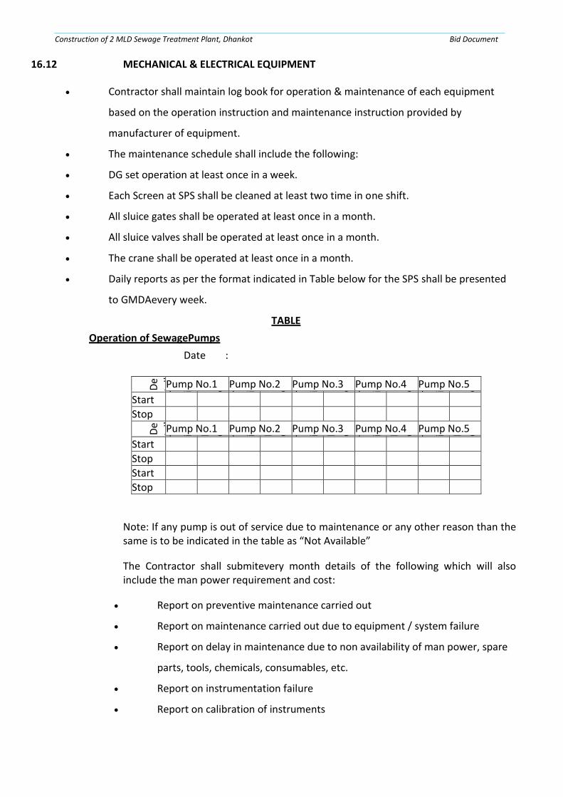
Construction of 2 MLD Sewage Treatment Plant, Dhankot Bid Document
16.12 MECHANICAL & ELECTRICAL EQUIPMENT
• Contractor shall maintain log book for operation & maintenance of each equipment
based on the operation instruction and maintenance instruction provided by
manufacturer of equipment.
• The maintenance schedule shall include the following:
• DG set operation at least once in a week.
• Each Screen at SPS shall be cleaned at least two time in one shift.
• All sluice gates shall be operated at least once in a month.
• All sluice valves shall be operated at least once in a month.
• The crane shall be operated at least once in a month.
• Daily reports as per the format indicated in Table below for the SPS shall be presented
to GMDAevery week.
TABLE
Operation of SewagePumps
Date :
De
tail Pump No.1 Pump No.2 Pump No.3 Pump No.4 Pump No.5 T i m e P o w e r R e a d i n g T i m e P o w e r R e a d i n g T i m e P o w e r R e a d i n g T i m e P o w e r R e a d i n g T i m e P o w e r R e a d i n g
Start
Stop
De
tail Pump No.1 Pump No.2 Pump No.3 Pump No.4 Pump No.5 T i m e P o w e r R e a d i n g T i m e P o w e r R e a d i n g T i m e P o w e r R e a d i n g T i m e P o w e r R e a d i n g T i m e P o w e r R e a d i n g
Start
Stop
Start
Stop
Note: If any pump is out of service due to maintenance or any other reason than the same is to be indicated in the table as “Not Available”
The Contractor shall submitevery month details of the following which will also include the man power requirement and cost:
• Report on preventive maintenance carried out
• Report on maintenance carried out due to equipment / system failure
• Report on delay in maintenance due to non availability of man power, spare
parts, tools, chemicals, consumables, etc.
• Report on instrumentation failure
• Report on calibration of instruments

Construction of 2 MLD Sewage Treatment Plant, Dhankot Bid Document
• Spare parts used and/or to be procured
• Tools used and/or to be procured
• Chemical & consumables used
• DG set operation
• Quantity of screened material removed
• Quantity of grit removed
The contractor shall make arrangements for training the operation staff of the PHED during O&M period. Monthly report on training of operation staff shall be submitted to client.
The contractor shall provide necessary sets of minimal safety equipment required for regular operation & maintenance such as safety gloves, helmets, oxygen mask, safety harness, life jackets, gum boots, overalls etc. The contractor shall give a list of all the safety kits which will be provided.
SAFETY REQUIREMENTS:
Checking, testing and replacement procedures to be carried out on all plant items on a daily weekly and monthly basis or at longer intervals to ensure trouble free operation. Full maintenance instructions for all equipment including planned maintenance schedules or charts giving daily, weekly, monthly, quarterly, half yearly, annual and overhaul instructions, together with recommended lubricants and spares. These shall also include details of routine maintenance work that will be within the competence of the normal maintenance staff and notification of maintenance work that will have to be done by the manufacturer, his agent or other specialist operator.
Fault locations and remedy charts to facilitate tracing the cause of malfunctions or breakdown and correcting faults.
Complete list of recommended lubricants and lubrications charts, insulating oil and insulation checking / replacement chart.
A ‘spares schedule', which shall consist of a complete list of item wise spares for all Plant, items with ordering references and part numbers.
A complete list of manufacturer’s instructions for operation and maintenance of all bought out equipment. The list shall be tabulated in alphabetical order giving the name of supplier / manufacture, identification of the Plant item giving the model number and the literature provided including instruction leaflets and drawing numbers.
Step by step procedure for the dismantling, repair and re-assembly of all items of equipment.
Part-list and drawings or exploded diagrams for each item of Plant with construction particulars, materials of construction, mating components, clearances and

Construction of 2 MLD Sewage Treatment Plant, Dhankot Bid Document
tolerances, maximum wear permitted before replacements are to be done etc
Record drawings of all systems installed, including general arrangements, conduit and wiring systems, wiring diagrams, control schematics and valve charts, etc., to a reduced scale.
The Operation and Maintenance Manual shall include details of all equipment (i.e. new, refurbished and existing).
The Contractor shall furnish 8 copies of the Operation and Maintenance Manual for the pumping station. Each volume shall be durable and permanently bound within a stiff binder of a design to be approved by the Employer. They shall permit the subsequent incorporation of revisions to be necessary during the Defect Liability Period.
16.13 INSPECTION AND TESTING REQUIREMENTS
16.13.1 General
The Contractor shall submit the following forapproval:
(a) Certificate/undertaking for having achieved Physical completion of Plant and
facilities;
(b) As- Built Drawings; and
(c) Operation and Maintenance Manuals.
All the tests shall be conducted in the presence of Employer’s representative and shall not be commenced until the aforementioned documents are approved by the Employer’s representative.
16.13.2 Tests on Physical Completion of Plant And Facilities
(A) Dry test General
As a minimum requirement, the following dry tests shall be carried out:
(a) A general inspection to check for correct assembly, installation of all equipment etc.,
and quality of workmanship;
(b) A check on the presence of lubricant, cooling medium etc;
(c) A general check to ensure that all covers, access ladders, water proofing, guard
railings, etc are in place; and
(d) A check on damp-proofing, rust – proofing, vermin-proofing and particularly the
sealing of apertures between building structures, chambers etc.
B Civil and Building Works
As a minimum requirement the presence of foreign bodies in pipe work and structures shall be checked and rectified as necessary. All Building services including Lighting and Sanitary fixtures shall be checked.

Construction of 2 MLD Sewage Treatment Plant, Dhankot Bid Document
C Mechanical Works
As a minimum requirement, preliminary running checks shall be carried out on all the mechanical works as far as permitted by circumstances in order to ensure smooth operation of the equipment and machinery. The noise levels and vibration etc of centrifuge, blower and gas engine if provided shall be assessed and corrective measures for meeting the criteria taken, as required.
D Electrical Works
The following tests are to be carried out on all the equipment/ systems, as applicable.
(a) Insulation resistance measurement of equipment, accessories, cabling, wiring etc.;
(b) Dielectric tests of the oil of Transformer;
(c) Phase sequence and polarity of Transformer;
(d) Voltage and current ratios of Transformer;
(e) Vector group of Transformer;
(f) Resistance measurement of winding, contacts, of Transformer and motors;
(g) Continuity tests of all equipment;
(h) Calibration of indicators, meters, relays etc.;
(i) Control and interlock checks in PMCC, MCC etc.;
(j) Settings of equipment and accessories;
(k) Checking of accuracy and error;
(l) Checking of operation characteristics, pick-up voltages and currents, etc. of all drives;
(m) No load tests and trials on drives (electrical motors);
(n) Operational and functional tests on equipment, accessories, control schemes,
alarms, trip, indication circuits etc.
(o) Measurement of guaranteed or approved designs including lighting levels, earth
resistance measurements etc. and
(p) Complete commissioning checks of the system.
E Instrumentation & Control System
The following dry tests shall be carried out on the instrumentation and control system:
(a) Continuity checks on all signal, control and power supply cables;
(b) Checking of instrument loop integrity, functionality and calibration. A written report
on each instrument in the format required by the Employer’s representative shall be
provided certifying that the instruments have been calibrated to the published
specified accuracy;
(c) Checking functionality of the instrument control panels and consoles; and
(d) PLC console/MMI and associated equipment.

Construction of 2 MLD Sewage Treatment Plant, Dhankot Bid Document
F Hydraulic wet test
General:
Hydraulic wet tests shall be carried out on completion of dry tests. Screened and degritted raw sewage shall be used for hydraulic performance of the Works. In order to demonstrate hydraulic wet test, the Contractor shall ensure that each part of the works is hydraulically loaded to its rated throughput for a period of at least twenty-four (24) hours. In order to remove doubt, the following tests inter alia shall be carried out:
a) Pressure testing of all piped systems in accordance with the relevant standards;
b) Filling of all structures and check for leaks and structural stability;
c) Running of all rotating systems in order to check for:
d) Correct functionality;
e) Absence of leaks;
f) Allowed temperature rise, smoothness of running and the absence of undue
vibration, stress, and noise level; and
g) Check drives running currents, power-factor, efficiency etc. under full load conditions
of all equipment.
h) Carry out calibration of instruments, especially flow meters and integrators for gas
and raw sewage where appropriate;
i) Carry out valving, diversions etc. to full hydraulic load (or where there is a
requirement to withstand no load to overload) on each process element;
j) Demonstrating correct functionality of electrical, control, and instrumentation
systems.
k) Assess leakage levels in piping, gates and valves etc.
During these tests a check on the performance of Plant shall be made, as far as site facilities will allow, to compare its site performance with the factory test data and to identify any constraints on performance due to site conditions.
16.14 SAFETYAUDIT
After satisfactory completion of the hydraulic wet tests and prior to the continuous introduction of raw sewage to the plant, a safety audit shall be carried out to ensure compliance with the necessary requirements of safety during operation of the Plant. The safety audit shall be documented. The Employer’s Representative shall approve the safety audit document.
16.15 TESTS DURING TRIAL RUN AND COMMISSIONING
A Process wet tests
On approval of safety audit the Contractor shall carry out process wet tests. Screened and degritted sewage shall be used as the primary feed stock for process wet tests. These tests shall be carried out to demonstrate the process performance
Construction of 2 MLD Sewage Treatment Plant, Dhankot Bid Document
of the works. In order to demonstrate this, the Contractor shall ensure that each part of the treatment system is loaded to its rated throughput for a continuous stable operating period of not less than 36 hours. The Contractor shall arrange collection and disposal of screenings, wet grit and sludge also as generated from the plant area as directed by the Employer’s representative from this point of time onwards.
The following test inter-alia shall be carried out:
(a) Check for leaks in structures, chambers, pumps and pipe works.
(b) Running of all rotating systems in order to check for:
• Correct functionality
• Absence of leaks
• Allowed temperature rise.
• Smoothness of running and absence of undue vibration or stress.
• Check drive running currents where the clear sewage and sludge is
pumped
• Carry out calibration of laboratory instruments.
• Demonstrate correct functionality of electrical, control and
instrumentation systems
On completion of the tests on the various parts of the works the Contractor shall proceed for commissioning and stabilizing the plant.
During commissioning and stabilization period Contactor shall collect raw sewage and treated sewage composite samples based on flow. The laboratory shall be utilized to analyze the Biochemical Oxygen Demand (BOD), Suspended solids (SS) and Chemical Oxygen Demand (COD) of both raw and treated sewage.
The Contractor shall establish a graph for the relationship of COD and BOD in both raw sewage and treated sewage. This ratio may be utilized during PG test to arrive at the value of BOD on the basis of COD test results. However, results of laboratory BOD tests shall prevail. In the same way, relationship between BOD and suspended solids shall also be generated in the treated sewage samples.
16.16 TESTS ON COMPLETION
A Performance Guarantee tests (PG tests)
Once the Contractor is satisfied with the stabilization of critical units and energy efficiency of the system, it will inform the Employer’s representative in writing that it is ready to perform performance guarantee test (PG Test). The performance guarantee test will be conducted at a mutually agreed convenient date.
1. The performance test shall be conducted for a continuous period of 5days (120
hours). The Employer’s representative in the presence of line agency and / or such
referee appointed by it shall conduct all tests.
In the event, during commissioning stage, BOD values exceed the design values as stated in contract then it shall admit the BOD equal to MLD by regulating the flow to

Construction of 2 MLD Sewage Treatment Plant, Dhankot Bid Document
either one stream or both the streams depending on the inflow of sewage. Contractor shall inform the Employer’s representative in writing about the flow it is proposing to load on the system and get the approval for the same. PG test conducted with flow regulation based on BOD load per day as per the design norm shall meet the functional guarantees. However, the Employer reserves the right to ask the Contractor to load the plant to full capacity or in one stream if sufficient flow is not available. In this case the Employer will take
2. Over the plant based on the actual results obtained, which may or may not meet the
all the functional guarantees.
Alternatively, the Employer reserves the right to conduct PG test within six months by issuing a “Conditional Taking-Over Certificate” from the date of issue of this certificate. In such an event, the ‘Operation & maintenance period’ shall be deemed to have commenced from the date of issue of “Conditional Taking over Certificate”. The Employer’s decision shall be final and binding on the Contactor in this regard.
3. Plants shall be operated at rated capacity. In the event, at the time of trial run and
commissioning the flow observed does not reach this figure, then during PG test
then the flow shall be maintained as follows.
4. In the event of any interruption in the PG Test for the reasons not attributable to the
Employer, the Contractor shall redo the PG test for 120 hours again. The time gap
between the interruption and restart shall not exceed 5 days. If the Contractor does
not restart the test after interruption within the period stipulated above the
Employer shall initiate action in accordance to contract conditions.
5. During the tests the Contractor shall take samples to demonstrate that each part of
the works and the works as a whole is performing in accordance with functional
guarantees. In case, functional guarantees are not met during the Performance
Guarantee Test, Performance Guarantee Test shall be considered as failed.
6. In case of failure of first Performance Guarantee Test, action shall be initiated in
accordance with condition of contract. In any case, the extension for clearing the PG
Tests shall not be extended beyond 90 days after the Works has failed first
Performance Guarantee Tests.
7. In case of failure of Performance Guarantee Test, in-respect of Effluent parameters
(BOD, COD, SS, pH, N P) the works shall be rejected and the Performance Security
shall be forfeited by the Employer without referring to the Contractor, besides
initiating action in accordance with Conditions of the contract.
8. All consumables needed for operation of the works such as laboratory chemicals,
lubricants, etc and transportation of screening and wet grit, off site, shall be provided
by the Contractor. The wet sludge shall be disposed inside the plant premises as
directed by the Employer’s Representative. The Contractor shall provide all facilities
and equipment not supplied under the contract and which are deemed necessary to
carry out and monitor the Tests on Completion.
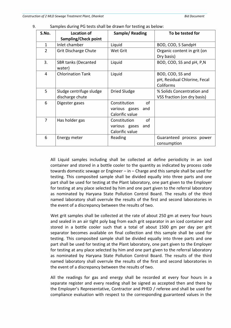
Construction of 2 MLD Sewage Treatment Plant, Dhankot Bid Document
9. Samples during PG tests shall be drawn for testing as below:
S.No. Location of Sampling/Check point
Sample/ Reading To be tested for
1 Inlet chamber Liquid BOD, COD, S SandpH
2 Grit Discharge Chute Wet Grit Organic content in grit (on Dry basis)
3. SBR tanks (Decanted water)
Liquid BOD, COD, SS and pH, P,N
4 Chlorination Tank Liquid BOD, COD, SS and pH, Residual Chlorine, Fecal Coliforms
5 Sludge centrifuge sludge discharge chute
Dried Sludge % Solids Concentration and VSS fraction (on dry basis)
6 Digester gases Constitution of various gases and Calorific value
7 Has holder gas Constitution of various gases and Calorific value
6 Energy meter Reading Guaranteed process power consumption
All Liquid samples including shall be collected at define periodicity in an iced container and stored in a bottle cooler to the quantity as indicated by process code towards domestic sewage or Engineer – in – Charge and this sample shall be used for testing. This composited sample shall be divided equally into three parts and one part shall be used for testing at the Plant laboratory, one part given to the Employer for testing at any place selected by him and one part given to the referral laboratory as nominated by Haryana State Pollution Control Board. The results of the third named laboratory shall overrule the results of the first and second laboratories in the event of a discrepancy between the results of two.
Wet grit samples shall be collected at the rate of about 250 gm at every four hours and sealed in an air tight poly bag from each grit separator in an iced container and stored in a bottle cooler such that a total of about 1500 gm per day per grit separator becomes available on final collection and this sample shall be used for testing. This composited sample shall be divided equally into three parts and one part shall be used for testing at the Plant laboratory, one part given to the Employer for testing at any place selected by him and one part given to the referral laboratory as nominated by Haryana State Pollution Control Board. The results of the third named laboratory shall overrule the results of the first and second laboratories in the event of a discrepancy between the results of two.
All the readings for gas and energy shall be recorded at every four hours in a separate register and every reading shall be signed as accepted then and there by the Employer’s Representative, Contractor and PHED / referee and shall be used for compliance evaluation with respect to the corresponding guaranteed values in the

Construction of 2 MLD Sewage Treatment Plant, Dhankot Bid Document
contract.
TREATED SEWAGE QUALITY CRITERIA FOR PASSING THE TESTS ONCOMPLETION OF STPS
The works shall be considered to have achieved the required treated sewage quality standards for passing Tests on Completion if all samples taken during a five (5) day continuous operational period comply with the guaranteed quality In respect of BOD, COD, pH and Suspended solids in all 5 out of 5 cases. For other parameters if compliance is achieved in 4 out of 5 results, in accordance with criteria defined for the same, the P G Tests (Tests on Completion) shall be deemed to have been cleared. If the two or higher number of such samples fail the tests, a suitable compensation may be levied by the Employer, which shall not exceed amount of Insurance for Design given in Appendix to Tender.
16.17 TESTS AFTER COMPLETION
During O & M period, tests for BOD, SS, COD and pH shall be done daily on composite samples. The values observed on composite sample shall comply with the guaranteed values in100% samples for BOD, SS, COD and pH. Test for other parameters shall be carried out on fortnightly basis or as need arises. The results of these parameters shall have 90% compliance of the guaranteed values recorded over a month.
16.18 PENALTIES FOR FAILURE TO ACHIEVE THE FUNCTIONAL GUARANTEES
In case of failure to supply the required quantity of water, liquidated damages shall be imposed for such failure to meet the performance criteria, as described in the following.
The Employer will be entitled to recover any such damages from the monthly progress payments to be made to the Contractor in the month in which the failure occurred, or at any time thereafter from the subsequent monthly progress payments.
16.19 DOWN TIME
Applicable rate for penalty shall be as given herebelow.
Sr.No. Details Penalty Amount per day or partday
1
Delay in Commissioning of STP within the completion period
Rs 10 Lacs/ Month or as prescribed by Ho’nble NGT from time to time.
This penalty is apart from the penalty imposed during clause -2
2 When desired parameters of effluent are not achieved (except when repair work is not being carried out)
An amount of min.Rs. 10,000 perday or as per Section 15 of Env. Act 1986
3 When any of the pump, motor, valve, soft starter, control panel, transformer, actuator, relay, switch, breaker etc. unit
An amount of Rs. 10,000 perday

Construction of 2 MLD Sewage Treatment Plant, Dhankot Bid Document
has been taken out ofservice Note: If several units have been taken out of service at the same time, the amount to be deducted from monthly payment shall be appliedin respect of each of the units out of service, for more than 2% of the workinghours.
4
When the contractor fails to keep the automatic system, PLCs, SCADA etc. in operation, otherthan for a planned outage for maintenance that has been arranged with prior approval of the Employer
Rs. 2500 perday
5 When contractor fails to keep the good house keepingandlandscaping
Rs. 1000 perday
6 When contractor fails to make and submit the reports intime
Rs. 5000 perday
16.20 ABSENCE FROM DUTY
When contractor’s General Manager, Shift Engineer, Instrumentation Engineer,
Electrical Engineer, Foreman-Electrical, Foreman-Mechanical, Foreman
Instrumentation, Instrumentation Technician, Pump operator, Helpers, Security
Guards, Attendant, Gardener are absent from duty, the following deduction shall be
made from monthly payments:
S.No. Conditions Rate per day or partday
I Pump operator is not on site for more than 3 days or morein a month without an approved replacement
Rs.1000
v Helpers, Security Guards, Attendant is not on site for more than 3 days or more in a month without an approved replacement
Rs.500
vi When any employee of the contractor is not wearing prescribeduniform
Rs.75
16.21 FACILITIES TO CONTRACTOR The Contractor will be permitted to use the premise and quarters developed under the Contract for use by his staff during operation and maintenance to the extent agreed and approved by the Employers Representative.
16.22 PAYMENTS The Contractor, at the time of bidding, will be responsible to ensure the

Construction of 2 MLD Sewage Treatment Plant, Dhankot Bid Document
completeness and adequacy of his Bid Price to fulfill the entire responsibilities as described above. His bid price, as quoted on a monthly basis in the Schedule of Prices, shall include all costs for carrying out all O&M responsibilities, except for the following items for which the Employer will bear the cost:
The cost of electric power consumed, will be paid directly to DHVBN by the Employer.
16.23 In case of non-achievement of desired results of treated effluent as per prescribed norms of DNIT/NGT Guidelines/CPCB Norms, the contractor shall be liable to all the consequences resulting from any law enforcing agencies of the country.
16.24 PRECAUTIONARY MEASURES
Provisions for following precautionary measures shall be made by contractor at his own cost and precautions shall be taken by the contractor accordingly
A. Traffic Control
Place easily readable and clear warning signs well ahead of work area
Fence off adequate space around the manhole for placing equipment and deposition of still removed Place barricades or signs to channelize the traffic, if possible
Vehicles can be parked between the traffic and the work area
Use flagman at the two ends for controlling flow of traffic from each direction and to avoid a traffic jam, if the road is narrow and only one lane of traffic is possible.
B. Manhole Safety
Ventilate the sewer line by opening two or three manholes on both the sides where work is to be carried out. The manholes should be opened at least one hour before start of operations. The opened manholes should be properly fenced to prevent any person, especially children, accidentally falling into the sewer. Dummy covers with BRC welded fabric can be used.
Where it is desirable to use the blowers, operate these for at least 30 minutes before start and during cleaning operations to ventilate the lowest working levels.
Use safety harness and life line before entering the sewer line. Two helpers at the top should be provided for each person. The person standing at the top must send signals at every few minutes interval to the person in the manhole to ensure safety.
Test for hazardous gases before entry of a person into the sewer line and also in between if the operations are for a longer time.
C. Infection
The personnel working in sewerage cleaning systems are prone to infections and hence the following precautions should be taken:

Construction of 2 MLD Sewage Treatment Plant, Dhankot Bid Document
a) Emergency first aid treatment kits shall be provided to take care of all
minor injuries like cuts and burns
D. Precautions of Pumping Stations
a) Guards, shields, fencing, railings, and enclosures should be provided
to help prevent slipping, failing or contacting machinery while in
operation. Replace or repair if they are missing or damaged. When
removed install a temporary safety barrier.
b) When dealing with equipment
Always stop the machine before removing any guard
See that power supply to the equipment is cut off. Place a warning board on the switch so that somebody does not accidentally put it on.
Hoisting equipment should be able to lift the required load. Temporary support should be given to any machine or equipment jacked or hoisted up before going under it.
When lubricating a machine in operation, fittings should be at least 30 cms from any moving part or piped outside a guard
If oil or grease is split, clean up at once.
E. Precautions against Electrical Shocks
a) Only qualified and specially trained personnel should be allowed to
operate and maintain electrical equipment at the pumping stations
b) All electrical controls should be kept dry and in good condition
c) No metal ladders or metal tapes should be used around electrical
equipment
d) Insulated rubber mats should be provided before all electrical control
panels and they should be kept dry
e) Always test wires for current before working on any electrical item.
Use tools with insulated handles and rubber gloves.
F. Safety Equipment
The various safety equipments that are normally required in sewer cleaning work are gas masks, oxygen breathing apparatus, portable lighting equipment, no sparking tools, portable air blowers, safety belts, inhalators and diver’s suit.
The use of the particular safety equipment is governed by the detection of various gases and oxygen deficiency.
Knowledge of the type of gases in the atmosphere and of the working location becomes essential for the selection of the right type of safety equipment.
G. Gas Masks
General purpose gas masks are used for respiratory protection from low and moderately high concentrations of all types of toxic gases and vapours present in the atmosphere in which there is sufficient oxygen to support life. Masks afford necessary respiratory protection under many circumstances but

Construction of 2 MLD Sewage Treatment Plant, Dhankot Bid Document
it is most important to know the limitations of the various types available and to be familiar with their use. Even when masks are used properly, other precautions such as never using open flames or creating sparks in the presence of inflammable gases must be taken. The general purpose gas masks afford protection against organic vapours, acid gases, and carbon monoxide up to 2 percent concentration, toxic dusts, fumes and smoke.
The gas mask consists of a face piece, a canister containing purifying chemicals, a timer for showing duration of service and a harness for support. Protection against specific contaminants can be achieved by the selection of appropriate canisters.
Persons using gas masks should practice regularly with them in order to become proficient in putting them on quickly and breathing through them.
Gas masks cannot be used in oxygen deficient atmospheres, in unventilated locations or areas where large concentrations of poisonous gases exist.
H. Breathing Apparatus
This is designed for respiratory protection from atmosphere that contains very high concentrations of toxic gases and vapours or that are deficient in oxygen. It fully protects a worker against all gases, vapours, dusts, fumes, smokes and oxygen deficiencies and can be safely used in petroleum vapours and is the most dependable device for work in atmospheres normally encountered in sewage works.
I. Air Hose Respirator
This should be used where a source of fresh air is available within a distance of 50m from the working location. It is essential that the supply of air is obtained from an uncontaminated source.
It consists of a mask which is a tight fitting face piece attached to a large diameter flexible hose, breathing tubes and a harness. Fresh air is blown to the mask through either a power operated or a hand operated blower. An inhalation check valve in the breathing tube assembly and exhalation valve in the face piece permit air flow only in one direction, from the source to the mask, when the blower is in operation. Exhaled air is released into the surrounding atmosphere through the exhalation valve. The valve arrangement permits the wearer to breathe directly through the hose in the even to blower failure. The maximum length of house will be about 50M. The hose, being of large diameter, permits breathing without excessive resistance in the event of blower failure. A special pressure release valve on the blower permits regulation of air delivery and a fresh air bypass valve functions automatically in the event of blower failure permits regulation of air delivery and a fresh air bypass valve functions automatically in the event of blower failure permitting the wearer to breathe directly through the hose. When a hand operated blower is used the operator will be available to attend to any emergent situation also. This apparatus does not depend on chemical and may be used over extended periods at low costs.
Purified air is used where a source of fresh air is not available within 50 m to permit the use of an air hose respirator or in situations where an air hose

Construction of 2 MLD Sewage Treatment Plant, Dhankot Bid Document
should encumber the worker.
J. Portable Lighting Equipment
The equipment normally used is portable electric hand lamps of permissible types, electric cap lamps and explosion proof flashlights.
K. No sparking Tools
These are made of an alloy (containing at least 80 percent of copper) that will not spark when struck against other objects and metals and yet retains the necessary strength and resistance to wear.
L. Portable Air Blowers
Forced ventilation of manholes, pits and tanks should be provided by portable blowers. Special precautions should be taken to ensure that the blowers do not serve as a source of ignition for inflammable gases. Such precautions shall include placing of the blower upwind from the manhole or at right angles to the wind direction and at least 2 m away from the opening. The use of such equipment requires a consideration of the depth of the manhole, size of enclosure and the number of openings to uncontaminated atmosphere. Trailer mounted blower having a capacity of 210 m3/min. can ventilate easily many meters of medium sized sewers.
M. Safety Belt
This consists of a body belt with a buckle and a shoulder harness. The life line is of high grade spliced manila rope, nylon rope or a steel cable anchored with rings on each side of the belt and provided with safety straps for anchoring of securing to a stable support. The life line should be about 15m in length and the overall assembly should be capable of withstanding a tensile load of 2000 Kg. The safety belt and life line should be tested by lifting the wearer clear of ground before each day’s use.
N. Inhalators
Approved inhalators employing a mixture of oxygen and carbon dioxide should be used for resuscitating victims of gas collapse, drowning or electric shock. Artificial respiration should be started at once on the patient and an inhalator face piece attached to the victims mouth as soon as the
Equipment can be made ready. The carbon dioxide used in small percentage sstimulates deep breathing so that more oxygen may be inhaled. Pure oxygen should be used only when irritant gases such as hydrogen sulphide or chlorine have caused the victim’s collapse.
O. Diver’s Suit
A good quality diver suit should be provided to the diver whose services are very necessary while plugging the sewer line or removal of some hard blockage due to stone etc. at the mouth of the pipe in the manholes. Depending upon the site condition, suit should have provision to connect an air line with compressor or oxygen cylinder.

Construction of 2 MLD Sewage Treatment Plant, Dhankot Bid Document
“Annexure-A”
LIST OF PREFERRED VENDOR LIST
A. Approved Vendor/Manufacturer/Make List -Instrumentation
The naming of a manufacturer in this specification is not intended to eliminate competition or prohibit qualified manufacturers from offering equipment. Rather,the intent is to establish a standard of excellence for the material used, and to indicate a principle of operation desired.
(i) List of Makes for Instruments:
S.NO DESCRIPTION VENDOR/MANUFACTURER/MAKE
1 Level IndicatorTransmitter
M/s EMERSON ,M/s ABB, M/sRoyceInstruments ,M/sGlobal Water, M/sEndress+Hauser, M/sPulsar, M/sKobold, M/sYokogawa M/s. Toshbro M/sSiemens
2 Flow meters/ Flow Indicator/ Transmitter
M/sEMERSON M/sABB M/sRoyceInstruments M/s Dynameters M/sEndress+Hauser, M/sKrohneMarshall M/sToshbro M/sSiemens
3 Level/Float Switches M/sDANFOSS M/sABB, M/sRoyceInstruments M/sEndress+Hauser, M/sKobold, M/sToshbro
4 Pressure Gauges/Pressure Switches
M/SWarry, M/SABB, DANFOSS M/sWika, M/sKobold M/sGenInstCoM/sSwitzerM/sDandfoss
5 Pressure Indicator Transmitter
M/sEMERSON, M/sABB, M/sKobold, M/sSwitzer, M/sRosemount M/sEndress+Hauser M/sYokogawa

Construction of 2 MLD Sewage Treatment Plant, Dhankot Bid Document
M/sSiemens M/sToshbro
6 Online Residual Chlorine Analyzer
M/sHachCompany, M/s SCAN M/sHFSCIENTIFIC INC, M/sEndress+Hauser, M/sYokogawa M/sWTW
7 Temperature Indicator Transmitters
M/sKobold M/sEndress+Hauser, M/sABB M/sHachCompanyM/sYokogawa
8 Analytical Online Instruments (DO,ORP, etc.)
M/sHachCompany, M/sEndress+Hauser, M/sABB M/s SCAN M/sWTW, M/sYokogawa
9 Strain Gage Load Cell M/sHachCompany, M/s Jenco M/sEndress+Hauser, M/sABB M/sSWAN M/sHFSCIENTIFIC, INC M/sWTWM/sOmron M/sYokogawa
(ii) List of Makes For UPS & Batteries:
(a) List of Makes for UPS
S.NO MANUFACTURER/MAKE
1 M/sAPC
2 M/sDB&ELECTRONICS
3 M/s HI-REL
4 M/s NUMERIC POWER SYSTEMS
(b) List of Makes for Batteries
S. NO MANUFACTURER/MAKE
1 M/s AMARRAJA
2 M/s HBLNIFE
3 M/s AMCO
4 M/s EXIDE
(iii) List of Makes for Cables
S.NO MANUFACTURER/MAKE
1 M/s UniversalCables
2 M/s Polycab
3 M/s Havell’s
4 M/s CCI
5 M/s Finolex
6 M/s NICCO

Construction of 2 MLD Sewage Treatment Plant, Dhankot Bid Document
7 M/s DeltonCablesLimited
(iv) List of Makes for Enclosures/ Panels
S.NO MANUFACTURER/MAKE
1 M/s Rittal
2 M/s ECIL
B. Approved Manufacturers List for Automation
The naming of a manufacturer in this specification is not intended to eliminate competition or prohibit qualified manufacturers from offering equipment. Rather, the intent is to establish a standard of excellence for the material used, and to indicate a principle of operation desired.
S.NO. DESCRIPTION MANUFACTURES/MAKES
1 Workstations, Servers Dell, HP, Lenovo, IBM
2 Program mable Logic Controllers
SchneiderElectric (QuantumSeries), SiemensPLC (S7400Hseries), AllanBradley (ControlLogixseries), ABB(AC800MSeries), Mitsubishi(Q 25Series), GE(7XiSeries),
3 SCADA Programming Software
IntellutionI Fix, Wonderware, WINCCV6.2, RS View, Visio Citect, Iconics, CX – Supervisor V3
4 GSM/GPRS Equipment Motorola, GE, Seimens, GSV Microtek,
In order to achieve standardization for appearance, operation, maintenance, sparepartsand manufacturer's service, like it emsofequipment provided hereunder shall be the end product so one(1) manufacturer.
In the event thatthe contractor wishes to propose alternate makes for the equipment mentioned above, he shall submit the following:
13 Submita letter from the manufacture of the each equipment mentioned
above, that the makes mentioned in this document are un-available.
14 Provide evidence from the manufacture of the proposed equipment and
demonstrate that the makes are superior/Equivalent to the approved
makes.

Construction of 2 MLD Sewage Treatment Plant, Dhankot Bid Document
C. Mechanical Items
S.N. Item Category Suggested Makes
1 CI Double Flanged Sluice Valves/CIDouble
A Kirloskar Bros. Ltd., Indian Valve Co. (IVC), VAG,TALIS
Flanged Butterfly valves/ Kinetic Double Air Valves/ Dual plate check valvesAs per API598
B IVC, VAG, Kirloskar, TALIS, IVC Nashik
2 CI Non Return Valves/ CheckValves
IVC, VAG, Kirloskar, TALIS, IVC Nashik
3 StainLessSteelExpansionBellows
KBL, Indian Valve, FOURESS
4 Thimble Mounted Sluice Gate
JASH, Oriental Castings, Shivpad,Durga Valves, Upadhaya valve
5 OpenChannelSluiceGate Oriental Castings, Jash, Shivpad
6 Pressure ReducingValves Oriental Casting, Shivpad, TALIS, VAG
7 DewateringPumps Crompton, Kirloskar, Mather & Platt, WPIL, Beacon, Jyoti Pumps(Baroda)
8 Back WashPumps Kirloskar Brothers Ltd, M&P, Jyoti, Crompton, Beacon
9 Dose MeteringPumps Crompton, Kirloskar, Mather & Platt, WPIL, Beacon, Jyoti Pumps(Baroda)
10 HorizontalSplitCasingCentrifugalPump
Crompton, Kirloskar, Mather & Platt, WPIL, Beacon, Jyoti Pumps(Baroda)
11 NonClogSubmersibleCentrifugalPump
Crompton, Kirloskar, Mather & Platt, WPIL, Beacon, Jyoti Pumps(Baroda)
12 Grit SeparatorMechanism
SHIV PAD, VOLTAS, TRIVENI
13 ManualCoarseBar Screen JASH, SHIV PAD, VOLTAS, Johnson, Oriental Casting
14 MechanicalCoarseBar Screen
JASH, SHIV PAD, VOLTAS, JOHNSON
15 MechanicalFineBar Screen JASH, SHIV PAD, JOHNSON, VOLTAS
16 ElectricallyOperatedTravellingCrane (EOT)/ Hand Operated Travelling Crane (HOT)/ Mono Rail Single GirderCranes
Greaves Cotton, REWA,WH Brady Co, Hercules Hoists Ltd.(INDEF)
Chain PulleyBlock
17 Chlorinators Metito, Pennwalt India Ltd.
18 Cast IronSpecials BEW, Electrosteel Casting Limited, Oriental Casting, Kejriwal
19 Turbo AirBlower Turbo Max, Korean Machinery, Godrej

Construction of 2 MLD Sewage Treatment Plant, Dhankot Bid Document
S.N. Item Category Suggested Makes
20 Air Blower RootType SWAM, KAY, Usha, Everest
21 ElectroMagneticFlowMeters
, FORBES MARSHALL, SIEMENS, E&H
22 SludgePump M&P, Kishor, KSB ,Rotomac, Tushaco
23 V.T.Pump Crompton, Kirloskar, Mather & Platt, WPIL, Beacon, Jyoti Pumps(Baroda)
24 S.S.DismantlingJoints ORIENTAL CASTING, DURGA, Kejriwal
25 AirVessel JASH(SURESEAL),Lotus Boiler andPressure Vessels P. Ltd., Hamdule Industries Pune
26 Mechanical Turbine type flowmeter
ITRON, CAPSTAN, NIVO CONTROL, ZENNER
27 AirCompressor Ingersol Rand, ELGI, KG Khosla, Atlas Copco Ltd.
28 DI Resilient(Soft) seated Butterfly valve/ DI Resilient(Soft) seated Sluice valve/ DI Resilient(Soft) seated Non Return valve/ DI Resilient(Soft) seated Kinetic Airvalve
VAG, IVC, Kirloskar Brothers Ltd,TALIS
29 Flow Control valve DARLING MUESCEO. VAG, BOSCHREXOROTH, Parker, Brand Hydraulics, TALIS
30 DWCPipes Any ISI marked brand as approved by competent authority
31 DIPipes Electrosteel, TATA- Metallics,RashmiMetallics,Electrotherm(India) Ltd, Jai Balaji Industries , Jindal Saw,provided they have not been blacklisted in past in any state.
32 DISpecials Electrosteel, KEJRIWAL, JINDAL SAW
33 UPVCPipes/UPVCSpecials Supereme, Polypack, FINOLEX
34 CIDoubleFlangedPipes BEW, CDIRON Industries, TRUFORM, ORIENTAL CASTINGS
35 Centrifuge HUMBOLTZ, HILLER, Pennwalt, Alfa Laval
36 CI Dismantling Joints/ CI D/F Specials/ CI Puddle Collar
BEW, SHIVA, Oriental Castings, Supra Enterprise
37 ConveyorBelt SHIV PAD, Voltas, Batliboi , Dynamic, Indiana

Construction of 2 MLD Sewage Treatment Plant, Dhankot Bid Document
S.N. Item Category Suggested Makes
38 CI FootValves Kirloskar Brother, Grand Metal Corporation (Bombay), Shree Jagannath Iron Foundary Pvt. Ltd., Kejriwal Enterprises( Raipur)
39 GearBox Premium, ELCON, Greaves Cotton,Alen Berry
40 MDPEPipes Jain Irrigation, Kisan Irrigation, Doroline
41 ZeroVelocityValve /Surge protectionsystem
JASH, IVC, R&D Multiple(Metal Casting), Kirloskar, Brothres.
42 GIPipes TATA, Jindal
43 Knife edge GateValve Jash, KBL,VAG, IVC,Fouress
44 CI S/SPipes Kejriwal Casting, Indian Iron Steel, TATA Iron & Steel.
45 FloatValve Upadhaya,KamalaCasting&Engineering, HSarker& Co.
46 Submersible`PumpsforClearWater
ABS,Grundfos,WPIL,Kirloskar Brothers Ltd., Mather & Platt, WILO
47 MSPipes TATA, Jindal, SAIL, Welspun
48 Agitators Filtech,MILTONROY,FIBER&FIBER,REMI,VOLTAS,SHIV PAD
49 SubmersibleMixers ABS, KSB, Grundfoss,KBL
50 WeighBridge VishwaKarma,Avery India Ltd.,Weightron, Rrockway Weigh Bridge
51 Fine BubbleDiffusers OTT, EDI USA, REHAU, SANITAIRE
52 Screw Pump Tushaco, AVS, ROTO, ALPHA HELICAL
53 Dosing Pump MILTON ROY, POSITIVE METERING, TOSHCON
54 PRVs,PSVs,Special Valves Saisanket Enterprises, Glenfield, Fluidtech Valves, National Safety Solutions, Uniflow Control Instruments Pvt Ltd
55 HDPE PIPES &FITTINGS Jain PE Pipes, Kimplas Piping Systems Ltd, Apollo Pipes Dutron Pipes, Duraline pipes
Reinforcement Make approved: Makes conforming to IS:1786 as per HSR
Cement make approved: Ordinary Portland Cement 43 grades of MAKE, Ambuja, Vikram, ACC, JK, Grasim, Ultratech duly ISI marked conforming to IS:IS-8112
Copyright © 2022 FDOKUMEN