Congestion Avoidance in Computer Net - works with a Connectionless Network Layer, Part I - Concepts,...
37
-
Upload
independent -
Category
Documents
-
view
1 -
download
0
Transcript of Congestion Avoidance in Computer Net - works with a Connectionless Network Layer, Part I - Concepts,...

CONGESTION AVOIDANCE IN COMPUTER NETWORKS
WITH A CONNECTIONLESS NETWORK LAYER
PART I: CONCEPTS, GOALS AND METHODOLOGY
Raj Jain, K. K. RamakrishnanDigital Equipment Corporation550 King Street (LKG 1-2/A19)
Littleton, MA 01460
ABSTRACT
Congestion is said to occur in the network when the resource demands exceed the capacityand packets are lost due to too much queuing in the network. During congestion, the networkthroughput may drop to zero and the path delay may become very high. A congestion controlscheme helps the network to recover from the congestion state.
A congestion avoidance scheme allows a network to operate in the region of low delay and highthroughput. Such schemes prevent a network from entering the congested state. Congestionavoidance is a prevention mechanism while congestion control is a recovery mechanism.
We compare the concept of congestion avoidance with that of ow control and congestioncontrol. A number of possible alternative for congestion avoidance have been identi�ed.From these a few were selected for study. The criteria for selection and goals for theseschemes have been described. In particular, we wanted the scheme to be globally e�cient,fair, dynamic, convergent, robust, distributed, con�guration independent, etc. These goalsand the test cases used to verify whether a particular scheme has met the goals have beendescribed.
We model the network and the user policies for congestion avoidance as a feedback con-trol system. The key components of a generic congestion avoidance scheme are: congestiondetection, congestion feedback, feedback selector, signal �lter, decision function, and in-crease/decrease algorithms. These components have been explained.
The congestion avoidance research was done using a combination of analytical modeling andsimulation techniques. The features of simulation model used have been described. Thisis the �rst report in a series on congestion avoidance schemes. Other reports in this seriesdescribe the application of these ideas leading to the development of speci�c congestionavoidance schemes.
Version: September 2, 1998
1
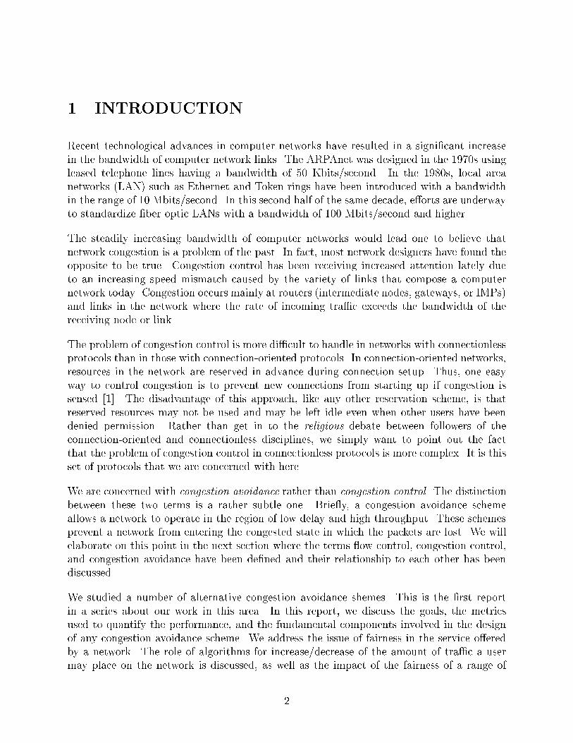
1 INTRODUCTION
Recent technological advances in computer networks have resulted in a signi�cant increasein the bandwidth of computer network links. The ARPAnet was designed in the 1970s usingleased telephone lines having a bandwidth of 50 Kbits/second. In the 1980s, local areanetworks (LAN) such as Ethernet and Token rings have been introduced with a bandwidthin the range of 10 Mbits/second. In this second half of the same decade, e�orts are underwayto standardize �ber optic LANs with a bandwidth of 100 Mbits/second and higher.
The steadily increasing bandwidth of computer networks would lead one to believe thatnetwork congestion is a problem of the past. In fact, most network designers have found theopposite to be true. Congestion control has been receiving increased attention lately dueto an increasing speed mismatch caused by the variety of links that compose a computernetwork today. Congestion occurs mainly at routers (intermediate nodes, gateways, or IMPs)and links in the network where the rate of incoming tra�c exceeds the bandwidth of thereceiving node or link.
The problem of congestion control is more di�cult to handle in networks with connectionlessprotocols than in those with connection-oriented protocols. In connection-oriented networks,resources in the network are reserved in advance during connection setup. Thus, one easyway to control congestion is to prevent new connections from starting up if congestion issensed [1]. The disadvantage of this approach, like any other reservation scheme, is thatreserved resources may not be used and may be left idle even when other users have beendenied permission. Rather than get in to the religious debate between followers of theconnection-oriented and connectionless disciplines, we simply want to point out the factthat the problem of congestion control in connectionless protocols is more complex. It is thisset of protocols that we are concerned with here.
We are concerned with congestion avoidance rather than congestion control. The distinctionbetween these two terms is a rather subtle one. Brie y, a congestion avoidance schemeallows a network to operate in the region of low delay and high throughput. These schemesprevent a network from entering the congested state in which the packets are lost. We willelaborate on this point in the next section where the terms ow control, congestion control,and congestion avoidance have been de�ned and their relationship to each other has beendiscussed.
We studied a number of alternative congestion avoidance shemes. This is the �rst reportin a series about our work in this area. In this report, we discuss the goals, the metricsused to quantify the performance, and the fundamental components involved in the designof any congestion avoidance scheme. We address the issue of fairness in the service o�eredby a network. The role of algorithms for increase/decrease of the amount of tra�c a usermay place on the network is discussed, as well as the impact of the fairness of a range of
2
increase/decrease algorithms. We also describe the simulation tools and the test sequencesthat we used to study alternative congestion avoidance schemes. These apply to all conges-tion avoidance schemes that we studied. Individual schemes will be described separately inother reports in this series.
The organization of this report is as follows. In section 2 we de�ne the concepts of owcontrol, congestion control, and congestion avoidance. We discuss the distinction betweenthese terms and show that the problem of congestion can not be solved simply by increasingmemory size or increasing link bandwidth. Section 3 describes the requirements for an idealcongestion avoidance scheme. Section 4 lists a number of alternative schemes for congestionavoidance. From this list, we selected a few schemes for detailed study. The criterion forselection are described. Section 5 de�nes a number of performance metrics that were used tode�ne optimality. Section 6 lists the goals that we set for the design of the schemes. Most ofthese goals are quantitative and veri�able. Section 7 describes the components of a genericcongestion avoidance scheme in the framework of a control system. This helps in a systematicdesign of the scheme in that most components can be designed in isolation. Two componentalgorithms that are common to all schemes are window increase/decrease algorithms andwindow update frequency. These are described in sections 8 and 9, respectively. Finally, wedescribe the simulation model in section 10 and the test sequences used to verify the goalsin section 11.
The next report in this series [19] describes a binary feedback congestion avoidance scheme.
2 CONCEPTS
In this section we de�ne the basic concepts of ow control, congestion control, and congestionavoidance. These three concepts are related but distinct. They are related because all threesolve the problem of resource management in the network. They are distinct because theysolve resource problems either in di�erent parts of the network or in a di�erent manner. Wealso point out how decreasing cost of memory, or increasing link bandwidth and processorspeed are not su�cient to solve these problems.
2.1 FLOW CONTROL
Consider the simple con�guration shown in Figure 1a in which two nodes are directly con-nected via a link. Without any control, the source may send packets at a pace too fast forthe destination. This may cause bu�er over ow at the destination leading to packet losses,retransmissions, and degraded performance. A ow control scheme protects the destinationfrom being ooded by the source.
3

Some of the schemes that have been described in the literature are window ow-control,Xon/Xo� [7], rate ow-control [5], etc. In the window ow-control scheme, the destina-tion speci�es a limit on the number of packets that the source may send without furtherpermission from the destination. The permission may be an explicit message or it may beimplicit in that an arriving acknowledgment may permit the source to send additional pack-ets. The Xon/Xo� scheme is a special case of window ow-control in which the window iseither in�nity (Xon) or zero (Xo�). In the rate ow-control schemes, the destination speci-�es a maximum rate (packets per second or bits per second) at which the source may sendinformation.
2.2 CONGESTION CONTROL
Now let us extend the con�guration to include a network 1 (see Figure 1b) consisting ofrouters and links that have limited memory, bandwidth, and processing speeds. Now thesource must not only obey the directives from the destination, but also from all the routersand links in the network. Without this additional control the source may send packets at apace too fast for the network, leading to queuing, bu�er over ow, packet losses, retransmis-sions, and performance degradation.
A congestion control scheme protects the network from being ooded by its users (source
1In most of the discussion on congestion, we use the term network to mean only the communication
subnet not including the end nodes (called users).
4

and/or destination). 2
In connection-oriented networks the congestion problem is generally solved by reserving theresources at all routers during connection setup. In connectionless networks it can be doneby explicit messages (choke packets) from the network to the sources [16], or by implicitmeans such as timeout on a packet loss. Jain [14] and Ramakrishnan [18] have discussed anumber of schemes for congestion control and analyzed a timeout-based scheme in detail.
2.3 FLOW CONTROL vs CONGESTION CONTROL
It is clear from the above discussion that the terms ow control and congestion control aredistinct. Flow control is an agreement between a source and a destination to limit the ow ofpackets without taking into account the load on the network. The purpose of ow control isto ensure that a packet arriving at a destination will �nd a bu�er there. Congestion controlis primarily concerned with controlling the tra�c to reduce overload on the network. Flowcontrol solves the problem of the destination resources being the bottleneck while congestioncontrol solves the problem of the routers and links being the bottleneck. Flow control isbipartite agreement. Congestion control is a social (network-wide) law. Di�erent connectionson a network can choose di�erent ow control strategies, but nodes on the network shouldfollow the same congestion control strategy, if it is to be useful. The two parties in owcontrol are generally interested in cooperating whereas the n parties (e.g., di�erent users) incongestion control may be noncooperative. Fairness is not an issue for the two cooperatingparties whereas it is an important issue for n competing parties.
It should be noted that there is considerable disagreement among researchers regarding thede�nitions of ow and congestion control. Some authors [7] consider congestion control tobe a special case of ow control, while others [20] distinguish them as above.
2.4 CONGESTION AVOIDANCE
Traditional congestion control schemes help improve the performance after congestion hasoccurred. Figure 2 shows hypothetical graphs of response time and throughput of a networkas the network load increases. If the load is small, throughput generally keeps up withthe load. As the load increases, throughput increases. After the load reaches the networkcapacity, throughput stops increasing. If the load is increased any further, the queues startbuilding, potentially resulting in packets being dropped. The throughput may suddenly dropwhen the load increases beyond this point and the network is said to be congested. The
2We use the term user to denote source or destination transport entity. Either one could take action to
limit the load on the network.
5

Figure 2: Network performance as a function of the load. Broken curves indicate perfor-mance with deterministic service and inter-arrival times.
response time curve follows a similar pattern. At �rst the response time increases little withload. When the queues start building up, the response time increases linearly until �nally,as the queues start over owing, the response time increases drastically.
The point at which throughput approaches zero is called the point of congestion collapse.This is also the point at which the response time approaches in�nity. The purpose of acongestion control scheme [14, 3] is to detect the fact that the network has reached the pointof congestion collapse resulting in packet losses and to reduce the load so the network canreturn to an uncongested state.
We call the point of congestion collapse a cli� due the fact that the throughput falls o�rapidly after this point. If the goal of the network design is to maximize throughput whilealso minimizing response time, then the knee is a better operating point as shown in Figure2. This is the point after which the increase in the throughput is small, but a signi�cantincrease in the response time results. Figure 2 also shows a plot of power [8] as a function
6

of the load. Power is de�ned as the ratio of throughput to response time. The peak of thepower curve occurs at the knee. We will discuss more about the use of power later underperformance metrics.
A scheme that allows the network to operate at the knee is called a congestion avoidancescheme as distinguished from a congestion control scheme which tries to keep the networkto the left of the cli�. A properly designed congestion avoidance scheme will ensure that theusers are encouraged to increase their load as long as this does not signi�cantly a�ect theresponse time and are encouraged to decrease it if that happens. Thus, the network oscillatesaround the knee and congestion never occurs. However, the congestion control schemes arestill required to protect the network should it reach the cli� due to transient changes in thenetwork.
2.5 CONGESTION AVOIDANCE vs CONGESTION CONTROL
The distinction between congestion control and congestion avoidance is similar to that be-tween deadlock recovery and deadlock avoidance. Congestion control procedures are curesand the avoidance procedures are preventive in nature. A congestion control scheme tries tobring the network back to an operating state, while a congestion avoidance scheme tries tokeep the network at an optimal state. Without congestion control a network may cease oper-ating (zero throughput) whereas networks have been operating without congestion avoidancefor a long time. The point at which a congestion control scheme is called upon depends onthe amount of memory available in the routers, whereas, the point at which a congestionavoidance scheme is invoked, is independent of the memory size. A congestion avoidancescheme may continuously oscillate slightly around its goal (knee) without signi�cant degra-dation in performance, whereas, a congestion control scheme tries to minimize the chancesof going above the limit (cli�).
3 DESIGN REQUIREMENTS
Before we discuss the various schemes for congestion avoidance and compare them it ishelpful to point out some of the design requirements that we followed. These requirementshelped us limit the number of schemes for further study. The key requirements are: no controlduring normal operation, no extra packets, a connectionless network layer, and con�gurationindependence. We describe these requirements below.
7
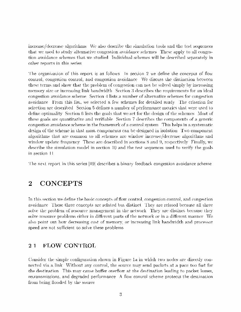
3.1 NO CONTROL DURING NORMAL OPERATION
Congestion is a transient phenomenon. Networks are con�gured in such a way that, on anaverage, the network is not overloaded. We therefore refrained from schemes that wouldgenerate extra overhead during normal (underloaded) conditions. This ruled out the use ofsuch techniques as sending encouragement packets to users during underload and indicatingoverload by the absence of these packets.
3.2 NO NEW PACKETS
The processing overhead for network services depends upon the number of packets and thesize of those packets. Performance measurements of existing implementations have shownthat the number of packets a�ects the overhead much more than the size. Short acknowl-edgment messages cost as much as 50% of the long data messages. This is why piggybacking(combining two are more messages) helps reduce the overhead.
In summary, adding an extra packet causes much more overhead than adding a few bits inthe header. We therefore preferred schemes that did not require generation of new messagesand concentrated instead on adding only a few bits in the header.
3.3 DISTRIBUTED CONTROL
The scheme must be distributed and work without any central observer. Thus, schemes whereall routers send congestion information to a central network control center were consideredunacceptable.
3.4 CONNECTIONLESS NETWORK LAYER
The key architectural assumption about the networks is that they use connectionless networkservice and transport level connections. By this we mean that a router is not aware of thetransport connections passing through it, and the transport entities are not aware of thepath used by their packets. There is no prior reservation of resources at routers before anentity sets up a connection. The routers cannot compute the resource demands except byobserving the tra�c owing through them.
Examples of network architectures with a connectionless network layer are DoD TCP/IP,Digital Network Architecture (DNA) [6], and ISO Connectionless Network Service used with
8
ISO Transport Class 4 [9].
4 CONGESTION AVOIDANCE SCHEMES
Congestion control and congestion avoidance are dynamic system control issues. Like allother control schemes they consist of two parts: a feedback mechanism and a control mech-anism. The feedback mechanism allows the system (network) to inform the users (source ordestination) of the current state of the system. The control mechanism allows the users toadjust their load on the system. The feedback signal in a congestion avoidance scheme tellsthe users whether the network is operating below or above the knee. The feedback signal ina congestion control scheme tells the users whether the network is operating below or abovethe cli�.
The problem of congestion control has been discussed extensively in literature. A numberof feedback mechanisms have been proposed. If we extend those mechanisms to signaloperations around the knee rather than the cli�, we obtain a congestion avoidance scheme.Of course, the control mechanism will also have to be adjusted to help the network operatearound the knee rather than the cli�. For the feedback mechanisms we have the followingalternatives:
1. Congestion feedback via packets sent from routers to sources.
2. Feedback included in the routing messages exchanged among routers.
3. End-to-end probe packets sent by sources.
4. Each packet contains a congestion feedback �eld that is �lled in by routers in packetsgoing in the reverse direction.
5. A congestion feedback �eld is �lled in by routers in packets going in the forwarddirection.
The �rst alternative is popularly known as choke packet [16] or source quench message inARPAnet [17]. It requires introducing additional tra�c in the network during congestion,which may not be desirable. A complement to this scheme is that of encouraging sources toincrease the load during underload. The absence of these encouragement messages signalsoverload. This scheme does not introduce additional tra�c during congestion. Nevertheless,it does introduce control overhead on the network even if there is no problem.
The second alternative, increasing the cost (used in the forwarding database update algo-rithm) of congested paths, has been tried before in ARPAnet's delay-sensitive routing. The
9

delays were found to vary too quickly, resulting in a large number of routing messages andstability problems. Again, the overhead was not considered justi�able [15].
The third alternative, probe packets, also su�ers from the disadvantage of added overheadunless probe packets had a dual role of carrying other information in them. If the latterwere the case, there would be no reason not to use every packet going through the networkas a probe packet. We may achieve this by reserving a �eld in the packet that is used by thenetwork to signal congestion. This leads us to the last two alternatives.
The fourth alternative, reverse feedback, requires routers to piggyback the signal on thepackets going in the direction opposite the congestion. This alternative has the advantage inthat the feedback reaches the source faster. However, the forward and reverse tra�c are notalways related. The destinations of the reverse tra�c may not be the cause of or even theparticipant in the congestion on the forward path. Also, many networks (including DNA)have path splitting such that the path from A to B is not necessarily the same as that fromB to A.
The �fth alternative, forward feedback, sends the signal in the packets going in the forwarddirection (direction of congestion). The destination either asks the source to adjust the loador returns the signal back to the source in the packets (or acknowledgments) going in thereverse direction. This is the alternative that we �nally chose for further study.
The minimal forward feedback requires just one bit of feedback signal with every packet.Although at �rst, one bit may not appear to be able to carry enough information, we showin the second part [19] of this report series that there is considerable performance gain evenby single-bit feedback.
Most of the discussions in this and associated reports center around window-based ow-control mechanisms. However, we must point out that this is not a requirement. Thecongestion avoidance algorithms and concepts can be easily modi�ed for other forms of ow control such as rate-based ow control in which the sources must send below a rate(packets/second or bytes/second) speci�ed by the destination. In this case, the users wouldadjust rates based on the signals received from the network.
5 PERFORMANCE METRICS
The performance of a network can be measured by several metrics. The commonly usedmetrics are: throughput, delay, and power.
Throughput is measured by the user bits transmitted per unit of time. Thus, protocol over-head, retransmissions, and duplicate packets are not considered in throughput computation.
10
Some of the more important applications of computer networks are: �le transfer, mail, andremote login. The �rst two are throughput sensitive. The response time (time for the packetto reach the destination) is generally not so important. On the other hand, for remote login,response time is more important than throughput.
The aforementioned goal, maximizing throughput and minimizing response time, are mutu-ally contradictory in that all methods to increase throughput result in increased responsetime as well and vice versa. To resolve this contradiction, Giessler et al. [8] proposed thefollowing metric:
Power =Throughput�
Response time
Here, � is a positive real number. Notice that by maximizing power, one tries to maximizethroughput and minimize response time. Normally, � = 1, i.e., increasing throughput anddecreasing response time are given equal weights. By setting � > 1, one can favor �le tra�cby emphasizing higher throughput. Similarly, by setting � < 1 one can favor terminal tra�cby emphasizing lower response time.
It must be pointed out that the throughput and response time used above are system-widethroughput (total number of packets sent for all users divided by the total time) and system-wide response time (averaged over all users) giving us system power. The operating pointobtained in this manner is di�erent from the one that would be obtained if each of the n userstries to maximize their own individual power (ratio of individual throughput and individualresponse time). Maximizing individual power leads to a number of undesirable e�ects [2, 10].
6 GOALS
Design of a congestion avoidance scheme requires comparing a number of alternative algo-rithms and selecting the right parameter values. To help us do this we set a number of goalswhich are described in this section. Each of these goals has an associated test to help usverify whether a particular scheme meets the goal.
6.1 EFFICIENT
A network operating at the knee is said to be operating e�ciently. The e�ciency is measuredby the system power as de�ned earlier. The congestion avoidance scheme should lead thenetwork to the knee, that is, the point of maximum system power.
11

Given any performance metric and a system of n users, there are two kinds of e�cient oper-ating points: individual and global. Individually e�cient operating points occur when eachuser tries to maximize its performance without regard for the performance of others. Thismay or may not lead to the globally e�cient operating point where the total system per-formance is the highest. In other words, at the globally e�cient operating point, there maystill be opportunities for each individual user to improve its performance (while degradingthat of others). We have explicitly chosen global e�ciency and not individual e�ciency asour goal.
We set the parameters of our congestion avoidance schemes to values that maximize globalpower and fairness.
6.2 RESPONSIVENESS
Network con�gurations and tra�c vary continuously. Nodes and links come up and down.The load placed on the network by users is highly varying. The optimal operating point istherefore a continuously moving target. It cannot be assumed that the optimal operatingpoint observed in the past is still optimal because the con�guration or workload mighthave changed. If the feedback is limited to a binary signal [19], this leads to schemes thatcontinuously change the load slightly below and slightly above the optimal level and verifythe current state by observing feedback signals obtained from the network.
When operating at the knee, to sense the state of the network, there is a need for oscillationof the window around the optimal level. Any attempt to eliminate oscillations also leadsto the loss of responsiveness. We explicitly tested the responsiveness of the algorithms bychanging router service times during a simulation and verifying that the operating pointfollowed the change in the optimal window size.
6.3 MINIMUM OSCILLATION
Schemes with a smaller amplitude of oscillation are preferable over those with a larger am-plitude. We found that schemes with smaller oscillations are also slower (less responsive)algorithms in that they take longer to reach the target. We therefore need to make a suitabletradeo� between the two requirements.
12
6.4 CONVERGENCE
If the network con�guration and workload were to remain stable, the scheme should bringthe network to a stable operating point. Many alternatives were rejected because they weredivergent. This means that the total load on the network either increased slowly towardsin�nity or decreased towards zero without stabilizing.
We also found cases where the system throughput would converge to a stable value but theindividual user's throughput would vary considerably. We call this phenomenon false con-
vergence. More speci�cally, it could be called global convergence without local convergence.
Among converging schemes, the preferred alternative is the one that takes the least time toconverge.
6.5 FAIRNESS
In any system shared by n independent users, fairness is an important issue. Fairness de-mands that given n users sharing a resource, each of them should get the same share of theresources (unless the user itself demanded less than its fair share). Thus, n users sharing apath and each demanding in�nite resources should have equal throughput. If the through-puts are not exactly equal, the fairness can be quanti�ed using the following fairness function[11]:
Fairness =(Pn
i=1 xi)2
nPn
i=1 x2
i
Here, xi is ith user's throughput.
In designing congestion avoidance schemes and in setting parameter values our goal was tochoose schemes and values that maximized fairness. Often, we found that there is a tradeo�between e�ciency and fairness. The values that maximize system power are not necessarilythe same as those that maximize fairness and vice versa. In such cases, we tried to err onthe side of e�ciency.
The de�nitions of fairness and e�ciency presented in this report treat the network as a singleresource to be shared equally among all users.
6.6 ROBUSTNESS
Robustness requires that the scheme work in a noisy (random) environment. Thus, schemeswhich work only for deterministic service times or schemes that presume a particular dis-
13
tribution (exponential) for service times were discarded. We tested robustness by varyingdistributions of service times.
6.7 SIMPLICITY
Simplicity of schemes is also an important goal. For most alternatives we tried their simplerversions. Only if the simpler versions caused a signi�cant reduction in performance did wesacri�ce simplicity.
6.8 LOW PARAMETER SENSITIVITY
In designing the congestion avoidance schemes we studied sensitivity with respect to param-eter values. If the performance of a scheme was found to be very sensitive to the setting ofa parameter value, the scheme was discarded.
6.9 INFORMATION ENTROPY
Information entropy relates to the use of feedback information. We want to get the maxi-mum information across with the minimum amount of feedback. Given n bits of feedback,information theory tells us that the maximum information would be communicated if eachof the 2n possible combinations were equally likely. In particular, with one bit of feedback,maximum information would be communicated if the bit was set 50% of the time, i.e.,
P (bit = 1) = P (bit = 0) = 0:5
6.10 DIMENSIONLESS PARAMETERS
A parameter that has dimensions (length, mass, time) is generally a function of networkspeed or con�guration. A dimensionless parameter has wider applicability. For example, inchoosing the increase algorithm we preferred to increase the window by an absolute amountof k packets rather than a rate of t packets/second. The optimal value of the latter dependsupon the link bandwidth. Our goal in developing the congestion avoidance scheme was tohave all parameters dimensionless, thereby ensuring that the scheme would be applicableto networks with widely varying bandwidths. Of course, we also studied the parametersensitivity and chose the least sensitive alternatives.
14

Figure 3: Components of a congestion avoidance scheme
6.11 CONFIGURATION INDEPENDENCE
Con�guration independence is a desirable goal. We therefore tested our schemes for manydi�erent con�gurations. Although it is a noble goal, generally it is possible to come up witha con�guration where a given scheme will not satisfy one of the goals. We have tried toidentify such limitations wherever appropriate.
In many network architectures, including DNA, paths are dynamically calculated. As therouters go up or down, the paths change. The congestion avoidance scheme should adapt tothe changing con�gurations.
7 COMPONENTS OF AN AVOIDANCE SCHEME
The two key components of any congestion avoidance scheme, the feedback mechanism andthe control mechanism, have already been discussed earlier in this report. We call thesenetwork policies and user policies, respectively. A more detailed break down of thesepolicies is shown in Figure 3. This allows us to concentrate on one component at a timeand test various alternatives for that particular component. During the analysis, it can beassumed that other components are operating optimally. Of course, one would need to verifyat the end that the combined system worked satisfactorily under imperfect conditions.
15

The network policy consists of three algorithms: congestion detection, feedback �lter, andfeedback selector. The user policy also consists of three algorithms: signal �lter, decisionfunction, and increase/decrease algorithm. These generic algorithms apply to many di�er-ent congestion avoidance schemes. For example, these six algorithms would apply whetherwe choose to implement network feedback in the form of source quench messages or weimplement it via a �eld in the packet header.
7.1 CONGESTION DETECTION
Before the network can feedback any information, it must determine its state or load level.In a general case, the network may be in one of n possible states. The congestion detectionfunction helps map these states into one of the two possible load levels: overload or underload(above or below the knee). A k-ary version of this function would result in k levels of loadindications. A congestion detection function, for example, could work based on the processorutilization, link utilization, or queue lengths.
7.2 FEEDBACK FILTER
After the network has determined the load level, it may want to verify that the state lastsfor a su�ciently long period before signaling it to the users. This is because a feedback ofstate is useful only if the state lasts long enough for the the users to take action based on it.A state which changes very fast may lead to confusion. By the time users become aware ofthe state, it no longer holds and the feedback is misleading. Therefore, we need a (low-pass)�lter function to pass only those states that are expected to last long enough for the useraction to be meaningful. Examples of feedback �lters are exponential weighted average ormoving average of processor utilization, link utilization, or queue lengths.
7.3 FEEDBACK SELECTOR
After the network has determined that it is overloaded (or underloaded) and has ensuredthat the state is likely to last long enough, it needs to communicate this information to usersso that they may reduce (or increase) the tra�c. A feedback selector function may be usedto determine the set of users to be noti�ed. In other words, the network may want all usersto reduce the tra�c or it may selectively ask some users to reduce and others to increase thetra�c. In the simplest case, it may give the same feedback signal to all users.
16
7.4 SIGNAL FILTER
The users receiving the feedback signals from the network (routers) need to interpret thesignal. The �rst step in this process is to accumulate a number of signals. Due to the proba-bilistic nature of the network, all these signals may not be identical. Some may indicate thatthe network is overloaded while others may indicate that it is underloaded. The user needsto combine these to decide its action. Some examples of received signal �lter are majority
voting (50%), or three-quarter majority (75%), or unanimous (100%). The percentage maybe used after applying a weighting function, for example, giving higher weight to recentsignals.
7.5 DECISION FUNCTION
Once the user knows the network load level, it has to decide either to increase its load ordecrease its load. The function can be broken down into two parts: the �rst part determinesthe direction and the other determines the amount. These parts are called decision functionand increase/decrease algorithms, respectively.
The decision function takes feedback signals for the last T seconds, for instance, as inputparameter, and determines the load level of the network path. The key parameter is T - ,the interval for which it should accumulate feedback. This determines the window updatefrequency. We will further discuss window update frequency later in this report.
In its simplest form a decision function may be a 2-way function indicating whether theload should be increased or decreased. Some would argue that it may be a 3-way functionincluding a gray area where no action is taken.
Another generalization often mentioned is to make a decision but not act on it unless wereach the same decision again, one or more times in the future. This may seem to increasethe probability of reaching the right decision.
Both the generalizations mentioned above result in postponement of the action thereby caus-ing the system to stay in the same state longer. This may be useful if the goal (knee) isstable but in a computer network the knee is a continuously moving target and it is helpfulto recon�rm the state by perturbing the load, however slightly, one way or the other.
The costs of the two types of errors, increasing the tra�c under overload and decreasingthe tra�c under underload, determine whether the users should err on the side of beingpessimistic or optimistic. For cli�-based policies (congestion control schemes), it is betterto be pessimistic because the cost (loss of a packet) of miss-signal is high. For knee-basedpolicies (congestion avoidance schemes), the two costs are approximately equal (assuming
17

the knee is far away from the cli�). We therefore recommend a two-way decision functionand no postponement of action.
7.6 INCREASE/DECREASE ALGORITHM
The key part of a control scheme is the control, i.e., the action taken as a result of thefeedback. For congestion avoidance schemes this part lies in the increase/decrease algorithmsused by the users. These algorithms are a key to achieving e�ciency as well as fairness. Thechoice of other components of the congestion avoidance scheme depends upon the type offeedback chosen, whereas, the increase/decrease algorithms can be discussed and analyzedgenerically in great detail and apply to several feedback mechanisms. We discuss some ofthese alternatives in the next section. A more complete discussion may be found in Chiuand Jain [4].
8 INCREASE/DECREASE ALGORITHMS
In this section we compare a number of alternative algorithms for window increase anddecrease. We show that an additive increase, multiplicative decrease algorithm provides fairand stable operation and that it is important to keep windows as real valued variables whichare rounded-o� to the nearest integer.
We assume that the source and destination transport entities are using a window-based ow-control. Thus, increasing the window increases the load on the network and decreasingthe window decreases the load. It must be pointed out, however, that all the argumentsapply equally well to other forms of ow control such as rate based ow-control, in whichthe destination permits the source to send data at a pre-speci�ed rate (bits/second or pack-ets/second). In this case, it is obvious that increasing the rate increases the load and viceversa.
A general increase (or decrease) algorithm would take the current control ( ow-control win-dow) and feedback signals as input arguments and produce the new control as an outputargument. However, as discussed above, we assume that the feedback signals have beenanalyzed by other components of the congestion avoidance scheme and the decision providedto this component is to increase or decrease the tra�c. Thus, the key parameter to theincrease/decrease algorithms is the current window.
We considered two types of increase/decrease algorithms:
18

1. Additive - The window is increased or decreased by a �xed amount.
w = w + k1
w = w � k2
2. Multiplicative - The window is increased or decreased by a �xed multiple.
w = r1w; r1 > 1
w = r2w; 0 < r2 < 1
More general increase/decrease algorithms using linear and non-linear functions of the win-dow were also considered and are described in Part 3 of this report series [4]. Here, weconcentrate on choosing one of the following four combinations:
1. Multiplicative Increase, Multiplicative Decrease
2. Multiplicative Increase, Additive Decrease
3. Additive Increase, Additive Decrease
4. Additive Increase, Multiplicative Decrease
In all these alternatives we assume that the computed value is rounded to an integer valueand that the window is never allowed to go below 1.
The two key requirements of the increase/decrease policy are that it should allow a single usernetwork to operate as close to optimality as possible and that it should allow a multi-usernetwork to operate as fairly as possible. In comparing the above alternative we will assume asimpli�ed model of the network in which all users share the same path and therefore receivethe same feedback. If ith user has a window wi, the network gives the signal to go up if andonly if:
nX
i=1
wi � wknee
Here, wknee is the window at the knee of the throughput (or response time) curve for thegiven network con�guration.
The fairness goal dictates that regardless of any starting point all n users should convergeto the same �nal window wknee=n. While going down, the users with higher windows shouldgo down more than those with lower windows, i.e., the decrease should be proportional(multiplicative). While going up, the users with lower windows should go up more than
19
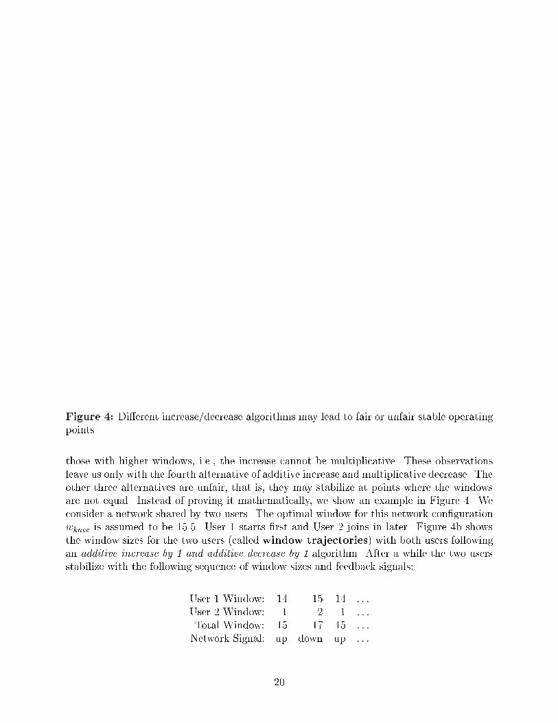
Figure 4: Di�erent increase/decrease algorithms may lead to fair or unfair stable operatingpoints.
those with higher windows, i.e., the increase cannot be multiplicative. These observationsleave us only with the fourth alternative of additive increase and multiplicative decrease. Theother three alternatives are unfair, that is, they may stabilize at points where the windowsare not equal. Instead of proving it mathematically, we show an example in Figure 4. Weconsider a network shared by two users. The optimal window for this network con�gurationwknee is assumed to be 15.5. User 1 starts �rst and User 2 joins in later. Figure 4b showsthe window sizes for the two users (called window trajectories) with both users followingan additive increase by 1 and additive decrease by 1 algorithm. After a while the two usersstabilize with the following sequence of window sizes and feedback signals:
User 1 Window: 14 15 14 : : :
User 2 Window: 1 2 1 : : :
Total Window: 15 17 15 : : :
Network Signal: up down up : : :
20

Thus, the system reaches a stable state where the �rst user oscillates with an average windowof 14.5, while the second user oscillates with an average window of 1.5. The throughput ofthe �rst user is approximately ten times that of the second. The algorithm is unfair.
It can similarly be shown that the �rst two alternatives with multiplicative increase areunfair.
The window trajectory, using the fourth alternative (additive increase and multiplicativedecrease) for the same network con�guration, is shown in Figure 4c. With this algorithmthe two users stablize at window size very close to each other. This algorithm is fair in mostcases. The unfairness occurs in this case mainly due to the control (window) being discrete(integer valued). This issue as well as a few others are discussed next.
8.1 EFFECT OF DISCRETE CONTROL
An important aspect of increase/decrease algorithms is the truncation/rounding issue. Thereare two values for the window size that a user maintains: computed and implemented.The values computed using the increase and decrease algorithms are real valued variables.However, if the computed window comes out to 2.6, for instance, the user must decidewhether to use 2 (truncated) or 3 (rounded) as the number of packets (implemented window)which will be sent in the next cycle.
It is important that the window values be maintained as real numbers even though actualwindows used are integer valued. It is possible to study the e�ect of discrete control bystudying the variation of the window at a user in isolation assuming that the network feedbackis perfect (based on the global knowledge). Thus, using a simple computer program, it ispossible to try various values of increase amount, decrease factor, starting window values,and to �nd the cases where the algorithms stabilize to unfair values. We found that generally,single precision oating point representation of window is adequate.
If only integer values are maintained for the window, additive increase and multiplicative
decrease may also stabilize to unfair values, although this may not be the case for all valuesof increase amounts and decrease factors. Figure 5 shows a particular case of unfairness fromhaving discrete control. The two-user con�guration discussed earlier in Figure 4 is used. Theusers increase additively by 1 and decrease multiplicatively by a factor of 0.8. The optimalwindow is 15.5. After a while the two users stabilize such that User 1 has a window of 10 anduser 2 has a window of 6. The sum is more than wknee = 15:5 and therefore both users areasked to reduce. They come down (using a factor of 0.8) to 8 and 4 (0.8(6)=4.8 truncatedto 4). The total window is less than wknee and hence both users are asked to go up. They goup by 1 to 9 and 5. The total window is still less than wknee and the users go up to 10 and 6.After this, the cycle repeats and the second user gets 6/10th of the �rst user's throughput.
21
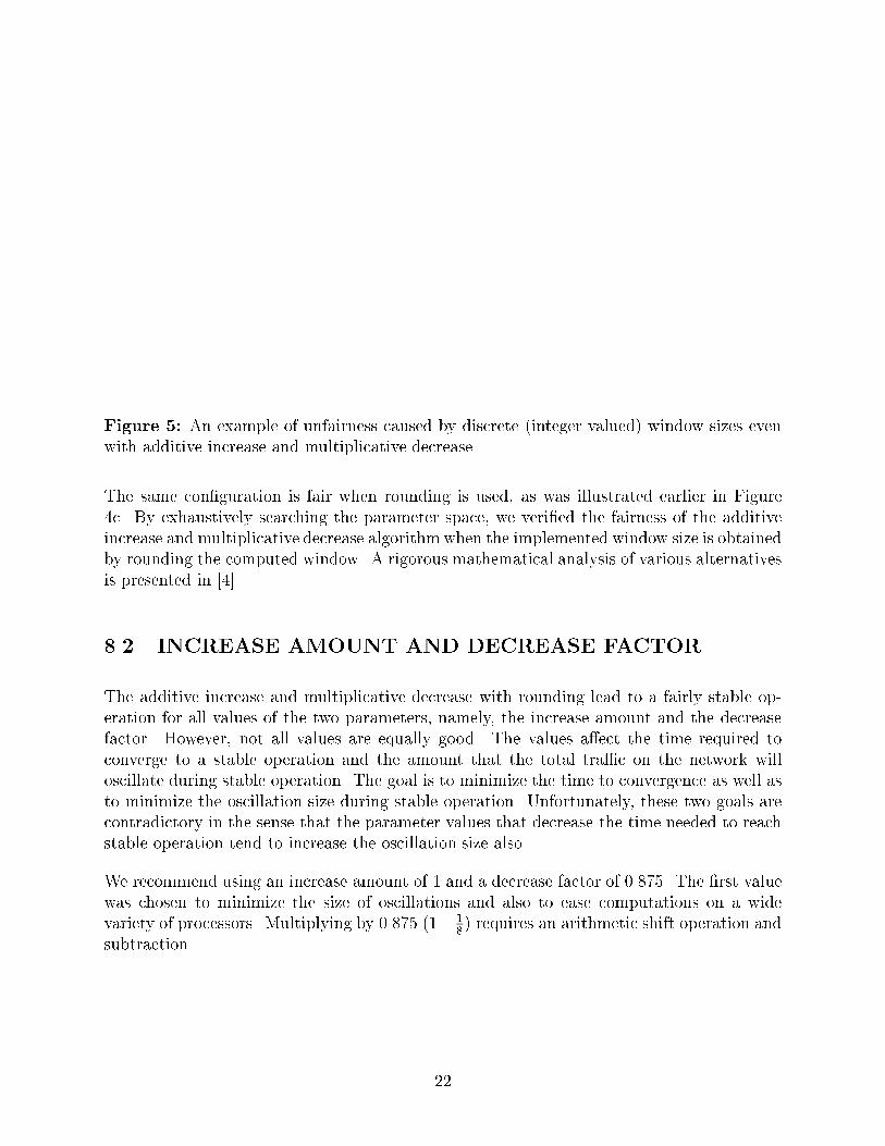
Figure 5: An example of unfairness caused by discrete (integer valued) window sizes evenwith additive increase and multiplicative decrease.
The same con�guration is fair when rounding is used, as was illustrated earlier in Figure4c. By exhaustively searching the parameter space, we veri�ed the fairness of the additiveincrease and multiplicative decrease algorithmwhen the implemented window size is obtainedby rounding the computed window. A rigorous mathematical analysis of various alternativesis presented in [4].
8.2 INCREASE AMOUNT AND DECREASE FACTOR
The additive increase and multiplicative decrease with rounding lead to a fairly stable op-eration for all values of the two parameters, namely, the increase amount and the decreasefactor. However, not all values are equally good. The values a�ect the time required toconverge to a stable operation and the amount that the total tra�c on the network willoscillate during stable operation. The goal is to minimize the time to convergence as well asto minimize the oscillation size during stable operation. Unfortunately, these two goals arecontradictory in the sense that the parameter values that decrease the time needed to reachstable operation tend to increase the oscillation size also.
We recommend using an increase amount of 1 and a decrease factor of 0.875. The �rst valuewas chosen to minimize the size of oscillations and also to ease computations on a widevariety of processors. Multiplying by 0.875 (1� 1
8) requires an arithmetic shift operation and
subtraction.
22

Figure 6: Birth policies.
8.3 BIRTH POLICIES
Another alternative to convergence time and the oscillation size dilemma is the use of abirth policy. The parameter values are initially chosen to minimize the time to convergence.Once convergence is reached, another set of parameter values is used which minimizes theoscillation size. The convergence is detected by a change of direction (a decrease followingan increase or vice versa).
Figure 6 shows the case of a single user passing through a path with a knee at 15.5, startingwith a window of 1. Two cases are shown. In the �rst case (without a birth policy) theincrease amount and the decrease factor are set at 1 and 0.875, respectively. In the secondcase (with a birth policy) the increase amount is 2 until the �rst decrease when the increaseamount is reset to 1. It is seen that the birth policy does allow the user to reach the kneefaster. However, the additional complication of keeping an additional code to detect thedirection change may not be considered worthwhile.
8.4 SOURCE BOUND CASE
In the discussion so far, we have assumed that the sources are able to send as many packets asthe optimal window computation requires. An interesting case to consider is what happensif the source (and not the network or the destination) is the bottleneck. In this case, thenetwork always gives increase signals to the user which computes a new larger window but isnot able to send more than w packets in one round-trip delay. Based on w packets per cycle,the network continues to ask the user to increase the load. In this case, it is possible for thecomputed window to increase continuously and over ow. Actually, in this case the computed
23

window has no meaning and therefore should never be increased beyond w + dw, where dwis the increase amount and w is the previously `used' window. This leads to the rule that auser does not increase the window if it has not been able to implement the previous increase.
8.5 DESTINATION BOUND CASE
If the destination has limited bu�ering then it can impose a limit on the window used bythe source. The source should never increase the window beyond that permitted by thedestination. It tries to satisfy both the destination as well as the network.
8.6 K-ARY SEARCH
In addition to the four alternatives of additive/multiplicative, increase/decrease, we alsotried a k-ary search for the operating point determined by the knee. The well-known binarysearch is a special case of k-ary search with k=2. In the k-ary search, the user remembersthe highest and lowest windows at which the direction was changed. A direction change isde�ned as an increase followed by a decrease or vice versa. If wlow and whigh are the twowindow values at which the direction was changed, the user next tries the window:
w = wlow +whigh � wlow
k
Here, k is a real number greater than 1.
We found that the k-ary search not only requires additional state variables (wlow and whigh)to be maintained, but it also is less responsive. It works �ne in stable con�gurations. How-ever, in cases where the number of users or router speeds change during simulation, we needalgorithms to allow previously remembered values to be forgotten in favor of the new in-formation. This introduces additional complexity making the k-ary search not worthwhilepursuing.
The discussion on increase/decrease is summarized by the algorithm given in Box 1.
9 WINDOW UPDATE FREQUENCY
The issue of window update frequency involves a decision on how often the users shouldchange their windows. This is another component algorithm (along with increase/decrease)
24

Box 1: Increase/decrease algorithms
PROCEDURE increase(w,wmax,wused);REAL w; !Computed window (real valued);INTEGER wmax; !Window permitted by destination;INTEGER wused; !Window used (integer valued);BEGIN
w:=w + 1; !Go up by 1;IF (w > (wused + 1)) THEN w := wused + 1; !No more than 1 above last used;IF (w > wmax) THEN w := wmax; !Obey destination;wused:=Entier(w + 0:5); !Entier(x) gives an integer � x;
END of increase;
PROCEDURE decrease(w,wused);REAL w; !Computed window (real valued);INTEGER wused; !Window to be used (integer valued);BEGIN
w := 0:875 � w; !Multiplicative decrease;IF (w < 1) THEN w := 1; !Do not reduce below 1;wused:=Entier(w + 0:5); !Round-o�;
END of decrease;
that is common to many di�erent congestion avoidance schemes that we considered. Theideas that are common to all avoidance schemes are being discussed here. A more speci�cdiscussion relating to the binary feedback scheme appears in [19].
The key results we want to present in this section are that windows should be adjusted onceevery two round-trip delays (two window turns) and that only the feedback signals receivedin the past cycle should be used in window adjustment. We present a set of control theoreticarguments and show that the simplest control scheme is obtained with these two restrictions.
In every system control scheme, we have a choice of exercising control (e.g., changing awindow) every time we have a new feedback signal from the system. Exercising control toooften may lead to unnecessary oscillations, while delaying control for long may lead to alethargic system that takes too long to converge. The optimal control frequency dependsupon the feedback delay, that is, the time required for the control to take e�ect.
To demonstrate the feedback delay, consider an example of a new source of tra�c deciding tojoin the network with a large starting window of w1. As shown in Figure 7, this is a case ofthe source changing its window from w0 to w1 with w0 = 0. Let us assume that this happensat time t = 0. The e�ect of this window change will not be felt immediately. In fact, the �rst
25
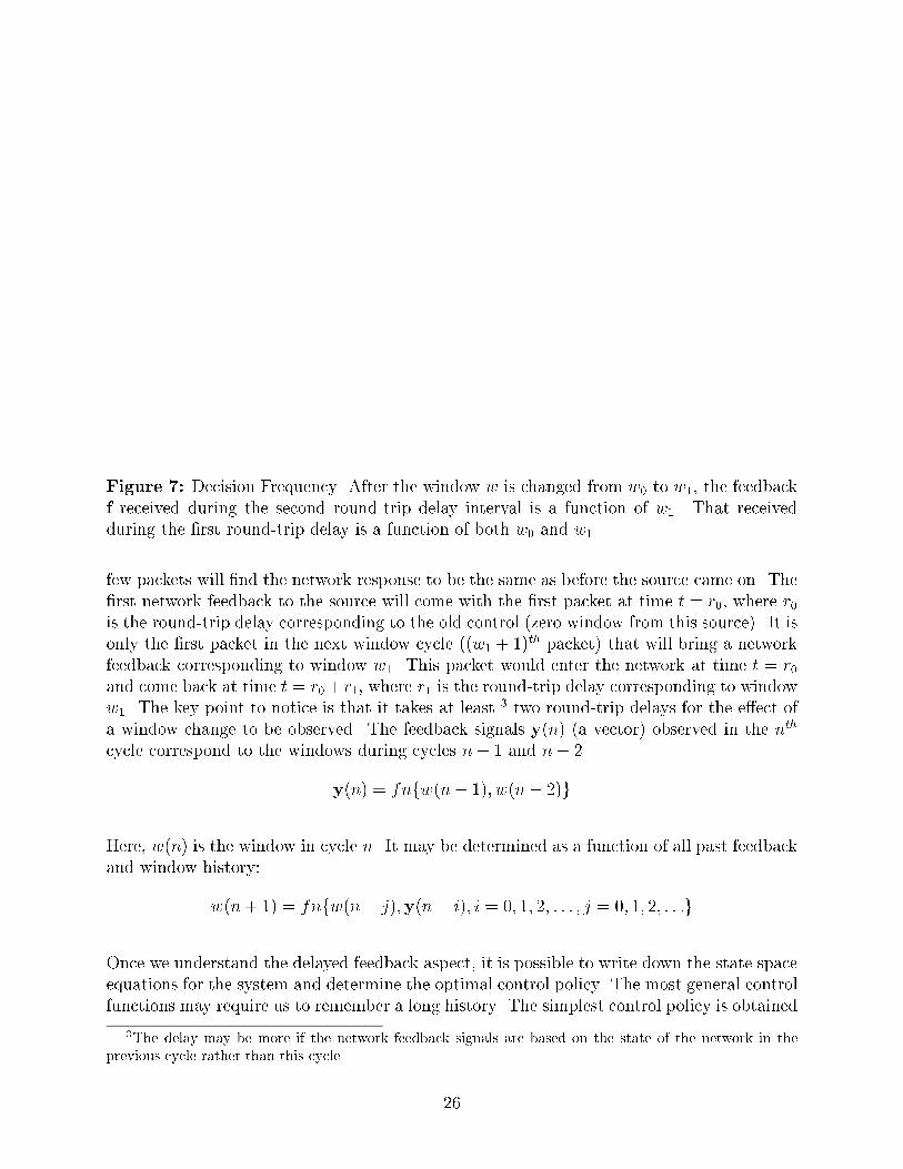
Figure 7: Decision Frequency. After the window w is changed from w0 to w1, the feedbackf received during the second round-trip delay interval is a function of w1. That receivedduring the �rst round-trip delay is a function of both w0 and w1.
few packets will �nd the network response to be the same as before the source came on. The�rst network feedback to the source will come with the �rst packet at time t = r0, where r0is the round-trip delay corresponding to the old control (zero window from this source). It isonly the �rst packet in the next window cycle ((w1 + 1)th packet) that will bring a networkfeedback corresponding to window w1. This packet would enter the network at time t = r0and come back at time t = r0+r1, where r1 is the round-trip delay corresponding to windoww1. The key point to notice is that it takes at least 3 two round-trip delays for the e�ect ofa window change to be observed. The feedback signals y(n) (a vector) observed in the nth
cycle correspond to the windows during cycles n� 1 and n� 2.
y(n) = fnfw(n� 1); w(n� 2)g
Here, w(n) is the window in cycle n. It may be determined as a function of all past feedbackand window history:
w(n+ 1) = fnfw(n� j);y(n� i); i = 0; 1; 2; : : : ; j = 0; 1; 2; : : :g
Once we understand the delayed feedback aspect, it is possible to write down the state spaceequations for the system and determine the optimal control policy. The most general controlfunctions may require us to remember a long history. The simplest control policy is obtained
3The delay may be more if the network feedback signals are based on the state of the network in the
previous cycle rather than this cycle.
26

if we keep the window constant for two cycles, so that w(n� 1) = w(n) for n even, and useonly the feedback for the last cycle, that is, for even values of n:
y(n) = fnfw(n� 1)g
w(n+ 1) = fnfw(n);y(n)g
This is the argument for adjusting the window only every two round-trip delays and for usingthe feedback signals obtained during the last round-trip interval.
10 SIMULATION MODEL
Various schemes for congestion avoidance were studied using a combination of analytical andsimulation modeling techniques. In this section, we describe the simulation model used. Themodel described in [12], has been extended to simulate congestion avoidance algorithms. Themodel written in SIMULA simulates portions of network and transport layers and was usedinitially to study timeout algorithms [13] and a timeout based congestion control scheme[14]. In the model, the transport layer protocol is simulated in detail. In particular, the ow control portion is a verbatim copy of the DNA's transport layer speci�cations [6]. Therouters and links are modeled as a single queue.
A number of features of the model including the trace facility and various modules havealready been described in [12], and will not be repeated here. Instead we concentrate onthe new features: shared paths, non-homogeneous paths, satellite links, and staggered start.Brief descriptions of these features follow.
10.1 SHARED PATHS
The model allows a con�guration shown in Figure 8a. A number of sources on one localarea network communicate with a number of destinations on another local area network andconnect to the �rst by a number of routers. Its logical representation is shown in Figure 8b.There is no limitation on the number of users or number of routers.
10.2 NON-HOMOGENEITY
Routers and links are represented by queues, each of which can have a di�erent service rate.The service time is determined by the packet length and the service rate. Local tra�c is
27

Figure 8: Initial con�gurations. Two LANs interconnected via lower speed links possiblyincluding a satellite link.
assumed to slow down the service rate. Thus, even if all routers and links are operatingat the same speed, di�erent service rates may be used depending upon the percentage ofresources used up by local tra�c.
10.3 SATELLITES
Satellite links consist of a ground station followed by a long propagation delay. The groundstation is simulated like other intermediate nodes, that is, a queue with a given service rate.The propagation delay is constant. A path may contain any number of satellite links.
10.4 STARTING GAP
It is possible to specify starting times individually for each user. This helps us verify thatthe scheme adapts to a changing workload as users go on/o� the network.
10.5 TRANSIENTS
It is possible to simulate a transient change in service rate caused by increased local tra�cor by nodes/links going down and coming back up. The speci�ed simulation length ( ofpackets to send) is divided into three parts. During the middle part, the service rate of the
28

bottleneck, as well as number of bu�ers there, may be changed (increased/decreased) to anyspeci�ed value.
10.6 PARAMETER VARIATION
There are more than 40 di�erent input parameters to the model. It is possible to run manysimulation experiments by specifying a range of values of any subset of the parameters. Thisallows us to get a plot of any performance variable as a function of the parameter values,thereby �nding the optimal value as well as determining the sensitivity.
10.7 WORKLOAD
The workload is speci�ed by the number of active users and the packet size distribution.Once a user is active, it has a su�cient supply of packets to transmit, and is limited onlyby the ow-control windows. The packet sizes can take a number of di�erent distributionssuch as: constant, uniform, exponential, bimodal, erlang, etc. Constant values are useful inrunning deterministic simulations and debugging.
By specifying the network service time that is less than the source service time, the modelallows the simulation of a case where the throughput is limited by the source and not thenetwork. However, this case is not very interesting, as the network has little congestion. Weuse this case to verify that all the algorithms do work in the source-bound case also.
10.8 PERFORMANCE DATA
The model provides time-varying graphs of the performance of individual users, routers, aswell as the whole system. It is possible to plot ow-control windows, throughput (packetsper unit of time), packet round-trip delays, exponentially weighted average of delay, networkfeedback (bits, for example), router queue lengths, and router utilization. These time-varyinggraphs can be observed on line as the simulation is proceeding and are helpful in monitoringthe simulation.
For each run, �rst a set of goal throughputs is computed for each user. This is the throughputthat gives the e�cient and fair performance for a given con�guration and workload. At theend of a batch run, the model computes average (over the run) user throughput and a scaledvalue (ratio of actual to goal). The variance (across users) of the scaled throughput indicatesfairness. For a totally fair system, the variance should be zero. The average (across users)
29

of the scaled throughput indicates e�ciency. For an optimal system, the average scaledthroughput must be one, i.e., equal to the goal.
Averages and variances of each performance variable is obtained in three di�erent stages.Consider, for example, user throughput. T (t; u; i; p) denotes throughput at time t for uth
user in the ith repetition of the simulation with pth input parameter set. T (u; i; p) wouldrepresent average throughput for the uth user during ith repetition. T (i; p) would representaverage throughput across all users during ith repetition, and �nally T (p) would representaverage throughput (across all users and replications) for the given parameter set. Varianceis similarly computed at each level. High variance over time or high variance across users orhigh variance over repetition is undesirable. Time variance of ow-control windows gives anidea of the oscillations.
10.9 ASSUMPTIONS
10.9.1 No Loss of Packets
In our congestion avoidance studies, we concentrated on a no loss case. We assumed that therouters have a large bu�er capacity. The performance degradation is caused not by packetlosses (as was the case with previous congestion control studies) rather by increased queueingin the network.
10.9.2 Equal Paths
All results presented in the �rst two parts of this report series assume equal paths, i.e., packetsfrom all sources join the path at �rst router and leave it at the last router.
10.10 LIMITATIONS
The simulation model has the following known limitations.
10.10.1 No Reverse Tra�c
The acknowledgments traveling back from the destination to the source are not explicitlysimulated. The source is informed of the packet delivery as soon as the packet is acceptedby the destination.
30

10.10.2 No Acknowledgment Withholding
Each packet passing through the network brings with it the feedback. The acknowledg-ments returning from the destination bring the feedback back to the source. If there isacknowledgment-withholding so that a single acknowledgment is sent for a number of pack-ets received, the destination would need an algorithm to combine multiple feedbacks receivedor to piggyback all of them on the single acknowledgment. We have not yet studied suchcases.
11 TEST SEQUENCE
In order to verify that the congestion avoidance algorithms that we developed do satisfy thegoals described earlier in this report, we created a number of test scenarios for simulation.In this section, we describe these test scenarios and show how they help verify the goals.For each alternative considered, we repeated the test sequence, and if the alternative did notprovide acceptable performance for a test case, the alternative was rejected.
The test sequences are identi�ed by a three or four character identi�er constructed as follows.The �rst character indicates whether the path is Homogeneous (H), Non-Homogeneous (N),Satellite Link (S), or Mixed (M). A non-homogeneous path with one or more satellite linksis called mixed. The second character in the identi�er indicates if the packet lengths areDeterministic (D) or Random (R). The third character n is a digit identifying the number ofusers sharing the path. The fourth character, which is optional, indicates special conditionsand will be described later.
11.1 EFFICIENCY
Most alternatives were �rst tested for the MD1 con�guration shown in Figure 9. This is amixed con�guration with deterministic packet lengths and a single user. It is clear that thealternatives that do not work with single users are not worth further consideration. Thedeterministic nature of the simulation helps identify the bugs in the implementation of thealternative. Due to the presence of the satellite delay, the e�cient (knee) window is generallysu�ciently high to help clearly see the e�ciency.
The single-user case also helps identify optimal values of some parameters. The bursty natureof network tra�c makes the single-user case performance the most important.
If the alternative works satisfactorily for MD1, we test other sub-cases such as ND1 (without
31

Figure 9: MD1 con�guration used for testing e�ciency.
Figure 10: MDn con�guration used for testing fairness.
the satellite) and HD1 (homogeneous). We found a few schemes that work mainly becauseof the long delay introduced by the satellite and therefore do not work with ND1 and HD1.
11.2 FAIRNESS
The next step is to see if the alternative is fair. We therefore move to the MDn con�gurationshown in Figure 10 which is similar to MD1 con�guration shown earlier but with n userssharing the same path. In a totally fair scheme, each user should get (1=n)th of the totalsystem throughput.
32

Figure 11: ND9 con�guration used for testing overload case.
11.3 CONVERGENCE
Some schemes diverge if there are too many users. Such schemes were discovered by usingan ND9 con�guration shown in Figure 11. This con�guration has nine users sharing a non-homogeneous deterministic path. For this con�guration, we set the service rates such thatthe knee occurs when the sum of the window sizes is 3. Obviously, with nine users eachhaving a minimum window limit of 1, the knee can never be achieved. The best alternativeskeep the window �xed at 1 for all users. Others allow them to alternate between 1 and 3.Divergent alternatives allowed the window sizes to grow inde�nitely in this test case.
11.4 ROBUSTNESS
The scheme should work satisfactorily for any given distribution of packet sizes. We found theexponential distribution to be the one most di�cult to satisfy. Therefore, we test robustnessby using MR1 and NR1 con�gurations with exponentially distributed packet lengths. Single-user cases help us concentrate on the e�ects of randomness. We replicated the simulationseveral times (with di�erent random-number generation seeds) to verify that the scheme doesgive an acceptable average performance and that the variation of the window is acceptable.NR1 con�guration without satellite is more di�cult than MR1 because in the latter, thesatellite delay, which constitutes a large part of the total delay, is a constant.
33

11.5 RESPONSIVENESS
We test responsiveness by introducing temporary changes in the bottleneck router speed andverifying that the scheme adapts to the new knee. This test case is identi�ed as MD1T, amixed, deterministic, single-user case with transients. The transient feature of the simulationwas described earlier in this report.
Two other aspects of responsiveness are starting credit value and staggered start. These aredescribed separately below.
11.6 ANY INITIAL WINDOW
If a scheme is responsive and adapts to changes in the network con�guration, the initialwindow at which a user starts should not matter. We verify this requirement by using anMD1H con�guration in which the user starts at a very high window, generally several timesthe knee value.
11.7 STAGGERED START
Another aspect of responsiveness is the change in the number of users. In actual networks,users constantly get on/o� the network. We simulate this condition by using the staggeredstart feature of the simulation. The con�guration called MDnS starts initially with one userand the (i + 1)st user comes on after ith user has sent a prespeci�ed fraction, for instance10%, of its total packets.
11.8 SOURCE BOUND
It is possible to have networks in which the sources of tra�c, not the networks, are thebottleneck. They cannot send packets as fast as the network would allow them to. Wecall this the source-bound case and it is tested by the con�guration called ND1B - non-homogeneous deterministic, one user with bottleneck source.
12 SUMMARY
The key contributions of the research reported in this report are the following.
34
1. We have introduced a new term congestion avoidance. It has been distinguished fromother similar terms of ow control and congestion control. It is shown that the pre-ventive nature of congestion avoidance helps the network use its resources in a globallyoptimal manner.
2. We have shown that the key to congestion avoidance in connectionless networks isfeedback from the network to the users about its state and a cooperative e�ort on thepart of the users to adjust their demands based on this feedback.
3. We listed a number of alternatives for the feedback and described the criteria used toselect the set of acceptable alternatives. Also, a number of goals were described thathelped select the best alternative from this set.
4. It has been shown that the problem of congestion avoidance can be broken down intoa number of components. The interrelationships among these components, if any, weredescribed.
5. The demand ( ow-control window) increase/decrease algorithms used by sources playa key role in the design of a congestion avoidance scheme. These algorithms, as wellas the question of demand update frequency, were discussed.
6. The goals that we set to measure the goodness of congestion avoidance schemes werequanti�ed using a simulation model and a series of test sequences. These were de-scribed.
This is the �rst report in a series describing our research on congestion avoidance. Thenext report in this series [19] describes the application of the concepts described here to thedevelopment of a congestion avoidance scheme using binary feedback.
13 ACKNOWLEDGMENTS
Many architects and implementers of Digital's networking architecture participated in aseries of meetings over the last three years in which the ideas presented here were discussedand improved. Almost all members of the architecture group contributed to the project inone way or another. In particular, we would like to thank Tony Lauck and Linda Wrightfor encouraging us to work in this area. Radia Perlman, Art Harvey, Kevin Miles, and MikeShand are the responsible architects whose willingness to incorporate our ideas providedfurther encouragement. We would also like to thank Bill Hawe, Dave Oran, and John Harperfor feedback and interest. The idea of proportional decrease was �rst proposed by GeorgeVerghese. The concept of maximal fairness was proposed by Bob Thomas.
35

References
[1] V. Ahuja, \Routing and Flow Control in Systems Network Architecture," IBM SystemsJournal, Vol. 18, No. 2, 1979, pp. 298 - 314.
[2] K. Bharat-Kumar and J. M. Ja�e, \A New Approach to Performance-Oriented FlowControl," IEEE Transactions on Communications, Vol. COM-29, No. 4, April 1981, pp.427 - 435.
[3] W. Bux and D. Grillo, \Flow Control in Local-Area Networks of Interconnected TokenRings," IEEE Transactions on Communications, Vol. COM-33, No. 10, October 1985,pp. 1058-66.
[4] Dah-Ming Chiu and Raj Jain, \Congestion Avoidance in Computer Networks with aConnectionless Network Layer. Part III: Analysis of Increase/Decrease Algorithms,"Digital Equipment Corporation, Technical Report #TR-509, August 1987.
[5] David Clark, \NETBLT: A Bulk Data Transfer Protocol," Massachusetts Institute ofTechnology, Lab for Computer Science, RFC-275, February 1985.
[6] Digital Equipment Corp., \DECnet Digital Network Architecture NSP Functional Spec-i�cation, Phase IV, Version 4.0.0," March 1982.
[7] M. Gerla and L. Kleinrock, \Flow Control: A Comparative Survey," IEEE Transactionson Communications, Vol. COM-28, No. 4, April 1980, pp. 553 - 574.
[8] A. Giessler, J. Haanle, A. Konig and E. Pade, \Free Bu�er Allocation - An Investigationby Simulation," Computer Networks, Vol. 1, No. 3, July 1978, pp. 191-204.
[9] International Organization of Standardization, \ISO 8073: Information Processing Sys-tems - Open Systems Interconnection - Connection Oriented Transport Protocol Spec-i�cation," July 1986.
[10] J. M. Ja�e, \Flow Control Power is Nondecentralizable," IEEE Transaction on Com-munications, Vol. COM-29, No. 9, September 1981, pp. 1301-1306.
[11] Raj Jain, Dah-Ming Chiu, and William Hawe, \A Quantitative Measure of Fairnessand Discrimination for Resource Allocation in Shared Systems," Digital EquipmentCorporation, Technical Report TR-301, September 1984.
[12] Raj Jain, \Using Simulation to Design a Computer Network Congestion Control Pro-tocol," Proc. Sixteenth Annual Modeling and Simulation Conference, Pittsburgh, PA,April 1985.
[13] Raj Jain, \Divergence of Timeout Algorithms for Packet Retransmission," Proc. FifthAnnual International Phoenix Conf. on Computers and Communications, Scottsdale,AZ, March 26-28, 1986, pp. 174-179.
36

[14] Raj Jain, \A Timeout-Based Congestion Control Scheme for Window Flow-ControlledNetworks," IEEE Journal on Selected Areas in Communications, Vol. SAC-4, No. 7,October 1986, pp. 1162-1167.
[15] J. M. McQuillan, I. Richer, and E. C. Rosen, \The New Routing Algorithm for theARPANET," IEEE Transactions on Communications, Vol. COM-28, No. 5, May 1980,pp. 711-719.
[16] J.C. Majithia, et al., \Experiments in Congestion Control Techniques," Proc. Int. Symp.Flow Control Computer Networks, Versailles, France. February 1979.
[17] John Nagle, \Congestion Control in TCP/IP Internetworks," Computer CommunicationReview, Vol. 14, No. 4, October 1984, pp. 11-17.
[18] K. K. Ramakrishnan, \Analysis of a Dynamic Window Congestion Control Protocolin Heterogeneous Environments Including Satellite Links," Proceedings of ComputerNetworking Symposium, November 1986.
[19] K. K. Ramakrishnan and Raj Jain, \Congestion Avoidance in Computer Networks witha Connectionless Network Layer. Part II: An Explicit Binary Feedback Scheme," DigitalEquipment Corporation, Technical Report #TR-508, August 1987.
[20] A.S. Tanenbaum, Network Protocols. Prentice-Hall: Englewood Cli�s, NJ, 1981.
37