ConfigEd Lite Product Manual
46
© Copyright Eurotherm Drives, Inc. 2002 All rights strictly reserved. No part of this document may be stored in a retrieval system or transmitted in any form. Although every effort has been taken to ensure the accuracy of this manual, it may be necessary, without notice, to make amendments or correct omissions in this document. Eurotherm Drives, Inc. cannot accept responsibility for damage, injury, or expenses resulting therefrom. Procedures detailed in this manual are designed to be performed by personnel with sufficient training and/or experience. Only sufficiently qualified personnel familiar with the construction and operation of industrial drive equipment and the dangers of working with high-voltage electrical systems should attempt installation, adjustment, operation, or service of this equipment. Failure to follow these guidelines could result in damage to the equipment and severe injury or loss of life to personnel. If you are unsure of your qualifications or do not understand certain procedures in this manual, contact Eurotherm Drives Customer Service for assistance. Before attempting any procedures in this manual, including installation, verify that the model numbers on the product and in this manual match. If any discrepancy is found, contact Customer Service immediately. Printed in the United States of America RG352747 Issue 6 ConfigEd Lite Product Manual For use with ConfigEdLite version 5.x
-
Upload
independent -
Category
Documents
-
view
7 -
download
0
Transcript of ConfigEd Lite Product Manual
© Copyright Eurotherm Drives, Inc. 2002All rights strictly reserved. No part of this document may be stored in a retrieval system or transmitted in any form.Although every effort has been taken to ensure the accuracy of this manual, it may be necessary, without notice, to makeamendments or correct omissions in this document. Eurotherm Drives, Inc. cannot accept responsibility for damage, injury, or expensesresulting therefrom.Procedures detailed in this manual are designed to be performed by personnel with sufficient training and/or experience. Onlysufficiently qualified personnel familiar with the construction and operation of industrial drive equipment and the dangers of workingwith high-voltage electrical systems should attempt installation, adjustment, operation, or service of this equipment. Failure to followthese guidelines could result in damage to the equipment and severe injury or loss of life to personnel. If you are unsure of yourqualifications or do not understand certain procedures in this manual, contact Eurotherm Drives Customer Service for assistance.Before attempting any procedures in this manual, including installation, verify that the model numbers on the product and in thismanual match. If any discrepancy is found, contact Customer Service immediately.
Printed in the United States of America RG352747 Issue 6
ConfigEd Lite
Product Manual
For use with ConfigEdLite version 5.x

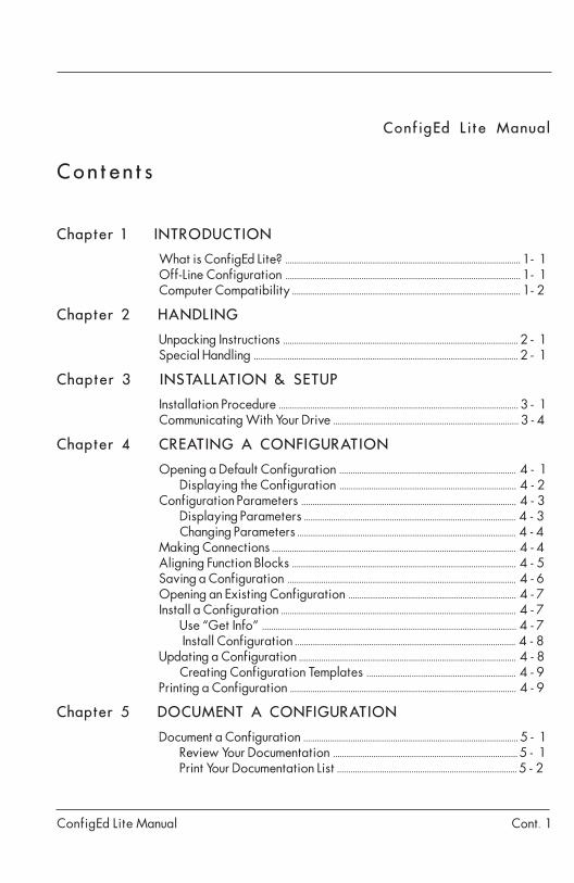
ConfigEd Lite Manual Cont. 1
ConfigEd Lite Manual
Contents
Chapter 1 INTRODUCTION
What is ConfigEd Lite? ......................................................................................................... 1 - 1Off-Line Configuration ......................................................................................................... 1 - 1Computer Compatibility ...................................................................................................... 1 - 2
Chapter 2 HANDLING
Unpacking Instructions ......................................................................................................... 2 - 1Special Handling ...................................................................................................................... 2 - 1
Chapter 3 INSTALLATION & SETUP
Installation Procedure ........................................................................................................... 3 - 1Communicating With Your Drive .................................................................................. 3 - 4
Chapter 4 CREATING A CONFIGURATION
Opening a Default Configuration ............................................................................... 4 - 1Displaying the Configuration .............................................................................. 4 - 2
Configuration Parameters ................................................................................................ 4 - 3Displaying Parameters .............................................................................................. 4 - 3Changing Parameters ................................................................................................. 4 - 4
Making Connections ............................................................................................................. 4 - 4Aligning Function Blocks .................................................................................................... 4 - 5Saving a Configuration ...................................................................................................... 4 - 6Opening an Existing Configuration ........................................................................... 4 - 7Install a Configuration ......................................................................................................... 4 - 7
Use “Get Info” ................................................................................................................. 4 - 7 Install Configuration .................................................................................................. 4 - 8
Updating a Configuration ................................................................................................. 4 - 8Creating Configuration Templates .................................................................. 4 - 9
Printing a Configuration ..................................................................................................... 4 - 9
Chapter 5 DOCUMENT A CONFIGURATION
Document a Configuration ................................................................................................ 5 - 1Review Your Documentation .................................................................................. 5 - 1Print Your Documentation List ................................................................................ 5 - 2
ConfigEd Lite ManualCont. 2
ConfigEd Lite Manual
Chapter 6 ADVANCED FEATURES
Forms ................................................................................................................................................. 6 - 1Create a Form .................................................................................................................... 6 - 1Automatic Data Entry ................................................................................................ 6 - 3
Chapter 7 TROUBLESHOOTING
Communications Problems ................................................................................................ 7 - 1Mismatched Baud Rates ........................................................................................... 7 - 1Baud Rate Set Too High ............................................................................................. 7 - 1Wrong Communications Port ............................................................................... 7 - 1Drive P3 Mode Set Wrong ....................................................................................... 7 - 1
Error Messages ......................................................................................................................... 7 - 2
Chapter 8 REFERENCE
Function Blocks .......................................................................................................................... 8 - 1Inter-Sheet Connections ..................................................................................................... 8 - 1Split Connections .................................................................................................................... 8 - 2Drawing ......................................................................................................................................... 8 - 3
Drawing Tools .................................................................................................................. 8 - 4Display Options ...................................................................................................................... 8 - 6Annotating Drawings ......................................................................................................... 8 - 6Scratch Pad ................................................................................................................................. 8 - 6
Chapter 9 APPENDIX
Menus ................................................................................................................................................ 9 - 1File .............................................................................................................................................. 9 - 1Edit ............................................................................................................................................ 9 - 1Command ............................................................................................................................. 9 - 1Window ................................................................................................................................. 9 - 2Font ........................................................................................................................................... 9 - 2Style ......................................................................................................................................... 9 - 2Help .......................................................................................................................................... 9 - 2
ConfigEd Lite Manual
Chapter 1 - Introduction
1 - 1
Chapter 1 INTRODUCTION
WHAT IS CONFIGED LITE?ConfigEd Lite (CE Lite) is a software tool used to configure Eurotherm controllers.CE Lite employs a graphical user interface and drawing tools that allow you tocreate and diagram your configurations in an easy-to-understand format thatrepresents the functionality of your configuration.
CE Lite can be used to configure a number of Eurotherm Drives products.Examples in this manual are for 590 and 590 + series drives.
DRIVE COMPATIBILITY590 series, firmware version 3.2 or later; 590SP, all firmware versions; 584S series,firmware version 4.1 or later; 584SV all firmware versions; 605 series, all firmwareversions; 620 series firmware version 4.0 or later; 590 + all firmware versions; 690+ all firmware versions; and 650V all firmware versions.
Key FeaturesUsing CE Lite, you can:
• Create configurations for controllers;
• Install configurations into controllers;
• Modify configurations for controllers;
• Retrieve configurations from controllers.
WARNING!Installing new configurations into a drive must only be done when thedrive is in a stopped and safe condition. Errors in the configuration maycause unexpected and/or dangerous consequences in the control system.It is imperative that all configurations be checked and tested by aqualified engineer BEFORE installing them into drives and putting theminto service.
OFF-LINE CONFIGURATIONYou do not need drive hardware to create your system configurations using CE Lite.The entire system can be created off-line and installed into your drive. Once theconfiguration has been installed into your drive, changes can be made and re-installed while all the affected equipment is fully stopped.

ConfigEd Lite Manual
Chapter 1 - Introduction
1 - 2
COMPUTER COMPATIBILITYCE Lite is designed to be used with computers equipped with:
• 386 processor or better;
• Microsoft® Windows™ operating system 95 / 98, Windows NT, Windows 2000,Windows XP;
• Minimum of 4 MB of RAM recognized by Windows (see your Windows manual);
• Minimum of 2 MB of hard drive space. More disk space may be needed as thenumber of configurations increases;
• Serial port for connecting the computer to the P3 port (similar to a telephonehandset socket) on the drive;
• Windows-compatible mouse, trackball, or similar pointing device;
• UDP cable kit (Eurotherm Drives part number CM351909);
• VGA or higher resolution display. (This is recommended for viewing.);
• Laser printer. (This is recommended for printing your configurations.)
NOISEGround noise may disturb the P3 communications link. It is created by ground loopscaused when both the computer and the drive are grounded. CE Lite has built-inretry mechanisms to deal with occasional electrical noise. Continuous noise,however, will cause extremely slow communications between the computer and thedrive.
In systems with a large amount of electrical noise (for example, systems containinginverters) it may be necessary to break the ground loop to achieve usablecommunications. The ground loop can be broken by:
• Using a battery-powered notebook computer rather than a plug-in model sincemost notebook computers are not grounded;
• Installing an RS232 isolator module between the computer and the P3 socket.
WARNING!Do not use any connectors, adapters, and/or cables other than thosesupplied by Eurotherm Drives. Failure to use materials supplied byEurotherm Drives can result in severe damage to equipment and injury topersonnel, and will void the Eurotherm Drives warranty.
ConfigEd Lite Manual
Chapter 2 - Handling
2 - 1
Chapter 2 HANDLING
UNPACKING INSTRUCTIONSBefore you install and use ConfigEd Lite, verify the completeness of your package.Your ConfigEd Lite package should include:
• ConfigEd Lite product manual (part number RG352747);
• Installation disks containing the ConfigEd Lite program;
• UDP cable with 9 pin adapter (part number CM351909);
• User license for ConfigEd Lite.
If any item on this list is missing, contact the Eurotherm Drives Customer ServiceDepartment in your area. If the package or any of its contents is damaged, contactthe shipper directly.
SPECIAL HANDLINGProper care must be shown in the handling of the materials used for the program. Thedistribution disk should be kept in a clean, dry environment within a relativelyconstant range of temperature and humidity. Keep the ConfigEd Lite disk far fromany sources of magnetism and electrical fields, including permanent magnet motors,as the magnetic or electrical fields may erase the information on the distributiondisk.
WARNING!ConfigEd Lite is a powerful software tool specifically designed toconfigure drives. Using ConfigEd Lite, it is possible to create potentiallydangerous drive configurations. The user assumes all liability and riskfor the performance, application, reliability, and safety of systemsimplemented using this tool. It is the responsibility of that user tounderstand the configurations thoroughly and check them independentlyprior to installation and operation of any equipment. Eurotherm Drivescan accept no liability for the application of this software.

ConfigEd Lite Manual
Chapter 2 - Handling
2 - 2
ConfigEd Lite Manual
Chapter 3 - Installation & Setup
3 - 1
Chapter 3 INSTALLATION & SETUP
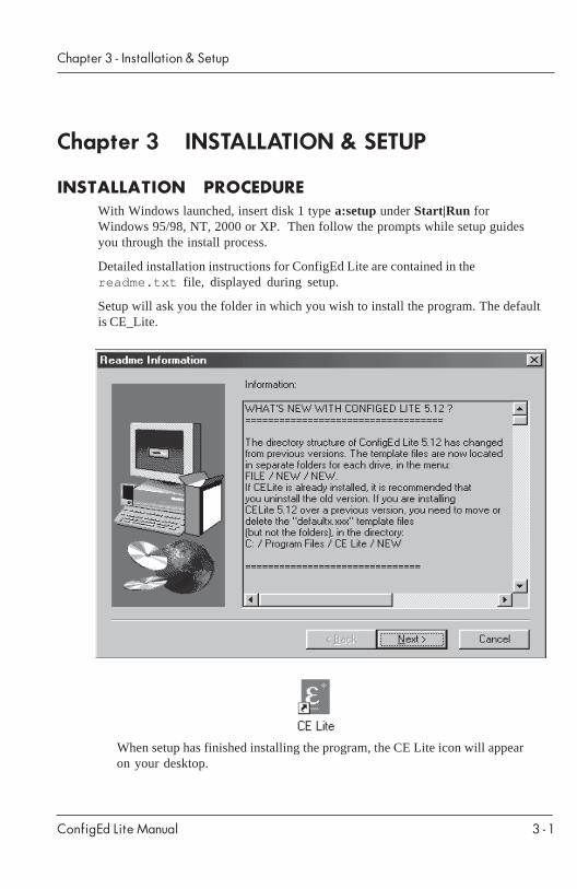
INSTALLATION PROCEDUREWith Windows launched, insert disk 1 type a:setup under Start|Run forWindows 95/98, NT, 2000 or XP. Then follow the prompts while setup guidesyou through the install process.
Detailed installation instructions for ConfigEd Lite are contained in thereadme.txt file, displayed during setup.
Setup will ask you the folder in which you wish to install the program. The defaultis CE_Lite.
When setup has finished installing the program, the CE Lite icon will appearon your desktop.
ConfigEd Lite Manual
Chapter 3 - Installation & Setup
3 - 2
Before using CE Lite the following items need to be completed prior to using.
1. In Windows install a local printer driver (cannot not be a network printer).If a local printer driver is not installed, your PC will lock up while doingcertain CE Lite operations.
2. In the properties of the local printer select “Spooling” to be “Print directlyto printer” or “Raw”. If “EMF” is selected the configuration will not printcorrectly.
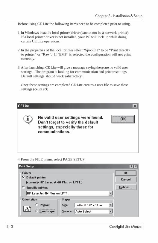
3.After launching, CE Lite will give a message saying there are no valid usersettings. The program is looking for communication and printer settings.Default settings should work satisfactory.
Once these settings are completed CE Lite creates a user file to save thesesettings (celite.rct).
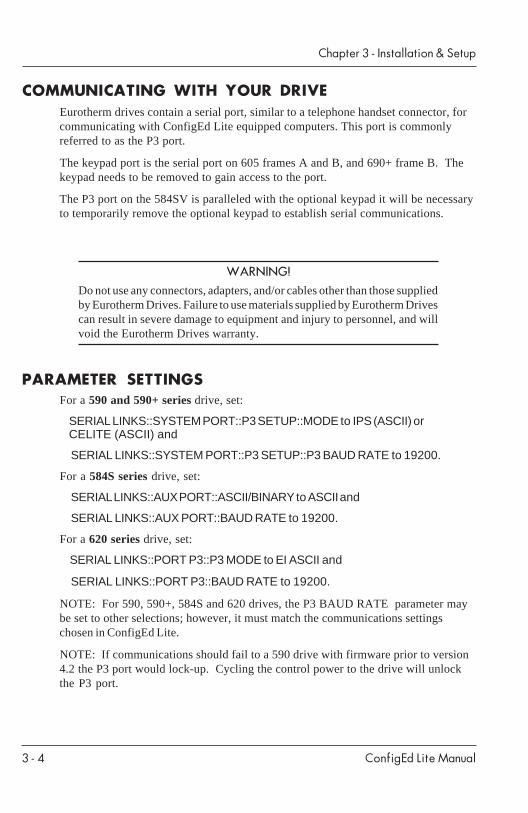
4.From the FILE menu, select PAGE SETUP.

ConfigEd Lite Manual
Chapter 3 - Installation & Setup
3 - 3
This brings up a window in which you may specify the printer you will beusing and various options concerning the printing of your pages.
Since ConfigEd Lite creates drawings in a horizontal format, make sureyour page is set for Landscape mode.
3.You should now set the communication parameters for the serial portconnection between your computer and the drive to which it will beconnected. From the Command menu, select Comms.
This brings up the Bisynch Master Setup dialog in which youset the port and baud rate of your drive connection.
Select a serial port (COM1, COM2, COM3, or COM4) and then select onebaud rate (2400 , 9600 , 19200 , 38400 , or 57600 ). Be sure theserial port you select is not being used by other serial devices. If themouse is connected to COM1, you would normally use COM2 for yourdrive connection.
It is recommended that you use 19,200 baud. Some computers mayexperience communication errors at 19,200 baud when using the standardWindows driver; the lower rates should reduce the errors. However, the584SV, 605, 690+ and 650V will only communicate at 19,200 baud.Additionally older 590 and the 590+ drives will communicate best at 9600baud.
CE Lite automatically creates a user file that contains these settings. CELite is now set up and ready to run. In the future when you launch CELite you will not be required to configure the printer and communicationparameters. Launch ConfigEd Lite by double-clicking on the program icon.
ConfigEd Lite Manual
Chapter 3 - Installation & Setup
3 - 4
WARNING!Do not use any connectors, adapters, and/or cables other than those suppliedby Eurotherm Drives. Failure to use materials supplied by Eurotherm Drivescan result in severe damage to equipment and injury to personnel, and willvoid the Eurotherm Drives warranty.
PARAMETER SETTINGSFor a 590 and 590+ series drive, set:
SERIAL LINKS::SYSTEM PORT::P3 SETUP::MODE to IPS (ASCII) orCELITE (ASCII) and
SERIAL LINKS::SYSTEM PORT::P3 SETUP::P3 BAUD RATE to 19200.
For a 584S series drive, set:
SERIAL LINKS::AUX PORT::ASCII/BINARY to ASCII and
SERIAL LINKS::AUX PORT::BAUD RATE to 19200.
For a 620 series drive, set:
SERIAL LINKS::PORT P3::P3 MODE to EI ASCII and
SERIAL LINKS::PORT P3::BAUD RATE to 19200.
NOTE: For 590, 590+, 584S and 620 drives, the P3 BAUD RATE parameter maybe set to other selections; however, it must match the communications settingschosen in ConfigEd Lite.
NOTE: If communications should fail to a 590 drive with firmware prior to version4.2 the P3 port would lock-up. Cycling the control power to the drive will unlockthe P3 port.
COMMUNICATING WITH YOUR DRIVEEurotherm drives contain a serial port, similar to a telephone handset connector, forcommunicating with ConfigEd Lite equipped computers. This port is commonlyreferred to as the P3 port.
The keypad port is the serial port on 605 frames A and B, and 690+ frame B. Thekeypad needs to be removed to gain access to the port.
The P3 port on the 584SV is paralleled with the optional keypad it will be necessaryto temporarily remove the optional keypad to establish serial communications.
ConfigEd Lite Manual
Chapter 4 - Creating a Configuration
4 - 1
Chapter 4 CREATING A CONFIGURATION
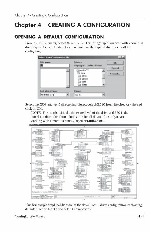
OPENING A DEFAULT CONFIGURATIONFrom the File menu, select New::New . This brings up a window with choices ofdrive types. Select the directory that contains the type of drive you will beconfiguring.
Select the 590P and ver 5 directories. Select default5.590 from the directory list andclick on OK.
(NOTE: The number 5 is the firmware level of the drive and 590 is themodel number. This format holds true for all default files. If you areworking with a 690+, version 4, open default4.690).
This brings up a graphical diagram of the default 590P drive configuration containingdefault function blocks and default connections.
ConfigEd Lite Manual
Chapter 4 - Creating a Configuration
4 - 2
DISPLAYING THE CONFIGURATIONThere are a variety of Windows controls available to enhance viewing of theconfigurations. To enlarge the ConfigEd Lite window to fill your monitor screen,click on the zoom box in the upper right corner of the window. Clicking again on thebox will return the window to its previous size.
Notice the gray outline frame near the bottom and right side of your ConfigEd Litewindow. If the gray outline is not visible, try scrolling down or to the right until itappears. This frame marks the limits of the “page” on which your configuration isdrawn. You must allow an extra margin inside the gray outline for the edges of thepaper where the printer cannot print. Items extending beyond the gray outline willnot print.
You can also re-size the ConfigEd Lite window by moving the mouse pointer toeither an edge or a corner of the window until it changes into a two-pointed arrow.Then hold the left mouse key down as you drag the window edge to the size youwant.
To get the configuration window to appear in the ConfigEd Lite window, press theShift key while selecting the appropriate configuration from the Window menu.This is especially useful if you are using a small screen and the configuration youdesire gets “lost” on your desktop.
You can enlarge or reduce the view inside the window from the keyboard by usingthe number keys (either at the top of the keyboard or on the numeric keypad), the +or - keys, or by choosing a different Scale size in the Draw menu. The arrowkeys and the Page Up and Page Down keys modify the view of and/or movethe drawing within the ConfigEd Lite window. For a complete list of keyboardcommands, see the following table.
Keyboard CommandsKeystrokeResult
3 Scales to 3pt. font (0.50x drawing);homes drawing to upper left corner
4 Scales to 4pt. font (0.67x drawing);homes drawing to upper left corner
5 Scales to 5pt. font (0.83x drawing)6 Scales to 6pt. font (1.00x drawing)7 Scales to 7pt. font (1.17x drawing)8 Scales to 8pt. font (1.33x drawing)9 Scales to 9pt. font (1.50x drawing)0 Scales to 10pt. font (1.67x drawing)1 Scales to 11pt. font (1.83x drawing)2 Scales to 12pt. font (2.00x drawing)+ Increases scaling by factor of 1.33- Decreases scaling by factor of 1.33
ConfigEd Lite Manual
Chapter 4 - Creating a Configuration
4 - 3
Keystroke ResultHome Sets origin of view to upper left cornerPage Up Moves view of drawing up by 7/8 of current sizePage Down Moves view of drawing down by 7/8 of current sizeUp arrow Nudges view of drawing upDown arrow Nudges view of drawing downLeft arrow Nudges view of drawing to the leftRight arrow Nudges view of drawing to the rightShift Page Up Moves view of drawing to previous sheetShift Page Down Moves view of drawing to next sheetBackspace Deletes currently-selected item
You may also use the mouse pointer to select an area of the drawing to enlarge.Determine the area of the drawing you want to enlarge, then hold down the mousekey as you “draw” a box around that area. When you release the mouse key, the areayou have selected will fill the window. You must include a function block somewherein the area you are selecting for this feature to work.
CONFIGURATION PARAMETERS
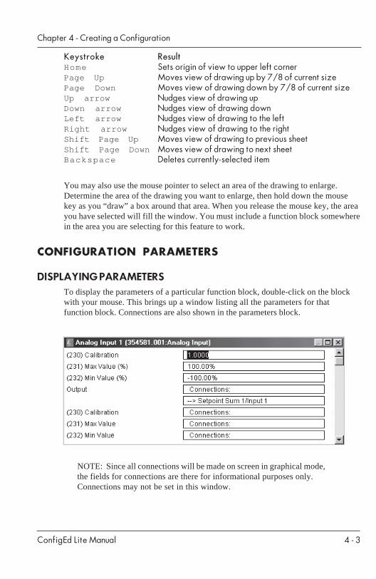
DISPLAYING PARAMETERSTo display the parameters of a particular function block, double-click on the blockwith your mouse. This brings up a window listing all the parameters for thatfunction block. Connections are also shown in the parameters block.
NOTE: Since all connections will be made on screen in graphical mode,the fields for connections are there for informational purposes only.Connections may not be set in this window.
ConfigEd Lite Manual
Chapter 4 - Creating a Configuration
4 - 4
CHANGING PARAMETERSTo change non-numeric parameters (for example, on/off or positive/negative ), double-click on the appropriate field in the parameter function blockwindow. A list of optional choices will appear from which you may choose yournew parameter setting.
For a numeric field (for example, 0.500 seconds or 0.50% ), click once on the fieldto highlight the numeric figure, then type in the new value to assign to the field.When you are finished making your changes, close the parameters window to updateand return to your configuration drawing.
MAKING CONNECTIONS
NOTE: Before creating any new or changing any existing connections inthe default configuration, refer to the product manual for your drive.
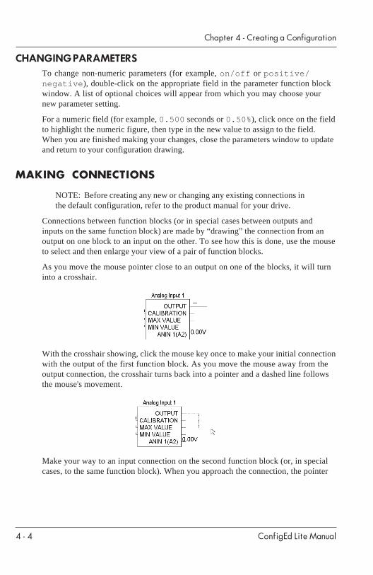
Connections between function blocks (or in special cases between outputs andinputs on the same function block) are made by “drawing” the connection from anoutput on one block to an input on the other. To see how this is done, use the mouseto select and then enlarge your view of a pair of function blocks.
As you move the mouse pointer close to an output on one of the blocks, it will turninto a crosshair.
With the crosshair showing, click the mouse key once to make your initial connectionwith the output of the first function block. As you move the mouse away from theoutput connection, the crosshair turns back into a pointer and a dashed line followsthe mouse's movement.
Make your way to an input connection on the second function block (or, in specialcases, to the same function block). When you approach the connection, the pointer
ConfigEd Lite Manual
Chapter 4 - Creating a Configuration
4 - 5
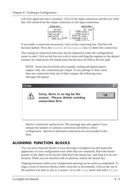
will once again turn into a crosshair. Click on the input connection and the now solidline will extend from the output connection to the input connection.
If you make a connection incorrectly, click on the connecting line. The line willbecome dashed. Press the Delete or Backspace key to delete the connection.
The routing of connection lines may also be adjusted to make the configurationseasier to read. Click on the line you wish to move and drag the segment to the desiredlocation. Its connections will remain intact but the line will follow the new path.
NOTE: Some function blocks (for example, analog and digital inputs)support only one connection per output. If you attempt to draw morethan one connection from one of their outputs, the following errormessage will appear:
Delete a connection and proceed. This message may also appear if youexhaust the number of common connections allowed in a driveconfiguration. Special or dedicated connections are not included in thislimit.
ALIGNING FUNCTION BLOCKSYou can move function blocks in your drawing to straighten out and neaten theappearance of your configuration even when they are connected. Place the mousepointer on the object to be moved, hold down the mouse key, and drag it to its newlocation. When you are satisfied with its position, release the mouse key.
Aligning elements within your configuration drawing can be easily accomplished. Toalign a series of function blocks, either vertically or horizontally, click on the one inthe position you plan to use as a master. Go to the Draw menu and select Align .

ConfigEd Lite Manual
Chapter 4 - Creating a Configuration
4 - 6
A check mark will appear next to Align to show that the alignment feature isoperational. The alignment feature works on only the top or left side of the objectsbeing aligned.
Select each element you want to align with the first, drag it to the general locationyou want, and release the mouse key. ConfigEd Lite will automatically snap it intoalignment with the original element. ConfigEd Lite “senses” whether the mostappropriate alignment is in the vertical or horizontal plane and moves the elementaccordingly. You can turn the alignment feature off by clicking on an empty sectionof the drawing (so no function block is selected) and selecting Align again. Thecheck mark will now be gone, showing that the alignment feature is toggled off.
SAVING A CONFIGURATIONOnce you have finished making changes and adjustments to the configuration, youmust save it. If you have previously saved the configuration and wish to save it tothe same name, select Save from the File menu. If this is the first time you aresaving the configuration (for example, you selected New from the File menu toopen the default configuration), you should select Save As from the File menu.This brings up a dialog box in which you name the configuration you are saving.
The default directory for saving new configurations is the celite directory. Youshould create additional directories in which to organize your configurationsaccording to particular job needs. In this example, we have created a subdirectorycalled new in which we will save the test_1.590 configuration. If you areunsure how to do this, consult your Windows manual.
Once you are in the correct directory, type in the new name for your configurationand click on the OK button to save it to that directory.
ConfigEd Lite Manual
Chapter 4 - Creating a Configuration
4 - 7
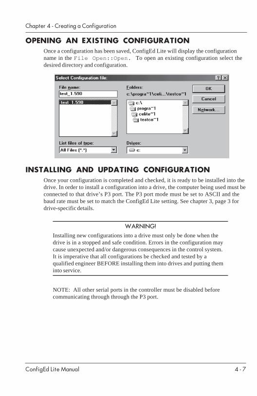
OPENING AN EXISTING CONFIGURATIONOnce a configuration has been saved, ConfigEd Lite will display the configurationname in the File Open::Open. To open an existing configuration select thedesired directory and configuration.
INSTALLING AND UPDATING CONFIGURATIONOnce your configuration is completed and checked, it is ready to be installed into thedrive. In order to install a configuration into a drive, the computer being used must beconnected to that drive’s P3 port. The P3 port mode must be set to ASCII and thebaud rate must be set to match the ConfigEd Lite setting. See chapter 3, page 3 fordrive-specific details.
WARNING!Installing new configurations into a drive must only be done when thedrive is in a stopped and safe condition. Errors in the configuration maycause unexpected and/or dangerous consequences in the control system.It is imperative that all configurations be checked and tested by aqualified engineer BEFORE installing them into drives and putting theminto service.
NOTE: All other serial ports in the controller must be disabled beforecommunicating through through the P3 port.
ConfigEd Lite Manual
Chapter 4 - Creating a Configuration
4 - 8
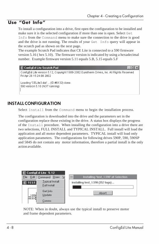
Use “Get Info”To install a configuration into a drive, first open the configuration to be installed andmake sure it is the selected configuration if more than one is open. Select GetInfo from the Command menu to make sure the connection to the drive is goodand the drive is not running. The results of your Get Info query will appear inthe scratch pad as shown on the next page.The example Scratch Pad indicates that CE Lite is connected to a 590 firmwareversion 5.16 ( hex 5.10). The firmware version is indicated by using a hexadecimalnumber. Example firmware version 5.11 equals 5.B, 5.15 equals 5.F
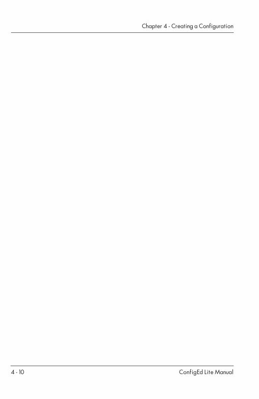
INSTALL CONFIGURATIONSelect Install from the Command menu to begin the installation process.
The configuration is downloaded into the drive and the parameters set in theconfiguration replace those existing in the drive. A status box displays the progressof the Install procedure. When installing the configuration into a drive there aretwo selections, FULL INSTALL and TYPICAL INSTALL. Full install will load theapplication and all motor dependent parameters. TYPICAL install will load onlyapplication parameters. The configurations for following drives 590P, 590, 590SPand 584S do not contain any motor information, therefore a partial install is the onlyaction available.
NOTE: When in doubt, always use the typical install to preserve motorand frame dependent parameters.

ConfigEd Lite Manual
Chapter 4 - Creating a Configuration
4 - 9
Updating a ConfigurationThe drive configuration and parameters can be retrieved from the drive by using theUpdate function in the Command menu.
Select Get Info from the Command menu to make sure the drive is connected.The results of your query will appear in the scratch pad.
Open the configuration file you want to update, if it is not already open.
Select Update from the Command menu to replace the configuration parameterswith those of the drive.
A status box displays the progress of the Update procedure.
NOTE: The Update function will overwrite all the connections andparameter settings of the currently-selected configuration. Make sure youdo not accidentally overwrite an unsaved configuration.
When the Update procedure is completed, save the configuration to preserve theupdated parameters using either Save or Save As from the File menu.
CREATING CONFIGURATION TEMPLATESTemplate files are useful for reusing configurations and creating standard graphicalpresentations. They are not overwritten when saving a configuration.
To create a template, open a configuration and modify it as needed. Select SaveAs in the File menu. Change the destination directory to \celite\new andchoose OK to close the configuration file. This file will appear in the pop down menuwhen selecting New in the File menu.
PRINTING A CONFIGURATIONOnce your page and printer setup are complete, you can print out a copy of yourconfiguration in graphical mode by selecting Print from the File menu. Refer toChapter 3, pages 3-2 and 3-3 for printer setup instructions.
ConfigEd Lite Manual
Chapter 4 - Creating a Configuration
4 - 10
ConfigEd Lite Manual
Chapter 5 - Document a Configuration
5 - 1
Chapter 5 DOCUMENTING A CONFIGURATIONIt is very helpful to have a printed reference list of configuration parameters andconnections. This section shows you how to generate and print that list.
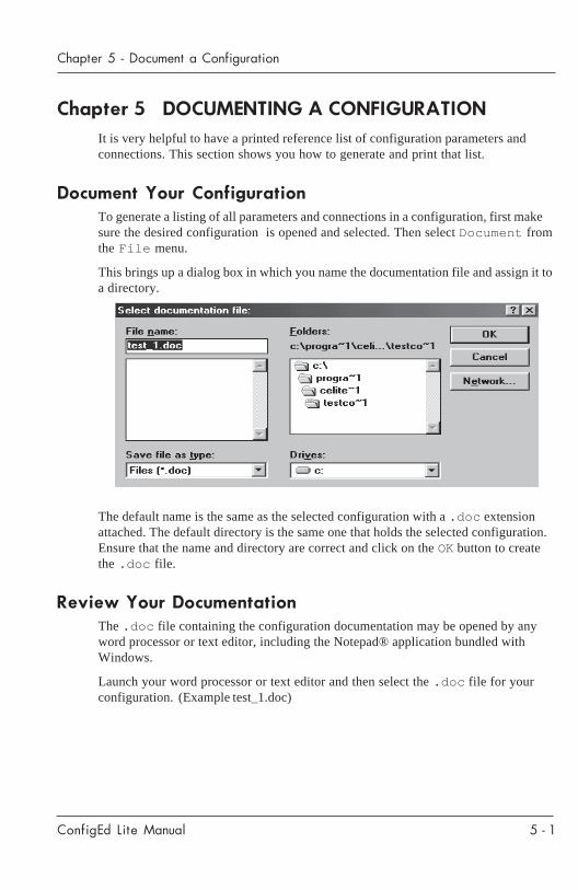
Document Your ConfigurationTo generate a listing of all parameters and connections in a configuration, first makesure the desired configuration is opened and selected. Then select Document fromthe File menu.
This brings up a dialog box in which you name the documentation file and assign it toa directory.
The default name is the same as the selected configuration with a .doc extensionattached. The default directory is the same one that holds the selected configuration.Ensure that the name and directory are correct and click on the OK button to createthe .doc file.
Review Your DocumentationThe .doc file containing the configuration documentation may be opened by anyword processor or text editor, including the Notepad® application bundled withWindows.
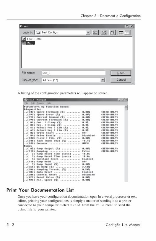
Launch your word processor or text editor and then select the .doc file for yourconfiguration. (Example test_1.doc)
ConfigEd Lite Manual
Chapter 5 - Document a Configuration
5 - 2
A listing of the configuration parameters will appear on screen.
Print Your Documentation ListOnce you have your configuration documentation open in a word processor or texteditor, printing your configurations is simply a matter of sending it to a printerconnected to your computer. Select Print from the File menu to send the.doc file to your printer.
ConfigEd Lite Manual
Chapter 6 - Advanced Features
6 - 1
Chapter 6 ADVANCED FEATURESFORMS
An outline or border inserted around your configuration diagram provides auniform, professional appearance when printed. Adding important text material canhelp make your diagrams clearer and more easily understood. ConfigEd Litecontains special drawing tools that let you design and produce your own forms andinsert descriptive text. These forms (containing both graphical and text material) arestored as .frm files in ConfigEd Lite’s working directory.
By now, you have learned that your configuration diagram must reside within thegray border that appears on your computer screen in order to be printed. When youadd a custom form to your diagram, that form must also reside within the grayborder. The form will appear on your screen and your diagram must then be placedwithin its borders to be printed.
NOTE: The gray border represents the page size, not the printable area.Make sure to leave a margin inside the border to suit your printer.
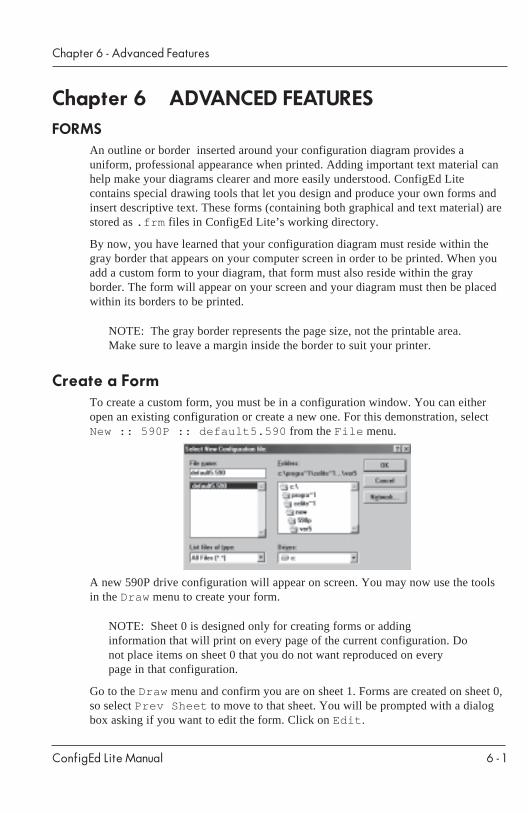
Create a FormTo create a custom form, you must be in a configuration window. You can eitheropen an existing configuration or create a new one. For this demonstration, selectNew :: 590P :: default5.590 from the File menu.
A new 590P drive configuration will appear on screen. You may now use the toolsin the Draw menu to create your form.
NOTE: Sheet 0 is designed only for creating forms or addinginformation that will print on every page of the current configuration. Donot place items on sheet 0 that you do not want reproduced on everypage in that configuration.
Go to the Draw menu and confirm you are on sheet 1. Forms are created on sheet 0,so select Prev Sheet to move to that sheet. You will be prompted with a dialogbox asking if you want to edit the form. Click on Edit .
ConfigEd Lite Manual
Chapter 6 - Advanced Features
6 - 2
A new sheet will appear on screen. A gray border and title block will be visible onyour page. Information can now be placed in this template that will appear on allsheets of your configuration. You should see a notation in the lower left corner thatindicates the drive type/model number.
Text and objects maybe entered on this sheet. Text maybe added to the title blockthat will indicate the customer, revision, date, and other pertinent information.
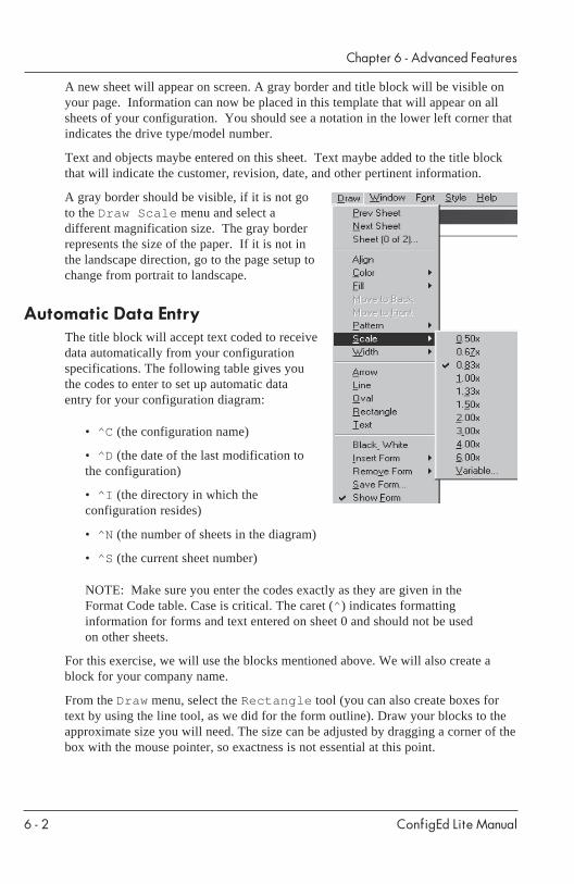
A gray border should be visible, if it is not goto the Draw Scale menu and select adifferent magnification size. The gray borderrepresents the size of the paper. If it is not inthe landscape direction, go to the page setup tochange from portrait to landscape.
Automatic Data EntryThe title block will accept text coded to receivedata automatically from your configurationspecifications. The following table gives youthe codes to enter to set up automatic dataentry for your configuration diagram:
• ^C (the configuration name)
• ^D (the date of the last modification tothe configuration)
• ^I (the directory in which theconfiguration resides)
• ^N (the number of sheets in the diagram)
• ^S (the current sheet number)
NOTE: Make sure you enter the codes exactly as they are given in theFormat Code table. Case is critical. The caret (^ ) indicates formattinginformation for forms and text entered on sheet 0 and should not be usedon other sheets.
For this exercise, we will use the blocks mentioned above. We will also create ablock for your company name.
From the Draw menu, select the Rectangle tool (you can also create boxes fortext by using the line tool, as we did for the form outline). Draw your blocks to theapproximate size you will need. The size can be adjusted by dragging a corner of thebox with the mouse pointer, so exactness is not essential at this point.
ConfigEd Lite Manual
Chapter 6 - Advanced Features
6 - 3
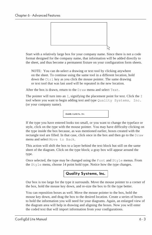
Start with a relatively large box for your company name. Since there is not a codeformat designed for the company name, that information will be added directly tothe sheet, and thus become a permanent fixture on your configuration form sheets.
NOTE: You can de-select a drawing or text tool by clicking anywhereon the sheet. To continue using the same tool in a different location, holddown the Ctrl key as you click the mouse pointer. The same drawingor text tool that was last used will be repeated in the new location.
After the box is drawn, return to the Draw menu and select Text .
The pointer will turn into an I , signifying the placement point for text. Click the Itool where you want to begin adding text and type Quality Systems, Inc.(or your company name).
If the type you have entered looks too small, or you want to change the typeface orstyle, click on the type with the mouse pointer. You may have difficulty clicking onthe type inside the box because, as was mentioned earlier, boxes created with therectangle tool are filled. In that case, click once in the box and then go to the Drawmenu and select Move to Back .
This action will shift the box to a layer behind the text block but still on the samesheet of the diagram. Click on the type block; a gray box will appear around thetype.
Once selected, the type may be changed using the Font and Style menus. Fromthe Style menu, choose 14 point bold type. Notice how the type changes.
Our box is too large for the type it surrounds. Move the mouse pointer to a corner ofthe box, hold the mouse key down, and re-size the box to fit the type better.
You can reposition boxes as well. Move the mouse pointer to the box, hold themouse key down, and drag the box to the desired location. Create a series of boxesto hold the information you will need for your diagrams. Again, an enlarged view ofthe diagram area will help in drawing and aligning the boxes. Now you will enterthe coded text that will import information from your configurations.

ConfigEd Lite Manual
Chapter 6 - Advanced Features
6 - 4
Decide which box will hold the configuration’s name. For this exercise, we will usethe top left box next to your company name. Select the Text tool and click onceinside the box. Type the appropriate code, in this case ^C.
To de-select the text function, click anywhere on the rest of the sheet. To continueadding text in another location, hold the Ctrl key down as you click the I tool inthe new location. Using the Ctrl key and mouse click combination instructs thecomputer to repeat the last drawing tool selected. Proceed to designate boxes for theother codes listed at the beginning of this section. When you are finished, yourboxes should look something like this:
Placing these codes instructs ConfigEd Lite to automatically insert the properinformation for your configuration diagram, either on screen or when printing.Check to make sure that your information is in the correct block; if not, review eachstep carefully to find where you made a mistake.
NOTE: Holding down the Ctrl key when you click the mouse buttonretains the previous function and allows you to continue drawing oradding text, whichever was last done. In our example, the action willallow us to add a second line starting at the end point of the first.Continue drawing the other lines bordering your diagram area,connecting them at the corners by holding down the Ctrl key whileclicking on the mouse key.
Once you have completed the design of your form and placed the coded text in theappropriate boxes, go to the Draw menu and select Save Form . A dialog windowwill ask you to name the form. Enter Test and click on the OK button.
NOTE: If you have inserted a standard form into your configuration andthen try to save it under another name, you will be asked to confirm thatyou want to merge the standard form into your new form.
ConfigEd Lite Manual
Chapter 6 - Advanced Features
6 - 5
A second window will tell you your form has been saved and the number of items(including the text boxes and coded type) processed.
Notice that .frm has been appended to the name of your form. This tells ConfigEdLite to include it in the list of forms available for inserting into a diagram. Once yousave a form, it can be added to any configuration diagram by going to the Drawmenu, selecting Insert Form , and then selecting the form to insert.
You cannot have different forms for different sheets in the same multiple-sheetconfiguration. Only one form may be selected for each configuration. It is placed onsheet 0 and appears on every sheet of that configuration. Forms may be removedfrom configuration diagrams by going to the Draw menu, selecting RemoveForm, and then choosing the form to be removed.
Selecting the Show Form menu item makes the form visible while working on theconfiguration and for printing. De-selecting Show Form can speed up screenredraws, which may be desired when modifying a diagram; however, it must beselected for the form to appear in the printout.
ConfigEd Lite Manual
Chapter 6 - Advanced Features
6 - 6
ConfigEd Lite Manual
Chapter 7 - Troubleshooting
7 - 1
Chapter 7 TROUBLESHOOTING
Mismatched Baud RatesThe baud rates in the drive must match those in ConfigEdLite. Check the BAUDRATE setting on the drive under SERIAL LINKS. The 584SV, 605, 650V, and690+ only communicate at 19,200 baud, which is also the default for ConfigEdLite.
Baud Rate Set Too HighSome computers my experience difficulty with the 19200 baud rate. For thosecomputers, reduce the baud rate to 9600 on both, the drive as well as ConfigEdLite.(Remember, the 584SV, 605, 650V, and 690+ only communicate at 19,200 baud).
Wrong Communications PortAnother common error is trying to select a communications port already in use,typically by the mouse. Go to the Command Comms menu, select anothercommunications port, and ensure your drive is connected to that port.
Drive P3 Mode Set WrongFor a 590 and 590P series drive, set:
SERIAL LINKS::SYSTEM PORT::P3 SETUP::MODE to IPS (ASCII) or CELITE (ASCII)SERIAL LINKS::SYSTEM PORT::P3 SETUP::P3 BAUD RATE to 9600.
For a 584S series drive, set:
SERIAL LINKS::AUX PORT::ASCII/BINARY to ASCIISERIAL LINKS::AUX PORT::BAUD RATE to 19200.
For a 620 series drive, set:
SERIAL LINKS::PORT P3::P3 MODE to EI ASCIISERIAL LINKS::PORT P3::BAUD RATE to 19200.
NOTE: For 590, 584S and 620 drives, the P3 BAUD RATE parameter maybe set to other selections; however, it must match the communicationssettings chosen in ConfigEd Lite.
For 584SV, 605, 650 and 690+ drives, no special settings are required tocommunicate with CE Lite. The BAUD RATE in CE Lite must always be set at19,200 for 584SV, 605, 650V and 690+.
ConfigEd Lite Manual
Chapter 7 - Troubleshooting
7 - 2
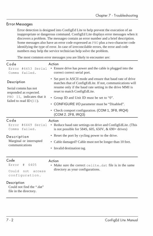
CodeError # 6405
Could not accessconfiguration.
DescriptionCould not find the “.dat”file in the directory.
Description
Serial comms has notresponded as expected.PNO II , indicates that itfailed to read ID (II ).
Action• Ensure drive has power and the cable is plugged into the
correct correct serial port.
• Set port in ASCII mode and ensure that baud rate of drivematches that of ConfigEdLite. If not, communications willresume only if the baud rate setting in the drive MMI isreset to match ConfigEdLite.
• Group ID and Unit ID must be set to “0”.
• CONFIGURE I/O parameter must be “Disabled”.
• Check comport configuration. (COM 1, 3F8, IRQ4)(COM 2. 2F8, IRQ3)
Error MessagesError detection is designed into ConfigEd Lite to help prevent the execution of aninappropriate or dangerous command. ConfigEd Lite displays error messages when itdiscovers a problem. The messages contain an error number and a brief description.Some messages also have an error code expressed as PNO plus a two-character codeidentifying the type of error. In case of irreconcilable errors, the error and codenumbers may help the service technician help solve the problem.
The most common error messages you are likely to encounter are:
CodeError #6449 SerialComms failed.
Descr ip t ionMarginal or interruptedcommunications
Action• Reduce baud rate settings on drive and ConfigEdLite. (This
is not possible for 584S, 605, 650V, & 690+ drives)
• Reset the port by cycling power to the drive.
• Cable damaged? Cable must not be longer than 10 feet.
• Invalid destination tag.
Action• Make sure the correct celite.dat file is in the same
directory as your configurations.
CodeError #6453 SerialComms failed.

ConfigEd Lite Manual
Chapter 7 - Troubleshooting
7 - 3
CodeError # 6463Cannot installconfigurationwhile drive isrunning.
CodeError #6459 Couldnot open SerialComms Library.
Descr ip t ionThe Comms port on thecomputer is not active,turned off, or used byanother device.
Act ion• Check comms port
allocation and settings
CodeError #6461Wrong versionfirmware
DescriptionFirmware version of thedrive does not match theCE Lite configuration.
Action• Select the correct CE
Lite configuration tomatch the drive version.
CodeError #6597Could not settag 2201-1
DescriptionCould not set tag number201 to the regen mode.
Action• Select the correct mode
of operation for the590+power stackconfiguration. See“CURRENT LOOP”function block.
• Select the correct “PCODE” for the 590+drive. Refer to themanual for instructions.
Description Action• Remove RUN/START
signal.The drive must be stoppedand disabled when youwant to update theconfiguration with theparameters in the drive orinstall the configurationinto the drive. The RUN/START signal must be offto use the Install command.
CautionThis safety feature prevents dangerous consequences caused by modifying the operationof the drive while equipment is running.
NoteIf CE Lite aborts during installation of the configuration, it is possible that an “anti-virus”program is running on the computer. Close the “anti-virus” program and try again.
ConfigEd Lite Manual
Chapter 7 - Troubleshooting
7 - 4
ConfigEd Lite Manual
Chapter 8 - Reference
8 - 1
Chapter 8 REFERENCE
FUNCTION BLOCKSFunction blocks are pre-configured elements providing processes required forconfigurations to be operational. All the function blocks necessary for the properconfiguration of 590 series drives are included in the default.590 configurationsupplied with ConfigEd Lite, as is true for all drives supported by ConfigEdLite.
INTER-SHEET CONNECTIONSConfigEd Lite allows you to draw connections between function blocks on differentsheets. This is an important and valuable feature since drive configurations covermore than one sheet. To make inter-sheet connections:
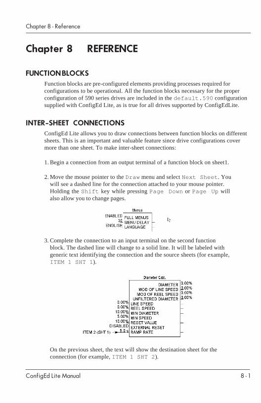
1. Begin a connection from an output terminal of a function block on sheet1.
2. Move the mouse pointer to the Draw menu and select Next Sheet . Youwill see a dashed line for the connection attached to your mouse pointer.Holding the Shift key while pressing Page Down or Page Up willalso allow you to change pages.
3. Complete the connection to an input terminal on the second functionblock. The dashed line will change to a solid line. It will be labeled withgeneric text identifying the connection and the source sheets (for example,ITEM 1 SHT 1 ).
On the previous sheet, the text will show the destination sheet for theconnection (for example, ITEM 1 SHT 2 ).
ConfigEd Lite Manual
Chapter 8 - Reference
8 - 2
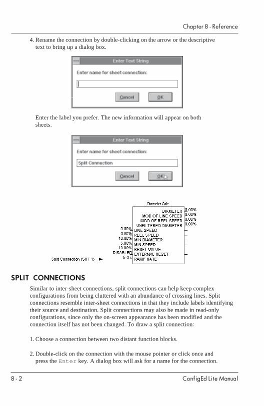
4. Rename the connection by double-clicking on the arrow or the descriptivetext to bring up a dialog box.
Enter the label you prefer. The new information will appear on bothsheets.
SPLIT CONNECTIONSSimilar to inter-sheet connections, split connections can help keep complexconfigurations from being cluttered with an abundance of crossing lines. Splitconnections resemble inter-sheet connections in that they include labels identifyingtheir source and destination. Split connections may also be made in read-onlyconfigurations, since only the on-screen appearance has been modified and theconnection itself has not been changed. To draw a split connection:
1. Choose a connection between two distant function blocks.
2. Double-click on the connection with the mouse pointer or click once andpress the Enter key. A dialog box will ask for a name for the connection.

ConfigEd Lite Manual
Chapter 8 - Reference
8 - 3
3. Enter the name and click the OK button. The connection will be split andlabels will be attached to each end identifying the source and destinationof the connection.
To change the connection name, double-click on either the connection or the labeland enter the new information in the dialog box.
DRAWINGThe ability to create configurations in a graphical display on screen is a key featureof ConfigEd Lite. The Draw menu contains a variety of tools to assist you in yourwork. It provides functions to move among multiple sheets of drawings, createcustom outline forms, and annotate drawings with important information.
Additional commands in the Draw menu include Oval , Color , Fill , Pattern ,and Width . These commands are used to modify objects drawn in or text added tothe configuration. The color, fill, or width of the lines of function blocks andconnecting lines cannot be modified. Only objects or lines you have drawn in aconfiguration can be modified with these tools.
To apply Color , Fill , Pattern , or Width commands to an existing object,select the object with the mouse pointer. As an example, we will use a box created ina blank configuration using the Rectangle tool. After creating the box, select itwith the mouse pointer and then go to the draw menu and select Pattern .
A pop up list of pattern options will appear on screen; Hollow is the defaultpattern. Select a different pattern (for example, Solid ) with the mouse and releasethe mouse key. The box will automatically be filled on screen. For illustrationpurposes, Black has been selected as the Fill color; the default fill is White .
ConfigEd Lite Manual
Chapter 8 - Reference
8 - 4
The same sequence of steps can be used to modify the color of text or graphics, thewidth of lines (either alone or as part of a drawn object), and the fill of a drawnobject.
NOTE: Pressing the Ctrl key after use of any drawing tool causesConfigEd Lite to “remember” the last drawing action taken (whether drawinglines, arrows, or shapes, or adding text) and allows you to immediately repeatthat action. This saves the time and effort of repeatedly selecting the toolfrom the Draw menu.
Drawing Tools
ColorThe Color command is used to specify the outline color for rectangles and ovalsand the display color for lines, arrows, and text you have added to your drawing.
To apply color to an object or text, either select a color and then a line or object todraw or text to place, or select an already-placed object or block of text and thenchange the color. The default color setting is Black .
FillThe Fill command is used to color the contents of an object and highlight itsappearance on a color display. To change the color for new objects, select Fill andchoose the new color. All new objects will be drawn with that color.
To change the fill color of an existing object, select the object. Then select Filland choose the new color. The default color is White .
PatternThe Pattern command is used to set the fill pattern of an object. To change the fillpattern for new objects, select Pattern and choose the new style. All new objectswill be drawn with that fill pattern.
To change the fill pattern of an existing object, select the object. Then selectPattern and choose the new fill pattern. The default Pattern setting isHollow .
WidthThe Width command is used to specify the thickness of lines created with theArrow , Line , Oval , and Rectangle commands. One point is equal to 1/72 of aninch. Line width ranges from 0.5 points to 16.0 points; the default line width is 0.5points.
ConfigEd Lite Manual
Chapter 8 - Reference
8 - 5
To get an idea of the differences in line widths, select the oval drawn previously andchange the line using the Width tool. Notice the difference in the oval when the lineis changed. The Width setting is also used for all newly-drawn objects.
ArrowThe Arrow command is a variant of the Line command. It is used to add lines witharrows to your drawings. Combined with text and other tools, arrows can be aneffective tool to bring attention to a particular item.
LineThe Line command allows you to draw straight lines anywhere in your drawing. Itcan be used to create form outlines and text boxes, and to add highlighting todrawings. When you select Line from the Draw menu, your mouse pointer turnsinto an X, showing it is now a drawing tool. Place the X where you want to beginyour line, press and hold the mouse key down, and drag a line to the desired endpoint.
Release the mouse key when your line is finished. To draw a series of connectedlines, hold the Ctrl key down when you click the mouse the second time. A newline, starting where the first one finished, can then be dragged with the mouse.
OvalThe Oval command allows you to add an oval or circle to your drawing. When youcreate an oval on screen, the borders formed during the drawing process arerectangular. Only after you release the mouse key does the oval appear. When youselect the oval to move it or modify its shape, it is highlighted by a rectangular graybox outlining its perimeter.
RectangleThe Rectangle command allows you to add a rectangle to your drawing.
TextThe Text command allows you to add text to your drawing. It is covered in depth inChapter 6.
DISPLAY OPTIONSThe Scale and Black & White display options are used to change the view of aconfiguration on your computer screen.
ConfigEd Lite Manual
Chapter 8 - Reference
8 - 6
ScaleThe Scale command is used to select the magnification ratio of your configurationdisplay. The Scale menu presents a list of preset ratios as well as a Variabledialog function. The Variable dialog asks for a magnification setting within therange of .34x to 10x . The default Variable setting is the current viewing scale.
Keyboard commands may also be used to change scaling. See page 4-2 for a list ofkeyboard scaling commands.
Black & WhiteThe Black & White command is used to switch the display of your configurationfrom color to black and white mode. This is useful when taking a drawing created ona color monitor and viewing it on a black and white monitor. It is also used whensending a color configuration to a black and white printer. With this commandtoggled on, it prevents printing the drawing in gray scale, which may result in poorprintout quality.
ANNOTATING DRAWINGSObjects and/or text may be added to your drawings in the same manner as is used forcreating forms. The only difference is that such annotations are usually made onindividual configuration sheets rather than on sheet 0.
Review the sections on using the drawing tools to add text or graphics to yourconfiguration drawings.
SCRATCH PADThe scratch pad provides a written record of your actions regarding the configurations,including loading, saving, and deleting drawings. That record is kept in thecelite.tex file, which is created automatically when you first launch ConfigEdLite. Every time the program is run, the information written to the scratch pad isadded to the end of the celite.tex file. It is located in the working directory forthe ConfigEd Lite icon, typically the celite directory. The celite.tex filemay be edited using any text or word processing program that reads text files.
The scratch pad window appears on screen whenever ConfigEd Lite is launched. Itresponds to the same sizing commands and actions as any other Windows™element.
The launch time for ConfigEd Lite is recorded automatically in the scratch pad whenthe program opens. You can manually insert the current time at any point byselecting Paste Time from the Edit menu.
You can select the typeface and size for the information in the scratch pad by firstmaking sure it is the active window. Next, go to the Font and Style menus and
ConfigEd Lite Manual
Chapter 8 - Reference
8 - 7
select the typeface and size you prefer. The type in the scratch pad will change tothe style you specified. The style selected for the scratch pad will also become thedefault for text you add to your configuration drawings, so choose it with care. Asans serif typeface, such as Helvetica, will be the clearest and easiest to read in yourdrawings and is recommended for that reason. Type that is automatically includedwith function blocks retains its default font regardless of the style chosen for thescratch pad.
To print out your ConfigEd Lite Scratch Pad records:
1. Launch a text editor or word processing program, such as theWindows™ Notepad®;
2. Select Open from the File menu;
3. Locate and open the celite directory;
4. Search for files with .tex in the file name;
5. Select celite.tex from the menu of files;
6. Select Print from the File menu once the file is opened.
You can also use the ConfigEd Lite Scratch Pad as a simple text editor to makenotes on the actions recorded there. To add text manually, make sure that the scratchpad window is active and that you can see a blinking cursor. Then add whatevernotations you wish by typing them in from the keyboard.
It is a good idea to edit your celite.tex file periodically, as it can grow quitelarge. Before deleting portions of the file or the entire file, make a copy (eitherprinted or saved to a floppy disk) to retain for your records. This record is invaluablein tracking installations, modifications, and other actions regarding ConfigEd Lite.
You can either select portions of the file to delete while in your text editor or wordprocessor or delete the entire file from your hard drive. If you delete the entire file,ConfigEd Lite will create a new celite.tex file the next time it is launched.
To clear the text displayed in the scratch pad window, make sure it is the activewindow and then choose Save from the File menu. This saves the text to disk andclears the on-screen display of the scratch pad information.
ConfigEd Lite Manual
Chapter 8 - Reference
8 - 8

ConfigEd Lite Manual
Chapter 9 - Appendix
9 - 1
Chapter 9 APPENDIX
MENUS
F i le
Ed i t
C o m m a n d
The File menu provides access to the New, Open, Close ,Save , Save As , Document , Page Setup , PrintScale , Print , and Exit functions.
The Edit menu provides access to Cut , Copy, Paste ,Clear , Select All , and Paste Time functions to be usedin reference to the scratch pad.
The Command menu provides access to the Install , GetInfo , Update , and Comms functions.
ConfigEd Lite Manual
Chapter 9 - Appendix
9 - 2
Window
Font
Style
Help
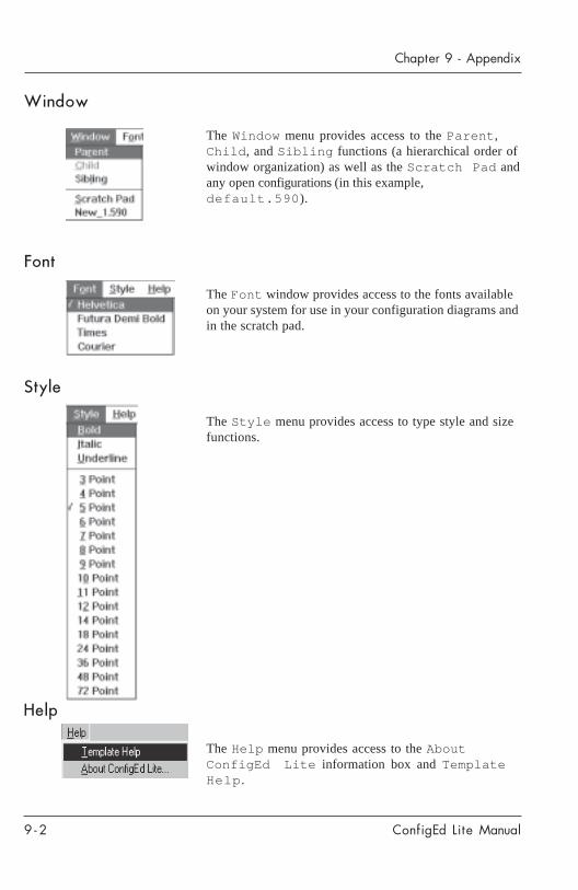
The Window menu provides access to the Parent ,Child , and Sibling functions (a hierarchical order ofwindow organization) as well as the Scratch Pad andany open configurations (in this example,default.590 ).
The Font window provides access to the fonts availableon your system for use in your configuration diagrams andin the scratch pad.
The Style menu provides access to type style and sizefunctions.
The Help menu provides access to the AboutConfigEd Lite information box and TemplateHelp .
ConfigEd Lite Manual
Chapter 9 - Appendix
9 - 3
ConfigEd Lite Manual
Chapter 9 - Appendix
9 - 4