GRANITE 6 Product Manual - Campbell Scientific
281
Revision: 04/22/2022 Copyright © 2000 – 2022 Campbell Scientific, Inc.
-
Upload
khangminh22 -
Category
Documents
-
view
0 -
download
0
Transcript of GRANITE 6 Product Manual - Campbell Scientific

Revision: 04/22/2022Copyright © 2000 – 2022Campbell Scientific, Inc.

Table of Contents1. Introduction 1
2. Precautions 2
3. Initial inspection 3
4. GRANITE 6 data acquisition system components 44.1 The GRANITE 6 Datalogger 5
4.1.1 Overview 54.1.2 Operations 64.1.3 Programs 6
4.2 Sensors 6
5. Wiring panel and terminal functions 85.1 Power input 12
5.1.1 Powering a data logger with a vehicle 145.1.2 Power LED indicator 14
5.2 Power output 145.3 Grounds 155.4 Communications ports 17
5.4.1 USB device port 175.4.2 USB host port 175.4.3 Ethernet port 185.4.4 C and U terminals for communications 18
5.4.4.1 SDI-12 ports 185.4.4.2 RS-232, RS-422, RS-485, TTL, and LVTTL ports 185.4.4.3 SDM ports 19
5.4.5 CS I/O port 195.4.6 CPI/RS-232 port 20
5.5 Programmable logic control 21
6. Setting up the GRANITE 6 246.1 Setting up communications with the data logger 24
6.1.1 USB or RS-232 communications 256.1.2 Virtual Ethernet over USB (RNDIS) 26
Table of Contents - i

6.1.3 Ethernet communications option 276.1.3.1 Configuring data logger Ethernet settings 286.1.3.2 Ethernet LEDs 296.1.3.3 Setting up Ethernet communications between the data logger and computer 29
6.1.4 Wi-Fi communications 306.1.4.1 Hosting a Wi-Fi network 31
Configure the data logger to host a Wi-Fi network 31Connect your phone to the data logger over Wi-Fi 32Set up LoggerLink 33Connect your computer to the data logger over Wi-Fi 33Set up LoggerNet, RTDAQ or PC400W 34
6.1.4.2 Joining a Wi-Fi network 35Configure the data logger to join a Wi-Fi network 35Set up LoggerNet, RTDAQ or PC400W 35
6.1.4.3 Wi-Fi configurations and mode button 36Join a Network 37Create a Network 37Normally Off, Join Network on Button Press (default) 37Normally Off, Create Network on Button Press 37Join Network, Create Network on Button Press 38Disable 38
6.1.4.4 Wi-Fi LED indicator 386.2 Testing communications with EZSetup 396.3 Making the software connection 406.4 Measurement quickstart using SURVEYOR 406.5 Programming quickstart using SURVEYOR 436.6 Programming quickstart using Short Cut 446.7 Sending a program to the data logger 47
7. Working with data 497.1 Default data tables 497.2 Collecting data 50
7.2.1 Collecting data using LoggerNet 507.2.2 Collecting data using RTDAQ 507.2.3 Collecting data using PC400 51
7.3 Viewing historic data 51
Table of Contents - ii

7.4 Data types and formats 527.4.1 Variables 537.4.2 Constants 547.4.3 Data storage 54
7.5 About data tables 557.5.1 Table definitions 56
7.5.1.1 Header rows 567.5.1.2 Data records 58
7.6 Creating data tables in a program 58
8. Data memory 618.1 Data tables 618.2 Memory allocation 628.3 SRAM 62
8.3.1 USR drive 638.4 Flash memory 64
8.4.1 CPU drive 648.5 MicroSD (CRD: drive) 64
8.5.1 Formatting microSD cards 668.5.2 MicroSD card precautions 668.5.3 Act LED indicator 668.5.4 Card data retrieval 67
8.5.4.1 Via a communications link 678.5.4.2 Card transport to computer 68
8.6 USB host (USB: drive) 718.6.1 USB host precautions 718.6.2 Data type collection speed 718.6.3 Skipped scans 728.6.4 Formatting drives 32 GB or larger 72
9. Measurements 739.1 Voltage measurements 73
9.1.1 Single-ended measurements 749.1.2 Differential measurements 75
9.1.2.1 Reverse differential 759.2 Current-loop measurements 75
9.2.1 Example current-loop measurement connections 76
Table of Contents - iii

9.3 Resistance measurements 779.3.1 Resistance measurements with voltage excitation 789.3.2 Resistance measurements with current excitation 809.3.3 Strain measurements 829.3.4 AC excitation 849.3.5 Accuracy for resistance measurements 85
9.4 Period-averaging measurements 859.5 Pulse measurements 86
9.5.1 Low-level AC measurements 889.5.2 High-frequency measurements 88
9.5.2.1 U terminals 899.5.2.2 C terminals 89
9.5.3 Switch-closure and open-collector measurements 899.5.3.1 U Terminals 899.5.3.2 C terminals 90
9.5.4 Edge timing and edge counting 909.5.4.1 Single edge timing 909.5.4.2 Multiple edge counting 909.5.4.3 Timer input NAN conditions 91
9.5.5 Quadrature measurements 919.5.6 Pulse measurement tips 92
9.5.6.1 Input filters and signal attenuation 929.5.6.2 Pulse count resolution 93
9.6 Vibrating wire measurements 939.6.1 VSPECT® 94
9.6.1.1 VSPECT diagnostics 95Decay ratio 95Signal-to-noise ratio 95Low signal strength amplitude warning 95
9.6.2 Improving vibrating wire measurement quality 959.6.2.1 Matching measurement ranges to expected frequencies 959.6.2.2 Rejecting noise 969.6.2.3 Minimizing resonant decay 969.6.2.4 Preventing spectral leakage 96
9.7 Sequential and pipeline processing modes 969.7.1 Sequential mode 979.7.2 Pipeline mode 97
Table of Contents - iv

9.7.3 Slow Sequences 98
10. Communications protocols 9910.1 General serial communications 100
10.1.1 RS-232 10210.1.2 RS-485 10310.1.3 RS-422 10410.1.4 TTL 10510.1.5 LVTTL 10510.1.6 TTL-Inverted 10510.1.7 LVTTL-Inverted 106
10.2 CPI 10610.3 Modbus communications 107
10.3.1 About Modbus 10810.3.2 Modbus protocols 10910.3.3 Understanding Modbus Terminology 10910.3.4 Connecting Modbus devices 11010.3.5 Modbus client-server protocol 11010.3.6 About Modbus programming 111
10.3.6.1 Endianness 11110.3.6.2 Function codes 111
10.3.7 Modbus information storage 11210.3.7.1 Registers 11310.3.7.2 Coils 11310.3.7.3 Data Types 113
Unsigned 16-bit integer 114Signed 16-bit integer 114Signed 32-bit integer 114Unsigned 32-bit integer 11432-Bit floating point 115
10.3.8 Modbus tips and troubleshooting 11510.3.8.1 Error codes 115
Result code -01: illegal function 115Result code -02: illegal data address 115Result code -11: COM port error 116
10.4 Internet communications 11610.4.1 IP address 117
Table of Contents - v

10.4.2 HTTPS server 11710.4.3 FTP server 117
10.5 DNP3 communications 11910.6 Serial peripheral interface (SPI) and I2C 11910.7 PakBus communications 11910.8 SDI-12 communications 120
10.8.1 SDI-12 transparent mode 12110.8.1.1 Watch command (sniffer mode) 12210.8.1.2 SDI-12 transparent mode commands 122
10.8.2 SDI-12 programmed mode/recorder mode 12310.8.3 Programming the data logger to act as an SDI-12 sensor 12410.8.4 SDI-12 power considerations 124
11. Installation 12611.1 Default program 12711.2 Data logger security 128
11.2.1 TLS 12911.2.2 Security codes 13011.2.3 Creating a .csipasswd file 131
11.3 Web interface 13211.4 Power budgeting 13211.5 Field work 13311.6 Data logger enclosures 13411.7 Electrostatic discharge and lightning protection 134
12. GRANITE 6 maintenance 13612.1 Data logger calibration 136
12.1.1 About background calibration 13712.2 Internal battery 137
12.2.1 Replacing the internal battery 13812.3 Updating the operating system 139
12.3.1 Sending an operating system to a local data logger 13912.3.2 Sending an operating system to a remote data logger 140
12.4 gzip 14112.5 File management via powerup.ini 143
12.5.1 Syntax 14312.5.2 Example powerup.ini files 144
Table of Contents - vi

13. Tips and troubleshooting 14613.1 Checking station status 147
13.1.1 Viewing station status 14713.1.2 Watchdog errors 14813.1.3 Results for last program compiled 14813.1.4 Skipped scans 14913.1.5 Skipped records 14913.1.6 Variable out of bounds 14913.1.7 Battery voltage 149
13.2 Understanding NAN and INF occurrences 14913.3 Timekeeping 150
13.3.1 Clock best practices 15013.3.2 Time stamps 15113.3.3 Avoiding time skew 151
13.4 CRBasic program errors 15213.4.1 Program does not compile 15213.4.2 Program compiles but does not run correctly 153
13.5 Resetting the data logger 15313.5.1 Processor reset 15413.5.2 Program send reset 15413.5.3 Manual data table reset 15413.5.4 Formatting drives 15413.5.5 Full memory reset 155
13.6 Troubleshooting power supplies 15513.6.1 SDI-12 transparent mode 156
13.6.1.1 Watch command (sniffer mode) 15713.6.1.2 SDI-12 transparent mode commands 157
13.7 Ground loops 15813.7.1 Common causes 15813.7.2 Detrimental effects 15813.7.3 Severing a ground loop 16013.7.4 Soil moisture example 161
13.8 Improving voltage measurement quality 16213.8.1 Deciding between single-ended or differential measurements 16213.8.2 Minimizing ground potential differences 163
13.8.2.1 Ground potential differences 16413.8.3 Detecting open inputs 164
Table of Contents - vii

13.8.4 Minimizing power-related artifacts 16513.8.4.1 Minimizing electronic noise 166
13.8.5 Filtering to reduce measurement noise 16713.8.5.1 GRANITE 6 filtering details 167
13.8.6 Minimizing settling errors 16813.8.6.1 Measuring settling time 168
13.8.7 Factors affecting accuracy 17013.8.7.1 Measurement accuracy example 171
13.8.8 Minimizing offset voltages 17113.8.8.1 Compensating for offset voltage 17313.8.8.2 Measuring ground reference offset voltage 174
13.9 Field calibration 17513.10 File system error codes 17613.11 File name and resource errors 17713.12 Background calibration errors 177
14. Information tables and settings (advanced) 17814.1 DataTableInfo table system information 179
14.1.1 DataFillDays 17914.1.2 DataRecordSize 17914.1.3 DataTableName 17914.1.4 RecNum 17914.1.5 SecsPerRecord 18014.1.6 SkippedRecord 18014.1.7 TimeStamp 180
14.2 Status table system information 18014.2.1 Battery 18014.2.2 BuffDepth 18014.2.3 CalCurrent 18014.2.4 CalGain 18114.2.5 CalOffset 18114.2.6 CalRefOffset 18114.2.7 CalRefSlope 18114.2.8 CalVolts 18114.2.9 CardStatus 18114.2.10 ChargeInput 18114.2.11 ChargeState 181
Table of Contents - viii

14.2.12 CommsMemFree 18114.2.13 CompileResults 18214.2.14 ErrorCalib 18214.2.15 FullMemReset 18214.2.16 IxResistor 18214.2.17 LastSystemScan 18214.2.18 LithiumBattery 18214.2.19 Low12VCount 18214.2.20 MaxBuffDepth 18214.2.21 MaxProcTime 18314.2.22 MaxSystemProcTime 18314.2.23 MeasureOps 18314.2.24 MeasureTime 18314.2.25 MemoryFree 18314.2.26 MemorySize 18314.2.27 Messages 18314.2.28 OSDate 18414.2.29 OSSignature 18414.2.30 OSVersion 18414.2.31 PakBusRoutes 18414.2.32 PanelTemp 18414.2.33 PortConfig 18414.2.34 PortStatus 18414.2.35 PowerSource 18514.2.36 ProcessTime 18514.2.37 ProgErrors 18514.2.38 ProgName 18514.2.39 ProgSignature 18514.2.40 RecNum 18514.2.41 RevBoard 18514.2.42 RunSignature 18614.2.43 SerialNumber 18614.2.44 SkippedScan 18614.2.45 SkippedSystemScan 18614.2.46 StartTime 18614.2.47 StartUpCode 18614.2.48 StationName 186
Table of Contents - ix

14.2.49 SW12Volts 18714.2.50 SystemProcTime 18714.2.51 TimeStamp 18714.2.52 VarOutOfBound 18714.2.53 WatchdogErrors 18714.2.54 WiFiUpdateReq 187
14.3 CPIStatus system information 18714.3.1 BusLoad 18814.3.2 ModuleReportCount 18814.3.3 ActiveModules 18814.3.4 BuffErr (buffer error) 18814.3.5 RxErrMax 18814.3.6 TxErrMax 18814.3.7 FrameErr (frame errors) 18914.3.8 ModuleInfo array 189
14.4 Settings 18914.4.1 Baudrate 19014.4.2 Beacon 19014.4.3 CentralRouters 19014.4.4 CommsMemAlloc 19014.4.5 ConfigComx 19114.4.6 CSIOxnetEnable 19114.4.7 CSIOInfo 19114.4.8 DisableLithium 19214.4.9 DeleteCardFilesOnMismatch 19214.4.10 DNS 19214.4.11 EthernetInfo 19214.4.12 EthernetPower 19214.4.13 FilesManager 19314.4.14 FTPEnabled 19314.4.15 FTPPassword 19314.4.16 FTPPort 19314.4.17 FTPUserName 19314.4.18 HTTPEnabled 19314.4.19 HTTPHeader 19314.4.20 HTTPPort 19414.4.21 HTTPSEnabled 194
Table of Contents - x

14.4.22 HTTPSPort 19414.4.23 IncludeFile 19414.4.24 IPAddressCSIO 19414.4.25 IPAddressEth 19414.4.26 IPGateway 19514.4.27 IPGatewayCSIO 19514.4.28 IPMaskCSIO 19514.4.29 IPMaskEth 19514.4.30 IPMaskWiFi 19514.4.31 IPTrace 19514.4.32 IPTraceCode 19614.4.33 IPTraceComport 19614.4.34 IsRouter 19614.4.35 KeepAliveURL (Ping keep alive URL) 19614.4.36 KeepAliveMin (Ping keep alive timeout value) 19614.4.37 MaxPacketSize 19714.4.38 Neighbors 19714.4.39 NTPServer 19714.4.40 PakBusAddress 19714.4.41 PakBusEncryptionKey 19714.4.42 PakBusNodes 19714.4.43 PakBusPort 19814.4.44 PakBusTCPClients 19814.4.45 PakBusTCPEnabled 19814.4.46 PakBusTCPPassword 19814.4.47 PingEnabled 19814.4.48 PCAP 19814.4.49 pppDial 19914.4.50 pppDialResponse 19914.4.51 pppInfo 19914.4.52 pppInterface 19914.4.53 pppIPAddr 19914.4.54 pppPassword 20014.4.55 pppUsername 20014.4.56 RouteFilters 20014.4.57 RS232Handshaking 20014.4.58 RS232Power 200
Table of Contents - xi

14.4.59 RS232Timeout 20114.4.60 Security(1), Security(2), Security(3) 20114.4.61 ServicesEnabled 20114.4.62 TCPClientConnections 20114.4.63 TCP_MSS 20114.4.64 TCPPort 20114.4.65 TelnetEnabled 20114.4.66 TLSConnections (Max TLS Server Connections) 20114.4.67 TLSPassword 20214.4.68 TLSStatus 20214.4.69 UDPBroadcastFilter 20214.4.70 USBConfig (Configure USB) 20214.4.71 USBEnumerate 20214.4.72 USRDriveFree 20214.4.73 USRDriveSize 20314.4.74 UTCOffset 20314.4.75 Verify 20314.4.76 Wi-Fi settings 203
14.4.76.1 IPAddressWiFi 20414.4.76.2 IPGatewayWiFi 20414.4.76.3 IPMaskWiFi 20414.4.76.4 WiFiChannel 20414.4.76.5 WiFiConfig 20414.4.76.6 WiFiEAPMethod 20514.4.76.7 WiFiEAPPassword 20514.4.76.8 WiFiEAPUser 20514.4.76.9 Networks 20514.4.76.10 WiFiEnable 20614.4.76.11 WiFiFwdCode (Forward Code) 20614.4.76.12 WiFiPassword 20614.4.76.13 WiFiPowerMode 20614.4.76.14 WiFiSSID (Network Name) 20614.4.76.15 WiFiStatus 20714.4.76.16 WiFiTxPowerLevel 20714.4.76.17 WLANDomainName 207
Table of Contents - xii

15. GRANITE 6 specifications 20815.1 System specifications 20815.2 Physical specifications 20915.3 Power requirements 20915.4 Power output specifications 211
15.4.1 System power out limits (when powered with 12 VDC) 21115.4.2 12 V and SW12 V power output terminals 21115.4.3 5 V fixed output 21215.4.4 U and C as power output 21215.4.5 CS I/O pin 1 21215.4.6 Voltage and current excitation specifications 213
15.4.6.1 Voltage excitation 21315.4.6.2 Current excitation 213
15.5 Analog measurement specifications 21315.5.1 Voltage measurements 21415.5.2 Resistance measurement specifications 21615.5.3 Period-averaging measurement specifications 21615.5.4 Static vibrating wire measurement specifications 21715.5.5 Thermistor measurement specifications 21715.5.6 Current-loop measurement specifications 218
15.6 Pulse measurement specifications 21815.6.1 Switch closure input 21915.6.2 High-frequency input 21915.6.3 Low-level AC input 220
15.7 Digital input/output specifications 22015.7.1 Switch closure input 22115.7.2 High-frequency input 22115.7.3 Edge timing 22115.7.4 Edge counting 22115.7.5 Quadrature input 22115.7.6 Pulse-width modulation 222
15.8 Communications specifications 22215.8.1 Wi-Fi specifications 223
15.9 Standards compliance specifications 223
Appendix A. Glossary 225
Table of Contents - xiii

1. IntroductionThe GRANITE™6 DAQ is a powerful core component for your complete data-acquisition system. The GRANITE 6 provides fast communications, low power requirements, built-in USB and Wi-Fi, modular design, and high analog input accuracy and resolution. It uses universal (U) terminals to allow a connection to virtually any sensor—analog, digital, or smart. The multipurpose DAQ is also capable of measuring static vibrating-wire measurements.
Additional Campbell Scientific publications are available online at www.campbellsci.com . Video tutorials are available at www.campbellsci.com/videos . Generally, if a particular feature of the data logger requires a peripheral hardware device, more information is available in the help or manual written for that device.
1. Introduction 1

2. PrecautionsREAD AND UNDERSTAND the Safety section at the back of this manual.
An authorized technician shall verify that the installation and use of this product is in accordance to the manufacturer’s instructions, recommendations and intended use.
Although the GRANITE 6 is rugged, it should be handled as a precision scientific instrument.
Maintain a level of calibration appropriate to the application. Campbell Scientific recommends factory recalibration every three years.
2. Precautions 2

3. Initial inspectionUpon receiving the GRANITE 6, inspect the packaging and contents for damage. File damage claims with the shipping company.
Immediately check package contents. Thoroughly check all packaging material for product that may be concealed. Check model numbers, part numbers, and product descriptions against the shipping documents. Model or part numbers are found on each product. Report any discrepancies to Campbell Scientific.
Check the GRANITE 6 operating system version as outlined in Updating the operating system (p. 139), and update as needed.
3. Initial inspection 3

4. GRANITE 6 data acquisition system componentsA basic data acquisition system consists of sensors, measurement hardware, and a computer with programmable software. The objective of a data acquisition system should be high accuracy, high precision, and resolution as high as appropriate for a given application.
The components of a basic data acquisition system are shown in the following figure.
Following is a list of typical data acquisition system components:
l Sensors - Electronic sensors convert the state of a phenomenon to an electrical signal (see Sensors (p. 6) for more information).
l Data logger - The data logger measures electrical signals or reads serial characters. It converts the measurement or reading to engineering units, performs calculations, and reduces data to statistical values. Data is stored in memory to await transfer to a computer by way of an external storage device or a communications link.
4. GRANITE 6 data acquisition system components 4

l Data Retrieval and Communications - Data is copied (not moved) from the data logger, usually to a computer, by one or more methods using data logger support software. Most communications options are bi-directional, which allows programs and settings to be sent to the data logger. For more information, see Sending a program to the data logger (p. 47).
l Datalogger Support Software - Software retrieves data, sends programs, and sets settings. The software manages the communications link and has options for data display.
l Programmable Logic Control - Some data acquisition systems require the control of external devices to facilitate a measurement or to control a device based on measurements. This data logger is adept at programmable logic control. See Programmable logic control (p. 21) for more information.
l Measurement and Control Peripherals - Sometimes, system requirements exceed the capacity of the data logger. The excess can usually be handled by addition of input and output expansion modules.
l Campbell Distributed Module (CDM) - CDMs increase measurement capability can be centrally located or distributed throughout the network. Modules are controlled and synchronized by a single GRANITE 6. GRANITE Measurement Modules are one type of CDM.
4.1 The GRANITE 6 DataloggerThe GRANITE 6 data logger provides fast communications, low power requirements, built-in USB, compact size and and high analog input accuracy and resolution. It includes universal (U) terminals, which allow connection to virtually any sensor - analog, digital, or smart. This multipurpose data logger is also capable of doing static vibrating-wire measurements.
4.1.1 OverviewThe GRANITE 6 data logger is the main part of a data acquisition system (see GRANITE 6 data acquisition system components (p. 4) for more information). It has a central-processing unit (CPU), analog and digital measurement inputs, analog and digital outputs, and memory. An operating system (firmware) coordinates the functions of these parts in conjunction with the onboard clock and the CRBasic application program.
The GRANITE 6 can simultaneously provide measurement and communications functions. Low power consumption allows the data logger to operate for extended time on a battery recharged with a solar panel, eliminating the need for ac power. The GRANITE 6 temporarily suspends operations when primary power drops below 9.6 V, reducing the possibility of inaccurate measurements.
4. GRANITE 6 data acquisition system components 5

4.1.2 OperationsThe GRANITE 6 measures almost any sensor with an electrical response, drives direct communications and telecommunications, reduces data to statistical values, performs calculations, and controls external devices. After measurements are made, data is stored in onboard, nonvolatile memory. Because most applications do not require that every measurement be recorded, the program usually combines several measurements into computational or statistical summaries, such as averages and standard deviations.
4.1.3 ProgramsA program directs the data logger on how and when sensors are measured, calculations are made, data is stored, and devices are controlled. The application program for the GRANITE 6 is written in CRBasic, a programming language that includes measurement, data processing, and analysis routines, as well as the standard BASIC instruction set. For simple applications, Short Cut, a user-friendly program generator, can be used to generate the program. See also:
l Creating a Short Cut data logger program l https://www.campbellsci.com/videos/datalogger-programming
For more demanding programs, use the full-featured CRBasic Editor. The CRBasic Editor help contains program structure details, instruction information and program examples: https://help.campbellsci.com/crbasic/granite6/ .
Programs are run by the GRANITE 6 in either sequential mode or pipeline mode. In sequential mode, each instruction is executed sequentially in the order it appears in the program. In pipeline mode, the GRANITE 6 determines the order of instruction execution to maximize efficiency.
4.2 SensorsSensors transduce phenomena into measurable electrical forms by modulating voltage, current, resistance, status, or pulse output signals. Suitable sensors do this with accuracy and precision. Smart sensors have internal measurement and processing components and simply output a digital value in binary, hexadecimal, or ASCII character form.
Most electronic sensors, regardless of manufacturer, will interface with the data logger. Some sensors require external signal conditioning. The performance of some sensors is enhanced with specialized input modules. The data logger, sometimes with the assistance of various peripheral devices, can measure or read nearly all electronic sensor output types.
4. GRANITE 6 data acquisition system components 6

The following list may not be comprehensive. A library of sensor manuals and application notes is available at www.campbellsci.com/support to assist in measuring many sensor types.
l Analog o Voltage o Current o Strain o Thermocouple o Resistive bridge
l Pulse o High frequency o Switch-closure o Low-level ac o Quadrature
l Period average l Vibrating wire l Smart sensors
o SDI-12 o RS-232 o Modbus o DNP3 o TCP/IP o RS-422 o RS-485
4. GRANITE 6 data acquisition system components 7

5. Wiring panel and terminal functionsThe GRANITE 6 wiring panel provides ports and removable terminals for connecting sensors, power, and communications devices. It is protected against surge, over-voltage, over-current, and reverse power. The wiring panel is the interface to most data logger functions so studying it is a good way to get acquainted with the data logger. Functions of the terminals are broken down into the following categories:
l Analog input l Pulse counting l Analog output l Communications l Digital I/O l Power input l Power output l Power ground l Signal ground
5. Wiring panel and terminal functions 8

FIGURE 5-1. GRANITE 6 Wiring panel
FIGURE 5-2. GRANITE 6
5. Wiring panel and terminal functions 9

Table 5-1: Analog input terminal functions
U1 U2 U3 U4 U5 U6 U7 U8 U9 U10 U11 U12 RG
Single-Ended Voltage
Differential Voltage H L H L H L H L H L H L
Ratiometric/Bridge
Vibrating Wire (Static, VSPECT®)
Vibrating Wire with Thermistor
Thermistor
Thermocouple
Current Loop
Period Average
Table 5-2: Pulse counting terminal functions
U1 U2 U3 U4 U5 U6 U7 U8 U9 U10 U11 U12 C1-C4
Switch-Closure
High Frequency
Low-level Ac
NOTE:Conflicts can occur when a control port pair is used for different instructions (TimerInput(), PulseCount(), SDI12Recorder(), WaitDigTrig()). For example, if C1 is used for SDI12Recorder(), C2 cannot be used for TimerInput(), PulseCount(), or WaitDigTrig().
Table 5-3: Analog output terminal functions
U1-U12
Switched Voltage Excitation
Switched Current Excitation
5. Wiring panel and terminal functions 10

Table 5-4: Voltage output terminal functions
U1-U12 C1-C4 12V SW12-1 SW12-2 5V
3.3 VDC
5 VDC
12 VDC C and even numbered U terminals have limited drive capacity. Voltage levels are configured in pairs.
Table 5-5: Communications terminal functions
U1 U2 U3 U4 U5 U6 U7 U8 U9 U10 U11 U12 C1 C2 C3 C4
RS-
232/
CPI
SDI-12
GPS
Time
Sync
PPS Rx Tx Rx Tx Rx
TTL
0-5 VTx Rx Tx Rx Tx Rx Tx Rx Tx Rx Tx Rx Tx Rx Tx Rx
LVTTL
0-3.3 VTx Rx Tx Rx Tx Rx Tx Rx Tx Rx Tx Rx Tx Rx Tx Rx
RS-232 Tx Rx Tx Rx
RS-485
(Half
Duplex)
A- B+ A- B+
RS-485
(Full
Duplex)
Tx- Tx+ Rx- Rx+
I2C SCL SDA SCL SDA SCL SDA SCL SDA SCL SDA SCL SDA SCL SDA SCL SDA
SPI MOSI SCLK MISO MOSI SCLK MISO MOSI SCLK MISO MOSI SCLK MISO
5. Wiring panel and terminal functions 11

Table 5-5: Communications terminal functions
U1 U2 U3 U4 U5 U6 U7 U8 U9 U10 U11 U12 C1 C2 C3 C4
RS-
232/
CPI
SDM Data Clk Enabl Data Clk Enabl Data Clk Enabl Data Clk Enabl
CPI/
CDM
Table 5-6: Digital I/O terminal functions
U1-U12 C1-C4
General I/O
Pulse-Width Modulation Output
Timer Input
Interrupt
Quadrature
5.1 Power inputThe data logger requires a power supply. It can receive power from a variety of sources, operate for several months on non-rechargeable batteries, and supply power to many sensors and devices. The data logger operates with external power connected to the green BAT and/or CHG terminals on the side of the module. The positive power wire connects to +. The negative wire connects to -. The power terminals are internally protected against polarity reversal and high voltage transients.
In the field, the data logger can be powered in any of the following ways:
l 10 to 18 VDC applied to the BAT + and – terminals l 16 to 32 VDC applied to the CHG + and – terminals
To establish an uninterruptible power supply (UPS), connect the primary power source (often a transformer, power converter, or solar panel) to the CHG terminals and connect a nominal 12 VDC sealed rechargeable lead-acid battery to the BAT terminals. See Power budgeting (p. 132) for more information. The Status Table ChargeState may display any of the following:
5. Wiring panel and terminal functions 12

l No Charge - The charger input voltage is either less than +9.82V±2% or there is no charger attached to the terminal block.
l Low Charge Input – The charger input voltage is less than the battery voltage. l Current Limited – The charger input voltage is greater than the battery voltage AND the
battery voltage is less than the optimal charge voltage. For example, on a cloudy day, a solar panel may not be providing as much current as the charger would like to use.
l Float Charging – The battery voltage is equal to the optimal charge voltage. l Regulator Fault - The charging regulator is in a fault condition.
WARNING:Sustained input voltages in excess of 32 VDC on CHG or BAT terminals can damage the transient voltage suppression.
Ensure that power supply components match the specifications of the device to which they are connected. When connecting power, switch off the power supply, insert the connector, then turn the power supply on. See Troubleshooting power supplies (p. 155) for more information.
Following is a list of GRANITE 6 power input terminals and the respective power types supported.
l BAT terminals: Voltage input is 10 to 18 VDC. This connection uses the least current since the internal data logger charging circuit is bypassed. If the voltage on the BAT terminals exceeds 19 VDC, power is shut off to certain parts of the data logger to prevent damaging connected sensors or peripherals.
l CHG terminals: Voltage input range is 16 to 32 VDC. Connect a primary power source, such as a solar panel or VAC-to-VDC transformer, to CHG. The voltage applied to CHG terminals must be at least 0.3 V higher than that needed to charge a connected battery. When within the 16 to 32 VDC range, it will be regulated to the optimal charge voltage for a lead acid battery at the current data logger temperature, with a maximum voltage of approximately 15 VDC. A battery need not be connected to the BAT terminals to supply power to the data logger through the CHG terminals. The onboard charging regulator is designed for efficiently charging lead-acid batteries. It will not charge lithium or alkaline batteries.
l USB Device port: 5 VDC via USB connection. If power is also provided with BAT or CHG, power will be supplied by whichever has the highest voltage. If USB is the only power source, then the CS I/O port, the 12V and SW12V terminals will not be operational. When powered by USB (no other power supplies connected) Status field Battery = 0. Functions that will be active with a 5 VDC source include sending programs, adjusting data logger settings, and making some measurements.
5. Wiring panel and terminal functions 13

NOTE:The Status field Battery value and the destination variable from the Battery() instruction (often called batt_volt or BattV) in the Public table reference the external battery voltage. For information about the internal battery, see Internal battery (p. 137).
5.1.1 Powering a data logger with a vehicleIf a data logger is powered by a motor-vehicle power supply, a second power supply may be needed. When starting the motor of the vehicle, battery voltage often drops below the voltage required for data logger operation. This may cause the data logger to stop measurements until the voltage again equals or exceeds the lower limit. A second supply or charge regulator can be provided to prevent measurement lapses during vehicle starting.
In vehicle applications, the earth ground lug should be firmly attached to the vehicle chassis with 12 AWG wire or larger.
5.1.2 Power LED indicatorWhen the data logger is powered, the Power LED will turn on according to power and program states:
l Off: No power, no program running. l 1 flash every 10 seconds: Powered from BAT, program running. l 2 flashes every 10 seconds: Powered from CHG, program running. l 3 flashes every 10 seconds: Powered via USB, program running. l Always on: Powered, no program running.
5.2 Power outputThe data logger can be used as a power source for communications devices, sensors and peripherals. Take precautions to prevent damage to these external devices due to over- or under-voltage conditions, and to minimize errors. Additionally, exceeding current limits causes voltage output to become unstable. Voltage should stabilize once current is again reduced to within stated limits. The following are available:
l 12V: unregulated nominal 12 VDC. This supply closely tracks the primary data logger supply voltage; so, it may rise above or drop below the power requirement of the sensor or peripheral. Precautions should be taken to minimize the error associated with measurement of underpowered sensors.
5. Wiring panel and terminal functions 14

l 5V: regulated 5 VDC. The 5 VDC supply is regulated to within a few millivolts of 5 VDC as long as the main power supply for the data logger does not drop below the minimum supply voltage. It is intended to power sensors or devices requiring a 5 VDC power supply. It is not intended as an excitation source for bridge measurements. Current output is shared with the CS I/O port; so, the total current must be within the current limit. See 5 V fixed output (p. 212) specifications.
l SW12: program-controlled, switched 12 VDC terminals. It is often used to power devices such as sensors that require 12 VDC during measurement. Voltage on a SW12 terminal will change with data logger supply voltage. CRBasic instruction SW12() controls the SW12 terminal. See the CRBasic Editor help for detailed instruction information and program examples: https://help.campbellsci.com/crbasic/granite6/ .
l CS I/O port: used to communicate with and often supply power to Campbell Scientific peripheral devices.
CAUTION:Voltage levels at the 12V and switched SW12 terminals, and pin 8 on the CS I/O port, are tied closely to the voltage levels of the main power supply. Therefore, if the power received at the POWER IN 12V and G terminals is 16 VDC, the 12V and SW12 terminals and pin 8 on the CS I/O port will supply 16 VDC to a connected peripheral. The connected peripheral or sensor may be damaged if it is not designed for that voltage level.
l C or U terminals: can be set low or high as output terminals . With limited drive capacity, digital output terminals are normally used to operate external relay-driver circuits. Drive current varies between terminals. See also Digital input/output specifications (p. 220).
l U terminals: can be configured to provide regulated ±2500 mV dc excitation.
See also Power output specifications (p. 211).
5.3 GroundsProper grounding lends stability and protection to a data acquisition system. Grounding the data logger with its peripheral devices and sensors is critical in all applications. Proper grounding will ensure maximum ESD protection and measurement accuracy. It is the easiest and least expensive insurance against data loss, and often the most neglected. The following terminals are provided for connection of sensor and data logger grounds:
5. Wiring panel and terminal functions 15

l Signal Ground ( ) - reference for single-ended analog inputs, excitation returns, and a ground for sensor shield wires.
o 6 common terminals l Power Ground (G) - return for 3.3 V, 5 V, 12 V, U or C terminals configured for control, and
digital sensors. Use of G grounds for these outputs minimizes potentially large current flow through the analog-voltage-measurement section of the wiring panel, which can cause single-ended voltage measurement errors.
o 6 common terminals l Resistive Ground (RG) - used for non-isolated 0-20 mA and 4-20 mA current loop
measurements (see Current-loop measurements (p. 75) for more information). Also used for decoupling ground on RS-485 signals. Includes 100 Ω resistance to ground. Maximum voltage for RG terminal is ±16 V.
o 1 terminal l Earth Ground Lug ( ) - connection point for heavy-gage earth-ground wire. A good earth
connection is necessary to secure the ground potential of the data logger and shunt transients away from electronics. Campbell Scientific recommends 14 AWG wire, minimum.
NOTE:Several ground wires can be connected to the same ground terminal.
A good earth (chassis) ground will minimize damage to the data logger and sensors by providing a low-resistance path around the system to a point of low potential. Campbell Scientific recommends that all data loggers be earth grounded. All components of the system (data loggers, sensors, external power supplies, mounts, housings) should be referenced to one common earth ground.
In the field, at a minimum, a proper earth ground will consist of a 5-foot copper-sheathed grounding rod driven into the earth and connected to the large brass ground lug on the wiring panel with a 14 AWG wire. In low-conductive substrates, such as sand, very dry soil, ice, or rock, a single ground rod will probably not provide an adequate earth ground. For these situations, search for published literature on lightning protection or contact a qualified lightning-protection consultant.
In laboratory applications, locating a stable earth ground is challenging, but still necessary. In older buildings, new VAC receptacles on older VAC wiring may indicate that a safety ground exists when, in fact, the socket is not grounded. If a safety ground does exist, good practice dictates to verify that it carries no current. If the integrity of the VAC power ground is in doubt, also ground the system through the building plumbing, or use another verified connection to earth ground.
5. Wiring panel and terminal functions 16

See also:
l Ground loops (p. 158) l Minimizing ground potential differences (p. 163)
5.4 Communications portsThe data logger is equipped with ports that allow communications with other devices and networks, such as:
l Computers l Smart sensors l Modbus and DNP3 networks l Ethernet l Modems l Campbell Scientific PakBus® networks l Other Campbell Scientific data loggers l GRANITE Measurement Modules
Campbell Scientific data logger communications ports include:
l CS I/O l CPI/RS-232 l USB Device l USB Host l Ethernet l C and U terminals
5.4.1 USB device portThe USB device port supports communicating with a computer through data logger support software or through virtual Ethernet (RNDIS), and provides 5 VDC power to the data logger (powering through the USB port has limitations - details are available in the specifications). The data logger USB device port does not support USB flash or thumb drives; use the USB host port for these external devices. Although the USB connection supplies 5 V power, a 12 VDC battery will be needed for field deployment.
5.4.2 USB host portUSB host provides portable data storage on a USB thumb drive. A FAT32-formatted USB thumb drive can be inserted into the host port and will show up as a drive (USB:) in file-related operations. Measurement data is stored on USB: as discrete files by using the TableFile()
5. Wiring panel and terminal functions 17

instruction. Files on USB: can be collected by inserting the thumb drive into a computer and copying the files.
USB: can be used in all CRBasic file-access-related instructions. Because of data reliability concerns in non-industrial rated drives, this drive is not intended for long-term unattended data storage. Rather, configure Tablefile() for milking (plug-and-pull) to periodically collect data. Files on USB: are not affected by program recompilation or formatting of other drives.
See the CRBasic Editor help for detailed instruction information and program examples:
https://help.campbellsci.com/crbasic/granite6/
5.4.3 Ethernet portThe RJ45 10/100 Ethernet port is used for IP communications.
5.4.4 C and U terminals for communicationsC and U terminals are configurable for the following communications types:
l SDI-12 l RS-232 l RS-422 l RS-485 l TTL (0 to 5 V) l LVTTL (0 to 3.3 V) l SDM
Some communications types require more than one terminal, and some are only available on specific terminals. See Communications specifications (p. 222) for more information.
5.4.4.1 SDI-12 portsSDI-12 is a 1200 baud protocol that supports many smart sensors. C1, C3, U1, U3, U5, U7, U9, and U11 can each be configured as SDI-12 ports. Maximum cable lengths depend on the number of sensors connected, the type of cable used, and the environment of the application. Refer to the sensor manual for guidance.
For more information, see SDI-12 communications (p. 120).
5.4.4.2 RS-232, RS-422, RS-485, TTL, and LVTTL portsRS-232, RS-422, RS-485, TTL, and LVTTL communications are typically used for the following:
l Reading sensors with serial output l Creating a multi-drop network
5. Wiring panel and terminal functions 18

l Communications with other data loggers or devices over long cables
Configure C or U terminals as serial ports using Device Configuration Utility or by using the SerialOpen() CRBasic instruction. C and U terminals are configured in pairs for TTL and LVTTL communications, and C terminals are configured in pairs for RS-232 or half-duplex RS-422 and RS-485. For full-duplex RS-422 and RS-485, all four C terminals are required. See also Communications protocols (p. 99).
NOTE:RS-232 ports are not isolated.
5.4.4.3 SDM portsSDM is a protocol proprietary to Campbell Scientific that supports several Campbell Scientific digital sensor and communications input and output expansion peripherals and select smart sensors. It uses a common bus and addresses each node. CRBasic SDM device and sensor instructions configure terminals C1, C2, and C3 together to create an SDM port. Alternatively, terminals U1, U2, and U3; U5, U6, and U7; or U9, U10, and U11 can be configured together to be used as SDM ports by using the SDMBeginPort() instruction.
See also Communications specifications (p. 222).
5.4.5 CS I/O portOne nine-pin port, labeled CS I/O, is available for communicating with a computer through Campbell Scientific communications interfaces, modems, and peripherals. Campbell Scientific recommends keeping CS I/O cables short (maximum of a few feet). See also Communications specifications (p. 222).
Table 5-7: CS I/O pinout
PinNumber Function Input (I)
Output (O) Description
1 5 VDC O 5 VDC: sources 5 VDC, used to power peripherals.
2 SG Signal ground: provides a power return for pin 1 (5V), and is used as a reference for voltage levels.
3 RING I Ring: raised by a peripheral to put the GRANITE 6 in the telecom mode.
4 RXD I Receive data: serial data transmitted by a peripheral are received on pin 4.
5. Wiring panel and terminal functions 19

Table 5-7: CS I/O pinout
PinNumber Function Input (I)
Output (O) Description
5 ME O Modem enable: raised when the GRANITE 6 determines that a modem raised the ring line.
6 SDE O Synchronous device enable: addresses synchronous devices (SD); used as an enable line for printers.
7 CLK/HS I/O
Clock/handshake: with the SDE and TXD lines addresses and transfers data to SDs. When not used as a clock, pin 7 can be used as a handshake line; during printer output, high enables, low disables.
8 12 VDC Nominal 12 VDC power. Same power as 12V and SW12 terminals.
9 TXD O
Transmit data: transmits serial data from the data logger to peripherals on pin 9; logic-low marking (0V), logic-high spacing (5V), standard-asynchronous ASCII: eight data bits, no parity, one start bit, one stop bit. User selectable baud rates: 300, 1200, 2400, 4800, 9600, 19200, 38400, 115200.
5.4.6 CPI/RS-232 portThe data logger includes one RJ45 module jack labeled RS-232/CPI. CPI is a proprietary interface for communications between Campbell Scientific data loggers and Campbell Distributed Modules (CDMs) such as the GRANITE-Series peripheral devices and smart sensors. It consists of a physical layer definition and a data protocol. CDM devices are similar to Campbell Scientific SDM devices in concept, but the CPI bus enables higher data-throughput rates and use of longer cables. Some GRANITE devices may require more power to operate in general than do SDM devices. Consult the manuals for GRANITE modules for more information.
NOTE:CPI/RS-232 port is not isolated.
CPI port power levels are controlled automatically by the GRANITE 6:
l Off: Not used. l High power: Fully active.
5. Wiring panel and terminal functions 20

l Low-power standby: Used whenever possible. l Low-power bus: Sets bus and modules to low power.
When used with a Campbell Scientific RJ45-to-DB9 converter cable, the CPI/RS-232 port can be used as an RS-232 port. It defaults to 115200 bps (in autobaud mode), 8 data bits, no parity, and 1 stop bit. Use Device Configuration Utility or the SerialOpen() CRBasic instruction to change these options.
Table 5-8: RS-232/CPI pinout
Pin Number Description
1 RS-232: Transmit (Tx)
2 RS-232: Receive (Rx)
3 100 Ω Res Ground
4 CPI: Data
5 CPI: Data
6 100 Ω Res Ground
7 RS-232 CTS CPI: Sync
8 RS-232 DTR CPI: Sync
9 Not Used
5.5 Programmable logic controlThe data logger can control instruments and devices such as:
l Controlling cellular modem or GPS receiver to conserve power. l Triggering a water sampler to collect a sample. l Triggering a camera to take a picture. l Activating an audio or visual alarm. l Moving a head gate to regulate water flows in a canal system. l Controlling pH dosing and aeration for water quality purposes. l Controlling a gas analyzer to stop operation when temperature is too low. l Controlling irrigation scheduling.
Control decisions can be based on time, an event, or a measured condition. Controlled devices can be physically connected to C, U, or SW12 terminals. Short Cut has provisions for simple on/off
5. Wiring panel and terminal functions 21

control. Control modules and relay drivers are available to expand and augment data logger control capacity.
l C and U terminals are selectable as binary inputs, control outputs, or communications ports. These terminals can be set low (0 VDC) or high (3.3 or 5 VDC) using the PortSet() or WriteIO() instructions. See the CRBasic Editor help for detailed instruction information and program examples: https://help.campbellsci.com/crbasic/granite6/ . Other functions include device-driven interrupts, asynchronous communications and SDI-12 communications. The high voltage for these terminals defaults to 5 V, but it can be changed to 3.3 V using the PortPairConfig() instruction. A C or U terminal configured for digital I/O is normally used to operate an external relay-driver circuit because the terminal itself has limited drive capacity.
l SW12 terminals can be set low (0 V) or high (12 V) using the SW12() instruction (see the CRBasic help for more information).
The following image illustrates a simple application wherein a C or Uterminal configured for digital input, and another configured for control output are used to control a device (turn it on or off) and monitor the state of the device (whether the device is on or off).
In the case of a cell modem, control is based on time. The modem requires 12 VDC power, so connect its power wire to a data logger SW12 terminal. The following code snip turns the modem
5. Wiring panel and terminal functions 22

on for the first ten minutes of every hour using the TimeIsBetween() instruction embedded in an If/Then logic statement:
If TimeIsBetween (0,10,60,Min)Then SW12(SW12_1,1,1) 'Turn phone on.
Else SW12(SW12_1,0,1) 'Turn phone off.
EndIf
5. Wiring panel and terminal functions 23

6. Setting up the GRANITE 6The basic steps for setting up your data logger to take measurements and store data are included in the following sections:
6.1 Setting up communications with the data logger 24
6.2 Testing communications with EZSetup 39
6.3 Making the software connection 40
6.4 Measurement quickstart using SURVEYOR 40
6.5 Programming quickstart using SURVEYOR 43
6.6 Programming quickstart using Short Cut 44
6.7 Sending a program to the data logger 47
6.1 Setting up communications with the data loggerThe first step in setting up and communicating with your data logger is to configure your connection. Communications peripherals, data loggers, and software must all be configured for communications. Additional information is found in your specific peripheral manual, and the data logger support software manual and help.
The default settings for the data logger allow it to communicate with a computer via USB, RS-232, or Ethernet. For other communications methods or more complex applications, some settings may need adjustment. Settings can be changed through Device Configuration Utility or through data logger support software.
You can configure your connection using any of the following options. The simplest is via USB. For detailed instruction, see:
6.1.1 USB or RS-232 communications 25
6.1.2 Virtual Ethernet over USB (RNDIS) 26
6.1.3 Ethernet communications option 27
6.1.4 Wi-Fi communications 30
6. Setting up the GRANITE 6 24

For other configurations, see the LoggerNet EZSetup Wizard help. Context-specific help is given in each step of the wizard by clicking the Help button in the bottom right corner of the window. For complex data logger networks, use Network Planner. For more information on using the Network Planner, watch a video at https://www.campbellsci.com/videos/loggernet-software-network-planner .
6.1.1 USB or RS-232 communicationsSetting up a USB or RS-232 connection is a good way to begin communicating with your data logger. Because these connections do not require configuration (like an IP address), you need only set up the communications between your computer and the data logger. Use the following instructions or watch the Quickstart videos at https://www.campbellsci.com/videos .
Follow these steps to get started. These settings can be revisited using the data logger support software Edit Datalogger Setup option .
1. Using data logger support software, launch the EZSetup Wizard. l LoggerNet users, click Setup , click the View menu to ensure you are in the EZ
(Simplified) view, then click Add Datalogger . l RTDAQ users, click Add Datalogger . l PC400 users, click Add Datalogger .
2. Click Next.
3. Select your data logger from the list, type a meaningful name for your data logger (for example, a site identifier or project name), and click Next.
4. Select the Direct Connect connection type and click Next.
5. If this is the first time connecting this computer to a GRANITE 6 via USB, click Install USB Driver, select your data logger, click Install, and follow the prompts to install the USB drivers.
6. Plug the data logger into your computer using a USB or RS-232 cable. The USB connection supplies 5 V power as well as a communications link, which is adequate for setup. A 12V battery will be needed for field deployment. If using RS-232, external power must be provided to the data logger and a CPI/RS-232 RJ45 to DB9 cable is required to connect to the computer.
NOTE:The Power LED on the data logger indicates the program and power state. Because the data logger ships with a program set to run on power-up, the Power LED flashes 3
6. Setting up the GRANITE 6 25

times every 10 seconds when powered over USB. When powered with a 12 V battery, it flashes 1 time every 10 seconds. When no program is running, the LED is always on.
7. From the COM Port list, select the COM port used for your data logger. It will appear as GRANITE 6 (COM number).
8. USB and RS-232 connections do not typically require a COM Port Communication Delay - which allows time for hardware devices to "wake up" and negotiate a communications link. Accept the default value of 00 seconds and click Next.
9. The baud rate and PakBus address must match the hardware settings for your data logger. The default PakBus address is 1. A USB connection does not require a baud rate selection. RS-232 connections default to 115200 baud.
10. Set an Extra Response Time if you have a difficult or marginal connection and you want the data logger support software to wait a certain amount of time before returning a communications failure error. Accept the default value of 00 seconds.
11. Set a Max Time On-Line to limit the amount of time the data logger remains connected. When the data logger is connected, communications with it are terminated when this time limit is exceeded. A value of 0 in this field indicates that there is no time limit for maintaining a connection to the data logger.
12. Leave the Neighbor PakBus Address as the default of 0.
13. Click Next.
14. By default, the data logger does not use a security code or a PakBus encryption key. Therefore, the Security Code can be set to 0 and the PakBus Encryption Key can be left blank. If either setting has been changed, enter the new code or key. See Data logger security (p. 128) for more information.
15. Click Next.
16. Review the Setup Summary. If you need to make changes, click Previous to return to a previous window and change the settings.
17. Setup is now complete, and the EZSetup Wizard allows to you finish, or click Next to test communications, set the data logger clock, and send a program to the data logger. See Testing communications with EZSetup (p. 39) for more information.
6.1.2 Virtual Ethernet over USB (RNDIS)GRANITE 6 data loggers support RNDIS (virtual Ethernet over USB). This allows the data logger to communicate via TCP/IP over USB. Watch a video at https://www.campbellsci.com/videos/ethernet-over-usb or use the following instructions.
6. Setting up the GRANITE 6 26

1. Supply power to the data logger. If connecting via USB for the first time, you must first install USB drivers by using Device Configuration Utility (select your data logger, then on the main page, click Install USB Driver). Alternately, you can install the USB drivers using EZ Setup. A USB connection supplies 5 V power (as well as a communications link), which is adequate for setup, but a 12 V battery will be needed for field deployment.
NOTE:Ensure the data logger is connected directly to the computer USB port (not to a USB hub). We recommended always using the same USB port on your computer.
2. Physically connect your data logger to your computer using a USB cable, then in Device Configuration Utility select your data logger.
3. Retrieve your IP Address. On the bottom, left side of the screen, select IP as the Connection Type, then click the browse button next to the Server Address box. Note the IP Address (default is 192.168.66.1). If you have multiple data loggers in your network, more than one data logger may be returned. Ensure you select the correct data logger by verifying the data logger serial number or station name (if assigned).
4. A virtual IP address can be used to connect to the data logger using Device Configuration Utility or other computer software, or to view the data logger internal web page in a browser. To view the web page, open a browser and enter linktodevice.com or the IP address you retrieved in the previous step (for example, 192.168.66.1) into the address bar.
To secure your data logger from others who have access to your network, we recommend that you set security. For more information, see Data logger security (p. 128).
NOTE:Ethernet over USB (RNDIS) is considered a direct communications connection. Therefore, it is a trusted connection and Administrator privileges are automatically granted for all functionality (csipasswd does not apply).
6.1.3 Ethernet communications optionThe GRANITE 6 offers a 10/100 Ethernet connection. Use Device Configuration Utility to enter the data logger IP Address, Subnet Mask, and IP Gateway address. After this, use the EZSetup Wizard to set up communications with the data logger. If you already have the data logger IP information, you can skip these steps and go directly to Setting up Ethernet communications between the data logger and computer (p. 29). Watch a video at https://www.campbellsci.com/videos/datalogger-ethernet-configuration or use the following instructions.
6. Setting up the GRANITE 6 27

6.1.3.1 Configuring data logger Ethernet settings 1. Supply power to the data logger. If connecting via USB for the first time, you must first
install USB drivers by using Device Configuration Utility (select your data logger, then on the main page, click Install USB Driver). Alternately, you can install the USB drivers using EZ Setup. A USB connection supplies 5 V power (as well as a communications link), which is adequate for setup, but a 12 V battery will be needed for field deployment.
2. Connect an Ethernet cable to the 10/100 Ethernet port on the data logger. The yellow and green Ethernet port LEDs display activity approximately one minute after connecting. If you do not see activity, contact your network administrator. For more information, see Ethernet LEDs (p. 29).
3. Using data logger support software (LoggerNet or RTDAQ), open Device Configuration Utility .
4. Select the GRANITE 6 data logger from the list
5. Select the port assigned to the data logger from the Communication Port list. If connecting via Ethernet, select Use IP Connection.
6. By default, this data logger does not use a PakBus encryption key; so, the PakBus Encryption Key box can be left blank. If this setting has been changed, enter the new code or key. See Data logger security (p. 128) for more information.
7. Click Connect.
8. On the Deployment tab, click the Ethernet subtab.
9. The Ethernet Power setting allows you to reduce the power consumption of the data logger. If there is no Ethernet connection, the data logger will turn off its Ethernet interface for the time specified before turning it back on to check for a connection. Select Always On, 1 Minute, or Disable.
10. Enter the IP Address, Subnet Mask, and IP Gateway. These values should be provided by your network administrator. A static IP address is recommended. If you are using DHCP, note the IP address assigned to the data logger on the right side of the window. When the IP Address is set to the default, 0.0.0.0, the information displayed on the right side of the window updates with the information obtained from the DHCP server. Note, however, that this address is not static and may change. An IP address here of 169.254.###.### means the data logger was not able to obtain an address from the DHCP server. Contact your network administrator for help.
11. Apply to save your changes.
6. Setting up the GRANITE 6 28

6.1.3.2 Ethernet LEDsWhen the data logger is powered, and Ethernet Power setting is not disabled, the 10/100 Ethernet LEDs will show the Ethernet activity:
l Solid Yellow: Valid Ethernet link. l No Yellow: Invalid Ethernet link. l Flashing Yellow: Ethernet activity. l Solid Green: 100 Mbps link. l No Green: 10 Mbps link.
6.1.3.3 Setting up Ethernet communications between the data logger and computerOnce you have configured the Ethernet settings or obtained the IP information for your data logger, you can set up communications between your computer and the data logger over Ethernet. Watch a video at https://www.campbellsci.com/videos/ezsetup-ethernet-connection or use the following instructions.
This procedure only needs to be followed once per data logger. However, these settings can be revised using the data logger support software Edit Datalogger Setup option .
1. Using data logger support software, open EZSetup. l LoggerNet users, select Setup from the Main category on the toolbar, click the
View menu to ensure you are in the EZ (Simplified) view, then click Add Datalogger. l RTDAQ users, click Add Datalogger .
2. Click Next.
3. Select the GRANITE 6 from the list, enter a name for your station (for example, a site or project name), Next.
4. Select the IP Port connection type and click Next.
5. Type the data logger IP address followed by a colon, then the port number of the data logger in the Internet IP Address box (these were set up through the Ethernet communications option (p. 27)) step. They can be accessed in Device Configuration Utility on the Ethernet subtab. Leading 0s must be omitted. For example:
l IPv4 addresses are entered as 192.168.1.2:6785 l IPv6 addresses must be enclosed in square brackets. They are entered as
[2001:db8::1234:5678]:6785
6. Setting up the GRANITE 6 29

6. The PakBus address must match the hardware settings for your data logger. The default PakBus address is 1.
l Set an Extra Response Time if you want the data logger support software to wait a certain amount of time before returning a communications failure error.
l LoggerNet users can set a Max Time On-Line to limit the amount of time the data logger remains connected. When the data logger is contacted, communications with it is terminated when this time limit is exceeded. A value of 0 in this field indicates that there is no time limit for maintaining a connection to the data logger. Next.
7. By default, the data logger does not use a security code or a PakBus encryption key. Therefore the Security Code can be set to 0 and the PakBus Encryption Key can be left blank. If either setting has been changed, enter the new code or key. See Data logger security (p. 128). Next.
8. Review the Communication Setup Summary. If you need to make changes, click Previous to return to a previous window and change the settings.
Setup is now complete, and the EZSetup Wizard allows you Finish or select Next. The Next steps take you through testing communications, setting the data logger clock, and sending a program to the data logger. See Testing communications with EZSetup (p. 39) for more information.
6.1.4 Wi-Fi communicationsThe GRANITE 6 default Wi-Fi configuration is Normally Off, Create Network on Button Press. With a button press it can create and host its own Wi-Fi network. This allows for easy on-site communications during routine maintenance. Once Wi-Fi communications are complete the data logger returns to a low-power state.
It also can be configured to join an existing Wi-Fi network.
6. Setting up the GRANITE 6 30

NOTE:A 12 VDC power source is necessary to power Wi-Fi functions of the GRANITE 6.
NOTE:The user is responsible for emissions if changing the antenna type or increasing the gain.
See also Communications specifications (p. 222).
6.1.4.1 Hosting a Wi-Fi networkBy default, the GRANITE 6 is configured to host a Wi-Fi network when the button is pressed. Up to eight devices can be connected at one time. The hosted network times out after a minimum of five minutes. See: Normally Off, Join Network on Button Press (default) (p. 37) for more information. Use data logger support software or the LoggerLink mobile app for iOS and Android to connect to the GRANITE 6 network.
See also: CR350 QuickStart Part 5 - Wi-Fi Communications .
Configure the data logger to host a Wi-Fi networkFollow these instructions to check the data logger settings or reconfigure it.
1. Ensure your GRANITE 6 is connected to an antenna and 12 VDC power.
2. Using Device Configuration Utility, connect to the data logger.
3. On the Deployment tab, click the Wi-Fi sub-tab.
6. Setting up the GRANITE 6 31

4. In the Configuration list, select the Create a Network or Normally Off, Create Network on Button Press option.
5. Optionally, set security on the network to prevent unauthorized access by typing a password in the Password box (recommended).
6. Click Apply.
Connect your phone to the data logger over Wi-Fi
1. Press the GRANITE 6 button.
2. Open your phone settings and connect to the Wi-Fi network hosted by the data logger. The default name is GRANITE 6 followed by the serial number of the data logger.
(Click image to expand/collapse display)
3. If you set a password, enter it. The resulting setting will look similar to this image.
(Click image to expand/collapse display)
4. Close the phone settings.
6. Setting up the GRANITE 6 32

Set up LoggerLink
1. Open the LoggerLink phone app.
2. Read through the Getting Started information if this is your first time using LoggerLink.
3. Click + then the UDP discovery button .
4. Select the GRANITE 6.
(Click image to expand/collapse display)
5. Save.
6. All LoggerLink features are now available until the Wi-Fi connection times out with inactivity or theGRANITE 6 button is pressed. See the in-app help for more information about LoggerLink.
Connect your computer to the data logger over Wi-Fi
1. Press the GRANITE 6 button.
2. Open the Wi-Fi network settings on your computer.
6. Setting up the GRANITE 6 33

3. Select the Wi-Fi-network hosted by the data logger. The default name is GRANITE 6 followed by the serial number of the data logger. In the previous image, the Wi-Fi network is CRxxx.
4. If you set a password, select the Connect Using a Security Key option (instead of a PIN) and type the password you chose.
5. Connect to this network.
Set up LoggerNet, RTDAQ or PC400W
1. Using data logger support software, launch the EZSetup Wizard. l LoggerNet users, click Setup , click the View menu to ensure you are in the EZ
(Simplified) view, then click Add Datalogger . l RTDAQ users, click Add Datalogger . l PC400 users, click Add Datalogger .
2. Select the IP Port connection type and click Next.
3. In the Internet IP Address field, type 192.168.67.1. This is the default data logger IP address created when the GRANITE 6 creates a network.
4. Click Next.
5. The PakBus address must match the hardware settings for your data logger. The default PakBus address is 1.
l Set an Extra Response Time if you want the data logger support software to wait a certain amount of time before returning a communication failure error. This can usually be left at 00 seconds.
l You can set a Max Time On-Line to limit the amount of time the data logger remains connected. When the data logger is contacted, communication with it is terminated when this time limit is exceeded. A value of 0 in this field indicates that there is no time limit for maintaining a connection to the data logger.
6. Click Next.
7. By default, the data logger does not use a security code or a PakBus encryption key. Therefore, the Security Code can be set to 0 and the PakBus Encryption Key can be left blank. If either setting has been changed, enter the new code or key. See Data logger security (p. 128) for more information.
8. Click Next.
6. Setting up the GRANITE 6 34

9. Review the Setup Summary. If you need to make changes, click Previous to return to a previous window and change the settings.
10. Setup is now complete, and the EZSetup Wizard allows to you finish, or click Next to test communications, set the data logger clock, and send a program to the data logger. See Testing communications with EZSetup (p. 39) for more information.
6.1.4.2 Joining a Wi-Fi networkBy default, the GRANITE 6 is configured to host a Wi-Fi network. Alternatively it can be set up to join an existing Wi-Fi network. Then a computer or mobile device on the same network can communicate with it.
Configure the data logger to join a Wi-Fi network
1. Ensure your GRANITE 6 is connected to an antenna and 12 VDC power.
2. Using Device Configuration Utility, connect to the data logger.
3. On the Deployment tab, click the Wi-Fi sub-tab.
4. In the Configuration list, select the Join a Network option.
5. Next to the Network Name (SSID) box, click Browse to search for and select a Wi-Fi network. To join a hidden network, manually enter its SSID.
6. If the network is a secured network, you must enter the password in the Password box and add any additional security in the Enterprise section of the window.
7. Enter the IP Address, Network Mask, and Gateway. These values should be provided by your network administrator. A static IP address is recommended.
l Alternatively, you can use an IP address assigned to the data logger via DHCP. To do this, make sure the IP Address is set to 0.0.0.0. Click Apply to save the configuration changes. Then reconnect. The IP information obtained through DHCP is updated and displayed in the Status section of the Wi-Fi subtab. Note, however, that this address is not static and may change. An IP address here of 169.254.###.### means the data logger was not able to obtain an address from the DHCP server. Contact your network administrator for help.
8. Click Apply.
Set up LoggerNet, RTDAQ or PC400WFor each data logger you want to connect to network, you must follow the instruction in Wi-Fi communications (p. 30), using the IP address used to configure that data logger (step 7 in this instruction).
6. Setting up the GRANITE 6 35

1. Using data logger support software, launch the EZSetup Wizard. l LoggerNet users, click Setup , click the View menu to ensure you are in the EZ
(Simplified) view, then click Add Datalogger . l RTDAQ users, click Add Datalogger . l PC400 users, click Add Datalogger .
2. Click Next.
3. Select your data logger from the list, type a meaningful name for your data logger (for example, a site identifier or project name), and click Next.
4. Select the IP Port connection type and click Next
5. Use UDP Search... to find and Add the data logger IP address.
6. Click Next.
7. The PakBus address must match the hardware settings for your data logger. The default PakBus address is 1.
l Set an Extra Response Time if you want the data logger support software to wait a certain amount of time before returning a communication failure error. This can usually be left at 00 seconds.
l You can set a Max Time On-Line to limit the amount of time the data logger remains connected. When the data logger is contacted, communication with it is terminated when this time limit is exceeded. A value of 0 in this field indicates that there is no time limit for maintaining a connection to the data logger.
8. Click Next.
9. By default, the data logger does not use a security code or a PakBus encryption key. Therefore, the Security Code can be set to 0 and the PakBus Encryption Key can be left blank. If either setting has been changed, enter the new code or key. See Data logger security (p. 128) for more information.
10. Review the Setup Summary. If you need to make changes, click Previous to return to a previous window and change the settings.
11. Setup is now complete, and the EZSetup Wizard allows to you finish, or click Next to test communications, set the data logger clock, and send a program to the data logger. See Testing communications with EZSetup (p. 39) for more information.
6.1.4.3 Wi-Fi configurations and mode buttonConfigure the Wi-Fi mode and button using Device Configuration Utility software.
6. Setting up the GRANITE 6 36

Join a NetworkThe GRANITE 6 will scan for available Wi-Fi networks and attempt to join the network specified by the SSID field. If the data logger cannot join the desired SSID (for example, the network is out of range or there are incorrect parameters), it will go to a low power state and retry about every one minute.
When this mode is selected, the Wi-Fi button is disabled. The WIFI LED will turn solid green while attempting to join the specified network and will flash green with network activity. If the attempt to join the network fails, the LED will flash red while waiting for the periodic retry.
Create a NetworkThe data logger will create and host a Wi-Fi network. Enter the desired name of the network in the SSID field. A network created by the GRANITE 6 supports up to eight joinees. If a password is supplied, the network created will be secured by WPA2 encryption. If no password is supplied, the network created will be an open network with no encryption.
When this mode is selected, the Wi-Fi button is disabled. The WIFI LED will turn solid amber while attempting to create the specified network and will flash amber with activity while hosting the network.
Normally Off, Join Network on Button Press (default)The Wi-Fi will be normally turned off until the Wi-Fi button is pressed. When the button is pressed, the GRANITE 6 will attempt to join the network specified. The Wi-Fi will stay powered, and joined to the network until it times out or until the button is pressed again. Then the Wi-Fi shuts off. The timeout will be a minimum of five minutes with a two minute refresh on any communications sent by the data logger.
When the button is pressed, the WIFI LED will turn solid green while attempting to join the specified network and will flash green with network activity. The LED will turn off when the WIFI is no longer powered following a time-out or another button press.
Normally Off, Create Network on Button PressThe Wi-Fi will be normally turned off until the Wi-Fi button is pressed. When the button is pressed, the data logger will create and host the network specified. The Wi-Fi will stay powered and hosting the network until it times out or until the button is pressed again. Then the Wi-Fi
6. Setting up the GRANITE 6 37

shuts off. The timeout will be a minimum of five minutes with a two minute refresh on any communications sent by the data logger.
When the button is pressed, the WIFI LED will turn solid amber while attempting to create the specified network and will flash amber with activity while hosting the network. The LED will turn off when the WIFI is no longer powered following a time-out or another button press.
Join Network, Create Network on Button PressThe GRANITE 6 will attempt to join the network specified. It will remain joined to the network until the Wi-Fi button is pressed. When the button is pressed, the data logger will disassociate with the previously joined network and create and host an open (unencrypted) network with the name model_serialnumber. The data logger will continue hosting the network until it times out or until the button is pressed again. Then the Wi-Fi will switch back to join mode and attempt to join the network specified. The timeout on the hosted network will be a minimum of five minutes with a two minute refresh on any communication sent to the data logger .
NOTE:During the time the data logger is creating and hosting the temporary network, no communications can take place on the previously joined network until the created network has timed out and the data logger re-joins the other network.
The WIFI LED will turn solid green while attempting to join the specified network and will flash green with network activity. When the button is pressed, the LED will turn solid amber while creating a network and will flash amber with activity while hosting the network.
DisableWi-Fi communications will be disabled and the module turned off.
NOTE:When the Wi-Fi configuration is set to Join a Network or Create a Network the Wi-Fi button is disabled.
6.1.4.4 Wi-Fi LED indicatorWhen the data logger is powered, the Wi-Fi LED will turn on according to Wi-Fi communication states:
l Off: Insufficient power, Wi-Fi disabled, or data logger failed to join or create a network (periodic retries will occur).
l Solid for 2 seconds: Attempting to join or create a network.
6. Setting up the GRANITE 6 38

l Flashing: Successfully joined or created a network. Flashes with network activity and once every four seconds when there is no activity.
6.2 Testing communications with EZSetup 1. Advance to, or select, the Communication Test step in EZ Setup. See USB or RS-232
communications (p. 25) for more information.
2. Ensure the data logger is physically connected to the computer, select Yes to test communications, then click Next to initiate the test. To troubleshoot an unsuccessful test, see Tips and troubleshooting (p. 146).
3. With a successful connection, the Connection Time with the data logger is displayed in the lower left corner of the wizard. Click Next.
4. The Datalogger Clock window displays the time for both the data logger and the computer (server).
l The Adjusted Server Date/Time displays the current reading of the clock for the computer running your data logger support software. If the Datalogger Date/Time and Adjusted Server Date/Time don't match, click Set Datalogger Clock to set the data logger clock to the computer clock.
l Optionally, specify a positive or negative Time Zone Offset to apply when setting the data logger clock. This offset allows you to set the clock for a data logger that is in a different time zone than the computer (or to accommodate for changes in daylight saving time).
5. Click Next.
6. The data logger ships with a default GettingStarted program. If the data logger does not have a program, you can choose to send one by clicking Select and Send Program. Click
6. Setting up the GRANITE 6 39

Next.
7. LoggerNet only - Use the following instructions or watch the Scheduled/Automatic Data Collection video :
l The Datalogger Table Output Files window displays the data tables available to be collected from the data logger and the output file name. By default, all data tables set up in the data logger program will be included for collection. Make note of the Output File Name and location. Click Next.
l Check Scheduled Collection Enabled to have LoggerNet automatically collect data from the data logger on the Collection Interval entered. When the Base Date and Time are in the past, scheduled collection will begin immediately after finishing the EZSetup wizard. Do not setup a scheduled collection for this tutorial. Click Next.
8. Click Finish.
6.3 Making the software connectionOnce you have configured your hardware connection (see Setting up communications with the data logger (p. 24), your data logger and computer can communicate. Use the Connect screen to send a program, set the clock, view real-time data, and manually collect data.
l LoggerNet users, select Main and Connect on the LoggerNet toolbar, select the data logger from the Stations list, then Connect .
l RTDAQ and PC400 users, select the data logger from the list and click Connect .
To disconnect, click Disconnect .
For more information see the Connect Window Tutorial .
6.4 Measurement quickstart using SURVEYORCampbell Scientific SURVEYOR software is an easy way to quickly see measurement results and store data from a GRANITE Measurement Module. The module configuration can be saved on the computer or exported as a CRBasic data logger program. SURVEYOR is available as a download from www.campbellsci.com/cs-surveyor . A video tutorial is available at www.campbellsci.com/videos/surveyor .
If your data acquisition system does not include a GRANITE Measurement Module such as the VOLT 100 series proceed to Programming quickstart using Short Cut (p. 44).
6. Setting up the GRANITE 6 40

This section will guide you through reading a differential Type-T thermocouple on a VOLT 100 series Measurement Module. With minor changes, these steps can apply to other compatible measurements and Measurement Modules.
1. Open SURVEYOR .
2. Connect a USB cable between your computer and the VOLT 100 series USB port.
3. Apply 9.6 to 32 VDC external power using the green Power connector on the side of the VOLT 100 series.
4. Select Connect Now .
5. Select the communications port, it will be labeled similar to VOLT 100 series (COM3).
6. Make selections for Speed or Noise Rejection and CAN enabled. See the SURVEYOR help for more information on all settings.
7. Click Apply.
8. Select a Sample Rate. For this exercise, select 10 Hz. (1/2 Hz is typical for thermocouple measurements.)
9. Add Measurement(s). For this exercise, add a Type-T differential thermocouple on DIFF1.
6. Setting up the GRANITE 6 41

10. Wire the sensor according to the given wiring diagram.
11. Complete the rest of the form and Apply to save the configuration.
6. Setting up the GRANITE 6 42

12. Check the resulting measurements in the numeric and graphic displays.
13. Click Start Storing Data . While data is being stored the options to stop and pause data storage become available.
6.5 Programming quickstart using SURVEYORCampbell Scientific SURVEYOR is an easy way to generate a simple CRBasic program for your VOLT 100 series Campbell Scientific data acquisition system.
1. Configure the VOLT 100 series for measurements, see Measurement quickstart using SURVEYOR (p. 40).
6. Setting up the GRANITE 6 43

2. Select File > Export Datalogger Program then select the data logger you will be connecting the VOLT 100 series to. For this example, we'll select GRANITE 6.
3. By default, the CRBasic program will be saved in C:\Users\username\Documents\SURVEYOR.
6.6 Programming quickstart using Short CutShort Cut is another easy way to program a Campbell Scientific data acquisition system to measure a sensor and assign wiring terminals. Short Cut is available as a download from www.campbellsci.com/shortcut . It is also included in installations of LoggerNet, RTDAQ, and PC400.
The following procedure shows using Short Cut to program the data logger to measure a type-T thermocouple on a VOLT 100 series.
1. Open Short Cut and click Create New Program.
2. Double-click your data logger.
3. In the Available Sensors and Devices box, start typing GRANITE. You can also locate it in the Devices folder. Double click the GRANITE Measurement Module you are working with. Type the serial number located on the VOLT 100 series label. Optionally, type a name in the Module ID String if you want the module to have an ID. This is useful when multiple VOLT 100 series modules are connected to the data logger.
6. Setting up the GRANITE 6 44

4. In the Available Sensors and Devices box, type Type T. You can also locate the thermocouple in the Sensors > Temperature folder. Double click Type T Thermocouple. Type the number of type T thermocouples connected to the VOLT 100 series. The temperature defaults to degree C. This can be changed by clicking the Temperature units box and selecting one of the other options.
6. Setting up the GRANITE 6 45

5. Click on the Wiring tab to see how the sensor is to be wired to the VOLT 100 series. Click OK after wiring the thermocouple.
6. Repeat steps four and five for other sensors you want to measure. Click Next.
7. In Output Setup, type the scan rate, a meaningful table name, and the Data Output Storage Interval.
6. Setting up the GRANITE 6 46

8. Select the measurement and its associated output option.
9. Click Finish and save the program. Send the program just created to the data logger if it is connected to the computer.
10. If the thermocouple is connected to the VOLT 100 series, check the output of the thermocouple in the data display of LoggerNet, RTDAQ, or PC400 to make sure it is making reasonable measurements.
6.7 Sending a program to the data loggerTIP:It is good practice to always retrieve data from the data logger before sending a program; otherwise, data may be lost. See Collecting data (p. 50) for detailed instruction.
Some methods of sending a program give the option to retain data when possible. Regardless of the program upload tool used, data will be erased when a new program is sent if any change occurs to one or more data table structures in the following list:
l Data table name(s) l Data output interval or offset l Number of fields per record
l Number of bytes per field l Field type, size, name, or position l Number of records in table
Use the following instructions or watch the Quickstart part 3 video .
1. Connect the data logger to your computer (see Making the software connection (p. 40) for more information).
6. Setting up the GRANITE 6 47

l LoggerNet users, select Main and Connect on the LoggerNet toolbar, select the data logger from the Stations list, then Connect .
l RTDAQ and PC400 users, select the data logger from the list and click Connect .
2. LoggerNet users, click Send New... (located in the Current Program section on the right side of the window).
RTDAQ and PC400 users, click Send Program... (located in the Datalogger Program section on the right side of the window).
3. RTDAQ and PC400 users, confirm that you would like to proceed and erase all data tables saved on the data logger. Click Yes.
4. Navigate to the program, select it, and click Open. For example: navigate to C:\Campbellsci\SCWin and select MyTemperature.CRB. Click Open.
5. LoggerNet users, confirm that you would like to proceed and erase all data tables saved on the data logger. Click Yes.
6. The program is sent and compiled.
7. Review the Compile Results window for errors, messages and warnings.
8. LoggerNet users, click Details, select the Table Fill Times tab.
RTDAQ and PC400 user click OK then click Station Status , select the Table Fill Times tab.
Ensure that the times shown are expected for your application. Click OK.
After sending a program, it is a good idea to monitor the Public table to make sure sensors are taking good measurements. See Working with data (p. 49) for more information.
6. Setting up the GRANITE 6 48

7. Working with data7.1 Default data tablesBy default, the data logger includes three tables: Public, Status, and DataTableInfo. Each of these tables only contains the most recent measurements and information.
l The Public table is configured by the data logger program, and updated at the scan interval set within the data logger program. It shows measurement and calculation results as they are made.
l The Status table includes information about the health of the data logger and is updated only when viewed.
l The DataTableInfo table reports statistics related to data tables. It also only updates when viewed.
l User-defined data tables update at the schedule set within the program.
For information on collecting your data, see Collecting data (p. 50).
Use these instructions or follow the Connect Window tutorial to monitor real-time data.
LoggerNet users, select the Main category and Connect on the LoggerNet toolbar, then select the data logger from the Stations list, then click Connect . Once connected, select a table to view in the Table Monitor.
RTDAQ and PC400 users click Connect , then Monitor Data. When this tab is first opened for a data logger, values from the Public table are displayed. To view data from other tables, click Add
, select a table or field from the list, then drag it into a cell on the Monitor Data tab.
Additionally, RTDAQ has a Start/Stop button to start and stop monitoring data values. The name of this button changes based on its state.
7. Working with data 49

7.2 Collecting dataThe data logger writes to data tables based on intervals and conditions set in the CRBasic program (see Creating data tables in a program (p. 58) for more information). After the program has been running for enough time to generate data records, data may be collected by using data logger support software. During data collection, data is copied to the computer and still remains on the data logger. Collections may be done manually, or automatically through scheduled collections set in LoggerNet Setup. Use these instruction or follow the Collect Data Tutorial .
7.2.1 Collecting data using LoggerNet 1. From the LoggerNet toolbar, click Main and Connect , select the data logger from the
Stations list, then Connect .
2. Click Collect Now .
3. After the data is collected, the Data Collection Results window displays the tables collected and where they are stored on the computer.
4. Select a data file, then View File to view the data. See Viewing historic data (p. 51)
7.2.2 Collecting data using RTDAQ 1. Click Connect on the main RTDAQ window.
2. Go to the Collect Data tab.
7. Working with data 50

3. Leave the default Collection Options: l Collect Mode should be Data Since Last Collection l File Mode should be Append to End of File. l File Format should be ASCII Table Data (TOA5)
4. Select the check boxes for tables in the Table Collection list to indicate which tables will be collected.
5. Click Start Collection.
6. After the data is collected, the Data Collection Results window displays the tables collected and where they are stored on the computer.
7. Select a data file, then View File to view the data. See Viewing historic data (p. 51)
7.2.3 Collecting data using PC400 1. Click Connect on the main PC400 window.
2. Go to the Collect Data tab.
3. By default, all output tables set up in the data logger program are selected for collection. Typically, the default tables (DataTableInfo, Public, and Status) are not collected.
4. Select an option for What to Collect. Either option creates a new file if one does not already exist.
l New data from data logger (Append to data files): This is the default, and most often used option. Collect only the data, in the selected tables, stored since the last data collection from this instance of PC400 and append this data to the end of the existing files on the computer.
l All data from data logger (Overwrite data files): Collects all of the data in the selected tables and overwrites (or replaces) the existing data files on the computer.
5. Click Start Data Collection.
6. After the data is collected, the Data Collection Results window displays the tables collected and where they are stored on the computer.
7. Select a data file, then View File to view the data. See Viewing historic data (p. 51)
7.3 Viewing historic dataView Pro contains tools for reviewing data in tabular form as well as several graphical layouts for visualization. Use these instructions or follow the View Data Tutorial .
7. Working with data 51

Once the data logger has had enough time to store multiple records collect and review the data.
1. To view the most recent data, connect the data logger to your computer and collect your data (see Collecting data (p. 50) for more information).
2. Open View Pro: l LoggerNet users click Data then View Pro on the LoggerNet toolbar. l RTDAQ and PC400 users click View Data Files via View Pro .
3. Click Open , navigate to the directory where you saved your tables (the default directory is C:\Campbellsci\[your data logger software application]). For example: navigate to the C:\Campbellsci\LoggerNet folder and select OneMin.dat.
4. Click Open.
7.4 Data types and formatsData takes different formats as it is created and manipulated in the data logger, as it is displayed through software, and as it is retrieved to a computer file. It is important to understand the different data types, formats and ranges, and where they are used.
Table 7-1: Data types, ranges and resolutions
Data type Description Range Resolution Where used
Float IEEE four-byte floating point
+/–1.8 *10^–38 to +/–3.4 *10^38
24 bits (about 7 digits) variables
Long four-byte signed integer
–2,147,483,648 to +2,147,483,647 1 bit variables, output
Boolean four-byte signed integer –1, 0 True (–1) or
False ( 0)variables,
sample output
String ASCII String variables, sample output
IEEE4 IEEE four-byte floating point
+/–1.8 *10^–38 to +/–3.4 *10^38
24 bits (about 7 digits)
internal calculations, output
IEEE8 IEEE eight-byte floating point
+/–2.23 *10^–308 to +/–1.8 *10^308
53 bits (about 16 digits)
internal calculations, output
FP2 Campbell Scientific two-byte floating point –7999 to +7999 13 bits
(about 4 digits) output
NSEC eight-byte time stamp nanoseconds variables, output
7. Working with data 52

7.4.1 VariablesIn CRBasic, the declaration of variables (via the DIM or the PUBLIC statement) allows an optional type descriptor As that specifies the data type. The data types are Float, Long, Boolean, and String. The default type is Float.
Example variables declared with optional data typesPublic PTemp As Float, Batt_voltPublic Counter As LongPublic SiteName As String * 24
As Float specifies the default data type. If no data type is explicitly specified with the As statement, then Float is assumed. Measurement variables are stored and calculations are performed internally in IEEE 4 byte floating point with some operations calculated in double precision. A good rule of thumb is that resolution will be better than 1 in the seventh digit.
As Long specifies the variable as a 32 bit integer. There are two possible reasons a user would do this: (1) speed, since the GRANITE 6 Operating System can do math on integers faster than with Floats, and (2) resolution, since the Long has 31 bits compared to the 24 bits in the Float. A good application of the As Long declaration is a counter that is expected to get very large.
As Boolean specifies the variable as a 4 byte Boolean. Boolean variables are typically used for flags and to represent conditions or hardware that have only 2 states (e.g., On/Off, High/Low). A Boolean variable uses the same 32 bit long integer format as a Long but can set to only one of two values: True, which is represented as –1, and false, which is represented with 0. When a Float or Long integer is converted to a Boolean, zero is False (0), any non-zero value will set the Boolean to True (-1). The Boolean data type allows application software to display it as an On/Off, True/False, Red/Blue, etc.
The GRANITE 6 uses –1 rather than some other non-zero number because the AND and OR operators are the same for logical statements and binary bitwise comparisons. The number -1 is expressed in binary with all bits equal to 1, the number 0 has all bits equal to 0. When –1 is anded with any other number the result is the other number, ensuring that if the other number is non-zero (true), the result will be non-zero.
As String * size specifies the variable as a string of ASCII characters, NULL terminated, with an optional size specifying the maximum number of characters in the string. A string is convenient in handling serial sensors, dial strings, text messages, etc. When size is not specified, a default of 24 characters will be used (23 usable bytes and 1 terminating byte).
As a special case, a string can be declared As String * 1. This allows the efficient storage of a single character. The string will take up 4 bytes in memory and when stored in a data table, but it will hold only one character.
7. Working with data 53

Structures (StructureType/EndStructureType) are an advanced technique used to organize variables and display data in a structured manner. They can significantly shorten program code, especially for instructions that output an array of values, such as AVW200(), GPS(), and SDI12Recorder(). For example, a single StructureType may be used to organize and display data for multiple vibrating wire sensors or many SDI-12 sensors without creating aliases for each sensor. See the CRBasic Editor help for detailed instruction information and program examples: https://help.campbellsci.com/crbasic/granite6/ .
7.4.2 ConstantsThe Const declaration is used to assign a name that can be used in place of a value in the data logger CRBasic program. Once a value is assigned to a constant, each time the value is needed in the program, the programmer can type in the constant name instead of the value itself. The use of the Const declaration can make the program easier to follow, easier to modify, and more secure against unintended changes. Unlike variables, constants cannot be changed while the program is running.
Constants must be defined before they are used in the program. Constants can be defined in a ConstTable/EndConstTable construct allowing them to be changed using the keyboard display, the C command in terminal mode, or via a custom menu.
Constants can also be typed For example: Const A as Long = 9999, and Const B as String = “MyString”. Valid data types for constants are: Long, Float, Double, and String. Other data types return a compile error.
When the CRBasic program compiles, the compiler determines the type of the constant (Long, Float, Double, or String) from the expression. This data type is communicated to the software. The software formats or restricts the input based on the data type communicated to it by the data logger.
You can declare a constant with or without specifying a data type. If a data type is not specified, the compiler determines the data type from the expression. For example: Const A = 9999 will use the Long data type. Const A = 9999.0 will use the Floatdata type.
7.4.3 Data storageData can be stored in IEEE4 or FP2 formats. The format is selected in the program instruction that outputs the data, such as Minimum() and Maximum().
Additionally, data can be stored in IEEE8 format when high precision is needed. For more information on double-precision math, watch an instructional video at: http://www.campbellsci.com/videos/double-precision .
7. Working with data 54

While Float (IEEE 4 byte floating point) is used for variables and internal calculations, FP2 is adequate for most stored data. Campbell Scientific 2 byte floating point (FP2) provides 3 or 4 significant digits of resolution, and requires half the memory space as IEEE4 (2 bytes per value vs 4).
Table 7-2: Resolution and range limits of FP2 data
Zero Minimum magnitude Maximum Magnitude
0.000 ±0.001 ±7999.
The resolution of FP2 is reduced to 3 significant digits when the first (left most) digit is 8 or greater. Thus, it may be necessary to use IEEE4 output or an offset to maintain the desired resolution of a measurement. For example, if water level is to be measured and output to the nearest 0.01 foot, the level must be less than 80 feet for FP2 output to display the 0.01 foot increment. If the water level is expected to range from 50 to 90 feet the data could either be output in IEEE4 or could be offset by 20 feet (transforming the range to 30 to 70 feet).
Table 7-3: FP2 decimal location
Absolute value Decimal location
0 – 7.999 X.XXX
8 – 79.99 XX.XX
80 – 799.9 XXX.X
800 – 7999. XXXX.
NOTE:String and Boolean variables can be output with the Sample() instruction. Results of Sampling a Boolean variable will be either -1 or 0 in the collected Data Table. A Boolean displays in the Numeric Monitor Public and Data Tables as true or false.
7.5 About data tablesA data table is essentially a file that resides in data logger memory (for information on data table storage, see Data memory (p. 61)). The file consists of five or more rows. Each row consists of columns, or fields. The first four rows constitute the file header. Subsequent rows contain data records. Data tables may store individual measurements, individual calculated values, or summary data such as averages, maximums, or minimums.
Typically, files are written to based on time or event. The number of data tables is limited to 250, which includes the Public, Status, DataTableInfo, and ConstTable. You can retrieve data based on
7. Working with data 55

a schedule or by manually choosing to collect data using data logger support software (see Collecting data (p. 50)).
Table 7-4: Example data
TOA5, MyStation, GRANITE 6, 1142, GRANITE 6.Std.01, CPU:MyTemperature..CRB, 1958, OneMin
TIMESTAMP RECORD BattV_Avg PTemp_C_Avg Temp_C_Avg
TS RN Volts Deg C Deg C
Avg Avg Avg
2019-03-08 14:24:00 0 13.68 21.84 20.71
2019-03-08 14:25:00 1 13.65 21.84 20.63
2019-03-08 14:26:00 2 13.66 21.84 20.63
2019-03-08 14:27:00 3 13.58 21.85 20.62
2019-03-08 14:28:00 4 13.64 21.85 20.52
2019-03-08 14:29:00 5 13.65 21.85 20.64
7.5.1 Table definitionsEach data table is associated with descriptive information, referred to as a“table definition,” that becomes part of the file header (first few lines of the file) when data is downloaded to a computer. Table definitions include the data logger type and OS version, name of the CRBasic program associated with the data, name of the data table (limited to 20 characters), and alphanumeric field names.
7.5.1.1 Header rowsThe first header row of the data table is the environment line, which consists of eight fields. The following list describes the fields using the previous table entries as an example:
l TOA5 - Table output format. Changed via LoggerNet Setup Standard View, Data Files tab.
l MyStation - Station name. Changed via LoggerNet Setup, Device Configuration Utility, or CRBasic program.
l GRANITE 6 - Data logger model. l 1142 - Data logger serial number. l GRANITE 6.Std.01 - Data logger OS version. l CPU:MyTemperature.CRB - Data logger program name. Changed by sending a new
program (see Sending a program to the data logger (p. 47) for more information).
7. Working with data 56

l 1958 - Data logger program signature. Changed by revising a program or sending a new program (see Sending a program to the data logger (p. 47) for more information).
l OneMin - Table name as declared in the running program (see Creating data tables in a program (p. 58) for more information).
The second header row reports field names. Default field names are a combination of the variable names (or aliases) from which data is derived, and a three-letter suffix. The suffix is an abbreviation of the data process that outputs the data to storage. A list of these abbreviations follows in Data processing abbreviations (p. 57).
If a field is an element of an array, the field name will be followed by a indices within parentheses that identify the element in the array. For example, a variable named Values, which is declared as a two-by-two array in the data logger program, will be represented by four field names: Values(1,1), Values(1,2), Values(2,1), and Values(2,2). There will be one value in the second header row for each scalar value defined by the table.
If the default field names are not acceptable to the programmer, the FieldNames() instruction can be used in the CRBasic program to customize the names. TIMESTAMP, RECORD, BattV_Avg, PTemp_C_Avg, and Temp_C_Avg are the default field names in the previous Example data (p. 56).
The third header row identifies engineering units for that field. These units are declared at the beginning of a CRBasic program using the optional Units() declaration. In Short Cut, units are chosen when sensors or measurements are added. Units are strictly for documentation. The data logger does not make use of declared units, nor does it check their accuracy.
The fourth header row reports abbreviations of the data process used to produce the field of data.
Table 7-5: Data processing abbreviations
Data processing name Abbreviation
Totalize Tot
Average Avg
Maximum Max
Minimum Min
Sample at Max or Min SMM
Standard Deviation Std
Moment MMT
Sample No abbreviation
7. Working with data 57

Table 7-5: Data processing abbreviations
Data processing name Abbreviation
Histogram1 Hst
Histogram4D H4D
FFT FFT
Covariance Cov
Level Crossing LCr
WindVector WVc
Median Med
ET ETsz
Solar Radiation (from ET) RSo
Time of Max TMx
Time of Min TMn
7.5.1.2 Data recordsSubsequent rows are called data records. They include observed data and associated record keeping. The first field is a time stamp (TS), and the second field is the record number (RN).
The time stamp shown represents the time at the beginning of the scan in which the data is written. Therefore, in record number 3 in the previous Example data (p. 56), Temp_C_Avg shows the average of the measurements taken over the minute beginning at 14:26:01 and ending at 14:27:00. As another example, consider rainfall measured every second with a daily total rainfall recorded in a data table written at midnight. The record time stamped 2019-03-08 00:00:00 will contain the total rainfall beginning at 2019-03-07 00:00:01 and ending at 2019-03-08 00:00:00.
7.6 Creating data tables in a programData is stored in tables as directed by the CRBasic program. In Short Cut, data tables are created in the Output steps (see Programming quickstart using Short Cut (p. 44)). Data tables are created within the CRBasic data logger program using the DataTable()/EndTable instructions. They are placed after variable declarations and before the BeginProg instruction.
7. Working with data 58

Public 'Declare Public Variables
DataTable() 'Output Trigger Condition(s) 'Output Processing Instructions EndTable 'Main ProgramBeginProg
Between DataTable() and EndTable() are instructions that define what data to store and under what conditions data is stored. A data table must be called by the CRBasic program for data processing and storage to occur. Typically, data tables are called by the CallTable() instruction once each program scan.
See the CRBasic Editor help for detailed instruction information and program examples: https://help.campbellsci.com/crbasic/granite6/ .
Use the DataTable() instruction to define the number of records, or rows, allocated to a data table. You can set a specific number of records, which is recommended for conditional tables, or allow your data logger to auto-allocate table size. With auto-allocation, the data logger balances the memory so the tables “fill up” (newest data starts to overwrite the oldest data) at about the same time. It is recommended you reserve the use of auto-allocation for data tables that store data based only on time (tables that store data based on the DataInterval() instruction). Event or conditional tables are usually set to a fixed number of records. View data table fill times for your program on the Station Status > Table Fill Times tab (see Checking station status (p. 147) for more information). An example of the Table Fill Times tab follows. For information on data table storage see Data memory (p. 61).
7. Working with data 59

For additional information on data logger memory, visit the Campbell Scientific blog article, How to Know when Your Datalogger Memory is Getting Full .
7. Working with data 60
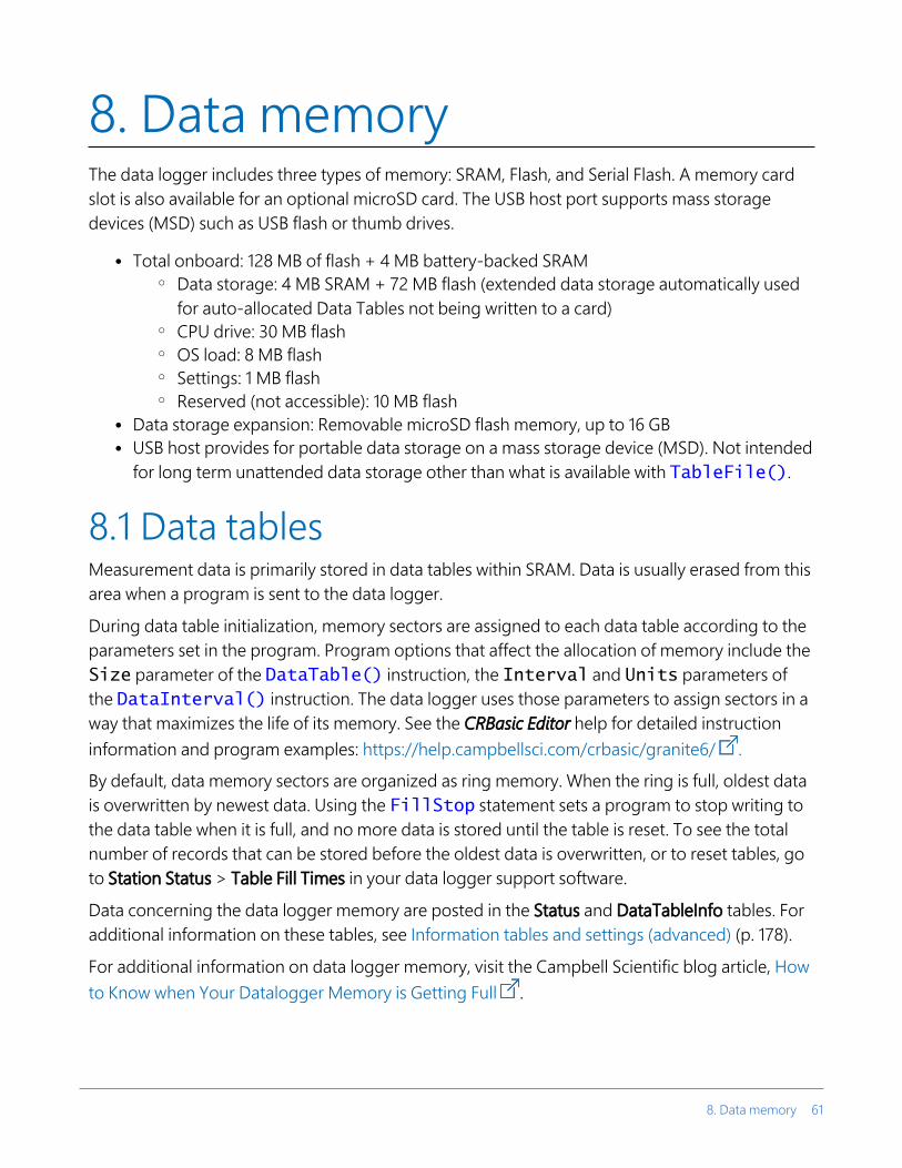
8. Data memoryThe data logger includes three types of memory: SRAM, Flash, and Serial Flash. A memory card slot is also available for an optional microSD card. The USB host port supports mass storage devices (MSD) such as USB flash or thumb drives.
l Total onboard: 128 MB of flash + 4 MB battery-backed SRAM o Data storage: 4 MB SRAM + 72 MB flash (extended data storage automatically used
for auto-allocated Data Tables not being written to a card) o CPU drive: 30 MB flash o OS load: 8 MB flash o Settings: 1 MB flash o Reserved (not accessible): 10 MB flash
l Data storage expansion: Removable microSD flash memory, up to 16 GB l USB host provides for portable data storage on a mass storage device (MSD). Not intended
for long term unattended data storage other than what is available with TableFile().
8.1 Data tablesMeasurement data is primarily stored in data tables within SRAM. Data is usually erased from this area when a program is sent to the data logger.
During data table initialization, memory sectors are assigned to each data table according to the parameters set in the program. Program options that affect the allocation of memory include the Size parameter of the DataTable() instruction, the Interval and Units parameters of the DataInterval() instruction. The data logger uses those parameters to assign sectors in a way that maximizes the life of its memory. See the CRBasic Editor help for detailed instruction information and program examples: https://help.campbellsci.com/crbasic/granite6/ .
By default, data memory sectors are organized as ring memory. When the ring is full, oldest data is overwritten by newest data. Using the FillStop statement sets a program to stop writing to the data table when it is full, and no more data is stored until the table is reset. To see the total number of records that can be stored before the oldest data is overwritten, or to reset tables, go to Station Status > Table Fill Times in your data logger support software.
Data concerning the data logger memory are posted in the Status and DataTableInfo tables. For additional information on these tables, see Information tables and settings (advanced) (p. 178).
For additional information on data logger memory, visit the Campbell Scientific blog article, How to Know when Your Datalogger Memory is Getting Full .
8. Data memory 61

8.2 Memory allocationData table SRAM and the CPU drive are automatically partitioned by the data logger. The USR drive and the USB drive can be partitioned as needed. The CRD drive is automatically partitioned when a memory card is installed.
The CPU and USR drives use the FAT file system. There is no limit, beyond practicality and available memory, to the number of files that can be stored. While a FAT file system is subject to fragmentation, performance degradation is not likely to be noticed since the drive has a relatively small amount of solid state RAM and is accessed very quickly.
8.3 SRAMSRAM holds program variables, communications buffers, final-data memory, and, if allocated, the USR drive. An internal lithium battery retains this memory when primary power is removed.
The structure of the data logger SRAM memory is as follows:
l Static Memory: This is memory used by the operating system, regardless of the running program. This sector is rebuilt at power-up, program recompile, and watchdog events.
l Operating Settings and Properties: Also known as the "Keep" memory, this memory is used to store settings such as PakBus address, station name, beacon intervals, and allowed neighbor lists. This memory also stores dynamic properties such as known routes and communications timeouts.
l CRBasic Program Operating Memory: This memory stores the currently compiled and running user program. This sector is rebuilt on power-up, recompile, and watchdog events.
l Variables & Constants: This memory stores constants and public variables used by the CRBasic program. Variables may persist through power-up, recompile, and watchdog events if the PreserveVariables instruction is in the running program.
l Final-Data Memory: This memory stores data. Auto-allocated tables fill whatever memory remains after all other demands are satisfied. A compile error occurs if insufficient memory is available for user-allocated data tables. This memory is given lowest priority in SRAM memory allocation.
l Communication Memory 1: Memory used for construction and temporary storage of PakBus packets.
l Communication Memory 2: Memory used to store the list of known nodes and routes to nodes. Routers use more memory than leaf nodes because routes store information about
8. Data memory 62

other routers in the network. You can increase the Communication Allocation field in Device Configuration Utility to increase this memory allocation.
l USR drive: Optionally allocated. Holds image files. Holds a copy of final-data memory when TableFile() instruction used. Provides memory for FileRead() and FileWrite() operations. Managed in File Control. Status reported in Status table fields USRDriveSize and USRDriveFree.
8.3.1 USR driveBattery-backed SRAM can be partitioned to create a FAT USR drive, analogous to partitioning a second drive on a computer hard disk. Certain types of files are stored to USR to reserve limited CPU drive memory for data logger programs and calibration files. Partitioning also helps prevent interference from data table SRAM. The USR drive holds any file type within the constraints of the size of the drive and the limitations on filenames. Files typically stored include image files from cameras, certain configuration files, files written for FTP retrieval, HTML files for viewing with web access, and files created with the TableFile() instruction. Measurement data can also be stored on USR as discrete files by using the TableFile() instruction. Files on USR can be collected using data logger support software Retrieve command in File Control, or automatically using the LoggerNet Setup > File Retrieval tab functions.
USR is not affected by program recompilation or formatting of other drives. It will only be reset if the USR drive is formatted, a new operating system is loaded, or the size of USR is changed. USR size is set manually by accessing it in the Settings Editor, or programmatically by loading a CRBasic program with a USR drive size entered in a SetSetting() instruction. Partition the USR drive to at least 11264 bytes in 512-byte increments. If the value entered is not a multiple of 512 bytes, the size is rounded up. Maximum size of USR 2990080 bytes.
8. Data memory 63

WARNING:Partitioning or changing the size of the USR drive will delete stored data from tables. Collect data first.
NOTE:Placing an optional USR size setting in the CRBasic program overrides manual changes to USR size. When USR size is changed manually, the CRBasic program restarts and the programmed size for USR takes immediate effect.
Files in the USR drive can be managed through data logger support software File Control or through the FileManage() instruction in CRBasic program.
8.4 Flash memoryThe data logger operating system is stored in a separate section of flash memory. To update the operating system, see Updating the operating system (p. 139).
Serial flash memory holds the CPU drive, web page, and data logger settings. Because flash memory has a limited number of write/erase cycles, care must be taken to avoid continuously writing to files on the CPU drive.
8.4.1 CPU driveThe serial flash memory CPU drive contains data logger programs and other files. This memory is managed in File Control.
NOTE:When writing to files under program control, take care to write infrequently to prevent premature failure of serial flash memory. Internal chip manufacturers specify the flash technology used in Campbell Scientific CPU: drives at about 100,000 write/erase cycles. While Campbell Scientific's in-house testing has found the manufacturers' specifications to be very conservative, it is prudent to note the risk associated with repeated file writes via program control.
Also, see System specifications (p. 208) for information on data logger memory.
8.5 MicroSD (CRD: drive)The data logger has a microSD card slot for removable, supplemental memory. The card can be configured as an extension of the data logger final-data memory or as a repository of discrete data files.
8. Data memory 64

When storing high-frequency data, or when storing data to cards greater than 2 GB, TableFile() with Option 64 is recommended to write final storage data to a card. In other applications CardOut() can be used to store data to a card.
NOTE:Sub-folders are not supported.
See the CRBasic Editor help for detailed instruction information and program examples: https://help.campbellsci.com/crbasic/granite6/ .
The CRD: drive uses microSD cards exclusively. Campbell Scientific recommends and supports only the use of microSD cards obtained from Campbell Scientific. These cards are industrial-grade and have passed Campbell Scientific hardware testing. Use of consumer-grade cards substantially increases the risk of data loss. Following are advantages Campbell Scientific cards have over less expensive commercial-grade cards:
l Verified compatibility with Campbell Scientific data loggers l Less susceptible to failure and data loss l Match the data logger operating temperature range l Provide faster read/write times l Include vibration and shock resistance l Have longer life spans (more read/write cycles)
A "card controller error" indicates that the data logger has failed to communicate with the card. It is an error caused by the micro-controller built into the microSD card. Sometimes this error may be resolved by reformatting the card. If the error repeats itself, try an industrial-grade card. For more information on errors, see File system error codes (p. 176).
A maximum of 30 data tables can be created using CardOut() on a microSD card. When a data table is sent to a microSD card, a data table of the same name in SRAM is used as a buffer for transferring data to the card. Note that with TableFile(), the number of files stored on the card is controlled by the MaxFiles parameter.
When a new program is compiled that sends data to the card, the data logger checks if a card is present and if the card has adequate space for the data tables. If no card is present, or if space is inadequate, the data logger will warn that the card is not being used. However, the CRBasic program runs anyway and data is stored to SRAM. When a card is inserted later, data accumulated in the SRAM table is copied to the card.
NOTE:A card must be exchanged before it fills, or the oldest data will be overwritten, by incoming new records, and lost. During the card exchange, once the old card is removed, the new card
8. Data memory 65

must be inserted before the data table in data logger CPU memory rings, or data will be overwritten and lost.
A microSD card can also facilitate the use of powerup.ini (see File management via powerup.ini (p. 143) for more information).
8.5.1 Formatting microSD cardsThe data logger accepts microSD cards formatted as FAT16 or FAT32; however, FAT32 is recommended. Otherwise, some functionality, such as the ability to manage large numbers of files (>254) is lost. There are several ways to format cards such as using: File Control, CR1000KD, and Windows. Formatting on the data logger is recommended because this ensures correct FAT32 format.
8.5.2 MicroSD card precautionsObserve the following precautions when using optional memory cards:
l Before removing a card from the data logger, disable the card by pressing the Eject button and wait for the green LED. You then have 15 seconds to remove the card before normal operations resume.
l Do not remove a memory card while the drive is active, or data corruption and damage to the card may result.
l Prevent data loss by collecting data before sending a program. Sending a program to the data logger often erases all data.
l See System specifications (p. 208) for information on maximum card size.
8.5.3 Act LED indicatorWhen the data logger is powered and a microSD card installed, the Act (Activity) LED will turn on according to card activity or status:
l Red flash: Card read/write activity l Solid green: This LED indicates it is OK to remove card. The Eject button must be pressed
before removing a card to allow the data logger to store buffered data to the card and then power it off.
l Solid orange: Error l Dim/flashing orange: Card has been removed and has been out long enough that CPU
memory has wrapped and data is being overwritten without being stored to the card.
8. Data memory 66

8.5.4 Card data retrievalData stored on cards can be retrieved through a communications link to the data logger or by removing the card and carrying it to a computer with a card adapter. With large files, transferring the card to a computer may be faster than collecting the data over a communications link.
CAUTION:Removing a card while it is active can cause corrupted data and can damage the card. Always press the Eject button and wait for a green light before removing card. Do not switch off the data logger power if a card is present and active.
CAUTION:File Control (in LoggerNet or PC400) should not be used to retrieve an open file (for example, a file created by using CardOut() or the latest file created by TableFile(), Option 64) from a card. Using File Control to retrieve the data can result in a corrupted data file. However, File Control can be used to retrieve closed files such as JPEG images or files (other than the latest) created by TableFile(), Option 64.
8.5.4.1 Via a communications linkData can be copied to a computer via a communications link by using one of Campbell Scientific data logger support software packages (for example, LoggerNet or PC400). There is no need to distinguish whether the data is to be collected from the CPU memory or a card. The software package will look for data in both the CPU memory and the card.
The data logger manages data on a card as final-storage data, accessing the card as needed to fill data-collection requests initiated with the Collect button in data logger support software. If desired, binary data can be collected by using the File Control utility in data logger support software. Before collecting data this way, stop the data logger program to ensure data is not written to the card while data is retrieved; this will avoid data corruption.
Fast storage/data-collection constraints
Factors affecting how fast the data logger stores data include the data storage rate, number of table values, and number of tables. For more information, see Creating data tables in a program (p. 58).
When data logger support software collects data from ring tables that have filled, there is the possibility of missing records due to the collection process. When a ring table has filled, the oldest data is overwritten by the newest data. LoggerNet and PC400 use a collection algorithm that collects data from multiple tables in small blocks as they collect from all the tables. Collection starts with the oldest data for each table.
8. Data memory 67

With filled ring tables, as collection begins, the data collection software queries the data logger for the oldest data starting with the first table. When this data block is returned, the software goes to the next table and so on until all of the tables are initially collected. By the time LoggerNet or PC400 make the second pass requesting more data from the tables, the possibility exists that some of that data may have been overwritten.
Normally, data is collected without gaps; however, if the data logger is storing data fast enough, it is possible to get into an always-behind scenario where the data collection never catches up and the data logger repeatedly overwrites uncollected data.
CAUTION:The possibility of missing records is greater when collecting data over high-latency communications links, such as RF or busy IP networks. This is due to the high demand of communications on processor time.
8.5.4.2 Card transport to computerWith large files, transferring the card to a computer may be faster than collecting the data over a communications link.
CAUTION:Removing a card while it is active can cause corrupted data and can damage the card. Always press the Eject button and wait for a green light before removing card. Do not switch off the data logger power if a card is present and active.
To remove a card, first press the Eject button. The data logger will copy any buffered data to the card and then power the card off. The Act LED will turn green when it is OK to physically remove the card. The card will be reactivated after 15 seconds if it is not removed.
When the card is inserted into a computer, the data files can be copied to another drive or used directly from the card just as one would from any other disk. In most cases, however, it will be necessary to convert the file format before using the data.
Note that for both CardOut() and TableFile() Option 64, data is stored on the card in binary (TOB3) format. TOB3 is a binary format that incorporates features to improve reliability of cards. TOB3 format is different from the data file formats created when data is collected via a communications link, which is ASCII (TOA5) format. Hence, data files that are read directly from the card need to be converted into another format to be human readable. You can convert files from binary or other formats using CardConvert software that is included in your data logger support software.
Converting file formats
Use CardConvert to convert data to a different format.
8. Data memory 68

1. Open CardConvert. l On the LoggerNet toolbar select the Data category. l In PC400 select the Tools menu.
2. Click Select Card Drive.
3. Select where the files to be converted are stored and press OK.
4. Click Change Output Dir and select where to store the converted files.
5. Place check marks next to the files to be converted. A default destination filename is given. It can be changed by right-clicking with the filename highlighted.
6. Press Destination File Options to select what file format to convert to and other options.
7. Press Start Conversion to begin converting files. Green check marks will appear next to each filename as conversion is complete. Refer to the data logger support software manual or built-in CardConvert help for more information.
FIGURE 8-1. CardConvert
Reinserting the card
If the same card is inserted again into the data logger, the data logger will store all data to the card that has been generated since the card was removed that is still in the CPU memory. If the
8. Data memory 69

data tables have been left on the card, new data will be appended to the end of the old files. If the data tables have been deleted, new ones will be created.
CAUTION:Check the status of the card before leaving the data logger. If a card was not properly accepted, the LED will flash orange. In that case, reformat and erase all data contained on the card. Formatting or erasing a card might be done on a computer or data logger. See MicroSD (CRD: drive) (p. 64) for information on formatting a card.
Card swapping
When transporting a card to a computer to retrieve data, most users will want to use a second card to ensure that no data is lost. For this method of collection, use the following steps.
1. Insert formatted card (“card-A”) into the data logger card slot. See Formatting microSD cards (p. 66).
2. Send program containing TableFile() or CardOut() instruction(s).
3. When ready to retrieve data (hours, days, or months later), press the Eject button. The LED will be red while the most-current data is stored to the card and then turn green. Remove the card while the LED is green.
4. Insert the clean card (“card-B”).
5. Use CardConvert to copy data from card-A to computer and convert. The default CardConvert filename will be TOA5_stationname_tablename.dat. Once the data is copied, use Windows Explorer to delete all data files from the card.
6. At the next card swap, eject card-B, press the Eject button. The LED will be red while the most-current data is stored to the card and then turn green. Remove the card while the LED is green.
7. Insert the clean card-A.
8. Running CardConvert on card-B will result in separate data files containing records since card-A was ejected. CardConvert can increment the filename to TOA5_stationname_tablename_0.dat.
9. The data files can be joined by using text editing software such as WordPad or a spreadsheet such as Excel.
CardConvert file Card-A record numbers Card-B record numbers
TOA5_tablename.dat 0-100
TOA5_tablename.dat 101-1234
8. Data memory 70

CardConvert file Card-A record numbers Card-B record numbers
TOA5_tablename.dat 1235-….
8.6 USB host (USB: drive)USB host provides portable data storage on a USB thumb drive. A FAT32-formatted USB thumb drive can be inserted into the host port and will show up as a drive (USB:) in file-related operations. Measurement data is stored on USB: as discrete files by using the TableFile() instruction. Files on USB: can be collected by inserting the thumb drive into a computer and copying the files.
USB: can be used in all CRBasic file-access-related instructions. Because of data reliability concerns in non-industrial rated drives, this drive is not intended for long-term unattended data storage. Rather, configure Tablefile() for milking (plug-and-pull) to periodically collect data. Files on USB: are not affected by program recompilation or formatting of other drives.
See the CRBasic Editor help for detailed instruction information and program examples:
https://help.campbellsci.com/crbasic/granite6/
8.6.1 USB host precautionsObserve the following precaution when using an optional USB thumb drive:
l Do not remove a USB drive while the drive is active, or data corruption and damage to the USB drive may result. Many USB thumb drives have built-in LEDs to indicate when they are active.
8.6.2 Data type collection speedFile type declared in the Tablefile() TFOption parameter can affect plug and pull data-collection speed. Data is buffered in the data logger as binary. While data is collected, the data logger converts the binary data to the declared data type. TOB1 options are binary and require very little processor overhead to convert from the binary buffer. TOA5, CSIXML, and JSON are ASCII options and are much slower since they consume significant processor overhead to convert to ASCII from the binary buffer. CSIXML is especially slow. The effects on collection time will be particularly noticeable if the data logger is running a long or complex program. In short, if large files need collection, using the TOB1 format may save considerable time. Consult the Loggernet manual for options available to convert TOB1 data files on the computer to easier-to-read formats.
8. Data memory 71

8.6.3 Skipped scansCompile data logger programs in pipeline mode when possible. Data logger programs compiled in sequential mode require a longer scan interval than programs compiled in pipeline mode to avoid skipped scans. In pipeline mode, increase the Scan() / NextScan BufferOption parameter to prevent skipped scans.
8.6.4 Formatting drives 32 GB or largerWindows does not support creating a FAT32 partition on a 32 GB or greater drive. The work-around is to use a Windows computer to format the drive as NTFS (NT file system). Then use the data logger to format the drive as FAT32.
8. Data memory 72

9. Measurements9.1 Voltage measurements 73
9.2 Current-loop measurements 75
9.3 Resistance measurements 77
9.4 Period-averaging measurements 85
9.5 Pulse measurements 86
9.6 Vibrating wire measurements 93
9.7 Sequential and pipeline processing modes 96
9.1 Voltage measurementsVoltage measurements are made using an Analog-to-Digital Converter (ADC). A high-impedance Programmable-Gain Amplifier (PGA) amplifies the signal. Internal multiplexers route individual terminals within the amplifier. The CRBasic measurement instruction controls the ADC gain and configuration – either single-ended or differential input. Information on the differences between single-ended and differential measurements can be found here: Deciding between single-ended or differential measurements (p. 162).
A voltage measurement proceeds as follows:
1. Set PGA gain for the voltage range selected with the CRBasic measurement instruction parameter Range. Set the ADC for the first notch frequency selected with fN1.
2. If used, such as with bridge measurements, turn on excitation to the level selected with ExmV.
3. Multiplex selected terminals (SEChan or DiffChan).
4. Delay for the entered settling time (SettlingTime).
5. Perform the analog-to-digital conversion.
6. Repeat for input reversal as determined by parameters RevEx and RevDiff.
7. Apply multiplier (Mult) and offset (Offset) to measured result.
Conceptually, analog voltage sensors output two signals: high and low. For example, a sensor that outputs 1000 mV on the high signal and 0 mV on the low has an overall output of 1000 mV. A sensor that outputs 2000 mV on the high signal and 1000 mV on the low also has an overall
9. Measurements 73

output of 1000 mV. Sometimes, the low signal is simply sensor ground (0 mV). A single-ended measurement measures the high signal with reference to ground; the low signal is tied to ground. A differential measurement measures the high signal with reference to the low signal. Each configuration has a purpose, but the differential configuration is usually preferred.
In general, use the smallest input range that accommodates the full-scale output of the sensor. This results in the best measurement accuracy and resolution (see Analog measurement specifications (p. 213) for more information).
A set overhead reduces the chance of overrange. Overrange limits are available in the specifications. The data logger indicates a measurement overrange by returning a NAN for the measurement.
WARNING:Sustained voltages in excess of ±20 V applied to terminals configured for analog input will damage GRANITE 6 circuitry.
9.1.1 Single-ended measurementsA single-ended measurement measures the difference in voltage between the terminal configured for single-ended input and the reference ground. For example, single-ended channel 1 is comprised of terminals U1 and . For more information, see Wiring panel and terminal functions (p. 8). The single-ended configuration is used with the following CRBasic instructions:
l VoltSE() l BrHalf() l BrHalf3W() l TCSE() l Therm107() l Therm108() l Therm109() l Thermistor()
See the CRBasic Editor help for detailed instruction information and program examples: https://help.campbellsci.com/crbasic/granite6/ .
9. Measurements 74

9.1.2 Differential measurementsA differential measurement measures the difference in voltage between two input terminals. For example, differential channel 1 is comprised of terminals U1 and U2, with U1 as high and U2 as low. For more information, see Wiring panel and terminal functions (p. 8). The differential configuration is used with the following CRBasic instructions:
l VoltDiff() l BrFull() l BrFull6W() l BrHalf4W() l TCDiff()
9.1.2.1 Reverse differentialDifferential measurements have the advantage of an input reversal option, RevDiff. When RevDiff is set to True, two differential measurements are made, the first with a positive polarity and the second reversed. Subtraction of opposite polarity measurements cancels some offset voltages associated with the measurement.
For more information on voltage measurements, see Improving voltage measurement quality (p. 162) and Analog measurement specifications (p. 213).
9.2 Current-loop measurementsRG terminals can be configured to make analog current measurements using the CurrentSE() instruction. When configured to measure current, terminals each have an internal resistance of 101 Ω in the current measurement loop. The return path of the sensor must be connected directly to the RG terminal. The following image shows a simplified schematic of a current measurement.
9. Measurements 75

9.2.1 Example current-loop measurement connectionsThe following table shows example schematics for connecting typical current sensors and devices. See also Current-loop measurement specifications (p. 218).
Sensor Type Connection Example
2-wire transmitter using data logger power
2-wire transmitter using external power
3-wire transmitter using data logger power
9. Measurements 76
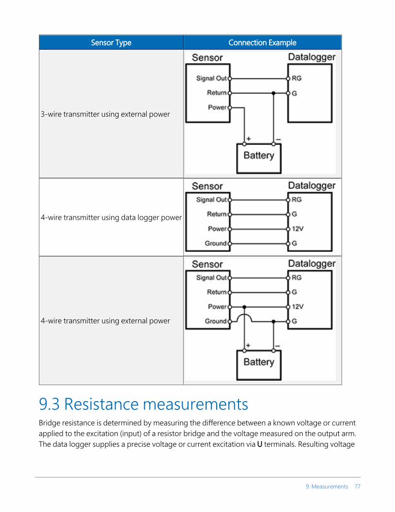
Sensor Type Connection Example
3-wire transmitter using external power
4-wire transmitter using data logger power
4-wire transmitter using external power
9.3 Resistance measurementsBridge resistance is determined by measuring the difference between a known voltage or current applied to the excitation (input) of a resistor bridge and the voltage measured on the output arm. The data logger supplies a precise voltage or current excitation via U terminals. Resulting voltage
9. Measurements 77

is measured on analog input terminals configured for single-ended or differential input. The result of the measurement is a ratio of excitation voltage or current and measured voltages.
See also Resistance measurement specifications (p. 216).
9.3.1 Resistance measurements with voltage excitationCRBasic instructions for measuring resistance with voltage excitation include:
l BrHalf() - half bridge l BrHalf3W() - three-wire half bridge l BrHalf4W() - four-wire half bridge l BrFull() - four-wire full bridge l BrFull6W() - six-wire full bridge
See the CRBasic Editor help for detailed instruction information and program examples: https://help.campbellsci.com/crbasic/granite6/ .
Resistive-Bridge Type andCircuit Diagram
CRBasic Instruction andFundamental Relationship Relational Formulas
Half Bridge1
CRBasic Instruction: BrHalf()
Fundamental Relationship:
Three Wire Half Bridge1,2
CRBasic Instruction: BrHalf3W()
Fundamental Relationship:
9. Measurements 78

Resistive-Bridge Type andCircuit Diagram
CRBasic Instruction andFundamental Relationship Relational Formulas
Four Wire Half Bridge1,2
CRBasic Instruction: BrHalf4W()
Fundamental Relationship:
Full Bridge1,2
CRBasic Instruction: BrFull()
Fundamental Relationship:
These relationships apply to
BrFull()and BrFull6W()
Six Wire Full Bridge1
CRBasic Instruction: BrFull6W()
Fundamental Relationship:
1 Key: Vx = excitation voltage; V1, V2 = sensor return voltages; Rf = fixed, bridge or completion resistor; Rs = variable or sensing resistor.2 Campbell Scientific offers terminal input modules to facilitate this measurement.
Offset voltage compensation applies to bridge measurements. In addition to RevDiff and MeasOff parameters discussed in Minimizing offset voltages (p. 171), CRBasic bridge
9. Measurements 79

measurement instructions include the RevEx parameter that provides the option to program a second set of measurements with the excitation polarity reversed. Much of the offset error inherent in bridge measurements is canceled out by setting RevDiff, RevEx, and MeasOff to True.
Measurement speed may be reduced when using RevDiff, MeasOff, and RevEx. When more than one measurement per sensor is necessary, such as occurs with the BrHalf3W(), BrHalf4W(), and BrFull6W() instructions, input and excitation reversal are applied separately to each measurement. For example, in the four-wire half-bridge (BrHalf4W()), when excitation is reversed, the differential measurement of the voltage drop across the sensor is made with excitation at both polarities and then excitation is again applied and reversed for the measurement of the voltage drop across the fixed resistor. The results of the measurements (X) must then be processed further to obtain the resistance value, which requires additional program execution time.
CRBasic Example 1: Four-Wire Full Bridge Measurement and Processing
'This program example demonstrates the measurement and'processing of a four-wire resistive full bridge.'In this example, the default measurement stored'in variable X is deconstructed to determine the'resistance of the R1 resistor, which is the variable'resistor in most sensors that have a four-wire'full-bridge as the active element.'Declare VariablesPublic XPublic X_1Public R_1Public R_2 = 1000 'Resistance of fixed resistor R2Public R_3 = 1000 'Resistance of fixed resistor R3Public R_4 = 1000 'Resistance of fixed resistor R4'Main ProgramBeginProgScan(500,mSec,1,0)'Full Bridge Measurement:BrFull(X,1,mV200,U1,U3,1,2500,True,True,0,60,1.0,0.0) X_1 = ((-1 * X) / 1000) + (R_3 / (R_3 + R_4))R_1 = (R_2 * (1 - X_1)) / X_1
NextScanEndProg
9.3.2 Resistance measurements with current excitationU terminals can be configured to supply precise current excitation for use with resistive bridges. Resistance can be measured by supplying a precise current and measuring the return voltage.
9. Measurements 80

The data logger supplies a precise current from terminals configured for current excitation. Return voltage is measured on U terminals configured for single-ended or differential analog input.
U terminals can be configured as current-output terminals under program control for making resistance measurements. For the current return, use the signal ground ( ) terminal closest to the current source terminal. CRBasic instructions that control current excitation include:
l Resistance() - Applies an excitation current to a circuit and measures the resistance. The maximum excitation current is ±2500 μA.
l Resistance3W() - Makes a three-wire resistance measurement. The maximum excitation current is ±2500 μA.
Resistive Bridge Circuits with Current Excitation: (use the signal ground ( ) terminal adjacent to the current excitation terminal)
Resistive-Bridge Type andCircuit Diagram
CRBasic Instruction andFundamental Relationship Relational Formulas
Four WireCRBasic Instruction: Resistance()
Fundamental Relationship1:
Four Wire Full Bridge CRBasic Instruction: Resistance()
Fundamental Relationship1:
9. Measurements 81

Resistive-Bridge Type andCircuit Diagram
CRBasic Instruction andFundamental Relationship Relational Formulas
Three Wire
CRBasic Instruction: Resistance3W()
Fundamental Relationship2:
1 Where X = result of the CRBasic bridge measurement instruction with a multiplier of 1 and an offset of 0.
2 Where Ri is the precision internal resistor value that is saved as part of the factory calibration procedure and Rs is the sense resistance.
9.3.3 Strain measurementsA principal use of the four-wire full bridge is the measurement of strain gages in structural stress analysis. StrainCalc() calculates microstrain (µɛ) from the formula for the specific bridge configuration used. All strain gages supported by StrainCalc() use the full-bridge schematic. 'Quarter-bridge', 'half-bridge' and 'full-bridge' refer to the number of active elements in the bridge schematic. In other words, a quarter-bridge strain gage has one active element, a half-bridge has two, and a full-bridge has four.
StrainCalc() requires a bridge-configuration code. The following table shows the equation used by each configuration code. Each code can be preceded by a dash (-). Use a code without the dash when the bridge is configured so the output decreases with increasing strain. Use a dashed code when the bridge is configured so the output increases with increasing strain. A dashed code sets the polarity of Vr to negative.
9. Measurements 82

Table 9-1: StrainCalc() configuration codes
BrConfig Code Configuration
1
Quarter-bridge strain gage:
2
Half-bridge strain gage. One gage parallel to strain, the other at 90° to strain:
3
Half-bridge strain gage. One gage parallel to +ɛ, the other parallel to -ɛ:
4
Full-bridge strain gage. Two gages parallel to +ɛ, the other two parallel to -ɛ:
9. Measurements 83

Table 9-1: StrainCalc() configuration codes
BrConfig Code Configuration
5
Full-bridge strain gage. Half the bridge has two gages parallel to +ɛ and -ɛ, and the other half to +νɛ and -νɛ
6
Full-bridge strain gage. Half the bridge has two gages parallel to +ɛ and -νɛ , and the other half to -νɛ and +ɛ:
Where: ν : Poisson's Ratio (0 if not applicable).GF: Gage Factor.Vr: 0.001 (Source-Zero) if BRConfig code is positive (+).
Vr: –0.001 (Source-Zero) if BRConfig code is negative (–).
and where:"source": the result of the full-bridge measurement (X = 1000 • V1 / Vx) when multiplier = 1 and offset = 0."zero": gage offset to establish an arbitrary zero.
9.3.4 AC excitationSome resistive sensors require AC excitation. AC excitation is defined as excitation with equal positive (+) and negative (–) duration and magnitude. These include electrolytic tilt sensors, soil moisture blocks, water-conductivity sensors, and wetness-sensing grids. The use of single polarity DC excitation with these sensors can result in polarization of sensor materials and the substance measured. Polarization may cause erroneous measurement, calibration changes, or rapid sensor decay.
Other sensors, for example, LVDTs (linear variable differential transformers), require AC excitation because they require inductive coupling to provide a signal. DC excitation in an LVDT will result in no measurement.
CRBasic bridge-measurement instructions have the option to reverse polarity to provide AC excitation by setting the RevEx parameter to True.
9. Measurements 84

NOTE:Take precautions against ground loops when measuring sensors that require AC excitation. See also Ground loops (p. 158).
For more information, see Accuracy for resistance measurements (p. 85).
9.3.5 Accuracy for resistance measurementsConsult the following technical papers for in-depth treatments of several topics addressing voltage measurement quality:
l Preventing and Attacking Measurement Noise Problems l Benefits of Input Reversal and Excitation Reversal for Voltage Measurements l Voltage Measurement Accuracy, Self- Calibration, and Ratiometric Measurements
NOTE:Error discussed in this section and error-related specifications of the GRANITE 6 do not include error introduced by the sensor, or by the transmission of the sensor signal to the data logger.
For accuracy specifications of ratiometric resistance measurements, see Resistance measurement specifications (p. 216). Voltage measurement is variable V1 or V2 in resistance measurements. Offset is the same as that for simple analog voltage measurements.
Assumptions that support the ratiometric-accuracy specification include:
l Data logger is within factory calibration specification. l Input reversal for differential measurements and excitation reversal for excitation voltage
are within specifications. l Effects due to the following are not included in the specification:
o Bridge-resistor errors o Sensor noise o Measurement noise
9.4 Period-averaging measurementsUse PeriodAvg() to measure the period (in microseconds) or the frequency (in Hz) of a signal on a single-ended channel. For these measurements, the data logger uses a high-frequency digital clock to measure time differences between signal transitions, whereas pulse-count measurements simply accumulate the number of counts. As a result, period-average measurements offer much better frequency resolution per measurement interval than pulse-count measurements. See also Pulse measurements (p. 86).
9. Measurements 85

U terminals on the data logger are configurable for measuring the period of a signal.
The measurement is performed as follows: low-level signals are amplified prior to a voltage comparator. The internal voltage comparator is referenced to the programmed threshold. The threshold parameter allows referencing the internal voltage comparator to voltages other than 0 V. For example, a threshold of 2500 mV allows a 0 to 5 VDC digital signal to be sensed by the internal comparator without the need for additional input conditioning circuitry. The threshold allows direct connection of standard digital signals, but it is not recommended for small-amplitude sensor signals.
A threshold other than zero results in offset voltage drift, limited accuracy (approximately ±10 mV) and limited resolution (approximately 1.2 mV).
See also Period-averaging measurement specifications (p. 216).
TIP:Both pulse count and period-average measurements are used to measure frequency output sensors. However, their measurement methods are different. Pulse count measurements use dedicated hardware - pulse count accumulators, which are always monitoring the input signal, even when the data logger is between program scans. In contrast, period-average measurements use program instructions that only monitor the input signal during a program scan. Consequently, pulse count scans can occur less frequently than period-average scans. Pulse counters may be more susceptible to low-frequency noise because they are always "listening", whereas period-averaging measurements may filter the noise by reason of being "asleep" most of the time.
Pulse count measurements are not appropriate for sensors that are powered off between scans, whereas period-average measurements work well since they can be placed in the scan to execute only when the sensor is powered and transmitting the signal.
9.5 Pulse measurementsThe output signal generated by a pulse sensor is a series of voltage waves. The sensor couples its output signal to the measured phenomenon by modulating wave frequency. The data logger detects the state transition as each wave varies between voltage extremes (high-to-low or low-to-high). Measurements are processed and presented as counts, frequency, or timing data. Both pulse count and period-average measurements are used to measure frequency-output sensors. For more information, see Period-averaging measurements (p. 85).
9. Measurements 86

The data logger includes terminals that are configurable for pulse input as shown in the following image.
Table 9-2: Pulse input terminals and the input types they can measure
Input Type Pulse Input Terminal
High-frequency C (all)U (all)
Low-level AC U (even numbered terminals)
Switch-closure
P1P2
C (all)U (all)
Using the PulseCount() instruction, U and C terminals are configurable for pulse input to measure counts or frequency. Maximum input frequency is dependent on input voltage. If pulse input voltages exceed the maximum voltage, third-party external-signal conditioners should be employed. Do not measure voltages greater than 20 V.
NOTE:Conflicts can occur when a control port pair is used for different instructions (TimerInput(), PulseCount(), SDI12Recorder(), WaitDigTrig()). For example, if C1 is used for SDI12Recorder(), C2 cannot be used for TimerInput(), PulseCount(), or WaitDigTrig().
9. Measurements 87

U terminals configured for pulse input have internal filters that reduce electronic noise, and thus reduce false counts. Internal AC coupling is used to eliminate DC offset voltages. For tips on working with pulse measurements, see Pulse measurement tips (p. 92).
Output can be recorded as counts, frequency or a running average of frequency.
For more information, see Pulse measurement specifications (p. 218).
See the CRBasic Editor help for detailed instruction information and program examples: https://help.campbellsci.com/crbasic/granite6/ .
9.5.1 Low-level AC measurementsLow-level AC (alternating current or sine-wave) signals can be measured on U terminals. AC generator anemometers typically output low-level AC.
Measurement output options include the following:
l Counts l Frequency (Hz) l Running average
Rotating magnetic-pickup sensors commonly generate ac voltage ranging from millivolts at low-rotational speeds to several volts at high-rotational speeds.
CRBasic instruction: PulseCount(). See the CRBasic Editor help for detailed instruction information and program examples: https://help.campbellsci.com/crbasic/granite6/ .
Low-level AC signals cannot be measured directly by C terminals. Peripheral terminal expansion modules, such as the Campbell Scientific LLAC4, are available for converting low-level AC signals to square-wave signals measurable by C terminals.
For more information, see Pulse measurement specifications (p. 218).
9.5.2 High-frequency measurementsHigh-frequency (square-wave) signals can be measured on terminals:
l U or C
Common sensors that output high-frequency pulses include:
l Photo-chopper anemometers l Flow meters
Measurement output optionss include counts, frequency in hertz, and running average. Note that the resolution of a frequency measurement can be different depending on the terminal used in the PulseCount() instruction. See the CRBasic help for more information.
9. Measurements 88

The data logger has built-in pull-up and pull-down resistors for different pulse measurements which can be accessed using the PulseCount() instruction. Note that pull down options are usually used for sensors that source their own power.
9.5.2.1 U terminals l CRBasic instruction: PulseCount()
9.5.2.2 C terminals l CRBasic instructions: PulseCount()
See Pulse measurement specifications (p. 218) for more information.
9.5.3 Switch-closure and open-collector measurementsSwitch-closure and open-collector (also called current-sinking) signals can be measured on terminals:
l U or C
Mechanical switch-closures have a tendency to bounce before solidly closing. Unless filtered, bounces can cause multiple counts per event. The data logger automatically filters bounce. Because of the filtering, the maximum switch-closure frequency is less than the maximum high-frequency measurement frequency. Sensors that commonly output a switch-closure or an open-collector signal include:
l Tipping-bucket rain gages l Switch-closure anemometers l Flow meters
The data logger has built-in pull-up and pull-down resistors for different pulse measurements which can be accessed using the PulseCount() instruction. Note that pull down options are usually used for sensors that source their own power.
Data output options include counts, frequency (Hz), and running average.
9.5.3.1 U TerminalsAn internal 100 kΩ pull-up resistor pulls an input to 5 VDC with the switch open, whereas a switch-closure to ground pulls the input to 0 V.
l CRBasic instruction: PulseCount(). See the CRBasic Editor help for detailed instruction information and program examples: https://help.campbellsci.com/crbasic/granite6/ .
9. Measurements 89

Switch Closure on U or C Terminal Open Collector on U or C Terminal
9.5.3.2 C terminalsSwitch-closure mode is a special case edge-count function that measures dry-contact switch-closures or open collectors. The operating system filters bounces.
l CRBasic instruction: PulseCount().
See also Pulse measurement specifications (p. 218).
9.5.4 Edge timing and edge countingEdge time, period, and counts can be measured on U or C terminals. Feedback control using pulse-width modulation (PWM) is an example of an edge timing application.
9.5.4.1 Single edge timingA single edge or state transition can be measured on U or C terminals. Measurements can be expressed as a time (µs), frequency (Hz) or period (µs).
CRBasic instruction: TimerInput()
9.5.4.2 Multiple edge countingTime between edges, time from an edge on the previous terminal, and edges that span the scan interval can be measured on U or C terminals. Measurements can be expressed as a time (µs), frequency (Hz) or period (µs).
l CRBasic instruction: TimerInput()
9. Measurements 90

9.5.4.3 Timer input NAN conditionsNAN is the result of a TimerInput() measurement if one of the following occurs:
l Measurement timer expires l The signal frequency is too fast
For more information, see:
l Pulse measurement specifications (p. 218) l Digital input/output specifications (p. 220) l Period-averaging measurement specifications (p. 216)
9.5.5 Quadrature measurementsThe Quadrature() instruction is used to measure shaft or rotary encoders. A shaft encoder outputs a signal to represent the angular position or motion of the shaft. Each encoder will have two output signals, an A line and a B line. As the shaft rotates the A and B lines will generate digital pulses that can be read, or counted, by the data logger.
In the following example, channel A leads channel B, therefore the encoder is determined to be moving in a clockwise direction. If channel B led channel A, it would be determined that the encoder was moving in a counterclockwise direction.
Terminals U1-U12 can be configured as digital pairs to monitor the two channels of an encoder. The Quadrature() instruction can return:
l The accumulated number of counts from channel A and channel B. Count will increase if channel A leads channel B. Count will decrease if channel B leads channel A.
l The net direction. l Number of counts in the A-leading-B direction. l Number of counts in the B-leading-A direction.
9. Measurements 91

Counting modes:
l Counting the increase on rising edge of channel A when channel A leads channel B. Counting the decrease on falling edge of channel A when channel B leads channel A.
l Counting the increase at each rising and falling edge of channel A when channel A leads channel B. Counting the decrease at each rising and falling edge of channel A when channel A leads channel B.
l Counting the increase at each rising and falling edge of both channels when channel A leads channel B. Counting the decrease at each rising and falling edge of both channels when channel B leads channel A.
For more information, see Digital input/output specifications (p. 220).
9.5.6 Pulse measurement tipsThe PulseCount() instruction uses dedicated 32-bit counters to accumulate all counts over the programmed scan interval. The resolution of pulse counters is one count. Counters are read at the beginning of each scan and then cleared. Counters will overflow if accumulated counts exceed 4,294,967,296 (232), resulting in erroneous measurements. See the CRBasic Editor help for detailed instruction information and program examples: https://help.campbellsci.com/crbasic/granite6/ .
Counts are the preferred PulseCount() output option when measuring the number of tips from a tipping-bucket rain gage or the number of times a door opens. Many pulse-output sensors, such as anemometers and flow meters, are calibrated in terms of frequency (Hz) so are usually measured using the PulseCount() frequency-output option.
Use the LLAC4 module to convert non-TTL-level signals, including low-level ac signals, to TTL levels for input to C terminals
Conflicts can occur when a control port pair is used for different instructions (TimerInput(), PulseCount(), SDI12Recorder(), WaitDigTrig()). For example, if C1 is used for SDI12Recorder(), C2 cannot be used for TimerInput(), PulseCount(), or WaitDigTrig().
Understanding the signal to be measured and compatible input terminals and CRBasic instructions is helpful. See Pulse input terminals and the input types they can measure (p. 87).
9.5.6.1 Input filters and signal attenuationTerminals configured for pulse input have internal filters that reduce electronic noise. The electronic noise can result in false counts. However, input filters attenuate (reduce) the amplitude (voltage) of the signal. Attenuation is a function of the frequency of the signal. Higher-frequency
9. Measurements 92

signals are attenuated more. If a signal is attenuated too much, it may not pass the detection thresholds required by the pulse count circuitry. See Pulse measurement specifications (p. 218) for more information. The listed pulse measurement specifications account for attenuation due to input filtering.
9.5.6.2 Pulse count resolutionLonger scan intervals result in better resolution. PulseCount() resolution is 1 pulse per scan. On a 1 second scan, the resolution is 1 pulse per second. The resolution on a 10 second scan interval is 1 pulse per 10 seconds, which is 0.1 pulses per second. The resolution on a 100 millisecond interval is 10 pulses per second.
For example, if a flow sensor outputs 4.5 pulses per second and you use a 1 second scan, one scan will have 4 pulses and the next 5 pulses. Scan to scan, the flow number will bounce back and forth. If you did a 10 second scan (or saved a total to a 10 second table), you would get 45 pulses. The total is 45 pulses for every 10 seconds. An average will correctly show 4.5 pulses per second. You wouldn't see the reading bounce on the longer time interval.
9.6 Vibrating wire measurementsThe data logger can measure vibrating wire sensors either directly, or through vibrating-wire interface modules. Vibrating wire sensors are the sensor of choice in many environmental and industrial applications that need sensor stability over very long periods, such as years or even decades. A thermistor included in most sensors can be measured to compensate for temperature errors.
The following image provides some examples for connecting vibrating wire sensors to the GRANITE 6. You can use the Short Cut software to create a program and display a wiring diagram for most types of vibrating wire sensors. Access the vibrating wire measurement in Short Cut through the Generic Measurements sensors folder. Short Cut also has measurements for specific sensor models in the Geotechnical & Structural and Water > Level & Flow folders.
9. Measurements 93

9.6.1 VSPECT®Measuring the resonant frequency by means of period averaging is the classic technique, but Campbell Scientific has developed static and dynamic spectral-analysis techniques (VSPECT) that produce superior noise rejection, higher resolution, diagnostic data, and, in the case of dynamic VSPECT, measurements up to 333.3 Hz. For detailed information on VSPECT, see Vibrating Wire Spectral Analysis Technology .
NOTE:GRANITE 6 DAQ has built in static spectral-analysis. Dynamic measurements are made by the GRANITE VWIRE 305. See https://www.campbellsci.com/vwire305 .
The data logger uses an audio ADC to capture vibrating wire signals on U terminals. Noise frequencies may be sourced from harmonics of the natural frequency, electronic noise, or harmonics of the electronic noise. For example, 50 Hz or 60 Hz noise from ac mains grid power and associated harmonics are common noise sources. Noise frequencies may also originate from mechanical obstruction of the taut wire, such as may be caused by a loose wire or when the wire vibration is physically changed by sensor movement. VSPECT makes possible the separation of the natural-resonant frequency from these other frequencies.
NOTE:The FFT algorithm requires time for computation. Compile or download errors will occur if the CRBasic program does not allow two seconds for the measurement of each sensor.
9. Measurements 94

9.6.1.1 VSPECT diagnosticsThe following diagnostics indicate the condition of a vibrating wire sensor:
l Decay ratio l Signal-to-noise ratio l Low signal strength amplitude warning l Invalid voltage-supply warning
Decay ratio“Decay” is the dampening of the wire vibration over time. The decay ratio is calculated as:
Decay Ratio = Ending Amplitude / Beginning Amplitude
Some sensors will decay very rapidly. A good practice is to characterize sensor decay and amplitude when a sensor is new; so, the health of the sensor can be monitored over time.
Signal-to-noise ratioThe signal-to-noise ratio is calculated as:
Signal-to-Noise Ratio = Response Amplitude / Noise Amplitude
Low signal strength amplitude warningWhen the response amplitude is measured as less than 0.01 mV RMS, the Resonant Frequency value reports NAN indicating that low signal strength amplitudes have occurred. The 0.01 mV threshold can be modified in the VibratingWire() instruction.
9.6.2 Improving vibrating wire measurement qualityThe following may improve measurement quality:
l Match frequency ranges to expected frequencies. l Reject noise. l Minimize resonant decay. l Prevent spectral leakage.
9.6.2.1 Matching measurement ranges to expected frequenciesMeasurements are best when the frequency ranges of the swept excitation and of the response analysis match the range of resonant frequencies expected from the sensor. The swept and analysis ranges for specific sensors are determined using the tools in Device Configuration Utility on the VW Diagnostics tab. Once determined, the ranges are then programmed into the CRBasic program by adjusting the BeginFreq and EndFreq parameters in the VibratingWire() instruction.
9. Measurements 95

9.6.2.2 Rejecting noiseMore accurate readings can be obtained when the sensor is swept over narrower-frequency ranges. A narrow-frequency measurement reduces noise and yields a greater signal-to-noise ratio than a wide measurement. Sensors with frequency ranges below 450 Hz should work well even in the presence of 50 or 60 Hz noise; however, they should be characterized.
NOTE:Check the manufacturer specifications for the sensor frequency and excitation ranges to help determine the swept frequency range.
9.6.2.3 Minimizing resonant decayA narrow-swept range ensures minimal decay of the resonant response prior to measurement. Gage response starts to decay as soon as the frequency sweep moves past the resonant frequency. Observing this decay is difficult because the swept frequency overwhelms the resonant-frequency response while excitation is still active. Because wider excitation sweeps take longer, the resonant response decays for a longer time before the data logger can measure it. The resulting resonant amplitude is smaller.
9.6.2.4 Preventing spectral leakageMatching the swept excitation to the expected resonant frequency range prevents spectral leakage from complicating the spectral analysis. Vibrating wire sensors are usually optimized for a single resonant frequency to overwhelm harmonic and sub-harmonic responses; so, spectral leakage usually has little impact. Measurements of poorly constructed vibrating wire gages that may have large harmonic and sub-harmonic responses are more susceptible to spectral leakage.
9.7 Sequential and pipeline processing modesThe data logger has two processing modes: sequential mode and pipeline mode. In sequential mode, data logger tasks run more or less in sequence. In pipeline mode, data logger tasks run more or less in parallel. Mode information is included in a message returned by the data logger, which is displayed by software when the program is sent and compiled, and it is found in the Status Table, CompileResults field. The CRBasic Editor pre-compiler returns a similar message.
The default mode of operation is pipeline mode. However, when the data logger program is compiled, the data logger analyzes the program instructions and automatically determines which mode to use. The data logger can be forced to run in either mode by placing the
9. Measurements 96

PipeLineMode or SequentialMode instruction at the beginning of the program (before the BeginProg instruction).
For additional information, visit the Campbell Scientific blog article, "Understanding CRBasic Program Compile Modes: Sequential and Pipeline ." Or watch an instructional video at: http://www.campbellsci.com/videos/pipeline-sequential .
9.7.1 Sequential modeSequential mode executes instructions in the sequence in which they are written in the program. After a measurement is made, the result is converted to a value determined by processing arguments that are included in the measurement instruction, and then program execution proceeds to the next instruction. This line-by-line execution allows writing conditional measurements into the program.
NOTE:The exact time at which measurements are made in sequential mode may vary if other measurements or processing are made conditionally, if there is heavy communications activity, or if other interrupts occur (such as accessing a Campbell Scientific memory card).
9.7.2 Pipeline modePipeline mode handles measurement, most digital, and processing tasks separately, and, in many cases, simultaneously. Measurements are scheduled to execute at exact times and with the highest priority, resulting in more precise timing of measurements, and usually more efficient processing and power consumption.
In pipeline mode, it will take less time for the data logger to execute each scan of the program. However, because processing can lag behind measurements, there could be instances, such as when turning on a sensor using the SW12() instruction, that the sensor might not be on at the correct time to make the measurement.
Pipeline scheduling requires that the program be written such that measurements are executed every scan. Because multiple tasks are taking place at the same time, the sequence in which the instructions are executed may not be in the order in which they appear in the program. Therefore, conditional measurements are not allowed in pipeline mode. Because of the precise execution of measurement instructions, processing in the current scan (including updating public variables and data storage) is delayed until all measurements are complete. Some processing, such as transferring variables to control instructions, like PortSet() and ExciteV(), may not be completed until the next scan.
When a condition is true for a task to start, it is put in a queue. Because all tasks are given the same priority, the task is put at the back of the queue. Every 1 ms (or faster if a new task is
9. Measurements 97

triggered) the task currently running is paused and put at the back of the queue, and the next task in the queue begins running. In this way, all tasks are given equal processing time by the data logger.
9.7.3 Slow SequencesPriority of a slow sequence (SlowSequence) in the data logger will vary, depending upon whether the data logger is executing its program in pipeline mode or sequential mode. With the important exception of measurements, when running in pipeline mode all sequences in the program have the same priority. When running in sequential mode, the main scan has the highest priority for measurements, followed by background calibration (which is automatically run in a slow sequence), then the first slow sequence, the second slow sequence, and so on. The effects of this priority are negligible; however, since, once the tasks begin running, each task is allotted a 1 msec time slice, after which, the next task in the queue runs for 1 msec. The data logger cycles through the queue until all instructions for all sequences are complete.
9. Measurements 98

10. Communications protocolsData loggers communicate with data logger support software, other Campbell Scientific data loggers, and other hardware and software using a number of protocols including PakBus, Modbus, DNP3, CPI, SPI, and TCP/IP. Several industry-specific protocols are also supported. CAN-bus is supported when using the Campbell Scientific SDM-CAN communications module. See also Communications specifications (p. 222).
10.1 General serial communications 100
10.2 CPI 106
10.3 Modbus communications 107
10.4 Internet communications 116
10.5 DNP3 communications 119
10.6 Serial peripheral interface (SPI) and I2C 119
10.7 PakBus communications 119
10.8 SDI-12 communications 120
Some communications services, such as satellite networks, can be expensive to send and receive information. Best practices for reducing expense include:
l Declare Public only those variables that need to be public. Other variables should be declared as Dim.
l Be conservative with use of string variables and string variable sizes. Make string variables as big as they need to be and no more. The default size, if not specified, is 24 bytes, but the minimum is 4 bytes. Declare string variables Public and sample string variables into data tables only as needed.
l When using GetVariables() / SendVariables() to send values between data loggers, put the data in an array and use one command to get the multiple values. Using one command to get 10 values from an array and swath of 10 is more efficient (requires only 1 transaction) than using 10 commands to get 10 single values (requires 10 transactions). See the CRBasic Editor help for detailed instruction information and program examples: https://help.campbellsci.com/crbasic/granite6/ .
10. Communications protocols 99

l Set the data logger to be a PakBus router only as needed. When the data logger is a router, and it connects to another router like LoggerNet, it exchanges routing information with that router and, possibly (depending on your settings), with other routers in the network. Network Planner set this appropriately when it is used. This is also set through the IsRouter setting in the Settings Editor. For more information, see the Device Configuration Settings Editor Information tables and settings (advanced) (p. 178).
l Set PakBus beacons and verify intervals properly. For example, there is no need to verify routes every five minutes if communications are expected only every 6 hours. Network Planner will set this appropriately when it is used. This is also set through the Beacon and Verify settings in the Settings Editor. For more information, see the Device Configuration Settings Editor Beacon() and Verify() settings.
For information on Designing a PakBus network using the Network Planner tool in LoggerNet, watch the following video: https://www.campbellsci.com/videos/loggernet-software-network-planner .
10.1 General serial communicationsThe data logger supports two-way serial communications. These communications ports can be used with smart sensors that deliver measurement data through serial-data protocols, or with devices such as modems, that communicate using serial data protocols.
CRBasic instructions for general serial communications include:
l SerialOpen() l SerialClose() l SerialIn() l SerialInRecord() l SerialInBlock() l SerialInChk()
l SerialOut() l SerialOutBlock() l SerialBrk() l SerialFlush()
See the CRBasic Editor help for detailed instruction information and program examples: https://help.campbellsci.com/crbasic/granite6/ .
To communicate over a serial port, it is important to be familiar with the protocol used by the device with which you will be communicating. Refer to the manual of the sensor or device to find its protocol and then select the appropriate options for each CRBasic parameter. See the application note Interfacing Serial Sensors with Campbell Scientific Dataloggers for more programming details and examples.
10. Communications protocols 100

Configure C or U terminals as serial ports using Device Configuration Utility or by using the SerialOpen() CRBasic instruction. C and U terminals are configured in pairs for TTL and LVTTL communications, and C terminals are configured in pairs for RS-232 or half-duplex RS-422 and RS-485. For full-duplex RS-422 and RS-485, all four C terminals are required.
FIGURE 10-1. RS-232 single-ended full-duplex communications
FIGURE 10-2. RS-485/RS-422 differential-pair full-duplex communications
10. Communications protocols 101

FIGURE 10-3. RS-485 differential-pair half-duplex communications
Table 10-1: Serial communications summary
RS-232 RS-485 RS-422 TTL LVTTL TTL-INV
LVTTL-INV
Communications Point-to-point Multi-drop
Single ended
Multi-drop
Point-to-
point
Point-to-
point
Point-to-
point
Point-to-point
Maximum number of
devices
1 Transmitter
1 Receiver
32 Transmitters
32 Receivers
1 Transmitter
10 Receivers
1 Tx
1 Rx
1 Tx
1 Rx
1 Tx
1 Rx
1 Tx
1 Rx
Mode type Full duplexFull duplex
Half duplex
Full duplex
Half duplexFull
duplexFull
duplexFull
duplexFull
duplex
ReferenceSingle wire
Tx ref to GND
Differential pair
TxB+ referenced to TxA–
Single wire
Tx referenced to GND
Voltage range –25 V to 25 V –5 V to 5 V –6 V to 6 V 0 V to
5 V0 V to 3.3 V
0 V to 5 V
0 V to 3.3 V
Idle voltage –25 V to –3 V –0.2 V to 5 V –0.2 V to
6 V 5 V 3.3 V 0 V 0 V
10.1.1 RS-232RS-232 supports point-to-point communications between one base (usually the data logger) and one external device. See FIGURE 10-1 (p. 101). Data bits are sent from the base to external devices across the transmit (Tx) line with respect to DC ground. The Tx line idle state is between –25 V
10. Communications protocols 102

and –3 V, depending on the transmitter. The transition from negative voltage to above 3 V begins data transmission.
NOTE:Most RS-232 devices are also compatible with the data logger using TTL-inverted communications.
NOTE:The data logger uses about -7 V to represent logic 1, and about 5.8 V to represent logic 0.
FIGURE 10-4. RS-232 Tx voltage with respect to GND
10.1.2 RS-485RS-485 supports communications between 32 base and 32 external devices. See FIGURE 10-3 (p. 102) and FIGURE 10-2 (p. 101). Differential voltage between two lines (A & B) transmit data. When the voltage of B with respect to A is between -0.2 V and -6 V that is interpreted as logic 0. When the differential voltage in the range of positive 0.2 V to 6 V that is interpreted as logic 1.
NOTE:The GRANITE 6 uses about -1 V to represent logic 0, and about 1 V to represent logic 1.
10. Communications protocols 103
FIGURE 10-5. RS-485 Voltage B with respect to A
10.1.3 RS-422RS-422 communications protocol is similar to RS-485. The difference is that RS-422 ranges from -6 V to 6 V instead of -5 V to 5 V. Also, RS-422 only supports communications from 1 base to 10 external devices, but not return communications from all 10 external devices. In full-duplex point-to-point (1 base, 1 external) RS-422 communications, both devices can transmit and receive. Half-duplex can be used in cases where sensors broadcast data to a receiving data logger. See FIGURE 10-3 (p. 102) and FIGURE 10-2 (p. 101).
NOTE:Use the RS-485 communications type when setting up the data logger for RS-422 communications. Most RS-422 sensors will work with RS-485 protocol.
FIGURE 10-6. RS-422 Voltage B with respect to A
10. Communications protocols 104

10.1.4 TTLTTL supports point-to-point communications between one base and one external device. See FIGURE 10-1 (p. 101). Data bits are sent from base to external device with a voltage between transmit (Tx) and ground. The transmit line idle state is 5 V (logic 1). Data is sent after one clock cycle once the voltage is pulled low (to 0 V).
FIGURE 10-7. TTL Tx voltage with respect to GND
10.1.5 LVTTLThe only difference between low-voltage TTL (LVTTL) and TTL is that the voltage range is 0 V to 3.3 V. See FIGURE 10-1 (p. 101).
FIGURE 10-8. LVTTL Tx voltage with respect to GND
10.1.6 TTL-InvertedThe only difference between TTL-inverted and TTL is that the logic is inverted. The idle state for TTL-inverted is 0 V instead of 5 V. See FIGURE 10-1 (p. 101). Data is sent after the voltage is pulled high (to 5 V).
10. Communications protocols 105

NOTE:Many RS-232 devices are compatible with this communications protocol.
FIGURE 10-9. TTL-inverted Tx voltage with respect to GND
10.1.7 LVTTL-InvertedThe only difference between LVTTL-inverted and TTL-inverted is that the voltage range is 0 V to 3.3 V. See FIGURE 10-1 (p. 101).
FIGURE 10-10. LVTTL-inverted Tx voltage with respect to GND
10.2 CPIThe data logger includes one RJ45 module jack labeled RS-232/CPI. CPI is a proprietary interface for communications between Campbell Scientific data loggers and Campbell Distributed Modules (CDMs) such as the GRANITE-Series peripheral devices and smart sensors. It consists of a physical layer definition and a data protocol. CDM devices are similar to Campbell Scientific SDM devices in concept, but the CPI bus enables higher data-throughput rates and use of longer cables. Some GRANITE devices may require more power to operate in general than do SDM devices. Consult the manuals for GRANITE modules for more information.
10. Communications protocols 106

10.3 Modbus communicationsThe data logger supports Modbus RTU, Modbus ASCII, and Modbus TCP protocols and can be programmed as a Modbus client (master) or Modbus server (slave). These protocols are often used in SCADA networks. Data loggers can communicate using Modbus on all available communications ports. The data logger supports RTU and ASCII communications modes on RS-232 and RS-485 connections.
CRBasic Modbus instructions include:
l ModbusClient() l ModbusServer() l MoveBytes()
See the CRBasic Editor help for detailed instruction information and program examples: https://help.campbellsci.com/crbasic/granite6/ .
For additional information on Modbus, see:
l About Modbus (p. 108) l Why Modbus Matters: An Introduction l How to Access Live Measurement Data Using Modbus l Using Campbell Scientific Dataloggers as Modbus Slave Devices in a SCADA Network
Because Modbus has a set command structure, programming the data logger to get data from field instruments can be much simpler than from some other serial sensors. Because Modbus uses a common bus and addresses each node, field instruments are effectively multiplexed to a data logger without additional hardware.
When doing Modbus communications over RS-232, the data logger, through Device Configuration Utility or the Settings editor, can be set to keep communications ports open and awake, but at higher power usage. Set RS-232Power to Always on. Otherwise, the data logger goes into sleep mode after 40 seconds of communications inactivity. Once asleep, two packets are required before it will respond. The first packet awakens the data logger; the second packet is received as data. This would make a Modbus client fail to poll the data logger, if not using retries.
More information on Modbus can be found at:
l www.simplyModbus.ca/FAQ.htm l www.Modbus.org/tech.php l www.lammertbies.nl/comm/info/modbus.html
10. Communications protocols 107

10.3.1 About ModbusModbus is a communications protocol that enables communications among many devices connected to the same network. Modbus is often used in supervisory control and data acquisition (SCADA) systems to connect remote terminal units (RTUs) with a supervisory computer - allowing them to relay measurement data, device status, control commands, and configuration information.
The popularity of Modbus has grown because it is freely available and because its messaging structure is independent of the type of physical interface or connection that is used. Modbus can coexist with other types of connections on the same physical interface at the same time. You can operate the protocol over several data links and physical layers.
Modbus is supported by many industrial devices, including those offered by Campbell Scientific. Not only can intelligent devices such as microcontrollers and programmable logic controllers (PLCs) communicate using Modbus, but many intelligent sensors have a Modbus interface that enables them to send their data to host systems. Examples of using Modbus with Campbell Scientific data loggers include:
l Interfacing data loggers and Modbus-enabled sensors. l Sending and retrieving data between data loggers and other industrial devices. l Delivering environmental data to SCADA systems. l Integrating Modbus data into PakBus networks, or PakBus data into Modbus networks.
10. Communications protocols 108

10.3.2 Modbus protocolsThere are three standard variants of Modbus protocols:
l Modbus RTU — Modbus RTU is the most common implementation available for Modbus. Used in serial communications, data is transmitted in a binary format. The RTU format follows the commands/data with a cyclic redundancy check checksum.
NOTE:The Modbus RTU protocol standard does not allow a delay between characters of 1.5 times or more the length of time normally required to receive a character. This is analogous to “pizza” being understood, and “piz za” being gibberish. It's important to note that communications hardware used for Modbus RTU, such as radios, must transfer data as entire packets without injecting delays in the middle of Modbus messages.
l Modbus ASCII — Used in serial communications, data is transmitted as an ASCII representation of the hexadecimal values. Timing requirements are loosened, and a simpler longitudinal redundancy check checksum is used.
l Modbus TCP/IP or Modbus TCP — Used for communications over TCP/IP networks. The TCP/IP format does not require a checksum calculation, as lower layers already provide checksum protection. The packet structure is similar to RTU, but uses a different header. Devices labeled as Modbus gateways will convert from Modbus TCP to Modbus RTU.
Campbell Scientific data loggers support Modbus RTU, Modbus ASCII, and Modbus TCP protocols. If the connection is over IP, Campbell Scientific data loggers always use Modbus TCP. Modbus server functionality over other comports use RTU. When acting as a client, the data logger can be switched between ASCII and RTU protocols using an option in the ModbusClient() instruction. See the CRBasic Editor help for detailed instruction information and program examples: https://help.campbellsci.com/crbasic/granite6/ .
10.3.3 Understanding Modbus TerminologyMany of the object types are named from using Modbus in driving relays: a single-bit physical output is called a coil, and a single-bit physical input is called a discrete input or a contact.
Information is stored in the server device in up to four different tables. Two tables store on/off discrete values (coils) and two store numerical values (registers). The coils and registers each have a read-only table and read/write table.
10. Communications protocols 109

10.3.4 Connecting Modbus devicesData loggers can communicate with Modbus on all available communications ports. Consideration should be given to proper surge protection of any cabled connection. Between systems of significantly different ground potential, optical isolation may be appropriate. For additional information on grounds, see Grounds (p. 15).
The common serial interface used for Modbus RTU connections is RS-485 half-duplex, or two-wire RS-485. This connection uses one differential pair for data, and another wire for a signal ground. When twisted pair cable is used, the signal can travel long distances. Resistors are often used to reduce noise. Bias resistors are used to give a clean default state on the signal lines. For long cable lengths, termination resistors, which are usually 120 ohms, are needed to stop data corruption due to reflections. Signal grounds are terminated to earth ground with resistors to prevent ground loops, but allow a common mode signal. The resistors to ground are usually integral to the equipment. The resistive ground is labeled as RG on Campbell Scientific equipment.
10.3.5 Modbus client-server protocolModbus is a client-server protocol. The device requesting the information is called the Modbus client, and the devices supplying information are Modbus servers. In a standard Modbus network, there is one client and up to 247 servers. A client does not have a Modbus address. However, each Modbus server on a shared network has a unique address from 1 to 247.
A single Modbus client device initiates commands (requests for information), sending them to one or more Modbus server devices on the same network. Only the Modbus client can initiate communications. Modbus servers, in turn, remain silent, communicating only when responding to requests from the Modbus client.
Every message from the client will begin with the server address, followed by the function code, function parameters, and a checksum. The server will respond with a message beginning with its address, followed by the function code, data, and a checksum. The amount of data in the packet will vary, depending on the command sent to the server. Server devices only process one command at a time. So, the client needs to wait for a response, or timeout before sending the next command.
A broadcast address is specified to allow simultaneous communications with all servers. Because response time of server devices is not specified by the standard, and device manufacturers also rarely specify a maximum response time, broadcast features are rarely used. When implementing a system, timeouts in the client will need to be adjusted to account for the observed response time of the servers.
10. Communications protocols 110

Campbell Scientific data loggers can be programmed to be a Modbus client or Modbus server - or even both at the same time! This proves particularly helpful when your data logger is a part of two wider area networks. In one it uses Modbus to query data (as a client) from localized sensors or other data sources, and then in the other, it serves that data up (as a server) to another Modbus client.
10.3.6 About Modbus programmingModbus capability of the data logger must be enabled through configuration or programming. See the CRBasic Editor help for detailed information on program structure, syntax, and each instruction available to the data logger.
CRBasic Modbus instructions include:
l ModbusClient() l ModbusServer() l MoveBytes()
See the CRBasic Editor help for detailed instruction information and program examples: https://help.campbellsci.com/crbasic/granite6/ .
10.3.6.1 EndiannessEndianness refers to the sequential order in which bytes are arranged into larger numerical values when stored in memory. Words may be represented in big-endian or little-endian format, depending on whether bits or bytes or other components are ordered from the big end (most significant bit) or the little end (least significant bit).
In big-endian format, the byte containing the most significant bit is stored first, then the following bytes are stored in decreasing significance order, with the byte containing the least significant bit stored last. Little-endian format reverses this order: the sequence stores the least significant byte first and the most significant byte last. Endianness is used in some Modbus programming so it is important to note that the GRANITE 6 is a big-endian instrument.
10.3.6.2 Function codesA function code tells the server which storage entity to access and whether to read from or write to that entity. Different devices support different functions (consult the device documentation for support information). The most commonly used functions (codes 01, 02, 03, 04, 05, 15, and 16 ) are supported by Campbell Scientific data loggers.
Most users only require the read- register functions. Holding registers are read with function code 03. Input registers are read with function code 04. This can be confusing, because holding
10. Communications protocols 111

registers are usually listed with an offset of 40,000 and input registers with an offset of 30,000. Don’t mix up the function codes. Double check the register type in the device documentation.
Function Code Action Entity
01 (01 hex) Read Discrete Output Coils
05 (05 hex) Write single Discrete Output Coil
15 (0F hex) Write multiple Discrete Output Coils
02 (02 hex) Read Discrete Input
04 (04 hex) Read Input Registers
03 (03 hex) Read Holding Registers
06 (06 hex) Write single Holding Register
16 (10 hex) Write multiple Holding Registers
The write-register functions will only work on holding registers. Function 06 only changes one 16-bit register, whereas function 16, changes multiple registers. Note, when writing registers, the Variable parameter for the ModbusClient() instruction refers to a source, not a destination.
10.3.7 Modbus information storageWith the Modbus protocol, most of the data values you want to transmit or receive are stored in registers. Information is stored in the server device in four different entities. Two store on/off discrete values (coils) and two store numerical values (registers). The four entities include:
l Coils – 1-bit registers, used to control discrete outputs (including Boolean values), read/write.
l Discrete Input – 1-bit registers, used as inputs, read only. l Input Registers – 16-bit registers, used as inputs, read only. l Holding Registers – 16-bit registers; used for inputs, output, configuration data, or any
requirement for “holding” data; read/write.
See the CRBasic Editor help for detailed instruction information and program examples: https://help.campbellsci.com/crbasic/granite6/ .
10. Communications protocols 112

10.3.7.1 RegistersIn a 16-bit memory location, a 4-byte value takes up two registers. The Modbus protocol always refers to data registers with a starting address number, and a length to indicate how many registers to transfer.
Campbell Scientific uses 1-based numbering (a common convention for numbering registers in equipment) in the ModbusClient() instruction. With 1-based numbering, the first data location is referred to as register number 1. Some equipment uses 0-based numbering (check the equipment documentation). With 0-based numbering, the first register is referred to as 0.
Reading register numbers can be complicated by the fact that register numbers are often written with an offset added. Input registers are written with an offset of 30000. So, the first input register is written as 30001, with 1-based numbering. Holding registers are numbered with an offset of 40000. You must remove the offset before writing the number as the Start parameter of ModbusClient().
There are rare instances when equipment is designed with the registers mapped including the offset. That means 40001 in the documentation is really register number 40001. Those are rare instances, and the equipment is deviating from standards. If 1 or 2 don’t work for the Start parameter, try 40001 and 40002.
10.3.7.2 CoilsDiscrete digital I/O channels in Modbus are referred to as coils. The term coil has its roots in digital outputs operating solenoid coils in an industrial environment. Coils may be read only or read/write. A read only coil would be a digital input. A read/write coil is used as an output. Coils are read and manipulated with their own function codes, apart from the registers. Many modern devices do not use coils at all.
When working with coils, the data logger requires Boolean variables. When reading coils, each Boolean in an array will hold the state of one coil. A value of True will set the coil, a value of False will unset the coil.
10.3.7.3 Data TypesModbus does not restrict what data types may be contained within holding and input registers. Equipment manufacturers need to indicate what binary data types they are using to store data. Registers are 16-bit, so 32-bit data types use 2 registers each. Some devices combine more registers together to support longer data types like strings. The ModbusClient() instruction has a ModbusOption parameter that supports several different data types.
10. Communications protocols 113

When data types use more than 1 register per value, the register order within the data value is important. Some devices will swap the high and low bytes between registers. You can compensate for this by selecting the appropriate ModbusOption.
Byte order is also important when communicating data over Modbus. Big Endian byte order is the reverse of Little Endian byte order. It may not always be apparent which a device uses. If you receive garbled data, try reversing the byte order. Reversing byte order is done using the MoveBytes() instruction. There is an example in CRBasic help for reversing the bytes order of a 32-bit variable.
After properly reading in a value from a Modbus device, you might have to convert the value to proper engineering units. With integer data types, it is common to have the value transmitted in hundredths or thousandths.
Unsigned 16-bit integerThe most basic data type used with Modbus is unsigned 16-bit integers. It is the original Modbus data type with 1 register per value. On the data logger, declare your destination variable as type Long. A Long is a 32-bit signed integer that contains the value received. Select the appropriate ModbusOption to avoid post-processing.
Signed 16-bit integerSigned 16-bit integers use 1 register per value. On the data logger, declare your destination variable as type Long. A Long is a 32-bit signed integer that contains the value received . Select the appropriate ModbusOption to avoid post-processing.
Signed 32-bit integerSigned 32-bit integers require two registers per value. This data type corresponds to the native Long variable type in Campbell data loggers. Declare your variables as type Long before using them as the Variable parameter in ModbusClient(). Select the appropriate ModbusOption to avoid post-processing.
Unsigned 32-bit integerUnsigned 32-bit integers require two registers per value. Declare your variables as type Long before using them as the Variable parameter in ModbusClient(). The Long data type is a signed integer, and does not have a range equal to that of an unsigned integer. If the integer value exceeds 2,147,483,647 it will display incorrectly as a negative number. If the value does not exceed that number, there are no issues with a variable of type Long holding it.
10. Communications protocols 114

32-Bit floating point32-bit floating point values use 2 registers each. This is the default FLOAT data type in Campbell Scientific data loggers. Select the appropriate ModbusOption to avoid post-processing.
10.3.8 Modbus tips and troubleshootingMost of the difficulties with Modbus communications arise from deviations from the standards, which are not enforced within Modbus. Whether you are connecting via Modbus to a solar inverter, power meter, or flow meter, the information provided here can help you overcome the challenges, and successfully gather data into a Campbell data logger. Further information on Modbus can be found at:
l www.simplyModbus.ca/FAQ.htm l www.Modbus.org/tech.php l www.lammertbies.nl/comm/info/modbus.html
10.3.8.1 Error codesModbus defines several error codes, which are reported back to a client from a server. ModbusClient() displays these codes as a negative number. A positive result code indicates no response was received.
Result code -01: illegal functionThe illegal function error is reported back by a Modbus server when either it does not support the function at all, or does not support that function code on the requested registers. Different devices support different functions (consult the device documentation). If the function code is supported, make sure you are not trying to write to a register labeled as read-only. It is common for devices to have holding registers where read-only and read/write registers are mapped next to each other.
An uncommon cause for the -01 result is a device with an incomplete implementation of Modbus. Some devices do not fully implement parsing Modbus commands. Instead, they are hardcoded to respond to certain Modbus messages. The result is that the device will report an error when you try selectively polling registers. Try requesting all of the registers together.
Result code -02: illegal data addressThe illegal data address error occurs if the server rejects the combination of starting register and length used. One possibility, is a mistake in your program on the starting register number. Refer to the earlier section about register number and consult the device documentation for support information. Also, too long of a length can trigger this error. The ModbusClient() instruction
10. Communications protocols 115

uses length as the number of values to poll. With 32-bit data types, it requests twice as many registers as the length.
An uncommon cause for the -02 result is a device with an incomplete implementation of Modbus. Some devices do not fully implement parsing Modbus commands. Instead, they are hard coded to respond to certain Modbus messages. The result is that the device will report an error when you try selectively polling registers. Try requesting all of the registers together.
Result code -11: COM port errorResult code -11 occurs when the data logger is unable to open the COM port specified. For serial connections, this error may indicate an invalid COM port number. For Modbus TCP, it indicates a failed socket connection.
If you have a failed socket connection for Modbus TCP, check your TCPOpen() instruction. The socket returned from TCPOpen() should be a number less than 99. Provided the data logger has a working network connection, further troubleshooting can be done with a computer running Modbus software. Connect the computer to the same network and attempt to open a Modbus TCP connection to the problem server device. Once you resolve the connection between the computer and the server device, the connection from the data logger should work.
10.4 Internet communicationsSee the Communications specifications (p. 222) for a list of the internet protocols supported by the data logger. The most up-to-date information on implementing these protocols is contained in CRBasic Editor help.
CRBasic instructions for internet communications include:
l EmailRelay() l EmailSend() l EmailRecv() l FTPClient() l HTTPGet() l HTTPOut() l HTTPPost()
l HTTPPut l IPInfo() l PPPOpen() l PPPClose() l TCPOpen() l TCPClose()
Once the hardware has been configured, PakBus communications over TCP/IP are possible. These functions include the following:
l Sending programs l Retrieving programs l Setting the data logger clock
10. Communications protocols 116

l Collecting data l Displaying the current record in a data table
Data logger callback to LoggerNet and data logger-to-data logger communications are also possible over TCP/IP. For details and example programs see the CRBasic help.
See the FTP streaming technical paper for information on using FTPClient() or HTTPPut() to stream data.
10.4.1 IP addressWhen connected to a server with a list of IP addresses available for assignment, the data logger will automatically request and obtain an IP address through DHCP. Once the address is assigned, look in the Settings Editor: Ethernet | information box to see the assigned IP address.
The GRANITE 6 provides a DNS client that can query a DNS server to determine if an IP address has been mapped to a hostname. If it has, then the hostname can be used interchangeably with the IP address in some data logger instructions.
10.4.2 HTTPS serverUse Device Configuration Utility to configure the data logger to act as an HTTPS server.
10.4.3 FTP serverAn FTP server facilitates file transfers. Use Device Configuration Utility to configure the data logger to act as an FTP server. This is useful when receiving and storing images from an Ethernet enabled device such as a camera.
Select FTPEnabled (p. 193) and assign a User Name and Password.
10. Communications protocols 117

Allocate memory where the received files will be stored. Often this is on the USR drive. Data memory (p. 61)
WARNING:Partitioning or changing the size of the USR drive will delete stored data from tables. Collect data first.
Specify the memory drive in the path when putting or getting files. For example, to put a file named image.jpg on the USR drive, use a command similar to put image.jpg /USR/image.jpg.
10. Communications protocols 118

NOTE:Use FTPclient() to send files to a remote server. This is different than setting up the data logger to act as an FTP server. See the FTP streaming technical paper for more information.
10.5 DNP3 communicationsDNP3 is designed to optimize transmission of data and control commands from a master computer to one or more remote devices or outstations. The data logger allows DNP3 communications on all available communications ports. CRBasic DNP3 instructions include:
l DNP() l DNPUpdate() l DNPVariable()
See the CRBasic Editor help for detailed instruction information and program examples: https://help.campbellsci.com/crbasic/granite6/ .
When DNPUpdate() is used to set up the data logger as a remote (slave) device, up to three DNP3 clients (masters) are supported.
For additional information on DNP3 see:
l DNP3 with Campbell Scientific Dataloggers l Getting to Know DNP3 l How to Access Your Measurement Data Using DNP3
10.6 Serial peripheral interface (SPI) and I2CSerial Peripheral Interface is a clocked synchronous interface, used for short distance communications, generally between embedded devices. I2C is a multi-controller (master), multi-peripheral (slave), packet switched, single-ended, serial computer bus. I2C is typically used for attaching lower-speed peripheral ICs to processors and microcontrollers in short-distance, intra-board communications. I2C and SPI are protocols supported by the operating system. See CRBasic Editor help for instructions that support these protocols.
For additional information on I2C, see www.i2c-bus.org .
10.7 PakBus communicationsPakBus is a Campbell Scientific communications protocol. By using signed data packets, PakBus increases the number of communications and networking options available to the data logger.
10. Communications protocols 119

The data logger allows PakBus communications on all available communications ports. For additional information, see The Many Possibilities of PakBus Networking blog article.
Advantages of PakBus include:
l Simultaneous communications between the data logger and other devices. l Peer-to-peer communications - no computer required. Special CRBasic instructions
simplify transferring data between data loggers for distributed decision making or control. l Data consolidation - other PakBus data loggers can be used as "sensors" to consolidate all
data into one data logger. l Routing - the data logger can act as a router, passing on messages intended for another
Campbell Scientific data logger. PakBus supports automatic route detection and selection. l Short distance networks - a data logger can talk to another data logger over distances up
to 30 feet by connecting transmit, receive, and ground wires between the data loggers.
In a PakBus network, each data logger is assigned a unique address. The default PakBus address in most devices is 1. To communicate with the data logger, the data logger support software must know the data logger PakBus address. The PakBus address is changed using Device Configuration Utility, data logger Settings Editor, or PakBus Graph software.
10.8 SDI-12 communicationsSDI-12 is a 1200 baud communications protocol that supports many smart sensors, probes and devices. The data logger supports SDI-12 communications through two modes — transparent mode and programmed mode (see SDI-12 ports (p. 18) for wiring terminal information).
Conflicts can occur when a control port pair is used for different instructions (TimerInput(), PulseCount(), SDI12Recorder(), WaitDigTrig()). For example, if C1 is used for SDI12Recorder(), C2 cannot be used for TimerInput(), PulseCount(), or WaitDigTrig().
Transparent mode facilitates sensor setup and troubleshooting. It allows commands to be manually issued and the full sensor response viewed. Transparent mode does not record data. See SDI-12 transparent mode (p. 156) for more information.
Programmed mode automates much of the SDI-12 protocol and provides for data recording. See SDI-12 programmed mode/recorder mode (p. 123) for more information.
CRBasic SDI-12 instructions include:
l SDI12Recorder() l SDI12SensorSetup()
10. Communications protocols 120

l SDI12SensorResponse()
See the CRBasic Editor help for detailed instruction information and program examples: https://help.campbellsci.com/crbasic/granite6/ .
The data logger uses SDI-12 version 1.4.
10.8.1 SDI-12 transparent modeAll SDI-12 probes have just three wires—a signal, ground, and 12 V power line. They are connected to the data logger according to the following table.
Table 10-2: SDI-12 probe connections
Wire function Data logger connection
SDI-12 signal C or U configured for SDI-121
Shield (analog ground)
Power 12V
Power ground G1 U and C terminals are automatically configured by the measurement instruction.
System operators can manually interrogate and enter settings in probes, connected to the data logger, using transparent mode. Transparent mode is useful in troubleshooting SDI-12 systems because it allows direct communications with probes.
Transparent mode may need to wait for commands issued by the programmed mode to finish before sending responses. While in transparent mode, the data logger programs may not execute. Data logger security may need to be unlocked before transparent mode can be activated.
Transparent mode is entered while the computer is communicating with the data logger through a terminal emulator program such as through Device Configuration Utility or other data logger support software. Keyboard displays cannot be used. For how-to instructions for communicating directly with an SDI-12 sensor using a terminal emulator, watch this video: https://www.campbellsci.com/videos/sdi12-sensors-transparent-mode .
10. Communications protocols 121

To enter the SDI-12 transparent mode, enter the data logger support software terminal emulator:
1. Press Enter until the data logger responds with the prompt GRANITE 6>.
2. Type SDI12 at the prompt and press Enter.
3. In response, the query Select SDI12 Port is presented with a list of available ports. Enter the port number assigned to the terminal to which the SDI-12 sensor is connected, and press Enter. For example, 1 is entered for terminal C1.
4. An Entering SDI12 Terminal response indicates that SDI-12 transparent mode is active and ready to transmit SDI-12 commands and display responses.
10.8.1.1 Watch command (sniffer mode)The terminal-mode utility allows monitoring of SDI-12 traffic by using the watch command (sniffer mode). Watch an instructional video: https://www.campbellsci.com/videos/sdi12-sensors-watch-or-sniffer-mode or use the following instructions.
1. Enter the transparent mode as described previously.
2. Press Enter until a GRANITE 6> prompt appears.
3. Type W and then press Enter.
4. In response, the query Select SDI12 Port: is presented with a list of available ports. Enter the port number assigned to the terminal to which the SDI-12 sensor is connected, and press Enter.
5. In answer to Enter timeout (secs): type 100 and press Enter.
6. In response to the query ASCII (Y)?, type Y and press Enter.
7. SDI-12 communications are then opened for viewing.
10.8.1.2 SDI-12 transparent mode commandsSDI-12 commands and responses are defined by the SDI-12 Support Group (www.sdi-12.org ) and are available in the SDI-12 Specification . Sensor manufacturers determine which
10. Communications protocols 122

commands to support. Commands have three components:
l Sensor address ( a): A single character and the first character of the command. Sensors are usually assigned a default address of zero by the manufacturer. The wildcard address ( ?) is used in the Address Query command. Some manufacturers may allow it to be used in other commands. SDI-12 sensors accept addresses 0 through 9, a through z, and A through Z.
l Command body (for example, M1): An upper case letter (the “command”) followed by alphanumeric qualifiers.
l Command termination ( !): An exclamation mark.
An active sensor responds to each command. Responses have several standard forms and terminate with <CR><LF> (carriage return–line feed).
10.8.2 SDI-12 programmed mode/recorder modeThe data logger can be programmed to read SDI-12 sensors or act as an SDI-12 sensor itself. The SDI12Recorder() instruction automates sending commands and recording responses. With this instruction, the commands to poll sensors and retrieve data is done automatically with proper elapsed time between the two. The data logger automatically issues retries. See CRBasic Editor help for more information on this instruction.
Commands entered into the SDIRecorder() instruction differ slightly in function from similar commands entered in transparent mode. In transparent mode, for example, the operator manually enters aM! and aD0! to initiate a measurement and get data, with the operator providing the proper time delay between the request for measurement and the request for data. In programmed mode, the data logger provides command and timing services within a single line of code. For example, when the SDI12Recorder() instruction is programmed with the M! command (note that the SDI-12 address is a separate instruction parameter), the data logger issues the aM! and aD0! commands with proper elapsed time between the two. The data logger automatically issues retries and performs other services that make the SDI-12 measurement work as trouble free as possible.
For troubleshooting purposes, responses to SDI-12 commands can be captured in programmed mode by placing a variable declared As String in the variable parameter. Variables not declared As String will capture only numeric data.
See the CRBasic Editor help for detailed instruction information and program examples: https://help.campbellsci.com/crbasic/granite6/ .
10. Communications protocols 123

10.8.3 Programming the data logger to act as an SDI-12 sensorThe SDI12SensorSetup() / SDI12SensorResponse() instruction pair programs the data logger to behave as an SDI-12 sensor. A common use of this feature is to copy data from the data logger to other Campbell Scientific data loggers over a single data-wire interface (terminal configured for SDI-12 to terminal configured for SDI-12), or to copy data to a third-party SDI-12 recorder.
See the CRBasic Editor help for detailed instruction information and program examples: https://help.campbellsci.com/crbasic/granite6/ .
When programmed as an SDI-12 sensor, the data logger will respond to SDI-12 commands M, MC, C, CC, R, RC, V, ?, and I.
When acting as a sensor, the data logger can be assigned only one SDI-12 address per SDI-12 port. For example, a data logger will not respond to both 0M! and 1M! on SDI-12 port C1. However, different SDI-12 ports can have unique SDI-12 addresses. Use a separate SlowSequence for each SDI-12 port configured as a sensor.
10.8.4 SDI-12 power considerationsWhen a command is sent by the data logger to an SDI-12 probe, all probes on the same SDI-12 port will wake up. However, only the probe addressed by the data logger will respond. All other probes will remain active until the timeout period expires.
Example:
Probe: Water Content
Power Usage:
l Quiescent: 0.25 mA l Active: 66 mA l Measurement: 120 mA
Measurement time: 15 s
Timeout: 15 s
Probes 1, 2, 3, and 4 are connected to SDI-12 port C1.
The time line in the following table shows a 35-second power-usage profile example.
For most applications, total power usage of 318 mA for 15 seconds is not excessive, but if 16 probes were wired to the same SDI-12 port, the resulting power draw would be excessive. Spreading sensors over several SDI-12 terminals helps reduce power consumption.
10. Communications protocols 124

Table 10-3: Example power use for a network of SDI-12 probes
Time into Measurement
ProcessesCommand
All Probes Awake
Time Out
Expires
Probe 1 (mA)
Probe 2 (mA)
Probe 3 (mA)
Probe 4 (mA)
Total (mA)
Sleep 0.25 0.25 0.25 0.25 1
1 1M! Yes 120 66 66 66 318
2–14 120 66 66 66 318
15 Yes 120 66 66 66 318
16 1D0! Yes 66 66 66 66 264
17-29 66 66 66 66 264
30 Yes 66 66 66 66 264
Sleep 0.25 0.25 0.25 0.25 1
10. Communications protocols 125

11. InstallationCampbell Scientific data loggers support research and operations all over the world in a variety of applications. The limits of the GRANITE 6 are defined by your application needs. Therefore, every installation will be unique. See www.campbellsci.com/solutions .
TIP:Time spent in the office, setting up and testing hardware and software, will make time in the field more efficient.
Recommended tools:
l Voltmeter l Screwdrivers
o Flat-blade o Phillips-head o Small flat-blade
l Wire cutter/stripper l Crescent wrench l Pliers l Pad and pen l Laptop computer, fully charged, with software and drivers installed l USB cable
Tools required to install a Campbell Scientific tripod or tower:
l Shovel l Rake l Open-end wrench set l Socket wrench set l Magnetic compass l Tape measure l Nut driver
11. Installation 126

l Level l Sledgehammer l Pliers l Flat-bladed screwdrivers l Phillips screwdrivers
For more information, watch a video at: http://www.campbellsci.com/videos/toolbox-for-installation-and-maintenance .
11.1 Default programMany data logger settings can be changed remotely over a communications link. This convenience comes with the risk of inadvertently changing settings and disabling communications. For example, external cellular modems are often controlled by a switched 12 VDC (SW12 (SW1, SW2)) terminal. SW12 (SW1, SW2) is normally off; so, if the program controlling SW12 (SW1, SW2) is disabled, such as by changing a setting or sending a new operating system, the cellular modem is switched off and the remote data logger will not turn it on. This could require an on-site visit to correct the problem unless a special program called default has been installed.
Having a default.CRB program stored on the data logger will also ensure that a non-compiling CRBasic program does not lock out a remote user.
NOTE:The default program may use the extension .CRB or .DLD.
When a file named default.CRB is stored on the data logger CPU: drive, it is loaded if no other program takes priority. Program execution priorities are as follows:
l When the GRANITE 6 powers up, it executes commands in the powerup.ini file (on an attached mass storage device or memory card) including commands to set the CRBasic program file attributes to Run Now or Run on Power Up.
l When the GRANITE 6 powers up, a program file marked as Run on Power Up will be the current program.
l If the program cannot be compiled or if no program is specified, the data logger will attempt to run the program named default.CRB on its CPU: drive.
l If there is no default.CRB file or it cannot be compiled, the GRANITE 6 will not automatically run any program.
See File management via powerup.ini (p. 143) for more information.
11. Installation 127

The default.CRB program generally contains instructions to preserve critical datalogger settings such as communications settings, but should not be more than a few lines of code.
CRBasic Example 2: default.CRB example
'This program turns ON the SW12 (SW1, SW2) switched'power terminal, for 30 seconds every 60 seconds.BeginProgScan(1,Sec,0,0)If TimeIsBetween (15,45,60,Sec) Then SW12(SW12_1,1)
NextScanEndProg
Downloading operating systems over communications requires much of the available GRANITE 6 memory. If the intent is to load operating systems via a communications link and have a default.CRB file in the GRANITE 6, the default.CRB program should not allocate significant memory, as might happen by allocating a large USR: drive. Also, do not auto-allocate tables in DataTable() instructions; if it is necessary to use DataTable() instructions, set small fixed table sizes. Refer to Sending an operating system to a remote data logger (p. 140) for information about sending the operating system.
Execution of default.CRB at power-up can be aborted by holding down the DEL key on a CR1000KD Keyboard/Display.
11.2 Data logger securityData logger security concerns include:
l Collection of sensitive data l Operation of critical systems l Networks that are accessible to many individuals
Some options to secure your data logger from mistakes or tampering include:
l Sending the latest operating system to the data logger. See Updating the operating system (p. 139) for more information.
l Disabling unused services and securing those that are used. This includes disabling HTTP, HTTPS, FTP, Telnet, and Ping network services (Device Configuration Utility > Deployment > Network Services tab). These services can be used to discover your data logger on an IP network.
NOTE:FTP, Telnet, and Ping services are disabled by default.
11. Installation 128

l Setting security codes (see following information under "Security Codes"). l Setting a PakBus/TCP password. The PakBus TCP password controls access to PakBus
communications over a TCP/IP link. PakBusTCP passwords can be set in Device Configuration Utility.
l Disabling FTP or setting an FTP username and password in Device Configuration Utility. l Setting a PakBus encryption (AES-128) key in Device Configuration Utility. This forces
PakBus data to be encrypted during transmission. l Disabling HTTP/HTTPS or creating a .csipasswd file to secure HTTP/HTTPS (see Creating
a .csipasswd file (p. 131) for more information). l Enabling HTTPS and disabling HTTP. To prevent data collection via the web interface, both
HTTP and HTTPS must be disabled. l Using a public/private key pair for SFTP authentication. Load a .PEM format file through the
Device Configuration Utility Settings Editor > Advanced tab. l Tracking Operating System, Run, and Program signatures. l Encrypting program files if they contain sensitive information (see CRBasic help
FileEncrypt() instruction or use the CRBasic Editor File menu, Save and Encrypt option).
l Hiding program files for extra protection (see CRBasic help FileManage() instruction). l Monitoring your data logger for changes by tracking program and operating system
signatures, as well as CPU, USR, and CRD file contents. l Securing the physical data logger and power supply under lock and key.
WARNING:All security features can be subverted through physical access to the data logger. If absolute security is a requirement, the physical data logger must be kept in a secure location.
11.2.1 TLSTransport Layer Security (TLS) is an internet communications security protocol. TLS settings are necessary for server applications, not for client applications.
Example server application instructions include:
l HTTPS server l DNP3()
Example client application instructions include:
11. Installation 129

l HTTPGet(), HTTPPut() and HTTPPost() l EmailRelay() l EmailSend() and EmailRecv() l FTPClient()
Use the Device Configuration Utility to enable and set up TLS. See Deployment > Datalogger > TLS tab.
11.2.2 Security codesThe data logger employs a security scheme that includes three levels of security. Security codes can effectively lock out innocent tinkering and discourage wannabe hackers on all communications links. However, any serious hacker with physical access to the data logger or to the communications hardware can, with only minimal trouble, overcome the five-digit security codes. Security codes are held in the data logger Settings Editor.
The preferred methods of enabling security include the following:
l Device Configuration Utility: Security codes are set on the Deployment> Datalogger tab. l Network Planner: Security codes can be set as data loggers are added to the network.
Alternatively, in CRBasic the SetSecurity() instruction can be used. It is only executed at program compile time. This is not recommended because deleting SetSecurity() from a CRBasic program is not equivalent to SetSecurity(0,0,0). Settings persist when a new program is downloaded that has no SetSecurity() instruction.
Up to three levels of security can be set. Valid security codes are 1 through 65535 ( 0 confers no security). Security 1 must be set before Security 2. Security 2 must be set before Security 3. If any one of the codes is set to 0, any security code level greater than it will be set to 0. For example, if Security 2 is 0 then Security 3 is automatically set to 0. Security codes are unlocked in reverse order: Security 3 before Security 2, Security 2 before Security 1.
Table 11-1: Functions affected by security codes
Function Security code 1 set Security code 2 set Security code 3 set
data logger program Cannot change or retrieve
All communications prohibited
Settings editorand Status table Writable variables cannot be changed
Setting clock unrestricted Cannot change or set
Public table unrestricted Writable variables cannot be changed
Collecting data unrestricted unrestricted
11. Installation 130

See Security(1), Security(2), Security(3) (p. 201) for the related fields in the Settings Editor.
For additional information on data logger security, see:
l 4 Ways to Make your Data More Secure l Available Security Measures for Internet-Connected Dataloggers l How to Use Datalogger Security Codes l How Can Data be Made More Secure on a CRBasic PakBus Datalogger
11.2.3 Creating a .csipasswd fileThe data logger employs a security code scheme that includes three levels of security (see Data logger security (p. 128) for more information). This scheme can be used to limit access to a data logger that is publicly available. However, the security codes are visible in Device Configuration Utility. In addition, the range of codes is relatively small. To provide a more robust means of security, basic access authentication was implemented with the HTTP API interface in the form of an encrypted password file named .csipasswd. See the CRBasic Editor help for information about the data logger web server and API commands: https://help.campbellsci.com/crbasic/granite6/#Info/webserverapicommands1.htm .
NOTE:Ethernet over USB (RNDIS) is considered a direct communications connection. Therefore, it is a trusted connection and Administrator privileges are automatically granted for all functionality (csipasswd does not apply).
When a file named .csipasswd is stored on the data logger CPU drive, basic access authentication is enabled in the data logger and read/write access to the web interface can be defined. Multiple user accounts with differing levels of access can be defined for one data logger. Four levels of access are available:
l None: Disable a user account. l Read Only: Data collection is unrestricted. Clock and writable variables cannot be changed.
Programs cannot be viewed, stopped, deleted, or retrieved. l Read/Write: Data collection is unrestricted. Clock and writable variables can be changed.
Programs cannot be viewed, stopped, deleted, or retrieved. l All (Administrator): Data collection is unrestricted. Clock, writable variables and settings can
be changed. Programs can be viewed, stopped, deleted, and retrieved. Hidden tables can be viewed. Files, including programs can be sent to the data logger.
NOTE:All levels of access allow data collection.
11. Installation 131

Create an encrypted password file or modify an existing password file using Device Configuration Utility:
1. Connect to your device in Device Configuration Utility.
2. Click the Network Services tab, then the Edit .csipasswd File button.
3. Define user accounts and access levels.
4. Click Apply. The .csipasswd file is automatically saved to the data logger CPU drive.
When a .csipasswd file is used, the PakBus/TCP Password security setting is not used when accessing the data logger via HTTP. If the .csipasswd file is blank or does not exist, the default user name is "anonymous" with no password and a user level of read only.
When access to the data logger web interface is attempted without the appropriate security level, the data logger will prompt for a username and password. If an invalid username or password is entered, the data logger will default to the level of access assigned to “anonymous”. As noted previously, anonymous is assigned a user level of read-only, though this can be changed using Device Configuration Utility.
If the numeric security code has been enabled, and no .csipasswd file is on the data logger, then that numeric security code must be entered to access the data logger. If a .csipasswd file is on the data logger, the username and password employed by the basic access authentication will eliminate the need for entering the numeric security code.
11.3 Web interfaceFor data loggers with an IP connection, the built-in web interface provides access to real-time and stored data logger data. For more information on the web interface, watch an instructional video at: http://www.campbellsci.com/videos/web-interface .
Read/write access to the web interface requires a .csipasswd file. See Creating a .csipasswd file (p. 131) for more information.
NOTE:Ethernet over USB (RNDIS) is considered a direct communications connection. Therefore, it is a trusted connection and Administrator privileges are automatically granted for all functionality (csipasswd does not apply).
11.4 Power budgetingIn low-power situations, the data logger can operate for several months on non-rechargeable batteries. Power systems for longer-term remote applications typically consist of a charging
11. Installation 132

source, a charge controller, and a rechargeable battery. When ac line power is available, a VAC-to-VDC wall adapter, the onboard charging regulator, and a rechargeable battery can be used to construct an uninterruptible power supply (UPS).
When designing a power supply, consider worst-case power requirements and environmental extremes. For example, the power requirement of a weather station may be substantially higher during extreme cold, while at the same time, the extreme cold constricts the power available from the power supply. System operating time for batteries can be estimated by dividing the battery capacity (ampere hours) by the average system current drain (amperes).
For more information see:
l Power Supplies Application Note l Battery Care Blog l Troubleshooting Your Solar Panel blog l Power Budget Spreadsheet l Power Budgeting Video
See also:
l Power input (p. 12) l Power output (p. 14) l Power requirements (p. 209) l Power output specifications (p. 211)
11.5 Field workField installation is site- and application- specific. This section lists resources to aid with system installation.
l Data logger enclosures (p. 134) l Grounds (p. 15) l Electrostatic discharge and lightning protection (p. 134) l Weather Station Siting and Installation Technical Paper l Protect Station from Birds Blog l Tripod Manual l Tripod Installation Videos l Tower Manual (UT20 and UT30) l UTBASE Installation Video l Surge Protector Kits: Installation and Troubleshooting White Paper l GRANITE CHASSIS Manual
11. Installation 133

11.6 Data logger enclosuresThe data logger and most of its peripherals must be protected from moisture and humidity. Moisture in the electronics will seriously damage the data logger. In most cases, protection from moisture is easily accomplished by placing the data logger in a weather-tight enclosure with desiccant and elevating the enclosure above the ground. Desiccant in enclosures should be changed periodically.
WARNING:Do not completely seal the enclosure if lead-acid batteries are present; hydrogen gas generated by the batteries may build to an explosive concentration.
See also Physical specifications (p. 209).
11.7 Electrostatic discharge and lightning protection
WARNING:Lightning strikes may damage or destroy the data logger, associated sensors and power supplies.
Electrostatic discharge (ESD) can originate from several sources, the most common and destructive are primary and secondary lightning strikes. Primary lightning strikes hit instrumentation directly. Secondary strikes induce voltage in power lines or wires connected to instrumentation. While elaborate, expensive, and nearly infallible lightning protection systems are on the market, Campbell Scientific, for many years, has employed a simple and inexpensive design that protects most systems in most circumstances. The system consists of a lightning rod, metal mast, heavy-gauge ground wire, and ground rod to direct damaging current away from the data logger. This system, however, is not infallible. The following image displays a typical application of the system:
11. Installation 134

All critical inputs and outputs on the data logger are ESD protected. To be effective, the earth ground lug must be properly connected to earth (chassis) ground.
Communications ports are another path for transients. You should provide communications paths, such as telephone or short-haul modem lines, with spark-gap protection. Spark-gap protection is usually an option with these products; so, request it when ordering. Spark gaps must be connected to earth (chassis) ground.
For detailed information on grounding, see Grounds (p. 15).
11. Installation 135

12. GRANITE 6 maintenanceProtect the data logger from humidity and moisture. When humidity levels reach the dewpoint, condensation occurs, and damage to data logger electronics can result. Adequate desiccant should be placed in instrumentation enclosure to provide protection, and control humidity. Desiccant should be changed periodically.
If sending the data logger to Campbell Scientific for calibration or repair, consult first with Campbell Scientific. If the data logger is malfunctioning, be prepared to perform some troubleshooting procedures (see Tips and troubleshooting (p. 146)). See: Does Your Data Logger Need to be Repaired Blog and Troubleshooting Data Acquisition System Blog .
Also, consider checking, or posting your question to, the Campbell Scientific user forum https://www.campbellsci.com/forum . Our web site www.campbellsci.com has additional manuals (with example programs), FAQs, specifications and compatibility information for all of our products.
Video tutorials www.campbellsci.com/videos and blog articles www.campbellsci.com/blog are also useful troubleshooting resources.
If calibration or repair is needed, the procedure shown on: https://www.campbellsci.com/repair should be followed when sending the product.
12.1 Data logger calibrationCampbell Scientific recommends factory recalibration every three years. During calibration, all the input terminals, peripheral and communications ports, operating system, and memory areas are checked; and the internal battery is replaced. The data logger is checked to ensure that all hardware operates within published specifications before it is returned. To request recalibration for a product, see https://www.campbellsci.com/repair .
It is recommended that you maintain a level of calibration appropriate to the data logger application. Consider the following factors when setting a calibration schedule:
l The importance of the measurements l How long the data logger will be used l The operating environment l How the data logger will be handled
See also About background calibration (p. 137).
12. GRANITE 6 maintenance 136

You can download and print calibration certificates for many products you have purchased by logging in to the Campbell Scientific website and going to: https://www.campbellsci.com/calcerts .
NOTE:Note, you will need your product's serial number to access its certificate.
Watch an instructional video: http://www.campbellsci.com/videos/calibration-certs .
12.1.1 About background calibrationThe data logger uses an internal voltage reference to routinely self-calibrate and compensate for changes caused by changing operating temperatures and aging. Background calibration calibrates only the coefficients necessary to the running CRBasic program. These coefficients are reported in the Status table as CalVolts(), CalGain(), CalOffset(), and CalCurrent().
Background calibration will be disabled automatically when the scan rate is too fast for the background calibration measurements to occur in addition to the measurements in the program. The Calibrate() instruction can be used to override or disable background calibration. Disable background calibration when it interferes with execution of very fast programs and less accuracy can be tolerated. With background calibration disabled, measurement accuracy over the operational temperature range is specified as less accurate by a factor of 10. That is, over the extended temperature range of –55 °C to 85 °C, the accuracy specification of ±0.08 % of reading can degrade to ±0.8 % of reading with background calibration disabled. If the temperature of the data logger remains the same, there is little calibration drift when background calibration is disabled.
12.2 Internal batteryThe lithium battery powers the internal clock and SRAM when the data logger is not powered. This voltage is displayed in the LithiumBattery (see Information tables and settings (advanced) (p. 178)) field in the Status table. Replace the battery when voltage is approximately 2.7 VDC. The internal lithium battery life is extended when the data logger is installed with an external power source. If the data logger is used in a high-temperature application, the battery life is shortened.
To prevent clock and memory issues, it is recommended you proactively replace the battery every 2 to 3 years, or more frequently when operating continuously in high temperatures.
NOTE:The battery is replaced during regular factory recalibration, which is recommended every 3 years. For more information, see Data logger calibration (p. 136).
12. GRANITE 6 maintenance 137

When the lithium battery is removed (or is depleted and primary power to the data logger is removed), the CRBasic program and most settings are maintained, but the following are lost:
l Run-now and run-on power-up settings. l Routing and communications logs (relearned without user intervention). l Time. Clock will need resetting when the battery is replaced. l Final-memory data tables.
A replacement lithium battery can be purchased from Campbell Scientific or another supplier.
l 1/2AA, 1.2 Ah, 3.6 VDC (Tadiran L5902S) for battery-backed memory and clock. 1.5-year life with no external power source.
See Power requirements (p. 209) for more information.
WARNING:Misuse or improper installation of the internal lithium battery can cause severe injury. Fire, explosion, and severe burns can result. Do not recharge, disassemble, heat above 100 °C (212 °F), solder directly to the cell, incinerate, or expose contents to water. Dispose of spent lithium batteries properly.
NOTE:The Status field Battery value and the destination variable from the Battery() instruction (often called batt_volt) in the Public table reference the external battery voltage.
For additional information on the internal battery, visit the Campbell Scientific blog article, Get to Know Your Data Logger’s Spare Tire: The Lithium Battery .
12.2.1 Replacing the internal batteryIt is recommended that you send the data logger in for scheduled calibration, which includes internal battery replacement (see Data logger calibration (p. 136)).
WARNING:Any damage made to the data logger during user replacement of the internal battery is not covered under warranty.
12. GRANITE 6 maintenance 138

1. Remove external battery cover.
2. Remove the lithium battery by gently prying it out with a small flat-bladed screwdriver.
3. Install new battery.
4. Replace external battery cover.
12.3 Updating the operating systemCampbell Scientific posts operating system (OS) updates at https://www.campbellsci.com/downloads when they become available. It is recommended that before deploying instruments, you check operating system versions and update them as needed. The data logger operating system version is shown in the Status table, Station Status Summary, and Device Configuration Utility Deployment > Datalogger. An operating system may be sent through Device Configuration Utility or through program-send procedures.
WARNING:Because sending an OS resets data logger memory and resets all settings on the data logger to factory defaults, data loss will certainly occur. Depending on several factors, the data logger may also become incapacitated until the new OS is programmed into memory.
TIP:It is recommended that you retrieve data from the data logger and back up your programs and settings before updating your OS. To collect data using LoggerNet, connect to your data logger and click Collect Now . To backup your data logger, connect to it in Device Configuration Utility, click the Backup menu and select Backup Datalogger.
12.3.1 Sending an operating system to a local data loggerSend an OS using Device Configuration Utility. This method requires a direct connection between your data logger and computer.
12. GRANITE 6 maintenance 139

1. Download the latest Operating System at https://www.campbellsci.com/downloads .
2. Locate the .exe download and double-click to run the file. This will extract the .obj OS file to the C:\Campbellsci\Lib\OperatingSystems folder.
3. Supply power to the data logger. If connecting via USB for the first time, you must first install USB drivers by using Device Configuration Utility (select your data logger, then on the main page, click Install USB Driver). Alternately, you can install the USB drivers using EZ Setup. A USB connection supplies 5 V power (as well as a communications link), which is adequate for setup, but a 12 V battery will be needed for field deployment.
4. Physically connect your data logger to your computer using a USB cable, then open Device Configuration Utility and select your data logger.
5. Select the communications port used to communicate with the data logger from the COM Port list (you do not need to click Connect).
6. Click the Send OS tab. At the bottom of the window, click Start.
7. On the Avoid Conflicts with the Local Server window, click OK.
8. Navigate to the C:\Campbellsci\Lib\OperatingSystems folder.
9. Ensure Datalogger Operating System Files (*.obj) is selected in the Files of type list, select the new OS .obj file, and click Open to update the OS on the data logger.
Watch a video: Sending an OS to a Local Datalogger .
12.3.2 Sending an operating system to a remote data loggerIf you have a data logger that is already deployed, you can update the OS over a telecommunications link by sending the OS to the data logger as a program. In most instances, sending an OS as a program preserves settings. This allows for sending supported operating systems remotely (check the release notes). However, this should be done with great caution as updating the OS may reset the data logger settings, even settings critical to supporting the telecommunication link.
The default.CRB program can be edited to preserve critical datalogger settings such as communications settings. See Default program (p. 127) for more information.
1. Download the latest Operating System at https://www.campbellsci.com/downloads .
2. Locate the .exe download and double-click to run the file. This will extract the .obj OS file to the C:\Campbellsci\Lib\OperatingSystems folder.
12. GRANITE 6 maintenance 140

3. Using data logger support software, connect to your data logger. l LoggerNet users, select Main and click Connect on the LoggerNet toolbar, select
the data logger from the Stations list, then click Connect .
4. Select File Control at the top of the Connect window.
5. Click Send at the top of the File Control window.
6. Navigate to the C:\Campbellsci\Lib\OperatingSystems folder.
7. Ensure Datalogger Operating System Files (*.obj) is selected in the files of type list, select the new OS .obj file, and click Open to update the OS on the data logger.
Note the following precautions when sending as a program:
l Any peripherals being powered through the SW12 terminals will be turned off until the program logic turns them on again.
l Operating systems are very large files. Be cautious of data charges. Sending over a direct serial or USB connection is recommended, when possible.
12.4 gzipThe GRANITE 6 supports the ability to extract the contents of program, operating system, and other files that have been created using gzip. The file name must be in the format: filename.fileextension.gz (for example: TestPgm.CRB.gz, GRANITE 6.Std.01.obj.gz, or GRANITE 6.Std.01.web.obj.gz).
For more information see: www.gzip.org .
12. GRANITE 6 maintenance 141

Zipping a file can significantly reduce its size, resulting in fewer bytes to transfer when sending a zipped file to a data logger. This is especially beneficial over slow, high-latency, or costly telecommunications links. Therefore, those using low-baud-rate radios, satellite, or restricted cellular data plans should consider gzipping operating systems and large programs before sending.
Compatible files can be created using any utility that supports the gzip file format. Use a file tarball (filename.tar.gz) to compress multiple files. Several free utilities provide zipping to these formats.
Send the zipped file to the CPU:, CRD: or USB: drive using data logger support software. Files sent using Connect > Send Program will be unzipped automatically. However, the data logger will not automatically unzip files that are sent using File Control > Send File. To unzip files sent with File Control, mark them as Run Now.
Unzipping and installing file contents takes a long time; expect several minutes for operating systems and additional time for .web files. The details of unzipping and installing files from a gzip file are as follows:
1. The data logger receives the gzip file and restarts.
2. The data logger unzips the .gz file to the same drive to which it was sent.
3. The .tar portion of the file, if available, is processed.
4. Operating system (.obj or .iobj files) are programmed to the respective destination.
5. The data logger restarts.
6. When an .obj file is involved the OS will be loaded by the boot code resulting in another restart.
7. Web user interface (.web) files, if available, are installed. This may take over ten minutes.
NOTE:Compression has little effect on an encrypted program (FileEncrypt() ) and on files that already employ compression such as JPEG or MP4.
TIP:The data logger also has the ability to compress files using GZip(). See the CRBasic Editor help for detailed instruction information and program examples: https://help.campbellsci.com/crbasic/granite6/ .
12. GRANITE 6 maintenance 142

12.5 File management via powerup.iniAnother way to upload a program, install a data logger OS, or format a drive is to create a powerup.ini file. The file is created with a text editor and saved to a memory card or SC115 with the associated files. Alternatively, the powerup.ini file and associated files can be saved to the data logger using the data logger support software File Control > Send command. With the memory card or SC115 connected, or with the powerup.ini file saved in the data logger memory, a power cycle to the data logger begins the process chosen in the powerup.ini file.
l When the GRANITE 6 powers up, it executes commands in the powerup.ini file (on an attached mass storage device or memory card) including commands to set the CRBasic program file attributes to Run Now or Run on Power Up.
l When the GRANITE 6 powers up, a program file marked as Run on Power Up will be the current program.
l If the program cannot be compiled or if no program is specified, the data logger will attempt to run the program named default.CRB on its CPU: drive.
l If there is no default.CRB file or it cannot be compiled, the GRANITE 6 will not automatically run any program.
See Default program (p. 127) for more information.
Syntax for the powerup.ini file and available options follow.
12.5.1 SyntaxSyntax for powerup.ini is:
Command,File,Device
where,
l Command is one of the numeric commands in the following table. l File is the accompanying operating system or user program file. l Device is the data logger memory drive to which the accompanying operating system or
user program file is copied (usually CPU). If left blank or with an invalid option, default device will be CPU. Use the same drive designation as the transporting external device if the preference is to not copy the file.
WARNING:Uploading a program, installing a data logger OS, or formatting a drive may result in data loss. Depending on several factors, the data logger may also become incapacitated for a time. It is recommended that you retrieve data from the data logger and back up your programs before sending a powerup.ini file; otherwise, data may be lost. To collect data using
12. GRANITE 6 maintenance 143

LoggerNet, connect to your data logger and click Collect Now . To backup your data logger, connect to it in Device Configuration Utility, click the Backup menu and select Backup Datalogger.
Table 12-1: Powerup.ini commands
Command Action Details
1 Run always,preserve data
Copies a program file to a drive and sets the program to both Run Now and Run on Power Up. Data on a memory card from the previously running program will be preserved if table structures have not changed.
2 Run onpower up
Copies a program file to a drive and sets the program to Run Always unless command 6 or 14 is used to set a separate Run Now program.
5 Format Formats a drive.
6 Run now,preserve data
Copies a program file to a drive and sets the program to Run Now. Data on a memory card from the previously running program will be preserved if table structures have not changed.
7 Copysupport files
Copies a file, such as an Include or program support file, to the specified drive.
9 Load OS(File= .obj)
Loads an .obj file to the CPU drive and then loads the .obj file as the new data logger operating system.
13 Run always,erase data
Copies a program to a drive and sets the program to both Run Now and Run on Power Up. Data on a memory card from the previously running program will be erased.
14 Run now,erase data
Copies a program to a drive and sets the program to Run Now. Data on a memory card from the previously running program will be erased.
15 Move file Moves a file, such as an Include or program support file, to the specified drive.
12.5.2 Example powerup.ini filesComments can be added to the file by preceding them with a single-quote character ('). All text after the comment mark on the same line is ignored.
12. GRANITE 6 maintenance 144

TIP:Test the powerup.ini file and procedures in the lab before going to the field. Always carry a laptop or mobile device (with data logger support software) into difficult- or expensive-to-access places as backup.
Example: Code Format and Syntax'Command = numeric power up command'File = file associated with the action'Device = device to which File is copied. Defaults to CPU 'Command,File,Device13,Write2CRD_2.CRB,cpu:
Example: Run Program on Power Up'Copy program file pwrup.CRB from the external drive to CPU: 'File will run only when the data logger is powered-up later.2,pwrup.CRB,cpu:
Example: Format the USR Drive
5,,usr:
Example: Send OS on Power Up'Load an operating system (.obj) file into FLASH as the new OS9,GRANITE6.Std.01.obj
Example: Run Program from SC115 Flash Memory Drive'A program file is carried on an SC115 Flash Memory drive. 'Do not copy program file from SC115'Run program always, erase data.13,toobigforcpu.CRB,cs9:
Example: Always Run Program, Erase Data13,pwrup_1.CRB,cpu:
Example: Run Program Now and Erase Data Now14,run.CRB,cpu:
12. GRANITE 6 maintenance 145
13. Tips and troubleshootingStart with these basic procedures if a system is not operating properly.
1. Ensure your system is well grounded. See Grounds (p. 15). The symptoms of a poorly grounded system range from bad measurements, to intermittent communications, to damaged hardware.
2. Using a voltmeter, check the voltage of the primary power source at the CHG and BAT terminals on the face of the data logger, it should be 10 to 18 VDC. If connecting to a power source via the CHG terminals, voltage measured should be 16 to 32 VDC.
3. Check wires and cables for the following: l Incorrect wiring connections. Make sure each sensor and device are wired to the
terminals assigned in the program. If the program was written in Short Cut, check wiring against the generated wiring diagram. If written in CRBasic Editor, check wiring against each measurement and control instruction.
l Loose connection points l Faulty connectors l Cut wires l Damaged insulation, which allows water to migrate into the cable. Water, whether or
not it comes in contact with wire, can cause system failure. Water may increase the dielectric constant of the cable sufficiently to impede sensor signals, or it may migrate into the sensor, which will damage sensor electronics.
4. Check the CRBasic program. If the program was written solely with Short Cut, the program is probably not the source of the problem. If the program was written or edited with CRBasic Editor, logic and syntax errors could easily have crept in. To troubleshoot, create a simpler version of the program, or break it up into multiple smaller units to test individually. For example, if a sensor signal-to-data conversion is faulty, create a program that only measures that sensor and stores the data, absent from all other inputs and data.
5. Reset the data logger. Sometimes the easiest way to resolve a problem is by resetting the data logger (see Resetting the data logger (p. 153) for more information).
For additional troubleshooting options, see:
13.1 Checking station status 147
13. Tips and troubleshooting 146

13.2 Understanding NAN and INF occurrences 149
13.3 Timekeeping 150
13.4 CRBasic program errors 152
13.5 Resetting the data logger 153
13.6 Troubleshooting power supplies 155
13.7 Ground loops 158
13.8 Improving voltage measurement quality 162
13.9 Field calibration 175
13.10 File system error codes 176
13.11 File name and resource errors 177
13.12 Background calibration errors 177
Also, consider checking, or posting your question to, the Campbell Scientific user forum https://www.campbellsci.com/forum . Our web site www.campbellsci.com has additional manuals (with example programs), FAQs, specifications and compatibility information for all of our products.
Video tutorials www.campbellsci.com/videos and blog articles www.campbellsci.com/blog are also useful troubleshooting resources.
13.1 Checking station statusView the condition of the data logger using Station Status. Here you see the operating system version of the data logger, the name of the current program, program compile results, and other key indicators. Items that may need your attention appear in red or blue. The following information describes the significance of some entries in the station status window. Watch a video at: https://www.campbellsci.com/videos/connect-station-status or use the following instructions.
13.1.1 Viewing station statusUsing your data logger support software, access the Station Status to view the condition of the data logger.
l From LoggerNet: Click Connect , then Station Status to view the Summary tab.
13. Tips and troubleshooting 147

13.1.2 Watchdog errorsWatchdog errors indicate that the data logger has crashed and reset itself. Experiencing occasional watchdog errors is normal. You can reset the Watchdog error counter in the Station Status > Status Table.
TIP:Before resetting the counter, make note of the number accumulated and the date.
Watchdog errors could be due to:
l Transient voltage l Incorrectly wired or malfunctioning sensor l Poor ground connection on the power supply l Numerous PortSet() instructions back-to-back with no delay l High-speed serial data on multiple ports with very large data packets or bursts of data
The error "Results for Last Program Compiled: Warning: Watchdog Timer IpTask Triggered" can result from:
l The IP communications on the data logger got stuck, and the data logger had to reboot itself to recover. Or communications failures may cause the data logger to reopen the IP connections more than usual. Check your data logger operating system version; recent operating system versions have improved stability of IP communications.
If any of these are not the apparent cause, contact Campbell Scientific for assistance (see https://www.campbellsci.com/support ). Causes that may require assistance include:
l Memory corruption l Operating System problem l Hardware problem l IP communications problem
13.1.3 Results for last program compiledMessages generated by the data logger at program upload and as the program runs are reported here. Warnings indicate that an expected feature may not work, but the program will still operate. Errors indicate that the program cannot run. For more information, see CRBasic program errors (p. 152).
13. Tips and troubleshooting 148
13.1.4 Skipped scansSkipped scans are caused when a program takes longer to process than the scan interval allows. If any scan skips repeatedly, the data logger program may need to be optimized or reduced. For more information, see: How to Prevent Skipped Scans and a Sunburn .
13.1.5 Skipped recordsSkipped records usually occur because a scan is skipped. They indicate that a record was not stored to the data table when it should have been.
13.1.6 Variable out of boundsVariable-out-of-bounds errors happen when an array is not sized to the demands of the program. The data logger attempts to catch out-of-bounds errors at compile time. However, it is not always possible; when these errors occur during runtime the variable-out-of-bounds field increments. Variable-out-of-bounds errors are always caused by programming problems.
13.1.7 Battery voltageIf powering through USB, reported battery voltage should be 0 V. If connecting to an external power source, battery voltage should be reported at or near 12 V. See also:
l Power input (p. 12) l Power requirements (p. 209)
13.2 Understanding NAN and INF occurrencesNAN (not a number) and INF (infinite) are data words indicating an exceptional occurrence in data logger function or processing. INF indicates that the program has encountered an undefined arithmetic expression, such as 0 ÷ 0. NAN indicates an invalid measurement. For more information, see Tips and Tricks: Who's NAN? .
NANs are expected in the following conditions:
l Input signals exceed the voltage range chosen for the measurement. l An invalid SDI-12 command is sent. l An SDI-12 sensor does not respond or aborts without sending data.
NAN is a constant that can be used in expressions. This is shown in the following example code that sets a CRBasic variable to False when the wind direction is NAN:
13. Tips and troubleshooting 149
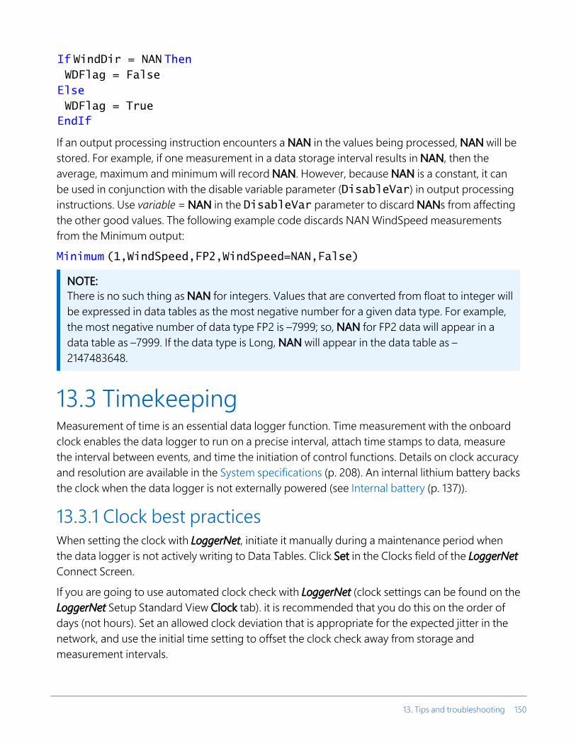
If WindDir = NAN Then WDFlag = FalseElse WDFlag = TrueEndIf
If an output processing instruction encounters a NAN in the values being processed, NAN will be stored. For example, if one measurement in a data storage interval results in NAN, then the average, maximum and minimum will record NAN. However, because NAN is a constant, it can be used in conjunction with the disable variable parameter (DisableVar) in output processing instructions. Use variable = NAN in the DisableVar parameter to discard NANs from affecting the other good values. The following example code discards NAN WindSpeed measurements from the Minimum output:
Minimum (1,WindSpeed,FP2,WindSpeed=NAN,False)
NOTE:There is no such thing as NAN for integers. Values that are converted from float to integer will be expressed in data tables as the most negative number for a given data type. For example, the most negative number of data type FP2 is –7999; so, NAN for FP2 data will appear in a data table as –7999. If the data type is Long, NAN will appear in the data table as –2147483648.
13.3 TimekeepingMeasurement of time is an essential data logger function. Time measurement with the onboard clock enables the data logger to run on a precise interval, attach time stamps to data, measure the interval between events, and time the initiation of control functions. Details on clock accuracy and resolution are available in the System specifications (p. 208). An internal lithium battery backs the clock when the data logger is not externally powered (see Internal battery (p. 137)).
13.3.1 Clock best practicesWhen setting the clock with LoggerNet, initiate it manually during a maintenance period when the data logger is not actively writing to Data Tables. Click Set in the Clocks field of the LoggerNet Connect Screen.
If you are going to use automated clock check with LoggerNet (clock settings can be found on the LoggerNet Setup Standard View Clock tab). it is recommended that you do this on the order of days (not hours). Set an allowed clock deviation that is appropriate for the expected jitter in the network, and use the initial time setting to offset the clock check away from storage and measurement intervals.
13. Tips and troubleshooting 150

The amount of time required for a Clock Check command to reach the data logger, be processed, and for it to send its response is called round-trip time, or time-of-flight. To calculate an estimate of this time-of-flight, LoggerNet maintains a history (in order) of the round-trip times for the ten previous successful clock check transactions. It adds this average to the time values received from the data logger and subtracts it from any adjustment that it might make.
13.3.2 Time stampsA measurement without an accurate time reference often has little meaning. Data collected from data loggers is stored with time stamps. How closely a time stamp corresponds to the actual time a measurement is taken depends on several factors.
The time stamp in common CRBasic programs matches the time at the beginning of the current scan as measured by the real-time data logger clock. If a scan starts at 15:00:00, data output during that scan will have a time stamp of 15:00:00 regardless of the length of the scan, or when in the scan a measurement is made. The possibility exists that a scan will run for some time before a measurement is made. For instance, a scan may start at 15:00:00, execute a time-consuming part of the program, then make a measurement at 15:00:00.51. The time stamp attached to the measurement, if the CallTable() instruction is called from within the Scan() / NextScan construct, will be 15:00:00, resulting in a time-stamp skew of 510 ms.
13.3.3 Avoiding time skewTime skew between consecutive measurements is a function of settling and integration times, ADC, and the number entered into the Reps parameter of CRBasic instructions. A close approximation is:
time skew = reps * (settling time + integration time + ADC time) + instruction setup timewhere ADC time equals 170 µs, and instruction setup time is 15 µs.If reps (repetitions) > 1 (multiple measurements by a single instruction), no setup time is required. If reps = 1 for consecutive voltage instructions, include the setup time for each instruction.
Applications that are very sensitive to time skew should consider using measurement modules such as GRANITE SPECTRUM series. These provide dedicated sampling hardware for every channel and very tight time synchronization.
Time-stamp skew is not a problem with most applications because:
l Program execution times are usually short; so, time-stamp skew is only a few milliseconds. Most measurement requirements allow for a few milliseconds of skew.
13. Tips and troubleshooting 151

l Data processed into averages, maxima, minima, and so forth are composites of several measurements. Associated time stamps only reflect the time of the scan when processing calculations were completed; so, the significance of the exact time a specific sample was measured diminishes.
Applications measuring and storing sample data wherein exact time stamps are required can be adversely affected by time-stamp skew. Skew can be avoided by:
l Making measurements in the scan before time-consuming code. l Programming the data logger such that the time stamp reflects the system time rather than
the scan time using the DataTime() instruction. See the CRBasic Editor help for detailed instruction information and program examples: https://help.campbellsci.com/crbasic/granite6/ .
13.4 CRBasic program errorsAnalyze data soon after deployment to ensure the data logger is measuring and storing data as intended. Most measurement and data-storage problems are a result of one or more CRBasic program bugs. Watch a video: CRBasic | Common Errors - Identifying and fixing common errors in the CRBasic programming language .
13.4.1 Program does not compileWhen a program is compiled, the CRBasic Editor checks the program for syntax errors and other inconsistencies. The results of the check are displayed in a message window at the bottom of the main window. If an error can be traced to a specific line in the program, the line number will be listed before the error. Double-click an error preceded by a line number and that line will be highlighted in the program editing window. Correct programming errors and recompile the program.
Occasionally, the CRBasic Editor compiler states that a program compiles OK; however, the program may not compile in the data logger itself. This is rare, but reasons may include:
l The data logger has a different operating system than the computer compiler. Check the two versions if in doubt. The computer compiler version is shown on the first line of the compile results. Update the computer compiler by first downloading the executable OS file from www.campbellsci.com . When run, the executable file updates the computer compiler. To update the data logger operating system, see Updating the operating system (p. 139).
13. Tips and troubleshooting 152

l The program has large memory requirements for data tables or variables and the data logger does not have adequate memory. This normally is flagged at compile time in the compile results. If this type of error occurs:
o Check the CPU drive for copies of old programs. The data logger keeps copies of all program files unless they are deleted, the drive is formatted, or a new operating system is loaded with Device Configuration Utility.
o Check the USR drive size. If it is too large it may be using memory needed for the program.
o Ensure a memory card is available when a program is attempting to access the CRD drive.
13.4.2 Program compiles but does not run correctlyIf the program compiles but does not run correctly, timing discrepancies may be the cause. If a program is tight on time, look further at the execution times. Check the measurement and processing times in the Status table (MeasureTime, ProcessTime, MaxProcTime) for all scans, then try experimenting with the InstructionTimes() instruction in the program. Analyzing InstructionTimes() results can be difficult due to the multitasking nature of the data logger, but it can be a useful tool for fine-tuning a program. For more information, see Information tables and settings (advanced) (p. 178).
See the CRBasic Editor help for detailed instruction information and program examples: https://help.campbellsci.com/crbasic/granite6/ .
13.5 Resetting the data loggerA data logger reset is sometimes referred to as a "memory reset." Backing up the current data logger configuration before a reset makes it easy to revert to the old settings. To back up the data logger configuration, connect to the data logger using Device Configuration Utility, and click Backup > Back Up Datalogger. To restore a configuration after the data logger has been reset, connect and click Backup > Restore Datalogger.
The following features are available for complete or selective reset of data logger memory:
l Processor reset l Program send reset l Manual data table reset l Formatting memory drives l Full memory reset
13. Tips and troubleshooting 153

13.5.1 Processor resetTo reset the processor, simply power cycle the data logger. This resets its short-term memory, restarts the current program, sets variables to their starting values, and clears communications buffers. This does not clear data tables but may result in a skipped record. If the data logger is remote, a power cycle can be mimicked in a Terminal Emulator program (type REBOOT <Enter>).
13.5.2 Program send resetFinal-data memory is erased when user programs are uploaded, unless preserve / erase data options are used and the program was not altered. Preserve / erase data options are presented when sending programs using File Control Send command and CRBasic Editor Compile, Save and Send.
TIP:It is good practice to always retrieve data from the data logger before sending a program; otherwise, data may be lost. See Collecting data (p. 50) for detailed instruction.
When a program compiles, all variables are initialized. A program is recompiled after a power failure or a manual stop. For instances that require variables to be preserved through a program recompile, consider PreserveVariables().
13.5.3 Manual data table resetData table memory is selectively reset from:
l Datalogger support software: Station Status > Table Fill Times tab, Reset Tables. l Device Configuration Utility: Data Monitor tab, Reset Table button. l CR1000KD Keyboard/Display add-on: Data > Reset Data Tables.
13.5.4 Formatting drivesCPU, USR, CRD (memory card required), and USB (module required) drives can be formatted individually. Formatting a drive erases all files on that drive. If the currently running user program is on the drive to be formatted, the program will cease running and data associated with the program are erased. Drive formatting is performed through the data logger support software File Control > Format command.
13. Tips and troubleshooting 154

13.5.5 Full memory resetFull memory reset occurs when an operating system is sent to the data logger using Device Configuration Utility or when entering 98765 in the Status table field FullMemReset (see Information tables and settings (advanced) (p. 178)). A full memory reset does the following:
l Clears and formats CPU drive (all program files erased) l Clears data tables. l Clears Status table fields. l Restores settings to default. l Initializes system variables. l Clears communications memory.
Full memory reset does not affect the CRD drive directly. Subsequent user program uploads, however, can erase CRD. See Updating the operating system (p. 139) for more information.
13.6 Troubleshooting power suppliesPower supply systems may include batteries, charging regulators, and a primary power source such as solar panels or ac/ac or ac/dc transformers attached to mains power. All components may need to be checked if the power supply is not functioning properly. Check connections and check polarity of connections.
Base diagnostic: connect the data logger to a new 12 V battery. (A small 12 V battery carrying a full charge would be a good thing to carry in your maintenance tool kit.) Ensure correct polarity of the connection. If the data logger powers up and works, troubleshoot the data logger power supply.
When diagnosing or adjusting power equipment supplied by Campbell Scientific, it is recommended you consider:
l Battery-voltage test l Charging-circuit test (when using an unregulated solar panel) l Charging-circuit test (when using a transformer) l Adjusting charging circuit
If power supply components are working properly and the system has peripherals with high current drain, such as a satellite transmitter, verify that the power supply is designed to provide adequate power. For additional information, see Power budgeting (p. 132).
13. Tips and troubleshooting 155

13.6.1 SDI-12 transparent modeAll SDI-12 probes have just three wires—a signal, ground, and 12 V power line. They are connected to the data logger according to the following table.
Table 13-1: SDI-12 probe connections
Wire function Data logger connection
SDI-12 signal C or U configured for SDI-121
Shield (analog ground)
Power 12V
Power ground G1 U and C terminals are automatically configured by the measurement instruction.
System operators can manually interrogate and enter settings in probes, connected to the data logger, using transparent mode. Transparent mode is useful in troubleshooting SDI-12 systems because it allows direct communications with probes.
Transparent mode may need to wait for commands issued by the programmed mode to finish before sending responses. While in transparent mode, the data logger programs may not execute. Data logger security may need to be unlocked before transparent mode can be activated.
Transparent mode is entered while the computer is communicating with the data logger through a terminal emulator program such as through Device Configuration Utility or other data logger support software. Keyboard displays cannot be used. For how-to instructions for communicating directly with an SDI-12 sensor using a terminal emulator, watch this video: https://www.campbellsci.com/videos/sdi12-sensors-transparent-mode .
To enter the SDI-12 transparent mode, enter the data logger support software terminal emulator:
1. Press Enter until the data logger responds with the prompt GRANITE 6>.
2. Type SDI12 at the prompt and press Enter.
13. Tips and troubleshooting 156

3. In response, the query Select SDI12 Port is presented with a list of available ports. Enter the port number assigned to the terminal to which the SDI-12 sensor is connected, and press Enter. For example, 1 is entered for terminal C1.
4. An Entering SDI12 Terminal response indicates that SDI-12 transparent mode is active and ready to transmit SDI-12 commands and display responses.
13.6.1.1 Watch command (sniffer mode)The terminal-mode utility allows monitoring of SDI-12 traffic by using the watch command (sniffer mode). Watch an instructional video: https://www.campbellsci.com/videos/sdi12-sensors-watch-or-sniffer-mode or use the following instructions.
1. Enter the transparent mode as described previously.
2. Press Enter until a GRANITE 6> prompt appears.
3. Type W and then press Enter.
4. In response, the query Select SDI12 Port: is presented with a list of available ports. Enter the port number assigned to the terminal to which the SDI-12 sensor is connected, and press Enter.
5. In answer to Enter timeout (secs): type 100 and press Enter.
6. In response to the query ASCII (Y)?, type Y and press Enter.
7. SDI-12 communications are then opened for viewing.
13.6.1.2 SDI-12 transparent mode commandsSDI-12 commands and responses are defined by the SDI-12 Support Group (www.sdi-12.org ) and are available in the SDI-12 Specification . Sensor manufacturers determine which commands to support. Commands have three components:
l Sensor address ( a): A single character and the first character of the command. Sensors are usually assigned a default address of zero by the manufacturer. The wildcard address ( ?) is used in the Address Query command. Some manufacturers may allow it to be used in other commands. SDI-12 sensors accept addresses 0 through 9, a through z, and A through Z.
l Command body (for example, M1): An upper case letter (the “command”) followed by alphanumeric qualifiers.
l Command termination ( !): An exclamation mark.
An active sensor responds to each command. Responses have several standard forms and terminate with <CR><LF> (carriage return–line feed).
13. Tips and troubleshooting 157

13.7 Ground loopsA ground loop is a condition in an electrical system that contains multiple conductive paths for the flow of electrical current between two nodes. Multiple paths are usually associated with the ground or 0 V-potential point of the circuit. Ground loops can result in signal noise, communications errors, or a damaging flow of ground current on long cables. Most often, ground loops do not have drastic negative effects and may be unavoidable. Special cases exist where additional grounding helps shield noise from sensitive signals; however, in these cases, multiple ground conductors are usually run tightly in parallel without conductive shielding material placed between the parallel grounds. If possible, ground loops should be avoided. When problems arise in a system, ground loops may be the source of the problems.
See also Grounds (p. 15).
13.7.1 Common causesSome of the common causes of ground loops include the following:
l The drain wire of a shielded cable is connected to the local ground at both ends, and the ground is already being carried by a conductor inside the cable. In this case, two wires, one on either side of the cable shield, are connected to the ground nodes at both ends of the cable.
l A long cable connects the grounds of two electrical devices, and the mounting structure or grounding rod also directly connects the grounds of each device to the local earth ground. The two paths, in this case, are the connecting cable and earth itself.
l When electrical devices are connected to a common metal chassis such as an instrument tower, the structure can create a ground path in parallel to the ground wires in sensor cables running over the structure.
l Conductors connected to ground are found in most cables that connect to a data logger. These include sensors cables, communications cables, and power cables. Any time one of these cables connects to the same two endpoints as another cable, a ground loop is formed.
13.7.2 Detrimental effectsThe harm from a ground loop can be seen in different ways. One consideration is the electromagnetically induced effect. This will manifest as AC noise or an AC pulse. As seen in FIGURE 13-1 (p. 159) the parallel conductive paths form an electrical loop that acts as an antenna to pick up electromagnetic energy.
13. Tips and troubleshooting 158

FIGURE 13-1. Stray AC magnetic fields picked up in loop antenna
l Relatively small electromagnetic energy: This could come from AC current on a nearby power cable, or RF energy transmitting through the air, and can cause electrical noise that either corrupts an analog signal or disrupts digital communications.
l Larger electromagnetic energy: The antenna loop scenario can have a more damaging effect when a large current is discharged nearby. The creation of an electromagnetic pulse can induce a surge that damages attached electronic devices.
Another way ground loops affect a system is by allowing ground current to flow between devices. This can be either a DC or AC effect. For various reasons, the voltage potential between two different points on the surface of the earth is not always 0 V. Therefore, when two electrical devices are both connected to a local earth ground, there may exist a voltage difference between the two devices. When a cable is connected between the two devices at different voltages, physics dictates than an electrical current must flow between the two points through the cable. See FIGURE 13-2 (p. 159).
FIGURE 13-2. Leakage current (AC or DC) from nearby load
13. Tips and troubleshooting 159

l One effect of this DC ground current-flow is a voltage offset error in analog measurements. Errors of this sort are usually not obvious but can have meaningful effects on measurements.
l For digital communications, an offset in the ground voltage reduces the dynamic range of the digital signals. This makes them more susceptible to noise corruption. If the ground voltage changes by one volt or more, the digital communications could stop working because the signals no longer reach the thresholds for determining the state of each bit.
l If the ground voltage differences reach several volts, damaging effects may occur at the terminals of the electronics devices. Damage occurs when the maximum allowable voltage on the internal components is exceeded.
13.7.3 Severing a ground loopTo avoid or eliminate ground loops, when they are detected, requires severing the loop. Suggestions for severing ground loops include:
l Connect the shield wire of a signal cable to ground only at one end of the cable. Leave the other end floating (not connected to ground).
l Never intentionally use the shield (or drain wire) of a cable as a signal ground or power ground.
l Use the mechanical support structure only as a connection for the safety ground (usually the ground lug). Do not intentionally return power ground through the structure.
l Do not use shielded Cat5e cables for Ethernet, CPI or EPI communications. l For long distance communications protocols such as RS-485, RS-422, and CAN, use a
Resistive Ground (RG) terminal for the ground connection. The RG terminal has a 100-ohm resistor in series with ground to limit the amount of DC current that can flow between the two endpoints while keeping the common-mode voltage in range of the transceivers. The transceivers themselves have enhanced voltage range inputs allowing for ground voltage differences of up to 7 V between endpoints.
l For exceptional cases, use optical or galvanic isolation devices to provide a signal connection without any accompanying ground connection. These should be used only when ground loops are causing system problems and the other methods of breaking a ground loop don’t apply. These devices add expense and tend to consume large amounts of power.
13. Tips and troubleshooting 160

13.7.4 Soil moisture exampleWhen measuring soil moisture with a resistance block, or water conductivity with a resistance cell, the potential exists for a ground loop error. In the case of an ionic soil matric potential (soil moisture) sensor, a ground loop arises because soil and water provide an alternate path for the excitation to return to data logger ground. This example is modeled in the following image:
With Rg in the resistor network, the signal measured from the sensor is described by the following equation:
where
l Vx is the excitation voltage l Rf is a fixed resistor l Rs is the sensor resistance l Rg is the resistance between the excited electrode and data logger earth ground.
RsRf/Rg is the source of error due to the ground loop. When Rg is large, the error is negligible. Note that the geometry of the electrodes has a great effect on the magnitude of this error. The Delmhorst gypsum block used in the Campbell Scientific 227 probe has two concentric cylindrical electrodes. The center electrode is used for excitation; because it is encircled by the ground electrode, the path for a ground loop through the soil is greatly reduced. Moisture blocks that consist of two parallel plate electrodes are particularly susceptible to ground loop problems. Similar considerations apply to the geometry of the electrodes in water conductivity sensors.
The ground electrode of the conductivity or soil moisture probe and the data logger earth ground form a galvanic cell, with the water/soil solution acting as the electrolyte. If current is
13. Tips and troubleshooting 161

allowed to flow, the resulting oxidation or reduction will soon damage the electrode, just as if DC excitation was used to make the measurement. Campbell Scientific resistive soil probes and conductivity probes are built with series capacitors to block this DC current. In addition to preventing sensor deterioration, the capacitors block any DC component from affecting the measurement.
13.8 Improving voltage measurement qualityThe following topics discuss methods of generally improving voltage measurements:
13.8.1 Deciding between single-ended or differential measurements 162
13.8.2 Minimizing ground potential differences 163
13.8.3 Detecting open inputs 164
13.8.4 Minimizing power-related artifacts 165
13.8.5 Filtering to reduce measurement noise 167
13.8.6 Minimizing settling errors 168
13.8.7 Factors affecting accuracy 170
13.8.8 Minimizing offset voltages 171
Read More: Consult the following technical papers at www.campbellsci.com/app-notes for in-depth treatments of several topics addressing voltage measurement quality:
l Preventing and Attacking Measurement Noise Problems l Benefits of Input Reversal and Excitation Reversal for Voltage Measurements l Voltage Accuracy, Self-Calibration, and Ratiometric Measurements
13.8.1 Deciding between single-ended or differential measurementsDeciding whether a differential or single-ended measurement is appropriate is usually, by far, the most important consideration when addressing voltage measurement quality. The decision requires trade-offs of accuracy and precision, noise cancellation, measurement speed, available measurement hardware, and fiscal constraints.
In broad terms, analog voltage is best measured differentially because these measurements include the following noise reduction features that are not included in single-ended measurements.
13. Tips and troubleshooting 162

l Passive Noise Rejection o No voltage reference offset o Common-mode noise rejection, which filters capacitively coupled noise
l Active Noise Rejection o Input reversal o For more information, see Compensating for offset voltage (p. 173).
Reasons for using single-ended measurements, however, include:
l Not enough differential terminals are available. Differential measurements use twice as many analog input terminals as do single-ended measurements.
l Rapid sampling is required. Single-ended measurement time is about half that of differential measurement time.
l Sensor is not designed for differential measurements. Some Campbell Scientific sensors are not designed for differential measurement, but the drawbacks of a single-ended measurement are usually mitigated by large programmed excitation and/or sensor output voltages.
Sensors with a high signal-to-noise ratio, such as a relative-humidity sensor with a full-scale output of 0 to 1000 mV, can normally be measured as single-ended without a significant reduction in accuracy or precision.
Sensors with a low signal-to-noise ratio, such as thermocouples, should normally be measured differentially. However, if the measurement to be made does not require high accuracy or precision, such as thermocouples measuring brush-fire temperatures, which can exceed 2500 °C, a single-ended measurement may be appropriate. If sensors require differential measurement, but adequate input terminals are not available, an analog multiplexer should be acquired to expand differential input capacity.
Because a single-ended measurement is referenced to data logger ground, any difference in ground potential between the sensor and the data logger will result in an error in the measurement. For more information on grounds, see Grounds (p. 15) and Minimizing ground potential differences (p. 163).
13.8.2 Minimizing ground potential differencesLow-level, single-ended voltage measurements (<200 mV) are sensitive to ground potential fluctuation due to changing return currents from 12V, SW12, and C terminals. The data logger grounding scheme is designed to minimize these fluctuations by separating signal grounds ( ) from power grounds (G). For more information on data logger grounds, see Grounds (p. 15). To take advantage of this design, observe the following rules:
13. Tips and troubleshooting 163

l Connect grounds associated with 12V, SW12, and C terminals to G terminals. l Connect excitation grounds to the nearest terminal on the same terminal block. l Connect the low side of single-ended sensors to the nearest terminal on the same
terminal block. l Connect shield wires to the terminal nearest the terminals to which the sensor signal
wires are connected.
If offset problems occur because of shield or ground wires with large current flow, tying the problem wires into terminals next to terminals configured for excitation and pulse-count should help. Problem wires can also be tied directly to the ground lug to minimize induced single-ended offset voltages.
13.8.2.1 Ground potential differencesBecause a single-ended measurement is referenced to data logger ground, any difference in ground potential between the sensor and the data logger will result in a measurement error. Differential measurements MUST be used when the input ground is known to be at a different ground potential from data logger ground.
Ground potential differences are a common problem when measuring full-bridge sensors (strain gages, pressure transducers, etc), and when measuring thermocouples in soil.
l Soil Temperature Thermocouple: If the measuring junction of a thermocouple is not insulated when in soil or water, and the potential of earth ground is, for example, 1 mV greater at the sensor than at the point where the data logger is grounded, the measured voltage will be 1 mV greater than the thermocouple output. With a Type T (copper-constantan) thermocouple, 1 mV equates to approximately 25 °C measurement error.
l External Signal Conditioner: External instruments with integrated signal conditioners, such as an infrared gas analyzer (IRGA), are frequently used to make measurements and send analog information to the data logger. These instruments are often powered by the same VAC-line source as the data logger. Despite being tied to the same ground, differences in current drain and wire resistance result in different ground potentials at the two instruments. For this reason, a differential measurement should be made on the analog output from the external signal conditioner.
For additional information, see Minimizing offset voltages (p. 171).
13.8.3 Detecting open inputsA useful option available to single-ended and differential measurements is the detection of open inputs due to a broken or disconnected sensor wire. This prevents otherwise undetectable
13. Tips and troubleshooting 164

measurement errors. Range codes appended with C enable open-input detection. For detailed information, see the CRBasic help (VoltSE() and VoltDiff() instructions, Range parameter)
The C option may not detect an open circuit in the following situations:
l When the input is not a truly open circuit, such as might occur on a wet cut cable end, the open circuit may not be detected because the input capacitor discharges to a normal voltage through external leakage to ground within the settling time of the measurement. This problem is worse when a long settling time is selected, as more time is given for the input capacitors to discharge to a "normal" level.
l If the open circuit is at the end of a very long cable, the test pulse may not charge the cable (with its high capacitance) up to a voltage that generates NAN or a distinct error voltage. The cable may even act as an aerial and inject noise which also might not read as an error voltage.
l The sensor may "object" to the test pulse being connected to its output, even for 100 µs. There is little or no risk of damage, but the sensor output may be caused to temporarily oscillate. Programming a longer settling time in the CRBasic measurement instruction to allow oscillations to decay before the ADC may mitigate the problem.
13.8.4 Minimizing power-related artifactsSome VAC-to-VDC power converters produce switching noise or AC ripple as an artifact of the ac-to-dc rectification process. Excessive switching noise on the output side of a power supply can increase measurement noise, and so increase measurement error. Noise from grid or mains power also may be transmitted through the transformer, or induced electromagnetically from nearby motors, heaters, or power lines.
High-quality power regulators typically reduce noise due to power regulation. Using the 50 Hz or 60 Hz first notch frequency (fN1) option for CRBasic analog input measurement instructions often improves rejection of noise sourced from power mains. The CRBasic standard deviation output instruction, StdDev(), can be used to evaluate measurement noise.
The data logger includes adjustable digital filtering, which serves two purposes:
l Arrive as close as possible to the true input signal l Filter out measurement noise at specific frequencies, the most common being noise at 50
Hz or 60 Hz, which originate from mains-power lines.
Filtering time is inversely proportional to the frequency being filtered.
13. Tips and troubleshooting 165

13.8.4.1 Minimizing electronic noiseElectronic noise can cause significant error in a voltage measurement, especially when measuring voltages less than 200 mV. So long as input limitations are observed, the PGA ignores voltages, including noise, that are common to each side of a differential-input pair. This is the common-mode voltage. Ignoring (rejecting or canceling) the common-mode voltage is an essential feature of the differential input configuration that improves voltage measurements. The following image illustrates the common-mode component (Vcm) and the differential-mode component (Vdm) of a voltage signal. Vcm is the average of the voltages on the V+ and V– inputs. So, Vcm = (V+ + V–)/2 or the voltage remaining on the inputs when Vdm = 0. The total voltage on the V+ and V– inputs is given as VH = Vcm + Vdm/2, and VL = Vcm – Vdm/2, respectively.
13. Tips and troubleshooting 166

13.8.5 Filtering to reduce measurement noiseAn adjustable filter is applied to analog measurements, reducing signal components at selected frequencies. The following figure shows the filter frequency response. Using the first notch frequency (fN1) parameter, users can select the placement of the filter notches. The first notch falls at the specified fN1, and subsequent notches fall at integer multiples of fN1. Commonly, fN1 is set at 50 or 60 Hz to filter 50 or 60 Hz signal components, reducing noise from ac power mains.
Filtering comes at the expense of measurement time. The time required for filtering is equal to 1/fN1. For example, setting fN1 equal to 50 will require 1/50 sec (20 ms) for filtering. As fN1 is set to smaller values, random noise in the measurement results decreases, while measurement time increases. The total time required for a single result includes settling + filtering + overhead.
Consult the following technical paper at www.campbellsci.com/app-notes for in-depth treatment of measurement noise: Preventing and Attacking Measurement Noise Problems .
13.8.5.1 GRANITE 6 filtering detailsThe data logger utilizes a sigma-delta ADC that outputs digitized data at a rate of 93750 samples per second. User-specified filtering is achieved by averaging several samples from the ADC. Recall that averaging the signal over a period of 1/fN1 seconds will filter signal components at fN1 Hz. The final result, then, is the average calculated from 93750/fN1 samples. For example, if fN1 is set to 50 Hz, 1875 samples (93750 / 50) are averaged to generate the final filtered result.
13. Tips and troubleshooting 167

The actual fN1 may deviate from the user-specified setting since a whole integer number of samples must be averaged. For example, if fN1 is set to 60 Hz, 1563 samples (93750 / 60 = 1562.5) will be averaged to produce the filtered result. The rounding of 1562.5 to 1563 moves the actual fN1 to 93750 / 1563 = 59.98 Hz.
13.8.6 Minimizing settling errorsSettling time allows an analog voltage signal to rise or fall closer to its true magnitude prior to measurement. Default settling times, those resulting when the SettlingTime parameter is set to 0, provide sufficient settling in most cases. Additional settling time is often programmed when measuring high-resistance (high-impedance) sensors, or when sensors connect to the input terminals by long cables. The time to complete a measurement increases with increasing settling time. For example, a 1 ms increase in settling time for a bridge instruction with input reversal and excitation reversal results in a 4 ms increase in time to perform the instruction.
When sensors require long cable lengths, use the following general practices to minimize settling errors:
l Do not use leads with PVC-insulated conductors. PVC has a high dielectric constant, which extends input settling time.
l Where possible, run excitation leads and signal leads in separate shields to minimize transients.
l When measurement speed is not a prime consideration, additional time can be used to ensure ample settling time.
l In difficult cases where measurement speed is a consideration, an appropriate settling time can be determined through testing.
13.8.6.1 Measuring settling timeSettling time for a particular sensor and cable can be measured with the GRANITE 6. Programming a series of measurements with increasing settling times will yield data that indicate at what settling time a further increase results in negligible change in the measured voltage. The programmed settling time at this point indicates the settling time needed for the sensor / cable combination.
The following CRBasic Example: Measuring Settling Time presents CRBasic code to help determine settling time for a pressure transducer using a high-capacitance semiconductor. The code consists of a series of full-bridge measurements (BrFull()) with increasing settling times. The pressure transducer is placed in steady-state conditions so changes in measured voltage are attributable to settling time rather than changes in pressure.
13. Tips and troubleshooting 168

CRBasic Example 3: Measuring Settling Time
'This program example demonstrates the measurement of settling time'using a single measurement instruction multiple times in succession.Public PT(20) 'Variable to hold the measurementsDataTable(Settle,True,100)Sample(20,PT(),IEEE4)
EndTableBeginProgScan(1,Sec,3,0)BrFull(PT(1), 1,mV200,U1,U11,1,2500,True,True, 100,15000,1.0,0)BrFull(PT(2), 1,mV200,U1,U11,1,2500,True,True, 200,15000,1.0,0)BrFull(PT(3), 1,mV200,U1,U11,1,2500,True,True, 300,15000,1.0,0)BrFull(PT(4), 1,mV200,U1,U11,1,2500,True,True, 400,15000,1.0,0)BrFull(PT(5), 1,mV200,U1,U11,1,2500,True,True, 500,15000,1.0,0)BrFull(PT(6), 1,mV200,U1,U11,1,2500,True,True, 600,15000,1.0,0)BrFull(PT(7), 1,mV200,U1,U11,1,2500,True,True, 700,15000,1.0,0)BrFull(PT(8), 1,mV200,U1,U11,1,2500,True,True, 800,15000,1.0,0)BrFull(PT(9), 1,mV200,U1,U11,1,2500,True,True, 900,15000,1.0,0)BrFull(PT(10),1,mV200,U1,U11,1,2500,True,True,1000,15000,1.0,0)BrFull(PT(11),1,mV200,U1,U11,1,2500,True,True,1100,15000,1.0,0)BrFull(PT(12),1,mV200,U1,U11,1,2500,True,True,1200,15000,1.0,0)BrFull(PT(13),1,mV200,U1,U11,1,2500,True,True,1300,15000,1.0,0)BrFull(PT(14),1,mV200,U1,U11,1,2500,True,True,1400,15000,1.0,0)BrFull(PT(15),1,mV200,U1,U11,1,2500,True,True,1500,15000,1.0,0)BrFull(PT(16),1,mV200,U1,U11,1,2500,True,True,1600,15000,1.0,0)BrFull(PT(17),1,mV200,U1,U11,1,2500,True,True,1700,15000,1.0,0)BrFull(PT(18),1,mV200,U1,U11,1,2500,True,True,1800,15000,1.0,0)BrFull(PT(19),1,mV200,U1,U11,1,2500,True,True,1900,15000,1.0,0)BrFull(PT(20),1,mV200,U1,U11,1,2500,True,True,2000,15000,1.0,0)CallTable Settle
NextScanEndProg
The first six measurements are shown in the following table:
Table 13-2: Example data from Measuring Settling Time Program
TimestampRecord Number
PT(1)Smp
PT(2)Smp
PT(3)Smp
PT(4)Smp
PT(5)Smp
PT(6)Smp
8/3/2017 23:34 0 0.03638599 0.03901386 0.04022673 0.04042887 0.04103531 0.04123745
8/3/2017 23:34 1 0.03658813 0.03921601 0.04002459 0.04042887 0.04103531 0.0414396
8/3/2017 23:34 2 0.03638599 0.03941815 0.04002459 0.04063102 0.04042887 0.04123745
8/3/2017 23:34 3 0.03658813 0.03941815 0.03982244 0.04042887 0.04103531 0.04103531
8/3/2017 23:34 4 0.03679027 0.03921601 0.04022673 0.04063102 0.04063102 0.04083316
13. Tips and troubleshooting 169

Each trace in the following image contains all twenty PT() mV/V values (left axis) for a given record number and an average value showing the measurements as percent of final reading (right axis). The reading has settled to 99.5% of the final value by the fourteenth measurement, which is contained in variable PT(14). This is suitable accuracy for the application, so a settling time of 1400 µs is determined to be adequate.
13.8.7 Factors affecting accuracyAccuracy describes the difference between a measurement and the true value. Many factors affect accuracy. This topic discusses the effect percent-of-reading, offset, and resolution have on the accuracy of an analog voltage measurement. Accuracy is defined as follows:
accuracy = percent-of-reading + offset
where percents-of-reading and offsets are displayed in the Analog measurement specifications (p. 213).
NOTE:Error discussed in this section and error-related specifications of the data logger do not include error introduced by the sensor, or by the transmission of the sensor signal to the data logger.
13. Tips and troubleshooting 170

13.8.7.1 Measurement accuracy exampleThe following example illustrates the effect percent-of-reading and offset have on measurement accuracy. The effect of offset is usually negligible on large signals.
Example:
l Sensor-signal voltage: approximately 1050 mV l CRBasic measurement instruction: VoltDiff() l Programmed input-voltage range (Range) : mV 5000 (±5000 mV) l Input measurement reversal (RevDiff): True l Data logger circuitry temperature: 10° C
Accuracy of the measurement is calculated as follows:
accuracy = percent-of-reading + offset
where
percent-of-reading = 1050 mV • ±0.04%
=±0.42 mV
and
offset = 5 µV
Therefore,
accuracy = ±(0.42 mV + 5 µV) = ±0.425 mV
13.8.8 Minimizing offset voltagesVoltage offset can be the source of significant error. For example, an offset of 3 μV on a 2500 mV signal causes an error of only 0.00012%, but the same offset on a 0.25 mV signal causes an error of 1.2%. Measurement offset voltages are unavoidable, but can be minimized. Offset voltages originate with:
l Ground currents (see Minimizing ground potential differences (p. 163). l Seebeck effect l Residual voltage from a previous measurement
Remedies include:
l Connecting power grounds to power ground terminals (G). l Using input reversal (RevDiff = True) with differential measurements. l Automatic offset compensation for differential measurements when RevDiff = False.
13. Tips and troubleshooting 171

l Automatic offset compensation for single-ended measurements when MeasOff = False.
l Using MeasOff = True for better offset compensation. l Using excitation reversal (RevEx = True) with bridge measurements. l Programming longer settling times.
Single-ended measurements are susceptible to voltage drop at the ground terminal caused by return currents from another device that is powered from the data logger wiring panel, such as another manufacturer's communications modem, or a sensor that requires a lot of power. Currents greater than 5 mA are usually undesirable. The error can be avoided by routing power grounds from these other devices to a power ground G terminal, rather than using a signal ground ( ) terminal. Ground currents can be caused by the excitation of resistive-bridge sensors, but these do not usually cause offset error. These currents typically only flow when a voltage excitation is applied. Return currents associated with voltage excitation cannot influence other single-ended measurements because the excitation is usually turned off before the data logger moves to the next measurement. However, if the CRBasic program is written in such a way that an excitation terminal is enabled during an unrelated measurement of a small voltage, an offset error may occur.
The Seebeck effect results in small thermally induced voltages across junctions of dissimilar metals as are common in electronic devices. Differential measurements are more immune to these than are single-ended measurements because of passive voltage cancellation occurring between matched high and low pairs such as U1/U2. So, use differential measurements when measuring critical low-level voltages, especially those below 200 mV, such as are output from pyranometers and thermocouples.
When analog voltage signals are measured in series by a single measurement instruction, such as occurs when VoltSE() is programmed with Reps = 2 or more, measurements on subsequent terminals may be affected by an offset, the magnitude of which is a function of the voltage from the previous measurement. While this offset is usually small and negligible when measuring large signals, significant error, or NAN, can occur when measuring very small signals. This effect is caused by dielectric absorption of the integrator capacitor and cannot be overcome by circuit design. Remedies include the following:
l Programing longer settling times. l Using an individual instruction for each input terminal, the effect of which is to reset the
integrator circuit prior to filtering. l Avoiding preceding a very small voltage input with a very large voltage input in a
measurement sequence if a single measurement instruction must be used.
13. Tips and troubleshooting 172

The following table lists some of the tools available to minimize the effects of offset voltages:
Table 13-3: Offset voltage compensation options
CRBasic Measurement
Instruction
Input Reversal(RevDiff=True)
Excitation Reversal (RevEx=True)
Measure Offset During Measurement
(MeasOff=True)
Measure Offset During Background
Calibration(RevDiff=False)(RevEx=False)
(MeasOff=False)
BrHalf() ü ü
BrHalf3W() ü ü
BrHalf4W() ü ü ü
BrFull() ü ü ü
BrFull6W() ü ü ü
Resistance() ü ü ü
Resistance3W() ü ü
TCDiff() ü ü
TCSe() ü ü
VoltDiff() ü ü
VoltSe() ü ü
13.8.8.1 Compensating for offset voltageDifferential measurements also have the advantage of an input reversal option, RevDiff. When RevDiff is True, two differential measurements are made, the first with a positive polarity and the second reversed. Subtraction of opposite polarity measurements cancels some offset voltages associated with the measurement.
Ratiometric measurements use an excitation voltage or current to excite the sensor during the measurement process. Reversing excitation polarity also reduces offset voltage error. Setting the RevEx parameter to True programs the measurement for excitation reversal. Excitation reversal results in a polarity change of the measured voltage so that two measurements with opposite polarity can be subtracted and divided by 2 for offset reduction similar to input reversal for differential measurements.
13. Tips and troubleshooting 173

For example, if 3 µV offset exists in the measurement circuitry, a 5 mV signal is measured as 5.003 mV. When the input or excitation is reversed, the second sub-measurement is –4.997 mV. Subtracting the second sub-measurement from the first and then dividing by 2 cancels the offset:
5.003 mV – (–4.997 mV) = 10.000 mV
10.000 mV / 2 = 5.000 mV
Ratiometric differential measurement instructions allow both RevDiff and RevEx to be set True. This results in four measurement sequences, which the data logger processes into the reported measurement:
l positive excitation polarity with positive differential input polarity l negative excitation polarity with positive differential input polarity l positive excitation polarity with negative differential input polarity l negative excitation polarity with negative differential input polarity
For ratiometric single-ended measurements, such as a BrHalf(), setting RevEx = True results in two measurements of opposite excitation polarity that are subtracted and divided by 2 for offset voltage reduction. For RevEx = False for ratiometric single-ended measurements, an offset-voltage measurement is determined from self-calibration.
When the data logger reverses differential inputs or excitation polarity, it delays the same settling time after the reversal as it does before the first sub-measurement. So, there are two delays per measurement when either RevDiff or RevEx is used. If both RevDiff and RevEx are True, four sub-measurements are performed; positive and negative excitations with the inputs one way and positive and negative excitations with the inputs reversed. The automatic procedure then is as follows:
1. Switch to the measurement terminals. 2. Set the excitation, settle, and then measure. 3. Reverse the excitation, settle, and then measure. 4. Reverse the excitation, reverse the input terminals, settle, measure. 5. Reverse the excitation, settle, measure.
There are four delays per measurement. In cases of excitation reversal, excitation time for each polarity is exactly the same to ensure that ionic sensors do not polarize with repetitive measurements.
Read More: The Benefits of Input Reversal and Excitation Reversal for Voltage Measurements .
13.8.8.2 Measuring ground reference offset voltageSingle-ended and differential measurements without input reversal use an offset voltage measurement with the PGIA inputs grounded. This offset voltage is subtracted from the
13. Tips and troubleshooting 174

subsequent measurement. For differential measurements without input reversal, this offset voltage measurement is performed as part of the routine background calibration of the data logger (see About background calibration (p. 137)). Single-ended measurement instructions VoltSE() and TCSe() include the MeasOff parameter determines whether the offset voltage measured is done at the beginning of the measurement instruction, or as part of self-calibration. This option provides you with the opportunity to weigh measurement speed against measurement accuracy. When MeasOff = True, a measurement of the single-ended offset voltage is made at the beginning of the VoltSE() or TCSe() instruction. When MeasOff = False, measurements will be corrected for the offset voltage determined during self-calibration. For installations experiencing fluctuating offset voltages, choosing MeasOff = True for the VoltSE() or TCSe() instruction results in better offset voltage performance.
If RevDiff, RevEx, or MeasOff is disabled ( = False), offset voltage compensation is automatically performed, albeit less effectively, by using measurements from the background calibration. Disabling RevDiff, RevEx, or MeasOff speeds up measurement time; however, the increase in speed comes at the cost of accuracy because of the following:
l RevDiff, RevEx, and MeasOff are more effective. l Background calibrations are performed only periodically, so more time skew occurs
between the background calibration offsets and the measurements to which they are applied.
NOTE:When measurement duration must be minimal to maximize measurement frequency, consider disabling RevDiff, RevEx, and MeasOff when data logger temperatures and return currents are slow to change.
13.9 Field calibrationCalibration increases accuracy of a measurement device by adjusting its output, or the measurement of its output, to match independently verified quantities. Adjusting sensor output directly is preferred, but not always possible or practical. By adding the FieldCal() or FieldCalStrain() instruction to a CRBasic program, measurements of a linear sensor can be adjusted by modifying the programmed multiplier and offset applied to the measurement, without modifying or recompiling the CRBasic program. See the CRBasic Editor help for detailed instruction information and program examples: https://help.campbellsci.com/crbasic/granite6/
.
13. Tips and troubleshooting 175

13.10 File system error codesErrors can occur when attempting to access files on any of the available drives. All occurrences are rare, but they are most likely to occur when using optional memory cards. Often, formatting the drive will resolve the error. The errors display in the File Control messages box or in the CardStatus field of the Status table. See Information tables and settings (advanced) (p. 178) for more information.
1 Invalid format 2 Device capabilities error 3 Unable to allocate memory for file operation 4 Max number of available files exceeded 5 No file entry exists in directory 6 Disk change occurred 7 Part of the path (subdirectory) was not found 8 File at EOF 9 Bad cluster encountered 10 No file buffer available 11 Filename too long or has bad chars 12 File in path is not a directory 13 Access permission, opening DIR or LABEL as file, or trying to open file as DIR or mkdir existing file 14 Opening read-only file for write 15 Disk full (can't allocate new cluster) 16 Root directory is full 17 Bad file ptr (pointer) or device not initialized 18 Device does not support this operation 19 Bad function argument supplied 20 Seek out-of-file bounds 21 Trying to mkdir an existing dir 22 Bad partition sector signature 23 Unexpected system ID byte in partition entry 24 Path already open 25 Access to uninitialized ram drive 26 Attempted rename across devices 27 Subdirectory is not empty 31 Attempted write to Write Protected disk 32 No response from drive (Door possibly open) 33 Address mark or sector not found 34 Bad sector encountered
13. Tips and troubleshooting 176

35 DMA memory boundary crossing error 36 Miscellaneous I/O error 37 Pipe size of 0 requested 38 Memory-release error (relmem) 39 FAT sectors unreadable (all copies) 40 Bad BPB sector 41 Time-out waiting for filesystem available 42 Controller failure error 43 Pathname exceeds _MAX_PATHNAME
13.11 File name and resource errorsThe maximum file name size that can be stored, run as a program, or FTP transferred in the data logger is 59 characters. If the name + file extension is longer than 59 characters, an Invalid Filename error is displayed. If several files are stored, each with a long file name, memory allocated to the root directory can be exceeded before the actual memory of storing files is exceeded. When this occurs, an Insufficient resources or memory full error is displayed.
13.12 Background calibration errorsBackground calibration errors are rare. When they do occur, the cause is usually an analog input that exceeds the input limits of the data logger.
l Check all analog inputs to make sure they are not greater than ±5 VDC by measuring the voltage between the input and a G terminal. Do this with a multimeter.
l Check for condensation, which can sometimes cause leakage from a 12 VDC source terminal.
l Check for a lose ground wire on a sensor powered from a 12V or SW12 terminal. l If a multimeter is not available, disconnect sensors, one at a time, that require power from 9
to 16 VDC. If measurements return to normal, you have found the cause.
13. Tips and troubleshooting 177

14. Information tables and settings (advanced)Information tables and settings consist of fields, settings, and system information essential to setup, programming, and debugging of many advanced GRANITE 6 systems. In many cases, the info tables and settings keyword can be used to pull that field into a running CRBasic program. There are several locations where this system information and settings are stored or changed:
l Status table: The Status table is an automatically created data table. View the Status table by connecting the data logger to your computer (see Making the software connection (p. 40) for more information) Station Status , then clicking the Status Table tab.
l DataTableInfo table: The DataTableInfo table is automatically created when a program produces other data tables. View the DataTableInfo table by connecting the data logger to your computer (see Making the software connection (p. 40) for more information).
o LoggerNet users, select DataTableInfo from the Table Monitor list. l Settings: Settings can be accessed from the LoggerNet Connect Screen Datalogger >
Settings Editor, or using Device Configuration Utility Settings Editor tab. Clicking on a setting in Device Configuration Utility also provides information about that setting.
l Terminal Mode: A list of setting field names is also available from the data logger terminal mode (from Device Configuration Utility, click the Terminal tab) using command "F".
l Status, DataTableInfo and Settings values may be accessed programmatically using Tablename.Fieldname syntax. For example: Variable = Settings.Fieldname. For more information see: https://www.campbellsci.com/blog/programmatically-access-stored-data-values .
Communications and processor bandwidth are consumed when generating the Status and other information tables. If data logger is very tight on processing time, as may occur in very fast, long, or complex operations, retrieving these tables repeatedly may cause skipped scans.
Settings that affect memory usage force the data logger program to recompile, which may cause loss of data. Before changing settings, it is a good practice to collect your data (see Collecting data (p. 50) for more information). Examples of settings that force the data logger program to recompile:
14. Information tables and settings (advanced) 178

l IP address l IP default gateway l Subnet mask l PPP interface l PPP dial string l PPP dial response l Baud rate change on control ports l Maximum number of TLS server connections
l USR drive size l PakBus encryption key l PakBus/TCP server port l HTTP service port l FTP service port l PakBus/TCP service port l PakBus/TCP client connections l Communications allocation
14.1 DataTableInfo table system informationThe DataTableInfo table is automatically created when a program produces other data tables. View the DataTableInfo table by connecting the data logger to your computer (see Making the software connection (p. 40) for more information).
Most fields in the DataTableInfo table are read only and of a numeric data type unless noted. Error counters (for example SkippedRecord) may be reset to 0 for troubleshooting purposes.
l LoggerNet users, select DataTableInfo from the Table Monitor list. l RTDAQ users, click the Monitor Data tab and add the DataTableInfo to display it. l PC400 users, click the Monitor Data tab and add the DataTableInfo to display it.
14.1.1 DataFillDaysReports the time required to fill a data table. Each table has its own entry in a two-dimensional array. First dimension is for on-board memory. Second dimension is for card memory.
14.1.2 DataRecordSize Reports the number of records allocated to a data table.
14.1.3 DataTableName Reports the names of data tables. Array elements are in the order the data tables are declared in the CRBasic program.
l String data type
14.1.4 RecNumRecord number is incremented when any one of the DataTableInfo fields change, for example SkippedRecord.
14. Information tables and settings (advanced) 179

14.1.5 SecsPerRecordReports the data output interval for a data table.
14.1.6 SkippedRecordReports how many times records have been skipped in a data table. Array elements are in the order that data tables are declared in the CRBasic program. Enter 0 to reset.
14.1.7 TimeStampScan time that a record was generated.
l NSEC data type
14.2 Status table system informationThe Status table is an automatically created data table. View the Status table by connecting the data logger to your computer (see Making the software connection (p. 40) for more information).
Most fields in the Status table are read only and of a numeric data type unless noted. Error counters (for example, WatchdogErrors or SkippedScan) may be reset to 0 for troubleshooting purposes.
Status table values may be accessed programatically using SetStatus() or Tablename.Fieldname syntax. For example: Variable = Status.Fieldname. For more information see: https://www.campbellsci.com/blog/programmatically-access-stored-data-values .
14.2.1 BatteryVoltage (VDC) of the battery powering the system. Updates once per minute, when viewing the Status table, or programatically.
14.2.2 BuffDepthShows the current pipeline mode processing buffer depth, which indicates how far the processing task is currently behind the measurement task. Updated at the conclusion of scan processing, prior to waiting for the next scan.
14.2.3 CalCurrentShows the offset calibration factor for the resistor used in 0-20 and 4-20 mA measurements on RG terminals. Measured once during production calibration.
14. Information tables and settings (advanced) 180

14.2.4 CalGainArray of floating-point values reporting calibration gain (mV) for each integration / range combination.
14.2.5 CalOffsetDisplays the offset calibration factor for the different voltage ranges.
14.2.6 CalRefOffsetDisplays voltage reference temperature compensation offset.
14.2.7 CalRefSlopeDisplays voltage reference temperature compensation slope.
14.2.8 CalVoltsArray of floating-point values reporting a factory calibrated correction factor for the different voltage ranges.
14.2.9 CardStatusContains a string with the most recent status information for the removable memory card.
l String data type
14.2.10 ChargeInputVoltage on the CHG terminals. Updates when background calibration executes.
14.2.11 ChargeStateState of the CHG terminals. Responses include: Regulator Fault, No Charge, Current Limit, Float Charge, Low Charge Input. Updates when background calibration executes (see Power input (p. 12) for more information).
l String data type
14.2.12 CommsMemFree Memory allocations for communications. Numbers outside of parentheses reflect current memory allocation. Numbers inside parentheses reflect the lowest memory size reached.
14. Information tables and settings (advanced) 181

14.2.13 CompileResultsContains messages generated at compilation or during runtime. Updated after compile and for runtime errors such as variable out of bounds.
l String data type
14.2.14 ErrorCalibNumber of erroneous calibration values measured. Erroneous values are discarded. Updated at startup.
14.2.15 FullMemResetEnter 98765 to start a full-memory reset, all data and programs will be erased.
14.2.16 IxResistorFactory-calibrated correction factor (in units of ohms) applied to resistance measurements. Normal value is near 1000 ohms. Updates at start up.
14.2.17 LastSystemScanReports the time of the of the last auto (background) calibration, which runs in a hidden slow-sequence type scan. See MaxSystemProcTime, SkippedSystemScan, and SystemProcTime.
14.2.18 LithiumBatteryVoltage of the internal lithium battery. Updated at GRANITE 6 power up. For battery information, see Internal battery (p. 137).
14.2.19 Low12VCountCounts the number of times the primary GRANITE 6 supply voltage drops below ≈9.0 VDC. Updates with each Status table update. Range = 0 to 99. Reset by entering 0. Incremented prior to scan (slow or fast) with measurements if the internal hardware signal is asserted.
14.2.20 MaxBuffDepthMaximum number of buffers the GRANITE 6 will use to process lagged measurements. Enter 0 to reset.
14. Information tables and settings (advanced) 182
14.2.21 MaxProcTimeMaximum time (μs) required to run through processing for the current scan. Value is reset when the scan exits. Enter 0 to reset. Updated at the conclusion of scan processing, prior to waiting for the next scan.
14.2.22 MaxSystemProcTime Maximum time (μs) required to process the auto (background) calibration, which runs in a hidden slow-sequence type scan. Displays 0 until a background calibration runs. Enter 0 to reset.
l Numeric data type
14.2.23 MeasureOpsReports the number of task-sequencer opcodes required to do all measurements. Calculated at compile time. Includes operation codes for calibration (compile time), auto (background) calibration (system), and Slow Sequences. Assumes all measurement instructions run each scan. Updated after compile and before running.
14.2.24 MeasureTimeReports the time (μs) needed to make measurements in the current scan. Calculated at compile time. Includes integration and settling time. In pipeline mode, processing occurs concurrent with this time so the sum of MeasureTime and ProcessTime is not equal to the required scan time. Assumes all measurement instructions will run each scan. Updated when a main scan begins.
14.2.25 MemoryFreeUnallocated final-data memory on the CPU (bytes). All free memory may not be available for data tables. As memory is allocated and freed, holes of unallocated memory, which are unusable for final-data memory, may be created. Updated after compile completes.
14.2.26 MemorySizeTotal final-data memory size (bytes) in the GRANITE 6. Updated at startup.
14.2.27 MessagesContains a string of manually entered messages.
l String data type
14. Information tables and settings (advanced) 183

14.2.28 OSDateRelease date of the operating system in the format mm/dd/yyyy. Updated at startup.
l String data type
14.2.29 OSSignatureSignature of the operating system.
14.2.30 OSVersionVersion of the operating system in the GRANITE 6. Updated at OS startup.
l String data type
14.2.31 PakBusRoutesLists routes or router neighbors known to the data logger at the time the setting was read. Each route is represented by four components separated by commas and enclosed in parentheses: (port, via neighbor address, pakbus address, response time in ms). Updates when routes are added or deleted.
l String data type
14.2.32 PanelTempCurrent processor board temperature (°C). Updates once per minute, when viewing the Status table, or programatically.
14.2.33 PortConfigProvides information on the configuration settings (input, output, SDM, RS-485, SDI-12, COM port) for Cor U terminals in numeric order of terminals. Default = Input. Updates when the port configuration changes.
l String data type
14.2.34 PortStatusStates of C terminals configured for control. On/high (true) or off/low (false). Array elements in numeric order of C terminals. Default = false. Updates when state changes. Enter -1 to set to true. Enter 0 to set to false.
l Boolean data type
14. Information tables and settings (advanced) 184

14.2.35 PowerSourcePrimary source of data logger power. Updates when background calibration executes.
l String data type
14.2.36 ProcessTimeProcessing time (μs) of the last scan. Time is measured from the end of the EndScan instruction (after the measurement event is set) to the beginning of the EndScan (before the wait for the measurement event begins) for the subsequent scan. Calculated on-the-fly. Updated at the conclusion of scan processing, prior to waiting for the next scan.
14.2.37 ProgErrorsNumber of compile or runtime errors for the running program. Updated after compile.
14.2.38 ProgNameName of current (running) program; updates at startup.
l String data type
14.2.39 ProgSignatureSignature of the running CRBasic program including comments. Does not change with operating-system changes. Updates after compiling the program.
14.2.40 RecNumRecord number increments when the Status Table is requested by support software. Range = 0 to 232.
l Long data type
14.2.41 RevBoardElectronics board revision in the form xxx.yyy, where xxx = hardware revision number; yyy = clock chip software revision. Stored in flash memory. Updated at startup.
l String data type
14. Information tables and settings (advanced) 185

14.2.42 RunSignatureSignature of the running binary (compiled) program. Value is independent of comments or non-functional changes. Often changes with operating-system changes. Updates after compiling and before running the program.
14.2.43 SerialNumberGRANITE 6 serial number assigned by the factory when the data logger was calibrated. Stored in flash memory. Updated at startup.
14.2.44 SkippedScanNumber of skipped program scans (see Checking station status (p. 147) for more information) that have occurred while running the CRBasic program. Does not include scans intentionally skipped as may occur with the use of ExitScan and Do / Loop instructions. Updated when they occur. Enter 0 to reset.
14.2.45 SkippedSystemScan Number of scans skipped in the background calibration. Enter 0 to reset. See LastSystemScan, MaxSystemProcTime, and SystemProcTime.
14.2.46 StartTimeTime (date and time) the CRBasic program started. Updates at beginning of program compile.
l NSEC data type
14.2.47 StartUpCodeIndicates how the running program was compiled. Updated at startup. 65 = Run on powerup is running and normal powerup occurred.
14.2.48 StationNameStation name stored in flash memory. This is not the same name as that is entered into your data logger support software. This station name can be sampled into a data table, but it is not the name that appears in data file headers. Updated at startup or when the name is changed. This value is read-only if the data logger is currently running a program with a CardOut() instruction.
l String data type
14. Information tables and settings (advanced) 186

14.2.49 SW12VoltsStatus of switched, 12 VDC terminal(s). On/high (true) or off/low (false) Enter -1 to set to true. Enter 0 to set to false. Updates when the state changes.
l Boolean data type
14.2.50 SystemProcTimeTime (μs) required to process auto (background) calibration. Default is 0 until background calibration runs.
14.2.51 TimeStampScan-time that a record was generated.
l NSEC data type
14.2.52 VarOutOfBoundNumber of attempts to write to an array outside of the declared size. The write does not occur. Indicates a CRBasic program error. If an array is used in a loop or expression, the pre-compiler and compiler do not check to see if an array is accessed out-of-bounds (i.e., accessing an array with a variable index such as arr(index) = arr(index–1), where index is a variable). Updated at runtime when the error occurs. Enter 0 to reset.
14.2.53 WatchdogErrorsNumber of watchdog errors that have occurred while running this program. Resets automatically when a new program is compiled. Enter 0 to reset. Updated at startup and at occurrence.
14.2.54 WiFiUpdateReqShows if WiFi operating system update is available. Update available (true) or not (false). Updates when state changes.
l Boolean data type
14.3 CPIStatus system informationMost fields in the CPIStatus table are read/write and of a numeric data type unless noted. Error counters (for example BuffErr) may be reset to 0 for troubleshooting purposes.
14. Information tables and settings (advanced) 187

l LoggerNet users, select DataTableInfo from the Table Monitor list. l RTDAQ and PC400 users, click the Monitor Data tab and add DataTableInfo.
For more information on the CPI bus and how to design a CDM network, see the technical paper at: https://s.campbellsci.com/documents/us/technical-papers/cpi-bus.pdf .
14.3.1 BusLoadPercentage of the possible CPI network bandwidth use over the scan interval. BusLoad = Used capacity / Maximum capacity.
l Read only l Percentage (0.000 to 100)
TIP:Use CPISpeed() to change the CPI bit rate. The default bit rate is 250 kbps. Use a higher bit rate if the BusLoad exceeds 75 percent.
14.3.2 ModuleReportCountReports the number of times measurement modules report in to the CPI bus. Modules report in on program send or when settings in the CPIStatus table are edited remotely. Activity that could cause the number of modules to be reported differently will cause ModuleReportCount to increment. Also, if there are devices on the network that are connected but not active, (such as those not in the running program) they will report in once minute, advertising their presence, and incrementing ModuleReportCount.
14.3.3 ActiveModulesReports the number of measurement modules that are active on the CPI bus.
l Read only
14.3.4 BuffErr (buffer error)Reports how many times there is an error in the buffer. Enter 0 to reset.
14.3.5 RxErrMaxReports the maximum number of receive errors. Enter 0 to reset.
14.3.6 TxErrMaxReports the maximum number of transmit errors. Enter 0 to reset.
14. Information tables and settings (advanced) 188

14.3.7 FrameErr (frame errors)Reports how many times a frame has an error. Enter 0 to reset.
14.3.8 ModuleInfo arrayReports: CDM Type, Serial Number, Device Name, CPI Address, Activity, OS Version.
l String data type l Read only
Possible responses and meanings in the Activity field are below:
l Active: The module is connected to the CPI bus and is making measurements according to the data logger program.
l Offline: The module was present after startup but is no longer responding. l Unused: The module is or was connected and powered but is not included in the data
logger program. l Wait Config: The module has not yet responded to a data logger attempts to configure it. l Config Fail: The module could not be configured. A configuration error message is
appended to this response. l CAN Errors, resetting CPI: The CDM module is not used in the data logger program.
14.4 SettingsSettings can be accessed from the LoggerNet Connect Screen Datalogger > Setting Editor, or using Device Configuration Utility Settings Editor tab. Settings are organized in tabs and can be searched for.
Most Settings are read/write and of a numeric data type unless noted.
Settings may be accessed programatically using SetSetting() or Tablename.Fieldname syntax. For example: Variable = Settings.Fieldname. For more information see: https://www.campbellsci.com/blog/programmatically-access-stored-data-values .
NOTE:A list of Settings fieldnames is also available from the data logger terminal mode using command F.
14. Information tables and settings (advanced) 189

14.4.1 BaudrateThis setting governs the baud rate that the data logger will use for a given port in order to support serial communications. For some ports (COM), this setting also controls whether the port will be enabled for serial communications.
Some ports (RS-232 and CS I/O ME) support auto-baud synchronization while the other ports support only fixed baud. With auto-baud synchronization, the data logger will attempt to match the baud rate to the rate used by another device based upon the receipt of serial framing errors and invalid packets.
14.4.2 BeaconThis setting, in units of seconds, governs the rate at which the data logger will broadcast PakBus messages on the associated port in order to discover any new PakBus neighboring nodes. If this setting value is set to a value of 0 or 65,535, the data logger will not broadcast beacon messages on this port.
This setting will also govern the default verification interval if the value of the Verify() setting for the associated port is zero. If the value of this setting is non-zero, and the value of the Verify setting is zero, the effective verify interval will be calculated as 2.5 times the value for this setting. If both the value of this setting and the value of the Verify setting is zero, the effective verify interval will be 300 seconds (five minutes).
14.4.3 CentralRoutersThis setting specifies a list of PakBus addresses for routers that are able to work as Central Routers. By specifying a non-empty list for this setting, the data logger will be configured as a Branch Router meaning that it will not be required to keep track of neighbors of any routers except those in its own branch. Configured in this fashion, the data logger will ignore any neighbor lists received from addresses in the central routers setting and will forward any messages that it receives to the nearest default router if it does not have the destination address for those messages in its routing table.
l String data type
14.4.4 CommsMemAllocReplaces PakBusNodes. Controls the amount of memory allocated for PakBus routing and communications in general. Increase the value of this setting if you require more memory dedicated to communications. Increase this value if the data logger will be used for routing a large number of PakBus nodes (>50). Increase this value if your data logger is dropping
14. Information tables and settings (advanced) 190

connections during short periods of high TCP/IP traffic. This setting will effect the values reported in CommsMemFree.
14.4.5 ConfigComxSpecifies the configuration for a data logger control port as it relates to serial communications. It is significant only when the associated port baud rate setting is set to something other than Disabled. This setting denotes the physical layer properties used for communications. It does not indicate the port's current configuration as it relates to standard or inverted logic. Options include:
l RS-232: Configures the port as RS-232 with standard voltage levels. l TTL: The port is configured to use TTL, 0 to 5V voltage levels. By default, the port will use
inverted logic levels. Use SerialOpen() to configure this port for standard TTL logic levels.
l LVTTL: The port is configured to use Low Voltage TTL (LVTTL), 0 to 3.3V voltage levels. By default, the port will use inverted logic levels. Use SerialOpen() to configure this port for standard TTL logic levels.
l RS-485 Half-Duplex PakBus: The port is configured as RS-485 half-duplex (two wire) and uses the PakBus/MDROP protocol. This allows reliable PakBus peer-to-peer networking of multiple devices including the MD485 and NL100 using the RS-485 interface.
l RS-485 Half-Duplex Transparent: The port is configured as RS-485 half-duplex (two wire). This setting is most commonly used when communicating with other non-PakBus RS-485 devices. Use this setting when communicating with devices such as Modbus RTUs or third-party serial sensors with RS-485 interfaces.
l RS-485 Full Duplex Transparent: The port is configured as RS-485 full-duplex (four wire). In this configuration, four adjacent control ports will be required.
14.4.6 CSIOxnetEnable Controls whether the CS I/O IP #1 or #2 TCP/IP interface should be enabled.
14.4.7 CSIOInfoReports the IP address, network mask, and default gateway for each of the data logger's active network interfaces. If DHCP is used for the interface, this setting will report the value that was configured by the DHCP server.
l String data type
14. Information tables and settings (advanced) 191

14.4.8 DisableLithiumControls whether the data logger will maintain its real time clock and battery backed memory when it loses power. Setting this value to one will cause the data logger clock to lose time on power loss. If this value is set to one, the data logger will not maintain its program or data after it powers down.
This value is useful when the data logger needs to be stored as it will prolong the shelf life of the lithium battery almost indefinitely.
If this value is set to one, the data logger will set it to zero when it powers up.
14.4.9 DeleteCardFilesOnMismatchControls the behavior of the data logger when it restarts with a different program and it detects that data files created by the CardOut() are present but do not match the new program. If this value is set to one, the data logger will delete these files so that new files can be stored. If set to a value of zero, the data logger will retain the existing files and prevent any data from being appended to these files.
14.4.10 DNSThis setting specifies the addresses of up to two domain name servers that the data logger can use to resolve domain names to IP addresses. Note that if DHCP is used to resolve IP information, the addresses obtained via DHCP will be appended to this list.
l String data type
14.4.11 EthernetInfoReports the IP address, network mask, and default gateway for each of the data logger's active network interfaces. If DHCP is used for the interface, this setting will report the value that was configured by the DHCP server.
l String data type l Read only
14.4.12 EthernetPowerThis setting specifies how the data logger controls power to its Ethernet interface. This setting provides a means of reducing the data logger power consumption while Ethernet is not connected. Always on, 1 Minute, or Disable.
14. Information tables and settings (advanced) 192

14.4.13 FilesManagerThis setting controls how the data logger will handle incoming files with specific extensions from various sources. There can be up to four specifications. Each specification has three required fields: PakBus Address, File Name, and Count.
l String data type
14.4.14 FTPEnabledSet to 1 if to enable FTP service. Default is 0.
14.4.15 FTPPasswordSpecifies the password that is used to log in to the FTP server.
l String data type
14.4.16 FTPPortConfigures the TCP port on which the FTP service is offered. The default value is usually sufficient unless a different value needs to be specified to accommodate port mapping rules in a network address translation firewall. Default = 21.
14.4.17 FTPUserNameSpecifies the user name that is used to log in to the FTP server. An empty string (the default) inactivates the FTP server.
l String data type
14.4.18 HTTPEnabledSpecifies additions to the HTTP header in the web service response. It can include multiple lines. Set to 1 to enable HTTP (web server) service or 0 to disable it.
14.4.19 HTTPHeaderSpecifies additions to the HTTP header in the web service response. It can include multiple lines. Example: Access-Control-Allow-Origin: *
l String data type
14. Information tables and settings (advanced) 193

14.4.20 HTTPPortConfigures the TCP port on which the HTTP (web server) service is offered. Generally, the default value is sufficient unless a different value needs to be specified to accommodate port-mapping rules in a network-address translation firewall. Default = 80.
14.4.21 HTTPSEnabledSet to 1 to enable the HTTPS (secure web server) service.
14.4.22 HTTPSPortConfigures the TCP port on which the HTTPS (secure web server) service is offered. Generally, the default value is sufficient unless a different value needs to be specified to accommodate port mapping rules in a network address translation firewall.
14.4.23 IncludeFileThis setting specifies the name of a file to be implicitly included at the end of the current CRBasic program or can be run as the default program. In order to work as an include file, the file referenced by this setting cannot contain a BeginProg() statement or define any variable names or tables that are defined in the main program file.
This setting must specify both the name of the file to run as well as on the device (CPU:, USR:, or CRD:) on which the file is located. The extension of the file must also be valid for a data logger program (.CRB, .DLD).
See also File management via powerup.ini (p. 143).
l String data type
14.4.24 IPAddressCSIOArrays that specify the IP addresses of the internet interfaces that use the CS I/O bridge protocol. If a value is specified as zero (the default), the data logger will use DHCP to configure the IP address, network mask, and default gateway for that interface.
l String data type
14.4.25 IPAddressEthSpecifies the IP address used by the Ethernet interface. If this value is specified as "0.0.0.0" (the default), the data logger will use DHCP to configure the effective value for this setting as well as the Ethernet Default Gateway and Ethernet Subnet Mask settings. This setting is the equivalent to the IPAddressEth status table variable.
14. Information tables and settings (advanced) 194

l String data type
14.4.26 IPGatewaySpecifies the IP address of the network gateway on the same subnet as the Ethernet interface. If the value of the Ethernet IP Address setting is set to "0.0.0.0" (the default), the data logger will configure the effective value of this setting using DHCP. This setting is the equivalent to the IPGateway status table variable.
l String data type
14.4.27 IPGatewayCSIOThese settings specify the IP addresses of the router on the subnet to which the first or second CS I/O bridge internet interface is connected. The data logger will forward all non-local IP packets to this address when it has no other route. If the CS I/O IP Address setting is set to a value of "0.0.0.0", the data logger will configure the effective value of this setting using DHCP.
l String data type
14.4.28 IPMaskCSIOThese settings specify the subnet masks for the CS I/O bridge mode internet interface. If the corresponding CS I/O Address setting is set to a value of "0.0.0.0", the data logger will configure the effective value of this setting using DHCP.
l String data type
14.4.29 IPMaskEthSpecifies the subnet mask for the Ethernet interface. If the value of the Ethernet IP Address setting is set to "0.0.0.0" (the default), the data logger will configure the effective value of this setting using DHCP.
l String data type
14.4.30 IPMaskWiFiSpecifies the subnet mask for the WiFi interface.
l String data type
14.4.31 IPTraceDiscontinued; aliased to IPTraceComport
14. Information tables and settings (advanced) 195

14.4.32 IPTraceCodeControls what type of information is sent on the port specified by IPTraceComport and via Telnet. Each bit in this integer represents a certain aspect of tracing that can be turned on or off. Values for particular bits are described in the Device Configuration Utility. Default = 0, no messages generated.
14.4.33 IPTraceComportSpecifies the port (if any) on which TCP/IP trace information is sent. Information type is controlled by IPTraceCode.
14.4.34 IsRouterThis setting controls whether the data logger is configured as a router or as a leaf node. If the value of this setting is true, the data logger will be configured to act as a PakBus router. That is, it will be able to forward PakBus packets from one port to another. To perform its routing duties, a data logger configured as a router will maintain its own list of neighbors and send this list to other routers in the PakBus network. It will also obtain and receive neighbor lists from other routers.
If the value of this setting is false, the data logger will be configured to act as a leaf node. In this configuration, the data logger will not be able to forward packets from one port to another and it will not maintain a list of neighbors. Under this configuration, the data logger can still communicate with other data loggers and wireless sensors. It cannot, however, be used as a means of reaching those other data loggers. The default value is false.
l Boolean data type
14.4.35 KeepAliveURL (Ping keep alive URL)The URL to send a ping to when there has been no network activity for the KeepAliveMin interval. If there is no ping response then the network connection is reestablished.
l String data type
14.4.36 KeepAliveMin (Ping keep alive timeout value)When there has been no network activity for this amount of time, in seconds, a ping will be sent to the KeepAliveURL. Default = 0 which disables keep alive pings.
l Long data type (allowed values: 0,5,10,15,30,60,120,180,240,300,360,480,720)
14. Information tables and settings (advanced) 196
14.4.37 MaxPacketSizeSpecifies the maximum number of bytes per data collection packet.
14.4.38 NeighborsThis setting specifies, for a given port, the explicit list of PakBus node addresses that the data logger will accept as neighbors. If the list is empty (the default value) any node will be accepted as a neighbor. This setting will not affect the acceptance of a neighbor if that neighbor's address is greater than 3999.
l String data type
14.4.39 NTPServerThis setting specifies an NTP Server to be queried (once per day) to adjust the data logger clock. This setting uses the UTC Offset setting. If UTC Offset setting is not set, it is assumed to be 0.
l String data type
14.4.40 PakBusAddressThis setting specifies the PakBus address for this device. Valid values are in the range 1 to 4094. The value for this setting must be chosen such that the address of the device will be unique in the scope of the data logger network. Duplication of PakBus addresses can lead to failures and unpredictable behavior in the PakBus network.
When a device has an allowed neighbor list for a port, any device that has an address greater than or equal to 4000 will be allowed to connect to that device regardless of the allowed neighbor list.
14.4.41 PakBusEncryptionKeyThis setting specifies text that will be used to generate the key for encrypting PakBus messages sent or received by this data logger. If this value is specified as an empty string, the data logger will not use PakBus encryption. If this value is specified as a non-empty string, however, the data logger will not respond to any PakBus message unless that message has been encrypted.
l String data type
14.4.42 PakBusNodesDiscontinued; aliased to CommsMemAlloc
14. Information tables and settings (advanced) 197

14.4.43 PakBusPortThis setting specifies the TCP service port for PakBus communications with the data logger. Unless firewall issues exist, this setting probably does not need to be changed from its default value. Default 6785.
14.4.44 PakBusTCPClients This setting specifies outgoing PakBus/TCP connections that the data logger should maintain. Up to four addresses can be specified.
l String data type
14.4.45 PakBusTCPEnabledBy default, PakBus TCP communications are enabled. To disable PakBus TCP communications, set the PakBusPort setting to 65535.
14.4.46 PakBusTCPPasswordThis setting specifies a password that, if not empty, will make the data logger authenticate any incoming or outgoing PakBus/TCP connection. This type of authentication is similar to that used by CRAM-MD5.
l String data type
14.4.47 PingEnabledSet to one to enable the ICMP ping service.
14.4.48 PCAPPCAP is a packet capture (PCAP) file of network packet data (network traffic) that can be opened by Wireshark. This setting specifies the network interface, file name, and maximum size of the PCAP file. For example:
l "usr:debug.pcap" saves the file to the USR drive with the file type .pcap. l ".ring." found in name will create new files once the file size has been reached.
"crd:debug.ring.pcap" creates crd:debug001.pcap, crd:debug002.pcap... l If a number follows .ring. then only that number of files will be saved, with the oldest
deleted. For example: "usr:debug.ring.3.pcap" will save three files.
If All Networks is selected as the Network Interface and PPP/Cell is active, then separate files will be opened for the PPP/Cell network with "ppp." prefixed on the file name.
14. Information tables and settings (advanced) 198
14.4.49 pppDialSpecifies the dial string that would follow the ATD command (#777 for the Redwing CDMA).
Alternatively, this value can specify a list of AT commands where each command is separated by a semi-colon (;). When specified in this fashion, the data logger will transmit the string up to the semicolon, transmit a carriage return to the modem, and wait for two seconds before proceeding with the rest of the dial string (or up to the next semicolon). If multiple semicolons are specified in succession, the data logger will add a delay of one second for each additional semicolon.
If a value of PPP is specified for this setting, will configure the data logger to act as a PPP client without any modem dialing. Finally, an empty string (the default) will configure the data logger to listen for incoming PPP connections also without any modem dialing.
l String data type
14.4.50 pppDialResponseSpecifies the response expected after dialing a modem before a PPP connection can be established.
l String data type
14.4.51 pppInfoReports the IP address, network mask, and default gateway for each of the data logger's active network interfaces. If DHCP is used for the interface, this setting will report the value that was configured by the DHCP server.
l String data type l Read only
14.4.52 pppInterfaceThis setting controls which data logger port PPP service will be configured to use.
14.4.53 pppIPAddrSpecifies the IP address that will be used for the PPP interface if that interface is active (the PPP Interface setting needs to be set to something other than Inactive).
l String data type
14. Information tables and settings (advanced) 199

14.4.54 pppPasswordSpecifies the password that will be used for PPP connections when the value of PPP Interface is set to something other than Inactive.
l String data type
14.4.55 pppUsernameSpecifies the user name that is used to log in to the PPP server.
l String data type
14.4.56 RouteFiltersThis setting configures the data logger to restrict routing or processing of some PakBus message types so that a "state changing" message can only be processed or forwarded by this data logger if the source address of that message is in one of the source ranges and the destination address of that message is in the corresponding destination range. If no ranges are specified (the default), the data logger will not apply any routing restrictions. "State changing" message types include set variable, table reset, file control send file, set settings, and revert settings.
If a message is encoded using PakBus encryption, the router will forward that message regardless of its content. If, however, the routes filter setting is active in the destination node and the unencrypted message is of a state changing type, the route filter will be applied by that end node.
l String data type
14.4.57 RS232Handshaking If non-zero, hardware handshaking is active on the RS-232 port. This setting specifies the maximum packet size sent between checking for CTS.
14.4.58 RS232PowerControls whether the RS-232 port will remain active even when communications are not taking place. Note that if RS232Handshaking is enabled (handshaking buffer size is non-zero), that this setting must be set to Yes.
l Boolean data type
14. Information tables and settings (advanced) 200

14.4.59 RS232TimeoutRS-232 hardware handshaking timeout. Specifies the time (tens of ms) that the GRANITE 6 will wait between packets if CTS is not asserted.
14.4.60 Security(1), Security(2), Security(3)An array of three security codes. A value of zero for a given level will grant access to that level's privileges for any given security code. For more information, see Data logger security (p. 128).
14.4.61 ServicesEnabledDiscontinued; replaced by/aliased to HTTPEnabled, PingEnabled, TelnetEnabled.
14.4.62 TCPClientConnections Discontinued; replaced by / aliased to PakBusTCPClients.
14.4.63 TCP_MSSThe maximum TCP segment size. This value represents the maximum TCP payload size. It is used to limit TCP packet size. A maximum TCP transmission unit (MTU) can be calculated by adding the IP Header size (20 bytes), the TCP Header size (20 bytes), and the payload size.
14.4.64 TCPPortDiscontinued; replaced by / aliased to PakBusPort.
14.4.65 TelnetEnabledEnables (1) or disables (0) the Telnet service.
14.4.66 TLSConnections (Max TLS Server Connections)This setting controls the number of concurrent TLS (secure or encrypted) client socket connections that the data logger will be capable of handling at any given time. This will affect FTPS and HTTPS services. This count will be increased by the number of DNP() instructions in the data logger program.
This setting will control the amount of RAM that the data logger will use for TLS connections. For every connection, approximately 20KBytes of RAM will be required. This will affect the amount of memory available for program and data storage. Changing this setting will force the data logger to recompile its program so that it can reallocate memory
14. Information tables and settings (advanced) 201

14.4.67 TLSPasswordThis setting specifies the password that will be used to decrypt the TLS Private Key setting.
l String data type
14.4.68 TLSStatusReports the current status of the data logger TLS network stack.
l String data type l Read only
14.4.69 UDPBroadcastFilterSet to one if all broadcast IP packets should be filtered from IP interfaces. Do not set this if you use the IP discovery feature of the device configuration utility or of LoggerLink. If this is set, the data logger will fail to respond to the broadcast requests.
Default = 0.
14.4.70 USBConfig (Configure USB)Controls the configuration of the data logger USB (host) port. When set to a value of 1 it configures the data logger to enumerate USB as a virtual com port only. A value of 0 (the default) causes the data logger to enumerate as a composite device with both a virtual com port and a virtual Ethernet port (RNDIS) available.
Default = 0.
14.4.71 USBEnumerateControls the behavior of the data logger when its USB connector is plugged into the computer. If set to a value of 1, the data logger will use its own serial number for identification in the USB enumeration. If set to a value of 0 (the default), the data logger will use a fixed serial number in the USB enumeration. This behavior controls whether the computer will allocate a new virtual serial port for the data logger USB connection or will use a previously allocated (but not currently used) virtual serial port.
Default = 0.
14.4.72 USRDriveFreeProvides information on the available bytes for the USR drive.
l Read only
14. Information tables and settings (advanced) 202

14.4.73 USRDriveSizeSpecifies the size in bytes allocated for the USR: ram disk drive. This memory is allocated from the memory that the data logger would normally use to store its compiled program or RAM based data tables. If this setting is too large, some programs may not be able to compile on the data logger.
Setting the USR: Drive Size setting will force the data logger to recompile its program and may result in the loss of data.
This setting controls the amount of memory set aside for the USR: size and is only indirectly related to the amount of storage within that file system. The amount of space available for storing files is always going to be less than this value because of the overhead of file system structures.
14.4.74 UTCOffsetSpecifies the offset, in seconds, of the data logger's clock from Coordinated Universal Time (UTC, or GMT). For example, if the clock is set to Mountain Standard Time in the U.S. (-7 Hours offset from UTC) then this setting should be -25200 (-7*3600). This setting is used by the NTP Server setting as well as EmailSend() and HTTP(), which require Universal Time in their headers. This setting will also be adjusted by the Daylight Savings functions if they adjust the clock.
If a value of -1 is supplied for this setting, no UTC offset will be applied.
14.4.75 VerifyThis setting specifies the interval, in units of seconds, that will be reported as the link verification interval in the PakBus hello transaction messages. It will indirectly govern the rate at which the data logger will attempt to start a hello transaction with a neighbor if no other communications have taken place within the interval.
14.4.76 Wi-Fi settingsAccess Wi-Fi settings, using Device Configuration Utility. Clicking on a setting in Device Configuration Utility also provides information about that setting.
Where to find:
l All settings: Settings Editor tab in Device Configuration Utility: Wi-Fi tab. l Key settings: in Device Configuration Utility: Deployment > Wi-Fi tab.
See also Wi-Fi communications (p. 30)
14. Information tables and settings (advanced) 203

NOTE:A list of Settings fieldnames is also available from the data logger terminal mode using command F.
14.4.76.1 IPAddressWiFiSpecifies the IP address for the Wi-Fi Interface. If specified as zero, the address, net mask, and gateway will be configured automatically using DHCP.
l String data type
14.4.76.2 IPGatewayWiFiSpecifies the address of the IP router to which the data logger will forward all non-local IP packets for which it has no route.
l String data type
14.4.76.3 IPMaskWiFiSpecifies the subnet mask for the WiFi interface.
l String data type
14.4.76.4 WiFiChannelThis setting is only applicable when the device is configured to create a network (Configuration). It then specifies in which channel the network should be created. If Auto is selected, the device will use only channels 1, 6, and 11 to minimize interference from other networks detected in the area.
When manually selecting a channel, it should be noted that two Wi-Fi networks operating on the same channel will interfere with each other and will have to compete for bandwidth. The center frequencies of adjacent channels are 5 MHz apart and the bandwidth of each channel is 20 MHz which means that adjacent channels overlap. To completely avoid interference there must be a spacing of at least 5 channels between each Wi-Fi network. It is therefore recommended to use channels 1, 6, and 11.
l Long data type
14.4.76.5 WiFiConfigIn addition to joining, creating or disabling a network, this setting controls how the device acts when the WIFI Mode button is pressed.
14. Information tables and settings (advanced) 204

When the Mode button is used to temporarily create the Wi-Fi network, it will stay powered for at least 5 minutes. There is a 5 minute timeout that is refreshed every time communications are detected. Once the timeout has expired the device will power off the Wi-Fi network. If the Mode button is pressed again while the temporary network is active, the device will power off the network.
l Long data type, where: o 0 = Join network o 1 = Create network o 4 = Disable network o 5 = Normally off; join network on button press o 6 = Normally off; create network on button press o 7 = Join network; create network on button press
14.4.76.6 WiFiEAPMethodThe EAP Method must be chosen to match the EAP method being used by the Enterprise Security network. The inner EAP Methods supported are MSCHAPv2, MSCHAP, CHAP, and PAP.
l Long data type
14.4.76.7 WiFiEAPPasswordIf joining an Enterprise Security-enabled network enter password here.
l String data type
14.4.76.8 WiFiEAPUserIf joining an Enterprise Security-enabled network enter user name here.
l String data type
14.4.76.9 NetworksLists the networks available in the area. Information listed for each network is shown as SSID, RSSI / Signal Strength, Channel, Security. Sometimes areas are covered by multiple access points configured with the same network name (SSID). In that case multiple unique access points possessing the same network name (SSID) may be listed here.
l String data type l Read only
14. Information tables and settings (advanced) 205

14.4.76.10 WiFiEnableSet to enable or disable the WiFi service. By default, WiFi is enabled. To disable, set the Configuration option to Disable. 0 Disabled, 1 or <>0 Enabled.
l Boolean data type
14.4.76.11 WiFiFwdCode (Forward Code)This is an advanced setting to allow some customized filtering by the Wi-Fi module. It specifies which incoming packets are forwarded to the data logger. This decreases the amount of processing required by the data logger.
l Long data type
14.4.76.12 WiFiPasswordIf joining a WPA or WPA2 security enabled network then this is where the passphrase is entered. If joining a WEP security enabled network then this is where the WEP key is entered.
If creating a network and a password is supplied, the network will be created using WPA2 encryption. The password must be at least 8 characters. If a password is not supplied, an open (unencrypted) network will be created.
When joining a network the device supports 64-bit WEP and 128-bit WEP. For 64-bit WEP enter a 40 bit key in the form of 5 ASCII characters or 10 hexadecimal digits (0-9, A-F). For 128-bit WEP enter a 104 bit key in the form of 13 ASCII characters or 26 hexadecimal digits (0-9, A-F).
l String data type
14.4.76.13 WiFiPowerModeThis setting controls the power saving mode of the device. Regardless of the Power Mode setting, the device enables power-save mode when communications are not active. Power Mode determines how the device acts when communications are ongoing. This setting only applies when the device is configured to Join a Network using the Configuration option.
l Long data type
14.4.76.14 WiFiSSID (Network Name)The Network Name (SSID) is the name that identifies a wireless network (31 character maximum). The SSID differentiates one wireless network from another, so all devices attempting to connect to the same network must use the same SSID. If the device is configured to 'Join a Network', then enter the SSID of the network, including hidden networks, to join here. If the device is configured
14. Information tables and settings (advanced) 206

to Create a Network using the Configuration option, then the SSID entered here will be the SSID of the network created.
NOTE:When creating a network, the device will not create the network if the Network Name (SSID) specified is the same as one that already exists in the area.
l String data type
14.4.76.15 WiFiStatusSpecifies the current status of the Wi-Fi module.
l String data type l Read only
14.4.76.16 WiFiTxPowerLevelThis fixes the transmit power level of the Wi-fi module. This value can be set as follows: Low (7 +/- 1 dBm), Medium (10 +/- 1 dBm), High (15 +/- 2 dBm). The value of this setting does not affect power consumption.
l Long data type
14.4.76.17 WLANDomainNameThe WLAN Domain Name is only relevant when the device is configured to create a network. When attempting to communicate with the device, attached Wi-Fi client devices can simply use the domain name specified here which will be resolved to the device's IP address. For example, the data logger web page can be accessed simply by entering the domain name specified here into a web browser.
l String data type
14. Information tables and settings (advanced) 207

15. GRANITE 6 specificationsElectrical specifications are valid over a -40 to +70 °C, non-condensing environment, unless otherwise specified. Extended electrical specifications (noted as XD in specifications) are valid over a -55 to +85 °C non-condensing environment. Recalibration is recommended every three years. Critical specifications and system configuration should be confirmed with Campbell Scientific before purchase.
15.1 System specifications 208
15.2 Physical specifications 209
15.3 Power requirements 209
15.4 Power output specifications 211
15.5 Analog measurement specifications 213
15.6 Pulse measurement specifications 218
15.7 Digital input/output specifications 220
15.8 Communications specifications 222
15.9 Standards compliance specifications 223
15.1 System specificationsProcessor: Renesas RX63N (32-bit with hardware FPU, running at 100 MHz)
Memory (see Data memory (p. 61) for more information):
l Total onboard: 128 MB of flash + 4 MB battery-backed SRAM o Data storage: 4 MB SRAM + 72 MB flash (extended data storage automatically used
for auto-allocated Data Tables not being written to a card) o CPU drive: 30 MB flash o OS load: 8 MB flash o Settings: 1 MB flash o Reserved (not accessible): 10 MB flash
l Data storage expansion: Removable microSD flash memory, up to 16 GB l USB host provides for portable data storage on a mass storage device (MSD). Not intended
for long term unattended data storage other than what is available with TableFile().
Program Execution Period: 1 ms to 1 day
15. GRANITE 6 specifications 208

Real-Time Clock:
l Battery backed while external power is disconnected l Resolution: 1 ms l Accuracy: ±3 min. per year, optional GPS correction to ±10 µs; 5.7 ppm
Wiring Panel Temperature: Measured using a thermistor, located on the analog board.
15.2 Physical specificationsCase Material: Stainless Steel 304 and Aluminum 6061
Dimensions: 21.4 x 12.0 x 5.0 cm (8.4 x 4.7 x 2.0 in); additional clearance required for cables, wires, and antennas.
Weight/Mass: 0.86 kg (1.9 lb)
15.3 Power requirementsProtection: Power inputs are protected against surge, over-voltage, over-current, and reverse power. IEC 61000-4 Class 4 level.
CHG Terminals:
l Voltage Input: 16 to 32 VDC l Input Current Limit at 12 VDC:
o 1.2 A @ 20 °C maximum l Input voltage must be at least 0.3 V higher than the voltage required to charge the battery;
40 VDC sustained voltage limit without damage. Transient voltage suppressor (TVS) diodes at the BAT and CHG terminals clamp transients to 19 to 21 V and 19 to 40 V respectively. Sustained input voltages in excess of 19 V or 40 V respectively can damage the TVS diodes.
BAT Terminals:
l 10 to 18 VDC l 19 VDC sustained voltage limit without damage; transient voltage protected l 2.5 A max current at 12 VDC at 20° C; trickle charges the battery
External Batteries:
l Float charge on BAT terminal l 12 VDC l Valve-regulated, lead-acid (VRLA) l 2 to 24 Ah battery typical
15. GRANITE 6 specifications 209

USB Device Power: Functions that will be active with USB Device 5 VDC include sending programs, adjusting data logger settings, and making some measurements. If USB Device is the only power source, then the CS I/O port and the 12V and SW12 terminals will not be operational. When powered by USB Device (no other power supplies connected) Status table field Battery = 0.
Internal Lithium Battery: 1/2AA, 1.2 Ah, 3.6 VDC (Tadiran L5902S) for battery-backed memory and clock. 1.5-year life with no external power source. See also Internal battery (p. 137).
Average Current Drain:
Assumes 12 VDC on BAT terminals — add 2 mA if using CHG terminals.
l Idle: <1 mA l Active 1 Hz Scan: 3 mA l Active 20 Hz Scan: 67 mA l Serial (RS-232/RS-485): Active + 25 mA l Ethernet Power Requirements:
o Ethernet 1 Minute: Active + 1 mA o Ethernet Idle: Active + 4 mA o Ethernet Link: Active + 47 mA
Vehicle Power Connection: When primary power is pulled from the vehicle power system, a second power supply OR charge regulator may be required to overcome the voltage drop at vehicle start-up.
Wi-Fi Additional Current Contribution at 12 VDC:
Mode Wi-Fi Option
Client Mode 7 mA idle, 70 mA communicating
Access Point Mode 62 mA idle, 70 mA communicating
Sleep (use IPNetPower() or DevConfig setting to disable) <1 mA
15. GRANITE 6 specifications 210

15.4 Power output specifications 15.4.1 System power out limits (when powered with 12 VDC)Temperature (°C) Current Limit1 (A)
–40° 3.88
0° 2.98
20° 2.50
50° 1.80
70° 1.35
85° 1.001 Limited by self-resetting thermal fuse
15.4.2 12 V and SW12 V power output terminals12V, SW12-1, and SW12-2: Provide unregulated 12 VDC power with voltage equal to the Power Input supply voltage. These are disabled when operating on USB power only. Voltage output is 0.3 VDC less than voltage at BAT terminals. The 12V terminal is limited to the current shown in the previous table. Each SW12 terminal has a thermal-fuse hold-current limited to the values in the following table.
SW12 current limits
Temperature (°C) Current Limit 1 (mA)
–40° 1600
0° 1290
20° 1100
50° 830
70° 640
85° 5001 Thermal fuse hold current. Overload causes voltage drop. Disconnect and let cool to reset. Operate at limit if the application can tolerate some fluctuation.
15. GRANITE 6 specifications 211

15.4.3 5 V fixed output 5V: One regulated 5 V output. Supply is shared between the 5V terminal and CS I/O pin 1.
l Voltage Output: Regulated 5 V output (±5%) l Current Limit: 250 mA
15.4.4 U and C as power outputOperating at the current limit is OK if voltage fluctuation can be tolerated. Drive capacity is determined by the logic level of the VDC supply and the output resistance (Ro) of the U terminal. It is expressed as: Vo = 5 V – (Ro • Io), where Vo is the drive limit, and Io is the current required by the external device. For example: if a device requires the maximum current limit of 20 mA, on U1 (odd number terminal) the voltage level would reduce from 5 V to 3.5 V. To operate the same device on U2 (even number terminal) the voltage would drop to 2.0 V. Many 5 V devices will not operate correctly at 2.0 V; so this device should be connected to an odd channel.
NOTE:U terminals can be shorted to ground without damage.
l C Terminals: o Output Resistance (Ro): 150 Ω o 5 V Logic Level Drive Capacity: 10 mA @ 3.5 VDC; Vo = 5 V - (150 Ω •Io) o 3.3 V Logic Level Drive Capacity: 10 mA @ 1.8 VDC; Vo = 3.3 V - (150 Ω •Io)
l l U Terminals:
U odd terminals U even terminals
Voltage Excitation Max Current @ ±2500 mV ±25 mA ±25 mA
Current Excitation Max Current ±2500 µA ±2500 µA
5 V Logic Level Output Resistance (Ro) 75 Ω 150 Ω
5 V Logic Level Max Current @ 3.5 V 20 mA 10 mA
3.3 V Logic Level Output Resistance (Ro) 73 Ω 145 Ω
3.3 V Logic Level Max Current @1.85 V 20 mA 10 mAU odd terminals: U1, U3, U5, U7, U9, U11.U even terminals: U2, U4, U6, U8, U10, U12
15.4.5 CS I/O pin 15 V Logic Level Max Current: 200 mA
15. GRANITE 6 specifications 212

15.4.6 Voltage and current excitation specificationsA 12-bit DAC produces voltage and current excitation. When used for resistance measurement, excitation is active only during measurement.
15.4.6.1 Voltage excitationTerminals: U1 - U12
Range: ±2500 mV
Resolution: 0.6 mV
Voltage Excitation Absolute Accuracy (note that ratiometric accuracy, rather than the absolute accuracy or excitation or analog measurement, determines the accuracy of ratiometric-resistance measurements):
l 0 to 40 °C: ±(0.1% of setting + 1.2 mV) l –40 to 70 °C: ±(0.1% of setting + 1.5 mV) l –55 to 85 °C (XD): ±(0.1% of setting + 1.6 mV)
Maximum Source or Sink Current (exceeding current limits causes voltage output to become unstable. Voltage should stabilize when current is reduced to within stated limits): ±25 mA
15.4.6.2 Current excitationTerminals: U1 - U12
Range: ±2.5 mA
Resolution: 0.6 µA
Current Excitation Absolute Accuracy (note that ratiometric accuracy, rather than the absolute accuracy or excitation or analog measurement, determines the accuracy of ratiometric-resistance measurements):
l 0 to 40 °C: ±(0.11% of setting + 2.0 μA) l –40 to 70 °C: ±(0.12% of setting + 2.5 μA) l –55 to 85 °C (XD): ±(0.13% of setting + 3.0 μA)
Compliance Voltage: ±5 V
15.5 Analog measurement specifications12 universal (U) terminals individually configurable for voltage, thermocouple, thermistor, current loop, ratiometric, static vibrating wire, and period average measurements, using a 24-bit ADC. One channel at a time is measured.
15. GRANITE 6 specifications 213

15.5.1 Voltage measurementsTerminals:
l Differential Configuration (H/L): U1/U2- U11/U12 l Single-Ended Configuration: U1 – U12
Input Resistance: 20 GΩ typical
Input Voltage Limits: ±5 V
Sustained Input Voltage without Damage: ±20 VDC
DC Common Mode Rejection:
l > 120 dB with input reversal l ≥ 86 dB without input reversal
Normal Mode Rejection: > 70 dB @ 60 Hz
Input Current @ 25 °C: ±2 nA typical
Filter First Notch Frequency (fN1) Range: 5 Hz to 93 kHz (user specified)
Analog Range and Resolution:
Differential with Input Reversal
Single-Ended and Differential without Input
Reversal
Notch Frequency(fN1) (Hz)
Range1
(mV)RMS(µV) Bits2 RMS
(µV) Bits2
15000±5000±1000±200
20.04.01.6
191918
30.05.51.8
181817
50/603±5000±1000±200
1.20.240.10
232322
5.01.1
0.24
202020
15. GRANITE 6 specifications 214

Differential with Input Reversal
Single-Ended and Differential without Input
Reversal
Notch Frequency(fN1) (Hz)
Range1
(mV)RMS(µV) Bits2 RMS
(µV) Bits2
5±5000±1000±200
0.600.120.05
242423
4.91.0
0.22
202020
1 Range overhead of ~5% on all ranges guarantees that full-scale values will not cause over range
2 Typical effective resolution (ER) in bits; computed from ratio of full-scale range to RMS resolution.
3 50/60 corresponds to rejection of 50 and 60 Hz ac power mains noise.
Accuracy (does not include sensor or measurement noise):
l 0 to 40 °C: ±(0.04% of measurement + offset) l –40 to 70 °C: ±(0.06% of measurement + offset) l –55 to 85 °C (XD): ±(0.08% of measurement + offset)
Voltage Measurement Accuracy Offsets:
Typical Offset (µV RMS)
Range (mV) Differentialwith Input Reversal
Single-Ended or Differentialwithout Input Reversal
±5000 ±10 ±40
±1000 ±5 ±12
±200 ±2 ±6
Measurement Settling Time: 20 µs to 600 ms; 500 µs default
Multiplexed Measurement Time:
These are not maximum speeds. Multiplexed denotes circuitry inside the data logger that switches signals into the ADC.
Measurement time = INT(multiplexed measurement time • (reps+1) + 2ms
15. GRANITE 6 specifications 215

Differentialwith Input Reversal
Single-Ended or Differentialwithout Input Reversal
Example fN11 (Hz) Time2 (ms) Time2 (ms)
15000 2.8 1.4
60 36 18.1
50 42.07 21.3
5 402.7 201.41 Notch frequency (1/integration time).
2 Default settling time of 500 µs used.
See also Voltage measurements (p. 73).
15.5.2 Resistance measurement specificationsThe data logger makes ratiometric-resistance measurements for four- and six-wire full-bridge circuits and two-, three-, and four-wire half-bridge circuits using voltage excitation or for direct resistance measurements using current excitation. Excitation polarity reversal is available to minimize dc error. Typically, at least one terminal is configured for excitation output. Multiple sensors may be able to use a common excitation terminal.
Accuracy:
Assumes input reversal for differential measurements RevDiff and excitation reversal RevEx for excitation voltage <1000 mV and excitation current < 1 mA. Does not include bridge resistor errors or sensor and measurement noise.
Ratiometric accuracy, rather than absolute accuracy, determines overall measurement accuracy. Offset is the same as specified for analog voltage measurements.
l 0 to 40 °C: ±(0.02% of voltage measurement + offset) l –40 to 70 °C: ±(0.025% of voltage measurement + offset) l –55 to 85 °C (XD): ±(0.03% of voltage measurement + offset)
15.5.3 Period-averaging measurement specificationsUse PeriodAvg() to measure the period (in microseconds) or the frequency (in Hz) of a signal on a single-ended channel.
Terminals: U1-U12
Accuracy: ±(0.01% of measurement + resolution), where resolution is 0.13 µs divided by the number of cycles to be measured
15. GRANITE 6 specifications 216

Ranges:
l Minimum signal centered around specified period average threshold. l Maximum signal centered around data logger ground. l Maximum frequency = 1/(2 * (minimum pulse width)) for 50% duty cycle signals
GainCode
Option
VoltageGain
MinimumPeak to PeakSignal (mV)
MaximumPeak to Peak
Signal (V)
MinimumPulse Width (µs)
MaximumFrequency (kHz)
0 1 500 10 2.5 200
1 2.5 50 2 10 50
2 12.5 10 2 62 8
3 64 2 2 100 5
See also Period-averaging measurements (p. 85).
15.5.4 Static vibrating wire measurement specificationsUp to 6 static vibrating wire measurements without thermistor measurements, or up to 3 static vibrating wire measurements with thermistor measurements. A U terminal pair both excites and measures vibrating wire transducers. Logarithmic sine-wave-frequency excitation is adjustable up to ±6 V (12 V peak-to-peak), programmable from 100 Hz to 6.5 kHz, then followed by frequency domain measurements, one at a time.
Terminals: U1 - U12
Input Resistance: 4.75 kΩ
Measurement Type: Differential voltage
Range: ±200 mV
Accuracy: ±0.013% of reading
Resolution: 0.001 Hz RMS
Measurement Speed (vibrating wire and thermistor combined): < 1 s
15.5.5 Thermistor measurement specifications6 U terminal pairs can be configured to measure two-wire thermistors directly using an on-board 5 kΩ resistor to complete the bridge. The U terminal pair both excites and measures the thermistor.
Terminals: U1 - U12
15. GRANITE 6 specifications 217

Input Resistance: 5 kΩ ±0.1%, 10 ppm/°C completion resistor
Measurement Type: Single-ended voltage
Range: ±5000 mV
Resolution: 0.001 Ω RMS
Accuracy: ±0.25% of reading
15.5.6 Current-loop measurement specificationsThe data logger makes current-loop measurements by measuring across a current-sense resistor associated with the RS-485 resistive ground terminal.
Terminal: RG
Maximum Input Voltage: ±16 V
Resistance to Ground: 101 Ω
Current Measurement Shunt Resistance: 10 Ω
Maximum Current Measurement Range: ±80 mA
Absolute Maximum Current: ±160 mA
Resolution: ≤ 20 nA
Accuracy:
l 0 to 40 °C: ±0.14% of reading l -40 to 70 °C: ±0.26% of reading
See also Current-loop measurements (p. 75).
15.6 Pulse measurement specificationsThe data logger can measure switch closure or high-frequency pulse signals on C and U terminals. Terminals are configured as pairs with options for pull-up or pull-down. Even-numbered U terminals can be configured as low-level AC inputs. See also Digital input/output specifications (p. 220). Each terminal has its own independent 32-bit counter. Terminal pairs are U1 and U2, U3 and U4, through U11 and U12.
15. GRANITE 6 specifications 218

NOTE:Conflicts can occur when a control port pair is used for different instructions (TimerInput(), PulseCount(), SDI12Recorder(), WaitDigTrig()). For example, if C1 is used for SDI12Recorder(), C2 cannot be used for TimerInput(), PulseCount(), or WaitDigTrig().
Pulse Event: Transition from logic low to logic high.
Terminal Pair Configuration Logic Low Logic High
5 V ≤ 1.5 V ≥ 3.5 V
3.3 V ≤ 0.8 V ≥ 2.0 V
Maximum Input Voltage: ±20 VDC
Maximum Counts Per Channel: 232
Maximum Counts Per Scan: 232
Input Resistance: 5 kΩ
Accuracy: ±(6 ppm of reading + 0.00001)
15.6.1 Switch closure inputTerminals: C1-C4, U1-U12
Resistance: Configurable in terminal pairs with 100 kΩ pull-up or pull-down
Maximum Input Frequency: 150 Hz
Minimum Switch Closed Time: 5 ms
Minimum Switch Open Time: 6 ms
Maximum Bounce Time: 1 ms open without being counted
Software Debounce Time: 3.3 ms
15.6.2 High-frequency inputTerminals: C1-C4, U1-U12
Resistance: Configurable in terminal pairs with 100 kΩ pull-up or pull-down
Typical Wave Form: 5 or 3.3 VDC square wave
Maximum Input Frequency: 1 MHz
15. GRANITE 6 specifications 219

15.6.3 Low-level AC inputTerminals: U2, U4, U6, U8, U10, U12
NOTE:When an even numbered U terminal (for example, U2) is used for low-level AC pulse counting, its paired odd numbered terminal (U1 in this example) can be used only for switch-closure or high-frequency pulse counting or in the digital I/O control or state function.
DC-offset rejection: Internal AC coupling eliminates DC-offset voltages up to ±0.05 VDC
Input Hysteresis: 12 mV at 1 Hz
Low-Level AC Pulse Input Ranges for U Terminals:
Sine wave (mV RMS) Range (Hz)
20 1.0 to 20
200 0.5 to 200
2000 0.3 to 10,000
5000 0.3 to 20,000
15.7 Digital input/output specificationsTerminals configurable for digital input and output (I/O) including status high/low, pulse width modulation, external interrupt, edge timing, switch closure pulse counting, high-frequency pulse counting, UART, RS-232, RS-422, RS-485, SDM, SDI-12, I2C, and SPI function. Terminals are configurable in pairs for 5 V or 3.3 V logic for some functions.
NOTE:Conflicts can occur when a control port pair is used for different instructions (TimerInput(), PulseCount(), SDI12Recorder(), WaitDigTrig()). For example, if C1 is used for SDI12Recorder(), C2 cannot be used for TimerInput(), PulseCount(), or WaitDigTrig().
Maximum Input Voltage: ±20 V
Logic Levels and Drive Current:
Terminal Pair Configuration 5 V Source 3.3 V Source
Logic low ≤ 1.5 V ≤ 0.8 V
Logic high ≥ 3.5 V ≥ 2.5 V
15. GRANITE 6 specifications 220

Terminal Pair Configuration 5 V Source 3.3 V Source
C1 - C4 10 mA @ 3.5V 10 mA @ 1.85V
U odd 20 mA @ 3.5V 20 mA @ 1.85V
U even 10 mA @ 3.5V 10 mA @ 1.85V
15.7.1 Switch closure inputTerminals: C1-C4, U1-U12
Resistance: Configurable in terminal pairs with 100 kΩ pull-up or pull-down
Maximum Input Frequency: 150 Hz
Minimum Switch Closed Time: 5 ms
Minimum Switch Open Time: 6 ms
Maximum Bounce Time: 1 ms open without being counted
Software Debounce Time: 3.3 ms
15.7.2 High-frequency inputTerminals: C1-C4, U1-U12
Resistance: Configurable in terminal pairs with 100 kΩ pull-up or pull-down
Typical Wave Form: 5 or 3.3 VDC square wave
Maximum Input Frequency: 1 MHz
15.7.3 Edge timingTerminals: C1-C4, U1-U12
Maximum Input Frequency: ≤ 1 kHz
Resolution: 520 ns
15.7.4 Edge countingTerminals: C1-C4, U1-U12
Maximum Input Frequency: ≤ 2.2 kHz
15.7.5 Quadrature inputTerminals: C1-C4 and U1-U12 can be configured as digital pairs to monitor the two sensing channels of an encoder.
15. GRANITE 6 specifications 221

Maximum Frequency: 2.5 kHz
Resolution: 31.25 µs or 32 kHz
15.7.6 Pulse-width modulationModulation Voltage: Logic high
Maximum Period: 128 seconds
Resolution:
l 0 to ≤ 5 ms: 1/12 MHz or 83.33 ns l > 5 to ≤ 300 ms: 187.62 kHz or 5.33 µs l > 300 ms: 1/32 kHz or 31.25 µs
See also Pulse measurements (p. 86) and Pulse measurement specifications (p. 218).
15.8 Communications specificationsA data logger is normally part of a two-way conversation started by a computer. In applications with some types of interfaces, the data logger can also initiate the call (callback) when needed. In satellite applications, the data logger may simply send bursts of data at programmed times without waiting for a response.
Ethernet Port: RJ45 jack, 10/100Base Mbps, full and half duplex, Auto-MDIX, magnetic isolation, and TVS surge protection. See also Ethernet communications option (p. 27).
Internet Protocols: Ethernet, PPP, RNDIS, ICMP/Ping, Auto-IP(APIPA), IPv4, IPv6, UDP, TCP, TLS (v1.2), DNS, DHCP, SLAAC, Telnet, HTTP(S), SFTP, FTP(S), POP3/TLS, NTP, SMTP/TLS, SNMPv3, CS I/O IP
Additional Protocols: CPI, PakBus, PakBus Encryption, SDM, SDI-12, Modbus RTU / ASCII / TCP, DNP3, custom user definable over serial, NTCIP, NMEA 0183, I2C, SPI
USB Device: Micro-B device for computer connectivity
USB Host: USB 2.0 full speed host 12 Mbps, Type-A for mass storage devices
CS I/O: 9-pin D-sub connector to interface with Campbell Scientific CS I/O peripherals.
0 – 5 V Serial (U1 to U12, C1 to C4): Eight independent TX/RX pairs
SDI-12 (C1, C3, U1, U3, U5, U7, U9, U11): Eight independent SDI-12 compliant terminals are individually configured and meet SDI-12 Standard v 1.4.
RS-485 (C1 to C4): One full duplex or two half duplex
RS-422 (C1 to C4): One full duplex or two half duplex
15. GRANITE 6 specifications 222

CPI/RS-232: Single RJ45 module port that can operate in one of two modes: CPI or RS-232. CPI interfaces with Campbell Scientific CDM measurement peripherals and sensors. RS-232 connects, with an adapter cable, to computer, sensor, or communications devices serially.
CPI: One CPI bus. Up to 1 Mbps data rate. Synchronization of devices to 5 μS. Total cable length up to 610 m (2000 ft). Up to 20 devices. CPI is a proprietary interface for communications between Campbell Scientific data loggers and Campbell Scientific CDM peripheral devices. It consists of a physical layer definition and a data protocol.
Wireless: Wi-Fi
Hardwired: Multi-drop, short haul, RS-232, fiber optic
Satellite: GOES, Argos, Inmarsat Hughes, Irridium
15.8.1 Wi-Fi specificationsWLAN (Wi-Fi)
Maximum Possible Over-the-Air Data Rates: <11 Mbps over 802.11b, <54 Mbps over 802.11g, <72 Mbps over 802.11n
Operating Frequency: 2.4 GHz, 20 MHz bandwidth
Antenna Connector: Reverse Polarity SMA (RPSMA)
Antenna (shipped with data logger): Unity gain (0 dBd), 1/2 wave whip, omnidirectional. Features an articulating knuckle joint that can be oriented vertically or at right angles
Supported Technologies: 802.11 b/g/n, WPA/WPA2-Personal, WPA/WPA2-Enterprise Security, WEP
Client Mode: WPA/WPA2-Personal and Enterprise, WEP
Access Point Mode: WPA2-Personal
Receive Sensitivity: -97 dBm
For WiFi additional current contribution specifications, see Power requirements (p. 209).
15.9 Standards compliance specificationsView compliance and conformity documents at www.campbellsci.com/granite6 .
Protection: IP40
15. GRANITE 6 specifications 223

EMI and ESD protection:
l Immunity: Meets or exceeds following standards: o ESD: per IEC 61000-4-2; ±15 kV air, ±8 kV contact discharge o Radiated RF: per IEC 61000-4-3; 10 V/m, 80-1000 MHz o EFT: per IEC 61000-4-4; 4 kV power, 4 kV I/O o Surge: per IEC 61000-4-5; 4 kV power, 4kV I/O o Conducted RF: per IEC 61000-4-6; 10 V power, 10 V I/O
l Emissions and immunity performance criteria available on request.
Wi-Fi
l United States FCC ID: XF6-RS9113SB l Industry Canada (IC): 8407A-RS9113SB
NOTE:The user is responsible for emissions if changing the antenna type or increasing the gain.
15. GRANITE 6 specifications 224

Appendix A. GlossaryA
AC
Alternating current (see VAC).
accuracy
The degree to which the result of a measurement, calculation, or specification conforms to the correct value or a standard.
ADC
Analog to digital conversion. The process that translates analog voltage levels to digital values.
alias
A second name assigned to variable in CRBasic.
allowed neighbor list
In PakBus networking, an allowed neighbor list is a list of neighbors with which a device will communicate. If a device address is entered in an allowed neighbor list, a hello exchange will be initiated with that device. Any device with an address between 1 and 3999 that is not entered in the allowed neighbor list will be filtered from communicating with the device using the list.
amperes (A)
Base unit for electric current. Used to quantify the capacity of a power source or the requirements of a power-consuming device.
analog
Data presented as continuously variable electrical signals.
Appendix A. Glossary 225

APN
Cellular Access Point Name (obtained from your cellular network provider)
argument
Part of a procedure call (or command execution).
array
A group of variables as declared in CRBasic.
ASCII/ANSI
Abbreviation for American Standard Code for Information Interchange / American National Standards Institute. An encoding scheme in which numbers from 0-127 (ASCII) or 0-255 (ANSI) are used to represent pre-defined alphanumeric characters. Each number is usually stored and transmitted as 8 binary digits (8 bits), resulting in 1 byte of storage per character of text.
asynchronous
The transmission of data between a transmitting and a receiving device occurs as a series of zeros and ones. For the data to be "read" correctly, the receiving device must begin reading at the proper point in the series. In asynchronous communications, this coordination is accomplished by having each character surrounded by one or more start and stop bits which designate the beginning and ending points of the information. Also indicates the sending and receiving devices are not synchronized using a clock signal.
AWG
AWG ("gauge") is the accepted unit when identifying wire diameters. Larger AWG values indicate smaller cross-sectional diameter wires. Smaller AWG values indicate large-diameter wires. For example, a 14 AWG wire is often used for grounding because it can carry large currents. 22 AWG wire is often used as sensor wire since only small currents are carried when measurements are made.
Appendix A. Glossary 226

B
baud rate
The rate at which data is transmitted.
beacon
A signal broadcasted to other devices in a PakBus network to identify "neighbor" devices. A beacon in a PakBus network ensures that all devices in the network are aware of other devices that are viable.
binary
Describes data represented by a series of zeros and ones. Also describes the state of a switch, either being on or off.
BOOL8
A one-byte data type that holds eight bits (0 or 1) of information. BOOL8 uses less space than the 32 bit BOOLEAN data type.
boolean
Name given a function, the result of which is either true or false.
boolean data type
Typically used for flags and to represent conditions or hardware that have only two states (true or false) such as flags and control ports.
burst
Refers to a burst of measurements. Analogous to a burst of light, a burst of measurements is intense, such that it features a series of measurements in rapid succession, and is not continuous.
Appendix A. Glossary 227
C
calibration wizard
The calibration wizard facilitates the use of the CRBasic field calibration instructions FieldCal() and FieldCalStrain(). It is found in LoggerNet (4.0 and later) or RTDAQ.
callback
A name given to the process by which the data logger initiates communications with a computer running appropriate Campbell Scientific data logger support software. Also known as "Initiate Comms."
CardConvert software
A utility to retrieve binary final data from memory cards and convert the data to ASCII or other formats.
CD100
An optional enclosure mounted keyboard/display for use with data loggers.
CDM/CPI
CPI is a proprietary interface for communications between Campbell Scientific data loggers and Campbell Scientific CDM peripheral devices. It consists of a physical layer definition and a data protocol.
CF
CompactFlash®
code
A CRBasic program, or a portion of a program.
Collect button
Button or command in data logger support software that facilitates collection-on-demand of final-data memory. This feature is found in PC400, LoggerNet, and RTDAQ software.
Appendix A. Glossary 228

Collect Now button
Button or command in data logger support software that facilitates collection-on-demand of final-data memory. This feature is found in PC400, LoggerNet, and RTDAQ software.
COM port
COM is a generic name given to physical and virtual serial communications ports.
COM1
When configured as a communications port, terminals C1 and C2 act as a pair to form Com1.
command
An instruction or signal that causes a computer to perform one of its basic functions (usually in CRBasic).
command line
One line in a CRBasic program. Maximum length, even with the line continuation characters <space> <underscore> ( _), is 512 characters. A command line usually consists of one program statement, but it may consist of multiple program statements separated by a <colon> (:).
CompactFlash
CompactFlash® (CF) is a memory-card technology used in some Campbell Scientific card-storage modules.
compile
The software process of converting human-readable program code to binary machine code. Data logger user programs are compiled internally by the data logger operating system.
conditioned output
The output of a sensor after scaling factors are applied.
Appendix A. Glossary 229

connector
A connector is a device that allows one or more electron conduits (wires, traces, leads, etc) to be connected or disconnected as a group. A connector consists of two parts — male and female. For example, a common household ac power receptacle is the female portion of a connector. The plug at the end of a lamp power cord is the male portion of the connector.
constant
A packet of memory given an alpha-numeric name and assigned a fixed number.
control I/O
C terminals configured for controlling or monitoring a device.
CoraScript
CoraScript is a command-line interpreter associated with LoggerNet data logger support software.
CPU
Central processing unit. The brains of the data logger.
cr
Carriage return.
CRBasic
Campbell Scientific's BASIC-like programming language that supports analog and digital measurements, data processing and analysis routines, hardware control, and many communications protocols.
CRBasic Editor
The CRBasic programming editor; stand-alone software and also included with LoggerNet, PC400, and RTDAQ software.
Appendix A. Glossary 230

CRC
Cyclic Redundancy Check
CRD
An optional memory drive that resides on a memory card.
CS I/O
Campbell Scientific proprietary input/output port. Also, the proprietary serial communications protocol that occurs over the CS I/O port.
CVI
Communications verification interval. The interval at which a PakBus® device verifies the accessibility of neighbors in its neighbor list. If a neighbor does not communicate for a period of time equal to 2.5 times the CVI, the device will send up to four Hellos. If no response is received, the neighbor is removed from the neighbor list.
D
DAC
Digital to analog conversion. The process that translates digital voltage levels to analog values.
data bits
Number of bits used to describe the data and fit between the start and stop bit. Sensors typically use 7 or 8 data bits.
data cache
The data cache is a set of binary files kept on the hard disk of the computer running the data logger support software. A binary file is created for each table in each data logger. These files mimic the storage areas in data logger memory, and by default are two times the size of the data logger storage area. When the software collects data from a data logger, the data is stored in the binary file for that data logger. Various software functions retrieve data from
Appendix A. Glossary 231

the data cache instead of the data logger directly. This allows the simultaneous sharing of data among software functions.
data logger support software
LoggerNet, RTDAQ, and PC400 - these Campbell Scientific software applications include at least the following functions: data logger communications, downloading programs, clock setting, and retrieval of measurement data.
data output interval
The interval between each write of a record to a final-storage memory data table.
data output processing instructions
CRBasic instructions that process data values for eventual output to final-data memory. Examples of output-processing instructions include Totalize(), Maximize(), Minimize(), and Average(). Data sources for these instructions are values or strings in variable memory. The results of intermediate calculations are stored in data output processing memory to await the output trigger. The ultimate destination of data generated by data output processing instructions is usually final-storage memory, but the CRBasic program can be written to divert to variable memory by the CRBasic program for further processing. The transfer of processed summaries to final-data memory takes place when the Trigger argument in the DataTable() instruction is set to True.
data output processing memory
Memory automatically allocated for intermediate calculations performed by CRBasic data output processing instructions. Data output processing memory cannot be monitored.
data point
A data value which is sent to final-data memory as the result of a data-output processing instruction. Data points output at the same time make up a record in a data table.
data table
A concept that describes how data is organized in memory, or in files that result from collecting data in memory. The fundamental data table is created by the CRBasic program as a result of the DataTable() instruction and resides in binary form in memory. The data table
Appendix A. Glossary 232

structure resides in the data cache, in discrete data files, and in files that result from collecting final-data memory with data logger support software.
DC
Direct current.
DCE
Data Communications Equipment. While the term has much wider meaning, in the limited context of practical use with the data logger, it denotes the pin configuration, gender, and function of an RS-232 port. The RS-232 port on the data logger is DCE. Interfacing a DCE device to a DCE device requires a null-modem cable.
desiccant
A hygroscopic material that absorbs water vapor from the surrounding air. When placed in a sealed enclosure, such as a data logger enclosure, it prevents condensation.
Device Configuration Utility
Software tool used to set up data loggers and peripherals, and to configure PakBus settings before those devices are deployed in the field and/or added to networks.
DHCP
Dynamic Host Configuration Protocol. A TCP/IP application protocol.
differential
A sensor or measurement terminal wherein the analog voltage signal is carried on two wires. The phenomenon measured is proportional to the difference in voltage between the two wires.
Dim
A CRBasic command for declaring and dimensioning variables. Variables declared with Dim remain hidden during data logger operations.
Appendix A. Glossary 233

dimension
To code a CRBasic program for a variable array as shown in the following examples: DIM example(3) creates the three variables example(1), example(2), and example(3); DIM example(3,3) creates nine variables; DIM example(3,3,3) creates 27 variables.
DNP3
Distributed Network Protocol is a set of communications protocols used between components in process automation systems. Its main use is in utilities such as electric and water companies.
DNS
Domain name server. A TCP/IP application protocol.
DTE
Data Terminal Equipment. While the term has much wider meaning, in the limited context of practical use with the data logger, it denotes the pin configuration, gender, and function of an RS-232 port. The RS-232 port on the data logger is DCE. Attachment of a null-modem cable to a DCE device effectively converts it to a DTE device.
duplex
A serial communications protocol. Serial communications can be simplex, half-duplex, or full-duplex.
duty cycle
The percentage of available time a feature is in an active state. For example, if the data logger is programmed with 1 second scan interval, but the program completes after only 100 milliseconds, the program can be said to have a 10% duty cycle.
E
earth ground
A grounding rod or other suitable device that electrically ties a system or device to the earth. Earth ground is a sink for electrical transients and possibly damaging potentials, such as
Appendix A. Glossary 234

those produced by a nearby lightning strike. Earth ground is the preferred reference potential for analog voltage measurements. Note that most objects have a "an electrical potential" and the potential at different places on the earth - even a few meters away - may be different.
endian
The sequential order in which bytes are arranged into larger numerical values when stored in memory.
engineering units
Units that explicitly describe phenomena, as opposed to, for example, the data logger base analog-measurement unit of millivolts.
ESD
Electrostatic discharge.
ESS
Environmental sensor station.
excitation
Application of a precise voltage, usually to a resistive bridge circuit.
execution interval
The time interval between initiating each execution of a given Scan() of a CRBasic program. If the Scan() Interval is evenly divisible into 24 hours (86,400 seconds), it is synchronized with the 24 hour clock, so that the program is executed at midnight and every Scan() Interval thereafter. The program is executed for the first time at the first occurrence of the Scan() Interval after compilation. If the Scan() Interval does not divide evenly into 24 hours, execution will start on the first even second after compilation.
execution time
Time required to execute an instruction or group of instructions. If the execution time of a program exceeds the Scan() Interval, the program is executed less frequently than programmed and the Status table SkippedScan field will increment.
Appendix A. Glossary 235

expression
A series of words, operators, or numbers that produce a value or result.
F
FAT
File Allocation Table - a computer file system architecture and a family of industry-standard file systems utilizing it.
FFT
Fast Fourier Transform. A technique for analyzing frequency-spectrum data.
field
Data tables are made up of records and fields. Each row in a table represents a record and each column represents a field. The number of fields in a record is determined by the number and configuration of output processing instructions that are included as part of the DataTable() declaration.
File Control
File Control is a feature of LoggerNet, PC400, Device Configuration Utility, and RTDAQ data logger support software. It provides a view of the data logger file system and a menu of file management commands.
fill and stop memory
A memory configuration for data tables forcing a data table to stop accepting data when full.
final-data memory
The portion of memory allocated for storing data tables. Once data is written to final-data memory, it cannot be changed but only overwritten when it becomes the oldest data. Final-data memory is configured as ring memory by default, with new data overwriting the oldest data.
Appendix A. Glossary 236

final-storage data
Data that resides in final-data memory.
Flash
A type of memory media that does not require battery backup. Flash memory, however, has a lifetime based on the number of writes to it. The more frequently data is written, the shorter the life expectancy.
FLOAT
Four-byte floating-point data type. Default data logger data type for Public or Dim variables. Same format as IEEE4.
FP2
Two-byte floating-point data type. Default data logger data type for stored data. While IEEE4 four-byte floating point is used for variables and internal calculations, FP2 is adequate for most stored data. FP2 provides three or four significant digits of resolution, and requires half the memory as IEEE4.
frequency domain
Frequency domain describes data graphed on an X-Y plot with frequency as the X axis. VSPECT vibrating wire data is in the frequency domain.
frequency response
Sample rate is how often an instrument reports a result at its output; frequency response is how well an instrument responds to fast fluctuations on its input. By way of example, sampling a large gage thermocouple at 1 kHz will give a high sample rate but does not ensure the measurement has a high frequency response. A fine-wire thermocouple, which changes output quickly with changes in temperature, is more likely to have a high frequency response.
FTP
File Transfer Protocol. A TCP/IP application protocol.
Appendix A. Glossary 237

full-duplex
A serial communications protocol. Simultaneous bi-directional communications. Communications between a serial port and a computer is typically full duplex.
G
garbage
The refuse of the data communications world. When data is sent or received incorrectly (there are numerous reasons why this happens), a string of invalid, meaningless characters (garbage) often results. Two common causes are: 1) a baud-rate mismatch and 2) synchronous data being sent to an asynchronous device and vice versa.
global variable
A variable available for use throughout a CRBasic program. The term is usually used in connection with subroutines, differentiating global variables (those declared using Public or Dim) from local variables, which are declared in the Sub() and Function() instructions.
ground
Being or related to an electrical potential of 0 volts.
ground currents
Pulling power from the data logger wiring panel, as is done when using some communications devices from other manufacturers, or a sensor that requires a lot of power, can cause voltage potential differences between points in data logger circuitry that are supposed to be at ground or 0 Volts. This difference in potentials can cause errors when measuring single-ended analog voltages.
H
half-duplex
A serial communications protocol. Bi-directional, but not simultaneous, communications. SDI-12 is a half-duplex protocol.
Appendix A. Glossary 238

handshake
The exchange of predetermined information between two devices to assure each that it is connected to the other.
hello exchange
In a PakBus network, this is the process of verifying a node as a neighbor.
hertz
SI unit of frequency. Cycles or pulses per second.
HTML
Hypertext Markup Language. Programming language used for the creation of web pages.
HTTP
Hypertext Transfer Protocol. A TCP/IP application protocol.
HTTPS
Hypertext Transfer Protocol Secure. A secure version of HTTP.
hysteresis
The dependence of the state of the system on its history.
Hz
SI unit of frequency. Cycles or pulses per second.
I
I2C
Inter-Integrated Circuit is a multi-controller, multi-peripheral, packet switched, single-ended, serial computer bus.
Appendix A. Glossary 239

IEEE4
Four-byte, floating-point data type. IEEE Standard 754. Same format as Float.
Include file
A file containing CRBasic code to be included at the end of the current CRBasic program, or it can be run as the default program.
INF
A data word indicating the result of a function is infinite or undefined.
initiate comms
A name given to a processes by which the data logger initiates communications with a computer running LoggerNet. Also known as Callback.
input/output instructions
Used to initiate measurements and store the results in input storage or to set or read control/logic ports.
instruction
Usually refers to a CRBasic command.
integer
A number written without a fractional or decimal component. 15 and 7956 are integers; 1.5 and 79.56 are not.
intermediate memory
Memory automatically allocated for intermediate calculations performed by CRBasic data output processing instructions. Data output processing memory cannot be monitored.
IP
Internet Protocol. A TCP/IP internet protocol.
Appendix A. Glossary 240

IP address
A unique address for a device on the internet.
IP trace
Function associated with IP data transmissions. IP trace information was originally accessed through the CRBasic instruction IPTrace() and stored in a string variable. Files Manager setting is now modified to allow for creation of a file in data logger memory.
isolation
Hardwire communications devices and cables can serve as alternate paths to earth ground and entry points into the data logger for electromagnetic noise. Alternate paths to ground and electromagnetic noise can cause measurement errors. Using opto-couplers in a connecting device allows communications signals to pass, but breaks alternate ground paths and may filter some electromagnetic noise.
J
JSON
Java Script Object Notation. A data file format available through the data logger or LoggerNet.
K
keep memory
Keep memory is non-volatile memory that preserves some settings during a power-up or program start up reset. Examples include PakBus address, station name, beacon intervals, neighbor lists, routing table, and communications timeouts.
keyboard/display
The data logger has an optional external keyboard/display.
Appendix A. Glossary 241

L
leaf node
A PakBus node at the end of a branch. When in this mode, the data logger is not able to forward packets from one of its communications ports to another. It will not maintain a list of neighbors, but it still communicates with other PakBus data loggers and wireless sensors. It cannot be used as a means of reaching (routing to) other data loggers.
lf
Line feed. Often associated with carriage return (<cr>). <cr><lf>.
linearity
The quality of delivering identical sensitivity throughout the measurement.
local variable
A variable available for use only by the subroutine in which it is declared. The term differentiates local variables, which are declared in the Sub() and Function() instructions, from global variables, which are declared using Public or Dim.
LoggerLink
Mobile applications that allow a mobile device to communicate with IP, wi-fi, or Bluetooth enabled data loggers.
LoggerNet
Campbell Scientific's data logger support software for programming, communications, and data retrieval between data loggers and a computer.
LONG
Data type used when declaring integers.
loop
A series of instructions in a CRBasic program that are repeated for a programmed number of times. The loop ends with an End instruction.
Appendix A. Glossary 242

loop counter
Increments by one with each pass through a loop.
LSB
Least significant bit (the trailing bit).
LVDT
The linear variable differential transformer (LVDT) is a type of electrical transformer used for measuring linear displacement (position).
M
mains power
The national power grid.
manually initiated
Initiated by the user, usually with a Keyboard/Display, as opposed to occurring under program control.
mass storage device
A mass storage device may also be referred to as an auxiliary storage device. The term is commonly used to describe USB mass storage devices.
MD5 digest
16 byte checksum of the TCP/IP VTP configuration.
micro SD
Removable memory-card technology.
milli
The SI prefix denoting 1/1000 of a base SI unit.
Appendix A. Glossary 243

Modbus
Communications protocol published by Modicon in 1979 for use in programmable logic controllers (PLCs).
modem/terminal
Any device that has the following: ability to raise the ring line or be used with an optically isolated interface to raise the ring line and put the data logger in the communications command state, or an asynchronous serial communications port that can be configured to communicate with the data logger.
modulo divide
A math operation. Result equals the remainder after a division.
MQTT
An open communications protocol for the Internet of Things (IoT). MQTT is not an acronym, it is simply the name of the protocol. Source: https://www.hivemq.com/blog/mqtt-essentials-part-1-introducing-mqtt/
MSB
Most significant bit (the leading bit).
multimeter
An inexpensive and readily available device useful in troubleshooting data acquisition system faults.
multiplier
A term, often a parameter in a CRBasic measurement instruction, that designates the slope (aka, scaling factor or gain) in a linear function. For example, when converting °C to °F, the equation is °F = °C*1.8 + 32. The factor 1.8 is the multiplier.
mV
The SI abbreviation for millivolts.
Appendix A. Glossary 244

N
NAN
Not a number. A data word indicating a measurement or processing error. Voltage overrange, SDI-12 sensor error, and undefined mathematical results can produce NAN.
neighbor device
Device in a PakBus network that communicates directly with a device without being routed through an intermediate device.
Network Planner
Campbell Scientific software designed to help set up datal oggers in PakBus networks so that they can communicate with each other and the LoggerNet server. For more information, see https://www.campbellsci.com/loggernet.
NIST
National Institute of Standards and Technology.
node
Devices in a network — usually a PakBus network. The communications server dials through, or communicates with, a node. Nodes are organized as a hierarchy with all nodes accessed by the same device (parent node) entered as child nodes. A node can be both a parent and a child.
NSEC
Eight-byte data type divided up as four bytes of seconds since 1990 and four bytes of nanoseconds into the second.
null modem
A device, usually a multi-conductor cable, which converts an RS-232 port from DCE to DTE or from DTE to DCE.
Appendix A. Glossary 245

Numeric Monitor
A digital monitor in data logger support software or in a keyboard/display.
O
offset
A term, often a parameter in a CRBasic measurement instruction, that designates the y-intercept (aka, shifting factor or zeroing factor) in a linear function. For example, when converting °C to °F, the equation is °F = °C*1.8 + 32. The factor 32 is the offset.
ohm
The unit of resistance. Symbol is the Greek letter Omega (Ω). 1.0 Ω equals the ratio of 1.0 volt divided by 1.0 ampere.
Ohm's Law
Describes the relationship of current and resistance to voltage. Voltage equals the product of current and resistance (V = I • R).
on-line data transfer
Routine transfer of data to a peripheral left on-site. Transfer is controlled by the program entered in the data logger.
operating system
The operating system (also known as "firmware") is a set of instructions that controls the basic functions of the data logger and enables the use of user written CRBasic programs. The operating system is preloaded into the data logger at the factory but can be re-loaded or upgraded by you using Device Configuration Utility software. The most recent data logger operating system .obj file is available at www.campbellsci.com/downloads.
output
A loosely applied term. Denotes a) the information carrier generated by an electronic sensor, b) the transfer of data from variable memory to final-data memory, or c) the transfer of electric power from the data logger or a peripheral to another device.
Appendix A. Glossary 246

output array
A string of data values output to final-data memory. Output occurs when the data table output trigger is True.
output interval
The interval between each write of a record to a data table.
output processing instructions
CRBasic instructions that process data values for eventual output to final-data memory. Examples of output-processing instructions include Totalize(), Maximum(), Minimum(), and Average(). Data sources for these instructions are values or strings in variable memory. The results of intermediate calculations are stored in data output processing memory to await the output trigger. The ultimate destination of data generated by data output processing instructions is usually final-data memory, but the CRBasic program can be written to divert to variable memory for further processing. The transfer of processed summaries to final-data memory takes place when the Trigger argument in the DataTable() instruction is set to True.
output processing memory
Memory automatically allocated for intermediate calculations performed by CRBasic data output processing instructions. Data output processing memory cannot be monitored.
P
PakBus
® A proprietary communications protocol developed by Campbell Scientific to facilitate communications between Campbell Scientific devices. Similar in concept to IP (Internet Protocol), PakBus is a packet-switched network protocol with routing capabilities. A registered trademark of Campbell Scientific, Inc.
PakBus Graph
Software that shows the relationship of various nodes in a PakBus network and allows for monitoring and adjustment of some registers in each node.
Appendix A. Glossary 247

parameter
Part of a procedure (or command) definition.
PDP
Packet Data Protocol
period average
A measurement technique using a high-frequency digital clock to measure time differences between signal transitions. Sensors commonly measured with period average include water-content reflectometers.
peripheral
Any device designed for use with the data logger. A peripheral requires the data logger to operate. Peripherals include measurement, control, and data retrieval and communications modules.
PGA
Programmable Gain Amplifier
ping
A software utility that attempts to contact another device in a network.
pipeline mode
A CRBasic program execution mode wherein instructions are evaluated in groups of like instructions, with a set group prioritization.
PLC
Programmable Logic Controllers
Poisson ratio
A ratio used in strain measurements.
Appendix A. Glossary 248

ppm
Parts per million.
precision
The amount of agreement between repeated measurements of the same quantity (AKA repeatability).
PreserveVariables
CRBasic instruction that protects Public variables from being erased when a program is recompiled.
print device
Any device capable of receiving output over pin 6 (the PE line) in a receive-only mode. Printers, "dumb" terminals, and computers in a terminal mode fall in this category.
print peripheral
Any device capable of receiving output over pin 6 (the PE line) in a receive-only mode. Printers, "dumb" terminals, and computers in a terminal mode fall in this category.
processing instructions
CRBasic instructions used to further process input-data values and return the result to a variable where it can be accessed for output processing. Arithmetic and transcendental functions are included.
program control instructions
Modify the execution sequence of CRBasic instructions. Also used to set or clear flags.
Program Send command
Program Send is a feature of data logger support software.
Appendix A. Glossary 249

program statement
A complete program command construct confined to one command line or to multiple command lines merged with the line continuation characters <space><underscore> ( _). A command line, even with line continuation, cannot exceed 512 characters.
public
A CRBasic command for declaring and dimensioning variables. Variables declared with Public can be monitored during data logger operation.
pulse
An electrical signal characterized by a rapid increase in voltage follow by a short plateau and a rapid voltage decrease.
R
ratiometric
Describes a type of measurement or a type of math. Ratiometric usually refers to an aspect of resistive-bridge measurements - either the measurement or the math used to process it. Measuring ratios and using ratio math eliminates several sources of error from the end result.
record
A record is a complete line of data in a data table or data file. All data in a record share a common time stamp. Data tables are made up of records and fields. Each row in a table represents a record and each column represents a field. The number of fields in a record is determined by the number and configuration of output processing instructions that are included as part of the DataTable() declaration.
regulator
A setting, a Status table element, or a DataTableInformation table element. Also a device for conditioning an electrical power source. Campbell Scientific regulators typically condition ac or dc voltages greater than 16 VDC to about 14 VDC.
Appendix A. Glossary 250

resistance
A feature of an electronic circuit that impedes or redirects the flow of electrons through the circuit.
resistor
A device that provides a known quantity of resistance.
resolution
The smallest interval measurable.
ring line
Ring line is pulled high by an external device to notify the data logger to commence communications. Ring line is pin 3 of the CS I/O port.
ring memory
A memory configuration that allows the oldest data to be overwritten with the newest data. This is the default setting for data tables.
ringing
Oscillation of sensor output (voltage or current) that occurs when sensor excitation causes parasitic capacitances and inductances to resonate.
RMS
Root-mean square, or quadratic mean. A measure of the magnitude of wave or other varying quantities around zero.
RNDIS
Remote Network Driver Interface Specification - a Microsoft protocol that provides a virtual Ethernet link via USB.
Appendix A. Glossary 251

router
A device configured as a router is able to forward PakBus packets from one port to another. To perform its routing duties, a data logger configured as a router maintains its own list of neighbors and sends this list to other routers in the PakBus network. It also obtains and receives neighbor lists from other routers. Routers maintain a routing table, which is a list of known nodes and routes. A router will only accept and forward packets that are destined for known devices. Routers pass their lists of known neighbors to other routers to build the network routing system.
RS-232
Recommended Standard 232. A loose standard defining how two computing devices can communicate with each other. The implementation of RS-232 in Campbell Scientific data loggers to computer communications is quite rigid, but transparent to most users. Features in the data logger that implement RS-232 communications with smart sensors are flexible.
RS-422
Communications protocol similar to RS-485. Most RS-422 sensors will work with RS-485 protocol.
RS-485
Recommended Standard 485. A standard defining how two computing devices can communicate with each other.
RTDAQ
Real Time Data Acquisition software for high-speed data acquisition applications. RTDAQ supports a variety of telecommunication options, manual data collection, and extensive data display. It includes Short Cut for creating data logger programs, as well as full-featured program editors.
RTU
Remote Telemetry Units
Appendix A. Glossary 252

Rx
Receive
S
sample rate
The rate at which measurements are made by the data logger. The measurement sample rate is of interest when considering the effect of time skew, or how close in time are a series of measurements, or how close a time stamp on a measurement is to the true time the phenomenon being measured occurred. A 'maximum sample rate' is the rate at which a measurement can repeatedly be made by a single CRBasic instruction. Sample rate is how often an instrument reports a result at its output; frequency response is how well an instrument responds to fast fluctuations on its input. By way of example, sampling a large gage thermocouple at 1 kHz will give a high sample rate but does not ensure the measurement has a high frequency response. A fine-wire thermocouple, which changes output quickly with changes in temperature, is more likely to have a high frequency response.
SCADA
Supervisory Control And Data Acquisition
scan interval
The time interval between initiating each execution of a given Scan() of a CRBasic program. If the Scan() Interval is evenly divisible into 24 hours (86,400 seconds), it is synchronized with the 24 hour clock, so that the program is executed at midnight and every Scan() Interval thereafter. The program is executed for the first time at the first occurrence of the Scan() Interval after compilation. If the Scan() Interval does not divide evenly into 24 hours, execution will start on the first even second after compilation.
scan time
When time functions are run inside the Scan() / NextScan construct, time stamps are based on when the scan was started according to the data logger clock. Resolution of scan time is equal to the length of the scan.
Appendix A. Glossary 253

SDI-12
Serial Data Interface at 1200 baud. Communications protocol for transferring data between the data logger and SDI-12 compatible smart sensors.
SDK
Software Development Kit
SDM
Synchronous Device for Measurement. A processor-based peripheral device or sensor that communicates with the data logger via hardwire over a short distance using a protocol proprietary to Campbell Scientific.
Seebeck effect
Induces microvolt level thermal electromotive forces (EMF) across junctions of dissimilar metals in the presence of temperature gradients. This is the principle behind thermocouple temperature measurement. It also causes small, correctable voltage offsets in data logger measurement circuitry.
semaphore
(Measurement semaphore.) In sequential mode, when the main scan executes, it locks the resources associated with measurements. In other words, it acquires the measurement semaphore. This is at the scan level, so all subscans within the scan (whether they make measurements or not), will lock out measurements from slow sequences (including the auto self-calibration). Locking measurement resources at the scan level gives non-interrupted measurement execution of the main scan.
send button
Send button in data logger support software. Sends a CRBasic program or operating system to a data logger.
sequential mode
A CRBasic program execution mode wherein each statement is evaluated in the order it is listed in the program.
Appendix A. Glossary 254

serial
A loose term denoting output of a series of ASCII, HEX, or binary characters or numbers in electronic form.
Settings Editor
An editor for observing and adjusting settings. Settings Editor is a feature of LoggerNet|Connect, PakBus Graph, and Device Configuration Utility.
Short Cut
A CRBasic programming wizard suitable for many data logger applications. Knowledge of CRBasic is not required to use Short Cut.
SI
Système Internationale. The uniform international system of metric units. Specifies accepted units of measure.
signature
A number which is a function of the data and the sequence of data in memory. It is derived using an algorithm that assures a 99.998% probability that if either the data or the data sequence changes, the signature changes.
simplex
A serial communications protocol. One-direction data only. Serial communications between a serial sensor and the data logger may be simplex.
single-ended
Denotes a sensor or measurement terminal wherein the analog voltage signal is carried on a single wire and measured with respect to ground (0 V).
skipped scans
Occur when the CRBasic program is too long for the scan interval. Skipped scans can cause errors in pulse measurements.
Appendix A. Glossary 255

slow sequence
A usually slower secondary scan in the CRBasic program. The main scan has priority over a slow sequence.
SMS
Short message service. A text messaging service for web and mobile device systems.
SMTP
Simple Mail Transfer Protocol. A TCP/IP application protocol.
SNP
Snapshot file.
SP
Space.
SPI
Serial Peripheral Interface - a clocked synchronous interface, used for short distance communications, generally between embedded devices.
SRAM
Static Random-Access Memory
start bit
The bit used to indicate the beginning of data.
state
Whether a device is on or off.
Station Status command
A command available in most data logger support software.
Appendix A. Glossary 256

stop bit
The end of the data bits. The stop bit can be 1, 1.5, or 2.
string
A datum or variable consisting of alphanumeric characters.
support software
Campbell Scientific software that includes at least the following functions: data logger communications, downloading programs, clock setting, and retrieval of measurement data.
synchronous
The transmission of data between a transmitting and a receiving device occurs as a series of zeros and ones. For the data to be "read" correctly, the receiving device must begin reading at the proper point in the series. In synchronous communications, this coordination is accomplished by synchronizing the transmitting and receiving devices to a common clock signal (see also asynchronous).
system time
When time functions are run outside the Scan() / NextScan construct, the time registered by the instruction will be based on the system clock, which has a 10 ms resolution.
T
table
See data table.
task
Grouping of CRBasic program instructions automatically by the data logger compiler. Tasks include measurement, SDM or digital, and processing. Tasks are prioritized when the CRBasic program runs in pipeline mode. Also, a user-customized function defined through LoggerNet Task Master.
Appendix A. Glossary 257

TCP/IP
Transmission Control Protocol / Internet Protocol.
TCR
Temperature Coefficient of Resistance. TCR tells how much the resistance of a resistor changes as the temperature of the resistor changes. The unit of TCR is ppm/°C (parts-per-million per degree Celsius). A positive TCR means that resistance increases as temperature increases. For example, a resistor with a specification of 10 ppm/°C will not increase in resistance by more than 0.000010 Ω per ohm over a 1 °C increase of the resistor temperature or by more than .00010 Ω per ohm over a 10 °C increase.
Telnet
A software utility that attempts to contact and interrogate another specific device in a network. Telnet is resident in Windows OS.
terminal
Point at which a wire (or wires) connects to a wiring panel or connector. Wires are usually secured in terminals by screw- or lever-and-spring actuated gates with small screw- or spring-loaded clamps.
terminal emulator
A command-line shell that facilitates the issuance of low-level commands to a data logger or some other compatible device. A terminal emulator is available in most data logger support software available from Campbell Scientific.
thermistor
A thermistor is a temperature measurement device with a resistive element that changes in resistance with temperature. The change is wide, stable, and well characterized. The output of a thermistor is usually non-linear, so measurement requires linearization by means of a Steinhart-Hart or polynomial equation. CRBasic instructions Therm107(), Therm108(), and Therm109() use Steinhart-Hart equations.
Appendix A. Glossary 258

throughput rate
Rate that a measurement can be taken, scaled to engineering units, and the stored in a final-memory data table. The data logger has the ability to scan sensors at a rate exceeding the throughput rate. The primary factor determining throughput rate is the processing programmed into the CRBasic program. In sequential-mode operation, all processing called for by an instruction must be completed before moving on to the next instruction.
time domain
Time domain describes data graphed on an X-Y plot with time on the X axis. Time series data is in the time domain.
TLS
Transport Layer Security. An Internet communications security protocol.
toggle
To reverse the current power state.
TTL
Transistor-to-Transistor Logic. A serial protocol using 0 VDC and 5 VDC as logic signal levels.
Tx
Transmit
U
UART
Universal Asynchronous Receiver/Transmitter for asynchronous serial communications.
UINT2
Data type used for efficient storage of totalized pulse counts, port status (status of 16 ports stored in one variable, for example) or integer values that store binary flags.
Appendix A. Glossary 259
unconditioned output
The fundamental output of a sensor, or the output of a sensor before scaling factors are applied.
UPS
Uninterruptible Power Supply. A UPS can be constructed for most data logger applications using ac line power, a solar panel, an ac/ac or ac/dc wall adapter, a charge controller, and a rechargeable battery.
URI
Uniform Resource Identifier
URL
Uniform Resource Locator
user program
The CRBasic program written by you in Short Cut program wizard.
USR drive
A portion of memory dedicated to the storage of image or other files.
V
VAC
Volts alternating current.
variable
A packet of memory given an alphanumeric name.
VDC
Volts direct current.
Appendix A. Glossary 260

VisualWeather
Data logger support software specialized for weather and agricultural applications. The software allows you to initialize the setup, interrogate the station, display data, and generate reports from one or more weather stations.
volt meter
An inexpensive and readily available device useful in troubleshooting data acquisition system faults.
voltage divider
A circuit of resistors that ratiometrically divides voltage. For example, a simple two-resistor voltage divider can be used to divide a voltage in half. So, when fed through the voltage divider, 1 mV becomes 500 µV, 10 mV becomes 5 mV, and so forth. Resistive-bridge circuits are voltage dividers.
volts
SI unit for electrical potential.
VSPECT®
® A registered trademark for Campbell Scientific's proprietary spectral-analysis, frequency domain, vibrating wire measurement technique.
W
watchdog timer
An error-checking system that examines the processor state, software timers, and program-related counters when the CRBasic program is running. The following will cause watchdog timer resets, which reset the processor and CRBasic program execution: processor bombed, processor neglecting standard system updates, counters are outside the limits, voltage surges, and voltage transients. When a reset occurs, a counter is incremented in the WatchdogTimer entry of the Status table. A low number (1 to 10) of watchdog timer resets is of concern, but normally indicates that the situation should just be monitored. A large number of errors (>10) accumulating over a short period indicates a hardware or software problem. Consult with a Campbell Scientific support engineer.
Appendix A. Glossary 261

weather-tight
Describes an instrumentation enclosure impenetrable by common environmental conditions. During extraordinary weather events, however, seals on the enclosure may be breached.
web API
Application Programming Interface
wild card
A character or expression that substitutes for any other character or expression.
X
XML
Extensible markup language.
Τ
τ
Time constant
Appendix A. Glossary 262

Warranty and AcknowledgementsThe data logger is warranted by Campbell Scientific to be free from defects in materials and workmanship under normal use and service, from the date of shipment, for:
l Standard: Three years against defects in materials and workmanship. l Extended (optional): An additional two years, bringing the total to five years.
See Product Details on the Ordering Information pages at www.campbellsci.com .
Refer to www.campbellsci.com/terms#warranty for more information.
CAMPBELL SCIENTIFIC EXPRESSLY DISCLAIMS AND EXCLUDES ANY IMPLIED WARRANTIES OF MERCHANTABILITY OR FITNESS FOR A PARTICULAR PURPOSE. Campbell Scientific hereby disclaims, to the fullest extent allowed by applicable law, any and all warranties and conditions with respect to the Products, whether express, implied or statutory, other than those expressly provided herein.
AcknowledgementslwIP
Copyright 2022 Campbell Scientific.
All rights reserved.
Redistribution and use in source and binary forms, with or without modification, are permitted provided that the following conditions are met:
1. Redistributions of source code must retain the above copyright notice, this list of conditions and the following disclaimer.
2. Redistributions in binary form must reproduce the above copyright notice, this list of conditions and the following disclaimer in the documentation and/or other materials provided with the distribution.
THIS SOFTWARE IS PROVIDED BY THE AUTHOR “AS IS” AND ANY EXPRESS OR IMPLIED WARRANTIES, INCLUDING, BUT NOT LIMITED TO, THE IMPLIED WARRANTIES OF MERCHANTABILITY AND FITNESS FOR A PARTICULAR PURPOSE ARE DISCLAIMED. IN NO
EVENT SHALL THE AUTHOR BE LIABLE FOR ANY DIRECT, INDIRECT, INCIDENTAL, SPECIAL, EXEMPLARY, OR CONSEQUENTIAL DAMAGES (INCLUDING, BUT NOT LIMITED TO, PROCUREMENT OF SUBSTITUTE GOODS OR SERVICES; LOSS OF USE, DATA, OR PROFITS; OR BUSINESS INTERRUPTION) HOWEVER CAUSED AND ON ANY THEORY OF LIABILITY, WHETHER IN CONTRACT, STRICT LIABILITY, OR TORT (INCLUDING NEGLIGENCE OR OTHERWISE) ARISING IN ANY WAY OUT OF THE USE OF THIS SOFTWARE, EVEN IF ADVISED OF THE POSSIBILITY OF SUCH DAMAGE.
mbed TLS
Copyright 2022 Campbell Scientific.
Licensed under the Apache License, Version 2.0 (the "License") http://www.apache.org/licenses/LICENSE-2.0 .
Unless required by applicable law or agreed to in writing, software distributed under the License is distributed on an "AS IS" BASIS, WITHOUT WARRANTIES OR CONDITIONS OF ANY KIND, either express or implied. See the License for the specific language governing permissions and limitations under the License.
AssistanceProducts may not be returned without prior authorization.
Products shipped to Campbell Scientific require a Returned Materials Authorization (RMA) or Repair Reference number and must be clean and uncontaminated by harmful substances, such as hazardous materials, chemicals, insects, and pests. Please complete the required forms prior to shipping equipment.
Campbell Scientific regional offices handle repairs for customers within their territories. Please see the back page for the Global Sales and Support Network or visit www.campbellsci.com/contact to determine which Campbell Scientific office serves your country.
To obtain a Returned Materials Authorization or Repair Reference number, contact your CAMPBELL SCIENTIFIC regional office. Please write the issued number clearly on the outside of the shipping container and ship as directed.
For all returns, the customer must provide a “Statement of Product Cleanliness and Decontamination” or “Declaration of Hazardous Material and Decontamination” form and comply with the requirements specified in it. The form is available from your CAMPBELL SCIENTIFIC regional office. Campbell Scientific is unable to process any returns until we receive this statement. If the statement is not received within three days of product receipt or is incomplete, the product will be returned to the customer at the customer’s expense. Campbell Scientific reserves the right to refuse service on products that were exposed to contaminants that may cause health or safety concerns for our employees.

SafetyDANGER — MANY HAZARDS ARE ASSOCIATED WITH INSTALLING, USING, MAINTAINING, AND WORKING ON OR AROUND TRIPODS, TOWERS, AND ANY ATTACHMENTS TO TRIPODS AND TOWERS SUCH AS SENSORS, CROSSARMS, ENCLOSURES, ANTENNAS, ETC. FAILURE TO PROPERLY AND COMPLETELY ASSEMBLE, INSTALL, OPERATE, USE, AND MAINTAIN TRIPODS, TOWERS, AND ATTACHMENTS, AND FAILURE TO HEED WARNINGS, INCREASES THE RISK OF DEATH, ACCIDENT, SERIOUS INJURY, PROPERTY DAMAGE, AND PRODUCT FAILURE. TAKE ALL REASONABLE PRECAUTIONS TO AVOID THESE HAZARDS. CHECK WITH YOUR ORGANIZATION'S SAFETY COORDINATOR (OR POLICY) FOR PROCEDURES AND REQUIRED PROTECTIVE EQUIPMENT PRIOR TO PERFORMING ANY WORK.Use tripods, towers, and attachments to tripods and towers only for purposes for which they are designed. Do not exceed design limits. Be familiar and comply with all instructions provided in product manuals. Manuals are available at www.campbellsci.com. You are responsible for conformance with governing codes and regulations, including safety regulations, and the integrity and location of structures or land to which towers, tripods, and any attachments are attached. Installation sites should be evaluated and approved by a qualified engineer. If questions or concerns arise regarding installation, use, or maintenance of tripods, towers, attachments, or electrical connections, consult with a licensed and qualified engineer or electrician.General
l Protect from over-voltage. l Protect electrical equipment from water. l Protect from electrostatic discharge (ESD). l Protect from lightning. l Prior to performing site or installation work, obtain required approvals and permits. Comply with all governing structure-height regulations. l Use only qualified personnel for installation, use, and maintenance of tripods and towers, and any attachments to tripods and towers. The
use of licensed and qualified contractors is highly recommended. l Read all applicable instructions carefully and understand procedures thoroughly before beginning work. l Wear a hardhat and eye protection, and take other appropriate safety precautions while working on or around tripods and towers. l Do not climb tripods or towers at any time, and prohibit climbing by other persons. Take reasonable precautions to secure tripod and tower
sites from trespassers. l Use only manufacturer recommended parts, materials, and tools.
Utility and Electrical l You can be killed or sustain serious bodily injury if the tripod, tower, or attachments you are installing, constructing, using, or maintaining, or
a tool, stake, or anchor, come in contact with overhead or underground utility lines. l Maintain a distance of at least one-and-one-half times structure height, 6 meters (20 feet), or the distance required by applicable law,
whichever is greater, between overhead utility lines and the structure (tripod, tower, attachments, or tools). l Prior to performing site or installation work, inform all utility companies and have all underground utilities marked. l Comply with all electrical codes. Electrical equipment and related grounding devices should be installed by a licensed and qualified
electrician. l Only use power sources approved for use in the country of installation to power Campbell Scientific devices.
Elevated Work and Weather l Exercise extreme caution when performing elevated work. l Use appropriate equipment and safety practices. l During installation and maintenance, keep tower and tripod sites clear of un-trained or non-essential personnel. Take precautions to prevent
elevated tools and objects from dropping. l Do not perform any work in inclement weather, including wind, rain, snow, lightning, etc.
Maintenance l Periodically (at least yearly) check for wear and damage, including corrosion, stress cracks, frayed cables, loose cable clamps, cable tightness,
etc. and take necessary corrective actions. l Periodically (at least yearly) check electrical ground connections.
Internal Battery l Be aware of fire, explosion, and severe-burn hazards. l Misuse or improper installation of the internal lithium battery can cause severe injury. l Do not recharge, disassemble, heat above 100 °C (212 °F), solder directly to the cell, incinerate, or expose contents to water. Dispose of spent
batteries properly.WHILE EVERY ATTEMPT IS MADE TO EMBODY THE HIGHEST DEGREE OF SAFETY IN ALL CAMPBELL SCIENTIFIC PRODUCTS, THE CUSTOMER ASSUMES ALL RISK FROM ANY INJURY RESULTING FROM IMPROPER INSTALLATION, USE, OR MAINTENANCE OF TRIPODS, TOWERS, OR ATTACHMENTS TO TRIPODS AND TOWERS SUCH AS SENSORS, CROSSARMS, ENCLOSURES, ANTENNAS, ETC.

AustraliaLocation:Phone:Email:Website:
Garbutt, QLD Australia61.7.4401.7700info@campbellsci.com.auwww.campbellsci.com.au
BrazilLocation:Phone:Email:Website:
São Paulo, SP Brazil11.3732.3399vendas@campbellsci.com.brwww.campbellsci.com.br
CanadaLocation:Phone:Email:Website:
Edmonton, AB [email protected]
ChinaLocation:Phone:Email:Website:
Beijing, P. R. China86.10.6561.0080info@campbellsci.com.cnwww.campbellsci.com.cn
Costa RicaLocation:Phone:Email:Website:
San Pedro, Costa [email protected]
FranceLocation:Phone:Email:Website:
Vincennes, [email protected]
GermanyLocation:Phone:Email:Website:
Bremen, [email protected]
IndiaLocation:Phone:Email:Website:
New Delhi, DL [email protected]
South AfricaLocation:Phone:Email:Website:
Stellenbosch, South [email protected]
SpainLocation:Phone:Email:Website:
Barcelona, [email protected]
ThailandLocation:Phone:Email:Website:
Bangkok, [email protected]
UKLocation:Phone:Email:Website:
Shepshed, Loughborough, [email protected]
USALocation:Phone:Email:Website:
Logan, UT [email protected]
Campbell Scientific Regional Offices