,Optimal Integrated Broaching Manufacture Process I A Thesis ...
Upload
khangminh22Category
view
1download
0
The INL is a U.S. Department of Energy National Laboratory operated by Battelle Energy Alliance
INL/EXT-08-13840
Conceptual Process Description for the Manufacture of Low-Enriched Uranium-Molybdenum Fuel
Daniel M. Wachs Curtis R. Clark Randall J. Dunavant
February 2008

DISCLAIMER This information was prepared as an account of work sponsored by an
agency of the U.S. Government. Neither the U.S. Government nor any agency thereof, nor any of their employees, makes any warranty, expressed or implied, or assumes any legal liability or responsibility for the accuracy, completeness, or usefulness, of any information, apparatus, product, or process disclosed, or represents that its use would not infringe privately owned rights. References herein to any specific commercial product, process, or service by trade name, trade mark, manufacturer, or otherwise, does not necessarily constitute or imply its endorsement, recommendation, or favoring by the U.S. Government or any agency thereof. The views and opinions of authors expressed herein do not necessarily state or reflect those of the U.S. Government or any agency thereof.
INL/EXT-08-13840
Conceptual Process Description for the Manufacture of Low-Enriched Uranium-Molybdenum Fuel
Daniel M. Wachs1
Curtis R. Clark1
Randall J. Dunavant2
1Idaho National Laboratory 2Y-12 National Security Complex
February 2008
Idaho National Laboratory Nuclear Nonproliferation Idaho Falls, Idaho 83415
Prepared for the U.S. Department of Energy
Office of National Nuclear Security Administration Under DOE Idaho Operations Office
Contract DE-AC07-05ID14517

Conceptual Process Description for the INL/EXT-08-13840 Manufacture of LEU-Molybdenum Fuel February 2008
Conceptual Process Description for the INL/EXT-08-13840 Manufacture of LEU-Molybdenum Fuel February 2008
iii
SUMMARY
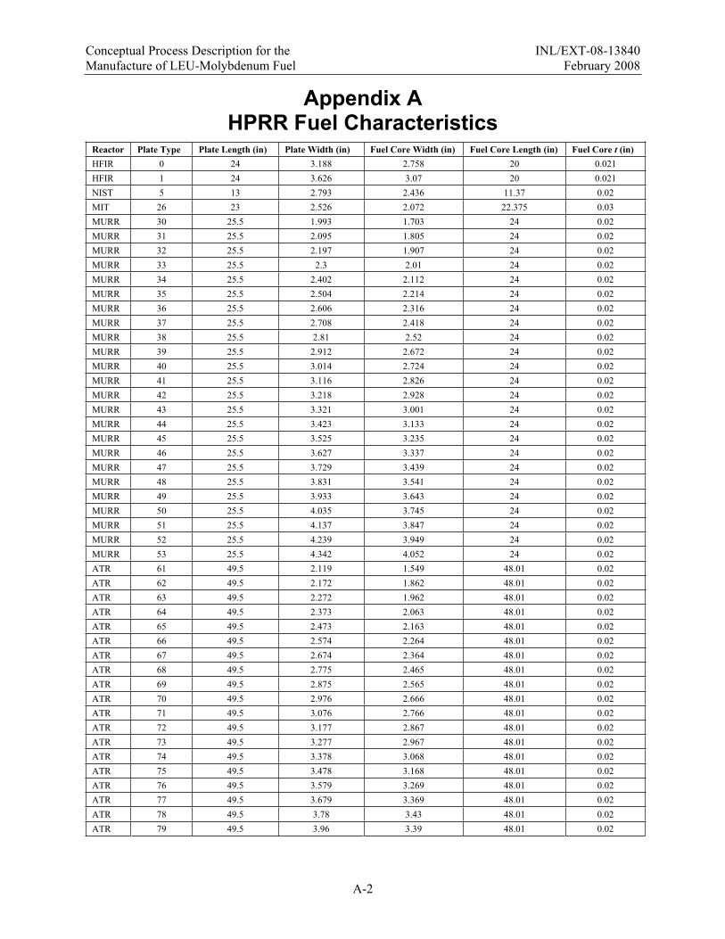
The National Nuclear Security Agency Global Threat Reduction Initiative (GTRI) is tasked with minimizing the use of high-enriched uranium (HEU) worldwide. A key component of that effort is the conversion of research reactors from HEU to low-enriched uranium (LEU) fuels. The GTRI Convert Fuel Development program, previously known as the Reduced Enrichment for Research and Test Reactors program was initiated in 1978 by the United States Department of Energy to develop the nuclear fuels necessary to enable these conversions. The program cooperates with the research reactors’ operators to achieve this goal of HEU to LEU conversion without reduction in reactor performance. The programmatic mandate is to complete the conversion of all civilian domestic research reactors by 2014. These reactors include the five domestic high-performance research reactors (HPRR), namely: the High Flux Isotope Reactor at the Oak Ridge National Laboratory, the Advanced Test Reactor at the Idaho National Laboratory, the National Bureau of Standards Reactor at the National Institute of Standards and Technology, the Missouri University Research Reactor at the University of Missouri–Columbia, and the MIT Reactor-II at the Massachusetts Institute of Technology. Characteristics for each of the HPRRs are given in Appendix A.
The GTRI Convert Fuel Development program is currently engaged in the development of a novel nuclear fuel that will enable these conversions. The fuel design is based on a monolithic fuel meat (made from a uranium-molybdenum alloy) clad in Al-6061 that has shown excellent performance in irradiation testing. The unique aspects of the fuel design, however, necessitate the development and implementation of new fabrication techniques and, thus, establishment of the infrastructure to ensure adequate fuel fabrication capability. A conceptual fabrication process description and rough estimates of the total facility throughput are described in this document as a basis for establishing preconceptual fabrication facility designs.

Conceptual Process Description for the INL/EXT-08-13840 Manufacture of LEU-Molybdenum Fuel February 2008
iv
Conceptual Process Description for the INL/EXT-08-13840 Manufacture of LEU-Molybdenum Fuel February 2008
v
CONTENTS
SUMMARY................................................................................................................................................. iii
ACRONYMS..............................................................................................................................................vii
1. INTRODUCTION.............................................................................................................................. 1
2. MONOLITHIC U-Mo FUEL REACTOR REQUIREMENTS.......................................................... 42.1 Estimated Annual HPRR LEU Demand .................................................................................. 4
2.1.1 Estimated Annual Element, Plate, and Monolithic Foil Demand ............................... 5
3. CONCEPTUAL MONOLITHIC U-Mo FUEL FABRICATION PROCESS................................... 73.1 U-Mo Alloy Source Material Development............................................................................. 73.2 U-Mo Foil Fabrication ............................................................................................................. 8
3.2.1 Foil Rolling Process .................................................................................................... 83.2.2 Additional Foil Profile Requirements ......................................................................... 83.2.3 Foil Storage Requirements.......................................................................................... 8
3.3 U-Mo Fuel Plate Fabrication.................................................................................................... 93.3.1 Machine Cladding Pockets.......................................................................................... 93.3.2 Diffusion Barrier Layer Application........................................................................... 93.3.3 Fuel Plate Assembly.................................................................................................... 93.3.4 Surface Finish Plates................................................................................................. 113.3.5 Straighten Plates........................................................................................................ 123.3.6 Final Shear Plates...................................................................................................... 123.3.7 Non-Standard Fuel Plate Surfacing........................................................................... 123.3.8 Store Fuel Plates........................................................................................................ 123.3.9 Form Fuel Plates ....................................................................................................... 123.3.10 Store Formed Fuel Plates .......................................................................................... 12
3.4 U-Mo Fuel Element Assembly............................................................................................... 12
4. INSPECTION REQUIREMENTS / QUALITY ASSURANCE ..................................................... 13
5. MONOLITHIC FUEL FABRICATION CAPABILITY PROCESS REQUIREMENTS AND INTERFACES ........................................................................................................................ 145.1 Process Requirements ............................................................................................................ 145.2 Building Requirements .......................................................................................................... 145.3 Monolithic Fuel Capacity Development Facility Interface Considerations.......................... 14
Appendix A. HPRR Fuel Characteristics.................................................................................................A-1
Appendix B. Estimate of Facility Footprint............................................................................................. B-1
FIGURESFigure 1. Comparison of Dispersion and Monolithic Fuel Types................................................................ 1
Figure 2. Fundamental Monolithic U-Mo Fuel Process Flow ..................................................................... 3

Conceptual Process Description for the INL/EXT-08-13840 Manufacture of LEU-Molybdenum Fuel February 2008
vi
TABLESTable 1. Densities of Typical LEU Alloys and Fuel Matrices ..................................................................... 2
Table 2. Approximate Current Annual U.S. HPRR HEU Demand ............................................................. 4
Table 3. Current Maximum Annual HPRR Dispersion HEU, Element, and Plate Requirements ............... 5
Table 4. Estimated Annual HPRR Monolithic Fuel Element, Plate, and Foil Requirements (based fabrication losses associated with these process steps) ................................................................ 6
Table 5. Estimated Annual U.S. HPRR LEU Demand ................................................................................ 6
Table 6. Potential HIP Process Production Rates ...................................................................................... 10
Table 7. Assumed Friction Bond Processing Parameters .......................................................................... 11
Table 8. Projected Annual Friction Bond Machine Time Requirements................................................... 11
Conceptual Process Description for the INL/EXT-08-13840 Manufacture of LEU-Molybdenum Fuel February 2008
vii
ACRONYMSATR Advanced Test Reactor
DOE Department of Energy
DOT Department of Transportation
DU depleted uranium
FB friction bonding
GTRI Global Threat Reduction Initiative
HEU high-enriched uranium
HFIR High Flux Research Reactor
HIP hot isostatic pressing
HPRR high-performance research reactors
INL Idaho National Laboratory
LEU low-enriched uranium
MIT Massachusetts Institute of Technology
MITR-II University of Missouri–Columbia, and the MIT Reactor-II
MURR Missouri University Research Reactor
NBSR National Bureau of Standards Reactor
NNSA National Nuclear Security Agency
NIST National Institute of Standards and Technology
NRC Nuclear Regulatory Commission
NU natural uranium
ORNL Oak Ridge National Laboratory
RERTR Reduced Enrichment for Research and Test Reactors
U.S. United States
UT ultrasonic testing

Conceptual Process Description for the INL/EXT-08-13840 Manufacture of LEU-Molybdenum Fuel February 2008
viii
Conceptual Process Description for the INL/EXT-08-13840 Manufacture of LEU-Molybdenum Fuel February 2008
1
Conceptual Process Description for the Manufacture of Low-Enriched Uranium-Molybdenum Fuel
1. INTRODUCTION The National Nuclear Security Agency (NNSA) Global Threat Reduction Initiative (GTRI) is tasked
with enabling the conversion of research reactors from high-enriched uranium (HEU) to low-enriched uranium (LEU) fuels. The GTRI Convert Fuel Development program, previously known as the Reduced Enrichment for Research and Test Reactors (RERTR) program, was initiated in 1978 by the United States (U.S.) Department of Energy (DOE) to develop the technical means for these conversions, including the development of new fuels. The program cooperates with the research reactors’ operators to achieve this goal of HEU to LEU conversion while maintaining reactor performance. The goal of the program is to complete the conversion of the civilian domestic research reactors by 2014. These reactors include the five domestic high-performance research reactors (HPRR, namely: the High Flux Isotope Reactor (HFIR) at the Oak Ridge National Laboratory (ORNL), the Advanced Test Reactor (ATR) at the Idaho National Laboratory (INL), the National Bureau of Standards Reactor (NBSR) at the National Institute of Standards and Technology (NIST), the Missouri University Research Reactor (MURR) at the University of Missouri–Columbia, and the MIT Reactor-II (MITR-II) at the Massachusetts Institute of Technology (MIT). Characteristics for each of the HPRRs are given in Appendix A.
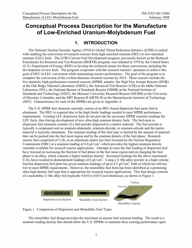
The U.S. HPRR fuel elements currently consist of an HEU-based dispersion fuel meat clad in aluminum. The HEU is required due to the high fissile loadings needed to meet HPRR performance requirements. Existing LEU dispersion fuels do not provide the necessary HPRR uranium loadings for LEU fuels, thus forcing development of new ultra-high uranium density fuels. The fuel meat in dispersion fuel elements consists of a fuel powder dispersed in a matrix material. The fuel powder is typically a compound such as uranium-aluminide, uranium-dioxide, or uranium-silicide and the matrix material is typically aluminum. The uranium loading of this fuel type is limited by the amount of material that can be packed into the fuel meat region and by the uranium density of the fuel phase. Research reactor fuel comprised of U3Si2 in an aluminum matrix has been licensed by the Nuclear Regulatory Commission (NRC) at a uranium loading of 4.8 gU/cm3, which provides the highest uranium density currently available for research reactor applications. Attempts to raise the fuel loading of dispersion fuel have focused on increasing the fraction of fuel phase in the fuel meat region and on changing the fuel phase to an alloy, which contains a higher uranium density. Increased loadings for the above mentioned U3Si2 have resulted in demonstrated loadings of 6 gU/cm3. Using a U-Mo alloy powder in a high-volume fraction dispersion fuel plate has given uranium loadings of up to 8.5 gU/cm3, both of which are still too low to meet HPRR requirements. However, the monolithic fuel form has been identified as a promising ultra-high density fuel type that is appropriate for research reactor applications. This fuel design consists of a monolithic U-Mo alloy foil (typically 0.010 to 0.015-inch thickness), as shown in Figure 1.
Dispersion Cross Section Monolithic Cross SectionMonolithic Cutaway
Cladding
Fuel Foil
Figure 1. Comparison of Dispersion and Monolithic Fuel Types
The monolithic fuel design provides the maximum in-reactor fuel uranium loading. The result is a uranium loading density that should allow the U.S. HPRRs to maintain their existing performance upon

Conceptual Process Description for the INL/EXT-08-13840 Manufacture of LEU-Molybdenum Fuel February 2008
2
conversion without major modifications. Table 1 summarizes the comparative densities achievable with various fuel alloys.
Table 1. Densities of Typical LEU Alloys and Fuel Matrices Fuel Matrix U Density (g-U/cm3)
U-Alx 2.3 U3O8 3.2
U-ZrHx 3.7 U3Si2 6
U-10Mo1 (dispersion) 8.5 U-10Mo1 (monolithic) 15.3
U 18.95 1. Compositions are given in weight %
The development, testing, and qualification of monolithic LEU fuel technologies is being aggressively pursued since the current goal of the program is to achieve full fuel qualification of the ‘base fuel design’ by the end of 2011 and of fuels incorporating burnable poison and graded fuel zones by 2012. Down selections of the interlayer design will be made in mid-2009, and down selection of the bonding process will be made after element testing in 2010. To accommodate this testing and the 2014 conversion deadline, the establishment of the necessary fuel fabrication capability must occur concurrently with the completion of the fuel qualification effort. This document serves to present a conceptual process definition for the manufacture of the monolithic LEU fuels and will be substantially elaborated upon as part of the final facility design process.
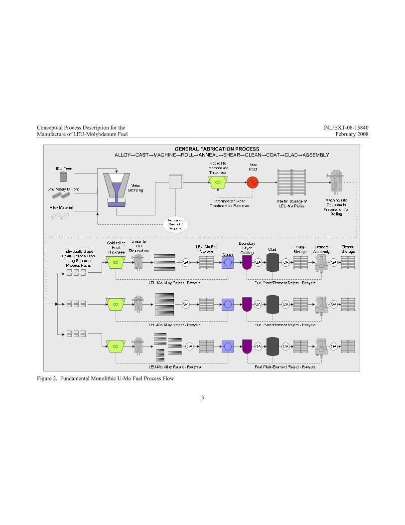
The initial step in the fabrication process requires development of an LEU-Mo alloy source material. Existing enriched uranium, which will continue to serve as the feedstock for the HPRR fuel, is primarily in the form of HEU metal. The HEU metal must be downblended with a diluent (low in wt% 235U—typically natural uranium [NU] or deleted uranium [DU]) and alloyed with molybdenum to generate LEU-Mo. While it is hoped that downblending and alloying can be accomplished in a single casting step, a second casting step may also be required to ensure a homogenous blend of the alloy. The LEU-Mo should be cast into a shape that maximizes both casting efficiency and subsequent foil production. The cast LEU-Mo shape will be roll-formed to achieve the required final fuel meat thickness, which may vary from reactor to reactor or may even vary within the reactor to obtain the desired flux profile. Upon achieving final thickness, the LEU-Mo foil will be sheared to obtain the final required fuel meat dimensions (length-width) while minimizing scrap. The next step in the fabrication process requires the application of a layer to control fuel/clad interaction on either the LEU-Mo foil or the fuel plate cladding. This layer consists of material added to the fuel-cladding interface to mitigate detrimental interactions between the U-Mo and the Al both during the fabrication processes and during reactor operation. The final step in the process includes bonding of the fuel plate aluminum cladding to the foil and finally to the reactor element assembly. This entire process will be discussed in detail in Section 3 of this document. A flow chart of the fabrication process is presented in Figure 2.
Conceptual Process Description for the INL/EXT-08-13840 Manufacture of LEU-Molybdenum Fuel February 2008
3
Figure 2. Fundamental Monolithic U-Mo Fuel Process Flow
Conceptual Process Description for the INL/EXT-08-13840 Manufacture of LEU-Molybdenum Fuel February 2008
4
2. MONOLITHIC U-Mo FUEL REACTOR REQUIREMENTS Domestic monolithic U-Mo fuel requirements are dominated by the five major U.S. high-performance
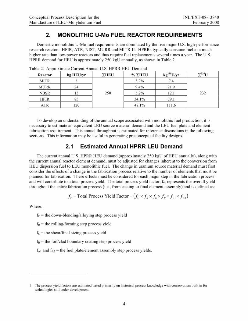
research reactors: HFIR, ATR, NIST, MURR and MITR-II. HPRRs typically consume fuel at a much higher rate than low-power reactors and thus require fuel replacements several times a year. The U.S. HPRR demand for HEU is approximately 250 kgU annually, as shown in Table 2.
Table 2. Approximate Current Annual U.S. HPRR HEU Demand Reactor kg HEU/yr HEU % HEU kg235U/yr 235UMITR 8 3.2% 7.4 MURR 24 9.4% 21.9 NBSR 13 5.2% 12.1 HFIR 85 34.1% 79.1 ATR 120
250
48.1% 111.6
232
To develop an understanding of the annual scope associated with monolithic fuel production, it is necessary to estimate an equivalent LEU source material demand and the LEU fuel plate and element fabrication requirement. This annual throughput is estimated for reference discussions in the following sections. This information may be useful in generating preconceptual facility designs.
2.1 Estimated Annual HPRR LEU Demand The current annual U.S. HPRR HEU demand (approximately 250 kgU of HEU annually), along with
the current annual reactor element demand, must be adjusted for changes inherent to the conversion from HEU dispersion fuel to LEU monolithic fuel. The change in uranium source material demand must first consider the effects of a change in the fabrication process relative to the number of elements that must be planned for fabrication. These effects must be considered for each major step in the fabrication process1
and will contribute to a total process yield. The total process yield factor, fy, represents the overall yield throughout the entire fabrication process (i.e., from casting to final element assembly) and is defined as:
21FactorYieldProcessTotal AABSRCY fffffff
Where:
fC = the down-blending/alloying step process yield
fR = the rolling/forming step process yield
fS = the shear/final sizing process yield
fB = the foil/clad boundary coating step process yield
fA1 and fA2 = the fuel plate/element assembly step process yields.
1 The process yield factors are estimated based primarily on historical process knowledge with conservatism built in for technologies still under development.
Conceptual Process Description for the INL/EXT-08-13840 Manufacture of LEU-Molybdenum Fuel February 2008
5
Very rough estimates of values for each of the individual process yields are given in the following:
Down-Blending/Alloying Process Step, fc = 0.91. The yield losses in the down-blending/alloying step result from typical casting losses to dross, oxide products, etc. The factor assumes an initial yield of 85% with a 50% recycle rate of casting scrap.
Rolling/Forming Process Step, fR = 0.90. The yield losses in the rolling/forming step result from material losses as a result of rolling material failures or unacceptable foil product during the 2-stage rolling process. The factor assumes an initial yield of 85% with a 50% recycle rate of fabrication scrap.
Shear/Final Sizing Process Step, fS = 0.93. The yield losses in the shear/final sizing step result from material losses from required final sizing steps and from rejections due to improper sizing. The factor assumes an initial yield of 90% with a 50% recycle rate of fabrication scrap.
Foil/Clad Boundary Coating Process Step, fB = 0.85. The yield losses in the foil/clad boundary coating step result from rejections due to unacceptable coating results. No recycle is assumed.
Fuel Plate Fabrication Process Step, fA1 = 0.9. The yield losses in the fuel plate/element fabrication step result from rejected plates and elements during final assembly. No recycle is assumed.
Fuel Element Fabrication Process Step, fA2 = 0.9. The yield losses in the fuel plate/element fabrication step result from rejected plates and elements during final assembly.
These factors result in an estimated total process yield of 0.56. In other words, of the net material allocated annually for LEU-10Mo, 56% will end up as fuel elements. It is important to note that the yield factors are currently based on engineering judgment and may change as the fabrication processes are further developed.
These factors must now be applied to the known annual reactor core requirements to estimate the required element, plate, and foil capacity to be planned. In addition to the above fabrication yield, the change in enrichment of the reactor fuel and its effect on the material requirements must also be evaluated.
2.1.1 Estimated Annual Element, Plate, and Monolithic Foil Demand
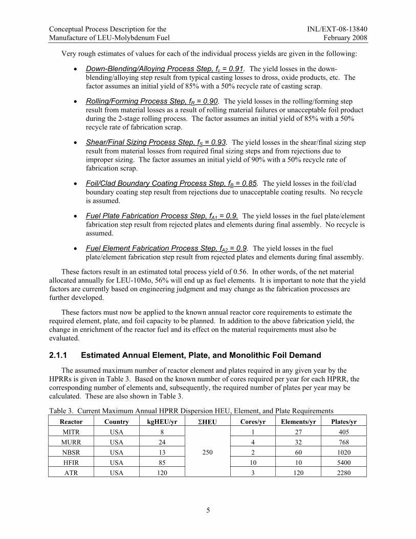
The assumed maximum number of reactor element and plates required in any given year by the HPRRs is given in Table 3. Based on the known number of cores required per year for each HPRR, the corresponding number of elements and, subsequently, the required number of plates per year may be calculated. These are also shown in Table 3.
Table 3. Current Maximum Annual HPRR Dispersion HEU, Element, and Plate Requirements Reactor Country kgHEU/yr HEU Cores/yr Elements/yr Plates/yr MITR USA 8 1 27 405 MURR USA 24 4 32 768 NBSR USA 13 2 60 1020 HFIR USA 85 10 10 5400 ATR USA 120
250
3 120 2280
Conceptual Process Description for the INL/EXT-08-13840 Manufacture of LEU-Molybdenum Fuel February 2008
6
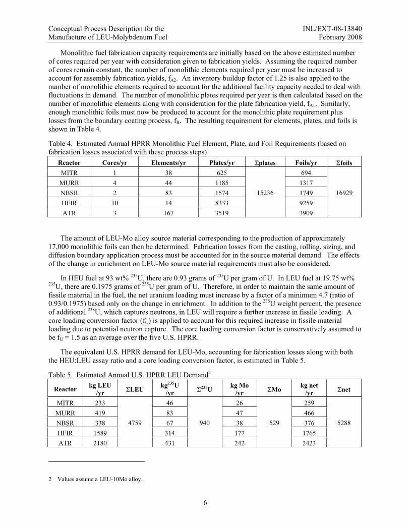
Monolithic fuel fabrication capacity requirements are initially based on the above estimated number of cores required per year with consideration given to fabrication yields. Assuming the required number of cores remain constant, the number of monolithic elements required per year must be increased to account for assembly fabrication yields, fA2. An inventory buildup factor of 1.25 is also applied to the number of monolithic elements required to account for the additional facility capacity needed to deal with fluctuations in demand. The number of monolithic plates required per year is then calculated based on the number of monolithic elements along with consideration for the plate fabrication yield, fA1. Similarly, enough monolithic foils must now be produced to account for the monolithic plate requirement plus losses from the boundary coating process, fB. The resulting requirement for elements, plates, and foils is shown in Table 4.
Table 4. Estimated Annual HPRR Monolithic Fuel Element, Plate, and Foil Requirements (based on fabrication losses associated with these process steps)
Reactor Cores/yr Elements/yr Plates/yr plates Foils/yr foilsMITR 1 38 625 694 MURR 4 44 1185 1317 NBSR 2 83 1574 1749 HFIR 10 14 8333 9259 ATR 3 167 3519
15236
3909
16929
The amount of LEU-Mo alloy source material corresponding to the production of approximately 17,000 monolithic foils can then be determined. Fabrication losses from the casting, rolling, sizing, and diffusion boundary application process must be accounted for in the source material demand. The effects of the change in enrichment on LEU-Mo source material requirements must also be considered.
In HEU fuel at 93 wt% 235U, there are 0.93 grams of 235U per gram of U. In LEU fuel at 19.75 wt% 235U, there are 0.1975 grams of 235U per gram of U. Therefore, in order to maintain the same amount of fissile material in the fuel, the net uranium loading must increase by a factor of a minimum 4.7 (ratio of 0.93/0.1975) based only on the change in enrichment. In addition to the 235U weight percent, the presence of additional 238U, which captures neutrons, in LEU will require a further increase in fissile loading. A core loading conversion factor (fU) is applied to account for this required increase in fissile material loading due to potential neutron capture. The core loading conversion factor is conservatively assumed to be fU = 1.5 as an average over the five U.S. HPRR.
The equivalent U.S. HPRR demand for LEU-Mo, accounting for fabrication losses along with both the HEU:LEU assay ratio and a core loading conversion factor, is estimated in Table 5.
Table 5. Estimated Annual U.S. HPRR LEU Demand2
Reactor kg LEU /yr LEU kg235U
/yr 235U kg Mo
/yr Mo kg net /yr net
MITR 233 46 26 259 MURR 419 83 47 466 NBSR 338 67 38 376 HFIR 1589 314 177 1765 ATR 2180
4759
431
940
242
529
2423
5288
2 Values assume a LEU-10Mo alloy.
Conceptual Process Description for the INL/EXT-08-13840 Manufacture of LEU-Molybdenum Fuel February 2008
7
3. CONCEPTUAL MONOLITHIC U-Mo FUEL FABRICATION PROCESS
3.1 U-Mo Alloy Source Material Development Blend-down and alloy of LEU-Mo source material will be required as essentially all the suitable
enriched uranium in the U.S. stockpile is high-purity HEU metal. Blend-down is accomplished via blending HEU with a low-assay diluent, typically either NU or DU. The uranium will also be alloyed with molybdenum during the blend-down process. The likely technology used in fabrication of the LEU-Mo alloy is casting. The stock pile for both the HEU and the low-assay diluent are primarily in metal form; therefore, solution blending or other comparable blending processes that require conversion from the metallic form are an added complication and likely not an appropriate step for a LEU metal alloy fuel as the final product. For example, if solution blending were used for blend-down, dissolution, mixing, precipitation (or dry process), and bomb reduction, steps would be required to produce a metal suitable for alloying with molybdenum metal.
During the casting process, the alloy constituents would be weighed and dispensed into melt crucibles. The melt crucibles will likely be graphite, coated to minimize reaction of the melt with the crucible walls. Introduction of carbon into the metal should also be minimized. A vacuum melting process will be used to heat the crucible in the melt blending step. Heating of the melt crucible by either induction or microwave energy are comparable technologies.3 Even though the U-10Mo alloy has a melting point of around 1200°C, obtaining the required homogeneous alloy with molybdenum is not a simple task because of the high melting point (2623°C) of the molybdenum constituent. A 50% re-melt frequency is assumed to obtain the required homogeneity. Based on a 30 kgU LEU-10Mo batch size, it is estimated that 265 casting operations would be required annually to support development of 5,288 kg net of LEU-10Mo. The number of casting operations should be minimized to maximize process efficiency and cost, and to limit the effects of multiple casting operations on detrimental elemental impurities. The final cast LEU-Mo shape (just prior to rolling) should be such as to maximize the casting efficiency (i.e., maximum batch size) while also optimizing the cast shape for the rolling and sizing fabrications steps downstream. After casting, the material would be sampled and the samples analyzed for isotopics, alloy composition, and elemental impurities. The LEU-10Mo alloy will ultimately be required to meet a standard material specification based on HPRR requirements and fabrication limitations. This material specification should be similar to current LEU specifications in the industry.
The recycle and waste stream generated in this process step includes clean scrap material (i.e., casting runners) as well as slag, used graphite melt crucibles, and furnace air filters. Economically recoverable LEU-10Mo should be recycled into the LEU-Mo product stream. Other waste, below economically recoverable quantities, would be disposed of as low-level radioactive waste. Other radioactive waste generated in this process would include room air filters, discarded personal protective clothing, and miscellaneous other waste generated within the regulated zone. All of this waste would require packaging and disposal as low-level radioactive material. The overall yield for the casting process is assumed to be 91% based on historical process experience (includes a recycle rate of 50%).
3 Plasma arc melting could be considered in the future, if the alloying and blending steps are separated, but this option was notselected as the reference process. The use of arc melting would minimize the carbon pickup during the process as the hearth material is typically copper. The disadvantages of arc melting are that the standard batch size is lower and it is difficult touse as a casting method where there is a large disparity between constituent melting points (U-Mo TMP = 1491K).

Conceptual Process Description for the INL/EXT-08-13840 Manufacture of LEU-Molybdenum Fuel February 2008
8
It is assumed that this process will be performed at the Y-12 National Security Complex and that ingots will be shipped to the foil fabrication process in a Department of Transportation (DOT)-certified transport container ready to be prepared for rolling.
3.2 U-Mo Foil Fabrication
3.2.1 Foil Rolling Process
Based on initial fuel development activities, rolling of cast LEU-10Mo is a feasible process for large-scale foil production. The foil rolling process is common to all HPRRs with the exception that different widths and thicknesses will likely be required for each reactor. Nominal foil thickness is considered to be 0.015 inches; however, some reactors may require foil thickness in the range of 0005 – 0.020 inches. The foil lengths required range from approximately 24 inches for MIT, MURR, HFIR, and NBSR (may be sheared into two equal length shorter foils) to 48 inches for the ATR and ATR-C. The maximum foil width required is that of HFIR and ATR at approximately 3.5 inches with the remaining reactors requiring foils at widths of around 2.8 inches.
The primary equipment requirements will be based on roll size (determined by roll separating forces), the starting LEU-10Mo ingot size, reduction per roll pass, and final foil size. The rolling process should be optimized based on the cast LEU-Mo ingot shape. Depending upon the thickness of the initial cast ingot, a two-phase rolling process will likely be required (i.e., hot-roll the ingot to an intermediate thickness with subsequent cold-rolling to the final foil thickness). If hot-rolling is required, heat treatment capabilities will be needed. Upon rolling to final thickness, foils will be sheared to external dimension specifications (length-width). Foil rolling development work suggests that an initial ingot thickness of 1 inch can be readily hot rolled to 0.090 inches. It has also been shown that the ingot can be encapsulated in a steel can for rolling, which allows greater flexibility during heating and reduces rolling mill ventilation requirements. The rolled ingot is then cut into smaller coupons that can be either cold or hot rolled to the final foil thickness depending on the desired microstructure or interlayer material.
The recycle and waste streams generated in this step are comparable to the blend-down step and will affect the infrastructure and operating costs. In the shearing process, the generation of significant quantities of clean scrap (trimmings) is inherent, and the scrap is usually recycled back into the melt batches. A 90% process yield is assumed for the entire rolling process (includes a 50% recycle rate). A process yield of 93% is assumed for the shearing process (includes a 50% recycle rate).
3.2.2 Additional Foil Profile Requirements
The surface profile for the MIT, MURR, NIST, ATR, and ATR-C are flat foils, while the HFIR requires foils contoured in the radial direction. A process for producing foils with the required contours has not been demonstrated to date. Several approaches have been conceptually considered, including shaping previously rolled foils (via a mechanical mass removal process) or rolling an assembly containing a shaped ingot and a matching blank (formed and assembled so as to form parallel outer surfaces). No methods have progressed beyond a proof-of-concept phase.
3.2.3 Foil Storage Requirements
Intermediate storage of the foils is required in preparation for downstream operations. Intermediate foil storage may require that exposed foils be stored under vacuum or under high purity inert cover gas.

Conceptual Process Description for the INL/EXT-08-13840 Manufacture of LEU-Molybdenum Fuel February 2008
9
3.3 U-Mo Fuel Plate Fabrication
3.3.1 Machine Cladding Pockets
Each foil will be sealed in two-piece aluminum cladding to make fuel plates for each individual HPRR element. Hot isostatic pressing (HIP) and Friction bonding (FB) bonding processes are both under development for monolithic plate fabrication. The current processing techniques require that both of these processes machine the aluminum cladding (Al-6061) prior to bonding to accommodate a monolithic foil fuel foil already fabricated to final dimensions. A pocket will be machined in the cladding (1 piece) to the dimensions of the monolithic foil. Each reactor fuel type will require unique cladding hardware (regarding size, finishing, etc.), but the infrastructure required to supply it is not unique. The supply of the machined aluminum hardware could be from an external machine shop, in which case a controlled storage area would be the only requirement. A supply of roughly 17,000 each of pocketed and flat aluminum plates per year is required. There should be adequate storage space available to accommodate a year’s supply of hardware for each reactor type since the hardware will likely need to be supplied and used in core size batches. The cladding hardware will be slightly oversized compared to the final fuel plate dimensions (the amount of oversizing required is dependent on the fuel plate assembly process discussed in Section 3.3.3).
3.3.2 Diffusion Barrier Layer Application
It is assumed that the fuel will require the application of an interlayer between the fuel matrix and cladding to achieve the desired in-pile performance. Two types of interlayers are currently being evaluated by the GTRI Convert Fuel Development program, but it is anticipated that a single approach will ultimately be selected for use in all fuel systems.
The first type of interlayer is a zirconium diffusion barrier, which would be applied directly to the foil. The fuel plates used thus far to demonstrate fuel performance were fabricated by hot co-rolling the U-Mo in a steel can with a thin layer of zirconium on the top and bottom of the coupon. The can was coated with yittria to prevent sticking. This technique could potentially be applied at the ingot rolling stage, leading to the supply of large sheets of partially rolled zirconium clad coupons. Alternate diffusion barrier application techniques are also being explored, including physical vapor deposition/chemical vapor deposition and HIP. HIP at temperatures relevant to clad-fuel bonding were found insufficient to bond the interlayer to the fuel, which precludes the coincident bonding of clad-interlayer-fuel system.
The second interlayer type is formed by the application of an aluminum-silicon alloy to the region of the cladding that comes into contact with the fuel foil. Only a very thin layer (on the order of 0.001 inch) is required. The layer may be applied in many ways but has been successfully applied by thermal spray techniques and by the insertion of a high silicon aluminum alloy foil in between the clad and fuel prior to bonding. Approximately 35,000 pieces of hardware would need to be prepared per year. The thermal spray technique has been most readily used during performance demonstrations. However, at this point it appears that the shelf life of the thermal sprayed hardware is very short (approximately one week under rough vacuum) and a just-in-time supply approach would be desirable. A single automated thermal spray booth (~20 ft × 40 ft) with regularly interchanged and rebuilt spray heads should be adequate for this purpose.
3.3.3 Fuel Plate Assembly
Two approaches to final fuel plate assembly are currently under development: HIP and FB. Because the final process selection has not been made, the fuel fabrication facility should be designed such that it can accommodate either manufacturing process (but not both).

Conceptual Process Description for the INL/EXT-08-13840 Manufacture of LEU-Molybdenum Fuel February 2008
10
3.3.3.1 HIP Bonding
The HIP process is a common industrial manufacturing method used for powder metallurgy. This process subjects a working piece to both elevated temperature and isostatic gas pressure in a high-pressure containment vessel for consolidation and/or to induce bonding.
Fuel plates will need to be individually pre-assembled (foil plus two-piece aluminum cladding) prior to insertion in the HIP. Each plate must be assembled to ensure that the fuel is properly located within the cladding pocket. Each fuel plate will then be hermetically sealed by electron beam welding or loaded into a HIP can to ensure proper bonding. The aluminum cladding used in the HIP process is oversized both to allow the portion used to pre-assemble the plates (in the case of e-beam welding) to be removed from the plate and to allow the fabricator some freedom in locating the fuel zone in the final plate. Typical process parameters are 15,000 psi at 560 C for at least 90 minutes (longer times have also been examined).
Hot isostatic pressing is a batch process. Production throughput is a function of the process (heat up, dwell, and cool down) time and the number of plates that can be located inside the chamber4. The HIP process is not sensitive to the distribution of plate types, just the number of plates to be run and maximum plate size, which is a driver for the HIP hot zone dimensions. A standard lot size of 40 plates and 200 HIP cycles per year is required to produce 8000 plates per year. To produce the number of plates estimated in Table 4, two dedicated HIPs would be required based on this assumption. Increasing the batch size or the number of cycles per year are alternatives.
Table 6. Potential HIP Process Production Rates HIP Batch Size
(plates) HIP Thermal Cycles
(per yr) Plate Production Rate
(per yr) 40 200 8000 60 200 12000 80 200 16000 40 400 16000 60 300 18000
3.3.3.2 Friction Bonding
Friction bonding is a process whereby the fuel plate assembly (foil plus two-piece aluminum cladding) is joined together by the force of a rotating pin plastically deforming the material to bond the aluminum cladding, thereby forming a hermetic seal. This process must be performed over both surfaces of the plate so as to bond the entire area that will comprise the final fuel plate.
Fuel plates will need to be individually pre-assembled on the FB machine prior to processing. The assembly must be done so as to ensure that the fuel is properly located within the cladding pocket. The aluminum cladding used to fabricate FB plates needs to be oversized such that the material may be rigidly clamped throughout the process.
A number of assumptions are required to estimate a potential throughput through the bonding process. In FB, it is assumed that each plate is bonded individually (although this potentially may be expanded so that more than one plate would be placed on the machine at a time). These assumptions include primarily weld speeds, setup times, amount of welding overlap, etc. The basic parameter list and definitions are
4 Criticality limits will be a restricting factor.

Conceptual Process Description for the INL/EXT-08-13840 Manufacture of LEU-Molybdenum Fuel February 2008
11
shown in Table 7. Note that these parameters are based on developmental fabrication efforts and should not be considered final.
Table 7. Assumed Friction Bond Processing Parameters Parameter (units) Value Definition
Setup Time - Initial Pass (min) 10 Time to put individual fuel plate in tooling and perform necessary checks.
Jog Step Time (min) 0.02 Time for machine to jog over to the next adjacent weld pass.
Plate Length Over Weld (in) 0.5 Additional weld on each end beyond nominal plate length, which is sheared off in plate finishing operations.
Plate Width Over Weld (in) 0.38 Same as above, but for plate width. Setup Time - Second Pass (min) 5 Flip plate over and reinstall into tooling.
Linear Weld Speed (in/min) 40 Developmental welding speed. Weld Width (in) 0.38 Diameter of FSW tool that penetrates into the plate.
An estimate on the number of FB machines required can be developed by considering the required number of plate throughput per year (approximately 17,000) and subsequent required weld time shown in Table 8. The weld time is based on the individual plate surface area and the parameters listed in Table 7.
Table 8. Projected Annual Friction Bond Machine Time Requirements
Reactor Average
Plate Width (in)
PlateLength
(in)
Single Side Weld Time
(min)
PlateFabrication
Time(min)
Plates Required (per yr)
FrictionBond
Machine Hours
Required
FBHours
MIT 2.526 23 5.42 25.83 694 299 MURR 3.168 25.5 7.13 29.26 1317 642 NBSR 2.793 13 3.50 21.99 1749 641 HFIR 3.188 24 6.77 28.55 2932 1395 HFIR 3.626 24 7.53 30.05 6327 3169 ATR 2.983 49.5 12.77 40.53 3909 2641
8788
It is assumed that a single FB machine can provide 2,000 hours of plate fabrication time per year. Therefore, five machines would be required to provide the necessary fabrication capacity based on a single plate throughput. Note that this estimate is likely conservative as efficiencies may be gained in performing FB on multiple plates in a single operation. Although FB of fuel plates for performance testing is performed on a ‘manual control’ machine, the process is expected to be transferred to a computer numerical control machine in the near future.
3.3.4 Surface Finish Plates
Fuel plates emerging from the fabrication processing (HIP or FB) will need to be finished both to obtain the required surface finish (as determined by the individual reactors) and to obtain the required thickness since, unlike roll bonding of dispersion fuel plates, the fabrication methods used to manufacture monolithic plates have shown a tendency to have out-of-tolerance variation of the thickness across the surface of the plate.

Conceptual Process Description for the INL/EXT-08-13840 Manufacture of LEU-Molybdenum Fuel February 2008
12
The finishing steps required will be determined by the previous processing steps. If the location of the fuel foil can be accurately determined (relative to the cladding surface), then a mass removal step may be undertaken. Mass removal may be done manually (sandpaper, ScotchBrite, or similar) or mechanically (milling, planning, etc.).
3.3.5 Straighten Plates
The monolithic fuel type, due to its solid alloy core, has proven to be less compliant than dispersion fuel. It has been shown that the flatness of the U-Mo foil prior to fabrication has a large effect on the ability to flatten the final plate. Full-size plates fabricated by the FB process have been flattened by manual manipulation (i.e., the plates coming out of the FB process are visibly warped, but removal of the perimeter material that was not processed results in a plate with minimal warping). Full-size monolithic HIP plates have yet to be fabricated. It is possible that plates coming from either process could be flattened by the roller leveling process or that warpage will be eliminated once the plate is swaged into the element box.
3.3.6 Final Shear Plates
There should be no significant impact on fuel plate shearing when switching from the current HEU process to the proposed LEU process. Plates may be sheared to final dimensions on a standard shear used for processing aluminum sheet.
3.3.7 Non-Standard Fuel Plate Surfacing
The MIT reactor fuel plate design calls for thin grooves to be machined in each face of the plate. There should be no significant impact on this processing step when switching from the current HEU process to the proposed LEU process.
3.3.8 Store Fuel Plates
There should be no significant impact on fuel plate storage when switching from the current HEU process to the proposed LEU process. Fuel plates will still need to be staged in preparation for element assembly.
3.3.9 Form Fuel Plates
It is anticipated that, due to the higher yield strength of the solid U-Mo core relative to aluminum, a monolithic fuel plate will require a greater deformation than an equivalent dispersion fuel plate to achieve a given bend radius in a fuel plate. It is speculated that this change in processing could be achieved by a change in bend tooling geometry.
3.3.10 Store Formed Fuel Plates
The long-term dimensional stability of formed monolithic fuel plates is unknown; however, it is speculated that the solid core will tend to flatten the plate over time. As such, it may be a requirement that once fuel plates are formed they must be installed in a subassembly within a certain time frame. Alternatively, constrained storage may be employed to maintain the required plate radius.
3.4 U-Mo Fuel Element Assembly There should be no significant impact on element assembly and fabrication processes when switching
from the current HEU process to the proposed LEU process. Individual monolithic U-Mo fuel plates will

Conceptual Process Description for the INL/EXT-08-13840 Manufacture of LEU-Molybdenum Fuel February 2008
13
be stiffer than current dispersion fuel plates, and there may be secondary mechanical effects for curved plates and swaging into side plates. Minor changes in tooling should accommodate any effects.
4. INSPECTION REQUIREMENTS / QUALITY ASSURANCE Non-destructive examination of bonded fuel plates is an area that requires further investigation. It is
unknown if current equipment has the capability to resolve bond defects on either side of the U-Mo fuel. Ultrasonic testing (UT) inspections, which have been one of the standard methods to nondestructively analyze dispersion fuel, will require additional development effort.
Fuel homogeneity within each plate will be determined by the U-Mo foil homogeneity, which in turn is determined by melting practice and rolling imperfections (i.e., ripples). X-ray examination of fuel plates will readily locate the fuel bearing region. Fuel inhomogeneities introduced from plate integration mishaps (e.g., folded foil corners or torn foils) can be readily observed with current equipment.
The following inspections will be required at each process step:
1. Uranium Blend-down. Uranium metal will be required to meet an impurity specification comparable to existing specifications.
2. LEU Alloying with Molybdenum. The alloyed uranium metal will also be required to meet a trace element specification, as described in the step above.
3. Rolling Operations for Foil. Inspection of finished foils would consist of dimensional and surface inspection covering 100% of the foil surface and destructive metallographic examination of samples for grain structure and micro-structural phases. The weight of each finished foil will be measured and recorded for accountability. Engineering drawings and specifications will have to be developed for the fuel foils.
4. Foil Preparation for Assembly. Dimensional inspection of each completed foil should be capable of a resolution of 12 μm (~0.0005 inches) and weighing to ~0.010 g. The foil surfaces should be free of scratches and gouges of some specified depth and length. Standards for surface defects will be required.
5. Aluminum Clad Preparation. Dimensional inspection of the finished hardware can be performed using conventional measuring tools. Inspection for surface defects can be done visually.
6. Fuel Plate Assembly. The process for nondestructive inspection of the finished fuel plates will be the same as currently used for HEU dispersion fuel plates. This inspection includes a real-time x-ray system for end and edge cladding determinations and UT for blister and nonbonded areas using a water-coupled ultrasonic detection system. Manual inspection of the finished fuel plates will include visual inspection for surface defects and dimensional inspection of the finished plates. Destructive examination of sample plates will be required to evaluate the bonding.
Conceptual Process Description for the INL/EXT-08-13840 Manufacture of LEU-Molybdenum Fuel February 2008
14
5. MONOLITHIC FUEL FABRICATION CAPABILITY PROCESS REQUIREMENTS AND INTERFACES
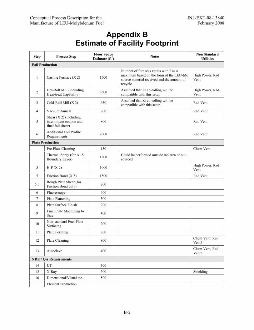
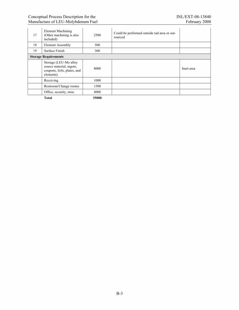
5.1 Process Requirements The process steps required to fabricate monolithic fuel as outlined above are show in Appendix B.
Estimates are given as to the space requirements for this installation.
5.2 Building Requirements The facility will need to be constructed to be in compliance with applicable codes (seismic, static
loading, etc.) for the material to be processed. In addition, the security arrangements would need to apply for the radiological category of the facility.
The nature of the facility will dictate the required utilities. Electrical power requirements are not stated here but will largely be dictated by the individual items of process equipment. Specific items of equipment (e.g., a vacuum induction melting furnace) may have specific voltage or current requirements that are not typically installed in an industrial environment. In addition, the radioactive nature of the process material will dictate ventilation systems on various items of equipment. Ventilation to protect personnel from chemical and radiological hazards will also be required for some processing steps.
5.3 Monolithic Fuel Capacity Development Facility Interface Considerations
The process requirements are presented based on overall capacity. It should be noted that options exist in which the required fabrication capabilities exist in separate facilities. Due to logistical considerations (including security and transportation issues) and process efficiencies (including minimizing process steps such as casting operations), it may prove advantageous that foil fabrication capabilities and subsequent plate/element fabrication capabilities be located at different sites. If separate fuel foil and plate/element fabrication sites are selected, packaging and transportation of the fabricated foils from the foil fabrication facility to the fuel plate and element fabrication facility would be required. To accommodate this, the foil fabrication facility would require a storage and staging area for finished foils of various sizes. A staging area would also be required for the plate and element assembly building. It is anticipated that approximately 17,000 fuel foils would need to be shipped per year if separate facilities for foil and plate/element fabrication are utilized.
Also, it should be noted that there will be a period of transition where the capabilities will be required at the existing dispersion fabrication facility to fabricate both the existing HEU dispersion fuel and monolithic LEU-Mo fuel.

Conceptual Process Description for the INL/EXT-08-13840 Manufacture of LEU-Molybdenum Fuel February 2008
A-1
Appendix A
HPRR Fuel Characteristics
Conceptual Process Description for the INL/EXT-08-13840 Manufacture of LEU-Molybdenum Fuel February 2008
A-2
Appendix A HPRR Fuel Characteristics
Reactor Plate Type Plate Length (in) Plate Width (in) Fuel Core Width (in) Fuel Core Length (in) Fuel Core t (in) HFIR 0 24 3.188 2.758 20 0.021 HFIR 1 24 3.626 3.07 20 0.021 NIST 5 13 2.793 2.436 11.37 0.02 MIT 26 23 2.526 2.072 22.375 0.03 MURR 30 25.5 1.993 1.703 24 0.02 MURR 31 25.5 2.095 1.805 24 0.02 MURR 32 25.5 2.197 1.907 24 0.02 MURR 33 25.5 2.3 2.01 24 0.02 MURR 34 25.5 2.402 2.112 24 0.02 MURR 35 25.5 2.504 2.214 24 0.02 MURR 36 25.5 2.606 2.316 24 0.02 MURR 37 25.5 2.708 2.418 24 0.02 MURR 38 25.5 2.81 2.52 24 0.02 MURR 39 25.5 2.912 2.672 24 0.02 MURR 40 25.5 3.014 2.724 24 0.02 MURR 41 25.5 3.116 2.826 24 0.02 MURR 42 25.5 3.218 2.928 24 0.02 MURR 43 25.5 3.321 3.001 24 0.02 MURR 44 25.5 3.423 3.133 24 0.02 MURR 45 25.5 3.525 3.235 24 0.02 MURR 46 25.5 3.627 3.337 24 0.02 MURR 47 25.5 3.729 3.439 24 0.02 MURR 48 25.5 3.831 3.541 24 0.02 MURR 49 25.5 3.933 3.643 24 0.02 MURR 50 25.5 4.035 3.745 24 0.02 MURR 51 25.5 4.137 3.847 24 0.02 MURR 52 25.5 4.239 3.949 24 0.02 MURR 53 25.5 4.342 4.052 24 0.02 ATR 61 49.5 2.119 1.549 48.01 0.02 ATR 62 49.5 2.172 1.862 48.01 0.02 ATR 63 49.5 2.272 1.962 48.01 0.02 ATR 64 49.5 2.373 2.063 48.01 0.02 ATR 65 49.5 2.473 2.163 48.01 0.02 ATR 66 49.5 2.574 2.264 48.01 0.02 ATR 67 49.5 2.674 2.364 48.01 0.02 ATR 68 49.5 2.775 2.465 48.01 0.02 ATR 69 49.5 2.875 2.565 48.01 0.02 ATR 70 49.5 2.976 2.666 48.01 0.02 ATR 71 49.5 3.076 2.766 48.01 0.02 ATR 72 49.5 3.177 2.867 48.01 0.02 ATR 73 49.5 3.277 2.967 48.01 0.02 ATR 74 49.5 3.378 3.068 48.01 0.02 ATR 75 49.5 3.478 3.168 48.01 0.02 ATR 76 49.5 3.579 3.269 48.01 0.02 ATR 77 49.5 3.679 3.369 48.01 0.02 ATR 78 49.5 3.78 3.43 48.01 0.02 ATR 79 49.5 3.96 3.39 48.01 0.02
Conceptual Process Description for the INL/EXT-08-13840 Manufacture of LEU-Molybdenum Fuel February 2008
B-1
Appendix B
Estimate of Facility Footprint
Conceptual Process Description for the INL/EXT-08-13840 Manufacture of LEU-Molybdenum Fuel February 2008
B-2
Appendix B Estimate of Facility Footprint
Step Process Step Floor Space Estimate (ft2) Notes Non Standard
Utilities Foil Production
1 Casting Furnace (X 2) 1500
Number of furnaces varies with 2 as a maximum based on the form of the LEU-Mo source material received and the amount of recycle.
High Power, Rad Vent
2 Hot-Roll Mill (including Heat-treat Capability) 3600 Assumed that Zr co-rolling will be
compatible with this setup High Power, Rad Vent
3 Cold-Roll Mill (X 3) 650 Assumed that Zr co-rolling will be compatible with this setup Rad Vent
4 Vacuum Anneal 200 Rad Vent
5Shear (X 2) (including intermittent coupon and final foil shear)
800 Rad Vent
6 Additional Foil Profile Requirements 2000 Rad Vent
Plate Production Pre-Plate Cleaning 150 Chem Vent
Thermal Spray (for Al-Si Boundary Layer) 1200 Could be performed outside rad area or out-
sourced
5 HIP (X 2) 1000 High Power, Rad Vent
5 Friction Bond (X 5) 1500 Rad Vent
5.5 Rough Plate Shear (for Friction Bond only) 200
6 Fluoroscope 400
7 Plate Flattening 500
8 Plate Surface Finish 200
9 Final Plate Machining to Size 400
10 Non-standard Fuel Plate Surfacing 200
11 Plate Forming 200
12 Plate Cleaning 800 Chem Vent, Rad Vent?
13 Autoclave 400 Chem Vent, Rad Vent?
NDE / QA Requirements14 UT 300
15 X-Ray 500 Shielding
16 Dimensional/Visual etc. 500
Element Production
Conceptual Process Description for the INL/EXT-08-13840 Manufacture of LEU-Molybdenum Fuel February 2008
B-3
17Element Machining (Other machining is also included)
2500 Could be performed outside rad area or out-sourced
18 Element Assembly 500
19 Surface Finish 300
Storage RequirementsStorage (LEU-Mo alloy source material, ingots, coupons, foils, plates, and elements)
8000 Inert area
Receiving 1000
Restroom/Change rooms 1500
Office, security, misc 4000
Total 35000
Copyright © 2022 FDOKUMEN