Domain Models - Finding conceptual classes and description ...
26
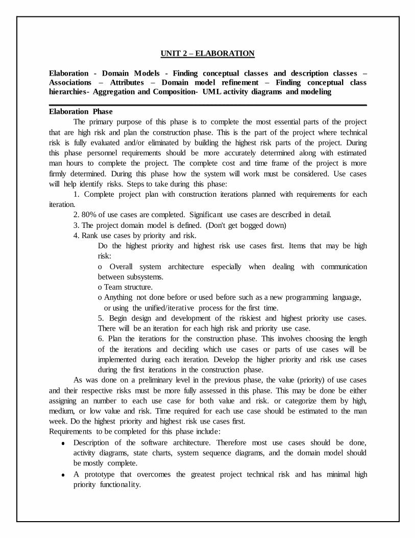
UNIT 2 – ELABORATION Elaboration - Domain Models - Finding conceptual classes and description classes – Associations – Attributes – Domain model refinement – Finding conceptual class hierarchies- Aggregation and Composition- UML activity diagrams and modeling ______________________________________________________________________________ Elaboration Phase The primary purpose of this phase is to complete the most essential parts of the project that are high risk and plan the construction phase. This is the part of the project where technical risk is fully evaluated and/or eliminated by building the highest risk parts of the project. During this phase personnel requirements should be more accurately determined along with estimated man hours to complete the project. The complete cost and time frame of the project is more firmly determined. During this phase how the system will work must be considered. Use cases will help identify risks. Steps to take during this phase: 1. Complete project plan with construction iterations planned with requirements for each iteration. 2. 80% of use cases are completed. Significant use cases are described in detail. 3. The project domain model is defined. (Don't get bogged down) 4. Rank use cases by priority and risk. Do the highest priority and highest risk use cases first. Items that may be high risk: o Overall system architecture especially when dealing with communication between subsystems. o Team structure. o Anything not done before or used before such as a new programming language, or using the unified/iterative process for the first time. 5. Begin design and development of the riskiest and highest priority use cases. There will be an iteration for each high risk and priority use case. 6. Plan the iterations for the construction phase. This involves choosing the length of the iterations and deciding which use cases or parts of use cases will be implemented during each iteration. Develop the higher priority and risk use cases during the first iterations in the construction phase. As was done on a preliminary level in the previous phase, the value (priority) of use cases and their respective risks must be more fully assessed in this phase. This may be done be either assigning an number to each use case for both value and risk. or categorize them by high, medium, or low value and risk. Time required for each use case should be estimated to the man week. Do the highest priority and highest risk use cases first. Requirements to be completed for this phase include: Description of the software architecture. Therefore most use cases should be done, activity diagrams, state charts, system sequence diagrams, and the domain model should be mostly complete. A prototype that overcomes the greatest project technical risk and has minimal high priority functionality.
-
Upload
khangminh22 -
Category
Documents
-
view
1 -
download
0
Transcript of Domain Models - Finding conceptual classes and description ...
UNIT 2 – ELABORATION
Elaboration - Domain Models - Finding conceptual classes and description classes –
Associations – Attributes – Domain model refinement – Finding conceptual class
hierarchies- Aggregation and Composition- UML activity diagrams and modeling
______________________________________________________________________________
Elaboration Phase
The primary purpose of this phase is to complete the most essential parts of the project
that are high risk and plan the construction phase. This is the part of the project where technical
risk is fully evaluated and/or eliminated by building the highest risk parts of the project. During
this phase personnel requirements should be more accurately determined along with estimated
man hours to complete the project. The complete cost and time frame of the project is more
firmly determined. During this phase how the system will work must be considered. Use cases
will help identify risks. Steps to take during this phase:
1. Complete project plan with construction iterations planned with requirements for each
iteration.
2. 80% of use cases are completed. Significant use cases are described in detail.
3. The project domain model is defined. (Don't get bogged down)
4. Rank use cases by priority and risk.
Do the highest priority and highest risk use cases first. Items that may be high
risk:
o Overall system architecture especially when dealing with communication
between subsystems.
o Team structure.
o Anything not done before or used before such as a new programming language,
or using the unified/iterative process for the first time.
5. Begin design and development of the riskiest and highest priority use cases.
There will be an iteration for each high risk and priority use case.
6. Plan the iterations for the construction phase. This involves choosing the length
of the iterations and deciding which use cases or parts of use cases will be
implemented during each iteration. Develop the higher priority and risk use cases
during the first iterations in the construction phase.
As was done on a preliminary level in the previous phase, the value (priority) of use cases
and their respective risks must be more fully assessed in this phase. This may be done be either
assigning an number to each use case for both value and risk. or categorize them by high,
medium, or low value and risk. Time required for each use case should be estimated to the man
week. Do the highest priority and highest risk use cases first.
Requirements to be completed for this phase include:
Description of the software architecture. Therefore most use cases should be done,
activity diagrams, state charts, system sequence diagrams, and the domain model should
be mostly complete.
A prototype that overcomes the greatest project technical risk and has minimal high
priority functionality.
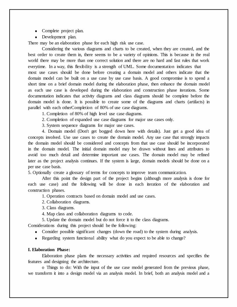
Complete project plan.
Development plan.
There may be an elaboration phase for each high risk use case.
Considering the various diagrams and charts to be created, when they are created, and the
best order to create them in, there seems to be a variety of opinions. This is because in the real
world there may be more than one correct solution and there are no hard and fast rules that work
everytime. In a way, this flexibility is a strength of UML. Some documentation indicates that
most use cases should be done before creating a domain model and others indicate that the
domain model can be built on a use case by use case basis. A good compromise is to spend a
short time on a brief domain model during the elaboration phase, then enhance the domain model
as each use case is developed during the elaboration and construction phase iterations. Some
documentation indicates that activity diagrams and class diagrams should be complete before the
domain model is done. It is possible to create some of the diagrams and charts (artifacts) in
parallel with each otherCompletion of 80% of use case diagrams.
1. Completion of 80% of high level use case diagrams.
2. Completion of expanded use case diagrams for major use cases only.
3. System sequence diagrams for major use cases.
4. Domain model (Don't get bogged down here with details). Just get a good idea of
concepts involved. Use use cases to create the domain model. Any use case that strongly impacts
the domain model should be considered and concepts from that use case should be incorporated
in the domain model. The initial domain model may be drawn without lines and attributes to
avoid too much detail and determine important use cases. The domain model may be refined
later as the project analysis continues. If the system is large, domain models should be done on a
per use case basis.
5. Optionally create a glossary of terms for concepts to improve team communication.
After this point the design part of the project begins (although more analysis is done for
each use case) and the following will be done in each iteration of the elaboration and
construction phases.
1. Operation contracts based on domain model and use cases.
2. Collaboration diagrams.
3. Class diagrams.
4. Map class and collaboration diagrams to code.
5. Update the domain model but do not force it to the class diagrams.
Considerations during this project should be the following:
Consider possible significant changes (down the road) to the system during analysis.
Regarding system functional ability what do you expect to be able to change?
I. Elaboration Phase:
Elaboration phase plans the necessary activities and required resources and specifies the
features and designing the architecture.
o Things to do: With the input of the use case model generated from the previous phase,
we transform it into a design model via an analysis model. In brief, both an analysis model and a
design model are structures made up of classifiers and a set of use-case realizations that describe
how this structure realizes the use cases. Classifiers are, in general, "class-like" things.
The analysis model is a detailed specification of the requirements and works as a first cut
at a design model, although it is a model of its own. It is used by developers to understand
precisely the use cases as described in the requirements. The analysis model is different from the
design model in that it is a conceptual model rather than a blueprint of the implementation.
Class Diagrams
Sequence Diagrams
Collaboration Diagrams
Exit Criteria:
A detailed software development plan, containing:
An updated risk assessment,
A management plan,
A staffing plan,
A phase plan showing the number and contents of the iteration
An iterative plan, detailing the next iteration
The development environment and other tools required
A test plan
A baseline vision, in the form of a set of evalution criteria for the final product
Objective, measurable evalution criteria for assessing the results of the initial
iterations of the construction phase
A domain analysis model (80% complete), sufficient to be able to call the
corresponding architecture 'complete'.
A software architecture description (stating constraints and limitations)
An executable architectural baseline.
Glossary:
baseline: a release that is subject to change management and configuration control.
stereotype: an extension of the vocabulary of the UML, allowing you to create new
kinds of building blocks that are derived from existing ones but that are specific to your
particular problem.
Elaboration Phase
During the Elaboration phase the project team is expected to capture a healthy majority of
the system requirements. However, the primary goals of Elaboration are to address known risk
factors and to establish and validate the system architecture. Common processes undertaken in
this phase include the creation of use case diagrams, conceptual diagrams (class diagrams with
only basic notation) and package diagrams (architectural diagrams).
The architecture is validated primarily through the implementation of an Executable
Architecture Baseline. This is a partial implementation of the system which includes the core,
most architecturally significant, components. It is built in a series of small, time boxed iterations.
By the end of the Elaboration phase the system architecture must have stabilized and the
executable architecture baseline must demonstrate that the architecture will support the key
system functionality and exhibit the right behavior in terms of performance, scalability and cost.
The final Elaboration phase deliverable is a plan (including cost and schedule estimates) for the
Construction phase. At this point the plan should be accurate and credible, since it should be
based on the Elaboration phase experience and since significant risk factors should have been
addressed during the Elaboration phase.
The Lifecycle Architecture Milestone marks the end of the Elaboration phase.
Domain Model
A domain model, or Domain Object Model (DOM) in problem solving and software
engineering can be thought of as a conceptual model of a domain of interest (often referred to as
a problem domain) which describes the various entities, their attributes and relationships, plus
the constraints that govern the integrity of the model elements comprising that problem domain.
Overview
The domain model is created in order to represent the vocabulary and key concepts of the
problem domain. The domain model also identifies the relationships among all the entities within
the scope of the problem domain, and commonly identifies their attributes. A domain model that
encapsulates methods within the entities is more properly associated with object oriented models.
The domain model provides a structural view of the domain that can be complemented by other
dynamic views, such as Use Case models.
An important benefit of a domain model is that it describes and constrains the scope of
the problem domain. The domain model can be effectively used to verify and validate the
understanding of the problem domain among various stakeholders. It is especially helpful as a
communication tool and a focusing point both amongst the different members of the business
team as well as between the technical and business teams.
Usage
A well-thought domain model serves as a clear depiction of the conceptual fabric of the
problem domain and therefore is invaluable to ensure all stakeholders are aligned in the scope
and meaning of the concepts indigenous to the problem domain. A high fidelity domain model
can also serve as an essential input to solution implementation within a software development
cycle since the model elements comprising the problem domain can serve as key inputs to code
construction, whether that construction is achieved manually or through automated code
generation approaches. It is important, however, not to compromise the richness and clarity of
the business meaning depicted in the domain model by expressing it directly in a form influenced
by design or implementation concerns.
The domain model is one of the central artifacts in the project development approach
called Feature Driven Development (FDD).
In UML, a class diagram is used to represent the domain model. In Domain-driven
design, the domain model (Entities and Value objects) is a part of the Domain layer which often
also includes other concepts such as Services.
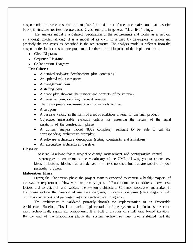
Sample domain model for a health insurance plan
Concepts: Conceptual Data Modeling
Introduction
Conceptual data modeling represents the initial stage in the development of the design of
the persistent data and persistent data storage for the system. In many cases, the persistent data
for the system are managed by a relational database management system (RDBMS). The
business and system entities identified at a conceptual level from the business models and system
requirements will be evolved through the use-case analysis, use-case design, and database design
activities into detailed physical table designs that will be implemented in the RDBMS. Note that
the Conceptual Data Model discussed in this concept document is not a separate artifact. Instead
it consists of a composite view of information contained in existing Business Modeling,
Requirements, and Analysis and Design Disciplines artifacts that is relevant to the development
of the Data Model.
The Data Model typically evolves through the following three general stages:
Conceptual—This stage involves the identification of the high level key business and system
entities and their relationships that define the scope of the problem to be addressed by the
system. These key business and system entities are defined using the modeling elements of the
UML profile for business modeling included in the Business Analysis Model and the Analysis
Class model elements of the Analysis Model.
Logical—This stage involves the refinement of the conceptual high level business and system
entities into more detailed logical entities. These logical entities and their relationships can be
optionally defined in a Logical Data Model using the modeling elements of the UML profile for
database design as described in Guidelines: Data Model. This optional Logical Data Model is
part of the Artifact: Data Model and not a separate RUP artifact.
Physical—This stage involves the transformation of the logical class designs into detailed and
optimized physical database table designs. The physical stage also includes the
mapping of the database table designs to tablespaces and to the database component in the
database storage design.
The activities related to database design span the entire software development lifecycle,
and the initial database design activities might start during the inception phase. For projects that
use business modeling to describe the business context of the application, database design may
start at a conceptual level with the identification of Business Actors and Business Use Cases in
the Business Use-Case Model, and the Business Workers and Business Entities in the Business
Analysis Model. For projects that do not use business modeling, the database design might start
at the conceptual level with the identification of System Actors and System Use Cases in the
Use-Case Model, and the identification of Analysis Classes in the Analysis Model from the Use-
Case Realizations.
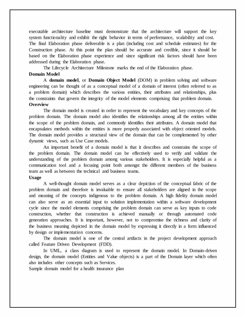
The figure below shows the set of Conceptual Data Model elements that reside in the
Business Models, Requirements Models, and the Analysis Model.
The following sections describe the elements of the Business Models, Use-Case Model,
and Analysis Model that can be used to define the initial Conceptual Data Model for persistent
data in the system.
Conceptual Data Modeling Elements
Business Models
Business Use-Case Model
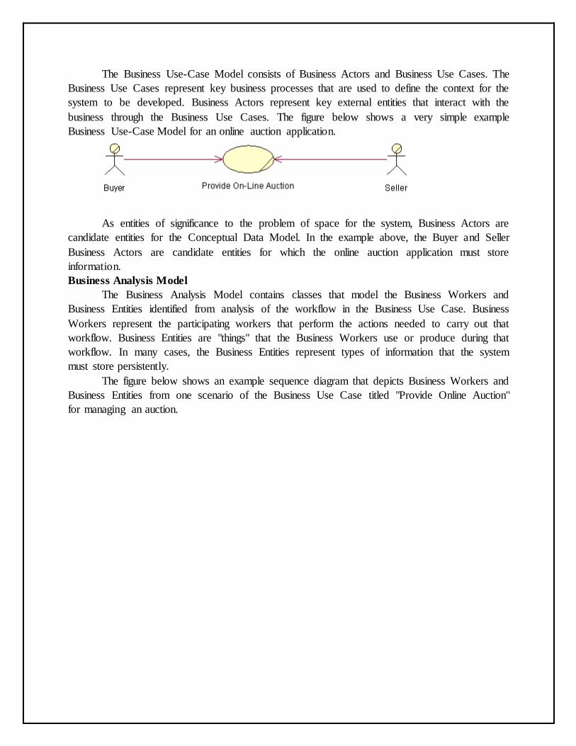
The Business Use-Case Model consists of Business Actors and Business Use Cases. The
Business Use Cases represent key business processes that are used to define the context for the
system to be developed. Business Actors represent key external entities that interact with the
business through the Business Use Cases. The figure below shows a very simple example
Business Use-Case Model for an online auction application.
As entities of significance to the problem of space for the system, Business Actors are
candidate entities for the Conceptual Data Model. In the example above, the Buyer and Seller
Business Actors are candidate entities for which the online auction application must store
information.
Business Analysis Model
The Business Analysis Model contains classes that model the Business Workers and
Business Entities identified from analysis of the workflow in the Business Use Case. Business
Workers represent the participating workers that perform the actions needed to carry out that
workflow. Business Entities are "things" that the Business Workers use or produce during that
workflow. In many cases, the Business Entities represent types of information that the system
must store persistently.
The figure below shows an example sequence diagram that depicts Business Workers and
Business Entities from one scenario of the Business Use Case titled "Provide Online Auction"
for managing an auction.
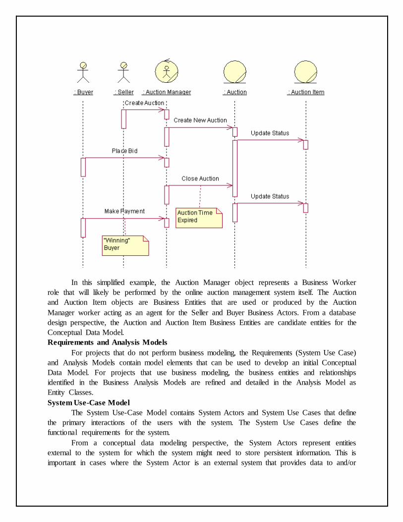
In this simplified example, the Auction Manager object represents a Business Worker
role that will likely be performed by the online auction management system itself. The Auction
and Auction Item objects are Business Entities that are used or produced by the Auction
Manager worker acting as an agent for the Seller and Buyer Business Actors. From a database
design perspective, the Auction and Auction Item Business Entities are candidate entities for the
Conceptual Data Model.
Requirements and Analysis Models
For projects that do not perform business modeling, the Requirements (System Use Case)
and Analysis Models contain model elements that can be used to develop an initial Conceptual
Data Model. For projects that use business modeling, the business entities and relationships
identified in the Business Analysis Models are refined and detailed in the Analysis Model as
Entity Classes.
System Use-Case Model
The System Use-Case Model contains System Actors and System Use Cases that define
the primary interactions of the users with the system. The System Use Cases define the
functional requirements for the system.
From a conceptual data modeling perspective, the System Actors represent entities
external to the system for which the system might need to store persistent information. This is
important in cases where the System Actor is an external system that provides data to and/or
receives data from the system under development. System Actors can be derived from the
Business Actors in the Business Use-Case Model and the Business Workers in the Business
Analysis Model.
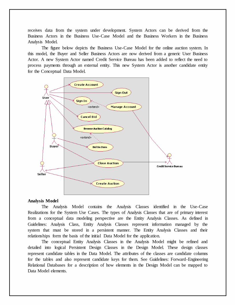
The figure below depicts the Business Use-Case Model for the online auction system. In
this model, the Buyer and Seller Business Actors are now derived from a generic User Business
Actor. A new System Actor named Credit Service Bureau has been added to reflect the need to
process payments through an external entity. This new System Actor is another candidate entity
for the Conceptual Data Model.
Analysis Model
The Analysis Model contains the Analysis Classes identified in the Use-Case
Realizations for the System Use Cases. The types of Analysis Classes that are of primary interest
from a conceptual data modeling perspective are the Entity Analysis Classes. As defined in
Guidelines: Analysis Class, Entity Analysis Classes represent information managed by the
system that must be stored in a persistent manner. The Entity Analysis Classes and their
relationships form the basis of the initial Data Model for the application.
The conceptual Entity Analysis Classes in the Analysis Model might be refined and
detailed into logical Persistent Design Classes in the Design Model. These design classes
represent candidate tables in the Data Model. The attributes of the classes are candidate columns
for the tables and also represent candidate keys for them. See Guidelines: Forward-Engineering
Relational Databases for a description of how elements in the Design Model can be mapped to
Data Model elements.
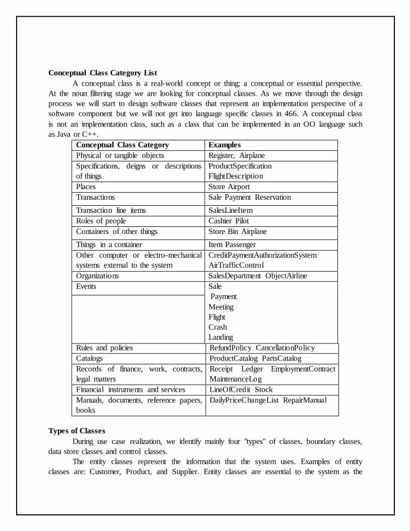
Conceptual Class Category List
A conceptual class is a real-world concept or thing; a conceptual or essential perspective.
At the noun filtering stage we are looking for conceptual classes. As we move through the design
process we will start to design software classes that represent an implementation perspective of a
software component but we will not get into language specific classes in 466. A conceptual class
is not an implementation class, such as a class that can be implemented in an OO language such
as Java or C++.
Conceptual Class Category Examples
Physical or tangible objects Register, Airplane
Specifications, deigns or descriptions
of things
ProductSpecification
FlightDescription
Places Store Airport
Transactions Sale Payment Reservation
Transaction line items SalesLineItem
Roles of people Cashier Pilot
Containers of other things Store Bin Airplane
Things in a container Item Passenger
Other computer or electro-mechanical
systems external to the system
CreditPaymentAuthorizationSystem
AirTrafficControl
Organizations SalesDepartment ObjectAirline
Events Sale
Payment
Meeting
Flight
Crash
Landing
Rules and policies RefundPolicy CancellationPolicy
Catalogs ProductCatalog PartsCatalog
Records of finance, work, contracts,
legal matters
Receipt Ledger EmploymentContract
MaintenanceLog
Financial instruments and services LineOfCredit Stock
Manuals, documents, reference papers,
books
DailyPriceChangeList RepairManual
Types of Classes
During use case realization, we identify mainly four "types" of classes, boundary classes,
data store classes and control classes.
The entity classes represent the information that the system uses. Examples of entity
classes are: Customer, Product, and Supplier. Entity classes are essential to the system as the
expected functionality of the system includes maintaining information about them or retrieving
information from them.
The boundary classes represent the interaction between the system and its actors. A GUI
form is an example of a boundary class.
Data store classes encapsulate the design decisions about data storage and retrieval
strategies. This provides us flexibility to move a n application from database platform to another.
The control classes represent the control logic of the system. They implement the flow of events
as given in a use case.
Entity Classes
Entity classes are the abstractions of the keys concepts of the system being modelled. If
the steps of the Architectural Analysis have been carried out, many of the entity classes may
have already been identified during those steps.
The Core functionality and logic of the system are encapsulated in the various entity
classes. For example, if interest is to be calculated and paid to savings account holders, a savings
Account entity class may be responsible for computing and returning the interest.
You can normally look for the following types of things as potential entity classes:
o Roles played by people or organizations about which information is required to be
maintained by the system. For Example, Student in a Library Management System,
Vendor in a Purchase Ordering System.
o Other physical, tangible things. For example, Book in a Library Management System.
o Events that requires remembrance. For example, Reservation and Issue in a Library
Management System.
The logical data structures (attributes and relationships) of the entity classes would be
designed to hold and manipulate the data according to the system's requirements. Values of the
attributes and their relationships of the entity class objects are often given by actors. The entity
classes are responsible for storing and managing information in the system.
Entity class objects are usually persistent, having attributes and relationships that need to
be retained for a long time, sometimes even before the life of system. An entity class is usually
not specific to one use cause realization. Objects of most entity classes would required in
multiple use cases. Sometimes, an entity object may not be specific to the system itself.
Boundary Classes
Boundary classes represent the interaction between the system and its actors. They
insulate the system from changes in the surroundings of the system, such as user interfaces, and
interfaces to other systems.
There may be various types of boundary classes in a system:
o User Interfaces classes: Classes for encapsulating the human user interface of the
system, such as GUI forms.
o System Interface Classes: Classes that encapsulate the interaction of the system with
other systems.
o Device Interface Classes: Classes that provide the interface to devices that detect
external events.
An important objective of identifying boundary classes is to ensure that the entity classes
and the control classes are not affected by any changes to the boundary classes.
Actors interact with the system only through the boundary classes.
User Interface Classes
A user interface class represents the interaction between a use case and its initiating actor.
This class has the responsibility of coordinating the interaction with the actor. A boundary class
may have various subsidiary classes to which some of its responsibilities are delegated. For
example, in a GUI application, there may be multiple forms within a use case.
During use case analysis, you should use the boundary classes as just place-holders for
the GUI forms. Detailed GUI design is an activity of Class Design. During Analysis, the
emphasis should be only on isolating all environment-dependent behaviour as boundary classes.
These classes will get refined or replaced in the later stages.
System Interface Classes
A system interface class is responsible for interfacing with an external system. The
interface offered by the external system would have been identified by the developers of that
system. Thus, the behaviour of a system interface class should be derived directly from the
interface specifications of the external system.
System interface classes achieve the purpose of isolating the internal details of the
external systems, which may change over a period of time. Our system should not get affected by
such changes in the internal details of the external systems.
Device Interface Classes
Device interface classes are responsible for interacting with the external devices that the
system may depend upon for receiving inputs or handling outputs. Examples of such external
devices would be: bar code reader, system clock, printer, etc.
A device may already have a well-defined interface, which could be used by you later
during design. Therefore, a note of such interface should be made in the model documentation.
Data Store Classes
Data Store classes encapsulate our design decisions about the database structures which
are used to store entity class objects, and to retrieve them later. For each entity class that required
persistence, we create a corresponding data store class. A data store class typically receives an
object of an entity class, and make it persistence (for example, by inserting a row in a table). At a
later point of time, we may ask the data store class to return the entity class object.
Encapsulating the database design designs in data store classes, makes the entity classes
independent of the database structure, and thus provides us greater flexibility to move an
application from one database platform to another.
Controller Classes
Controller classes provide co-ordinating behaviour in the system. A typical example
would be a controller class implementing the logic and flow of events of a use case.
Controller Classes isolates the entity classes and boundary classes from each other,
making the system independent of the changes to the system boundary. They also isolate the use
case specific behaviour from the entity class objects, thus making them re-usable across use
cases and even across systems.
Simple use cases may be performed without using controller classes, with direct flow of
data between boundary objects and entity objects. However, more complex use cases usually
require and benefit from such controller classes. The characteristics of controller classes are:
o They define the order of events and transactions within a use case. In other words, they
encapsulate the use case-specific behaviour of the system.
o They are relatively independent of the changes to the internal structure or behaviour of
the entity classes.
o They are nearly independent of changes to the boundary classes.
o They may use or set several entity classes, thus coordinating the behaviour of these
entity classes. However, this coordination can be invisible to the participating entity
classes.
Though most of the times a control class correspond to a single use case, some times a
single controller class may be use to control several use cases. Some tines there may even be
multiple controller classes with in a single use case. As mentioned earlier, there may be use cases
that do not require controller classes.
Association:
Association defines the relationship between two or more classes in the System. These
generally relates to the one object having instance or reference of another object inside it. This
article discusses on how we can implement Association in UML.
Associations in UML can be implemented using following ways: 1) Multiplicity 2) Aggregation
3) Composition
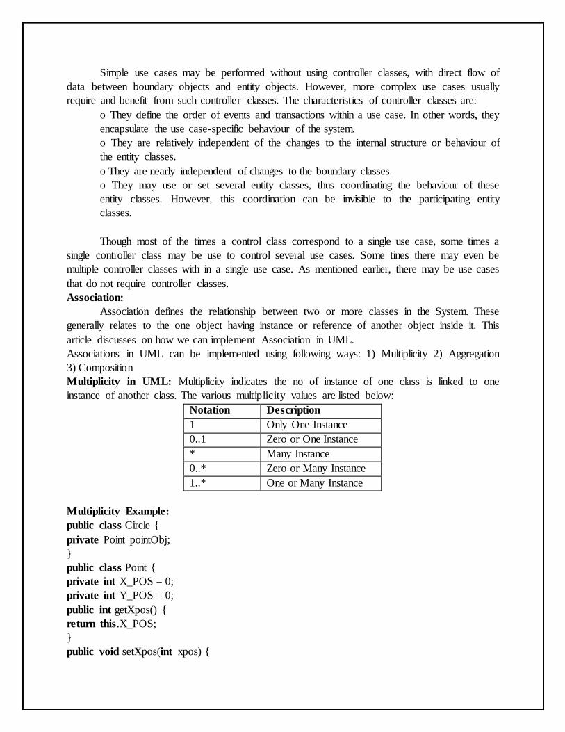
Multiplicity in UML: Multiplicity indicates the no of instance of one class is linked to one
instance of another class. The various multiplicity values are listed below:
Notation Description
1 Only One Instance
0..1 Zero or One Instance
* Many Instance
0..* Zero or Many Instance
1..* One or Many Instance
Multiplicity Example:
public class Circle {
private Point pointObj;
}
public class Point {
private int X_POS = 0;
private int Y_POS = 0;
public int getXpos() {
return this.X_POS;
}
public void setXpos(int xpos) {
this.X_POS = xpos;
}
public int getYpos() {
return this.Y_POS;
}
public void setYpos(int ypos) {
this.Y_POS = ypos;
}
}
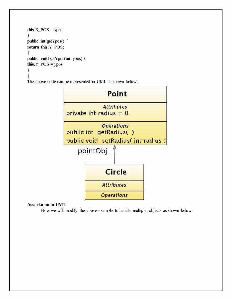
The above code can be represented in UML as shown below:
Association in UML
Now we will modify the above example to handle multiple objects as shown below:
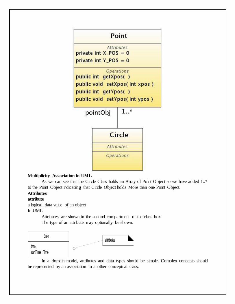
Multiplicity Association in UML
As we can see that the Circle Class holds an Array of Point Object so we have added 1..*
to the Point Object indicating that Circle Object holds More than one Point Object.
Attributes
attribute
a logical data value of an object
In UML:
Attributes are shown in the second compartment of the class box.
The type of an attribute may optionally be shown.
In a domain model, attributes and data types should be simple. Complex concepts should
be represented by an association to another conceptual class.
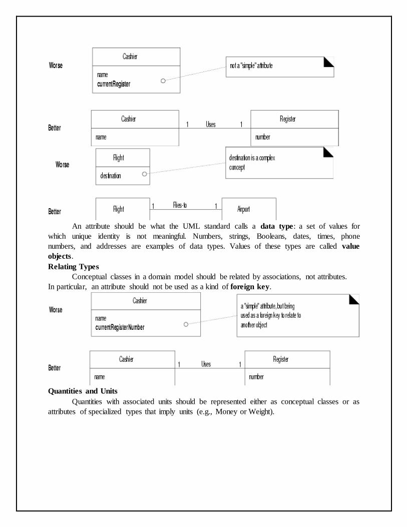
An attribute should be what the UML standard calls a data type: a set of values for
which unique identity is not meaningful. Numbers, strings, Booleans, dates, times, phone
numbers, and addresses are examples of data types. Values of these types are called value
objects.
Relating Types
Conceptual classes in a domain model should be related by associations, not attributes.
In particular, an attribute should not be used as a kind of foreign key.
Quantities and Units
Quantities with associated units should be represented either as conceptual classes or as
attributes of specialized types that imply units (e.g., Money or Weight).
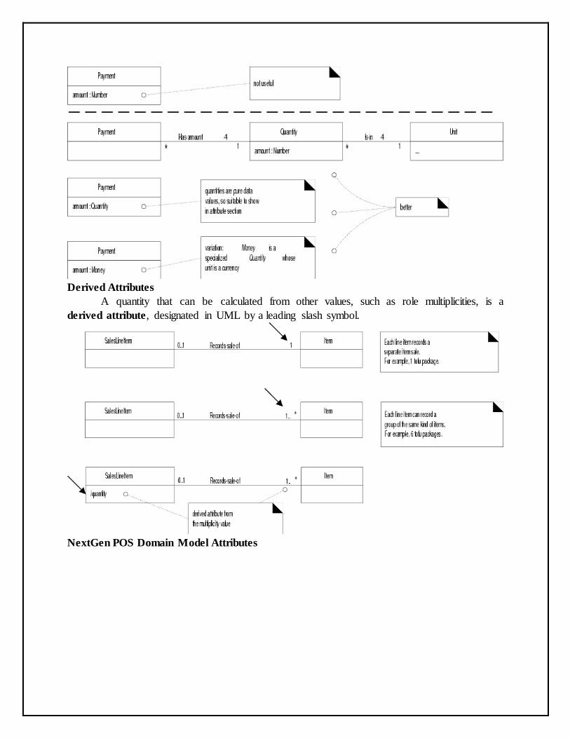
Derived Attributes
A quantity that can be calculated from other values, such as role multiplicities, is a
derived attribute, designated in UML by a leading slash symbol.
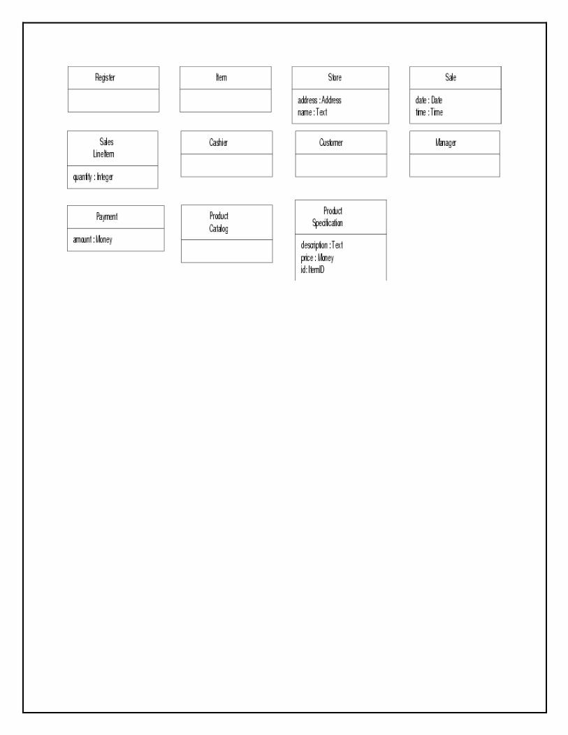
NextGen POS Domain Model Attributes
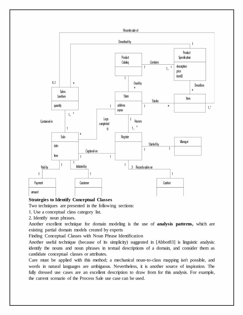
Strategies to Identify Conceptual Classes
Two techniques are presented in the following sections:
1. Use a conceptual class category list.
2. Identify noun phrases.
Another excellent technique for domain modeling is the use of analysis patterns, which are
existing partial domain models created by experts
Finding Conceptual Classes with Noun Phrase Identification
Another useful technique (because of its simplicity) suggested in [Abbot83] is linguistic analysis:
identify the nouns and noun phrases in textual descriptions of a domain, and consider them as
candidate conceptual classes or attributes.
Care must be applied with this method; a mechanical noun-to-class mapping isn't possible, and
words in natural languages are ambiguous. Nevertheless, it is another source of inspiration. The
fully dressed use cases are an excellent description to draw from for this analysis. For example,
the current scenario of the Process Sale use case can be used.
Main Success Scenario (or Basic Flow):
1. Customer arrives at a POS checkout with goods and/or services to purchase.
2. Cashier starts a new sale.
3. Cashier enters item identifier.
4. System records sale line item and presents item description, price, and running total. Price
calculated from a set of price rules. Cashier repeats steps 2-3 until indicates done.
5. System presents total with taxes calculated.
6. Cashier tells Customer the total, and asks for payment.
7. Customer pays and System handles payment.
8. System logs the completed sale and sends sale and payment information to the external
Accounting (for accounting and commissions) and Inventory systems (to update inventory).
9. System presents receipt.
10.Customer leaves with receipt and goods (if any).
Extensions (or Alternative Flows):
7a. Paying by cash:
1. Cashier enters the cash amount tendered.
2. System presents the balance due, and releases the cash drawer.
3. Cashier deposits cash tendered and returns balance in cash to Customer.
4. System records the cash payment.
The domain model is a visualization of noteworthy domain concepts and vocabulary. Where are
those terms found? In the use cases. Thus, they are a rich source to mine via noun phrase
identification.
Some of these noun phrases are candidate conceptual classes, some may refer to conceptual
classes that are ignored in this iteration (for example, "Accounting" and "commissions"), and
some may be attributes of conceptual classes.
A weakness of this approach is the imprecision of natural language; different noun
phrases may represent the same conceptual class or attribute, among other ambiguities.
Nevertheless, it is recommended in combination with the Conceptual Class Category List
technique.
Specification or Description Conceptual Classes
The following discussion may at first seem related to a rare, highly specialized issue.
However, it turns out that the need for specification conceptual classes (as will be defined) is
common in any domain models. Thus, it is emphasized.
Note that in earlier times a register was just one possible implementation of how to
record sales. The term has acquired a generalized meaning over time.
Assume the following:
• An Item instance represents a physical item in a store; as such, it may even have a serial
number.
• An Item has a description, price, and itemID, which are not recorded anywhere else.
• Everyone working in the store has amnesia.
• Every time a real physical item is sold, a corresponding software instance of Item is deleted
from "software land."
With these assumptions, what happens in the following scenario?
There is strong demand for the popular new vegetarian burger—ObjectBurger. The store sells
out, implying that all Item instances of ObjectBurgers are deleted from computer memory.
Now, here is the heart of the problem: If someone asks, "How much do Object Burgers
cost?", no one can answer, because the memory of their price was attached to inventoried
instances, which were deleted as they were sold.
Notice also that the current model, if implemented in software as described, has duplicate
data and is space-inefficient because the description, price, and itemID are duplicated for every
Item instance of the same product.
The Need for Specification or Description Conceptual Classes
The preceding problem illustrates the need for a concept of objects that are specifications
or descriptions of other things. To solve the Item problem, what is needed is a
ProductSpecification (or ItemSpecification, ProductDescription, ...) conceptual class that records
information about items. A ProductSpecification does not represent an Item, it represents a
description of information about items. Note that even if all inventoried items are sold and their
corresponding Item software instances are deleted, the ProductSpecifications still remain.
Description or specification objects are strongly related to the things they describe. In a
domain model, it is common to state that an XSpecification Describes an X.
The need for specification conceptual classes is common in sales and product domains. It
is also common in manufacturing, where a description of a manufactured thing is required that is
distinct from the thing itself. Time and space have been taken in motivating specification
conceptual classes because they are very common; it is not a rare modeling concept.
When Are Specification Conceptual Classes Required?
The following guideline suggests when to use specifications:
Add a specification or description conceptual class (for example, ProductSpecification)
when:
1. There needs to be a description about an item or service, independent of the current existence
of any examples of those items or services.
2. Deleting instances of things they describe (for example, Item) results in a loss of information
that needs to be maintained, due to the incorrect association of information with the deleted
thing.
3. It reduces redundant or duplicated information.
Association, Aggregation and Composition Relationships with Examples
Association is a simple structural connection or channel between classes and is a
relationship where all objects have their own lifecycle and there is no owner. Lets take an
example of Department and Student. Multiple students can associate with a single Department
and single student can associate with multiple Departments, but there is no ownership between
the objects and both have their own lifecycle. Both can create and delete independently. Here
is respective Model and Code for the above example.
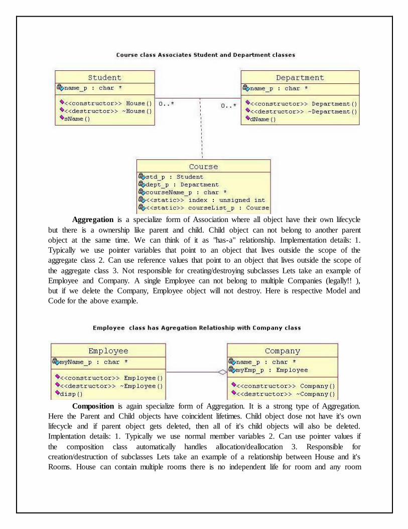
Aggregation is a specialize form of Association where all object have their own lifecycle
but there is a ownership like parent and child. Child object can not belong to another parent
object at the same time. We can think of it as "has-a" relationship. Implementation details: 1.
Typically we use pointer variables that point to an object that lives outside the scope of the
aggregate class 2. Can use reference values that point to an object that lives outside the scope of
the aggregate class 3. Not responsible for creating/destroying subclasses Lets take an example of
Employee and Company. A single Employee can not belong to multiple Companies (legally!! ),
but if we delete the Company, Employee object will not destroy. Here is respective Model and
Code for the above example.
Composition is again specialize form of Aggregation. It is a strong type of Aggregation.
Here the Parent and Child objects have coincident lifetimes. Child object dose not have it's own
lifecycle and if parent object gets deleted, then all of it's child objects will also be deleted.
Implentation details: 1. Typically we use normal member variables 2. Can use pointer values if
the composition class automatically handles allocation/deallocation 3. Responsible for
creation/destruction of subclasses Lets take an example of a relationship between House and it's
Rooms. House can contain multiple rooms there is no independent life for room and any room
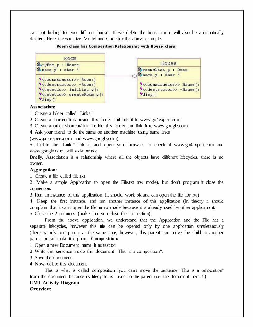
can not belong to two different house. If we delete the house room will also be automatically
deleted. Here is respective Model and Code for the above example.
Association:
1. Create a folder called "Links"
2. Create a shortcut/link inside this folder and link it to www.go4expert.com
3. Create another shortcut/link instide this folder and link it to www.google.com
4. Ask your friend to do the same on another machine using same links
(www.go4expert.com and www.google.com)
5. Delete the "Links" folder, and open your browser to check if www.go4expert.com and
www.google.com still exist or not
Briefly, Association is a relationship where all the objects have different lifecycles. there is no
owner.
Aggregation:
1. Create a file called file.txt
2. Make a simple Application to open the File.txt (rw mode), but don't program it close the
connection.
3. Run an instance of this application (it should work ok and can open the file for rw)
4. Keep the first instance, and run another instance of this application (In theory it should
complain that it can't open the file in rw mode because it is already used by other application).
5. Close the 2 instances (make sure you close the connection).
From the above application, we understand that the Application and the File has a
separate lifecycles, however this file can be opened only by one application simuletanously
(there is only one parent at the same time, however, this parent can move the child to another
parent or can make it orphan). Composition:
1. Open a new Document name it as test.txt
2. Write this sentence inside this document "This is a composition".
3. Save the document.
4. Now, delete this document.
This is what is called composition, you can't move the sentence "This is a omposition"
from the document because its lifecycle is linked to the parent (i.e. the document here !!)
UML Activity Diagram
Overview:

Activity diagram is another important diagram in UML to describe dynamic aspects of
the system.
Activity diagram is basically a flow chart to represent the flow form one activity to
another activity. The activity can be described as an operation of the system.
So the control flow is drawn from one operation to another. This flow can be sequential,
branched or concurrent. Activity diagrams deals with all type of flow control by using different
elements like fork, join etc.
Purpose:
The basic purposes of activity diagrams are similar to other four diagrams. It captures the
dynamic behaviour of the system. Other four diagrams are used to show the message flow from
one object to another but activity diagram is used to show message flow from one activity to
another.
Activity is a particular operation of the system. Activity diagrams are not only used for
visualizing dynamic nature of a system but they are also used to construct the executable system
by using forward and reverse engineering techniques. The only missing thing in activity diagram
is the message part.
It does not show any message flow from one activity to another. Activity diagram is some
time considered as the flow chart. Although the diagrams looks like a flow chart but it is not. It
shows different flow like parallel, branched, concurrent and single.
So the purposes can be described as:
Draw the activity flow of a system.
Describe the sequence from one activity to another.
Describe the parallel, branched and concurrent flow of the system.
How to draw Component Diagram?
Activity diagrams are mainly used as a flow chart consists of activities performed by the
system. But activity diagram are not exactly a flow chart as they have some additional
capabilities. These additional capabilities include branching, parallel flow, swimlane etc.
Before drawing an activity diagram we must have a clear understanding about the
elements used in activity diagram. The main element of an activity diagram is the activity itself.
An activity is a function performed by the system. After identifying the activities we need to
understand how they are associated with constraints and conditions.
So before drawing an activity diagram we should identify the following elements:
Activities
Association
Conditions
Constraints
Once the above mentioned parameters are identified we need to make a mental layout of
the entire flow. This mental layout is then transformed into an activity diagram.
The following is an example of an activity diagram for order management system. In the diagram
four activities are identified which are associated with conditions. One important point should be
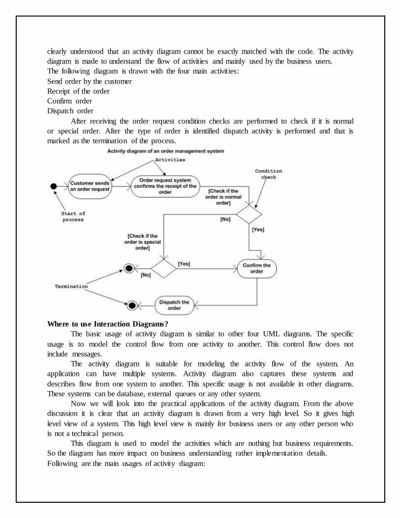
clearly understood that an activity diagram cannot be exactly matched with the code. The activity
diagram is made to understand the flow of activities and mainly used by the business users.
The following diagram is drawn with the four main activities:
Send order by the customer
Receipt of the order
Confirm order
Dispatch order
After receiving the order request condition checks are performed to check if it is normal
or special order. After the type of order is identified dispatch activity is performed and that is
marked as the termination of the process.
Where to use Interaction Diagrams?
The basic usage of activity diagram is similar to other four UML diagrams. The specific
usage is to model the control flow from one activity to another. This control flow does not
include messages.
The activity diagram is suitable for modeling the activity flow of the system. An
application can have multiple systems. Activity diagram also captures these systems and
describes flow from one system to another. This specific usage is not available in other diagrams.
These systems can be database, external queues or any other system.
Now we will look into the practical applications of the activity diagram. From the above
discussion it is clear that an activity diagram is drawn from a very high level. So it gives high
level view of a system. This high level view is mainly for business users or any other person who
is not a technical person.
This diagram is used to model the activities which are nothing but business requirements.
So the diagram has more impact on business understanding rather implementation details.
Following are the main usages of activity diagram:
Modeling work flow by using activities.
Modeling business requirements.
High level understanding of the system's functionalities.
Investigate business requirements at a later stage.