Concept of the simulation environment for prototyping design of fault detection and diagnostic...
11
ELSEVIER Simulation Practice and Theory 4 (1996) 349-359 SIMULATION PRACTICE ~' THEORY Concept of the simulation environment for prototyping design of fault detection and diagnostic systems D. Juri~i6*, E. Kragevec, M. Rak, S. Strm~nik Department of Computer Automation and Control, Jo~ef Stefan Institme, Jamova 39, 61111 Ljubljana, Slovenia Received 9 May 1995; revised 13 May 1996 Abstract In recent years a number of new methods for fault detection and diagnosis (FDD) have been proposed in the literature. However, for a practitioner wishing to solve a concrete FDD problem it is often not easy to choose the right method for the problem at hand. Since the FDD design is normally iterative, use of CAD support is of great practical interest in order to make the design more efficient. In this paper we deal with the preliminary FDD design process referred to as prototyping in which simulation plays an important role. First, the main stages of the prototyping design cycle are identified. Accordingly, a concept is proposed for the simulation environment to support the needs of the designer during realisation of particular stages of the prototyping design cycle. Practical realisation of the concept is, however, confined by several problems. One of these is related to the fact that the FDD design often imposes processing of different knowledge items like heuristic facts, qualitative models or analytical models. To support their processing, it is necessary to make use of different program tools which, at the present level of development, lack the cost-effective mechanisms for easy integ- ration. In turn, such a mismatch demands an extra effort from the designer in arranging transfer of data between the packages, as well as in handling the various tools. These problems are illustrated by an example of the environment developed for support of the FDD prototyping design of a DC motor. Keywords: Fault detection; Simulation; Systems modelling; Specification methodology; System prototyping 1. Introduction Techniques for fault detection and diagnosis (FDD) have gained increasing impor- tance in the last few years due to the need for reliability and safety of plant operation. * Corresponding author. E-mail: [email protected]. 0928-4869/96/$15.00 Copyright © 1996 Elsevier Science B.V. All rights reserved PH0928-4869 (96)00017-1
-
Upload
independent -
Category
Documents
-
view
0 -
download
0
Transcript of Concept of the simulation environment for prototyping design of fault detection and diagnostic...
ELSEVIER Simulation Practice and Theory 4 (1996) 349-359
SIMULATION PRACTICE ~ ' THEORY
Concept of the simulation environment for prototyping design of fault detection and diagnostic systems
D. Juri~i6*, E. Kragevec, M. Rak, S. Strm~nik
Department of Computer Automation and Control, Jo~ef Stefan Institme, Jamova 39, 61111 Ljubljana, Slovenia
Received 9 May 1995; revised 13 May 1996
Abstract
In recent years a number of new methods for fault detection and diagnosis (FDD) have been proposed in the literature. However, for a practitioner wishing to solve a concrete FDD problem it is often not easy to choose the right method for the problem at hand. Since the F D D design is normally iterative, use of CAD support is of great practical interest in order to make the design more efficient. In this paper we deal with the preliminary FDD design process referred to as prototyping in which simulation plays an important role. First, the main stages of the prototyping design cycle are identified. Accordingly, a concept is proposed for the simulation environment to support the needs of the designer during realisation of particular stages of the prototyping design cycle. Practical realisation of the concept is, however, confined by several problems. One of these is related to the fact that the FDD design often imposes processing of different knowledge items like heuristic facts, qualitative models or analytical models. To support their processing, it is necessary to make use of different program tools which, at the present level of development, lack the cost-effective mechanisms for easy integ- ration. In turn, such a mismatch demands an extra effort from the designer in arranging transfer of data between the packages, as well as in handling the various tools. These problems are illustrated by an example of the environment developed for support of the FDD prototyping design of a DC motor.
Keywords: Fault detection; Simulation; Systems modelling; Specification methodology; System prototyping
1. Introduction
Techniques for fault de tec t ion and diagnosis ( F D D ) have gained increas ing impor - tance in the last few years due to the need for rel iabi l i ty and safety of p lan t opera t ion .
* Corresponding author. E-mail: [email protected].
0928-4869/96/$15.00 Copyright © 1996 Elsevier Science B.V. All rights reserved PH0928-4869 (96)00017-1
350 D. Juridi~ et al./Simulation Practice and Theory 4 (1996) 349-359
As a consequence, a number of methods for detection and diagnosis, suitable for a broad range of fault types and background process knowledge, have been developed ]-6,7,10,19]. How, among so many methods, can the right one be chosen for the problem at hand so that the prespecified requirements are satisfied? Yet, we are not in a position to operate with standards or guidelines for choosing the right tool for the problem. As a consequence, several options have to be tried. It is, therefore, preferable to use simulation aids to facilitate the search for the optimal solution. However, by simulation it is possible to achieve a preliminary version of a part of the final diagnostic system, in which only certain aspects of the problem are treated. This part of the overall FDD design process is referred to as prototyping [9]. Basically, prototyping consists of capturing an initial set of needs and (by implement- ing them quickly) expanding and refining the requirements through a growing understanding of how the system should work [-9,23].
In this paper we do not concentrate on any particular diagnostic technique. Our aim is, rather, to draw attention to the relationship between the conceptual frame- work of the computer-aided environment and the structure of the prototyping design process to be supported. Since simulation plays the essential role in the prototyping stage, we use the notion of simulation environment. In the area of diagnosis, this interrelation has not yet attracted sufficient attention. It is, perhaps, much better elaborated in some other engineering disciplines, for instance in software engineering. There, the design process is modelled via a succession of engineering tasks, normally referred to as the life cycle [-1,23]. What is most important is that there are also program packages which help the designer in realisation of the particular stages of the life cycle. The cycle can take different forms depending on the complexity of the problem at hand, cf. [-13,21] for the case of control systems design.
The content of the paper is organised as follows. First, the FDD prototyping life cycle is presented in Section 2. This is followed by the concept of the simulation environment which is adopted to the needs around the FDD prototyping cycle. In Section 3, the concept of the environment is realised by combining several program tools that interchange data through files. The relation between fast prototyping and the simulation environment is illustrated by the example on an FDD system design for a DC motor. The conclusions are presented in Section 4.
2. Conceptual framework of the FDD simulation environment
2.1. Structure of the prototyping design process
Analysis of the development of a diagnostic system indicates the need for a prototyping cycle comprising three major stages:
(1) establishing preliminary requirements for diagnosis and system analysis, (2) specification and design of the diagnostic system and (3) testing and evaluation by simulation. Definition of requirements and system analysis are very closely interlaced in case
of FDD prototyping design. The purpose of this step is to answer the question what
D. Juridid et al./Simulation Practice and Theory 4 (1996) 349-359 351
and why should be done. The emphasis is on system targets and functions to be realised. These are expressed in terms of task requirements [ 15]. The specific problems of F DD design strongly depend on the nature of faults to be revealed, and this must be clearly specified within the fault requirements.
Formulation of requirements, however, needs insight into the system under treat- ment. That is, to define the targets we have to combine different pieces of knowledge about the system in terms of model requirements. This is partly the answer to the question how to fulfil the task requirements. Further elaboration of model require- ments is done within the system analysis in more detail. It is important to note that system modelling might be an important part of system analysis, and can be repre- sented by its own life cycle (cf. [17]).
The purpose of the specification phase is to propose the solution of the FDD problem by taking into account the aspects investigated in the previous stage. The purpose of design is to generate solution within the frame of the simulation environment.
Finally, in the last stage, the solution is tested and evaluated by performing various simulation experiments. The solution, which proved suitable on the simulation level, is then a candidate for the final solution to be elaborated later on by experiments on the real process.
2.2. Concept of the simulation environment for FDD prototyping
By the notion of simulation environment we mean a set of tools that serve to solve the problem by means of simulation. The principal aim is to offer integrated support to possibly all the phases of the prototyping design cycle. Additional requirements which are expected to be fulfilled by the simulation environment are the following [-4,17,20]: • separation of the model from experiment: process description is separated from
the description of experiments, thus implying flexibility and simplicity in the test phase,
• modularity: particular units occur in the self-contained blocks, • experimental frame: the ability of the simulation environment to allow for experi-
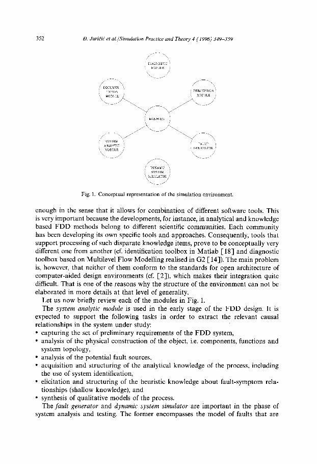
ments on the model which highlight the relevant aspects of the problem. Functional representation of the simulation environment is given in Fig. 1. It is composed of seven principal modules: • system analytic module, • fault generator, • dynamic system simulator, • perception module, • diagnostic module, • documentation module and • manager.
The modules can be realised by one or more program tools in order to perform particular tasks within the prototyping design. Two or more modules can also be realised within the same tool. It is believed that the proposed structure is general
352 D. JurKid et al./Sirnulation Practice and Theory 4 (1996) 349-359
~DIAGNOSTIC~ ~, MODULE ,~
,[ DOCUMEN ',, , \ I TATION I PERCEPTION ' / MODULE /
I MANAGER )
_ Y
[
f ANA,,Y IC I ( EGG ) \ \ ~ . . . . / y CF> /-L\
,,' DYNAMIC \ I SYSTEM I
Fig. 1. Conceptual representation of the simulation environment.
enough in the sense that it allows for combination of different software tools. This is very important because the developments, for instance, in analytical and knowledge based FDD methods belong to different scientific communities. Each community has been developing its own specific tools and approaches. Consequently, tools that support processing of such disparate knowledge items, prove to be conceptually very different one from another (cf. identification toolbox in Matlab 1-18] and diagnostic toolbox based on Multilevel Flow Modelling realised in G2 [ 14]). The main problem is, however, that neither of them conform to the standards for open architecture of computer-aided design environments (cf. [2]), which makes their integration quite difficult. That is one of the reasons why the structure of the environment can not be elaborated in more details at that level of generality.
Let us now briefly review each of the modules in Fig. 1. The system analytic module is used in the early stage of the FDD design. It is
expected to support the following tasks in order to extract the relevant causal relationships in the system under study: • capturing the set of preliminary requirements of the FDD system, • analysis of the physical construction of the object, i.e. components, functions and
system topology, • analysis of the potential fault sources, • acquisition and structuring of the analytical knowledge of the process, including
the use of system identification, • elicitation and structuring of the heuristic knowledge about fault-symptom rela-
tionships (shallow knowledge), and • synthesis of qualitative models of the process.
The fault generator and dynamic system simulator are important in the phase of system analysis and testing. The former encompasses the model of faults that are
D. Juri6ik et al./Simulation Practice and Theory 4 (1996) 349-359 353
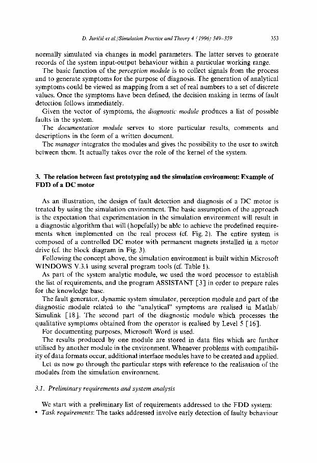
normally simulated via changes in model parameters. The latter serves to generate records of the system input-output behaviour within a particular working range.
The basic function of the perception module is to collect signals from the process and to generate symptoms for the purpose of diagnosis. The generation of analytical symptoms could be viewed as mapping from a set of real numbers to a set of discrete values. Once the symptoms have been defined, the decision making in terms of fault detection follows immediately.
Given the vector of symptoms, the diagnostic module produces a list of possible faults in the system.
The documentation module serves to store particular results, comments and descriptions in the form of a written document.
The manager integrates the modules and gives the possibility to the user to switch between them. It actually takes over the role of the kernel of the system.
3. The relation between fast prototyping and the simulation environment: Example of F D D of a DC motor
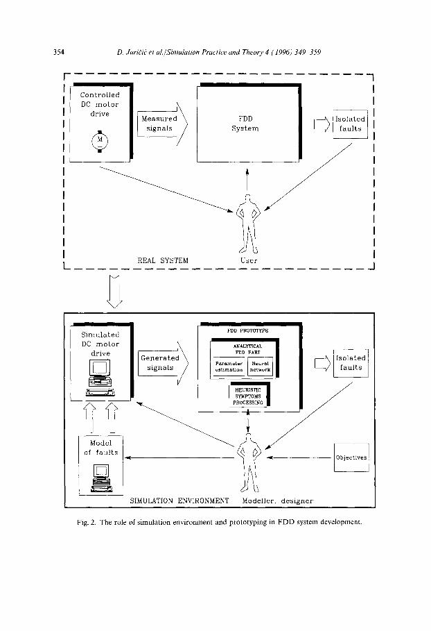
As an illustration, the design of fault detection and diagnosis of a DC motor is treated by using the simulation environment. The basic assumption of the approach is the expectation that experimentation in the simulation environment will result in a diagnostic algorithm that will (hopefully) be able to achieve the predefined require- ments when implemented on the real process (cf. Fig. 2). The entire system is composed of a controlled DC motor with permanent magnets installed in a motor drive (cf. the block diagram in Fig. 3).
Following the concept above, the simulation environment is built within Microsoft WINDOWS V.3.1 using several program tools (cf. Table 1).
As part of the system analytic module, we used the word processor to establish the list of requirements, and the program ASSISTANT [3] in order to prepare rules for the knowledge base.
The fault generator, dynamic system simulator, perception module and part of the diagnostic module related to the "analytical" symptoms are realised in Matlab/ Simulink [18]. The second part of the diagnostic module which processes the qualitative symptoms obtained from the operator is realised by Level 5 [ 16].
For documenting purposes, Microsoft Word is used. The results produced by one module are stored in data files which are further
utilised by another module in the environment. Whenever problems with compatibil- ity of data formats occur, additional interface modules have to be created and applied.
Let us now go through the particular steps with reference to the realisation of the modules from the simulation environment.
3.1. Preliminary requirements and system analysis
We start with a preliminary list of requirements addressed to the FDD system: • Task requirements: The tasks addressed involve early detection of faulty behaviour
354 D. Juri(i( et al./Simulation Practice and Theory 4 (1996) 349 359
k.
Controlled DC motor
drive
_+ ~ : i a s u r e d ~
gnals / /
REAL SYSTEM
System
User
Simulated DC motor
drive
Model of faults
FDD PROTOTYPE
I SYMPTOsMS ~ /
SIMULATION ENVIRONMENT Modeller, designer
Fig. 2. The role of simulation environment and prototyping in FDD system development.
k3. Jurigid et al./Simulation Practice and Theory 4 (1996) 349-359 355
I In ternal control loop . . . . . . . . . . . . . . . . . . . . . . . . . . . . . . . . . . . . . . . . . . . . . . . . . . . . . . . . . . . . . . . . . . ,
Externa l control loop . . . . . . . . . . . . . . . . . . . . . . . . . . . . . . . . . . . . . . . . . . . . . . . . . . . . . . . . . . . . . . . . . . . . . . . . . . . . . . . . . . . . . . . . . . . . . . . . . . . . . . . . . . . . . . . . . . . . . . . . . . . . . . . . . . . . . . . . . . . . . . . . .
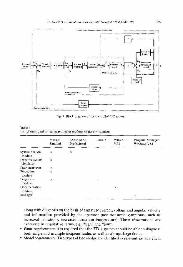
Fig. 3. Block diagram of the controlled DC motor.
Table 1 List of tools used to realise particular modules of the environment
Matlab/ ASSISTANT Level 5 Winword Program Manager Simulink Professional V5.3 Windows V3.1
System analytic x x module
Dynamic system x simulator
Fault generator x Perception x module
Diagnostic x x module
Documentation x module
Manager x
a long with d iagnos is on the basis of a rma tu re current , vol tage and angula r velocity and in format ion p rov ided by the ope ra to r (non-measured symptoms , such as increased vibra t ions , increased a r m a t u r e temperature) . These observa t ions are expressed in qual i ta t ive terms, e.g. "high" and "low".
* Fau l t requirements : It is requi red tha t the F D D system should be able to d iagnose bo th single and mul t ip le incipient faults, as well as a b r u p t large faults.
• M o d e l requirements : Two types of knowledge are identif ied as relevant, i.e. ana ly t ica l
356 D. Juri(i{ et al./Simulation Practice and Theory 4 (1996) 349 359
knowledge expressed via dynamic equations [12,22], and heuristic knowledge concerning the subset of fault symptom relationships [5]. The analysis of system behaviour results in the system of differential equations
[-12,22] in which model parameters display certain physical properties of the system components. Therefore, they could be used as a means of injecting artificial faults in the system (e.g. increased Coulomb friction in the bearings, increased rotor resistance as a way to mimic worn or dirty brushes). Consequently, in the fault generator module a fault is triggered by step changes in particular model parameters.
Analysis of the heuristic knowledge available from the troubleshooting chart (as substitute for an expert) also forms part of the system analysis [-5]. A problem often encountered in practice is that such a set of heuristic rules requires proper reorganisa- tion in order to shorten the search through fault-symptom trees. Consequently, the idea applied is to rank the attributes according to their importance (i.e. informativity [3]) and also to achieve (possibly) unambiguous diagnosis when some of the attri- butes are, for whatever reason, not specified. For this purpose inductive learning is used to extract rules from a learning set composed of possible attributes (e.g. no-load speed = 'normal', sparking = 'not known', speed = 'erratic' etc.), and the corresponding class of faults (e.g. stator fault). The program ASSISTANT [-3], based on Quinlan's ID3 algorithm, is utilised as a part of the system analytic module the result of which is a set of rules for the knowledge base. The knowledge base is implemented in the Level 5 expert system shell [16].
3.3. FDD system specifications and design
In this phase of the work, analytical symptom generation is performed via parame- ter estimation of the continuous process model, which is acceptable because the excitation caused by variations in speed reference is satisfactory. The paradigm, which has been thoroughly elaborated in [ 10,11] has been applied.
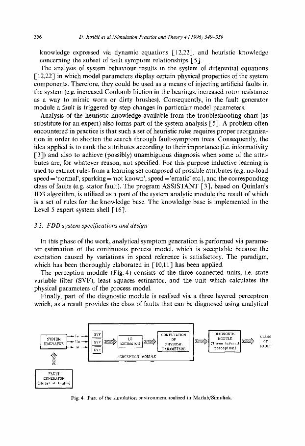
The perception module (Fig. 4) consists of the three connected units, i.e. state variable filter (SVF), least squares estimator, and the unit which calculates the physical parameters of the process model.
Finally, part of the diagnostic module is realised via a three layered perceptron which, as a result provides the class of faults that can be diagnosed using analytical
Y TEM Ua SIMULATOR
PERCEPTION MODULE
COMPUTATION OF
PHYSICAL PARAMETERS
L I D,A NO T,C I
FAULT [ GENERATOR
(Model of faults)
Fig. 4. Part of the simulation environment realised in Matlab/Simulink.
CLASS OF
FAULT
D. Juri(i? et al./Simulation Practice and Theory 4 (1996) 349-359 357
symptoms. However, analytical model and, accordingly, the analytical symptoms can be used to properly identify only a part of the space of faults. Processing of the remaining heuristic symptoms is done via the expert system shell Level 5.
3.4. FDD system testing
The developed simulation environment was tested through the simulation experi- ments. The influence of the sampling frequency and measurement noise was estimated first. The second type of experiments were performed to analyse the influence of the working point (temperature) of the DC motor on values of the estimated parameters. Similarly, other types of experiments were performed in order to analyse the influence of the excitation signal on parameter estimation and to tune the constants of the state variable filters.
Some of the observations made in testing of the FDD system are the following: • the parameter estimator appears to be a critical part of the system, since its stability
depends on excitation; an adaptive forgetting strategy based on a constant trace of the parameter covariance matrix turned out to be a good choice,
• the cut-off frequency of the SVF should be close to that of the process; this could be best determined by trials,
• it is not possible to identify unambiguously all the parameters of the mechanical part of the model; therefore, it was assumed that the moment of inertia is known a priori,
• trials are also needed in order to deduce how false diagnosis could be avoided in periods of transients in parameter estimates immediately after a fault occurs; also, the detector must be made more sensitive to small faults resulting in increased probability of false alarms. At this point the work could progress in two directions:
• go back to one of the prototyping stages and invest additional efforts in further improvements, or
• try new solutions, e.g. on the bases of the observer design [8] and repeat the whole cycle. When the prototyping process is completed, we are in a position to revise the
requirements for the FDD system where necessary, and to provide specifications for real system design.
4. Conclusions
The aim of this paper is to match the concept of computer-aided environment to the needs of designing the FDD systems in a structured way. The significance of prototyping as a model for the FDD design process is outlined. Consequently, the importance of program support for each design phase is indicated. Unfortunately, the program tools that could be used for that purpose are at a level which, presently, does not conform to the definition of the open systems. Therefore, the concept of a simulation environment is proposed in the form of a set of interconnected tools used
358 D. Juridi~ et al./Simulation Practice and Theory 4 (1996) 349-359
to solve the problem stated in the simulation framework. The realisation presented here should be regarded as an illustration of the concept rather than as a final solution, since other methods and options are possible. Nevertheless, it seems reason- able and useful to define a general framework that can cover most important applications.
Our work can be placed at the intersection of three research fields: Fault Detection and Diagnosis, Modelling and Simulation, and Systems Engineering. We believe that many new issues can be found through such an intersection, and that our work could be counted as a small step towards their stronger interference.
Acknowledgments
The financial support of Ministry of Science and Technology of Republic of Slovenia is gratefully acknowledged. The authors are indebted to Professor David Murray-Smith, Mr. Giovanni Godena, and the referees for their invaluable comments.
References
[1] B. Boehm, A spiral model of software development and enhancement, Computer (May 1988) 61 72. [-2] A. Barker, M. Chen, P.W. Grant, C.P. Jobling and P. Townsend, Open architecture for computer-
aided control engineering, IEEE Control Systems Magazine 3 (2) (1993) 17 27. [-3] B. Cestnik, I. Kononenko and I. Bratko. ASSISTANT 86: A knowledge elicitation tool, in: I. Bratko
and N. Lavra6, eds., Progress in Machine Learning (Sigma Press, Wilmslow, 1987). [4] F.E. Cellier, Continuous System Modelling (Springer, New York, 1990). [5] Electro Craft, DC Motors Speed Controls Servo Systems (Electro Craft Corporation, MN, 1975). [-6] P.M. Frank, Diagnoseverfahren in der Automatisierungs-technik, Automatisierungstechnik 42
(1994) 47-64. [7] D.M. Himmelblau, Fault Detection and Diagnosis in Chemical and Petrochemical Processes (Elsevier,
Amsterdam, 1978). [8] T. H6fling, Detection of parameter variations by continuous-time parity equations, in: Prepr. 12th
IFAC World Congress, Sidney (1993) 511 516. [-9] V. Illingworth, E.L. Glaser and I.C. Pyle, Dictionary of Computing (Oxford University Press,
Oxford, 1990). [-10] R. Isermann, Process fault detection based on modelling and estimation methods - A survey,
Automatica 20 (4) (1984) 387-404. [11] R. Isermann, Fault diagnosis of machines via parameter estimation and knowledge processing,
Automatica 29 (4) (1993) 815-835. [12] F. Jia and J. Jiang, Fault diagnosis in DC servo systems A comparative study of three fault
diagnosis schemes, in: Proceedings of the International Conference on Fault Diagnosis, Tooldiag, Toulouse (1993) 573-581.
[13] D. Juri~i6, M. Zele and E. Kragevec, The concept of life cycle in the design of control systems, in: Proceedings SEFI/TEMPUS JEP 2011 - IMPACT"Computer Science Topics for Control Engineering Education", Vienna (1993) 133 138.
[14] J.E. Larson, Diagnostic reasoning strategies for means-end models, Automatica 30 (5) (1994) 775-87. [- 15] R. Leitch, Engineering diagnosis: Matching problems to solutions, in: Proceedings of the International
Conference on Fault Diagnosis, Tooldiag, Toulouse (1993) 837-844.
D. JuridiC" et al./Simulation Practice and Theory 4 (1996) 349-359 359
[16] Level 5 Object, Object oriented expert system, User's Guide, FOCUS Integrated Data and Knowledge Based Systems (1992).
[17] D. Matko, R. Karba and B. Zupan~i~, Simulation and Modelling of Continuous Systems, A Case Study Approach (Prentice-Hall, New York, 1992).
[18] Math Works, Simulink, User's Guide (The Math Works Inc., MA, 1992). [ 19] R. Patton, P. Frank and R. Clark, Fault Diagnosis in Dynamic Systems, Theory and Applications
(Prentice-Hall, New York, 1989). [20] T.I. Oren and P.B. Zeigler, Concepts for advanced simulation methodologies, Simulation 32 (3)
(1979) 69 82. [21] M. Subelj, t9. Juri~id and M. Rihar, An approach to CIPS from the point of view of software
engineering, in: Prepr. IFAC Conference on Integrated Systems Engineering, Baden-Baden (1994) 407-412.
[22] D. Vran~i6, 19. Juri6i6 and T. H6fling, Measurements and mathematical modelling of a DC motor for the purpose of fault diagnosis, IJS Report 7091 (1994).
[23] E. Yourdon, Modern Structured Analysis (Prentice-Hall, Englewood Cliffs, NJ, 19891.