EDMD COLLABORATION AND VIRTUAL PROTOTYPING
61
Markus Välkky EDMD COLLABORATION AND VIRTUAL PROTOTYPING
-
Upload
khangminh22 -
Category
Documents
-
view
0 -
download
0
Transcript of EDMD COLLABORATION AND VIRTUAL PROTOTYPING

Markus Välkky
EDMD COLLABORATION AND VIRTUAL PROTOTYPING

EDMD COLLABORATION AND VIRTUAL PROTOTYPING
Markus Välkky Master Thesis Spring 2014 Industrial Management Oulu University of Applied Sciences

3
TIIVISTELMÄ
Oulu University of Applied Sciences Industrial Management Tekijä: Markus Välkky Opinnäytetyön nimi: EDMD Collaboration and Virtual Prototyping Työn ohjaaja: Jussi Huikari Työn valmistumislukukausi ja -vuosi: Kevät 2014 Sivumäärä: 58 + 1 liite Nokia Solutions and Networks (NSN) tarvitsee tuotekehitykseensä uusia työka-luja elektroniikka- ja mekaniikkasuunnittelun yhdistämiseen. Tutkimuksen en-simmäisessä osassa esitellään Electrical Data Mechanical Data (EDMD) sovel-lus, suoritetaan testaus projektilla ja selvitetään työkalun mahdollisuudet ja haasteet NSN:n käyttöympäristöä ajatellen. Tutkimuksen tuloksena kerättyä tietoa hyödynnetään jatkotoimenpiteistä päätettäessä muun muassa työkalun laajemman käyttöönoton osalta. Toinen osa tutkimuksesta käsittelee virtuaalista prototyyppien kehittämistä toimintatapana ja siinä käytettäviä simulointityökalu-ja. Ensimmäisessä osassa tutkittu EDMD -työkalu on yksi osa simulointiympä-ristöä. Tavoitteena on testata virtuaalista prototyyppien tekemistä oikeassa tuo-tekehitysprojektissa ja saada siitä käyttökokemusta NSN:n toimintatapojen ke-hittämiseksi. EDMD -työkalun testaus ja sopivuus NSN:n ympäristöön suoritettiin lyhyen mut-ta intensiivisen testijakson aikana. Testaus suoritettiin NSN:n ympäristössä en-nalta mietittyjen testaussuunnitelmien mukaan viiden asiantuntijan ryhmässä. Virtuaalinen prototyyppien kehittäminen suoritettiin oikealla projektilla; projektiin osallistuvat työntekijät ohjeistettiin uuteen toimintamalliin ja simulointityökaluilla kerätty testausdata analysoitiin asiantuntijoiden kanssa. EDMD -työkalun testaus onnistui hyvin tiukasta aikataulusta huolimatta. Hyvän työkalutuen avulla suurin osa ongelmista ratkaistiin nopeasti ja kaikki testaus-suunnitelman kohdat ehdittiin käydä läpi. EDMD -työkalussa on selkeästi poten-tiaalia, sillä visuaalisen avun lisäksi se mahdollistaa paremman kommunikoinnin eri suunnittelualueiden välillä. Myös koeponnistettu toimintatapa virtuaalisesta prototyypin kehityksestä sai positiivista palautetta projektiryhmältä. Tutkimuksen tuloksena laadittiin raportti NSN:lle jatkosuunnitelmien toteuttamis-ta varten.
Asiasanat: EDMD, virtuaalinen prototyyppien kehitys, simulointi
4
ABSTRACT
Oulu University of Applied Sciences Industrial Management Author: Markus Välkky Title of thesis: EDMD Collaboration and Virtual Prototyping Supervisor: Jussi Huikari Term and year of completion: Spring 2014 Pages: 58 + 1 appendix Nokia Solutions and Networks (NSN) requires new tools for collaborating elec-tronic and mechanic design phases in its product development. In the first part of this thesis will be introduced Electrical Data Mechanical Data (EDMD) appli-cation; the software will be tested within a project to resolve tool’s possibilities and challenges from NSN’s point of view. Results of the study will be used for deciding further usage of the tool. Secondly the thesis will study virtual prototyp-ing as a new working method and also related simulation tools. Tested EDMD tool is one module of the simulation environment. Virtual prototyping will be tested within real product development process and experiences of team mem-bers will be utilized to improve NSN’s practices. EDMD tool’s suitability for NSN’s development was tested during short but in-tensive testing period. Tests were carried out by five experts according to pre-decided testing plan. Virtual prototyping was trialed in project of which team members were instructed to use the new way of working. Simulation tools were tested in same project and collected testing data was analyzed with experts. Testing of EDMD tool succeeded despite of the tide schedule. Tool support was excellent and majority of problems was solved swiftly enabling performance of all planned testing tasks. EDMD tool clearly has potentiality as in addition of visual aid it improves communication between separate design modules. Also new practice of using virtual prototyping received positive feedback from the project team. As a result of the study a conclusive report was presented to NSN for further actions. Keywords: EDMD, Virtual Prototyping, Simulation
5
CONTENTS
TIIVISTELMÄ 3
ABSTRACT 4
TERMS AND ABBREVIATIONS 6
1 INTRODUCTION 8
2 EDMD COLLABORATION 9
2.1 Problem statement 9
2.2 ECAD 10
2.3 MCAD 12
2.4 Constraints 13
2.5 History of EDMD 14
2.6 CAD implementation 16
2.7 Current design flow 20
2.8 Current solution 21
2.8.1 IDF 22
2.8.2 DXF 23
2.9 Advantages of EDMD integration 25
2.10 Implementation 26
2.10.1 Operating 27
2.10.2 Challenges 30
2.11 The way forward 31
2.12 Results and conclusion 32
3 VIRTUAL PROTOTYPING 34
3.1 Problem statement 34
3.2 Background 34
3.3 Current design flow 36
3.4 Existing solutions 36
3.5 Virtual prototyping modules 43
3.6 Data management 49
3.7 The way forward 52
4 CONCLUSION 54
REFERENCES 56
APPENDIX 59

6
TERMS AND ABBREVIATIONS
CAD Computer-Aided Design
CAE Computer-Aided Engineering
CAM Computer-Aided Manufacturing
DFM Design for Manufacturing
DWG Drawing
DXF Drawing eXchange Format
ECAD Electronic Computer-Aided Design
EDA Electronic Design Automation
EDMD Electrical Data Mechanical Data
EMC Electromagnetic Compatibility
IDF Intermediate Data Format
IDX Incremental Data eXchange
MCAD Mechanical Computer-Aided Design
MCAM Mechanical Computer-Aided Manufacturing
NPI New Project Introduction
NSN Nokia Solution and Networks
OS Operating System
PCB Printed Circuit Board
PDM Product Data Management
PI Power Integrity

7
PLM Product Lifecycle Management
PWA Printed Wiring Assembly
PWB Printed Wired Board
PTC Parametric Technology Corporation
R&D Research and Development
SI Signal Integrity
STEP Standard for the Exchange of Product model data

8
1 INTRODUCTION
NSN is looking for means to improve the company’s internal product develop-
ment processes. Obviously, in an international company of NSN’s size, fluent
project performance also has a remarkable effect on the cost level. Currently
the development process consists of several, individual design phases and
most of the prototyping tests are carried out with physical parts. The starting
point for this master thesis was NSN’s need to have more flowing processes
through improved communication and prototype simulation.
In a product development process the designing of mechanic and electronic
parts has a major role. Interactive communication between the design phases is
not possible with current tooling and therefore NSN is considering implementing
the so called EDMD tool. A prior version of EDMD tool was tested at NSN few
years back but at that time the software was inadequate for NSN’s use. The
scope of this study is to define whether the current version of the EDMD tool
would be suitable for NSN. There are other software for same purpose but NSN
has restricted options specifically to the EDMD tool by same the suppliers which
are delivering the design software in use. The actual tool testing will be carried
out in a simulated project to discover possible disadvantages and to find out if
the tool really facilitates communication between mechanic and electronic de-
signs.
Prototype simulation is a part of every product development project. NSN has
invested remarkably to simulation tools but currently the simulation results are
overshadowed by tests with physical prototypes. Considering the duration of the
projects NSN would have clear benefits of using virtual prototyping and there-
fore testing the new approach was set as another scope of this study. Virtual
prototyping will be tested within an actual product development project to evi-
dence that the practice would apply to NSN’s design process. Efficient virtual
prototyping requires well-organized data management which also has an im-
portant role from communication’s point of view. The thesis presents alternative
solutions for the company’s data management.

9
2 EDMD COLLABORATION
2.1 Problem statement
In today’s global market, the pressure to create smaller, more intel-ligent products in less time is forcing design engineers to critically reassess and revise the overall product design process – from con-cept right through to manufacture. The need for change is further fueled by the rapid development of electronics technology, which in a series of evolutionary steps has altered the fundamental processes we use to create today’s elec-tronic products. The emerging challenge for product development teams is managing and working with these increasingly interde-pendent processes while meeting production deadlines. As electronic products and the processes used to create them evolve, the fundamentally dissimilar worlds of electronic and me-chanical design need to work in harmony. To stay competitive in today’s market, designers must adopt systems that unify the design process and allow the smooth flow of design data across the elec-tromechanical divide (1.) Currently available methods based on data exchange formats do not permit collaboration. The IDF format, for example, is not suita-ble for adequate collaboration due in particular to its limitations when changing the position of components, inadequate functionali-ty when defining data ownerships and the lack of an option for per-forming incremental data exchange. There are also no data man-agement functions for implementing satisfactory change and ver-sioning processes. The handling of constraints as well as their ex-change and administration also remains an unresolved task within the framework of ECAD/MCAD collaboration (2, p10.)
Nowadays most companies try to improve their competitiveness by savings in
operation flow, with tighter schedules and strict quality control. It is not easy to
combine these targets and in fact, separate improvement actions can be totally
conflicting. When project schedules are tightened and project time is shorter,
the tools in use must be exploited for possible time saving. Nevertheless, even
with tightest timelines the quality must not be affected. Several new tools
streamline designing process and enables simultaneous design works to be
performed at different locations. Implementation and introduction of new tools
requires some time and practicing, but in many cases it pays off. Still it is quite
common that old practices are considered so well that the properties of the tools
are not even studied through. For example, combining mechanics and electrical
10
circuit board design can be slow and complex due to multiple files in use. Also
this phase of the process is very vulnerable for human mistakes; the used file
might be an old version, some mechanic part may be missing or the electronic
design is lacking some parts. Monitoring Mechanical Computer-Aided Design
(MCAD) and Electrical Computer-Aided Design (ECAD) sections within finaliz-
ing phase is vital but very challenging without collaboration tool.
Many software manufacturers have been developing products to solve those
common problems described and the result is an EDMD collaboration tool. In
the development of electro-mechanical products, the ideal process of concur-
rent engineering would be parallel work of electronic and mechanic engineers
that are aware of simultaneous work of their colleagues and they can collabo-
rate when necessary. However, this concept of concurrent engineering in elec-
tro-mechanical product development cannot be realized unless a direct com-
munication between MCAD and ECAD systems exists. Hence, overcoming this
barrier of systems integration would release a tremendous efficiency potential
with regard to the development of electro-mechanical product since the prod-
uct’s time-to-market would be significantly reduced and thereby increasing the
company’s productivity.
2.2 ECAD
“ECAD is fundamentally a two-dimensional layout tool” (3, p8).
Computer-aided engineering tools cover all aspects of engineering design from drawing to analysis to manufacturing. Computer-aided design (CAD) is a category of CAE related to the physical layout and drawing development of a system design, CAD programs spe-cific to the electronics industry are known as electrical CAD (ECAD) or electronic design automation (EDA). EDA tools reduce develop-ment time and cost because they allow design to be simulated and analyzed prior to purchasing and manufacturing hardware. Once a design has been proven through drawings, simulations, and analy-sis, the system can be manufactured (4, p1.)

FIGURE1. ECAD tools by Mentor Graphics:
Hyperlynx, ValorNPI and EDMD Collaboration tools
Figure 1 presents typical Mentor Graphics ECAD tools
tion tool DxDesigner schematic,
Board (PWB) layout (place and routing tool) Expedition, a variety of collabor
tion tools (EDMD, CES, VisECAD, XtremePCB), a Library M
11
by Mentor Graphics: DxDesigner, ExpeditionPCB,
Hyperlynx, ValorNPI and EDMD Collaboration tools (5, p.2, 3, 8)
Mentor Graphics ECAD tools such as a design cre
tion tool DxDesigner schematic, a simulation tool Hyperlynx, a Printed Wired
layout (place and routing tool) Expedition, a variety of collabor
, CES, VisECAD, XtremePCB), a Library Management
DxDesigner, ExpeditionPCB,
design crea-
Printed Wired
layout (place and routing tool) Expedition, a variety of collabora-
anagement System

12
(LMS), as well as Design for Manufacturing (DFM) and New Project Introduction
(NPI) tools. Other software manufacturers have similar selection of tools. A de-
sign with ECAD is usually performed with various tools and is combining work of
many designers. The current version of ECAD enables parallel working of de-
signer which makes process faster.
2.3 MCAD
Mechanical computer-aided design (MCAD) and mechanical com-puter-aided manufacturing (MCAM) are enormously sophisticated disciplines, capable, for example, of designing an airplane of sev-eral million assembled parts. The major software systems for me-chanical design (MCAD) are parametric, solid-modeling, feature-based systems. These terms are explained as follows: Parametric. This means that the physical shape of an object is de-termined by a number of constraints – e.g., a hole appears at the center of a block, or at a specific distance from one edge. If you modify the object, e.g., change the size of the block, the constraints will propagate with the changes, e.g, the hole will appear at the center of the modified block, or at the same specific distance from one of its edges. Solid modeling. This refers to the fact that what is constructed is not a surface model, but a model with material between the surface. This is useful for many aspects of MCAD, for example, because the eventual machining of the object will be achieved by the removal of material, e.g., by drilling or milling. Feature-based. This means that the object is designed by adding successive features. Standardly, MCAD programs such as Pro/Engineer and Mechanical Desktop use three types of features: (a)Sketched features. These begin with sketching a profile curve on a 2D plane. The sketch is then resolved (i.e., cleaned); and finally it is swept to create a 3D object. (b) Placed features. These are standard features such as holes, cuts, pockets, chamfers, rounds, slots, and shafts. They are pre-existing in the software, and therefore the user merely has to in-stance and place them at run-time. Therefore, the use of these fea-tures avoids sketching. (c) Datum features. Conventionally these are understood not as physical parts of the object, but are used as reference elements in the process of designing the object; e.g., as reference points, axes, and planes (6, p299.)

Usually the mechanic design is performed with
design object separately. In general
within same project and the
tions. In addition of actual designing the work includes data management and
information sharing to other
sign view.
FIGURE 2, MCAD tool, Creo 2
2.4 Constraints
The original plan was to use
study in practice the EDMD
however, postponed so the
sion. Most of the planned tests were possible to be performed; only few interes
ing features remain to be tested in future.
The testing results would have been more
possible to test more than just one
13
mechanic design is performed with a single software, handling each
In general the mechanic design contains several parts
the designer needs to notice demands of different se
In addition of actual designing the work includes data management and
information sharing to other designers. Figure 2 presents a typical MCAD d
Creo 2 by PTC (7)
riginal plan was to use a new release of MCAD tool for testing purposes
study in practice the EDMD collaboration tool. The release of new version was,
the testing has been carried out with the current ve
sion. Most of the planned tests were possible to be performed; only few interes
ing features remain to be tested in future.
esting results would have been more comprehensive if it would have been
possible to test more than just one collaboration tool. This was not possible
single software, handling each
mechanic design contains several parts
to notice demands of different sec-
In addition of actual designing the work includes data management and
typical MCAD de-
of MCAD tool for testing purposes to
collaboration tool. The release of new version was,
current ver-
sion. Most of the planned tests were possible to be performed; only few interest-
comprehensive if it would have been
. This was not possible

14
within the timeframe and also new collaboration tools may be incompatibly with
the current design tooling in use. Mentor Graphics’ collaboration tool is being
used in the testing environment and hence it was easy to have support for test-
ing the new tool.
Testing the new tool involved altogether four design specialists who were re-
quired to use the collaboration tool in their daily work for different kind of design
tasks. Some challenge was encountered to arrange enough time to test persons
to perform the test, as many of the specialists were busy with their own ongoing
projects and testing the collaboration tool was an additional task for them.
2.5 History of EDMD
For nearly 20 years, the Intermediate Data Format (IDF) has been the preferred file format for exchanging basic design information between the ECAD and MCAD systems that PCB layout designers and mechanical designers use to design electromechanical prod-ucts.” “IDX grew out of discussions between Mentor Graphics and Parametric Technology Corp. and their customers about ways to enable more collaborative use of their respective tools on designing electromechanical products. Faced with the challenges of designing smaller, more complex products, the customers were asking for a design collaboration solution that could not be developed around the IDF. As a result of these discussions, they engaged the ProSTEP iViP Association, a standards development consortium based in Ger-many, to develop a new data exchange format for ECAD/MCAD design collaboration and make it available to the entire CAD vendor and OEM community. A project group was established, and work on the new format began in 2006. The project group created a data model for ECAD/MCAD collabora-tion called the EDMD (Electronic Data Mechanical Data). The EDMD data model borrows from STEP (Standard for the Exchange of Product model data), an international standard, specifically, Ap-plication Protocol (AP) 214 “Core Data Model for Automotive Me-chanical Design Processes” and AP 210 “Electronic Assembly, In-terconnection, and Packaging Design.” In addition, a goal of the project group was to incorporate the concepts and content of IDF 3.0 in the initial data model (8.)

15
FIGURE 3 EDMD collaboration flow (9)
Figure 3 presents well the interaction between MCAD and ECAD; both the
ECAD and MCAD software contains a design tool, a component library and a
collaboration tool. The communication between the design software passes
through the EDMD tools with a data transfer based on Incremental Data
eXchange (IDX) format.
As noted in the story above the EDMD collaboration has been demanded over
longer period of time. Currently a lack of collaboration tool leads to poor and
inflexible communication between separate sections in the design, resulting to
loss of both money and time. Moreover, this also affects the quality in negative
way. The EDMD collaboration streamlines the design process as a whole and
significantly reduces the possibility of errors.
Every PCB design is at least in part driven by the mechanical as-pects of the product for which it is being designed. The shape of the board outline, locations of mounting holes, connectors, switches, and so on, are constrained by the system or enclosure in which the PCB will be mounted. The ECAD (Electronic Computer Aided De-sign) and MCAD (Mechanical Computer Aided Design) groups might be working on the same product, but creating PCB and me-chanical designs independently from each other. These ECAD and MCAD groups could be co-located, separated by several time zones, and might not even be part of the same company. Over the

16
product development period, it is very likely that either organization might need to make changes to their design that could impact their counterpart organization. Prompt understanding, communication, and agreement of such changes becomes important in managing development costs, and to the overall success of the product. To-day, communication methods used to explain and adopt such changes are often limited to emails, phone conversations, and marked up drawings. These methods are sometimes inefficient and can lead to mis-communication and confusion, resulting costly er-rors later in the manufacturing process. To solve these problems, the Mentor Graphics ECAD-MCAD Collaborator provides an appli-cation and user interface that engineers in both organizations can use to capture and collaborate on minor iterations and changes in the design that could potentially affect design parameters in the other organization (10.)
The EDMD collaboration tool development originated from an insufficient com-
munication between MCAD and ECAD; this was also a start for an IDX standard
which has now proceeded to version 2.0.
2.6 CAD implementation
The incremental Data eXchange (IDX) format is developed and created by PTC
and Mentor Graphics, but also many other manufacturers have chosen to inte-
grate it to a part of their own products. Several manufacturers have started ac-
tions to develop their own EDMD collaboration tool, with their own approach.
The following presents the situation and the existing solutions of few well-known
manufacturers.
Cadence. Support for IDX is built directly into Allegro 16.5 as a standard feature. Versions 1.2 and 2.0 of IDX are both supported. Importing and exporting IDX files in Allegro is similar to importing and exporting IDF files, including the ability to configure export filter settings. Importing an IDX change file brings up a form that lists all the proposed changes. Selecting an item from the list previews the change in the design so you can see the effect of the change be-fore accepting it. Similarly, when exporting changes, a form is dis-played showing all the changes made since the last synchronized state of the design. You can choose which items to include in the IDX change file from this form. As with the IDF, Allegro also pro-vides a batch executable command for exporting IDX files from the Allegro command line or from an OS command prompt. A batch command for importing IDX files is not provided because importing requires users to preview, accept, and reject changes.

17
Dassault Systèmes (Catia). Dassault Systèmes is working to im-plement IDX for its CATIA Circuit Board Design and CATIA Flexible Board Design products. The IDX interface will be implemented by a DS Development Partner, CadCam Design Centar D.O.O. CATIA currently manages PCB exchanges through IDF 2.0 and 3.0 in CATIA Circuit Board Design and CATIA Flexible Board Design. With CATIA V6, collaboration and synchronization between electri-cal and mechanical PCB designs is ensured by IDF file sharing. To improve this sharing, IDF files are saved directly within the V6 Plat-form, ensuring full synchronization at all times, and efficient tracea-bility of design changes. Dassault Systèmes (SolidWorks). Solidworks support for IDX is provided by the CircuitWorks add-in included with SolidWorks Pre-mium 2012. The CircuitWorks add-in supports both IDX versions 1.2 and 2.0, as well as Mentor PADS .asc files and all versions of the IDF. CircuitWorks sets up a common folder for exchanging IDX files with ECAD and constantly monitors this folder, sending notifications whenever a new IDX file comes in. If a common folder cannot be set up, CircuitWorks can be configured to automatically email IDX baseline and change files. Once a baseline is established and an IDX change file is imported, proposed changes can be viewed and accepted or rejected. A one-button operation updates the SolidWorks design with the accepted changes and exports an IDX change file for synchronizing with ECAD. CircuitWorks maintains a model tree showing the history and status of all changes. Mentor Graphics. Mentor’s ECAD-MCAD Collaborator (EDMD) supports IDX versions 1.2 and 2.0 for the Expedition Enterprise, BoardStation XE and PADS design flows. The ECAD-MCAD Col-laborator provides a 3D visualization environment to review, accept, and reject IDX change proposals from MCAD. Detailed 3D models of electronic and mechanical parts can be imported to help evaluate the effects of the proposed changes. Mechanical packaging data can also be imported so that a complete product assembly with multiple PCB databases can be built completely within the PCB en-vironment. The ECAD-MCAD Collaborator also allows dynamic view following with the PCB tool. If a part is moved in the PCB tool, the 3D view updates in real time. Panning, zooming and layer display changes in the PCB tools also dynamically update in the Collaborator. PTC. Creo, PTC’s suite of design software, and Pro/Engineer Wild-fire both support IDX. IDX support for Creo Parametric, PTC’s 3D parametric design app, is provided with the ECAD-MCAD Collaboration Extension (ECX), available beginning with Pro/Engineer Wildfire 5.0. ECX supports both versions 1.2 and 2.0 of IDX.

18
With ECX, IDX baseline files can be exported or changes proposed for exporting in an IDX change file. One could either manually se-lect the changes to propose from the Creo Parametric assembly or use the compare functionality to propose all changes made since a previous saved version of the board assembly. When importing IDX files, Creo View ECAD Validate lets you select the proposed changes from a transaction list and preview them in the Creo Parametric assembly. Once it’s been decided which changes to accept or reject in the transaction list, they can be ap-proved to update the assembly and then saved in a new IDX file for ECAD to synchronize the design accordingly. Creo View ECAD, PTC’s standalone visualization app for ECAD, also supports importing both versions 1.2 and 2.0 of IDX for graph-ical visualization. Siemens PLM. NX 8 provides support for IDX through a fully-embedded application called NX PCB Exchange. NX PCB Ex-change is developed by Maya Heat Transfer Technologies, an OEM technology partner with Siemens PLM Software. NX PCB Exchange currently supports baseline IDX version 1.2 transfers. However, NX PCB Exchange also has the ability to com-pare, preview, and accept/reject changes in IDF files. This func-tionality will be extended in the near future to support incremental IDX changes. IDX 2.0 files will also be supported. Zuken. Zuken supports IDX for CR-5000 with the Zuken Inter-changer for Creo. As the name suggests, the Zuken Interchanger for Creo is currently optimized for use with Creo Parametric and was developed cooperatively with PTC. Over time, as CAD industry support for IDX matures, Zuken expects to use it with other MCAD systems as well. The Zuken Interchanger for Creo supports IDX version 2.0 and can exchange both baseline and change files. It also provides filtering capabilities when exporting from CR-5000 so that designers can limit the number and type of design objects included in the resultant mechanical model (11.)
19
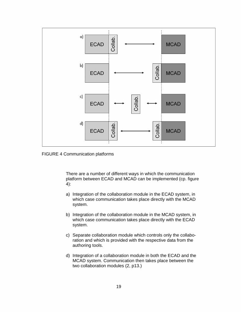
FIGURE 4 Communication platforms
There are a number of different ways in which the communication platform between ECAD and MCAD can be implemented (cp. figure 4): a) Integration of the collaboration module in the ECAD system, in
which case communication takes place directly with the MCAD system.
b) Integration of the collaboration module in the MCAD system, in which case communication takes place directly with the ECAD system.
c) Separate collaboration module which controls only the collabo-ration and which is provided with the respective data from the authoring tools.
d) Integration of a collaboration module in both the ECAD and the
MCAD system. Communication then takes place between the two collaboration modules (2, p13.)
20
The IDX standard could be used in any model presented in the figure 4; for the
testing project NSN has chosen the tools according to the model d). Both de-
sign tools have separate EDMD modules which are connected for data transfer.
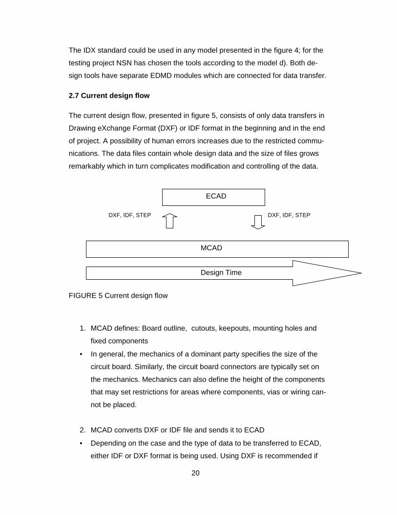
2.7 Current design flow
The current design flow, presented in figure 5, consists of only data transfers in
Drawing eXchange Format (DXF) or IDF format in the beginning and in the end
of project. A possibility of human errors increases due to the restricted commu-
nications. The data files contain whole design data and the size of files grows
remarkably which in turn complicates modification and controlling of the data.
DXF, IDF, STEP DXF, IDF, STEP
FIGURE 5 Current design flow
1. MCAD defines: Board outline, cutouts, keepouts, mounting holes and
fixed components
• In general, the mechanics of a dominant party specifies the size of the
circuit board. Similarly, the circuit board connectors are typically set on
the mechanics. Mechanics can also define the height of the components
that may set restrictions for areas where components, vias or wiring can-
not be placed.
2. MCAD converts DXF or IDF file and sends it to ECAD
• Depending on the case and the type of data to be transferred to ECAD,
either IDF or DXF format is being used. Using DXF is recommended if
ECAD
MCAD
Design Time

21
designer wants to shape up the layout of the background. IDF is a practi-
cal tool to update board edges and defining keepouts.
3. ECAD imports DXF or IDF file and defines the design structure
• The layout designer ensures that the data transfer was successful from
mechanics and all the necessary information can be found in DXF or IDF
file.
4. ECAD converts IDF or Standard for the Exchange of Product model data
(STEP) file and sends it to MCAD
• The layout designer will export DXF or IDF file to the mechanic designer
depending on which format is more practical. The IDF is often used as it
easily demonstrates components’ height information on mechanic tool.
The problem lays in relocation of vias and wiring which has to be carried
out manually.
5. MCAD verifies components’ height and location etc
• The mechanic designer imports the file to the mechanic tool and simulta-
neously inspects the design of components, connectors and the board in
general so that all parts are located correctly. Also a possible collision
must be verified if the file contains vias or wiring.
6. Loop continues as long as the design is ready for manufacturing
• If errors are detected it might be necessary to resend the files number of
times and make further amendments. All the checking are performed
visually, which is rather slow and the possible mistakes are difficult to no-
tice.
2.8 Current solution
One of the main problems is a slow information flow and the repeated need to
convert new files. Since the IDF and the DXF files are slow and laborious to
convert, the files are not made in time and this is due to the poor communica-
22
tion between the mechanics and the layout. In general, the data is being trans-
ferred to the layout before starting to work and in the end at the final stage of
layout. This kind of data transfer can result to time-consuming changes during
the final stage in both MCAD and ECAD. In final phase the time to find errors is
very limited and possible only either MCAD or ECAD can react to the change.
The IDF and the DXF are illustrative but those can only be checked visually by
users and the amendments are difficult or nearly impossible to self-check.
DXF’s benefit is that it is widely supported by most of the design programs
which can export DXF file for example to simulation tools. The DXF can be
saved as a component in the layout and designer can easily move it if neces-
sary. Also the IDF is supported by many mechanics and layout tools. The IDF
allows easily to determine high components’ compatibility with mechanics and
to limit keepouts.
2.8.1 IDF
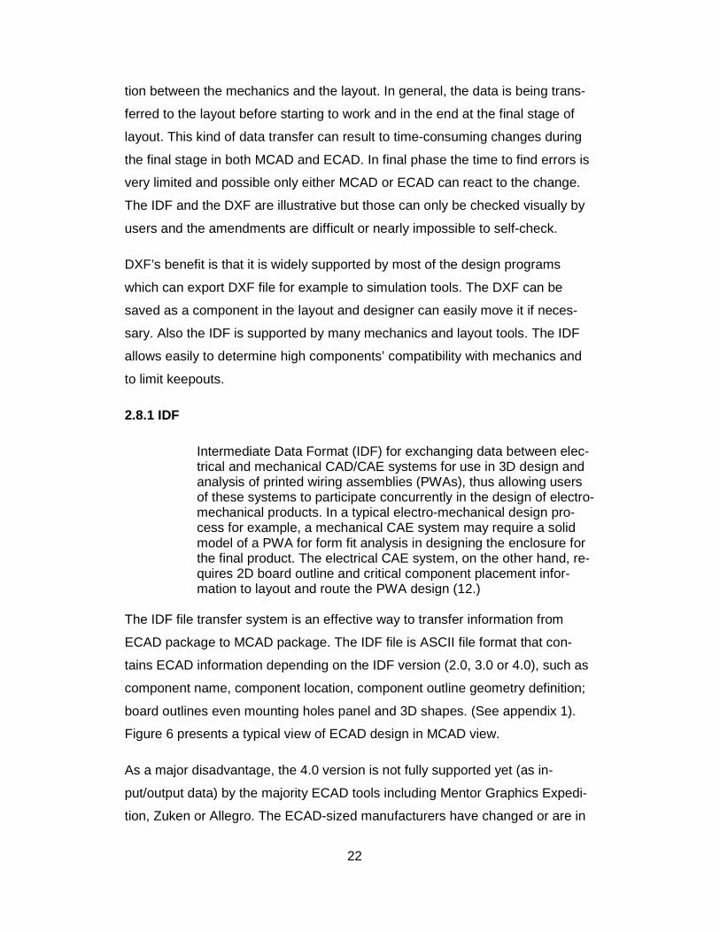
Intermediate Data Format (IDF) for exchanging data between elec-trical and mechanical CAD/CAE systems for use in 3D design and analysis of printed wiring assemblies (PWAs), thus allowing users of these systems to participate concurrently in the design of electro-mechanical products. In a typical electro-mechanical design pro-cess for example, a mechanical CAE system may require a solid model of a PWA for form fit analysis in designing the enclosure for the final product. The electrical CAE system, on the other hand, re-quires 2D board outline and critical component placement infor-mation to layout and route the PWA design (12.)
The IDF file transfer system is an effective way to transfer information from
ECAD package to MCAD package. The IDF file is ASCII file format that con-
tains ECAD information depending on the IDF version (2.0, 3.0 or 4.0), such as
component name, component location, component outline geometry definition;
board outlines even mounting holes panel and 3D shapes. (See appendix 1).
Figure 6 presents a typical view of ECAD design in MCAD view.
As a major disadvantage, the 4.0 version is not fully supported yet (as in-
put/output data) by the majority ECAD tools including Mentor Graphics Expedi-
tion, Zuken or Allegro. The ECAD-sized manufacturers have changed or are in
23
process to change to the next IDF's version, IDX (EDMD) collaboration tool, that
is widely supported by a number of manufacturers.
FIGURE 6 ECAD design imported to MCAD
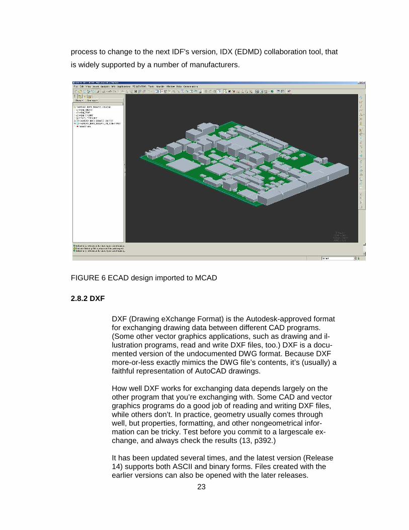
2.8.2 DXF
DXF (Drawing eXchange Format) is the Autodesk-approved format for exchanging drawing data between different CAD programs. (Some other vector graphics applications, such as drawing and il-lustration programs, read and write DXF files, too.) DXF is a docu-mented version of the undocumented DWG format. Because DXF more-or-less exactly mimics the DWG file’s contents, it’s (usually) a faithful representation of AutoCAD drawings. How well DXF works for exchanging data depends largely on the other program that you’re exchanging with. Some CAD and vector graphics programs do a good job of reading and writing DXF files, while others don’t. In practice, geometry usually comes through well, but properties, formatting, and other nongeometrical infor-mation can be tricky. Test before you commit to a largescale ex-change, and always check the results (13, p392.) It has been updated several times, and the latest version (Release 14) supports both ASCII and binary forms. Files created with the earlier versions can also be opened with the later releases.
24
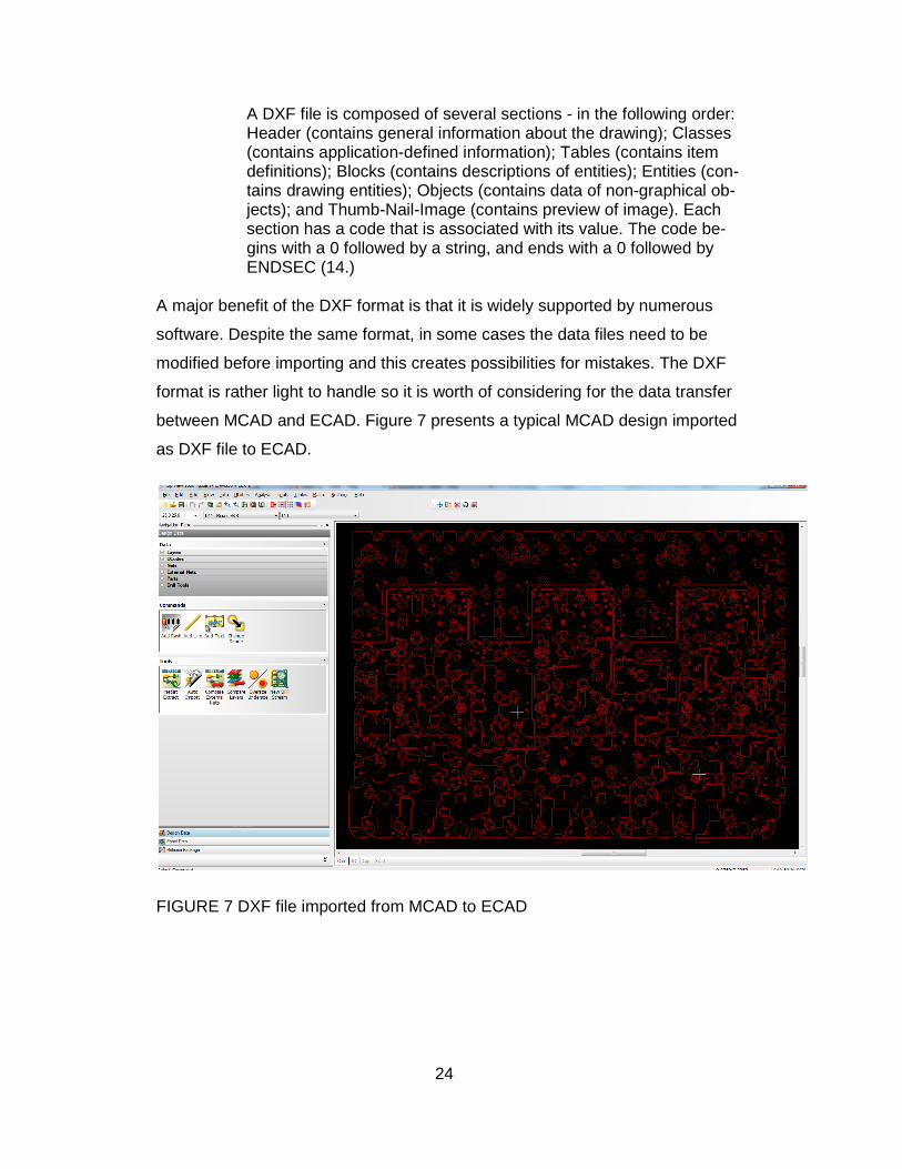
A DXF file is composed of several sections - in the following order: Header (contains general information about the drawing); Classes (contains application-defined information); Tables (contains item definitions); Blocks (contains descriptions of entities); Entities (con-tains drawing entities); Objects (contains data of non-graphical ob-jects); and Thumb-Nail-Image (contains preview of image). Each section has a code that is associated with its value. The code be-gins with a 0 followed by a string, and ends with a 0 followed by ENDSEC (14.)
A major benefit of the DXF format is that it is widely supported by numerous
software. Despite the same format, in some cases the data files need to be
modified before importing and this creates possibilities for mistakes. The DXF
format is rather light to handle so it is worth of considering for the data transfer
between MCAD and ECAD. Figure 7 presents a typical MCAD design imported
as DXF file to ECAD.
FIGURE 7 DXF file imported from MCAD to ECAD
25
2.9 Advantages of EDMD integration
As John MacKrell, senior CIMdata consultant, says: “The bottom line is that the benefits of implementing an ECAD-MCAD collabora-tion strategy today can bring both positive and broad-reaching ben-efits that can be not only financial, but improve product design qual-ity (15.) The integration of mechanical and electrical components in mecha-tronic integrated products is becoming increasingly important. De-velopment takes place in separate domains using different CAD tools (ECAD and MCAD). Although powerful software tools are available on the market for the respective disciplines, support for existing processes and systems is reaching its functional limits with regard to collaboration between these systems. With increasing product complexity and the demand for shorter development cy-cles, there is a growing need for feasible solutions for sustainable collaboration on the basis the existing ECAD and MCAD systems (2, p2.)
The benefits of the EDMD collaboration are faster engineering change resolu-
tion, more functionally valid designs and increased product design innovation.
The IDX is a file type trying to tackle the problems and to improve weaknesses
within the DXF and the IDF formats. The data does not need to be manually
transferred nor does it require to be edited manually. MCAD and ECAD follow
the design progress of other section and are able to react on possible errors
already in early stage. There are some compatibility problems within the differ-
ent tools even though the DXF is widely used and supported format. For exam-
ple, the DXF file needs to be manually edited in another Computer-Aided Manu-
facturing (CAM) tool before layout importing, as there are lots of unnecessary
text, layers and shapes. Along the EDMD collaboration it is possible to gain
traceability and to have the co-operation on a whole new level. With the collabo-
ration tool the design changes can be accepted or rejected and update of this
information is available immediately to other designers. The real time infor-
mation flow reduces the risk of errors and this in turn may lead to innovative
solutions in the design cycle.
26
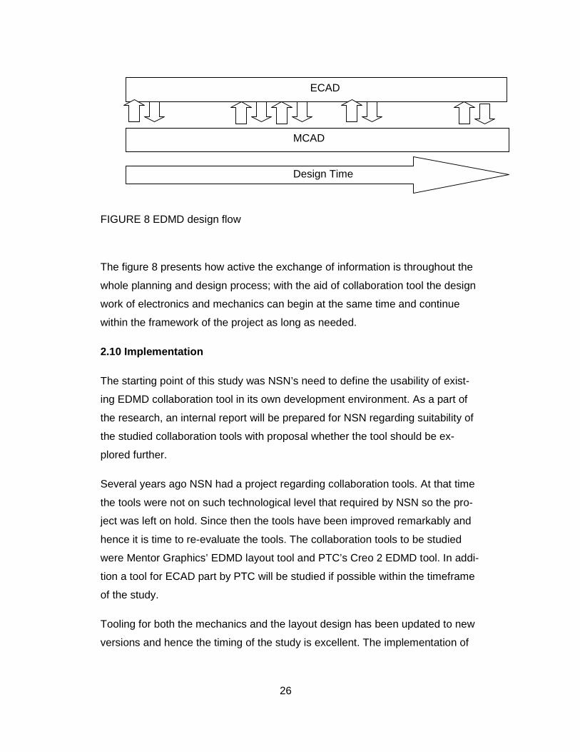
FIGURE 8 EDMD design flow
The figure 8 presents how active the exchange of information is throughout the
whole planning and design process; with the aid of collaboration tool the design
work of electronics and mechanics can begin at the same time and continue
within the framework of the project as long as needed.
2.10 Implementation
The starting point of this study was NSN’s need to define the usability of exist-
ing EDMD collaboration tool in its own development environment. As a part of
the research, an internal report will be prepared for NSN regarding suitability of
the studied collaboration tools with proposal whether the tool should be ex-
plored further.
Several years ago NSN had a project regarding collaboration tools. At that time
the tools were not on such technological level that required by NSN so the pro-
ject was left on hold. Since then the tools have been improved remarkably and
hence it is time to re-evaluate the tools. The collaboration tools to be studied
were Mentor Graphics’ EDMD layout tool and PTC’s Creo 2 EDMD tool. In addi-
tion a tool for ECAD part by PTC will be studied if possible within the timeframe
of the study.
Tooling for both the mechanics and the layout design has been updated to new
versions and hence the timing of the study is excellent. The implementation of
ECAD
MCAD
Design Time
27
both tools is still in starting phase so it is practical to add the implementation of
collaboration in same project.
2.10.1 Operating
The evaluation in practice was started by defining the tasks and the timetable
for performing the needed tests. The tasks were shared to the members of the
project team which consisted of four experts of NSN’s tool development. The
project team was deliberately kept small so that an intensive progress would be
possible along members’ normal work load.
The overall time period for the whole project was planned to be three months.
The schedule is rather tight considering that also the final project report and
possible decisions of further actions should be completed in the same time
frame. However, the short project duration ensures more efficient working pace
and moreover, the decision of future utilization of the evaluated tools is ex-
pected in short term by NSN.
The testing objects were defined strictly based on the NSN requirement; the
results should be applicable directly into the practice. The tasks to be tested are
for example relocation of components, adding and modifying keepout areas,
modifying circuit boards outline and thickness. All the tasks need to be tested
with several different components and in addition it has to be considered that
the tested change input may emerge either in the MCAD or in the ECAD tool.
Moreover, within the testing changing points and the communication between
the MCAD and the ECAD tool it should be noted that the designer need to have
an opportunity either to accept or to reject the proposed change. Altogether
there are numerous items to be tested and all the testing tasks are being fol-
lowed up separately.
After some challenges with installing the licenses the project was started with
self-introduction to the new tool by all participants. The representatives of PTC
and Mentor Graphics organized an excellent live demo session of the tools; with
the given introduction to correct approach it was a lot easier to start actual test-
ing of the tasks. Also, in the demo session were looked through the restrictions
28
of the EDMD tool so it was especially easy to rule out certain tasks that are not
possible to solve with the tool at all. The project meetings were decided to be
held every second week to follow up the progress of the testing and to solve
together with PTC and Mentor Graphics possible arising problem cases.
The actual testing was carried out with the whole project team gathered in the
same meeting room. It was considered to be the most efficient way of working
as the communication was fluent and the problems were solved concurrently. In
a normal working environment the tools allow simultaneous using in several
locations and between separate design centers; the possible restriction results
of limited number of floating licenses available.
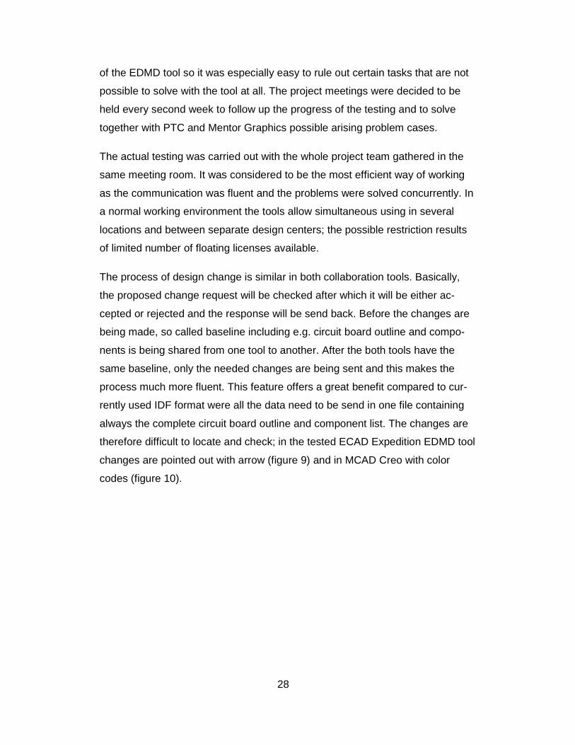
The process of design change is similar in both collaboration tools. Basically,
the proposed change request will be checked after which it will be either ac-
cepted or rejected and the response will be send back. Before the changes are
being made, so called baseline including e.g. circuit board outline and compo-
nents is being shared from one tool to another. After the both tools have the
same baseline, only the needed changes are being sent and this makes the
process much more fluent. This feature offers a great benefit compared to cur-
rently used IDF format were all the data need to be send in one file containing
always the complete circuit board outline and component list. The changes are
therefore difficult to locate and check; in the tested ECAD Expedition EDMD tool
changes are pointed out with arrow (figure 9) and in MCAD Creo with color
codes (figure 10).
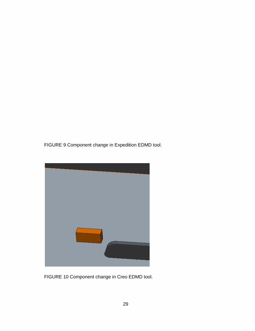
FIGURE 9 Component change in Expedition EDMD tool.
FIGURE 10 Component change in Creo EDMD tool.
29
Component change in Expedition EDMD tool.
Component change in Creo EDMD tool.
30
2.10.2 Challenges
Software implementation projects usually have some difficulties and this project
was not an exception. Part of the needed licenses was delayed and also in-
stalling the licenses was not completed as planned; therefore starting of the pro-
ject was postponed. Nevertheless, the original deadline was kept which tight-
ened the timetables. The project schedule of only three months was the main
challenge and also limited number of testing personnel. The team members had
their own projects to work with and it slowed down the tool development.
The design software, for which collaboration tool was intended, were rather re-
cently taken into use so the team members had limited experience of working
with the design tools. Some additional support from the software manufacturers
was required in order to complete the collaboration tool testing in such extend
than planned. There were also minor challenges to integrate two operating sys-
tems into one environment as MCAD is based on Windows and ECAD runs on
Linux. It was decided to use solely Windows as it was an easier system to build
up testing environment with. The system change was possible to perform even
with project ongoing as Mentor Graphics Expedition supports both Windows
and Linux.
Despite the technical challenges and the very tight schedule the project was
completed timely mostly due to the excellent tool support and the active sched-
ule management. Based on the experiences of the project it can be assumed
that the possible tool implementation in the actual design environment will be
challenging. Most likely the collaboration tool would encounter resistance of
change as it would alter the ways of working significantly. The benefits of the
new tool should be clearly explained and also the guidelines should be well
prepared to ensure positive response.
2.11 The way forward
In case the collaboration tool is decided to be implemented throughout NSN’s
functions based on this pilot testing project, there will be a new testing project
with wider scope. Most probably
that the actual implementation could take place in 2015.
The collaboration tools are under constant development at their manufacturers;
both Mentor Graphics and PTC are going to release new versions
Both software will have good
in the testing phase but some challenges will remain
ered critical will be solved in later versions.
cated that in future Creo will support
stackup from ECAD. Mentor Graphics has also published future plans for r
newed design software Xpedition, currently named Expedition. In Xpedition
there will be a 3D component library with more exact models of components
which improves greatly the
will have a new feature for importing
or even whole mechanic to layout design.
the new Xpedition tool.
FIGURE 11 Mentor Graphics’ Xpedition
31
In case the collaboration tool is decided to be implemented throughout NSN’s
functions based on this pilot testing project, there will be a new testing project
with wider scope. Most probably the testing would be performed during 2014 so
plementation could take place in 2015.
The collaboration tools are under constant development at their manufacturers;
both Mentor Graphics and PTC are going to release new versions during 2014.
good improvements in EDMD tools which were missed
but some challenges will remain; few deficiencies consi
solved in later versions. PTC, MCAD manufacturer, has ind
cated that in future Creo will support for example copper planes and layer
Mentor Graphics has also published future plans for r
newed design software Xpedition, currently named Expedition. In Xpedition
3D component library with more exact models of components
the visual review of designs. In addition the Xpedition
will have a new feature for importing mechanic parts such as screws, heat sinks
or even whole mechanic to layout design. Figure 11 illustrates the 3D view
Mentor Graphics’ Xpedition layout tool (16)
In case the collaboration tool is decided to be implemented throughout NSN’s
functions based on this pilot testing project, there will be a new testing project
testing would be performed during 2014 so
The collaboration tools are under constant development at their manufacturers;
during 2014.
were missed
; few deficiencies consid-
PTC, MCAD manufacturer, has indi-
and layer
Mentor Graphics has also published future plans for re-
newed design software Xpedition, currently named Expedition. In Xpedition
3D component library with more exact models of components
Xpedition
such as screws, heat sinks
view in

32
2.12 Results and conclusion
During the short testing period the EDMD proved to be a potential tool for im-
proving co-operation between the mechanics and electrical design. The collabo-
ration tool provides excellent information for PWB designer in the 3D format
which was not available before. The designer can easily find possible error
components or check correct disposition of components. The exact modeling of
component has a great role in the whole design process and therefore it is high-
ly important that also the 3D modeling is reliable. However, creating and supply-
ing 3D models of components are not at software manufacturers’ responsibility
but those are provided by component suppliers. There is a need for better co-
operation between these two supplier groups so that there would be more 3D
models available; surely it would expand the usage of EDMD.
From mechanic design point of view, the EDMD also provides exact component
models. Furthermore, the communication between mechanic and PWB design-
ers improves greatly as it is continuous throughout the whole design project. For
mechanic designer the EDMD does not offer other visual improvements of sig-
nificant meaning.
The EDMD tool enables data transfer in IDX format which is much flexible com-
pared to the current IDF format. A data file in IDF contains all possible infor-
mation related to a layout design in hand; the IDX instead consists of only the
changes designer has selected for transfer. This way the checking of the
changes is much more fluent for designer receiving the data.
PTC and Mentor Graphics have a major role in creating new IDX format and the
companies have also close co-operation in the development process. Therefore
it is rather strange that the two EDMD tools are quite different; for example the
change function and the related log data are processed completely different
ways. Both the tool manufacturers should improve especially users’ possibilities
to track and manage the log data. Nevertheless, a major deficiency in both tools
is a lack of design module off PWB planes such as solder mask.

33
The purpose of this pilot testing project was to gather and document relevant
information of the collaboration tools to support the decision whether the tools
should be taken into use at NSN. All the planned testing tasks were completed
within the schedule; some of the tasks failed in the current version but were
passed with workaround solutions. With some reservation the EDMD could be
an excellent aid for PWB and mechanic design, providing that the tools are im-
proved and developed further.

34
3 VIRTUAL PROTOTYPING
3.1 Problem statement
Virtual prototyping is focusing on reducing project cost and time, as well as im-
proving quality. Currently the problem is inoperative discussion or communica-
tion between different designers or departments. The lack of fluent information
flow weakens the interaction and creates ground for possible errors. The infor-
mation gaps also cause delays or difficulties to react and repair problems. The
sooner you are aware of the problem, the easier it is to respond with a correct
action. Many times the amount and quality of the data is enough, but controlling
the data is challenging. Each designer need to figure it out themselves what
kind of data is needed by others and when it should be released. It requires
well-instructed teams in order to have a fluent design process with the current
tooling.
3.2 Background
FIGURE 12 Differences of old and new mind-set (17 p.51)

Figure 12 is a good exampl
one of the main focus point
ing, to start operating and simulation in more early phase. In the
failures are encountered in
may be very limited before mass production phase. Usually
is carried out in hast; product introduction, problem solving and documentation
take a lot of time. New mind
Through a proactive mind set and virtual prototyping more failures can be found
earlier than in physical assembly
spond in virtual prototyping
FIGURE 13 Knowledge Managem
Figure 13 presents a diagram of knowledge management
be collected from various simulations after which
tered to sort out the relevant part
be analyzed further for gaining understanding of possible issues or problems at
hand. Finally, a decision can be completed of actions to be taken
basic process of the data utilization in
35
s a good example of needed changing of mind-set. This is actually
in focus points in virtual prototyping; how to turn the way of thin
operating and simulation in more early phase. In the old mind
tered in pre-production and the response time for corrections
may be very limited before mass production phase. Usually the pre-production
is carried out in hast; product introduction, problem solving and documentation
time. New mind-set aims to shorten the process turnaround time.
proactive mind set and virtual prototyping more failures can be found
ical assembly and furthermore, there are more time to r
phase.
Knowledge Management (18 p.15)
a diagram of knowledge management. At first the data will
be collected from various simulations after which the gathered data will be fi
tered to sort out the relevant parts. The information considered necessary will
analyzed further for gaining understanding of possible issues or problems at
decision can be completed of actions to be taken; this is
data utilization in virtual prototyping.
. This is actually
way of think-
old mind-set
response time for corrections
production
is carried out in hast; product introduction, problem solving and documentation
process turnaround time.
proactive mind set and virtual prototyping more failures can be found
ime to re-
data will
gathered data will be fil-
s. The information considered necessary will
analyzed further for gaining understanding of possible issues or problems at
; this is the

36
3.3 Current design flow
In the current process flow with the old mind-set the loop of engineering, testing
and analyzing results continues as many proto rounds as needed. It is relatively
common that the product in the design process may be behind schedule and it
proceeds to production unfinished resulting to a situation that the product faults
are being found only in the pre-production.
Typically in the starting phase of a project the basic data needed is already
available but gathering and storing it in a same place is quite difficult, especially
when the data should be accessed by many. Controlling the data is a very
common problem within larger organizations. Also, manual analyzing and se-
lecting relevant data may be difficult to organize in a way that it serves all func-
tions participating in the project. In worst case the data is being processed in
haste as some decision needs to be made before proceeding.
Briefly, all the needed data and know-how is available but the utilization of those
is a bottleneck. Practical and controlled collection of data, fluent sharing of
knowledge and changing processes into a bit more anticipatory planning are
clearly targets to aim for and virtual prototyping could be just the right tool.
3.4 Existing solutions
The basic ideas behind virtual prototyping are not new or unique; for long time
there have been solutions for saving product costs and increasing quality. Some
of the methods have proven to be successful and here are few examples; it is
good to remember though that companies do not present their latest innova-
tions.
Toyota has started its own virtual prototyping model in 1996 and here is couple
of examples of their flow. Basically, instead of having clearly separate phase of
engineering and production, Toyota has involved production personnel in early
phase in engineering process by using a virtual assembly review. It is easy to
understand the benefit of virtual testing environment to be used, as the tests
and reviews can be repeated quite easily after engineering changes.

37
FIGURE 14 Previous design flow vs virtual assembly review (17 p.29)
In the car industry physical assemblies are complex and expensive; also model-
ing all parts are challenging. By using the virtual assembly review Toyota has
fasten engineering process flow and figure 14 presents clearly how much faster
products are ready for production than earlier.
38
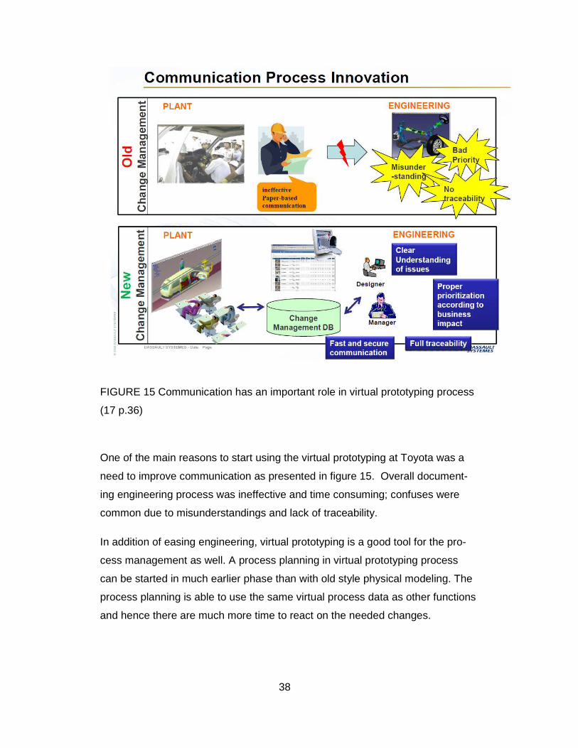
FIGURE 15 Communication has an important role in virtual prototyping process
(17 p.36)
One of the main reasons to start using the virtual prototyping at Toyota was a
need to improve communication as presented in figure 15. Overall document-
ing engineering process was ineffective and time consuming; confuses were
common due to misunderstandings and lack of traceability.
In addition of easing engineering, virtual prototyping is a good tool for the pro-
cess management as well. A process planning in virtual prototyping process
can be started in much earlier phase than with old style physical modeling. The
process planning is able to use the same virtual process data as other functions
and hence there are much more time to react on the needed changes.
39
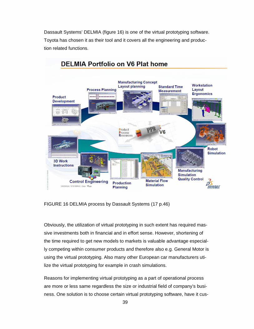
Dassault Systems’ DELMIA (figure 16) is one of the virtual prototyping software.
Toyota has chosen it as their tool and it covers all the engineering and produc-
tion related functions.
FIGURE 16 DELMIA process by Dassault Systems (17 p.46)
Obviously, the utilization of virtual prototyping in such extent has required mas-
sive investments both in financial and in effort sense. However, shortening of
the time required to get new models to markets is valuable advantage especial-
ly competing within consumer products and therefore also e.g. General Motor is
using the virtual prototyping. Also many other European car manufacturers uti-
lize the virtual prototyping for example in crash simulations.
Reasons for implementing virtual prototyping as a part of operational process
are more or less same regardless the size or industrial field of company’s busi-
ness. One solution is to choose certain virtual prototyping software, have it cus-

40
tomized and implement it to be standard part of company’s processes, as Toyo-
ta has done. The other option is to use more readymade solutions which are
also widely available on the market. In practice this usually means acquiring of
subcontracting and this might not be so time-saving solution but it does not re-
quire heavy investments either.
Ansys is one of the leading software manufacturers providing tools for virtual
prototyping and data management. Compared to Dassault Systems used by
Toyota, Ansys’ solutions are lighter.
ANSYS Engineering Knowledge Manager™ (EKM) is a compre-hensive and intuitive foundation for CAE data/configuration man-agement and automation. With this tool, you can accommodate crit-ical needs within your global product development process, from in-tegration with PLM systems (CAD/PDM) and execution (HPC) to collaboration and communication. Right out of the box, EKM is tightly coupled with ANSYS products. You can easily integrate it with other simulation codes, including legacy and commercial off-the-shelf software (19, p2.)
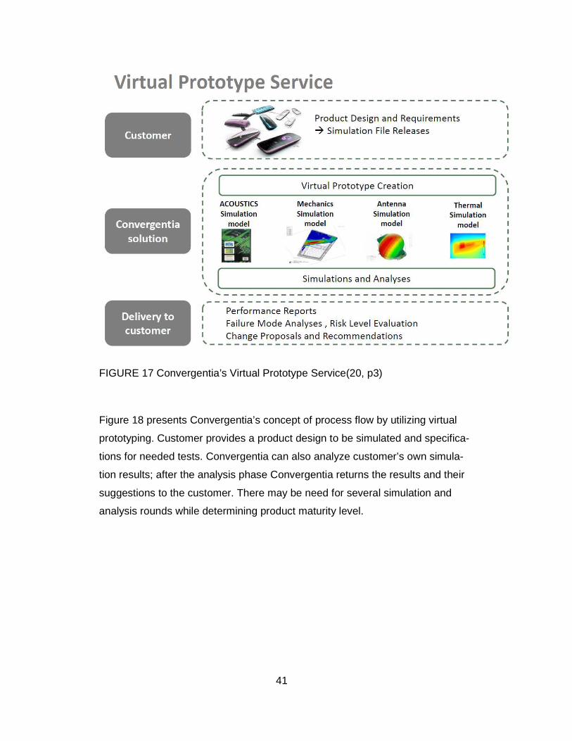
A company called Convergentia is providing a full set of simulation surroundings
and as they describe it in their brochure: “World’s First Virtual Prototype Factory
-Integrated Simulation Solutions based on customer requirements” (20, p1). At
the simplest they perform a separate simulation and analyze the results for cus-
tomer for further actions. Convergentia can also play a significant role in cus-
tomer’s project by offering various simulation models and expertise e.g. in me-
chanics and antenna development as presented in figure 17.
41
FIGURE 17 Convergentia’s Virtual Prototype Service(20, p3)
Figure 18 presents Convergentia’s concept of process flow by utilizing virtual
prototyping. Customer provides a product design to be simulated and specifica-
tions for needed tests. Convergentia can also analyze customer’s own simula-
tion results; after the analysis phase Convergentia returns the results and their
suggestions to the customer. There may be need for several simulation and
analysis rounds while determining product maturity level.

42
FIGURE 18 Convergentia’s State Machine (20, p6)
For the study Convergentia’s Director R&D operations Jukka Solla was inter-
viewed and he raised few issues to be noticed from customer’s point of view
when using their services. The project costs in the beginning might be higher
compared to a in-house R&D project but in most cases the total project costs
end up to be significantly less. The project process will remain same so it can
be easily taken as a standard part of customer’s own process and possible
threads are minimized by using the same approach at all time. Solla also point-
ed out that both time and costs can be saved with an upfront project schedule
as there is more time to react on and correct possible faults.
43
3.5 Virtual prototyping modules
There are numerous software available for virtual prototyping, from various
manufacturers. When selecting suitable tools for a certain project, it is worth
considering which modules should be used. The existing system environment
and for example a number of possible users may have an impact on the range
of modules to be used.
Mechanic design has a major role in virtual prototyping. The mechanic data is
required in every simulation module and especially the data of circuit board
modeling is needed in PWB design. Usually the data is being transferred in the
DXF or IDF format depending on the content of the data and the receiving tool-
ing. Mechanic parts have quite long lead times and currently the completion of
mechanic design defines the project schedule for whole team.
PWB design provides data for PWB SI (Signal Integrity), PI (Power Integrity)
and PWB EMC (Electromagnetic Compatibility) simulation. Usually the data is
being transferred in an ODB++ format as it is widely supported within simulation
tools. From the mechanic tool the data of PWB outline is transferred in DXF or
IDF format. Along progressing in the design, the data from completed sections
is being transferred for simulation purposes. For example, the PWBs have a
shorter lead time than mechanic so it is possible to proceed with design while
waiting for rest of the parts.
Thermal simulation includes for example measurements of heat conduction and
transfer, air pressure and flow. Usually the thermal simulation requires a long
testing period as the mechanical design can be in very early state when the first
simulation rounds are being started. A tool called Icepak by Ansys is suitable for
simulating thermal features of for example components and circuit boards. Fig-
ure 19 presents a view over test result in Ansys’ Icepak simulation tool.

44
FIGURE 19 Ansys’ Icepak simulation tool (21)
EMC simulation is currently considered rather important from product quality
point of view. Possible failures caused by the EMC are tried to be discovered
and removed already in an early phase of the project. Suitable tools are for ex-
ample Microwave Studio and Cable Studio by CST which can also be used for
3D simulations. Simulation objects may be e.g. tightness of mechanical design
in the Microwave Studio and cable interfaces in Cable Studio. There are also
some additional features available for Microwave Studio, for example a TLM
Solver for lightning simulation. Figure 20 shows an example of simulation pos-
sibilities offered by CST Microwave Studio.
FIGURE 20 A simulation view in CST Microwave studio (22)
45
PWB simulations can be divided into three sections; SI (signal integrity), PI
(power integrity) and PWB EMC simulation. All these simulation phases have a
significant role in the design process and hence there are separate simulation
software for each segment.
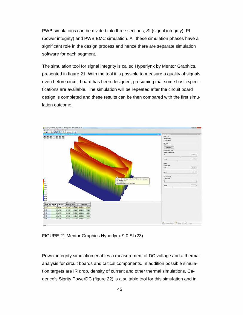
The simulation tool for signal integrity is called Hyperlynx by Mentor Graphics,
presented in figure 21. With the tool it is possible to measure a quality of signals
even before circuit board has been designed, presuming that some basic speci-
fications are available. The simulation will be repeated after the circuit board
design is completed and these results can be then compared with the first simu-
lation outcome.
FIGURE 21 Mentor Graphics Hyperlynx 9.0 SI (23)
Power integrity simulation enables a measurement of DC voltage and a thermal
analysis for circuit boards and critical components. In addition possible simula-
tion targets are IR drop, density of current and other thermal simulations. Ca-
dence’s Sigrity PowerDC (figure 22) is a suitable tool for this simulation and in
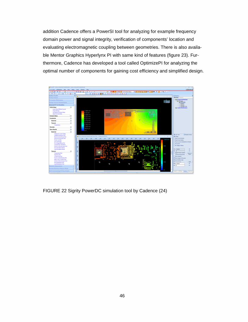
46
addition Cadence offers a PowerSI tool for analyzing for example frequency
domain power and signal integrity, verification of components’ location and
evaluating electromagnetic coupling between geometries. There is also availa-
ble Mentor Graphics Hyperlynx PI with same kind of features (figure 23). Fur-
thermore, Cadence has developed a tool called OptimizePI for analyzing the
optimal number of components for gaining cost efficiency and simplified design.
FIGURE 22 Sigrity PowerDC simulation tool by Cadence (24)
47
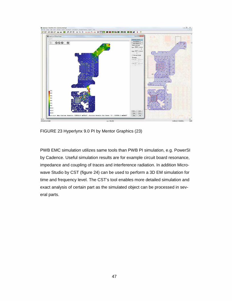
FIGURE 23 Hyperlynx 9.0 PI by Mentor Graphics (23)
PWB EMC simulation utilizes same tools than PWB PI simulation, e.g. PowerSI
by Cadence. Useful simulation results are for example circuit board resonance,
impedance and coupling of traces and interference radiation. In addition Micro-
wave Studio by CST (figure 24) can be used to perform a 3D EM simulation for
time and frequency level. The CST’s tool enables more detailed simulation and
exact analysis of certain part as the simulated object can be processed in sev-
eral parts.
48
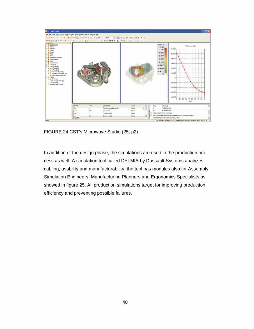
FIGURE 24 CST’s Microwave Studio (25, p2)
In addition of the design phase, the simulations are used in the production pro-
cess as well. A simulation tool called DELMIA by Dassault Systems analyzes
cabling, usability and manufacturability; the tool has modules also for Assembly
Simulation Engineers, Manufacturing Planners and Ergonomics Specialists as
showed in figure 25. All production simulations target for improving production
efficiency and preventing possible failures.

49
FIGURE 25 DELMIA Ergonomics Specialists simulation tool by Dassault Sys-
tems (26, p1)
3.6 Data management
Data management has a significant role in the simulation process. The simula-
tion result data and related documents usually require plenty of storage space
and at the same time the information should be available for several users. This
might form some challenges especially in projects shared with several locations;
the version control lies on each designer and e.g. email is too size-limited tool
for communication. Nowadays there are commercial solutions in wide range for
creating company’s own cloud services but naturally this will require some dedi-
cated resources for maintenance. It is also possible to use ready-made tools
with a fixed data management structure; these are offered e.g. by Arena and
Ansys.
50
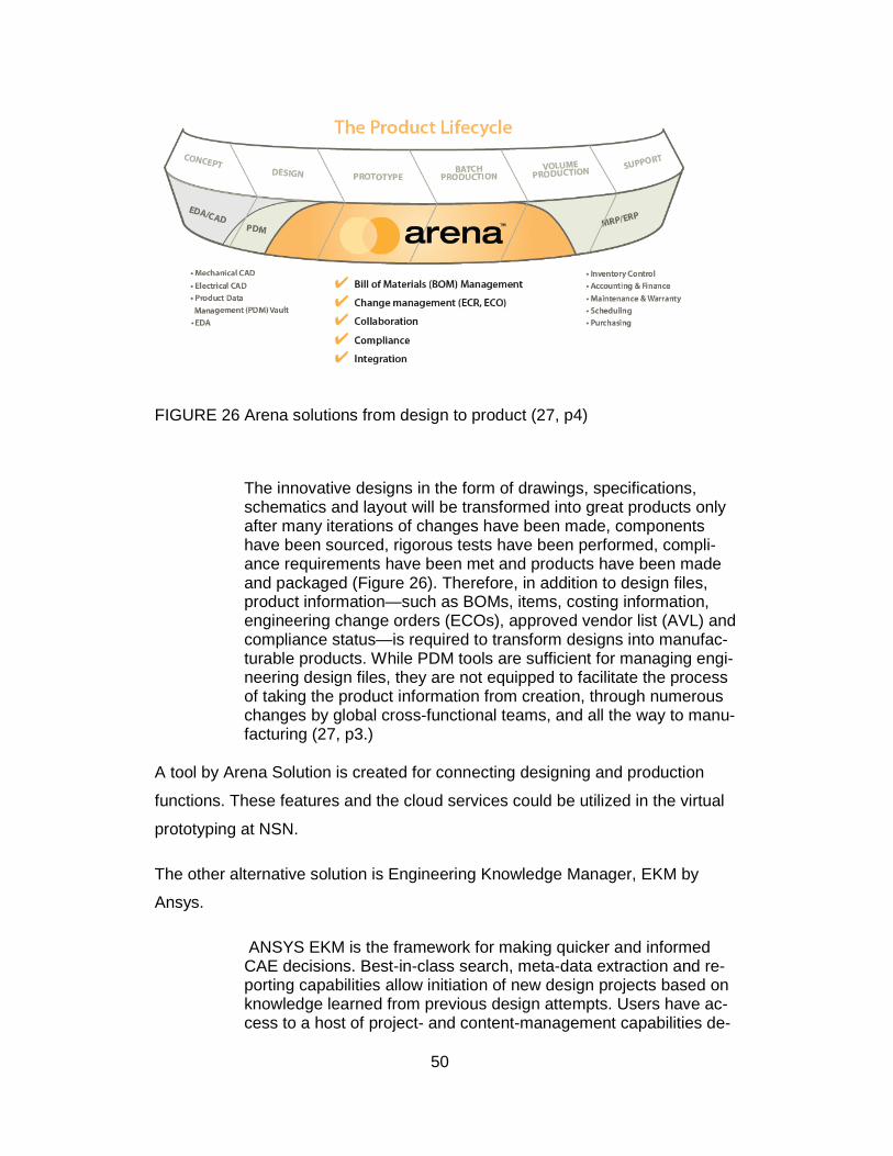
FIGURE 26 Arena solutions from design to product (27, p4)
The innovative designs in the form of drawings, specifications, schematics and layout will be transformed into great products only after many iterations of changes have been made, components have been sourced, rigorous tests have been performed, compli-ance requirements have been met and products have been made and packaged (Figure 26). Therefore, in addition to design files, product information—such as BOMs, items, costing information, engineering change orders (ECOs), approved vendor list (AVL) and compliance status—is required to transform designs into manufac-turable products. While PDM tools are sufficient for managing engi-neering design files, they are not equipped to facilitate the process of taking the product information from creation, through numerous changes by global cross-functional teams, and all the way to manu-facturing (27, p3.)
A tool by Arena Solution is created for connecting designing and production
functions. These features and the cloud services could be utilized in the virtual
prototyping at NSN.
The other alternative solution is Engineering Knowledge Manager, EKM by
Ansys.
ANSYS EKM is the framework for making quicker and informed CAE decisions. Best-in-class search, meta-data extraction and re-porting capabilities allow initiation of new design projects based on knowledge learned from previous design attempts. Users have ac-cess to a host of project- and content-management capabilities de-
51
signed specifically for work-in-progress and archival CAE needs (19, p2.)
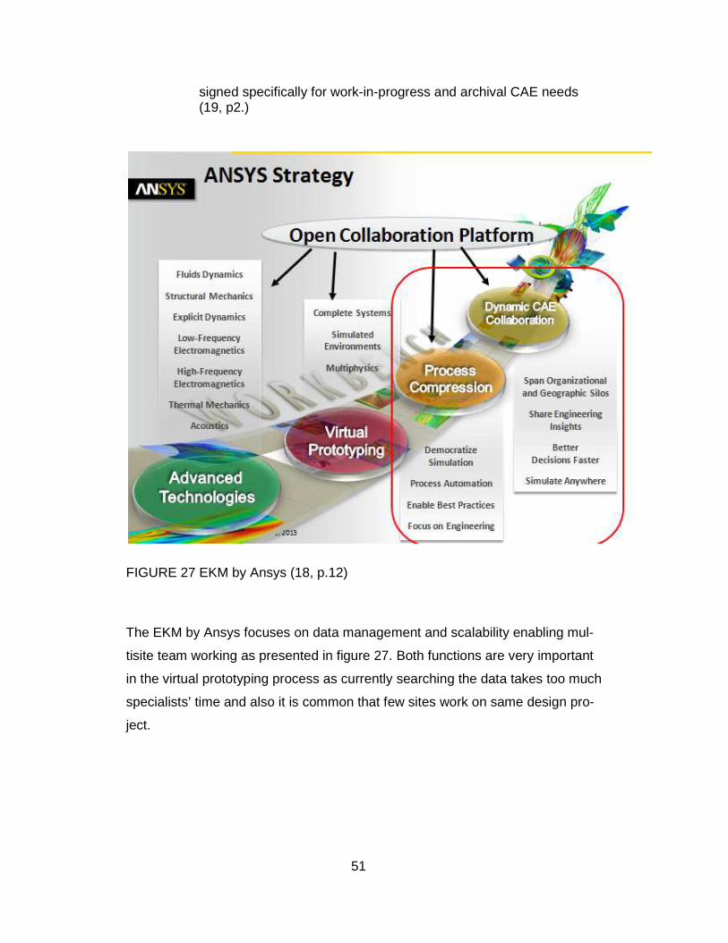
FIGURE 27 EKM by Ansys (18, p.12)
The EKM by Ansys focuses on data management and scalability enabling mul-
tisite team working as presented in figure 27. Both functions are very important
in the virtual prototyping process as currently searching the data takes too much
specialists’ time and also it is common that few sites work on same design pro-
ject.
52
3.7 The way forward
Based on this pilot project, it can be stated that virtual prototyping has clear
benefits and potential. It would be sensible to implement it at NSN within next
project starting even if there will be need for further development to adjust virtu-
al prototyping into NSN’s practices. Integrating the new way of working will be
challenging as it will cover wide range of functions from data management to
communication on many levels. One of the major challenges will be training
personnel and instructing the usage of virtual prototyping in such way that it will
serve the whole process in optimal way.
Before implementing virtual prototyping it should be decided which functions will
be included in the project and what kind of simulation is required. There are ex-
isting models of approach for the virtual prototyping, but it is advisable for every
company to discover suitable practices of their own. For easier start the virtual
prototyping can be integrated into existing process even though in practice it will
trigger need for continuous development within R&D functions.
Data management is also one of the issues to be solved before implementing
any tools. The options are either to have own data storage system or to use
some ready-made solution; both methods have their advantages and weak-
nesses. Own data management system is naturally customized according to
NSN’s needs but on the other hand requires constant maintenance resources.
On contrary, the commercial data storage tool is more easier to maintenance
but for sure some compromises must be done with the tool features and hence
usability.
Starting to use the virtual prototyping requires some practical preparations such
as data management and user training. Running projects with the method will
get easier over the time but it should be noted that the virtual prototyping serves
well in projects of certain size. It might be too heavy for small projects but on the
other hand, complex and massive projects may be difficult to control as one
trough virtual prototyping. An optimal virtual prototyping project consists of de-
velopment work of single clearly specified object.

53
The virtual prototyping is rather new procedure at NSN and there are only lim-
ited experiences of usage. It has been implemented into few projects and the
feedback has been positive. So far the greatest benefit has been a new meeting
practice for problem solving in which the experts of all functions participate. This
way the project team members get to know each other and they learn to under-
stand the whole project. In the meetings and in virtual prototyping in general
team members can share their expertise and in many cases new points of view
may help to solve problematic issues.

54
4 CONCLUSION
The thesis concentrated on studying two possible methods to improve the
NSN’s product development process. A new software tool called EDMD was
trialed in collaboration with the current design tools and virtual approach of pro-
totyping and simulation was tested with a real product project. The purpose of
these tests was to define possible advantages of the tools considering the
NSN’s design environment.
The EDMD collaboration software proved to be a rather potential tool for im-
proving communication between the mechanic and electronic design phases.
Currently data the transfer is quite cumbersome and hence changing the infor-
mation during the design processes is insufficient. The possibility to flowing data
transfer enables more fluent project working and may even shorten the project
duration. Another clear advantage of the EDMD tool is its visual functionalities;
the designs are easier to perceive with the 3D modeling and most likely this will
also decrease the number of human errors. Finally, as an additional module to
the existing design software EDMD tool should be simple to implement but
clearly it still requires further development. During the testing few significant
deficiencies appeared with the software’s basic functionalities and the problems
remained unsolved by the software suppliers. Nevertheless, both the suppliers
have indicated that there will be new versions released during 2014. At this
stage, it must be concluded that the tested version of the EDMD tool is not yet
suitable for NSN environment.
Virtual prototyping is not only a software or a tool to be implemented but a new
approach to the way of working. The results from the test project were promis-
ing but it will take years to learn the true benefits of the practice. The main ob-
servations of the test project were improved communication of team members
and better utilization of the existing simulation tools. Based on these it could be
assumed that in longer run the virtual prototyping could produce cost and time
savings; at its best the virtual simulation could replace the usage of physical
prototypes. Implementation of virtual prototyping requires strong commitment
from project team members to really change the ways of thinking and hence it

55
might encounter resistance among designers accustomed to old practices. De-
spite of the possible complications with getting started, virtual prototyping is def-
initely recommendable. Especially the concept of project meetings and infor-
mation sharing was considered useful by the team members of the test project.
Overall, concentrated data management has an important role in virtual proto-
typing since simulation results should be easily accessible by all project mem-
bers. It can be summarized that the most relevant benefit of virtual prototyping
is increased understanding of whole project process and its target by the partic-
ipating employees; the actual measurable results may be difficult to gather.
The studies performed for the thesis provided adequate answers to the objec-
tives set by NSN. The testing period could have been longer but the findings are
considered sufficient in order to proceed with resolution in the current situation.
Both the tools are very interesting from the product development’s point of view
and most likely these topics will be under further action at NSN in the near fu-
ture.

56
REFERENCES
1. Evans, Rob ECAD-MCAD Design Integration. Available at: 01 November
2007 http://pcdandf.com/cms/magazine/95/3929. Date of data acquisi-
tion: 01 August 2013.
2. ECAD/MCAD Collaboration, RECOMMENDATION ECAD/MCAD Collab-
oration, PSI 5 Version 1.0, specification sheet.
3. Odell, Daniel L and Wright, Paul K Concurrent Product Design: A Case
Study on the Pico Radio Test Bed.
http://www.southampton.ac.uk/~jps7/DSO%20SESG6019/DSO%20case
%20study.pdf. Date of data acquisition: 18 June 2013.
4. Mitzner, Kraig, Complete PCB Design Using OrCAD Capture and PCB
Editor, 2009.
5. Mentor Graphics Xpedition Enterprise Brochure.
http://s3.mentor.com/public_documents/datasheet/pcb/xpedition-
brochure.pdf. Date of data acquisition: 15 January 2014.
6. Leyton, Michael, A Generative Theory of Shapes, 2001.
7. PTC Creo. Available at: 28 May 2013
http://creo.ptc.com/2013/05/28/prepare-for-last-minute-changes-
download-fmx-free/. Date of data acquisition: 15 October 2013.
8. Kehmeier, Dave Integrating PCB Layout and Mechanical Design. Availa-
ble at: 29 June 2012
http://pcdandf.com/cms/component/content/article/9152-mcad-ecad.
Date of data acquisition: 29 Septemper 2013.
9. Jäkel, Volker and Fröhlich, Arnulf Standardized Library Components for
ECAD/MCAD Collaboration presentation. Available at: 12 May 2009
http://www.prostep.org/fileadmin/user_upload/ProSTEPiViP/Events/Sym
57
posium-2009/Praesentationen_Tag_1/0405_Presentation-Froehlich-
Jaekel.pdf. Date of data acquisition: 15 November 2013.
10. Mentor Graphics ECAD-MCAD Collaborator User’s Guide Software Ver-
sion 2.3.1 February 2012.
11. Integrating PCB Layout and Mechanical Design.
http://pcdandf.com/cms/advertise/9152-mcad-ecad. Date of data acquisi-
tion: 12 June 2013.
12. Mechanical Data Exchange Specification for the Design and Analysis of
Printed Wiring Assemblies Version 2.0. Available at: 5 January 1993
http://www.simplifiedsolutionsinc.com/images/idf_v20_spec.pdf. Date of
data acquisition: 15 June 2013.
13. Byrnes, David AutoCAD 2008 For Dummies. 2008.
14. What is DXF? http://www.coolutils.com/formats/dxf. Date of data acquisi-
tion: 30 Jun 2013.
15. PTC ECAD-MCAD collaboration: Best practice spotlight 6882–ECAD-
MCAD Collaboration BP–SL–EN–0911 Brochure. 12 May 2009.
16. Mentor Graphics webinar. http://www.mentor.com/pcb/series/xpedition-
vx-webinar-series?cmpid=7874. Date of data acquisition: 15 January
2014.
17. Negishi, Takatoshi Toyota way and Digital manufacturing Presentation.
13 June 2011.
18. Virdung, Torbjörn Collaborative Knowledge Management ANSYS EKM
Presentation. 11 October 2012.
19. Ansys EKM brochure. 2011
http://www.ansys.com/staticassets/ANSYS/staticassets/resourcelibrary/b
rochure/ansys-ekm-brochure-14.0.pdf. Date of data acquisition: 30 De-
cember 2013.

58
20. Convergentia Company Presentation, Brochure. September 2013.
21. Ansys Icepak.
http://www.ansys.com/Products/Simulation+Technology/Fluid+Dynamics/
Specialized+Products/ANSYS+Icepak. Date of data acquisition: 12 De-
cember 2013.
22. CST Microwave studio. https://www.cst.com/Products/CSTMWS/Solvers.
Date of data acquisition: 12 December 2013.
23. Mentor Graphics Hyperlynx Si and PI.
http://www.mentor.com/pcb/hyperlynx/. Date of data acquisition: 12 De-
cember 2013.
24. Cadense Sigrity PowerDC.
http://www.cadence.com/products/sigrity/powerdc/pages/default.aspx.
Date of data acquisition: 13 December 2013.
25. CST EM Studio Low Frequency Electromagnetic Design and Simulation.
https://www.cst.com/Content/Media/CST_EMS_low.pdf. Date of data ac-
quisition: 18 December 2013.
26. Dassault Systems DELMIA Ergonomics Specialists.
http://www2.3ds.com/fileadmin/PRODUCTS/DELMIA/PDF/DM-12847-
Ergo-Analysis-Human-Activities-Datasheet_HR.pdf. Date of data acquisi-
tion: 18 December 2013.
27. Arena Turning Great Designs Into Great Products - The Changing World
of Mechanical Design. http://www.arenasolutions.com/resources/white-
paper/. Date of data acquisition: 4 January 2014.

APPENDIX1/1
1
APPENDIX
IDF Overview
IDF2.0 IDF3.0 IDF4.0
Data FormatDIP_8 PN-2245-D U1 100.0 600.0 270.0
TOP PLACED
DIP_8 PN-2245-D U1 100.0 600.0 0.0 270.0
TOP PLACED
Electrical_Part_Instance (
Entity_ID (#3003),
Part_Name (“DIP_8”),
Part_Number (“PN-2245-D”),
Refdes
(“U1”),
XY_
Loc
(0.1, 0.6),
Side (Top),
Rotation (270.0),
Mnt
_Offset (0.0, 0.0)
); /* End Electrical_Part_Instance */
Component
Shapes
Component
Instances
Annotations X This Is a Note
Graphics X X
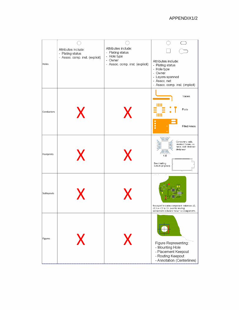
APPENDIX1/2
2
Holes
Conductors X X
Footprints X X
Sublayouts X X
Figures X X
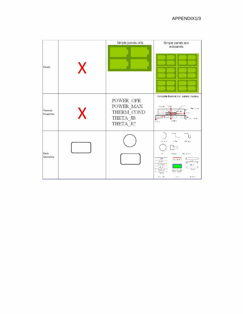
APPENDIX1/3
3
Panels X
Thermal
Properties X
Basic
Geometry