Computational study of strengthening effects of stiffeners on regular and arbitrarily stiffened...
10
(This is a sample cover image for this issue. The actual cover is not yet available at this time.) This article appeared in a journal published by Elsevier. The attached copy is furnished to the author for internal non-commercial research and education use, including for instruction at the authors institution and sharing with colleagues. Other uses, including reproduction and distribution, or selling or licensing copies, or posting to personal, institutional or third party websites are prohibited. In most cases authors are permitted to post their version of the article (e.g. in Word or Tex form) to their personal website or institutional repository. Authors requiring further information regarding Elsevier’s archiving and manuscript policies are encouraged to visit: http://www.elsevier.com/copyright
Transcript of Computational study of strengthening effects of stiffeners on regular and arbitrarily stiffened...

(This is a sample cover image for this issue. The actual cover is not yet available at this time.)
This article appeared in a journal published by Elsevier. The attachedcopy is furnished to the author for internal non-commercial researchand education use, including for instruction at the authors institution
and sharing with colleagues.
Other uses, including reproduction and distribution, or selling orlicensing copies, or posting to personal, institutional or third party
websites are prohibited.
In most cases authors are permitted to post their version of thearticle (e.g. in Word or Tex form) to their personal website orinstitutional repository. Authors requiring further information
regarding Elsevier’s archiving and manuscript policies areencouraged to visit:
http://www.elsevier.com/copyright

Author's personal copy
Computational study of strengthening effects of stiffeners on regularand arbitrarily stiffened plates
Yucheng Liu n, Qingkui Wang
Department of Mechanical Engineering, University of Louisiana at Lafayette, Lafayette, LA 70503, USA
a r t i c l e i n f o
Article history:
Received 28 February 2012
Received in revised form
27 April 2012
Accepted 1 May 2012
Keywords:
Stiffened plate
USL
Strength analysis
Arbitrary stiffener
ANSYS nonlinear FEA
a b s t r a c t
In this paper, strengthening effects of stiffeners on regular and arbitrarily stiffened plates are discussed
in terms of the ultimate strength limit (USL) obtained through full nonlinear transient analysis. This
study starts from the investigation of strengthening effects of regular stiffened plates which are
subjected to uniaxial stress and then arbitrarily stiffened plates that are subjected to biaxial stress. The
optimal height, number, and arrangement of the stiffener that provide the best strengthening effect are
revealed and it is also found that the strengthening effects of an arbitrarily oriented stiffener (or oblique
stiffener) can be decoupled to two perpendicular regular stiffeners which are located in appropriate
positions. Nonlinear buckling analyses were performed on the arbitrarily stiffened plates with one and
two arbitrarily oriented stiffeners to verify this finding. The outcome of this paper can be further
extended and applied to develop simplified semi-analytical models for buckling strength analysis of
constructional plates.
& 2012 Elsevier Ltd. All rights reserved.
1. Introduction
In many branches of engineering (such as aerospace engineer-ing, automotive engineering, and shipbuilding), stiffened platesare used as one of the main structural components in manyengineering structures (wings, truck boxes, ship bottom plates,etc.), which are usually subjected to in-plane biaxial and shearloading. Being economical but strong enough, the stiffened platesefficiently improve the strength/weight ratios and reduce costs ofstructures, in which stiffeners are positioned to prevent a globalbuckling mode. The elastic buckling and buckling strength ana-lysis of the stiffened plates subject to the in-plane loading is veryimportant in structural design and analysis. Advanced analyticaland computational approaches to perform such analysis havebeen presented by a number of investigators.
Byklum and Amdahl derived a computational model for analysisof local buckling and postbuckling of stiffened panels to provide a toolthat was more accurate and efficient than nonlinear finite elementmethods [1]. Based on that model, the investigators continued toderive a computational model for global buckling and postbucklinganalysis of the stiffened plates subject to biaxial in-plane compressionor tension, shear, and lateral pressure [2]. Brubak et al. presented andvalidated an approximate, semi-analytical computational model for
the stiffened plates subject to in-plane loading and estimated thebuckling strength using the von Mises yield criterion for the mem-brane stress as the strength limit [3]. With that model as a bench-mark, the investigators continued to present a computationallyefficient method for the elastic buckling and buckling yield strengthanalysis of in-plane biaxial and shear loaded stiffened plates withvarying, stepwise constant thickness [4]; and a semi-analyticalmethod for pre- and postbuckling analysis of imperfect plates witharbitrary stiffener arrangements by using a large deflection theory incombination with the Rayleigh–Ritz approach on a incremental form,which is able to trace both local and global equilibrium paths [5].Along with developing those methods and studying the stiffenedplates, Brubak and Hellesland studied various strength criteria thatmay be used in the semi-analytical methods for ultimate strengthprediction of arbitrarily stiffened plates and evaluated the applic-ability of the criteria in ultimate strength predictions of in-planeloaded plates, both in local and global bending [6]. Paik and Lee,however, presented a semi-analytical method for the elastic–plasticlarge deflection analysis of stiffened panels under biaxial loads, edgeshear, biaxial in-plane bending and out-of-plane (lateral) pressureloads until the ultimate strength was reached [7]. In their method, theeffect of initial imperfections in the form of initial deflection andwelding residual stresses was accounted for and the validity of thatmethod was demonstrated by comparing the calculated results withnumerical results.
The previously developed approaches can correctly predict thebuckling behavior of the stiffened plates when they are subjectedto different types of loading. However, those methods did not
Contents lists available at SciVerse ScienceDirect
journal homepage: www.elsevier.com/locate/tws
Thin-Walled Structures
0263-8231/$ - see front matter & 2012 Elsevier Ltd. All rights reserved.
http://dx.doi.org/10.1016/j.tws.2012.05.001
n Corresponding author. Tel.: þ1 337 482 5822; fax: þ1 337 482 1129.
E-mail addresses: [email protected] (Y. Liu),
[email protected] (Q. Wang).
Thin-Walled Structures 59 (2012) 78–86

Author's personal copy
answer how the stiffener’s height, location, and number affect thestrengthening effects on the structural plates. Meanwhile, thedeveloped semi-analytical models for the arbitrarily stiffenedplates are still complicated and can be simplified to be better fitfor computer programming. Since ultimate limit state assessmenthas been recognized as an important field in design and analysisof stiffened plates [8], this paper follows Paik and Lee’s methodsto find out the strengthening effects of stiffeners on regular andarbitrarily stiffened plates by comparing the ultimate strengthlimit (USL). The stiffened plates involved in this study aresubjected to either uniaxial or biaxial stress and the numericalresults are calculated using ANSYS nonlinear finite elementanalysis (FEA) methods.
2. Modeling information
Finite element (FE) models for all the stiffened plates involvedin this study are meshed using Shell 93, which incorporatesquadratic deformation shapes in both in-plane directions andprovides six degrees of freedom (DOF’s) at each node. The Shell 93element is selected for this study because it has plasticity, stressstiffening, large deflection, and large strain capabilities, which areextremely suitable for the nonlinear buckling strength analysisinvolved here [9]. In order to simplify the FEA models and savecomputing time, element Beam 189, instead of a shell element, isused to model the stiffeners that attached to the plates. The Beam189 is a quadratic three-node beam element defined in 3D spacewith six DOF’s at each node. With an optional seventh DOF(warping magnitude) available, such beam element is well suitedfor linear, large rotation, and large-strain applications [9]. In ourmodels, the stiffeners are reliably attached to the plate usingmultipoint constraints (MPC) technique, which is provided byANSYS. The MPC is modeled via bonded contact together with aspecial contact solution algorithm [10], which is valid for bothsmall and large deflection analysis.
The ultimate strength limit (USL) is selected to assess thestiffened plate’s buckling strength because it is crucial for determin-ing the safety margin of platforms, ships, and other engineeringstructures against both local and overall collapse. Moreover, USL isoften used as a buckling criterion in specifying dimensions of loadbearing structures such as hull girders, truck boxes, and platforms,etc. The importance and popularity of USL in design and analysis ofengineering structures, especially those load carrying and loadbearing structures, have been demonstrated in a series of papersauthored by Paik et al. [11–13] and Paik and Seo [14]. As suggestedby Brubak et al. [3], in calculating the USL, an initial imperfectionw0¼5 mm is applied on the plates in order to generate obviousbuckling. Since the objective of this paper is to investigate thestrengthening effects of the stiffeners, it is assumed that all thestudied plates have the same dimension 1000�1000 mm2 and thethickness 22 mm. Those plates are made of mild steel with Young’smodulus E¼208 GPa, Possion’s ratio n¼0.3, and yield strengthfY¼235 MPa. A bilinear stress-strain relationship is assumed todescribe the material behavior of the steel, where the hardeningmodulus ET¼1000 MPa. In estimating the USL, the von Misesyield criteria is used and an isotropic work hardening assumptionis taken.
3. Regular stiffened plates subject to uniaxial stress
In this section, the strengthening effects of stiffener’s height,arrangement, and number on the regular stiffened plates that aresubjected to uniaxial stress are found out through ANSYS non-linear FEA. Fig. 1 plots a FE stiffened plate model which is simply
supported and subjected to the uniaxial stress Sx. A typical load-deflection response of an unstiffened plate subject to the sameloading and boundary conditions is plotted at first (Fig. 2) toprovide a benchmark to the following analyses. As shown inFig. 2, the unstiffened plate reaches its USL when the externalstress Sx is 172.2 MPa, and the maximum additional displacementis 5.52 mm at the onset of membrane yielding.
3.1. Stiffener’s height
The stiffener with ‘‘I’’ cross section is discussed in this studywhich has fixed thickness tw¼12 mm, bf¼35 mm, tf¼10 mm, andvarying height hw (Fig. 3). This paper mainly focuses on the effectsof hw on the stiffened plate’s USL and will find the optimal hw thatyields the best USL. The effects of other dimensions on thestiffened plate’s buckling behavior will be thoroughly investi-gated in another paper by following a similar approach. In thatpaper, the strengthening effects of stiffeners with different crosssections will also be discussed.
Table 1 lists different hw (therefore hw/tw) tested in this study.It is assumed that the stiffened plate only has one stiffenerattached to the middle position, with the boundary and loadingconditions described above. By performing the buckling strengthanalysis, USL are calculated for the stiffened plates with differentstiffener height hw, as shown in Fig. 4. From Fig. 4 it can be foundthat the USL increases with hw increased, but there exists athreshold value, exceed which the calculated USL will not appar-ently increase. Instead of directly showing the USL, we display theratio of USL and the material’s yield strength Sx/fY in Fig. 4. Since
Fig. 1. FE stiffened plate model subjects to uniaxial loading.
Fig. 2. Load-deflection response of the unstiffened plate.
Y. Liu, Q. Wang / Thin-Walled Structures 59 (2012) 78–86 79

Author's personal copy
the mild steel’s yield strength fY¼235 MPa, it can be easily esti-mated from Fig. 4 that the optimal USL is 246 MPa when thethreshold ratio hw/tw¼15. Since the stiffener’s height-thickness ratiohw/tw¼15 yields the best USL, in the following computationalanalyses that ratio is assumed for all the stiffeners.
3.2. Location of stiffeners
Next, the effects of location of stiffeners on the calculated USLof the stiffened plates are discussed. We start our study from thestiffened plates with one stiffener and have tested a number ofstiffened plates whose stiffener is located at different position. Forexample, Fig. 5 shows three stiffened plates are plotted with thestiffener located at the middle, third, and fifth of the plate. Thesame uniaxial loading and boundary conditions are applied andthe calculated USL are displayed in Fig. 6, from which it is foundthat the stiffener located at the middle of the plate provides thebest effect to enhance the USL.
For the stiffened plates with more than one stiffener, it isfound that the plate whose stiffeners are evenly arranged on itwill provide the best strengthening effect and lead to optimal USL.Such arrangement is called as homogeneous arrangement. Fig. 7shows the von Mises stress distribution on three stiffened plateswith two unevenly-arranged stiffeners (a and b) and two evenly-arranged stiffeners (c). The numerical results show that thestiffened plates with nonhomogeneous arrangement yield USLas Sx/fY¼0.97 (a) and 1.07 (b), while the stiffened plate withhomogeneous arrangement lead to the optimal USL Sx/fY¼1.20.Similar phenomenon can also be observed for the stiffened plateswith three and more stiffeners. For example, the USL calculatedfor a stiffened plate whose three stiffeners are unevenly arranged(Fig. 8) is Sx/fY¼0.96, while the stiffened plate with homogeneousarrangement yields the value Sx/fY¼1.21. In summary, throughcomputational analyses and results comparisons, it is foundthat with the same number of stiffeners, the stiffened platewith homogeneous arrangement of its stiffeners provides the
Fig. 3. Cross section of the stiffener studied in this paper.
Table 1hw and hw/tw.
hw 24 60 84 120 144 160 240 300
hw/tw 2 5 7 10 12 15 20 25
Fig. 4. USL of stiffened plates with different hw.
Fig. 5. Locations of a single stiffener on a plate. (a) Stiffener at 1/5 of plate, (b) Stiffener at 1/3 of plate, (c) Stiffener at 1/2 of plate.
0.8
0.85
0.9
0.95
1
1.05
1.1
1/5
Sx/f
Y
Location of plate1/4 1/3 1/3 2/5 4/9 1/2
Fig. 6. USL of stiffened plates with one stiffener located at different positions.
Y. Liu, Q. Wang / Thin-Walled Structures 59 (2012) 78–8680

Author's personal copy
maximum USL. Thus, in discussing the effect of number ofstiffeners on improving strength of the stiffened plate, it isassumed that the stiffeners always follow the homogeneousarrangement.
3.3. Number of stiffeners
In order to find the relationship between USL and the numberof stiffeners, stiffened plates with one to four stiffeners with
homogeneous arrangment (Fig. 9) are modeled and used foranalysis. As shown in Fig. 10, when the number of stiffenersincreases from 0 to 1, the USL increases 43.2%; when it increasesfrom 1 to 2, the USL increases 14.0%; when it increases from 2 to3, the USL increases about 1.13%; while when the numberincreases from 3 to 4, the USL only increases 0.69%, and noobvious increment in USL is found by adding more stiffeners.
From the results, it is found that the strengthening effect ofstiffeners decreases as the number of stiffeners increases. And forany plate with certain size, there should be an optimal number ofstiffeners which can yield the best USL while reducing the designand manufacturing cost. In the plates involved in this study, thatnumber is four.
4. Discussion
Based on the analysis performed on the regular stiffened plateswhich are simply supported and subjected to uniaxial loading,following conclusions can be drawn for the strengthening effectsof the stiffeners:
(1) For the stiffener with ‘‘I’’ cross section, the ratio hw/tw¼15 canoptimally improve the plate’s buckling strength.
(2) Stiffeners with homogeneous arrangement provide betterbuckling performance than the stiffeners with nonhomogeneousarrangement.
(3) For any plate with specified size, there is an optimal numberof stiffeners yields the best USL while reducing the design andmanufacturing cost. In the plates involved in this study, thatnumber is four.
The presented conclusions can be applied to the design andanalysis of the stiffened plate in order to acquire optimal behaviorduring buckling strength analysis.
Fig. 7. Stiffened plates with two stiffeners.
Fig. 8. Nonhomogeneous arrangement of three stiffeners.
Fig. 9. Stiffened plate with four stiffeners with homogeneous arrangement.
0.7
0.8
0.9
1
1.1
1.2
1.3
0
Sx/f
Y
Amout of stiffeners
1 2 3 4
Fig. 10. USL of different numbers of stiffeners.
Y. Liu, Q. Wang / Thin-Walled Structures 59 (2012) 78–86 81

Author's personal copy
5. Arbitrarily stiffened plates subject to biaxial stress
Compared to the regular stiffened plates, the arbitrarily stif-fened plates provide a better buckling performance by resistingbiaxial loadings. Apparently, the analytical analysis of arbitrarilystiffened plates is more complicated than the regular stiffenedplates. Brubak et al. [3] presented an analytical model to predictthe bending strain energy (Ustiff
b ) due to an arbitrarily orientedstiffener, with length Ls and cross section area As as
Ustiffb¼
EIe
2Ls4
ZðLx
2w,xxþ2LxLyw,xyþLy2w,yyÞ
2dLs ð1Þ
where (x1, y1) and (x2, y2) are the coordinates of the stiffener ends,Lx¼x2�x1, Ly¼y2�y1 and
Ie ¼
ZAs
ðz�zcÞ2dAsþtbezc
2 ð2Þ
is an effective moment of inertia about the axis of bending. Herezc is the distance from the middle plane of the plate to thecentroidal axis of a cross section consisting of the stiffener andan effective plate width be. The USL then can be predicted fromEqs. (1) and (2).
Brubak’s model has a simple form and correctly evaluates thestiffened plate’s buckling performance. In order to further inves-tigate the strengthening effects of the arbitrarily oriented stif-fener, it would be useful to compare those effects of arbitrarilyoriented stiffener and regular stiffener during the structuralanalysis. Based on the geometric features of the arbitrarilyoriented stiffener, it is hypothesized that if an arbitrary stiffenercan be decoupled into two regular stiffeners in a stiffened platefollowing a manner of ‘‘vector analysis’’. If that hypothesis is verified,it means that an arbitrarily oriented stiffener can be replaced by twoorthogonal regular stiffeners and the strengthening effects of thearbitrarily oriented stiffener can be approximated through the
effects of the regular stiffeners. Thus, Brubak’s model can be furthersimplified and implemented into the computer algorithm.
5.1. Stiffened plate with one oblique stiffener and subjects to
uniaxial stress
We start to testify our hypothesis from a simplest case: astiffened plate with one oblique stiffener and subjects to theuniaxial loading. To equalize the oblique stiffener to a stiffeneralong the x-direction and a stiffener long the y-direction (just likethe 2D vector analysis), a number of scenarios can be considereddepends on the positions of the replacing stiffeners. Fig. 11 plotsthree scenarios, the replacing stiffeners can be located either atends of the original stiffener or at middle position of the originalstiffener. Even better, since under the uniaxial loading case(assume the load is applied along the x-direction), only theregular stiffener along the x-direction resist that load, therefore,in uniaxial stress analysis, the equivalent regular stiffened platewith two stiffeners can be further simplified to a plate with onlyone stiffener that is along the same direction as the applied loading.Without losing generality, Fig. 11 displays two orthogonal stiffenersfor each case because they are needed when the stiffened platesubjects to biaxial loading.
Fig. 11. Different scenarios of replacing an arbitrary stiffener with two regular stiffeners.
Fig. 12. Examples of arbitrarily stiffened plates subject to uniaxial loading.
Table 2Calculated USL for arbitrarily stiffened plates and equivalent regular stiffened
plates–one stiffener and uniaxial stress.
Results Original plate Case 1 Case 2 Case 3
Sample 1 Sx/Fy 0.8826 0.91 0.808 0.859
Error – 3.10% �8.45% �2.67%
Sample 2 Sx/Fy 0.921 1.1 0.811 0.915
Error – 19.44% �11.94% �0.65%
Y. Liu, Q. Wang / Thin-Walled Structures 59 (2012) 78–8682
Author's personal copy
A number of analyses were performed on different arbitrarilystiffened plates to find the best positions of the replacing stiffen-ers to test our hypothesis. Fig. 12 shows two examples.
For each arbitrarily stiffened plate in Fig. 12, uniaxial bucklinganalysis was performed on each cases listed in Fig. 11 to calculatethe USL, which is denoted as Sx/Fy (assume the loading wasapplied along the x-direction), as listed in Table 2.
From Table 2, it can be found that under uniaxial loading, anarbitrarily stiffened plate with an oblique stiffener can beapproximated to a regular stiffened plate with a stiffener alignedalong the direction of the loading stress and located at the middleposition of the original stiffener (with error o3%). Thus, in thefollowing analyses, the replaced regular stiffeners are alwayspositioned at the central position of the arbitrary stiffener.
5.2. Stiffened plate with one oblique stiffener and subjects to biaxial
stress
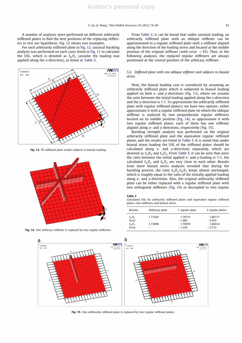
Next, the biaxial loading case is considered by assuming anarbitrarily stiffened plate which is subjected to biaxial loadingapplied on both x- and y-directions (Fig. 13), where we assumethe ratio between the initial loading applied along the x-directionand the y-direction is 1:1. To approximate the arbitrarily stiffenedplate with regular stiffened plate(s) we have two options: eitherapproximate it with a regular stiffened plate on which the obliquestiffener is replaced by two perpendicular regular stiffenerslocated on its middle position (Fig. 14), or approximate it withtwo regular stiffened plates, each of them has one stiffeneraligned along x- and y-directions, respectively (Fig. 15).
Buckling strength analysis was performed on the originalarbitrarily stiffened plate and the equivalent regular stiffenedplates, and the results are listed in Table 3. It is noted that underbiaxial stress loading the USL of the stiffened plates should becalculated along x- and y-directions separately, which aredenoted as Sx/Fy and Sy/Fy. From Table 3, it can be seen that sincethe ratio between the initial applied x- and y-loading is 1:1, thecalculated Sx/Fy and Sy/Fy are very close to each other. Resultsfrom more biaxial stress analyses revealed that during thebuckling process, the ratio Sx/Fy:Sy/Fy keeps almost unchanged,which is roughly equal to the ratio of the initially applied loadingalong x- and y-directions. Also, the original arbitrarily stiffenedplate can be either replaced with a regular stiffened plate withtwo orthogonal stiffeners (Fig. 14) or decoupled to two regular
Fig. 13. FE stiffened plate model subjects to biaxial loading.
Fig. 14. One arbitrary stiffener is replaced by two regular stiffeners.
Fig. 15. One arbitrarily stiffened plate is replaced by two regular stiffened plates.
Table 3Calculated USL for arbitrarily stiffened plates and equivalent regular stiffened
plates–two stiffeners and biaxial stress.
Results Arbitrary plate 1 regular plate 2 regular plates
Sx/Fy 1.73302 1.70731 1.68717
Error – �1.48% �2.65%
Sy/Fy 1.73098 1.70970 1.68414
Error – �1.24% �2.71%
Y. Liu, Q. Wang / Thin-Walled Structures 59 (2012) 78–86 83

Author's personal copy
stiffened plates each with one stiffener (Fig. 15). Both optionscorrectly approximate the strengthening effects of the initialarbitrarily stiffened plate (with the error of calculated USLo3%). However, comparatively, the stiffened plate with twoorthogonal regular stiffeners is more close to the initial arbitrarilystiffened plate (with the error of calculated USL o2%). Insummary, the results in Table 3 show that like the uniaxialloading case, under the biaxial loading, the strengthening effectsof one oblique stiffener are almost equal to those provided by twoperpendicular stiffeners.
5.3. Stiffened plate with two oblique stiffeners and subjects to biaxial
stress
Next, the idea that an arbitrarily oriented stiffener can bereplaced by two orthogonal regular stiffeners is tested on stif-fened plates with two oblique stiffeners. According to the presentmethod, the two arbitrarily stiffened plates displayed in Fig. 16can be approximated by the same regular stiffened plate (Fig. 17)because the middle positions of the oblique stiffeners in bothplates in Fig. 16 are the same. Nonlinear buckling analyses wereperformed on the three stiffened plates (Fig. 16(a), (b), andFig. 17) and the USL results are listed and compared in Table 4.As shown in that table, the replacement regular stiffened plateswith orthogonal stiffeners yielded good USL results which are
very close to the results generated from both arbitrarily stiffenedplates (the maximum error is only 2.13%). Therefore the presentmethod of approximating one arbitrarily oriented stiffener withtwo orthogonal regular stiffeners is correct for stiffened plateswith multi stiffeners. Also, despite slight differences, it is foundthat the two arbitrarily stiffened plates shown in Fig. 16(a) and(b) provided close USL results. It can be deduced that thestrengthening effects of arbitrarily oriented stiffeners are notseriously influenced by the stiffeners’ orientations but by theirmiddle positions.
6. Other advantages of stiffeners
Besides improving the plate’s buckling and ultimate strengthlimit, other advantages of stiffeners can be revealed from theload-displacement curves. As can be seen from the stress–timeplots yielded from Table 3 (Figs. 18–20), during the same bucklingstrength analysis, the stiffened plate yields smooth load-displace-ment curves, which indicate that the stiffened plate subjects to aslowly changed, quasi-static loading. However, as shown fromFig. 21, the unstiffened plate yields oscillating load-displacementcurves with sudden jumps in magnitude of load. These curvessuggest that during the analysis, the unstiffened plate subjects toan oscillating loading and a suddenly-increased loading, whichwill significantly reduce service time of the plate and cause itsfailure due to fatigue and impact hit. It is thus apparently that theusing of stiffeners can prevent the plate from subjecting tooscillating and suddenly-increased loading, which will greatlyextend the plate’s service time and reduce the cost formaintenance.
7. Conclusions
This paper discusses the strengthening effects of stiffener onregular and arbitrarily stiffened plates through a series of ANSYSbuckling strength analyses. Both uniaxial and biaxial loadingcases are considered in this study. Through the results, followingconclusions can be made:
(1) For the stiffener with ‘‘I’’ cross section, the ratio hw/tw¼15 canoptimally improve the plate’s buckling strength.
(2) For regular stiffened plates, stiffeners with homogeneousarrangement provide better buckling performance than thestiffeners with nonhomogeneous arrangement.
(3) Fore any regular stiffened plate with specified size, there is anoptimal number of stiffeners yields the best USL whilereducing the design and manufacturing cost. In the platesinvolved in this study, that number is four.
(4) An arbitrarily stiffened plate which is subjected to biaxialloading can be either considered as one regular stiffened platewith two orthogonal stiffeners or two regular stiffened plates
Fig. 16. FE stiffened plate model with two oblique stiffeners at different orientations.
Fig. 17. Arbitrarily stiffened plates in Fig. 16 is replaced by one regular
stiffened plate.
Table 4Calculated USL for arbitrarily stiffened plates with two stiffeners (Fig. 20).
Results Case (a) Case (b) Regular plate
Sx/Fy 1.364 1.345 1.335
Error �2.13% �0.74% –
Sy/Fy 1.362 1.340 1.337
Error �1.84% �0.22% –
Y. Liu, Q. Wang / Thin-Walled Structures 59 (2012) 78–8684

Author's personal copy
with one stiffener on each, where the regular stiffeners arelocated at the middle position of the original arbitrarystiffener. Our results show that the former approximationcan better simulate the buckling strength and behavior of theoriginal arbitrarily stiffened plate.
(5) Arbitrarily stiffened plates with multi-stiffeners can be replacedby regular stiffened plates following the same approach. It wasalso found that in arbitrarily oriented stiffeners, the orientationof the stiffener does not apparently affect the strengthening
effects while the middle position of the stiffeners determinesthe strengthening effects.
(6) The use of stiffeners in the structural plates can effectivelyprotect the plates from oscillating and suddenly-increasedloading, therefore extend the plate’s service time and reduceits maintenance cost.
The listed conclusions will enhance the capability of predictingthe structural plate’s buckling performance, therefore have wide
Fig. 18. Stress–time plot of arbitrarily stiffened plate.
Fig. 19. Stress–time plot of one regular stiffened plate with two stiffeners.
Fig. 20. Stress–time plot of two regular stiffened plates.
Y. Liu, Q. Wang / Thin-Walled Structures 59 (2012) 78–86 85

Author's personal copy
applicability in any industry that involves design and analysis ofconstructional plates. The interesting finding that the strengthen-ing effects of an oblique stiffener can be approximated as those oftwo regular stiffeners aligned along x- and y-directions can beapplied in analytical analysis of the stiffened plate. Based on thatfinding, Brubak’s model (Eq. (1)) can be significantly simplifiedand easily implemented into the computer algorithm. Analyticalanalysis of the stiffened plate by using computer programmingand the simplified algorithm of predicting the buckling behaviorof the arbitrarily stiffened plates will be demonstrated in acompanion paper, based on which the study of the arbitrarilystiffened plates with multi-stiffeners will be initiated.
Acknowledgment
The work is supported by Louisiana Space Consortium(LaSPACE). The authors are grateful to Dr. John Wefel and otherpersonnel in that organization for their invaluable contributionsto this work. The author also wants to extend his appreciation toDr. Krishen Kumar (NASA JSC) for his substantial support in thisproject.
References
[1] Byklum E, Amdahl J. A simplified method for elastic large deflection analysisof plates and stiffened panels due to local buckling. Thin-Walled Structures2002;40:925–53.
[2] Byklum E, Steen E, Amdahl J. A semi-analytical model for global buckling andpostbuckling analysis of stiffened panels. Thin-Walled Structures 2004;42:701–17.
[3] Brubak L, Hellesland J, Steen E. Semi-analytical buckling strength analysis ofplates with arbitrary stiffener arrangements. Journal of Constructional SteelResearch 2007;63:532–43.
[4] Brubak L, Hellesland J. Approximate buckling strength analysis of arbitrarilystiffened stepped plates. Engineering Structures 2007;29:2321–33.
[5] Brubak L, Hellesland J. Semi-analytical postbuckling and strength analysis ofarbitrarily stiffened plates in local and global bending. Thin-Walled Structures2007;45:620–33.
[6] Brubak L, Hellesland J. Strength criteria in semi-analytical, large deflectionanalysis of stiffened plates in local and global bending. Thin-Walled Structures2008;46:1382–90.
[7] Paik JK, Lee MS. A semi-analytical method for the elastic–plastic largedeflection analysis of stiffened panels under combined biaxial compression/tension, biaxial in-plane bending, edge shear, and lateral pressure loads.Thin-Walled Structures 2005;43:375–410.
[8] Jiang BS, Suh YS, Paik JK, Seo JK, Kim BJ. Ultimate limit state assessment oftankers considering common structural rules. 2007.
[9] ANSYS Inc. ANSYS Documentation 9.0. Canonsburg (PA): Southpointe; 2004.[10] Maeed M. Finite element analysis: theory and application with ANSYS. 2nd
ed.Prentice Hall; 2007.[11] Paik JK, Kim BJ, Seo JK. Methods for ultimate limit state assessment of ships
and ship-shaped offshore structures: part I–unstiffened plates. Ocean Engineering2008;35(2):261–70.
[12] Paik JK, Kim BJ, Seo JK. Methods for ultimate limit state assessment of shipsand ship-shaped offshore structures: part II–stiffened plates. Ocean Engineering2008;35(2):271–80.
[13] Paik JK, Kim BJ, Seo JK. Methods for ultimate limit state assessment of shipsand ship-shaped offshore structures: part III–hull girders. Ocean Engineering2008;35(2):281–6.
[14] Paik JK, Seo JK. Nonlinear finite element method models for ultimate strengthanalysis of steel stiffened-plate structures under combined biaxial compressionand lateral pressure actions—part I: plate elements. Thin-Walled Structures2009;47(8–9):1008–17.
Fig. 21. Stress–time plot of unstiffened plate.
Y. Liu, Q. Wang / Thin-Walled Structures 59 (2012) 78–8686