Component Tolerance Effect on Ultra-Wideband Low-Noise Amplifier Performance
10
Linköping University Post Print Compontent Tolerance Effect on Ultra- Wideband Low-Noise Amplifier Performance Adriana Serban, Magnus Karlsson and Shaofang Gong N.B.: When citing this work, cite the original article. ©2011 IEEE. Personal use of this material is permitted. However, permission to reprint/republish this material for advertising or promotional purposes or for creating new collective works for resale or redistribution to servers or lists, or to reuse any copyrighted component of this work in other works must be obtained from the IEEE. Adriana Serban, Magnus Karlsson and Shaofang Gong, Compontent Tolerance Effect on Ultra-Wideband Low-Noise Amplifier Performance, 2011, IEEE Transactions on Advanced Packaging, (33), 3, 660-668. http://dx.doi.org/10.1109/TADVP.2010.2041348 Postprint available at: Linköping University Electronic Press http://urn.kb.se/resolve?urn=urn:nbn:se:liu:diva-53604
-
Upload
independent -
Category
Documents
-
view
0 -
download
0
Transcript of Component Tolerance Effect on Ultra-Wideband Low-Noise Amplifier Performance

Linköping University Post Print
Compontent Tolerance Effect on Ultra-
Wideband Low-Noise Amplifier Performance
Adriana Serban, Magnus Karlsson and Shaofang Gong
N.B.: When citing this work, cite the original article.
©2011 IEEE. Personal use of this material is permitted. However, permission to
reprint/republish this material for advertising or promotional purposes or for creating new
collective works for resale or redistribution to servers or lists, or to reuse any copyrighted
component of this work in other works must be obtained from the IEEE.
Adriana Serban, Magnus Karlsson and Shaofang Gong, Compontent Tolerance Effect on
Ultra-Wideband Low-Noise Amplifier Performance, 2011, IEEE Transactions on Advanced
Packaging, (33), 3, 660-668.
http://dx.doi.org/10.1109/TADVP.2010.2041348
Postprint available at: Linköping University Electronic Press
http://urn.kb.se/resolve?urn=urn:nbn:se:liu:diva-53604

660 IEEE TRANSACTIONS ON ADVANCED PACKAGING, VOL. 33, NO. 3, AUGUST 2010
Component Tolerance Effect on Ultra-WidebandLow-Noise Amplifier Performance
Adriana Serban, Magnus Karlsson, and Shaofang Gong, Member, IEEE
Abstract—A study of the component tolerances on an ultra-wide-band (UWB) low-noise amplifier designed on a conventionalprinted circuit board is presented in this paper. The low-noiseamplifier design employs dual-section input and output microstripmatching networks for wideband operation with a low noise figureand a flat power gain. First, the effect of passive component andmanufacturing process tolerances on the low-noise amplifier per-formance is theoretically studied by means of sensitivity analyses.Second, simulation and measurement results are presented forverification of the analytical results. It is shown that, comparedwith a lumped matching network design, a microstrip matchingnetwork design significantly reduces the UWB low-noise amplifiersensitivity to component tolerances.
Index Terms—Low-noise amplifier (LNA), matching networks,sensitivity analysis, ultra-wideband (UWB).
I. INTRODUCTION
T HE low-noise amplifier (LNA) for ultra-wideband (UWB)radio systems is one of the most critical components in the
radio front-end. Due to the characteristics of UWB signals, i.e.,very low radiated power ( ) and large band-width, a UWB receiver requires better receiver sensitivity anda lower noise figure than, for example, an IEEE 802.11a re-ceiver [1]. The expected receiver sensitivity can be achieved byan optimal design of the LNA in terms of a near-to-minimumnoise figure and reasonable power gain over the entire band. Onone hand, classical wideband amplifier topologies, e.g., feed-back [2], [3] and distributed amplifiers [4], [5], have difficultyto meet all the requirements of a near-to-minimum noise figure,low-power consumption, small area, and low cost. On the otherhand, an LNA implemented with multisection matching net-works provides more degrees-of-freedom to achieve both a lownoise figure and flat power gain without increasing the powerconsumption [6], [7]. However, as the multisection input andoutput matching networks have more circuit components, theLNA noise figure and power gain can be more sensitive to thestatistical variations of the passive components, either they arelumped inductors and capacitors or distributed passives, e.g.,using microstrip transmission lines.
Manuscript received April 15, 2009; revised July 05, 2009; accepted De-cember 13, 2009. This work was supported by SonyEricsson and Vinnova. Thiswork was recommended for publication by Associate Editor R.-B. Wu uponevaluation of the reviewers comments.
The authors are with the Linköping University, SE-60174 Norrkoping,Sweden (e-mail: [email protected]).
Color versions of one or more of the figures in this paper are available onlineat http://ieeexplore.ieee.org.
Digital Object Identifier 10.1109/TADVP.2010.2041348
Fig. 1. Multisection UWB LNA topologies with (a) lumped and (b) distributedmatching networks. � is the loaded �-factor.
From our previous radio-frequency (RF) circuit designs,i.e., antenna [8], [9], frequency-triplexer [10], narrowband andUWB LNAs [11], [12], antenna-LNA co-design [13], [14] andUWB bias networks [15] as well as considering the passivecomponent tolerance problem, two interesting observationswere found. First, using distributed components of microstrips,very good agreement was obtained between simulated andmeasured results. Second, the measured circuit parameters haveshown low variation from circuit to circuit under test. However,this approach to use distributed components on a printed circuitboard has rarely been used in RF front-end circuit design forwideband applications, mainly due to a common view thatthe printed circuit board process requires large manufacturingtolerance and therefore large variation of circuit performance.
In this paper multisection UWB LNA designs with lumped-and distributed-matching networks are studied. The simplifiedschematics of the two UWB LNA implementations are shownin Fig. 1. First, sensitivity analyses of the noise figure matchingcondition in response to frequency are done with regard topassive component tolerances. Then, simulations includingreal-world lumped passive component tolerances, and for thedistributed matching networks, manufacturing process toler-ances are performed in advanced design system (ADS) fromAgilent Technologies, Inc. In order to get a clear picture ofhow manufacturing tolerances affect RF circuit performance,the LNA with multisection distributed matching networks isdesigned and manufactured in a commercial printed circuitboard process aiming for a low noise figure and a flat powergain over the entire 3.1–4.8 GHz bandwidth.
1521-3323/$26.00 © 2010 IEEE

SERBAN et al.: COMPONENT TOLERANCE EFFECT ON ULTRA-WIDEBAND LOW-NOISE AMPLIFIER PERFORMANCE 661
Fig. 2. Circuit model for noise matching condition analysis with dual-sectioninput matching network and transistor equivalent noise impedance.
The simulation results of the UWB LNA with distributedmatching networks are verified by experimental results. Finally,the amplifier performance with distributed matching networkson a commercial printed circuit board is discussed and con-cluded.
II. SENSITIVITY ANALYSIS OF WIDEBAND LNA WITH
MULTISECTION MATCHING NETWORKS
Passive components, e.g., capacitors, inductors, transformers,and transmission lines, play a key role in determining the overallcharacteristics of RF circuits [16], [17]. Due to their nominalvalue tolerances, parasitics and manufacturing process varia-tions, the response of the multisection UWB LNA shown inFig. 1(a) and (b) is likely to deviate from the results predicted bysimulations where only nominal component values and typicalmean process parameters are used. It is therefore of interest toknow and compare the sensitivity of a multisection UWB LNAimplemented with (a) lumped and (b) distributed matching net-works.
There are different ways to approach the passive componenttolerance problem: 1) statistical analysis using electronic de-sign automation software tools to perform Monte Carlo analysis[18], and 2) sensitivity analysis based on sensitivity functionsderived from a given circuit configuration [19]. In this work, theproblem of UWB LNA parameter variation due to passive com-ponent tolerance is firstly addressed using sensitivity analysisof the matching condition. The cumulative effect of the passivecomponent tolerances on impedance [see Fig. 1(a)] de-viation from the designed value is modeled, simulated, and ver-ified by measurement. Other aspects as the problem of via-holeparasitics which can affect the amplifier properties at high fre-quencies are not treated in this study.
A. Noise-Matching Circuit Model
The effect of the input matching network and its componenttolerances on the wideband LNA noise figure can be analyzedconsidering the circuit model shown in Figs. 2 and 3. In Fig. 2,the input matching network is a lossless dual-section networkrepresented by its parallel and series reactances, , ,and , , respectively. It transforms the generator resistor
(usually 50 ) into a complex source impedance ,, where and are the re-
sistive and reactive parts of , as illustrated in Fig. 3(c). Theselection of the parallel and series reactances, , , and
Fig. 3. Series-parallel conversion of a dual-section input matching network at� � � .
, of the lossless dual-section input matching networkin Fig. 2 is not unique. The only restriction is that andand and are of opposite sign. Moreover, dependingon the requirements of the application, the input and outputmatching networks can be implemented as band-pass, low-passand high-pass filters [12]. For the aim of this study, low-passmatching networks of constant nodal quality factor are con-sidered.
The active device, i.e., the transistor, is represented in Fig. 2by its equivalent input noise impedance
. In RF and microwave LNA design approaches, thenoise matching condition is given as
(1)
where is the optimum noise impedance seen towardsthe generator. is usually a known transistor param-eter given by the manufacturer. Hence, using (1), the equivalentnoise impedance looking into the transistor can be expressed as
, i.e., and .However, the noise matching condition (1) occurs only at
one frequency , and (1) becomes . In anarrow band around the resonance frequency the impedancematching condition can be represented by the RLC series equiv-alent network shown in Fig. 3(c). Moreover, using two par-allel-series transformations at [20], [21], the dual-sec-tion matching network in Fig. 3(a) can be represented firstly asan equivalent single-section matching network [Fig. 3(b)], andsecondly as an equivalent series network [Fig. 3(c)]. In Fig. 3,
is the loaded -factor of the matching network and relatedto its bandwidth (BW) by , [17]. Following[21], the shunt and series branches [ and in Fig. 3(a)] areresonant at . Hence, in Fig. 3(b) only the resistive component
driving the rest of the circuit is shown. Finally,the source resistance and source reactance can be ex-pressed as a function of the generator resistance and loaded
-factor, as shown in Fig. 3(c).The equivalent network in Fig. 3(c) is further used in Sec-
tions II-B and II-C for the analysis of the noise matching condi-tion at .

662 IEEE TRANSACTIONS ON ADVANCED PACKAGING, VOL. 33, NO. 3, AUGUST 2010
B. Noise-Matching Sensitivity to Component Tolerance
The noise figure degradation due to mismatch from isusually represented by
(2)where is the “spot” noise figure, i.e., calculated for a 1-Hzbandwidth at a given frequency and is the amplifier min-imum attainable noise figure. is the equivalent noise con-ductance of the active device ( , where is theequivalent noise resistance of the device) [16]. In this study, pa-rameters in (2) are not normalized, hence capitalized.
From (2) it is seen that the noise figure of an amplifier de-pends on (a) the accuracy of the noise impedance matching, rep-resented by the and and(b) intrinsic noise transistor parameter, . For the aim of thiswork, , and variation due to the on-wafer processparameter variation is not considered, while and are con-sidered to diverge from their designed (optimal) value due tocomponent and manufacturing process tolerances. Thus, withreference to Fig. 1(a) and Fig. 3, the source impedance isthe result of generator resistance ( ) transformation and it isa function of all the reactive lumped network components, i.e.,
, , 2, 3, 4. For the distributed matching net-work case in Fig. 1(b), the source impedance is a function ofthe characteristic impedance and of the electrical lengthof every transmission line in the network, i.e., .
, where is the propagation constant [16] and is thelength of every distributed element in Fig. 1(b).
For a better insight into sensitivity aspects of the noisematching condition in terms of component value tolerances, anew approach has been used. Firstly, applying the noise wavetheory [22], is used as complex reference impedanceand the source reflection coefficient is derived. Secondly, thefrequency response of in terms of resonance frequency andbandwidth of the circuit in Fig. 3(c) is analyzed. Consideringthe circuit model in Fig. 3(c), is [22]
(3)
where the normalization impedance is the optimum noiseimpedance , i.e., a complex impedance. When thenoise-matching condition (3) is achieved, . How-ever, for values diverging form the ideal value , (3)becomes
(4)
where denotes the complex frequency. Equation (4) isa classical second-order function, i.e., ,which allows to express the denominator as
. Hence, from (4), the resonance frequencyand the quality factor of the equivalent network at the input ofthe active device under matching conditions [16], are
(5)
(6)
Near resonance, e.g., , and for small matching errors( ), (4) becomes
(7)
The input inherent bandwidth under the near-to-noisematching condition [16] and fixed can be expressed
(8)
Now, studying the sensitivity of and sensi-tivity, rather than sensitivity to component tolerances,permits a more practical approach to the sensitivity of any LNAamplifier to component tolerances.
Classically, the sensitivity of a network function withrespect to a parameter is defined as
(9)
where is the relative variation of the functiondue to parameter variation . Applying (9) to (5) and (8),the relative variation of and in terms of compo-nent value variation is given by
(10)
(11)
Differentiating (5) and (8) with respect to real and imaginarycomponents of , the resonance frequency and bandwidth sen-sitivity to and variation can be analytically derived
(12a)
(12b)
(12c)
Since the sensitivity of the resonance frequency and inputinherent bandwidth due to variations are constants ( ,
), and can be mini-mized only by the use of high-precision components, e.g., com-ponent values near to the designed values and small tolerances.Rewriting (10) and (11), while assuming zero variation of ,
and , one gets for the LNA circuit model in Fig. 3(c)
(13a)
(13b)
SERBAN et al.: COMPONENT TOLERANCE EFFECT ON ULTRA-WIDEBAND LOW-NOISE AMPLIFIER PERFORMANCE 663
Equations (13a) and (13b) show that any variation of theoutput impedance of the IMN ( and ) from the designedvalue due to component value tolerances willresult in variations of the frequency response of , i.e.,deviations of the frequency and input inherent bandwidth
. Finally, this will result in deviation of the UWBLNA noise figure from the optimized design value.
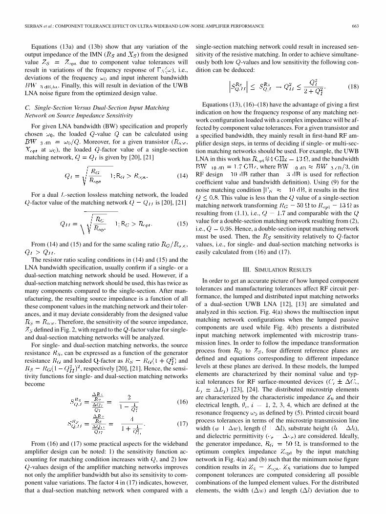
C. Single-Section Versus Dual-Section Input MatchingNetwork on Source Impedance Sensitivity
For given LNA bandwidth (BW) specification and properlychosen , the loaded -value can be calculated using
. Moreover, for a given transistor ( ,at ), the loaded -factor value of a single-section
matching network, is given by [20], [21]
(14)
For a dual -section lossless matching network, the loaded-factor value of the matching network is [20], [21]
(15)
From (14) and (15) and for the same scaling ratio ,.
The resistor ratio scaling conditions in (14) and (15) and theLNA bandwidth specification, usually confirm if a single- or adual-section matching network should be used. However, if adual-section matching network should be used, this has twice asmany components compared to the single-section. After man-ufacturing, the resulting source impedance is a function of allthese component values in the matching network and their toler-ances, and it may deviate considerably from the designed value
. Therefore, the sensitivity of the source impedance,defined in Fig. 2, with regard to the -factor value for single-
and dual-section matching networks will be analyzed.For single- and dual-section matching networks, the source
resistance , can be expressed as a function of the generatorresistance and loaded -factor as and
, respectively [20], [21]. Hence, the sensi-tivity functions for single- and dual-section matching networksbecome
(16)
(17)
From (16) and (17) some practical aspects for the widebandamplifier design can be noted: 1) the sensitivity function ac-counting for matching condition increases with , and 2) low
-values design of the amplifier matching networks improvesnot only the amplifier bandwidth but also its sensitivity to com-ponent value variations. The factor 4 in (17) indicates, however,that a dual-section matching network when compared with a
single-section matching network could result in increased sen-sitivity of the resistive matching. In order to achieve simultane-ously both low -values and low sensitivity the following con-dition can be deduced:
(18)
Equations (13), (16)–(18) have the advantage of giving a firstindication on how the frequency response of any matching net-work configuration loaded with a complex impedance will be af-fected by component value tolerances. For a given transistor anda specified bandwidth, they mainly result in first-hand RF am-plifier design steps, in terms of deciding if single- or multi-sec-tion matching networks should be used. For example, the UWBLNA in this work has , and the bandwidth
, where , (inRF design rather than is used for reflectioncoefficient value and bandwidth definition). Using (9) for thenoise matching condition , it results in the first
. This value is less than the value of a single-sectionmatching network transforming to asresulting from (1.1), i.e., and comparable with thevalue for a double-section matching network resulting from (2),i.e., . Hence, a double-section input matching networkmust be used. Then, the sensitivity relatively to -factorvalues, i.e., for single- and dual-section matching networks iseasily calculated from (16) and (17).
III. SIMULATION RESULTS
In order to get an accurate picture of how lumped componenttolerances and manufacturing tolerances affect RF circuit per-formance, the lumped and distributed input matching networksof a dual-section UWB LNA [12], [13] are simulated andanalyzed in this section. Fig. 4(a) shows the multisection inputmatching network configurations when the lumped passivecomponents are used while Fig. 4(b) presents a distributedinput matching network implemented with microstrip trans-mission lines. In order to follow the impedance transformationprocess from to , four different reference planes aredefined and equations corresponding to different impedancelevels at these planes are derived. In these models, the lumpedelements are characterized by their nominal value and typ-ical tolerances for RF surface-mounted devices ( ,
) [23], [24]. The distributed microstrip elementsare characterized by the characteristic impedance and theirelectrical length, , , 2, 3, 4, which are defined at theresonance frequency as defined by (5). Printed circuit boardprocess tolerances in terms of the microstrip transmission linewidth ( ), length ( ), substrate height ( ),and dielectric permittivity ( ) are considered. Ideally,the generator impedance, , is transformed to theoptimum complex impedance by the input matchingnetwork in Fig. 4(a) and (b) such that the minimum noise figurecondition results in . variations due to lumpedcomponent tolerances are computed considering all possiblecombinations of the lumped element values. For the distributedelements, the width ( ) and length ( ) deviation due to

664 IEEE TRANSACTIONS ON ADVANCED PACKAGING, VOL. 33, NO. 3, AUGUST 2010
Fig. 4. Input matching network impedance transformation model: (a) lumpedand (b) distributed.
photolithographic and etching processes are considered corre-lated, i.e., all transmission lines have the same width (narrow,nominal, large) and . Then, the substrate height anddielectric permittivity deviations are considered for each case.
A. Lumped Input Matching Network Equations
The four impedances, to in Fig. 4(a) can be derived bymeans of iterative substitution in (19)–(22)
(19)
(20)
(21)
(22)
In this way, the dual-section impedance transformation isbroken into several steps. The impedance deviation from thedesigned value can be followed from planes 1–4, showing ina simple way the cumulative effect of the passive componenttolerances on the optimal noise matching condition.
B. Distributed Input Matching Network Equations
The open stub impedance [16] transformsto the equivalent impedance defined by
(23)
(24)
The series transmission line then transforms to whereand are defined as
(25)
(26)
The generalized equations for open stub and series microstriptransmission line impedance transformation are
(27)
(28)
(29)
(30)
Equations (27)–(30) show that the optimal noise matchingcondition at plane 4 depends on the variation of and the elec-trical length of every transmission line in the network. The char-acteristic impedance is related to the physical transmissionline parameters and material properties, i.e.,[16]. The electrical length is related to the physical length ofthe transmission line by , where is the propagationconstant [16] and is the length of every distributed element inFig. 4(b).
C. Lumped Versus Distributed
For better comparison of the robustness of the lumpedand distributed UWB LNA in Fig. 1(a) and (b), (19)–(30)are computed and the results are graphically represented inFig. 5(a) and (b). The transformation processes fromto using the nominal value of the lumped- or dis-tributed-impedance are represented as traces on the Smithchart. The resulting impedance values at different planes inFig. 4(a) and (b) and their variation due to passive compo-nent and manufacturing process tolerances are represented asnormalized impedance values on the Smith chart. Detailedspecification of the passive components is listed in Table I.Statistical simulations were performed with Advanced DesignSystem (ADS2009) from Agilent Technologies Inc. Outputnoise figure variation due to lumped and distributed com-ponent tolerances over a large frequency range is shown inFig. 6(a) and (b). As seen in Fig. 5(b) and Fig. 6(b), simulationstaking typical printed circuit board process tolerances ( )

SERBAN et al.: COMPONENT TOLERANCE EFFECT ON ULTRA-WIDEBAND LOW-NOISE AMPLIFIER PERFORMANCE 665
Fig. 5. � sensitivity to input matching network component variations. (a)Lumped components (� � ���, �� ���). (b) Distributed components (� �
�����mm����, � �����, � � �������,� � �����mm������mm).Low- matching technique where � �.
into consideration predict extremely low sensitivity of thenoise figure of the UWB LNA, with a variation around thedesigned (nominal) value less than 0.6%. In contrast, as shownin Fig. 5(a) and Fig. 6(a), lumped element tolerances result inlarger variation of the noise figure, e.g., 9.5% at 4 GHz.
Unlike the UWB LNA implemented with lumped elements,the LNA implemented with distributed matching networksusing a conventional printed circuit board process shows anextremely low sensitivity to manufacturing process tolerances.Two main aspects related to the previous simulation resultsshould be noted: 1) the need for experimental results to verifythe low sensitivity of the distributed matching networks and2) the need to understand why distributed matching networksprovide robust performance of the LNA.
IV. EXPERIMENTAL RESULTS
Instead of manufacturing a large number of LNA mod-ules—usually necessary when statistical analysis is per-formed—three different UWB LNA modules were fabricatedto the purpose to compare with the simulation results. In thesemodules, the width of all microstrip lines ( ) including thetransmission lines in the bias network is purposely modifiedwith around the designed nominal value. The
Fig. 6. Simulated noise figure of (a) lumped UWB LNA design, and (b) dis-tributed UWB LNA design.
TABLE IPASSIVE COMPONENT PARAMETERS
variation corresponds to the width variations given in the man-ufacturer process data sheet. The three UWB LNA modules arethus: one corresponding to the “nominal” UWB LNA designthat is characterized by the width of the transmission lines
mm for , and the other two UWB LNAmodules where the width of the transmission lines is modifiedwith (“large”) and (“small”). Then, the sensi-tivity of UWB LNA was evaluated in terms of transmission linewidth variation.
The photograph of the UWB LNA, including the broadbandbias network using a butterfly radial stub [15] is presentedin Fig. 7(a). The presented UWB LNA is designed for anoise figure below 4 dB and a flat transfer function over the3.1–4.8 GHz bandwidth. The active device is MAX2649.For optimal wideband matching, the multisection widebandamplifier design is combined with the frequency-compensated

666 IEEE TRANSACTIONS ON ADVANCED PACKAGING, VOL. 33, NO. 3, AUGUST 2010
Fig. 7. UWB LNA prototype: (a) Photograph of the UWB LNA (a) and (b)layout detail with LNA foot print and via contacts to the ground.
Fig. 8. Printed circuit board structure.
matching technique [16]. The matching networks are optimizedat 4.5 GHz and the amplifier is unconditionally stable by meansof a shunt stabilization resistor at the output [12]. Electromag-netic simulations were performed and the distributed inputand output matching networks and the wideband bias networkwere optimized. Grounding-via analytical model in ADS wasconsidered in schematic simulations. On layout level, viacontacts to the ground seen in Fig. 7(b) were modeled as 2-Ddistributed layout components using electromagnetic simulatorMomentum in ADS [25]. Simulated input reflection coefficientat 4.5 GHz is . The UWB LNA is integrated into afour-layer board shown in Fig. 8. The topside of the board inFig. 8 is dedicated to the UWB LNA, whereas the backsideof the board to the rest of the UWB RF front-end [13]. Theprototypes have a size of 23 50 mm.
The stack of the printed circuit board consists of two dual-layer RO4350B boards and a RO4450 prepreg, see Fig. 8.
Table II lists the printed circuit board parameters. Metallayers 1 and 4 are thicker than metal layers 2 and 3 because thesurface layers are plated twice whereas the embedded metallayers 2 and 3 are plated once.
-parameter measurements were done with aRhode&Schwartz ZVM vector network analyzer. TheAgilent N8974A Noise Figure Analyzer was used to measurethe noise figure of the LNA. Fig. 9(a) and (b) shows themeasured performances of the LNA.
Measured noise figure is less than 4 dB from 3.1 to near 4.8GHz and follows the minimum noise figure of the device withsome deviation at the upper frequency edge. This deviation cor-responds to downward shift in frequency of the forward transferfunction compared to the simulated , as illustratedin Fig. 9(b). The measured forward transfer function isgreater than 13 dB with a variation. The supply voltageis 3 V and the consumed current is 13 mA. The input third-orderintercept point (IIP3) is at 4 GHz and 3.0 V supply.
TABLE IIPRINTED CIRCUIT BOARD PARAMETERS
Fig. 9. Measured performance of the LNA: (a) measured noise figure, (b) mea-sured forward transmission, when the microstrip line width varies ����.
Using the simulated and measured results presented inSections III and IV, the noise figure variance was calculated(variance , where is the standard deviation from themean value). For example, at 4 GHz and in the case of thelow-noise amplifier implemented with distributed matchingnetworks, the variance of the simulated noise figure was
and the variance of the measurednoise figure was . In the case ofthe low-noise amplifier implemented with lumped matchingnetworks, the simulated noise figure shown in Fig. 7(a) resultsin considerably higher values of the noise figure variance, i.e.,
.
V. CONCLUSION
The component tolerance effect on UWB LNA designs isstudied and discussed in this work. A 3.1–4.8 GHz LNA ampli-

SERBAN et al.: COMPONENT TOLERANCE EFFECT ON ULTRA-WIDEBAND LOW-NOISE AMPLIFIER PERFORMANCE 667
fier using distributed dual-section matching networks was pre-sented. It was shown that the noise matching condition in itsfrequency response is sensitive to value variation from thedesigned value due to component value tolerances.It was demonstrated that lower LNA sensitivity can be achievedonly by the use of high-precision passive components. For thedual-section UWB LNA the cumulative effect of passive com-ponent tolerances on the noise matching condition was modeled,calculated and compared for lumped and distributed matchingnetworks. Simulations have shown large deviations from thetarget value of the noise figure when the dual-section UWB LNAwas implemented with lumped matching networks. However,simulation and measurement results of the UWB LNA imple-mented with distributed microstrip matching networks showeda very robust performance, despite the variation of theline width.
One important conclusion of this study is that distributedimpedance transformation process results in predictable andstable impedance values, near to the designed values. The lowsensitivity of distributed passive components can be explainedby low relative variation of the transmission line length .For the UWB LNA presented in this work, assuming the samevariation of the line length as for its width, the typical relativevariation of the transmission line length was in the range of
– .In contradiction to the general conception that the organic
printed circuit board technology has too large process variationsfor radio frequency circuit design, it was demonstrated in thisstudy that a conventional printed circuit board can in fact en-able the multisection matching networks UWB LNA with morepassive components design, with low sensitivity to componenttolerances.
ACKNOWLEDGMENT
Agilent Technologies Inc. is acknowledged for donation ofAdvanced Design System licenses and their long term supportto Linköping University, Sweden.
REFERENCES
[1] B. Razavi, T. Aytur, C. Lam, F. R. Yang, K. Y. Li, R. H. Yan, H. C.Hang, C. C. Hsu, and C. C. Lee, “A UWB CMOS transceiver,” IEEEJ. Solid-State Circuits, vol. 40, no. 12, pp. 2555–2562, Dec. 2005.
[2] C.-W. Kim, M.-S. Kang, P. T. Anh, H.-T. Kim, and S.-G. Lee,“An ultra-wideband CMOS low-noise amplifier for 3–5-GHz UWBsystem,” IEEE J. Solid-State Circuits, vol. 40, no. 2, pp. 544–547,Feb. 2005.
[3] J.-H. C. Zhan and S. S. Taylor, “A 5 GHz resistive-feedback CMOSLNA for low-cost multi-standard applications,” in IEEE Int. Solid-StateCircuits Conf. Dig. Tech. Papers, 2006, pp. 721–730.
[4] X. Guan and C. Nguyen, “Low-power consumption and high-gainCMOS distributed amplifiers using cascade of inductively coupledcommon-source gain cells for UWB systems,” IEEE Trans. MicrowaveTheory Tech., vol. 54, no. 8, pp. 3278–3283, Aug. 2006.
[5] C. Grewing, M. Friedrich, G. L. Puma, C. Sander, S. van Waasen,A. Wiesbauer, and K. Winterberg, “Fully integrated ultra wide bandCMOS low-noise amplifier,” in Proc. 30th Eur. Solid-State CircuitsConf., 2004, pp. 435–438.
[6] A. Bevilacqua and A. M. Niknejad, “An ultrawideband CMOS low-noise amplifier for 3.1–10.6 GHz wireless receiver,” IEEE J. Solid-State Circuits, vol. 39, no. 12, pp. 2259–2268, Dec. 2004.
[7] A. Ismail and A. Abidi, “A 3–10 GHz low-noise amplifier with wide-band LC-ladder matching network,” IEEE J. Solid-State Circuits, vol.39, pp. 2269–2277, Dec. 2004.
[8] M. Karlsson and S. Gong, “A frequency-triplexed inverted-F antennasystem for ultra-wide multi-band systems 3.1–4.8 GHz,” ISAST Trans.Electron. Signal Process., vol. 1, no. 1, pp. 95–100, 2007.
[9] M. Karlsson and S. Gong, “Circular dipole antenna for Mode 1 UWBradio with integrated balun utilizing a flex-rigid structure,” IEEE Trans.Antennas Propag., vol. 57, no. 10, pp. 2967–2971, Oct. 2009.
[10] M. Karlsson, P. Hakansson, and S. Gong, “A frequency triplexer forultra-wideband systems utilizing combined broadside- and edge-cou-pled filters,” IEEE Trans. Adv. Packag., vol. 31, no. 4, pp. 794–802,Nov. 2008.
[11] A. Serban and S. Gong, “Low-noise amplifier design at 5 GHz,”in Proc. IMAPS Nordic Annu. Conf., Tønsberg, Norway, 2005, pp.227–229.
[12] A. Serban and S. Gong, “Ultra-wideband low-noise amplifier designfor 3.1–4.8 GHz,” in Proc. GigaHertz 2005 Conf., Uppsala, Sweden,pp. 291–294.
[13] A. Serban, M. Karlsson, and S. Gong, “A frequency-triplexed RFfront-end for ultra-wideband systems,” ISAST Trans. Electron. SignalProcess., vol. 2, no. 1, pp. 83–88, 2008.
[14] A. Serban, M. Karlsson, and S. Gong, “All-microstrip design of threemultiplexed antennas and LNA for UWB systems,” in Proc. IEEE Asia-Pacific Microwave Conf., Dec. 2006, pp. 1109–1112.
[15] A. Serban, M. Karlsson, and S. Gong, “Microstrip bias networks forultra-wideband systems,” ISAST Trans. Electron. Signal Process., vol.2, no. 1, pp. 16–20, 2008.
[16] R. Ludwig and P. Bretchko, RF Circuit Design. Theory and Applica-tions. New York: Prentice Hall, 2000, pp. 502–504.
[17] G. Gonzalez, Microwave Transistor Amplifier Analysis and Design.Upper Saddle River, NJ: Prentice-Hall, 1997, pp. 344–352.
[18] A. Nieuwoudt and Y. Massoud, “Variability-aware multi-level inte-grated spiral inductor synthesis,” IEEE Trans. Comput.-Aided DesignIntegr. Circuits Syst., vol. 25, no. 12, pp. 2613–2625, Dec. 2006.
[19] J. Dobes and Z. Kolka, “Enhanced modes of the sensitivity analysis forRF design,” in Proc. IEEE 30th Eur. Solid-State Circuits Conf., 2004,pp. 435–438.
[20] T. H. Lee, RF Circuit Design. The Design of CMOS Radio-FrequencyIntegrated Circuits, 2nd ed. Cambridge, U.K.: Cambridge Univ.Press, 2004, pp. 92–93.
[21] C. Bowick, RF Circuit Design. London, U.K.: Newnes, 1997, pp.72–75.
[22] P. Penfield Jr., “Wave representation of amplifier noise,” IRE Trans.Circuit Theory, vol. 9, no. 1, pp. 84–86, Mar. 1962.
[23] Chip Inductors Product Catalog Toko, Selection Guide: Chip inductortype: LL1005FHL [Online]. Available: http://www.toko.com
[24] Chip Monolithic Ceramic Capacitors Product Catalog Murata, Capac-itors type: GJM Series [Online]. Available: http://www.murata.com
[25] Advanced Design Systems (ADS) Agilent Technologies Inc. [Online].Available: http://eesof.tm.agilent.com/
Adriana Serban received the M.Sc. degree inelectronic engineering from Politehnica University,Bucharest, Romania. She is working toward thePh.D. degree in communication electronics.
From 1981 to 1990, she was with MicroelectronicaInstitute, Bucharest, Romania, being involved inmixed integrated circuit design. From 1992 to 2002,she was with Siemens AG, Munich, Germany,and with Sicon AB, Linkoping, Sweden as analogand mixed signal integrated circuit Senior DesignEngineer. Since 2002 she has been a Lecturer at
Linkoping University teaching in analog/digital system design, RF systemdesign, and microwave engineering. Her main research and work interesthas been RF circuit design, high-speed data transmissions, and high-speedintegrated circuit design.

668 IEEE TRANSACTIONS ON ADVANCED PACKAGING, VOL. 33, NO. 3, AUGUST 2010
Magnus Karlsson was born in Västervik, Sweden,in 1977. He received the M.Sc., Licentiate of En-gineering, and the Ph.D. degrees from LinköpingUniversity, Norrkoping, Sweden, in 2002, 2005, and2008, respectively.
In 2003 he started in the Communication Elec-tronics Research Group at Linköping University andis currently working as a Senior Researcher. Hismain work involves wideband antenna-techniques,wideband transceiver front-ends, and wireless com-munications.
Shaofang Gong (M’03) was born in Shanghai,China, in 1960. He received the B.Sc. degree fromFudan University, Shanghai, China, in 1982, and theLicentiate of Engineering and Ph.D. degrees fromLinköping University, Norrkoping, Sweden, in 1988and 1990, respectively.
Between 1991 and 1999, he was a Senior Re-searcher at the Microelectronic Institute–Acreoin Sweden. From 2000 to 2001 he was the ChiefTechnology Officer at a spin-off company fromthe institute. Since 2002 he has been Professor
in Communication Electronics at Linköping University. His main researchinterest has been communication electronics, including RF design, wirelesscommunications, and high-speed data transmissions.