On buried weapon detection by means of scattering matrix decomposition for quad-polarized...
7
On Buried Weapon Detection by Means of Scattering Matrix Decomposition for Quad-Polarized Ultra-Wideband Radar Rahmi Salman, Ingolf Willms Fachgebiet Nachrichtentechnische Systeme (NTS) Universität Duisburg-Essen Duisburg, Germany [email protected] Lars Reichardt, Thomas Zwick, Werner Wiesbeck Institut für Hochfrequenztechnik und Elektronik (IHE) Karlsruher Institute of Technology (KIT) Karlsruhe, Germany [email protected] Reiner S. Thomä Electronic Measurement Lab EMT Ilmenau University of Technology Ilmenau, Germany [email protected] Abstract—In this paper a bi-static, fully polarimetric Ultra- Wideband (UWB) Radar system for the detection of buried weapons as well as other man-made targets by scattering matrix decomposition is presented. A bulk good made of chunks of sand- lime brick is non-destructively inspected with the objective to survey the interior and to robustly detect discontinuities in the permittivity which might indicate a buried target. The method employs the theory of Pauli scattering matrix decomposition onto the quad-polarized Radar data to improve the detection decision. The investigations are applied to three scenarios, i.e. a model of an assault rifle, the same rifle completely buried under chunks of sand-lime brick and just a bulk good made of the same chunks. Within these investigations a novel broadband dual-polarized antenna which operates between 0.8 to 8 GHz was developed. The main features of the tapered slot lines Vivaldi antennas are a high polarization purity and a symmetric layout resulting in equal phase centres for both polarizations. The experimental validation promises for improved detection capability of buried targets by simultaneously providing high range resolution. Keywords—Buried Weapon Detection; UWB Radar; UWB Scattering Matrix Decomposition; Broadband Dual-Polarized Antennas. I. INTRODUCTION AND MAJOR CHALLENGES Non-destructive subsurface sensing has a long tradition in the Radar community for more than 4 decades and the range of applications includes e.g. geology, glaciology, hydrology, mining, archaeology, antipersonnel landmine detection and many more [1][2][3][4][5][6]. Principally, the detection of buried weapons and other man-made targets is thematically very close to the large field of landmine detection by ground penetrating Radar. Similar challenges are faced and solutions can be adapted in most cases easily in the other field. For the sake of generality, it shall be referred to as medium penetrating Radar in the following. Medium penetrating Radar for the detection of landmines and other buried man-made targets takes an exceptional position in the field of non-destructive subsurface imaging. It has substantially different requirements for subsurface sensing, i.e. the very short distance to the ground, the need of high down-rage and cross-range resolution as well as high sensitivity and stability. These requirements have to be met to provide an extreme high detection rate at simultaneously low false alarm rates in a lossy medium with high clutter even of targets which are made of ceramic or plastic which offer low dielectric contrast. Contributions from clutter (e.g. air-ground interface roughness, inhomogeneity and moisture of the soil), antenna ringing, direct coupling etc. may mask the already weak reflection of the target or at least distort the targets Radar signature and therewith limit the applicability. A major research effort has been provided to investigate and develop target detection and discrimination algorithms that perform robustly across different environments and scenarios. Among the most popular methods and features are hidden Markov models [7], edge histogram descriptors [8], spectral features [9], geometric features [10], texture features [11] and polarimetric features [4][5][12]. The exploitation of polarimetric diversity was the recent great advance to estimate a degree of target symmetry by specific co- and cross-polar characteristics which allowed to reject non-symmetrical clutter objects. However, this assumes an a priori finite alphabet which consists of symmetrical targets (landmines) and non- symmetrical clutter (e.g. stones). In contrast to this, in the field of buried weapon detection the target may consist of a wide variety of geometries including complex edged shapes which reveal not only single bounce but also double and higher order bounces. Another main difference is that the scan track in mine detection is strictly restricted to planar scans where the antenna main beam is aligned to the normal of the ground. Whereas weapons can be buried anywhere which potentially allows for more diverse scan tracks and consequently provides a more non-linear synthetic aperture. With regard to these circumstances, we extend the idea of exploiting polarimetric methods by the employment of scattering Matrix decomposition theory to improve the
-
Upload
independent -
Category
Documents
-
view
0 -
download
0
Transcript of On buried weapon detection by means of scattering matrix decomposition for quad-polarized...

On Buried Weapon Detection by Means of Scattering Matrix Decomposition for Quad-Polarized
Ultra-Wideband Radar
Rahmi Salman, Ingolf Willms Fachgebiet Nachrichtentechnische
Systeme (NTS) Universität Duisburg-Essen
Duisburg, Germany [email protected]
Lars Reichardt, Thomas Zwick, Werner Wiesbeck
Institut für Hochfrequenztechnik und Elektronik (IHE)
Karlsruher Institute of Technology (KIT) Karlsruhe, Germany
Reiner S. Thomä Electronic Measurement Lab EMT Ilmenau University of Technology
Ilmenau, Germany [email protected]
Abstract—In this paper a bi-static, fully polarimetric Ultra-Wideband (UWB) Radar system for the detection of buried weapons as well as other man-made targets by scattering matrix decomposition is presented. A bulk good made of chunks of sand-lime brick is non-destructively inspected with the objective to survey the interior and to robustly detect discontinuities in the permittivity which might indicate a buried target. The method employs the theory of Pauli scattering matrix decomposition onto the quad-polarized Radar data to improve the detection decision. The investigations are applied to three scenarios, i.e. a model of an assault rifle, the same rifle completely buried under chunks of sand-lime brick and just a bulk good made of the same chunks. Within these investigations a novel broadband dual-polarized antenna which operates between 0.8 to 8 GHz was developed. The main features of the tapered slot lines Vivaldi antennas are a high polarization purity and a symmetric layout resulting in equal phase centres for both polarizations. The experimental validation promises for improved detection capability of buried targets by simultaneously providing high range resolution.
Keywords—Buried Weapon Detection; UWB Radar; UWB Scattering Matrix Decomposition; Broadband Dual-Polarized Antennas.
I. INTRODUCTION AND MAJOR CHALLENGES
Non-destructive subsurface sensing has a long tradition in the Radar community for more than 4 decades and the range of applications includes e.g. geology, glaciology, hydrology, mining, archaeology, antipersonnel landmine detection and many more [1][2][3][4][5][6]. Principally, the detection of buried weapons and other man-made targets is thematically very close to the large field of landmine detection by ground penetrating Radar. Similar challenges are faced and solutions can be adapted in most cases easily in the other field. For the sake of generality, it shall be referred to as medium penetrating Radar in the following.
Medium penetrating Radar for the detection of landmines and other buried man-made targets takes an exceptional position in the field of non-destructive subsurface imaging. It
has substantially different requirements for subsurface sensing, i.e. the very short distance to the ground, the need of high down-rage and cross-range resolution as well as high sensitivity and stability. These requirements have to be met to provide an extreme high detection rate at simultaneously low false alarm rates in a lossy medium with high clutter even of targets which are made of ceramic or plastic which offer low dielectric contrast. Contributions from clutter (e.g. air-ground interface roughness, inhomogeneity and moisture of the soil), antenna ringing, direct coupling etc. may mask the already weak reflection of the target or at least distort the targets Radar signature and therewith limit the applicability.
A major research effort has been provided to investigate and develop target detection and discrimination algorithms that perform robustly across different environments and scenarios. Among the most popular methods and features are hidden Markov models [7], edge histogram descriptors [8], spectral features [9], geometric features [10], texture features [11] and polarimetric features [4][5][12]. The exploitation of polarimetric diversity was the recent great advance to estimate a degree of target symmetry by specific co- and cross-polar characteristics which allowed to reject non-symmetrical clutter objects. However, this assumes an a priori finite alphabet which consists of symmetrical targets (landmines) and non-symmetrical clutter (e.g. stones).
In contrast to this, in the field of buried weapon detection the target may consist of a wide variety of geometries including complex edged shapes which reveal not only single bounce but also double and higher order bounces. Another main difference is that the scan track in mine detection is strictly restricted to planar scans where the antenna main beam is aligned to the normal of the ground. Whereas weapons can be buried anywhere which potentially allows for more diverse scan tracks and consequently provides a more non-linear synthetic aperture.
With regard to these circumstances, we extend the idea of exploiting polarimetric methods by the employment of scattering Matrix decomposition theory to improve the

detection of weapons and other man-made targets buried in dielectric medium.
II. HARDWARE SETUP AND SYSTEM DESIGN
The experimental validation is carried out with an M-Sequence Radar system with a band of DC to 4.5 GHz. However, the operational Bandwidth is limited by the later illustrated antennas to 0.8 GHz up to 4.5 GHz.
A. Experiment Scenario and used Targets
The model of the assault rifle and the chunks of sand-lime brick for burying the target completely as well as the experiment scenario are shown as follows.
Figure 1. Model of the used assault rifle with a length of approximately 60 cm
Figure 2. Experiment scenario with a bulk good made of sand-lime brick
Figure 3. Position of the rifle for its solo as well as buried inspection
Microwave penetration is restricted to low frequencies (practically very low frequencies are not accessible due to limited antenna sizes). Additionally, an adequate range resolution requires bandwidth [13]. To combine both aspects the consequence is a huge fractional bandwidth to avoid, to some extent, a trade-off between desirable resolution and desirable penetration depth. But on the other hand, as the cross-range resolution is proportional to the used frequencies, low frequencies result in lower cross-resolution. However, this can be compensated by SAR focusing methods at the expense of immense mechanical effort for the antenna track and an extended non-linear synthetic aperture [14]. Hence, an adequate focused 3D image at low frequencies would require an extended spherical scanning scheme. Due to the given hardware restrictions this paper deals consequently with a 2D investigation and a cylindrical scan around the target under test. The rifle is within all scenarios (solo and buried) placed in a standing position on its stock and magazine which can be seen in Fig. 3. The distance to the target under test was about 90 cm and the separation between the antennas itself was 70 cm. This large distance of the bi-static configuration was necessary due to the demand of high transmit-receive antenna isolation. Otherwise the crosstalk would have minimized the hardware given dynamic range and would have deteriorated the performance. The investigated scenario can be seen in Fig. 2.
B. Dual-Polarized UWB Antennas
In any radar for buried object detection application, the antenna is one of the most critical components. For this research a dual-polarized UWB antenna was designed and manufactured. Apart from a broad bandwidth, which is between 0.8 to 8 GHz, the main features are a high polarization purity and a symmetric layout resulting in equal phase centres for both polarizations. The antenna itself is tapered slot lines based, typically known as Vivaldi structures (antennas). Additionally to the description of the design also measurement results of a prototype are presented.
The integration of two antennas per polarization gives a higher gain, a narrower main beam-width and saves space compared to an array of two separated antennas. The main challenge for the antenna design was to realize exactly the same antenna behaviour for both polarizations, including the location of the phase centre. Due to this the post-processing of the measured signals simplifies significantly. The equal antenna characteristics are realized by a complete symmetrical layout for both polarizations. Therefore the feeding has to take place from an orthogonal plane. Both radiating structures are fed by a network as shown in Fig. 4. Starting with a micro-strip line (where the connector is soldered on) and after changing the plane an aperture coupling transforms to slot-line which finally divides the power and feeds it to the two elements. The two polarizations are realized by shifting two orthogonal elements into each other. In order to do so a slot has to be cut into both elements.
Rotatable platform
RX Antenna
TX Antenna
Target under test
Magazine Grip
Stock

(a) Top view (b) Bottom view
Figure 4. Schematic of the antenna
C. Antenna Performance
The antennas are manufactured on a Duroid RT5880 substrate of a thickness of 0.79 mm. The measurements of the S-parameters (Fig. 5) show a good matching for both polarizations (antenna elements) between 0.8 and 8 GHz
Figure 5. Measured S-parameters
The pattern over frequency as well as the gain were measured in an anechoic chamber. The results are presented in Fig. 6 and Fig. 7.
Figure 6. Measured gain pattern over frequency for antenna 1
Since the antenna is symmetrically, in both polarizations the same performance was achieved. Table 1 summarizes the antenna performance data.
Figure 7. Measured gain
Parameter Min. Max. Typ. Frequency in GHz 0.8 >8 Gain in dBi 10 Polarization purity in dB 10 35 20 Isolation (S21) 25 40 3dB beamwidth in azimuth in ° 16 40 20 3dB beamwidth in elevation ° 48 108 92
Table 1. Measured antenna properties
III. PAULI SCATTERING MATRIX DECOMPOSITION
Unpolarized electromagnetic incident waves on a target are reflected, diffracted or scattered in all directions. The spatial distribution of scattered energy depends on the target geometry, material composition, the operating frequency and polarization of the incident wave. In the frequency domain the fully polarimetric scattering behavior is expressed by the 2×2 RCS matrix [15]
HH HVSc Sc
Sc VH VVSc Sc
f ff
f f
(1)
which utilizes orthogonal polarizations, i.e. within this paper horizontal (h) and vertical (v). The square of the scattering matrix is proportional to the RCS matrix as
Sc
HH HV
VH VV
2
2 2
2 2
4
4 .
f f
f f
f f
S S
S S
S
(2)
The tilt of an object from its vertical or horizontal position
induces polarization orientation angle shifts that modify the scattering matrix. The scattering matrix rotated by an angle can be expressed as
HH HV
VH VV
,
cos sin cos sin.
sin cos sin cos
f
f f
f f
S S
S S
S
(3)
As a consequence of this consideration even a calibration target (e.g. a dihedral) which has just co- or cross-polar components will have returns in all four terms after a slight tilt or a spatial variation of the sensors. Depending on the orientation a vectorial superposition in terms of H and V will be received containing the detailed scattering mechanisms in the Radar link.
According to the Pauli matrix decomposition the Sinclair scattering matrix can be represented as the following linear combination
1 Odd 2 Even 3 Diffuse
1 2 3
1
2
1 0 1 0 0 11
0 1 0 -1 1 02
k k k
k k k
S S S S
(4)
where k1, k2 and k3 are the weighting factors for single bounce (odd), double bounce (even) and diffuse scattering contribution, respectively. A scattering vector can be defined as
T
1 2 3
T
1
21
.2
HH VV HH VV HV VH
k k k
S S S S S S
k =
(5)
According to this model, the backscattered Radar signature can be regarded as the superposition of three basic scattering processes. The objective of scattering decomposition theory is to associate each process with certain elementary scattering patterns. Thus, fully polarimetric synthetic aperture Radar exhibits increased information content of an electromagnetic wave [16][17][18][19].
IV. IMAGING ALGORITHM AND RESULTS
To show the applicability of the scattering matrix decomposition to Radar data of buried targets an evaluation by imaging was applied. All Radar images in this paper are obtained with the Kirchhoff migration (KM). KM is a widely spread imaging algorithm which is well known and extensively analysed in the literature [20]. Due to its rather simple adaption to given scenarios it is quite popular. KM relies on SAR principles and performs measurements from various positions to carry out a coherent summation of the field intensities. That means that a pixel of the Radar image is produced by integrating the phase-shifted Radar data of the field amplitude measurements at each antenna position. KM produces image spots of high intensity which correspond to scattering centres of the target. The image contrast is higher with increasing number of impulse responses recorded at different positions which results in a more non-linear aperture.
Subsequently the resulting images are presented. At first the raw data for both co- and cross- polarization and afterwards the decomposed data are shown. The images are clustered threesome to provide a simple comparison.
A. HH - Images
Figure 8. HH images of the rifle only (top), the rifle completely buried with
chunks of sand-lime bricks (middle) and a bulk good made of these chunks
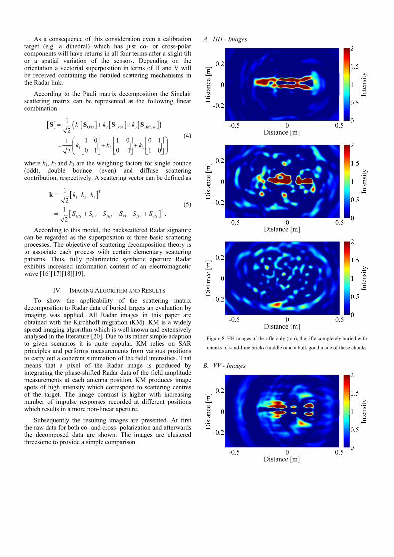
B. VV - Images

Figure 9. VV images of the rifle only (top), the rifle completely buried with
chunks of sand-lime bricks (middle) and a bulk good made of these chunks
C. HV - Images
Actually, for the backscattering from reciprocal media both cross-polarizations are equal. In the strict sense, this does not hold true within this paper because of the bi-static configuration. However, the difference between both cross-polarization channels are negligibly small and shall be reduced in the following to the HV channel for the sake of clarity.
Figure 10. HV images of the rifle only (top), the rifle completely buried with
chunks of sand-lime bricks (middle) and a bulk good made of these chunks
D. HH+VV Matrix Decomposition Images

Figure 11. HH+VV matrix decomposition images of the rifle only (top), the
rifle completely buried with chunks of sand-lime bricks (middle) and a bulk
good made of these chunks
E. HH-VV Matrix Decomposition Images
Figure 11. HH-VV matrix decomposition images of the rifle only (top), the
rifle completely buried with chunks of sand-lime bricks (middle) and a bulk
good made of these chunks
F. HV+VH Matrix Decomposition Images
Figure 12. HV+VH matrix decomposition images of the rifle only (top), the
rifle completely buried with chunks of sand-lime bricks (middle) and a bulk
good made of these chunks

V. DISCUSSION AND CONCLUSION
As aforementioned, every inspection of a target under test was performed on a circular track. The scanning pattern consists of two measurements per one degree. Due to this, every image was extracted from 720 measurements.
The geometry of the rifle exhibits a predominant horizontal orientation, because the length is much higher then the height. Due to this, both the HH image solo rifle and the HH image of the buried one clearly indicate the rifle. In every case the bottom of the rifle is hardly visible because this part of the rifle was not covered with conductive material. In the used position the rifle has 3 major vertical structures, i.e. the magazine, the grip and a part of the stock. These scattering centres are emphasized in the VV images. Due to the diversity between VV and HH features, the addition as well as the subtraction of the co-polar components within the scattering matrix decomposition provide different hot spots in the image. Except of the HV+VH case, the discrimination of the bulk good with rifle from the one without rifle is due to stronger hot spots feasible.
This paper shows a concept for employing the Pauli matrix decomposition as a feature for buried weapon or other man-made target detection. Novel tapered slot lines based broadband dual-polarized antennas which operate between 0.8 to 8 GHz were presented. The main features are a high polarization purity and equal phase centres for both polarizations. SAR focusing could be applied but that would require additional mechanical effort to span an extended 3D synthetic aperture. The combination of UWB technology at low frequencies with the theory of scattering matrix decomposition promises to be attractive for further research. One challenge is the low cross-range resolution due to low frequencies which are mandatory to reliably penetrate the covering medium. Future investigations should consider an overall optimization, e.g. for methods to increase the cross-range resolution.
REFERENCES [1] V. Kovalenko, A. Yarovoy, and L. Ligthart, “A novel clutter
suppression algorithm for landmine detection with GPR, ”IEEE Trans. Geosci. Remote Sens. , vol. 45, no. 11, pp. 3740–3751, Oct. 2007.
[2] J. Sachs, A. Badstübner, F. Bonitz et al., “High Resolution Non-Destructive Testing in Civil Engineering by Ultra-Wideband Pseudo-Noise Approaches,” ICUWB 2008 .
[3] R. Salman, I. Willms, ”In-Wall Object Recognition based on SAR-like Imaging by UWB-Radar,” Proc. 8th European Conference on Synthetic Aperture Radar (EUSAR), 2010.
[4] Chi-Chih Chen; Higgins, M.B.; Jin Au Kong; Detsch, R., "Ultrawide-bandwidth fully-polarimetric ground penetrating radar classification of subsurface unexploded ordnance," Geoscience and Remote Sensing, IEEE Transactions on , vol.39, no.6, pp.1221,1230, Jun 2001.
[5] Kovalenko, V.; Yarovoy, A.; Ligthart, L.P., "Polarimetric feature fusion in GPR for landmine detection," Geoscience and Remote Sensing Symposium, 2007. IGARSS 2007. IEEE International , vol., no., pp.30,33, 23-28 July 2007.
[6] Yarovoy, A.G.; Sai, B.; Hermans, G.; Van Genderen, P.; Ligthart, L.P.; Schukin, A.D.; Kaploun, I.V., "Ground penetrating impulse radar for detection of small and shallow-buried objects," Geoscience and Remote Sensing Symposium, 1999. IGARSS '99 Proceedings. IEEE 1999 International , vol.5, no., pp.2468,2470 vol.5, 1999.
[7] P. D. Gader, M. Mystkowski, and Y. Zhao, “Landmine detection with ground penetrating radar using hidden Markov models,” IEEE Trans. Geosci. Remote Sens., vol. 39, no. 6, pp. 1231–1244, Jun. 2001.,
[8] H. Frigui and P. Gader, “Detection and discrimination of land mines in ground-penetrating radar based on edge histogram descriptors and a possibilistic k-nearest neighbor classifier,” IEEE Trans. Fuzzy Syst., vol. 17, no. 1, pp. 185–199, Feb. 2009.
[9] T. G. Savelyev, L. van Kempen, H. Sahli, J. Sachs, and M. Sato, “Investigation of time frequency features for GPR landmine discrimination,” IEEE Trans. Geosci. Remote Sens., vol. 45, no. 1, pp. 118–129, Jan. 2007.
[10] W. H. Lee, P. D. Gader, J. N. Wilson, N. Inc, and V. A. Sterling, “Optimizing the area under a receiver operating characteristic curve with application to landmine detection,” IEEE Trans. Geosci. Remote Sens., vol. 45, no. 2, pp. 389–397, Feb. 2007.
[11] P. Torrione and L. Collins, “Texture features for antitank landmine detection using ground penetrating radar,” IEEE Trans. Geosci. Remote Sens., vol. 45, no. 7, pp. 2374–2382, Jul. 2007.
[12] A. Yarovoy, F. Roth, V. Kovalenko, and L.P. Ligthart, "Application of UWB Near-Field Polarimetry to Classification of GPR Targets" –in the book of Proc. of EuroEM 2004, July 12-16,2004, Magdeburg, Germany, pp. 665 – 674.
[13] Cherniakov, M.; Donskoi, L., "Frequency band selection of radars for buried object detection," Geoscience and Remote Sensing, IEEE Transactions on , vol.37, no.2, pp.838,845, Mar 1999.
[14] Yarovoy, A.; Ligthart, L.; Schukin, Alexander; Kaploun, Igor, "Full-polametric video impulse radar for landmine detection: experimental verification of main design ideas," Advanced Ground Penetrating Radar, 2003. Proceedings of the 2nd International Workshop on , vol., no., pp.148,155, 14-16 May 2003
[15] W. Wiesbeck, S. Riegger, “A Complete Error Model for Free Space Polarimetric Measurements”, IEEE Trans. on Antennas and Propagations, vol.39, no.8, pp. 1105-1111, Aug. 1991.
[16] Salman, R.; Willms, I.; Reichardt, L.; Zwick, T.; Wiesbeck, W., "On polarization diversity gain in short range UWB-Radar object imaging," Ultra-Wideband (ICUWB), 2012 IEEE International Conference on , vol., no., pp.402,406, 17-20 Sept. 2012
[17] Malz, E.; Thoma, R.S.; Zetik, R.; Semashko, P.; Ariza, A.P.G., "Polarimetric Ultrawideband Radar — Principles and applications," Ultra-Wideband (ICUWB), 2012 IEEE International Conference on , vol., no., pp.407,411, 17-20 Sept. 2012
[18] R. Salman, I. Willms, “ Exploitation of Polarimetry in Short Range 3D UWB-Radar Object Imaging”, 2012 IEEE International Conference on 3D Imaging (IC3D), Liège, Belgium, Dec. 2012.
[19] R. Zetik, H. Yan, E. Malz, S. Jovanoska, G. Shen, R.S. Thomä, R. Salman, T. Schultze, R. Tobera, I. Willms, L. Reichardt, M. Janson, T. Zwick, W.Wiesbeck, T. Deißler, J. Thielecke, “Cooperative Localization and Object Recognition” in UKoLoS Ultra-Wideband Radio Technologies for Communications, Localization and Sensor Applications. R.S. Thomä, R. Knöchel, J. Sachs, I. Willms, T. Zwick (Eds.). InTech Academic Publisher, ISBN: 978-953-307-740-6.
[20] Xiaodong Zhuge; Yarovoy, A.G.; Savelyev, T.; Ligthart, L., "Modified Kirchhoff Migration for UWB MIMO Array-Based Radar Imaging," Geoscience and Remote Sensing, IEEE Transactions on , vol.48, no.6, pp.2692,2703, June 2010.