
Inferring the photometric and size evolution of galaxies from ...
Upload
khangminh22Category
view
2download
0
University of Tennessee, Knoxville University of Tennessee, Knoxville
TRACE: Tennessee Research and Creative TRACE: Tennessee Research and Creative
Exchange Exchange
Masters Theses Graduate School
12-1992
A Photometric Analysis of Weapon Separation Characteristics A Photometric Analysis of Weapon Separation Characteristics
Douglas Paul Yurovich University of Tennessee, Knoxville
Follow this and additional works at: https://trace.tennessee.edu/utk_gradthes
Part of the Aviation Commons
Recommended Citation Recommended Citation Yurovich, Douglas Paul, "A Photometric Analysis of Weapon Separation Characteristics. " Master's Thesis, University of Tennessee, 1992. https://trace.tennessee.edu/utk_gradthes/4930
This Thesis is brought to you for free and open access by the Graduate School at TRACE: Tennessee Research and Creative Exchange. It has been accepted for inclusion in Masters Theses by an authorized administrator of TRACE: Tennessee Research and Creative Exchange. For more information, please contact [email protected].

To the Graduate Council:
I am submitting herewith a thesis written by Douglas Paul Yurovich entitled "A Photometric
Analysis of Weapon Separation Characteristics." I have examined the final electronic copy of this
thesis for form and content and recommend that it be accepted in partial fulfillment of the
requirements for the degree of Master of Science, with a major in Aviation Systems.
Ralph D. Kimberlin, Major Professor
We have read this thesis and recommend its acceptance:
Robert Richards, Ted Paludan
Accepted for the Council:
Carolyn R. Hodges
Vice Provost and Dean of the Graduate School
(Original signatures are on file with official student records.)

To the Graduate Council:
I am submitting herewith a thesis written by Douglas Paul Yurovich entitled "A Photometric Analysis of Weapon Separation Characteristics". I have examined the final copy of this thesis for f onn and content and recommend that it be accepted in partial fulfillment of the requirements for the degree of Masters of Science, with a major in Aviation Systems.
We have read this thesis and recommend its acceptance:
Professor Robert Richards
Dr. Ted Paludan
:r
Dr. Ralph D. Kimberlin, Major Professor
Accepted for the Council:
Associate Vice Chancellor and Dean of The Graduate School

STATEMENT OF PERMISSION TO USE
In presenting this thesis in partial fulfillment of the requirements for a
Masters degree at The University of Tennessee, Knoxville, I agree that the Library
shall make it available to borrowers under rules of the Library. Brief quotations
from this thesis are allowable without special permission, provided that accurate
acknowledgment of the source is made.
Permission for extensive quotation from or reproduction or this thesis may
be granted by the major professor, or in his absence, by the Head of Interlibrary
Services when, in the opinion of either, the proposed use of the material is for
scholarly purposes. Any copying or use of the material in this thesis for financial
gain shall not be allowed without my written permission.

A PHOTOMETRIC ANALYSIS
OF
WEAPON SEPARATION CHARACfERISTICS
A Thesis
Presented for the
Master of Science
Degree
The University of Tennessee, Knoxville
Douglas Paul Yurovich
December 1992

DEDICATION
This thesis is dedicated to my wife, Donna,
and my daughter, Deanna,
whose unending support and eternal energy
offer me continued motivation.
ii

ACKNOWLEOOMENTS
I would like to thank the members of my thesis committee for their professional
support and guidance. I would also like to express my gratitude to Mr. Gary Evans
for his computer instruction and assistance over the last two years, most of which
made this task a little easier. Finally, to Mr. Charles Buckheit, my project engineer,
whose attention to detail and professional attitude made this an enjoyable
experience.
I would like to also make a special acknowledgment to LtCol Troy Pennington
USMC, whose timely decision to eject us both from an F/A-18 that crashed on 1
October 1992, is in my opinion, the only reason I am alive today to complete this
project. Thank you Wizard!
iii

ABS1RACT
This project attempted to implement a unique multi-camera photometric
te.chnology into the discipline of weapons separation testing from tactical jet aircraft.
This project was a U.S. Governmental, Department of Defense tasked
affair, that utilized assets of the Naval Air Warfare Center Aircraft Division, Naval
Air Station, Patuxent River, Maryland
The methodology employed consisted of a standard lens calibration
procedure; an airspace calibration procedure, that defined the zone for the activity of
motion, and targeting of the aircraft and specific store.
With filmed flight test data in hand, the data was digitized through a motion
sensor and stored as computer files. It was then transferred to 4D Video, an Image
Based Motion Measurement Company, Sebastopol, Ca., the Contractor, whose
analysis quantified the results.
The process as seen here has limited potential for future use, but with the
augmentation of recent technological advancements, this process will become more
efficient with manpower, assets and monies.
It is with continual evaluation and improvement that a Flight Test and
Engineering organization can make this process the nucleus of a multi-camera
photometric capability, giving the organization added accuracies in their ability to
quantify weapon separation characteristics.
iv

INTRODUCTION
BACKGROUND
Introduction.
Separation Test Theory
TABLE OF CONTENTS
Aerodynamics of Store Separation
Static Forces and Moments
Freestream
Interference
Dynamic Effects
Cross-flow Effects
LITERARY REVIEW
Introduction
History of Aerial Bombardment
Photogrammetry
METIIOOOLOGY
Introduction
Description of Test Aircraft and Test Equipment
F/A-18 Hornet
BRU-32 Parent Rack
AIM-9R Sidewinder Missile
LA U-115 Missile Rail Launcher
LAU-127 Missile Rail Launcher
LAU-115 Jettison Adapter
Multiple Ejector Rack (MER)
Cameras and Ftlm
Motion Analysis System
V
1
3
3
5
5
7
7
7
8
8
9
9
9
12
13
13
13
13
15
16
17
18
19
20
20
21
TABLE OF CONTENTS
Method of Test: The Unique Process
Introduction
Image Deformations
Barrel or Pincushion Distortion
Decentering Distortion
Control Points
Lens Calibrations
Airspace Calibration
Aircraft and Store Targeting
Flight Tests
Data Reduction
The Algorithm
Data Presentation
RESULTS and DISCUSSION
Results
Discussion
Introduction
Problem Areas
CONCLUSIONS
REFERENCES
BIBLIOGRAPHY
Store Surveying
Time Matching ofFUm
Airspace Calibration
Data Confidence and Errors
Work Load
Data Turn Around TlIDe
vi
22
22
22
24
25
26
27
28
29
30
30
31
33
34
34
34
34
34
34
35
36
36
37
37
39
40
42

APPENDIX A
APPENDIXB
VITA
TABLE OF CONTENTS
vii
44
51
65

LIST OF FIGURES
Fi�re �
Figure 1 Aerodynamic Forces and Moments on a Store 6
Figure 2 Early Bombers 10
Figure 3 Gravity Bomb Rack 11
Figure 4 F/A-18 Aircraft 14
Figure 5 F/ A-18 Weapon Station Numbering 14
Figure 6 BRU-32 Bomb Rack unit 15
Figure 7 AIM-9 Sidewinder Missile 17
Figure 8 AIM-9/LAU-127 /LAU-115 MRL Combination (Rear View) 18
Figure 9 LAU-127 Missile Rail Launcher 19
Figure 10 LAU-115 Jettison Adapter 20
Figure 11 Image Defonnations 23
Figure 12 Barrel and Pincushion Distortion 24
Figure 13 Decentering Distortion 25
Figure 14 A Semi-Pennanent System of Control Points 26
Figure 15 Calibration Board 27
Figure 16 Object Space Calibration 29
Figure 17 Rotation of a Coordinate System 32
Figure 18 Computer Animation of One View From The Contractor 33 Video
Appendix B, Figure 1 MER With Strongbacks and Cameras 52
Appendix B, Figure 2 Cameras 53
Appendix B, Figure 3 Camera Locations 54
Appendix B, Figure 4 Fully Corrected Reference Targets 55
viii
LIST OF FIGURES
Fi� �
Appendix B, Figure 5 Scaled (x2) Radial Distortion 56
Appendix B, Figure 6 Scaled (xl5) Tangential Distortion 57
Appendix B, Figure 7 Radial Distortion Plot 58
Appendix B, Figure 8 Control Point Construction 59
Appendix B, Figure 9 Control Point Construction 60
Appendix B, Figure 10 Surveyed Aircraft Targets 61
Appendix B, Figure 11 Fuel Tank and Wing Pylon Targets 62
Appendix B, Figure 12 Release Sequence 63
Appendix B, Figure 13 Coordinate Corrections by 4D Video 64
ix

89C
AIM
AMRAAM
AOA/a
AUR
BRU
BuNo
CCU
CVER
OOF
F/A-18
GCS
Tl KCAS
LAU
M'
MAP
:MER
MI
MK
MM
MRL
MSL
NATOPS
NA V AIRSYSCOM
NAWCAD
OFP
p
GLOSSARY
Numerical Designation for an Operational Hight
Program
Air Intercept Missile
Advanced Medium Range Air to Air Missile
Angle of Attack
All Up Round
Bomb Release Unit
Bureau Number
Combustible Cartridge Unit
Canted Vertical Ejector Rack
Degree of Freedom
Fighter/ Attack Hornet
Guidance and Control System
Grid Traverse Angle From The Vertical
Knots Calibrated Airspeed
Launch Adapter Unit
Mach Number
Motion Analysis Package
Multiple Ejector Rack
Moment of Inertia
Marlc
Millimeter
Multiple Release Launcher
Mean Sea Level
Naval Aviation Training and Operating Procedures
Standardization Program
Naval Aviation Systems Command
Naval Air Warfare Center Aircraft Division
Operational Flight Program
Parent Aircraft Parameter
X

PC
R
s
SMS
suu
us
(U,V)
VER
WWI
(X,Y,Z)
z
GLOSSARY
Personal Computer
Radial Distance From Store to Captive Posttion
Store Parameter
Stores Management System
Stores Suspension and Release Unit
United States
Digitizer Coordinates
Vertical Ejector Rack
World War One
Object Space Coordinates
Nonna! Force
xi

INTRODUCTION
Historically, high speed photography has been used to perform qualitative
examinations of the kinematics of weapon separation from aircraft. With
technological advancement, electronic devices can create, store and interpret
images at great speed, allowing a greater flexibility in gathering and analyzing
data.
In an effort to employ this technology and better quantify weapon
separation characteristics, a process of multi-camera photometric analysis is being
evaluated at Strike Ordnance, Naval Air Warfare Center, Naval Air Station,
Patuxent River, Maryland during a US Governmentally tasked, Department of
Defense sponsored jettison program.
This process allows the test team the ability to obtain multi-camera three
dimensional tracking of a well-defined objective. It also offers the test
organization a mid-range technological solution to the transition to a full high
speed video capability.
This technique employed multi-cameras mounted externally on the F/A-
18, with a Dell 210 PC system utilizing motion analysis software and a model
1214A motion analysis system. Compiled data were then transferred to the
Contractor, whose analysis accomplished the 3 dimensional positioning of the
jettisoned store with respect to the airplane and time.
This process was used to document the separation characteristics of a store
used in a specific jettison test off the F/A-18 Hornet.
1

The flight test consisted of jettisoning:
Two AIM 9R missiles suspended on a LAU-127 MRL on station
eight, also referred to as the store in this text.
This thesis represents the critical analysis of this unique process
applied to the science of weapon separation testing and assesses the utility for its
future employment
2

BACKGROUND
Introduction
The Weapons Compatibility Sections of the Ordnance Systems
Department of NA WC conduct aircraft weapons compatibility testing. This work
includes, but is not limited to, the establishment of weapon separation and jettison
envelopes for tactical, patrol, and rotary wing aircraft. The types and function of
these weapon systems are varied and complex. Integration of smart weaponry (ie.
missiles, laser guided bombs, etc.) is an expensive endeavor owing to the
individual cost of each weapon. For this reason, the standard buildup approach 1 to
establishing a weapon envelope is cost prohibitive. As a result, the method of
testing is evolving into a procedure that relies heavily on analysis and prediction
with a minimum number of weapons expended to verify the accuracy and
precision of analytical models. To verify the analytical predictions, the weapons
are separated at the initial conditions of the analysis and the results of the
separation are compared. In order to conduct this comparison, it is necessary to
extract quantitative data from onboard 16mm film or video. The data extracted
from this two dimensional media can be transformed into six degree of freedom
(6-DOF) motion and spatial position for comparison to perspective wind tunnel
predictions. If the predictions are valid, the model can be used to expand the
separation envelope without the expenditure of weapons in an incremental build
up. The technique for extracting data from film and determining the quantitative
values of spatial position is called photometric analysis or photometrics.
1 The standard buildup approach begim with straight and level releases with an intaval incr� in airspeed, roughly 50 KCAS. Once a limiting airspeed is established, the dive angle is increased from straight and level (0 degrees) to 30, 45 and 60 degrees at that limiting airspeed.
3
The Naval Air Warfare Center has a photometric analysis capability that
utilizes a single camera solution. Although a single camera solution can provide
6-DOF data, the accuracy and precision have proven to be inadequate for the
application of critical stores separation where store-to-aircraft miss distances can
be less than a foot. By conducting a multi-camera solution, the accuracy and
precision of the analysis is increased by triangulation of the data from each
camera. The Ordnance System Department is pursuing the development of a
multi-camera photometric analysis capability for application to an upcoming
missile jettison program. Contractor support is required to expedite the
development of these improved test methods and to ensure the successful and
timely completion of this jettison program.
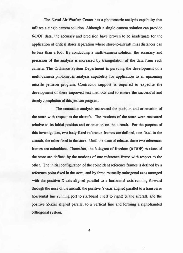
The contractor analysis recovered the position and orientation of
the store with respect to the aircraft. The motions of the store were measured
relative to its initial position and orientation on the aircraft. For the purpose of
this investigation, two body-fixed reference frames are defined, one fixed in the
aircraft, the other fixed in the store. Until the time of release, these two references
frames are coincident Thereafter, the 6 degree-of-freedom (6-DOF) motions of
the store are defined by the motions of one reference frame with respect to the
other. The initial configuration of the coincident reference frames is defined by a
reference point fixed in the store, and by three mutually onhogonal axes arranged
with the positive X-axis aligned parallel to a horizontal axis running forward
through the nose of the airer� the positive Y-axis aligned parallel to a transverse
horizontal line running port to starboard ( left to right) of the aircraft, and the
positive Z-axis aligned parallel to a vertical line and forming a right-handed
orthogonal system.
4

Separation Test Themy
The separation of an external store of an aircraft is a highly complex
phenomenon requiring detailed knowledge of the influence of the aircraft flow
field upon the store, the store's aerodynamic and physical characteristics, the
release mechanism used, and the physical installation of the store on the aircraft.
The factors governing the motions of separation include the store's mass
properties, specifically the density, center of gravity location, and moment of
inertia (Ml) in pitch, roll, and yaw; flight parameters such as airspeed, normal
acceleration, dynamic pressure, sideslip angle, and aircraft angle of attack (AOA);
aircraft design parameters such as wing/fuselage geometry, chord wise and
spanwise flow, and vertical location of the stores; means of store stabili7.ation; and
ejector unit design. These factors are discussed in the following paragraphs.
Aerodynamics of Store Separation (Kohiyar,l)
Aerodynamic forces and moments may be classified into three
categories: static, dynamic and cross-flow, as shown in Figure 1, and table I,
appendix A. For stores with extendible fins, the effect of fin deployment must be
incorporated, as this has a significant effect on freestream static and dynamic
stability.
5

CAPllVE POSmON
z
Figure 1 Aerodynamic Forces and Moments on a Store
NOMENCLATIJRE
M'
R
z
11
Mach number
Radial distance from store to captive position
Nonnal Force
grid traverse angle from the vertical
6
SUBSCRIPTS
p
s
(X
parent aircraft parameter
store parameter
angle of attack

Static Forces and Moments
Freestream
Freestream forces and moments are, by definition, the basic
aerodynamic characteristics of the isolated store and are functions of store
incidence (angle of attack or sideslip) and Mach number. A measure of the static
stability is obtained from the magnitude and sign of the variation of pitching and
yawing moments with angle of attack (AOA) and sideslip, respectively. ff the
slope of the pitching moment curve vs. AOA is negative the store is statically
stable and increasing the magnitude of the slope increases the level of stability.
Similarly, the variation of yawing moment with sideslip angle is a measure of
static directional (weathercock) stability; the slope of this curve, however, must
be positive for static directional stability. Stores without tail fins are generally
statically unstable. The restoring moments due to tail fins tend to rotate the store
back into the wind, so if the fins are sufficiently large, static stability will be
attained.
Interference
Aircraft-store interference effects are best obtained from
wind tunnel tests, using the grid survey technique, which maps the flowfield, by
measuring aerodynamic forces and moments at a number of pre-selected positions
relative to the parent aircraft. It is generally assumed that interference varies more
with vertical displacement than with axial or lateral displacement and also, that
interference is independent of store attitude relative to the parent aircraft.
7

Dynamic Effects
For dynamic stability it is necessary to consider the motion of the
body after it has been subjected to a disturbance from a state of equilibrium. If a
body is stable, it will return to its equilibrium condition by a subsidence or by
means of a damped oscillation. For stores, it is only necessary to consider
damping in roll, pitch and yaw. These damping moments are most conveniently
obtained in coefficient form.
Cross-Flow Effects
Cross-flow components are generated by asymmetric vortex
shedding, which occurs on bodies of revolution at high angles of incidence, or due
to rolling of the body. Vortex shedding is sttongly affected by Reynolds number,
turbulence, roughness and Mach number. Nose shape also effects cross flow
components - blunt nose bodies have a small effect and pointed nose shapes have
a large effect. The cross-flow components are:
( 1) Side force and yawing moment due to angle of attack
(2) Normal force and pitching moment due to sideslip angle
The derivatives are generally referred to as cross-derivatives
because the force or moment is due to variation of the incidence angle in the
normal plane. The signs of these parameters depend on the position and strength
of the vortices and can be of random sign.
8

LITERARY REVIEW
Introduction
Research for this project fell into two categories: history of aerial bombing
and the science of Photometrics. These two disciplines had been brought together
in the past, but this unique photometric technique had its initial application to
aviation and separation testing in this project. The unique technique is taken
from a Doctorate Thesis written by Dr. James S. Walton, President of 4D Video
of Sebastopol, California. Dr. Walton's previous applications of this technique
include quantification of human motion and tire deformation studies for General
Motors.
A more thorough appreciation for Dr. Walton's knowledge in this area can
be gained by reading his Doctorate Thesis, "Close-Range Cine-Photogrammetry:
A Generalized Technique for Quantifying Gross Human Motion", reference 2.
History of Aerial Bombardment
Bombing from the air was proposed in America by John Wise during the Mexican War (1846-1848) when he wrote a memorandum to the War Department headed ''Easy Method of Capturing the Castle Vera Cruz". He proposed a giant balloon with a twenty-ton lift which was to carry 18 tons of explosive shells and seven men. This was to be flown at the end of a rope 8 miles long, anchored either on land or to the deck of a ship to drop its bombs from a mile in the air over the castle, out of artillery range.(Donovan, 3)
Some 55 years later, with the Wright Brothers first flight, a new weapon of
war was questionably unleashed. Initially, the airplane had little application to war
and was limited to scouting missions and aerial reconnaissance. Figure 2 depicts
early bombing techniques.
9

Figure 2 Early Bombers
Peter B. Mersky writes in U. S . Marine Corps Aviation, 1912 to the Present, reference 4:
The military uses of aircraft, though immediately obvious to some, were somewhat limited by the imagination of the military leaders of the time and the petformancc of the little contraptions themselves.
In 1910 three Air meets were conducted in the United States with bombing competitions. It is in this carnival atmosphere that aerial bombardment from
airplanes established a foundation.
The first bombs were sctjd to be used by the French. They were flcchettcs,
steel arrows, as thick and as long as lead pencils. A can of flcchettes was thrown
over the side of the airplane; this provt.d very useless, but the British kept calling
for them, since they made good pub darts. (Note: Flcchettes were also tried again
in Viemam).
10

But when the airplane first entered combat the following year (19 1 1), it quickly added bomb dropping to its duties; although these frrst bombing sorties were more in the nature of operational experiments, they nevertheless pointed to an increasing belief that the airplane could take part in actual air-to-ground combat. During fighting in Tripoli against Turkey, Italian Aviators flying French designed Bleriot and Austrian designed Taube ("Dove") monoplanes performed both reconnaissance and strike missions against Turkish positions. On October 23, 191 1, Capt. Carlos Piau.a flew a recon mission from Tripoli to Aziza in a Bleriot, and just over a week later, 2Lt Giulio Gavotti of the Squadriglia di Tripoli dropped four small bombs from a Taube on the towns of 'Taguira and Ainzara. Subsequent bombing sorties became commonplace and although they had negligible effect on the war, the nascent potential of the airplane impressed military correspondents who witnessed its employment (Hallion, 5)
Also, the Billy Mitchell bombing of the Ostfriesland on Sunday 24 July
1921 , gave a big boost to American Tactical Bombing Aviation. This feat proved
that aitcraft were able to sink naval warships.
In addition to the air-superiority and interception roles defined in the WWI time period, the modem fighter may be employed for ground attack operations, long range interdiction missions and photo reconnaissance duties. (Lofton, 6)
As the airplane accelerated into the jet age and speeds progressed into the
high subsonic and transonic Mach numbers, compressibility effects started to
become evident in weapon separation characteristics and ejection racks replaced
the gravity racks pictured in figure 3.
Figure 3 Gravity Bomb Rack
1 1

The need for the ejection racks was to impart an ejection velocity on the
bomb/store to overcome any drafting or airflow effects on the expended stores due
to compressibility. The BRU-32 was used in this test and represents the state of
the art in bomb racks and is discussed later in detail in this text.
Photommmetry
From the Manual of Photogrammetry, reference 7, written in 1952, comes
this definition of photogrammetry: "the science or art of obtaining reliable
measurements by means of photography".
From the same text we gather these amplifying remarks: "It is interesting
to note that the word "photogrammetry" came into general usage in the United
States at about 1934, the same time the American Society of Photogrammetry was
founded, although the term had been widely used in Europe for several years. It is
derived from three Greek words, one meaning light, a second meaning drawing or
graph and a third meaning to measure. The root words, therefore, originally
signified measuring graphically by means of light."
Most aerial photography is used to take photographs for mapping
purposes. The mathematical corrections necessary to account for any oblique
angle of the picture with respect to the ground, and all lenses aberrations, are
applied to achieve the most accurate mapping possible. It is this mathematical
application that comprises a major portion of the Science of Photogrammetty.
Although this multi-camera process is unique in this aviation application,
it does maintain the generic traits of all photogrammetric study; therefore we will
cover those traits in greater detail in the Methodology section of this thesis.
12

METIIODOLOOY
Introduction
The purpose of this test was to examine the jettison characteristics of the
AIM 9R and missiles suspended on the LAU-127 MRL on the F/A-18 aircraft.
Tasking for this test was directed by Naval Air Systems Command
(NA V AIRSYSCOM) to Naval Air Warfare Center Aircraft Division
(NA WCAD), Patuxent River, Maryland. With the completion of this test, a formal
repon was written to sat isfy the governmental requirement The posit ion of
NA V AIRSYSCOM was stated, in this repon of which the author of this thesis
was the co-author and project officer.
This thesis represents the author's personal analysis of this photometric
process and should not be considered the view of the United States Government,
NA V AIRSYSCOM, NA WCAD or the Strike Aircraft Test Directorate, his parent
command at Patuxent River, Maryland.
Description of Test Aircraft and Test EQuipment
F/A-18 Aircraft
The F/A-18 Hornet, figure 4, was a single seat, dual-engine,
supersonic strike fighter/attack aircraft built by the McDonnell Douglas Aircraft
Company. It was powered by two General Electric F404-GE-400 turbofan
engines with afterburner. The aircraft has an all-weather intercept, identify,
destroy, and ground attack capability.
13

Figurc 4 F/A-18 Aircraft
Nine weapon stations were provided on the F/A-1 8, five of which were capable of
carrying and releasing air-to-ground ordnance. The weapon stations are numbered
acconling to figure 5.
Figure s F/A-18 Weapon Station Numbering
14

The aircraft utilized an integrated Stores Management System (SMS) for
weapons systems control. Air to ground stations incorporated BRU-32 bomb
racks. The test aircraft SMS utilized 89C software for these tests. F/A- 18A
BuNo 161925 was utilized for jettison tests. The test aircraft was representative
of production models for the purposes of this test A more detai led description of
the F/A- 18 aircraft can be found in the F/A- 18 NATOPS Manual, reference 8.
BRU-32 Parent Rack
The BRU-32 bomb rack (figure 6) was a dual ejector foot, gas
operated, bomb rack which incorporated 14 and 30 inch suspension hooks. It
cou ld carry single weapon stores, BRU-33s, MERs, VERs, CVERS, BRU-42s,
and LAU-1 15, 1 17, 1 18 missile
Figure 6 BRU-32 Bomb Rack unit
launchers. Features of the bomb rack inc luded safety interlock and automatic
sway bracing. Sensing switches were incorporated to indicate store presence to
the armament computer. The primary ejection unit used two CCU-45 cartridges
to generate the required gas pressw-e for rack operation. The auxiliary release unit
used one MK-19 cartridge, which would open the hooks should primary ejection
15

fail. Nose and tail arming units were provided for mechanical fuses and a
receptacle was provided for connection of the electrical fusing umbilical.
Provisions were made for positive arming by use of positive arming latches. The
BRU-32 is designed to fit into the SUU-63 Wing Pylon and then attached to the
F/A-1 8. The SUU-63 Wing Pylon provides the necessary mechanical and
electrical interface between the aircraft wing structure and the stores to be _carried.
AIM-9R Sidewinder Missile
The AIM-9R missile (figure 7) was an upgrade to the current AIM-
9 weapon system. Changes were made to the Guidance and Control Section
(GCS) to provide improved acquisition and countermeasures performance. All
other components were standard AIM-9L/M hardware. The improved GCS is 2
inches longer and 10 lb heavier than the AIM-9UM GCS, which increases the All
Up Round length to approximately 1 17 in. and the weight to approximately 200
lb. The increased weight also shifts the center of gravity approximately 2 inches
forward. AIM-91JM missiles massed to emulate AIM-9R missiles were used for
all testing described hereafter. Missiles used for carriage and launch testing were
certified fleet representative during buildup at the Naval Weapons Station,
Yorktown, VA. A hardware summary is contained in appendix A, table II.
16

Figure 7 AIM-9 Sidewinder Missile
LAU-1 15 Missile Rail Launcher
The LAU- 1 15 (figure 8) was a rail type missile launcher designed
primarily for carriage and launch of AIM-7 series missiles on the F/A- 18 aircraft.
The LAU- 1 15NA MRL incorporated changes to the LAU-1 15/A required to
support AMRAAM and the LAU- 1 27 . The LAU- 1 15NA provided the
appropriate structural, mechanical, and electrical systems required to attach two
LAU- 127 launchers to allow loading of AIM-9 missiles as shown in figure 5.
Two suspension lugs, 30 inches apart, are provided and allow the MRL to be
loaded on the BRU-32 bomb rack. For jettison tests, LAU- 1 15/A launchers
ballasted by Point Mugu to simulate LAU- 1 15NA launchers were used. A fleet
representative production LAU-1 15NA was used for captive carriage and launch
tests. LAU-1 15 mass properties data are summarized in appendix A, table m.
17

Figure 8 AIM-9/LAU-127 /LAU-1 15 MRL Combination (Rear View)
LA U-127 Missile Rail Launcher
The LAU- 127 MRL (figure 9) was the U.S. Navy version of a
series of rail type missile launchers designed for carriage and launch of AIM-120
AMRAAM and AIM-9 Sidewinder missiles. Two other configurations (LAU-128
and LAU-129) existed for U.S. Air Force applications. The LAU-127 provided
support for the missile on the aircraft, missile orientation at the beginning of
missile flight, holdback restraint until motor ignition and partial thrust buildup,
electrical interface between aircraft and missile, and control circuits to prepare
and launch the missile. It consisted of a forward fairing assembly, detent
assembly, Sidewinder umbilical retract mechanism, launcher structure assembly,
Sidewinder power supply, aft fairing assembly, aft snubber assembly, Sidewinder
nitrogen coolant supply, and the aircraft/launcher wiring harness. Two
suspension bolts, 30 inches ap� were provided on the launcher to mount to the
LAU-115. For jettison tests, LAU-128 MRLs ballasted to simulate LAU-127
18
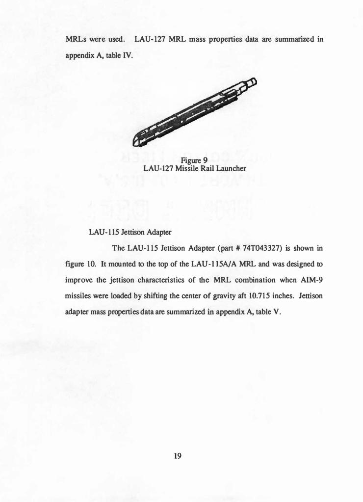
MRLs were used . LA U- 127 MRL mass propenies data are summarized in
appendix A, table IV.
Figure 9 LAU-127 Missile Rail Launcher
LAU-1 15 Jettison Adapter
The LAU- 1 15 Jettison Adapter (part # 74T043327) is shown in
figure 10. It mounted to the top of the LAU- 1 15NA MRL and was designed to
improve the jettison characteristics of the MRL combination when AIM-9
missiles were loaded by shifting the center of gravity aft 10. 715 inches . Jettison
adapter mass properties data are summarized in appendix A, table V.
19
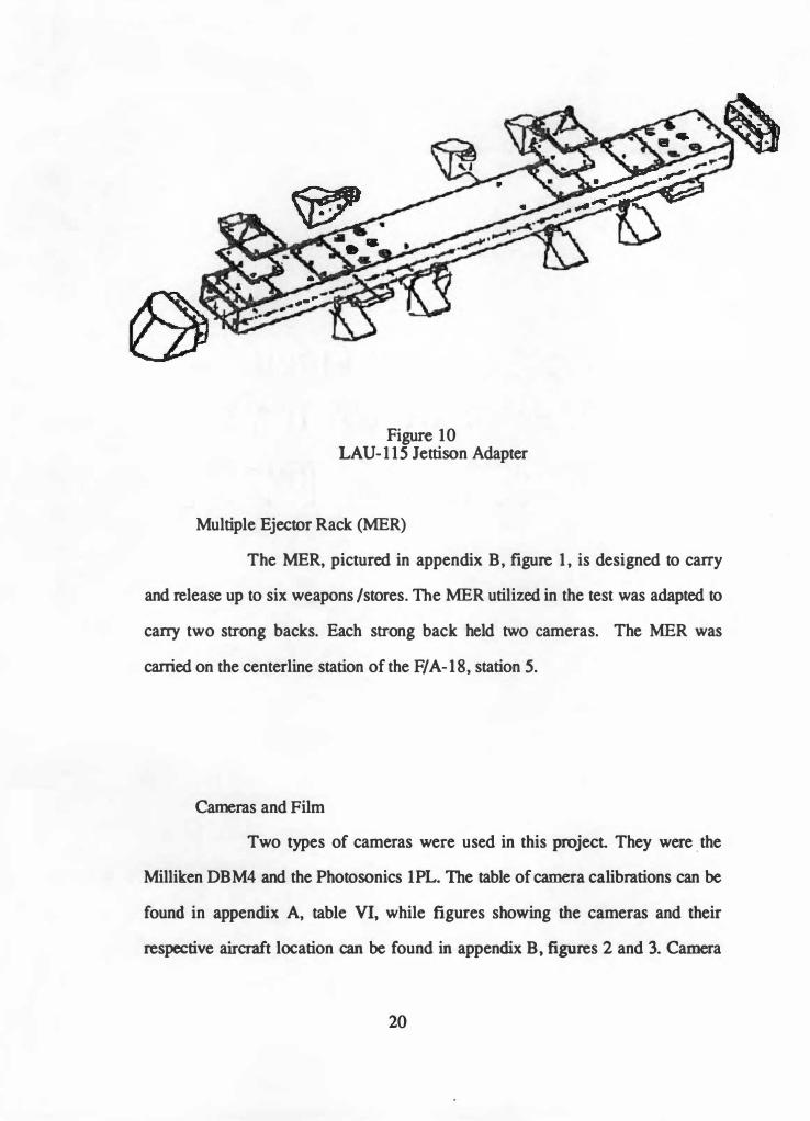
Figure 10 LAU- 1 15 Jettison Adapter
Multiple Ejector Rack (MER)
The MER, pictured in appendix B, figure 1 , is designed to carry
and release up to six weapons /stores. The MER utilized in the test was adapted to
carry two strong backs. Each strong back held two cameras. The MER was
carried on the centerline station of the F/ A- 18, station 5.
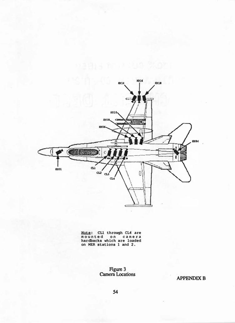
Cameras and Film
Two types of cameras were used in this project. They were _ the
Milliken DBM4 and the Photosonics IPL. The table of camera calibrations can be
found in appendix A, table VI, while figures showing the cameras and their
respective aircraft location can be found in appendix B, figures 2 and 3. Camera
20

locations are referred to an origin located in the plane of symmetry of the aircraft,
7 inches above the nose , and 60.5 inches forward of the nose for data reduction
purposes .
The Milliken DBM4 is a high speed motion picture camera with
intermittent pin registration. They run at 200 frames per second with an internal
film capacity load of 200 feet.
The Photosonics Model IPL is a high speed motion picture camera with
intermittent two pin registration. The 1 PL also uses two pull down pins with film
held captive in aperture gate at all times . The Photosonics 1 PL also runs at 200
frames per second, and has a capacity of 200 feet for its film load.
Film type was KODAK 2239 VNF day light color balanced reversal film
designed for use under low level illumination or for high speed application. The
processed film is balanced for direct projection .
Motion Analysis System
Our motion analysis system consists of a Dell 2 10 Personal
Computer, VIC Model 1240A Motion Analysis Sys tem, with a Motion Analysis
Package (MAP) Version 5.4 software. In this film analysis si tuation, like most
o ther film analyses, the test team was interested in monitoring the location in
space of a target (one point) or a contour (a set of connected points), and tracking
them frame to frame. Using the MAP, the film analysis included the following
tasks:
21
1 . Identify the film to be analyzed with a unique test ID.
2. Collect the (Ui,Vi) coordinates of the selected objects in the
desired frames.
3. Scale the digitized images to the object space.
4. Graphically review data using displacement and time history
plots.
5. Reformat the data to Macintosh II format for transmission to
other computing systems.
Method of Test: The Unigue Process
Introduction
The mission of the implementation of this unique process was to
better quantify store movement when re leased from an aircraft. This multi-camera
solution was to achieve accuracies of +/- 1 inch and +/- 1 degree of store
movement in any axis . As previously stated , this process was implemented with
contractor support offered by 4-D Video .
Image Deformations
From Dr . Walton's dissertation we can get an appreciation of the
number of ways our flight data can be deformed . This deformation will result in
erroneous conclusions if not corrected . Figure 1 1 (Walton:2,50) describes these
defonnations.
22

PIIM NJ::TIONI Due to C11.a11ae•
•• ,, •• C.O•try
Prod1ac .. la the Ca•ra •nd tl,t toa
Aaalyaer
Due t• Procea•l•1 and the !nw lroaaat
PMJIC'Tlft DISTORTION
· Prnd11eed •, tM Not loa Anal yaer
I OPTICAi.
DI STOITlOII
A Lene -·r·-IAIREL OR
PINCVSHIOII DISTORTIOII
Figure 1 1 Image Deformations
1.1111 11!.n .. � .. . , , ..
. ObjeUlvee of , .. C.•r• •IMI Nott•
Anal,aer
- I I
l)[CtJffDltlC DISTORTION
Due to lapropn Al tanaeec of
I '-·r··· I TAIICIKTJAL l>IStOlTION
Amt«ETIIC IADIAL
Dl STOlTIOII
Through analysis by the Contractor the image deformations attributed to film
deformation and projective distortion were considered insignificant. The
information gathered from each lense calibration was used to quantify the barrel
or pincushion distortion, and the decentering distortions. Each of these
deformations will be addressed in the following paragraphs.
23

Barrel or Pincushion Distortion
This type of distortion is a measure of radial distortion as a
percentage of the radius vs. the radius. When the distortion is positive, the target
is moved away from the center of the image, producing pincushion distortion.
When the distortion is negative, the target is moved toward the center of the
image, producing barrel distortion. These types of deformations are pictured in
figure 12 (Walton:2, 52).
I '
I
I I I I
, _ ___ .., _ _ _ _ J
a) Barrel distortion
rs reduced by As
b) No distortion
rs correct
c) Pincushion distortion
r5 increased by As
Where: rs is the radius from the point of symmetry to the ideal image position
Ar is the image defonnation poduced by the optical distMion
Ar increases as rs increases
Ms is the point of symmetry
Figure 12 Barrel and Pincushion Distortion
24

Decentering Distortion
Decentering distortion can be divided into radial and
tangential distortion. The changes in the geometry of an image due to decentering
distortion are respresented in figure 13 (Walton:2, 59).
I I I I . I I I I I I I I I I t I - - � - - , - - � - - , - - -'- - , - - � - - , - - � - -' . I I • I
I r . I I I - I t I - L - - r _ _ , - - · - - - - - .- - - '- - - r - · L I -- I ' ' ' I - I I I I
J I I -' - - -, - - - - -- - - -- - - -- .. - .. ... t _ _ , - - J . I - - f I I f
- 1 - - ' - - - - - - - - - - L 1-
- .. - -
- - - - - - - - -- - - - - -- . � 7
I I I I I
� - - , - - · - - - - - - - - - - - .J - - -, - - .:.1 -- I I I t ---, I I •
I I I . L - - ,- - - L - - .- - - - - - - - - 1 - - r - - L
I I I
I ' I ,, I I I I I
-' - - , - - J - - · - - · - - , - - .J - - , - - -' � l I I I t
1 I ' I ' I · r
Figure 13 Decentering Distortion
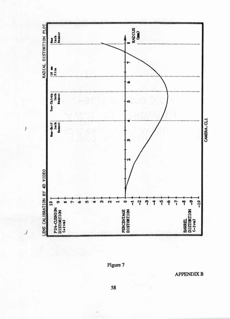
With each lense the Contractor supplied four plots from our lens calibration files.
These plots are:
a) Fully Corrected Reference Targets b) Scaled (2X) Radial Distortion c) Scaled (15x) Tangential Distortion d) Radial Distortion Plot
25

Examples of each of these plots can be found in appendix B, figures 4-7. The
Fully Corrected Reference Targets shows each of the targets before and after a
combined correction for radial and tangential distortion. The Scale (2X) Radial
Distortion Plot shows the corrected locations ( outermost) and the corresponding
hypothetical locations when the radial - distortion only is doubled. The Scaled
( 1 SX) Tangential Distortion shows the corrected locations and the corresponding
hypothetical locations when the tangential distortion only is magnified by a factor
of 15. The Radial Distortion Plot measures the radial distortion as a percentage of
the radius vs. the radius. The test team's immediate concern was the 16mm
reference for distortions.
Control Points
Dr. Walton refers to our system of control points as a semi
permanent system. A semi-permanent system of control points, as depicted in
figure 14, is used to outline the zone for the activity, the object space, that is
trying to captured on film and later analyzed.
--f\.oaa--· - __. P\.N � � QIQI ISAI.IQIIOf �.
Figure 14 A Semi-Permanent System of Control Points
26

The control points are attached to plumb lines that arc attached to a suppon
mechanism. The control points were hard rubber balls, positioned at heights along
the plumb lines, that allowed for the easiest preflight construction and the best
definition of the airspace. Balls are used as targets, because their centers -can
always be identified in an image, regardless of their perspective. The number of
control points is somewhat dependant on the number of cameras, but it is the
definition of the object space that is the primary concern. Appendix B, figures 8
and 9 show some of the control points and supporting construction.
Lens Calibrations
Each of the 12 lenses had to be calibrated to account for the image
distortions. Each camera photographed a calibration board, figure 15, and then
each camera was digitized, the process of_ inputting the data into the computer, by
4 individuals, to minimize human error. These computer files were transferred to
the contractor and the 4 data files were condensed into 1 calibration file per
camera, by a method of least squares, to be used later in the process.
Figure 15 Calibration Board
27
Airspace Calibration
This calibration posed a unique problem to the test team. A support
system needed to be constructed to hold the control points, that are· necessary to
outline the object space that the jettisoned store was to fall through. This airspace
needed to be referenced to the F/A- 1 8 and the camera locations on the F/A-18 for
the correct triangulation of the flight data.
Another dilemma accompaning the object space calibration was
that the object space was underneath the F/A- 18. With the F/A- 1 8 in a static
position on the hanger deck, we did not have sufficient clearance under the
aircraft to define the object space.
It was decided to define the same volume of airspace from two
different sets of camera references. A plumbob was used from the nose camera
and the tail camera that defined the centerline of the aircraft. This frame of
reference coincided with the MER on the centerline of the aircraft, and the
cameras located on the MER.
The MER and cameras were suspended 16 feet in the hangar,
representing an inflight status on the centerline station of the F/A- 1 8, while the
right wing of the F/A- 18 was mapped out on the floor of the hangar. The object
space of concern could now be defined by suspended control points. The object
space that was calibrated was 6 feet wide, 13 feet long and 16 feet deep, and is
represented in figure 16.
28

ff 1 {j <::F§ s2;- ( ; I@=!]£ ta-JD
. . . . . . .
. . . . . . .
. . . . . . .
. . . . . . .
. . . . . . .
Figure 16 Object Space Calibration
Photographs of the control points were taken from each of the camera positions,
encompassing as many of the control points as possible in a single shot. The
mathematical model requires a minimum of two cameras, for triangulation, and
six non-coplanar control points for a solution. These photos were then digitized to
establish the object space in the MAP, (U,V) coordinates for each control point,
and transferred to the contractor for future use in the process.
Aircraft and Store Targeting
The surveyed aircraft boresigbt target locations can be found in
appendix B, figure 10. Also utilized were surveyed targets on a fuel tank that was
carried on station 7, appendix B, figure 1 1.
29

The AIM-9R/LAU 127 was targeted, but not surveyed. This in
re trospect was an error, and surveying of the store should have been
accomplished.
One can generalize and say you never can have enough targets to
analyze after the test is accomplished. The surveying of the store would have
provided a target, whether it was marked or not, since positions on the store
would have been known beforehand, and if it was in the post-flight picture, it
could have been used for an additional target. In some cases this would have
been very helpful, due to the motion of the store after release and concealment of
primary targets.
Flight Tests
The AIM-9/LAU-127 combination was jettisoned on 20 Sept 1991
and again on 2 Oct 1991. The flight parameters for the first test were: 26,000
. MSL and 260 KCAS; while the second test was accomplished at 3,000 feet MSL
and 400 KCAS.
Film coverage was obtained and data reduction began the next day.
A film sequence of the event is pictured in appendix B, figure 12.
Data Reduction
Each of the 12 camera views had to be digitized into the Motion
Analysis Package. Each of the views presented roughly 300 frames of film to
digitize, with 30 to 50 data points per frame. It was a laborious task that took 6
individuals roughly 1 week to accomplish, reading data 24 hours a day.
Once the data was stored in computer files, it was transported to the
Contractor. The Contractor produced calibration data, named Fully Corrected and
30

Remapped Targets, for each of the 12 views. An example of the calibration da ta
can be found in appendix B, figure 13. Three locations are shown for each point.
The first location (no marker) shows the location of the target as specified by the
raw data . The second location, shown by the symbol 'x', shows the location of the
target after the data have been corrected for lens distortions. The third location,
shown by the '+', shows the reconstructed location of the target based on the
image-to-object mapping. This image-to-object mapping established coordinate
mappings CXi,Yi,Zi) from the (Ui,Vi) coordina tes established from the digitizing
for each of the 12 views in the calibrated object space .
From the 12 object-to-image mappings, a cross check was established by
backing out the control point positions from the flight test gathered mappings . The
correlation was very good.
From here we could establish the distance between any points established
in the calibrated airspace . This would allow us to quantify the distance between a
poin t on the ejected store, to the aircraft location that came within the closest
proximity of the store d uring the separation .
The Algorithm
In essence , the algorithm that accomplished the tracking of
our ejected store through our calibrated object space, is one dependent on
directional cosines . Its presentation is most eloquently stated and picture in The
VNR Concise Encyclopedia of Mathematics , (Gellert, 9), and is presented here :
A rectangular coordinate system wi th the axes X,Y,Z can always be
brought in to coincidence with a second rectangular coordinate system with the
same origin and axes X', Y' �· by first rotating about the X-axis through the angle
31
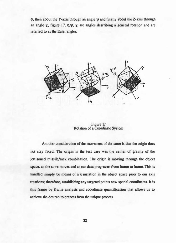
q,, then about the Y-axis through an angle 'I' and finally about the Z-axis through
an angle X, figure 17. q>,'V, X arc angles describing a general rotation and are
ref erred to as the Euler angles.
Figure 17 Rotation of a Coordinate System
Another consideration of the movement of the store is that the origin does
not stay fixed. The origin in the test case was the center of gravity of the
jettisoned missile/rack combination. The origin is moving through the object
space, as the store moves and as our data progresses from frame to frame. This is
handled simply be means of a translation in the object space prior to our axis
rotations; therefore, establishing any targeted points new spatial coonlinates. It is
this frame by frame analysis and coordinate quantification that allows us to
achieve the desired tolerances from the unique process.
32

Data Presentation
A final note to the process. A video, along the line of a Computer
Aided Design picture analysis, is a part of the Contractor's obligations. At the
time of this writing, a preliminary video has been received. It is very unique and
impressive, offering us the ability to view the test event through any Euler angle,
creating a graphic reconstruction of "critical views" not provided by the cameras,
and is the most pleasing presentation of data one will witness. An example of one
possible view is presented in figure 18, taken from a computer animation.
Figure 18 Computer Animation of One View From
The Conttactor Video
33

RESULTS AND DISCUSSION
Results
Although the separation characteristics of this test was benign in nature,
the test team was able to meet the objectives and quantify the store movement
after release to specified tolerances. With the results, sponsors in the Flight
Clearance Branch, AIR 530, in Washington DC, who were concerned about our
abilities to employ the process and analyze the data, were satisfied. In this aspect,
the test was very successful.
Separation clearances were visually identified and the time or
frame of occurrence noted. The test team could then proceed to the tabular data
and establish the distances from the points in question.
Discussion
Introduction
Although all sounds well in the end, the test team encountered
some difficulties, establishing a learning curve for possible future employment of
this technology.
Problem Areas
Store Surveying
Instead of just targeting the store, placing two color
markers on the store for identification, surveying the store would provide a more
detailed definition of the store in the database. This offers the test team more
opportunities to gather data during release of the store, when selected targets are
34

shielded from critical camera views, while some protion of the store is still in
view of a specific camera and can still be digitized.
A quick and accurate means of doing this is called
PIXSYS. This system uses a touchwand that emits light pulses and triangulates to
establish the (X, Y ,Z) coordinates of the store. These touches register in a
computer aided design file in current PC systems to establish that store in the
database. New stores can be quickly added. This surveying also allows the test
team the flexibility to assign the (0,0,0) point on the expendable store, so that a
prominent feature of the store may be used instead of the center of gravity, for
instance. Store surveying is a necessity for future employment of this technology.
Time Matching of Film
Data reduction would have proved easier and more efficient
if all the cameras were time matched. An electronic timer, running with all the
cameras and injecting the running time onto every frame of the pictured test event,
would have minimized assumptions made when analyzing this data. To overcome
the lack of time matching, the Contractor attempted to match the frames from
different cameras by overlapping the cameras respective frames and minimizing
the discrepencies.
The correlation with this frame analysis proved sufficient,
as is evident by the final product, but increased data reduction time. Time
matching would provide quicker data reduction, reduced test cost and less
assumptions in data reduction and is a necessity for any future employment of this
technology.
35

Airspace Calibration
The volume of ai rspace needi ng to be calibrated is
dependent on the size of the store and the predicted separation characteristics of
the expended store . Predictions do not always reflect test results. In this test, the
predictions were quite accurate and the tail empennage . namely the stabilator,
never became a factor. Subsequent tests will include calibrations out to the tail of
the aircraft . An attempt at extrapolation outside the calibrated airspace resulted in
erroneous findings and little confidence in their validity. How much airspace to
calibrate is a difficult question the test team must wrestle with . since the size of
the support structure for the control points and the computer storage space
available are variables that arc dependent on this decision. ' Too much' calibrated
airspace, in this case, can be just as bad as 'not enough' .
Data Confidence and Errors
All six of the individuals who digiti zed data had done so
previously, but not for this type of process. As one works through the process and
digitize an assigned file, one wonders how accurate the readings are, especially at
3 a. m .; and how small errors in data collection might affect the final results .
It was not u ntil the Contractor backed out the locations of
the control points, from the expended store motion, that the test team knew it was
'good' data. Some assumptions were made by the contractor, time matching, for
instance , that facilitated the process . There are many junctures in this process
where human error can cause catastrophic data results .
A test team should not attempt this process without a
learned mentor, educated in the process, to insure a successful test result .
36

Work Load
Realistically, the test organi zation should have a
photometric section if this technology is to become a typical means of analysis.
The tempo for analysis was demanding, and could only be maintained for a
temporary length of time. This tempo would be impossible to be considered for
normal operations. Granted, with the positive learning curve about the process,
redundant efforts can be cut down, but the work load necessary to implement this
technology might be the strongest argument against its implementation. One can
argue though, once a database was established for each aircraft and its associated
airspace, implementation would be easier. The generic nature of the database is
yet to be determined, and probably will be a large factor in a decision to utilize
this type of analysis .
Data Tum Around Time
From the start of the project until the arrival of the final
video was 13 months. A more responsive data analysis time frame is needed to
achieve a final test decision . With benign separation , the final engineering
decision was not that difficult to arrive at. With separations more dependent on
the photomett:ic analysis and the data return, other projects and the use of aircraft
assets become jeopardized due to turn around time. Typically tests are not single
flights and require aircraft modifications, requiring even more down time for an
airplane . Those concerns are compounded with the fact that data transfer was
coast to coast, adding to even more time that accounted for data analysis . The
37

process must be streamlin� so as to become more efficient with the people,
aircraft and monies involved.
38

CONCLUSIONS
This project gave the test team greater appreciation for its abilities in the
area of Photometric analysis and the amount of manpower necessary for the
implementation of this process.
The department became more capable with the completion of this
endeavor, more knowledgeable in this discipline, and more cognizant that this
process does not offer a means to an end. Technological advancement in store
surveying, data storage and retrieval off er process improvements that need to be
incorporated. Just recently, the existance of electronic data storage that modifies
existing camera housings by removing the film pack and replacing them with
electronic memory capability was introduced. This memory capability can be
telemetried to a ground station, facilitating an almost immediate data analysis
capability. Many in this discipline feel a transition to hi-speed video is inevitable,
but electronic data storage will offer considerable competition.
This multi-camera process is not totally optimized unless all the problem
areas discussed in this thesis are addressed and resolved. The process as seen here
has limited potential for future use, due to high workload and inefficiencies in
time, money and aircraft management. It is with continual evaluation and
improvement that a Flight Test Organization can make this process the nucleus of
any multi-camera photometric capability , giving the organization added
accuracies in the area of quantification of weapon separation characteristics.
39

REFERENCES
40

REFERENCES
1) Kohiyar, F. A. and Ugolini, B., Aerodynamics of Store Se.paration.
Canadian Aeronautics and Space Journal, Vol. 37, No. 3,
September, 1991 . 2) Walton, James S., Close-Ran&e Cine-Photommroeuy. Doctorate
· dissertation, Penn State University, 198 1 .
3) Donovan, Frank, The Early Ea�Ies, Vail-Ballou Press, Inc.,
Binghampton, New York, 1962.
4) Mersky, Peter B., U.S. Marine Cor.ps Aviation, 1912 to the Present Nautical and Aviation Publishing Company, Annapolis, Marylan�
1983. 5) Hallion, Richard P ., Strike From the Sky, The History of
Battlefield Air Attack, 1911-1945. Smithsonian Institute Press,
Washington, D.C., 1989.
6)
7)
Loftin, Laurence K., Ouest for Performance, The Evolution of the
Modem Aircraft, National Aeronautics and Space Administration,
Washington D.C., 1985. Manual of Photogrammetry, American Society of
Photogrammetry, George Banta Publishing, Menasha, Wisconsin, 1952.
8) F/A-18 Hornet NATOPS Flight Manual
9) Gellert, ·w., Kustner, H., Hellwich, M., Kastner, H., The VNR
Concise Encyclopedia of Mathematics, Van Nostrand Reinhold Company, New York, New York, 1977.
41

BIBLIOORAPHY
42

BIBLIOGRAPHY
Antonsson, E. K.,. Automatic 6 DOF Kinematic Trajectory AcQUisition and Analysis, Journal of Dynamic Systems, Measurement and Control, Vol. ID, March 1989.
Gansler, Jacques S., Needed Chanees in Weapons Testine, Harvard, Cambridge, Massachusettes, 1989.
Jordanoff, Assen, Jordapoffs Illustrated Aviation Dictionary, Harper and Brothers, New York, New Y orlc, 1942.
Sid-Ahmed, M. A., Photommmetric Aerotrianplation Usin& Mattix CCD Cameras for Close-Ran" Position Sensine. Computers in Industry, Vol 12, 1989.
Turek, D., A Test of Close-Ranee Photoerammen:y, Experimental Techniques, Vol 1 3, 1989.
Walton, James s .. A Surnmazy of Observations and Recommendations Reeardin� Photometric Measurements of Airborne Weapon Releases, September 1991 .
Yurovich, Douglas P., Ordnance Se,paration Theoa and fli&ht Test Technigues. United States Naval Test Pilot School, Patuxent River, Maryland, March, 1992.
----, The Evolution of Ordnance, U.S. Naval Ordnance Laboratory, White Oak, Maryland, September 1960.
----, Influence Function Prediction of Store Inuectories, Part I Themy and Applications. Grumman Aerospace Corporation, Bethpage, New York, August 1984.
Guide to the Pre,paration of Theses and Dissertations, 7th Edition, the Graduate School, The University of Tennessee, Knoxville, 1991.
43

APPENDIX A
DATA TABLES
44
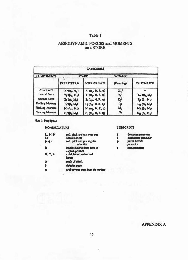
Table 1
AERODYNAMIC FORCES and MOMENTS
on a STORE
CATEOORIES
COMPONEHTS STATIC .
FREESTREAM INTERFF.RENCE
AxiaJ Force xr<as. Ms> Xi (ap. M, ll. 11) La&ml foo:e Yr (k, Ms) Yi (ap. M, ll. 11) Noonaf Polte Zr(ot. Ms) Zi Cap. M. ll. 'I)
Rollin1 Momeac L{(Ps. Ms) Li (ap. M. ll. 11) Pilehina Momeat Mr<as. Ms) Mi Cap. M, R, 11) Yawin1 Momeat Nr � Ms) Ni (aDt M, ll. 11)
Noce I: Ne&li&11>le
NQMENCI.A]JJRE
L, M, N M'
p. q. r
R
X. Y, Z
ron. pitch and yaw momCIU Mach number ro11. pilCb and yaw anau•
Radial distance liom Sl(ft IO apdve positiol axial, lalttal and ICWIIIII faca qleolaaact
sideslip mp pwt cnvene qlc Crom de �
45
DYNAMIC
(Dampina) CROSS-FLOW
�
-
Yo. (Gt, Ms) �· lf <J's, Ms) Lp la (ot. Ms) Mq MJ C,.. Ms) Nr Na (Os. Ms)
SUBSCRIPT$
f i p
•
fftauean l*lfflC&tt' � pmmdCI � airmft ..... SIGl'C pm narwam-�i-
APPENDIX A

�
><
>
T•
AIM
-9R
Jeuilon
#1
Compleled
20Sept
91
Tc&al#l
->
AIM
-9R
Jelilon
12
Compleeed
020c&
91
TOIIIIW.Z.
>
Tab
le II
AIM
-9R
JBn'ISO
N HARD
WA
RE S
UMMA
RY
Delcripcioa
SIN
&pee
led
Wei
gh&
(LB)
Jeailon Adapcer
N
/ACJ
> L
AU
-llS
A/A
M
QJ460
102
± 5
Ballulcd
LAU
-128
()()2
86±
4.S
Balia.d
LAU
-128
00
3 86
:.tH
AIM
".9R
Jeuiton R
ound
11-'
198 :t
6,
AlM-9
R Jcuilon
Round
15
198
± 6
Dull M
�le
. Loedin
1 �
±50
Je
ni,onAdaoter
N
IA
LA
U-l
l5A/
A_
�S95
1 02
:t 5
Bal1ulod
LAU-
128
0023
86±
4.5
Ballalllld
LAU
-_128
026
86
±4.5
A,I
M-9R
JeailonRound
0007
198
::t 6
AIM
-9R
Jeailon Round
008
198
:t 6
.Dual
Mllli
le Loadi
n.a
684 :t
50
( 1)
measured
aft of
nose or
forward
surfac
e.
(2)
meuun:d
aft of
fwd lu
a or
bolL
(3
) N
/A->
Noc
Avail
able
.
Meaaured
Eq,ected
CO
Wei
gh&
(LB)
(inches
)
103.0
N
/A
85. l
N/A
85
.9
N/A
200
. 60
±1
199.
60±
I 688
.0_
N/A
103.0
N
/A
86.0
N
/A
85.0
N
/A
200
60_±
1 19
8 60
:t l_
697
N/A
Meaaured
CO
Blpecled Pi
lCb
MealuredPi
lCb
MOI
MOI
(inc
bea)
lslu.r
ft2>
(sl
u• r,
2>
36.o
O>
N/A
6.
6 2
91a
(;L>
N/A
15
.52
9 1/2
(Z)
N/A
15
.63
S9 1 12
(1)
53.09
:t 10
S3
.47
S9 1/4
(1)
53.09
± 10
53
.02
17 1/4
(l)
N/A
U
:5.17
36.0
(1)
N/A
6.
51
9 1n.
('Z)•
N/A
13
.98
1 0 I...,.
_ (2)
N/A
13
.96
581"
(I)
53.09
± 10
53
.01
58 '.3J4
(I}
53.09
± 10
52.
3'
17 9
/ 16
\I}
N/A
147
..49

�
� i >
Tab
le I
II
DIME
NSI
ON
AL D
AT
A A
ND
MA
SS P
RO
PE
RITES
_OF
TiiE LA
U-1
15 �
ngtn
/ lS
.U m
(+
/-.S-
%)
Wei
ght
62.0
pounds
(+/-
5%
) Ce
nter
of Gra
vity
14
.25 in
( +/-
lin)
aft
of
forwar
d lu
g ce
nterli
ne
Mo
ments
of
Inerti
a Y
aw
Pitc
h R
oll
4.6
7 Slu
g-F
t2 (
+/1
0%)
4.7
0 S
lug-
Ft2
(+/-
10%
) 0
.170
Slu
g-F
t2 (
+/-
10%

�
?;
� I >
Tab
le I
V
DIME
NSIO
NA
L D
AT
A A
ND
MA
SS P
RO
PE
RITES
OF
TI-IE LA
U-1
27/
A LO:f
2 M
RL
n
Wei
ght bo
ttle)
Ce
nter
of Gra
vity
mo
unting
bolt
M
ome
nt o
f In
ertia
Yaw
Pitc
h R
oll
• ,
1n
95.6
1 ±
.24 lb (in
clud
es f
ull
nitro
gen
10.6
5 ±
.CY7 i
n af
t of
forw
ard
16.8
7 S
lug-F
t2 (+/-
0. 90
) 16
.91
Slug
-Ft2
(+/-
0. 90
) 0.09
5 Slu
2-F
t2 (
+/:-
0.00
5
Note
: D
ata v
alue
s are
ave
raged
mea
sured v
alue
s for
SIN
100
2002
thru 1
0020
12.

�
�
�
�
>
Tab
le V
D
IMEN
SIO
NAL
DA
TA
AN
D M
ASS
PR
OP
ER
ITES
OF
nm LA
U-1
15 j£
1 I I
SON
AD
APTE
R
ng
Wei
ght
Cente
r of
Gravi
ty
Mome
nt o
f In
ertia
Yaw
Pi
tch
Rol
l
.,
.., 1
0
40.0
poun
ds
19 .2
3 in
aft
of
forw
ard l
ug c
ente
rlin
e
1.0
Slu
g-F
t2 (
+/-
10%
) 1.
0 S
lug-
Ft2
(+/
-10
%)
0.0
Slu
jt·F
t2 (
+/-1
0%

Table 'VI
F/A- 1 8 SD 1 0 6 Camera Ca l ibrat ions
HX Pos on Focal Actua l F i lm , Corresponding A/C Lenqt h ( mm ) Speed ( fps ) Stock t
0 1 1 6 . 0 1 88 . 3 4 1
0 6 5 . 9 2 00 . 0 30
08 5 . 9 2 0 2 . 0 2 2
1 0 5 . 9 2 02 . 0 2 5
1 4 9 . 0 1 9 8 . 3 4 9 . .
1 6 5 . 9 1 9 8 . 3 62
18 9 . 0 1 93 . 3 52 . . .
. · 8 4 1 5 . 0 202 . 0 2 9.
CL l 5 . 9 . - 1 97 . 5 2 3
CL2 5 . 9 1 98 . 3 2 7 r
. . . .
CL3 5 . 9 2 00 . 0 I 32
CL4 5 . 9 2 0 4 . 0 ' 3 3
APPENDIX A
50

APPENDIX B
FIGURES
51

I .
figure 1 MER With Strongbacks and Cameras
52
� e
en en
.... e
APPENDIX B
..
·,

PHOTOSONICS MODEL lPL
MILLIKEN DBM 4
Figure 2 Cameras
53
APPENDIX B
RXOl
BX14 i' HXll
�h� i K,
/ � (
�= CLl through CL4 are m o u n t e d o n c a m e r a hardbacks which are loaded on MER stations 1 and 2 .
Figure 3 Camera Locations
54
APPENDIX B

\ \ \ \ \ I I I I I f,-4
' \ \ \ \ I I I I /
"-\ \
� ' \ I I / /
' ' \ \ I I / /
' \ ,
, ....
-
•
,
'
� ,
� / / I I
\ '
�
� / I I I \ \ ' '
-
/ I I I \ \ \ '
-
I
! I I I \ \ \ . \ '
..J t
,
Figure 4
APPENDIX B
ss

�
\ \ \ \ \ I I I I I -'
\ \ \ \ \ , . I I I I -
, , \ \ \ I I I I / � -
\ \ \ I I � ' ' I / / -@ ' ' ' \ ' I I / / /
--....... ' .... .. . . . , .,,,,. ,,,,,.,,,
- - - . . - --u
J • .
- - - . - - -j
__.,,,,. ;,' � . .. .... ' .._,...,
0 / / / I \ ' ' ' !
I '
-/ / ' '
ij : I I I ' \ \
� / I I I I \ \ \ , ,
I I \ � i I I I \ \ \
I I I I I \ \ \ \ \ �
figure 5
APPENDIX B
S6

I I I I I I
.... I I I Q I I I
I I I I /
! I I I / /
I ' I
! , , ,
, ,
•
� ,
, ,
, 0 , Q ....
, ij / / I I
�
� / I I / . I
....
I I I I I I I ....
� I I I I I I
- ··
Figure 6
APPENDIX B
57
V\
00
�
�
\....
LENS
CAL
IBRA
llON
BY
40
V
IDE
O
10
PIN-C\.91
ION
DIST
ORT
l<N
9
<+
tve
>
8 7
f,
5
4
3
2
1
PERCENT
AGE
O D
ISTOR
TION
i
-1
-2
-3
-'
-5
-6
-7
BARREL
-8
DIST
CRT
I�
-9
' <-
lve)
-10
�
._
IM
-la
lt
Ja
e•
leM
H 4
.
CAMP.RA.cu
t11•-
n tr
•• :
lacl
1:
le•
•r
5
6
RADIAL
D
I STO
RT
I 0r{.
PL
OT
....
H -
:rac
• FIi
a ile
••r
'/
8 RAD
IUS
: <-
>

Figure 8 Control Point Construcnon
APPENDIX B
59

,;..T.����.;,. . .
1
Figure 9 Control Point Constructton
APPENDIX B

Figure 10 Surveyed Aircraft Targets
61
APPENDIX B

Figure 1 1 Fuel Tank and Wmg Pylon Targets
APPENDIX B
62

Figure 12 Release Sequence
63
APPENDIX B

fa ' t
<
/
'
flt'
�
' ' ' ' '
, , � .�
,, • • ... 1l
• • te ...
.. «
• It • • • .. 1t fl
• • • • •
• • ...
• • •
•
� • � •
� 4.
'
' ' '
I
, ' I' '
\ � • IC
I • -- • •
•• • - - • * • , X
• • • • • • •
• ·� '
'
\ \ ' '
I
-· u [ _____________________________ _ � I
Figure 13
APPENDIX B
64

VITA
Major Douglas Paul Yurovich USMC was born in Lorain, Ohio on May
16, 1957. He graduated from Lorain Senior High School in June, 1975. In the Fall
of that same year, he entered The Ohio State University and in June, 1979
received Bachelor of Science degrees in Mathematics and Education. Major
Yurovich was commissioned as a Second Lieutenant in the United States Marine
Corps on 8 June 1979 and entered U. S. Navy Flight School in June, 1980. He
received his wings on 25 September 198 1 . After eight years of operational flying
in the F-4 Phantom and the F/A-18 Hornet, Major Yurovich was selected to attend
the U. S . Navy Test Pilot School, Patuxent River, Maryland. He graduated from
the fixed wing test pilot course in June, 1990.
Major Yurovich has logged over 2350 flight hours in 26 different types of
aircraft. He is a graduate of Navy Fighter Weapons School (TOPGUN), and
designated a Weapons and Tactics Instructor (WTI) by the United States Marine
Corps. He is currently assigned as a test pilot at the S trike Aircraft Test
Directorate, Naval Air Warfare Center, Patuxent River, Maryland.
65
Copyright © 2022 FDOKUMEN