Comparison of Various Water Level Controllers' Models for Boiler Drum
7
International Journal of Mechanical Engineering and Research Volume 3 Issue 1 (Page, 29-35), ISSN: 2277-8128 Copyright © 2014 IJWRE, All Right Reserved 29 Comparison of Various Water Level Controllers’ Models for Boiler Drum Brijendra kr. Maurya 1 , Saurabh kr. Bajpai 2 , Abhishek kr. Singh 3 1. Assistant Professor Department of Electronics and Communication Engineering Shobhit University, Saharanpur, India. 2. Assistant Professor in Department of Electrical Engineering in Shobhit University, Saharanpur, India. 3. Lecturer in Department of Mechanical Engineering in Shobhit University, Saharanpur, India. ABSTRACT: In this paper we have design various models for water level controller for boiler drum. First model is based on PID, Second model based on Fuzzy (mamdani) and third model based on Fuzzy (Sugeno) and then compared with the help of Simulink. Drum Level Control Systems are used extensively throughout the process industries and the Utilities to control the level of boiling water contained in boiler drums on process plant and help provide a constant supply of steam. The purpose of the drum level controller is to bring the drum up to level at boiler start-up and maintain the level at constant steam load. Key Words-Boiler Drum Level control, PID tuning, Fuzzy Inference System (FIS), Fuzzy Logic, MATLAB. I. Introduction Drum Level Control Systems are used extensively throughout the process industries and the Utilities to control the level of boiling water contained in boiler drums on process plant and help provide a constant supply of steam. The purpose of the drum level controller is to bring the drum up to level at boiler start-up and maintain the level at constant steam load. A dramatic decrease in this level may uncover boiler tubes, allowing them to become overheated and damaged. An increase in this level may interfere with the process of separating moisture from steam within the drum, thus reducing boiler efficiency and carrying moisture into the process or turbine. Boiler drum water level control is critical to secure operation of the boiler and the steam turbine. The functions of this control module can be broken down into the following: i) Operator adjustment of the set point for drum level. ii) Compensation for the shrink & swell effects. iii) Automatic control of drum level. iv) Manual control of the feed water valve. v) Bump less transfer between auto and manual modes. vi) Indication of drum level and steam flow. vii) Indication of feed water valve position and feed water flow. viii) Absolute/deviation alarms for drum level. The most basic and pervasive control algorithm used in the feedback control is the Proportional Integral and Derivative (PID) control algorithm.PID control is a widely used control strategy to control most of the industrial automation processes. The three element PID control system is introduced to regulate the drum level with the fixed PID parameters. The control is not ideal because the gains and time constants of the system response change significantly with the change in steam load and disturbances. Therefore, some other controller is required to improve the performance of drum level control system [1].The followings of the paper includes, Section II describing the types and design of boiler. In Section III development of virtual laboratory is explained. In Section IV result and comparison between the boiler performances is discussed. II. Boiler Drum Level Control In the process industries, boiling water to make steam is a very important procedure. The control of water level is a major function in this process and it is achieved through a water steam interface established in a cylindrical vessel called the drum which is usually lying on its side and located near the top of the boiler. Maintaining the correct water level in the drum is critical for many reasons. A water level that is too high causes flooding of the steam purification equipment; resulting in the carryover of water and impurities into the steam system. A water level that is too low results in a reduction in efficiency of the treatment and recirculation function. It can even result in tube failure due to overheating from lack of cooling water on the boiling surfaces. Normally drum level is expected to be held within 2 to 5cm of the set-point with some tolerance for temporary load changes. There are several components affecting its operation. Under boiling conditions, steam supporting field products such as bubbles exist below the water/steam level interface [12]. These bubbles have volume and therefore displace water to create a misrepresentation of the true water level in the drum. Another effect upon drum level is pressure in the drum. Because steam bubbles compress under pressure (if the drum pressure changes due to load demands), the steam bubbles expand or contract respective to these pressure changes. A higher steam demand will cause the drum pressure to drop, and the steam bubbles to
-
Upload
shobhituniversity -
Category
Documents
-
view
0 -
download
0
Transcript of Comparison of Various Water Level Controllers' Models for Boiler Drum

International Journal of Mechanical Engineering and Research
Volume 3 Issue 1 (Page, 29-35), ISSN: 2277-8128
Copyright © 2014 IJWRE, All Right Reserved 29
Comparison of Various Water Level Controllers’ Models for
Boiler Drum
Brijendra kr. Maurya1, Saurabh kr. Bajpai
2, Abhishek kr. Singh
3
1. Assistant Professor Department of Electronics and Communication Engineering Shobhit University, Saharanpur, India.
2. Assistant Professor in Department of Electrical Engineering in Shobhit University, Saharanpur, India.
3. Lecturer in Department of Mechanical Engineering in Shobhit University, Saharanpur, India.
ABSTRACT:
In this paper we have design various models for water level
controller for boiler drum. First model is based on PID, Second
model based on Fuzzy (mamdani) and third model based on Fuzzy
(Sugeno) and then compared with the help of Simulink. Drum Level
Control Systems are used extensively throughout the process
industries and the Utilities to control the level of boiling water
contained in boiler drums on process plant and help provide a
constant supply of steam. The purpose of the drum level controller is
to bring the drum up to level at boiler start-up and maintain the
level at constant steam load.
Key Words-Boiler Drum Level control, PID tuning, Fuzzy
Inference System (FIS), Fuzzy Logic, MATLAB.
I. Introduction
Drum Level Control Systems are used extensively throughout the
process industries and the Utilities to control the level of boiling
water contained in boiler drums on process plant and help provide
a constant supply of steam. The purpose of the drum level
controller is to bring the drum up to level at boiler start-up and
maintain the level at constant steam load. A dramatic decrease in
this level may uncover boiler tubes, allowing them to become
overheated and damaged. An increase in this level may interfere
with the process of separating moisture from steam within the
drum, thus reducing boiler efficiency and carrying moisture into
the process or turbine. Boiler drum water level control is critical
to secure operation of the boiler and the steam turbine. The
functions of this control module can be broken down into the
following:
i) Operator adjustment of the set point for drum level. ii) Compensation for the shrink & swell effects. iii) Automatic control of drum level. iv) Manual control of the feed water valve.
v) Bump less transfer between auto and manual modes. vi) Indication of drum level and steam flow.
vii) Indication of feed water valve position and feed water
flow. viii) Absolute/deviation alarms for drum level.
The most basic and pervasive control algorithm used in the
feedback control is the Proportional Integral and Derivative (PID)
control algorithm.PID control is a widely used control strategy to
control most of the industrial automation processes. The three
element PID control system is introduced to regulate the drum
level with the fixed PID parameters. The control is not ideal
because the gains and time constants of the system response
change significantly with the change in steam load and
disturbances. Therefore, some other controller is
required to improve the performance of drum level control
system [1].The followings of the paper includes, Section II
describing the types and design of boiler. In Section III
development of virtual laboratory is explained. In Section IV
result and comparison between the boiler performances is
discussed.
II. Boiler Drum Level Control
In the process industries, boiling water to make steam is a very
important procedure. The control of water level is a major
function in this process and it is achieved through a water steam
interface established in a cylindrical vessel called the drum
which is usually lying on its side and located near the top of the
boiler. Maintaining the correct water level in the drum is critical
for many reasons. A water level that is too high causes flooding
of the steam purification equipment; resulting in the carryover of
water and impurities into the steam system. A water level that is
too low results in a reduction in efficiency of the treatment and
recirculation function.
It can even result in tube failure due to overheating from lack of
cooling water on the boiling surfaces. Normally drum level is
expected to be held within 2 to 5cm of the set-point with some
tolerance for temporary load changes. There are several components affecting its operation. Under
boiling conditions, steam supporting field products such as
bubbles exist below the water/steam level interface [12]. These
bubbles have volume and therefore displace water to create a
misrepresentation of the true water level in the drum. Another
effect upon drum level is pressure in the drum. Because steam
bubbles compress under pressure (if the drum pressure changes
due to load demands), the steam bubbles expand or contract
respective to these pressure changes. A higher steam demand
will cause the drum pressure to drop, and the steam bubbles to

International Journal of Mechanical Engineering and Research
Volume 3 Issue 1 (Page, 29-35), ISSN: 2277-8128
Copyright © 2014 IJWRE, All Right Reserved 30
expand to give the appearance of a water level higher than it truly
is. This fictitious higher water level causes the feed water input to
be shut down at a time when more water is really required. A
surge in water level as a result of the drum pressure decreasing is
called 'swell'. A water level decrease due to drum pressure
increase is called 'shrink'. Providing tight water level control in a
drum is accomplished by utilizing one of three types of drum
level control: single-element, two-element, or three-element [1].
II. A. Single element drum level control Single-level element control uses only the level measurement and
the feed water valve. The controller responds to a proportional
signal from the drum level transmitters by generating a
proportional output to the boiler feed water valve when needed.
This approach is often used when starting up a boiler and there is
no steam flow or when a flow meter has failed. The drawback of
this strategy is that the level is subject to uncontrolled
disturbances from the steam header and the feed water. For
example, if the feed water header pressure rises, the feed water
flow to the boiler also increases. Without a feed water control
loop, this situation would be uncorrected until the level changes.
In addition, the installed characteristics of the feed water valve
may compromise level control performance over a large
operating range.
II. B. Double element drum level control The two-element level control adds the steam flow as a feed
forward element to the level controller output. A steam mass flow
rate signal is used to control the feed water flow so that feed
water demand can be adjusted immediately in response to load
changes. The level controller is used to correct any imbalance
between the steam mass flow out of and the feed water mass flow
into the drum. This approach delivers more effective drum level
control than a single element. It is well suited for use on a single boiler with a single feed water
pump using a constant feed water pressure. A potential weakness
is that the installed characteristics of the feed water valve may
compromise level control performance over a large operating
range. In addition, steam feed forward may need to be
characterized when using this approach. .
II. C.Three elements drum level control Three-element level control as shown in Fig.1 is the most
common boiler drum level control strategy. A feed water flow
loop slave is added to the two-element strategy. Three-element
level control linearized the feed water flow with respect to the
steam flow and the level controller output. The control loop now
requests volumetric flow change, not just a change in the valve
position. This strategy attempts to compensate for changes or
disturbances in steam flow and feed water flow based on the
principle that flow in equals flow out. The installed characteristics
of the feed water valve are no longer an issue because the flow
controller can compensate. Using this approach, the steam feed
forward element can be a simple gain without requiring
characterization [1].
Fig. 1 Three element boiler drum level control
III. Control Strategies and Simulation Control strategies are necessary for any system to perform
accurately. Some of these are given below. The simulation
results are shown here for different control strategies. The
relationship between the feed water flow rate and drum level for
the boiler process are expressed by the following equations [3].
The process function, valve function and disturbance function is
shown below. Gp(s) = [0.25(-s+1)] / [s (2s+1)]……..…. (1)
Gv(s) = 1/ [0.15s+1]...…...……......…....... (2)
Gd(s) = [-0.25(-s+1)]/ [s(s+1) (2s+1)]….... (3)
IV. Simulation & Result
Simulink block diagram of boiler System without Controller
Figure 2: Simulink block diagram of boiler system
Output Response of without Controller
Figure 3: Output Response of system

International Journal of Mechanical Engineering and Research
Volume 3 Issue 1 (Page, 29-35), ISSN: 2277-8128
Copyright © 2014 IJWRE, All Right Reserved 31
V. PID Controller A Proportional-Integral-Derivative (PID) controller is a general
feedback control loop mechanism widely used in industrial
process control systems. A PID controller corrects the error
between a measured process variable and the desired set point by
calculating the value of error. The corrective action can adjust the
process rapidly to keep the error minimal. If u (t) is the control
signal, y (t) is the measured output and r (t) is the desired output,
and tracking error e (t) = r (t) − y (t), a PID controller has the
general form. d
u (t ) K P e (t ) K I e(t ) dt K D dt e (t ) Where KP, KI, KD are proportional gain, Integral gain and
Derivative gain, e (t) = error signal. PID controller separately calculate the three parameters i.e. the
proportional, the integral, the derivative values. The proportional
value determines the reaction to the current error. The integral
value determines the reaction based on the sum of recent errors as
past error. The derivative value determines the reaction based on
the rate at which the error has been changing as a future error. By
tuning these three constants in the PID controller algorithm, the
controller can provide control action designed for specific process
control requirements. Some applications may require only one or
two parameters of the PID controller to provide the appropriate
control on system. A PID controller will be called a PI, PD, P or I
controller in the absence of the respective control actions. This is
achieved by setting the gain of undesired control outputs to zero.
PI controllers are very common, since derivative action is very
sensitive to measurement noise and the absence of an integral
value may prevent the system from reaching its target value due
to control action [2].
Block Diagram of boiler System with PID
Controller
Figure 4: Simulink Block Diagram of PID controller Where KP = 1.280, KI = 0.0036, KD = 1.84
PID Controller output response
Figure 5: Output Response of PID Controller
Fuzzy Logic Controller After being mostly viewed as a controversial technology for two
decades, fuzzy logic has finally been accepted as an emerging
technology since the late 1980s. This is largely due to a wide
array of successful applications ranging from consumer
products, to industrial process control, to automotive
applications [1]. Fuzzy logic is closer in spirit to human thinking
and natural language than conventional logical systems [2].
Classical control theory is based on the mathematical models
that describe the physical plant under consideration. The essence
of fuzzy control is to build a model of human expert who is
capable of controlling the plant without thinking in terms of
mathematical model [3].Fuzzy systems are very useful in two
general contexts: (1) in situations involving highly complex
systems whose behaviors are not well understood, and (2) in
situations where an approximate, but fast, solution is warranted
[4]. Fuzzy logic was put forward earliest in 1965 by L.A. Zadeh.
One of the primary applications of fuzzy logic was subway
system in Sendai city of Japan. The applied result showed that
fuzzy logic control was superior to traditional control. But
finding out the correct rule set and determining the essence and
range of fuzzy variables is time consuming work. Such as in
subway system of Sendai, to obtain correct input sets, the
engineers spent several months. Similarly, in water level boiler
system field today, there is a long way to find out a mature
expert fuzzy control model which must need plenty of project
experience [5]. The rest of the paper is organized as follows
gives the difference between Mamdani-type and Sugeno-type
FIS. And shows the development of Mamdani (MAM)-type
FIS.And also, shows the development of Sugeno-type FIS.
Development of Mamdani-Type FIS Boiler system is first developed using mamdani fuzzy model. It
consists of two inputs from water flow and feed water valve. The
system has one output that controls the water level of the boiler.
Each of the inputs has seven

International Journal of Mechanical Engineering and Research
Volume 3 Issue 1 (Page, 29-35), ISSN: 2277-8128
Copyright © 2014 IJWRE, All Right Reserved 32
gaussian membership functions as shown in Figs.7 and 8. The
output i.e. water level is taken in range from 0 to 1 and have
seven gaussian membership functions shown in Fig. 9. The rules
viewer included for the water level of the boiler system are
described in below. Fuzzy logic is extension of binary logic. It
uses partial truth values instead of completely true or completely
false .They have a value that shows the degree of truth in the
range 0 to1.0 represents absolute false and 1 represents
completely true[2][5]. Fuzzy logic controller converts the
intelligent knowledge into an automatic control action. It handles
information in systematic way. Fuzzy logic is widely used in very
complex and highly nonlinear system. [3]
Figure 6: Block diagram of Fuzzy Inference System The FLC implemented here is a two-input &
single-output. The two inputs are error, and error rate. Both input
variables are classified into three fuzzy levels in this
implementation based on the resolution and real-time
requirements needed. Subsets for Inputs and Output: Input 1(Water Error): Membership Functions for input1: NB (Negative Big) NM (Negative Medium) NS (Negative Small) ZO (Zero) PS (Positive Small), PM (Positive Medium) PB (Positive Big)
Membership functions for input1: Error
Figure 7: Membership function for error
Input 2 (Water Error Rate): Membership Functions for input2: NB (Negative Big) NM (Negative Medium) NS (Negative Small) ZO (Zero) PS (Positive Small), PM (Positive Medium) PB (Positive Big)
Membership Functions for input2:
Change of Error
Figure 8: Membership function for error rate
Membership Functions for output:
Figure 9: Membership function for fuzzy output
Rule viewer: This Rule Viewer provides an animation of how the rules are fired during simulation.
Figure 10: Rule Viewer
International Journal of Mechanical Engineering and Research
Volume 3 Issue 1 (Page, 29-35), ISSN: 2277-8128
Copyright © 2014 IJWRE, All Right Reserved 33
Surface Viewer: In this paper this plot is generated by the fourteen nine rules that accounted for both error and change in error.
Figure11: Surface View
Block Diagram of FLC (Mamdani)
Figure 12: Simulink block diagram of FLC Where, KP= 0.5892, KD = 0.9115, Gain = 4.48
Fuzzy Logic Controller (Mamdani type) output Response
Figure 13: Output water level response
Development of Sugeno-Type FIS: For development of water level of boiler system using Sugeno-
type model, the initial steps are same as Mamdani-type model. It
also takes inputs from water flow and feed water and produces an
output signal that controls the water level of boiler system. Inputs
water flow and feed water have seven gaussian membership
functions over the range of -1 to 1.The output water level can
only be either constant or linear in this FIS, so seven membership
functions for the output are NB (Negative Big), NM (Negative
Medium), NS (Negative Small), ZO (Zero), PS (Positive Small),
PM (Positive Medium), PB (Positive Big) which are constant and
are shown figure below. The output in Sugeno-type FIS can only
be in
range of 0-1. The rule base for Sugeno-type FIS is same as for Mamdani-type FIS.
Output of membership functions of Sugeno: Water Error &chance of water error same as mamdani and different only output using constant given-
Figure 14: Output of member function Rule viewer:
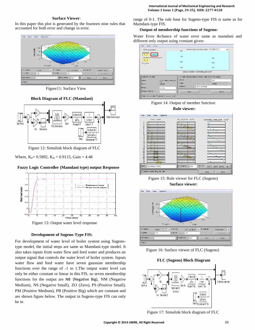
Figure 15: Rule viewer for FLC (Sugeno) Surface viewer:
Figure 16: Surface viewer of FLC (Sugeno)
FLC (Sugeno) Block Diagram
Figure 17: Simulink block diagram of FLC

International Journal of Mechanical Engineering and Research
Volume 3 Issue 1 (Page, 29-35), ISSN: 2277-8128
Copyright © 2014 IJWRE, All Right Reserved 34
Where, KP = 0.5892, KD = 0.9149, Gain = 4.48
FLC (Sugeno) Output Response:
Figure 18: Output water level response
Mamdani-Type FIS vs. Sugeno-Type FIS Mamdani method is widely accepted for capturing expert
knowledge. It allows us to describe the expertise in more
intuitive, more human-like manner. However, Mamdani-type FIS
entails a substantial computational burden. On the other hand,
Sugeno method is computationally efficient and works well with
optimization and adaptive techniques, which makes it very
attractive in control problems, particularly for dynamic non linear
systems. These adaptive techniques can be used to customize the
membership functions so that fuzzy system best models the data.
The most fundamental difference between Mamdani-type FIS and
Sugeno-type FIS is the way the crisp output is generated from the
fuzzy inputs. While Mamdani-type FIS uses the technique of
defuzzification of a fuzzy output, Sugeno-type FIS uses weighted
average to compute the crisp output. The expressive power and
interpretability of Mamdani output is lost in the Sugeno FIS since
the consequents of the rules are not fuzzy [7]. But Sugeno has
better processing time since the weighted average replace the time
consuming defuzzification process. Due to the interpretable and
intuitive nature of the rule base, Mamdani-type FIS is widely used
in particular for decision support application. Other differences
are that Mamdani FIS has output membership functions whereas
Sugeno FIS has no output membership functions. Mamdani FIS is
less flexible in
system design in comparison to Sugeno FIS as latter can
be integrated with ANFIS tool to optimize the outputs.
Comparison performance Simulink block diagram of PID and FLC (mamdani & Sugeno):
Figure 19: Comparison performance of PID and FLC
Comparison output response of water level:
Figure 20: Comparison output response of PID and FLC
Table1: Comparison of different parameters for step input
Without PID FLC FLC
Controllers controller (Mamdani) (Sugeno)
Parameters
Peak time tp 12.25 8.04 5.15 4.80
(sec) Settling time 28.25 11.24 5.65 5.05
ts (sec)
Rise time tr 8.25 3.69 3.15 3.05
(sec)
Peak 15.89 2.83 0 0 Overshoot Mp
(%)
Peak 6.25 0 0 0 undershoot
(%) Integral 6.348 3.398 3.222 2.991
Absolute
Error (IAE)
(%)
Integral 4.173 2.76 2.696 2.68 Square Error
(ISE) (%) Absolute 0.0114 0.00028 0.00038 0.00034
Error (%)

International Journal of Mechanical Engineering and Research
Volume 3 Issue 1 (Page, 29-35), ISSN: 2277-8128
Copyright © 2014 IJWRE, All Right Reserved 35
IV Conclusions: This paper presents a comparative study of
performance of PID and FLC. Based on the results and the
analysis, a conclusion has been made that FLC provides a better
control action. As per Comparison of different parameters for step
input in table1FLC is based on Sugeno is superior then other type
of water level controller model.
References [1 ] Roopal Agarwal, Umesh C. Pati, ―Design and Data Logging of Three Element Boiler Level Control Using
LabVIEW,National Conference on Recent Advances in
Chemical and Environmental Engineering (RACEE),
Rourkela, Jan 2012 [2 ] Xiang fei, ZOU Li hua, Optimization design of PID
controller and its application”, 2011 Third International
Conference on Measuring Technology and Mechatronics
Automation, vol.2, pp. 803-806, Jan 2011. [3] B. Wayne Bequette, Process Control Modeling Design & Simulation, Pearson Education Inc 2003 [4 ] Liu Jinkun, ―MATLAB Simulation of Advanced PID
Control[M], Electronic Industry Press, Beijing, 2006, pp. 102-
129. [5] I.L.Chien, and P.S Fruehauf,, ― Consider IMC tuning
to improve controller performance‖, Chemical Engineering Progress, pp. 33 - 41. 1990. [6] A.M.D. Poar, M. O’Malley, Controllers of Ziegler-
Nichols type for unstable processes, Int. J. Control 49 (1989)
1273–1284. [7 ] W. Tan, Y. Q. Yuan, Y. G. Niu, Tuning of PID controller
for unstable process, in: Proc. of the IEEE International Conf. on
Control Applications (CCA), Vol. 1, Hawaii, USA, 1999,
pp.121–124. [8] Luis E. Zarate, Peterson Resende, & M. Benjamin,” A Fuzzy
Logic and Variable Structure Base Controller for CSTR Control.
Annual conference of IEEE, 2001. [9] Chuen Chien Lee, “Fuzzy Logic in Control System: Fuzzy
Logic Controller – Part 1,” IEEE Transactions on System, Man
and Cybernetics, vol.20, No 2 (1990). [10] Gang Feng, “A Survey on Analysis and Design of Model-
Based Fuzzy Control Systems,” IEEE transactions on fuzzy
systems, vol. 14, no. 5, October 2006. [11] Boiler Control Systems Engineering, 2nd Edition, by Jerry Gilman. [12] Sathyanathan, Dr V T. "Bi Drum and Single Drum Boiler Compared".
Author Profile : Brijendra kumar maurya presently working as Assistant Professor in Department of Electronics&Communication Engineering in
Shobhit University, Saharanpur. His current area of interest in Control System, Digital Electronics, Network Analysis and Synthesis, Automatic Control System, Signal System, Electromagnetic Field Theory, Analog Integrated Circuits Electronic Circuits.
Saurabh kumar Bajpai presently working as Assistant Professor in Department of Electrical Engineering in Shobhit University. He published several papers in
National & International journal. His current area of interest in control system, power system, Electric Machine, FACTS.
Abhishek kumar Singh presently working as lecturer
in Department of Mechanical Engineering in Shobhit
University. His current area of interest in
thermodynamic, heat transfer, fluid mechanics, and engineering
mechanics.