Comparison of numerical and experimental results of nonlinear wave-induced vertical ship motions and...
12
J Mar Sci Technol (2002) 6:193–204 Comparison of numerical and experimental results of nonlinear wave-induced vertical ship motions and loads Nuno Fonseca and Carlos Guedes Soares Unit of Marine Technology and Engineering, Technical University of Lisbon, Instituto Superior Técnico, Av. Rovisco Pais, 1049-001 Lisbon, Portugal the ship’s sides have considerable flare on both the bow and the stern areas. Ships of this type are container ships, frigates, some passenger ships, etc., which com- bine the requirements of relatively fast speeds with large cargo and internal volumes and also a large deck area. For these reasons, the underwater hull is fine and the volume and the deck area are obtained with a large flare up to deck level. Furthermore, the flare on the bow helps fast ships to keep their decks drier. There is experimental evidence, mainly from model tests but also from full-scale measurements, that nonlin- ear effects are important for the vertical ship responses, and particularly for the vertical bending moment of small block coefficient ships. Results from model tests 1,2 show that the sagging peaks of the vertical bending moment may be twice as large or more than the hogging peaks, and the differences increase for models with smaller block coefficients. Murdey 3 and Nethercote 4 obtained similar results for models of series 60 ships and a frigate. Watanabe et al. 5 presented a more systematic study of the nonlinear effects on the vertical bending moment on a container ship advancing in head regular and irregular waves. As well as the asymmetry of the bending mo- ment, the harmonic content of the signals measured and the mean values were determined. It was concluded that all these nonlinear characteristics are present in the measured vertical bending moment. O’Dea et al. 6 conducted experimental tests with a model of the same containership with the objective of determining the influence of the wave steepness on the vertical motions and accelerations. In regular waves, it was observed that the higher harmonic content of the responses is small, but around the resonance frequency, the first harmonics normalized by the wave amplitude tend to decrease with greater wave steepness. Few full-scale measurements have been published, but Smith 7 and Hay et al., 8 for example, presented the results of stresses measured on board a frigate sailing in moderate to severe sea states. The results clearly show Abstract A nonlinear time-domain procedure is presented which is used to calculate the vertical responses of a container ship advancing in head waves. The method assumes linear radiation forces represented by time convolution of memory functions, infinite frequency added masses, and radiation re- storing coefficients. The nonlinear hydrostatic restoring and Froude–Krilov forces are computed exactly over the instanta- neous wetted surface of the ship’s hull. Forces due to green water on deck are calculated using the momentum method. Nonlinear effects are identified on different vertical ship re- sponses, namely on the heave and pitch motions, the vertical accelerations, and the vertical bending moment. These non- linear effects are expressed by the variation of the transfer function with the wave amplitude, the higher-order harmonics of the time signals, the offset of the time series, and the asym- metry of the peaks. The numerical results and the quantified nonlinear effects are compared with experimental results showing an ability to reproduce the main nonlinear effects. Key words Vertical motions and loads · Nonlinear · Experi- mental data · Time simulation 1 Introduction It is known that ships with fine forms, or small block coefficients, may experience wave-induced vertical loads that are highly asymmetric. This means, for ex- ample, that the sagging moment peaks may be much larger than the hogging ones. The importance of these nonlinear effects is reflected by the Classification Society rules, which suggest empirical formulae for determining the wave-induced design bending moment differently for sagging and hogging conditions. The nonlinearities mentioned above are mostly asso- ciated with the “nonlinear geometry” of the hull, where Address correspondence to: C. Guedes Soares (e-mail: [email protected]) Received: December 17, 2001 / Accepted: January 31, 2002
-
Upload
independent -
Category
Documents
-
view
1 -
download
0
Transcript of Comparison of numerical and experimental results of nonlinear wave-induced vertical ship motions and...
J Mar Sci Technol (2002) 6:193–204
Comparison of numerical and experimental results ofnonlinear wave-induced vertical ship motions and loads
Nuno Fonseca and Carlos Guedes Soares
Unit of Marine Technology and Engineering, Technical University of Lisbon, Instituto Superior Técnico, Av. Rovisco Pais, 1049-001 Lisbon,Portugal
the ship’s sides have considerable flare on both the bowand the stern areas. Ships of this type are containerships, frigates, some passenger ships, etc., which com-bine the requirements of relatively fast speeds withlarge cargo and internal volumes and also a large deckarea. For these reasons, the underwater hull is fine andthe volume and the deck area are obtained with a largeflare up to deck level. Furthermore, the flare on the bowhelps fast ships to keep their decks drier.
There is experimental evidence, mainly from modeltests but also from full-scale measurements, that nonlin-ear effects are important for the vertical ship responses,and particularly for the vertical bending moment of smallblock coefficient ships. Results from model tests1,2 showthat the sagging peaks of the vertical bending momentmay be twice as large or more than the hogging peaks,and the differences increase for models with smallerblock coefficients. Murdey3 and Nethercote4 obtainedsimilar results for models of series 60 ships and a frigate.
Watanabe et al.5 presented a more systematic study ofthe nonlinear effects on the vertical bending moment ona container ship advancing in head regular and irregularwaves. As well as the asymmetry of the bending mo-ment, the harmonic content of the signals measured andthe mean values were determined. It was concluded thatall these nonlinear characteristics are present in themeasured vertical bending moment.
O’Dea et al.6 conducted experimental tests with amodel of the same containership with the objective ofdetermining the influence of the wave steepness on thevertical motions and accelerations. In regular waves, itwas observed that the higher harmonic content of theresponses is small, but around the resonance frequency,the first harmonics normalized by the wave amplitudetend to decrease with greater wave steepness.
Few full-scale measurements have been published,but Smith7 and Hay et al.,8 for example, presented theresults of stresses measured on board a frigate sailing inmoderate to severe sea states. The results clearly show
Abstract A nonlinear time-domain procedure is presentedwhich is used to calculate the vertical responses of a containership advancing in head waves. The method assumes linearradiation forces represented by time convolution of memoryfunctions, infinite frequency added masses, and radiation re-storing coefficients. The nonlinear hydrostatic restoring andFroude–Krilov forces are computed exactly over the instanta-neous wetted surface of the ship’s hull. Forces due to greenwater on deck are calculated using the momentum method.Nonlinear effects are identified on different vertical ship re-sponses, namely on the heave and pitch motions, the verticalaccelerations, and the vertical bending moment. These non-linear effects are expressed by the variation of the transferfunction with the wave amplitude, the higher-order harmonicsof the time signals, the offset of the time series, and the asym-metry of the peaks. The numerical results and the quantifiednonlinear effects are compared with experimental resultsshowing an ability to reproduce the main nonlinear effects.
Key words Vertical motions and loads · Nonlinear · Experi-mental data · Time simulation
1 Introduction
It is known that ships with fine forms, or small blockcoefficients, may experience wave-induced verticalloads that are highly asymmetric. This means, for ex-ample, that the sagging moment peaks may be muchlarger than the hogging ones. The importance of thesenonlinear effects is reflected by the ClassificationSociety rules, which suggest empirical formulae fordetermining the wave-induced design bending momentdifferently for sagging and hogging conditions.
The nonlinearities mentioned above are mostly asso-ciated with the “nonlinear geometry” of the hull, where
Address correspondence to: C. Guedes Soares(e-mail: [email protected])Received: December 17, 2001 / Accepted: January 31, 2002
194 N. Fonseca and C. Guedes Soares: Nonlinear wave-induced motion
that the sagging stresses are much higher than the hog-ging ones for low probability levels.
Since it is recognized that nonlinear effects are impor-tant for certain types of ship and cannot be neglected inhydrodynamic-based calculations of design wave loads,there have been efforts to develop methods to calculatethe nonlinear seakeeping of ships in waves. Some meth-ods have been proposed which are based on partiallynonlinear formulations, with the objective of givingpractical solutions, but there have also been attempts tosolve the fully nonlinear problem.
A fully nonlinear solution has been attempted byassuming both viscous and inviscid flow. Assuming aviscous fluid, Wilson et al.9 applied a Reynolds averagedNavier–Stokes (RANS) code to compute the viscousflow around two ships subjected to regular incidentwaves. Although some results of the wave elevationaround the ships were presented, numerical problemsstill exist and the computational effort is huge.
Beck et al.,10 Scorpio et al.,11 and Subramani et al.12
followed a different approach, assuming an ideal fluidand based on the Euler–Lagrange method together witha representation of the hull and a free surface boundaryby desingularized Rankine sources. Some partial resultshave been presented, but numerical problems still existand the computational effort is also huge. One can saythat fully nonlinear solutions are still under develop-ment, and will not be available for practical applicationsin the near future.
Partial nonlinear methods are based on potentialflow, and some degree of linearization is assumed in thesolution of the hydrodynamic problem, but the equa-tions of motion and loads include nonlinear terms.More complete methods do exist, but they are less prac-tical for use in routine applications. These are based ontime domain panel methods, using Green functions anddiscretizing only the hull surface,13,14 or Rankine sourcesdistributed over the hull and free surface.15,16 In thesemethods, the body boundary condition may be nonlin-ear by being satisfied at the exact position at each timeinstant, but the free surface is linearized.
More practical methods have been proposed by Xiaand Wang17 and Fonseca and Guedes Soares,18,19 whichare based on time domain strip theories where the lin-ear radiation forces are represented by the convolutionof memory functions. Froude–Krilov and hydrostaticforces are computed instantaneously over the wettedhull surface. Additional nonlinear terms may be intro-duced in the equations of motions, such as slammingforces and water-on-deck forces.
Watanabe and Guedes Soares20 presented compara-tive calculations for an S175 container ship using sixdifferent simplified, partially nonlinear codes. Headregular waves, three wavelengths, and two wave heightswere considered. The results presented included verti-
cal motions, accelerations, and vertical bending mo-ments. Details of the approximations used by each ofthe codes were presented in tabular form to make iteasy to compare the code assumptions. For low waveheights, most of the results agree with each other andwith linear strip theory to within approximately 10%.For larger wave heights, substantial differences wereobserved between the predictions from the differentcodes, but the origin of these differences is not clear.
The ISSC 1997 Committee on Loads21 and the ISSC2000 Committee VI.1 on Extreme Loads22 concludedthat these type of methods may be appropriate topredict nonlinear loads on ships, but validation isnecessary, which includes comparisons with nonlinearexperimental data.
In this paper, the method developed by Fonseca andGuedes Soares18,19 is used to make systematic computa-tions of the nonlinear vertical motions and loads on acontainer ship. The nonlinear characteristics of theresponses are identified and compared with publishedexperimental data.
2 Numerical model
The formulation on which the numerical model is basedwas developed by Fonseca and Guedes Soares.18 Thatpublication presents some calculated results for a shipadvancing in regular waves. The method was also gen-eralized for irregular seas.19 Here, the formulation willbe described briefly to provide the background of themethod, which will be required for the discussion of theresults.
A coordinate system fixed with respect to the meanposition of the ship is defined, X = (x,y,z), with z in thevertical upward direction and passing through the cen-ter of gravity of the ship, x in the longitudinal directionof the ship and pointing to the bow, and y perpendicularto the latter and in the port direction. The origin is in theplane of the undisturbed free surface.
The solution of the hydrodynamic problem assumesthat the flow is inviscid, the hull is slender, the forwardspeed is small, and the amplitudes of the incident wavesand unsteady motions are small enough. Consideringa ship advancing in waves and oscillating as an unre-strained rigid body: the oscillatory motions will consistof three translations and three rotations. Here, onlyhead waves will be considered, and it is assumed thatthe longitudinal (fore–aft) hydrodynamic unsteadyforces are negligible, which is the basis of the strip-theory assumptions. Therefore, the ship will only heaveand pitch.
Equating the hydrodynamic external forces to themass and gravity forces, one obtains the equations ofmotion. These equations, which combine linear and
195N. Fonseca and C. Guedes Soares: Nonlinear wave-induced motion
nonlinear terms, are solved in the time domain by anumerical procedure. For heave and pitch the equationsare
M A t K t C t A t
K t C t F t Mg F t
F t F t
m
t
m
mt
m gw
+( ) ( ) + -( ) ( )[ ] ( ) + ( )
+ -( ) ( )[ ] ( ) + ( ) - + ( )= ( ) + ( )
•
-•
•
-•
Ú
Ú
33 3 33 3 33 3 35 5
35 5 5 3 3
3 3
˙̇ ˙ ˙̇
˙
x t x t t x x
t x t t x
d +
d + 35H
D K
I A t K t C t A t
K t C t F t F t
F t F t
mt
m
mt
m gw
55 55 5 55 5 55 5 53 3
53 3 3 5 5
5 5
+( ) ( ) + -( ) ( )[ ] ( ) + ( )
+ -( ) ( )[ ] ( ) + ( ) + ( )= ( ) + ( )
•
-•
•
-•
Ú
Ú
˙̇ ˙ ˙̇
˙
x t x t t x x
t x t t x
d +
d + 53H
D K
where x3 and x5 represent the heave and pitch motions,respectively, and the dots over the symbols representdifferentiation with respect to time. M is the ship’s mass,g is the acceleration due to gravity, and I55 representsthe ship’s inertia about the y-axis. The hydrostatic forceand moment, F 3
H and F 5H, respectively, are calculated
at each time step by integration of the hydrostatic pre-ssure over the wetted hull under the undisturbed waveprofile. The exciting forces due to the incident waves aredecomposed into a diffraction part, Fk
D, and the Froude–Krilov part Fk
K. The diffraction part, which is related tothe scattering of the incident wave field due to the pres-ence of the moving ship, is kept linear. It results fromthe solution of the hydrodynamic problem of the shipadvancing with constant speed through the incidentwaves and being restrained at her mean position. Sincethis is a linear problem and the exciting waves areknown a priori, it can be solved in the frequency domainand the resulting transfer functions can be used to gen-erate a time history of the diffraction heave force andpitch moment. The transfer functions are calculated bya strip method.
The Froude–Krilov part is related to the incidentwave potential, and results from the integration at eachtime-step of the associated pressure over the wettedsurface of the hull under the undisturbed wave profile.
The radiation forces, which are calculated using astrip method, are represented in the time domain byinfinite frequency added masses A•
kj, radiation restoringcoefficients Cm
kj, and convolution integrals of memoryfunctions Km
kj(t). The radiation restoring forces, associ-ated with the restoring coefficients, represent a correc-tion to the hydrodynamic steady forces acting on theship due to the steady flow. The convolution integrals
represent the effects of the whole past history of themotion, accounting for the memory effects due to theradiated waves. The memory functions and the radia-tion restoring coefficients are obtained by relating theradiation forces in the time domain and in the frequencydomain by means of Fourier analysis.
Finally, the vertical forces associated with the greenwater on deck Fk
gw(t), which occurs when the relativemotion is larger than the free board, are calculated us-ing the momentum method. This way the hydrodynamicpressure on the deck includes three terms: the hydro-static pressure, one term that accounts for the variationof the mass of water on the deck, and one term associ-ated with the acceleration of the deck.
The wave-induced structural dynamic loads at a crosssection are given by the difference between the inertiaforces and the sum of the hydrodynamic forces actingon the part of the hull forward of that section. Thevertical shear force and vertical bending moment,respectively, are given by
V t I t R t D t K t H t G t3 3 3 3 3 3 3( ) = ( ) - ( ) - ( ) - ( ) - ( ) - ( ) (3)
M t I t R t D t K t H t G t5 5 5 5 5 5 5( ) = ( ) - ( ) - ( ) - ( ) - ( ) - ( ) (4)
where Ik represents the vertical inertia force (or mo-ment) associated with the ship’s mass forward of thecross section under study. As assumed for the calcula-tion of the ship’s motions, the radiation (Rk) and diffrac-tion (Dk) hydrodynamic contributions for the loads arelinear, and the Froude–Krylov (Kk) and hydrostatic(Hk) contributions are nonlinear since they are calcu-lated over the “exact” wetted hull surface at each timestep. Gk represents the contribution to the structuralloads of the forces of the green water on deck.
The formulation to calculate all contributions to theloads is consistent with the formulation applied to solvethe unsteady motion problem. The convention for theloads is such that the sagging shear force and hoggingbending moment are positive.
3 Comparison between numerical andexperimental results
Experimental sea-keeping tests with scaled ship modelshave been carried out during the last four decades inorder to obtain data to validate theoretical and numeri-cal sea keeping methods. Some of these experimentaldata have been published, but most of these results arenot adequate when the object is to investigate the non-linear responses of ships subjected to large-amplitudewaves. This is because the results are usually presentedin the form of transfer functions, defined by the ampli-tude of the first harmonic of the response divided by the
(1)
(2)

196 N. Fonseca and C. Guedes Soares: Nonlinear wave-induced motion
first harmonic of the incoming wave, together with thephase angle of the first harmonic. Usually, all nonlineareffects are lost, and the results are suitable to validatelinear methods.
O’Dea et al.6 and Watanabe et al.5 are among the fewauthors who have published experimental data on thevertical responses of ship models to regular and irregu-lar waves, with an emphasis on the nonlinear effects.Both authors tested models of the S-175 container ship.These experimental results will serve has a benchmarkto evaluate the quality of the predictions of the numeri-cal model.
3.1 Characteristics of the ship
The S-175 container ship is well known because it wasused by the 15th ITTC23 and the 16th ITTC24 to carryout a comparative numerical study of linear wave-induced motions and structural loads. The database thatresulted from that study includes numerical results frommany institutions, and also some experimental data.The ship’s hull has a pronounced flare on the bow andthe stern, and therefore it is expected that large nonl-inear effects are associated with the vertical motions.Figure 1 shows the ship’s bodylines, Table 1 lists themain particulars, and Fig. 2 shows the weight distribu-tion used by Watanabe et al.5
3.2 Vertical motions and accelerations
O’Dea et al.6 conducted an experimental program witha model of the S-175 with the objective of identifyingnonlinear effects on the vertical motions. Some of thetests were carried out in head regular waves, for twospeeds of advance (Fn = 0.20 and Fn = 0.275), threewavelengths (l/Lpp = 1.0, 1.2, and 1.4), and several wave
amplitudes between Lpp/240 and Lpp/40. The resonanceof the vertical motions occurs at approximately l/Lpp =1.2, Fn represents the Froude number, l the wavelength,and Lpp the length between perpendiculars.
Measurements were taken of the heave and pitchmotions, and of the vertical acceleration on the bow ata point located at 0.15 Lpp aft of the forward perpendi-cular. To identify the nonlinear effects, the authors ap-plied Fourier analysis to the signals measured in order
Fig. 1. Bodylines of the S-175 containership
Fig. 2. Longitudinal weight distribution of the model
Table 1. Main particulars of the S-175 container ship
Length between perpendiculars Lpp (m) 175.0Beam B (m) 25.40Depth D (m) 15.40Draft T (m) 9.50Displacement D (ton) 24 742Long position of CG LCG (m) -2.43Block coefficient Cb 0.5716Pitch radius of gyration Kyy/Lpp 0.24
197N. Fonseca and C. Guedes Soares: Nonlinear wave-induced motion
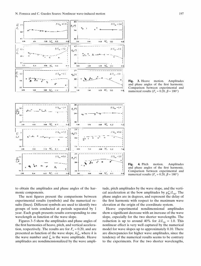
to obtain the amplitudes and phase angles of the har-monic components.
The next figures present the comparisons betweenexperimental results (symbols) and the numerical re-sults (lines). Different symbols are used to identify twogroups of tests conducted at periods separated by 1year. Each graph presents results corresponding to onewavelength as function of the wave slope.
Figures 3–5 show the amplitudes and phase angles ofthe first harmonics of heave, pitch, and vertical accelera-tion, respectively. The results are for Fn = 0.20, and arepresented as function of the wave slope, kza, where k isthe wave number and za is the wave amplitude. Heaveamplitudes are nondimensionalized by the wave ampli-
tude, pitch amplitudes by the wave slope, and the verti-cal acceleration at the bow amplitudes by gza/Lpp. Thephase angles are in degrees, and represent the delay ofthe first harmonic with respect to the maximum waveelevation at the origin of the coordinate system.
Heave experimental nondimensional amplitudesshow a significant decrease with an increase of the waveslope, especially for the two shorter wavelengths. Thereduction is up to around 40% for l/Lpp = 1.0. Thisnonlinear effect is very well captured by the numericalmodel for wave slopes up to approximately 0.10. Thereare discrepancies for higher wave amplitudes, since thetendency of the numerical results seems to be contraryto the experiments. For the two shorter wavelengths,
Fig. 3. Heave motion. Amplitudesand phase angles of the first harmonic.Comparison between experimental andnumerical results (Fn = 0.20, b = 180°)
Fig. 4. Pitch motion. Amplitudesand phase angles of the first harmonic.Comparison between experimental andnumerical results (Fn = 0.20, b = 180°)

198 N. Fonseca and C. Guedes Soares: Nonlinear wave-induced motion
the numerical results slightly overestimate the ex-periments. With respect to the phase angles, the experi-mental data seem to be independent of the waveslope. The calculated results compare well with theexperiments.
The pitch nondimensional amplitudes are less sen-sitive to the wave slope, although there is a smallreduction with the wave slope. The numerical resultscompare well with the experiments, except for theshorter wavelength where they overestimate the mea-sured results. Unlike heave, the experimental pitchphase angles tend to increase with the wave amplitude,with variations up to 30°. In general, this tendencyis well represented by the numerical results. The non-
dimensional amplitudes of the vertical accelerations atthe bow reduce with the wave slope, a characteristic thatis captured by the numerical model.
Figures 6–8 represent ship’s responses which are simi-lar to those described in the previous paragraphs, butfor a higher Froude number (Fn = 0.275). The observa-tions for Fn = 0.20 concerning the experimental data canbe used to describe Figs. 6–8, since the conclusions aresimilar. However, with respect to the numerical results,the comparisons are, in general, worse. One can say thatthe problems identified previously for the lower Froudenumber are now amplified. In particular, the heaveamplitudes in the higher wave steepness range largelyexceed those found in the experiments, and in general
Fig. 5. Vertical acceleration at the bow.Amplitudes and phase angles of the firstharmonic. Comparison between experi-mental and numerical results (Fn = 0.20,b = 180°)
Fig. 6. Heave motion. Amplitudesand phase angles of the first harmonic.Comparison between experimental andnumerical results (Fn = 0.275, b = 180°)

199N. Fonseca and C. Guedes Soares: Nonlinear wave-induced motion
all vertical response amplitudes are above the experi-mental points for the two shorter wavelengths.
The worsening of the numerical predictions for thehigher Froude number reveals the limitations of thestrip theory to represent the forward speed effects cor-rectly. In fact, the forward speed effects on the radiationand diffraction forces only account for the steady flow atinfinity, together with the angle between this flow andthe hull. All perturbations due to the hull, and inter-actions between these perturbations and the oscillatoryflow are neglected. Theoretically, this assumption isvalid for slender ships advancing at low speed.
Another aspect is the deviation of the numerical am-plitudes of heave from the experimental data for the
higher-amplitude waves. It is believed that the limita-tion here is not simply the strip method itself, but alsothe theoretical model that represents the nonlinear ef-fects associated with the vertical motions. The assump-tion of this model is that the dominant nonlinearcontributions arise from the hydrostatic and Froude–Krilov components, and therefore these componentsare calculated at each time instant and account for the“exact” hull wetted surface. The assumption seems tobe adequate for medium to large amplitude waves, butnot for very large waves.
In fact the conditions where the numerical model failsare extremely severe and unrealistic. For example, inthe graphs in Fig. 6, the ship advances with a relatively
Fig. 7. Pitch motion. Amplitudesand phase angles of the first harmonic.Comparison between experimental andnumerical results (Fn = 0.275, b = 180°)
Fig. 8. Vertical acceleration at the bow.Amplitudes and phase angles of the firstharmonic. Comparison between experi-mental and numerical results (Fn = 0.275,b = 180°)

200 N. Fonseca and C. Guedes Soares: Nonlinear wave-induced motion
high speed (Fn = 0.275), in regular waves with doubleamplitudes almost equal to the ship’s draft, and thewaves induce resonant heave motion. It is possible thatfor these conditions, the nonlinear effects on the radia-tion and diffraction forces have some influence on thecalculation of the resonance heave amplitude.
In addition, the viscous effects due to the separationof flow during the upward vertical motion of the hullmay have some influence. Preliminary simulations ofthe ship’s motions accounting for viscous effects associ-ated with the relative motions seem to indicate that thevertical viscous forces reduce the resonance heave am-plitude, thus shortening the gap between calculationsand experimental results. The calculation of viscousforces is based on an empirical model.
Another characteristic of the nonlinear responses isthe presence of higher harmonics on the time signals. Inthe case of heave and pitch motions, the magnitude ofthe higher harmonics is small. According to O’Dea etal.,6 the magnitudes of the second and third harmonicsof the measured vertical motions are around 1% to 2%of the first harmonics. On the other hand, the verticalaccelerations are more sensitive to the existence ofhigher harmonics. In fact, the second derivative of thefirst three harmonics of the accelerations with respect totime in effect multiplies the displacements by w2, 4w2,and 9w2, respectively. This means that, compared withthe motions, the importance of the second and thirdharmonics is 4 and 9 times larger, respectively, for theaccelerations. Experimental results show that for thelargest wave amplitude, the second and third harmonicsof the vertical accelerations account for 20% and 8%,respectively, of the first harmonic.
The numerical model is able to capture these nonlin-ear effects, but there are some discrepancies. Figure 9shows the second and third harmonics of the verticalacceleration at the bow as a function of the wave slopefor Fn = 0.20 and head regular waves with l/Lpp = 1.0.The results are normalized by the acceleration due to
gravity, g, the symbols represent experimental results,and the lines represent numerical results. Regarding thesecond harmonics, the tendency of the calculated resultsis correct up to the range of large wave slopes, but theexperimental data is overestimated.
Above ka = 0.10–0.12, the tendency of the curvechanges and the magnitude of the second-order effectsreduces, which is contrary to the experiments. The rea-son may be related to the effects on the bow of thegreen water on deck. In fact the change in the tendencyof the calculated curve occurs for wave slopes where therelative motion at the bow is larger than the free board,and thus green water on the deck starts. According tothe numerical model, from the instant that the free sur-face of the wave crosses the line of the deck, not onlydoes the vertical upward impulsion force cease to in-crease, but the downward force of green water on thedeck begins. This affects the characteristics of the verti-cal acceleration. Certainly these effects also occur in theexperiments, and one does not see a drop in the secondharmonics of the experimental data for large waveslopes, which may mean that the mathematical modeldoes not correctly represent reality.
In general, the numerical line of the third harmoniccomponents compares better with the experimentaldata.
3.3 Vertical bending moment
Watanabe et al.5 tested the S-175 to investigate the in-fluence of the bow flare on the shipping of water on thebow deck, and on the asymmetry and higher-order ef-fects of the wave-induced vertical bending moment.Two models, 4.5m long, and with different bows, weretested. One had the standard S-175 original bow shape(O-model), while the other had a modified bow withmore flare and a greater volume above the waterline(M-model). Figure 10 shows the cross-section lines andbow profile of both models.
Fig. 9. Second and third harmonics of thevertical acceleration at the bow as a func-tion of the wave slope (Fn = 0.20, b = 180°,l/Lpp = 1.0)

201N. Fonseca and C. Guedes Soares: Nonlinear wave-induced motion
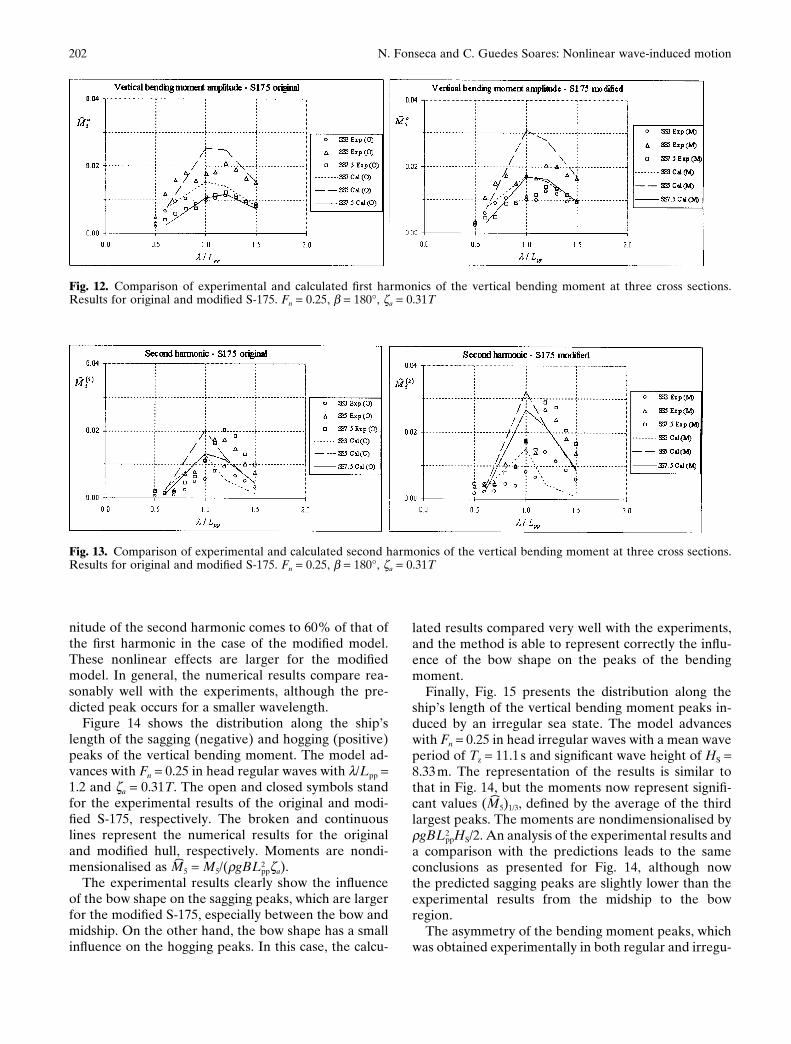
Watanabe et al.5 present the results of tests conductedin head regular waves for the whole wavelength rangeof interest, and a Froude number of 0.25. The waveamplitude was kept constant and equal to 0.31T, whereT is the mean draft. The results include measured dataof the pitch motion, relative motion and vertical accel-eration at the bow, impact pressures at several points,and vertical bending moment at six positions alongthe ship’s length. The signals of the vertical bendingmoment were analyzed to extract the mean offset andthe magnitudes of the first and second harmonics. Inaddition, tests were carried out for one irregularlong-crested sea-state.
Figures 11–13 show the results of the mean offset, andof the first and second harmonics, respectively, of thevertical bending moment at three cross sections (SS3,SS5, SS7.5) of the original and modified S-175. Thesections are numbered on a reference system from 0 (aftperpendicular) to 10 (forward perpendicular). The re-sults are presented as a function of the nondimensionalwavelength (l/Lpp). The symbols stand for experimentaldata, and the lines for the calculated results.
Starting with the mean values of the verticalbending moment in Fig. 11, these magnitudes are
nondimensionalised by rgBL2ppz a
2/T. The experimentalresults are larger around the wave frequencies that in-duce the vertical motion resonance. In terms of magni-tude, the mean offset at section 7.5 (on the bow) comesto around 50% of the first harmonic, revealing thestrong nonlinear behavior of this response. The numeri-cal results compare very well with the experimentalones for section 7.5, but largely exceed the experimentalones for the other two sections. The measured meanoffset is larger for the modified model than for theoriginal, behavior that is well predicted by the numeri-cal model.
The amplitudes of the first harmonics of thebending moment are shown in Fig. 12, where thenondimensional values are M�a
5 = Ma5/(rgBL2
ppz a2). In this
case, one can observe that the influence of the bowshape on the experimental data is small. The calculatedresults exceed those of the experiments and are largerfor the modified model.
With respect to the second harmonics (Fig. 13), theirmagnitudes are non-dimensionalized by the meanvalues. The experimental results show that their magni-tudes reach large values for the wave frequency rangearound the resonance of the vertical motions. The mag-
Fig. 10. Bodylines of the original S-175(O-model) and the modified S-175(M-model)5
Fig. 11. Comparison of experimental and calculated mean offset of the vertical bending moment at three cross sections. Resultsfor original and modified S-175. Fn = 0.25, b = 180°, za = 0.31T
202 N. Fonseca and C. Guedes Soares: Nonlinear wave-induced motion
nitude of the second harmonic comes to 60% of that ofthe first harmonic in the case of the modified model.These nonlinear effects are larger for the modifiedmodel. In general, the numerical results compare rea-sonably well with the experiments, although the pre-dicted peak occurs for a smaller wavelength.
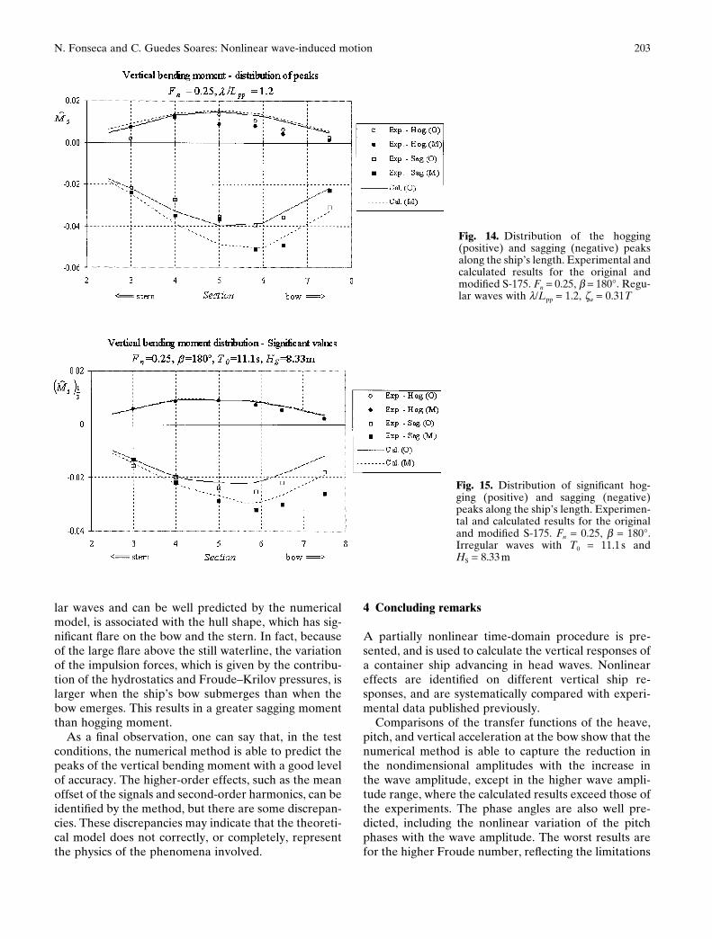
Figure 14 shows the distribution along the ship’slength of the sagging (negative) and hogging (positive)peaks of the vertical bending moment. The model ad-vances with Fn = 0.25 in head regular waves with l/Lpp =1.2 and za = 0.31T. The open and closed symbols standfor the experimental results of the original and modi-fied S-175, respectively. The broken and continuouslines represent the numerical results for the originaland modified hull, respectively. Moments are nondi-mensionalised as M�5 = M5/(rgBL2
ppza).The experimental results clearly show the influence
of the bow shape on the sagging peaks, which are largerfor the modified S-175, especially between the bow andmidship. On the other hand, the bow shape has a smallinfluence on the hogging peaks. In this case, the calcu-
lated results compared very well with the experiments,and the method is able to represent correctly the influ-ence of the bow shape on the peaks of the bendingmoment.
Finally, Fig. 15 presents the distribution along theship’s length of the vertical bending moment peaks in-duced by an irregular sea state. The model advanceswith Fn = 0.25 in head irregular waves with a mean waveperiod of Tz = 11.1 s and significant wave height of HS =8.33m. The representation of the results is similar tothat in Fig. 14, but the moments now represent signifi-cant values (M�5)1/3, defined by the average of the thirdlargest peaks. The moments are nondimensionalised byrgBL2
ppHS/2. An analysis of the experimental results anda comparison with the predictions leads to the sameconclusions as presented for Fig. 14, although nowthe predicted sagging peaks are slightly lower than theexperimental results from the midship to the bowregion.
The asymmetry of the bending moment peaks, whichwas obtained experimentally in both regular and irregu-
Fig. 12. Comparison of experimental and calculated first harmonics of the vertical bending moment at three cross sections.Results for original and modified S-175. Fn = 0.25, b = 180°, za = 0.31T
Fig. 13. Comparison of experimental and calculated second harmonics of the vertical bending moment at three cross sections.Results for original and modified S-175. Fn = 0.25, b = 180°, za = 0.31T
203N. Fonseca and C. Guedes Soares: Nonlinear wave-induced motion
Fig. 14. Distribution of the hogging(positive) and sagging (negative) peaksalong the ship’s length. Experimental andcalculated results for the original andmodified S-175. Fn = 0.25, b = 180°. Regu-lar waves with l/Lpp = 1.2, za = 0.31T
Fig. 15. Distribution of significant hog-ging (positive) and sagging (negative)peaks along the ship’s length. Experimen-tal and calculated results for the originaland modified S-175. Fn = 0.25, b = 180°.Irregular waves with T0 = 11.1 s andHS = 8.33 m
lar waves and can be well predicted by the numericalmodel, is associated with the hull shape, which has sig-nificant flare on the bow and the stern. In fact, becauseof the large flare above the still waterline, the variationof the impulsion forces, which is given by the contribu-tion of the hydrostatics and Froude–Krilov pressures, islarger when the ship’s bow submerges than when thebow emerges. This results in a greater sagging momentthan hogging moment.
As a final observation, one can say that, in the testconditions, the numerical method is able to predict thepeaks of the vertical bending moment with a good levelof accuracy. The higher-order effects, such as the meanoffset of the signals and second-order harmonics, can beidentified by the method, but there are some discrepan-cies. These discrepancies may indicate that the theoreti-cal model does not correctly, or completely, representthe physics of the phenomena involved.
4 Concluding remarks
A partially nonlinear time-domain procedure is pre-sented, and is used to calculate the vertical responses ofa container ship advancing in head waves. Nonlineareffects are identified on different vertical ship re-sponses, and are systematically compared with experi-mental data published previously.
Comparisons of the transfer functions of the heave,pitch, and vertical acceleration at the bow show that thenumerical method is able to capture the reduction inthe nondimensional amplitudes with the increase inthe wave amplitude, except in the higher wave ampli-tude range, where the calculated results exceed those ofthe experiments. The phase angles are also well pre-dicted, including the nonlinear variation of the pitchphases with the wave amplitude. The worst results arefor the higher Froude number, reflecting the limitations

204 N. Fonseca and C. Guedes Soares: Nonlinear wave-induced motion
of strip theory to represent the forward speed effects.Higher-order effects on the vertical accelerations arereasonably well represented by the calculation method,but there are discrepancies for the higher wave ampli-tudes.
With respect to the vertical bending moment, thenumerical method is able to capture all nonlinear effectsobserved in the experimental data. However, there aresome discrepancies on the mean offset and first harmon-ics where the calculations exceed the experimental re-sults. Second harmonics are reasonably well predicted,although the numerical peaks occur for frequencies alittle higher than those of the experimental curves. Thedistribution of peaks along the ship’s length is very wellpredicted, in both regular and irregular waves.
Acknowledgments. The first author is grateful to theFundação para a Ciência e a Tecnologia for havingprovided a scholarship, which has supported him duringthe development of the theoretical work. This workwas partially developed within the research projectWAVELOADS (Advanced Methods to Predict WaveInduced Loads for High Speed Ships), which was par-tially financed by the European Commission throughthe contract BRPR-CT-97-0580.
References
1. Dalzell JF (1962) Cross-spectral analysis of ship model motions: adestroyer model in irregular long-crested head seas. Rep 810,Davidson Laboratory, Stevens Institute of Technology
2. Dalzell JF (1962) Some further experiments on the application oflinear superposition techniques to the responses of a destroyermodel in extreme long-crested head seas. Rep 819, DavidsonLaboratory, Stevens Institute of Technology
3. Murday DC (1972) An analysis of longitudinal bending momentsmeasured on models in head waves. Trans R Inst Nav Archit114:221–240
4. Nethercote WCE (1981) Motions and bending moments of a war-ship design. Trans R Inst Nav Archit 123:352–375
5. Watanabe I, Keno M, Sawada H (1989) Effect of bow flare onshape to wave loads of a container ship. J Soc Nav Archit Jpn166:259–266
6. O’Dea J, Powers E, Zselecsky J (1992) Experimental determina-tion of non-linearities in vertical plane ship motions. Proceedingsof the 19th Symposium on Naval Hydrodynamics, Seoul, Korea,pp 73–91
7. Smith CS (1966) Measurements of service stresses in warships.Conference on Stresses in Service, Institute of Civil Engineers,London, pp 1–18
8. Hay B, Bourne J, Eagle A, et al (1994) Characteristics of hydro-dynamic loads data for a naval combatant. In: Faltinsen O (ed)Hydroelasticity in marine hydrodynamics. Balkema, Rotterdam,pp 169–188
9. Wilson R, Paterson E, Stern F (1998) Unsteady RANS CFDmethod for naval combatants in waves. Proceedings of the 22ndSymposium on Naval Hydrodynamics, National Academy Press,Washington, DC, pp 532–549
10. Beck RF, Cao Y, Scorpio SM, et al (1994) Non-linear ship motioncomputations using the desingularized method. Proceedings ofthe 20th Symposium on Naval Hydrodynamics, Santa Barbara,CA, pp 227–246
11. Scorpio SM, Beck RF, Korsmeyer FT (1996) Non-linear waterwave computations using a multipole accelerated, desingularizedmethod. Proceedings of the 21st Symposium on Naval Hydrody-namics, Trondheim, pp 69–74
12. Subramani A, Beck R, Scorpio S (1998) Fully nonlinear free-surface computations for arbitrary and complex hull forms.Proceedings of the 22nd Symposium on Naval Hydrodynamics,Washington, DC, pp 47–58
13. Lin WM, Zhang S, Yue D (1996) Linear and nonlinear analysis ofmotions and loads of a ship with forward speed in large-amplitudewaves. Proceedings of the 11th International Workshop on WaterWaves and Floating Bodies. Hamburg
14. Weems K, Zhang S, Lin WM, et al (1998) Structural dynamicloadings due to impact and whipping. In: Oosterveld MWC, TanSG (eds) Practical design of ships and mobile units (PRADS’98).Elsevier, Amsterdam, pp 79–85
15. Sclavounos PD, Kring DC, Huang YF, et al (1997) A computa-tional method as an advanced tool for design. Trans Soc NavArchit Mar Eng 105:375–398
16. Huang Y, Sclavounos PD (1998) Nonlinear ship motions. J ShipRes 42:120–130
17. Xia J, Wang Z (1997) Time-domain hydro-elasticity theory ofships responding to waves. J Ship Res 41:286–300
18. Fonseca N, Guedes Soares C (1998a) Time-domain analysis oflarge-amplitude vertical motions and wave loads. J Ship Res42:100–113
19. Fonseca N, Guedes Soares C (1998b) Nonlinear wave-induced responses of ships in irregular seas. Proceedings of the12th International Conference on Offshore Mechanics andArctic Engineering (OMAE’98), ASME, New York, paper 980446
20. Watanabe I, Guedes Soares C (1999) Comparative study on thetime-domain analysis of non-linear ship motions and loads. MarStruct 12:153–170
21. Guedes Soares C, Brown DT, Cariou A, et al (1997) Loads. In:Moan T, Berge S (eds) Proceedings of the 13th International Shipand Offshore Structures Congress (ISSC’97). Elsevier Science,London, vol 1, pp 59–122
22. Jensen JJ, Beck RF, Du S, et al (2000) Extreme hull girder load-ing. In: Ohtsubo H, Sumi Y (eds) Proceedings of the 14th Interna-tional Ship and Offshore Structures Congress (ISSC’2000). 2–6October. Elsevier Science, London, vol 2, pp 236–320
23. ITTC (1978) 15th ITTC Seakeeping Committee Report, Proceed-ings of the 15th ITTC, The Hague
24. ITTC (1981) 16th ITTC Seakeeping Committee Report, Proceed-ings of the 16th ITTC, Leningrad