Comparison of fast ion collective Thomson scattering measurements at ASDEX Upgrade with numerical...
10
IOP PUBLISHING and INTERNATIONAL ATOMIC ENERGY AGENCY NUCLEAR FUSION Nucl. Fusion 50 (2010) 035012 (10pp) doi:10.1088/0029-5515/50/3/035012 Comparison of fast ion collective Thomson scattering measurements at ASDEX Upgrade with numerical simulations M. Salewski 1 , F. Meo 1 , M. Stejner 1 , O. Asunta 2 , H. Bindslev 1 , V. Furtula 1 , S.B. Korsholm 1 , T. Kurki-Suonio 2 , F. Leipold 1 , F. Leuterer 3 , P.K. Michelsen 1 , D. Moseev 1 , S.K. Nielsen 1 , J. Stober 3 , G. Tardini 3 , D. Wagner 3 , P. Woskov 4 and the ASDEX Upgrade team 3 1 Association Euratom - Risø National Laboratory for Sustainable Energy, Technical University of Denmark, DK-4000 Roskilde, Denmark 2 Association Euratom - TEKES, Helsinki University of Technology, FI-02015 TKK, Finland 3 Association Euratom-Max-Planck-Institut f ¨ ur Plasmaphysik, D-85748 Garching, Germany 4 MIT Plasma Science and Fusion Center, Cambridge, MA 02139, USA E-mail: [email protected] Received 19 November 2009, accepted for publication 2 February 2010 Published 5 March 2010 Online at stacks.iop.org/NF/50/035012 Abstract Collective Thomson scattering (CTS) experiments were carried out at ASDEX Upgrade to measure the one- dimensional velocity distribution functions of fast ion populations. These measurements are compared with simulations using the codes TRANSP/NUBEAM and ASCOT for two different neutral beam injection (NBI) configurations: two NBI sources and only one NBI source. The measured CTS spectra as well as the inferred one-dimensional fast ion velocity distribution functions are clearly asymmetric as a consequence of the anisotropy of the beam ion populations and the selected geometry of the experiment. As expected, the one-beam configuration can clearly be distinguished from the two-beam configuration. The fast ion population is smaller and the asymmetry is less pronounced for the one-beam configuration. Salient features of the numerical simulation results agree with the CTS measurements while quantitative discrepancies in absolute values and gradients are found. PACS numbers: 52.25.Os, 52.40.Db, 52.50.Gj, 52.65.Cc, 52.70.Gw 1. Introduction Medium-sized tokamaks such as ASDEX Upgrade are designed to confine hot plasmas with temperatures in the kiloelectronvolt range and are usually equipped with powerful auxiliary heating systems: neutral beam injection (NBI), ion cyclotron resonance heating (ICRH) or electron cyclotron resonance heating (ECRH) [1, 2]. The energetic ions generated by NBI and ICRH play a key role in heating the bulk plasma, and understanding fast ion physics is therefore essential. However, reliable predictions of fast ion motion still face many challenges: fast ions exhibit collective behaviour [3, 4] and can interact with magnetohydrodynamic (MHD) activity such as the family of Alfv` en eigenmodes [5–8], sawteeth [9–12], kinetic ballooning modes [6, 13, 14], neoclassical tearing modes [6, 15] or the sierpes mode [16]. Fast ions may also interact with turbulent fluctuations [17–19]. Theories describing such phenomena need to be tested against experimental data. The implications for ITER and tokamaks beyond are also far-reaching: the confinement of the bulk plasma and the fast ions may degrade due to such effects. Measurements of fast ion distributions have therefore been recognized as a milestone towards understanding plasmas in the burning regime [20, 21]. Millimetre wave collective Thomson scattering (CTS) has been demonstrated to provide measurements of one-dimensional velocity distribution functions of confined fast ions in various selected directions and locations in the plasma at JET [22], TEXTOR [23, 24] and ASDEX Upgrade [25, 26]; a fast ion CTS system at ITER is also foreseen [27–32]. CTS experiments at other machines have further contributed to the experience with millimetre wave CTS diagnostics [33–36]. For example, the ion temperature 0029-5515/10/035012+10$30.00 1 © 2010 IAEA, Vienna Printed in the UK
Transcript of Comparison of fast ion collective Thomson scattering measurements at ASDEX Upgrade with numerical...
IOP PUBLISHING and INTERNATIONAL ATOMIC ENERGY AGENCY NUCLEAR FUSION
Nucl. Fusion 50 (2010) 035012 (10pp) doi:10.1088/0029-5515/50/3/035012
Comparison of fast ion collective Thomsonscattering measurements at ASDEXUpgrade with numerical simulationsM. Salewski1, F. Meo1, M. Stejner1, O. Asunta2, H. Bindslev1,V. Furtula1, S.B. Korsholm1, T. Kurki-Suonio2, F. Leipold1,F. Leuterer3, P.K. Michelsen1, D. Moseev1, S.K. Nielsen1,J. Stober3, G. Tardini3, D. Wagner3, P. Woskov4 and theASDEX Upgrade team3
1 Association Euratom - Risø National Laboratory for Sustainable Energy, TechnicalUniversity of Denmark, DK-4000 Roskilde, Denmark2 Association Euratom - TEKES, Helsinki University of Technology, FI-02015 TKK, Finland3 Association Euratom-Max-Planck-Institut fur Plasmaphysik, D-85748 Garching, Germany4 MIT Plasma Science and Fusion Center, Cambridge, MA 02139, USA
E-mail: [email protected]
Received 19 November 2009, accepted for publication 2 February 2010Published 5 March 2010Online at stacks.iop.org/NF/50/035012
AbstractCollective Thomson scattering (CTS) experiments were carried out at ASDEX Upgrade to measure the one-dimensional velocity distribution functions of fast ion populations. These measurements are compared withsimulations using the codes TRANSP/NUBEAM and ASCOT for two different neutral beam injection (NBI)configurations: two NBI sources and only one NBI source. The measured CTS spectra as well as the inferredone-dimensional fast ion velocity distribution functions are clearly asymmetric as a consequence of the anisotropyof the beam ion populations and the selected geometry of the experiment. As expected, the one-beam configurationcan clearly be distinguished from the two-beam configuration. The fast ion population is smaller and the asymmetryis less pronounced for the one-beam configuration. Salient features of the numerical simulation results agree withthe CTS measurements while quantitative discrepancies in absolute values and gradients are found.
PACS numbers: 52.25.Os, 52.40.Db, 52.50.Gj, 52.65.Cc, 52.70.Gw
1. Introduction
Medium-sized tokamaks such as ASDEX Upgrade aredesigned to confine hot plasmas with temperatures in thekiloelectronvolt range and are usually equipped with powerfulauxiliary heating systems: neutral beam injection (NBI), ioncyclotron resonance heating (ICRH) or electron cyclotronresonance heating (ECRH) [1, 2]. The energetic ions generatedby NBI and ICRH play a key role in heating the bulk plasma,and understanding fast ion physics is therefore essential.However, reliable predictions of fast ion motion still facemany challenges: fast ions exhibit collective behaviour [3, 4]and can interact with magnetohydrodynamic (MHD) activitysuch as the family of Alfven eigenmodes [5–8], sawteeth[9–12], kinetic ballooning modes [6, 13, 14], neoclassicaltearing modes [6, 15] or the sierpes mode [16]. Fast
ions may also interact with turbulent fluctuations [17–19].Theories describing such phenomena need to be tested againstexperimental data. The implications for ITER and tokamaksbeyond are also far-reaching: the confinement of the bulkplasma and the fast ions may degrade due to such effects.Measurements of fast ion distributions have therefore beenrecognized as a milestone towards understanding plasmasin the burning regime [20, 21]. Millimetre wave collectiveThomson scattering (CTS) has been demonstrated to providemeasurements of one-dimensional velocity distributionfunctions of confined fast ions in various selected directionsand locations in the plasma at JET [22], TEXTOR [23, 24]and ASDEXUpgrade [25, 26]; a fast ion CTS system at ITERis also foreseen [27–32]. CTS experiments at other machineshave further contributed to the experiencewithmillimetrewaveCTS diagnostics [33–36]. For example, the ion temperature
0029-5515/10/035012+10$30.00 1 © 2010 IAEA, Vienna Printed in the UK

Nucl. Fusion 50 (2010) 035012 M. Salewski et al
1
3
5
PN
BI [
MW
]
S3+S8 S8
1
3
5
Te,
i [ke
V] bulk ions
electrons
5
7
ne [
1019
m–3
]
Time [s]
2.3 2.4 2.5 2.6 2.70
1
Vi [
105 m
/s]
Time [s]
Figure 1. Time traces of NBI power, ion and electron temperatures,electron density and toroidal bulk ion drift velocity in the plasmacentre in discharge 24089. Neutral beams S3 and S8 heated theplasma up to 2.5 s when beam S3 was switched off.
has been estimated by millimetre wave CTS at the W7-ASstellarator [37].
Here we report recent fast ion velocity distribution resultsobtained by CTS for different NBI configurations at ASDEXUpgrade. We compare the measurements with numericalsimulations and describe methods for such a comparison. Theexperimental conditions are summarized in section 2 and themethods in section 3. The measured spectral power densitiesof scattered radiation are compared with synthetic CTS spectracalculated with a scattering model [38, 39] using fast ionvelocity distributions obtained with the simulation codesTRANSP/NUBEAM[40, 41] orASCOT [42, 43] (section 4.1).Moreover, the inferred one-dimensional fast ion velocitydistributions obtained for this experiment are presented andcompared with the simulations (section 4.2). We discussperspectives and draw conclusions in sections 5 and 6.
2. CTS experiment at ASDEX Upgrade
2.1. Plasma parameters
The CTS measurements were carried out in a co-current NBIheated, standard H-mode plasma (discharge 24089). ASDEXUpgrade is equipped with two-beam boxes each containingfour neutral beam injectors [44]. We used two of the injectors,namely source 3 (S3) and source 8 (S8). S3 and S8 havefull acceleration energies of 60 keV and 93 keV in deuterium,respectively, and they have similar injection geometries. BothNBI sources (S3+S8) injected deuterium with a total power ofabout 5MW (2×2.5MW), until S3 was switched off. Fast ionpopulations in the plasma centre for both NBI configurations(S3+S8 and S8 only) were measured by CTS.
CTS spectra of scattered radiation depend not only onthe fast ion velocity distribution function—the parameters
of interest—but also on other parameters which are not thegoal of the measurement and encumber the data analysis—the nuisance parameters. Among the nuisance parametersare several bulk plasma parameters which we discuss here.Figure 1 shows time traces of the NBI power, the electronand ion temperatures, the electron density and the toroidalbulk ion drift velocity. The temperatures and the drift velocitydecreased when beam S3 was turned off whereas the electrondensity was feedback controlled. From here on we shalluse representative values to characterize the plasma for bothNBI configurations: two beams (S3+S8) versus one beam(S8). These representative values and their 1σ confidencelevels are given in table 1, which also contains additionalplasma parameters affecting the CTS spectra: the magneticfield, the isotope ratio and impurity concentrations. The iontemperature and bulk ion drift velocity were obtained fromthe charge exchange diagnostic, the electron temperature from(non-collective) Thomson scattering [45], the electron densityfrom the integrated data analysis (IDA) [46–49], the isotoperatio from a neutral particle analyzer, and the impurity contentwas estimated by spectroscopy [50].
2.2. CTS experiment description
In CTS experiments at ASDEX Upgrade, a probe beam ofmillimetre waves is launched into the plasma, and radiationis scattered off microscopic fluctuations in the plasma. Partof this scattered radiation is collected by a receiver with aquasi-optical antenna and resolved into frequency intervals.The acceptance cone of the antenna, referred to as the receiverbeam, is defined by the antenna design. Information about thefast ions can be inferred from the spectral power density of thescattered radiation. The measurement is spatially resolved atthe location where probe and receiver beam patterns intersect.This location is called the scattering volume and lies near theplasma centre at R = 1.7m and z = 0.1m in this experiment.The scattering geometry is sketched in poloidal and toroidalviews in figures 2(a) and (b), respectively. CTS enablesmeasuring the fast ion velocity distribution projected onto thefluctuation wave vector kδ = ks − ki where the superscripts sand i refer to scattered and incident radiation, respectively. Thespectral content of the scattered radiation bears a signature ofthe ion velocity distribution since the CTS system at ASDEXUpgrade satisfies Salpeter’s condition [51]: |λDkδ| < 1 whereλD is theDebye length. A frequency shift in scattered radiation,νδ , can be approximately related to an ion velocity, vion, byνδ = νs − ν i ≈ vion · kδ/2π .
In discharge 24089 the incident gyrotron power wasPi = 250 kW at an average frequency of Fi = 104.93GHz[25, 26, 52]. The geometry and gyrotron parameters forthe CTS experiment and their estimated uncertainties aresummarized in table 2. The resolved angle φ = � (kδ, B), thescattering angle θ = � (ki, ks) and the less important azimuthalangle ψ describe the scattering geometry. The so-called beamoverlap Ob accounts for the effects of the widths of the probeand receiver beam patterns and for the extent to which theyoverlap in the plasma [38, 39]. The role of the overlap in ourcomparison is explained in section 4.1. This set of CTS systemparameters (table 2) and the set of plasma parameters (table 1)form the set of nuisance parameters mentioned in section 2.1.
2
Nucl. Fusion 50 (2010) 035012 M. Salewski et al
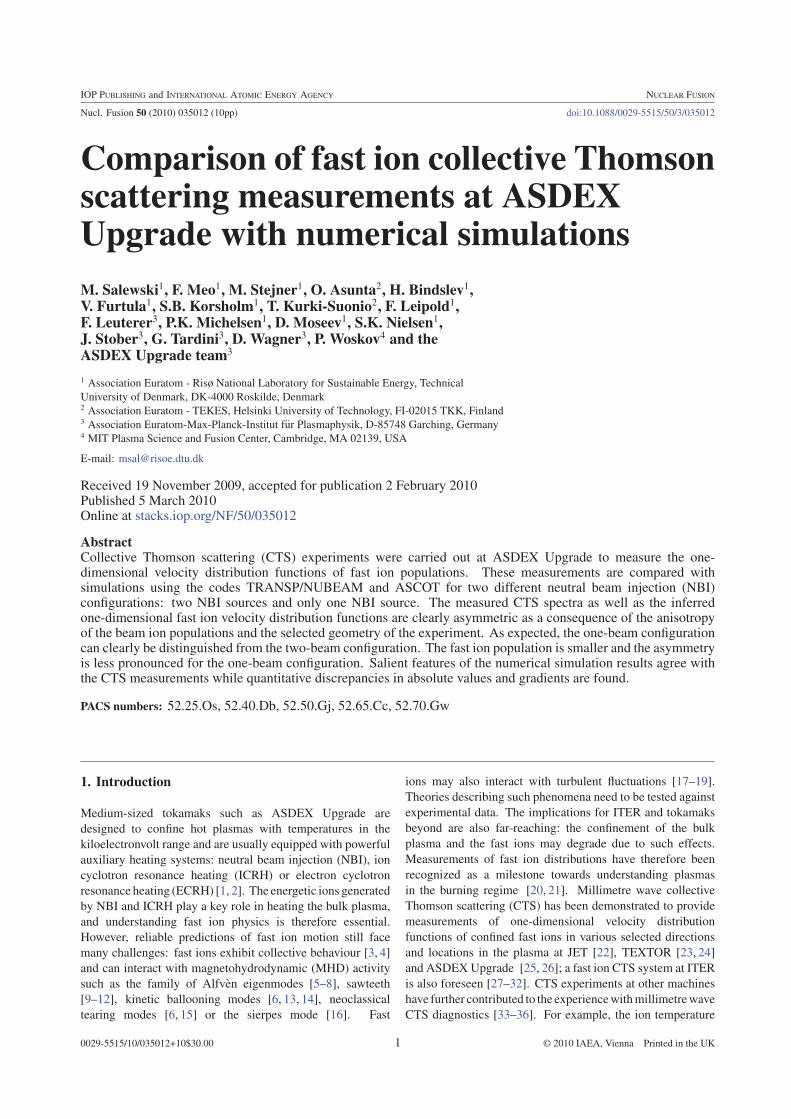
Table 1. Parameters of the plasma in discharge 24089 at the location of the CTS scattering volume (ρpol = 0) and their estimated 1σuncertainties. The parameters are given separately for the NBI configurations with two beams (S3+S8) and one beam (S8). Z stands for theimpurity ion charge and m for the mass.
Parameter Symbol 2 NBIs 1 NBI
Magnetic field Bmod 2.6± 0.1 T 2.6± 0.1 TElectron density ne 6.6± 0.3× 10¹⁹ m−3 6.5± 0.3× 10¹⁹ m−3
Electron temperature Te 2.9± 0.3 keV 2.2± 0.3 keVIon temperature Ti 3.7± 0.5 keV 2.1± 0.5 keVIon drift velocity Vi 1.1± 0.6× 10⁵ m s−1 0.6± 0.6× 10⁵ m s−1Isotope ratio nH/(nH + nD) Ri 0.03± 0.02 0.03± 0.02Impurity (Z/m = 6/12) ni1/ne Ni1 0.005± 0.005 0.005± 0.005Impurity (Z/m = 50/184) ni2/ne Ni2 0.0005± 0.0005 0.0005± 0.0005
1 1.5 2 2.5
–0.8
–0.4
0
0.4
0.8
R [m]
(a)�Poloidal�view (b)�Toroidal�view
z [m
]
–2.5 –2 –1.5 –1 –0.5 0
0
0.5
1
1.5
2
2.5
x [m]
y [m
]B
p I
i
k k k
t
s δ
Figure 2. Ray tracing for the scattering geometry in discharge 24089 projected into the poloidal and toroidal planes, respectively. The probebeam is plotted in blue, the receiver beam in green. Both have O-mode polarization. The scattering volume lies at the intersection of probeand receiver beams and is illustrated in magenta. In (b) viewing the torus from the top, the directions of the toroidal magnetic field Bt , theplasma current Ip and the projected wave vectors kδ , ki and ks are indicated. The dashed lines represent the magnetic axis (red) and the lastclosed flux surface (blue).
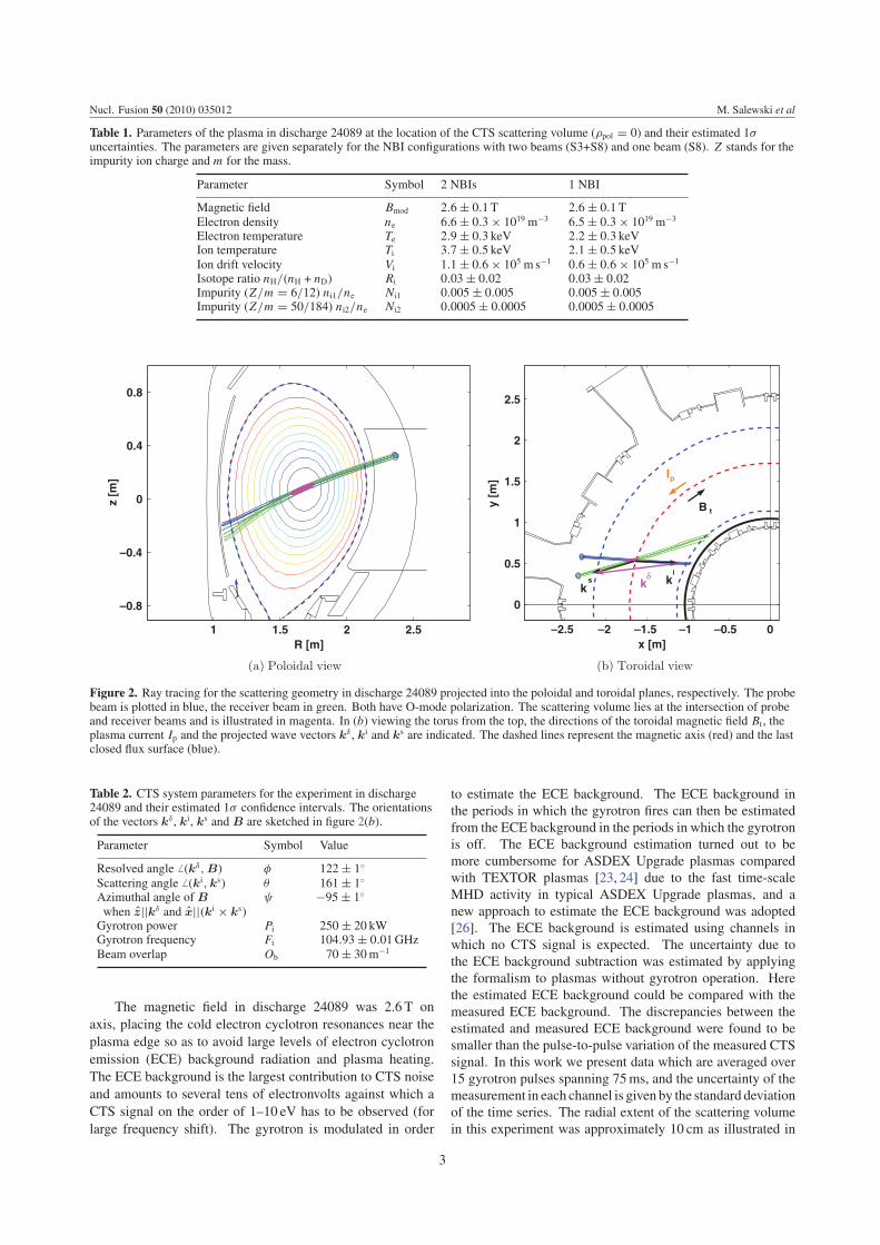
Table 2. CTS system parameters for the experiment in discharge24089 and their estimated 1σ confidence intervals. The orientationsof the vectors kδ , ki, ks and B are sketched in figure 2(b).
Parameter Symbol Value
Resolved angle � (kδ, B) φ 122± 1◦
Scattering angle � (ki, ks) θ 161± 1◦
Azimuthal angle of B ψ −95± 1◦
when z||kδ and x||(ki × ks)Gyrotron power Pi 250± 20 kWGyrotron frequency Fi 104.93± 0.01GHzBeam overlap Ob 70± 30m−1
The magnetic field in discharge 24089 was 2.6 T onaxis, placing the cold electron cyclotron resonances near theplasma edge so as to avoid large levels of electron cyclotronemission (ECE) background radiation and plasma heating.The ECE background is the largest contribution to CTS noiseand amounts to several tens of electronvolts against which aCTS signal on the order of 1–10 eV has to be observed (forlarge frequency shift). The gyrotron is modulated in order
to estimate the ECE background. The ECE background inthe periods in which the gyrotron fires can then be estimatedfrom the ECE background in the periods in which the gyrotronis off. The ECE background estimation turned out to bemore cumbersome for ASDEX Upgrade plasmas comparedwith TEXTOR plasmas [23, 24] due to the fast time-scaleMHD activity in typical ASDEX Upgrade plasmas, and anew approach to estimate the ECE background was adopted[26]. The ECE background is estimated using channels inwhich no CTS signal is expected. The uncertainty due tothe ECE background subtraction was estimated by applyingthe formalism to plasmas without gyrotron operation. Herethe estimated ECE background could be compared with themeasured ECE background. The discrepancies between theestimated and measured ECE background were found to besmaller than the pulse-to-pulse variation of the measured CTSsignal. In this work we present data which are averaged over15 gyrotron pulses spanning 75ms, and the uncertainty of themeasurement in each channel is given by the standard deviationof the time series. The radial extent of the scattering volumein this experiment was approximately 10 cm as illustrated in
3

Nucl. Fusion 50 (2010) 035012 M. Salewski et al
figure 2. Amore detailed description of the system parametersand the capabilities of CTS at ASDEX Upgrade can be foundin [25, 26].
3. Methods for CTS data analysis
Experimental CTS results can be compared with theoreticalexpectations in two complementary ways: either in frequencyspace, if a synthetic CTS spectrum is calculated fromtheoretical ion and electron velocity distributions, or in velocityspace, if the one-dimensional fast ion velocity distributiong(u)
is inferred from the experimental CTS spectra. The velocityspace comparison has the advantage that it is the velocitydistribution g(u) that one is actually interested in. On theother hand, the frequency space comparison has the advantagethat the spectral power density is the quantity that is directlymeasured with the CTS receiver. The latter option is presentedin section 4.1 and the former in section 4.2. We thus need tofindthe experimental and the simulated g(u) and the experimentaland the synthetic spectral power densities which are obtainedby methods explained in the following three sections.
3.1. Forward model of CTS and synthetic spectra
The forward model provides a mapping from velocity space tofrequency space [38, 39]: if the velocity distributions of fastions (see section 3.2), bulk ions and electrons as well as thenuisance parameters are known, the expected CTS spectrumcan be calculated [31, 53]. Not only do calculated spectrarely on this forward model but also the estimation of g(u)
from the measured spectra (section 3.3). The comparison ofexperimental and numerical data therefore also depends on theforward model. Predicted spectra are calculated using the bestavailable estimates for the plasma and CTS system parameters(tables 1 and 2). The spectral power density of the scatteredradiation ∂P s/∂νs is calculated as
∂P s
∂νs= PiObneλ
i02r2e1
2π�, (1)
where λi0 is the vacuum wavelength of the probe radiation,re the classical electron radius and � the scattering functionthat gives the spectral shape [38, 39]. This forward model isderived from a kinetic, fully electromagnetic description of thescattering process, and it accounts for fluctuations in electrondensity, in the electric and magnetic fields, and in the electroncurrent density.
Figure 3 shows a synthetic CTS spectrum calculatedusing this forward model for the NBI configuration withtwo beams (S3+S8). The bulk ion species are assumed toconsist of deuterium, hydrogen, carbon and tungsten withMaxwellian velocity distributions parametrized by a commonbulk ion temperature and toroidal drift velocity with densitiesof the various ion species as given in table 1. However, thedeuterium velocity distribution function is the sum of the beamion velocity distribution function g(u) (section 3.2) and theMaxwellian distribution for the bulk deuterium. The electronsare assumed to have aMaxwellian distribution characterized bythe electron temperature anddensity. The various species in theplasma each contribute a component to theCTS spectrumgivenby their assumed velocity distributions. The bulk ion feature
103 104 105 106 1070.1
1
10
100
νs [GHz]
Sp
ectr
al p
ow
er d
ensi
ty [
eV]
totalbeam ionsdeuteriumhydrogenimpuritieselectrons
Figure 3. Synthetic CTS spectrum for the two-beam phase (S3+S8)in discharge 24089. The spectrum was calculated using the datafrom tables 1 and 2 and the fast ion distribution simulated withTRANSP/NUBEAM shown in figure 4(a). The total signal is thesum of the individual contributions indicated in this figure. Thedotted line marks the gyrotron frequency.
dominates the spectrum from 104.3 to 105.5GHz, the maincontributions coming from deuterium and impurities. Notethat the bulk ion feature has a small frequency shift from thegyrotron frequency due to the assumed bulk ion drift velocity.The beam ions are clearly the largest contributor to the CTSspectrum for frequencies above 105.5 and below 104.3GHz inthis configuration. The asymmetry of the fast ion feature is aconsequence of the asymmetry of the one-dimensional beamion velocity distribution function to be discussed in section 3.2.
3.2. Simulation models for the fast ion velocity distributions
In this section we describe how to obtain one-dimensionalvelocity distribution functions g(u) from numerical simulationwith the help of the widely used transport code TRANSPcoupled with the neutral beam module NUBEAM [40, 41]or the test-particle Monte Carlo code ASCOT [42, 43].The simulation codes compute the two-dimensional fast iondistribution f (v‖, v⊥) at the location of the scattering volumewhere v‖ and v⊥ refer to the velocity components parallel andperpendicular to the magnetic field, respectively. We comparethe CTS results with both sets of simulation results (fromTRANSP/NUBEAM and from ASCOT). A full comparisonof the two codes is, however, beyond the scope of thiswork. The steady-state velocity space distribution of beamions originating from S3 and S8, as computed with ASCOTand TRANSP/NUBEAM, is presented in figure 4. Thelargest velocity space densities for these beams are found at apitch angle of 120◦. The rotationally symmetric distributionf (v‖, v⊥) is then projected onto the resolved direction kδ
indicated in figure 4. The projection g(u) of the full velocitydistribution function f (v‖, v⊥) along the direction of kδ isgiven by
g(u) =∫dvf δ
(v · kδ
kδ− u
), (2)
where δ() is the Dirac δ-function and u is the resolved one-dimensional velocity component.
4

Nucl. Fusion 50 (2010) 035012 M. Salewski et al
–3 –2 –1 0 1 2 30
1
2
3
kδB
f [s3/m6]
v|| [106 m/s]
v ⊥ [
106 m
/s]
0.05
0.1
0.15
0.2
0.25
0.3
–3 –2 –1 0 1 2 30
1
2
3
v|| [106 m/s]
v ⊥ [
106 m
/s]
kδB
f [s3/m6]
0.05
0.1
0.15
0.2
0.25
0.3
Figure 4. Equally spaced contours of the beam ion velocitydistribution f in the scattering volume (R = 1.7m, z = 0.1m)computed with TRANSP/NUBEAM (a) and ASCOT (b) for heatingwith S3 and S8. The bulk ion distribution is not plotted in thisfigure, leading to low densities near the origin. The directions of themagnetic field B and kδ are indicated.
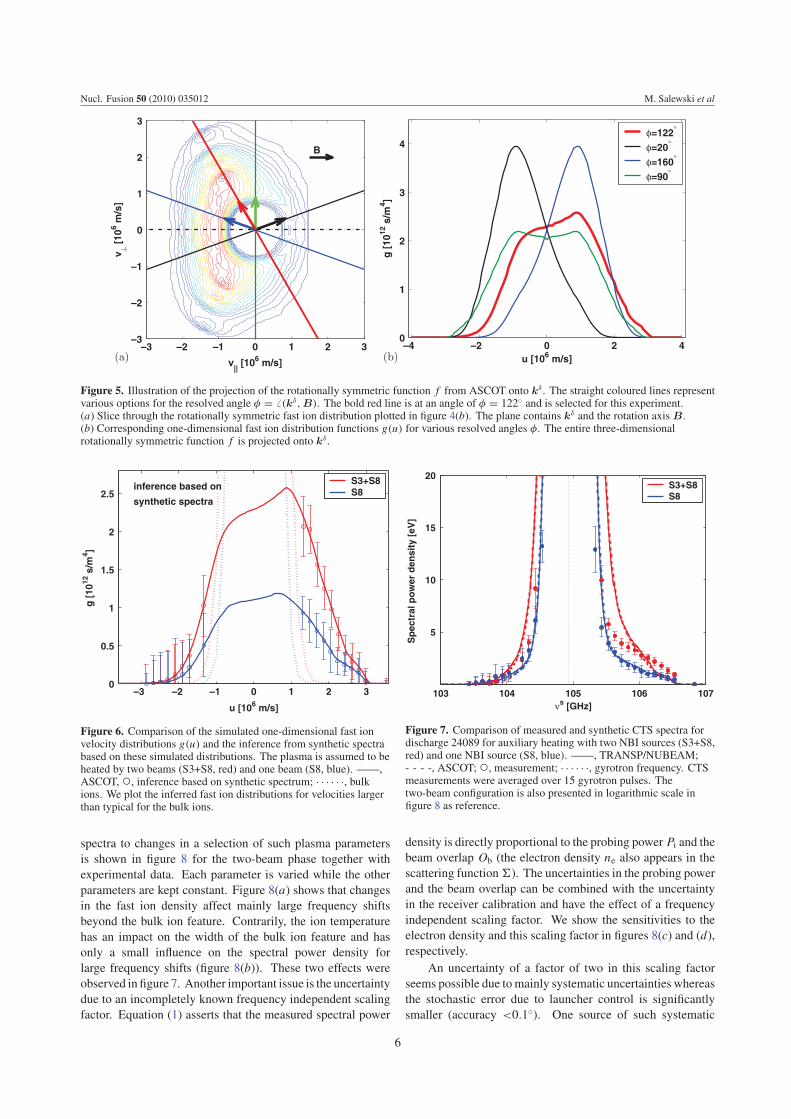
We illustrate the projection of the rotationally invariantfunction f onto kδ in figure 5, using ASCOT data as anexample. The rotation axis B and kδ define a plane whichslices through the three-dimensional, rotationally invariantfunction f . The resolved angle in the experiment was φ =� (kδ, B) = 122◦ indicated as the bold red line in figure 5(a).Additionally, other options for resolved directions are shownfor illustration: φ = 20◦, φ = 90◦ and φ = 160◦. Resolvedangles ofφ = 20◦ andφ = 160◦ are at the limits of the steeringcapability of theCTS antenna system atASDEXUpgrade. Thecorresponding projections g(u) onto these resolved directionskδ are plotted in figure 5(b). If the resolved direction isφ = 90◦, the projection of f onto kδ will be symmetric aboutu = 0. For resolution as close to parallel to the magnetic fieldas possible, φ = 20◦ or φ = 160◦, the projection becomesvery asymmetric. These two projections are mirror images ofeach other. For the resolved angle chosen in this experiment,φ = 122◦, g(u) is asymmetric about u = 0 which leads to theasymmetry in the computed spectra described in section 3.1.For this angle a finite phase space density exists at the largestvalues of the velocity component u. Scattering is then foundat the largest possible frequency upshift with this angle. Thus,the spectral range of the CTS receiver for frequency upshift isexploited optimally for this angle.
3.3. Inference of the fast ion velocity distribution from CTSmeasurements
The inference of the one-dimensional fast ion velocitydistribution g(u) and of its estimated uncertainty—the
parameters of interest—demands the solution to an inverseproblem. Direct operators mapping from frequency space (themeasured CTS spectrum) to velocity space are not availablewhereas a forward model mapping from velocity space tofrequency space has been formulated (section 3.1) [38, 39].The velocity distribution g(u) is obtained from the measuredspectra by a least square fitting procedure using this forwardmodel. Uncertainties in the nuisance parameters and in themeasured spectral power density are accounted for. Assumingnormal distributions for the measured spectral power densitiesand the nuisance parameters, one can derive expressions forthe misfit between the experimental data and the expectation[54]. The nuisance parameters and their uncertainties aresummarized in tables 1 and 2.
We demonstrate the inference in figure 6 for the simulatedone-dimensional fast ion distribution function g(u). Asynthetic spectrum based on this distribution function andthe nuisance parameters in tables 1 and 2 was displayed infigure 3. We infer g(u), given only the synthetic spectrumand the nuisance parameters as well as their uncertainties. Weassume the uncertainties of the synthetic spectrum to be givenby the measurement uncertainties of the actual experiment. Inthe inference we make use of the full spectrum, except for theparts which are blocked by the notch filter in the experiment.In this way the inference is demonstrated for experimentalconditions. The inference should then ideally be identical tothe fast ion distribution function used to calculate the syntheticspectrum. Figure 6 demonstrates that the underlying fast iondistributions can be inferred from the synthetic spectra withgood accuracy.
4. Results
4.1. Comparison of measured and synthetic CTS spectra
Figure 7 presents a comparison of experimentally obtainedspectra against synthetically generated spectra, such as theone shown in figure 3, for both NBI configurations (S3+S8and S8 only). The synthetic spectra obtained on the basis ofTRANSP/NUBEAM or ASCOT simulations agree reasonablywell with each other, especially for large frequency shifts. Wenote several points of agreement between the simulations andthe measurements. First, there is a clear asymmetry aboutthe gyrotron frequency due to the presence of beam ions inthe measurement and in the simulation, the reason for whichwe explained in sections 3.1 and 3.2. Second, the largerparticle density of beam ions in the two-beam phase (S3+S8) isreflected in the larger spectral power densities for frequenciesabove 105.5GHz. When neutral beam S3 is switched off, thespectral power density above 105.5GHz drops significantlycompared with the error bars. We attribute this to a smallerpopulation of fast ions (see section 4.2). Measurements andsimulations agree in this respect. Third, the bulk ion featurefrom 104.3 to 105.5GHz is measured to be narrower due tothe ion temperature drop after 2.5 s as was expected accordingto simulation.
However, there are quantitative discrepancies between thesimulation and the experiment. To point these out, we needto address the sensitivity of the synthetic spectra to changes inplasma parameters affecting the spectra. The sensitivity of the
5
Nucl. Fusion 50 (2010) 035012 M. Salewski et al
–3 –2 –1 0 1 2 3–3
–2
–1
0
1
2
3
B
v|| [106 m/s]
v ⊥ [
106 m
/s]
–4 –2 0 2 40
1
2
3
4
u [106 m/s]
g [
1012
s/m
4 ]
φ=122°
φ=20°
φ=160°
φ=90°
(a) (b)
Figure 5. Illustration of the projection of the rotationally symmetric function f from ASCOT onto kδ . The straight coloured lines representvarious options for the resolved angle φ = � (kδ, B). The bold red line is at an angle of φ = 122◦ and is selected for this experiment.(a) Slice through the rotationally symmetric fast ion distribution plotted in figure 4(b). The plane contains kδ and the rotation axis B.(b) Corresponding one-dimensional fast ion distribution functions g(u) for various resolved angles φ. The entire three-dimensionalrotationally symmetric function f is projected onto kδ .
–3 –2 –1 0 1 2 30
0.5
1
1.5
2
2.5
u [106 m/s]
g [
1012
s/m
4 ]
inference based on
synthetic spectra
S3+S8S8
Figure 6. Comparison of the simulated one-dimensional fast ionvelocity distributions g(u) and the inference from synthetic spectrabased on these simulated distributions. The plasma is assumed to beheated by two beams (S3+S8, red) and one beam (S8, blue). ——,ASCOT, ◦, inference based on synthetic spectrum; · · · · · ·, bulkions. We plot the inferred fast ion distributions for velocities largerthan typical for the bulk ions.
spectra to changes in a selection of such plasma parametersis shown in figure 8 for the two-beam phase together withexperimental data. Each parameter is varied while the otherparameters are kept constant. Figure 8(a) shows that changesin the fast ion density affect mainly large frequency shiftsbeyond the bulk ion feature. Contrarily, the ion temperaturehas an impact on the width of the bulk ion feature and hasonly a small influence on the spectral power density forlarge frequency shifts (figure 8(b)). These two effects wereobserved in figure 7. Another important issue is the uncertaintydue to an incompletely known frequency independent scalingfactor. Equation (1) asserts that the measured spectral power
103 104 105 106 107
5
10
15
20
νs [GHz]
Sp
ectr
al p
ow
er d
ensi
ty [
eV]
S3+S8S8
Figure 7. Comparison of measured and synthetic CTS spectra fordischarge 24089 for auxiliary heating with two NBI sources (S3+S8,red) and one NBI source (S8, blue). ——, TRANSP/NUBEAM;- - - -, ASCOT; ◦, measurement; · · · · · ·, gyrotron frequency. CTSmeasurements were averaged over 15 gyrotron pulses. Thetwo-beam configuration is also presented in logarithmic scale infigure 8 as reference.
density is directly proportional to the probing power Pi and thebeam overlap Ob (the electron density ne also appears in thescattering function�). The uncertainties in the probing powerand the beam overlap can be combined with the uncertaintyin the receiver calibration and have the effect of a frequencyindependent scaling factor. We show the sensitivities to theelectron density and this scaling factor in figures 8(c) and (d),respectively.
An uncertainty of a factor of two in this scaling factorseems possible due tomainly systematic uncertainties whereasthe stochastic error due to launcher control is significantlysmaller (accuracy <0.1◦). One source of such systematic
6

Nucl. Fusion 50 (2010) 035012 M. Salewski et al
Figure 8. Sensitivity of the spectra to changes in the fast ion density, the ion temperature, the electron density and the frequencyindependent scaling factor for the two-NBI configuration. The spectra are here presented in logarithmic scale. The baseline spectrum (red)was also displayed in linear scale in figure 7. One parameter is varied in each figure as indicated. The fast ion velocity distribution functionhas not been recomputed in each case.
uncertainty is the antenna characteristic of the receiver beamwhich is only known for the component of radiation whichexcites an HE11-mode in the transmission line. Anothersystematic uncertainty is due to beam diffraction by transversedensity gradients. A third systematic uncertainty is due to thepower measurement of the probe beam using the embeddeddirectional coupler which may not be accurate for short pulses.A direct calorimetric measurement of a short sequence ofthese pulses is in principle possible and should reduce thiserror component significantly (<5%). An additional source ofuncertainty lies in the calibration of the CTS receiver.
Due to the relatively large uncertainties in the scalingfactor illustrated in figure 8(d), one should only consider theshape of a CTS spectrum when comparing with a simulationand allow an overall multiplicative factor. Such a frequencyindependent scaling factor will move the spectrum up or downin the logarithmic plot and scale the values and the gradientsin a linear plot. In figure 7 we use the nominal values as thebest guess before consideration of the CTS data. Note thatany deviation from these nominal values should be the samefor the cases with one and with two beam sources shown infigure 7 since the antenna setting is unchanged, the densityprofiles are very similar and the nominal ECRH power is
identical. Thismeans that there is essentially only one commonscaling factor to be applied to the simulated data. We willcome back to this point in the discussion of figure 10 at theend of section 4.2. We do not comment on the sensitivitiesto other nuisance parameters further here even though thesealso have a bearing on the uncertainty of the measurementresults [54]. An additional uncertainty originates from thefinite size of the scattering volumewhich implies a distributionof kδ . In the experiment the CTS signal will be measuredfor a convolution over the distribution of kδ whereas onlythe nominal kδ is assumed in our model. Moreover, we notethat the nuisance parameters may not be constant within ourscattering volume. However, these uncertainties can be shownto be small compared with the uncertainty due to uncertainnominal values of the nuisance parameters.
For the discussion of figure 7 we keep in mind that thesimulation results are uncertain with respect to an overallscaling factor between 0.5 and 2. We note that the computationpredicts a significantly steeper gradient in the spectra for thetwo-NBI configuration (S3+S8) compared with the one-NBIconfiguration (S8). This difference in gradient is smaller inthemeasured spectra. A second difference is that themeasuredbulk ion feature has a tendency to be narrower than the expected
7
Nucl. Fusion 50 (2010) 035012 M. Salewski et al
bulk ion feature as is also visible in figure 8. It can furthermorebe noted that the expected decrease in spectral power densities,after S3 is switched off, for negative frequency shift is too smallto be measured. The error bars in this frequency range (below104.3GHz) are larger due to the higher ECE background levelsfor these frequencies in this experiment.
4.2. Comparison of measured and simulated fast ion velocitydistributions
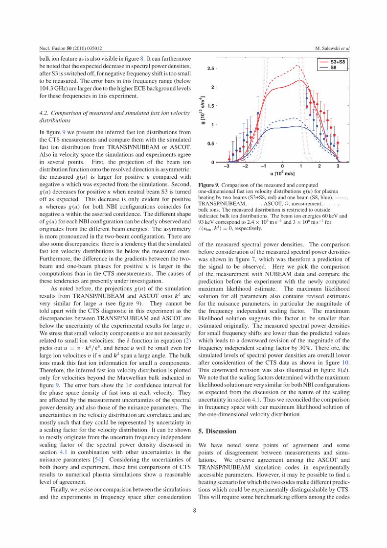
In figure 9 we present the inferred fast ion distributions fromthe CTS measurements and compare them with the simulatedfast ion distribution from TRANSP/NUBEAM or ASCOT.Also in velocity space the simulations and experiments agreein several points. First, the projection of the beam iondistribution function onto the resolved direction is asymmetric:the measured g(u) is larger for positive u compared withnegative u which was expected from the simulations. Second,g(u) decreases for positive u when neutral beam S3 is turnedoff as expected. This decrease is only evident for positiveu whereas g(u) for both NBI configurations coincides fornegative u within the asserted confidence. The different shapeof g(u) for eachNBI configuration can be clearly observed andoriginates from the different beam energies. The asymmetryis more pronounced in the two-beam configuration. There arealso some discrepancies: there is a tendency that the simulatedfast ion velocity distributions lie below the measured ones.Furthermore, the difference in the gradients between the two-beam and one-beam phases for positive u is larger in thecomputations than in the CTS measurements. The causes ofthese tendencies are presently under investigation.
As noted before, the projections g(u) of the simulationresults from TRANSP/NUBEAM and ASCOT onto kδ arevery similar for large u (see figure 9). They cannot betold apart with the CTS diagnostic in this experiment as thediscrepancies between TRANSP/NUBEAM and ASCOT arebelow the uncertainty of the experimental results for large u.We stress that small velocity components u are not necessarilyrelated to small ion velocities: the δ-function in equation (2)picks out u = v · kδ/kδ , and hence u will be small even forlarge ion velocities v if v and kδ span a large angle. The bulkions mask this fast ion information for small u components.Therefore, the inferred fast ion velocity distribution is plottedonly for velocities beyond the Maxwellian bulk indicated infigure 9. The error bars show the 1σ confidence interval forthe phase space density of fast ions at each velocity. Theyare affected by the measurement uncertainties of the spectralpower density and also those of the nuisance parameters. Theuncertainties in the velocity distribution are correlated and aremostly such that they could be represented by uncertainty ina scaling factor for the velocity distribution. It can be shownto mostly originate from the uncertain frequency independentscaling factor of the spectral power density discussed insection 4.1 in combination with other uncertainties in thenuisance parameters [54]. Considering the uncertainties ofboth theory and experiment, these first comparisons of CTSresults to numerical plasma simulations show a reasonablelevel of agreement.
Finally, we revise our comparison between the simulationsand the experiments in frequency space after consideration
–3 –2 –1 0 1 2 30
0.5
1
1.5
2
2.5
u [106 m/s]
g [
1012
s/m
4 ]
S3+S8S8
Figure 9. Comparison of the measured and computedone-dimensional fast ion velocity distributions g(u) for plasmaheating by two beams (S3+S8, red) and one beam (S8, blue). ——,TRANSP/NUBEAM; - - - -, ASCOT; ◦, measurement; · · · · · ·,bulk ions. The measured distribution is restricted to outsideindicated bulk ion distributions. The beam ion energies 60 keV and93 keV correspond to 2.4× 10⁶ m s−1 and 3× 10⁶ m s−1 for� (vion, kδ) = 0, respectively.
of the measured spectral power densities. The comparisonbefore consideration of the measured spectral power densitieswas shown in figure 7, which was therefore a prediction ofthe signal to be observed. Here we pick the comparisonof the measurement with NUBEAM data and compare theprediction before the experiment with the newly computedmaximum likelihood estimate. The maximum likelihoodsolution for all parameters also contains revised estimatesfor the nuisance parameters, in particular the magnitude ofthe frequency independent scaling factor. The maximumlikelihood solution suggests this factor to be smaller thanestimated originally. The measured spectral power densitiesfor small frequency shifts are lower than the predicted valueswhich leads to a downward revision of the magnitude of thefrequency independent scaling factor by 30%. Therefore, thesimulated levels of spectral power densities are overall lowerafter consideration of the CTS data as shown in figure 10.This downward revision was also illustrated in figure 8(d).We note that the scaling factors determined with the maximumlikelihood solution are very similar for bothNBI configurationsas expected from the discussion on the nature of the scalinguncertainty in section 4.1. Thus we reconciled the comparisonin frequency space with our maximum likelihood solution ofthe one-dimensional velocity distribution.
5. Discussion
We have noted some points of agreement and somepoints of disagreement between measurements and simu-lations. We observe agreement among the ASCOT andTRANSP/NUBEAM simulation codes in experimentallyaccessible parameters. However, it may be possible to find aheating scenario forwhich the two codesmakedifferent predic-tions which could be experimentally distinguishable by CTS.This will require some benchmarking efforts among the codes
8

Nucl. Fusion 50 (2010) 035012 M. Salewski et al
103 104 105 106 107
5
10
15
20
νs [GHz]
Sp
ectr
al p
ow
er d
ensi
ty [
eV]
S3+S8S8
Figure 10. Comparison of measured and synthetic CTS spectra fordischarge 24089 for auxiliary heating with two NBI sources (S3+S8,red) and one NBI source (S8, blue). ——, TRANSP/NUBEAMbefore consideration of the CTS data; — ·—, TRANSP/NUBEAMafter consideration of the CTS data consistent with thecorresponding g(u) from figure 9; ◦, measurement; · · · · · ·,gyrotron frequency.
and additional CTS experiments which is beyond the scopeof this work. In future experiments the results of simulationscould be compared with CTS measurements for several loca-tions in the plasma and several resolved directions for variousheating scenarios. Furthermore, it will be feasible to reducethe uncertainties of the CTS measurements. Recent modifica-tions of the CTS receiver will allow the spectral power densityto be measured with higher accuracy. Additionally, CTS dataanalysis will benefit from more accurate measurements of thenuisance parameters. In this work the full capabilities of theCTS system have not yet been fully exploited: the signal-to-noise ratio has been increased at the expense of time resolu-tion. In future experiments it may be possible to inject highergyrotron powers [52] which may improve the signal-to-noiseratio and thus enable us to increase the time resolution. Thismay allow detailed studies of plasma dynamics on millisecondtime scales by CTS—the results of whichmay be interesting tocompare with numerical simulations. It would also be of con-siderable benefit to add a second receiver to the CTS systemat ASDEX Upgrade. A second receiver located in a differ-ent port would enable CTS measurements resolving simulta-neously two directions and would allow a reconstruction oftwo-dimensional fast ion velocity distribution functions [55].
6. Conclusions
The fast ion populations in the plasma centre of ASDEXUpgrade were compared for two-NBI configurations: oneneutral beam versus two neutral beams. One-dimensionalfast ion velocity distributions g(u) were inferred for bothNBI configurations. The inferred g(u) and the measuredCTS spectra for both heating regimes have different shapesand can, as expected, clearly be distinguished. TheCTS measurements were compared with simulations usingthe TRANSP/NUBEAM and ASCOT codes. Salient
features of the measured spectral power densities and one-dimensional fast ion velocity distributions are in reasonableagreement with the simulations within the limits of thegiven uncertainties. Quantitative discrepancies betweenmeasurement and simulation in absolute values and gradientswere observed which will drive future activities in thedevelopment of the diagnostic and the codes.
Acknowledgments
This work, supported by the European Communities under thecontract of Association between EURATOM and Risø DTU,was partly carried out within the framework of the EuropeanFusion Development Agreement. The views and opinionsexpressed herein do not necessarily reflect those of theEuropean Commission. The computing facilities of theFinnish IT Centre for Science (CSC) used in this work aregratefully acknowledged. This work was partially funded byThe Finnish Academy project No 121371.
References
[1] Herrmann A. and Gruber O. 2003 Fusion Sci. Technol.44 569–77
[2] Gruber O. et al 2007 Nucl. Fusion 47 S622–34[3] Chen L. 1994 Phys. Plasma 1 1519–22[4] Briguglio S. et al 2007 Phys. Plasma 14 055904–055904[5] Heidbrink W.W. and Sadler G.J. 1994 Nucl. Fusion 34 535[6] Zweben S.J. et al 2000 Nucl. Fusion 40 91–149[7] Heidbrink W.W. 2002 Phys. Plasma 9 2213–9[8] Pinches S.D. et al 2004 Plasma Phys. Control. Fusion
46 B187–B200[9] Campbell D.J. et al 1988 Phys. Rev. Lett. 60 2148–51[10] Marcus F.B. et al 1994 Nucl. Fusion 34 687–701[11] Kolesnichenko Y.I., Lutsenko V.V., White R.B. and
Yakovenko Y.V. 2000 Nucl. Fusion 40 1325–41[12] Graves J. et al 2005 Plasma Phys. Control. Fusion 47 B121–33[13] Chang Z. et al 1996 Phys. Rev. Lett. 76 1071[14] Nazikian R. et al 1996 Phys. Plasma 3 593–605[15] Garcıa-Munoz M. et al 2007 Nucl. Fusion 47 L10–5[16] Garcıa-Munoz M. et al 2008 Phys. Rev. Lett. 100 055005[17] Gunter S. et al 2007 Nucl. Fusion 47 920–8[18] Hauff T., Pueschel M.J., Dannert T. and Jenko F. 2009
Phys. Rev. Lett. 102 075004[19] Heidbrink W.W. et al 2009 Phys. Rev. Lett. 103 175001[20] ITER Physics Expert Group on Energetic Particles, Heating
and Current Drive 1999 Nucl. Fusion 39 2471–95[21] Fasoli A. et al 2007 Nucl. Fusion 47 S264–84[22] Bindslev H. et al 1999 Phys. Rev. Lett. 83 3206–9[23] Bindslev H. et al 2006 Phys. Rev. Lett. 97 205005[24] Nielsen S.K. et al 2008 Phys. Rev. E 77 016407[25] Meo F. et al 2008 Rev. Sci. Instrum. 79 10E501[26] Meo F. et al 2010 First results and analysis of collective
Thomson scattering (CTS) fast ion distributionmeasurements on ASDEX Upgrade 14th Int. Symp. onLaser-Aided Plasma Diagnostics J. Phys.: Conf. Ser.submitted
[27] Bindslev H. et al 2004 Rev. Sci. Instrum. 75 3598–600[28] Meo F. et al 2004 Rev. Sci. Instrum. 75 3585–8[29] Korsholm S.B. et al 2008 Burning plasma diagnostics
AIP Conf. Proc. 988 118–22[30] Salewski M. et al 2008 Rev. Sci. Instrum. 79 10E729[31] Salewski M. et al 2009 Plasma Phys. Control. Fusion
51 035006[32] Leipold F. et al 2009 Rev. Sci. Instrum. 80 093501[33] Machuzak J. et al 1997 Rev. Sci. Instrum. 68 458–61[34] Tartari U. et al 2006 Nucl. Fusion 46 928
9

Nucl. Fusion 50 (2010) 035012 M. Salewski et al
[35] Westerhof E. et al 2009 Phys. Rev. Lett. 103 125001[36] Nishiura M. et al 2008 Rev. Sci. Instrum. 79 10E731[37] Suvorov E. et al 1995 Plasma Phys. Control. Fusion 37 1207[38] Bindslev H. 1993 Plasma Phys. Control. Fusion 35 1615–40[39] Bindslev H. 1996 J. Atmos. Terr. Phys. 58 983[40] Budny R.V. et al 1995 Nucl. Fusion 35 1497[41] Pankin A., McCune D., Andre R. and Kritz A. 2004 Comput.
Phys. Commun. 159 157–84[42] Heikkinen J.A. and Sipila S.K. 1995 Phys. Plasma 2 3724–33[43] Heikkinen J.A. et al 2001 J. Comput. Phys. 173 527–48[44] Streibl B. et al 2003 Fusion Sci. Technol. 44 578–92[45] Murmann H. et al 1992 Rev. Sci. Instrum. 63 4941–3[46] Fischer R., Dinklage A. and Pasch E. 2003 Plasma Phys.
Control. Fusion 45 1095–111
[47] Fischer R. et al 2008 Plasma Phys. Control. Fusion50 085009
[48] Fischer R. et al 2008 Integrated density profile analysis inASDEX upgrade H-modes Europhys. Conf. Abstractsvol 32D p P4.010
[49] Fischer R. et al 2009 Multiple diagnostic data analysis ofdensity and temperature profiles in ASDEX UpgradeEurophys. Conf. Abstracts vol 33E P1.159
[50] Dux R. 2003 Fusion Sci. Technol. 44 708–15[51] Salpeter E.E. 1960 Phys. Rev. 120 1528–35[52] Wagner D.H. et al 2008 IEEE Trans. Plasma Sci. 36 324–31[53] Salewski M. et al 2009 Nucl. Fusion 49 025006[54] Bindslev H. 1999 Rev. Sci. Instrum. 70 1093–9[55] Egedal J. and Bindslev H. 2004 Phys. Plasma 11 2191–8
10