Influence of Free Ferrite Content on the Machinability of GCI ...
TECHNICAL PAPER
Comparative study of the machinability of austemperedand pearlitic ductile irons in drilling process
Patrıcia Alves Barbosa • Eder Silva Costa •
Wilson Luiz Guesser • Alisson Rocha Machado
Received: 15 May 2012 / Accepted: 2 April 2013 / Published online: 27 March 2014
� The Brazilian Society of Mechanical Sciences and Engineering 2014
Abstract The aim of this work is to analyze the aus-
tempered ductile iron (ADI) feasibility to substitute the
conventional ductile iron in automotive components man-
ufacture. This analysis was based on machinability criteria
comparison of thrust force, torque and cutting power of two
ADI grades (ISO 800-10 and ISO 1.050-6) with FE 70003
pearlitic ductile iron as-cast. Cutting speed, feed rate and
cutting fluid application technique, besides the work
material, were varied in the drilling tests. The tool used in
the tests was the K20 cemented carbide twist drill coated
with multilayers of TiN/TiAlN with diameter of 10 mm.
The results showed that the ISO 800-10 ADI grade was the
material with highest machinability followed by FE 70003
pearlitic ductile iron as-cast and then by ISO 1.050-6 ADI
grade. It was concluded that the machinability of the
materials studied is thereafter closely related to their
microstructures. Therefore, ADIs obtained by DI partially
austenitized have excellent potential to substitute ductile
irons based on the machinability criteria evaluated.
Keywords Machinability � Drilling process �Austempered ductile iron � Pearlitic ductile iron
Abbreviations
ADI Austempered ductile iron
ANOVA Analyses of variance
DI Ductile cast iron; Pearlitic ductile iron
f Feed rate, mm/rev
FZ Thrust force, N
Lf Feed length, mm
MQF Minimum quantity of fluid
MZ Torque, Nm
p Significance level
Pc Cutting power consumption, W
Vc Cutting speed, m/min
1 Introduction
In the industry, increasing demands for new engineering
materials are driven by the cost as well as the ‘‘strength to
weight ratio’’. In the effort to achieve these requirements
metallurgists either apply new materials with similar
strengths but lower densities, or increase the strength of
traditional material by alloying or by heat treatment. The
option chosen depends on parameters such as the
mechanical and thermal loads or on boundary conditions
such as manufacturing costs, recyclability, public accep-
tance and machinability [12]. In this list are the cast irons,
which almost always offer good machinability and low
manufacturing cost. In this regard, heat treatment of ductile
Technical Editor: Alexandre Abrao.
P. A. Barbosa (&) � E. S. Costa � A. R. Machado
Department of Mechanical Engineering, Federal University of
Uberlandia, Uberlandia, MG 38408-902, Brazil
e-mail: [email protected]
E. S. Costa
e-mail: [email protected]
A. R. Machado
e-mail: [email protected]
W. L. Guesser
Tupy S.A., Joinville, SC 89206-900, Brazil
e-mail: [email protected]
W. L. Guesser
Center of Technological Sciences, Santa Catarina State
University, Joinville, SC 89223-100, Brazil
123
J Braz. Soc. Mech. Sci. Eng. (2015) 37:115–122
DOI 10.1007/s40430-014-0161-z
cast irons using different routes offers a wide range of
properties through matrix microstructure control, making
these cast irons very efficient materials [25].
The history of ductile cast iron (DI), also known as
nodular, has been influenced by a large number of technical
developments that have resulted in materials offering new
business opportunities for the foundry industry [13, 29]. DI
presents good castability, damping capacity, and mechan-
ical properties [high ductility (up to more than 18 %), high
toughness, and high strength (up to 850 MPa)] as well as
acceptable machinability [5]. Because of these good
properties, nodular cast iron has been used in many struc-
tural applications. Camshafts, crankshafts, brake disks,
pump cases, steering parts are major examples of vehicles
parts made of ductile iron [25]. Usually, the nodular can be
machined with the same techniques used for the gray cast
irons due to its similar behavior during machining, despite
the best mechanical properties in relation to the latter [26].
Austempered ductile iron (ADI) is a heat-treated ductile
iron, which was developed quite recently. Due to its
attractive properties such as good ductility, substantial
toughness, good wear resistance and high fatigue strength
with low cost [4, 18–20], ADI has rapidly emerged as an
important engineering material. Nowadays, ADI is con-
stantly used in automotive, military, earth moving and
agricultural equipment, and railway industries. ADI is used
in many structural applications, in situations involving
impact, fatigue and wear, such as in spring hanger of
trucks, transport components in coal mining and gear [3,
11, 14]. In the automotive industry, ADI is widely used for
the manufacturing of chassis and suspension system parts,
as well as engine components, such as crankshafts, valves
and connecting rods [27].
Regarding to contact fatigue strength, Dommarco and
Sanvande [9] investigated the resistance of ADI and
found great influence of the austempering temperature.
Higher hardness and contact fatigue strength were
observed in the ADI austempered at a lower temperature
of 240 �C (compared to samples austempered at up to
300 �C). Brunetti et al. [3], however, point out that the
specimen preparation mode (whether gridding or polish-
ing) has an influence on the results when using ball-on-
flat test system. Higher strength was found for polished
specimens.
As to abrasive wear resistance of ductile cast iron, Velez
et al. [28] have studied the performance of several cast
irons with different matrix microstructures (ferrite, pearlite,
bainite and martensite) in a single pass pendulum device,
and found that the resistances of the materials depend on
their mechanical properties and test conditions. Pearlite
matrix showed best performance among materials with
hardness up to 300 HV; bainite was the best material
among those with hardness up to 450 HV and materials
with hardness above 500 HV; the martensite did not per-
form well due to its lack of toughness. Sahin et al. [20] also
studied the abrasive wear behavior of ductile iron and the
mechanisms involved in pin-on-disk tests. Several dual
matrix structures were investigated (austempered and
quenched). The abrasive wear resistance was higher for the
austempered specimens than for the quenched ones. In all
the austempered specimens, the abrasive wear increased
with austempering time.
As compared to conventional ductile iron and steels with
similar strengths, ADI has shown several economic
advantages, namely, in automotive industry [16]. However,
it is very difficult to machine due to its relatively high
hardness, which derives from its particular microstructure
obtained after heat treatment [7, 10]. Another fact that can
account for the poor machinability of ADI is the presence
of retained austenite in its microstructure. The content of
this retained austenite increases with reduced austempering
time [4]. Retained austenite can be transformed into mar-
tensite during machining [23]. Because of this poor
machinability, Brandenberg (2001, apud [2]) suggests to
machine ADI components in three different routes: (1)
machining before heat treatment, (2) rough machining prior
to heat treatment and finish machining thereafter, and (3)
machining after heat treatment. The choice among these
various ways depends upon the dimensional requirements,
costs and manufacturing time. An alternative to the tradi-
tional austempering heat treatment would be to perform
partial austenitizing so that the final microstructure would
consist of primary ferrite and ausferrite. Such dual micro-
structure will then allow an affordable machinability of
ADI components [14]. This novel heat treatment of ADI
together with many other possible options of controlling
the ADI microstructure has stimulated research on the
machinability of ADI.
Among all the conventional machining processes
involved in the manufacturing industry, about 25 % of
machining time is spent on drilling operations [22]. This
shows that drilling is one of the most important
machining processes in the manufacturing industry.
Accordingly, researches on the machinability of ADI,
particularly in the drilling process [17, 25], are thus of
utmost importance for the automotive industry in the
context where ADI is proposed as an alternative material
to nodular cast iron.
The graphite particles embedded in the microstructure of
cast irons act already as a solid lubricant during machining.
Thus, in cast iron machining, cutting fluids are not usually
recommended, due to their many environmental hazards.
However, mineral oil emulsions are still recommended for
drilling. They can be useful for cooling and helping chip
removal from the cutting area. Since the thermal conduc-
tivity of ADI is lower than that of many steels, cutting fluid
116 J Braz. Soc. Mech. Sci. Eng. (2015) 37:115–122
123
application during drilling would be required to reduce the
temperature ahead of cutting area [2].
Knowledge of drilling forces is of major significance,
because they can affect the cutting power, the ability to
achieve tight tolerances, as well as the cutting temperature
and tool wear [8]. During metal cutting, a drill is basically
subjected to torsion and compressive stresses due, respec-
tively, to its rotation and thrust motions. Thereby,
machinability study of ADI based on torque and thrust
force (Fz) developed will be particularly relevant for dril-
ling operations.
In this sense, the aim of the present work is to analyze
the ADI feasibility to substitute the conventional ductile
iron in automotive components manufacture. This analysis
was based on machinability criteria comparison of thrust
force, torque (MZ), and cutting power (Pc) of two ADI
grades (ISO 1.050-6 and ISO 800-10) with FE 70003
pearlitic ductile iron as-cast. The first ADI is composed of
an ausferrite matrix, while the second ADI has a dual
ferrite—ausferrite matrix. The cutting conditions (cutting
speed, and feed rate), cutting fluid application technique,
and work material were varied in drilling tests.
2 Materials and methods
2.1 Workpieces and cutting condition
Workpieces of nodular cast irons, whose chemical com-
position is shown in Table 1, were used under three dif-
ferent matrix types:
• DI (FE 70003): pearlitic ductile iron as-cast;
• ADI I (ISO 1.050-6 ADI): pearlitic ductile iron fully
austenitized at 900 �C for 2 h and austempered at 360 �C
for 2 h;
• ADI II (ISO 800-10 ADI): pearlitic ductile iron par-
tially austenitized into critical zone at 780 �C for 5 h and
austempered at 360 �C for 2 h.
The austempering temperature was kept constant at
360 �C to maintain similar microstructural features of
ausferrite in ADIs. Mo and Cu were introduced in the
chemical composition of nodular cast irons to provide
hardenability (Table 1).
Bars of 104-mm diameter were produced by continuous
casting by Tupy S.A. Disk samples with thickness of
32 mm were cut out of these bars. Thereafter, these disk
samples were faced on a lathe to maintain a standard
thickness of 30 mm. This facing helped avoiding the
slippage of drills at the beginning of the drilling operation.
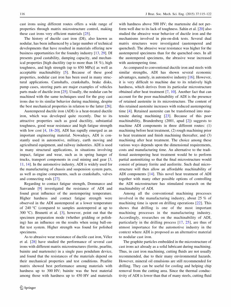
Table 2 shows the matrix type, graphite characteriza-
tion, and hardness of the work materials used in the current
investigation studied. Figure 1 shows the typical micro-
structures of them.
TiN/TiAlN multilayers coated K20 grade Sandvik Cor-
omant CoroDrill� Delta C-840 cemented carbide twist
drills with diameter of 10 mm, helix and point angles of
30.6 � and 143 �, respectively, were used for all the
experiments. In each drilling test, a new tool was used.
2.2 Experimental procedure
The drilling tests were carried out in a Discovery 760—
Romi CNC machine center. This machine tool has 15 kVA
of the apparent power, and 10,000 rpm of maximum
spindle rotation speed. The trials followed two full factorial
planning 24, considering two quantitative variables [cutting
speed (Vc) and feed rate (f)], and two qualitative variables
(work material and cutting fluid application technique).
The first full factorial planning and the analyses of variance
(ANOVA) by Statistica 6.0 software were used to compare
the machinability of the two ADI grades and the significant
variables effects on the test responses evaluated with a
confidence interval of 95 and 5 % of significance level.
Then, results from each ADI grade were compared to those
from as-cast pearlitic ductile iron. Table 3 shows the input
variables at two levels.
Table 1 Pearlitic ductile
iron—FE 70003—chemical
composition (%wt)
C Si Mn P S Cr Cu Mo Mg
3.600 2.500 0.250 0.050 0.015 0.060 0.460 0.23 0.040–0.050
Table 2 Matrix type, graphite
characterization and Brinell
hardness of work materials
Material Matrix type Graphite Brinell
hardness
Shape Nodularity
(%)
Nodule
(p/mm2)
Grain
size
HB 5/750
DI FE 70003 Pearlite with *2 % of ferrite VI 90 182 5–6 269
ADI I ISO 1.050-6 Ausferrite VI 90 195 5–6 288
ADI II ISO 800-10 Ausferrite with ferrite and
residual spheroidized perlite
VI 90 218 5–6 203
J Braz. Soc. Mech. Sci. Eng. (2015) 37:115–122 117
123
Through holes were machined with total feed length (Lf)
of 35 mm to allow the main cutting edges of the drill to
exit completely out of the button face of the disks (5 mm).
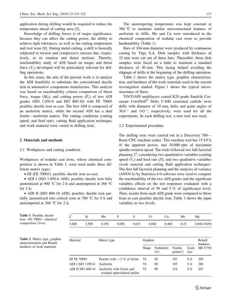
Thrust force (Fz) and torque (MZ) were online monitored
during drilling tests with a Kistler type 9123C rotating
dynamometer using a Kistler type 5223 signals conditioner
and Labview� 6.5 signal processing software by National
Instrument Brazil Ltd, in an acquisition rate of 2 kHz. The
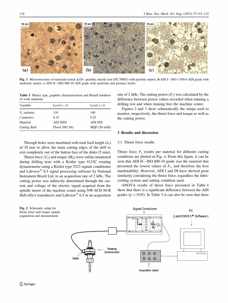
cutting power was indirectly determined through the cur-
rent and voltage of the electric signal acquired from the
spindle motor of the machine center using NW-SCD-50-R
Hall-effect transducers and Labview� 6.5 in an acquisition
rate of 2 kHz. The cutting power (Pc) was calculated by the
difference between power values recorded when running a
drilling test and when running free the machine center.
Figures 2 and 3 show schematically the setups used to
monitor, respectively, the thrust force and torque as well as
the cutting power.
3 Results and discussion
3.1 Thrust force results
Thrust force Fz results per material for different cutting
conditions are plotted in Fig. 4. From this figure, it can be
seen that ADI II—ISO 800-10 grade was the material that
presented the lowest values of Fz, and therefore the best
machinability. However, ADI I and DI have showed great
similarity considering the thrust force, regardless the lubri-
cooling system and cutting condition used.
ANOVA results of thrust force presented in Table 4
show that there is a significant difference between the ADI
grades (p \ 0.05). In Table 5 it can also be seen that there
Fig. 1 Microstructures of materials tested: a DI—pearlitic ductile iron (FE 70003) with pearlitic matrix; b ADI I—ISO 1.050-6 ADI grade with
ausferrite matrix; c ADI II—ISO 800-10 ADI grade with ausferrite and primary ferrite
Table 3 Matrix type, graphite characterization and Brinell hardness
of work materials
Variable Level (-1) Level (?1)
Vc (m/min) 110 140
f (mm/rev) 0.15 0.25
Material ADI II/DI ADI I/DI
Cutting fluid Flood (982 l/h) MQF (50 ml/h)
Fig. 2 Schematic setup for
thrust force and torque signals
acquisition and measurement
118 J Braz. Soc. Mech. Sci. Eng. (2015) 37:115–122
123
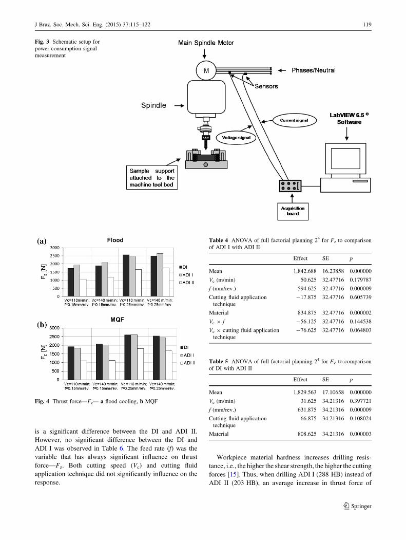
is a significant difference between the DI and ADI II.
However, no significant difference between the DI and
ADI I was observed in Table 6. The feed rate (f) was the
variable that has always significant influence on thrust
force—Fz. Both cutting speed (Vc) and cutting fluid
application technique did not significantly influence on the
response.
Workpiece material hardness increases drilling resis-
tance, i.e., the higher the shear strength, the higher the cutting
forces [15]. Thus, when drilling ADI I (288 HB) instead of
ADI II (203 HB), an average increase in thrust force of
Fig. 3 Schematic setup for
power consumption signal
measurement
Fig. 4 Thrust force—Fz— a flood cooling, b MQF
Table 4 ANOVA of full factorial planning 24 for Fz to comparison
of ADI I with ADI II
Effect SE p
Mean 1,842.688 16.23858 0.000000
Vc (m/min) 50.625 32.47716 0.179787
f (mm/rev.) 594.625 32.47716 0.000009
Cutting fluid application
technique
-17.875 32.47716 0.605739
Material 834.875 32.47716 0.000002
Vc 9 f -56.125 32.47716 0.144538
Vc 9 cutting fluid application
technique
-76.625 32.47716 0.064803
Table 5 ANOVA of full factorial planning 24 for FZ to comparison
of DI with ADI II
Effect SE p
Mean 1,829.563 17.10658 0.000000
Vc (m/min) 31.625 34.21316 0.397721
f (mm/rev.) 631.875 34.21316 0.000009
Cutting fluid application
technique
66.875 34.21316 0.108024
Material 808.625 34.21316 0.000003
J Braz. Soc. Mech. Sci. Eng. (2015) 37:115–122 119
123
835 N should be expected (Table 4). Likewise, when
machining DI (269 HB) instead of ADI II (203 HB), an
average rise of Fz about 809 N should be expected (Table 5).
The feed rate influence on thrust force was clear and within
expectation. The higher the feed rate, the higher the thrust
force. Increasing feed rate (f) increases the areas of the primary
and secondary shear planes. Higher forces and power are thus
required to form the chip. The feed velocity is also increased in
a direct proportion, thereby also contributing to the increase of
thrust force. Accordingly, the increase of feed rate from 0.15
to 0.25 mm/rev should raise the thrust force by about 595 N
when comparing the two ADI grades (Table 4), by about
632 N when comparing DI and ADI II (Table 5), and by about
614 N when comparing DI and ADI I.
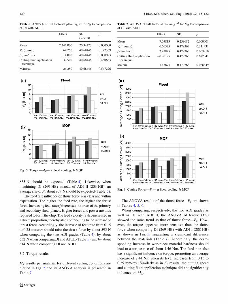
3.2 Torque results
MZ results per material for different cutting conditions are
plotted in Fig. 5 and its ANOVA analysis is presented in
Table 7.
The ANOVA results of the thrust force—Fz are shown
in Tables 4, 5, 6.
When comparing, respectively, the two ADI grades as
well as DI with ADI II, the ANOVA of torque (MZ)
showed the same trend as that of thrust force—Fz. How-
ever, the torque appeared more sensitive than the thrust
force when comparing DI (269 HB) with ADI I (288 HB)
as shown in Fig. 5, suggesting a significant difference
between the materials (Table 7). Accordingly, the corre-
sponding increase in workpiece material hardness should
lead to a torque rise of about 1.46 Nm. The feed rate also
has a significant influence on torque, promoting an average
increase of 2.44 Nm when its level increases from 0.15 to
0.25 mm/rev. Similarly as in Fz results, the cutting speed
and cutting fluid application technique did not significantly
influence on MZ.
Table 6 ANOVA of full factorial planning 24 for FZ to comparison
of DI with ADI I
Effect SE
(Rev B)
p
Mean 2,247.000 20.34223 0.000000
Vc (m/min) 64.750 40.68446 0.172369
f (mm/rev.) 614.000 40.68446 0.000023
Cutting fluid application
technique
32.500 40.68446 0.460633
Material -26.250 40.68446 0.547226
Fig. 5 Torque—MZ— a flood cooling, b MQF
Table 7 ANOVA of full factorial planning 24 for MZ to comparison
of DI with ADI I
Effect SE p
Mean 7.03813 0.239682 0.000001
Vc (m/min) 0.50375 0.479363 0.341431
f (mm/rev.) 2.43875 0.479363 0.003810
Cutting fluid application
technique
-0.20125 0.479363 0.692041
Material 1.45875 0.479363 0.028649
Fig. 6 Cutting Power—Pc— a flood cooling, b MQF
120 J Braz. Soc. Mech. Sci. Eng. (2015) 37:115–122
123
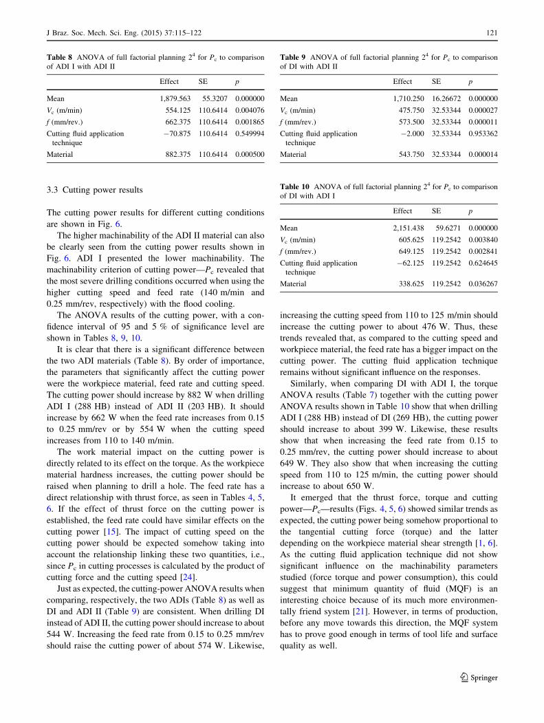
3.3 Cutting power results
The cutting power results for different cutting conditions
are shown in Fig. 6.
The higher machinability of the ADI II material can also
be clearly seen from the cutting power results shown in
Fig. 6. ADI I presented the lower machinability. The
machinability criterion of cutting power—Pc revealed that
the most severe drilling conditions occurred when using the
higher cutting speed and feed rate (140 m/min and
0.25 mm/rev, respectively) with the flood cooling.
The ANOVA results of the cutting power, with a con-
fidence interval of 95 and 5 % of significance level are
shown in Tables 8, 9, 10.
It is clear that there is a significant difference between
the two ADI materials (Table 8). By order of importance,
the parameters that significantly affect the cutting power
were the workpiece material, feed rate and cutting speed.
The cutting power should increase by 882 W when drilling
ADI I (288 HB) instead of ADI II (203 HB). It should
increase by 662 W when the feed rate increases from 0.15
to 0.25 mm/rev or by 554 W when the cutting speed
increases from 110 to 140 m/min.
The work material impact on the cutting power is
directly related to its effect on the torque. As the workpiece
material hardness increases, the cutting power should be
raised when planning to drill a hole. The feed rate has a
direct relationship with thrust force, as seen in Tables 4, 5,
6. If the effect of thrust force on the cutting power is
established, the feed rate could have similar effects on the
cutting power [15]. The impact of cutting speed on the
cutting power should be expected somehow taking into
account the relationship linking these two quantities, i.e.,
since Pc in cutting processes is calculated by the product of
cutting force and the cutting speed [24].
Just as expected, the cutting-power ANOVA results when
comparing, respectively, the two ADIs (Table 8) as well as
DI and ADI II (Table 9) are consistent. When drilling DI
instead of ADI II, the cutting power should increase to about
544 W. Increasing the feed rate from 0.15 to 0.25 mm/rev
should raise the cutting power of about 574 W. Likewise,
increasing the cutting speed from 110 to 125 m/min should
increase the cutting power to about 476 W. Thus, these
trends revealed that, as compared to the cutting speed and
workpiece material, the feed rate has a bigger impact on the
cutting power. The cutting fluid application technique
remains without significant influence on the responses.
Similarly, when comparing DI with ADI I, the torque
ANOVA results (Table 7) together with the cutting power
ANOVA results shown in Table 10 show that when drilling
ADI I (288 HB) instead of DI (269 HB), the cutting power
should increase to about 399 W. Likewise, these results
show that when increasing the feed rate from 0.15 to
0.25 mm/rev, the cutting power should increase to about
649 W. They also show that when increasing the cutting
speed from 110 to 125 m/min, the cutting power should
increase to about 650 W.
It emerged that the thrust force, torque and cutting
power—Pc—results (Figs. 4, 5, 6) showed similar trends as
expected, the cutting power being somehow proportional to
the tangential cutting force (torque) and the latter
depending on the workpiece material shear strength [1, 6].
As the cutting fluid application technique did not show
significant influence on the machinability parameters
studied (force torque and power consumption), this could
suggest that minimum quantity of fluid (MQF) is an
interesting choice because of its much more environmen-
tally friend system [21]. However, in terms of production,
before any move towards this direction, the MQF system
has to prove good enough in terms of tool life and surface
quality as well.
Table 8 ANOVA of full factorial planning 24 for Pc to comparison
of ADI I with ADI II
Effect SE p
Mean 1,879.563 55.3207 0.000000
Vc (m/min) 554.125 110.6414 0.004076
f (mm/rev.) 662.375 110.6414 0.001865
Cutting fluid application
technique
-70.875 110.6414 0.549994
Material 882.375 110.6414 0.000500
Table 9 ANOVA of full factorial planning 24 for Pc to comparison
of DI with ADI II
Effect SE p
Mean 1,710.250 16.26672 0.000000
Vc (m/min) 475.750 32.53344 0.000027
f (mm/rev.) 573.500 32.53344 0.000011
Cutting fluid application
technique
-2.000 32.53344 0.953362
Material 543.750 32.53344 0.000014
Table 10 ANOVA of full factorial planning 24 for Pc to comparison
of DI with ADI I
Effect SE p
Mean 2,151.438 59.6271 0.000000
Vc (m/min) 605.625 119.2542 0.003840
f (mm/rev.) 649.125 119.2542 0.002841
Cutting fluid application
technique
-62.125 119.2542 0.624645
Material 338.625 119.2542 0.036267
J Braz. Soc. Mech. Sci. Eng. (2015) 37:115–122 121
123
4 Conclusions
The thrust force, torque and cutting power increased in the
following order of the workpiece materials tested: ADI II,
DI and ADI I. This sequence respects the hardness
increasing order of these materials (203, 269, and 288 HB).
ADI II which presents a dual matrix of primary ferrite and
ausferrite outperforms the two other workpiece materials
with regard to machinability in drilling process. Thus,
partially austenitized ADIs are contribution that should
guide and strengthen the plans of substituting, at least in
the automotive industry, pearlitic ductile iron to ADI.
ANOVA analyses allowed identifying the material
machinability differences, showing also that feed rate is the
most impacting cutting parameter on the output variables
investigated.
In spite of cutting fluid application is required during
ADI drilling to reduce the temperature ahead of the cutting
area, statistically it did not affect thrust force, torque and
cutting power results significantly. The different techniques
evaluated showed similar results. MQF system is likely to
be the choice if only environmental approach is the goal.
However, in terms of productivity other machinability
criteria, such as tool life and surface roughness should also
be considered before any decision.
Acknowledgments The authors are grateful to Capes, CNPq, Fap-
emig, and IFM for their financial supports. They are also indebted to
Tupy S.A., Sandvik do Brazil S.A., and LEPU/UFU for providing,
respectively, the work materials, cutting tools and infrastructure
necessary for handling this research.
References
1. Astakhov VP (2005) Tribology of metal cutting. Elsevier Ltd,
Oxford 419
2. Avishan B, Yazdani S, Jalali Vahid D (2009) The influence of
depth of cut on the machinability of an alloyed austempered
ductile iron. Mater Sci Eng A 523:93–98
3. Brunetti C, Leite MV, Pintaude G (2007) Effect of specimen
preparation on contact fatigue wear resistance of austempered
ductile cast iron. Wear 263:663–668
4. Cakir MC, Bayram A, Isik Y, Salar B (2005) The effects of
austempering temperature and time onto the machinability of
austempered ductile iron. Mater Sci Eng A 407:147–153
5. Cavallini M, Di Bartolomeo O, Iacoviello F (2008) Fatigue crack
propagation damaging micromechanisms in ductile cast irons.
Eng Fract Mech 75:694–704
6. Childs T, Maekawa K, Obikawa T, Yamane Y (2005) Metal
machining-theory and applications. Arnold publishers, London
408
7. Da Silva D, Hupalo MF, Ferrer MH, De Lima NB (2007) Aus-
tempering condition effects on microstructure of ductile cast iron
grade ferritic-pearlitic (In Portuguese). In: Proceedings of the 8�Congresso Ibero Americano de Engenharia Mecanica, Cusco,
pp 1255–1262
8. Diniz AE, Marcondes FC, Coppini NL (2008) Tecnologia Da
Usinagem Dos Materiais. Artliber Editora, Sao Paulo 262
9. Dommarco RC, Sanvande JD (2003) Contact fatigue resistance of
austempered and partially chilled ductile irons. Wear 254:230–236
10. Erdogan M, Kilidi V, Demir B (2009) Transformation charac-
teristics of ductile iron austempered from intercritical austeni-
tizing temperature ranges. J Mater Sci 44:1394–1403
11. Guesser WL, Guedes LC (1997) Recents developments in cast
irons applied in automotive industry (In Portuguese). In: Pro-
ceedings of the IX symposium on automotive engineering, vol 8.
Sao Paulo, Brazil
12. Klocke F, Kloppe C, Lung D, Essig C (2007) Fundamental wear
mechanisms when machining austempered ductile iron (ADI).
Ann CIRP 56:73–76
13. Labrecque C, Gagne M (1998) Review ductile iron: fifty years of
continuous development. Can Metall Q 37:343–378
14. Lussoli RJ (2003) Copper addition and parts section effects on
microstructure and mechanical characteristics of austempered
ductile iron (In Portuguese). Ph.D. Thesis, Federal University of
Santa Catarina, Florianopolis, p 85
15. Machado AR, Abrao AM, Coelho RT, da Silva MB (2011) Teoria
da Usinagem dos Materiais. Editora Edgard Blucher, Sao Paulo
371
16. Martins R, Seabra J, Magalhaes L (2008) Austempered ductile
iron (ADI) gears: power loss, pitting and micropitting. Wear
264:838–849
17. Neri MA, Carreno C (2003) Effect of copper content on the
microstructure and mechanical properties of a modified nodular
iron. Mater Charact 51:219–224
18. Nili Ahmadabadi M, Ghasemi HM, Osia M (1999) Effects of
successive austempering on the tribological behavior of ductile
cast iron. Wear 231:293–300
19. Patatunda SK, Kesani S, Tackett R, Lawes G (2006) Develop-
ment of austenite free ADI (austempered ductile cast iron). Mater
Sci Eng A 435–436:112–122
20. Sahin Y, Kilicli V, Ozer M, Erdagon M (2010) Comparison of
abrasive wear behavior of ductile iron with different dual matrix
structures. Wear 268:153–165
21. Sales WF, Diniz AE, Machado AR (2001) Application of cutting
fluids in machining process. J Braz Soc Mech Sci 23(2):227–240
22. Santos SC (2002) Study of coatings and cutting fluid application
techniques influence on high speed steel and cemented carbide
twist drills performance in gray cast iron machining (In Portu-
guese). Ph.D. Thesis, Federal University of Uberlandia, Uber-
landia, p 200
23. Seah KHW, Sharma SC (1994) Machinability of alloyed aus-
tempered ductile iron. Int J Mach Tools Manufact 35(10):
1475–1479
24. Shaw MC (2005) Metal cutting principles. Oxford University
Press, New York 651
25. Toktas G, Tayanc M, Toktas A (2006) Effect of matrix structure
on the impact properties of an alloyed ductile iron. Mater Charact
57:290–299
26. Trent EM, Wright PK (2000) Metal cutting. Butterworth, Eng-
land 466
27. Tupy S.A. (2013) http://www.tupy.com.br. Accessed 12 Mar
2013
28. Velez JM, Tanaka DK, Sinatora A, Tschiptschin AP (2005)
Evaluation of abrasive wear of ductile cast iron in a single pass
pendulum device. Wear 251:1315–1319
29. Weingaertner WL, Tikal F, Da Silva HR (1997) Ductile cast iron
threading machining (In Portuguese). In: Proceedings of the 14th
Brazilian congress of mechanical engineering, Bauru
122 J Braz. Soc. Mech. Sci. Eng. (2015) 37:115–122
123
Copyright © 2022 FDOKUMEN