Dielectric and magnetic properties of ferrite/poly(vinylidene fluoride) nanocomposites
Upload
khangminh22Category
view
1download
0
Influence of Free Ferrite Content on the Machinability of GCI using CBN Tool
By
Yesong (Luke) Liu, Mechanical. Eng
(McMaster University, Canada)
A Thesis
Submitted to the School of Graduate Studies
in Partial Fulfilment of the Requirements
for the Degree
Master of Applied Science
McMaster University

i
MASTER OF APPLIED SCIENCE (2018) McMaster University
(Mechanical Engineering) Hamilton, Ontario
TITLE: Influence of Free Ferrite Content on the Machinability of GCI using
CBN Tool
AUTHOR: YeSong Liu (McMaster University, Canada)
SUPERVISOR: Dr. Stephen C. Veldhuis
Department of Mechanical Engineering
McMaster University
NUMBER OF PAGES: x, 85

ii
Abstract
Over the years, industrial partners experienced issues related to inconsistent
free ferrite in gray cast iron. In the course of a hot summer and a cold winter,
machinability balance varies up to 350%. During warm months it is better and cold
months worse. The inconsistent machinability increases the scrap rates by up to 400%
and reduces tool life by up to 70%. The ultimate objective of this research is to collaborate
with an automotive industrial partner to investigate the periodic machinability variability
of gray cast iron engine sleeves, with a goal to reduce the cost and scrap rate of tool
inserts. In this study, a significant amount of work was conducted concerning sample
preparation for a metallography check. Samples from different months with varying
amount of “free ferrite” were collected to study the seasonal effect on their machinability
and high-speed machining under similar industrial conditions. Furthermore, a room
temperature age strengthening of gray cast iron was conducted to demonstrate how the
hardness increase from aging could improve the machinability of gray cast iron.
A CBN insert is the second hardest cutting tool after the diamond insert, and is
widely used in industry for machining cast iron. It has a high cutting speed is commonly
used due to its high hardness and impressive wear resistance. It is known that gray cast
iron can naturally age at room temperature or artificially age under a controlled
temperature. Under different aging temperatures and times, gray cast iron exhibits a
greater hardness after age strengthening, which affects the CBN tool life. The latter is
usually limited by flank wear length, however the content of free ferrite in gray cast iron
can generate ferrous built-up on the CBN cutting edge and significantly shorten the tool
life of the CBN cutting tool.
iii
Acknowledgements
First, and the most important, I would like to thank my supervisor, Dr. Stephen
C. Veldhuis. He is my mentor and all of his research guidance supported me during my
study at MMRI. He is patient, kindly and encouraging to myself and all MMRI colleagues
in their life and studies. I would also like to thank all the other amazing and helpful
colleagues at team MMRI.
I’m grateful to the technicians from Material Engineering department, Xiaogang
Li and Doug Culley. Their help with operating all of the equipment supported me in
finishing my research.
I would like to thank Dr. Abul Fazal M. Arif for his detailed and patient guidance
with my entire research organization and thesis writing. Also, great thanks to Simon
Oomen-Hurst for the rich opportunity he provided to me in working on an industrial
project with him. The excellent work experience gained from those projects, benefited
my problem-solving skills.
I would like to acknowledge Ahmed Sweed, Baoqin Deng and Bipasha Bose for
their training and technical support throughout my work.
I would like to acknowledge CANRIMT for their financial contributions.
Lastly, I would like to thank my wife. Her endless love and support throughout
my research as well as daily life, aided me in finishing my study. Without her it wouldn’t
have been possible for me.
iv
Table of Content
Abstract ................................................................................................................................ii
Acknowledgements ............................................................................................................. iii
Table of Content ................................................................................................................. iv
List of Figures ..................................................................................................................... vii
List of Tables ........................................................................................................................ x
Chapter 1: Introduction............................................................................................... 1
1.1. Gray Cast Iron .................................................................................................... 1
1.2. Phenomenon of Age Strengthening .................................................................. 2
1.3. Seasonal Effect .................................................................................................. 3
1.4. Objectives and Motivation ................................................................................ 3
1.4.1. Objectives .................................................................................................. 3
1.4.2. Motivation ................................................................................................. 4
1.5. Methodology ..................................................................................................... 4
1.6. Thesis Outline .................................................................................................... 5
Chapter 2: Literature Review ...................................................................................... 6
2.1. Cast Iron............................................................................................................. 6
2.1.1. Classification – Gray Cast Iron ................................................................... 6
2.1.2. Microstructure of GCI ................................................................................ 8
2.1.3. GCI Chemical Composition ...................................................................... 13
2.1.4. GCI Cooling Rate ...................................................................................... 15
2.1.5. Mechanical Properties ............................................................................ 16
2.2. Age Strengthening ........................................................................................... 18
2.2.1. Effect of Aging Temperature ................................................................... 18

v
2.2.2. Effect of Nitride Precipitation ................................................................. 20
2.2.3. Effect of Alloying Elements ..................................................................... 20
2.2.4. Influence of GCI Aging on Machinability ................................................. 21
2.3. High Speed Machining ..................................................................................... 23
2.3.1. Tools for HSM of GCI ............................................................................... 24
2.4. Metal Cutting Process ..................................................................................... 26
2.4.1. Orthogonal Cutting .................................................................................. 26
2.4.2. Turning .................................................................................................... 27
2.4.3. Tool Wear Mechanisms ........................................................................... 28
Chapter 3: Experimental Work.................................................................................. 32
3.1. Workpiece Materials ....................................................................................... 32
3.1.1. Workpiece Material Characteristics ........................................................ 33
3.1.2. Metallographic Analysis .......................................................................... 33
3.1.3. GCI Skin Layers ........................................................................................ 35
3.1.4. Scanning Electron Microscopy ................................................................ 36
3.1.5. Quantitative Image Analysis .................................................................... 37
3.2. Cutting Tools .................................................................................................... 38
3.3. Experimental Setup ......................................................................................... 39
Chapter 4: Tool Wear Behavior of Varied CBN Composition .................................... 41
4.1. Experimental Procedure .................................................................................. 41
4.2. Results and Discussion .................................................................................... 42
Chapter 5: Effect of Cutting Speed on CBN Tool Wear Behavior.............................. 46
5.1. Experimental Procedure .................................................................................. 46
5.2. Results and Discussion .................................................................................... 46
vi
Chapter 6: Effect of Free Ferrite Content ................................................................. 52
6.1. Experimental Procedure .................................................................................. 52
6.2. Results and Discussion .................................................................................... 53
Chapter 7: Influence of GCI Age Strengthening on Machinability ............................ 56
7.1. Experimental Procedure .................................................................................. 56
7.2. Results and Discussion .................................................................................... 57
7.2.1. Machinability Test ................................................................................... 57
7.2.2. Metallographic Inspection ...................................................................... 59
7.2.3. Hardness Testing ..................................................................................... 60
Chapter 8: Seasonal Effect ........................................................................................ 63
8.1. Experimental Procedure .................................................................................. 63
8.2. Results and Discussion .................................................................................... 63
Chapter 9: Conclusions and Future Work ................................................................. 66
9.1. Conclusions ...................................................................................................... 66
9.2. Future Work .................................................................................................... 68
Reference .......................................................................................................................... 69
vii
List of Figures
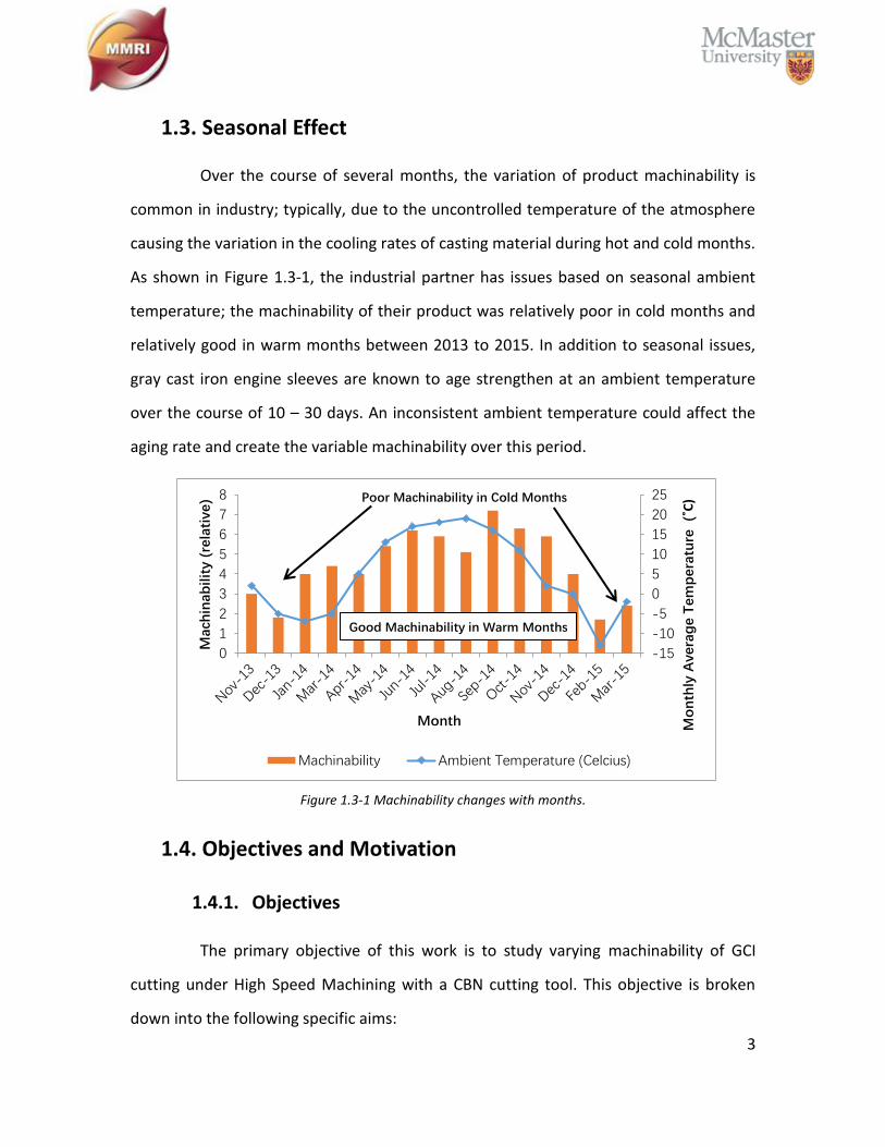
Figure 1.3-1 Machinability changes with months. .............................................................. 3
Figure 2.1-1 Engine sleeves and engine block. ................................................................... 8
Figure 2.1-2 GCI graphite distributions. (based on ISO 945-1:2008 [20]) ........................ 11
Figure 2.1-3 Influencing of cooling rate based on section size change. (based on [10]) . 15
Figure 2.2-1 Room temperature age strengthening data over a month. (based on [26]) 18
Figure 2.2-2 Acceleration of aging at 182 °C and 285 °C. (based on [26]) ........................ 19
Figure 2.2-3 Influencing of temperature change on aging rate. ...................................... 20
Figure 2.2-4 Effect of GCI aging on machinability. (based on [31]) .................................. 22
Figure 2.2-5 Dependency of cutting force with hardness by aging. (based on [44]) ....... 23
Figure 2.3-1 Different range of cutting speed for HSM. (based on [21], [47]) ................. 24
Figure 2.3-2 Two structures of boron nitride: (a) is HBN, (b) is CBN. (based on [57]) ..... 25
Figure 2.4-1 (a) is orthogonal cutting and (b) is oblique cutting. (based on [59]) ............ 27
Figure 2.4-2 Ernst and Merchant’s shear plane theory of orthogonal cutting. (based on
[59]) ................................................................................................................................... 27
Figure 2.4-3 Simple turning model. (based on [59]) ......................................................... 28
Figure 2.4-4 Types of wear on cutting tools: (a) flank wear; (b) crater wear; (c) notch wear;
(d) nose radius wear; (e) edge (thermal) cracks; (f) parallel (mechanical) cracks; (g) built-
up edge; (h) edge plastic deformation; (i) edge chipping or frittering; (j) chip hammering;
(k) gross fracture. (based on [59]) .................................................................................... 29
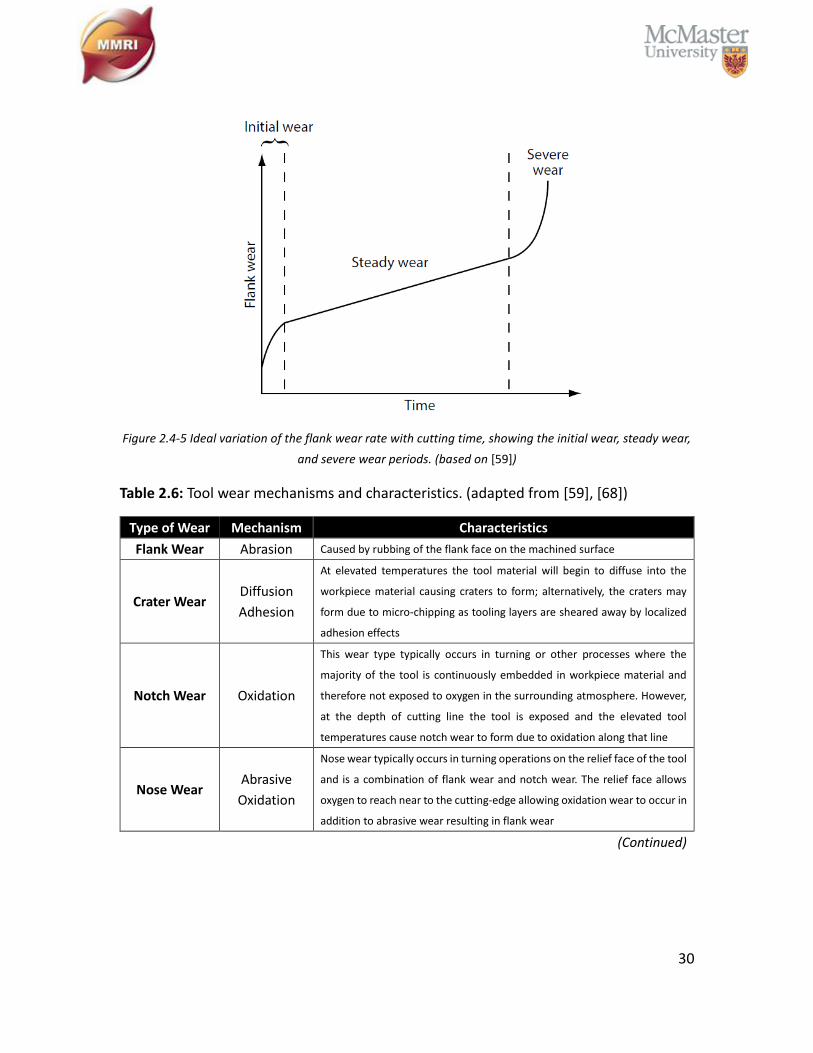
Figure 2.4-5 Ideal variation of the flank wear rate with cutting time, showing the initial
wear, steady wear, and severe wear periods. (based on [59]) ........................................ 30
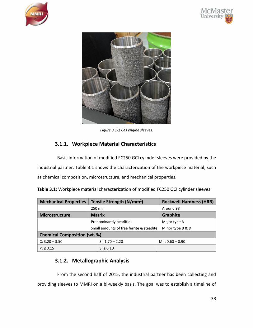
Figure 3.1-1 GCI engine sleeves. ....................................................................................... 33
Figure 3.1-2 A sample of unetched microstructure of FC250 GCI with a magnification of
×100. ................................................................................................................................. 34
viii
Figure 3.1-3 A sample of etched microstructure of FC250 GCI with a magnification of ×200.
........................................................................................................................................... 35
Figure 3.1-4 Skin region with predominant free ferrite. The maximum thickness for the
layer is around 1mm. ........................................................................................................ 36
Figure 3.1-5 EDS mapping with results show the sharp crystals are MnS inclusions. ...... 37
Figure 3.1-6 Quantitative image analysis by ImageJ, the red area is free ferrite based on
the pixels been counted. Yellow circle is steadite which been counted as free ferrite. .. 38
Figure 3.3-1 Machine setup. ............................................................................................. 39
Figure 3.3-2 Dynamometer with cutting forces directions. ............................................. 40
Figure 4.2-1 Optical Microscopic images of CBN inserts “CBN composition 1, composition
2, composition 3, and composition 4” after flank wear reaches 300 µm. ....................... 43
Figure 4.2-2 The total cutting length of each type of CBN insert after flank wear reaches
300 µm. ............................................................................................................................. 44
Figure 5.2-1 Relation between cutting force and cutting length. .................................... 47
Figure 5.2-2 Relation between feed force and cutting length. ........................................ 48
Figure 5.2-3 Relation between radial force and cutting length. ....................................... 48
Figure 5.2-4 Relation between flank wear behavior and cutting length. ......................... 49
Figure 5.2-5 Optical Microscopic images of CBN inserts compostion 1 tool wear behavior
with a low cutting speed (250 m/min) and a high cutting speed (800 m/min). .............. 50
Figure 5.2-6 SEM images of tool rake face. Left one is low cutting speed, right one is high
cutting speed. More abrasion wear appears on low cutting speed CBN rake face. ........ 50
Figure 6.2-1 Effect of percent free ferrite content on CBN flank wear behavior with 3,000
m cutting length. ............................................................................................................... 54
Figure 6.2-2 EDS mapping on CBN tool tip after cutting GCI workpiece with free ferrite
content between 0 – 2.0 %. .............................................................................................. 55
Figure 7.2-1 Variating tool life as room temperature aging processing. Very poor
machinability at all stages of testing. ............................................................................... 58
ix
Figure 7.2-2 Tool life test results comparing fully aged sleeve with low free ferrite and
sleeve from aging study with high free ferrite. ................................................................ 59
Figure 7.2-3 Comparison of free ferrite content in a “normal” sleeve and a sleeve from
the Oct 25th production run. ............................................................................................ 60
Figure 7.2-4 Results of hardness progressing with time as measured by nano-indentation
........................................................................................................................................... 61
Figure 7.2-5 Results of hardness progressing with time as measured by Rockwell Hardness
indentation. ....................................................................................................................... 61
Figure 8.2-1 GCI sleeves’ mechanical properties in 2015. ................................................ 65
Figure 8.2-2 GCI sleeves’ mechanical properties in 2016. ................................................ 65
Figure 9.1-1 Tool life changes with variation of free ferrite content. .............................. 67

x
List of Tables
Table 2.1: Classification of cast irons by commercial designation, microstructure, and
fracture (based on [10]). ..................................................................................................... 7
Table 2.2: Cross references of ISO 185 grade designations. (based on ISO 185 [14]). ...... 9
Table 2.3: Graphite distributions in GCI. (based on [10]) ................................................. 12
Table 2.4: Ranges for alloying elements content [5], [11]. .............................................. 14
Table 2.5: The influence of typical phases found in GCI on mechanical properties. (based
on [5], [21]) ....................................................................................................................... 17
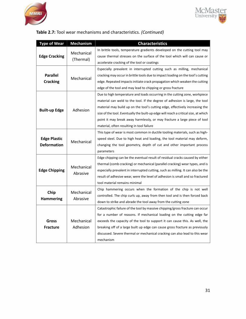
Table 2.6: Tool wear mechanisms and characteristics. (adapted from [59], [68]) .......... 30
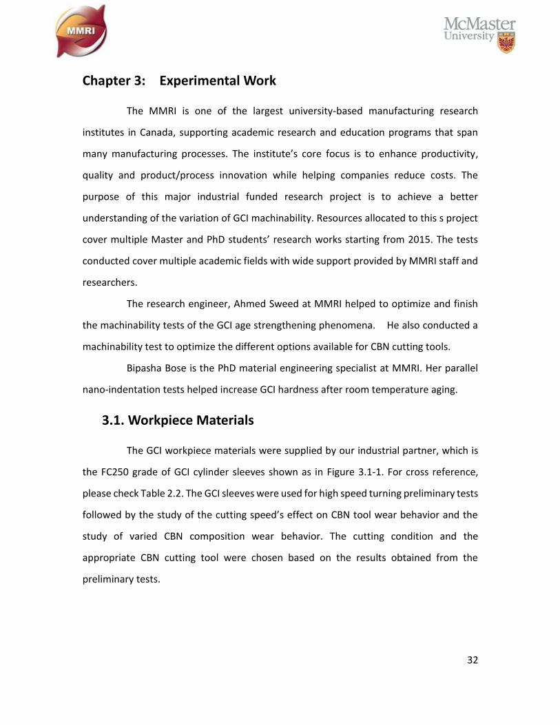
Table 2.7: Tool wear mechanisms and characteristics. (Continued) ................................ 31
Table 3.1: Workpiece material characterization of modified FC250 GCI cylinder sleeves.
........................................................................................................................................... 33
Table 3.2: Cutting inserts information. ............................................................................. 38
Table 6.1: Five ranges of free ferrite content which three GCI sleeves per range. ......... 52
1
Chapter 1: Introduction
This topic is based on the study of metallography and machining of GCI.
Metallography is nothing but the selection of the best metallurgical tools for investigating
the property of certain materials [1] and machining is a metal removal process for altering
the bulk material into a desired shape. This is achieved by removing small layers of the
workpiece material into chips with an edge prepared tool. Recipes of polishing and
etching solutions are described later for the study of the microscope images which were
polished to 1µm level of surface roughness. The automotive partner manufactures GCI
sleeves through a high-speed turning process to achieve a specific high production rate
and efficiency. It was proven that CBN tools are capable of high-speed machining with a
high production efficiency [2], [3]. Therefore, the machining operation is to basically
mimick the cutting conditions (cutting speed, feed rate, depth of cut) and the industrial
partner is to make sure that the results are authentic and representative of actual practice.
1.1. Gray Cast Iron
The history of using GCI can be traced back thousands of years. In modern times,
GCI is the most widely used cast iron in industrial applications, since it has good tool wear
resistance, low power requirement and high machinability. Its favorable damping capacity
and good surface finish [4]makes GCI one of the best materials for engine sleeves. The
name “gray” cast iron originates from its fracture surface which is the color of graphite
flakes [5]. Pre-existing cracks help generate discontinuous chips which are easily removed
[6]. GCI can be machined with conventional carbide cutting tools at relatively low cutting
speeds of around 300m/s or cut with cubic Boron Nitride (CBN) inserts under a high-speed
machining process with speeds up to 1000m/s.
To satisfy the market demand at the same time as maintaining a high
production efficiency with relatively low production cost, most industrial companies
would like to increase the cutting speed while keeping the tool life at a reasonable range.
2
Traditional carbide tools or ceramic tools are no longer suitable for high speed machining;
under severe cutting conditions, practical use has demonstrated that CBN cutting tools
can cut cast iron or hardened steel with promising tool life and high efficiency [3].
Although, CBN is best option for cutting GCI at high speeds, the content of free ferrite has
to be limited. Traceable amount of free ferrite can cause significant CBN tool wear,
therefore in this study, the free ferrite content of workpiece materials was chosen to be
from 1% to around 10%.
1.2. Phenomenon of Age Strengthening
Certain gray cast iron grades experience a very interesting, but little understood
phenomenon. After casting and cooling to room temperature, a gray cast iron part left
undisturbed at room temperature in open air will undergo microstructural changes. In
general, the aging process progresses in a non-linear fashion, with major changes
occurring quickly in the first 5 - 7 days after casting, and more gradual changes continuing
for up to 60 days after casting. The aging process can increase the tensile strength of the
cast iron by up to 15% but can increase machinability by up to 500%. This represents a
fantastic opportunity for industry to understand the optimal machining age of GCI or
other cast iron products for maximization of productivity and tool life.
The aging phenomenon was first identified in 1955 [7], but little research has been
conducted on understanding this phenomenon, until the 1990’s when researchers Nicola
and Richards rekindled this subject [8]. Since then, several studies were completed to
understand this phenomenon, but these have been limited to a few specific grades of
gray cast iron. The research to date provides a solid foundation for investigating the aging
process, and predicts the aging progress in GCI engine sleeves.
3
1.3. Seasonal Effect
Over the course of several months, the variation of product machinability is
common in industry; typically, due to the uncontrolled temperature of the atmosphere
causing the variation in the cooling rates of casting material during hot and cold months.
As shown in Figure 1.3-1, the industrial partner has issues based on seasonal ambient
temperature; the machinability of their product was relatively poor in cold months and
relatively good in warm months between 2013 to 2015. In addition to seasonal issues,
gray cast iron engine sleeves are known to age strengthen at an ambient temperature
over the course of 10 – 30 days. An inconsistent ambient temperature could affect the
aging rate and create the variable machinability over this period.
Figure 1.3-1 Machinability changes with months.
1.4. Objectives and Motivation
1.4.1. Objectives
The primary objective of this work is to study varying machinability of GCI
cutting under High Speed Machining with a CBN cutting tool. This objective is broken
down into the following specific aims:
-15
-10
-5
0
5
10
15
20
25
0
1
2
3
4
5
6
7
8
Mo
nth
ly A
vera
ge T
em
pera
ture
(˚
C)
Month
Mac
hin
abilit
y (r
ela
tive
)
Machinability Ambient Temperature (Celcius)
Good Machinability in Warm Months
Poor Machinability in Cold Months

4
To optimize the best fitting CBN cutting tool as well as the cutting conditions for
all of the following studies.
To observe how the content of free ferrite in GCI engine sleeves affect the
machinability of a CBN cutting tool under an industrial high-speed turning process.
To mimick the room temperature aging process that the industrial partner
conducted to demonstrate how the age strengthening process can improve the
machinability of GCI and the impact of its free ferrite content.
To demonstrate that the seasonal effect in industry is majorly affected by the
content of free ferrite.
1.4.2. Motivation
The industrial partner in Ontario manufactures thousands of engine blocks per
day which include grey cast iron cylinder sleeves. By eliminating factors that affect the
machinability of GCI, significant savings on tool life and scrap costs can be achieved, and
the additional benefits to production and personnel are difficult to estimate. Overall,
improving GCI engine sleeve machining can be of interest to many automotive companies.
1.5. Methodology
Samples were collected from different warm and cold months for microscopical
study. The elemental content, graphite types and their matrix composition were
compared using polished microscopic images and EDS mapping. Likewise, Vicker’s
hardness results collected from each sample were used to analyze whether there was any
micro-hardness difference between samples from warm and cold months. Later on,
fresh/unaged samples with a range of 1 – 10% of “free ferrite” were chosen for the high-
speed turning test. CBN inserts were selected to test the influence of age strengthening
on machinability as well as the extent “free ferrite” negatively affects CBN tool life.
5
1.6. Thesis Outline
Chapter 1 of this thesis explains the major objectives and the motivation of this
research study. Literature review about workpiece material and theories are covered in
chapter 2. All the experimental setup and procedures are detailly described in chapter 3.
Chapter 4 and chapter 5 are preliminary tests, which provides the optimal choice of CBN
cutting insert and cutting speed. The results and discussions about influence of free ferrite
content on machinability of gray cast iron are provided in chapter 6. The results about
gray cast iron age strengthening and its influence on machinability are illustrated in
chapter 7. Chapter 8 illustrates the reason of seasonal change of gray cast iron
machinability. Eventually, conclusions and future research suggestions are provided in
chapter 9.
6
Chapter 2: Literature Review
2.1. Cast Iron
Similar to the steel family, the term cast iron refers to a large family of ferrous
alloys which amounts to more than 70% of total world’s production tonnage [9]. Cast iron
are primarily iron alloys with major carbon (>2%) and silicon content (>1%). Since cast iron
has a higher carbon content than steel, the structure of cast iron exhibits a rich carbon
phase [10].
Cast irons are multicomponent ferrous alloys, which solidify with a eutectic.
Thermodynamically metastable Fe-Fe3C system and the stable Fe-Gr system can be
achieved by balancing the content of C and Si, by the composition of alloying elements,
and by control of founding, cooling, and heat-treating processes. Under the metastable
path, the majority of the carbon phase in the eutectic forms iron carbide is Fe3C; on the
other hand, under the stable solidification path, the majority of the carbon phase is
graphite. These two types of eutectics – the stable Fe-Gr (austenite – graphite) and the
metastable Fe-Fe3C (austenite – iron carbide) are the most basic iron phases with
significant differences in their mechanical properties. Therefore, categories of the type,
amount and morphology of the eutectic are capable of achieving desired mechanical
properties [11].
2.1.1. Classification – Gray Cast Iron
In History, the earliest classification of cast iron was based on its fractured
surface colors, which are gray iron and white iron. Typically, as its name suggests, white
iron exhibits a white crystalline fracture surface because the rich carbon phase is
metastable iron carbide (Fe3C). Gray iron has a gray fracture surface because of its rich
graphite flakes and the stable solidified graphite eutectic does not reflect light. As
7
metallography advanced, cast iron can be classified based on the following
microstructural features [11]:
• Graphite type: Lamellar (flake) graphite, spheroidal (nodular) graphite,
compacted (vermicular) graphite, and temper graphite
• Matrix: Ferritic, pearlitic, austenitic, martensitic, and bainitic (austempered)
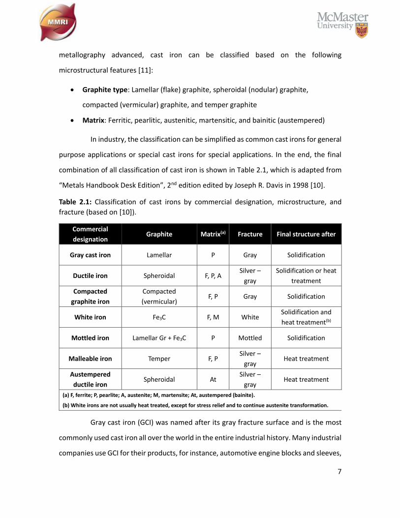
In industry, the classification can be simplified as common cast irons for general
purpose applications or special cast irons for special applications. In the end, the final
combination of all classification of cast iron is shown in Table 2.1, which is adapted from
“Metals Handbook Desk Edition”, 2nd edition edited by Joseph R. Davis in 1998 [10].
Table 2.1: Classification of cast irons by commercial designation, microstructure, and
fracture (based on [10]).
Commercial
designation Graphite Matrix(a) Fracture Final structure after
Gray cast iron Lamellar P Gray Solidification
Ductile iron Spheroidal F, P, A Silver –
gray
Solidification or heat
treatment
Compacted
graphite iron
Compacted
(vermicular) F, P Gray Solidification
White iron Fe3C F, M White Solidification and
heat treatment(b)
Mottled iron Lamellar Gr + Fe3C P Mottled Solidification
Malleable iron Temper F, P Silver –
gray Heat treatment
Austempered
ductile iron Spheroidal At
Silver –
gray Heat treatment
(a) F, ferrite; P, pearlite; A, austenite; M, martensite; At, austempered (bainite).
(b) White irons are not usually heat treated, except for stress relief and to continue austenite transformation.
Gray cast iron (GCI) was named after its gray fracture surface and is the most
commonly used cast iron all over the world in the entire industrial history. Many industrial
companies use GCI for their products, for instance, automotive engine blocks and sleeves,
8
machine tool base, transformation pipes, enclosures, housings and an uncountable
number of other products. GCI normally contains 2.5% - 4% carbon and 1% - 3% silicon.
By artificially controlling the casting processes and the elemental content, the rich carbon
phase forms irregular graphite precipitations and the iron matrix gets saturated with
elongated and curved graphite flakes. The latter work as natural crakes and provide good
damping characteristics as well as good machinability, since the flakes enhance chip
breaking and lubricate the cutting tools. For many applications requiring good wear
resistance, GCI is favored due to the graphite flakes. However, they also concentrate
stress and result in brittleness, a property not only common to GCI but also to all cast
irons [12].
2.1.2. Microstructure of GCI
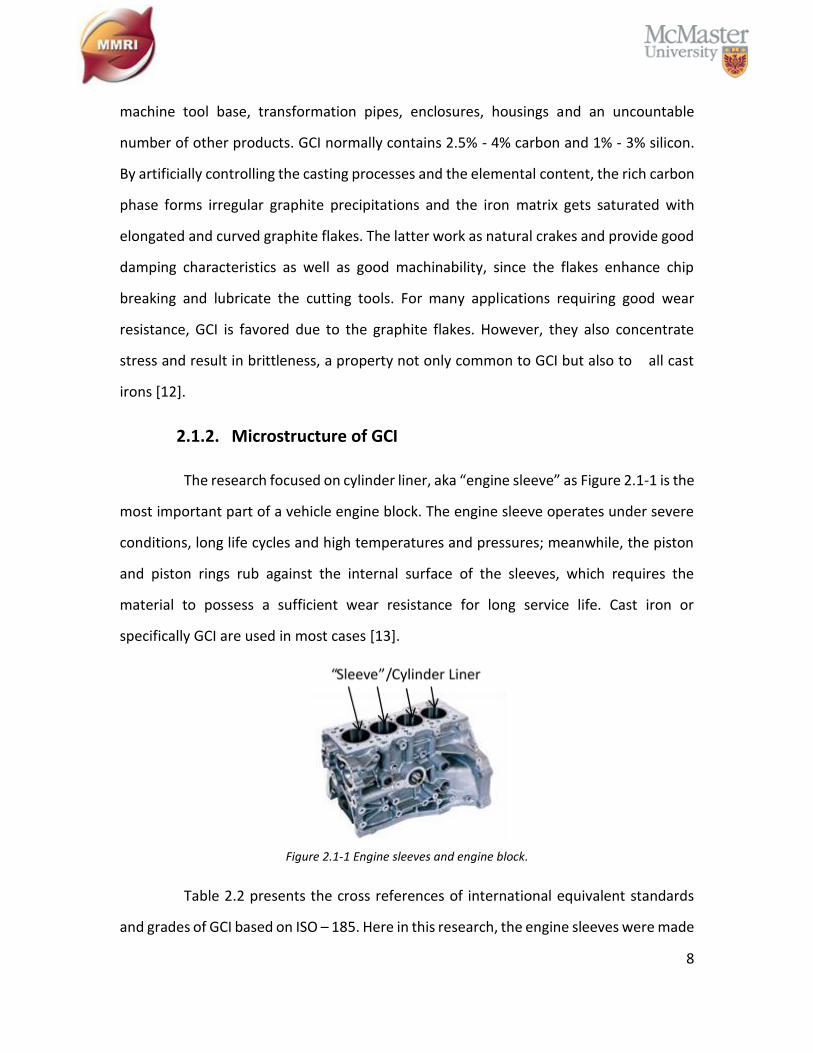
The research focused on cylinder liner, aka “engine sleeve” as Figure 2.1-1 is the
most important part of a vehicle engine block. The engine sleeve operates under severe
conditions, long life cycles and high temperatures and pressures; meanwhile, the piston
and piston rings rub against the internal surface of the sleeves, which requires the
material to possess a sufficient wear resistance for long service life. Cast iron or
specifically GCI are used in most cases [13].
Figure 2.1-1 Engine sleeves and engine block.
Table 2.2 presents the cross references of international equivalent standards
and grades of GCI based on ISO – 185. Here in this research, the engine sleeves were made
9
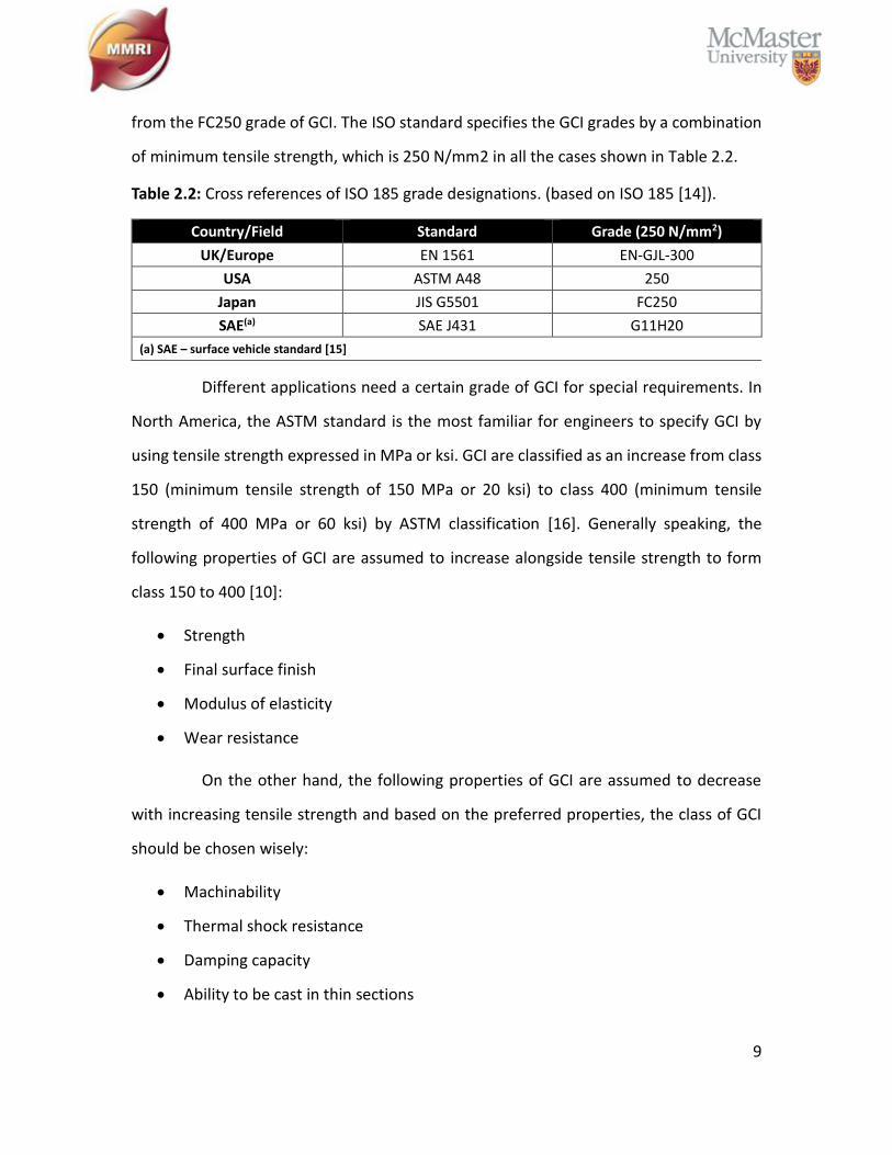
from the FC250 grade of GCI. The ISO standard specifies the GCI grades by a combination
of minimum tensile strength, which is 250 N/mm2 in all the cases shown in Table 2.2.
Table 2.2: Cross references of ISO 185 grade designations. (based on ISO 185 [14]).
Country/Field Standard Grade (250 N/mm2)
UK/Europe EN 1561 EN-GJL-300
USA ASTM A48 250
Japan JIS G5501 FC250
SAE(a) SAE J431 G11H20
(a) SAE – surface vehicle standard [15]
Different applications need a certain grade of GCI for special requirements. In
North America, the ASTM standard is the most familiar for engineers to specify GCI by
using tensile strength expressed in MPa or ksi. GCI are classified as an increase from class
150 (minimum tensile strength of 150 MPa or 20 ksi) to class 400 (minimum tensile
strength of 400 MPa or 60 ksi) by ASTM classification [16]. Generally speaking, the
following properties of GCI are assumed to increase alongside tensile strength to form
class 150 to 400 [10]:
• Strength
• Final surface finish
• Modulus of elasticity
• Wear resistance
On the other hand, the following properties of GCI are assumed to decrease
with increasing tensile strength and based on the preferred properties, the class of GCI
should be chosen wisely:
• Machinability
• Thermal shock resistance
• Damping capacity
• Ability to be cast in thin sections
10
Matrix
For GCI, the main elements of chemical composition are carbon and silicon. The
mechanical properties of GCI mainly depend on the iron matrix (pearlite matrix or ferrite
matrix) and minimally influenced by the type of graphite. A relatively low cooling rate and
relatively high carbon and silicon content is likely to produce a ferrite matrix (pure iron
phase) which has low strength but high ductility, since the high silicon content increases
the graphitization potential and the carbon dissolved in iron deposits onto the existing
graphite flake structure in process of slow cooling. On the other hand, rapid cooling
prevents the carbon from dissolving into the graphite flakes, which increase the hardness
and tensile strength of GCI and produce a pearlite matrix (iron carbide). Minor alloying
elements such as manganese, sulfur, phosphorous, aluminum, nickel, lead and many
other alloying elements can significantly affect both the microstructure of the matrix and
the morphology of graphite [11], [17]. The best case is the content of manganese and
sulfur, both of which are common minor elements in the composition of GCI. Manganese
is a strong pearlite promoter and the relatively high content of manganese helps to
produce a pearlite matrix. If the content of the manganese and sulfur is well balanced, a
manganese sulfide (MnS) will form, which helps to lubricate the cutting tool and improve
the machinability [18], [19].
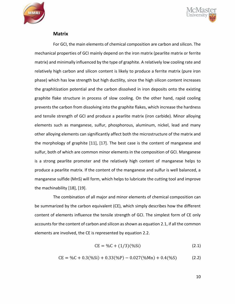
The combination of all major and minor elements of chemical composition can
be summarized by the carbon equivalent (CE), which simply describes how the different
content of elements influence the tensile strength of GCI. The simplest form of CE only
accounts for the content of carbon and silicon as shown as equation 2.1, if all the common
elements are involved, the CE is represented by equation 2.2.
CE = %C + (1/3)(%Si) (2.1)
CE = %C + 0.3(%Si) + 0.33(%P) − 0.027(%Mn) + 0.4(%S) (2.2)

11
Graphite
Similar to the iron matrix, the cooling rate and both major and minor
elemental composition have a strong influence on the morphology of graphite flakes. Five
types of graphite flakes (Type A – Type E) are classified by ISO 945 based on their graphite
microstructure in GCI through comparative visual analysis. The mechanical properties of
GCI are not only affected by the matrix but also by the shape, size, amount, and
distribution of the graphite flakes. The five graphite flake distributions are shown as
Figure 2.1-2.
Figure 2.1-2 GCI graphite distributions. (based on ISO 945-1:2008 [20])
Type A graphite flake distributes as a random orientation, and compared to all
other types of graphite, it has the best mechanical properties and is favorable for most of
the applications. The Type B graphite flake exhibits a rosette pattern and is formed with
a greater amount of undercooling. Usually, the type B graphite flake appears on common

12
moderately thin sections or along the surface of thicker sections. The Type C graphite
flake distinctively reduces the mechanical properties of GCI and produces rough surfaces
after machining. It occurs in hypereutectic irons due to minimum undercooling. However,
the type C graphite flake can be used for applications requiring a product with a high
thermal conductivity and damping capacity. Both type D and type E graphite flakes form
with a high amount of undercooling and without a sufficient amount of carbide formation.
Type D graphite flakes have a random orientation while type E graphite flakes have a
directed orientation. The following table summarizes the details of graphite distributions
in GCI [10].
Table 2.3: Graphite distributions in GCI. (based on [10])
Distribution Main 2D appearance Occurrences
A Apparently uniform
distribution
Cast iron solidified with a low to intermediate degree of
undercooling.
B Rosette graphite with
undercooling graphite
Cast iron solidified with an intermediate degree of
undercooling, particularly thin-walled castings.
C
Aggregate of larger
graphite flakes surrounded
by smaller, randomly
oriented graphite flakes
(eutectic graphite)
Hypereutectic cast iron.
D
Finely branched graphite
Fine, randomly oriented
graphite flakes in the
interdendritic position
Cast iron solidified with a high degree of undercooling.
The distribution can be associated with other
distributions (for example A and/or B and/or E).
E
Preferentially orientated
graphite flakes in the
interdendritic position
Cast iron with low carbon equivalent, solidified with low
or moderate undercooling. Local area corresponding to
a plane of polish cutting through the main axis of some
highly oriented dendrites.
Overall, not only do the types of graphite influence mechanical properties but
also the size of graphite flakes. A slow cooling rate and high CE values produce large
graphite flakes. GCI with large flakes have a week tensile strength but better thermal
conductivity and damping capacity. On the other hand, small graphite flakes are formed

13
under rapid solidification and provide a better tensile strength and a fine, smooth surface
finish.
2.1.3. GCI Chemical Composition
A typical unalloyed common GCI is formed with iron, followed by 2.5 – 4% of
carbon and 1.0 – 3.0% of silicon, similar to the composition of Manganese (0.2 – 1.0%),
Phosphorus (0.002 – 1.0%) and Sulphur (0.02 – 0.25%) [5], [11]. A list of alloying elements
can contribute to the common GCI to enhance the mechanical properties by influencing
both the graphitization potential and the microstructure of GCI. Elements that have a high
positive graphitization potential are listed below in order of decreasing positive potential
from top to bottom:
• Carbon
• Tin
• Phosphorus
• Silicon
• Aluminum
• Copper
• Nickel
Visa versa, elements that have high negative graphitization potential are listed
below in order of increasing negative potential from top to bottom:
• Manganese
• Chromium
• Molybdenum
• Vanadium
• Tungsten
14
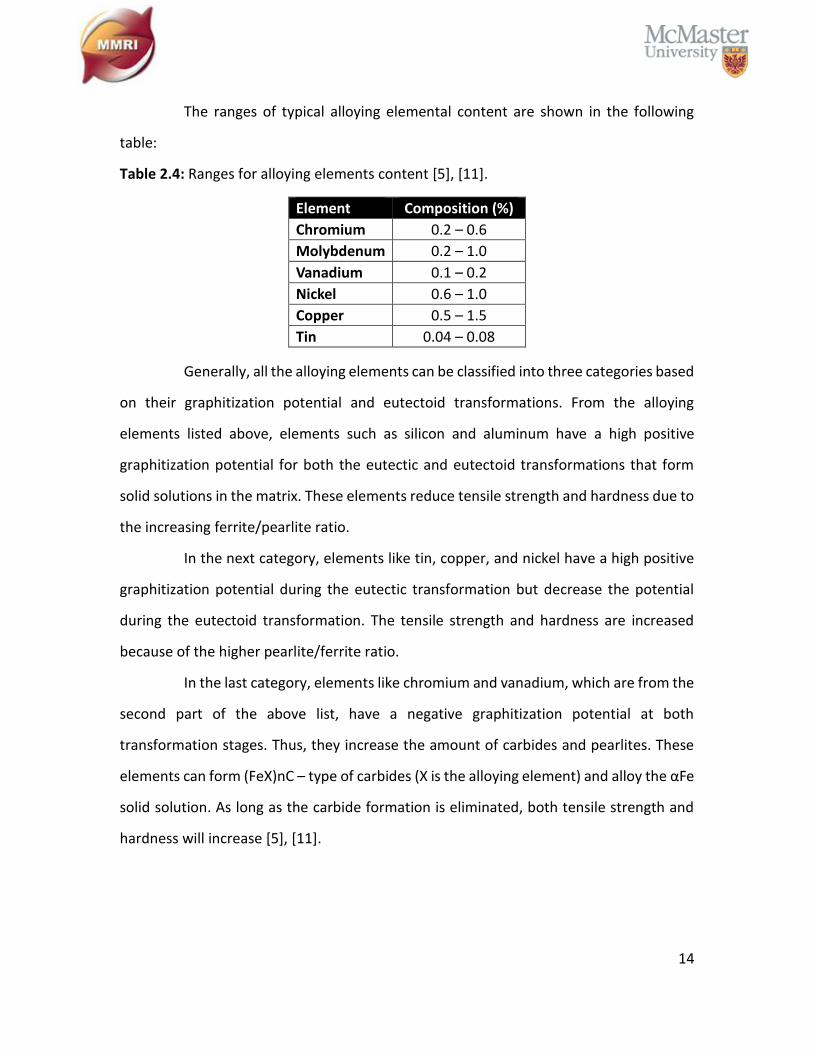
The ranges of typical alloying elemental content are shown in the following
table:
Table 2.4: Ranges for alloying elements content [5], [11].
Element Composition (%)
Chromium 0.2 – 0.6
Molybdenum 0.2 – 1.0
Vanadium 0.1 – 0.2
Nickel 0.6 – 1.0
Copper 0.5 – 1.5
Tin 0.04 – 0.08
Generally, all the alloying elements can be classified into three categories based
on their graphitization potential and eutectoid transformations. From the alloying
elements listed above, elements such as silicon and aluminum have a high positive
graphitization potential for both the eutectic and eutectoid transformations that form
solid solutions in the matrix. These elements reduce tensile strength and hardness due to
the increasing ferrite/pearlite ratio.
In the next category, elements like tin, copper, and nickel have a high positive
graphitization potential during the eutectic transformation but decrease the potential
during the eutectoid transformation. The tensile strength and hardness are increased
because of the higher pearlite/ferrite ratio.
In the last category, elements like chromium and vanadium, which are from the
second part of the above list, have a negative graphitization potential at both
transformation stages. Thus, they increase the amount of carbides and pearlites. These
elements can form (FeX)nC – type of carbides (X is the alloying element) and alloy the αFe
solid solution. As long as the carbide formation is eliminated, both tensile strength and
hardness will increase [5], [11].
15
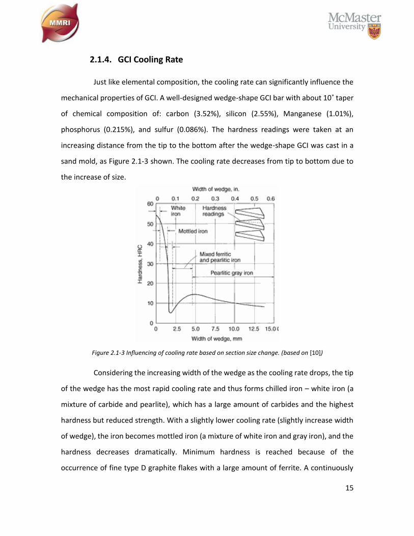
2.1.4. GCI Cooling Rate
Just like elemental composition, the cooling rate can significantly influence the
mechanical properties of GCI. A well-designed wedge-shape GCI bar with about 10˚ taper
of chemical composition of: carbon (3.52%), silicon (2.55%), Manganese (1.01%),
phosphorus (0.215%), and sulfur (0.086%). The hardness readings were taken at an
increasing distance from the tip to the bottom after the wedge-shape GCI was cast in a
sand mold, as Figure 2.1-3 shown. The cooling rate decreases from tip to bottom due to
the increase of size.
Figure 2.1-3 Influencing of cooling rate based on section size change. (based on [10])
Considering the increasing width of the wedge as the cooling rate drops, the tip
of the wedge has the most rapid cooling rate and thus forms chilled iron – white iron (a
mixture of carbide and pearlite), which has a large amount of carbides and the highest
hardness but reduced strength. With a slightly lower cooling rate (slightly increase width
of wedge), the iron becomes mottled iron (a mixture of white iron and gray iron), and the
hardness decreases dramatically. Minimum hardness is reached because of the
occurrence of fine type D graphite flakes with a large amount of ferrite. A continuously
16
decreased cooling rate reaches another peak of maximum hardness on the curve. This is
the most desirable structure due to fine type A graphite flakes with a pearlite matrix
providing a balance of strength and hardness. Beyond this point on the curve, a lower
cooling rate results in the formation of coarse graphite flakes in a pearlite matrix with
relatively less hardness. Further decreasing the cooling rate, the pearlite matrix
progressively decomposes into a mixture of ferrite – pearlite matrix, resulting in softer
and weaker iron [10]. For a better understanding of this process, see Table 2.1 and Table
2.3.
Consequently, given the chemical composition, the cooling rate must be
appropriately designed to provide the correct graphitization potential. The summary of
the influence of chemical composition and cooling rate on the tensile strength can be
estimated by equation 2.3 [5], [11].
TS = 162.37 +16.61
D− 21.78(%C) − 61.29(%Si)
− 10.59(%Mn − 1.7%S) + 13.80(%Cr) + 2.05(%Ni)
+ 30.66(%Cu) + 39.75(%Mo) + 14.16(%Si)2
− 26.25(%Cu)2 − 23.83(%Mo)2
TS: tensile strength
(2.3)
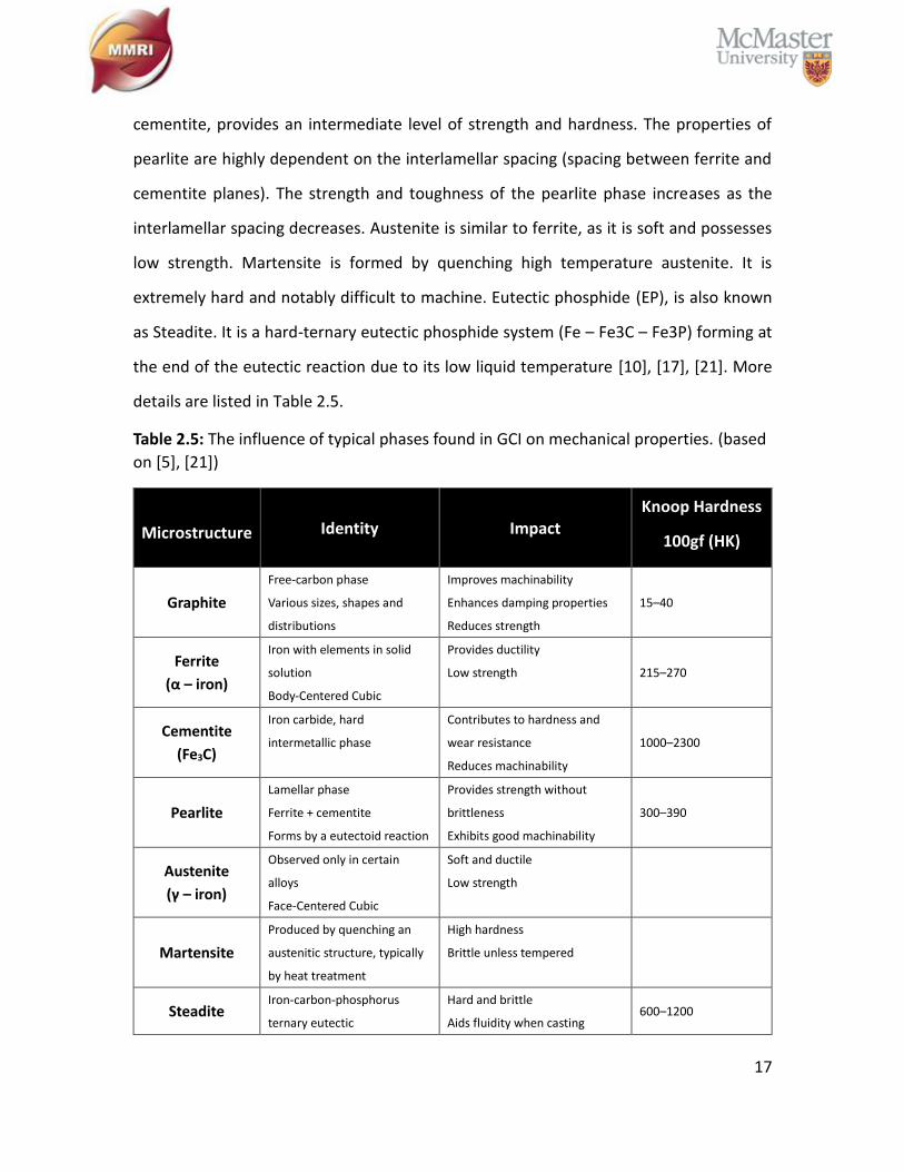
2.1.5. Mechanical Properties
Typical phases found in GCI are: graphite, ferrite, pearlite, cementite, austenite,
martensite, and steadite. Ferrite is the pure iron phase with low carbon content - it
exhibits low strength but good ductility. Slow cooling rate and high silicon content
promotes the formation of ferrite. Cementite, which is produced by a rapid cooling rate,
is a very hard iron carbide (Fe3C) phase that significantly reduces the machinability or GCI.
However, Pearlite, a product of alternate lamellar planes of soft ferrite and hard
17
cementite, provides an intermediate level of strength and hardness. The properties of
pearlite are highly dependent on the interlamellar spacing (spacing between ferrite and
cementite planes). The strength and toughness of the pearlite phase increases as the
interlamellar spacing decreases. Austenite is similar to ferrite, as it is soft and possesses
low strength. Martensite is formed by quenching high temperature austenite. It is
extremely hard and notably difficult to machine. Eutectic phosphide (EP), is also known
as Steadite. It is a hard-ternary eutectic phosphide system (Fe – Fe3C – Fe3P) forming at
the end of the eutectic reaction due to its low liquid temperature [10], [17], [21]. More
details are listed in Table 2.5.
Table 2.5: The influence of typical phases found in GCI on mechanical properties. (based
on [5], [21])
Microstructure Identity Impact Knoop Hardness
100gf (HK)
Graphite
Free-carbon phase
Various sizes, shapes and
distributions
Improves machinability
Enhances damping properties
Reduces strength
15–40
Ferrite
(α – iron)
Iron with elements in solid
solution
Body-Centered Cubic
Provides ductility
Low strength 215–270
Cementite
(Fe3C)
Iron carbide, hard
intermetallic phase
Contributes to hardness and
wear resistance
Reduces machinability
1000–2300
Pearlite
Lamellar phase
Ferrite + cementite
Forms by a eutectoid reaction
Provides strength without
brittleness
Exhibits good machinability
300–390
Austenite
(γ – iron)
Observed only in certain
alloys
Face-Centered Cubic
Soft and ductile
Low strength
Martensite
Produced by quenching an
austenitic structure, typically
by heat treatment
High hardness
Brittle unless tempered
Steadite Iron-carbon-phosphorus
ternary eutectic
Hard and brittle
Aids fluidity when casting 600–1200
18
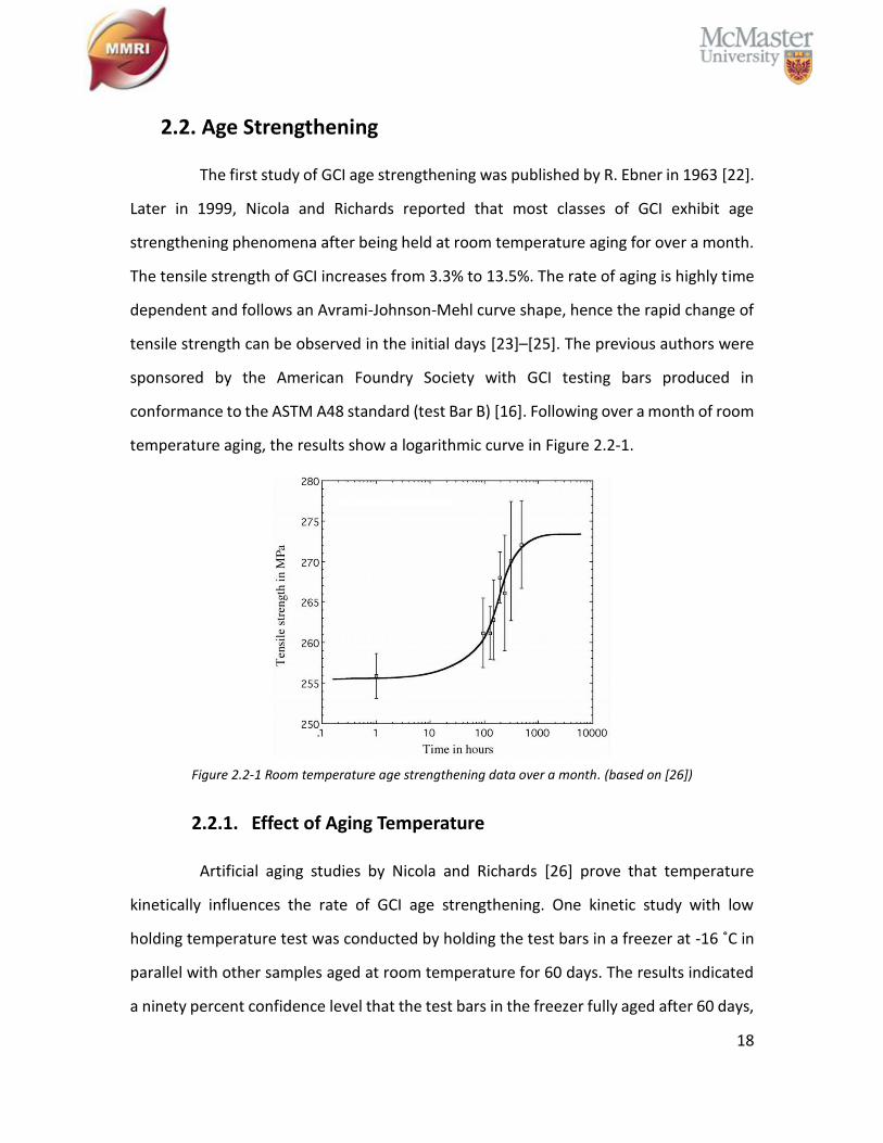
2.2. Age Strengthening
The first study of GCI age strengthening was published by R. Ebner in 1963 [22].
Later in 1999, Nicola and Richards reported that most classes of GCI exhibit age
strengthening phenomena after being held at room temperature aging for over a month.
The tensile strength of GCI increases from 3.3% to 13.5%. The rate of aging is highly time
dependent and follows an Avrami-Johnson-Mehl curve shape, hence the rapid change of
tensile strength can be observed in the initial days [23]–[25]. The previous authors were
sponsored by the American Foundry Society with GCI testing bars produced in
conformance to the ASTM A48 standard (test Bar B) [16]. Following over a month of room
temperature aging, the results show a logarithmic curve in Figure 2.2-1.
Figure 2.2-1 Room temperature age strengthening data over a month. (based on [26])
2.2.1. Effect of Aging Temperature
Artificial aging studies by Nicola and Richards [26] prove that temperature
kinetically influences the rate of GCI age strengthening. One kinetic study with low
holding temperature test was conducted by holding the test bars in a freezer at -16 ˚C in
parallel with other samples aged at room temperature for 60 days. The results indicated
a ninety percent confidence level that the test bars in the freezer fully aged after 60 days,
19
had a lower tensile strength compared to the test bars aging for the same amount of time
at room temperature. Furthermore, samples that have been stored in dry ice resulted in
halted aging.
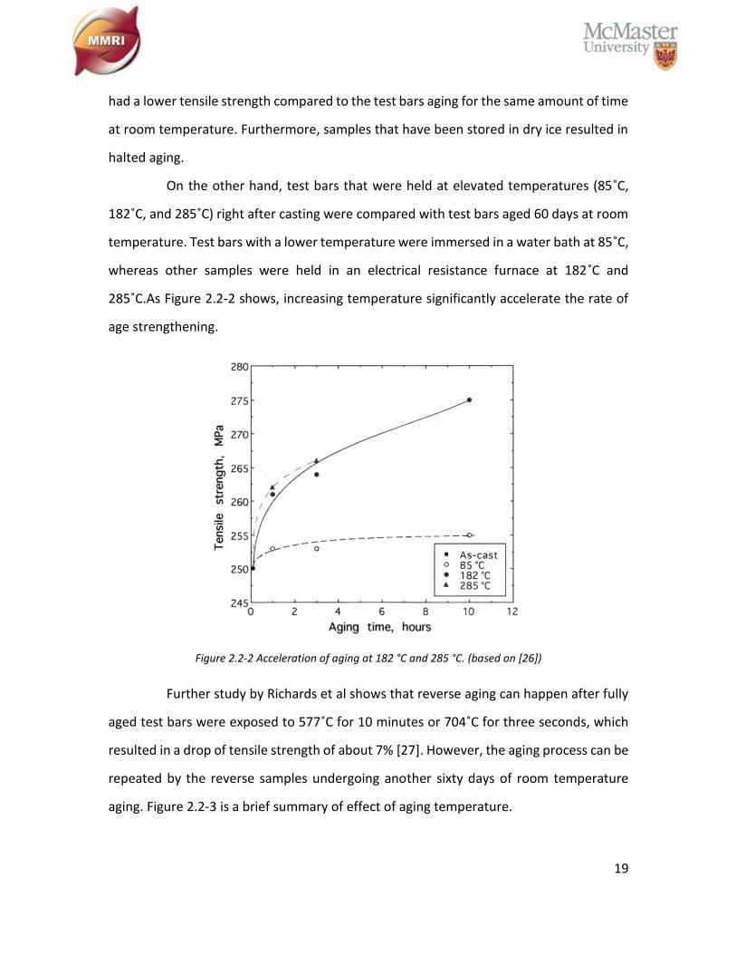
On the other hand, test bars that were held at elevated temperatures (85˚C,
182˚C, and 285˚C) right after casting were compared with test bars aged 60 days at room
temperature. Test bars with a lower temperature were immersed in a water bath at 85˚C,
whereas other samples were held in an electrical resistance furnace at 182˚C and
285˚C.As Figure 2.2-2 shows, increasing temperature significantly accelerate the rate of
age strengthening.
Figure 2.2-2 Acceleration of aging at 182 °C and 285 °C. (based on [26])
Further study by Richards et al shows that reverse aging can happen after fully
aged test bars were exposed to 577˚C for 10 minutes or 704˚C for three seconds, which
resulted in a drop of tensile strength of about 7% [27]. However, the aging process can be
repeated by the reverse samples undergoing another sixty days of room temperature
aging. Figure 2.2-3 is a brief summary of effect of aging temperature.

20
Figure 2.2-3 Influencing of temperature change on aging rate.
2.2.2. Effect of Nitride Precipitation
Age strengthening has been known as iron-nitride precipitation, and nitrogen is
required to produce cast iron age strengthening behavior[26]–[32]. Stable Fe4N (also
called: γ’) and metastable Fe16N2 (also called: α’’) are widely known as key factors of
increasing the tensile strength after room temperature aging [33]–[42]. More specifically,
Edmonds and Honeycombe [43] determined that a three-stage precipitation process, in
which nitrides are precipitated into soft ferrite (α-iron), beginning with the formation of
interstitial-atom clusters, followed by the nucleation of metastable Fe16N2 and ending
up as the stable Fe4N [24], [44]. A heat treatment with the temperature below the iron-
carbon eutectoid but beyond the iron-nitrogen eutectoid, can reverse the age
strengthening process and reduce the increased strength [27]. This is the reason, shown
in section 2.2.1, that the fully aged samples underwent reverse aging following a heat
treatment with temperature above 577 ˚C.
2.2.3. Effect of Alloying Elements
As discussed above, GCI age strengthening is highly dependent on temperature
and nitride precipitation. The artificial aging with elevated temperature accelerates the
aging rate significantly; however, the natural aging at room temperature is strongly
affected by GCI chemical composition. From section 2.1, manganese and sulfur are the
most common and helpful alloying elements in GCI. The formation of MnS improves GCI
machinability significantly. A result was published by S.N Lekakh and V.L. Richards [44]
demonstrating that any free Mn element which does not form MnS, is likely to form the

21
nitride in the Fe-Mn-N system. The manganese iron nitride delays the sequential growth
of the stable Fe4N and eventually appears as lower aging rate. [5], [11] provide the
optimum ratio between manganese and sulfur for GCI, as shown in equation (2.4).
Therefore, the calculation of free Mn is equation (2.5).
%Mn = 1.7(%S) + 0.15 (2.4)
(%Mn)free = %Mn − 1.7(%S) − 0.15 (2.5)
Other elements such as Ti, Al and B strongly promote the formation of (X)nN –
type of nitrides (X is the alloying element), which can easily suppress the iron nitride
precipitation [28], [45]. Also, a carbide promoter such as chromium can decrease the
amount of free ferrite in GCI as a cause of iron carbide formation. Since age strengthening,
as a nitride precipitation phenomenon, happens in free ferrite, aging is eliminated
without a traceable amount of free ferrite.
2.2.4. Influence of GCI Aging on Machinability
Usually, it is common sense that an increase in the hardness of the workpiece
material also increases the machining cutting force, which leads to reduced machinability.
Although aging increases the hardness and strengthening of GCI due to iron nitride
precipitation, but it was proven by Edington et al. [31] that machinability actually
improved from age strengthening of GCI and the result is shown in Figure 2.2-4. The total
number of parts produced per cutting tool increases alongside the room temperature
aging time. It is noticeable that the shape of the curve is logarithmic and similar to the
increase of tensile strength along with aging time as shown in Figure 2.2-1.
22
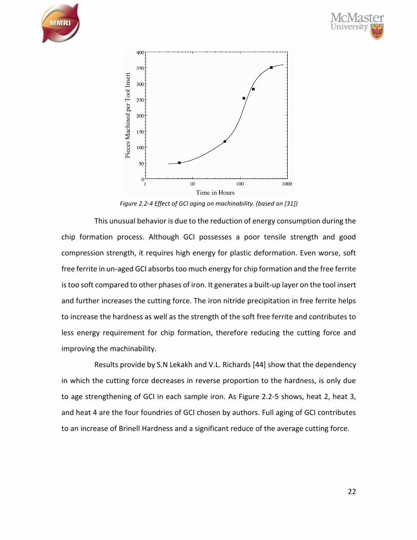
Figure 2.2-4 Effect of GCI aging on machinability. (based on [31])
This unusual behavior is due to the reduction of energy consumption during the
chip formation process. Although GCI possesses a poor tensile strength and good
compression strength, it requires high energy for plastic deformation. Even worse, soft
free ferrite in un-aged GCI absorbs too much energy for chip formation and the free ferrite
is too soft compared to other phases of iron. It generates a built-up layer on the tool insert
and further increases the cutting force. The iron nitride precipitation in free ferrite helps
to increase the hardness as well as the strength of the soft free ferrite and contributes to
less energy requirement for chip formation, therefore reducing the cutting force and
improving the machinability.
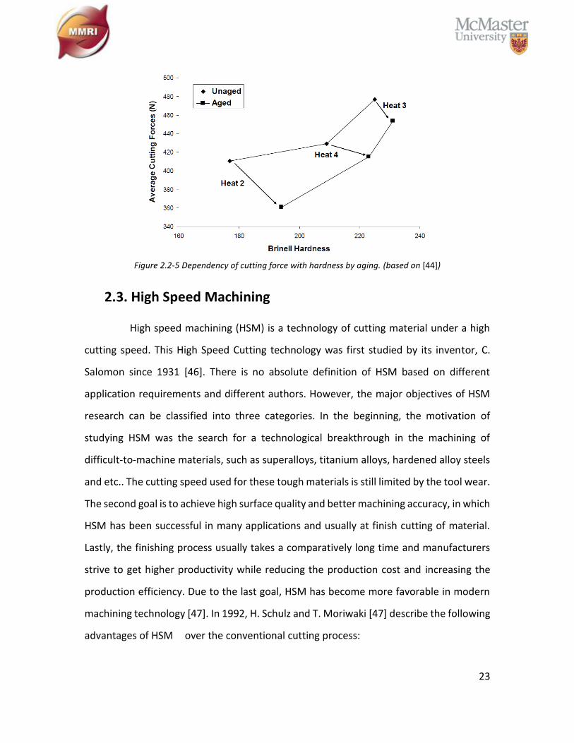
Results provide by S.N Lekakh and V.L. Richards [44] show that the dependency
in which the cutting force decreases in reverse proportion to the hardness, is only due
to age strengthening of GCI in each sample iron. As Figure 2.2-5 shows, heat 2, heat 3,
and heat 4 are the four foundries of GCI chosen by authors. Full aging of GCI contributes
to an increase of Brinell Hardness and a significant reduce of the average cutting force.
23
Figure 2.2-5 Dependency of cutting force with hardness by aging. (based on [44])
2.3. High Speed Machining
High speed machining (HSM) is a technology of cutting material under a high
cutting speed. This High Speed Cutting technology was first studied by its inventor, C.
Salomon since 1931 [46]. There is no absolute definition of HSM based on different
application requirements and different authors. However, the major objectives of HSM
research can be classified into three categories. In the beginning, the motivation of
studying HSM was the search for a technological breakthrough in the machining of
difficult-to-machine materials, such as superalloys, titanium alloys, hardened alloy steels
and etc.. The cutting speed used for these tough materials is still limited by the tool wear.
The second goal is to achieve high surface quality and better machining accuracy, in which
HSM has been successful in many applications and usually at finish cutting of material.
Lastly, the finishing process usually takes a comparatively long time and manufacturers
strive to get higher productivity while reducing the production cost and increasing the
production efficiency. Due to the last goal, HSM has become more favorable in modern
machining technology [47]. In 1992, H. Schulz and T. Moriwaki [47] describe the following
advantages of HSM over the conventional cutting process:
24
Increased machining accuracy, especially in machining of thin webs due to
reduced chip load
Better surface finish and reduction in the damaged layer
Reduced bur formation
Better chip disposal
Possibility of higher stability in cutting due to stability lobes against chatter
vibration
Simplified tooling, and etc.
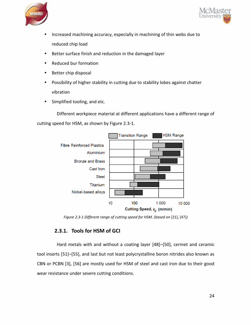
Different workpiece material at different applications have a different range of
cutting speed for HSM, as shown by Figure 2.3-1.
Figure 2.3-1 Different range of cutting speed for HSM. (based on [21], [47])
2.3.1. Tools for HSM of GCI
Hard metals with and without a coating layer [48]–[50], cermet and ceramic
tool inserts [51]–[55], and last but not least polycrystalline boron nitrides also known as
CBN or PCBN [3], [56] are mostly used for HSM of steel and cast iron due to their good
wear resistance under severe cutting conditions.
25
However, in many applications, it was realized that even carbide or ceramic
tools struggle to meet the strict manufacturing requirements. Manufacturers eagerly
demand critical elements in metal cutting with sufficient tool wear resistance and less
production cost while the workpiece materials are becoming harder, tougher, and more
chemically reactive. Researchers found that the CBN cutting tool is the best candidate for
HSM.
CBN is the second hardest material after diamond, possessing high thermal
conductivity and excellent chemical stability at high temperatures. These characteristics
make CBN, as a cutting tool, perfectly fit the requirements of HSM. Although CBN cutting
tools are very expensive compared to other conventional carbide or ceramic tools,
optimizing the cutting conditions can maximize the production efficiency. Just like carbon,
they exhibit a soft, slippery hexagonal structure called graphite well as a cubic structure
known as diamond. Boron nitride (BN) has a soft hexagonal boron nitride (HBN) structure
which can be transformed into a cubic boron nitride (CBN) structure under high
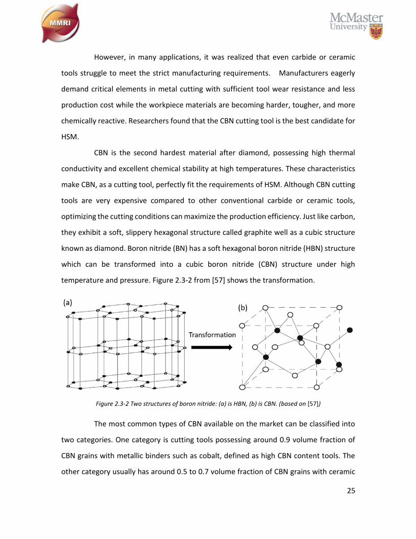
temperature and pressure. Figure 2.3-2 from [57] shows the transformation.
Figure 2.3-2 Two structures of boron nitride: (a) is HBN, (b) is CBN. (based on [57])
The most common types of CBN available on the market can be classified into
two categories. One category is cutting tools possessing around 0.9 volume fraction of
CBN grains with metallic binders such as cobalt, defined as high CBN content tools. The
other category usually has around 0.5 to 0.7 volume fraction of CBN grains with ceramic
26
binders such as titanium nitride or titanium carbide and is defined as low CBN content
tools [57]. Takatsu et al. [58] reported that the CBN tool life is mainly related to flank wear
and chipping on the cutting edge. The flank wear is influenced by both the inherent wear
resistance of the CBN compacts and the adhesion of the workpiece materials [57].
2.4. Metal Cutting Process
The chief activity of industry around the world revolves around shaping
materials into desired parts. This is also known as the process of metal cutting, in which
the unwanted materials are removed from the workpiece by a variety of traditional chip
removal processes such as turning, milling, drilling, and boring. In other applications,
abrasive processes such as grinding and honing, as well as nontraditional machining
processes such as electro-discharge machining (EDS), ultrasonic machining, laser
machining, water jet machining, and electrochemical machining are related to metal
removal processes [59].
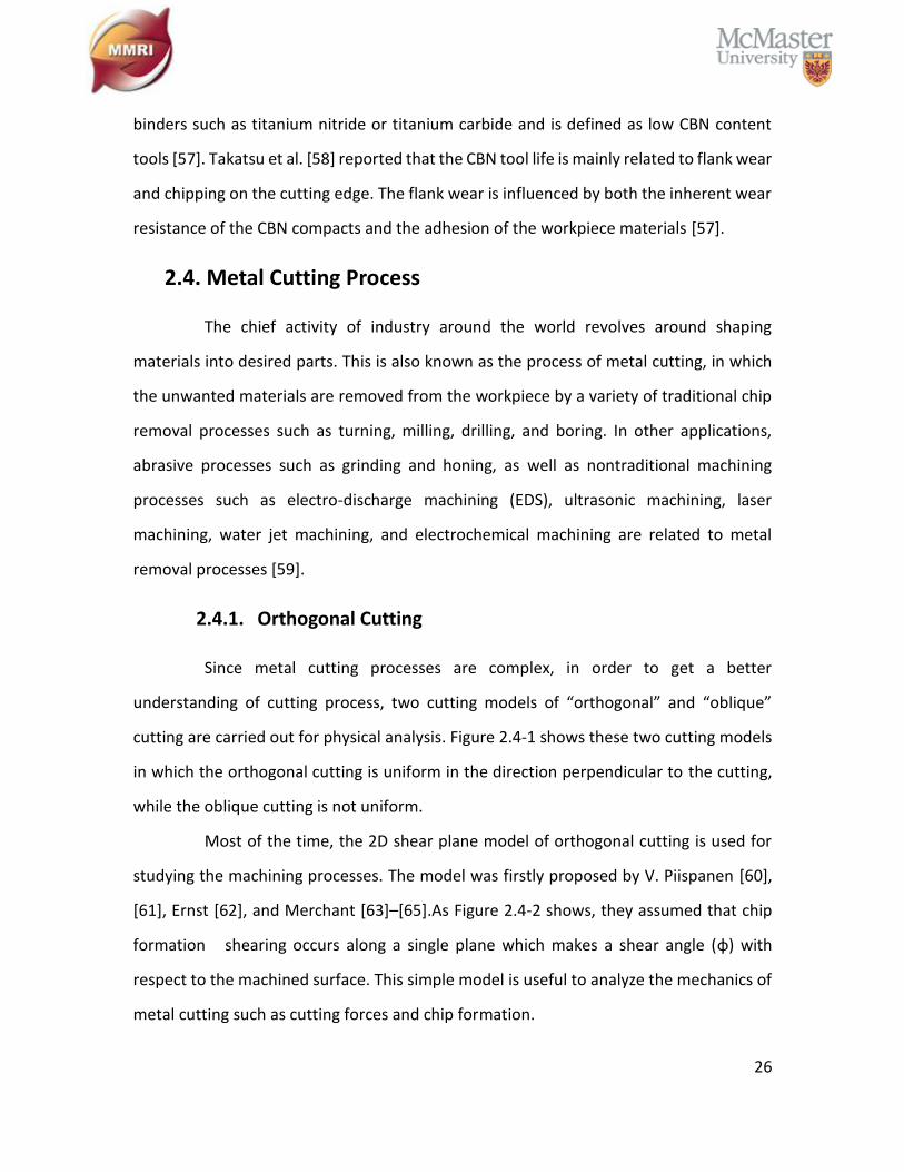
2.4.1. Orthogonal Cutting
Since metal cutting processes are complex, in order to get a better
understanding of cutting process, two cutting models of “orthogonal” and “oblique”
cutting are carried out for physical analysis. Figure 2.4-1 shows these two cutting models
in which the orthogonal cutting is uniform in the direction perpendicular to the cutting,
while the oblique cutting is not uniform.
Most of the time, the 2D shear plane model of orthogonal cutting is used for
studying the machining processes. The model was firstly proposed by V. Piispanen [60],
[61], Ernst [62], and Merchant [63]–[65].As Figure 2.4-2 shows, they assumed that chip
formation shearing occurs along a single plane which makes a shear angle (φ) with
respect to the machined surface. This simple model is useful to analyze the mechanics of
metal cutting such as cutting forces and chip formation.
27
Figure 2.4-1 (a) is orthogonal cutting and (b) is oblique cutting. (based on [59])
Figure 2.4-2 Ernst and Merchant’s shear plane theory of orthogonal cutting. (based on [59])
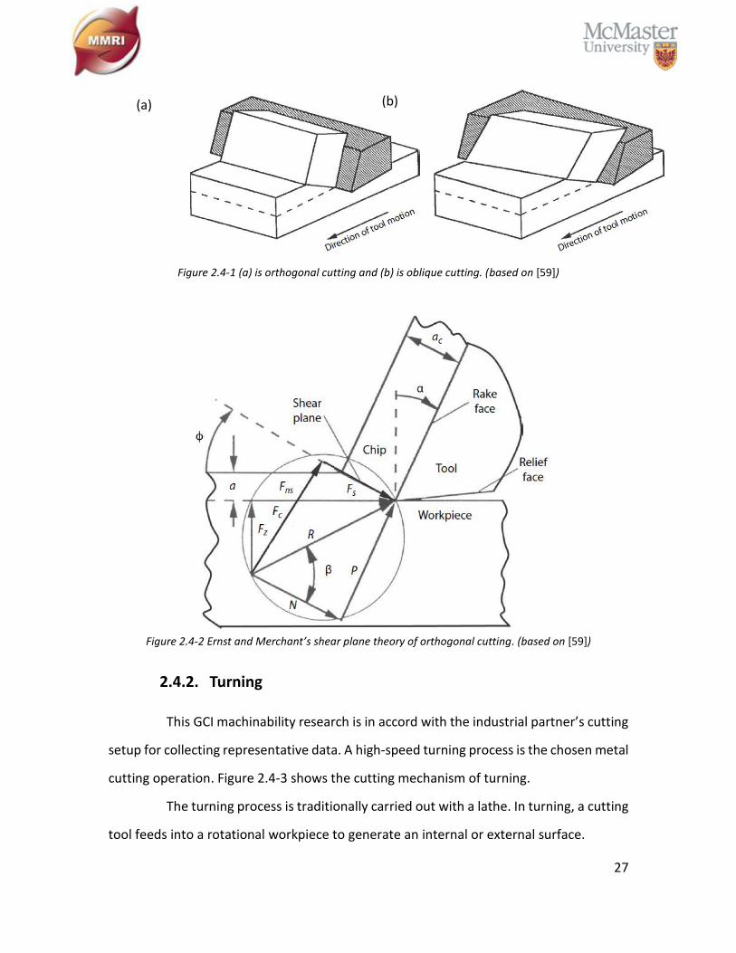
2.4.2. Turning
This GCI machinability research is in accord with the industrial partner’s cutting
setup for collecting representative data. A high-speed turning process is the chosen metal
cutting operation. Figure 2.4-3 shows the cutting mechanism of turning.
The turning process is traditionally carried out with a lathe. In turning, a cutting
tool feeds into a rotational workpiece to generate an internal or external surface.
(a) (b)
28
High cutting speed turning [59], [66], is usually machined with carbide, ceramic
or CBN tool inserts. In machining hardened materials such as GCI in this study, high speed
turning provides more potential advantages than conventional turning, such as less
production cost, less operation steps, higher production efficiency, and the elimination of
cutting fluid. Under intensifying cutting conditions, a CBN tool enables the high speed
turning technology to potentially replace the grinding process[57], [67]. It has been
noticed that the stripped hard boron nitride particles easily generate three-body abrasive
wear on the tool flank face. This flank wear is a major limitation of CBN tool life during
high speed turning [67].
Figure 2.4-3 Simple turning model. (based on [59])
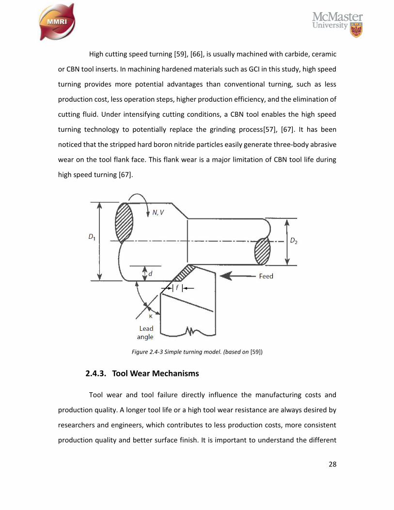
2.4.3. Tool Wear Mechanisms
Tool wear and tool failure directly influence the manufacturing costs and
production quality. A longer tool life or a high tool wear resistance are always desired by
researchers and engineers, which contributes to less production costs, more consistent
production quality and better surface finish. It is important to understand the different
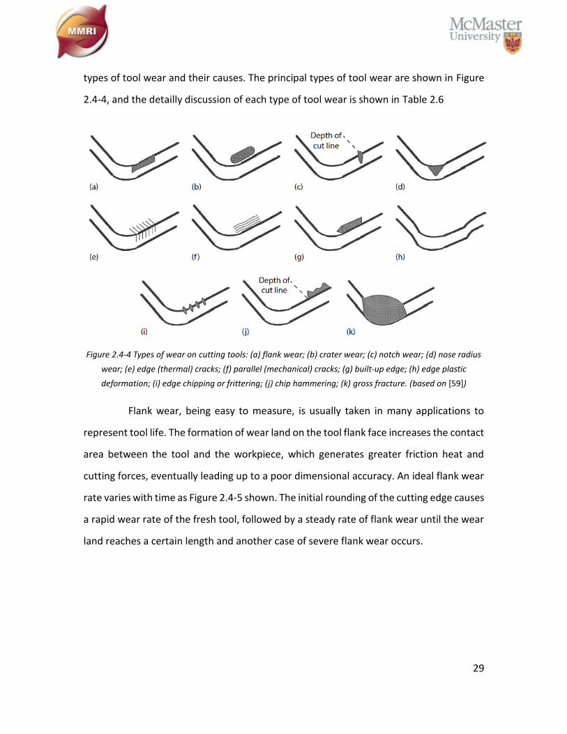
29
types of tool wear and their causes. The principal types of tool wear are shown in Figure
2.4-4, and the detailly discussion of each type of tool wear is shown in Table 2.6
Figure 2.4-4 Types of wear on cutting tools: (a) flank wear; (b) crater wear; (c) notch wear; (d) nose radius
wear; (e) edge (thermal) cracks; (f) parallel (mechanical) cracks; (g) built-up edge; (h) edge plastic
deformation; (i) edge chipping or frittering; (j) chip hammering; (k) gross fracture. (based on [59])
Flank wear, being easy to measure, is usually taken in many applications to
represent tool life. The formation of wear land on the tool flank face increases the contact
area between the tool and the workpiece, which generates greater friction heat and
cutting forces, eventually leading up to a poor dimensional accuracy. An ideal flank wear
rate varies with time as Figure 2.4-5 shown. The initial rounding of the cutting edge causes
a rapid wear rate of the fresh tool, followed by a steady rate of flank wear until the wear
land reaches a certain length and another case of severe flank wear occurs.
30
Figure 2.4-5 Ideal variation of the flank wear rate with cutting time, showing the initial wear, steady wear,
and severe wear periods. (based on [59])
Table 2.6: Tool wear mechanisms and characteristics. (adapted from [59], [68])
Type of Wear Mechanism Characteristics
Flank Wear Abrasion Caused by rubbing of the flank face on the machined surface
Crater Wear Diffusion
Adhesion
At elevated temperatures the tool material will begin to diffuse into the
workpiece material causing craters to form; alternatively, the craters may
form due to micro-chipping as tooling layers are sheared away by localized
adhesion effects
Notch Wear Oxidation
This wear type typically occurs in turning or other processes where the
majority of the tool is continuously embedded in workpiece material and
therefore not exposed to oxygen in the surrounding atmosphere. However,
at the depth of cutting line the tool is exposed and the elevated tool
temperatures cause notch wear to form due to oxidation along that line
Nose Wear Abrasive
Oxidation
Nose wear typically occurs in turning operations on the relief face of the tool
and is a combination of flank wear and notch wear. The relief face allows
oxygen to reach near to the cutting-edge allowing oxidation wear to occur in
addition to abrasive wear resulting in flank wear
(Continued)
31
Table 2.7: Tool wear mechanisms and characteristics. (Continued)
Type of Wear Mechanism Characteristics
Edge Cracking Mechanical
(Thermal)
In brittle tools, temperature gradients developed on the cutting tool may
cause thermal stresses on the surface of the tool which will can cause or
accelerate cracking of the tool or coatings
Parallel
Cracking Mechanical
Especially prevalent in interrupted cutting such as milling, mechanical
cracking may occur in brittle tools due to impact loading on the tool’s cutting
edge. Repeated impacts initiate crack propagation which weaken the cutting
edge of the tool and may lead to chipping or gross fracture
Built-up Edge Adhesion
Due to high temperature and loads occurring in the cutting zone, workpiece
material can weld to the tool. If the degree of adhesion is large, the tool
material may build up on the tool’s cutting edge, effectively increasing the
size of the tool. Eventually the built-up edge will reach a critical size, at which
point it may break away harmlessly, or may fracture a large piece of tool
material, often resulting in tool failure
Edge Plastic
Deformation Mechanical
This type of wear is most common in ductile tooling materials, such as high-
speed steel. Due to high heat and loading, the tool material may deform,
changing the tool geometry, depth of cut and other important process
parameters
Edge Chipping Mechanical
Abrasive
Edge chipping can be the eventual result of residual cracks caused by either
thermal (comb cracking) or mechanical (parallel cracking) wear types, and is
especially prevalent in interrupted cutting, such as milling. It can also be the
result of adhesive wear, were the level of adhesion is small and so fractured
tool material remains minimal
Chip
Hammering
Mechanical
Abrasive
Chip hammering occurs when the formation of the chip is not well
controlled. The chip curls up, away from then tool and is then forced back
down to strike and abrade the tool away from the cutting zone
Gross
Fracture
Mechanical
Adhesion
Catastrophic failure of the tool by massive chipping/gross fracture can occur
for a number of reasons. If mechanical loading on the cutting edge far
exceeds the capacity of the tool to support it can cause this. As well, the
breaking off of a large built up edge can cause gross fracture as previously
discussed. Severe thermal or mechanical cracking can also lead to this wear
mechanism
32
Chapter 3: Experimental Work
The MMRI is one of the largest university-based manufacturing research
institutes in Canada, supporting academic research and education programs that span
many manufacturing processes. The institute’s core focus is to enhance productivity,
quality and product/process innovation while helping companies reduce costs. The
purpose of this major industrial funded research project is to achieve a better
understanding of the variation of GCI machinability. Resources allocated to this s project
cover multiple Master and PhD students’ research works starting from 2015. The tests
conducted cover multiple academic fields with wide support provided by MMRI staff and
researchers.
The research engineer, Ahmed Sweed at MMRI helped to optimize and finish
the machinability tests of the GCI age strengthening phenomena. He also conducted a
machinability test to optimize the different options available for CBN cutting tools.
Bipasha Bose is the PhD material engineering specialist at MMRI. Her parallel
nano-indentation tests helped increase GCI hardness after room temperature aging.
3.1. Workpiece Materials
The GCI workpiece materials were supplied by our industrial partner, which is
the FC250 grade of GCI cylinder sleeves shown as in Figure 3.1-1. For cross reference,
please check Table 2.2. The GCI sleeves were used for high speed turning preliminary tests
followed by the study of the cutting speed’s effect on CBN tool wear behavior and the
study of varied CBN composition wear behavior. The cutting condition and the
appropriate CBN cutting tool were chosen based on the results obtained from the
preliminary tests.
33
Figure 3.1-1 GCI engine sleeves.
3.1.1. Workpiece Material Characteristics
Basic information of modified FC250 GCI cylinder sleeves were provided by the
industrial partner. Table 3.1 shows the characterization of the workpiece material, such
as chemical composition, microstructure, and mechanical properties.
Table 3.1: Workpiece material characterization of modified FC250 GCI cylinder sleeves.
Mechanical Properties Tensile Strength (N/mm2) Rockwell Hardness (HRB)
250 min Around 98
Microstructure Matrix Graphite
Predominantly pearlitic
Small amounts of free ferrite & steadite
Major type A
Minor type B & D
Chemical Composition (wt. %)
C: 3.20 – 3.50 Si: 1.70 – 2.20 Mn: 0.60 – 0.90
P: ≤ 0.15 S: ≤ 0.10
3.1.2. Metallographic Analysis
From the second half of 2015, the industrial partner has been collecting and
providing sleeves to MMRI on a bi-weekly basis. The goal was to establish a timeline of
34
microstructure information, which could be tied to periods of poor machinability as
described in the introduction. Observations of free ferrite content and aging phenomena
also require metallographic inspection of the samples to record the change of material
characteristics. Metallographic analysis was carried out on small pieces of GCI workpiece
cut from individual cylinder sleeves by bulk abrasive saw and hot-mounted in an epoxy
resin with mineral filler using Struers Ensuring Certainty Hot Mounting under a
temperature of 150˚C and pressure of 250 Bar for 5 mins of heating and 3 mins of cooling.
All the mounted samples were then ground using progressively finer grades of SiC paper
(P500 – P4000) and polished with a final 1µm diamond particle and “blue-ethanol”
lubricant mixture with a Struers Ensuring Certainty Auto-polisher. After each
progressively finer step of polishing, especially at the final step, samples were rinsed in
95% ethanol and dried using a hot air blower. Polished samples were examined with a
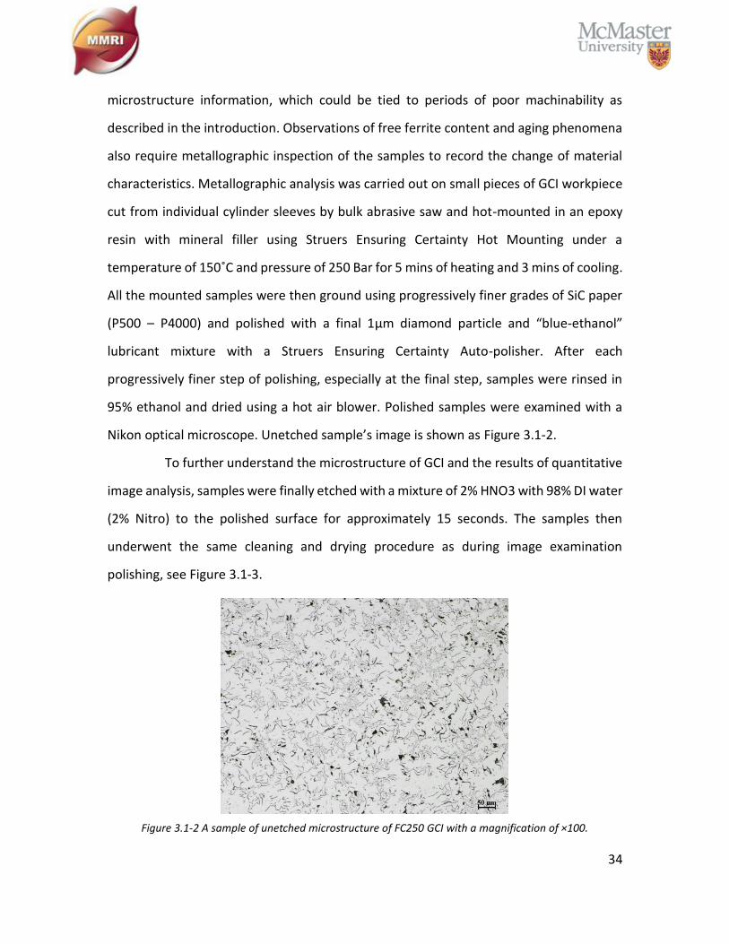
Nikon optical microscope. Unetched sample’s image is shown as Figure 3.1-2.
To further understand the microstructure of GCI and the results of quantitative
image analysis, samples were finally etched with a mixture of 2% HNO3 with 98% DI water
(2% Nitro) to the polished surface for approximately 15 seconds. The samples then
underwent the same cleaning and drying procedure as during image examination
polishing, see Figure 3.1-3.
Figure 3.1-2 A sample of unetched microstructure of FC250 GCI with a magnification of ×100.
35
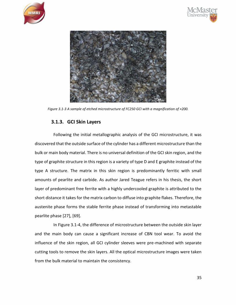
Figure 3.1-3 A sample of etched microstructure of FC250 GCI with a magnification of ×200.
3.1.3. GCI Skin Layers
Following the initial metallographic analysis of the GCI microstructure, it was
discovered that the outside surface of the cylinder has a different microstructure than the
bulk or main body material. There is no universal definition of the GCI skin region, and the
type of graphite structure in this region is a variety of type D and E graphite instead of the
type A structure. The matrix in this skin region is predominantly ferritic with small
amounts of pearlite and carbide. As author Jared Teague refers in his thesis, the short
layer of predominant free ferrite with a highly undercooled graphite is attributed to the
short distance it takes for the matrix carbon to diffuse into graphite flakes. Therefore, the
austenite phase forms the stable ferrite phase instead of transforming into metastable
pearlite phase [27], [69].
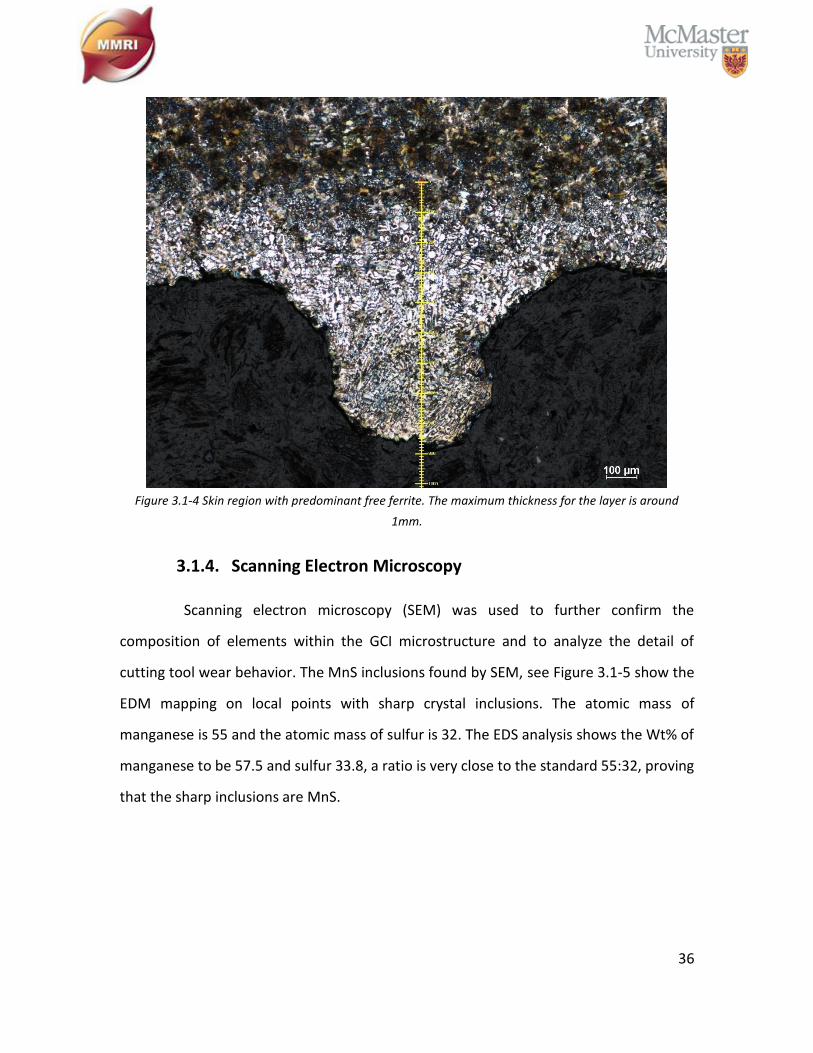
In Figure 3.1-4, the difference of microstructure between the outside skin layer
and the main body can cause a significant increase of CBN tool wear. To avoid the
influence of the skin region, all GCI cylinder sleeves were pre-machined with separate
cutting tools to remove the skin layers. All the optical microstructure images were taken
from the bulk material to maintain the consistency.
36
Figure 3.1-4 Skin region with predominant free ferrite. The maximum thickness for the layer is around
1mm.
3.1.4. Scanning Electron Microscopy
Scanning electron microscopy (SEM) was used to further confirm the
composition of elements within the GCI microstructure and to analyze the detail of
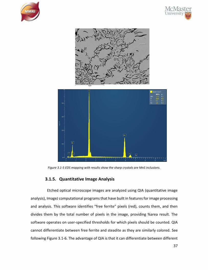
cutting tool wear behavior. The MnS inclusions found by SEM, see Figure 3.1-5 show the
EDM mapping on local points with sharp crystal inclusions. The atomic mass of
manganese is 55 and the atomic mass of sulfur is 32. The EDS analysis shows the Wt% of
manganese to be 57.5 and sulfur 33.8, a ratio is very close to the standard 55:32, proving
that the sharp inclusions are MnS.
37
Figure 3.1-5 EDS mapping with results show the sharp crystals are MnS inclusions.
3.1.5. Quantitative Image Analysis
Etched optical microscope images are analyzed using QIA (quantitative image
analysis), ImageJ computational programs that have built in features for image processing
and analysis. This software identifies “free ferrite” pixels (red), counts them, and then
divides them by the total number of pixels in the image, providing %area result. The
software operates on user-specified thresholds for which pixels should be counted. QIA
cannot differentiate between free ferrite and steadite as they are similarly colored. See
following Figure 3.1-6. The advantage of QIA is that it can differentiate between different

38
materials based on the color contrast. However, the result is subjective, since the red area
is a manual threshold which may underestimate or overestimate the reading. Also, since
steadite and free ferrite have a similar color, a small amount of steadite is present in the
result under any color contrast. However, its influence is negligible.
On the other hand, there is no exact measurement of free ferrite which can only
be optimized. To get a relatively reliable result with QIA, the optimized threshold between
the higher and lower estimate was chosen from the average of multiple images.
Figure 3.1-6 Quantitative image analysis by ImageJ, the red area is free ferrite based on the pixels been
counted. Yellow circle is steadite which been counted as free ferrite.
3.2. Cutting Tools
Four indexable CBN cutting inserts were mounted in a commercial tool holder
for high turning to study the variation of GCI machinability for the cutting process
optimization. The geometries of these inserts are constant, see Table 3.2.
Table 3.2: Cutting inserts information.
Insert Grade CBN
(vol%)
Grain Size
(µm) Chamfer
Rake
Angle Major Binder
Composition 1 95 2 No Chamfer 0 ̊ Titanium Alloy
Composition 2 85 2 No Chamfer 0 ̊ AlWCoB
Composition 3 65 3 No Chamfer 0 ̊ TiN
Composition 4 50 1.5 No Chamfer 0 ̊ TiC
39
3.3. Experimental Setup
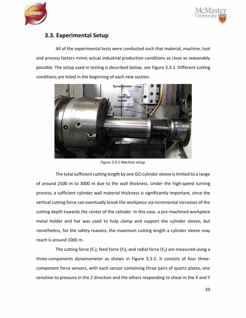
All of the experimental tests were conducted such that material, machine, tool
and process factors mimic actual industrial production conditions as close as reasonably
possible. The setup used in testing is described below, see Figure 3.3-1. Different cutting
conditions are listed in the beginning of each new section.
Figure 3.3-1 Machine setup.
The total sufficient cutting length by one GCI cylinder sleeve is limited to a range
of around 2500 m to 3000 m due to the wall thickness. Under the high-speed turning
process, a sufficient cylinder wall material thickness is significantly important, since the
vertical cutting force can eventually break the workpiece via incremental increases of the
cutting depth towards the center of the cylinder. In this case, a pre-machined workpiece
metal holder and hat was used to help clamp and support the cylinder sleeve, but
nonetheless, for the safety reasons, the maximum cutting length a cylinder sleeve may
reach is around 1000 m.
The cutting force (Fc), feed force (Ff), and radial force (Fd) are measured using a
three-components dynamometer as shown in Figure 3.3-2. It consists of four three-
component force sensors, with each sensor containing three pairs of quartz plates, one
sensitive to pressure in the Z direction and the others responding to shear in the X and Y
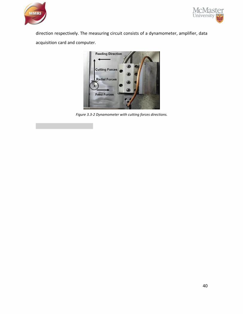
40
direction respectively. The measuring circuit consists of a dynamometer, amplifier, data
acquisition card and computer.
Figure 3.3-2 Dynamometer with cutting forces directions.
41
Chapter 4: Tool Wear Behavior of Varied CBN Composition
4.1. Experimental Procedure
Tests on the tool wear behavior of four types of CBN cutting tools, as shown in
Table 3.2, were conducted to optimize the following machinability tests and to observe
how different machining process parameters and tools performed under given material
conditions. The data for these four CBN cutting inserts are shown in Table 3.2The major
differences between them are the volume percentage content of CBN particle, the CBN
particle size, and the binder materials.
The experiments were conducted on BOEHRINGER VDF 180 CM CNC turning
center with Siemens controlling unit using a pre-machined (skin layers were removed)
cylindrical GCI sleeve. All the workpiece materials were fully aged and QIA was performed
prior to running the machining processes, so that all of the workpieces had similar
microstructure and mechanical properties. The machine setup is the same as Figure 3.3-1
described. Detail cutting conditions are listed below.
Cutting Speed: 1176 m/min
Feed Rate: 0.125 mm/rev
Depth of Cut: 0.3 mm on radius
Cutting Fluid: Flood coolant, semi-synthetic, 8-10% concentration
Tool Failure Criteria: 300 µm length of flank wear
All cutting conditions were chosen to simulate those found in industry, in order
to get relatively reliable results. As section 2.4.2 mentioned, CBN inserts are extreme hard
cutting tools best suited for the high-speed turning process, but the stripped CBN particles
easily cause abrasive wear on flank face. In industry, a 300 µm length of flank wear is a
common failure criterion to indicate tool life. Whenever significant tool chipping occurs
or the flank wear reaches 300 µm, the machine processes would stop and the total cutting
length for each type of CBN tool would be calculated and listed as a graph.
42
Cutting Length = ∑(π × 𝐷𝑖 × Z)/(1000 × f)
𝑛
𝑖=1
𝐷𝑖: uncut diameter of cylinder sleeve at i cutting pass; Z: cut length of cylinder sleeve; n:
total number of cutting pass per insert; f: feed rate
(4.6)
4.2. Results and Discussion
The cutting tool optimization tests were conducted with four different types of
commercial CBN inserts with fully aged GCI workpiece materials of FC250 grade. These
four CBN inserts are CBN composition 1, composition 2, composition 3, and composition
4 with details listed in Table 3.2. The content of free ferrite is less than 2% for this batch
of workpiece material. The cutting condition for these four different types of CBN inserts
were constant according to the industrial partner’s cutting parameters. Using a
BOEHRINGER VDF 180 CM CNC turning center, the cutting speed was 1176 m/min, depth
of cut on radius is 0.3 mm per pass, and the feed rate is 0.125 mm/rev. As mentioned in
section 3.1.3, the GCI cylinder sleeves have a 1mm thick ferritic skin layer, and following
the removal of this layer on all the workpiece materials, the maximum cutting passes are
limited to a total of four on each cylinder sleeve. Under severe cutting conditions of HST,
the reduced cylinder sleeve wall thickness can cause critical damage from friction with
the workpiece. Each different cutting pass has a different uncut diameter of the cylinder
sleeve and the total cutting length can be calculated with equation 4.6.
In industry, it is common to set the tool failure criteria to 300 µm length of flank
wear. The following optical microscopic images Figure 4.2-1 show the wear behavior on
both flank face and rake face of four chosen CBN cutting tools, after each insert reaches
its tool failure criteria. The total tool wear behavior graph and tool wear pattern is shown
in Figure 4.2-2.
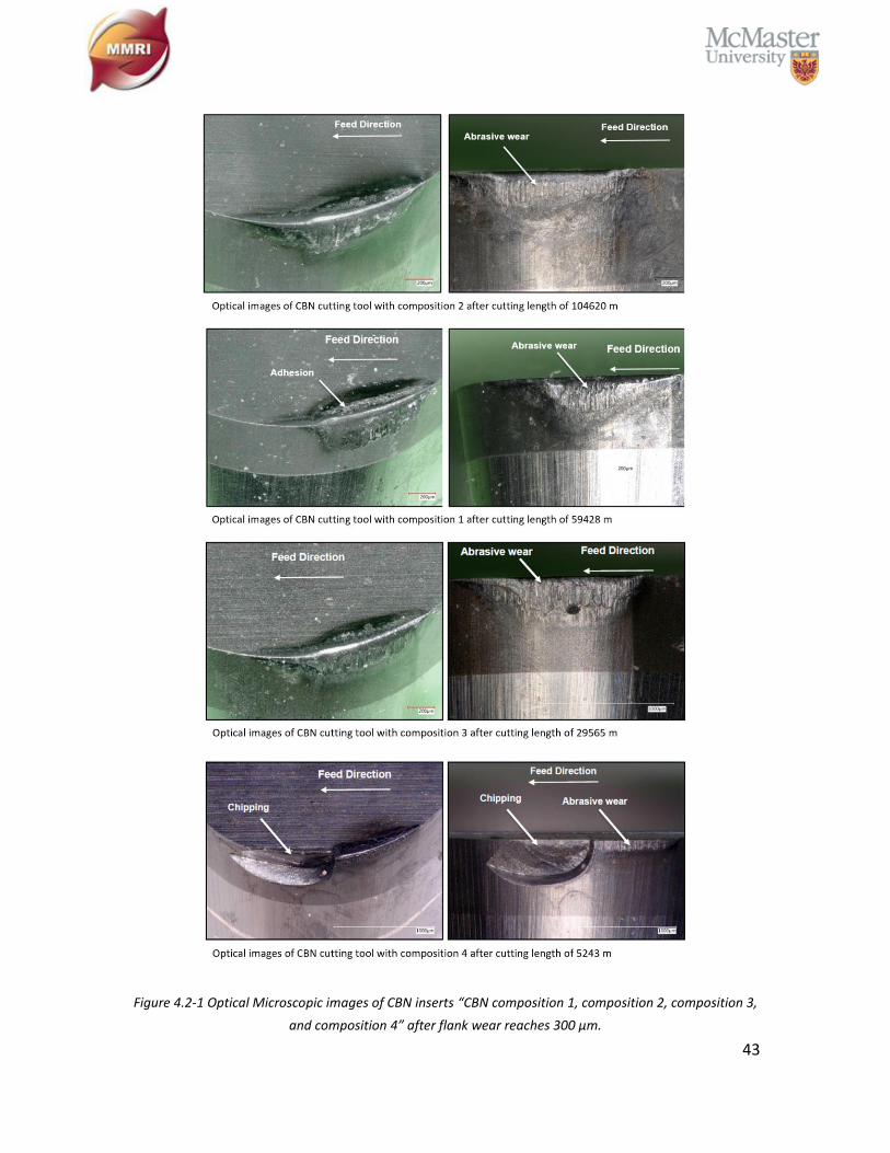
43
Figure 4.2-1 Optical Microscopic images of CBN inserts “CBN composition 1, composition 2, composition 3,
and composition 4” after flank wear reaches 300 µm.
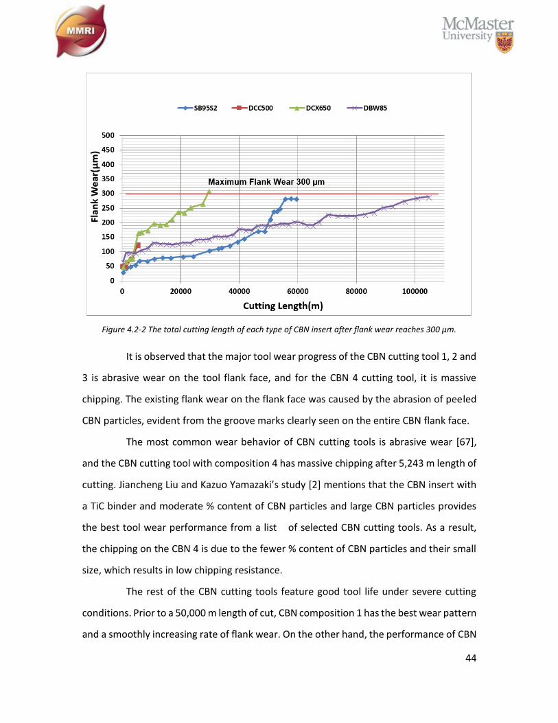
44
Figure 4.2-2 The total cutting length of each type of CBN insert after flank wear reaches 300 µm.
It is observed that the major tool wear progress of the CBN cutting tool 1, 2 and
3 is abrasive wear on the tool flank face, and for the CBN 4 cutting tool, it is massive
chipping. The existing flank wear on the flank face was caused by the abrasion of peeled
CBN particles, evident from the groove marks clearly seen on the entire CBN flank face.
The most common wear behavior of CBN cutting tools is abrasive wear [67],
and the CBN cutting tool with composition 4 has massive chipping after 5,243 m length of
cutting. Jiancheng Liu and Kazuo Yamazaki’s study [2] mentions that the CBN insert with
a TiC binder and moderate % content of CBN particles and large CBN particles provides
the best tool wear performance from a list of selected CBN cutting tools. As a result,
the chipping on the CBN 4 is due to the fewer % content of CBN particles and their small
size, which results in low chipping resistance.
The rest of the CBN cutting tools feature good tool life under severe cutting
conditions. Prior to a 50,000 m length of cut, CBN composition 1 has the best wear pattern
and a smoothly increasing rate of flank wear. On the other hand, the performance of CBN
45
cutting tool with composition 3 is not as good. The total cutting length of CBN 3 is less
than 30,000 m, and it has the steepest tool wear pattern compared to other CBN cutting
tools. CBN cutting tool with composition 2 shows the longest tool life (104,620 meter of
cutting length), almost double the length of CBN 1 and thrice that of CBN 3. It was
observed that CBN 1 has the most adhesion material on rake face compared to other CBN
cutting tools, which may be the reason that the change of cutting tool geometry after a
certain length of flank wear causes a dramatically increasing rate of built-up layer
formation on the rake face and eventual loss of tool life compared to CBN 2.
CBN 1 has the greatest % content of CBN particles, but second longest tool life
out of four of the chosen CBN cutting tools. It may cause a greater tendency of boron
from the workpiece material to diffuse into ferrite [70], [71].
46
Chapter 5: Effect of Cutting Speed on CBN Tool Wear Behavior
5.1. Experimental Procedure
Based on the last experiment, the tool wear behavior of four types of CBN
cutting tools were identified. Selecting the CBN cutting tool with the best wear resistance,
the following cutting conditions were used to study the effect of cutting speed on CBN
tool wear behavior.
Cutting Speed: 250 m/min and 800 m/min
Feed Rate: 0.125 mm/rev
Depth of Cut: 0.3 mm on radius
Cutting Fluid: Flood coolant, semi-synthetic, 8-10% concentration
Tool Failure Criteria: 2400 m of total cutting length
Two parallel machinability tests were conducted using a low cutting speed (250
m/min) and high cutting speed (800 m/min). The same workpiece material was used to
ensure consistent GCI microstructure and mechanical properties. The three orthogonal
force components: radial force, feed force and cutting force were measured with the
dynamometer as shown in Figure 3.3-2. The forces were compared with the cutting length
under two cutting speeds (250 m/min and 800 m/min). Equation 4.6 calculates the total
cutting length. After the total cutting length reaches 2400 m, the length of flank wear was
measured for both the low and high cutting speed.
5.2. Results and Discussion
Based on the previous section, CBN 1 has a better tool life before the cutting
length reaches 50,000 m. Therefore, this insert was selected in testing the effect of the
cutting speed on tool wear behavior under a low cutting speed (250 m/min) and a high
cutting speed (800m/min). The remaining cutting conditions are the same as in previous
tests, and the experiment stops whenever the total cutting length reaches 2,400 m.
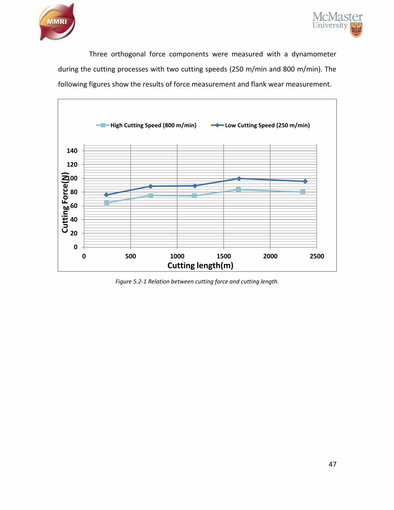
47
Three orthogonal force components were measured with a dynamometer
during the cutting processes with two cutting speeds (250 m/min and 800 m/min). The
following figures show the results of force measurement and flank wear measurement.
Figure 5.2-1 Relation between cutting force and cutting length.
0
20
40
60
80
100
120
140
0 500 1000 1500 2000 2500
Cu
ttin
g Fo
rce
(N)
Cutting length(m)
High Cutting Speed (800 m/min) Low Cutting Speed (250 m/min)
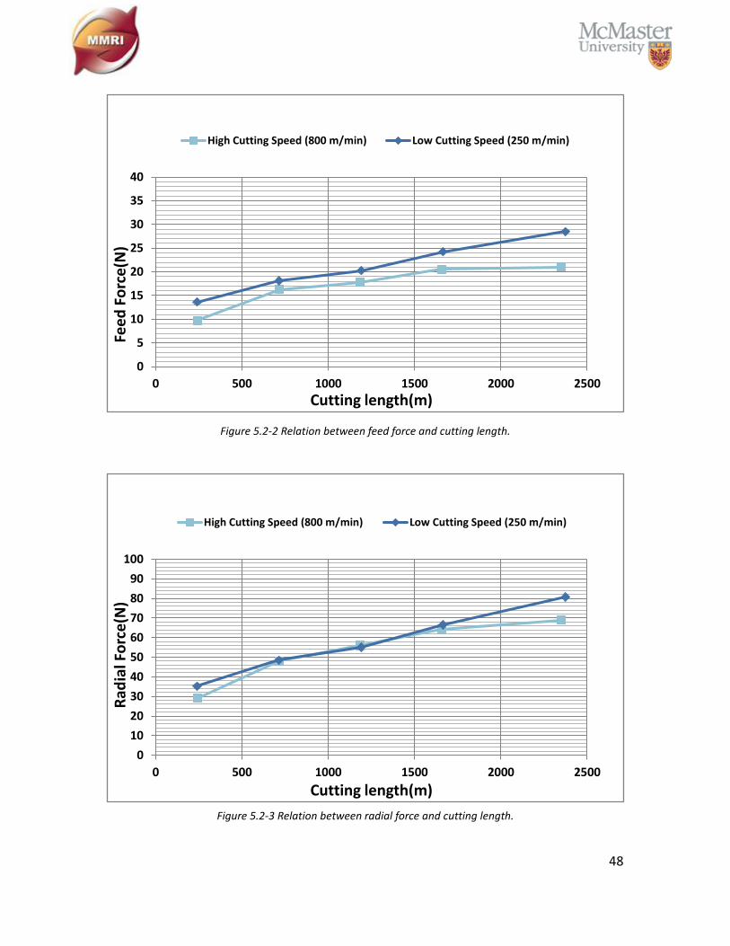
48
Figure 5.2-2 Relation between feed force and cutting length.
Figure 5.2-3 Relation between radial force and cutting length.
0
5
10
15
20
25
30
35
40
0 500 1000 1500 2000 2500
Fee
d F
orc
e(N
)
Cutting length(m)
High Cutting Speed (800 m/min) Low Cutting Speed (250 m/min)
0
10
20
30
40
50
60
70
80
90
100
0 500 1000 1500 2000 2500
Rad
ial F
orc
e(N
)
Cutting length(m)
High Cutting Speed (800 m/min) Low Cutting Speed (250 m/min)

49
Figure 5.2-4 Relation between flank wear behavior and cutting length.
It is observed that under orthogonal cutting conditions with a high cutting
speed (800 m/min) and a low cutting speed (250 m/min), CBN 1 presents less force
measurements. This confirms that the high-speed machining of GCI extends the CBN tool
life compared to the conventional cutting speed. The high cutting speed shows a stable
and reduced rate of flank wear.
Optical microscopic images show that the lower cutting speed not only has
larger flank wear but also more aggressive crater wear on tool rake face. This may be due
to the longer tool-chip contact time generating more heat on tool-chip interface zone.
SEM images on the tool rake face under both a low cutting speed and a high cutting speed
further prove that the CBN insert with the low cutting speed has greater abrasion on the
tool rake face.
0
20
40
60
80
100
120
140
0 500 1000 1500 2000 2500
Flan
k W
ear
(μ)
Cutting length(m)
High Cutting Speed (800 m/min) Low Cutting Speed (250 m/min)
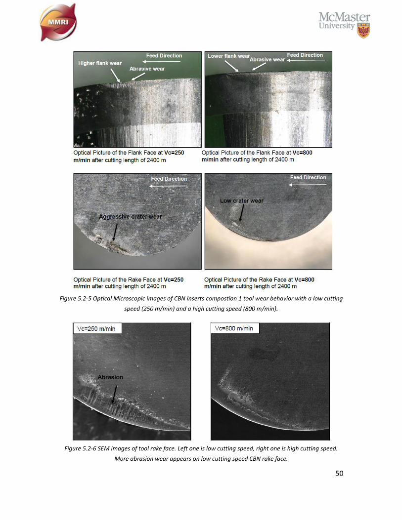
50
Figure 5.2-5 Optical Microscopic images of CBN inserts compostion 1 tool wear behavior with a low cutting
speed (250 m/min) and a high cutting speed (800 m/min).
Figure 5.2-6 SEM images of tool rake face. Left one is low cutting speed, right one is high cutting speed.
More abrasion wear appears on low cutting speed CBN rake face.

51
It has been confirmed that a high cutting speed on the GCI cylinder sleeves is
likely not sacrificing tool life but in fact contributes to a better tool life. Following the
results from this section, the subsequent studies keep using CBN insert composition 1.
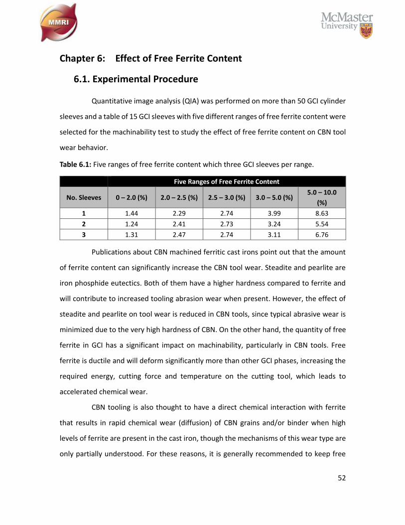
52
Chapter 6: Effect of Free Ferrite Content
6.1. Experimental Procedure
Quantitative image analysis (QIA) was performed on more than 50 GCI cylinder
sleeves and a table of 15 GCI sleeves with five different ranges of free ferrite content were
selected for the machinability test to study the effect of free ferrite content on CBN tool
wear behavior.
Table 6.1: Five ranges of free ferrite content which three GCI sleeves per range.
Five Ranges of Free Ferrite Content
No. Sleeves 0 – 2.0 (%) 2.0 – 2.5 (%) 2.5 – 3.0 (%) 3.0 – 5.0 (%) 5.0 – 10.0
(%)
1 1.44 2.29 2.74 3.99 8.63
2 1.24 2.41 2.73 3.24 5.54
3 1.31 2.47 2.74 3.11 6.76
Publications about CBN machined ferritic cast irons point out that the amount
of ferrite content can significantly increase the CBN tool wear. Steadite and pearlite are
iron phosphide eutectics. Both of them have a higher hardness compared to ferrite and
will contribute to increased tooling abrasion wear when present. However, the effect of
steadite and pearlite on tool wear is reduced in CBN tools, since typical abrasive wear is
minimized due to the very high hardness of CBN. On the other hand, the quantity of free
ferrite in GCI has a significant impact on machinability, particularly in CBN tools. Free
ferrite is ductile and will deform significantly more than other GCI phases, increasing the
required energy, cutting force and temperature on the cutting tool, which leads to
accelerated chemical wear.
CBN tooling is also thought to have a direct chemical interaction with ferrite
that results in rapid chemical wear (diffusion) of CBN grains and/or binder when high
levels of ferrite are present in the cast iron, though the mechanisms of this wear type are
only partially understood. For these reasons, it is generally recommended to keep free

53
ferrite to low levels (<2-5%) and to ensure suitable aging time for grey cast iron parts prior
to machining.
Five levels of free ferrite were chosen based on a significant amount of QIA prior
to machinability tests, using a fresh composition 1 CBN insert per level of free ferrite. A
total of five fresh inserts were used in this part of the study and the cutting conditions are
as follows:
Cutting Speed: 1176 m/min
Feed Rate: 0.125 mm/rev
Depth of Cut: 0.3 mm on radius
Cutting Fluid: Flood coolant, semi-synthetic, 8-10% concentration
Tool Failure Criteria: 3000 m of total cutting length by three-cylinder sleeves
6.2. Results and Discussion
Each cylinder sleeve can be machined until a maximum cutting length of 1,000
m. Therefore, multiple sleeves are required to test one insert’s wear behavior. Also, the
free ferrite content for each sleeve is different to the others and a range of 5% of free
ferrite content was decided for the GCI sleeves after QIA.
Free ferrite ranges from 0 – 2.0%, 2.0 – 2.5%, and 2.5 – 3.0%, were chosen to
represent the conventional high-speed machining of low free ferrite content GCI
workpiece. Free ferrite ranges from 3.0 – 5.0% and 5.0 – 10.0% were chosen to represent
the high-speed machining of a high level of free ferrite content GCI workpiece. After
cutting length reaches 3,000 m (three sleeves been machined), the tool life graph relating
to % free ferrite content is shown in Figure 6.2-1.
With the increase of free ferrite content, the CBN flank wear grows linearly,
while the maximum cutting length remains constant for all the testing CBN inserts, i.e.
3,000 m.
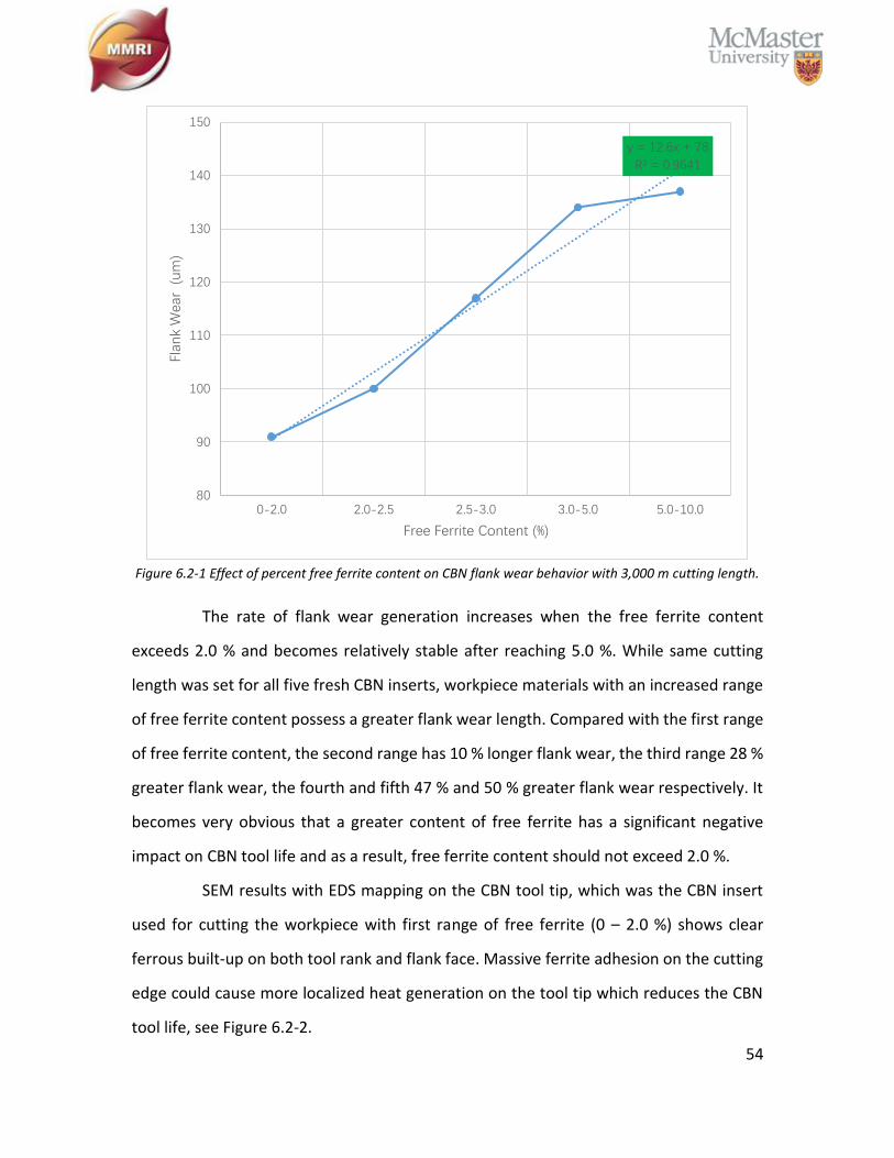
54
Figure 6.2-1 Effect of percent free ferrite content on CBN flank wear behavior with 3,000 m cutting length.
The rate of flank wear generation increases when the free ferrite content
exceeds 2.0 % and becomes relatively stable after reaching 5.0 %. While same cutting
length was set for all five fresh CBN inserts, workpiece materials with an increased range
of free ferrite content possess a greater flank wear length. Compared with the first range
of free ferrite content, the second range has 10 % longer flank wear, the third range 28 %
greater flank wear, the fourth and fifth 47 % and 50 % greater flank wear respectively. It
becomes very obvious that a greater content of free ferrite has a significant negative
impact on CBN tool life and as a result, free ferrite content should not exceed 2.0 %.
SEM results with EDS mapping on the CBN tool tip, which was the CBN insert
used for cutting the workpiece with first range of free ferrite (0 – 2.0 %) shows clear
ferrous built-up on both tool rank and flank face. Massive ferrite adhesion on the cutting
edge could cause more localized heat generation on the tool tip which reduces the CBN
tool life, see Figure 6.2-2.
y = 12.6x + 78
R² = 0.9641
80
90
100
110
120
130
140
150
0-2.0 2.0-2.5 2.5-3.0 3.0-5.0 5.0-10.0
Flan
k W
ear
(u
m)
Free Ferrite Content (%)
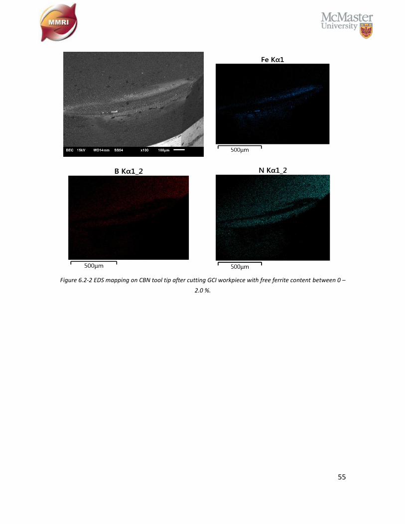
55
Figure 6.2-2 EDS mapping on CBN tool tip after cutting GCI workpiece with free ferrite content between 0 –
2.0 %.
56
Chapter 7: Influence of GCI Age Strengthening on Machinability
7.1. Experimental Procedure
To support the GCI aging study, a special lot of approximately 1200 fresh
(unaged) GCI cylinder sleeves were prepared by the industrial partner on October 25th,
2017. These sleeves were shipped to the MMRI lab to be used in a full room temperature
aging study, commencing on October 27th, 2017. All of the samples were stacked under
room temperature. The industrial machining processes were mimicked in MMRI lab by a
Boehringer VDF 180 CM CNC turning center using the following industrial cutting
conditions.
Cutting Speed: 1176 m/min
Feed Rate: 0.125 mm/rev
Depth of Cut: 0.3 mm on radius
Cutting Fluid: Flood coolant, semi-synthetic, 8-10% concentration
Tool Failure Criteria: 300 µm length of flank wear
Since QIA takes a long time to produce workpiece microstructure results, it was
skipped while the artificial room temperature GCI age strengthening was in progress.
Every two days, sleeves were machined until a fresh CBN tool was fully worn;
producing a set of experiments relating tool life to age of the sleeves. In parallel to
machinability testing, a material characterization study was initiated to track how the
hardness of the GCI cylinder sleeve material changed with aging progression. Previously
published research shows that the GCI aging phenomena is the precipitation of stable iron
nitride (Fe4N) into soft ferrite. Observing how the hardness of GCI cylinder sleeves
changes over time would provide additional data to support machinability testing results.
57
7.2. Results and Discussion
7.2.1. Machinability Test
Prior to the beginning of the aging study, the experimental set-up had been
used extensively in related tests including identifying optimal CBN grades and the cutting
speed. These tests were completed using “fully aged” sleeves with free ferrite content
fewer than 2%. The preliminary tests validate the set-up prior to the beginning of the
aging test, establishing a benchmark tool life in the range of 20,000 m – 100,000 m of cut.
The aging study was completed with this same set-up, identical in all aspects except for
the sleeves being cut.
The result of the aging study is shown in Figure 7.2-1. Initial tests demonstrated
tool life of approximately 1000 m, which improved over the first 5 days to 2500 m. The
expectation was that tool life would continue to increase and eventually reach the same
life as previous tests on fully-aged liners, being somewhere in the range of 20,000 m –
100,000 m of cut. Day 7.5 showed a significant drop of tool life and was the first sign that
testing was not proceeding as expected, based on fully aged GCI preliminary tests. Given
this unexpected result, testing was repeated on day 8.5, showing the highest life of the
experiment after approximately 3700 m of cut, but still far short of the 100,000 m of tool
life achieved in the previous tests on fully aged cylinder sleeves.
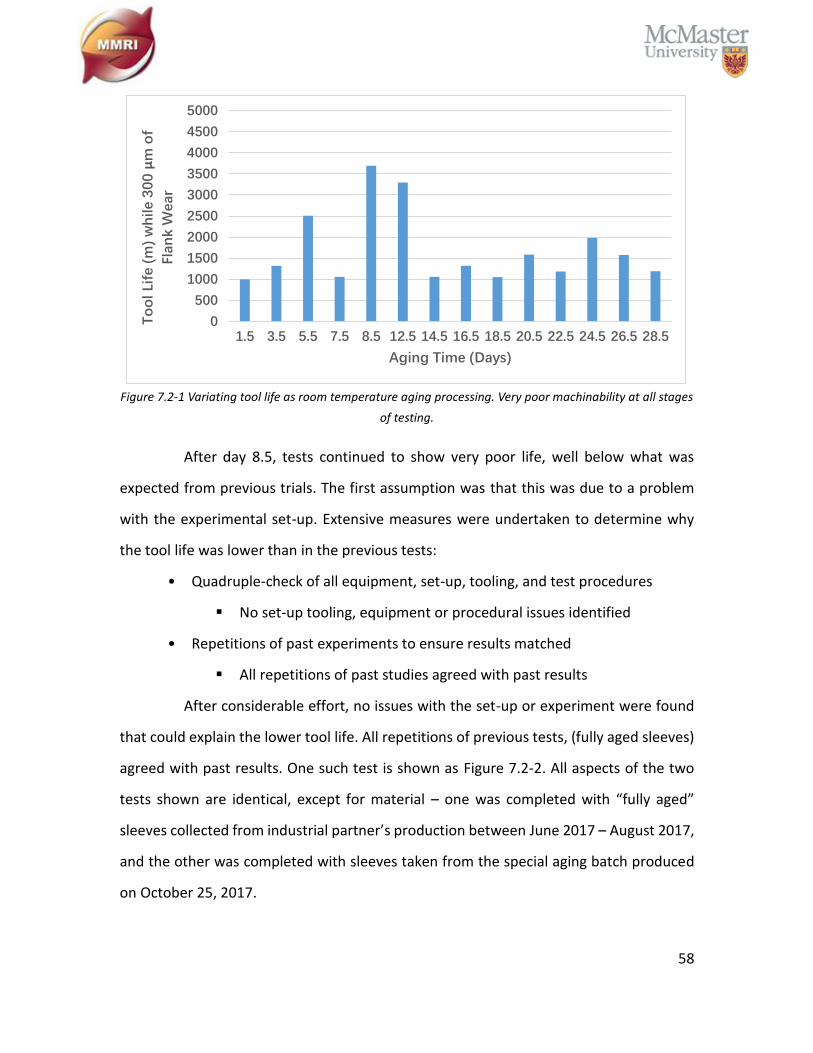
58
Figure 7.2-1 Variating tool life as room temperature aging processing. Very poor machinability at all stages
of testing.
After day 8.5, tests continued to show very poor life, well below what was
expected from previous trials. The first assumption was that this was due to a problem
with the experimental set-up. Extensive measures were undertaken to determine why
the tool life was lower than in the previous tests:
• Quadruple-check of all equipment, set-up, tooling, and test procedures
▪ No set-up tooling, equipment or procedural issues identified
• Repetitions of past experiments to ensure results matched
▪ All repetitions of past studies agreed with past results
After considerable effort, no issues with the set-up or experiment were found
that could explain the lower tool life. All repetitions of previous tests, (fully aged sleeves)
agreed with past results. One such test is shown as Figure 7.2-2. All aspects of the two
tests shown are identical, except for material – one was completed with “fully aged”
sleeves collected from industrial partner’s production between June 2017 – August 2017,
and the other was completed with sleeves taken from the special aging batch produced
on October 25, 2017.
0
500
1000
1500
2000
2500
3000
3500
4000
4500
5000
1.5 3.5 5.5 7.5 8.5 12.5 14.5 16.5 18.5 20.5 22.5 24.5 26.5 28.5
To
ol Li
fe (
m)
wh
ile 3
00
µm
of
Flan
k W
ear
Aging Time (Days)
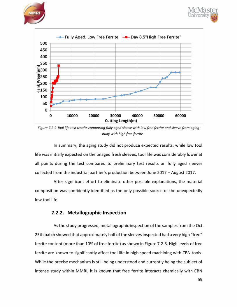
59
Figure 7.2-2 Tool life test results comparing fully aged sleeve with low free ferrite and sleeve from aging
study with high free ferrite.
In summary, the aging study did not produce expected results; while low tool
life was initially expected on the unaged fresh sleeves, tool life was considerably lower at
all points during the test compared to preliminary test results on fully aged sleeves
collected from the industrial partner’s production between June 2017 – August 2017.
After significant effort to eliminate other possible explanations, the material
composition was confidently identified as the only possible source of the unexpectedly
low tool life.
7.2.2. Metallographic Inspection
As the study progressed, metallographic inspection of the samples from the Oct.
25th batch showed that approximately half of the sleeves inspected had a very high “free”
ferrite content (more than 10% of free ferrite) as shown in Figure 7.2-3. High levels of free
ferrite are known to significantly affect tool life in high speed machining with CBN tools.
While the precise mechanism is still being understood and currently being the subject of
intense study within MMRI, it is known that free ferrite interacts chemically with CBN
0
50
100
150
200
250
300
350
400
450
500
0 10000 20000 30000 40000 50000 60000
Flan
k W
ear(
μm
)
Cutting Length(m)
Fully Aged, Low Free Ferrite Day 8.5"High Free Ferrite"
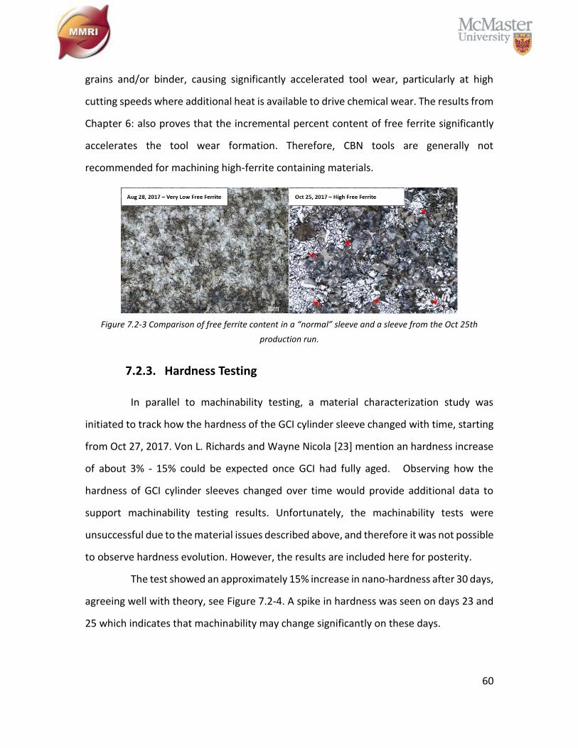
60
grains and/or binder, causing significantly accelerated tool wear, particularly at high
cutting speeds where additional heat is available to drive chemical wear. The results from
Chapter 6: also proves that the incremental percent content of free ferrite significantly
accelerates the tool wear formation. Therefore, CBN tools are generally not
recommended for machining high-ferrite containing materials.
Figure 7.2-3 Comparison of free ferrite content in a “normal” sleeve and a sleeve from the Oct 25th
production run.
7.2.3. Hardness Testing
In parallel to machinability testing, a material characterization study was
initiated to track how the hardness of the GCI cylinder sleeve changed with time, starting
from Oct 27, 2017. Von L. Richards and Wayne Nicola [23] mention an hardness increase
of about 3% - 15% could be expected once GCI had fully aged. Observing how the
hardness of GCI cylinder sleeves changed over time would provide additional data to
support machinability testing results. Unfortunately, the machinability tests were
unsuccessful due to the material issues described above, and therefore it was not possible
to observe hardness evolution. However, the results are included here for posterity.
The test showed an approximately 15% increase in nano-hardness after 30 days,
agreeing well with theory, see Figure 7.2-4. A spike in hardness was seen on days 23 and
25 which indicates that machinability may change significantly on these days.

61
Figure 7.2-4 Results of hardness progressing with time as measured by nano-indentation
Figure 7.2-5 Results of hardness progressing with time as measured by Rockwell Hardness indentation.
In addition, after 30 days room temperature aging, the Rockwell-hardness tests
show a macro -hardness increase of about 2%, which demonstrates that GCI room
temperature aging contributes to the volume of hardness. Since iron nitride precipitates
0
1
2
3
4
5
6
7
0 5 10 15 20 25 30 35 40
Har
dn
ess
(Gp
a)
Days
96.5
97
97.5
98
98.5
99
99.5
100
100.5
101
2 4 6 8 10 12 14 16 18 20 22 24 26
Ro
ckw
ell H
ard
nes
s (H
RB
)
Days

62
into ferrite, the nano-indentation was directly on the ferrite phase, the results of which
are more obvious than in the Rockwell hardness measurements.
63
Chapter 8: Seasonal Effect
8.1. Experimental Procedure
Though the relationship between seasons and difficult-to-machine sleeves
seemed to be that of poor machinability corresponding to the colder months, only one
year of data was available to support this, see Figure 1.3-1. And so, it was not reasonable
to expect that the issue would arise again. Therefore, a long-term material study of
incoming GCI cylinder sleeves from the industrial partner was initiated:
• Collect 2 sleeves per week from industrial partner
• Extract samples from each sleeve and prepare for metallurgical analysis
• Perform inspection to measure material properties:
▪ Vickers’ microhardness (HV)
▪ Graphite measured via Quantitative Image Analysis (QIA)
➢ Graphite flake size and percentage of area
• Attempt to relate material properties to tool life as reported by industrial partner (the
best measure of machinability)
This effort progressed for approximately 14 months, beginning in late 2015 and
ending in early 2017. Frustratingly, despite spanning two winter seasons, the issues with
the industrial partner’s difficult-to-machine sleeves did not surface during this study – the
machinability of the sleeves within the industrial process remained relatively stable.
8.2. Results and Discussion
In an attempt to understand the root cause driving seasonal “difficult-to-
machine” sleeves, see Figure 1.3-1 from Introduction. Sleeves were collected from the
industrial partner’s weekly production and subjected to material characterization to
quantify graphite size and shape as well as hardness - the material properties most
relevant to machinability. Graphite size, shape and area % were quantified using
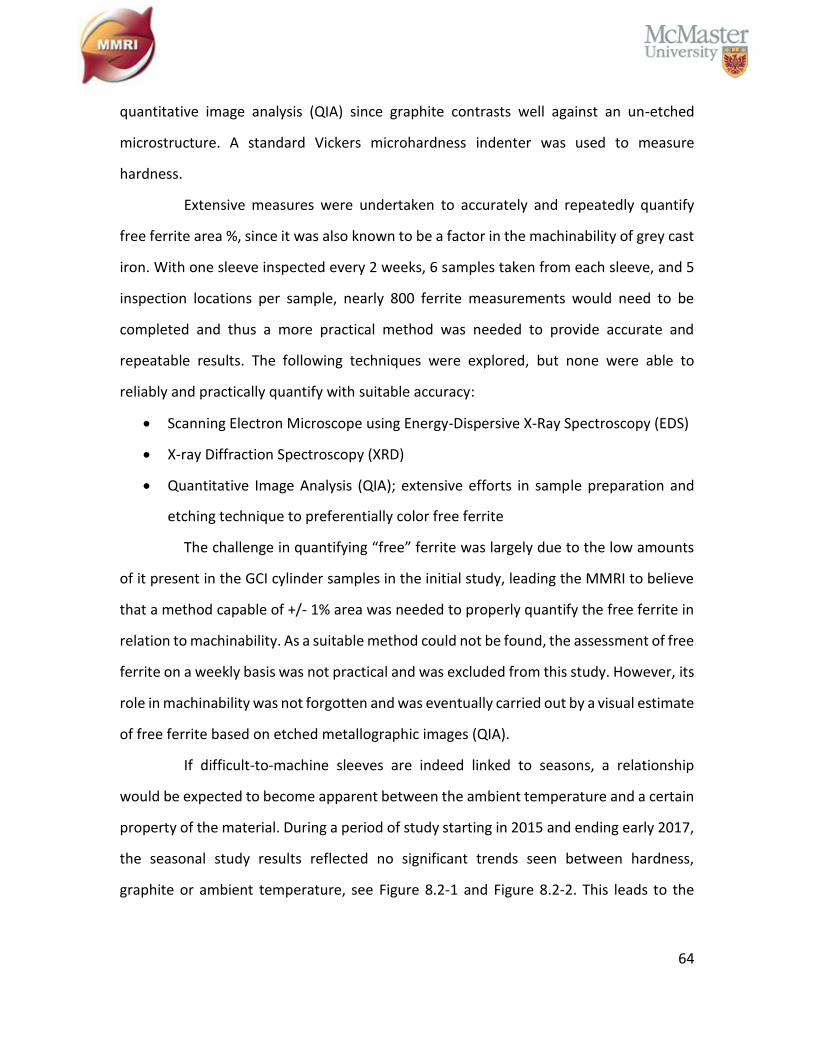
64
quantitative image analysis (QIA) since graphite contrasts well against an un-etched
microstructure. A standard Vickers microhardness indenter was used to measure
hardness.
Extensive measures were undertaken to accurately and repeatedly quantify
free ferrite area %, since it was also known to be a factor in the machinability of grey cast
iron. With one sleeve inspected every 2 weeks, 6 samples taken from each sleeve, and 5
inspection locations per sample, nearly 800 ferrite measurements would need to be
completed and thus a more practical method was needed to provide accurate and
repeatable results. The following techniques were explored, but none were able to
reliably and practically quantify with suitable accuracy:
• Scanning Electron Microscope using Energy-Dispersive X-Ray Spectroscopy (EDS)
• X-ray Diffraction Spectroscopy (XRD)
• Quantitative Image Analysis (QIA); extensive efforts in sample preparation and
etching technique to preferentially color free ferrite
The challenge in quantifying “free” ferrite was largely due to the low amounts
of it present in the GCI cylinder samples in the initial study, leading the MMRI to believe
that a method capable of +/- 1% area was needed to properly quantify the free ferrite in
relation to machinability. As a suitable method could not be found, the assessment of free
ferrite on a weekly basis was not practical and was excluded from this study. However, its
role in machinability was not forgotten and was eventually carried out by a visual estimate
of free ferrite based on etched metallographic images (QIA).
If difficult-to-machine sleeves are indeed linked to seasons, a relationship
would be expected to become apparent between the ambient temperature and a certain
property of the material. During a period of study starting in 2015 and ending early 2017,
the seasonal study results reflected no significant trends seen between hardness,
graphite or ambient temperature, see Figure 8.2-1 and Figure 8.2-2. This leads to the
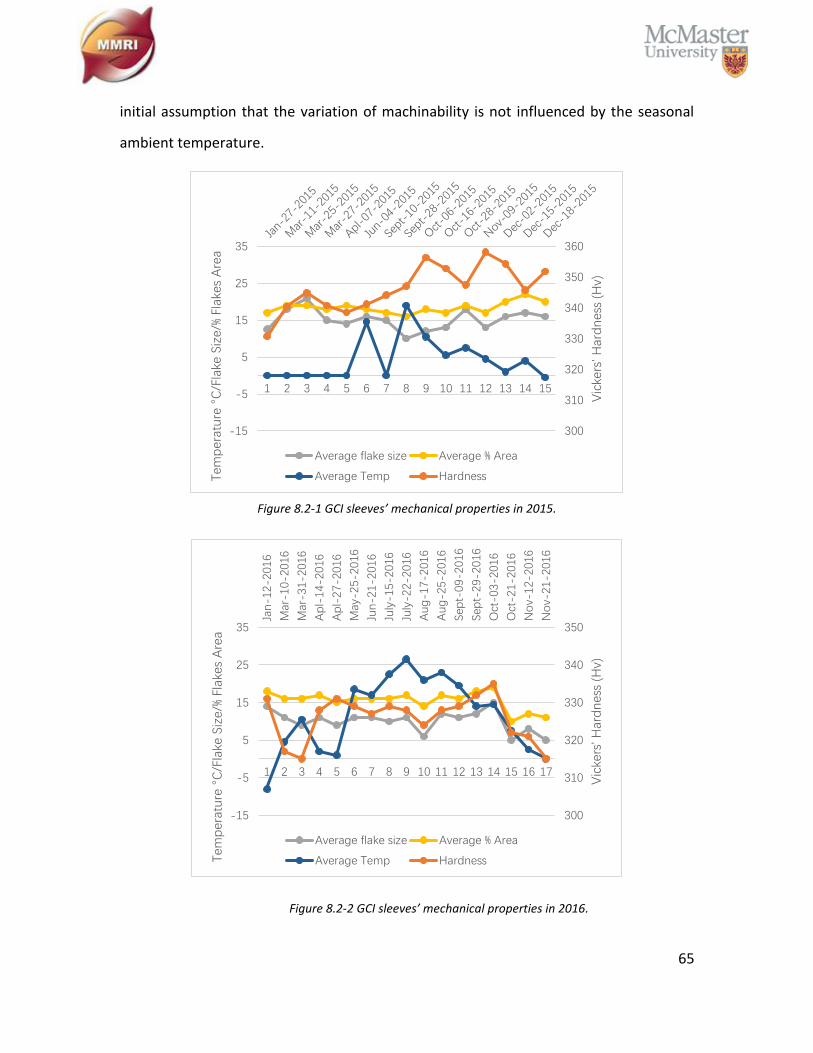
65
initial assumption that the variation of machinability is not influenced by the seasonal
ambient temperature.
Figure 8.2-1 GCI sleeves’ mechanical properties in 2015.
Figure 8.2-2 GCI sleeves’ mechanical properties in 2016.
300
310
320
330
340
350
360
1 2 3 4 5 6 7 8 9 10 11 12 13 14 15
-15
-5
5
15
25
35
Vic
kers
' Har
dn
ess
(Hv)
Tem
per
atu
re °
C/F
lake
Siz
e/%
Flak
es A
rea
Average flake size Average % Area
Average Temp Hardness
Jan-1
2-2
016
Mar
-10-
2016
Mar
-31-
2016
Ap
l-14-
2016
Ap
l-27-
2016
May
-25-
2016
Jun-2
1-2
016
July
-15-
2016
July
-22-
2016
Aug
-17-2
016
Aug
-25-2
016
Sep
t-09-
2016
Sep
t-29-
2016
Oct
-03-
2016
Oct
-21-
2016
No
v-12-
2016
No
v-21-
2016
300
310
320
330
340
350
1 2 3 4 5 6 7 8 9 10 11 12 13 14 15 16 17
-15
-5
5
15
25
35
Vic
kers
' Har
dn
ess
(Hv)
Tem
per
atu
re °
C/F
lake
Siz
e/%
Flak
es A
rea
Average flake size Average % Area
Average Temp Hardness
66
Chapter 9: Conclusions and Future Work
9.1. Conclusions
With support from an industrial partner, this research’s purpose is to solve the
seasonal variation of GCI machinability using four study directions. First, the preliminary
machinability tests determine the selection of optimal CBN inserts and cutting conditions.
Later on, a study is conducted of the impact of free ferrite content on CBN tool wear
behavior. The next study focuses on the improvement of GCI machinability through room
temperature artificial aging. Lastly, the studies of the seasonal variation of machinability,
the effect of free ferrite and room temperature aging, were combined.
The CBN cutting tool with composition 1has the second longest tool life (around
50,000 m cutting length). To ensure consistency with the industrial partner and to
simulate their practical conditions in the MMRI lab, it was selected as the cutting tool for
running all the experimental tests. The tests confirmed that the high-speed cutting
process resulted in the improvement of CBN tool life.
The % content of free ferrite has a significant influence on CBN tool wear
behavior, especially under high speed machining. The soft ferrite requires more energy
to plastically deform and generates more heat during the chip removal process. The
additional heat and built-up ferrite layer create a greater tendency of crater and flank
wear. Usually, the CBN tool life is limited by abrasion on the flank face by its own hard
CBN particles, but a greater content of free ferrite in the workpiece material also leads to
boron diffusion and crater wear on the rake face. The CBN tool life is much lower under
high free ferrite content GCI machining.
The room temperature aging study did not produce the expected results. The
tool life during the one-month aging period was inconsistent, but still considerably low. It
was confirmed by QIA that this batch of GCI cylinder sleeves contained a much higher
level of free ferrite. More than half of the workpiece inspected, had over 10% of free
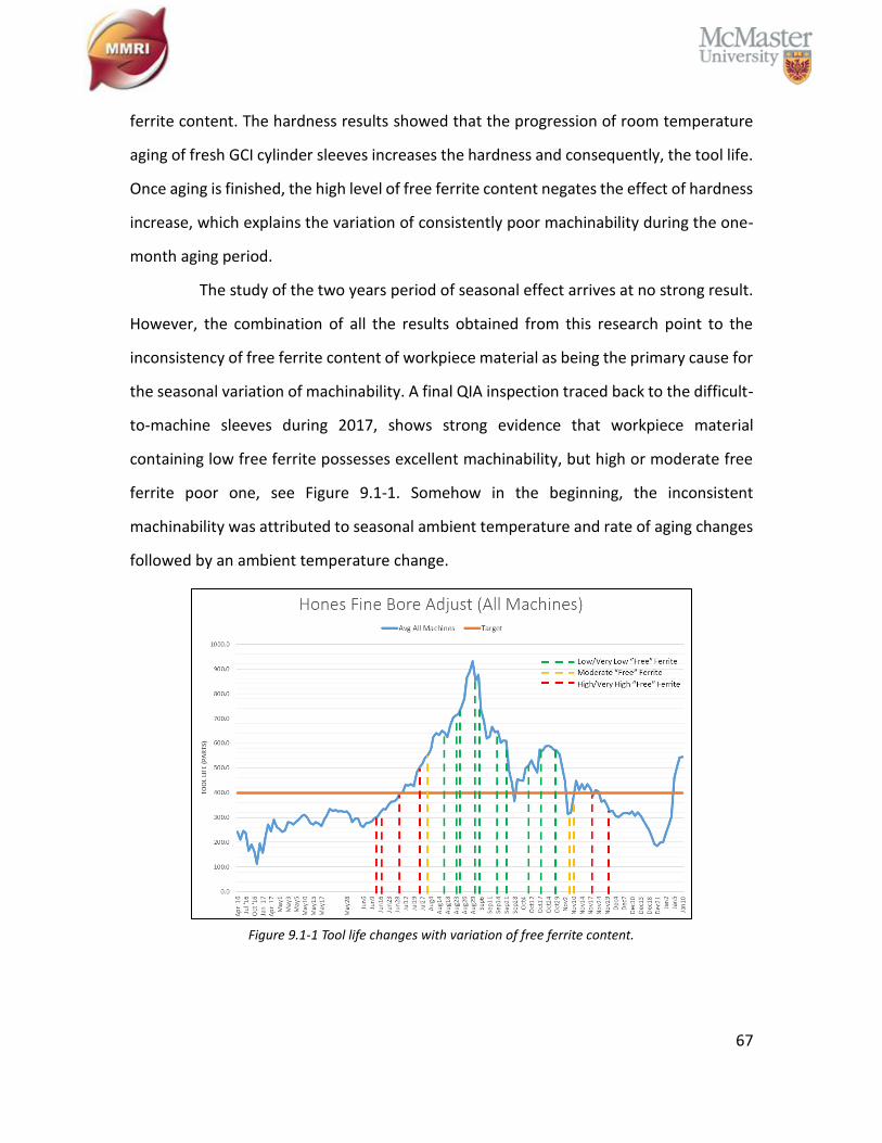
67
ferrite content. The hardness results showed that the progression of room temperature
aging of fresh GCI cylinder sleeves increases the hardness and consequently, the tool life.
Once aging is finished, the high level of free ferrite content negates the effect of hardness
increase, which explains the variation of consistently poor machinability during the one-
month aging period.
The study of the two years period of seasonal effect arrives at no strong result.
However, the combination of all the results obtained from this research point to the
inconsistency of free ferrite content of workpiece material as being the primary cause for
the seasonal variation of machinability. A final QIA inspection traced back to the difficult-
to-machine sleeves during 2017, shows strong evidence that workpiece material
containing low free ferrite possesses excellent machinability, but high or moderate free
ferrite poor one, see Figure 9.1-1. Somehow in the beginning, the inconsistent
machinability was attributed to seasonal ambient temperature and rate of aging changes
followed by an ambient temperature change.
Figure 9.1-1 Tool life changes with variation of free ferrite content.
68
9.2. Future Work
1. Since free ferrite can cause accelerating of CBN tool wear, the
phenomena is still unclear, not much literature cover this topic.
Discovering wear mechanism between CBN and free ferrite is important.
Why it is free ferrite not pearlite, since pearlite is a combination of
ferrite and cementite. Dose free ferrite chemically react with CBN
particles or the binder material and lead to a diffusion wear.
2. Study the reason causing the inconstancy of free ferrite content of GCI
cylinder sleeves over times (seasonal variation).
3. Sometime, it cannot to avoid machine high free ferrite content GCI
workpiece. Since CBN is not working well in this situation what kind of
cutting tool can replace CBN inserts and improve the machinability while
aging is still working.
69
Reference
[1] G. F. Vander Voort, Metallography: Principles and practice, vol. 18, no. 3. 1985.
[2] J. Liu, K. Yamazaki, H. Ueda, N. Narutaki, and Y. Yamane, “Machinability of Pearlitic Cast Iron With
Cubic Boron Nitride (CBN) Cutting Tools,” J. Manuf. Sci. Eng., vol. 124, no. 4, p. 820, 2002.
[3] M. Mizutani, “Super High-speed Face Milling By CBN Cutting Tool,” Tool Eng., pp. 49–53, 1996.
[4] E. Trent and P. K. Wright, Metal Cutting. 2000.
[5] J.R. Davis, “Classification and Basic Metallurgy of Cast Irons,” in ASM Specialty Handbook Cast Irons,
1996.
[6] H. K. Toenshoff and B. Denkena, “Chip formation,” Basic Cut. Abras. Process., pp. 21–37, 2013.
[7] G. E. Kempka, “Embrittlement, Toughening, and Subcritical Thermal Treatment of Malleable Iron,”
AFS Trans., 1955.
[8] W. M. Nicola and V. Richards, “Age Strengthening of Gray Cast Iron , Phase I : Statistical Verification,”
AFS Trans., 1999.
[9] D. M. Stefanescu, “Solidification and modeling of cast iron - A short history of the defining moments,”
Mater. Sci. Eng. A, vol. 413–414, pp. 322–333, 2005.
[10] ASM, Metals Handbook. 1998.
[11] M. Schmidt and K. Rohrbach, “ASM Handbook, Volume 1: Properties and Selection: Irons, Steels,
and High-Performance Alloys,” Met. Handb., vol. 1, no. February 1990, pp. 793–800, 1990.
[12] S. Genculu, “Cast Irons --Properties and Applications.”
[13] K. S. Rao, “ANALYSIS OF ENGINE CYLINDER LINERS,” Int. Res. J. Eng. Technol., 2015.
[14] I. Standard, “ISO 185, Grey cast irons- Classification.” 2005.
[15] I. Revised, A. Gray, I. Castings, and T. S. A. E. Standard, “Vehicle,” 2000.
[16] “Standard Specification for Gray Iron Castings,” in ASTM/A48, vol. 03, no. Reapproved 2008, 2008,
70
pp. 1–5.
[17] L. Collini, G. Nicoletto, and R. Konečná, “Microstructure and mechanical properties of pearlitic gray
cast iron,” Mater. Sci. Eng. A, vol. 488, no. 1–2, pp. 529–539, 2008.
[18] P. Fiorini and G. Byrne, “The influence of built-up layer formation on cutting performance of GG25
grey cast iron,” CIRP Ann. - Manuf. Technol., vol. 65, no. 1, pp. 93–96, 2016.
[19] A. A. Pereira, L. Boehs, and W. L. Guesser, “The influence of sulfur on the machinability of gray cast
iron FC25,” J. Mater. Process. Technol., vol. 179, no. 1–3, pp. 165–171, 2006.
[20] I. Standard, “ISO 945-1, Microstructure of cast irons.” 2008.
[21] P. Vincenzo and E. Fiorini, “High Efficiency Cutting of GG25 Grey Cast Iron by,” 2015.
[22] R. Ebner, “Giesserei,” vol. 50, pp. 689–691, 1963.
[23] V. Richards and W. Nicola, “FINAL TECHNICAL REPORT : AGE STRENGTHENING OF GRAY CAST IRON
PHASE III,” 2003.
[24] T. V. Anish, “Age strengthening of gray cast iron : alloying effects and kinetics study,” 2007.
[25] V. Richards, T. Anish, S. Lekakh, D. Van Aken, and W. Nicola, “Age strengthening of gray iron - Kinetics
study,” International Journal of Metalcasting. 2008.
[26] V. L. Richards, D. C. Van Aken, and W. Nicola, “Age strengthening of gray cast iron,” Int. J. Cast Met.
Res., vol. 16, no. 1–3, pp. 275–280, 2003.
[27] Jared Ashley teague, “Dependency of machinability in gray cast iron on nitride-induced age
strengthening,” 2010.
[28] T. Anish, S. N. Lekakh, and V. L. Richards, “The Effect of Ti and N on Iron Age Strengthening,” AFS
Trans., 2008.
[29] P. V. Novichkov, “Novichkov, P.V., "Thermocyclic Aging of Cast Iron at 200 - 280 Degrees
C," Liteinoe Proizvodstvo (in Russian), 31-5 (1970).,” Liteinoe Proizv. Russ., no. 31–5, 1970.
[30] V. L. Richards and W. Nicola, “Age strengthening of gray cast iron phase III,” AFS Trans., vol. Report
71
Num, no. 749–55, pp. 1–9, 2003.
[31] J. Edington, W. Nicola, and V. L. Richards, “Age Strengthening of Gray Cast Iron : Nitrogen Effects and
Machinability,” AFS Trans., 2002.
[32] P. B. Burgess, “Age Hardening Ferritic Malleable,” AFS Trans., no. 172–9, 1969.
[33] G. R. Booker, A. L. Sutton, and D. Phil, “An Investigation of Nitride rPrecipitates in Pure Iron and Mild
Steels,” J. Iron Steel Inst., no. 205–15, 1957.
[34] I. Fall and J. M. R. Genin, “Mössbauer spectroscopy study of the aging and tempering of high
nitrogen quenched Fe-N alloys: Kinetics of formation of Fe16N2nitride by interstitial ordering in
martensite,” Metall. Mater. Trans. A Phys. Metall. Mater. Sci., 1996.
[35] L. J. Dijkstra, “Precipitation Phenomena in the Solid Solutions of Nitrogen and Carbon in Alpha Iron
below the Eutectoid Temperature,” Trans. Metall. Soc. AIME, vol. 185, pp. 252–260, 1949.
[36] U. Dahmen, P. Ferguson, and K. H. Westmacott, “A TEM Study of α’’-Fe16N2 and γ’-Fe4N
Precipitation in Iron-Nitrogen,” Acta Metall., vol. 35, no. 5, 1987.
[37] J. F. Enrietto, “Solubility and Precipitation Of Nitrides in Alpha-Iron Containing Manganese,” Trans.
Metall. Soc. AIME, vol. 224, no. 1, pp. 43–48, 1962.
[38] K. F. Hale and D. McLean, “Structure of Quench-Aged Iron-Carbon and Iron-Nitrogen Alloys,” J. Iron
Steel Inst. London, vol. 201, no. 337–52, 1963.
[39] I. Hrivňák, “Low-Temperature Ageing of Iron and Low Carbon Steel,” Met. Treat. Drop Forg., no. 175–
81, 1961.
[40] K. H. Jack, “Binary and Ternary Interstitial Alloys. I. The Iron-Nitrogen System: The Structures of
FeFormulaN and FeFormulaN,” Proc. R. Soc. A Math. Phys. Eng. Sci., vol. 195, no. 1040, pp. 34–40,
1948.
[41] K. H. Jack, “The Occurrence and the Crystal Structure of Formula-Iron Nitride; a New Type of
Interstitial Alloy Formed during the Tempering of Nitrogen-Martensite,” Proc. R. Soc. A Math. Phys.
72
Eng. Sci., vol. 208, no. 1093, pp. 216–224, 1951.
[42] V. A. Phillips, “An Electron Microscope Study of Quench-Aging and Strain- Aging in A Dilute Fe-C-N
Alloy,” Trans. ASM, vol. 56, no. 600–17, 1963.
[43] D. V. Edmonds and R. W. K. Honeycombe, “Precipitation in Iron-Base Alloys,” Met Soc. AIME Precip.
Process. Solids, 1978.
[44] S. N. Lekakh and V. L. Richards, “Aging and Machinability Interactions in Cast Iron,” Trans. Am.
Foundry Soc., vol. 120, no. 12-026, pp. 307–318, 2012.
[45] V. L. Richards, T. V Anish, S. Lekakh, D. C. Van Aken, and W. Nicola, “Composition Effects on Age
Strengthening of Gray Iron,” AFS Trans., 2006.
[46] H. Schulz, “The History of High-Speed Machining,” Rev. Ciência e Tecnol., pp. 9–18, 1999.
[47] H. Schulz and T. Moriwaki, “High-speed Machining,” CIRP Ann. - Manuf. Technol., vol. 41, no. 2, pp.
637–643, 1992.
[48] A. Ber and M. Goldblatt, “The Influence of Temperature Gradient on Cutting Tool’s Life,” CIRP Ann.
- Manuf. Technol., vol. 38/1, pp. 69–73, 1989.
[49] A. K. . C. A. B. Chattopadhyay, “Mechanism of crater wear growth of coated carbides in high speed
machining,” J. Inst. Eng. 1 ndial Prod. Eng. Div., vol. 70, 1989.
[50] B. P. Sarmah and M. K. Khare, “Some investigations of the wear mechanisms of widalon carbide
inserts in machining EN24 (317 M 40) steel,” Wear, vol. 127, pp. 229–238, 1988.
[51] S. Foshag, “Neue Schneidstoffe und Beschichtungen,” Welkstatt und Betr., vol. 122, no. 12, pp.
1085–1087, 1989.
[52] R. Porat, Nahariya, A. Ber, and Haifa, “New Approach of Cutting Tool Materials - CERMET (Titanium
Carbonitride-Based Material) for Machining Steels,” CIRP Ann. - Manuf. Technol., 1990.
[53] A. Ippolito, R., Levi. R.. Lombardi. F., Tomincasa. S.. Villa, “High speed turning: technological and
economical involved aspects,” CIRP Semin. Torino, pp. 12–14, 1989.
73
[54] R. F. Silva, J. M. Gomes, A. S. Miranda, and J. M. Vieira, “Resistance of Si3N4 ceramic tools to thermal
and mechanical loading in cutting of iron alloys,” Wear, 1991.
[55] Venkatesh. V. C., “High speed machining of cast iron and steel,” Ann. ClRP, vol. XV, pp. 387–391,
1967.
[56] F. Koenigsberger and J. Tlusty, Structure of Machine Tools. 1971.
[57] Y. Huang, Y. K. Chou, and S. Y. Liang, “CBN tool wear in hard turning: A survey on research progresses,”
Int. J. Adv. Manuf. Technol., vol. 35, no. 5–6, pp. 443–453, 2007.
[58] S. Takatsu, Shimoda, and Otani, “Effects of CBN content on the cutting performance of
polycrystalline CBN tools,” Int. J. Refract. Hard Met, vol. 2, no. 4, pp. 175–178, 1983.
[59] D. A. Stephenson and J. S. Agapiou, Metal Cutting Theory and Practice Third Edition. 2016.
[60] V. Piispanen, “Lastunmuodostumisen teoriaa,” Tek. Aikakausl., vol. 27, p. 315–322 (in Finnish), 1937.
[61] V. Piispanen, “Theory of formation of metal chips,” J. Appl. Phys., vol. 19, no. 10, pp. 876–881, Oct.
1948.
[62] H. Ernst and M. E. Merchant, “Chip formation, friction and high quality machined surfaces,” Surf.
Treat. Met. ASM, vol. 29, pp. 299–378, 1941.
[63] M. E. Merchant, “Basic Mechanics of the Metal-Cutting Process,” J. Appl. Mech, vol. 11, pp. 168–
175, 1944.
[64] M. E. Merchant, “Mechanics of the metal cutting process. I. Orthogonal cutting and a type 2 chip,”
J. Appl. Phys., vol. 16, pp. 267–275, 1945.
[65] M. E. Merchant, “Mechanics of the metal cutting process. II. Plasticity conditions in orthogonal
cutting,” J. Appl. Phys., vol. 16, no. 6, pp. 318–324, Jun. 1945.
[66] G. Poulachon, A. Moisan, and I. S. Jawahir, “Tool-wear mechanisms in hard turning with
polycrystalline cubic boron nitride tools,” Wear, vol. 250–251, pp. 576–586, 2001.
[67] M. Dogra, V. S. Sharma, and J. Dureja, “Effect of tool geometry variation on finish turning - A review,”
74
J. Eng. Sci. Technol. Rev., vol. 4, no. 1, pp. 1–13, 2011.
[68] S. OOMEN-HURST, “PROCESS OPTIMIZATION IN MACHINING: AN APPLIED RESEARCH APPROACH,”
2012.
[69] ASM Handbook Volume 15: Casting. 1991.
[70] SECO, PCBN Technical Guide -. 2009.
[71] L. N. L. de Lacalle, A. Lamikiz, J. F. de Larrinoa, and I. Azkona, “Chapter 2: Advanced Cutting Tools,”
Mach. Hard Mater., pp. 33–86, 2011.
Copyright © 2022 FDOKUMEN